JP7201986B2 - Magnetic control method and transcranial magnetic stimulation system for activating proliferation of nervous system cells - Google Patents
Magnetic control method and transcranial magnetic stimulation system for activating proliferation of nervous system cells Download PDFInfo
- Publication number
- JP7201986B2 JP7201986B2 JP2018164498A JP2018164498A JP7201986B2 JP 7201986 B2 JP7201986 B2 JP 7201986B2 JP 2018164498 A JP2018164498 A JP 2018164498A JP 2018164498 A JP2018164498 A JP 2018164498A JP 7201986 B2 JP7201986 B2 JP 7201986B2
- Authority
- JP
- Japan
- Prior art keywords
- stimulation
- stimulus
- output
- control device
- generating devices
- Prior art date
- Legal status (The legal status is an assumption and is not a legal conclusion. Google has not performed a legal analysis and makes no representation as to the accuracy of the status listed.)
- Active
Links
Images


Landscapes
- Magnetic Treatment Devices (AREA)
Description
本明細書には、神経系細胞の増殖を活性化させるための磁気の制御方法、及び経頭蓋磁気刺激システムが開示される。 Disclosed herein are a magnetic control method and a transcranial magnetic stimulation system for activating proliferation of nervous system cells.
長期増強(Long-Term Potentiation:LTP)による興奮性シナプス伝達が記憶形成や、シナプス可塑性の誘導に重要な役割を果たすと言われている。非特許文献1には、電気刺激による長期増強が、成体ラット歯状回における神経新生を促すこと、及び成体ラット歯状回で申請された神経細胞の生存を増強することが記載されている。非特許文献2には、4台の磁気刺激装置を使ってシナプス可塑性の誘導を経頭蓋磁気刺激によって誘導することが記載されている。
Excitatory synaptic transmission by long-term potentiation (LTP) is said to play an important role in memory formation and induction of synaptic plasticity. Non-Patent Document 1 describes that long-term potentiation by electrical stimulation promotes neurogenesis in the adult rat dentate gyrus and enhances the survival of proposed neurons in the adult rat dentate gyrus. Non-Patent
また、非特許文献3には、皮質脊髄路の損傷に対し、電気刺激を行うことにより軸索の発芽を促すことが記載されている。
In addition, Non-Patent
非特許文献1では、電流の6パルスを400Hz(2.5ms)間隔、20ms持続、10秒間隔で6束行い、さらにこれを2分間あけて6シリーズ負荷し海馬を刺激している。しかし、神経組織に電気刺激を負荷するためには、刺激電極を開頭手術により刺激を負荷する部位に埋植しなければならない。このため、電気による神経組織の刺激は、非常に侵襲性が高いという課題がある。 In Non-Patent Document 1, 6 pulses of current are applied at intervals of 400 Hz (2.5 ms), duration of 20 ms, and 6 bundles at intervals of 10 seconds, and 6 series of 6 pulses are applied at intervals of 2 minutes to stimulate the hippocampus. However, in order to apply electrical stimulation to nerve tissue, stimulation electrodes must be implanted in the site to be stimulated by craniotomy. Therefore, there is a problem that electrical stimulation of nerve tissue is highly invasive.
非侵襲性脳刺激装置として、磁気刺激を負荷する装置(例えばマグスティム社製の経頭蓋磁気刺激装置)が知られており、非特許文献2に記載の経頭蓋磁気刺激装置は、マグスティム社製の経頭蓋磁気刺激装置を4台連結している。しかし、既存の経頭蓋磁気刺激装置では、非特許文献1に記載されているような電気刺激の条件を再現することはでない。したがって、現状では、磁気刺激によって神経系細胞の増殖を活性化することはできない。
As a noninvasive brain stimulator, a device that loads magnetic stimulation (for example, a transcranial magnetic stimulator manufactured by Magstim) is known. The transcranial magnetic stimulator described in Non-Patent
本発明は、非侵襲的に、又は低侵襲的に、経頭蓋磁気刺激を行い、神経系細胞の増殖を活性化することを課題とする。 An object of the present invention is to noninvasively or minimally invasively perform transcranial magnetic stimulation to activate proliferation of nervous system cells.
本発明者は、鋭意研究を重ねたところ、経頭蓋磁気刺激が同じ条件の電気刺激よりも強く神経系細胞の増殖を活性化することを見出した。 As a result of extensive research, the present inventor found that transcranial magnetic stimulation activates proliferation of nervous system cells more strongly than electrical stimulation under the same conditions.
本発明は、当該知見に基づいて完成されたものであり、以下の態様を含む。
項1.
頭蓋を介して磁気刺激を個体の神経組織に負荷するための磁気の発生を制御する制御デバイスと、
前記制御デバイスに接続された少なくとも6台の刺激発生デバイスであって、前記少なくとも6台の刺激発生デバイスのそれぞれが、前記制御デバイスにより、1回の刺激あたり、一定時間内に、他の刺激発生デバイスからは独立して時間差を持って一定間隔で複数回電流のパルスを出力するように制御される前記少なくとも6台の刺激発生デバイスと、
それぞれの刺激発生デバイスが出力した電流から磁気を発生する刺激デバイスと、
を備える経頭蓋磁気刺激システム。
項2.
前記一定時間が1分から6時間であり、前記時間差が2から5ミリ秒であり、前記一定間隔が1から15秒であり、前記複数回が5から120,000回である、項1に記載の経頭蓋磁気刺激システム。
項3.
前記一定時間が10分であり、前記時間差が2.5ミリ秒であり、前記一定間隔が10秒であり、前記複数回が60回である、
項1に記載の経頭蓋磁気刺激システム。
項4.
1回のバーストの持続時間が、10から50ミリ秒である、項1から3のいずれか一項に記載の経頭蓋磁気刺激システム。
項5.
刺激を複数回繰り返して負荷する、項1から4のいずれか一項に記載の経頭蓋磁気刺激システム。
項6.
前記複数回出力される電流の値が、毎回実質的に同じである、項1から5のいずれか一項に記載の経頭蓋磁気刺激システム。
項7.
前記複数回出力される電流の値が、少なくとも一部の回において他の回とは異なるか、前記少なくとも6台の刺激発生デバイスのうちの一部が他の刺激発生デバイスとは異なる値の電流を出力する、項1から5のいずれか一項に記載の経頭蓋磁気刺激システム。
項8.
前記制御デバイスに接続された刺激発生デバイスが8台である、項1から7のいずれか一項に記載の経頭蓋磁気刺激システム。
項9.
前記制御デバイスに接続された刺激発生デバイスが16台である、項1から7のいずれか一項に記載の経頭蓋磁気刺激システム。
項10.
神経系細胞の増殖を活性化させるための、項1から9のいずれか一項に記載の経頭蓋磁気刺激システム。
項11.
前記刺激デバイスが、2つのコイルを含む、項1から10のいずれか一項に記載の経頭蓋磁気刺激システム。
項12.
神経系細胞の増殖を活性化させるための磁気の制御方法であって、
刺激デバイスが、1回の刺激あたり、一定時間内に、一定間隔で少なくとも6回の磁気のパルスを出力するように制御することを含み、前記磁気のパルスは、頭蓋を介して磁気刺激を個体の神経組織に負荷する、
磁気の制御方法。
項13.
前記磁気のパルスが、磁気の発生を制御する制御デバイスを使って、前記制御デバイスに接続された少なくとも6台の刺激発生デバイスのそれぞれが、1回の刺激あたり、一定時間内に、他の刺激発生デバイスからは独立して時間差を持って一定間隔で複数回電流のパルスを出力するように制御することにより発生する、
項12に記載の磁気の制御方法。
項14.
前記制御デバイスに接続された刺激発生デバイスが8台である、項13に記載の磁気の制御方法。
項15.
前記制御デバイスに接続された刺激発生デバイスが16台である、項13に記載の磁気の制御方法。
項16.
前記一定時間が1分から6時間であり、前記時間差が2から5ミリ秒であり、前記一定間隔が1から15秒であり、前記複数回が5から120,000回である、項13から15のいずれか一項に記載の磁気の制御方法。
項17.
前記一定時間が10分であり、前記時間差が、2.5ミリ秒であり、前記一定間隔が10秒であり、前記複数回が60回である、項13から15のいずれか一項に記載の磁気の制御方法。
項18.
1回のバーストの持続時間が、10から50ミリ秒である、項13から15のいずれか一項に記載の磁気の制御方法。
項19.
刺激を複数回繰り返して負荷する、項12から18のいずれか一項に記載の磁気の制御方法。
項20.
前記複数回出力される電流の値が、毎回実質的に同じである、項13から19のいずれか一項に記載の磁気の制御方法。
項21.
前記複数回出力される電流の値が、少なくとも一部の回において他の回とは異なる、項13から19のいずれか一項に記載の磁気の制御方法。
項22.
頭蓋を介して磁気刺激を個体の神経組織に負荷するための磁気の発生を制御する制御デバイスであって、
少なくとも6台の刺激発生デバイスであって、前記少なくとも6台の刺激発生デバイスのそれぞれが、前記制御デバイスにより、1回の刺激あたり、一定時間内に、他の刺激発生デバイスからは独立して時間差を持って一定間隔で複数回電流のパルスを出力するよう制御される前記少なくとも6台の刺激発生デバイスと、
それぞれの刺激発生デバイスが出力した電流から磁気を発生する刺激デバイスと、
が接続される、制御デバイス。
項23.
頭蓋を介して磁気刺激を個体の神経組織に負荷するための磁気の発生を制御する制御デバイスに接続された少なくとも6台の刺激発生デバイスのそれぞれが、1回の刺激あたり、一定時間内に、他の刺激発生デバイスからは独立して時間差を持って一定間隔で複数回出力する電流のパルスから磁気を発生させる、
神経系細胞の増殖を活性化させるために個体の頭部に接触させる又は個体の頭部に接近させる刺激デバイス。
項24.
コンピュータに実行させたときに、コンピュータに、
頭蓋を介して磁気刺激を個体の神経組織に負荷するための磁気の発生を制御する制御デバイスに接続された少なくとも6台の刺激発生デバイスのそれぞれが、1回の刺激あたり、一定時間内に、他の刺激発生デバイスからは独立して時間差を持って一定間隔で複数回出力する電流のパルスを刺激デバイスに出力させる、
神経系細胞の増殖を活性化させるためのコンピュータプログラム。
The present invention has been completed based on this finding, and includes the following aspects.
Section 1.
a control device for controlling the generation of magnetism for applying magnetic stimulation to the neural tissue of the individual via the cranium;
at least six stimulus-generating devices connected to the control device, each of the at least six stimulus-generating devices being activated by the control device to generate another stimulus per stimulus within a period of time; the at least six stimulus generating devices controlled to output multiple pulses of current at regular intervals with time lags independently from the devices;
a stimulation device that generates magnetism from the current output by each stimulation generation device;
A transcranial magnetic stimulation system comprising:
The fixed time is 10 minutes, the time difference is 2.5 milliseconds, the fixed interval is 10 seconds, and the plurality of times is 60 times.
Item 1. The transcranial magnetic stimulation system according to item 1.
4. A transcranial magnetic stimulation system according to any one of clauses 1 to 3, wherein the duration of one burst is 10 to 50 milliseconds.
Item 6.
Item 6. The transcranial magnetic stimulation system according to any one of Items 1 to 5, wherein the value of the current output multiple times is substantially the same each time.
Item 7.
The value of the current output a plurality of times is different in at least some times from other times, or the current value of some of the at least 6 stimulus generating devices is different from other stimulus generating devices. Item 6. The transcranial magnetic stimulation system according to any one of Items 1 to 5, which outputs
8. The transcranial magnetic stimulation system according to any one of clauses 1 to 7, wherein eight stimulation generating devices are connected to the control device.
Item 9.
8. The transcranial magnetic stimulation system according to any one of clauses 1 to 7, wherein there are 16 stimulation generating devices connected to the control device.
Item 11.
11. The transcranial magnetic stimulation system of any one of clauses 1-10, wherein the stimulation device comprises two coils.
Item 12.
A magnetic control method for activating proliferation of nervous system cells, comprising:
controlling the stimulation device to output at least six magnetic pulses at regular intervals within a specified time period per stimulation, wherein the magnetic pulses provide magnetic stimulation through the cranium to the individual; load the nervous tissue of
Magnetic control method.
Item 13.
Using a control device for controlling the generation of magnetism, the magnetic pulse is generated by each of at least six stimulus generating devices connected to the control device, within a certain period of time, per stimulus, another stimulus Generated by controlling to output multiple pulses of current at regular intervals with time lags independently from the generating device,
Item 13. A magnetism control method according to Item 12.
Item 14.
Item 14. A magnetism control method according to Item 13, wherein eight stimulus generating devices are connected to the control device.
Item 15.
Item 14. The magnetic control method according to Item 13, wherein 16 stimulus generating devices are connected to the control device.
Item 16.
Clauses 13-15, wherein said fixed time is 1 minute to 6 hours, said time difference is 2 to 5 milliseconds, said fixed interval is 1 to 15 seconds, and said plurality of times is 5 to 120,000 times The magnetism control method according to any one of 1.
Item 17.
16. Any one of Clauses 13 to 15, wherein the fixed time is 10 minutes, the time difference is 2.5 milliseconds, the fixed interval is 10 seconds, and the plurality of times is 60 times. magnetic control method.
Item 18.
16. A magnetic control method according to any one of Items 13 to 15, wherein the duration of one burst is 10 to 50 milliseconds.
Item 19.
Item 19. The magnetism control method according to any one of Items 12 to 18, wherein the stimulus is repeatedly applied a plurality of times.
Item 20.
Item 20. The magnetism control method according to any one of Items 13 to 19, wherein the value of the current output multiple times is substantially the same each time.
Item 21.
Item 20. The magnetism control method according to any one of Items 13 to 19, wherein the value of the current output multiple times is different in at least some times from other times.
Item 22.
A control device for controlling the generation of magnetism for applying magnetic stimulation to neural tissue of an individual via the cranium,
at least six stimulus-generating devices, each of said at least six stimulus-generating devices being independently timed from other stimulus-generating devices within a period of time per stimulation by said control device; the at least six stimulus-generating devices controlled to output multiple pulses of current at regular intervals with
a stimulation device that generates magnetism from the current output by each stimulation generation device;
control device to which is connected.
Item 23.
Each of at least six stimulus-generating devices connected to a control device for controlling the generation of magnetism for applying magnetic stimuli to the neural tissue of the individual via the cranium, within a certain period of time per stimulus, Magnetism is generated from current pulses that are output multiple times at regular intervals with time lags independently from other stimulus generating devices.
A stimulation device that contacts or approaches an individual's head to activate proliferation of nervous system cells.
Item 24.
When I let the computer run it, the computer
Each of at least six stimulus-generating devices connected to a control device for controlling the generation of magnetism for applying magnetic stimuli to the neural tissue of the individual via the cranium, within a certain period of time per stimulus, Cause the stimulation device to output multiple pulses of current at regular intervals with time lags independently from other stimulation generation devices;
A computer program for activating proliferation of nervous system cells.
本発明によれば、神経系細胞の増殖を活性化することができる。 According to the present invention, proliferation of nervous system cells can be activated.
以下、本発明の実施形態の例を、添付の図面を参照して詳細に説明する。図面において、同じ符号は、同じ又は実質的に同じ構成を意図する。 Examples of embodiments of the present invention will now be described in detail with reference to the accompanying drawings. In the drawings, the same reference numerals denote the same or substantially the same configuration.
[経頭蓋磁気刺激]
本開示の実施形態の第1例は、頭蓋を介して磁気刺激を個体の神経組織に負荷するため経頭蓋磁気刺激に関する。また、第1例は、神経系細胞の増殖を活性化させるための磁気の制御方法に関する。前記磁気刺激は、神経系細胞の増殖を活性化させることができる。好ましくは、前記神経系細胞の活性化は、神経組織内のS6タンパク質のリン酸化の程度によって評価することができる。
[Transcranial magnetic stimulation]
A first exemplary embodiment of the present disclosure relates to transcranial magnetic stimulation to load neural tissue of an individual with magnetic stimulation through the cranium. Also, the first example relates to a magnetic control method for activating proliferation of nervous system cells. The magnetic stimulation can activate proliferation of nervous system cells. Preferably, activation of said nervous system cells can be assessed by the degree of phosphorylation of S6 protein in neural tissue.
本開示において、神経系細胞には、神経細胞と神経細胞に栄養を供給するグリア細胞(アストログリア細胞、オリゴデンドログリア細胞、ミクログリア細胞等)を含む。 In the present disclosure, nervous system cells include neurons and glial cells that provide nutrients to neurons (astroglial cells, oligodendroglial cells, microglial cells, etc.).
本開示において、個体は、哺乳類である限り制限されない。例えば、ヒト、サル、イヌ、ネコ、マウス、ラット、及びウサギ等を例示することができる。好ましくはヒトである。 In the present disclosure, individuals are not limited as long as they are mammals. Examples include humans, monkeys, dogs, cats, mice, rats, and rabbits. Humans are preferred.
前記磁気の制御方法は、刺激デバイス125が、後述する制御デバイス10の制御下において、1回の刺激あたり、一定時間内に、一定間隔で少なくとも6回の磁気のパルスを出力するように制御することを含み、前記磁気のパルスは、頭蓋を介して磁気刺激を個体の神経組織に負荷することにより行われる。
The magnetic control method controls the
[経頭蓋磁気刺激システム]
本開示の実施形態の第2例は、頭蓋を介して磁気刺激を個体の神経組織に負荷するため経頭蓋磁気刺激システム1000に関する。第2例は、神経系細胞の増殖を活性化させるための磁気の制御方法に関する。前記磁気刺激は、神経系細胞の増殖を活性化させることができる。
[Transcranial magnetic stimulation system]
A second exemplary embodiment of the present disclosure relates to a transcranial magnetic stimulation system 1000 for applying magnetic stimulation to neural tissue of an individual via the cranium. A second example relates to a magnetic control method for activating proliferation of nervous system cells. The magnetic stimulation can activate proliferation of nervous system cells.
図1に、制御デバイス10と、制御デバイス10に刺激発生デバイス連結モジュール122を介して接続された第1の刺激発生デバイスSG1,第2の刺激発生デバイスSG2,第3の刺激発生デバイスSG3,第4の刺激発生デバイスSG4,第5の刺激発生デバイスSG5,第6の刺激発生デバイスSG6,第7の刺激発生デバイスSG7,第8の刺激発生デバイスSG8と、刺激発生デバイスSG1,SG2,SG3,SG4,SG5,SG6,SG7,SG8がそれぞれに出力した電流から磁気を発生する刺激発生デバイス連結モジュール122に接続された刺激デバイス125と、を備える経頭蓋磁気刺激システム1000aを例示する。
FIG. 1 shows a
また、図2には、前記制御デバイス10にさらに第9の刺激発生デバイスSG9,第10の刺激発生デバイスSG10,第11の刺激発生デバイスSG11,第12の刺激発生デバイスSG12,第13の刺激発生デバイスSG13,第14の刺激発生デバイスSG14,第15の刺激発生デバイスSG15,第16の刺激発生デバイスSG16接続された経頭蓋磁気刺激システム1000bを例示する。
経頭蓋磁気刺激システム1000a及び経頭蓋磁気刺激システム1000bを含む包括的なシステム概念を経頭蓋磁気刺激システム1000と称する。
2 further includes a ninth stimulus generating device SG9, a tenth stimulus generating device SG10, an eleventh stimulus generating device SG11, a twelfth stimulus generating device SG12, and a thirteenth stimulus generating device SG12. A transcranial
A comprehensive system concept including transcranial
図3に示すように、制御デバイス10と各刺激発生デバイスとの接続は、制御デバイス10の通信インタフェース(I/F)108を介し、制御デバイス10から各刺激発生デバイスに、刺激発生デバイスSGから電流を出力するための指令である信号(トリガ)を送信できる限り制限されない。制御デバイス10と各刺激発生デバイスとの接続は、例えば、BNCケーブル等のケーブル123で接続され得る。
As shown in FIG. 3, the connection between the
また、各刺激発生デバイスと刺激発生デバイス連結モジュール122とは、例えばマグスティム社製の磁気刺激装置に使用されるコイルケーブル等のケーブル123で接続され得る。
Also, each stimulus generating device and the stimulus generating
刺激発生デバイス連結モジュール122と刺激デバイス125と、例えばマグスティム社製の磁気刺激装置に使用されるコイルケーブル等のケーブル124で接続され得る。
The stimulator
制御デバイス10に接続される刺激発生デバイスSG(符号「SG」は、刺激発生デバイスの任意の1台を示す際に使用する)は少なくとも6台であれば良く、100台程度まで、好ましくは50台程度まで、より好ましくは32台程度まで制御デバイス10に接続することができる。好ましくは、7台、8台、9台、10台、12台、14台、16台、18台、20台、24台、28台、32台、36台、又は40台である。以下では、刺激発生デバイスSG1,SG2,SG3,SG4,SG5,SG6,SG7,SG8,SG9,SG10,SG11,SG12,SG13,SG14,SG15,SG16を接続する例を用いて実施形態の例を説明する。
The number of stimulus generating devices SG connected to the control device 10 (the symbol "SG" is used to indicate any one stimulus generating device) may be at least six, up to about 100, preferably 50. Up to about 32 devices can be connected to the
経頭蓋磁気刺激システム1000は、少なくとも6台の刺激発生デバイスSG1,SG2,SG3,SG4,SG5,SG6や刺激発生デバイス連結モジュール122を設置するための設置台B1を備えていてもよい。
The transcranial magnetic stimulation system 1000 may include a mounting base B1 for mounting at least six stimulus generating devices SG1, SG2, SG3, SG4, SG5, SG6 and the stimulus generating
・制御デバイス
図3を用いて制御デバイスのハードウェアの構成を説明する。
制御デバイス10は、少なくとも6台の刺激発生デバイスSG1,SG2,SG3,SG4,SG5,SG6の他、入力部111と、出力部112と、記憶媒体113とに接続されていてもよい。
- Control Device The hardware configuration of the control device will be described with reference to FIG.
The
制御デバイス10は、処理部101と、主記憶部102と、ROM(read only memory)103と、補助記憶部104と、通信インタフェース(I/F)105と、入力インタフェース(I/F)106と、出力インタフェース(I/F)107と、メディアインターフェース(I/F)108を備えており、各部はバス109によって互いにデータ通信可能に接続されている。主記憶部102と補助記憶部104とを合わせて、単に記憶部と呼ぶこともある。
The
処理部101は、制御デバイス10のCPUである。処理部101は、GPUであってもよい。処理部101が、補助記憶部104又はROM103に記憶されているコンピュータプログラムを実行し、少なくとも6台の刺激発生デバイス刺激発生デバイスSG1,SG2,SG3,SG4,SG5,SG6を、1回の刺激あたり、一定時間内に、他の刺激発生デバイスSGからは独立して時間差を持って一定間隔で複数回電流のパルスを出力するように各刺激発生デバイスSGを制御することで制御デバイス10が機能する。
A
主記憶部102は、SRAM又はDRAMなどのRAM(Random access memory)によって構成される。主記憶部102は、ROM103及び補助記憶部104に記録されているコンピュータプログラムの読み出しに用いられる。また、主記憶部102は、処理部101がこれらのコンピュータプログラムを実行するときの作業領域として利用される。
The
ROM103は、マスクROM、PROM、EPROM、EEPROMなどによって構成され、処理部101により実行されるコンピュータプログラム及びこれに用いるデータが記録されている。処理部101はMPU101としてもよい。ROM103は、制御デバイス10の起動時に、処理部101によって実行されるブートプログラムや制御デバイス10のハードウェアの動作に関連するプログラムや設定を記憶する。
The
補助記憶部104は、ハードディスク、フラッシュメモリ等の半導体メモリ素子、光ディスク等によって構成される。補助記憶部104には、オペレーティングシステム及びアプリケーションプログラムなどの、処理部101に実行させるための種々のコンピュータプログラム及びコンピュータプログラムの実行に用いる各種設定データが記憶されている。例えば、後述する経頭蓋磁気刺激を処理部101に実行させるためのコンピュータプログラムを不揮発性に記憶する。
The
通信I/F105は、USB、IEEE1394、RS-232Cなどのシリアルインタフェース、SCSI、IDE、IEEE1284などのパラレルインタフェース、及びD/A変換器、A/D変換器などからなるアナログインタフェース、ネットワークインタフェースコントローラ(Network interface controller:NIC)等から構成される。通信I/F105は、処理部101の制御下で、通信インタフェース(I/F)108を介して、ケーブル121に接続される。通信I/F105は、ネットワークを介して他の外部機器と通信を行ってもよい。
The communication I/
入力I/F106は、例えばUSB、IEEE1394、RS-232Cなどのシリアルインタフェース、SCSI、IDE、IEEE1284などのパラレルインタフェース、及びD/A変換器、A/D変換器などからなるアナログインタフェースなどから構成される。入力I/F106は、入力部111からユーザによる例えば各刺激発生デバイスSGの制御条件等の文字入力、クリック、音声入力等を受け付ける。受け付けた入力内容は、主記憶部102又は補助記憶部104に記憶される。
The input I/
入力部111は、タッチパネル、キーボード、マウス、ペンタブレット、マイク等から構成され、制御デバイス10に文字入力又は音声入力を行う。入力部111は、制御デバイス10の外部から接続されても、制御デバイス10と一体となっていてもよい。
The
出力I/F107は、例えば入力I/F106と同様のインタフェースから構成される。出力I/F107は、処理部101が生成した情報を出力部112に出力する。出力I/F107は、処理部101が生成し、補助記憶部104に記憶した情報を、出力部112に出力する。
The output I/
出力部112は、例えばディスプレイ、プリンター等で構成され、経頭蓋磁気刺激の条件を入力するためのユーザインターフェースや、少なくとも6台の刺激発生デバイス刺激発生デバイスSG1,SG2,SG3,SG4,SG5,SG6の動作履歴等を出力する。
The
メディアI/F108は、記憶媒体113に記憶された例えばアプリケーションソフト等を読み出す。読み出されたアプリケーションソフト等は、主記憶部102又は補助記憶部104に記憶される。また、メディアI/F108は、処理部101が生成した情報を記憶媒体113に書き込む。メディアI/F108は、処理部101が生成し、補助記憶部104に記憶した情報を、記憶媒体113に書き込む。
The media I/
記憶媒体113は、フレキシブルディスク、CD-ROM、又はDVD-ROM等で構成される。記憶媒体113は、フレキシブルディスクドライブ、CD-ROMドライブ、又はDVD-ROMドライブ等によってメディアI/F108と接続される。記憶媒体113には、コンピュータがオペレーションを実行するためのアプリケーションプログラム等が格納されていてもよい。
The
処理部101は、制御デバイス10の制御に必要なアプリケーションソフトや各種設定をROM103又は補助記憶部104からの読み出しに代えて、ネットワークを介して取得してもよい。前記アプリケーションプログラムがネットワーク上のサーバコンピュータの補助記憶部内に格納されており、このサーバコンピュータに制御デバイス10がアクセスして、コンピュータプログラムをダウンロードし、これをROM103又は補助記憶部104に記憶することも可能である。
The
また、ROM103又は補助記憶部104には、例えば米国マイクロソフト社が製造販売するWindows(登録商標)などのグラフィカルユーザインタフェース環境を提供するオペレーションシステムがインストールされている。後述する経頭蓋刺激を行うためのコンピュータプログラムは、前記オペレーティングシステム上で動作するものとする。すなわち、制御デバイス10は、パーソナルコンピュータ等であり得る。
An operating system that provides a graphical user interface environment such as Windows (registered trademark) manufactured and sold by Microsoft Corporation in the United States is installed in the
制御デバイス10は、例えば後述するコンピュータプログラムの制御下でトリガを通信I/F105から出力する。
The
・刺激発生デバイス
刺激発生デバイスSGは、頭蓋を介して磁気刺激を個体の神経組織に負荷するために刺激デバイス125に磁気を発生させることができる限り制限されない。刺激発生デバイスSGは、約1,000Aから10,000A程度の電流を出力可能であり、出力される電流から生じる刺激波形は、例えば、単相であり、刺激時間は1ミリ秒以下(刺激デバイスに依存する場合がある)。例えば、磁場の空間分布及び時間変化は立ち上がり時間が83から103マイクロ秒程度(刺激デバイスに依存する場合がある)及び最大磁束変化率21.6キロから47キロT/秒程度(刺激デバイスに依存する場合がある)、最大磁束密度1.2から2.39T(100%出力時程度、刺激デバイスに依存する場合がある)、少なくとも単発刺激が可能である限り制限されない。また、刺激発生デバイスSGは、0から49%出力の際少なくとも2秒程度ごと、50から79%出力の際少なくとも3秒ごと、80から100%出力の際少なくとも4秒ごと程度の刺激出力を繰り返し行えることが好ましい。刺激発生デバイスSGのトリガ入力は、極性がアクティブL(負理論)又はアクティブH(正理論)であり、エッジ入力又はレベル入力から選択することができる。トリガ出力は、極性がアクティブL(負理論)又はアクティブH(正理論)であり、トリガ出力は、トリガごとにトリガ出力パルスを出力できることが好ましい。トリガ出力のパルス幅は、100マイクロ秒から80ミリ秒、好ましくは100マイクロ秒、8、18、28、38、48、58、68、又は78ミリ秒程度である。例えば、刺激発生デバイスSGとしてマグスティム社製のマグスティム200スクエアを例示することができる。
• Stimulus Generating Device The stimulus generating device SG is not limited as long as it can generate magnetism in the
図3に示すように、各刺激発生デバイスSGは、制御デバイス10の通信I/F105に接続されており、図4に示すように、制御デバイス10の通信I/F10に接続されたケーブル123は、刺激発生デバイスSG1,SG2,SG3,SG4,SG5,SG6,SG7,SG8,SG9,SG10,SG11,SG12,SG13,SG14,SG15,SG16のそれぞれに備えられたBNC端子等のトリガ入力端子T1,T2,T3,T4,T5,T6,T7,T8,T9,T10,T11,T12,T13,T14,T15,T16に接続される。また、各刺激発生デバイスSGは電流を供給するためのAC電源131に接続するケーブル132に接続されている。また、図示しないが、刺激発生デバイスSG1,SG2,SG3,SG4,SG5,SG6,SG7,SG8,SG9,SG10,SG11,SG12,SG13,SG14,SG15,SG16には、トリガを出力するためのトリガ出力部が備えられており、各刺激発生デバイスSGにトリガが入力されると、各刺激発生デバイスSGのトリガ出力部は、入力ごとに1回ずつパルス(電流)を出力する。言い換えると、1台の刺激発生デバイスSGが電流を出力している間、同じ制御デバイス10に接続されている他の刺激発生デバイスSGは電流を出力しない。
As shown in FIG. 3, each stimulus generating device SG is connected to the communication I/
・刺激発生デバイス連結モジュール
刺激発生デバイス連結モジュール122は、少なくとも6台の刺激発生デバイスSG1,SG2,SG3,SG4,SG5,SG6からの電流の出力を1つの刺激デバイス125に伝送するためのアイソレータを備える。このアイソレータにより、トリガが入力された刺激発生デバイスSGのみからケーブル124に電流が伝送され、1台の刺激発生デバイスSGのみからの電流により、刺激デバイス125が磁気を発生することとなる。
Stimulus Generation Device Connection Module The stimulation generation
・刺激デバイス
刺激デバイス125は、通電により磁気を発生するコイル構造を備える限り制限されない。好ましくは、個体の頭部に接触させる又は個体の頭部に接近させる刺激デバイス125である。より好ましくは、刺激デバイス125は、2つのコイル構造を備える。1つのコイルの直径は、25mm、50mm、70mm、及び90mmから選択することができる。好ましくは、1つのコイルの直径は、好ましくは70mmである。
• Stimulation device The
コイルとして好ましくは、マグスティム社製のスタンダードコイル、ダブルアルファコイル、ダブルコーンコイル等を例示することができる。コイルは被覆されていても良い。コイルを被覆する場合には、例えば断熱性プラスチック樹脂を使用することができる。 Preferred coils include standard coils, double alpha coils and double cone coils manufactured by Magstim. The coil may be coated. For coating the coil, for example, a heat-insulating plastic resin can be used.
・磁気刺激の制御
(刺激の出力)
図5から図10を参照しながら、制御デバイス10の動作について説明する。
制御デバイス10の制御により、制御デバイス10に接続された少なくとも6台の刺激発生デバイスSG1,SG2,SG3,SG4,SG5,SG6はそれぞれが、1回の刺激あたり、一定時間内に、他の刺激発生デバイスからは独立して時間差(パルス間のインターバル)を持って一定間隔(バースト間のインターバル)で複数回電流のパルスを出力する。好ましくは、前記一定時間が1分から6時間であり、前記時間差が2ミリ秒から5ミリ秒であり、前記一定間隔が1秒から15秒であり、前記複数回が5回から120,000回である。より好ましくは、前記一定時間が10分であり、前記時間差が2.5ミリ秒であり、前記一定間隔が10秒であり、前記複数回が60回である。また、1回のバーストの持続時間は、10から50ミリ秒であることが好ましく、20から25ミリ秒であることがより好ましい。より好ましくは、17.7秒である。バーストの持続時間のカウントは、1回のバースト内のはじめのパルスの出力開始から、最後のパルスの出力終了までを意図する。1つのパルスの持続時間は、0.1から0.5ミリ秒程度、好ましくは0.2ミリ秒程度である。前記時間差のカウントは1回のバースト内における先のパルスの出力開始から、次のパルスの出力開始までを意図する。出力される電流値は、1,000Aから10,000A程度、好ましくは3,000から6,000A程度、より好ましくは5,000A程度である。
・Control of magnetic stimulation (output of stimulation)
The operation of the
Under the control of the
刺激は、上記条件の1回の刺激を複数回繰り返しても良い。刺激の繰り返し回数は、好ましくは、2回以上、4回以上、6回以上、8回以上又は10回以上である。刺激の繰り返し回数は、好ましくは30回以下、25回以下、20回以下又は15回以下である。刺激を繰り返す場合には、1日に前記回数の刺激を繰り返してもよい。また、1日1回の刺激を上記所定の刺激回数に達するまで繰り返してもよい。 As for the stimulation, one stimulation under the above conditions may be repeated multiple times. The number of stimulation repetitions is preferably 2 or more, 4 or more, 6 or more, 8 or more, or 10 or more. The number of stimulation repetitions is preferably 30 times or less, 25 times or less, 20 times or less, or 15 times or less. When the stimulation is repeated, the stimulation may be repeated the number of times per day. Alternatively, stimulation once a day may be repeated until the prescribed number of stimulations is reached.
図5に示す例を用いて、制御デバイス10の制御により刺激発生デバイスSG1,SG2,SG3,SG4,SG5,SG6,SG7,SG8が出力する電流のパルスのタイミングを例として制御デバイス10による刺激の例を説明する。刺激デバイス125において出力する電流のパルスのパターンは磁気のパルスのパターンとなる。
Using the example shown in FIG. 5, the timing of current pulses output by the stimulation generating devices SG1, SG2, SG3, SG4, SG5, SG6, SG7, and SG8 under the control of the
はじめに、図5の(1)欄に示すように、制御デバイス10は、刺激発生デバイスSG1にトリガを入力し、刺激発生デバイスSG1が電流のパルスを出力し、電流のパルスは刺激発生デバイス連結モジュールを介して刺激デバイス125に伝送される。
First, as shown in column (1) of FIG. 5, the
次に制御デバイス10は刺激デバイスSG1へのトリガの入力から一定の時間差例えば2.5ミリ秒)で、刺激発生デバイスSG2にトリガを入力し、刺激発生デバイスSG2が電流のパルスを出力し、電流のパルスは刺激発生デバイス連結モジュールを介して刺激デバイス125に伝送される。
Next, the
次に制御デバイス10は刺激デバイスSG2へのトリガの入力から一定の時間差例えば2.5ミリ秒)で、刺激発生デバイスSG3にトリガを入力し、刺激発生デバイスSG3が電流のパルスを出力し、電流のパルスは刺激発生デバイス連結モジュールを介して刺激デバイス125に伝送される。
Next, the
次に制御デバイス10は刺激デバイスSG3へのトリガの入力から一定の時間差例えば2.5ミリ秒)で、刺激発生デバイスSG4にトリガを入力し、刺激発生デバイスSG4が電流のパルスを出力し、電流のパルスは刺激発生デバイス連結モジュールを介して刺激デバイス125に伝送される。
Next, the
次に制御デバイス10は刺激デバイスSG4へのトリガの入力から一定の時間差例えば2.5ミリ秒)で、刺激発生デバイスSG5にトリガを入力し、刺激発生デバイスSG5が電流のパルスを出力し、電流のパルスは刺激発生デバイス連結モジュールを介して刺激デバイス125に伝送される。
Next, the
次に制御デバイス10は刺激デバイスSG5へのトリガの入力から一定の時間差例えば2.5ミリ秒)で、刺激発生デバイスSG6にトリガを入力し、刺激発生デバイスSG6が電流のパルスを出力し、電流のパルスは刺激発生デバイス連結モジュールを介して刺激デバイス125に伝送される。
Next, the
次に制御デバイス10は刺激デバイスSG6へのトリガの入力から一定の時間差例えば2.5ミリ秒)で、刺激発生デバイスSG7にトリガを入力し、刺激発生デバイスSG7が電流のパルスを出力し、電流のパルスは刺激発生デバイス連結モジュールを介して刺激デバイス125に伝送される。
Next, the
次に制御デバイス10は刺激デバイスSG7へのトリガの入力から一定の時間差例えば2.5ミリ秒)で、刺激発生デバイスSG8にトリガを入力し、刺激発生デバイスSG8が電流のパルスを出力し、電流のパルスは刺激発生デバイス連結モジュールを介して刺激デバイス125に伝送される。
Next, the
刺激発生デバイスSG1から刺激発生デバイスSG8までのパルスの出力の束を1バーストとする。1バースト内のパルス数は、刺激発生デバイスSGの台数に対応する。 A bundle of pulse outputs from the stimulus generating device SG1 to the stimulus generating device SG8 is assumed to be one burst. The number of pulses in one burst corresponds to the number of stimulus generating devices SG.
次に、制御デバイス10は、1バースト目の刺激発生デバイスSG1へのトリガの入力から一定間隔(例えば10秒後)に再度刺激発生デバイスSG1から刺激発生デバイスSG8に順次1バースト目と同様の時間差でトリガを入力し、2バースト目の刺激を発生させる(図5の(2)欄)。図5の(3)欄には1バーストあたりのパルスの波形を示す。単相波経で8パルスが1バーストあたり20ミリ秒の持続時間で間隔が2.5ミリ秒で繰り替えされる。制御デバイス10は、1回の刺激あたり、一定時間内(例えば10分間)に複数回(例えば60)のバーストが起こるように、刺激発生デバイスSG1から刺激発生デバイスSG8に電流を出力させ、刺激デバイス125が刺激発生デバイスSGの電流の出力に応じた磁気を出力する。
Next, the
各バーストにおけるパルスの強さは、図5の(2)欄、(4)欄、(5)欄に示すように各バーストにおいて同じあっても異なっていてもよい。すなわち、複数回出力される電流の値は、毎回実質的に同じであってもよく、複数回出力される電流の値が、少なくとも一部の回において他の回とは異なっていてもよい。実質的に同じとは、例えば電圧供給や抵抗の揺らぎ等に起因する電流値の揺らぎを含みうることを意図する。刺激発生デバイスSGから出力される電流の値は、出力値(最大出力を100%としたときの割合)で表されてもよい。出力値は、図1に示すダイヤルD1で調整してもよく、制御デバイス10が、刺激発生デバイスSGの出力値を変更してもよい。
The pulse strength in each burst may be the same or different in each burst as shown in columns (2), (4) and (5) of FIG. That is, the value of the current output multiple times may be substantially the same each time, or the value of the current output multiple times may be different in at least some times from other times. "Substantially the same" is intended to include fluctuations in current values caused by, for example, fluctuations in voltage supply and resistance. The value of the current output from the stimulus generating device SG may be represented by an output value (percentage of the maximum output as 100%). The output value may be adjusted with the dial D1 shown in FIG. 1, or the
図6には、刺激発生デバイスSG1,SG2,SG3,SG4,SG5,SG6,SG7,SG8,SG9,SG10,SG11,SG12,SG13,SG14,SG15,SG16が出力する電流のパルスのタイミングを示す。図6は、1バーストあたり16パルスを2.5ミリ秒間隔で出力する例を示す。 FIG. 6 shows the timing of current pulses output by stimulus generating devices SG1, SG2, SG3, SG4, SG5, SG6, SG7, SG8, SG9, SG10, SG11, SG12, SG13, SG14, SG15 and SG16. FIG. 6 shows an example of outputting 16 pulses per burst at 2.5 millisecond intervals.
図7には、刺激発生デバイスSG1,SG2,SG3,SG4,SG5,SG6,SG7,SG8,SG9,SG10,SG11,SG12,SG13,SG14,SG15,SG16を使って各バーストで異なる強さの電流のパルスを出力する例を示す。図7では、制御デバイス10は、1回目のバーストにおいて刺激発生デバイスSG1,SG2,SG3,SG4,SG5,SG6,SG7,SG8を制御し、電流のパルスを出力させ、2回目のバーストにおいて、刺激発生デバイスSG9,SG10,SG11,SG12,SG13,SG14,SG15,SG16を使って、1回目のバーストとは異なる電流のパルスを出力させる。すなわち、少なくとも6台の刺激発生デバイスSG1,SG2,SG3,SG4,SG5,SG6が他の刺激発生デバイスSGとは異なる値の電流を出力することを意図する。
FIG. 7 shows currents of different strength in each burst using stimulus generating devices SG1, SG2, SG3, SG4, SG5, SG6, SG7, SG8, SG9, SG10, SG11, SG12, SG13, SG14, SG15, SG16. shows an example of outputting a pulse of In FIG. 7, the
(制御デバイスの動作)
図8を用いて、刺激発生デバイスSG1,SG2,SG3,SG4,SG5,SG6SG7,SG8を備える経頭蓋磁気刺激システム1000を制御する際の制御デバイス10の動作の例を説明する。
(Operation of control device)
An example of the operation of the
制御デバイス10の処理部101は、ユーザが入力部111より入力する刺激開始の指示を受け付け、1バースト目の電流のパルスを発生させるように第1番目から第8番目までの刺激発生デバイスSG1,SG2,SG3,SG4,SG5,SG6SG7,SG8に一定の時間差で順次トリガを送信する(ステップS11)。処理部10は、次のパルスを出力するまでの一定の間隔で待機する(ステップS12)。処理部10は、待機が終了すると、次のバーストの電流のパルスを発生させるように第1番目から第8番目までの刺激発生デバイスSG1,SG2,SG3,SG4,SG5,SG6SG7,SG8に一定の時間差で順次トリガを送信する(ステップS13)。処理部10は、規定回数のバーストを行ったか否かを判定し(ステップS14)、規定回数のバーストが終了していない場合にはNoに進み、ステップS12に戻り、ステップS12からステップS14を繰り返す。ステップS14において、規定回数のバーストを行ったと判定した場合には、Yesに進み、刺激を終了する。
The
規定回数は、前記「複数回」に対応する。規定回数含め刺激の条件は、例えば補助記憶装置104に記憶されている。処理部101は、バーストを行う度に実行回数を例えば主記憶部102に記憶し、実行回数と規定回数を比較し、実行回数が規定回数に達したか否かを判定することにより規定回数のバーストを行ったことを判定する。
The prescribed number of times corresponds to the aforementioned "multiple times". The stimulation conditions including the specified number of times are stored in the
ステップS11からステップS14までの動作は、少なくとも6台の刺激発生デバイスSG1,SG2,SG3,SG4,SG5,SG6を備える経頭蓋磁気刺激システム1000については共通である。 The operations from step S11 to step S14 are common to the transcranial magnetic stimulation system 1000 including at least six stimulus generating devices SG1, SG2, SG3, SG4, SG5 and SG6.
図9は、刺激発生デバイスSG1,SG2,SG3,SG4,SG5,SG6,SG7,SG8,SG9,SG10,SG11,SG12,SG13,SG14,SG15,SG16を備える経頭蓋磁気刺激システム1000において、刺激発生デバイスSG1,SG2,SG3,SG4,SG5,SG6,SG7,SG8と、刺激発生デバイスSG9,SG10,SG11,SG12,SG13,SG14,SG15,SG16とが異なる値の電流を出力するように制御する際の制御デバイス10の動作の例を説明する。
FIG. 9 shows a transcranial magnetic stimulation system 1000 comprising stimulus generating devices SG1, SG2, SG3, SG4, SG5, SG6, SG7, SG8, SG9, SG10, SG11, SG12, SG13, SG14, SG15, SG16. When controlling devices SG1, SG2, SG3, SG4, SG5, SG6, SG7, SG8 and stimulus generating devices SG9, SG10, SG11, SG12, SG13, SG14, SG15, SG16 to output different current values An example of the operation of the
制御デバイス10の処理部101は、ユーザが入力部111より入力する刺激開始の指示を受け付け、1バースト目の電流のパルスを発生させるように第1番目から第8番目までの刺激発生デバイスSG1,SG2,SG3,SG4,SG5,SG6SG7,SG8に一定の時間差で順次トリガを送信する(ステップS21)。処理部10は、次のパルスを出力するまでの一定の間隔で待機する(ステップS22)。処理部10は、待機が終了すると、次のバーストの電流のパルスを発生させるように第9番目から第16番目までの刺激発生デバイスSG9,SG10,SG11,SG12,SG13,SG14,SG15,SG16に一定の時間差で順次トリガを送信する(ステップS23)。処理部10は、ステップS14と同様に規定回数のバーストを行ったか否かを判定し(ステップS24)、規定回数のバーストが終了していない場合にはNoに進み、一定の間隔で待機(ステップS25)した後に、ステップS21に戻り、ステップS21からステップS24を繰り返す。ステップS24において、規定回数のバーストを行ったと判定した場合には、Yesに進み、刺激を終了する。
The
本実施形態の例では、第1番目から第8番目までの刺激発生デバイスSG1,SG2,SG3,SG4,SG5,SG6,SG7,SG8によるバーストと第9番目から第16番目までの刺激発生デバイスSG9,SG10,SG11,SG12,SG13,SG14,SG15,SG16によるバーストを交互に行うパターンを示しているが、第1番目から第8番目までの刺激発生デバイスSG1,SG2,SG3,SG4,SG5,SG6SG7,SG8によるバーストを所定回数行った後に、第9番目から第16番目までの刺激発生デバイスSG9,SG10,SG11,SG12,SG13,SG14,SG15,SG16によるバーストを所定回数行っても良い。この場合、規定回数は、第1番目から第8番目までの刺激発生デバイスSG1,SG2,SG3,SG4,SG5,SG6,SG7,SG8によるバーストの回数と第9番目から第16番目までの刺激発生デバイスSG9,SG10,SG11,SG12,SG13,SG14,SG15,SG16によるバーストの回数の合計とする。 In the example of this embodiment, the first to eighth stimulus generation devices SG1, SG2, SG3, SG4, SG5, SG6, SG7, and SG8 burst and the ninth to sixteenth stimulus generation device SG9 , SG10, SG11, SG12, SG13, SG14, SG15, and SG16 alternately, the first to eighth stimulus generating devices SG1, SG2, SG3, SG4, SG5, SG6, SG7. , SG8 may be performed a predetermined number of times, and then bursts by the 9th to 16th stimulus generating devices SG9, SG10, SG11, SG12, SG13, SG14, SG15 and SG16 may be performed a predetermined number of times. In this case, the specified number of times is the number of bursts by the first to eighth stimulus generating devices SG1, SG2, SG3, SG4, SG5, SG6, SG7, and SG8, and the number of bursts by the ninth to sixteenth stimulus generation devices. Let the sum of the number of bursts by devices SG9, SG10, SG11, SG12, SG13, SG14, SG15 and SG16 be used.
すなわち、図10に示すように、制御デバイス10の処理部101は、ユーザが入力部111より入力する刺激開始の指示を受け付け、1バースト目の電流のパルスを発生させるように第1番目から第8番目までの刺激発生デバイスSG1,SG2,SG3,SG4,SG5,SG6SG7,SG8に一定の時間差で順次トリガを送信する(ステップS31)。処理部10は、次のパルスを出力するまでの一定の間隔で待機する(ステップS32)。処理部10は、待機が終了すると、次のバーストの電流のパルスを発生させるように第1番目から第8番目までの刺激発生デバイスSG1,SG2,SG3,SG4,SG5,SG6SG7,SG8に一定の時間差で順次トリガを送信する(ステップS33)。処理部10は、ステップS14と同様に所定回数のバーストを行ったか否かを判定し(ステップS34)、所定回数のバーストが終了していない場合にはNoに進み、ステップS21に戻り、ステップS32からステップS34を繰り返す。ステップS34において、所定回数のバーストを行ったと判定した場合には、Yesに進み、1つ前のバーストから一定間隔後に、電流のパルスを発生させるように第9番目から第16番目までの刺激発生デバイスSG9,SG10,SG11,SG12,SG13,SG14,SG15,SG16に一定の時間差で順次トリガを送信する(ステップS35)。処理部10は、次のパルスを出力するまでの一定の間隔で待機する(ステップS36)。処理部10は、待機が終了すると、次のバーストの電流のパルスを発生させるように第9番目から第16番目までの刺激発生デバイスSG9,SG10,SG11,SG12,SG13,SG14,SG15,SG16に一定の時間差で順次トリガを送信する(ステップS37)。処理部10は、ステップS14と同様に所定回数のバーストを行ったか否かを判定し(ステップS38)、所定回数のバーストが終了していない場合にはNoに進み、ステップS36に戻り、ステップS36からステップS38を繰り返す。ステップS38において、所定回数のバーストを行ったと判定した場合には、Yesに進み、刺激を終了する。ステップS31からステップS38を行うことにより、少なくとも6台の刺激発生デバイスのうちの一部が他の刺激発生デバイスとは異なる値の電流を出力することができる。
ここで、ステップS34及びステップS38では、例えば補助記憶部104に記憶されている所定回数とバーストの実行回数を比較するものとする。
That is, as shown in FIG. 10, the
Here, in steps S34 and S38, for example, the predetermined number of times stored in the
[経頭蓋磁気刺激制御プログラム]
本開示の実施形態の第3例は、経頭蓋磁気刺激を制御するためのコンピュータプログラムに関する。コンピュータプログラムは処理部101において、頭蓋を介して磁気刺激を個体の神経組織に負荷するための磁気の発生を制御する制御デバイス10に接続された少なくとも6台の刺激発生デバイスSG1,SG2,SG3,SG4,SG5,SG6のそれぞれが、1回の刺激あたり、一定時間内に、他の刺激発生デバイスからは独立して時間差を持って一定間隔で複数回出力する電流のパルスを、刺激デバイス125に出力するように制御する。
[Transcranial magnetic stimulation control program]
A third example embodiment of the disclosure relates to a computer program for controlling transcranial magnetic stimulation. The computer program executes in a
より具体的には、図8に示すステップS11からステップS14、図9に示すステップS21からステップS25、又は図10に示すステップS31からステップS38を処理部101に実行させるプログラムである。
More specifically, it is a program that causes the
さらに、本開示のある実施形態は、前記コンピュータプログラムを記憶した、記憶媒体に関する。すなわち、前記コンピュータプログラムは、ハードディスク、フラッシュメモリ等の半導体メモリ素子、光ディスク等の記憶媒体に記憶される。前記記憶媒体へのプログラムの記憶形式は、処理部101が前記プログラムを読み取り可能である限り制限されない。前記記憶媒体への記憶は、不揮発性であることが好ましい。
Furthermore, an embodiment of the present disclosure relates to a storage medium storing the computer program. That is, the computer program is stored in a storage medium such as a hard disk, a semiconductor memory device such as a flash memory, or an optical disc. The storage format of the program in the storage medium is not limited as long as the
以下に実施例を用いて、本開示の実施形態の効果について説明するが、本開示は実施例に限定して解釈されるものではない。 Although the effects of the embodiments of the present disclosure will be described below using examples, the present disclosure should not be construed as being limited to the examples.
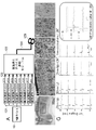
図11Aには、実施例で用いた8台の刺激発生デバイスを備える経頭蓋磁気刺激システムのハードウェアの構成を示す。図11Aに示すシステムを用いて、1バーストあたり8パルス、2.5ミリ秒インターバル(400 Hz)、バースト間インターバル10秒間で、10分間に60バーストの刺激を8週齢のSDラットの頭部に負荷した。1パルスあたりの電流値は約5,000 A、バースト持続時間は20 ミリ秒とした。刺激発生デバイスは、マグスティム社製のマグスティム200スクエアを使用し、コイルは直径70 mmのダブルコイル(マグスティム社製 カタログ番号9925-00)を使用した。 FIG. 11A shows the hardware configuration of a transcranial magnetic stimulation system including eight stimulation generating devices used in the example. Using the system shown in FIG. 11A, 8-week-old SD rats were subjected to 60 bursts of stimulus over 10 minutes with 8 pulses per burst, 2.5 ms intervals (400 Hz), and 10 seconds between bursts. bottom. The current value per pulse was about 5,000 A, and the burst duration was 20 ms. The stimulation generating device used was Magstim 200 Square manufactured by Magstim, and the coil used was a double coil with a diameter of 70 mm (manufactured by Magstim, Catalog No. 9925-00).
また、対照として、電気刺激を行った。電気刺激は電気刺激装置SEN3301を使用し、電極をラットの頭部に埋殖し、経頭蓋磁気刺激システムによる刺激と同じになるように電流を1バーストあたり8パルス、2.5ミリ秒インターバル(400 Hz)、バースト間インターバル10秒間で、10分間に60バーストの刺激で負荷した。 In addition, electrical stimulation was performed as a control. For electrical stimulation, an electrical stimulator SEN3301 was used, electrodes were implanted in the head of the rat, and 8 pulses per burst of current were applied at 2.5 ms intervals (400 Hz) to be the same as stimulation by a transcranial magnetic stimulation system. ), loaded with 60 bursts of stimulation for 10 minutes with an inter-burst interval of 10 seconds.
磁気刺激又は電気刺激を負荷したラットから大脳を摘出し、固定、凍結切片またはパラフィン包埋、及び薄切した後、リン酸化S6の免疫染色を行った。一次抗体として抗リン酸化S6抗体(Cell Signaling Technology)を使用し、二次抗体としてペルオキシダーゼ標識Biotin-SP AffiniPure F(ab')2 Fragment Donkey Anti-Rabbit IgG (H+L)抗体を使用した。基質にはDAB(diamino benzidine)を使用した。 Cerebrum was excised from rats subjected to magnetic or electrical stimulation, fixed, frozen or paraffin-embedded, and sliced, and immunostained for phosphorylated S6. An anti-phosphorylated S6 antibody (Cell Signaling Technology) was used as the primary antibody, and a peroxidase-labeled Biotin-SP AffiniPure F(ab') 2 Fragment Donkey Anti-Rabbit IgG (H+L) antibody was used as the secondary antibody. DAB (diaminobenzidine) was used as the substrate.
図11Bには、磁気刺激を行った大脳の免疫染色の弱拡大の組織像を示す。図11C(皮質第I層)及び図11D(皮質第V層)は、図11Bの四角枠内の強拡大を示す。また、図11Eは経頭蓋磁気刺激と同一条件を電気刺激装置にて刺激した場合のDと同一の皮質第V層の染色像を示す。図11Fは、NMDA型グルタミン酸受容体アンタゴニスト投与にて電気刺激を行った大脳の組織におけるリン酸化S6タンパク質の免疫染色像(強拡大)を示す。図11Dと図11Eは同じ皮質第V層の組織であるが、磁気刺激の方が強くS6がリン酸化されていた。S6は、神経系細胞の増殖が活性化する際にmTORが活性化し、その下流にあるS6キナーゼ1をリン酸化し、リン酸化により活性化したS6キナーゼ1によりリン酸化される。したがってリン酸化S6が増えたことは、神経系細胞の増殖が活性化されたことを示す。 FIG. 11B shows a low-magnification histological image of immunostaining of the cerebrum subjected to magnetic stimulation. FIG. 11C (cortical layer I) and FIG. 11D (cortical layer V) show high magnification within the box in FIG. 11B. FIG. 11E shows the same staining image of the cortical layer V as in D when stimulation was performed with an electrical stimulator under the same conditions as the transcranial magnetic stimulation. FIG. 11F shows an immunostaining image (high magnification) of phosphorylated S6 protein in cerebral tissue subjected to electrical stimulation by administration of an NMDA-type glutamate receptor antagonist. Figures 11D and 11E show the same cortical layer V tissue, but S6 was more phosphorylated by magnetic stimulation. S6 is phosphorylated by S6 kinase 1, which is phosphorylated by S6 kinase 1 that is phosphorylated by mTOR activation, which is downstream of mTOR, and activated by phosphorylation. Therefore, increased phosphorylated S6 indicates activation of neural cell proliferation.
本実施例においては、刺激の条件等は同じであるにもかかわらず、電気刺激よりも磁気刺激の方が強く神経系細胞の増殖を誘導した。このことは、磁気刺激は電気刺激よりも侵襲性が低いという効果にとどまらず、神経系細胞の増殖の活性化の点においても優れていることを示している。 In this example, although the stimulation conditions and the like were the same, the magnetic stimulation induced the proliferation of neural cells more strongly than the electrical stimulation. This indicates that magnetic stimulation is not only less invasive than electrical stimulation, but also superior in terms of activation of proliferation of nervous system cells.
図11Gには、直径が70 mmのダブルコイル、50 mmのダブルコイル、又は25 mmのダブルコイルを使って運動野単一刺激パルスで磁気刺激を行った際の上肢筋活動電位(運動誘発電位)と、電気刺激を行った時の運動誘発電位(1 mm-electrical stim)を示す。グラフ中の「1」、「2」、「3」、「4」、「5」、は刺激を負荷したBregmaからの距離(mm)を示す。図11G内の四角枠内には磁気刺激を行った後の運動電位を示す。 FIG. 11G shows the upper extremity muscle action potential (motor evoked potential ) and the motor evoked potential (1 mm-electrical stim) when electrical stimulation was performed. "1", "2", "3", "4", and "5" in the graph indicate the distance (mm) from Bregma to which the stimulus was applied. The square frames in FIG. 11G show the motor potentials after the magnetic stimulation.
磁気刺激は、いずれのサイズのコイルを使用した場合であっても広範囲で神経細胞が興奮し上肢筋運動誘発電位を誘発していた。これに対して、電気刺激は、刺激部位から3 mm程度の範囲でしか神経細胞の興奮が認められなかった。 Magnetic stimulation excited nerve cells in a wide range and induced upper extremity muscle movement-evoked potentials, regardless of the size of the coil used. On the other hand, with electrical stimulation, nerve cell excitation was observed only within a range of about 3 mm from the stimulation site.
さらに磁気刺激では、運動野の神経の興奮も確認できた。Gの枠内は、磁気刺激を行った前・刺激中・並びに後の運動誘発電位を示す。運動誘発電位は運動野単一刺激パルスで誘発可能であった(前・後)。この強度で刺激中の運動誘発電位は時間的加重により振幅増大するが、刺激終了後単一刺激パルスによる運動誘発電位は振幅増大現象が長期持続しLTPを介したシナプス可塑性の誘導を示唆する。 Furthermore, with magnetic stimulation, we were able to confirm the excitation of nerves in the motor cortex. The frame of G shows motor evoked potentials before, during, and after magnetic stimulation. Motor-evoked potentials could be evoked by a single motor cortex stimulation pulse (before and after). The amplitude of the motor-evoked potential during stimulation at this intensity increases with time loading, but the amplitude increase phenomenon of the motor-evoked potential by a single stimulus pulse persists for a long period after stimulation, suggesting the induction of synaptic plasticity via LTP.
Claims (4)
前記制御デバイスに接続された少なくとも6台の刺激発生デバイスであって、前記少なくとも6台の刺激発生デバイスのそれぞれが、前記制御デバイスにより、1回の刺激あたり、一定時間内に、他の刺激発生デバイスからは独立して時間差を持って一定間隔で複数回電流のパルスを出力するように制御される前記少なくとも6台の刺激発生デバイスと、
それぞれの刺激発生デバイスが出力した電流から磁気を発生する1つの刺激デバイスと、を備える神経系細胞の増殖を活性化させるための経頭蓋磁気刺激システムであって、
1回の刺激は複数回のバーストを含み、少なくとも6台の刺激発生デバイスのそれぞれから出力される1パルスずつの電流の出力の束が、1つのバーストを構成する、
経頭蓋磁気刺激システム。 a control device for controlling the generation of magnetism for applying magnetic stimulation to the neural tissue of the individual via the cranium;
at least six stimulus-generating devices connected to the control device, each of the at least six stimulus-generating devices being activated by the control device to generate another stimulus per stimulus within a period of time; the at least six stimulus generating devices controlled to output multiple pulses of current at regular intervals with time lags independently from the devices;
A transcranial magnetic stimulation system for activating proliferation of nervous system cells, comprising: a stimulation device that generates magnetism from the current output by each stimulation device;
A single stimulation includes multiple bursts, wherein a pulse-by-pulse current output bundle output from each of the at least six stimulus-generating devices constitutes one burst.
Transcranial magnetic stimulation system.
前記時間差が2から5ミリ秒であり、
前記一定間隔が1から15秒であり、
前記複数回が5から120,000回であり、
1回のバーストの持続時間が、10から50ミリ秒であり、
前記複数回出力される電流の値が、毎回実質的に同じである、
請求項1に記載の経頭蓋磁気刺激システム。 The certain period of time is 1 minute to 6 hours,
the time difference is 2 to 5 milliseconds;
the constant interval is 1 to 15 seconds;
said plurality of times is from 5 to 120,000 times;
the duration of one burst is 10 to 50 milliseconds;
wherein the value of the current output multiple times is substantially the same each time;
The transcranial magnetic stimulation system of claim 1.
1つの刺激デバイスは、少なくとも6台の刺激発生デバイスのそれぞれが出力した電流から磁気を発生するように制御され、
前記少なくとも6台の刺激発生デバイスのそれぞれは、制御デバイスによって、1回の刺激あたり、一定時間内に、他の刺激発生デバイスからは独立して時間差を持って一定間隔で複数回電流のパルスを出力するように制御され、
1回の刺激は複数回のバーストを含み、少なくとも6台の刺激発生デバイスのそれぞれから出力される1パルスずつの電流の出力の束が、1つのバーストを構成する、制御方法。 1. A method of controlling a stimulation device that contacts or approaches an individual's head for activating proliferation of nervous system cells, comprising:
one stimulation device is controlled to generate magnetism from the current output by each of the at least six stimulation generation devices;
Each of the at least six stimulus-generating devices is controlled by a control device to pulse a current multiple times at regular intervals with time lags independently of other stimulus-generating devices within a specified period of time per stimulation. controlled to output
A control method, wherein a single stimulation includes multiple bursts, and wherein a single-pulse current output bundle output from each of the at least six stimulus-generating devices constitutes a single burst.
前記時間差が2から5ミリ秒であり、
前記一定間隔が1から15秒であり、
前記複数回が5から120,000回であり、
1回のバーストの持続時間が、10から50ミリ秒であり、
前記複数回出力される電流の値が、毎回実質的に同じである、
請求項3に記載の制御方法。 The certain period of time is 1 minute to 6 hours,
the time difference is 2 to 5 milliseconds;
the constant interval is 1 to 15 seconds;
said plurality of times is from 5 to 120,000 times;
the duration of one burst is 10 to 50 milliseconds;
wherein the value of the current output multiple times is substantially the same each time;
The control method according to claim 3.
Priority Applications (1)
| Application Number | Priority Date | Filing Date | Title |
|---|---|---|---|
| JP2018164498A JP7201986B2 (en) | 2018-09-03 | 2018-09-03 | Magnetic control method and transcranial magnetic stimulation system for activating proliferation of nervous system cells |
Applications Claiming Priority (1)
| Application Number | Priority Date | Filing Date | Title |
|---|---|---|---|
| JP2018164498A JP7201986B2 (en) | 2018-09-03 | 2018-09-03 | Magnetic control method and transcranial magnetic stimulation system for activating proliferation of nervous system cells |
Publications (3)
| Publication Number | Publication Date |
|---|---|
| JP2020036704A JP2020036704A (en) | 2020-03-12 |
| JP2020036704A5 JP2020036704A5 (en) | 2021-10-07 |
| JP7201986B2 true JP7201986B2 (en) | 2023-01-11 |
Family
ID=69737035
Family Applications (1)
| Application Number | Title | Priority Date | Filing Date |
|---|---|---|---|
| JP2018164498A Active JP7201986B2 (en) | 2018-09-03 | 2018-09-03 | Magnetic control method and transcranial magnetic stimulation system for activating proliferation of nervous system cells |
Country Status (1)
| Country | Link |
|---|---|
| JP (1) | JP7201986B2 (en) |
Citations (5)
| Publication number | Priority date | Publication date | Assignee | Title |
|---|---|---|---|---|
| JP2010536496A (en) | 2007-08-20 | 2010-12-02 | ネオスティム インコーポレイテッド | Firing patterns of deep brain transcranial magnetic stimulation |
| JP2016522059A (en) | 2013-06-21 | 2016-07-28 | テヒニッシェ ウニヴェルジテート ミュンヘンTechnische Universitat Munchen | Magnetic stimulator for tissue stimulation by magnetic field |
| JP2016538044A (en) | 2013-11-11 | 2016-12-08 | ニューロネティクス インコーポレイテッド | Monitoring and detecting magnetic stimulation |
| US20170001026A1 (en) | 2015-07-01 | 2017-01-05 | Btl Holdings Limited | Method of neural structure stimulation by magnetic field |
| WO2017132750A1 (en) | 2016-02-05 | 2017-08-10 | Neuhorizon Medical Corporation | Systems and methods for an adaptive high powered pulsed transcranial magnetic stimulator |
Family Cites Families (1)
| Publication number | Priority date | Publication date | Assignee | Title |
|---|---|---|---|---|
| US6179771B1 (en) * | 1998-04-21 | 2001-01-30 | Siemens Aktiengesellschaft | Coil arrangement for transcranial magnetic stimulation |
-
2018
- 2018-09-03 JP JP2018164498A patent/JP7201986B2/en active Active
Patent Citations (5)
| Publication number | Priority date | Publication date | Assignee | Title |
|---|---|---|---|---|
| JP2010536496A (en) | 2007-08-20 | 2010-12-02 | ネオスティム インコーポレイテッド | Firing patterns of deep brain transcranial magnetic stimulation |
| JP2016522059A (en) | 2013-06-21 | 2016-07-28 | テヒニッシェ ウニヴェルジテート ミュンヘンTechnische Universitat Munchen | Magnetic stimulator for tissue stimulation by magnetic field |
| JP2016538044A (en) | 2013-11-11 | 2016-12-08 | ニューロネティクス インコーポレイテッド | Monitoring and detecting magnetic stimulation |
| US20170001026A1 (en) | 2015-07-01 | 2017-01-05 | Btl Holdings Limited | Method of neural structure stimulation by magnetic field |
| WO2017132750A1 (en) | 2016-02-05 | 2017-08-10 | Neuhorizon Medical Corporation | Systems and methods for an adaptive high powered pulsed transcranial magnetic stimulator |
Also Published As
| Publication number | Publication date |
|---|---|
| JP2020036704A (en) | 2020-03-12 |
Similar Documents
| Publication | Publication Date | Title |
|---|---|---|
| Ruffini et al. | Transcranial current brain stimulation (tCS): models and technologies | |
| JP6505835B2 (en) | Neural modulation specific to the modulation field objective function for the target tissue | |
| Saiote et al. | Combining functional magnetic resonance imaging with transcranial electrical stimulation | |
| JP5676000B2 (en) | Architecture for an implantable medical device system having a daisy chain electrode driver integrated circuit | |
| EP2183025B1 (en) | Firing patterns for deep brain transcranial magnetic stimulation | |
| US7422555B2 (en) | Systems and methods for therapeutically treating neuro-psychiatric disorders and other illnesses | |
| Molnar et al. | Principles of cord activation during spinal cord stimulation | |
| US20100198315A1 (en) | Neurostimulation system | |
| JP2017533072A (en) | Method and apparatus for programming complex neural stimulation patterns | |
| KR20160018660A (en) | Transcranial pulsed current stimulation | |
| JP2017529175A (en) | Neuromodulation using burst stimulation | |
| KR20160025490A (en) | Method and system for treatment of neuromotor dysfunction | |
| AU2019260567B2 (en) | Neurostimulation system for delivering selectivity modes | |
| US20180071515A1 (en) | Pulse Definition Circuitry for Creating Stimulation Waveforms in an Implantable Pulse Generator | |
| US9492667B1 (en) | Systems and methods for closed loop neurostimulation | |
| US20200061380A1 (en) | Stimulation Using Long Duration Waveform Phases in a Spinal Cord Stimulator System | |
| Haque et al. | Neural substrate and underlying mechanisms of working memory: insights from brain stimulation studies | |
| JP7201986B2 (en) | Magnetic control method and transcranial magnetic stimulation system for activating proliferation of nervous system cells | |
| Fisher | Anterior thalamic nucleus stimulation: issues in study design | |
| JP2022514289A (en) | Nerve stimulation system | |
| Majdi et al. | Reinterpreting published tDCS results in terms of a cranial and cervical nerve co-stimulation mechanism | |
| Kesselheim et al. | Multipulse transcranial magnetic stimulation of human motor cortex produces short-latency corticomotor facilitation via two distinct mechanisms | |
| Nitsche et al. | Transcranial direct current stimulation-an adjuvant tool for the treatment of neuropsychiatric diseases? | |
| US20220062636A1 (en) | METHOD AND APPARATUS FOR MULTl MODAL ELECTRICAL MODULATION OF PAIN USING COMPOSITE ELECTROMAGNETIC FIELDS | |
| Sánchez-León et al. | Exploring new transcranial electrical stimulation strategies to modulate brain function in animal models |
Legal Events
| Date | Code | Title | Description |
|---|---|---|---|
| A521 | Request for written amendment filed |
Free format text: JAPANESE INTERMEDIATE CODE: A523 Effective date: 20210830 |
|
| A621 | Written request for application examination |
Free format text: JAPANESE INTERMEDIATE CODE: A621 Effective date: 20210830 |
|
| A977 | Report on retrieval |
Free format text: JAPANESE INTERMEDIATE CODE: A971007 Effective date: 20220427 |
|
| A131 | Notification of reasons for refusal |
Free format text: JAPANESE INTERMEDIATE CODE: A131 Effective date: 20220517 |
|
| A601 | Written request for extension of time |
Free format text: JAPANESE INTERMEDIATE CODE: A601 Effective date: 20220705 |
|
| A521 | Request for written amendment filed |
Free format text: JAPANESE INTERMEDIATE CODE: A523 Effective date: 20220908 |
|
| A131 | Notification of reasons for refusal |
Free format text: JAPANESE INTERMEDIATE CODE: A131 Effective date: 20221004 |
|
| A521 | Request for written amendment filed |
Free format text: JAPANESE INTERMEDIATE CODE: A523 Effective date: 20221129 |
|
| TRDD | Decision of grant or rejection written | ||
| A01 | Written decision to grant a patent or to grant a registration (utility model) |
Free format text: JAPANESE INTERMEDIATE CODE: A01 Effective date: 20221213 |
|
| A61 | First payment of annual fees (during grant procedure) |
Free format text: JAPANESE INTERMEDIATE CODE: A61 Effective date: 20221216 |
|
| R150 | Certificate of patent or registration of utility model |
Ref document number: 7201986 Country of ref document: JP Free format text: JAPANESE INTERMEDIATE CODE: R150 |