JP7201826B2 - Clip device - Google Patents
Clip device Download PDFInfo
- Publication number
- JP7201826B2 JP7201826B2 JP2021539086A JP2021539086A JP7201826B2 JP 7201826 B2 JP7201826 B2 JP 7201826B2 JP 2021539086 A JP2021539086 A JP 2021539086A JP 2021539086 A JP2021539086 A JP 2021539086A JP 7201826 B2 JP7201826 B2 JP 7201826B2
- Authority
- JP
- Japan
- Prior art keywords
- clip
- hold down
- down tube
- jaws
- arms
- Prior art date
- Legal status (The legal status is an assumption and is not a legal conclusion. Google has not performed a legal analysis and makes no representation as to the accuracy of the status listed.)
- Active
Links
Images


Classifications
-
- A—HUMAN NECESSITIES
- A61—MEDICAL OR VETERINARY SCIENCE; HYGIENE
- A61B—DIAGNOSIS; SURGERY; IDENTIFICATION
- A61B17/00—Surgical instruments, devices or methods, e.g. tourniquets
- A61B17/12—Surgical instruments, devices or methods, e.g. tourniquets for ligaturing or otherwise compressing tubular parts of the body, e.g. blood vessels, umbilical cord
- A61B17/122—Clamps or clips, e.g. for the umbilical cord
- A61B17/1227—Spring clips
-
- A—HUMAN NECESSITIES
- A61—MEDICAL OR VETERINARY SCIENCE; HYGIENE
- A61B—DIAGNOSIS; SURGERY; IDENTIFICATION
- A61B17/00—Surgical instruments, devices or methods, e.g. tourniquets
- A61B17/08—Wound clamps or clips, i.e. not or only partly penetrating the tissue ; Devices for bringing together the edges of a wound
- A61B17/083—Clips, e.g. resilient
-
- A—HUMAN NECESSITIES
- A61—MEDICAL OR VETERINARY SCIENCE; HYGIENE
- A61B—DIAGNOSIS; SURGERY; IDENTIFICATION
- A61B17/00—Surgical instruments, devices or methods, e.g. tourniquets
- A61B17/12—Surgical instruments, devices or methods, e.g. tourniquets for ligaturing or otherwise compressing tubular parts of the body, e.g. blood vessels, umbilical cord
- A61B17/12022—Occluding by internal devices, e.g. balloons or releasable wires
- A61B17/12027—Type of occlusion
- A61B17/12031—Type of occlusion complete occlusion
-
- A—HUMAN NECESSITIES
- A61—MEDICAL OR VETERINARY SCIENCE; HYGIENE
- A61B—DIAGNOSIS; SURGERY; IDENTIFICATION
- A61B17/00—Surgical instruments, devices or methods, e.g. tourniquets
- A61B17/12—Surgical instruments, devices or methods, e.g. tourniquets for ligaturing or otherwise compressing tubular parts of the body, e.g. blood vessels, umbilical cord
- A61B17/122—Clamps or clips, e.g. for the umbilical cord
-
- A—HUMAN NECESSITIES
- A61—MEDICAL OR VETERINARY SCIENCE; HYGIENE
- A61B—DIAGNOSIS; SURGERY; IDENTIFICATION
- A61B17/00—Surgical instruments, devices or methods, e.g. tourniquets
- A61B17/12—Surgical instruments, devices or methods, e.g. tourniquets for ligaturing or otherwise compressing tubular parts of the body, e.g. blood vessels, umbilical cord
- A61B17/128—Surgical instruments, devices or methods, e.g. tourniquets for ligaturing or otherwise compressing tubular parts of the body, e.g. blood vessels, umbilical cord for applying or removing clamps or clips
- A61B17/1285—Surgical instruments, devices or methods, e.g. tourniquets for ligaturing or otherwise compressing tubular parts of the body, e.g. blood vessels, umbilical cord for applying or removing clamps or clips for minimally invasive surgery
-
- A—HUMAN NECESSITIES
- A61—MEDICAL OR VETERINARY SCIENCE; HYGIENE
- A61B—DIAGNOSIS; SURGERY; IDENTIFICATION
- A61B17/00—Surgical instruments, devices or methods, e.g. tourniquets
- A61B2017/00477—Coupling
-
- A—HUMAN NECESSITIES
- A61—MEDICAL OR VETERINARY SCIENCE; HYGIENE
- A61B—DIAGNOSIS; SURGERY; IDENTIFICATION
- A61B17/00—Surgical instruments, devices or methods, e.g. tourniquets
- A61B2017/00831—Material properties
- A61B2017/00862—Material properties elastic or resilient
-
- A—HUMAN NECESSITIES
- A61—MEDICAL OR VETERINARY SCIENCE; HYGIENE
- A61B—DIAGNOSIS; SURGERY; IDENTIFICATION
- A61B17/00—Surgical instruments, devices or methods, e.g. tourniquets
- A61B2017/00831—Material properties
- A61B2017/00867—Material properties shape memory effect
-
- A—HUMAN NECESSITIES
- A61—MEDICAL OR VETERINARY SCIENCE; HYGIENE
- A61B—DIAGNOSIS; SURGERY; IDENTIFICATION
- A61B17/00—Surgical instruments, devices or methods, e.g. tourniquets
- A61B17/11—Surgical instruments, devices or methods, e.g. tourniquets for performing anastomosis; Buttons for anastomosis
- A61B2017/1125—Forceps, specially adapted for performing or assisting anastomosis
-
- A—HUMAN NECESSITIES
- A61—MEDICAL OR VETERINARY SCIENCE; HYGIENE
- A61B—DIAGNOSIS; SURGERY; IDENTIFICATION
- A61B17/00—Surgical instruments, devices or methods, e.g. tourniquets
- A61B17/12—Surgical instruments, devices or methods, e.g. tourniquets for ligaturing or otherwise compressing tubular parts of the body, e.g. blood vessels, umbilical cord
- A61B2017/12004—Surgical instruments, devices or methods, e.g. tourniquets for ligaturing or otherwise compressing tubular parts of the body, e.g. blood vessels, umbilical cord for haemostasis, for prevention of bleeding
-
- A—HUMAN NECESSITIES
- A61—MEDICAL OR VETERINARY SCIENCE; HYGIENE
- A61B—DIAGNOSIS; SURGERY; IDENTIFICATION
- A61B17/00—Surgical instruments, devices or methods, e.g. tourniquets
- A61B17/12—Surgical instruments, devices or methods, e.g. tourniquets for ligaturing or otherwise compressing tubular parts of the body, e.g. blood vessels, umbilical cord
- A61B17/12022—Occluding by internal devices, e.g. balloons or releasable wires
- A61B2017/1205—Introduction devices
-
- A—HUMAN NECESSITIES
- A61—MEDICAL OR VETERINARY SCIENCE; HYGIENE
- A61B—DIAGNOSIS; SURGERY; IDENTIFICATION
- A61B90/00—Instruments, implements or accessories specially adapted for surgery or diagnosis and not covered by any of the groups A61B1/00 - A61B50/00, e.g. for luxation treatment or for protecting wound edges
- A61B90/03—Automatic limiting or abutting means, e.g. for safety
- A61B2090/037—Automatic limiting or abutting means, e.g. for safety with a frangible part, e.g. by reduced diameter
Description
閉鎖デバイスは、創傷、切開、欠損、穿孔、および瘻孔を治療し、内出血を止めるために使用できる。怪我、病気、または外科的処置により、組織または体壁に穴が開くことがある。例えば、組織または体壁は、手術中に意図せずに穿孔されるなどの損傷を受ける可能性があり、またはヘルニアなどの病気または損傷のために穿孔される可能性がある。ときには、外科的経管腔処置の際などに、意図的に組織または体壁に穴をあける場合がある。胃腸管などの管腔組織の穿孔は、体液や他の内容物が胃や腸から近くの体腔に漏れるため、重篤な感染症を迅速に制御する必要がある。 Closure devices can be used to treat wounds, incisions, defects, perforations, and fistulas and to stop internal bleeding. Injuries, illnesses, or surgical procedures can pierce tissue or body walls. For example, tissue or body walls may be damaged, such as being unintentionally perforated during surgery, or may be perforated due to disease or injury, such as a hernia. Occasionally, tissue or body walls are intentionally pierced, such as during transluminal surgical procedures. Perforation of luminal tissue, such as the gastrointestinal tract, allows fluids and other contents to leak from the stomach and intestines into nearby body cavities, and is therefore necessary for rapid control of serious infections.
穿孔を閉じて治癒を促進するために、内視鏡的に閉鎖デバイスを導入することができる。例えば、閉鎖デバイスは、止血クリップを体内の対象領域に搬送して、穿孔の周囲の組織を把持し、出血または他の体液および内容物の漏出を止めることができる。次に、クリップを所定の位置に残したまま、閉鎖デバイスを取り外す。クリップは、自然に脱落するか、創傷が治癒した後、後続の手順で除去される場合がある。 A closure device may be introduced endoscopically to close the perforation and promote healing. For example, the closure device can deliver a hemostatic clip to a target area within the body to grasp tissue around the perforation to stop bleeding or leakage of other body fluids and contents. The closure device is then removed, leaving the clip in place. Clips may fall off spontaneously or may be removed in subsequent procedures after the wound has healed.
穿孔のサイズや形状、または穿孔された身体の構造によっては、穿孔を適切に閉じて体液の漏れを防ぐことが難しい場合がある。例えば、内視鏡を通して導入される止血クリップは、しばしば「スルーザスコープクリップ(through-the-scope clip)」と称され、クリップアームの開口幅が限られるため、大きな欠損を完全に閉鎖することができない。多くの場合、傷を閉じて止血や体液の漏れを止めるために、多くのクリップを導入する必要があるが、大きな孔を完全に閉じることが難しく、合併症の可能性が高まる。 Depending on the size and shape of the perforation, or the structure of the body in which it is perforated, it may be difficult to properly close the perforation to prevent leakage of bodily fluids. For example, hemostatic clips introduced through an endoscope, often referred to as "through-the-scope clips," are unable to completely close large defects due to the limited opening width of the clip arms. can't Many clips need to be introduced to close the wound to stop bleeding and fluid leakage, but it is difficult to completely close large holes, increasing the potential for complications.
一方、消化管壁全層縫合器は、内視鏡の遠位端に閉塞装置を取り付けるために、留置可能な状態となる前に、内視鏡を患者の身体から取り出す必要があり、問題がある。このような消化管壁全層縫合器閉塞装置は、準備と展開が煩雑である。さらに、処置中に内視鏡を体外に取り出すと、処置対象領域を見失う可能性があり、また消化管壁全層縫合器閉塞装置の準備および内視鏡に取り付けている間に、穿孔が大きくなる可能性がある。消化管壁全層縫合器の搬送は、しばしば高度なスキルが要求される。消化管壁全層縫合器の留置の間、対象組織をクリップ内に引き込むためにしばしば吸引操作が行われる。しかし、吸引対象組織が内視鏡のレンズを覆うことが多く、把持中に対象領域を見ることが困難または不可能になることがある。また、消化管壁全層縫合器のクリップアーム構造は、クリップを互いに近接して並べて配置することが難しい。また、消化管壁全層縫合器は配置後に再配置できない。したがって、特にクリップが正しく配置されていない場合は、消化管壁全層縫合器で大きな穿孔を完全に閉じることが困難であり、合併症の可能性が高まる可能性がある。 On the other hand, full-thickness gastrointestinal wall sutures are problematic because the endoscope must be removed from the patient's body before it can be placed in order to attach the occlusive device to the distal end of the endoscope. be. Such gastrointestinal wall full-thickness suture closure devices are complicated to prepare and deploy. In addition, exteriorizing the endoscope during the procedure may result in loss of the area to be treated, and large perforations may occur during the preparation and attachment of the gastrointestinal wall full-thickness suture closure device to the endoscope. may become. Delivery of full-thickness gastrointestinal wall sutures often requires a high degree of skill. During the placement of full-thickness gastrointestinal wall sutures, a suction operation is often used to draw the target tissue into the clip. However, the tissue to be aspirated often covers the lens of the endoscope, making it difficult or impossible to see the target area during grasping. Also, the clip arm structure of the gastrointestinal wall full-thickness suture instrument makes it difficult to position the clips in close proximity to each other. Also, full-thickness gastrointestinal wall sutures cannot be repositioned after placement. Therefore, full-thickness gastrointestinal wall sutures may be difficult to completely close large perforations, increasing the potential for complications, especially if the clips are not properly placed.
したがって、例えば食道、腸、結腸、胃、心臓等における欠損、穿孔、大きな穿孔、その他の創傷、消化管穿孔、瘻孔、吻合部漏出、およびヘルニアを含む他の身体的欠損を治療できる改善されたデバイスが望まれている。 Thus, for example, it is capable of treating defects in the esophagus, intestine, colon, stomach, heart, etc., perforations, large perforations, other wounds, gastrointestinal perforations, fistulas, anastomotic leaks, and other physical defects including hernias. A device is desired.
本開示の実施形態は、クリップ装置を含む。 Embodiments of the present disclosure include clip devices .
クリップ装置は、遠位端から近位端まで貫通する管路を有する押さえ管と、近位端で互いに連結された複数のクリップアームを有し、少なくとも一部が前記押さえ管の前記管路内に配置され、前記クリップアームの前記遠位端が離間して前記クリップアームの間に組織を受けることが可能な開形態と、前記クリップアームの前記遠位端同士が前記開形態より近く、組織を間に挟むことが可能な閉形態と、の間で前記押さえ管に対して進退移動可能に構成されたクリップと、前記クリップに設けられる第一接続部と、前記押さえ管に設けられ、前記第一接続部と係合可能な第二接続部と、前記クリップアームの前記遠位端に回動可能に連結されたジョーと、を備え、前記クリップが前記開形態であるか前記閉形態であるかに関わらず、前記第一接続部の一部が前記押さえ管の前記管路内に配置され、前記第二接続部は、前記クリップが前記押さえ管によって押圧された前記閉形態を、前記第一接続部と係合することにより保持し、前記ジョーが前記押さえ管の前記管路内に配置されている時に、前記ジョーは、前記クリップアームに平行な方向に延びるように構成される。 The clipping device has a hold down tube with a passage extending from a distal end to a proximal end, and a plurality of clip arms connected to each other at their proximal ends, at least a portion of said hold down tube. an open configuration wherein the distal ends of the clip arms are spaced apart to receive tissue between the clip arms, and wherein the distal ends of the clip arms are closer together than the open configuration; a clip configured to be movable back and forth with respect to the holding tube between a closed form capable of sandwiching tissue; a first connecting portion provided on the clip ; a second connecting portion engageable with the first connecting portion and jaws pivotally coupled to the distal end of the clip arm , wherein the clip is in the open configuration or the closed configuration; A part of the first connection part is arranged in the conduit of the holding tube, and the second connection part is in the closed configuration in which the clip is pressed by the holding tube, Retained by engaging the first connecting portion, the jaws are configured to extend in a direction parallel to the clip arm when the jaws are positioned within the channel of the hold down tube. .
詳細な説明の教示から実質的に逸脱することなく、多くの変更が可能である。したがって、そのような変更は、特許請求の範囲に定義された開示の範囲内に含まれる。 Many modifications are possible without departing substantially from the teachings of the detailed description. Accordingly, such modifications are included within the scope of the disclosure as defined in the claims.
本発明のこれらおよび他の態様および特徴は、当業者が添付の図面と併せて以下の説明を検討することにより、明らかになる。 These and other aspects and features of the present invention will become apparent to those of ordinary skill in the art upon consideration of the following description in conjunction with the accompanying drawings.
図1Aは、本開示の実施形態に係る組織クリップ装置を示す。 FIG. 1A shows a tissue clipping device according to an embodiment of the present disclosure.
図1Bおよび1Cは、開示された実施形態に係るデリバリデバイスを示す。図1Bは、図1Cに示されるデリバリデバイスの断面図である。 1B and 1C show delivery devices according to disclosed embodiments. FIG. 1B is a cross-sectional view of the delivery device shown in FIG. 1C.
図2A~2Cは、開示された実施形態に係る離脱可能なクリップ接続機構を示している。 Figures 2A-2C illustrate a releasable clip attachment mechanism according to the disclosed embodiments.
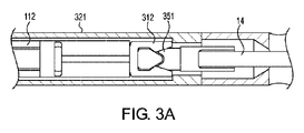
図3A~3Cは、開示された実施形態に係る離脱可能なクリップ接続機構を示している。 Figures 3A-3C illustrate a releasable clip attachment mechanism according to the disclosed embodiments.
図4は、開示された実施形態に係る離脱可能なクリップ接続機構を示している。 FIG. 4 illustrates a releasable clip attachment mechanism according to the disclosed embodiments.
図5A~5Cは、開示された実施形態に係る離脱可能な押さえ管接続機構を示している。 5A-5C illustrate a detachable hold down tube connection mechanism according to the disclosed embodiments.
図6A~6Cは、開示された実施形態に係る離脱可能な押さえ管接続機構を示している。 Figures 6A-6C illustrate a detachable hold down tube connection mechanism according to the disclosed embodiments.
図7A~7Dは、開示された実施形態に係る離脱可能な押さえ管接続機構を示している。 Figures 7A-7D illustrate a detachable hold down tube connection mechanism according to the disclosed embodiments.
図8A~8Eは、開示された実施形態に係る離脱可能な押さえ管接続機構を示す図である。 8A-8E illustrate a detachable hold down tube connection mechanism according to the disclosed embodiments.
図9A~9Cは、開示された実施形態に係る離脱可能な押さえ管接続機構を示している。 Figures 9A-9C illustrate a detachable hold down tube connection mechanism according to the disclosed embodiments.
図10A~10Fは、開示された実施形態に係る組織クリップ装置を示している。 10A-10F illustrate tissue clipping devices according to disclosed embodiments.
図11A~11Fは、開示された実施形態に係る組織クリップ装置を示している。 11A-11F illustrate tissue clipping devices according to disclosed embodiments.
図12A~12Fは、開示された実施形態に係る組織クリップシステムを示している。 12A-12F illustrate a tissue clip system according to disclosed embodiments.
図13A~13Fは、開示された実施形態に係る組織クリップシステムを示している。 13A-13F illustrate a tissue clip system according to disclosed embodiments.
図14A~14Gは、開示された実施形態に係る組織クリップシステムを示している。 14A-14G illustrate a tissue clip system according to disclosed embodiments.
図15A~15Dは、開示された実施形態に係る組織クリップシステムを示している。 Figures 15A-15D show a tissue clip system according to the disclosed embodiments.
図16A~16Jは、開示された実施形態に係る組織クリップシステムを示している。 16A-16J illustrate a tissue clip system according to disclosed embodiments.
図17A~17Dは、開示された実施形態に係る組織クリップ装置ロック機構を示している。 17A-17D illustrate a tissue clip device locking mechanism according to disclosed embodiments.
図18A~18Eは、開示された実施形態に係る組織クリップ装置ロック機構を示している。 18A-18E illustrate a tissue clip device locking mechanism according to disclosed embodiments.
本開示の実施形態は、上述の問題に対処するために考案されたものである。特に、本開示の実施形態は、例えば、大きな欠損および穿孔、胃腸穿孔、瘻孔、吻合漏出、およびヘルニアを含む、欠損、穿孔、および他の創傷の治療、他の身体的欠損、例えば食道、腸、結腸、胃、心臓等における欠損、穿孔、大きな穿孔、その他の創傷、消化管穿孔、瘻孔、吻合部漏出、およびヘルニアを含む、を治療するために径内視鏡的に搬送できる組織クリップ装置およびシステムを含む。本開示のクリップ装置は、クリップの数を減らして、大きな欠損、穿孔、および瘻孔を迅速かつ正確に閉じることができる。 Embodiments of the present disclosure have been devised to address the problems discussed above. In particular, embodiments of the present disclosure are useful for treating defects, perforations, and other wounds, including, for example, large defects and perforations, gastrointestinal perforations, fistulas, anastomotic leaks, and hernias; , including defects, perforations, large perforations, other wounds, gastrointestinal perforations, fistulas, anastomotic leaks, and hernias in the colon, stomach, heart, etc. and systems. The clipping device of the present disclosure can reduce the number of clips to close large defects, perforations, and fistulas quickly and accurately.
本装置は、患者に予め挿入されている内視鏡を取り出すことなく導入でき、それにより、内視鏡を準備して閉鎖装置を内視鏡に取り付けるために内視鏡を取り出すことに伴う問題がなくなる。本装置は、隙間をなくすために可能な限り近くに配置することができる。例えば、複数のクリップを
使用する場合、隙間をなくすためにクリップを並べて密に展開することができる。さらに、クリップ装置は、展開する前に再度開いて再調整することができる。展開中は、内視鏡を通して対象領域が見える。例えば、組織をクリップに引き込むのに吸引は必要ないかもしれない。したがって、組織が内視鏡のレンズを覆う可能性が減少する。したがって、開示されたクリップ装置は、特別な訓練を必要とせずに、少ない数のクリップで大きな欠損、穿孔、および瘻孔を迅速かつ正確に閉鎖することができる。その結果、開示されたクリップ装置およびシステムを使用することにより、体液の出血または漏出に起因する再介入を必要とする可能性のある合併症を軽減することができる。
The device can be introduced without removing an endoscope that has been pre-inserted into the patient, thereby eliminating the problems associated with removing the endoscope to prepare it and attach the closure device to the endoscope. disappears. The devices can be placed as close together as possible to eliminate gaps. For example, if multiple clips are used, the clips can be deployed closely side by side to eliminate gaps. Additionally, the clip device can be reopened and readjusted prior to deployment. During deployment, the target area is visible through the endoscope. For example, suction may not be required to draw tissue into the clip. Therefore, the likelihood of tissue covering the lens of the endoscope is reduced. Thus, the disclosed clipping device can quickly and accurately close large defects, perforations, and fistulas with a small number of clips without the need for special training. As a result, use of the disclosed clipping devices and systems can reduce complications that may require reintervention due to bleeding or leakage of bodily fluids.
図面とともに様々な実施形態を詳細に説明する。発明の原理の例示的な実施形態は、当業者にとって多くの改訂および変形が明らかであるため、単に例示として意図されている。 Various embodiments are described in detail in conjunction with the drawings. The illustrative embodiments of the principles of the invention are intended only as illustrations, as many modifications and variations will be apparent to those skilled in the art.
開示された実施形態は、以下に説明するように、組織クリップ装置、システム、および組織を把持するための方法を含む。図1Aは、組織を寄せ集めて把持し、欠損、穿孔、および瘻孔を閉じるための例示的なクリップ装置10を示す。クリップ装置10は、組織を掴んで挟持するためのクリップアームを備えたクリップ11を含む。クリップ11は、組織を間に受け入れるための開形態と、組織を挟持するための閉形態との間で移動可能となるように、押さえ管12の管路内にスライド可能に配置されている。押さえ管12は、クリップアーム11を閉形態にするように径方向内側に圧縮するように設計されており、クリップアーム11が押さえ管12の遠位端から外側に前進したときに、クリップアームが径方向外側に弾性変形して開いて開形態になるように設計されている。クリップ装置10は、体内の対象領域でクリップ装置を搬送および展開するために、デリバリデバイスに離脱可能に連結される。図1Cは、クリップ装置10を体内の対象領域に搬送するためのデリバリデバイス13の例を示す。図1Bは、デリバリデバイス13の断面図を示す。例えば、デリバリデバイス13は、クリップ装置10を対象領域に搬送し、クリップ11を押さえ管12の遠位端12aから前進させて、クリップアーム11が径方向外側に弾性変形して間に組織を受け入れる開形態になるように設計されている。次に、押さえ管12をクリップ11に対して遠位方向に前進させて、クリップアームを引き込んで径方向内側に移動させて、その間に受け入れた組織を挟持した閉形態にする。閉形態、組織挟持形態に動かす時、クリップアーム11は、欠損、穿孔、または瘻孔の縁部を引き寄せて孔を閉じるように設計されている。次に、クリップ11は、押さえ管12に係合されロックされてクリップ11を閉形態、組織挟持形態にロックして、欠損、穿孔、または瘻孔の自然治癒を促進させるように設計されている。次に、クリップ装置10はデリバリデバイス13から離され、デリバリデバイス13は後退されて体外に取り出され、クリップ装置10は体内の所定位置に残される。
The disclosed embodiments include tissue clipping devices, systems, and methods for grasping tissue, as described below. FIG. 1A shows an
上述したように、図1Aに示すクリップ装置10は、図1Bおよび1Cに示すデリバリデバイス13から取り外しまたは離脱可能であり、デリバリデバイス13を外した後に体内に残すように設計されている。クリップ装置10は、クリップ11と押さえ管12とを備える。クリップ11は、押さえ管12の管路内に配置され、遠位端11aおよび近位端11bを含む。図1Aでは、クリップ11の遠位端11aは、押さえ管12の遠位端12aから突出して示されている。説明の便宜上、図1Aでは、クリップ11の近位端11bは、押さえ管の近位端12bから外側に延在して示している。しかし、クリップ11が図1Aに示す位置に配置されるとき、クリップ11の近位端11bは、押さえ管12の管路内に収容されてもよい。クリップの近位端11bは、体内の対象領域へのクリップ11の搬送および展開のために、デリバリデバイス13のクリップ接続部15に離脱可能に連結されるように設計されている。
As mentioned above, the
クリップ11は、近位端11bで互いに連結されたクリップアームを含む。図1Aにおいて、クリップ11は、放射状のアームを有し、閉形態で示される。クリップアームは、放射状のクリップアーム112(図12Bに示す)でもよく、または放射状のクリップアーム212(図13Bに示す)でもよく、あるいはクリップアームは、回動可能なジョー512(図15A)または回動可能なジョー612(図16B)がその遠位端11aに連結されてもよい。放射状クリップアーム112、212、および回動可能なジョー512、612はすべて、大きな穿孔、欠損、および瘻孔を挟持するように設計されている。放射状およびジョークリップ構造の特徴については、以下でさらに詳しく説明する。
Clip 11 includes clip arms that are connected together at
クリップ11は、開形態と閉形態との間で押さえ管12に対して遠位側および近位側に移動するように設計されている。開形態では、クリップアームの遠位端11aは、それらの間に組織を受け入れるために互いに離れている(図12B、12D、13B、14B、14D、16Bを参照)。閉形態では、クリップアームの遠位端11aは、間に受け入れられた組織を挟持するため、開形態、および/または、例えば内視鏡を介したクリップデバイス搬送時よりも近い(図12A、12C、13A、13C、13D、13E、14A、14C、15A、15C、16C、16G、16H、16I、および16Dを参照)。閉形態のより小さな輪郭は、クリップ11の対象領域への搬送を容易にする。クリップ11は、弾性材料または形状記憶材料、例えばニチノール、または任意の他の適切な材料で作ることができ、押さえ管12の遠位端12aから遠位方向に前進したときにクリップアームが自動的に径方向に拡張する。
Clip 11 is designed to move distally and proximally relative to hold down
クリップ装置10が対象領域に搬送されたとき、クリップ11は、クリップアームが押さえ管12によって拘束されないように、かつ、クリップアームが径方向に拡張して間に組織を受け入れるための開形態となるように、押さえ管12の遠位端12aから遠位方向に前進する。例えば、クリップアーム11は、ばねの付勢力により組織を受け入れ可能な開形態に拡張できる。次に、押さえ管12をクリップ11に対して遠位方向に前進させて、クリップアームを互いに向かうように押圧し、クリップ11を開形態から閉形態に変えて組織を挟持することができる。クリップ11が閉形態に変わり、組織がクリップアーム間に挟持された後、クリップのロックコネクタが押さえ管12のロックコネクタと係合させ、クリップ11を押さえ管12にロックするように、クリップに対して押さえ管12を前進させることができる。次に、クリップ装置10をデリバリデバイス13から取り外すことができるため、デリバリデバイス13が身体から引き出されている間、クリップ装置10は、体内に残すことができる。
When the
押さえ管12は、図1Aに示すように、クリップ11を収容し、クリップアームが押さえ管12の管路内に配置されたときに、クリップアームが開形態に拡張するのを抑制するように、クリップ11の周囲に配置される。押さえ管12は、略円筒形の中空体であり、その中を連通する管路は、クリップ11を摺動可能に受け入れ可能サイズである。押さえ管12の壁は、クリップ11を径方向に押圧して閉形態にするように設計されている。押さえ管12は、クリップ11に対して近位方向および遠位方向にスライド可能である。上述のように、押さえ管12は、組織がクリップアーム間に挟持された後、閉形態でクリップ11をロックするためのロックコネクタを含んでもよい。さらに、押さえ管12の近位端12bは、クリップ装置10の搬送および留置を容易にするために、デリバリデバイス13に含まれる押さえ管コネクタ17に解除可能に連結されるように設計されている。
The hold down
押さえ管12は、解剖学的構造上の蛇行部内の搬送を容易にするように湾曲または曲がるとともにクリップ装置の展開を容易にするために、可撓性部分を含むか、または全長に沿って可撓性を有する。例えば、押さえ管12は、対象領域でのクリップ11の展開を容易にするために曲がってもよい。押さえ管12またはその遠位端部などの一部は、可撓性を付与するためにレーザーカットによって加工されてもよい。例えば、押さえ管12は、押さえ管12の一部または全体に可撓性を与えるためにレーザー加工されたステンレス鋼で作ることができる。レーザー加工の結果、押さえ管12は、圧縮されたばねに類似したギャップを有する円筒形状を有することができる。この構造は、解剖学的構造上の蛇行部分にアクセスするための押さえ管12の柔軟性を向上させると同時に、径内視鏡的に優れた押しやすさと追従性を可能にする。
The hold down
図1B及び図1Cに示されるデリバリデバイス13は、制御部材14および挿入部材16を含む。制御部材14は、挿入部材16の管路165内にスライド可能に配置される。制御部材14は、例えば、ワイヤまたはガイドワイヤであってもよく、あるいは他の好適な構造を有していてもよい。制御部材14は、クリップ11の近位端11bに離脱可能に連結されるように設計されたクリップ接続部15を含む。クリップ11の近位端11bは、フックコネクタ、フォーク接続部、または任意の他の適切な離脱可能な連結を介してクリップ接続部15に離脱可能に連結されてもよい。クリップの離脱可能な連結は、以下でより詳細に説明する図2A~2C、3A~3C、および4に例示されている。
The
挿入部材16は、螺旋チューブまたは他の任意の可撓性チューブであってもよい。例えば、挿入部材16は、押さえ管12に関して上述したように、柔軟性を付与するためにレーザー加工されてもよい。挿入部材16の遠位端は、押さえ管12の近位端12bに解除可能に連結されるように設計された押さえ管コネクタ17を含む。ボールとソケット、摩擦スライダー、くさびジョー、ブレークアウェイ、湾曲可能なシートコネクタ、または任意の他の好適な解除可能なコネクタによって、押さえ管12の近位端12bは、挿入部材16の押さえ管コネクタ17に解除可能に連結されている。例示的な押さえ管解除接続は、以下でより詳細に説明する図5A~5C、6A~6C、7A~7D、8A~8E、および9A~9Cに例示されている。搬送装置13は、内側ライナー19および外側シース18も含む。内側ライナー19は、制御部材14がスライド可能に内部に延びる管路195を有する。外側シース18は、挿入部材16がスライド可能に内部に延びる管路185を含む。
The
デリバリデバイス13は、クリップ装置10を体内の対象領域に搬送するように設計されている。例えば、クリップ11に離脱可能に連結された制御部材14は、押さえ管12に対してクリップ11を前進または後退させるために前進または後退させることができる。同様に、押さえ管12に離脱可能に連結された挿入部材16は、クリップ11に対して押さえ管12を前進または後退させるために前進または後退させることができる。クリップ11が組織を集めて挟持し、穿孔または欠損を閉鎖し、閉形態でロックされると、クリップ11の近位端11bは、制御部材14のクリップ接続部15から解除され、押さえ管12の近位端12bは、押さえ管コネクタ17から解除される。クリップ11は、押さえ管12が挿入部材16から解放される前または後に制御部材14から解放されてもよい。
例示的な組織クリップシステムを以下に説明する。クリップ装置10およびデリバリデバイス13に関して上述の全ての特徴は、以下で説明する実施形態に等しく適用可能であるため、繰り返し説明しない。
An exemplary tissue clip system is described below. All features described above with respect to the
図12A~12Fは、デリバリデバイス130に離脱可能に連結できるクリップ装置110を含む例示的なクリップシステム100を示す。図12Aおよび12Bに示すように、クリップ装置110は、クリップ111および押さえ管121を含む。クリップ装置110は、図12Aのデリバリデバイス130に連結されており、クリップ111が押さえ管121の管路内で閉形態にあり、体内の対象領域へのクリップ装置110の搬送を容易にする。クリップ装置110は、図12Aに示す搬送形態にあるものとして説明する。図12Bおよび12Dでは、クリップ装置110は未だデリバリデバイス130に連結されているが、クリップ111は、クリップアーム112が開形態であるように、押さえ管121の遠位端から遠位方向に前進している。換言すれば、クリップ111は、対象領域に展開され、クリップアーム112の間に組織を受容するために開形態に遷移する。
12A-12F illustrate an
クリップ111は、対象組織を把んで挟持するための放射状アーム112を含む。図12Bは、5つのクリップアーム112を備えたクリップ111を示す。しかしながら、クリップ111は、クリップが広い領域にわたって組織を確実に挟持できる限り、より少ないまたはより多いクリップアーム112を有するように設計されてもよい。例えば、クリップは、広い領域での挟持を容易にするために、3、4、5、またはそれ以上のクリップアームを有してもよい。クリップアーム112は、互いに等しい角度で離間するか、または他の適切な間隔を有してもよい。各クリップアーム112の径方向外側は滑らかであり、組織を傷つけたり損傷したりする可能性のある突起や戻り止めを備えない。図12Bに示すように、クリップアーム112は、より大きな欠損、穿孔、および瘻孔を容易に挟持するために、径方向外向きに曲率を含む。クリップアーム112の各々の遠位の自由端は、クリップアーム112による組織の把持を容易にするフックまたはバーブ113を含む。あるいは、クリップアーム112は、組織の把持を容易にするのに適した任意の他の遠位端を含んでもよいし、または、クリップアーム112は、組織への外傷を減らすために鈍いまたは丸い端を含んでもよい。
クリップ111は、押さえ管121の管路内にスライド可能に収容される。押さえ管121は、クリップ111のアーム112を径方向に押圧して、図12Aおよび12Cに示すような閉形態にするように設計されている。クリップ111のクリップアーム112は、図12Bおよび12Dに示すようにクリップ111が遠位方向に前進するとき、径方向に拡張して開形態になるように設計されている。例えば、クリップアーム112は、ばね付勢下にあり、押さえ管121から解放されたときに自動的に開形態に拡張してもよい。
The
デリバリデバイス130は、制御部材14、内ライナー19、挿入部材161、および外シース181を含む(図12F参照)。外シース181は、挿入部材161の外面を囲むように設計されているが、本実施形態ではクリップ装置110を覆わなくてもよい(図12Aおよび12B参照)。図12Eの断面図に示すように、順に、外シース181の管路185内に挿入部材161が設けられ、挿入部材161の管路165内に内ライナー19が設けられ、内ライナー19の管路195内に制御部材14が設けられている。
図12A、12B、12D、および12Eに示すように、クリップ装置110は、クリップ装置110を搬送および展開するために搬送装置130に離脱可能に連結される。具体的には、図12Eに示すように、クリップ111の近位端114は、制御部材14の遠位端にあるフックコネクタ151に連結され、押さえ管121の近位端12bは、制御部材14の遠位端にあるソケットコネクタ171に連結される。
As shown in FIGS. 12A, 12B, 12D, and 12E,
クリップ111と制御部材14との間のフック接続機構の詳細図は、図2A~2Cに示されている。図2Aでは、フックコネクタ151は、クリップ111の近位端114に離脱可能に連結される。例えば、フックコネクタ151は、クリップの近位端114の開口部114aと離脱可能に係合できるフック151aを含んでもよい(図12F参照)。フックコネクタ151は、制御部材14を後退させることにより押さえ管121が押さえ管コネクタ17から外された後、クリップ111を離脱するように設計されている。フックコネクタ151が押さえ管121の近位端から露出すると、制御部材14の後退によりフックコネクタ151が制御部材14に対して回動し、クリップ111の近位端114との係合を解除する。つまり、押さえ管121や挿入部材161によるフックコネクタ151の拘束が解除される。したがって、フックコネクタ151は、回動してクリップ111の近位端114との係合を解除できる。その後、制御部材14の後退は、図2Cにおいて継続し、デリバリデバイス13を身体から取り出す。
A detailed view of the hook connection mechanism between
押さえ管121と挿入部材161との間のボールソケット接続機構の詳細図を図5A~5Cに示す。挿入部材161の先端のソケットコネクタ171は、外シース181に形成されたロックリング182によって、押さえ管121の基端に形成されたボールコネクタ122を保持するように設計されている。外向きにばねの荷重が掛けられたソケット171は、ロック歯183を含むロックリング182によって押圧され、ボール122を押さえ管121の近位端に保持することができる。図5Aに示すように。押さえ管121は、ソケット171の近位部分の周りに配置されたロック歯183を含むロックリング182によって、挿入部材161のソケットコネクタ171に離脱可能に連結され、押さえ管121の近位端のボール122回りに対してソケット171を押圧する。図5Bに示すように、ソケットコネクタ171は、挿入部材161に対して外シース181を後退させることにより、押さえ管121を解除するように設計されている。図5Cに示すように、ロックリング182がソケット171を解放するように外シース181が後退すると、ソケット171がバネにより自動的に開き(例えば、ソケットアーム171が径方向に離れる)、押さえ管121の近位端に形成されたボールコネクタ122を解放する。図12A~12Fに示される例示的な実施形態は、フックコネクタ151とのボールソケット接続を採用しているが、押さえ管のボールソケット接続構造は、以下で説明するフック151、フック551、フォーク312、フォーク617、または他のフォーク751コネクタのいずれとも互換性がある。図12A~12Eに示される例示的な実施形態では、押さえ管121と挿入部材161との間のボールソケット接続は、柔軟性を有する。
Detailed views of the ball-and-socket connection mechanism between the hold down
図13A~13Fは、互いに離脱可能に連結されたクリップ装置210およびデリバリデバイス230を含む例示的な組織クリップシステム200を示す。図13Aおよび13Bに示すように、クリップ装置210は、クリップ211および押さえ管221を含む。クリップ装置210は、押さえ管221の管路内に配置された閉形態であるクリップ211とともに図13Bのデリバリデバイス230に連結されており、体内の対象領域へクリップ装置210を容易に搬送する。クリップ装置210は、図13Aに示す搬送形態であるものとして説明する。図13Bでは、クリップ装置210は依然としてデリバリデバイス230に連結されているが、クリップ211は、クリップアーム212が開形態にあるように、押さえ管221の遠位端から遠位方向に前進している。換言すれば、クリップ211は、対象領域において展開され、クリップアーム212の間に組織を受容するために開形態に遷移する。
13A-13F show an exemplary
クリップ211は、対象組織を掴んで挟持するための放射状のクリップアーム212を含む。放射状クリップアーム212は、クリップアーム212の遠位端に当接アーチ214をさらに含むことを除いて図12A~12Fにおいて説明した実施形態におけるクリップアーム112と同じである。以下でより詳細に説明するように、アーチ214は、デリバリデバイス230からの押さえ管221の取り外しを容易にするために、押さえ管221が当接するように設計された当接部として機能する。
クリップ211は、押さえ管221の管路内にスライド可能に収容される。押さえ管221は、クリップ211のアーム212を径方向に押圧して、図13A、13C、および13Dに示すような閉形態にするように設計されている。クリップ211のアーム212は、図3Bに示すように、クリップ211が遠位方向に前進したときに、径方向に拡張して開形態になるように設計されている。例えば、クリップアーム212は、押さえ管221から解放されたときに、自動的に開形態に拡張するようにばね付勢下にあってもよい。本実施形態における押さえ管221は、クリップアーム212とともに回転可能である。
The
デリバリデバイス230は、制御部材14、内ライナー19、挿入部材261、および外シース281を含む(図13F参照)。外シース281は、挿入部材261の外面を取り囲むように設計されているが、クリップ装置210を覆わなくてもよい(図13Aおよび13B参照)。順に、外シース281の管路285内に挿入部材261が設けられ、挿入部材261の管路265内に内ライナー19が設けられ、内ライナー19の管路295内に制御部材14が設けられている。
図13A、13B、13D、および13Eに示すように、クリップ装置210は、クリップ装置210を搬送および展開するためのデリバリデバイス230に離脱可能に連結される。具体的には、図13Dおよび13Eに示すように、クリップ211の近位端114は、制御部材14の遠位端においてフックコネクタ151に連結され、押さえ管221の近位端222は、挿入部材261の遠位端において制御部材14の破断コネクタ271に連結される。
As shown in FIGS. 13A, 13B, 13D, and 13E,
フックコネクタ151とクリップ211の近位端114との間のフック接続は、上述のものと同じであるため、ここでは繰り返し説明しない。
The hook connection between
押さえ管221を挿入部材261に離脱可能に連結するための破断コネクタ271の詳細を図8A~8Eに示す。図8Aおよび図8Bに示すように、破断コネクタ271の内面に形成されたリップ273は、押さえ管221の近位端の外面に形成された接続リップ222と係合するように設計されている。破断コネクタ271は、破断部分272を含む(図8Aおよび図8B(図13Eも参照)では破断していない)。破断コネクタ271から押さえ管221を外すために、挿入部材261は、押さえ管221に対して遠位方向に短い距離だけ前進させる。挿入部材261を遠位方向に前進させると、図13Dに示すように、押さえ管221の遠位端がクリップアーム212の遠位端に形成されたアーチ状の当接部241に当接する。これにより、押さえ管221が挿入部材261とともに前進することが防止される。すなわち、挿入部材261は、破断部272を破断するために、押さえ管221に対して遠位方向に短い距離だけ前進せることができる。挿入部材が遠位方向に前進すると、リップ273のテーパー面273aが押さえ管221のテーパー面221aに沿って前進し(図8A参照)、径方向外向きの力が破断コネクタの壁に加えられ、破断部272に破断力を加える。その結果、図8Cに示すように、破断部272が破断する。次に、挿入部材261を近位方向に後退させて、破断コネクタ271を押さえ管221の近位端222から完全に分離する。図8Dおよび8Eに示し、かつ上述の通り、破断コネクタ271と押さえ管221の近位端222との係合を解除した後、フックコネクタ151をクリップ111の近位端114から解放することができる。
Details of
図12A~12Fおよび13A~13Fに示す例示的な実施形態において、外シース181、281は、クリップ111、211を覆うようには設計されていない。しかし、把持方式はこのような構成に限定されない。例えば、以下に説明する例示的な実施形態では、シース381はクリップ311を覆うように設計されている。
In the exemplary embodiment shown in FIGS. 12A-12F and 13A-13F, the outer sheaths 181,281 are not designed to cover the clips 111,211. However, the grasping method is not limited to such a configuration. For example, in the exemplary embodiment described below,
図14A~14Gは、デリバリデバイス330に離脱可能に連結されたクリップ装置310を含む例示的な組織クリップシステム300を示す。図14Aに示すように、クリップ装置310は、クリップ311および押さえ管321を含む。クリップ装置310は、体内の対象領域へのクリップ装置310の搬送を容易にするために、クリップ311が押さえ管321の管路の内側で閉形態にあるクリップ311とともに図14Aに示すデリバリデバイス330に連結されている。図14Aに示すように、デリバリデバイス330のシース381は、クリップ装置310を覆うように設計されている。図14Aでは、クリップ装置310は、搬送形態にあるものとして説明する。図14Bおよび14Dでは、クリップ装置310は未だデリバリデバイス330に連結されているが、シース381は近位側に後退しており、および/またはクリップ装置310はシース381から遠位に前進しており、クリップ311は、クリップアーム112が開形態になるように、遠位側に前進して押さえ管321の遠位端から外に出ている。換言すれば、クリップ311は、対象領域に展開され、クリップアーム112の間に組織を受け入れるために開形態に遷移される。
14A-14G show an exemplary
クリップ311は、対象組織を掴んで挟持するための放射状アーム112を含む。放射状クリップアーム112は、図12A~12Fに関する上述の実施形態におけるクリップアーム112と同じである。
クリップ311は、押さえ管321の管路内にスライド可能に収容される。押さえ管321は、クリップ311のアーム112を径方向に押圧して、図14Aおよび14Cに示すような閉形態にするように設計されている。クリップ311のアーム112は、クリップ311が遠位方向に前進したとき、図14Bおよび14Dに示すように、径方向に拡張して開形態になるように設計されている。例えば、クリップアーム112は、押さえ管321から解放されたときに自動的に開形態に拡張するように、ばね付勢下にあってもよい。
The
デリバリデバイス330は、制御部材14、内ライナー19、挿入部材361、および外シース381を含む(図12F参照)。外シース381は、挿入部材361の外面を取り囲むように設計されており、例えば、体内の対象領域へのクリップ装置310の搬送中にクリップ装置310を覆ってもよい(図14A参照)。図14Dおよび図14Eに示すように、順に、制御部材14は内ライナー19の管路195内に配置され、内ライナー19は挿入部材361の管路365内に配置され、挿入部材361は、外シース381の管路385内に配置される。
図14A、14B、14D、および14Eに示すように、クリップ装置310は、クリップ装置310の搬送および展開のために、デリバリデバイス330に離脱可能に連結される。具体的には、図14Dおよび14Eに示すように、フォーク接続部312がクリップ311の近位端に形成され、制御部材14の遠位端にあるクリップ接続部351に離脱可能に連結される。押さえ管321の近位端322は、挿入部材361の遠位端の楔ジョー接続部371に連結される。
As shown in FIGS. 14A, 14B, 14D, and 14E,
クリップ3111の近位端にあるフォーク接続部312と、制御部材14の遠位端に形成されたクリップ接続部351との間のフォーク接続機構の詳細図を図3A~3Cに示す。図14Gに示すように、クリップ接続部351は、クリップ接続部351の残りの部分よりも小さい直径を有するキャッチ351aを含んでもよい。キャッチ351aは、クリップ311のフォーク接続部312のフォークアーム312a、312bによって画定される領域内に設けられ、クリップ311と搬送装置13の制御部材14とを取り外し可能に連結する。例えば、クリップ311のフォーク接続部312は、図3Aにおける制御部材14のクリップ接続部351に離脱可能に連結される。クリップ311が閉位置で押さえ管321にロックされた後であるが、押さえ管321が押さえ管コネクタ317から外される前に、制御部材14を後退させることによりフォーク接続が解除される。制御部材14を後退させると、フォーク接続部312のアームが径方向に広がり、図3Bに示すように、クリップ接続部351のキャッチ351aを解放する。すなわち、フォーク接続アーム312は、キャッチ351aの引張力に応じて径方向に分離する。図14Gに示すようにキャッチ351aは、フォークアーム312a、312bからのキャッチ351aの離脱を容易にするために、テーパー面を有してもよい。同様に、フォークアーム312aおよび312bもテーパー形状にしてもよい。次に、図3Cに示すように、クリップ接続部351がフォーク接続部312から完全に外される。
Detailed views of the fork connection mechanism between the
挿入部材361の遠位端にある楔ジョー接続部371と押さえ管321の近位端との間の楔アーム接続機構の詳細図を図7A~7Dに示す。図7Aに示すように、楔ジョー接続部371は、押さえ管321の近位端のコネクタ322に離脱可能に係合するジョー371a、371bを含む。押さえ管321は、図7Bにおける楔ジョー接続部371と連結する。楔ジョー接続部371は、制御部材14を近位方向に引くことによって押さえ管321を解放するように設計されている。これにより、図7Bに示すように、クリップ311の近位端にあるフォーク接続部312が、挿入部材361の遠位端にあるクリップ接続部351との係合を解除する。制御部材14の牽引を続けると、図7Cに示すように、楔ジョー接続部371が押さえ管321の近位端コネクタ322を開いて解放する力が作用する。特に、楔ジョー371a、371bは、押さえ管321の近位端にあるコネクタ322を解放するために、径方向に互いに離れる。次に、図7Dに示すように、クリップ装置10が搬送装置13から完全に解放されるように押さえ管321をくさびジョー接続部371から完全に解放することができる。楔ジョー接続部371は、フォーク接続部751と同様にフォーク接続部312(617と同じ)と互換性がある。
Detailed views of the wedge arm connection mechanism between the
上述の例示的な実施形態では、クリップ111、211、および311は、組織を集めて挟持するための放射状のクリップアーム112、212を含んでいた。しかし、クリップ装置はこのような構成に限定されない。例えば、クリップは、代替として、以下の例示的な実施形態で論じるように、組織を集めて挟持するために、クリップアームの遠位端に回動可能なジョーを含んでもよい。
In the exemplary embodiment described above, clips 111, 211, and 311 included
図15A~15Dは、デリバリデバイス530に離脱可能に連結されたクリップ装置510を含む例示的な組織クリップシステム500を示す。図15Aおよび15Bに示すように、クリップ装置510は、クリップ511および押さえ管521を含む。クリップ装置510は、図15のデリバリデバイス530に連結される。クリップ装置510は、体内の対象領域へのクリップ装置510の搬送を容易にするために、クリップ装置510は、押さえ管521の管路内で閉形態にあるクリップ511とともに図15Bに示すデリバリデバイス531に連結されている。図15Bではクリップ装置510は搬送形態にあるものとして説明できる。図15Aでは、クリップ装置510は未だデリバリデバイス530に連結されているが、クリップ511が押さえ管521の遠位端から遠位方向に前進している。図15Aにおいて、クリップ511は閉形態で示されているが、クリップ511が押さえ管521から遠くまで前進すると、開形態に拡張し始める。言い換えれば、図15Aにおいて、挟持する組織を受け入れるために、クリップ511は、対象領域に展開され開形態に遷移する。
15A-15D show an exemplary
本実施形態では、クリップ511は、図15Cおよび15Dに示すように、遠位端に連結された回動可能なジョー512a、512bを備えた2つのクリップアーム511a、511bを含む。回動可能なジョー512a、512bは、組織を集めて挟持するように設計されている。例えば、ジョー512a、512bは、組織を容易に挟持するために歯513a、513b(図15D参照)を有してもよい。
In this embodiment, the
図10A~10Fにも回動可能なジョー512の詳細図を示している。ジョー512a、512bは、クリップアーム511a、511bの遠位端に旋回可能に連結される。例えば、図15Dにおいて、リベット514aおよび514bは、ジョー512a、512bをクリップアーム511a、511bに回動可能に連結するために用いられる。リベット514aは、ジョー512aをクリップアーム511aに回動可能に連結するように、ジョー512aの開口部515aおよびクリップアーム511の開口部519を通って延びる。同様に、リベット514bは、ジョー512bをクリップアーム511aに回動可能に連結するように、ジョー512bの開口部515bおよびクリップアーム511bの開口部(図示せず)を通って延びる。クリップ511は、ジョー512をアーム511に連結するためのリベット514を用いた例に限定されない。ジョー512をアーム511回動可能に取り付けるための他の適切な接続機構を用いてもよい。
10A-10F also show detailed views of the
図10Cに示すように、ジョー512a、512bは、搬送のために押さえ管521の管路内に嵌合して、クリップアーム511a、511bと実質的に平行になるように設計されている。押さえ管521は、クリップアーム511を径方向に押圧して、図15Bに示すような閉形態にするように設計されている。クリップアーム511は、クリップ511が遠位方向に前進したときに、径方向に拡張して開形態になるように設計されている。例えば、クリップアーム511は、ステンレス鋼のスプリングアームであってもよい。押さえ管521は、ジョー512a、512bが押さえ管521の管路内に配置されているときに、ジョー512a、512bがクリップアーム511a、511bに対して回動するのを制限する。
As shown in FIG. 10C,
クリップ511が押さえ管521を通って遠位方向に前進し、ジョー512a、512bが押さえ管521の拘束から解放されると、ジョー512a、512bは、図10Cおよび10Dに示すように、アーム511a、511bに対して自動的に回動し始める。図10Aおよび10Bに示すように、ジョー512a、512bを回動させるための予荷重が生じるように、アーム511a、511bの遠位端に湾曲した表面または突起518a、518bが設けられてもよい。クリップアーム511a、511bに対してジョー512a、512bを完全に回動させるために、図10E~10Fに示すように、ジョー512a、512bが押さえ管521の遠位端に当接するように、クリップを近位方向に短い距離だけ後退させることができる。図10Fに示すように、ジョー512a、512bは完全に回動して、開く準備ができている。次に、上述のように、ジョー512a、512bの間に組織を受け入れることができるようにクリップ511を遠位方向に前進させて、クリップ511を閉形態から開形態に遷移させる。押さえ管521は、クリップ511に対して遠位方向に前進すると、クリップ511を開形態から閉形態、組織がジョー512a、512bの間に挟まれる組織挟持形態に遷移するように、押さえ管521の壁がクリップ511を径方向に拘束されるように設計されている。次に、クリップ511は、押さえ管521上のロッキングコネクタにロック可能に係合して、ジョー512a、512bを含むクリップ511を閉形態、組織挟持形態にロックすることができ、その後、クリップ装置510をデリバリデバイス530から取り外し、デリバリデバイスは、クリップ装置510を残して体から取り出すことができる。
As
ジョー512a、512bは、組織のより広い領域を挟持することを容易にする。体液の出血または漏れを減らすために、必要に応じて、ジョー512a、512bを備えた複数のクリップを、横に並べて隙間を少なくして互いに近づけて設けてもよい。
デリバリデバイス530は、制御部材14、内ライナー19、挿入部材161、および外シース181を含む(図12F参照)。外シース181は、挿入部材161の外面を囲むように設計されているが、クリップ装置510を覆わなくてもよい(図12Aおよび12B参照)。制御部材14は、内ライナー19の管路195内に配置されるように設計され、内ライナー510は挿入部材161の管路165内に配置されるように設計され、挿入部材161は、外シース181の管路185内に配置されるように設計されている。
クリップ装置510は、クリップ装置510の搬送および展開のためにデリバリデバイス530に離脱可能に連結される。特に、図15Dを参照すると、クリップ511の近位端517は、制御部材14の遠位端のフックコネクタ551に連結されるように設計され、押さえ管521の近位端522は、挿入部材161の遠位端にあるソケットコネクタ171に連結されるように設計される。フックコネクタ551とクリップ511の近位端517との間のフック接続は、上述したフックコネクタ151と同じであり、したがって、ここでは繰り返し説明しない。同様に、押さえ管521のボール状近位端522とソケットコネクタ171との間のボールソケット接続は、上述の例と同じであるため、ここでは繰り返し説明しない。
図16A~16Jは、デリバリデバイス630に離脱可能に連結されたクリップ装置610を含む例示的な組織クリップシステム600を示す。図16Aおよび図16Bに示すように、クリップ装置610は、クリップ611および押さえ管621を含む。クリップ装置610は、体内の対象領域へのクリップ装置610の搬送を容易にするように、図16Aのデリバリデバイス630に押さえ管621の管路内で閉形態であるクリップ611が連結される。クリップ装置610は、図16Aの搬送形態にあるものとして説明できる。図16Bでは、クリップ装置610は未だデリバリデバイス630に連結されているが、クリップ611はクリップアーム611が径方向に拡張して開形態になるように、押さえ管621の遠位端から遠位方向に前進している。言い換えれば、図16Bにおいて、クリップ611は、対象領域に配置され、組織を受け入れて挟持するために開形態に遷移される。
16A-16J illustrate an exemplary
本実施形態では、図16Jに示すように、クリップ611は、遠位端に連結された回動可能なジョー612a、612bを備えた2つのクリップアーム611a、611bを含む。回動可能なジョー612a、612bは、組織を集めて挟持するように設計されている。例えば、ジョー612a、612bは、組織の教示を容易にするための歯613a、613bを有してもよい。ジョー612a、612bを含むクリップ611は、以下でより詳細に説明するテンションワイヤ618をさらに含むことを除いて、ジョー512a、512bを含むクリップ511と実質的に同じである。
In this embodiment, as shown in FIG. 16J,
ジョー612a、612bは、クリップアーム611a、611bの遠位端に回動可能に連結される。例えば、図16Jにおいて、リベット614a、614bは、ジョー612a、612bをクリップアーム511a、511bに回動可能に連結するために使用される。リベット614aは、ジョー612aをクリップアーム611aに回動可能に連結するように、ジョー612aの開口部およびクリップアーム611aの開口部を通って延びる。同様に、リベット614bは、ジョー612bをクリップアーム611aに回動可能に連結するように、ジョー612bの開口部615bおよびクリップアーム611bの開口部619を通って延びる。クリップ611は、ジョー612をアーム611に連結するためのリベット614の使用に限定されない。ジョー612をアーム611に回動可能に取り付けるための他の適切な接続機構を使用できる。
回動可能なジョー612の詳細図は、図11A~11Fにも示されている。図12Cに示すように、ジョー612a、612bは、クリップアーム611a、611bと実質的に平行になるように設計され、搬送のために押さえ管621の管路内に係合する。押さえ管621は、クリップアーム611を径方向に押圧して、図16Aに示すような閉形態になるように設計されている。クリップアーム611は、クリップ611が遠位方向に前進すると、径方向に拡張して開形態になるように設計されている。例えば、クリップアーム611はニチノールスプリングアームであってもよい。押さえ管621は、ジョー612a、612bが押さえ管521の管路内に配置されるとき、ジョー612a、612bがクリップアーム611a、611bに対して回動することを制限する。
A detailed view of the
上述のジョー512と同様に、ジョー612a、612bは、図11Cおよび11Dに示すように、アーム611a、611bの予荷重により、自動的に回動するように設計されている。しかし、クリップ511に関して上述したように、ジョー612a、612bが押さえ管621の遠位端に当接してジョー612がアーム611に対して完全に回動するように、クリップ611を後退させる構成は必須ではない。これに代えて、クリップ611が遠位方向に前進してワイヤ618に張力を加えるとき、ジョー612a、612bがアーム611a、611bに対して回動するように設計されている。すなわち、クリップ611をワイヤ618が引っ張られる方向に遠位方向に前進させて、ジョー612a、612bは、アーム611a、611bに対して完全に旋回させる。したがって、図11Eおよび11F6に示すように、ジョーアーム611a、611bが完全に開いているとき、ジョー612a、612bは完全に回動される。
Similar to
図11Fでは、上述したように、ジョー612a、612bは完全に回動しており、ジョー612a、612bの間に組織を受け入れるために開形態になっている。ジョー612a、612bが組織を受け入れるために配置された後、押さえ管621をクリップ611に対して遠位方向に前進させ、押さえ管621は、クリップアーム611aを径方向に規制して、クリップ611を開形態から、組織がジョー612a、612bの間で挟持される閉形態に遷移することができる。例えば、閉形態におけるクリップ611の詳細図が図16Dに示されている。次に、クリップ611は、押さえ管621上のロッキングコネクタにロック可能に係合して、ジョー612a、612bを含むクリップ611を閉形態および組織挟持形態にロックすることができ、その後、クリップ装置610をデリバリデバイス630から取り外し、デリバリデバイスは、クリップ装置610を残して体から取り外すことができる。
In FIG. 11F,
ジョー612a、612bは、組織のより広い領域を容易に挟持する。必要に応じて、体液の出血または漏れを減らすために、ジョー612a、612bを備えた複数のクリップを、横に並べて隙間を少なくして互いに近づけて設けてもよい。
デリバリデバイス630は、制御部材14、内ライナー19、挿入部材661、および外シース681を含む(図16J参照)。外シース681は、挿入部材661の外面を取り囲むように設計されているが、クリップ装置610を覆わなくてもよい(図16Aおよび16B参照)。図16D~16Iの断面図に示すように、制御部材14は内ライナー19の管路195内に配置され、内ライナー19は挿入部材661の管路665内に配置され、挿入部材661は外シース681の管路685内に配置される。
クリップ装置610は、図16A、16B、および16D~16Iに示すように、クリップ装置610の搬送および展開のためデリバリデバイス630に離脱可能に連結される。特に、クリップ611の近位端には、ワイヤの遠位端上のクリップ接続部651に解除可能に接続するように設計されたフォーク接続部617を含む。押さえ管621の近位端も、内部スライダ672を介して挿入部材661の遠位端にある押さえ管コネクタ671に離脱可能に連結される。
フォーク接続部617とクリップ接続部651との間のフォーク接続は、フォーク接続部312とクリップ接続部351に関して上述した例と同じであるため、ここでは繰り返し説明しない。
The fork connection between
押さえ管621と挿入部材661との間の内部スライダ接続の詳細図を図6A~6Cおよび図16E~16Iに示す。内部スライダ接続では、挿入部材661の遠位端にある押さえ管コネクタ671が、押さえ管621の近位端を内部スライダ671によって摩擦により把持する。押さえ管コネクタ671は、ばねにより内側に付勢されているが、押さえ管621の内面を内部スライダ671によって摩擦により把持することができる。図6Aに示すように、押さえ管621は、スライダ672を含む押さえ管コネクタ671によってクリップ611の近位端で解放可能に保持される。同様に、クリップ接続部651は、図6Aのクリップ611の近位端でフォーク接続部617によって保持される。上述のように、制御部材14を近位方向に後退させることにより、押さえ管コネクタ671は押さえ管621から外される。制御部材14の引き続き後退させることによって、図6Bに示すように、クリップ接続部651が押さえ管コネクタ671および内部スライダ672の内部管路を通して牽引され、クリップ接続部651が内部スライダ672のアーム672a、672bに当接し、内部スライダを押さえ管コネクタ671に対して近位方向に引っ張る。内部スライダ672が押さえ管コネクタ671の近位端に移動すると、ばねにより内側に付勢された押さえ管コネクタ671が径方向内側に移動して解放され、押さえ管621の内部を摩擦で掴まなくなる。その後、制御部材14を引き続けると、押さえ管コネクタ671が押さえ管621の端部から近位方向に移動し、図6Cに示すように、押さえ管621が挿入部材661の押さえ管コネクタ671から完全に解放される。押さえ管コネクタ671および内部スライダ672は、フォーク接続部312(617と同じである)、ならびに以下に説明する代替フォーク接続部751と互換性がある。
Detailed views of the internal slider connection between the hold down
クリップ装置610を含むクリップシステム600は、大きな穿孔、欠損、および瘻孔の挟持が可能であるだけでなく、単純な作用を含み、クリップ装置610はより短くてもよい。
上述のように、クリップの近位端は、フックコネクタ、フォーク接続部、または任意の他の適切な解放可能な接続を介してクリップ接続部に離脱可能に連結され得る。図2A~2Cのフックコネクタ151、および図3A~3Cのフォーク接続部312は、上述されている。
As noted above, the proximal end of the clip may be releasably coupled to the clip connection via a hook connector, fork connection, or any other suitable releasable connection.
図4に挿入部材の遠位端におけるクリップ接続部とクリップの近位端との間におけるクリップを解放可能な接続の別の例示的な態様を示す。図4は、フォーク接続部751が制御部材14の遠位端に形成され、キャッチ717がクリップ511のクリップアーム511a、511bの近位端に形成される代替のフォーク接続を示す。このクリップ接続は、図3A~3Cに関して上述したのと同じ方法で解放されるように設計されている。例えば、クリップ511が一度押さえ管521にロックされると、制御部材14は近位方向に後退して、クリップ511の近位端にあるキャッチ717を制御部材14の近位方向への牽引に応じて拡張可能なフォーク接続部751から解放することができる。フォーク接続部751は、押さえ管521が押さえ管コネクタ171から解放される前に、クリップ511のキャッチ717を解放するように同様に設計されている。代替のフォーク接続部751およびキャッチ717が回動可能なジョークリップ511上に図示されているが、代替のフォーク接続は、本明細書に開示される実施形態のいずれかと共に使用可能である。
FIG. 4 illustrates another exemplary aspect of a clip releasable connection between the clip connection at the distal end of the insertion member and the proximal end of the clip. FIG. 4 shows an alternative fork connection in which
上述したとともに図5A~5C、6A~6C、7A~7D、および8A~8Eに示すように、押さえ管の近位端は、ボールおよびソケット、摩擦スライダ、楔ジョー、または破断、あるいはその他の適切な取り外し可能なコネクタを介して挿入部材の押さえ管コネクタに離脱可能に連結され得る。 As described above and shown in FIGS. 5A-5C, 6A-6C, 7A-7D, and 8A-8E, the proximal end of the hold down tube may be a ball and socket, a friction slider, a wedge jaw, or a break, or other suitable can be releasably connected to the hold down tube connector of the insertion member via a detachable connector.
図9A~9Cは、屈曲性シート接続を使用する代替の解放可能な押さえ管コネクタを示している。図9A~9Cに示すように、押さえ管421は、屈曲性シートコネクタ472を介して挿入部材461に離脱可能に連結される。図9Aに示すように、屈曲性シートコネクタ472は、挿入部材461の遠位端471の開口部473と、押さえ管421の近位端の開口部422とを通って延びる。屈曲性シートコネクタ472は、挿入部材461の遠位端471および押さえ管421の近位端の両方にわたって曲げられて、挿入部材461および押さえ管421を共に保持する。制御部材14は、屈曲性シートコネクタ472に対して遠位方向および近位方向に移動可能に、屈曲性シートの開口部472aを通って延在する。制御部材14は、その遠位端にフックコネクタ151を含む。図9A~9Cには示されていないが、フックコネクタ151は、上述のように、クリップ111の近位端114と係合する。フックコネクタ151は、制御部材14よりも外径が大きく、屈曲性シートコネクタ472の開口部472aを通過できない。図9Bに示すように、屈曲性シートコネクタ471を押さえ管421から外すために、制御部材14は、フックコネクタ151が屈曲性シートコネクタ472の遠位面に当接し、屈曲性シートコネクタ472を変形させるように近位方向に後退する。フックコネクタ151は、図9Bおよび9Cに示すように、屈曲性シートコネクタ472を、押さえ管421の近位端の開口部422および挿入部材461の遠位端部471の開口部473から押し出す。これにより、挿入部材461の先端部471から押さえ管421が外れる。屈曲性シートコネクタ472は、放射状アームクリップ411およびフックコネクタ151とともに図示しているが、屈曲性シートコネクタ472は、本明細書に開示された実施形態のいずれかと共に使用され得る。
Figures 9A-9C show an alternative releasable hold down tube connector using flexible sheet connections. As shown in FIGS. 9A-9C, hold down
上述のように、クリップは、押さえ管にロック係合して、クリップを閉形態、組織挟持形態で押さえ管にロックするように設計されている。例えば、クリップは、クリップを閉形態にロックするために、押さえ管に含まれる第2コネクタと係合するように設計された第1コネクタを含んでもよい。クリップが開形態か閉形態かに関わらず、クリップに備える第1のコネクタは、押さえ管の管路内に配置される。例示的なロック機構および構造は、図17A~17Dおよび18A~18Eに図示し、以下で説明する。 As noted above, the clip is designed to lockingly engage the hold down tube to lock the clip to the hold down tube in a closed, tissue clamping configuration. For example, the clip may include a first connector designed to engage a second connector included in the hold down tube to lock the clip in a closed configuration. Regardless of whether the clip is in the open or closed configuration, the first connector provided with the clip is positioned within the conduit of the hold down tube . Exemplary locking mechanisms and structures are illustrated in FIGS. 17A-17D and 18A-18E and described below.
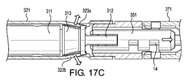
図17A~17Dは、放射状クリップアーム構造のいずれかを閉形態、組織挟持形態で、押さえ管にロックするための例示的なロック機構を示す。図17Aは、押さえ管321の壁がロック突起323を含む押さえ管321の分解図を示す。図17Bに示すように、クリップ311は、クリップ311の近位端の近くに連結されたクリップ接続部313を含む。例えば、クリップ接続部313は、クリップ311の近位端の近くに溶接されていてもよい。クリップ311は、クリップ接続部313が押さえ管321のロック突起323a、323の遠位側にある間、押さえ管321に対して遠位および近位に摺動可能に設計されている。クリップ311が組織を挟持するために配置された後、制御部材14を近位方向に後退させて、クリップ311を押さえ管321に対して近位方向に移動させることにより、クリップ311を押さえ管321にロックすることができる。後退の結果、クリップ接続部313は、押さえ管321のロック突起323a、323bを通過する。図17Cに示すように、ロック突起323a、323bは、クリップ接続部313が通過可能に、径方向外向きに拡張または変形するように設計されている。次に、ロック突起323a、323bがパチンと閉じて(例えば、突起323a、323bが元の位置に向かって径方向内側に移動して)、図17Dに示すように、クリップ311を押さえ管321にロックする。その結果、クリップ311は閉形態、組織挟持形態にロックされる。次に、上述のように、クリップ装置をデリバリデバイスから取り外すことができる。図17A~17Dに示すロック機構は、上述した放射状クリップアーム構造(例えば、111、211、または311)のいずれかと一緒に使用できる。
Figures 17A-17D show an exemplary locking mechanism for locking any of the radial clip arm structures in the closed, tissue clamping configuration to the hold down tube. FIG. 17A shows an exploded view of hold down
図18A~18Eは、閉形態、組織挟持形態における、回動可能なジョークリップアーム構造のいずれかを押さえ管にロックするための例示的なロック機構を示す。図18Aは、押さえ管521がロックコネクタ523を含み、クリップアーム511a、511bがそれぞれロック歯520a、520bを含み、クリップ装置511がロックスライダ524を含む、クリップシステム500の断面図を示す。図18Aでは、クリップアーム511a、511bは、搬送形態において未だ押さえ管521の管路内に配置されている。図18Bでは、ジョー512a、512bは、押さえ管521から解放されており、ばね作用によってわずかに回転し始めている。また、ロックスライダ524は、フォーク接続部751によって遠位方向に前進するように押されている。クリップ511は、図18Cの近位方向に後退し、これにより、ジョー512が押さえ管521の遠位端に当接し、ジョーがクリップアーム511a、511bに対して完全に回動する。図18Dでは、クリップ511が遠位方向に前進して、組織をクリップするためにクリップ511を開形態に展開する。ロックスライダ524は、同様に、図18Dにおいて遠位方向に前進している(例えば、クリップ511が前進するとき、フォーク接続部751によって押されるため)。これにより、押さえ管521のロックコネクタ523の所定の位置にロックされる。すると、クリップ511が開形態から図18Dに示される閉形態、組織挟持形態に遷移する。次に、クリップ511を近位方向に後退させて、クリップアーム511a、511bのロック歯520a、520bがロックスライダ524の内側でロック係合し、クリップ511を閉形態で押さえ管521にロックする。図18A~18Eに示すロック機構は、上述の放射状クリップアーム構造(例えば、511または611)のいずれかと一緒に使用することができる。
Figures 18A-18E show an exemplary locking mechanism for locking either of the pivotable jaw clip arm structures to the hold down tube in the closed, tissue clamping configuration. 18A shows a cross-sectional view of
上記の装置および方法の図示された例示的な実施形態は、例示を意図するものであり、限定されるものではなく、それぞれ組み合わせることができる。例えば、解除可能なクリップ接続構造は、さまざまな解除可能な押さえ管接続構造のいずれかと組み合わせることができる。同様に、放射状ジョークリップアーム構造は交換可能である。本発明の精神および範囲から逸脱することなく、様々な変更を行うことができる。 The illustrated exemplary embodiments of the apparatus and methods described above are intended to be illustrative, not limiting, and may be combined with each other. For example, a releasable clip connection structure can be combined with any of a variety of releasable hold down tube connection structures. Likewise, the radial jaw clip arm constructions are interchangeable. Various changes may be made without departing from the spirit and scope of the invention.
Claims (10)
近位端で互いに連結された複数のクリップアームを有し、少なくとも一部が前記押さえ管の前記管路内に配置され、前記クリップアームの前記遠位端が離間して前記クリップアームの間に組織を受けることが可能な開形態と、前記クリップアームの前記遠位端同士が前記開形態より近く、組織を間に挟むことが可能な閉形態と、の間で前記押さえ管に対して進退移動可能に構成されたクリップと、
前記クリップに設けられる第一接続部と、
前記押さえ管に設けられ、前記第一接続部と係合可能な第二接続部と、
前記クリップアームの前記遠位端に回動可能に連結されたジョーと、を備え、
前記クリップが前記開形態であるか前記閉形態であるかに関わらず、前記第一接続部の一部が前記押さえ管の前記管路内に配置され、
前記第二接続部は、前記クリップが前記押さえ管によって押圧された前記閉形態を、前記第一接続部と係合することにより保持し、
前記ジョーが前記押さえ管の前記管路内に配置されている時に、前記ジョーは、前記クリップアームに平行な方向に延びるように構成される、クリップ装置。 a hold down tube having a conduit extending from the distal end to the proximal end;
having a plurality of clip arms connected together at proximal ends, at least partially disposed within the duct of the hold down tube, and the distal ends of the clip arms spaced apart between the clip arms. Advances and retreats with respect to the hold down tube between an open configuration capable of receiving tissue and a closed configuration wherein the distal ends of the clip arms are closer to each other than the open configuration and tissue can be pinched therebetween. a clip configured to be movable;
a first connecting portion provided on the clip;
a second connecting portion provided on the holding tube and engageable with the first connecting portion ;
a jaw pivotally connected to the distal end of the clip arm ;
regardless of whether the clip is in the open configuration or the closed configuration, a portion of the first connecting portion is arranged in the conduit of the holding tube;
The second connecting portion holds the closed configuration in which the clip is pressed by the pressing tube by engaging with the first connecting portion,
A clipping device, wherein the jaws are configured to extend in a direction parallel to the clip arm when the jaws are disposed within the channel of the hold down tube .
前記連結部材は、前記ジョーと前記クリップアームとを回動可能に連結する、請求項1に記載のクリップ装置。 The clip has a connecting member,
The clip device according to claim 1 , wherein the connecting member rotatably connects the jaw and the clip arm .
前記クリップアームが前記押さえ管に対して遠位側に前進する時に、前記ワイヤは、前記クリップアームに対して前記ジョーを回動させる、請求項1に記載のクリップ装置。 the clip has a wire,
The clipping device of claim 1 , wherein the wire pivots the jaws relative to the clip arm as the clip arm advances distally relative to the hold down tube .
Applications Claiming Priority (2)
| Application Number | Priority Date | Filing Date | Title |
|---|---|---|---|
| US201962787787P | 2019-01-03 | 2019-01-03 | |
| PCT/IB2019/001322 WO2020141345A1 (en) | 2019-01-03 | 2019-12-10 | A clipping device for large defects, perforations and fistulas |
Publications (2)
| Publication Number | Publication Date |
|---|---|
| JP2022525717A JP2022525717A (en) | 2022-05-19 |
| JP7201826B2 true JP7201826B2 (en) | 2023-01-10 |
Family
ID=69593733
Family Applications (1)
| Application Number | Title | Priority Date | Filing Date |
|---|---|---|---|
| JP2021539086A Active JP7201826B2 (en) | 2019-01-03 | 2019-12-10 | Clip device |
Country Status (5)
| Country | Link |
|---|---|
| US (1) | US11622765B2 (en) |
| JP (1) | JP7201826B2 (en) |
| CN (1) | CN113316424A (en) |
| DE (1) | DE112019005835T5 (en) |
| WO (1) | WO2020141345A1 (en) |
Families Citing this family (1)
| Publication number | Priority date | Publication date | Assignee | Title |
|---|---|---|---|---|
| CN114587480B (en) * | 2022-03-23 | 2023-07-21 | 中国人民解放军火箭军特色医学中心 | Aortic occlusion balloon device based on 18F-FDG detection and positioning |
Citations (16)
| Publication number | Priority date | Publication date | Assignee | Title |
|---|---|---|---|---|
| WO2004017839A1 (en) | 2002-08-21 | 2004-03-04 | Olympus Corporation | Ligating device for biological tissue |
| JP2004073646A (en) | 2002-08-21 | 2004-03-11 | Olympus Corp | Ligature apparatus for viable tissue |
| US20050107809A1 (en) | 2003-11-07 | 2005-05-19 | Eric Litscher | Endoscopic hemostatic clipping apparatus |
| US20050251189A1 (en) | 2004-05-07 | 2005-11-10 | Usgi Medical Inc. | Multi-position tissue manipulation assembly |
| JP2006198388A (en) | 2004-12-24 | 2006-08-03 | Olympus Corp | Ligating apparatus |
| JP2007500020A (en) | 2003-07-26 | 2007-01-11 | カール シュタール ゲゼルシャフト ミット ベシュレンクテル ハフツング | Method and apparatus for endoscopic application of medical self-closing clip |
| WO2009155286A1 (en) | 2008-06-19 | 2009-12-23 | Boston Scientific Scimed, Inc. | Hemostatic clipping devices and methods |
| US20110245855A1 (en) | 2010-03-30 | 2011-10-06 | Fujifilm Corporation | Ligating apparatus |
| US20130226200A1 (en) | 2012-02-28 | 2013-08-29 | Boston Scientific Scimed, Inc. | Clip applier |
| US20140171973A1 (en) | 2011-11-11 | 2014-06-19 | Jian Zhu | Living tissue ligation device |
| US20140379018A1 (en) | 2009-12-22 | 2014-12-25 | Cook Medical Technologies Llc | Medical devices with detachable pivotable jaws |
| US20160242778A1 (en) | 2013-06-29 | 2016-08-25 | Anrei Medical (Hz) Co., Ltd. | Clamp device and its clamp unit |
| JP2016526448A (en) | 2013-07-10 | 2016-09-05 | ボストン サイエンティフィック サイムド,インコーポレイテッドBoston Scientific Scimed,Inc. | Tissue grasping and wound closure clip device |
| JP2017509392A (en) | 2014-05-23 | 2017-04-06 | 南京微創医学科技股▲ふん▼有限公司 | Hemostatic clip |
| US20180140300A1 (en) | 2016-11-22 | 2018-05-24 | Boston Scientific Limited | Hemostasis Reloadable Clip Release Mechanism |
| US20190150929A1 (en) | 2017-11-15 | 2019-05-23 | United States Endoscopy Group, Inc. | Clip and clip assembly |
Family Cites Families (1)
| Publication number | Priority date | Publication date | Assignee | Title |
|---|---|---|---|---|
| US5107809A (en) * | 1991-05-28 | 1992-04-28 | Kia Motors Corporation | Engine block and bearing assembly |
-
2019
- 2019-12-10 US US16/709,328 patent/US11622765B2/en active Active
- 2019-12-10 WO PCT/IB2019/001322 patent/WO2020141345A1/en active Application Filing
- 2019-12-10 DE DE112019005835.5T patent/DE112019005835T5/en active Pending
- 2019-12-10 CN CN201980087777.7A patent/CN113316424A/en active Pending
- 2019-12-10 JP JP2021539086A patent/JP7201826B2/en active Active
Patent Citations (20)
| Publication number | Priority date | Publication date | Assignee | Title |
|---|---|---|---|---|
| JP2004073646A (en) | 2002-08-21 | 2004-03-11 | Olympus Corp | Ligature apparatus for viable tissue |
| WO2004017839A1 (en) | 2002-08-21 | 2004-03-04 | Olympus Corporation | Ligating device for biological tissue |
| JP2007500020A (en) | 2003-07-26 | 2007-01-11 | カール シュタール ゲゼルシャフト ミット ベシュレンクテル ハフツング | Method and apparatus for endoscopic application of medical self-closing clip |
| US20050107809A1 (en) | 2003-11-07 | 2005-05-19 | Eric Litscher | Endoscopic hemostatic clipping apparatus |
| US20050251189A1 (en) | 2004-05-07 | 2005-11-10 | Usgi Medical Inc. | Multi-position tissue manipulation assembly |
| US20050251202A1 (en) | 2004-05-07 | 2005-11-10 | Usgi Medical Inc. | Interlocking tissue anchor apparatus and methods |
| JP2006198388A (en) | 2004-12-24 | 2006-08-03 | Olympus Corp | Ligating apparatus |
| WO2009155286A1 (en) | 2008-06-19 | 2009-12-23 | Boston Scientific Scimed, Inc. | Hemostatic clipping devices and methods |
| JP2011524793A (en) | 2008-06-19 | 2011-09-08 | ボストン サイエンティフィック サイムド, インコーポレイテッド | Hemostasis clipping device and method |
| US20140379018A1 (en) | 2009-12-22 | 2014-12-25 | Cook Medical Technologies Llc | Medical devices with detachable pivotable jaws |
| US20110245855A1 (en) | 2010-03-30 | 2011-10-06 | Fujifilm Corporation | Ligating apparatus |
| US20140171973A1 (en) | 2011-11-11 | 2014-06-19 | Jian Zhu | Living tissue ligation device |
| US20140171974A1 (en) | 2011-11-11 | 2014-06-19 | Jian Zhu | Clamping and ligation device |
| US20130226200A1 (en) | 2012-02-28 | 2013-08-29 | Boston Scientific Scimed, Inc. | Clip applier |
| US20160242778A1 (en) | 2013-06-29 | 2016-08-25 | Anrei Medical (Hz) Co., Ltd. | Clamp device and its clamp unit |
| JP2016526448A (en) | 2013-07-10 | 2016-09-05 | ボストン サイエンティフィック サイムド,インコーポレイテッドBoston Scientific Scimed,Inc. | Tissue grasping and wound closure clip device |
| JP2017509392A (en) | 2014-05-23 | 2017-04-06 | 南京微創医学科技股▲ふん▼有限公司 | Hemostatic clip |
| US20180140300A1 (en) | 2016-11-22 | 2018-05-24 | Boston Scientific Limited | Hemostasis Reloadable Clip Release Mechanism |
| JP2019524351A (en) | 2016-11-22 | 2019-09-05 | ボストン サイエンティフィック リミテッド | Refillable hemostatic clip release mechanism |
| US20190150929A1 (en) | 2017-11-15 | 2019-05-23 | United States Endoscopy Group, Inc. | Clip and clip assembly |
Also Published As
| Publication number | Publication date |
|---|---|
| WO2020141345A1 (en) | 2020-07-09 |
| JP2022525717A (en) | 2022-05-19 |
| CN113316424A (en) | 2021-08-27 |
| US11622765B2 (en) | 2023-04-11 |
| US20200214705A1 (en) | 2020-07-09 |
| DE112019005835T5 (en) | 2021-10-14 |
Similar Documents
| Publication | Publication Date | Title |
|---|---|---|
| AU2006223494B2 (en) | Multi-clip device | |
| JP5606563B2 (en) | Release mechanism for clip device | |
| US9060779B2 (en) | Clip devices and methods of delivery and deployment | |
| JP5244816B2 (en) | Combination therapy hemostatic clip | |
| EP2496148B1 (en) | Planar clamps for anastomosis | |
| EP3106098A1 (en) | Apparatus for maintaining a force upon tissue using a loop member | |
| CN111655172B (en) | Hemostatic clamp | |
| JPH07148172A (en) | Surgical substance applicator and endoscope applicator | |
| JP7191961B2 (en) | Tissue alignment for surgical closure | |
| US11213292B2 (en) | Endoscopic hemostasis closure device and delivery system | |
| KR20220040467A (en) | wound closure device | |
| JP7201826B2 (en) | Clip device | |
| US20210022745A1 (en) | Spring loaded mechanism for the deployment of a hemostatic clip | |
| AU2020444017B2 (en) | System and device for treating tissue | |
| CN117320641A (en) | Extendable repositioning clip | |
| JP2024505544A (en) | Repositionable over-the-scope clip |
Legal Events
| Date | Code | Title | Description |
|---|---|---|---|
| A521 | Request for written amendment filed |
Free format text: JAPANESE INTERMEDIATE CODE: A523 Effective date: 20210702 |
|
| A621 | Written request for application examination |
Free format text: JAPANESE INTERMEDIATE CODE: A621 Effective date: 20210702 |
|
| A131 | Notification of reasons for refusal |
Free format text: JAPANESE INTERMEDIATE CODE: A131 Effective date: 20220906 |
|
| A521 | Request for written amendment filed |
Free format text: JAPANESE INTERMEDIATE CODE: A523 Effective date: 20221102 |
|
| TRDD | Decision of grant or rejection written | ||
| A01 | Written decision to grant a patent or to grant a registration (utility model) |
Free format text: JAPANESE INTERMEDIATE CODE: A01 Effective date: 20221122 |
|
| A61 | First payment of annual fees (during grant procedure) |
Free format text: JAPANESE INTERMEDIATE CODE: A61 Effective date: 20221222 |
|
| R151 | Written notification of patent or utility model registration |
Ref document number: 7201826 Country of ref document: JP Free format text: JAPANESE INTERMEDIATE CODE: R151 |