JP7200239B2 - Phase tracking reference signal - Google Patents
Phase tracking reference signal Download PDFInfo
- Publication number
- JP7200239B2 JP7200239B2 JP2020520210A JP2020520210A JP7200239B2 JP 7200239 B2 JP7200239 B2 JP 7200239B2 JP 2020520210 A JP2020520210 A JP 2020520210A JP 2020520210 A JP2020520210 A JP 2020520210A JP 7200239 B2 JP7200239 B2 JP 7200239B2
- Authority
- JP
- Japan
- Prior art keywords
- samples
- sequence
- dft
- sample
- symbol
- Prior art date
- Legal status (The legal status is an assumption and is not a legal conclusion. Google has not performed a legal analysis and makes no representation as to the accuracy of the status listed.)
- Active
Links
Images


Classifications
-
- H—ELECTRICITY
- H04—ELECTRIC COMMUNICATION TECHNIQUE
- H04L—TRANSMISSION OF DIGITAL INFORMATION, e.g. TELEGRAPHIC COMMUNICATION
- H04L1/00—Arrangements for detecting or preventing errors in the information received
- H04L1/0078—Avoidance of errors by organising the transmitted data in a format specifically designed to deal with errors, e.g. location
- H04L1/0086—Unequal error protection
-
- H—ELECTRICITY
- H04—ELECTRIC COMMUNICATION TECHNIQUE
- H04L—TRANSMISSION OF DIGITAL INFORMATION, e.g. TELEGRAPHIC COMMUNICATION
- H04L1/00—Arrangements for detecting or preventing errors in the information received
- H04L1/12—Arrangements for detecting or preventing errors in the information received by using return channel
- H04L1/16—Arrangements for detecting or preventing errors in the information received by using return channel in which the return channel carries supervisory signals, e.g. repetition request signals
- H04L1/18—Automatic repetition systems, e.g. Van Duuren systems
- H04L1/1812—Hybrid protocols; Hybrid automatic repeat request [HARQ]
-
- H—ELECTRICITY
- H04—ELECTRIC COMMUNICATION TECHNIQUE
- H04L—TRANSMISSION OF DIGITAL INFORMATION, e.g. TELEGRAPHIC COMMUNICATION
- H04L25/00—Baseband systems
- H04L25/02—Details ; arrangements for supplying electrical power along data transmission lines
- H04L25/0202—Channel estimation
- H04L25/0212—Channel estimation of impulse response
-
- H—ELECTRICITY
- H04—ELECTRIC COMMUNICATION TECHNIQUE
- H04L—TRANSMISSION OF DIGITAL INFORMATION, e.g. TELEGRAPHIC COMMUNICATION
- H04L25/00—Baseband systems
- H04L25/02—Details ; arrangements for supplying electrical power along data transmission lines
- H04L25/0202—Channel estimation
- H04L25/0224—Channel estimation using sounding signals
- H04L25/0226—Channel estimation using sounding signals sounding signals per se
-
- H—ELECTRICITY
- H04—ELECTRIC COMMUNICATION TECHNIQUE
- H04L—TRANSMISSION OF DIGITAL INFORMATION, e.g. TELEGRAPHIC COMMUNICATION
- H04L27/00—Modulated-carrier systems
- H04L27/26—Systems using multi-frequency codes
- H04L27/2601—Multicarrier modulation systems
- H04L27/2602—Signal structure
- H04L27/2605—Symbol extensions, e.g. Zero Tail, Unique Word [UW]
- H04L27/2607—Cyclic extensions
-
- H—ELECTRICITY
- H04—ELECTRIC COMMUNICATION TECHNIQUE
- H04L—TRANSMISSION OF DIGITAL INFORMATION, e.g. TELEGRAPHIC COMMUNICATION
- H04L27/00—Modulated-carrier systems
- H04L27/26—Systems using multi-frequency codes
- H04L27/2601—Multicarrier modulation systems
- H04L27/2602—Signal structure
- H04L27/261—Details of reference signals
- H04L27/2613—Structure of the reference signals
- H04L27/26134—Pilot insertion in the transmitter chain, e.g. pilot overlapping with data, insertion in time or frequency domain
-
- H—ELECTRICITY
- H04—ELECTRIC COMMUNICATION TECHNIQUE
- H04L—TRANSMISSION OF DIGITAL INFORMATION, e.g. TELEGRAPHIC COMMUNICATION
- H04L27/00—Modulated-carrier systems
- H04L27/26—Systems using multi-frequency codes
- H04L27/2601—Multicarrier modulation systems
- H04L27/2626—Arrangements specific to the transmitter only
- H04L27/2627—Modulators
- H04L27/2634—Inverse fast Fourier transform [IFFT] or inverse discrete Fourier transform [IDFT] modulators in combination with other circuits for modulation
- H04L27/2636—Inverse fast Fourier transform [IFFT] or inverse discrete Fourier transform [IDFT] modulators in combination with other circuits for modulation with FFT or DFT modulators, e.g. standard single-carrier frequency-division multiple access [SC-FDMA] transmitter or DFT spread orthogonal frequency division multiplexing [DFT-SOFDM]
-
- H—ELECTRICITY
- H04—ELECTRIC COMMUNICATION TECHNIQUE
- H04L—TRANSMISSION OF DIGITAL INFORMATION, e.g. TELEGRAPHIC COMMUNICATION
- H04L27/00—Modulated-carrier systems
- H04L27/26—Systems using multi-frequency codes
- H04L27/2601—Multicarrier modulation systems
- H04L27/2626—Arrangements specific to the transmitter only
- H04L27/2627—Modulators
- H04L27/2644—Modulators with oversampling
-
- H—ELECTRICITY
- H04—ELECTRIC COMMUNICATION TECHNIQUE
- H04L—TRANSMISSION OF DIGITAL INFORMATION, e.g. TELEGRAPHIC COMMUNICATION
- H04L27/00—Modulated-carrier systems
- H04L27/26—Systems using multi-frequency codes
- H04L27/2601—Multicarrier modulation systems
- H04L27/2647—Arrangements specific to the receiver only
- H04L27/2655—Synchronisation arrangements
- H04L27/2657—Carrier synchronisation
- H04L27/266—Fine or fractional frequency offset determination and synchronisation
-
- H—ELECTRICITY
- H04—ELECTRIC COMMUNICATION TECHNIQUE
- H04L—TRANSMISSION OF DIGITAL INFORMATION, e.g. TELEGRAPHIC COMMUNICATION
- H04L27/00—Modulated-carrier systems
- H04L27/26—Systems using multi-frequency codes
- H04L27/2601—Multicarrier modulation systems
- H04L27/2647—Arrangements specific to the receiver only
- H04L27/2655—Synchronisation arrangements
- H04L27/2668—Details of algorithms
- H04L27/2673—Details of algorithms characterised by synchronisation parameters
- H04L27/2675—Pilot or known symbols
-
- H—ELECTRICITY
- H04—ELECTRIC COMMUNICATION TECHNIQUE
- H04L—TRANSMISSION OF DIGITAL INFORMATION, e.g. TELEGRAPHIC COMMUNICATION
- H04L5/00—Arrangements affording multiple use of the transmission path
- H04L5/0001—Arrangements for dividing the transmission path
- H04L5/0003—Two-dimensional division
- H04L5/0005—Time-frequency
- H04L5/0007—Time-frequency the frequencies being orthogonal, e.g. OFDM(A) or DMT
- H04L5/001—Time-frequency the frequencies being orthogonal, e.g. OFDM(A) or DMT the frequencies being arranged in component carriers
-
- H—ELECTRICITY
- H04—ELECTRIC COMMUNICATION TECHNIQUE
- H04L—TRANSMISSION OF DIGITAL INFORMATION, e.g. TELEGRAPHIC COMMUNICATION
- H04L5/00—Arrangements affording multiple use of the transmission path
- H04L5/003—Arrangements for allocating sub-channels of the transmission path
- H04L5/0048—Allocation of pilot signals, i.e. of signals known to the receiver
- H04L5/005—Allocation of pilot signals, i.e. of signals known to the receiver of common pilots, i.e. pilots destined for multiple users or terminals
-
- H—ELECTRICITY
- H04—ELECTRIC COMMUNICATION TECHNIQUE
- H04W—WIRELESS COMMUNICATION NETWORKS
- H04W56/00—Synchronisation arrangements
- H04W56/0035—Synchronisation arrangements detecting errors in frequency or phase
-
- H—ELECTRICITY
- H04—ELECTRIC COMMUNICATION TECHNIQUE
- H04L—TRANSMISSION OF DIGITAL INFORMATION, e.g. TELEGRAPHIC COMMUNICATION
- H04L27/00—Modulated-carrier systems
- H04L27/26—Systems using multi-frequency codes
- H04L27/2601—Multicarrier modulation systems
- H04L27/2647—Arrangements specific to the receiver only
- H04L27/2655—Synchronisation arrangements
Landscapes
- Engineering & Computer Science (AREA)
- Signal Processing (AREA)
- Computer Networks & Wireless Communication (AREA)
- Power Engineering (AREA)
- Physics & Mathematics (AREA)
- Discrete Mathematics (AREA)
- General Physics & Mathematics (AREA)
- Mathematical Physics (AREA)
- Mobile Radio Communication Systems (AREA)
- Quality & Reliability (AREA)
- Electromagnetism (AREA)
Description
[0001]本出願は、それらの全体が参照により本明細書に明確に組み込まれる、「PHASE TRACKING REFERENCE SIGNAL」と題し、2017年11月17日に出願された米国仮出願第62/588,110号、「PHASE TRACKING REFERENCE SIGNAL」と題し、2017年10月11日に出願された米国仮出願第62/571,138号、および「PHASE TRACKING REFERENCE SIGNAL」と題し、2018年5月9日に出願された米国特許出願第15/975,112号の利益を主張する。 [0001] This application is based on U.S. Provisional Application No. 62/588,110, entitled "PHASE TRACKING REFERENCE SIGNAL," filed November 17, 2017, which is expressly incorporated herein by reference in its entirety. No. 62/571,138, entitled "PHASE TRACKING REFERENCE SIGNAL," filed Oct. 11, 2017, and U.S. Provisional Application No. 62/571,138, entitled "PHASE TRACKING REFERENCE SIGNAL," filed May 9, 2018. No. 15/975,112 filed.
[0002]本開示は、一般に、通信システムに関し、より詳細には、基準信号を使用する位相トラッキングに関する。 [0002] This disclosure relates generally to communication systems, and more particularly to phase tracking using a reference signal.
[0003]ワイヤレス通信システムは、電話、ビデオ、データ、メッセージング、およびブロードキャストなどの様々な電気通信サービスを提供するために広く展開されている。典型的なワイヤレス通信システムは、利用可能なシステムリソースを共有することによって複数のユーザとの通信をサポートすることが可能な多元接続技術を採用し得る。そのような多元接続技術の例には、符号分割多元接続(CDMA)システム、時分割多元接続(TDMA)システム、周波数分割多元接続(FDMA)システム、直交周波数分割多元接続(OFDMA)システム、シングルキャリア周波数分割多元接続(SC-FDMA)システム、および時分割同期符号分割多元接続(TD-SCDMA)システムが含まれる。 [0003] Wireless communication systems are widely deployed to provide various telecommunication services such as telephone, video, data, messaging, and broadcast. A typical wireless communication system may employ multiple-access techniques that are capable of supporting communication with multiple users by sharing available system resources. Examples of such multiple-access techniques include code division multiple access (CDMA) systems, time division multiple access (TDMA) systems, frequency division multiple access (FDMA) systems, orthogonal frequency division multiple access (OFDMA) systems, single carrier Included are Frequency Division Multiple Access (SC-FDMA) systems and Time Division Synchronous Code Division Multiple Access (TD-SCDMA) systems.
[0004]これらの多元接続技術は、様々なワイヤレスデバイスが都市、国家、地域、さらには地球規模で通信することを可能にする共通プロトコルを提供するために、様々な電気通信規格において採用されている。例示的な電気通信規格は5G新無線(NR)である。5G NRは、待ち時間、信頼性、安全性、(たとえば、モノのインターネット(IoT)による)スケーラビリティ、および他の要件に関連する新しい要件を満たすように第3世代パートナーシッププロジェクト(3GPP(登録商標))によって公布された、連続的なモバイルブロードバンドの進化の一部である。5G NRのいくつかの態様は、4Gロングタームエボリューション(LTE(登録商標))規格に基づき得る。5G NR技術はさらなる改善を行う必要がある。これらの改善はまた、他の多元接続技術、およびこれらの技術を採用する電気通信規格に適用可能であり得る。 [0004] These multiple access techniques have been adopted in various telecommunication standards to provide a common protocol that allows various wireless devices to communicate on a city, national, regional and even global scale. there is An exemplary telecommunications standard is 5G New Radio (NR). 5G NR will be supported by the 3rd Generation Partnership Project (3GPP®) to meet new requirements related to latency, reliability, security, scalability (e.g. with the Internet of Things (IoT)), and other requirements. ) is part of the continuous mobile broadband evolution promulgated by Some aspects of 5G NR may be based on the 4G Long Term Evolution (LTE) standard. 5G NR technology needs to make further improvements. These improvements may also be applicable to other multiple access technologies and telecommunications standards that employ these technologies.
[0005]PT-RSは、ワイヤレス通信(たとえば、5G NR)における位相誤差を追跡し補正するために、ワイヤレス通信において適用され得る。PT-RSは、(たとえば、mmWave(mmW)システムにおける)位相誤差を追跡し補正するために、5G NRにおいて使用され得る。位相誤差は、位相雑音、キャリア周波数オフセット、ドップラー効果などによって引き起こされ得る。しかしながら、逆離散フーリエ変換(IDFT)と関連してPT-RSを受信するときに、問題が発生し得る。 [0005] PT-RS may be applied in wireless communications (eg, 5G NR) to track and correct phase errors in wireless communications. PT-RS may be used in 5G NR to track and correct phase errors (eg, in mmWave (mmW) systems). Phase errors can be caused by phase noise, carrier frequency offset, Doppler effect, and the like. However, problems can arise when receiving the PT-RS in conjunction with the Inverse Discrete Fourier Transform (IDFT).
[0006]以下で、1つまたは複数の態様の基本的理解を与えるために、そのような態様の簡略化された概要を提示する。この概要は、すべての考察された態様の包括的な概説ではなく、すべての態様の主要または重要な要素を識別するものでも、いずれかまたはすべての態様の範囲を定めるものでもない。その唯一の目的は、後に提示されるより詳細な説明の導入として、1つまたは複数の態様のいくつかの概念を簡略化された形で提示することである。 [0006] The following presents a simplified summary of one or more aspects in order to provide a basic understanding of such aspects. This summary is not a comprehensive overview of all discussed aspects, and it does not identify key or critical elements of all aspects, or delineate the scope of any or all aspects. Its sole purpose is to present some concepts of one or more aspects in a simplified form as a prelude to the more detailed description that is presented later.
[0007]PT-RSは、mmWシステムにおける位相誤差、たとえば、位相雑音、キャリア周波数オフセット、ドップラー効果などによって引き起こされる位相誤差を追跡し補正するために、5G NRにおいて使用され得る。しかしながら、IDFTと関連してPT-RSを受信するときに、受信機において問題が発生し得る。たとえば、離散フーリエ変換スプレッド直交周波数分割多重化(DFT-s-OFDM)通信において送信のためのデータを処理するときに、DFT演算の前にPT-RSサンプルが挿入された場合、PT-RSに基づいて位相誤差の軌跡を補間しようと試みる受信機においてウィンドウ効果が発生し得る。受信機において、IDFTプロセスは、受信シンボルを決定するために受信信号に適用され得る。IDFTプロセスの出力シーケンスは巡回構造に従い得、巡回構造は、位相誤差の軌跡における最初のサンプルおよび最後のサンプルを同様の値に収束させる。受信機における強制収束は、受信機におけるPT-RSの適用に起因して、推定された位相軌跡における誤差および不確実性につながる可能性がある。たとえば、サンプルの先頭および/または終端のサンプルにおいて誤差が発生し得る。この潜在的な誤差および不確実性は、ウィンドウ効果と呼ばれ得る。 [0007] PT-RS may be used in 5G NR to track and correct phase errors in mmW systems, eg, phase errors caused by phase noise, carrier frequency offset, Doppler effect, and the like. However, problems can occur at the receiver when receiving PT-RS in conjunction with IDFT. For example, when processing data for transmission in discrete Fourier transform spread orthogonal frequency division multiplexing (DFT-s-OFDM) communications, if PT-RS samples are inserted before the DFT operation, the PT-RS Windowing effects can occur in receivers that attempt to interpolate the phase error trajectory based on the At the receiver, an IDFT process may be applied to the received signal to determine the received symbols. The output sequence of the IDFT process may follow a cyclic structure, which causes the first and last samples in the phase error trajectory to converge to similar values. Forced convergence at the receiver can lead to errors and uncertainties in the estimated phase trajectory due to the application of PT-RS at the receiver. For example, errors may occur in the leading and/or trailing samples. This potential error and uncertainty can be called window effect.
[0008]本出願は、たとえば、PT-RSを受信しようと試みる受信機におけるウィンドウ効果に起因する上記の誤差および不確実性の問題に対処する。本出願は、受信機におけるウィンドウ効果を低減または最小化するPT-RSパターンを介して、不確実性に対する解決策を提供する。送信機は、受信機において発生し得るウィンドウ効果に基づくパターンで、送信機におけるデータ送信にPT-RSを挿入し得る。たとえば、送信機は、ウィンドウ効果によって影響を受ける可能性が低い位置におけるデータ送信にPT-RSを挿入し得る。PT-RSは、先頭および/または終端のサンプルとは異なる位置におけるデータ送信に挿入され得る。ウィンドウ効果による影響をそれほど受けない位置、たとえば、先頭および/または終端のサンプルとは異なる位置におけるデータ送信とPT-RSを結合することにより、PT-RSを受信し抽出しようと試みる受信機にとっての不確実性が低減され得る。 [0008] The present application addresses the above error and uncertainty issues due, for example, to window effects in receivers attempting to receive PT-RS. The present application provides a solution to uncertainty through PT-RS patterns that reduce or minimize window effects at the receiver. The transmitter may insert PT-RSs into the data transmission at the transmitter in patterns based on windowing effects that may occur at the receiver. For example, a transmitter may insert PT-RS into data transmissions at locations that are less likely to be affected by window effects. The PT-RS may be inserted into the data transmission at positions different from the leading and/or trailing samples. For receivers trying to receive and extract PT-RS by combining PT-RS with data transmissions at locations less affected by window effects, e.g., locations different from the leading and/or trailing samples. Uncertainties can be reduced.
[0009]本開示の一態様では、ユーザ機器などの送信機におけるワイヤレス通信のための方法、コンピュータ可読媒体、および装置が提供される。装置は、位相トラッキング基準信号(PT-RS)サンプルを複数のサンプルのシーケンスに挿入するための少なくとも1つの位置を決定し、複数のサンプルの第1のセットは、シーケンスの先頭にある第1の数のサンプルおよびシーケンスの終端にある第2の数のサンプルのうちの少なくとも1つを備え、PT-RSサンプルのための少なくとも1つの位置は複数のサンプルの第2のセット内にある。次いで、装置は、決定された少なくとも1つの位置に基づいてシーケンスにPT-RSサンプルを挿入し、挿入されたPT-RSサンプルに基づいて信号を送信する。複数のサンプルの第1のセットは、受信機側のエッジ効果を受ける可能性があると識別され得る。信号はDFT-s-OFDM信号を備え得る。したがって、装置は、最初に、シンボルのためのサンプルのプレDFTシーケンスを形成するために、決定された位置に基づいてPT-RSサンプルのためのサンプルと他のサンプルとを結合し、プレDFTシーケンス上でDFTを実行し得る。受信機側のウィンドウ効果を受ける可能性があるサンプルの第1のセットは、シンボル内のプレDFTシーケンスの先頭にある第1の数のサンプルおよびプレDFTシーケンスの終端にある第2の数のサンプルのうちの少なくとも1つを備え得る。複数のサンプルの第2のセットは、受信機側のウィンドウ効果を受けないか、または受ける可能性が低いサンプルを備え得る。PT-RSパターンは、あらかじめ定義された式に基づいて決定され得る。 [0009] In one aspect of the present disclosure, methods, computer-readable media, and apparatus are provided for wireless communication in transmitters, such as user equipment. The apparatus determines at least one position for inserting phase tracking reference signal (PT-RS) samples into a sequence of samples, the first set of samples being a first position at the beginning of the sequence. at least one of the number of samples and a second number of samples at the end of the sequence, wherein the at least one position for the PT-RS sample is within the second set of samples. The device then inserts PT-RS samples into the sequence based on the determined at least one position and transmits a signal based on the inserted PT-RS samples. A first set of samples may be identified as potentially subject to receiver-side edge effects. The signal may comprise a DFT-s-OFDM signal. Accordingly, the apparatus first combines the samples for the PT-RS samples and the other samples based on the determined positions to form a pre-DFT sequence of samples for the symbol, the pre-DFT sequence DFT can be performed on The first set of samples that may be subject to receiver-side windowing effects is a first number of samples at the beginning of the pre-DFT sequence and a second number of samples at the end of the pre-DFT sequence within a symbol. at least one of The second set of samples may comprise samples that are not, or are unlikely to be, subject to receiver-side windowing effects. A PT-RS pattern may be determined based on a predefined formula.
[0010]本開示の一態様では、基地局などの受信機におけるワイヤレス通信のための方法、コンピュータ可読媒体、および装置が提供される。装置は、複数のサンプルのシーケンスを備える受信された送信内の位相トラッキング基準信号(PT-RS)サンプルのための少なくとも1つの位置を決定し、複数のサンプルの第1のセットは、シーケンスの先頭にある第1の数のサンプルおよびシーケンスの終端にある第2の数のサンプルのうちの少なくとも1つを備え、PT-RSサンプルのための少なくとも1つの位置は複数のサンプルの第2のセット内にある。装置は、決定された少なくとも1つの位置に基づいて、受信された送信からPT-RSサンプルを抽出し、抽出されたPT-RSサンプルに基づいて、受信された送信内のデータサンプルについての位相誤差を推定する。信号はDFT-s-OFDM信号を備え得る。したがって、装置は、PT-RSサンプルを抽出する前に、受信された送信に対してIDFTを実行し得る。装置は、推定された位相誤差に基づいて、受信されたデータサンプルの位相を補正し得る。受信機側のウィンドウ効果を受ける可能性があるサンプルの第1のセットは、シンボル内のプレDFTサンプルシーケンスの先頭にある第1の数のサンプルおよびシンボル内のプレDFTシーケンスの終端にある第2の数のサンプルのうちの少なくとも1つを備え得る。複数のサンプルの第2のセットは、受信機側のウィンドウ効果を受けないサンプルを備える。PT-RSパターンは、あらかじめ定義された式に基づいて決定され得る。 [0010] In one aspect of the present disclosure, methods, computer-readable media, and apparatus are provided for wireless communication in a receiver, such as a base station. An apparatus determines at least one position for a phase tracking reference signal (PT-RS) sample within a received transmission comprising a sequence of samples, the first set of samples being the beginning of the sequence. and at least one of a first number of samples at the end of the sequence and a second number of samples at the end of the sequence, wherein the at least one position for the PT-RS samples is within the second set of samples It is in. An apparatus extracts PT-RS samples from the received transmission based on the determined at least one position, and calculates a phase error for the data samples in the received transmission based on the extracted PT-RS samples. to estimate The signal may comprise a DFT-s-OFDM signal. Accordingly, the device may perform an IDFT on the received transmission before extracting the PT-RS samples. The device may correct the phase of the received data samples based on the estimated phase error. The first set of samples that may be subject to receiver-side windowing effects is a first number of samples at the beginning of the pre-DFT sample sequence in a symbol and a second number at the end of the pre-DFT sample sequence in a symbol. number of samples. The second set of samples comprises samples that are not subject to receiver-side windowing effects. A PT-RS pattern may be determined based on a predefined formula.
[0011]上記の目的および関係する目的を達成するために、1つまたは複数の態様は、以下で十分に記載され、特に特許請求の範囲において指摘される特徴を備える。以下の説明および付属の図面は、1つまたは複数の態様のいくつかの例示的な特徴を詳細に記載する。しかしながら、これらの特徴は、様々な態様の原理が採用され得る様々な方法のほんのいくつかを示すものであり、この説明は、すべてのそのような態様およびそれらの均等物を含むものである。 [0011] To the accomplishment of the foregoing and related ends, the one or more aspects comprise the features hereinafter fully described and particularly pointed out in the claims. The following description and the annexed drawings set forth in detail certain illustrative features of the one or more aspects. These features are indicative, however, of but a few of the various ways in which the principles of various aspects may be employed and this description is intended to include all such aspects and their equivalents.
[0025]添付の図面に関して以下に記載される発明を実施するための形態は、様々な構成の説明として意図されており、本明細書に記載される概念が実践され得る構成のみを表すように意図されていない。発明を実施するための形態は、様々な概念を完全に理解する目的で具体的な詳細を含む。しかしながら、これらの概念はこれらの具体的な詳細なしに実践され得ることは、当業者には明らかであろう。場合によっては、そのような概念を不明瞭にすることを回避するために、よく知られている構造およびコンポーネントがブロック図の形式で示される。 [0025] The Detailed Description set forth below with respect to the accompanying drawings is intended as a description of various configurations and is intended to represent only those configurations in which the concepts described herein may be practiced. Not intended. The detailed description includes specific details for the purpose of providing a thorough understanding of various concepts. However, it will be apparent to one skilled in the art that these concepts may be practiced without these specific details. In other instances, well-known structures and components are shown in block diagram form in order to avoid obscuring such concepts.
[0026]次に、様々な装置および方法を参照して、電気通信システムのいくつかの態様が提示される。これらの装置および方法は、以下の発明を実施するための形態において記載され、(「要素」と総称される)様々なブロック、コンポーネント、回路、プロセス、アルゴリズムなどによって添付の図面に示される。これらの要素は、電子ハードウェア、コンピュータソフトウェア、またはそれらの任意の組合せを使用して実装され得る。そのような要素がハードウェアとして実装されるかソフトウェアとして実装されるかは、特定の適用例および全体的なシステムに課される設計制約に依存する。 [0026] Several aspects of telecommunications systems are now presented with reference to various apparatus and methods. These devices and methods are described in the detailed description below and illustrated in the accompanying drawings by various blocks, components, circuits, processes, algorithms, etc. (collectively referred to as "elements"). These elements may be implemented using electronic hardware, computer software, or any combination thereof. Whether such elements are implemented as hardware or software depends on the particular application and design constraints imposed on the overall system.
[0027]例として、要素、または要素の任意の部分、または要素の任意の組合せは、1つまたは複数のプロセッサを含む「処理システム」として実装され得る。プロセッサの例には、マイクロプロセッサ、マイクロコントローラ、グラフィックス処理装置(GPU)、中央処理装置(CPU)、アプリケーションプロセッサ、デジタル信号プロセッサ(DSP)、縮小命令セットコンピューティング(RISC)プロセッサ、システムオンチップ(SoC)、ベースバンドプロセッサ、フィールドプログラマブルゲートアレイ(FPGA)、プログラマブル論理デバイス(PLD)、状態機械、ゲート論理、個別ハードウェア回路、および本開示全体にわたって記載される様々な機能を実行するように構成された他の適切なハードウェアが含まれる。処理システム内の1つまたは複数のプロセッサはソフトウェアを実行し得る。ソフトウェアは、ソフトウェア、ファームウェア、ミドルウェア、マイクロコード、ハードウェア記述言語などの名称にかかわらず、命令、命令セット、コード、コードセグメント、プログラムコード、プログラム、サブプログラム、ソフトウェアコンポーネント、アプリケーション、ソフトウェアアプリケーション、ソフトウェアパッケージ、ルーチン、サブルーチン、オブジェクト、実行ファイル、実行スレッド、プロシージャ、関数などを意味するように広く解釈されるべきである。 [0027] By way of example, an element, or any portion of an element, or any combination of elements, may be implemented as a "processing system" that includes one or more processors. Examples of processors include microprocessors, microcontrollers, graphics processing units (GPUs), central processing units (CPUs), application processors, digital signal processors (DSPs), reduced instruction set computing (RISC) processors, system-on-chip (SoC), baseband processors, field programmable gate arrays (FPGAs), programmable logic devices (PLDs), state machines, gate logic, discrete hardware circuits, and to perform various functions described throughout this disclosure. Other suitable hardware configured is included. One or more processors within the processing system may execute software. Software means instructions, instruction sets, code, code segments, program code, programs, subprograms, software components, applications, software applications, software, whether called software, firmware, middleware, microcode, hardware description language, or otherwise. It should be interpreted broadly to mean packages, routines, subroutines, objects, executables, threads of execution, procedures, functions, and the like.
[0028]したがって、1つまたは複数の例示的な実施形態では、記載される機能は、ハードウェア、ソフトウェア、またはそれらの任意の組合せに実装され得る。ソフトウェアに実装される場合、機能は、コンピュータ可読媒体上に記憶されるか、またはコンピュータ可読媒体上の1つもしくは複数の命令もしくはコードとして符号化され得る。コンピュータ可読媒体はコンピュータ記憶媒体を含む。記憶媒体は、コンピュータによってアクセスされることができる任意の利用可能な媒体であり得る。限定ではなく例として、そのようなコンピュータ可読媒体は、ランダムアクセスメモリ(RAM)、読取り専用メモリ(ROM)、電気的消去可能プログラマブルROM(EEPROM(登録商標))、光ディスクストレージ、磁気ディスクストレージ、他の磁気ストレージデバイス、前述のタイプのコンピュータ可読媒体の組合せ、またはコンピュータによってアクセスされることができる命令もしくはデータ構造の形態のコンピュータ実行可能コードを記憶するために使用されることができる任意の他の媒体を備えることができる。 [0028] Thus, in one or more exemplary embodiments, the functions described may be implemented in hardware, software, or any combination thereof. If implemented in software, the functions may be stored on or encoded as one or more instructions or code on a computer-readable medium. Computer-readable media includes computer storage media. A storage media may be any available media that can be accessed by a computer. By way of example, and not limitation, such computer readable media include random access memory (RAM), read only memory (ROM), electrically erasable programmable ROM (EEPROM®), optical disk storage, magnetic disk storage, etc. a magnetic storage device, a combination of the aforementioned types of computer-readable media, or any other that can be used for storing computer-executable code in the form of instructions or data structures accessible by a computer A medium can be provided.
[0029]図1は、ワイヤレス通信システムおよびアクセスネットワーク100の一例を示す図である。(ワイヤレスワイドエリアネットワーク(WWAN)とも呼ばれる)ワイヤレス通信システムは、基地局102と、UE104と、発展型パケットコア(EPC)160とを含む。基地局102は、マクロセル(高電力セルラー基地局)および/またはスモールセル(低電力セルラー基地局)を含み得る。マクロセルには、基地局が含まれる。スモールセルには、フェムトセル、ピコセル、およびマイクロセルが含まれる。
[0029] FIG. 1 illustrates an example wireless communication system and
[0030](発展型ユニバーサルモバイルテレコミュニケーションシステム(UMTS)地上波無線アクセスネットワーク(E-UTRAN)と総称される)基地局102は、バックホールリンク132(たとえば、S1インターフェース)を介してEPC160とインターフェースする。他の機能に加えて、基地局102は、以下の機能:ユーザデータの転送、無線チャネルの暗号化および解読、完全性保護、ヘッダ圧縮、モビリティ制御機能(たとえば、ハンドオーバ、デュアル接続性)、セル間干渉協調、接続のセットアップおよび解放、負荷分散、非アクセス層(NAS)メッセージのための分配、NASノード選択、同期、無線アクセスネットワーク(RAN)共有、マルチメディアブロードキャストマルチキャストサービス(MBMS)、加入者および機器トレース、RAN情報管理(RIM)、ページング、測位、ならびに警告メッセージの配信のうちの1つまたは複数を実行し得る。基地局102は、バックホールリンク134(たとえば、X2インターフェース)上で互いと直接的または間接的に(たとえば、EPC160を介して)通信し得る。バックホールリンク134は有線またはワイヤレスであり得る。
[0030] Base stations 102 (collectively referred to as Evolved Universal Mobile Telecommunications System (UMTS) Terrestrial Radio Access Network (E-UTRAN)) interface with
[0031]基地局102はUE104とワイヤレスに通信し得る。基地局102の各々は、それぞれの地理的カバレージエリア110に通信カバレージを提供し得る。重複する地理的カバレージエリア110が存在し得る。たとえば、スモールセル102’は、1つまたは複数のマクロ基地局102のカバレージエリア110と重複するカバレージエリア110’を有し得る。スモールセルとマクロセルの両方を含むネットワークは、異種ネットワークとして知られる場合がある。異種ネットワークはまた、限定加入者グループ(CSG)として知られる限られたグループにサービスを提供し得るホーム発展型ノードB(eNB)(HeNB)を含み得る。基地局102とUE104との間の通信リンク120は、UE104から基地局102への(逆方向リンクとも呼ばれる)アップリンク(UL)送信、および/または基地局102からUE104への(順方向リンクとも呼ばれる)ダウンリンク(DL)送信を含み得る。通信リンク120は、空間多重化、ビームフォーミング、および/または送信ダイバーシティを含む、多入力多出力(MIMO)アンテナ技術を使用し得る。通信リンクは、1つまたは複数のキャリアを介し得る。基地局102/UE104は、各方向の送信に使用される合計YxMHz(x個のコンポーネントキャリア)までのキャリアアグリゲーションにおいて割り振られた、キャリア当たりYMHz(たとえば、5、10、15、20、100MHz)までの帯域幅のスペクトルを使用し得る。キャリアは、互いに隣接しても、しなくてもよい。キャリアの割振りは、DLおよびULに対して非対称であり得る(たとえば、ULよりも多いかまたは少ないキャリアがDLに割り振られてよい)。コンポーネントキャリアは、プライマリコンポーネントキャリアと、1つまたは複数のセカンダリコンポーネントキャリアとを含み得る。プライマリコンポーネントキャリアはプライマリセル(PCell)と呼ばれる場合があり、セカンダリコンポーネントキャリアはセカンダリセル(SCell)と呼ばれ得る。
[0031]
[0032]いくつかのUE104は、デバイス間(D2D)通信リンク192を使用して互いに通信し得る。D2D通信リンク192は、DL/UL WWANスペクトルを使用し得る。D2D通信リンク192は、物理サイドリンクブロードキャストチャネル(PSBCH)、物理サイドリンク発見チャネル(PSDCH)、物理サイドリンク共有チャネル(PSSCH)、および物理サイドリンク制御チャネル(PSCCH)などの、1つまたは複数のサイドリンクチャネルを使用し得る。D2D通信は、たとえば、FlashLinQ、WiMedia、Bluetooth(登録商標)、ZigBee(登録商標)、IEEE802.11規格に基づくWi-Fi(登録商標)、LTE、またはNRなどの、様々なワイヤレスD2D通信システムを介し得る。
[0032] Some
[0033]ワイヤレス通信システムは、5GHz無認可周波数スペクトル内で通信リンク154を介してWi-Fi局(STA)152と通信しているWi-Fiアクセスポイント(AP)150をさらに含み得る。無認可周波数スペクトル内で通信するとき、STA152/AP150は、チャネルが利用可能かどうかを決定するために、通信するより前にクリアチャネルアセスメント(CCA)を実行し得る。
[0033] The wireless communication system may further include a Wi-Fi access point (AP) 150 in communication with a Wi-Fi station (STA) 152 via a
[0034]スモールセル102’は、認可および/または無認可の周波数スペクトル内で動作し得る。無認可周波数スペクトル内で動作するとき、スモールセル102’はNRを採用し、Wi-Fi AP150によって使用されるのと同じ5GHz無認可周波数スペクトルを使用し得る。無認可周波数スペクトル内でNRを採用するスモールセル102’は、アクセスネットワークへのカバレージを強化し、および/またはアクセスネットワークの容量を増大させ得る。
[0034] Small cells 102' may operate in licensed and/or unlicensed frequency spectrums. When operating within the unlicensed frequency spectrum,
[0035]gノードB(gNB)180は、UE104と通信しているミリメートル波(mmW)周波数および/または近mmW周波数で動作し得る。gNB180がmmWまたは近mmWの周波数で動作するとき、gNB180はmmW基地局と呼ばれ得る。極高周波(EHF)は電磁スペクトル内のRFの一部である。EHFは30GHz~300GHzのレンジと、1ミリメートルと10ミリメートルとの間の波長とを有する。その帯域内の電波はミリメートル波と呼ばれ得る。近mmWは、100ミリメートルの波長で3GHzの周波数まで下方に延在し得る。超高周波(SHF)帯域は、3GHzから30GHzまで延在し、センチメートル波とも呼ばれる。mmW/近mmW無線周波数帯域を使用する通信は、極めて高い経路損失と短いレンジとを有する。mmW基地局180は、極めて高い経路損失と短いレンジとを補償するために、UE104とのビームフォーミング184を利用し得る。
[0035] A gNode B (gNB) 180 may operate at millimeter wave (mmW) and/or near-mmW frequencies communicating with
[0036]EPC160は、モビリティ管理エンティティ(MME)162と、他のMME164と、サービングゲートウェイ166と、マルチメディアブロードキャストマルチキャストサービス(MBMS)ゲートウェイ168と、ブロードキャストマルチキャストサービスセンタ(BM-SC)170と、パケットデータネットワーク(PDN)ゲートウェイ172とを含み得る。MME162は、ホーム加入者サーバ(HSS)174と通信していてよい。MME162は、UE104とEPC160との間のシグナリングを処理する制御ノードである。概して、MME162はベアラ管理と接続管理とを実現する。すべてのユーザのインターネットプロトコル(IP)パケットはサービングゲートウェイ166を介して転送され、サービングゲートウェイ166自体はPDNゲートウェイ172に接続される。PDNゲートウェイ172は、UEのIPアドレス割振りならびに他の機能を実現する。PDNゲートウェイ172およびBM-SC170は、IPサービス176に接続される。IPサービス176は、インターネット、イントラネット、IPマルチメディアサブシステム(IMS)、PSストリーミングサービス、および/または他のIPサービスを含み得る。BM-SC170は、MBMSユーザサービスのプロビジョニングおよび配信のための機能を実現し得る。BM-SC170は、コンテンツプロバイダMBMS送信のためのエントリポイントとして働くことができ、公的地域モバイルネットワーク(PLMN)内のMBMSベアラサービスを認可および開始するために使用されてよく、MBMS送信をスケジュールするために使用され得る。MBMSゲートウェイ168は、特定のサービスをブロードキャストするマルチキャストブロードキャスト単一周波数ネットワーク(MBSFN)エリアに属する基地局102にMBMSトラフィックを配信するために使用されてよく、セッション管理(開始/停止)と、eMBMS関係の課金情報を収集することとを担い得る。
[0036] The
[0037]基地局は、gNB、ノードB、発展型ノードB(eNB)、アクセスポイント、基地トランシーバ局、無線基地局、無線トランシーバ、トランシーバ機能、基本サービスセット(BSS)、拡張サービスセット(ESS)、または何らかの他の適切な用語で呼ばれ得る。基地局102は、UE104にEPC160へのアクセスポイントを提供する。UE104の例には、携帯電話、スマートフォン、セッション開始プロトコル(SIP)電話、ラップトップ、携帯情報端末(PDA)、衛星無線、全地球測位システム、マルチメディアデバイス、ビデオデバイス、デジタルオーディオプレーヤ(たとえば、MP3プレーヤ)、カメラ、ゲーム機、タブレット、スマートデバイス、ウェアラブルデバイス、車両、電気メータ、ガスポンプ、大もしくは小の台所器具、ヘルスケアデバイス、インプラント、ディスプレイ、または任意の他の同様の機能デバイスが含まれる。UE104のうちのいくつかは、IoTデバイス(たとえば、パーキングメータ、ガスポンプ、トースタ、車両、心臓モニタなど)と呼ばれ得る。UE104は、局、移動局、加入者局、モバイルユニット、加入者ユニット、ワイヤレスユニット、リモートユニット、モバイルデバイス、ワイヤレスデバイス、ワイヤレス通信デバイス、リモートデバイス、モバイル加入者局、アクセス端末、モバイル端末、ワイヤレス端末、リモート端末、ハンドセット、ユーザエージェント、モバイルクライアント、クライアント、または何らかの他の適切な用語で呼ばれ得る。
[0037] Base stations include gNBs, Node Bs, Evolved Node Bs (eNBs), Access Points, Base Transceiver Stations, Radio Base Stations, Radio Transceivers, Transceiver Functions, Basic Service Set (BSS), Extended Service Set (ESS) , or some other suitable term.
[0038]再び図1を参照すると、いくつかの態様では、UE104/基地局180は、たとえば、図5~図10に関して記載される態様のうちのいずれかを含む、送信のためのデータを処理するときに複数のサンプルのプレDFTシーケンスにPT-RSサンプルを挿入するように構成されたPT-RS送信機コンポーネント198とともに構成され得る。いくつかの態様では、UE104/基地局180は、たとえば、図5~図7および図11~図13に関して記載される態様のうちのいずれかを含む、受信された信号データを処理するときにPT-RSサンプルを抽出するように構成されたPT-RS受信機コンポーネント199を含むように構成され得る。
[0038] Referring again to FIG. 1, in some aspects the
[0039]図2Aは、5G/NRフレーム構造内のDLサブフレームの一例を示す図200である。図2Bは、DLサブフレーム内のチャネルの一例を示す図230である。図2Cは、5G/NRフレーム構造内のULサブフレームの一例を示す図250である。図2Dは、ULサブフレーム内のチャネルの一例を示す図280である。5G/NRフレーム構造は、サブキャリアの特定のセット(キャリアシステム帯域幅)に対して、サブキャリアのセット内のサブフレームがDLまたはULのいずれかに専用であるFDDであり得、サブキャリアの特定のセット(キャリアシステム帯域幅)に対して、サブキャリアのセット内のサブフレームがDLとULの両方に専用であるTDDであってもよい。図2A、図2Cによって提供された例では、5G/NRフレーム構造は、サブフレーム4 DLサブフレームとサブフレーム7 ULサブフレームとを伴う、TDDであると想定される。サブフレーム4はDLのみを提供するものとして示されており、サブフレーム7はULのみを提供するものとして示されているが、任意の特定のサブフレームはULとDLの両方を提供する異なるサブセットに分割され得る。以下の説明は、FDDである5G/NRフレーム構造にも適用されることに留意されたい。
[0039] Figure 2A is a diagram 200 illustrating an example of a DL subframe within a 5G/NR frame structure. FIG. 2B is a diagram 230 illustrating an example of channels within a DL subframe. FIG. 2C is a diagram 250 illustrating an example of a UL subframe within a 5G/NR frame structure. FIG. 2D is a diagram 280 illustrating an example of channels within a UL subframe. The 5G/NR frame structure can be FDD where, for a particular set of subcarriers (carrier system bandwidth), subframes within the set of subcarriers are dedicated to either DL or UL, For a particular set (carrier system bandwidth), it may be TDD where subframes within the set of subcarriers are dedicated to both DL and UL. In the example provided by FIGS. 2A, 2C, the 5G/NR frame structure is assumed to be TDD, with
[0040]他のワイヤレス通信技術は、異なるフレーム構造および/または異なるチャネルを有してよい。フレーム(10ms)は、10個の等しいサイズのサブフレーム(1ms)に分割され得る。各サブフレームは、1つまたは複数のタイムスロットを含み得る。各スロットは、スロット構成に応じて7個または14個のシンボルを含み得る。スロット構成0の場合、各スロットは14個のシンボルを含んでよく、スロット構成1の場合、各スロットは7個のシンボルを含み得る。サブフレーム内のスロットの数は、スロット構成および数秘学に基づく。スロット構成0の場合、異なる数秘学0~5は、サブフレーム当たり、それぞれ、1、2、4、8、16、および32個のスロットを可能にする。スロット構成1の場合、異なる数秘学0~2は、サブフレーム当たり、それぞれ、2、4、および8個のスロットを可能にする。サブキャリア間隔およびシンボル長/持続時間は、数秘学の関数である。サブキャリア間隔は2μ*15kHZに等しくなり得、ここで、μは数秘学0~5である。シンボル長/持続時間はサブキャリア間隔と逆関係にある。図2A、図2Cは、スロット当たり7シンボルを有するスロット構成1、およびサブフレーム当たり2スロットを有する数秘学0の一例を提供する。サブキャリア間隔は15kHzであり、シンボル持続時間は約66.7μsである。
[0040] Other wireless communication technologies may have different frame structures and/or different channels. A frame (10 ms) may be divided into 10 equally sized subframes (1 ms). Each subframe may include one or more time slots. Each slot may contain 7 or 14 symbols depending on the slot configuration. For
[0041]フレーム構造を表すためにリソースグリッドが使用され得る。各タイムスロットは、12個の連続するサブキャリアを延在する(物理RB(PRB)とも呼ばれる)リソースブロック(RB)を含む。リソースグリッドは複数のリソース要素(RE)に分割される。各REによって搬送されるビットの数は変調方式に依存する。 [0041] A resource grid may be used to represent the frame structure. Each timeslot includes a resource block (RB) (also called physical RB (PRB)) that extends over 12 consecutive subcarriers. A resource grid is divided into multiple resource elements (REs). The number of bits carried by each RE depends on the modulation scheme.
[0042]図2Aに示されたように、REのうちのいくつかは、(Rと示された)UEのための基準(パイロット)信号(RS)を搬送する。RSは、復調RS(DM-RS)と、UEにおけるチャネル推定のためのチャネル状態情報基準信号(CSI-RS)とを含み得る。RSはまた、ビーム測定RS(BRS)と、ビーム改良RS(BRRS)と、位相トラッキングRS(PT-RS)とを含み得る。 [0042] As shown in FIG. 2A, some of the REs carry reference (pilot) signals (RS) for UEs (denoted as R). The RS may include a demodulation RS (DM-RS) and a channel state information reference signal (CSI-RS) for channel estimation at the UE. The RS may also include a Beam Measuring RS (BRS), a Beam Refining RS (BRRS) and a Phase Tracking RS (PT-RS).
[0043]図2Bは、フレームのDLサブフレーム内の様々なチャネルの一例を示す。物理制御フォーマットインジケータチャネル(PCFICH)はスロット0のシンボル0内にあり、物理ダウンリンク制御チャネル(PDCCH)が1つのシンボルを占有するか、2つのシンボルを占有するか、3つのシンボルを占有するかを示す制御フォーマットインジケータ(CFI)を搬送する(図2Bは、3つのシンボルを占有するPDCCHを示す)。PDCCHは、1つまたは複数の制御チャネル要素(CCE)内でダウンリンク制御情報(DCI)を搬送し、各CCEは9つのREグループ(REG)を含み、各REGはOFDMシンボル内に4つの連続するREを含む。UEは、DCIも搬送するUE固有拡張PDCCH(ePDCCH)で構成され得る。ePDCCHは、2つ、4つ、または8つのRBペアを有し得る(図2Bは2つのRBペアを示し、各サブセットは1つのRBペアを含む)。物理ハイブリッド自動再送要求(ARQ)(HARQ)インジケータチャネル(PHICH)もスロット0のシンボル0内にあり、物理アップリンク共有チャネル(PUSCH)に基づいてHARQ肯定応答(ACK)/否定ACK(NACK)フィードバックを示すHARQインジケータ(HI)を搬送する。プライマリ同期チャネル(PSCH)は、フレームのサブフレーム0および5内のスロット0のシンボル6内にあり得る。PSCHは、サブフレーム/シンボルタイミングと物理レイヤ識別情報とを決定するためにUE104によって使用されるプライマリ同期信号(PSS)を搬送する。セカンダリ同期チャネル(SSCH)は、フレームのサブフレーム0および5内のスロット0のシンボル5内にあり得る。SSCHは、物理レイヤセル識別情報グループ番号と無線フレームタイミングとを決定するためにUEによって使用されるセカンダリ同期信号(SSS)を搬送する。物理レイヤ識別情報および物理レイヤセル識別情報グループ番号に基づいて、UEは物理セル識別子(PCI)を決定することができる。PCIに基づいて、UEは前述のDL-RSの位置を決定することができる。マスタ情報ブロック(MIB)を搬送する物理ブロードキャストチャネル(PBCH)は、同期信号(SS)/PBCHブロックを形成するためにPSCHおよびSSCHを用いて論理的にグループ化され得る。MIBは、DLシステム帯域幅内のRBの数と、PHICH構成と、システムフレーム番号(SFN)とを提供する。物理ダウンリンク共有チャネル(PDSCH)は、ユーザデータと、システム情報ブロック(SIB)などのPBCHを介して送信されないブロードキャストシステム情報と、ページングメッセージとを搬送する。
[0043] FIG. 2B shows an example of various channels within a DL subframe of a frame. The Physical Control Format Indicator Channel (PCFICH) is in
[0044]図2Cに示されたように、REのうちのいくつかは、基地局におけるチャネル推定のための復調基準信号(DM-RS)を搬送する。UEは、サブフレームの最終シンボル内でサウンディング基準信号(SRS)をさらに送信し得る。SRSはコム構造を有することができ、UEは、コムのうちの1つの上でSRSを送信し得る。SRSは、チャネル品質推定がUL上での周波数依存スケジューリングを可能にするために、基地局によって使用され得る。 [0044] As shown in FIG. 2C, some of the REs carry demodulation reference signals (DM-RS) for channel estimation at the base station. The UE may also transmit a Sounding Reference Signal (SRS) in the last symbol of the subframe. SRS may have a comb structure, and a UE may transmit SRS on one of the combs. SRS may be used by the base station for channel quality estimation to enable frequency dependent scheduling on the UL.
[0045]図2Dは、フレームのULサブフレーム内の様々なチャネルの一例を示す。物理ランダムアクセスチャネル(PRACH)は、PRACH構成に基づいてフレーム内の1つまたは複数のサブフレーム内にあり得る。PRACHは、サブフレーム内に6つの連続するRBペアを含み得る。PRACHにより、UEが初期システムアクセスを実行し、UL同期を実現することが可能になる。物理アップリンク制御チャネル(PUCCH)は、ULシステム帯域幅のエッジ上に配置され得る。PUCCHは、スケジューリング要求、チャネル品質インジケータ(CQI)、プリコーディング行列インジケータ(PMI)、ランクインジケータ(RI)、およびHARQ ACK/NACKフィードバックなどのアップリンク制御情報(UCI)を搬送する。PUSCHはデータを搬送し、バッファステータス報告(BSR)、電力ヘッドルーム報告(PHR)、および/またはUCIを搬送するためにさらに使用され得る。 [0045] FIG. 2D shows an example of various channels within a UL subframe of a frame. A physical random access channel (PRACH) may be in one or more subframes within a frame based on the PRACH configuration. A PRACH may include 6 consecutive RB pairs in a subframe. PRACH allows the UE to perform initial system access and achieve UL synchronization. A physical uplink control channel (PUCCH) may be located on the edge of the UL system bandwidth. PUCCH carries uplink control information (UCI) such as scheduling requests, channel quality indicator (CQI), precoding matrix indicator (PMI), rank indicator (RI), and HARQ ACK/NACK feedback. PUSCH carries data and may be further used to carry buffer status reports (BSR), power headroom reports (PHR), and/or UCI.
[0046]図3は、アクセスネットワーク内でUE350と通信している基地局310のブロック図である。DLでは、EPC160からのIPパケットは、コントローラ/プロセッサ375に供給され得る。コントローラ/プロセッサ375はレイヤ3およびレイヤ2の機能を実装する。レイヤ3は無線リソース制御(RRC)レイヤを含み、レイヤ2は、パケットデータコンバージェンスプロトコル(PDCP)レイヤと、無線リンク制御(RLC)レイヤと、媒体アクセス制御(MAC)レイヤとを含む。コントローラ/プロセッサ375は、システム情報(たとえば、MIB、SIB)のブロードキャスティング、RRC接続制御(たとえば、RRC接続ページング、RRC接続確立、RRC接続修正、およびRRC接続解放)、無線アクセス技術(RAT)間モビリティ、ならびにUE測定報告のための測定構成に関連するRRCレイヤ機能と、ヘッダ圧縮/解凍、セキュリティ(暗号化、解読、完全性保護、完全性検証)、およびハンドオーバーサポート機能に関連するPDCPレイヤ機能と、上位レイヤパケットデータユニット(PDU)の転送、ARQを介した誤り訂正、RLCサービスデータユニット(SDU)の連結、セグメンテーション、およびリアセンブリ、RLCデータPDUの再セグメンテーション、ならびにRLCデータPDUの並べ替えに関連するRLCレイヤ機能と、論理チャネルとトランスポートチャネルとの間のマッピング、トランスポートブロック(TB)上へのMAC SDUの多重化、TBからのMAC SDUの逆多重化、スケジューリング情報報告、HARQを介した誤り訂正、優先度処理、および論理チャネル優先度付けに関連するMACレイヤ機能とを実現する。
[0046] FIG. 3 is a block diagram of a
[0047]送信(TX)プロセッサ316および受信(RX)プロセッサ370は、様々な信号処理機能に関連するレイヤ1機能を実装する。物理(PHY)レイヤを含むレイヤ1は、トランスポートチャネル上の誤り検出と、トランスポートチャネルの前方誤り訂正(FEC)コーディング/復号と、インターリービングと、レートマッチングと、物理チャネル上へのマッピングと、物理チャネルの変調/復調と、MIMOアンテナ処理とを含み得る。TXプロセッサ316は、様々な変調方式(たとえば、2位相シフトキーイング(BPSK)、4位相シフトキーイング(QPSK)、M位相シフトキーイング(M-PSK)、M直交振幅変調(M-QAM))に基づく信号コンスタレーションへのマッピングを扱う。コーディングされ変調されたシンボルは、次いで、並列ストリームに分割され得る。各ストリームは、次いで、時間領域OFDMシンボルストリームを搬送する物理チャネルを生成するために、OFDMサブキャリアにマッピングされ、時間領域および/または周波数領域内で基準信号(たとえば、パイロット)と多重化され、次いで、逆高速フーリエ変換(IFFT)を使用して一緒に合成され得る。OFDMストリームは、複数の空間ストリームを生成するために空間的にプリコーディングされる。チャネル推定器374からのチャネル推定値は、コーディングおよび変調方式を決定するために、ならびに空間処理のために使用され得る。チャネル推定値は、UE350によって送信される基準信号および/またはチャネル状態フィードバックから導出され得る。各空間ストリームは、次いで、別々の送信機318TXを介して異なるアンテナ320に供給され得る。各送信機318TXは、送信のためにそれぞれの空間ストリームを有するRFキャリアを変調し得る。
[0047] A transmit (TX)
[0048]UE350において、各受信機354RXは、受信機のそれぞれのアンテナ352を介して信号を受信する。各受信機354RXは、RFキャリア上に変調された情報を復元し、その情報を受信(RX)プロセッサ356に供給する。TXプロセッサ368およびRXプロセッサ356は、様々な信号処理機能に関連するレイヤ1機能を実装する。RXプロセッサ356は、UE350に宛てられた任意の空間ストリームを復元するために、情報に対して空間処理を実行し得る。複数の空間ストリームがUE350に宛てられた場合、複数の空間ストリームは、RXプロセッサ356によって単一のOFDMシンボルストリームに合成され得る。次いで、RXプロセッサ356は、高速フーリエ変換(FFT)を使用して、OFDMシンボルストリームを時間領域から周波数領域に変換する。周波数領域信号はOFDM信号のサブキャリアごとに別々のOFDMシンボルストリームを備える。各サブキャリア上のシンボルおよび基準信号は、基地局310によって送信される、可能性が最も高い信号コンスタレーションポイントを決定することによって復元および復調される。これらの軟判定は、チャネル推定器358によって算出されたチャネル推定値に基づき得る。軟判定は、次いで、物理チャネル上で基地局310によって最初に送信されたデータと制御信号とを復元するために復号およびデインターリーブされる。データおよび制御信号は、次いで、レイヤ3およびレイヤ2の機能を実装するコントローラ/プロセッサ359に供給される。
[0048] At the
[0049]コントローラ/プロセッサ359は、プログラムコードとデータとを記憶するメモリ360と関連付けることができる。メモリ360は、コンピュータ可読媒体と呼ばれ得る。ULでは、コントローラ/プロセッサ359は、EPC160からのIPパケットを復元するために、トランスポートチャネルと論理チャネルとの間の逆多重化と、パケットリアセンブリと、解読と、ヘッダ解凍と、制御信号処理とを実現する。コントローラ/プロセッサ359はまた、HARQ動作をサポートするために、ACKおよび/またはNACKプロトコルを使用する誤り検出を担う。
[0049] Controller/
[0050]基地局310によるDL送信に関して記載された機能と同様に、コントローラ/プロセッサ359は、システム情報(たとえば、MIB、SIB)収集、RRC接続、および測定報告に関連するRRCレイヤ機能と、ヘッダ圧縮/解凍およびセキュリティ(暗号化、解読、完全性保護、完全性検証)に関連するPDCPレイヤ機能と、上位レイヤPDUの転送、ARQを介した誤り訂正、RLC SDUの連結、セグメンテーション、およびリアセンブリ、RLCデータPDUの再セグメンテーション、ならびにRLCデータPDUの並べ替えに関連するRLCレイヤ機能と、論理チャネルとトランスポートチャネルとの間のマッピング、TB上へのMAC SDUの多重化、TBからのMAC SDUの逆多重化、スケジューリング情報報告、HARQを介した誤り訂正、優先度処理、および論理チャネル優先度付けに関連するMACレイヤ機能とを実現する。
[0050] Similar to the functions described with respect to DL transmission by
[0051]基地局310によって送信された基準信号またはフィードバックからチャネル推定器358によって導出されたチャネル推定値は、適切なコーディングおよび変調方式を選択し、空間処理を容易にするために、TXプロセッサ368によって使用され得る。TXプロセッサ368によって生成された空間ストリームは、別々の送信機354TXを介して異なるアンテナ352に供給され得る。各送信機354TXは、送信のためにそれぞれの空間ストリームでRFキャリアを変調し得る。
[0051] Channel estimates derived by
[0052]UL送信は、UE350における受信機機能に関して記載された方式と同様の方式で、基地局310において処理される。各受信機318RXは、受信機のそれぞれのアンテナ320を介して信号を受信する。各受信機318RXは、RFキャリア上に変調された情報を復元し、その情報をRXプロセッサ370に供給する。
[0052] UL transmissions are processed at
[0053]コントローラ/プロセッサ375は、プログラムコードとデータとを記憶するメモリ376と関連付けることができる。メモリ376は、コンピュータ可読媒体と呼ばれ得る。ULでは、コントローラ/プロセッサ375は、UE350からのIPパケットを復元するために、トランスポートチャネルと論理チャネルとの間の逆多重化と、パケットリアセンブリと、解読と、ヘッダ解凍と、制御信号処理とを実現する。コントローラ/プロセッサ375からのIPパケットは、EPC160に供給され得る。コントローラ/プロセッサ375はまた、HARQ動作をサポートするために、ACKおよび/またはNACKプロトコルを使用する誤り検出を担う。
[0053] Controller/
[0054]図4は、UE404と通信している基地局402を示す図400である。図4を参照すると、基地局402は、方向402a、402b、402c、402d、402e、402f、402g、402hのうちの1つまたは複数において、UE404にビームフォーミングされた信号を送信し得る。UE404は、1つまたは複数の受信方向404a、404b、404c、404dにおいて、基地局402からビームフォーミングされた信号を受信し得る。UE404は、方向404a~404dのうちの1つまたは複数において、基地局402にビームフォーミングされた信号を送信することもできる。基地局402は、受信方向402a~402hのうちの1つまたは複数において、UE404からビームフォーミングされた信号を受信し得る。基地局402/UE404は、基地局402/UE404の各々のための最良の受信方向と送信方向とを決定するために、ビームトレーニングを実行し得る。基地局402のための送信方向と受信方向は、同じであってもなくてもよい。UE404のための送信方向と受信方向は、同じであってもなくてもよい。
[0054] FIG. Referring to FIG. 4,
[0055]NRにおける基準信号のうちの1つはPT-RSであり得る。PT-RSは、位相誤差を追跡し補正するために、5G NRにおいて適用され得る。位相誤差は、位相雑音、キャリア周波数オフセット、ドップラー効果などによって引き起こされ得る。たとえば、位相雑音は、ワイヤレスリンク内の発振のジッタに起因して、送信された波形の位相におけるランダムな変動を引き起こす可能性がある。キャリア周波数オフセット(CFO)および/またはドップラーも、送信された波形の位相を変化させる可能性がある。 [0055] One of the reference signals in NR may be PT-RS. PT-RS may be applied in 5G NR to track and correct phase errors. Phase errors can be caused by phase noise, carrier frequency offset, Doppler effect, and the like. For example, phase noise can cause random fluctuations in the phase of the transmitted waveform due to oscillation jitter in the wireless link. Carrier frequency offset (CFO) and/or Doppler can also change the phase of the transmitted waveform.
[0056]位相雑音の影響、たとえば、位相誤差は、サブ6GHzワイヤレス通信システムよりもmmWワイヤレス通信システムにおいてより重大になる可能性があるので、これはmmWシステムにおいて特に重要であり得る。位相雑音は、発振器キャリア周波数に応じて増大し得る。したがって、位相雑音を軽減するために、mmWシステムにおいてPT-RSが有用であり得る。 [0056] This may be particularly important in mmW systems, as the effects of phase noise, eg, phase error, can be more significant in mmW wireless communication systems than in sub-6 GHz wireless communication systems. Phase noise can increase with oscillator carrier frequency. Therefore, PT-RS may be useful in mmW systems to mitigate phase noise.
[0057]共通位相誤差(CPE)に起因する位相回転はOFDMシンボル内のすべてのサブキャリアに対して同じであり得るが、それらはOFDMシンボルにわたる位相誤差の相関が低い場合があるので、PT-RSは、周波数領域内の低密度と、時間領域内の高密度とを有してよい。PT-RSは、UE固有で、スケジュールされたリソース内に限定されてよく、ビームフォーミングされ得る。PT-RSは、発振器の品質、送信に使用される変調およびコーディング方式、キャリア周波数、OFDMサブキャリア間隔などに基づいて構成され得る。 [0057] Although the phase rotation due to the common phase error (CPE) may be the same for all subcarriers within an OFDM symbol, they may have poorly correlated phase errors across the OFDM symbol, so the PT- The RS may have a low density in the frequency domain and a high density in the time domain. PT-RS may be UE-specific, limited within scheduled resources, and may be beamformed. The PT-RS may be configured based on oscillator quality, modulation and coding scheme used for transmission, carrier frequency, OFDM subcarrier spacing, and so on.
[0058]図5は、DFT-s-OFDMに関連するデータシンボルとPT-RSを結合するための例示的な図を示す。図5は、受信機への送信のためのデータを処理するときに、データシンボルa1、a2、a3とともに挿入されるPT-RSシーケンスb1、b2、...を示す。502において、PT-RSシーケンスb1、b2、...はデータa1、a2、a3とともに挿入され、シリアルパラレル変換504によって処理される。次いで、506において、M点DFTプロセスが適用され、ここで、Mは送信において割り当てられたサブキャリアの数に対応する。508において、サブキャリアマッピングが実行され、次いで、N点逆高速フーリエ変換(IFFT)プロセス510が適用される。512において、パラレルシリアル変換が適用され、514において、サイクリックプレフィックスが追加される。次いで、ワイヤレスチャネルを介して受信機にデータとPT-RSとを送信するための信号を生成するために、516において、デジタルアナログ変換(DAC)または無線周波数(RF)変換が適用される。
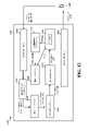
[0058] FIG. 5 shows an exemplary diagram for combining data symbols and PT-RSs associated with DFT-s-OFDM. Figure 5 shows the PT-RS sequences b1, b2, . . . indicate. At 502, the PT-RS sequences b1, b2, . . . are inserted with the data a1, a2, a3 and processed by the serial-to-
[0059]チャネル上で信号を受信する受信機は、518においてアナログデジタル変換(ADC)を適用し、520においてサイクリックプレフィックスを除去し、522においてシリアルパラレル変換を実行する。524において、N点高速フーリエ変換(FFT)プロセスが適用され、526において、サブキャリアのデマッピングまたは等化が適用される。528におけるM点逆離散フーリエ変換(IDFT)演算の後に、530において、パラレルシリアル変換が適用される。次いで、532において、受信データからPT-RSが抽出され得る。534において位相補正を計算して受信信号内の位相雑音を補償するために、抽出されたPT-RSが使用され得る。536において、算出された位相補正に基づいて受信データに位相補正が適用され得る。次いで、538において、受信データが復号され得る。 [0059] A receiver that receives a signal on a channel applies analog-to-digital conversion (ADC) at 518, removes the cyclic prefix at 520, and performs serial-to-parallel conversion at 522. At 524, an N-point Fast Fourier Transform (FFT) process is applied, and at 526 subcarrier demapping or equalization is applied. After an M-point Inverse Discrete Fourier Transform (IDFT) operation at 528 , a parallel-serial transform is applied at 530 . PT-RS can then be extracted from the received data at 532 . The extracted PT-RS can be used to compute a phase correction at 534 to compensate for phase noise in the received signal. At 536, a phase correction can be applied to the received data based on the calculated phase correction. The received data can then be decoded at 538 .
[0060]しかしながら、たとえば、506において、DFT処理より前にデータシンボルとともにPT-RSサンプルを挿入するときに、問題が発生し得る。DFT-s-OFDMでは、送信機において送信を処理するときのPT-RSサンプルのプレDFT挿入は、受信機におけるウィンドウ効果につながる可能性がある。受信機は、経時的に位相軌跡を推定するために、受信されたPT-RSサンプルの位相を使用し得る。受信機において、受信シンボルを決定するために、受信信号にIDFTプロセスが適用され得る。IDFTプロセスの出力シーケンスは巡回構造に従い得、巡回構造は、位相誤差の軌跡における最初のサンプルおよび最後のサンプルを同様の値に収束させる。図6は、軌跡の開始に近いサンプルおよび軌跡の終端に近いサンプルが同様の値に収束する、例示的な巡回構造600を示す。図6では、Y(1)はシンボルのためのプレDFTサンプルシーケンスのN個のサンプル内の第1のサンプル値を表し、Y(2)は第2のサンプル値を表し、Y(N)はシンボルのための最後のサンプル値を表し、Y(N-1)は最後のサンプル値の前のサンプル値を表す。サンプルの数Nは、受信機において適用されたN点IDFTの数Nに対応する。図6に示されたように、Y(N)の値は、この巡回構造においてY(1)の初期値の近くに収束する。受信機における強制収束は、PT-RSに基づいて推定された位相軌跡における誤差および不確実性につながる可能性がある。潜在的な誤差および不確実性は、本明細書ではウィンドウ効果と呼ばれ得る。
[0060] However, a problem may arise when inserting PT-RS samples with data symbols prior to DFT processing, eg, at 506 . In DFT-s-OFDM, pre-DFT insertion of PT-RS samples when processing the transmission at the transmitter can lead to window effects at the receiver. The receiver may use the phase of the received PT-RS samples to estimate the phase trajectory over time. At the receiver, an IDFT process may be applied to the received signal to determine received symbols. The output sequence of the IDFT process may follow a cyclic structure, which causes the first and last samples in the phase error trajectory to converge to similar values. FIG. 6 shows an exemplary
[0061]本出願は、PT-RSを受信しようと試みる受信機が遭遇するウィンドウ効果を低減または最小化するPT-RSパターンを介して、PT-RSの受信における誤差および不確実性の問題に対処する。たとえば、PT-RSは、受信機において遭遇し得るウィンドウ効果に基づく位置における送信機において挿入されるか、またはデータと結合され得る。たとえば、送信機は、ウィンドウ効果によって影響を受ける可能性が低い位置におけるデータ送信のためのプレDFTサンプルシーケンスにPT-RSサンプルを挿入し得る。PT-RSは、シンボルのためのプレDFTサンプルシーケンス内の先頭および/または終端のサンプルとは異なる位置におけるデータ送信に挿入され得る。シーケンスがシンボルのための時間領域内でサンプル1からサンプルNまで延在するN個のサンプルを含むシンボルのためのプレDFTサンプルシーケンスの場合、先頭のサンプルは、時間領域に従ってシーケンス内の最初のサンプル、たとえば、シンボルのためのシーケンス内のサンプル1を含んでよく、サンプル1に続く最初の数個のサンプル、たとえば、サンプル2、サンプル3などを含み得る。終端のサンプルは、時間領域に従ってシーケンス内の最後のサンプル、たとえば、サンプルNを含んでよく、シーケンス内のサンプルNの直前の数個のサンプル、たとえば、サンプルN-1、サンプルN-2などを含み得る。ウィンドウ効果による影響をそれほど受けないサンプル位置、たとえば、シンボルまたは間隔のためのプレDFTサンプルシーケンスの先頭および/または終端のサンプルとは異なるサンプル位置におけるデータ送信のためのシンボルのプレDFTシーケンスとPT-RSを結合することにより、受信し、受信信号からPT-RSを抽出しようと試みる受信機にとっての不確実性が低減され得る。
[0061] The present application addresses the problem of error and uncertainty in the reception of PT-RS through a PT-RS pattern that reduces or minimizes the window effect encountered by a receiver attempting to receive PT-RS. deal with. For example, the PT-RS can be inserted at the transmitter or combined with the data at locations based on window effects that may be encountered at the receiver. For example, the transmitter may insert PT-RS samples into the pre-DFT sample sequence for data transmission at locations less likely to be affected by window effects. The PT-RS may be inserted into the data transmission at positions different from the leading and/or trailing samples in the pre-DFT sample sequence for the symbol. For a pre-DFT sample sequence for a symbol where the sequence contains N samples extending from
[0062]したがって、PT-RSパターンは、PT-RSを受信する受信機において遭遇し得る潜在的なウィンドウ効果を低減し得る。たとえば、シンボルのための時間(プレDFT)サンプルシーケンス内の先頭および/または終端のサンプルにPT-RSを挿入するとき、PT-RSパターンは、受信機においてウィンドウ効果を受ける可能性がある領域を回避し得る。したがって、PT-RS挿入パターンは、潜在的なウィンドウ効果に遭遇し得るシンボルのためのサンプルのシーケンスの先頭および/または終端の領域を回避し得る。PT-RSパターンは、ウィンドウ効果を受ける可能性が低いサンプルの少なくとも1つの領域、たとえば、シンボルのためのプレDFTサンプルシーケンス内の先頭および/または終端のサンプルを含む領域以外の領域にPT-RSを挿入し得る。図7Aは、時間領域に従って、シンボルのためのN個のサンプルのプレDFTサンプルシーケンスの例700を示す。サンプルの数Nは、送信機において適用されるN点DFTのNに対応し、それは、受信機において適用されるN点IDFTのN、およびN長プレDFTサンプルシーケンスのサイズにも対応する。例702では、シンボルのための最初のサンプル~K番目のサンプルは、受信機においてウィンドウ効果によって影響を受ける可能性がある。プレDFTサンプルシーケンスの終端において、たとえば、シーケンス内のM番目のサンプル~最後のサンプルは、ウィンドウ効果によって影響を受ける可能性がある。影響を受けるサンプルは、受信機において適用されるIDFTの巡回構造に起因して、シンボル内のプレDFTシーケンスの先頭のサンプルおよび終端のサンプルに対応する。したがって、サンプルK701は、受信機においてウィンドウ効果を受ける可能性があると識別されたプレDFTサンプルシーケンス内の境界サンプルであってよく、K番目のサンプルに続くサンプルは、ウィンドウ効果を受けない可能性があるか、またはウィンドウ効果を受ける可能性が低い場合がある。同様に、サンプルM703は、受信機においてウィンドウ効果を受ける可能性があると識別された第2の境界サンプルであってよく、サンプルMより前のサンプルは、ウィンドウ効果を受けない可能性があるか、またはウィンドウ効果を受ける可能性が高い場合がある。図7Aでは、シンボルのためのサンプルのプレDFTシーケンスのためのN個のサンプルの2つの連続するサブセットが、受信機においてウィンドウ効果を受けていると識別され、第1のサブセットは1番目のサンプル~K番目のサンプルを備え、第2のサブセットはN-M番目のサンプル~M番目のサンプルを備える。K番目のサンプルとM番目のサンプルとの間の第3のサブセットは、受信機においてウィンドウ効果によって影響を受けていないか、または影響を受けている可能性が低いと識別される。
[0062] Thus, the PT-RS pattern may reduce potential window effects that may be encountered at a receiver receiving PT-RS. For example, when inserting the PT-RS at the leading and/or trailing samples in the temporal (pre-DFT) sample sequence for the symbol, the PT-RS pattern will cover areas that can experience windowing effects at the receiver. can be avoided. Thus, the PT-RS insertion pattern may avoid areas at the beginning and/or end of the sequence of samples for symbols that may encounter potential windowing effects. The PT-RS pattern includes PT-RS patterns in at least one region of samples that are unlikely to be subject to windowing effects, e.g., regions other than regions containing the leading and/or trailing samples in the pre-DFT sample sequence for the symbol. can be inserted. FIG. 7A shows an example 700 of a pre-DFT sample sequence of N samples for a symbol according to the time domain. The number of samples N corresponds to N of the N-point DFT applied at the transmitter, which also corresponds to N of the N-point IDFT applied at the receiver and the size of the N-length pre-DFT sample sequence. In example 702, the first through Kth samples for a symbol may be affected by window effects at the receiver. At the end of the pre-DFT sample sequence, for example, the Mth sample to the last sample in the sequence may be affected by window effects. The affected samples correspond to the leading and trailing samples of the pre-DFT sequence within the symbol due to the cyclic structure of the IDFT applied at the receiver. Therefore, sample K701 may be a boundary sample in the pre-DFT sample sequence that has been identified as potentially subject to windowing effects at the receiver, and samples following the Kth sample may not be subject to windowing effects. or less likely to be subject to window effects. Similarly,
[0063]送信機において、PT-RSは、ウィンドウ効果によって影響を受ける領域を回避する、たとえば、ウィンドウ効果を受けていると識別されたシンボルの先頭および終端におけるサンプルの2つのサブセットを回避するパターンに従って挿入され得る。したがって、PT-RSパターンは、たとえば、701と703との間のサンプルを備える、先頭および/または終端のサンプル以外のサンプルにPT-RSを挿入し得る。これにより、PT-RSパターンが、受信機側のウィンドウ効果を受けないサンプルのセット、たとえば、先頭および/または終端のサンプルとは異なるサンプルにPT-RS信号を挿入することが可能になる。したがって、PT-RSパターンは、受信機側のウィンドウ効果を受ける可能性があるサンプルのセットにPT-RS信号を加えることを回避し得る。 [0063] At the transmitter, PT-RS is a pattern that avoids regions affected by windowing effects, e.g., two subsets of samples at the beginning and end of symbols identified as being windowed. can be inserted according to Thus, a PT-RS pattern may insert PT-RS in samples other than the leading and/or trailing samples, comprising, for example, samples between 701 and 703 . This allows the PT-RS signal to be inserted in a set of samples where the PT-RS pattern is not subject to receiver-side windowing effects, eg samples different from the leading and/or trailing samples. Thus, the PT-RS pattern may avoid adding the PT-RS signal to the set of samples that may be subject to windowing effects on the receiver side.
[0064]影響を受けるサンプルは、チャネル遅延スプレッド推定値に基づいて識別され得る。たとえば、送信機は、チャネルの遅延スプレッドの推定値を識別し得る。推定値はサイクリックプレフィックス(CP)の長さであり得る。次いで、送信機は、チャネル遅延スプレッド推定値に基づいて、たとえば、シンボルの先頭および終端においてウィンドウ効果によって影響を受ける可能性がある、ある数のサンプルを識別し得る。識別されたサンプルは、シンボルの先頭にある第1の数のサンプルおよび/またはシンボルの終端における第2の数のサンプルを備え得る。たとえば、識別されたサンプルは、関数Q=S*J/Lに基づく数のサンプルを備え得る。Qはサンプルの数に対応し、Sはチャネル遅延スプレッド推定値に対応し、Jは高速フーリエ変換(FFT)サイズに対応し、Lは離散フーリエ変換スプレッド直交周波数分割多重化(DFT-s-OFDM)の離散フーリエ変換(DFT)サイズに対応する。したがって、PT-RSパターンは、たとえば、チャネル遅延スプレッド推定値、FFTサイズ、DFT-s-OFDMのDFTサイズの任意の組合せの関数に基づき得る。PT-RSパターンはS*J/Lに比例してよい。これは、PT-RSパターンが基づき得るあらかじめ定義された式の一例である。一例では、識別されたサンプルは、シンボルの先頭におけるQ個のサンプルと、シンボルの終端におけるQ個のサンプルとを含み得る。したがって、シンボルの先頭においてウィンドウ効果によって影響を受けると識別されたサンプルの数は、シンボルの終端においてウィンドウ効果によって影響を受けると識別されたサンプルの数と同じであり得る。別の例では、シンボルの先頭においてウィンドウ効果によって影響を受けると識別されたサンプルの数は、シンボルの終端においてウィンドウ効果によって影響を受けると識別されたサンプルの数とは異なっていてよい。 [0064] Affected samples may be identified based on the channel delay spread estimate. For example, the transmitter may identify an estimate of the channel's delay spread. The estimated value may be the length of the cyclic prefix (CP). The transmitter may then identify a certain number of samples that can be affected by window effects, eg, at the beginning and end of a symbol, based on the channel delay spread estimate. The identified samples may comprise a first number of samples at the beginning of the symbol and/or a second number of samples at the end of the symbol. For example, the identified samples may comprise a number of samples based on the function Q=S*J/L. Q corresponds to the number of samples, S corresponds to the channel delay spread estimate, J corresponds to the fast Fourier transform (FFT) size, L is the discrete Fourier transform spread orthogonal frequency division multiplexing (DFT-s-OFDM ) corresponds to the Discrete Fourier Transform (DFT) size. Thus, the PT-RS pattern may be based on a function of any combination of channel delay spread estimate, FFT size, DFT size for DFT-s-OFDM, for example. The PT-RS pattern may be proportional to S*J/L. This is an example of a predefined formula on which a PT-RS pattern can be based. In one example, the identified samples may include Q samples at the beginning of the symbol and Q samples at the end of the symbol. Thus, the number of samples identified as affected by the window effect at the beginning of the symbol may be the same as the number of samples identified as affected by the window effect at the end of the symbol. In another example, the number of samples identified as affected by the window effect at the beginning of the symbol may be different than the number of samples identified as affected by the window effect at the end of the symbol.
[0065]受信機において、ウィンドウ効果を最小化するためにIDFTの巡回構造を考慮に入れる位相軌跡を復元するために、アルゴリズムが適用され得る。たとえば、位相誤差の軌跡は、区分的な方式で推定され得る。位相軌跡の第1の推定または補間は、サンプルK+1~N-M-1、たとえば、受信機においてウィンドウ効果によって影響を受けていないと識別されたサンプルに対して行われてよい。したがって、位相軌跡の第2の推定または補間は、1番目のサンプル~K番目のサンプルおよびN-M番目のサンプル~M番目のサンプル、たとえば、受信機においてウィンドウ効果を受ける可能性があるサンプルの2つのサブセットに対して行われてよい。 [0065] At the receiver, an algorithm can be applied to recover the phase trajectory that takes into account the cyclic structure of the IDFT to minimize window effects. For example, the phase error trajectory can be estimated in a piecewise fashion. A first estimate or interpolation of the phase trajectory may be performed for samples K+1 to NM-1, eg, samples identified as unaffected by window effects at the receiver. Therefore, a second estimation or interpolation of the phase trajectory is performed for the 1 th sample to the K th sample and the NM th sample to the M th sample, e.g. It may be done for two subsets.
[0066]図7Bは、シンボルのためのシーケンスの先頭にあるサンプルのグループ706およびシンボルのためのシーケンスの終端にあるサンプルのグループ712が、ウィンドウ効果によって大いに影響を受けていると識別され得る、第2の例を示す。シンボルのためのシーケンスの先頭にあるサンプルの第2のグループ708およびシンボルのためのシーケンスの終端にあるサンプルの第2のグループ710は、ウィンドウ効果によって影響を受ける可能性があると識別され得る。PT-RSパターンは、ウィンドウ効果によって大いに影響を受けるサンプルのグループ706、712、および/またはウィンドウ効果によってそれほど影響を受けない可能性があるサンプルのグループ708、710にPT-RSを挿入することを回避するように選択され得る。PT-RSパターンは、ウィンドウ効果によって影響を受けていないと識別されたシンボルのサンプル712にPT-RSを挿入することができ、ウィンドウ効果によって影響を受けていないと識別されたシンボルのサンプル714へのPT-RS挿入を制限することさえできる。
[0066] FIG. 7B shows that the group of
[0067]図8は、送信機装置におけるワイヤレス通信の方法のフローチャート800である。方法は、UE(たとえば、104、350、装置902/902’)または(たとえば、ワイヤレスバックホールネットワーク内の)gNBなどの送信装置によって実行され得る。オプションの態様は破線で示されている。
[0067] Figure 8 is a
[0068]804において、装置は、複数のサンプルのシーケンスにPT-RSサンプルを挿入するための少なくとも1つの位置を決定し得る。複数のサンプルの第1のセットは、シーケンスの先頭にある第1の数のサンプルおよびシーケンスの終端にある第2の数のサンプルのうちの少なくとも1つを備えてよく、PT-RSサンプルのための少なくとも1つの位置は複数のサンプルの第2のセット内にあり得る。複数のサンプルの第1のセットは、たとえば、図7Aおよび図7Bに関して記載されたサンプルのシーケンスの先頭のサンプルおよび/または終端のサンプルなどの、受信機側のウィンドウ効果を受ける可能性があると識別され得る。たとえば、802において、装置は、場合によっては、受信機側のウィンドウ効果を受ける可能性がある送信のためのサンプルを識別し得る。複数のサンプルの第2のセットは、受信機側のウィンドウ効果を受けない可能性がある。たとえば、少なくとも1つの位置は、先頭および/または終端のサンプル以外のサンプルを備え得る。PT-RSサンプルの少なくとも1つの位置は、受信機側のウィンドウ効果を受ける可能性がある複数のサンプルの第1のセットにPT-RS信号を挿入することを回避することができ、PT-RSの挿入のための少なくとも1つの位置がある複数のサンプルの第2のセットは、受信機側のウィンドウ効果を受ける可能性が低いサンプルを備え得る。 [0068] At 804, the apparatus may determine at least one position for inserting a PT-RS sample into the sequence of samples. The first set of samples may comprise at least one of a first number of samples at the beginning of the sequence and a second number of samples at the end of the sequence; may be within the second set of samples. The first set of samples may be subject to receiver-side windowing effects, such as, for example, the leading and/or trailing samples of the sequence of samples described with respect to FIGS. 7A and 7B. can be identified. For example, at 802, the apparatus may, in some cases, identify samples for transmission that may be subject to receiver-side windowing effects. The second set of samples may not be subject to receiver-side windowing effects. For example, at least one position may comprise samples other than the leading and/or trailing samples. The at least one position of the PT-RS samples can avoid inserting the PT-RS signal into the first set of samples that may be subject to receiver-side windowing effects, and A second set of samples with at least one position for insertion of may comprise samples less likely to be subject to receiver-side windowing effects.
[0069]複数のサンプルは、DFT-s-OFDM送信のシンボルのサンプルを備え得る。受信機側のウィンドウ効果を受ける可能性がある複数のサンプルの第1のセットは、あらかじめ定義された式および/または受信されたシグナリングに基づいて識別され得る。同様に、PT-RSサンプルを挿入するための少なくとも1つの位置は、あらかじめ定義された式に基づいて決定され得る。たとえば、装置は、装置が受信機においてウィンドウ効果を受ける可能性があるそれ自体の送信内のサンプルを識別し得る、第2のワイヤレスデバイスからのシグナリングを受信し得る。サンプルは、サンプルのサイクリックシフト、または第2のワイヤレスデバイスがシンボルに対して実行するFFT演算ウィンドウ位置のうちのうちの少なくとも1つに基づいて識別され得る。たとえば、サンプルは、第2のワイヤレスデバイスがFFT演算に使用するシンボル内のサンプルのセットに基づいて識別され得る。第2のワイヤレスデバイスがFFT演算に使用するシンボル内のサンプルのセットは、あらかじめ定義された方法、送信内のサイクリックプレフィックスの長さ、および第2のデバイスからのインジケーションのうちの少なくとも1つに基づいて決定され得る。第2のワイヤレスデバイスがFFT演算に使用するサンプルのセットは、受信シンボル内のサンプルのサブセットのサイクリックシフトに対応してよい。したがって、受信機側のウィンドウ効果を受ける可能性があるサンプルの第1のセットは、第2のワイヤレスデバイスがFFT演算に使用するシンボル内のサンプルの第3のセットに基づいてよく、それらは、あらかじめ定義された方法、送信内のサイクリックプレフィックスの長さ、および第2のデバイスからのインジケーションのうちの少なくとも1つに基づき得る。サンプルの第1のセットは、シンボルの先頭にある第1の数のサンプル、たとえば、K個のサンプル、またはシンボルの終端にある第2の数のサンプル、たとえば、M個のサンプルのうちの少なくとも1つを備え得る。第2のワイヤレスデバイスがFFT演算に使用するサンプルの第3のセットは、シンボル内の複数のサンプルのサブセットのサイクリックシフトに対応してよい。シンボルのためのプレDFTサンプルシーケンスの先頭にあるサンプルは、シンボルのための図7Aおよび図7Bのサンプルシーケンスに関して示されたように、プレDFTシーケンス内の最初のサンプル/最初の数個のサンプルである。プレDFTシーケンスの最初の数個のサンプルは、本明細書ではシーケンスの「ヘッド」と呼ばれ得る。同様に、シンボルのためのプレDFTサンプルシーケンスの終端にあるM個のサンプルは、図7Aおよび図7Bに関して示されたように、シーケンスの終端にある最終/最後のサンプル、またはシーケンスの終端にある最後の数個のサンプルを含む、プレDFTサンプルシーケンス内の最後のサンプルに対応するサンプルである。プレDFTシーケンスの最後の数個のサンプルは、本明細書ではシーケンスの「テール」と呼ばれ得る。KおよびMは、送信を送信する装置のトーン間隔に基づき得る。図7Aおよび図7Bは、受信機側のウィンドウ効果を受ける可能性がある識別されたサンプルの例を示す。シンボルのためのプレDFTサンプルシーケンスの先頭にある第1の数のサンプルおよび/またはシンボルのためのプレDFTサンプルシーケンスの終端にある第2の数のサンプルは、あらかじめ定義された式に基づいて定義され得る。同様に、PT-RSパターンは、あらかじめ定義された式に基づいて決定され得る。 [0069] The plurality of samples may comprise samples of symbols of a DFT-s-OFDM transmission. A first set of samples that are likely to be subject to receiver-side windowing effects may be identified based on a predefined formula and/or received signaling. Similarly, at least one position for inserting PT-RS samples can be determined based on a predefined formula. For example, the apparatus may receive signaling from a second wireless device that may identify samples in its own transmission that the apparatus may experience windowing effects at the receiver. The samples may be identified based on at least one of a cyclic shift of the samples or an FFT operation window position that the second wireless device performs on the symbols. For example, the samples may be identified based on the set of samples in the symbol that the second wireless device uses for FFT operations. The set of samples in the symbol that the second wireless device uses for the FFT calculation is at least one of a predefined method, a cyclic prefix length in the transmission, and an indication from the second device. can be determined based on The set of samples that the second wireless device uses for FFT computation may correspond to a cyclic shift of a subset of the samples within the received symbol. Thus, the first set of samples that may be subject to receiver-side windowing effects may be based on the third set of samples in the symbol that the second wireless device uses for the FFT operation, which are: It may be based on at least one of a predefined method, the length of the cyclic prefix in the transmission, and an indication from the second device. The first set of samples is at least one of a first number of samples at the beginning of the symbol, e.g., K samples, or a second number of samples, e.g., M samples, at the end of the symbol. can have one. A third set of samples that the second wireless device uses for FFT computation may correspond to a cyclic shift of a subset of the plurality of samples within the symbol. The samples at the beginning of the pre-DFT sample sequence for the symbol are the first samples/first few samples in the pre-DFT sequence, as shown with respect to the sample sequences of FIGS. 7A and 7B for the symbol. be. The first few samples of the pre-DFT sequence may be referred to herein as the "head" of the sequence. Similarly, the M samples at the end of the pre-DFT sample sequence for a symbol are the last/last samples at the end of the sequence, or at the end of the sequence, as shown with respect to FIGS. The sample corresponding to the last sample in the pre-DFT sample sequence, including the last few samples. The last few samples of the pre-DFT sequence may be referred to herein as the "tail" of the sequence. K and M may be based on the tone spacing of the device sending the transmission. 7A and 7B show examples of identified samples that may be subject to receiver-side windowing effects. A first number of samples at the beginning of the pre-DFT sample sequence for the symbol and/or a second number of samples at the end of the pre-DFT sample sequence for the symbol are defined based on a predefined formula. can be Similarly, PT-RS patterns can be determined based on predefined formulas.
[0070]ウィンドウ効果を受ける可能性があるシーケンス内の複数のサンプルの第1のセットは、プレDFTサンプルシーケンスの先頭にある第1の数のサンプルおよびプレDFTサンプルシーケンスの終端にある第2の数のサンプルのうちの少なくとも1つを備え得る。一例では、第1の数のサンプルおよび/または第2の数のサンプルは、チャネル遅延スプレッド推定値に基づき得る。たとえば、801において、装置はチャネルの遅延スプレッドの推定値を識別し得る。チャネルの遅延スプレッドの推定値は、CPの長さを備え得る。第1の数のサンプルおよび第2の数のサンプルは、チャネルの遅延スプレッドの推定値、FFTサイズ、およびDFT-s-OFDMのDFTの任意の組合せに基づき得る。たとえば、サンプルの対応する数(Q)は、あらかじめ定義された式に基づいてよく、たとえば、QがS*J/Lに比例する関数に基づいてよく、ここで、Qはサンプルの数に対応し、Sはチャネルの推定された遅延スプレッドに対応し、JはFFTサイズに対応し、LはDFT-s-OFDMのDFTサイズに対応する。したがって、PT-RSパターンの数は、S、J、およびLの任意の組合せに基づき得る。プレDFTサンプルシーケンスの先頭にある第1の数のサンプルおよびプレDFTサンプルシーケンスの終端にある第2の数のサンプルは、同じであり得る。別の例では、第1の数のサンプルおよび第2の数のサンプルは、異なっていてよい。 [0070] The first set of samples in the sequence that may be subject to the window effect is a first number of samples at the beginning of the pre-DFT sample sequence and a second number at the end of the pre-DFT sample sequence. At least one of the number of samples may be provided. In one example, the first number of samples and/or the second number of samples may be based on a channel delay spread estimate. For example, at 801, an apparatus may identify an estimate of the channel's delay spread. The channel delay spread estimate may comprise the length of the CP. The first number of samples and the second number of samples may be based on any combination of channel delay spread estimate, FFT size, and DFT-s-OFDM DFT. For example, the corresponding number of samples (Q) may be based on a predefined formula, such as a function in which Q is proportional to S*J/L, where Q corresponds to the number of samples. where S corresponds to the estimated delay spread of the channel, J corresponds to the FFT size, and L corresponds to the DFT size of DFT-s-OFDM. Therefore, the number of PT-RS patterns can be based on any combination of S, J, and L. The first number of samples at the beginning of the pre-DFT sample sequence and the second number of samples at the end of the pre-DFT sample sequence may be the same. In another example, the first number of samples and the second number of samples may be different.
[0071]806において、装置は、決定された少なくとも1つの位置に基づいて、シーケンスにPT-RSサンプルを挿入し得る。図5の502に示されたように、PT-RS信号b1、b2、...は、804からの決定された位置に従って、データa1、a2、a3、...とともに挿入され得る。 [0071] At 806, the device may insert PT-RS samples into the sequence based on the determined at least one position. PT-RS signals b1, b2, . . . , according to the determined positions from 804, the data a1, a2, a3, . . . can be inserted with
[0072]810において、装置は、挿入されたPT-RSサンプル、たとえば、サンプルのシーケンスに挿入されたPT-RSサンプルに基づいて、信号を送信し得る。 [0072] At 810, the device may transmit a signal based on the inserted PT-RS samples, eg, the PT-RS samples inserted into the sequence of samples.
[0073]送信は、図5に関して記載されたように、送信用に処理されたDFT-s-OFDM送信を備え得る。したがって、装置は、808において、プレDFTサンプルシーケンスの複数のサンプルにPT-RSサンプルを挿入した後に、複数のサンプルに対してDFTを実行し得る。図5は、502におけるPT-RS挿入の後に、506において実行されるDFTを示す。 [0073] The transmission may comprise a DFT-s-OFDM transmission processed for transmission as described with respect to FIG. Accordingly, at 808, the apparatus may perform DFT on the multiple samples after inserting the PT-RS samples into the multiple samples of the pre-DFT sample sequence. FIG. 5 shows DFT performed at 506 after PT-RS insertion at 502 .
[0074]図7Aおよび図7Bに示されたように、サンプルの第1のセットは、シンボルのためのプレDFTサンプルシーケンスの先頭にある第1の境界サンプル、たとえば、K番目のサンプル、および/またはシンボルのためのプレDFTサンプルシーケンスの終端にある第2の境界サンプル、たとえば、M番目のサンプルのうちの少なくとも1つを備え得る。図7Aに示されたように、シンボルのためのプレDFTサンプルシーケンスの先頭から第1の境界サンプルであるK番目のサンプルまで延在するサンプルの第3のセットは、受信機側のウィンドウ効果によって影響を受ける可能性があり得る。サンプルの第3のセットは図7Aのサンプル1~サンプルKに対応する。同様に、第2の境界サンプルであるM番目のサンプルからシンボルのためのプレDFTサンプルシーケンスの終端まで延在するサンプルの第4のセットは、受信機側のウィンドウ効果によって影響を受ける可能性があり得る。サンプルの第4のセットはサンプルM~サンプルNに対応し、ここで、NはN個のサンプルのセット内の最後のサンプルである。少なくとも1つの位置は、第1の境界サンプル、第2の境界サンプル、サンプルの第3のセット、またはサンプルの第4のセットのうちの少なくとも1つを含まないように、たとえば、サンプル1~KとサンプルM~Nとを回避して決定され得る。位置は、第1の境界サンプルと第2の境界サンプルとの間の、たとえば、サンプルK+1~K+kおよびN-M-m~N-M-1の間隔内の少なくとも1つのサンプルを含んでよく、ここで、kおよびmはゼロより大きい整数であり、(k+m)は送信において使用されるPT-RSサンプルの数である。したがって、PT-RSサンプルの少なくとも一部は、受信機におけるウィンドウ効果を受ける可能性がない位置にあるプレDFTサンプルシーケンスのサンプルの間隔内に挿入され得る。
[0074] As shown in FIGS. 7A and 7B, the first set of samples is the first boundary sample at the beginning of the pre-DFT sample sequence for the symbol, eg, the Kth sample, and/or or at least one of the second boundary samples, eg, the Mth sample, at the end of the pre-DFT sample sequence for the symbol. As shown in FIG. 7A, the third set of samples extending from the beginning of the pre-DFT sample sequence for a symbol to the Kth sample, which is the first boundary sample, is reduced due to window effects on the receiver side. may be affected. A third set of samples corresponds to
[0075]図9は、例示的な装置902内の様々な手段/コンポーネント間のデータフローを示す概念的なデータフロー図900である。装置は、UE(たとえば、UE104、350、1250)などの送信装置であり得る。装置は、基地局950からのダウンリンク通信などのワイヤレス通信および/または他のワイヤレスデバイスからのワイヤレスシグナリングを受信する受信コンポーネント904を含む。装置は、受信デバイスにワイヤレス送信を送信するように構成された送信コンポーネント906を含む。送信は、図5に関して記載されたようなDFT-s-OFDM送信を備え得る。装置は、図8の804ならびに図7Aおよび図7Bに関して記載されたように、複数のサンプルのシーケンスにPT-RSサンプルを挿入するための少なくとも1つの位置を決定するように構成されたPT-RSコンポーネント910を含んでよく、複数のサンプルの第1のセットは、シーケンスの先頭にある第1の数のサンプルおよびシーケンスの終端にある第2の数のサンプルのうちの少なくとも1つを備え、PT-RSサンプルのための少なくとも1つの位置は複数のサンプルの第2のセット内にある。装置は、図8の801ならびに図7Aおよび図7Bに関して記載されたように、受信機側のウィンドウ効果を受ける可能性がある送信のためのサンプルを識別するように構成された識別コンポーネント908を含み得る。位置は、あらかじめ定義された式および/または別のワイヤレスデバイスからの受信シグナリングに基づき得る。位置は、チャネル遅延スプレッド推定値に基づき得る。たとえば、装置は、チャネルの遅延スプレッドの推定値を識別するように構成された遅延スプレッドコンポーネント918を含み得る。サンプルの第1のセットは、シンボルのためのプレDFTサンプルシーケンスの先頭にある第1の数のサンプル、および/またはシンボルのためのプレDFTサンプルシーケンスの終端にある第2の数のサンプルを備え得る。第1の数のサンプルおよび第2の数のサンプルは、たとえば、図7Aおよび図7Bに関して記載されたように、チャネルの遅延スプレッドの推定値に基づき得る。
[0075] FIG. 9 is a conceptual data flow diagram 900 showing data flow between various means/components within an
[0076]決定された位置は、たとえば、決定された位置に基づいてデータコンポーネント912からのデータサンプルを有するサンプルシーケンスにPT-RSサンプルを挿入する結合コンポーネント914に提供され得る。装置は、たとえば、図8の808および図5に関して記載されたように、複数のサンプルにPT-RSサンプルを挿入した後に、サンプルに対してDFTを実行するように構成されたDFTコンポーネント916を含み得る。送信コンポーネント906は、挿入されたPT-RSサンプルに基づいて信号を送信するように構成され得る。
[0076] The determined positions may be provided, for example, to a combining
[0077]装置は、図8のフローチャート内のアルゴリズムのブロックの各々を実行する追加のコンポーネントを含み得る。そのため、図8のフローチャート内の各ブロックは1つのコンポーネントによって実行されてよく、装置はそれらのコンポーネントのうちの1つまたは複数を含み得る。コンポーネントは、述べられたプロセス/アルゴリズムを実行するように具体的に構成された1つもしくは複数のハードウェアコンポーネントであるか、述べられたプロセス/アルゴリズムを実行するように構成されたプロセッサによって実装されるか、プロセッサによる実装のためにコンピュータ可読媒体内に記憶されるか、またはそれらの何らかの組合せであり得る。 [0077] The apparatus may include additional components that implement each of the blocks of the algorithm in the flowchart of FIG. As such, each block in the flowchart of FIG. 8 may be performed by one component, and an apparatus may include one or more of those components. A component is one or more hardware components specifically configured to perform the stated process/algorithm or implemented by a processor configured to perform the stated process/algorithm. or stored in a computer readable medium for implementation by a processor, or some combination thereof.
[0078]図10は、処理システム1014を採用する装置902’のためのハードウェア実装形態の一例を示す図1000である。処理システム1014は、バス1024によって全体的に表される、バスアーキテクチャを用いて実装され得る。バス1024は、処理システム1014の特定の用途および全体的な設計制約に応じて、任意の数の相互接続するバスとブリッジとを含み得る。バス1024は、プロセッサ1004によって表される1つまたは複数のプロセッサおよび/またはハードウェアコンポーネントと、コンポーネント904、906、908、910、912、914、916、918と、コンピュータ可読媒体/メモリ1006とを含む様々な回路を互いにリンクする。バス1024はまた、タイミングソース、周辺機器、電圧調整器、および電力管理回路などの様々な他の回路をリンクし得るが、それらは当技術分野においてよく知られており、したがって、これ以上記載されない。
[0078] FIG. 10 is a diagram 1000 illustrating an example hardware implementation for an apparatus 902' employing a
[0079]処理システム1014は、トランシーバ1010に結合され得る。トランシーバ1010は、1つまたは複数のアンテナ1020に結合される。トランシーバ1010は、送信媒体を介して様々な他の装置と通信するための手段を提供する。トランシーバ1010は、1つまたは複数のアンテナ1020から信号を受信し、受信された信号から情報を抽出し、抽出された情報を処理システム1014、具体的には受信コンポーネント904に提供する。加えて、トランシーバ1010は、処理システム1014、具体的には送信コンポーネント906から情報を受信し、受信された情報に基づいて、1つまたは複数のアンテナ1020に印加されるべき信号を生成する。処理システム1014は、コンピュータ可読媒体/メモリ1006に結合されたプロセッサ1004を含む。プロセッサ1004は、コンピュータ可読媒体/メモリ1006に記憶されたソフトウェアの実行を含む一般的な処理を担う。ソフトウェアは、プロセッサ1004によって実行されると、任意の特定の装置のための上記に記載された様々な機能を処理システム1014に実行させる。コンピュータ可読媒体/メモリ1006はまた、ソフトウェアを実行するときにプロセッサ1004によって操作されるデータを記憶するために使用され得る。処理システム1014は、コンポーネント904、906、908、910、912、914、916、918のうちの少なくとも1つをさらに含む。それらのコンポーネントは、プロセッサ1004において実行され、コンピュータ可読媒体/メモリ1006内に存在する/記憶されたソフトウェアコンポーネント、プロセッサ1004に結合された1つもしくは複数のハードウェアコンポーネント、またはそれらの何らかの組合せであり得る。処理システム1014は、UE350のコンポーネントであってよく、メモリ360、ならびに/またはTXプロセッサ368、RXプロセッサ356、およびコントローラ/プロセッサ359のうちの少なくとも1つを含み得る。
A
[0080]1つの構成では、ワイヤレス通信のための装置902/902’は、受信機側のウィンドウ効果を受ける可能性があるプレDFTサンプルシーケンスのサンプルを識別するための手段、チャネルの遅延スプレッドの推定値を識別するための手段、複数のサンプルのシーケンスにPT-RSサンプルを挿入するための少なくとも1つの位置を決定するための手段、ここにおいて、複数のサンプルの第1のセットが、シーケンスの先頭にある第1の数のサンプルおよびシーケンスの終端にある第2の数のサンプルのうちの少なくとも1つを備え、ここにおいて、PT-RSサンプルのための少なくとも1つの位置が複数のサンプルの第2のセット内にある、決定された少なくとも1つの位置に基づいてシーケンスにPT-RSサンプルを挿入するための手段、挿入されたPT-RSサンプルに基づいて信号を送信するための手段、ならびに複数のサンプルにPT-RSサンプルを挿入した後にサンプルに対してDFTを実行するための手段のうちのいずれかを含む。前述の手段は、前述の手段によって列挙された機能を実行するように構成された、装置902、および/または装置902’の処理システム1014の前述のコンポーネントのうちの1つまたは複数であり得る。上記に記載されたように、処理システム1014は、TXプロセッサ368と、RXプロセッサ356と、コントローラ/プロセッサ359とを含み得る。そのため、1つの構成では、前述の手段は、前述の手段によって列挙された機能を実行するように構成されたTXプロセッサ368、RXプロセッサ356、およびコントローラ/プロセッサ359であり得る。
[0080] In one configuration, an
[0081]図11は、ワイヤレス通信の方法のフローチャート1100である。方法は、基地局(たとえば、基地局102、180、310、950、装置1202/1202’)などの受信デバイスによって実行され得る。受信デバイスは、図5に関して記載されたように、DFT-s-OFDM送信を受信することができ、送信を処理し得る。オプションの態様は破線で示されている。
[0081] Figure 11 is a
[0082]1104において、装置は、複数のサンプルのシーケンスを備える受信された送信内のPT-RSサンプルのための少なくとも1つの位置を決定し、複数のサンプルの第1のセットは、シーケンスの先頭にある第1の数のサンプルおよびシーケンスの終端にある第2の数のサンプルのうちの少なくとも1つを備え、PT-RSサンプルのための少なくとも1つの位置は複数のサンプルの第2のセット内にある。複数のサンプルの第1のセットは、ウィンドウ効果に起因して位相誤差を受ける可能性があり得る。サンプルの第2のセットは、ウィンドウ効果を受ける可能性があるサンプルを回避し得る。したがって、決定された位置は、K+1番目のサンプルからM-1番目のサンプルまで延在するサンプルのセットに限定され得る。したがって、サンプルの第2のセットは、受信機側のウィンドウ効果を受けないサンプルを備え得る。 [0082] At 1104, the apparatus determines at least one position for a PT-RS sample within a received transmission comprising a sequence of samples, the first set of samples being the beginning of the sequence. and at least one of a first number of samples at the end of the sequence and a second number of samples at the end of the sequence, wherein the at least one position for the PT-RS samples is within the second set of samples It is in. The first set of samples may be subject to phase error due to windowing effects. A second set of samples may avoid samples that may be subject to windowing effects. Thus, the determined positions can be limited to the set of samples extending from the K+1th sample to the M-1th sample. Thus, the second set of samples may comprise samples that are not subject to receiver-side windowing effects.
[0083]1102において、装置は、ウィンドウ効果に起因して位相誤差を受ける可能性がある受信された送信内のサンプルを識別し得る。 [0083] At 1102, the apparatus may identify samples in the received transmission that may be subject to phase error due to windowing effects.
[0084]サンプルの第1のセットは、たとえば、図7Aおよび図7Bに関して記載されたように、シンボルのためのプレDFTサンプルシーケンスの先頭にある第1の数Kのサンプル、およびシンボルのためのプレDFTサンプルシーケンスの終端にある第2の数Mのサンプルのうちの少なくとも1つを備え得る。シンボルのためのプレDFTサンプルシーケンスの先頭にある第1の数KのサンプルおよびシンボルのためのプレDFTサンプルシーケンスの終端にある第2の数Mのサンプルは、受信された送信を送信するユーザ機器のトーン間隔に基づき得る。シンボルのためのプレDFTサンプルシーケンスの先頭にある第1の数KのサンプルおよびシンボルのためのプレDFTサンプルシーケンスの終端にある第2の数Mのサンプルは、受信された送信においてユーザ機器によって使用されるスケジュールされた帯域幅またはDFTサイズと無関係であり得る。シーケンスの先頭にある第1の数のサンプルおよびシーケンスの終端にある第2の数のサンプルは、あらかじめ定義された式に基づいて識別され得る。同様に、PT-RSサンプルのための少なくとも1つの位置は、あらかじめ定義された式に基づいて決定され得る。位置は、サンプルのサイクリックシフト、または第2のワイヤレスデバイスがシンボルに対して実行する高速フーリエ変換演算ウィンドウ位置のうちの少なくとも1つに基づいて識別され得る。たとえば、位置は、第2のワイヤレスデバイスがFFT演算に使用するシンボルのためのプレDFTサンプルシーケンス内のサンプルのセット、たとえば、サンプルの第3のセットに基づいて識別され得る。第2のワイヤレスデバイスがFFT演算に使用するシンボル内のサンプルの第3のセットは、あらかじめ定義された方法、送信内のサイクリックプレフィックスの長さ、および第2のデバイスからのインジケーションのうちの少なくとも1つに基づき得る。第2のワイヤレスデバイスがFFT演算に使用するサンプルの第3のセットは、シンボル内の複数のサンプルのサブセットのサイクリックシフトに対応してよい。 [0084] The first set of samples is the first number K of samples at the beginning of the pre-DFT sample sequence for the symbol and the At least one of the second number M of samples at the end of the pre-DFT sample sequence may be provided. The first number K samples at the beginning of the pre-DFT sample sequence for the symbol and the second number M samples at the end of the pre-DFT sample sequence for the symbol are the user equipment transmitting the received transmission. can be based on the tone spacing of A first number K samples at the beginning of the pre-DFT sample sequence for the symbol and a second number M samples at the end of the pre-DFT sample sequence for the symbol are used by the user equipment in the received transmission. be independent of scheduled bandwidth or DFT size. A first number of samples at the beginning of the sequence and a second number of samples at the end of the sequence may be identified based on predefined formulas. Similarly, at least one position for the PT-RS samples can be determined based on a predefined formula. The positions may be identified based on at least one of a cyclic shift of the samples or a fast Fourier transform computation window position that the second wireless device performs on the symbols. For example, the position may be identified based on a set of samples, eg, a third set of samples, in the pre-DFT sample sequence for the symbols that the second wireless device uses for FFT computation. The third set of samples in the symbol that the second wireless device uses for the FFT operation is determined according to the predefined method, the length of the cyclic prefix in the transmission, and the indication from the second device. It can be based on at least one. A third set of samples that the second wireless device uses for FFT computation may correspond to a cyclic shift of a subset of the plurality of samples within the symbol.
[0085]一例では、識別されたサンプルはチャネル遅延スプレッド推定値に基づき得る。たとえば、1101において、装置はチャネルの遅延スプレッドの推定値を識別し得る。チャネルの遅延スプレッドの推定値はCPの長さであり得る。位置は、受信デバイスが高速フーリエ変換演算に使用するシンボル内のサンプルのセットに基づき得る。識別されたサンプルは、シンボルのためのプレDFTサンプルシーケンスの先頭にある第1の数のサンプルおよびシンボルのためのプレDFTサンプルシーケンスの終端にある第2の数のサンプルを備えてよく、第1の数のサンプルおよび第2の数のサンプルは、チャネルの遅延スプレッドの推定値に基づく。サンプルの対応する数(Q)は、QがS*J/Lに比例する関数に基づいてよく、ここで、Qはサンプルの数に対応し、Sはチャネルの推定された遅延スプレッドに対応し、JはFFTサイズに対応し、LはDFT-s-OFDMのDFTサイズに対応する。したがって、第1および/または第2の数のサンプルは、結果として位置は、S、J、およびLの任意の組合せに基づき得る。一例では、第1の数のサンプルは、第2の数のサンプルと同じ数であり得る。別の例では、第1の数のサンプルは、第2の数のサンプルとは異なる数を備え得る。 [0085] In one example, the identified samples may be based on channel delay spread estimates. For example, at 1101, the device may identify an estimate of the channel's delay spread. An estimate of the channel delay spread may be the length of the CP. The position may be based on the set of samples within the symbol that the receiving device uses for fast Fourier transform operations. The identified samples may comprise a first number of samples at the beginning of the pre-DFT sample sequence for the symbol and a second number of samples at the end of the pre-DFT sample sequence for the symbol; The number of samples and the second number of samples are based on an estimate of the delay spread of the channel. The corresponding number of samples (Q) may be based on a function where Q is proportional to S*J/L, where Q corresponds to the number of samples and S corresponds to the estimated delay spread of the channel. , J corresponds to the FFT size and L corresponds to the DFT size of DFT-s-OFDM. Accordingly, the first and/or second number of samples, resulting positions may be based on any combination of S, J, and L. In one example, the first number of samples may be the same number as the second number of samples. In another example, the first number of samples may comprise a different number than the second number of samples.
[0086]一例では、シンボルの先頭にある第1の数のサンプルおよびシンボルの終端にある第2の数のサンプルは、スケジュールされた帯域幅または受信された送信内でユーザ機器によって使用される離散フーリエ変換サイズと無関係に識別され得る。シンボルの先頭にある第1の数のサンプルおよびシンボルの終端にある第2の数のサンプルは、受信された送信を送信するユーザ機器の間隔に基づいて識別され得る。 [0086] In one example, the first number of samples at the beginning of the symbol and the second number of samples at the end of the symbol are discrete values used by the user equipment within the scheduled bandwidth or received transmission. It can be identified independently of Fourier transform size. A first number of samples at the beginning of the symbol and a second number of samples at the end of the symbol may be identified based on the spacing of the user equipments transmitting the received transmissions.
[0087]複数のサンプルの第1のセットは、シンボルのためのプレDFTサンプルシーケンスの先頭にある第1の境界サンプルおよびシンボルのためのプレDFTサンプルシーケンスの終端にある第2の境界サンプルのうちの少なくとも1つを含んでよく、シンボルのためのプレDFTサンプルシーケンスの先頭から第1の境界サンプルまで延在するサンプルの第3のセットは、受信機側のウィンドウ効果によって影響を受ける可能性があり、または第2の境界サンプルからシンボルのためのプレDFTサンプルシーケンスの終端まで延在するサンプルの第4のセットは、受信機側のウィンドウ効果によって影響を受ける可能性がある。1104において決定された少なくとも1つの位置は、第1の境界サンプル、第2の境界サンプル、サンプルの第3のセット、またはサンプルの第4のセットのうちの少なくとも1つを含まない可能性がある。 [0087] The first set of samples includes a first boundary sample at the beginning of the pre-DFT sample sequence for the symbol and a second boundary sample at the end of the pre-DFT sample sequence for the symbol. and a third set of samples extending from the beginning of the pre-DFT sample sequence for the symbol to the first boundary sample can be affected by receiver-side windowing effects. A fourth set of samples extending from the second boundary sample to the end of the pre-DFT sample sequence for the symbol may be affected by windowing effects on the receiver side. The at least one location determined at 1104 may not include at least one of the first boundary sample, the second boundary sample, the third set of samples, or the fourth set of samples. .
[0088]1106において、装置は、図5および図6に関して記載されたように、PT-RS信号を抽出する前に受信された送信に対してIDFTを実行することができ、IDFTは出力サンプルに巡回構造を課す。 [0088] At 1106, the apparatus may perform an IDFT on the received transmission prior to extracting the PT-RS signal, as described with respect to FIGS. impose a circular structure;
[0089]1108において、装置は、たとえば、図5の532に示されたように、識別されたPT-RSパターンに基づいて、受信された送信からPT-RS信号を抽出する。 [0089] At 1108, the device extracts a PT-RS signal from the received transmission based on the identified PT-RS pattern, eg, as shown at 532 in FIG.
[0090]1110において、装置は、抽出されたPT-RS信号に基づいて、受信された送信内のデータサンプルについて位相誤差を推定する。データサンプルについての位相誤差は、位相誤差シーケンスの巡回構造に基づいて推定され得る。位相誤差の推定は、サンプルの第1のセットについての第1の推定とサンプルの第2のセットについての第2の推定とを備えてよく、サンプルの第1のセットはウィンドウ効果を備えるように識別され、サンプルの第2のセットはウィンドウ効果がないと識別される。したがって、位相誤差の推定は、ウィンドウ効果を受けると識別された領域およびウィンドウ効果がない領域について、区分的な方式で実行され得る。 [0090] At 1110, the apparatus estimates the phase error for the data samples in the received transmission based on the extracted PT-RS signal. A phase error for the data samples may be estimated based on the cyclic structure of the phase error sequence. Estimating the phase error may comprise a first estimate for a first set of samples and a second estimate for a second set of samples, such that the first set of samples comprises a window effect. identified and the second set of samples is identified as free of window effects. Accordingly, phase error estimation may be performed in a piecewise fashion for regions identified as subject to windowing and regions without windowing.
[0091]1112において、装置は、図5に関して記載されたように、推定された位相誤差に基づいて受信されたデータサンプルの位相を補正する。 [0091] At 1112, the apparatus corrects the phase of the received data samples based on the estimated phase error, as described with respect to FIG.
[0092]図12は、例示的な装置1202内の様々な手段/コンポーネント間のデータフローを示す概念的なデータフロー図1200である。装置は、基地局(たとえば、基地局102、180、310、950)などの受信装置であり得る。装置は、たとえば、ユーザ機器1250などの送信デバイスからワイヤレス送信を受信する受信コンポーネント1204を含む。装置は、たとえば、ユーザ機器1250にワイヤレス通信を送信するように構成された送信デバイス1206を含む。
[0092] FIG. 12 is a conceptual data flow diagram 1200 showing data flow between various means/components within an
[0093]装置は、受信された送信内のサンプルを識別するように構成された識別コンポーネント1208を含んでよく、サンプルは、図7Aおよび図7Bに関して記載されたように、ウィンドウ効果に起因して位相誤差を受ける。識別は、チャネル遅延スプレッド推定値に基づき得る。たとえば、装置は、チャネルの遅延スプレッドの推定値を識別するように構成された遅延スプレッドコンポーネント1220を含み得る。識別されたサンプルは、たとえば、図7Aおよび図7Bに関して記載されたように、シンボルのためのプレDFTサンプルシーケンスの先頭にある第1の数のサンプルおよびシンボルのためのプレDFTサンプルシーケンスの終端にある第2の数のサンプルを備えてよく、第1の数のサンプルおよび第2の数のサンプルは、チャネルの遅延スプレッドの推定値に基づく。
[0093] The apparatus may include an
[0094]装置は、複数のサンプルのシーケンスを備える受信された送信内のPT-RSサンプルのための少なくとも1つの位置を決定するように構成されたPT-RSコンポーネント1210を含んでよく、複数のサンプルの第1のセットは、シーケンスの先頭にある第1の数のサンプルおよびシーケンスの終端にある第2の数のサンプルのうちの少なくとも1つを備え、PT-RSサンプルのための少なくとも1つの位置は複数のサンプルの第2のセット内にある。装置は、PT-RSサンプルを抽出する前に受信された送信に対してIDFTを実行するように構成されたIDFTコンポーネント1212を含んでよく、IDFTは出力サンプルに巡回構造を課す。装置は、決定された位置に基づいて受信された送信からPT-RSサンプルを抽出するように構成されたPT-RS抽出コンポーネント1214を含み得る。装置は、抽出されたPT-RSサンプルに基づいて受信された送信内のデータサンプルについての位相誤差を推定するように構成された位相誤差推定コンポーネント1216を備え得る。装置は、推定された位相誤差に基づいて受信されたデータサンプルの位相を補正するように構成された補正コンポーネント1218を含み得る。
[0094] The apparatus may include a PT-
[0095]装置は、図11の前述のフローチャート内のアルゴリズムのブロックの各々を実行する追加のコンポーネントを含み得る。そのため、図11の前述のフローチャート内の各ブロックは1つのコンポーネントによって実行されてよく、装置はそれらのコンポーネントのうちの1つまたは複数を含み得る。コンポーネントは、述べられたプロセス/アルゴリズムを実行するように具体的に構成された1つもしくは複数のハードウェアコンポーネントであるか、述べられたプロセス/アルゴリズムを実行するように構成されたプロセッサによって実装されるか、プロセッサによる実装のためにコンピュータ可読媒体内に記憶されるか、またはそれらの何らかの組合せであり得る。 [0095] The apparatus may include additional components that perform each of the blocks of the algorithms in the foregoing flowchart of FIG. As such, each block in the foregoing flowchart of FIG. 11 may be performed by one component, and an apparatus may include one or more of those components. A component is one or more hardware components specifically configured to perform the stated process/algorithm or implemented by a processor configured to perform the stated process/algorithm. or stored in a computer readable medium for implementation by a processor, or some combination thereof.
[0096]図13は、処理システム1314を採用する装置1202’のためのハードウェア実装形態の一例を示す図1300である。処理システム1314は、バス1324によって全体的に表される、バスアーキテクチャを用いて実装され得る。バス1324は、処理システム1314の特定の用途および全体的な設計制約に応じて、任意の数の相互接続するバスとブリッジとを含み得る。バス1324は、プロセッサ1304によって表される1つまたは複数のプロセッサおよび/またはハードウェアコンポーネントと、コンポーネント1204、1206、1208、1210、1212、1214、1216、1218、1220と、コンピュータ可読媒体/メモリ1306とを含む様々な回路を互いにリンクする。バス1324はまた、タイミングソース、周辺機器、電圧調整器、および電力管理回路などの様々な他の回路をリンクし得るが、それらは当技術分野においてよく知られており、したがって、これ以上記載されない。
[0096] FIG. 13 is a diagram 1300 illustrating an example hardware implementation for an apparatus 1202' employing a
[0097]処理システム1314は、トランシーバ1310に結合され得る。トランシーバ1310は、1つまたは複数のアンテナ1320に結合される。トランシーバ1310は、送信媒体を介して様々な他の装置と通信するための手段を提供する。トランシーバ1310は、1つまたは複数のアンテナ1320から信号を受信し、受信された信号から情報を抽出し、抽出された情報を処理システム1314、具体的には受信コンポーネント1204に提供する。加えて、トランシーバ1310は、処理システム1314、具体的には送信コンポーネント1206から情報を受信し、受信された情報に基づいて、1つまたは複数のアンテナ1320に印加されるべき信号を生成する。処理システム1314は、コンピュータ可読媒体/メモリ1306に結合されたプロセッサ1304を含む。プロセッサ1304は、コンピュータ可読媒体/メモリ1306に記憶されたソフトウェアの実行を含む一般的な処理を担う。ソフトウェアは、プロセッサ1304によって実行されると、任意の特定の装置のための上記に記載された様々な機能を処理システム1314に実行させる。コンピュータ可読媒体/メモリ1306はまた、ソフトウェアを実行するときにプロセッサ1304によって操作されるデータを記憶するために使用され得る。処理システム1314は、コンポーネント1204、1206、1208、1210、1212、1214、1216、1218、1220のうちの少なくとも1つをさらに含む。それらのコンポーネントは、プロセッサ1304において実行され、コンピュータ可読媒体/メモリ1306内に存在する/記憶されたソフトウェアコンポーネント、プロセッサ1304に結合された1つもしくは複数のハードウェアコンポーネント、またはそれらの何らかの組合せであり得る。処理システム1314は、基地局310のコンポーネントであってよく、メモリ376、ならびに/またはTXプロセッサ316、RXプロセッサ370、およびコントローラ/プロセッサ375のうちの少なくとも1つを含み得る。
A
[0098]1つの構成では、ワイヤレス通信のための装置1202/1202’は、ウィンドウ効果に起因して位相誤差を受ける可能性がある受信された送信内のサンプルを識別するための手段、複数のサンプルのシーケンスを備える受信された送信内のPT-RSサンプルのための少なくとも1つの位置を決定するための手段、ここにおいて、複数のサンプルの第1のセットが、シーケンスの先頭にある第1の数のサンプルおよびシーケンスの終端にある第2の数のサンプルのうちの少なくとも1つを備え、ここにおいて、PT-RSサンプルのための少なくとも1つの位置が複数のサンプルの第2のセット内にある、決定された少なくとも1つの位置に基づいて受信された送信からPT-RSサンプルを抽出するための手段、チャネルの遅延スプレッドの推定値を識別するための手段、抽出されたPT-RSサンプルに基づいて受信された送信内のデータサンプルについての位相誤差を推定するための手段、PT-RSサンプルを抽出する前に受信された送信に対してIDFTを実行するための手段、ここにおいて、IDFTが出力サンプルに巡回構造を課す、ならびに推定された位相誤差に基づいて受信されたデータサンプルの位相を補正するための手段を含む。前述の手段は、前述の手段によって列挙された機能を実行するように構成された、装置1202、および/または装置1202’の処理システム1314の前述のコンポーネントのうちの1つまたは複数であり得る。上記に記載されたように、処理システム1314は、TXプロセッサ316と、RXプロセッサ370と、コントローラ/プロセッサ375とを含み得る。そのため、1つの構成では、前述の手段は、前述の手段によって列挙された機能を実行するように構成されたTXプロセッサ316、RXプロセッサ370、およびコントローラ/プロセッサ375であり得る。
[0098] In one configuration, an
[0099]開示されたプロセス/フローチャート内のブロックの特定の順序または階層は、例示的な手法の一例であることを理解されたい。設計上の選好に基づいて、プロセス/フローチャート内のブロックの特定の順序または階層は、再配置され得ることを理解されたい。さらに、いくつかのブロックは組み合わされるかまたは省略され得る。添付の方法クレームは、様々なブロックの要素を例示的な順序で提示したものであり、提示された特定の順序または階層に限定されるものではない。 [0099] It is to be understood that the specific order or hierarchy of blocks in the processes/flowcharts disclosed is an example of exemplary approaches. Based on design preferences, it is understood that the specific order or hierarchy of blocks in the processes/flowcharts may be rearranged. Additionally, some blocks may be combined or omitted. The accompanying method claims present elements of the various blocks in a sample order, and are not meant to be limited to the specific order or hierarchy presented.
[00100]以上の説明は、当業者が本明細書に記載された様々な態様を実践することを可能にするために提供される。これらの態様への様々な修正は当業者には容易に明らかであり、本明細書において定義された一般的な原理は他の態様に適用され得る。したがって、特許請求の範囲は、本明細書に示された態様に限定されるものではなく、特許請求の範囲の言い回しに矛盾しない最大の範囲を与えられるべきであり、単数形の要素への言及は、そのように明記されていない限り、「唯一無二の」を意味するものではなく、「1つまたは複数の」を意味するものである。「例示的」という単語は、本明細書では、「例、事例、または例示の働きをすること」を意味するために使用する。「例示的」として本明細書に記載されたいかなる態様も、必ずしも他の態様よりも好ましいか、または有利であると解釈されるべきではない。別段に明記されていない限り、「いくつか」という用語は1つまたは複数を指す。「A、B、またはCのうちの少なくとも1つ」、「A、B、またはCのうちの1つまたは複数」、「A、B、およびCのうちの少なくとも1つ」、「A、B、およびCのうちの1つまたは複数」、および「A、B、C、またはそれらの任意の組合せ」などの組合せは、A、B、および/またはCの任意の組合せを含み、複数のA、複数のB、または複数のCを含み得る。具体的には、「A、B、またはCのうちの少なくとも1つ」、「A、B、またはCのうちの1つまたは複数」、「A、B、およびCのうちの少なくとも1つ」、「A、B、およびCのうちの1つまたは複数」、および「A、B、C、またはそれらの任意の組合せ」などの組合せは、Aのみ、Bのみ、Cのみ、AおよびB、AおよびC、BおよびC、またはAおよびBおよびCであってよく、任意のそのような組合せは、A、B、またはCのうちの1つまたは複数のメンバを含み得る。本開示全体にわたって記載された様々な態様の要素に対するすべての構造的および機能的な均等物は、当業者に知られているか、または後に知られるようになり、参照により本明細書に明確に組み込まれ、特許請求の範囲によって包含されるものである。その上、本明細書で開示された何ものも、そのような開示が特許請求の範囲に明示的に列挙されているかどうかにかかわらず、公に供するものではない。「モジュール」、「機構」、「要素」、「デバイス」などという単語は、「手段」という単語の代用ではない場合がある。そのため、いかなるクレーム要素も、その要素が「のための手段」という語句を使用して明確に列挙されていない限り、ミーンズプラスファンクションとして解釈されるべきではない。
以下に、本願出願の当初の特許請求の範囲に記載された発明を付記する。
[C1]
送信デバイスにおけるワイヤレス通信の方法であって、
位相トラッキング基準信号(PT-RS)サンプルを複数のサンプルのシーケンスに挿入するための少なくとも1つの位置を決定すること、ここにおいて、前記複数のサンプルの第1のセットは、前記シーケンスの先頭にある第1の数のサンプルおよび前記シーケンスの終端にある第2の数のサンプルのうちの少なくとも1つを備え、前記PT-RSサンプルのための前記少なくとも1つの位置は、前記複数のサンプルの第2のセット内にある、と、
前記少なくとも1つの位置に基づいて、前記シーケンスに前記PT-RSサンプルを挿入することと、
前記挿入されたPT-RSサンプルに基づいて、信号を送信することと
を備える、方法。
[C2]
前記複数のサンプルに前記PT-RSサンプルを挿入した後に、前記複数のサンプルに対して離散フーリエ変換(DFT)を実行することをさらに備える、
[C1]に記載の方法。
[C3]
前記複数のサンプルの前記第1のセットは、受信機側のエッジ効果を受ける可能性があると識別される、
[C1]に記載の方法。
[C4]
前記シーケンスの前記先頭にある前記第1の数のサンプルおよび前記シーケンスの前記終端にある前記第2の数のサンプルは、あらかじめ定義された式に基づいて識別される、
[C3]に記載の方法。
[C5]
前記PT-RSサンプルのための前記少なくとも1つの位置は、あらかじめ定義された式に基づいて決定される、
[C1]に記載の方法。
[C6]
前記PT-RSサンプルの前記少なくとも1つの位置は、受信機側のウィンドウ効果を受ける可能性がある前記複数のサンプルの前記第1のセットに前記PT-RS信号を挿入することを回避する、
[C1]に記載の方法。
[C7]
前記複数のサンプルの前記第2のセットは、受信機側のウィンドウ効果を受ける可能性が低いサンプルを備える、
[C1]に記載の方法。
[C8]
チャネルの遅延スプレッドの推定値を識別することをさらに備える、
[C1]に記載の方法。
[C9]
前記遅延スプレッドの前記推定値は、サイクリックプレフィックス(CP)の長さを備える、
[C8]に記載の方法。
[C10]
前記複数のサンプルの前記第1のセットは、シンボルのためのプレDFTサンプルシーケンスの先頭にある前記第1の数のサンプルおよび前記シンボルのための前記プレDFTサンプルシーケンスの終端にある前記第2の数のサンプルのうちの少なくとも1つを備え、前記第1の数のサンプルおよび前記第2の数のサンプルは、前記チャネルの前記遅延スプレッドの前記推定値に基づく、
[C8]に記載の方法。
[C11]
前記第1の数のサンプルおよび前記第2の数のサンプルのうちの少なくとも1つは、前記チャネルの前記遅延スプレッドの前記推定値、高速フーリエ変換(FFT)サイズ、および離散フーリエ変換スプレッド直交周波数分割多重化(DFT-s-OFDM)の離散フーリエ変換(DFT)サイズのうちの少なくとも1つに基づく、
[C10]に記載の方法。
[C12]
前記第1の数のサンプルおよび前記第2の数のサンプルのうちの少なくとも1つは、S*J/Lに比例し、Sは、前記チャネルの前記遅延スプレッドの前記推定値に対応し、Jは、高速フーリエ変換(FFT)サイズに対応し、Lは、離散フーリエ変換スプレッド直交周波数分割多重化(DFT-s-OFDM)の離散フーリエ変換(DFT)サイズに対応する、
[C10]に記載の方法。
[C13]
前記複数のサンプルの前記第1のセットは、第2のワイヤレスデバイスが高速フーリエ変換(FFT)演算に使用するシンボル内のサンプルの第3のセットに基づく、
[C1]に記載の方法。
[C14]
前記第2のワイヤレスデバイスが前記FFT演算に使用する前記シンボル内のサンプルの前記第3のセットは、あらかじめ定義された方法、送信内のサイクリックプレフィックスの長さ、および第2のデバイスからのインジケーションのうちの少なくとも1つに基づく、
[C13]に記載の方法。
[C15]
前記第2のワイヤレスデバイスが前記FFT演算に使用するサンプルの前記第3のセットは、前記シンボル内の前記複数のサンプルのサブセットのサイクリックシフトに対応する、
[C13]に記載の方法。
[C16]
前記複数のサンプルの前記第1のセットは、シンボルのためのプレDFTサンプルシーケンスの先頭にある第1の境界サンプル、および前記シンボルのためのプレDFTサンプルシーケンスの終端にある第2の境界サンプルのうちの少なくとも1つを含み、
前記シンボルのための前記プレDFTサンプルシーケンスの前記先頭から前記第1の境界サンプルまで延在するサンプルの第3のセットは、受信機側のウィンドウ効果によって影響を受ける可能性がある、または
前記第2の境界サンプルから前記シンボルのための前記プレDFTサンプルシーケンスの前記終端まで延在するサンプルの第4のセットは、前記受信機側のウィンドウ効果によって影響を受ける可能性があり、
前記少なくとも1つの位置は、前記第1の境界サンプル、前記第2の境界サンプル、サンプルの前記第3のセット、またはサンプルの前記第4のセットのうちの少なくとも1つを含まない、
[C1]に記載の方法。
[C17]
前記少なくとも1つの位置は、前記第1の境界サンプルと前記第2の境界サンプルとの間の少なくとも1つのサンプルを含む、
[C16]に記載の方法。
[C18]
ワイヤレス通信のための装置であって、
メモリと、
前記メモリに結合された少なくとも1つのプロセッサと
を備え、前記少なくとも1つのプロセッサは、
位相トラッキング基準信号(PT-RS)サンプルを複数のサンプルのシーケンスに挿入するための少なくとも1つの位置を決定すること、ここにおいて、前記複数のサンプルの第1のセットは、前記シーケンスの先頭にある第1の数のサンプルおよび前記シーケンスの終端にある第2の数のサンプルのうちの少なくとも1つを備え、前記PT-RSサンプルのための前記少なくとも1つの位置は、前記複数のサンプルの第2のセット内にある、と、
前記少なくとも1つの位置に基づいて、前記シーケンスに前記PT-RSサンプルを挿入することと、
前記挿入されたPT-RSサンプルに基づいて、信号を送信することと
を行うように構成される、装置。
[C19]
前記少なくとも1つのプロセッサは、
前記複数のサンプルに前記PT-RSサンプルを挿入した後に、前記複数のサンプルに対して離散フーリエ変換(DFT)を実行するようにさらに構成される、
[C18]に記載の装置。
[C20]
前記PT-RSサンプルの前記少なくとも1つの位置は、受信機側のウィンドウ効果を受ける可能性がある前記複数のサンプルの前記第1のセットに前記PT-RS信号を挿入することを回避する、
[C18]に記載の装置。
[C21]
前記複数のサンプルの前記第2のセットが、受信機側のウィンドウ効果を受ける可能性が低いサンプルを備える、
[C18]に記載の装置。
[C22]
前記少なくとも1つのプロセッサは、
チャネルの遅延スプレッドの推定値を識別するようにさらに構成される、
[C18]に記載の装置。
[C23]
前記複数のサンプルの前記第1のセットは、シンボルのためのプレDFTサンプルシーケンスの先頭にある前記第1の数のサンプルおよび前記シンボルのための前記プレDFTサンプルシーケンスの終端にある前記第2の数のサンプルのうちの少なくとも1つを備え、前記第1の数のサンプルおよび前記第2の数のサンプルは、前記チャネルの前記遅延スプレッドの前記推定値に基づく、
[C22]に記載の装置。
[C24]
前記第1の数のサンプルおよび前記第2の数のサンプルのうちの少なくとも1つは、前記チャネルの前記遅延スプレッドの前記推定値、高速フーリエ変換(FFT)サイズ、および離散フーリエ変換スプレッド直交周波数分割多重化(DFT-s-OFDM)の離散フーリエ変換(DFT)サイズのうちの少なくとも1つに基づく、
[C23]に記載の装置。
[C25]
前記複数のサンプルの前記第1のセットは、シンボルのためのプレDFTサンプルシーケンスの先頭にある第1の境界サンプル、および前記シンボルのための前記プレDFTサンプルシーケンスの終端にある第2の境界サンプルのうちの少なくとも1つを含み、
前記シンボルのための前記プレDFTサンプルシーケンスの前記先頭から前記第1の境界サンプルまで延在するサンプルの第3のセットは、受信機側のウィンドウ効果によって影響を受ける可能性がある、または
前記第2の境界サンプルから前記シンボルのための前記プレDFTサンプルシーケンスの前記終端まで延在するサンプルの第4のセットは、前記受信機側のウィンドウ効果によって影響を受ける可能性があり、
前記少なくとも1つの位置は、前記第1の境界サンプル、前記第2の境界サンプル、サンプルの前記第3のセット、またはサンプルの前記第4のセットのうちの少なくとも1つを含まない、
[C18]に記載の装置。
[C26]
前記少なくとも1つの位置は、前記第1の境界サンプルと前記第2の境界サンプルとの間の少なくとも1つのサンプルを含む、
[C25]に記載の装置。
[C27]
送信デバイスにおけるワイヤレス通信のための装置であって、
位相トラッキング基準信号(PT-RS)サンプルを複数のサンプルのシーケンスに挿入するための少なくとも1つの位置を決定するための手段、ここにおいて、前記複数のサンプルの第1のセットは、前記シーケンスの先頭にある第1の数のサンプルおよび前記シーケンスの終端にある第2の数のサンプルのうちの少なくとも1つを備え、前記PT-RSサンプルのための前記少なくとも1つの位置は、前記複数のサンプルの第2のセット内にある、と、
前記少なくとも1つの位置に基づいて、前記シーケンスに前記PT-RSサンプルを挿入するための手段と、
前記挿入されたPT-RSサンプルに基づいて、信号を送信するための手段と
を備える、装置。
[C28]
前記複数のサンプルに前記PT-RSサンプルを挿入した後に、前記複数のサンプルに対して離散フーリエ変換(DFT)を実行するための手段さらに備える、
[C27]に記載の装置。
[C29]
チャネルの遅延スプレッドの推定値を識別するための手段をさらに備える、
[C27]に記載の装置。
[C30]
送信デバイスにおけるワイヤレス通信のためのコンピュータ実行可能コードを記憶するコンピュータ可読媒体であって、
位相トラッキング基準信号(PT-RS)サンプルを複数のサンプルのシーケンスに挿入するための少なくとも1つの位置を決定すること、ここにおいて、前記複数のサンプルの第1のセットは、前記シーケンスの先頭にある第1の数のサンプルおよび前記シーケンスの終端にある第2の数のサンプルのうちの少なくとも1つを備え、前記PT-RSサンプルのための前記少なくとも1つの位置は、前記複数のサンプルの第2のセット内にある、と、
前記少なくとも1つの位置に基づいて、前記シーケンスに前記PT-RSサンプルを挿入することと、
前記挿入されたPT-RSサンプルに基づいて、信号を送信することと
を行うコードを備える、コンピュータ可読媒体。
[C31]
前記複数のサンプルに前記PT-RSサンプルを挿入した後に、前記複数のサンプルに対して離散フーリエ変換(DFT)を実行するコードをさらに備える、
[C30]に記載のコンピュータ可読媒体。
[C32]
チャネルの遅延スプレッドの推定値を識別するコードをさらに備える、
[C30]に記載のコンピュータ可読媒体。
[C33]
受信デバイスにおけるワイヤレス通信の方法であって、
複数のサンプルのシーケンスを備える受信された送信内の位相トラッキング基準信号(PT-RS)サンプルのための少なくとも1つの位置を決定すること、ここにおいて、前記複数のサンプルの第1のセットは、前記シーケンスの先頭にある第1の数のサンプルおよび前記シーケンスの終端にある第2の数のサンプルのうちの少なくとも1つを備え、前記PT-RSサンプルのための前記少なくとも1つの位置は、前記複数のサンプルの第2のセット内にある、と、
前記少なくとも1つの位置に基づいて、前記受信された送信から前記PT-RSサンプルを抽出することと、
前記抽出されたPT-RSサンプルに基づいて、前記受信された送信内のデータサンプルについて位相誤差を推定することと
を備える、方法。
[C34]
前記PT-RS信号を抽出する前に前記受信された送信に対して逆離散フーリエ変換(IDFT)を実行することをさらに備え、前記IDFTは、出力サンプルに巡回構造を課す、
[C33]に記載の方法。
[C35]
前記推定された位相誤差に基づいて、前記データサンプルの位相を補正することをさらに備える、
[C33]に記載の方法。
[C36]
前記データサンプルについての前記位相誤差は、位相誤差シーケンスの巡回構造に基づいて推定される、
[C33]に記載の方法。
[C37]
前記位相誤差を前記推定することは、前記複数のサンプルの前記第1のセットについて第1の推定を実行することと、前記複数のサンプルの前記第2のセットについて第2の推定を実行することとを備える、
[C33]に記載の方法。
[C38]
前記複数のサンプルの前記第1のセットは、受信機側のエッジ効果を受ける可能性がある、
[C33]に記載の方法。
[C39]
前記シーケンスの前記先頭にある前記第1の数のサンプルおよび前記シーケンスの前記終端にある前記第2の数のサンプルは、あらかじめ定義された式に基づいて識別される、
[C38]に記載の方法。
[C40]
前記PT-RSサンプルのための前記少なくとも1つの位置は、あらかじめ定義された式に基づいて決定される、
[C33]に記載の方法。
[C41]
前記PT-RSサンプルの前記少なくとも1つの位置は、受信機側のウィンドウ効果を受ける可能性がある前記複数のサンプルの前記第1のセットを含まない、
[C33]に記載の方法。
[C42]
前記複数のサンプルの前記第2のセットは、受信機側のウィンドウ効果を受ける可能性が低いサンプルを備える、
[C33]に記載の方法。
[C43]
チャネルの遅延スプレッドの推定値を識別することをさらに備える、
[C33]に記載の方法。
[C44]
前記遅延スプレッドの前記推定値は、サイクリックプレフィックス(CP)の長さを備える、
[C43]に記載の方法。
[C45]
前記複数のサンプルの前記第1のセットは、シンボルのためのプレDFTサンプルシーケンスの先頭にある前記第1の数のサンプルおよび前記シンボルのための前記プレDFTサンプルシーケンスの終端にある前記第2の数のサンプルのうちの少なくとも1つを備え、前記第1の数のサンプルおよび前記第2の数のサンプルは、前記チャネルの前記遅延スプレッドの前記推定値に基づく、
[C43]に記載の方法。
[C46]
前記第1の数のサンプルおよび前記第2の数のサンプルのうちの少なくとも1つは、前記チャネルの前記遅延スプレッドの前記推定値、高速フーリエ変換(FFT)サイズ、および離散フーリエ変換スプレッド直交周波数分割多重化(DFT-s-OFDM)の離散フーリエ変換(DFT)サイズのうちの少なくとも1つに基づく、
[C45]に記載の方法。
[C47]
前記第1の数のサンプルおよび前記第2の数のサンプルのうちの少なくとも1つは、S*J/Lに比例し、Sは、前記チャネルの前記遅延スプレッドの前記推定値に対応し、Jは、高速フーリエ変換(FFT)サイズに対応し、Lは、離散フーリエ変換スプレッド直交周波数分割多重化(DFT-s-OFDM)の離散フーリエ変換(DFT)サイズに対応する、
[C45]に記載の方法。
[C48]
前記複数のサンプルの前記第1のセットは、第2のワイヤレスデバイスが高速フーリエ変換(FFT)演算に使用するシンボル内のサンプルの第3のセットに基づく、
[C33]に記載の方法。
[C49]
前記第2のワイヤレスデバイスが前記FFT演算に使用する前記シンボル内のサンプルの前記第3のセットは、あらかじめ定義された方法、送信内のサイクリックプレフィックスの長さ、および第2のデバイスからのインジケーションのうちの少なくとも1つに基づく、
[C48]に記載の方法。
[C50]
前記第2のワイヤレスデバイスが前記FFT演算に使用するサンプルの前記第3のセットは、前記シンボル内の前記複数のサンプルのサブセットのサイクリックシフトに対応する、
[C48]に記載の方法。
[C51]
前記複数のサンプルの前記第1のセットは、シンボルのためのプレDFTサンプルシーケンスの先頭にある第1の境界サンプル、および前記シンボルのための前記プレDFTサンプルシーケンスの終端にある第2の境界サンプルのうちの少なくとも1つを含み、
前記シンボルのための前記プレDFTサンプルシーケンスの前記先頭から前記第1の境界サンプルまで延在するサンプルの第3のセットは、受信機側のウィンドウ効果によって影響を受ける可能性がある、または
前記第2の境界サンプルから前記シンボルのための前記プレDFTサンプルシーケンスの前記終端まで延在するサンプルの第4のセットは、前記受信機側のウィンドウ効果によって影響を受ける可能性があり、
前記少なくとも1つの位置は、前記第1の境界サンプル、前記第2の境界サンプル、サンプルの前記第3のセット、またはサンプルの前記第4のセットのうちの少なくとも1つを含まない、
[C33]に記載の方法。
[C52]
前記少なくとも1つの位置は、前記第1の境界サンプルと前記第2の境界サンプルとの間の少なくとも1つのサンプルを含む、
[C51]に記載の方法。
[C53]
シンボルの前記先頭にある前記第1の数のサンプルおよび前記シンボルの前記終端にある前記第2の数のサンプルは、前記受信された送信を送信するユーザ機器の間隔に基づいて識別される、
[C33]に記載の方法。
[C54]
シンボルの前記先頭にある前記第1の数のサンプルおよび前記シンボルの前記終端にある前記第2の数のサンプルは、スケジュールされた帯域幅または前記受信された送信内でユーザ機器によって使用される離散フーリエ変換サイズと無関係に識別される、
[C33]に記載の方法。
[C55]
前記少なくとも1つの位置は、前記受信デバイスが高速フーリエ変換演算に使用するシンボル内のサンプルのセットに基づく、
[C33]に記載の方法。
[C56]
送信デバイスにおけるワイヤレス通信のための装置であって、
メモリと、
前記メモリに結合された少なくとも1つのプロセッサと
を備え、前記少なくとも1つのプロセッサは、
複数のサンプルのシーケンスを備える受信された送信内の位相トラッキング基準信号(PT-RS)サンプルのための少なくとも1つの位置を決定すること、ここにおいて、前記複数のサンプルの第1のセットは、前記シーケンスの先頭にある第1の数のサンプルおよび前記シーケンスの終端にある第2の数のサンプルのうちの少なくとも1つを備え、前記PT-RSサンプルのための前記少なくとも1つの位置は、前記複数のサンプルの第2のセット内にある、と、
前記少なくとも1つの位置に基づいて、前記受信された送信から前記PT-RSサンプルを抽出することと、
前記抽出されたPT-RSサンプルに基づいて、前記受信された送信内のデータサンプルについて位相誤差を推定することと
を行うように構成される、装置。
[C57]
前記少なくとも1つのプロセッサは、
前記PT-RS信号を抽出する前に前記受信された送信に対して逆離散フーリエ変換(IDFT)を実行するようにさらに構成され、前記IDFTが出力サンプルに巡回構造を課す、
[C56]に記載の装置。
[C58]
前記少なくとも1つのプロセッサは、
前記推定された位相誤差に基づいて、前記データサンプルの位相を補正するようにさらに構成される、
[C56]に記載の装置。
[C59]
前記データサンプルについての前記位相誤差は、位相誤差シーケンスの巡回構造に基づいて推定される、
[C56]に記載の装置。
[C60]
前記位相誤差を前記推定することは、前記複数のサンプルの前記第1のセットについて第1の推定を実行することと、前記複数のサンプルの前記第2のセットについて第2の推定を実行することとを備える、
[C56]に記載の装置。
[C61]
前記PT-RSサンプルの前記少なくとも1つの位置は、受信機側のウィンドウ効果を受ける可能性がある前記複数のサンプルの前記第1のセットを含まない、
[C56]に記載の装置。
[C62]
前記少なくとも1つのプロセッサは、
チャネルの遅延スプレッドの推定値を識別するようにさらに構成される、
[C56]に記載の装置。
[C63]
前記複数のサンプルの前記第1のセットは、シンボルのためのプレDFTサンプルシーケンスの先頭にある前記第1の数のサンプルおよび前記シンボルのための前記プレDFTサンプルシーケンスの終端にある前記第2の数のサンプルのうちの少なくとも1つを備え、前記第1の数のサンプルおよび前記第2の数のサンプルは、前記チャネルの前記遅延スプレッドの前記推定値に基づく、
[C62]に記載の装置。
[C64]
送信デバイスにおけるワイヤレス通信のための装置であって、
複数のサンプルのシーケンスを備える受信された送信内の位相トラッキング基準信号(PT-RS)サンプルのための少なくとも1つの位置を決定するための手段、ここにおいて、前記複数のサンプルの第1のセットは、前記シーケンスの先頭にある第1の数のサンプルおよび前記シーケンスの終端にある第2の数のサンプルのうちの少なくとも1つを備え、前記PT-RSサンプルのための前記少なくとも1つの位置は、前記複数のサンプルの第2のセット内にある、と、
前記少なくとも1つの位置に基づいて、前記受信された送信から前記PT-RSサンプルを抽出するための手段と、
前記抽出されたPT-RSサンプルに基づいて、前記受信された送信内のデータサンプルについて位相誤差を推定するための手段と
を備える、装置。
[C65]
前記PT-RS信号を抽出する前に前記受信された送信に対して逆離散フーリエ変換(IDFT)を実行するための手段をさらに備え、前記IDFTは、出力サンプルに巡回構造を課す、
[C64]に記載の装置。
[C66]
前記推定された位相誤差に基づいて、前記データサンプルの位相を補正するための手段をさらに備える、
[C64]に記載の装置。
[C67]
チャネルの遅延スプレッドの推定値を識別するための手段をさらに備える、
[C64]に記載の装置。
[C68]
受信デバイスにおけるワイヤレス通信のためのコンピュータ実行可能コードを記憶するコンピュータ可読媒体であって、
複数のサンプルのシーケンスを備える受信された送信内の位相トラッキング基準信号(PT-RS)サンプルのための少なくとも1つの位置を決定すること、ここにおいて、前記複数のサンプルの第1のセットは、前記シーケンスの先頭にある第1の数のサンプルおよび前記シーケンスの終端にある第2の数のサンプルのうちの少なくとも1つを備え、前記PT-RSサンプルのための前記少なくとも1つの位置は、前記複数のサンプルの第2のセット内にある、と、
前記少なくとも1つの位置に基づいて、前記受信された送信から前記PT-RSサンプルを抽出することと、
前記抽出されたPT-RSサンプルに基づいて、前記受信された送信内のデータサンプルについて位相誤差を推定することと
を行うコードを備える、コンピュータ可読媒体。
[C69]
前記PT-RS信号を抽出する前に前記受信された送信に対して逆離散フーリエ変換(IDFT)を実行するコードをさらに備え、前記IDFTは、出力サンプルに巡回構造を課す、
[C68]に記載のコンピュータ可読媒体。
[C70]
前記推定された位相誤差に基づいて、前記データサンプルの位相を補正するコードをさらに備える、
[C68]に記載のコンピュータ可読媒体。
[C71]
チャネルの遅延スプレッドの推定値を識別するコードをさらに備える、
[C68]に記載のコンピュータ可読媒体。
[00100] The previous description is provided to enable any person skilled in the art to practice the various aspects described herein. Various modifications to these aspects will be readily apparent to those skilled in the art, and the generic principles defined herein may be applied to other aspects. Accordingly, the claims are not to be limited to the embodiments shown herein, but are to be accorded the fullest scope consistent with claim language and references to elements in the singular. does not mean "one and only", but rather "one or more", unless expressly specified as such. The word "exemplary" is used herein to mean "serving as an example, instance, or illustration." Any aspect described herein as "exemplary" is not necessarily to be construed as preferred or advantageous over other aspects. Unless specified otherwise, the term "some" refers to one or more. "at least one of A, B, or C", "one or more of A, B, or C", "at least one of A, B, and C", "A, B , and one or more of C", and combinations such as "A, B, C, or any combination thereof" include any combination of A, B, and/or C, and a plurality of A , multiple Bs, or multiple Cs. Specifically, "at least one of A, B, or C,""one or more of A, B, or C,""at least one of A, B, and C." , "one or more of A, B, and C", and "A, B, C, or any combination thereof" are combinations such as A only, B only, C only, A and B, It may be A and C, B and C, or A and B and C, and any such combination may include one or more members of A, B, or C. All structural and functional equivalents to the elements of the various aspects described throughout this disclosure are known, or later become known, to those skilled in the art and are expressly incorporated herein by reference. and is encompassed by the claims. Moreover, nothing disclosed herein is made available to the public, regardless of whether such disclosure is explicitly recited in the claims. Words such as "module,""mechanism,""element,""device," etc. may not be substitutes for the word "means." As such, no claim element should be construed as means-plus-function unless that element is specifically recited using the phrase "means for."
The invention described in the original claims of the present application is appended below.
[C1]
A method of wireless communication in a transmitting device, comprising:
Determining at least one position for inserting phase tracking reference signal (PT-RS) samples into a sequence of samples, wherein the first set of samples is at the beginning of the sequence. comprising at least one of a first number of samples and a second number of samples at the end of the sequence, wherein the at least one position for the PT-RS sample is the second of the plurality of samples; is in the set of , and
inserting the PT-RS samples into the sequence based on the at least one position;
transmitting a signal based on the inserted PT-RS samples;
A method.
[C2]
further comprising performing a Discrete Fourier Transform (DFT) on the plurality of samples after inserting the PT-RS samples into the plurality of samples;
The method according to [C1].
[C3]
the first set of the plurality of samples is identified as potentially subject to receiver-side edge effects;
The method according to [C1].
[C4]
the first number of samples at the beginning of the sequence and the second number of samples at the end of the sequence are identified based on a predefined formula;
The method described in [C3].
[C5]
the at least one position for the PT-RS sample is determined based on a predefined formula;
The method according to [C1].
[C6]
the at least one location of the PT-RS samples avoids inserting the PT-RS signal into the first set of samples that may be subject to receiver-side windowing effects;
The method according to [C1].
[C7]
the second set of the plurality of samples comprises samples less likely to be subject to receiver-side windowing effects;
The method according to [C1].
[C8]
further comprising identifying an estimate of delay spread for the channel;
The method according to [C1].
[C9]
the estimate of the delay spread comprises a cyclic prefix (CP) length;
The method according to [C8].
[C10]
The first set of the plurality of samples comprises the first number of samples at the beginning of the pre-DFT sample sequence for a symbol and the second number at the end of the pre-DFT sample sequence for the symbol. at least one of a number of samples, wherein the first number of samples and the second number of samples are based on the estimate of the delay spread for the channel;
The method according to [C8].
[C11]
at least one of said first number of samples and said second number of samples comprises said estimate of said delay spread of said channel, a fast Fourier transform (FFT) size, and a discrete Fourier transform spread orthogonal frequency division based on at least one of the discrete Fourier transform (DFT) sizes of the multiplexing (DFT-s-OFDM);
The method according to [C10].
[C12]
at least one of the first number of samples and the second number of samples is proportional to S*J/L, where S corresponds to the estimate of the delay spread for the channel; corresponds to the Fast Fourier Transform (FFT) size and L corresponds to the Discrete Fourier Transform (DFT) size of the Discrete Fourier Transform Spread Orthogonal Frequency Division Multiplexing (DFT-s-OFDM).
The method according to [C10].
[C13]
the first set of the plurality of samples is based on a third set of samples in symbols that a second wireless device uses for a fast Fourier transform (FFT) operation;
The method according to [C1].
[C14]
The third set of samples in the symbol that the second wireless device uses for the FFT operation is determined according to a predefined method, a cyclic prefix length in a transmission, and an indication from a second device. based on at least one of the options
The method according to [C13].
[C15]
the third set of samples that the second wireless device uses for the FFT operation corresponds to a cyclic shift of a subset of the plurality of samples within the symbol;
The method according to [C13].
[C16]
The first set of the plurality of samples is a first boundary sample at the beginning of a pre-DFT sample sequence for a symbol and a second boundary sample at the end of a pre-DFT sample sequence for the symbol. including at least one of
a third set of samples extending from the beginning of the pre-DFT sample sequence for the symbol to the first boundary sample may be affected by receiver-side windowing effects, or
a fourth set of samples extending from the second boundary samples to the end of the pre-DFT sample sequence for the symbol may be affected by window effects at the receiver;
the at least one location does not include at least one of the first boundary sample, the second boundary sample, the third set of samples, or the fourth set of samples;
The method according to [C1].
[C17]
the at least one location includes at least one sample between the first boundary sample and the second boundary sample;
The method of [C16].
[C18]
An apparatus for wireless communication, comprising:
memory;
at least one processor coupled to the memory;
wherein the at least one processor comprises:
Determining at least one position for inserting phase tracking reference signal (PT-RS) samples into a sequence of samples, wherein the first set of samples is at the beginning of the sequence. comprising at least one of a first number of samples and a second number of samples at the end of the sequence, wherein the at least one position for the PT-RS sample is the second of the plurality of samples; is in the set of , and
inserting the PT-RS samples into the sequence based on the at least one position;
transmitting a signal based on the inserted PT-RS samples;
A device configured to perform
[C19]
The at least one processor
further configured to perform a Discrete Fourier Transform (DFT) on the plurality of samples after inserting the PT-RS samples into the plurality of samples;
The apparatus of [C18].
[C20]
the at least one location of the PT-RS samples avoids inserting the PT-RS signal into the first set of samples that may be subject to receiver-side windowing effects;
The apparatus of [C18].
[C21]
the second set of the plurality of samples comprises samples less likely to be subject to receiver-side windowing effects;
The apparatus of [C18].
[C22]
The at least one processor
further configured to identify an estimate of delay spread for the channel;
The apparatus of [C18].
[C23]
The first set of the plurality of samples comprises the first number of samples at the beginning of the pre-DFT sample sequence for a symbol and the second number at the end of the pre-DFT sample sequence for the symbol. at least one of a number of samples, wherein the first number of samples and the second number of samples are based on the estimate of the delay spread for the channel;
The apparatus of [C22].
[C24]
at least one of said first number of samples and said second number of samples comprises said estimate of said delay spread of said channel, a fast Fourier transform (FFT) size, and a discrete Fourier transform spread orthogonal frequency division based on at least one of the discrete Fourier transform (DFT) sizes of the multiplexing (DFT-s-OFDM);
The apparatus of [C23].
[C25]
The first set of samples includes a first boundary sample at the beginning of a pre-DFT sample sequence for a symbol and a second boundary sample at the end of the pre-DFT sample sequence for the symbol. including at least one of
a third set of samples extending from the beginning of the pre-DFT sample sequence for the symbol to the first boundary sample may be affected by receiver-side windowing effects, or
a fourth set of samples extending from the second boundary samples to the end of the pre-DFT sample sequence for the symbol may be affected by window effects at the receiver;
the at least one location does not include at least one of the first boundary sample, the second boundary sample, the third set of samples, or the fourth set of samples;
The apparatus of [C18].
[C26]
the at least one location includes at least one sample between the first boundary sample and the second boundary sample;
The apparatus of [C25].
[C27]
An apparatus for wireless communication in a transmitting device, comprising:
Means for determining at least one position for inserting a phase tracking reference signal (PT-RS) sample into a sequence of samples, wherein said first set of samples is at the beginning of said sequence. and at least one of a first number of samples at the end of the sequence and a second number of samples at the end of the sequence, wherein the at least one position for the PT-RS sample is one of the plurality of samples. is in the second set, and
means for inserting the PT-RS samples into the sequence based on the at least one position;
means for transmitting a signal based on the inserted PT-RS samples;
A device comprising:
[C28]
means for performing a Discrete Fourier Transform (DFT) on the plurality of samples after inserting the PT-RS samples into the plurality of samples;
The apparatus of [C27].
[C29]
further comprising means for identifying an estimate of delay spread for the channel;
The apparatus of [C27].
[C30]
A computer-readable medium storing computer-executable code for wireless communication in a transmitting device, comprising:
Determining at least one position for inserting phase tracking reference signal (PT-RS) samples into a sequence of samples, wherein the first set of samples is at the beginning of the sequence. comprising at least one of a first number of samples and a second number of samples at the end of the sequence, wherein the at least one position for the PT-RS sample is the second of the plurality of samples; is in the set of , and
inserting the PT-RS samples into the sequence based on the at least one position;
transmitting a signal based on the inserted PT-RS samples;
A computer readable medium comprising code for performing
[C31]
further comprising code for performing a Discrete Fourier Transform (DFT) on the plurality of samples after inserting the PT-RS samples into the plurality of samples;
The computer-readable medium of [C30].
[C32]
further comprising a code that identifies an estimate of delay spread for the channel;
The computer-readable medium of [C30].
[C33]
A method of wireless communication in a receiving device, comprising:
Determining at least one position for a phase tracking reference signal (PT-RS) sample in a received transmission comprising a sequence of samples, wherein said first set of samples comprises said comprising at least one of a first number of samples at the beginning of a sequence and a second number of samples at the end of said sequence, wherein said at least one position for said PT-RS samples comprises said plurality of is in the second set of samples of
extracting the PT-RS samples from the received transmission based on the at least one location;
estimating a phase error for data samples in the received transmission based on the extracted PT-RS samples;
A method.
[C34]
further comprising performing an inverse discrete Fourier transform (IDFT) on the received transmission prior to extracting the PT-RS signal, the IDFT imposing a cyclic structure on the output samples;
The method of [C33].
[C35]
further comprising correcting the phase of the data samples based on the estimated phase error;
The method of [C33].
[C36]
the phase error for the data samples is estimated based on a cyclic structure of a phase error sequence;
The method of [C33].
[C37]
The estimating the phase error includes performing a first estimation for the first set of the plurality of samples and performing a second estimation for the second set of the plurality of samples. and
The method of [C33].
[C38]
the first set of the plurality of samples may be subject to receiver-side edge effects;
The method of [C33].
[C39]
the first number of samples at the beginning of the sequence and the second number of samples at the end of the sequence are identified based on a predefined formula;
The method of [C38].
[C40]
the at least one position for the PT-RS sample is determined based on a predefined formula;
The method of [C33].
[C41]
wherein the at least one position of the PT-RS samples does not include the first set of the plurality of samples that may be subject to receiver-side windowing effects;
The method of [C33].
[C42]
the second set of the plurality of samples comprises samples less likely to be subject to receiver-side windowing effects;
The method of [C33].
[C43]
further comprising identifying an estimate of delay spread for the channel;
The method of [C33].
[C44]
the estimate of the delay spread comprises a cyclic prefix (CP) length;
The method of [C43].
[C45]
The first set of the plurality of samples comprises the first number of samples at the beginning of the pre-DFT sample sequence for a symbol and the second number at the end of the pre-DFT sample sequence for the symbol. at least one of a number of samples, wherein the first number of samples and the second number of samples are based on the estimate of the delay spread for the channel;
The method of [C43].
[C46]
at least one of said first number of samples and said second number of samples comprises said estimate of said delay spread of said channel, a fast Fourier transform (FFT) size, and a discrete Fourier transform spread orthogonal frequency division based on at least one of the discrete Fourier transform (DFT) sizes of the multiplexing (DFT-s-OFDM);
The method of [C45].
[C47]
at least one of the first number of samples and the second number of samples is proportional to S*J/L, where S corresponds to the estimate of the delay spread for the channel; corresponds to the Fast Fourier Transform (FFT) size and L corresponds to the Discrete Fourier Transform (DFT) size of the Discrete Fourier Transform Spread Orthogonal Frequency Division Multiplexing (DFT-s-OFDM).
The method of [C45].
[C48]
the first set of the plurality of samples is based on a third set of samples in symbols that a second wireless device uses for a fast Fourier transform (FFT) operation;
The method of [C33].
[C49]
The third set of samples in the symbol that the second wireless device uses for the FFT operation is determined according to a predefined method, a cyclic prefix length in a transmission, and an indication from a second device. based on at least one of the options
The method of [C48].
[C50]
the third set of samples that the second wireless device uses for the FFT operation corresponds to a cyclic shift of a subset of the plurality of samples within the symbol;
The method of [C48].
[C51]
The first set of samples includes a first boundary sample at the beginning of a pre-DFT sample sequence for a symbol and a second boundary sample at the end of the pre-DFT sample sequence for the symbol. including at least one of
a third set of samples extending from the beginning of the pre-DFT sample sequence for the symbol to the first boundary sample may be affected by receiver-side windowing effects, or
a fourth set of samples extending from the second boundary samples to the end of the pre-DFT sample sequence for the symbol may be affected by window effects at the receiver;
the at least one location does not include at least one of the first boundary sample, the second boundary sample, the third set of samples, or the fourth set of samples;
The method of [C33].
[C52]
the at least one location includes at least one sample between the first boundary sample and the second boundary sample;
The method of [C51].
[C53]
the first number of samples at the beginning of a symbol and the second number of samples at the end of the symbol are identified based on an interval of user equipment transmitting the received transmission;
The method of [C33].
[C54]
The first number of samples at the beginning of a symbol and the second number of samples at the end of the symbol are discrete bandwidths used by user equipment within the received transmission. identified independently of the Fourier transform size,
The method of [C33].
[C55]
the at least one position is based on a set of samples within a symbol that the receiving device uses for a fast Fourier transform operation;
The method of [C33].
[C56]
An apparatus for wireless communication in a transmitting device, comprising:
memory;
at least one processor coupled to the memory;
wherein the at least one processor comprises:
Determining at least one position for a phase tracking reference signal (PT-RS) sample in a received transmission comprising a sequence of samples, wherein said first set of samples comprises said comprising at least one of a first number of samples at the beginning of a sequence and a second number of samples at the end of said sequence, wherein said at least one position for said PT-RS samples comprises said plurality of is in the second set of samples of
extracting the PT-RS samples from the received transmission based on the at least one location;
estimating a phase error for data samples in the received transmission based on the extracted PT-RS samples;
A device configured to perform
[C57]
The at least one processor
further configured to perform an inverse discrete Fourier transform (IDFT) on the received transmission prior to extracting the PT-RS signal, the IDFT imposing a cyclic structure on the output samples;
The apparatus of [C56].
[C58]
The at least one processor
further configured to correct the phase of the data samples based on the estimated phase error;
The apparatus of [C56].
[C59]
the phase error for the data samples is estimated based on a cyclic structure of a phase error sequence;
The apparatus of [C56].
[C60]
The estimating the phase error includes performing a first estimation for the first set of the plurality of samples and performing a second estimation for the second set of the plurality of samples. and
The apparatus of [C56].
[C61]
wherein the at least one position of the PT-RS samples does not include the first set of the plurality of samples that may be subject to receiver-side windowing effects;
The apparatus of [C56].
[C62]
The at least one processor
further configured to identify an estimate of delay spread for the channel;
The apparatus of [C56].
[C63]
The first set of the plurality of samples comprises the first number of samples at the beginning of the pre-DFT sample sequence for a symbol and the second number at the end of the pre-DFT sample sequence for the symbol. at least one of a number of samples, wherein the first number of samples and the second number of samples are based on the estimate of the delay spread for the channel;
The apparatus of [C62].
[C64]
An apparatus for wireless communication in a transmitting device, comprising:
Means for determining at least one position for a phase tracking reference signal (PT-RS) sample in a received transmission comprising a sequence of samples, wherein said first set of samples is , a first number of samples at the beginning of the sequence and a second number of samples at the end of the sequence, wherein the at least one position for the PT-RS samples comprises: is within the second set of the plurality of samples;
means for extracting the PT-RS samples from the received transmission based on the at least one location;
means for estimating a phase error for data samples in the received transmission based on the extracted PT-RS samples;
A device comprising:
[C65]
further comprising means for performing an inverse discrete Fourier transform (IDFT) on the received transmission prior to extracting the PT-RS signal, the IDFT imposing a cyclic structure on output samples;
The apparatus of [C64].
[C66]
further comprising means for correcting the phase of the data samples based on the estimated phase error;
The apparatus of [C64].
[C67]
further comprising means for identifying an estimate of delay spread for the channel;
The apparatus of [C64].
[C68]
A computer-readable medium storing computer-executable code for wireless communication in a receiving device, comprising:
Determining at least one position for a phase tracking reference signal (PT-RS) sample in a received transmission comprising a sequence of samples, wherein said first set of samples comprises said comprising at least one of a first number of samples at the beginning of a sequence and a second number of samples at the end of said sequence, wherein said at least one position for said PT-RS samples comprises said plurality of is in the second set of samples of
extracting the PT-RS samples from the received transmission based on the at least one location;
estimating a phase error for data samples in the received transmission based on the extracted PT-RS samples;
A computer readable medium comprising code for performing
[C69]
further comprising code for performing an inverse discrete Fourier transform (IDFT) on the received transmission prior to extracting the PT-RS signal, the IDFT imposing a cyclic structure on the output samples;
The computer-readable medium of [C68].
[C70]
further comprising code for correcting the phase of the data samples based on the estimated phase error;
The computer-readable medium of [C68].
[C71]
further comprising a code that identifies an estimate of delay spread for the channel;
The computer-readable medium of [C68].
Claims (66)
時間領域において、位相トラッキング基準信号(PT-RS)サンプルを複数のサンプルのシーケンスに挿入するための少なくとも1つの位置を決定すること、ここにおいて、前記複数のサンプルの第1のセットは、前記シーケンスの先頭にある第1の数のサンプルおよび前記シーケンスの終端にある第2の数のサンプルのうちの少なくとも1つを備え、前記PT-RSサンプルのための前記少なくとも1つの位置は、前記複数のサンプルの第2のセット内にある、と、
前記少なくとも1つの位置に基づいて、前記シーケンスに前記PT-RSサンプルを挿入すること、ここにおいて、前記PT-RSサンプルの前記少なくとも1つの位置を前記決定することは、前記複数のサンプルの前記第1のセットを除外することを備える、と、
前記挿入されたPT-RSサンプルに基づいて、信号を送信することと、
を備え、
前記第1の数のサンプルの数および前記第2の数のサンプルの数のうちの少なくとも1つは、チャネルの遅延スプレッドの推定値、受信デバイスにおける高速フーリエ変換(FFT)サイズ、および前記送信デバイスにおける離散フーリエ変換スプレッド直交周波数分割多重化(DFT-s-OFDM)の離散フーリエ変換(DFT)サイズに基づく、方法。 A method of wireless communication in a transmitting device, comprising:
determining, in the time domain, at least one position for inserting a phase tracking reference signal (PT-RS) sample into a sequence of samples, wherein said first set of samples comprises said sequence; and at least one of a first number of samples at the beginning of the sequence and a second number of samples at the end of the sequence, wherein the at least one position for the PT-RS samples is located in the plurality of is within the second set of samples, and
Inserting the PT-RS samples into the sequence based on the at least one position, wherein the determining the at least one position of the PT-RS samples includes: excluding the set of 1;
transmitting a signal based on the inserted PT-RS samples;
with
at least one of the first number of samples and the second number of samples is an estimate of a channel delay spread, a fast Fourier transform (FFT) size at a receiving device, and the transmission; A method based on discrete Fourier transform (DFT) size of discrete Fourier transform spread orthogonal frequency division multiplexing (DFT-s-OFDM) in a device.
請求項1に記載の方法。 further comprising performing a Discrete Fourier Transform (DFT) on the plurality of samples after inserting the PT-RS samples into the plurality of samples;
The method of claim 1.
請求項1に記載の方法。 the first number of samples at the beginning of the sequence and the second number of samples at the end of the sequence are identified based on a predefined formula;
The method of claim 1.
請求項3に記載の方法。 the at least one position for the PT-RS sample is determined based on the predefined formula;
4. The method of claim 3.
請求項1に記載の方法。 wherein the first set of the plurality of samples is subject to receiver-side windowing effects;
The method of claim 1.
請求項1に記載の方法。 the second set of the plurality of samples comprises samples less likely to be subject to receiver-side windowing effects;
The method of claim 1.
請求項1に記載の方法。 further comprising identifying the estimate of the delay spread for the channel;
The method of claim 1.
請求項7に記載の方法。 the estimate of the delay spread comprises a cyclic prefix (CP) length;
8. The method of claim 7.
請求項7に記載の方法。 The first set of the plurality of samples comprises the first number of samples at the beginning of the pre-DFT sample sequence for a symbol and the second number at the end of the pre-DFT sample sequence for the symbol. at least one of a number of samples, wherein the first number of samples and the second number of samples are based on the estimate of the delay spread for the channel;
8. The method of claim 7.
請求項1に記載の方法。 at least one of the first number of samples and the second number of samples is proportional to S*J/L, where S is the estimate of the delay spread of the channel; Correspondingly, J corresponds to the Fast Fourier Transform (FFT) size at the receiving device, and L is the Discrete Fourier Transform (DFT) of the Discrete Fourier Transform Spread Orthogonal Frequency Division Multiplexing (DFT-s-OFDM) at the transmitting device. corresponding to the size of
The method of claim 1 .
請求項1に記載の方法。 the first set of the plurality of samples is based on a third set of samples within a symbol that a receiving device uses for a fast Fourier transform (FFT) operation;
The method of claim 1.
請求項11に記載の方法。 The third set of samples in the symbol that the receiving device uses for the FFT operation is selected according to a predefined method, a length of a cyclic prefix in transmission, and an indication from the receiving device. based on at least one
12. The method of claim 11 .
請求項11に記載の方法。 the third set of samples that the receiving device uses for the FFT operation corresponds to a cyclic shift of a subset of the plurality of samples within the symbol;
12. The method of claim 11 .
前記シンボルのための前記プレDFTサンプルシーケンスの前記先頭から前記第1の境界サンプルまで延在するサンプルの第3のセットは、受信機側のウィンドウ効果によって影響を受ける、または
前記第2の境界サンプルから前記シンボルのための前記プレDFTサンプルシーケンスの前記終端まで延在するサンプルの第4のセットは、前記受信機側のウィンドウ効果によって影響を受ける、
前記少なくとも1つの位置は、前記第1の境界サンプル、前記第2の境界サンプル、サンプルの前記第3のセット、またはサンプルの前記第4のセットのうちの少なくとも1つを含まない、
請求項1に記載の方法。 The first set of the plurality of samples is a first boundary sample at the beginning of a pre-DFT sample sequence for a symbol and a second boundary sample at the end of a pre-DFT sample sequence for the symbol. including at least one of
a third set of samples extending from the beginning of the pre-DFT sample sequence for the symbol to the first boundary sample is affected by receiver-side windowing effects; or a fourth set of samples extending from to the end of the pre-DFT sample sequence for the symbol is affected by windowing effects on the receiver side;
the at least one location does not include at least one of the first boundary sample, the second boundary sample, the third set of samples, or the fourth set of samples;
The method of claim 1.
請求項14に記載の方法。 the at least one location includes at least one sample between the first boundary sample and the second boundary sample;
15. The method of claim 14 .
メモリと、
前記メモリに結合された少なくとも1つのプロセッサと
を備え、前記少なくとも1つのプロセッサは、
時間領域において、位相トラッキング基準信号(PT-RS)サンプルを複数のサンプルのシーケンスに挿入するための少なくとも1つの位置を決定すること、ここにおいて、前記複数のサンプルの第1のセットは、前記シーケンスの先頭にある第1の数のサンプルおよび前記シーケンスの終端にある第2の数のサンプルのうちの少なくとも1つを備え、前記PT-RSサンプルのための前記少なくとも1つの位置は、前記複数のサンプルの第2のセット内にある、と、
前記少なくとも1つの位置に基づいて、前記シーケンスに前記PT-RSサンプルを挿入すること、ここにおいて、前記PT-RSサンプルの前記少なくとも1つの位置を決定することは、前記複数のサンプルの前記第1のセットを除外することを備える、と、
前記挿入されたPT-RSサンプルに基づいて、信号を送信することと、
を行うように構成され、
前記第1の数のサンプルの数および前記第2の数のサンプルの数のうちの少なくとも1つは、チャネルの遅延スプレッドの推定値、受信デバイスにおける高速フーリエ変換(FFT)サイズ、および送信デバイスにおける離散フーリエ変換スプレッド直交周波数分割多重化(DFT-s-OFDM)の離散フーリエ変換(DFT)サイズに基づく、装置。 An apparatus for wireless communication, comprising:
memory;
at least one processor coupled to said memory, said at least one processor comprising:
determining, in the time domain, at least one position for inserting a phase tracking reference signal (PT-RS) sample into a sequence of samples, wherein said first set of samples comprises said sequence; and at least one of a first number of samples at the beginning of the sequence and a second number of samples at the end of the sequence, wherein the at least one position for the PT-RS samples is located in the plurality of is within the second set of samples, and
Inserting the PT-RS samples into the sequence based on the at least one position, wherein determining the at least one position of the PT-RS samples includes: and excluding the set of
transmitting a signal based on the inserted PT-RS samples;
is configured to do
at least one of the first number of samples and the second number of samples is an estimate of a channel delay spread, a fast Fourier transform (FFT) size at a receiving device, and a transmitting device; based on the Discrete Fourier Transform (DFT) size of the Discrete Fourier Transform Spread Orthogonal Frequency Division Multiplexing (DFT-s-OFDM) in .
前記複数のサンプルに前記PT-RSサンプルを挿入した後に、前記複数のサンプルに対して離散フーリエ変換(DFT)を実行するようにさらに構成される、
請求項16に記載の装置。 The at least one processor
further configured to perform a Discrete Fourier Transform (DFT) on the plurality of samples after inserting the PT-RS samples into the plurality of samples;
17. Apparatus according to claim 16 .
請求項16に記載の装置。 wherein the first set of the plurality of samples is subject to receiver-side windowing effects;
17. Apparatus according to claim 16 .
請求項16に記載の装置。 the second set of the plurality of samples comprises samples less likely to be subject to receiver-side windowing effects;
17. Apparatus according to claim 16 .
前記チャネルの前記遅延スプレッドの前記推定値を識別するようにさらに構成される、
請求項16に記載の装置。 The at least one processor
further configured to identify the estimate of the delay spread for the channel;
17. Apparatus according to claim 16 .
請求項20に記載の装置。 The first set of the plurality of samples comprises the first number of samples at the beginning of the pre-DFT sample sequence for a symbol and the second number at the end of the pre-DFT sample sequence for the symbol. at least one of a number of samples, wherein the first number of samples and the second number of samples are based on the estimate of the delay spread for the channel;
21. Apparatus according to claim 20 .
前記シンボルのための前記プレDFTサンプルシーケンスの前記先頭から前記第1の境界サンプルまで延在するサンプルの第3のセットは、受信機側のウィンドウ効果によって影響を受ける、または
前記第2の境界サンプルから前記シンボルのための前記プレDFTサンプルシーケンスの前記終端まで延在するサンプルの第4のセットは、前記受信機側のウィンドウ効果によって影響を受ける、
前記少なくとも1つの位置は、前記第1の境界サンプル、前記第2の境界サンプル、サンプルの前記第3のセット、またはサンプルの前記第4のセットのうちの少なくとも1つを含まない、
請求項16に記載の装置。 The first set of samples includes a first boundary sample at the beginning of a pre-DFT sample sequence for a symbol and a second boundary sample at the end of the pre-DFT sample sequence for the symbol. including at least one of
a third set of samples extending from the beginning of the pre-DFT sample sequence for the symbol to the first boundary sample is affected by receiver-side windowing effects; or a fourth set of samples extending from to the end of the pre-DFT sample sequence for the symbol is affected by windowing effects on the receiver side;
the at least one location does not include at least one of the first boundary sample, the second boundary sample, the third set of samples, or the fourth set of samples;
17. Apparatus according to claim 16 .
請求項22に記載の装置。 the at least one location includes at least one sample between the first boundary sample and the second boundary sample;
23. Apparatus according to claim 22 .
時間領域において、位相トラッキング基準信号(PT-RS)サンプルを複数のサンプルのシーケンスに挿入するための少なくとも1つの位置を決定するための手段、ここにおいて、前記複数のサンプルの第1のセットは、前記シーケンスの先頭にある第1の数のサンプルおよび前記シーケンスの終端にある第2の数のサンプルのうちの少なくとも1つを備え、前記PT-RSサンプルのための前記少なくとも1つの位置は、前記複数のサンプルの第2のセット内にある、と、
前記少なくとも1つの位置に基づいて、前記シーケンスに前記PT-RSサンプルを挿入するための手段、ここにおいて、前記PT-RSサンプルの前記少なくとも1つの位置を前記決定するための手段は、前記複数のサンプルの前記第1のセットを除外するための手段を備える、と、
前記挿入されたPT-RSサンプルに基づいて、信号を送信するための手段と、
を備え、
前記第1の数のサンプルの数および前記第2の数のサンプルの数のうちの少なくとも1つは、チャネルの遅延スプレッドの推定値、受信デバイスにおける高速フーリエ変換(FFT)サイズ、および前記送信デバイスにおける離散フーリエ変換スプレッド直交周波数分割多重化(DFT-s-OFDM)の離散フーリエ変換(DFT)サイズに基づく、装置。 An apparatus for wireless communication in a transmitting device, comprising:
Means for determining, in the time domain, at least one position for inserting a phase tracking reference signal (PT-RS) sample into a sequence of samples, wherein said first set of samples comprises: comprising at least one of a first number of samples at the beginning of the sequence and a second number of samples at the end of the sequence, wherein the at least one position for the PT-RS samples comprises: is within the second set of samples;
means for inserting the PT-RS samples into the sequence based on the at least one position, wherein the means for determining the at least one position of the PT-RS samples includes: comprising means for excluding the first set of samples;
means for transmitting a signal based on the inserted PT-RS samples;
with
at least one of the first number of samples and the second number of samples is an estimate of a channel delay spread, a fast Fourier transform (FFT) size at a receiving device, and the transmission; An apparatus based on discrete Fourier transform (DFT) size of discrete Fourier transform spread orthogonal frequency division multiplexing (DFT-s-OFDM) in a device.
請求項24に記載の装置。 means for performing a Discrete Fourier Transform (DFT) on the plurality of samples after inserting the PT-RS samples into the plurality of samples;
25. Apparatus according to claim 24 .
請求項24に記載の装置。 further comprising means for identifying the estimate of the delay spread for the channel;
25. Apparatus according to claim 24 .
時間領域において、位相トラッキング基準信号(PT-RS)サンプルを複数のサンプルのシーケンスに挿入するための少なくとも1つの位置を決定すること、ここにおいて、前記複数のサンプルの第1のセットは、前記シーケンスの先頭にある第1の数のサンプルおよび前記シーケンスの終端にある第2の数のサンプルのうちの少なくとも1つを備え、前記PT-RSサンプルのための前記少なくとも1つの位置は、前記複数のサンプルの第2のセット内にある、と、
前記少なくとも1つの位置に基づいて、前記シーケンスに前記PT-RSサンプルを挿入すること、ここにおいて、前記PT-RSサンプルの前記少なくとも1つの位置を前記決定することは、前記複数のサンプルの前記第1のセットを除外することを備える、と、
前記挿入されたPT-RSサンプルに基づいて、信号を送信することと
を含む動作を実行させる、送信デバイスにおけるワイヤレス通信のためのコンピュータ実行可能コードを記憶し、
前記第1の数のサンプルの数および前記第2の数のサンプルの数のうちの少なくとも1つは、チャネルの遅延スプレッドの推定値、受信デバイスにおける高速フーリエ変換(FFT)サイズ、および前記送信デバイスにおける離散フーリエ変換スプレッド直交周波数分割多重化(DFT-s-OFDM)の離散フーリエ変換(DFT)サイズに基づく、コンピュータ可読媒体。 When executed by a computer, said computer:
determining, in the time domain, at least one position for inserting a phase tracking reference signal (PT-RS) sample into a sequence of samples, wherein said first set of samples comprises said sequence; and at least one of a first number of samples at the beginning of the sequence and a second number of samples at the end of the sequence, wherein the at least one position for the PT-RS samples is located in the plurality of is within the second set of samples, and
Inserting the PT-RS samples into the sequence based on the at least one position, wherein the determining the at least one position of the PT-RS samples includes: excluding the set of 1;
transmitting a signal based on the inserted PT-RS samples; storing computer executable code for wireless communication at a transmitting device;
At least one of the first number of samples and the second number of samples is an estimate of a channel delay spread, a fast Fourier transform (FFT) size at a receiving device, and the A computer-readable medium based on a discrete Fourier transform (DFT) size for a discrete Fourier transform spread orthogonal frequency division multiplexing (DFT-s-OFDM) in a transmitting device .
前記複数のサンプルに前記PT-RSサンプルを挿入した後に、前記複数のサンプルに対して離散フーリエ変換(DFT)を実行することをさらに含む、
請求項27に記載のコンピュータ可読媒体。 The operation is
further comprising performing a Discrete Fourier Transform (DFT) on the plurality of samples after inserting the PT-RS samples into the plurality of samples;
28. A computer readable medium according to claim 27 .
前記チャネルの前記遅延スプレッドの前記推定値を識別することをさらに含む、
請求項27に記載のコンピュータ可読媒体。 The operation is
further comprising identifying the estimate of the delay spread for the channel;
28. A computer readable medium according to claim 27 .
複数のサンプルのシーケンスを備える受信された信号内の位相トラッキング基準信号(PT-RS)サンプルのための少なくとも1つの位置を決定すること、ここにおいて、前記複数のサンプルの第1のセットは、前記シーケンスの先頭にある第1の数のサンプルおよび前記PT-RSサンプルを含まない前記シーケンスの終端にある第2の数のサンプルのうちの少なくとも1つを備え、前記PT-RSサンプルのための前記少なくとも1つの位置は、前記PT-RSサンプルを含む前記複数のサンプルの第2のセット内にあり、前記PT-RSサンプルのための前記少なくとも1つの位置を前記決定することは、前記複数のサンプルの前記第1のセットを除外することを備える、と、
前記少なくとも1つの位置に基づいて、前記受信された信号から前記PT-RSサンプルを抽出することと、
前記抽出されたPT-RSサンプルに基づいて、前記受信された信号内のデータサンプルについて位相誤差を推定することと、
を備え、
前記第1の数のサンプルの数および前記第2の数のサンプルの数のうちの少なくとも1つは、チャネルの遅延スプレッドの推定値、前記受信デバイスにおける高速フーリエ変換(FFT)サイズ、および送信デバイスにおける離散フーリエ変換スプレッド直交周波数分割多重化(DFT-s-OFDM)の離散フーリエ変換(DFT)サイズに基づく、方法。 A method of wireless communication in a receiving device, comprising:
Determining at least one position for a phase tracking reference signal (PT-RS) sample within a received signal comprising a sequence of samples, wherein said first set of samples comprises said for the PT-RS samples, comprising at least one of a first number of samples at the beginning of a sequence and a second number of samples at the end of the sequence not including the PT-RS samples; The at least one position is within a second set of the plurality of samples including the PT-RS samples, and the determining the at least one position for the PT-RS samples includes: excluding the first set of
extracting the PT-RS samples from the received signal based on the at least one location;
estimating a phase error for data samples in the received signal based on the extracted PT-RS samples;
with
at least one of the first number of samples and the second number of samples is an estimate of a channel delay spread, a fast Fourier transform (FFT) size at the receiving device, and a transmission A method based on discrete Fourier transform (DFT) size of discrete Fourier transform spread orthogonal frequency division multiplexing (DFT-s-OFDM) in a device.
請求項30に記載の方法。 further comprising performing an inverse discrete Fourier transform (IDFT) on the received signal prior to extracting the PT-RS signal, the IDFT imposing a cyclic structure on the output samples;
31. The method of claim 30 .
請求項30に記載の方法。 further comprising correcting the phase of the data samples based on the estimated phase error;
31. The method of claim 30 .
請求項30に記載の方法。 the phase error for the data samples is estimated based on a cyclic structure of a phase error sequence;
31. The method of claim 30 .
請求項30に記載の方法。 The estimating the phase error includes performing a first estimation for the first set of the plurality of samples and performing a second estimation for the second set of the plurality of samples. and
31. The method of claim 30 .
請求項30に記載の方法。 the first number of samples at the beginning of the sequence and the second number of samples at the end of the sequence are identified based on a predefined formula;
31. The method of claim 30 .
請求項35に記載の方法。 the at least one position for the PT-RS sample is determined based on the predefined formula;
36. The method of claim 35 .
請求項30に記載の方法。 wherein the at least one location of the PT-RS samples does not include the first set of the plurality of samples subject to receiver-side windowing effects;
31. The method of claim 30 .
請求項30に記載の方法。 the second set of the plurality of samples comprises samples less likely to be subject to receiver-side windowing effects;
31. The method of claim 30 .
請求項30に記載の方法。 further comprising identifying the estimate of the delay spread for the channel;
31. The method of claim 30 .
請求項39に記載の方法。 the estimate of the delay spread comprises a cyclic prefix (CP) length;
40. The method of claim 39 .
請求項39に記載の方法。 The first set of the plurality of samples comprises the first number of samples at the beginning of the pre-DFT sample sequence for a symbol and the second number at the end of the pre-DFT sample sequence for the symbol. at least one of a number of samples, wherein the first number of samples and the second number of samples are based on the estimate of the delay spread for the channel;
40. The method of claim 39 .
請求項30に記載の方法。 at least one of the first number of samples and the second number of samples is proportional to S*J/L, where S is the estimate of the delay spread of the channel; Correspondingly, J corresponds to the Fast Fourier Transform (FFT) size at the receiving device, and L is the Discrete Fourier Transform (DFT) of the Discrete Fourier Transform Spread Orthogonal Frequency Division Multiplexing (DFT-s-OFDM) at the transmitting device. corresponding to the size of
31. The method of claim 30 .
請求項30に記載の方法。 the first set of the plurality of samples is based on a third set of samples within a symbol that the receiving device uses for a fast Fourier transform (FFT) operation;
31. The method of claim 30 .
請求項43に記載の方法。 The third set of samples in the symbol that the receiving device uses for the FFT operation is selected according to a predefined method, a length of a cyclic prefix in transmission, and an indication from the receiving device. based on at least one
44. The method of claim 43 .
請求項43に記載の方法。 the third set of samples that the receiving device uses for the FFT operation corresponds to a cyclic shift of a subset of the plurality of samples within the symbol;
44. The method of claim 43 .
前記シンボルのための前記プレDFTサンプルシーケンスの前記先頭から前記第1の境界サンプルまで延在するサンプルの第3のセットは、受信機側のウィンドウ効果によって影響を受ける、または
前記第2の境界サンプルから前記シンボルのための前記プレDFTサンプルシーケンスの前記終端まで延在するサンプルの第4のセットは、前記受信機側のウィンドウ効果によって影響を受ける、
前記少なくとも1つの位置は、前記第1の境界サンプル、前記第2の境界サンプル、サンプルの前記第3のセット、またはサンプルの前記第4のセットのうちの少なくとも1つを含まない、
請求項30に記載の方法。 The first set of samples includes a first boundary sample at the beginning of a pre-DFT sample sequence for a symbol and a second boundary sample at the end of the pre-DFT sample sequence for the symbol. including at least one of
a third set of samples extending from the beginning of the pre-DFT sample sequence for the symbol to the first boundary sample is affected by receiver-side windowing effects; or a fourth set of samples extending from to the end of the pre-DFT sample sequence for the symbol is affected by windowing effects on the receiver side;
the at least one location does not include at least one of the first boundary sample, the second boundary sample, the third set of samples, or the fourth set of samples;
31. The method of claim 30 .
請求項46に記載の方法。 the at least one location includes at least one sample between the first boundary sample and the second boundary sample;
47. The method of claim 46 .
請求項30に記載の方法。 the first number of samples at the beginning of a symbol and the second number of samples at the end of the symbol are identified based on tone spacing of a transmitting device transmitting the received signal ;
31. The method of claim 30 .
請求項30に記載の方法。 The first number of samples at the beginning of a symbol and the second number of samples at the end of the symbol are a scheduled bandwidth or discrete used by a transmitting device within the received signal . identified independently of the Fourier transform size,
31. The method of claim 30 .
請求項30に記載の方法。 the at least one position is based on a set of samples within a symbol that the receiving device uses for a fast Fourier transform operation;
31. The method of claim 30 .
メモリと、
前記メモリに結合された少なくとも1つのプロセッサと、
を備え、前記少なくとも1つのプロセッサは、
複数のサンプルのシーケンスを備える受信された信号内の位相トラッキング基準信号(PT-RS)サンプルのための少なくとも1つの位置を決定すること、ここにおいて、前記複数のサンプルの第1のセットは、前記PT-RSサンプルを含まない、前記シーケンスの先頭にある第1の数のサンプルおよび前記シーケンスの終端にある第2の数のサンプルのうちの少なくとも1つを備え、前記PT-RSサンプルのための前記少なくとも1つの位置は、前記PT-RSサンプルを含む前記複数のサンプルの第2のセット内にあり、前記PT-RSサンプルのための前記少なくとも1つの位置を前記決定することは、前記複数のサンプルの前記第1のセットを除外することを備える、と、
前記少なくとも1つの位置に基づいて、前記受信された信号から前記PT-RSサンプルを抽出することと、
前記抽出されたPT-RSサンプルに基づいて、前記受信された信号内のデータサンプルについて位相誤差を推定することと、
を行うように構成され、
前記第1の数のサンプルの数および前記第2の数のサンプルの数のうちの少なくとも1つは、チャネルの遅延スプレッドの推定値、前記受信デバイスにおける高速フーリエ変換(FFT)サイズ、および送信デバイスにおける離散フーリエ変換スプレッド直交周波数分割多重化(DFT-s-OFDM)の離散フーリエ変換(DFT)サイズに基づく、装置。 An apparatus for wireless communication in a receiving device, comprising:
memory;
at least one processor coupled to the memory;
wherein the at least one processor comprises:
Determining at least one position for a phase tracking reference signal (PT-RS) sample within a received signal comprising a sequence of samples, wherein said first set of samples comprises said for the PT-RS samples, comprising at least one of a first number of samples at the beginning of the sequence and a second number of samples at the end of the sequence that do not include PT-RS samples; The at least one position is within a second set of the plurality of samples including the PT-RS samples, and the determining the at least one position for the PT-RS samples comprises: excluding the first set of samples;
extracting the PT-RS samples from the received signal based on the at least one location;
estimating a phase error for data samples in the received signal based on the extracted PT-RS samples;
is configured to do
at least one of the first number of samples and the second number of samples is an estimate of a channel delay spread, a fast Fourier transform (FFT) size at the receiving device, and a transmission An apparatus based on discrete Fourier transform (DFT) size of discrete Fourier transform spread orthogonal frequency division multiplexing (DFT-s-OFDM) in a device.
前記PT-RS信号を抽出する前に前記受信された信号に対して逆離散フーリエ変換(IDFT)を実行するようにさらに構成され、前記IDFTが出力サンプルに巡回構造を課す、
請求項51に記載の装置。 The at least one processor
further configured to perform an inverse discrete Fourier transform (IDFT) on the received signal prior to extracting the PT-RS signal, the IDFT imposing a cyclic structure on the output samples;
52. Apparatus according to claim 51 .
前記推定された位相誤差に基づいて、前記データサンプルの位相を補正するようにさらに構成される、
請求項51に記載の装置。 The at least one processor
further configured to correct the phase of the data samples based on the estimated phase error;
52. Apparatus according to claim 51 .
請求項51に記載の装置。 the phase error for the data samples is estimated based on a cyclic structure of a phase error sequence;
52. Apparatus according to claim 51 .
請求項51に記載の装置。 The estimating the phase error includes performing a first estimation for the first set of the plurality of samples and performing a second estimation for the second set of the plurality of samples. and
52. Apparatus according to claim 51 .
請求項51に記載の装置。 wherein the at least one location of the PT-RS samples does not include the first set of the plurality of samples subject to receiver-side windowing effects;
52. Apparatus according to claim 51 .
前記チャネルの前記遅延スプレッドの前記推定値を識別するようにさらに構成される、
請求項51に記載の装置。 The at least one processor
further configured to identify the estimate of the delay spread for the channel;
52. Apparatus according to claim 51 .
請求項57に記載の装置。 The first set of the plurality of samples comprises the first number of samples at the beginning of the pre-DFT sample sequence for a symbol and the second number at the end of the pre-DFT sample sequence for the symbol. at least one of a number of samples, wherein the first number of samples and the second number of samples are based on the estimate of the delay spread for the channel;
58. Apparatus according to claim 57 .
複数のサンプルのシーケンスを備える受信された信号内の位相トラッキング基準信号(PT-RS)サンプルのための少なくとも1つの位置を決定するための手段、ここにおいて、前記複数のサンプルの第1のセットは、前記PT-RSサンプルを含まない、前記シーケンスの先頭にある第1の数のサンプルおよび前記シーケンスの終端にある第2の数のサンプルのうちの少なくとも1つを備え、前記PT-RSサンプルのための前記少なくとも1つの位置は、前記PT-RSサンプルを含む前記複数のサンプルの第2のセット内にあり、前記PT-RSサンプルのための前記少なくとも1つの位置を前記決定するための手段は、前記複数のサンプルの前記第1のセットを除外するための手段を備える、と、
前記少なくとも1つの位置に基づいて、前記受信された信号から前記PT-RSサンプルを抽出するための手段と、
前記抽出されたPT-RSサンプルに基づいて、前記受信された信号内のデータサンプルについて位相誤差を推定するための手段と、
を備え、
前記第1の数のサンプルの数および前記第2の数のサンプルの数のうちの少なくとも1つは、チャネルの遅延スプレッドの推定値、前記受信デバイスにおける高速フーリエ変換(FFT)サイズ、および送信デバイスにおける離散フーリエ変換スプレッド直交周波数分割多重化(DFT-s-OFDM)の離散フーリエ変換(DFT)サイズに基づく、装置。 An apparatus for wireless communication in a receiving device, comprising:
means for determining at least one position for a phase tracking reference signal (PT-RS) sample within a received signal comprising a sequence of samples, wherein said first set of samples is , a first number of samples at the beginning of the sequence and a second number of samples at the end of the sequence, not including the PT-RS samples; is within the second set of the plurality of samples including the PT-RS samples, and the means for determining the at least one position for the PT-RS samples is , means for excluding said first set of said plurality of samples;
means for extracting the PT-RS samples from the received signal based on the at least one location;
means for estimating phase error for data samples in the received signal based on the extracted PT-RS samples;
with
at least one of the first number of samples and the second number of samples is an estimate of a channel delay spread, a fast Fourier transform (FFT) size at the receiving device, and a transmission An apparatus based on discrete Fourier transform (DFT) size of discrete Fourier transform spread orthogonal frequency division multiplexing (DFT-s-OFDM) in a device.
請求項59に記載の装置。 further comprising means for performing an inverse discrete Fourier transform (IDFT) on the received signal prior to extracting the PT-RS signal, the IDFT imposing a cyclic structure on the output samples;
60. Apparatus according to claim 59 .
請求項59に記載の装置。 further comprising means for correcting the phase of the data samples based on the estimated phase error;
60. Apparatus according to claim 59 .
請求項59に記載の装置。 further comprising means for identifying the estimate of the delay spread for the channel;
60. Apparatus according to claim 59 .
複数のサンプルのシーケンスを備える受信された信号内の位相トラッキング基準信号(PT-RS)サンプルのための少なくとも1つの位置を決定すること、ここにおいて、前記複数のサンプルの第1のセットは、前記PT-RSサンプルを含まない、前記シーケンスの先頭にある第1の数のサンプルおよび前記シーケンスの終端にある第2の数のサンプルのうちの少なくとも1つを備え、前記PT-RSサンプルのための前記少なくとも1つの位置は、前記PT-RSサンプルを含む前記複数のサンプルの第2のセット内にあり、前記PT-RSサンプルのための前記少なくとも1つの位置を前記決定することは、前記複数のサンプルの前記第1のセットを除外することを備える、と、
前記少なくとも1つの位置に基づいて、前記受信された信号から前記PT-RSサンプルを抽出することと、
前記抽出されたPT-RSサンプルに基づいて、前記受信された信号内のデータサンプルについて位相誤差を推定することと
を含む動作を実行させる、受信デバイスにおけるワイヤレス通信のためのコンピュータ実行可能コードを記憶し、
前記第1の数のサンプルの数および前記第2の数のサンプルの数のうちの少なくとも1つは、チャネルの遅延スプレッドの推定値、前記受信デバイスにおける高速フーリエ変換(FFT)サイズ、および送信デバイスにおける離散フーリエ変換スプレッド直交周波数分割多重化(DFT-s-OFDM)の離散フーリエ変換(DFT)サイズに基づく、コンピュータ可読媒体。 When executed by a computer, said computer:
Determining at least one position for a phase tracking reference signal (PT-RS) sample within a received signal comprising a sequence of samples, wherein said first set of samples comprises said for the PT-RS samples, comprising at least one of a first number of samples at the beginning of the sequence and a second number of samples at the end of the sequence that do not include PT-RS samples; The at least one position is within a second set of the plurality of samples including the PT-RS samples, and the determining the at least one position for the PT-RS samples comprises: excluding the first set of samples;
extracting the PT-RS samples from the received signal based on the at least one location;
estimating a phase error for data samples in the received signal based on the extracted PT-RS samples; and storing computer executable code for wireless communication in a receiving device. death,
at least one of the first number of samples and the second number of samples is an estimate of a channel delay spread, a fast Fourier transform (FFT) size at the receiving device, and a transmission A computer-readable medium based on a discrete Fourier transform (DFT) size of a discrete Fourier transform spread orthogonal frequency division multiplexing (DFT-s-OFDM) in a device .
前記PT-RS信号を抽出する前に前記受信された信号に対して逆離散フーリエ変換(IDFT)を実行することをさらに含み、前記IDFTは、出力サンプルに巡回構造を課す、
請求項63に記載のコンピュータ可読媒体。 The operation is
further comprising performing an inverse discrete Fourier transform (IDFT) on the received signal prior to extracting the PT-RS signal, wherein the IDFT imposes a cyclic structure on the output samples;
64. A computer readable medium according to claim 63 .
前記推定された位相誤差に基づいて、前記データサンプルの位相を補正することをさらに含む、
請求項63に記載のコンピュータ可読媒体。 The operation is
further comprising correcting the phase of the data samples based on the estimated phase error;
64. A computer readable medium according to claim 63 .
前記チャネルの前記遅延スプレッドの前記推定値を識別することをさらに含む、
請求項63に記載のコンピュータ可読媒体。 The operation is
further comprising identifying the estimate of the delay spread for the channel;
64. A computer readable medium according to claim 63 .
Priority Applications (1)
| Application Number | Priority Date | Filing Date | Title |
|---|---|---|---|
| JP2021204103A JP2022046566A (en) | 2017-10-11 | 2021-12-16 | Phase tracking reference signal |
Applications Claiming Priority (7)
| Application Number | Priority Date | Filing Date | Title |
|---|---|---|---|
| US201762571138P | 2017-10-11 | 2017-10-11 | |
| US62/571,138 | 2017-10-11 | ||
| US201762588110P | 2017-11-17 | 2017-11-17 | |
| US62/588,110 | 2017-11-17 | ||
| US15/975,112 | 2018-05-09 | ||
| US15/975,112 US10715369B2 (en) | 2017-10-11 | 2018-05-09 | Phase tracking reference signal |
| PCT/US2018/051531 WO2019074633A1 (en) | 2017-10-11 | 2018-09-18 | Phase tracking reference signal |
Related Child Applications (1)
| Application Number | Title | Priority Date | Filing Date |
|---|---|---|---|
| JP2021204103A Division JP2022046566A (en) | 2017-10-11 | 2021-12-16 | Phase tracking reference signal |
Publications (3)
| Publication Number | Publication Date |
|---|---|
| JP2020537421A JP2020537421A (en) | 2020-12-17 |
| JP2020537421A5 JP2020537421A5 (en) | 2021-02-04 |
| JP7200239B2 true JP7200239B2 (en) | 2023-01-06 |
Family
ID=65993573
Family Applications (2)
| Application Number | Title | Priority Date | Filing Date |
|---|---|---|---|
| JP2020520210A Active JP7200239B2 (en) | 2017-10-11 | 2018-09-18 | Phase tracking reference signal |
| JP2021204103A Withdrawn JP2022046566A (en) | 2017-10-11 | 2021-12-16 | Phase tracking reference signal |
Family Applications After (1)
| Application Number | Title | Priority Date | Filing Date |
|---|---|---|---|
| JP2021204103A Withdrawn JP2022046566A (en) | 2017-10-11 | 2021-12-16 | Phase tracking reference signal |
Country Status (9)
| Country | Link |
|---|---|
| US (1) | US10715369B2 (en) |
| EP (1) | EP3695547B1 (en) |
| JP (2) | JP7200239B2 (en) |
| KR (1) | KR102278511B1 (en) |
| CN (1) | CN111194536B (en) |
| BR (1) | BR112020006598A2 (en) |
| CA (1) | CA3075394C (en) |
| TW (1) | TWI745619B (en) |
| WO (1) | WO2019074633A1 (en) |
Cited By (1)
| Publication number | Priority date | Publication date | Assignee | Title |
|---|---|---|---|---|
| JP2022046566A (en) * | 2017-10-11 | 2022-03-23 | クゥアルコム・インコーポレイテッド | Phase tracking reference signal |
Families Citing this family (10)
| Publication number | Priority date | Publication date | Assignee | Title |
|---|---|---|---|---|
| US10439663B2 (en) * | 2016-04-06 | 2019-10-08 | Qualcomm Incorporated | Methods and apparatus for phase noise estimation in data symbols for millimeter wave communications |
| CN108288984B (en) * | 2017-01-09 | 2022-05-10 | 华为技术有限公司 | Parameter indication and determination method, receiver device and transmitter device |
| CN110855593B (en) * | 2019-10-29 | 2021-01-15 | 北京邮电大学 | A downlink communication method for single code cyclic shift multiple access system |
| CA3187198A1 (en) * | 2020-07-31 | 2022-02-03 | David GOMEZ CASCO | A computer-implemented method for detecting global navigation satellite system signal spoofing, a data processing apparatus, a computer program product, and a computer-readable storage medium |
| US11616617B2 (en) * | 2020-11-16 | 2023-03-28 | Jaihyung Cho | Method for transmitting reference signal for positioning and apparatus for the same |
| CN112953660B (en) * | 2021-01-26 | 2022-08-05 | 电子科技大学 | A Robust Channel State Information CSI Phase Calibration Method |
| CN115550119A (en) * | 2021-06-30 | 2022-12-30 | 华为技术有限公司 | Signal transmission method and communication device |
| CN113839900B (en) * | 2021-10-09 | 2024-06-07 | 上海东软载波微电子有限公司 | Carrier frequency offset estimation method and device and computer readable storage medium |
| US12309727B2 (en) * | 2022-02-08 | 2025-05-20 | Qualcomm Incorporated | Techniques for rate matching order for orthogonal time frequency space multiplexing |
| WO2025194604A1 (en) * | 2024-03-21 | 2025-09-25 | Huawei Technologies Co., Ltd. | Methods, apparatus, and systems for frequency-division multiplexing of discrete fourier transform-spread signals |
Family Cites Families (13)
| Publication number | Priority date | Publication date | Assignee | Title |
|---|---|---|---|---|
| US7385617B2 (en) * | 2003-05-07 | 2008-06-10 | Illinois Institute Of Technology | Methods for multi-user broadband wireless channel estimation |
| WO2007135964A1 (en) * | 2006-05-19 | 2007-11-29 | Panasonic Corporation | Radio communication device and radio communication method |
| EP2449740B1 (en) * | 2009-06-29 | 2023-03-01 | NXP USA, Inc. | Integrated circuit with channel estimation module and method therefor |
| US9531573B2 (en) * | 2012-04-09 | 2016-12-27 | Samsung Electronics Co., Ltd. | Methods and apparatus for cyclic prefix reduction in MMwave mobile communication systems |
| WO2014003612A1 (en) | 2012-06-27 | 2014-01-03 | Telefonaktiebolaget L M Ericsson (Publ) | A user equipment supporting communication in a multicarrier radio communication system and a method therein for receiving information |
| WO2014154294A1 (en) * | 2013-03-28 | 2014-10-02 | Telefonaktiebolaget L M Ericsson (Publ) | A phase reference symbol format for ofdm phase synchronization |
| EP3286485B1 (en) * | 2015-04-23 | 2019-12-18 | Graco Minnesota Inc. | Centerfill of lubricant reservoir |
| US10135596B2 (en) * | 2016-01-20 | 2018-11-20 | Qualcomm Incorporated | Narrow band ACK / NACK transmissions |
| US10103868B2 (en) * | 2016-04-05 | 2018-10-16 | Qualcomm Incorporated | Narrow band synchronization signal transmission and detection |
| US10447513B2 (en) * | 2017-01-06 | 2019-10-15 | National Instruments Corporation | Common phase error (CPE) compensation for frequency division multiplex (FDM) symbols in wireless communication systems |
| CN108737058B (en) * | 2017-01-06 | 2019-07-12 | 华为技术有限公司 | A kind of configuration method of reference signal, apparatus and system |
| US20180227035A1 (en) * | 2017-02-09 | 2018-08-09 | Yu-Hsin Cheng | Method and apparatus for robust beam acquisition |
| US10715369B2 (en) * | 2017-10-11 | 2020-07-14 | Qualcomm Incorporated | Phase tracking reference signal |
-
2018
- 2018-05-09 US US15/975,112 patent/US10715369B2/en active Active
- 2018-09-18 WO PCT/US2018/051531 patent/WO2019074633A1/en not_active Ceased
- 2018-09-18 BR BR112020006598-6A patent/BR112020006598A2/en unknown
- 2018-09-18 JP JP2020520210A patent/JP7200239B2/en active Active
- 2018-09-18 EP EP18783223.3A patent/EP3695547B1/en active Active
- 2018-09-18 CN CN201880065585.1A patent/CN111194536B/en active Active
- 2018-09-18 KR KR1020207010085A patent/KR102278511B1/en active Active
- 2018-09-18 CA CA3075394A patent/CA3075394C/en active Active
- 2018-09-19 TW TW107132928A patent/TWI745619B/en active
-
2021
- 2021-12-16 JP JP2021204103A patent/JP2022046566A/en not_active Withdrawn
Non-Patent Citations (2)
| Title |
|---|
| InterDigital,Inc.,Remaining issues on PT-RS[online],3GPP TSG RAN WG1 #90b R1-1718825,2017年10月9日,Internet<URL:http://www.3gpp.org/ftp/tsg_ran/WG1_RL1/TSGR1_90b/Docs/R1-1718825.zip> |
| Nokia,Nokia Shanghai Bell,On details of the PT-RS design for DFT-S-OFDM[online],3GPP TSG RAN WG1 #90 R1-1714258,2017年8月11日,Internet<URL:http://www.3gpp.org/ftp/tsg_ran/WG1_RL1/TSGR1_90/Docs/R1-1714258.zip> |
Cited By (1)
| Publication number | Priority date | Publication date | Assignee | Title |
|---|---|---|---|---|
| JP2022046566A (en) * | 2017-10-11 | 2022-03-23 | クゥアルコム・インコーポレイテッド | Phase tracking reference signal |
Also Published As
| Publication number | Publication date |
|---|---|
| CN111194536B (en) | 2022-10-28 |
| KR102278511B1 (en) | 2021-07-15 |
| EP3695547B1 (en) | 2024-08-14 |
| CN111194536A (en) | 2020-05-22 |
| JP2022046566A (en) | 2022-03-23 |
| US10715369B2 (en) | 2020-07-14 |
| EP3695547A1 (en) | 2020-08-19 |
| JP2020537421A (en) | 2020-12-17 |
| KR20200063156A (en) | 2020-06-04 |
| US20190109749A1 (en) | 2019-04-11 |
| CA3075394A1 (en) | 2019-04-18 |
| TWI745619B (en) | 2021-11-11 |
| EP3695547C0 (en) | 2024-08-14 |
| BR112020006598A2 (en) | 2020-10-06 |
| CA3075394C (en) | 2023-05-23 |
| WO2019074633A1 (en) | 2019-04-18 |
| TW201924260A (en) | 2019-06-16 |
Similar Documents
| Publication | Publication Date | Title |
|---|---|---|
| JP7200239B2 (en) | Phase tracking reference signal | |
| CN110495129B (en) | Sharing a single CORESET bandwidth across multiple user equipment | |
| CN110326245B (en) | Use of Sync Block Index in New Radio | |
| JP7389804B2 (en) | Default beam selection based on subset of CORESET | |
| CN110574298B (en) | Configurable intra-slot frequency hopping for variable length uplink control channels | |
| JP7335997B2 (en) | Different methods for PRACH and PUSCH separation in NR | |
| JP7237073B2 (en) | Precedence rules for conflicting signal repetitions | |
| JP7499275B2 (en) | Reference coordinates for two-stage RACH resource configuration | |
| JP7571194B2 (en) | Reference signal generation using low cross-correlation sequences - Patents.com | |
| US10841952B2 (en) | Puncturing PT-RS based on a collision between PT-RS and coreset | |
| JP2019508938A (en) | Narrow band ACK / NACK transmission | |
| JP6466591B2 (en) | Uplink scheduling using power control commands in FDD half-duplex networks | |
| US11985524B2 (en) | Timing synchronization for intercell UE to UE cross link interference measurement | |
| US12279246B2 (en) | Modulation and coding scheme capability for high band wireless communication | |
| JP7710532B2 (en) | Message 1 CFO compensation method based on RAPID mismatch | |
| EP4278497A1 (en) | Modulation and coding scheme capability for high band wireless communication |
Legal Events
| Date | Code | Title | Description |
|---|---|---|---|
| A521 | Request for written amendment filed |
Free format text: JAPANESE INTERMEDIATE CODE: A523 Effective date: 20201110 |
|
| A621 | Written request for application examination |
Free format text: JAPANESE INTERMEDIATE CODE: A621 Effective date: 20201110 |
|
| A871 | Explanation of circumstances concerning accelerated examination |
Free format text: JAPANESE INTERMEDIATE CODE: A871 Effective date: 20201110 |
|
| A975 | Report on accelerated examination |
Free format text: JAPANESE INTERMEDIATE CODE: A971005 Effective date: 20201120 |
|
| A131 | Notification of reasons for refusal |
Free format text: JAPANESE INTERMEDIATE CODE: A131 Effective date: 20210224 |
|
| A521 | Request for written amendment filed |
Free format text: JAPANESE INTERMEDIATE CODE: A523 Effective date: 20210524 |
|
| A02 | Decision of refusal |
Free format text: JAPANESE INTERMEDIATE CODE: A02 Effective date: 20210817 |
|
| A521 | Request for written amendment filed |
Free format text: JAPANESE INTERMEDIATE CODE: A523 Effective date: 20211216 |
|
| C60 | Trial request (containing other claim documents, opposition documents) |
Free format text: JAPANESE INTERMEDIATE CODE: C60 Effective date: 20211216 |
|
| A911 | Transfer to examiner for re-examination before appeal (zenchi) |
Free format text: JAPANESE INTERMEDIATE CODE: A911 Effective date: 20211228 |
|
| C21 | Notice of transfer of a case for reconsideration by examiners before appeal proceedings |
Free format text: JAPANESE INTERMEDIATE CODE: C21 Effective date: 20220104 |
|
| A912 | Re-examination (zenchi) completed and case transferred to appeal board |
Free format text: JAPANESE INTERMEDIATE CODE: A912 Effective date: 20220210 |
|
| C211 | Notice of termination of reconsideration by examiners before appeal proceedings |
Free format text: JAPANESE INTERMEDIATE CODE: C211 Effective date: 20220215 |
|
| C22 | Notice of designation (change) of administrative judge |
Free format text: JAPANESE INTERMEDIATE CODE: C22 Effective date: 20220628 |
|
| C22 | Notice of designation (change) of administrative judge |
Free format text: JAPANESE INTERMEDIATE CODE: C22 Effective date: 20220906 |
|
| C13 | Notice of reasons for refusal |
Free format text: JAPANESE INTERMEDIATE CODE: C13 Effective date: 20220927 |
|
| C302 | Record of communication |
Free format text: JAPANESE INTERMEDIATE CODE: C302 Effective date: 20220927 |
|
| A521 | Request for written amendment filed |
Free format text: JAPANESE INTERMEDIATE CODE: A523 Effective date: 20221004 |
|
| C22 | Notice of designation (change) of administrative judge |
Free format text: JAPANESE INTERMEDIATE CODE: C22 Effective date: 20221018 |
|
| C23 | Notice of termination of proceedings |
Free format text: JAPANESE INTERMEDIATE CODE: C23 Effective date: 20221025 |
|
| C03 | Trial/appeal decision taken |
Free format text: JAPANESE INTERMEDIATE CODE: C03 Effective date: 20221122 |
|
| C30A | Notification sent |
Free format text: JAPANESE INTERMEDIATE CODE: C3012 Effective date: 20221122 |
|
| A61 | First payment of annual fees (during grant procedure) |
Free format text: JAPANESE INTERMEDIATE CODE: A61 Effective date: 20221221 |
|
| R150 | Certificate of patent or registration of utility model |
Ref document number: 7200239 Country of ref document: JP Free format text: JAPANESE INTERMEDIATE CODE: R150 |
|
| R250 | Receipt of annual fees |
Free format text: JAPANESE INTERMEDIATE CODE: R250 |