JP7199525B2 - Determination device, determination method, and program - Google Patents
Determination device, determination method, and program Download PDFInfo
- Publication number
- JP7199525B2 JP7199525B2 JP2021519926A JP2021519926A JP7199525B2 JP 7199525 B2 JP7199525 B2 JP 7199525B2 JP 2021519926 A JP2021519926 A JP 2021519926A JP 2021519926 A JP2021519926 A JP 2021519926A JP 7199525 B2 JP7199525 B2 JP 7199525B2
- Authority
- JP
- Japan
- Prior art keywords
- information
- lightning
- current
- wind turbine
- turbine generator
- Prior art date
- Legal status (The legal status is an assumption and is not a legal conclusion. Google has not performed a legal analysis and makes no representation as to the accuracy of the status listed.)
- Active
Links
Images


Classifications
-
- F—MECHANICAL ENGINEERING; LIGHTING; HEATING; WEAPONS; BLASTING
- F03—MACHINES OR ENGINES FOR LIQUIDS; WIND, SPRING, OR WEIGHT MOTORS; PRODUCING MECHANICAL POWER OR A REACTIVE PROPULSIVE THRUST, NOT OTHERWISE PROVIDED FOR
- F03D—WIND MOTORS
- F03D17/00—Monitoring or testing of wind motors, e.g. diagnostics
-
- F—MECHANICAL ENGINEERING; LIGHTING; HEATING; WEAPONS; BLASTING
- F03—MACHINES OR ENGINES FOR LIQUIDS; WIND, SPRING, OR WEIGHT MOTORS; PRODUCING MECHANICAL POWER OR A REACTIVE PROPULSIVE THRUST, NOT OTHERWISE PROVIDED FOR
- F03D—WIND MOTORS
- F03D80/00—Details, components or accessories not provided for in groups F03D1/00 - F03D17/00
- F03D80/30—Lightning protection
-
- Y—GENERAL TAGGING OF NEW TECHNOLOGICAL DEVELOPMENTS; GENERAL TAGGING OF CROSS-SECTIONAL TECHNOLOGIES SPANNING OVER SEVERAL SECTIONS OF THE IPC; TECHNICAL SUBJECTS COVERED BY FORMER USPC CROSS-REFERENCE ART COLLECTIONS [XRACs] AND DIGESTS
- Y02—TECHNOLOGIES OR APPLICATIONS FOR MITIGATION OR ADAPTATION AGAINST CLIMATE CHANGE
- Y02E—REDUCTION OF GREENHOUSE GAS [GHG] EMISSIONS, RELATED TO ENERGY GENERATION, TRANSMISSION OR DISTRIBUTION
- Y02E10/00—Energy generation through renewable energy sources
- Y02E10/70—Wind energy
- Y02E10/72—Wind turbines with rotation axis in wind direction
Landscapes
- Engineering & Computer Science (AREA)
- Life Sciences & Earth Sciences (AREA)
- Sustainable Development (AREA)
- Sustainable Energy (AREA)
- Chemical & Material Sciences (AREA)
- Combustion & Propulsion (AREA)
- Mechanical Engineering (AREA)
- General Engineering & Computer Science (AREA)
- Wind Motors (AREA)
Description
本発明の実施形態は、判定装置、判定方法、及びプログラムに関する。 TECHNICAL FIELD Embodiments of the present invention relate to determination devices, determination methods, and programs.
従来、落雷により風力発電装置が受けた影響の度合いを判定する異常判定システムが知られている。 Conventionally, there has been known an abnormality determination system that determines the degree of influence that a wind power generator has received due to a lightning strike.
このような異常判定システムには、ブレード部の先端、中間、根元の3箇所に取り付けたセンサからの情報を基に異常を判定する仕組みが採用されているものがある。このようなシステムにおいて、ブレード部などの回転体にセンサを取り付けた場合、検出された信号を送信するためのスリップリングなどが必要となる。また、センサには回転遠心力が加わるため、それに耐え得る構造や飛散防止の措置をとる必要がある。すなわち、強固な構造のセンサやスリップリングの追加などの初期費用の増大、及びそれらのメンテナンスに要する費用が必要となる。更に、センサを回転体に取り付けていることにより、センサに遠心力、風による振動が作用し、尚且つ回転部と静止部との接続部にノイズが生じやすいことから、センサの精度が悪化し、信頼性が低下することが考えられる。 Some of such abnormality determination systems employ a mechanism for determining abnormality based on information from sensors attached to the tip, middle, and base of the blade. In such a system, when a sensor is attached to a rotating body such as a blade, a slip ring or the like is required for transmitting the detected signal. In addition, since rotational centrifugal force is applied to the sensor, it is necessary to have a structure that can withstand it and measures to prevent scattering. That is, an increase in the initial cost of adding a sensor with a strong structure and a slip ring, etc., and the cost required for their maintenance are required. Furthermore, since the sensor is attached to the rotating body, the sensor is subjected to centrifugal force and vibration due to wind, and noise is likely to occur at the connection between the rotating part and the stationary part, which deteriorates the accuracy of the sensor. , reliability may be reduced.
また、異常判定システムには、風力発電装置が受けた影響の度合いを異常レベルとして判定し、落雷回数に応じて異常レベルの程度を引き上げる仕組みが採用されているものがある。しかしながら、落雷は季節により特性が異なり、特に夏季雷と冬季雷ではその規模、エネルギーが大きく異なる。このため、落雷回数により異常判定レベルを引き上げるだけでは実運用上不十分であり、季節に応じた判定が困難であった。 In addition, some abnormality determination systems employ a mechanism that determines the degree of influence that a wind power generator has received as an abnormality level, and raises the degree of abnormality according to the number of lightning strikes. However, the characteristics of lightning strikes differ depending on the season, and in particular, the scale and energy of lightning strikes differ greatly between summer lightning and winter lightning. For this reason, simply increasing the abnormality determination level based on the number of lightning strikes is insufficient in actual operation, and it has been difficult to make determinations according to the season.
また、異常判定システムには、ブレードに着雷した場合、落雷電流をナセル部に設けた接地部(非直線抵抗体)を通して大地に放電させる避雷対策を講じた仕組みが採用されているものがある。落雷電流は、例えば接地線に変流器(CT)やタワー根元部にロゴスキーコイルを配置した電流センサにより検出され、落雷の有無の判定に用いられる。しかしながら、風車ブレードへの落雷は、正常落雷と異常落雷とがある。正常落雷は、風車ブレードに設けられた受電部(レセプタ)に着雷し、落雷電流が引き込み導線(ダウンコンダクタ)を経由して大地に放電される落雷である。異常落雷は、レセプタ以外に着雷して落雷電流がタワーを通じて大地に放電される落雷である。落雷電流を検出するだけでは、その落雷が正常落雷なのか異常落雷なのかを区別することができない。 In addition, some anomaly determination systems employ a lightning protection mechanism that discharges the lightning current to the ground through the grounding part (non-linear resistor) provided in the nacelle when lightning strikes the blade. . The lightning current is detected by, for example, a current sensor that has a current transformer (CT) in the ground wire or a Rogowski coil at the base of the tower, and is used to determine the presence or absence of a lightning strike. However, there are normal lightning strikes and abnormal lightning strikes on wind turbine blades. A normal lightning strike is a lightning strike that strikes a power receiving part (receptor) provided on a wind turbine blade, and the lightning current is discharged to the ground via a lead-in conductor (down conductor). An abnormal lightning strike is a lightning strike that strikes something other than the receptor and discharges the lightning current to the ground through the tower. Only by detecting the lightning current, it is impossible to distinguish whether the lightning strike is normal or abnormal.
本発明が解決しようとする課題は、回転体にセンサを取り付けることなく、落雷による風力発電装置の影響の度合いを精度よく判定することができる判定装置、判定方法、及びプログラムを提供することである。 The problem to be solved by the present invention is to provide a determination device, a determination method, and a program capable of accurately determining the degree of influence of a lightning strike on a wind turbine generator without attaching a sensor to a rotating body. .
実施形態の判定装置は、振動情報取得部と、位相情報取得部と、電流情報取得部と、判定部と、を持つ。振動情報取得部は、風力発電装置のナセル部に設けられたセンサにより検出された、メインシャフト部が受ける振動を示す振動情報を、少なくとも互いに異なる二方向について取得する。位相情報取得部は、前記風力発電装置におけるブレード部の回転位相を示す位相情報を取得する。電流情報取得部は、前記風力発電装置を流れる電流を示す電流情報を取得する。判定部は、前記振動情報、前記位相情報、及び前記電流情報に基づいて、前記風力発電装置への落雷に関する判定事項を判定する。 A determination device according to an embodiment includes a vibration information acquisition section, a phase information acquisition section, a current information acquisition section, and a determination section. The vibration information acquisition section acquires vibration information indicating vibrations received by the main shaft section, detected by a sensor provided in the nacelle section of the wind turbine generator, in at least two different directions. The phase information acquisition unit acquires phase information indicating the rotational phase of the blades in the wind turbine generator. The current information acquisition unit acquires current information indicating a current flowing through the wind turbine generator. The determination unit determines a determination item regarding a lightning strike to the wind turbine generator based on the vibration information, the phase information, and the current information.
以下、実施形態の判定装置を、図面を参照して説明する。 A determination device according to an embodiment will be described below with reference to the drawings.
(第1の実施形態)
まず、第1の実施形態について説明する。
風力発電システム1の構成について、図1及び図2を用いて説明する。図1は、第1の実施形態の判定装置200が適用される風力発電システム1の構成の例を示す図である。図2は、第1の実施形態の風力発電装置100の構造を示す模式図である。(First embodiment)
First, the first embodiment will be explained.
A configuration of the wind
図1に示すように、風力発電システム1は、例えば、風力発電装置100と、判定装置200と、各種のセンサR(着雷情報検出センサR0-1、R0-2、電流センサR1、振動センサR2(図2参照)、回転位相検出センサR3(図2参照))を備える。
As shown in FIG. 1, the wind
風力発電装置100は、例えば、三つのブレード部110(ブレード部110-1~110-3)と、ナセル部120と、タワー部130を備える。ブレード部110は、軸受123で回動可能に支持され、風を受けて回転する風車の羽根である。ナセル部120は、ブレード部110の回転により生じた動力を用いて発電を行うための機構を収容する。タワー部130は、ブレード部110及びナセル部120を地上から所定の高さに支持する。
The
判定装置200は、各種のセンサRにより検知された情報を取得し、取得した情報に基づいて風力発電装置100への落雷による影響の度合いを判定する。
The
着雷情報検出センサR0は、着雷情報を取得するためのセンサである。着雷情報は、着雷により発生する現象を示す情報であって、例えば、着雷による閃光、雷鳴、着雷の様子などを示す情報である。着雷情報検出センサR0は、例えば、着雷による閃光を検出する照度センサ、着雷による雷鳴を検出する音響センサ(マイクロフォン)、着雷の様子を撮像する画像センサ(カメラ)などである。着雷情報検出センサR0は、例えば、ナセル部120に設けられる。なお、着雷情報検出センサR0は、着雷情報を検出できればよく、ナセル部120に設けられる場合に限定されることはない。
The lightning strike information detection sensor R0 is a sensor for acquiring lightning strike information. The lightning strike information is information indicating a phenomenon that occurs due to lightning strikes, and is, for example, information indicating a flash caused by lightning strikes, a roar of thunder, a state of lightning strikes, and the like. The lightning information detection sensor R0 is, for example, an illuminance sensor that detects a flash caused by lightning, an acoustic sensor (microphone) that detects a thunderclap caused by lightning, or an image sensor (camera) that captures the appearance of lightning. The lightning information detection sensor R0 is provided in the
一般に、雷は、建物において最も高い箇所、或いは尖った箇所に落ちる性質がある。すなわち、風力発電装置100への落雷が有るとすれば、ブレード部110へ着雷する可能性が高い。このため、本実施形態では、ブレード部110への着雷を想定し、当該ブレード部110への着雷に伴う着雷情報を検出可能に構成される。
In general, lightning tends to strike the highest point or sharpest point in a building. That is, if lightning strikes the
具体的に、着雷情報検出センサR0は、メインシャフト部122の回転軸(以下、単に回転軸という)に垂直な面(ZX平面)に沿った領域を、着雷情報を検出する検出領域とする。 Specifically, the lightning strike information detection sensor R0 defines an area along a plane (ZX plane) perpendicular to the rotation axis of the main shaft portion 122 (hereinafter simply referred to as the rotation axis) as a detection area for detecting lightning strike information. do.
例えば、図1に示すように、着雷情報検出センサR0-1は、例えば、回転軸の径方向D1(例えば、X軸正方向)に沿った領域E1を着雷情報を検出する検出領域とする。着雷情報検出センサR0-2は、例えば、自身が設けられたナセル部120から回転軸の径方向D2(例えば、X軸負方向)に沿った領域E2を着雷情報を検出する検出領域とする。
For example, as shown in FIG. 1, the lightning strike information detection sensor R0-1 uses an area E1 along the radial direction D1 of the rotating shaft (for example, the positive direction of the X-axis) as a detection area for detecting lightning strike information. do. The lightning information detection sensor R0-2, for example, defines an area E2 along the radial direction D2 of the rotating shaft (for example, the negative direction of the X axis) from the
例えば、着雷情報検出センサR0が照度センサである場合、着雷情報検出センサR0は、ブレード部110への着雷による閃光が到来することが想定される特定の方向(例えば、ZX平面上を回転の中心に向かう方向)からの光が照度センサの受光部に入射されるように設置される。着雷情報検出センサR0が音響センサである場合、着雷情報検出センサR0は、ブレード部110への着雷による雷鳴が到来することが想定される特定の方向(同上)からの音響が集音されるように音響センサの集音部の位置が設置される。着雷情報検出センサR0が撮像センサである場合、着雷情報検出センサR0は、ブレード部110への着雷が撮像可能な特定の方向(同上)が撮像方向となるように設置される。 For example, if the lightning information detection sensor R0 is an illuminance sensor, the lightning information detection sensor R0 detects a specific direction (for example, on the ZX plane) in which a flash due to lightning strikes on the blade portion 110 is expected to arrive. It is installed so that light from the direction toward the center of rotation is incident on the light-receiving part of the illuminance sensor. When the lightning information detection sensor R0 is an acoustic sensor, the lightning information detection sensor R0 collects sound from a specific direction (same as above) from which thunder is assumed to arrive due to lightning striking the blade portion 110. The position of the sound collecting part of the acoustic sensor is set so that When the lightning information detection sensor R0 is an imaging sensor, the lightning information detection sensor R0 is installed so that the imaging direction is a specific direction (same as above) in which lightning strikes to the blade portion 110 can be imaged.
電流センサR1は、風力発電装置100を流れる電流を検出する。電流センサR1は、例えば、ロゴスキーコイル型のセンサである。電流センサR1は、例えば、タワー部130に設けられ、タワー部130を流れる電流(風力発電装置100への落雷により一時的に発生する落雷電流)を検出する。なお、電流センサR1は、風力発電装置100を流れる電流を検出できればよく、タワー部130に設けられる場合に限定されることはない。
The current sensor R1 detects current flowing through the
図2に示すように、ナセル部120の内部には、例えば、ハブ部121と、メインシャフト部122と、軸受123と、増速部124と、発電部125とが収容される。ハブ部121は、ブレード部110とメインシャフト部122とを連結する。メインシャフト部122はブレード部110の回転を増速部124に伝達する。軸受け部123は、メインシャフト部122を支持する。増速部124は、メインシャフト部122の回転の速度を増速させて発電部125に伝達する。発電部125は、増速部124が回転することで生じる動力を用いて発電する。
As shown in FIG. 2, inside the
振動センサR2は、メインシャフト部122における、少なくとも二方向(例えば、X軸方向とZ軸方向)の振動を検出する。振動センサR2は、例えば、ピエゾ抵抗型の加速度センサなどの圧電式の加速度センサである。振動センサR2は、例えば、軸受け部123に設けられ、メインシャフト部122の振動(風力発電装置100への落雷による振動)を検出する。なお、振動センサR2は、少なくともメインシャフト部122の振動を検出できればよく、軸受け部123に設けられる場合に限定されることはない。また、振動センサR2は、赤外線レーザなどを用いた変位センサなどであってもよい。
The vibration sensor R2 detects vibrations of the
回転位相検出センサR3は、ブレード部110の回転位相を検出する。回転位相検出センサR3は、例えば、メインシャフト部122の回転速度とブレード部110の初期位相とを用いて、ブレード部110の回転位相を検出する。
A rotational phase detection sensor R3 detects the rotational phase of the blade portion 110 . The rotational phase detection sensor R3 detects the rotational phase of the blade portion 110 using the rotational speed of the
図3は、第1の実施形態の判定装置200の構成の例を示すブロック図である。判定装置200は、例えば、通信部210と、記憶部220と、制御部230とを備える。通信部210は、各種のセンサRにより検出された情報を受信する。通信部210と各種のセンサRとの通信方法は、任意であってよいが、例えば、インターネットなどの通信ネットワークを用いた通信、或いは特定小電力などの無線通信で行われてもよいし、光ファイバーケーブルなどを用いた有線通信で行われてもよい。また、これらを組み合わせて通信が行われてもよい。
FIG. 3 is a block diagram showing an example of the configuration of the
記憶部220は、例えば、HDD(Hard Disk Drive)やフラッシュメモリ、RAM(Random Access Memory)などである。記憶部220は、例えば、着雷情報記憶部221と、電流情報記憶部222と、振動情報記憶部223と、位相情報記憶部224とを備える。着雷情報記憶部221は、着雷情報に関する情報、例えば着雷情報の履歴を記憶する。電流情報記憶部222は、電流情報に関する情報、例えば電流情報の履歴を記憶する。振動情報記憶部223は、振動情報に関する情報、例えば振動情報の履歴を記憶する。位相情報記憶部224は、振動情報に関する情報、例えば位相情報の履歴を記憶する。
The
制御部230は、例えば、着雷情報取得部231と、電流情報取得部232と、振動情報取得部233と、位相情報取得部234と、判定部235とを備える。これらの構成要素は、例えば、CPU(Central Processing Unit)などのハードウェアプロセッサがプログラム(ソフトウェア)を実行することにより実現される。これらの構成要素のうち一部または全部は、LSI(Large Scale Integration)やASIC(Application Specific Integrated Circuit)、FPGA(Field-Programmable Gate Array)、GPU(Graphics Processing Unit)などのハードウェア(回路部;circuitryを含む)によって実現されてもよいし、ソフトウェアとハードウェアの協働によって実現されてもよい。プログラムは、予めHDD(Hard Disk Drive)やフラッシュメモリなどの記憶装置(非一過性の記憶媒体を備える記憶装置)に格納されていてもよいし、DVDやCD-ROMなどの着脱可能な記憶媒体(非一過性の記憶媒体)に格納されており、記憶媒体がドライブ装置に装着されることでインストールされてもよい。着雷情報取得部231は、着雷情報検出センサR0により検出された着雷情報を、通信部210を介して取得し、取得した情報を判定部235に出力する。電流情報取得部232は、電流センサR1により検出された電流情報を、通信部210を介して取得し、取得した情報を判定部235に出力する。振動情報取得部233は、振動センサR2により検出された振動情報を、通信部210を介して取得し、取得した情報を判定部235に出力する。位相情報取得部234は、回転位相検出センサR3により検出された位相情報を、通信部210を介して取得し、取得した情報を判定部235に出力する。
The
判定部235は、振動情報、電流情報、及び位相情報に基づいて、風力発電装置100への落雷に関する判定事項を判定する。落雷に関する判定事項は、落雷による風力発電装置100の影響の度合いを判定するために必要な判定事項であって、例えば、風力発電装置100への落雷の有無、風力発電装置100へ落雷した場合における雷の規模、落雷した箇所などである。
The
以下では、判定部235が電流情報を用いて落雷の有無を判定する方法、及び、振動情報を用いて落雷の有無を判定する方法を説明するが、判定部235が、電流情報及び振動情報の両方を用いて総合的に落雷の有無を判定するようにしてもよい。
A method for determining the presence or absence of a lightning strike by the
判定部235は、電流情報に基づいて風力発電装置100への落雷の有無を判定する。判定部235は、例えば、所定の閾値以上の電流値が電流センサR1によって検出された場合に風力発電装置100への落雷が有ったと判定する。一方、判定部235は、所定の閾値以上の電流値が検出されない場合には風力発電装置100への落雷がないと判定する。
The
判定部235は、風力発電装置100への落雷が有ったと判定した場合に、当該落雷の規模を判定する。判定部235は、例えば、所定の閾値以上の電流値が検出された時間区間の電流値を積分することにより落雷により風力発電装置100に流れた電荷の量(電荷量)を算出し、算出した電荷量と所定の閾値と比較することにより、落雷の規模(例えば、大規模であるか否か)を判定する。また、判定部235は、所定の閾値以上の電流値が検出された時間区間における電流値の最大値(ピーク値)に応じて落雷の規模を判定するようにしてもよい。また、判定部235は、所定の閾値以上の電流値が検出された時間区間における電流波形に応じて、落雷の規模を判定するようにしてもよい。例えば、判定部235は、電流値の変化率が所定の閾値以上、つまり電流値の変化が急峻である場合に落雷が大規模であると判定する。
When determining that the
風力発電装置100への落雷が有った場合、振動センサR2は、落雷によりブレード部110に加わった反力がメインシャフト部122を伝達して軸受け部123に作用したことによる振動を検出する。これを利用して、判定部235は、振動情報を用いて落雷の規模を判定するようにしてもよい。判定部235は、例えば、Z軸方向の振動情報と、X軸方向の振動情報とを合成することにより、振動の大きさを導出する。判定部235は、振動の大きさが所定の閾値以上である場合に落雷が大規模であると判定する。
When lightning strikes the
判定部235は、風力発電装置100への落雷が有った場合、いずれのブレード部110に着雷したかを判定する。判定部235は、例えば、振動情報と位相情報とを用いて、いずれのブレード部110に着雷したかを判定する。判定部235は、Z軸方向の振動情報と、X軸方向の振動情報とを合成することにより、振動の方向を導出する。判定部235は、導出したメインシャフト部122の振動の方向に基づいて、振動元の対象物(ブレード部110)の方向を推定する。
When lightning strikes the
風力発電装置100において、ブレード部110は、ブレードの長手方向に振動し難く、ブレードの長手方向に垂直な方向に振動し易い構造となっている。ブレード部110に着雷があった場合、ブレード部110はブレードの長手方向に垂直な方向に振動すると考えられる。つまり、長手方向がZ軸方向となる位置にあるブレード部110に着雷があった場合、当該ブレード部110は、左右方向(X軸方向やY軸方向)に振動すると考えられる。判定部235は、このような観点から、例えば、振動情報から導出したメインシャフト部122の振動の方向と垂直な方向を、振動元のブレード部110が位置する方向と推定する。
In the
或いは、判定部235は、予め用意した対応テーブルを用いて、振動したブレード部110が位置する方向を推定してもよい。この場合の対応テーブルは、例えば、振動情報と、振動元のブレード部110が位置する方向とを対応させたテーブルである。この場合、判定部235は、振動情報に基づいて対応テーブルを参照し、当該振動情報に対応する振動元の方向を取得する。
Alternatively, the
判定部235は、振動元と推定されるブレード部110の方向と、着雷時におけるブレード部110それぞれの位相とを比較する。判定部235は、着雷時におけるブレード部110それぞれの位相を、位相情報に基づいて導出する。判定部235は、導出した振動の方向と、ブレード部110それぞれの位相とを比較し、着雷時において、振動したと推定されるブレード部110の方向に、最も近い位相にあったブレード部110を、着雷したブレード部110と判定する。
The
ここで、風力発電システム1において、雷雲が近づくなど落雷が警戒される場合、落雷のリスクを下げるために予め風力発電装置100の運転を停止させ、ブレード部110の高さが低くなるように制御される。例えば、図1に示すように、1つのブレード(図1ではブレード部110-2)の長手方向が真下(Z軸負方向)、残りの2つのブレード(図1ではブレード部110-1、及び101-3)が左右対称となるようにする。このような位置関係において、左右対称に配置されたいずれのブレード部110に着雷があっても、Z軸方向の振動情報と、X軸方向の振動情報とが似通った波形となると考えられる。このため、振動情報に基づく着雷したブレード部110の判定が困難となることが予想される。
Here, in the wind
この対策として、判定部235は、振動情報と位相情報に加え、着雷情報を用いて、いずれのブレード部110に着雷したかを判定する。判定部235は、例えば、振動情報と位相情報に基づいて、左右対称に配置されたいずれかブレード部110に着雷したと判定した場合、着雷情報に基づいて左右いずれのブレード部110に着雷したかを判定する。
As a countermeasure against this, the
判定部235は、二つの着雷情報検出センサR0の何れにより、着雷による閃光等が検出されたかに応じて、左右いずれの方向に着雷があったかを判定する。この場合、例えば、二つの着雷情報検出センサR0は、Z軸方向を対称軸として左右方向に対象となるように配置される。判定部235は、右側に配置された着雷情報検出センサR0により着雷による閃光等が検出された場合、右側に配置されたブレード部110に着雷したと判定する。一方、判定部235は、左側に配置された着雷情報検出センサR0により着雷による閃光等が検出された場合、左側に配置されたブレード部110に着雷したと判定する。
The
なお、上記では、着雷情報検出センサR0が左右対称に配置される場合を例に説明したが、これに限定されない。二つの着雷情報検出センサR0が共にZ軸方向を軸として右側に配置されている場合であっても、二つの着雷情報検出センサR0の両方により着雷による閃光等が検出された場合に右側に配置されたブレード部110に着雷したと判定し、二つの着雷情報検出センサR0の両方により着雷による閃光等が検出されない場合に左側に配置されたブレード部110に着雷したと判定するようにしてもよい。 In the above description, an example in which the lightning information detection sensors R0 are arranged symmetrically has been described, but the present invention is not limited to this. Even if both of the two lightning information detection sensors R0 are arranged on the right side of the Z-axis direction, if both of the two lightning information detection sensors R0 detect a flash due to lightning, It is determined that lightning strikes the blade portion 110 located on the right side, and if a flash or the like due to the lightning strike is not detected by both of the two lightning strike information detection sensors R0, it is determined that lightning strikes the blade portion 110 located on the left side. You may make it judge.
判定部235は、何れのブレード部110に着雷したかを判定すると共に、着雷した箇所を判定するようにしてもよい。判定部235は、例えば、ブレードの先端、中央部、中心部(根本)の三つの区分の何れの箇所に着雷したかを判定する。判定部235は、例えば、電流値から判定した落雷の規模と、ブレードの先端、中央部、中心部(根本)のそれぞれに着雷した場合に想定される振動の大きさとを対応させたテーブルを予め用意する。判定部235は、電流値から判定した落雷の規模に応じてテーブルを参照し、三つの区分において想定される振動の大きさを取得する。判定部235は、テーブルから取得した振動の大きさのうち、振動情報から判定した振動の大きさに最も近い大きさをもつ振動に対応する区分を、着雷した箇所と判定する。
The
判定部235は、落雷に関する判定事項の判定結果に基づいて、風力発電装置100の異常レベルを判定する。異常レベルは、風力発電装置100における落雷による影響の度合いを示す指標である。例えば、異常レベルに応じて、風力発電装置100の運転を停止させるか否かが判断される。また、風力発電装置100の運転を停止させる場合、異常レベルに応じた点検の内容や、補修の要否が判断される。
The
判定部235は、例えば、落雷の規模に応じて異常レベルを判定する。例えば、落雷により風力発電装置100が受けた最大電流値(電流のピーク値(A))に応じて異常レベルを判定する。判定部235は、例えばタワー部130を流れる電流値に基づいて風力発電装置100が受けたエネルギーとして熱量に換算可能である比エネルギーEs[J/Ω]の指標となる電荷移動量Q[クーロン]を算出する。比エネルギーEsは以下の(1)式で、電荷移動量Qは以下の(2)式で示される。ILは落雷電流値であり、例えば、タワー部130を流れる電流値である。The
Es=∫IL^2dt …(1)
Q=∫ILdt …(2)Es=∫I L ^2dt (1)
Q= ∫IL dt (2)
判定部235は、落雷の規模に加え、着雷箇所に応じて異常レベルを判定するようにしてもよい。例えば、ブレードの先端部分に着雷した場合と、根元部分に着雷した場合とで異常レベルを異なるレベルとする。
The
図4は、第1の実施形態の着雷情報記憶部221に記憶される着雷情報の構成の例を示す図である。着雷情報は、例えば、時刻と、第1領域と、第2領域の項目を備える。時刻には、着雷情報が検出された時刻が示される。第1領域には、着雷情報検出センサR0-1により検出された領域E1における着雷情報が示される。第2領域には、着雷情報検出センサR0-2により検出された領域E2における着雷情報が示される。第1領域、及び第2領域それぞれは、例えば、照度、音響、撮像画像の項目を備える。照度には、着雷情報検出センサR0が照度センサである場合に検出された照度に関する情報が示される。音響には、着雷情報検出センサR0が音響センサである場合に検出された音響に関する情報が示される。撮像画像には、着雷情報検出センサR0が撮像センサである場合に撮像された画像の情報が示される。
FIG. 4 is a diagram showing an example of the configuration of lightning strike information stored in the lightning strike
図5は、第1の実施形態の電流情報記憶部222に記憶される電流情報の構成の例を示す図である。電流情報は、例えば、時刻と電流値の項目を備える。時刻には、電流情報が検出された時刻が示される。電流値には、電流センサR1により検出された電流値が示される。
FIG. 5 is a diagram showing an example of the configuration of current information stored in the current
図6は、第1の実施形態の振動情報記憶部223に記憶される振動情報の構成の例を示す図である。振動情報は、例えば、時刻と振動量の項目を備える。時刻には、振動情報が検出された時刻が示される。振動量は、例えば、第1方向と第2方向の項目を備える。第1方向には、振動センサR2により検出されたZ軸方向の振動量が示される。第2方向には、振動センサR2により検出されたX軸方向の振動量が示される。
FIG. 6 is a diagram showing an example of the configuration of vibration information stored in the vibration
図7は、第1の実施形態の位相情報記憶部224に記憶される位相情報の構成の例を示す図である。位相情報は、例えば、時刻とブレード回転位相の項目を備える。時刻には、位相情報が検出された時刻が示される。ブレード回転位相には、回転位相検出センサR3により検出された位相が示される。
FIG. 7 is a diagram showing an example of the configuration of phase information stored in the phase
ここで、図8を用いて着雷があった場合における振動情報の時系列変化の例について説明する。図8は、第1の実施形態の回転情報及び振動情報の時系列変化の例を示す図である。図8の上段は回転情報の時系列変化、中段は振動情報における上下方向(Z軸方向)の時系列変化、下段は振動情報における左右方向(X軸方向)の時系列変化を示す。図8の横軸は時刻、縦軸は回転位相r、又は振動量vを示す。 Here, an example of time-series changes in vibration information when lightning strikes will be described with reference to FIG. FIG. 8 is a diagram showing an example of chronological changes in rotation information and vibration information according to the first embodiment. The upper part of FIG. 8 shows time-series changes in rotation information, the middle part shows time-series changes in vibration information in the vertical direction (Z-axis direction), and the lower part shows time-series changes in vibration information in the horizontal direction (X-axis direction). The horizontal axis in FIG. 8 indicates time, and the vertical axis indicates rotation phase r or vibration amount v. In FIG.
図8に示すように、ブレード部110は、例えば、時刻0~t2の間に一回転する。ブレード部110が一回転する途中の時刻t1において着雷があった場合、振動センサR2には上下、左右方向共に、着雷のない平常時と比較して大きな振動が検出される。図8の例では、時刻t1において下方向(Z軸負方向)、及び左方向(X軸負方向)に大きく変位している。
As shown in FIG. 8, the blade portion 110 rotates once between
次に、図9を用いて、図8に示す振動情報が検出された場合における判定部235が着雷したブレード部110を判定する処理の流れを説明する。
Next, the flow of processing for determining the blade portion 110 struck by lightning by the
まず、風力発電システム1において、振動センサR2により上下方向、及び左右方向の振動量が検出される(ステップS1、S2)。判定部235は、振動センサR2により検出された振動量を用いて波形処理を行う(ステップS3、4)。判定部235は、波形処理として、例えば、振動のピーク検出や変化量の算出などを行う。判定部235は、上下方向、及び左右方向の振動量を波形処理した結果を用いて、波形分析を行う(ステップS5)。判定部235は、例えば、二方向の振動を合成した振動の大きさ及び方向の時系列変化、及びピーク検出や変化量などを算出する。判定部235は、波形分析の結果を用いて着雷の方向を判定する(ステップS6)。判定部235は、例えば、合成した振動の時系列変化のうち、最も大きな振動が検出された時点における振動の方向に基づいて着雷の方向を判定する。
First, in the wind
以上、説明したように第1の実施形態の判定装置200は、振動情報取得部233と、位相情報取得部234と、電流情報取得部232と、判定部235とを備える。振動情報取得部233は、ナセル部120に設けられた振動センサR2により検出された、メインシャフト部122が受ける振動を示す振動情報を、少なくとも互いに異なる二方向について取得する。位相情報取得部234は、ブレード部110の回転位相を示す位相情報を取得する。電流情報取得部232は、風力発電装置100を流れる電流を示す電流情報を取得する。判定部235は、振動情報、位相情報、及び電流情報に基づいて、風力発電装置100への落雷に関する判定事項を判定する。これにより、第1の実施形態の判定装置200は、ナセル部120に設けられた振動センサR2からの振動情報を用いて着雷方向を判定できるため、ブレード部110などの回転体にセンサを設けることなく落雷に関する判定事項を判定することが可能である。
As described above, the
比較例として、回転体にセンサを設ける場合を考える。この場合、検出した信号を判定装置に伝送するために、スリップリングなどを用いた有線による伝達を行う構成、又はセンサと接続する無線伝送装置から無線による伝達を行う構成となる。つまり、伝送のための専用の機器(スリップリングや無線伝送装置)が必要となり初期費用や維持費用が増大する。また、回転体に取り付けるセンサや無線伝送装置には、回転による遠心力が作用するため、それに耐え得る強固な構造にする必要があり、尚且つ簡単に外れて機器が飛散しないように飛散防止の措置を行う必要がある。また、センサが遠心力の作用や、風による振動、スリップリングで混入するノイズなどの影響を受けて、検出の精度が劣化し、信頼性が大幅に低下する。 As a comparative example, consider a case where a sensor is provided on a rotating body. In this case, in order to transmit the detected signal to the determination device, a wire transmission using a slip ring or the like is performed, or a wireless transmission is performed from a wireless transmission device connected to the sensor. In other words, a dedicated device (slip ring or radio transmission device) for transmission is required, increasing the initial cost and maintenance cost. Centrifugal force due to rotation acts on sensors and wireless transmission devices attached to rotating bodies. It is necessary to take measures. In addition, the sensor is affected by centrifugal force, vibration due to wind, noise mixed in with slip rings, and the like, which degrades detection accuracy and greatly reduces reliability.
これに対し、第1の実施形態の判定装置200では、振動センサR2がナセル部120に設けられているため、遠心力に耐え得る強固な構造とする必要がない。また、伝送のためのスリップリングを必要としない。このため装置コストを抑制でき、且つノイズの混入を低減できる。また、伝送に無線伝送設備を用いる場合であっても、遠心力に耐え得る強固な構造とする必要がなく、装置費用を抑えることが可能である。
In contrast, in the
また、第1の実施形態の判定装置200では、判定部235は、電流情報に基づいて風力発電装置100への落雷の有無を判定し、風力発電装置100への落雷が有ったと判定した場合に、当該落雷の規模を判定する。これにより、第1の実施形態の判定装置200では、判定した落雷の規模に基づいて、風力発電装置100の停止や点検、修理等を行うか否かを判定でき、より精度よく判断することが可能となる。
Further, in the
また、第1の実施形態の判定装置200では、判定部235は、風力発電装置100への落雷が有ったと判定した場合に、振動情報、及び位相情報に基づいて着雷した箇所を判定する。これにより、着雷した箇所に応じた対応が可能となる。
Further, in the
また、第1の実施形態の判定装置200は、着雷情報取得部231を更に備える。着雷情報取得部231は、メインシャフト部122の軸に垂直な面に沿った、互いに異なる二つの領域における着雷に伴う現象を示す着雷情報を取得する。これにより、ブレードの位置が左右対称となっている状態でも着雷したブレード部110を判定することが可能である。着雷情報取得部231が照度センサである場合、夜間などにおいても、精度を劣化させることなく判定することが可能である。着雷情報取得部231が音響センサである場合、霧などが発生して視界が悪い場合においても、精度を劣化させることなく判定することが可能である。着雷情報取得部231が撮像センサである場合、着雷の様子が撮像でき容易かつ正確に判定することが可能である。
Further, the
(第2の実施形態)
次に、第2の実施形態について、説明する。本実施形態においては、落雷に関する判定事項として、風力発電装置100に落ちた雷が正常落雷か異常落雷かを判定する点において、上述した第1の実施形態と相違する。正常落雷は、雷が避雷のために設けられたレセプタ部111(図10参照)に落ちた雷である。異常落雷は、雷がレセプタ部111以外の箇所に落ちた雷である。(Second embodiment)
Next, a second embodiment will be described. This embodiment differs from the above-described first embodiment in that it is determined whether the lightning striking the
以下では、上述した第1の実施形態とは異なる構成について、風力発電システム1A、風力発電装置100Aなど、符号の末尾に「A」の文字を付して説明する。また、上述した第1の実施形態と同様の構成について同じ符号を付してその説明を省略する。
In the following, configurations different from those of the above-described first embodiment will be described with the letter "A" added to the end of the reference numerals, such as the wind power generation system 1A and the wind
図10は、第2の実施形態の風力発電装置100Aの斜視図を模式的に示す図である。風力発電システム1Aは、落雷から風力発電装置100Aを保護するための機構を備える。具体的に、風力発電システム1Aは、三つのレセプタ部111(レセプタ部111-1~111-3)と、三つのダウンコンダクタ112(ダウンコンダクタ112-1~112-3)と、ナセル接地部126とを備える。
FIG. 10 is a diagram schematically showing a perspective view of the
レセプタ部111は、ブレード部110それぞれの先端部分に設けられる。レセプタ部111はアルミニウム等の導電性部材から構成され、落雷を受ける受雷部として機能する。ナセル接地部126は、ナセル部120に設けられた接地(アース)領域である。ナセル接地部126は、タワー部130に収容された引き込み導線を介して大地(グランド)に接続されており、レセプタ部111に落雷した際に生じた落雷電流を大地に放電する。ダウンコンダクタ112は、レセプタ部111とナセル接地部126を接続する引き込み導線である。
The
風力発電装置100Aには、二つの電流センサR1-1、及びR1-2が設けられる。電流センサR1-1は、ナセル接地部126に流れ込む電流(レセプタ部111への落雷により一時的に発生した落雷電流)を検出する。電流センサR1-2は、タワー部130を流れる電流を検出する。なお、電流センサR1-1、及びR1-2が電流を検出する構成については、上述した第1の実施形態と同様であるため、その説明を省略する。
The
電流情報取得部232Aは、電流センサR1-1及びR1-2により検出された電流情報を、通信部210を介して取得し、取得した情報を判定部235Aに出力する。
Current information acquisition section 232A acquires current information detected by current sensors R1-1 and R1-2 via
判定部235Aは、電流センサR1-1及びR1-2により検出された電流情報に基づいて、風力発電装置100Aに落ちた雷が正常落雷か異常落雷かを判定する。判定部235Aが正常落雷か異常落雷かを判定する方法について、図11及び図12を用いて説明する。
Based on the current information detected by the current sensors R1-1 and R1-2, the determination unit 235A determines whether the lightning striking the
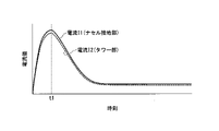
図11及び図12は、第2の実施形態の電流情報の時系列変化の例を示す図である。図11には正常落雷の場合、図12には異常落雷の場合における電流情報の時系列変化が示されている。図11及び図12では、電流センサR1-1により検出された電流を電流I1(図では、「電流I1(ナセル接地部)」と記載)、電流センサR1-2により検出された電流を電流I2(図では、「電流I2(タワー)」と記載)として示す。図11及び図12の横軸は時刻、縦軸は電流値を示す。 11 and 12 are diagrams showing examples of time-series changes in current information according to the second embodiment. FIG. 11 shows time-series changes in the current information in the case of a normal lightning strike, and FIG. 12 shows the time-series changes in the case of an abnormal lightning strike. 11 and 12, the current detected by current sensor R1-1 is current I1 (described as "current I1 (nacelle ground part)" in the figure), and the current detected by current sensor R1-2 is current I2. (In the figure, it is indicated as "current I2 (tower)"). 11 and 12, the horizontal axis indicates time, and the vertical axis indicates current value.
図11に示すように、正常落雷の場合、ナセル接地部126には、時刻t1をピークとした落雷電流I1が流れる。また、タワー部130には、落雷電流I1と同様に、時刻t1をピークとした落雷電流I2が流れる。正常落雷の場合、ナセル接地部126とタワー部130とに流れる電流値はほぼ同量であり、時系列変化も同じように変化する。
As shown in FIG. 11, in the case of a normal lightning strike, a lightning current I1 peaking at time t1 flows through the
図12に示すように、異常落雷の場合、レセプタ部111に着雷しないため、ナセル接地部126には、ほとんど落雷電流I1が流れない。一方、タワー部130には、時刻t1をピークとした落雷電流I2が流れる。
As shown in FIG. 12, in the case of an abnormal lightning strike, the lightning strike current I1 hardly flows through the
判定部235Aは、例えば、タワー部130を流れる電流I2が所定の閾値以上となる時刻において、ナセル接地部126を流れる電流I1に対する、タワー部130を流れる電流I2の割合(電流割合)が所定の閾値以上である場合、異常落雷と判定する。判定部235Aは、電流I2が所定の閾値以上となる時刻において、電流割合が所定の閾値未満である場合、正常落雷と判定する。
For example, at the time when the current I2 flowing through the
判定部235Aは、落雷の規模、着雷した箇所、及び正常落雷か異常落雷かの判定結果に応じて、異常レベルを判定する。判定部235Aは、正常落雷である場合、異常落雷と比較して、異常レベルを低いレベル(小さい値)に判定する。 The determination unit 235A determines the abnormal level according to the scale of the lightning strike, the location where lightning strikes, and the determination result as to whether the lightning strike is normal or abnormal. In the case of a normal lightning strike, the determination unit 235A determines the abnormal level to be a lower level (smaller value) than that of an abnormal lightning strike.
図13は、第2の実施形態の判定部235Aが行う正常落雷と異常落雷を判定する処理の流れを示す図である。 FIG. 13 is a diagram showing the flow of processing for determining normal lightning strikes and abnormal lightning strikes performed by the determination unit 235A of the second embodiment.
まず、風力発電システム1において、電流センサR1-1(図では、「電流センサA」と記載)によりナセル接地部126を流れる電流値が検出される(ステップS11)。電流センサR1-2(図では、「電流センサB」と記載)によりタワー部130を流れる電流値が検出される(ステップS12)。判定部235Aは、電流センサR1-1により検出された電流値を用いて波形処理を行う(ステップS13)。判定部235Aは、電流センサR1-2により検出された電流値用いて波形処理を行う(ステップS14)。判定部235Aは、波形処理として、例えば、電流値のピーク検出や変化量の算出などを行う。判定部235Aは、電流センサR1-1及びR1-2により検出された電流値を波形処理した結果を用いて、波形比較を行う(ステップS15)。判定部235Aは、例えば、二つの電流値のピーク値や、時系列変化の推移を比較する。判定部235Aは、波形比較の結果を用いて正常落雷か異常落雷かを判定する(ステップS16)。
First, in the wind
以上説明したように、第2の実施形態の判定装置200Aでは、電流情報取得部232Aは、ナセル接地部126を流れる電流I1(第1電流)、及びタワー部130を流れる電流I1(第2電流)を示す情報を、電流情報としてそれぞれ取得する。判定部235Aは、電流I1、及び電流I2を示す電流情報に基づいて、風力発電装置100Aへの落雷が正常落雷か異常落雷かを判定する。これにより、第2の実施形態の判定装置200Aでは、正常落雷か異常落雷かを判定することができ、落雷により風力発電装置100Aが受ける影響の度合いをより精度よく判定することが可能である。
As described above, in the determination device 200A of the second embodiment, the current information acquisition unit 232A obtains the current I1 (first current) flowing through the
(実施形態の変形例1)
次に、実施形態の変形例1について説明する。本変形例1では、異常レベルを補正する点において、上述した実施形態と相違する。(
Next,
判定部235(235A)は、例えば、風力発電装置100(100A)の使用年数に応じて、異常レベルを補正する。判定部235(235A)は、例えば、重みづけ係数を用いて異常レベルを補正する。重みづけ係数は、使用年数が大きいほど、大きな値になるように設定される。つまり、判定部235(235A)は、落雷の規模や着雷箇所が同じ場合であっても、使用年数が大きい程、異常レベルが大きくなるように補正する。これにより、経年劣化を考慮した、より実情に即した異常レベルを判定することが可能である。 The determination unit 235 (235A) corrects the abnormality level according to, for example, the years of use of the wind turbine generator 100 (100A). The determination unit 235 (235A) corrects the abnormal level using, for example, a weighting factor. The weighting factor is set to have a larger value as the number of years of use increases. In other words, the determination unit 235 (235A) performs correction so that the abnormality level increases as the number of years of use increases, even when the scale of the lightning strike and the location of the lightning strike are the same. As a result, it is possible to determine a more realistic abnormality level in consideration of deterioration over time.
判定部235(235A)は、風力発電装置100(100A)が設置されている設置環境や季節に応じて、異常レベルを補正するようにしてもよい。これにより、例えば、風力発電装置100(100A)が山間部に設置されているか海岸沿いに設置されているか等に応じて、より正確な異常レベルを判定することが可能である。また、雷は冬季雷、夏季雷などと呼ばれ、季節により雷の規模やエネルギーなどの特性が大きく異なることが知られている。判定部235(235A)が、季節に応じた補正を行うことで、雷の特性をより考慮した異常レベルを判定することができる。 The determination unit 235 (235A) may correct the abnormality level according to the installation environment where the wind turbine generator 100 (100A) is installed and the season. Thereby, for example, it is possible to determine a more accurate abnormality level depending on whether the wind turbine generator 100 (100A) is installed in a mountainous area or along the coast. In addition, lightning is called winter lightning, summer lightning, etc., and it is known that characteristics such as the magnitude and energy of lightning differ greatly depending on the season. The determination unit 235 (235A) can determine an abnormality level that takes into consideration the characteristics of lightning by making corrections according to the season.
判定部235(235A)は、推定モデルを用いて、異常レベルを補正するようにしてもよい。推定モデルは、機械学習の手法を用いて生成されたモデルであり、例えば、サポートベクタマシン(SVM)を用いて作成されたモデルである。推定モデルは、判定事項を判定した判定結果、及びその判定に用いられた振動情報などの情報群と、異常レベルとの対応関係を学習データとして、その対応関係を学習する。これにより、推定モデルは、異常レベルの領域ごとの境界線(線形分離直線、或いは非線形分離曲線)を推定する。 The determination unit 235 (235A) may correct the abnormal level using the estimation model. An estimation model is a model generated using a machine learning technique, such as a model created using a support vector machine (SVM). The estimation model learns the correspondence relationship between the determination result of determining the determination item, the information group such as the vibration information used for the determination, and the abnormality level as learning data. Thereby, the estimation model estimates a boundary line (linear separation straight line or nonlinear separation curve) for each abnormal level region.
判定部235(235A)は、判定結果、及びその判定に用いられた振動情報などの情報群を用いて、推定モデルが推定した異常レベルの領域の何れに属するかを判定する。判定部235(235A)は、情報群が属する異常レベルの領域に応じて、異常レベルを判定する。 The determination unit 235 (235A) determines to which region of the estimated abnormal level the estimated model belongs, using the determination result and information group such as vibration information used for the determination. The determination unit 235 (235A) determines the abnormal level according to the abnormal level area to which the information group belongs.
なお、推定モデルは、SVM以外の機械学習の技法を用いて作成されてもよい。例えば、CNN(Convolutional Neural Network)、RCNN(Reccurent CNN)決定木学習、遺伝的プログラミングなどの一般的に用いられている機械学習の技法のいずれを用いて作成されてもよい。 Note that the estimation model may be created using a machine learning technique other than SVM. For example, it may be created using any of commonly used machine learning techniques such as CNN (Convolutional Neural Network), RCNN (Reccurent CNN) decision tree learning, and genetic programming.
以上説明いたとおり、実施形態の変形例1に係る判定装置200(200A)は、異常レベルを、使用年数、設置環境、又は季節のうち、少なくとも何れかを用いて補正することで、より実情に即した異常レベルを判定することが可能となる。
As described above, the determination device 200 (200A) according to
また、実施形態の変形例1に係る判定装置200(200A)は、推定モデルを用いて異常レベルを補正するようにしてもよい。これにより、振動情報などの情報群が何れの異常レベルの領域に含まれるかを判定するという容易な処理で、異常レベルを判定することが可能となる。
Further, the determination device 200 (200A) according to
以上説明した少なくともひとつの実施形態によれば、ナセル部120に設けられた振動センサR2により検出された、メインシャフト部122が受ける振動を示す振動情報を、少なくとも互いに異なる二方向について取得する。これにより、判定装置200は、ナセル部120に設けられた振動センサR2からの振動情報を用いて着雷方向を判定できる。このため、ブレード部110などの回転体にセンサを設けることなく落雷に関する判定事項を判定することが可能である。
According to at least one embodiment described above, the vibration information indicating the vibration received by the
本発明のいくつかの実施形態を説明したが、これらの実施形態は、例として提示したものであり、発明の範囲を限定することは意図していない。これら実施形態は、その他の様々な形態で実施されることが可能であり、発明の要旨を逸脱しない範囲で、種々の省略、置き換え、変更を行うことができる。これら実施形態やその変形は、発明の範囲や要旨に含まれると同様に、特許請求の範囲に記載された発明とその均等の範囲に含まれるものである。 While several embodiments of the invention have been described, these embodiments have been presented by way of example and are not intended to limit the scope of the invention. These embodiments can be implemented in various other forms, and various omissions, replacements, and modifications can be made without departing from the scope of the invention. These embodiments and their modifications are included in the scope and spirit of the invention, as well as the scope of the invention described in the claims and equivalents thereof.
Claims (14)
前記風力発電装置におけるブレード部の回転位相を示す位相情報を取得する位相情報取得部と、
前記風力発電装置を流れる電流を示す電流情報を取得する電流情報取得部と、
前記振動情報、前記位相情報、及び前記電流情報に基づいて、前記風力発電装置への落雷に関する判定事項を判定する判定部と、
を備える判定装置。a vibration information acquisition unit configured to acquire, in at least two different directions, vibration information indicative of vibration received by the main shaft, which is detected by a sensor provided in the nacelle of the wind turbine generator;
a phase information acquisition unit that acquires phase information indicating a rotation phase of a blade unit in the wind turbine generator;
a current information acquisition unit that acquires current information indicating the current flowing through the wind turbine generator;
a determination unit that determines a determination item regarding a lightning strike to the wind turbine generator based on the vibration information, the phase information, and the current information;
A determination device comprising:
請求項1に記載の判定装置。The determination unit determines whether lightning strikes the wind turbine generator based on the current information, and determines the scale of the lightning strike when it is determined that the wind turbine generator has been struck.
The determination device according to claim 1.
請求項1に記載の判定装置。When determining that lightning strikes the wind turbine generator, the determination unit determines a location where lightning strikes based on the vibration information and the phase information.
The determination device according to claim 1.
前記判定部は、前記着雷情報に基づいて着雷した箇所を判定する、
請求項1に記載の判定装置。further comprising a lightning strike information acquisition unit that acquires lightning strike information indicating a phenomenon associated with lightning strikes in two different regions along a plane perpendicular to the axis of the main shaft,
The determination unit determines a location where lightning strikes based on the lightning strike information.
The determination device according to claim 1.
請求項4に記載の判定装置。The lightning strike information acquisition unit acquires information indicating illuminance as the lightning strike information.
The determination device according to claim 4.
請求項4に記載の判定装置。The lightning strike information acquisition unit acquires information indicating sound as the lightning strike information.
The determination device according to claim 4.
請求項4に記載の判定装置。The lightning strike information acquisition unit acquires information indicating an image as the lightning strike information.
The determination device according to claim 4.
前記判定部は、前記第1電流、及び前記第2電流を示す前記電流情報に基づいて、前記風力発電装置への落雷が正常落雷か異常落雷かを判定する、
請求項1に記載の判定装置。The current information acquisition unit includes a first current flowing through a ground portion of a conductor connected to a lightning receptor provided in the blade and a tower supporting the blade at a predetermined height from the ground. Acquiring information indicating a second current as the current information,
The determination unit determines whether the lightning strike to the wind turbine generator is normal or abnormal based on the current information indicating the first current and the second current.
The determination device according to claim 1.
請求項1に記載の判定装置。The determination unit determines an abnormality level indicating the degree of influence of lightning on the wind turbine generator based on a determination result of determining the determination item.
The determination device according to claim 1.
請求項9に記載の判定装置。The determination unit corrects the abnormality level according to the years of use of the wind turbine generator.
The determination device according to claim 9.
請求項9に記載の判定装置。The determination unit corrects the abnormality level according to the usage environment and season of the wind turbine generator.
The determination device according to claim 9.
前記推定モデルは、前記振動情報、前記位相情報及び前記判定事項を判定した判定結果と、前記風力発電装置における落雷の影響の度合いを示す異常レベルとの対応関係を学習した学習済みモデルである、
請求項9に記載の判定装置。The determination unit corrects the abnormal level using an estimated model,
The estimation model is a learned model that has learned a correspondence relationship between the vibration information, the phase information, and the judgment results obtained by judging the judgment items, and an abnormal level indicating the degree of influence of lightning on the wind turbine generator.
The determination device according to claim 9.
風力発電装置のナセル部に設けられたセンサにより検出された、メインシャフト部が受ける振動を示す振動情報を、少なくとも互いに異なる二方向について取得し、
前記風力発電装置におけるブレード部の回転位相を示す位相情報を取得し、
前記風力発電装置を流れる電流を示す電流情報を取得し、
前記振動情報、前記位相情報、及び前記電流情報に基づいて、前記風力発電装置への落雷に関する判定事項を判定する、
判定方法。The judgment device
Acquiring vibration information indicating vibration received by the main shaft portion in at least two different directions, which is detected by a sensor provided in the nacelle portion of the wind turbine generator;
Acquiring phase information indicating the rotation phase of the blade part in the wind turbine generator,
Acquiring current information indicating the current flowing through the wind power generator;
Based on the vibration information, the phase information, and the current information, determination items regarding a lightning strike to the wind turbine generator are determined;
judgment method.
風力発電装置のナセル部に設けられたセンサにより検出された、メインシャフト部が受ける振動を示す振動情報を、少なくとも互いに異なる二方向について取得させ、
前記風力発電装置におけるブレード部の回転位相を示す位相情報を取得させ、
前記風力発電装置を流れる電流を示す電流情報を取得させ、
前記振動情報、前記位相情報、及び前記電流情報に基づいて、前記風力発電装置への落雷に関する判定事項を判定させる、
プログラム。to the judgment device,
Acquiring vibration information indicating vibration received by the main shaft in at least two different directions, which is detected by a sensor provided in the nacelle of the wind turbine generator;
Acquiring phase information indicating the rotation phase of the blade part in the wind turbine generator,
obtaining current information indicating the current flowing through the wind turbine generator;
Determining items related to a lightning strike to the wind turbine generator based on the vibration information, the phase information, and the current information;
program.
Applications Claiming Priority (1)
| Application Number | Priority Date | Filing Date | Title |
|---|---|---|---|
| PCT/JP2019/020017 WO2020234983A1 (en) | 2019-05-21 | 2019-05-21 | Determination device, determination method, and program |
Publications (2)
| Publication Number | Publication Date |
|---|---|
| JPWO2020234983A1 JPWO2020234983A1 (en) | 2020-11-26 |
| JP7199525B2 true JP7199525B2 (en) | 2023-01-05 |
Family
ID=73459082
Family Applications (1)
| Application Number | Title | Priority Date | Filing Date |
|---|---|---|---|
| JP2021519926A Active JP7199525B2 (en) | 2019-05-21 | 2019-05-21 | Determination device, determination method, and program |
Country Status (2)
| Country | Link |
|---|---|
| JP (1) | JP7199525B2 (en) |
| WO (1) | WO2020234983A1 (en) |
Families Citing this family (2)
| Publication number | Priority date | Publication date | Assignee | Title |
|---|---|---|---|---|
| JP7241363B2 (en) * | 2021-05-19 | 2023-03-17 | 学校法人中部大学 | lightning detection system |
| WO2024189912A1 (en) * | 2023-03-16 | 2024-09-19 | 日本電信電話株式会社 | System, method, device, and program for inspecting wind power generation facility |
Citations (4)
| Publication number | Priority date | Publication date | Assignee | Title |
|---|---|---|---|---|
| JP2000265938A (en) | 1999-03-17 | 2000-09-26 | Hitachi Ltd | Lightning protection system for wind power |
| WO2014024303A1 (en) | 2012-08-10 | 2014-02-13 | 三菱重工業株式会社 | State observation system and state observation method for wind power generation device |
| JP2015129493A (en) | 2014-01-09 | 2015-07-16 | 株式会社日立製作所 | Abnormal degree determination system and method for wind power generator |
| JP2017181410A (en) | 2016-03-31 | 2017-10-05 | 国立研究開発法人 海上・港湾・航空技術研究所 | Abnormal lightning strike determination system and method for fixing the abnormal lightning strike determination system to wind turbine generator facility |
Family Cites Families (1)
| Publication number | Priority date | Publication date | Assignee | Title |
|---|---|---|---|---|
| US20140093373A1 (en) * | 2012-10-03 | 2014-04-03 | General Electric Company | System and method for detecting lightning strikes on a wind turbine |
-
2019
- 2019-05-21 JP JP2021519926A patent/JP7199525B2/en active Active
- 2019-05-21 WO PCT/JP2019/020017 patent/WO2020234983A1/en not_active Ceased
Patent Citations (4)
| Publication number | Priority date | Publication date | Assignee | Title |
|---|---|---|---|---|
| JP2000265938A (en) | 1999-03-17 | 2000-09-26 | Hitachi Ltd | Lightning protection system for wind power |
| WO2014024303A1 (en) | 2012-08-10 | 2014-02-13 | 三菱重工業株式会社 | State observation system and state observation method for wind power generation device |
| JP2015129493A (en) | 2014-01-09 | 2015-07-16 | 株式会社日立製作所 | Abnormal degree determination system and method for wind power generator |
| JP2017181410A (en) | 2016-03-31 | 2017-10-05 | 国立研究開発法人 海上・港湾・航空技術研究所 | Abnormal lightning strike determination system and method for fixing the abnormal lightning strike determination system to wind turbine generator facility |
Also Published As
| Publication number | Publication date |
|---|---|
| JPWO2020234983A1 (en) | 2020-11-26 |
| WO2020234983A1 (en) | 2020-11-26 |
Similar Documents
| Publication | Publication Date | Title |
|---|---|---|
| CN101937025B (en) | System and method for detecting lightning | |
| US10774814B2 (en) | System and method for monitoring blade deflection of wind turbines | |
| EP3495655B1 (en) | Method and system for testing a lightning protection system of a wind turbine | |
| CN103206342B (en) | The demarcation of blade aerodynamic load sensor | |
| US7870783B2 (en) | Method for measuring the turbulence intensity of a horizontal axis wind turbine | |
| JP5614765B2 (en) | Wind power generator state monitoring system and state monitoring method | |
| US11448195B2 (en) | Sensor arrangement for a wind turbine | |
| CN106922162B (en) | Method for validating sensor, wind field, controller, and method for controlling nacelle yaw system | |
| US11422052B2 (en) | System and method for diagnosing a rotor unbalance of a wind turbine | |
| KR101476986B1 (en) | Control device for a wind power plant | |
| CN112388606B (en) | Method and device for detecting bolt state in wind driven generator | |
| CN102278962A (en) | Method for measuring a rotational position of a rotor blade of a wind turbine and measuring device | |
| JP7199525B2 (en) | Determination device, determination method, and program | |
| CN110226096B (en) | State monitoring system, state monitoring method, state monitoring program, and storage medium | |
| CN109642542A (en) | Diagnostic system and method for wind turbines | |
| CN104483007A (en) | Overhead power transmission line vibration monitoring system and method | |
| DK179333B1 (en) | Method of identifying a wind distribution pattern over the rotor plane and a wind turbine thereof | |
| US11639712B2 (en) | System and method for monitoring blade deflection of wind turbines | |
| CN115065155A (en) | Risk early warning system of wind-powered electricity generation field booster station based on 5G communication | |
| JP6258339B2 (en) | Wind turbine device, wind turbine device abnormality detection device, and wind turbine device abnormality detection method | |
| KR102644417B1 (en) | Offshore wind power generation monitoring system and offshore wind power generation diagnosis method using the same | |
| CN113007037A (en) | Structure monitoring system and method | |
| CN114127413B (en) | Method and apparatus for computer-implemented monitoring of one or more wind turbines in a wind farm | |
| CN107797016A (en) | A kind of diagnostic method for transmission line lightning stroke failure | |
| CN115698503A (en) | Method and wind energy installation for condition monitoring of a powertrain or tower of a wind energy installation |
Legal Events
| Date | Code | Title | Description |
|---|---|---|---|
| A621 | Written request for application examination |
Free format text: JAPANESE INTERMEDIATE CODE: A621 Effective date: 20211025 |
|
| TRDD | Decision of grant or rejection written | ||
| A01 | Written decision to grant a patent or to grant a registration (utility model) |
Free format text: JAPANESE INTERMEDIATE CODE: A01 Effective date: 20221122 |
|
| A61 | First payment of annual fees (during grant procedure) |
Free format text: JAPANESE INTERMEDIATE CODE: A61 Effective date: 20221220 |
|
| R150 | Certificate of patent or registration of utility model |
Ref document number: 7199525 Country of ref document: JP Free format text: JAPANESE INTERMEDIATE CODE: R150 |