JP7196628B2 - Driving support device - Google Patents
Driving support device Download PDFInfo
- Publication number
- JP7196628B2 JP7196628B2 JP2019007888A JP2019007888A JP7196628B2 JP 7196628 B2 JP7196628 B2 JP 7196628B2 JP 2019007888 A JP2019007888 A JP 2019007888A JP 2019007888 A JP2019007888 A JP 2019007888A JP 7196628 B2 JP7196628 B2 JP 7196628B2
- Authority
- JP
- Japan
- Prior art keywords
- vehicle
- gate
- target
- travel route
- ecu
- Prior art date
- Legal status (The legal status is an assumption and is not a legal conclusion. Google has not performed a legal analysis and makes no representation as to the accuracy of the status listed.)
- Active
Links
Images


Description
本発明は、自車両の操舵角度を自動的に制御する操舵支援処理を実行する運転支援装置に関する。 BACKGROUND OF THE INVENTION 1. Field of the Invention The present invention relates to a driving assistance device that executes steering assistance processing for automatically controlling a steering angle of a host vehicle.
この種の運転支援装置の1つ(以下、「従来装置」とも称呼される。)は、自車両が有料道路の料金所に接近したとき、当該料金所に設置された料金所ゲートの内の1つを予め設定された条件に基づいて選択し、自車両に当該選択された料金所ゲートを通過させる(例えば、特許文献1を参照。)。 One of such driving support devices (hereinafter also referred to as a "conventional device") is a toll gate installed at a toll gate when a vehicle approaches a toll gate on a toll road. One is selected based on preset conditions, and the own vehicle is allowed to pass through the selected toll gate (see Patent Document 1, for example).
ところで、料金所ゲートは、例えば、ETC(電子料金収受システム)による通行料金が支払い可能であるか否かに応じて分類される。そのため、運転者は、料金所の通過に際し、特定の種別の料金所ゲートを利用(通過)することを所望する場合がある。 By the way, toll gates are classified, for example, according to whether tolls can be paid by ETC (Electronic Toll Collection System). Therefore, the driver may desire to use (pass through) a specific type of toll gate when passing through the toll gate.
しかしながら、従来装置によって選択された自車両が通過する予定の料金所ゲート(以下、「予定通過ゲート」とも称呼される。)の種別が、運転者が期待している料金所ゲートの種別と異なる場合が発生する虞がある。 However, the type of the toll gate through which the vehicle is scheduled to pass (hereinafter also referred to as the "planned passage gate") selected by the conventional device is different from the type of toll gate expected by the driver. A case is likely to occur.
そこで、本発明の目的の1つは、操舵支援処理が実行された結果として運転者が望んでいない種別の料金所ゲートへの自車両の進入を回避することを容易にする運転支援装置を提供することである。 Accordingly, one of the objects of the present invention is to provide a driving assistance device that facilitates avoidance of the own vehicle entering a toll gate of a type that is not desired by the driver as a result of the execution of steering assistance processing. It is to be.
上記目的を達成するための運転支援装置(以下、「本発明装置」とも称呼される。)は、運転支援部、及び、ゲート種別通知部を備える。 A driving support device (hereinafter also referred to as "the device of the present invention") for achieving the above object includes a driving support unit and a gate type notification unit.
前記運転支援部は、
自車両が走行している車線である「自車線」を画定する一対の区画線の位置、及び、前記自車線における前記自車両の前方を走行する他車両である「追従対象車両」の位置の少なくとも一方に基づいて前記自車両の操舵角度を制御する「操舵支援処理」を実行する。
The driving support unit
The position of a pair of marking lines that define the "own lane", which is the lane in which the own vehicle is traveling, and the position of the "following target vehicle", which is another vehicle traveling in front of the own vehicle in the own lane. A "steering assistance process" is executed to control the steering angle of the own vehicle based on at least one of them.
前記ゲート種別通知部は、
前記操舵支援処理の実行中に前記自車両が「1つ以上の料金所ゲートが設置された料金所」に接近しているとき、前記操舵支援処理の実行が継続された結果として前記自車両が通過すると予想される前記料金所ゲートである「予定通過ゲート」の種別を取得し、当該予定通過ゲートの当該取得された種別を前記自車両の運転者に通知する。
The gate type notification unit,
When the own vehicle is approaching "a toll gate having one or more toll gates" during the execution of the steering support process, the own vehicle is stopped as a result of the continuation of the steering support process. The type of the "planned passage gate", which is the toll gate expected to pass through, is acquired, and the acquired type of the planned passage gate is notified to the driver of the own vehicle.
例えば、予定通過ゲートの通知は、運転者によって視認可能な位置に配設されたディスプレイを介して行われる。通知された予定通過ゲートの種別が運転者によって所望されている料金所ゲートの種別と異なっていれば、運転者は、操舵支援処理を中断し且つ操舵操作を自ら行うことによって自車両を所望の料金所ゲートへ進入させることができる。従って、本発明装置によれば、運転者は、操舵支援処理が実行された結果として運転者が望んでいない種別の料金所ゲートに自車両が進入することを容易に回避できる。 For example, notification of scheduled passage gates is provided via a display located at a position visible to the driver. If the notified type of planned passage gate is different from the type of toll gate desired by the driver, the driver interrupts the steering support process and performs the steering operation himself/herself to bring the vehicle into the desired state. You can enter the toll gate. Therefore, according to the device of the present invention, the driver can easily avoid the driver's own vehicle from entering the type of toll gate that the driver does not want as a result of the steering assistance processing being executed.
上記説明においては、本発明の理解を助けるために、後述される実施形態に対応する発明の構成に対し、その実施形態で用いた名称及び/又は符号を括弧書きで添えている。しかしながら、本発明の各構成要素は、前記名称及び/又は符号によって規定される実施形態に限定されるものではない。本発明の他の目的、他の特徴及び付随する利点は、以下の図面を参照しつつ記述される本発明の実施形態についての説明から容易に理解されるであろう。 In the above description, in order to facilitate understanding of the present invention, names and/or symbols used in the embodiments are added in parentheses to configurations of the invention corresponding to the embodiments to be described later. However, each component of the present invention is not limited to the embodiments defined by the names and/or symbols. Other objects, features and attendant advantages of the present invention will be readily understood from the description of embodiments of the present invention described with reference to the following drawings.
以下、図面を参照しながら本発明の実施形態に係る運転支援装置(以下、「本支援装置」とも称呼される。)について説明する。本支援装置は、図1に示される車両10に適用される。加えて、本支援装置のブロック図が図2に示される。本支援装置は、それぞれが電子制御ユニット(ECU:Electronic Control Unit)である「運転支援ECU20、エンジンECU31、ブレーキECU32及びEPS-ECU33」を含んでいる。
Hereinafter, a driving support device (hereinafter also referred to as "this support device") according to an embodiment of the present invention will be described with reference to the drawings. This support device is applied to a
運転支援ECU20は、CPU、不揮発性メモリ及びRAMを備えたマイクロコンピュータを主要素として含んでいる。CPUは、所定のプログラム(ルーチン)を逐次実行することによってデータの読み込み、数値演算、及び、演算結果の出力等を行う。不揮発性メモリは、フラッシュメモリにより構成され、CPUが実行するプログラム及びプログラムの実行時に参照されるルックアップテーブル(マップ)等を記憶する。RAMは、CPUが参照するデータを一時的に記憶する。 The driving assistance ECU 20 includes a microcomputer having a CPU, a nonvolatile memory and a RAM as main elements. The CPU sequentially executes predetermined programs (routines) to read data, perform numerical calculations, output calculation results, and the like. The nonvolatile memory is composed of flash memory and stores programs executed by the CPU and lookup tables (maps) referenced when the programs are executed. The RAM temporarily stores data referred to by the CPU.
エンジンECU31、ブレーキECU32及びEPS-ECU33のそれぞれは、運転支援ECU20と同様に、マイクロコンピュータを主要素として含んでいる。これらのECUは、CAN(Controller Area Network)34を介して互いにデータ通信可能(データ交換可能)となっている。加えて、これらのECUは、他のECUに接続されたセンサの出力値をその「他のECU」からCAN34を介して受信することができる。
Each of the engine ECU 31, the
運転支援ECU20は、前方カメラ21、ミリ波レーダ22、車速センサ23、加速度センサ24、ディスプレイ25及びETC車載器26と接続されている。
The driving support ECU 20 is connected to a
前方カメラ21(図1を参照)は、車両10の前方領域を撮影した画像(以下、「前方画像」とも称呼される。)を取得し、前方画像を表す信号を所定時間が経過する毎に運転支援ECU20へ出力する。
A front camera 21 (see FIG. 1) acquires an image (hereinafter also referred to as a "front image") of a front area of the
ミリ波レーダ22は、それぞれがレーダ装置である前方中央レーダ22a、前方左方レーダ22b及び前方右方レーダ22cを含んでいる(図1を参照)。
The
前方中央レーダ22aは、車両10の前方領域にある物標を検出する。前方左方レーダ22bは、車両10の前方左領域にある物標を検出する。前方右方レーダ22cは、車両10の前方右領域にある物標を検出する。
The
ミリ波レーダ22に含まれるレーダ装置のそれぞれは、ミリ波帯の電波(ミリ波)を送信(放射)し且つ送信されたミリ波の反射波を受信することによって、物標の方位、距離及び相対速度等を表す情報を「物標情報」として取得し、物標情報を所定時間が経過する毎に運転支援ECU20へ出力する。
Each of the radar devices included in the
車速センサ23は、車両10の走行速度である車速Vtを検出し、車速Vtを表す信号を運転支援ECU20へ出力する。加速度センサ24は、車両10の前後方向の加速度Asを検出し、加速度Asを表す信号を運転支援ECU20へ出力する。
The
ディスプレイ25は、車両10の車室内の運転者によって視認可能な位置(具体的には、運転者の前方)に配設されている(図1を参照)。ディスプレイ25は、液晶ディスプレイ(LCD)を備えている。ディスプレイ25に表示される文字及び図形等は、運転支援ECU20によって制御される。
The
ETC車載器26には、通行料金収受用のクレジットカード(即ち、ETCカード)が挿入される。ETC車載器26は、料金所ゲートに設置された路側装置との通信を行い、通行料金がETCカードによって決済される。
A credit card for toll collection (that is, an ETC card) is inserted into the ETC vehicle-mounted
エンジンECU31は、エンジン41及びトランスミッション42を制御することにより、車両10の駆動力を調整する(図2を参照)。エンジンECU31は、種々のエンジンセンサ43と接続され、これらのセンサの出力値を受信する。エンジンセンサ43は、エンジン41の運転状態量(パラメータ)を検出するセンサである。エンジンセンサ43は、アクセルペダルの操作量(踏み込み量)センサ、スロットル弁開度センサ、機関回転速度センサ及び吸入空気量センサ等を含んでいる。エンジンECU31は、車速Vt及びエンジンセンサ43の出力値等に基づいて要求駆動トルクDreq(後述される駆動トルクDdの要求値)を決定する。
The engine ECU 31 adjusts the driving force of the
加えて、エンジンECU31は、スロットル弁アクチュエータ及び燃料噴射弁等を含むエンジンアクチュエータ44と接続され、これらのアクチュエータを制御することによってエンジン41の発生トルクを制御する。エンジンECU31は、車両10の駆動輪に伝達される駆動トルクDdが要求駆動トルクDreqと一致するようにエンジンアクチュエータ44及びトランスミッション42を制御し、以て、加速度Asを制御する。
In addition, the
更に、エンジンECU31は、運転支援ECU20から目標駆動トルクDdtgを含む「駆動力制御要求」を受信すると、実際の駆動トルクDdが目標駆動トルクDdtgと一致するようにエンジンアクチュエータ44及びトランスミッション42を制御する。
Further, when the
ブレーキECU32は、車両10に搭載された油圧式摩擦制動装置であるブレーキ機構45を制御する。ブレーキECU32は、種々のブレーキセンサ46と接続され、これらのセンサの出力値を受信する。ブレーキセンサ46は、ブレーキ機構45を制御するために使用される状態量を検出するセンサであり、ブレーキペダルの操作量センサ及びブレーキ機構45に作用するブレーキオイルの圧力センサ等を含んでいる。ブレーキECU32は、車速Vt及びブレーキセンサ46の出力値等に基づいて要求制動力Breq(後述される制動力Bfの要求値)を決定する。
The
加えて、ブレーキECU32は、ブレーキ機構45の油圧制御アクチュエータである種々のブレーキアクチュエータ47と接続されている。ブレーキECU32は、車輪のそれぞれが発生させる摩擦制動力である制動力Bfが要求制動力Breqと一致するようにブレーキアクチュエータ47を制御し、以て、加速度As(この場合、車速Vtの大きさの減少度合い、即ち、減速度)を制御する。
Additionally, the
更に、ブレーキECU32は、運転支援ECU20から目標制動力Bftgを含む「制動力制御要求」を受信すると、実際の制動力Bfが目標制動力Bftgと一致するようにブレーキアクチュエータ47を制御する。
Further, when the
EPS-ECU33は、トルクセンサ51及び操舵角度センサ52と接続され、これらのセンサの検出信号を受信するようになっている。トルクセンサ51は、運転者が操舵ハンドル55(図1を参照)に加える操舵トルクTsを検出し、操舵トルクTsを表す信号を出力する。操舵角度センサ52は、操舵ハンドル55の回転角度である操舵角度θsを検出し、操舵角度θsを表す信号を出力する。
The EPS-
操舵ハンドル55が中立位置にあるとき操舵角度θsは「0」となる。操舵ハンドル55が左方に回転しているとき操舵角度θsは正の値となり、操舵ハンドル55が右方に回転しているとき操舵角度θsは負の値となる。
The steering angle θs is "0" when the
EPS-ECU33は、車速Vt、操舵トルクTs及び操舵角度θs等に基づいて運転者による操舵ハンドル55に対する操作を補助するトルク(アシストトルク)の目標値である目標アシストトルクTagtを決定する。
The EPS-
EPS-ECU33は、駆動回路53と接続されている。駆動回路53は、操舵電動機54に電力を供給する。操舵電動機54は、操舵ハンドル55とトルク伝達可能に接続されたステアリングシャフトを回転させるトルクTmを発生する。EPS-ECU33は、トルクTmが目標アシストトルクTagtと一致するように駆動回路53を制御する。
EPS-
更に、EPS-ECU33は、運転支援ECU20から目標操舵角度θtgを含む「操舵角度制御要求」を受信すると、実際の操舵角度θsが目標操舵角度θtgと一致するように操舵電動機54を制御する。
Further, when the EPS-
(運転支援機能の概要)
運転支援ECU20は、運転者による車両10の運転を支援するため、運転支援機能を提供(実行)する。運転支援機能には、レーダー・クルーズ・コントロール機能(以下、単に「RCC機能」とも称呼される。)及びレーン・トレーシング・アシスト機能(以下、単に「LTA機能」とも称呼される。)が含まれる。LTA機能を提供するときに運転支援ECU20が実行する処理は、便宜上、「操舵支援処理」とも称呼される。
(Outline of driving support function)
The driving
車両10の運転者は、所定の操作を行うことによりRCC機能及びLTA機能のそれぞれの実行状態(即ち、実行開始のタイミング及び実行終了のタイミング)を制御することができる。本実施形態において、LTA機能は、RCC機能が実行されているときにのみ実行される。
The driver of the
RCC機能は、運転者がアクセルペダルに対する操作を行わなくても「追従対象車両」との車間距離が所定の車間距離目標値Divに一致するように加速度Asを制御する機能である。追従対象車両は、車両10が走行している車線(自車線)における車両10の前方の位置(具体的には、車両10の直前の位置)を走行している他車両である。車両10と追従対象車両との車間距離が所定の距離閾値よりも大きくなった場合、及び、追従対象車両が車線変更を行って自車線以外の車線を走行するようになった場合、運転支援ECU20は、その他車両が追従対象車両ではなくなったと判定する。
The RCC function is a function that controls the acceleration As so that the following distance from the "following target vehicle" matches a predetermined following distance target value Div even if the driver does not operate the accelerator pedal. The vehicle to be followed is another vehicle traveling in a position ahead of the vehicle 10 (specifically, a position immediately in front of the vehicle 10) in the lane in which the
一方、RCC機能の実行中、追従対象車両が存在していなければ、車速Vtが「運転者による所定の操作により設定されたセット車速Vset」と一致するように加速度Asが制御される。RCC機能は、アダプティブ・クルーズ・コントロール(ACC)機能とも称呼される。 On the other hand, during execution of the RCC function, if there is no vehicle to be followed, the acceleration As is controlled so that the vehicle speed Vt coincides with the "set vehicle speed Vset set by a predetermined operation by the driver." The RCC function is also called adaptive cruise control (ACC) function.
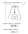
RCC機能の実行中に追従対象車両が存在していれば、運転支援ECU20は、追従対象車両の存在を表す先行車両記号61をディスプレイ25に表示する。図3(A)には、ディスプレイ25に先行車両記号61が表示されている場合の例として、画面62が示される。画面62には、車両10を表す車両記号10a及び先行車両記号61が含まれている。一方、追従対象車両が存在していなければ、或いは、RCC機能が実行されていなければ、図3(B)の画面63に示されるように、運転支援ECU20は、先行車両記号61をディスプレイ25に表示しない。
If there is a vehicle to be followed during execution of the RCC function, the driving
LTA機能は、車両10が自車線に沿って走行するように(即ち、車両10が自車線から逸脱しないように)操舵角度θsを制御する機能である。LTA機能は、レーン・キーピング・アシスト(LKA)機能とも称呼される。
The LTA function is a function of controlling the steering angle θs so that the
これらの運転支援機能(即ち、RCC機能及びLTA機能)を実現するため、運転支援ECU20は、前方カメラ21から受信した前方画像、及び、ミリ波レーダ22から受信した物標情報を利用する。加えて、運転支援機能を実現するため、運転支援ECU20は、必要に応じてエンジンECU31、ブレーキECU32及びEPS-ECU33を制御する。即ち、運転支援ECU20は、必要に応じて駆動力制御要求、制動力制御要求、及び、操舵角度制御要求を、これらの要求のそれぞれに対応するECUへ送信する。
In order to implement these driving support functions (that is, the RCC function and the LTA function), the driving
より具体的に述べると、RCC機能の実行中、運転支援ECU20は、目標加速度Atgを所定の時間が経過する毎に取得(決定)する。目標加速度Atgを取得するため、運転支援ECU20は、物標情報に基づいて追従対象車両と車両10との間の距離及び相対速度を取得する。更に、運転支援ECU20は、追従対象車両との車間距離が車間距離目標値Divと一致するように目標加速度Atgを取得する。追従対象車両が存在していなければ、運転支援ECU20は、車速Vtがセット車速Vsetと一致するように目標加速度Atgを算出する。加えて、運転支援ECU20は、実際の加速度Asが目標加速度Atgと一致するようにエンジンECU31及びブレーキECU32を制御する。
More specifically, during execution of the RCC function, the driving
一方、LTA機能の実行中、運転支援ECU20は、目標操舵角度θtgを所定の時間が経過する毎に取得(決定)し、その目標操舵角度θtgを含む操舵角度制御要求をEPS-ECU33へ送信する。目標操舵角度θtgを取得するため、運転支援ECU20は、「目標走行経路」を取得(決定)する。目標走行経路が取得されると、運転支援ECU20は、目標走行経路と実際の車両10の走行経路との偏差を求め、その偏差に基づいて車両10が目標走行経路に沿って走行するように(即ち、車両10が目標走行経路上を走行するように)目標操舵角度θtgを算出する。
On the other hand, during execution of the LTA function, the driving
追従対象車両が存在していない場合、運転支援ECU20は、前方画像に含まれる「自車線を画定する一対の車線区画線(即ち、左区画線及び右区画線)」を周知の方法により抽出(認識)する。更に、運転支援ECU20は、左区画線及び右区画線のそれぞれの車両10に対する位置に基づいて「車両10の前方に延在する自車線の左右方向中心点の集合」である車線中心線を目標走行経路として取得する。
If the vehicle to be followed does not exist, the driving
一方、追従対象車両が存在している場合、運転支援ECU20は、物標情報に基づいて追従対象車両の左右方向中心位置を取得する。更に、運転支援ECU20は、自車両の現在位置から追従対象車両の左右方向中心位置に至る経路を目標走行経路として取得する。
On the other hand, if the target vehicle to be followed exists, the driving
RCC機能のより具体的な説明は、例えば、特開2014-148293号公報、特開2006-315491号公報、特許第4172434号に係る明細書、及び、特許第4929777号に係る明細書に記載されている。LTA機能のより具体的な説明は、例えば、特開2008-195402号公報、特開2009-190464号公報、特開2010-6279号公報、及び、特許第4349210号に係る明細書に記載されている。 A more specific description of the RCC function is described in, for example, Japanese Patent Application Laid-Open No. 2014-148293, Japanese Patent Application Laid-Open No. 2006-315491, the specification of Japanese Patent No. 4172434, and the specification of Japanese Patent No. 4929777. ing. A more specific description of the LTA function is described in, for example, Japanese Unexamined Patent Application Publication No. 2008-195402, Japanese Unexamined Patent Application Publication No. 2009-190464, Japanese Unexamined Patent Application Publication No. 2010-6279, and Japanese Patent No. 4349210. there is
RCC機能の実行中に運転者がブレーキペダルを操作すると、運転支援ECU20は、RCC機能の実行を停止する。RCC機能の実行中に追従対象車両が停止すると、運転支援ECU20は、車両10を追従対象車両の後ろに停止させる。この場合、追従対象車両が走行を再開した後、運転者がアクセルペダルを操作すると、運転支援ECU20は、RCC機能の実行を再開する。
When the driver operates the brake pedal during execution of the RCC function, the driving
一方、LTA機能の実行中に運転者が操舵ハンドル55を操作すると(即ち、操舵トルクTsの大きさが所定のトルク閾値よりも大きくなると)、運転支援ECU20は、LTA機能の実行を停止する。運転者による操舵ハンドル55に対する操作によってLTA機能の実行を停止させることは、以下、「ステアリング・オーバーライド」とも称呼される。この場合、運転者が所定の復帰操作を行うと、運転支援ECU20は、LTA機能の実行を再開する。
On the other hand, when the driver operates the
(料金所進入処理)
RCC機能及びLTA機能が共に実行されているときに車両10が有料道路(高速自動車国道及び都市高速道路を含む)の料金所に接近した場合、運転支援ECU20は、「料金所進入処理」を実行して車両10による料金所の通過を支援する。車両10が通過しようとしている料金所に複数のゲート(料金所ゲート)が設置されていれば、運転支援ECU20は、それら複数の料金所ゲートの1つに車両10を通過させる。
(Toll gate entry process)
When the
車両10が料金所ゲートを通過すると、運転支援ECU20は、料金所進入処理の実行を終了する。換言すれば、車両10が料金所ゲートを通過したとき、運転支援ECU20は、従前の運転支援機能(即ち、上述したRCC機能及びLTA機能)の実行を再開する。
When the
運転支援ECU20は、前方画像に写る料金所ゲートのそれぞれの位置及び種別を取得(認識)できたとき、車両10が料金所に接近していると判定する。本実施形態において、料金所ゲートの種別は、「一般」、「ETC」及び「一般/ETC」である。
The driving
「一般」は、現金及びクレジットカード(ETCカードを除く)等を用いて通行料金の支払いを行う料金所ゲートである。「ETC」は、通行料金収受用の路側装置を備え、路側装置とETC車載器26(及び、車両10以外の車両に搭載されたETC車載器)との間の通信によって通行料金の支払いを行う料金所ゲートである。「一般/ETC」は、「一般」及び「ETC」の双方の機能を兼ね備えた料金所ゲートである。 "General" is a toll booth gate where tolls are paid using cash, credit cards (excluding ETC cards), and the like. The "ETC" has a roadside device for collecting tolls, and pays the toll by communication between the roadside device and the ETC onboard device 26 (and the ETC onboard device mounted on a vehicle other than the vehicle 10). It is a toll booth gate. "General/ETC" is a toll gate that has both the functions of "general" and "ETC".
運転支援ECU20は、予め記憶している種々の料金所ゲートのテンプレートと類似する前方画像内の領域を探索する。即ち、運転支援ECU20は、テンプレートマッチング処理により前方画像に写る料金所ゲートを探索(抽出)する。テンプレートの1つと類似する前方画像内の領域(料金所ゲート領域)の探索に成功すれば、運転支援ECU20は、その料金所ゲート領域に料金所ゲートが写っていると判定する。
The driving
料金所ゲート領域が抽出されると、運転支援ECU20は、その料金所ゲートの種別を判定する。具体的には、運転支援ECU20は、料金所ゲート領域に「一般」を表す表示が含まれているか否かを文字認識処理により判定する。同様に、運転支援ECU20は、料金所ゲート領域に「ETC」を表す表示が含まれているか否かを文字認識処理により判定する。料金所ゲート領域に「一般」を表す表示及び「ETC」を表す表示が共に含まれていれば、運転支援ECU20は、料金所ゲートの種別が「ETC/一般」であると判定する。
When the toll gate area is extracted, the driving
次に、料金所進入処理の具体的な内容について、追従対象車両が存在していない場合、及び、追従対象車両が存在している場合の順に説明する。 Next, the specific contents of the toll gate entry process will be described in the order of the case where the follow target vehicle does not exist and the case where the follow target vehicle exists.
料金所進入処理の実行時に追従対象車両が存在していなければ、運転支援ECU20は、車速Vtが所定の料金所通過車速Vgと一致するように目標加速度Atgを取得する。加えて、運転支援ECU20は、通過しようとしている料金所に設置されたゲートの1つに到達する経路を目標走行経路として取得する。
If the vehicle to be followed does not exist when the toll gate entry process is executed, the driving
目標走行経路を取得するため、運転支援ECU20は、車両10の現在位置から料金所ゲートのそれぞれに至る走行経路(ゲート走行経路)をそれぞれ取得する。更に、運転支援ECU20は、取得されたゲート走行経路の中で、料金所ゲートを通過するために必要となる操舵ハンドル55に対する操舵操作の大きさ(即ち、操舵角度θsの変化量)が最も少ない経路を、目標走行経路として取得(選択)する。
In order to acquire the target travel route, the driving
即ち、運転支援ECU20は、車両10がゲート走行経路を走行する場合の操舵角度θsと現時点における操舵角度θsとの差分の最大値が最も小さいゲート走行経路を目標走行経路として選択する。選択されたゲート走行経路(目標走行経路)に対応する料金所ゲートが「予定通過ゲート」となる。
That is, the driving
一方、追従対象車両が存在している場合、運転支援ECU20は、追従対象車両を追尾し、その結果、追従対象車両が通過した料金所ゲートを通過する。即ち、運転支援ECU20は、上述した通常の処理(即ち、料金所進入処理が実行されていない場合に実行されるLTA機能に係る処理)と同様の処理を実行して目標走行経路を取得する。
On the other hand, when the target vehicle to be followed exists, the driving
更に、運転支援ECU20は、後述されるゲート種別記号(即ち、ゲート種別記号91乃至ゲート種別記号93)をディスプレイ25に表示するため、予定通過ゲートを取得(判別)する。具体的には、運転支援ECU20は、追従対象車両が料金所ゲートに進入するまでの予想走行経路を取得(推定)し、その予想走行経路に最も近い料金所ゲートを予定通過ゲートとして取得する。運転支援ECU20は、追従対象車両の走行軌跡に基づいて追従対象車両の予想走行経路を取得する。
Further, the driving
車両10が料金所に接近し、その結果、料金所進入処理が実行される場合の例が、図4に示される。図4において、車両10が接近している料金所には、料金所ゲート71、料金所ゲート72及び料金所ゲート73が設置されている。図4から理解されるように、料金所ゲート71、料金所ゲート72及び料金所ゲート73のそれぞれの種別は、それぞれ、「一般」、「ETC/一般」及び「ETC」である。
FIG. 4 shows an example in which the
図4における車両81は、追従対象車両である。矢印Ar1は、車両81の走行軌跡である。本例において、車両81は、料金所ゲート71を通過しようとしている。即ち、車両81は、その後、破線矢印Ab1により表された経路を走行する。従って、この場合、運転支援ECU20は、車両10に車両81を追尾させ、その結果、車両10は、料金所ゲート71を通過する。加えて、この場合、予定通過ゲートは、料金所ゲート71である。
A
仮に、車両81(即ち、追従対象車両)が存在していなければ、運転支援ECU20は、車両10の現在位置である点P0から料金所ゲート71に至るゲート走行経路、点P0から料金所ゲート72に至るゲート走行経路、及び、点P0から料金所ゲート73に至るゲート走行経路を取得する。加えて、運転支援ECU20は、これらのゲート走行経路の中の1つを目標走行経路として選択する。
If the vehicle 81 (that is, the target vehicle to be followed) does not exist, the driving
点P0から料金所ゲート71に至るゲート走行経路は、矢印Ar1における「車両10の現在位置である点P0から車両81の現在位置である点P1までの区間」と、破線矢印Ab1によって表される区間と、の和である。点P0から料金所ゲート72に至るゲート走行経路は、点P0を始点とする破線矢印Ab2によって表される。点P0から料金所ゲート73に至るゲート走行経路は、点P0を始点とする破線矢印Ab3によって表される。
The gate travel route from point P0 to
図4から理解されるように、これら3つのゲート走行経路の中で車両10が走行した場合の操舵ハンドル55に対する操舵操作の大きさが最も小さいのは、料金所ゲート72に至るゲート走行経路である。従って、この場合、運転支援ECU20は、予定通過ゲートとして料金所ゲート72を選択し、破線矢印Ab2によって表される経路を目標走行経路として取得する。
As can be understood from FIG. 4, among these three gate travel routes, the magnitude of the steering operation to the
(料金所進入処理-料金所種別の通知)
料金所進入処理の実行時、運転支援ECU20は、予定通過ゲートの種別(即ち、「一般」、「ETC/一般」及び「ETC」の何れか)を、ディスプレイ25を介して運転者に通知する。
(Toll gate entry processing - Notification of toll gate type)
When the toll gate entry process is executed, the driving
通知された予定通過ゲートの例が図5(A)の画面64に示される。画面64において、予定通過ゲートの種別が「一般」であることを表すゲート種別記号91が表示されている。
An example of notified scheduled passage gates is shown on the
予定通過ゲートの種別が「ETC/一般」であれば、運転支援ECU20は、図5(B)に示されるゲート種別記号92をディスプレイ25の「図5(A)に示されるゲート種別記号91の位置」に表示する。予定通過ゲートの種別が「一般」であれば、運転支援ECU20は、図5(C)に示されるゲート種別記号93をディスプレイ25の「図5(A)に示されるゲート種別記号91の位置」に表示する。
If the type of planned passage gate is "ETC/general", the driving
図4の例によれば、車両10が点P0の位置にあるとき、運転支援ECU20は、破線矢印Ab1により表される経路を追従対象車両である車両81の予想走行経路として取得し、その結果、料金所ゲート71を予定通過ゲートとして選択する。そのため、運転支援ECU20は、料金所ゲート71の種別(即ち、「一般」)に対応するゲート種別記号91をディスプレイ25に表示する。
According to the example of FIG. 4, when the
仮に、追従対象車両である車両81が存在していなければ、予定通過ゲートである料金所ゲート72の種別(即ち、「ETC/一般」)に対応するゲート種別記号92をディスプレイ25に表示する。
If the
ところで、運転者が料金所ゲート73の通過を所望したために操舵ハンドル55を操作して(即ち、ステアリング・オーバーライドを行って)LTA機能の実行を中断させ且つ車両10を一点鎖線矢印Aq1によって表される経路を走行させ、その後、点P2の位置に到達したときにLTA機能の実行を再開させたと仮定する。この場合、運転支援ECU20は料金所進入処理を実行(再開)して、料金所ゲート73を予定通過ゲートとして選択する。加えて、運転支援ECU20は、予定通過ゲートである料金所ゲート73の種別(即ち、「ETC」)に対応するゲート種別記号93をディスプレイ25に表示する。
By the way, since the driver desires to pass through the
(具体的作動)
次に、図6を参照しながら運転支援機能(特に、料金所進入処理)に係る運転支援ECU20の具体的作動について説明する。運転支援ECU20のCPU(以下、単に「CPU」とも称呼される。)は、所定の時間が経過する毎に図6にフローチャートにより表された「運転支援処理ルーチン」を実行する。
(Specific operation)
Next, specific operations of the driving
従って、適当なタイミングとなると、CPUは、図6のステップ600から処理を開始してステップ605に進み、RCC機能及びLTA機能が共に実行中であるか否かを判定する。
Therefore, when the timing is appropriate, the CPU starts processing from
(ケースA)
現時点において、RCC機能及びLTA機能が共に実行中であり、車両10が料金所に接近していないと仮定する。
この場合、CPUは、ステップ605にて「Yes」と判定してステップ610に進み、車両10が料金所に接近しているか否かを判定する。即ち、CPUは、上述したテンプレートマッチング処理により前方画像に写る料金所ゲートを抽出できているか否かを判定する。
(Case A)
Assume that at this time both the RCC and LTA functions are running and the
In this case, the CPU determines "Yes" in
前述の仮定によれば、車両10は料金所に接近していないので、CPUは、ステップ610にて「No」と判定してステップ660に進み、上述した処理(即ち、料金所進入処理が実行されていない場合の処理)を実行して目標加速度Atg及び目標走行経路を決定する。次いで、CPUは、ステップ635に進み、目標走行経路に基づいて操舵角度θsを制御する。即ち、CPUは、目標走行経路に基づいて目標操舵角度θtgを決定し、その目標操舵角度θtgを含む操舵角度制御要求をEPS-ECU33へ送信する。その結果、実際の操舵角度θsが目標操舵角度θtgと一致するように操舵電動機54が制御される。
According to the above assumption, the
更に、CPUは、ステップ640に進み、目標加速度Atgに基づいてエンジン41及びブレーキ機構45を制御する。より具体的に述べると、CPUは、現時点における車速Vt及び加速度Asに鑑みて加速度Asを目標加速度Atgに一致させるためにエンジン41に駆動力を発生させる必要があると判定すると、エンジン41に発生させるべき目標駆動トルクDdtgを決定する。加えて、CPUは、その目標駆動トルクDdtgを含む駆動力制御要求をエンジンECU31へ送信する。
Further, the CPU proceeds to step 640 and controls the
一方、CPUは、加速度Asを目標加速度Atgに一致させるためにブレーキ機構45に制動力を発生させる必要があると判定すると、ブレーキ機構45に発生させるべき目標制動力Bftgを決定する。加えて、CPUは、その目標制動力Bftgを含む制動力制御要求をブレーキECU32へ送信する。この場合、CPUは、目標駆動トルクDdtgが「0」に設定された駆動力制御要求をエンジンECU31へ送信する。
On the other hand, when the CPU determines that it is necessary to cause the
次いで、CPUは、ステップ645に進み、運転支援機能の実行状態に基づいてゲート種別記号91乃至ゲート種別記号93、及び、先行車両記号61の何れかを必要に応じてディスプレイ25に表示する。即ち、料金所進入処理の実行中であれば、CPUは、予定通過ゲートの種別に対応するゲート種別記号をディスプレイ25に表示する。一方、料金所進入処理が実行されておらず、RCC機能の実行中であり、追従対象車両が存在していれば、CPUは、先行車両記号61をディスプレイ25に表示する。
Next, the CPU proceeds to step 645 and displays any one of the
或いは、車両10がLTA機能の実行中に料金所ゲート進入した後に最初に本ルーチンが実行されたとき(即ち、料金所進入処理が終了した直後に本ルーチンが実行されたとき)、ステップ645にてCPUは、ディスプレイ25におけるゲート種別記号の表示を終了する。同様に、追従対象車両が存在していた状態から追従対象車両が存在していない状態に遷移した後、最初に本ルーチンが実行されたとき、ステップ645にてCPUは、ディスプレイ25における先行車両記号61の表示を終了する。
Alternatively, when this routine is executed for the first time after the
次いで、CPUは、ステップ695に進み、本ルーチンの処理を一旦終了する。 Next, the CPU proceeds to step 695 and temporarily terminates the processing of this routine.
(ケースB1)
次に、現時点において、RCC機能及びLTA機能が共に実行中であり、車両10が料金所に接近していて、追従対象車両が存在していると仮定する。
この場合、CPUは、ステップ610にて「Yes」と判定してステップ615に進み、追従対象車両が存在しているか否かを判定する。
(Case B1)
Now assume that at the moment both the RCC and LTA functions are running, the
In this case, the CPU makes a "Yes" determination in
前述の仮定によれば、追従対象車両が存在しているので、CPUは、ステップ615にて「Yes」と判定して以下に説明するステップ620乃至ステップ630の処理を順に実行し、更に、ステップ635に進む。
According to the above assumption, there is a vehicle to be followed, so the CPU determines "Yes" in
ステップ620:CPUは、車両10が追従対象車両を追尾するように目標走行経路を取得する。
ステップ625:CPUは、予想走行経路に基づいて予定通過ゲートを選択する。即ち、CPUは、追従対象車両の予想走行経路を取得し、その予想走行経路に最も近い料金所ゲートを予定通過ゲートとして選択する。更に、CPUは、予定通過ゲートの種別を取得(認識)する。
ステップ630:CPUは、追従対象車両との車間距離が車間距離目標値Divと一致するように目標加速度Atgを取得する。
Step 620: The CPU acquires the target travel route so that the
Step 625: The CPU selects a planned transit gate based on the expected travel route. That is, the CPU obtains the expected travel route of the vehicle to be followed, and selects the toll gate closest to the expected travel route as the expected passage gate. Furthermore, the CPU acquires (recognizes) the type of the planned passage gate.
Step 630: The CPU acquires the target acceleration Atg so that the inter-vehicle distance to the vehicle to be followed matches the inter-vehicle distance target value Div.
(ケースB2)
現時点において、RCC機能及びLTA機能が共に実行中であり、車両10が料金所に接近していて、追従対象車両が存在していないと仮定する。
この場合、CPUは、ステップ615にて「No」と判定してステップ665に進み、車両10の走行状態に基づいて目標走行経路及び予定通過ゲートを取得(決定)する。即ち、CPUは、車両10の現在位置から料金所ゲートのそれぞれに至るゲート走行経路をそれぞれ取得し、ゲート走行経路の1つを目標走行経路として選択する。加えて、CPUは、目標走行経路(即ち、選択されたゲート走行経路の1つ)に対応する料金所ゲートを予定通過ゲートとして選択する。更に、CPUは、予定通過ゲートの種別を取得(認識)する。
(Case B2)
Assume that at this time both the RCC and LTA functions are running, the
In this case, the CPU makes a “No” determination in
次いで、CPUは、ステップ670に進み、車速Vtが料金所通過車速Vgと一致するように目標加速度Atgを決定する。更に、CPUは、ステップ635に進む。 Next, the CPU proceeds to step 670 and determines the target acceleration Atg so that the vehicle speed Vt matches the toll gate passing vehicle speed Vg. Furthermore, the CPU proceeds to step 635 .
(ケースC)
現時点において、RCC機能は実行されているが、LTA機能は実行されていないと仮定する。
この場合、CPUは、ステップ605にて「No」と判定してステップ650に進み、RCC機能が実行されているか否かを判定する。
(Case C)
Assume that at the moment the RCC function is running, but the LTA function is not.
In this case, the CPU makes a "No" determination in
前述の仮定によれば、RCC機能は実行されているので、CPUは、ステップ650にて「Yes」と判定してステップ655に進み、上述した処理(即ち、料金所進入処理が実行されていない場合の処理)を実行して目標加速度Atgを決定する。次いで、CPUは、ステップ640に進む。
According to the above assumption, the RCC function is being executed, so the CPU determines "Yes" in
(ケースD)
次に、現時点においてRCC機能及びLTA機能が何れも実行されていないと仮定する。
この場合、CPUは、ステップ650にて「No」と判定してステップ645に直接進む。
(Case D)
Now assume that neither the RCC nor the LTA functions are currently running.
In this case, the CPU determines “No” in
例えば、RCC機能が実行され且つ追従対象車両が存在していたためにディスプレイ25に先行車両記号61が表示されていたときに運転者による操作によってRCC機能の実行が中止された後、本ルーチンが最初に実行されていれば、ステップ645にてCPUは、ディスプレイ25における先行車両記号61の表示を終了する。
For example, when the preceding
以上、説明したように、運転支援機能の実行中に車両10が料金所に接近すると、運転支援ECU20は、予定通過ゲートを選択し且つ予定通過ゲートの種別をディスプレイ25に表示する。予定通過ゲートの種別が運転者の期待と異なっていれば、運転者はステアリング・オーバーライドによって車両10が通過する料金所ゲートを変更することができる。従って、本支援装置によれば、運転支援機能が実行された結果として運転者が望んでいない種別の料金所ゲートに車両10が進入することを容易に回避することが可能となる。
As described above, when the
以上、本発明に係る運転支援装置の実施形態について説明したが、本発明は上記実施形態に限定されるものではなく、本発明の目的を逸脱しない限りにおいて種々の変更が可能である。例えば、本実施形態における運転支援ECU20は、前方画像に含まれる料金所ゲート領域に基づいて車両10が料金所に接近しているか否かを判定していた。しかし、運転支援ECU20は、これとは異なる方法によって車両10が料金所に接近しているか否かを判定しても良い。例えば、運転支援ECU20は、測位衛星(例えば、GPS衛星)から受信した信号に基づいて車両10の現在位置を取得し且つ記憶している地図データベースに車両10の現在位置を適用することによって車両10が料金所に接近しているか否かを判定しても良い。更に、運転支援ECU20は、料金所ゲートのそれぞれの種別を(上述した文字認識処理を実行する代わりに)料金所ゲートの種別に関する情報を含んでいる地図データベースを参照することによって取得しても良い。
Although the embodiments of the driving assistance device according to the present invention have been described above, the present invention is not limited to the above embodiments, and various modifications are possible without departing from the object of the present invention. For example, the driving
加えて、本実施形態における運転支援ECU20は、料金所進入処理の実行時、追従対象車両の有無に拘わらずゲート種別記号91乃至ゲート種別記号93の何れかをディスプレイ25に表示していた。しかし、運転支援ECU20は、料金所進入処理の実行時、追従対象車両が存在しているときにのみゲート種別記号91乃至ゲート種別記号93の何れかをディスプレイ25に表示しても良い。
In addition, the driving
加えて、本実施形態における運転支援ECU20は、LTA機能を、RCC機能が実行されているときにのみ実行していた。しかし、運転支援ECU20は、LTA機能を、RCC機能が実行されていないときに実行しても良い。
In addition, the driving
加えて、本実施形態における運転支援ECU20は、予定通過ゲートの種別をディスプレイ25により運転者に通知していた。しかし、運転支援ECU20は、スピーカーを備え、音声により予定通過ゲートの種別を運転者に通知しても良い。
In addition, the driving
加えて、本実施形態における運転支援ECU20は、操舵支援処理として車両10を自車線に沿って走行させるLTA機能を実行していた。しかし、運転支援ECU20は、これとは異なる機能を操舵支援処理として提供しても良い。例えば、運転支援ECU20は、予め設定された目的地に車両10が到達するように目標走行経路を取得する自動運転機能を操舵支援処理として提供しても良い。
In addition, the driving
10…車両、10a…車両記号、20…運転支援ECU、21…前方カメラ、22…ミリ波レーダ、22a…前方中央レーダ、22b…前方左方レーダ、22c…前方右方レーダ、25…ディスプレイ、26…ETC車載器、55…操舵ハンドル、61…先行車両記号、71…料金所ゲート、72…料金所ゲート、73…料金所ゲート、91…ゲート種別記号、92…ゲート種別記号、93…ゲート種別記号。
10
Claims (1)
前記自車両の前方領域に存在する物標の情報である物標情報を取得するレーダと、
前記前方画像に含まれる自車線を画定する一対の車線区画線を認識し、前記自車線における前記自車両の前方を走行する他車両である追従対象車両が存在していない場合、前記認識した車線区画線に基づいて取得した車線中心線を目標走行経路として設定する一方、前記追従対象車両が存在している場合、前記自車両の現在位置から前記物標情報に基いて取得した前記追従対象車両の左右方向中心位置に至る経路を目標走行経路として設定する経路設定部と、
目標走行経路と実際の前記自車両の走行経路との偏差に基いて前記自車両が前記目標走行経路に沿って走行するように前記自車両の操舵角度を制御する操舵支援処理を実行する運転支援部と、
前記自車両が通過すると予想される料金所ゲートを予定通過ゲートとして取得するとともに当該予定通過ゲートの種別を前記前方画像に基いて取得し、当該予定通過ゲートの当該取得された種別を前記自車両の運転者に通知するゲート種別通知部と、
を備える運転支援装置において、
前記運転支援部は、
前記前方画像に基いて前記自車両が1つ以上の前記料金所ゲートが設置された料金所に接近していると判定したとき、
前記追従対象車両が存在していない場合、前記自車両の現在位置から前記料金所ゲートのそれぞれに至る走行経路であるゲート走行経路を取得し、前記取得されたゲート走行経路の中で、前記料金所ゲートのそれぞれを通過するために必要となる操舵角度の変化量が最も小さい経路を目標走行経路として取得し、
前記追従対象車両が存在している場合、前記追従対象車両の左右方向中心位置に至る経路を目標走行経路として取得し、
前記取得された目標走行経路に沿って前記自車両が走行するように前記操舵支援処理を実行する、
ように構成され、
前記ゲート種別通知部は、
前記自車両が前記取得された目標走行経路に沿って走行するように前記操舵支援処理の実行が継続された結果として前記自車両が通過すると予想される前記料金所ゲートのうちの一つを前記予定通過ゲートとして取得する、
ように構成された、
運転支援装置。 a front camera that acquires a front image that is an image of an area in front of the vehicle;
a radar that acquires target information, which is information about a target existing in an area ahead of the own vehicle;
A pair of lane markings demarcating the own lane included in the forward image is recognized, and if there is no other vehicle to be followed, which is another vehicle traveling in front of the own vehicle in the own lane, the recognized lane. While the lane center line acquired based on the lane marking is set as the target travel route, if the vehicle to be followed exists, the vehicle to be followed acquired based on the target object information from the current position of the own vehicle. a route setting unit that sets a route to the center position in the left-right direction of the as a target travel route;
Driving assistance for executing steering assistance processing for controlling the steering angle of the own vehicle so that the own vehicle travels along the target travel route based on the deviation between the target travel route and the actual travel route of the own vehicle. Department and
acquiring the tollgate through which the vehicle is expected to pass as a scheduled passage gate, acquiring the type of the scheduled passage gate based on the forward image, and determining the acquired type of the scheduled passage gate as the scheduled passage gate; a gate type notification unit that notifies the driver of the own vehicle;
In a driving support device comprising
The driving support unit
when it is determined that the own vehicle is approaching a toll gate having one or more toll gates based on the forward image;
If the vehicle to be followed does not exist, a gate travel route, which is a travel route from the current position of the subject vehicle to each of the tollgate gates, is acquired, and the toll is selected from the acquired gate travel routes. acquiring the route that requires the smallest amount of change in the steering angle required to pass through each of the gates as the target travel route;
when the vehicle to be tracked exists, acquiring a route to the center position in the left-right direction of the vehicle to be tracked as a target travel route;
executing the steering support process so that the own vehicle travels along the acquired target travel route;
configured as
The gate type notification unit,
of the toll gates through which the vehicle is expected to pass as a result of continuing the execution of the steering support process so that the vehicle travels along the acquired target travel route obtaining one as the scheduled transit gate;
configured as
Driving assistance device.
Priority Applications (1)
| Application Number | Priority Date | Filing Date | Title |
|---|---|---|---|
| JP2019007888A JP7196628B2 (en) | 2019-01-21 | 2019-01-21 | Driving support device |
Applications Claiming Priority (1)
| Application Number | Priority Date | Filing Date | Title |
|---|---|---|---|
| JP2019007888A JP7196628B2 (en) | 2019-01-21 | 2019-01-21 | Driving support device |
Publications (2)
| Publication Number | Publication Date |
|---|---|
| JP2020119088A JP2020119088A (en) | 2020-08-06 |
| JP7196628B2 true JP7196628B2 (en) | 2022-12-27 |
Family
ID=71892064
Family Applications (1)
| Application Number | Title | Priority Date | Filing Date |
|---|---|---|---|
| JP2019007888A Active JP7196628B2 (en) | 2019-01-21 | 2019-01-21 | Driving support device |
Country Status (1)
| Country | Link |
|---|---|
| JP (1) | JP7196628B2 (en) |
Citations (5)
| Publication number | Priority date | Publication date | Assignee | Title |
|---|---|---|---|---|
| JP2003302231A (en) | 2002-04-08 | 2003-10-24 | Hcx:Kk | Navigation device having toll gate indicating function |
| JP2015210720A (en) | 2014-04-28 | 2015-11-24 | トヨタ自動車株式会社 | Driving support apparatus |
| JP2018083539A (en) | 2016-11-24 | 2018-05-31 | 株式会社Subaru | Traveling control device of vehicle |
| JP2018106381A (en) | 2016-12-26 | 2018-07-05 | 株式会社Subaru | Automatic operation controller |
| JP2018154213A (en) | 2017-03-17 | 2018-10-04 | マツダ株式会社 | Driving assist control device |
-
2019
- 2019-01-21 JP JP2019007888A patent/JP7196628B2/en active Active
Patent Citations (5)
| Publication number | Priority date | Publication date | Assignee | Title |
|---|---|---|---|---|
| JP2003302231A (en) | 2002-04-08 | 2003-10-24 | Hcx:Kk | Navigation device having toll gate indicating function |
| JP2015210720A (en) | 2014-04-28 | 2015-11-24 | トヨタ自動車株式会社 | Driving support apparatus |
| JP2018083539A (en) | 2016-11-24 | 2018-05-31 | 株式会社Subaru | Traveling control device of vehicle |
| JP2018106381A (en) | 2016-12-26 | 2018-07-05 | 株式会社Subaru | Automatic operation controller |
| JP2018154213A (en) | 2017-03-17 | 2018-10-04 | マツダ株式会社 | Driving assist control device |
Also Published As
| Publication number | Publication date |
|---|---|
| JP2020119088A (en) | 2020-08-06 |
Similar Documents
| Publication | Publication Date | Title |
|---|---|---|
| JP6365390B2 (en) | Lane change support device | |
| CN108177653A (en) | Controller of vehicle | |
| US8423250B2 (en) | Vehicle control device, vehicle control method and computer program | |
| JP6573594B2 (en) | Automatic operation control device | |
| EP3725628A1 (en) | Vehicle control device | |
| EP3816962B1 (en) | Driving assistance method and driving assistance device | |
| JP4899429B2 (en) | Driving support device | |
| US11423777B2 (en) | Traffic sign displaying device | |
| JP7174645B2 (en) | Vehicle control device and vehicle | |
| EP3725629A1 (en) | Vehicle control device | |
| JP7331450B2 (en) | VEHICLE TRIP CONTROL METHOD AND TRIP CONTROL DEVICE | |
| CN113727899A (en) | Method for at least partially automatically guiding a motor vehicle | |
| EP3730368A1 (en) | Vehicle control device, method and computer program product | |
| US20210357663A1 (en) | Road recognition device | |
| EP3865361B1 (en) | Travel route generation system, vehicle driving assistance system, method of generating a travel route for a vehicle and computer program product | |
| CN113302105A (en) | Driving assistance method and driving assistance device | |
| EP4206054A1 (en) | Driving assistance method and driving assistance device | |
| JP7196628B2 (en) | Driving support device | |
| JP2020199809A (en) | Vehicle control apparatus, vehicle, method for operating vehicle control apparatus, and program | |
| JP2010064613A (en) | Navigator cooperative travel control device | |
| JP7189088B2 (en) | VEHICLE CONTROL DEVICE, VEHICLE, OPERATING METHOD AND PROGRAM OF VEHICLE CONTROL DEVICE | |
| CN112313131B (en) | Driver assistance system and method for autopilot with automatic longitudinal guidance | |
| JP2021160625A (en) | Travel route generating system and vehicle drive support system | |
| JP2021160631A (en) | Automatic operation control system | |
| WO2023105960A1 (en) | Vehicle control device |
Legal Events
| Date | Code | Title | Description |
|---|---|---|---|
| A621 | Written request for application examination |
Free format text: JAPANESE INTERMEDIATE CODE: A621 Effective date: 20210426 |
|
| A977 | Report on retrieval |
Free format text: JAPANESE INTERMEDIATE CODE: A971007 Effective date: 20220330 |
|
| A131 | Notification of reasons for refusal |
Free format text: JAPANESE INTERMEDIATE CODE: A131 Effective date: 20220405 |
|
| A521 | Request for written amendment filed |
Free format text: JAPANESE INTERMEDIATE CODE: A523 Effective date: 20220516 |
|
| A131 | Notification of reasons for refusal |
Free format text: JAPANESE INTERMEDIATE CODE: A131 Effective date: 20220719 |
|
| A521 | Request for written amendment filed |
Free format text: JAPANESE INTERMEDIATE CODE: A523 Effective date: 20220916 |
|
| TRDD | Decision of grant or rejection written | ||
| A01 | Written decision to grant a patent or to grant a registration (utility model) |
Free format text: JAPANESE INTERMEDIATE CODE: A01 Effective date: 20221115 |
|
| A61 | First payment of annual fees (during grant procedure) |
Free format text: JAPANESE INTERMEDIATE CODE: A61 Effective date: 20221128 |
|
| R151 | Written notification of patent or utility model registration |
Ref document number: 7196628 Country of ref document: JP Free format text: JAPANESE INTERMEDIATE CODE: R151 |