JP7195616B2 - Flying object with a long main body - Google Patents
Flying object with a long main body Download PDFInfo
- Publication number
- JP7195616B2 JP7195616B2 JP2019222630A JP2019222630A JP7195616B2 JP 7195616 B2 JP7195616 B2 JP 7195616B2 JP 2019222630 A JP2019222630 A JP 2019222630A JP 2019222630 A JP2019222630 A JP 2019222630A JP 7195616 B2 JP7195616 B2 JP 7195616B2
- Authority
- JP
- Japan
- Prior art keywords
- main body
- rotorcraft
- working
- flying
- flight
- Prior art date
- Legal status (The legal status is an assumption and is not a legal conclusion. Google has not performed a legal analysis and makes no representation as to the accuracy of the status listed.)
- Active
Links
- 230000005484 gravity Effects 0.000 claims description 17
- 238000005452 bending Methods 0.000 claims 1
- 238000012545 processing Methods 0.000 description 9
- 230000000694 effects Effects 0.000 description 5
- 238000012986 modification Methods 0.000 description 5
- 230000004048 modification Effects 0.000 description 5
- 238000011835 investigation Methods 0.000 description 4
- 238000013459 approach Methods 0.000 description 3
- 238000004891 communication Methods 0.000 description 3
- 238000007689 inspection Methods 0.000 description 3
- 238000005507 spraying Methods 0.000 description 3
- 241001465754 Metazoa Species 0.000 description 2
- 238000010586 diagram Methods 0.000 description 2
- 230000033001 locomotion Effects 0.000 description 2
- 230000001133 acceleration Effects 0.000 description 1
- 230000005540 biological transmission Effects 0.000 description 1
- 239000002131 composite material Substances 0.000 description 1
- 239000000470 constituent Substances 0.000 description 1
- 238000001514 detection method Methods 0.000 description 1
- 239000007788 liquid Substances 0.000 description 1
- 238000012423 maintenance Methods 0.000 description 1
- 238000012544 monitoring process Methods 0.000 description 1
- 238000010422 painting Methods 0.000 description 1
- 238000011160 research Methods 0.000 description 1
- XLYOFNOQVPJJNP-UHFFFAOYSA-N water Substances O XLYOFNOQVPJJNP-UHFFFAOYSA-N 0.000 description 1
Images


Description
本発明は、長尺に延びる本体部を備えた飛行体に関する。 TECHNICAL FIELD The present invention relates to an aircraft having an elongated main body.
近年、様々な用途に利用されるドローン(Drone)や無人航空機(UAV:Unmanned Aerial Vehicle)などの回転翼機(以下、単に「回転翼機」と総称する)を利用した様々なサービスが提供されている。かかる回転翼機は、カメラやセンサー、噴霧器、スピーカー等、多様な作業部を備えることができるため、産業利用の幅は更に広がっている。 In recent years, various services using rotary wing aircraft (hereinafter collectively referred to as "rotary wing aircraft") such as drones and unmanned aerial vehicles (UAVs) that are used for various purposes have been provided. ing. Since such rotary wing aircraft can be equipped with various working units such as cameras, sensors, sprayers, and speakers, the range of industrial applications is further expanding.
回転翼機に作業部を備える場合、多くの機種では回転翼機の上部または下部に作業部を固定している。しかし、その場合、自由量物となる作業部の搭載によって、回転翼機のバランスが崩れ、飛行効率が悪化したり、飛行が不安定になったりする。 When a rotorcraft is provided with a working section, in many models, the working section is fixed to the upper or lower portion of the rotorcraft. However, in that case, the balance of the rotorcraft is lost due to the mounting of the working section, which is a free mass, and the flight efficiency deteriorates or the flight becomes unstable.
一方、特許文献1では、重量物を回転翼機の鉛直下方に備えた回転翼機においても、各回転翼の差が少ない安定した飛行の継続が可能な仕組みを提供する(例えば、特許文献1参照)。
On the other hand,
特許文献1においては、カメラ等の重量物を備えた回転翼機を、複数の回転翼が回転することによって機体に発生する揚力の中心が、回転翼を支持するアーム部と重量物を搭載する搭載部との接続部に位置するように構成している。これにより、各回転翼の差が少ない安定した飛行の継続が可能となるものである。
In
しかしながら、特許文献1における飛行体に備えられた作業部の使用時、作業部は飛行体から発生する風や音等、様々な影響を受ける。また、作業を行う対象物(例えば、調査対象の動植物、監視対象の人物、作業対象の建造物等)に、飛行体本体が接近する必要がある。
However, when the working unit provided on the flying object in
作業対象によっては、飛行体が作業に適した距離に近づかなければならないことにより、作業が円滑に進まない。例えば監視や調査の場合、飛行体の姿や音が対象に影響を与えてしまい、作業そのものが実施できない。また、作業場所が狭小な場合、飛行体が進入できない、もしくは、進入に接触等の危険が伴う可能性がある。 Depending on the work target, the flying object must approach a distance suitable for the work, which prevents the work from proceeding smoothly. For example, in the case of surveillance and investigation, the appearance and sound of the flying object affect the target, and the work itself cannot be carried out. In addition, if the work area is narrow, there is a possibility that the flying object cannot enter, or there is a risk of contact with the approach.
そこで、本発明は、飛行体から離れた位置に作業部を設け、飛行体本体は作業対象から距離を保ったり、安全な飛行が可能な位置を保ったりしながらも、作業部は作業対象に対して適切な距離に近づけることが可能な飛行体を提供することを一つの目的とする。 Therefore, according to the present invention, a working unit is provided at a position away from the flying object, and the working unit is located away from the working object while the main body of the flying object maintains a distance from the working object or a position where safe flight is possible. It is an object of the present invention to provide a flying object capable of approaching an appropriate distance to the object.
本発明によれば、複数の回転翼及び前記回転翼を駆動させるモータを少なくとも備えた飛行部と、垂直方向に長尺に延びる本体部と、前記飛行部と前記本体部とを互いに変位可能に接続する接続部と、を備え、前記本体部の前記垂直方向における全長は前記飛行部の水平方向における最大直径の2倍以上である、飛行体を提供することができる。 According to the present invention, a flying portion including at least a plurality of rotor blades and a motor for driving the rotor blades, a main body portion elongated in the vertical direction, and the flying portion and the main body portion being displaceable relative to each other. and a connecting portion, wherein the total length of the main body in the vertical direction is at least twice the maximum diameter of the flying portion in the horizontal direction.
本発明によれば、飛行体本体は作業対象から距離を保ったり、安全な飛行が可能な位置を保ったりしながらも、作業部は作業対象に対して適切な距離に近づけることが可能な飛行体を提供し得る。 According to the present invention, the flying object body maintains a distance from the work target or maintains a position where safe flight is possible, while the working part can be brought close to the work target at an appropriate distance. can provide the body.
本発明の実施形態の内容を列記して説明する。本発明の実施の形態による長尺に延びる本体部を備えた飛行体は、以下のような構成を備える。
[項目1]
複数の回転翼及び前記回転翼を駆動させるモータを少なくとも備えた飛行部と、 垂直方向に長尺に延びる本体部と、前記飛行部と前記本体部とを互いに変位可能に接続する接続部と、を備え、前記本体部の前記垂直方向における全長は前記飛行部の水平方向における最大直径の2倍以上である、飛行体。
[項目2]
項目1に記載の飛行体であって、前記本体部は、前記接続部よりも上側の上部と、前記接続部よりも下側の下部とを有しており、前記上部の長さは、前記下部の長さの3倍以上である、飛行体。
[項目3]
項目2に記載の飛行体であって、前記下部は、少なくとも前記上部と釣り合いを取るための構造を有している、飛行体。
[項目4]
項目1乃至項目3のいずれかに記載の飛行体であって、前記接続部は、当該本体部の重心又は略重心に設けられている、飛行体。
[項目5]
項目1乃至項目4に記載の飛行体であって、前記上部の先端には、作業部が取り付け可能である、飛行体。
[項目6]
項目1乃至項目5のいずれかに記載の飛行体であって、前記下部は、脚部を備えている、飛行体。
[項目7]
項目1に記載の飛行体であって、前記本体部は、前記接続部よりも上側の上部と、前記接続部よりも下側の下部とを有しており、前記下部の長さは、前記上部の長さの3倍以上である、飛行体。
[項目8]
項目7に記載の飛行体であって、前記上部は、少なくとも前記下部と釣り合いを取るための構造を有している、飛行体。
[項目9]
項目7乃至項目8のいずれかに記載の飛行体であって、前記接続部は、当該本体部の重心又は略重心に設けられている、飛行体。
[項目10]
項目7乃至項目9のいずれかに記載の飛行体であって、前記下部の先端には、作業部が取り付け可能である、飛行体。
[項目11]
項目1乃至項目6のいずれかに記載の飛行体であって、前記飛行部は、前記本体部に沿って上下方向に移動自在に構成されている、
飛行体。
The contents of the embodiments of the present invention are listed and explained. An aircraft having an elongated main body according to an embodiment of the present invention has the following configuration.
[Item 1]
a flight portion including at least a plurality of rotor blades and a motor for driving the rotor blades; a body portion extending vertically in a long length; a connection portion connecting the flight portion and the body portion so as to be displaceable; wherein the total length of the body portion in the vertical direction is at least twice the maximum diameter of the flight portion in the horizontal direction.
[Item 2]
The aircraft according to
[Item 3]
3. The aircraft of item 2, wherein the lower portion has a structure for balancing at least the upper portion.
[Item 4]
4. The flying object according to any one of
[Item 5]
5. The aircraft according to any one of
[Item 6]
The aircraft according to any one of
[Item 7]
The aircraft according to
[Item 8]
8. The aircraft of item 7, wherein the upper portion has a structure for balancing at least the lower portion.
[Item 9]
9. The flying object according to any one of items 7 to 8, wherein the connecting portion is provided at the center of gravity or approximately the center of gravity of the main body.
[Item 10]
10. The aircraft according to any one of items 7 to 9, wherein a working part can be attached to the tip of the lower part.
[Item 11]
7. The flying object according to any one of
Airplane.
<本発明による実施の形態の詳細>
以下、本発明の実施の形態による長尺に延びる本体部を備えた飛行体について、図面を参照しながら説明する。
<Details of the embodiment according to the present invention>
Hereinafter, a flying object provided with an elongated main body portion according to an embodiment of the present invention will be described with reference to the drawings.
<本発明による第1の実施の形態の詳細>
図1に示されるように、本発明の実施の形態による回転翼機10は、複数の回転翼12及び回転翼12を駆動させるモータ13を少なくとも備えた飛行部11と、 垂直方向に長尺に延びる本体部20と、飛行部11と本体部20とを互いに変位可能に接続する接続部30と、を備えている。
<Details of the first embodiment according to the present invention>
As shown in FIG. 1, a
飛行部11と本体部20が互いに変位可能であることにより、本体部20ならびに第1搭載部21、第2搭載部22に搭載される作業部24の状態は飛行部の姿勢に関わらず、重力の作用によって回転翼機10から鉛直方向下方に懸垂された状態に維持することが可能である。この場合、姿勢の維持は重力の作用によるため、接続部は駆動機構等を必要とせず、単純な構成が可能となる。また、駆動機構等を使用して、任意の角度に傾けて運用することも可能である。
Since the
本体部20の前記垂直方向における全長は飛行部11の水平方向における最大直径の2倍以上である。本体部を丈長にすることで、第1搭載部21および第2搭載部22を飛行部11から離すことができる。
The total length of the
本体部20は、接続部30よりも上側の上部26と、接続部30よりも下側の下部27とを有しており、 上部26の長さは、下部27の長さの3倍以上である。前記垂直方向における上方へ特化して丈長にすることで、作業部24の利便性を向上させる。作業部24の利用については後述する。
The
下部27は、上部26と釣り合いを取るために、カウンタウェイト等の構造を備えることも可能である。下部27と上部26の釣り合いが取られていれば、駆動機構等を使用して、本体部20を任意の角度に傾けて運用する際に、駆動機が必要とする力は、下部27と上部26の釣り合いが取られていない本体部20を傾ける時に比較して、少なくなる。
The
また、接続部30を本体部20の重心又は略重心に設けることによっても、同様の効果を得ることが可能である。接続部30を飛行体全体の重心又は略重心位置に来るように設けた場合には、飛行部11が備える複数のモータ13の回転数が均一化され、飛行効率が向上するし、接続部30を飛行体の浮心又は略浮心位置に来るように設けた場合には、接続部30に対する飛行部11の傾きを大きくできるため、前記水平方向へ作業部をずらすことが可能になる。
Also, the same effect can be obtained by providing the
上部26の先端には、作業部24を取り付け、作業を行うことが可能である。作業部と当該作業部が行う作業は、例示すれば、カメラやセンサ、マイク等の、外界情報を取得可能な情報取得機器による撮影や監視、調査、記録、噴霧器や吹き付け装置、放水装置による液体の散布、塗装、消火、動植物への散水、スピーカーや臭気発生装置、発光装置による外部への働きかけ、工具やロボットアームによる工作や整備、物体の移動等があるが、これに限られない。
A working
例えば、情報取得機器を取り付けて使用した場合には、上部26の長さを丈長にすることにより、潜望鏡的に利用することが可能である。
For example, when an information acquisition device is attached and used, it can be used like a periscope by increasing the length of the
図2に示されるように、建造物の高所に監視対象者が存在する場合などは、作業部24のみを必要な高さに位置させ、飛行部11や下部27は対象者から目視されない位置に留まることで、難視性を向上させたり、飛行音による発見を防いだりする他、飛行高度を低く保つことで安全性を向上させる。
As shown in FIG. 2, when a person to be monitored exists at a high place in a building, only the working
他にも、木や橋梁、崖の上など、飛行位置よりも高度の高い場所に位置する監視対象者に対しても、同様に難視性を向上させたり、飛行音による発見を防いだりする他、飛行高度を低く保つことで安全性を向上させることが可能である。また、飛行部11が進入できない狭い空間などに対して、作業部24のみを差し込むことで情報取得を可能にする。
In addition, it also improves the visibility of surveillance targets located at higher altitudes than the flight position, such as trees, bridges, and cliffs, and prevents them from being detected by flight noise. In addition, it is possible to improve safety by keeping the flight altitude low. Also, by inserting only the working
図2に示されるように、回転翼機10はケーブル等により、地面や装置に係留してもよい。例えば、係留に複合ケーブルを使用して地上電源装置等と接続した場合、給電を受けての長時間運用や有線によるデータ送受信を行うとともに、回転翼機10の活動範囲を限定し、活動予定範囲外の人や物件等に対する安全性を保つことが可能である。また、ケーブルの重量により、本体部20へセルフレベリングの作用をもたらすこともできる。
As shown in FIG. 2, the
図1に示されるように、下部27は、必要に応じて、着陸等に使用可能な脚部23を備えることもできる。脚部を備えることにより、着陸や離陸を簡便に行えるほか、飛行していない間も地上にて作業を行うことが可能となる。
As shown in FIG. 1, the
<本発明による第2の実施の形態の詳細>
本発明による第2の実施の形態の詳細において、第1の実施の形態と重複する構成要素は同様の動作を行うので、再度の説明は省略する。
<Details of Second Embodiment According to the Present Invention>
In the details of the second embodiment according to the present invention, constituent elements that overlap with those of the first embodiment operate in the same manner, and therefore will not be described again.
本体部20は、接続部30よりも上側の上部26と、接続部30よりも下側の下部27とを有しており、 下部27の長さは、上部26の長さの3倍以上である。前記垂直方向における上方へ特化して丈長にすることで、作業部24の利便性を向上させる。
The
上部26は、下部27と釣り合いを取るために、カウンタウェイト等の構造を備えることも可能である。上部26と下部27の釣り合いが取られていれば、駆動機構等を使用して、本体部20を任意の角度に傾けて運用する際に、駆動機が必要とする力は、下部27と上部26の釣り合いが取られていない本体部20を傾ける時に比較して、少なくなる。
また、接続部30を本体部20の重心又は略重心に設けることによっても、同様の効果を得ることが可能である。接続部30を飛行体全体の重心又は略重心位置に来るように設けた場合には、飛行部11が備える複数のモータ13の回転数が均一化され、飛行効率が向上するし、接続部30を飛行体の浮心又は略浮心位置に来るように設けた場合には、接続部30に対する飛行部11の傾きを大きくできるため、前記水平方向へ作業部をずらすことが可能になる。
Also, the same effect can be obtained by providing the
図3に示されるように、下部27の先端には、作業部24が取り付け可能である。作業部24については、前記作業部の例の通り。
As shown in FIG. 3, the working
例えば、情報取得機器を取り付けて使用した場合には、下部27の長さを丈長にすることにより、逆潜望鏡的に利用することが可能である。
For example, when an information acquisition device is attached and used, it can be used like a reverse periscope by making the length of the
例えば、図4に示されるように、建物階下に監視対象者が存在する場合などは、作業部24のみを必要な高さに位置させ、飛行部11や上部26は対象者から目視されない位置に留まることで、難視性を向上させたり、飛行音による発見を防いだりすることが可能となる。
For example, as shown in FIG. 4, when a person to be monitored exists in the lower floors of a building, only the working
他にも、木や橋梁、崖の下など、飛行位置よりも高度の低い場所に位置する監視対象者に対しても、同様に難視性を向上させたり、飛行音による発見を防いだりする他、飛行高度を低く保つことで安全性を向上させることが可能である。また、飛行部11が進入できない狭い空間などに対して、作業部24のみを差し込むことで情報取得を可能にする。
In addition, it also improves the visibility of surveillance targets located in places lower than the flight position, such as trees, bridges, and under cliffs, and prevents them from being detected by flight noise. In addition, it is possible to improve safety by keeping the flight altitude low. Also, by inserting only the working
前記対象者とは、例えば、テロや犯罪行為時の犯人や、事件や事故、災害時などの救助対象者、あるいは、調査対象になっている人物、生物などが該当する。 The subject is, for example, a criminal at the time of terrorism or a criminal act, a person to be rescued at the time of an incident, an accident, or a disaster, or a person or a living being to be investigated.
<本発明による第3の実施の形態の詳細>
飛行部11は、本体部20に沿って上下方向に移動自在に構成されていてもよく、本体部20の重心又は略重心に移動して本体部20を傾け易くしたり、離着陸位置に接地する際、飛行部11が接地できるように本体部20の最下部まで移動したりする等の動作をすることが可能である。
<Details of the third embodiment according to the present invention>
The
上述した回転翼機は、図5に示される機能ブロックを有している。なお、図5の機能ブロックは最低限の参考構成である。フライトコントローラは、所謂処理ユニットである。処理ユニットは、プログラマブルプロセッサ(例えば、中央処理ユニット(CPU))などの1つ以上のプロセッサを有することができる。処理ユニットは、図示しないメモリを有しており、当該メモリにアクセス可能である。メモリは、1つ以上のステップを行うために処理ユニットが実行可能であるロジック、コード、および/またはプログラム命令を記憶している。メモリは、例えば、SDカードやランダムアクセスメモリ(RAM)などの分離可能な媒体または外部の記憶装置を含んでいてもよい。カメラやセンサ類から取得したデータは、メモリに直接に伝達されかつ記憶されてもよい。例えば、カメラ等で撮影した静止画・動画データが内蔵メモリ又は外部メモリに記録される。 The rotorcraft described above has the functional blocks shown in FIG. Note that the functional blocks in FIG. 5 are a minimum reference configuration. A flight controller is a so-called processing unit. A processing unit may have one or more processors, such as a programmable processor (eg, central processing unit (CPU)). The processing unit has a memory (not shown) and can access the memory. The memory stores logic, code, and/or program instructions executable by the processing unit to perform one or more steps. The memory may include, for example, removable media or external storage devices such as SD cards and random access memory (RAM). Data acquired from cameras and sensors may be communicated directly to and stored in memory. For example, still image/moving image data captured by a camera or the like is recorded in a built-in memory or an external memory.
処理ユニットは、回転翼機の状態を制御するように構成された制御モジュールを含んでいる。例えば、制御モジュールは、6自由度(並進運動x、y及びz、並びに回転運動θx、θy及びθz)を有する回転翼機の空間的配置、速度、および/または加速度を調整するために回転翼機の推進機構(モータ等)を制御する。制御モジュールは、搭載部、センサ類の状態のうちの1つ以上を制御することができる。 The processing unit includes a control module configured to control the state of the rotorcraft. For example, the control module may adjust the spatial orientation, velocity, and/or acceleration of a rotorcraft having six degrees of freedom (translational motions x , y , and z , and rotational motions θx, θy, and θz). control the propulsion mechanism (motor, etc.) of the rotorcraft. The control module can control one or more of the states of the mount, sensors.
処理ユニットは、1つ以上の外部のデバイス(例えば、端末、表示装置、または他の遠隔の制御器)からのデータを送信および/または受け取るように構成された送受信部と通信可能である。送受信機は、有線通信または無線通信などの任意の適当な通信手段を使用することができる。例えば、送受信部は、ローカルエリアネットワーク(LAN)、ワイドエリアネットワーク(WAN)、赤外線、無線、WiFi、ポイントツーポイント(P2P)ネットワーク、電気通信ネットワーク、クラウド通信などのうちの1つ以上を利用することができる。送受信部は、センサ類で取得したデータ、処理ユニットが生成した処理結果、所定の制御データ、端末または遠隔の制御器からのユーザコマンドなどのうちの1つ以上を送信および/または受け取ることができる。 The processing unit can communicate with a transceiver configured to send and/or receive data from one or more external devices (eg, terminals, displays, or other remote controls). The transceiver may use any suitable means of communication such as wired or wireless communication. For example, the transceiver utilizes one or more of local area networks (LAN), wide area networks (WAN), infrared, wireless, WiFi, point-to-point (P2P) networks, telecommunications networks, cloud communications, etc. be able to. The transceiver is capable of transmitting and/or receiving one or more of data acquired by sensors, processing results generated by the processing unit, predetermined control data, user commands from a terminal or remote controller, and the like. .
本実施の形態によるセンサ類は、慣性センサ(加速度センサ、ジャイロセンサ)、GPSセンサ、近接センサ(例えば、ライダー)、またはビジョン/イメージセンサ(例えば、カメラ)を含み得る。 Sensors according to this embodiment may include inertial sensors (accelerometers, gyro sensors), GPS sensors, proximity sensors (eg lidar), or vision/image sensors (eg cameras).
<変形例1>
図6及び図7に示されるように、回転翼機10は、接続部30を中心に回動し折れ曲がることが可能な上部26を備えることとしてもよい。これにより、上方及び側方(水平方向)の点検等を一台の回転翼機で行うことが可能となる。
<
As shown in FIGS. 6 and 7 , the
<変形例2>
図8に示されるように、回転翼機10は、接続部30からT字に延びる上部26を備えることとしてもよい。上部26は、中点から水平方向の2方向(例えば図示されるような180度の両方向)に延び、夫々の先端には作業部24が搭載されている。これにより、側方(水平方向)の点検等を一台の回転翼機で行うことが可能となる。また、両端の作業部24として、広角又は180度以上の視野角を有するカメラを設けることにより、広い範囲の点検を行うことが可能となる。
<Modification 2>
As shown in FIG. 8, the
<変形例3>
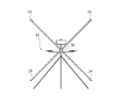
図9に示されるように、回転翼機10は、接続部30に接続され、少なくとも四方に延伸する部位を備えていてもよい、各部位の先端には作業部24が搭載されている。
<Modification 3>
As shown in FIG. 9, the
<変形例4>
図10に示されるように、回転翼機10は、接続部30に接続され、Z形状を有する部位を備えていてもよい。当該部位の両端(即ち、水平方向逆向きに延びる部位の先端)は作業部24が搭載されている。
<Modification 4>
As shown in FIG. 10, the
<変形例5>
図11に示されるように、回転翼機10は、脚部23に水平方向に延びる部位を有していてもよい。当該部位の両端には作業部24が搭載されている。
<Modification 5>
As shown in FIG. 11 , the
本発明の回転翼機は、監視、調査業務用の回転翼機としての利用、及び倉庫、工場内や屋外における産業用の回転翼機としての利用が期待できる。また、本発明の回転翼機は、マルチコプター・ドローン等の飛行機関連産業において利用することができ、さらに、本発明は、カメラ等を搭載した調査用の回転翼機としても好適に使用することができる他、セキュリティ分野、農業、研究、災害時、インフラ点検等の様々な産業にも利用することができる。 INDUSTRIAL APPLICABILITY The rotorcraft of the present invention can be expected to be used as a rotorcraft for surveillance and investigation work, and as an industrial rotorcraft in warehouses, factories, and outdoors. In addition, the rotorcraft of the present invention can be used in the aircraft-related industry such as multicopter drones, etc. Further, the present invention can be suitably used as a rotorcraft for investigation equipped with a camera or the like. In addition, it can be used in various industries such as security, agriculture, research, disasters, and infrastructure inspection.
上述した実施の形態は、本発明の理解を容易にするための例示に過ぎず、本発明を限定して解釈するためのものではない。本発明は、その趣旨を逸脱することなく、変更、改良することができると共に、本発明にはその均等物が含まれることは言うまでもない。 The above-described embodiments are merely examples for facilitating understanding of the present invention, and are not intended to limit and interpret the present invention. It goes without saying that the present invention can be modified and improved without departing from its spirit, and that equivalents thereof are included in the present invention.
10 回転翼機
11 飛行部
12 回転翼
13 モータ
20 本体部
21 第1搭載部
22 第2搭載部
23 脚部
24 作業部
25 カウンタウェイト
26 上部
27 下部
30 接続部
40 ケーブル
41 地上電源
10
Claims (4)
作業部を有する本体部と、
前記飛行部の姿勢に関わらず前記本体部の姿勢を維持するように、前記飛行部と前記本体部とを互いに独立して変位可能に接続する接続部と、
を備え、
前記本体部は、前記接続部を中心に点対象な形状の部位を備え、
前記部位は、少なくとも2つの折れ曲がる部分を含む、
飛行体。 a flight section including at least a plurality of rotor blades and a motor for driving the rotor blades;
a body portion having a working portion;
a connecting portion that connects the flying portion and the main body so that the flying portion and the main body can be displaced independently of each other so that the posture of the main body is maintained regardless of the posture of the flying portion;
with
The main body portion has a portion having a point-symmetrical shape with respect to the connection portion ,
the portion includes at least two bending portions;
Airplane.
前記点対象な形状の部位は、Z形状の部位である、
飛行体。 The aircraft according to claim 1,
The point-symmetrical shaped portion is a Z-shaped portion,
Airplane.
前記作業部は、前記部位の各先端側に設けられている、
飛行体。 The aircraft according to any one of claims 1 and 2,
The working part is provided on each tip side of the part,
Airplane.
前記接続部は、当該本体部の重心又は略重心、若しくは、飛行体の浮心又は略浮心位置に設けられている、
飛行体。
The aircraft according to any one of claims 1 to 3,
The connecting portion is provided at or near the center of gravity of the main body, or at or near the center of buoyancy of the aircraft,
Airplane.
Priority Applications (3)
| Application Number | Priority Date | Filing Date | Title |
|---|---|---|---|
| JP2019222630A JP7195616B2 (en) | 2019-12-10 | 2019-12-10 | Flying object with a long main body |
| JP2021079112A JP6904628B1 (en) | 2019-12-10 | 2021-05-07 | An air vehicle with a long body |
| JP2021079111A JP6904627B1 (en) | 2019-12-10 | 2021-05-07 | An air vehicle with a long body |
Applications Claiming Priority (1)
| Application Number | Priority Date | Filing Date | Title |
|---|---|---|---|
| JP2019222630A JP7195616B2 (en) | 2019-12-10 | 2019-12-10 | Flying object with a long main body |
Related Parent Applications (1)
| Application Number | Title | Priority Date | Filing Date |
|---|---|---|---|
| JP2019541470A Division JP6798729B2 (en) | 2018-07-19 | 2018-07-19 | An air vehicle with a long body |
Related Child Applications (5)
| Application Number | Title | Priority Date | Filing Date |
|---|---|---|---|
| JP2021002828A Division JP6881804B2 (en) | 2021-01-12 | 2021-01-12 | An air vehicle with a long body |
| JP2021002827A Division JP6881803B2 (en) | 2021-01-12 | 2021-01-12 | An air vehicle with a long body |
| JP2021002826A Division JP6881802B2 (en) | 2021-01-12 | 2021-01-12 | An air vehicle with a long body |
| JP2021079111A Division JP6904627B1 (en) | 2019-12-10 | 2021-05-07 | An air vehicle with a long body |
| JP2021079112A Division JP6904628B1 (en) | 2019-12-10 | 2021-05-07 | An air vehicle with a long body |
Publications (3)
| Publication Number | Publication Date |
|---|---|
| JP2020033021A JP2020033021A (en) | 2020-03-05 |
| JP2020033021A5 JP2020033021A5 (en) | 2021-08-26 |
| JP7195616B2 true JP7195616B2 (en) | 2022-12-26 |
Family
ID=69666797
Family Applications (3)
| Application Number | Title | Priority Date | Filing Date |
|---|---|---|---|
| JP2019222630A Active JP7195616B2 (en) | 2019-12-10 | 2019-12-10 | Flying object with a long main body |
| JP2021079111A Active JP6904627B1 (en) | 2019-12-10 | 2021-05-07 | An air vehicle with a long body |
| JP2021079112A Active JP6904628B1 (en) | 2019-12-10 | 2021-05-07 | An air vehicle with a long body |
Family Applications After (2)
| Application Number | Title | Priority Date | Filing Date |
|---|---|---|---|
| JP2021079111A Active JP6904627B1 (en) | 2019-12-10 | 2021-05-07 | An air vehicle with a long body |
| JP2021079112A Active JP6904628B1 (en) | 2019-12-10 | 2021-05-07 | An air vehicle with a long body |
Country Status (1)
| Country | Link |
|---|---|
| JP (3) | JP7195616B2 (en) |
Families Citing this family (1)
| Publication number | Priority date | Publication date | Assignee | Title |
|---|---|---|---|---|
| WO2022172111A1 (en) | 2021-02-15 | 2022-08-18 | Ricoh Company, Ltd. | Cleaning blade, lubricant leveling blade, process cartridge, and image forming apparatus |
Citations (5)
| Publication number | Priority date | Publication date | Assignee | Title |
|---|---|---|---|---|
| JP2016133508A (en) | 2015-01-21 | 2016-07-25 | ザ・ボーイング・カンパニーThe Boeing Company | System, method, and apparatus for automated predictive shimming for large structures |
| WO2016185572A1 (en) | 2015-05-19 | 2016-11-24 | 株式会社0 | Rotorcraft |
| JP2016219941A (en) | 2015-05-18 | 2016-12-22 | 株式会社amuse oneself | Unmanned aerial vehicle |
| JP2017533133A (en) | 2015-09-11 | 2017-11-09 | エスゼット ディージェイアイ オスモ テクノロジー カンパニー リミテッドSZ DJI Osmo Technology Co., Ltd. | Support mechanism |
| WO2018033922A1 (en) | 2016-08-18 | 2018-02-22 | Tevel Advanced Technologies Ltd. | Device, system and method for harvesting and diluting using aerial drones, for orchards, plantations and green houses |
Family Cites Families (12)
| Publication number | Priority date | Publication date | Assignee | Title |
|---|---|---|---|---|
| JP2003026097A (en) * | 2001-07-17 | 2003-01-29 | Yoshikazu Kikuoka | Helicopter |
| JP4679527B2 (en) * | 2007-01-25 | 2011-04-27 | 大成建設株式会社 | Biped robot |
| US10605365B1 (en) * | 2012-10-26 | 2020-03-31 | Other Lab, Llc | Fluidic actuator |
| JP6527012B2 (en) * | 2015-04-28 | 2019-06-05 | 学校法人 名城大学 | Inspection device |
| CN111765337A (en) * | 2015-07-02 | 2020-10-13 | 深圳市大疆灵眸科技有限公司 | Pan-tilt for image capture |
| EP3195292B1 (en) * | 2015-07-10 | 2019-01-09 | SZ DJI Technology Co., Ltd. | Systems and methods for gimbal simulation |
| JP2017177978A (en) * | 2016-03-29 | 2017-10-05 | 大和ハウス工業株式会社 | Remote-controlled rotary wing aircraft |
| JP6844097B2 (en) * | 2016-04-19 | 2021-03-17 | インダストリーネットワーク株式会社 | Drone flying object |
| JP6758119B2 (en) * | 2016-08-24 | 2020-09-23 | 東京瓦斯株式会社 | Unmanned aerial vehicle |
| KR101919919B1 (en) * | 2016-09-02 | 2019-02-08 | (주)비씨디이엔씨 | Vibration-free gimbal device |
| JP6732666B2 (en) * | 2017-01-06 | 2020-07-29 | 株式会社フジタ | Unmanned aerial vehicle |
| JP7120509B2 (en) * | 2018-03-09 | 2022-08-17 | Thk株式会社 | flying robot |
-
2019
- 2019-12-10 JP JP2019222630A patent/JP7195616B2/en active Active
-
2021
- 2021-05-07 JP JP2021079111A patent/JP6904627B1/en active Active
- 2021-05-07 JP JP2021079112A patent/JP6904628B1/en active Active
Patent Citations (5)
| Publication number | Priority date | Publication date | Assignee | Title |
|---|---|---|---|---|
| JP2016133508A (en) | 2015-01-21 | 2016-07-25 | ザ・ボーイング・カンパニーThe Boeing Company | System, method, and apparatus for automated predictive shimming for large structures |
| JP2016219941A (en) | 2015-05-18 | 2016-12-22 | 株式会社amuse oneself | Unmanned aerial vehicle |
| WO2016185572A1 (en) | 2015-05-19 | 2016-11-24 | 株式会社0 | Rotorcraft |
| JP2017533133A (en) | 2015-09-11 | 2017-11-09 | エスゼット ディージェイアイ オスモ テクノロジー カンパニー リミテッドSZ DJI Osmo Technology Co., Ltd. | Support mechanism |
| WO2018033922A1 (en) | 2016-08-18 | 2018-02-22 | Tevel Advanced Technologies Ltd. | Device, system and method for harvesting and diluting using aerial drones, for orchards, plantations and green houses |
Also Published As
| Publication number | Publication date |
|---|---|
| JP6904627B1 (en) | 2021-07-21 |
| JP2021107229A (en) | 2021-07-29 |
| JP6904628B1 (en) | 2021-07-21 |
| JP2021107228A (en) | 2021-07-29 |
| JP2020033021A (en) | 2020-03-05 |
Similar Documents
| Publication | Publication Date | Title |
|---|---|---|
| US20230365129A1 (en) | Apparatus and methods for obstacle detection | |
| US10618652B2 (en) | Surface washing drone | |
| EP3586212B1 (en) | Control systems for unmanned aerial vehicles | |
| EP3194265A1 (en) | Improvements in and relating to unmanned aerial vehicles | |
| JP6085520B2 (en) | Remotely controlled unmanned air vehicle | |
| CN112384443B (en) | Rotorcraft system | |
| WO2018053715A1 (en) | Unmanned aerial vehicle | |
| JP6798729B2 (en) | An air vehicle with a long body | |
| Miyazaki et al. | Long-reach aerial manipulation employing wire-suspended hand with swing-suppression device | |
| JP7195616B2 (en) | Flying object with a long main body | |
| JP2023174891A (en) | Flight body system comprising a plurality of connectable flight bodies | |
| JP6881804B2 (en) | An air vehicle with a long body | |
| JP6881803B2 (en) | An air vehicle with a long body | |
| JP6881802B2 (en) | An air vehicle with a long body | |
| WO2020016942A1 (en) | Power feeding method with rotary-wing aircraft for power feeding cable relay | |
| JP6860948B2 (en) | An air vehicle system with multiple air vehicles that can be connected | |
| JP2023083623A (en) | flying object | |
| Sujatha et al. | Application of fire fighting drone in containment of small-scale fires | |
| US20240083576A1 (en) | Aerial system including a thrusted platform and thrusted platform for said aerial system | |
| JP2023115308A (en) | Flight vehicle | |
| CA3174022A1 (en) | Aerial system including a thrusted platform and thrusted platform for said aerial system |
Legal Events
| Date | Code | Title | Description |
|---|---|---|---|
| A521 | Request for written amendment filed |
Free format text: JAPANESE INTERMEDIATE CODE: A523 Effective date: 20210716 |
|
| A621 | Written request for application examination |
Free format text: JAPANESE INTERMEDIATE CODE: A621 Effective date: 20210719 |
|
| A131 | Notification of reasons for refusal |
Free format text: JAPANESE INTERMEDIATE CODE: A131 Effective date: 20220602 |
|
| A521 | Request for written amendment filed |
Free format text: JAPANESE INTERMEDIATE CODE: A523 Effective date: 20220725 |
|
| TRDD | Decision of grant or rejection written | ||
| A01 | Written decision to grant a patent or to grant a registration (utility model) |
Free format text: JAPANESE INTERMEDIATE CODE: A01 Effective date: 20221110 |
|
| A61 | First payment of annual fees (during grant procedure) |
Free format text: JAPANESE INTERMEDIATE CODE: A61 Effective date: 20221207 |
|
| R150 | Certificate of patent or registration of utility model |
Ref document number: 7195616 Country of ref document: JP Free format text: JAPANESE INTERMEDIATE CODE: R150 |