JP7194840B2 - Determining the reachability of electronic devices over multiple wireless communication protocols - Google Patents
Determining the reachability of electronic devices over multiple wireless communication protocols Download PDFInfo
- Publication number
- JP7194840B2 JP7194840B2 JP2021547370A JP2021547370A JP7194840B2 JP 7194840 B2 JP7194840 B2 JP 7194840B2 JP 2021547370 A JP2021547370 A JP 2021547370A JP 2021547370 A JP2021547370 A JP 2021547370A JP 7194840 B2 JP7194840 B2 JP 7194840B2
- Authority
- JP
- Japan
- Prior art keywords
- electronic device
- wireless communication
- communication protocol
- reachable
- processor
- Prior art date
- Legal status (The legal status is an assumption and is not a legal conclusion. Google has not performed a legal analysis and makes no representation as to the accuracy of the status listed.)
- Active
Links
- 238000004891 communication Methods 0.000 title claims description 143
- 238000000034 method Methods 0.000 claims description 33
- 238000003860 storage Methods 0.000 claims description 24
- 238000004590 computer program Methods 0.000 claims description 21
- 238000012360 testing method Methods 0.000 claims description 14
- 230000004044 response Effects 0.000 claims description 13
- 230000005540 biological transmission Effects 0.000 claims description 6
- 230000015654 memory Effects 0.000 description 28
- 238000012545 processing Methods 0.000 description 25
- 238000010586 diagram Methods 0.000 description 17
- 230000006870 function Effects 0.000 description 11
- 238000005259 measurement Methods 0.000 description 4
- 238000005516 engineering process Methods 0.000 description 3
- 230000003287 optical effect Effects 0.000 description 3
- 230000001902 propagating effect Effects 0.000 description 3
- 230000006399 behavior Effects 0.000 description 2
- 230000004397 blinking Effects 0.000 description 2
- 230000008859 change Effects 0.000 description 2
- 239000000463 material Substances 0.000 description 2
- 238000012986 modification Methods 0.000 description 2
- 230000004048 modification Effects 0.000 description 2
- 230000002085 persistent effect Effects 0.000 description 2
- 238000003825 pressing Methods 0.000 description 2
- 230000008569 process Effects 0.000 description 2
- 239000004065 semiconductor Substances 0.000 description 2
- 239000007787 solid Substances 0.000 description 2
- 230000003213 activating effect Effects 0.000 description 1
- 230000009286 beneficial effect Effects 0.000 description 1
- 238000012790 confirmation Methods 0.000 description 1
- 238000013500 data storage Methods 0.000 description 1
- 239000000835 fiber Substances 0.000 description 1
- 238000009434 installation Methods 0.000 description 1
- 230000003993 interaction Effects 0.000 description 1
- 230000007257 malfunction Effects 0.000 description 1
- 238000004519 manufacturing process Methods 0.000 description 1
- 230000007246 mechanism Effects 0.000 description 1
- 239000002184 metal Substances 0.000 description 1
- 239000013307 optical fiber Substances 0.000 description 1
- 230000000644 propagated effect Effects 0.000 description 1
- 230000000007 visual effect Effects 0.000 description 1
Images


Classifications
-
- H—ELECTRICITY
- H05—ELECTRIC TECHNIQUES NOT OTHERWISE PROVIDED FOR
- H05B—ELECTRIC HEATING; ELECTRIC LIGHT SOURCES NOT OTHERWISE PROVIDED FOR; CIRCUIT ARRANGEMENTS FOR ELECTRIC LIGHT SOURCES, IN GENERAL
- H05B47/00—Circuit arrangements for operating light sources in general, i.e. where the type of light source is not relevant
- H05B47/10—Controlling the light source
- H05B47/175—Controlling the light source by remote control
- H05B47/19—Controlling the light source by remote control via wireless transmission
-
- H—ELECTRICITY
- H04—ELECTRIC COMMUNICATION TECHNIQUE
- H04L—TRANSMISSION OF DIGITAL INFORMATION, e.g. TELEGRAPHIC COMMUNICATION
- H04L43/00—Arrangements for monitoring or testing data switching networks
- H04L43/10—Active monitoring, e.g. heartbeat, ping or trace-route
-
- H05B47/1965—
Landscapes
- Engineering & Computer Science (AREA)
- Computer Networks & Wireless Communication (AREA)
- Health & Medical Sciences (AREA)
- Cardiology (AREA)
- General Health & Medical Sciences (AREA)
- Signal Processing (AREA)
- Mobile Radio Communication Systems (AREA)
- Circuit Arrangement For Electric Light Sources In General (AREA)
- Selective Calling Equipment (AREA)
- Communication Control (AREA)
- Telephone Function (AREA)
- Electrophonic Musical Instruments (AREA)
- Near-Field Transmission Systems (AREA)
Description
本発明は、ワイヤレス接続を介したさらなる電子デバイスの到達可能性(reachability)を決定するための電子デバイスであって、前記さらなる電子デバイスは、ワイヤレスネットワークの一部である、電子デバイスに関する。 The present invention relates to an electronic device for determining reachability of a further electronic device via a wireless connection, said further electronic device being part of a wireless network.
本発明はさらに、ワイヤレス接続を介したさらなる電子デバイスの到達可能性を決定する方法であって、前記さらなる電子デバイスは、ワイヤレスネットワークの一部である、方法に関する。 The invention further relates to a method of determining reachability of a further electronic device via a wireless connection, said further electronic device being part of a wireless network.
本発明はまた、コンピュータシステムがこのような方法を実行することを可能にするコンピュータプログラムプロダクトに関する。 The invention also relates to a computer program product enabling a computer system to carry out such method.
コネクテッド照明(connected lighting)において、ユーザは、自身のコネクテッド照明デバイスを制御するために自信のモバイルデバイスを使用できることを期待している。何かが期待通りに働かない場合、根本的原因(例えば、ランプが届かない(out of reach)、ランプが給電されていない、ブリッジが給電されていない、アプリが正しくセットアップされていない)を判断するのは困難であることが多い。 In connected lighting, users expect to be able to use their mobile devices to control their connected lighting devices. Determine the root cause when something doesn't work as expected (e.g. lamp out of reach, lamp not powered, bridge not powered, app not set up correctly) is often difficult to do.
コネクテッド照明において、ランプの制御及び/又は挙動(behavior)は、ランプのハードスイッチオフ(hard switch-off)によって阻害される場合があり、又は、ランプは、(単に)ワイヤレスで届かない(out of wireless reach)ことがあり得る。ランプは、ある時点では届き(within reach)、他のランプがオフされていることに起因して又は環境の変化(例えば、ユーザが隣の部屋の金属製のドアを閉める)に起因して次の時点では届かないことがあり得る。それゆえ、機能不全をしているシステムの根本的原因を見つけるのはかなりうんざりする(tedious)ことであり得る。 In connected lighting, the control and/or behavior of the lamp may be hampered by a hard switch-off of the lamp, or the lamp may (simply) be out of reach wirelessly. wireless reach). The lamp is within reach at one point and the next due to other lamps being turned off or due to a change in environment (e.g. user closing the metal door in the next room). may not arrive at the time of Therefore, finding the root cause of a malfunctioning system can be quite tedious.
モバイルデバイスにネットワークデバイスの状態を示すことができるシステムがある。例えば、US2018/0227204A1は、第1ネットワークデバイスと関連する第1カウント値及び第1ネットワークデバイスにメッセージを送るよう適応される第2ネットワークデバイスと関連する第2カウント値を決定すること、及び、第1カウント値及び第2カウント値に基づいて第1ネットワークデバイスの状態を決定することを含む方法を開示している。カウント値は、例えば、第1ネットワークデバイスに送信される/第1ネットワークデバイスによって受信されるメッセージ数の測定値であってもよい。第1カウント値が、第2カウント値に対して所定の範囲内にある、例えば、第2カウント値よりも著しく低い場合、第1ネットワークデバイスは非アクティブであると決定される。一実施形態では、第1ネットワークデバイスの状態に基づく情報は、ビジュアル出力ディスプレイに表示される。 There are systems that allow mobile devices to indicate the status of network devices. For example, US2018/0227204A1 determines a first count value associated with a first network device and a second count value associated with a second network device adapted to send a message to the first network device; A method is disclosed that includes determining a state of a first network device based on a first count value and a second count value. The count value may be, for example, a measurement of the number of messages sent to/received by the first network device. The first network device is determined to be inactive if the first count value is within a predetermined range relative to the second count value, eg, significantly lower than the second count value. In one embodiment, information based on the state of the first network device is displayed on a visual output display.
US2018/0227204A1の方法は、問題が発生したかどうかを判断するのに役立つが、なぜデバイスが現在制御できないのかを判断するのには役立たない。単にスイッチを入れて、ランプがオンするか、オフしたままであるかを見ることは、この問題の原因を見つけるのに役立つかもしれないが、これは常に可能ではない。ランプ/照明器具が、ユーザに何のフィードバックも与えずに非給電状態からスタンバイになることが起こる可能性がある。例えば、Zigbee Lighting & Occupancy Device Specification version 1.0は、ライトデバイスに電力が供給される場合のライトデバイスの望ましいスタートアップ挙動を定義するStartUpOnOff属性を規定している。StartUpOnOff属性が値0x00に設定される場合、ライトデバイスの光源は、ライトデバイスに電力が供給される場合にオンされない。また、スイッチを入れることは、同じスイッチに接続されている他のランプを意図せずにオンし、他のユーザを邪魔する可能性がある。 The method of US2018/0227204A1 helps determine if a problem has occurred, but does not help determine why the device is currently out of control. Simply flipping the switch and seeing if the lamp turns on or stays off may help find the cause of the problem, but this is not always possible. It may happen that the lamp/luminaire goes from unpowered to standby without any feedback to the user. For example, the Zigbee Lighting & Occupancy Device Specification version 1.0 defines a StartUpOnOff attribute that defines the desired startup behavior of a light device when power is applied to the light device. If the StartUpOnOff attribute is set to the value 0x00, the light source of the light device is not turned on when the light device is powered. Activating the switch may also unintentionally turn on other lamps connected to the same switch, disturbing other users.
KR 2016/0044240 Aは、ワイヤレス通信手段を有することにより照明装置間のネットワークを形成する及びネットワークを介して照明制御情報を送信ことができるワイヤレス照明装置、及びその制御方法を開示している。 KR 2016/0044240 A discloses a wireless lighting device that has wireless communication means so that a network can be formed between lighting devices and lighting control information can be transmitted over the network, and a control method thereof.
本発明の第1の目的は、さらなる電子デバイスが遠隔制御できない原因を見つけるために使用されることができる、電子デバイスを提供することである。 A first object of the present invention is to provide an electronic device that can be used to find out why a further electronic device cannot be remotely controlled.
本発明の第2の目的は、電子デバイスがリモートで遠隔制御できない原因を見つけるために使用されることができる、方法を提供することである。 A second object of the present invention is to provide a method that can be used to find out why an electronic device cannot be remotely controlled remotely.
本発明の第1の態様において、ワイヤレス接続を介してさらなる電子デバイスの到達可能性(reachability)を決定するための電子デバイスであって、前記さらなる電子デバイスは、ワイヤレスネットワークの一部である、電子デバイスは、少なくとも1つの入力インターフェースと、少なくとも1つの出力インターフェースと、前記さらなる電子デバイスが第1のワイヤレス通信プロトコルを使用して到達可能であるかどうかを判断するために前記少なくとも1つの入力インターフェースを使用する、前記さらなる電子デバイスが第2のワイヤレス通信プロトコルを使用して到達可能であるかどうかを判断するために前記少なくとも1つの入力インターフェースを使用する、及び、前記第1のワイヤレス通信プロトコルを使用する前記さらなる電子デバイスの前記到達可能性及び前記第2のワイヤレス通信プロトコルを使用する前記さらなる電子デバイスの前記到達可能性に基づいて前記さらなる電子デバイスの状態のインディケーション(indication)を提供するために前記少なくとも1つの出力インターフェースを使用するように構成される、少なくとも1つのプロセッサとを含む。 In a first aspect of the invention, an electronic device for determining reachability of a further electronic device via a wireless connection, said further electronic device being part of a wireless network. The device uses at least one input interface, at least one output interface, and said at least one input interface for determining whether said further electronic device is reachable using a first wireless communication protocol. using said at least one input interface to determine if said further electronic device is reachable using a second wireless communication protocol; and using said first wireless communication protocol. to provide an indication of the status of the further electronic device based on the reachability of the further electronic device and the reachability of the further electronic device using the second wireless communication protocol and at least one processor configured to use the at least one output interface.
複数の異なるワイヤレス通信プロトコルを使用してさらなる電子デバイスの到達可能性を決定する及びこの情報に基づいてさらなる電子デバイスの状態のインディケーションを提供することにより、ユーザは、さらなる電子デバイスがリモートで制御できない(すなわち、さらなる電子デバイス以外のデバイスを使用して制御できない)ある原因を除外することができる。さらなる電子デバイスが第1のワイヤレス通信プロトコルを用いて通常は制御されていて、このプロトコルを用いて到達可能ではないが、さらなる電子デバイスが第2のワイヤレス通信プロトコルを用いて到達可能である場合、さらなる電子デバイスはオンされていて、問題の原因はより複雑であることが明らかである。 By determining the reachability of the additional electronic device using a plurality of different wireless communication protocols and providing an indication of the status of the additional electronic device based on this information, the user can remotely control the additional electronic device. Certain causes of inability (ie, inability to control using a device other than an additional electronic device) can be ruled out. If the additional electronic device is normally controlled using the first wireless communication protocol and is not reachable using this protocol, but the additional electronic device is reachable using the second wireless communication protocol, Additional electronic devices are turned on and it is clear that the cause of the problem is more complex.
当該電子デバイスは、前記さらなる電子デバイス、例えば、照明デバイスをさらに含む、システム、例えば、照明システムの一部であってもよい。前記第1のワイヤレス通信プロトコルは、例えば、Zigbee(登録商標)であってもよい。前記第2のワイヤレス通信プロトコルは、例えば、Bluetooth(登録商標)であってもよい。前記少なくとも1つのプロセッサは、例えば、ディスプレイを介して、音声出力を介して及び/又は触覚フィードバックを介して前記インディケーションを提供するために前記少なくとも1つの出力インターフェースを使用するように構成されてもよい。電子デバイスが第1のワイヤレス通信プロトコルを使用して到達可能であるかどうかの判断は、第2のワイヤレス通信プロトコルを使用して行われてもよい。 The electronic device may be part of a system, eg a lighting system, further comprising said further electronic device, eg a lighting device. The first wireless communication protocol may be, for example, Zigbee® . Said second wireless communication protocol may be, for example, Bluetooth® . The at least one processor may be configured to use the at least one output interface to provide the indication, e.g., via a display, via audio output and/or via haptic feedback. good. A determination of whether the electronic device is reachable using the first wireless communication protocol may be made using a second wireless communication protocol.
例えば、コネクテッドランプ(connected lamp)は、(別個の無線機で又は単一のRFフロントエンドをタイムシェアリングすることにより兼用的に)Bluetooth(登録商標)及びZigBee(登録商標)の接続性を有してもよく、ランプのBluetooth(登録商標)及びZigBee(登録商標)の両通信経路に関する情報をユーザに示すことができるアプリが、スマートフォンで実行されてもよい。ブリッジ等の中央デバイスが、アプリに情報を提供/変換するのに役立ってもよい。 For example, connected lamps have Bluetooth® and ZigBee® connectivity ( either on separate radios or by time-sharing a single RF front end ) . An app may be run on the smart phone that can show the user information about both the lamp's Bluetooth® and ZigBee® communication paths. A central device such as a bridge may help provide/translate information to the app.
前記少なくとも1つのプロセッサは、前記第1のワイヤレス通信プロトコルを使用して前記さらなる電子デバイスにテストメッセージを送信するために前記少なくとも1つの出力インターフェースを使用する、及び、前記テストメッセージに応答する送信を受信すると前記さらなる電子デバイスは前記第1のワイヤレス通信プロトコルを使用して到達可能であると判断するために前記少なくとも1つの入力インターフェースを使用するように構成されてもよい。テストメッセージを送ることにより、ユーザがさらなる電子デバイスを制御したいと思う前に、問題があるかどうかを見つけ、この問題を知らせる(signal)ことができる。 The at least one processor uses the at least one output interface to transmit a test message to the further electronic device using the first wireless communication protocol, and transmits in response to the test message. Upon receipt, the further electronic device may be configured to use the at least one input interface to determine reachable using the first wireless communication protocol. By sending a test message, it is possible to find out if there is a problem and signal this problem before the user wishes to control further electronic devices.
前記少なくとも1つのプロセッサは、前記ワイヤレスネットワーク内のネットワークデバイスを介して前記第1のワイヤレス通信プロトコルを使用して前記さらなる電子デバイスに前記テストメッセージを送信するために前記少なくとも1つの出力インターフェースを使用するように構成されてもよい。ネットワークデバイスは、例えば、ブリッジであってもよい。直接接続を介してコネクテッドデバイスをリモート制御することは可能であるかもしれないが、多くのコネクテッドデバイスは、例えば、コネクテッドデバイスが制御されることができる範囲を広げるために、ブリッジ(例えば、Philips Hueブリッジ)を介して又はアクセスポイントを介して制御されることができる。 The at least one processor uses the at least one output interface to transmit the test message to the further electronic device using the first wireless communication protocol via a network device within the wireless network. It may be configured as A network device may be, for example, a bridge. While it may be possible to remotely control a connected device via a direct connection, many connected devices use a bridge (e.g. Philips Hue bridge) or via an access point.
前記少なくとも1つのプロセッサは、前記さらなる電子デバイスから前記第2のワイヤレス通信プロトコルを使用するブロードキャストを受信すると前記さらなる電子デバイスは前記第2のワイヤレス通信プロトコルを使用して到達可能であると判断するために前記少なくとも1つの入力インターフェースを使用するように構成されてもよい。コネクテッドデバイスは、例えば、Bluetooth(登録商標)を使用して、自身の存在、及び任意選択的に、提供されるサービス/ケイパビリティのリストをブロードキャストしてもよい。このブロードキャストは、典型的には、あるワイヤレス通信プロトコルを介してブロードキャストをブロードキャスティングするデバイスがこのあるワイヤレス通信プロトコルを使用して到達可能であることを意味する。 The at least one processor for determining that the further electronic device is reachable using the second wireless communication protocol upon receiving a broadcast using the second wireless communication protocol from the further electronic device. may be configured to use said at least one input interface to A connected device may broadcast its presence and, optionally, a list of services/capabilities offered, using Bluetooth® , for example. This broadcast typically means that the device broadcasting the broadcast over a certain wireless communication protocol is reachable using this certain wireless communication protocol.
前記少なくとも1つのプロセッサは、前記第2のワイヤレス通信プロトコルを使用して前記さらなる電子デバイスから情報を受信するために前記少なくとも1つの入力インターフェースを使用するように構成され、前記情報は、どのようにして前記さらなる電子デバイスが前記第1のワイヤレス通信プロトコルを使用して到達されることができるかを示してもよい。情報は、例えば、特定のプロトコルコンフィギュレーション設定、デバイスアドレス及び/又はセキュリティキーを含んでもよい。 The at least one processor is configured to use the at least one input interface to receive information from the further electronic device using the second wireless communication protocol, wherein the information is may indicate whether said further electronic device can be reached using said first wireless communication protocol. Information may include, for example, specific protocol configuration settings, device addresses and/or security keys.
前記少なくとも1つのプロセッサは、前記第2のワイヤレス通信プロトコルを使用して前記さらなる電子デバイスから情報を受信するために前記少なくとも1つの入力インターフェースを使用するように構成され、前記情報は、前記さらなる電子デバイスが前記第1のワイヤレス通信プロトコルを使用して到達可能であるかどうかを示してもよい。これは、第1のワイヤレス通信プロトコルを使用する別個のテストメッセージの必要性を回避する一方、ユーザが問題があるかどうかを事前に判断することを可能にする。制御されるべき電子デバイスは、あるワイヤレス通信プロトコルを介して制御できないかどうか知ることが多い。 The at least one processor is configured to use the at least one input interface to receive information from the further electronic device using the second wireless communication protocol, the information received from the further electronic It may indicate whether the device is reachable using said first wireless communication protocol. This avoids the need for a separate test message using the first wireless communication protocol while allowing the user to proactively determine if there is a problem. Electronic devices to be controlled often know if they cannot be controlled via some wireless communication protocol.
前記少なくとも1つのプロセッサは、当該電子デバイスと前記さらなる電子デバイスとの間の近接性の指標(measure of proximity)、例えば、距離を表す値を決定する、及び、前記近接性の指標がある閾値よりも小さいことに依存して前記インディケーションを提供するように構成されてもよい。これは、多くの制御可能なデバイスが設置されている場合に特に有益であり、ユーザが問題があると思われる電子デバイスの隣に立ってその状態を学習することを可能にする。 The at least one processor is configured to determine a value representing a measure of proximity, e.g. a distance, between the electronic device and the further electronic device; may be configured to provide said indication in dependence on being small. This is particularly useful in installations with many controllable devices, allowing the user to stand next to an electronic device that appears to be problematic and learn its status.
前記少なくとも1つのプロセッサは、前記近接性の指標が前記ある閾値よりも小さいと判断すると通知(notification)を提供することにより前記インディケーションを提供するように構成されてもよい。これは、ユーザによって必要とされるインタラクションの量を減らす。インディケーションは、例えば、ユーザがさらなる電子デバイスの近くにいる場合常に提供されてもよく、又は、ユーザがさらなる電子デバイスの近くにいて、さらなる電子デバイスが第1のワイヤレス通信プロトコルを使用して到達可能ではない若しくは第2のワイヤレス通信プロトコルを使用して到達可能ではない場合にのみ提供されてもよい。近接性の指標は、2つのワイヤレス通信プロトコルのうちの1つを使用して決定されてもよい。この場合、さらなる電子デバイスが少なくともこのワイヤレス通信プロトコルを使用して到達可能である場合にのみ近接性の指標を判断すると通知を提供することができてもよい。 The at least one processor may be configured to provide the indication by providing a notification upon determining that the proximity metric is below the certain threshold. This reduces the amount of interaction required by the user. The indication may for example be provided whenever the user is near the further electronic device, or the user is near the further electronic device and the further electronic device is reachable using the first wireless communication protocol. It may only be provided if it is not possible or reachable using the second wireless communication protocol. A proximity indicator may be determined using one of two wireless communication protocols. In this case, it may be possible to provide a notification upon determining a proximity indicator only if the further electronic device is reachable using at least this wireless communication protocol.
前記少なくとも1つのプロセッサは、前記さらなる電子デバイスと同様の又は同じ状態を有する1つ以上の他の電子デバイスのインディケーションを提供するために前記少なくとも1つの出力インターフェースを使用するように構成されてもよい。この情報は、ユーザが問題の原因を突き止める又はよりよく問題を解決するのに役立ってもよい。 The at least one processor may be configured to use the at least one output interface to provide an indication of one or more other electronic devices having a similar or same state as the further electronic device. good. This information may assist the user in diagnosing or better resolving the problem.
前記少なくとも1つのプロセッサは、前記さらなる電子デバイスが前記第1のワイヤレス通信プロトコルを介して到達不能であると判断すると前記第2のワイヤレス通信プロトコルを介して前記さらなる電子デバイスにコンフィギュレーションメッセージ(configuration message)を送信するために前記少なくとも1つの出力インターフェースを使用するように構成されてもよい。コンフィギュレーションメッセージは、例えば、特定のプロトコルコンフィギュレーション設定、デバイスアドレス及び/又はセキュリティキーを含んでもよい。第1のワイヤレス通信プロトコルに関して問題が検出される場合、さらなる電子デバイスの状態のインディケーションが提供される前又は後に、第2のワイヤレス通信プロトコルを使用して自動的に問題を解決するための最初の試みがあってもよい。 The at least one processor configures a configuration message to the further electronic device via the second wireless communication protocol upon determining that the further electronic device is unreachable via the first wireless communication protocol. ) using said at least one output interface. Configuration messages may include, for example, specific protocol configuration settings, device addresses and/or security keys. initially for automatically resolving the problem using the second wireless communication protocol if a problem is detected with the first wireless communication protocol, before or after further electronic device status indications are provided; There may be attempts to
本発明の第2の態様において、ワイヤレス接続を介して電子デバイスの到達可能性を決定する方法であって、前記電子デバイスは、ワイヤレスネットワークの一部である、方法は、前記電子デバイスが第1のワイヤレス通信プロトコルを使用して到達可能であるかどうかを判断することと、前記電子デバイスが第2のワイヤレス通信プロトコルを使用して到達可能であるかどうかを判断することと、前記第1のワイヤレス通信プロトコルを使用する前記電子デバイスの前記到達可能性及び前記第2のワイヤレス通信プロトコルを使用する前記電子デバイスの前記到達可能性に基づいて前記電子デバイスの状態のインディケーションを提供することとを含む。前記方法は、プログラマブルデバイスで実行されるソフトウェアによって実行されてもよい。このソフトウェアは、コンピュータプログラムプロダクトとして提供されてもよい。 In a second aspect of the invention, a method of determining reachability of an electronic device over a wireless connection, said electronic device being part of a wireless network, the method comprising: determining whether the electronic device is reachable using a second wireless communication protocol; determining whether the electronic device is reachable using a second wireless communication protocol; providing an indication of the status of the electronic device based on the reachability of the electronic device using a wireless communication protocol and the reachability of the electronic device using the second wireless communication protocol. include. The method may be performed by software running on a programmable device. This software may be provided as a computer program product.
電子デバイスが第1のワイヤレス通信プロトコルを使用して到達可能であるかどうかの判断は、第2のワイヤレス通信プロトコルを使用して行われてもよい。 A determination of whether the electronic device is reachable using the first wireless communication protocol may be made using a second wireless communication protocol.
本発明の第3の態様において、ポータブル電子デバイスを介して照明デバイスの到達可能性を示すコンピュータ実施方法であって、前記照明デバイスは、ワイヤレスネットワークの一部である、方法は、前記照明デバイスがポイントツーポイントワイヤレス通信プロトコルを使用して前記ポータブル電子デバイスから到達可能であるかどうかを判断すること、及び、前記照明デバイスが前記ポイントツーポイントワイヤレス通信プロトコルを使用して到達可能であるという判断がなされる場合、前記ポータブル電子デバイスを介してユーザに前記照明デバイスは到達可能であることを示すことと、前記ポータブル電子デバイスを介して前記照明デバイスを制御するための入力を受信することと、前記ポイントツーポイントワイヤレス通信プロトコルとは異なるワイヤレス通信プロトコルを使用して前記ワイヤレスネットワークを介して前記照明デバイスを制御することとを含む。 In a third aspect of the invention, a computer-implemented method of indicating reachability of a lighting device via a portable electronic device, said lighting device being part of a wireless network, the method comprising: determining whether the portable electronic device is reachable using a point-to-point wireless communication protocol; and determining that the lighting device is reachable using the point-to-point wireless communication protocol. If done, indicating to a user via the portable electronic device that the lighting device is reachable; receiving input via the portable electronic device to control the lighting device; controlling the lighting device over the wireless network using a wireless communication protocol different from a point-to-point wireless communication protocol.
斯くして、照明デバイスがポイントツーポイントワイヤレス通信プロトコルを介して到達可能であることが確認された場合、照明デバイスは、第2の(異なる)ワイヤレス通信プロトコルを介して到達可能であると仮定される。 Thus, if a lighting device is confirmed reachable via a point-to-point wireless communication protocol, the lighting device is assumed to be reachable via a second (different) wireless communication protocol. be.
ポータブル電子デバイスは、例えば、スマートフォンであってもよい。ポイントツーポイントワイヤレス通信プロトコルは、例えば、Bluetooth(登録商標)であってもよい。第2の(異なる)ワイヤレス通信プロトコルは、例えば、Zigbee(登録商標)であってもよい。ポータブル電子デバイスは、ポータブル電子デバイスがポイントツーポイントワイヤレス通信プロトコルを使用して照明デバイスからブロードキャストを受信する場合、又は、ポータブル電子デバイスがポイントツーポイントワイヤレス通信プロトコルを使用して照明デバイスにメッセージを送信し、このメッセージに対する応答、例えば、確認応答を受信する場合、照明デバイスから到達可能であると考えられてもよい。 A portable electronic device may be, for example, a smart phone. The point-to-point wireless communication protocol may be Bluetooth® , for example. The second (different) wireless communication protocol may be Zigbee® , for example. The portable electronic device receives a broadcast from the lighting device using a point-to-point wireless communication protocol, or the portable electronic device sends a message to the lighting device using a point-to-point wireless communication protocol. and may be considered reachable from the lighting device if it receives a response, eg an acknowledgment, to this message.
本発明の第4の態様において、照明デバイスを介して前記照明デバイスの到達可能性を示すコンピュータ実施方法であって、前記照明デバイスは、ワイヤレスネットワークの一部である、方法は、ポイントツーポイントワイヤレス通信プロトコルを使用して前記照明デバイスにおいてポータブル電子デバイスからの送信を受信することと、前記送信を受信すると、前記照明デバイスを介してユーザに前記照明デバイスは前記ポイントツーポイントワイヤレス通信プロトコル及び前記ポイントツーポイントワイヤレス通信プロトコルとは異なるワイヤレス通信プロトコルの両方を使用して到達可能であることを示すこととを含む。 In a fourth aspect of the invention, a computer-implemented method of indicating reachability of said lighting device via a lighting device, said lighting device being part of a wireless network, the method comprising: receiving a transmission from a portable electronic device at said lighting device using a communication protocol; upon receiving said transmission, said lighting device communicates said point-to-point wireless communication protocol and said point to a user via said lighting device; indicating reachability using both wireless communication protocols different from the point-to-point wireless communication protocol.
ランプがBluetooth(登録商標)を介して到達可能であることは、該ランプがZigbee(登録商標)を介しても到達可能であることをすでに示してもよい。ゆえに、Bluetooth(登録商標)を介してランプにメッセージが送られる場合、該ランプは(例えば、スイッチで)オフされていないこと及びランプ自体は壊れていないことを示すためにブリンキングを開始する/確認のフラッシュを与えてもよい。 A lamp reachable via Bluetooth (R) may already indicate that the lamp is also reachable via Zigbee (R) . Thus, when a message is sent to the lamp via Bluetooth , the lamp starts blinking to indicate that it has not been turned off (e.g. with a switch) and that the lamp itself is not broken/ A confirmation flash may be given.
さらに、本明細書で説明される方法を実践するためのコンピュータプログラム、並びに、そのコンピュータプログラムを記憶している非一時的コンピュータ可読記憶媒体が提供される。コンピュータプログラムは、例えば、既存のデバイスによってダウンロードされるか、又は、既存のデバイスにアップロードされてもよく、あるいは、これらのシステムの製造時に記憶されてもよい。 Further provided are computer programs for practicing the methods described herein, as well as non-transitory computer-readable storage media storing the computer programs. Computer programs may, for example, be downloaded by or uploaded to existing devices, or may be stored at the time of manufacture of these systems.
非一時的コンピュータ可読記憶媒体は、少なくとも第1のソフトウェアコード部分を記憶し、第1のソフトウェアコード部分は、コンピュータによって実行又は処理されると、電子デバイスが第1のワイヤレス通信プロトコルを使用して到達可能であるかどうかを判断することと、前記電子デバイスが第2のワイヤレス通信プロトコルを使用して到達可能であるかどうかを判断することと、前記第1のワイヤレス通信プロトコルを使用する前記電子デバイスの前記到達可能性及び前記第2のワイヤレス通信プロトコルを使用する前記電子デバイスの前記到達可能性に基づいて前記電子デバイスの状態のインディケーションを提供することとを含む、実行可能オペレーションを実行するように構成される。 A non-transitory computer-readable storage medium stores at least a first software code portion, the first software code portion being executed or processed by a computer to cause the electronic device to use a first wireless communication protocol. determining whether the electronic device is reachable using a second wireless communication protocol; determining whether the electronic device is reachable using the first wireless communication protocol; providing an indication of the state of the electronic device based on the reachability of the device and the reachability of the electronic device using the second wireless communication protocol. configured as
非一時的コンピュータ可読記憶媒体は、少なくとも第2のソフトウェアコード部分を記憶し、第2のソフトウェアコード部分は、コンピュータによって実行又は処理されると、照明デバイスがポイントツーポイントワイヤレス通信プロトコルを使用してポータブル電子デバイスから到達可能であるかどうかを判断すること、及び、前記照明デバイスが前記ポイントツーポイントワイヤレス通信プロトコルを使用して到達可能であるという判断がなされる場合、前記ポータブル電子デバイスを介してユーザに前記照明デバイスは到達可能であることを示すことと、前記ポータブル電子デバイスを介して前記照明デバイスを制御するための入力を受信することと、前記ポイントツーポイントワイヤレス通信プロトコルとは異なるワイヤレス通信プロトコルを使用して前記ワイヤレスネットワークを介して前記照明デバイスを制御することとを含む、実行可能オペレーションを実行するように構成される。 A non-transitory computer-readable storage medium stores at least a second software code portion that, when executed or processed by a computer, causes the lighting device to use a point-to-point wireless communication protocol to determining whether reachable from a portable electronic device; and, if a determination is made that the lighting device is reachable using the point-to-point wireless communication protocol, via the portable electronic device. indicating to a user that the lighting device is reachable; receiving input via the portable electronic device to control the lighting device; and wireless communication different from the point-to-point wireless communication protocol. controlling the lighting device over the wireless network using a protocol.
非一時的コンピュータ可読記憶媒体は、少なくとも第3のソフトウェアコード部分を記憶し、第3のソフトウェアコード部分は、コンピュータによって実行又は処理されると、ポイントツーポイントワイヤレス通信プロトコルを使用して照明デバイスにおいてポータブル電子デバイスからの送信を受信することと、前記送信を受信すると、前記照明デバイスを介してユーザに前記照明デバイスは前記ポイントツーポイントワイヤレス通信プロトコル及び前記ポイントツーポイントワイヤレス通信プロトコルとは異なるワイヤレス通信プロトコルの両方を使用して到達可能であることを示すこととを含む、実行可能オペレーションを実行するように構成される。 A non-transitory computer-readable storage medium stores at least a third software code portion, the third software code portion, when executed or processed by a computer, at the lighting device using a point-to-point wireless communication protocol. receiving a transmission from a portable electronic device; upon receiving the transmission, the lighting device communicates with a user via the lighting device the point-to-point wireless communication protocol and a wireless communication different from the point-to-point wireless communication protocol. indicating that it is reachable using both protocols.
当業者には理解されるように、本発明の諸態様は、デバイス、方法、又はコンピュータプログラムプロダクトとして具現化されてもよい。したがって、本発明の諸態様は、完全にハードウェアの実施形態、完全にソフトウェアの実施形態(ファームウェア、常駐ソフトウェア、マイクロコード等を含む)、あるいは、ソフトウェアの態様とハードウェアの態様とを組み合わせた実施形態の形態を取ってもよく、それらは全て、本明細書では「回路」、「モジュール」、又は「システム」と総称されてもよい。本開示で説明される機能は、コンピュータのプロセッサ/マイクロプロセッサによって実行される、アルゴリズムとして実装されてもよい。更には、本発明の諸態様は、1つ以上のコンピュータ可読媒体として具現化されている、コンピュータプログラムプロダクトの形態を取ってもよく、1つ以上のコンピュータ可読媒体は、その上に具現化されている、例えば記憶されている、コンピュータ可読プログラムコードを有する。 As will be appreciated by those skilled in the art, aspects of the invention may be embodied as a device, method or computer program product. Accordingly, aspects of the present invention may be an entirely hardware embodiment, an entirely software embodiment (including firmware, resident software, microcode, etc.), or a combination of software and hardware aspects. It may take the form of embodiments, all of which may be collectively referred to herein as a "circuit," "module," or "system." The functions described in this disclosure may be implemented as algorithms executed by a computer's processor/microprocessor. Furthermore, aspects of the present invention may take the form of a computer program product embodied in one or more computer-readable media, on which one or more computer-readable media are embodied. computer readable program code stored in, for example,
1つ以上のコンピュータ可読媒体の任意の組み合わせが、利用されてもよい。コンピュータ可読媒体は、コンピュータ可読信号媒体又はコンピュータ可読記憶媒体であってもよい。コンピュータ可読記憶媒体は、例えば、限定するものではないが、電子、磁気、光学、電磁気、赤外線、又は半導体の、システム、装置、若しくはデバイス、あるいは、上述の任意の好適な組み合わせであってもよい。より具体的なコンピュータ可読記憶媒体の例としては、限定するものではないが、1つ以上のワイヤを有する電気的接続、ポータブルコンピュータディスケット、ハードディスク、ランダムアクセスメモリ(random access memory;RAM)、読み出し専用メモリ(read-only memory;ROM)、消去可能プログラマブル読み出し専用メモリ(erasable programmable read-only memory;EPROM又はフラッシュメモリ)、光ファイバ、ポータブルコンパクトディスク読み出し専用メモリ(portable compact disc read-only memory;CD-ROM)、光学記憶デバイス、磁気記憶デバイス、又は上述の任意の好適な組み合わせを挙げることができる。本発明の文脈では、コンピュータ可読記憶媒体は、命令実行システム、装置、若しくはデバイスによって、又はそれらに関連して使用するためのプログラムを含むか、又は記憶することが可能な、任意の有形媒体であってもよい。 Any combination of one or more computer readable media may be utilized. A computer-readable medium may be a computer-readable signal medium or a computer-readable storage medium. A computer-readable storage medium may be, for example, without limitation, an electronic, magnetic, optical, electromagnetic, infrared, or semiconductor system, apparatus, or device, or any suitable combination of the foregoing. . More specific examples of computer readable storage media include, but are not limited to, electrical connections having one or more wires, portable computer diskettes, hard disks, random access memory (RAM), read-only read-only memory (ROM), erasable programmable read-only memory (EPROM or flash memory), optical fiber, portable compact disc read-only memory (CD-ROM) ROM), optical storage devices, magnetic storage devices, or any suitable combination of the foregoing. In the context of the present invention, a computer-readable storage medium is any tangible medium capable of containing or storing a program for use by or in connection with an instruction execution system, apparatus, or device. There may be.
コンピュータ可読信号媒体としては、例えばベースバンド内又は搬送波の一部として、その内部に具現化されているコンピュータ可読プログラムコードを有する、伝搬データ信号を挙げることができる。そのような伝搬信号は、限定するものではないが、電磁気、光学、又はこれらの任意の好適な組み合わせを含めた、様々な形態のうちのいずれを取ってもよい。コンピュータ可読信号媒体は、コンピュータ可読記憶媒体ではなく、命令実行システム、装置、若しくはデバイスによって、又はそれらに関連して使用するためのプログラムを、通信、伝搬、又は伝送することが可能な、任意のコンピュータ可読媒体であってもよい。 A computer readable signal medium can include a propagated data signal having computer readable program code embodied therein, such as in baseband or as part of a carrier wave. Such propagating signals may take any of a variety of forms including, but not limited to, electromagnetic, optical, or any suitable combination thereof. A computer-readable signal medium is not a computer-readable storage medium, but any medium capable of communicating, propagating, or transmitting a program for use by or in connection with an instruction execution system, apparatus, or device. It may be a computer readable medium.
コンピュータ可読媒体上に具現化されているプログラムコードは、限定するものではないが、無線、有線、光ファイバ、ケーブル、RF等、又は上述の任意の好適な組み合わせを含めた、任意の適切な媒体を使用して送信されてもよい。本発明の諸態様に関する動作を実施するためのコンピュータプログラムコードは、Java(商標)、Smalltalk、C++等のオブジェクト指向プログラミング言語、及び、「C」プログラミング言語又は同様のプログラミング言語等の従来の手続き型プログラミング言語を含めた、1つ以上のプログラミング言語の任意の組み合わせで書き込まれてもよい。このプログラムコードは、スタンドアロン型ソフトウェアパッケージとして、完全にユーザのコンピュータ上で、部分的にユーザのコンピュータ上で実行されてもよく、部分的にユーザのコンピュータ上かつ部分的にリモートコンピュータ上で、又は完全にリモートコンピュータ若しくはサーバ上で実行されてもよい。後者のシナリオでは、リモートコンピュータは、ローカルエリアネットワーク(local area network;LAN)若しくは広域ネットワーク(wide area network;WAN)を含めた任意のタイプのネットワークを通じて、ユーザのコンピュータに接続されてもよく、又は、この接続は、外部コンピュータに対して(例えば、インターネットサービスプロバイダを使用してインターネットを通じて)実施されてもよい。 Program code embodied on a computer readable medium may be any suitable medium including, but not limited to, wireless, wired, fiber optic, cable, RF, etc., or any suitable combination of the above. may be sent using Computer program code for carrying out operations related to aspects of the present invention may be written in object oriented programming languages such as Java™, Smalltalk, C++ and conventional procedural programming languages such as the "C" programming language or similar programming languages. It may be written in any combination of one or more programming languages, including programming languages. This program code may run entirely on the user's computer, partly on the user's computer, partly on the user's computer and partly on a remote computer, or as a stand-alone software package. It may run entirely on a remote computer or server. In the latter scenario, the remote computer may be connected to the user's computer through any type of network, including a local area network (LAN) or wide area network (WAN), or , this connection may be made to an external computer (eg, over the Internet using an Internet service provider).
本発明の実施形態による方法、装置(システム)、及びコンピュータプログラムプロダクトの、フローチャート図及び/又はブロック図を参照して、本発明の諸態様が以下で説明される。フローチャート図及び/又はブロック図の各ブロック、並びに、フローチャート図及び/又はブロック図内のブロックの組み合わせは、コンピュータプログラム命令によって実装されることができる点が理解されるであろう。これらのコンピュータプログラム命令は、マシンを作り出すために、汎用コンピュータ、専用コンピュータ、又は他のプログラマブルデータ処理装置の、プロセッサ、特にマイクロプロセッサ又は中央処理ユニット(central processing unit;CPU)に提供されてもよく、それにより、コンピュータ、他のプログラマブルデータ処理装置、又は他のデバイスのプロセッサを介して実行される命令が、フローチャート及び/又はブロック図のブロック内で指定されている機能/行為を実施するための手段を作り出す。 Aspects of the present invention are described below with reference to flowchart illustrations and/or block diagrams of methods, apparatus (systems) and computer program products according to embodiments of the invention. It will be understood that each block of the flowchart illustrations and/or block diagrams, and combinations of blocks in the flowchart illustrations and/or block diagrams, can be implemented by computer program instructions. These computer program instructions may be provided to a processor, particularly a microprocessor or central processing unit (CPU), of a general purpose computer, special purpose computer, or other programmable data processing apparatus to produce a machine. , whereby instructions executed via a processor in a computer, other programmable data processing apparatus, or other device, perform the functions/acts specified in the flowchart and/or block diagram blocks. create means.
これらのコンピュータプログラム命令はまた、コンピュータ、他のプログラマブルデータ処理装置、又は他のデバイスに、特定の方式で機能するように指示することが可能な、コンピュータ可読媒体内に記憶されてもよく、それにより、コンピュータ可読媒体内に記憶されている命令が、フローチャート及び/又はブロック図のブロック内で指定されている機能/行為を実施する命令を含む、プロダクトを作り出す。 These computer program instructions may also be stored in a computer-readable medium capable of directing a computer, other programmable data processing apparatus, or other device to function in a particular manner; produces a product in which instructions stored in a computer-readable medium include instructions for performing the functions/acts specified in the flowchart and/or block diagram blocks.
コンピュータプログラム命令はまた、コンピュータ実施プロセスを作り出すために、コンピュータ、他のプログラマブルデータ処理装置、又は他のデバイス上にロードされて、それらのコンピュータ、他のプログラマブルデータ処理装置、又は他のデバイス上で一連の動作ステップを実行させてもよく、それにより、コンピュータ又は他のプログラマブル装置上で実行される命令が、フローチャート及び/又はブロック図のブロック内で指定されている機能/行為を実施するためのプロセスを提供する。 Computer program instructions may also be loaded onto and executed on computers, other programmable data processing apparatus, or other devices to create computer-implemented processes. A series of operational steps may be caused to cause instructions executing on a computer or other programmable device to perform the functions/acts specified in the flowchart and/or block diagram blocks. Provide a process.
図におけるフローチャート及びブロック図は、本発明の様々な実施形態によるデバイス、方法、及びコンピュータプログラムプロダクトの可能な実装の、アーキテクチャ、機能性、及び動作を示す。この点に関して、フローチャート又はブロック図内の各ブロックは、指定されている論理関数を実施するための1つ以上の実行可能命令を含む、コードのモジュール、セグメント、又は部分を表してもよい。また、一部の代替的実装形態では、ブロック内に記されている機能は、それらの図に記されている順序と異なる順序で行われてもよい点にも留意されたい。例えば、連続して示されている2つのブロックは、実際には、実質的に同時に実行されてもよく、又は、それらのブロックは、関与している機能性に応じて、逆の順序で実行される場合があってもよい。また、ブロック図及び/又はフローチャート図の各ブロック、並びに、それらブロック図及び/又はフローチャート図内のブロックの組み合わせは、指定されている機能若しくは行為を実行する専用ハードウェアベースのシステム、又は、専用ハードウェアとコンピュータ命令との組み合わせによって実施されることができる点にも留意されたい。 The flowcharts and block diagrams in the Figures illustrate the architecture, functionality, and operation of possible implementations of devices, methods and computer program products according to various embodiments of the present invention. In this regard, each block in a flowchart or block diagram may represent a module, segment, or portion of code containing one or more executable instructions for performing the specified logical function. It should also be noted that, in some alternative implementations, the functions noted in the block may occur out of the order noted in the figures. For example, two blocks shown in succession may, in fact, be executed substantially concurrently or they may be executed in the reverse order, depending on the functionality involved. may be used. Additionally, each block of the block diagrams and/or flowchart illustrations, and combinations of blocks in those block diagrams and/or flowchart illustrations, depict either a dedicated hardware-based system or a dedicated hardware-based system that performs the specified functions or acts. Note also that it can be implemented by a combination of hardware and computer instructions.
本発明のこれらの態様及び他の態様は、以下の図面から明らかであり、例として、それらの図面を参照して更に解明されるであろう。
図面中の対応する要素は、同じ参照番号によって示される。 Corresponding elements in the drawings are indicated by the same reference numerals.
図1は、ワイヤレス接続システムを介してさらなる電子デバイスの到達可能性を決定するための電子デバイスの第1の実施形態を示している。図1の実施形態では、モバイルデバイス1は、照明デバイス15~18のうちの1つ以上の到達可能性を決定するように構成される。モバイルデバイス1は、ワイヤレスLANアクセスポイント12に接続される。ブリッジ13、例えば、Philips Hueブリッジもまた、ワイヤレスLANアクセスポイント12に、例えば、Ethernet(登録商標)を介して接続される。
FIG. 1 shows a first embodiment of an electronic device for determining reachability of further electronic devices via a wireless connection system. In the embodiment of Figure 1, the
図1の実施形態では、ブリッジ13は、Zigbee(登録商標)技術を用いて照明デバイス15~18と通信する。ブリッジ13及び照明デバイス15~18は、Zigbee(登録商標)ネットワークの一部である。照明デバイス15~18は、例えば、Philips Hueライトであってもよい。ワイヤレスLANアクセスポイント12は、インターネット(バックボーン)14に接続される。
In the embodiment of FIG. 1,
モバイルデバイス1は、レシーバ3、プロセッサ5、トランスミッタ7、及びディスプレイ9を含む。プロセッサ5は、照明デバイス15~18のうちの1つ以上が第1のワイヤレス通信プロトコルを使用して到達可能であるかどうかを判断するためにレシーバ3を使用する、該1つ以上の照明デバイスが第2のワイヤレス通信プロトコルを使用して到達可能であるかどうかを判断するためにレシーバ3を使用する、及び、第1のワイヤレス通信プロトコルを使用する該1つ以上の照明デバイスの到達可能性及び第2のワイヤレス通信プロトコルを使用する該1つ以上の照明デバイスの到達可能性に基づいて該1つ以上の照明デバイスの状態のインディケーションを提供するためにディスプレイ9を使用するように構成される。
機能不全が発生する場合、又は、ユーザが単に状態を確認したい場合、ユーザは、モバイルデバイス1を、状態に関心のある照明デバイスの近くに保つことができてもよい。ここで、モバイルデバイス1で実行されているアプリは、例えば、ZigBee(登録商標)に属する(すなわち、照明デバイスはブリッジ13を介して到達可能である)接続性インジケータを示す、及び、Bluetooth(登録商標)に属する(すなわち、照明デバイスはモバイルデバイス1の近くにある)別の接続性インジケータを示すことにより、照明デバイスがコンタクトされ得るかどうかを示してもよい。
If a malfunction occurs, or if the user simply wants to check the status, the user may be able to keep the
ZigBee(登録商標)接続性インジケータが接続性を示していないが、Bluetooth(登録商標)接続性インジケータが接続性を示している場合、照明デバイスは、(Bluetooth(登録商標)信号を提供しているので)給電されているが、ブリッジ13の届かない状況にある可能性があることを意味する。この場合、ユーザは、壁スイッチを介して、又は潜在的には、可能であれば、Bluetooth(登録商標)インターフェースを介して照明デバイスをデフォルト状態に設定してもよい。
If the ZigBee (R) connectivity indicator does not indicate connectivity but the Bluetooth (R) connectivity indicator does indicate connectivity, the lighting device is providing a (Bluetooth (R) signal ) means that it is powered, but may be out of reach of the
照明デバイスが給電されるが、到達可能ではない場合、ユーザがZigbee(登録商標)ネットワーク内の他の照明デバイスをチェックすることを可能にすることが有益である。同じ部屋/付近にある他の照明デバイスのうちどれだけの照明デバイスが同じ特性を共有しているか(例えば、ZigBee(登録商標)はオフだがBluetooth(登録商標)はオン)を知ることは、ブリッジへの到達可能性の問題の深刻さ(severity)のインディケーションを与える。 If a lighting device is powered but not reachable, it is beneficial to allow the user to check other lighting devices in the Zigbee® network. Knowing how many of the other lighting devices in the same room/nearby share the same characteristics (e.g. ZigBee off but Bluetooth on ) is useful for bridge gives an indication of the severity of the reachability problem.
ZigBee(登録商標)接続性インジケータ及びBluetooth(登録商標)接続性インジケータの両方が接続性を示さない場合、これは、照明デバイスは単純に給電されてない可能性が高いというインディケーションであり、そのため、ユーザは、照明デバイスが壊れている場合は交換するか、動作状態に戻すために壁スイッチを使って手動で照明デバイスをオンすることができる。 If both the ZigBee (R) connectivity indicator and the Bluetooth (R) connectivity indicator show no connectivity, this is likely an indication that the lighting device is simply not powered, so , the user can replace the lighting device if it is broken, or manually turn on the lighting device using the wall switch to restore it to working condition.
メカニズムは、例えば、ランプに近づいた場合にユーザに触覚フィードバックを提供することにより、もう少し侵入性(invasive)又は手動性を減らすことができる。このようにして、ユーザは、自身の携帯電話を取り出し、ロックを解除し、アプリを開き、ライトを探す必要はなく、その代わりに、ライトに接近した場合に携帯電話が振動したので、この特定のライトは、例えば、ZigBee(登録商標)を介して到達可能ではないが、Bluetooth(登録商標)を介して到達可能であることを意味すると単に知ることができる。触覚フィードバックに加えて又は触覚フィードバックの代わりに、モバイルデバイス1のライトが、フィードバックを提供するために使用されてもよい。例えば、異なる点滅パターンが、各接続性モードにリンクされてもよく、又は、ZigBee(登録商標)で到達可能な場合は赤、Bluetooth(登録商標)で到達可能な場合は青でライトが点滅してもよい。
The mechanism can be a little less invasive or manual, for example, by providing tactile feedback to the user when the lamp is approached. In this way, the user did not have to take out his phone, unlock it, open the app and look for the light, instead the phone vibrated when approaching the light, so this identification lights are not reachable via ZigBee® , for example, but can simply be known to mean reachable via Bluetooth®. Lights of the
さらに、上記のようなことが起こる場合、アプリは、モバイルデバイス1のディスプレイ9に、照明デバイスはZigBee(登録商標)を介して到達不能であるかもしれないが、Bluetooth(登録商標)を介して制御されることができるという情報をユーザに与える通知を生成することができてもよく、これにより、ユーザは容易に照明デバイスの設定を変更することを決めることができる。
Furthermore, if the above happens, the app will display the
図1の実施形態では、第1のワイヤレス通信プロトコルはZigbee(登録商標)であり、第2のワイヤレス通信プロトコルはBluetooth(登録商標)である。代替的な実施形態では、1つ以上の異なるプロトコルが使用されてもよい。図1の実施形態では、プロセッサ5は、ディスプレイ9を介してインディケーションを提供するように構成される。代替的な実施形態では、プロセッサ5は、追加的又は代替的に、音声出力及び/又は触覚フィードバックを介してインディケーションを提供するように構成される。
In the embodiment of FIG. 1, the first wireless communication protocol is Zigbee® and the second wireless communication protocol is Bluetooth®. In alternate embodiments, one or more different protocols may be used. In the embodiment of FIG. 1, processor 5 is configured to provide indications via
図1に示されるモバイルデバイス1の実施形態では、モバイルデバイス1は、1つのプロセッサ5を含む。代替的な実施形態では、モバイルデバイス1は、複数のプロセッサを含む。モバイルデバイス1のプロセッサ5は、例えばARM若しくはQualcommからの汎用プロセッサ、又は特定用途向けプロセッサであってよい。モバイルデバイス1のプロセッサ5は、例えば、Android(登録商標)又はiOS(登録商標)オペレーティングシステムを実行してもよい。図1に示される実施形態では、モバイルデバイス1は、別個のレシーバ3及びトランスミッタ7を含む。代替的な実施形態では、レシーバ3及びトランスミッタ7は、トランシーバにまとめられる。この代替的な実施形態又は異なる代替的な実施形態では、複数のレシーバ及び/又は複数のトランスミッタが使用される。
In the embodiment of
レシーバ3及びトランスミッタ7は、ワイヤレスアクセスポイント12と通信するために1つ以上のワイヤレス通信技術、例えば、Wi-Fi(登録商標)を使用してもよい。ディスプレイ9は、例えば、LCD又はOLEDディスプレイパネルを備えてもよい。ディスプレイ9は、例えば、タッチスクリーンであってもよい。プロセッサ5は、例えば、ユーザインターフェースを提供するためにこのタッチスクリーンを使用してもよい。モバイルデバイス1は、バッテリ、メモリ及び電源コネクタ等のモバイルデバイスに典型的な他の構成要素を含んでもよい。メモリは、1つ以上のメモリユニットを含んでもよい。メモリは、例えば、固体メモリを含んでもよい。本発明は、1つ以上のプロセッサで実行されるコンピュータプログラムを使用して実装されてもよい。
図1の実施形態では、ブリッジが、照明デバイス15~18を制御するために使用される。代替的な実施形態では、照明デバイス15~18は、ブリッジを使用することなく制御される。 In the embodiment of Figure 1, a bridge is used to control the lighting devices 15-18. In alternative embodiments, lighting devices 15-18 are controlled without the use of bridges.
図2は、ワイヤレス接続システムを介してさらなる電子デバイスの到達可能性を決定するための電子デバイスの第2の実施形態、ブリッジ21、例えば、Philips Hueブリッジを示している。ブリッジ21は、レシーバ23、プロセッサ25、及びトランスミッタ27を含む。プロセッサ25は、照明デバイス15~18のうちの1つ以上が第1のワイヤレス通信プロトコルを使用して到達可能であるかどうかを判断するためにレシーバ23を使用する、該1つ以上の照明デバイスが第2のワイヤレス通信プロトコルを使用して到達可能であるかどうかを判断するためにレシーバ23を使用する、及び、第1のワイヤレス通信プロトコルを使用する該1つ以上の照明デバイスの到達可能性及び第2のワイヤレス通信プロトコルを使用する該1つ以上の照明デバイスの到達可能性に基づいて該1つ以上の照明デバイスの状態のインディケーションを提供するためにトランスミッタ27を使用するように構成される。インディケーションは、例えば、モバイルデバイス11に送信されてもよく、モバイルデバイス11に表示されてもよい。
Figure 2 shows a second embodiment of an electronic device, a
図2に示されるブリッジ21の実施形態では、ブリッジ21は1つのプロセッサ25を含む。代替的な実施形態では、ブリッジ21は複数のプロセッサを含む。ブリッジ21のプロセッサ25は、例えばARMベースの、汎用プロセッサ、又は特定用途向けプロセッサであってよい。ブリッジ21のプロセッサ25は、例えば、Unix(登録商標)ベースのオペレーティングシステムを実行してもよい。レシーバ23及びトランスミッタ27は、ワイヤレスLANアクセスポイント12と通信するために1つ以上の有線及び/又はワイヤレス通信技術、例えば、Ethernet(登録商標)を使用してもよい。図2に示される実施形態では、ブリッジ21は、別個のレシーバ23及びトランスミッタ27を含む。代替的な実施形態では、レシーバ23及びトランスミッタ27は、トランシーバにまとめられる。この代替的な実施形態又は異なる代替的な実施形態では、複数のレシーバ及び/又は複数のトランスミッタが使用される。
In the embodiment of
ブリッジ21は、メモリ、電源コネクタ等のネットワークデバイスに典型的な他の構成要素を含んでもよい。メモリは、1つ以上のメモリユニットを含んでもよい。メモリは、例えば、1つ以上のハードディスク及び/又は固体メモリを含んでもよい。メモリは、例えば、コネクテッドライトのテーブル(table of connected lights)を記憶するために使用されてもよい。本発明は、1つ以上のプロセッサで実行されるコンピュータプログラムを使用して実装されてもよい。
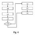
ワイヤレス接続方法を介して電子デバイスの到達可能性を決定する方法の第1の実施形態が、図3に示されている。この第1の実施形態では、ステップ101は、例えば、ワイヤレスネットワーク内のネットワークデバイスを介して、第1のワイヤレス通信プロトコルを使用して電子デバイスにテストメッセージを送信することを含む。ステップ103は、電子デバイスが第1のワイヤレス通信プロトコルを使用して到達可能であるかどうかを判断することを含む。テストメッセージに応答する送信を受信すると電子デバイスは第1のワイヤレス通信プロトコルを使用して到達可能であると判断される。
A first embodiment of a method for determining reachability of an electronic device via a wireless connection method is shown in FIG. In this first embodiment,
ステップ105は、電子デバイスが第2のワイヤレス通信プロトコルを使用して到達可能であるかどうかを判断することを含む。図3の実施形態では、ステップ105は、電子デバイスから第2のワイヤレス通信プロトコルを使用するブロードキャストを受信すると電子デバイスは第2のワイヤレス通信プロトコルを使用して到達可能であると判断することを含む。
Step 105 includes determining whether the electronic device is reachable using the second wireless communication protocol. In the embodiment of FIG. 3,
ステップ107は、第1のワイヤレス通信プロトコルを使用する電子デバイスの到達可能性及び第2のワイヤレス通信プロトコルを使用する電子デバイスの到達可能性に基づいて電子デバイスの状態のインディケーションを提供することを含む。 Step 107 provides an indication of the state of the electronic device based on the reachability of the electronic device using the first wireless communication protocol and the reachability of the electronic device using the second wireless communication protocol. include.
図3の実施形態では、次にステップ109が実行される。ステップ109は、電子デバイスが第1のワイヤレス通信プロトコルを介して到達不能であると判断すると第2のワイヤレス通信プロトコルを介して電子デバイスにコンフィギュレーションメッセージを送信することを含む。
In the embodiment of Figure 3,
方法の第2の実施形態が、図4に示されている。ステップ131は、第1のワイヤレス通信プロトコルを使用して電子デバイス、例えば、ランプに制御コマンドを送信することを含む。ステップ133は、電子デバイスが第1のワイヤレス通信プロトコルを使用して到達可能であるかどうかを判断することを含む。制御コマンドに対する確認応答が受信されない場合、電子デバイスは第1のワイヤレス通信プロトコルを使用して到達可能ではないと判断される。 A second embodiment of the method is shown in FIG. Step 131 includes sending control commands to an electronic device, eg, a lamp, using a first wireless communication protocol. Step 133 includes determining whether the electronic device is reachable using the first wireless communication protocol. If no acknowledgment is received for the control command, it is determined that the electronic device is not reachable using the first wireless communication protocol.
ステップ135は、電子デバイスが第2のワイヤレス通信プロトコルを使用して到達可能であるかどうかを判断することを含む。図4の実施形態では、ステップ135は、第2のワイヤレス通信プロトコルを介して電子デバイスにテストメッセージを送信することを含む。第2のワイヤレス通信プロトコルを介して電子デバイスに到達するために使用されることができるアドレスがわからない場合、テストメッセージは、電子デバイスによって認識され得るような、第1のワイヤレス通信プロトコルを介して電子デバイスに到達するために使用されることができるアドレスを含むブロードキャストメッセージであってもよい。
Step 135 includes determining whether the electronic device is reachable using the second wireless communication protocol. In the embodiment of FIG. 4,
ステップ137において、応答が第2のワイヤレス通信プロトコルを使用して電子デバイスから受信されるまである期間待たれる。ステップ139において、応答が電子デバイスから受信されたかどうかがチェックされる。
At
応答が電子デバイスから受信され、応答がどのようにして電子デバイスが第1のワイヤレス通信プロトコルを使用して到達されることができるかを示す情報を含む場合、ステップ131及び133が再び実行されるが、ここではステップ137で受信された情報を使用して実行される。ステップ133で送信された制御コマンドに対する確認応答が受信される場合、電子デバイスは第1のワイヤレス通信プロトコルを使用して到達可能であると判断される。制御コマンドが確認応答されない場合、電子デバイスは依然として第1のワイヤレス通信プロトコルを使用して到達可能ではないと判断される。
If a response is received from the electronic device and the response contains information indicating how the electronic device can be reached using the first wireless communication protocol, steps 131 and 133 are performed again. is now performed using the information received in
応答が上述の情報を含まない場合、次にステップ141が実行される。いずれの場合も、電子デバイスは第2のワイヤレス通信プロトコルを介して到達可能であると判断される。 If the response does not contain the above information, then step 141 is executed. In either case, the electronic device is determined reachable via the second wireless communication protocol.
ステップ139において、応答が電子デバイスから受信されていないと判断される場合、電子デバイスは第2のワイヤレス通信プロトコルを使用して到達不能であると判断され、次にステップ141が実行される。ステップ141は、第1のワイヤレス通信プロトコルを使用する電子デバイスの到達可能性及び第2のワイヤレス通信プロトコルを使用する電子デバイスの到達可能性に基づいて電子デバイスの状態のインディケーションを提供することを含む。
If in
図5及び6は、本発明を使用して決定されていないさらなる電子デバイスの状態を示すためのユーザインターフェースの例を示す。図5の例では、ユーザインターフェースの第1のスクリーン41が、図1のモバイルデバイス1のディスプレイ9に示されている。ユーザインターフェースを用いて、ユーザは、自身のコネクテッド照明デバイスを制御することができる。図1の照明デバイス15及び16は、それぞれアイコン51及び61によって並びにテキストフィールド52及び62の名前によって表されている。
Figures 5 and 6 show examples of user interfaces for indicating further electronic device states that have not been determined using the present invention. In the example of FIG. 5, a first screen 41 of the user interface is shown on the
図5の例では、アイコン51及び61は数字を含むが、照明デバイスをアイコンで異なるように表すことも可能である。照明デバイス15は「Hue Bloom」という名前でアイコン51によって表され、照明デバイス16は「Hue Go」という名前でアイコン52によって表されている。(アイコン51及び61によって表される)照明デバイス15及び16は、Living Roomグループ49に割り当てられている。
In the example of FIG. 5,
図5に描かれるユーザインターフェースにおいて、アイコン53及び63は、(アイコン51及び61によって表される)照明デバイス15及び16が到達可能であるか否かを示す。スクリーン41では、アイコン53及び63は、照明デバイス15及び16が到達可能であることを示している。アイコン54及び64は、それぞれ照明デバイス15及び16の状態を示す。スクリーン41では、アイコン54は、照明デバイス15の光源が現在オンであることを示し、アイコン64は、照明デバイス16の光源が現在オフであることを示している。アイコン54及び/又はアイコン64を押すことにより、対応する照明デバイスの光源が、オン/オフされることができる。
In the user interface depicted in FIG. 5,
このユーザインターフェースの第2のスクリーン42が、図6に示されている。この第2のスクリーン42では、アイコン63は、(アイコン61によって表される)照明デバイス16が到達可能ではないことを示している。アイコン64は、照明デバイス16の光源が現在オンであるのかオフであるのかがわからないことを示している。照明デバイス16の光源は、スクリーン42でアイコン64を押すことにより制御されることはできない。
A
図7は、本発明を使用して決定されているさらなる電子デバイスの状態を示すためのユーザインターフェースの第1の実施形態のスクリーン43を示す。(アイコン51によって表される)照明デバイス15の状態は、2つのアイコン(アイコン53及びアイコン59)を含む。アイコン53は、第1のワイヤレス通信プロトコルを使用する照明デバイス15の到達可能性を示す。アイコン59は、第2のワイヤレス通信プロトコルを使用する照明デバイス15の到達可能性を示す。
FIG. 7 shows
(アイコン61によって表される)照明デバイス16の状態は、2つのアイコン(アイコン63及びアイコン69)を含む。アイコン63は、第1のワイヤレス通信プロトコルを使用する照明デバイス16の到達可能性を示す。アイコン69は、第2のワイヤレス通信プロトコルを使用する照明デバイス16の到達可能性を示す。図6のスクリーン42におけるように、照明デバイス16は、アイコン63によって示されるように、第1のワイヤレス通信プロトコルを使用して到達可能ではない。しかしながら、照明デバイス15及び16の両方は、アイコン59及び69によって示されるように、第2のワイヤレス通信プロトコルを使用して到達可能である。それゆえ、ユーザにとって、照明デバイス16はオンであり、問題はそれほど単純ではないことが明らかである。
The status of lighting device 16 (represented by icon 61) includes two icons (
図7のユーザインターフェースの第1の実施形態では、アイコン64は、照明デバイス16の光源がオンであるかオフであるかがわからないことを示している。なぜなら、この情報が第1のワイヤレス通信プロトコルを介して得られることができなかったためである。図8のユーザインターフェースの第2の実施形態では、スクリーン44に示されるアイコン64は、照明デバイス16の光源がオフであることを示している。なぜなら、この情報が照明デバイス16によって第2のワイヤレス通信プロトコルを使用して送信されるメッセージに含められたためである。
In the first embodiment of the user interface of FIG. 7,
図9のユーザインターフェースの第3の実施形態では、スクリーン45は、同様の又は同じ状態を有するデバイスを識別する。この例では、スクリーン45は、(アイコン71によって表される)第1のプロトコルを介して到達可能ではないが、(アイコン72によって表される)第2のプロトコルを介して到達可能である照明デバイスを示している。スクリーン45は、特定の状態、例えば、「第1のプロトコルを介して到達可能ではないが、第2のプロトコルを介して到達可能である」、及び/又は、特定の照明デバイス、例えば、照明デバイス15若しくは照明デバイス16を選択した後に示されてもよい。ユーザインターフェースのこの第3の実施形態では、アイコン54及び64は、それぞれの照明デバイスの光源がオンであるかオフであるかがわからないことを示している。なぜなら、この情報が、第1のワイヤレス通信プロトコルを使用して得られることができなかった、及び、第2のワイヤレス通信プロトコルを使用して受信された情報に含まれなかったためである。
In a third embodiment of the user interface of FIG. 9,
方法の第3の実施形態が、図10に示されている。ステップ151は、電子デバイスが第2のワイヤレス通信プロトコルを介してワイヤレスネットワーク内のさらなる電子デバイスからブロードキャストを受信することを含む。このブロードキャストを受信するとさらなる電子デバイスは第2のワイヤレス通信プロトコルを使用して到達可能であると判断される。応答は、さらなる電子デバイスが第1のワイヤレス通信プロトコルを使用して到達可能であるかどうかを示す情報を含む。 A third embodiment of the method is shown in FIG. Step 151 includes the electronic device receiving broadcasts from additional electronic devices in the wireless network via the second wireless communication protocol. Upon receiving this broadcast, the additional electronic device is determined reachable using the second wireless communication protocol. The response includes information indicating whether the additional electronic device is reachable using the first wireless communication protocol.
ステップ153は、ブロードキャストに基づいて電子デバイスとさらなる電子デバイスとの間の近接性の指標を表す値を決定することを含む。値は、例えば、ブロードキャストが受信される強度のインジケータ(すなわち、RSSI)であってもよく、又は、このRSSIに基づいて決定されてもよい。値は、他のデバイスからの入力を使用して決定されてもよい。例えば、モバイルデバイスが、自身のRSSI測定に基づいてランプAからのRSSI_A、ランプBからのRSSI_B及びランプCからのRSSI_Cを決定し、ランプもクロスRSSI測定も行い、これらの測定値をモバイルデバイスに提供する(ゆえに、モバイルデバイスは、BからのRSSI_A、AからのRSSI_B等を受信する)場合、とりわけモバイルデバイスが複数のランプに近接している場合、モバイルデバイスはあるフォールスポジティブを破棄することができ得る。 Step 153 includes determining a value representing an indication of proximity between the electronic device and the further electronic device based on the broadcast. The value may be, for example, an indicator of the strength at which the broadcast is received (ie, RSSI), or may be determined based on this RSSI. Values may be determined using input from other devices. For example, if a mobile device determines RSSI_A from lamp A, RSSI_B from lamp B, and RSSI_C from lamp C based on its own RSSI measurements, the lamp also makes cross RSSI measurements, and sends these measurements to the mobile device. (so the mobile device receives RSSI_A from B, RSSI_B from A, etc.), the mobile device may discard certain false positives, especially if the mobile device is in proximity to multiple lamps. can be done
決定された値、例えば、RSSIは、ステップ155で閾値と比較される。近接性の指標がある閾値よりも小さい場合、例えば、RSSI値が最小RSSIよりも大きい場合、次にステップ157が実行される。
The determined value, eg, RSSI, is compared to a threshold at
ステップ157は、第1のワイヤレス通信プロトコルを使用するさらなる電子デバイスの到達可能性及び第2のワイヤレス通信プロトコルを使用するさらなる電子デバイスの到達可能性に基づいてさらなる電子デバイスの状態のインディケーションを提供することを含む。図10の実施形態では、インディケーションは、近接性の指標がある閾値よりも小さいと判断すると提供される通知を含む。斯くして、ステップ157は、近接性の指標がある閾値よりも小さい場合にのみ実行される。
A
図11は、図3、4及び10を参照して述べられたような方法を実行し得る、例示的なデータ処理システムを示すブロック図を示す。 FIG. 11 depicts a block diagram illustrating an exemplary data processing system capable of performing methods such as those described with reference to FIGS.
図11に示されるように、データ処理システム300は、システムバス306を介してメモリ要素304に結合される、少なくとも1つのプロセッサ302を含んでもよい。それゆえ、データ処理システムは、メモリ要素304内にプログラムコードを記憶してもよい。さらに、プロセッサ302は、システムバス306を介してメモリ要素304からアクセスされるプログラムコードを実行してもよい。一態様では、データ処理システムは、プログラムコードを記憶及び/又は実行するために好適な、コンピュータとして実装されてもよい。しかしながら、データ処理システム300は、本明細書内で述べられる機能を実行することが可能な、プロセッサ及びメモリを含む任意のシステムの形態で実装されてもよい点を理解されたい。
As shown in FIG. 11,
メモリ要素304は、例えば、ローカルメモリ308及び1つ以上の大容量記憶デバイス310などの、1つ以上の物理メモリデバイスを含んでもよい。ローカルメモリとは、プログラムコードの実際の実行中に一般に使用される、ランダムアクセスメモリ又は他の非永続的メモリデバイスを指してもよい。大容量記憶デバイスは、ハードドライブ又は他の永続的データ記憶デバイスとして実装されてもよい。処理システム300はまた、実行中に大容量記憶デバイス310からプログラムコードが取得されなければならない回数を低減するために、少なくとも一部のプログラムコードの一時記憶を提供する、1つ以上のキャッシュメモリ(図示せず)を含んでもよい。また、処理システム300は、例えば、処理システム300がクラウドコンピューティングプラットフォームの一部である場合、別の処理システムのメモリ要素を使用することができてもよい。
入力デバイス312及び出力デバイス314として示される、入出力(input/output;I/O)デバイスが、オプションとして、データ処理システムに結合されることができる。入力デバイスの例としては、限定するものではないが、キーボード、マウス等のポインティングデバイス、(例えば、ボイス及び/又はスピーチ認識のための)マイク等を挙げることができる。出力デバイスの例としては、限定するものではないが、モニタ又はディスプレイ、スピーカ等を挙げることができる。入力デバイス及び/又は出力デバイスは、直接、又は介在I/Oコントローラを介して、データ処理システムに結合されてもよい。
Input/output (I/O) devices, designated
一実施形態では、入力デバイス及び出力デバイスは、複合型入力/出力デバイス(入力デバイス312及び出力デバイス314を取り囲む破線で図11に示されるもの)として実装されてもよい。そのような複合型デバイスの一例は、「タッチスクリーンディスプレイ」又は単に「タッチスクリーン」と称される場合もある、タッチ感知ディスプレイである。そのような実施形態では、デバイスへの入力は、タッチスクリーンディスプレイ上、又はタッチスクリーンディスプレイの近くでの、例えばスタイラス又はユーザの指等の、物理的実体の移動によって提供されてもよい。
In one embodiment, the input and output devices may be implemented as hybrid input/output devices (shown in FIG. 11 by the dashed lines surrounding
ネットワークアダプタ316もまた、データ処理システムに結合されて、介在する私設ネットワーク又は公衆ネットワークを介して、そのデータ処理システムが、他のシステム、コンピュータシステム、リモートネットワークデバイス、及び/又はリモート記憶デバイスに結合されることを可能にしてもよい。ネットワークアダプタは、上述のシステム、デバイス、及び/又はネットワークによってデータ処理システム300に送信されるデータを受信するための、データ受信機と、データ処理システム300から上述のシステム、デバイス、及び/又はネットワークにデータを送信するための、データ送信機とを含んでもよい。モデム、ケーブルモデム、及びEthernet(登録商標)カードは、データ処理システム300と共に使用されてもよい、種々のタイプのネットワークアダプタの例である。
図11に示されるように、メモリ要素304は、アプリケーション318を記憶してもよい。様々な実施形態では、アプリケーション318は、ローカルメモリ308、1つ以上の大容量記憶デバイス310内に記憶されてもよく、あるいは、それらローカルメモリ及び大容量記憶デバイスとは別個であってもよい。データ処理システム300はさらに、アプリケーション318の実行を容易にすることが可能なオペレーティングシステム(図8には示さず)を実行してもよい点を理解されたい。アプリケーション318は、実行可能プログラムコードの形態で実装されており、データ処理システム300によって、例えばプロセッサ302によって、実行されることができる。アプリケーションの実行に応答して、データ処理システム300は、本明細書で述べられる1つ以上の動作又は方法ステップを実行するよう構成されてもよい。
As shown in FIG. 11,
本発明の様々な実施形態は、コンピュータシステムと共に使用するためのプログラム製品として実装されてもよく、このプログラム製品のプログラムは、(本明細書で説明される方法を含めた)実施形態の機能を定義する。一実施形態では、このプログラムは、様々な非一時的コンピュータ可読記憶媒体上に含まれることができ、本明細書で使用されるとき、「非一時的コンピュータ可読記憶媒体」という表現は、全てのコンピュータ可読媒体を含むが、唯一の例外は一時的な伝搬信号である。別の実施形態では、このプログラムは、様々な一時的コンピュータ可読記憶媒体上に含まれることができる。例示的なコンピュータ可読記憶媒体としては、限定するものではないが、(i)情報が永続的に記憶される、書き込み不可記憶媒体(例えば、CD-ROMドライブによって読み取り可能なCD-ROMディスク、ROMチップ、又は任意のタイプの不揮発性固体半導体メモリ等の、コンピュータ内部の読み出し専用メモリデバイス)、及び(ii)変更可能な情報が記憶される、書き込み可能記憶媒体(例えば、フラッシュメモリ、ディスケットドライブ若しくはハードディスクドライブ内部のフロッピー(登録商標)ディスク、又は任意のタイプのランダムアクセス固体半導体メモリ)が挙げられる。コンピュータプログラムは、本明細書で述べられるプロセッサ302上で実行されてもよい。
Various embodiments of the invention may be implemented as a program product for use with a computer system, the programs of which program perform the functions of the embodiments (including the methods described herein). Define. In one embodiment, the program can be contained on a variety of non-transitory computer-readable storage media, and as used herein the term "non-transitory computer-readable storage medium" refers to any Including computer readable media, the only exception being transitory propagating signals. In another embodiment, the program may be contained on various temporary computer-readable storage media. Exemplary computer readable storage media include, but are not limited to: (i) non-writable storage media on which information is permanently stored (e.g., CD-ROM discs readable by a CD-ROM drive, ROM (ii) a writable storage medium (e.g., flash memory, diskette drive or floppy disk inside a hard disk drive, or any type of random access solid state semiconductor memory). Computer programs may run on the
本明細書で使用される用語法は、特定の実施形態を説明することのみを目的とするものであり、本発明を限定することを意図するものではない。本明細書で使用されるとき、単数形「a」、「an」、及び「the」は、文脈がそうではないことを明確に示さない限り、複数形も含むことが意図される。本明細書で使用されるとき、用語「含む(comprises)」及び/又は「含んでいる(comprising)」は、記述された特徴、整数、ステップ、動作、要素、及び/又は構成要素の存在を指定するものであるが、1つ以上の他の特徴、整数、ステップ、動作、要素、構成要素、及び/又はそれらの群の存在若しくは追加を排除するものではない点が、更に理解されるであろう。 The terminology used herein is for the purpose of describing particular embodiments only and is not intended to be limiting of the invention. As used herein, the singular forms "a," "an," and "the" are intended to include the plural forms as well, unless the context clearly indicates otherwise. As used herein, the terms “comprises” and/or “comprising” refer to the presence of the stated features, integers, steps, acts, elements, and/or components. It is further understood that the specification does not preclude the presence or addition of one or more other features, integers, steps, acts, elements, components, and/or groups thereof. be.
以下の請求項における全てのミーンズプラスファンクション又はステッププラスファンクションの要素の、対応する構造、材料、行為、及び均等物は、具体的に特許請求される他の特許請求要素と組み合わせて機能を実行するための、任意の構造、材料、又は行為を含むことが意図される。本発明の実施形態の説明は、例示を目的として提示されてきたが、網羅的であるか、又は開示された形態の実装形態に限定されることを意図するものではない。本発明の範囲及び趣旨から逸脱することなく、多くの修正形態及び変形形態が当業者には明らかとなるであろう。実施形態は、本発明の原理及び一部の実際的応用を最良に説明し、想到される特定の用途に適するような様々な修正を有する様々な実施形態に関して、他の当業者が本発明を理解することを可能にするために、選択及び説明されるものとした。 Corresponding structures, materials, acts, and equivalents of all means-plus-function or step-plus-function elements in the following claims perform the functions in combination with other claim elements specifically claimed. is intended to include any structure, material, or act for The description of embodiments of the present invention has been presented for purposes of illustration, but is not intended to be exhaustive or limited to the forms of implementation disclosed. Many modifications and variations will become apparent to those skilled in the art without departing from the scope and spirit of this invention. The embodiments best illustrate the principles and some practical applications of the invention and may be used by others skilled in the art to interpret the invention in terms of various embodiments with various modifications as are appropriate for the particular uses envisioned. It has been selected and explained to enable understanding.
Claims (13)
少なくとも1つの入力インターフェースと、
少なくとも1つの出力インターフェースと、
前記さらなる電子デバイスが第1のワイヤレス通信プロトコルを使用して到達可能であるかどうかを判断するために前記少なくとも1つの入力インターフェースを使用する、
前記さらなる電子デバイスが第2のワイヤレス通信プロトコルを使用して到達可能であるかどうかを判断するために前記少なくとも1つの入力インターフェースを使用する、及び
前記第1のワイヤレス通信プロトコルを使用する前記さらなる電子デバイスの前記到達可能性及び前記第2のワイヤレス通信プロトコルを使用する前記さらなる電子デバイスの前記到達可能性に基づいて前記さらなる電子デバイスの状態のインディケーションを提供するために前記少なくとも1つの出力インターフェースを使用する、
ように構成される、少なくとも1つのプロセッサと、
を含み、
前記少なくとも1つのプロセッサは、前記第1のワイヤレス通信プロトコルを使用して前記さらなる電子デバイスにテストメッセージを送信するために前記少なくとも1つの出力インターフェースを使用する、及び、前記テストメッセージに応答する送信を受信すると前記さらなる電子デバイスは前記第1のワイヤレス通信プロトコルを使用して到達可能であると判断するために前記少なくとも1つの入力インターフェースを使用するように構成される、電子デバイス。 An electronic device for determining reachability of a further electronic device via a wireless connection, said further electronic device being part of a wireless network, said electronic device comprising:
at least one input interface;
at least one output interface;
using the at least one input interface to determine if the further electronic device is reachable using a first wireless communication protocol;
using the at least one input interface to determine if the further electronic device is reachable using a second wireless communication protocol; and the further electronic device using the first wireless communication protocol. the at least one output interface for providing an indication of the status of the further electronic device based on the reachability of the device and the reachability of the further electronic device using the second wireless communication protocol; use,
at least one processor configured to
including
The at least one processor uses the at least one output interface to transmit a test message to the further electronic device using the first wireless communication protocol, and transmits in response to the test message. Electronic device configured to use said at least one input interface to determine, upon receipt, that said further electronic device is reachable using said first wireless communication protocol.
当該電子デバイスと前記さらなる電子デバイスとの間の近接性の指標を表す値を決定する、及び
前記近接性の指標がある閾値よりも小さいことに依存して前記インディケーションを提供する、
ように構成される、請求項1に記載の電子デバイス。 The at least one processor
determining a value representative of the proximity indicator between the electronic device and the further electronic device, and providing the indication in dependence on the proximity indicator being less than a threshold;
The electronic device of claim 1, configured to:
前記電子デバイスが第1のワイヤレス通信プロトコルを使用して到達可能であるかどうかを判断することと、
前記電子デバイスが第2のワイヤレス通信プロトコルを使用して到達可能であるかどうかを判断することと、
前記第1のワイヤレス通信プロトコルを使用する前記電子デバイスの前記到達可能性及び前記第2のワイヤレス通信プロトコルを使用する前記電子デバイスの前記到達可能性に基づいて前記電子デバイスの状態のインディケーションを提供することと、
を含み、
前記電子デバイスが第1のワイヤレス通信プロトコルを使用して到達可能であるかどうかを判断することは、前記第1のワイヤレス通信プロトコルを使用して前記電子デバイスにテストメッセージを送信することと、前記テストメッセージに応答する送信を受信すると前記電子デバイスは前記第1のワイヤレス通信プロトコルを使用して到達可能であると判断することとを含む、方法。 A method of determining reachability of an electronic device over a wireless connection, said electronic device being part of a wireless network, the method comprising:
determining whether the electronic device is reachable using a first wireless communication protocol;
determining whether the electronic device is reachable using a second wireless communication protocol;
providing an indication of the status of the electronic device based on the reachability of the electronic device using the first wireless communication protocol and the reachability of the electronic device using the second wireless communication protocol. and
including
Determining whether the electronic device is reachable using a first wireless communication protocol comprises sending a test message to the electronic device using the first wireless communication protocol; determining that the electronic device is reachable using the first wireless communication protocol upon receiving a transmission in response to a test message.
Applications Claiming Priority (3)
| Application Number | Priority Date | Filing Date | Title |
|---|---|---|---|
| EP19157113.2 | 2019-02-14 | ||
| EP19157113 | 2019-02-14 | ||
| PCT/EP2020/053259 WO2020165070A1 (en) | 2019-02-14 | 2020-02-10 | Determining a reachability of an electronic device over multiple wireless communication protocols |
Publications (2)
| Publication Number | Publication Date |
|---|---|
| JP2022515925A JP2022515925A (en) | 2022-02-22 |
| JP7194840B2 true JP7194840B2 (en) | 2022-12-22 |
Family
ID=65685102
Family Applications (1)
| Application Number | Title | Priority Date | Filing Date |
|---|---|---|---|
| JP2021547370A Active JP7194840B2 (en) | 2019-02-14 | 2020-02-10 | Determining the reachability of electronic devices over multiple wireless communication protocols |
Country Status (9)
| Country | Link |
|---|---|
| US (1) | US11871498B2 (en) |
| EP (1) | EP3925418B1 (en) |
| JP (1) | JP7194840B2 (en) |
| CN (1) | CN113424662A (en) |
| ES (1) | ES2935590T3 (en) |
| FI (1) | FI3925418T3 (en) |
| HU (1) | HUE060748T2 (en) |
| PL (1) | PL3925418T3 (en) |
| WO (1) | WO2020165070A1 (en) |
Citations (4)
| Publication number | Priority date | Publication date | Assignee | Title |
|---|---|---|---|---|
| JP2011082775A (en) | 2009-10-07 | 2011-04-21 | Sii Data Service Kk | Radio communication system, and radio communication method |
| JP2014186417A (en) | 2013-03-22 | 2014-10-02 | Hochiki Corp | Alarm system |
| JP2016119658A (en) | 2014-12-05 | 2016-06-30 | テクニカル コンシューマー プロダクツ インコーポレイテッド | Dynamic configuration for wireless peripheral device |
| JP2016197831A (en) | 2015-04-06 | 2016-11-24 | アルパイン株式会社 | Electronic device, communication system, communication setting program, and communication setting method |
Family Cites Families (20)
| Publication number | Priority date | Publication date | Assignee | Title |
|---|---|---|---|---|
| WO2008084414A1 (en) | 2007-01-04 | 2008-07-17 | Koninklijke Philips Electronics N.V. | Network communication system |
| WO2011031891A1 (en) | 2009-09-09 | 2011-03-17 | Abbott Diabetes Care Inc. | Analyzing wireless communication degradation through comparison of communication links |
| US9730144B2 (en) * | 2010-11-01 | 2017-08-08 | Costa Apostolakis | System and method for mixed-mesh wireless networking |
| US9596156B2 (en) * | 2011-09-26 | 2017-03-14 | Theranos, Inc. | Network connectivity methods and systems |
| JP5658706B2 (en) * | 2012-03-29 | 2015-01-28 | 株式会社東芝 | Communication station, communication control program, and communication network system |
| US9100299B2 (en) * | 2012-05-21 | 2015-08-04 | Verizon Patent And Licensing Inc. | Detecting error conditions in standby links |
| US8989807B2 (en) * | 2013-02-28 | 2015-03-24 | Intel Mobile Communications GmbH | Communication terminal device, communication device, communication network server and method for controlling |
| CN104516798B (en) * | 2013-09-26 | 2018-06-15 | 晨星半导体股份有限公司 | Wireless one-to-many test system |
| US9727357B2 (en) * | 2013-10-01 | 2017-08-08 | International Business Machines Corporation | Failover detection and treatment in checkpoint systems |
| US9661445B2 (en) * | 2014-05-02 | 2017-05-23 | Qualcomm Incorporated | Methods and apparatus for integrating bluetooth devices into neighbor aware networks |
| KR20160012661A (en) * | 2014-07-25 | 2016-02-03 | 한국전자통신연구원 | Apparatus and method for controlling zigbee lighting |
| KR101747923B1 (en) * | 2014-10-15 | 2017-06-16 | (주)씨지라이팅 | A wireless lighting device and a method for controlling thereof |
| JP6368050B2 (en) * | 2014-11-24 | 2018-08-01 | フィリップス ライティング ホールディング ビー ヴィ | Control of lighting devices connected to the network |
| JP6772248B2 (en) * | 2015-08-07 | 2020-10-21 | シグニファイ ホールディング ビー ヴィSignify Holding B.V. | Determining the state of network devices |
| KR102347069B1 (en) * | 2015-12-14 | 2022-01-04 | 삼성전자주식회사 | Electronic device and operating method for the same |
| HK1218492A2 (en) * | 2015-12-30 | 2017-02-17 | 演基發展有限公司 | Method for controlling wireless communication between a mobile device and an electronic device |
| CN105813138A (en) * | 2016-03-07 | 2016-07-27 | 联想(北京)有限公司 | Information processing method and first electronic device |
| CN109076681B (en) * | 2016-03-08 | 2020-04-17 | 伊顿智能动力有限公司 | Controller for interconnected lighting devices |
| JP6995770B2 (en) * | 2016-06-15 | 2022-01-17 | アイロボット・コーポレーション | Systems and methods for controlling autonomous mobile robots |
| US9820361B1 (en) * | 2016-07-20 | 2017-11-14 | Abl Ip Holding Llc | Wireless lighting control system |
-
2020
- 2020-02-10 US US17/428,701 patent/US11871498B2/en active Active
- 2020-02-10 PL PL20702841.6T patent/PL3925418T3/en unknown
- 2020-02-10 JP JP2021547370A patent/JP7194840B2/en active Active
- 2020-02-10 WO PCT/EP2020/053259 patent/WO2020165070A1/en unknown
- 2020-02-10 ES ES20702841T patent/ES2935590T3/en active Active
- 2020-02-10 EP EP20702841.6A patent/EP3925418B1/en active Active
- 2020-02-10 HU HUE20702841A patent/HUE060748T2/en unknown
- 2020-02-10 CN CN202080014284.3A patent/CN113424662A/en active Pending
- 2020-02-10 FI FIEP20702841.6T patent/FI3925418T3/en active
Patent Citations (4)
| Publication number | Priority date | Publication date | Assignee | Title |
|---|---|---|---|---|
| JP2011082775A (en) | 2009-10-07 | 2011-04-21 | Sii Data Service Kk | Radio communication system, and radio communication method |
| JP2014186417A (en) | 2013-03-22 | 2014-10-02 | Hochiki Corp | Alarm system |
| JP2016119658A (en) | 2014-12-05 | 2016-06-30 | テクニカル コンシューマー プロダクツ インコーポレイテッド | Dynamic configuration for wireless peripheral device |
| JP2016197831A (en) | 2015-04-06 | 2016-11-24 | アルパイン株式会社 | Electronic device, communication system, communication setting program, and communication setting method |
Also Published As
| Publication number | Publication date |
|---|---|
| CN113424662A (en) | 2021-09-21 |
| FI3925418T3 (en) | 2023-01-13 |
| EP3925418A1 (en) | 2021-12-22 |
| ES2935590T3 (en) | 2023-03-08 |
| US11871498B2 (en) | 2024-01-09 |
| EP3925418B1 (en) | 2022-10-12 |
| HUE060748T2 (en) | 2023-04-28 |
| PL3925418T3 (en) | 2023-06-19 |
| WO2020165070A1 (en) | 2020-08-20 |
| US20220117064A1 (en) | 2022-04-14 |
| JP2022515925A (en) | 2022-02-22 |
Similar Documents
| Publication | Publication Date | Title |
|---|---|---|
| EP2677774B1 (en) | Method and apparatus for managing a group profile in a wi-fi direct communication system | |
| CN106576221B (en) | Terminal for internet of things and operation method thereof | |
| CN107360633B (en) | Pairing connection method and device of virtual reality system and virtual reality system | |
| JP2021530762A (en) | Local control and / or registration of smart devices by assistant client devices | |
| CN106357485A (en) | Method and device for marking equipment | |
| KR20160052105A (en) | Method for transmitting and receiving data and Electronic device using the same | |
| TWI426808B (en) | Method of piaring a computer and wireless electronic devices | |
| US9357577B2 (en) | Automated connection to a preferred wireless device | |
| JP7163534B2 (en) | Presentation of the current status of the device depending on the privacy mode | |
| JP7194840B2 (en) | Determining the reachability of electronic devices over multiple wireless communication protocols | |
| TW201828765A (en) | Launch method for applications with early-time memory reclaim and electronic device | |
| US20160073219A1 (en) | Communication device and bluetooth communication system | |
| JP7179205B2 (en) | Providing Notifications for Lighting Devices Without User-Specified Power Switch Behavior | |
| US20230033157A1 (en) | Displaying a light control ui on a device upon detecting interaction with a light control device | |
| CN113378670A (en) | Intelligent construction site construction method and device and electronic equipment | |
| US20230092759A1 (en) | Disable control of a lighting device by a light control device in a query mode | |
| US20230199932A1 (en) | Executing control command in dependence on presence being detected | |
| US20230123882A1 (en) | Causing a lighting device to visually indicate whether it can be commissioned using a particular wireless technology | |
| WO2022184569A1 (en) | Displaying an aggregation of data in dependence on a distance to a closest device in an image | |
| JP6450232B2 (en) | Data transmission apparatus, display system, and computer program | |
| CN114616927A (en) | Configuring a bridge having a group after adding the bridge to a lighting system | |
| JP2016066897A (en) | Electric apparatus, communication adaptor, and program |
Legal Events
| Date | Code | Title | Description |
|---|---|---|---|
| A621 | Written request for application examination |
Free format text: JAPANESE INTERMEDIATE CODE: A621 Effective date: 20211007 |
|
| A871 | Explanation of circumstances concerning accelerated examination |
Free format text: JAPANESE INTERMEDIATE CODE: A871 Effective date: 20211007 |
|
| A131 | Notification of reasons for refusal |
Free format text: JAPANESE INTERMEDIATE CODE: A131 Effective date: 20220216 |
|
| A601 | Written request for extension of time |
Free format text: JAPANESE INTERMEDIATE CODE: A601 Effective date: 20220512 |
|
| A521 | Request for written amendment filed |
Free format text: JAPANESE INTERMEDIATE CODE: A523 Effective date: 20220815 |
|
| TRDD | Decision of grant or rejection written | ||
| A01 | Written decision to grant a patent or to grant a registration (utility model) |
Free format text: JAPANESE INTERMEDIATE CODE: A01 Effective date: 20221124 |
|
| A61 | First payment of annual fees (during grant procedure) |
Free format text: JAPANESE INTERMEDIATE CODE: A61 Effective date: 20221212 |
|
| R150 | Certificate of patent or registration of utility model |
Ref document number: 7194840 Country of ref document: JP Free format text: JAPANESE INTERMEDIATE CODE: R150 |