JP7194574B2 - Electric driving device and electric power steering device - Google Patents
Electric driving device and electric power steering device Download PDFInfo
- Publication number
- JP7194574B2 JP7194574B2 JP2018230642A JP2018230642A JP7194574B2 JP 7194574 B2 JP7194574 B2 JP 7194574B2 JP 2018230642 A JP2018230642 A JP 2018230642A JP 2018230642 A JP2018230642 A JP 2018230642A JP 7194574 B2 JP7194574 B2 JP 7194574B2
- Authority
- JP
- Japan
- Prior art keywords
- cover
- annular
- motor housing
- side annular
- electric
- Prior art date
- Legal status (The legal status is an assumption and is not a legal conclusion. Google has not performed a legal analysis and makes no representation as to the accuracy of the status listed.)
- Active
Links
Images


Landscapes
- Power Steering Mechanism (AREA)
- Motor Or Generator Frames (AREA)
Description
本発明は電動駆動装置及び電動パワーステアリング装置に係り、特に電子制御装置を内蔵した電動駆動装置及び電動パワーステアリング装置に関する。 The present invention relates to an electric drive device and an electric power steering device, and more particularly to an electric drive device and an electric power steering device incorporating an electronic control device.
一般的な産業機械分野においては、電動モータによって機械系制御要素を駆動することが行われているが、最近では電動モータの回転速度や回転トルクを制御する半導体素子等からなる電子制御部を電動モータに一体的に組み込む、いわゆる機電一体型の電動駆動装置が採用され始めている。 In the field of general industrial machinery, electric motors are used to drive mechanical control elements. A so-called electromechanical integrated type electric drive device, which is integrally incorporated into a motor, is beginning to be adopted.
機電一体型の電動駆動装置の例として、例えば自動車の電動パワーステアリング装置においては、運転者がステアリングホィールを操作することにより回動するステアリングシャフトの回動方向と回動トルクとを検出し、この検出値に基づいてステアリングシャフトの回動方向と同じ方向へ回動するように電動モータを駆動し、操舵アシストトルクを発生させるように構成されている。この電動モータを制御するため、電子制御部(ECU:Electronic Control Unit)がパワーステアリング装置に設けられている。 As an example of an electromechanically integrated type electric drive device, for example, in an electric power steering device for an automobile, the rotational direction and rotational torque of a steering shaft that is rotated by the driver's operation of the steering wheel are detected. Based on the detected value, the electric motor is driven so as to rotate in the same direction as the steering shaft, thereby generating steering assist torque. In order to control the electric motor, an electronic control unit (ECU) is provided in the power steering device.
従来の電動パワーステアリング装置としては、例えば、特開2015-134598号公報(特許文献1)に記載のものが知られている。特許文献1には、電動モータ部と電子制御部とにより構成された電動パワーステアリング装置が記載されている。そして、電動モータ部の電動モータは、アルミ合金等から作られた筒部を有するモータハウジングに収納され、電子制御部の電子部品が実装された基板は、モータハウジングの軸方向の出力軸とは反対側に配置されたECUハウジングとして機能するヒートシンクに取り付けられている。 As a conventional electric power steering device, for example, one described in Japanese Patent Application Laid-Open No. 2015-134598 (Patent Document 1) is known. Japanese Patent Application Laid-Open No. 2002-200001 describes an electric power steering device that is composed of an electric motor section and an electronic control section. The electric motor of the electric motor section is housed in a motor housing having a tubular section made of aluminum alloy or the like, and the board on which the electronic components of the electronic control section are mounted is located at the axial direction of the output shaft of the motor housing. It is attached to a heatsink that acts as the ECU housing located on the opposite side.
ヒートシンクに取り付けられる基板は、電源回路部、電動モータを駆動制御するMOSFET、或いはIGBT等のようなパワースイッチング素子を有する電力変換回路部、及びパワースイッチング素子を制御する制御回路部を備え、パワースイッチング素子の出力端子と電動モータの入力端子とはバスバーを介して電気的に接続されている。 The substrate attached to the heat sink includes a power supply circuit, a power conversion circuit having power switching elements such as MOSFETs or IGBTs for driving and controlling the electric motor, and a control circuit for controlling the power switching elements. An output terminal of the element and an input terminal of the electric motor are electrically connected through a bus bar.
そして、ヒートシンクに取り付けられた電子制御部には、合成樹脂から作られたコネクタケースを介して電源から電力が供給され、また検出センサ類から運転状態等の検出信号が供給されている。コネクタケースは蓋体として機能しており、ヒートシンクを密閉して塞ぐように固定され、また固定ねじによってヒートシンクの外周表面に固定されている。 The electronic control unit attached to the heat sink is supplied with electric power from a power source through a connector case made of synthetic resin, and is also supplied with detection signals such as operating conditions from detection sensors. The connector case functions as a lid body, is fixed to hermetically close the heat sink, and is fixed to the outer peripheral surface of the heat sink by fixing screws.
尚、この他に電子制御装置を一体化した電動駆動装置としては、電動ブレーキや各種油圧制御用の電動油圧制御器等が知られているが、以下の説明では代表して電動パワーステアリング装置について説明する。 In addition, as an electric drive device integrated with an electronic control device, an electric brake, an electrohydraulic controller for controlling various hydraulic pressures, and the like are known. explain.
ここで、特許文献1にあるような構成の電動パワーステアリング装置においては、モータハウジングとヒートシンク及びコネクタケースは外周側に突出して形成された固定部を挿通した固定ねじによって共締めされる構成である。
Here, in the electric power steering apparatus having the configuration disclosed in
そして、モータハウジングとヒートシンクの間、或いはヒートシンクとコネクタケースの間は液密のためにOリング等のシール部材が使用されている。更に、モータハウジングとヒートシンクの間、或いはヒートシンクとコネクタケースの固定には固定ねじによって固定されている。尚、ヒートシンクを使用しない場合は、モータハウジングとコネクタケースの間にOリングを介装して固定ねじで固定する構成となっている。 A sealing member such as an O-ring is used between the motor housing and the heat sink or between the heat sink and the connector case for liquid tightness. Furthermore, fixing screws are used to fix between the motor housing and the heat sink or between the heat sink and the connector case. When the heat sink is not used, an O-ring is interposed between the motor housing and the connector case and fixed with fixing screws.
ところで、自動車においては融雪剤等を散布された道路を走行する場合や、海岸線に近い道路を走行する場合が往々にしてある。このため、融雪された道路や、雨が降った海岸線に近い道路を走行する場合、塩水が自動車の床下に浸入することは良く経験することである。このため、Oリングだけの液密シール構造の場合、Oリングが配置されている領域までの間は、実質的に嵌合隙間が形成されることになる。このため、この嵌合隙間に塩水が入り込み、Oリング収納部が腐食されて、最悪の場合は液密不良を惹起して塩水が内部に浸入して電気的な信頼性を損なう恐れがある。 By the way, automobiles often travel on roads sprayed with snow-melting agents or the like, or on roads near coastlines. For this reason, when driving on a snow-melted road or on a road near a coastline after rain, it is common to experience salt water entering under the floor of the automobile. Therefore, in the case of a liquid-tight seal structure with only an O-ring, a substantial fitting gap is formed up to the area where the O-ring is arranged. For this reason, salt water enters the fitting gap, corrodes the O-ring accommodating portion, and in the worst case causes a liquid-tightness failure, which may cause salt water to enter the interior and impair electrical reliability.
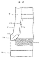
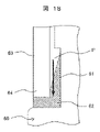
そこで、このような課題を解決するために、例えば図18に示す通り、モータハウジングの端面部に電子制御部を配置し、これを覆う金属カバーの開口端をモータハウジングの端面に液状シール剤を介して接合する構成が考えられる。 Therefore, in order to solve such problems, for example, as shown in FIG. It is possible to conceive of a configuration in which the connection is made through
図18において、モータハウジング60の外周面には、内側方向に後退する環状のシール剤収納溝61が形成されており、このシール剤収納溝61に液状シール剤62を充填した後に、金属カバー63の金属カバー側環状先端部64でシール剤収納溝61を覆うように配置することで、モータハウジング60と金属カバー63を液密的に接合することができる。
In FIG. 18, an annular sealing
ところで、液状シール剤62は塗布した時の形状を維持するため、接着性と粘性を備えており、これによって、金属カバー側環状先端部64とシール剤収納溝61の間を液状シール剤62で接合することができる。しかしながら、この接着性と粘性を備えていることが要因となって、金属カバー側環状先端部64をモータハウジング60の端面側に矢印の方向に押し込んでいく時、金属カバー側環状先端部64の内周面に接する液状シール剤62に一方向(図面では下側矢印方向)に引張り力が作用する。
By the way, the
このため、金属カバー側環状先端部64をモータハウジング60の端面側に押し込んでいく時、シール剤収納溝61に充填されている液状シール剤62が、金属カバー側環状先端部64の内周面の移動に沿って引っ張られて移動する現象が生じる。これによって、液状シール剤62と金属カバー側環状先端部64の内周側の面において、シール剤収納溝61に液状シール剤62が存在しない空間Pが発生する。
Therefore, when the metal cover side
これによって、結果的にシール長が短くなって、塩水等が金属カバー63内に浸入する恐れが高くなり、機械的及び電気的な信頼性を損なうという課題が新たに生じるようになる。
As a result, the length of the seal is shortened, which increases the possibility that salt water or the like may enter the
したがって、このような課題に対応した電動駆動装置及び電動パワーステアリング装置が要請されている。本発明の主たる目的は、機械的及び電気的な信頼性を高めた新規な電動駆動装置及び電動パワーステアリング装置を提供することにある。 Therefore, an electric driving device and an electric power steering device are demanded to cope with such problems. A primary object of the present invention is to provide a novel electric drive device and electric power steering device with improved mechanical and electrical reliability.
本発明の特徴は、電動モータの回転軸の出力部とは反対側のモータハウジングの端面部の外周面に形成され、モータハウジングの軸線に直交する径方向の内側に後退する環状溝からなるモータハウジング側環状溝部と、電動モータを制御する電子制御部を覆うカバーの開口端に形成され、モータハウジング側環状溝部の環状溝に外側から対向するカバー側環状先端部とを備え、モータハウジング側環状溝部にカバー側環状先端部が対向して配置された状態で、モータハウジング側環状溝部とカバー側環状先端部との間に液状シール剤が充填されていると共に、カバー側環状先端部の内周面には、カバーの径方向で外側に向けて傾斜して拡開する環状傾斜面が形成され、更に環状傾斜面の先端内周側が弧の形状、或いは環状傾斜面より外側に傾斜した傾斜形状に形成されている、ところにある。 A feature of the present invention is that the motor consists of an annular groove that is formed on the outer peripheral surface of the end surface of the motor housing opposite to the output portion of the rotary shaft of the electric motor and that recedes inward in a radial direction perpendicular to the axis of the motor housing. a housing-side annular groove; and a cover-side annular tip formed at an open end of a cover that covers an electronic control unit that controls the electric motor and facing the annular groove of the motor-housing-side annular groove from the outside. A liquid sealant is filled between the motor housing side annular groove portion and the cover side annular tip portion in a state where the cover side annular tip portion is arranged to face the groove portion, and the inner periphery of the cover side annular tip portion The surface is formed with an annular inclined surface that inclines and expands outward in the radial direction of the cover, and the inner peripheral side of the distal end of the annular inclined surface has an arc shape or an inclined shape that is inclined outward from the annular inclined surface. formed in, in place.
本発明によれば、カバー側環状先端部の内周面には、カバーの径方向で外側に向けて傾斜して拡開する環状傾斜面が形成され、更に環状傾斜面の先端内周側が弧状、或いは傾斜形状に形成されているので、カバー側環状先端部をモータハウジングの端面側に押し込んでいく時、液状シール剤がカバー側環状先端部の内周面の移動に沿って引っ張られて移動するのが抑制され、液状シール剤が存在しない空間が発生するのを抑制することができる。 According to the present invention, the inner peripheral surface of the cover-side annular distal end portion is formed with an annular inclined surface that is inclined and expands outward in the radial direction of the cover. Alternatively, since it is formed in an inclined shape, when the cover-side annular tip portion is pushed toward the end face side of the motor housing, the liquid sealant is pulled and moved along with the movement of the inner peripheral surface of the cover-side annular tip portion. It is possible to suppress the generation of a space where the liquid sealing agent does not exist.
以下、本発明の実施形態について図面を用いて詳細に説明するが、本発明は以下の実施形態に限定されることなく、本発明の技術的な概念の中で種々の変形例や応用例をもその範囲に含むものである。 Hereinafter, embodiments of the present invention will be described in detail with reference to the drawings. However, the present invention is not limited to the following embodiments, and various modifications and applications can be made within the technical concept of the present invention. is also included in the scope.
本発明の実施形態を説明する前に、本発明が適用される一例としての操舵装置の構成について図1を用いて簡単に説明する。 Before describing the embodiments of the present invention, the configuration of a steering system as an example to which the present invention is applied will be briefly described with reference to FIG.
まず、自動車の前輪を操舵するための操舵装置について説明する。操舵装置1は図1に示すように構成されている。図示しないステアリングホイールに連結されたステアリングシャフト2の下端には図示しないピニオンが設けられ、このピニオンは車体左右方向へ長い図示しないラックと噛み合っている。このラックの両端には前輪を左右方向へ操舵するためのタイロッド3が連結されており、ラックはラックハウジング4に覆われている。そして、ラックハウジング4とタイロッド3との間にはゴムブーツ5が設けられている。
First, a steering device for steering the front wheels of an automobile will be described. The
ステアリングホイールを回動操作する際のトルクを補助するため、電動パワーステアリング装置6が設けられている。即ち、ステアリングシャフト2の回動方向と回動トルクとを検出するトルクセンサ7が設けられ、トルクセンサ7の検出値に基づいてラックにギヤ10を介して操舵補助力を付与する電動モータ部8と、電動モータ部8に配置された電動モータを制御する電子制御装置(ECU)部9とが設けられている。電動パワーステアリング装置6の電動モータ部8は、出力軸側の外周部の3箇所が図示しないねじを介してギヤ10に接続され、電動モータ8部の出力軸とは反対側に電子制御部9が設けられている。
An electric
電動パワーステアリング装置6においては、ステアリングホイールが操作されることによりステアリングシャフト2がいずれかの方向へ回動操作されると、このステアリングシャフト2の回動方向と回動トルクとをトルクセンサ7が検出し、この検出値に基づいて制御回路部が電動モータの駆動操作量を演算する。この演算された駆動操作量に基づいて電力変換回路部のパワースイッチング素子により電動モータが駆動され、電動モータの出力軸はステアリングシャフト1を操作方向と同じ方向へ駆動するように回動される。出力軸の回動は、図示しないピニオンからギヤ10を介して図示しないラックへ伝達され、自動車が操舵される。これらの構成、作用は既によく知られているので、これ以上の説明は省略する。
In the electric
繰り返しなるが、図18において、液状シール剤62においては接着性と粘性を備えていることが要因となって、金属カバー側環状先端部64をモータハウジング60の端面側に矢印の方向に押し込んでいく時、金属カバー側環状先端部64の内周面に接する液状シール剤62に引張り力が作用する。
Again, in FIG. 18, the adhesiveness and viscosity of the
このため、金属カバー側環状先端部64をモータハウジング60の端面側に押し込んでいく時、シール剤収納溝部61に充填されている液状シール剤62が、金属カバー側環状先端部64の内周面の移動に沿って引っ張られて移動する現象が生じる。これによって、シール剤収納溝部61に液状シール剤62が存在しない空間Pが発生し、結果的にシール長が短くなって、塩水等が金属カバー63内に浸入する恐れが高くなり、機械的及び電気的な信頼性を損なうという課題が新たに生じるようになる。
Therefore, when the metal cover side
このような背景から、本発明では次のような構成の電動パワーステアリング装置を提案するものである。 Against this background, the present invention proposes an electric power steering apparatus having the following configuration.
本発明においては、電動モータの回転軸の出力部とは反対側の金属製のモータハウジングの端面部の外周面に形成され、モータハウジングの軸線に直交する径方向の内側に後退する環状溝からなるモータハウジング側環状溝部と、電動モータを制御する電子制御部を覆うカバーの開口端に形成され、モータハウジング側環状溝部の環状溝に外側から対向するカバー側環状先端部とを備え、モータハウジング側環状溝部に金属カバー側環状先端部が対向して配置された状態で、モータハウジング側環状溝部とカバー側環状先端部との間に液状シール剤が充填されていると共に、カバー側環状先端部の内周面には、カバーの径方向で外側に向けて傾斜して拡開する環状傾斜面が形成され、更に環状傾斜面の先端内周側が弧の形状、或いは傾斜形状に形成されている構成とした。 In the present invention, from an annular groove that is formed on the outer peripheral surface of the end face portion of a metal motor housing opposite to the output portion of the rotary shaft of the electric motor and retreats inward in a radial direction perpendicular to the axis of the motor housing. and a cover-side annular tip portion formed at the open end of a cover that covers an electronic control unit that controls the electric motor and facing the annular groove of the motor housing-side annular groove from the outside, and the motor housing A liquid sealant is filled between the motor housing side annular groove and the cover side annular tip with the metal cover side annular tip facing the side annular groove. The inner peripheral surface of the cover is formed with an annular inclined surface that inclines and expands outward in the radial direction of the cover. It was configured.
これよれば、カバー側環状先端部の内周面には、カバーの径方向で外側に向けて傾斜して拡開する環状傾斜面が形成され、更に環状傾斜面の先端内周側が弧状、或いは傾斜形状に形成されているので、カバー側環状先端部をモータハウジングの端面側に押し込んでいく時、液状シール剤がカバー側環状先端部の内周面の移動に沿って引っ張られて移動するのが抑制され、液状シール剤が存在しない空間が発生するのを抑制することができる。 According to this, on the inner peripheral surface of the cover-side annular front end portion, an annular inclined surface is formed which is inclined and spreads outward in the radial direction of the cover. Since it is formed in an inclined shape, when the cover-side annular tip portion is pushed toward the end face side of the motor housing, the liquid sealant is pulled along with the movement of the inner peripheral surface of the cover-side annular tip portion and moves. is suppressed, and it is possible to suppress the generation of a space where the liquid sealing agent does not exist.
以下、本発明の実施形態になる電動パワーステアリング装置の具体的な構成について、図2乃至図15を用いて詳細に説明する。 A specific configuration of an electric power steering apparatus according to an embodiment of the present invention will be described in detail below with reference to FIGS. 2 to 15. FIG.
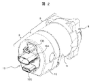
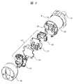
図2は本実施形態になる電動パワーステアリング装置の全体的な構成を示した図面であり、図3は図2に示す電動パワーステアリング装置の構成部品を分解して斜め方向から見た図面であり、図4から図9は各構成部品の組み立て順序にしたがって各構成部品を組み付けていった状態を示す図面である。したがって、以下の説明では、各図面を適宜引用しながら説明を行うものとする。 FIG. 2 is a drawing showing the overall configuration of the electric power steering system according to the present embodiment, and FIG. 3 is a drawing showing the components of the electric power steering system shown in FIG. 4 to 9 are drawings showing the state in which each component is assembled according to the order of assembly of each component. Therefore, in the following description, each drawing will be referred to as appropriate.
尚、図4から図9において、制御回路部と電源回路部の電子部品や電気部品は、図3に示すものと構成が若干異なっているが、機能的には同じ機能である。 4 to 9, the electronic parts and electrical parts of the control circuit section and the power supply circuit section are slightly different in configuration from those shown in FIG. 3, but have the same functions.
図2に示すように、電動パワーステアリング装置を構成する電動モータ部8は、アルミニウム、或いはアルミ合金等のアルミ系金属から作られた筒部を有するモータハウジング11及びこれに収納された図示しない電動モータとから構成され、電子制御部9は、モータハウジング11の軸方向の出力軸とは反対側に配置された、アルミニウム、或いはアルミ合金等のアルミ系金属、或いは鉄系の金属で作られた金属カバー12及びこれに収納された図示しない電子制御組立体から構成されている。
As shown in FIG. 2, the
モータハウジング11と金属カバー12は、その対向端面に形成され外周方向の固定領域部において、加締め固定によって一体的に固定される。金属カバー12の内部に収納された電子制御組立体は、必要な電源を生成する電源回路部や、電動モータ部8の電動モータを駆動制御するMOSFET或いはIGBT等からなるパワースイッチング素子を有する電力変換回路や、このパワースイッチング素子を制御する制御回路部からなり、パワースイッチング素子の出力端子と電動モータのコイル入力端子とはバスバーを介して電気的に接続されている。
The
モータハウジング11とは反対側の金属カバー12の端面には、金属カバー12に形成した孔部からコネクタ端子組立体13が露出している。また、コネクタ端子組立体13は、モータハウジング11に形成した固定部に固定ねじによって固定されている。コネクタ端子組立体13には電力供給用のコネクタ端子形成部13A、検出センサ用のコネクタ端子形成部13B、制御状態を外部機器に送出する制御状態送出用のコネクタ端子形成部13Cを備えている。
A
そして、金属カバー12に収納された電子制御組立体は、合成樹脂から作られた電力供給用のコネクタ端子形成部13Aを介して電源から電力が供給され、また検出センサ類から運転状態等の検出信号が検出センサ用のコネクタ形成端子部13Bを介して供給され、現在の電動パワーステアリング装置の制御状態信号が制御状態送出用のコネクタ端子形成部13Cを介して送出されている。
The electronic control assembly housed in the
図3に電動パワーステアリング装置6の分解斜視図を示している。モータハウジング11には内部に円環状の鉄製のサイドヨーク(図示せず)が嵌合されており、このサイドヨーク内に電動モータ(図示せず)が収納されている。電動モータの出力部14はギヤを介してラックに操舵補助力を付与している。尚、電動モータの具体的な構造は良く知られているので、ここでは説明を省略する。
FIG. 3 shows an exploded perspective view of the electric
モータハウジング11はアルミ合金から作られており、電動モータで発生した熱や、後述する電源回路部や電力変換回路部で発生した熱を外部大気に放出するヒートシンク部材として機能している。電動モータとモータハウジング11で電動モータ部8を構成している。
The
電動モータ部8の出力部14の反対側のモータハウジング11の端面部15には電子制御部ECが取り付けられている。電子制御部ECは、電力変換回路部16、電源回路部17、制御回路部18、コネクタ端子組立体13から構成されている。モータハウジング11の端面部15は、モータハウジング11と一体的に形成されているが、この他に端面部15だけを別体に形成し、ねじや溶接によってモータハウジング11と一体化しても良い。
An electronic control unit EC is attached to an
ここで、電力変換回路部16、電力変換回路部17、制御回路部18は冗長系を構成するものであり、主電子制御部と副電子制御部の二重系を構成している。そして、通常は主電子制御部によって電動モータが制御、駆動されているが、主電子制御部に異常や故障が生じると、副電子制御部に切り換えられて電動モータが制御、駆動されるようになる。
Here, the power
したがって、後述するが、通常は主電子制御部からの熱がモータハウジング11に伝えられ、主電子制御部に異常や故障が生じると、主電子制御部が停止して副電子制御部が作動し、モータハウジング11には副電子制御部からの熱が伝えられる。
Therefore, as will be described later, heat from the main electronic control section is normally transferred to the
ただ、本実施形態では採用していないが、主電子制御部と副電子制御部を合せて正規の電子制御部として機能させ、一方の電子制御部に異常、故障が生じると、他方の電子制御部で半分の能力によって電動モータを制御、駆動することも可能である。この場合、電動モータの能力は半分となるが、いわゆる「パワーステアリング機能」は確保されるようになっている。したがって、通常の場合は、主電子制御部と副電子制御部の熱がモータハウジング11に伝えられる。
However, although not adopted in this embodiment, the main electronic control unit and the sub electronic control unit are combined to function as a regular electronic control unit, and if an abnormality or failure occurs in one electronic control unit, the other electronic control unit It is also possible to control and drive the electric motor with half the capacity at the part. In this case, the capacity of the electric motor is halved, but the so-called "power steering function" is ensured. Therefore, in a normal case, heat from the main electronic control section and the sub electronic control section is transferred to the
電子制御部ECは制御回路部18、電源回路部17、電力変換回路部16、コネクタ端子組立体13から構成されており、端面部15側から離れる方向に向かって、電力変換回路部16、電源回路部17、制御回路部18、コネクタ端子組立体13の順序で配置されている。制御回路部18は電力変換回路部16のスイッチング素子を駆動する制御信号を生成するもので、マイクロコンピュータ、周辺回路等から構成されている。電源回路部17は、制御回路部18を駆動する電源及び電力変換回路部16の電源を生成するもので、コンデンサ、コイル、スイッチング素子等から構成されている。電力変換回路部16は、電動モータのコイルに流れる電力を調整するもので、3相の上下アームを構成するスイッチング素子等から構成されている。
The electronic control unit EC includes a
電子制御部ECで発熱量が多いのは、主に電力変換回路部16、電源回路部17であり、電力変換回路部16、電源回路部17の熱は、アルミ合金からなるモータハウジング11から放熱される。この詳細な構成については、図4乃至図9を用いて後述する。
In the electronic control unit EC, the power
制御回路部18と金属カバー12の間には、合成樹脂からなるコネクタ端子組立体13が設けられており、車両バッテリ(電源)や外部の図示しない他の制御装置と接続されている。もちろん、このコネクタ端子組立体13は、電力変換回路部16、電源回路部17、制御回路部18と接続されていることはいうまでもない。
A
金属カバー12は、電力変換回路部16、電源回路部17、制御回路部18を収納してこれらを液密的に封止する機能を備えているものであり、本実施形態では加締め固定によってモータハウジング11に固定されている。
The
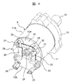
次に、図4から図9に基づき各構成部品の構成と組み立て方法について説明する。先ず、図4はモータハウジング11の外観を示しており、図5はその軸方向断面を示している。
Next, the configuration and assembly method of each component will be described with reference to FIGS. 4 to 9. FIG. First, FIG. 4 shows the appearance of the
図4、図5において、モータハウジング11は、筒状の形態に形成されて側周面部11Aと、側周面部11Aの一端を閉塞する端面部15と、側周面部11Aの他端を閉塞する端面部19とから構成されている。本実施形態では、モータハウジング11は有底円筒状であり、側周面部11Aと端面部15は一体的に形成されている。また、端面部19は、蓋の機能を備えており、側周面部11Aに電動モータを収納した後に側周面部11Aの他端を閉塞する。
In FIGS. 4 and 5, the
また、端面部15の全周面には径方向外側に向けて開口した環状溝を有するモータハウジング側環状溝部35が設けられている。そして、このモータハウジング側環状溝部35に、図9に示す金属カバー12の開口端(以下、金属カバー側環状先端部と表記する)37が対向して配置される。モータハウジング側環状溝部35と金属カバー12の金属カバー側環状先端部37の間の部分は、いわゆる液状シール剤によって液密的に接合される。
A motor housing side
図5にあるように、モータハウジング11の側周面部11Aの内部には、鉄心にコイル20が巻回されたステータ21が嵌合されており、このステータ21の内部に、永久磁石を埋設したロータ22が回転可能に収納されている。ロータ22には回転軸23が固定されており、一端は出力部14となり、他端は回転軸23の回転位相や回転数を検出するための回転検出部24となっている。回転検出部24には永久磁石が設けてあり、端面部15に設けた貫通孔25を貫通して外部に突き出している。そして、図示しないGMR素子等からなる感磁部によって回転軸23の回転位相や回転数を検出するようになっている。
As shown in FIG. 5, a
図4に戻って、回転軸23の出力部14とは反対側に位置する端面部15の面には電力変換回路部16(図3参照)、電源回路部17(図3参照)の放熱部15A、15Bが形成されている。端面部15の四隅には、基板/コネクタ固定凸部26が一体的に植立されており、内部にねじ穴が形成されている。
Returning to FIG. 4, on the surface of the
基板/コネクタ固定凸部26は後述する制御回路部18の基板、及びコネクタ端子組立体13を固定するために設けられている。また、後述する電力変換用放熱領域15Aから植立した基板/コネクタ固定凸部26には、これも後述する電源用放熱領域15Bと軸方向で同じ高さの基板受け部27が形成され、基板受け部27には、ねじ孔が形成されている。この基板受け部27は後述する電源回路部17のガラスエポキシ基板31を載置、固定するためのものである。
The board/
端面部15を形成する、回転軸23と直交する径方向の平面領域は2分割されている。1つはMOSFET等のパワースイッチング素子よりなる電力変換回路部16が取り付けられる電力変換用放熱領域15Aを形成し、もう1つは電源回路部17が取り付けられる電源用放熱領域15Bを形成している。本実施形態では、電力変換用放熱領域15Aの方が電源用放熱領域15Bより面積が大きく形成されている。これは、上述したように二重系を採用しているため、電力変換回路部16の設置面積を確保するためである。
A plane area in the radial direction orthogonal to the
そして、電力変換用放熱領域15Aと電源用放熱領域15Bは、軸方向(回転軸23が延びる方向)に向けて高さが異なる段差を有している。つまり、電源用放熱領域15Bは、電動モータの回転軸23の方向で見て、電力変換用放熱領域15Aに対して離れる方向に段差を有して形成されている。この段差は、電力変換回路部16を設置した後に電源回路部17を設置した場合に、電力変換回路部16と電源回路部17が夫々干渉しない長さに設定されている。
The power conversion
電力変換用放熱領域15Aには、3個の細長い矩形の突状放熱部28が形成されている。この突状放熱部28は後述する二重系の電力変換回路部16が設置される。また、突状放熱部28は、電動モータの回転軸23の方向で見て電動モータから離れる方向に突出して延びている。
Three elongated rectangular projecting
また、電源用放熱領域15Bは平面状であって、後述する電源回路部17が設置される。したがって、突状放熱部28は電力変換回路部16で発生した熱を端面部15に伝熱する放熱部として機能し、電源用放熱領域15Bは電源回路部17で発生した熱を端面部15に伝熱する放熱部として機能する。
Further, the power
尚、突状放熱部28は省略することができ、この場合は電力変換用放熱領域15Aが電力変換回路部16で発生した熱を端面部15に伝熱する放熱部として機能する。ただ、本実施形態では、突状放熱部28に電力変換回路部16の金属基板を摩擦撹拌接合によって溶着して確実な固定を図っている。
Note that the projecting
このように、本実施形態になるモータハウジング11の端面部15においては、ヒートシンク部材を省略して軸方向の長さを短くできるようになる。また、モータハウジング11は十分な熱容量を有しているので、電源回路部17や電力変換回路部16の熱を効率よく外部に放熱することができるようになる。
As described above, in the
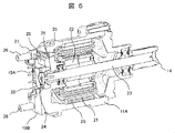
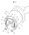
次に、図6は電力変換回路部16を突条放熱部28(図4参照)に設置した状態を示している。図6にある通り、電力変換用放熱領域15Aに形成された突状放熱部28(図4参照)の上部には二重系よりなる電力変換回路部16が設置されている。電力変換回路部16を構成するスイッチング素子は金属基板(ここではアルミ系の金属を使用している)に載置され、放熱されやすく構成されている。そして、金属基板は突状放熱部28に摩擦撹拌接合によって溶着されている。
Next, FIG. 6 shows a state in which the power
したがって、金属基板は突状放熱部28(図4参照)に強固に固定され、またスイッチング素子で発生した熱を効率良く突状放熱部28(図4参照)に伝熱させることができる。突状放熱部28(図4参照)に伝えられた熱は電力変換用放熱領域15Aに拡散され、更にモータハウジング11の側周面部11Aに伝熱されて外部に放熱される。ここで、上述した通り、電力変換回路部16の軸方向の高さは、電源用放熱領域15Bの高さより低くなっているので、後述する電源回路部17と干渉することはない。
Therefore, the metal substrate is firmly fixed to the projecting heat radiation portion 28 (see FIG. 4), and the heat generated by the switching element can be efficiently transferred to the projecting heat radiation portion 28 (see FIG. 4). The heat transmitted to the protruding heat radiation portion 28 (see FIG. 4) is diffused to the power conversion
このように、電力変換用放熱領域15Aに形成された突状放熱部28の上部に電力変換回路部16が設置されている。したがって、電力変換回路部16のスイッチング素子で発生した熱を効率良く突状放熱部28に伝熱させることができる。更に、突状放熱部28に伝えられた熱は電力変換用放熱領域15Aに拡散され、モータハウジング11の側周面部11Aに伝熱されて外部に放熱されるようになる。
In this manner, the power
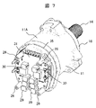
次に、図7は電力変換回路部16の上から電源回路部17を設置した状態を示している。図7にある通り、電源用放熱領域15Bの上部には電源回路部17が設置されている。電源回路部17を構成するコンデンサ29やコイル30等はガラスエポキシ基板31に載置されている。電源回路部17も二重系が採用されており、図からわかるように、夫々対称にコンデンサ29やコイル30等からなる電源回路が形成されている。尚、ガラスエポキシ基板31には、電力変換回路16のスイッチング素子以外のコンデンサ等の電気素子が載置されている。
Next, FIG. 7 shows a state in which the power
このガラスエポキシ基板31の電源用放熱領域15B(図6参照)側の面は、電源用放熱領域15Bと接触するようにして端面部15に固定されている。固定方法は、図7にあるように、基板/コネクタ固定凸部26の基板受け部27に設けられたねじ穴に図示しない固定ねじによって固定されている。また、電源用放熱領域15B(図6参照)に設けられたねじ穴にも図示しない固定ねじによって固定されている。
The surface of the
尚、電源回路部17がガラスエポキシ基板31で形成されているため、両面実装が可能となっている。そして、ガラスエポキシ基板31の電源用放熱領域15B(図6参照)側の面には、図示しないGMR素子やこれの検出回路等からなる回転位相、回転数検出部が実装され、回転軸23(図5参照)に設けた回転検出部24(図5参照)と協働して、回転の回転位相や回転数を検出するようになっている。
Since the power
このように、ガラスエポキシ基板31は電源用放熱領域15B(図6参照)に接触するようにして固定されているので、電源回路部17で発生した熱を効率良く電源用放熱領域15B(図6参照)に伝熱させることができる。電源用放熱領域15B(図6参照)に伝えられた熱は、モータハウジング11の側周面部11Aに拡散して伝熱されて外部に放熱される。ここで、ガラスエポキシ基板31と電源用放熱領域15B(図6参照)の間は、熱伝達性の良い接着剤、放熱グリース、放熱シートのいずれか1つを介在させることで、更に熱伝達性能を向上させることができる。
In this manner, since the
このように、電源用放熱領域15Bの上部には電源回路部17が設置されている。電源回路部17の回路素子が載置されたガラスエポキシ基板31の電源用放熱領域15B側の面は、電源用放熱領域15Bと接触するようにして端面部15に固定されている。したがって、電源回路部17で発生した熱を効率良く電源用放熱領域15Bに伝熱させることができる。電源用放熱領域15Bに伝えられた熱は、モータハウジング11の側周面部11Aに拡散して伝熱されて外部に放熱されるようになる。
In this manner, the power
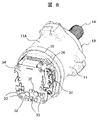
次に、図8は電源回路部17の上から制御回路部18を設置した状態を示している。図8にある通り、電源回路部17の上部には制御回路部18が設置されている。制御回路部18を構成するマイクロコンピュータ32や周辺回路33はガラスエポキシ基板34に載置されている。制御回路部18も二重系が採用されており、図からわかるように、夫々対象にマイクロコンピュータ32や周辺回路33からなる制御回路が形成されている。尚、マイクロコンピュータ32や周辺回路33は、ガラスエポキシ基板34の電源回路17側の面に設けられていても良い。
Next, FIG. 8 shows a state in which the
このガラスエポキシ基板34は、図8にあるように、基板/コネクタ固定凸部26(図7参照)の頂部に設けられたねじ穴にコネクタ端子組立体13によって挟まれる形態で図示しない固定ねじによって固定されており、電源回路部17(図7参照)のガラスエポキシ基板31と制御回路部18のガラスエポキシ基板34の間は、図7に示す電源回路部17のコンデンサ29やコイル30等が配置される空間となっている。
As shown in FIG. 8, the
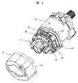
次に、図9は制御回路部18の上からコネクタ端子組立体13を設置した状態を示している。図9にある通り、制御源回路部18の上部にはコネクタ端子組立体13が設置されている。そして、コネクタ端子組立体13は基板/コネクタ固定凸部26の頂部に設けられたねじ穴に制御回路部18を挟み込むようにして固定ねじ36によって固定されている。この状態で、図3に示すようにコネクタ端子組立体13が電力変換回路部16、電源回路部17、制御回路部18と接続されている。
Next, FIG. 9 shows a state in which the
更にこの後に金属カバー12の金属カバー側環状先端部37が、モータハウジング11のモータハウジング側環状溝部35を外側から覆うようにして配置され、金属カバー12の外周方向に沿って設けられた加締め固定部によって固定される。
Furthermore, after this, the metal cover side
図10に示す通り、この加締め固定部38は、金属カバー12の外周において、回転軸23の軸線を中心にして、ほぼ120°間隔に形成されている。図10は、モータハウジング11と金属カバー12が加締め固定によって固定された状態の電動パワーステアリング装置6の外観を示している。尚、図11は金属カバー12がモータハウジング11の端面部15に固定される前の断面を示している。
As shown in FIG. 10 , the
図10、図11において、金属カバー12の外周面には、複数(3個)の加締め固定部38が形成されている。この加締め固定部38は、モータハウジング11の端面部15の全周面に形成したモータハウジング側環状溝部35からコネクタ端子組立体13側に向けて軸方向に延びた、電力変換用放熱領域15A、電源用放熱領域15Bを形成する固定壁39に設けられた加締め溝、或いは加締め孔等からなる加締め凹部40に、金属カバー12の壁面が押し込み工具によって押し込まれて塑性変形して加締められることで形成されている。金属カバー12の軸方向の位置決めは、コネクタ組立体13を利用して行われており、金属カバー12の軸方向位置が決まった状態で、金属カバー12の壁面が押し込み工具によって加締め凹部40に押し込まれて加締められるようになっている。
10 and 11, a plurality (three) of
また、金属カバー12の金属カバー側環状先端部37が配置される、モータハウジング側環状溝部35によって形成される空間には、液密用の液状シール剤41が隙間なく充填される。したがって、加締め固定部38と金属カバー12の金属カバー側環状先端部37の間には液密用のシール領域が形成されるので、塩水等はシール領域で浸入が阻止される。このため、加締め固定部38には塩水等が浸入しないので、加締め固定部38が腐食するのが抑制されて、機械的な信頼性を向上することが可能となる。更には、電子制御部9への塩水等の浸入が抑制されるので電気的な信頼性を併せて向上することが可能となる。
In addition, the space formed by the motor housing side
次に、金属カバー側環状先端部37とモータハウジング側環状溝部35の接合領域付近の更に詳細な構成について、図12、図13を用いて説明する。
12 and 13, a more detailed configuration of the vicinity of the joint region between the metal cover side
図12において、金属カバー12の金属カバー側環状先端部37の最先端の外周径Dcとモータハウジング11の端面部15の外周径Dhは、ほぼ同じ半径とされており、それぞれの外周面は見掛け上では同一面(面一)に形成されている。そして、モータハウジング11の端面部15の外周面に形成されたモータハウジング側環状溝部35は、回転軸23(図11参照)の軸線と同一であるモータハウジング11の軸線に直交する半径方向で内側に、固定壁39から所定距離Lだけ後退した(内側に凹んでいる)形状に形成されている。
In FIG. 12, the outer diameter Dc of the metal cover-side annular
一方、金属カバー12の金属カバー側環状先端部37は、開口面が外側に向けて折り曲げ加工によって拡開されており、金属カバー側環状先端部37の内周面には、金属カバー12の径方向で外側に向けて傾斜して拡開する環状傾斜面37INが形成されている。この環状傾斜面37INの折り曲げ始点37Sは、モータハウジング側環状溝部35の図面上で上側の壁面35U付近から折り曲げられて拡開されている。
On the other hand, the opening surface of the metal cover-side
そして、図11にある通り液状シール剤41は、金属カバー12が取り付けられる前に、モータハウジング側環状溝部35に充填されるように塗布される。ここで、上述した通り、液状シール剤41は接着性と粘性を備えており、金属カバー側環状先端部37をモータハウジング11の端面部15の方向に押し込んでいく時、金属カバー側環状先端部37の内周面である環状傾斜面37INに接する液状シール剤41に引っ張り力が作用する。このため、モータハウジング側環状溝部35に充填されている液状シール剤41が、金属カバー側環状先端部37の環状傾斜面37INの移動に沿って引っ張られて移動する現象が生じる。
11, the
しかしながら、本実施形態では、金属カバー側環状先端部37の内周面には、金属カバー12の径方向で外側に向けて傾斜して拡開する環状傾斜面37INが形成されていることで、液状シール剤41と接触して生じる引っ張り力が、矢印で示しているように、少なくとも環状傾斜面37INに沿った方向と、金属カバー12の押し込み方向と、径方向とに分散されるようになる。このため、液状シール剤41が金属カバー側環状先端部37の環状傾斜面37INの移動に沿って引っ張られても、その荷重が分散されるので、液状シール剤41の移動による空間が形成されるのが抑制されることになる。
However, in the present embodiment, the annular inclined surface 37IN that is inclined and expands outward in the radial direction of the
このように、金属カバー側環状先端部37をモータハウジング11の端面部15の側に押し込んでいく時、モータハウジング側環状溝部35に充填されている液状シール剤41が、金属カバー側環状先端部37の環状傾斜面37INの移動に沿って引っ張られて移動する現象が抑制される。これによって、モータハウジング側環状溝部35に液状シール剤41が存在しない空間が発生し難くなり、シール長が長くなることで、塩水等が金属カバー12内に浸入する恐れが抑制され、結果的に機械的及び電気的な信頼性を向上することができるようになる。
As described above, when the metal cover side
ここで、図13に示すように、本実施形態になる金属カバー12の金属カバー側環状先端部37の環状傾斜面37INの傾斜角θは、好ましくは5°~9°の範囲に決められていれば十分に液状シール剤41を残存させることができる。
Here, as shown in FIG. 13, the inclination angle θ of the annular inclined surface 37IN of the metal cover side
そして、実際にモータハウジング側環状溝部35の軸方向の長さで、どの程度の割合で液状シール剤41が金属カバー側環状先端部37の環状傾斜面37INと接触しているかを測定した。この場合、金属カバー12を周方向で等間隔に8分割して、それぞれの部分での接着長さの割合(接着長さ/モータハウジング側環状溝部35の軸方向の長さ)を求めて平均化した。
Then, the ratio of the
図18に示す従来の構造においては、接着長さの割合は約43%であったのに対して、環状傾斜面37INの傾斜角θが5°の場合は約81%、7°の場合は約89%、9°の場合は約92%であった。したがって、若干の余裕を見て環状傾斜面37INの傾斜角θは、4°~12°の範囲に決められていれば、充分であると見做せる。 In the conventional structure shown in FIG. 18, the ratio of the bonding length was about 43%. It was about 89%, and about 92% in the case of 9°. Therefore, it can be considered sufficient if the inclination angle .theta.
ただ、このような実施形態においては、次に述べるような課題も想定されるので、これに対する対策が重要である。 However, in such an embodiment, the following problems are assumed, and it is important to take countermeasures against them.
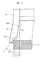
図14に示している通り、金属カバー側環状先端部37の先端面37Tの全面が、回転軸23の軸線23Cに直交する面に形成されている。このため、先端面37Tの面が、液状シール剤41に対して液状シール剤41を押し出していくことになり、結果的に金属カバー側環状先端部37の環状傾斜面37INと液状シール剤41の接着面の距離が短くなるという現象を生じることになる。
As shown in FIG. 14 , the entire
このような現象によって、環状傾斜面37INと液状シール剤41の接着面の距離が短くなるのを抑制するために、図15に示すように、カバー側環状先端部37の先端側の内周面には、金属カバー12の径方向で外側に向けて傾斜して拡開する環状傾斜面37INが形成され、更に環状傾斜面37INの先端内周側が弧状に形成されている。
In order to prevent the distance between the annular inclined surface 37IN and the bonding surface of the
図15において、金属カバー12の金属カバー側環状先端部37は、外側に向けて湾曲するように折り曲げられており、環状傾斜面37INは、直線部37Lと弧状部37Cとから形成されている。弧状部37Cは直線部37Lより先端側に形成されており、この弧状部37Cは、液状シール剤41側に向かって突出する形状とされている。
In FIG. 15, the metal cover-side annular
このような形状とされているので、金属カバー12の金属カバー側環状先端部37を、モータハウジング11のモータハウジング側環状溝部35に組み込んでいく過程で、弧状部37Cに液状シール剤41が接触するようになる。この時、弧状部37Cと液状シール剤41の間では摩擦が少なくなって、液状シール剤の押し出し量を少なくでき、液状シール剤41の接着面の距離が短くなるという現象を抑制することができる。
With such a shape, the
また、金属カバー側環状先端部37の折り曲げられた部分は、モータハウジング11の端面部15の外周より外側に張り出すので、モータハウジング11の端面部15の外周と同じ面(面一)になるように、張り出した部分を切断して面一面37Eとしている。これによって、この種の電動駆動装置の大径化を避けることが可能となる。
Further, the bent portion of the metal cover-side annular
このように、金属カバー側環状先端部37をモータハウジング11の端面部15の側に押し込んでいく時、モータハウジング側環状溝部35に充填されている液状シール剤41が、金属カバー側環状先端部37の移動に沿って引っ張られて移動する現象が抑制される。
As described above, when the metal cover side
これによって、モータハウジング側環状溝部35に液状シール剤41が存在しない空間が発生し難くなり、シール長が長くなることで、塩水等が金属カバー12内に浸入する恐れが抑制され、結果的に機械的及び電気的な信頼性を向上することができるようになる。
As a result, a space in which the
図15に示す実施形態は、金属カバー12の金属カバー側環状先端部37が、開口面が外側に向けて湾曲するようにして折り曲げることで拡開されて、直線部37Lと弧状部37Cとからなる環状傾斜面37INが形成されている。
In the embodiment shown in FIG. 15, the metal cover-side annular
これに対して、図16に示す実施形態は、折り曲げによって弧状部37Cを形成しないで、プレス、研磨、或いは切削によって環状傾斜面42INの先端側の内周面にだけ弧状部42Cを形成したものである。
On the other hand, in the embodiment shown in FIG. 16, the arc-shaped
本実施形態も図15に示したものと同様に、弧状部42Cと液状シール剤41の間では摩擦が少なくなって、液状シール剤の押し出し量を少なくでき、液状シール剤41の接着面の距離が短くなるという現象を抑制することができる。
15, the friction between the
この構造によっても、金属カバー側環状先端部37をモータハウジング11の端面部15の側に押し込んでいく時、モータハウジング側環状溝部35に充填されている液状シール剤41が、金属カバー側環状先端部37の移動に沿って引っ張られて移動する現象が抑制される。
With this structure as well, when the metal cover side
これによって、モータハウジング側環状溝部35に液状シール剤41が存在しない空間が発生し難くなり、シール長が長くなることで、塩水等が金属カバー12内に浸入する恐れが抑制され、結果的に機械的及び電気的な信頼性を向上することができるようになる。
As a result, a space in which the
図15に示す実施形態は、金属カバー12の金属カバー側環状先端部37が、開口面が外側に向けて湾曲するようにして折り曲げることで拡開されて、直線部37Lと弧状部37Cとからなる環状傾斜面37INが形成されている。同様に、図16に示す実施形態は、金属カバー12の金属カバー側環状先端部42の環状傾斜面42INの先端側の内周面に、プレス、研磨、或いは切削によって弧状部42Cが形成されている。
In the embodiment shown in FIG. 15, the metal cover-side annular
これに対して、本実施形態は図17に示すように、金属カバー12の金属カバー側環状先端部43の環状傾斜面43INの先端側の内周面に、プレス、研磨、或いは切削によって傾斜面部43Cを形成したものである。この傾斜面部43Cの傾斜角θ2は、直線部43Lの傾斜角θ1に対して外側に向けて更に傾斜した傾斜形状に形成されている。ここで、夫々の傾斜角θ1、θ2は回転軸23の軸線の23Cに平行な金属カバー12の上側の内周壁に対する角度を示している。
On the other hand, in this embodiment, as shown in FIG. 17, an inclined surface portion is formed on the inner peripheral surface of the annular inclined surface 43IN of the metallic cover side annular
本実施形態も図15に示したものと同様に傾斜面部43Cと液状シール剤41の間では摩擦が少なくなって、液状シール剤の押し出し量を少なくでき、液状シール剤41の接着面の距離が短くなるという現象を抑制することができる。
In this embodiment, as in the case shown in FIG. 15, the friction between the inclined surface portion 43C and the
この構造によっても、金属カバー側環状先端部43をモータハウジング11の端面部15の側に押し込んでいく時、モータハウジング側環状溝部35に充填されている液状シール剤41が、金属カバー側環状先端部43の移動に沿って引っ張られて移動する現象が抑制される。
With this structure as well, when the metal cover side
これによって、モータハウジング側環状溝部35に液状シール剤41が存在しない空間が発生し難くなり、シール長が長くなることで、塩水等が金属カバー12内に浸入する恐れが抑制され、結果的に機械的及び電気的な信頼性を向上することができるようになる。
As a result, a space in which the
尚、上述したそれぞれの実施形態において、液密用の液状シール剤41は、接着性を有する合成樹脂を使用しており、本実施形態ではシリコンゴム系の弾性接着剤を使用している。
In each of the above-described embodiments, the liquid-tight
シリコンゴム系の弾性接着剤は、外的な振動、衝撃等の応力を吸収し、接着界面に応力が集中しにくい性質を有している。このため、電動パワーステアリング装置のように振動、衝撃等が作用するものでは、接着界面が剥がれて液密機能が喪失する恐れがあるが、シリコンゴム系の弾性接着剤を使用することで、液密機能が喪失する恐れを少なくするこができる。 Silicone rubber-based elastic adhesives have the property of absorbing stress such as external vibrations and impacts, and preventing stress from concentrating on the adhesive interface. For this reason, there is a risk that the adhesive interface will peel off and the liquid-tight function will be lost in devices such as electric power steering devices that are subject to vibrations and impacts. It is possible to reduce the risk of loss of dense functions.
また、本実施形態では、接着性を有する液状シール剤41で封止を行うため、従来から使用されてきた液密用のOリングを省略することができる。このため、Oリングを収納する収納溝を固定壁39に形成する必要がなく、製造コストの高騰を抑制することができる。
In addition, in this embodiment, sealing is performed with the adhesive
このシリコン系の弾性接着剤(液状シール剤41)は、接着機能を備える液状ガスケット(FIPG:FORMED IN PLACE GASKET)であっても良いものであり、常温硬化や加熱硬化する材料で作られているものを使用することができる。 This silicon-based elastic adhesive (liquid sealing agent 41) may be a liquid gasket (FIPG: FORMED IN PLACE GASKET) having an adhesive function, and is made of a material that cures at room temperature or heat. can use things.
また、固定ねじを使用しないで金属カバー12とモータハウジング11を加締め固定部38によって固定するので、外観形状を小さく、しかも重量を低減することができる。
In addition, since the
更に、Oリングを用いる場合は、Oリングを収納する収納溝を形成する必要があるが、本実施形態の場合はOリングを使用しないので収納溝等の加工が必要なく、製造コストの高騰を抑制することができる。 Furthermore, when an O-ring is used, it is necessary to form an accommodation groove for accommodating the O-ring, but in the case of this embodiment, no O-ring is used, so there is no need to process the accommodation groove, etc., which reduces the manufacturing cost. can be suppressed.
尚、液状シール剤41をアルミナ等の伝熱性の良い材料を混練した高放熱性の液状シール剤41とすることで、接着面積が大きいことと併せて、電力変換用放熱領域15Aや電源用放熱領域15Bの熱を金属カバー12に効率的に放熱させることが可能となる。これによって、電源回路部や電力変換回路部を構成する電気部品からの熱を効率よく外部に放熱してやることができ、小型化が可能となる。
By using a highly heat-
上述した実施形態では、固定ねじを使用しないで金属カバー11とモータハウジング11を固定する固定手段として、3ヶ所に加締め固定部38を形成したが、全周に亘って加締め固定部を形成することも可能である。
In the above-described embodiment, as fixing means for fixing the
以上述べた通り、本発明によれば、電動モータの回転軸の出力部とは反対側のモータハウジングの端面部の外周面に形成され、モータハウジングの軸線に直交する径方向の内側に後退する環状溝からなるモータハウジング側環状溝部と、電動モータを制御する電子制御部を覆うカバーの開口端に形成され、モータハウジング側環状溝部の環状溝に外側から対向するカバー側環状先端部とを備え、モータハウジング側環状溝部にカバー側環状先端部が対向して配置された状態で、モータハウジング側環状溝部とカバー側環状先端部との間に液状シール剤が充填されていると共に、カバー側環状先端部の内周面には、カバーの径方向で外側に向けて傾斜して拡開する環状傾斜面が形成され、更に環状傾斜面の先端内周側が弧の形状、或いは環状傾斜面より外側に傾斜した傾斜形状に形成されている構成とした。 As described above, according to the present invention, it is formed on the outer peripheral surface of the end surface portion of the motor housing opposite to the output portion of the rotating shaft of the electric motor, and retreats inward in the radial direction perpendicular to the axis of the motor housing. A motor-housing-side annular groove formed of an annular groove, and a cover-side annular tip formed at an open end of a cover that covers an electronic control unit for controlling the electric motor and facing the annular groove of the motor-housing-side annular groove from the outside. a liquid sealant is filled between the motor housing side annular groove portion and the cover side annular tip portion in a state where the cover side annular tip portion is arranged to face the motor housing side annular groove portion; The inner peripheral surface of the tip portion is formed with an annular slanted surface that inclines and expands outward in the radial direction of the cover. It is configured such that it is formed in a slanted shape.
これによれば、カバー側環状先端部の内周面には、カバーの径方向で外側に向けて傾斜して拡開する環状傾斜面が形成され、更に環状傾斜面の先端内周側が円弧状に形成されているので、カバー側環状先端部をモータハウジングの端面側に押し込んでいく時、液状シール剤がカバー側環状先端部の内周面の移動に沿って引っ張られて移動するのが抑制され、液状シール剤が存在しない空間が発生するのを抑制することができる。 According to this, the inner peripheral surface of the cover-side annular distal end portion is formed with an annular inclined surface that is inclined and expands outward in the radial direction of the cover. When the cover-side annular tip is pushed toward the end face of the motor housing, the liquid sealant is prevented from being pulled and moved along the movement of the inner peripheral surface of the cover-side annular tip. Therefore, it is possible to suppress the generation of a space where the liquid sealing agent does not exist.
尚、本発明は上記した実施例に限定されるものではなく、様々な変形例が含まれる。例えば、上記した実施例は本発明を分かりやすく説明するために詳細に説明したものであり、必ずしも説明した全ての構成を備えるものに限定されるものではない。また、ある実施例の構成の一部を他の実施例の構成に置き換えることが可能であり、また、ある実施例の構成に他の実施例の構成を加えることも可能である。また、各実施例の構成の一部について、他の構成の追加・削除・置換をすることが可能である。 It should be noted that the present invention is not limited to the above-described embodiments, and includes various modifications. For example, the above-described embodiments have been described in detail in order to explain the present invention in an easy-to-understand manner, and are not necessarily limited to those having all the described configurations. In addition, it is possible to replace part of the configuration of one embodiment with the configuration of another embodiment, and it is also possible to add the configuration of another embodiment to the configuration of one embodiment. Moreover, it is possible to add, delete, or replace a part of the configuration of each embodiment with another configuration.
6…電動パワーステアリング装置、8…電動モータ部、9…電子制御部、11…モータハウジング、12…金属カバー、13…コネクタ端子組立体、14…出力部、15…端面部、15A…電力変換用放熱領域、15B…電源用放熱領域、16…電力変換回路部、17…電源回路部、18…制御回路部、19…端面部、20…コイル、21…ステータ、22…ロータ、23…回転軸、24…回転検出部、25…貫通孔、26…基板/コネクタ固定凸部、27…基板受け部、28…突状放熱部、29…コンデンサ、30…コイル、31…ガラスエポキシ基板、32…マイクコンピュータ、33…周辺回路、34…ガラスエポキシ基板、35…モータハウジング側環状溝部、36…固定ねじ、37、42、43…金属カバー側環状先端部、37IN、42IN、43IN…環状傾斜面、37L,42L、43L…直線部、37C、42C…弧状部、43C…傾斜面部、41…液状シール剤。
DESCRIPTION OF
Claims (10)
前記電動モータの前記回転軸の前記出力部とは反対側の前記モータハウジングの前記端面部の外周面に形成され、前記モータハウジングの軸線に直交する径方向の内側に後退する環状溝からなるモータハウジング側環状溝部と、前記電動モータを制御する前記電子制御部を覆う前記カバーの開口端に形成され、前記モータハウジング側環状溝部の前記環状溝に外側から対向するカバー側環状先端部とを備え、
前記モータハウジング側環状溝部に前記カバー側環状先端部が対向して配置された状態で、前記モータハウジング側環状溝部と前記カバー側環状先端部との間に液状シール剤が充填されていると共に、
前記カバー側環状先端部の内周面には、前記カバーの径方向で外側に向けて傾斜して拡開する環状傾斜面が形成され、更に前記環状傾斜面の先端内周側が弧の形状、或いは前記環状傾斜面より外側に傾斜した傾斜形状に形成されている
ことを特徴とする電動駆動装置。 A motor housing containing an electric motor for driving a mechanical system control element, and an end surface of the motor housing opposite to the output section of the rotating shaft of the electric motor for driving the electric motor. and a cover covering the electronic control unit, wherein
A motor comprising an annular groove that is formed on the outer peripheral surface of the end face portion of the motor housing on the side opposite to the output portion of the rotating shaft of the electric motor and retreats inward in a radial direction perpendicular to the axis of the motor housing. a housing-side annular groove; and a cover-side annular distal end portion formed at an open end of the cover covering the electronic control unit for controlling the electric motor and facing the annular groove of the motor housing-side annular groove from the outside. ,
A liquid sealant is filled between the motor housing side annular groove portion and the cover side annular tip portion in a state in which the cover side annular tip portion is arranged to face the motor housing side annular groove portion, and
An annular slanted surface that is slanted outward in the radial direction of the cover and expands is formed on the inner peripheral surface of the cover-side annular front end portion, and the inner peripheral side of the front end of the annular slanted surface is arc-shaped, Alternatively, the electric drive device is formed in an inclined shape inclined outward from the annular inclined surface.
前記カバーは金属で形成されている
ことを特徴とする電動駆動装置。 In the electric drive device according to claim 1,
An electric drive device, wherein the cover is made of metal.
前記カバーの前記カバー側環状先端部は、折り曲げ加工によって前記環状傾斜面の先端内周側が弧の形状に形成されている
ことを特徴とする電動駆動装置。 In the electric drive device according to claim 2,
The electric drive device according to claim 1, wherein the cover-side annular front end portion of the cover is bent so that the front end inner peripheral side of the annular inclined surface is formed into an arc shape.
前記カバーの前記カバー側環状先端部は、折り曲げ加工によって前記環状傾斜面の直線部が形成され、更に前記環状傾斜面の先端内周側が研磨、或いは切削によって弧の形状に形成されている
ことを特徴とする電動駆動装置。 In the electric drive device according to claim 2,
The cover-side annular distal end portion of the cover is bent to form a linear portion of the annular inclined surface, and the inner peripheral side of the distal end of the annular inclined surface is formed into an arc shape by grinding or cutting. An electric drive device characterized by:
前記カバーの前記カバー側環状先端部は、折り曲げ加工によって前記環状傾斜面の直線部が形成され、更に前記環状傾斜面の先端内周側が研磨、或いは切削によって、前記環状傾斜面より外側に傾斜した傾斜面部とされている
ことを特徴とする電動駆動装置。 In the electric drive device according to claim 2,
The cover-side annular distal end portion of the cover has a linear portion of the annular inclined surface formed by bending, and the tip inner peripheral side of the annular inclined surface is ground or cut to be inclined outward from the annular inclined surface. Slanted surface
An electric drive device characterized by:
前記電動モータの前記回転軸の前記出力部とは反対側の前記モータハウジングの前記端面部の外周面に形成され、前記モータハウジングの軸線に直交する径方向の内側に後退する環状溝からなるモータハウジング側環状溝部と、前記電動モータを制御する前記電子制御部を覆う前記カバーの開口端に形成され、前記モータハウジング側環状溝部の前記環状溝に外側から対向するカバー側環状先端部とを備え、
前記モータハウジング側環状溝部に前記カバー側環状先端部が対向して配置された状態で、前記モータハウジング側環状溝部と前記カバー側環状先端部との間に液状シール剤が充填されていると共に、
前記カバー側環状先端部の内周面には、前記カバーの径方向で外側に向けて傾斜して拡開する環状傾斜面が形成され、更に前記環状傾斜面の先端内周側が弧の形状、或いは前記環状傾斜面より外側に傾斜した傾斜形状に形成されている
ことを特徴とする電動パワーステアリング装置。 An electric motor that applies a steering assist force to the steering shaft based on an output from a torque sensor that detects a rotational direction and a rotational torque of the steering shaft; a motor housing that accommodates the electric motor; and rotation of the electric motor. An electric power steering comprising: an electronic control section for driving the electric motor arranged on the side of the end surface of the motor housing opposite to the output section of the shaft; and a cover covering the electronic control section. a device,
A motor comprising an annular groove that is formed on the outer peripheral surface of the end face portion of the motor housing on the side opposite to the output portion of the rotating shaft of the electric motor and retreats inward in a radial direction perpendicular to the axis of the motor housing. a housing-side annular groove; and a cover-side annular distal end portion formed at an open end of the cover covering the electronic control unit for controlling the electric motor and facing the annular groove of the motor housing-side annular groove from the outside. ,
A liquid sealant is filled between the motor housing side annular groove portion and the cover side annular tip portion in a state in which the cover side annular tip portion is arranged to face the motor housing side annular groove portion, and
An annular slanted surface that is slanted outward in the radial direction of the cover and expands is formed on the inner peripheral surface of the cover-side annular front end portion, and the inner peripheral side of the front end of the annular slanted surface is arc-shaped, Alternatively, the electric power steering device is formed in an inclined shape inclined outward from the annular inclined surface.
前記カバーは金属で形成されている
ことを特徴とする電動パワーステアリング装置。 In the electric power steering device according to claim 6,
An electric power steering apparatus, wherein the cover is made of metal.
前記カバーの前記カバー側環状先端部は、折り曲げ加工によって前記環状傾斜面の先端内周側が弧の形状に形成されている
ことを特徴とする電動パワーステアリング装置。 In the electric power steering device according to claim 7,
An electric power steering apparatus according to claim 1, wherein the cover-side annular distal end portion of the cover is formed in an arc shape on the inner peripheral side of the distal end of the annular inclined surface by bending.
前記カバーの前記カバー側環状先端部は、折り曲げ加工によって前記環状傾斜面の直線部が形成され、更に前記環状傾斜面の先端内周側が研磨、或いは切削によって弧の形状に形成されている
ことを特徴とする電動パワーステアリング装置。 In the electric power steering device according to claim 7,
The cover-side annular distal end portion of the cover is bent to form a linear portion of the annular inclined surface, and the inner peripheral side of the distal end of the annular inclined surface is formed into an arc shape by grinding or cutting. An electric power steering device characterized by:
前記カバーの前記カバー側環状先端部は、折り曲げ加工によって前記環状傾斜面の直線部が形成され、更に前記環状傾斜面の先端内周側が研磨、或いは切削によって、前記環状傾斜面より外側に傾斜した傾斜面部とされている
ことを特徴とする電動パワーステアリング装置。 In the electric power steering device according to claim 7,
The cover-side annular distal end portion of the cover has a linear portion of the annular inclined surface formed by bending, and the tip inner peripheral side of the annular inclined surface is ground or cut to be inclined outward from the annular inclined surface. Slanted surface
An electric power steering device characterized by:
Priority Applications (1)
| Application Number | Priority Date | Filing Date | Title |
|---|---|---|---|
| JP2018230642A JP7194574B2 (en) | 2018-12-10 | 2018-12-10 | Electric driving device and electric power steering device |
Applications Claiming Priority (1)
| Application Number | Priority Date | Filing Date | Title |
|---|---|---|---|
| JP2018230642A JP7194574B2 (en) | 2018-12-10 | 2018-12-10 | Electric driving device and electric power steering device |
Publications (2)
| Publication Number | Publication Date |
|---|---|
| JP2020093564A JP2020093564A (en) | 2020-06-18 |
| JP7194574B2 true JP7194574B2 (en) | 2022-12-22 |
Family
ID=71084426
Family Applications (1)
| Application Number | Title | Priority Date | Filing Date |
|---|---|---|---|
| JP2018230642A Active JP7194574B2 (en) | 2018-12-10 | 2018-12-10 | Electric driving device and electric power steering device |
Country Status (1)
| Country | Link |
|---|---|
| JP (1) | JP7194574B2 (en) |
Families Citing this family (3)
| Publication number | Priority date | Publication date | Assignee | Title |
|---|---|---|---|---|
| DE102023205352A1 (en) * | 2023-06-08 | 2024-12-12 | Volkswagen Aktiengesellschaft | Annular sealing system for sealing connection points within a steer-by-wire steering system of a motor vehicle |
| CN121285928A (en) * | 2023-06-12 | 2026-01-06 | 三菱电机移动出行株式会社 | Motor and vehicle |
| WO2026009365A1 (en) * | 2024-07-04 | 2026-01-08 | 株式会社ジェイテクト | Motor device |
Citations (5)
| Publication number | Priority date | Publication date | Assignee | Title |
|---|---|---|---|---|
| JP2005168186A (en) | 2003-12-03 | 2005-06-23 | Koyo Seiko Co Ltd | Waterproof structure of housing and motor |
| JP2015089216A (en) | 2013-10-30 | 2015-05-07 | 株式会社デンソー | Rotating electric machine |
| JP2015108407A (en) | 2013-12-04 | 2015-06-11 | 日立金属株式会社 | Pipe joint |
| JP2016046939A (en) | 2014-08-25 | 2016-04-04 | Ntn株式会社 | Electric actuator |
| US20160116064A1 (en) | 2016-01-08 | 2016-04-28 | Caterpillar Inc. | Sealing assembly between components |
Family Cites Families (1)
| Publication number | Priority date | Publication date | Assignee | Title |
|---|---|---|---|---|
| JPS5136010U (en) * | 1974-09-11 | 1976-03-17 |
-
2018
- 2018-12-10 JP JP2018230642A patent/JP7194574B2/en active Active
Patent Citations (5)
| Publication number | Priority date | Publication date | Assignee | Title |
|---|---|---|---|---|
| JP2005168186A (en) | 2003-12-03 | 2005-06-23 | Koyo Seiko Co Ltd | Waterproof structure of housing and motor |
| JP2015089216A (en) | 2013-10-30 | 2015-05-07 | 株式会社デンソー | Rotating electric machine |
| JP2015108407A (en) | 2013-12-04 | 2015-06-11 | 日立金属株式会社 | Pipe joint |
| JP2016046939A (en) | 2014-08-25 | 2016-04-04 | Ntn株式会社 | Electric actuator |
| US20160116064A1 (en) | 2016-01-08 | 2016-04-28 | Caterpillar Inc. | Sealing assembly between components |
Also Published As
| Publication number | Publication date |
|---|---|
| JP2020093564A (en) | 2020-06-18 |
Similar Documents
| Publication | Publication Date | Title |
|---|---|---|
| JP6867245B2 (en) | Electric drive device and electric power steering device | |
| JP7291468B2 (en) | Electric driving device and electric power steering device | |
| JP6944889B2 (en) | Electric drive device and electric power steering device | |
| CN111264021B (en) | Electric drives and electric power steering | |
| KR20170136418A (en) | Electromotive device and electric power steering device | |
| JP6894714B2 (en) | Electric drive device and electric power steering device | |
| JP7085458B2 (en) | Electric drive device and electric power steering device | |
| JP2019004635A (en) | Electric drive device and electric power steering device | |
| JP7194574B2 (en) | Electric driving device and electric power steering device | |
| KR20200008027A (en) | Electric drive and electric power steering | |
| JP7041541B2 (en) | Electric drive device and electric power steering device | |
| JP6909689B2 (en) | Electric drive device and electric power steering device | |
| JP2019134679A (en) | Electric drive device | |
| JP7470148B2 (en) | Electric drive unit | |
| JP6852945B2 (en) | Electric drive device and electric power steering device | |
| JP6770938B2 (en) | Electric drive device and electric power steering device | |
| JP7296205B2 (en) | Wiring board and electric drive device | |
| JP7085439B2 (en) | Electric drive device and electric power steering device | |
| WO2019159406A1 (en) | Electronic control device and electric drive device |
Legal Events
| Date | Code | Title | Description |
|---|---|---|---|
| A621 | Written request for application examination |
Free format text: JAPANESE INTERMEDIATE CODE: A621 Effective date: 20210602 |
|
| A977 | Report on retrieval |
Free format text: JAPANESE INTERMEDIATE CODE: A971007 Effective date: 20220526 |
|
| A131 | Notification of reasons for refusal |
Free format text: JAPANESE INTERMEDIATE CODE: A131 Effective date: 20220531 |
|
| A521 | Request for written amendment filed |
Free format text: JAPANESE INTERMEDIATE CODE: A523 Effective date: 20220722 |
|
| TRDD | Decision of grant or rejection written | ||
| A01 | Written decision to grant a patent or to grant a registration (utility model) |
Free format text: JAPANESE INTERMEDIATE CODE: A01 Effective date: 20221115 |
|
| A61 | First payment of annual fees (during grant procedure) |
Free format text: JAPANESE INTERMEDIATE CODE: A61 Effective date: 20221212 |
|
| R150 | Certificate of patent or registration of utility model |
Ref document number: 7194574 Country of ref document: JP Free format text: JAPANESE INTERMEDIATE CODE: R150 |
|
| R250 | Receipt of annual fees |
Free format text: JAPANESE INTERMEDIATE CODE: R250 |