JP7190879B2 - Cooling device, structure, welding method - Google Patents
Cooling device, structure, welding method Download PDFInfo
- Publication number
- JP7190879B2 JP7190879B2 JP2018216755A JP2018216755A JP7190879B2 JP 7190879 B2 JP7190879 B2 JP 7190879B2 JP 2018216755 A JP2018216755 A JP 2018216755A JP 2018216755 A JP2018216755 A JP 2018216755A JP 7190879 B2 JP7190879 B2 JP 7190879B2
- Authority
- JP
- Japan
- Prior art keywords
- aluminum
- hardness
- main body
- holding member
- cooling device
- Prior art date
- Legal status (The legal status is an assumption and is not a legal conclusion. Google has not performed a legal analysis and makes no representation as to the accuracy of the status listed.)
- Active
Links
- 238000003466 welding Methods 0.000 title claims description 91
- 238000001816 cooling Methods 0.000 title claims description 69
- 238000000034 method Methods 0.000 title claims description 18
- 239000000463 material Substances 0.000 claims description 139
- XAGFODPZIPBFFR-UHFFFAOYSA-N aluminium Chemical compound [Al] XAGFODPZIPBFFR-UHFFFAOYSA-N 0.000 claims description 113
- 229910052782 aluminium Inorganic materials 0.000 claims description 113
- 229910045601 alloy Inorganic materials 0.000 claims description 42
- 239000000956 alloy Substances 0.000 claims description 42
- 239000007788 liquid Substances 0.000 claims description 19
- 238000005304 joining Methods 0.000 claims description 13
- 230000004927 fusion Effects 0.000 claims description 12
- 230000001678 irradiating effect Effects 0.000 claims description 8
- 229910000838 Al alloy Inorganic materials 0.000 claims description 3
- 238000003483 aging Methods 0.000 claims description 2
- 238000005482 strain hardening Methods 0.000 claims 1
- 235000019589 hardness Nutrition 0.000 description 72
- 230000008859 change Effects 0.000 description 14
- 238000002844 melting Methods 0.000 description 10
- 230000008018 melting Effects 0.000 description 10
- 239000000110 cooling liquid Substances 0.000 description 8
- 230000007547 defect Effects 0.000 description 8
- 239000002826 coolant Substances 0.000 description 5
- 238000005219 brazing Methods 0.000 description 3
- 238000005520 cutting process Methods 0.000 description 3
- 238000010586 diagram Methods 0.000 description 3
- 230000008569 process Effects 0.000 description 3
- 238000007711 solidification Methods 0.000 description 3
- 230000008023 solidification Effects 0.000 description 3
- IJGRMHOSHXDMSA-UHFFFAOYSA-N Atomic nitrogen Chemical compound N#N IJGRMHOSHXDMSA-UHFFFAOYSA-N 0.000 description 2
- 238000001125 extrusion Methods 0.000 description 2
- 239000000835 fiber Substances 0.000 description 2
- 238000010438 heat treatment Methods 0.000 description 2
- 239000011261 inert gas Substances 0.000 description 2
- 230000009471 action Effects 0.000 description 1
- 230000008901 benefit Effects 0.000 description 1
- 238000005336 cracking Methods 0.000 description 1
- 230000007423 decrease Effects 0.000 description 1
- 238000010030 laminating Methods 0.000 description 1
- 238000004519 manufacturing process Methods 0.000 description 1
- 230000004048 modification Effects 0.000 description 1
- 238000012986 modification Methods 0.000 description 1
- 238000010791 quenching Methods 0.000 description 1
- 230000000171 quenching effect Effects 0.000 description 1
- 239000004065 semiconductor Substances 0.000 description 1
- 238000005476 soldering Methods 0.000 description 1
Images


Classifications
-
- B—PERFORMING OPERATIONS; TRANSPORTING
- B23—MACHINE TOOLS; METAL-WORKING NOT OTHERWISE PROVIDED FOR
- B23K—SOLDERING OR UNSOLDERING; WELDING; CLADDING OR PLATING BY SOLDERING OR WELDING; CUTTING BY APPLYING HEAT LOCALLY, e.g. FLAME CUTTING; WORKING BY LASER BEAM
- B23K26/00—Working by laser beam, e.g. welding, cutting or boring
- B23K26/08—Devices involving relative movement between laser beam and workpiece
- B23K26/0869—Devices involving movement of the laser head in at least one axial direction
-
- B—PERFORMING OPERATIONS; TRANSPORTING
- B23—MACHINE TOOLS; METAL-WORKING NOT OTHERWISE PROVIDED FOR
- B23K—SOLDERING OR UNSOLDERING; WELDING; CLADDING OR PLATING BY SOLDERING OR WELDING; CUTTING BY APPLYING HEAT LOCALLY, e.g. FLAME CUTTING; WORKING BY LASER BEAM
- B23K26/00—Working by laser beam, e.g. welding, cutting or boring
- B23K26/14—Working by laser beam, e.g. welding, cutting or boring using a fluid stream, e.g. a jet of gas, in conjunction with the laser beam; Nozzles therefor
-
- B—PERFORMING OPERATIONS; TRANSPORTING
- B23—MACHINE TOOLS; METAL-WORKING NOT OTHERWISE PROVIDED FOR
- B23K—SOLDERING OR UNSOLDERING; WELDING; CLADDING OR PLATING BY SOLDERING OR WELDING; CUTTING BY APPLYING HEAT LOCALLY, e.g. FLAME CUTTING; WORKING BY LASER BEAM
- B23K26/00—Working by laser beam, e.g. welding, cutting or boring
- B23K26/20—Bonding
- B23K26/21—Bonding by welding
- B23K26/24—Seam welding
- B23K26/244—Overlap seam welding
-
- B—PERFORMING OPERATIONS; TRANSPORTING
- B23—MACHINE TOOLS; METAL-WORKING NOT OTHERWISE PROVIDED FOR
- B23K—SOLDERING OR UNSOLDERING; WELDING; CLADDING OR PLATING BY SOLDERING OR WELDING; CUTTING BY APPLYING HEAT LOCALLY, e.g. FLAME CUTTING; WORKING BY LASER BEAM
- B23K26/00—Working by laser beam, e.g. welding, cutting or boring
- B23K26/20—Bonding
- B23K26/21—Bonding by welding
- B23K26/24—Seam welding
- B23K26/28—Seam welding of curved planar seams
-
- B—PERFORMING OPERATIONS; TRANSPORTING
- B23—MACHINE TOOLS; METAL-WORKING NOT OTHERWISE PROVIDED FOR
- B23K—SOLDERING OR UNSOLDERING; WELDING; CLADDING OR PLATING BY SOLDERING OR WELDING; CUTTING BY APPLYING HEAT LOCALLY, e.g. FLAME CUTTING; WORKING BY LASER BEAM
- B23K26/00—Working by laser beam, e.g. welding, cutting or boring
- B23K26/20—Bonding
- B23K26/32—Bonding taking account of the properties of the material involved
-
- F—MECHANICAL ENGINEERING; LIGHTING; HEATING; WEAPONS; BLASTING
- F28—HEAT EXCHANGE IN GENERAL
- F28D—HEAT-EXCHANGE APPARATUS, NOT PROVIDED FOR IN ANOTHER SUBCLASS, IN WHICH THE HEAT-EXCHANGE MEDIA DO NOT COME INTO DIRECT CONTACT
- F28D1/00—Heat-exchange apparatus having stationary conduit assemblies for one heat-exchange medium only, the media being in contact with different sides of the conduit wall, in which the other heat-exchange medium is a large body of fluid, e.g. domestic or motor car radiators
- F28D1/02—Heat-exchange apparatus having stationary conduit assemblies for one heat-exchange medium only, the media being in contact with different sides of the conduit wall, in which the other heat-exchange medium is a large body of fluid, e.g. domestic or motor car radiators with heat-exchange conduits immersed in the body of fluid
- F28D1/0246—Heat-exchange apparatus having stationary conduit assemblies for one heat-exchange medium only, the media being in contact with different sides of the conduit wall, in which the other heat-exchange medium is a large body of fluid, e.g. domestic or motor car radiators with heat-exchange conduits immersed in the body of fluid heat-exchange elements having several adjacent conduits forming a whole, e.g. blocks
-
- F—MECHANICAL ENGINEERING; LIGHTING; HEATING; WEAPONS; BLASTING
- F28—HEAT EXCHANGE IN GENERAL
- F28F—DETAILS OF HEAT-EXCHANGE AND HEAT-TRANSFER APPARATUS, OF GENERAL APPLICATION
- F28F21/00—Constructions of heat-exchange apparatus characterised by the selection of particular materials
- F28F21/08—Constructions of heat-exchange apparatus characterised by the selection of particular materials of metal
- F28F21/081—Heat exchange elements made from metals or metal alloys
- F28F21/084—Heat exchange elements made from metals or metal alloys from aluminium or aluminium alloys
-
- F—MECHANICAL ENGINEERING; LIGHTING; HEATING; WEAPONS; BLASTING
- F28—HEAT EXCHANGE IN GENERAL
- F28F—DETAILS OF HEAT-EXCHANGE AND HEAT-TRANSFER APPARATUS, OF GENERAL APPLICATION
- F28F9/00—Casings; Header boxes; Auxiliary supports for elements; Auxiliary members within casings
- F28F9/02—Header boxes; End plates
- F28F9/0246—Arrangements for connecting header boxes with flow lines
- F28F9/0248—Arrangements for sealing connectors to header boxes
-
- B—PERFORMING OPERATIONS; TRANSPORTING
- B23—MACHINE TOOLS; METAL-WORKING NOT OTHERWISE PROVIDED FOR
- B23K—SOLDERING OR UNSOLDERING; WELDING; CLADDING OR PLATING BY SOLDERING OR WELDING; CUTTING BY APPLYING HEAT LOCALLY, e.g. FLAME CUTTING; WORKING BY LASER BEAM
- B23K2101/00—Articles made by soldering, welding or cutting
- B23K2101/04—Tubular or hollow articles
- B23K2101/14—Heat exchangers
-
- B—PERFORMING OPERATIONS; TRANSPORTING
- B23—MACHINE TOOLS; METAL-WORKING NOT OTHERWISE PROVIDED FOR
- B23K—SOLDERING OR UNSOLDERING; WELDING; CLADDING OR PLATING BY SOLDERING OR WELDING; CUTTING BY APPLYING HEAT LOCALLY, e.g. FLAME CUTTING; WORKING BY LASER BEAM
- B23K2103/00—Materials to be soldered, welded or cut
- B23K2103/08—Non-ferrous metals or alloys
- B23K2103/10—Aluminium or alloys thereof
-
- B—PERFORMING OPERATIONS; TRANSPORTING
- B23—MACHINE TOOLS; METAL-WORKING NOT OTHERWISE PROVIDED FOR
- B23K—SOLDERING OR UNSOLDERING; WELDING; CLADDING OR PLATING BY SOLDERING OR WELDING; CUTTING BY APPLYING HEAT LOCALLY, e.g. FLAME CUTTING; WORKING BY LASER BEAM
- B23K2103/00—Materials to be soldered, welded or cut
- B23K2103/18—Dissimilar materials
-
- F—MECHANICAL ENGINEERING; LIGHTING; HEATING; WEAPONS; BLASTING
- F28—HEAT EXCHANGE IN GENERAL
- F28F—DETAILS OF HEAT-EXCHANGE AND HEAT-TRANSFER APPARATUS, OF GENERAL APPLICATION
- F28F1/00—Tubular elements; Assemblies of tubular elements
- F28F1/02—Tubular elements of cross-section which is non-circular
- F28F1/022—Tubular elements of cross-section which is non-circular with multiple channels
-
- F—MECHANICAL ENGINEERING; LIGHTING; HEATING; WEAPONS; BLASTING
- F28—HEAT EXCHANGE IN GENERAL
- F28F—DETAILS OF HEAT-EXCHANGE AND HEAT-TRANSFER APPARATUS, OF GENERAL APPLICATION
- F28F2220/00—Closure means, e.g. end caps on header boxes or plugs on conduits
-
- F—MECHANICAL ENGINEERING; LIGHTING; HEATING; WEAPONS; BLASTING
- F28—HEAT EXCHANGE IN GENERAL
- F28F—DETAILS OF HEAT-EXCHANGE AND HEAT-TRANSFER APPARATUS, OF GENERAL APPLICATION
- F28F2275/00—Fastening; Joining
- F28F2275/06—Fastening; Joining by welding
- F28F2275/067—Fastening; Joining by welding by laser welding
-
- F—MECHANICAL ENGINEERING; LIGHTING; HEATING; WEAPONS; BLASTING
- F28—HEAT EXCHANGE IN GENERAL
- F28F—DETAILS OF HEAT-EXCHANGE AND HEAT-TRANSFER APPARATUS, OF GENERAL APPLICATION
- F28F9/00—Casings; Header boxes; Auxiliary supports for elements; Auxiliary members within casings
- F28F9/02—Header boxes; End plates
- F28F9/04—Arrangements for sealing elements into header boxes or end plates
- F28F9/16—Arrangements for sealing elements into header boxes or end plates by permanent joints, e.g. by rolling
- F28F9/18—Arrangements for sealing elements into header boxes or end plates by permanent joints, e.g. by rolling by welding
Landscapes
- Engineering & Computer Science (AREA)
- Physics & Mathematics (AREA)
- Optics & Photonics (AREA)
- Mechanical Engineering (AREA)
- Plasma & Fusion (AREA)
- Thermal Sciences (AREA)
- General Engineering & Computer Science (AREA)
- Laser Beam Processing (AREA)
- Details Of Heat-Exchange And Heat-Transfer (AREA)
Description
本発明は、冷却装置、構造物、溶接方法に関する。 TECHNICAL FIELD The present invention relates to a cooling device, a structure, and a welding method.
近年、アルミニウム又はアルミニウム合金等のアルミニウム材料を用いて成形された部材にて構成される冷却装置において、アルミニウム材料を用いて成形された部材同士を接合するために、はんだ付やろう付を行うことが提案されている。
例えば、特許文献1に記載された液冷式冷却装置は、冷却液流通体の流入部の一端面にアルミニウム製入口ヘッダをろう付し、同じく流出部の一端面にアルミニウム製出口ヘッダをろう付し、冷却液流通体の他端面にアルミニウム製中間ヘッダをろう付することにより構成されている。
また、アルミニウム材料を用いて成形された部材を接合するための方法として、特許文献2には、レーザ溶接を行うことが提案されている。
In recent years, in a cooling device composed of members formed using an aluminum material such as aluminum or an aluminum alloy, soldering or brazing is performed to join the members formed using an aluminum material. is proposed.
For example, in the liquid-cooling type cooling device described in
Further, as a method for joining members formed using an aluminum material, Patent Document 2 proposes performing laser welding.
冷却装置を構成する、アルミニウム材料を用いて成形された部材(以下、「アルミニウム材」と称する場合がある。)同士を接合するために、レーザ溶接を行うことが考えられる。そして、レーザ溶接による溶接部は、溶接欠陥がない、又は、溶接欠陥が許容範囲内である、信頼性の高い溶接部であることが必要である。
本発明は、信頼性の高い溶接部を有する冷却装置等を提供することを目的とする。
Laser welding may be used to join members molded using an aluminum material (hereinafter sometimes referred to as "aluminum materials") that constitute a cooling device. A welded portion by laser welding is required to be a highly reliable welded portion that has no weld defects or has weld defects within an allowable range.
An object of the present invention is to provide a cooling device or the like having highly reliable welds.
かかる目的のもと完成させた本発明は、性質の異なる2つのアルミニウム材をレーザ溶接にて接合して構成される冷却装置であって、前記レーザ溶接による溶融部の硬さが、前記2つのアルミニウム材の内の一方のアルミニウム材の硬さよりも硬いことを特徴とする冷却装置である。
ここで、前記一方のアルミニウム材の材料が非熱処理合金であり、他方のアルミニウム材の材料が熱処理合金であっても良い。
また、前記一方のアルミニウム材の材料が3000系であり、前記他方のアルミニウム材の材料が6000系であっても良い。
また、前記一方のアルミニウム材は加工硬化後であり、前記他方のアルミニウム材は時効硬化後であっても良い。
また、前記一方のアルミニウム材の硬さが35(HV)以上であり、他方のアルミニウム材の硬さが42(HV)以上であっても良い。
また、前記一方のアルミニウム材は板材であり、他方のアルミニウム材は押出材であっても良い。
また、他の観点から捉えると、本発明は、液体が流通する流通路を内部に有する本体と、前記本体に対してレーザ溶接にて接合される被接合部材と、を備え、前記本体がアルミニウムの熱処理合金であり、前記被接合部材がアルミニウムの非熱処理合金であり、前記レーザ溶接の溶融部の硬さが、前記被接合部材の硬さよりも硬いことを特徴とする冷却装置である。
また、他の観点から捉えると、本発明は、性質の異なる2つのアルミニウム材を重ね合わせた状態でレーザ溶接することにより接合して構成される冷却装置であって、レーザ光を照射しない方のアルミニウム材における溶融部の深さが、前記2つのアルミニウム材の接合界面における当該溶融部の幅以上であることを特徴とする冷却装置である。
ここで、前記溶融部の幅が前記レーザ光を照射する方のアルミニウム材の板厚の45%以上の大きさであり、熱影響部の幅が当該溶融部の幅より小さくても良い。
また、前記レーザ光を照射しない方のアルミニウム材は、液体が流通する流通路を内部に有する部材であり、前記溶融部は、前記流通路まで至っていなくても良い。
また、他の観点から捉えると、本発明は、性質の異なる2つのアルミニウム材を重ね合わせた状態でレーザ溶接することにより接合して構成される冷却装置であって、前記レーザ溶接による溶融部の幅がレーザ光を照射する方のアルミニウム材の板厚の45%以上の大きさであり、熱影響部の幅が当該溶融部の幅より小さいことを特徴とする冷却装置である。
また、他の観点から捉えると、本発明は、液体が流通する流通路を内部に有する本体と、前記本体に重ね合わせられた状態でレーザ光が照射されることで、当該本体に対してレーザ溶接にて接合される被接合部材と、を備え、前記レーザ溶接による溶融部は、前記本体の前記流通路まで至っていないことを特徴とする冷却装置である。
また、他の観点から捉えると、本発明は、性質の異なる2つのアルミニウム材をレーザ溶接にて接合して構成される構造物であって、前記レーザ溶接による溶融部の硬さが、前記2つのアルミニウム材の内の一方のアルミニウム材の硬さよりも硬いことを特徴とする構造物である。
また、他の観点から捉えると、本発明は、硬さが異なる2つのアルミニウム材を重ね合わせてレーザ溶接する溶接方法であって、前記2つのアルミニウム材の内、硬さが低い方のアルミニウム材に対してレーザ光を照射することを特徴とする溶接方法である。
また、他の観点から捉えると、本発明は、熱伝導率が異なる2つのアルミニウム材を重ね合わせてレーザ溶接する溶接方法であって、前記2つのアルミニウム材の内、熱伝導率が低い方のアルミニウム材に対してレーザ光を照射することを特徴とする溶接方法である。
The present invention completed for such purpose is a cooling device configured by joining two aluminum materials having different properties by laser welding, wherein the hardness of the melted portion by the laser welding is equal to the hardness of the two aluminum materials. The cooling device is characterized in that the hardness of the aluminum material is higher than that of one of the aluminum materials.
Here, the material of the one aluminum material may be a non-heat-treated alloy, and the material of the other aluminum material may be a heat-treated alloy.
Further, the material of the one aluminum material may be 3000 series, and the material of the other aluminum material may be 6000 series.
The one aluminum material may be work-hardened, and the other aluminum material may be age-hardened.
Further, the hardness of the one aluminum material may be 35 (HV) or more, and the hardness of the other aluminum material may be 42 (HV) or more.
Further, the one aluminum material may be a plate material, and the other aluminum material may be an extruded material.
From another point of view, the present invention includes a main body having therein a flow passage through which liquid flows, and a member to be joined to be joined to the main body by laser welding, wherein the main body is made of aluminum. and the member to be joined is a non-heat-treated alloy of aluminum, and the hardness of the melted portion of the laser welding is higher than the hardness of the member to be joined.
From another point of view, the present invention provides a cooling device configured by joining two aluminum materials having different properties by superimposing them on top of each other and joining them by laser welding. The cooling device is characterized in that the depth of the melted portion in the aluminum material is equal to or greater than the width of the melted portion at the joint interface between the two aluminum materials.
Here, the width of the melted portion may be 45% or more of the plate thickness of the aluminum material irradiated with the laser beam, and the width of the heat affected zone may be smaller than the width of the melted portion.
Further, the aluminum material to which the laser beam is not irradiated is a member having therein a flow path through which the liquid flows, and the melted portion does not have to reach the flow path.
From another point of view, the present invention provides a cooling device configured by joining two aluminum materials having different properties in a superimposed state by laser welding, wherein the melted portion is formed by laser welding. The cooling device is characterized in that the width of the heat-affected zone is 45% or more of the plate thickness of the aluminum material irradiated with the laser beam, and the width of the heat-affected zone is smaller than the width of the melted zone.
In addition, from another point of view, the present invention provides a main body having a flow path for liquid flow therein, and a laser beam irradiated to the main body in a state of being superimposed on the main body. and a member to be joined by welding, wherein the melted portion by the laser welding does not reach the flow path of the main body.
From another point of view, the present invention provides a structure constructed by joining two aluminum materials having different properties by laser welding, wherein the hardness of the melted portion obtained by the laser welding is equal to the above two aluminum materials. The structure is characterized by being harder than one of the two aluminum materials.
From another point of view, the present invention provides a welding method for overlapping and laser-welding two aluminum materials having different hardnesses, wherein the aluminum material having the lower hardness among the two aluminum materials It is a welding method characterized by irradiating a laser beam to.
From another point of view, the present invention provides a welding method for laminating and laser-welding two aluminum materials having different thermal conductivities, wherein one of the two aluminum materials having the lower thermal conductivity is This welding method is characterized by irradiating an aluminum material with a laser beam.
本発明によれば、信頼性の高い溶接部を有する冷却装置等を提供することができる。 ADVANTAGE OF THE INVENTION According to this invention, the cooling device etc. which have a highly reliable welded part can be provided.
以下、添付図面を参照して、実施の形態について詳細に説明する。
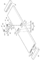
図1は、実施の形態に係る液冷式冷却装置1の斜視図である。
図2は、液冷式冷却装置1を構成する部品を分解した図である。
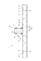
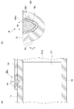
図3は、図1のIII-III部の断面図である。
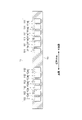
図4は、図1のIV-IV部の断面図である。
実施の形態に係る液冷式冷却装置1は、内部に冷却液が流通する装置本体10と、装置本体10を流通する冷却液の流通方向を変更する変更部材20と、を備えている。また、液冷式冷却装置1は、装置本体10の外部から内部に冷却液を流入させる入口ジョイント30と、装置本体10の内部から外部に冷却液を流出させる出口ジョイント40と、を備えている。
Hereinafter, embodiments will be described in detail with reference to the accompanying drawings.
FIG. 1 is a perspective view of a
FIG. 2 is an exploded view of the parts that make up the
FIG. 3 is a cross-sectional view taken along line III--III in FIG.
FIG. 4 is a cross-sectional view taken along line IV-IV in FIG.
A liquid-cooling
(装置本体10)
装置本体10は、概形が直方体の部材である。装置本体10は、押出加工にて成形された、JIS A6063合金の押出材を用いて成形されており、押出方向が長手方向となるように成形されている。また、図1に示すように、装置本体10の長手方向及び短手方向の長さは、上下方向の長さよりも大きい。なお、JIS A6063合金の質別は、T0又はT6であることを例示することができる。また、その他の質別であっても良いが、装置本体10の硬さが、42(HV(ビッカース硬さ))以上であることが望ましい。
(Device body 10)
The device
装置本体10の内部には、長手方向における一方の端部から他方の端部まで貫通した貫通孔11が複数形成されている。本実施の形態に係る液冷式冷却装置1においては、図4に示すように、貫通孔11は、短手方向の中央部よりも手前側と、中央部よりも奥側とに、それぞれ6つ形成されている。
A plurality of through
手前側の6つの貫通孔11は、入口ジョイント30を介して流入し、変更部材20に至る前の冷却液が流通する流入側流路111として機能する。隣接する流入側流路111は、流入側壁111aにより仕切られている。
他方、奥側の6つの貫通孔11は、変更部材20を通過後に流入し、出口ジョイント40に至る前の冷却液が流通する流出側流路112として機能する。隣接する流出側流路112は、流出側壁112aにより仕切られている。
The six through-
On the other hand, the six through-
また、装置本体10には、長手方向における中央部に、上面から凹んだ空間12が2つ形成されている。2つの空間12の内の一つは、流入側流路111と連通するように形成された流入側空間121であり、他方は、流出側流路112と連通するように形成された流出側空間122である。
流入側空間121は、上壁13及び流入側壁111aが例えば切削加工にて除去されることで形成された空間であり、上壁13が貫通された貫通孔121aと、流入側壁111aが除去された下部空間121bとにより形成される。なお、図2に示した例では、流入側壁111aは、上側から下側にかけて全て除去されているが、上側の一部が除去され、下側の部分が残っていても良い。
流出側空間122は、上壁13及び流出側壁112aが例えば切削加工にて除去されることで形成された空間であり、上壁13が貫通された貫通孔122aと、流出側壁112aが除去された下部空間122bとにより形成される。なお、図2に示した例では、流出側壁112aは、上側から下側にかけて全て除去されているが、上側の一部が除去され、下側の部分が残っていても良い。
In addition, two
The inflow-
The
(変更部材20)
変更部材20は、装置本体10における長手方向の両端部それぞれに配置されている。
変更部材20は、概形が直方体の部材であるとともに、装置本体10側の端面から凹んだ凹部21が形成されている。凹部21により、流入側流路111と流出側流路112とが連通させられている。
変更部材20は、装置本体10側の端面と、装置本体10の長手方向の端面とが突き合わせられた状態で、突き合わせ部にレーザ溶接が施されることにより接合されている。このように、変更部材20は、本体の一例としての装置本体10に対してレーザ溶接にて接合される被接合部材の一例である。
(Change member 20)
The changing
The
The
変更部材20は、例えば、質別OのJIS A3000系合金からなる条に深絞り加工が施されることにより成形されたものであることを例示することができる。また、変更部材20は、例えば、質別H14のJIS A3000系合金又は質別H14のJIS A1000系アルミニウムからなる素材に切削加工が施されることにより成形されたものであっても良い。
For example, the modified
(入口ジョイント30)
入口ジョイント30は、円筒状であり中心線方向が上下方向となるように配置される入口パイプ31と、入口パイプ31を保持する保持部材32とを有している。
(Inlet joint 30)
The inlet joint 30 has a
入口パイプ31は、上端寄りの部分に設けられた、径方向外側に全周に亘って突出した上端側突出部311と、下端寄りの部分に設けられた、径方向外側に全周に亘って突出した下端側突出部312とを有している。
入口パイプ31における、下端側突出部312よりも下端側の部分が、保持部材32に形成された後述する貫通孔321に挿入されている。
保持部材32は、概形が板状の直方体の部材であり、中央部に円形の貫通孔321が形成されている。保持部材32は、JIS A3003合金の板材を用いて成形されている。なお、JIS A3003合金の質別は、質別H12又は質別H18であることを例示することができる。また、その他の質別であっても良いが、保持部材32の硬さが、35(HV)以上であることが望ましい。
The
A portion of the
The holding
入口パイプ31は、下端側突出部312よりも下端側の部分が、保持部材32に形成された貫通孔321に挿入された状態でろう付されている。下端側突出部312における最外径部と保持部材32との間には、溶融したろう材からなるフィレット33が形成されている。
The
そして、入口ジョイント30は、入口パイプ31の下端部が装置本体10の流入側空間121に挿入され、保持部材32の下端面が装置本体10の上面に載せられた状態(保持部材32と装置本体10とを重ね合わせた状態)で、レーザ溶接が施されることにより接合されている。このように、保持部材32は、装置本体10に対してレーザ溶接にて接合される被接合部材の一例である。
The inlet joint 30 is in a state in which the lower end of the
(出口ジョイント40)
出口ジョイント40は、入口ジョイント30と同様の部材であり、円筒状であり中心線方向が上下方向となるように配置される出口パイプ41と、出口パイプ41を保持する保持部材42とを有している。
(Exit joint 40)
The outlet joint 40 is a member similar to the inlet joint 30, and has a
出口パイプ41は、上端寄りの部分に設けられた、径方向外側に全周に亘って突出した上端側突出部411と、下端寄りの部分に設けられた、径方向外側に全周に亘って突出した下端側突出部412とを有している。
出口パイプ41における、下端側突出部412よりも下端側の部分が、保持部材42に形成された後述する貫通孔(不図示)に挿入されている。
保持部材42は、概形が板状の直方体の部材であり、中央部に円形の貫通孔(不図示)が形成されている。保持部材42は、保持部材32と同様に、JIS A3003合金の板材を用いて成形されている。なお、JIS A3003合金の質別は、質別H12又は質別H18であることを例示することができる。また、その他の質別であっても良いが、保持部材42の硬さが、35(HV)以上であることが望ましい。
The
A portion of the
The holding
出口パイプ41は、下端側突出部412よりも下端側の部分が、保持部材42に形成された貫通孔(不図示)に挿入された状態でろう付されている。下端側突出部412における最外径部と保持部材42との間には、溶融したろう材からなるフィレット43が形成されている。
The
そして、出口ジョイント40は、出口パイプ41の下端部が装置本体10の流出側空間122に挿入され、保持部材42の下端面が装置本体10の上面に載せられた状態(保持部材42と装置本体10とを重ね合わせた状態)で、レーザ溶接が施されることにより接合されている。このように、保持部材42は、装置本体10に対してレーザ溶接にて接合される被接合部材の一例である。
The outlet joint 40 is in a state in which the lower end of the
(液冷式冷却装置1の作用)
以上のように構成された液冷式冷却装置1には、装置本体10の上面であって、入口ジョイント30及び出口ジョイント40が設けられた部位よりも長手方向の外側に、この液冷式冷却装置1により冷却される被冷却物が載せられる。被冷却物は、複数の直方体状の単電池101からなる組電池100であることを例示することができる。
(Action of Liquid Cooling System 1)
In the
そして、液冷式冷却装置1においては、入口ジョイント30の入口パイプ31から装置本体10の流入側空間121内に流入した冷却液が、流入側流路111を通って変更部材20の凹部21内に至る。変更部材20の凹部21内に至った冷却液は、その後、流出側流路112を通って流出側空間122に至り、出口ジョイント40の出口パイプ41から流出する。このようにして、冷却液が、装置本体10の流入側流路111及び流出側流路112を流通する間に、装置本体10の上面に載せられた組電池100を冷却する。
In the liquid cooling
(液冷式冷却装置1の製造方法)
以上のように構成された液冷式冷却装置1は、以下のようにして製造される。
装置本体10における長手方向の両端部の端面と、変更部材20における装置本体10側の端面とを突き合わせた状態で、突き合わせ部に対して、レーザ光を連続的に照射する。このようにして、装置本体10における長手方向の両端部に、変更部材20を、レーザ溶接にて接合する。
突き合わせ部にレーザ光が照射されることで、突き合わせ部と略同一位置に溶接部22(図3参照)が形成される。
(Manufacturing method of liquid cooling type cooling device 1)
The
In a state in which the end faces of both longitudinal ends of the device
By irradiating the butted portion with the laser beam, the welded portion 22 (see FIG. 3) is formed at substantially the same position as the butted portion.
また、装置本体10の流入側空間121に入口ジョイント30の入口パイプ31の下端部を挿入し、入口ジョイント30の保持部材32の下端面を装置本体10の上面に載せる(保持部材32と装置本体10とを重ね合わせる)。そして、保持部材32と装置本体10とを重ね合わせた状態で、保持部材32に対してレーザ光を照射し、入口パイプ31の周囲にレーザ光を連続的に照射していく。このようにして、装置本体10における中央部に、入口ジョイント30を、レーザ溶接にて接合する。
重ね合わせ部にレーザ光が照射されることで、照射された位置と略同一位置に溶接部34(図3参照)が形成される。
Also, the lower end of the
By irradiating the overlapped portion with the laser beam, the welded portion 34 (see FIG. 3) is formed at substantially the same position as the irradiated position.
同様に、装置本体10の流出側空間122に出口ジョイント40の出口パイプ41の下端部を挿入し、出口ジョイント40の保持部材42の下端面を装置本体10の上面に載せる(保持部材42と装置本体10とを重ね合わせる)。そして、保持部材42と装置本体10とを重ね合わせた状態で、保持部材42に対してレーザ光を照射し、出口パイプ41の周囲にレーザ光を連続的に照射していく。このようにして、装置本体10における中央部に、出口ジョイント40を、レーザ溶接にて接合する。
重ね合わせ部にレーザ光が照射されることで、照射された位置と略同一位置に溶接部44(図1参照)が形成される。
Similarly, the lower end of the
A welded portion 44 (see FIG. 1) is formed at substantially the same position as the irradiated position by irradiating the overlapping portion with the laser beam.
(レーザ溶接工程)
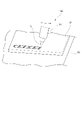
図5は、重ね合わせ部におけるレーザ溶接工程を説明する斜視図である。
図5に示すように、装置本体10と入口ジョイント30の保持部材32(出口ジョイント40の保持部材42)との重ね合わせ部に向けて、レーザ装置150のレーザヘッド151からレーザ光Lを照射する。そして、レーザヘッド151を、入口パイプ31(出口パイプ41)の周囲の保持部材32(保持部材42)の端部形状に沿って移動させることで、レーザ光Lを連続的に照射する。
なお、レーザ装置150のレーザ源は特に限定されない。YAGレーザ、CO2レーザ、ファイバレーザ、ディスクレーザ、半導体レーザであることを例示することができる。また、レーザ光Lの照射方向は、重ね合わせ部の保持部材32(保持部材42)の面に対して直交する方向でも良いし、直交方向に対して傾斜した方向であっても良い。
また、装置本体10と変更部材20との突き合わせ部に向けて、レーザヘッド151からレーザ光Lを照射する。そして、レーザヘッド151を、突き合わせ部の形状に沿って移動させることで、レーザ光Lを連続的に照射する。
(laser welding process)
FIG. 5 is a perspective view explaining the laser welding process in the overlapped portion.
As shown in FIG. 5, a laser beam L is emitted from a
Note that the laser source of the
In addition, the
(溶接部)
上述したように製造される液冷式冷却装置1において、装置本体10に用いられるアルミニウム材料と、変更部材20に用いられるアルミニウム材料とは異なる。また、装置本体10に用いられるアルミニウム材料と、入口ジョイント30の保持部材32及び出口ジョイント40の保持部材42に用いられるアルミニウム材料とは異なる。
これは、本発明者が鋭意研究したところ、性質の異なる2つのアルミニウム材がレーザ溶接にて接合されることで、レーザ溶接による溶融部の硬さが、2つのアルミニウム材の内の一方のアルミニウム材の硬さよりも硬くなることを見出したことに起因する。
(welded part)
In the liquid cooling
As a result of intensive research by the present inventors, it was found that by joining two aluminum materials with different properties by laser welding, the hardness of the melted portion due to laser welding is the same as that of one of the two aluminum materials. This is due to the discovery that it becomes harder than the hardness of the material.
図6(a)は、図1のVI-VI部の断面図である。図6(b)は、図6(a)のVIb部の拡大図である。
図7は、溶接部の硬さを示す図である。
図6(a)及び図6(b)は、入口ジョイント30の保持部材32と装置本体10との重ね合わせ部の溶接部34の断面形状を示している。レーザ装置150のレーザヘッド151から保持部材32に対してレーザ光Lが照射され、レーザ光Lのエネルギーが熱に変換されることによって、重ね合わせ部を構成している、アルミニウム材である保持部材32と装置本体10の母材自体が溶融し、その後急速に冷却される。この急速加熱・急速冷却により溶接部34に組織変化が生じ、溶接部34は、溶けて固まった溶融部34mと、溶接熱により組織変化の生じた熱影響部34hとにより構成される。熱影響部34hは、保持部材32の熱影響部32hと、装置本体10の熱影響部10hとにより構成される。
FIG. 6(a) is a sectional view taken along the line VI-VI in FIG. FIG. 6(b) is an enlarged view of the VIb portion of FIG. 6(a).
FIG. 7 is a diagram showing hardness of a welded portion.
FIGS. 6(a) and 6(b) show cross-sectional shapes of the welded
図7は、図6(b)に示した、溶接部34の断面における部位である、保持部材32の母材、保持部材32の熱影響部32h、溶融部34m、装置本体10の熱影響部10h、装置本体10の母材の硬さを示す図である。図7に示した硬さは、質別T6のJIS A6063合金からなる押出材を用いてつくられた装置本体10と、質別H18のJIS A3003合金からなる板材(板厚0.9(mm))を用いてつくられた保持部材32とを、ファイバレーザのレーザ装置にてレーザ溶接した場合の硬さを示している。なお、溶接条件は、スポット径が50(μm)、レーザ出力をレーザの移動速度で割ったものが25(J/mm)であり、不活性ガスとして窒素(N2)を使用し、焦点は材料表面に合うように設定した。溶接条件は、例えば、接合体である保持部材32の板厚によって好適な条件が異なるが、板厚0.9~1.2(mm)であれば上記条件が好適な条件である。
7 shows the base material of the holding
図7に示した、保持部材32の母材の硬さは、質別H18のJIS A3003合金の板材、言い換えれば、冷間加工後に加工硬化されたJIS A3003合金の硬さである、55(HV(ビッカース硬さ))である。装置本体10の母材の硬さは、質別T6のJIS A6063合金の押出材、言い換えれば、焼き入れ後、時効硬化処理の一例である焼き戻しされたJIS A6063合金の硬さである、73(HV)である。
The hardness of the base material of the holding
そして、図7に示すように、溶融部34mの硬さは、40~50(HV)である。装置本体10の熱影響部10hの硬さは、約50(HV)であり、保持部材32の熱影響部32hの硬さは、約36(HV)である。つまり、溶融部34mの硬さは、保持部材32の熱影響部32hの硬さよりも硬く、装置本体10の熱影響部10hの硬さよりも柔らかい。なお、図7に示すように、保持部材32の熱影響部32hの硬さは、質別H16のJIS A3003合金の硬さよりも柔らかいが、質別OのJIS A3003合金の硬さよりも硬い。また、図7に示すように、装置本体10の熱影響部10hの硬さは、質別T5のJIS A6063合金の硬さよりも柔らかいが、質別T1のJIS A6063合金の硬さよりも硬い。
As shown in FIG. 7, the hardness of the
このように、本実施の形態に係る液冷式冷却装置1においては、性質の異なる2つのアルミニウム材がレーザ溶接にて接合されることで、レーザ溶接による溶融部(例えば溶融部34m)の硬さが、2つのアルミニウム材の内の一方のアルミニウム材(例えば熱影響部32h)の硬さよりも硬くなることが実現されている。その結果、本実施の形態に係る液冷式冷却装置1においては、溶融部(例えば溶融部34m)が破断するよりも、溶融部(例えば溶融部34m)よりも硬くない保持部材32の方が先に破断するので、溶融部(例えば溶融部34m)から破断することを抑制することができる。それゆえ、信頼性の高い溶接部34とすることができる。
As described above, in the liquid-cooling
なお、硬さが同じの2つのアルミニウム材をレーザ溶接にて接合した場合には、レーザ溶接による溶融部の硬さが最も低くなる。例えば、質別T6のJIS A6063合金同士をレーザ溶接にて接合した場合には、溶融部の硬さがほぼO材の硬さまで戻ってしまい、溶融部の硬さが最も低くなる。その結果、溶融部から破断してしまう。そのため、実施の形態に係る液冷式冷却装置1は、硬さが同じである2つのアルミニウム材をレーザ溶接にて接合して構成される冷却装置に比べて壊れ難いので、信頼性の高い溶接部とすることができる。
When two aluminum materials having the same hardness are joined by laser welding, the hardness of the melted portion by laser welding is the lowest. For example, when JIS A6063 alloys of temper grade T6 are joined by laser welding, the hardness of the fusion zone returns to almost that of the O material, and the hardness of the fusion zone becomes the lowest. As a result, it breaks from the fusion zone. Therefore, the liquid-cooled
また、出口ジョイント40の保持部材42も入口ジョイント30の保持部材32と同じアルミニウム材料を用いているので、出口ジョイント40の保持部材42と装置本体10との重ね合わせ部の溶接部44においても、溶融部の硬さは、保持部材42の熱影響部の硬さよりも硬い。その結果、溶融部が破断するよりも、溶融部よりも硬くない保持部材42の方が先に破断するので、溶融部から破断することを抑制することができる。それゆえ、信頼性の高い溶接部44とすることができる。
In addition, since the holding
また、上記事項は、硬さが異なる2つのアルミニウム材がレーザ溶接にて接合された場合、溶接部の硬さが、2つのアルミニウム材の内の硬い方のアルミニウム材の熱影響部、溶融部、2つのアルミニウム材の内の硬くない方のアルミニウム材の熱影響部と、順に低下することを示すものと考えられる。 In addition, the above matter is that when two aluminum materials having different hardnesses are joined by laser welding, the hardness of the welded portion is the heat affected zone and fusion zone of the harder aluminum material among the two aluminum materials. , and the heat-affected zone of the less hard of the two aluminum materials decreases in turn.
それゆえ、硬さが異なる2つのアルミニウム材の内の一方のアルミニウム材が非熱処理合金で、他方のアルミニウム材が熱処理合金である場合においては、非熱処理合金の方が熱処理合金よりも硬くないので、溶融部の硬さは、非熱処理合金の熱影響部の硬さよりも硬くなる。その結果、溶融部が破断するよりも、溶融部よりも硬くない非熱処理合金の方が先に破断するので、溶融部から破断することを抑制することができ、信頼性の高い溶接部とすることができる。 Therefore, when one of two aluminum materials having different hardness is a non-heat-treated alloy and the other is a heat-treated alloy, the non-heat-treated alloy is less hard than the heat-treated alloy. , the hardness of the molten zone becomes harder than that of the heat-affected zone of the non-heat-treated alloy. As a result, the non-heat-treated alloy, which is less hard than the melted portion, breaks first before the melted portion breaks, so it is possible to suppress breakage from the melted portion, resulting in a highly reliable weld. be able to.
なお、非熱処理合金としては、上述した保持部材32(保持部材42)のアルミニウム材料であるJIS A3003合金が含まれるA3000系や、A1000系、A5000系を例示することができる。熱処理合金としては、上述した装置本体10のアルミニウム材料であるJIS A6063合金が含まれるA6000系や、A2000系、A7000系を例示することができる。
Examples of non-heat-treated alloys include the A3000 series including JIS A3003 alloy, which is the aluminum material of the holding member 32 (holding member 42), the A1000 series, and the A5000 series. Examples of heat treatment alloys include A6000 series including JIS A6063 alloy, which is the aluminum material of the
それゆえ、例えば、保持部材32がA1000系合金、装置本体10がA6000系合金である組み合わせの場合においても、溶融部34mの硬さは、保持部材32の熱影響部32hの硬さよりも硬くなる。その結果、溶融部34mが破断するよりも、溶融部34mよりも硬くない保持部材32の方が先に破断するので、溶融部34mから破断することを抑制することができ、信頼性の高い溶接部34とすることができる。
Therefore, for example, even in the case of a combination in which the holding
上記事項により、装置本体10と変更部材20との突き合わせ部がレーザ溶接にて接合された溶接部22においても、装置本体10の硬さよりも変更部材20の硬さの方が低いことから、溶融部の硬さは、変更部材20の熱影響部の硬さよりも硬い。その結果、溶融部が破断するよりも、溶融部よりも硬くない変更部材20の方が先に破断するので、溶融部から破断することを抑制することができる。それゆえ、信頼性の高い溶接部22とすることができる。
Due to the above, even at the welded
(重ね合わせ部のレーザ溶接に関して)
また、本発明者が鋭意研究したところ、硬さが異なる2つのアルミニウム材を重ね合わせてレーザ溶接する場合において、硬さが低い方のアルミニウム材に対してレーザ光を照射すると、硬さが高い方のアルミニウム材に対してレーザ光を照射する場合に比べて、凝固割れが生じる可能性が小さくなることを見出した。
(Regarding laser welding of overlapping parts)
In addition, as a result of intensive research by the present inventors, when two aluminum materials having different hardness are overlapped and laser-welded, if the aluminum material having the lower hardness is irradiated with a laser beam, the hardness becomes higher. It was found that the possibility of occurrence of solidification cracking is reduced compared to the case where the aluminum material on the other side is irradiated with laser light.
それゆえ、本実施の形態に係る液冷式冷却装置1における装置本体10と入口ジョイント30の保持部材32(出口ジョイント40の保持部材42)とのアルミニウム材料を選定するにあたって以下のことに鑑みる。つまり、装置本体10が細長い部材であるため硬さ(強度)が高い必要があること、及び、装置本体10の上面に入口ジョイント30の保持部材32(出口ジョイント40の保持部材42)を載せた状態でレーザ溶接を施すために、保持部材32(保持部材42)に対してレーザ光を照射することに鑑みる。その結果、本実施の形態に係る液冷式冷却装置1においては、装置本体10の母材の硬さよりも低い硬さのアルミニウム材料を用いて保持部材32(保持部材42)を成形する。例えば、質別T6のJIS A6063合金を用いて装置本体10を成形し、このアルミニウム材よりも硬さが低い、質別H18のJIS A3003合金を用いて保持部材32(保持部材42)を成形する。あるいは、質別T1のJIS A6063合金(硬さ42(HV))を用いて装置本体10を成形し、このアルミニウム材よりも硬さが低い、質別H12のJIS A3003合金(硬さ35(HV))を用いて保持部材32(保持部材42)を成形する。
Therefore, in selecting the aluminum material for the
すなわち、本実施の形態に係る液冷式冷却装置1を、硬さが異なる2つのアルミニウム材を重ね合わせてレーザ溶接する溶接方法であって、2つのアルミニウム材の内、硬さが低い方のアルミニウム材に対してレーザ光を照射する溶接方法を用いて製造した。そして、これにより、溶融部(例えば溶融部34m)に凝固割れが生じることを抑制することができるので、溶接欠陥がない、又は、溶接欠陥が許容範囲内である、信頼性の高い溶接部を実現し易くなる。
That is, the liquid-cooling
また、本発明者が鋭意研究したところ、熱伝導率が異なる2つのアルミニウム材を重ね合わせてレーザ溶接する場合において、熱伝導率が低い方のアルミニウム材に対してレーザ光を照射すると、熱伝導率が高い方のアルミニウム材に対してレーザ光を照射する場合に比べて、高品質な溶接が可能であることを見出した。これは、同じエネルギーのレーザ光を照射したとしても、熱伝導率が低い方のアルミニウム材に対してレーザ光を照射する方が、発熱量が高くなり、溶融部(例えば溶融部34m)を深くすることができると考えられるためである。
Further, as a result of intensive research by the present inventors, when two aluminum materials having different thermal conductivity are superimposed and laser-welded, if the aluminum material having the lower thermal conductivity is irradiated with a laser beam, the heat conduction It was found that high-quality welding is possible compared to the case of irradiating the aluminum material with the higher rate with the laser beam. This is because even if laser beams of the same energy are irradiated, the amount of heat generated increases when the laser beam is irradiated to the aluminum material having the lower thermal conductivity, and the melting portion (for example, the
それゆえ、本実施の形態に係る液冷式冷却装置1における装置本体10と入口ジョイント30の保持部材32(出口ジョイント40の保持部材42)とのアルミニウム材料を選定するにあたって以下のことに鑑みる。つまり、装置本体10が細長い部材であるため硬さ(強度)が高い必要があること、装置本体10の上面に入口ジョイント30の保持部材32(出口ジョイント40の保持部材42)を載せた状態でレーザ溶接を施すために、保持部材32(保持部材42)に対してレーザ光を照射することに鑑みる。そして、本実施の形態に係る液冷式冷却装置1においては、装置本体10のアルミニウム材料の熱伝導率よりも低い熱伝導率のアルミニウム材料を用いて保持部材32(保持部材42)を成形した。例えば、質別T6のJIS A6063合金(熱伝導率210(W/m・℃))を用いて装置本体10を成形し、このアルミニウム材よりも熱伝導率が低い、質別H18のJIS A3003合金(熱伝導率160(W/m・℃))を用いて保持部材32(保持部材42)を成形した。
Therefore, in selecting the aluminum material for the
すなわち、本実施の形態に係る液冷式冷却装置1を、熱伝導率が異なる2つのアルミニウム材を重ね合わせてレーザ溶接する溶接方法であって、2つのアルミニウム材の内、熱伝導率が低い方のアルミニウム材に対してレーザ光を照射する溶接方法を用いて製造した。そして、これにより、高品質な溶接部を実現し易くなる。
That is, the liquid-cooled
ここで、十分な接合強度を確保するためには、レーザ光を照射しない方のアルミニウム材における溶融部の深さが、両アルミニウム材の接合界面における溶融部の幅以上であることが望ましい。
本実施の形態に係る液冷式冷却装置1においては、装置本体10と入口ジョイント30の保持部材32(出口ジョイント40の保持部材42)との重ね合わせ部に対して、レーザ溶接が施されているので、装置本体10における溶融部34mの深さH(図6(b)参照)が、装置本体10と保持部材32(保持部材42)の接合界面における溶融部34mの幅W(図6(b)参照)以上である。レーザ溶接は、例えばアーク溶接に比較して、エネルギー密度が極めて高く、溶融部34mのアスペクト比(深さ/幅)が大きくなり易いためである。
Here, in order to ensure sufficient bonding strength, it is desirable that the depth of the melted portion in the aluminum material that is not irradiated with the laser beam is greater than or equal to the width of the melted portion at the joint interface between the two aluminum materials.
In the liquid-cooling
また、十分な接合強度を確保するためには、溶融部の幅が、レーザ光を照射する方のアルミニウム材の板厚の45%以上の大きさであることが望ましい。
本実施の形態に係る液冷式冷却装置1においては、装置本体10と入口ジョイント30の保持部材32(出口ジョイント40の保持部材42)との重ね合わせ部に対して、レーザ溶接が施されることによって、溶融部34mの幅Wが、レーザ光を照射する保持部材32(保持部材42)の板厚0.9~1.2(mm)の45%以上の大きさである0.5(mm)を確保している。
Moreover, in order to secure sufficient bonding strength, it is desirable that the width of the melted portion is 45% or more of the plate thickness of the aluminum material irradiated with the laser beam.
In the liquid-cooled
また、溶融部に生じる割れ等の溶接欠陥を抑制するためには、熱影響部の幅が溶融部の幅Wより小さいことが望ましい。
本実施の形態に係る液冷式冷却装置1においては、装置本体10と入口ジョイント30の保持部材32(出口ジョイント40の保持部材42)との重ね合わせ部に対して、レーザ溶接が施されているので、保持部材32(保持部材42)の熱影響部32hの幅及び装置本体10の熱影響部10hの幅が、溶融部34mの幅Wより小さい。より具体的には、溶融部34mの幅Wが0.5(mm)であるのに対して、装置本体10の熱影響部10hの幅が0.3(mm)、保持部材32(保持部材42)の熱影響部32hの幅が0.2(mm)である。レーザ溶接は、例えばアーク溶接に比較して、エネルギー密度が極めて高いため、熱影響部の幅を小さくすることができるので、凝固・収縮を小さくすることができる。その結果、割れ等の溶接欠陥を抑制することができる。
In order to suppress welding defects such as cracks occurring in the fusion zone, it is desirable that the width of the heat affected zone is smaller than the width W of the fusion zone.
In the liquid-cooling
ただし、本実施の形態に係る液冷式冷却装置1においては、上述したように、装置本体10における溶融部34mの深さHが、装置本体10と保持部材32(保持部材42)の接合界面における溶融部34mの幅W以上であるとしても、溶融部34mの深さHが、貫通孔11まで至っていない。つまり、溶融部34mが、冷却液が流通する流入側流路111及び流出側流路112に達していない(図6(a)参照)。これにより、流入側流路111又は流出側流路112を流通する冷却液の流れを阻害することに起因して、圧力損失が増大することが抑制される。
However, in the liquid-cooling
なお、上述した溶接部34の形状を実現するように、以下の溶接条件にて、装置本体10と入口ジョイント30の保持部材32(出口ジョイント40の保持部材42)との重ね合わせ部に対して、レーザ溶接を施している。
溶接条件は、例えばスポット径が50(μm)、不活性ガスとして窒素(N2)を使用し、焦点は材料表面に合うように設定した場合に、レーザ出力をレーザの移動速度で割ったものをエネルギーとした場合に22~26(J/mm)となるように設定した。溶接条件は、例えば、接合体である保持部材32の板厚によって好適な条件が異なるが、板厚0.9~1.2(mm)であれば上記条件が好適な条件である。
In addition, in order to realize the shape of the welded
The welding conditions are, for example, the laser output divided by the moving speed of the laser when the spot diameter is 50 (μm), nitrogen (N 2 ) is used as the inert gas, and the focus is set to match the material surface. was set to be 22 to 26 (J/mm) when . Suitable welding conditions differ depending on the plate thickness of the holding
以上説明したように、本実施の形態に係る液冷式冷却装置1は、性質の異なる2つのアルミニウム材をレーザ溶接にて接合して構成される冷却装置であって、レーザ溶接による溶融部の硬さが、2つのアルミニウム材の内の一方のアルミニウム材の硬さよりも硬いことを特徴とする冷却装置の一例である。ただし、この特徴点である、性質の異なる2つのアルミニウム材がレーザ溶接にて接合され、レーザ溶接による溶融部の硬さが、2つのアルミニウム材の内の一方のアルミニウム材の硬さよりも硬いのは、冷却装置に限って好適なわけではない。2つのアルミニウム材をレーザ溶接にて接合して構成される全ての構造物に好適である。そして、レーザ溶接による溶融部の硬さが、2つのアルミニウム材の内の一方のアルミニウム材の硬さよりも硬いことで、溶接欠陥がない、又は、溶接欠陥が許容範囲内である、信頼性の高い溶接部となるので、この構造物が壊れ難くなる。
As described above, the
1…液冷式冷却装置、10…装置本体、10h…熱影響部、20…変更部材、30…入口ジョイント、31…入口パイプ、32…保持部材、32h…熱影響部、34…溶接部、34m…溶融部、34h…熱影響部、40…出口ジョイント、41…出口パイプ、42…保持部材
DESCRIPTION OF
Claims (11)
前記レーザ溶接による溶融部の硬さが、前記2つのアルミニウム材の内の一方のアルミニウム材の硬さよりも硬く、
前記一方のアルミニウム材の材料が非熱処理合金であり、他方のアルミニウム材の材料が熱処理合金である、ことを特徴とする冷却装置。 A cooling device configured by joining two aluminum materials with different properties by laser welding,
The hardness of the melted portion by the laser welding is higher than the hardness of one of the two aluminum materials ,
A cooling device , wherein the material of the one aluminum material is a non-heat-treated alloy, and the material of the other aluminum material is a heat-treated alloy .
請求項1に記載の冷却装置。 2. The cooling device according to claim 1 , wherein the material of said one aluminum material is 3000 series and the material of said other aluminum material is 6000 series.
請求項2に記載の冷却装置。 3. The cooling device according to claim 2 , wherein said one aluminum material is after work hardening and said other aluminum material is after age hardening.
請求項1から3のいずれか1項に記載の冷却装置。 The cooling device according to any one of claims 1 to 3 , wherein the one aluminum material has a hardness of 35 (HV) or higher, and the other aluminum material has a hardness of 42 (HV) or higher.
請求項1から4のいずれか1項に記載の冷却装置。 The cooling device according to any one of claims 1 to 4 , wherein the one aluminum material is a plate material and the other aluminum material is an extruded material.
前記本体に対してレーザ溶接にて接合される被接合部材と、
を備え、
前記本体がアルミニウムの熱処理合金であり、前記被接合部材がアルミニウムの非熱処理合金であり、
前記レーザ溶接の溶融部の硬さが、前記被接合部材の硬さよりも硬い
ことを特徴とする冷却装置。 a main body having therein a flow path through which liquid flows;
a member to be joined that is joined to the main body by laser welding;
with
The main body is a heat-treated aluminum alloy, and the member to be joined is a non-heat-treated aluminum alloy,
A cooling device, wherein hardness of the melted portion of the laser welding is higher than hardness of the member to be joined.
細長い部材であり、液体が流通する流通路を内部に有する本体と、
前記流通路の少なくとも一部の上方に位置するように前記本体に重ね合わせた状態でレーザ光が照射されることにより当該本体に対してレーザ溶接にて接合される被接合部材と、
を備え、
前記本体における溶融部の深さが、当該本体と前記被接合部材との接合界面における当該溶融部の幅以上であり、
前記溶融部は、前記流通路まで至っていない、
ことを特徴とする冷却装置。 A cooling device configured by joining two aluminum materials having different properties by superimposing them and laser welding them,
a main body which is an elongated member and has therein a flow passage through which liquid flows;
a member to be joined that is superimposed on the main body so as to be positioned above at least a part of the flow path and is joined to the main body by laser welding by being irradiated with a laser beam;
with
the depth of the melted portion in the main body is equal to or greater than the width of the melted portion at the joint interface between the main body and the member to be joined ;
The fusion zone does not reach the flow path,
A cooling device characterized by:
請求項7に記載の冷却装置。 8. The cooling device according to claim 7 , wherein the width of the melted portion is 45% or more of the plate thickness of the aluminum material irradiated with the laser beam, and the width of the heat affected zone is smaller than the width of the melted portion. .
前記レーザ溶接による溶融部の硬さが、前記2つのアルミニウム材の内の一方のアルミニウム材の硬さよりも硬く、
前記一方のアルミニウム材の材料が非熱処理合金であり、他方のアルミニウム材の材料が熱処理合金である、ことを特徴とする構造物。 A structure constructed by joining two aluminum materials with different properties by laser welding,
The hardness of the melted portion by the laser welding is higher than the hardness of one of the two aluminum materials ,
A structure , wherein the material of the one aluminum material is a non-heat-treated alloy, and the material of the other aluminum material is a heat-treated alloy .
前記2つのアルミニウム材の内、硬さが低い方のアルミニウム材に対してレーザ光を照射する
ことを特徴とする溶接方法。 A welding method in which two aluminum materials having different hardness are superimposed and laser-welded,
A welding method characterized by irradiating a laser beam to the aluminum material having the lower hardness among the two aluminum materials.
前記2つのアルミニウム材の内、熱伝導率が低い方のアルミニウム材に対してレーザ光を照射する
ことを特徴とする溶接方法。 A welding method for superimposing and laser welding two aluminum materials having different thermal conductivities,
A welding method, wherein, of the two aluminum materials, the aluminum material having the lower thermal conductivity is irradiated with a laser beam.
Priority Applications (3)
| Application Number | Priority Date | Filing Date | Title |
|---|---|---|---|
| JP2018216755A JP7190879B2 (en) | 2018-11-19 | 2018-11-19 | Cooling device, structure, welding method |
| DE102019127813.9A DE102019127813A1 (en) | 2018-11-19 | 2019-10-15 | Cooling device, structure and welding process |
| CN201911132743.3A CN111272003B (en) | 2018-11-19 | 2019-11-19 | Cooling device, structure, and welding method |
Applications Claiming Priority (1)
| Application Number | Priority Date | Filing Date | Title |
|---|---|---|---|
| JP2018216755A JP7190879B2 (en) | 2018-11-19 | 2018-11-19 | Cooling device, structure, welding method |
Publications (2)
| Publication Number | Publication Date |
|---|---|
| JP2020082100A JP2020082100A (en) | 2020-06-04 |
| JP7190879B2 true JP7190879B2 (en) | 2022-12-16 |
Family
ID=70470132
Family Applications (1)
| Application Number | Title | Priority Date | Filing Date |
|---|---|---|---|
| JP2018216755A Active JP7190879B2 (en) | 2018-11-19 | 2018-11-19 | Cooling device, structure, welding method |
Country Status (3)
| Country | Link |
|---|---|
| JP (1) | JP7190879B2 (en) |
| CN (1) | CN111272003B (en) |
| DE (1) | DE102019127813A1 (en) |
Families Citing this family (3)
| Publication number | Priority date | Publication date | Assignee | Title |
|---|---|---|---|---|
| JP2022177690A (en) * | 2021-05-18 | 2022-12-01 | 昭和電工株式会社 | Cooling device, welding joint, manufacturing method of cooling device, and manufacturing method of welding joint |
| JP7677001B2 (en) * | 2021-07-05 | 2025-05-15 | 株式会社レゾナック | Cooling device and irradiation method |
| JP7623243B2 (en) * | 2021-07-29 | 2025-01-28 | 古河電気工業株式会社 | Female terminals, connectors, electric wires with terminals, electric wires with connectors, and wire harnesses |
Citations (3)
| Publication number | Priority date | Publication date | Assignee | Title |
|---|---|---|---|---|
| JP2016052666A (en) | 2014-09-03 | 2016-04-14 | 三菱電機株式会社 | Junction structure, manufacturing method thereof, and cooler |
| JP2016537201A (en) | 2013-11-14 | 2016-12-01 | ザ ウェルディング インスティテュート | Method for welding first and second metal workpieces using cold spraying or thermal spraying of a layer of weld modifier on one of the surfaces of the first and second metal workpieces |
| JP2017168267A (en) | 2016-03-15 | 2017-09-21 | 株式会社神戸製鋼所 | Conductive member and method of manufacturing conductive member |
Family Cites Families (11)
| Publication number | Priority date | Publication date | Assignee | Title |
|---|---|---|---|---|
| JPH04270088A (en) | 1991-02-19 | 1992-09-25 | Nissan Motor Co Ltd | Laser beam welding method for aluminum materials |
| JPH05277772A (en) * | 1992-03-16 | 1993-10-26 | Toshiba Corp | Welded structure containing heat-treatable aluminum alloy |
| JPH08332582A (en) * | 1995-06-05 | 1996-12-17 | Toshiba Corp | Laser welding method |
| JPH106056A (en) * | 1996-06-21 | 1998-01-13 | Kobe Steel Ltd | Laser welding method of aluminum alloy material |
| JP3780706B2 (en) * | 1998-06-23 | 2006-05-31 | スズキ株式会社 | Laser welding method |
| JP3793379B2 (en) * | 1999-09-24 | 2006-07-05 | 株式会社ケーヒン | Beam welding method for two parts with different hardness |
| US6955785B2 (en) * | 2002-09-05 | 2005-10-18 | Honda Giken Kogyo Kabushiki Kaisha | Aluminum alloy for rapidly cooled welding and welding method therefor |
| CN104741784A (en) * | 2013-12-25 | 2015-07-01 | 张方浩 | Metal welding process of diagonal pliers |
| HUE037672T2 (en) * | 2014-11-27 | 2018-09-28 | Hydro Aluminium Rolled Prod | Heat exchanger, use of an aluminium alloy and an aluminium tape and method for producing an aluminium tape |
| JP6513427B2 (en) | 2015-02-27 | 2019-05-15 | 昭和電工株式会社 | Liquid cooling system |
| CN105420645B (en) * | 2015-11-09 | 2017-08-11 | 广东长盈精密技术有限公司 | Forging and pressing treatment process for aluminum material |
-
2018
- 2018-11-19 JP JP2018216755A patent/JP7190879B2/en active Active
-
2019
- 2019-10-15 DE DE102019127813.9A patent/DE102019127813A1/en active Pending
- 2019-11-19 CN CN201911132743.3A patent/CN111272003B/en active Active
Patent Citations (3)
| Publication number | Priority date | Publication date | Assignee | Title |
|---|---|---|---|---|
| JP2016537201A (en) | 2013-11-14 | 2016-12-01 | ザ ウェルディング インスティテュート | Method for welding first and second metal workpieces using cold spraying or thermal spraying of a layer of weld modifier on one of the surfaces of the first and second metal workpieces |
| JP2016052666A (en) | 2014-09-03 | 2016-04-14 | 三菱電機株式会社 | Junction structure, manufacturing method thereof, and cooler |
| JP2017168267A (en) | 2016-03-15 | 2017-09-21 | 株式会社神戸製鋼所 | Conductive member and method of manufacturing conductive member |
Also Published As
| Publication number | Publication date |
|---|---|
| CN111272003A (en) | 2020-06-12 |
| CN111272003B (en) | 2024-09-20 |
| JP2020082100A (en) | 2020-06-04 |
| DE102019127813A1 (en) | 2020-05-20 |
Similar Documents
| Publication | Publication Date | Title |
|---|---|---|
| TWI740827B (en) | Laser processing apparatus and use thereof, method for processing workpiece by using laser beam and optical component for combining and aligning laser beam | |
| US11400548B2 (en) | Methods and laser welding devices for deep welding a workpiece | |
| EP3285956B1 (en) | Laser processing apparatus and method | |
| JP7190879B2 (en) | Cooling device, structure, welding method | |
| JP5248344B2 (en) | Laser welding method | |
| KR101831584B1 (en) | Method for laser welding of materials with different thicknesses | |
| JP2022552696A (en) | Laser welding method for corner joints of workpiece parts | |
| KR20210089680A (en) | Splash-free welding method, especially with solid-state lasers | |
| JP5853849B2 (en) | Laser welding method and engine manufacturing method | |
| KR20130124407A (en) | Laser welding method | |
| Barbieri et al. | Welding of automotive aluminum alloys by laser wobbling processing | |
| JP2012045570A (en) | Method for manufacturing aluminum joined body | |
| JP7213070B2 (en) | Cooling system | |
| JP2003136262A (en) | Laser welding method for material of different thickness | |
| CN112276353A (en) | Welding method | |
| JP7318201B2 (en) | manufacturing method, structure | |
| JP7502444B2 (en) | Laser Processing Method | |
| JP7516831B2 (en) | Cooling device and method for manufacturing the cooling device | |
| WO2017099004A1 (en) | Butt welding method | |
| JP4797659B2 (en) | Laser welding method | |
| JP7690830B2 (en) | Heat exchanger and method for manufacturing the same | |
| CN112975128A (en) | Welding method and structure | |
| JP2020015053A (en) | Welding method, welding equipment, and welded steel plate | |
| JP7419775B2 (en) | Welding methods and structures | |
| JP2022177690A (en) | Cooling device, welding joint, manufacturing method of cooling device, and manufacturing method of welding joint |
Legal Events
| Date | Code | Title | Description |
|---|---|---|---|
| A621 | Written request for application examination |
Free format text: JAPANESE INTERMEDIATE CODE: A621 Effective date: 20210811 |
|
| A131 | Notification of reasons for refusal |
Free format text: JAPANESE INTERMEDIATE CODE: A131 Effective date: 20220524 |
|
| A977 | Report on retrieval |
Free format text: JAPANESE INTERMEDIATE CODE: A971007 Effective date: 20220531 |
|
| A521 | Request for written amendment filed |
Free format text: JAPANESE INTERMEDIATE CODE: A523 Effective date: 20220722 |
|
| TRDD | Decision of grant or rejection written | ||
| A01 | Written decision to grant a patent or to grant a registration (utility model) |
Free format text: JAPANESE INTERMEDIATE CODE: A01 Effective date: 20221129 |
|
| A61 | First payment of annual fees (during grant procedure) |
Free format text: JAPANESE INTERMEDIATE CODE: A61 Effective date: 20221206 |
|
| R150 | Certificate of patent or registration of utility model |
Ref document number: 7190879 Country of ref document: JP Free format text: JAPANESE INTERMEDIATE CODE: R150 |
|
| S111 | Request for change of ownership or part of ownership |
Free format text: JAPANESE INTERMEDIATE CODE: R313111 |
|
| R350 | Written notification of registration of transfer |
Free format text: JAPANESE INTERMEDIATE CODE: R350 |
|
| S531 | Written request for registration of change of domicile |
Free format text: JAPANESE INTERMEDIATE CODE: R313531 |
|
| R350 | Written notification of registration of transfer |
Free format text: JAPANESE INTERMEDIATE CODE: R350 |