JP7189231B2 - Energy chains with damping elements and lateral parts for energy chains - Google Patents
Energy chains with damping elements and lateral parts for energy chains Download PDFInfo
- Publication number
- JP7189231B2 JP7189231B2 JP2020556780A JP2020556780A JP7189231B2 JP 7189231 B2 JP7189231 B2 JP 7189231B2 JP 2020556780 A JP2020556780 A JP 2020556780A JP 2020556780 A JP2020556780 A JP 2020556780A JP 7189231 B2 JP7189231 B2 JP 7189231B2
- Authority
- JP
- Japan
- Prior art keywords
- damping
- abutment
- bows
- bow
- recess
- Prior art date
- Legal status (The legal status is an assumption and is not a legal conclusion. Google has not performed a legal analysis and makes no representation as to the accuracy of the status listed.)
- Active
Links
Images


Classifications
-
- F—MECHANICAL ENGINEERING; LIGHTING; HEATING; WEAPONS; BLASTING
- F16—ENGINEERING ELEMENTS AND UNITS; GENERAL MEASURES FOR PRODUCING AND MAINTAINING EFFECTIVE FUNCTIONING OF MACHINES OR INSTALLATIONS; THERMAL INSULATION IN GENERAL
- F16G—BELTS, CABLES, OR ROPES, PREDOMINANTLY USED FOR DRIVING PURPOSES; CHAINS; FITTINGS PREDOMINANTLY USED THEREFOR
- F16G13/00—Chains
- F16G13/12—Hauling- or hoisting-chains so called ornamental chains
- F16G13/16—Hauling- or hoisting-chains so called ornamental chains with arrangements for holding electric cables, hoses, or the like
-
- F—MECHANICAL ENGINEERING; LIGHTING; HEATING; WEAPONS; BLASTING
- F16—ENGINEERING ELEMENTS AND UNITS; GENERAL MEASURES FOR PRODUCING AND MAINTAINING EFFECTIVE FUNCTIONING OF MACHINES OR INSTALLATIONS; THERMAL INSULATION IN GENERAL
- F16F—SPRINGS; SHOCK-ABSORBERS; MEANS FOR DAMPING VIBRATION
- F16F15/00—Suppression of vibrations in systems; Means or arrangements for avoiding or reducing out-of-balance forces, e.g. due to motion
- F16F15/02—Suppression of vibrations of non-rotating, e.g. reciprocating systems; Suppression of vibrations of rotating systems by use of members not moving with the rotating systems
- F16F15/04—Suppression of vibrations of non-rotating, e.g. reciprocating systems; Suppression of vibrations of rotating systems by use of members not moving with the rotating systems using elastic means
- F16F15/08—Suppression of vibrations of non-rotating, e.g. reciprocating systems; Suppression of vibrations of rotating systems by use of members not moving with the rotating systems using elastic means with rubber springs ; with springs made of rubber and metal
-
- F—MECHANICAL ENGINEERING; LIGHTING; HEATING; WEAPONS; BLASTING
- F16—ENGINEERING ELEMENTS AND UNITS; GENERAL MEASURES FOR PRODUCING AND MAINTAINING EFFECTIVE FUNCTIONING OF MACHINES OR INSTALLATIONS; THERMAL INSULATION IN GENERAL
- F16L—PIPES; JOINTS OR FITTINGS FOR PIPES; SUPPORTS FOR PIPES, CABLES OR PROTECTIVE TUBING; MEANS FOR THERMAL INSULATION IN GENERAL
- F16L3/00—Supports for pipes, cables or protective tubing, e.g. hangers, holders, clamps, cleats, clips, brackets
- F16L3/01—Supports for pipes, cables or protective tubing, e.g. hangers, holders, clamps, cleats, clips, brackets for supporting or guiding the pipes, cables or protective tubing, between relatively movable points, e.g. movable channels
- F16L3/015—Supports for pipes, cables or protective tubing, e.g. hangers, holders, clamps, cleats, clips, brackets for supporting or guiding the pipes, cables or protective tubing, between relatively movable points, e.g. movable channels using articulated- or supple-guiding elements
-
- H—ELECTRICITY
- H02—GENERATION; CONVERSION OR DISTRIBUTION OF ELECTRIC POWER
- H02G—INSTALLATION OF ELECTRIC CABLES OR LINES, OR OF COMBINED OPTICAL AND ELECTRIC CABLES OR LINES
- H02G11/00—Arrangements of electric cables or lines between relatively-movable parts
- H02G11/006—Arrangements of electric cables or lines between relatively-movable parts using extensible carrier for the cable, e.g. self-coiling spring
-
- F—MECHANICAL ENGINEERING; LIGHTING; HEATING; WEAPONS; BLASTING
- F16—ENGINEERING ELEMENTS AND UNITS; GENERAL MEASURES FOR PRODUCING AND MAINTAINING EFFECTIVE FUNCTIONING OF MACHINES OR INSTALLATIONS; THERMAL INSULATION IN GENERAL
- F16F—SPRINGS; SHOCK-ABSORBERS; MEANS FOR DAMPING VIBRATION
- F16F2224/00—Materials; Material properties
- F16F2224/02—Materials; Material properties solids
Description
本発明は、側方部品およびクロスバーから構成されて連接的に一体に接続される複数のチェーンリンクを有する、少なくとも一方が非固定である2つの接続ポイントの間で、ホース、またはケーブルなどを誘導するための誘導チャンネルを備えるエネルギーチェーンに関し、ここでは、隣接するまたは後続するチェーンリンクの互いを基準とした枢動可能性が、側方部品の上に配置される協働する当接部および当接面によって制限され、またここでは、当接部と当接面との間の領域の当接を減衰する弾性的に変形可能な減衰要素が提供される。本発明はまた、本発明による特徴を有するような側方部品に関する。 The present invention provides for a hose, cable, or the like, between two connection points, at least one of which is free, having a plurality of chain links that are articulated together and that consist of side pieces and crossbars. An energy chain with guide channels for guiding, wherein the pivotability of adjacent or subsequent chain links with respect to each other is achieved by cooperating abutments arranged on the side parts and An elastically deformable damping element is provided which is limited by the abutment surface and which damps the abutment in the region between the abutment part and the abutment surface. The invention also relates to such a side piece having the features according to the invention.
この種類のエネルギーチェーンは特許文献1から知られている。ここでは、減衰要素が、後ろに連なるチェーンリンクの当接面に当たるときにそれぞれの当接部に向かう方向に弾性的に屈曲する、それぞれの当接部から斜めに突出するばねリップの形態である。このような減衰要素は実際に非常に有用であることが既に分かっている。ばねリップが当接面に当たるときにそれぞれの当接部に向かうように湾曲させられると、張力がばねリップの上側に発生し、圧縮力が下側に発生する。エネルギーチェーンをそこから作っている材料は概して圧縮力の影響を受けない。しかし、張力が発生すると、特にプラスチックの場合では、材料内で材料疲労が起こるリスクがあり、これが対象のエネルギーチェーンの耐用寿命を短縮するのに寄与してしまう。 An energy chain of this kind is known from US Pat. Here, the damping element is in the form of a spring lip projecting obliquely from the respective abutment, which elastically bends in the direction towards the respective abutment when it impinges on the abutment surface of the following chain link. . Such damping elements have already proven to be very useful in practice. When the spring lips are bent toward their respective abutments when they hit the abutment surfaces, tension is generated on the upper side of the spring lip and compression is generated on the lower side. The material from which the energy chain is made is generally immune to compressive forces. However, when tension occurs, there is a risk of material fatigue occurring within the material, especially in the case of plastics, which contributes to shortening the service life of the energy chain in question.
既に、特許文献2において出願人が、減衰要素を備えるエネルギーチェーン側方部品のさらなる発展形態を提案している。この事例でも、減衰要素がやはり、弾性的に変形させられ得るばねリップである。 The applicant has already proposed a further development of the energy chain side part with damping elements in US Pat. In this case, too, the damping elements are spring lips that can be elastically deformed.
上記に記載される一般的な種類の衝撃吸収のための別の設計が、請求項のプリアンブルの特徴をやはり示している、特許文献(特許文献3参照)または実用的なモデル(特許文献4参照)で提案されている。
特許文献5は、枢動時に、後ろに連なる側方部品の当接部の接触領域に部分的に点接触するV形当接面を有する側方部品を備えるケーブルチェーンを公開している。これにより、当接面と当接部との間の空気が逃げることが可能となり、それにより衝突の騒音を低減する。加えて、この円筒形状の当接部が全体として弾性的に変形可能である。
特許文献6は、シェル形状を有するまたは凹形状を有する、ケーブルドラグチェーンのための側方部品、および枢動時に、後ろに連なる側方部品の当接部と相互作用する、当接面上にある弾性的に変形可能である減衰要素を公開している。特許文献6による減衰要素の内法幅が、相互作用する当接部の直径よりわずかに小さく、その結果、当接部が当たるときに減衰要素が広がる。したがって、特許文献6による減衰要素は摩耗を受けやすい。
Another design for shock absorption of the general type described above, which also features the preamble of the claim, is US Pat. ) has been proposed.
DE 10 2005 020 012 A1 discloses a cable chain comprising side parts with V-shaped abutment surfaces which, when pivoted, make partial point contact with the contact areas of the abutments of the trailing side parts. This allows air between the abutment surface and the abutment to escape, thereby reducing crash noise. In addition, the cylindrical contact portion as a whole is elastically deformable.
WO 2005/063003 discloses a side part for a cable drag chain, having a shell shape or having a concave shape, and on the abutment surface, which interacts with the abutment of the following side part when pivoting. A damping element that is elastically deformable is disclosed. The internal width of the damping element according to US Pat. No. 6,200,000 is slightly smaller than the diameter of the interacting abutment, so that the damping element expands when the abutment hits. Therefore, the damping element according to US Pat.
したがって、本発明の根底にある目的は、エネルギーチェーンの耐用寿命を延ばすことであり、具体的には、歪み領域(屈曲領域)内でのチェーンリンクの間での減衰挙動を好適には改善もしながら、減衰要素の耐用寿命を延ばすことである。 The underlying objective of the present invention is therefore to extend the service life of the energy chain, in particular preferably to improve the damping behavior between the chain links in the strain region (flexion region). while prolonging the service life of the damping element.
本発明によると、この目的が、当接部のうちの少なくとも一部の当接部が、当接面に接触するそれらの接触領域内に、それぞれの当接面に向かう方向に凸形に湾曲している少なくとも1つの減衰弓部(damping bow)を有するという形で、減衰弓部の後方に自由空間が設けられるという形で、および減衰弓部の両端部が弓形ブリッジを形成するようにそれぞれの当接部に固定的に接続されるという形で、達成される。本発明によると、特には横方向において、減衰弓部の端部の間の少なくとも部分的なエリア内でまたはその寸法全体にわたって、減衰弓部がそれぞれの側方部品の内壁すなわち内側の誘導チャンネルの方を向く壁に接続され得る。減衰弓部のこの追加的な接続は、具体的には、側方プレートのボディの残りの部分との、一体部片による接続または一体的な接続であってよく、好適には同質(同じ材料で作られる)であってよい。これにより比較的安定する構成が得られ、耐用寿命がさらに長くなる。 According to the invention, the object is that at least some of the abutment portions are convexly curved in the direction towards the respective abutment surface in their contact area where they contact the abutment surface. free space behind the damping bow, and so that the ends of the damping bow form an arcuate bridge, respectively This is achieved in that it is fixedly connected to the abutment of the According to the invention, in particular in the lateral direction, the damping bows are arranged in at least a partial area between the ends of the damping bows, or over their entire dimension, in the inner wall of the respective lateral part, i.e. the inner guide channel. It can be connected to a facing wall. This additional connection of the damping bow may in particular be an integral piece connection or an integral connection with the rest of the body of the lateral plate, preferably homogeneous (same material). ) may be. This results in a relatively stable construction and a longer service life.
この湾曲している減衰弓部は最適な減衰効果を生み出すことに加えて;変形時に、例えば弓形ブリッジの場合に支配的であるような、実質的に圧縮力のみを発生させる。本発明による構成では材料疲労の原因となり得る張力が発生しないか非常に小さい程度のみで発生する。これにより既に、好適には低い弾性を有する非常に高剛性のプラスチックが使用される場合には特に、耐用寿命が有意に向上する。 This curved damping bow, in addition to producing an optimal damping effect; generates substantially only compressive forces when deformed, such as are prevalent in the case of arcuate bridges, for example. In the construction according to the invention, tensions which can cause material fatigue do not occur or occur only to a very small extent. This already significantly increases the service life, especially when very rigid plastics with preferably low elasticity are used.
側方部品の内壁に対して、つまり弓部の長さに対して横方向において、弓部ブリッジを接続することと組み合わせることにより、弓部ブリッジが支持されてつまり安定することを理由として、非常にロバストで耐久性のある構成が得られる。加えて、追加的な自由度を介して、弓部ブリッジの変形可能性の程度が必要に応じて調整可能であり、これが、側壁との接続部の寸法によって決定される。 Combined with connecting the bow bridges to the inner walls of the side parts, i.e. transversely to the length of the bow, it is very resulting in a robust and durable configuration. In addition, via an additional degree of freedom, the degree of deformability of the bow bridge can be adjusted as required, which is determined by the dimensions of the connection with the side walls.
さらに、側方部品の内壁が減衰弓部のエリア内で窪んでいることが予見される。好適には、自由空間の方に開いているつまり自由空間に接続される第1の凹部ならびに反対側にある第2の凹部が提供され得る。両方の凹部が内壁の表面の周囲エリアを基準として窪んでいる。これにより、射出成形テクノロジを使用する場合、アンダーカットを形成するための手段を備える高価なツールが必要とならないことを理由として、弓部ブリッジの製造がかなり単純化される。加えて、凹部の寸法決定により、内壁に対する弓部ブリッジの接続を安定させるが、弓部ブリッジに十分な柔軟性または変形可能性を与えることが可能となり、安定する接続部に剪断力が加えられることが回避され得る。 Furthermore , it is foreseen that the inner walls of the side parts are recessed in the area of the damping bow. Advantageously, a first recess opening towards or connected to the free space and a second recess on the opposite side can be provided. Both recesses are recessed with respect to the peripheral area of the surface of the inner wall. This considerably simplifies the manufacture of the bow bridge, since when using injection molding technology, no expensive tools with means for forming undercuts are required. In addition, the dimensioning of the recess stabilizes the connection of the bow bridge to the inner wall, but allows the bow bridge to be sufficiently flexible or deformable to apply shear forces to the stable connection. can be avoided.
凹部が弓部ブリッジの広い側の方を向き、空間的に制限される。両方の凹部が、好適には、長手方向において、弓部ブリッジの長さに概して一致するか、例えば+/-20%といったようにわずかに逸脱する寸法までに制限される。高さ方向では、各凹部が少なくとも弓部の高さに一致すべきである。 The recess faces the wide side of the bow bridge and is spatially restricted. Both recesses are preferably limited to dimensions in the longitudinal direction that generally match the length of the arch bridge or deviate slightly, for example +/−20%. Heightwise, each recess should at least correspond to the height of the bow.
好適な実施形態では、凹部が、内壁の表面を基準とした周囲の壁厚さの少なくとも50%の凹部深さを有し、および/または凹部の深さ(側方プレートの材料厚さの方向で見る)が、長手方向に対して垂直である減衰弓部の幅の少なくとも33%である。これにより、内壁に接続されながらも、非常に良好な変形可能性が得られる。 In a preferred embodiment, the recess has a recess depth of at least 50% of the surrounding wall thickness relative to the surface of the inner wall and/or the depth of the recess (in the direction of the material thickness of the lateral plates ) is at least 33% of the width of the damping bow perpendicular to the longitudinal direction. This provides very good deformability while being connected to the inner wall.
本発明によるエネルギーチェーンを構成する側方部品が、それ自体は既知の手法で、適切なプラスチックから構成可能であり、射出成形プロセスにより特には単一部片または単一材料で作られ得る。比較的高いスティフネスを有する例えばポリアミドなどの繊維強化ポリマーが特に適する。 The side parts that make up the energy chain according to the invention can be constructed in a manner known per se from a suitable plastic and can be made in particular in a single piece or in a single material by means of an injection molding process. Fiber-reinforced polymers, such as polyamides, which have a relatively high stiffness are particularly suitable.
このような構成では、減衰弓部がそれらの両端部で関連する当接部と一体に形成され得る。これが製造の点で特に有利であることに加えて、このように一体に形成される減衰弓部を用いることで非常に良好な減衰効果も達成される。 In such a configuration the damping bows may be integrally formed with associated abutments at their ends. Besides this being particularly advantageous in terms of manufacturing, a very good damping effect is also achieved with such a one-piece damping bow.
好適には、湾曲している減衰弓部が当接部の両側に設けられ、つまり当接部の上側および当接部の下側に設けられ、その結果、エネルギーチェーンの湾曲手順および延伸手順の両方において有利な減衰効果が達成される。言い換えると、本発明による湾曲している減衰弓部が好適には両方の旋回方向に提供され、つまり、歪んでいるところの屈曲箇所内に存在する完全な角度位置および完全な延伸位置のそれぞれに設けられ、後者では必要である場合に予張力が加えられる。 Preferably, curved damping bows are provided on both sides of the abutment, i.e. on the upper side of the abutment and on the lower side of the abutment, so that the bending and stretching procedures of the energy chain are A favorable damping effect is achieved in both cases. In other words, the curved damping bow according to the invention is preferably provided in both pivot directions, i.e. in the full angular position and full extension position respectively present in the bend where it is distorted. provided, the latter being pretensioned if required.
減衰弓部の曲率半径は有利には比較的大きく、その結果、湾曲部が比較的平らになる。所望の減衰効果を達成するのに平らに近い湾曲部で十分である。平らに近い状態で湾曲している減衰弓部が変形させられると、その変形中にほぼ圧縮効果のみが生じ、その結果、変形した弓部内の引張応力が概して回避される。 The radius of curvature of the damping bow is advantageously relatively large, resulting in a relatively flat curvature. A near-flat curve is sufficient to achieve the desired damping effect. When a damping bow that is curved in a near-flat state is deformed, almost only compressive effects occur during the deformation, so that tensile stresses in the deformed bow are generally avoided.
湾曲部の高さに対する弦長さの比は約20:1であってよく、好適には少なくとも10:1である。 The ratio of chord length to bend height may be about 20:1, preferably at least 10:1.
好適には、それぞれの減衰弓部が、関連する当接部の全幅にわたって延在する。それにより、減衰時に生じる圧力が当接部の全幅にわたって分散される。 Preferably, each damping bow extends over the full width of the associated abutment. The pressure that occurs during damping is thereby distributed over the entire width of the abutment.
有利には、減衰弓部およびその後方に位置する自由空間がそれぞれの側方部品の長手方向に対して横方向に延在する。この構成により、減衰弓部の変形効果が最適化される。減衰弓部を基準とした自由空間の位置を指す「後方」という用語は当接部の動作方向を表しており、つまり有効な当接面から離れる方を向く側を表しており、これは減衰弓部の前方側である。当接面は好適には互いに平らに当たり、好適には側方プレートの主平面(つまり、側方プレートの長手方向および高さに及ぶ平面)に対して垂直であり、つまり側方プレートの幅または材料厚さの方向にある。 Advantageously, the damping bow and the free space behind it extend transversely to the longitudinal direction of the respective side part. This configuration optimizes the deformation effect of the damping bow. The term "rearward", referring to the position in free space relative to the damping bow, denotes the direction of motion of the abutment, i.e. the side facing away from the effective abutment surface, which is the damping It is the front side of the bow. The abutment surfaces preferably lie flat against each other and are preferably perpendicular to the main plane of the side plates (i.e. the plane extending longitudinally and in the height of the side plates), i.e. the width or in the direction of material thickness.
本発明を、図面において、特許請求の範囲を限定することなく例として説明し、図面を参照しながら本明細書において以下に詳細に説明する。 The invention is illustrated by way of example without limiting the scope of the claims in the drawings and will be described in detail hereinbelow with reference to the drawings.
図面の図1によると、チェーンリンク1が2つの側方部品2および3を有し、2つの側方部品2および3が、図面の頂部のところのそれらの領域内で、クロスバー4により一体に接続される。図面の底部にある2つの側方部品2および3の領域が、図面には示されない別のクロスバーによって接続される。誘導チャンネル5が2つの側方部品2および3ならびに2つのクロスバーの間に形成され、誘導チャンネルが、ホースおよびケーブルなどを受けるように機能する。 According to FIG. 1 of the drawing, a chain link 1 has two lateral parts 2 and 3 which are held together by a crossbar 4 in their area at the top of the drawing. connected to The areas of the two lateral parts 2 and 3 at the bottom of the drawing are connected by another crossbar not shown in the drawing. A guide channel 5 is formed between the two lateral parts 2 and 3 and the two crossbars, the guide channel serving to receive hoses and cables and the like.
図面には示されない下側のクロスバーは開けることができ、その結果、ホースおよびケーブルなどをエネルギーチェーンの中に挿入するために誘導チャンネル5にアクセスすることが可能となる。下側のクロスバーに関しては、側方部品2および3上にある設置具6および7のみが示されており、設置具6および7のうちの少なくとも一方がヒンジ軸の形態である。
The lower crossbar, not shown in the drawings, can be opened so that the guide channel 5 can be accessed for inserting hoses and cables etc. into the energy chain. As for the lower crossbar only the
エネルギーチェーンの歪み領域内で、チェーンリンク1が互いに所与の角度で枢動させられなければならない。枢動角を制限するために、側方部品2および3の各々に、当接部8と、上側当接面10および下側当接面11を有する切欠部9とが設けられる。「上側」および「下側」という呼称は図1および2による描写のみに当てはまるものである。
Within the strain area of the energy chain, the chain links 1 must be pivoted at a given angle relative to each other. To limit the pivoting angle, each of the side parts 2 and 3 is provided with an
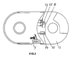
当接部8の各々が、図4に示される後ろに連なるチェーンリンク12の当接面10および11と協働する。
Each
従来、エネルギーチェーンの高速の運動には、厄介な問題であると認識されるかなりの騒音の発生が伴う場合があった。これを理由として、当接部8と当接面10および11との間に減衰要素が設けられることとなった。
In the past, the high speed motion of the energy chain could be accompanied by significant noise generation that was perceived as a nuisance. For this reason damping elements have been provided between the
図面に示される例示の実施形態では、当接部8が、後ろに連なるチェーンリンク12の当接面10および11に接触するそれらの接触領域内において、それらの側方領域内に、凸形に湾曲している減衰弓部13および14を備えており、これらの凸形に湾曲している領域が、各々の場合に、対応する当接面10または11に向かう方向に方向付けられる。
In the exemplary embodiment shown in the drawings, the
各々の減衰弓部13または14の後方に自由空間15が設けられる。それぞれの減衰弓部13または14が対応する当接面10または11に当たると、減衰弓部13または14が自由空間15の方にわずかに動くことができる。
A
減衰弓部13および14は弓形ブリッジの形態となるように構成され、それらの両端部が当接部8に固定的に接続される。
The damping bows 13 and 14 are configured in the form of arcuate bridges and are fixedly connected at their ends to the
減衰弓部13および14がブリッジ状の形態であることにより、減衰弓部13および14の変形中にそれらの材料内には主として圧縮力が発生する。 Due to the bridge-like configuration of damping bows 13 and 14, predominantly compressive forces are generated within the material of damping bows 13 and 14 during deformation.
本発明によるチェーンリンクは、概して、プラスチック材料から単一部片として作られ、それぞれの減衰弓部13および14が、それらの両端部において、関連する当接部8と一体となるように形成される。
The chain links according to the invention are generally made in a single piece from a plastics material, with each damping
エネルギーチェーンを作るのに使用されるプラスチック材料は、有意な材料疲労を結果として生じさせることなく圧縮応力を容易に吸収することができる。この点に関して、減衰弓部13、14の変形中にほぼ圧縮力のみが発生するという事実によって、本発明による特徴を備えるエネルギーチェーンの耐用寿命が大幅に延長され得る。 The plastic materials used to make energy chains can easily absorb compressive stress without resulting in significant material fatigue. In this regard, due to the fact that substantially only compressive forces occur during deformation of the damping bows 13, 14, the service life of an energy chain with features according to the invention can be significantly extended.
減衰弓部13および14の曲率半径は、湾曲部を比較的平らにするようにかつ減衰弓部13および14の変形の程度を比較的小さくするように、比較的大きくなるように選択される。図面に示される例示の実施形態では、湾曲部の高さに対する弦長さの比は約20:1である。 The radii of curvature of the damping bows 13 and 14 are selected to be relatively large so as to make the curvature relatively flat and to make the degree of deformation of the damping bows 13 and 14 relatively small. In the exemplary embodiment shown in the drawings, the ratio of chord length to bend height is about 20:1.
図面に示される実施形態によると、それぞれの減衰弓部13または14が関連する当接部8の全幅にわたって延在し、その結果、接触圧力が当接部8の全幅にわたって一様に分散される。減衰弓部13および14さらにはそれらの後方に位置する自由空間15は、それぞれの側方部品2または3の長手方向に対して横方向に延在する。
According to the embodiment shown in the drawings, each damping
図面に示される例示の実施形態では、減衰弓部13および14が、内側の誘導チャンネル5の方を向くそれぞれの側方部品2または3の壁に接続される。 In the exemplary embodiment shown in the drawings, damping bows 13 and 14 are connected to the walls of the respective side parts 2 or 3 facing the inner guide channel 5 .
しかし、別法として、内側の誘導チャンネル5の方を向くそれぞれの側方部品2または3の壁がそれぞれの減衰弓部13または14の領域で窪んでいるような実施形態も可能である。したがって、このような実施形態では、それぞれの減衰弓部13または14がそれぞれの側方部品2または3の内部壁に接続されず、結果として、それぞれの当接面10または11に当たるときにその全幅にわたって一様に圧縮され得る。
Alternatively, however, embodiments are also possible in which the wall of the respective lateral part 2 or 3 facing the inner guide channel 5 is recessed in the region of the respective damping
図4は、一体に接続される2つのチェーンリンク1および12から構成されるエネルギーチェーンの上側移動経路の一部分を示す。図面の右側のチェーンリンク12の上側当接面10がチェーンリンク1の当接部8の上に載置され、当接部8の上側減衰弓部13がわずかに押し下げられる。
FIG. 4 shows part of the upper travel path of the energy chain consisting of two
エネルギーチェーンの転回領域内で、つまり2つのチェーンリンクのうちの一方が下方に枢動するとき、チェーンリンク12の下側当接面11が下側減衰弓部14に当たり、下側減衰弓部14が衝撃の瞬間に自由空間15の方にわずかに動く。
Within the turning region of the energy chain, i.e. when one of the two chain links pivots downwards, the
チェーンリンク1および12が下側移動経路の水平方向領域の中まで再び枢動すると、当接面10が、当接面10の方を向く減衰弓部13に再び接触する。
When the
図3で最も良好に見ることができるように、各減衰弓部13、14が、誘導チャンネル5の方を向いている内壁16に接続されるかまたはそれぞれの側方部品2、3の周囲のボディに接続される。これは誘導チャンネル5から離れる方を向く側に沿うものであり、両端部の間の部分的な長さにわたるものであるか好適には両端部の間で完全に連続するものである。この接続は、同質である、つまり減衰弓部13、14と同じ材料を一様に有する、接続領域17を介するものである。
As can best be seen in FIG. 3, each damping
さらに図2で見ることができるように、側方部品2、3の内壁16が減衰弓部13、14のエリア内で窪んでいる。それぞれ、減衰弓部13、14の上方および下方において、内壁16の表面の反対側に2つの凹部18A、18Bが設けられる。これらの凹部18A、18Bは、減衰弓部13、14に関連する凹部として側方部品2、3と共に射出成形されるものであり、これらの間の残りの材料エリアが減衰弓部13、14を形成する。凹部18A、18Bは、周囲の壁厚さの少なくとも50%に一致する大きさで窪んでおり、図3では、図3の平面内につまり長手方向に対して横向きの平面内に、減衰弓部13、14の幅のほぼ50%である深さを有する。
Furthermore, as can be seen in FIG. 2, the
図3が示すように、後方の凹部18Aが開いている形で自由空間15に接続されており、つまり自由空間15を形成しており、前方のまたは反対側の凹部18Bが減衰弓部13、14のもう一方側に設けられる。横方向で見たときに、後方の凹部18Aが完全に当接部8の中に位置する。両方の凹部18A、18Bが同じ深さを有し、側面図(図2)において同等の基部面積を有し、これらの各々が、図2で見ることができるように、突出する当接部8より明らかに小さい。凹部18A、18Bが十分に深い場合、減衰弓部13、14が減衰を行いながら変形するとき、接続領域17の全体にわたってわずかな捻じれのみが生じ、一方で主として所望される弓形ブリッジの効果が生じ、つまり支配的な圧縮荷重が得られ、この圧縮荷重が減衰弓部13、14の端部を介して当接部8の耐荷重中実ボディエリアへ案内される。
As FIG. 3 shows, the
結果として、本発明による構成により、非常に単純な手段を用いて、エネルギーチェーンの最適な騒音減衰を達成することが可能となる。さらに、減衰弓部13および14内での有利な応力比により、これらの領域内での材料疲労が概して回避可能となり、結果として、エネルギーチェーンの耐用寿命が大幅に延長され得る。 As a result, the arrangement according to the invention makes it possible to achieve optimum noise attenuation of the energy chain using very simple means. Furthermore, the favorable stress ratio within the damping bows 13 and 14 allows material fatigue within these regions to be generally avoided, and as a result the useful life of the energy chain can be significantly extended.
1 チェーンリンク
2 側方部品
3 側方部品
4 クロスバー
5 誘導チャンネル
6 設置具
7 設置具
8 当接部
9 切欠部
10 当接面
11 当接面
12 後ろに連なるチェーンリンク
13 減衰弓部
14 減衰弓部
15 自由空間
16 内壁
17 接続領域
18A、18B 凹部
1 chain link 2 side part 3 side part 4 crossbar 5 guide channel 6
Claims (10)
- 前記側方部品(2、3)が、後ろに連なる側方部品(2、3)の当接面(10、11)と協働することにより、互いに連接的に接続されるチェーンリンク(1)の枢動可能性を制限するように構成される当接部(8)を有し、
- 前記側方部品(2、3)の上に前記当接部(8)と前記当接面(10、11)との間の領域の当接を減衰する弾性的に変形可能な減衰要素が設けられ、
- 少なくとも1つの当接部(8)が、前記枢動可能性を制限するために協働する前記当接面(10、11)に接触するその接触領域の各々において、少なくとも1つの減衰弓部(13、14)を備え、該少なくとも1つの減衰弓部(13、14)が、それぞれの協働する前記当接面(10、11)に向かう方向に凸形に湾曲しており、
- 前記減衰弓部(13、14)の後方に自由空間(15)が設けられ、
- 前記減衰弓部(13、14)の両端部が弓形ブリッジを形成するようにそれぞれの前記当接部(8)に固定的に接続され、および
- 前記減衰弓部(13、14)が、横方向において、前記減衰弓部の前記端部の間の少なくとも部分的なエリアにおいて、またはその全寸法にわたって、接続領域(17)を介して、前記側方部品(2、3)の内壁に接続され(17)、
- 前記側方部品(2、3)の前記内壁(16)が前記減衰弓部(13、14)の前記エリア内で窪んでおり、前記自由空間(15)の方に開いている第1の凹部(18A)ならびに反対側にある第2の凹部(18B)を提供し、前記第1の凹部(18A)および前記第2の凹部(18B)が前記内壁の表面を基準として窪んでおり、
前記第1の凹部(18A)は、横方向で見たときに、完全に前記当接部(8)の内側に位置しており、前記第1の凹部(18A)は前記第2の凹部(18B)とは分離している側方部品。 Two connections, at least one of which is free, comprising a plurality of chain links (1) consisting of two lateral parts (2, 3) and two crossbars (4) and articulated together A lateral part for an energy chain comprising a guiding channel (5) for guiding lines, such as hoses or cables, between points,
- chain links (1) in which said side parts (2, 3) are articulated to each other by cooperating with the abutment surfaces (10, 11) of the following side parts (2, 3); ) having an abutment (8) configured to limit the pivotability of the
- on said side parts (2, 3) elastically deformable damping elements damping the abutment of the region between said abutment (8) and said abutment surfaces (10 1 , 11 2 ); provided,
- at least one damping bow in each of its contact areas where at least one abutment (8) contacts said abutment surfaces (10, 11) cooperating to limit said pivotability; (13, 14), said at least one damping bow (13, 14) being convexly curved in a direction towards said respective cooperating abutment surfaces (10, 11);
- a free space (15) is provided behind said damping bows (13, 14),
- both ends of said damping bows (13, 14) are fixedly connected to respective said abutments (8) so as to form an arcuate bridge, and - said damping bows (13, 14) are In the lateral direction, at least in a partial area between the ends of the damping bow or over its entire dimension, it is connected via a connection area (17) to the inner wall of the lateral parts (2, 3). is (17),
- a first wherein said inner walls (16) of said lateral parts (2, 3) are recessed in said areas of said damping bows (13, 14) and open towards said free space (15); providing a recess (18A) and an opposite second recess (18B), said first recess (18A) and said second recess (18B) being recessed with respect to said inner wall surface ;
Said first recess (18A) is located completely inside said abutment portion (8) when viewed laterally, and said first recess (18A) is located above said second recess ( 18B) and separate lateral parts.
Applications Claiming Priority (3)
| Application Number | Priority Date | Filing Date | Title |
|---|---|---|---|
| DE202018102144.3 | 2018-04-18 | ||
| DE202018102144.3U DE202018102144U1 (en) | 2018-04-18 | 2018-04-18 | Energy guiding chain with damping elements and side part for it |
| PCT/EP2019/059301 WO2019201748A1 (en) | 2018-04-18 | 2019-04-11 | Cable carrier having damping elements and side part for same |
Publications (3)
| Publication Number | Publication Date |
|---|---|
| JP2021521391A JP2021521391A (en) | 2021-08-26 |
| JPWO2019201748A5 JPWO2019201748A5 (en) | 2022-03-16 |
| JP7189231B2 true JP7189231B2 (en) | 2022-12-13 |
Family
ID=66251743
Family Applications (1)
| Application Number | Title | Priority Date | Filing Date |
|---|---|---|---|
| JP2020556780A Active JP7189231B2 (en) | 2018-04-18 | 2019-04-11 | Energy chains with damping elements and lateral parts for energy chains |
Country Status (13)
| Country | Link |
|---|---|
| US (1) | US11460091B2 (en) |
| EP (1) | EP3781840B1 (en) |
| JP (1) | JP7189231B2 (en) |
| KR (1) | KR20200141090A (en) |
| CN (1) | CN112135989B (en) |
| AU (1) | AU2019254367B2 (en) |
| BR (1) | BR112020020951A2 (en) |
| CA (1) | CA3097030A1 (en) |
| DE (1) | DE202018102144U1 (en) |
| ES (1) | ES2910982T3 (en) |
| PL (1) | PL3781840T3 (en) |
| TW (1) | TWI785232B (en) |
| WO (1) | WO2019201748A1 (en) |
Families Citing this family (3)
| Publication number | Priority date | Publication date | Assignee | Title |
|---|---|---|---|---|
| KR20230029680A (en) * | 2020-05-27 | 2023-03-03 | 이구스 게엠베하 | Energy guide chain with flexible joint connector and side plate and joint connector therefor |
| DE202020103050U1 (en) | 2020-05-27 | 2021-09-02 | Igus Gmbh | Line guiding device, in particular energy guiding chain, and chain link with damping elements |
| WO2024008664A1 (en) * | 2022-07-04 | 2024-01-11 | Ocado Innovation Limited | A cable router and a load handling device |
Citations (4)
| Publication number | Priority date | Publication date | Assignee | Title |
|---|---|---|---|---|
| DE29607492U1 (en) | 1996-04-25 | 1997-08-21 | Igus Gmbh | Energy chain |
| JP2005256947A (en) | 2004-03-11 | 2005-09-22 | Tsubakimoto Chain Co | Protection and guide device of low noise type cable or the like |
| CN106151379A (en) | 2016-08-19 | 2016-11-23 | 江苏科瑞斯机件有限公司 | A kind of noise abatement drag chain |
| JP2019515202A (en) | 2016-04-22 | 2019-06-06 | イグス ゲゼルシャフト ミット ベシュレンクター ハフトゥング | Side parts, chain links, and energy guide chains |
Family Cites Families (23)
| Publication number | Priority date | Publication date | Assignee | Title |
|---|---|---|---|---|
| DE4105651A1 (en) * | 1991-02-22 | 1992-09-03 | Kabelschlepp Gmbh | POWER SUPPLY CHAIN |
| JP3100889B2 (en) * | 1995-10-27 | 2000-10-23 | 株式会社椿本チエイン | Rotational angle stopper for cable drag chain |
| JP3709892B2 (en) * | 1997-03-13 | 2005-10-26 | カーベルシユレツプ ゲゼルシヤフト ミツト ベシユレンクテル ハフツング | Protective element with lid that can be moved to two different stable positions |
| DE29806969U1 (en) | 1998-04-20 | 1998-06-10 | Igus Gmbh | Energy chain system |
| US6107565A (en) * | 1998-11-17 | 2000-08-22 | A&A Manufacturing Co., Inc. | Covered energy transmission line carrier |
| DE20107003U1 (en) * | 2001-04-23 | 2002-09-19 | Igus Gmbh | Power supply chain |
| US6978595B2 (en) * | 2002-02-05 | 2005-12-27 | Delphi Technologies, Inc. | Chain links and cable carrier chains containing same |
| DE10339168A1 (en) | 2003-08-21 | 2005-04-28 | Kabelschlepp Gmbh | Chain link for an energy chain and energy chain |
| JP4098275B2 (en) | 2004-06-07 | 2008-06-11 | 株式会社椿本チエイン | Cable protection guide device |
| JP4076550B2 (en) * | 2005-06-23 | 2008-04-16 | 株式会社椿本チエイン | Cable protection guide device |
| DE102005061760A1 (en) * | 2005-12-23 | 2007-07-19 | Kabelschlepp Gmbh | Wiring arrangement with reduced noise emission |
| DE202006006492U1 (en) * | 2006-04-20 | 2006-06-22 | Igus Gmbh | Energy guiding chain with molded sliding shoe |
| DE202006006645U1 (en) * | 2006-04-21 | 2006-07-06 | Igus Gmbh | Power supply chain |
| DE202006006638U1 (en) * | 2006-04-21 | 2006-06-22 | Igus Gmbh | Power supply chain |
| JP4302752B2 (en) * | 2007-05-02 | 2009-07-29 | 株式会社椿本チエイン | Cable protection guide device |
| JP5618933B2 (en) | 2011-07-25 | 2014-11-05 | 株式会社椿本チエイン | Cable protection guide device |
| KR101358451B1 (en) * | 2012-04-19 | 2014-02-05 | 주식회사 코닥트 | Link combination structure for cable carrier |
| DE202012003908U1 (en) * | 2012-04-19 | 2012-05-15 | Igus Gmbh | Energy guiding chain with rollers |
| JP6175402B2 (en) * | 2014-04-04 | 2017-08-02 | 株式会社椿本チエイン | Cable protection guide device |
| BR112018015120B1 (en) * | 2016-01-28 | 2022-08-23 | Igus Gmbh | POWER CABLED CONVEYOR WITH ELECTRICAL DETERIORATION DETECTION, DETECTION MODULE AND ITS USE |
| JP6378266B2 (en) * | 2016-08-08 | 2018-08-22 | 株式会社椿本チエイン | Cable protection guide device |
| CN205991137U (en) * | 2016-08-19 | 2017-03-01 | 江苏科瑞斯机件有限公司 | Noise abatement drag chain |
| DE202017101483U1 (en) * | 2017-03-14 | 2017-03-31 | Igus Gmbh | Strain relief and end fastening part with strain relief |
-
2018
- 2018-04-18 DE DE202018102144.3U patent/DE202018102144U1/en active Active
-
2019
- 2019-04-11 BR BR112020020951-1A patent/BR112020020951A2/en active IP Right Grant
- 2019-04-11 JP JP2020556780A patent/JP7189231B2/en active Active
- 2019-04-11 WO PCT/EP2019/059301 patent/WO2019201748A1/en active Search and Examination
- 2019-04-11 US US17/048,439 patent/US11460091B2/en active Active
- 2019-04-11 PL PL19719192.7T patent/PL3781840T3/en unknown
- 2019-04-11 EP EP19719192.7A patent/EP3781840B1/en active Active
- 2019-04-11 KR KR1020207033137A patent/KR20200141090A/en not_active Application Discontinuation
- 2019-04-11 CA CA3097030A patent/CA3097030A1/en active Pending
- 2019-04-11 ES ES19719192T patent/ES2910982T3/en active Active
- 2019-04-11 AU AU2019254367A patent/AU2019254367B2/en active Active
- 2019-04-11 CN CN201980031918.3A patent/CN112135989B/en active Active
- 2019-04-18 TW TW108113519A patent/TWI785232B/en active
Patent Citations (4)
| Publication number | Priority date | Publication date | Assignee | Title |
|---|---|---|---|---|
| DE29607492U1 (en) | 1996-04-25 | 1997-08-21 | Igus Gmbh | Energy chain |
| JP2005256947A (en) | 2004-03-11 | 2005-09-22 | Tsubakimoto Chain Co | Protection and guide device of low noise type cable or the like |
| JP2019515202A (en) | 2016-04-22 | 2019-06-06 | イグス ゲゼルシャフト ミット ベシュレンクター ハフトゥング | Side parts, chain links, and energy guide chains |
| CN106151379A (en) | 2016-08-19 | 2016-11-23 | 江苏科瑞斯机件有限公司 | A kind of noise abatement drag chain |
Also Published As
| Publication number | Publication date |
|---|---|
| AU2019254367B2 (en) | 2023-06-15 |
| DE202018102144U1 (en) | 2019-05-27 |
| US20210088111A1 (en) | 2021-03-25 |
| ES2910982T3 (en) | 2022-05-17 |
| KR20200141090A (en) | 2020-12-17 |
| TW201943978A (en) | 2019-11-16 |
| JP2021521391A (en) | 2021-08-26 |
| CA3097030A1 (en) | 2019-10-24 |
| EP3781840B1 (en) | 2022-01-12 |
| US11460091B2 (en) | 2022-10-04 |
| WO2019201748A1 (en) | 2019-10-24 |
| CN112135989A (en) | 2020-12-25 |
| PL3781840T3 (en) | 2022-07-18 |
| AU2019254367A1 (en) | 2020-12-03 |
| EP3781840A1 (en) | 2021-02-24 |
| TWI785232B (en) | 2022-12-01 |
| BR112020020951A2 (en) | 2021-03-02 |
| CN112135989B (en) | 2022-11-18 |
Similar Documents
| Publication | Publication Date | Title |
|---|---|---|
| JP7189231B2 (en) | Energy chains with damping elements and lateral parts for energy chains | |
| US7601041B2 (en) | High deflection hydrofoils and swim fins | |
| CN103635712B (en) | There is the cable carrying chain of deformable hinged member | |
| CN100585219C (en) | Hinge element for energy drag chain | |
| CN1291535C (en) | Energy guiding chain | |
| EP2060197B1 (en) | Foot part structure of sole assembly of shoes | |
| US8402595B2 (en) | Windscreen wiper device comprising an elastic, elongated carrier element, as well as an elongated wiper blade of a flexible material, which can be placed in abutment with the windscreen to be wiped | |
| US20130219852A1 (en) | Cable protection and guide device | |
| JP4961612B2 (en) | Transmission path guide device with low noise emission | |
| JP7429077B2 (en) | wiper blade | |
| US7134680B2 (en) | Alpine ski | |
| KR20160136384A (en) | Line guiding device with a single-piece hinge, corresponding chain link, and hinged belt | |
| US9951666B2 (en) | Oil pan | |
| US9764192B1 (en) | Swim fin | |
| US6053788A (en) | Swimming flipper | |
| US11300182B2 (en) | Side portion, chain link and energy guiding chain | |
| CN101285516A (en) | Compliant snubber | |
| JP4702752B2 (en) | Chain side plate for energy guide chain and energy guide chain | |
| US10926741B2 (en) | Wiper bracket and wiper | |
| JP4702753B2 (en) | Chain link and energy guide chain | |
| JPWO2019201748A5 (en) | ||
| KR20120128989A (en) | a Bumper back beam for vehicle |
Legal Events
| Date | Code | Title | Description |
|---|---|---|---|
| A529 | Written submission of copy of amendment under article 34 pct |
Free format text: JAPANESE INTERMEDIATE CODE: A529 Effective date: 20201210 |
|
| A521 | Request for written amendment filed |
Free format text: JAPANESE INTERMEDIATE CODE: A523 Effective date: 20220308 |
|
| A621 | Written request for application examination |
Free format text: JAPANESE INTERMEDIATE CODE: A621 Effective date: 20220308 |
|
| A871 | Explanation of circumstances concerning accelerated examination |
Free format text: JAPANESE INTERMEDIATE CODE: A871 Effective date: 20220308 |
|
| A131 | Notification of reasons for refusal |
Free format text: JAPANESE INTERMEDIATE CODE: A131 Effective date: 20220614 |
|
| A601 | Written request for extension of time |
Free format text: JAPANESE INTERMEDIATE CODE: A601 Effective date: 20220912 |
|
| A521 | Request for written amendment filed |
Free format text: JAPANESE INTERMEDIATE CODE: A523 Effective date: 20221026 |
|
| TRDD | Decision of grant or rejection written | ||
| A01 | Written decision to grant a patent or to grant a registration (utility model) |
Free format text: JAPANESE INTERMEDIATE CODE: A01 Effective date: 20221115 |
|
| A61 | First payment of annual fees (during grant procedure) |
Free format text: JAPANESE INTERMEDIATE CODE: A61 Effective date: 20221201 |
|
| R150 | Certificate of patent or registration of utility model |
Ref document number: 7189231 Country of ref document: JP Free format text: JAPANESE INTERMEDIATE CODE: R150 |