JP7186805B2 - Wind turbine rotor blades and wind turbines - Google Patents
Wind turbine rotor blades and wind turbines Download PDFInfo
- Publication number
- JP7186805B2 JP7186805B2 JP2020569976A JP2020569976A JP7186805B2 JP 7186805 B2 JP7186805 B2 JP 7186805B2 JP 2020569976 A JP2020569976 A JP 2020569976A JP 2020569976 A JP2020569976 A JP 2020569976A JP 7186805 B2 JP7186805 B2 JP 7186805B2
- Authority
- JP
- Japan
- Prior art keywords
- rotor blade
- rotor
- swirl
- swirl elements
- angle
- Prior art date
- Legal status (The legal status is an assumption and is not a legal conclusion. Google has not performed a legal analysis and makes no representation as to the accuracy of the status listed.)
- Active
Links
- 230000008859 change Effects 0.000 claims description 14
- 238000009434 installation Methods 0.000 claims description 8
- 238000000034 method Methods 0.000 claims description 5
- 230000007423 decrease Effects 0.000 description 10
- 238000000926 separation method Methods 0.000 description 7
- 238000004519 manufacturing process Methods 0.000 description 5
- 230000009467 reduction Effects 0.000 description 4
- 230000006978 adaptation Effects 0.000 description 3
- 230000002411 adverse Effects 0.000 description 2
- 238000010276 construction Methods 0.000 description 2
- 238000009826 distribution Methods 0.000 description 2
- 238000005516 engineering process Methods 0.000 description 2
- 238000001746 injection moulding Methods 0.000 description 2
- 230000009471 action Effects 0.000 description 1
- 230000003247 decreasing effect Effects 0.000 description 1
- 230000001419 dependent effect Effects 0.000 description 1
- 230000001627 detrimental effect Effects 0.000 description 1
- 238000010586 diagram Methods 0.000 description 1
- 230000000694 effects Effects 0.000 description 1
- 230000006698 induction Effects 0.000 description 1
- 238000002347 injection Methods 0.000 description 1
- 239000007924 injection Substances 0.000 description 1
- 238000003860 storage Methods 0.000 description 1
Images


Classifications
-
- F—MECHANICAL ENGINEERING; LIGHTING; HEATING; WEAPONS; BLASTING
- F03—MACHINES OR ENGINES FOR LIQUIDS; WIND, SPRING, OR WEIGHT MOTORS; PRODUCING MECHANICAL POWER OR A REACTIVE PROPULSIVE THRUST, NOT OTHERWISE PROVIDED FOR
- F03D—WIND MOTORS
- F03D1/00—Wind motors with rotation axis substantially parallel to the air flow entering the rotor
- F03D1/06—Rotors
- F03D1/065—Rotors characterised by their construction elements
- F03D1/0675—Rotors characterised by their construction elements of the blades
-
- F—MECHANICAL ENGINEERING; LIGHTING; HEATING; WEAPONS; BLASTING
- F03—MACHINES OR ENGINES FOR LIQUIDS; WIND, SPRING, OR WEIGHT MOTORS; PRODUCING MECHANICAL POWER OR A REACTIVE PROPULSIVE THRUST, NOT OTHERWISE PROVIDED FOR
- F03D—WIND MOTORS
- F03D1/00—Wind motors with rotation axis substantially parallel to the air flow entering the rotor
- F03D1/06—Rotors
- F03D1/065—Rotors characterised by their construction elements
- F03D1/0658—Arrangements for fixing wind-engaging parts to a hub
-
- F—MECHANICAL ENGINEERING; LIGHTING; HEATING; WEAPONS; BLASTING
- F03—MACHINES OR ENGINES FOR LIQUIDS; WIND, SPRING, OR WEIGHT MOTORS; PRODUCING MECHANICAL POWER OR A REACTIVE PROPULSIVE THRUST, NOT OTHERWISE PROVIDED FOR
- F03D—WIND MOTORS
- F03D7/00—Controlling wind motors
- F03D7/02—Controlling wind motors the wind motors having rotation axis substantially parallel to the air flow entering the rotor
- F03D7/022—Adjusting aerodynamic properties of the blades
-
- F—MECHANICAL ENGINEERING; LIGHTING; HEATING; WEAPONS; BLASTING
- F05—INDEXING SCHEMES RELATING TO ENGINES OR PUMPS IN VARIOUS SUBCLASSES OF CLASSES F01-F04
- F05B—INDEXING SCHEME RELATING TO WIND, SPRING, WEIGHT, INERTIA OR LIKE MOTORS, TO MACHINES OR ENGINES FOR LIQUIDS COVERED BY SUBCLASSES F03B, F03D AND F03G
- F05B2240/00—Components
- F05B2240/20—Rotors
- F05B2240/30—Characteristics of rotor blades, i.e. of any element transforming dynamic fluid energy to or from rotational energy and being attached to a rotor
- F05B2240/306—Surface measures
- F05B2240/3062—Vortex generators
-
- Y—GENERAL TAGGING OF NEW TECHNOLOGICAL DEVELOPMENTS; GENERAL TAGGING OF CROSS-SECTIONAL TECHNOLOGIES SPANNING OVER SEVERAL SECTIONS OF THE IPC; TECHNICAL SUBJECTS COVERED BY FORMER USPC CROSS-REFERENCE ART COLLECTIONS [XRACs] AND DIGESTS
- Y02—TECHNOLOGIES OR APPLICATIONS FOR MITIGATION OR ADAPTATION AGAINST CLIMATE CHANGE
- Y02E—REDUCTION OF GREENHOUSE GAS [GHG] EMISSIONS, RELATED TO ENERGY GENERATION, TRANSMISSION OR DISTRIBUTION
- Y02E10/00—Energy generation through renewable energy sources
- Y02E10/70—Wind energy
- Y02E10/72—Wind turbines with rotation axis in wind direction
Description
本発明は、風力タービンのロータブレードに関する。本発明はまた、ロータブレード用の渦発生器、風力タービン、および風力タービンを最適化するための方法に関する。 The present invention relates to rotor blades of wind turbines. The invention also relates to vortex generators for rotor blades, wind turbines and methods for optimizing wind turbines.
風力タービンのロータ用のロータブレードは一般的に知られている。このようなロータブレードは、特別な空力要件を可能にするプロファイル(断面プロファイル)を備えている。
ロータブレードの空力特性に影響を与えるために、ロータブレードの断面プロファイルに、表面に垂直に延びる複数のスワール要素を含む渦発生器を提供することが知られている。渦発生器は、流れの分離に対する抵抗を増加させるように、ロータブレードの表面上に乱流の局所領域を生成するのに役立つ。この目的のために、渦発生器-壁に近いロータブレード上で流れを旋回させ、その結果、壁の近くと壁から離れた流れの層の間の運動量の交換が大幅に増加し、壁の近くの境界層の流速が増加する。壁の近くで速度が増加するため、流れはロータブレードの表面でのより長い距離にわたる圧力の上昇に打ち勝つことができる。
Rotor blades for wind turbine rotors are generally known. Such rotor blades have a profile (cross-sectional profile) that allows for special aerodynamic requirements.
In order to influence the aerodynamic properties of a rotor blade, it is known to provide a vortex generator in the cross-sectional profile of the rotor blade that includes a plurality of swirl elements extending perpendicular to the surface. Vortex generators help create localized regions of turbulence on the surface of the rotor blades to increase the resistance to flow separation. For this purpose, the vortex generators—swirling the flow on the rotor blades close to the wall, as a result of which the momentum exchange between the near-wall and far-wall flow layers is greatly increased and the wall Nearby boundary layer flow velocity increases. Due to the increased velocity near the walls, the flow can overcome the increased pressure over a longer distance on the surface of the rotor blades.
欧州特許出願第3 309 388号明細書は、冒頭で述べたタイプのロータブレードと風力タービンを開示している。欧州特許出願第3 309 388号明細書は、ロータブレードをロータハブに取り付けるためのハブ領域のロータブレード根元部と、先端領域のロータブレード根元部とは反対側を向いて配置されているロータブレード先端部とを有する風力タービン用の、吸引側および圧力側を持つロータブレードを記載している。ロータブレードは、複数の構造的に同一の渦発生器がロータブレードの長手方向に断面的に隣り合って配置されている断面プロファイルを有する。渦発生器は、長さと高さのあるスワール要素で構成されており、ペアで並べて配置されている。スワール要素は、いずれの場合も、ロータブレードの主流方向に対してある角度で配向されており、同じ角度で配置されたスワール要素は、互いに一定の横方向の間隔を有する。 European Patent Application No. 3 309 388 discloses a rotor blade and wind turbine of the type mentioned at the outset. European Patent Application No. 3 309 388 discloses rotor blade roots in the hub region for mounting the rotor blades to a rotor hub and rotor blade tips in the tip region facing away from the rotor blade roots. A rotor blade having a suction side and a pressure side is described for a wind turbine having a section. The rotor blade has a cross-sectional profile in which a plurality of structurally identical vortex generators are arranged cross-sectionally adjacent to each other longitudinally of the rotor blade. The vortex generator consists of swirl elements of length and height, arranged side by side in pairs. The swirl elements are in each case oriented at an angle to the main flow direction of the rotor blades, and swirl elements arranged at the same angle have a constant lateral spacing from each other.
渦発生器およびスワール要素を備えた風力タービン用のロータブレードは、米国特許出願公開第2014/0328692号明細書、米国特許出願公開第2014/0328693号明細書、米国特許第9,869,297号明細書、および国際公開第2010/033018号からも知られている。 Rotor blades for wind turbines with vortex generators and swirl elements are disclosed in US 2014/0328692, US 2014/0328693, US 9,869,297 specification, and also from WO 2010/033018.
渦発生器を備えたそのようなブレードセクションでは、ロータブレードは通常、渦発生器が不要なブレードセクションよりも、後縁で初めて流れの分離が発生する迎え角の限界が大幅に大きくなる。渦発生器は、その作用の結果として、必然的にロータブレードのプロファイル表面でより大きな皮膚摩擦抗力を引き起こす、つまり、断面プロファイルの抗力係数が大幅に増加し、その結果、揚抗比(lift-to-drag ratios)、比率、揚力係数と抗力係数の比率は増加し、場合によっては減少する。抗力係数の増加または揚抗比の減少は、設置の歩留まりに悪影響を及ぼす。この点で、揚抗比または抗力係数の出力への影響は、ロータブレード根元部からロータブレード先端部に向かって増加し続けている。ロータブレード上の位置がロータブレード根元部からロータ先端の方向に離れるほど、風力タービンの出力と歩留まりにとって、より重要な小さな抗力係数または大きな揚抗比が重要になる。さらに、渦発生器は、騒音放出の増加に寄与する可能性がある。 In such blade sections with vortex generators, the rotor blades typically have a much higher angle of attack limit at which flow separation occurs first at the trailing edge than in blade sections without vortex generators. Vortex generators, as a result of their action, inevitably cause greater skin friction drag on the profile surface of the rotor blades, i.e., the drag coefficient of the cross-sectional profile is greatly increased, resulting in a lift-to-drag ratio (lift- to-drag ratios), ratios of lift and drag coefficients, increase and possibly decrease. An increase in drag coefficient or decrease in lift-to-drag ratio adversely affects installation yield. In this regard, the impact of lift-to-drag ratio or drag coefficient on power output continues to increase from the rotor blade root to the rotor blade tip. The further away the position on the rotor blade is from the rotor blade root towards the rotor tip, the more important a small drag coefficient or a large lift-to-drag ratio becomes for the power and yield of the wind turbine. Additionally, vortex generators can contribute to increased noise emissions.
本発明は、前述の問題を排除または少なくとも低減するという目的に基づいており、特に、ハブ領域における迎え角の大きな変動に対する補償および先端領域の大きな揚抗比によって特徴付けられるロータブレードを特定することを目的としている。
ロータブレードに関しては、この目的は、請求項1に記載のロータブレードによって達成される。本発明はまた、請求項10に記載の渦発生器、請求項11に記載の風力タービン、および請求項12に記載の風力タービンを最適化するための方法にも通じる。
The present invention is based on the object of eliminating or at least reducing the aforementioned problems, and in particular to identify a rotor blade characterized by compensation for large variations in angle of attack in the hub region and a large lift-to-drag ratio in the tip region. It is an object.
As regards the rotor blade, this object is achieved by a rotor blade according to
請求項1によれば、風力タービン用の吸引側および圧力側を備えたロータブレードが提供され、ロータブレードは、ロータブレードをロータハブに接続するためのハブ領域のロータブレード根元部と、ロータブレード根元部とは反対側に配置された先端領域(II)のロータブレード先端部と、ロータブレード根元部(2)とロータブレード先端部(3)との間に配置された少なくとも1つの渦発生器と、を備え、少なくとも1つの渦発生器(9)は、長さおよび高さを有するスワール要素を含み、これらは、ロータブレードの長手方向において隣り合って配置され、それぞれの場合において、ロータブレードの主流方向に対してある角度で配向されている。ロータブレードの長手方向において、スワール要素は、互いに横方向の間隔を有し、スワール要素の形状は、スワール要素の配置とロータブレード根元部との間のそれぞれの距離に応じて変化する。
According to
本発明は、風力タービンが定常状態の動作点で動作することはできず、むしろ異なる影響を受け、その結果、空力動作点が連続的に変化するという考察に基づいている。ロータブレードの断面プロファイルに対する迎え角は、風力タービンの運転中に恒久的に変化する。特に、入射流乱流などのパラメータは、下部境界層の水平および垂直せん断と空気密度は、迎え角分布に影響を与える。ロータブレードを超えて、この場合、これらのパラメータへの変更の影響は不均一である。例えば、小規模な入射流の乱流と空気密度の変化により、高速回転速度が低下し、先端領域よりもハブ領域では迎え角が大きく変化する。 The present invention is based on the observation that wind turbines cannot operate at a steady-state operating point, but rather are subject to different influences, resulting in continuously varying aerodynamic operating points. The angle of attack relative to the cross-sectional profile of the rotor blades permanently changes during operation of the wind turbine. In particular, parameters such as incident flow turbulence, horizontal and vertical shear in the lower boundary layer and air density affect the angle-of-attack distribution. Beyond the rotor blades, the impact of changes to these parameters is uneven in this case. For example, small-scale incident flow turbulence and changes in air density reduce the high rotational velocity and cause a greater change in angle of attack in the hub region than in the tip region.
順に、パッシブ流量測定器を使用する場合には、渦発生器の配置によって構成されるように、従来技術と比較して流れに影響を与える測定の複雑さを増すために、スワール要素の配置とロータブレード根元部との間のそれぞれの距離に応じてスワール要素の形状が変化する。ロータブレード根元部までの間隔に応じたスワール要素の形状の適応は、ハブ領域と先端領域との間のロータセクションのそれぞれの場合に優勢なロータブレードでの境界条件への有利な適応を可能にする。スワール要素の形状を距離に応じて変更することで、さまざまな揚力係数と揚抗比を実現することができる。これらのプロファイル係数特性は、特に、渦発生器のスワール要素の寸法を変更することで達成され、ロータブレードの要件を正確に満たす。 In turn, when using a passive flow meter, swirl element placement and The shape of the swirl element changes according to the respective distance from the rotor blade root. Adaptation of the shape of the swirl element according to the spacing to the rotor blade root allows an advantageous adaptation to the boundary conditions at the rotor blade prevailing in each case of the rotor section between the hub region and the tip region. do. By varying the shape of the swirl element with distance, different lift coefficients and lift-drag ratios can be achieved. These profile factor characteristics are achieved, inter alia, by changing the dimensions of the swirl elements of the vortex generators to precisely meet the rotor blade requirements.
好ましくは、スワール要素は、対で、ロータブレードの主流方向に対してある角度で配向され、ロータブレードは、それぞれ、実質的に反対方向に形成され、横方向の間隔は、実質的に同じ角度で隣り合って配置されたスワール要素間で決定される。スワール要素のペアワイズ配置は、特に、反対方向に回転する渦が互いに隣接して生成されることにより、特に効果的な渦の生成を確実にする。もちろん、対になって形成されていない2つの個別に設計されたスワール要素間の横方向の間隔を使用することも可能である。 Preferably, the swirl elements are oriented in pairs at an angle to the main flow direction of the rotor blades, the rotor blades being respectively formed in substantially opposite directions and laterally spaced at substantially the same angle. is determined between swirl elements placed next to each other. The pairwise arrangement of the swirl elements ensures particularly effective vortex generation, in particular by counter-rotating vortices being generated next to each other. Of course, it is also possible to use lateral spacing between two individually designed swirl elements that are not formed in pairs.
好ましくは、スワール要素の形状の変化は、スワール要素の長さに対する横方向の間隔の比率に起因する可能性があり、その比率は、距離の関数として決定される。この場合、長さの減少または同じ向きのスワール要素間の間隔の増加による、ロータの根元からの距離の増加に伴う比率の増加は、揚抗比を改善させ、最大到達可能迎え角の減少をもたらす。スワール要素の長さに対する横方向の間隔の比率が小さい場合、ハブ領域で大きな最大迎え角が許容される。 Preferably, the change in shape of the swirl element can be attributed to the ratio of lateral spacing to length of the swirl element, the ratio being determined as a function of distance. In this case, increasing the ratio with increasing distance from the root of the rotor, either by decreasing the length or increasing the spacing between swirl elements of the same orientation, improves the lift-to-drag ratio and reduces the maximum attainable angle of attack. Bring. A small ratio of lateral spacing to length of the swirl element allows a large maximum angle of attack in the hub region.
さらに、スワール要素の形状の変化は、高さに対する横方向の間隔の比率に起因する可能性があり、この比率は、同様に距離の関数として決定される。これ応じて、ロータの根元からの距離に依存する方法での比率の変更、この場合はスワール要素の高さの変更または同じ向きのスワール要素間の間隔の変更により、揚抗比の改善を支持する達成可能な最大迎え角の適応が可能になる。 In addition, changes in swirl element shape can be attributed to the ratio of lateral spacing to height, which is also determined as a function of distance. Correspondingly, changing the ratio in a manner that depends on the distance from the rotor root, in this case changing the height of the swirl elements or changing the spacing between swirl elements of the same orientation favors improved lift-to-drag ratio. allows adaptation of the maximum achievable angle of attack.
ハブ領域の長さに対する横方向の間隔の比率が比較的小さいため、風力タービンの運転中の迎え角の大きな変動を、流れの分離を減らしてカバーすることができる。そこでは、不利な揚抗比が設備の歩留まりにとって二次的に重要である。さらに外側では、そこでは、操作によって引き起こされる迎え角の変動も減少するが、これはその後、大きな揚抗比が歩留まりに及ぼす影響が連続的に増加するため、長さまたは高さに対する横方向の間隔の比率の増加に伴って発生する最大許容迎え角の低下が許容される。 Due to the relatively small ratio of lateral spacing to length of the hub region, large variations in angle of attack during operation of the wind turbine can be covered with reduced flow separation. There, the adverse lift-to-drag ratio is of secondary importance to the yield of the equipment. Further outside, there, the maneuver-induced variation in angle of attack also decreases, but this is followed by a continuous increase in the impact of large lift-to-drag ratios on yield, so that the lateral relative to length or height A decrease in the maximum allowable angle of attack that occurs with increasing spacing ratio is allowed.
好ましくは、スワール要素の形状の変化は、ロータブレードの主流方向に対する角度に対する横方向の間隔の比率に起因し、この比率は、距離の関数として決定される。
形状の変化の異なる形態は、個別に、独立して、または互いに組み合わせて提供することができる。
特に、スワール要素の長さに対する横方向の間隔の比率および/またはスワール要素の高さに対する横方向の間隔の比率は、距離の増加とともに増加してもよいし、および/またはスワール要素の設置角度に対する横方向の間隔の比率は、距離の増加とともに増加してもよい。設置角度は、特に主流方向に対するスワール要素の角度として理解されるべきである。
Preferably, the change in shape of the swirl element is due to the ratio of the lateral spacing to the angle of the rotor blades relative to the mainstream direction, the ratio being determined as a function of distance.
Different forms of shape variation can be provided individually, independently, or in combination with each other.
In particular, the ratio of the lateral spacing to the length of the swirl element and/or the ratio of the lateral spacing to the height of the swirl element may increase with increasing distance and/or the installation angle of the swirl element may increase with increasing distance. The installation angle should be understood in particular as the angle of the swirl element with respect to the mainstream direction.
好ましくは、スワール要素は、実質的に三角形またはフィンのようなプロファイルを有していてもよい。
好ましくは、スワール要素の長さおよび/または高さおよび/または取り付け角度は、実質的に一定であってもよい。次に、幾何学的変化は、好ましくは、隣接するスワール要素間の横方向間隔の変化を介して実現されてもよい。その結果、ただ1つのタイプのスワール要素を使用することが可能であり、本発明による利点はまだ達成されていない。さらに、スワール要素を混合することによる建設現場でのエラーおよび誤った取り付けの事例の低減、および製造中の利点が達成される。これは、例えば、射出成形プロセスを使用して、スワール要素を製造するために1つの工具を提供するだけでよいからである。特に好ましくは、前述のように、スワール要素は、共通のベースとペアで、例えば、射出成形部品として一体で提供される。
Preferably, the swirl element may have a substantially triangular or fin-like profile.
Preferably, the length and/or height and/or mounting angle of the swirl element may be substantially constant. A geometric change may then preferably be realized via a change in the lateral spacing between adjacent swirl elements. As a result, it is possible to use only one type of swirl element and the advantages according to the invention have not yet been achieved. In addition, a reduction in construction site errors and instances of incorrect installation and advantages during manufacturing are achieved by mixing swirl elements. This is because only one tool needs to be provided to manufacture the swirl element, for example using an injection molding process. Particularly preferably, as mentioned above, the swirl elements are provided integrally in pairs with a common base, for example as injection molded parts.
特に好ましくは、特にペアのスワール要素は同一である、すなわち、ロータブレードの長さにわたって同一の長さ、高さ、および取り付け角度を有する。複数のタイプのスワール要素が存在することも考えられ、スワール要素間の間隔は、ロータブレード根元部からの距離が増加するにつれて増加することが好ましい。
好ましくは、スワール要素の形状の変化は、スワール要素の、ロータブレードの表面からの距離における先端の内角に対する横方向の間隔の比率に起因する可能性があり、この比率は、距離の関数として決定される。先端の内角により、どれだけの高さであるか、つまり、ロータブレードの表面に垂直な範囲でどれだけ大きいか、を説明することができ、スワール要素は、つまり、特に、実質的に三角形またはフィン形状のプロファイルの場合には、ロータブレードの表面の平面内において、その長さに関連する。
さらに、少なくとも1つの渦発生器は、スワール要素が対に配置されている少なくとも1つのベースプレートを含んでいてもよい。その結果、異なるロータセクションに対して、そのスワール要素が、個々のロータセクションに適合された、長さに対する横方向の間隔および/または高さに対する横方向の間隔の比を有する渦発生器を生成することが可能である。
Particularly preferably, in particular the swirl elements of a pair are identical, ie have identical lengths, heights and mounting angles over the length of the rotor blade. There may be more than one type of swirl element and the spacing between swirl elements preferably increases with increasing distance from the rotor blade root.
Preferably, the change in shape of the swirl element may be attributed to the ratio of the lateral spacing of the swirl element to the interior angle of the tip at the distance from the surface of the rotor blade, the ratio being determined as a function of distance. be done. The interior angle of the tip can describe how high it is, i.e. how large it is in the range perpendicular to the surface of the rotor blade, and the swirl element is i.e., in particular substantially triangular or In the case of a fin-shaped profile, it relates to its length in the plane of the surface of the rotor blade.
Additionally, the at least one vortex generator may include at least one base plate on which the swirl elements are arranged in pairs. As a result, for different rotor sections, the swirl elements produce vortex generators with lateral spacing to length and/or lateral spacing to height ratios adapted to the individual rotor sections. It is possible to
本発明によれば、風力タービンのロータブレード用の渦発生器も提案されており、渦発生器は、前縁および後縁を備えたベースプレートを有し、前縁は、ロータブレード上の意図された方向において前縁の方向であり、後縁は、ロータブレード上で意図された方向における後縁の方向を向いており、このようにして、ベースプレートの方向は、ロータブレード根元部からロータブレード先端部に固定され、複数のスワール要素がベースプレート上に配置されている。ベースプレート上のスワール要素の形状は、スワール要素の配置とロータブレード根元部との間のそれぞれの距離に応じて変化する。 According to the invention there is also proposed a vortex generator for rotor blades of a wind turbine, the vortex generator having a base plate with a leading edge and a trailing edge, the leading edge being intended on the rotor blade. and the trailing edge in the intended direction on the rotor blade, thus the direction of the baseplate is from the rotor blade root to the rotor blade tip. A plurality of swirl elements are positioned on the base plate. The shape of the swirl element on the baseplate varies according to the respective distances between the placement of the swirl element and the rotor blade roots.
スワール要素は、好ましくは対に配置され、特に好ましくは、複数の対がベースプレート上に配置される。
ベースプレートまたはその前縁および後縁の方向は、必ずしもロータブレードの長手方向に完全に平行である必要はない。例えば、ベースプレートはまた、ロータブレードの後縁に平行であるように、または特定の角度、例えば、長手方向および/または後縁に対して最大20°、好ましくは10°未満で傾斜するように構成されてもよい。
The swirl elements are preferably arranged in pairs, particularly preferably several pairs on the base plate.
The orientation of the baseplate or its leading and trailing edges need not necessarily be perfectly parallel to the longitudinal direction of the rotor blades. For example, the baseplate is also configured to be parallel to the trailing edge of the rotor blade, or to be inclined at a certain angle, for example up to 20°, preferably less than 10°, relative to the longitudinal direction and/or the trailing edge. may be
本発明によれば、上記の実施形態のうちの少なくとも1つによる1つまたは複数のロータブレードおよび/または本発明による少なくとも1つの渦発生器を備えた風力タービンも提案される。特に提案されるのは、3つのロータブレードを有する風力タービンであって、その各ロータブレードは、上記の実施形態のうちの1つに従って設計されている。
最後に、本発明によれば、風力タービンを最適化するための方法が提案され、ここで、風力タービンは、風力タービン用に、吸引側および圧力側を備えたロータブレードを有し、ロータブレードは、ロータブレードをロータハブに取り付けるためのハブ領域のロータブレード根元部と、ロータブレード根元部とは反対側に配置された先端領域のロータブレード先端部と、ロータブレード根元部とロータブレード先端部との間に配置された少なくとも1つの渦発生器とを備えている。少なくとも1つの渦発生器は、ロータブレードの長手方向に隣り合って配置され、それぞれの場合において、ロータブレードの主流方向に対してある角度で配向された、長さおよび高さを有するスワール要素を含む。ここで、スワール要素は、互いに横方向の間隔を有する。この方法は、スワール要素の形状が、スワール要素の配置とロータブレード根元部との間のそれぞれの距離に応じて変化する。
According to the invention, a wind turbine is also proposed comprising one or more rotor blades according to at least one of the above embodiments and/or at least one vortex generator according to the invention. Proposed in particular is a wind turbine having three rotor blades, each rotor blade being designed according to one of the above embodiments.
Finally, according to the invention a method is proposed for optimizing a wind turbine, wherein the wind turbine has rotor blades with a suction side and a pressure side for the wind turbine, the rotor blades includes rotor blade roots in a hub region for mounting the rotor blades to the rotor hub, rotor blade tips in a tip region located opposite the rotor blade roots, and rotor blade roots and rotor blade tips. and at least one vortex generator disposed between. The at least one vortex generator comprises a swirl element having a length and a height arranged longitudinally adjacent to the rotor blade and in each case oriented at an angle to the main flow direction of the rotor blade. include. Here, the swirl elements have a lateral spacing from each other. This method changes the swirl element shape according to the respective distance between the swirl element arrangement and the rotor blade root.
さらなる例および利点は、添付の図面を参照して以下で説明される。 Further examples and advantages are described below with reference to the accompanying drawings.
図1は、基礎103上に建てられたタワー102を有する風力タービン100を示している。基礎103の反対側に位置する上端において、ロータハブ106およびそれに取り付けられたロータブレード1を有するロータ105を備えたナセル104(機械ハウジング)が配置され、これらのロータブレードは、さらなる図を参照してより詳細に説明される。ロータ105は、機械的仕事を電気エネルギーに変換する目的で、ナセル104の内部で発電機に結合されている。ナセル104は、タワー102上に回転可能に取り付けられ、その基礎103は、必要な安定性を提供する。
FIG. 1 shows a
図2は、一実施形態のロータブレード1の概略図を示している。ロータブレード1は、一端にロータブレード根元部2を有し、それとは反対側にロータブレード先端部3を有する。ロータブレード根元部2において、または一般に、ロータブレード根元部2に近い領域において、ロータブレード1は、大きなプロファイル深さを有する。対照的に、ロータブレード先端部3では、プロファイルの深さは非常に小さい。プロファイルルートとも呼ばれるロータブレード根元部2から進むと、プロファイルの深さは、ブレード内部領域で増加した後、この例では中央領域4まで大幅に減少する。分割点(ここには示されていない)は、中間領域4に提供されてもよい。中間領域4からロータブレード先端部3まで、プロファイル深さはほぼ一定であるか、またはプロファイル深さの減少が大幅に減少する。ロータブレード1は、例えば、実質的に凸状の負圧側7と、例えば、実質的に凹状の圧力側と、前縁5および後縁6を有する。圧力側および/または負圧側はまた、真っ直ぐであってもよく、別の形であってもよい。ロータブレード1の全長は8で示されている。
FIG. 2 shows a schematic view of a
図2の図はさらに、ロータブレード1の負圧側7に配置された渦発生器9を示している。渦発生器9は、一対で隣り合って配置されたスワール要素10,11を備えている。それぞれのスワール要素10,11は、前縁5と後縁6との間に断面的に延在し、それぞれの場合、スワール要素10,11の対が、前縁5から後縁6まで広がるプロファイルを有するように、流れがその周りを通過するロータブレード1の主流方向SRに対してある角度で配向される。
The diagram of FIG. 2 also shows a
この例では、スワール要素10,11は、ロータブレード1の表面に対して垂直に延在し、スワール要素10,11とロータブレード1の表面との間の直角以外の角度であってもよい。実施例の渦発生器9は、負圧側7に配置されて示されているが、圧力側の渦発生器9は、代替的または追加的であってもよい。
スワール要素10,11は、ロータハブまたはロータブレード根元部2から距離Rに配置されている。ロータブレード根元部2から進むと、ロータブレード1のハブ領域Iは、実質的に中央領域4まで延びる。ロータブレード1の先端領域IIは、実質的に中央領域4からロータブレード先端部3まで延びる。
In this example, the
The
図3は、斜視図における渦発生器9の実施形態の概略図を示している。渦発生器9は、ロータブレード1の表面への渦発生器9の取り付けに役立つ少なくとも1つのベースプレート13を有していてもよい。ベースプレート13は、前縁14と後縁15とを有する。前縁14は、ロータブレード1に取り付けられた位置で、前縁5に面し、後縁15は、後縁6に面する。この例では、実質的に三角形またはフィン状の輪郭を有するそれぞれのスワール要素10,11が延伸する。
FIG. 3 shows a schematic illustration of an embodiment of the
スワール要素10,11は、それぞれ高さHを有し、高さプロファイルはベースプレート13の後縁15の方向に最大値まで増加し、前縁14と後縁15との間、またはロータブレード平面内にあるそれぞれのスワール要素10,11の範囲を示す長さLを有する。
それぞれの場合にペアで隣り合って配置されたスワール要素10,11は、主流方向SRに対してある角度で傾斜して配置されており、前縁14から進んで、隣接するスワール要素10,11の拡大プロファイルが後縁15まで確立されている。隣り合って配置された2つのスワール要素10,11は、主流方向SRに対して実質的に対称な向きを有し、すなわち、対に配置されたスワール要素10,11のうちの1つのスワール要素10は、
ロータブレードの長手方向の外側、および別のスワール要素11は、ロータブレードの長手方向の内側をそれぞれ向いている。実質的に同じ方向に向けられた2つのスワール要素10または11の2つの先端間の横方向の間隔は、参照記号DまたはD1によって示される。
The
The
The longitudinally outer side of the rotor blade and the
渦発生器は、一般に、スワール要素は主流方向に対してある角度で傾斜して配置されているため、同じ横方向の間隔で配置された渦発生器のスワール要素が境界層の流れの渦に影響を与えるという点で、流れに影響を与えるための受動的な尺度を形成する。渦発生器は、壁の近くにあるロータブレード上の流れを旋回させ、その結果、壁の近くと壁から離れた流れの層の間の運動量の交換が大幅に増加し、壁の近くの境界層の流速が増加する。壁の近くで流速が増加するため、流れは、ロータブレードの表面でのより長い距離にわたる圧力の増加を克服することができる。これにより、流れの分離に対する抵抗が増加する。 Vortex generators are generally arranged such that the swirl elements are arranged at an angle to the main flow direction, so that the swirl elements of the same laterally spaced vortex generators form vortices in the boundary layer flow. In terms of influencing, it forms a passive measure for influencing flow. The vortex generators swirl the flow over the rotor blades near the wall, resulting in a large increase in momentum exchange between the near-wall and far-wall flow layers and the near-wall boundary Layer flow velocity increases. Due to the increased velocity near the walls, the flow is able to overcome pressure build-up over longer distances at the surface of the rotor blades. This increases the resistance to flow separation.
風力タービンは、定常状態の動作点では動作せず、常にさまざまな影響を受け、その結果、ロータブレード1の空気力学動作点が連続的に変化する。ブレード半径にわたるロータブレード1の迎え角αは、設備の動作中に連続的に変化する。特に、入射流の乱流、下部境界層の水平および垂直方向のせん断、空気密度などのパラメータは、最も重要なパラメータだけに言及すると、ロータブレード1の迎え角分布に影響を与える。この点で、小規模な入射流の乱流または空気密度の変化は、高速回転速度の低下をもたらし、それは、内部領域、すなわち、例えば、ロータブレード1の外側領域よりもロータブレード1のハブ領域Iから中間ドル領域4まで、すなわち、ロータブレード1の中間領域4から先端領域IIまでで、より大きく変化する迎え角αにつながる。よって、ロータブレード1の外側領域よりもロータブレード1の内側領域での動作中の迎え角αに対して、より大きな予備が提供される。したがって、渦発生器9は、特に、ロータブレードの内側領域で使用される。渦発生器9は、流れの分離に対する抵抗の増加を通じて、揚力と迎え角との間に比例関係がある、いわゆる線形分岐と呼ばれるロータブレード1のプロファイルの使用領域を長くする。
Wind turbines do not operate at a steady-state operating point and are constantly subject to various influences, resulting in continuously varying aerodynamic operating points of the
さらに、ロータブレード根元部2からロータブレード1のロータブレード先端3まで、揚抗比εまたは抗力係数Cwの力に対する影響はますます増大している。ロータブレード根元部2からの距離が大きくなるにつれて、設備の出力と歩留まりが小さな抗力係数Cwまたは大きな揚抗比εを達成することが不可欠である。
風力タービンの信頼性の高い操作のために、補償は、ロータブレード1の内部領域における迎え角の大きな変動に対して提供されなければならず、これは、その上に配置された渦発生器9を有するロータブレード1によって保証される。渦発生器9を使用する場合の揚抗比εの減少の不利な点は、揚抗比εが設置歩留まりに及ぼす影響はロータブレード1の内側領域では無視できるため、設置歩留まりに対する揚抗比εの影響が無視できるので、ロータブレード1の内部領域で許容できる。ロータブレード1の位置が外側に行くほど、カバーしなければならない迎え角範囲が小さくなり、風力タービンの降伏に対する揚力対抗力比εの影響が大きくなる。これらの状況を考慮して、スワール要素10,11の寸法決定は、スワール要素10,11の配置とロータブレード根元部2との間のそれぞれの距離Rに依存する方法で実現される。これは、ロータハブまたはロータブレード根元部2からの距離Rが増加するにつれて、スワール要素10,11の幾何学的寸法高さH、長さL、および/または横方向間隔Dが変化することを意味する。
Moreover, from the
For reliable operation of the wind turbine, compensation must be provided for large fluctuations in the angle of attack in the inner region of the
ここで、横方向間隔D対高さHまたは横方向間隔D対長さLの比Vは変化し、横方向間隔D対高さHまたは横方向間隔D対長さLの比Vは、距離Rの増加とともに増加する。ロータハブ領域Iでは、高さHに対する横方向間隔Dまたは長さLに対する横方向間隔Dの小さな比率Vが選択され、その結果、流れの分離なしに風力タービンの運転中の迎え角の大きな変動をカバーすることが可能である。対照的に、距離Rが大きくなると、高さHに対する横方向の間隔Dまたは長さLに対する横方向の間隔Dの比率Vの増加に伴って発生する最大許容迎え角の減少は許容される。これは、ロータハブからの距離Rが増加すると、操作によって引き起こされる迎え角の変動も減少するためであり、これは、大きな揚抗比が歩留まりに及ぼす影響が連続的に増加することで対応される。 Here, the ratio V of lateral spacing D to height H or lateral spacing D to length L varies, and the ratio V of lateral spacing D to height H or lateral spacing D to length L varies from distance It increases with increasing R. In the rotor hub region I, a small ratio V of the lateral spacing D to the height H or the lateral spacing D to the length L is chosen, resulting in large variations in the angle of attack during operation of the wind turbine without flow separation. can be covered. In contrast, as the distance R increases, a decrease in the maximum allowable angle of attack that occurs with an increase in the ratio V of lateral spacing D to height H or lateral spacing D to length L is acceptable. This is because as the distance R from the rotor hub increases, the maneuver-induced variation in angle of attack also decreases, which is countered by the continuously increasing impact of large lift-to-drag ratios on yield. .
代替の実施形態では、スワール要素10,11が主流方向SRに対して配置される角度γは、同様にまたは代替的に、ロータハブまたはロータブレード根元部2からの距離Rの増加に伴って変化する。主流方向SRに対する角度は、距離Rの増加とともに小さくなる。
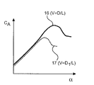
図4および図5は、それぞれ、いずれの場合も、横方向の間隔Dと高さHの2つの異なる比率Vについて、渦発生器9を備えたロータブレード1の迎え角αに対する揚力係数CAと揚力比εの2つの曲線16,17,18,19を示している。曲線16および18は、高さHに対する横方向間隔Dの第1の比率Vについて決定され、一方、曲線17および19は、高さHに対する横方向間隔D1の第2の比率Vについて決定され、横方向の間隔D1は横方向の間隔Dよりも大きい。
In an alternative embodiment, the angle γ at which the
4 and 5 respectively show the lift coefficient C A against the angle of attack α of a
図4で比較した曲線16と17から、最大揚力係数CAは、高さHに対する横方向の間隔Dの比率Vが増加するにつれて減少することが分かる。対照的に、図5で比較した曲線18と19は、広い迎え角範囲で達成可能な最大揚力比εが増加することを示している。その結果、ロータブレード1のハブ領域Iにおけるスワール要素10,11の横方向間隔D対高さHまたはHまたは横方向間隔D対長さLの比Vが小さく、大きい最大迎え角αになるように選択されると、ロータブレード1のこのプロファイルセクションでは許容されるが、これは揚抗比εの低下に関連し、横方向の間隔Dと高さHまたはHの比、または横方向の間隔Dと長さLの比がブレード先端3に向かって増加すると、最大到達迎え角αが減少し、揚抗比εが改善される。
From
図6は、スワール要素10,11の対の間の間隔が、ロータブレード根元部2からの距離の増加とともに増加するロータブレード1を概略的に示している。スワール要素10,11は、実質的に同一、すなわち、角度があり、ロータブレードの長手方向の全距離にわたって同じ高さHと長さLを持つように取り付けられている。
特にペアで提供される1つのタイプのスワール要素10,11のみを使用することにより、スワール要素10,11を混同して誤って取り付けるリスクが低減されるため、例えば、建設現場での取り付けを単純化することができる。また、例えば、射出成形技術を用いた製造の場合、必要な製造工具は1つだけであるため、製造技術の面での利点がそれに関連している。さらに、図6の実施形態は、それに関連する利点を達成しながら、記載された他のすべての幾何学的変形と組み合わせることができる。
FIG. 6 schematically shows a
By using only one type of
風力タービンに衝突する突風、すなわち、入射流の速度の変化は、これが作動している間、ロータブレード1での有効迎え角の変化を引き起こす。有効迎え角は、円周速度と流入風速のベクトル加算から生じる。したがって、円周速度と風速の比率によって、入射流の速度の変化が有効迎え角の大きな変化と小さな変化のどちらにつながるかが決まる。
ロータブレード根元部2では、円周速度に対する入射流速度が速いため、突風により有効迎え角が大きく変化する。ロータ先端3付近の外側のブレードでは、円周速度が数桁高く、それに関連する入射流速度がそれに応じて大幅に低い場合、同じ突風によって有効迎え角がわずかに変化するだけである。
A gust of wind impinging on the wind turbine, ie a change in the velocity of the incident flow, causes a change in the effective angle of attack on the
At the rotor
このため、可能な限り最大の迎え角の予備力をもたらすように、内側ブレード上に渦発生器9を構成する必要がある。これはまた、可能な限り分離のない所望のプロファイル極性によって表現することができ、渦発生器9の間の間隔が比較的小さい場合である。結果として生じる追加の抗力およびそれから生じる揚抗性能の低下は、低い円周速度での風力タービンの出力にとってほとんど重要ではない。
For this reason, it is necessary to configure the
ロータ先端3付近の外側ブレードでは、記載されている理由により、追加の迎え角予備力を減らす必要がある。また、高い円周速度が発生するロータブレード1の過度に大きな抗力は、ロータブレード根元部2よりもロータ出力に著しく大きな悪影響を与えるであろう。したがって、この地域では、渦発生器9の間の間隔を大きくすることが好ましく、その結果、抗力が小さいため、揚力対抗力の性能が向上し、失速点までの迎え角の広がりがわずかに減少する。
The outer blades near the
代替的または追加的に、外側に向かってより小さな渦発生器9を使用することもまた好都合であって、特に、渦発生器9が外側に向かってサイズが小さくなったとしても、外側に向かって間隔を拡大することと組み合わせることが好ましい。特に好ましくは、渦発生器9は、3から5つの利用可能な異なるサイズの渦発生器9から選択されるので、例えば、保管および取り付けの場合の複雑さは、管理可能なままである。
Alternatively or additionally, it is also advantageous to use
発生する騒音については、風にさらされる渦発生器9の数が多いほど、生成されるノイズの量が多いほど、さらに、風速が高いほど、個々の渦発生器9によって生成される騒音の量が大きくなる場合がある。したがって、音響の観点から、ロータブレード根元部2と比較して、外側に向かう渦発生器9の密度も低いことが好ましい。
ロータブレード1のブレード設計では、目的はまた、半径全体の誘導係数に対して1/3の電力最適値を維持することでもある。遅い速度のため、これは、プロファイルの深さを増やすことによってのみ、ロータブレード根元部2の領域で可能になる。これは、輸送上の理由から限られた範囲でのみ可能であるか、揚力係数を増やすことによってのみ可能である。したがって、ロータブレード根元部2で最大深度が制限された出力最適ロータは、常に、ルート領域で可能な限り最大の揚力係数が達成されるように設計する必要がある。
Regarding the noise generated, the greater the number of
In the blade design of
Claims (9)
-前記ロータブレード(1)をロータハブに接続するためのハブ領域(I)のロータブレード根元部(2)と、
-前記ロータブレード根元部(2)とは反対側に配置された先端領域(II)のロータブレード先端部(3)と、
-前記ロータブレード根元部(2)と前記ロータブレード先端部(3)との間に配置された少なくとも1つの渦発生器(9)と、
を備え、
少なくとも1つの渦発生器(9)は、長さ(L)および高さ(H)を有するスワール要素(10,11)を含み、これらは、ロータブレードの長手方向に隣り合って配置され、それぞれの場合において、前記ロータブレード(1)の主流方向(SR)に対してある角度で配向され、ロータブレードの長手方向において、前記スワール要素(10,11)は、互いに横方向の間隔(D,D1)を有し、
前記渦発生器(9)は、前記スワール要素(10,11)が前記ロータブレード(1)の主流方向(SR)に対してある角度で配向され、それぞれが、実質的に互いに対称な向きになるように対で配置され、横方向の間隔(D,D 1 )は、実質的に同じ角度で隣り合って配置された前記スワール要素(10,11)の間で決定される、少なくとも1つのベースプレート(13)を含み、
前記スワール要素(10,11)の形状は、前記スワール要素(10,11)の配置と前記ロータブレード根元部(2)との間のそれぞれの距離(R)に応じて変化するとともに、前記スワール要素(10,11)の形状の変化は、前記ロータブレード(1)の主流方向(SR)に対する角度に対する横方向の間隔(D,D 1 )の比率(V)に起因し、これは、距離(R)の増加とともに距離(R)の関数として増加する、
ロータブレード(1)。 A rotor blade (1) with a suction side and a pressure side for a wind turbine, comprising:
- a rotor blade root (2) in the hub region (I) for connecting said rotor blade (1) to the rotor hub;
- a rotor blade tip (3) in a tip region (II) located opposite said rotor blade root (2);
- at least one vortex generator (9) arranged between said rotor blade root (2) and said rotor blade tip (3);
with
The at least one vortex generator (9) includes swirl elements (10, 11) having a length (L) and a height (H), which are arranged longitudinally adjacent to the rotor blade and each oriented at an angle to the mainstream direction (SR) of said rotor blade (1) and in the longitudinal direction of the rotor blade said swirl elements (10, 11) are laterally spaced from each other (D, D 1 ),
The vortex generators (9) are configured such that the swirl elements (10, 11) are oriented at an angle to the mainstream direction (SR) of the rotor blades (1) and each are oriented substantially symmetrically to each other. at least one swirl element (10, 11) arranged in pairs such that the lateral spacing (D, D 1 ) is determined between said swirl elements (10, 11) arranged adjacently at substantially the same angle. including a base plate (13);
The shape of the swirl elements (10, 11) varies according to the respective distance (R) between the arrangement of the swirl elements (10, 11) and the rotor blade root (2) , and the swirl The change in shape of the elements (10, 11) is due to the ratio (V) of the lateral spacing (D, D 1 ) to the angle of said rotor blades (1) with respect to the mainstream direction (SR), which is the distance increases as a function of distance (R) with increasing (R) ,
rotor blades (1);
請求項1に記載のロータブレード(1)。 The change in shape of said swirl elements (10, 11) is due to the ratio (V) of lateral spacing (D, D1 ) to length (L), which is determined as a function of distance (R). to be
A rotor blade (1) according to claim 1 .
請求項1または2に記載のロータブレード(1)。 The change in shape of said swirl elements (10, 11) is due to the ratio (V) of lateral spacing (D, D1 ) to height (H), which is determined as a function of distance (R). to be
A rotor blade (1) according to claim 1 or 2 .
請求項2または3に記載のロータブレード(1)。 The ratio of lateral spacing (D, D1 ) to length (L) and/or the ratio of lateral spacing (D, D1 ) to height (H) increases with increasing distance (R). to add
A rotor blade (1) according to claim 2 or 3 .
請求項4に記載のロータブレード(1)。 the length (L) and/or height (H) and/or mounting angle of said swirl elements (10, 11) are substantially constant;
A rotor blade (1) according to claim 4 .
請求項1から5のいずれか1つに記載のロータブレード(1)。 said swirl elements (10, 11) have a substantially triangular or fin-shaped profile,
A rotor blade (1) according to any one of claims 1 to 5 .
請求項1から6のいずれか1つに記載のロータブレード(1) The change in shape of said swirl elements (10, 11) is laterally between the tips of two said swirl elements (10, 11) oriented in substantially the same direction away from the surface of said rotor blades (1). , which is determined as a function of the distance (R), due to the ratio (V) of the spacing (D, D 1 ) of
Rotor blade (1) according to any one of claims 1 to 6
前記ロータは、請求項1から7のいずれか1つに記載の少なくとも1つのロータブレード(1)を有する、
風力エネルギー設備。 A wind energy installation comprising a rotor, comprising:
The rotor has at least one rotor blade (1 ) according to any one of claims 1 to 7 ,
Wind energy equipment.
-前記ロータブレード(1)をロータハブに接続するためのハブ領域(I)のロータブレード根元部(2)と、
-前記ロータブレード根元部(2)とは反対側に配置された先端領域(II)のロータブレード先端部(3)と、
-前記ロータブレード根元部(2)と前記ロータブレード先端部(3)との間に配置された少なくとも1つの渦発生器(9)と、
を備え、
少なくとも1つの前記渦発生器(9)は、前記ロータブレードの長手方向に互いに隣接して配置され、それぞれ前記ロータブレード(1)の主流方向(SR)に対してある角度をもって配向された、長さ(L)および高さ(H)を有するスワール要素(10,11)を含み、
前記スワール要素(10,11)は互いに横方向の間隔(D,D1)を有し、
前記渦発生器(9)は、前記スワール要素(10,11)が前記ロータブレード(1)の主流方向(SR)に対してある角度で配向され、それぞれが、実質的に互いに対称な向きになるように対で配置され、横方向の間隔(D,D 1 )は、実質的に同じ角度で隣り合って配置された前記スワール要素(10,11)の間で決定される、少なくとも1つのベースプレート(13)を含み、
前記スワール要素(10,11)の形状は、前記スワール要素(10,11)の配置から前記ロータブレード根元部(2)までのそれぞれの距離(R)に応じて変化するとともに、前記スワール要素(10,11)の形状の変化は、前記ロータブレード(1)の主流方向(SR)に対する角度に対する横方向の間隔(D,D 1 )の比率(V)に起因し、これは、距離(R)の増加とともに距離(R)の関数として増加する、
方法。 A method for optimizing a wind turbine, said wind turbine having rotor blades (1) with a suction side and a pressure side for the wind turbine, said rotor blades comprising:
- a rotor blade root (2) in the hub region (I) for connecting said rotor blade (1) to the rotor hub;
- a rotor blade tip (3) in a tip region (II) located opposite said rotor blade root (2);
- at least one vortex generator (9) arranged between said rotor blade root (2) and said rotor blade tip (3);
with
The at least one vortex generator (9) is arranged adjacent to each other in the longitudinal direction of the rotor blades, each oriented at an angle to the mainstream direction (SR) of the rotor blades (1). comprising swirl elements (10, 11) having a height (L) and a height (H);
said swirl elements (10, 11) have a lateral spacing (D, D1 ) from each other;
The vortex generators (9) are configured such that the swirl elements (10, 11) are oriented at an angle to the mainstream direction (SR) of the rotor blades (1) and each are oriented substantially symmetrically to each other. at least one swirl element (10, 11) arranged in pairs such that the lateral spacing (D, D 1 ) is determined between said swirl elements (10, 11) arranged adjacently at substantially the same angle. including a base plate (13);
The shape of the swirl elements (10, 11) varies depending on the distance (R) from the arrangement of the swirl elements (10, 11) to the rotor blade root (2), and the swirl element ( 10, 11) is due to the ratio (V) of the lateral spacing (D, D 1 ) to the angle to the mainstream direction (SR) of said rotor blades (1), which is the distance ( R ) as a function of the distance (R) ,
How .
Applications Claiming Priority (3)
| Application Number | Priority Date | Filing Date | Title |
|---|---|---|---|
| DE102018117398.9 | 2018-07-18 | ||
| DE102018117398.9A DE102018117398A1 (en) | 2018-07-18 | 2018-07-18 | Rotor blade for a wind turbine and wind turbine |
| PCT/EP2019/069351 WO2020016351A1 (en) | 2018-07-18 | 2019-07-18 | Rotor blade for a wind turbine and wind turbine |
Publications (2)
| Publication Number | Publication Date |
|---|---|
| JP2021527774A JP2021527774A (en) | 2021-10-14 |
| JP7186805B2 true JP7186805B2 (en) | 2022-12-09 |
Family
ID=67390075
Family Applications (1)
| Application Number | Title | Priority Date | Filing Date |
|---|---|---|---|
| JP2020569976A Active JP7186805B2 (en) | 2018-07-18 | 2019-07-18 | Wind turbine rotor blades and wind turbines |
Country Status (8)
| Country | Link |
|---|---|
| US (1) | US11644007B2 (en) |
| EP (1) | EP3824176A1 (en) |
| JP (1) | JP7186805B2 (en) |
| CN (1) | CN112424469A (en) |
| CA (1) | CA3104294C (en) |
| DE (1) | DE102018117398A1 (en) |
| RU (1) | RU2766498C1 (en) |
| WO (1) | WO2020016351A1 (en) |
Families Citing this family (2)
| Publication number | Priority date | Publication date | Assignee | Title |
|---|---|---|---|---|
| CN112943565B (en) * | 2021-03-16 | 2021-12-28 | 中国华能集团清洁能源技术研究院有限公司 | Fan blade with wave-shaped vortex generator and design method thereof |
| DE102022124161A1 (en) | 2022-09-21 | 2024-03-21 | Nordex Energy Se & Co. Kg | Vortex generator strip for attachment to a wind turbine rotor blade |
Citations (7)
| Publication number | Priority date | Publication date | Assignee | Title |
|---|---|---|---|---|
| JP2014070638A (en) | 2012-09-28 | 2014-04-21 | Siemens Aktiengesellschaft | Wind turbine rotor blade |
| US20140140856A1 (en) | 2011-07-22 | 2014-05-22 | Lm Wp Patent Holding A/S | Wind turbine blade comprising vortex generators |
| US20140328693A1 (en) | 2013-05-03 | 2014-11-06 | General Electric Company | Rotor blade assembly having vortex generators for wind turbine |
| US20150204306A1 (en) | 2014-01-17 | 2015-07-23 | General Electric Company | Rotatable aerodynamic surface features for wind turbine rotor blades |
| US20150361952A1 (en) | 2013-02-19 | 2015-12-17 | Senvion Gmbh | Rotor blade of a wind turbine |
| JP2016041916A (en) | 2014-08-18 | 2016-03-31 | 株式会社日本自動車部品総合研究所 | Wind turbine apparatus |
| JP2017089526A (en) | 2015-11-12 | 2017-05-25 | 三菱重工業株式会社 | Vortex generator, windmill blade and wind power generator |
Family Cites Families (26)
| Publication number | Priority date | Publication date | Assignee | Title |
|---|---|---|---|---|
| US5058837A (en) * | 1989-04-07 | 1991-10-22 | Wheeler Gary O | Low drag vortex generators |
| RU2118699C1 (en) * | 1996-06-18 | 1998-09-10 | Институт теоретической и прикладной механики СО РАН | Wind-power plant and its operation |
| DK1886016T3 (en) * | 2005-05-17 | 2017-06-19 | Vestas Wind Sys As | Pitch-controlled wind turbine blade with turbulence generating means, a wind turbine and its use |
| EP2027390B2 (en) * | 2006-06-09 | 2020-07-01 | Vestas Wind Systems A/S | A wind turbine blade and a pitch controlled wind turbine |
| CN102187092B (en) * | 2008-09-19 | 2015-05-20 | 考特能源有限公司 | Wind turbine with low induction tips |
| US9039381B2 (en) * | 2010-12-17 | 2015-05-26 | Vestas Wind Systems A/S | Wind turbine blade and method for manufacturing a wind turbine blade with vortex generators |
| DK2484897T3 (en) * | 2011-02-04 | 2014-03-10 | Lm Wind Power As | Vortex generator for a wind turbine and having a base portion with a recess for an adhesive |
| ES2759027T3 (en) * | 2011-07-22 | 2020-05-07 | Lm Wp Patent Holding As | A vortex generator arrangement for a lift surface |
| EP2548801A1 (en) | 2011-07-22 | 2013-01-23 | LM Wind Power A/S | Wind turbine blade comprising vortex generators |
| ES2554863T5 (en) * | 2011-11-23 | 2019-05-07 | Siemens Ag | Wind turbine blade |
| DE102013206437A1 (en) * | 2013-04-11 | 2014-10-16 | Senvion Se | Rotor blade of a wind turbine and wind turbine |
| US9556849B2 (en) * | 2013-05-02 | 2017-01-31 | General Electric Company | Attachment system and method for wind turbine vortex generators |
| DE102013210901A1 (en) * | 2013-06-11 | 2014-12-11 | Wobben Properties Gmbh | Rotor blade of a wind turbine and wind turbine |
| US9624782B2 (en) * | 2013-11-11 | 2017-04-18 | General Electric Company | Template for aligning surface features on a rotor blade |
| WO2015169471A1 (en) * | 2014-05-06 | 2015-11-12 | Siemens Aktiengesellschaft | Noise reduction means for a rotor blade of a wind turbine |
| DE102014106529B4 (en) * | 2014-05-09 | 2016-02-04 | Senvion Gmbh | Repair procedure for vortex generator and a kit for it |
| DE102014213930A1 (en) * | 2014-07-17 | 2016-01-21 | Wobben Properties Gmbh | Rotor blade tip trailing edge |
| US10087912B2 (en) * | 2015-01-30 | 2018-10-02 | General Electric Company | Vortex generator for a rotor blade |
| US9869297B2 (en) * | 2015-05-07 | 2018-01-16 | General Electric Company | Attachment method and system to install components, such as vortex generators, to a wind turbine blade |
| JP6154037B1 (en) * | 2016-02-26 | 2017-06-28 | 三菱重工業株式会社 | Vortex generator mounting method and template |
| JP6148364B1 (en) * | 2016-02-26 | 2017-06-14 | 三菱重工業株式会社 | Wind turbine blade vortex generator, wind turbine blade, wind power generator, and vortex generator mounting method |
| JP6632553B2 (en) | 2017-01-16 | 2020-01-22 | 三菱重工業株式会社 | Vortex generator and its installation method, windmill blade and wind power generator |
| JP6779180B2 (en) * | 2017-06-30 | 2020-11-04 | 三菱重工業株式会社 | Vortex generator and wind turbine wing assembly |
| JP6732697B2 (en) * | 2017-07-05 | 2020-07-29 | 三菱重工業株式会社 | Method for determining arrangement position of vortex generator on wind turbine blade, method for manufacturing wind turbine blade assembly, and wind turbine blade assembly |
| JP6783212B2 (en) * | 2017-10-20 | 2020-11-11 | 三菱重工業株式会社 | How to position the vortex generator on the wind turbine wing, how to manufacture the wind turbine wing assembly and the wind turbine wing assembly |
| JP6783211B2 (en) * | 2017-10-20 | 2020-11-11 | 三菱重工業株式会社 | How to determine the placement of the vortex generator on the wind turbine blades and wind turbine blades |
-
2018
- 2018-07-18 DE DE102018117398.9A patent/DE102018117398A1/en active Pending
-
2019
- 2019-07-18 US US17/259,881 patent/US11644007B2/en active Active
- 2019-07-18 WO PCT/EP2019/069351 patent/WO2020016351A1/en active Application Filing
- 2019-07-18 RU RU2021103877A patent/RU2766498C1/en active
- 2019-07-18 JP JP2020569976A patent/JP7186805B2/en active Active
- 2019-07-18 CN CN201980047681.8A patent/CN112424469A/en active Pending
- 2019-07-18 CA CA3104294A patent/CA3104294C/en active Active
- 2019-07-18 EP EP19742352.8A patent/EP3824176A1/en active Pending
Patent Citations (7)
| Publication number | Priority date | Publication date | Assignee | Title |
|---|---|---|---|---|
| US20140140856A1 (en) | 2011-07-22 | 2014-05-22 | Lm Wp Patent Holding A/S | Wind turbine blade comprising vortex generators |
| JP2014070638A (en) | 2012-09-28 | 2014-04-21 | Siemens Aktiengesellschaft | Wind turbine rotor blade |
| US20150361952A1 (en) | 2013-02-19 | 2015-12-17 | Senvion Gmbh | Rotor blade of a wind turbine |
| US20140328693A1 (en) | 2013-05-03 | 2014-11-06 | General Electric Company | Rotor blade assembly having vortex generators for wind turbine |
| US20150204306A1 (en) | 2014-01-17 | 2015-07-23 | General Electric Company | Rotatable aerodynamic surface features for wind turbine rotor blades |
| JP2016041916A (en) | 2014-08-18 | 2016-03-31 | 株式会社日本自動車部品総合研究所 | Wind turbine apparatus |
| JP2017089526A (en) | 2015-11-12 | 2017-05-25 | 三菱重工業株式会社 | Vortex generator, windmill blade and wind power generator |
Also Published As
| Publication number | Publication date |
|---|---|
| JP2021527774A (en) | 2021-10-14 |
| US11644007B2 (en) | 2023-05-09 |
| CA3104294A1 (en) | 2020-01-23 |
| CA3104294C (en) | 2023-06-27 |
| WO2020016351A1 (en) | 2020-01-23 |
| DE102018117398A1 (en) | 2020-01-23 |
| CN112424469A (en) | 2021-02-26 |
| EP3824176A1 (en) | 2021-05-26 |
| RU2766498C1 (en) | 2022-03-15 |
| US20210222671A1 (en) | 2021-07-22 |
Similar Documents
| Publication | Publication Date | Title |
|---|---|---|
| US20160252073A1 (en) | Blade for a rotor of a wind turbine provided with barrier generating means | |
| US8047801B2 (en) | Wind turbine blades with aerodynamic vortex elements | |
| CN105715449B (en) | Rotor blade with vortex generators and wind turbine | |
| EP2834517B1 (en) | Twisted blade root | |
| EP2122163A2 (en) | Wind turbine with rotor blades equipped with winglets and blades for such rotor | |
| WO2013060722A1 (en) | Wind turbine blade provided with slat | |
| JP6067130B2 (en) | Wind power generator | |
| US11149707B2 (en) | Wind turbine blade and method for determining arrangement of vortex generator on wind turbine blade | |
| EP3421782B1 (en) | Vortex generator and wind turbine blade assembly | |
| AU2017204260B2 (en) | Blade for a wind turbine having a guide vane | |
| JP7186805B2 (en) | Wind turbine rotor blades and wind turbines | |
| JP2019078191A5 (en) | ||
| KR20140027248A (en) | Runner for a hydraulic machine, hydraulic machine provided with such a runner and power-conversion equipment including such a hydraulic machine | |
| JP5479300B2 (en) | Wind turbine blade, wind power generator equipped with the wind turbine blade, and wind turbine blade design method | |
| US20170306925A1 (en) | Three-vane double rotor for vertical axis turbine | |
| CN109563804B (en) | Wind turbine blade with tip serrations | |
| EP3098436B1 (en) | Noise reducing flap with opening | |
| EP2851556A1 (en) | Arrangement to reduce noise of a wind turbine rotor blade | |
| KR20110083476A (en) | The vertical axis wind turbine using drag force and lift force simultaneouly | |
| KR102606803B1 (en) | A blade for wind power generator | |
| DK201770908A1 (en) | Wind turbine blade vortex generators | |
| KR20130068037A (en) | Aerogenerator attached bump on blade |
Legal Events
| Date | Code | Title | Description |
|---|---|---|---|
| A521 | Request for written amendment filed |
Free format text: JAPANESE INTERMEDIATE CODE: A523 Effective date: 20201215 |
|
| A621 | Written request for application examination |
Free format text: JAPANESE INTERMEDIATE CODE: A621 Effective date: 20201215 |
|
| A131 | Notification of reasons for refusal |
Free format text: JAPANESE INTERMEDIATE CODE: A131 Effective date: 20220208 |
|
| A601 | Written request for extension of time |
Free format text: JAPANESE INTERMEDIATE CODE: A601 Effective date: 20220509 |
|
| A521 | Request for written amendment filed |
Free format text: JAPANESE INTERMEDIATE CODE: A523 Effective date: 20220705 |
|
| TRDD | Decision of grant or rejection written | ||
| A01 | Written decision to grant a patent or to grant a registration (utility model) |
Free format text: JAPANESE INTERMEDIATE CODE: A01 Effective date: 20221108 |
|
| A61 | First payment of annual fees (during grant procedure) |
Free format text: JAPANESE INTERMEDIATE CODE: A61 Effective date: 20221129 |
|
| R150 | Certificate of patent or registration of utility model |
Ref document number: 7186805 Country of ref document: JP Free format text: JAPANESE INTERMEDIATE CODE: R150 |