JP7184879B2 - Smart pellets for sample testing - Google Patents
Smart pellets for sample testing Download PDFInfo
- Publication number
- JP7184879B2 JP7184879B2 JP2020515695A JP2020515695A JP7184879B2 JP 7184879 B2 JP7184879 B2 JP 7184879B2 JP 2020515695 A JP2020515695 A JP 2020515695A JP 2020515695 A JP2020515695 A JP 2020515695A JP 7184879 B2 JP7184879 B2 JP 7184879B2
- Authority
- JP
- Japan
- Prior art keywords
- sensor
- sensing device
- housing
- sample
- sensors
- Prior art date
- Legal status (The legal status is an assumption and is not a legal conclusion. Google has not performed a legal analysis and makes no representation as to the accuracy of the status listed.)
- Active
Links
Images


Classifications
-
- A—HUMAN NECESSITIES
- A61—MEDICAL OR VETERINARY SCIENCE; HYGIENE
- A61B—DIAGNOSIS; SURGERY; IDENTIFICATION
- A61B5/00—Measuring for diagnostic purposes; Identification of persons
- A61B5/145—Measuring characteristics of blood in vivo, e.g. gas concentration, pH value; Measuring characteristics of body fluids or tissues, e.g. interstitial fluid, cerebral tissue
- A61B5/14507—Measuring characteristics of blood in vivo, e.g. gas concentration, pH value; Measuring characteristics of body fluids or tissues, e.g. interstitial fluid, cerebral tissue specially adapted for measuring characteristics of body fluids other than blood
-
- A—HUMAN NECESSITIES
- A61—MEDICAL OR VETERINARY SCIENCE; HYGIENE
- A61B—DIAGNOSIS; SURGERY; IDENTIFICATION
- A61B5/00—Measuring for diagnostic purposes; Identification of persons
- A61B5/145—Measuring characteristics of blood in vivo, e.g. gas concentration, pH value; Measuring characteristics of body fluids or tissues, e.g. interstitial fluid, cerebral tissue
- A61B5/14532—Measuring characteristics of blood in vivo, e.g. gas concentration, pH value; Measuring characteristics of body fluids or tissues, e.g. interstitial fluid, cerebral tissue for measuring glucose, e.g. by tissue impedance measurement
-
- G—PHYSICS
- G01—MEASURING; TESTING
- G01N—INVESTIGATING OR ANALYSING MATERIALS BY DETERMINING THEIR CHEMICAL OR PHYSICAL PROPERTIES
- G01N21/00—Investigating or analysing materials by the use of optical means, i.e. using sub-millimetre waves, infrared, visible or ultraviolet light
- G01N21/62—Systems in which the material investigated is excited whereby it emits light or causes a change in wavelength of the incident light
- G01N21/63—Systems in which the material investigated is excited whereby it emits light or causes a change in wavelength of the incident light optically excited
- G01N21/64—Fluorescence; Phosphorescence
- G01N21/6428—Measuring fluorescence of fluorescent products of reactions or of fluorochrome labelled reactive substances, e.g. measuring quenching effects, using measuring "optrodes"
-
- G—PHYSICS
- G01—MEASURING; TESTING
- G01N—INVESTIGATING OR ANALYSING MATERIALS BY DETERMINING THEIR CHEMICAL OR PHYSICAL PROPERTIES
- G01N21/00—Investigating or analysing materials by the use of optical means, i.e. using sub-millimetre waves, infrared, visible or ultraviolet light
- G01N21/75—Systems in which material is subjected to a chemical reaction, the progress or the result of the reaction being investigated
- G01N21/77—Systems in which material is subjected to a chemical reaction, the progress or the result of the reaction being investigated by observing the effect on a chemical indicator
- G01N21/78—Systems in which material is subjected to a chemical reaction, the progress or the result of the reaction being investigated by observing the effect on a chemical indicator producing a change of colour
-
- G—PHYSICS
- G01—MEASURING; TESTING
- G01N—INVESTIGATING OR ANALYSING MATERIALS BY DETERMINING THEIR CHEMICAL OR PHYSICAL PROPERTIES
- G01N21/00—Investigating or analysing materials by the use of optical means, i.e. using sub-millimetre waves, infrared, visible or ultraviolet light
- G01N21/84—Systems specially adapted for particular applications
- G01N21/8483—Investigating reagent band
-
- G—PHYSICS
- G01—MEASURING; TESTING
- G01N—INVESTIGATING OR ANALYSING MATERIALS BY DETERMINING THEIR CHEMICAL OR PHYSICAL PROPERTIES
- G01N33/00—Investigating or analysing materials by specific methods not covered by groups G01N1/00 - G01N31/00
- G01N33/48—Biological material, e.g. blood, urine; Haemocytometers
- G01N33/50—Chemical analysis of biological material, e.g. blood, urine; Testing involving biospecific ligand binding methods; Immunological testing
- G01N33/53—Immunoassay; Biospecific binding assay; Materials therefor
- G01N33/543—Immunoassay; Biospecific binding assay; Materials therefor with an insoluble carrier for immobilising immunochemicals
- G01N33/54366—Apparatus specially adapted for solid-phase testing
- G01N33/54386—Analytical elements
- G01N33/54387—Immunochromatographic test strips
- G01N33/54388—Immunochromatographic test strips based on lateral flow
-
- G—PHYSICS
- G01—MEASURING; TESTING
- G01N—INVESTIGATING OR ANALYSING MATERIALS BY DETERMINING THEIR CHEMICAL OR PHYSICAL PROPERTIES
- G01N33/00—Investigating or analysing materials by specific methods not covered by groups G01N1/00 - G01N31/00
- G01N33/48—Biological material, e.g. blood, urine; Haemocytometers
- G01N33/50—Chemical analysis of biological material, e.g. blood, urine; Testing involving biospecific ligand binding methods; Immunological testing
- G01N33/53—Immunoassay; Biospecific binding assay; Materials therefor
- G01N33/558—Immunoassay; Biospecific binding assay; Materials therefor using diffusion or migration of antigen or antibody
-
- G—PHYSICS
- G16—INFORMATION AND COMMUNICATION TECHNOLOGY [ICT] SPECIALLY ADAPTED FOR SPECIFIC APPLICATION FIELDS
- G16H—HEALTHCARE INFORMATICS, i.e. INFORMATION AND COMMUNICATION TECHNOLOGY [ICT] SPECIALLY ADAPTED FOR THE HANDLING OR PROCESSING OF MEDICAL OR HEALTHCARE DATA
- G16H10/00—ICT specially adapted for the handling or processing of patient-related medical or healthcare data
- G16H10/40—ICT specially adapted for the handling or processing of patient-related medical or healthcare data for data related to laboratory analysis, e.g. patient specimen analysis
-
- A—HUMAN NECESSITIES
- A61—MEDICAL OR VETERINARY SCIENCE; HYGIENE
- A61B—DIAGNOSIS; SURGERY; IDENTIFICATION
- A61B5/00—Measuring for diagnostic purposes; Identification of persons
- A61B5/145—Measuring characteristics of blood in vivo, e.g. gas concentration, pH value; Measuring characteristics of body fluids or tissues, e.g. interstitial fluid, cerebral tissue
- A61B5/14539—Measuring characteristics of blood in vivo, e.g. gas concentration, pH value; Measuring characteristics of body fluids or tissues, e.g. interstitial fluid, cerebral tissue for measuring pH
-
- G—PHYSICS
- G01—MEASURING; TESTING
- G01N—INVESTIGATING OR ANALYSING MATERIALS BY DETERMINING THEIR CHEMICAL OR PHYSICAL PROPERTIES
- G01N2201/00—Features of devices classified in G01N21/00
- G01N2201/02—Mechanical
- G01N2201/021—Special mounting in general
- G01N2201/0218—Submersible, submarine
Description
本発明は、液体(たとえば、生物)試料の試験技法に関し、より詳細には、生物および他の液体試料を試験するための小さいペレットとして構成された浸漬可能な感知デバイスに関する。 The present invention relates to techniques for testing liquid (eg, biological) samples, and more particularly to submersible sensing devices configured as small pellets for testing biological and other liquid samples.
バイオアッセイは典型的に、試験ストリップを液体生物試料内に浸し、次いでベンチトップ分析器などのデバイスを使用して試験ストリップを分析することを伴う。しかし、試料収集と分析との間の時間に、試料が汚染、劣化、または他の形で損なわれる可能性がある。たとえば、患者から試料が収集されてから試料が分析されるまでの間に相当な量の時間がある可能性がある。その時間中、試料が試験箇所に到達するまでに、試料の輸送または貯蔵あるいはその両方が行われることがある。この間ずっと、試料は、その試験に対する完全性および有用性を維持するために、適切に取り扱われなければならない。適切な取扱いには、汚染、漏れを防止すること、劣化を防止するために試料を適切な温度で維持することなどが含まれうる。したがって、試験前に試料が損なわれる多くの機会が存在する。 Bioassays typically involve dipping a test strip into a liquid biological sample and then analyzing the test strip using a device such as a benchtop analyzer. However, during the time between sample collection and analysis, the sample can become contaminated, degraded, or otherwise damaged. For example, there can be a significant amount of time between when a sample is collected from a patient and when the sample is analyzed. During that time, the sample may be transported and/or stored until it reaches the test site. Throughout this time, the sample must be handled properly to maintain its integrity and utility for testing. Proper handling may include preventing contamination, leakage, maintaining the sample at the proper temperature to prevent deterioration, and the like. Therefore, there are many opportunities for samples to be compromised prior to testing.
したがって、収集時に試料の包括的な試験を可能にする技法が所望される。 Techniques that allow for comprehensive testing of samples at the time of collection are therefore desirable.
本発明は、生物および他の液体試料を試験するための小さいペレットとして構成された浸漬可能な感知デバイスを提供する。本発明の一態様では、感知デバイスが提供される。感知デバイスは、ハウジングと、ハウジング内に収容された1つまたは複数のセンサとを含み、ハウジングは、感知デバイスが液体検体内に完全に浸漬可能になるように、センサを密封する。 The present invention provides immersible sensing devices configured as small pellets for testing biological and other liquid samples. In one aspect of the invention, a sensing device is provided. The sensing device includes a housing and one or more sensors contained within the housing, the housing enclosing the sensor such that the sensing device is fully immersible in the liquid analyte.
本発明の別の態様では、別の感知デバイスが提供される。感知デバイスは、ハウジングと、感知デバイスが検体内に完全に浸漬可能になるようにハウジング内に密封された1つまたは複数のセンサとを含み、ハウジングは、平坦な頂面と、平坦な頂面とは反対側の平坦な底面とを含み、平坦な頂面および平坦な底面はどちらも円形であり、したがって感知デバイスはペレットの形状を有し、その直径dは約10cm以下であり、その厚さtは約1.25mm~約25mmおよびそれらの間の範囲である。 In another aspect of the invention, another sensing device is provided. The sensing device includes a housing and one or more sensors sealed within the housing to allow the sensing device to be fully immersed in the analyte, the housing having a flat top surface and a flat top surface. Both the flat top surface and the flat bottom surface are circular, so that the sensing device has the shape of a pellet, the diameter d of which is about 10 cm or less, and the thickness The thickness t ranges from about 1.25 mm to about 25 mm and ranges therebetween.
本発明のさらに別の態様では、液体試料を分析する方法が提供される。この方法は、感知デバイスを液体試料内に浸漬することであり、感知デバイスが、ハウジングおよびハウジング内に収容された1つまたは複数のセンサを含み、感知デバイスが液体試料内に完全に浸漬可能になるようにハウジングがセンサを密封する、浸漬することと、センサを使用して液体試料からデータを収集することと、感知デバイスからのデータをデータ管理システムおよび電子記録のうちの少なくとも1つへ伝送することとを含む。 In yet another aspect of the invention, a method of analyzing a liquid sample is provided. The method comprises immersing the sensing device in the liquid sample, the sensing device including a housing and one or more sensors contained within the housing, such that the sensing device is fully immersed in the liquid sample. collecting data from the liquid sample using the sensor; and transmitting data from the sensing device to at least one of a data management system and an electronic record. including doing.
本発明のさらに別の態様では、液体試料を分析するシステムが提供される。システムは、ハウジングおよびハウジング内に収容された1つまたは複数のセンサを有する少なくとも1つの感知デバイスであり、感知デバイスが液体試料内に完全に浸漬可能になるようにハウジングがセンサを密封する、少なくとも1つの感知デバイスと、少なくとも1つの感知デバイスに通信可能に接続されたデータ管理システムとを含む。 In yet another aspect of the invention, a system for analyzing liquid samples is provided. The system is at least one sensing device having a housing and one or more sensors housed within the housing, the housing enclosing the sensor such that the sensing device is fully immersible within the liquid sample. It includes one sensing device and a data management system communicatively connected to the at least one sensing device.
本発明のより完全な理解、ならびに本発明のさらなる特徴および利点は、以下の詳細な説明および図面を参照することによって得られる。 A more complete understanding of the invention, as well as further features and advantages of the invention, can be obtained by reference to the following detailed description and drawings.
浸漬可能な感知デバイスを使用する収集時試料試験のための改善された技法が、本明細書に提供される。このデバイスは、通信、電力、および識別(ID)の構成要素が組み込まれた試料分析のための複数のセンサを含む。 Improved techniques for on-collection sample testing using immersible sensing devices are provided herein. The device contains multiple sensors for sample analysis that incorporate communication, power, and identification (ID) components.
本発明の一実施形態では、デバイスはペレットの形状であり、たとえば患者から収集された液体試料内に容易に浸漬することができるように小さい寸法を有する。試験のため、デバイスは、試料を収容するカップなどの容器内へ簡単に投入される。デバイスは、主表面のいずれか(頂面または底面)が試料カップの底部に支持された状態で動作することができる。好ましくは、ペレットはまた、試験のためにペレットを浸漬するために必要とされる試料が最小体積のみになるように薄い。 In one embodiment of the invention, the device is in the form of a pellet and has small dimensions so that it can be easily immersed in a liquid sample, eg, collected from a patient. For testing, the device is simply placed into a container, such as a cup, containing the sample. The device can operate with either of its major surfaces (top or bottom) supported on the bottom of the sample cup. Preferably, the pellet is also thin so that only a minimal volume of sample is required to immerse the pellet for testing.
例示のみを目的として、デバイスの直径dは、約10センチメートル(cm)以下、好ましくは約2.5cm以下、より好ましくは約2cm以下であり、たとえば約0.5cm~約1cmの範囲である。デバイスの厚さtは、好ましくは約3cm以下、より好ましくは約0.5cm以下であり、たとえば約1.25ミリメートル(mm)~約25mmの範囲である。デバイスのサイズは、標準的なサイズの収集容器またはカップ内に収容された試料に対して試験が実行されているときに重要である。たとえば、尿分析のためなどの生物製剤に関する試料試験は、約60mm(直径)×70mm(高さ)の寸法を有する試料カップ内に収容された検体を扱うことが多い。したがって、デバイスを試料カップ内に、デバイスの頂面または底面がカップの底部に完全に支持された状態で配置するには、デバイス自体の直径を、試料カップの直径より小さくしなければならない。さらに、デバイスは、その頂面または底面が試料カップの底部に支持されているいずれの向きでもうまく機能することができるため、デバイスの寸法をより小さくすることで(試料カップと比較して)、使用者がデバイスを試料/試料カップ内へ簡単に投入すると、デバイスが試料内に浸漬し、(その頂面または底面が)試料カップの底部に支持されていることが保証される。 By way of example only, the diameter d of the device is no greater than about 10 centimeters (cm), preferably no greater than about 2.5 cm, more preferably no greater than about 2 cm, such as in the range of about 0.5 cm to about 1 cm. . The thickness t of the device is preferably no greater than about 3 cm, more preferably no greater than about 0.5 cm, for example in the range of about 1.25 millimeters (mm) to about 25 mm. The size of the device is important when testing is being performed on samples contained in standard size collection containers or cups. For example, sample testing on biopharmaceuticals, such as for urine analysis, often involves specimens contained within sample cups having dimensions of approximately 60 mm (diameter) by 70 mm (height). Therefore, the diameter of the device itself must be smaller than the diameter of the sample cup in order for the device to be placed in the sample cup with the top or bottom of the device fully supported by the bottom of the cup. Furthermore, the device can function well in either orientation with its top or bottom surface supported by the bottom of the sample cup, so the smaller dimensions of the device (compared to the sample cup) A user simply drops the device into the sample/sample cup ensuring that the device is immersed in the sample and rests (either on its top or bottom surface) on the bottom of the sample cup.
上述したように、デバイスには多数の異なるセンサが装備されている。所与の1つのデバイスで用いられるセンサの組合せは、標的検体に応じて変動する可能性がある。たとえば、ある1組のセンサは、尿分析中などに生物試料からデータを収集するのに有用になる可能性がある一方で、別の異なる1組のセンサは、水試料または液体化学試料の試験により適している可能性がある。デバイスは、それに応じて構成することができる。例示のみを目的として、デバイス内で使用するのに好適なセンサには、それだけに限定されるものではないが、電気センサ、電気化学センサ、光センサ、圧力センサ、温度センサ、比重センサ、または音響センサ、あるいはその組合せが含まれる。 As mentioned above, the device is equipped with many different sensors. The combination of sensors used in a given device can vary depending on the target analyte. For example, one set of sensors may be useful for collecting data from biological samples, such as during urine analysis, while another and different set of sensors may be useful for testing water samples or liquid chemical samples. may be more suitable for Devices can be configured accordingly. By way of example only, sensors suitable for use within the device include, but are not limited to, electrical sensors, electrochemical sensors, optical sensors, pressure sensors, temperature sensors, specific gravity sensors, or acoustic sensors. , or combinations thereof.
上述したように、デバイスには電力構成要素を組み込むことができる。たとえば、デバイスは、電池源が組み込まれた独立型のデバイスとして構成することができる。この独立型の構成は、外部電源が容易に利用可能でない可能性がある分野で使用するのに特に有益である。別法として、デバイスは、たとえば非接触充電を介してデバイスに給電するために使用されるシステム・ハブを含むアセンブリの一部とすることができる。そのようなアセンブリの使用は、病院または医院、研究所、診療所などの常時電源を有する環境によく適している。任意選択で、組み込まれた電力構成要素は、外部電源への直接接続を使用するシステム・ハブまたは非接触充電あるいはその両方を介して再充電可能とすることができる。しかし、デバイス自体が自立型の組み込まれた電力構成要素を有していないときは、非接触充電を使用してデバイスに給電することができる。本明細書における使用が企図される他の電源には、それだけに限定されるものではないが、照明下で発電する光起電セルなどの光起電性の電源、および光起電セルによって生成されるエネルギーを貯蔵する再充電可能電池が含まれる。 As noted above, the device may incorporate power components. For example, the device can be configured as a standalone device with an integrated battery source. This stand-alone configuration is particularly beneficial for use in areas where external power sources may not be readily available. Alternatively, the device may be part of an assembly that includes a system hub that is used to power the device via, for example, contactless charging. Use of such an assembly is well suited for environments with constant power sources such as hospitals or doctor's offices, laboratories, clinics, and the like. Optionally, embedded power components may be rechargeable via system hub and/or contactless charging using direct connection to an external power source. However, when the device itself does not have a self-contained built-in power component, contactless charging can be used to power the device. Other power sources contemplated for use herein include, but are not limited to, photovoltaic power sources, such as photovoltaic cells that generate electricity under illumination, and photovoltaic cells generated by photovoltaic cells. Includes rechargeable batteries that store energy that
本発明を実施する技法の概要について、デバイスを使用して試料を分析する図1の方法100を参照して次に提供する。ステップ102で、デバイスは検体内に浸漬される。好ましくは、検体は、市販の試料カップなどの器または容器内に収容された液体試料であり、カップ内に存在する検体の体積は、検体内にデバイスを完全に浸漬するのに十分である。例示のみを目的として、検体は、尿分析のためなどの生物試料、水または化学試験などのための水または液体化学試料などとすることができる。上述したように、ステップ102は、検体を収容する試料カップ内へデバイスを投入することによって簡単に実行することができる。デバイスは、感知デバイスが(その頂面または底面が)試料カップの底部に載って平らに支持されるように、試料内に浸漬される。本発明の実施形態では、デバイスが試料内に完全に浸漬される場合について本明細書に記載するが、ペレット自体全体が完全に浸漬されていない場合でも、センサを有するデバイスの表面(以下参照)が検体内に浸漬された場合、試料からデータを得ることも可能であることに注目すべきである。したがってたとえば、検体の体積がデバイス全体を完全に浸漬するのに十分でないが、センサを収容するデバイスの表面が浸漬されている(すなわち、デバイスの感知面が検体内に位置する)場合、読取り値を得ることができる(デバイスが部分的にのみ浸漬されている状態でも)。
An overview of techniques embodying the present invention will now be provided with reference to
有利には、試料の収集時点で試験を実行することができ、したがって試料およびそこから拾い集めたデータの完全性が保持される。たとえば、患者から生物試料を収集している医師、水試料を収集している研究者などは、検体試料を(たとえば、試料カップ内に)収集し、次いで試料内へデバイスをすぐに投入することができる。比較として、ほとんどの従来の試験手法は、この分野には適していないベンチトップ機器を要し、したがって多くの場合、試料が収集されてから分析されるまでの間に長い期間を要し、その間、輸送、出荷中などに試料は広い範囲で取り扱われる。 Advantageously, testing can be performed at the time the sample is collected, thus preserving the integrity of the sample and the data gleaned therefrom. For example, a physician collecting a biological sample from a patient, a researcher collecting a water sample, etc. may collect an analyte sample (e.g., in a sample cup) and then quickly insert the device into the sample. can be done. By comparison, most conventional testing methods require bench-top equipment that is not suitable for this field, and therefore often require long periods of time between the time a sample is collected and the time it is analyzed. Samples are extensively handled during, for example, transportation, shipping, etc.
ステップ104で、ここで検体内に浸漬されているデバイスを使用して、検体からデータを集める/収集する。上述したように、デバイスは、検体からデータを収集するように構成された様々な異なるセンサ(たとえば、電気センサ、電気化学センサ、光センサ、圧力センサ、温度センサ、比重センサ、または音響センサ、あるいはその組合せ)を含むことができる。デバイス内に存在するセンサの数またはタイプあるいはその両方は、特定の応用例および試験されている検体に依存する可能性がある。たとえば、生物試料を評価する際は、特定のバイオマーカ・センサが有用になることもあるが、これらは水試料の試験には適用されないはずである。したがって、本発明の一実施形態によれば、異なる試験の応用例には、異なるデバイスが利用可能であり、それらのデバイスは、デバイスが含む特定のセンサに基づいて互いに異なる。検体からデータを集めることに加えて、試料のソースに関する情報を記録し、他の結果に関連付けることもできる。たとえば、デバイスと通信する電話または他の入力デバイスからの無線リンクを使用して、患者識別(ID)を追加することができる。
At
ステップ106で、デバイスは、収集したデータを伝送する。本発明の一実施形態によれば、デバイスによって収集されたデータは、ローカル・ハブを介してクラウドへ伝送され、次いでデータ管理システムへ、および/または電子医療記録すなわちEMRなどの電子記録へ伝送される。たとえば、後述するシステム1100を参照されたい。好ましくは、デバイスからのデータ伝送は、感知デバイスを独立型のユニットとして検体内へ導入することが可能になるように、無線で実行される。しかし、本発明の実施形態には、有線接続を介してデバイスからデータが得られる場合、および/またはデバイスによってデータが収集および記憶され、次にアーカイブ、分析などのためにシステムへ伝送される場合についても含まれる。
At
次いで、デバイスから伝送されるデータが分析され(ステップ108)、および/または記憶されて(アーカイブされて)電子記録を作成することができる(ステップ110)。本発明の一実施形態によれば、データは、データ管理システム(システム1100参照)を介して処理される。以下に詳細に説明するように、データ分析に基づいて、診断レポートを生成し、適当な1人または複数の使用者へ伝送することができる。たとえば、医療診断のために、患者試料から(尿分析からなど)収集されたデータの分析を、患者を治療している医師、および/または病院、診療所などへ伝送することができる。同様に、水試料からのデータの分析を、試験を実施している研究所、研究者などへ伝送することができる。 Data transmitted from the device may then be analyzed (step 108) and/or stored (archived) to create an electronic record (step 110). According to one embodiment of the invention, data is processed through a data management system (see system 1100). Based on the data analysis, a diagnostic report can be generated and transmitted to the appropriate user or users, as described in detail below. For example, analysis of data collected from a patient sample (such as from a urine analysis) can be transmitted to the doctor treating the patient and/or to a hospital, clinic, etc. for medical diagnosis. Similarly, analysis of data from water samples can be transmitted to laboratories, researchers, etc. conducting tests.
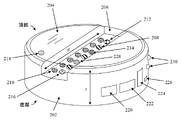
デバイスの特徴のより詳細な説明について、図2に示すデバイスの例示的な構成を参照して次に提供する。図2に示すセンサの構成、配置、またはタイプ、あるいはその組合せは、デバイスについて例示するために提供される一例に過ぎないことを理解されたい。センサの異なる配置またはセンサの異なるタイプあるいはその両方、ならびにフォームファクタ/ハウジングを含む他の構成も、本明細書に予想される。 A more detailed description of the features of the device will now be provided with reference to the exemplary configuration of the device shown in FIG. It should be understood that the configuration, arrangement, or types of sensors, or combinations thereof, shown in FIG. 2 are only one example provided to illustrate the device. Other configurations, including different arrangements of sensors and/or different types of sensors, as well as form factors/housings, are also contemplated herein.
図2に示すように、デバイスは、好ましくはペレット状である。「ペレット状」とは、デバイスが円柱形の形状を有し、円形で平坦な頂面および底面をその両端に有することを意味する。上述したように、使用中、デバイスは、液体試料内へ簡単に投入され、たとえば(その頂面または底面が)試料を収容する容器の底部に支持される。標準的なサイズの試料カップ内の試料の試験で使用する場合、ペレットは好ましくは、小さい直径dおよび厚さtを有する。dおよびtに対する例示的な値は、上述したとおりである。デバイスの全体的なサイズおよび形状は、デバイスを形成するために使用されるハウジング202の形状によって大きく左右される。図2を参照されたい。たとえば、本発明の例示的な実施形態によれば、デバイスは、1つまたは複数のセンサを収容するペレット状のハウジング202(上述したサイズ、形状、および寸法)を含む。デバイスを浸漬可能にするために、ハウジング202は水密性であり、デバイスのセンサおよび他の電子構成要素を外側の検体から密封する。好適なハウジング材料には、それだけに限定されるものではないが、プラスチック、金属、ポリマー、および他の材料が含まれる。たとえば、ハウジング202は、射出成形プラスチックから形成することができる。センサがハウジング202から突出する場合、封止材(ポリマー接着材など)を使用して、ハウジング202を貫通するセンサ部分の周りを封止する。しかし、すべてのセンサがハウジング202を通過する必要があるわけではない。たとえば、ハウジングが透明(部分的または全体的に)である限り、ハウジングを介して光学測定を行うことができる。したがって、本発明の実施形態では、ハウジング202の少なくとも一部分が透明である場合についても本明細書に企図される。たとえば、ハウジング202全体を透明材料から作ることができ、または別法として、光センサの位置にハウジング202の透明部分(たとえば、透過窓)を設けることができる。
As shown in Figure 2, the device is preferably in pellet form. By "pellet-like" is meant that the device has a cylindrical shape with circular flat top and bottom surfaces at its ends. As mentioned above, in use the device is simply dropped into a liquid sample and supported, for example (on its top or bottom surface) on the bottom of a container containing the sample. The pellet preferably has a small diameter d and thickness t when used in testing samples in standard size sample cups. Exemplary values for d and t are given above. The overall size and shape of the device is largely determined by the shape of
マイクロ流体工学を使用して、検体から感知面へ単位量の試料を収集することができる。たとえば、デバイスは、センサを覆うその少なくとも1つの表面上に、吸収パッド204を含むことができる(たとえば、図2参照)。好適な吸収パッド材料には、それだけに限定されるものではないが、紙、綿、布、ポリマー膜、およびヒドロゲルなどのセルロース材料が含まれる。この例では、吸収パッド204は、センサの上のペレットの頂面上に位置する。パッド204は、指定の体積の液体を吸収するように構成される。したがって、吸収パッド204によって収集されたその特有の体積の検体に基づいて、行われた測定を分析することができる。例示のみを目的として、吸収パッド204は、1回の使用を意図したものであり、試験が完了した後に交換される。加えて、センサの1つまたは複数をデバイスの表面上でチャネル206内に配置することで、(チャネル206の寸法に基づいて)単位体積の検体が感知面に接触することが確実になる。たとえば、センサの1つまたは複数が、デバイスの頂面におけるチャネル206内に配置された、図2を参照されたい。チャネル206を画定するために、吸収パッド204の代わりにカバー・スリップを使用することもできる。
Microfluidics can be used to collect a unit amount of sample from the specimen to the sensing surface. For example, the device can include an
この例では、デバイスは、少なくとも1つの光センサ208をその表面上に含む。光センサは、たとえばイムノアッセイなどの色検出を伴う応用例または検体の色を判定する必要のある応用例あるいはその両方で有用である。たとえばイムノアッセイは、試薬に基づく観察可能な色の変化を使用して読み取ることができる生化学試験である。水試料中に存在する添加物、不純物などが、その色に影響を及ぼすこともあり、光センサ208を使用してそれを検出することができる。本発明の実施形態で使用することができる例示的な光センサは、後述する図3に示す。
In this example, the device includes at least one
図2に示すデバイスはまた、少なくとも1つの電気化学センサ210をその表面上に含む。電気化学センサは、作用電極および基準電極を使用して、溶液中の反応物質の電気パラメータを測定する。たとえば生物製剤に関して、反応物質は、様々な症状、疾病などに対して知られているバイオマーカを含むことができる。たとえば、Adhikari et al., "Carbon Nanomaterials Based Electrochemical Sensors/Biosensors for the Sensitive Detection of Pharmaceutical and Biological Compounds," Sensors September 2015, 15, 22490-22508を参照されたい。好適な電気化学センサには、それだけに限定されるものではないが、たとえばカリフォルニア州サンディエゴのDexcom,Inc.およびアイルランド、ダブリンのMedtronicから入手可能なグルコース・センサ、ならびにニュージャージー州プリンストンのAbbottから入手可能なi-STAT(R)センサが含まれる。
The device shown in Figure 2 also includes at least one
本発明の好ましい実施形態はまた、少なくとも1つの圧力センサまたは歪みゲージ212をデバイスの表面上に含む。圧力センサまたは歪みゲージは、検体の密度測定値を得て、比重などの特定のパラメータを判定するために使用することができる。好適な圧力センサは、たとえば、ドイツ、ベルリンのFirst Sensorから市販されている。例示的な歪みゲージおよび比重を判定する技法は、図8~図10の説明とともに後述する。
Preferred embodiments of the present invention also include at least one pressure sensor or
音響センサ214もまた、設計に組み込むことができる。後述するように、音響センサは、歪みゲージより上の液体検体の高さを評価(たとえば、音波の飛行時間に基づく)する際に使用することができる。好適な音響センサには、それだけに限定されるものではないが、たとえばオーストリアのEV Groupから入手可能な表面弾性波(SAW)センサが含まれる。
An
感知デバイスの表面上のイオン感応性電界効果トランジスタ(FET)センサ216もまた、この例における設計の一部である。イオン感応性FETは、検体のpHを判定するために使用することができる。たとえば、イオン感応性FETは、ゲート絶縁体上に形成される界面電位に基づいて、溶液中のH+またはOH-イオンの濃度を測定することができる。たとえば、Lee et al., "Ion-Sensitive Field-Effect Transistor for Biological Sensing," Sensors September 2009, 9, 7111-7131を参照されたい。
An ion sensitive field effect transistor (FET)
温度、汚染物質などの試料品質を監視するために、他のセンサを含むこともできる。試料温度は、温度センサ218を使用して監視される。以下に詳細に説明するように、温度測定も比重計算において有用である。汚染物質に関する概念は、たとえば医薬品で見られる細菌または化学物質あるいはその両方などの汚染物質によってデータ内で起こりうるあらゆる干渉を除去し、汚染物質が検出された場合は(たとえば、可聴)警報を開始したいと考えることである。
Other sensors can also be included to monitor sample quality such as temperature, contaminants, and the like. Sample temperature is monitored using
汚染物質の検出方法は、分析のタイプに依存する。この方法は、検体認識の際のバイオセンサ表面の蛍光の変化、またはそれほど一般的ではないが吸収度もしくはルミネセンスを測定する光センサを伴うことができる。これはまた、検体が表面に結合した際のインピーダンスまたは電位もしくは電流の変化あるいは酸化還元反応を測定するためのインピーダンスまたは電気化学センサなどの電気センサとすることができる。細菌検出のための例示的なプロセスは、たとえば、Ahmed et al., "Biosensors for Hole-Cell Bacterial Detection," Clinical Microbiology Reviews, July 2014, 27(3): 631-646に記載されている。 Contaminant detection methods depend on the type of analysis. This method can involve an optical sensor that measures the change in fluorescence of the biosensor surface upon analyte recognition, or less commonly absorbance or luminescence. It can also be an electrical sensor, such as an impedance or electrochemical sensor for measuring changes in impedance or potential or current or redox reactions when an analyte binds to a surface. Exemplary processes for bacterial detection are described, for example, in Ahmed et al., "Biosensors for Hole-Cell Bacterial Detection," Clinical Microbiology Reviews, July 2014, 27(3): 631-646.
抗生物質などの医薬品の場合、クロマトグラフィー、キャピラリー電気泳動(CE)、ダイオード・アレイ(DA)、炎イオン化(FI)、および酵素結合免疫吸着検定法(ELISA)などの従来の検出方法はすべて、複雑なプロセスを要する。しかし、ナノ粒子に基づく光および電気化学センサを代わりに用いることができる。たとえば、Lan et al., "Recent advances in nanomaterial-based biosensors for antibiotics detection," Biosensors and Bioelectronics, vol. 91, May2017, pgs. 504-514を参照されたい。 For pharmaceuticals such as antibiotics, conventional detection methods such as chromatography, capillary electrophoresis (CE), diode array (DA), flame ionization (FI), and enzyme-linked immunosorbent assay (ELISA) are all A complicated process is required. However, nanoparticle-based optical and electrochemical sensors can be used instead. See, for example, Lan et al., "Recent advances in nanomaterial-based biosensors for antibiotics detection," Biosensors and Bioelectronics, vol. 91, May2017, pgs. 504-514.
図2に示すように、デバイスは、様々な自立型の電子機器を含む。たとえば、小型電池220を使用して、デバイスおよびセンサ、ならびにデータ伝達動作に給電する。マイクロコントローラ222またはシステム・オン・チップは、搭載型の処理およびメモリ能力をデバイスに提供する。デバイスは、たとえばクラウドへ、次いでデータ管理システムまたは電子医療記録(EMR)あるいはその両方へのデータの伝達を可能にするBluetooth(登録商標)224/RFID226対応の接続性を有する。デバイスによって収集されるすべてのデータには、タイムスタンプおよび日付が記録される。位置情報を提供するために、全地球測位システム(GPS)チップを組み込むことができる。位置情報はまた、スマート・フォンまたはウォッチあるいはその両方などの使用者のGPSデバイスとの結合によって組み込むこともできる。
As shown in Figure 2, the devices include various self-contained electronic devices. For example, a
好ましくは、デバイスは、分析をいつ開始(または完了)するべきかが分かるように、液体試料に追加されたこと(または液体試料から除去されたこと)を検出することができる。たとえば、加速度計228は、ペレットが液体試料内へ投入され、次に試料から回収されることに伴う運動を検出することができる。様々な好適な加速度計および他の運動センサが、たとえばニューヨーク州デピューのPCB(R)から市販されている。分析が進行中であること、完了したことなどを示すために、図2に示すように状態発光ダイオード(LED)230もデバイス表面上に存在する。
Preferably, the device is capable of detecting when added to (or removed from) the liquid sample so that it knows when to start (or complete) the analysis. For example, the
デバイスにおける使用が企図される1つのタイプの光センサは、イムノアッセイ光検出器300である。たとえば、図3(側面図)および図4(上面図)を参照されたい。上述したように、イムノアッセイとは、観察可能な色の変化を使用して読み取ることができる生化学試験である。したがってこの例では、イムノアッセイ試験ストリップ(「イムノアッセイ・ストリップ」)と、デバイスが検体内に浸漬されたときに結果として生じる色の変化を検出するように構成された光センサとが組み合わされている。
One type of optical sensor contemplated for use in the device is an
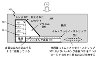
たとえば図3を参照すると、イムノアッセイ光センサ300は、イムノアッセイ・ストリップ302と、光源312と、光検出器314および付随する電源304と、光を光源312からイムノアッセイ・ストリップ302の方へ誘導し、また再び検出器314へ誘導するプリズム306(または他の手段)と、バッキング基板308とを含む。図示の構成では、試験されている流体がイムノアッセイ・ストリップ302に沿って「吸い上げ」られるが表面に「溢れ」ないように、プリズム306の底面およびイムノアッセイ・ストリップ302が互いに密接に接触していることが重要である。表面に「溢れ」た場合、試薬が余分の液体によって過度に希釈、混合、または洗い流される可能性がある。プリズムの底部には、散乱光の干渉を制限するために、任意選択のアパーチャ410(後述する図4参照)を設置することができる。
For example, referring to FIG. 3,
図3に示すように、センサ300は、封止された(水密性の)エンクロージャ309に入っており、エンクロージャ309は、イムノアッセイ・ストリップ302の挿入/除去のための開口をプリズム306の底部に有する。これにより、センサ300内のイムノアッセイ・ストリップを使用後に容易に除去し、新しいストリップと交換することが可能になる。
As shown in FIG. 3,
概して、イムノアッセイ・ストリップは多孔質材料から形成され、毛管作用を介して検体試料がストリップを横切って横方向に輸送される。この毛管作用を使用して、流体体積を制限し、試薬の過度の希釈を防ぐ。試料は、ストリップを横切って動くにつれて、特定の試薬を収容している1つまたは複数の領域に接触し、試薬は検体と反応して複合体を形成する(または試薬が存在しない場合、対応する検体は反応しない)。複合体の蓄積は、ストリップの色を変化させる。ストリップは、複数のレーンまたは試験パッドを含むことができる。イムノアッセイ・ストリップがたとえば4つの試験パッドA~Dを有する図4を参照されたい。図4は、たとえば視点A(図3参照)から見た上面図である。上述したように、使用後、センサ300内のイムノアッセイ・ストリップは、容易に除去して新しいストリップと交換することができる。図4に示すように、プリズム306の底部にアパーチャ410を設けて散乱光の干渉を制限することができる。例示のみを目的として、アパーチャは、プリズム306の底部に遮光層を取り付け、遮光層内にアパーチャ410が存在するようにすることによって、プリズム306の底部に簡単に設置することができる。
Immunoassay strips are generally formed from a porous material to laterally transport an analyte sample across the strip via capillary action. This capillary action is used to limit fluid volume and prevent excessive dilution of reagents. As the sample moves across the strip, it contacts one or more regions containing specific reagents, which react with the analyte to form complexes (or, in the absence of reagents, corresponding sample does not react). Accumulation of complexes causes the strip to change color. A strip can include multiple lanes or test pads. See FIG. 4, where an immunoassay strip has, for example, four test pads AD. FIG. 4 is a top view seen from, for example, viewpoint A (see FIG. 3). As noted above, after use, the immunoassay strips within
イムノアッセイ・ストリップを照射するために、少なくとも1つの光源312が設けられる。イムノアッセイ試験ストリップ302から反射した光を検出するために、少なくとも1つの光検出器314が使用される。任意選択で、光源312/光検出器314とプリズム306との間にレンズ310を用いて、光を収束させることができる。この特定の例では、光源はLEDであり、光検出器はフォトダイオード(PD)などの光検出器である。CCD/CMOSイメージャを光検出器として使用することもできる。したがって、本発明の一実施形態によれば、光センサ300内でLEDが光源として使用され、フォトダイオード(PD)が光検出器として使用され、たとえば、LEDは光を生成してイムノアッセイ試験ストリップを照射し、フォトダイオードはイムノアッセイ試験ストリップから反射した光を検出する。図3に示す例示的な構成では、LED/フォトダイオードは、イムノアッセイ試験ストリップ302対して直交するように配置され、LED/フォトダイオードおよびイムノアッセイ・ストリップ302との間を行き来する光は、LED/フォトダイオードとイムノアッセイ試験ストリップ302との間に位置するプリズム306(または鏡などの他の好適な手段)を使用して案内される。
At least one
各試験パッド上の液体検体の量は、精度を確保し、試験パッド間の交差汚染を防ぐように制御および制限されるべきである。これにはいくつかの方法がある。一例は、各試験パッド間にセパレータを構築することである。図5および図6を参照されたい。別の例は、イムノアッセイ・ストリップ302がセンサ300へ挿入され、濡れが検出されたとき、試験パッド間に接触して試験パッドを分離する働きをするセパレータをセンサ300の一部(図示せず)として有することである(すなわち、セパレータは、濡れると膨張し、それによってイムノアッセイ・ストリップ302に係合するように構成することができる)。セパレータはまた、試験パッド上にも同様に構築することができる(たとえば、図6のセパレータ602参照)。一例では、セパレータは、高吸水性ポリマー(SAP)など、濡れると膨張(すなわち、拡大)する材料から作られる。SAPの一例は、ポリアクリル酸ナトリウムである。SAPの別の例は、ヒドロゲルである。図5は、イムノアッセイ・ストリップ302の断面図を示し、イムノアッセイ・ストリップ302とバッキング基板308との間にSAP層502が存在する。図6に示すように、イムノアッセイ・ストリップ302の上面の試験パッド間には、イムノアッセイ・ストリップ302が濡れているときに分離壁として働くセパレータ602(たとえば、SAPストリップ)も存在する。使用中、液体はイムノアッセイ・ストリップ302を通って吸い上げられ、SAP層502およびセパレータ602/SAPストリップを濡らす。SAPは膨張し、イムノアッセイ・ストリップ302を持ち上げてプリズム306の底面に接触させ、試験パッドを封止する(すなわち、上述したように、プリズム306の底面およびイムノアッセイ・ストリップ302は、試験されている流体がイムノアッセイ・ストリップ302に沿って「吸い上げ」られるが表面に「溢れ」ないように、互いに密接に接触しているべきである)。図6は、たとえば視点B(図5参照)から見た上面図である。
The amount of liquid sample on each test pad should be controlled and limited to ensure accuracy and prevent cross-contamination between test pads. There are several ways to do this. One example is to build a separator between each test pad. See FIGS. 5 and 6. FIG. Another example is that when an
デバイスにおける使用が企図される別のタイプの光センサは、顕微鏡的構成要素700である。図7を参照されたい。図7に示すように、顕微鏡的構成要素700は、マイクロ流体チャネル704の一方の端部に位置する検体が顕微鏡的構成要素700に入るための入口702と、マイクロ流体チャネル704の反対側の端部に位置する撮像デバイス706とを含む。液体検体は、毛管力によって、またはマイクロ流体チャネル704に接続されたポンプによって駆動される。光源708(マイクロ流体チャネル704の入口702側の端部に隣接)には、光源708からの光を撮像デバイス706へ誘導するための導波路710(マイクロ流体チャネル704の下)などの手段が設けられる。
Another type of optical sensor contemplated for use in the device is
本発明の一実施形態によれば、マイクロ流体チャネル704は、1つまたは複数の試薬に特有の染料、着色剤、および/または他のタイプのマーカによって被覆される。検体が入口702を通って顕微鏡的構成要素700に入り、マイクロ流体チャネル704を通過するにつれて、試薬が検体内に存在する場合、マーカと反応する。次いで、この反応(またはその欠如)は、撮像デバイス706を介して画像内に捕捉される。たとえば、着色剤または染料が特定の試薬と反応すると、特定の色または他の兆候が画像内に現れる。本発明の一実施形態によれば、撮像デバイス706に近位のマイクロ流体チャネル704の端部には、液体を通しながら試料内の粒子沈殿物714を収集するように、膜712が設置される。顕微鏡的構成要素700は(撮像デバイス706を介して)、さらなる分析のために沈殿物の画像を得ることができる。
According to one embodiment of the invention, microfluidic channel 704 is coated with one or more reagent-specific dyes, colorants, and/or other types of markers. As the specimen enters the
本発明の一実施形態によれば、撮像デバイス706は、電荷結合デバイス/相補型金属酸化膜半導体CCD/CMOSイメージャである。好適なCCD/CMOS撮像デバイスには、それだけに限定されるものではないが、カリフォルニア州サンタクララのOmniVision Technologies,Inc.から入手可能なOmnivision OV6922という画素サイズ2.5マイクロメートル(μm)のカメラ・オン・チップが含まれる。任意の好適な光源を顕微鏡的構成要素700内で用いることができる。本発明の一実施形態によれば、光源はLED光源である。図7を参照されたい。例示のみを目的として、LED光源は、広帯域の白色光LED、狭帯域の単一波長LED、または複数の狭帯域LEDの組合せを含むことができる。
According to one embodiment of the present invention,
直前に記載した例示的な撮像デバイスは、構成要素700が沈殿物714中の顕微鏡的粒子の存在を検出することを可能にする高分解能の光学系である。たとえば、提出された患者試料の文脈で、たとえば尿分析のために、顕微鏡的構成要素700は、異なる細胞型に対する色、形状、および関連する特徴を見ることによって、白血球、赤血球円柱、上皮細胞、硝子円柱、結晶などを検出および定量化するために使用することができる。
The exemplary imaging device just described is a high resolution optical system that enables
上述したように、デバイスは、歪みゲージを含むことができる。歪みゲージは、検体から比重などの有用な測定値を得るために用いられる。例示的な歪みゲージ800が、図8(側面図)および図9(上面図)に示されている。図8をまず参照すると、歪みゲージ800は、ゲージ・ハウジング806内のキャビティ804内に位置決めされたフロート802を含む。フロート802は、キャビティ804の底部で歪みセンサ808に接触している。さらに、万一感知デバイス(検体内に配置されているとき)がその主頂面を下にした状態で設置された場合に(上記参照)、たとえば試料カップの底部によってフロート802が物理的に押されることを防止するために、フロート802は、図8に示すように、好ましくはゲージ・ハウジング806の頂面より下に凹んでいる。
As noted above, the device may include strain gauges. Strain gauges are used to obtain useful measurements, such as specific gravity, from specimens. An
またデバイスがいずれの向きでも動作可能になることに関して、キャビティ804の底部からゲージ・ハウジング806の反対側(キャビティ804から見て)の外へつながる通気管路810が設けられる。そのようにして、万一デバイスが検体内に上下反対に落ちた場合でも、キャビティ804から通気管路810を通って空気を容易に追い払うことができる。好適な歪みセンサには、それだけに限定されるものではないが、たとえばコネティカット州ウォリングフォードのAmphenol Corporationから入手可能な微小電気機械システム(MEMS)センサが含まれる。
Also for allowing the device to operate in either orientation, a
図9は、歪みゲージ800の上面図(たとえば、図8の視点Cから見た図)を提供する。図9に示すように、フロート802は、好ましくは、ゲージ・ハウジング806に対するフロート802のねじれを防止する形状を有する。言い換えれば、フロート802の形状(およびキャビティ804の相補的な形状)は、フロートの唯一の運動がキャビティ804内での上下であるような形状である。図8を参照されたい。そのようにして、検体の比重に基づくより正確な歪み測定値を得ることができる。例示のみを目的として、図9に示すように、フロート802は、ゲージ・ハウジング806の壁に沿って突起902が垂直の溝904と相補形をなすように構成することができる。そのようにして、フロート802が上下に自由に動くことを可能にしながら、フロート802のあらゆるねじれまたは回転が防止される。
FIG. 9 provides a top view of strain gauge 800 (eg, view from view C in FIG. 8). As shown in FIG. 9, float 802 preferably has a shape that prevents twisting of
本発明の一実施形態によれば、フロート802は、1未満の既知の密度および既知の体積を有する。フロート802の密度および体積が既知であるため、歪みセンサ800にかかる浮力から、検体の比重を計算することができる。検体の既知の温度値によって(温度センサを介する、上記参照)、流体の熱膨張に対する補正を行うことができる。感知デバイスが検体内に上下反対に位置する場合、力の符号が逆になることに注目すべきである。
According to one embodiment of the invention,
検体の比重を計算する例示的なプロセスについて、図10を参照して次に説明する。図10に示すデバイスは、図8および図9の説明によって上述したように構成することができる歪みゲージを含む。歪みゲージから読み取る圧力Pに基づいて、以下の計算を行うことができる。
P(t)=H(t)ASρ(t) (1)
上式で、H(t)は試料カップ内の歪みゲージより上の液体検体の高さであり(たとえば、図10参照)、ASは歪みゲージの面積であり、ρ(t)は液体検体の密度である。歪みゲージより上の液体検体の高さは、音波の飛行時間によって(たとえば音響センサを使用、上記参照)、または試料カップ内へ投入されるときにデバイスが濡れると作動される加速度計およびジャイロメータによって測定することができる。デバイスが試料カップ内に上下反対に落ち、または傾斜している場合、デバイスの厚さは測定値から補正される。
An exemplary process for calculating the specific gravity of an analyte will now be described with reference to FIG. The device shown in FIG. 10 includes strain gauges that can be configured as described above with reference to FIGS. Based on the pressure P reading from the strain gauge, the following calculations can be made.
P(t)=H(t) AS ρ(t) (1)
where H(t) is the height of the liquid sample above the strain gauge in the sample cup (see, for example, FIG. 10), A S is the area of the strain gauge, and ρ(t) is the liquid sample is the density of The height of the liquid sample above the strain gauge is actuated by the time-of-flight of the sound wave (e.g. using an acoustic sensor, see above) or by wetting the device as it is dropped into the sample cup. can be measured by If the device is dropped or tilted upside down in the sample cup, the thickness of the device is corrected from the measurements.
症状がない場合、成人に対する尿分析の比重は通常、約1.000~約1.030である。しかし、脱水症、発汗過多、腎臓への血流減少などの特定の症状を伴う場合、比重は増大する。逆に、腎不全、間質性腎炎などの他の症状を伴う場合、比重は減少する。したがって、上式(1)を使用して行われる判定に基づいて、特定の検体の比重(すなわち、上式(1)によりセンサ読取り値から計算された液体検体の密度ρ(t)と、基準として症状のない成人の密度読取り値との比)が症状の存在を示す(すなわち、検体が標準外の比重を有する)かどうか、および症状の存在を示す場合、それはどのタイプの症状である可能性があるか、またはどのタイプの症状でない可能性があるか(たとえば、比重が高い場合、比重を低くする症状を除外することができ、逆も同様である)を判定することができる。 In the absence of symptoms, the specific gravity of urine analysis for adults is usually about 1.000 to about 1.030. However, with certain conditions such as dehydration, excessive sweating, and reduced blood flow to the kidneys, the specific gravity increases. Conversely, when accompanied by other conditions such as renal failure, interstitial nephritis, the specific gravity decreases. Therefore, based on the determination made using equation (1) above, the specific gravity of a particular analyte (i.e., the density ρ(t) of the liquid analyte calculated from the sensor readings by equation (1) above, and the reference (i.e., the specimen has a non-standard specific gravity) indicates the presence of symptoms, and if so, what type of symptoms it may be. or what type of symptoms it may not be (eg, if it is of high gravity, then the symptoms of low gravity can be ruled out and vice versa).
図11は、デバイスを使用して試料を分析する例示的なシステム1100を示す図である。図11に示すように、システム1100は、データ管理システム1102と(クラウド1101を介して)通信している少なくとも1つのデバイスを含む。データ管理システム1102は、デバイスによって収集されたデータを受け取り、このデータを処理/分析し、たとえばデータベースDB1104内に記憶されたEMRなどの電子記録を生成するように構成される。
FIG. 11 illustrates an
図11に示すように、データ管理システム1102はまた、1つまたは複数の関係者1106によってアクセスすることができる。たとえば、試料検体が患者から収集されたとき、関係者には、患者を治療している医師または病院、診療所など、あるいはその両方を含むことができる。水試料試験などの研究または診断の状況では、関係者には、研究所または研究者あるいはその両方、水管理当局または試料が収集された地方自治体あるいはその両方などを含むことができる。任意選択で、システム1100はまた、感知デバイスおよび/またはデータ管理システム1102と、使用者(患者および/または他の関係者など、上記参照)が感知デバイスによって収集されたデータに注釈を付けることができるスマート・フォンまたは他のモバイル・スマート・デバイスなどの1つまたは複数のローカル・デバイス1108との間の通信を(クラウド1101を介して)可能にすることができる。デバイスからデータを受け取った際、医師はたとえば、観察、診断、推奨されるさらなる試験などに関係する注記を追加することができる。患者は、自身に関する識別データ(たとえば、名前、誕生日、身長、体重などの患者データ)、または健康状態、食事、自身が感じた症状などに関する説明、あるいはその両方を提供する可能性がある。
As shown in FIG. 11,
図11はまた、感知デバイスをその主頂面または底面が上向きまたは下向きの状態で試料内にどのように浸漬することができるかを示す。たとえば、上の図では、デバイスは検体内に正しい向きで浸漬されているが、下の図では、上下反対になっている。いずれの向き(正しい向きまたは上下反対)も好適である。さらに、特に上述した(たとえば、図8および図9参照)歪みゲージ800が測定に用いられているとき、試料カップの底部にぴったり接しているデバイスの向き(正しい向きまたは上下反対)が必要とされることに注目すべきである。他方では、歪みゲージ800が読み取られていない場合、ペレット状の感知デバイスは、流体試料において傾斜または横向きを含む任意の向きで機能することができる。
Figure 11 also shows how the sensing device can be immersed in the sample with its major top or bottom surface facing up or down. For example, in the top picture the device is immersed in the specimen in the correct orientation, while in the bottom picture it is upside down. Either orientation (upright or upside down) is suitable. Further, particularly when the
上述したように、デバイスは、検体内に浸漬された後、その複数のセンサを介してデータを収集し、そのデータを(たとえば、無線で)データ管理システム1102へ伝送する。次いで、クラウド1101を介してデータ管理システム1102によってデバイスから収集されたデータは、分析することまたはデータベース1104内に電子記録として記憶することあるいはその両方ができる。例示のみを目的として、尿分析のために患者試料から収集されたデータをすべてのセンサから集合的に分析して、患者が知られている症状に対するバイオマーカまたは他の指標を有するかどうかを判定することができる。複数のセンサからの測定を使用して、干渉の補正を計算することもできる。たとえば、知られているpHによって、グルコースに対するpH作用を補正することができる。たとえば、尿分析バイオマーカには、pH、比重、白血球、硝酸塩、タンパク質、グルコース、ケトン、ウロビリノーゲン、ビリルビン、および血液を含むことができ、さらに敗血症/炎症、細菌の種分化、腫瘍マーカ、および原線維凝集に対して他のバイオマーカを含むこともできる。またたとえば、機械学習粒子認識アルゴリズムを尿分析試料に適用し、新しいデータを使用して、光センサによって捕捉された画像データの視覚分析をさらに訓練および改善することができる。関係者1106、たとえば医師、研究者などは、そのデータおよび/またはデータ分析にアクセスことができる。
As described above, after the device is immersed in the specimen, it collects data via its multiple sensors and transmits the data (eg, wirelessly) to the
図12を次に参照すると、本明細書に提示する方法の1つまたは複数を実行するように構成することができる装置1200のブロック図が示されている。たとえば、装置1200は、システム1100内でデータ処理装置1102として働くことができ、上述した方法100(図1)のステップのうちの1つまたは複数を実行するように構成することができる。装置1200は、コンピュータ・システム1210および取外し可能な媒体1250を含む。コンピュータ・システム1210は、プロセッサ・デバイス1220、ネットワーク・インターフェース1225、メモリ1230、媒体インターフェース1235、および任意選択のディスプレイ1240を含む。ネットワーク・インターフェース1225は、コンピュータ・システム1210がネットワークに接続することを可能にし、媒体インターフェース1235は、コンピュータ・システム1210がハード・ドライブまたは取外し可能な媒体1250などの媒体と相互作用することを可能にする。
Referring now to FIG. 12, shown is a block diagram of an
プロセッサ・デバイス1220は、本明細書に開示する方法、ステップ、および機能を実施するように構成することができる。メモリ1230は、分散させてもまたはローカルでもよく、プロセッサ・デバイス1220は、分散させてもまたは単独でもよい。メモリ1230は、電気、磁気、もしくは光メモリ、またはこれらの任意の組合せ、あるいは他のタイプの記憶デバイスとして実施することができる。さらに、「メモリ」という用語は、プロセッサ・デバイス1220によってアクセスされるアドレス指定可能な空間内のアドレスから読み取りまたはそのアドレスへ書き込むことが可能なあらゆる情報を包含するように十分に広く解釈されるべきである。この定義では、プロセッサ・デバイス1220がネットワークから情報を検索することができることから、ネットワーク・インターフェース1225を介してアクセス可能なネットワーク上の情報は依然としてメモリ1230内にある。プロセッサ・デバイス1220を構成する分散させた各プロセッサは、全体としてその独自のアドレス指定可能なメモリ空間を収容することに留意されたい。コンピュータ・システム1210の一部またはすべてを、特定用途向けまたは汎用の集積回路に組み込むことができることにも留意されたい。
任意選択のディスプレイ1240は、装置1200の人間の使用者と相互作用するのに好適な任意のタイプのディスプレイである。概して、ディスプレイ1240は、コンピュータ・モニタまたは他の類似のディスプレイである。
本発明の例示的な実施形態について本明細書に説明したが、本発明は、それらの厳密な実施形態に限定されるものではなく、当業者であれば、本発明の範囲から逸脱することなく、様々な他の変更および修正を加えることもできることを理解されたい。 While illustrative embodiments of the invention have been described herein, the invention is not intended to be limited to those precise embodiments, and one of ordinary skill in the art will be able to implement modifications without departing from the scope of the invention. , it should be understood that various other changes and modifications may also be made.
Claims (18)
少なくとも一部分が透明である、ハウジングと、
前記ハウジング内に収容された1つまたは複数のセンサと、を備え、
前記ハウジングが、前記感知デバイスが液体検体内に完全に浸漬可能であるように、前記センサを密封している、感知デバイス。 a sensing device,
a housing, at least a portion of which is transparent;
one or more sensors housed within the housing;
The sensing device, wherein the housing encloses the sensor such that the sensing device is fully immersible in a liquid analyte.
ハウジングと、
前記ハウジング内に収容された1つまたは複数のセンサと、を備え、
前記ハウジングが、前記感知デバイスが液体検体内に完全に浸漬可能であるように、前記センサを密封しており、
前記センサは、少なくとも1つの光センサを備え、前記少なくとも1つの光センサが、イムノアッセイ試験ストリップを備える、感知デバイス。 a sensing device,
a housing;
one or more sensors housed within the housing;
the housing encloses the sensor such that the sensing device is fully immersible in a liquid analyte;
A sensing device, wherein said sensor comprises at least one optical sensor, said at least one optical sensor comprising an immunoassay test strip.
光源と、
光検出器であり、前記光源および光検出器が前記イムノアッセイ試験ストリップに直交する方向に配置された、光検出器と、
前記イムノアッセイ試験ストリップと前記光源および前記光検出器との間に配置されたプリズムと
をさらに備える、請求項6に記載の感知デバイス。 wherein the at least one optical sensor is
a light source;
a photodetector, wherein the light source and photodetector are oriented perpendicular to the immunoassay test strip;
7. The sensing device of claim 6, further comprising: a prism positioned between said immunoassay test strip and said light source and said photodetector.
前記少なくとも1つの光センサが、濡れると膨張するポリマーを含むセパレータを前記試験パッドのそれぞれの間にさらに備える、請求項6または請求項7に記載の感知デバイス。 the immunoassay test strip comprising a plurality of test pads;
8. The sensing device of claim 6 or claim 7, wherein the at least one optical sensor further comprises a separator between each of the test pads comprising a polymer that swells when wetted.
試薬に特有なマーカによって被覆されたマイクロ流体チャネルと、
前記マイクロ流体チャネルの第1の端部に位置する入口と、
前記入口とは反対側の前記マイクロ流体チャネルの第2の端部に位置する撮像デバイスと、
前記マイクロ流体チャネルの前記第1の端部に隣接している光源と、
前記光源からの光を前記撮像デバイスへ誘導する導波路と、
を備える、請求項1から請求項5のいずれか一項に記載の感知デバイス。 wherein said sensor comprises at least one optical sensor, said at least one optical sensor comprising:
a microfluidic channel coated with reagent-specific markers;
an inlet located at a first end of the microfluidic channel;
an imaging device positioned at a second end of the microfluidic channel opposite the inlet;
a light source adjacent to the first end of the microfluidic channel;
a waveguide that directs light from the light source to the imaging device;
6. The sensing device of any one of claims 1-5, comprising:
ハウジングと、
前記ハウジング内に収容された1つまたは複数のセンサと、を備え、
前記ハウジングが、前記感知デバイスが液体検体内に完全に浸漬可能であるように、前記センサを密封しており、
前記センサは、少なくとも1つの歪みゲージを備えており、
前記少なくとも1つの歪みゲージが、
キャビティを有するセンサ・ハウジングと、
前記キャビティの底部に位置する歪みセンサと、
前記歪みセンサに接触するように前記キャビティ内に配置されたフロートと、
を備える、感知デバイス。 a sensing device,
a housing;
one or more sensors housed within the housing;
the housing encloses the sensor such that the sensing device is fully immersible in a liquid analyte;
the sensor comprises at least one strain gauge;
The at least one strain gauge is
a sensor housing having a cavity;
a strain sensor located at the bottom of the cavity;
a float positioned within the cavity to contact the strain sensor;
A sensing device comprising :
前記キャビティの前記底部から、前記センサ・ハウジングの前記キャビティとは反対側の外へつながる通気管路をさらに備える、請求項11または請求項12に記載の感知デバイス。 The strain gauge is
13. The sensing device of claim 11 or 12 , further comprising a vent line leading from the bottom of the cavity to the outside of the sensor housing on the opposite side of the cavity.
ハウジングと前記ハウジング内に密封された1つまたは複数のセンサとを備える感知デバイスを前記液体試料内に浸漬することと、
前記感知デバイスが前記センサを使用して前記液体試料からデータを収集することと、
前記感知デバイスが前記データをデータ管理システムおよび電子記録のうちの少なくとも1つへ伝送することと、
を含み、
前記センサは、イムノアッセイ試験ストリップが挿入された少なくとも1つの光センサを備える、方法。 A method of analyzing a liquid sample, comprising:
immersing in the liquid sample a sensing device comprising a housing and one or more sensors sealed within the housing;
the sensing device collecting data from the liquid sample using the sensor;
the sensing device transmitting the data to at least one of a data management system and an electronic record;
including
The method, wherein the sensor comprises at least one optical sensor into which an immunoassay test strip is inserted.
前記液体試料が、試料カップ内に収容され、
前記感知デバイスが、前記平坦な頂面または前記平坦な底面が前記試料カップの底部に支持された状態で、前記液体試料内に少なくとも部分的に浸漬される、請求項15に記載の方法。 The housing has a flat top surface and a flat bottom surface opposite the flat top surface, the flat top surface and the flat bottom surface are both circular, and the sensing device is in the form of a pellet. and
the liquid sample is contained in a sample cup;
16. The method of claim 15 , wherein the sensing device is at least partially immersed in the liquid sample with the flat top surface or the flat bottom surface supported on the bottom of the sample cup.
請求項1から請求項14のいずれか一項に記載の感知デバイスと、
前記感知デバイスに通信可能に接続されたデータ管理システムと、
を備えるシステム。
A system for analyzing a liquid sample, comprising:
a sensing device according to any one of claims 1 to 14 ;
a data management system communicatively connected to the sensing device;
A system with
Applications Claiming Priority (3)
| Application Number | Priority Date | Filing Date | Title |
|---|---|---|---|
| US15/715,558 | 2017-09-26 | ||
| US15/715,558 US11039765B2 (en) | 2017-09-26 | 2017-09-26 | Smart pellet for sample testing |
| PCT/IB2018/056835 WO2019064094A1 (en) | 2017-09-26 | 2018-09-07 | Smart pellet for sample testing |
Publications (3)
| Publication Number | Publication Date |
|---|---|
| JP2020535394A JP2020535394A (en) | 2020-12-03 |
| JP2020535394A5 JP2020535394A5 (en) | 2021-01-21 |
| JP7184879B2 true JP7184879B2 (en) | 2022-12-06 |
Family
ID=65806366
Family Applications (1)
| Application Number | Title | Priority Date | Filing Date |
|---|---|---|---|
| JP2020515695A Active JP7184879B2 (en) | 2017-09-26 | 2018-09-07 | Smart pellets for sample testing |
Country Status (6)
| Country | Link |
|---|---|
| US (1) | US11039765B2 (en) |
| JP (1) | JP7184879B2 (en) |
| CN (1) | CN111094937B (en) |
| DE (1) | DE112018005501T5 (en) |
| GB (1) | GB2581275B (en) |
| WO (1) | WO2019064094A1 (en) |
Families Citing this family (4)
| Publication number | Priority date | Publication date | Assignee | Title |
|---|---|---|---|---|
| WO2020101772A1 (en) * | 2018-10-08 | 2020-05-22 | Florida Atlantic University Board Of Trustees | Underwater imaging system |
| US20220274111A1 (en) * | 2019-08-23 | 2022-09-01 | The Regents Of The University Of California | Electrokinetic microelectrode devices and methods for biomarker analysis |
| JP7459738B2 (en) | 2019-09-24 | 2024-04-02 | 住友金属鉱山株式会社 | Method for preparing resin-embedded samples and method for analyzing porous samples |
| US20220026253A1 (en) * | 2020-07-24 | 2022-01-27 | International Business Machines Corporation | Evaluation of flow properties in physical media |
Citations (1)
| Publication number | Priority date | Publication date | Assignee | Title |
|---|---|---|---|---|
| JP2000500380A (en) | 1995-11-22 | 2000-01-18 | レガシー グッド サマリタン ホスピタル アンド メディカル センター | Device for monitoring changes in sample concentration |
Family Cites Families (39)
| Publication number | Priority date | Publication date | Assignee | Title |
|---|---|---|---|---|
| DE1910272U (en) | 1964-11-12 | 1965-02-18 | Boehringer & Soehne Gmbh | TEST STRIP. |
| JPS5340475B2 (en) * | 1973-07-19 | 1978-10-27 | ||
| US4116066A (en) | 1977-12-12 | 1978-09-26 | Becton, Dickinson And Company | Specimen sampler cup |
| US5310526A (en) * | 1990-10-30 | 1994-05-10 | The Dow Chemical Company | Chemical sensor |
| US6055487A (en) | 1991-07-30 | 2000-04-25 | Margery; Keith S. | Interactive remote sample analysis system |
| JPH07167857A (en) | 1991-11-08 | 1995-07-04 | Kaoru Shimizu | Stick for collecting urine |
| US6256522B1 (en) * | 1992-11-23 | 2001-07-03 | University Of Pittsburgh Of The Commonwealth System Of Higher Education | Sensors for continuous monitoring of biochemicals and related method |
| US5312009A (en) | 1993-06-07 | 1994-05-17 | Sage Products, Inc. | Liquid specimen collector with removable extraction device |
| US6057773A (en) * | 1994-02-25 | 2000-05-02 | Shukla; Ashok K. | Unanchored sensor for fluid characteristics |
| US6342183B1 (en) * | 1997-02-14 | 2002-01-29 | Escreen | System for collecting and locally analyzing a fluid specimen |
| US6277646B1 (en) | 1997-05-05 | 2001-08-21 | Dade Behring Inc. | Fluid specimen collecting and testing apparatus |
| US6485438B1 (en) | 2000-09-28 | 2002-11-26 | Jennifer L. Minue | Cup to assist with urine specimen sampling |
| US6879397B2 (en) * | 2001-09-07 | 2005-04-12 | The United States Of America As Represented By The Secretary Of The Navy | Light scattering detector |
| US20050232638A1 (en) * | 2004-04-02 | 2005-10-20 | Woods Hole Oceanographic Institution | Methods and apparatus for underwater wireless optical communication |
| US7377690B1 (en) * | 2004-05-13 | 2008-05-27 | The United States Of America As Represented By The Secretary Of The Navy | High trigger temperature lithium intermetallic thermal sensors |
| US7799278B2 (en) * | 2004-07-06 | 2010-09-21 | Schlumberger Technology Corporation | Microfluidic system for chemical analysis |
| US7758815B2 (en) | 2004-08-03 | 2010-07-20 | Hartselle R Lawrence | Specimen collection, storage, transportation and assaying device |
| US8730031B2 (en) | 2005-04-28 | 2014-05-20 | Proteus Digital Health, Inc. | Communication system using an implantable device |
| US7669360B2 (en) * | 2006-03-21 | 2010-03-02 | Davidson Kent G | Fishing system |
| CN101285762B (en) * | 2007-04-11 | 2011-08-03 | 中国科学院电子学研究所 | Multi-parameter immunity-chromatography test strip quantitative determination instrument |
| CN201130152Y (en) * | 2007-12-21 | 2008-10-08 | 北京工业大学 | Apparatus for measuring and controlling speed of microfluid fluorescence in fluorescence PCR micro-current-control chip micro-channel |
| WO2009094761A1 (en) | 2008-01-31 | 2009-08-06 | Exceltion Medical Innovations Inc. | Apparatus and method for urinalysis |
| EP2326421B1 (en) * | 2008-07-21 | 2012-06-20 | Becton, Dickinson and Company | Density phase separation device |
| WO2010059537A1 (en) * | 2008-11-19 | 2010-05-27 | Siemens Healthcare Diagnostics Inc. | Polarized optics for optical diagnostic device |
| US20110056276A1 (en) * | 2009-09-09 | 2011-03-10 | Hach Company | Anti-fouling submersible liquid sensor and method |
| US8373140B2 (en) * | 2010-03-31 | 2013-02-12 | Ecolab Usa Inc. | Fluorometric sensor |
| SG184494A1 (en) | 2010-04-07 | 2012-11-29 | Proteus Biomedical Inc | Miniature ingestible device |
| US9250229B2 (en) | 2011-09-25 | 2016-02-02 | Theranos, Inc. | Systems and methods for multi-analysis |
| US9417210B2 (en) | 2011-09-30 | 2016-08-16 | Pandora Genomics, LLC | System, apparatus and method for evaluating samples or analytes using a point-of-care device |
| US8992751B2 (en) * | 2012-04-09 | 2015-03-31 | Compose Element Limited | Test strips and preparation method thereof |
| WO2013170011A2 (en) | 2012-05-09 | 2013-11-14 | William Beaumont Hospital | Method for determining biospecimen quality |
| CN202776284U (en) | 2012-08-13 | 2013-03-13 | 山东瑞科物联信息技术有限公司 | Portable multi-parameter checking all-in-one machine |
| BR112015006242A2 (en) * | 2012-09-21 | 2017-07-04 | Proteus Digital Health Inc | wireless wearable device, system and method |
| EP2904389A4 (en) | 2012-10-01 | 2016-07-06 | Univ Princeton | Microfluidic sensors with enhanced optical signals |
| US9357961B2 (en) | 2013-02-22 | 2016-06-07 | Thuban, Inc. | Device for enabling patient self testing and treatment self- administration and system using the device for managing the patient's health care |
| CN203630123U (en) * | 2013-12-13 | 2014-06-04 | 天津孚感科技有限公司 | Water area monitoring device |
| JP2018512587A (en) | 2015-03-23 | 2018-05-17 | ウェルメトリス,エルエルシー | Urine testing device, software, and testing platform enabled with a smartphone |
| EP3430394A4 (en) * | 2016-03-18 | 2020-03-11 | Connectedyard, Inc. | Chemical monitoring devices and methods |
| US20200348662A1 (en) * | 2016-05-09 | 2020-11-05 | Strong Force Iot Portfolio 2016, Llc | Platform for facilitating development of intelligence in an industrial internet of things system |
-
2017
- 2017-09-26 US US15/715,558 patent/US11039765B2/en active Active
-
2018
- 2018-09-07 JP JP2020515695A patent/JP7184879B2/en active Active
- 2018-09-07 CN CN201880061071.9A patent/CN111094937B/en active Active
- 2018-09-07 WO PCT/IB2018/056835 patent/WO2019064094A1/en active Application Filing
- 2018-09-07 DE DE112018005501.9T patent/DE112018005501T5/en active Pending
- 2018-09-07 GB GB2004604.1A patent/GB2581275B/en active Active
Patent Citations (1)
| Publication number | Priority date | Publication date | Assignee | Title |
|---|---|---|---|---|
| JP2000500380A (en) | 1995-11-22 | 2000-01-18 | レガシー グッド サマリタン ホスピタル アンド メディカル センター | Device for monitoring changes in sample concentration |
Also Published As
| Publication number | Publication date |
|---|---|
| US20190090791A1 (en) | 2019-03-28 |
| WO2019064094A1 (en) | 2019-04-04 |
| JP2020535394A (en) | 2020-12-03 |
| CN111094937B (en) | 2023-02-10 |
| GB2581275A (en) | 2020-08-12 |
| US11039765B2 (en) | 2021-06-22 |
| GB2581275B (en) | 2022-09-14 |
| CN111094937A (en) | 2020-05-01 |
| DE112018005501T5 (en) | 2020-07-09 |
| GB202004604D0 (en) | 2020-05-13 |
Similar Documents
| Publication | Publication Date | Title |
|---|---|---|
| JP7184879B2 (en) | Smart pellets for sample testing | |
| Liu et al. | Point-of-care testing based on smartphone: The current state-of-the-art (2017–2018) | |
| EP2839264B1 (en) | Device for performing diagnostic test and methods for use thereof | |
| US10132802B2 (en) | Device for performing a diagnostic test and methods for use thereof | |
| EP3283883B1 (en) | Lateral flow device, assay device and kit and method for analyzing a fluid sample | |
| US20130280698A1 (en) | Rapid multiplex lateral flow assay device | |
| US20130164771A1 (en) | Measuring device, measuring apparatus and method of measuring | |
| CN110568193A (en) | test device and method for ST2 cardiac biomarkers | |
| CN110892247B (en) | Apparatus, systems, and methods for performing optical and electrochemical assays | |
| Woodburn et al. | Analysis of paper-based colorimetric assays with a smartphone spectrometer | |
| US20150111778A1 (en) | Bio-nano-chip for anticonvulsant drug salivary assay | |
| WO2019067822A1 (en) | Mobile biosensing instrument capable of multiple detection modalities | |
| TW201721129A (en) | Method and system of using a mobile device for analyte detection | |
| CN110869746B (en) | Techniques for performing optical and electrochemical assays using universal circuitry | |
| CN110869745B (en) | Apparatus, system and method for performing optical assays | |
| KR102537664B1 (en) | handheld digital diagnostic device | |
| Guan et al. | An integrated platform for fibrinogen quantification on a microfluidic paper-based analytical device | |
| Yang et al. | An immunoassay cassette with a handheld reader for HIV urine testing in point-of-care diagnostics | |
| US11002725B2 (en) | Device and method for unit use sensor testing | |
| Bertão et al. | Stability of colorimetric results in the detection of urine biomarkers using a paper-based analytical device | |
| Bren-Cardali et al. | Urinalysis Screening for Rural Communities | |
| JP7064069B2 (en) | Micro sampling chip | |
| US11287404B2 (en) | Analysis apparatus with spectrometer | |
| JP2011196820A (en) | Blood collecting tube | |
| US20230018531A1 (en) | Uroflow measurement device implementing load cell based weight measurement using rigid support passing through spacer within flexible diaphragm of housing |
Legal Events
| Date | Code | Title | Description |
|---|---|---|---|
| A521 | Request for written amendment filed |
Free format text: JAPANESE INTERMEDIATE CODE: A523 Effective date: 20201117 |
|
| A621 | Written request for application examination |
Free format text: JAPANESE INTERMEDIATE CODE: A621 Effective date: 20210222 |
|
| A977 | Report on retrieval |
Free format text: JAPANESE INTERMEDIATE CODE: A971007 Effective date: 20211215 |
|
| A131 | Notification of reasons for refusal |
Free format text: JAPANESE INTERMEDIATE CODE: A131 Effective date: 20220111 |
|
| A521 | Request for written amendment filed |
Free format text: JAPANESE INTERMEDIATE CODE: A523 Effective date: 20220304 |
|
| RD04 | Notification of resignation of power of attorney |
Free format text: JAPANESE INTERMEDIATE CODE: A7424 Effective date: 20220502 |
|
| A131 | Notification of reasons for refusal |
Free format text: JAPANESE INTERMEDIATE CODE: A131 Effective date: 20220607 |
|
| A521 | Request for written amendment filed |
Free format text: JAPANESE INTERMEDIATE CODE: A523 Effective date: 20220901 |
|
| TRDD | Decision of grant or rejection written | ||
| A01 | Written decision to grant a patent or to grant a registration (utility model) |
Free format text: JAPANESE INTERMEDIATE CODE: A01 Effective date: 20221115 |
|
| A61 | First payment of annual fees (during grant procedure) |
Free format text: JAPANESE INTERMEDIATE CODE: A61 Effective date: 20221124 |
|
| R150 | Certificate of patent or registration of utility model |
Ref document number: 7184879 Country of ref document: JP Free format text: JAPANESE INTERMEDIATE CODE: R150 |