JP7183228B2 - Coexistence of wireless communication and radar probing - Google Patents
Coexistence of wireless communication and radar probing Download PDFInfo
- Publication number
- JP7183228B2 JP7183228B2 JP2020153937A JP2020153937A JP7183228B2 JP 7183228 B2 JP7183228 B2 JP 7183228B2 JP 2020153937 A JP2020153937 A JP 2020153937A JP 2020153937 A JP2020153937 A JP 2020153937A JP 7183228 B2 JP7183228 B2 JP 7183228B2
- Authority
- JP
- Japan
- Prior art keywords
- radar
- resource elements
- processor
- probing
- radar probe
- Prior art date
- Legal status (The legal status is an assumption and is not a legal conclusion. Google has not performed a legal analysis and makes no representation as to the accuracy of the status listed.)
- Active
Links
Images


Description
様々な例は、無線送受信器、および無線送受信器を介してデータを無線チャネル上で通信するように構成される少なくとも1つのプロセッサを備えるデバイスに関する。少なくとも1つのプロセッサは、無線送受信器を制御して、レーダプロービングに関与するようにさらに構成される。直交するリソースエレメントが、それぞれレーダプロービングとデータ通信のために採用される。さらなる例は、対応する方法に関する。 Various examples relate to a device that includes a wireless transceiver and at least one processor configured to communicate data over a wireless channel via the wireless transceiver. The at least one processor is further configured to control the radio transceiver to participate in radar probing. Orthogonal resource elements are employed for radar probing and data communication, respectively. Further examples relate to corresponding methods.
より広いデータ帯域幅を達成するため、無線チャネル上の通信で使用されるスペクトルは、より高い周波数、たとえば6または10GHzを超える周波数に移動することが期待される。 In order to achieve wider data bandwidths, the spectrum used for communication over wireless channels is expected to move to higher frequencies, eg, frequencies above 6 or 10 GHz.
そのような周波数では、レーダプロービングが実行可能である。これは、それぞれのスペクトル中の電磁波の、明確な空間送信特質に起因する。 At such frequencies radar probing is feasible. This is due to the distinct spatial transmission properties of electromagnetic waves in their respective spectrums.
しかし、データ通信とレーダプロービングが同じスペクトルに共存すると、干渉によって、データ通信の送信信頼性および/またはレーダプロービングの精度が減少する可能性がある。 However, when data communications and radar probing coexist in the same spectrum, interference can reduce the transmission reliability of data communications and/or the accuracy of radar probing.
したがって、データ通信とレーダプロービングが共存する先進技法へのニーズがある。特に、データ通信とレーダプロービングの間の干渉を低減する技法へのニーズがある。 Therefore, there is a need for advanced techniques in which data communication and radar probing coexist. In particular, there is a need for techniques that reduce interference between data communications and radar probing.
このニーズは、独立請求項の特徴によって満たされる。従属請求項の特徴は、実施形態を規定する。 This need is met by the features of the independent claims. The features of the dependent claims define embodiments.
例によれば、デバイスは、無線送受信器と少なくとも1つのプロセッサとを備える。少なくとも1つのプロセッサは、無線送受信器を介して、無線チャネルの第1のリソースエレメントを採用する無線チャネル上でデータを通信するように構成される。少なくとも1つのプロセッサは、無線送受信器を制御して、無線チャネルの第2のリソースエレメントを採用するレーダプロービングに関与するようにさらに構成される。第2のリソースエレメントは、第1のリソースエレメントに対して直交する。 According to an example, a device comprises a wireless transceiver and at least one processor. The at least one processor is configured to communicate data over a wireless channel employing first resource elements of the wireless channel via the wireless transceiver. The at least one processor is further configured to control the wireless transceiver to participate in radar probing employing the second resource element of the wireless channel. The second resource elements are orthogonal to the first resource elements.
例によれば、方法は、無線チャネルの第1のリソースエレメントを採用する無線チャネル上でデータを通信することを含む。方法は、無線チャネルの第2のリソースエレメントを採用するレーダプロービングに関与することをさらに含む。第2のリソースエレメントは、第1のリソースエレメントに対して直交する。 According to the example, the method includes communicating data over a wireless channel employing a first resource element of the wireless channel. The method further includes engaging in radar probing employing a second resource element of the wireless channel. The second resource elements are orthogonal to the first resource elements.
例によれば、少なくとも1つのプロセッサが実行できる制御命令を含むコンピュータプログラム製品が提供される。制御命令を実行することによって、少なくとも1つのプロセッサに方法を実施させる。方法は、無線チャネルの第1のリソースエレメントを採用する無線チャネル上でデータを通信することを含む。方法は、無線チャネルの第2のリソースエレメントを採用するレーダプロービングに関与することをさらに含む。第2のリソースエレメントは、第1のリソースエレメントに対して直交する。 According to an example, a computer program product is provided that includes control instructions executable by at least one processor. Execution of the control instructions causes at least one processor to perform the method. The method includes communicating data over a wireless channel employing first resource elements of the wireless channel. The method further includes engaging in radar probing employing a second resource element of the radio channel. The second resource elements are orthogonal to the first resource elements.
上で記載した例および以降で記載される例は、互いと、またさらなる例と組み合わせることができる。 The examples described above and the examples described below can be combined with each other and with further examples.
図面は、概略的な表現であると考えるべきであり、図面に図示されるエレメントは、必ずしも原寸に比例しない。むしろ、様々なエレメントは、それらの機能および一般的な目的が当業者に明らかとなるように表現される。図面に示される、または本明細書に記載される機能ブロック、デバイス、構成エレメント、または他の物理もしくは機能ユニット間の任意の接続または結合は、間接的な接続または結合によって実装することもできる。構成エレメント間の結合は、ワイヤレス接続を通して確立することもできる。機能ブロックは、ハードウェア、ファームウェア、ソフトウェア、またはそれらの組合せで実装することができる。 The drawings are to be considered schematic representations and the elements illustrated in the drawings are not necessarily to scale. Rather, various elements are presented such that their function and general purpose will be apparent to those skilled in the art. Any connection or coupling between functional blocks, devices, components or other physical or functional units shown in the drawings or described herein can also be implemented by an indirect connection or coupling. Couplings between components may also be established through wireless connections. Functional blocks may be implemented in hardware, firmware, software, or a combination thereof.
以降では、無線チャネル上のデータ通信とレーダプロービングの共存の技法が記載される。共存を容易にするため、1つまたは複数のリソースマッピングを採用して、データ通信とレーダプロービングの間のリソース使用を調整および分散させることができる。1つまたは複数のリソースマッピングは、以下、すなわち、周波数次元、時間次元、空間次元、およびコード次元のうちの1つまたは複数に関してのリソースエレメントを規定することができる。場合によって、リソースエレメントは、リソースブロックとも呼ばれる。 In the following, techniques for coexistence of data communication and radar probing on wireless channels are described. To facilitate coexistence, one or more resource mappings can be employed to coordinate and distribute resource usage between data communications and radar probing. The one or more resource mappings may define resource elements with respect to one or more of the following: frequency dimension, time dimension, spatial dimension, and code dimension. Sometimes resource elements are also referred to as resource blocks.
リソースエレメントは、こうして、明確な、時間ドメインにおける持続時間および/または周波数ドメインにおける帯域幅を有することができる。リソースエレメントを、代替または追加として、ある種の符号化および/または変調方式に関して規定することができる。所与のリソースマッピングを、ある種の空間的適用区域またはセルに関して規定することができる。 A resource element can thus have a well-defined duration in the time domain and/or bandwidth in the frequency domain. Resource elements may alternatively or additionally be defined in terms of certain coding and/or modulation schemes. A given resource mapping can be defined for a certain spatial coverage or cell.
いくつかの例では、互いに直交するリソースマッピングのリソースエレメントが、それぞれ、データ通信とレーダプロービングのために採用される。ここで、リソースエレメントの直交性は、以下、すなわち、周波数次元、時間次元、空間次元、およびコード次元のうちの1つまたは複数に関して、互いと異なるリソースエレメントに対応することができる。場合によって、これらのケースは、周波数分割二重(FDD)、時間分割二重(TDD)、空間分割二重、およびコード分割二重(CDD)と呼ばれる。 In some examples, mutually orthogonal resource mapping resource elements are employed for data communication and radar probing, respectively. Here, orthogonality of resource elements may correspond to resource elements that differ from each other with respect to one or more of the following: frequency dimension, time dimension, spatial dimension and code dimension. Sometimes these cases are called frequency division duplex (FDD), time division duplex (TDD), space division duplex, and code division duplex (CDD).
一方の側でデータ通信、他方の側でレーダプロービングのため直交するリソースエレメントを採用することによって、データ通信とレーダプロービング間の干渉を低減することができる。さらに、データ通信とレーダプロービングの両方を実施するために、たとえばハンドヘルドデバイスまたは無線基地局といった、同一のハードウェアを採用することが可能となる。 By employing orthogonal resource elements for data communication on one side and radar probing on the other side, interference between data communication and radar probing can be reduced. Furthermore, it becomes possible to employ the same hardware, for example a handheld device or a radio base station, to perform both data communication and radar probing.
データ通信のために構成されるデバイスとの関連でレーダプロービングを採用することによって、そのデバイスの機能性を非常に向上させることができる。例としては、測位補助、トラフィック検出、ドローン着地支援、障害物検出、安全性検出、写真用特徴などが挙げられる。 Employing radar probing in conjunction with a device configured for data communication can greatly enhance the functionality of that device. Examples include positioning assistance, traffic detection, drone landing assistance, obstacle detection, safety detection, photographic features, and the like.
ここで、図1を参照すると、レーダプロービング109とパケット化したデータ通信などのデータ通信108との間の共存の例示的なシナリオが描かれている。ここで、セルラネットワークの基地局(BS)112は(図1では、セルラネットワークのセルは図示されない)、データ通信108を実装し、端末130を無線チャネル101を介してセルラネットワークに参加させる。通信データは、送信データおよび/または受信データを含むことができる。図1の例では、データ通信108は、双方向性として、すなわちアップリンク(UL)通信およびダウンリンク(DL)通信を含むものとして図示されている。
Referring now to FIG. 1, an exemplary scenario of coexistence between radar probing 109 and
たとえば、端末130は、ハンドヘルドデバイス、モバイルデバイス、ロボットデバイス、スマートフォン、ラップトップ、ドローン、タブレットコンピュータなどを含むグループから選択することができる。
For example,
データ通信108は、無線アクセス技術(RAT)に関して規定することができる。RATは、レイヤ構造での送信プロトコルスタックを含むことができる。たとえば、送信プロトコルスタックは、物理レイヤ(レイヤ1)、データリンクレイヤ(レイヤ2)などを含むことができる。ここで、1組のルールを、様々なレイヤに関して規定することができ、そのルールがデータ通信を容易にする。たとえば、レイヤ1は、データ通信108およびパイロット信号についての送信ブロックを規定することができる。
図1および以降の図に関して様々な例がセルラネットワークに関して提供される一方で、他の例において、それぞれの技法をポイントツーポイントネットワークに容易に適用することができる。セルラネットワークの例としては、第3世代パートナーシッププロジェクト(3GPP)が規定したネットワーク、3G、4G、および来たるべき5Gなどが挙げられる。ポイントツーポイントネットワークの例としては、米国電気電子技術者協会(IEEE)が規定したネットワーク、802.11x Wi-FiプロトコルまたはBluetoothプロトコルなどが挙げられる。わかるように、様々なRATを、様々な例にしたがって採用することができる。 While various examples are provided for cellular networks with respect to FIG. 1 and subsequent figures, in other examples, the respective techniques can be readily applied to point-to-point networks. Examples of cellular networks include 3rd Generation Partnership Project (3GPP) defined networks, 3G, 4G and upcoming 5G. Examples of point-to-point networks include those defined by the Institute of Electrical and Electronics Engineers (IEEE), 802.11x Wi-Fi protocol or Bluetooth protocol. As can be appreciated, different RATs can be employed according to different examples.
データ通信108は、BS112と端末130の両方によってサポートされる。データ通信108は、無線チャネル101上で実装される共有チャネル105を採用する。共有チャネル106は、UL共有チャネルおよびDL共有チャネルを含む。データ通信108は、BS112と端末130の間の、アプリケーションレイヤユーザデータのアップリンクおよび/またはダウンリンク通信を実施するために使用することができる。
図1に図示されるように、さらに、制御チャネル106が、無線チャネル101上に実装される。また、制御チャネル106は、双方向性であり、UL制御チャネルおよびDL制御チャネルを含む。制御チャネル106は、制御メッセージの通信を実装するために採用することができる。たとえば、制御メッセージは、無線チャネル101の送信特性をセットアップするのを可能にすることができる。
Further, a
共有チャネル105の性能と制御チャネル106の性能の両方は、パイロット信号に基づいて監視される。パイロット信号は、基準信号またはサウンディング信号と呼ばれることもあるが、無線チャネル101の送信特質を決定するために使用することができる。詳細には、パイロット信号は、チャネル検知とリンク適応のうちの少なくとも1つを実施するために採用することができる。チャネル検知は、無線チャネル101の、データ損失の尤度、ビットエラーレート、マルチパスエラーなどといった、送信特質を決定するのを可能にすることができる。リンク適応は、変調方式、ビットローディング、符号化方式などといった、無線チャネル101の送信特質を設定することを含むことができる。パイロット信号は、セル固有であってよい。
Both shared
BS112および/または端末130の近傍におけるパッシブ物体の位置および/または速度を決定するために、レーダプロービング109を使用することができる。レーダ送信器への距離として、パッシブ物体の位置を決定することが可能である。代替または追加として、位置は、たとえば基準フレームに関してより正確に決定することが可能である。径方向および/または接線方向の速度を決定することができる。このために、レーダプローブパルスのエコーの、1つまたは複数の受信特性を、レーダプロービングの部分として採用することができる。エコーは、典型的には、以降では簡単にするために非見通し線(LOS)と呼ばれる直線に沿って送信されず、物体の表面における反射によって影響を受ける。受信特性は、レーダ受信器でローカルに処理することができ、ならびに/または、位置および/もしくは速度をもたらすように処理するため、レーダ送信器などのさらなる実体に提供することができる。
Radar probing 109 can be used to determine the position and/or velocity of passive objects in the vicinity of
図1に図示されるように、レーダプロービング109もBS112と端末130の両方によってサポートされる。こうして、データ通信108とレーダプロービング109は、BS112および端末130のハードウェア中に共存する。
Radar probing 109 is also supported by both
ここで、BS112がレーダ送信器および/またはレーダ受信器を実装することが可能である。同様に、端末130がレーダ送信器および/またはレーダ受信器を実装することが可能である。レーダ送信器は、レーダプローブパルスを送信するように構成される。同様に、レーダ受信器は、パッシブ物体から反射されるレーダプローブパルスのエコーを受信するように構成される。
Here,
第1の例では、レーダプローブパルスは、BS112によって送信され、対応するエコーがBS112によって受信される。第2の例では、レーダプローブパルスは、BS112によって送信され、対応するエコーが端末130によって受信される。第3の例では、レーダプローブパルスは、端末130によって送信され、対応するエコーが端末130によって受信される。第4の例では、レーダプローブパルスは、端末130によって送信され、対応するエコーがBS112によって受信される。
In a first example, radar probe pulses are transmitted by
図1に関して、2デバイスのシナリオが図示されている一方、さらなる例では、2つより多いデバイスが、それぞれレーダ送信器および/またはレーダ受信器としてレーダプロービング109に関与することが可能である。たとえば、セルラネットワークに接続されるさらなる端末(図1には図示せず)が、レーダプロービング109に関与することができる。 While a two-device scenario is illustrated with respect to FIG. 1, in further examples more than two devices can be involved in radar probing 109 as radar transmitters and/or radar receivers, respectively. For example, additional terminals (not shown in FIG. 1) connected to the cellular network may be involved in radar probing 109 .
一般的に、本明細書に記載される技法は、ネットワークのBS112または1つまたは複数の端末130などの、ネットワークの様々なデバイス上に実装することができる。
In general, the techniques described herein may be implemented on various devices of a network, such as
図2は、リソースマッピング155に関する態様を図示する。図2に図示されるように、リソースマッピング155は、周波数ドメイン(図2中の垂直軸)および時間ドメイン(図2中の水平軸)で規定される。図2中の矩形ブロックは、異なるリソースエレメントを図示する。第1のリソースエレメント160は、データ通信で使用される。第2のリソースエレメント161~163は、レーダプロービング109で使用される。図2に図示されるように、FDDおよびTDD技法が採用され、第1のリソースエレメント160と第2のリソースエレメント161~163が互いに関して直交することを確実にする。データ送信108は、第2のリソースエレメント161~163の期間、ミュートされる、すなわち、オフにされる、または抑制される。第1のリソースエレメント160と第2のリソースエレメント161~163が互いに関して直交するように設計することによって、第1のリソースエレメント160中のデータ通信108と、第2のリソースエレメント161~163中のレーダプロービング109との間の干渉を低減することができる。第2のリソースエレメント161~163中のデータ通信109をミュートすることによって、データ通信108の送信信頼性が劣化するのを回避することができる。
FIG. 2 illustrates aspects related to
図2の例では、リソースエレメント161~163は、同程度に制限された周波数帯域幅を有する。いくつかの例では、周波数ドメインで互いに隣接する、リソースマッピング155の複数のリソースエレメント161~163をカバーするレーダプロービング109を実装することが可能である。リソースマッピング155のすべての周波数帯域幅が、レーダプロービング109専用とすることが可能である。
In the example of FIG. 2, resource elements 161-163 have similarly limited frequency bandwidths. In some examples, it is possible to implement radar probing 109 covering multiple resource elements 161-163 of
図2に図示されるのは、第2のリソースエレメント161~163が、断続的(間欠的)なシーケンスで配置される例である。第2のリソースエレメント161~163のシーケンスの繰返し率または周期151は、レーダプロービング109を容易にするために第2のリソースエレメント161~163が割り当てられる継続時間152を含み、第2のリソースエレメント161~163が存在しないまたはミュートされる継続時間153をさらに含む(図2では、簡単にするために、第2のリソースエレメント161~163のシーケンスの単に1回の繰返しが完全に描かれる)。
Illustrated in FIG. 2 is an example in which the second resource elements 161-163 are arranged in an intermittent (intermittent) sequence. A repetition rate or
一例では、第2のリソースエレメントのシーケンスの、個別のエレメントの平均繰返し率、たとえば周期151は、0.5秒より長く、好ましくは0.8秒より長い。そのような繰返し率によって、一方の側でレーダプロービング109のため、十分に大きい時間解像度を提供することができるが、データ通信108のスループットは、不当に減少しない。
In one example, the average repetition rate of the individual elements of the second sequence of resource elements, eg
効率的なレーダプロービング109を容易にするために、第2のリソースエレメント161~163のシーケンスの個別のエレメントの持続時間152は、典型的には、2マイクロ秒よりも短く、好ましくは0.8マイクロ秒よりも短く、より好ましくは0.1マイクロ秒よりも短い。それによって、デバイス112、130の周りのパッシブ物体の、位置/速度の有意なスナップショットを得ることができると同時に、リソースは不当に占有されない。距離が、d=50mであるシナリオを考えると、レーダプローブパルスについての飛行時間は、2*d/c=100/(3*10Λ8)=0.33μsに達し、ここで、cは光の速さである。複数のレーダプローブパルスを含むように、第2のリソースエレメント161~163を寸法決定することによって、走査が可能である。
To facilitate efficient radar probing 109, the
いくつかの例では、レーダプロービングで使用されるリソースエレメント161~163の持続時間が、データ送信で使用されるリソースエレメント160の持続時間と異なることが可能である。一般的に、リソースエレメント161~163の時間-周波数形状は、リソースエレメント160の形状と異なってよい。
In some examples, the duration of resource elements 161-163 used in radar probing may be different than the duration of
一般的に、本明細書に記載される技法は、特定のスペクトルまたは帯域に限定されない。たとえば、リソースマッピング155によって占有されるスペクトルは、許可された帯域または未許可帯域である可能性がある。典型的には、未許可帯域では、未登録デバイスがアクセスを得ることができる。場合によって、許可された帯域では、リポジトリがすべての適格な加入者を追跡するが、そうではなく、未許可帯域では、そのような適格な加入者のデータベースが存在しない場合がある。異なる操作者が、未許可帯域にアクセスする場合がある。たとえば、リソースマッピング155により占有されるスペクトルは、少なくとも部分的に6GHzより上、好ましくは少なくとも部分的に15GHzより上、より好ましくは少なくとも部分的に30GHzより上であってよい。典型的には、周波数が増加すると、アンテナのアパーチャが減少する。本明細書では、レーダプロービング109で採用される電磁波の、明確な指向性送信特質に起因して、レーダプロービング109の部分としてパッシブ物体の位置を決定するとき、高い空間解像度を達成することができる。
In general, the techniques described herein are not limited to any particular spectrum or band. For example, the spectrum occupied by
典型的には、アンテナアレイのより多くのアンテナによって、より小さいアパーチャを補うことができる。このことによって、レーダプロービングのより高い角解像度が容易になる。 A smaller aperture can typically be compensated for by more antennas in the antenna array. This facilitates higher angular resolution of radar probing.
いくつかの例では、一方の側でデータ通信108、他方の側でレーダプロービング109に採用される送信電力は、互いに大幅に異なることができる。たとえば、第1のリソースエレメント160の期間より、第2のリソースエレメント161~163の期間に、大幅に大きい送信電力を使用することを可能とすることができる。BS112と端末130のうちの少なくとも1つによる、レーダプローブパルスに使用されるより大きい送信電力によって、レーダプロービング109の精度を向上させることができる。他の例では、データ通信108とレーダプロービング109について、実質的に同じ送信電力を採用することが可能である。たとえば、レーダプロービング109に採用される送信電力は、データ通信108に採用される送信電力より、少なくとも5倍、好ましくは少なくとも50倍、より好ましくは少なくとも100倍大きい。たとえば、セル縁部のシナリオでは、レーダプロービング109とデータ通信108の両方に、それぞれの無線送受信器の、実質的に最大の、ハードウェアがサポートする送信電力が採用されることが可能である。
In some examples, the transmit powers employed for
一例を挙げると、セル縁部では、連続的通信のための最大電力は、このシナリオについての規制によって、たとえば約20dBmに制限される場合がある。短い送信距離では、電力は、非常に小さい、たとえば-20dBmの程度であってよい。レーダプロービングは、少数のパルスに基づいて実装される。ここでは、たとえば、30dBmあるいはおそらく20dBmに達する、より大きい送信電力を実装する場合がある。したがって、データ送信とレーダプロービングについての送信電力間の様々な比率が可能である。 As an example, at the cell edge, the maximum power for continuous communication may be limited by regulations for this scenario, eg, to about 20 dBm. For short transmission distances, the power may be very small, eg on the order of -20 dBm. Radar probing is implemented based on a small number of pulses. Here, for example, a higher transmit power may be implemented, reaching 30 dBm or perhaps 20 dBm. Therefore, various ratios between transmit power for data transmission and radar probing are possible.
図3は、第2のリソースエレメント161~163のうちの1つの期間に送信および/または受信したレーダプローブパルス171に関する態様を図示しており、たとえば、第2のリソースエレメント161~163のうちの1つの持続時間は、100μsに達する場合がある。レーダプローブパルス171は、プロービングパルスセクション165を含む。任意選択で、レーダプローブパルス171は、レーダプロービング109を実装するのを助けることができるデータを符号化するデータセクション166を含むことができる。
FIG. 3 illustrates aspects relating to a
たとえば、プロービングパルスセクション165は、それぞれの第2のリソースエレメント161~163に関連する周波数内に配置されるスペクトルの寄与を有する波形を含むことができる。たとえば、プロービングパルスセクション165の持続時間は、0.1~2μsの範囲内、好ましくは0.8~1.2μsの範囲内であってよい。波形の振幅が変調される場合があり、これは、場合によって、エンベロープと呼ばれる。エンベロープは、実装に依存して、矩形、シンク関数形、または任意の他の関数依存性を有することができる。プロービングパルスセクション165の持続時間は、場合によって、パルス幅と呼ばれる。パルス幅は、進行時間を考慮して、それぞれの第2のリソースエレメント161~163の持続時間の期間に、レーダプローブパルス171のエコーを受信できるように、それぞれの第2のリソースエレメント161~163の持続時間よりも短い場合がある。
For example, probing
任意選択のデータセクション166は、レーダプロービング109を容易にするのに好適な、追加情報を含むことができる。そのような情報は、識別情報などのレーダ送信器についての情報、位置、セル識別情報、バーチャルセル識別情報など、および/または、送信の時間、指向性送信プロファイルなどのレーダプローブパルス171自体についての情報を含むことができる。そのような情報を、一般的に明示的または暗示的に含むことができる。たとえば、それぞれの情報が暗示的に含まれる際には、無線チャネル101上に実装される制御チャネル106を介して通信されるルックアップ方式を採用して、圧縮したフラグを含むことを可能にすることができる。
図3の例では、そのような情報は、レーダプローブパルス171自体のデータセクション166の中に含まれる一方で、他の例では、そのような情報が、レーダプローブパルス171とは別個に、たとえば、第1のリソースエレメント160のうちの1つの中の制御チャネル106上で通信される制御メッセージ中で通信されることも可能である。ここでは、たとえばレーダプローブパルス171および制御メッセージの固有の時間配置、または制御メッセージおよびレーダプローブパルス171中の特質識別子を含む、制御メッセージとレーダプローブパルス171との間の相互参照を達成することができる。
In the example of FIG. 3, such information is included within the
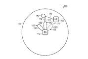
図4は、レーダプロービング109の例を概略的に図示する。ここで、BS112はレーダ送信器である。BS112は、こうして、第2のリソースエレメント161~163中でレーダプローブパルス171を送信する。BS112は、セルラネットワークのセル110を実装する。セル110は、BS112の周りに広がる。
FIG. 4 schematically illustrates an example of radar probing 109 . Here,
図4の例におけるレーダプローブパルス171は、等方性の指向性送信プロファイル180を有する、すなわち、BS112に関して様々な送信の向きで実質的に同じ振幅を有する(図4の中で、点線の円によって概略的に図示される)。したがって、レーダプローブパルスの振幅または位相は、送信方向への有意な依存性を示さない。
The
レーダプローブパルス171は、BS112から端末130にLOSに沿って進行することができる(図4中の点線の矢印)。レーダプローブパルス171は、たとえば、障害物、車、植物、家、車、人、壁、3D物体、チャネル、アールケーブなどといったパッシブ物体140によっても反射される。パッシブ物体140は、通信能力を有する必要はない。したがって、パッシブ物体140は、無線チャネル101、105、106上で通信するように構成されなくてよい。パッシブ物体140における反射に起因して、レーダプローブパルス171のエコー172が生じる。これらのエコー172は、図4にそれぞれの矢印によって示されるように、端末130および/またはBS112が受信することができる。
A
いくつかの例では、エコー172の方向および/またはエコー172の位相シフトは、物体140の位置または形状の特質である場合がある。エコー172のドップラシフトは、物体140の速度の特質である場合がある。
In some examples, the direction of
図5Aは、BS112と端末130の間の通信の信号伝達図である。図5Aの例に図示される通信は、レーダプロービング109を容易にする。
5A is a signaling diagram of communication between
第1に、1001において、無線チャネル101がBS112と端末130の間で確立される。ここで、参加手順を実行することができる。その後、端末130は、接続モードで動作することができる。
First, at 1001 a
接続モードでは、たとえばBS112から端末130に、制御チャネル106を介して、スケジュールグラント1001Aを通信することができる。スケジュールグラント1001Aは、第2のリソースエレメント161~163のうちの少なくとも1つを示すことができる。スケジュールグラント1001Aは、レーダプロービング109、すなわち、レーダプローブパルス171の送信を先制して知らせるために使用することができる。ここで、BS112は、データ通信108との干渉を避けて、第2のリソースエレメント161~163についての中心的スケジューラとしての役割を果たすことができる。
In connected mode, for example, schedule grant 1001A may be communicated from
スケジュールグラント1001Aが第2のリソースエレメント161~163のうちのただ1つを示す場合、スケジュールグラントは、専用スケジュールグラントと呼ぶこともでき、すなわち、スケジュールグラント1001Aが示す特定の第2のリソースエレメント161~163に専用であることができる。専用スケジュールグラントは、要求/要望によって通信することができる。専用スケジュールグラント毎に、予め規定した限定した数のレーダプローブパルス171、たとえば単一のレーダプローブパルス171を送信することができる。それによって、調整したレーダプロービング109を達成することができる。
If the schedule grant 1001A indicates only one of the second resource elements 161-163, the schedule grant can also be referred to as a dedicated schedule grant, ie the particular
しかし、スケジュールグラント1001Aが複数の第2のリソースエレメント161~163を示す場合、スケジュールグラントは、持続的スケジュールグラントと呼ぶことができる。詳細には、スケジュールグラントは、第2のリソースエレメント161~163のある種のタイミングパターンまたは繰返し率を示す場合がある。たとえば、持続的スケジュールグラントは、繰返し率151、持続時間152などを示すことができる。別途通知があるまで、第2のリソースエレメント161~163は、この場合、持続的にスケジュールされてよい。ここで、予め規定しない、または未規定の数のレーダプローブパルス171を、持続的スケジュールグラント毎に送信することができる。それによって、無線チャネル101上のオーバーヘッドの減少を達成することができる。
However, if the schedule grant 1001A indicates multiple second resource elements 161-163, the schedule grant can be referred to as a persistent schedule grant. In particular, the schedule grant may indicate certain timing patterns or repetition rates of the second resource elements 161-163. For example, a persistent schedule grant can indicate a
いくつかの例では、スケジュールグラント1001Aは、BS112から端末130へのユニキャスト送信中、および任意選択で、ネットワークに接続される影響を受ける他のデバイスにさらなるユニキャスト送信中で通信することができる。他の例では、スケジュールグラント1001Aは、無線チャネル101上でブロードキャストすることができる。それによって、無線チャネル101上で通信する1つまたは複数のさらなるデバイスに、スケジュールグラント1001Aによって示される少なくとも1つのリソースエレメントにおけるデータの送信をミュートするように促すことができる。それによって、ネットワークに接続される複数のデバイスについて、干渉を効果的に低減することができる。
In some examples, schedule grant 1001A may communicate during a unicast transmission from
次いで、1002において、レーダプローブパルス171の送信が遂行される。図5Aの例では、BS112がレーダプローブパルス171を送信する。図5Aの例では、レーダプローブパルス171のエコー172が、端末130によって受信される。
Then, at 1002, transmission of
図5Aの例では、端末130は、レーダプローブパルス171の受信を、何らかの程度に評価する。詳細には、端末は、生の受信データを分析し、たとえば到達角度、飛行時間、ドップラシフト、および/または受信電力レベルといった、エコー172のある種の受信特性を決定する。
In the example of FIG. 5A, terminal 130 evaluates the reception of
端末は、次いで、リポートメッセージ1003をBS112に送る。リポートメッセージは、決定した、エコー172の1つまたは複数の受信特性を示す。任意選択で、リポートメッセージ1003は、端末130の位置を示す。1つまたは複数の受信特性、および任意選択で、端末130の位置に基づいて、他の方法でBS112に知られていない場合、BS112は、次いで、エコー172に関連するパッシブ物体の位置および/または速度を決定することができる。詳細には、たとえばBS112に関する、端末130の絶対または相対位置がわかると、たとえば三角測量などによって、パッシブ物体140の位置を戻って判断を下すことが可能である。同様の考慮を、パッシブ物体140の運動の方向に関して適用する。
The terminal then sends
図5Bは、BS112と端末130の間の通信の信号伝達図である。図5Bの例は、図5Aの例に一般的に対応する。しかし、図5Bの例では、端末130において、レーダプロービング109の部分としてさらなる処理が実施される。特に、端末130は、物体140の相対または絶対位置を決定するために、エコー172の1つまたは複数の受信特性を事前に評価する。この位置および/または速度は、リポートメッセージ1004に含まれる。
FIG. 5B is a signaling diagram of communications between
様々な例では、端末130に、および一般的にレーダ受信器にあるロジックの量は変わる場合がある。一例では、受信したエコー172についての生の情報は、レーダ送信器、たとえばBS112にリポートされる。他の例では、生の情報の何らかの処理は、たとえば図5Aの例でのように、1つまたは複数の受信特性を決定することおよび/または生の情報を圧縮することのために実施される。他の例では、エコー172が発生する物体140の位置を決定することさえ可能である。次いで、この位置を、レーダ送信器、たとえばBS112にリポートすることができる。
In various examples, the amount of logic present in
上の様々な例は、等方性の指向性送信プロファイル180を有するレーダプローブパルス171に関して記載してきたが、レーダプローブパルス171が異方性の指向性送信プロファイルを有することも可能である。
Although the various examples above have been described with respect to
上の様々な例は、BS112がレーダ送信器であるシナリオに関して記載してきたが、他の例では、端末130がレーダ送信器130を実装することも可能である。ここで、リソースマッピング155は、BS112によって集中方式でスケジュールすることができる。すなわち、BS112が、第2のリソースエレメント161~163の発生について端末130に通知することが可能である。BS112が、レーダプロービングについてのリソース割当てを制御することが可能である。端末130がレーダ送信器を実装する場合、端末130および/またはBS112は、レーダプローブパルスを受信することができる。
Although various examples above have been described for scenarios in which
図6は、採用されたレーダプローブパルス171が異方性の指向性送信プロファイル181~183を有する、レーダプロービング109の例を概略的に図示する。異方性の指向性送信プロファイル181~183は、BS112に関する図6の例では、レーダ送信器に対する方位に関するそれぞれのレーダプローブパルス171の振幅の依存性と関連する。図6の例では、異方性の方向送信プロファイル181~183は、対応するペンシルビームによって実装されるが、一般的に他の形状が考えられる。異方性の指向性送信プロファイル181~183は、ビーム形成の技法に基づいて採用することができる。ビーム形成では、アンテナアレイのアンテナの振幅および位相は、ある種のアンテナの重み付けにしたがって変えられる。それによって、送信器に関する異なる方向について、強め合う干渉および弱め合う干渉を達成することができる。このことによって、異方性の方向送信プロファイル181~183がもたらされる。
FIG. 6 schematically illustrates an example of radar probing 109 in which the employed
図6に図示されるように、複数の異なる異方性の指向性送信プロファイル182が、異なるレーダプローブパルス171のために実装される。特に、異なる異方性の指向性送信プロファイル181~183は、第2のリソースエレメント161~163のうちの様々なエレメントの期間に送信されるレーダプローブパルス171に関連する。図6の例では、簡単にするため、ただ3つの異方性の指向性送信プロファイル181~183が図示される。一般的に、複数の異方性の指向性送信プロファイル181~183を、たとえばレーダ送信器の周りすべてをカバーするために採用することができる。
As illustrated in FIG. 6, multiple different anisotropic directional transmission profiles 182 are implemented for different
図6の例では、異方性の指向性送信プロファイル182はペンシルビームとして実装される。一般的に、プロファイル181~183を実装するペンシルビームは、90°未満、好ましくは45°未満、より好ましくは20°未満の開口角度を有することができる。たとえば図6に図示されるようなペンシルビームの形状で、明確な、または狭い異方性の指向性送信プロファイル181~183を実装することによって、レーダプロービング109の高い空間解像度を達成することができる。これは図6から明らかであり、図6では、プロファイル182のレーダプローブパルス171がパッシブ物体140によって反射される。それぞれのエコー172は、BS112と端末130の両方によって受信されている。一方で、プロファイル183のレーダプローブパルス171は、パッシブ物体140によって反射されない。というのは、パッシブ物体140は、プロファイル183の外側に位置するためである。
In the example of FIG. 6, the anisotropic directional transmit
異方性の指向性送信プロファイル182は、干渉を低減するために採用することもできる。たとえば、レーダ送信器の位置および/またはレーダ受信器の位置および/またはさらなる端末など無線チャネル101上で通信する少なくとも1つのさらなるデバイスの位置に基づいて、レーダプローブパルス171の少なくとも一部の異方性の指向性送信プロファイル181~183を決定することが可能である。たとえば、図6の例では、第2のリソースエレメント162の中の異方性の指向性送信プロファイル182に基づいてレーダプロービング109を採用すること、および第2のリソースエレメント162を端末130とのデータ通信108のために再使用することが可能である。そのような例では、それぞれのレーダプロファイル171の異方性の指向性送信プロファイル182は、端末130の方向への送信を避けるように決定される。これは、場合によって、空間ダイバーシティと呼ばれる。
An anisotropic
図7は、採用されたレーダプローブパルス171が異方性の指向性送信プロファイル181~183を有する、レーダプロービング109の例を概略的に図示する。図7は、一般的に図6の例に対応する。しかし図7の例では、異なる異方性の指向性送信プロファイル181~183は、BS112の異なるバーチャルセル111に関連する(図7では、簡単にするため、異方性の指向性送信プロファイル181に関連するバーチャルセル111だけが図示される)。様々なバーチャルセル111は、異なるセル識別子に関連してよく、したがって、いくつかの例では、異なるリソースマッピング155を採用することができる。異なるバーチャルセル111中で通信されるパイロット信号は、互いに直交することができる。バーチャルセル111は、データ通信108の空間ダイバーシティを容易にすることができる。いくつかの例では、バーチャルセル111が、1つまたは1つより多いBS(図7に図示せず)に関連することが可能である。
FIG. 7 schematically illustrates an example of radar probing 109 in which the employed
図8は、採用されたレーダプローブパルス171が異方性の指向性送信プロファイル181~183を有する、レーダプロービング109の例を概略的に図示する。ここで、2つより多いデバイス、図8の例では端末130、131、およびBS112が、レーダプロービング109に関与することができる。この例では、BS112がレーダ送信器である。物体140の位置および速度を決定するとき、BS112が、端末130、131から受信した情報を融合することが可能である。このために、BS112は、端末130、131の各々からリポートメッセージ1003、1004を受信することができる。加えて、物体140の速度における位置を決定するとき、BS112は、BS112が直接受信したエコー172を考慮に入れることができる。端末130、131は、(パッシブ)レーダ受信器を実装する。レーダプロービング109に関する情報の複数の発生源を考慮に入れることによって、レーダプロービング109の部分として、物体140の位置および速度を決定する際の精度を向上させることができる。
FIG. 8 schematically illustrates an example of radar probing 109 in which the employed
図9は、採用されたレーダプローブパルス171が異方性の指向性送信プロファイル181~183を有する、レーダプロービング109の例を概略的に図示する。図9の例では、LOS送信において、端末130がレーダプローブパルス171を受信できる一方で、それぞれのエコー172がBS112に(および、図9に図示されないが、任意選択で端末130にも)戻って反射されることが図示される。
FIG. 9 schematically illustrates an example of radar probing 109 in which the employed
図10は、BS112の概略図である。BSは、たとえばマルチコアプロセッサといった、プロセッサ1122を備える。BS112は、無線送受信器1121をさらに備える。無線送受信器1121は、たとえば、送信および受信(送受信)によって、無線チャネル101上で通信するように構成される。さらに、無線送受信器1121は、レーダプローブパルス171を送信および/または受信するように構成される。プロセッサ1122は、データ送信108とレーダプロービング109の共存に関し本明細書に記載したような技法を実施するように構成することができる。このために、それぞれの制御命令を記憶する不揮発性メモリを設けることができる。
FIG. 10 is a schematic diagram of
図11は、端末130の概略図である。端末130は、たとえばマルチコアプロセッサといった、プロセッサ1302を備える。端末130は、無線送受信器1301をさらに備える。無線送受信器1301は、たとえば送受信によって、無線チャネル101上で通信するように構成される。さらに、無線送受信器1301は、レーダプローブパルス171を送信および/または受信するように構成される。プロセッサ1302は、データ送信108とレーダプロービング109の共存に関し本明細書に記載したような技法を実施するように構成することができる。このために、それぞれの制御命令を記憶する不揮発性メモリを設けることができる。
FIG. 11 is a schematic diagram of
図12は、送受信器1121、1301を、より詳細に、概略的に図示する。送受信器1121、1301は、図示した例の中にアンテナアレイ1400を備える。アンテナアレイ1400に基づいて、たとえば、レーダプローブパルス171のエコー172の受信期間に、異方性の感度プロファイルを採用することができる。たとえば、いくつかの例では、無線送受信器1121、1301のアンテナアレイ1400の異方性の感度プロファイルを採用することによって、レーダプロービング109の精度をさらに向上することが可能である。アンテナアレイ1400のそのような異方性の感度プロファイルを、それぞれのレーダプローブパルス171の、等方性の指向性送信プロファイル180または異方性の指向性送信プロファイル181~183と組み合わせることができる。
FIG. 12 schematically illustrates the
図12の例では、送受信器1121、1301は、単一のアンテナアレイ1400を備える。さらなる例では、送受信器1121、1301が、複数のアンテナアレイ1400を備えることが可能である。複数のアンテナアレイ1400は、それぞれのデバイスに関して異なる方向をカバーするように異なって向けることができる。全方向的カバレージを提供することができる。
In the example of FIG. 12, the
図12は、受信電力レベル1413、到達角度1412、および飛行時間1411などの受信特性をさらに概略的に図示する。レーダプロービング109に関する対象のさらなる受信特性は、物体140の速度、たとえばレーダ送信器および/またはレーダ受信器との間の径方向の速度を決定するために使用できるドップラシフトを含む。たとえば、到達角度1412は、絶対的に、たとえば別個のコンパス(図12に図示せず)により提供される磁北極の方向などに関して決定することができる。到達角度1412が、相対的に、たとえばアンテナアレイ1400の特質方向に関して決定されることも可能である。到達角度1412および/またはさらなる受信特性の規定に依存して、対応する情報をそれぞれのリポートメッセージ1003に含むことができる。さらなる受信特性は、たとえば、任意の基準位相または見通し線送信に関して規定される基準位相に関する位相シフトである。
FIG. 12 further schematically illustrates reception characteristics such as received
図13は、様々な実施形態にしたがった方法のフローチャートである。たとえば、図13の方法は、BS112のプロセッサ1122および/または端末130のプロセッサ1302によって実行することができる。
FIG. 13 is a flowchart of a method according to various embodiments. For example, the method of FIG. 13 may be performed by
第1に、3001において、データ通信108が実行される。このため、パケット化したデータを、第1のリソースエレメント160中の無線チャネル111上で送信および/または受信することができる。典型的には、データ通信108を、LOS送信に基づいて実行することができる。
First, at 3001
第2に、3002において、レーダプロービング109への関与が実行される。典型的には、レーダプロービング109は、非LOS送信に基づいて、すなわちエコーに基づいて実行することができる。3002は、以下、すなわち、第2のリソースエレメント161~163中のレーダプローブパルス171を送信することと(図14、3011参照)、第2のリソースエレメント161~163中のレーダプローブパルス171のエコー172を受信することと(図15、3021参照)、レーダプローブパルス171の少なくとも1つの受信特性1411~1413に基づいてパッシブ物体の速度における位置のうちの少なくとも1つを決定することと、受信したエコー172から少なくとも1つの受信特性1411~1413を決定することと、レーダ受信器の少なくとも1つの受信特性1411~1413、位置、および速度のうちの少なくとも1つを示す制御メッセージ1003を受信することとのうちの1つまたは複数を含むことができる。
Second, at 3002, participation in radar probing 109 is performed. Typically, radar probing 109 can be performed based on non-LOS transmissions, ie echoes. 3002: transmitting
上をまとめると、データ通信のためだけでなく、レーダプロービングのために、より高い周波数の電磁波の特性を再使用することを可能にする技法が説明されている。レーダプロービングは、典型的には、レーダプローブパルスの異なる反射/エコーについて、遅延プロファイルおよび到達角度を測定することを含む。 In summary, techniques are described that allow the reuse of the properties of higher frequency electromagnetic waves not only for data communications, but also for radar probing. Radar probing typically involves measuring delay profiles and angles of arrival for different reflections/echoes of a radar probe pulse.
いくつかの例では、タイムスロットなどのリソースエレメントがレーダプロービングに割り当てられる/レーダプロービング専用である、通信プロトコルを実装する技法が記載されている。いくつかの例では、それぞれのリソースエレメントは、BSによって集中方式でスケジュールすることができる。 In some examples, techniques are described for implementing communication protocols in which resource elements, such as time slots, are allocated/dedicated to radar probing. In some examples, each resource element can be centrally scheduled by the BS.
そのような技法は、データ通信とレーダプロービングで同じハードウェアを再使用することを可能にする。したがって、システムレベル上と各端末についての両方で、費用、サイズ、識別情報を節約し、干渉の低減を簡単にすることが可能である。 Such techniques allow reuse of the same hardware for data communication and radar probing. Therefore, it is possible to save cost, size, identity and simplify interference reduction both on the system level and for each terminal.
レーダプロービングのためのリソースエレメントは、許可された帯域および未許可帯域で使用することができる。典型的には、それぞれのスペクトルは、得られたレーダ画像の空間解像度を高くするため、6GHzより上であってよい。こうして、本技法によって、重複する周波数帯域において、ハンドセットデバイスにおけるレーダプロービングとデータ通信を組み合わせて採用することが可能である。対象の周波数帯域は、30~100GHzの間におよぶことができる。ライセンスフリー帯域を採用することができる。ライセンスフリー帯域は、典型的には、それぞれの帯域にだれでもアクセスできるものと指定されており、場合によっては、出力電力、デューティサイクルなどとしていくつかの組の規定を有する。未許可帯域のそのようなシナリオでは、本明細書に記載した干渉低減の技法が特に重要となる。 Resource elements for radar probing may be used in licensed and unlicensed bands. Typically, each spectrum may be above 6 GHz in order to increase the spatial resolution of the acquired radar images. Thus, the techniques may employ a combination of radar probing and data communications in handset devices in overlapping frequency bands. The frequency band of interest can range between 30-100 GHz. A license-free band can be adopted. License-free bands are typically designated as open access to the respective band, and possibly have some set of rules as output power, duty cycle, etc. In such scenarios for unlicensed bands, the interference mitigation techniques described herein are of particular importance.
本明細書に記載した技法は、レーダプロービングとデータ通信の両方を、小さい、たとえばハンドヘルドデバイスによってサポートできるという発見に基づいている。この発見に基づいて、同じハードウェアの中にデータ通信能力とレーダプロービング能力の一体化を可能にする技法が提供される。データ通信およびレーダプロービングに使用される異なるプロトコルを、ソフトウェアで規定することができる。 The techniques described herein are based on the discovery that both radar probing and data communication can be supported by small, eg, handheld devices. Based on this discovery, techniques are provided that allow the integration of data communication and radar probing capabilities within the same hardware. Different protocols used for data communication and radar probing can be defined in software.
干渉を避けるため、データ通信を実施するとき、レーダプロービングを認可することができ、その逆も同様である。したがって、レーダプロービングのためのそれぞれのリソースエレメントを、時々、繰り返し、および/または要求に応じてスケジュールすることができる。レーダ送信器が、ある種のさらなるデバイスの方向についての知識を有する場合、空間ダイバーシティに依拠することによって、レーダプロービングを、さらなるデバイスとのデータ通信と同時に採用することができる。 To avoid interference, radar probing can be authorized when conducting data communications and vice versa. Accordingly, each resource element for radar probing can be scheduled from time to time, repeatedly and/or on demand. By relying on spatial diversity, radar probing can be employed concurrently with data communication with additional devices if the radar transmitter has knowledge of the orientation of certain additional devices.
本発明は、ある種の好ましい例に関して示され記載されてきたが、本明細書を読み理解すれば、当業者には、等価物および修正物が想到されよう。本発明は、すべてのそのような等価物および修正物を含み、添付した請求項の範囲によってのみ限定される。 Although the invention has been shown and described with respect to certain preferred embodiments, equivalents and modifications will occur to those skilled in the art upon the reading and understanding of the specification. The present invention includes all such equivalents and modifications and is limited only by the scope of the appended claims.
たとえば、上の様々な例は、BSによって送信されるレーダプローブパルスに関して記載してきたが、それぞれの技法は、端末によって送信されるレーダプローブパルスに関して容易に実装することができる。本明細書に記載した技法は、場合によってサイドリンク通信と呼ばれる、デバイスツーデバイスチャネルに適用可能とすることができる。デバイスツーデバイスチャネルの特定の例は、車両-車両間通信を含む。 For example, although the various examples above have been described in terms of radar probe pulses transmitted by BSs, each technique can be readily implemented in terms of radar probe pulses transmitted by terminals. The techniques described herein may be applicable to device-to-device channels, sometimes referred to as sidelink communications. Particular examples of device-to-device channels include vehicle-to-vehicle communications.
Claims (17)
前記無線送受信器(1121、1301)を介して、無線チャネル(101、105、106)の第1のリソースエレメント(160)を採用する前記無線チャネル(101、105、106)上でデータ(108)を通信するように構成されている少なくとも1つのプロセッサ(1122、1302)と
を備えるデバイス(112、130、131)であって、
前記少なくとも1つのプロセッサ(1122、1302)が、前記無線送受信器(1121、1301)を制御して、前記無線チャネル(101、105、106)の第2のリソースエレメント(161~163)を採用するレーダプロービング(109)に関与するようにさらに構成され、前記第2のリソースエレメント(161~163)が前記第1のリソースエレメント(160)に対して直交しており、
前記少なくとも1つのプロセッサ(1122、1302)が、前記無線送受信器(1121、1301)を制御して、レーダプローブパルス(171)を送信するように構成されており、
前記レーダプローブパルス(171)の少なくとも一部が異方性の指向性送信プロファイル(181~183)を有し、
前記少なくとも1つのプロセッサ(1122、1302)が、前記デバイス(112、130、131)の位置および前記無線チャネル(101、105、106)上で通信する少なくとも1つのさらなるデバイス(112、130、131)の位置に基づいて、前記レーダプローブパルス(171)の前記少なくとも一部の前記異方性の指向性送信プロファイル(181~183)を決定するように構成されている、デバイス(112、130、131)。 a wireless transceiver (1121, 1301);
Data (108) on said radio channel (101, 105, 106) employing a first resource element (160) of said radio channel (101, 105, 106) via said radio transceiver (1121, 1301) a device (112, 130, 131) comprising at least one processor (1122, 1302) configured to communicate with
The at least one processor (1122, 1302) controls the radio transceiver (1121, 1301) to employ second resource elements (161-163) of the radio channel (101, 105, 106). further configured to participate in radar probing (109), said second resource elements (161-163) being orthogonal to said first resource elements (160);
said at least one processor (1122, 1302) configured to control said wireless transceiver (1121, 1301) to transmit radar probe pulses (171);
at least a portion of said radar probe pulses (171) having an anisotropic directional transmission profile (181-183);
The at least one processor (1122, 1302) communicates with the location of the device (112, 130, 131) and at least one further device (112, 130, 131) over the wireless channel (101, 105, 106). a device (112, 130, 131) configured to determine said anisotropic directional transmission profile (181-183) of said at least a portion of said radar probe pulse (171) based on the position of the ).
前記第1の送信電力が、前記第2の送信電力より、少なくとも5倍大きい、請求項1に記載のデバイス(112、130、131)。 The at least one processor (1122, 1302) controls the radio transceiver (1121, 1301) to transmit the radar probe pulses (171) at a first transmit power and transmit the data (108) to a second is configured to transmit at a transmission power of 2,
2. The device (112, 130, 131) of claim 1, wherein said first transmit power is at least five times greater than said second transmit power.
前記第2のリソースエレメント(161~163)の前記シーケンスの、個別のエレメントの平均繰返し率(151)が、0.5秒より長い、請求項1から11のいずれか一項に記載のデバイス(112、130、131)。 said second resource elements (161-163) arranged in an intermittent sequence;
A device according to any one of claims 1 to 11, wherein said sequence of said second resource elements (161-163) has an average repetition rate (151) of individual elements greater than 0.5 seconds ( 112, 130, 131).
前記第2のリソースエレメント(161~163)の前記シーケンスの、個別のエレメントの平均持続時間(152)が、2μsよりも短い、請求項1から12のいずれか一項に記載のデバイス(112、130、131)。 said second resource elements (161-163) arranged in an intermittent sequence;
A device (112) according to any one of the preceding claims, wherein the average duration (152) of individual elements of said sequence of said second resource elements (161-163) is less than 2 μs. 130, 131).
前記デバイス(112、130、131)が、前記セルラネットワークの端末である、請求項1から14のいずれか一項に記載のデバイス(112、130、131)。 said device (112, 130, 131) is a base station of a cellular network containing said radio channel (101, 105, 106); or said device (112, 130, 131) is a terminal of said cellular network A device (112, 130, 131) according to any one of claims 1 to 14.
前記第1のリソースエレメント(160)に対して直交する第2のリソースエレメント(161~163)を採用するレーダプロービング(109)に関与することと、
デバイス(112、130、131)の無線送受信器(1121、1301)を制御して、その少なくとも一部が異方性の指向性送信プロファイル(181~183)を有するレーダプローブパルス(171)を送信することと、
前記デバイス(112、130、131)の位置および前記無線チャネル(101、105、106)上で通信する少なくとも1つのさらなるデバイス(112、130、131)の位置に基づいて、前記レーダプローブパルス(171)の前記少なくとも一部の前記異方性の指向性送信プロファイル(181~183)を決定することと
を含む、方法。 communicating data (108) over a wireless channel (101, 105, 106) employing a first resource element (160) of the wireless channel (101, 105, 106);
engaging in radar probing (109) employing second resource elements (161-163) orthogonal to said first resource element (160);
Controlling radio transceivers (1121, 1301) of devices (112, 130, 131) to transmit radar probe pulses (171), at least some of which have anisotropic directional transmission profiles (181-183) and
based on the location of said device (112, 130, 131) and the location of at least one further device (112, 130, 131) communicating on said radio channel (101, 105, 106), said radar probe pulse (171 ), and determining the anisotropic directional transmission profiles (181-183) of the at least some of the .
17. A method according to claim 16, performed by a device (112, 130, 131) according to any one of claims 1 to 15.
Priority Applications (1)
| Application Number | Priority Date | Filing Date | Title |
|---|---|---|---|
| JP2020153937A JP7183228B2 (en) | 2020-09-14 | 2020-09-14 | Coexistence of wireless communication and radar probing |
Applications Claiming Priority (1)
| Application Number | Priority Date | Filing Date | Title |
|---|---|---|---|
| JP2020153937A JP7183228B2 (en) | 2020-09-14 | 2020-09-14 | Coexistence of wireless communication and radar probing |
Related Parent Applications (1)
| Application Number | Title | Priority Date | Filing Date |
|---|---|---|---|
| JP2018562287A Division JP6764948B2 (en) | 2016-06-01 | 2016-06-01 | Coexistence of wireless communication and radar probing |
Publications (2)
| Publication Number | Publication Date |
|---|---|
| JP2021002847A JP2021002847A (en) | 2021-01-07 |
| JP7183228B2 true JP7183228B2 (en) | 2022-12-05 |
Family
ID=73995537
Family Applications (1)
| Application Number | Title | Priority Date | Filing Date |
|---|---|---|---|
| JP2020153937A Active JP7183228B2 (en) | 2020-09-14 | 2020-09-14 | Coexistence of wireless communication and radar probing |
Country Status (1)
| Country | Link |
|---|---|
| JP (1) | JP7183228B2 (en) |
Citations (3)
| Publication number | Priority date | Publication date | Assignee | Title |
|---|---|---|---|---|
| DE102009054776A1 (en) | 2009-01-23 | 2010-08-12 | Adc Automotive Distance Control Systems Gmbh | Communication system for use in driver assistance system of e.g. vehicle, has radar module for executing communication function, which executes transmission of communication signal via radar signal to adjacent vehicle |
| US20120143397A1 (en) | 2009-07-29 | 2012-06-07 | Mix Telematics International (Proprietary) Limited | Asset tracking system and method |
| US20140035774A1 (en) | 2012-08-01 | 2014-02-06 | Audi Ag | Radar sensor for a motor vehicle, motor vehicle and communication method |
Family Cites Families (2)
| Publication number | Priority date | Publication date | Assignee | Title |
|---|---|---|---|---|
| JPH08249596A (en) * | 1995-01-11 | 1996-09-27 | Mitsubishi Electric Corp | Base station radar device, mobile station radar device, and mobile object discriminating system |
| JPH09190593A (en) * | 1996-01-12 | 1997-07-22 | Japan Radio Co Ltd | Road state monitoring device |
-
2020
- 2020-09-14 JP JP2020153937A patent/JP7183228B2/en active Active
Patent Citations (3)
| Publication number | Priority date | Publication date | Assignee | Title |
|---|---|---|---|---|
| DE102009054776A1 (en) | 2009-01-23 | 2010-08-12 | Adc Automotive Distance Control Systems Gmbh | Communication system for use in driver assistance system of e.g. vehicle, has radar module for executing communication function, which executes transmission of communication signal via radar signal to adjacent vehicle |
| US20120143397A1 (en) | 2009-07-29 | 2012-06-07 | Mix Telematics International (Proprietary) Limited | Asset tracking system and method |
| US20140035774A1 (en) | 2012-08-01 | 2014-02-06 | Audi Ag | Radar sensor for a motor vehicle, motor vehicle and communication method |
Non-Patent Citations (2)
| Title |
|---|
| 三田村 健 他,カーロボティックスによるぶつからない車の実現を目指して,機関誌"ロボット" 199号 ,日本,社団法人日本ロボット工業会 Japan Robot Association(JARA),2011年03月20日,pp. 32-38 |
| 二宮 芳樹,車載周辺のセンシング・認識技術,システム/制御/情報 第55巻 第1号 SYSTEMS,CONTROL AND INFORMATION,日本,システム制御情報学会 The Institute of Systems,Control and Information Engineers,2011年01月15日,第55巻,pp. 8-13 |
Also Published As
| Publication number | Publication date |
|---|---|
| JP2021002847A (en) | 2021-01-07 |
Similar Documents
| Publication | Publication Date | Title |
|---|---|---|
| JP6764948B2 (en) | Coexistence of wireless communication and radar probing | |
| CN109565324B (en) | System and method for user equipment operation management | |
| CN109477885B (en) | Radar detection using pilot signals | |
| EP3959538A1 (en) | Radar probing using radio communication terminals | |
| CN114375547A (en) | Joint communication and sensing assisted beam management for NR | |
| WO2021178941A1 (en) | Methods, architectures, apparatuses and systems directed to wireless transmit/receive unit (wtru) initiated active sensing | |
| US11477754B2 (en) | Systems and methods for positioning reference signal staggering configuration | |
| CN116806441A (en) | Sensing in a wireless communication system | |
| KR102544310B1 (en) | System for multistatic radar communication | |
| CN115777178B (en) | System and method for beam sweep for new radio positioning | |
| US20230076874A1 (en) | Power control and beam management for communication and sensing | |
| US11889436B2 (en) | Calibration of group delay in a mobile device | |
| EP4229440A1 (en) | Enabling target localization with bi/multi-static measurements in nr | |
| JP7183228B2 (en) | Coexistence of wireless communication and radar probing | |
| KR20240028531A (en) | Communication systems and user devices | |
| US11977143B2 (en) | Radar probing using radio communication terminals | |
| WO2023231042A1 (en) | Sensing resource detection with interference self-awareness | |
| US20240012086A1 (en) | Mitigation of impact of oscillator error on doppler estimation for radio frequency sensing |
Legal Events
| Date | Code | Title | Description |
|---|---|---|---|
| A521 | Request for written amendment filed |
Free format text: JAPANESE INTERMEDIATE CODE: A523 Effective date: 20201002 |
|
| A621 | Written request for application examination |
Free format text: JAPANESE INTERMEDIATE CODE: A621 Effective date: 20201002 |
|
| A977 | Report on retrieval |
Free format text: JAPANESE INTERMEDIATE CODE: A971007 Effective date: 20211026 |
|
| A131 | Notification of reasons for refusal |
Free format text: JAPANESE INTERMEDIATE CODE: A131 Effective date: 20211207 |
|
| A601 | Written request for extension of time |
Free format text: JAPANESE INTERMEDIATE CODE: A601 Effective date: 20220207 |
|
| A131 | Notification of reasons for refusal |
Free format text: JAPANESE INTERMEDIATE CODE: A131 Effective date: 20220823 |
|
| A521 | Request for written amendment filed |
Free format text: JAPANESE INTERMEDIATE CODE: A523 Effective date: 20221024 |
|
| TRDD | Decision of grant or rejection written | ||
| A01 | Written decision to grant a patent or to grant a registration (utility model) |
Free format text: JAPANESE INTERMEDIATE CODE: A01 Effective date: 20221108 |
|
| A61 | First payment of annual fees (during grant procedure) |
Free format text: JAPANESE INTERMEDIATE CODE: A61 Effective date: 20221122 |
|
| R150 | Certificate of patent or registration of utility model |
Ref document number: 7183228 Country of ref document: JP Free format text: JAPANESE INTERMEDIATE CODE: R150 |
|
| S111 | Request for change of ownership or part of ownership |
Free format text: JAPANESE INTERMEDIATE CODE: R313113 |
|
| R350 | Written notification of registration of transfer |
Free format text: JAPANESE INTERMEDIATE CODE: R350 |