[1.パチンコ機の全体構造]
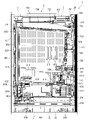
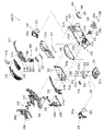
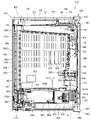
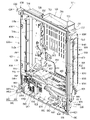
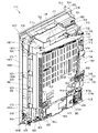
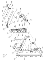
以下、図面を参照して本発明の好適な実施形態について、図面を参照して説明する。まず、図1乃至図7を参照して実施形態に係るパチンコ機の全体について説明する。図1乃至図7において、本実施形態に係るパチンコ機1は、遊技ホールの島設備(図示しない)に設置される外枠2と、外枠2に開閉自在に軸支され前側が開放された箱枠状の本体枠3と、本体枠3に前側から装着固定され遊技媒体としての遊技球Tが打ち込まれる遊技領域1100を有した遊技盤4と、本体枠3及び遊技盤4の前面を遊技者側から閉鎖するように本体枠3に対して開閉自在に軸支された扉枠5とを備えている。このパチンコ機1の扉枠5には、遊技盤4の遊技領域1100が遊技者側から視認可能となるように形成された遊技窓101と、遊技窓101の下方に配置され遊技球Tを貯留する皿状の上皿301及び下皿302と、上皿301に貯留された遊技球Tを遊技盤5の遊技領域1100内へ打ち込むために遊技者が操作するハンドル装置500と、を備えている。
[1. Overall Structure of Pachinko Machine]
Preferred embodiments of the present invention will be described below with reference to the drawings. First, the overall pachinko machine according to the embodiment will be described with reference to FIGS. 1 to 7. FIG. 1 to 7, a pachinko machine 1 according to this embodiment includes an outer frame 2 installed on an island facility (not shown) of a game hall, and an outer frame 2 pivotally supported so as to be openable and closable, and the front side is open. A box-shaped body frame 3, a game board 4 having a game area 1100 attached and fixed to the body frame 3 from the front side and into which a game ball T as a game medium is driven, and a front surface of the body frame 3 and the game board 4 are played. A door frame 5 pivotally supported to be openable and closable with respect to the body frame 3 so as to be closed from the side of the person. The door frame 5 of the pachinko machine 1 has a game window 101 formed so that the game area 1100 of the game board 4 can be visually recognized from the player side, and a game ball T which is arranged below the game window 101 to store game balls T. and a handle device 500 operated by the player to hit the game ball T stored in the upper plate 301 into the game area 1100 of the game board 5. .
本例のパチンコ機1は、図示するように、正面視において、外枠2、本体枠3、及び扉枠5が夫々上下方向へ延びた縦長の矩形状に形成されており、夫々の左右方向の横幅が略同じ寸法とされていると共に、上下方向の縦幅の寸法が、外枠2に対して本体枠3及び扉枠5の寸法が若干短く形成されている。そして、本体枠3及び扉枠5よりも下側の位置において、外枠2の前面に装飾カバー23が取付けられており、扉枠5及び装飾カバー23によって外枠2の前面が完全に閉鎖されるようになっている。また、外枠2、本体枠3、及び扉枠5は、上端が略揃うように夫々が配置されると共に、外枠2の左端前側の位置で本体枠3及び扉枠5が回転可能に軸支されており、外枠2に対して本体枠3及び扉枠5の右端が前側へ移動することで開状態となるようになっている。
As shown in the figure, the pachinko machine 1 of the present embodiment has an outer frame 2, a main body frame 3, and a door frame 5 each formed in a vertically long rectangular shape extending in the vertical direction when viewed from the front. , and the vertical width of the main body frame 3 and the door frame 5 is slightly shorter than that of the outer frame 2 . A decorative cover 23 is attached to the front surface of the outer frame 2 at a position below the main body frame 3 and the door frame 5, and the front surface of the outer frame 2 is completely closed by the door frame 5 and the decorative cover 23. It has become so. The outer frame 2, the main body frame 3, and the door frame 5 are arranged such that their upper ends are substantially aligned, and the main body frame 3 and the door frame 5 are rotatably pivoted at a position on the front side of the left end of the outer frame 2. The right ends of the main body frame 3 and the door frame 5 are moved forward with respect to the outer frame 2 to open them.
このパチンコ機1は、正面視において、略円形状の遊技窓101を介して遊技球Tが打ち込まれる遊技領域1100が望むようになっており、その遊技窓101の下側に前方へ突出するように二つの上皿301及び下皿302が上下に配置されている。また、扉枠5の前面右下隅部には、遊技者が操作するためのハンドル装置500が配置されており、上皿301内に遊技球Tが貯留されている状態で遊技者がハンドル装置500を回転操作すると、その回転角度に応じた打球強さで上皿301内の遊技球Tが遊技盤4の遊技領域1100内へ打ち込まれて、遊技をすることができるようになっている。
When viewed from the front, the pachinko machine 1 is configured such that a game area 1100 into which game balls T are hit can be seen through a substantially circular game window 101. An upper plate 301 and a lower plate 302 are arranged vertically. A handle device 500 for a player to operate is arranged at the lower right corner of the front surface of the door frame 5 . is rotated, the game ball T in the upper tray 301 is hit into the game area 1100 of the game board 4 with a hitting strength corresponding to the rotation angle, and a game can be played.
なお、詳細は後述するが、扉枠5の遊技窓101は、透明なガラスユニット590によって閉鎖されており、遊技者から遊技領域1100内を視認することができるものの、遊技者が遊技領域1100内へ手等を挿入して遊技領域1100内の遊技球Tや障害釘G(図98を参照)、各種入賞口や役物等に触ることができないようになっている。また、本体枠3の後側には、各種の制御基板が備えられていると共に、遊技盤4の後方を覆うように閉鎖するカバー体1250備えられている。
Although the details will be described later, the game window 101 of the door frame 5 is closed by a transparent glass unit 590, and although the player can visually recognize the inside of the game area 1100, the player cannot see inside the game area 1100. The player cannot touch the game ball T, obstacle nail G (see FIG. 98), various winning openings, accessories, etc. in the game area 1100 by inserting his/her hand or the like. Various control boards are provided on the rear side of the body frame 3, and a cover body 1250 that closes the game board 4 so as to cover the rear side thereof is provided.
[1-1.外枠]
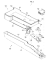
外枠2について、主として図8乃至図16を参照して説明する。図8及び図9に示すように、本実施形態のパチンコ機1における外枠2は、横方向へ延びる上下の上枠板10及び下枠板11と、縦(上下)方向へ延びる左右の側枠板12,13と、夫々の枠板10,11,12,13の端部を連結する四つの連結部材14と、を備えており、連結部材14で各枠板10,11,12,13同士を連結することで縦長の矩形状(方形状)に組立てられている。本例の外枠2における上枠板10及び下枠板11は、所定厚さの無垢材(例えば、木材、合板、等)により形成されており、左右両端の前後方向の略中央に、上下に貫通し左右方向中央側へ窪んだ係合切欠部15が備えられている。なお、上枠板10における左側端部の上面及び前面には、その他の一般面よりも窪んだ取付段部10aが形成されており、この取付段部10aに後述する上支持金具20が取付けられるようになっている。
[1-1. Outer frame]
The outer frame 2 will be described mainly with reference to FIGS. 8 to 16. FIG. As shown in FIGS. 8 and 9, the outer frame 2 of the pachinko machine 1 of this embodiment includes upper and lower upper frame plates 10 and lower frame plates 11 extending in the horizontal direction, and left and right side plates extending in the vertical (vertical) direction. Frame plates 12, 13 and four connecting members 14 connecting ends of the frame plates 10, 11, 12, 13 are provided. By connecting them together, they are assembled into a vertically long rectangular shape (square shape). The upper frame plate 10 and the lower frame plate 11 in the outer frame 2 of the present example are formed of solid wood (for example, wood, plywood, etc.) with a predetermined thickness, and are placed approximately in the center in the front-rear direction of both the left and right ends. An engagement notch 15 is provided which penetrates through the body and is recessed toward the center in the left-right direction. Mounting stepped portions 10a that are recessed from other general surfaces are formed on the upper surface and front surface of the left end portion of the upper frame plate 10, and upper support metal fittings 20, which will be described later, are mounted on the mounting stepped portions 10a. It's like
一方、側枠板12,13は、一定断面形状の軽量金属型材(例えば、アルミ合金)とされており、外側側面は略平坦面とされていると共に、内側側面は後端部に内側へ突出し上下方向(押出方向)に貫通する空洞を有した突出部16を備えており、強度剛性が高められている(図9及び図108を参照)。なお、側枠板12,13の外側側面及び内側側面には、上下方向へ延びた複数の溝が形成されており、パチンコ機1を遊技ホールの島設備に設置する際等に、作業者の指掛りとなってパチンコ機1を保持し易くすることができるようにっていると共に、外観の意匠性を高められるようになっている。なお、便宜上、側枠板12,13の側面に形成された複数の溝を省略して示した図面もある。
On the other hand, the side frame plates 12 and 13 are made of a lightweight metal material (for example, an aluminum alloy) with a constant cross section, and the outer side surfaces are substantially flat surfaces, and the inner side surfaces protrude inward at the rear ends. It has a protruding portion 16 having a cavity penetrating in the vertical direction (extrusion direction) to increase strength and rigidity (see FIGS. 9 and 108). In addition, a plurality of grooves extending in the vertical direction are formed on the outer and inner side surfaces of the side frame plates 12 and 13, and when the pachinko machine 1 is installed on the island equipment of the game hall, the operator can The pachinko machine 1 can be easily held as a finger rest, and the design of the appearance can be enhanced. For the sake of convenience, there are drawings in which the plurality of grooves formed on the side surfaces of the side frame plates 12 and 13 are omitted.
本例の外枠2における連結部材14は、所定厚さの金属板をプレス成型等によって屈曲塑性変形させることで形成されたものであり、上枠板10又は下枠板11に固定され左右方向へ延びた板状の水平片17と、水平片17の外側端部から上下方向の一方側へ延び側枠板12,13に固定される板状の垂直片18と、垂直片18とは反対方向へ延び上枠板10又は下枠板11の係合切欠部15内に挿入係合可能な板状の係合片19と、を有している。なお、本例では、上枠板10と左側の側枠板12とを連結する連結部材14と、上枠板10と右側の側枠板13とを連結する連結部材14とは、夫々左右非対称の形状に形成されていると共に、垂直片18が前後に分かれて形成されている。一方、下枠板11と左側の側枠板12とを連結する連結部材14と、下枠板11と右側の側枠板13とを連結する連結部材14とは、夫々左右対称の形状に形成されている。
The connecting member 14 in the outer frame 2 of the present example is formed by bending and plastically deforming a metal plate of a predetermined thickness by press molding or the like, and is fixed to the upper frame plate 10 or the lower frame plate 11 and fixed to the left-right direction. a plate-like horizontal piece 17 extending from the outer edge of the horizontal piece 17 to one side in the vertical direction and fixed to the side frame plates 12 and 13; and a plate-like engaging piece 19 that extends in the direction and can be inserted into and engaged with the engaging notch 15 of the upper frame plate 10 or the lower frame plate 11 . In this example, the connecting member 14 connecting the upper frame plate 10 and the left side frame plate 12 and the connecting member 14 connecting the upper frame plate 10 and the right side frame plate 13 are left-right asymmetrical. , and a vertical piece 18 is formed so as to be divided into front and rear portions. On the other hand, the connecting member 14 that connects the lower frame plate 11 and the left side frame plate 12, and the connecting member 14 that connects the lower frame plate 11 and the right side frame plate 13 are formed in a bilaterally symmetrical shape. It is
この連結部材14は、水平片17の上面及び下面が上枠板10及び下枠板11の下面及び上面と当接すると共に、係合片19が上枠板10及び下枠板11の係合切欠部15内に挿入係合された状態で、水平片17及び係合片19を貫通して所定のビスが上枠板10及び下枠板11にねじ込まれることで、上枠板10及び下枠板11に固定されるようになっている。また、上枠板10に固定された連結部材14は、その垂直片18が側枠体12,13の上端内側側面に当接した状態で、側枠体12,13を貫通して所定のビスが垂直片18へねじ込まれることで、上枠板10と側枠板12,13とを連結することができるようになっている。なお、上枠板10に固定された連結部材14における後側の垂直片18は、側枠板12,13の突出部16内に挿入された状態で、側枠板12,13へ固定されるようになっている。更に、下枠板11に固定された連結部材14は、その垂直片18が側枠体12,13の下端内側側面に当接した状態で、側枠体12,13を貫通して所定のビスが垂直片18へねじ込まれることで、下枠板11と側枠板12,13とを連結することができるようになっており、四つの連結部材14により、上枠板10、下枠板11、及び側枠板12,13を枠状に組立てることができるようになっている。
The upper and lower surfaces of the horizontal piece 17 abut against the lower and upper surfaces of the upper frame plate 10 and the lower frame plate 11 , and the engaging piece 19 of the connecting member 14 engages the upper and lower frame plate 10 and the lower frame plate 11 . In the state of being inserted into and engaged with the portion 15, a predetermined screw is screwed into the upper frame plate 10 and the lower frame plate 11 through the horizontal piece 17 and the engagement piece 19, whereby the upper frame plate 10 and the lower frame It is adapted to be fixed to the plate 11 . The connecting member 14 fixed to the upper frame plate 10 is screwed through the side frames 12, 13 with the vertical piece 18 in contact with the inner side surface of the upper end of the side frames 12, 13 and screwed with a predetermined screw. is screwed into the vertical piece 18 so that the upper frame plate 10 and the side frame plates 12 and 13 can be connected. The rear vertical piece 18 of the connecting member 14 fixed to the upper frame plate 10 is fixed to the side frame plates 12 and 13 while being inserted into the projecting portion 16 of the side frame plates 12 and 13. It's like Further, the connecting member 14 fixed to the lower frame plate 11 is inserted through the side frames 12, 13 with the vertical piece 18 in contact with the inner side surface of the lower end of the side frames 12, 13 and screwed with a predetermined screw. is screwed into the vertical piece 18 to connect the lower frame plate 11 and the side frame plates 12 and 13. Four connecting members 14 connect the upper frame plate 10 and the lower frame plate 11 , and the side frame plates 12 and 13 can be assembled into a frame shape.
本例の外枠2は、上枠板10の左端上面に固定される上支持金具20と、上支持金具20と対向するように配置され左側の側枠板12における下部内側の所定位置に固定される下支持金具21と、下支持金具21の下面を支持するように配置され左右の側枠板12,13を連結するように固定される補強金具22と、補強金具22の前面に固定される装飾カバー23と、を備えている。この上支持金具20及び下支持金具21は、本体枠3及び扉枠5を開閉可能に軸支するためのものである。
The outer frame 2 of this example includes an upper support metal fitting 20 fixed to the top surface of the left end of the upper frame plate 10, and is arranged to face the upper support metal fitting 20 and fixed to a predetermined position inside the lower part of the left side frame plate 12. a lower supporting metal fitting 21 attached to the lower supporting metal fitting 21; a reinforcing metal fitting 22 arranged so as to support the lower surface of the lower supporting metal fitting 21 and fixed so as to connect the left and right side frame plates 12 and 13; and a decorative cover 23. The upper support metal fitting 20 and the lower support metal fitting 21 are for pivotally supporting the body frame 3 and the door frame 5 so that they can be opened and closed.
まず、上支持金具20は、上枠板10に固定される板状の固定片20aと、固定片20aの前端から上枠板10の前端よりも前方へ突出する支持突出片20bと、支持突出片20bにおける前端付近の右側端から先端中央部へ向かって屈曲するように切欠かれて形成された支持鉤穴20cと、固定片20及び支持突出片20bの左端から下方へ垂下し左側の側枠板12における外側側面と当接する板状の垂下固定片20d(図14(A)を参照)と、垂下固定片20dと連続し支持突出片20bの外側縁に沿って垂下する垂下壁20e(図14を参照)と、垂下壁20eと連続し支持鉤穴20cの入口端部で内側へ向って傾斜した停止垂下部20f(図15を参照)と、を備えている。この上支持金具20における支持鉤穴20cには、後述する本体枠3における上軸支金具630の軸支ピン633(図63を参照)が着脱自在に係合されるようになっている。また、上支持金具20は、固定片20aと垂下固定片20dとによって、上枠板10と左側の側枠板12とを連結することができるようになっている。
First, the upper support metal fitting 20 includes a plate-like fixing piece 20a fixed to the upper frame plate 10, a supporting projecting piece 20b projecting forward from the front end of the fixing piece 20a beyond the front end of the upper frame plate 10, and a supporting projection. A supporting hook hole 20c is formed by notching from the right end near the front end of the piece 20b so as to bend toward the center of the tip, and the left side frame hangs downward from the left ends of the fixed piece 20 and the supporting protruding piece 20b. A plate-shaped hanging fixed piece 20d (see FIG. 14A) that abuts the outer side surface of the plate 12, and a hanging wall 20e that is continuous with the hanging fixed piece 20d and hangs down along the outer edge of the support projecting piece 20b (see FIG. 14A). 14) and a stop droop 20f (see FIG. 15) which is continuous with the depending wall 20e and slopes inwardly at the entrance end of the support barb 20c. A pivot pin 633 (see FIG. 63) of an upper pivot bracket 630 of the body frame 3, which will be described later, is detachably engaged with the support hook hole 20c of the upper support bracket 20. As shown in FIG. Also, the upper support fitting 20 can connect the upper frame plate 10 and the left side frame plate 12 by means of a fixing piece 20a and a hanging fixing piece 20d.
この上支持金具20は、支持突出片20bの外側縁から垂下する垂下壁20eによって、支持突出片20bの強度が高められていると共に、詳細は後述するが、正面から見た時に支持突出片20bの裏面に配置されるロック部材27が遊技者側から視認できないように隠蔽することができ、外観の見栄えを良くすることができるようになっている。また、支持突出片20bに形成された支持鉤穴20cは、垂下壁20eが形成されない反対側(右側)の側方から先端中央部に向かって傾斜状となるようにく字状に屈曲した形状とされていると共に、支持鉤穴20cの傾斜状穴部の幅寸法は、軸支ピン633の直径よりもやや大きな寸法とされている。
The strength of the support projecting piece 20b is increased by the hanging wall 20e that hangs down from the outer edge of the support projecting piece 20b. The lock member 27 arranged on the rear surface of the player can be hidden so as not to be visually recognized from the player side, and the external appearance can be improved. Further, the support hook hole 20c formed in the support protruding piece 20b is bent in a V-shape so as to be inclined toward the center of the tip from the opposite side (right side) where the hanging wall 20e is not formed. , and the width dimension of the inclined hole portion of the support hook hole 20 c is slightly larger than the diameter of the pivot pin 633 .
一方、下支持金具21は、補強金具22上に載置固定される水平固定片21aと、水平固定片21aの左端から上方へ立上がり左側の側枠板12の内側側面に固定される垂直固定片21bと、水平固定片21aの前端から上枠板10及び下枠板11よりも前方へ突出する板状の支持突出片21cと、支持突出片21cの前端付近から上向きに突設されたピン状の支持突起21dと、を備えている。この下支持金具21における支持突起21dには、後述する本体枠3の本体枠軸支金具644(図66等を参照)に形成された本体枠軸支が挿入されるようになっており、下支持金具21の支持突起21dを、本体枠3における本体枠軸支金具644の支持穴に挿入した後に、本体枠3の上軸支金具630の軸支ピン633を支持鉤穴20cに係止することにより簡単に本体枠3を開閉自在に軸支することができるようになっている。
On the other hand, the lower support metal fitting 21 comprises a horizontal fixing piece 21a placed and fixed on the reinforcing metal fitting 22, and a vertical fixing piece rising upward from the left end of the horizontal fixing piece 21a and fixed to the inner side surface of the left side frame plate 12. 21b, a plate-like support projecting piece 21c projecting forward from the front end of the horizontal fixed piece 21a beyond the upper frame plate 10 and the lower frame plate 11, and a pin-like projecting upward from near the front end of the support projecting piece 21c. and a support projection 21d. A body frame shaft support formed on a body frame shaft support metal fitting 644 (see FIG. 66, etc.) of the body frame 3, which will be described later, is inserted into the support projection 21d of the lower support metal fitting 21. After inserting the support protrusion 21d of the support metal fitting 21 into the support hole of the main body frame pivot metal fitting 644 of the main body frame 3, the pivot pin 633 of the upper shaft support metal fitting 630 of the main body frame 3 is engaged with the support hook hole 20c. As a result, the body frame 3 can be easily pivotally supported so that it can be freely opened and closed.
また、本例の外枠2は、図示するように、右側の側枠板13の内側に、上下方向に所定距離離反して配置される二つの閉鎖板24,25が取付固定されている。これら閉鎖板24,25は、平面視で略L字状に形成されており、下側に配置される閉鎖板25には、前後方向に貫通する矩形状の開口25aを有している(図9を参照)。この閉鎖板24,25は、外枠2に対して本体枠3を閉じる際に、本体枠3の開放側辺に沿って取付けられる錠装置1000のフック部1054,1065(図93を参照)と係合するものであり、詳細は後述するが、錠装置1000のシリンダ錠1010に鍵を差し込んで一方に回動することにより、フック部1054,1065と閉鎖板24,25との係合が外れて本体枠3を外枠2に対して開放することができるものである。
As shown in the drawing, the outer frame 2 of this example has two closing plates 24 and 25 arranged vertically apart from each other by a predetermined distance inside the right side frame plate 13 and fixed. These closing plates 24 and 25 are formed in a substantially L-shape in plan view, and the closing plate 25 arranged on the lower side has a rectangular opening 25a penetrating in the front-rear direction (Fig. 9). The closing plates 24 and 25 are attached along the open sides of the body frame 3 when the body frame 3 is closed to the outer frame 2. Although the details will be described later, when the key is inserted into the cylinder lock 1010 of the lock device 1000 and turned to one side, the engagement between the hook portions 1054 and 1065 and the closing plates 24 and 25 is released. The body frame 3 can be opened with respect to the outer frame 2 by pressing.
更に、本例の外枠2は、補強金具22の右端上面に固定される案内板26を更に備えている。この案内板26は、外枠2に対して本体枠3を閉止する際に、本体枠3をスムーズに案内するためのものであり、交換可能に装着固定されている。
Furthermore, the outer frame 2 of this example further includes a guide plate 26 fixed to the upper surface of the right end of the reinforcing metal fitting 22 . This guide plate 26 is for smoothly guiding the body frame 3 when closing the body frame 3 with respect to the outer frame 2, and is attached and fixed so as to be replaceable.
また、本例の外枠2は、図14等に示すように、上支持金具20における支持突出片20bの裏面に支持されたロック部材27を更に備えており、リベット28によって支持突出片20bに対して回動可能に軸支されている。このロック部材27は、合成樹脂により形成されており、リベット28により軸支される位置から前方へ突出するストッパ部27aと、リベット28により軸支される位置から右方向へストッパ部27aよりも短く突出する操作部27bと、操作部27bに対してリベット28により軸支される位置とは反対側から突出する弾性片27cと、ストッパ部27aの先端に前方側へ膨出するように形成された円弧状の先端面27dと、を備えている。このロック部材27は、図示するように、ストッパ部27aと操作部27bとで、略L字状に形成されている。また、ロック部材27の弾性部27cは、ストッパ部27aや操作部27bよりも狭い幅に形成されていると共に、ストッパ部27aから左方へ遠ざかるに従って前方へ延びだすように形成されている。
14, the outer frame 2 of this example further includes a lock member 27 supported on the back surface of the support projecting piece 20b of the upper support metal fitting 20, and is secured to the support projecting piece 20b by a rivet 28. It is rotatably supported with respect to. The lock member 27 is made of synthetic resin, and has a stopper portion 27a that protrudes forward from the position where it is supported by the rivet 28, and a portion that is shorter than the stopper portion 27a to the right from the position where it is supported by the rivet 28. A projecting operation portion 27b, an elastic piece 27c projecting from the side opposite to the position where the operation portion 27b is pivotally supported by the rivet 28, and an elastic piece 27c formed at the tip of the stopper portion 27a so as to bulge forward. and an arcuate tip surface 27d. As shown, the lock member 27 is formed in a substantially L shape by a stopper portion 27a and an operating portion 27b. The elastic portion 27c of the locking member 27 is formed to have a width narrower than that of the stopper portion 27a and the operating portion 27b, and is formed to extend forward as it moves leftward from the stopper portion 27a.
このロック部材27は、図14(B)や図15に示すように、上支持金具20の支持突出片20bに支持した状態(通常の状態)では、弾性片27cの先端当接部が垂下壁20eの内側面と当接しており、ストッパ部27aが支持鉤穴20cの傾斜状穴部を閉塞するようになっていると共に、ストッパ部27aの先端部分が、支持鉤穴20cの傾斜状穴部の先頭空間部分を閉塞した状態とはならず、支持鉤穴20cの先頭空間部分に本体枠3の上軸支金具630の軸支ピン633を挿入可能な空間が形成された状態となっている。
As shown in FIGS. 14(B) and 15, when the lock member 27 is supported by the support protruding piece 20b of the upper support fitting 20 (normal state), the end abutting portion of the elastic piece 27c is the hanging wall. 20e, the stopper portion 27a closes the inclined hole portion of the support hook hole 20c, and the tip portion of the stopper portion 27a contacts the inclined hole portion of the support hook hole 20c. is not closed, and a space is formed in the leading space of the support hook hole 20c so that the pivot pin 633 of the upper pivot bracket 630 of the body frame 3 can be inserted. .
本例の上支持金具20とロック部材27とを用いた軸支ピン633の支持機構は、軸支ピン633が支持鉤穴20cの傾斜状穴部の先端空間部分に挿入されてストッパ部27aの先端側方が入口端部の停止垂下部20fに対向している状態(この状態ではストッパ部27aの先端側方と停止垂下部20fとの間に僅かな隙間があり当接した状態となっていない)である通常の軸支状態においては、屈曲して形成される支持鉤穴20cの傾斜状穴部の先端空間部分に位置する軸支ピン633とストッパ部27aの先端面27dとの夫々の中心が斜め方向にずれて対向した状態となっている。そして、この通常の軸支状態においては、重量のある本体枠3を軸支している軸支ピン633が支持鉤穴20cの先端部分に当接した状態となっているので、軸支ピン633からストッパ部27aの先端面27dへの負荷がほとんどかかっていないため、ロック部材27の弾性片27cに対し負荷がかかっていない状態となっている。なお、ストッパ部27aの先端に円弧状の先端面27dを備えているので、ロック部材27を回動させるために操作部27bを回動操作した時に、ロック部材27がスムーズに回動するようになっている。また、図示では、先端面27dの円弧中心が、リベット28の中心(ロック部材27の回転中心)とされている。
In the support mechanism of the pivot pin 633 using the upper support metal fitting 20 and the lock member 27 of this embodiment, the pivot pin 633 is inserted into the tip space portion of the inclined hole portion of the support hook hole 20c, and the stopper portion 27a is locked. A state in which the tip side faces the stop drooping portion 20f of the inlet end (in this state, there is a slight gap between the tip side of the stopper portion 27a and the stop drooping portion 20f, and they are in contact with each other). (not shown), the axial support pin 633 located in the tip space portion of the inclined hole portion of the support hook hole 20c formed by bending and the tip end surface 27d of the stopper portion 27a They face each other with their centers shifted in an oblique direction. In this normal pivoting state, the pivot pin 633 that pivotally supports the heavy body frame 3 is in contact with the tip of the support hook hole 20c. Since almost no load is applied to the tip surface 27d of the stopper portion 27a, the elastic piece 27c of the lock member 27 is in a state where no load is applied. In addition, since the stopper portion 27a has an arcuate tip surface 27d at the tip thereof, when the operation portion 27b is rotated to rotate the lock member 27, the lock member 27 can be rotated smoothly. It's becoming Also, in the illustration, the center of the arc of the tip surface 27d is the center of the rivet 28 (the center of rotation of the lock member 27).
従って、軸支ピン633が支持鉤穴20cの傾斜状穴部の傾斜に沿って抜ける方向に作用力Fがかかって円弧状の先端面27dに当接したとき、その作用力Fを、軸支ピン633と円弧状の先端面27dとの当接部分に作用する分力F1(先端面27dの円弧の法線方向)と、軸支ピン633と支持鉤穴20cの傾斜状穴部の一側内面との当接部分に作用する分力F2と、に分けたときに、分力F1の方向がリベット28の中心(ロック部材27の回転中心)を向くため、ロック部材27のストッパ部27aの先端部が支持突出片20bから外れる方向(図示の時計方向)に回転させるモーメントが働かず、軸支ピン633がロック部材27のストッパ部27aの先端部と支持鉤穴20cの傾斜状穴部の一側内面との間に挟持された状態を保持する。このため、通常の軸支状態でもあるいは軸支ピン633の作用力がロック部材27にかかった状態でも、ロック部材27の弾性片27cに常時負荷がかからず、合成樹脂で一体形成される弾性片27cのクリープによる塑性変形を防止し、長期間に亘って軸支ピン633の支持鉤穴20cからの脱落を防止することができる。なお、仮に無理な力がかかってロック部材27のストッパ部27aの先端部が支持突出片20bから外れる方向(図示の時計方向)に回転させられても、ストッパ部27aの先端部の一側方が停止垂下部20fに当接してそれ以上外れる方向に回転しないので、ロック部材27が支持突出片20bの外側にはみ出ないようになっている。
Therefore, when the axial support pin 633 contacts the arcuate end surface 27d with an acting force F acting in a direction in which the axial support pin 633 is pulled out along the inclination of the inclined hole portion of the support hook hole 20c, the acting force F is applied to the axial support pin 633. A force component F1 acting on the contact portion between the pin 633 and the arc-shaped tip end surface 27d (the normal direction of the arc of the tip end surface 27d), and one side of the inclined hole portion of the support pin 633 and the support hook hole 20c When the direction of the component force F1 is directed toward the center of the rivet 28 (the center of rotation of the lock member 27), the stopper portion 27a of the lock member 27 is stopped. No moment acts to rotate the tip portion in the direction (clockwise in the figure) to separate from the support projecting piece 20b, and the pivot pin 633 is positioned between the tip portion of the stopper portion 27a of the lock member 27 and the inclined hole portion of the support hook hole 20c. It maintains the state of being sandwiched between the inner surface of one side. Therefore, even in a normal axially supported state or in a state in which the force of the axially supporting pin 633 is applied to the lock member 27, the elastic piece 27c of the lock member 27 is not always subjected to a load, and the elastic member 27c integrally formed of synthetic resin is secured. It is possible to prevent plastic deformation due to creep of the piece 27c and to prevent the pivot pin 633 from falling out of the support hook hole 20c for a long period of time. Even if the tip of the stopper portion 27a of the locking member 27 is rotated in the direction (clockwise direction in the drawing) in which the tip portion of the stopper portion 27a of the locking member 27 is disengaged from the support projecting piece 20b by applying an excessive force, the tip portion of the stopper portion 27a will not move to one side. abuts on the stop drooping portion 20f and does not rotate further in the direction of detachment, so that the locking member 27 does not protrude outside the support projecting piece 20b.
なお、ストッパ部27aの先端面27dの形状は円弧状でなくても、上記した分力F1の作用により回転モーメントが生じない位置又はロック部材27をその先端部が支持突出片20bの外側に向って回転させる回転モーメントが生ずる位置にロック部材27の回転中心(リベット28により固定される軸)を位置させることにより、常時ロック部材27の弾性片27cに対しても負荷がかかることはないし、ロック部材27が回転してもストッパ部27aの先端一側方が停止垂下部20fに当接するだけであるため、ロック部材27が支持突出片20bの外側にはみ出ることもないという点を本出願人は確認している。
Even if the shape of the tip surface 27d of the stopper portion 27a is not arcuate, the tip portion of the locking member 27 may be placed in a position where the force component F1 does not generate a rotational moment, or the tip portion of the locking member 27 may be positioned toward the outside of the support projecting piece 20b. By locating the center of rotation of the lock member 27 (the shaft fixed by the rivet 28) at a position where a rotational moment is generated, no load is applied to the elastic piece 27c of the lock member 27 at all times. Even if the member 27 rotates, the one side of the tip of the stopper portion 27a only abuts the stop drooping portion 20f. Confirmed.
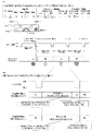
本例のロック部材27の作用について図16を参照して具体的に説明する。外枠2に本体枠3を開閉自在に軸支する前提として、本体枠3の本体枠軸支金具644(図63を参照)に形成される本体枠軸支穴(図示しない)に下支持金具21の支持突起21dが挿通されていることが必要である。そのような前提において、図16(A)に示すように、本体枠3の上軸支金具630の軸支ピン633をロック部材27のストッパ部27aの側面に当接させて押し込むことにより、図16(B)に示すように、ロック部材27が弾性片27cを変形させながら反時計方向に回動させるので、軸支ピン633を支持鉤穴20cに挿入することができる。そして、軸支ピン633が支持鉤穴20cの傾斜状穴部の先頭空間部分に到達すると、図16(C)に示すように、軸支ピン633とストッパ部27aの先端側面とが当接しなくなるためロック部材27が弾性片27cの弾性力に付勢されて時計方向に回動し、ロック部材27のストッパ部27aが再度通常の状態に戻って支持鉤穴20cの入口部分を閉塞すると同時に、ストッパ部27aの先端部分が軸支ピン633と対向して軸支ピン633が支持鉤穴20cから抜け落ちないようになっている。
The action of the locking member 27 of this example will be specifically described with reference to FIG. On the premise that the main body frame 3 is pivotally supported on the outer frame 2 so as to be openable and closable, lower support metal fittings are inserted into the main body frame shaft support holes (not shown) formed in the main body frame shaft support metal fittings 644 (see FIG. 63) of the main body frame 3 . It is necessary that the support projections 21d of 21 are inserted. On such a premise, as shown in FIG. As shown in 16(B), the locking member 27 rotates the elastic piece 27c counterclockwise while deforming it, so that the pivot pin 633 can be inserted into the supporting hook hole 20c. Then, when the pivot pin 633 reaches the top space of the inclined hole portion of the support hook hole 20c, as shown in FIG. Therefore, the lock member 27 is biased by the elastic force of the elastic piece 27c and rotates clockwise, and the stopper portion 27a of the lock member 27 returns to its normal state to close the entrance portion of the support hook hole 20c. The tip portion of the stopper portion 27a faces the pivot pin 633 so that the pivot pin 633 does not drop out of the support hook hole 20c.
そして、この状態は、図16(D)に示すように、本体枠3が完全に閉じられた状態でもあるいは本体枠3の通常の開閉動作中も保持される。次いで、軸支ピン633を支持鉤穴20cから取外すためには、図16(E)に示すように、指を支持突出片20bの裏面に差し入れてロック部材27の操作部27bを反時計方向に回動することにより、ロック部材27が弾性片27cの弾性力に抗して回動し、ストッパ部27aの先端部分が支持鉤穴20cから退避した状態となるため、軸支ピン633を支持鉤穴20cから取り出すことができる。その後、本体枠3を持ち上げて、本体枠軸支金具644に形成される本体枠軸支穴と下支持金具21の支持突起21dとの係合を解除することにより、本体枠3を外枠2から取外すことができるようになっている。
This state is maintained even when the body frame 3 is completely closed or during the normal opening/closing operation of the body frame 3, as shown in FIG. 16(D). Next, in order to remove the pivot pin 633 from the support hook hole 20c, as shown in FIG. By rotating, the lock member 27 rotates against the elastic force of the elastic piece 27c, and the tip portion of the stopper portion 27a is retracted from the support hook hole 20c. It can be taken out from the hole 20c. After that, the body frame 3 is lifted up to release the engagement between the body frame shaft support holes formed in the body frame shaft support metal fittings 644 and the support projections 21d of the lower support metal fittings 21, thereby moving the body frame 3 to the outer frame 2. can be removed from the
上述したように、本例の外枠2は、外枠2の外郭を構成する上枠板10と下枠板11とを従来と同じく木製とすると共に、側枠板12,13を軽量金属(例えば、アルミ合金)の押出型材としているので、パチンコ機1を遊技場に列設される島設備に設置する場合に、島の垂直面に対し所定の角度をつけて固定する作業を行う必要があるが、そのような作業は上枠板10及び下枠板11と島とに釘を打ち付けて行われるため、釘を打ち易くすることができ、既存の島設備に本パチンコ機1を問題なく設置することができるようになっている。また、側枠板12,13を軽量金属(例えば、アルミ合金)の押出型材としているので、従来の木製の外枠と比較して強度を維持しつつ肉厚を薄く形成することが可能となり、側枠板12,13の内側に隣接する本体枠3の周壁部605(図63等を参照)の正面から見たときの左右幅を広くすることができ、左右方向の寸法の大きな遊技盤4を本体枠3に装着することができると同時に、遊技盤4の遊技領域1100を大きく形成することができるようになっている。
As described above, in the outer frame 2 of this example, the upper frame plate 10 and the lower frame plate 11 that constitute the outer shell of the outer frame 2 are made of wood as in the conventional case, and the side frame plates 12 and 13 are made of lightweight metal ( For example, aluminum alloy) is used as an extruded material, so when the pachinko machine 1 is installed on the island facilities arranged in a line in the game hall, it is necessary to fix it at a predetermined angle with respect to the vertical plane of the island. However, since such work is performed by driving nails into the upper frame plate 10 and the lower frame plate 11 and the island, the nails can be easily driven, and the pachinko machine 1 can be easily installed in the existing island equipment. It can be installed. In addition, since the side frame plates 12 and 13 are extruded materials of light weight metal (for example, aluminum alloy), it is possible to form a thin wall thickness while maintaining the strength compared to the conventional wooden outer frame. The lateral width of the peripheral wall 605 (see FIG. 63, etc.) of the main body frame 3 adjacent to the inside of the side frame plates 12, 13 can be widened when viewed from the front, and the game board 4 with a large lateral dimension. can be attached to the main body frame 3, and at the same time, the game area 1100 of the game board 4 can be formed large.
また、外枠2の外郭を構成する上枠板10、下枠板11、及び側枠板12,13を連結部材14で連結するようにしており、連結部材14が側枠板12,13の内面に密着して止着されると共に連結部材14と上枠板10及び下枠板11が係合した状態で止着されるので、外枠2の組付け強度を高くすることができ、頑丈な方形状の枠組みとすることができるようになっている。また、連結部材14によって上枠板10、下枠板11、及び側枠板12,13を連結した後、上支持金具20を所定の位置に取付けたときに、図10に示すように、各枠板10,11,12,13の外側面(外周面)から外側に突出する部材が存在しないので、パチンコ機1を図示しない遊技ホールの島設備に設置する際に、隣接する装置(例えば、隣接する玉貸機)と密着して取付けることができるようになっている。
The upper frame plate 10, the lower frame plate 11, and the side frame plates 12 and 13, which constitute the outline of the outer frame 2, are connected by a connecting member 14. The connecting member 14 connects the side frame plates 12 and 13. Since the outer frame 2 is fixed in close contact with the inner surface and is fixed while the connecting member 14 and the upper frame plate 10 and the lower frame plate 11 are engaged with each other, the assembly strength of the outer frame 2 can be increased, and the outer frame 2 is sturdy. It is designed to be able to be a square-shaped framework. After the upper frame plate 10, the lower frame plate 11, and the side frame plates 12 and 13 are connected by the connecting member 14, when the upper support bracket 20 is attached at a predetermined position, each Since there is no member protruding outward from the outer surface (peripheral surface) of the frame plates 10, 11, 12, 13, when the pachinko machine 1 is installed in the island facility of a game hall (not shown), an adjacent device (for example, It can be installed in close contact with the adjacent ball lending machine).
[1-2.扉枠の全体構成]
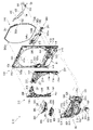
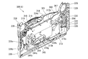
次に、上記した本体枠3の前面側に開閉自在に設けられる扉枠5について、図17乃至図23を参照して説明する。本実施形態のパチンコ機1における扉枠5は、図示するように、外形が縦長の矩形状に形成され内周形状がやや縦長の円形状(楕円形状)とされた遊技窓101を有する扉枠ベースユニット100と、扉枠ベースユニット100の前面で遊技窓101の右外周に取付けられる右サイド装飾ユニット200と、右サイド装飾ユニット200と対向し扉枠ベースユニット100の前面で遊技窓101の左外周に取付けられる左サイド装飾ユニット240と、扉枠ベースユニット100の前面で遊技窓101の上部外周に取付けられる上部装飾ユニット280と、を備えている。
[1-2. Overall configuration of door frame]
Next, the door frame 5 provided openable and closable on the front side of the body frame 3 will be described with reference to FIGS. 17 to 23. FIG. The door frame 5 in the pachinko machine 1 of the present embodiment has a game window 101 having a vertically long rectangular outer shape and a slightly vertically long circular (elliptical) inner peripheral shape, as shown in the figure. A base unit 100, a right side decoration unit 200 attached to the right outer periphery of the game window 101 in front of the door frame base unit 100, and a right side decoration unit 200 facing the right side decoration unit 200 and to the left of the game window 101 in front of the door frame base unit 100. A left side decoration unit 240 attached to the outer circumference and an upper decoration unit 280 attached to the upper outer circumference of the game window 101 on the front surface of the door frame base unit 100 are provided.
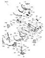
また、扉枠5は、扉枠ベースユニット100の前面で遊技窓101の下部に取付けられる皿ユニット300と、皿ユニット300の上部中央に取付けられる操作ユニット400と、皿ユニット300を貫通して扉枠ベースユニット100の右下隅部に取付けられ遊技球Tの打込操作をするためのハンドル装置500と、扉枠ベースユニット100を挟んで皿ユニット300の後側に配置され扉枠ベースユニット100の後面に取付けられるファールカバーユニット540と、ファールカバーユニット540の右側で扉枠ベースユニット100の後面に取付けられる球送りユニット580と、扉枠ベースユニット100の後側に遊技窓101を閉鎖するように取付けられるガラスユニット590と、を備えている。
The door frame 5 includes a plate unit 300 attached to the lower part of the game window 101 on the front surface of the door frame base unit 100, an operation unit 400 attached to the upper center of the plate unit 300, and a door penetrating the plate unit 300. A handle device 500 attached to the lower right corner of the frame base unit 100 for driving the game ball T, and a door frame base unit 100 disposed behind the plate unit 300 with the door frame base unit 100 interposed therebetween. A foul cover unit 540 attached to the rear surface, a ball feeding unit 580 attached to the rear surface of the door frame base unit 100 on the right side of the foul cover unit 540, and a game window 101 on the rear side of the door frame base unit 100 so as to close the game window 101. and an attached glass unit 590 .
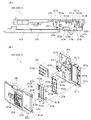
[1-2A.扉枠ベースユニット]
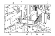
続いて、扉枠5における扉枠ベースユニット100について、主に図24乃至図28を参照して説明する。本例の扉枠ベースユニット100は、図示するように、外形が縦長の矩形状に形成されると共に、前後方向に貫通し内周が縦長の略楕円形状に形成された遊技窓101を有する扉枠ベース本体110と、扉枠ベース本体110の前面で遊技窓101の下端左右両外側に配置される一対のサイドスピーカ130と、サイドスピーカ130を扉枠べース本体110へ固定するためのスピーカブラケット132と、扉枠ベース本体110の前面で正面視右下隅部に取付けられハンドル装置500を支持するためのハンドルブラケット140と、を備えている。
[1-2A. door frame base unit]
Next, the door frame base unit 100 in the door frame 5 will be described mainly with reference to FIGS. 24 to 28. FIG. As illustrated, the door frame base unit 100 of this example has a vertically long rectangular outer shape and a game window 101 that penetrates in the front-rear direction and has an inner circumference that is substantially elliptical in a vertically long shape. A frame base body 110, a pair of side speakers 130 arranged in front of the door frame base body 110 on both left and right sides of the lower end of the game window 101, and speakers for fixing the side speakers 130 to the door frame base body 110. A bracket 132 and a handle bracket 140 for supporting the handle device 500 attached to the front surface of the door frame base body 110 at the lower right corner in front view are provided.
なお、扉枠ベースユニット100は、正面視で右側のサイドスピーカ130の外側には、サイドスピーカ130の側面と、右サイド装飾ユニット200等へ接続される配線(図示は省略)の前側とを覆い扉枠ベース本体110の前面に取付けられるカバー部材134を更に備えている。このカバー部材134は、配線をスピーカ取付部111の外周に沿って案内させることができると共に、サイドスピーカ130を取付ける際や取外す際に、配線が邪魔にならないように配線を保持することができるようになっている。
The door frame base unit 100 covers the side surface of the side speaker 130 and the front side of wiring (not shown) connected to the right side decorative unit 200 and the like on the outside of the right side speaker 130 when viewed from the front. A cover member 134 attached to the front surface of the door frame base body 110 is further provided. The cover member 134 can guide the wiring along the outer circumference of the speaker mounting portion 111, and can hold the wiring so that the wiring does not get in the way when the side speaker 130 is attached or removed. It has become.
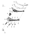
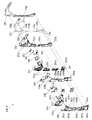
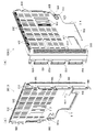
また、扉枠ベースユニット100は、扉枠ベース本体110の後側に固定される金属製で枠状の補強ユニット150と、扉枠ベース本体110の後面で遊技窓101の下部を被覆するように取付けられる防犯カバー180と、扉枠ベース本体110の後面で遊技窓101の外周の所定位置に回動可能に取付けられるガラスユニット係止部材190と、背面視で左右方向の中央より左側(開放側)に配置され遊技窓101の下端に沿って扉枠ベース本体110の後面に取付けられる発射カバー191と、発射カバー191の下側で扉枠ベース本体110の後面に取付けられハンドル装置500の回転位置検知センサ512と主制御基板4100との接続を中継するハンドル装置中継基板192と、ハンドル装置中継基板192の後側を被覆するハンドル装置中継基板カバー193と、左右方向の中央を挟んで発射カバー191やハンドル装置中継基板192等とは反対側(背面視で左右方向中央よりも右側(軸支側))に配置され扉枠ベース本体110の後面に取付けられる扉枠ベース基板194と、扉枠ベース基板194の後側を被覆する扉枠ベース基板カバー195と、扉枠ベース基板カバー195の後面に回動可能に軸支され扉枠5側と本体枠3側とを接続する配線コード196(図28を参照)の一部を保持する配線保持部材197と、を備えている。
In addition, the door frame base unit 100 includes a metal frame-shaped reinforcing unit 150 fixed to the rear side of the door frame base body 110, and a rear surface of the door frame base body 110 so as to cover the lower part of the game window 101. A security cover 180 to be attached, a glass unit locking member 190 rotatably attached to a predetermined position on the outer circumference of the game window 101 on the rear surface of the door frame base body 110, and a left side (open side) from the center in the left and right direction in rear view. ) and attached to the rear surface of the door frame base body 110 along the lower end of the game window 101, and the rotation position of the handle device 500 attached to the rear surface of the door frame base body 110 under the firing cover 191 A handle device relay board 192 that relays the connection between the detection sensor 512 and the main control board 4100, a handle device relay board cover 193 that covers the rear side of the handle device relay board 192, and a launch cover 191 sandwiching the center in the left-right direction. A door frame base substrate 194 arranged on the opposite side (on the right side (rotary support side) of the center in the left-right direction in rear view) from the handle device relay substrate 192 and the like and attached to the rear surface of the door frame base body 110, and the door frame base A door frame base board cover 195 covering the rear side of the board 194, and a wiring cord 196 (see FIG. 1) which is rotatably supported on the rear surface of the door frame base board cover 195 and connects the door frame 5 side and the body frame 3 side. 28), and a wiring holding member 197 that holds a part of the wiring.
本例の扉枠ベースユニット100は、合成樹脂からなる矩形状の扉枠ベース本体110の後側に、金属板金をリベット等で組立てた補強ユニット150が固定されることで、全体の剛性が高められていると共に、各装飾ユニット200,240,280や皿ユニット300等を充分に支持することができる強度を有している。
The door frame base unit 100 of this example has a reinforcing unit 150 assembled from metal sheets with rivets or the like and fixed to the rear side of a rectangular door frame base body 110 made of synthetic resin, thereby increasing the rigidity of the whole. In addition, it has sufficient strength to support each of the decorative units 200, 240, 280, the plate unit 300, and the like.
この扉枠ベースユニット100における扉枠ベース基板194は、サイドスピーカ130や左右のサイド装飾ユニット200,240の上部スピーカ222,262と接続されると共に、後述する遊技盤4に備えられた周辺制御基板4010と接続されており、周辺制御基板4010から送られた音響信号を増幅して各スピーカ130へ出力する増幅回路を備えている。なお、本例では、各装飾ユニット200,240,280及び皿ユニット300や操作ユニット400に備えられた各装飾基板430,432、操作ユニット400に備えられたダイヤル駆動モータ414やセンサ432a,432b,432c、ハンドル装置中継基板192、皿ユニット300の貸球ユニット360等と、払出制御基板4110や周辺制御基板4010等とを接続する配線コード196が、扉枠ベース基板194の背面視で右側(軸支側)の位置に集約して束ねられた上で、詳細は後述するが、配線保持部材197に保持されて後方へ延出し、本体枠3の主側中継端子板880や周辺側中継端子板882に接続されるようになっている(図1及び図28を参照)。
The door frame base board 194 in the door frame base unit 100 is connected to the side speaker 130 and the upper speakers 222, 262 of the left and right side decorative units 200, 240, and is connected to a peripheral control board provided on the game board 4, which will be described later. 4010 , and has an amplifier circuit that amplifies the acoustic signal sent from the peripheral control board 4010 and outputs it to each speaker 130 . In this example, each decoration unit 200, 240, 280, each decoration board 430, 432 provided in the plate unit 300 and the operation unit 400, the dial drive motor 414 provided in the operation unit 400, sensors 432a, 432b, 432c, the wiring cord 196 that connects the handle device relay board 192, the ball rental unit 360 of the plate unit 300, etc., and the dispensing control board 4110, the peripheral control board 4010, etc. is on the right side (axis After being collectively bundled at the position of the support side), although details will be described later, it is held by the wiring holding member 197 and extends rearward, and the main side relay terminal board 880 of the main body frame 3 and the peripheral side relay terminal board 882 (see FIGS. 1 and 28).
本例の扉枠ベースユニット100における扉枠ベース本体110は、図25及び図26等に示すように、合成樹脂によって縦長の額縁状に形成されており、前後方向に貫通し内形が縦長で略楕円形状の遊技窓101が全体的に上方へオフセットするような形態で形成されている。この遊技窓101は、図示するように、左右側及び上側の内周縁が連続した滑らかな曲線状に形成されているのに対して、下側の内周縁は左右へ延びた直線状に形成されている。また、扉枠ベース本体110における遊技窓101の下側の内周縁には、軸支側(正面視で左側)にファールカバーユニット540の第一球出口544aを挿通可能な方形状の切欠部101aが形成されている。この扉枠ベース本体110は、遊技窓101によって形成される上辺、及び左右の側辺の幅が、後述する補強ユニット150の上側補強板金151、軸支側補強板金152、及び開放側補強板金153の幅と略同じ幅とされており、正面視における扉枠ベース本体110の大きさに対して、遊技窓101が可及的に大きく形成されている。従って、扉枠5の後側に配置される遊技盤4のより広い範囲を遊技者側から視認できるようになっており、従来のパチンコ機よりも広い遊技領域1100を容易に形成することができるようになっている。
As shown in FIGS. 25 and 26, the door frame base body 110 in the door frame base unit 100 of the present embodiment is formed of synthetic resin in the shape of a vertically long picture frame. A substantially elliptical game window 101 is formed in such a manner that it is entirely offset upward. As shown in the drawing, the game window 101 is formed such that the left, right, and upper inner peripheral edges are formed in continuous smooth curved lines, while the lower inner peripheral edge is formed in a straight line extending to the left and right. ing. In addition, a rectangular notch 101a through which the first ball outlet 544a of the foul cover unit 540 can be inserted is provided on the inner peripheral edge of the lower side of the game window 101 in the door frame base body 110 on the pivot side (left side in front view). is formed. The width of the upper side formed by the game window 101 and the left and right side sides of the door frame base body 110 are equal to the upper side reinforcing sheet metal 151, the pivot side reinforcing sheet metal 152, and the opening side reinforcing sheet metal 153 of the reinforcing unit 150, which will be described later. , and the game window 101 is formed as large as possible with respect to the size of the door frame base body 110 in front view. Therefore, a wider range of the game board 4 arranged on the rear side of the door frame 5 can be visually recognized from the player side, and a wider game area 1100 than that of the conventional pachinko machine can be easily formed. It's like
この扉枠ベース本体110は、遊技窓101の他に、遊技窓101の下辺の左右両外側に配置されサイドスピーカ130を取付固定するためのスピーカ取付部111と、球送りユニット580を取付固定するための球送りユニット取付凹部112(図26を参照)と、球送りユニット取付凹部112の所定位置で前後方向に貫通し皿ユニット300の上皿301に貯留された遊技球Tを球送りユニット580へ供給するための球送り開口113と、正面視で右下隅部に配置され前方へ膨出した前面の右側(開放側)端が後退するように斜めに傾斜しハンドルブラケット140を取付けるためのハンドル取付部114と、ハンドル取付部114の所定位置で前後方向へ貫通しハンドル装置500からの配線が通過可能な配線通過口115と、ハンドル取付部114の上側で前方へ向かって短く延びた筒状に形成され後述するシリンダ錠1010が挿通可能な錠穴116と、を備えている。
In addition to the game window 101, the door frame base body 110 has a speaker mounting portion 111 for mounting and fixing the side speaker 130 which is arranged on both left and right outer sides of the lower side of the game window 101, and a ball feeding unit 580. A ball feeding unit mounting recess 112 (see FIG. 26) for feeding game balls T penetrating in the front-rear direction at a predetermined position of the ball feeding unit mounting recess 112 and stored in the upper plate 301 of the plate unit 300 to the ball feeding unit 580. A ball feeding opening 113 for supplying to the ball, and a handle for mounting a handle bracket 140, which is arranged at the lower right corner in front view and is inclined so that the right side (open side) end of the front surface bulging forward is retreated. A mounting portion 114, a wire passage opening 115 that penetrates in the front-rear direction at a predetermined position of the handle mounting portion 114 and allows the wiring from the handle device 500 to pass therethrough, and a cylindrical shape that extends short forward above the handle mounting portion 114. and a lock hole 116 through which a cylinder lock 1010 described later can be inserted.
また、扉枠ベース本体110は、図26に示すように、球送りユニット取付凹部112に下側にハンドル装置中継基板192を取付けるための中継基板取付部117と、背面視で扉枠ベース本体の下部右側(軸支側)に配置され扉枠ベース基板194を取付けるための基板取付部118と、遊技窓101の下端の背面視左側(開放側)でスピーカ取付部111よりも中央寄りの配置から後方へ突出し防犯カバー180の装着弾性片185を装着するための防犯カバー装着部119と、扉枠ベース本体110は、その後側に、遊技窓101の内周に略沿って前側へ凹みガラスユニット590の前面外周縁が当接可能なガラスユニット支持段部110aと、遊技窓101の外周の所定位置から後方へ突出しガラスユニット係止部材190を回動可能に支持するための二つの係止部材取付部110bと、を更に備えている。
Further, as shown in FIG. 26, the door frame base body 110 has a relay board mounting portion 117 for mounting the handle device relay board 192 on the lower side of the ball feed unit mounting recess 112, and the door frame base body as viewed from the rear. From the substrate mounting portion 118 arranged on the lower right side (rotary support side) for mounting the door frame base substrate 194, and the arrangement closer to the center than the speaker mounting portion 111 on the rear view left side (open side) of the lower end of the game window 101 The security cover mounting portion 119 for mounting the mounting elastic piece 185 of the security cover 180 projecting backward and the door frame base main body 110 are recessed forward along the inner periphery of the game window 101 on the rear side and the glass unit 590. A glass unit supporting stepped portion 110a with which the outer peripheral edge of the front surface of the game window 101 can abut, and two locking members that protrude backward from a predetermined position on the outer periphery of the game window 101 and support the glass unit locking member 190 in a rotatable manner. and a portion 110b.
更に、扉枠ベース本体110の後側には、その下辺から後方へ所定量突出する扉枠突片110cを備えており、この扉枠突片110cは、後述する本体枠3の係合溝603内に挿入されるようになっている。これにより、扉枠5が本体枠3に対して位置決め係止することができると共に、扉枠5と本体枠3との下辺の隙間からピアノ線等の不正な工具をパチンコ機1内に挿入しようとしても、係合溝603と係合した扉枠突片110cによって工具の侵入を阻止することができ、パチンコ機1の防犯機能が高められている。また、扉枠ベース本体110の後側には、背面視で錠穴116よりもやや右下の位置から後方へ突出し本体枠3の嵌合溝612と嵌合する位置決め突起110dを、備えており、この位置決め突起110dが嵌合溝612と嵌合することで、扉枠5と本体枠3とが正しい位置に位置決めされるようになっている。
Further, on the rear side of the door-frame base body 110, there is provided a door-frame projecting piece 110c projecting backward from the lower side of the door-frame base body 110 by a predetermined amount. It is designed to be inserted inside. As a result, the door frame 5 can be positioned and locked to the main body frame 3, and an illegal tool such as a piano wire can be inserted into the pachinko machine 1 through the gap between the lower sides of the door frame 5 and the main body frame 3. Even so, the door frame projecting piece 110c engaged with the engaging groove 603 can prevent the tool from entering, and the security function of the pachinko machine 1 is enhanced. Further, on the rear side of the door frame base body 110, there is provided a positioning projection 110d that protrudes rearward from a position slightly lower right than the lock hole 116 in a rear view and fits into the fitting groove 612 of the body frame 3. By fitting the positioning protrusion 110d into the fitting groove 612, the door frame 5 and the body frame 3 are positioned at the correct positions.
また、扉枠ベース本体110は、図25に示すように、その前面に、装飾ユニット200,240,280や皿ユニット300等を固定するための前方へ突出した複数の取付ボス110eが備えられていると共に、ハンドルブラケット140等を取付けるための取付穴が適宜位置に多数形成されている。また、扉枠ベース本体110は、サイドスピーカ130を取付けるスピーカブラケット132を取付けるための取付部110gや、サイドスピーカカバー338を取付けるための取付孔110h(図18等を参照)が、適宜位置に夫々形成されている。
Further, as shown in FIG. 25, the door frame base body 110 is provided with a plurality of mounting bosses 110e protruding forward for fixing the decorative units 200, 240, 280, the dish unit 300, etc. on the front surface thereof. In addition, a large number of mounting holes for mounting the handlebar bracket 140 and the like are formed at appropriate positions. Further, the door frame base body 110 has mounting portions 110g for mounting the speaker brackets 132 for mounting the side speakers 130, and mounting holes 110h (see FIG. 18, etc.) for mounting the side speaker covers 338 at appropriate positions. formed.
また、扉枠ベース本体110には、球送りユニット取付凹部112と基板取付部118との間で、後述する皿ユニット300の皿ユニットベース310における下皿球供給口310g及びファールカバーユニット540の第二球出口544bと対応する位置に、前後方向に貫通する矩形状の球通過口110fを備えている。
Further, in the door frame base body 110, between the ball feeding unit mounting recess 112 and the board mounting portion 118, a lower plate ball supply port 310g in the plate unit base 310 of the plate unit 300 and a foul cover unit 540, which will be described later, are provided. A rectangular ball passage opening 110f penetrating in the front-rear direction is provided at a position corresponding to the two-ball outlet 544b.
更に、扉枠ベース本体110は、その前面側で左右のスピーカ取付部111の上側に形成され、略三角形状に後方へ窪んだ浅い皿状の防犯凹部120を備えている。この防犯凹部120内には、前側から浅い箱状に形成された防犯部材121が挿入されるようになっている。防犯部材121は、金属板を屈曲させて前側が開放された浅い箱状に形成されている。これにより、パチンコ機1の内部に対して不正行為を行うために、例えば、サイド装飾ユニット200,240と皿ユニット300との接合部位から細いドリル等により穴を開けられてしまうのを金属製の防犯部材121によって阻止することができ、不正行為が行われるのを防止することができるようになっている。
Further, the door frame base main body 110 is formed above the left and right speaker mounting portions 111 on the front side thereof, and has shallow dish-shaped anti-crime recesses 120 recessed rearward in a substantially triangular shape. A shallow box-shaped security member 121 is inserted into the security recess 120 from the front side. The security member 121 is formed into a shallow box shape with an open front side by bending a metal plate. As a result, in order to carry out an illegal act on the inside of the pachinko machine 1, for example, a thin drill or the like is used to make a hole from the joining portion between the side decoration units 200 and 240 and the plate unit 300. It can be blocked by the security member 121, and it is possible to prevent a fraudulent act.
また、扉枠ベースユニット100における一対のサイドスピーカ130は、詳細な図示は省略するが、その中心軸の交点が正面視で遊技領域1100の中央から前方へ所定距離(例えば、0.2m~1.5m)の位置となるように斜めに固定されており、パチンコ機1の前に着座した遊技者に対して最も効率良く音が届くようになっている。また、このサイドスピーカ130は、主に中高音域の音を出力するようになっていると共に、パチンコ機1に対して、可及的に左右方向へ離反した位置に配置されており、左右のサイドスピーカ130から関連した異なる音を出力させることで、ステレオ感の高い音を出力することができるようになっている。
In addition, the pair of side speakers 130 in the door frame base unit 100 are not shown in detail, but the point of intersection of their central axes is a predetermined distance (for example, 0.2 m to 1 m) forward from the center of the game area 1100 when viewed from the front. 5 m), so that the sound reaches the player seated in front of the pachinko machine 1 most efficiently. The side speaker 130 mainly outputs mid-to-high range sound, and is arranged at a position separated from the pachinko machine 1 in the horizontal direction as much as possible. By outputting related and different sounds from the side speakers 130, it is possible to output sound with a high sense of stereo.
これらサイドスピーカ130は、その外周が、前側に配置された略円環状のスピーカブラケット132と、後側に配置された扉枠ベース本体110のスピーカ取付部111とによって挟持されることで、扉枠ベース本体110に取付けられるようになっている。なお、スピーカブラケット132は、所定のビスによって、前側から扉枠ベース本体110の取付部110gに取付けられるようになっている。
The outer periphery of these side speakers 130 is sandwiched between a substantially annular speaker bracket 132 arranged on the front side and the speaker mounting portion 111 of the door frame base body 110 arranged on the rear side, so that the door frame It is adapted to be attached to the base body 110 . The speaker bracket 132 is attached to the attachment portion 110g of the door frame base body 110 from the front side with a predetermined screw.
また、扉枠ベースユニット100における扉枠ベース基板カバー195は、図25乃至図27等に示すように、前側が開放された薄い箱状に形成されていると共に、後側の後面に、上下方向の中央よりもやや下寄りの位置で前方へ窪んだ段部195aを備えている。この扉枠ベース基板カバー195の段部195aに、配線保持部材197が回動可能に取付けられている。
25 to 27, the door-frame base board cover 195 in the door-frame base unit 100 is formed in a thin box-like shape with an open front side, and a vertical A stepped portion 195a recessed forward is provided at a position slightly lower than the center. A wire holding member 197 is rotatably attached to the step portion 195a of the door frame base board cover 195. As shown in FIG.
一方、扉枠ベースユニット100における配線保持部材197は、図27及び図28等に示すように、横方向へ長く延びた板状に形成されていると共に、断面がI字状に形成されており、比較的、硬質の合成樹脂によって形成されている。また、配線保持部材197は、図示するように、上下両端に長手方向へ沿って所定間隔で複数(本例では、上下に夫々三つずつ)の保持孔197aを備えている。この配線保持部材197は、扉枠5を組立てた状態で扉枠5が本体枠3に軸支される側の端部が、扉枠ベース基板カバー195における後面の段部195aに、上下方向へ延びた軸周りに回動可能に軸支されており、詳細な図示は省略するが、配線保持部材197の自由端側が扉枠ベース基板カバー195側へ回動することで、配線保持部材197が扉枠ベース基板カバー195の段部195a内へ収容することができるようになっている。
On the other hand, as shown in FIGS. 27 and 28, the wire holding member 197 in the door frame base unit 100 is formed in a plate-like shape elongated in the horizontal direction and has an I-shaped cross section. , which is made of a relatively hard synthetic resin. The wiring holding member 197 is provided with a plurality of holding holes 197a (three each in the upper and lower direction in this example) along the longitudinal direction at predetermined intervals at both upper and lower ends, as shown in the figure. The wire holding member 197 has an end portion on the side where the door frame 5 is pivotally supported by the main body frame 3 in the assembled state of the door frame 5, and is vertically attached to the stepped portion 195a on the rear surface of the door frame base board cover 195. The wire holding member 197 is rotatably supported around the extended shaft, and although detailed illustration is omitted, the wire holding member 197 is rotated toward the door frame base board cover 195 by rotating the free end side of the wire holding member 197 toward the door frame base board cover 195 side. It can be accommodated in the step portion 195 a of the door frame base board cover 195 .
この配線保持部材197は、その後面側に扉枠5と本体枠3とを電気的に接続するための配線コード196を沿わせた状態で、上下で対になった保持孔197aに所定の結束バンド198を挿通させて、その結束バンド198により配線保持部材197ごと配線コード196を締付けることで、配線コード196を保持することができるようになっている(図1及び図28を参照)。
The wire holding member 197 has a wiring cord 196 for electrically connecting the door frame 5 and the main body frame 3 along the rear surface thereof, and is bound in a pair of upper and lower holding holes 197a. The wiring cord 196 can be held by inserting the band 198 and tightening the wiring cord 196 together with the wiring holding member 197 with the banding band 198 (see FIGS. 1 and 28).
本例の配線保持部材197は、本体枠3に対して扉枠5を閉じる方向へ回動させると、配線保持部材197の自由端側が、配線コード196における自由端側から本体枠3へ延びた部分により前方へ押されて扉枠ベース基板カバー195側へ近付く方向へ回動することとなる。これにより、扉枠5が閉まるに従って、配線保持部材197の自由端側が扉枠ベース基板カバー195へ接近すると共に、配線保持部材197の自由端から本体枠3側へ延びだした配線コード196が自由端付近で折れ曲りが大きく(鋭く)なる。そして、本体枠3に対して扉枠5が閉じられた状態となると、配線コード196が配線保持部材197の自由端側で横方向へ二つに折り畳まれたような状態となる。
When the wire holding member 197 of this example is rotated in the direction in which the door frame 5 is closed with respect to the body frame 3, the free end side of the wire holding member 197 extends from the free end side of the wiring cord 196 to the body frame 3. The door frame base board cover 195 is pushed forward by a portion of the door frame base board cover 195 to rotate. As a result, as the door frame 5 closes, the free end side of the wiring holding member 197 approaches the door frame base board cover 195, and the wiring cord 196 extending from the free end of the wiring holding member 197 toward the body frame 3 side becomes free. The bend becomes large (sharp) near the edge. When the door frame 5 is closed with respect to the body frame 3, the wiring cord 196 is folded in half at the free end of the wiring holding member 197 in the horizontal direction.
一方、本体枠3に対して閉じられた扉枠5を開ける場合では、本体枠3と扉枠5とが相対的に遠ざかることとなるので、本体枠3側に接続された配線コード196によって配線保持部材197の自由端側が後方へ引っ張られることとなり、自由端側が扉枠ベース基板カバー195から遠ざかる方向(本体枠3の方向)へ移動するように配線保持部材197がスムーズに回動する。これにより、配線保持部材197の自由端側で折り畳まれた配線コード196が真直ぐに延びるように展開し、配線コード196によって阻害されること無く扉枠5を開くことができるようになっている。
On the other hand, when opening the door frame 5 closed with respect to the main body frame 3, the main body frame 3 and the door frame 5 move relatively away from each other. The free end side of the holding member 197 is pulled rearward, and the wire holding member 197 rotates smoothly so that the free end side moves away from the door frame base board cover 195 (toward the body frame 3). As a result, the wiring cord 196 folded at the free end side of the wiring holding member 197 is unfolded so as to extend straight, and the door frame 5 can be opened without being hindered by the wiring cord 196. - 特許庁
このように、本例によると、配線保持部材197における扉枠5が軸支された側と同じ側の端部を、自由端側が本体枠3側へ移動するように扉枠ベース基板カバー195の後面に回動可能に軸支させると共に、扉枠5と本体枠3とを電気的に接続する配線コード196の一部が上下方向へ移動しないように保持するようにしているので、本体枠3に対して扉枠5を開閉させる際に、配線保持部材197の自由端側で配線コード196を横方向へ折り畳んだり、展開したりすることができ、扉枠5の開閉時に配線コード196が引っ掛かったり挟まれたりして不具合(配線コード196の断線、接続コネクタの外れ、等)が発生するのを防止することができるようになっている。
Thus, according to this example, the end portion of the wire holding member 197 on the same side as the side on which the door frame 5 is pivotally supported is attached to the door frame base board cover 195 so that the free end side moves toward the body frame 3 side. A part of the wiring cord 196 that electrically connects the door frame 5 and the body frame 3 is held so as not to move in the vertical direction. When the door frame 5 is opened and closed, the wiring cord 196 can be laterally folded or unfolded on the free end side of the wiring holding member 197, so that the wiring cord 196 is not caught when the door frame 5 is opened and closed. It is possible to prevent troubles (disconnection of the wiring cord 196, disconnection of the connection connector, etc.) due to being pinched.
また、本例によると、配線保持部材197を比較的硬質で剛性の高い合成樹脂によって形成するようにしているので、扉枠5の開閉時に、配線コード196を介して力が作用しても、上下方向へブレ難くすることができ、配線コード196を確実に横方向へ折り畳んで不具合の発生を防止することができるようになっている。
Further, according to this example, since the wire holding member 197 is made of a relatively hard and highly rigid synthetic resin, even if a force acts through the wire cord 196 when the door frame 5 is opened and closed, It is possible to prevent the wiring cord 196 from swaying in the vertical direction, and to reliably fold the wiring cord 196 in the horizontal direction to prevent the occurrence of problems.
更に、上述したように、本体枠3に対して扉枠5を開閉させると、配線保持部材197によって本体枠3と扉枠5との間に橋が掛けられたような状態となり、配線196の一部が配線保持部材197によって架橋された状態となるので、扉枠5を開閉させても配線196が垂れ下がるのを防止することが可能となり、配線196が垂れ下がることで他の部材に引っ掛かって断線したり扉枠5を閉じることができなくなったりする不具合が発生するのを防止することができ、本体側電気機器としての主制御基板4100、周辺制御基板4010、払出制御基板4110等、と扉側電気機器としての各装飾基板214,216,254,256,288,290,322,430,432、スピーカ130,222,262、貸球ユニット360、ハンドル装置500等、とを接続する配線196に不具合が発生するのを可及的に低減させることが可能なパチンコ機1を提供することができる。
Further, as described above, when the door frame 5 is opened and closed with respect to the main body frame 3, the wiring holding member 197 creates a state as if a bridge is hung between the main body frame 3 and the door frame 5, and the wiring 196 is removed. Since a part of the wire holding member 197 is bridged, it is possible to prevent the wire 196 from sagging even when the door frame 5 is opened and closed. The main control board 4100, the peripheral control board 4010, the payout control board 4110, etc. as the main body side electrical equipment can be prevented from occurring, and the door frame 5 cannot be closed. Defect in the wiring 196 connecting the decorative boards 214, 216, 254, 256, 288, 290, 322, 430, 432, the speakers 130, 222, 262, the ball rental unit 360, the handle device 500, etc. as electric devices. It is possible to provide the pachinko machine 1 capable of reducing the occurrence of .
また、配線196の一部を回動可能な配線保持部材197で保持するようにしており、扉枠5を開ける時に、配線196が無理に引っ張られても、配線保持部材197が回動することでその力を逃がすことができるので、配線196が引っ張られるのを防止することができ、配線196が引っ張られて断線したり接続コネクタが外れたりするような不具合が発生するのを防止することができる。また、配線保持部材197によって配線196の一部を保持しており、配線196は配線保持部材197の回動に伴って単に部分的に曲がるだけなので、従来のもの(例えば、特開2009-213675)のように配線196が摺動することは無く、配線196が擦れて漏電や断線等の不具合が発生するのを防止することができる。
A part of the wiring 196 is held by a rotatable wiring holding member 197, so that even if the wiring 196 is forcibly pulled when the door frame 5 is opened, the wiring holding member 197 will not rotate. Since the force can be released by , it is possible to prevent the wiring 196 from being pulled, and it is possible to prevent problems such as disconnection of the wiring 196 and disconnection of the connector due to the pulling of the wiring 196 . can. In addition, since a portion of the wiring 196 is held by the wiring holding member 197, and the wiring 196 only partially bends as the wiring holding member 197 rotates, conventional methods (for example, Japanese Unexamined Patent Application Publication No. 2009-213675) can be used. ), it is possible to prevent troubles such as electric leakage and disconnection due to rubbing of the wiring 196 .
更に、配線保持部材197では、長手方向へ所定間隔で複数配置された貫通する保持孔197aに結束バンド198を挿通し、その結束バンド198によって配線196を保持するようにしているので、配線196を保持した結束バンド198が保持孔197aによって配線保持部材197の長手方向へ移動(スライド)するのを防止することができ、配線保持部材197から結束バンド198ごと配線196が脱落するのを確実に防止することができる。
Furthermore, in the wiring holding member 197, a binding band 198 is inserted through a plurality of penetrating holding holes 197a arranged at predetermined intervals in the longitudinal direction, and the wiring 196 is held by the binding band 198. The held binding band 198 can be prevented from moving (sliding) in the longitudinal direction of the wiring holding member 197 by the holding hole 197a, and the wiring 196 is reliably prevented from falling off from the wiring holding member 197 together with the binding band 198. can do.
また、本体枠3や扉枠5から配線196が延びだす位置を、扉枠5を軸支した側辺から離れた位置に配置しても、上述したように、配線保持部材197によって配線196をガイド(案内)して扉枠5を開閉する際に配線196が垂れ下がるのを良好に防止することができるので、扉枠5おける軸支された側辺側の強度・剛性を高めた本体枠3や扉枠5とすることができ、不正行為に対する防犯性の高いパチンコ機1とすることができる。
Even if the position where the wiring 196 extends from the main body frame 3 and the door frame 5 is arranged away from the side edge on which the door frame 5 is pivotally supported, the wiring 196 is held by the wiring holding member 197 as described above. Since it is possible to satisfactorily prevent the wire 196 from hanging down when the door frame 5 is opened and closed by guiding, the body frame 3 is improved in strength and rigidity on the pivotally supported side of the door frame 5.例文帳に追加and a door frame 5, and the pachinko machine 1 having high security against fraud.
更に、配線保持部材197に、長手方向に対して直角方向両端から少なくとも配線196が沿う側へ突出した突条を備えるようにしているので、一対の突条と配線保持部材197の板面によって配線196の三方を囲むことができ、配線保持部材197に沿って配線196を保持し易くすることができる。また、配線保持部材197に突条を備えているので、板状の配線保持部材197の曲げ剛性を高めることができ、扉枠5を開閉する際に配線保持部材197が撓むのを防止して、良好な状態で扉枠5を開閉させることができる。
Furthermore, since the wiring holding member 197 is provided with projections projecting from both ends in the direction perpendicular to the longitudinal direction at least to the side along which the wiring 196 runs, the pair of projections and the plate surface of the wiring holding member 197 can hold the wiring together. 196 can be surrounded on three sides, and the wiring 196 can be easily held along the wiring holding member 197 . In addition, since the wiring holding member 197 is provided with the ridge, the bending rigidity of the plate-like wiring holding member 197 can be increased, and the bending of the wiring holding member 197 is prevented when the door frame 5 is opened and closed. Thus, the door frame 5 can be opened and closed in good condition.
また、配線保持部材197の基端から先端までの長さを、扉枠5の軸心から基端の軸心までの距離と略同じ長さとすると共に、配線196における本体枠3の延出した所定位置を、本体枠3に対して扉枠5を閉じた状態で、配線保持部材197の先端よりも扉枠5の軸心側の位置としており、扉枠5の軸心と、配線保持部材197の軸心と、配線保持部材197の先端と、本体枠3における配線196が延出した位置とで、パンタグラフ状のリンクが形成されることとなるので、扉枠5を開閉する時の配線保持部材197や配線196等の動きをスムーズにすることができ、開閉作業を行い易くすることができると共に、配線196等に無理な力が作用するのを低減させて断線等の不具合が発生するのを防止することができる。また、パンタグラフ状のリンクを形成するようにしており、扉枠5を閉じる時に、配線196における配線保持部材197の先端から延出した部位が、配線保持部材197と沿うように先端側で折返されるので、扉枠5を閉じた状態では配線196を折り畳んでコンパクトに纏めることができ、配線保持部材197や配線196に係るスペースを小さくすることができる。
In addition, the length from the base end to the tip of the wiring holding member 197 is set to be substantially the same length as the distance from the axis of the door frame 5 to the axis of the base end, and the wiring 196 extends from the body frame 3. The predetermined position is a position closer to the axis of the door frame 5 than the tip of the wiring holding member 197 when the door frame 5 is closed with respect to the main body frame 3, and the axis of the door frame 5 and the wiring holding member are aligned. Since a pantograph-like link is formed by the axis of 197, the tip of the wire holding member 197, and the position where the wire 196 extends in the body frame 3, the wire when opening and closing the door frame 5 is formed. The movement of the holding member 197, the wiring 196, etc. can be made smooth, the opening/closing operation can be facilitated, and the application of excessive force to the wiring 196, etc., can be reduced to cause problems such as disconnection. can be prevented. Also, a pantograph-like link is formed, and when the door frame 5 is closed, the portion of the wiring 196 extending from the tip of the wiring holding member 197 is folded back at the tip side so as to be along the wiring holding member 197. Therefore, when the door frame 5 is closed, the wiring 196 can be folded and compacted, and the space for the wiring holding member 197 and the wiring 196 can be reduced.
また、配線保持部材197を軸支した扉枠5の扉枠ベース基板カバー195に、本体枠3に対して扉枠5を閉じた状態で、本体枠3側へ向かって開口するように凹み、配線保持部材197を収納可能な段部195aを備えるようにしており、本体枠3に対して扉枠5を閉じた状態とすると、配線保持部材197が扉枠ベース基板カバー195に備えられた段部195a内へ収納されるので、扉枠5側から本体枠3側への配線保持部材197の突出を殆ど無くすことができ、扉枠5を閉じ易くすることができると共に、配線保持部材197や配線196をコンパクトに纏めることができ、配線196が他の部材に引っ掛かるのを抑制して不具合が発生するのを防止することができる。
Further, the door frame base board cover 195 of the door frame 5 pivotally supporting the wiring holding member 197 is recessed so as to open toward the main body frame 3 in a state where the door frame 5 is closed with respect to the main body frame 3, A step portion 195a capable of accommodating the wire holding member 197 is provided, and when the door frame 5 is closed with respect to the main body frame 3, the wire holding member 197 is positioned on the step provided on the door frame base board cover 195. Since the wire holding member 197 is housed in the portion 195a, it is possible to almost eliminate the protrusion of the wiring holding member 197 from the side of the door frame 5 to the side of the body frame 3, making it easier to close the door frame 5, The wiring 196 can be gathered compactly, and it is possible to prevent the wiring 196 from being caught on other members and thereby preventing the occurrence of troubles.
更に、配線196を、本体枠3に対して扉枠5を閉じた状態で、配線保持部材197における本体枠3側を向いた面に沿って保持させるようにしており、本体枠3に対して扉枠5を閉じた状態とした時に、配線保持部材197を扉枠5側(扉枠ベース基板カバー195側)へ可及的に近づけることができるので、これによっても、扉枠5からの配線保持部材197の突出を少なくすることができ、扉枠5を閉じ易くすることができると共に、配線保持部材197や配線196に係るスペースを可及的に小さくすることができる。
Furthermore, the wiring 196 is held along the surface of the wiring holding member 197 facing the main body frame 3 side with the door frame 5 closed with respect to the main body frame 3 . When the door frame 5 is closed, the wiring holding member 197 can be brought as close to the door frame 5 side (door frame base substrate cover 195 side) as possible, so that wiring from the door frame 5 is also prevented. The protrusion of the holding member 197 can be reduced, the door frame 5 can be easily closed, and the space for the wiring holding member 197 and the wiring 196 can be reduced as much as possible.
また、配線保持部材197を移動(開閉)する扉枠5側に備えているので、扉枠5を開閉させる慣性力や衝撃力等によって配線保持部材197を回動させ易くすることができ、上述した作用効果を確実に奏することができる。また、配線保持部材197を扉枠5に備えており、本体枠3に配線保持部材197を備えるためのスペースを確保する必要が無いので、相対的に本体枠3における遊技盤4を保持するスペースを大きくしてより大きな遊技領域1100を有した遊技盤4を保持させることができ、大型の遊技盤4を有して遊技者の関心を強く引付けることが可能なパチンコ機1とすることができる。
In addition, since the wire holding member 197 is provided on the side of the door frame 5 that moves (opens and closes), the wire holding member 197 can be easily rotated by the inertial force or impact force that causes the door frame 5 to open and close. It is possible to reliably achieve the effects of the above. In addition, since the wiring holding member 197 is provided on the door frame 5, there is no need to secure a space for providing the wiring holding member 197 on the main body frame 3. The pachinko machine 1 can hold a game board 4 having a larger game area 1100 by increasing the size of the game board 4 and can strongly attract the player's interest with the large game board 4.例文帳に追加can.
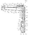
更に、扉枠ベースユニット100におけるハンドルブラケット140は、図25及び図26等に示すように、前後方向へ延びた円筒状の筒部141と、筒部141の後端から筒部141の軸に対して直角方向外方へ延びた円環状のフランジ部142と、筒部141内に突出し筒部141の周方向に対して不等間隔に配置された複数(本例では三つ)の突条143と、筒部141の外周面とフランジ部142の前面とを繋ぎ筒部141の周方向に対して複数配置された補強リブ144と、を備えている。このハンドルブラケット140は、フランジ部142の後面を、扉枠ベース本体110におけるハンドル取付部114の前面に当接させた状態で、所定のビスによってハンドル取付部114に取付けられるようになっており、図示は省略するが、ハンドル取付部114に取付けた状態で、筒部141の軸が配線通過口115と略一致するようになっている。
25 and 26, the handle bracket 140 in the door frame base unit 100 includes a cylindrical tubular portion 141 extending in the front-rear direction and a shaft extending from the rear end of the tubular portion 141 to the axis of the tubular portion 141. An annular flange portion 142 extending outward in a direction perpendicular to the opposite direction, and a plurality of (three in this example) protrusions projecting into the cylindrical portion 141 and arranged at uneven intervals in the circumferential direction of the cylindrical portion 141. 143 , and a plurality of reinforcing ribs 144 that connect the outer peripheral surface of the tubular portion 141 and the front surface of the flange portion 142 and are arranged in the circumferential direction of the tubular portion 141 . The handle bracket 140 is attached to the handle mounting portion 114 with a predetermined screw while the rear surface of the flange portion 142 is in contact with the front surface of the handle mounting portion 114 of the door frame base body 110. Although not shown, the axis of the cylindrical portion 141 is substantially aligned with the wire passage opening 115 when attached to the handle attachment portion 114 .
このハンドルブラケット140は、筒部141内の上側に一つ、下側に二つの突条143が備えられており、これら突条143はハンドル装置500におけるハンドルベース502の円筒部の外周に形成された三つの溝部502aと対応する位置に配置形成されている。そして、ハンドルブラケット140の三つの突条143と、ハンドル装置500の三つの溝部502aとが一致した状態でのみ、筒部141内にハンドル装置500の円筒部を挿入させることができるようになっている。従って、ハンドルブラケット140に挿入支持されたハンドル装置500のハンドルベース502は、ハンドルブラケット140に対して相対回転不能の状態に支持されるようになっている。
The handle bracket 140 is provided with two projections 143 on the upper side and two on the lower side in the cylindrical portion 141 . They are arranged and formed at positions corresponding to the three grooves 502a. The cylindrical portion of the handle device 500 can be inserted into the cylindrical portion 141 only when the three ridges 143 of the handle bracket 140 and the three grooves 502a of the handle device 500 are aligned. there is Accordingly, the handle base 502 of the handle device 500 inserted and supported by the handle bracket 140 is supported so as not to rotate relative to the handle bracket 140 .
なお、このハンドルブラケット140は、斜めに傾斜したハンドル取付部114に取付けることで、筒部141の軸が正面視で前方へ向かうに従って右側(開放側)へ向かうように延びるように取付けられ、この状態でハンドルブラケット140に支持されたハンドル装置500の軸も、同様に斜めに傾いた状態となるようになっている。
The handle bracket 140 is attached to the obliquely inclined handle attachment portion 114 so that the axis of the cylindrical portion 141 extends to the right (open side) as it goes forward in a front view. The shaft of the handle device 500 supported by the handle bracket 140 in this state is similarly tilted.
続いて、扉枠ベースユニット100における補強ユニット150は、主に図25及び図26に示すように、扉枠ベース本体110の上辺部裏面に沿って取付けられる上側補強板金151と、扉枠ベース本体110の軸支側辺部裏面に沿って取付けられる軸支側補強板金152と、扉枠ベース本体110の開放側辺部裏面に沿って取付けられる開放側補強板金153と、扉枠ベース本体110の遊技窓101の下辺裏面に沿って取付けられる下側補強板金154と、を備えており、それらが相互にビスやリベット等で締着されて方形状に形成されている。
25 and 26, the reinforcing unit 150 in the door-frame base unit 100 consists of an upper reinforcing sheet metal 151 attached along the rear surface of the upper side of the door-frame base body 110, and a door-frame base body. A support-side reinforcing sheet metal 152 attached along the back surface of the pivot-side side portion of the door-frame base body 110 , an opening-side reinforcing sheet metal 153 attached along the back surface of the open-side side portion of the door-frame base body 110 , and the door-frame base body 110 . A lower reinforcing sheet metal 154 attached along the back surface of the lower side of the game window 101 is provided, and they are fastened to each other with screws, rivets, or the like to form a rectangular shape.
この補強ユニット150は、図25に示すように、軸支側補強板金152の上下端部に、その上面に上下方向に摺動自在に設けられる軸ピン155を有する上軸支部156と、その下面に軸ピン157(図18を参照)を有する下軸支部158と、を一体的に備えている。そして、上下の軸ピン155,157が本体枠3の軸支側上下に形成される上軸支金具630及び下軸支金具640に軸支されることにより、扉枠5が本体枠3に対して開閉自在に軸支されるようになっている。
As shown in FIG. 25, this reinforcing unit 150 includes an upper shaft supporting portion 156 having a shaft pin 155 slidably provided on the upper surface thereof at the upper and lower ends of a supporting side reinforcing sheet metal 152, and a lower surface thereof. and a lower shaft support portion 158 having a shaft pin 157 (see FIG. 18). The upper and lower shaft pins 155 and 157 are pivotally supported by the upper and lower shaft support fittings 630 and 640 formed on the upper and lower sides of the body frame 3 on the shaft support side, so that the door frame 5 is attached to the body frame 3. It is pivotally supported so that it can be freely opened and closed.
また、補強ユニット150の下側補強板金154は、所定幅を有して扉枠ベース本体110の横幅寸法と略同じ長さに形成され、その長辺の両端縁のうち下方長辺端縁に前方へ向って折曲した下折曲突片159と(図25を参照)、上方長辺端縁の正面視右側(開放側)部に前方へ向って折曲した上折曲突片160と、上方長辺端縁の中央部分に後方へ折曲した上で垂直方向に延設された垂直折曲突片161と、を備えている。この下側補強板金154は、下折曲突片159や上折曲突片160等によって強度が高められている。また、この下側補強板金154の垂直折曲突片161は、後述するガラスユニット590のユニット枠592の下端に形成された係止片592bと係合係止するように形成されており、ガラスユニット590を扉枠5の裏面側に固定した時に、垂直折曲突片161がガラスユニット590におけるユニット枠592の係止片592bが係止されることで、ガラスユニット590の下端が左右方向及び後方へ移動するのを規制することができるようになっている。なお、下側補強板金154には、扉枠ベース本体110の切欠部101aと略対応した切欠部162が形成されている。
Further, the lower reinforcing sheet metal 154 of the reinforcing unit 150 has a predetermined width and is formed to have a length substantially equal to the width dimension of the door frame base body 110. A lower bent projecting piece 159 bent forward (see FIG. 25), and an upper bent projecting piece 160 bent forward on the right side (open side) of the upper long side edge in front view. and a vertically bent projecting piece 161 which is bent backward at the central portion of the upper long side edge and extends vertically. The strength of the lower reinforcing sheet metal 154 is increased by a lower bending projecting piece 159, an upper bending projecting piece 160, and the like. Further, the vertically bent projecting piece 161 of the lower reinforcing sheet metal 154 is formed so as to be engaged and locked with a locking piece 592b formed at the lower end of the unit frame 592 of the glass unit 590, which will be described later. When the unit 590 is fixed to the back side of the door frame 5, the vertically bent projecting piece 161 is engaged with the locking piece 592b of the unit frame 592 of the glass unit 590, so that the lower end of the glass unit 590 is horizontally and vertically bent. It is designed to be able to restrict backward movement. The lower reinforcing sheet metal 154 is formed with a notch 162 substantially corresponding to the notch 101 a of the door frame base body 110 .
また、補強ユニット150の開放側補強板金153は、上側補強板金151と下側補強板金154との間の長辺の両側に、後方へ向かって屈曲された開放側外折曲突片163と、開放側内折曲突片164とを備えており、図示するように、開放側外折曲突片163よりも開放側内折曲突片164の方が後方へ長く延び出したように形成されている。また、開放側補強板金153の後側下部には、後述する錠装置1000の扉枠用フック部1041と当接するフックカバー165が備えられている。更に、軸支側補強板金152には、その長辺の外側端に後方へ延び出すと共に軸支側の外側に開口したコ字状の軸支側コ字状突片166を備えている(図108を参照)。また、上側補強板金151は、その長辺の両側に後方へ向かって屈曲された屈曲突片167を夫々備えている。
In addition, the open-side reinforcing sheet metal 153 of the reinforcing unit 150 includes open-side outward bending projecting pieces 163 bent rearward on both sides of the long side between the upper reinforcing sheet metal 151 and the lower reinforcing sheet metal 154, As shown in the figure, the opening-side inward bending projection 164 is formed to extend longer rearward than the opening-side outward bending projection 163 . ing. A hook cover 165 is provided on the lower rear side of the open-side reinforcing sheet metal 153 so as to abut on a door frame hook portion 1041 of the lock device 1000, which will be described later. Further, the support-side reinforcing sheet metal 152 is provided with a support-side U-shaped protruding piece 166 extending rearward from the outer end of the long side thereof and opening outward on the support side (Fig. 108). In addition, the upper reinforcing sheet metal 151 is provided with bending projecting pieces 167 bent rearward on both sides of its long sides.
この補強ユニット150の軸支側補強板金152は、本体枠3に対して上軸支部156と下軸支部158の上下の二点でのみ取付支持されるようになっているので、軸支側の扉枠5と本体枠3との間にドライバーやバール等の不正な工具が差込まれると、軸支側補強板金152が変形して扉枠5と本体枠3との隙間が大きくなって不正行為を行い易くなる虞があるが、本例の軸支側補強板金152では、軸支側コ字状突片166を備えているので、軸支側補強板金152の強度がより高められており、軸支側補強板金152が曲がり難くなっている。また、軸支側補強板金152の軸支側コ字状突片166は、そのコ字内に後述する本体枠3における側面防犯板950における前端片952bが挿入されるようになっており(図108を参照)、工具の挿入を阻止することができると共に、軸支側補強板金152のみが曲がるのを防止することができ、パチンコ機1の防犯機能を高めることができるようになっている。
The support-side reinforcing sheet metal 152 of the reinforcement unit 150 is attached to and supported by the body frame 3 only at two points above and below the upper support portion 156 and the lower support portion 158. If an unauthorized tool such as a screwdriver or a crowbar is inserted between the door frame 5 and the main body frame 3, the shaft support side reinforcing sheet metal 152 is deformed and the gap between the door frame 5 and the main body frame 3 becomes larger, resulting in an illegal operation. Although there is a risk that the action may become easier, the support-side reinforcement sheet metal 152 of this example includes the support-side U-shaped projecting piece 166, so that the strength of the support-side reinforcement sheet metal 152 is further increased. , the shaft supporting side reinforcing sheet metal 152 is difficult to bend. Further, the support-side U-shaped projecting piece 166 of the support-side reinforcing sheet metal 152 is designed such that a front end piece 952b of a side crime prevention plate 950 of the main body frame 3, which will be described later, is inserted into the U-shape (Fig. 108), it is possible to prevent the insertion of a tool, and it is possible to prevent only the support-side reinforcing sheet metal 152 from bending, so that the security function of the pachinko machine 1 can be enhanced.
次に、扉枠5における扉枠ベースユニット100の防犯カバー180について、主に図25及び図26を参照して説明する。この防犯カバー180は、上記したガラスユニット590の下部裏面を被覆して遊技盤4への不正具の侵入を防ぐ防犯機能が付与されたものであり、図示するように、透明な合成樹脂によって左右の補強板金152,153の間に配されるガラスユニット590の下方部を覆うような平板状に形成され、その上辺部にて円弧状に形成された当接凹部181と、当接凹部181の上端に沿って後方に向って突出する防犯後突片182と、を備えている。また、防犯カバー180の左右両端には、その端部形状に沿って後方へ突出する防犯後端部突片183が夫々備えられている。なお、背面視で右側(軸支側)の防犯後端部突片183は、反対側(開放側)の防犯後端部突片183よりも後方へ長く延びだした形態となっている。一方、防犯カバー180の前面には、防犯カバー180を取付けた状態でガラスユニット590におけるユニット枠592の下方形状に沿って突設する防犯前突片184と、防犯前突片184の外側で左右の下部端に前方へ突出するU字状の装着弾性片185と、を備えている。
Next, the security cover 180 of the door frame base unit 100 in the door frame 5 will be described mainly with reference to FIGS. 25 and 26. FIG. The crime prevention cover 180 covers the lower back surface of the glass unit 590 and has a crime prevention function to prevent unauthorized devices from entering the game board 4. The contact recess 181 is formed in a flat plate shape to cover the lower part of the glass unit 590 disposed between the reinforcing metal plates 152 and 153, and the contact recess 181 is formed in an arc shape at the upper side of the plate. A security rear projecting piece 182 projecting rearward along the upper end is provided. Further, security rear end projecting pieces 183 are provided at both left and right ends of the security cover 180 so as to protrude rearward along the edge shape thereof. In addition, the crime prevention rear end projection 183 on the right side (rotary support side) in the rear view extends longer rearward than the crime prevention rear end projection 183 on the opposite side (open side). On the other hand, on the front surface of the security cover 180, a crime prevention front projecting piece 184 projecting along the lower shape of the unit frame 592 of the glass unit 590 with the crime prevention cover 180 attached, and left and right security projection pieces 184 on the outside of the crime prevention front projection piece 184. A U-shaped mounting elastic piece 185 protruding forward is provided at the lower end of the .
この防犯カバー180は、正面視で右側(開放側)の装着弾性片185を扉枠ベースユニット100の防犯カバー装着部119に装着すると共に、反対側(軸支側)の装着弾性片185を皿ユニット300の防犯カバー装着部364に装着することで、扉枠5の裏面側に着脱自在に取付けられるようになっている。この防犯カバー180を、扉枠5に取付けた状態では、詳細な図示は省略するが、防犯前突片184がガラスユニット590のユニット枠592の下部外周と嵌合するようになっていると共に、ユニット枠592の下端部後面が垂直折曲突片161と当接するようになっている。また、後方へ突出した防犯後突片182は、扉枠5を閉じた時に、軸支側の半分が遊技盤4に固定された内レールの下側面に挿入され、開放側の半分が前構成部材1110における内レールのレール防犯溝1118に挿入された状態となるようになっている。これにより、遊技盤4の遊技領域1100に不正な工具を侵入させようとしても、内レールの下側に挿入された防犯後突片182によりその侵入を阻止することができるようになっている。
In this security cover 180, the attachment elastic piece 185 on the right side (open side) in a front view is attached to the security cover attachment portion 119 of the door frame base unit 100, and the attachment elastic piece 185 on the opposite side (rotary support side) is attached to the plate. By attaching it to the crime prevention cover attachment part 364 of the unit 300, it can be detachably attached to the back side of the door frame 5. - 特許庁When the crime prevention cover 180 is attached to the door frame 5, although detailed illustration is omitted, the crime prevention front projecting piece 184 is fitted to the outer periphery of the lower portion of the unit frame 592 of the glass unit 590. The rear surface of the lower end portion of the unit frame 592 abuts on the vertically bent projecting piece 161 . In addition, when the door frame 5 is closed, the anti-crime rear projecting piece 182 projecting backward is inserted into the lower surface of the inner rail fixed to the game board 4 at the half on the pivot side, and the half on the open side is the front configuration. It is inserted into the rail security groove 1118 of the inner rail of the member 1110 . As a result, even if an illegal tool tries to enter the game area 1100 of the game board 4, the security rear projecting piece 182 inserted under the inner rail can prevent the entry.
なお、防犯カバー180は、その裏面によって、扉枠5を閉じた状態で外レールと内レールとで形成される打球の誘導通路の前面下方部分を覆うことができるようになっているので、誘導通路部分を飛送若しくは逆送する打球のガラス板594への衝突を防止することができるようになっている。
The back surface of the security cover 180 can cover the lower front portion of the guide passage for the hit ball formed by the outer rail and the inner rail when the door frame 5 is closed. It is possible to prevent the hitting of the ball flying or reversed through the passage portion from colliding with the glass plate 594 .
これにより、本例では、防犯カバー180で扉枠5におけるガラスユニット590(遊技窓101)の後側下部外周を覆うようにしているので、扉枠5の前側から遊技窓101とガラスユニット590との間に可撓性の高い工具を挿入してパチンコ機1内(遊技領域1100内)に対して不正行為を行おうとしても、防犯カバー180によって工具の侵入を阻止することができ、不正行為等に対してより安全性の高いパチンコ機1とすることができるようになっている。
As a result, in this example, since the crime prevention cover 180 covers the rear lower periphery of the glass unit 590 (game window 101) in the door frame 5, the game window 101 and the glass unit 590 are separated from the front side of the door frame 5. Even if a highly flexible tool is inserted between the holes to commit fraud in the pachinko machine 1 (inside the game area 1100), the crime prevention cover 180 prevents the tool from entering, thereby preventing fraudulent activity. Thus, the pachinko machine 1 can be made to have higher safety against such as.
続いて、扉枠ベースユニット100における四つのガラスユニット係止部材190は、扉枠ベース本体110から後方へ突出する係止部材取付部110bに対して回動可能に嵌合する嵌合部190aと、嵌合部190aの軸方向に対して直角方向へ延出しガラスユニット590の係止突片451fを係止する係止片190bと、を備えている。このガラスユニット係止部材190は、嵌合部190aに対して扉枠ベース本体110の係止部材取付部110bが貫通した状態で、係止部材取付部110bの先端に抜止め用のビスを固定することで、係止部材取付部110bに対して回転可能に軸支されるようになっている。
Subsequently, the four glass unit locking members 190 in the door frame base unit 100 are fitted with fitting portions 190a that are rotatably fitted to the locking member mounting portions 110b projecting rearward from the door frame base body 110. , and a locking piece 190b that extends in a direction perpendicular to the axial direction of the fitting portion 190a and locks the locking projecting piece 451f of the glass unit 590. As shown in FIG. The glass unit locking member 190 has a locking screw attached to the tip of the locking member mounting portion 110b in a state in which the locking member mounting portion 110b of the door frame base body 110 passes through the fitting portion 190a. By doing so, it is rotatably pivotally supported with respect to the locking member mounting portion 110b.
このガラスユニット係止部材190の係止片190bは、詳細な図示は省略するが、後側に後方へ突出した突条を有しており、この突条がガラスユニット590の着脱時において、回転操作する際の指掛りとなっている。
Although detailed illustration is omitted, the locking piece 190b of the glass unit locking member 190 has a ridge projecting rearward to the rear side. It serves as a finger grip for operation.
また、扉枠ベースユニット100における発射カバー191は、補強ユニット150における下側補強板金154の後側に固定されるようになっている。また、ハンドル装置中継基板カバー193及び扉枠ベース基板カバー195は、夫々扉枠ベース110の後側の所定位置に固定されるようになっている。なお、扉枠ユニットベース100に対して発射カバー191、ハンドル装置中継基板カバー193、及び球送りユニット580を取付けた状態では、それらの後面が略同一面状となるようになっており、それらによって本体枠3に取付けられる打球発射装置650の前面を被覆することができるようになっている。
Also, the launch cover 191 in the door frame base unit 100 is fixed to the rear side of the lower reinforcing sheet metal 154 in the reinforcing unit 150 . Also, the handle device relay board cover 193 and the door frame base board cover 195 are fixed to predetermined positions on the rear side of the door frame base 110, respectively. In addition, when the launch cover 191, the handle device relay board cover 193, and the ball feed unit 580 are attached to the door frame unit base 100, their rear surfaces are substantially flush with each other. The front surface of the ball shooting device 650 attached to the body frame 3 can be covered.
[1-2B.右サイド装飾ユニット]
続いて、扉枠5における右サイド装飾ユニット200について、主に図29乃至図31を参照して説明する。本実施形態における扉枠5の右サイド装飾ユニット200は、図示するように、遊技窓101の前側外周のうち、正面視で下部を除く右側半分を装飾するものであり、内側が遊技窓101に沿って円弧状に形成されていると共に、外側が扉枠ベースユニット100の外周に沿って直線状に形成されている。この右サイド装飾ユニット200は、右サイド装飾ユニット200の外面を形成し略紡錘状の複数の湾曲面を有したサイドレンズ210と、サイドレンズ210の後側に配置されるサイドインナーレンズ212と、サイドインナーレンズ212の後側で上下方向の略中央から上側に配置され表面に複数のLED214a(フルカラーLED),214b(白色LED)が実装された右サイド上装飾基板214と、下側でサイドインナーレンズ212の上下方向の略中央から下側に配置され表面に複数のLED216a(フルカラーLED),216b(白色LED)が実装された右サイド下装飾基板216と、右サイド上装飾基板214の後側を覆い右サイド上装飾基板214を挟むようにサイドインナーレンズ212に取付けられる右サイド上装飾基板カバー218と、右サイド下装飾基板216の後側を覆い右サイド下装飾基板216を挟むようにサイドレンズ210及びサイド装飾フレーム202に取付けられる右サイド下装飾基板カバー220と、を備えている。
[1-2B. right side decorative unit]
Next, the right side decoration unit 200 in the door frame 5 will be described mainly with reference to FIGS. 29 to 31. FIG. The right side decoration unit 200 of the door frame 5 in this embodiment, as illustrated, decorates the right half of the front outer periphery of the game window 101 excluding the lower part in front view, and the inside is the game window 101. The outer side is formed in a straight line along the outer periphery of the door frame base unit 100 . The right side decoration unit 200 includes a side lens 210 that forms the outer surface of the right side decoration unit 200 and has a plurality of substantially spindle-shaped curved surfaces, a side inner lens 212 that is arranged behind the side lens 210, A right side upper decorative substrate 214 arranged above from the approximate center in the vertical direction on the rear side of the side inner lens 212 and having a plurality of LEDs 214a (full color LED) and 214b (white LED) mounted on the surface, and a side inner on the lower side. A right side lower decoration substrate 216 arranged below the lens 212 from the center in the vertical direction and having a plurality of LEDs 216a (full-color LEDs) and 216b (white LEDs) mounted on the surface, and a right side upper decoration substrate 214 on the rear side. and a right side upper decorative board cover 218 attached to the side inner lens 212 so as to cover the right side upper decorative board 214 and cover the rear side of the right side lower decorative board 216 so as to hold the right side lower decorative board 216 therebetween. a right side lower decorative substrate cover 220 attached to the lens 210 and the side decorative frame 202;
また、右サイド装飾ユニット200は、サイドレンズ210の右上隅に取付けられるサイドアウターカバー202と、サイドレンズ210の前面で且つ遊技窓101の周方向に所定間隔で配置されると共に遊技窓101の略中央を中心として放射状に延びた複数のサイド閃光レンズ204と、サイドインナーレンズ212における左上部とサイドレンズ210との間に配置されるサイド上部インナーレンズ206と、サイド上部インナーレンズ206をサイドインナーレンズ212に取付けるためのインナーレンズブラケット208と、サイド上部インナーレンズ206に取付けられる右上部スピーカ222と、を備えている。
In addition, the right side decoration unit 200 includes a side outer cover 202 attached to the upper right corner of the side lens 210, and a side outer cover 202 which is arranged in front of the side lens 210 and in the circumferential direction of the game window 101 at predetermined intervals. A plurality of side flashing lenses 204 radially extending from the center, a side upper inner lens 206 arranged between the upper left part of the side inner lens 212 and the side lens 210, and the side upper inner lens 206 as the side inner lens. 212 and an upper right speaker 222 attached to the side upper inner lens 206 .
この右サイド装飾ユニット200は、サイドアウターカバー202、サイド閃光レンズ204、サイド上部インナーレンズ205、インナーレンズブラケット208、サイドレンズ210、及びサイドインナーレンズ212が、透光性の部材によって形成されており、サイドアウターカバー202、サイド上部インナーレンズ205、インナーレンズブラケット208、サイドレンズ210、及びサイドインナーレンズ212が略無色透明に、サイド閃光レンズ204が有色透明(本例では赤色)とされている。
In this right side decoration unit 200, the side outer cover 202, the side flashing lens 204, the side upper inner lens 205, the inner lens bracket 208, the side lens 210, and the side inner lens 212 are formed of translucent members. , the side outer cover 202, the side upper inner lens 205, the inner lens bracket 208, the side lens 210, and the side inner lens 212 are substantially colorless and transparent, and the side flashing lens 204 is colored and transparent (red in this example).
なお、詳細な図示は省略するが、サイドインナーレンズ212及びサイド上部インナーレンズ206の表面には、複数の小径レンズが形成されており、光を乱屈折させることができるようになっている。そのため、サイドレンズ210、サイドインナーレンズ212、及びサイド上部インナーレンズ206の後側に配置された右サイド上装飾基板214や右サイド下装飾基板216の表面(前面)に実装されたLED214a,214b,216a,216b等が、遊技者側から明確に視認することができないようになっている。また、右サイド上装飾基板214や右サイド下装飾基板216の前面は、白色とされており、実装されたLED214a,214b,216a,216b等の光によって右サイド装飾ユニット200を効率良く発光装飾させることができるようになっていると共に、LED214a,214b,216a,216bが非点灯時に各装飾基板214,216が目立たないようになっている。なお、右サイド上装飾基板214及び右サイド下装飾基板216は、夫々周辺制御基板4010と接続されており、周辺制御基板4010からの駆動信号(発光駆動信号)により各LED214a,214b,214c,216a,216bを適宜発光させて、右サイド装飾ユニット200を発光装飾させることができるようになっている。
Although detailed illustration is omitted, a plurality of small-diameter lenses are formed on the surfaces of the side inner lens 212 and the side upper inner lens 206 so that light can be irregularly refracted. Therefore, LEDs 214a, 214b, 214b, 214b, 214b, 214b, 214b, 214b, 214b, 214b, 214b, 214b, 214b, 214b, 214b, 214b, 214b, 214b, 214b, 214b, 214b, 214b, 214b, 214b, 214b, 214b, 214b, 214b, 214b, 214b, 214b, 214b, 214b, 214b, 214b, 214b, 214b, 214b, 214b, 214b, 214b, 214b, 214b, 214b, 214b, 214b, 214b, 214b respectively 216a, 216b, etc. cannot be clearly seen by the player. In addition, the front surfaces of the upper right side decoration board 214 and the lower right side decoration board 216 are white, and the right side decoration unit 200 is efficiently illuminated and decorated by the light from the mounted LEDs 214a, 214b, 216a, 216b. In addition, when the LEDs 214a, 214b, 216a, 216b are off, the decorative substrates 214, 216 are inconspicuous. The right side upper decoration board 214 and the right side lower decoration board 216 are connected to the peripheral control board 4010, respectively, and the LEDs 214a, 214b, 214c and 216a are controlled by drive signals (light emission drive signals) from the peripheral control board 4010. , 216b to emit light, and the right side decoration unit 200 can be decorated with light.
本例の右サイド装飾ユニット200におけるサイドレンズ210は、図示するように、正面視で右端及び上端が扉枠ベース本体110の外周に沿った直線状に形成されていると共に、左端が遊技窓101の右側外周に沿った湾曲状に形成されている。このサイドレンズ210は、略紡錘状の複数の湾曲面からなる周レンズ部210aと、周レンズ部210aを遊技窓101の周方向へ複数に分割すると共に遊技窓101と略同心円状に延びた複数のプリズム面からなる放射レンズ部210bと、を備えている。このサイドレンズ210における複数の放射レンズ部210bは、図示するように、正面視で遊技窓101の中央下部を中心とした放射線上に延びるように形成されていると共に、周レンズ部210aの前面よりも後方へ窪んだ状態に形成されており、その窪みにサイド閃光レンズ204が挿入されるようになっている。
As shown in the figure, the side lens 210 in the right side decoration unit 200 of this example has the right end and the upper end linearly formed along the outer periphery of the door frame base main body 110 when viewed from the front, and the left end is the game window 101. It is formed in a curved shape along the outer periphery of the right side. The side lens 210 includes a peripheral lens portion 210a composed of a plurality of substantially spindle-shaped curved surfaces, and a plurality of peripheral lens portions 210a which are divided in the circumferential direction of the game window 101 and extend substantially concentrically with the game window 101. and a radiation lens portion 210b consisting of a prism surface of . A plurality of radiation lens portions 210b in the side lens 210 are formed so as to extend radially from the center lower portion of the game window 101 in a front view, as shown in the figure, and from the front surface of the peripheral lens portion 210a. is recessed rearward, and the side flash lens 204 is inserted into the recess.
また、サイドレンズ210は、右側面に、前後方向へ延びると共に上下方向へ列設されたサイド拡散レンズ部210cを備えている。このサイド拡散レンズ部210cにより、右サイド上装飾基板214及び右サイド下装飾基板216からの光をパチンコ機1の右方向及び上下方向へ広く拡散させることができるようになっている。なお、詳細な図示は省略するが、サイドレンズ210における右上部スピーカの下側に該当する部位には、複数の貫通孔が形成されており、右上部スピーカからのサウンドを遊技者側へ良好に伝達させることができるようになっている。
In addition, the side lens 210 has a side diffusion lens portion 210c extending in the front-rear direction and arranged in rows in the vertical direction on the right side surface. The side diffusing lens portion 210c can widely diffuse the light from the right side upper decoration substrate 214 and the right side lower decoration substrate 216 in the right direction and the vertical direction of the pachinko machine 1. FIG. Although detailed illustration is omitted, a plurality of through holes are formed in a portion of the side lens 210 corresponding to the lower side of the upper right speaker, so that the sound from the upper right speaker can be transmitted to the player side. It is designed so that it can be transmitted.
サイドインナーレンズ212は、略無色透明でサイドレンズ210の内部に後側から挿入嵌合されるものであり、図示するように、サイドレンズ210における周レンズ部210aと対応した部位がシワ状に形成されていると共に、放射レンズ部210bと対応した部位が平坦面状に形成されている。また、詳細な図示は省略するが、サイドインナーレンズ212は、サイドレンズ210の周レンズ部210aに対応したシワ状の部位における前方へ突出した山部に複数の小径レンズが形成されている。このサイドインナーレンズ212は、シワ状の部位と複数の小径レンズとによって光を乱屈折及び乱反射させることができ、前側に配置されるサイドレンズ210と協同して右サイド装飾ユニット200の外観をキラキラさせると共に遠近感が不明瞭な不思議な感じに見せることができるようになっている。
The side inner lens 212 is substantially colorless and transparent, and is inserted and fitted into the side lens 210 from the rear side. In addition, a portion corresponding to the radiation lens portion 210b is formed to have a flat surface. Further, although detailed illustration is omitted, the side inner lens 212 has a plurality of small-diameter lenses formed on the crests protruding forward in the wrinkled portion corresponding to the peripheral lens portion 210 a of the side lens 210 . The side inner lens 212 can irregularly refract and irregularly reflect light with a wrinkled portion and a plurality of small-diameter lenses, and cooperates with the side lens 210 arranged on the front side to make the appearance of the right side decoration unit 200 sparkling. At the same time, it is possible to show a mysterious feeling in which the sense of perspective is unclear.
右サイド装飾ユニット200の右サイド上装飾基板214及び右サイド下装飾基板216は、表面に高輝度のカラーLEDが複数実装されており、サイドレンズ210の周レンズ部210aと対応する位置に配置されたLED214a,216aは比較的照射角度の広いもの(例えば、60゜~180゜)が用いられており、サイドレンズ210の放射レンズ部210bと対応する位置に配置されたLED214b,216bは比較的照射角度の狭いもの(例えば、15゜~60゜)が用いられている。なお、右サイド上装飾基板214のLED214cは、本例では、赤色と緑色のLEDとされている。
A plurality of high-intensity color LEDs are mounted on the surfaces of the right side upper decoration substrate 214 and the right side lower decoration substrate 216 of the right side decoration unit 200, and are arranged at positions corresponding to the peripheral lens portions 210a of the side lenses 210. The LEDs 214a and 216a have a relatively wide irradiation angle (for example, 60° to 180°), and the LEDs 214b and 216b arranged at a position corresponding to the radiation lens portion 210b of the side lens 210 have a relatively wide irradiation angle. Narrower angles (eg, 15° to 60°) are used. In this example, the LEDs 214c of the upper right decorative board 214 are red and green LEDs.
右サイド装飾ユニット200の右上部スピーカ222は、サイドスピーカ130と同様に、中高音域の音を出力するものであり、サイド上部インナーレンズ206により所定位置に所定方向へ向けて取付けられるようになっている。この右上部スピーカ222を支持するサイド上部インナーレンズ206は、正面視でパチンコ機1の左右中央で斜め前下方に向かって延びた円筒状のホーン部を備えており、ホーン部の上端裏側に、右上部スピーカ222が固定されて正面視では右上部スピーカ222が遊技者側から見えないようになっている。
The upper right speaker 222 of the right side decorative unit 200 outputs sounds in the mid-to-high range similarly to the side speaker 130, and is mounted at a predetermined position in a predetermined direction by means of the side upper inner lens 206. ing. The side upper inner lens 206 that supports the upper right speaker 222 has a cylindrical horn portion that extends obliquely forward and downward at the left and right center of the pachinko machine 1 when viewed from the front. The upper right speaker 222 is fixed so that the upper right speaker 222 cannot be seen from the player side when viewed from the front.
本例の右上部スピーカ222は、サイド上部インナーレンズ206のホーン部によって、パチンコ機1の上部から下方の遊技者へ向かって発せられるようになっており、他のパチンコ機に対して騒音に為り難いようになっている。なお、このサイド上部インナーレンズ206もまた、サイドインナーレンズ212と同様に、その前面がシワ状に形成されていると共に、シワ状の部位における前方へ突出した山部に複数の小径レンズが形成されており、シワ状の部位と複数の小径レンズとによって光を乱屈折及び乱反射させることができるようになっている。
The upper right speaker 222 of this example emits sound from the upper part of the pachinko machine 1 toward the player below by means of the horn part of the side upper inner lens 206, thereby making noise in relation to other pachinko machines. It is becoming difficult to As with the side inner lens 212, the side upper inner lens 206 also has a wrinkled front surface, and a plurality of small-diameter lenses are formed on the forward protruding ridges of the wrinkled portion. The wrinkled portion and the plurality of small-diameter lenses can refract and reflect light irregularly.
右サイド装飾ユニット200のサイド閃光レンズ204は、サイドレンズ210の後方へ窪んだ放射レンズ部210bの前側に挿入配置されるようになっており、紡錘状の複数の湾曲面によりゴツゴツした岩場を模したサイドレンズ210にアクセントを付けることができるようになっている。また、サイド閃光レンズ204は、後側に配置される右サイド上装飾基板214及び右サイド下装飾基板216のLED214b,216aの発光により、放射状の発光演出を行うことができると共に、周レンズ部210aを遊技窓101の周方向へ分割させて夫々を強調させることができるようになっている。
The side flashing lens 204 of the right side decoration unit 200 is arranged to be inserted in front of the radiation lens portion 210b recessed to the rear of the side lens 210, and simulates a rugged rocky area with a plurality of spindle-shaped curved surfaces. The side lens 210 can be accented. In addition, the side flashing lens 204 can perform radial light emission effect by light emission of the LEDs 214b and 216a of the right side upper decorative substrate 214 and the right side lower decorative substrate 216 arranged on the rear side, and the peripheral lens portion 210a. are divided in the circumferential direction of the game window 101 so that each can be emphasized.
[1-2C.左サイド装飾ユニット]
続いて、扉枠5における左サイド装飾ユニット240について、主に図32乃至図36を参照して説明する。本実施形態における扉枠5の左サイド装飾ユニット240は、図示するように、遊技窓101の前側外周のうち、正面視で下部を除く左側半分を装飾するものであり、右側が遊技窓101に沿って円弧状に形成されていると共に、左側及び上側が扉枠ベースユニット100の外周に沿って直線状に形成されており、右サイド装飾ユニット200とは非対称に形成されている。この左サイド装飾ユニット240は、右サイド装飾ユニット200の幅と略同じ幅で遊技窓101の周方向へ延びた複数の大窓枠242a、及び大窓枠242a同士の間に配置される楕円状の小窓枠242bを有した枠状のサイド下装飾フレーム242と、サイド下装飾フレーム242の上側に連続し遊技窓101の周方向へ延びると共に列設された二つの大窓枠244a、及び大窓枠244a同士の間に配置される一つの楕円状の小窓枠244bを有した枠状のサイド上装飾フレーム244と、を備えている。
[1-2C. Left side decorative unit]
Next, the left side decoration unit 240 in the door frame 5 will be described mainly with reference to FIGS. 32 to 36. FIG. The left side decoration unit 240 of the door frame 5 in this embodiment, as shown, decorates the left half of the front outer circumference of the game window 101 excluding the lower part when viewed from the front, and the game window 101 on the right side. The left side and the upper side are formed in a straight line along the outer periphery of the door frame base unit 100, and are formed asymmetrically with the right side decorative unit 200. - 特許庁The left side decoration unit 240 includes a plurality of large window frames 242a extending in the circumferential direction of the game window 101 with substantially the same width as the right side decoration unit 200, and elliptical windows arranged between the large window frames 242a. A frame-shaped lower side decorative frame 242 having a small window frame 242b, two large window frames 244a continuous to the upper side of the side lower decorative frame 242 and extending in the circumferential direction of the game window 101 and arranged in a row, and a large A frame-shaped side upper decorative frame 244 having one elliptical small window frame 244b arranged between the window frames 244a is provided.
また、左サイド装飾ユニット240は、サイド下装飾フレーム242及びサイド上装飾フレーム244の各小窓枠242a,244aに対して後側から嵌込まれるサイド閃光レンズ246と、サイド閃光レンズ246を後側から支持すると共にサイド下装飾フレーム242及びサイド上装飾フレーム244の大窓枠242a,244aに対して後側から嵌込まれる周レンズ部250aを複数有した透明なサイドレンズ250と、サイドレンズ250における周レンズ部250aの後側に配置され遊技窓101の周方向に延びた複数のスリット251aが形成され表面に金属光沢を有するメッキ層を備えたインナー装飾部材251と、インナー装飾部材251の後側に配置され遊技窓101の左右中央下部を中心とした放射状に延びる複数の帯状レンズにより形成された拡散部252aを有するサイドインナーレンズ252と、を備えている。
In addition, the left side decoration unit 240 includes a side flashing lens 246 fitted from the rear side into the small window frames 242a and 244a of the side lower decoration frame 242 and the side upper decoration frame 244, and the side flashing lens 246 on the rear side. a transparent side lens 250 having a plurality of peripheral lens portions 250a which are supported from the rear side and are fitted from the rear side into the large window frames 242a and 244a of the side lower decorative frame 242 and the side upper decorative frame 244; An inner decorative member 251 provided with a plurality of slits 251a arranged behind the peripheral lens portion 250a and extending in the circumferential direction of the game window 101 and provided with a plated layer having metallic luster on the surface, and the rear side of the inner decorative member 251. and a side inner lens 252 having a diffusing portion 252a formed by a plurality of belt-shaped lenses arranged radially around the lower left and right central portions of the game window 101. As shown in FIG.
また、左サイド装飾ユニット240は、サイドインナーレンズ252の後側で上下方向の略中央から上側に配置され表面に複数のLED254a(フルカラーLED),254b(白色LED)が実装された左サイド上装飾基板254と、下側でサイドインナーレンズ252の上下方向の略中央から下側に配置され表面に複数のLED256a(フルカラーLED),256b(白色LED)が実装された左サイド下装飾基板256と、左サイド上装飾基板254の後側を覆い左サイド上装飾基板254を挟むようにサイドインナーレンズ252に取付けられる左サイド上装飾基板カバー258と、左サイド下装飾基板256の後側を覆い左サイド下装飾基板256を挟むようにサイドレンズ250に取付けられる左サイド下装飾基板カバー260と、を備えている。
Also, the left side decoration unit 240 is arranged on the rear side of the side inner lens 252 from the approximate center in the vertical direction to the upper side, and has a plurality of LEDs 254a (full color LEDs) and 254b (white LEDs) mounted on the surface. a substrate 254, and a left side lower decorative substrate 256 arranged below from the approximate center in the vertical direction of the side inner lens 252 and having a plurality of LEDs 256a (full color LEDs) and 256b (white LEDs) mounted on the surface thereof; A left side upper decorative board cover 258 which covers the rear side of the left side upper decorative board 254 and is attached to the side inner lens 252 so as to sandwich the left side upper decorative board 254, and a left side cover which covers the rear side of the left side lower decorative board 256. and a left side lower decorative substrate cover 260 attached to the side lens 250 so as to sandwich the lower decorative substrate 256. - 特許庁
更に、左サイド装飾ユニット240は、サイドインナーレンズ252の前側且つ正面視右上部に配置される左上部スピーカ262と、左上部スピーカ262を支持しサイドインナーレンズ252の前面右上部に取付けられる透明な上部スピーカブラケット264と、上部スピーカブラケット264の前面に取付けられ正面視右上のインナー装飾部材251内に後側から挿入され左右中央下部を中心とした放射状に延びる複数の帯状レンズにより形成された拡散部266aを有する右上インナーレンズ266と、を備えている。なお、左上部スピーカ262は、サウンドを透過可能な金属板からなる保護板268を挟むように上部スピーカブラケット264に取付けられている。
Further, the left side decoration unit 240 includes an upper left speaker 262 arranged in front of the side inner lens 252 and in the upper right part when viewed from the front, and a transparent transparent speaker 262 which supports the upper left speaker 262 and is attached to the front upper right part of the side inner lens 252 . A diffuser portion formed by an upper speaker bracket 264 and a plurality of band-shaped lenses that are attached to the front surface of the upper speaker bracket 264 and are inserted into the inner decorative member 251 on the upper right in front view from the rear side and extend radially around the lower left and right center. a right upper inner lens 266 having 266a. The upper left speaker 262 is attached to the upper speaker bracket 264 so as to sandwich a protective plate 268 made of a metal plate through which sound can pass.
この左サイド装飾ユニット240は、サイド下装飾フレーム242、サイド上装飾フレーム244、左サイド上装飾基板カバー258、及び左サイド下装飾基板カバー260が不透光性の部材によって形成されており、インナー装飾部材251の表面には所定色(本例では、銀色)のメッキ層が備えられている。また、サイド閃光レンズ246は、透光性を有し全体が乳白色の合成樹脂により形成されている。また、サイドレンズ250、サイドインナーレンズ252、上部スピーカブラケット264、及び右上インナーレンズ266は、略無色透明の合成樹脂によって形成されている。
In this left side decoration unit 240, the side lower decoration frame 242, the side upper decoration frame 244, the left side upper decoration board cover 258, and the left side lower decoration board cover 260 are formed of opaque members. A plated layer of a predetermined color (in this example, silver) is provided on the surface of the decorative member 251 . The side flash lens 246 is made of translucent synthetic resin and is entirely made of opaque white synthetic resin. Also, the side lens 250, the side inner lens 252, the upper speaker bracket 264, and the upper right inner lens 266 are made of substantially colorless and transparent synthetic resin.
なお、本例では、サイド下装飾フレーム242及びサイド上装飾フレーム244における夫々の小窓枠242b,244bの両側(遊技窓101の左右中央下部を中心とした放射線状の軸線方向に対して小窓枠242b,244bを挟んだ両側)には、サイド下装飾フレーム242及びサイド上装飾フレーム244の側面まで切欠いた状態で貫通する開口枠242c,244cが形成されており、小窓枠242b,244b及び両側の開口枠242c,244cが後側からサイド閃光レンズ246によって閉鎖されるようになっている。従って、遊技者側からは、サイド下装飾フレーム242及びサイド上装飾フレーム244における小窓枠242b,244b及び開口枠242c,244cの後側が、乳白色のサイド閃光レンズ246によって視認できないようになっている。
In addition, in this example, both sides of the small window frames 242b and 244b in the side lower decorative frame 242 and the side upper decorative frame 244 (small windows in the radial axial direction centered on the lower left and right center of the game window 101) On both sides of the frames 242b and 244b, there are formed opening frames 242c and 244c that penetrate the lower side decorative frame 242 and the upper side decorative frame 244 in a notched state. Opening frames 242c and 244c on both sides are closed by side flash lenses 246 from the rear side. Therefore, the rear side of the small window frames 242b, 244b and the opening frames 242c, 244c of the side lower decorative frame 242 and the side upper decorative frame 244 cannot be visually recognized by the player due to the milky-white side flashing lens 246. .
一方、サイド下装飾フレーム242及びサイド上装飾フレーム244における大窓枠242a,244aには、後側から透明なサイドレンズ250における周レンズ部250aが挿入されて閉鎖されており、透明な周レンズ部250aを通して後側に配置されたインナー装飾部材251が遊技者側から視認できるようになっている。このインナー装飾部材251の後側には、サイドインナーレンズ252の拡散部252aが位置しており、拡散部252aで光が乱屈折することでインナー装飾部材251のスリット251aを通してサイドインナーレンズ252の後側を明確に視認することができないようになっている。つまり、インナー装飾部材251のスリット251aを通してサイドインナーレンズ252の後側に配置された左サイド上装飾基板254や左サイド下装飾基板256の表面(前面)に実装されたLED254a,254b,256a,256b等が、遊技者側から明確に視認することができないようになっている。
On the other hand, the large window frames 242a and 244a of the side lower decorative frame 242 and the side upper decorative frame 244 are closed by inserting the peripheral lens portion 250a of the transparent side lens 250 from the rear side. The inner decorative member 251 arranged on the rear side through 250a can be visually recognized from the player side. A diffusion portion 252a of the side inner lens 252 is positioned on the rear side of the inner decorative member 251. Light is irregularly refracted by the diffusion portion 252a and passes through the slit 251a of the inner decorative member 251 to the rear side of the side inner lens 252. A clear view of the sides is no longer possible. In other words, the LEDs 254a, 254b, 256a, and 256b mounted on the surface (front surface) of the left side upper decorative substrate 254 and the left side lower decorative substrate 256 arranged on the rear side of the side inner lens 252 through the slit 251a of the inner decorative member 251. etc. cannot be clearly seen from the player's side.
また、左サイド上装飾基板254や左サイド下装飾基板256の前面は、白色とされており、実装されたLED254a,254b,256a,256b等の光によって左サイド装飾ユニット240を効率良く発光装飾させることができるようになっていると共に、LED254a,254b,256a,256bが非点灯時に各装飾基板254,256が目立たないようになっている。なお、左サイド上装飾基板254及び左サイド下装飾基板256は、夫々周辺制御基板4010と接続されており、周辺制御基板4010からの駆動信号(発光駆動信号)により各LED254a,254b,256a,256bを適宜発光させて、左サイド装飾ユニット240を発光装飾させることができるようになっている。
In addition, the front surfaces of the left side upper decoration board 254 and the left side lower decoration board 256 are white, and the left side decoration unit 240 is efficiently illuminated and decorated by the light from the mounted LEDs 254a, 254b, 256a, 256b. In addition, when the LEDs 254a, 254b, 256a, 256b are off, the decorative substrates 254, 256 are inconspicuous. The left side upper decoration board 254 and the left side lower decoration board 256 are connected to the peripheral control board 4010, respectively, and the LEDs 254a, 254b, 256a, 256b are controlled by drive signals (light emission drive signals) from the peripheral control board 4010. can be appropriately illuminated to decorate the left side decoration unit 240 with light emission.
本例の左サイド装飾ユニット240におけるサイド下装飾フレーム242は、遊技窓101の左側外周に沿って上下方向へ延びた形態とされ、後側が開放された断面コ字状に形成されている。このサイド下装飾フレーム242は、遊技窓101の外周に沿って延び前後方向に貫通した複数の大窓枠242aと、大窓枠242a同士の間に配置され前後方向へ貫通した略楕円形状の小窓枠242bと、小窓枠242bの両側(遊技窓101側及びパチンコ機1の外側)に配置され前後方向に貫通すると共に側面まで切欠かれた開口枠242cと、を備えており、合成樹脂により形成されている。
The side lower decorative frame 242 in the left side decorative unit 240 of this example extends vertically along the left outer periphery of the game window 101 and has a U-shaped cross section with an open rear side. The side lower decorative frame 242 includes a plurality of large window frames 242a extending along the outer periphery of the game window 101 and penetrating in the front-rear direction, and a substantially elliptical small window frame 242a arranged between the large window frames 242a and penetrating in the front-rear direction. A window frame 242b and an opening frame 242c arranged on both sides of the small window frame 242b (on the side of the game window 101 and outside the pachinko machine 1) and penetrating in the front-rear direction and notched to the side are provided, and are made of synthetic resin. formed.
サイド下装飾フレーム242は、大窓枠242aにサイドレンズ250の対応する周レンズ部250aが後側から嵌め込まれるようになっていると共に、小窓枠242b及び開口枠242cに対応するサイド閃光レンズ246が後側から嵌め込まれるようになっている。つまり、サイド下装飾フレーム242は、夫々対応するサイドレンズ250の周レンズ部250aとサイド閃光レンズ246の外周枠を形成することができるようになっている。
The side lower decorative frame 242 has a peripheral lens portion 250a corresponding to the side lens 250 fitted into the large window frame 242a from the rear side, and a side flash lens 246 corresponding to the small window frame 242b and the opening frame 242c. is fitted from the rear side. That is, the side lower decorative frame 242 can form the outer peripheral frame of the peripheral lens portion 250a of the side lens 250 and the side flashing lens 246, which correspond to each other.
また、左サイド装飾ユニット240におけるサイド上装飾フレーム244は、サイド下装飾フレーム242の上端に連続し遊技窓101の左上側外周から上側外周にかけて延びた正面視が略三角形状の形態とされ、後側が開放された断面コ字状に形成されている。このサイド上装飾フレーム244は、遊技窓101に沿って延び前後方向に貫通した二つの大窓枠244aと、大窓枠244a同士の間に配置され前後方向に貫通した略楕円形状の小窓枠244bと、小窓枠244bの両側(遊技窓101側及びパチンコ機1の外側)に配置され前後方向に貫通すると共に側面まで切欠かれた開口枠244cと、を備えており、合成樹脂によって形成されている。
The upper side decorative frame 244 in the left side decorative unit 240 is continuous with the upper end of the lower side decorative frame 242 and extends from the upper left outer periphery of the game window 101 to the upper outer periphery. It has a U-shaped cross section with an open side. The side upper decorative frame 244 includes two large window frames 244a that extend along the game window 101 and penetrate in the front-rear direction, and a substantially elliptical small window frame that is arranged between the large window frames 244a and penetrates in the front-rear direction. 244b, and an opening frame 244c that is arranged on both sides of the small window frame 244b (the side of the game window 101 and the outside of the pachinko machine 1) and penetrates in the front-rear direction and is notched to the side, and is formed of synthetic resin. ing.
このサイド上装飾フレーム244は、大窓枠244aにサイドレンズ250の対応する周レンズ部250aが後側から嵌め込まれるようになっていると共に、小窓枠244b及び開口枠244cに対応するサイド閃光レンズ246が後側から嵌め込まれるようになっている。つまり、サイド上装飾フレーム244は、夫々対応するサイドレンズ250の周レンズ部250aとサイド閃光レンズ246の外周枠を形成することができるようになっている。サイド上装飾フレーム244は、左サイド装飾ユニット240として組立てた状態では、サイド下装飾フレーム242と連続した意匠を形成するようになっている。
The side upper decorative frame 244 is configured such that a peripheral lens portion 250a corresponding to the side lens 250 is fitted into the large window frame 244a from the rear side, and a side flash lens corresponding to the small window frame 244b and the opening frame 244c. 246 is fitted from the rear side. In other words, the side upper decorative frame 244 can form the outer peripheral frame of the peripheral lens portion 250a of the side lens 250 and the side flashing lens 246, which correspond to each other. The upper side decorative frame 244 forms a continuous design with the lower side decorative frame 242 when assembled as the left side decorative unit 240 .
なお、本例では、サイド下装飾フレーム242及びサイド上装飾フレーム244は、黒色に着色されており、大窓枠242a,244a、小窓枠242b,244b、及び開口枠242c,244cから臨むサイドレンズ250やサイド閃光レンズ246が強調されて見えるようになっている。
In this example, the side lower decorative frame 242 and the side upper decorative frame 244 are colored black, and the side lenses viewed from the large window frames 242a, 244a, the small window frames 242b, 244b, and the opening frames 242c, 244c 250 and the side flash lens 246 are emphasized.
また、左サイド装飾ユニット240におけるサイドレンズ250は、サイド下装飾フレーム242とサイド上装飾フレーム244とを組合せた大きさとされ、遊技窓101の左側及び上側で中央よりも左側に亘る大きさとされている。このサイドレンズ250は、サイド下装飾フレーム242及びサイド上装飾フレーム244の大窓枠242a,244aに後側から嵌め込まれる周レンズ部250aと、周レンズ部250a同士の間で後側へ窪んだ形態に形成され前側にサイド閃光レンズ246が配置される放射レンズ部250bと、を備えている。サイドレンズ250は、周レンズ部250aが夫々滑らかに湾曲した一つの曲面により形成されており、放射レンズ部250bが略平坦な面により形成されている。また、サイドレンズ250は、透明な合成樹脂により形成されており、後側が視認できるようになっている。
In addition, the side lens 250 in the left side decoration unit 240 has a size obtained by combining the side lower decoration frame 242 and the side upper decoration frame 244, and is sized to cover the left side and the upper side of the game window 101 from the center. there is The side lens 250 has a peripheral lens portion 250a that is fitted from the rear side into the large window frames 242a and 244a of the side lower decorative frame 242 and the side upper decorative frame 244, and a shape recessed rearward between the peripheral lens portions 250a. and a radiation lens portion 250b having a side flash lens 246 disposed on the front side thereof. In the side lens 250, the peripheral lens portion 250a is formed of a single smoothly curved surface, and the radiation lens portion 250b is formed of a substantially flat surface. Also, the side lenses 250 are made of a transparent synthetic resin so that the rear side can be visually recognized.
更に、左サイド装飾ユニット240におけるインナー装飾部材251は、サイドレンズ250における各周レンズ部250aの後側に配置され、遊技窓101の外周に沿って延び前後方向に貫通した複数のスリット251aを備えている。インナー装飾部材251は、図示するように、複数のスリット251aが、遊技窓101の外周に沿って延びると共に、遊技窓101の中央を中心として同心円状となるように、その幅方向に対しても複数備えられている。また、インナー装飾部材251は、複数のスリット251aが形成された前面が、サイドレンズ250の周レンズ部250aの内面に略沿った湾曲状に形成されている。なお、本例のインナー装飾部材251は、表面に銀色の金属光沢を有したメッキ層を有しており、透明なサイドレンズ250の周レンズ部250aを通して遊技者側から視認できるようになっている。
Further, the inner decorative member 251 in the left side decorative unit 240 is arranged behind each peripheral lens portion 250a in the side lens 250 and has a plurality of slits 251a extending along the outer periphery of the game window 101 and penetrating in the front-rear direction. ing. As shown in the figure, the inner decorative member 251 has a plurality of slits 251a extending along the outer periphery of the game window 101, and also in the width direction so as to form concentric circles around the center of the game window 101. Multiple are provided. Further, the inner decorative member 251 has a front surface in which a plurality of slits 251 a are formed in a curved shape substantially along the inner surface of the peripheral lens portion 250 a of the side lens 250 . The inner decorative member 251 of this example has a plated layer with silver metallic luster on the surface, and can be visually recognized from the player side through the peripheral lens portion 250a of the transparent side lens 250. .
また、左サイド装飾ユニット240におけるサイドインナーレンズ252は、インナー装飾部材251の後側に配置されると共にサイドレンズ250と略同じ大きさ且つ外形形状とされ、略無色透明な合成樹脂により形成されている。サイドインナーレンズ252は、インナー装飾部材251と対応する部位が各インナー装飾部材251の内部へ後側から挿入されるように前方へ膨出した拡散部252aが形成されている。このサイドインナーレンズ252の拡散部252aは、前面に遊技窓101の左右方向中央下部を中心とした放射状に延びる複数の帯状レンズが形成されており、帯状レンズの延びる方向が前側に配置されるインナー装飾部材251のスリット251aの延びる方向に対して交差(略直交)するようになっている。
The side inner lens 252 in the left side decorative unit 240 is arranged on the rear side of the inner decorative member 251, has substantially the same size and outer shape as the side lens 250, and is made of substantially colorless and transparent synthetic resin. there is The side inner lens 252 is formed with a diffused portion 252a that bulges forward so that the portion corresponding to the inner decorative member 251 is inserted into each inner decorative member 251 from the rear side. The diffusing portion 252a of the side inner lens 252 has a plurality of band-shaped lenses extending radially around the center lower portion in the left-right direction of the game window 101 on the front surface. It intersects (substantially perpendicularly) with the extending direction of the slit 251 a of the decorative member 251 .
サイドインナーレンズ252は、インナー装飾部材251のスリット251aを通して拡散部252aが遊技者側から見えるようになっているが、拡散部252aに形成された複数の帯状レンズにより光が乱屈折するため、拡散部252aを通しては後側が明確には見えないようになっている。また、サイドインナーレンズ252は、図示するように、拡散部252a同士の間が略平坦面となっており、後側に配置される左サイド上装飾基板254や左サイド下装飾基板256からの光を、拡散させたり屈折させたりすることなく前方へ透過させることができるようになっている。
The side inner lens 252 has a diffusing portion 252a that can be seen from the player side through the slit 251a of the inner decorative member 251. However, light is irregularly refracted by a plurality of belt-like lenses formed in the diffusing portion 252a. The rear side is not clearly visible through the portion 252a. As shown in the figure, the side inner lens 252 has a substantially flat surface between the diffusion portions 252a. can be transmitted forward without being diffused or refracted.
また、左サイド装飾ユニット240の左サイド上装飾基板254及び左サイド下装飾基板256は、表面に高輝度のカラーLEDが複数実装されており、サイド下装飾フレーム242及びサイド上装飾フレーム244の大窓枠242a,244a(サイドレンズ250の周レンズ部250a)と対応する位置に配置されたLED254a,256aは比較的照射角度の広いもの(例えば、60゜~180゜)が用いられており、サイド下装飾フレーム242及びサイド上装飾フレーム244の小窓枠242b,244b及び開口枠242c,244c(サイドレンズ250の放射レンズ部250b、つまり、サイド閃光レンズ246)と対応する位置に配置されたLED254b,256bは比較的照射角度の狭いもの(例えば、15゜~60゜)が用いられている。
The left side upper decoration board 254 and the left side lower decoration board 256 of the left side decoration unit 240 are mounted with a plurality of high-intensity color LEDs on their surfaces. The LEDs 254a and 256a arranged at positions corresponding to the window frames 242a and 244a (peripheral lens portion 250a of the side lens 250) have a relatively wide irradiation angle (for example, 60° to 180°). LEDs 254b arranged at positions corresponding to the small window frames 242b, 244b and opening frames 242c, 244c of the lower decorative frame 242 and the side upper decorative frame 244 (the radiation lens portion 250b of the side lens 250, that is, the side flashing lens 246), 256b has a relatively narrow irradiation angle (for example, 15° to 60°).
左サイド装飾ユニット240の左上部スピーカ262は、サイドスピーカ130と同様に、中高音域の音を出力するものであり、上部スピーカブラケット264により所定位置に所定方向へ向けて取付けられるようになっている。この左上部スピーカ262を支持する上部スピーカブラケット264は、正面視でパチンコ機1の左右中央で斜め前下方に向かって突出する円筒状のホーン部(図示は省略)を備えている。そして、上部スピーカブラケット264におけるホーン部の上端裏側に、左上部スピーカ262が保護板268を介して固定されるようになっており、正面視では、左上部スピーカ262が遊技者側から見えないようになっている。また、金属板からなる保護板268により、左上部スピーカ262にイタズラされたり、左上部スピーカ262のコーンを破ってパチンコ機1内に不正工具が挿入されたりするのを防止することができるようになっている。本例の左上部スピーカ262は、パチンコ機1の上部から下方の遊技者へ向かって発せられるようになっており、他のパチンコ機に対して騒音に為り難いようになっている。
The upper left speaker 262 of the left side decorative unit 240 outputs sounds in the mid-to-high range similarly to the side speaker 130, and is attached to a predetermined position in a predetermined direction by an upper speaker bracket 264. there is The upper speaker bracket 264 that supports the upper left speaker 262 has a cylindrical horn portion (not shown) projecting obliquely forward and downward at the left-right center of the pachinko machine 1 when viewed from the front. The upper left speaker 262 is fixed to the back side of the upper end of the horn portion of the upper speaker bracket 264 via a protective plate 268 so that the upper left speaker 262 is not visible from the player side when viewed from the front. It has become. In addition, the protective plate 268 made of a metal plate can prevent the upper left speaker 262 from being mischievous, and the cone of the upper left speaker 262 to be broken to insert an illegal tool into the pachinko machine 1. It's becoming The upper left speaker 262 of this example is designed to be emitted from the upper part of the pachinko machine 1 toward the player below, so that it is difficult to make noise with respect to other pachinko machines.
次に、本例の左サイド装飾ユニット240における特徴的な発光演出について説明する。左サイド装飾ユニット240は、上述したように、左サイド装飾ユニット240の外面を形成し湾曲した透明な周レンズ部250aを備えたサイドレンズ250と、周レンズ部250aの後側に配置され表面に金属光沢のメッキ層を有し前後方向に貫通した複数のスリット251aを備えたインナー装飾部材251と、インナー装飾部材251の後側に配置されスリット251aの延びる方向に対して交差する方向へ延びた複数の帯状レンズからなる拡散部252aを備えたサイドインナーレンズ252と、サイドインナーレンズ252の後側に配置され複数のLED254a,256aが実装された左サイド上装飾基板254及び左サイド下装飾基板256と、を備えている(図35等を参照)。これにより、左サイド装飾ユニット240では、LED254a,256aを発光させると、前方へ照射された光が、サイドインナーレンズ252の拡散部252aで拡散された上でインナー装飾部材251のスリット251aを通り、サイドレンズ250の周レンズ部250aから遊技者側へと照射され、左サイド装飾ユニット240の周レンズ部250aを発光装飾させることができるようになっている。
Next, a characteristic light emission effect in the left side decorative unit 240 of this example will be described. The left side decorative unit 240 includes, as described above, the side lens 250 that forms the outer surface of the left side decorative unit 240 and has a curved transparent peripheral lens portion 250a, and the peripheral lens portion 250a that is disposed behind the peripheral lens portion 250a. An inner decorative member 251 having a plated layer with metallic luster and having a plurality of slits 251a penetrating in the front-rear direction, and an inner decorative member 251 arranged on the rear side of the inner decorative member 251 and extending in a direction crossing the direction in which the slits 251a extend. A side inner lens 252 having a diffusing portion 252a made up of a plurality of band-shaped lenses, and a left side upper decoration substrate 254 and a left side lower decoration substrate 256 arranged behind the side inner lens 252 and having a plurality of LEDs 254a and 256a mounted thereon. and (see FIG. 35, etc.). Thus, in the left side decorative unit 240, when the LEDs 254a and 256a are caused to emit light, the light emitted forward is diffused by the diffusion portion 252a of the side inner lens 252, passes through the slit 251a of the inner decorative member 251, Light is emitted from the peripheral lens portion 250a of the side lens 250 toward the player side, and the peripheral lens portion 250a of the left side decoration unit 240 can be decorated with light emission.
ところで、インナー装飾部材251のスリット251aを通って前方(サイドレンズ250側)へ照射された光は、その一部が透明なサイドレンズ250の周レンズ部250aを透過して遊技者側へ照射されると共に、残りの光が周レンズ部250aの内面で反射してインナー装飾部材251の前面を照射することとなる。そして、インナー装飾部材251に表面には銀色の金属光沢を有したメッキ層が備えられているので、周レンズ部250aの内面でインナー装飾部材251側へ反射した光が、インナー装飾部材251の表面(前面)で周レンズ部250a側へ反射することとなり、インナー装飾部材251の表面で反射した光の一部が周レンズ部250aを透過して遊技者側へ照射されることとなる。
By the way, the light emitted forward (toward the side lens 250) through the slit 251a of the inner decorative member 251 is partially transmitted through the peripheral lens portion 250a of the side lens 250, which is partially transparent, and is emitted to the player side. At the same time, the rest of the light is reflected on the inner surface of the peripheral lens portion 250 a and illuminates the front surface of the inner decorative member 251 . Since the surface of the inner decorative member 251 is provided with a plated layer having a silvery metallic luster, the light reflected toward the inner decorative member 251 from the inner surface of the peripheral lens portion 250a reaches the surface of the inner decorative member 251. The (front surface) reflects toward the peripheral lens portion 250a side, and part of the light reflected on the surface of the inner decorative member 251 passes through the peripheral lens portion 250a and is irradiated to the player side.
この際に、本例では、図35に示すように、周レンズ部250a、インナー装飾部材251の前面、及びサイドインナーレンズ252の拡散部252aが、夫々滑らかに湾曲しているので、内面側(後面側)で反射した光は収束し外面側(前面側)で反射した光は拡散することとなり、周レンズ部250aには、インナー装飾部材251のスリット251aを通した直接的な光と、周レンズ部250a及びインナー装飾部材251の前面で反射した間接的な光とが、夫々ずれた位置に照射されることとなる。また、インナー装飾部材251のスリット251aを通過する光は、サイドインナーレンズ252における複数の帯状レンズにより形成された拡散部252aによって、スリット251aの延びた方向に対して縞状に拡散されると共に交差(略直交)する方向へ拡散される。従って、サイドレンズ250における周レンズ部250aには、スリット251aの幅よりも長くスリット251aの延びた方向に対して交差する方向へ延び、濃淡の異なる複数の縞状の光が照射(投影)されることとなり、遠近感のある幻想的な発光装飾をすることができるようになっている(図36を参照)。
At this time, in this example, as shown in FIG. 35, the peripheral lens portion 250a, the front surface of the inner decorative member 251, and the diffuser portion 252a of the side inner lens 252 are each smoothly curved. The light reflected on the rear surface side) converges, and the light reflected on the outer surface side (front side) is diffused. The indirect light reflected by the lens portion 250a and the front surface of the inner decorative member 251 are irradiated to positions that are shifted from each other. Further, the light passing through the slits 251a of the inner decorative member 251 is diffused in stripes in the extending direction of the slits 251a by the diffusing portions 252a formed by a plurality of band-shaped lenses in the side inner lens 252, and crosses the slits 251a. (substantially orthogonal). Therefore, the circumferential lens portion 250a of the side lens 250 is irradiated (projected) with a plurality of striped light beams having different densities and extending in a direction that is longer than the width of the slit 251a and intersecting the extending direction of the slit 251a. As a result, a fantastic luminous decoration with perspective can be achieved (see FIG. 36).
[1-2D.上部装飾ユニット]
続いて、扉枠5における上部装飾ユニット280について、主に図37乃至図40を参照して説明する。本実施形態の扉枠5における上部装飾ユニット280は、図17等に示すように、扉枠5の前面中央上部で、右サイド装飾ユニット200及び左サイド装飾ユニット240における中央側の上端縁同士の間に取付けられ、それらの間を装飾するものである。上部装飾ユニット280は、図示するように、前後方向に貫通した円環状の中央枠281a、中央枠281aの上部から左右に細長く延出し先端に向かうに従って細くなる枠状の上部延出枠281b、及び中央枠281aの下部から左右に延出し先端に向かうに従って細くなる枠状の下部延出枠281cを備えた前面装飾部材281と、前面装飾部材281の後側に配置され上部延出枠281b及び下部延出枠281cの枠内を閉鎖すると共に中央枠281aの内径よりも小径の貫通孔282aを備えた透光性を有する上部レンズ282と、上部レンズ282の貫通孔282aに挿入される筒状の中央スリーブ283と、中央スリーブ283内に挿入され前方へ膨出した上部中央レンズ284と、上部中央レンズ284の後側に配置され表面に微細なプリズムが複数形成された板状の拡散レンズ285と、拡散レンズ285の外周を保持すると共に上部レンズ282の後側に支持される環状のレンズ支持部材286と、レンズ支持部材286の後側に配置されレンズ支持部材286の内径と略同径の筒部287aを有した遮光部材287と、遮光部材287の後側に配置され遮光部材287の筒部287aの内側と対応した位置に配置された複数のLED288a、及び筒部287aの外側と対応した位置に配置された複数のLED288bが前面に実装された上部中央装飾基板288と、を備えている。
[1-2D. Upper decoration unit]
Next, the upper decoration unit 280 in the door frame 5 will be described mainly with reference to FIGS. 37 to 40. FIG. The upper decorative unit 280 in the door frame 5 of this embodiment is, as shown in FIG. It is installed between and decorates between them. As shown in the figure, the upper decorative unit 280 includes an annular center frame 281a penetrating in the front-rear direction, a frame-shaped upper extension frame 281b extending slenderly from the top of the center frame 281a to the left and right and tapering toward the tip, and A front decorative member 281 provided with a frame-shaped lower extension frame 281c extending left and right from the lower portion of the central frame 281a and tapering toward the tip, and an upper extension frame 281b and a lower portion disposed on the rear side of the front decorative member 281. A translucent upper lens 282 that closes the extension frame 281c and has a through hole 282a smaller in diameter than the inner diameter of the central frame 281a; A central sleeve 283, an upper central lens 284 that is inserted into the central sleeve 283 and bulges forward, and a plate-like diffusing lens 285 that is arranged behind the upper central lens 284 and has a plurality of fine prisms formed on its surface. , an annular lens support member 286 that holds the outer periphery of the diffuser lens 285 and is supported behind the upper lens 282, and a cylinder that is disposed behind the lens support member 286 and has approximately the same diameter as the inner diameter of the lens support member 286. A light shielding member 287 having a portion 287a, a plurality of LEDs 288a arranged on the rear side of the light shielding member 287 and at positions corresponding to the inner side of the cylindrical portion 287a of the light shielding member 287, and positions corresponding to the outer side of the cylindrical portion 287a. a top center decorative substrate 288 having a plurality of LEDs 288b arranged in the front mounted thereon.
また、上部装飾ユニット280は、前面装飾部材281、上部レンズ282、遮光部材287、及び上部中央装飾基板288を後側から支持するユニットベース289と、ユニットベース289の後側に配置され前面に複数のLED290aが実装された上部サイド装飾基板290と、上部サイド装飾基板290の後面を覆いユニットベース289の後側に取付けられる基板カバー291と、基板カバー291の後面下部に取付けられ後方に延出した取付ブラケット292と、取付ブラケット292の下側に取付けられ前面装飾部材281の下部後端から後方へ延出した上部下カバー293と、上部下カバー293の下側を多い透光性を有すると共に所定形状に造形された上部下装飾カバー294と、を備えている。
The upper decorative unit 280 includes a unit base 289 that supports the front decorative member 281, the upper lens 282, the light shielding member 287, and the upper central decorative substrate 288 from the rear side, and a plurality of units arranged on the rear side of the unit base 289 on the front side. , a board cover 291 covering the rear surface of the upper side decoration board 290 and attached to the rear side of the unit base 289, and a board cover 291 attached to the lower rear surface of the board cover 291 and extending rearward. a mounting bracket 292; an upper and lower cover 293 mounted on the lower side of the mounting bracket 292 and extending rearward from the lower rear end of the front decorative member 281; and a contoured upper and lower decorative cover 294 .
更に、上部装飾ユニット280は、基板カバー291に取付けられると共に前面装飾部材281の上部後端から後方へ板状に延出し、左右方向中央に後端側が開放された切欠き部295aを有する上部上カバー295と、上部上カバー295の切欠き部295aを閉鎖する板状の蓋部材296と、ユニットベース289の正面視右側面に取付けられ所定形状に造形された飾り部材297と、を備えている。
Further, the upper decorative unit 280 is attached to the board cover 291 and extends rearward from the upper rear end of the front decorative member 281 in a plate-like shape, and has a notch 295a at the center in the left-right direction, the rear end side of which is open. It includes a cover 295, a plate-like lid member 296 that closes the notch 295a of the upper upper cover 295, and a decorative member 297 attached to the right side of the unit base 289 in front view and shaped into a predetermined shape. .
本例の上部装飾ユニット280は、前面装飾部材281の表面に、銀色の金属光沢を有したメッキ層が形成されており、前面装飾部材281が外部からの光によってキラキラ光るようになっている。また、上部レンズ282は、無色透明な合成樹脂により形成されており、貫通孔282aの外周で前面装飾部材281の中央枠281a内に臨む中央環レンズ部282bと、前面装飾部材281における上部延出枠281b及び下部延出枠281cの枠内に臨む延出枠レンズ部282cと、を備えている。上部レンズ282は、中央環レンズ部282bの後面に放射状に延びた複数の帯状レンズが周方向に列設されていると共に、延出枠レンズ部282cの前面に貫通孔282aの軸芯を中心とした同心円状に延びた複数のプリズムが形成されている。これにより、上部レンズ282の複数のプリズムや帯状レンズにより、光を乱屈折させることができ、上部レンズ282の後側が明確には見えないようになっている。
In the upper decoration unit 280 of this example, a plated layer having silver metallic luster is formed on the surface of the front decoration member 281, so that the front decoration member 281 glitters with external light. The upper lens 282 is formed of a colorless and transparent synthetic resin, and includes a central ring lens portion 282b that faces the central frame 281a of the front decorative member 281 on the outer periphery of the through hole 282a, and an upper extending portion of the front decorative member 281. and an extension frame lens portion 282c facing inside the frames of the frame 281b and the lower extension frame 281c. The upper lens 282 has a plurality of band-like lenses extending radially on the rear surface of the central ring lens portion 282b and arranged in a row in the circumferential direction. A plurality of prisms extending concentrically are formed. As a result, light can be irregularly refracted by the plurality of prisms and belt-like lenses of the upper lens 282, so that the rear side of the upper lens 282 cannot be seen clearly.
また、上部装飾ユニット280の上部中央レンズ284は、無色透明な合成樹脂により形成されている。この上部中央レンズ284は、前面側が滑らかな紡錘形状に形成されているのに対して、後面側が同心円状の複数のレンズが形成されており、光を乱屈折させることができるので、後側が明確には見えないようになっている。
Also, the upper center lens 284 of the upper decorative unit 280 is made of colorless and transparent synthetic resin. The upper center lens 284 has a smooth spindle shape on the front side, and a plurality of concentric lenses on the rear side. is invisible to
また、上部装飾ユニット280の上部中央装飾基板288は、前面に実装された複数のLED288a,288bが夫々フルカラーLEDとされており、上部中央レンズ284と前面装飾部材281における中央枠281aの枠内で上部中央レンズ284の外周とを夫々別々に発光装飾させることができるようになっている。更に、上部装飾ユニット280の上部サイド装飾基板290は、前面に実装された複数のLED290aが夫々フルカラーLEDとされており、それらLED290aが前面装飾部材281における上部延出枠281b及び下部延出枠281cの夫々枠内と対応した位置に配置されている。この上部サイド装飾基板290は、LED290aを適宜発光させることで、前面装飾部材281の上部延出枠281bや下部延出枠281cを発光装飾させることができるようになっている。
In addition, the upper central decorative substrate 288 of the upper decorative unit 280 has a plurality of LEDs 288a and 288b mounted on the front surface, each of which is a full-color LED. The outer periphery of the upper central lens 284 can be separately decorated with light. Furthermore, the upper side decoration substrate 290 of the upper decoration unit 280 has a plurality of LEDs 290a mounted on the front surface thereof, each of which is a full-color LED. are arranged at positions corresponding to the respective frames. The upper side decorative substrate 290 can light-embellish the upper extending frame 281b and the lower extending frame 281c of the front decorative member 281 by properly emitting light from the LEDs 290a.
[1-2E.皿ユニット]
続いて、扉枠5における皿ユニット300について、主に図41乃至図45を参照して説明する。本実施形態の扉枠5における皿ユニット300は、後述する賞球装置740から払出された遊技球Tを貯留するための上皿301及び下皿302を備えていると共に、上皿301に貯留した遊技球Tを球送りユニット580を介して後述する打球発射装置650へ供給することができるものである。本例の皿ユニット300は、図43及び図44等に示すように、扉枠ベースユニット100の下部前面に固定される左右方向延びた略板状の皿ユニットベース310と、皿ユニットベース310の前面略中央に固定され上方及び後方が開放され正面視左側(軸支側)が大きく前方へ膨出した皿状の上皿本体312と、上皿本体312の上部外周を覆うと共前端が正面視で左右方向中央が前方へ突出するように湾曲状に形成された上皿上部パネル314と、上皿上部パネル314の上側前端縁に取付けられる上皿前部装飾部材316と、上皿前部装飾部材316と上皿上部パネル314との間に配置される上皿上部インナー装飾部材318と、上皿前部装飾部材316における右側の部位と連続すると共に上皿上部パネル314における右側上部を覆う上皿上部右装飾部材319と、を備えている。
[1-2E. plate unit]
Next, the plate unit 300 in the door frame 5 will be described mainly with reference to FIGS. 41 to 45. FIG. The tray unit 300 in the door frame 5 of the present embodiment includes an upper tray 301 and a lower tray 302 for storing game balls T dispensed from a prize ball device 740 described later. A game ball T can be supplied to a batted ball launching device 650 to be described later via a ball feeding unit 580 . As shown in FIGS. 43 and 44, the dish unit 300 of this example includes a substantially plate-shaped dish unit base 310 fixed to the lower front surface of the door frame base unit 100 and extending in the left-right direction. A dish-shaped upper plate body 312 that is fixed to the approximate center of the front surface, is open upward and rearward, and has a large frontwardly bulging left side (rotary support side) when viewed from the front. A top plate upper panel 314 formed in a curved shape so that the center in the horizontal direction projects forward when viewed, a top plate front decoration member 316 attached to the upper front edge of the top plate top panel 314, and a top plate front part. A top plate upper inner decorative member 318 disposed between the decorative member 316 and the top plate top panel 314 continues to the right portion of the top plate front decorative member 316 and covers the top right portion of the top plate top panel 314. An upper plate upper right decorative member 319 is provided.
また、皿ユニット300は、上皿上部パネル314における左右中央から右側の下面に取付けられ表面に微細なプリズムが複数形成された板状の基板取付ベース320と、基板取付ベース320の下側に取付けられ上面に複数のLED322aが実装された上皿装飾基板322と、を備えている。この上皿装飾基板322のLED322aを適宜発光させることで、上皿前部装飾部材316の一部と上皿上部右装飾部材319を発光装飾させることができるようになっている。
In addition, the plate unit 300 is mounted on the lower surface of the upper plate 314 on the right side from the center in the left and right direction. and an upper dish decoration substrate 322 having a plurality of LEDs 322a mounted on its upper surface. A part of the upper plate front decorative member 316 and the upper right upper plate decorative member 319 can be decorated with light emission by appropriately causing the LED 322a of the upper plate decorative substrate 322 to emit light.
更に、皿ユニット300には、上皿本体312の下側で皿ユニットベース310の前面に固定され上方及び後方が開放されると共に正面視で左右方向中央が前方へ膨出し前端が左右方向中央へ向かうに従って低くなるように形成された皿状の下皿本体324と、下皿本体324の上部に固定され正面視で左右方向中央が下皿本体324と略同様に前方へ膨出し前端が左右方向中央へ向かうに従って高くなるように湾曲した板状の下皿天板326と、下皿本体324の下辺前端を被覆し正面視で右側へ延出した部位に後述する錠装置1000のシリンダ錠1010が臨む錠孔328aを有した下皿カバー328と、下皿カバー328下端の左右中央左寄りの位置から右側を装飾し下皿カバー328の錠孔328aと同軸上の上開口部330a及び上開口部330aの下側に開口し前方からハンドル装置500が挿入される下開口部330bを備えた下皿右サイドカバー330と、を備えている。
Further, the plate unit 300 is fixed to the front surface of the plate unit base 310 on the lower side of the upper plate main body 312 and is opened upward and rearward, and the center in the horizontal direction bulges forward when viewed from the front, and the front end extends to the center in the horizontal direction. A dish-shaped lower plate body 324 is formed so as to become lower as it goes, and is fixed to the upper part of the lower plate body 324, and when viewed from the front, the center in the left-right direction bulges forward in substantially the same way as the lower plate body 324, and the front end is bulged in the left-right direction. A plate-shaped lower tray top plate 326 curved so as to become higher toward the center, and a cylinder lock 1010 of a lock device 1000, which will be described later, cover the front end of the lower side of the lower tray main body 324 and extend to the right when viewed from the front. A lower tray cover 328 having a facing lock hole 328a, and an upper opening 330a and an upper opening 330a which decorate the right side of the lower end of the lower tray cover 328 from a left-right center position and are coaxial with the lock hole 328a of the lower tray cover 328. and a lower tray right side cover 330 having a lower opening 330b that opens downward and into which the handle device 500 is inserted from the front.
また、皿ユニット300には、下皿本体324の左辺前端及び下皿天板326の左側前端を覆う斜めに延びた下皿左上サイドカバー332と、下皿左上サイドカバー332の下端に配置され前後方向に貫通した開口部334aを有する下皿左下サイドカバー334と、下皿左下サイドカバー334の開口部334aを後側から閉鎖しサウンドが透過可能とされた金属板からなる保護カバー336と、保護カバー336の外周を保持し下皿左下サイドカバー334の後面に取付けられる枠状の保持部材337と、を備えている。なお、下皿天板326の右側前端は、上皿前部装飾部材316によって覆われるようになっている。
The plate unit 300 also includes a lower plate upper left side cover 332 extending obliquely to cover the left front end of the lower plate main body 324 and the left front end of the lower plate top plate 326, and the lower plate upper left side cover 332 arranged at the lower end of the lower plate upper left side cover 332 and extending forward and backward. A lower pan left lower side cover 334 having an opening 334a penetrating in a direction, a protective cover 336 made of a metal plate that closes the opening 334a of the lower pan left lower side cover 334 from the rear side and allows sound to pass through, and a protection and a frame-like holding member 337 that holds the outer periphery of the cover 336 and is attached to the rear surface of the lower left side cover 334 of the lower pan. The right front end of the lower tray top plate 326 is covered with the upper tray front decoration member 316 .
また、皿ユニット300は、皿ユニットベース310の左右両端上部に取付けられ右サイド装飾ユニット200及び左サイド装飾ユニット240の下端と下皿サイドカバー330及び下皿左上カバー332の上端とがデザイン的に連続するような形状に形成されると共に扉枠ベースユニット100に取付けられたサイドスピーカ130と対応する位置に前後方向に貫通した開口部338aを有するサイドスピーカカバー338と、サイドスピーカカバー338の開口部338aを後側から閉鎖し前側へ膨出するように緩く湾曲した円盤状で複数の孔を有したカバー体339と、を備えている。
In addition, the plate unit 300 is attached to the upper left and right ends of the plate unit base 310, and the lower ends of the right side decoration unit 200 and the left side decoration unit 240, and the upper ends of the lower plate side cover 330 and the lower plate upper left cover 332 are designed. A side speaker cover 338 formed in a continuous shape and having an opening 338a penetrating in the front-rear direction at a position corresponding to the side speaker 130 attached to the door frame base unit 100, and an opening of the side speaker cover 338. A cover body 339 having a gently curved disc shape and having a plurality of holes is provided so as to close the cover 338a from the rear side and protrude forward.
なお、本例では、カバー体339が、所定のパンチングメタルによって形成されているので、表側から押されたり、叩かれたりしても、変形し難いようになっており、サイドスピーカ130を可能な限り保護することができるようになっている。また、サイドスピーカカバー338は、表面に銀色の金属光沢を有したメッキ層が形成されている。カバー体339は、黒色に着色されている。
In this example, since the cover body 339 is made of a predetermined punching metal, it is difficult to deform even if it is pushed or hit from the front side. as long as it can be protected. Also, the side speaker cover 338 has a plated layer with a silvery metallic luster formed on its surface. The cover body 339 is colored black.
更に、皿ユニット300には、皿ユニットベース310及び上皿本体312に取付けられ上皿301に貯留された遊技球Tを下皿302へ抜くための上皿球抜き機構340と、下皿本体324の下面に取付けられ下皿302に貯留された遊技球Tを下方へ抜くための下皿球抜き機構350と、皿ユニットベース310の正面視で左側上部に取付けられパチンコ機1に隣接して設置された球貸し機(CRユニット6とも称す、図示は省略)を作動させる貸球ユニット360と、を備えている。
Further, the plate unit 300 includes an upper plate ball extracting mechanism 340 attached to the plate unit base 310 and the upper plate main body 312 for removing game balls T stored in the upper plate 301 to the lower plate 302, and a lower plate main body 324. A lower tray ball extracting mechanism 350 attached to the lower surface for extracting game balls T stored in the lower tray 302 downward, and a lower tray ball extracting mechanism 350 attached to the upper left side of the tray unit base 310 in front view and installed adjacent to the pachinko machine 1. and a ball lending unit 360 that operates a ball lending machine (also called CR unit 6, not shown).
本例の皿ユニット300は、皿ユニットベース310の一部、上皿本体312、及び上皿上部パネル314等によって遊技球Tを貯留可能な上皿301を構成している。また、皿ユニット300は、皿ユニットベース310の一部、下皿本体324、下皿天板326、及び下皿カバー328等によって遊技球Tを貯留可能な下皿302を構成している。
The plate unit 300 of this example constitutes an upper plate 301 capable of storing game balls T by a part of the plate unit base 310, an upper plate main body 312, an upper plate upper panel 314, and the like. Further, the plate unit 300 constitutes a lower plate 302 capable of storing game balls T by a part of the plate unit base 310, a lower plate main body 324, a lower plate top plate 326, a lower plate cover 328, and the like.
この皿ユニット300における皿ユニットベース310は、図43に示すように、左右方向へ延びた略板状に形成されており、左右へ延びた上端縁には所定形状の形成された装飾部310aが備えられている。この装飾部310aの左端に前後方向へ貫通し貸球ユニット360を取付けるための貸球ユニット取付部310bが形成されている。この皿ユニットベース310は、貸球ユニット取付部310bの下側(正面視で左上隅部近傍)に配置され横長の矩形状で前後方向に貫通する上皿球供給口310cと、上皿球供給口310cよりも下側(皿ユニットベース310の高さ方向の略中間)で装飾部310aの右端近傍の下側に前後方向へ貫通し上下方向へ延びた上皿球排出口310dと、上皿球排出口310d及び上皿球供給口310cの直下に配置され前方へ突出すると共に上面が同じ高さとされた一対の下皿支持部310eと、を備えている。なお、上皿球排出口310dは、直下に配置された下皿支持部310eの上面の前後方向中間位置まで連続して形成されている。
As shown in FIG. 43, the plate unit base 310 of the plate unit 300 is formed in a substantially plate-like shape extending in the left-right direction. are provided. A ball rental unit mounting portion 310b for mounting a ball rental unit 360 is formed through the left end of the decoration portion 310a in the longitudinal direction. The plate unit base 310 includes an upper plate ball supply port 310c arranged below the ball rental unit mounting portion 310b (near the upper left corner when viewed from the front) and penetrating in the longitudinal direction in a horizontally long rectangular shape, and an upper plate ball supply port 310c. An upper tray ball discharge port 310d penetrating in the front-rear direction and extending vertically below the right end of the decorative portion 310a below the opening 310c (approximately in the middle of the plate unit base 310 in the height direction), and an upper plate. A pair of lower plate support portions 310e are arranged directly below the ball discharge port 310d and the upper plate ball supply port 310c, protrude forward, and have the same upper surface height. In addition, the upper tray ball outlet 310d is formed continuously up to an intermediate position in the front-rear direction of the upper surface of the lower tray support portion 310e arranged directly below.
また、皿ユニット300は、一対の下皿支持部310eの間に配置され下皿本体324及び下皿天板326の後端と嵌合し正面視で横長の矩形環状に形成された下皿支持溝310fと、下皿支持溝310fによって囲まれた部位の中央右寄りの下部に配置され前後方向に貫通する矩形状の下皿球供給口310gと、を備えている。更に、皿ユニットベース310は、図44に示すように、下皿球供給口310gと連続するように後方へ筒状に延びた下皿球供給樋310hと、下皿球供給樋310hの開放側側面に形成され遊技球Tが通過可能な大きさの切欠部310iと、を備えている。
The tray unit 300 is disposed between a pair of lower tray support portions 310e and is fitted with the lower tray main body 324 and the rear end of the lower tray top plate 326 to form a horizontally long rectangular annular lower tray support when viewed from the front. It is provided with a groove 310f and a rectangular lower tray ball supply port 310g that is arranged in the lower portion of the part surrounded by the lower tray support groove 310f and is located on the right side of the center and penetrates in the front-rear direction. Further, as shown in FIG. 44, the dish unit base 310 includes a lower dish ball supply gutter 310h that extends cylindrically rearward so as to be continuous with the lower dish ball supply port 310g, and an open side of the lower dish ball supply gutter 310h. A notch portion 310i formed on the side surface and having a size through which the game ball T can pass is provided.
この皿ユニットベース310の上皿球供給口310cは、扉枠ベースユニット100における扉枠ベース本体110及び補強ユニット150の切欠部101a,162を介して扉枠ベースユニットの後側に取付けられるファールカバーユニット540の第一球出口544aと連通するようになっている。この上皿球供給口310cの前端には、正面視右方向へ長く延び後方へ窪んだ誘導凹部310jを備えている。この誘導凹部310jは、左右方向に対しては正面視右端側が若干低くなるように傾斜していると共に、前後方向に対しては前端側が低くなるように傾斜している。これにより、誘導凹部310jの前端と上皿本体312の底面との高低差は、誘導凹部310j右端へ向かうほど高くなるようになっており、誘導凹部310jの右端では、上皿本体312の底面との高低差が遊技球Tの外径よりも若干高くなるようになっている。
The upper tray ball supply port 310c of the tray unit base 310 is a foul cover attached to the rear side of the door frame base unit 100 via the cutouts 101a and 162 of the door frame base body 110 and the reinforcing unit 150 of the door frame base unit 100. It communicates with the first bulb outlet 544 a of the unit 540 . The front end of the upper tray ball supply port 310c is provided with a guide recess 310j that extends long to the right in front view and is recessed rearward. The guide recess 310j is slanted so that the right end side in the front view is slightly lower in the left-right direction, and is slanted so that the front end side is lower in the front-rear direction. As a result, the difference in height between the front end of the guide recess 310j and the bottom surface of the upper plate main body 312 increases toward the right end of the guide recess 310j. is slightly higher than the outer diameter of the game ball T.
従って、本例では、上皿301内に貯留された遊技球Tによって上皿球供給口310cの前側が閉鎖された場合、ファールカバーユニット540を介して賞球装置740から払出された遊技球Tが、上皿球供給口310cから直線的に前方の上皿301内に出ることができなくなるので、払出された遊技球Tは上皿球供給口310cの前側を閉鎖した遊技球Tに当接してその転動方向が変化し、誘導凹部310j内を正面視右方向へと転動するように誘導され、誘導凹部310jの右端付近から上皿301内に貯留された遊技球Tの上側へと放出されることとなる。これにより、上皿301内において遊技球Tを自動的に上下二段に貯留させることができるので、上皿球供給口310cの前を遊技球Tが塞いだ時に遊技者が手で遊技球Tを寄せなくても払出された遊技球Tを上皿301内に供給(放出)し続けることが可能となり、上皿301への遊技球Tの貯留に対して遊技者が煩わしく感じてしまうのを抑制することができ、遊技者を遊技球Tの打込操作や打ち込まれた遊技球Tによる遊技に専念させて遊技に対する興趣が低下するのを抑制することができると共に、上皿301における遊技球Tの貯留量を多くすることができるようになっている。
Therefore, in this example, when the front side of the upper tray ball supply port 310c is closed by the game balls T stored in the upper tray 301, the game balls T paid out from the prize ball device 740 through the foul cover unit 540 However, since it is no longer possible to enter the upper tray 301 in a straight line from the upper tray ball supply port 310c, the game ball T that is paid out comes into contact with the game ball T that closes the front side of the upper tray ball supply port 310c. The direction of rolling is changed by the movement of the ball, and the ball is guided to roll in the right direction in front view in the guide recess 310j, and from near the right end of the guide recess 310j to the upper side of the game ball T stored in the upper tray 301. It will be released. As a result, the game balls T can be automatically stored in the upper and lower two stages in the upper tray 301, so that when the game balls T block the front of the upper tray ball supply port 310c, the player can move the game balls T by hand. It is possible to continue to supply (release) the put-out game balls T into the upper tray 301 without bringing the game balls T closer together, thereby preventing the player from feeling annoyed by the accumulation of the game balls T in the upper tray 301.例文帳に追加It is possible to prevent the player from declining interest in the game by devoting himself to the operation of hitting the game ball T and the game with the hit game ball T, and at the same time suppressing the decline in interest in the game. The storage amount of T can be increased.
皿ユニットベース310の上皿球排出口310dは、上皿球抜き機構340における上皿球抜きベース344の開口部344a、及び扉枠ベースユニット100における扉枠ベース本体110の球送り開口113、を介して扉枠ベースユニット100の後側に取付けられる球送りユニット580の進入口581aと連通するようになっている。更に、下皿球供給口310gは、その後側から後方へ延びた下皿球供給樋310hが、扉枠ベースユニット100における扉枠ベース本体110の球通過口110fを貫通して後方へ延出した上で、扉枠ベースユニット100の後側に取付けられるファールカバーユニット540の第二球出口544bに接続されていると共に、下皿球供給樋310hの切欠部310iが、上皿球抜き機構340における上皿球抜きベース344の球抜き流路344cと接続されている。
The upper tray ball discharge opening 310d of the tray unit base 310 includes the opening 344a of the upper tray ball removal base 344 of the upper tray ball removal mechanism 340 and the ball feed opening 113 of the door frame base main body 110 of the door frame base unit 100. It communicates with the entry port 581a of the ball feeding unit 580 attached to the rear side of the door frame base unit 100 through the hole. Further, the lower tray ball supply port 310g has a lower tray ball supply gutter 310h extending rearward from the rear side thereof, which penetrates the ball passage opening 110f of the door frame base body 110 of the door frame base unit 100 and extends rearward. Above, it is connected to the second ball outlet 544b of the foul cover unit 540 attached to the rear side of the door frame base unit 100, and the notch 310i of the lower tray ball supply gutter 310h is connected to the upper tray ball extraction mechanism 340. It is connected to the ball removal channel 344c of the upper tray ball removal base 344. As shown in FIG.
なお、本例では、図示するように、下皿球供給口310gの前端には、正面視で左方向へ広がった拡口部310kを備えており、この拡口部310kによって下皿球供給口310gの前端が左右方向へ広がった状態となっている。これにより、下皿球供給口310gの前側に溜まった下皿302内の遊技球Tにより下皿球供給口310gにおいて早期に球詰りが発生してしまうのを抑制することができ、より多くの遊技球Tを下皿302内へ供給することができるようになっている。
In this example, as shown in the figure, the front end of the lower tray ball supply port 310g is provided with a widening portion 310k that widens leftward in a front view. The front end of 310g spreads out in the left-right direction. As a result, it is possible to suppress early occurrence of ball clogging in the lower tray ball supply port 310g due to the game balls T in the lower tray 302 accumulated in front of the lower tray ball supply port 310g. A game ball T can be supplied into the lower tray 302. - 特許庁
皿ユニット300の上皿本体312は、正面視で中央よりも左側(軸支側)が前方へ膨出し、底面が全体的に左端側(開放側)及び後端側が低くなるように形成されている。この上皿本体312の底面は、軸支側の後端が皿ユニットベース310における上皿球供給口310cの底辺付近に、開放側の後端が皿ユニットベース310における上皿球排出口310dの上下方向中間位置付近に、夫々位置するように形成されており、上皿球供給口310cから上皿本体312(上皿301)に供給された遊技球Tが、上皿球排出口310dへ誘導されるようになっている。
The upper plate main body 312 of the plate unit 300 is formed so that the left side (rotary support side) bulges forward from the center when viewed from the front, and the bottom surface is generally lower on the left end side (open side) and the rear end side. there is The bottom surface of the upper tray main body 312 has a rear end near the bottom of the upper tray ball supply opening 310c in the tray unit base 310 on the pivot side, and a rear end on the open side near the upper tray ball discharge opening 310d in the tray unit base 310. The game balls T supplied to the upper tray main body 312 (upper tray 301) from the upper tray ball supply port 310c are guided to the upper tray ball discharge port 310d. It is designed to be
なお、上皿本体312は、底面の後端で左右方向中央から開放側に遊技球Tと接触可能な金属製の上皿レール313が取付けられている。この上皿レール313は、図示は省略するが、電気的に接地(アース)されており、遊技球Tに帯電した静電気を除去することができるようになっている。
The upper plate main body 312 has a metal upper plate rail 313 that can come into contact with the game ball T from the center in the left-right direction to the open side at the rear end of the bottom surface. Although illustration is omitted, the upper tray rail 313 is electrically grounded (earthed) so that the static electricity charged on the game ball T can be removed.
皿ユニット300の上皿上部パネル314は、上皿本体312の上端から扉枠5の左右方向中央が前方へ突出するように湾曲状に延びだしており、上皿本体312の開放側よりも外側に上下方向へ貫通し後述する上皿球抜き機構340の上皿球抜きボタン341が取付けられる取付孔314aが形成されている。この上皿上部パネル314は、前端に上皿本体312の上部前端よりも一段下がった段状に形成され上皿前部装飾部材316及び上皿上部インナー装飾部材318を取付けるための装飾取付部314bと、左右方向の中央で上皿本体312よりも前側の位置で装飾取付部314bよりも更に下がった段状に形成され後述する操作ユニット400を取付けるための操作ユニット取付部314cと、を備えている。
The upper plate upper panel 314 of the plate unit 300 extends in a curved shape from the upper end of the upper plate main body 312 so that the center of the door frame 5 in the left-right direction projects forward, and is outside the open side of the upper plate main body 312. is formed with a mounting hole 314a penetrating vertically and into which an upper tray ball removing button 341 of an upper tray ball removing mechanism 340, which will be described later, is attached. The upper plate upper panel 314 is formed in a stepped shape that is one step lower than the upper front end of the upper plate main body 312 at the front end thereof, and has a decorative mounting portion 314b for mounting the upper plate front decorative member 316 and the upper plate upper inner decorative member 318 thereon. and an operation unit mounting portion 314c formed in a stepped shape further lower than the decoration mounting portion 314b at a position in front of the upper plate main body 312 at the center in the left-right direction and for mounting an operation unit 400 described later. there is
上皿前部装飾部材316は、無色透明な合成樹脂により、上皿上部パネル314の前端に沿って左右方向へ湾曲状に延びた形状に形成されている。この上皿前部装飾部材316は、左右方向中央右寄りの位置から左側が滑らかな形状に形成されているのに対して、右側が紡錘状に湾曲した複数の湾曲面により形成されており岩場のようなゴツゴツした形状に形成されている。また、上皿前部装飾部材316は、詳細な図示は省略するが、複数の湾曲面により形成された右側の後面に複数の小径レンズが形成されており、光を乱屈折させることができると共に遊技者側から後側が明確に見えないようになっている。上皿上部インナー装飾部材318は、上皿前部装飾部材316における左側の滑らかに形成された部位の後側に配置されるものであり、表面に銀色の金属光沢を有したメッキ層が備えられている。これにより、上皿上部インナー装飾部材318は、組立てた状態では上皿前部装飾部材316の左側を通して見える部位が遊技者側から明確に見えるのに対して、上皿前部装飾部材316の右側を通して見える部位は遊技者側から不明確で距離感の定まらない感じに見えるようになっている。
The upper plate front decorative member 316 is made of a colorless and transparent synthetic resin and is formed into a curved shape extending in the left-right direction along the front end of the upper plate upper panel 314 . The upper plate front decorative member 316 has a smooth shape on the left side from the right side of the center in the left-right direction, while the right side is formed by a plurality of curved surfaces curved in a spindle shape. It is formed in a rugged shape like this. In addition, although detailed illustration is omitted, the upper plate front decorative member 316 has a plurality of small-diameter lenses formed on the right rear surface formed by a plurality of curved surfaces, and can refract light irregularly. The rear side cannot be clearly seen from the player side. The upper plate upper inner decorative member 318 is arranged behind the smoothly formed portion on the left side of the upper plate front decorative member 316, and is provided with a plated layer having silver metallic luster on its surface. ing. As a result, when the upper plate upper inner decorative member 318 is assembled, the portion that can be seen through the left side of the upper plate front decorative member 316 can be clearly seen from the player side, whereas the portion that can be seen through the left side of the upper plate front decorative member 316 is clearly visible from the right side of the upper plate front decorative member 316. The part that can be seen through is made so that it looks unclear from the player's side and the sense of distance is uncertain.
また、上皿上部右装飾部材319は、無色透明な合成樹脂により形成されている。この上皿上部右装飾部材319は、表面が上皿前部装飾部材316の右側の部位と同様に、紡錘状に湾曲した複数の湾曲面により形成されており、上皿前部装飾部材316の右側の部位と一体的な形状に形成されている共に、上部右端側が後述する上皿球抜き機構340の上皿球抜きボタン341の外周を装飾するように形成されている。また、上皿上部右装飾部材319は、裏面(下面)に複数の小径レンズが形成されており、光を乱屈折させることができると共に、遊技者側から下側が明確に見えないようになっている。なお、上皿前部装飾部材316における右側の部位の後側と、上皿上部右装飾部材319の下側には、上皿装飾基板322が配置されており、上皿装飾基板322のLED322aを適宜発光させることで、上皿前部装飾部材316及び上皿上部右装飾部材319を適宜発光させることができるようになっている。
In addition, the upper plate upper right decorative member 319 is made of a colorless and transparent synthetic resin. The surface of the upper plate upper right decorative member 319 is formed of a plurality of curved surfaces curved in a spindle shape like the right portion of the upper plate front decorative member 316 . It is formed integrally with the right portion, and the upper right end side is formed so as to decorate the outer circumference of an upper bowl ball extracting button 341 of an upper bowl ball extracting mechanism 340 described later. In addition, the upper plate upper right decorative member 319 has a plurality of small-diameter lenses formed on the rear surface (lower surface), which can refract light irregularly and prevent the player from clearly seeing the lower side. there is An upper plate decoration board 322 is arranged behind the right portion of the upper plate front decorative member 316 and below the upper plate upper right decorative member 319, and the LED 322a of the upper plate decoration board 322 By appropriately emitting light, the upper plate front decorative member 316 and the upper plate upper right decorative member 319 can be appropriately caused to emit light.
皿ユニット300の下皿本体324は、平面視で前方へ扇状に広がり後端が左右方向へ直線状に形成され上面の略中央が最も低くなるように形成された底板324aと、底板324aの中央に上下方向へ貫通するように形成された下皿球抜き孔324bと、底板324aの後端を除く前端及び側端から上方へ立上る側板324cと、を備えている。この下皿本体324の側板324cは、底板324aの側端から上方へ立上った上端が、前側が最も低く後側へ向かうに従って高くなるように曲線状に形成されていると共に、底板324aの側端から上方へ立上った上端が直線状に形成されており、上端の直線状の部分に下皿天板326の左右両端が載置接続されるようになっている。
The lower plate main body 324 of the plate unit 300 includes a bottom plate 324a that spreads forward in a fan shape in a plan view, the rear end of which is formed in a straight line in the left-right direction, and the bottom plate 324a that is formed so that the approximate center of the upper surface is the lowest, and the center of the bottom plate 324a. and side plates 324c rising upward from the front and side ends of the bottom plate 324a except for the rear end. The side plate 324c of the lower tray main body 324 is formed in a curved shape so that the upper end rising upward from the side end of the bottom plate 324a is lowest at the front side and becomes higher toward the rear side. The upper end that rises upward from the side end is formed in a linear shape, and both the left and right ends of the lower tray top plate 326 are placed and connected to the linear portion of the upper end.
この下皿本体324は、底板324a及び側板324cの後端が、皿ユニットベース310の前面に形成された下皿支持溝310f内に挿入支持されるようになっている。また、下皿本体324の下皿球抜き孔324bは、底板324aの裏面側に配置される下皿球抜き機構350の開閉シャッター352によって閉鎖されるようになっている。
The bottom plate 324a and the rear ends of the side plates 324c of the lower plate main body 324 are inserted and supported in the lower plate support grooves 310f formed in the front surface of the plate unit base 310. As shown in FIG. The lower tray ball removal hole 324b of the lower tray main body 324 is closed by an open/close shutter 352 of a lower tray ball removal mechanism 350 arranged on the back side of the bottom plate 324a.
下皿カバー328は、黒色の合成樹脂で形成されている。一方、下皿サイドカバー330は、所定の合成樹脂により形成されていると共に表面に銀色で金属感(鏡面ではなくサンドブラスト処理をしたような艶消しの状態)のあるメッキ層が備えられている。この下皿サイドカバー330は、下端から後方へ延出し皿ユニット300の底面の一部を形成する板状の部位を備えている。下皿カバー328の錠孔328aと下皿サイドカバー330の上開口部330aとは、本体枠3に取付けられた錠装置1000のシリンダ錠1010と対応した位置に形成されており、本体枠3に対して扉枠5を閉じた状態とすると、この錠孔328a及び上開口部330aからシリンダ錠1010の錠穴が臨むようになっている。
The lower tray cover 328 is made of black synthetic resin. On the other hand, the lower tray side cover 330 is made of a predetermined synthetic resin, and has a plated layer with a silver metallic feel (not a mirror surface but a matt state as if sandblasted) on the surface. The lower tray side cover 330 has a plate-like portion that extends rearward from the lower end and forms a part of the bottom surface of the tray unit 300 . The lock hole 328a of the lower tray cover 328 and the upper opening 330a of the lower tray side cover 330 are formed at positions corresponding to the cylinder lock 1010 of the lock device 1000 attached to the body frame 3. On the other hand, when the door frame 5 is closed, the lock hole of the cylinder lock 1010 faces from the lock hole 328a and the upper opening 330a.
また、下皿左上カバー332は、所定の合成樹脂により形成されていると共に表面に銀色の金属光沢を有したメッキ層が備えられている。また、下皿左下カバー334は、所定の合成樹脂により形成されていると共に表面に赤色の金属光沢を有したメッキ層が備えられており、下端から後方へ延出し皿ユニット300の底面の一部を形成する板状の部位を備えている。下皿左下カバー334の開口部334aは、後述する本体枠3に備えられたスピーカ821の前面に相当する位置に形成されており、スピーカ821からのサウンドを遊技者側へ透過させることができるようになっている。この下皿左下カバー334の開口部334aを閉鎖する保護カバー336は、金属板に複数の孔を穿設したパンチングメタルとされており、内部に不正工具が挿入されるのを防止している。
The lower plate upper left cover 332 is made of a predetermined synthetic resin and has a plated layer with silver metallic luster on its surface. The lower left lower cover 334 of the lower tray is formed of a predetermined synthetic resin and has a plated layer with a red metallic luster on the surface, and extends rearward from the lower end of the lower left side of the lower tray unit 300 . It has a plate-like part that forms a The opening 334a of the lower left cover 334 of the lower tray is formed at a position corresponding to the front surface of a speaker 821 provided in the body frame 3, which will be described later, so that the sound from the speaker 821 can be transmitted to the player side. It has become. A protective cover 336 that closes the opening 334a of the lower left lower cover 334 is made of a punching metal plate with a plurality of holes to prevent unauthorized tools from being inserted therein.
本例の皿ユニット300は、下皿サイドカバー330と下皿左下カバー334とによって左右方向中央を除いた底面が閉鎖されるようになっており、下皿サイドカバー330と下皿左下カバー334との間の底面が後述する下皿球抜き機構340によって閉鎖されるようになっている。
The plate unit 300 of this example is closed at the bottom surface except for the center in the horizontal direction by the lower plate side cover 330 and the lower left lower plate cover 334. The lower plate side cover 330 and the lower left lower plate cover 334 The bottom surface between is closed by a lower tray ball removing mechanism 340 which will be described later.
皿ユニット300における上皿球抜き機構340は、上皿上部パネル314の取付孔314aに対して上下方向へ進退可能に取付けられる上皿球抜きボタン341と、上皿球抜きボタン341の操作に対して上皿球抜きボタン341の上下動よりも大きく上下動し皿ユニットベース310の前面側に支持される作動片342と、作動片342を作動(回動)可能に支持すると共に皿ユニットベース310の前面に取付けられる取付ベース346と、取付ベース346に支持された作動片342の上下動によって上下方向へスライドし後述する球送りユニット580における球抜き部材583の作動棹583cと当接する当接片343aを備え皿ユニットベース310の後側に配置される上皿球抜きスライダ343と、上皿球抜きスライダ343を上下方向へスライド可能に支持し皿ユニットベース310の後側に取付けられる上皿球抜きベース344と、を備えている。
The upper tray ball removal mechanism 340 in the tray unit 300 includes an upper tray ball removal button 341 that is attached to the mounting hole 314a of the upper tray upper panel 314 so as to be able to advance and retreat in the vertical direction, and the upper tray ball removal button 341. and an operating piece 342 supported on the front side of the plate unit base 310 which moves up and down more than the upper plate ball removal button 341, and which supports the operating piece 342 so as to be operable (rotatable) and the plate unit base 310. and a contact piece that slides vertically by the vertical movement of the mounting base 346 attached to the front surface of the mounting base 346 and the operating piece 342 that is supported by the mounting base 346, and contacts the operating rod 583c of the ball removing member 583 in the ball feed unit 580, which will be described later. An upper tray ball extracting slider 343 provided on the rear side of the tray unit base 310 provided with 343a, and an upper tray ball attached to the rear side of the tray unit base 310 by supporting the upper tray ball removing slider 343 so as to be slidable in the vertical direction. a punch base 344;
この上皿球抜き機構340は、詳細な図示は省略するが、上皿球抜きボタン341が上側の移動端に位置するように、上皿球抜きボタン341と伴に上下動する作動片342がコイルバネによって上方側へ付勢されている。また、上皿球抜きスライダ343は、上皿球抜きベース344との間に備えられたコイルバネによって上方側へ付勢された状態となっている。
Although detailed illustration is omitted, the upper tray ball removing mechanism 340 has an operating piece 342 that moves up and down together with the upper tray ball removing button 341 so that the upper tray ball removing button 341 is positioned at the upper movement end. It is biased upward by a coil spring. Further, the upper bowl ball extraction slider 343 is in a state of being biased upward by a coil spring provided between it and the upper bowl ball extraction base 344 .
上皿球抜き機構340の上皿球抜きベース344は、皿ユニットベース310の上皿球排出口310dを閉鎖すると同時に上皿球排出口310dと連絡し前方へ向かって開口する開口部344a(図43を参照)と、上皿球抜きベース344の裏面側で開口部344aと連通し開口部344aを通過した遊技球Tを下方へ誘導した後に後方へ誘導する球誘導流路344b(図42及び図44を参照)と、球誘導流路344bの下側から下方へ延出した後に上皿球抜きベース344の下辺に略沿って背面視で右側(軸支側)の端部へ向かって延出し遊技球Tが流下可能とされた球抜き流路344cと、を備えている。
The upper tray ball removal base 344 of the upper tray ball removal mechanism 340 closes the upper tray ball discharge opening 310d of the tray unit base 310, and at the same time, communicates with the upper tray ball discharge opening 310d to open forward. 43), and a ball guiding passage 344b (FIGS. 42 and 44), and after extending downward from the lower side of the ball guide channel 344b, it extends substantially along the lower side of the upper tray ball extraction base 344 toward the end on the right side (rotary support side) in rear view. It is provided with a ball removal channel 344c in which the played game ball T can flow down.
上皿球抜きベース344は、開口部344aが上皿球排出口310dと連通すると共に、開口部344aと連通する球誘導流路344bの下端が扉枠ベースユニット100における扉枠ベース本体110の球送り開口113を介して扉枠ベース本体110の後側に取付けられる球送りユニット580の進入口581aと連通するようになっており、上皿301内に貯留された遊技球Tを、球送りユニット580へ供給することができるようになっている。
The upper tray ball extraction base 344 has an opening 344a that communicates with the upper tray ball discharge port 310d, and a lower end of a ball guide passage 344b that communicates with the opening 344a. Through the feed opening 113, it communicates with the entry port 581a of the ball feed unit 580 attached to the rear side of the door frame base body 110. 580.
また、上皿球抜きベース344の球抜き流路344cは、球誘導流路344bと隣接した上端が扉枠ベース本体110の球送り開口113を介して球送りユニット580の球抜口581bと連通していると共に、軸支側へ延びた下端が皿ユニットベース310における下皿球供給樋310hの切欠部310iと連通しており、球送りユニット580の球抜口581bから排出された遊技球Tを下皿302へ誘導することができるようになっている。なお、球抜き流路344cの後端下部は上皿球抜き流路カバー345によって閉鎖されている。
The upper end of the ball extraction channel 344c of the upper tray ball extraction base 344, which is adjacent to the ball guide channel 344b, communicates with the ball extraction port 581b of the ball feeding unit 580 through the ball feeding opening 113 of the door frame base body 110. In addition, the lower end extending to the shaft support side communicates with the notch portion 310i of the lower tray ball supply gutter 310h in the tray unit base 310, and the game ball T discharged from the ball outlet 581b of the ball feed unit 580. can be guided to the lower plate 302. A lower rear end portion of the ball removal channel 344c is closed by an upper plate ball removal channel cover 345. As shown in FIG.
この上皿球抜き機構340は、コイルバネの付勢力に抗して上皿球抜きボタン341を下方へ押圧すると、上皿球抜きスライダ343が下方へスライドすると共に後方へ突出した当接片343aも下方へ移動する。そして、当接片343aの上面と当接する球送りユニット580における球抜き部材583の作動棹583cは、当接片343aが下方へ移動することで球抜き部材583の仕切部583aが所定方向へ回動し、仕切部583aによって仕切られた進入口581aと球抜口581bとの仕切りが解除されて進入口581aと球抜口581bとが連通した状態となる。これにより、上皿301に貯留された遊技球Tは、上皿球排出口310dから上皿球抜きベース344の開口部344a及び球誘導路344bを介して、球送りユニット580の進入口581aへ進入した上で球抜口581bから上皿球抜きベース344の球抜き流路344cへと排出され、皿ユニットベース310の下皿球供給樋310hを介して下皿球供給口310gから下皿302へ排出することができるようになっている。
In this upper bowl ball extracting mechanism 340, when the upper bowl ball extracting button 341 is pushed downward against the urging force of the coil spring, the upper bowl ball extracting slider 343 slides downward and the contact piece 343a protruding rearward also moves. Move down. The actuating rod 583c of the ball removing member 583 in the ball feeding unit 580, which contacts the upper surface of the contact piece 343a, rotates the partition portion 583a of the ball removing member 583 in a predetermined direction as the contact piece 343a moves downward. As a result, the partition between the inlet 581a and the ball outlet 581b partitioned by the partition portion 583a is released, and the inlet 581a and the ball outlet 581b communicate with each other. As a result, the game balls T stored in the upper tray 301 pass from the upper tray ball outlet 310d to the entrance 581a of the ball feeding unit 580 through the opening 344a of the upper tray ball extraction base 344 and the ball guide path 344b. After entering the ball outlet 581b, the ball is discharged from the ball outlet 581b into the ball outlet channel 344c of the upper tray ball outlet base 344, and through the lower tray ball supply trough 310h of the tray unit base 310, from the lower tray ball supply opening 310g to the lower tray 302. can be discharged to
なお、球送りユニット580の球抜き部材583は、その作動棹583cがコイルバネによって上方へ付勢された上皿球抜きスライダ343における当接片343aの上面と当接しているので、球抜き部材583の仕切部581a上に遊技球Tが勢い良く供給されても、その衝撃を、作動棹583cを介して上皿球抜きスライダ343を付勢するコイルバネによって吸収させることができ、球抜き部材583等が破損するのを防止することができると共に、遊技球Tが仕切部583aで跳ね返るのを防止することができるようになっている。
The ball removing member 583 of the ball feeding unit 580 is in contact with the upper surface of the contact piece 343a of the upper tray ball removing slider 343 whose operating rod 583c is urged upward by the coil spring. Even if the game ball T is vigorously supplied onto the partition portion 581a, the impact can be absorbed by the coil spring that biases the upper tray ball removal slider 343 via the operating rod 583c, and the ball removal member 583 and the like can be absorbed. can be prevented from being damaged, and the game ball T can be prevented from bouncing off the partition portion 583a.
皿ユニット300における下皿球抜き機構350は、下皿本体324の下側で下皿サイドカバー330と下皿左下カバー334との間に配置され皿ユニット300の底面中央部を形成する下皿球抜きベース351と、下皿球抜きベース351の上面に回動可能に軸支され下皿本体324の下皿球抜き孔324bを開閉可能な板状の開閉シャッター352と、開閉シャッター352を回動させると共に下皿球抜きベース351の上面に前後方向へスライド可能に支持された下皿球抜きスライダ353と、下皿球抜きスライダ353の前端に取付けられる下皿球抜きボタン354と、を備えている。
The lower tray ball removing mechanism 350 in the tray unit 300 is disposed between the lower tray side cover 330 and the lower left lower tray cover 334 on the lower side of the lower tray main body 324, and forms the bottom center portion of the tray unit 300. A pull-out base 351, a plate-like open/close shutter 352 rotatably supported on the upper surface of the lower pan ball pull-out base 351 and capable of opening and closing the lower pan ball pull-out hole 324b of the lower pan main body 324, and the open/close shutter 352 is rotated. a lower dish ball extracting slider 353 supported on the upper surface of a lower dish ball extracting base 351 so as to be slidable in the front-rear direction; there is
この下皿球抜きベース351は、下皿本体324の下皿球抜き孔324bと対向する位置に上下方向に貫通したベース球抜き孔351aを備えている。また、開閉シャッター352は、下皿球抜き孔324bを閉鎖可能な閉鎖部352aと、閉鎖部352aの前側に配置され下皿球抜き孔324bと略一致可能な上下方向に貫通したシャッター球抜き孔352bと、を備えており、下皿球抜きベース351との間でコイルバネ356によって閉鎖部352aが下皿球抜き孔324b及びベース球抜き孔351aを閉鎖する位置となるように付勢されている。
The lower tray ball removal base 351 has a base ball removal hole 351a penetrating vertically at a position facing the lower tray ball removal hole 324b of the lower tray main body 324. As shown in FIG. The opening/closing shutter 352 includes a closing portion 352a capable of closing the lower tray ball removal hole 324b, and a shutter ball removal hole disposed in front of the closing portion 352a and penetrating in the vertical direction substantially coinciding with the lower tray ball removal hole 324b. The closing portion 352a is urged by a coil spring 356 between the lower tray ball removal base 351 and the closing portion 352a to a position to close the lower tray ball removal hole 324b and the base ball removal hole 351a. .
なお、詳細な図示は省略するが、開閉シャッター352は、下皿球抜きスライダ353と当接可能な当接ピンを備えており、この当接ピンが下皿球抜きスライダ353と当接することで、下皿球抜きスライダ353によって閉鎖部352a及びシャッター球抜き孔352bが後方へ移動するように回動させられたり、コイルバネ356の付勢力により下皿球抜きスライダ353を前方側へスライドさせたりすることができるようになっている。
Although not shown in detail, the open/close shutter 352 has a contact pin that can come into contact with the lower plate ball removal slider 353. When this contact pin contacts the lower plate ball removal slider 353, , the closing portion 352a and the shutter ball removal hole 352b are rotated backward by the lower plate ball removal slider 353, and the lower plate ball removal slider 353 is slid forward by the biasing force of the coil spring 356. It is possible to do so.
また、下皿球抜き機構350は、開閉シャッター352のシャッター球抜き孔352bが、下皿本体324の下皿球抜き孔324b及び下皿球抜きベース351のベース球抜き孔351aと略一致した回動位置に保持するために、下皿球抜きスライダ353を所定位置に保持する保持機構355を、更に備えている。
In addition, the lower tray ball removal mechanism 350 is configured so that the shutter ball removal hole 352b of the open/close shutter 352 is substantially coincident with the lower tray ball removal hole 324b of the lower tray main body 324 and the base ball removal hole 351a of the lower tray ball removal base 351. A holding mechanism 355 is further provided for holding the lower dish ball removal slider 353 in place to hold it in the moving position.
この下皿球抜き機構350は、下皿球抜きボタン354の表面形状が下皿カバー328等の表面形状と連続したような状態では、下皿球抜きボタン354が前方端へ移動した閉状態であり、開閉シャッター352の閉鎖部352aによって下皿本体324の下皿球抜き孔324bが閉鎖された状態となっている。この状態で、下皿本体324(下皿302)内に遊技球Tを貯留することができるようになっている。閉状態の下皿球抜きボタン354を、後方へ押圧しすると、下皿球抜きボタン354と下皿球抜きスライダ353とが後方へスライドすると共に、下皿球抜きスライダ353の後方へのスライドによって開閉シャッター352がコイルバネ356の付勢力に抗してその閉鎖部352a及びシャッター球抜き孔352bが後方へ移動するように回動することとなる。
When the surface shape of the lower tray ball removal button 354 is continuous with the surface shape of the lower tray cover 328 and the like, the lower tray ball removal mechanism 350 is closed when the lower tray ball removal button 354 is moved to the front end. The closing portion 352a of the open/close shutter 352 closes the lower tray ball extraction hole 324b of the lower tray main body 324. As shown in FIG. In this state, game balls T can be stored in the lower tray main body 324 (lower tray 302). When the lower tray ball removal button 354 in the closed state is pushed backward, the lower tray ball removal button 354 and the lower tray ball removal slider 353 slide rearward, and the lower tray ball removal slider 353 slides rearward. The opening/closing shutter 352 rotates against the urging force of the coil spring 356 so that the closing portion 352a and the shutter ball extraction hole 352b move rearward.
そして、開閉シャッター352が後方へ回動することでシャッター球抜き孔352bが下皿球抜き孔324b及びベース球抜き孔351aと重なるようになり、やがて、シャッター球抜き孔352bと下皿球抜き孔324bとが一致し、下皿302に貯留された遊技球Tを下皿球抜き孔324bを介して皿ユニット300の下方へ排出することができる。なお、シャッター球抜き孔352bと下皿球抜き孔324bとが略一致する位置へ下皿球抜きスライダ353が後方へ移動すると、下皿球抜きスライダ353が保持機構355によってスライドが保持されるようになっており、下皿球抜きスライダ353のスライドがロック(保持)されることで下皿球抜きボタン354が後方へ後退した開状態のままとなると共に、シャッター球抜き孔352bが下皿球抜き孔3324bと一致した状態で保持され、下皿球抜きボタン354を押し続けていなくても、下皿302に貯留された遊技球Tを下方へ排出することができるようになっている。
As the open/close shutter 352 rotates backward, the shutter ball removal hole 352b overlaps with the lower tray ball removal hole 324b and the base ball removal hole 351a. 324b, and the game balls T stored in the lower tray 302 can be discharged below the tray unit 300 through the lower tray ball extraction hole 324b. When the lower tray ball removal slider 353 moves rearward to a position where the shutter ball removal hole 352b and the lower tray ball removal hole 324b are substantially aligned, the lower tray ball removal slider 353 is held by the holding mechanism 355. By locking (holding) the slide of the lower pan ball extracting slider 353, the lower pan ball extracting button 354 remains in an open state in which it retreats rearward, and the shutter ball extracting hole 352b is opened. The game balls T stored in the lower tray 302 can be ejected downward even if the lower tray ball extraction button 354 is not kept pressed.
一方、下皿球抜き孔324bを閉鎖する場合、後退した開状態の下皿球抜きボタン354を更に後方へ押圧すると、保持機構355による下皿球抜きスライド353の保持が解除されて、下皿球抜きスライド353がスライドすることができるようになり、コイルバネによって閉鎖部352aが下皿球抜き孔324bを閉鎖する方向へ付勢された開閉シャッター352が、その付勢力によって閉鎖部352aが下皿球抜き孔324bの方向(前方)へ移動する方向へ回動することとなる。そして、開閉シャッター352の前方への回動に伴って下皿球抜きスライド353が前方へスライドし、閉鎖部352aによって下皿球抜き孔324bが閉鎖されると共に、下皿球抜きボタン354が下皿カバー328等の前面と略一致した閉状態の位置に復帰し、下皿302内に遊技球Tを貯留することができるようになる。
On the other hand, when closing the lower tray ball removal hole 324b, pressing the retracted open lower tray ball removal button 354 further rearward releases the lower tray ball removal slide 353 held by the holding mechanism 355, and the lower tray ball removal slide 353 is released. The ball removal slide 353 is slidable, and the open/close shutter 352 is biased by the coil spring in the direction in which the closing portion 352a closes the lower plate ball removal hole 324b. It rotates in the direction of moving in the direction (forward) of the ball extraction hole 324b. As the open/close shutter 352 rotates forward, the lower tray ball removal slide 353 slides forward, the lower tray ball removal hole 324b is closed by the closing portion 352a, and the lower tray ball removal button 354 is lowered. It returns to the closed state position substantially matching the front surface of the plate cover 328 and the like, and the game ball T can be stored in the lower plate 302.例文帳に追加
なお、下皿球抜き機構350の保持機構355は、上記の機能を有した公知の技術を用いており、その詳細な機構については、説明を省略する。
Note that the holding mechanism 355 of the lower tray ball removing mechanism 350 uses a known technique having the above function, and the detailed explanation of the mechanism is omitted.
皿ユニット300における貸球ユニット360は、後方へ押圧可能な貸球ボタン361及び返却ボタン362を備えていると共に、貸球ボタン361と返却ボタン362の間に貸出残表示部363を備えている。この貸球ユニット360は、パチンコ機1に隣接して設けられた球貸し機に対して現金やプリペイドカードを投入した上で、貸球ボタン361を押すと、所定数の遊技球Tを皿ユニット300の上皿301内へ貸出す(払出す)ことができると共に、返却ボタン362を押すと貸出された分の残りを引いた上で投入した現金の残金やプリペイドカードが返却されるようになっている。また、貸出残表示部363には、球貸し機に投入した現金やプリペイドカードの残数が表示されるようになっている。
A ball rental unit 360 in the plate unit 300 has a ball rental button 361 and a return button 362 that can be pushed backward, and a rental balance display portion 363 between the ball rental button 361 and the return button 362 . This ball lending unit 360 puts cash or a prepaid card into a ball lending machine provided adjacent to the pachinko machine 1, and presses a ball lending button 361 to release a predetermined number of game balls T to the tray unit. 300 can be lent (paid out) into the upper tray 301, and when the return button 362 is pressed, the balance of the lent cash and the prepaid card will be returned after subtracting the balance of the lent amount. ing. In addition, the remaining amount of cash or prepaid cards put into the ball lending machine is displayed in the remaining lending display section 363 .
この貸球ユニット360は、皿ユニットベース310における上端の装飾部310aに形成された球貸ユニット取付部310bに対して、後側から取付けられるようになっている。また、球貸ユニット360には、後面から後方へ突出し防犯カバー180における軸支側(正面視で左側)の装着弾性片185を装着係止する防犯カバー装着部364を備えている。
The ball rental unit 360 is attached to the ball rental unit mounting portion 310b formed in the decorative portion 310a at the upper end of the plate unit base 310 from the rear side. The ball lending unit 360 is also provided with a crime prevention cover mounting portion 364 that protrudes rearward from the rear surface and mounts and locks the mounting elastic piece 185 on the pivot side (left side in front view) of the crime prevention cover 180 .
更に詳述すると、貸球ユニット360は、貸出残表示部363の前面側を覆う透明な前カバー365と、前カバー365の後側に配置され貸出残表示部363が取付けられると共に貸球ボタン361及び返却ボタン362の操作により作動するスイッチが取付けられる貸球ユニット基板366(図45を参照)と、貸球ユニット基板366の後側を覆い皿ユニットベース310の貸球ユニット取付部310bの後側に取付けられる後カバー367と、を備えている。なお、防犯カバー装着部364は、後カバー364の後面に備えられている。
More specifically, the ball rental unit 360 includes a transparent front cover 365 that covers the front side of the remaining rental display portion 363, and a remaining rental display portion 363 that is arranged behind the front cover 365 and attached with the rental ball button 361. and a ball rental unit substrate 366 (see FIG. 45) to which a switch operated by operation of the return button 362 is attached, and the rear side of the ball rental unit mounting portion 310b of the plate unit base 310 covering the rear side of the ball rental unit substrate 366. and a rear cover 367 attached to the . The security cover mounting portion 364 is provided on the rear surface of the rear cover 364 .
この貸球ユニット360が取付けられる皿ユニットベース310の貸球ユニット取付部310bには、貸球ボタン361及び返却ボタン362が臨む円形状のボタン開口310mと、ボタン開口310m同士の間に形成され前カバー365によって閉鎖される矩形状の表示開口310nと、二つのボタン開口310mの外周に夫々形成され前方へ突出した突出部310oと、を備えており、表示開口310nを閉鎖する透明な前カバー365を通して後側に配置された貸出残表示部363が遊技者側から見えるようになっている。また、皿ユニットベース310の突出部310oは、図45に示すように、前端が丸く形成されている。
The ball rental unit mounting portion 310b of the dish unit base 310 to which the ball rental unit 360 is mounted has a circular button opening 310m facing the ball rental button 361 and the return button 362, and a front portion formed between the button openings 310m. A transparent front cover 365 having a rectangular display opening 310n closed by a cover 365, and projections 310o formed on the outer peripheries of the two button openings 310m and protruding forward, respectively, to close the display opening 310n. A remaining loan display portion 363 arranged on the rear side through the hole can be seen from the player side. Further, as shown in FIG. 45, the projecting portion 310o of the plate unit base 310 has a rounded front end.
本例の貸球ユニット360は、図示するように、皿ユニットベース310の貸球ユニット取付部310bが、上皿301よりも上側で上皿球供給口310cの直上に配置されていると共に、正面を向くように配置されている。また、貸球ユニット360は、返却ボタン362が貸球ボタン361よりも左右方向中央寄りの位置に配置されている。なお、本例では、貸球ボタン361及び返却ボタン362が、皿ユニットベース310(貸球ユニット取付部310b)とは異なる色に着色されている。これにより、遊技者に対して貸球ボタン361や返却ボタン362が認識し易くなっている。
In the ball rental unit 360 of this example, as shown in the figure, the ball rental unit mounting portion 310b of the plate unit base 310 is arranged above the upper plate 301 and directly above the upper plate ball supply port 310c. are placed facing the Further, in the ball rental unit 360, the return button 362 is arranged at a position closer to the center in the left-right direction than the ball rental button 361 is. In this example, the ball rental button 361 and the return button 362 are colored in a different color from the plate unit base 310 (ball rental unit mounting portion 310b). This makes it easier for the player to recognize the ball rental button 361 and return button 362 .
また、貸球ユニット360は、貸球ボタン361及び返却ボタン362の外周から前方(遊技者側)へ突出した突出部310oを備えており、遊技者が上皿301内に手を挿入した際に、手が貸球ボタン361や返却ボタン362に触れる前に突出部310oに触れることとなるので、遊技者に対して貸球ボタン361や返却ボタン362の存在に気付かせることができ、貸球ボタン361や返却ボタン362等を誤操作してしまうのを防止することができるようになっている。
In addition, the ball rental unit 360 is provided with a projecting portion 310o projecting forward (toward the player) from the outer periphery of the ball rental button 361 and the return button 362. Since the hand touches the protruding portion 310o before touching the ball rental button 361 or the return button 362, the player can be made aware of the existence of the ball rental button 361 or the return button 362, and the ball rental button 361, the return button 362, etc. can be prevented from being erroneously operated.
本例の皿ユニット300は、上皿301と下皿302とを備えており、貯留皿を二つ備えた従前のパチンコ機と同様な感じのパチンコ機1とすることができるので、昔ながらのパチンコ機を髣髴とさせることができ、新しいパチンコ機1(新機種のパチンコ機)でも遊技者に与える不安感等を低減させて遊技するパチンコ機として選択し易いパチンコ機1とすることができるようになっている。
The plate unit 300 of this example is provided with an upper plate 301 and a lower plate 302, and can be made into a pachinko machine 1 having the same feeling as the conventional pachinko machine provided with two storage plates. To make the pachinko machine 1 reminiscent of a pachinko machine and to reduce the feeling of uneasiness or the like given to a player even with a new pachinko machine 1 (a new model of pachinko machine) so that the pachinko machine 1 can be easily selected as a pachinko machine for playing. It's becoming
[1-2F.操作ユニット]
次に、扉枠5における操作ユニット400について、主に図46乃至図50を参照して説明する。本実施形態の扉枠5における操作ユニット400は、正面視左右方向の略中央で上皿301の前面に配置され、遊技者が回転操作可能なダイヤル操作部401と、遊技者が押圧可能な押圧操作部405と、を備えており、遊技状態に応じて遊技者の操作を受付けたり、ダイヤル操作部401が可動したりすることができ、遊技者に対して遊技球Tの打込操作だけでなく、遊技中の演出にも参加することができるようにするものである。
[1-2F. operation unit]
Next, the operation unit 400 in the door frame 5 will be described mainly with reference to FIGS. 46 to 50. FIG. The operation unit 400 in the door frame 5 of the present embodiment is arranged on the front surface of the upper tray 301 at substantially the center in the horizontal direction when viewed from the front. It is equipped with an operation unit 405, and can receive the operation of the player according to the game state, and the dial operation unit 401 can be moved, and the player can be operated only by hitting the game ball T. Instead, it enables the player to participate in the production during the game.
この操作ユニット400は、円環状のダイヤル操作部401と、ダイヤル操作部401の円環内に挿入される円柱状の押圧操作部405と、ダイヤル操作部405の下端と連結される円環状の従動ギア410と、従動ギア410と噛合する円盤状の駆動ギア412と、駆動ギア412が回転軸に固定されるダイヤル駆動モータ414と、従動ギア410を回転可能に支持する円環状のギアレール416a、及び押圧操作部405を上下方向へ摺動可能に支持する円筒状のボタン支持筒416bを有した操作部保持部材416と、操作部保持部材416のボタン支持筒416b内に配置され押圧操作部405を上方へ付勢するバネ418と、操作部保持部材416のギアレール416a及びボタン支持筒416bが通過可能な開口420aを有し操作部保持部材416とダイヤル駆動モータ414とが下面に固定されるベース部材420と、ベース部材420の上面を覆いダイヤル操作部401の内筒部401aが通過可能な開口422aを有した上カバー422と、上カバー422の下側にベース部材420を挟むように取付けられベース部材420及びダイヤル駆動モータ414の下面を覆う下カバー424と、を主に備えている。
The operation unit 400 includes an annular dial operation portion 401 , a cylindrical pressing operation portion 405 inserted into the ring of the dial operation portion 401 , and an annular driven portion 405 connected to the lower end of the dial operation portion 405 . A gear 410, a disk-shaped drive gear 412 that meshes with the driven gear 410, a dial drive motor 414 to which the drive gear 412 is fixed to a rotating shaft, an annular gear rail 416a that rotatably supports the driven gear 410, and An operation portion holding member 416 having a cylindrical button support cylinder 416b that supports the pressing operation portion 405 so as to be slidable in the vertical direction; A base member having an opening 420a through which a spring 418 biasing upward and a gear rail 416a and a button support cylinder 416b of the operation portion holding member 416 can pass, and to which the operation portion holding member 416 and the dial drive motor 414 are fixed to the lower surface. 420, an upper cover 422 covering the upper surface of the base member 420 and having an opening 422a through which the inner cylindrical portion 401a of the dial operating portion 401 can pass; A lower cover 424 that covers the lower surface of the member 420 and the dial drive motor 414 is mainly provided.
また、操作ユニット400は、上カバー422の上側を覆うようにベース部材420に固定されダイヤル操作部401の内筒部401aが通過可能な開口426a、及び開口426aの左右両側から外方へ延出し皿ユニット300における操作ユニット取付部314cへ固定するための固定部426bを有したカバー本体426と、カバー本体426の上側に配置され所定形状に形成されると共に表面に銀色の金属光沢を有したメッキ層が備えられたインナーカバー427と、インナーカバー427の上面を覆う透明な表面カバー428と、を備えている。インナーカバー427及び表面カバー428には、ダイヤル操作部401の外筒部401cが通過可能な円形の開口が形成されている。
The operation unit 400 is fixed to the base member 420 so as to cover the upper side of the upper cover 422, and extends outward from an opening 426a through which the inner cylindrical portion 401a of the dial operation portion 401 can pass, and from both left and right sides of the opening 426a. A cover body 426 having a fixing portion 426b for fixing to the operation unit mounting portion 314c of the plate unit 300, and a cover body 426 disposed above the cover body 426 and formed into a predetermined shape and plated with silver metallic luster on the surface. It has a layered inner cover 427 and a transparent surface cover 428 covering the upper surface of the inner cover 427 . The inner cover 427 and the surface cover 428 are formed with circular openings through which the outer cylindrical portion 401c of the dial operation portion 401 can pass.
更に、操作ユニット400は、ベース部材420の上面に取付けられ操作部保持部材416のボタン支持筒416b及びダイヤル操作部401の内筒部401aが通過可能な開口430aを有し上面におけるダイヤル操作部401の円環と対応した位置に複数のカラーLED430bが実装されたダイヤル装飾基板430と、操作部保持部材416の下側に固定され、ダイヤル操作部401の回転を検知する一対の回転検知センサ432a,432b、押圧操作部405の操作を検知する押圧検知センサ432c、及び押圧操作部405の直下の上面に実装されたカラーLED432dを有したボタン装飾基板432と、を備えている。このボタン装飾基板432は、操作部保持部材416の基板保持爪416gによって操作部保持部材416の下面に係止保持されるようになっている。
Furthermore, the operation unit 400 is attached to the upper surface of the base member 420 and has an opening 430a through which the button support cylinder 416b of the operation unit holding member 416 and the inner cylinder portion 401a of the dial operation unit 401 can pass. A dial decoration board 430 on which a plurality of color LEDs 430b are mounted at positions corresponding to the ring of , and a pair of rotation detection sensors 432a fixed to the lower side of the operation unit holding member 416 for detecting rotation of the dial operation unit 401, 432b, a press detection sensor 432c for detecting the operation of the press operation unit 405, and a button decoration substrate 432 having a color LED 432d mounted on the upper surface directly below the press operation unit 405. The button decoration substrate 432 is locked and held on the lower surface of the operation portion holding member 416 by the substrate holding claws 416g of the operation portion holding member 416. As shown in FIG.
本例の操作ユニット400におけるダイヤル操作部401は、透光性を有した素材により形成されており、上下方向へ延びた筒状の内筒部401aと、内筒部401aの上端から外方へ延出し表面に所定の装飾が施された円環状の天板部401bと、天板部401bの外周端から下方へ筒状に延出し内筒部401aよりも短い外筒部401cと、外筒部401cの下端から外側へ環状に延出する鍔部401dと、を主に備えている。このダイヤル操作部401における鍔部401dの外径は、上カバー422における開口422aの内径よりも大径とされている。また、ダイヤル操作部401は、内筒部401aの下端に連結係止部(図48を参照)を備えており、従動ギア410の連結係止爪410bが係止されることで、ダイヤル操作部401と従動ギア410とを連結することができるようになっている。
The dial operation portion 401 in the operation unit 400 of this example is formed of a translucent material, and includes a cylindrical inner cylinder portion 401a extending in the vertical direction, and an inner cylinder portion 401a extending outward from the upper end of the inner cylinder portion 401a. An annular top plate portion 401b having a predetermined decoration on the extended surface, an outer cylinder portion 401c extending cylindrically downward from the outer peripheral end of the top plate portion 401b and shorter than the inner cylinder portion 401a, and an outer cylinder and a flange portion 401d annularly extending outward from the lower end of the portion 401c. The outer diameter of the collar portion 401 d of the dial operating portion 401 is larger than the inner diameter of the opening 422 a of the upper cover 422 . In addition, the dial operation portion 401 has a connection locking portion (see FIG. 48) at the lower end of the inner cylindrical portion 401a, and by locking the connection locking claw 410b of the driven gear 410, the dial operation portion 401 and the driven gear 410 can be connected.
更に、ダイヤル操作部401は、上端から所定距離下がった位置に内筒部401aの内壁から中心方向へ突出した突出部401fを更に備えている。ダイヤル操作部401の突出部401fは、内筒部401aの内周に沿って環状に形成されている。この突出部401fは、詳細は後述するが、押圧操作部405におけるボタンキャップ407の段部407aと当接することができるようになっており、ボタンキャップ407の段部407aがダイヤル操作部401の突出部401fと当接することで、ボタンキャップ407(押圧操作部405)がこれ以上内筒部401e内へ没入するのを防止することができるようになっている(図50を参照)。
Further, the dial operating portion 401 further includes a protruding portion 401f that protrudes toward the center from the inner wall of the inner cylindrical portion 401a at a position lower than the upper end by a predetermined distance. A projecting portion 401f of the dial operation portion 401 is formed in an annular shape along the inner circumference of the inner cylindrical portion 401a. Although the details will be described later, this projecting portion 401f can come into contact with the stepped portion 407a of the button cap 407 in the pressing operation portion 405, and the stepped portion 407a of the button cap 407 protrudes from the dial operation portion 401. By coming into contact with the portion 401f, the button cap 407 (pressing operation portion 405) can be prevented from further retracting into the inner cylindrical portion 401e (see FIG. 50).
なお、図示するように、ダイヤル操作部401の突出部401fと、押圧操作部405におけるボタンキャップ407の段部407aは、互いの当接面が、ダイヤル操作部401の中心へ向かうに従って低くなるような傾斜面とされており、互いが当接した時の接触面積が大きくなるようになっている。これにより、押圧操作部405からの荷重をダイヤル操作部401側へより多く分散させる(逃がす)ことができると共に、ダイヤル操作部401からの振動を押圧操作部405側へ伝え易くすることができるようになっている。
As shown in the figure, the protruding portion 401f of the dial operation portion 401 and the stepped portion 407a of the button cap 407 in the pressing operation portion 405 are arranged such that their contact surfaces become lower toward the center of the dial operation portion 401. slanted surfaces, so that the contact area becomes large when they come into contact with each other. As a result, the load from the pressing operation unit 405 can be more dispersed (released) toward the dial operation unit 401 side, and the vibration from the dial operation unit 401 can be easily transmitted to the pressing operation unit 405 side. It has become.
また、操作ユニット400における押圧操作部405は、上端が閉鎖された円筒状に形成されており、有底筒状のボタン本体406と、ボタン本体406の上端を閉鎖するボタンキャップ407と、ボタンキャップ407の内側に配置されボタン本体406の上端とボタンキャップ407の間に挟持されるキャップインナ408と、を備えている。この押圧操作部405のボタン本体406は、底部下面が下方へ向かうに従って窄まる円錐台形状とされており、この円錐台形状の下面にコイル状のバネ418の上端が挿入されるようになっていると共に、円錐台形状の下端面中央に上下方向に貫通する貫通孔406aを備えており、この貫通孔406aを通してボタン装飾基板432のLED432dからの光がボタンキャップ407及びボタンインナ408へ照射されるようになっている。
Further, the pressing operation portion 405 in the operation unit 400 is formed in a cylindrical shape with a closed upper end, and includes a cylindrical button body 406 with a bottom, a button cap 407 closing the upper end of the button body 406, and a button cap. 407 and is sandwiched between the upper end of the button body 406 and the button cap 407 . The button body 406 of the pressing operation portion 405 has a truncated cone shape that tapers downward as the lower surface of the bottom portion goes downward, and the upper end of a coiled spring 418 is inserted into the lower surface of the truncated cone shape. In addition, a through hole 406a is provided in the center of the lower end surface of the truncated cone shape and penetrates in the vertical direction. It's like
また、ボタン本体406は、外周下部から下方へ向かって延出し下端が軸直角方向外方へ突出した一対の係止爪406bを有しており、この係止爪406bが操作部保持部材416のボタン支持筒416b内に形成された係止凸部416f(図49及び図50を参照)と係止することで、ボタン本体406がボタン支持部416bから抜けないように、上方への移動端を規制することができるようになっている。また、詳細な図示は省略するが、操作部保持部材416におけるボタン支持筒416b内には、ボタン本体406の係止爪406bが周方向へ移動するのを阻止する当接部を備えており、ボタン本体406(押圧操作部405)が、ボタン支持筒416b内で回転しないようになっている。なお、ボタン本体406の係止爪406bと、ボタン支持筒416b内の当接部との間には、周方向へ所定量の隙間が形成されており、その隙間によって、ボタン本体406が所定角度範囲内で回動することができるようになっている。
Further, the button body 406 has a pair of locking claws 406b extending downward from the lower part of the outer periphery and having lower ends protruding outward in the direction perpendicular to the axis. By engaging with a locking protrusion 416f (see FIGS. 49 and 50) formed in the button support tube 416b, the upward moving end is prevented from coming off the button body 406 from the button support section 416b. It can be regulated. Although not shown in detail, the button support cylinder 416b of the operation unit holding member 416 is provided with an abutting portion that prevents the engaging claw 406b of the button body 406 from moving in the circumferential direction. The button main body 406 (pressing operation portion 405) is prevented from rotating within the button support tube 416b. A gap of a predetermined amount is formed in the circumferential direction between the locking claw 406b of the button body 406 and the abutting portion in the button support cylinder 416b. It is designed to be able to rotate within a range.
また、ボタン本体406は、係止爪406bとは外周下部の異なる位置から下方へ延出しボタン装飾基板432の押圧検知センサ432cによって検知可能な押圧検知片406cを備えている。この押圧検知片406cは、バネ418の付勢力に抗してボタン本体406(押圧操作部405)が下方へ移動すると、押圧検知センサ432cによって検知されるようになっている。
Further, the button body 406 is provided with a press detection piece 406c that extends downward from a different position on the outer periphery lower portion of the button body 406b and that can be detected by the press detection sensor 432c of the button decoration substrate 432 . When the button main body 406 (press operation portion 405) moves downward against the biasing force of the spring 418, the press detection piece 406c is detected by the press detection sensor 432c.
更に、押圧操作部405のボタンキャップ407は、図示するように、上下方向の略中央よりも下側の外径が上側よりも小径とされており、上側と下側との間に段部407aが形成されている。このボタンキャップ407(押圧操作部405)は、段部407aよりも下側が、ダイヤル操作部401における突出部401fの内径よりも小径とされていると共に、段部407aよりも上側が、ダイヤル操作部401の内筒部401aの内径よりも小径で突出部401fの内径よりも大径とされている。これにより、ボタンキャップ407(押圧操作部405)を、ダイヤル操作部401の上側から内筒部401a内へ挿入すると、ボタンキャップ407の段部407aがダイヤル操作部401の突出部401fに当接して、ボタンキャップ407(押圧操作部405)がこれ以上内筒部401e内へ没入することができないようになっている(図50を参照)。
Furthermore, as shown in the figure, the button cap 407 of the pressing operation portion 405 has a smaller outer diameter on the lower side than the approximate center in the vertical direction, and a stepped portion 407a between the upper and lower sides. is formed. The button cap 407 (pressing operation portion 405) has a diameter smaller than the inner diameter of the projecting portion 401f of the dial operation portion 401 below the stepped portion 407a, and has a dial operation portion above the stepped portion 407a. 401 has a smaller diameter than the inner diameter of the inner cylindrical portion 401a and a larger diameter than the inner diameter of the projecting portion 401f. Accordingly, when the button cap 407 (pressing operation portion 405) is inserted into the inner cylinder portion 401a from the upper side of the dial operation portion 401, the stepped portion 407a of the button cap 407 comes into contact with the projecting portion 401f of the dial operation portion 401. , the button cap 407 (pressing operation portion 405) cannot be retracted further into the inner cylindrical portion 401e (see FIG. 50).
更に、押圧操作部405のボタンキャップ407及びキャップインナ408は、透光性環有した素材によって形成されている。キャップインナ408の上面には「Push」の文字が表示されており、その文字がボタンキャップ407を通して外側から視認することができるようになっている。
Furthermore, the button cap 407 and the cap inner 408 of the pressing operation portion 405 are made of a material having a translucent ring. A character “Push” is displayed on the upper surface of the cap inner 408 , and the character can be visually recognized from the outside through the button cap 407 .
操作ユニット400における従動ギア410は、円環状の外周に駆動ギア412と噛合する複数のギア歯を備えている。この従動ギア410は、その内径が操作部保持部材416におけるボタン支持筒416bの外径よりも若干大径とされていると共に、下面に操作部保持部材416のギアレール416aと当接する円環状の摺動面410aを備えている。この摺動ギア410をボタン支持筒416bへ挿入すると共に、摺動面410aをギアレール416a上に当接させることで、摺動ギア410がボタン支持筒416bと略同心状に摺動回転することができるようになっている。
The driven gear 410 in the operation unit 400 has a plurality of gear teeth that mesh with the driving gear 412 on its annular outer circumference. The driven gear 410 has an inner diameter slightly larger than the outer diameter of the button support cylinder 416b of the operating portion holding member 416, and has an annular slide on the lower surface thereof that contacts the gear rail 416a of the operating portion holding member 416. It has a moving surface 410a. By inserting the sliding gear 410 into the button supporting cylinder 416b and bringing the sliding surface 410a into contact with the gear rail 416a, the sliding gear 410 slides and rotates substantially concentrically with the button supporting cylinder 416b. It is possible.
また、従動ギア410は、上端の対向する位置から上方へ延出した上で内側へ向かって突出する一対の連結係止爪410bを備えており、この連結係止爪410bがダイヤル操作部401における内筒部401aの連結係止部401eと係止することで、従動ギア410とダイヤル操作部401とが一体回転可能に連結されるようになっている。
In addition, the driven gear 410 has a pair of connecting locking claws 410b extending upward from opposite positions of the upper end and protruding inward. The driven gear 410 and the dial operating portion 401 are connected so as to be rotatable together by being engaged with the connection engaging portion 401e of the inner cylindrical portion 401a.
また、従動ギア410は、下端から下方へ突出し周方向に一定間隔で列設された複数の回転検知片410cを備えている。これら回転検知片410cは、ボタン装飾基板432に取付けられた一対の回転検知センサ432a,432bによって検知されるようになっており、詳細は後述するが、回転検知片410cと回転検知片410c同士の間に形成されたスリット410dとにより、回転検知片410cに対する各回転検知センサ432a,432bの検知パターンによって従動ギア410すなわちダイヤル操作部401の回転方向を検知することができるようになっている。なお、本例では、回転検知片410cとスリット410dにおける周方向の長さが、略同じ長さとされている。
The driven gear 410 also has a plurality of rotation detection pieces 410c that protrude downward from the lower end and are arranged in a row at regular intervals in the circumferential direction. These rotation detection pieces 410c are detected by a pair of rotation detection sensors 432a and 432b attached to the button decoration substrate 432. Although details will be described later, the rotation detection pieces 410c and the rotation detection pieces 410c are detected by a pair of rotation detection sensors 432a and 432b. With the slit 410d formed therebetween, the rotation direction of the driven gear 410, that is, the dial operating portion 401 can be detected by the detection patterns of the rotation detection sensors 432a and 432b with respect to the rotation detection piece 410c. In this example, the circumferential lengths of the rotation detecting piece 410c and the slit 410d are substantially the same.
また、操作ユニット400における駆動ギア412は、図示するように、従動ギア410と噛合する平歯車とされており、ダイヤル駆動モータ414の回転軸と一体回転可能に固定されている。また、ダイヤル駆動モータ414は、回転方向、回転速度、及び回転角度を任意に制御可能な公知のステッピングモータとされており、ダイヤル駆動モータ414によって回転軸を介して駆動ギア412を回転駆動させることで、従動ギア410を介してダイヤル操作部401を回転させることができるようになっている。また、ダイヤル駆動モータ414によって駆動ギア412(回転軸)を小刻みに正転・逆転を繰返させることで、ダイヤル操作部401を振動させるようにすることができる。また、回転検知センサ432a,342bからの検知信号等に基づいて所定回転角度毎にダイヤル駆動モータ414の回転を短時間停止させるようにすることで、ダイヤル操作部401の回転操作に対して、クリック感を付与することができるようになっている。
Further, the drive gear 412 in the operation unit 400 is a spur gear that meshes with the driven gear 410 as shown, and is fixed to the rotation shaft of the dial drive motor 414 so as to rotate integrally therewith. The dial drive motor 414 is a known stepping motor that can arbitrarily control the direction of rotation, the speed of rotation, and the angle of rotation. , the dial operation unit 401 can be rotated via the driven gear 410 . In addition, the dial operation unit 401 can be vibrated by repeatedly rotating the driving gear 412 (rotating shaft) forward and reverse in small increments by the dial driving motor 414 . Further, by stopping the rotation of the dial drive motor 414 for a short period of time at each predetermined rotation angle based on the detection signals from the rotation detection sensors 432a and 342b, the rotation operation of the dial operation unit 401 is suppressed by clicking. It is designed to be able to give a feeling.
更に、操作ユニット400における操作部保持部材416は、従動ギア410を回転可能に支持する円環状のギアレール416aと、ギアレール416aの内側から上方へ筒状に突出し内部に押圧操作部405のボタン本体406を上下方向へ摺動可能に支持するボタン支持筒416bと、ボタン支持筒416b内の底部近傍の内周面に形成されボタン本体406の係止爪406bと係止可能な係止凸部416f(図49及び図50を参照)と、ボタン支持筒416b内の底部中央を貫通しボタン装飾基板432に実装されたLED432dからの光をボタン支持筒416b内(押圧操作部405)へ送る貫通孔416cと、ボタン支持筒416bよりも外側の底部を上下方向に貫通しボタン装飾基板432に取付けられた回転検知センサ432a,432bが通過可能な開口部416dと、ボタン支持筒416b内の底部を上下方向に貫通しボタン装飾基板432に取付けられた押圧検知センサ432cが上側から望む開口部416eと、下面から下方へ延出しボタン装飾基板432を係止保持するための一対の基板保持爪416gと、を備えている。
Furthermore, the operation unit holding member 416 in the operation unit 400 includes an annular gear rail 416a that rotatably supports the driven gear 410, and a cylindrical button body 406 of the pressing operation unit 405 that protrudes upward from the inside of the gear rail 416a. and a locking projection 416f ( 49 and 50), and a through hole 416c that penetrates through the center of the bottom of the button support cylinder 416b and transmits light from the LED 432d mounted on the button decoration substrate 432 into the button support cylinder 416b (press operation unit 405). An opening 416d through which the rotation detection sensors 432a and 432b attached to the button decoration substrate 432 can pass vertically through the bottom outside the button support cylinder 416b, and an opening 416d through which the bottom inside the button support cylinder 416b can pass. and a pair of board holding claws 416g extending downward from the bottom surface for engaging and holding the button decoration board 432. I have it.
また、操作部保持部材416は、詳細な図示は省略するが、ボタン支持筒416b内に配置され、ボタン本体406の係止爪406bに対して周方向へ所定量の隙間を形成すると共に係止爪406bと当接可能とされた複数の当接部を更に備えている。この当接部によって、ボタン本体406(押圧操作部405)が、所定角度範囲内で回動することができると共に、ボタン支持筒416b内でグルグルと回転しないようになっている。更に、操作部保持部材416は、詳細な説明は省略するが、ベース部材420へ固定するためのビス孔や、ベース部材420やボタン装飾基板432との位置決めをするための位置決めボス等が適宜位置に備えられている。
Further, although detailed illustration is omitted, the operation portion holding member 416 is disposed inside the button support cylinder 416b, forms a predetermined amount of gap in the circumferential direction with respect to the locking claw 406b of the button main body 406, and locks. It further includes a plurality of abutting portions that can abut against the claws 406b. This abutting portion allows the button body 406 (pressing operation portion 405) to rotate within a predetermined angular range, and prevents it from rotating around in the button support cylinder 416b. Further, the operation unit holding member 416 has screw holes for fixing to the base member 420, positioning bosses for positioning with the base member 420 and the button decoration substrate 432, etc., which are appropriately positioned. provided for.
この操作部保持部材416は、ボタン支持筒416bの外周に従動ギア410を挿通させてギアレール416a上に載置することで、従動ギア410(ダイヤル操作部401)を所定の回転軸を中心として摺動回転可能に支持することができるようになっている。また、ボタン支持筒416b内に押圧操作部405のボタン本体406を挿入することで、ボタン本体406を介して押圧操作部405を上下方向へ摺動可能に支持することができるようになっている。なお、ボタン支持筒416b内の底部とボタン本体406の円錐台状の下面と間に、コイル状のバネ418が配置されるようになっており、このバネ418によって、ボタン本体406(押圧操作部405)が上方へ向かって付勢された状態となっている。
The driven gear 410 is inserted through the outer circumference of the button support cylinder 416b and placed on the gear rail 416a, so that the driven gear 410 (dial operation part 401) slides around a predetermined rotation axis. It can be supported so as to be dynamically rotatable. Further, by inserting the button main body 406 of the pressing operation portion 405 into the button support cylinder 416b, the pressing operation portion 405 can be slidably supported in the vertical direction via the button main body 406. . A coiled spring 418 is arranged between the bottom of the button support cylinder 416b and the bottom surface of the button main body 406 in the shape of a truncated cone. 405) is biased upward.
操作ユニット400におけるベース部材420は、アルミ合金等の金属により形成されており、ダイヤル操作部401や押圧操作部405を強く叩いても操作ユニット400が破損し難いようになっている。このベース部材420は、操作保持部材416の外周が嵌合可能とされ上方へ向かって窪んだ下部凹部420bと、下部凹部420bの底部(天井部)を上下方向に貫通し操作部保持部材416のギアレール416aが通過可能な内形とされた開口420aと、開口420aを挟んで下部凹部420bとは反対側に配置され少なくとも従動ギア410を収容可能な下方へ向かって窪んだ上部凹部420cと、を備えている。また、ベース部材420は、図48に示すように、下部凹部420bの外側に下方へ向かって開放されダイヤル駆動モータ414を取付けるためのモータ取付部420dと、下部凹部420bの外側から下方へ向かって所定量突出する複数(本例では四つ)の脚部420eと、各脚部420eの下端に下方へ向かって開口する位置決め孔420fと、を備えている。
The base member 420 of the operation unit 400 is made of metal such as an aluminum alloy, so that the operation unit 400 is less likely to break even if the dial operation portion 401 or the pressing operation portion 405 is strongly struck. The base member 420 includes a lower recessed portion 420b recessed upward into which the outer periphery of the operation holding member 416 can be fitted, and a bottom portion (ceiling portion) of the lower recessed portion 420b. An opening 420a having an inner shape through which the gear rail 416a can pass, and an upper recess 420c recessed downward and capable of accommodating at least the driven gear 410, arranged on the opposite side of the opening 420a from the lower recess 420b. I have it. As shown in FIG. 48, the base member 420 has a motor mounting portion 420d for mounting the dial drive motor 414, which opens downward outside the lower recessed portion 420b, and a motor mounting portion 420d which opens downward from the outside of the lower recessed portion 420b. It has a plurality of (four in this example) legs 420e that protrude by a predetermined amount, and positioning holes 420f that open downward at the lower ends of the legs 420e.
また、ベース部材420は、上部凹部420cの外側に上方に配置されるカバー本体426を固定するための複数のカバー固定部420gと、カバー固定部420gとは上部凹部420cの外側の異なる位置から上方へ突出しダイヤル装飾基板430を取付けるための複数の基板取付ボス420hと、を備えている。更に、ベース部材420は、詳細な説明は省略するが、その上面及び下面の適宜位置に、各部材の位置決めをするための位置決めボスや、取付孔等が形成されている。
In addition, the base member 420 includes a plurality of cover fixing portions 420g for fixing the cover main body 426 arranged upwardly outside the upper concave portion 420c, and the cover fixing portions 420g are arranged upward from different positions outside the upper concave portion 420c. A plurality of board mounting bosses 420h for mounting the protruding dial decoration board 430 are provided. Further, although detailed description is omitted, the base member 420 has positioning bosses for positioning each member, mounting holes, etc., at appropriate positions on its upper and lower surfaces.
このベース部材420は、中央の開口420aに対して、下側からボタン支持筒416b及びギアレール416aが通過するように下部凹部420b内に操作部保持部材416を嵌合挿入した上で、所定のビスを上側から下部凹部420bの天井部を通して操作部保持部材416にねじ込むことで、操作部保持部材416を支持することができるようになっている。ベース部材420は、詳細な図示は省略するが、操作部保持部材416を支持した状態では、ギアレール416aの上端が下部凹部420bの天井部の上面、つまり、上部凹部420cの底面よりも僅かに上方へ突出した状態となるようになっており、ギアレール416a上に載置される従動ギア410が、上部凹部420c内で問題なく摺動回転することができるようになっている。
This base member 420 has an opening 420a in the center, and the operation portion holding member 416 is fitted and inserted into the lower recessed portion 420b so that the button support cylinder 416b and the gear rail 416a pass from below. is screwed into the operating section holding member 416 from above through the ceiling of the lower concave portion 420b, so that the operating section holding member 416 can be supported. Although the detailed illustration of the base member 420 is omitted, when the operating portion holding member 416 is supported, the upper end of the gear rail 416a is slightly above the upper surface of the ceiling portion of the lower recessed portion 420b, that is, the bottom surface of the upper recessed portion 420c. The driven gear 410 mounted on the gear rail 416a can slide and rotate within the upper recess 420c without any problem.
また、ベース部材420の脚部420eは、その下端に形成された位置決め孔420fが、後述する下カバー424における底部の上面に形成された位置決め突起424aと嵌合するようになっており、ベース部材420と下カバー424とが互いに決められた位置に位置決めすることができるようになっている。また、ベース部材420の基板取付ボス420hは、上部凹部420c内に収容配置された従動ギア410よりも上方の位置まで突出しており、基板取付ボス420h上に取付けられたダイヤル装飾基板430が、従動ギア410と接触しないようになっている。
A positioning hole 420f formed at the lower end of the leg portion 420e of the base member 420 is fitted with a positioning projection 424a formed on the upper surface of the bottom portion of a lower cover 424, which will be described later. 420 and lower cover 424 can be positioned at predetermined positions relative to each other. Further, the board mounting boss 420h of the base member 420 protrudes to a position above the driven gear 410 housed in the upper recess 420c, and the dial decoration board 430 mounted on the board mounting boss 420h is attached to the driven gear 420h. It is kept out of contact with the gear 410 .
更に、ベース部材420は、モータ取付部420dにダイヤル駆動モータ414を取付けることで、ダイヤル駆動モータ414の上面と面で接触するようになっており、ダイヤル駆動モータ414からの熱をベース部材420側へ充分に伝達させることができ、ダイヤル駆動モータ414の熱を、ベース部材420によって放熱させることができるようになっている。これにより、ダイヤル駆動モータ414の過熱を抑制させることができ、過熱によりダイヤル駆動モータ414等に不具合が発生するのを防止することができるようになっている。
Further, the dial drive motor 414 is attached to the motor attachment portion 420d of the base member 420, so that the upper surface of the dial drive motor 414 and the surface of the base member 420 are in contact with each other. , and the heat of the dial drive motor 414 can be radiated by the base member 420 . As a result, overheating of the dial drive motor 414 can be suppressed, thereby preventing malfunction of the dial drive motor 414 and the like due to overheating.
操作ユニット400の上カバー422は、下方が開放された箱状で、その天板にダイヤル操作部401の外筒部401cが通過可能で鍔部401dが通過不能とされた内径の開口422aを備えている。この上カバー422は、平面視で、押圧操作部405(従動ギア410)の軸心と、ダイヤル駆動モータ414(駆動ギア412)の軸心とを結ぶ方向(パチンコ機1における左右方向)が長く延びたように形成されており、その長軸方向両端に下方へ突出した係合爪422bを備えており、この係合爪422bを下カバー424の係合部424bに係合させることで、上カバー422と下カバー424とを組立てることができるようになっている。
The upper cover 422 of the operation unit 400 has a box shape with an open bottom, and has an inner diameter opening 422a through which the outer cylindrical portion 401c of the dial operation portion 401 can pass but the collar portion 401d cannot pass. ing. The top cover 422 is long in the direction connecting the axial center of the pressing operation portion 405 (driven gear 410) and the axial center of the dial driving motor 414 (driving gear 412) (horizontal direction in the pachinko machine 1) in plan view. It is formed to extend, and has engaging claws 422b protruding downward at both ends in the longitudinal direction. The cover 422 and the lower cover 424 can be assembled together.
また、上カバー422は、短軸方向(パチンコ機1における前後方向)の一方(パタンコ1における前側)の外周から下方へ延出した上で下端が外側へ突出した爪状の係止片422cを備えている。この係止片422cは、皿ユニット300における上皿前部装飾部材316と係止することができるようになっており、係止片422cを上皿前部装飾部材316に係止させることで、操作ユニット400が操作ユニット取付部314cから上方へ抜けるのを阻止することができるようになっている。
In addition, the upper cover 422 has a claw-shaped locking piece 422c extending downward from the outer periphery of one side (the front side of the pachinko machine 1) in the short axis direction (the front-rear direction of the pachinko machine 1) and having a lower end protruding outward. I have. This locking piece 422c can be locked to the upper plate front decorative member 316 of the plate unit 300. By locking the locking piece 422c to the upper plate front decorative member 316, The operation unit 400 can be prevented from coming off upward from the operation unit mounting portion 314c.
この上カバー422は、ベース部材420に、操作部保持部材416、従動ギア410、ダイヤル装飾基板430、及びダイヤル部材401等を取付けた状態で、開口422aに対して下側からダイヤル操作部401が通るようにベース部材420の上方を覆うことで、開口422aによってダイヤル操作部401が上方へ抜けるのを防止することができるようになっている。
The upper cover 422 has the operation portion holding member 416, the driven gear 410, the dial decoration substrate 430, the dial member 401, etc. attached to the base member 420, and the dial operation portion 401 is attached to the opening 422a from below. By covering the upper part of the base member 420 so as to pass through, the opening 422a can prevent the dial operation part 401 from coming off upward.
一方、操作ユニット400の下カバー424は、上方が開放された箱状で、外周形状が上カバー422の外周と略一致した形状とされており、底部上面の所定位置にベース部材420における脚部420d下端の位置決め孔420fと嵌合可能な位置決め突起424aを備えている。この下カバー424は、長軸方向(パチンコ機1における左右方向)両端の上部に、上カバー422の係合爪422bと係合可能な係合部424bを備えており、この係合部424bに係合爪422bを係合させることで、下カバー424に上カバー422を取付けることができるようになっている。
On the other hand, the lower cover 424 of the operation unit 400 has a box-like shape with an open top, and the outer circumference of the lower cover 424 has a shape that substantially matches the outer circumference of the upper cover 422 . A positioning projection 424a that can be fitted into the positioning hole 420f at the lower end of 420d is provided. The lower cover 424 is provided with engaging portions 424b at the upper portions of both ends in the longitudinal direction (horizontal direction in the pachinko machine 1) that can be engaged with the engaging claws 422b of the upper cover 422. The upper cover 422 can be attached to the lower cover 424 by engaging the engaging claws 422b.
操作ユニット400におけるカバー本体426は、図示するように、中央に上下方向に貫通し上カバー422が通過可能な開口426aと、開口426aの左右両側から外方へ延出し皿ユニット300の操作ユニット取付部314cに固定される固定部426bと、開口426aの外周下面から下方へ延出しベース部材420のカバー固定部420gに固定される固定ボス426cと、を備えている。
As shown, the cover body 426 of the operation unit 400 has an opening 426a through which the upper cover 422 can pass, and an opening 426a extending outward from the left and right sides of the opening 426a. A fixing portion 426b fixed to the portion 314c and a fixing boss 426c extending downward from the outer peripheral lower surface of the opening 426a and fixed to the cover fixing portion 420g of the base member 420 are provided.
本例の操作ユニット400は、カバー本体426の固定部426bを介して皿ユニット300に取付けられるようになっており、詳細な図示は省略するが、皿ユニット300の操作ユニット取付部314cに取付けた状態では、操作ユニット400(下カバー424)の下面が操作ユニット取付部314cの上面よりも若干浮いた状態(例えば、0.5mm~2.0mm)で取付けられるようになっており、操作ユニット400を押圧操作した場合や叩いた場合に、カバー本体426が弾性変形して衝撃を緩和させることができるようになっている。
The operation unit 400 of this example is attached to the plate unit 300 via the fixing portion 426b of the cover main body 426. Although detailed illustration is omitted, the operation unit 400 is attached to the operation unit attachment portion 314c of the plate unit 300. In this state, the operation unit 400 (lower cover 424) can be attached in a state where the lower surface of the operation unit 400 (lower cover 424) is slightly above the upper surface of the operation unit attachment portion 314c (for example, 0.5 mm to 2.0 mm). When the is pressed or hit, the cover main body 426 is elastically deformed to reduce the impact.
なお、この操作ユニット400は、インナーカバー427及び表面カバー428を外した状態で、皿ユニット300の操作ユニット取付部314cに対して、カバー本体426の固定部426bを所定のビスで取付け、その後、カバー本体426の上面にインナーカバー427及び表面カバー428を取付けるような構造となっている。
With the inner cover 427 and the surface cover 428 removed, the operation unit 400 attaches the fixing portion 426b of the cover main body 426 to the operation unit attachment portion 314c of the plate unit 300 with predetermined screws. The structure is such that an inner cover 427 and a surface cover 428 are attached to the upper surface of the cover main body 426 .
本実施形態の操作ユニット400は、ダイヤル操作部401と共に回転する従動ギア410の回転検知片410cが、隣接する回転検知片410c同士の間のスリットにおける周方向の長さと、回転検知片410cの周方向の長さが同じ長さとされている。また、ボタン装飾基板432に取付けられた一対の回転検知センサ432a,432bは、ダイヤル操作部401に対応した周方向の間隔が、回転検知片410の周方向における長さの2.5倍の間隔とされている。これにより、詳細は後述するが、遊技者がダイヤル操作部401を回転操作することで、一対の回転検知センサ432a,432bによる回転検知片410cの検知・非検知にタイムラグが発生し、各回転検知センサ432a,432bによる回転検知片410cの検知パターンから、ダイヤル操作部401が何れの方向に回転しているのかを検知することができるようになっている。
In the operation unit 400 of this embodiment, the rotation detection piece 410c of the driven gear 410 that rotates together with the dial operation part 401 has a circumferential length in the slit between the adjacent rotation detection pieces 410c and a circumference of the rotation detection piece 410c. The length in the direction is assumed to be the same length. The pair of rotation detection sensors 432a and 432b attached to the button decoration substrate 432 has a circumferential interval corresponding to the dial operation portion 401 that is 2.5 times the length of the rotation detection piece 410 in the circumferential direction. It is said that As a result, although the details will be described later, when the player rotates the dial operation unit 401, a time lag occurs between detection and non-detection of the rotation detection piece 410c by the pair of rotation detection sensors 432a and 432b, and each rotation is detected. From the detection pattern of the rotation detection piece 410c by the sensors 432a and 432b, it is possible to detect in which direction the dial operation unit 401 is rotating.
また、本例の操作ユニット400は、詳細は後述するが、ダイヤル駆動モータ414の駆動力によって、ダイヤル操作部401を時計回りや、反時計周りの方向へ回転させることができるようになっている。また、操作ユニット400は、ステッピングモータを用いたダイヤル駆動モータ414の駆動力によって、ダイヤル操作部401を、カクカクと段階的に回転させたり、遊技者がダイヤル操作部401を回転操作した時に、その回転を補助したり、わざと回らないようにしたり、回転にクリック感を付与したりすることができるようになっている。更に、操作ユニット400は、ダイヤル駆動モータ414を小刻みに正転・逆転を繰返させることで、ダイヤル操作部401を振動させるようにすることができるようになっている。
Further, although details will be described later, the operation unit 400 of this example can rotate the dial operation section 401 clockwise or counterclockwise by the driving force of the dial drive motor 414. . In addition, the operation unit 400 rotates the dial operation section 401 step by step by the driving force of a dial drive motor 414 using a stepping motor, and rotates the dial operation section 401 when the player rotates it. It is possible to assist the rotation, prevent it from rotating on purpose, and give a click feeling to the rotation. Further, the operation unit 400 can vibrate the dial operation section 401 by repeatedly rotating the dial driving motor 414 forward and backward in small steps.
また、本例の操作ユニット400は、図50に示すように、押圧操作部405を下方へ押圧すると、ボタンキャップ407の段部407aがダイヤル操作部401の突出部401fへ当接して、ボタンキャップ407(押圧操作部405)がこれ以上内筒部401e内へ没入することができないようになっているので、押圧操作部405へ加えられた荷重を、段部407a及び突出部401fを介してダイヤル操作部401側へ分散させることができ、押圧操作部405(操作ユニット400)が壊れ難いようになっている。
Further, in the operation unit 400 of this example, as shown in FIG. 50, when the pressing operation portion 405 is pressed downward, the stepped portion 407a of the button cap 407 abuts against the projecting portion 401f of the dial operation portion 401, thereby 407 (pressing operation portion 405) cannot be further retracted into the inner cylindrical portion 401e, so that the load applied to the pressing operation portion 405 is transferred to the dial via the stepped portion 407a and the projecting portion 401f. It can be distributed to the operation unit 401 side, and the pressing operation unit 405 (operation unit 400) is hard to break.
更に、本例の操作ユニット400は、押圧操作部405を押圧してボタンキャップ407の段部407aとダイヤル操作部401の突出部401fとが当接した状態で、ダイヤル駆動モータ414を小刻みに正転・逆転を繰返させることで、ダイヤル操作部401と共に押圧操作部405も振動させるようにすることができ、押圧操作部405の振動によって遊技者を驚かせて遊技や演出を楽しませることができるようになっている。
Further, in the operation unit 400 of this example, the pressing operation portion 405 is pressed to bring the stepped portion 407a of the button cap 407 and the projecting portion 401f of the dial operation portion 401 into contact with each other, and the dial drive motor 414 is rotated in small increments. By repeating rotation and reversal, it is possible to vibrate not only the dial operation unit 401 but also the pressing operation unit 405, and the vibration of the pressing operation unit 405 surprises the player to enjoy the game and performance. It has become.
本例の操作ユニット400によると、遊技者が回転操作可能なダイヤル操作部401と押圧操作可能な押圧操作部405とを、金属製のベース部材420によって支持するようにしており、操作ユニット400の強度を高めることができるので、遊技者等が操作部401,405を強く叩いても、操作ユニット400が破損するのを防止することができ、遊技者に対して操作部401,405を自由に操作させることができると共に、操作部401,405の操作性を向上させることができ、操作部401,405を用いた演出を楽しませて遊技者の遊技に対する興趣が低下するのを抑制することができる。
According to the operation unit 400 of this example, the dial operation part 401 that can be rotated by the player and the pressing operation part 405 that can be pressed by the player are supported by the metal base member 420. Since the strength can be increased, it is possible to prevent the operation unit 400 from being damaged even if a player or the like strikes the operation units 401 and 405 strongly. In addition to being able to operate, the operability of the operation units 401 and 405 can be improved, and the effect using the operation units 401 and 405 can be enjoyed to prevent the player from losing interest in the game. can.
また、円環状のダイヤル操作部401の中心に押圧操作部405を配置するようにしており、押圧操作部405を強く叩こうとすると、蓋然的に、ダイヤル操作部401も叩くこととなり、操作部401,405を叩く力をダイヤル操作部401と押圧操作部405とに分散させることができ、叩いた衝撃が集中するのを抑制して、操作ユニット400や皿ユニット300が破損するのを防止することができるので、操作ユニット400の操作部401,405を強打に耐え得るものとすることが可能となり、遊技者に対して操作部401,405を自由に操作させることができ、操作部401,405の操作性を向上させることができると共に、操作部401,405を用いた演出を楽しませて、遊技に対する興趣が低下するのを抑制することができる。
Further, the pressing operation part 405 is arranged at the center of the ring-shaped dial operation part 401, and if the pressing operation part 405 is to be hit strongly, the dial operation part 401 is also likely to be hit, and the operation part The force of striking 401 and 405 can be distributed to the dial operation part 401 and the pressing operation part 405, and the concentration of the striking impact is suppressed to prevent the operation unit 400 and the plate unit 300 from being damaged. Therefore, the operating sections 401 and 405 of the operating unit 400 can be made to withstand strong blows, and the player can freely operate the operating sections 401 and 405. The operability of the player 405 can be improved, and the performance using the operation units 401 and 405 can be enjoyed, thereby suppressing the decrease in interest in the game.
また、操作ユニット400のベース部材420等を皿ユニット300の凹んだ操作ユニット取付部内314cに収容すると共にベース部材420の下端と操作ユニット取付部314cの底面との間で所定量の隙間が形成されるように、ベース部材420に取付けられたカバー本体426を皿ユニット300の上面に固定しており、操作ユニット400の操作部401,405を叩いて衝撃をかけたり、荷重をかけたりした場合、操作ユニット400の下端が操作ユニット取付部314cの底面と当接するまでは、カバー本体426の弾性変形によって衝撃や荷重を吸収することができ、操作ユニット400の下端が操作ユニット取付部314cの底面と当接した後には、操作ユニット取付部314cの底部(皿ユニット300)によって衝撃や荷重を受けることができるので、操作部401,405からの衝撃等を分散させて衝撃等が集中するのを回避させることができ、操作ユニット400及び皿ユニット300による耐衝撃性や耐荷重性を高めることができる。
In addition, the base member 420 of the operation unit 400 and the like are accommodated in the recessed operation unit mounting portion 314c of the dish unit 300, and a predetermined gap is formed between the lower end of the base member 420 and the bottom surface of the operation unit mounting portion 314c. When the cover main body 426 attached to the base member 420 is fixed to the upper surface of the plate unit 300 as shown in FIG. Until the lower end of the operation unit 400 comes into contact with the bottom surface of the operation unit mounting portion 314c, the shock and load can be absorbed by the elastic deformation of the cover body 426, and the lower end of the operation unit 400 contacts the bottom surface of the operation unit mounting portion 314c. After the contact, the bottom portion of the operation unit mounting portion 314c (dish unit 300) can receive impact and load, so the impact and the like from the operation portions 401 and 405 are dispersed to avoid concentration of the impact and the like. The impact resistance and load resistance of the operation unit 400 and the plate unit 300 can be enhanced.
更に、操作部401,405を支持する位置から離れた位置に下方へ突出した複数の脚部420eをベース部材420に備えるようにしており、ベース部材420の脚部420eが皿ユニット300における操作ユニット取付部314cの底面と当接して、操作部401,405からの衝撃がベース部材420にかかっても、衝撃の直下に脚部420eが配置されていないので、ベース部材420における操作部401,405を支持した部位が衝撃によって撓むこととなり、ベース部材420が撓む(弾性変形する)ことで操作部401,405からの衝撃をある程度吸収することができ、ベース部材420から皿ユニット300へかかる衝撃を減少させて皿ユニット300が破損するのを防止することができる。
Further, the base member 420 is provided with a plurality of leg portions 420e protruding downward at positions away from the positions supporting the operation portions 401 and 405, and the leg portions 420e of the base member 420 are the operation units in the plate unit 300. Even if the impact from the operation portions 401 and 405 is applied to the base member 420 by coming into contact with the bottom surface of the mounting portion 314c, the operation portions 401 and 405 of the base member 420 are not placed directly under the impact. is bent by the impact, and the base member 420 is bent (elastically deformed) to absorb the impact from the operation parts 401 and 405 to some extent. By reducing the impact, it is possible to prevent the plate unit 300 from being damaged.
また、ベース部材420に下側から取付けられる操作部保持部材416によって、ダイヤル操作部401の一部が平面視でベース部材420と重なるようにダイヤル操作部401を保持するようにしているので、ダイヤル操作部401を上側から強打した時に、ダイヤル操作部401を保持する操作部保持部材416がベース部材420から外れて下方へ移動しても、ベース部材420の上面にダイヤル操作部401が当接してベース部材420によりダイヤル操作部401の下方への移動を規制することができ、ダイヤル操作部401が落ち込んでしまうのを良好に防止することができる。
In addition, the dial operation portion 401 is held by the operation portion holding member 416 attached to the base member 420 from below so that a portion of the dial operation portion 401 overlaps the base member 420 in plan view. Even if the operation portion holding member 416 that holds the dial operation portion 401 is disengaged from the base member 420 and moves downward when the operation portion 401 is struck from above, the dial operation portion 401 is in contact with the upper surface of the base member 420 . The downward movement of the dial operation unit 401 can be restricted by the base member 420, and the dial operation unit 401 can be well prevented from falling down.
更に、中心に押圧操作部405を配置したダイヤル操作部401を、遊技状態に応じてダイヤル駆動モータ414により回転させるようにしているので、勝手に回転(振動も含む回転駆動)するダイヤル操作部401によって、遊技者を驚かせて操作部401,405による演出に注目させることができ、遊技者を楽しませることができると共に、ダイヤル操作部401をダイヤル駆動モータ414によって適宜駆動させることで、ダイヤル操作部401(押圧操作部405)を用いた演出をより多様なものとして飽き難くすることができ、遊技者の遊技に対する興趣が低下するのを抑制することができる。
Furthermore, since the dial operation unit 401 with the pressing operation unit 405 arranged in the center is rotated by the dial drive motor 414 according to the game state, the dial operation unit 401 rotates (rotational drive including vibration) without permission. As a result, the player can be surprised and focused on the performance by the operation units 401 and 405, and the player can be entertained. 401 (press operation unit 405) can be made more diverse to make it difficult to get bored, and it is possible to prevent the player from losing interest in the game.
また、ダイヤル操作部401を従動ギア410及び駆動ギア412を介してダイヤル駆動モータ414によって回転させるようにしており、蓋然的に、ダイヤル駆動モータ414の回転軸の位置をダイヤル操作部401(従動ギア410)の回転軸の位置に対して偏芯した位置とすることができるので、ダイヤル操作部401や押圧操作部405が強く叩かれても、その衝撃がダイヤル操作部401の回転軸を介して直接ダイヤル駆動モータ414にかかるのを回避させることができ、ダイヤル駆動モータ414(操作ユニット400)が破損するのを防止することができる。
Further, the dial operating portion 401 is rotated by the dial driving motor 414 via the driven gear 410 and the driving gear 412, and it is likely that the position of the rotating shaft of the dial driving motor 414 is set to the position of the dial operating portion 401 (driven gear). 410), so that even if the dial operation unit 401 or the pressing operation unit 405 is strongly struck, the impact is transmitted through the rotation axis of the dial operation unit 401. It is possible to avoid direct contact with the dial drive motor 414 and prevent damage to the dial drive motor 414 (operation unit 400).
更に、ベース部材420の開口420aをダイヤル操作部401よりも小径とした上で、その開口420aを通して操作部保持部材416のギアレール416aによりダイヤル操作部401を支持するようにしているので、ダイヤル操作部401からの衝撃や荷重によってギアレール416a(操作部保持部材416)が下方へ移動しても、ダイヤル操作部401がベース部材420の開口420a上面に当接することができ、ダイヤル操作部401がベース部材420よりも落ち込んでしまうのを確実に防止することができる。また、ダイヤル操作部401を円環状のギアレール416aによって支持するようにしているので、ダイヤル操作部401と操作部保持部材416(ギアレール416a)との接触面積を増加させることができ、ダイヤル操作部401からの衝撃や荷重を分散させて操作部保持部材416が破損するのを防止することができる。
Furthermore, the opening 420a of the base member 420 has a diameter smaller than that of the dial operating portion 401, and the dial operating portion 401 is supported by the gear rail 416a of the operating portion holding member 416 through the opening 420a. Even if the gear rail 416a (operation unit holding member 416) moves downward due to the impact or load from 401, the dial operation unit 401 can contact the upper surface of the opening 420a of the base member 420, and the dial operation unit 401 can move downward. It is possible to reliably prevent depression beyond 420 . In addition, since the dial operating portion 401 is supported by the annular gear rail 416a, the contact area between the dial operating portion 401 and the operating portion holding member 416 (gear rail 416a) can be increased. It is possible to disperse the impact and load from the operation section holding member 416 and prevent the breakage of the operation section holding member 416 .
また、ダイヤル操作部401を回転駆動させるダイヤル駆動モータ414を金属製のベース部材420に取付けるようにしているので、ダイヤル駆動モータ414によりダイヤル操作部401を頻繁に回転駆動させたり、ダイヤル駆動モータ414により回転駆動させられているにも関わらず遊技者によってダイヤル操作部401の回転が強制的に停止させられていたりすることで、ダイヤル駆動モータ414に対する過度の負荷により発熱量が多くなっても、ダイヤル駆動モータ414から発生する熱を、ベース部材420を介して良好に発散・放熱させることができ、過熱によってダイヤル駆動手段414に不具合が発生するの防止することができると共に、ダイヤル駆動手段414を高い負荷に耐えられるようにすることが可能となり、上述したようなダイヤル駆動手段414を用いたダイヤル操作部401の演出を十分に具現化することができ、遊技者を楽しませられるパチンコ機1とすることができる。
Further, since the dial driving motor 414 for rotating the dial operating section 401 is attached to the metal base member 420, the dial operating section 401 is frequently rotated by the dial driving motor 414, and the dial driving motor 414 rotates. Even if the amount of heat generated increases due to excessive load on the dial drive motor 414 due to the player forcibly stopping the rotation of the dial operation unit 401 in spite of being driven to rotate by The heat generated from the dial driving motor 414 can be well dissipated and radiated through the base member 420, and the dial driving means 414 can be prevented from malfunctioning due to overheating. A pachinko machine 1 capable of withstanding a high load, sufficiently embodying the effects of the dial operation unit 401 using the dial driving means 414 as described above, and entertaining the players. can do.
更に、ダイヤル操作部401の回転を検知する回転検知センサ432a,432bと、押圧操作部405の押圧を検知する押圧検知センサ432cと、を備えるようにしており、ダイヤル操作部401や押圧操作部405の回転操作や押圧操作を検知することができるので、その検知信号に基いて遊技者の操作に応じた演出を行うことが可能となり、操作部401,405を操作する遊技者に対してより一体感の有る演出を提供することができ、遊技者を楽しませて遊技に対する興趣が低下するのを抑制することができる。また、操作部401,405を発光装飾させるためのダイヤル装飾基板430やボタン装飾基板432を備えるようにしており、操作部401,405を発光装飾させることができるので、操作部401,405を発光させることで、遊技者の関心を操作部401,405に引付けることができ、遊技者に対して操作部401,405を操作させ易くすることができる。
Furthermore, rotation detection sensors 432a and 432b for detecting rotation of the dial operation section 401 and a pressure detection sensor 432c for detecting pressure of the pressure operation section 405 are provided. Since it is possible to detect the rotation operation and the pressing operation of the controller, it is possible to perform an effect corresponding to the player's operation based on the detection signal. It is possible to provide a performance with bodily sensation, amuse the player, and suppress the decline in interest in the game. In addition, a dial decoration substrate 430 and a button decoration substrate 432 for decorating the operation units 401 and 405 with light emission are provided. By doing so, the player's interest can be attracted to the operation units 401 and 405, and the player can be made to operate the operation units 401 and 405 easily.
また、操作ユニット400における押圧操作部405を押圧した時に、押圧操作部405の段部407aとダイヤル操作部401の突出部401fとが互いに接触するようにしているので、遊技者が押圧操作部405を押圧した時に、ダイヤル駆動モータ414によりダイヤル操作部401を所定角度範囲内で正転・逆転を繰返させて振動させることで、ダイヤル操作部401の突出部401fと接触した段部407aを介して押圧操作部405も振動させるができる。従って、押圧操作部405を振動させるためのバイブレータ等を別途備えなくても、遊技者に対して押圧操作405に対する操作感を付与することができるので、操作ユニット400を用いた演出を楽しませて遊技に対する興趣が低下するのを抑制することができる。また、押圧操作部405を押圧操作した時に押圧操作部405が振動するので、勝手には動かないと思っていた押圧操作部405が動くことで遊技者を大きく驚かせることができ、何か良いことがあるのではないかと思わせることが可能となり、遊技に対する期待感を高めて興趣が低下するのを抑制することができる。従って、従来の操作部と違ってダイヤル操作部401や押圧操作部405が勝手に動くことで遊技者の関心を操作ユニット400へ強く引付けることができ、操作ユニット400を用いた演出へ参加させ易くすることができると共に、遊技者に対して操作ユニット400を積極的に操作させることができ、操作ユニット400のダイヤル操作部401や押圧操作部405の操作を楽しませて遊技に対する興趣が低下するのを抑制することができる。
Further, when the pressing operation portion 405 in the operation unit 400 is pressed, the step portion 407a of the pressing operation portion 405 and the projecting portion 401f of the dial operation portion 401 are brought into contact with each other. is pressed, the dial driving motor 414 vibrates the dial operating portion 401 by repeating forward and reverse rotations within a predetermined angle range, so that the stepped portion 407a in contact with the protruding portion 401f of the dial operating portion 401 The pressing operation part 405 can also be vibrated. Therefore, even if a vibrator or the like for vibrating the pressing operation unit 405 is not separately provided, it is possible to provide the player with an operational feeling for the pressing operation 405, so that the performance using the operation unit 400 can be enjoyed. It is possible to suppress the decline in interest in the game. In addition, since the pressing operation part 405 vibrates when the pressing operation part 405 is pressed, the player can be greatly surprised by the movement of the pressing operation part 405, which was thought not to move by itself. It is possible to make the player think that something is going to happen, and it is possible to increase the expectation for the game and suppress the decline in interest. Therefore, unlike the conventional operation unit, the dial operation unit 401 and the pressing operation unit 405 can be moved without permission, so that the player's interest can be strongly attracted to the operation unit 400, and the player can participate in the performance using the operation unit 400. At the same time, the player can actively operate the operation unit 400, and enjoy the operation of the dial operation part 401 and the pressing operation part 405 of the operation unit 400, thereby reducing interest in the game. can be suppressed.
更に、押圧操作部405を押圧操作した時に、押圧操作部405とダイヤル操作部401とが互いに接触するようにしているので、押圧操作部405からの力をダイヤル操作部401側へ伝達させることが可能となり、押圧操作部405を強打された場合でも、押圧操作部405にかかった荷重や衝撃をダイヤル操作部401側にも分散させることができ、押圧操作部405に対する耐荷重性や耐衝撃性を高めることができる。従って、押圧操作部405を強打しても、押圧操作部405が破損するのを防止することができるので、押圧操作部405(操作ユニット400)の破損によって遊技が中断してしまうのを回避させることができ、遊技の中断によって遊技者の遊技に対する興趣が低下するのを防止することができる。
Further, when the pressing operation portion 405 is pressed, the pressing operation portion 405 and the dial operation portion 401 are brought into contact with each other, so that the force from the pressing operation portion 405 can be transmitted to the dial operation portion 401 side. Even if the pressing operation part 405 is hit hard, the load and impact applied to the pressing operation part 405 can be dispersed to the dial operation part 401 side, and the load resistance and impact resistance of the pressing operation part 405 can be improved. can increase Therefore, even if the pressing operation part 405 is hit hard, it is possible to prevent the pressing operation part 405 from being damaged, thereby avoiding the interruption of the game due to the damage of the pressing operation part 405 (operation unit 400). It is possible to prevent the player from losing interest in the game due to interruption of the game.
また、押圧操作部405を、上下方向へ延びた軸心周りに対して所定角度範囲内のみ回動可能に支持するようにしており、遊技者が押圧操作部405を押圧操作した時に、ダイヤル駆動モータ414によってダイヤル操作部401を回転駆動させても、押圧操作部405がダイヤル操作部401と一緒に回転しようとするのを防止することができるので、遊技者に対して操作ユニット400におけるダイヤル操作部401と押圧操作部405の夫々の役割を確実に認識させることができ、遊技者に対して操作ユニット400を用いた演出を楽しませ易くすることができると共に、押圧操作部405の上面に案内された「PUSH」の文字が回ったり大きく傾いたりすることがなく遊技者側から読み易くすることができ、遊技者に対して押圧操作部405が押圧操作するものであることを確実に認識させることができる。
Further, the pressing operation portion 405 is supported so as to be rotatable only within a predetermined angle range about an axis extending in the vertical direction. Even if the dial operation unit 401 is rotationally driven by the motor 414, it is possible to prevent the pressing operation unit 405 from rotating together with the dial operation unit 401. Therefore, the dial operation on the operation unit 400 can be prevented by the player. The respective roles of the unit 401 and the pressing operation unit 405 can be reliably recognized, the player can easily enjoy the performance using the operation unit 400, and the upper surface of the pressing operation unit 405 can be guided. The characters of ``PUSH'' which are displayed are not rotated or tilted greatly, and can be easily read from the player side, and the player can surely recognize that the pressing operation part 405 is to be pressed. be able to.
また、ダイヤル操作部401における内筒部401aの内周から軸心側へ突出した突出部401fを備えると共に、押圧操作部405の外周面に上下方向の所定位置よりも下側を小径とすることで形成する段部407aを備えるようにしているので、操作ユニット400の上端ではダイヤル操作部401の内筒部401aの内周面と押圧操作部405の外周面とを可及的に近付けることができ、ダイヤル操作部401と押圧操作部405との隙間を可及的に小さくして見栄えを良くすることができると共に、ダイヤル操作部401と押圧操作部405との隙間を介して操作ユニット400内へゴミや埃等の異物の侵入をし難くすることができ、異物の侵入によってダイヤル操作部401が回動し難くなったり、押圧操作部405を押圧し難くなったりする不具合の発生を防止することができる。
In addition, the dial operation portion 401 is provided with a projecting portion 401f projecting from the inner circumference of the inner cylindrical portion 401a toward the axial center side, and the outer peripheral surface of the pressing operation portion 405 has a smaller diameter below a predetermined position in the vertical direction. At the upper end of the operation unit 400, the inner peripheral surface of the inner cylindrical portion 401a of the dial operation portion 401 and the outer peripheral surface of the pressing operation portion 405 can be brought as close as possible. The gap between the dial operation portion 401 and the pressing operation portion 405 can be made as small as possible to improve the appearance. It is possible to make it difficult for foreign matter such as dirt and dust to enter, and to prevent the occurrence of problems such as difficulty in rotating the dial operation part 401 or difficulty in pressing the pressing operation part 405 due to the intrusion of foreign matter. be able to.
更に、操作ユニット400における押圧操作部405とダイヤル操作部401との接触部位を円環状に形成しており、押圧操作部405を押圧操作した際に、ダイヤル操作部401に対して周方向のどの位置でも接触することができるので、押圧操作部405が傾くような感じで押圧(押圧操作部405の中心よりも外周へ偏った位置を押圧)されても、確実にダイヤル操作部401と接触させることができ、ダイヤル操作部401を介してダイヤル駆動モータ414からの回動駆動を押圧操作部405へ確実に伝達させることができる。また、ダイヤル操作部401と押圧操作部405とが円環状に接触するので、押圧操作部405からの荷重を広くダイヤル操作部401側へ分散させることができ、押圧操作部405に対する耐荷重性や耐衝撃性をより高めることができる。
Further, the contact portion between the pressing operation portion 405 and the dial operation portion 401 in the operation unit 400 is formed in an annular shape, and when the pressing operation portion 405 is pressed, any part in the circumferential direction with respect to the dial operation portion 401 is pressed. Since the contact can be made even at any position, even if the pressing operation part 405 is pressed with a feeling of tilting (pressing a position biased toward the outer periphery of the pressing operation part 405 from the center), the dial operation part 401 can be reliably brought into contact with the pressing operation part 401. Thus, the rotation drive from the dial drive motor 414 can be reliably transmitted to the pressing operation portion 405 via the dial operation portion 401 . Further, since the dial operation portion 401 and the pressing operation portion 405 are in annular contact with each other, the load from the pressing operation portion 405 can be widely distributed to the dial operation portion 401 side, and the load resistance of the pressing operation portion 405 and the Impact resistance can be further enhanced.
また、操作ユニット400における押圧操作部405とダイヤル操作部401との接触部位を、ダイヤル操作部401の回転軸心の方向へ向かって低くなるように傾斜させているので、傾斜していない場合と比較して相対的に接触面積を増やすことができ、ダイヤル操作部401を介してダイヤル駆動モータ414からの駆動力を押圧操作部405側へ伝達させ易くすることができる。また、押圧操作部405からの荷重を、回転軸心の延びた方向に対して直角方向の外側方向へ放射状に分散させることができ、荷重が集中するのを防止して、操作ユニット400における耐荷重性や耐衝撃性を確実に高めることができると共に、操作ユニット400の耐久性を高めることができ、遊技中に不具合が発生するのを可及的に低減させて遊技者の興趣が低下するのを抑制することができる。
Further, since the contact portion between the pressing operation portion 405 and the dial operation portion 401 in the operation unit 400 is inclined so as to become lower toward the rotation axis of the dial operation portion 401, it is not inclined. In comparison, the contact area can be relatively increased, and the driving force from the dial driving motor 414 can be easily transmitted to the pressing operation portion 405 via the dial operation portion 401 . In addition, the load from the pressing operation portion 405 can be radially dispersed in the outer direction perpendicular to the direction in which the rotation axis extends, preventing concentration of the load and increasing the durability of the operation unit 400 . The load capacity and impact resistance can be surely increased, the durability of the operation unit 400 can be increased, and the occurrence of troubles during the game can be reduced as much as possible to reduce the interest of the player. can be suppressed.
更に、操作ユニット400のダイヤル駆動モータ414を、正転・逆転可能なステッピングモータとしているので、ダイヤル操作部401を単に回転させるだけでなく、簡単に所定位置で停止させたり、正転、逆転の繰返しにより簡単に振動させたりすることができ、上記の作用効果を奏する操作ユニット400(パチンコ機1)を確実に具現化することができる。
Furthermore, since the dial drive motor 414 of the operation unit 400 is a stepping motor that can rotate forward and backward, the dial operation unit 401 is not only rotated, but also easily stopped at a predetermined position and rotated forward and reverse. The operation unit 400 (pachinko machine 1) that can be easily vibrated by repetition and has the above effects can be reliably realized.
また、遊技球Tを貯留する上皿301を備えた皿ユニット300に操作ユニット400を支持させるようにしているので、蓋然的に、多数の遊技球Tを貯留するために皿ユニット300の強度剛性が高くなっており、操作ユニット400(押圧操作部405)への強打に対しても充分に対応することができ、操作ユニット400を用いた演出を楽しませ易くすることができる。
In addition, since the operation unit 400 is supported by the plate unit 300 having the upper plate 301 for storing the game balls T, it is likely that the strength and rigidity of the plate unit 300 for storing a large number of game balls T will be reduced. is high, it is possible to sufficiently respond to a strong blow to the operation unit 400 (pressing operation portion 405), and the effect using the operation unit 400 can be easily enjoyed.
[1-2G.ハンドル装置]
次に、扉枠5におけるハンドル装置500について、主に図51を参照して説明する。本実施形態のハンドル装置500は、図示するように、皿ユニット300における皿サイド外カバー334のハンドル挿通孔334aを通して扉枠ベースユニット100における扉枠ベース本体110の前面に取付けられたハンドルブラケット140に固定され円筒状で前端が軸直角方向へ丸く膨出したハンドルベース502と、ハンドルベース502に対して相対回転可能にハンドルベース502の前側に配置されるハンドル本体504と、ハンドル本体504の前面に配置されると共にハンドルベース502に固定されハンドルベース502と協働してハンドル本体後504を回転可能に支持する前端カバー506と、を備えている。
[1-2G. handle device]
Next, the handle device 500 in the door frame 5 will be described mainly with reference to FIG. As illustrated, the handle device 500 of this embodiment is attached to the handle bracket 140 attached to the front surface of the door frame base body 110 of the door frame base unit 100 through the handle insertion hole 334a of the dish side outer cover 334 of the dish unit 300. A handle base 502 that is fixed and has a cylindrical shape with a front end that bulges in the direction perpendicular to the axis; and a front end cover 506 disposed and fixed to the handle base 502 and cooperating with the handle base 502 to rotatably support the handle body rear 504 .
また、ハンドル装置500は、ハンドル本体504の後側でハンドルベース502の前面に取付けられるインナーベース508と、インナーベース508及び前端カバー506とによって後端及び前端が回転可能に支持されると共にハンドル本体504と一体回転可能とされ外周に駆動ギア部510aを有した軸部材510と、軸部材510の駆動ギア部510aと噛合する伝達ギア511と、伝達ギア511と一体回転可能な検知軸部512aを有しインナーベース508とハンドルベース502との間に挟持される回転位置検知センサ512と、を備えている。
The handle device 500 is rotatably supported at its rear and front ends by an inner base 508 attached to the front surface of the handle base 502 on the rear side of the handle body 504, the inner base 508 and the front end cover 506, and the handle body 500 is mounted on the handle body. A shaft member 510 which is rotatable integrally with 504 and has a drive gear portion 510a on its outer periphery, a transmission gear 511 which meshes with the drive gear portion 510a of the shaft member 510, and a detection shaft portion 512a which is integrally rotatable with the transmission gear 511. and a rotational position detection sensor 512 sandwiched between the inner base 508 and the handle base 502 .
更に、ハンドル装置500は、一端側がインナーベース508に取付けられると共に他端側が伝達ギア511に取付けられ伝達ギア511を介して回転位置検知センサ512の検知軸部512aを正面視で時計回りの方向へ付勢する補助バネ514と、インナーベース508の後側に取付けられるタッチセンサ516と、タッチセンサ516とはインナーベース508の後面の異なる位置に取付けられる発射停止スイッチ518と、インナーベース508に対して回転可能に軸支され発射停止スイッチ518を作動させる単発ボタン520と、一端側がハンドルベース502に取付けられると共に他端側がハンドル本体504に取付けられハンドル本体504を初期回転位置(正面視で反時計周りの方向への回転端)へ復帰させるように付勢するハンドル復帰バネ522と、を備えている。
Further, the handle device 500 has one end attached to the inner base 508 and the other end attached to the transmission gear 511. Through the transmission gear 511, the detection shaft portion 512a of the rotational position detection sensor 512 is rotated clockwise in a front view. a biasing auxiliary spring 514; a touch sensor 516 attached to the rear side of the inner base 508; A single-shot button 520 that is rotatably supported to operate a firing stop switch 518, and one end of which is attached to the handle base 502 and the other end of which is attached to the handle main body 504 to rotate the handle main body 504 to an initial rotational position (counterclockwise when viewed from the front). and a handle return spring 522 that biases the handle to return to the rotation end in the direction of .
本例のハンドル装置500のハンドルベース502は、図示するように、前側が開放され後方へ丸く膨出した前端部から後方へ円筒状に延びた後端部を有した形態とされ、後端部の円筒状の外周に軸方向へ延びた三つの溝部502aが形成されている。ハンドルベース502の三つの溝部502aは、ハンドルブラケット140における筒部141内の三つの突条143と対応するように、上側に一つ、下側に二つ、周方向に対して不等間隔に配置されている。このハンドルベース502は、溝部502aが突条143と嵌合するように、ハンドルブラケット140の筒部141内に挿入することで、回転不能な状態で支持されるようになっている。
As shown in the figure, the handle base 502 of the handle device 500 of this embodiment has a front end that is open on the front side and bulges out roundly to the rear, and a rear end that extends rearward in a cylindrical shape. Three grooves 502a extending in the axial direction are formed on the outer circumference of the cylindrical shape. The three grooves 502a of the handlebar base 502 correspond to the three ridges 143 in the cylindrical portion 141 of the handlebar bracket 140, one on the upper side and two on the lower side, at irregular intervals in the circumferential direction. are placed. The handle base 502 is supported in a non-rotatable state by inserting it into the tubular portion 141 of the handle bracket 140 so that the groove portion 502 a fits with the ridge 143 .
ハンドル装置500は、ハンドル本体504に、その回転軸と同心円状に配置された円弧状のスリット504aが形成されていると共に、前端カバー506に、後方へ突出する三つの取付ボス506aが形成されており、これら取付ボス506aがハンドル本体504のスリット504aを通してハンドルベース502の前面に固定されるようになっている。これにより、ハンドル本体504におけるスリット504aの周方向端部が、前端カバー506の取付ボス506aに当接することで、ハンドル本体504の回転範囲が規制されるようになっている。
The handle device 500 has a handle main body 504 formed with arc-shaped slits 504a arranged concentrically with its rotation axis, and a front end cover 506 formed with three mounting bosses 506a projecting rearward. These mounting bosses 506a are fixed to the front surface of the handle base 502 through the slits 504a of the handle body 504. As shown in FIG. As a result, the circumferential ends of the slits 504a in the handle body 504 come into contact with the attachment bosses 506a of the front end cover 506, thereby restricting the rotation range of the handle body 504. As shown in FIG.
また、ハンドル装置500は、ハンドル本体504に、後方へ突出する係止突部504bが形成されており、この係止突部504bにコイル状のハンドル復帰バネ522の他端側(前端側)が係止されることで、一端側がハンドルベース502に取付けられたハンドル復帰バネ522によってハンドル本体504が正面視で反時計周りの方向へ回動するように付勢されている。
In the handle device 500, the handle main body 504 is formed with a locking protrusion 504b that protrudes rearward. By being locked, the handle body 504 is urged to rotate counterclockwise in a front view by a handle return spring 522 attached to the handle base 502 at one end.
本例のハンドル装置500は、扉枠ベース本体110のハンドル取付部114に対して、ハンドルブラケット140を介して取付けられるようになっている。この扉枠ベース本体110のハンドル取付部114は、上方から見た平面視において、その取付面が、外側(開放側)を向くように傾斜しているので、ハンドルブラケット140を介して取付けられるハンドル装置500も平面視で外側に傾斜(換言すると、パチンコ機1の前面垂直面に直交する線に対してその先端部がパチンコ機1の外側に向かうように傾斜している。)して扉枠5に取付固定されるようになっている。これにより、遊技者がハンドル装置500を握り易く、回動動作に違和感がなく回動操作が行い易いようになっている。
The handle device 500 of this example is attached to the handle attachment portion 114 of the door frame base body 110 via the handle bracket 140 . The handle mounting portion 114 of the door frame base body 110 has a mounting surface slanted so as to face the outside (opening side) in plan view from above, so that the handle mounted via the handle bracket 140 can be mounted. The device 500 is also inclined outward in plan view (in other words, the tip is inclined toward the outside of the pachinko machine 1 with respect to a line orthogonal to the front vertical plane of the pachinko machine 1), and the door frame 5 is attached and fixed. As a result, the player can easily grip the handle device 500, and the rotation operation can be easily performed without any sense of incompatibility.
また、ハンドル装置500は、回転位置検知センサ512が可変抵抗器とされており、ハンドル本体504(ハンドル装置500)を回転させると、軸部材510及び伝達ギア511を介して回転位置検知センサ512の検知軸部512aが回転することとなる。そして、検知軸部512aの回転角度に応じて回転位置検知センサ512の内部抵抗が変化し、回位置検知センサ512の内部抵抗に応じて後述する打球発射装置650における発射ソレノイド654の駆動力が変化して、ハンドル装置500の回転角度に応じた強さで遊技球Tが遊技領域1100内へ打ち込まれるようになっている。
Further, in the handle device 500, the rotational position detection sensor 512 is a variable resistor. The detection shaft portion 512a rotates. The internal resistance of the rotational position detection sensor 512 changes according to the rotation angle of the detection shaft portion 512a, and the driving force of the firing solenoid 654 in the ball shooting device 650, which will be described later, changes according to the internal resistance of the rotational position detection sensor 512. Then, the game ball T is driven into the game area 1100 with a force corresponding to the rotation angle of the handle device 500. - 特許庁
なお、ハンドル本体504や前端カバー508の外周表面は、導電性のメッキが施されており、遊技者がハンドル本体504等に接触することでタッチセンサ516が接触を検出するようになっている。そして、タッチセンサ516が遊技者の接触を検出している時に、ハンドル本体504が回動すると、その回動に応じた強さで発射ソレノイド654の回転駆動が制御されて、遊技球Tを打ち込むことができるようになっている。つまり、遊技者がハンドル装置500を触らずに、何らかの方法でハンドル装置500を回転させて遊技球Tの打ち込みを行おうとしても、発射ソレノイド654は駆動されず、遊技球Tを打ち込むことができず、遊技者が本来とは異なる遊技をすることを防止してパチンコ機1を設置する遊技ホールに係る負荷(負担)を軽減させることができるようになっている。
The outer peripheral surfaces of the handle body 504 and the front end cover 508 are plated with conductivity, and when the player touches the handle body 504 or the like, the touch sensor 516 detects the contact. When the handle body 504 rotates while the touch sensor 516 is detecting the contact of the player, the rotational drive of the firing solenoid 654 is controlled with the strength corresponding to the rotation, and the game ball T is hit. It is possible to do so. That is, even if the player tries to hit the game ball T by rotating the handle device 500 by some method without touching the handle device 500, the shooting solenoid 654 is not driven and the game ball T can be hit. First, it is possible to prevent the player from playing a game different from the original one, thereby reducing the load (burden) on the game hall where the pachinko machine 1 is installed.
また、遊技者がハンドル装置500を回転操作中に、単発ボタン520を押圧すると、発射停止スイッチ518が単発ボタン520の操作を検知し、発射電源基板831によって発射ソレノイド654の回転駆動が停止させられるようになっている。これにより、ハンドル装置500の回転操作を戻さなくても、遊技球Tの発射を一時的に停止させることができると共に、単発ボタン520の押圧操作を解除することで、単発ボタン520を操作する前の打込強さで遊技球Tを発射することができるようになっている。
When the player presses the single-shot button 520 while rotating the handle device 500, the firing stop switch 518 detects the operation of the single-shot button 520, and the firing power supply board 831 stops the rotation of the firing solenoid 654. It's like As a result, the shooting of the game ball T can be temporarily stopped without returning the rotation operation of the handle device 500, and by canceling the pressing operation of the single-shot button 520, The game ball T can be shot with a hitting strength of .
本例のハンドル装置500は、ハンドル本体504の回転操作を回転位置検知センサ512によって電気的に検知した上で、その回転位置検知センサ512からの回転位置の検知に基いて、発射電源基板831で発射ソレノイド654の回転駆動強さを制御するようにしているので、従来のパチンコ機のように、扉枠5に備えられるハンドル装置500と、本体枠3に備えられる打球発射装置650とを、扉枠5の閉鎖時には互いに連係し、扉枠5の開放時には連係が解除されるように機械的(例えば、ジョイントユニット)な機構を備える必要が無く、パチンコ機1に係る構成を簡略化することができると共に、ジョイントユニットでの不具合の発生をなくすことができ、遊技球Tの打込不具合によって遊技者の興趣が低下するのを抑制することができるようになっている。
The handle device 500 of this example electrically detects the rotation operation of the handle body 504 by the rotation position detection sensor 512, and based on the detection of the rotation position from the rotation position detection sensor 512, the firing power supply board 831. Since the rotational drive strength of the firing solenoid 654 is controlled, the handle device 500 provided on the door frame 5 and the batted ball firing device 650 provided on the body frame 3 are connected to the door like a conventional pachinko machine. It is not necessary to provide a mechanical (for example, a joint unit) mechanism for linking with each other when the frame 5 is closed and releasing the link when the door frame 5 is opened, so that the configuration of the pachinko machine 1 can be simplified. In addition, it is possible to eliminate the occurrence of troubles in the joint unit, and it is possible to suppress the deterioration of the player's interest due to the trouble of hitting the game ball T.
[1-2H.ファールカバーユニット]
次に、扉枠5におけるファールカバーユニット540について、主に図52及び図53を参照して説明する。扉枠5におけるファールカバーユニット540は、扉枠ベースユニット100における遊技窓101よりも下側の後面に取付けられ、後述する賞球ユニット700から払出された遊技球Tや、打球発射装置650により発射されたにも関わらず遊技領域1100内へ到達しなかった遊技球T(ファール球)を、皿ユニット300の上皿301や下皿302へ誘導するものである。本例のファールカバーユニット540は、前側が開放され複数の遊技球Tの流路を内部に有したカバーベース542と、カバーベース542の前端を閉鎖する前カバー544と、を備えている。
[1-2H. foul cover unit]
Next, the foul cover unit 540 in the door frame 5 will be described mainly with reference to FIGS. 52 and 53. FIG. The foul cover unit 540 in the door frame 5 is attached to the rear surface of the door frame base unit 100 below the game window 101, and the game ball T dispensed from the prize ball unit 700 described later and the shot ball launcher 650 are fired. A game ball T (foul ball) that has not reached the game area 1100 despite being played is guided to the upper plate 301 or the lower plate 302 of the plate unit 300.例文帳に追加The foul cover unit 540 of this example includes a cover base 542 having an open front side and having flow paths for a plurality of game balls T inside, and a front cover 544 closing the front end of the cover base 542 .
このファールカバーユニット540のカバーベース542は、図52(B)に示すように、背面視で右上隅に配置され前後方向に貫通する第一球入口542aと、第一球入口と連通しカバーベース542の前端に向かうに従って正面視右側へ広がる第一球通路542bと、第一球入口542aの外側(背面視でで右側)に配置され第一球入口542aよりも大口の第二球入口542cと、第二球通路542dと連通しカバーベース542の内部で、下方へ延びた上で正面視右下隅へ向かって低くなるように傾斜した第二球入口542cと、を備えている。この第一球入口542a及び第二球入口542cは、扉枠5を本体枠3に対して閉じた状態で、賞球ユニット700における満タン分岐ユニット770の通常球出口774及び満タン球出口776と夫々対向する位置に形成されている。なお、カバーベース542における第二球通路542dは、図示するように、下端に沿って左右方向へ延びた部分の高さが、遊技球Tの外径に対して約3倍の高さとされており、所定量の遊技球Tを収容可能な収容空間546が形成されている。
As shown in FIG. 52(B), the cover base 542 of the foul cover unit 540 includes a first ball inlet 542a arranged in the upper right corner in a rear view and penetrating in the front-rear direction, and a cover base communicating with the first ball inlet. A first ball passage 542b that widens to the right in front view toward the front end of 542, and a second ball inlet 542c that is arranged outside the first ball inlet 542a (right side in rear view) and is larger than the first ball inlet 542a. , and a second ball inlet 542c extending downward inside the cover base 542 and communicating with the second ball passage 542d and inclined so as to be lowered toward the lower right corner in a front view. The first ball inlet 542a and the second ball inlet 542c are the normal ball outlet 774 and the full tank ball outlet 776 of the full tank branch unit 770 in the prize ball unit 700 when the door frame 5 is closed with respect to the main body frame 3. are formed at positions facing each other. The second ball passage 542d in the cover base 542 has a portion extending in the left-right direction along the lower end, as shown in the figure, which is approximately three times as high as the outer diameter of the game ball T. A housing space 546 capable of housing a predetermined amount of game balls T is formed.
また、カバーベース542は、左右方向の略中央上部に配置され上方に開口したファール球入口542eと、ファール球入口542eと連通し第二球通路542dの下流付近の上部へ遊技球Tを誘導可能なファール球通路542fと、を備えている。また、カバーベース542は、第二球入口542cの下側の後面に球出口開閉ユニット790の開閉シャッター792を作動させるための開閉作動片542gを、備えている。この開閉作動片542gは、扉枠5を本体枠3に対して閉じた時に、球出口開閉ユニット790における開閉クランク793の球状の当接部793dと当接することで、開閉クランク793を回転させて開閉シャッター792を開状態とすることができるものである。
In addition, the cover base 542 has a foul ball inlet 542e that is arranged in the upper part of the center in the left-right direction and opens upward, and communicates with the foul ball inlet 542e to guide the game ball T to the upper part near the downstream of the second ball passage 542d. and a foul ball passage 542f. The cover base 542 also has an opening/closing operation piece 542g for operating the opening/closing shutter 792 of the ball outlet opening/closing unit 790 on the rear surface of the lower side of the second ball inlet 542c. When the door frame 5 is closed with respect to the body frame 3, the opening/closing operation piece 542g comes into contact with the spherical contact portion 793d of the opening/closing crank 793 in the ball outlet opening/closing unit 790, thereby rotating the opening/closing crank 793. The opening/closing shutter 792 can be opened.
ファールカバーユニット540の前カバー544は、カバーベース540の前面を閉鎖する略板状に形成されており、正面視左上隅に配置されカバーベース540の第一球通路542bと連通し前後方向に貫通した第一球出口544aと、正面視右下隅に配置されカバーベース540の第二球通路の下流端と連通し前後方向に貫通した第二球出口544bと、を備えている。前カバー544の第一球出口544aは、扉枠ベースユニット100の切欠部101aを通して皿ユニット300の上皿球供給口310cと接続されるようになっている。また、第二球出口544bは、扉枠ベース本体110の球通過口110fを通して皿ユニット300における下皿球供給樋310hの後端が接続されるようになっている。
The front cover 544 of the foul cover unit 540 is formed in a substantially plate shape that closes the front surface of the cover base 540, is arranged in the upper left corner when viewed from the front, communicates with the first ball passage 542b of the cover base 540, and penetrates in the front-rear direction. and a second ball outlet 544b arranged at the lower right corner in front view and communicating with the downstream end of the second ball passage of the cover base 540 and penetrating in the front-rear direction. The first ball outlet 544 a of the front cover 544 is connected to the upper tray ball supply port 310 c of the tray unit 300 through the notch 101 a of the door frame base unit 100 . The second ball outlet 544b is connected to the rear end of the lower tray ball supply gutter 310h in the tray unit 300 through the ball passage opening 110f of the door frame base body 110. As shown in FIG.
本例のファールカバーユニット540は、賞球ユニット700における満タン分岐ユニット770の通常球出口774から第一球入口542aへ供給された遊技球Tを、第一球通路542bを通って第一球出口544aから皿ユニット300の上皿球供給口310cを介して上皿301へ供給することができるようになっている。また、ファールカバーユニット540は、賞球ユニット700における満タン分岐ユニット770の満タン球出口776から第二球入口542cへ供給された遊技球Tを、第二球通路542dを通って第二球出口544bから皿ユニット300の下皿球供給樋310h及び下皿球供給口310gを介して下皿302へ供給することができるようになっている。
The foul cover unit 540 of this example passes the game ball T supplied from the normal ball outlet 774 of the full tank branch unit 770 in the prize ball unit 700 to the first ball inlet 542a through the first ball passage 542b. Balls can be supplied from the outlet 544a to the upper tray 301 through the upper tray ball supply port 310c of the tray unit 300. FIG. In addition, the foul cover unit 540 passes the game ball T supplied from the full tank ball outlet 776 of the full tank branch unit 770 in the prize ball unit 700 to the second ball inlet 542c through the second ball passage 542d. The lower tray 302 can be supplied from the outlet 544b through the lower tray ball supply gutter 310h and the lower tray ball supply port 310g of the tray unit 300. As shown in FIG.
更に、ファールカバーユニット540は、詳細は後述するが、扉枠5を本体枠3に対して閉じた状態とすると、ファール球入口542eが本体枠3のファール空間626の下部に位置するようになっており、打球発射装置650により発射された遊技球Tが遊技領域1100内へ到達せずにファール球となってファール空間626を落下すると、ファール球入口542eによって受けられるようになっている。そして、ファールカバーユニット540は、ファール球入口542eに受けられた遊技球Tを、ファール球通路542f及び第二球通路542dを通って第二球出口544bから皿ユニット300の下皿302へ排出(供給)することができるようになっている。
Further, the foul cover unit 540 is such that when the door frame 5 is closed with respect to the body frame 3, the foul ball inlet 542e is positioned below the foul space 626 of the body frame 3, although the details will be described later. When the game ball T shot by the batted ball shooting device 650 does not reach the game area 1100 and falls down the foul space 626 as a foul ball, it is received by the foul ball entrance 542e. Then, the foul cover unit 540 discharges the game ball T received by the foul ball inlet 542e from the second ball outlet 544b to the lower plate 302 of the plate unit 300 through the foul ball passage 542f and the second ball passage 542d ( supply).
また、本例のファールカバーユニット540は、第二球通路542dにおける収容空間546の上流側(正面視左側)側面を形成し収容空間546内に貯留された遊技球Tによって揺動可能にカバーベース542に軸支された揺動部材548と、揺動部材548の揺動を検知する満タン検知センサ550と、揺動部材548が満タン検知センサ550によって非検知状態となる方向へ付勢するバネ552と、を備えている。この揺動部材548は、図53に示すように、カバーベース542に対して下端が回動可能に軸支されていると共に、上端が正面視左側へ回動するようになっており、略垂直な状態で収容空間546の左側側壁を形成するようになっている。また、揺動部材548は、バネ552によって略垂直状態となる位置へ付勢されている。また、動揺部材548は、収容空間546側とは反対側の側面に外側へ突出する検知片548aが形成されており、この検知片548aが満タン検知センサ550よって検知されるようになっている。
In addition, the foul cover unit 540 of this example forms an upstream side (left side in a front view) of the storage space 546 in the second ball passage 542d, and is swingable by the game balls T stored in the storage space 546. A swinging member 548 pivotally supported by 542, a full-tank detection sensor 550 for detecting swinging of the swinging member 548, and the swinging member 548 is urged in the direction of non-detection by the full-tank detection sensor 550. and a spring 552 . As shown in FIG. 53, the swinging member 548 has its lower end rotatably supported on the cover base 542 and its upper end rotating to the left when viewed from the front. In this state, the left side wall of the accommodation space 546 is formed. Also, the swing member 548 is biased by a spring 552 to a substantially vertical position. Further, the rocking member 548 is formed with a detection piece 548a protruding outward on the side surface opposite to the housing space 546 side, and the detection piece 548a is detected by the full tank detection sensor 550. .
更に、ファールカバーユニット540は、第二球通路542dにおける収容空間546の底部に配置されるアースレール554と、カバーベース542の背面視で右端と、左端を夫々被覆する板状のアース金具556と、を備えており、遊技球Tの流下による転動抵抗によって発生する静電気を除去することができるようになっている。
Further, the foul cover unit 540 includes a ground rail 554 disposed at the bottom of the accommodation space 546 in the second ball passage 542d, and plate-shaped ground metal fittings 556 covering the right and left ends of the cover base 542 when viewed from the rear. , so that the static electricity generated by the rolling resistance caused by the game ball T flowing down can be removed.
本例では、賞球ユニット700から払出された遊技球Tが満タン分岐ユニット770の通常球出口774からファールカバーユニット540を介して皿ユニット300の上皿301へ供給されるようになっており、上皿301内が満杯となっても更に遊技球Tが賞球ユニット700から払出されると、ファールカバーユニット540の第一球通路542b内で滞り、更に満タン分岐ユニット770における通常球出口774の上流の通常通路773内も一杯になると、満タン分岐ユニット770の分岐空間772を介して満タン通路775側へ遊技球Tが流下するようになり(図79を参照)、満タン分岐ユニット770の満タン球出口776からファールカバーユニット540の第二球入口542c、第二球通路542d、及び第二球出口544bを介して皿ユニット300の下皿302へ供給されるようになる。
In this example, the game balls T paid out from the prize ball unit 700 are supplied from the normal ball outlet 774 of the full tank branch unit 770 to the upper plate 301 of the plate unit 300 via the foul cover unit 540. , Even if the inside of the upper plate 301 is full, if the game ball T is paid out from the prize ball unit 700, it will stay in the first ball passage 542b of the foul cover unit 540, and the normal ball outlet in the full tank branch unit 770. When the normal passage 773 upstream of 774 is also full, game balls T flow down to the full tank passage 775 side via the branch space 772 of the full tank branch unit 770 (see FIG. 79), and the full tank branch. The full ball outlet 776 of the unit 770 is supplied to the lower plate 302 of the plate unit 300 through the second ball inlet 542c, the second ball passage 542d, and the second ball outlet 544b of the foul cover unit 540.
そして、皿ユニット300の下皿302内が遊技球Tで一杯になると、ファールカバーユニット540の第二球出口544bから遊技球Tが出られなくなり、第二球通路542d内の収容空間546内に滞った遊技球Tが貯留されることとなる。更に、賞球ユニット700から遊技球Tが払出されて収容空間546内に遊技球Tが多く貯留されるにつれて、遊技球Tの貯留圧が揺動部材548に作用し、バネ552の付勢力に抗して揺動部材548の上端が左方へと移動することとなる。そして、揺動部材548の検知片548aが、満タン検知センサ550によって検知されると、払出制御基板4110(図126を参照)において賞球ユニット700から遊技球Tの払出しが停止されると共に、遊技者に対して皿ユニット300内の遊技球Tを外部へ排出するのを促す通知を行うようになっている。
When the lower tray 302 of the tray unit 300 is filled with game balls T, the game balls T cannot exit from the second ball outlet 544b of the foul cover unit 540, and the storage space 546 in the second ball passage 542d is filled. The stagnated game balls T are stored. Furthermore, as the game balls T are paid out from the prize ball unit 700 and more game balls T are stored in the storage space 546, the storage pressure of the game balls T acts on the swing member 548, and the biasing force of the spring 552 is applied. The upper end of the rocking member 548 moves to the left against this. Then, when the detection piece 548a of the swinging member 548 is detected by the full tank detection sensor 550, the payout control board 4110 (see FIG. 126) stops the payout of the game balls T from the prize ball unit 700, A notification prompting the player to discharge the game balls T in the plate unit 300 to the outside is sent.
なお、収容空間546(下皿302)内の遊技球Tが排出されて、揺動部材548がバネ552の付勢力によって略垂直な状態に復帰すると、満タン検知センサ550による検知片548aの検知が非検知となり、賞球ユニット700からの遊技球Tの払出しが再開されるようになっている。
When the game ball T in the storage space 546 (lower tray 302) is discharged and the swinging member 548 returns to a substantially vertical state by the biasing force of the spring 552, the detection piece 548a is detected by the full tank detection sensor 550. becomes non-detection, and the payout of game balls T from the prize ball unit 700 is restarted.
[1-2I.球送りユニット]
続いて、扉枠5における球送りユニット580について、主に図54乃至図57を参照して説明する。扉枠5における球送りユニット580は、皿ユニット300における上皿301から供給される遊技球Tを一つずつ打球発射装置650へ供給することができると共に、上皿301内に貯留された遊技球Tを、上皿球抜き機構340の上皿球抜きボタン341の操作によって下皿302へ抜くことができるものである。
[1-2I. Ball feed unit]
Next, the ball feeding unit 580 in the door frame 5 will be described mainly with reference to FIGS. 54 to 57. FIG. The ball feeding unit 580 in the door frame 5 can supply the game balls T supplied from the upper tray 301 in the tray unit 300 one by one to the hitting ball launching device 650, and the game balls stored in the upper tray 301. T can be removed to the lower tray 302 by operating the upper tray ball removal button 341 of the upper tray ball removal mechanism 340 .
この球送りユニット580は、皿ユニット300の上皿301に貯留された遊技球Tが、皿ユニットベース310の上皿球排出口310d、扉枠ベース本体110の球送り開口113を通して供給され前後方向に貫通した進入口581a、及び進入口581aの下側に開口する球抜口581bを有し後方が開放された箱状の前カバー581と、前カバー581の後端を閉鎖すると共に前方が開放された箱状で、前後方向に貫通し前カバー581の進入口581aから進入した遊技球Tを打球発射装置650へ供給するための打球供給口582aを有した後カバー582と、後カバー582及び前カバー581の間で前後方向へ延びた軸周りに回動可能に軸支され前カバー581の後側で進入口581aと球抜口581bとの間を仕切る仕切部583aを有した球抜き部材583と、球抜き部材583の仕切部583a上の遊技球Tを一つずつ後カバーの打球供給口582aへ送り前カバー581と後カバー582との間で上下方向へ延びた軸周りに回動可能に支持された球送り部材584と、球送り部材584を回動させる球送ソレノイド585と、を備えている。本例では、図示するように、正面視で、球送り部材584が進入口581aの右側に配置されており、この球送り部材584の左側に球抜き部材583が右側に球送ソレノイド585が夫々配置されている。
In this ball feeding unit 580, the game balls T stored in the upper tray 301 of the tray unit 300 are supplied through the upper tray ball outlet 310d of the tray unit base 310 and the ball feeding opening 113 of the door frame base main body 110, and are fed back and forth. A box-shaped front cover 581 having an entry port 581a penetrating through and a ball extraction port 581b opening below the entry port 581a, the rear end of which is closed and the front being open. a box-shaped rear cover 582 having a batted ball supply opening 582a for supplying the game ball T entering from the inlet 581a of the front cover 581 to the batted ball launching device 650; the rear cover 582; A ball extracting member having a partitioning portion 583a which is pivotally supported between the front covers 581 around an axis extending in the front-rear direction and partitions the entrance port 581a and the ball extraction port 581b on the rear side of the front cover 581. 583, the game balls T on the partition portion 583a of the ball removing member 583 are sent one by one to the hit ball supply port 582a of the rear cover, and rotated around the shaft extending in the vertical direction between the front cover 581 and the rear cover 582. It has a ball feed member 584 that can be supported and a ball feed solenoid 585 that rotates the ball feed member 584 . In this example, as shown in the figure, the ball feeding member 584 is arranged on the right side of the entry port 581a when viewed from the front. are placed.
この球送りユニット580の前カバー581は、正面視で球抜口581bの左側に、球抜き部材583の回転中心に対して同心円状に形成された円弧状のスリット581cを備えており、このスリット581cから後述する球抜き部材583の作動棹583cが前方へ延びだすようになっている。また、前カバー581は、進入口581aの上縁から上側が上方へ延びだしており、扉枠ベースユニット100へ組立てた際に、上皿球抜きベース344における球誘導流路344bの後端開口を閉鎖するように形成されている。
The front cover 581 of the ball feeding unit 580 has an arcuate slit 581c formed concentrically with respect to the center of rotation of the ball removing member 583 on the left side of the ball removing opening 581b in front view. An operating rod 583c of a ball removing member 583, which will be described later, extends forward from 581c. The front cover 581 extends upward from the upper edge of the entry port 581a. is formed to close the
また、球抜き部材583は、進入口581aよりも下側で進入口581aと球抜口581bと間を仕切り上面が球送り部材584の方向へ向かって低くなる仕切部583aと、仕切部583aの球送り部材584とは反対側の端部から下方へ延出すると共に上下方向の中間付近から球抜口581bの下側中央へ向かってく字状に屈曲し下端が前後方向へ延びた軸周りに回動可能に支持される回動棹部583bと、回動棹部583bの上端から前方へ向かって突出する棒状の作動棹583cと、作動棹583cよりも下側で回動棹部583bの側面から仕切部583aとは反対側へ突出した錘部583dと、を備えている。この球抜き部材583の作動棹583cは、前カバー581に形成された円弧状のスリット581cを通して前方へ突出するように形成されており(図54を参照)、扉枠ベース本体110の球送り開口113を介して皿ユニット300の上皿球抜き機構340における上皿球抜きスライダ343の当接片343aの上端と当接するようになっている。
In addition, the ball removing member 583 has a partition portion 583a which partitions between the entrance port 581a and the ball removal port 581b below the entrance port 581a and whose upper surface becomes lower toward the ball feeding member 584, and a partition portion 583a. It extends downward from the end opposite to the ball feeding member 584 and bends in a dogleg shape from near the middle in the vertical direction toward the center of the lower side of the ball outlet 581b. A rotating rod portion 583b that is rotatably supported, a rod-shaped operating rod 583c that protrudes forward from the upper end of the rotating rod portion 583b, and a side surface of the rotating rod portion 583b below the operating rod portion 583c. and a weight portion 583d projecting in the opposite direction to the partition portion 583a. The actuating rod 583c of the ball removing member 583 is formed to protrude forward through an arc-shaped slit 581c formed in the front cover 581 (see FIG. 54). 113, the upper end of the contact piece 343a of the upper plate ball removing slider 343 in the upper plate ball removing mechanism 340 of the plate unit 300 is contacted.
更に、球送り部材584は、進入口581a及び球抜き部材583の仕切部583aの方向を向き上下方向へ延びた回転軸芯を中心とした平面視が扇状の遮断部584aと、遮断部584aの後端から回転軸芯側へ円弧状に窪んだ球保持部584bと、球保持部584bの後端から下方へ延出する棒状の棹部584cと、を備えている。この球送り部材54における遮断部584aと球保持部584bは、夫々回転軸芯を中心とした約90゜の角度範囲内に夫々形成されている。また、球送り部材584の球保持部584bは、一つの遊技球Tを保持可能な大きさとされている。この球送り部材584は、球送ソレノイド585の駆動によって回転軸芯と偏芯した位置に配置された棹部584cが左右方向へ移動させられることで、回転軸芯周りに回動するようになっている。
Further, the ball feeding member 584 has a fan-shaped cut-off portion 584a centered on a rotational axis extending vertically in the direction of the entrance port 581a and the partition portion 583a of the ball extraction member 583, and a cut-off portion 584a. It has a ball holding portion 584b recessed in an arc shape from the rear end toward the center of the rotation axis, and a rod-shaped rod portion 584c extending downward from the rear end of the ball holding portion 584b. The blocking portion 584a and the ball holding portion 584b of the ball feeding member 54 are each formed within an angular range of about 90° around the rotation axis. Also, the ball holding portion 584b of the ball feeding member 584 is sized to hold one game ball T. As shown in FIG. The ball feed member 584 rotates around the rotation axis by driving the ball feed solenoid 585 to move the rod portion 584c, which is arranged at a position eccentric to the rotation axis, in the left-right direction. ing.
球送り部材584は、遮断部584aが仕切部583aの方向を向くと同時に球保持部584bが打球供給口582aと連通した方向を供給位置と、球保持部584bが仕切部583aの方向へ向いた保持位置との間で回動するようになっている。この球送り部材584が供給位置の時には、球保持部584bに保持された遊技球Tが、打球供給口582aから打球発射装置650へ供給されると共に、進入口581aから仕切部583a上に進入した遊技球Tが、遮断部584aによって球保持部584b(打球供給口582a)側への移動が遮断されて仕切部583a上に留まった状態となる。一方、球送り部材584が保持位置へ回動すると、球保持部584bが仕切部583aの方向を向くと共に、球保持部584bの棹部584c側の端部が打球供給口582aを閉鎖した状態となり、仕切部583a上の遊技球Tが一つだけ球保持部584b内に保持されるようになっている。
The ball feeding member 584 has a supply position in which the blocking portion 584a faces the partition portion 583a and the ball holding portion 584b communicates with the hit ball supply port 582a at the same time, and the ball holding portion 584b faces the partition portion 583a. It rotates between holding positions. When the ball feeding member 584 is at the supply position, the game ball T held by the ball holding portion 584b is supplied from the hit ball supply port 582a to the hit ball launching device 650, and enters the partition portion 583a from the entry port 581a. The game ball T is blocked from moving toward the ball holding portion 584b (hit ball supply port 582a) by the blocking portion 584a, and stays on the partition portion 583a. On the other hand, when the ball feed member 584 rotates to the holding position, the ball holding portion 584b faces the partition portion 583a, and the end of the ball holding portion 584b on the rod portion 584c side closes the hit ball supply port 582a. , Only one game ball T on the partition portion 583a is held in the ball holding portion 584b.
また、球送りユニット580は、球送ソレノイド585の駆動(通電)によって先端が上下方向へ揺動する球送り作動桿586と、球送り作動桿586における上下方向へ揺動する先端の動きによって前後方向へ延びた軸周りに回動すると共に、球送り部材584を上下方向へ延びた軸周りに回動させる球送りクランク587と、を備えている。この球送りクランク587は、球送り作動桿586の上下動する先端と係合可能とされ左右方向へ延びた係合部587aと、係合部587aの球送り作動桿586と係合する側とは反対側に配置され前カバー581と後カバー582との間で前後方向へ延びた軸周りに回動可能に軸支される軸部587bと、軸部587bから上方へ延出し球送り部材584における回動中心に対して偏芯した位置から下方へ突出する棒状の棹部584c(図56を参照)と係合する伝達部587cと、を備えている。
In addition, the ball feeding unit 580 includes a ball feeding operating rod 586 whose tip swings vertically by driving (energizing) a ball feeding solenoid 585, and the movement of the tip of the ball feeding operating rod 586 which swings up and down moves forward and backward. and a ball feed crank 587 that rotates around an axis extending in the direction and rotates the ball feed member 584 around an axis that extends in the vertical direction. The ball feed crank 587 has an engaging portion 587a extending in the left-right direction that can be engaged with the tip of the ball feed operating rod 586 that moves up and down, and a side of the engaging portion 587a that engages with the ball feed operating rod 586. is arranged on the opposite side and is supported between the front cover 581 and the rear cover 582 so as to be rotatable about an axis extending in the front-rear direction; and a transmitting portion 587c that engages with a rod-shaped rod portion 584c (see FIG. 56) protruding downward from a position eccentric with respect to the center of rotation.
本例の球送りユニット580は、球送り作動桿586及び球送りクランク587によって、上下方向へ進退する球送ソレノイド585の駆動により揺動する球送り作動桿586の動きを伝達させて球送り部材584を回動させることができるようになっている。なお、球送ソレノイド585の非駆動時(通常時)では、球送り作動桿586が球送ソレノイド585の下端から離れて揺動する先端が下方へ位置した状態となるようになっており、この状態では球送り部材584が供給位置に位置した状態となる。また、球送ソレノイド585の駆動時では、球送り作動桿586が球送ソレノイド585の下端に吸引され揺動する先端が上方へ位置した状態となり、球送り部材584が保持位置へ回動するようになっている。つまり、球送ソレノイド585が駆動される(ONの状態)と球送り部材584が遊技球Tを一つ受け入れ、球送ソレノイド585の駆動が解除される(OFFの状態)と球送り部材584が受け入れた遊技球Tを打球発射装置650側へ送る(供給する)ようになっている。この球送りユニット580における球送ソレノイド585の駆動は、発射電源基板831により発射ソレノイド654の駆動制御と同期して制御されるようになっている。
The ball feeding unit 580 of this example uses a ball feeding operating rod 586 and a ball feeding crank 587 to transmit the movement of the ball feeding operating rod 586, which swings when driven by a ball feeding solenoid 585 that advances and retreats in the vertical direction, to transmit the movement of the ball feeding member. 584 can be rotated. When the ball-feeding solenoid 585 is not driven (normal time), the ball-feeding operating rod 586 moves away from the lower end of the ball-feeding solenoid 585, and the tip of the ball-feeding solenoid 586 swings downward. In this state, the ball feeding member 584 is positioned at the supply position. When the ball-feeding solenoid 585 is driven, the ball-feeding actuation rod 586 is attracted to the lower end of the ball-feeding solenoid 585, and the swinging tip is positioned upward, so that the ball-feeding member 584 rotates to the holding position. It has become. That is, when the ball-feeding solenoid 585 is driven (ON state), the ball-feeding member 584 receives one game ball T, and when the ball-feeding solenoid 585 is deactivated (OFF state), the ball-feeding member 584 The received game ball T is sent (supplied) to the batted ball launching device 650 side. The driving of the ball feeding solenoid 585 in the ball feeding unit 580 is controlled by the firing power supply board 831 in synchronization with the driving control of the firing solenoid 654 .
また、本例の球送りユニット580における回動可能に軸支された球抜き部材583は、錘部583cによって正面視反時計周りの方向へ回転するようなモーメントがかかるようになっているが、前方へ突出した作動棹583cが皿ユニット300の上皿球抜き機構340における上皿球抜きスライダ343の当接片343aの上端と当接することで、その回動が規制されるようになっており、通常時では、球抜き部材583の仕切部583aが進入口581aと球抜口581bとの間を仕切って、球抜口581b側へ遊技球Tが侵入しないようになっている。そして、遊技者が、皿ユニット300における上皿球抜き機構340の上皿球抜きボタン341を下方へ押圧操作すると、上皿球抜きスライダ343が当接片343aと共に下方へスライドして、当接片343aの下方への移動に伴って作動棹583cも相対的に下方へ移動することとなる。
Further, the rotatably pivoted ball removing member 583 in the ball feeding unit 580 of this embodiment is subjected to a moment by the weight portion 583c so as to rotate counterclockwise when viewed from the front. The forwardly projecting actuating rod 583c abuts on the upper end of the contact piece 343a of the upper tray ball extracting slider 343 in the upper tray ball extracting mechanism 340 of the tray unit 300, thereby restricting its rotation. Normally, the partition portion 583a of the ball extraction member 583 separates the entry port 581a and the ball extraction port 581b so that the game ball T does not enter the ball extraction port 581b side. Then, when the player presses downward the upper tray ball removing button 341 of the upper tray ball removing mechanism 340 in the tray unit 300, the upper tray ball removing slider 343 slides downward together with the contact piece 343a and contacts. As the piece 343a moves downward, the operating rod 583c also moves relatively downward.
このように、上皿球抜き機構340の当接片343aと共に作動棹583cが下方へ移動することで、球抜き部材583が正面視反時計周りの方向へ回動して仕切部583aによる進入口381aと球抜口381bとの間の仕切りが解除され、進入口381aから進入した遊技球Tが、球抜口381bから皿ユニット300の上皿球抜きベース344の球抜き流路344cへと排出され、下皿302へ排出(供給)されるようになっている。
In this way, when the operating rod 583c moves downward together with the contact piece 343a of the upper tray ball removing mechanism 340, the ball removing member 583 rotates counterclockwise when viewed from the front, and the partition 583a closes the entry opening. The partition between 381a and the ball extraction port 381b is released, and the game ball T entering from the entrance port 381a is discharged from the ball extraction port 381b to the ball extraction channel 344c of the upper tray ball extraction base 344 of the tray unit 300. and discharged (supplied) to the lower tray 302 .
なお、球抜き部材583の作動棹583cが当接する上皿球抜きスライダ343の当接片343aは、コイルバネによって上方へ付勢されているので、仕切部581a上に遊技球Tが勢い良く供給されても、その衝撃を、作動棹583cを介して上皿球抜きスライダ343を付勢するコイルバネによって吸収させることができ、球抜き部材583等が破損するのを防止することができると共に、遊技球Tが仕切部583aで跳ね返るのを防止することができるようになっている。
Since the contact piece 343a of the upper tray ball removal slider 343 with which the actuating rod 583c of the ball removal member 583 contacts is biased upward by the coil spring, the game balls T are vigorously supplied onto the partition portion 581a. However, the impact can be absorbed by the coil spring that urges the upper tray ball removal slider 343 via the operating rod 583c, thereby preventing damage to the ball removal member 583 and the like, and preventing the game ball from being damaged. T can be prevented from rebounding on the partition portion 583a.
また、本例の球送りユニット580は、後カバー582における打球供給口582aの背面視で右上に前方へ窪んだ矩形状の取付凹部582b(図56(B)等を参照)が形成されていると共に、その取付凹部582b内に不正防止部材588が取付けられている。球送りユニット580の不正防止部材588は、工具鋼やステンレス等の硬質の金属板により形成されており、後カバー582の取付凹部582a内に対して後側から脱着可能に取付けられている。この不正防止部材588は、図55等に示すように、背面視における全体の外径が横長の矩形状に形成されており、背面視で左辺側となる先端における上下方向の略中央から反対側の基端側(右辺側)へ向かって所定長さ伸びた分割線588aを境界として上下に分断された上片部588b及び下片部588cと、上片部588b及び下片部588cの先端が互いに遠ざかるように上片部588bの基端側を不正防止部材588の一般面に対して垂直方向(後方)へ屈曲させることで上片部588bと下片部588cとの間に形成されるV字状の切断部588dと、上片部588b及び下片部588cの先端に形成され切断部588dへ向かって傾斜した傾斜部588eと、を備えている。
In addition, the ball feeding unit 580 of this example is formed with a rectangular attachment recess 582b (see FIG. 56B, etc.) recessed forward and to the upper right when viewed from the back of the hit ball supply port 582a in the rear cover 582. In addition, a fraud prevention member 588 is attached in the attachment recess 582b. The tamper-proof member 588 of the ball feeding unit 580 is made of a hard metal plate such as tool steel or stainless steel, and is detachably attached to the mounting recess 582a of the rear cover 582 from the rear side. As shown in FIG. 55 and the like, the tamper-proof member 588 has a laterally long rectangular outer diameter when viewed from the rear. An upper piece portion 588b and a lower piece portion 588c, which are divided vertically by a dividing line 588a extending a predetermined length toward the base end side (right side) of the A V is formed between the upper piece 588b and the lower piece 588c by bending the base end side of the upper piece 588b in a direction (backward) perpendicular to the general surface of the tamper-proof member 588 so as to move away from each other. It has a letter-shaped cutting portion 588d and an inclined portion 588e formed at the ends of the upper piece portion 588b and the lower piece portion 588c and inclined toward the cutting portion 588d.
この不正防止部材588は、図示するように、上片部588bの先端(背面視で左端側)が後方へ移動するように上片部588bの基端側が屈曲されることで、切断部588dが平面視でV字状に形成されており、V字状の内部に不正な遊技球Iに付けられた線材Iwが挿入されるようになっている。この不正防止部材588の切断部588dは、上片部588bの下辺と下片部588cの上辺とが平面視において所定角度で交差した状態となっており、基端側へ向かうに従って隙間が狭くなるように形成されている。
As shown in the figure, the tamper-proof member 588 is such that the distal end of the upper piece 588b (the left end in a rear view) is bent so that the base end of the upper piece 588b is bent so that the cut portion 588d is It is formed in a V shape in plan view, and a wire rod Iw attached to an illegal game ball I is inserted into the inside of the V shape. In the cutting portion 588d of the tamper-proof member 588, the lower side of the upper piece portion 588b and the upper side of the lower piece portion 588c intersect at a predetermined angle in plan view, and the gap narrows toward the base end side. is formed as
また、不正防止部材588の傾斜部588eは、切断部588dの先端に形成されており、傾斜部588eによって不正な遊技球Iに付けられた線材Iwを切断部588d内へ誘導案内することができるようになっている。本例の球送りユニット580は、不正防止部材588が、図示するように、後カバー582の取付凹部582b内に後側から取付けられていると共に、後カバー582における取付凹部582b内の切断部588dが形成された部位と対応した部位が前後方向に貫通すると同時に打球供給口582aと連通した形態に形成されている。換言すると、後カバー582は、打球供給口582aが取付凹部582b内まで延びだした形状に形成されている。
The slanted portion 588e of the fraud prevention member 588 is formed at the tip of the cutting portion 588d, and the wire Iw attached to the illicit game ball I can be guided and guided into the cutting portion 588d by the slanted portion 588e. It's like In the ball feeding unit 580 of this example, as shown in the figure, the anti-tampering member 588 is attached from the rear side in the mounting recess 582b of the rear cover 582, and the cutting portion 588d in the mounting recess 582b of the rear cover 582 is installed. A portion corresponding to the portion where is formed penetrates in the longitudinal direction and at the same time communicates with the batted ball supply port 582a. In other words, the rear cover 582 is formed in such a shape that the hit ball supply port 582a extends into the mounting recess 582b.
この不正防止部材588によると、線材Iwが付けられた不正な遊技球Iを球送りユニット580から打球発射装置650へ供給し、打球発射装置650によって不正な遊技球Iを遊技盤4の遊技領域1100内へ向かって打込むと、打球発射装置650によって発射された不正な遊技球Iが発射レール660に沿って正面視で斜め左上へと移動し、外レールと内レールとの間を通って遊技領域1100内に侵入しようとする。この際に、不正な遊技球Iに付けられた線材Iwは、打撃された遊技球Iの勢いによって引張られることとなり、線材Iwは不正な遊技球Iの移動軌跡とは異なり、遊技球Tの通路内において最短距離で結ぶルート上に沿うように移動することとなる。従って、皿ユニット300から球送りユニット580の打球供給口582aを通って打球発射装置650側へ延びた線材Iwは、遊技球Iが正面視で左上方向(背面視で右上方向)へ移動することで、最短ルート上へ移動しようと打球供給口582aの背面視右上隅の方へと引張られ、打球供給口582aの背面視右上に形成された取付凹部582b内へと移動することとなる。そして、打球供給口582aの背面視で右方へ延出した部位(取付凹部582b内)へ移動した線材Iwは、当該位置に配置された不正防止部材588の一対の傾斜部588eによって、切断部588d内へと案内された上で、更に、不正な遊技球Iの勢いによって背面視右方へと引張られる。
According to this fraud prevention member 588, the illegal game ball I attached with the wire Iw is supplied from the ball feeding unit 580 to the batted ball launcher 650, and the illegal game ball I is delivered to the game area of the game board 4 by the batted ball launcher 650. 1100, the illegal game ball I shot by the shot ball launching device 650 moves diagonally to the upper left in a front view along the shooting rail 660 and passes between the outer rail and the inner rail. Attempt to enter the game area 1100. At this time, the wire Iw attached to the illegal game ball I is pulled by the momentum of the hit game ball I, and the wire Iw is different from the movement trajectory of the illegal game ball I, and the wire Iw is attached to the game ball T. It will move along the shortest route in the passage. Therefore, the wire rod Iw extending from the plate unit 300 through the ball supply port 582a of the ball feeding unit 580 toward the ball launching device 650 moves the game ball I in the upper left direction when viewed from the front (upper right when viewed from the back). Then, it is pulled toward the upper right corner of the batted ball feed port 582a in the rear view to move to the shortest route, and moves into the mounting recess 582b formed in the upper right corner of the batted ball feed port 582a in the rear view. Then, the wire rod Iw that has moved to the portion (inside the mounting recess 582b) extending to the right in the rear view of the batted ball supply port 582a is cut by the pair of inclined portions 588e of the tamper-proof member 588 arranged at that position. After being guided into 588d, the force of the illegal game ball I further pulls it to the right in the rear view.
これにより、不正な遊技球Iに付いた線材Iwが、不正な遊技球Iの勢いにより、不正防止部材588の切断部588dで、その隙間が狭くなる方向(正面視で左方向)へ引張られた状態となり、切断部588dにより摩擦や剪断力が作用して、線材Iwが切断されることとなる(図57(D)を参照)。この際に、線材Iwが付いた不正な遊技球Iは、線材Iwに作用する摩擦等によりその勢いが減衰するので、遊技領域1100内へ侵入することなく外レール1111aと発射レール660との間を通って排出されることとなる。
As a result, the wire rod Iw attached to the fraudulent game ball I is pulled by the force of the fraudulent game ball I in the direction in which the gap is narrowed (to the left in front view) by the cut portion 588d of the fraud prevention member 588. Friction and shearing force are applied by the cutting portion 588d to cut the wire Iw (see FIG. 57(D)). At this time, the illegal game ball I attached to the wire Iw is attenuated by friction or the like acting on the wire Iw. will be discharged through
従って、不正防止部材588の切断部588dによって、不正な遊技球Iに付いた線材Iwを切断することができるので、遊技領域605内において線材Iwの付いた不正な遊技球Iで不正行為が行われるのを防止することができるようになっている。なお、仮に不正な遊技球Iが遊技領域1100内へ侵入した場合でも、上述したように、不正防止部材588により線材Iwを切断することができるので、不正行為を行うことができない状態となる。また、仮に不正防止部材588により線材Iwを切断することができなかった場合でも、線材IwがV字状の切断部588dに食込むことで不正な遊技球Iの勢いを減衰させて遊技領域1100内に侵入するのを阻止することができるので、不正行為が行われるのを防止することができるようになっている。
Therefore, since the wire Iw attached to the illegal game ball I can be cut by the cutting portion 588d of the fraud prevention member 588, cheating can be performed with the illegal game ball I attached to the wire Iw in the game area 605. It is designed to be able to prevent being caught. Even if an illegal game ball I enters the game area 1100, the wire rod Iw can be cut by the anti-tamper member 588 as described above, so that illegal acts cannot be performed. Further, even if the wire rod Iw cannot be cut by the fraud prevention member 588, the wire rod Iw bites into the V-shaped cut portion 588d, thereby attenuating the force of the illegal game ball I, thereby reducing the game area 1100. Since it is possible to prevent intrusion into the inside, it is possible to prevent fraudulent acts from being performed.
上述したように、本例によると、上皿301内に遊技球Tを貯留させて球送りユニット580へ遊技球Tを供給した上で、扉枠5の前面に備えられたハンドル装置500を遊技者が操作すると、球送りユニット580の球送ソレノイド585の駆動によって遊技球Tが打球発射装置650へ送られ、打球発射装置650によって遊技球Tが遊技領域1100へ打ち込まれることで、扉枠5の遊技窓101を介して視認可能とされた遊技領域1100内で遊技が行われることとなり、遊技者を楽しませることができると共に、扉枠ベースユニット100の後面に送り機構(球送り部材584や球送ソレノイド585等)と排出機構(球抜き部材583)とを備えた球送りユニット580を配置しているので、球送り部材584と球抜き部材583だけでなく球送り部材584と打球発射装置650も可及的に接近した状態となり、上皿球抜きボタン341の操作によって上皿301内の遊技球Tを排出させた時に、球送り部材584側に残存する遊技球Tの数を可及的に低減させることができ、遊技者が損した気分となるのを回避させて興趣が低下するのを抑制することができる。
As described above, according to this example, after the game balls T are stored in the upper tray 301 and supplied to the ball feeding unit 580, the handle device 500 provided on the front surface of the door frame 5 is operated. When operated by a player, the ball sending solenoid 585 of the ball sending unit 580 is driven to send the game ball T to the batted ball launching device 650, and the game ball T is hit into the game area 1100 by the batting ball launching device 650, thereby opening the door frame 5. The game is played in the game area 1100 that is visible through the game window 101, and the player can be entertained. Since a ball feeding unit 580 having a ball feeding solenoid 585 etc.) and a discharge mechanism (a ball extracting member 583) is arranged, not only the ball feeding member 584 and the ball extracting member 583 but also the ball feeding member 584 and the hitting ball launching device are arranged. 650 is also as close as possible, and when the game balls T in the upper tray 301 are ejected by operating the upper tray ball ejection button 341, the number of game balls T remaining on the side of the ball feeding member 584 is reduced as much as possible. It is possible to prevent the player from feeling lost, thereby suppressing the loss of interest.
また、球抜き部材583を備えた球送りユニット580を扉枠ベースユニット100の後面に配置しているので、皿ユニット300における上皿301の容量を大きくすることが可能となり、遊技球Tの打込操作によって上皿301内の遊技球Tが早期になくなったり、上皿301内が遊技球Tで早期に満タンとなってしまったりするのを抑制することができ、上皿301内の遊技球Tに対して遊技者が煩わしく感じるのを低減させて興趣が低下するのを抑制することができると共に、上皿301の容量を維持した状態で皿ユニット300を小型化することができるので、相対的に遊技領域1100を大きく(広く)して遊技者の関心を強く引付けられるパチンコ機1とすることができる。
In addition, since the ball feeding unit 580 having the ball removing member 583 is arranged on the rear surface of the door frame base unit 100, the capacity of the upper plate 301 in the plate unit 300 can be increased. It is possible to prevent the game balls T in the upper tray 301 from running out early and the inside of the upper tray 301 from being filled up with the game balls T early due to the loading operation. It is possible to reduce the player's feeling of annoyance with the ball T, suppress the decline in interest, and reduce the size of the plate unit 300 while maintaining the capacity of the upper plate 301. By making the game area 1100 relatively large (wide), the pachinko machine 1 can strongly attract the interest of the player.
また、球送りユニット580に球抜き部材583を備えるようにしているので、球送り部材584と球抜き部材583とを別々にしたものと比較して、球送りユニット580を取付けるだけで球送り部材584と球抜き部材583を取付けることができ、組立てに係る手間を簡略化することができると遊技球T共に、送りユニット580を容易に交換することができ、球送り部材584や球抜き部材583に不具合が発生しても、球送りユニット580を交換することで簡単に不具合を解消させることができる。
In addition, since the ball feeding unit 580 is provided with the ball removing member 583, the ball feeding member 584 and the ball removing member 583 are separated from each other. 584 and the ball removing member 583 can be attached, and the labor involved in assembly can be simplified, the game ball T can be easily replaced with the feeding unit 580, and the ball feeding member 584 and the ball removing member 583 can be easily replaced. Even if a problem occurs, the problem can be easily solved by exchanging the ball feeding unit 580.例文帳に追加
更に、扉枠5における扉枠ベースユニット100の後面に球送りユニット580を配置するようにしているので、球送りユニット580を本体枠3側に備えるようにしたものと比較して、上皿球抜きボタン341の操作を球送りユニット580の球抜き部材584へ伝達させる伝達機構(上皿球抜き機構340)を開閉可能な扉枠5と本体枠3とに跨るように構成する必要がなく、伝達機構にかかる構成を簡略化することができる。また、球送りユニット580を扉枠5側に備えるようにしているので、球送りユニット580を本体枠3側に備えるようにした場合と比較して、扉枠5を開放する度に伝達機構(上皿球抜き機構340)が遮断されることで伝達機構が早期に消耗して誤作動したり破損したりする虞を回避させることができ、伝達機構や球送りユニット580等の作動に対する信頼性や耐久性を高めることができる。
Furthermore, since the ball feeding unit 580 is arranged on the rear surface of the door frame base unit 100 in the door frame 5, compared with the case where the ball feeding unit 580 is provided on the main body frame 3 side, the upper tray ball The transmission mechanism (upper tray ball extracting mechanism 340) for transmitting the operation of the extracting button 341 to the ball extracting member 584 of the ball feeding unit 580 does not need to be configured to straddle the door frame 5 that can be opened and closed and the main body frame 3. The configuration of the transmission mechanism can be simplified. In addition, since the ball feed unit 580 is provided on the door frame 5 side, the transmission mechanism ( By shutting off the upper tray ball extracting mechanism 340), it is possible to avoid the possibility that the transmission mechanism will wear out early and malfunction or be damaged, and the reliability of the operation of the transmission mechanism, the ball feed unit 580, etc. and durability can be improved.
また、上皿球抜きボタン341を下方へ押圧操作するものとしているので、上皿球抜きボタン341を下方へ押圧するだけで上皿301から遊技球Tを下皿302へ排出させたり、上皿301からの遊技球Tの排出を停止させたりすることができ、遊技者に対して上皿球抜きボタン341による上皿301内の球抜き操作を楽に操作させることができる。
Further, since the upper tray ball removing button 341 is operated downward, the game ball T can be discharged from the upper tray 301 to the lower tray 302 or the upper tray simply by pressing the upper tray ball removing button 341 downward. Discharge of the game ball T from the 301 can be stopped, and the player can easily operate the ball removal operation in the upper tray 301 by the upper tray ball removal button 341. - 特許庁
また、上皿球抜きボタン341の操作に応じて上下方向へスライドする上皿球抜きスライダ343の動きによって、球抜き部材583の仕切部583aを可動させるようにしており、上皿球抜きスライダ343と共に仕切部583aも上下方向へ可動するので、上皿球抜きスライダ343や仕切部583aに係る水平方向の移動範囲を可及的に小さくすることが可能となり、上皿球抜き機構340や球送りユニット580を小型化することができ、上述した作用効果を確実に奏することが可能なパチンコ機1とすることができる。
In addition, the partition portion 583a of the ball removing member 583 is moved by the movement of the upper plate ball removing slider 343 that slides in the vertical direction in accordance with the operation of the upper plate ball removing button 341. At the same time, the partitioning portion 583a is also movable in the vertical direction, so that the horizontal movement range of the upper tray ball removing slider 343 and the partitioning portion 583a can be made as small as possible. The size of the unit 580 can be reduced, and the pachinko machine 1 can reliably achieve the above-described effects.
更に、上皿球抜きスライダ343を上方へ付勢すると共に、上皿球抜きスライダ343が上昇位置の時に球抜き部材583の仕切部583aが進入口581aと打球供給口582aとを連通させるようにしているので、上皿301から遊技球Tが勢い良く仕切部583aに当接しても、その衝撃を上皿球抜きスライダ343に作用する付勢力によって緩和させることができ、仕切部583a(球抜き部材583)の耐久性を高めることができる。また、上皿球抜きスライダ343に作用する付勢力によって仕切部583aに係る衝撃を緩和させることができるので、遊技球Tが仕切部583aに衝突しても撥ね難くすることができ、遊技球Tの撥ねにより球送りユニット580等が破損して不具合が発生するのを抑制することができる。
Further, the upper bowl ball extraction slider 343 is urged upward, and when the upper bowl ball extraction slider 343 is at the raised position, the partition portion 583a of the ball extraction member 583 communicates the entry port 581a and the hit ball supply port 582a. Therefore, even if the game ball T from the upper tray 301 vigorously contacts the partition 583a, the impact can be alleviated by the biasing force acting on the upper tray ball removal slider 343, and the partition 583a (ball removal The durability of the member 583) can be increased. In addition, the biasing force acting on the upper tray ball removing slider 343 can reduce the impact on the partition 583a. It is possible to prevent the ball feed unit 580 and the like from being damaged due to the rebound of the ball.
また、仕切部583aを回動させるようにしているので、仕切部583aをスライドさせるようにした場合と比較して、仕切部583aに遊技球Tの荷重がかかった時の仕切部583aの移動に係るフリクションロスを低減させることができ、上皿球抜きボタン341の操作を軽くして操作性を向上させることができると共に、平面投影において仕切部583aの移動範囲を小さくすることができ、上記と同様の作用効果を奏することができる。
In addition, since the partitioning portion 583a is rotated, compared with the case where the partitioning portion 583a is slid, the movement of the partitioning portion 583a when the load of the game ball T is applied to the partitioning portion 583a. This friction loss can be reduced, the operation of the upper bowl ball removal button 341 can be lightened, and operability can be improved, and the movement range of the partition portion 583a can be reduced in plan projection. Similar effects can be obtained.
また、仕切部583aを、自重によって進入口581aと球抜口581bを連通する方向へ回動させるようにしているので、仕切部583aや上皿球抜き機構340に不具合が発生した場合、仕切部が自重によって回動することで進入口と排出口とを連通させた状態となり、排出操作部を操作していないのにも関わらず貯留皿内の遊技媒体が送り機構(投入装置)側へ送られずに遊技者側へ排出されることとなるため、遊技者に対してパチンコ機1に不具合が発生していることを認識させることができ、不具合の無いパチンコ機1へ移動させて興趣が低下するのを抑制することができる。
In addition, since the partition 583a is rotated by its own weight in the direction in which the entrance port 581a and the ball extraction port 581b are communicated with each other, if the partition 583a or the upper tray ball extraction mechanism 340 malfunctions, the partition 583a rotates due to its own weight, the entry port and the discharge port are in a state of communication, and the game media in the storage tray is sent to the feed mechanism (insertion device) side even though the discharge operation unit is not operated. Since the ball is discharged to the player side without being discharged, the player can be made to recognize that the pachinko machine 1 has a problem, and the player can be moved to the pachinko machine 1 without the problem and enjoy the game. It is possible to suppress the decrease.
更に、球抜き部材583において仕切部583aを屈曲した回動棹部583bを介して回動させるようにしているので、遊技球Tが仕切部583aに衝突した場合、その衝撃を屈曲した回動棹部583bによって分散させたり、回動棹部583bの撓りによって吸収させたりすることで、回動軸へ直線的に衝撃が伝達されるのを防止することができ、球抜き部材583の耐久性を高めることができる。
Furthermore, since the ball removing member 583 is configured to rotate the partitioning portion 583a through the bent rotating rod portion 583b, when the game ball T collides with the partitioning portion 583a, the impact is transferred to the bent rotating rod. By dispersing the impact by the portion 583b or absorbing it by the bending of the rotating rod portion 583b, it is possible to prevent the impact from being transmitted in a straight line to the rotating shaft. can increase
また、上皿301側と連通する進入口581aの直下に球抜口581bを配置しているので、上皿301内の遊技球Tを排出させる際に、球送りユニット580内での遊技球Tの左右方向の動きを最小限とすることができ、球送りユニット580内での遊技球Tの通りを良くして遊技球Tを良好に排出させることができる。また、進入口581aの直下に球抜口581bを配置しているので、球送りユニット580内における遊技球Tの排出経路を可及的に短くすることができ、球送りユニット580に排出機構としての球抜き部材583を備えても、球送りユニット580が不必要に大型化するのを抑制することができる。
In addition, since the ball outlet 581b is arranged directly below the entry port 581a communicating with the upper tray 301 side, when the game ball T in the upper tray 301 is ejected, the game ball T in the ball feeding unit 580 is arranged. movement in the horizontal direction can be minimized, and the passage of the game ball T in the ball feeding unit 580 can be improved, so that the game ball T can be discharged satisfactorily. In addition, since the ball outlet 581b is arranged directly below the inlet 581a, the discharge path of the game ball T in the ball feeding unit 580 can be shortened as much as possible, and the ball feeding unit 580 functions as a discharge mechanism. Even if the ball removing member 583 is provided, it is possible to prevent the ball feeding unit 580 from becoming unnecessarily large.
更に、不正防止部材588を、後カバー582の後側の取付凹部582bに取付けるようにしており、不正防止部材588(切断部588d)を打球発射装置650に対して可及的に近い位置に配置することができるので、打球発射装置650によって発射された直後の最も速度の速い(勢いのある)状態の不正な遊技球Iに付着した線材Iwが切断部588dに接触することとなり、切断部588dに対して線材Iwが速く(強く)引張られることで、線材Iwを確実に切断することができると共に、不正な遊技球Iの勢いを減衰させて遊技領域1100内に侵入するのを阻止することができ、不正な遊技球Iによって不正行為が行われるのを確実に防止することができる。
Further, the anti-tampering member 588 is attached to the mounting recess 582b on the rear side of the rear cover 582, and the anti-tampering member 588 (cutting portion 588d) is arranged at a position as close as possible to the ball shooting device 650. Therefore, the wire rod Iw attached to the illegal game ball I in the fastest (momentum) state immediately after being shot by the ball shooting device 650 comes into contact with the cutting portion 588d, and the cutting portion 588d By pulling the wire Iw quickly (strongly) against the ball, the wire Iw can be reliably cut, and the impetus of the illegal game ball I is attenuated to prevent it from entering the game area 1100. It is possible to reliably prevent fraudulent acts caused by fraudulent game balls I.
また、切断部588dを備えた不正防止部材588を、後カバー582の後面から前方へ向かって窪んだ取付凹部582b内に取付けるようにしているので、V字状の切断部588dを形成するために後方へ折曲げられた上片部588bが後カバー582の後端面から後方へ突出しない状態とすることができ、不正防止部材588の上片部588bによって組立て等の際に作業者が怪我をしてしまうのを防止することができる。
Further, since the anti-tampering member 588 having the cut portion 588d is mounted in the mounting recess 582b recessed forward from the rear surface of the rear cover 582, the V-shaped cut portion 588d is formed. The rearwardly bent upper piece 588b can be kept in a state in which it does not protrude rearward from the rear end surface of the rear cover 582, and the operator is prevented from being injured during assembly or the like by the upper piece 588b of the tamper-proof member 588. You can prevent it from getting lost.
また、不正な遊技球Iに付けられた線材Iwを切断することが可能な不正防止部材588において、金属板材の右端から伸びた分割線588aを挟んで上側の上片部588bを後方へ屈曲させることで、V字状の切断部588dを形成するようにしているので、剪断力を発揮することが可能な切断部588dを簡単に形成(加工)することができ、パチンコ機1に係るコストが増加するのを抑制することができる。
In addition, in the fraud prevention member 588 capable of cutting the wire Iw attached to the fraudulent game ball I, the upper upper piece 588b is bent backward across the dividing line 588a extending from the right end of the metal plate. Thus, since the V-shaped cut portion 588d is formed, the cut portion 588d capable of exerting a shearing force can be easily formed (processed), and the cost of the pachinko machine 1 can be reduced. increase can be suppressed.
[1-2J.ガラスユニット]
次に、扉枠5におけるガラスユニット590について、主に図22及び図23を参照して説明する。このガラスユニット590は、遊技窓101と略同じ大きさの開口を有し合成樹脂で成型した環状で縦長八角形状のユニット枠592と、ユニット枠592の開口の前後端を夫々閉鎖する二枚の透明なガラス板594と、を備えている。このガラスユニット590のユニット枠592は、左右両辺の上部に配置され外方へ板状に延出した二つの止め片592aと、下端に沿って左右方向へ延び下方へ延出した板状の係止片592bと、を備えている。
[1-2J. glass unit]
Next, the glass unit 590 in the door frame 5 will be described mainly with reference to FIGS. 22 and 23. FIG. This glass unit 590 consists of an annular and vertically long octagonal unit frame 592 molded of synthetic resin and having an opening of approximately the same size as the game window 101, and two pieces that respectively close the front and rear ends of the opening of the unit frame 592. and a transparent glass plate 594 . A unit frame 592 of the glass unit 590 includes two plate-like stopper pieces 592a arranged at the upper portions of both left and right sides and extending outward in a plate-like shape, and a plate-like engaging piece 592a extending in the left-right direction along the lower end and extending downward. and a stop piece 592b.
このガラスユニット590は、下端の係止片592bを、扉枠ベースユニット100の補強ユニット150における下側補強板金154の垂直折曲突片161に対して後上方から係合するように係止させた上で、ユニット枠592の外周縁を扉枠ベース本体110のガラスユニット支持段部110a内に嵌め込み、ガラスユニット係止部材190によってユニット枠592の止め片592aを係止させることで、扉枠ベースユニット100に対して脱着可能に取付けられるようになっている(図21等を参照)。
This glass unit 590 has a locking piece 592b at the lower end that is locked so as to be engaged with the vertical bent projecting piece 161 of the lower reinforcing sheet metal 154 in the reinforcing unit 150 of the door frame base unit 100 from the rear upper side. After that, the outer peripheral edge of the unit frame 592 is fitted into the glass unit supporting stepped portion 110a of the door frame base body 110, and the glass unit locking member 190 locks the stop piece 592a of the unit frame 592, whereby the door frame is closed. It is detachably attached to the base unit 100 (see FIG. 21, etc.).
[1-2K.扉枠における造形装飾]
次に、扉枠5における造形装飾、つまり、形状的な装飾について主に図17、図19、図20、及び図58を参照して説明する。本実施形態のパチンコ機1における扉枠5は、図示するように、縦長楕円形状の遊技窓101の下側に、遊技球Tを貯留するための上皿301と下皿302とが上下に並ぶと共に、下皿302の正面視右側に、上皿301に貯留された遊技球Tを遊技窓101を閉鎖する透明なガラスユニット590の後側に配置された遊技盤4の遊技領域1100内へ打ち込むためのハンドル装置500が配置されている。また、扉枠5は、遊技窓101の左右及び上側を囲むように右サイド装飾ユニット200、左サイド装飾ユニット2200、及び上部装飾ユニット280が配置されていると共に、遊技窓101の下側を囲むように皿ユニット300が配置されている。
[1-2K. Figurative decoration on the door frame]
Next, the molding decoration on the door frame 5, that is, the shape decoration will be described mainly with reference to FIGS. 17, 19, 20 and 58. FIG. As shown in the figure, the door frame 5 of the pachinko machine 1 of the present embodiment has an upper tray 301 and a lower tray 302 for storing game balls T arranged vertically under the vertically long elliptical game window 101. At the same time, on the right side of the lower tray 302 in front view, the game ball T stored in the upper tray 301 is hit into the game area 1100 of the game board 4 arranged behind the transparent glass unit 590 closing the game window 101. A handle device 500 is arranged for. In addition, the door frame 5 has a right side decoration unit 200, a left side decoration unit 2200, and an upper decoration unit 280 arranged so as to surround the left, right, and upper sides of the game window 101, and also surrounds the lower side of the game window 101. The plate unit 300 is arranged as follows.
扉枠5は、遊技窓101を挟んで両側の外観が大きく異なっており、右側が右サイド装飾ユニット200の外面を形成するサイドレンズ210によりゴツゴツした自然の岩のような感じの外観となっているの対して、左側が左サイド装飾ユニット240の透明なサイドレンズ250の周レンズ部250aから見えるサイド下装飾フレーム242及びサイド上装飾フレーム244により金属質のシャープで人工的な感じの外観となっている。
The door frame 5 has a largely different appearance on both sides of the game window 101, and the right side has an appearance like a rugged natural rock due to the side lens 210 forming the outer surface of the right side decoration unit 200.例文帳に追加On the other hand, the left side can be seen from the peripheral lens portion 250a of the transparent side lens 250 of the left side decoration unit 240. The lower side decorative frame 242 and the upper side decorative frame 244 give a metallic sharp and artificial appearance. ing.
また、扉枠5は、図58に示すように、右サイド装飾ユニット200と左サイド装飾ユニット240とでは、前方への突出量が異なっており、右サイド装飾ユニット200の方が左サイド装飾ユニット240よりも大きく前方へ突出している。また、右サイド装飾ユニット200の前端は前方へ尖ったような形状に形成されているのに対して、左サイド装飾ユニット240の前端は緩く湾曲した平面状に形成されている。
Further, as shown in FIG. 58, the right side decorative unit 200 and the left side decorative unit 240 of the door frame 5 have different amounts of forward protrusion, and the right side decorative unit 200 is larger than the left side decorative unit. It protrudes forward more than 240. Further, the front end of the right side decoration unit 200 is formed in a shape that sharpens forward, while the front end of the left side decoration unit 240 is formed in a gently curved flat shape.
これにより、本例の扉枠5は、右前方から見た時には右サイド装飾ユニット200と左サイド装飾ユニット240とが互いに同じようなボリュウムに見える(図19を参照)のに対して、左前方から見た時には右サイド装飾ユニット200が左サイド装飾ユニット240よりも大きく見える上に左サイド装飾ユニット240の装飾が殆ど見えなくなり、パチンコ機1に対する遊技者の立ち位置によって異なる印象を与えることができるようになっている。つまり、本パチンコ機1に対する遊技者の位置によって本パチンコ機1の外観が変化して見えて機種の異なるパチンコ機のように錯覚させることができるので、遊技するパチンコ機を選択中の遊技者等に対する訴求力を高くすることができ、遊技者の関心を強く引付けられるパチンコ機1とすることができる。
As a result, when the door frame 5 of this example is viewed from the front right, the right side decoration unit 200 and the left side decoration unit 240 appear to have the same volume (see FIG. 19), whereas the front left When viewed from above, the right side decoration unit 200 looks larger than the left side decoration unit 240, and the decoration of the left side decoration unit 240 is almost invisible, so that different impressions can be given depending on the player's standing position with respect to the pachinko machine 1.例文帳に追加It's like In other words, the appearance of the pachinko machine 1 looks different depending on the position of the player with respect to the pachinko machine 1, giving the illusion of a pachinko machine of a different model. It is possible to make the pachinko machine 1 capable of strongly attracting the interest of the players.
また、扉枠5の前面外観を左右非対称としているので、例えば、遊技ホールの島設備等で本パチンコ機1を左右方向へ複数列設した場合、島設備全体の外観がのっぺりとしたベタな感じになってしまうのを抑制し異なる形態の右サイド装飾ユニット200と左サイド装飾ユニット240とが交互に配置されることでリズミカルな印象を与えて遊技者をワクワクさせられる外観(雰囲気)とすることができ、遊技者に対する訴求力を高くして遊技者の関心を強く引付けることができる。
In addition, since the front appearance of the door frame 5 is left-right asymmetrical, for example, when a plurality of pachinko machines 1 are arranged in the left-right direction in an island facility of a game hall, the appearance of the entire island facility looks flat and solid. By alternately arranging the right side decoration units 200 and the left side decoration units 240 of different forms, a rhythmical impression is given to provide an appearance (atmosphere) that excites the player. It is possible to increase the appeal to the player and strongly attract the player's interest.
また、扉枠5は、各ユニット200,220,280,300に備えられた装飾基板214,216,254,256,288,290,322等に実装されたLEDを発光させることで、遊技窓101を囲むように任意の発光色で発光装飾させることができるようになっている。また、右サイド装飾ユニット200及び左サイド装飾ユニット220に備えられた装飾基板214,216,254,256に実装されたLEDのうち、サイド閃光レンズ204,246の後側に配置されたLED214b,216b,254b,256を点灯したり消灯したりすることで、遊技窓101を囲んだ発光装飾の態様を変化させることができるようになっている。
In addition, the door frame 5 emits light from the LEDs mounted on the decorative substrates 214, 216, 254, 256, 288, 290, 322, etc. provided in the respective units 200, 220, 280, 300. can be decorated with an arbitrary luminescent color so as to surround the . Among the LEDs mounted on the decoration substrates 214, 216, 254, 256 provided in the right side decoration unit 200 and the left side decoration unit 220, LEDs 214b, 216b arranged behind the side flash lenses 204, 246 , 254b, and 256 are turned on or off, the mode of the luminous decoration surrounding the game window 101 can be changed.
[1-2L.扉枠における発光装飾]
続いて、扉枠5における発光装飾について、主に図59及び図60を参照して説明する。本実施形態の扉枠5は、右サイド装飾ユニット200、左サイド装飾ユニット240、上部装飾ユニット280、及び皿ユニット300によって遊技盤4の遊技領域1100と略対応した遊技窓101の外周を略環状に囲うように形成されている。これら各ユニット200,240,280,300には、LEDが実装された装飾基板214,216,254,256,288,290,322を備えており、各LEDを適宜発光させることで、遊技窓101の外周を発光装飾させることができるようになっている。
[1-2 L. Light-emitting decoration on the door frame]
Next, the luminous decoration on the door frame 5 will be described mainly with reference to FIGS. 59 and 60. FIG. The door frame 5 of this embodiment has a substantially annular outer periphery of the game window 101 substantially corresponding to the game area 1100 of the game board 4 by means of the right side decoration unit 200, the left side decoration unit 240, the upper decoration unit 280, and the plate unit 300. It is formed so as to surround the Each of these units 200, 240, 280, 300 is provided with decoration boards 214, 216, 254, 256, 288, 290, 322 on which LEDs are mounted. The outer periphery of the can be decorated with light emission.
扉枠5の右サイド装飾ユニット200及び左サイド装飾ユニット240は、上述したように、遊技窓101の下辺を除く外周の殆どを囲うように形成されており、サイドレンズ210,250における複数の周レンズ部210a,250aが遊技窓101の外周に沿うように配置されていると共に、サイド閃光レンズ204,246が遊技窓101の左右方向中央の下部付近を中心とした放射状の軸線に沿って延びるように隣接した周レンズ部210a,250a同士の間に配置されている。
The right side decorative unit 200 and the left side decorative unit 240 of the door frame 5 are formed so as to surround most of the outer circumference of the game window 101 except for the lower side, as described above. The lens portions 210a and 250a are arranged along the outer periphery of the game window 101, and the side flash lenses 204 and 246 are arranged so as to extend along radial axes around the lower part of the center of the game window 101 in the horizontal direction. are arranged between the peripheral lens portions 210a and 250a adjacent to each other.
本例の扉枠5は、右サイド装飾ユニット200におけるサイドレンズ210の周レンズ部210aが略紡錘状の複数の湾曲面により形成されているのに対して、左サイド装飾ユニット240におけるサイドレンズ250の周レンズ部250aが一つの滑らかな緩い湾曲面により形成されている。また、扉枠5は、右サイド装飾ユニット200及び左サイド装飾ユニット240におけるサイドレンズ210,250の後側に、光を拡散させることが可能なサイドインナーレンズ212,252が配置されている。なお、左サイド装飾ユニット240では、サイドレンズ250における周レンズ部250aとサイドインナーレンズ252との間に複数のスリット251aを有したインナー装飾部材251が配置されている。
In the door frame 5 of this example, the peripheral lens portion 210a of the side lens 210 in the right side decorative unit 200 is formed by a plurality of substantially spindle-shaped curved surfaces, whereas the side lens 250 in the left side decorative unit 240 , the peripheral lens portion 250a is formed by one smooth, gently curved surface. Further, the door frame 5 is provided with side inner lenses 212 and 252 capable of diffusing light behind the side lenses 210 and 250 in the right side decorative unit 200 and the left side decorative unit 240 . In addition, in the left side decorative unit 240 , an inner decorative member 251 having a plurality of slits 251 a is arranged between the peripheral lens portion 250 a of the side lens 250 and the side inner lens 252 .
また、扉枠5は、右サイド装飾ユニット200及び左サイド装飾ユニット240におけるサイドインナーレンズ212,252の後側に、右サイド上装飾基板214、右サイド下装飾基板216、左サイド上装飾基板254、及び左サイド下装飾基板256が配置されており、各装飾基板214,216,254,256の前面には複数のLED214a,214b,214c,216a,216b,254a,254b,256a,256bが実装されている。
In addition, the door frame 5 includes a right side upper decoration substrate 214 , a right side lower decoration substrate 216 , and a left side upper decoration substrate 254 behind the side inner lenses 212 and 252 of the right side decoration unit 200 and the left side decoration unit 240 . , and left side lower decoration board 256 are arranged, and a plurality of LEDs 214a, 214b, 214c, 216a, 216b, 254a, 254b, 256a, 256b are mounted on the front surface of each of the decoration boards 214, 216, 254, 256. ing.
サイドインナーレンズ212,252の後側に配置される右サイド上装飾基板214、右サイド下装飾基板216、左サイド上装飾基板254、左サイド下装飾基板256には、周レンズ部210a,250aと対応する位置に配置されたLED214a,216a,254a,256aと、放射レンズ部210b,250b(サイド閃光レンズ204,246)と対応する位置に配置されたLED214b,216b,254b,256bとを備えている。本例では、周レンズ部210a,250aと対応したLED214a,216a,254a,256aがフルカラーLEDとされており、放射レンズ部210b,250bと対応したLED214b,216b,254b,256bが比較的高輝度のLEDとされている。また、右サイド上装飾基板214における上部右端に配置された二つのLED214cは、緑色LEDと赤色LEDとされている。
The right side upper decoration substrate 214, the right side lower decoration substrate 216, the left side upper decoration substrate 254, and the left side lower decoration substrate 256 arranged behind the side inner lenses 212 and 252 are provided with the peripheral lens portions 210a and 250a. LEDs 214a, 216a, 254a, 256a arranged at corresponding positions, and LEDs 214b, 216b, 254b, 256b arranged at positions corresponding to radiation lens portions 210b, 250b (side flashing lenses 204, 246). . In this example, the LEDs 214a, 216a, 254a, 256a corresponding to the peripheral lens portions 210a, 250a are full-color LEDs, and the LEDs 214b, 216b, 254b, 256b corresponding to the radiation lens portions 210b, 250b have relatively high luminance. LEDs are used. The two LEDs 214c arranged at the upper right end of the right side upper decorative substrate 214 are a green LED and a red LED.
なお、本例では、右サイド上装飾基板214、右サイド下装飾基板216、左サイド上装飾基板254、及び左サイド下装飾基板256の表面が、白色のフォトレジスト、白色印刷(例えば、シルク印刷)、白色塗装、等によって白色とされている。これにより、装飾基板214,216,254,256での反射率を高めることができるので、各LED210a,210b等が非点灯時に遊技者側からの光を装飾基板214,216,254,256によって反射させることで、サイドレンズ210,250が暗くなりすぎて見栄えが悪くなるのを防止することができると共に、発光する各LED210a,210b等からの光を基板によって遊技者側へ反射させることで、サイドレンズ210,250をより明るく発光装飾させることができるようになっている。
In this example, the surfaces of the right side upper decorative substrate 214, the right side lower decorative substrate 216, the left side upper decorative substrate 254, and the left side lower decorative substrate 256 are coated with white photoresist, white printing (for example, silk printing). ), white paint, etc. As a result, the reflectance of the decoration substrates 214, 216, 254, 256 can be increased, so that the decoration substrates 214, 216, 254, 256 reflect the light from the player when the LEDs 210a, 210b, etc. are not lit. By doing so, it is possible to prevent the side lenses 210 and 250 from becoming too dark and deteriorating their appearance, and by reflecting the light from the emitting LEDs 210a and 210b to the player side by the substrate, the side lenses 210 and 250 can be The lenses 210 and 250 can be decorated with brighter light emission.
扉枠5の上部装飾ユニット280は、上述したように、右サイド装飾ユニット200及び左サイド装飾ユニット240の上部における扉枠5の左右方向中央側を向いた端部同士の間を接続するように形成されており、遊技窓101の上部中央を装飾するものである。この上部装飾ユニット280は、左右方向中央に配置される上部中央レンズ284と、上部中央レンズ284の外周に配置される環状の中央環レンズ部282bと、中央環レンズ部282bよりも外側で外方へ延びた四つの延出枠レンズ部282cと、を備えている。なお、正面視右下側の延出枠レンズ部282cは前面が上部下装飾カバー294によって被覆されている。
As described above, the upper decorative unit 280 of the door frame 5 connects the ends of the right side decorative unit 200 and the left side decorative unit 240 facing toward the center of the door frame 5 in the left-right direction. It is formed and decorates the upper center of the game window 101 . The upper decorative unit 280 includes an upper central lens 284 arranged in the center in the left-right direction, an annular central ring lens portion 282b arranged on the outer circumference of the upper central lens 284, and an outer ring outside the central ring lens portion 282b. and four extension frame lens portions 282c extending to the outside. The front surface of the extension frame lens portion 282c on the lower right side when viewed from the front is covered with an upper and lower decorative cover 294. As shown in FIG.
この上部装飾ユニット280は、上部中央レンズ284及び上部レンズ282における中央環レンズ部282bの後側に配置される上部中央装飾基板288と、上部中央装飾基板288よりも左右方向へ延出し上部レンズ282における延出枠レンズ部282c及び上部中央装飾基板288の後側に配置される上部サイド装飾基板290と、を備えている。上部中央装飾基板288には、上部中央レンズ284と対応した複数のLED288aと、中央環レンズ部282bと対応した複数のLED288bとが前面に実装されており、上部中央レンズ284と中央環レンズ部282bとを夫々別々に発光装飾させることができるようになっている。また、上部サイド装飾基板290には、延出枠レンズ部282cと対応した複数のLED290aが前面に実装されており、各延出枠レンズ部282cを夫々発光装飾させることができるようになっている。なお、上部中央装飾基板288及び上部サイド装飾基板290の各LED288a,288b,290aは、フルカラーLEDとされている。
The upper decorative unit 280 includes an upper central decorative substrate 288 arranged behind the central ring lens portion 282b of the upper central lens 284 and the upper lens 282, and the upper lens 282 extending laterally beyond the upper central decorative substrate 288. and an upper side decoration substrate 290 arranged behind the extension frame lens portion 282 c and the upper central decoration substrate 288 . A plurality of LEDs 288a corresponding to the upper central lens 284 and a plurality of LEDs 288b corresponding to the central ring lens portion 282b are mounted on the front surface of the upper central decorative substrate 288, and the upper central lens 284 and the central ring lens portion 282b are mounted. and can be decorated with light emission separately. In addition, a plurality of LEDs 290a corresponding to the extension frame lens portions 282c are mounted on the front surface of the upper side decoration substrate 290 so that each extension frame lens portion 282c can be decorated with light. . The LEDs 288a, 288b, and 290a of the upper center decorative substrate 288 and the upper side decorative substrate 290 are full-color LEDs.
続いて、皿ユニット300では、外側表面が略紡錘状の複数の湾曲面によって形成されており、右サイド装飾ユニット200の外観と連続した外観となっている。この皿ユニット300は、上皿前部装飾部材316の後側に上皿装飾基板322が配置されており、上皿装飾基板322に実装された複数のLED322aによって、上皿前部装飾部材316における右側の部位と、上皿球抜きボタン341の前側外周を装飾する上皿上右装飾部材319を発光装飾させることができるようになっている。なお、本例では、上皿装飾基板322のLED322aは、フルカラーLEDとされている。
Next, in the plate unit 300 , the outer surface is formed by a plurality of substantially spindle-shaped curved surfaces, and has an appearance that is continuous with the appearance of the right side decorative unit 200 . In this plate unit 300, a top plate decoration board 322 is arranged on the rear side of a top plate front decorative member 316, and a plurality of LEDs 322a mounted on the top plate decoration board 322 light up the top plate front decorative member 316. The right side portion and the top plate upper right decorative member 319 that decorates the front side outer periphery of the top plate ball removal button 341 can be decorated with light emission. In this example, the LEDs 322a of the upper plate decorative substrate 322 are full-color LEDs.
次に、皿ユニット300に取付けられる操作ユニット400は、透光性を有した環状のダイヤル操作部401と、ダイヤル操作部401の内側に配置された透光性を有した円柱状の押圧操作部405とを備えており、ダイヤル操作部401及び押圧操作部405の下側にはダイヤル装飾基板430及びボタン装飾基板432が夫々配置されている。ダイヤル装飾基板430には、ダイヤル操作部401と対応するように周方向へ複数(本例では、四つ)配置されたLED430bが備えられている。また、ボタン装飾基板432には、押圧操作部405と対応するように一つのLED432dが備えられている。本例では、ダイヤル装飾基板430のLED430bが高輝度の白色LEDとされており、ボタン装飾基板432のLED432dがフルカラーLEDとされている。また、ダイヤル装飾基板430及びボタン装飾基板432の表面(上面)もまた、白色とされており、上記と同様の作用効果を奏することができるようになっている。
Next, the operation unit 400 attached to the plate unit 300 includes a translucent ring-shaped dial operation portion 401 and a translucent cylindrical press operation portion disposed inside the dial operation portion 401 . 405, and a dial decoration substrate 430 and a button decoration substrate 432 are arranged below the dial operation portion 401 and the pressing operation portion 405, respectively. The dial decoration board 430 is provided with a plurality (four in this example) of LEDs 430 b arranged in the circumferential direction so as to correspond to the dial operation portion 401 . Further, the button decoration board 432 is provided with one LED 432 d corresponding to the pressing operation portion 405 . In this example, the LEDs 430b of the dial decoration substrate 430 are high-brightness white LEDs, and the LEDs 432d of the button decoration substrate 432 are full-color LEDs. The surfaces (upper surfaces) of the dial decoration substrate 430 and the button decoration substrate 432 are also white, so that the same effect as described above can be achieved.
ところで、本例の扉枠5では、遊技窓101の下辺よりも上側の外周を覆う右サイド装飾ユニット200及び左サイド装飾ユニット240におけるサイドレンズ210,250の各周レンズ部210a,250aと対応したLED214a,216a,254a,256aが、遊技窓101に近い第一環状グループ102(図59及び図60においてハッチの範囲内)と、第一環状グループ102よりも外側に配置された第二環状グループ103(図59及び図60においてクロスハッチの範囲内)とに分けられており、第一環状グループ102と第二環状グループ103のLEDを適宜発光させることで、遊技窓101を囲むように略同心円状に複数(本例では二つ)発光装飾させることができるようになっている。つまり、第一環状グループ102のLED214a,216a,254a,256aを全て発光させると、遊技窓101に近いハッチの範囲が環状に発光装飾され、第二環状グループ103のLED214a,216a,254a,256aを全て発光させると、遊技窓101から遠ざかったクロスハッチの範囲が環状に発光装飾されるようになっている。
By the way, in the door frame 5 of this example, the peripheral lens portions 210a and 250a of the side lenses 210 and 250 in the right side decoration unit 200 and the left side decoration unit 240 covering the outer periphery above the lower side of the game window 101 correspond to the peripheral lens portions 210a and 250a. LEDs 214a, 216a, 254a, 256a are arranged in the first annular group 102 (within the range of hatches in FIGS. 59 and 60) close to the game window 101, and the second annular group 103 arranged outside the first annular group 102 (Within the range of the cross hatch in FIGS. 59 and 60), and by appropriately emitting the LEDs of the first annular group 102 and the second annular group 103, substantially concentric circles so as to surround the game window 101 A plurality of (in this example, two) light-emitting decorations can be applied to each. That is, when all the LEDs 214a, 216a, 254a, and 256a of the first annular group 102 are made to emit light, the range of hatches near the game window 101 is decorated with annular light emission, and the LEDs 214a, 216a, 254a, and 256a of the second annular group 103 are illuminated. When all of them are illuminated, the range of the crosshatch away from the game window 101 is annularly decorated with illumination.
また、扉枠5では、右サイド装飾ユニット200及び左サイド装飾ユニット240におけるサイド閃光レンズ204,246(サイドレンズ210,250の放射レンズ部210b,250b)と対応したLED214b,216b,254b,256bが、第一環状グループ102及び第二環状グループ103を周方向へ分割するように遊技窓101(遊技領域1100)の左右方向中央下部を中心として放射状に延びた放射状グループ104(図59及び図60において網掛けの範囲内)とされている。この放射状グループ104のLED214b,216b,254b,256bを適宜発光させることで、遊技窓101の外側を放射状に発光装飾させることができる他に、第一環状グループ102や第二環状グループ103による環状の発光装飾を周方向へ分割するように発光装飾させることができるようになっている。
In the door frame 5, LEDs 214b, 216b, 254b, and 256b corresponding to the side flash lenses 204 and 246 (radiation lens portions 210b and 250b of the side lenses 210 and 250) in the right side decorative unit 200 and the left side decorative unit 240 are provided. , Radial groups 104 (in FIGS. 59 and 60 within the shaded area). By appropriately emitting light from the LEDs 214b, 216b, 254b, and 256b of this radial group 104, the outer side of the game window 101 can be radially decorated with light emission. The luminous decoration can be divided in the circumferential direction.
また、扉枠5では、右サイド装飾ユニット200におけるサイドレンズ210の右上隅と対応した右サイド上装飾基板214のLED214cは、報知グループ105とされており、このLED214cを適宜発光させることで、遊技者やパチンコ機1を設置した遊技ホールの従業員等に対して様々な情報を報知させることができるようになっている。
In addition, in the door frame 5, the LED 214c of the right side upper decoration board 214 corresponding to the upper right corner of the side lens 210 in the right side decoration unit 200 is included in the notification group 105. Various kinds of information can be notified to the pachinko player, the employee of the game hall where the pachinko machine 1 is installed, and the like.
また、扉枠5では、遊技窓101の上側中央を装飾する上部装飾ユニット280における上部中央レンズ284及び中央環レンズ部282bと対応したLED288a,288bが、第一環状グループ102及び第二環状グループ103の上部中央を発光装飾する上部中央グループ106とされている。この上部中央グループ106のLED288a,288bを適宜発光させることで、遊技窓101の上部中央を発光装飾させることができる他に、第一環状グループ102や第二環状グループ103による環状の発光装飾の基準点となるような発光装飾をさせることができるようになっている。また、上部装飾ユニット280における延出枠レンズ部282cと対応したLED290aは、上部中央グループ106の左右両側を発光装飾させる上部中央サイドグループ107とされている。この上部中央サイドグループ107のLED290aを適宜発光させることで、第一環状グループ102及び第二環状グループ103と上部中央グループ106との境界を発光装飾させることができるようになっている。
In addition, in the door frame 5, the LEDs 288a and 288b corresponding to the upper center lens 284 and the center ring lens portion 282b in the upper decoration unit 280 that decorates the upper center of the game window 101 are arranged in the first ring group 102 and the second ring group 103. An upper center group 106 is provided for luminous decoration at the upper center of the frame. By appropriately emitting light from the LEDs 288a and 288b of the upper center group 106, the center of the upper part of the game window 101 can be decorated with light emission. In addition, the reference of the ring light emission decoration by the first ring group 102 and the second ring group 103 It is designed so that it can be decorated with light emitting like dots. Also, the LEDs 290a corresponding to the extension frame lens portions 282c in the upper decorative unit 280 form the upper central side group 107 that decorates the left and right sides of the upper central group 106 with light. By appropriately lighting the LEDs 290a of the upper center side group 107, the boundaries between the first annular group 102 and the second annular group 103 and the upper center group 106 can be decorated with light.
更に、扉枠5では、遊技窓101の下側に配置された皿ユニット300の上皿前部装飾部材316及び上皿上右装飾部材319と対応したLED322aは、上皿301を発光装飾させる上皿グループ108とされている。また、扉枠5では、遊技窓101の下側中央で皿ユニット300の上部中央に配置された操作ユニット400のダイヤル操作部401及び押圧操作部405と対応したLED430b,432dが、操作ユニット400を発光装飾させる操作部グループ109とされている。この操作部グループ109のLED430b,432dを適宜発光させることで、ダイヤル操作部401や押圧操作部405を発光装飾させることができ、ダイヤル操作部401や押圧操作部405の操作タイミングや操作方向等を遊技者に知らせることができるようになっている。
Furthermore, in the door frame 5, the LEDs 322a corresponding to the upper plate front decorative member 316 and the upper plate upper right decorative member 319 of the plate unit 300 arranged on the lower side of the game window 101 are used to decorate the upper plate 301 with light emission. A plate group 108 is provided. In addition, in the door frame 5, LEDs 430b and 432d corresponding to the dial operation portion 401 and the pressing operation portion 405 of the operation unit 400 arranged in the center of the lower side of the game window 101 and in the center of the upper portion of the plate unit 300 activate the operation unit 400. It is an operation unit group 109 that is decorated with light. By appropriately lighting the LEDs 430b and 432d of the operation unit group 109, the dial operation unit 401 and the pressing operation unit 405 can be illuminated and decorated, and the operation timing and operation direction of the dial operation unit 401 and the pressing operation unit 405 can be controlled. Players can be notified.
本実施形態における扉枠5における発光装飾について、更に、詳述すると、本例では、扉枠5に備えられた各LED214a,214b,214c,216a,216b,254a,254b,256a,256b,288a,288b,290a,322a,430b,432dが、夫々が属するグループ102,103,104,106,107,108,109内で制御系統に対応して更に細分化されている。具体的には、図60に示すように、第一環状グループ102に属する20個のLED214a,216a,254a,256aは、サイドレンズ210,250の各周レンズ部210a,250a毎に102a~102jの10系統に分けられており、第二環状グループ103に属する26個のLED214a,216a,254a,256aは、サイドレンズ210,250の各周レンズ部210a,250a毎に103a~103jの10系統に分けられている。
More specifically, the luminous decoration on the door frame 5 in this embodiment will be described in more detail. 288b, 290a, 322a, 430b and 432d are further subdivided corresponding to the control system within groups 102, 103, 104, 106, 107, 108 and 109 to which they belong respectively. Specifically, as shown in FIG. 60, the 20 LEDs 214a, 216a, 254a, 256a belonging to the first annular group 102 are connected to the peripheral lens portions 210a, 250a of the side lenses 210, 250, respectively. The 26 LEDs 214a, 216a, 254a, 256a belonging to the second annular group 103 are divided into 10 systems 103a to 103j for each peripheral lens portion 210a, 250a of the side lenses 210, 250. It is
また、放射状グループ104に属する20個のLED214b,216b,254b,256bは、サイド閃光レンズ204,246(サイドレンズ210,250の放射レンズ部210b,250b)毎に104a~104hの8系統に分けられている。また、報知グループ105に属する2個のLED214cは、上側105aと下側105bの2系統に分けられている。更に、上部中央グループ106に属する8個のLED288a,288bは、中央部106a、右部106b、左部106cの3系統に分けられている。また、上部中央サイドグループ107に属する7個のLED290aは、右側107aと左側107bの2系統に分けられている。
The 20 LEDs 214b, 216b, 254b, 256b belonging to the radial group 104 are divided into eight systems 104a to 104h for each of the side flash lenses 204, 246 (the radiation lens portions 210b, 250b of the side lenses 210, 250). ing. Also, the two LEDs 214c belonging to the notification group 105 are divided into two systems of an upper side 105a and a lower side 105b. Furthermore, the eight LEDs 288a and 288b belonging to the upper central group 106 are divided into three systems of central portion 106a, right portion 106b, and left portion 106c. Also, the seven LEDs 290a belonging to the upper center side group 107 are divided into two systems of the right side 107a and the left side 107b.
更に、上皿グループ108に属する11個のLED322aは、前後及び左右に108a~108dの4系統に分けられている。また、操作グループ109に属する5個のLED430b,432dは、ダイヤル操作部401と対応した4個のLED430bが押圧操作部405を挟んで対角線状に配置されたLED430bを一組として左右109aと前後109bの2系統、押圧操作部405と対応した1個のLED432cが1系統、の3系統に分けられている。このように、本例の扉枠5では、各LED214a,214b,214c,216a,216b,254a,254b,256a,256b,288a,288b,290a,322a,430b,432dが、42の系統に分けられている。
Furthermore, the eleven LEDs 322a belonging to the upper plate group 108 are divided into four systems 108a to 108d in the front, rear, left and right directions. The five LEDs 430b and 432d belonging to the operation group 109 are arranged diagonally with the pressing operation portion 405 interposed between the four LEDs 430b corresponding to the dial operation portion 401. , and one LED 432c corresponding to the pressing operation unit 405 is divided into three systems. Thus, in the door frame 5 of this example, the LEDs 214a, 214b, 214c, 216a, 216b, 254a, 254b, 256a, 256b, 288a, 288b, 290a, 322a, 430b, 432d are divided into 42 systems. ing.
ところで、扉枠5では、上述したように、LED214a,216a,254a,256a,288a,288b,290a,322a,432dがフルカラーLEDとされており、それらLED214a,216a,254a,256a,288a,288b,290a,322a,432dの属する28の系統102a~102j,103a~103j,106a~106c,108a~108d,109cでは、フルカラーで発光させるためにRGBの独立した3つの系統を更に備えており、実際の発光制御では3倍の84系統となっている。また、LED288a,430bは高輝度の白色LEDとされており、それらLED288a,430bが属する4つの系統107a,109a,109bでは、高輝度で発光させるために多くの電流を必要とするので、夫々2つの系統が接続されており、実際の発光制御では2倍の8系統となっている。
By the way, in the door frame 5, as described above, the LEDs 214a, 216a, 254a, 256a, 288a, 288b, 290a, 322a, 432d are full-color LEDs. The 28 systems 102a to 102j, 103a to 103j, 106a to 106c, 108a to 108d, and 109c to which 290a, 322a, and 432d belong are further provided with three independent RGB systems for full-color light emission. In the light emission control, the number is tripled to 84 systems. In addition, the LEDs 288a and 430b are white LEDs with high brightness, and the four systems 107a, 109a and 109b to which the LEDs 288a and 430b belong require a large amount of current to emit light with high brightness. 1 system is connected, and in actual light emission control, the number is doubled to 8 systems.
なお、LED214b,216b,254b,256bは通常の輝度の白色LEDとされており、8つの系統104a~108hに属している。また、LED214cは緑色LED及び赤色LEDとされており、2つの系統105a,105bに属している。これらLED214b,216b,254b,256b,214cによる10の系統104a~108h,105a,105bは、各系統で充分に制御することができるので、実際の発光制御でも同数の10系統となっている。
The LEDs 214b, 216b, 254b, and 256b are white LEDs with normal brightness, and belong to eight systems 104a to 108h. Also, the LED 214c is a green LED and a red LED and belongs to two systems 105a and 105b. Since the ten systems 104a to 108h, 105a, and 105b by these LEDs 214b, 216b, 254b, 256b, and 214c can be sufficiently controlled by each system, the same number of ten systems are used in actual light emission control.
従って、扉枠5における発光制御での実際の系統数は、102系統となっており、各LED214a,214b,214c,216a,216b,254a,254b,256a,256b,288a,288b,290a,322a,430b,432dが属した系統毎に、点灯・点滅等がダイナミック点灯により制御されていると共に、階調(色や明るさ)がPWM制御(パルス幅変調制御)により制御されるようになっている。これにより、表情豊かな発光演出をすることができるようになっている。
Therefore, the actual number of systems in the light emission control in the door frame 5 is 102 systems, and each LED 214a, 214b, 214c, 216a, 216b, 254a, 254b, 256a, 256b, 288a, 288b, 290a, 322a, For each system to which 430b and 432d belong, lighting, blinking, etc. are controlled by dynamic lighting, and gradation (color and brightness) is controlled by PWM control (pulse width modulation control). . As a result, it is possible to perform an expressive lighting effect.
扉枠5における発光演出としては、例えば、第一環状グループ102から第二環状グループ103へ順に発光(同色、或いは、類似色で順次発光)させることで遊技窓101を中心として外側へ広がるような発光演出や、逆に、第二環状グループ103から第一環状グループ102へ順に発光(同色、或いは、類似色で順次発光)させることで遊技窓101へ向かって外側から収束するような発光演出、或いは、第一環状グループ102と第二環状グループ103とを同時に発光させることで遊技窓101の外周全体を広く発光させるような発光演出等をすることができるようになっている。
As the light emission effect in the door frame 5, for example, the first ring group 102 and the second ring group 103 are sequentially lighted (same color or similar color), so that the game window 101 spreads outward. Light emitting effect, or conversely, light emitting effect that converges from the outside toward the game window 101 by sequentially emitting light from the second ring group 103 to the first ring group 102 (sequentially emitting light in the same color or similar color), Alternatively, by causing the first annular group 102 and the second annular group 103 to emit light at the same time, it is possible to perform a light emitting effect or the like in which the entire outer periphery of the game window 101 is illuminated widely.
また、遊技盤4に備えられたLED(詳細な図示は省略する)と協調することで、遊技盤4のLEDと、遊技窓101に近い第一環状グループ102のLEDと、第一環状グループ102よりも外側に配置された第二環状グループ103のLEDとによって、更に表情豊かな発光演出を行うことが可能となり、遊技者の関心を強く引付けることができると共に、遊技者を楽しませて興趣が低下するのを抑制することができる。
In addition, by cooperating with the LEDs (detailed illustration is omitted) provided on the game board 4, the LEDs of the game board 4, the LEDs of the first ring group 102 near the game window 101, and the LEDs of the first ring group 102 With the LEDs of the second annular group 103 arranged outside, it is possible to perform a more expressive light emission effect, strongly attracting the player's interest, and amusing and entertaining the player. can be suppressed.
また、第一環状グループ102、第二環状グループ103や、下部グループ108において、各系統102a~102j,103a~103jを適宜発光させることで、遊技窓101の外周に沿って上部装飾ユニット280の上部中央レンズ284へ向かって光が移動するような、或いは、上部中央レンズ284から光が遊技窓101の外周に沿って移動するような発光演出をしたりすることができる。なお、本例では、第一環状グループ102や第二環状グループ103を周方向へ10系統102a~102j,103a~103jに分割(10分割)したものを示したが、これに限定するものではなく、8系統程に分割(8分割程)されていれば遊技窓101の外周を光が周回するような発光演出を良好に行うことができる。
In addition, in the first annular group 102, the second annular group 103, and the lower group 108, each system 102a ~ 102j, 103a ~ 103j by appropriately emitting light, along the outer periphery of the game window 101 upper decoration unit 280 It is possible to perform a lighting effect such that light moves toward the center lens 284 or light moves from the upper center lens 284 along the outer circumference of the game window 101 . In this example, the first annular group 102 and the second annular group 103 are divided (10 divisions) into 10 systems 102a to 102j and 103a to 103j in the circumferential direction, but the present invention is not limited to this. , 8 divisions (about 8 divisions), it is possible to satisfactorily perform a light emitting effect in which light circulates around the outer periphery of the game window 101. - 特許庁
更に、放射状グループ104のみを発光させることで遊技窓101を中心に放射状に発光する発光演出をしたり、放射状グループ104と同時に第一環状グループ102、第二環状グループ103、及び下部グループ108を発光させることで遊技窓101の外周全体を略均一に発光させる発光演出をしたり、第一環状グループ102や第二環状グループ103の発光中に放射状グループ104を発光(点灯・点滅)させることで環状の発光装飾に対してアクセントを付与する発光演出をしたりすることができる。また、放射状グループ104の各系統104a~104hを夫々個々に発光させることで、サイド閃光レンズ204,246(放射レンズ部210b,250b)が周回するような発光演出もすることができる。
Furthermore, by causing only the radial group 104 to emit light, a light emitting effect is produced in which the light is emitted radially around the game window 101, or the first annular group 102, the second annular group 103, and the lower group 108 emit light at the same time as the radial group 104. By making the entire outer periphery of the game window 101 emit light substantially uniformly, or by causing the radial group 104 to emit light (lighting/blinking) while the first annular group 102 or the second annular group 103 emits light. It is possible to perform a luminous production that gives an accent to the luminous decoration of the. In addition, by causing each of the systems 104a to 104h of the radial group 104 to emit light individually, it is possible to produce a light emission effect in which the side flash lenses 204 and 246 (radiation lens portions 210b and 250b) rotate.
また、上部中央グループ106や上部中央サイドグループ105を発光させることで、遊技者に対してチャンスの到来や特定の遊技状態(例えば、大当り遊技状態、確変遊技状態、時短遊技状態、確変時短遊技状態、等)を示唆する発光演出を行うことができる。
In addition, by emitting light from the upper central group 106 and the upper central side group 105, the arrival of a chance and a specific game state (for example, a big hit game state, a probability variable game state, a time reduction game state, a probability variable time reduction game state , etc.) can be performed.
更に、下部グループ108の各系統108a~108dを適宜発光させることで、上皿301を発光装飾させる発光演出をしたり、操作グループ109と関連させて発光させることで、ダイヤル操作部401や押圧操作部405の操作を促す発光演出をしたりすることができる。また、操作グループ109におけるダイヤル操作部401と対応した系統109a,109bを適宜発光させることで、ダイヤル操作部401の操作を促したり、ダイヤル操作部401の回転操作方向を案内したりする発光演出をすることができる。更に、操作グループ109における押圧操作部405と対応した系統109cを発光させることで、押圧操作部405の操作を促す発光演出をすることができる。
Further, by appropriately lighting the respective systems 108a to 108d of the lower group 108, a light-emitting effect of decorating the upper tray 301 is performed, or by light-emitting in association with the operation group 109, the dial operation unit 401 and the pressing operation are performed. It is possible to perform a lighting effect to prompt the user to operate the unit 405 . In addition, by appropriately lighting the systems 109a and 109b corresponding to the dial operation unit 401 in the operation group 109, the operation of the dial operation unit 401 is urged and the direction of rotation of the dial operation unit 401 is guided. can do. Further, by causing the system 109c corresponding to the pressing operation portion 405 in the operation group 109 to emit light, it is possible to perform a lighting effect that prompts the operation of the pressing operation portion 405. FIG.
なお、第一環状グループ102、第二環状グループ103、上部中央グループ106、下部グループ108、及び操作グループ109の系統109cは、フルカラーLEDとされているので、各グループ102,103,106,108,109毎や、各系統102a~102j,103a~103j,106a~106c,108a~108d,109c毎に、発光色や明るさ等の階調を異ならせた発光演出を行うことができ、多彩で表情豊かな発光演出を行うことができる。
The system 109c of the first annular group 102, the second annular group 103, the upper central group 106, the lower group 108, and the operation group 109 is full-color LED. 109 and each of the systems 102a-102j, 103a-103j, 106a-106c, 108a-108d, and 109c can perform light emission effects with different gradations such as light emission color and brightness. It is possible to perform a rich light emission effect.
[1-3.本体枠の全体構成]
次に、パチンコ機1における本体枠3について、図61乃至図67を参照して説明する。本実施形態の本体枠3は、外枠2に対して正面視左辺が軸支されており、扉枠5の後側で外枠2の前面を開閉するように扉状に支持されていると共に、前側が扉枠5によって開閉させられるようになっている。また、本体枠3は、扉枠5の遊技窓101と対応した位置に前側から遊技盤4を着脱自在に保持することができるようになっている。
[1-3. Overall configuration of main body frame]
Next, the body frame 3 of the pachinko machine 1 will be described with reference to FIGS. 61 to 67. FIG. The body frame 3 of this embodiment is pivotally supported on the left side of the outer frame 2 in a front view, and is supported in a door-like manner so as to open and close the front surface of the outer frame 2 on the rear side of the door frame 5 . , the front side of which can be opened and closed by a door frame 5. - 特許庁The main body frame 3 can detachably hold the game board 4 from the front side at a position corresponding to the game window 101 of the door frame 5 .
本例の本体枠3は、本体枠3の骨格を形成すると共に前後方向に貫通し遊技盤4を保持するための矩形状の遊技盤保持口601を有した本体枠ベース600と、本体枠ベース600の正面視左側端部の上端及び下端に夫々取付けられ外枠2に軸支されると共に扉枠5を軸支するための上軸支金具630及び下軸支金具640と、本体枠ベース600の下部前面に取付けられ遊技盤4の遊技領域1100内へ遊技球Tを打ち込むための打球発射装置650と、本体枠ベース600の後側に取付けられ皿ユニット300の上皿301へ遊技球Tを払出すための賞球ユニット700と、本体枠ベース600の前面に取付けられ本体枠3に対して扉枠5が開いた時に賞球ユニット700から扉枠5の皿ユニット300への遊技球Tの流れを遮断する球出口開閉ユニット790と、を備えている。
The main body frame 3 of this example includes a main body frame base 600 that forms the skeleton of the main body frame 3 and has a rectangular game board holding opening 601 that penetrates in the front-rear direction and holds the game board 4 . Upper and lower shaft support fittings 630 and 640, which are attached to the upper and lower ends of the left end portion of 600 in front view and are pivotally supported by the outer frame 2 and pivotally support the door frame 5, and the body frame base 600. A hitting ball launching device 650 for hitting a game ball T into the game area 1100 of the game board 4 attached to the lower front surface of the game board 4, and a game ball T to the upper tray 301 of the tray unit 300 attached to the rear side of the main body frame base 600. A prize ball unit 700 for putting out and a game ball T from the prize ball unit 700 to the tray unit 300 of the door frame 5 when the door frame 5 is opened from the main body frame base 600 attached to the front surface of the main body frame base 600. and a sphere outlet opening and closing unit 790 that blocks the flow.
また、本体枠3は、本体枠ベース600の下部後面に取付けられ遊技盤4を除く扉枠5や本体枠3に備えられた電気的部品を制御するための各種の制御基板や電源基板851等を一纏めにしてユニット化した基板ユニット800と、本体枠ベース600における遊技盤保持口601の後側開口を覆う裏カバー900と、本体枠ベース600の正面視左側端部を被覆する側面防犯板950と、本体枠ベースの正面視右側端部に取付けられ外枠2に対する本体枠3の開閉施錠、及び本体枠3に対する扉枠5の開閉施錠をする錠装置1000と、を主に備えている。
In addition, the main body frame 3 is attached to the lower rear surface of the main body frame base 600, and various control boards and a power supply board 851 for controlling the electrical parts provided in the door frame 5 and the main body frame 3 except for the game board 4 are provided. , a back cover 900 that covers the rear opening of the game board holding opening 601 in the main body frame base 600, and a side security plate 950 that covers the left end of the main body frame base 600 when viewed from the front. and a locking device 1000 attached to the right end of the main body frame base in front view for opening and closing and locking the main body frame 3 with respect to the outer frame 2 and opening and closing and locking the door frame 5 with respect to the main body frame 3 .
[1-3A.本体枠ベース]
次に、本体枠3における本体枠ベース600について、主に図68及び図69を参照して説明する。本実施形態の本体枠3における本体枠ベース600は、合成樹脂によって一体成形されており、正面視の外形が扉枠5の外形と沿った縦長の矩形状とされていると共に、前後方向へ略一定の奥行きDを有するように形成されている(図65を参照)。これにより、本体枠ベース600に対して、その後側に賞球ユニット700、基板ユニット800、裏カバー900、及び錠装置1000等の取付作業時において、本体枠ベース600を伏せた状態で作業する際に、本体枠ベース600の後面が本体枠ベース600における奥行きDの高さで略平らな状態となり、賞球ユニット700等を容易に載置することができ、本体枠3の組立てに係る作業性を良くすることができるようになっている。
[1-3A. Body frame base]
Next, the body frame base 600 of the body frame 3 will be described mainly with reference to FIGS. 68 and 69. FIG. The main body frame base 600 of the main body frame 3 of the present embodiment is integrally molded of synthetic resin, and has a vertically long rectangular shape in front view along the outer shape of the door frame 5, and is substantially elongated in the front-rear direction. It is formed to have a constant depth D (see Figure 65). As a result, when mounting the prize ball unit 700, the board unit 800, the rear cover 900, the lock device 1000, etc. on the rear side of the body frame base 600, the work is performed with the body frame base 600 facing down. In addition, the rear surface of the main body frame base 600 is in a substantially flat state at the height of the depth D in the main body frame base 600, so that the prize ball unit 700 etc. can be easily placed, and the workability related to the assembly of the main body frame 3 can be improved.
本体枠ベース600は、図示するように、上部から下部へ向かって全体の約3/4の範囲内が前後方向へ矩形状に貫通し遊技盤4の外周を嵌合保持可能な遊技盤保持口601と、本体枠ベース600の正面視左辺を除く前端外周を形成するコ字状の前端枠部602と、前端枠部602の前面から後方へ向かって窪み、扉枠5における扉枠ベース本体110の下端から後方へ突出した扉枠突片110c、扉枠5の補強ユニット150における上側補強板金151の後方へ突出した上側の屈曲突片167及び開放側補強板金153の後方へ突出した開放側外折曲突片163が挿入係合される係合溝603と、を備えている。
As shown in the figure, the body frame base 600 has a game board holding opening which penetrates in a rectangular shape in the front-rear direction within a range of about 3/4 of the whole from the upper part to the lower part and which can fit and hold the outer circumference of the game board 4. 601, a U-shaped front end frame portion 602 forming the outer periphery of the front end of the main body frame base 600 excluding the left side in front view, and a door frame base body 110 in the door frame 5 recessed rearward from the front surface of the front end frame portion 602. The door frame protrusion 110c protruding rearward from the lower end, the upper curved protrusion 167 protruding rearward of the upper reinforcing sheet metal 151 in the reinforcing unit 150 of the door frame 5, and the open side outer side protruding rearward of the open side reinforcing sheet metal 153 and an engaging groove 603 into which the bent projecting piece 163 is inserted and engaged.
また、本体枠ベース600は、遊技盤保持口601の下側から本体枠ベース600下端まで延出し前端枠部602の前端から所定量後側へ窪み左右方向へ板状に広がった下部後壁部604と、前端枠部601よりも内側で後方へ突出し遊技盤保持口601の内周壁を形成する周壁部605と、を備えている。この周壁部605によって、コ字状の前端枠部602の自由端部(正面視で上下の左側端部)同士が連結されるようになっており、本体枠ベース600の外形が枠状となるようになっている。
In addition, the main body frame base 600 extends from the lower side of the game board holding opening 601 to the lower end of the main body frame base 600, is recessed rearward by a predetermined amount from the front end of the front end frame portion 602, and is a lower rear wall portion that spreads in the left and right direction in a plate shape. 604 , and a peripheral wall portion 605 that protrudes rearward inside the front end frame portion 601 and forms the inner peripheral wall of the game board holding opening 601 . The peripheral wall 605 connects the free ends (upper and lower left ends in a front view) of the U-shaped front end frame 602, so that the body frame base 600 has a frame shape. It's like
また、本体枠ベース600は、下部後壁部604の上端に遊技盤保持口601の下辺を形成すると共に遊技盤4が載置される遊技盤載置部606と、遊技盤載置部606の左右方向略中央から上方へ突出し遊技盤4における遊技パネル1112のアウト球排出溝1156と係合する位置決め突起607と、周壁部605における正面視右側内壁の所定位置に形成され遊技盤4の遊技盤止め具1120が止め付けられる遊技盤係止部608(図61を参照)と、周壁部605の上側内壁から下方へ垂下し下端が遊技盤4の上端と当接可能な板状で左右方向に複数配置された上端規制リブ609と、を備えている。本体枠ベース600の位置決め突起607は、遊技盤4のアウト球排出溝1156と嵌合することで、遊技盤4の下端が左右方向及び後方向へ移動するのを規制することができるようになっている。また、遊技盤係止部608は、遊技盤4の遊技盤止め具1120が係止されることで遊技盤4の正面視右辺が前後方向へ移動するのを規制することができるようになっている。なお、遊技盤4の正面視左辺は、詳細は後述するが、側面防犯板950の位置決め部材956によって前後方向への移動が規制されるようになっている。
In addition, the main body frame base 600 forms the lower side of the game board holding opening 601 at the upper end of the lower rear wall part 604, and the game board placing part 606 on which the game board 4 is placed, and the game board placing part 606. A positioning projection 607 projecting upward from approximately the center in the left-right direction and engaging with the out-ball discharge groove 1156 of the game panel 1112 of the game board 4 , and a game board of the game board 4 formed at a predetermined position on the right inner wall of the peripheral wall portion 605 when viewed from the front. A game board locking portion 608 (see FIG. 61) to which a stopper 1120 is secured, and a plate-like plate that hangs downward from the upper inner wall of the peripheral wall portion 605 and whose lower end can contact the upper end of the game board 4 in the left-right direction. A plurality of upper end regulating ribs 609 are arranged. The positioning projections 607 of the main body frame base 600 are engaged with the out-ball discharge grooves 1156 of the game board 4 so that the lower end of the game board 4 can be restricted from moving in the left-right direction and the rearward direction. ing. In addition, the game board locking part 608 can regulate the front-view right side of the game board 4 from moving forward and backward by locking the game board stopper 1120 of the game board 4 . there is The front-view left side of the game board 4 is restricted from moving forward and backward by the positioning member 956 of the side crime prevention plate 950, although the details will be described later.
更に、本体枠ベース600は、コ字状の前端枠部602の自由端部(正面視で上下の左側端部)の後面に上軸支金具630及び下軸支金具640を取付けるための金具取付部610を備えている(図69を参照)。この金具取付部610は、図68等示すように、その前側が上下及び左右に延びた複数のリブによって補強されており、充分な強度で上軸支金具630及び下軸支金具640を取付けることができるようになっている。また、本体枠ベース600は、正面視で下部後壁部604の右端上部に前後方向に貫通した略円形のシリンダ錠貫通穴611と、シリンダ錠貫通穴611の正面視左下に形成され扉枠5における扉枠ベース本体110から後方へ突出する位置決め突起110dと嵌合するU字状の嵌合溝612と、嵌合溝612の正面視左下に形成され打球発射装置650の発射ソレノイド654を収容するソレノイド収容凹部613と、を備えている。
Further, the main body frame base 600 has metal fittings for mounting an upper shaft support metal fitting 630 and a lower shaft support metal fitting 640 on the rear surface of the free end portion of the U-shaped front end frame portion 602 (upper and lower left end portions in front view). A portion 610 is provided (see FIG. 69). As shown in FIG. 68, the front side of the metal fitting mounting portion 610 is reinforced by a plurality of ribs extending vertically and horizontally, so that the upper shaft support metal fitting 630 and the lower shaft support metal fitting 640 can be attached with sufficient strength. is now possible. The body frame base 600 also has a substantially circular cylinder lock through hole 611 that penetrates in the front-rear direction in the upper right end of the lower rear wall portion 604 in front view, and a door frame 5 that is formed in the lower left of the cylinder lock through hole 611 in front view. A U-shaped fitting groove 612 fitted with the positioning projection 110d protruding rearward from the door frame base body 110 in , and a firing solenoid 654 of the ball shooting device 650 formed at the lower left of the fitting groove 612 when viewed from the front. A solenoid housing recess 613 is provided.
本例の本体枠ベース600は、上述したように、下部後壁部604が前端枠部602の前面よりも後側へ一段窪んだ位置に形成されており、下部後壁部604の正面視右側前面に、打球発射装置650の発射ソレノイド654がソレノイド収容凹部613内に収容されるように前側から打球発射装置650が取付けられるようになっている。この下部後壁部604の前面に打球発射装置650を取付けた状態では、図63や図98等に示すように、打球発射装置650における発射レール660の上端よりも正面視左側に、左方向及び下方へ広がったファール空間626が形成されるようになっている。本例では、本体枠3に対して扉枠5を閉じた状態とすると、ファール空間626の下部にファールカバーユニット540におけるファール球入口542eが位置するようになっており、ファール空間626を下降した遊技球Tが、ファールカバーユニット540のファール球入口542eに受けられて、皿ユニット300における下皿302へ排出されるようになっている。
As described above, the main body frame base 600 of this example has the lower rear wall portion 604 recessed rearward from the front surface of the front end frame portion 602, and the right side of the lower rear wall portion 604 when viewed from the front. The ball shooting device 650 is mounted on the front side so that the shooting solenoid 654 of the ball shooting device 650 is housed in the solenoid housing recess 613 . When the ball launching device 650 is attached to the front surface of the lower rear wall portion 604, as shown in FIGS. A downward widening foul space 626 is formed. In this example, when the door frame 5 is closed with respect to the body frame 3, the foul ball inlet 542e of the foul cover unit 540 is positioned below the foul space 626, and the foul space 626 is lowered. A game ball T is received by a foul ball inlet 542 e of the foul cover unit 540 and discharged to the lower tray 302 of the tray unit 300 .
また、本体枠ベース600は、正面視で下部後壁部604の左右中央よりも左側に前後方向へ矩形状に貫通する開口部614と、開口部614の上側及び正面視左右両側に複数形成され前後方向に貫通した透孔615と、を備えている。この本体枠ベース600の開口部614は、前側から中継端子板カバー692(図66等を参照)によって閉鎖されるようになっており、中継端子板カバー692の開口692aを通して、下部後壁部604の後面に取付けられた基板ユニット800の主側中継端子板880と周辺側中継端子板882とが前側へ臨むようになっている。また、複数の透孔615は、基板ユニット800のスピーカボックス820からの音を、本体枠ベース600の前側へ伝達させるためのものである。なお、開口部614の左右両側に配置された透孔615は、前側に衝壁を有したベンチレーション型の孔とされている。
Further, the main body frame base 600 has an opening 614 that penetrates in the front-rear direction in a rectangular shape to the left of the left-right center of the lower rear wall portion 604 when viewed from the front, and a plurality of openings 614 are formed above the opening 614 and on both the left and right sides when viewed from the front. and a through hole 615 penetrating in the front-rear direction. The opening 614 of the body frame base 600 is closed from the front side by a relay terminal board cover 692 (see FIG. 66, etc.). The main-side relay terminal plate 880 and the peripheral-side relay terminal plate 882 of the board unit 800 attached to the rear face of the board face forward. Also, the plurality of through holes 615 are for transmitting sound from the speaker box 820 of the board unit 800 to the front side of the main body frame base 600 . The through-holes 615 arranged on the left and right sides of the opening 614 are ventilation-type holes having partition walls on the front side.
また、本体枠ベース600は、開口部614の上側で下部後壁部604の前面上端付近に遊技盤4を脱着可能に固定するための遊技盤固定具690を回転可能に支持する固定具支持部616と、固定具支持部616の正面視右下から前方へ突出し遊技盤固定具690の回転位置を規制するストッパ617と、を備えている。
In addition, the main body frame base 600 has a fixture support section that rotatably supports a game board fixture 690 for detachably fixing the game board 4 near the upper end of the front surface of the lower rear wall section 604 above the opening 614 . 616, and a stopper 617 that protrudes forward from the lower right side of the fixture support portion 616 in front view and regulates the rotational position of the game board fixture 690. As shown in FIG.
ここで、遊技盤固定具690は、図61等に示すように、本体枠ベース600の固定具支持部616に軸支される軸心を中心に扇状に広がる固定片690aと、固定片690aにおける周方向一端側(正面視で時計回りの方向へ回転させた時に後端となる側)から外方へ延出する操作片690bと、を備えている。この遊技盤固定具690は、本体枠ベース600の固定具支持部616に軸支させた上で、操作片690bを操作して遊技盤固定具690を正面視で時計回りの方向へ回動させると、固定片690aが遊技盤載置部606よりも上方へ突出し、遊技盤載置部606に載置された遊技盤4の固定凹部1121内に挿入されるようになっており、遊技盤4が前側へ移動するのを阻止することができるようになっている。また、遊技盤固定具690は、操作片690bがストッパ617と当接するようになっており、ストッパ617と当接することで、正面視反時計周りの方向への回動端が規制されるようになっている。
Here, as shown in FIG. 61 and the like, the game board fixing member 690 includes a fixing piece 690a that spreads in a fan-like shape around the axis supported by the fixing member support portion 616 of the main body frame base 600, and the fixing piece 690a. and an operating piece 690b that extends outward from one end in the circumferential direction (the side that becomes the rear end when rotated clockwise in a front view). The game board fixing member 690 is pivotally supported by the fixing member supporting portion 616 of the main body frame base 600, and the operation piece 690b is operated to rotate the game board fixing member 690 clockwise in a front view. Then, the fixed piece 690a protrudes upward from the game board placing portion 606 and is inserted into the fixed concave portion 1121 of the game board 4 placed on the game board placing portion 606. can be prevented from moving forward. The game board fixture 690 has an operating piece 690b that abuts against the stopper 617. By abutting the stopper 617, the end of rotation in the counterclockwise direction when viewed from the front is restricted. It's becoming
更に、本体枠ベース600は、シリンダ錠貫通穴611の下側前面に、本体枠3に対する扉枠5の開放を検知するための扉枠開放スイッチ618が取付けられており、本体枠3に対して扉枠5が開かれる(開放される)と、その押圧が解除されて扉枠5の開放を検知することができるようになっている。また、本体枠ベース600は、扉枠開放スイッチ618が取付けられた位置よりも下側後面に、外枠2に対する本体枠3の開放を検知するための本体枠開放スイッチ619が取付けられており(図69を参照)、外枠2に対して本体枠3が開かれる(開放される)と、その押圧が解除されて本体枠3の開放を検知することができるようになっている。
Furthermore, the body frame base 600 has a door frame open switch 618 for detecting opening of the door frame 5 with respect to the body frame 3 attached to the lower front surface of the cylinder lock through hole 611 . When the door frame 5 is opened (released), the pressure is released and the opening of the door frame 5 can be detected. In addition, the body frame base 600 has a body frame open switch 619 for detecting opening of the body frame 3 with respect to the outer frame 2 attached to the lower rear surface than the position where the door frame open switch 618 is attached ( 69), when the body frame 3 is opened (released) with respect to the outer frame 2, the pressure is released and the opening of the body frame 3 can be detected.
また、本体枠ベース600は、コ字状の前端枠部602における正面視で右側(開放側)辺の係合溝603よりも内側(軸支側)に、前後方向へ縦長に貫通する三つの扉用フック穴620と、下端の扉用フック穴620の下側に前後方向へ貫通し左右方向に二つ並んだ錠係止穴621と、を備えている。これら三つの扉用フック穴620は、上下方向の上下両端付近と、上下方向の略中央に夫々形成されている。この上側と中央の扉用フック穴620と錠係止穴621には、錠装置1000の上下両端に備えられた係止突起1004が係合係止されるようになっており、前端枠部602における正面視右辺の後側で周壁部605の外壁に沿って錠装置1000が本体枠ベース600に取付けられるようになっている。そして、本体枠ベース600に錠装置1000を取付けた状態では、錠装置1000の三つの扉枠用フック部1041が、三つの扉用フック穴620から前方へ突出すると共に、錠装置1000のシリンダ錠1010がシリンダ錠貫通穴611から前方へ突出した状態となるようになっている(図63を参照)。
In addition, the main body frame base 600 has three longitudinally penetrating portions extending in the front-rear direction inside (rotary support side) of the engaging groove 603 on the right side (open side) of the U-shaped front end frame portion 602 when viewed from the front. A door hook hole 620 and two lock engaging holes 621 lined up in the left-right direction are provided below the door hook hole 620 at the lower end and penetrating in the front-rear direction. These three door hook holes 620 are formed near the upper and lower ends in the vertical direction and approximately in the center in the vertical direction. Locking protrusions 1004 provided at both upper and lower ends of the lock device 1000 are engaged and locked in the upper and center door hook holes 620 and the lock locking holes 621 . The lock device 1000 is attached to the main body frame base 600 along the outer wall of the peripheral wall portion 605 on the rear side of the right side in the front view. When the lock device 1000 is attached to the body frame base 600, the three door frame hook portions 1041 of the lock device 1000 protrude forward from the three door hook holes 620, and the cylinder lock of the lock device 1000 is projected forward. 1010 protrudes forward from the cylinder lock through hole 611 (see FIG. 63).
更に、本体枠ベース600は、下部後壁部604の後面に、背面視で、右側上端から左右方向略中央へ向かって緩く斜めに下降した上で、左右方向の略中央で下部後壁部604における上下方向の中間からやや上寄りの位置まで垂下し遊技球Tが流下可能とされた本体枠ベース球抜通路622を備えている。この本体枠ベース球抜通路622は、基板ユニット800における基板ユニットベース810によって後側が閉鎖されようになっており、詳細は後述するが、賞球装置740における球抜通路741dを流下した遊技球Tが流下するようになっている。
Further, the body frame base 600 is located on the rear surface of the lower rear wall portion 604, and is gently and obliquely lowered from the right upper end toward the approximate center in the left-right direction in a rear view. A body frame base ball extraction passage 622 is provided, which hangs down from the middle in the vertical direction to a slightly upper position and allows the game ball T to flow down. The rear side of the body frame base ball extraction passage 622 is closed by the substrate unit base 810 in the substrate unit 800. Although details will be described later, the game ball T that has flowed down the ball extraction passage 741d in the prize ball device 740 is flowing down.
また、本体枠ベース600は、周壁部605における背面視左辺の後端に、上下方向へ所定間隔で複数配置され裏カバー900の軸支ピン906を回動可能に軸支する裏カバー軸支部623と、下部後壁部604の前面で開口部614の正面視斜め左上に球出口開閉ユニット790を取付けるための取付部624と、周壁部605の正面視右側(開放側)側面に錠装置1000を取付固定するための錠取付部625と、を備えている。
In addition, the body frame base 600 has a plurality of back cover shaft support portions 623 arranged at predetermined intervals in the vertical direction at the rear end of the left side of the peripheral wall portion 605 when viewed from the rear, and rotatably supporting the shaft support pins 906 of the back cover 900 . A mounting portion 624 for mounting the ball outlet opening/closing unit 790 on the front view obliquely upper left of the opening 614 on the front surface of the lower rear wall portion 604, and the lock device 1000 is mounted on the right side (opening side) of the peripheral wall portion 605 when viewed from the front. and a lock mounting portion 625 for mounting and fixing.
なお、詳細な説明は省略するが、本体枠ベース600には、上記の他に、打球発射装置650、賞球ユニット700、及び基板ユニット800等を取付けるための取付ボスや取付孔等が適宜位置に形成されている。
Although detailed description is omitted, the body frame base 600 has, in addition to the above, mounting bosses, mounting holes, and the like for mounting the hit ball launching device 650, prize ball unit 700, board unit 800, etc., at appropriate positions. is formed in
[1-3B.上軸支金具及び下軸支金具]
次に、本体枠3における上軸支金具630及び下軸支金具640について、主に図66及び図67を参照して説明する。本体枠3における上軸支金具630及び下軸支金具640は、本体枠ベース600の正面視左端上下後面の金具取付部610に、所定のビスを用いて夫々取付けることで、本体枠3に対して扉枠5を開閉可能に軸支することができると共に、外枠2に対して本体枠3を開閉可能に軸支させることができるものである。
[1-3B. Upper shaft support bracket and lower shaft support bracket]
Next, the upper shaft support metal fitting 630 and the lower shaft support metal fitting 640 of the body frame 3 will be described mainly with reference to FIGS. 66 and 67. FIG. The upper shaft support metal fitting 630 and the lower shaft support metal fitting 640 of the main body frame 3 are attached to the main body frame 3 by using predetermined screws, respectively, to the metal fitting mounting portions 610 on the upper and lower rear surfaces of the left end of the main body frame base 600 when viewed from the front. The door frame 5 can be pivotally supported so that it can be opened and closed, and the body frame 3 can be pivotally supported to the outer frame 2 so that it can be opened and closed.
まず、上軸支金具630は、本体枠ベース600の上側の金具取付部610に取付けられ上下左右方向へ広がる板状の取付部631と、取付部631の上端から前方へ延出する板状の前方延出部632と、前方延出部632の前端付近から上方へ延びだすように突設された軸支ピン633と、軸支ピン633の正面視左側に配置され扉枠5の軸ピン155が挿入される上下方向に貫通した扉枠軸支穴634(図63等を参照)と、前方延出部632の正面視左側端部から下方へ垂下し扉枠5の開放側への回動端を規制するストッパ635(図65及び図109を参照)と、を備えている。この上軸支金具630は、取付部631、前方延出部632、及びストッパ635が、一枚の金属板を屈曲成形することで一体的に形成されている。
First, the upper shaft support metal fitting 630 includes a plate-shaped mounting portion 631 attached to the metal fitting mounting portion 610 on the upper side of the main body frame base 600 and extending in the vertical and horizontal directions, and a plate-shaped mounting portion 631 extending forward from the upper end of the mounting portion 631. A forward extending portion 632, a pivot pin 633 projecting upward from near the front end of the forward extending portion 632, and a pivot pin 155 of the door frame 5 disposed on the left side of the pivot pin 633 in front view. is inserted vertically through the door frame shaft support hole 634 (see FIG. 63, etc.), and the forward extending portion 632 hangs downward from the left end of the front view and rotates the door frame 5 to the open side. and a stopper 635 (see FIGS. 65 and 109) that restricts the ends. In this upper shaft support metal fitting 630, a mounting portion 631, a forward extending portion 632, and a stopper 635 are integrally formed by bending a single metal plate.
一方、下軸支金具640は、扉枠5を軸支するための扉枠軸支金具642と、扉枠軸支金具642の下側に配置され外枠2に対して本体枠3を軸支するための本体枠軸支金具644と、を備えている。下軸支金具640における扉枠軸支金具642は、本体枠ベース600の下側の金具取付部610に取付けられ上下左右方向へ広がる板状の取付部642aと、取付部642aの下端から前方へ延出する板状の前方延出部642bと、前方延出部642bの前端付近に上下方向へ貫通し扉枠5の軸ピン157が挿入される扉枠軸支穴642cと、前方延出部642aの正面視左側端部から上方へ立設され扉枠5の開放側への回動端を規制するストッパ642dと、を備えている。この扉枠軸支金具642は、取付部642a、前方延出部642b、及びストッパ642dが、一枚の金属板を屈曲成形することで一体的に形成されている。
On the other hand, the lower shaft support metal fitting 640 is arranged below the door frame support metal fitting 642 for supporting the door frame 5 and the door frame support metal fitting 642 to support the body frame 3 with respect to the outer frame 2 . and a body frame pivot bracket 644 for The door frame pivot bracket 642 of the lower pivot bracket 640 has a plate-like mounting portion 642a that is attached to the bracket mounting portion 610 on the lower side of the main body frame base 600 and spreads in the vertical and horizontal directions. A plate-shaped forward extension portion 642b, a door frame shaft support hole 642c penetrating in the vertical direction near the front end of the forward extension portion 642b and into which the shaft pin 157 of the door frame 5 is inserted, and the forward extension portion. A stopper 642d is provided to stand upward from the left end portion of the door frame 642a in a front view and to restrict the rotation end of the door frame 5 toward the open side. In the door frame pivot fitting 642, a mounting portion 642a, a forward extending portion 642b, and a stopper 642d are integrally formed by bending a single metal plate.
また、下軸支金具640における本体枠軸支金具644は、本体枠ベース600の下側の金具取付部610に取付けられ上下左右方向へ広がる板状の取付部644aと、取付部644aの下端から前方へ延出する前方延出部644bと、前方延出部644b前端付近に上下方向へ貫通した本体枠軸支穴(図示は省略する)と、を備えている。この本体枠軸支金具644もまた、取付部644a、及び前方延出部644bが、一枚の金属板を屈曲成形することで一体的に形成されている。
The body frame shaft support metal fitting 644 of the lower shaft support metal fitting 640 includes a plate-shaped mounting portion 644a that is attached to the metal fitting mounting portion 610 on the lower side of the main body frame base 600 and spreads in the vertical and horizontal directions. It has a front extension portion 644b that extends forward, and a body frame shaft support hole (not shown) penetrating vertically near the front end of the front extension portion 644b. The body frame shaft support metal fitting 644 is also integrally formed by bending a single metal plate so that the mounting portion 644a and the forward extending portion 644b are formed.
本例の下軸支金具640は、扉枠軸支金具642の取付部642aと本体枠軸支金具644の取付部644aとが前後方向に重なった(接した)状態とされると共に、扉枠軸支金具642の前方延出部642bと本体枠軸支金具644の前方延出部644bとが上下方向に所定距離離間した状態で、本体枠ベース600における下側の金具取付部610に取付けられるようになっている。
In the lower shaft support metal fitting 640 of this example, the mounting portion 642a of the door frame shaft support metal fitting 642 and the mounting portion 644a of the main body frame shaft support metal fitting 644 overlap (contact) in the front-rear direction, and the door frame The forward extending portion 642b of the shaft support fitting 642 and the forward extending portion 644b of the main body frame shaft support fitting 644 are attached to the lower metal fitting mounting portion 610 of the main body frame base 600 with a predetermined vertical separation. It's like
この上軸支金具630及び下軸支金具640は、本体枠ベース600に取付けた状態で、上軸支金具630の軸支ピン633と、下軸支金具640の図示しない本体枠軸支穴とが同軸上に位置するようになっており、下軸支金具640における本体枠軸支金具644の本体枠軸支穴が、外枠2における下支持金具21の支持突起21dに嵌合挿入されるように、本体枠軸支金具644の前方延出部644bを、下支持金具21の支持突出片21c上に載置した上で、上軸支金具630の軸支ピン633を、外枠2における上支持金具20の支持鉤穴20c内に挿入することで、本体枠3を外枠2に対して開閉可能に軸支させることができるようになっている。
The upper shaft support metal fitting 630 and the lower shaft support metal fitting 640 are attached to the main body frame base 600 and are connected to the main body frame shaft support hole (not shown) of the lower shaft support metal fitting 640 and the shaft support pin 633 of the upper shaft support metal fitting 630 . are coaxially positioned, and the body frame shaft support hole of the body frame shaft support metal fitting 644 of the lower shaft support metal fitting 640 is fitted and inserted into the support projection 21d of the lower support metal fitting 21 of the outer frame 2. , the front extending portion 644b of the main body frame pivot bracket 644 is placed on the support projecting piece 21c of the lower support bracket 21, and then the pivot pin 633 of the upper pivot bracket 630 is attached to the outer frame 2. By inserting it into the support hook hole 20c of the upper support metal fitting 20, the main body frame 3 can be pivotally supported with respect to the outer frame 2 so that it can be opened and closed.
また、この上軸支金具630及び下軸支金具640は、本体枠ベース600に取付けた状態で、上軸支金具630の扉枠軸支穴634と、下軸支金具640の扉枠軸支金具642cとが同軸上に位置するようになっており、下軸支金具640における扉枠軸支金具642の扉枠軸支穴642cに、扉枠5の軸ピン157が挿入されるように扉枠5の下軸支部158を扉枠軸支金具642の前方延出部642b上に載置した上で、扉枠5の軸ピン155を、上軸支金具630の扉枠軸支穴634に挿入することで、本体枠3に対して扉枠5を開閉可能に軸支することができるようになっている。なお、本例では、扉枠5の上側の軸ピン155は、上下方向へ摺動可能とされており、上軸支金具630の扉枠軸支穴634へ挿入させる際に、軸ピン155を一旦、下方へスライドさせて、扉枠5の上軸支部156と上軸支金具630の前方延出部632とが上下に重なるようにした上で、軸ピン155を上方へスライドさせることで扉枠軸支穴634へ挿入することができるようになっている。
The upper and lower shaft support metal fittings 630 and 640 are attached to the main body frame base 600 so that the door frame support hole 634 of the upper and lower shaft support metal fittings 630 and the door frame support hole of the lower and lower shaft support metal fittings 640 are connected to each other. The door frame shaft support hole 642c of the door frame shaft support metal fitting 642 of the lower shaft support metal fitting 640 is inserted into the door frame shaft support hole 642c so that the shaft pin 157 of the door frame 5 is inserted. After placing the lower shaft support portion 158 of the frame 5 on the forward extending portion 642 b of the door frame support metal fitting 642 , the shaft pin 155 of the door frame 5 is inserted into the door frame shaft support hole 634 of the upper shaft support metal fitting 630 . By inserting it, the door frame 5 can be pivotally supported with respect to the main body frame 3 so that it can be opened and closed. In this example, the shaft pin 155 on the upper side of the door frame 5 is slidable in the vertical direction. Once slid downward so that the upper shaft support portion 156 of the door frame 5 and the forward extension portion 632 of the upper shaft support metal fitting 630 overlap vertically, the shaft pin 155 is slid upward to open the door. It can be inserted into the frame shaft support hole 634 .
[1-3C.打球発射装置]
次に、本体枠3における打球発射装置650について、主に図70及び図71を参照して説明する。この打球発射装置650は、扉枠5の球送りユニット580から供給された遊技球Tを、ハンドル装置500の回転操作に応じた強さで遊技盤4の遊技領域1100内へ打ち込むことができるものである。
[1-3C. Ball launcher]
Next, the hitting ball launching device 650 in the body frame 3 will be described mainly with reference to FIGS. 70 and 71. FIG. The hitting ball launching device 650 can hit the game ball T supplied from the ball feeding unit 580 of the door frame 5 into the game area 1100 of the game board 4 with a force corresponding to the rotation operation of the handle device 500. is.
本実施形態の打球発射装置650は、本体枠ベース600における下部後壁部604の前面所定位置に取付けられる金属板の発射ベース652と、発射ベース652の下部後面に前側へ回転駆動軸654aが突出するように取付けられる発射ソレノイド654と、発射ソレノイド654の駆動軸654aに一体回転可能に固定される打球槌656と、打球槌656の先端に固定される槌先658と、槌先658の移動軌跡上における所定位置を基端として正面視斜め左上へ延出し発射ベース652の前面に取付けられる発射レール660と、発射レール660の基端上部に発射レール660との間で打球槌656先端の槌先658が通過可能とされると同時に遊技球Tが通過不能な隙間を形成し発射レール660の基端に遊技球Tを保持する球止め片662と、球止め片662によって発射レール660の基端に保持された遊技球Tを打球可能な打球位置よりも打球槌656(槌先658)が発射レール660側へ回動するのを規制するストッパ664と、を備えている。
The ball shooting device 650 of this embodiment includes a metal plate shooting base 652 attached to a predetermined position on the front surface of the lower rear wall portion 604 of the main body frame base 600, and a rotary drive shaft 654a protruding forward from the lower rear surface of the shooting base 652. A shooting solenoid 654 attached so as to do so, a ball-hitting mallet 656 fixed to a drive shaft 654a of the shooting solenoid 654 so as to be able to rotate integrally, a tip 658 fixed to the tip of the ball-hitting mallet 656, and a movement trajectory of the mallet tip 658. A shooting rail 660 extending obliquely to the upper left in front view and attached to the front surface of the shooting base 652 with a predetermined position on the top as the base end, and the shooting rail 660 above the base end of the shooting rail 660. A ball stopping piece 662 that forms a gap through which the game ball T cannot pass and holds the game ball T at the proximal end of the firing rail 660, and a stopper 664 for restricting the rotation of the ball hitting mallet 656 (hammer tip 658) toward the launch rail 660 from the ball hitting position where the game ball T held in the ball T can be hit.
この打球発射装置650における発射ソレノイド654は、詳細な図示は省略するが、駆動軸654aがハンドル装置500の回転操作角度に応じた強さ(速さ)で往復回動するようになっている。また、打球発射装置650の打球槌656は、発射ソレノイド654の駆動軸654aに固定される固定部656aと、固定部656aから緩やかな円弧状に延出し先端が駆動軸654aの軸心に対して法線方向を向き先端に槌先658が固定される棹部656bと、棹部656bに対して固定部656aを挟んで反対側へ延出しストッパ664と当接可能なストッパ部656cと、を備えている。打球槌656のストッパ部656cがストッパ664と当接することで、先端の槌先658が打球位置(正面視で反時計周りの方向の回動端)よりも発射レール660側へ回動するのが規制されるようになっている。
The shooting solenoid 654 in the hitting ball shooting device 650 has a drive shaft 654a that reciprocates at a strength (speed) corresponding to the rotation operation angle of the handle device 500, although detailed illustration is omitted. The ball hitting mallet 656 of the ball shooting device 650 has a fixing portion 656a fixed to the driving shaft 654a of the shooting solenoid 654, and a tip extending in a gentle arc shape from the fixing portion 656a. A rod portion 656b to which a mallet tip 658 is fixed at the tip facing the normal direction, and a stopper portion 656c that extends to the opposite side of the rod portion 656b across the fixing portion 656a and is capable of coming into contact with the stopper 664. ing. When the stopper portion 656c of the ball hitting mallet 656 comes into contact with the stopper 664, the tip 658 of the mallet tip 658 rotates toward the launch rail 660 from the ball hitting position (rotating end in the counterclockwise direction when viewed from the front). It is supposed to be regulated.
また、打球発射装置650の発射レール660は、遊技盤4の外レール1111aの下端延長線上と略沿うように下方が窪んだ緩い円弧状とされている(図98を参照)と共に、前後方向に対して中央がV字状に窪んだ形状とされており、打球槌656によって打球された遊技球Tを発射レール660に沿って滑らかに遊技盤4側へ誘導させることができるようになっている。この発射レール660は、金属板を屈曲成形することで形成されている。
In addition, the shooting rail 660 of the hitting ball shooting device 650 has a gentle circular arc shape with a downward recess so as to be substantially along the extension line of the lower end of the outer rail 1111a of the game board 4 (see FIG. 98). On the other hand, the center has a V-shaped depression so that the game ball T hit by the ball hitting mallet 656 can be smoothly guided along the launch rail 660 to the game board 4 side. . The launch rail 660 is formed by bending a metal plate.
また、打球発射装置650は、打球槌656における打球位置側への回動端を規制可能なストッパ664の前面を被覆するストッパカバー666と、打球槌656における打球位置とは離れた位置の回動端(正面視で時計回りの方向の回動端)を規制するストッパ668と、を備えている。本例の打球発射装置650は、ストッパ664,668の表面がゴムで覆われており、打球槌656が当接した時の衝撃を吸収することができると共に、当接による騒音の発生を抑制することができるようになっている。
The ball shooting device 650 also includes a stopper cover 666 covering the front surface of a stopper 664 capable of restricting the end of the ball hitting position toward the ball hitting position of the ball hitting mallet 656, and a rotating position of the ball hitting mallet 656 away from the ball hitting position. and a stopper 668 that regulates the end (rotating end in the clockwise direction when viewed from the front). In the ball shooting device 650 of this example, the surfaces of the stoppers 664 and 668 are covered with rubber, so that it is possible to absorb the impact when the ball hitting mallet 656 abuts and to suppress the generation of noise due to the abutment. It is possible to do so.
本例の打球発射装置650は、図63や図98等に示すように、本体枠ベース600の下部後壁部604に取付けた状態とすると、発射レール660の上端が左右方向の略中央で下部後壁部604の上端、つまり、遊技盤載置部606(遊技盤保持口601の下辺)よりも下方に位置するようになっており、遊技盤保持口601に保持された遊技盤4における外レール1111aの下端との間で、左右方向に所定幅で下方へ広がったファール空間626が形成されるようになっている。そして、本例の打球発射装置650は、発射レール660よりも正面視左側のファール空間626を飛び越えるようにして遊技球Tを発射することで、遊技盤4の遊技領域1100内へ遊技球Tを打ち込むことができるようになっている。なお、上述したように、本体枠3に対して扉枠5を閉じた状態とすると、ファール空間626の下部にファールカバーユニット540のファール球入口542eが位置するようになっており、遊技領域1100内へ打ち込まれずにファール球となった遊技球Tが、ファール空間626を落下してファール球入口542eへ受け入れられて、下皿302へ排出されるようになっている。
As shown in FIGS. 63 and 98, the ball shooting device 650 of this example is attached to the lower rear wall portion 604 of the main body frame base 600, and the upper end of the shooting rail 660 is substantially in the center in the left-right direction. The upper end of the rear wall portion 604, that is, the game board mounting portion 606 (the lower side of the game board holding opening 601) is positioned below, and the outside of the game board 4 held by the game board holding opening 601 is positioned. A foul space 626 is formed between the rail 1111a and the lower end of the rail 1111a. The hitting ball launcher 650 of this example shoots the game ball T into the game area 1100 of the game board 4 by jumping over the foul space 626 on the left side of the launch rail 660 in the front view. It is designed so that it can be driven in. As described above, when the door frame 5 is closed with respect to the main body frame 3, the foul ball inlet 542e of the foul cover unit 540 is positioned below the foul space 626, and the game area 1100 A game ball T that has become a foul ball without being hit inside falls through the foul space 626, is received by the foul ball inlet 542e, and is discharged to the lower tray 302. - 特許庁
また、打球発射装置650は、発射ソレノイド654が、発射電源基板831によりハンドル装置500の回転操作に応じた駆動強さで駆動させられるようになっていると共に、球送りユニット580の球送ソレノイド585の駆動と同期するように駆動させられるようになっている。具体的には、打球発射装置650へ遊技球Tを供給する球送りユニット580では、球送ソレノイド585が駆動(ON)すると球送り部材584が遊技球Tを受け入れ、その状態から球送ソレノイド585の駆動が解除(OFF)されると球送り部材584が受け入れた遊技球Tを打球発射装置650側へ送るようになっているので、この球送りユニット580の球送ソレノイド585と略同時に発射ソレノイド654を駆動(ON)することで、球送りユニット580から発射レール660の後端へ遊技球Tを円滑に供給することができ、打球槌656の回動により遊技球Tを確実に発射することができるようになっている。
In addition, in the ball shooting device 650, the shooting solenoid 654 is driven by the shooting power supply board 831 with driving strength according to the rotation operation of the handle device 500, and the ball sending solenoid 585 of the ball sending unit 580 is driven so as to synchronize with the driving of Specifically, in the ball feed unit 580 that supplies the game ball T to the batted ball launcher 650, when the ball feed solenoid 585 is driven (ON), the ball feed member 584 receives the game ball T, and from that state, the ball feed solenoid 585 is released (OFF), the game ball T received by the ball feeding member 584 is sent to the batted ball launching device 650 side. By driving (ON) 654, the game ball T can be smoothly supplied from the ball feeding unit 580 to the rear end of the shooting rail 660, and the game ball T can be reliably shot by the rotation of the ball hitting mallet 656. can be done.
[1-3D.賞球ユニット]
次に、本体枠3における賞球ユニット700について、主に図72乃至図79を参照して説明する。本実施形態の本体枠3における賞球ユニット700は、パチンコ機1を設置する遊技ホールにおける島設備において、島設備側からパチンコ機1へ供給された遊技球Tを貯留した上で、所定の払出指示に基いてパチンコ機1の上皿301へ払出すものである。この賞球ユニット700は、本体枠ベース600の後面に取付けられる賞球ベース710と、賞球ベース710の後面上部に取付けられ島設備側から供給される遊技球Tを受けると共に貯留する賞球タンク720と、賞球タンク720の下側に配置され賞球タンク720に貯留された遊技球Tを整列させて下流側へ送るタンクレールユニット730と、タンクレールユニット730によって整列された遊技球Tを所定の払出指示に基いて払出す賞球装置740と、賞球装置740によって払出された遊技球Tを皿ユニットの上皿301へ誘導することができると共に上皿301が遊技球Tで満タンになると払出された遊技球Tを下皿302側へ分岐誘導することができる満タン分岐ユニット770と、を主に備えている。
[1-3D. Prize ball unit]
Next, the prize ball unit 700 in the body frame 3 will be described mainly with reference to FIGS. 72 to 79. FIG. The prize ball unit 700 in the main body frame 3 of the present embodiment stores game balls T supplied to the pachinko machine 1 from the island facility side in the island facility in the game hall where the pachinko machine 1 is installed, and then pays out a predetermined amount. It pays out to the upper tray 301 of the pachinko machine 1 based on the instruction. This prize ball unit 700 includes a prize ball base 710 attached to the rear surface of the body frame base 600, and a prize ball tank that is attached to the upper rear surface of the prize ball base 710 and receives and stores the game balls T supplied from the island facility side. 720, a tank rail unit 730 that arranges the game balls T arranged under the prize ball tank 720 and stored in the prize ball tank 720 and sends them to the downstream side, and the game balls T that are aligned by the tank rail unit 730. A prize ball device 740 that pays out based on a predetermined payout instruction, a game ball T paid out by the prize ball device 740 can be guided to the upper tray 301 of the plate unit, and the upper tray 301 is filled with the game balls T. It is mainly provided with a full tank branching unit 770 capable of branching and guiding the paid out game balls T to the lower tray 302 side.
また、賞球ユニット700は、賞球ベース710に形成された賞球通路715の後側開口を閉鎖する賞球通路蓋780と、タンクレールユニット730や賞球装置740を接地するためのアース金具782と、賞球ベース710の後面に取付けられる外部端子板784と、外部端子板784の後側を覆う外部端子板カバー786と、を備えている。賞球ユニット700における賞球通路蓋780は、その後面に裏カバー900を固定するための裏カバー係合溝780aと、裏カバー係合溝780aの背面視左側に裏カバー900を締結固定するための裏カバー締結孔780bとが形成されている(図73及び図75等を参照)。
In addition, the prize ball unit 700 includes a prize ball passage lid 780 that closes the rear opening of the prize ball passage 715 formed in the prize ball base 710, and a ground metal fitting for grounding the tank rail unit 730 and the prize ball device 740. 782, an external terminal plate 784 attached to the rear surface of the prize ball base 710, and an external terminal plate cover 786 covering the rear side of the external terminal plate 784. The prize ball passage lid 780 in the prize ball unit 700 has a back cover engagement groove 780a for fixing the back cover 900 on the rear surface, and a rear cover engagement groove 780a on the left side of the back cover engagement groove 780a for fastening and fixing the back cover 900. A back cover fastening hole 780b is formed (see FIGS. 73 and 75, etc.).
この賞球ユニット700は、賞球ベース710が、正面視で本体枠ベース600の上辺と左辺に沿うような逆L字状に形成されており、上辺に賞球タンク720及びタンクレールユニット730が配置されていると共に、左辺に縦長の賞球装置740が配置されており、賞球装置740の下側に満タン分岐ユニット770が配置されている。また、賞球装置740の直上でタンクレールユニット730よりも上側に賞球タンク720と隣接するように外部端子板784及び外部端子板カバー786が配置されている。
In this prize ball unit 700, a prize ball base 710 is formed in an inverted L shape along the upper and left sides of the body frame base 600 when viewed from the front, and a prize ball tank 720 and a tank rail unit 730 are formed on the upper side. Along with being arranged, a vertically long prize ball device 740 is arranged on the left side, and a full tank branch unit 770 is arranged below the prize ball device 740. In addition, an external terminal plate 784 and an external terminal plate cover 786 are arranged so as to be adjacent to the prize ball tank 720 above the tank rail unit 730 directly above the prize ball device 740 .
次に、賞球ユニット700における賞球ベース710は、図示するように、本体枠ベース600の上辺と正面視で遊技盤保持口601の左辺と略対応するような正面視逆L字状に形成されており、透明な合成樹脂によって一体的に成形されている。この賞球ベース710は、逆L字状の外側外周に略沿って後方へ延出した周壁部710aと、周壁部710aの後端から内側へ所定幅で延出し略同一面状に配置された後壁部710bと、を備えている。本例では、図75に示すように、周壁部710aの上辺側が、賞球ベース710の上端よりも一段下がった位置から後方へ延出するように形成されている。この賞球ベース710は、後壁部710bが前端よりも奥まった位置に位置しており、本体枠ベース600に取付けた時に、遊技盤4を収容可能な空間を形成することができるようになっている。
Next, the prize ball base 710 in the prize ball unit 700 is formed in an inverted L shape when viewed from the front so as to substantially correspond to the upper side of the main body frame base 600 and the left side of the game board holding opening 601 when viewed from the front. It is integrally molded from transparent synthetic resin. The prize ball base 710 is arranged substantially flush with a peripheral wall portion 710a extending rearward along the outer periphery of the inverted L shape and extending inwardly from the rear end of the peripheral wall portion 710a with a predetermined width. and a rear wall portion 710b. In this example, as shown in FIG. 75, the upper side of the peripheral wall portion 710a is formed to extend rearward from a position one step lower than the upper end of the prize ball base 710. As shown in FIG. The rear wall portion 710b of the prize ball base 710 is located at a position recessed from the front end, and when attached to the body frame base 600, a space capable of accommodating the game board 4 can be formed. ing.
また、賞球ベース710は、周壁部710aの上辺上側に賞球タンク720を取付けるタンク取付部711と、タンク取付部711の横(背面視で右側)に配置され外部端子板784及び外部端子板カバー786を取付けるための外部端子板取付部712と、後壁部710bの上辺下端後側にタンクレールユニット730を取付けるための複数の取付係止部713と、後壁部710bの垂直辺後側に賞球装置740を取付けるための賞球装置取付部714と、賞球装置取付部714に隣接して賞球装置740から払出された遊技球Tを下方へ誘導する賞球通路715と、後壁部710bの下端に満タン分岐ユニット770を取付けるための取付係止部716と、を備えている。
In addition, the prize ball base 710 has a tank mounting portion 711 for mounting the prize ball tank 720 on the upper side of the peripheral wall portion 710a, and an external terminal plate 784 and an external terminal plate arranged beside the tank mounting portion 711 (right side in rear view). An external terminal board mounting portion 712 for mounting the cover 786, a plurality of mounting locking portions 713 for mounting the tank rail unit 730 on the rear side of the lower end of the upper side of the rear wall portion 710b, and the rear side of the vertical side of the rear wall portion 710b. A prize ball device mounting portion 714 for mounting the prize ball device 740 on the prize ball device mounting portion 714, a prize ball passage 715 for guiding downward the game ball T paid out from the prize ball device 740 adjacent to the prize ball device mounting portion 714, and a rear A mounting locking portion 716 for mounting a full-tank branch unit 770 is provided at the lower end of the wall portion 710b.
更に、賞球ベース710は、後壁部710bの賞球装置取付部714の位置に前後方向へ貫通し賞球装置740から前方へ突出した払出モータ744等を逃がすための逃し穴717と、裏カバー900を固定するための裏カバー係合溝718と、を備えている。また、賞球ベース710には、詳細な説明は省略するが、賞球タンク720や賞球装置740等を取付けたり、本体枠ベース600に取付けたりするための取付孔や取付ボス等が適宜位置に形成されている。
Furthermore, the prize ball base 710 penetrates in the front-rear direction at the position of the prize ball device mounting portion 714 of the rear wall portion 710b and projects forward from the prize ball device 740. and a back cover engagement groove 718 for securing the cover 900 . In addition, although detailed description is omitted, the prize ball base 710 has mounting holes, mounting bosses, etc. for mounting the prize ball tank 720, the prize ball device 740, etc., and the body frame base 600, etc., at appropriate positions. is formed in
続いて、賞球ユニット700における賞球タンク720は、図76にも示すように、上方が開放された横長箱状に形成されており、平面視が横長の略矩形状とされた底壁部721と、底壁部721の外周から上方へ立上ると共に平面視で右側後部(開放側の後部)のみが矩形状に底壁部710よりも後方へ突出した外周壁部722と、外周壁部722における右側後部の底壁部721よりも後方へ突出した部位によって形成され下方へ開口した排出口723と、排出口723の平面視左側(軸支側)から賞球タンク720の左端まで板状に延びた庇部724と、庇部724の平面視左端下側から後方へ延出する棒状の軸部725と、軸部725の基端付近及び外周壁722の前側両端に形成され賞球タンク720を賞球ベース710における賞球タンク取付部711へ取付けるための取付部726と、を備えている。
Next, as shown in FIG. 76, the prize ball tank 720 in the prize ball unit 700 is formed in the shape of a horizontally long box with an open top, and the bottom wall portion has a horizontally long substantially rectangular shape in plan view. 721, an outer peripheral wall portion 722 that rises upward from the outer periphery of the bottom wall portion 721 and projects rearward from the bottom wall portion 710 in a rectangular shape only at the right rear portion (rear portion on the open side) in a plan view, and an outer peripheral wall portion. A discharge port 723 formed by a portion protruding rearward from the bottom wall portion 721 of the right rear portion of 722 and opening downward, and a plate shape from the left side of the discharge port 723 in plan view (shaft support side) to the left end of the prize ball tank 720 a rod-shaped shaft portion 725 extending rearward from the lower left end of the eaves portion 724 in plan view; and a mounting portion 726 for mounting 720 to the ball tank mounting portion 711 of the ball base 710 .
この賞球タンク720は、底壁部721の外周が外周壁部722で囲まれており、底壁部721上に所定量の遊技球Tを貯留することができるようになっている。また、賞球タンク720は、底壁部721の上面が、排出口723へ向かって低くなるように傾斜しており、底壁部721上の遊技球Tが排出口723へ向かって転動するようになっている。
The outer periphery of the bottom wall portion 721 of the prize ball tank 720 is surrounded by an outer peripheral wall portion 722 so that a predetermined amount of game balls T can be stored on the bottom wall portion 721 . In the prize ball tank 720, the upper surface of the bottom wall portion 721 is inclined so as to become lower toward the discharge port 723, and the game ball T on the bottom wall portion 721 rolls toward the discharge port 723. It's like
また、賞球タンク720は、軸部725に回動自在に軸支される二つの球ならし部材727を備えている。この球ならし部材727は、図示するように、一端側が軸部725に軸支されるようになっていると共に内部に錘を保持しており、自重によって他端側が垂下するようになっている。この球ならし部材727は、後述するタンクレールユニット730内に垂下するようになっており、タンクレールユニット730内を流下する遊技球Tをならして整列させることができるものである。また、賞球タンク720の庇部724は、タンクレールユニット730の上側の略半分を覆うように形成されており、タンクレールユニット730内から遊技球Tが溢れるのを防止することができると共に、タンクレールユニット730内に埃等が侵入するのを防止することができるようになっている。
The prize ball tank 720 also includes two ball leveling members 727 rotatably supported by the shaft portion 725 . As shown in the figure, this sphere leveling member 727 has one end supported by the shaft portion 725 and holds a weight inside so that the other end hangs down due to its own weight. . This ball leveling member 727 is designed to hang down inside a tank rail unit 730 which will be described later, and can level and align game balls T flowing down inside the tank rail unit 730 . In addition, the canopy part 724 of the prize ball tank 720 is formed so as to cover substantially the upper half of the tank rail unit 730, and it is possible to prevent the game balls T from overflowing from the tank rail unit 730. Intrusion of dust or the like into the tank rail unit 730 can be prevented.
なお、詳細な図示は省略するが、賞球タンク720の底壁部721の上面は、平面視で左側(排出口723から遠い側)が右側へ向かって低くなるように傾斜していると共に、平面視で右側(排出口723に近い側)が後側の排出口723へ向かって傾斜するように形成されている。これにより、遊技球Tの流れをスムーズにすることができ、賞球タンク720内で球詰まりが発生するのを抑制することができるようになっていると共に、排出口723からタンクレールユニット730側へ遊技球Tをスムーズに排出することができるようになっている。
Although detailed illustration is omitted, the upper surface of the bottom wall portion 721 of the prize ball tank 720 is inclined so that the left side (the side far from the discharge port 723) is lowered toward the right side in plan view, The right side (the side closer to the discharge port 723 ) in plan view is formed so as to incline toward the rear discharge port 723 . As a result, the flow of the game balls T can be made smooth, and it is possible to suppress the occurrence of ball clogging in the prize ball tank 720, and from the discharge port 723 to the tank rail unit 730 side. The game ball T can be discharged smoothly.
次に、賞球ユニット700におけるタンクレールユニット730は、図76にも示すように、賞球タンク720の下側に配置され左右方向へ長く延びたタンクレール731を備えている。このタンクレール731は、上方が開放された所定深さの樋状で前後方向に遊技球Tが二列で整列することが可能な幅(奥行)とされ、正面視左側(軸支側)端部が低くなるように底部が傾斜している。このタンクレール731は、左側(軸支側)端部に下方へ開口する排出口731a(図79を参照)と、前後方向の略中央で底部から上方へ延出した仕切壁731bと、前端下面より下方へ突出し賞球ベース710の取付係止部713に上側から係止される複数の係止突片731c(図74を参照)と、を備えている。
Next, as shown in FIG. 76, the tank rail unit 730 in the prize ball unit 700 has a tank rail 731 arranged below the prize ball tank 720 and elongated in the left-right direction. The tank rail 731 has a gutter shape with an open top and a predetermined depth, and has a width (depth) that allows the game balls T to be aligned in two rows in the front-rear direction. The bottom is slanted so that the bottom is low. The tank rail 731 has a discharge port 731a (see FIG. 79) that opens downward at the left (rotary support side) end, a partition wall 731b that extends upward from the bottom substantially at the center in the front-rear direction, and a lower surface at the front end. It is provided with a plurality of locking projecting pieces 731c (see FIG. 74) that protrude downward and are locked to the mounting locking portion 713 of the prize ball base 710 from above.
このタンクレール731は、正面視右側(開放側)端部が賞球タンク720における排出口723の直下に位置するようになっており、賞球タンク720の排出口723から排出された遊技球Tを受取った後に左方向へ転動させて排出口731aから賞球装置740側へ受け渡すことができるようになっている。また、タンクレール731の係止突片731cを賞球ベース710の取付係止部713に係止させることで、タンクレール731つまりタンクレールユニット730を賞球ベース710に取付けることができるようになっている。
The tank rail 731 has a right (open side) end in a front view located directly under the discharge port 723 of the prize ball tank 720, and the game ball T discharged from the discharge port 723 of the prize ball tank 720 After receiving it, it can be rolled to the left and delivered to the prize ball device 740 side from the discharge port 731a. In addition, by locking the locking projecting piece 731c of the tank rail 731 to the mounting locking portion 713 of the prize ball base 710, the tank rail 731, that is, the tank rail unit 730 can be attached to the prize ball base 710. ing.
また、タンクレールユニット730は、タンクレール731の排出口731a上部に回転可能に支持される整列歯車732と、整列歯車732の上部を覆う歯車カバー733と、歯車カバー733の正面視右端と連続しタンクレール731の上部を閉鎖する球押え板734と、タンクレール731内に進退可能とされタンクレール731内の遊技球Tが排出口731a側へ転動するのを停止させることが可能な球止片735と、タンクレール731内に配置されタンクレール731内の遊技球Tと接触可能とされたアース板736と、を備えている。整列歯車732は、図示するように、タンクレール731の仕切壁731bによって二列に仕切られた遊技球Tの二つの流路と対応するように、前後方向に並んで二つ備えられている。また、球押え板734は、上部に球止片735が取付けられる取付部734aと、上下方向に貫通し球止片735の突片735aが挿通可能な二つのスリット734bと、を備えている。
In addition, the tank rail unit 730 is continuous with an alignment gear 732 rotatably supported on the upper part of the discharge port 731a of the tank rail 731, a gear cover 733 covering the top of the alignment gear 732, and a right end of the gear cover 733 in front view. A ball retainer plate 734 that closes the upper part of the tank rail 731, and a ball stop that can move forward and backward in the tank rail 731 and stop the game ball T in the tank rail 731 from rolling toward the discharge port 731a side. A piece 735 and an earth plate 736 arranged in the tank rail 731 and capable of coming into contact with the game ball T in the tank rail 731 are provided. As illustrated, two aligning gears 732 are provided side by side in the front-rear direction so as to correspond to the two flow paths of the game balls T partitioned into two rows by the partition wall 731b of the tank rail 731 . Also, the ball retainer plate 734 has an attachment portion 734a to which the ball stopper 735 is attached, and two slits 734b that penetrate vertically and into which the projecting pieces 735a of the ball stopper 735 can be inserted.
このタンクレールユニット730内には、賞球タンク720に軸支された二つの球ならし部材727が上方から球押え板734の上流側(開放側)に挿入されるようになっており、この球ならし部材727によって賞球タンク720の排出口723からタンクレール731内に排出された遊技球Tが、一段となるようにならすと共に、仕切壁731bに沿って二列に整列させるようにすることができるようになっている。また、球押え板734は、球ならし部材727によって一段とならなかった遊技球Tを強制的に一段とするためのものであり、排出口731a側へ向かうに従ってタンクレール731の底部との隙間が狭くなるようにタンクレール731に取付けられている。
In this tank rail unit 730, two ball leveling members 727 pivotally supported by the prize ball tank 720 are inserted from above into the upstream side (open side) of the ball holding plate 734. The game balls T discharged into the tank rail 731 from the discharge port 723 of the prize ball tank 720 are smoothed by a ball smoothing member 727 and arranged in two rows along the partition wall 731b. can be done. Further, the ball retainer plate 734 is for forcing the game ball T that has not reached a single level by the ball leveling member 727, and the gap with the bottom of the tank rail 731 becomes narrower toward the discharge port 731a side. It is attached to the tank rail 731 so that it becomes.
タンクレールユニット730の整列歯車732は、図示するように、外周に複数の歯が形成されており、一対の整列歯車732における歯のピッチが半ピッチずつ、ずれるように軸支されている。これにより、タンクレール731を流下してきた遊技球Tの上部が整列歯車732の歯と噛み合いながら下流側の排出口732へ流下する時に、二列に整列された遊技球Tが交互に一つずつ賞球装置740へ送られるようになっている。
As illustrated, the alignment gear 732 of the tank rail unit 730 has a plurality of teeth formed on the outer circumference, and is pivotally supported such that the tooth pitches of the pair of alignment gears 732 are shifted by half a pitch. As a result, when the upper portion of the game ball T flowing down the tank rail 731 meshes with the teeth of the alignment gear 732 and flows down to the discharge port 732 on the downstream side, the game balls T aligned in two rows are alternately arranged one by one. It is designed to be sent to prize ball device 740 .
なお、タンクレール731の底部には、上下に貫通する細溝が形成されており、タンクレール731内を遊技球Tと一緒に転動する埃等の異物がその細溝から下方に落下するようになっている。また、タンクレール731の内壁に配置されたアース板736は、詳細な図示は省略するが、アース金具782を介して電源基板851のアース用コネクタを経由して外部に接地されるようになっており、タンクレール731内で遊技球Tがアース板736と接触することで、帯電した静電気を除去することができるようになっている。
In addition, a narrow groove penetrating vertically is formed in the bottom of the tank rail 731, and foreign matter such as dust rolling along with the game ball T in the tank rail 731 falls downward from the narrow groove. It has become. Further, the grounding plate 736 arranged on the inner wall of the tank rail 731 is grounded to the outside through the grounding connector of the power supply board 851 via the grounding metal fitting 782, although detailed illustration is omitted. When the game ball T comes into contact with the ground plate 736 within the tank rail 731, the static electricity can be removed.
また、タンクレールユニット730は、球押え板734の取付部734aに回動可能に取付けられた球止片735を回動させて、球止片735の突片735aをスリット734aを通してタンクレール730内へ挿入することで、突片735aによってタンクレール731内の二列の流路を閉止することができ、賞球装置740側へ遊技球Tが供給されるのを停止させることができるようになっている。
In addition, the tank rail unit 730 rotates the ball stop piece 735 that is rotatably attached to the mounting portion 734a of the ball retainer plate 734 so that the protruding piece 735a of the ball stop piece 735 is inserted into the tank rail 730 through the slit 734a. By inserting it into, it is possible to close the two-row flow path in the tank rail 731 by the projecting piece 735a, and it is possible to stop the supply of the game ball T to the prize ball device 740 side. ing.
更に、タンクレールユニット730は、タンクレール731が透明な合成樹脂によって形成されており、外部からタンクレール731内の遊技球T等の状態を視認することができるようになっている。
Further, in the tank rail unit 730, the tank rail 731 is made of a transparent synthetic resin so that the state of the game balls T and the like in the tank rail 731 can be visually recognized from the outside.
続いて、賞球ユニット700における賞球装置740は、タンクレールユニット730の排出口731aから排出供給された遊技球Tを、所定の払出指示に基いて皿ユニット300の上皿301へ払出すためのものである。この賞球装置740は、図77乃至図79等に示すように、賞球ベース710における賞球装置取付部714に取付けられる上下方向へ延びたユニットベース741を備えている。賞球装置740におけるユニットベース741は、図示するように、後面側に、上端に開口し遊技球Tの外形よりも若干広い幅で上下方向の中央よりもやや下側の位置まで延出する供給通路741aと、供給通路741aの下端と連通し所定広さの空間を有した振分空間741bと、振分空間741bの背面視左側(開放側)下端と連通し略く字状に曲がって背面視左側面に開口する賞球通路741cと、振分空間741bの背面視右側(軸支側)下端と連通し下方へ延出して下端に開口する球抜通路741dと、を備えている。このユニットベース741の供給通路741a、振分空間741b、賞球通路741c、及び球抜通路741dは、後方へ開放された状態で形成されている。
Subsequently, the prize ball device 740 in the prize ball unit 700 pays out the game balls T discharged and supplied from the discharge port 731a of the tank rail unit 730 to the upper plate 301 of the plate unit 300 based on a predetermined payout instruction. belongs to. This prize ball device 740 includes a vertically extending unit base 741 attached to a prize ball device mounting portion 714 of a prize ball base 710, as shown in FIGS. As shown, the unit base 741 in the prize ball device 740 is provided on the rear surface side with a width slightly wider than the outer shape of the game ball T and extending to a position slightly lower than the center in the vertical direction. A passage 741a, a distribution space 741b having a space of a predetermined size that communicates with the lower end of the supply passage 741a, and a left side (open side) lower end of the distribution space 741b in rear view that communicates with the lower end of the distribution space 741b. A winning ball passage 741c that opens on the left side of the view, and a ball removal passage 741d that communicates with the lower end of the distribution space 741b on the right side (pivot side) of the rear view and extends downward and opens on the lower end. The supply passage 741a, the distribution space 741b, the prize ball passage 741c, and the ball extraction passage 741d of the unit base 741 are formed in a rearwardly open state.
本例の賞球装置740は、ユニットベース741の後側に取付けられユニットベース741よりも上下方向の長さが短い裏蓋742と、裏蓋742の下側に配置される板状のモータ支持板743と、モータ支持板743の前側に配置され回転軸744aがモータ支持板743よりも後方へ突出するようにユニットベース741に固定される払出モータ744と、払出モータ744の回転軸744aに一体回転可能に固定されモータ支持板743の後側に配置される第一ギア745と、第一ギア745と噛合しユニットベース741に軸支される第二ギア746と、第二ギア746と噛合しユニットベース741に軸支される第三ギア747と、第三ギア747と共に一体回転しユニットベース741の振分空間741c内に配置される払出回転体748と、払出回転体748とは第三ギア747を挟んで反対側に一体回転可能に固定され周方向に等間隔で複数(本例では三つ)の検出スリット749aを有した回転検出盤749と、を備えている。
The prize ball device 740 of this example includes a back cover 742 attached to the rear side of the unit base 741 and having a shorter length in the vertical direction than the unit base 741, and a plate-shaped motor support arranged under the back cover 742. A board 743, a payout motor 744 arranged in front of the motor support plate 743 and fixed to the unit base 741 so that the rotary shaft 744a projects backward beyond the motor support plate 743, and the payout motor 744 is integrated with the rotary shaft 744a. A first gear 745 that is rotatably fixed and arranged on the rear side of the motor support plate 743 , a second gear 746 that meshes with the first gear 745 and is pivotally supported by the unit base 741 , and meshes with the second gear 746 . A third gear 747 pivotally supported by the unit base 741, a payout rotator 748 that rotates together with the third gear 747 and is arranged in the sorting space 741c of the unit base 741, and the payout rotator 748 is the third gear. A rotation detection plate 749 having a plurality of (three in this example) detection slits 749a at equal intervals in the circumferential direction is provided on the opposite side of the plate 747 with the rotation detection plate 749 therebetween.
また、賞球装置740は、ユニットベース741に取付けられ供給通路741a内の遊技球Tの有無を検出する球切れスイッチ750と、ユニットベース741に取付けられ賞球通路741c内を流下する遊技球Tの数を計測するための計数センサ751と、払出回転体748と一体回転する回転検出盤749の検出スリット749aを検出する回転角センサ752と、回転角センサ752を保持し裏蓋742の後面に取付けられるセンサ基板753と、払出モータ744、球切れスイッチ750、計数センサ751、及び回転角センサ752と払出制御基板4110との接続を中継し裏蓋742の後面に取付けられる賞球中継基板754と、を備えている。
In addition, the prize ball device 740 includes a ball break switch 750 attached to the unit base 741 and detecting the presence or absence of the game ball T in the supply passage 741a, and a game ball T attached to the unit base 741 and flowing down the prize ball passage 741c. A counting sensor 751 for measuring the number of , a rotation angle sensor 752 for detecting a detection slit 749a of a rotation detection plate 749 that rotates integrally with the dispensing rotating body 748, and a rotation angle sensor 752 are held on the rear surface of the back cover 742. A sensor board 753 to be attached, a prize ball relay board 754 attached to the back surface of the back cover 742 by relaying the connection between the payout motor 744, the ball cutoff switch 750, the counting sensor 751, and the rotation angle sensor 752 and the payout control board 4110. , is equipped with
更に、賞球装置740は、賞球中継基板754を後側から覆い裏蓋742の後面に取付けられる基板カバー755と、第一ギア745、第二ギア746、第三ギア747(回転検出盤749)、及びセンサ基板753を後側から覆い裏蓋742を挟んでユニットベース741の後面に取付けられるギアカバー756と、ユニットベース741の供給通路741a内を流下する遊技球Tと接触可能な供給通路アース金具757と、モータ支持板743を挟んで払出モータ744をユニットベース741へ固定すると共に払出モータ744をアース接続するためのビス758と、裏蓋742をユニットベース741に対して着脱可能に支持する着脱ボタン759と、を備えている。
Furthermore, the prize ball device 740 includes a board cover 755 that covers the prize ball relay board 754 from the rear side and is attached to the rear surface of the back cover 742, a first gear 745, a second gear 746, a third gear 747 (rotation detection board 749 ), and a gear cover 756 attached to the rear surface of the unit base 741 with the back cover 742 therebetween covering the sensor substrate 753 from the rear side, and a supply passage that can contact the game balls T flowing down the supply passage 741a of the unit base 741. A ground fitting 757, a screw 758 for fixing the payout motor 744 to the unit base 741 with the motor support plate 743 interposed therebetween, and a screw 758 for grounding the payout motor 744, and a back cover 742 are detachably supported on the unit base 741. and an attachment/detachment button 759 .
本例の賞球装置740は、ユニットベース741の後側に裏蓋742が取付けられることで、供給通路741a、振分空間741b、賞球通路741c、及び球抜通路741dの開放された後端が閉鎖されるようになっている。また、ユニットベース741は、供給通路741aにおける上端よりも下の位置が、一旦、後方へ膨出した形状とされており、タンクレールユニット730から排出落下してきた遊技球Tの勢いを緩和させることができるようになっている。また、ユニットベース741は、供給通路741aにおける後方へ膨出した位置よりも下側の一方(背面視左側)の側面が部分的に切欠かれていると共に供給通路741aの切欠かれた位置の外側に球切れスイッチ750を取付けるためのスイッチ取付部741eと、賞球通路741cの途中に計数センサ751を取付けるためのセンサ取付部741fと、賞球通路741aよりも下側で前後方向へ貫通するように形成され払出モータ744を挿通可能なモータ挿通孔741gと、を備えている。
The prize ball device 740 of this example has a back cover 742 attached to the rear side of the unit base 741, so that the supply passage 741a, the distribution space 741b, the prize ball passage 741c, and the ball extraction passage 741d are opened. is to be closed. In addition, the unit base 741 has a shape in which the position below the upper end of the supply passage 741a is once bulged rearward, so that the momentum of the game ball T ejected and dropped from the tank rail unit 730 can be reduced. can be done. In addition, the unit base 741 has one side surface (left side in the rear view) that is partially cut out below the rearwardly bulging position of the supply passage 741a, and is outside the cutout position of the supply passage 741a. A switch mounting portion 741e for mounting the ball cut switch 750, a sensor mounting portion 741f for mounting the counting sensor 751 in the middle of the prize ball passage 741c, and a lower side than the prize ball passage 741a so as to penetrate in the front and back direction. and a motor insertion hole 741g formed through which the payout motor 744 can be inserted.
このユニットベース741のスイッチ取付部741eに球切れスイッチ750を取付けることで、球切れスイッチ741eの作動片が供給通路741aの側壁の一部を形成するようになっており、供給通路741a内に存在する遊技球Tによって作動片が押圧されることで球切れスイッチ741eによって供給通路741a内の遊技球Tの有無を検知することができるようになっている。この球切れスイッチ741eにより供給通路741e内の遊技球Tが検知されていない状態(球切れの状態)では、払出モータ744が回転しないようになっていると共に、球切れであることが遊技者やホール側に報知されるようになっている。
By attaching the ball breaker switch 750 to the switch mounting portion 741e of the unit base 741, the operating piece of the ball breaker switch 741e forms a part of the side wall of the supply passage 741a. When the actuating piece is pressed by the game ball T, the presence or absence of the game ball T in the supply passage 741a can be detected by the ball break switch 741e. In the state where the game ball T in the supply passage 741e is not detected by the ball-out switch 741e (ball-out state), the payout motor 744 is not rotated, and the player and the player know that the ball is out. The hall side is notified.
また、ユニットベース741は、第二ギア746、及び第三ギア747(払出回転体748)を軸支するための軸受部741hと、供給通路741aにおけるスイッチ取付部741eと振分空間741bとの間に配置され供給通路アース金具757を取付けるためのアース金具取付部741iと、ユニットベース741の上部に配置され裏蓋742を着脱支持するための着脱ボタン759が支持されるボタン支持孔741jと、を備えている。このユニットベース741は、アース金具取付部741iに供給通路アース金具757を取付けることで、供給通路アース金具757の後面が供給通路741a内の遊技球Tと接触することができるようになっていると共に、供給通路アース金具757の前面がコ字状のアース金具782の下端後面と接触するようになっており、供給通路アース金具757を介して供給通路741a内を流下する遊技球Tの静電気を除去することができるようになっている。
In addition, the unit base 741 includes a bearing portion 741h for axially supporting the second gear 746 and the third gear 747 (dispensing rotating body 748), and between the switch mounting portion 741e and the distribution space 741b in the supply passage 741a. and a button support hole 741j for supporting a detachable button 759 disposed on the upper part of the unit base 741 and for detachably supporting the back cover 742. I have it. The unit base 741 has a supply passage grounding metal fitting 757 attached to the grounding fitting portion 741i so that the rear surface of the supply passage grounding metal fitting 757 can come into contact with the game ball T in the supply passage 741a. , The front surface of the supply passage grounding fitting 757 is in contact with the lower end rear surface of the U-shaped grounding fitting 782, and the static electricity of the game ball T flowing down the supply passage 741a via the supply passage grounding fitting 757 is removed. You can do it.
賞球装置740の裏蓋742は、全体が縦長の板状とされ上端が後方へ膨出した形態とされている。裏蓋742の上部には、着脱ボタン759を挿通させるボタン挿通穴742aと、上下方向の略中央後面に賞球中継基板754及び基板カバー755を取付けるための中継基板取付部742bと、中継基板取付部742bの下側に配置されセンサ基板753を取付けるためのセンサ基板取付部742cと、払出回転体748が通過可能な貫通孔742dと、を備えている。裏蓋742の中継基板取付部742bは、ユニットベース741のアース金具取付部741iの後側に位置するように形成されている。
The back cover 742 of the prize ball device 740 has a vertically elongated plate shape as a whole, and the upper end thereof is bulged rearward. In the upper part of the back cover 742, there are a button insertion hole 742a for inserting the attach/detach button 759, a relay board mounting part 742b for mounting the winning ball relay board 754 and the board cover 755 on the rear surface of the approximately center in the vertical direction, and a relay board mounting part. A sensor board mounting portion 742c for mounting the sensor board 753 disposed below the portion 742b, and a through hole 742d through which the payout rotating body 748 can pass are provided. The relay board mounting portion 742b of the rear cover 742 is formed so as to be positioned behind the ground metal fitting mounting portion 741i of the unit base 741. As shown in FIG.
また、賞球装置740のモータ支持板743は、本例では、アルミ板とされており、払出モータ744の金属製のモータハウジングと接触するようになっており、払出モータ744で発生する熱を放熱し易くすることができるようになっている。
In addition, the motor support plate 743 of the prize ball device 740 is an aluminum plate in this example, and is in contact with the metal motor housing of the payout motor 744, so that the heat generated by the payout motor 744 can be removed. It is designed to facilitate heat dissipation.
また、賞球装置740の払出回転体748は、図78に示すように、周方向に等間隔で夫々一つの遊技球Tを収容可能な大きさの三つの凹部748aを備えており、払出回転体748が回転することで、供給通路741aから供給された遊技球Tが一つずつ凹部748aに収容されて、賞球通路741c又は球抜通路741d側へ払出すことができるようになってい。また、払出回転体748と一体回転する回転検出盤749の三つの検出スリット749aは、払出回転体748の凹部748a間と対応する位置に夫々形成されており、検出スリット749aを回転角センサ752によって検出することで、払出回転体748の回転位置を検出することができるようになっている。
In addition, as shown in FIG. 78, the payout rotator 748 of the prize ball device 740 is provided with three concave portions 748a each having a size capable of accommodating one game ball T at equal intervals in the circumferential direction. By rotating the body 748, the game balls T supplied from the supply passage 741a are accommodated in the recess 748a one by one, and can be paid out to the winning ball passage 741c or the ball extraction passage 741d side. Three detection slits 749a of a rotation detection plate 749 that rotates integrally with the payout rotor 748 are formed at positions corresponding to the recesses 748a of the payout rotor 748. By detecting, the rotational position of the payout rotating body 748 can be detected.
本例の賞球装置740は、払出制御基板4110に、主制御基板4100からの払出コマンドやCRユニット6からの貸出コマンド等が入力されたり、球抜スイッチ860bが操作されたりすることで払出モータ744が回転して、所定数の遊技球Tを遊技者側(上皿301)へ払出したり、遊技ホール側(パチンコ機1の後側)へ排出したりすることができるようになっている。この払出モータ744の回転軸744aを回転駆動させると、回転軸744aに固定された第一ギア745を回転すると同時に、第一ギア745と噛合する第二ギア746が回転し、更に第二ギア746と噛合する第三ギア747が回転するようになっている。この第三ギア747には、前側に払出回転体748が、後側に回転検出盤749が、夫々一体回転可能に固定されており、第三ギア747と共に払出回転体748及び回転検出盤749が回転するようになっている。
In the prize ball device 740 of this example, a payout command from the main control board 4100, a lending command from the CR unit 6, or the like is input to the payout control board 4110, or a payout motor is operated by operating the ball extraction switch 860b. 744 rotates to discharge a predetermined number of game balls T to the player side (upper tray 301) or to the game hall side (rear side of the pachinko machine 1). When the rotary shaft 744a of the dispensing motor 744 is driven to rotate, the first gear 745 fixed to the rotary shaft 744a is rotated, and at the same time, the second gear 746 meshing with the first gear 745 is rotated. A third gear 747 meshing with is rotated. A payout rotor 748 is fixed to the front side of the third gear 747, and a rotation detection board 749 is fixed to the rear side of the third gear 747 so as to be rotatable together. It is designed to rotate.
この賞球装置740は、図78に示すように、振分空間741bの略中央に払出回転体748が回転可能に軸支されている。そして、払出モータ744によって払出回転体748が背面視反時計周りの方向へ回転させられると、供給通路741a内の遊技球Tが、賞球通路741c側へ払出されるようになっており、払出回転体748の回転によって賞球通路741c側へ払出された遊技球Tは、計数センサ751によって一つずつ数えられた上で賞球ベース710の賞球通路715へ受け渡されるようになっている。一方、払出モータ744によって払出回転体748が背面視時計回りの方向へ回転させられると、供給通路741a内の遊技球Tが球抜通路741d側へ払出されるようになっており、払出回転体748によって球抜通路741d側へ払出された遊技球Tは、球抜通路741dの下端から後述する満タン振分ユニット770の球抜通路778、本体枠ベース600の本体枠ベース球抜通路622、基板ユニット800における基板ユニットベース810の開口部812、及び電源基板ボックスホルダ840の排出通路842を介してパチンコ機1の後側外部へと排出することができるようになっている。
As shown in FIG. 78, the prize ball device 740 has a payout rotating body 748 rotatably supported substantially in the center of the sorting space 741b. When the payout rotating body 748 is rotated counterclockwise in the rear view by the payout motor 744, the game balls T in the supply passage 741a are paid out toward the winning ball passage 741c. The game balls T delivered to the prize ball passage 741c side by the rotation of the rotating body 748 are counted one by one by the counting sensor 751, and then delivered to the prize ball passage 715 of the prize ball base 710. . On the other hand, when the payout rotator 748 is rotated in the clockwise direction in the rear view by the payout motor 744, the game ball T in the supply passage 741a is paid out to the ball extraction passage 741d side, and the payout rotator The game ball T paid out to the ball extraction passage 741d side by 748 is distributed from the lower end of the ball extraction passage 741d to the ball extraction passage 778 of the full tank distribution unit 770 described later, the main body frame base ball extraction passage 622 of the main body frame base 600, It can be discharged to the outside of the pachinko machine 1 through the opening 812 of the board unit base 810 in the board unit 800 and the discharge passage 842 of the power board box holder 840 .
なお、本例の賞球装置740におけるユニットベース741は、透明な合成樹脂によって形成されており、本体枠3に組立てられた状態でも、透明な賞球ベース710を通して本体枠3の前側から、賞球装置740の供給通路741a、振分空間741b、賞球通路741c、球抜通路741d等の内部を視認することができ、球詰り等の不具合を簡単に発見することができるようになっている。
In addition, the unit base 741 in the prize ball device 740 of this example is formed of a transparent synthetic resin. The inside of the supply passage 741a, the distribution space 741b, the prize ball passage 741c, the ball extraction passage 741d, etc. of the ball device 740 can be visually recognized, and troubles such as ball clogging can be easily discovered. .
次に、賞球ユニット700における満タン分岐ユニット770について、主に図74、図75及び図79を参照して説明する。賞球ユニット700における満タン振分ユニット770は、賞球ベース710の下端に取付けられるものであり、賞球ユニット740の賞球通路741c側へ払出された遊技球Tを、皿ユニット300へ誘導することができると共に、皿ユニット300の上皿301において遊技球Tが満タンになると、皿ユニット300の下皿302に対して遊技球Tを払出すように振分けることができるものである。
Next, the full-tank branch unit 770 in the prize ball unit 700 will be described mainly with reference to FIGS. 74, 75 and 79. FIG. The full tank distribution unit 770 in the prize ball unit 700 is attached to the lower end of the prize ball base 710, and guides the game balls T dispensed to the prize ball passage 741c side of the prize ball unit 740 to the plate unit 300. In addition, when the upper plate 301 of the plate unit 300 is filled with the game balls T, the game balls T can be distributed to the lower plate 302 of the plate unit 300 so as to be put out.
この満タン分岐ユニット770は、前後方向の略中央上部に賞球ベース710の取付係止部716に係止される係止部770aと、後端上部に賞球ベース710の下端裏面に固定される固定部770bと、を備えている。満タン分岐ユニット770は、係止部770aを賞球ベース710の取付係止部716に、後側から係止させることで取付係止部716に対して吊持ちされた状態となり、賞球ベース710に対して固定部770bを所定のビスで固定することで、満タン分岐ユニット770を賞球ベース710の下端に取付固定することができるようになっている。
This full tank branch unit 770 has a locking portion 770a that is locked to the mounting locking portion 716 of the prize ball base 710 at the upper part in the approximate center in the front-rear direction, and is fixed to the lower end back surface of the prize ball base 710 at the upper rear end. and a fixing portion 770b. The full tank branch unit 770 is suspended from the mounting locking portion 716 by locking the locking portion 770a to the mounting locking portion 716 of the prize ball base 710 from the rear side, and the prize ball base By fixing the fixing portion 770b to the 710 with a predetermined screw, the full tank branch unit 770 can be attached and fixed to the lower end of the prize ball base 710.
また、満タン分岐ユニット770は、図示するように、全体が後端から前端へ向かうに従って低くなるような箱状に形成されており、後端上部における左右方向の略中央に上方へ向かって開口し賞球ベース710の賞球通路715を流下してきた遊技球Tを受ける賞球受口771と、賞球受口771の下側に配置され左右方向へ広がった分岐空間772(図79を参照)と、分岐空間772における賞球受口771の直下から前側へ向かって遊技球Tを誘導する通常通路773(図79を参照)と、通常通路773を流下した遊技球Tを前方へ放出し前端の正面視右端に開口した通常球出口774と、分岐空間772における賞球受口771の直下よりも背面視右側へ離れた位置から前側へ向かって遊技球Tを誘導する満タン通路775(図79を参照)と、満タン通路775を流下した遊技球Tを前方へ放出し通常球出口774の正面視左側に開口した満タン球出口776と、を備えている。
As shown in the figure, the full-tank branch unit 770 is formed in a box-like shape that is lowered from the rear end to the front end. A prize ball receiving port 771 that receives the game ball T that has flowed down the prize ball passage 715 of the prize ball base 710, and a branch space 772 that is arranged below the prize ball receiving port 771 and spreads in the left and right direction (see FIG. 79) ), a normal passage 773 (see FIG. 79) that guides the game ball T forward from directly below the winning ball receiving port 771 in the branch space 772, and releases the game ball T that has flowed down the normal passage 773 forward. A normal ball outlet 774 opened at the right end in the front view of the front end, and a full tank passage 775 ( 79), and a full ball outlet 776 that discharges the game ball T flowing down the full tank passage 775 forward and opens on the left side of the normal ball outlet 774 in front view.
更に、満タン分岐ユニット770は、後端上部の正面視左側端部に上方へ向かって開口し賞球装置740の球抜通路741dを流下してきた遊技球Tを受ける球抜受口777と、球抜受口777に受けられた遊技球Tを前側へ誘導する球抜通路778(図79を参照)と、球抜通路778を流下した遊技球Tを前方へ放出し正面視左端で通常球出口774及び満タン球出口776よりも後方の位置で開口した球抜出口779と、を備えている。
Furthermore, the full tank branch unit 770 has a ball extraction receiving opening 777 that opens upward at the left end of the front view of the upper rear end and receives the game ball T that has flowed down the ball extraction passage 741d of the prize ball device 740, A ball extraction passage 778 (see FIG. 79) that guides the game ball T received in the ball extraction receiving port 777 forward, and a game ball T that has flowed down the ball extraction passage 778 is released forward and a normal ball is released at the left end in the front view. A ball extraction port 779 opened at a position behind the outlet 774 and the full-filled ball outlet 776 is provided.
本例の満タン分岐ユニット770は、本体枠3に対して扉枠5を閉じた状態とすると、通常球出口774及び満タン球出口776が、夫々扉枠5におけるファールカバーユニット540の第一球入口542a及び第二球入口542cと対向して連通するようになっており、通常球出口774から放出された遊技球Tは、ファールカバーユニット540の第一球入口542aを通って皿ユニット300の上皿301へ供給され、満タン球出口776から放出された遊技球Tは、ファールカバーユニット540の第二球入口542cを通って皿ユニット300の下皿302へ供給されるようになっている。また、球抜出口779は、本体枠ベース600における本体枠ベース球抜通路622の背面視右側上端と連通するように形成されており、球抜出口779から放出された遊技球Tが本体枠ベース600の本体枠ベース球抜通路622へ受け渡されるようになっている。
In the full-tank branch unit 770 of this example, when the door frame 5 is closed with respect to the main body frame 3, the normal ball outlet 774 and the full-tank ball outlet 776 are the first foul cover units 540 in the door frame 5, respectively. The game ball T released from the normal ball outlet 774 passes through the first ball inlet 542a of the foul cover unit 540 and is communicated with the ball inlet 542a and the second ball inlet 542c. The game ball T supplied to the upper tray 301 and released from the full ball outlet 776 passes through the second ball inlet 542c of the foul cover unit 540 and is supplied to the lower tray 302 of the tray unit 300. there is In addition, the ball extraction port 779 is formed so as to communicate with the upper right end of the main body frame base ball extraction passage 622 in the main body frame base 600 when viewed from the rear. It is delivered to the body frame base ball extraction passage 622 of 600 .
この満タン分岐ユニット770は、賞球装置740の賞球通路741c側へ払出された遊技球Tが、賞球ベース710の賞球通路715を介して賞球受口771で受取られるようになっており、賞球受口771へ進入した遊技球Tは、通常の状態では、分岐空間772を垂下して賞球受口771の直下に配置された通常通路773内へと流下する。そして、通常通路773内へ流下した遊技球Tは、通常出口774からファールカバーユニット540の第一球入口542aに進入し、第一球通路542bを通って第一球出口544aから皿ユニット300の上皿301へ供給されることとなる。
This full-tank branch unit 770 receives the game ball T discharged to the prize ball passage 741c side of the prize ball device 740 at the prize ball receiving port 771 through the prize ball passage 715 of the prize ball base 710. In a normal state, the game ball T entering the prize ball receiving port 771 hangs down the branch space 772 and flows down into the normal passage 773 arranged directly below the prize ball receiving port 771 . Then, the game ball T that has flowed down into the normal passage 773 enters the first ball entrance 542a of the foul cover unit 540 from the normal exit 774, passes through the first ball passage 542b, and exits the first ball exit 544a of the plate unit 300. It will be supplied to the upper tray 301 .
ところで、皿ユニット300の上皿301が遊技球Tで満タンとなった状態で、更に賞球ユニット700(賞球装置740)から遊技球Tが払出されると、ファールカバーユニット540の第一球出口544aから上皿301側へ出られなくなった遊技球Tが、ファールカバーユニット540の第一球通路542b内で滞り、やがて、満タン分岐ユニット770における通常球出口774を通して上流の通常通路773内も一杯になる。この状態で、賞球受口771から分岐空間772内へ進入した遊技球Tは、通常通路773内へ進入することができず、分岐空間772内で横方向へ移動し始め、横方向へ移動した遊技球Tが満タン通路775内へ進入して、満タン球出口776からファールカバーユニット540の第二球入口542c、第二球通路542d、及び第二球出口544bを介して皿ユニット300の下皿302へ供給されるようになっている。
By the way, when the upper plate 301 of the plate unit 300 is filled with the game balls T and the game balls T are dispensed from the prize ball unit 700 (prize ball device 740), the first foul cover unit 540 is discharged. The game ball T, which cannot exit from the ball outlet 544a to the upper tray 301 side, stays in the first ball passage 542b of the foul cover unit 540, and eventually passes through the normal ball outlet 774 in the full tank branch unit 770 to the upstream normal passage 773. It will be full inside. In this state, the game ball T that has entered the branch space 772 from the prize ball receiving port 771 cannot enter the normal passage 773, and begins to move laterally within the branch space 772, moving laterally. The game ball T enters the full tank passage 775 and passes through the second ball entrance 542c of the foul cover unit 540, the second ball passage 542d, and the second ball exit 544b from the full tank ball exit 776 to the plate unit 300. is supplied to the lower plate 302 of the
なお、本例の満タン分岐ユニット770は、全体が透明な合成樹脂によって形成されており、外部から内部を視認することができるようになっている。これにより、満タン分岐ユニット770内に侵入した埃やゴミ等の異物や、球詰りの発生等を、満タン分岐ユニット7700を分解しなくても簡単に発見することができるようになっている。
The full-tank branch unit 770 of this example is entirely made of a transparent synthetic resin so that the inside can be visually recognized from the outside. As a result, foreign matter such as dust and dirt that has entered the full-tank branch unit 770 and the occurrence of ball clogging can be easily found without disassembling the full-tank branch unit 7700. .
このように、本例の満タン分岐ユニット770は、上皿301内で遊技球Tが満タンとなると、その満タンが解消されるまでは、賞球装置740から払出された遊技球Tを、自動的に下皿302へ供給させることができるので、従来のパチンコ機のように上皿が満タンとなって上皿の球抜ボタンを操作することで遊技球Tが打球発射装置に供給されなくなって遊技球Tの打込が中断してしまうのを回避させることができ、遊技中の煩わしさを解消させて遊技に対する興趣が低下するのを抑制することができるようになっている。
Thus, the full-tank branching unit 770 of this example, when the game balls T become full in the upper tray 301, keeps the game balls T paid out from the prize ball device 740 until the full tank is cleared. Since it can be automatically supplied to the lower tray 302, game balls T are supplied to the hitting ball shooting device by operating the ball ejection button of the upper tray when the upper tray is full like a conventional pachinko machine. It is possible to avoid the interruption of the hitting of the game ball T due to the lack of movement, eliminate the annoyance during the game, and suppress the decrease in interest in the game.
また、本例の満タン分岐ユニット770は、上述したように、上皿301が満タンとなると、賞球装置740の直下、つまり、パチンコ機1の後部で払出される遊技球Tの通路を分岐させるようにしており、満タン分岐ユニット770の通常通路773内で滞留した遊技球Tは上皿301へ払出されるので、上皿301内の遊技球Tと通常通路773内の遊技球Tが打球発射装置650によって直接打ち込むことができる遊技球Tとなり、上皿301における遊技球Tの貯留量は、実質的には、上皿301の容量と通常通路773の容量とを合わせた量となる。つまり、上皿301の容量を、従来のパチンコ機における上皿の容量よりも小さくしても、通常通路773の容量が加えられるので、従来と同等量の遊技球Tを上皿301で貯留することができる。従って、上皿301を小さくすることで相対的に扉枠5における遊技窓101を大きく(広く)することが可能となり、より広い遊技領域1100を備えたパチンコ機1とすることができ、遊技する遊技者に対して訴求力の高いパチンコ機1とすることができると共に、広い遊技領域1100により遊技者を楽しませることができるようになっている。
In addition, as described above, the full-tank branch unit 770 of this example, when the upper tray 301 is full, moves the passage of the game balls T directly below the prize ball device 740, that is, at the rear of the pachinko machine 1. Since the game balls T staying in the normal passage 773 of the full tank branch unit 770 are dispensed to the upper tray 301, the game balls T in the upper tray 301 and the game balls T in the normal passage 773 becomes a game ball T that can be directly hit by the hitting ball launching device 650, and the amount of game balls T stored in the upper tray 301 is substantially the sum of the capacity of the upper tray 301 and the capacity of the normal passage 773. Become. In other words, even if the capacity of the upper tray 301 is smaller than that of the conventional pachinko machine, the capacity of the normal passage 773 is added, so that the same amount of game balls T as the conventional ones are stored in the upper tray 301. be able to. Therefore, by making the upper tray 301 smaller, it becomes possible to relatively enlarge (widen) the game window 101 in the door frame 5, and the pachinko machine 1 having a wider game area 1100 can be provided. The pachinko machine 1 can be highly appealing to the players, and the wide game area 1100 can entertain the players.
更に、満タン分岐ユニット770の二つの通常球出口774と満タン球出口776とを左右に並べて配置しているので、扉枠5に貯留皿を一つのみ備えるようにして受入口(第一球入口542a及び第二球入口542c)を一つのみとした場合でも、本体枠3側(満タン分岐ユニット770)を変更することなく、扉枠5側へ遊技球Tを送ることができる。従って、本体枠3における遊技球Tの流路(満タン分岐ユニット770)を変更しなくても、貯留皿の数が異なる扉枠5に対応させることが可能なパチンコ機1とすることができると共に、貯留皿の数が異なる扉枠5を備えたパチンコ機1のラインナップにかかるコストが増加するのを抑制することができる。
Furthermore, since the two normal ball outlets 774 and the full tank outlet 776 of the full tank branch unit 770 are arranged side by side, the door frame 5 is provided with only one storage tray, and the receiving port (first Even if there is only one ball inlet 542a and second ball inlet 542c), the game ball T can be sent to the door frame 5 side without changing the main body frame 3 side (full tank branch unit 770). Therefore, the pachinko machine 1 can be made compatible with the door frames 5 having different numbers of storage trays without changing the flow path (full-tank branch unit 770) of the game balls T in the body frame 3. At the same time, it is possible to suppress an increase in the cost of line-up of pachinko machines 1 having door frames 5 with different numbers of storage trays.
また、上述したように、扉枠5に備えられた貯留皿の数を変更しても、本体枠3を変更することなく対応させることができるので、扉枠5の変更にかかるパチンコ機1全体のコストを低減させることができ、多様なパチンコ機1を低コストで提供することができるようになっている。
Further, as described above, even if the number of storage trays provided in the door frame 5 is changed, it can be dealt with without changing the main body frame 3, so the entire pachinko machine 1 related to the change of the door frame 5 cost can be reduced, and various pachinko machines 1 can be provided at low cost.
更に、通常通路773を通って通常球出口774から扉枠5側へ送られる遊技球Tが、優先的に遊技領域1100内へ打ち込まれるようにしており、貯留皿を一つのみ備えた扉枠5に交換しても、賞球装置740から払出された遊技球Tを通常通路773及び通常球出口774を介して直ちに貯留皿へ送ることができるので、払出しから貯留までのタイムラグを少なくすることができ、打ち込むための遊技球Tが不足して遊技者の興趣が低下するのを抑制することができると共に、貯留皿の数が異なる扉枠5に対して充分に対応することができるようになっている。
Furthermore, the game ball T sent to the door frame 5 side from the normal ball outlet 774 through the normal passage 773 is preferentially driven into the game area 1100, and the door frame has only one storage tray. 5, the game balls T put out from the prize ball device 740 can be immediately sent to the storage tray through the normal passage 773 and the normal ball outlet 774, so that the time lag from the payout to the storage can be reduced. In this way, it is possible to suppress the decrease in interest of the player due to lack of game balls T to be hit, and to sufficiently cope with the door frames 5 having different numbers of storage trays. It's becoming
また、上皿301が満タンでない限りは、賞球装置740から払出された遊技球Tが上皿301へ送られるので、下皿302に貯留された遊技球Tを上皿301へ移す頻度を低減させることが可能となり、遊技球Tの打込操作等に遊技者を専念させることができ、遊技者の遊技に対する興趣が低下するのを抑制することができる。
In addition, unless the upper tray 301 is full, the game balls T paid out from the prize ball device 740 are sent to the upper tray 301, so the frequency of moving the game balls T stored in the lower tray 302 to the upper tray 301 is reduced. This allows the player to concentrate on the operation of hitting the game ball T, etc., and prevents the player from losing interest in the game.
また、満タン分岐ユニット770の通常球出口774と満タン球出口776とを、左右に並んで配置しており、扉枠5に貯留皿を一つのみ備えるようにした場合でも、第一球入口542a等に相当する受入口の下端の位置を、貯留皿を二つ備えた扉枠5の上皿301と対応した第一球入口542a等と同じ高さとすることができるので、貯留皿の深さが浅くなるのを回避させることが可能となり、貯留皿を深くして充分な遊技球Tの貯留量を確保することができ、遊技者に対して頻繁に貯留量を気にさせることなく遊技を行わせることができると共に、本体枠3側を変更することなく、異なる数の貯留皿を備えた扉枠5に対応させることができ、パチンコ機1の機種変更等にかかるコストが増加するのを抑制することができる。
In addition, the normal ball outlet 774 and the full tank outlet 776 of the full tank branch unit 770 are arranged side by side, and even if the door frame 5 is provided with only one storage tray, the first ball Since the position of the lower end of the receiving port corresponding to the inlet 542a etc. can be made the same height as the first ball inlet 542a etc. corresponding to the upper plate 301 of the door frame 5 having two storage plates, It is possible to prevent the depth from becoming shallow, secure a sufficient storage amount of the game balls T by deepening the storage tray, and prevent the player from frequently worrying about the storage amount. A game can be played, and a door frame 5 having a different number of storage trays can be made compatible without changing the body frame 3 side, and the cost required for changing the model of the pachinko machine 1 is increased. can be suppressed.
更に、満タン分岐ユニット770における満タン通路775が通常通路773から分岐する位置を、賞球装置740に可及的に近い位置で分岐させるようにしており、上皿301が遊技球Tで満タンとなり通常球出口774から遊技球Tが出られなくなっても、通常球出口774から満タン通路775の分岐位置までの間の通常通路773内に貯留される遊技球Tの量を可及的に多くすることができ、上皿301に貯留される実質的な遊技球Tの貯留量を可及的に多くすることができる。なお、扉枠5に一つのみ貯留皿を備えるようにした場合では、貯留皿が遊技球Tで満タンとなって通常球出口773や満タン球出口776から遊技球Tが出られなくなっても、通常通路773から満タン通路775が分岐する位置を、賞球装置740に対して可及的に近い位置に配置しているので、通常通路773だけでなく満タン通路775にも多くの遊技球Tを貯留させることができ、貯留皿に貯留される実質的な遊技球Tの貯留量を可及的に多くすることができる。従って、扉枠5側に備えられた貯留皿の数が異なっていても、本体枠3側(満タン分岐ユニット770)を変更することなく、夫々の扉枠5における遊技球Tの貯留量を最大限に多くすることができ、異なる扉枠5に対して充分に対応することが可能なパチンコ機1とすることができる。
Furthermore, the position where the full tank passage 775 in the full tank branching unit 770 branches from the normal passage 773 is branched at a position as close as possible to the prize ball device 740, and the upper tray 301 is filled with game balls T. Even if the game ball T becomes tongue and can not come out from the normal ball outlet 774, the amount of the game balls T stored in the normal passage 773 between the normal ball outlet 774 and the branch position of the full tank passage 775 is reduced as much as possible. , and the substantial amount of game balls T stored in the upper tray 301 can be increased as much as possible. In the case where the door frame 5 is provided with only one storage tray, the storage tray becomes full of game balls T, and the game balls T cannot come out from the normal ball outlet 773 or the full ball outlet 776. Also, since the position where the full-filled passage 775 branches from the normal passage 773 is arranged as close as possible to the ball prize device 740, not only the normal passage 773 but also the full-filled passage 775 has many The game balls T can be stored, and the substantial amount of game balls T stored in the storage tray can be increased as much as possible. Therefore, even if the number of storage trays provided on the door frame 5 side is different, the amount of game balls T stored in each door frame 5 can be changed without changing the body frame 3 side (full tank branch unit 770). The pachinko machine 1 can be made as large as possible and can sufficiently cope with different door frames 5.例文帳に追加
また、満タン分岐ユニット770における通常通路773及び満タン通路775を、複数列で遊技球Tを流下可能な広さとしており、満タン分岐ユニット770内での遊技球Tの停留量(貯留量)をより多くすることができるので、扉枠5に備えられた貯留皿の数が異なっていても、満タン分岐ユニット770内の遊技球Tを合わせた実質的な貯留量が少なくなるのを回避させることができ、本体枠3における遊技球Tの流路を変更することなく、貯留皿の数が異なる扉枠5に対応させることが可能なパチンコ機1とすることができる。
In addition, the normal passage 773 and the full-tank passage 775 in the full-tank branch unit 770 have a size that allows the game balls T to flow down in a plurality of rows, and the amount of game balls T retained in the full-tank branch unit 770 (storage amount ) can be increased, even if the number of storage trays provided in the door frame 5 is different, it is possible to reduce the substantial storage amount including the game balls T in the full tank branch unit 770. The pachinko machine 1 can be made compatible with the door frames 5 having different numbers of storage trays without changing the flow paths of the game balls T in the body frame 3.例文帳に追加
また、満タン分岐ユニット770を透明樹脂で形成することで通常通路773及び満タン通路775の内部を、外部から視認可能としているので、満タン分岐ユニット770内で遊技球Tが詰まって不具合が発生した際に、満タン分岐ユニット770の外部から球詰りの箇所を容易に発見することができ、不具合を早期に解消させてパチンコ機1の稼働率を高めることができる。
In addition, since the inside of the normal passage 773 and the full tank passage 775 can be viewed from the outside by forming the full tank branch unit 770 with a transparent resin, there is no problem that the game ball T is clogged in the full tank branch unit 770. When the clogging occurs, it is possible to easily find the location of clogged balls from the outside of the full-tank branch unit 770, to eliminate the trouble early, and to increase the operating rate of the pachinko machine 1.例文帳に追加
[1-3E.球出口開閉ユニット]
次に、本体枠3における球出口開閉ユニット790について、主に図80乃至図82を参照して説明する。本実施形態の本体枠3における球出口開閉ユニット790は、本体枠ベース600の下部後壁部604における正面視左上端付近に形成された取付部624に取付けられるものであり、本体枠3に対して扉枠5が開いた時に、賞球ユニット700における満タン分岐ユニット770前端の通常球出口774と満タン球出口776とを閉鎖して、賞球ユニット700から扉枠5の皿ユニット300への遊技球Tの流れを遮断することができるものである。
[1-3E. Ball exit opening/closing unit]
Next, the ball outlet opening/closing unit 790 in the body frame 3 will be described mainly with reference to FIGS. 80 to 82. FIG. The ball outlet opening/closing unit 790 in the body frame 3 of this embodiment is attached to the mounting portion 624 formed near the upper left end in the front view of the lower rear wall portion 604 of the body frame base 600. When the door frame 5 is opened, the normal ball outlet 774 and the full tank ball outlet 776 at the front end of the full tank branch unit 770 in the prize ball unit 700 are closed, and the prize ball unit 700 goes to the plate unit 300 of the door frame 5. It is possible to block the flow of game balls T.
この球出口開閉ユニット790は、本体枠ベース600の下部後壁部604における正面視左上端付近に形成された取付部624に下部後壁部604の上端よりも突出しないように取付けられるシャッターベース791と、シャッターベース791に上下方向へスライド可能に保持される板状の開閉シャッター792と、開閉シャッター792を上下方向へスライドさせる開閉クランク793と、開閉クランク793を介して開閉シャッター792が上昇するように付勢する開閉バネ794と、を備えている。
The ball outlet opening/closing unit 790 is attached to a mounting portion 624 formed in the vicinity of the upper left end of the lower rear wall portion 604 of the main body frame base 600 when viewed from the front so as not to protrude beyond the upper end of the lower rear wall portion 604. A shutter base 791 is attached. Then, a plate-shaped opening/closing shutter 792 held by the shutter base 791 so as to be slidable in the vertical direction, an opening/closing crank 793 for sliding the opening/closing shutter 792 in the vertical direction, and the opening/closing shutter 792 are lifted through the opening/closing crank 793. and an opening/closing spring 794 that biases the opening and closing.
球出口開閉ユニット790のシャッターベース791は、開閉シャッター792がシャッターベース791の上端よりも上方へ突出するように上下方向へスライド可能に保持するための上下方向へ延びた一対のスライド溝791aと、一対のスライド溝791aの間で前後方向に貫通した矩形状の開口部791bと、正面視で左側端部前面に配置され開閉クランク793を前後方向へ延びた軸周りに回動可能に支持するクランク支持部791cと、開閉バネ794の一端(上端)を係止するバネ係止部791dと、を備えている。シャッターベース791のクランク支持部791cは、開口部791bの正面視左側に配置されていると共に、バネ係止部791dは、正面視で左右方向中央から左寄りの上部付近に配置されている。
The shutter base 791 of the ball outlet opening/closing unit 790 includes a pair of vertically extending slide grooves 791a for holding the opening/closing shutter 792 so as to be vertically slidable so as to protrude upward from the upper end of the shutter base 791; A rectangular opening 791b penetrating in the front-rear direction between the pair of slide grooves 791a, and a crank disposed on the front surface of the left end in a front view and supporting an opening/closing crank 793 so as to be rotatable about an axis extending in the front-rear direction. A support portion 791c and a spring locking portion 791d that locks one end (upper end) of the opening/closing spring 794 are provided. The crank support portion 791c of the shutter base 791 is arranged on the left side of the opening 791b in front view, and the spring locking portion 791d is arranged in the vicinity of the upper left side of the left-right center in front view.
また、球出口開閉ユニット790の開閉シャッター792は、平板状のシャッター本体792aと、シャッター本体792aの前面から突出しシャッターベース791のスライド溝791a内を摺動する一対の摺動突部(図示は省略)と、一対の摺動突部の間でシャッターベース791の開口部791bから臨む位置に配置され前後方向へ貫通した横長矩形状の駆動孔792bと、を備えている。
The opening/closing shutter 792 of the ball outlet opening/closing unit 790 includes a flat shutter body 792a and a pair of sliding projections (not shown) that protrude from the front surface of the shutter body 792a and slide in the slide grooves 791a of the shutter base 791. ), and a laterally long rectangular drive hole 792b that is arranged between the pair of sliding protrusions and faces the opening 791b of the shutter base 791 and penetrates in the front-rear direction.
更に、球出口開閉ユニット790の開閉クランク793は、シャッターベース791のクランク支持部791cにより前後方向へ延びた軸周りに回動可能に支持される軸部793aと、軸部793aの正面視右側外周から右外方へ延出し先端が開口部791bの左右方向中央付近まで延出した駆動棹793bと、駆動棹793bの先端から後方へ突出し開閉シャッター792の駆動孔792b内に摺動可能に挿入される駆動ピン793cと、軸部793aの正面視下側外周から下方へ延出し先端が球形状とされた当接部793dと、駆動棹793bの途中上面に形成され開閉バネ794の他端(下端)を係止するバネ係止部793eと、を備えている。
Further, the opening/closing crank 793 of the ball outlet opening/closing unit 790 includes a shaft portion 793a supported by a crank support portion 791c of the shutter base 791 so as to be rotatable about an axis extending in the front-rear direction, and a right outer periphery of the shaft portion 793a in front view. A drive rod 793b extends right outward from the opening 791b and has a tip extending to the vicinity of the center of the opening 791b in the left-right direction. an abutment portion 793d extending downward from the lower outer periphery of the shaft portion 793a in a front view and having a spherical tip; ), and a spring locking portion 793e for locking.
なお、本例の球出口開閉ユニット790は、シャッターベース791及び開閉シャッター792が、透明な合成樹脂によって形成されており、開閉シャッター792が上昇した状態でも、開閉シャッター792を通して後側に配置された満タン分岐ユニット770における通常球出口774や満タン球出口776等が視認できるようになっている。
In addition, in the ball outlet opening/closing unit 790 of this example, the shutter base 791 and the opening/closing shutter 792 are made of transparent synthetic resin, and even when the opening/closing shutter 792 is raised, it is arranged on the rear side through the opening/closing shutter 792. A normal ball outlet 774, a full tank outlet 776, and the like in the full-tank branch unit 770 can be visually recognized.
本例の球出口開閉ユニット790は、開閉クランク793が前後方向へ延びた軸回りに回動することで、開閉クランク793の駆動ピン793cが円弧状に上下方向へ回動すると同時に、駆動ピン793cが挿入された駆動孔792bを介して開閉シャッター792が上下方向へスライドするようになっている。この球出口開閉ユニット790は、本体枠3に対して扉枠5を閉じた状態では、開閉クランク793の当接部793dが扉枠5におけるファールカバーユニット540の開閉作動片542gと当接して、当接部793dが正面視で時計回りの方向へ開閉バネ794の付勢力に抗して回動させられるようになっており、当接部793dと共に駆動ピン793cが正面視時計回りの方向へ回動することで、開閉シャッター792が下降して満タン分岐ユニット770前端の通常球出口774と満タン球出口776とを開放させることができるようになっている。
In the ball outlet opening/closing unit 790 of this example, the opening/closing crank 793 rotates around an axis extending in the front-rear direction, so that the driving pin 793c of the opening/closing crank 793 rotates in an arc shape in the vertical direction, and at the same time, the driving pin 793c rotates. The open/close shutter 792 slides in the vertical direction through the drive hole 792b into which the is inserted. In the ball outlet opening/closing unit 790, when the door frame 5 is closed with respect to the body frame 3, the abutting portion 793d of the opening/closing crank 793 abuts the opening/closing operation piece 542g of the foul cover unit 540 on the door frame 5. The contact portion 793d is rotated clockwise in front view against the biasing force of the opening/closing spring 794, and the driving pin 793c rotates clockwise in front view together with the contact portion 793d. By moving, the open/close shutter 792 is lowered to open the normal ball outlet 774 and the full tank ball outlet 776 at the front end of the full tank branch unit 770 .
この状態から本体枠3に対して扉枠5を開くと、開閉クランク793の当接部793cと、扉枠5におけるファールカバーユニット540の開閉作動片542gとの当接が解除され、開閉クランク793が開閉バネ794の付勢力によって正面視反時計周りの方向へ回動すると同時に、開閉シャッター792が上昇して、満タン分岐ユニット770前端の通常球出口774と満タン球出口776とを閉鎖することができるようになっている。
When the door frame 5 is opened with respect to the body frame 3 from this state, the abutment between the contact portion 793c of the opening/closing crank 793 and the opening/closing operation piece 542g of the foul cover unit 540 on the door frame 5 is released, and the opening/closing crank 793 is released. is rotated counterclockwise in front view by the biasing force of the opening/closing spring 794, and at the same time, the opening/closing shutter 792 rises to close the normal ball outlet 774 and the full tank ball outlet 776 at the front end of the full tank branch unit 770. It is possible to do so.
このように、本体枠3に対する扉枠5の開閉に応じて、球出口開閉ユニット790により賞球ユニット700における満タン分岐ユニット770前端の通常球出口774と満タン球出口776とを自動的に開閉させることができるので、満タン分岐ユニット770内に遊技球Tが残っている状態で扉枠5を開いても、通常球出口774や満タン球出口776から遊技球Tがこぼれてしまうのを防止することができるようになっている。
Thus, according to the opening and closing of the door frame 5 with respect to the body frame 3, the ball outlet opening and closing unit 790 automatically opens the normal ball outlet 774 and the full tank ball outlet 776 at the front end of the full tank branch unit 770 in the prize ball unit 700. Since it can be opened and closed, even if the door frame 5 is opened with the game balls T remaining in the full tank branch unit 770, the game balls T will not spill from the normal ball outlet 774 or the full tank ball outlet 776. can be prevented.
[1-3F.基板ユニット]
次に、本体枠3における基板ユニット800について、主に図83乃至図89を参照して説明する。本体枠3における基板ユニット800は、本体枠ベース600の下部後壁部604の後面に取付けられる基板ユニットベース810と、基板ユニットベース810の正面視左側後面に取付けられるスピーカボックス820と、基板ユニットベース810の正面視右端後面に取付けられる発射電源基板ボックス830と、発射電源基板ボックス830を後側から囲うように基板ユニットベース810の後面に取付けられる電源基板ボックスホルダ840と、電源基板ボックスホルダ840の後面に取付けられ後端がスピーカボックス820の後端と略同一面状となる大きさに形成された電源基板ボックス850と、電源基板ボックス850及びスピーカボックス820の後面に取付けられる払出制御基板ボックス860と、払出制御基板ボックス860の正面視左側端部を覆うようにスピーカボックス820の後面に取付けられる端子基板ボックス840と、基板ユニットベース810の前面に取付けられる主側中継端子板880及び周辺側中継端子板882と、を備えている。
[1-3F. Substrate unit]
Next, the board unit 800 in the body frame 3 will be described mainly with reference to FIGS. 83 to 89. FIG. The board unit 800 in the body frame 3 includes a board unit base 810 attached to the rear surface of the lower rear wall portion 604 of the body frame base 600, a speaker box 820 attached to the left rear surface of the board unit base 810 in front view, and a board unit base. A power supply board box 830 attached to the rear surface of the right end of 810 in front view, a power supply board box holder 840 attached to the rear surface of the board unit base 810 so as to surround the power supply board box 830 from the rear side, and a power supply board box holder 840. A power supply board box 850 which is attached to the rear surface and whose rear end is formed in a size that is substantially flush with the rear end of the speaker box 820; a terminal board box 840 attached to the rear surface of the speaker box 820 so as to cover the left end of the dispensing control board box 860 in front view; A terminal plate 882 is provided.
本例の基板ユニット800における基板ユニットベース810は、図示するように、左右方向へ長く延びた形態とされ、左右方向の略中央部が下方へ一段下がり左右両端へ向かうに従って緩やかに上側へ傾斜し前面から前方へ突出した壁状の遮蔽壁部811と、遮蔽壁部811における左右方向中央の一段下がった位置の上側に配置され前後方向へ貫通した開口部812と、遮蔽壁部811の下側で正面視左端近傍の前面に形成され主側中継端子板880及び周辺側中継端子板882を取付けるための基板取付部813と、基板取付部813の正面視左側で前後方向へ横長の矩形状に貫通した筒状のダクト部814と、後面に固定されるスピーカボックス820のスピーカ821と対応する位置で前後方向に貫通する縦長スリット状の複数の透孔815と、背面視左側(正面視右側)上部の後面に後方及び上方へ開放され発射電源基板ボックス830の前側を収容可能なボックス収容部816と、を備えている。
The substrate unit base 810 in the substrate unit 800 of this example is, as shown in the drawing, elongated in the left-right direction, and the substantially center portion in the left-right direction is lowered by one step and gradually inclined upward toward the left and right ends. A wall-shaped shielding wall portion 811 protruding forward from the front surface, an opening 812 disposed above a position one step lower than the center in the left-right direction of the shielding wall portion 811 and penetrating in the front-rear direction, and the lower side of the shielding wall portion 811. A substrate mounting portion 813 formed on the front surface near the left end in front view for mounting the main relay terminal plate 880 and the peripheral relay terminal plate 882, and a rectangular shape elongated in the front-rear direction on the left side of the board mounting portion 813 in front view. A tubular duct portion 814 that penetrates through, a plurality of longitudinal slit-shaped through holes 815 that penetrate in the front-rear direction at positions corresponding to the speakers 821 of the speaker box 820 fixed to the rear surface, and the left side in rear view (right side in front view). A box housing portion 816 that is open rearward and upward and can house the front side of the firing power supply board box 830 is provided on the rear surface of the upper portion.
この基板ユニットベース810は、遮蔽壁部811が、本体枠ベース600における下部後壁部604の後面に形成された本体枠ベース球抜通路622の下側に沿うように形成されており、本体枠ベース球抜通路622から遊技球Tが下方へ脱落するのを防止することができると共に、基板ユニットベース810の強度を高めることができるようになっている。また、基板ベースユニット810は、前後方向に貫通した開口部812を通して、本体枠ベース球抜通路622を流下してきた遊技球Tを基板ユニットベース810の後側に配置された電源基板ボックスホルダ840へ送ることができるようになっている。
The board unit base 810 is formed such that the shielding wall portion 811 is formed along the lower side of the main body frame base ball extraction passage 622 formed on the rear surface of the lower rear wall portion 604 of the main body frame base 600. It is possible to prevent the game ball T from dropping downward from the base ball extraction passage 622 and to increase the strength of the board unit base 810 . In addition, the board base unit 810 passes the game ball T flowing down the body frame base ball extraction passage 622 through the opening 812 penetrating in the front-rear direction to the power board box holder 840 arranged on the rear side of the board unit base 810. can be sent.
また、基板ユニットベース810は、主側中継端子板880及び周辺側中継端子板882を取付ける基板取付部813が、本体枠ベース600における矩形状に開口した開口部614と対応した位置に配置されており、基板取付部813に主側中継端子板880と周辺側中継端子板882を取付けた状態では、本体枠ベース600の開口部614から主側中継端子板880と周辺側中継端子板882が前側へ臨むようになっている。また、基板ユニットベース810は、ダクト部814及び複数の透孔815によってスピーカボックス820のスピーカ821からの音を前側へ良好に伝達させることができるようになっている。
Further, the substrate unit base 810 is arranged such that the substrate mounting portion 813 for mounting the main-side relay terminal plate 880 and the peripheral-side relay terminal plate 882 is positioned at a position corresponding to the rectangular opening 614 in the main body frame base 600 . When the main-side relay terminal plate 880 and the peripheral-side relay terminal plate 882 are attached to the board mounting portion 813, the main-side relay terminal plate 880 and the peripheral-side relay terminal plate 882 are positioned forward from the opening 614 of the body frame base 600. It is designed to come to Further, the board unit base 810 is configured so that the sound from the speaker 821 of the speaker box 820 can be transmitted satisfactorily to the front side by means of the duct portion 814 and the plurality of through holes 815 .
更に、基板ユニットベース810は、ボックス収容部816が後側に配置される電源基板ボックスホルダ840の前ボックス収容部843と対応した位置に形成されており、ボックス収容部816と前ボックス収容部843とで、発射電源基板ボックス830を収容する収容凹部を形成することができるようになっている。
Furthermore, the board unit base 810 is formed at a position corresponding to the front box housing part 843 of the power supply board box holder 840 on which the box housing part 816 is arranged on the rear side. , it is possible to form a housing recess for housing the firing power supply board box 830 .
基板ユニット800におけるスピーカボックス820は、文字通り、前側を向いて取付けられたスピーカ821を備えている。このスピーカボックス820は、スピーカ821の後側を密閉状に覆うと同時に、正面視でスピーカ821の左側に横長矩形状の開放口822が形成されている。この開放口822は、詳細な図示は省略するが、所定の迷路状の通路を介してスピーカ821の後側の空間と連通することで、スピーカ821の後側の音の位相を反転させて前方へ放射するようにしており、スピーカ821の口径に対してより重低音を発することが可能なバスレフ型のスピーカボックスとされている。なお、基板ユニットベース810におけるダクト部814は、スピーカボックス820の開放口822と対応する位置に形成されており、開放口822から放射される音を前方へ良好に伝達させることができるようになっている。
A speaker box 820 in the board unit 800 literally has a speaker 821 mounted facing forward. The speaker box 820 hermetically covers the rear side of the speaker 821 and has a laterally long rectangular opening 822 on the left side of the speaker 821 in front view. Although detailed illustration is omitted, the opening 822 communicates with the space behind the speaker 821 through a predetermined labyrinthine passage, thereby inverting the phase of the sound behind the speaker 821 and It is a bass reflex type speaker box capable of emitting a deeper bass sound with respect to the diameter of the speaker 821 . The duct portion 814 of the board unit base 810 is formed at a position corresponding to the opening 822 of the speaker box 820, so that the sound radiated from the opening 822 can be transmitted well forward. ing.
基板ユニット800における発射電源基板ボックス830は、後方が開放された箱状に形成されており、その後端開口を閉鎖するように取付けられた発射電源基板831を備えている。この発射電源基板ボックス830は、発射電源基板831に取付けられた各種電子部品が内部に収容されるようになっており、上面及び下面に形成されたスリット830aを介して、電子部品等からの熱を外部へ放出することができるようになっている。
A firing power supply board box 830 in the board unit 800 is formed in a box shape with an open rear, and includes a firing power supply board 831 attached so as to close the rear end opening. The emission power supply board box 830 accommodates various electronic components attached to the emission power supply board 831. Heat from the electronic components, etc. can be released to the outside.
この発射電源基板ボックス830は、基板ユニットベース810のボックス収容部816と、後述する電源基板ボックスホルダ840の前ボックス収容部844とによって形成される上方へ開放された収容凹部内に、上方から脱着可能に収容されるようになっている。これにより、本体枠3を組立てた状態では、発射電源基板ボックス830に不具合が発生した場合、本体枠3の前側から発射電源基板ボックス830を簡単に脱着して交換したり修理したりすることができるようになっている(図63を参照)。
The launching power supply board box 830 is attached and detached from above into a housing recess that opens upward and is formed by the box housing part 816 of the board unit base 810 and the front box housing part 844 of the power supply board box holder 840, which will be described later. be accommodated as much as possible. As a result, when the body frame 3 is assembled, if a problem occurs in the firing power board box 830, the firing power board box 830 can be easily removed from the front side of the body frame 3 and replaced or repaired. (See Figure 63).
更に、発射電源基板ボックス830を詳述すると、図89にも示すように、発射電源基板831には、DC/DCコンバータ831aと、DC/DCコンバータ831aからの電力を充電及び放電する電解コンデンサSC0と、を備えており、DC/DCコンバータ831aからの電流と電解コンデンサSC0からの放電による電流とを併合した併合電流を打球発射装置650の発射ソレノイド654に電流を流して駆動している。この発射電源基板ボックス830は、発射電源基板831に実装されるDC/DCコンバータ831a及び電解コンデンサSC0が発する熱を外部へ放出するために、その上面及び下面に放熱孔としてのスリット830aが形成されている。
Further detailing the firing power supply board box 830, as shown in FIG. 89, the firing power supply board 831 includes a DC/DC converter 831a and an electrolytic capacitor SC0 that charges and discharges power from the DC/DC converter 831a. , and a combined current of the current from the DC/DC converter 831a and the current due to the discharge from the electrolytic capacitor SC0 is applied to the shooting solenoid 654 of the hitting ball shooting device 650 to drive it. The emission power supply board box 830 has slits 830a formed on its upper and lower surfaces as heat radiation holes in order to release heat generated by the DC/DC converter 831a and the electrolytic capacitor SC0 mounted on the emission power supply board 831 to the outside. ing.
また、発射電源基板831の電解コンデンサSC0はDC/DCコンバータ831aと比べて熱によって破損しやすい電子部品であるため、電解コンデンサSC0が配置される発射電源基板ボックス830の側面には放熱孔としてのスリット830aが形成されている。また発射電源基板ボックス830には、その内部空間を、DC/DCコンバータ831aを収容するための空間と、電解コンデンサSC0を収容するための空間と、の2つの空間に仕切る仕切壁830bが上面内壁と下面内壁とを接続するように底面から端開口縁まで一体に形成されている。これにより、発射電源基板ボックス830の端開口に発射電源基板831を取付けて発射電源基板ボックス830の内部空間を閉鎖すると、発射電源基板ボックス830の内部空間が仕切壁830bによって、電解コンデンサSC0を収容するための収容空間830cと、DC/DCコンバータ831aを収容するための収容空間830dと、の2つ空間が形成されるため、仕切壁830bは、電解コンデンサSC0を収容するための収容空間830cと、DC/DCコンバータ831aを収容するための収容空間830dと、の熱の出入りを遮断する断熱壁として機能している。
In addition, since the electrolytic capacitor SC0 of the emission power supply board 831 is an electronic component that is more easily damaged by heat than the DC/DC converter 831a, the side surface of the emission power supply board box 830 where the electrolytic capacitor SC0 is arranged has heat dissipation holes. A slit 830a is formed. In addition, in the emission power supply board box 830, a partition wall 830b that divides the internal space into two spaces, a space for accommodating the DC/DC converter 831a and a space for accommodating the electrolytic capacitor SC0, is an upper inner wall. and the inner wall of the lower surface are integrally formed from the bottom surface to the edge of the end opening. Accordingly, when the launch power board 831 is attached to the end opening of the launch power board box 830 to close the internal space of the launch power board box 830, the internal space of the launch power board box 830 is accommodated by the partition wall 830b to accommodate the electrolytic capacitor SC0. and an accommodation space 830d for accommodating the DC/DC converter 831a. , and an accommodation space 830d for accommodating the DC/DC converter 831a.
電解コンデンサSC0が収容された収容空間830c内の熱は、つまり、電解コンデンサSC0が発する熱は、収容空間830cと外気とを連通する上面、側面、及び下面にそれぞれ形成された放熱孔としてのスリット830aを介して、外部へ放出されることにより、この放出される熱をDC/DCコンバータ831aが収容される収容空間830dへ入り込ませないようにすることができる。従って、電解コンデンサSC0が発する熱をDC/DCコンバータ831aへ伝えないようにすることができる。また、DC/DCコンバータ831aが収容された収容空間830d内の熱は、つまり、DC/DCコンバータ831aが発する熱は、収容空間830dと外気とを連通する上面及び下面にそれぞれ形成された放熱孔としてのスリット830aを介して、外部へ放出されることにより、この放出される熱を電解コンデンサSC0が収容される収容空間830cへ入り込ませないようにすることができる。従って、DC/DCコンバータ831aが発する熱を電解コンデンサSC0へ伝えないようにすることができる。
The heat in the accommodation space 830c in which the electrolytic capacitor SC0 is accommodated, that is, the heat generated by the electrolytic capacitor SC0, is released through the slits as heat dissipation holes formed in the upper, side, and lower surfaces that communicate the accommodation space 830c with the outside air. By releasing the heat to the outside through 830a, it is possible to prevent the released heat from entering the accommodation space 830d in which the DC/DC converter 831a is accommodated. Therefore, the heat generated by the electrolytic capacitor SC0 can be prevented from being transmitted to the DC/DC converter 831a. The heat in the accommodation space 830d in which the DC/DC converter 831a is accommodated, that is, the heat generated by the DC/DC converter 831a is dissipated through heat dissipation holes formed in the upper and lower surfaces that communicate the accommodation space 830d and the outside air. By releasing the heat to the outside through the slit 830a, the released heat can be prevented from entering the accommodation space 830c in which the electrolytic capacitor SC0 is accommodated. Therefore, the heat generated by the DC/DC converter 831a can be prevented from being transferred to the electrolytic capacitor SC0.
本実施形態では、打球発射装置650の発射ソレノイド654に流す併合電流を作成するためのDC/DCコンバータ831a及び電解コンデンサSC0が電源基板851に設られるのではなく、電源基板851と別体の発射電源基板831に設けられることにより発射電源基板831のサイズを電源基板851のサイズと比べて小さくすることができる。従って、発射電源基板831の小型化により取り扱え易くなって発射電源基板831の交換作業が容易となりその交換作業に費やす時間の短縮化に寄与することができる。この交換作業では、発射電源基板ボックス830の端開口に発射電源基板831が取付けたままの状態、つまり発射電源基板ボックス830ごと、交換することもできる。
In this embodiment, the DC/DC converter 831a and the electrolytic capacitor SC0 for creating a combined current to flow through the shooting solenoid 654 of the batted ball shooting device 650 are not provided on the power supply board 851, but are separate from the power supply board 851. By being provided on the power supply board 831 , the size of the emission power supply board 831 can be made smaller than the size of the power supply board 851 . Therefore, the smaller size of the emission power supply board 831 makes it easier to handle, and the replacement work of the emission power supply board 831 is facilitated, which contributes to shortening the time spent on the replacement work. In this replacement work, the firing power board box 830 can be replaced while the firing power board 831 is attached to the end opening of the firing power board box 830 , that is, the entire firing power board box 830 can be replaced.
またパチンコ機1が稼働されて電解コンデンサSC0がその寿命を迎え、発射ソレノイド654による駆動発射が突然発射不能となって遊技を中断せざるを得なくなっても、発射電源基板831の交換作業が容易に行えることにより遊技の中断を早い段階で解消することができる。したがって、電解コンデンサSC0の寿命による発射不能を極めて簡単に解消することができるとともに、その発射不能による遊技の中断を早い段階で解消して遊技を再開することができ、遊技者の興趣が低下するのを抑制することができる。
In addition, even if the pachinko machine 1 is operated and the electrolytic capacitor SC0 reaches the end of its life and the driving discharge by the discharge solenoid 654 suddenly becomes impossible to discharge and the game has to be interrupted, the replacement work of the discharge power supply board 831 is easy. Interruption of the game can be resolved at an early stage by being able to do it immediately. Therefore, the impossibility of shooting due to the life of the electrolytic capacitor SC0 can be very easily resolved, and the interruption of the game due to the impossibility of shooting can be resolved at an early stage to resume the game, thereby reducing the interest of the player. can be suppressed.
なお、発射電源基板831の電解コンデンサSC0は、発射ソレノイド654による駆動発射が行われるごとに、例えば、1分あたりに100回という頻度において、充放電が繰り返し行われることにより劣化して寿命を迎えるのに対して、電源基板851は、遊技ホール等の島設備の交流電源から直流電源を作成するものの、発射電源基板831の電解コンデンサSC0と同様の頻度で充放電が繰り返し行わるものではないため、発射電源基板831と比べると、その寿命は極めて長い。換言すると、発射電源基板831は、電解コンデンサSC0の充放電にともなう劣化によって寿命を迎えるのに対して、電源基板851は、経年変化によって寿命を迎える。発射ソレノイド654に流す併合電流を作成するためのDC/DCコンバータ831a及び電解コンデンサSC0が電源基板851に設られるのではなく、電源基板851と別体の発射電源基板831に設けられることにより、寿命の長い経年変化にともなう電子部品を電源基板851に集中させることができる。これにより、寿命の長い経年変化にともなう電子部品が寿命の短い電解コンデンサSC0と一緒に交換されることを防止することができる。
In addition, the electrolytic capacitor SC0 of the firing power supply board 831 is repeatedly charged and discharged at a frequency of 100 times per minute, for example, every time the firing is performed by the firing solenoid 654. On the other hand, although the power supply board 851 creates a DC power supply from the AC power supply of island facilities such as game halls, charging and discharging are not repeated at the same frequency as the electrolytic capacitor SC0 of the launch power supply board 831. , compared to the launch power board 831, its life is extremely long. In other words, the emission power supply board 831 reaches the end of its life due to deterioration due to charging and discharging of the electrolytic capacitor SC0, whereas the power supply board 851 reaches the end of its life due to aging. The DC/DC converter 831a and the electrolytic capacitor SC0 for creating a combined current to flow through the firing solenoid 654 are not provided on the power supply board 851, but are provided on the power supply board 851 and the separate firing power supply board 831, thereby shortening the service life. It is possible to concentrate on the power supply board 851 the electronic components associated with long-term aging. As a result, it is possible to prevent an electronic component with a long life due to secular change from being replaced together with the electrolytic capacitor SC0 with a short life.
また、打球発射装置650を制御する電解コンデンサSC0を備えた発射電源基板831を、遊技盤4を保持する遊技盤保持口601を通して前側から脱着可能としているので、打込特性を変化させるために容量の異なる電解コンデンサSC0に変更する不正を行おうとしても、発射電源基板831を脱着させるには遊技盤保持口601に保持された遊技盤4を取外す必要があり、発射電源基板831を交換し辛くして不正を行い難くすることができ、発射電源基板831が不正改造されて最適化されている打込強さを故意に変化させる不正を抑止することができると共に、不正を行い難くすることで苛立ち等を覚えた遊技者が不正行為等の不正へ発展するのを抑止することが可能なパチンコ機1とすることができるようになっている。
In addition, since the shooting power supply board 831 having the electrolytic capacitor SC0 for controlling the hitting ball shooting device 650 can be attached and detached from the front side through the game board holding opening 601 holding the game board 4, the capacity Even if an attempt is made to cheat by changing to a different electrolytic capacitor SC0, it is necessary to remove the game board 4 held in the game board holding opening 601 in order to detach the firing power supply board 831, and it is difficult to replace the firing power supply board 831. By making it difficult to commit fraud, it is possible to deter fraud that intentionally changes the injection strength that is optimized by illegally modifying the launch power supply board 831, and to make it difficult to commit fraud. The pachinko machine 1 can prevent a frustrated player from developing into dishonesty such as dishonesty.
また、発射電源基板831を脱着可能として交換できるようにしているので、仮に、発射電源基板831の電解コンデンサSC0等に対して不正が行われても、発射電源基板831を直ちに交換して不正を解消させることができ、遊技の中断期間を可及的に短くすることができると共に、遊技の中断によって苛立ちを感じたり残念な気分になってしまったりするのを早期に解消させることができ、遊技者の遊技に対する興趣が低下するのを抑制することができるようになっている。
In addition, since the launch power supply board 831 is detachable and can be replaced, even if fraud is done to the electrolytic capacitor SC0 etc. of the launch power supply board 831, the launch power supply board 831 is immediately replaced to prevent fraud. The game interruption period can be shortened as much as possible, and the frustration and regret caused by the interruption of the game can be eliminated early. Therefore, it is possible to suppress the decline in the interest of the player in the game.
更に、打球発射装置650を制御する電解コンデンサSC0を備えた発射電源基板831が、遊技盤4を保持する本体枠3の遊技盤保持口601を通して前側から脱着可能とされており、機種変更等により遊技盤4を交換する際に、発射電源基板831(発射電源基板ボックス830)も簡単に交換することができるので、交換する新機種のコンセプト等にマッチした打込特性を実現できる電解コンデンサSC0やDC/DCコンバータ831aを備えた発射電源基板831に交換することで、本体枠3に以前から備えられている打球発射装置650の打込特性を、新しい遊技盤4にマッチしたものとすることができる。従って、遊技球Tの打込特性を遊技盤4のコンセプトに簡単に合わせることができるので、新機種の遊技盤4による遊技を充分に楽しませることができ、遊技者の興趣が低下するのを抑制することができる。
Furthermore, a shooting power supply board 831 equipped with an electrolytic capacitor SC0 that controls the hitting ball shooting device 650 can be attached and detached from the front side through the game board holding opening 601 of the main body frame 3 that holds the game board 4. Since the launch power board 831 (launch power board box 830) can be easily replaced when the game board 4 is replaced, electrolytic capacitor SC0 and By replacing the shooting power supply board 831 with the DC/DC converter 831a, it is possible to match the shooting characteristics of the ball shooting device 650 previously provided in the body frame 3 with the new game board 4. can. Therefore, since the hitting characteristic of the game ball T can be easily matched with the concept of the game board 4, the game by the new model of the game board 4 can be sufficiently enjoyed, and the player's interest is not lowered. can be suppressed.
また、発射電源基板831を前側から脱着できるようにしているので、発射電源基板831を交換する際に、遊技ホール等の島設備に対して本体枠3を開ける必要がなく、交換にかかる手間を簡略化することができると共に、短時間で交換することができ、遊技ホール側の負担が増加するのを抑制することができる。また、発射電源基板831(発射電源基板ボックス830)を脱着可能として交換できるようにしているので、払出制御基板4110全体を交換する場合と比較して、打込特性の変更にかかるコストを低減させることができ、ホール側等の負担を軽減させることができる。
In addition, since the firing power supply board 831 can be attached and detached from the front side, when replacing the firing power supply board 831, there is no need to open the main body frame 3 with respect to the island facilities such as game halls, which reduces the time and effort required for replacement. It can be simplified, replaced in a short time, and an increase in the burden on the game hall side can be suppressed. In addition, since the launch power board 831 (launch power board box 830) is detachable and can be replaced, compared to the case where the entire payout control board 4110 is replaced, the cost of changing the driving characteristics is reduced. It is possible to reduce the burden on the hall side and the like.
更に、機種等を変更する際に、遊技盤4のみを交換して扉枠5や本体枠3等は以前のものをそのまま使用できるようにしているので、長期間の使用によって発射電源基板831の電解コンデンサSC0等が劣化した場合、上述したように、発射電源基板ボックス830を前側から簡単に交換することができるので、劣化によって不具合が発生して発射電源基板831を直ちに交換して不具合を解消させることができ、遊技の中断期間を可及的に短くすることができると共に、遊技の中断によって苛立ちを感じたり残念な気分になってしまったりするのを早期に解消させることができ、遊技者の遊技に対する興趣が低下するのを抑制することができる。
Furthermore, when changing the model, etc., only the game board 4 is replaced, and the door frame 5, the main body frame 3, etc. can be used as they are. When the electrolytic capacitor SC0 or the like deteriorates, as described above, the firing power supply board box 830 can be easily replaced from the front side, so the deterioration causes a problem, and the firing power supply board 831 is immediately replaced to solve the problem. The interruption period of the game can be shortened as much as possible, and the frustration and disappointment caused by the interruption of the game can be eliminated early. It is possible to suppress the decline in interest in the game.
また、本体枠3の遊技盤保持口601を通して発射電源基板831(発射電源基板ボックス830)を支持させるようにしており、発射電源基板831を脱着させるには、遊技盤保持口601に保持された遊技盤4を取外す必要があるので、扉枠5と本体枠3との隙間から不正行為を行うための工具を侵入させても、遊技盤4によって不正な工具が発射電源基板831に到達するのを阻止することができ、発射電源基板831に対して不正行為が行われるのを防止することができると共に、不正行為に対する防御力の高いパチンコ機1とすることができる。
In addition, the firing power supply board 831 (shooting power board box 830) is supported through the game board holding opening 601 of the main body frame 3. Since it is necessary to remove the game board 4, even if a tool for cheating is inserted through the gap between the door frame 5 and the body frame 3, the game board 4 prevents the cheating tool from reaching the emission power supply board 831. can be blocked, and the pachinko machine 1 can be prevented from being fraudulent with respect to the launching power supply board 831, and has a high defense against fraudulent activity.
更に、遊技盤保持口601を通して発射電源基板ボックス830を支持させるようにしており、蓋然的に、発射電源基板ボックス830を支持する位置が本体枠3の前面よりも後側となるので、発射電源基板ボックス830を支持するためのスペースを確保し易くすることができ、発射電源基板ボックス830を支持して上記の作用効果を奏するパチンコ機1を確実に具現化することができる。
Furthermore, since the firing power supply board box 830 is supported through the game board holding opening 601, it is likely that the position where the firing power supply board box 830 is supported is behind the front surface of the body frame 3, so the firing power supply A space for supporting the board box 830 can be easily secured, and the pachinko machine 1 that supports the emission power board box 830 and achieves the above-described effects can be reliably realized.
また、電解コンデンサSC0を発射電源基板831に備えるようにしており、発射電源基板831を本体枠3の前側から簡単に脱着することができるので、電解コンデンサSC0から発射ソレノイド654へ電源を供給することで電解コンデンサSC0にかかる負荷が大きくなって電解コンデンサSC0が劣化し易くなっても、電解コンデンサSC0(発射電源基板831)を簡単に交換することができ、不具合を早期に解消させて遊技の中断時間を可及的に短くすることができると共に、上述した作用効果を確実に奏するパチンコ機1とすることができる。
In addition, since the electrolytic capacitor SC0 is provided on the firing power supply board 831, and the firing power supply board 831 can be easily attached and detached from the front side of the main body frame 3, power can be supplied from the electrolytic capacitor SC0 to the firing solenoid 654. Even if the load applied to the electrolytic capacitor SC0 increases and the electrolytic capacitor SC0 is likely to deteriorate, the electrolytic capacitor SC0 (the launch power supply board 831) can be easily replaced, and the problem can be resolved early to interrupt the game. It is possible to make the pachinko machine 1 capable of shortening the time as much as possible and reliably exhibiting the above-described effects.
また、基板ユニット800における電源基板ボックスホルダ840は、正面視で左右中央よりも左側前面に、上方へ開放され遊技盤4のアウト球排出部1161から排出された下方へ排出された遊技球Tを受ける排出球受部841と、排出球受部841で受けられた遊技球Tを下方へ誘導して排出する排出通路842と、排出通路842及び排出球受部841の横(正面視で右側)の前面に前方及び上方へ開放され発射電源基板ボックス830の後側を収容可能な前ボックス収容部843と、電源基板ボックスホルダ840の後面全体が前側へ窪んだように形成され電源基板ボックス850の前端を収容可能な後ボックス収容部844と、を備えている。
In addition, the power supply board box holder 840 in the board unit 800 is opened upward to the front left side of the left-right center in front view, and the game ball T discharged downward discharged from the out-ball discharge part 1161 of the game board 4 is received. A discharge ball receiving portion 841 to receive, a discharge passage 842 that guides downward and discharges the game ball T received by the discharge ball receiving portion 841, and a side of the discharge passage 842 and the discharge ball receiving portion 841 (right side in front view) A front box housing portion 843 that is open forward and upward on the front surface of the power supply board box 830 and can accommodate the rear side of the power supply board box 830. and a rear box accommodating portion 844 capable of accommodating the front end.
この電源基板ボックスホルダ840は、排出通路842の開放された前端側が基板ユニットベース810の後面によって閉鎖されるようになっていると共に、基板ユニットベース810の開口部812が排出通路842へ望む位置に形成されており、本体枠ベース600における下部後壁部604の後面に形成された本体枠ベース球抜通路622を流下して基板ベースユニット810の開口部812を通って基板ユニットベース810の後側へ流下した遊技球Tと、詳細は後述するが遊技盤4のアウト球排出部1161から排出されて排出球受部841で受けられた遊技球Tとを、排出通路842を通してパチンコ機1の後側下方へ排出することができるようになっている。
The power board box holder 840 is arranged such that the open front end side of the discharge passage 842 is closed by the rear surface of the board unit base 810 , and the opening 812 of the board unit base 810 faces the discharge passage 842 . 622 formed on the rear surface of the lower rear wall portion 604 of the main body frame base 600 flows down the main body frame base ball removal passage 622 and passes through the opening 812 of the board base unit 810 to the rear side of the board unit base 810. The game balls T that have flowed down to the pachinko machine 1 and the game balls T that have been discharged from the out-ball discharging portion 1161 of the game board 4 and received by the discharged ball receiving portion 841, which will be described in detail later, are passed through the discharge passage 842 to the rear of the pachinko machine 1. It is designed so that it can be discharged downward.
また、電源基板ボックスホルダ840は、基板ユニットベース810のボックス収容部816と対応した位置に形成されており、ボックス収容部816と前ボックス収容部843とで、発射電源基板ボックス830を収容する収容凹部を形成することができるようになっている。
In addition, the power supply board box holder 840 is formed at a position corresponding to the box accommodation part 816 of the board unit base 810, and the box accommodation part 816 and the front box accommodation part 843 are formed to accommodate the firing power supply board box 830. A recess can be formed.
更に、基板ユニット800における電源基板ボックス850は、前方が開放された横長の箱状に形成されており、その前端開口を閉鎖するように取付けられた電源基板851を備えている。この電源基板ボックス850は、電源基板851に取付けられた各種電子部品が収容されるようになっており、上面及び下面に形成された複数のスリット850aを介して、電子部品等からの熱を外部へ放出することができるようになっている。なお、図86に示すように、電源基板ボックス850の後面には、電源基板851に取付けられた電源スイッチ852が臨むようになっている。
Further, the power supply board box 850 in the board unit 800 is formed in a horizontally long box shape with an open front, and includes a power supply board 851 attached so as to close the front end opening. The power supply board box 850 accommodates various electronic components attached to the power supply board 851. Heat from the electronic components and the like is removed to the outside through a plurality of slits 850a formed on the upper and lower surfaces. can be released to As shown in FIG. 86, a power switch 852 attached to a power supply board 851 faces the rear surface of the power supply board box 850 .
また、電源基板ボックス850は、電源基板851における電源スイッチ852の下側に取付けられた電源端子853(図84及び図86を参照)が後側へ臨む開口の下辺に沿って後方へ突出した立壁部850bと、立壁部850bの後端の両側から後方へ突出した突起部850cと、立壁部850bよりも前側且つ下側に配置され電源基板ボックス850の外周との間で配線コード854を挿通可能な隙間を形成する配線ガイド部850dと、を備えている。なお、詳細な図示は省略するが、電源基板851に実装された電源端子853は、コネクタ端子855の係止爪と係止する係止片を有しており、それら係止爪と係止片とを係止させることで、電源端子853からコネクタ端子855が外れないようになっている。
In addition, the power board box 850 has a standing wall in which a power terminal 853 (see FIGS. 84 and 86) attached to the lower side of the power switch 852 on the power board 851 protrudes rearward along the lower side of the opening facing the rear side. A wiring cord 854 can be inserted between a portion 850b, a protrusion 850c projecting rearward from both sides of the rear end of the standing wall portion 850b, and the outer circumference of the power supply board box 850 arranged on the front side and below the standing wall portion 850b. and a wiring guide portion 850d that forms a large gap. Although detailed illustration is omitted, the power terminal 853 mounted on the power supply board 851 has a locking piece that locks with the locking claw of the connector terminal 855. The locking claw and the locking piece By locking the connector terminal 855 from the power terminal 853 , the connector terminal 855 is prevented from coming off.
この電源基板ボックス850は、立壁部850bが、図87に示すように、電源基板851の電源端子853に配線コード854のコネクタ端子855を接続した状態で、コネクタ端子855の後端よりも若干後方へ突出するように形成されている。本例の電源基板ボックス850では、配線コード854が電源基板ボックス850の前方下側から立壁部850bの後端に引っ掛かるように後側へ回り込んだ状態で、電源基板851の電源端子853にコネクタ端子855が接続されるようになっている。
As shown in FIG. 87, the power supply board box 850 has an upright wall portion 850b that extends slightly behind the rear end of the connector terminal 855 when the connector terminal 855 of the wiring cord 854 is connected to the power supply terminal 853 of the power supply board 851, as shown in FIG. It is formed so as to protrude to the In the power supply board box 850 of this example, the wiring cord 854 wraps around from the front lower side of the power supply board box 850 to the rear side so as to be caught by the rear end of the standing wall portion 850b, and the connector is connected to the power supply terminal 853 of the power supply board 851 . A terminal 855 is adapted to be connected.
ところで、基板に取付けられた接続端子に対して、配線コードが延びだしたコネクタ端子を接続した上で、その配線コードを基板側へ引っ張った状態とすると、配線コードから係る張力によってコネクタ端子が接続端子側へ押し付けられるような状態となるので、接続端子からコネクタ端子を外し難くなる問題がある。しかしながら、本例の電源基板ボックス850によると、配線コード854の先端側(電源端子853と接続されたコネクタ端子855側とは反対側)が電源基板851側(本体枠3に対して前側)へ引っ張られても、コネクタ端子855よりも後方へ突出した立壁部850bによって、配線コード854がコネクタ端子855よりも後側へ回り込む(折返す)ように取り回されているので、配線コード854からコネクタ端子855が電源端子853側へ押し付けられるような力が作用するのを防止することができ、電源端子853に接続されたコネクタ端子855を簡単に外すことができるようになっている。
By the way, when a connector terminal with a wiring cord extending out is connected to a connection terminal attached to a substrate and then the wiring cord is pulled toward the substrate, the connector terminal is connected by the tension applied from the wiring cord. Since the connector terminal is pressed against the terminal side, there is a problem that it becomes difficult to remove the connector terminal from the connection terminal. However, according to the power supply board box 850 of this example, the tip side of the wiring cord 854 (the side opposite to the connector terminal 855 side connected to the power supply terminal 853) is directed to the power supply board 851 side (the front side with respect to the main body frame 3). Even if the wiring cord 854 is pulled, the wiring cord 854 is routed around (turned back) behind the connector terminal 855 by the standing wall portion 850b projecting rearward from the connector terminal 855. It is possible to prevent the terminal 855 from being pressed against the power terminal 853 side, and the connector terminal 855 connected to the power terminal 853 can be easily removed.
また、電源基板ボックス850は、立壁部850bの後端両側に後方へ突出した突出部850cを備えているので、配線コード854が立壁部850bの後端に沿ってスライドしても、後端の両端に備えられた突起部850cによって、それ以上外側へ配線コード854がスライドするのを阻止することができ、配線コード854が立壁部850bから外れるのを防止することができるようになっている。
In addition, since the power supply board box 850 has protrusions 850c that protrude rearward on both sides of the rear end of the standing wall portion 850b, even if the wiring cord 854 slides along the rear end of the standing wall portion 850b, Protrusions 850c provided at both ends can prevent the wiring cord 854 from sliding further outward, thereby preventing the wiring cord 854 from coming off the standing wall portion 850b.
また、電源基板ボックス850の配線ガイド部850dに配線コード854を挿入させることで、立壁部850bで折返された配線コード854を立壁部850b側へ寄せることができるので、立壁部850bから配線コード854を外れ難くすることができると共に、立壁部850bで配線コード854を折返した上で、直ちに配線ガイド部850dで配線コード854を立壁部850b側へ寄せることができるので、一連の作業を連続して行わせることができ、組立てに係る作業工程を簡略化することができるようになっている。
In addition, by inserting the wiring cord 854 into the wiring guide portion 850d of the power supply board box 850, the wiring cord 854 folded back at the standing wall portion 850b can be moved toward the standing wall portion 850b. In addition, after folding the wiring cord 854 at the standing wall portion 850b, the wiring guide portion 850d can immediately move the wiring cord 854 toward the standing wall portion 850b side, so a series of operations can be performed continuously. can be performed, and the work process related to assembly can be simplified.
なお、電源基板ボックス850及び電源基板ホルダ840は、互いに組付けた状態における前後方向の寸法が、スピーカボックス820の前後方向の寸法と略同じとなるように形成されており、基板ユニットベース810に取付けると、電源基板ボックス850の後面と、スピーカボックス820の後面とが略同一面状となるようになっている。
The power supply board box 850 and the power supply board holder 840 are formed so that the front-to-rear dimensions when assembled with each other are substantially the same as the front-to-rear dimensions of the speaker box 820 . When attached, the rear surface of the power supply board box 850 and the rear surface of the speaker box 820 are substantially flush with each other.
また、本例では、電源基板851を覆う電源基板ボックス850の開口から臨む電源端子853にコネクタ端子855を接続した上で、コネクタ端子855の後端よりも後側へ突出した立壁部850bによってコネクタ端子855の後端から延出した配線コード854を折返させるようにしているので、配線コード854が引っ張られることでコネクタ端子855に作用する張力を、係止爪等により接続が固定された電源端子853との接続を解除するような方向へ作用させることが可能となり、配線コード854によってコネクタ端子855が外せなくなるのを回避させることができ、電源基板851の電源端子853に接続されたコネクタ端子855を外し易くして基板の交換等のメンテナンスを簡単に行うことができる。
In this example, the connector terminals 855 are connected to the power supply terminals 853 facing from the opening of the power supply board box 850 covering the power supply board 851, and the connector is connected by the vertical wall portion 850b projecting rearward from the rear end of the connector terminals 855. Since the wiring cord 854 extending from the rear end of the terminal 855 is folded back, the tension acting on the connector terminal 855 due to the pulling of the wiring cord 854 is reduced by the power supply terminal to which the connection is fixed by the locking claw or the like. It is possible to act in such a direction as to release the connection with 853, it is possible to prevent the connector terminal 855 from being unable to be removed by the wiring cord 854, and the connector terminal 855 connected to the power terminal 853 of the power supply board 851 can be avoided. can be easily removed, and maintenance such as replacement of the substrate can be easily performed.
また、電源基板ボックス850の立壁部850bによって配線コード854を折返させるようにしており、立壁部850bが無い場合と比較して、配線コード854の折曲がり具合を緩くさせることができるので、配線コード854自体に無理な力が作用するのを回避させることができ、無理な力により配線コード854が断線して不具合が発生するのを防止することができる。
In addition, since the wiring cord 854 is folded back by the vertical wall portion 850b of the power supply board box 850, the wiring cord 854 can be bent more loosely than when the vertical wall portion 850b is not provided. It is possible to avoid applying an unreasonable force to the 854 itself, and it is possible to prevent the wiring cord 854 from breaking due to an unreasonable force and causing a problem.
更に、電源端子853が臨む電源基板ボックス850の開口の近傍に立壁部850bを備えるようにしており、蓋然的に、立壁部850bが電源端子853と隣接した位置となるので、電源端子853に接続されたコネクタ端子855から延びた配線コード854を、コネクタ端子855に対して可及的に真直ぐ後側へ延びださせることが可能となり、コネクタ端子855と配線コード854との繋ぎ目が折れて無理な力が作用するのを防止することができ、断線等の不具合が発生するのを防止することができる。
Furthermore, the vertical wall portion 850b is provided in the vicinity of the opening of the power supply board box 850 facing the power terminal 853. Since the vertical wall portion 850b is likely to be positioned adjacent to the power terminal 853, it is connected to the power terminal 853. The wiring cord 854 extending from the connected connector terminal 855 can be extended to the rear side as straight as possible with respect to the connector terminal 855. It is possible to prevent an excessive force from acting, and it is possible to prevent troubles such as disconnection from occurring.
また、電源基板851を被覆する電源基板ボックス850に立壁部850bを備えるようにしているので、電源基板851に立壁部850bを備える必要が無く、電源基板851の組立作業を容易にすることができる。また、電源基板ボックス850で電源基板851を覆うようにしているので、電源基板851に不具合の発生原因となる埃やゴミ等が付着するのを防止することができると共に、電源基板851に実装された電子部品(例えば、抵抗器、コンデンサ、トランジスタ、IC、CPU、メモリー、等)に対して触れ難くしたり交換し難くしたりすることができ、不正行為に対する防御力を高めることができるようになっている。
Further, since the power supply board box 850 is provided with the vertical wall part 850b covering the power supply board 851, the power supply board 851 does not need to be provided with the vertical wall part 850b, and the power supply board 851 can be easily assembled. . In addition, since the power supply board box 850 covers the power supply board 851, it is possible to prevent dust and dirt from adhering to the power supply board 851, which may cause problems. It is possible to make it difficult to touch or replace electronic parts (for example, resistors, capacitors, transistors, ICs, CPUs, memories, etc.), and to increase the defense against fraud. It's becoming
また、電源基板851における電源端子853にコネクタ端子855を接続する方向を、基板面に対して略直角方向(前後方向)としており、電源基板851に実装された電源端子853に対して、コネクタ端子855を接続したり取外したりする時にかかる力を電源基板851の面に作用させ易くすることができるので、電源端子853におけるリード部に剪断力が作用するのを防止することが可能となり、リード部が破断して通電不良が発生したり電源基板851から電源端子853が外れてしまったりするのを防止することができ、不具合が発生し難いパチンコ機1とすることができる。
Also, the direction in which the connector terminals 855 are connected to the power terminals 853 on the power board 851 is substantially perpendicular to the board surface (the front-rear direction). 855 can be easily applied to the surface of the power supply substrate 851 when connecting or disconnecting 855, it is possible to prevent the shearing force from acting on the lead portions of the power supply terminals 853. It is possible to prevent the breakage of the power supply terminal 853 and the disconnection of the power supply terminal 853 from the power supply board 851, thereby making it possible to provide the pachinko machine 1 in which troubles are unlikely to occur.
更に、コネクタ端子855と電源端子853との接続を係止爪と係止片とによる固定手段によって固定するようにしているので、配線コード854が立壁部850bによって折返されることで配線コード854を介してコネクタ端子855に電源端子853との接続を解除するような方向へ力が作用しても、コネクタ端子855と電源端子853との接続が解除されてしまうのを防止することができ、コネクタ端子855と電源端子853との接続を確実に維持して接触不良や通電不良等の不具合が発生するのを防止することができる。
Furthermore, since the connection between the connector terminal 855 and the power supply terminal 853 is fixed by the fixing means of the locking claw and the locking piece, the wiring cord 854 is folded back by the standing wall portion 850b so that the wiring cord 854 can be fixed. Even if a force is applied to the connector terminal 855 in such a direction as to disconnect the connector terminal 855 from the power supply terminal 853 through the connector terminal 855, the disconnection between the connector terminal 855 and the power supply terminal 853 can be prevented. By reliably maintaining the connection between the terminal 855 and the power supply terminal 853, it is possible to prevent problems such as poor contact and poor conduction.
また、電源基板ボックス850の立壁部850bにおける配線コード854が折返される後端の両端に、後方へ突出する突起部850cを備えるようにしているので、配線コード854が立壁部850bにおける折返される辺に沿ってスライドしても、辺の両端に備えられた突起部850cによって、それ以上外側へ配線コード854がスライドするのを阻止することができ、配線コード854が立壁部850bから外れるのを防止して上述した作用効果を確実に奏するパチンコ機1を具現化することができる。
In addition, since the rear end of the standing wall portion 850b of the power supply board box 850 where the wiring cord 854 is folded back is provided with projections 850c projecting backward, the wiring cord 854 is folded back at the standing wall portion 850b. Even if the wiring cord 854 slides along the side, the projections 850c provided at both ends of the side can prevent the wiring cord 854 from sliding further outward, thereby preventing the wiring cord 854 from coming off the standing wall portion 850b. It is possible to embody the pachinko machine 1 that reliably exhibits the effects described above by preventing the above.
また、電源基板ボックス850に備えられた配線ガイド部850dによって、立壁部850bで折返された配線コード854を立壁部850b側へ寄せるようにしているので、立壁部850bから配線コード854を外れ難くすることができ、上述した作用効果を確実に奏するようにすることができると共に、立壁部850bで配線コード854を折返した上で、直ちに配線ガイド部850dで配線コード854を立壁部850b側へ寄せることが可能となり、一連の作業を連続して行わせることができ、組立てに係る作業工程を簡略化してコストが増加するのを抑制することができる。
In addition, since the wiring guide portion 850d provided in the power supply board box 850 guides the wiring cord 854 folded back at the vertical wall portion 850b toward the vertical wall portion 850b, it is difficult for the wiring cord 854 to come off the vertical wall portion 850b. In addition, the wiring cord 854 can be folded back at the vertical wall portion 850b and immediately brought to the vertical wall portion 850b side by the wiring guide portion 850d. can be performed, a series of operations can be performed continuously, and the work process related to assembly can be simplified, thereby suppressing an increase in cost.
また、基板ユニット800における払出制御基板ボックス860は、横長で後方が開放された薄箱状のボックスベース861と、ボックスベース861内へ後側から嵌合し前方が開放された薄箱状のカバー862と、ボックスベース861の後面に取付けられカバー862によって後面が覆われる払出制御基板4110(図126を参照)と、を備えている。また、払出制御基板ボックス860は、背面視左端から外方へ突出しボックスベース861及びカバー862の双方に形成された複数の分離切断部863を備えており、複数の分離切断部863の一箇所でボックスベース861とカバー862とがカシメ固定されている。これによってボックスベース861とカバー862とを分離するためには、分離切断部863を切断しないと分離できないようになっており、払出制御基板ボックス860を開くと、その痕跡が残るようになっている。従って、払出制御基板ボックス860が不正に開閉させられたか否かが判るようになっている。なお、本例では、検査等のために払出制御基板ボックス860を一回だけ開閉することができるようになっている。
The payout control board box 860 in the board unit 800 includes a thin box-shaped box base 861 which is oblong and open at the rear, and a thin box-shaped cover which is fitted into the box base 861 from the rear side and opened at the front. 862 and a payout control board 4110 (see FIG. 126) attached to the rear surface of the box base 861 and covered with the cover 862 . In addition, the payout control board box 860 has a plurality of separation cuts 863 formed on both the box base 861 and the cover 862 projecting outward from the left end in the rear view. A box base 861 and a cover 862 are caulked and fixed. Thus, in order to separate the box base 861 and the cover 862, they cannot be separated unless the separation cutting portion 863 is cut, and when the payout control board box 860 is opened, the trace remains. . Therefore, it is possible to know whether or not the payout control board box 860 has been illegally opened or closed. In this example, the payout control board box 860 can be opened and closed only once for inspection or the like.
この払出制御基板ボックス860は、払出制御基板4110に取付けられたエラー解除スイッチ860a、球抜スイッチ860b、検査用出力端子860c、等がカバー862を通して後方へ臨むようになっている(図62を参照)。また、払出制御基板ボックス860は、主制御基板4100等と接続するための各種接続用の端子が、カバー862を通して後方へ臨むようになっている。
The payout control board box 860 has an error release switch 860a, a ball removal switch 860b, an inspection output terminal 860c, etc. attached to the payout control board 4110 facing backward through a cover 862 (see FIG. 62). ). In the payout control board box 860, various connection terminals for connecting with the main control board 4100 or the like face rearward through the cover 862. As shown in FIG.
更に、基板ユニット800における端子基板ボックス870は、スピーカボックス820の後面に取付けられ、背面視左側上部後面に形成された基板取付部871a、及び背面視右端後面に形成された基板カバー取付部871bを有した基板ベース871と、基板ベース871の基板取付部871aに後側から取付けられ後面に周辺パネル中継端子872aが取付けられた周辺パネル中継端子板872と、基板ベース871の基板カバー取付部871bに後側から取付けられ後壁部873aに上下方向へ延びた開口部873bを有する接続端子板カバー873と、接続端子板カバー873の開口部873aから後方へ臨むCRユニット接続端子874aが後面に取付けられた接続端子板カバー873内に支持されるCRユニット接続端子板874と、接続継端子板カバー873と共に基板ベース871の後側を覆う基板ボックスカバー875と、を備えている。
Further, the terminal board box 870 in the board unit 800 is attached to the rear surface of the speaker box 820, and includes a board mounting portion 871a formed on the upper rear surface on the left side when viewed from the rear, and a board cover mounting portion 871b formed on the rear surface on the right end when viewed from the rear. a peripheral panel relay terminal plate 872 attached to the board mounting portion 871a of the board base 871 from the rear side and having peripheral panel relay terminals 872a mounted on the rear surface thereof; A connection terminal plate cover 873, which is attached from the rear side and has an opening 873b extending vertically in the rear wall portion 873a, and a CR unit connection terminal 874a facing rearward from the opening 873a of the connection terminal plate cover 873, are attached to the rear surface. and a board box cover 875 covering the rear side of the board base 871 together with the connection joint terminal board cover 873 .
この端子基板ボックス870における周辺パネル中継端子板872は、パチンコ機1を設置する島設備側に備えられたパチンコ機1の稼動状態等を表示するための度数表示器と本パチンコ機1とを接続するためのものであり、CRユニット接続端子板874は、パチンコ機1と隣接して設置される球貸し機(CRユニット6とも称す)と本パチンコ機1とを接続するためのものである。なお、端子基板ボックス870における基板ベース871、接続端子板カバー873、及び基板ボックスカバー875は、夫々透明な合成樹脂によって形成されており、外部から内部の周辺パネル中継端子板872やCRユニット接続端子板874等を視認することができるようになっている。また、基板ボックスカバー875の後面には、パチンコ機1において球詰り等の不具合が発生した場合に、島設備側に設置された度数表示器やCRユニット6等に表示されるエラーコードの内容が表示された状態表示シール876が貼り付けられている。
The peripheral panel relay terminal board 872 in the terminal board box 870 connects the pachinko machine 1 with a frequency indicator for displaying the operating state of the pachinko machine 1 provided on the side of the island facility where the pachinko machine 1 is installed. The CR unit connection terminal plate 874 is for connecting the pachinko machine 1 with a ball lending machine (also referred to as CR unit 6) installed adjacent to the pachinko machine 1. The substrate base 871, the connection terminal plate cover 873, and the substrate box cover 875 in the terminal substrate box 870 are each made of transparent synthetic resin, so that the peripheral panel relay terminal plate 872 and the CR unit connection terminals can be connected from the outside to the inside. The plate 874 and the like can be visually recognized. In addition, on the rear surface of the board box cover 875, when a problem such as ball jam occurs in the pachinko machine 1, the contents of the error code displayed on the frequency indicator and the CR unit 6 installed on the island equipment side are displayed. A displayed status display sticker 876 is attached.
この端子基板ボックス870における基板ベース871は、図88に示すように、基板取付部871aが、後端が開放された薄い箱状に形成されている。この基板ベース871は、基板取付部871aの内側上部に形成され周辺パネル中継端子板872の上端を固定する固定片(図示は省略する)と、基板取付部871aの内側下部に形成され周辺パネル中継端子板872の下端を係止する係止爪871cと、を備えており、固定片と係止爪871cとによって周辺パネル中継端子板872を後側から脱着可能に保持することができるようになっている。
As shown in FIG. 88, the board base 871 of the terminal board box 870 has a board mounting portion 871a formed in a thin box shape with an open rear end. The board base 871 includes a fixing piece (not shown) formed on the inner upper part of the board mounting part 871a for fixing the upper end of the peripheral panel relay terminal plate 872, and a peripheral panel relay terminal plate formed on the inner lower part of the board mounting part 871a. A locking claw 871c that locks the lower end of the terminal plate 872 is provided, and the peripheral panel relay terminal plate 872 can be detachably held from the rear side by the fixing piece and the locking claw 871c. ing.
また、基板ベース871は、基板カバー取付部871bが、後側へ開放された薄い箱状に形成されており、その内周の大きさが接続端子板カバー873の外周が挿入可能な大きさとされていると共に、その内周壁が前後方向へ延びた外片部871cとされている。基板ベース871は、背面視右側の外片部871cを左右方向へ貫通する一対の固定孔871dと、基板カバー取付部871bの底壁から後方へ延出しCRユニット接続端子板874の前面と当接する上下方向へ延びた二つの突条871eと、基板カバー取付部871bの背面視左外側に配置され前後方向へ貫通する係止孔871fと、を備えている。この基板ベース871における突条871eは、後方への突出量が外片部871cよりもやや控えた状態となっていると共に、図示するように、CRユニット接続端子板874の両側端に可及的に近い位置となるように配置されている。
The substrate cover mounting portion 871b of the substrate base 871 is formed in the shape of a thin box that is open rearward, and the size of the inner periphery is such that the outer periphery of the connection terminal plate cover 873 can be inserted thereinto. In addition, the inner peripheral wall thereof serves as an outer piece portion 871c extending in the front-rear direction. The board base 871 has a pair of fixing holes 871d that pass through the outer piece 871c on the right side in the rear view, and a bottom wall of the board cover mounting part 871b that extends rearward from the bottom wall of the board cover mounting part 871b and contacts the front surface of the CR unit connection terminal plate 874. It has two ridges 871e extending in the vertical direction, and a locking hole 871f that is arranged on the left outer side of the board cover mounting portion 871b in a rear view and penetrates in the front-rear direction. The ridges 871e on the substrate base 871 project slightly less backward than the outer piece portions 871c, and as shown in the figure, extend as far as possible on both side ends of the CR unit connection terminal plate 874. are arranged so as to be close to the
更に、基板ベース871は、基板カバー取付部871bの背面視右側後面に上下方向へ離反して配置され基板ボックスカバー875を回動可能に軸支するための一対の軸受部871gと、背面視左端部付近の後面に配置され前後方向へ延びた角筒状の係止部871hと、を備えている。
Further, the board base 871 includes a pair of bearings 871g arranged separately in the vertical direction on the rear surface of the right side of the board cover mounting part 871b when viewed from the rear and for rotatably supporting the board box cover 875, and the left end when viewed from the rear. and a rectangular tubular locking portion 871h arranged on the rear surface near the portion and extending in the front-rear direction.
端子基板ボックス870における接続端子板カバー873は、CRユニット接続端子板872の外周を囲うと共に基板ベース871の外片部871cで囲まれた基板カバー取付部871b内へ挿入可能とされた外壁部873cと、外壁部873cの後端を閉鎖する後壁部873aと、後壁部873aを貫通し上下方向へ延びた矩形状の開口部873bと、開口部873bの内周に略沿って後壁部873aから前方(基板ベース871側)へ延出する内壁部873dと、内壁部873dの前端がCRユニット接続端子板874の前面と当接するようにCRユニット接続端子板874を保持し上下の外壁部873cに形成された鉤爪状の一対の基板保持部873eと、を備えている。
The connection terminal plate cover 873 in the terminal board box 870 surrounds the outer periphery of the CR unit connection terminal plate 872 and has an outer wall portion 873c that can be inserted into the board cover mounting portion 871b surrounded by the outer piece portion 871c of the board base 871. A rear wall portion 873a that closes the rear end of the outer wall portion 873c, a rectangular opening 873b that penetrates the rear wall portion 873a and extends in the vertical direction, and a rear wall portion that extends substantially along the inner circumference of the opening portion 873b. The CR unit connection terminal plate 874 is held so that the inner wall portion 873d extending forward (toward the substrate base 871 side) from 873a and the front end of the inner wall portion 873d abut against the front surface of the CR unit connection terminal plate 874, and the upper and lower outer wall portions are attached. and a pair of claw-like substrate holding portions 873e formed on 873c.
また、接続端子板カバー873は、CRユニット接続端子板874に取付けられた複数の内部接続端子874bと対応する位置に配置され後壁部873aを貫通した複数の開口部873fと、上下方向の略中央に配置された開口部873fの後側を覆い背面視左側が開放された箱状の保護部873gと、外壁部873cにおける背面視右側端部から外方(右方向)へ延出し基板ベース871の固定孔871d内へ挿通可能とされた一対の固定片873hと、外壁部873cにおける背面視左側端部に形成され基板ベース871の係止孔871fへ係止可能とされた弾性爪状の係止爪片873iと、を備えている。なお、図示は省略するが、保護部873gを備えた中央の開口部873fにおける内周の上下にも前方へ延出した内壁部873dが形成されている。
The connection terminal plate cover 873 has a plurality of openings 873f penetrating the rear wall portion 873a arranged at positions corresponding to the plurality of internal connection terminals 874b attached to the CR unit connection terminal plate 874, A box-shaped protective portion 873g that covers the rear side of the opening 873f arranged in the center and is open on the left side in rear view, and a substrate base 871 that extends outward (to the right) from the right end of the outer wall portion 873c in rear view. A pair of fixing pieces 873h that can be inserted into the fixing holes 871d of the substrate base 871, and an elastic claw-like engagement that is formed at the left end of the outer wall 873c in rear view and can be engaged with the locking holes 871f of the substrate base 871. and a locking claw piece 873i. Although not shown, inner wall portions 873d extending forward are also formed on the upper and lower sides of the inner periphery of the central opening 873f provided with the protective portion 873g.
この接続端子板カバー873は、外壁部873cと後壁部873aとによって、前側が開放された薄い箱状となっている。また、接続端子板カバー873は、開口した前側からCRユニット接続端子板874を内部へ挿入することで、内壁部873dの前端によってCRユニット接続端子板874が後方へ移動するのを規制することができると共に、一対の基板保持部873eによってCRユニット接続端子板874が前方へ移動するのを規制することができ、而して、CRユニット接続端子板874を脱着可能に保持することができるようになっている。更に、接続端子板カバー873は、その固定片873hを基板ベース871の固定孔871d内へ挿入した上で、係止爪片873iを基板ベース871の係止孔871fへ係止させることで、基板ベース871の基板カバー取付部871bへ脱着可能に取付けることができるようになっている。
The connection terminal plate cover 873 has a thin box shape with an open front side formed by an outer wall portion 873c and a rear wall portion 873a. In addition, by inserting the CR unit connection terminal plate 874 inside the connection terminal plate cover 873 from the front side of the opening, the front end of the inner wall portion 873d can restrict the movement of the CR unit connection terminal plate 874 rearward. In addition, forward movement of the CR unit connection terminal plate 874 can be restricted by the pair of board holding portions 873e, and thus the CR unit connection terminal plate 874 can be detachably held. It's becoming Further, the connection terminal plate cover 873 is configured by inserting its fixing piece 873h into the fixing hole 871d of the board base 871 and then locking the locking claw piece 873i into the locking hole 871f of the board base 871, whereby the board is It can be detachably attached to the substrate cover attachment portion 871b of the base 871. As shown in FIG.
端子基板ボックス870におけるCRユニット接続端子板874は、その表面側(後面側)に、パチンコ機1と遊技ホールの島設備側に設置されたCRユニット6とを接続するためのCRユニット接続端子874aの他に、払出制御基板4110や、貸球ユニット360等と接続するための複数の内部接続端子874bが備えられている。なお、本例のCRユニット接続端子板874では、図示するように、CRユニット接続端子874aが係止機能を有したD-subコネクタとされており、内部接続端子874bが角形ツーピースコネクタとされている。
The CR unit connection terminal plate 874 in the terminal board box 870 has CR unit connection terminals 874a on its surface side (rear side) for connecting the pachinko machine 1 and the CR unit 6 installed on the island facility side of the game hall. In addition, a payout control board 4110 and a plurality of internal connection terminals 874b for connecting with the ball rental unit 360 and the like are provided. In the CR unit connection terminal plate 874 of this example, as shown, the CR unit connection terminal 874a is a D-sub connector having a locking function, and the internal connection terminal 874b is a rectangular two-piece connector. there is
また、端子基板ボックス870における基板ボックスカバー875は、基板ベース871の後面全体を略覆う大きさで全体が前側へ開放された薄い箱状に形成され、背面視右側面に配置され基板ベース871の軸受部871gに回動可能に軸支される一対の軸部875aと、接続端子板カバー873における開口部873bと対応し前後方向へ貫通した貫通口875bと、貫通口875bの左右両側端から前方へ延出する衝壁875cと、基板ベース871の係止部871hに係止される係止片875dと、を備えている。
The board box cover 875 of the terminal board box 870 is formed in a thin box shape that is open to the front side and has a size that substantially covers the entire rear surface of the board base 871 . A pair of shaft portions 875a rotatably supported by the bearing portion 871g, a through hole 875b penetrating in the front-rear direction corresponding to the opening 873b in the connection terminal plate cover 873, and forward from both left and right ends of the through hole 875b. and a locking piece 875d that is locked to the locking portion 871h of the board base 871 .
この基板ボックスカバー875は、一対の軸部875aを基板ベース871の軸受部871gに軸支させることで、接続端子板カバー873と共に基板ベース871の後面を開閉可能に覆うことができるようになっている。また、基板ボックスカバー875は、軸部875aに近い側(軸支された側)の衝壁875cが基板ベース871の後面まで延出する長さとされており、軸部875aから遠い側の衝壁875cが接続端子板カバー873の後面まで延出する長さとされている。つまり、本例の端子基板ボックス870では、基板ボックスカバー875を閉じた状態とすると、夫々の衝壁875cの前端が、基板ベース871や接続端子板カバー873の後面に略当接した状態となるようになっている。
The substrate box cover 875 can open and close the rear surface of the substrate base 871 together with the connection terminal plate cover 873 by pivotally supporting the pair of shaft portions 875a on the bearing portions 871g of the substrate base 871. there is Further, the substrate box cover 875 has a length such that the partition wall 875c on the side closer to the shaft portion 875a (the side on which the shaft is supported) extends to the rear surface of the substrate base 871, and the partition wall on the side farther from the shaft portion 875a. The length 875c extends to the rear surface of the connection terminal plate cover 873. As shown in FIG. In other words, in the terminal board box 870 of this example, when the board box cover 875 is closed, the front ends of the partition walls 875c are substantially in contact with the board base 871 and the rear surface of the connection terminal board cover 873. It's like
本例の端子基板ボックス870は、CRユニット接続端子板874のCRユニット接続端子874aをD-subコネクタとしているので、図88に示すように、CRユニット接続端子板874の後面に対してCRユニット接続端子874aの本体が浮いた状態となっており、CRユニット接続端子874aから延びたリード部がCRユニット接続端子板874の後面側でも外部に露出した状態となっている。また、CRユニット接続端板874の内部接続端子874bは、角形のツーピースコネクタとされており、図示するように、後方から嵌合接続できるように取付けられている。
In the terminal board box 870 of this example, the CR unit connection terminals 874a of the CR unit connection terminal plate 874 are D-sub connectors. The body of the connection terminal 874a is in a floating state, and the lead portion extending from the CR unit connection terminal 874a is exposed to the outside even on the rear surface side of the CR unit connection terminal plate 874. FIG. The internal connection terminal 874b of the CR unit connection end plate 874 is a rectangular two-piece connector, and as shown in the figure, it is attached so that it can be fitted and connected from the rear.
そして、本例の端子基板ボックス870は、図88に示すように、組立てた状態では、CRユニット接続端子板874の前面に沿った方向には接続端子板カバー873の外壁部873cと基板ベース871の突条871e及び外片部871cとが、また、CRユニット接続端子板874の後面に沿った方向には接続端子板カバー873の外壁部873cと内壁部873dと基板ボックスカバー875の軸部875a側の衝壁875cとが、夫々存在するので、幾重にもよる防壁が構築されることとなると共に、接続端子板カバー873と基板ベース871との境界の断面形状が蛇行したクランク形状となるようになっている。従って、喩え、接続端子板カバー873と基板ベース871との間(境界)に、可撓性に優れた不正な工具を侵入させようとしても、境界に沿って工具が曲がらず、CRユニット接続端子板874の面に沿った方向からの不正な工具の侵入を確実に阻止することができ、CRユニット接続端子板874に備えられたCRユニット接続端子874aに対する不正行為を確実に防ぐことができるようになっている。
As shown in FIG. 88, in the terminal board box 870 of this example, in the assembled state, the outer wall portion 873c of the connection terminal board cover 873 and the board base 871 extend in the direction along the front surface of the CR unit connection terminal board 874. As shown in FIG. In the direction along the rear surface of the CR unit connection terminal plate 874, the outer wall portion 873c and inner wall portion 873d of the connection terminal plate cover 873 and the shaft portion 875a of the board box cover 875 are arranged. Since the barrier walls 875c on the sides are present, multiple layers of barriers are constructed, and the cross-sectional shape of the boundary between the connection terminal plate cover 873 and the substrate base 871 is shaped like a meandering crank. It has become. Therefore, for example, even if an unauthorized tool having excellent flexibility is attempted to enter between the connection terminal plate cover 873 and the substrate base 871 (boundary), the tool will not bend along the boundary, and the CR unit connection terminals will not be bent. Intrusion of unauthorized tools from the direction along the surface of the plate 874 can be reliably prevented, and tampering with the CR unit connection terminals 874a provided on the CR unit connection terminal plate 874 can be reliably prevented. It has become.
また、この端子基板ボックス870は、接続端子板カバー873における内壁部873dの前端がCRユニット接続端子板874の後面と当接するようになっているので、CRユニット接続端子874aとして取付けられたCRユニット接続端子板874との間に隙間が形成されるD-subコネクタを用いても、内壁部873dによって露出したリード部の外周を覆うことができ、不正行為が行われるのを防止することができるようになっている。
In the terminal board box 870, the front end of the inner wall portion 873d of the connection terminal plate cover 873 abuts the rear surface of the CR unit connection terminal plate 874, so that the CR unit attached as the CR unit connection terminal 874a can be connected to the CR unit connection terminal 874a. Even if a D-sub connector in which a gap is formed between the connection terminal plate 874 and the connection terminal plate 874 is used, the outer circumference of the exposed lead portion can be covered by the inner wall portion 873d, and fraud can be prevented. It's like
また、端子基板ボックス870は、基板ベース871の後面に回動可能に軸支された基板ボックスカバー875に、CRユニット接続端子874aが臨む貫通口875bの軸部875a側に、一対の軸部875a間に跨る長さの衝壁875cを備えており、衝壁875cによって基板ボックスカバー875の強度・剛性を高めることができるので、基板ボックスカバー875と基板ベース871との間にドライバー等を差し込んで一対の軸部875aの間に隙間を形成させようとしても、基板ボックスカバー875が歪むのを阻止して隙間が形成されるのを防止することができ、不正行為を行い難くして抑止力の高いものとすることができるようになっている。
The terminal board box 870 has a board box cover 875 rotatably supported on the rear surface of the board base 871. A pair of shaft parts 875a are provided on the shaft part 875a side of the through hole 875b facing the CR unit connection terminal 874a. A partition wall 875c is provided with a length that spans between them, and the partition box cover 875c can increase the strength and rigidity of the board box cover 875. Even if an attempt is made to form a gap between the pair of shaft portions 875a, the board box cover 875 can be prevented from being distorted and the formation of the gap can be prevented. It is designed to be expensive.
更に、本例の端子基板ボックス870は、CRユニット接続端子板874の中央付近の内部接続端子874bの後側を接続端子板カバー873の保護部873gと基板ボックスカバー875とで覆うようにしているので、ツーピースコネクタとされた内部接続端子874bに配線コード側の接続端子が嵌合接続された状態で接続端子のコネクタ本体と配線コードとの隙間を通して針状の電極を挿入する不正行為を行おうとしても、保護部873gと基板ボックスカバー875とによって電極の挿入を阻止することができ、内部接続端子874bに対する不正行為も防止することができるようになっている。
Furthermore, in the terminal board box 870 of this example, the rear side of the internal connection terminals 874b near the center of the CR unit connection terminal board 874 is covered with the protection part 873g of the connection terminal board cover 873 and the board box cover 875. Therefore, it is illegal to insert a needle-like electrode through the gap between the connector main body of the connection terminal and the wiring cord while the wiring cord side connection terminal is fitted and connected to the internal connection terminal 874b that is a two-piece connector. Even so, the protection portion 873g and the substrate box cover 875 can prevent the electrode from being inserted, and can prevent tampering with the internal connection terminal 874b.
このように、本例によると、本体枠3の後面にCRユニット接続端子板874を収容した端子基板ボックス870を取付けるようにしているので、パチンコ機1の表側から外枠2と本体枠3との間等を介して不正な工具を挿入して、パチンコ機1の裏面側へ不正な工具の先端を侵入させても、端子基板ボックス870によって、収容されたCRユニット接続端子板874を保護することができ、CRユニット接続端子板874に対する不正行為を確実に防ぐことができる。
As described above, according to this example, since the terminal board box 870 containing the CR unit connection terminal plate 874 is attached to the rear surface of the main body frame 3, the outer frame 2 and the main body frame 3 are connected from the front side of the pachinko machine 1. Even if an illegal tool is inserted through a gap or the like and the tip of the illegal tool enters the back side of the pachinko machine 1, the terminal board box 870 protects the CR unit connection terminal board 874 accommodated. Thus, tampering with the CR unit connection terminal board 874 can be reliably prevented.
また、端子基板ボックス870内にCRユニット接続端子板874を収容した状態では、CRユニット接続端子板874の前面(基板の裏面)に沿った方向には接続端子板カバー873の外壁部873cと基板ベース871の突条871e及び外片部と871cが、また、CRユニット接続端子板874の後面(基板の表面)に沿った方向には接続端子板カバー873の外壁部873cと内壁部873dと基板ボックスカバー875の衝壁875cとが、夫々存在するので、幾重にもよる防壁が構築されることとなると共に、接続端子板カバー873と基板ベース871との境界の断面形状が蛇行したクランク形状となり、喩え、接続端子板カバー873と基板ベース871との間(境界)に、可撓性に優れた不正な工具を侵入させようとしても、境界に沿って工具が曲がらず、CRユニット接続端子板874の面に沿った方向からの不正な工具の侵入を確実に阻止することができ、CRユニット接続端子板874に備えられたCRユニット接続端子874aや内部接続端子874bに対する不正行為を確実に防ぐことが可能なパチンコ機1とすることができる。
In addition, when the CR unit connection terminal plate 874 is housed in the terminal board box 870, the outer wall portion 873c of the connection terminal plate cover 873 and the board are in the direction along the front surface of the CR unit connection terminal plate 874 (back surface of the board). The projection 871e and the outer piece 871c of the base 871 extend in the direction along the rear surface of the CR unit connection terminal plate 874 (the surface of the substrate). Since the partition walls 875c of the box cover 875 are present, multiple layers of defense walls are constructed, and the cross-sectional shape of the boundary between the connection terminal plate cover 873 and the substrate base 871 has a meandering crank shape. For example, even if an unauthorized tool with excellent flexibility is tried to enter between the connection terminal board cover 873 and the substrate base 871 (boundary), the tool will not bend along the boundary, and the CR unit connection terminal board will not be bent. It is possible to reliably prevent unauthorized tools from entering from the direction along the surface of 874, and to reliably prevent unauthorized actions on the CR unit connection terminals 874a and internal connection terminals 874b provided on the CR unit connection terminal plate 874. It can be a pachinko machine 1 capable of
また、接続端子板カバー873における内壁部873dの前端がCRユニット接続端子板874の後面と当接するようにしているので、CRユニット接続端子874aとして基板との間に各リード部が露出するようなD-subコネクタを用いても、内壁部873dによって露出したリード部の外周を覆うことができ、不正行為が行われるのを確実に防止することができる。
In addition, since the front end of the inner wall portion 873d of the connection terminal plate cover 873 is in contact with the rear surface of the CR unit connection terminal plate 874, each lead portion is exposed between the board and the CR unit connection terminal 874a. Even if the D-sub connector is used, the inner wall 873d can cover the outer periphery of the exposed lead portion, and fraudulent actions can be reliably prevented.
更に、端子基板ボックス870に、基板ベース871の後面に一方の端部が回動可能に軸支されて接続端子板カバー873の後面を開閉可能に覆うと共に、接続端子板カバー873の開口部873bと対応した貫通口875bにおける軸支された側の側端から前方へ基板ベース871の後面まで延出する板状の衝壁875cを有した基板ボックスカバー875を更に備えるようにしているので、基板ボックスカバー875における基板ベース871に対して軸支された部位同士の間に、ドライバー等を差し込んで隙間を形成して不正な工具を侵入させようとしても、衝壁875cによって不正な工具が接続端子板カバー873(CRユニット接続端子板874)側へ到達するのを阻止することができ、不正行為が行われるのを防止することができる。
Furthermore, one end of the terminal board box 870 is rotatably supported on the rear surface of the board base 871 to cover the rear surface of the connection terminal board cover 873 so as to be able to open and close, and the opening 873b of the connection terminal board cover 873 is provided. A substrate box cover 875 having a plate-like barrier wall 875c extending forward from the pivotally supported side end of the through hole 875b corresponding to the substrate to the rear surface of the substrate base 871 is further provided. Even if a screwdriver or the like is inserted to form a gap between the portions of the box cover 875 that are pivotally supported on the substrate base 871 to allow an unauthorized tool to enter, the barrier wall 875c prevents the unauthorized tool from entering the connection terminals. It is possible to prevent it from reaching the plate cover 873 (CR unit connection terminal plate 874) side and prevent fraudulent acts.
また、端子基板ボックス870内のCRユニット接続端子板874を取出すには、基板ボックスカバー875を開けた上で接続端子板カバー873を開けなければならず、CRユニット接続端子板874を取出し難くすることができ、不正行為に対する抑止力を高めることができる。また、衝壁875cによって基板ボックスカバー875の強度・剛性を高めることができるので、基板ボックスカバー875と基板ベース871との間にドライバー等を差し込んで隙間を形成させようとしても、基板ボックスカバー875が歪むのを阻止して隙間が形成されるのを防止することができ、不正行為を行い難くして抑止力の高いものとすることができる。
In addition, in order to take out the CR unit connection terminal plate 874 in the terminal board box 870, it is necessary to open the board box cover 875 and then open the connection terminal plate cover 873, which makes it difficult to take out the CR unit connection terminal plate 874. It is possible to increase the deterrence against fraud. In addition, since the strength and rigidity of the board box cover 875 can be increased by the barrier wall 875c, even if a screwdriver or the like is inserted between the board box cover 875 and the board base 871 to form a gap, the board box cover 875 cannot be removed. can be prevented from being distorted to prevent the formation of gaps, making it difficult for fraudulent actions to be performed, thereby increasing deterrence.
更に、CRユニット接続端子板874のC内部接続端子874bに接続された配線コード側の端子における被コネクタ本体と配線コードとの隙間を通して、針状の電極を挿入する不正行為を行おうとしても、対応した開口部873fの後側、すなわち、被コネクタ本体の配線コードと沿った隙間の開口の後側を保護部873gと基板ボックスカバー875とで覆うようにしているので、端子基板ボックス870の外側(後側)から被コネクタ本体の隙間へ針状の電極を挿入することができず、接続された配線コードの端子に対して不正行為が行われるのを防止することができ、防犯能力の高いものとすることができる。
Furthermore, even if an attempt is made to commit a fraudulent act of inserting a needle-like electrode through the gap between the connector body and the wiring cord in the terminal on the wiring cord side connected to the C internal connection terminal 874b of the CR unit connection terminal plate 874, Since the rear side of the corresponding opening 873f, that is, the rear side of the opening of the gap along the wiring cord of the connector body is covered with the protective portion 873g and the board box cover 875, the outside of the terminal board box 870 is covered. The needle-like electrode cannot be inserted into the gap of the connector body from (the rear side), and it is possible to prevent tampering with the terminals of the connected wiring cord, and the crime-prevention ability is high. can be
また、接続端子板カバー873の外壁部873cに、CRユニット接続端子板874を保持する基板保持部873eを備えると共に、外壁部873cをCRユニット接続端子板874よりも前側へ延出させているので、不正行為を行うために接続端子板カバー873と基板ベース871との間にドライバー等を差し込んで隙間を形成させても、CRユニット接続端子板874が接続端子板カバー873と共に後側へ移動するため、接続端子板カバー873における外壁部873cの前端とCRユニット接続端子板874との位置関係は変化することが無く、CRユニット接続端子板874の外周が外壁部873c(接続端子板カバー873)で保護されたままとすることができ、CRユニット接続端子板874の後面のCRユニット接続端子874a等に対して不正行為を行うことができず、CRユニット接続端子板874やCRユニット接続端子874a等を狙った不正行為を防止することができる。
Further, the outer wall portion 873c of the connection terminal plate cover 873 is provided with a board holding portion 873e for holding the CR unit connection terminal plate 874, and the outer wall portion 873c extends forward beyond the CR unit connection terminal plate 874. Even if a screwdriver or the like is inserted between the connection terminal plate cover 873 and the board base 871 to form a gap in order to commit fraud, the CR unit connection terminal plate 874 moves rearward together with the connection terminal plate cover 873. Therefore, the positional relationship between the front end of the outer wall portion 873c of the connection terminal plate cover 873 and the CR unit connection terminal plate 874 does not change, and the outer circumference of the CR unit connection terminal plate 874 is the outer wall portion 873c (connection terminal plate cover 873). can remain protected by the CR unit connection terminal plate 874 and the CR unit connection terminal 874a on the rear surface of the CR unit connection terminal plate 874. It is possible to prevent fraudulent acts aimed at etc.
更に、端子基板ボックス870を、透明樹脂によって形成しており、外側から端子基板ボックス870内を視認することができるので、端子基板ボックス870を分解しなくても、端子基板ボックス870の外側から、内部に収容されたCRユニット接続端子板874や周辺パネル中継端子板872等に対して不正な工具が挿入されていないか、CRユニット接続端子板874等自体が不正なものに交換されていないか、或いは、CRユニット接続端子板874等に実装された電子部品(例えば、ROM、IC、抵抗器、コンデンサ、等)が不正なものと交換されていないか、等を簡単に点検することができ、不正行為を発見し易くすることができると共に、不正行為が発見し易くなるので、不正行為を行うものに対して不正行為の実行を躊躇させることができ、不正行為に対する抑止力を高めることができる。
Furthermore, since the terminal board box 870 is made of transparent resin, the inside of the terminal board box 870 can be seen from the outside. Whether an unauthorized tool has been inserted into the CR unit connection terminal plate 874, the peripheral panel relay terminal plate 872, etc., which are accommodated inside, or whether the CR unit connection terminal plate 874, etc. itself has been replaced with an unauthorized one. Alternatively, it is possible to easily check whether electronic components (eg, ROM, IC, resistors, capacitors, etc.) mounted on the CR unit connection terminal plate 874 or the like have been replaced with unauthorized ones. Therefore, it is possible to make the fraudulent act easier to discover, and to make the person who commits the fraudulent act hesitate to carry out the fraudulent act, thereby enhancing the deterrence against the fraudulent act. can.
また、本体枠5の裏面側に、CRユニット接続端子板874等の表面が後側を向く方向となるように端子基板ボックス870を取付けているので、メンテナンス等の際に外枠2に対して本体枠5を前側へ回動させて本体枠5の後側が現れると、端子基板ボックス870に収容されたCRユニット接続端子板874等が作業者側(遊技者側)を向いた状態となり、CRユニット接続端子板874等や端子基板ボックス870を点検し易くすることができる。
In addition, since the terminal board box 870 is mounted on the back side of the body frame 5 so that the front surface of the CR unit connection terminal plate 874 etc. faces the rear side, it is possible to prevent the outer frame 2 from being damaged during maintenance or the like. When the body frame 5 is rotated forward and the rear side of the body frame 5 appears, the CR unit connection terminal plate 874 and the like accommodated in the terminal board box 870 face the operator side (player side), and the CR Inspection of the unit connection terminal plate 874 and the like and the terminal board box 870 can be facilitated.
基板ユニット800における主側中継端子板880及び周辺側中継端子板882は、本体枠3に取付けられる遊技盤4に備えられた周辺制御基板4010や基板ユニット800の払出制御基板4110等と、扉枠5に備えられたハンドル装置500、各装飾基板や操作ユニット400等との接続を中継するためのものである。これら主側中継端子板880及び周辺側中継端子板882は、本体枠3側や扉枠5側へ接続するための複数の接続端子を備えており、基板ユニットベース810の前面に形成された基板取付部813に取付けることで、それら接続端子が本体枠ベース600の前面から前側を向くようになっている。
The main-side relay terminal plate 880 and the peripheral-side relay terminal plate 882 in the board unit 800 include the peripheral control board 4010 provided in the game board 4 attached to the main body frame 3, the payout control board 4110 of the board unit 800, and the like, and the door frame. 5 for relaying connection with the handle device 500, each decorative substrate, the operation unit 400, and the like. The main-side relay terminal plate 880 and the peripheral-side relay terminal plate 882 have a plurality of connection terminals for connecting to the body frame 3 side and the door frame 5 side. By attaching to the attachment portion 813 , these connection terminals are directed forward from the front surface of the main body frame base 600 .
なお、主側中継端子板880及び周辺側中継端子板882は、図61及び図63等に示すように、本体枠ベース600の前面に取付けられる中継端子板カバー692によってその前側が覆われるようになっていると共に、中継端子板カバー692の開口692aを通して、扉枠5側と接続するための接続端子のみが前側へ臨むようになっており、それらの接続端子に配線コード196が接続されるようになっている(図1及び図28を参照)。
61 and 63, the main-side relay terminal plate 880 and the peripheral-side relay terminal plate 882 are covered with a relay terminal plate cover 692 attached to the front surface of the main body frame base 600. Only the connection terminals for connecting to the door frame 5 side face forward through the opening 692a of the relay terminal board cover 692, and the wiring cord 196 is connected to these connection terminals. (see FIGS. 1 and 28).
また、主側中継端子板880は、扉枠5側に配置される皿ユニット300における貸球ユニット360の貸球ボタン361、返却ボタン362、貸出残表示部363、ハンドル装置500の回転位置検知センサ512、タッチセンサ516、発射停止スイッチ518、及びファールカバーユニット540の満タン検知センサ550と、本体枠3側に配置される払出制御基板4110との接続を中継するためのものである。また、周辺側中継端子板882は、扉枠5側に配置される各装飾ユニット200,240,280及び皿ユニット300や操作ユニット400に備えられた各装飾基板430,432、及び操作ユニット400に備えられたダイヤル駆動モータ414やセンサ432a,432b,432cと、本体枠3側に配置される遊技盤4の周辺制御基板4010との接続を中継するためのものである。
In addition, the main relay terminal plate 880 includes the ball rental button 361, the return button 362, the remaining rental display portion 363, and the rotational position detection sensor of the handle device 500 of the ball rental unit 360 in the plate unit 300 arranged on the door frame 5 side. 512, the touch sensor 516, the firing stop switch 518, and the full tank detection sensor 550 of the foul cover unit 540, and the payout control board 4110 arranged on the main body frame 3 side. Further, the peripheral-side relay terminal plate 882 is connected to each of the decoration units 200, 240, and 280 arranged on the door frame 5 side, each of the decoration substrates 430 and 432 provided in the plate unit 300 and the operation unit 400, and the operation unit 400. It is for relaying the connection between the provided dial drive motor 414 and sensors 432a, 432b, 432c and the peripheral control board 4010 of the game board 4 arranged on the main body frame 3 side.
[1-3G.裏カバー]
続いて、本体枠3における裏カバー900について、図90乃至図92を参照して説明する。本例の裏カバー900は、透明な合成樹脂によって形成されており、パチンコ機1の後側から本体枠3内を視認することができるようになっている。
[1-3G. back cover]
Next, the rear cover 900 of the body frame 3 will be described with reference to FIGS. 90 to 92. FIG. The back cover 900 of this example is made of a transparent synthetic resin so that the inside of the body frame 3 can be seen from the rear side of the pachinko machine 1 .
本体枠3における裏カバー900は、本体枠3における遊技盤4を保持するための遊技盤保持口601(本体枠3に取付けられた遊技盤4)の後側を開閉可能に被覆するものである。この裏カバー900は、遊技盤保持口601の後側開口を閉鎖する板状の本体部902と、本体部902の正面視右辺から前方へ延出する側部904と、側部904の前端に上下方向へ並んで複数配置され下方へ向かって突出し本体枠ベース600の裏カバー軸支部623に軸支される軸支ピン906と、本体部902の正面視左辺上部と下部に夫々形成され賞球ベース710の裏カバー係合溝718と賞球通路蓋780の裏カバー係合溝780aとに夫々係合する係合片908と、下側の係合片908の近傍に裏カバー900を本体枠3に対して開閉不能に締結するための締結機構920とを備えている。
The back cover 900 of the body frame 3 covers the rear side of the game board holding opening 601 (the game board 4 attached to the body frame 3) for holding the game board 4 in the body frame 3 so that it can be opened and closed. . The back cover 900 includes a plate-shaped body portion 902 that closes the rear opening of the game board holding opening 601, a side portion 904 that extends forward from the right side of the body portion 902 when viewed from the front, and a front end of the side portion 904. A plurality of shaft support pins 906 are arranged in a vertical direction and protrude downward and are supported by the back cover shaft support portion 623 of the main body frame base 600, and prize balls are formed respectively at the upper and lower left side of the main body portion 902 when viewed from the front. Engaging pieces 908 that engage with the back cover engaging groove 718 of the base 710 and the back cover engaging groove 780a of the prize ball passage lid 780, and the back cover 900 near the engaging piece 908 on the lower side of the body frame. 3, and a fastening mechanism 920 for fastening so that it cannot be opened and closed.
裏カバー900における締結機構920は、図91及び図92等に示すように、裏カバー900の本体部902における下側の係止片908の背面視で左側に前後方向へ貫通した円形の挿通孔921と、挿通孔921の背面視で左側に所定距離はなれて配置され前後方向へ貫通した縦長矩形状の係止口922と、係止口922に対して後側から弾性係止される係止片923aを一端側に有すると共に他端側に挿通孔921と対応した横長の長孔923bを有する板状のガイド部材923と、ガイド部材923の長孔923bへ後側から挿通され本体部902の挿通孔921を介して賞球通路蓋780の裏カバー締結孔780bへ螺合される雄ねじ部924aを有した締結部材924と、締結部材924の雄ねじ部924aにガイド部材923を挟むように取付けられる保持部材925と、を備えている。なお、締結機構920におけるガイド部材923は、軟質の合成樹脂によって形成されており、曲がり易くなっている。
As shown in FIGS. 91 and 92, the fastening mechanism 920 in the back cover 900 is a circular insertion hole penetrating in the front-rear direction to the left side of the lower locking piece 908 in the body portion 902 of the back cover 900 when viewed from the rear. 921, a vertically elongated rectangular locking opening 922 which is arranged at a predetermined distance on the left side of the insertion hole 921 in rear view and penetrates in the front-rear direction, and locking which is elastically locked to the locking opening 922 from the rear side. A plate-like guide member 923 having a piece 923a on one end side and a horizontally elongated hole 923b corresponding to the insertion hole 921 on the other end side, and the main body portion 902 is inserted through the elongated hole 923b of the guide member 923 from the rear side. A fastening member 924 having a male screw portion 924a screwed into the back cover fastening hole 780b of the prize ball passage lid 780 through the insertion hole 921, and a guide member 923 is attached to the male screw portion 924a of the fastening member 924. A holding member 925 is provided. Note that the guide member 923 in the fastening mechanism 920 is made of soft synthetic resin and is easily bendable.
また、締結機構920は、ガイド部材923の係止片923aが、本体部902の係止口922に対して遊嵌状態で係止されるようになっており、ガイド部材923が所定の範囲内で遊動することができるようになっている。また、締結機構920は、締結部材924の雄ねじ部924aに取付けられた円盤状の保持部材925によって、締結部材924が長孔923bを通してガイド部材923に支持された状態となり、長孔923bに沿って左右方向へスライドすることができると共に、長孔923bから脱落しないようになっている。この締結機構920は、本体部902の係止口922へ後側からガイド部材923の係止片923aを係止させると、ガイド部材923の長孔923bを介して前側へ突出した締結部材924の雄ねじ部924aが、本体部902の挿通孔921へ挿通された状態となるようになっている。
Further, the fastening mechanism 920 is configured so that the locking piece 923a of the guide member 923 is loosely fitted into the locking opening 922 of the main body 902, and the guide member 923 is locked within a predetermined range. It is designed to be able to roam around. In addition, the fastening mechanism 920 is in a state in which the fastening member 924 is supported by the guide member 923 through the long hole 923b by the disk-shaped holding member 925 attached to the male threaded portion 924a of the fastening member 924, and along the long hole 923b. It can slide in the left-right direction and does not drop out of the long hole 923b. In this fastening mechanism 920, when the locking piece 923a of the guide member 923 is locked to the locking opening 922 of the main body 902 from the rear side, the fastening member 924 projects forward through the long hole 923b of the guide member 923. The male screw portion 924 a is inserted into the insertion hole 921 of the body portion 902 .
本例の裏カバー900は、軸支ピン906を本体枠ベース600の裏カバー軸支部623に軸支させることで、本体枠3における遊技盤保持口601の後側開口を開閉することができ、係合片908を本体枠ベース600及び賞球通路蓋780の裏カバー係合溝718,780aに係合させることで、閉じた状態とすることができるようになっている。なお、裏カバー900を閉じた状態とすると、締結機構920における挿通孔921と賞球通路蓋780の裏カバー締結孔780bとが略一致した状態となるようになっている。
The back cover 900 of this example can open and close the rear side opening of the game board holding opening 601 in the main body frame 3 by supporting the back cover supporting portion 623 of the main body frame base 600 with the pivot pin 906. By engaging the engagement piece 908 with the body frame base 600 and the back cover engagement grooves 718 and 780a of the prize ball passage lid 780, the closed state can be achieved. When the back cover 900 is closed, the insertion hole 921 of the fastening mechanism 920 and the back cover fastening hole 780b of the prize ball passage lid 780 are substantially aligned.
この裏カバー900を閉じた状態では、挿通孔921へ後側から前側へ挿通された締結部材924の雄ねじ部924aが、裏カバー締結孔780b内へ自然と螺合されることがないので、裏カバー900を閉じても雄ねじ部924aの先端が裏カバー締結孔780bの後端で止まった状態となり、締結部材924が裏カバー900の本体部902から後方へ突出することとなる。ところで、本例では、締結部材924が裏カバー900の本体部902の係止されたガイド部材923の長孔923b内に支持されているので、締結部材924が裏カバー900から脱落することなく、本体部9002の後側に位置した状態が維持されるようになっている。
When the back cover 900 is closed, the male threaded portion 924a of the fastening member 924 inserted into the insertion hole 921 from the rear side to the front side is not naturally screwed into the back cover fastening hole 780b. Even when the cover 900 is closed, the tip of the male threaded portion 924a is stopped at the rear end of the back cover fastening hole 780b, and the fastening member 924 protrudes rearward from the body portion 902 of the back cover 900. FIG. By the way, in this example, the fastening member 924 is supported in the elongated hole 923b of the guide member 923 engaged with the body portion 902 of the back cover 900. The state of being located on the rear side of the body portion 9002 is maintained.
そして、この状態から締結部材924の雄ねじ部924aの先端を裏カバー締結孔780bへ挿入して締結部材924を回転させることで、雄ねじ部924aが裏カバー締結孔780b内へとねじ込まれて(螺合されて)、裏カバー900を締結固定することができるようになっている。なお、本例の締結機構920は、締結部材924を裏カバー締結孔780bへねじ込む時に、締結部材924を支持するガイド部材923が本体部902に対して斜めになっていても、締結部材924を長孔923bで支持しているので、締結部材924(雄ねじ部924a)を裏カバー締結孔780bの軸心に対して真直ぐに位置させることができ、締結部材924を裏カバー締結孔780bへ良好にねじ込むことができるようになっている。
Then, by inserting the tip of the male threaded portion 924a of the fastening member 924 into the back cover fastening hole 780b from this state and rotating the fastening member 924, the male threaded portion 924a is screwed into the back cover fastening hole 780b. mated) so that the back cover 900 can be fastened and fixed. In the fastening mechanism 920 of this example, when the fastening member 924 is screwed into the back cover fastening hole 780b, even if the guide member 923 supporting the fastening member 924 is slanted with respect to the main body portion 902, the fastening member 924 can be screwed. Since it is supported by the long hole 923b, the fastening member 924 (male threaded portion 924a) can be positioned straight with respect to the axis of the back cover fastening hole 780b, and the fastening member 924 can be smoothly inserted into the back cover fastening hole 780b. It is designed so that it can be screwed in.
また、本例では、裏カバー900を、一箇所の締結機構920によって本体枠3側へ締結固定するようにしているので、一箇所の締結部材924を操作するだけで簡単に締結したり締結を解除したりすることができ、裏カバー900の開閉に係る手間を簡略化してメンテナンス性を向上させることができるようになっている。
In addition, in this example, since the back cover 900 is fastened and fixed to the main body frame 3 side by the fastening mechanism 920 at one place, the fastening member 924 at one place can be easily fastened and fastened. It is possible to release the back cover 900, thereby simplifying the time and effort involved in opening and closing the back cover 900 and improving maintainability.
また、裏カバー900は、本体部902の正面視右側下端で上方へ矩形状に切欠かれた接続用切欠部910と、接続用切欠部910の正面視上側で矩形状に貫通した確認用開口部912と、本体部902の正面視左下隅部に矩形状に切欠かれた確認用切欠部914と、を備えている。
The rear cover 900 also has a connection cutout portion 910 cut upward in a rectangular shape at the right lower end of the main body portion 902 when viewed from the front, and a confirmation opening which penetrates in a rectangular shape at the upper side of the connection cutout portion 910 when viewed from the front. 912 , and a confirmation notch 914 cut in a rectangular shape at the lower left corner of the main body 902 when viewed from the front.
この裏カバー900は、図5に示すように、本体枠3に対して閉じた状態で、接続用切欠部910を通して遊技盤4における主制御基板ボックス1103のRAMクリアスイッチ1103aや試験用端子1103b等が後側へ臨むようになっている。また、裏カバー900は、確認用開口部912を通して、主制御基板ボックス1103の後面に貼り付けられた基板管理シール1103c(図5を参照)が後側へ臨むようになっていると共に、確認用切欠部914を通して主制御基板ボックス1103の封止部1103dが臨むようになっている。これにより、裏カバー900を本体枠3に対して開かなくても、主制御基板ボックス1103及び主制御基板4100の作動確認や外観確認、管理状態確認等を行うことができるようになっている。
As shown in FIG. 5, the rear cover 900 is closed with respect to the main body frame 3, and the RAM clear switch 1103a, test terminals 1103b, etc. of the main control board box 1103 on the game board 4 are connected through the connection notch 910. is designed to face the rear side. Further, the rear cover 900 has a board management seal 1103c (see FIG. 5) pasted on the rear surface of the main control board box 1103 facing rearward through an opening 912 for confirmation. The sealing portion 1103 d of the main control board box 1103 faces through the notch portion 914 . As a result, without opening the back cover 900 with respect to the main body frame 3, it is possible to check the operation, appearance, management status, etc. of the main control board box 1103 and the main control board 4100. FIG.
また、裏カバー900は、本体部902及び側部904に細長く貫通した複数のスリット916が形成されており、これらスリット916を通して遊技盤4等で発生した熱を本体枠3(パチンコ機1)の後側外部へ排出することができるようになっている。なお、図示するように、中央から正面視でやや左寄りの位置に、幅広で上下方向へ長く延びた左右方向へ所定間隔で列設された複数の透孔918を備えている。これら透孔918は、裏カバー900を本体枠3に対して閉じた状態とすると共に、本体枠3内に遊技盤4を収容保持させた状態で、遊技盤4における演出表示装置1115の後側に備えられた周辺制御基板4010等を冷却するための冷却ファンの後側に位置するようになっており、周辺制御基板4010等からの熱を良好に排気することができるようになっている。因みに、透孔918の幅は、遊技球Tの外径よりも小さい幅とされており、透孔918を通してパチンコ機1内へ遊技球Tが侵入しないようになっている。
In addition, the back cover 900 has a plurality of elongated slits 916 penetrating through the body portion 902 and the side portion 904. Through these slits 916, the heat generated in the game board 4 and the like is transferred to the body frame 3 (pachinko machine 1). It can be discharged to the rear outside. As shown in the figure, a plurality of through-holes 918 that are wide and elongated in the vertical direction are arranged in a line at predetermined intervals in the left-right direction at a position slightly left of the center in a front view. These through holes 918 are formed on the rear side of the effect display device 1115 on the game board 4 in a state in which the back cover 900 is closed with respect to the main body frame 3 and the game board 4 is accommodated and held in the main body frame 3 . It is located behind a cooling fan for cooling the peripheral control board 4010 and the like provided in the , so that the heat from the peripheral control board 4010 and the like can be exhausted well. Incidentally, the width of the through hole 918 is smaller than the outer diameter of the game ball T so that the game ball T does not enter the pachinko machine 1 through the through hole 918 .
これにより、本例では、本体枠3に保持された遊技盤4の後側を閉鎖する裏カバー900を本体枠3へ締結する締結部材924を、裏カバー900に取付けられたガイド部材923に対して遊動可能に保持させているので、本体枠3に遊技盤4を保持した状態で、本体枠3の後側から裏カバー900を開いて遊技盤4の後側をメンテナンス等を行う際に、本体枠3に対して裏カバー900を締結固定している締結部材924の締結を解除して本体枠3の裏カバー締結孔780bから締結部材924を分離させても、締結部材924がガイド部材923を介して裏カバー900に保持された状態となり、締結部材924を紛失してしまったり、パチンコ機1内に取残してしまったりするのを防止することができ、裏カバー900から締結部材924が脱落するのを防止することが可能なパチンコ機1とすることができる。
As a result, in this example, the fastening member 924 for fastening the back cover 900 closing the rear side of the game board 4 held by the body frame 3 to the body frame 3 is attached to the guide member 923 attached to the back cover 900. Therefore, when the back cover 900 is opened from the rear side of the main body frame 3 to perform maintenance on the rear side of the game board 4 while the main body frame 3 holds the game board 4, Even if the fastening member 924 that fastens and fixes the back cover 900 to the main body frame 3 is released and the fastening member 924 is separated from the back cover fastening hole 780b of the main body frame 3, the fastening member 924 does not move to the guide member 923. It is held by the back cover 900 via the back cover 900, and it is possible to prevent the fastening member 924 from being lost or left behind in the pachinko machine 1, and the fastening member 924 is removed from the back cover 900. The pachinko machine 1 can be prevented from falling off.
また、上述したように、開いた裏カバー900から締結部材924が脱落するのを防止することができるので、メンテナンス等の際に、締結を解除した締結部材924を所定位置に保管する必要が無く、ガイド部材923を介して裏カバー900の挿入孔921の近傍に保持することができ、メンテナンスを行い易くすることができる。
In addition, as described above, it is possible to prevent the fastening member 924 from falling out of the opened back cover 900, so that it is not necessary to store the unfastened fastening member 924 in a predetermined position during maintenance or the like. , can be held in the vicinity of the insertion hole 921 of the back cover 900 via the guide member 923, and maintenance can be facilitated.
また、ガイド部材923の長孔923bを、少なくとも係止口922側とは反対側へ延びるようにしているので、ガイド部材923が裏カバー900の面に対して傾いた状態となっていても、締結部材923の雄ねじ部924aを裏カバー900の挿通孔921を通して本体枠3の裏カバー締結孔780bへ真直ぐに位置させることができ、裏カバー締結孔780bに対して雄ねじ部924aを正しい状態で確実に締結させることができる。従って、本体枠3に裏カバー900をきちんと締結させることができ、裏カバー900による防犯効果を確実に発揮させることができる。
Further, since the long hole 923b of the guide member 923 extends at least to the side opposite to the locking opening 922, even if the guide member 923 is inclined with respect to the surface of the back cover 900, The male threaded portion 924a of the fastening member 923 can be positioned straight into the rear cover fastening hole 780b of the main body frame 3 through the insertion hole 921 of the rear cover 900, and the male threaded portion 924a can be securely fixed in the correct state with respect to the rear cover fastening hole 780b. can be concluded in Therefore, the back cover 900 can be properly fastened to the body frame 3, and the crime prevention effect of the back cover 900 can be reliably exhibited.
更に、締結部材924の頭部と協働して締結部材924をガイド部材923に対して遊動可能に保持させる保持部材925を締結部材924の雄ねじ部924aに取付けるようにしているので、締結部材924の頭部と保持部材925とでガイド部材923が挟まれた状態となり、締結部材924の雄ねじ部924aがガイド部材923の長孔923bから抜けるのを確実に防止することができると共に、保持部材925との隙間と長孔923bによってガイド部材923に対して締結部材924を遊動可能に保持させることができる。
Furthermore, since the holding member 925 that cooperates with the head portion of the fastening member 924 to hold the fastening member 924 movably with respect to the guide member 923 is attached to the male threaded portion 924a of the fastening member 924, the fastening member 924 The guide member 923 is sandwiched between the head of the holding member 925 and the holding member 925, so that the male threaded portion 924a of the fastening member 924 can be reliably prevented from slipping out of the long hole 923b of the guide member 923, and the holding member 925 The fastening member 924 can be movably held with respect to the guide member 923 by the gap and the long hole 923b.
また、裏カバー900における挿通孔921の周囲に保持部材を収容可能な収容凹部を備えるようにしており、締結部材924の雄ねじ部924aを、裏カバー900の挿通孔921を通して本体枠3の裏カバー締結孔780bへ締結させる際に、締結部材924の頭部とでガイド部材923を挟んだ保持部材925を、収容凹部内へ収容することができるので、裏カバー900とガイド部材923とを密着させて裏カバー900からの突出を可及的に少なくすることができ、ガイド部材923や締結部材924の突出した部位に他の部材が当接する可能性を低くして不具合が発生するのを低減させることができると共に、見栄えを良くすることができる。
In addition, the back cover 900 is provided with a housing recess around the insertion hole 921 in which the holding member can be housed. When fastening to the fastening hole 780b, the holding member 925 sandwiching the guide member 923 with the head of the fastening member 924 can be accommodated in the accommodation recess, so that the back cover 900 and the guide member 923 are tightly attached. The protrusion from the back cover 900 can be reduced as much as possible, and the possibility of other members coming into contact with the protruding portions of the guide member 923 and the fastening member 924 is reduced, thereby reducing the occurrence of problems. You can do it and you can make it look better.
また、本体枠3の裏カバー締結孔780bを雌ねじ部として、締結部材924の雄ねじ部924aとねじ結合するようにしているので、単なる係止爪による係合と比較して、引っ張っただけでは締結を解除することができず裏カバー900を取外し難くすることができ、裏カバー900による防犯効果をより高めることができると共に、不正行為に対する抑止力の高いパチンコ機1とすることができる。
In addition, since the back cover fastening hole 780b of the main body frame 3 is used as a female threaded portion and is screwed to the male threaded portion 924a of the fastening member 924, it can be fastened by simply pulling it, compared to engagement by a simple locking claw. can be made difficult to remove the back cover 900, the crime-prevention effect of the back cover 900 can be enhanced, and the Pachinko machine 1 with high deterrence against fraud can be provided.
更に、可撓性を有したガイド部材923としており、ガイド部材923が撓むことができるので、裏カバー900(挿通孔921)に対する締結部材924の動きの自由度を更に高めることが可能となり、締結部材924の雄ねじ部924aを本体枠3の裏カバー締結孔780bに対して真直ぐな位置に位置させたり、雄ねじ部924を裏カバー締結孔770bに対して真直ぐに移動させたりするのをし易くすることができ、裏カバー締結孔780bに対して雄ねじ部924aを確実に締結させることができる。
Furthermore, since the guide member 923 is flexible and can be bent, the degree of freedom of movement of the fastening member 924 with respect to the back cover 900 (insertion hole 921) can be further increased. It is easy to position the male screw portion 924a of the fastening member 924 in a straight position with respect to the back cover fastening hole 780b of the main body frame 3, and to move the male screw portion 924 straight to the back cover fastening hole 770b. The male screw portion 924a can be reliably fastened to the rear cover fastening hole 780b.
また、ガイド部材923の係止片923aが、裏カバー900の係止口922における挿通孔921とを結んだ軸線に対して直角方向へ延びた内壁に沿って当接した状態で、係止口922へ弾性係止されるようにしているので、遊動可能に取付けられたガイド部材923の先端側(長孔923b側)を、挿通孔921とを結んだ軸線に対して直角方向へ延びた軸心周りを回動するように動かすことができ、係止口922に対して係止片923aが軸支されたようにすることができる。従って、ガイド部材923の先端側の長孔923bに保持された締結部材924を、裏カバー900の挿通孔921、すなわち、本体枠3の裏カバー締結孔780bを開閉するように回動させることができるので、挿通孔921や裏カバー締結孔780bに対して締結部材924の雄ねじ部924aを挿入し易くすることができ、締結部材924による締結作業を行い易くすることができる。
In addition, in a state in which the locking piece 923a of the guide member 923 abuts along the inner wall extending in the direction perpendicular to the axis connecting the insertion hole 921 of the locking opening 922 of the back cover 900, the locking opening is closed. Since it is elastically locked to 922, the tip end side (long hole 923b side) of the guide member 923 attached movably is attached to the axis extending in the direction perpendicular to the axis connecting the insertion hole 921. It can be moved so as to rotate around the center, and the locking piece 923 a can be pivotally supported with respect to the locking opening 922 . Therefore, the fastening member 924 held in the elongated hole 923b of the guide member 923 can be rotated to open and close the insertion hole 921 of the back cover 900, that is, the back cover fastening hole 780b of the body frame 3. Therefore, the male threaded portion 924a of the fastening member 924 can be easily inserted into the insertion hole 921 and the back cover fastening hole 780b, and the fastening operation of the fastening member 924 can be facilitated.
更に、本体枠3における裏カバー締結孔780bとは異なる位置に複数の裏カバー係合溝718,780aを更に備えた上で、裏カバー900に裏カバー係合溝718,780aと夫々弾性係合する複数の係合片908を更に備えるようにしており、裏カバー900の係合片908を本体枠3の裏カバー係合溝718,780aに係合させることで、締結部材924による締結とは別に、裏カバー900を本体枠3へ固定することができるので、締結部材924を用いて締結する箇所を一箇所のみとして締結作業を可及的に少なくすることができ、組立てやメンテナンス等の作業性を高めることができる。また、上述したように、締結部材924とは別に係合片908と裏カバー係合溝718,780aとの係合によって裏カバー900を本体枠3へ固定することができるので、閉鎖範囲の広い裏カバー900でも締結部材924による締結箇所を増やすことなく良好な状態で本体枠3における遊技盤保持口601の後側(遊技盤4の後側)を閉鎖させることができる。
Further, a plurality of back cover engaging grooves 718, 780a are further provided at positions different from the back cover fastening holes 780b in the body frame 3, and the back cover 900 is elastically engaged with the back cover engaging grooves 718, 780a. By engaging the engagement pieces 908 of the back cover 900 with the back cover engagement grooves 718 and 780a of the main body frame 3, fastening by the fastening member 924 is achieved. Separately, since the back cover 900 can be fixed to the main body frame 3, the number of places to be fastened using the fastening member 924 can be reduced to only one place, and the fastening work can be reduced as much as possible. can enhance sexuality. In addition, as described above, the back cover 900 can be fixed to the body frame 3 by engaging the engaging pieces 908 with the back cover engaging grooves 718 and 780a separately from the fastening member 924, so that the closing range is wide. Even with the back cover 900, the rear side of the game board holding opening 601 (the rear side of the game board 4) in the main body frame 3 can be closed in a good condition without increasing the fastening points by the fastening members 924. FIG.
また、本体枠3(本体枠ベース600)の裏カバー軸支部623に裏カバー900の軸支ピン906を軸支させることで、本体枠3に対して裏カバー900を回動可能に軸支できるようにしているので、裏カバー900を閉じる方向へ回動させて本体枠3における遊技盤保持口601の後側を閉鎖するだけで、裏カバー900の挿通孔921と本体枠3の裏カバー締結孔780bとを簡単に一致させることができ、挿通孔921を通して裏カバー900に保持された締結部材924を簡単に裏カバー締結孔780bへ締結させることができる。また、本体枠3に対して裏カバー900を回動可能に軸支するようにしているので、メンテナンス等の際に、締結部材924による締結を解除して裏カバー900を開けた場合でも、裏カバー900を本体枠3に軸支させた状態のままとすることができ、裏カバー900を本体枠3から取外す必要が無く、裏カバー900の開閉にかかる手間を簡略化することができる。
Further, the back cover 900 can be rotatably supported with respect to the body frame 3 by allowing the back cover shaft support portion 623 of the body frame 3 (body frame base 600 ) to support the shaft support pins 906 of the back cover 900 . Since the back cover 900 is rotated in the closing direction to close the rear side of the game board holding opening 601 in the main body frame 3, the insertion hole 921 of the back cover 900 and the back cover of the main body frame 3 are fastened. The fastening member 924 held by the back cover 900 can be easily fastened to the back cover fastening hole 780b through the insertion hole 921. As shown in FIG. Further, since the back cover 900 is rotatably supported with respect to the body frame 3, even if the back cover 900 is opened by releasing the fastening by the fastening members 924 during maintenance or the like, the back cover 900 can be opened. The cover 900 can be kept pivotally supported on the body frame 3, the back cover 900 does not need to be removed from the body frame 3, and the labor required for opening and closing the back cover 900 can be simplified.
[1-3H.錠装置]
続いて、本体枠3における錠装置1000について、主に図93乃至図97を参照して説明する。本体枠3における錠装置1000は、本体枠3の本体枠ベース600における周壁部605の開放側の外側側面に沿って本体枠3の略上端から下端にかけて取付けられるものであり、図68に示すように、本体枠ベース600における前端枠部602の正面視右側(開放側)辺の上部に形成された扉用フック穴620及び下部に形成された錠係止穴621と、本体枠ベース600における周壁部605の正面視右側側面に複数形成された錠取付部625と、に取付られるようになっている。
[1-3H. lock device]
Next, the lock device 1000 in the body frame 3 will be described mainly with reference to FIGS. 93 to 97. FIG. The lock device 1000 in the main body frame 3 is attached along the outer side surface of the opening side of the peripheral wall portion 605 of the main body frame base 600 of the main body frame 3 from substantially the upper end to the lower end of the main body frame 3, as shown in FIG. 2, a door hook hole 620 formed in the upper part of the right side (open side) of the front end frame part 602 in the main body frame base 600, a locking hole 621 formed in the lower part, and a peripheral wall of the main body frame base 600 A plurality of lock mounting portions 625 are formed on the right side surface of the portion 605 when viewed from the front.
図93乃至図95に示すように、錠装置1000は、断面コ字状に形成される錠基体としてのコ字状基体1001と、コ字状基体1001内に摺動自在に設けられる扉枠用摺動杆1040と、コ字状基体1001内に摺動自在に設けられる本体枠用摺動杆1050と、本体枠用摺動杆1050の摺動を不正に行うことができないようにコ字状基体1001の下部に取付けられる不正防止部材1023,1032と、を備えている。
As shown in FIGS. 93 to 95, the lock device 1000 includes a U-shaped base 1001 as a lock base having a U-shaped cross section and a door frame lock slidably provided in the U-shaped base 1001 . A sliding rod 1040, a main body frame sliding rod 1050 slidably provided in the U-shaped base 1001, and a U-shaped structure to prevent illegal sliding of the main body frame sliding rod 1050 and tamper-proof members 1023 and 1032 attached to the lower part of the base 1001 .
錠装置1000におけるコ字状基体1001は、所定の金属板を断面コ字状となるように折曲成形したものであり、その内部に扉枠用摺動杆1040と本体枠用摺動杆1050とが摺動可能に配置されるようになっている。なお、コ字状基体1001は、その横幅寸法が従来の断面L字状に成形された基体に集約された錠装置に比べて極めて薄いものとなっている。これにより、錠装置1000の左右方向の寸法を可及的に薄くすることが可能となり、相対的に本体枠3における遊技盤保持口601の左右方向の寸法を大きくすることができ、より遊技領域1100の広い遊技盤4を備えることができるようになっている。
The U-shaped base body 1001 in the lock device 1000 is formed by bending a predetermined metal plate so as to have a U-shaped cross section, and a door frame sliding rod 1040 and a main body frame sliding rod 1050 are provided therein. and are slidably arranged. The U-shaped base 1001 has a width dimension that is extremely thin as compared with that of a conventional lock device that is integrated into a base having an L-shaped cross section. As a result, the horizontal dimension of the lock device 1000 can be made as thin as possible, and the horizontal dimension of the game board holding opening 601 in the main body frame 3 can be relatively increased, thereby increasing the game area. A wide game board 4 of 1100 can be provided.
このコ字状基体1001は、断面コ字状の開放側が本体枠ベース600の裏面と対面した状態で取付けられるようになっており、錠装置1000を本体枠3に取付けた状態では、コ字状基体1001の開放側が本体枠ベース600に閉鎖されるようになっている。これにより、コ字状基体1001の内部に配置された扉枠用摺動杆1040と本体枠用摺動杆1050とが、夫々のフック部1041、1054,1065を除いてコ字状基体1001に完全に被覆された状態となり、外部から錠装置1000に対して不正行為を行い難い不正防止構造となっている。
The U-shaped substrate 1001 is attached with the open side of the U-shaped cross section facing the back surface of the main body frame base 600, and when the lock device 1000 is attached to the main body frame 3, The open side of the base body 1001 is closed by the body frame base 600 . As a result, the door frame sliding rod 1040 and the main body frame sliding rod 1050 arranged inside the U-shaped substrate 1001 are attached to the U-shaped substrate 1001 except for the hook portions 1041, 1054, and 1065, respectively. It is in a completely covered state, and has an anti-tampering structure that makes it difficult for the lock device 1000 to be tampered with from the outside.
また、錠装置1000におけるコ字状基体1001は、その開放側(後側)と反対の閉塞側(前側)上下に本体枠用摺動杆1050のフック部1054,1065が貫通可能な長方形状のフック貫通開口1002と、前側における本体枠ベース600の周壁部605と接する側面1001b(図95を参照)の上部と中程に外方へ向かって突設されたビス止め部1003と、ビス止め部1003が突設された側面1001bとは反対側の側面1001a(図95を参照)の開放側(前側)の上端部と中間部、及び開放側の両側面1001a,1001bの下端部から前方へ突出した係止突起1004と、を備えている。
The U-shaped base body 1001 in the lock device 1000 has a rectangular shape through which the hook portions 1054 and 1065 of the main body frame sliding rod 1050 can penetrate above and below the closed side (front side) opposite to the open side (rear side). A hook through opening 1002, a screwing portion 1003 protruding outward from the upper part of the side surface 1001b (see FIG. 95) in contact with the peripheral wall portion 605 of the main body frame base 600 on the front side and a screwing portion 1003, and a screwing portion. Protrudes forward from the upper and middle portions of the open side (front side) of the side surface 1001a (see FIG. 95) opposite to the side surface 1001b on which the 1003 protrudes, and from the lower ends of both side surfaces 1001a and 1001b on the open side. and a locking protrusion 1004 .
コ字状基体1001のビス止め部1003と係止突起1004は、錠装置1000を本体枠ベース600の裏面に取付けるためのものであり、係止突起1004を本体枠ベース600の扉用フック穴620及び錠係止穴621に後側から挿入した上で、上方へ移動させると、ビス止め部1003と本体枠ベース600の錠取付部625とが一致するようになっており、ビス止め部1003を介して図示しないビスを錠取付部625へ螺着することで、錠装置1000を本体枠ベース600(本体枠3)に強固に固定することができるようになっている。
The screw portion 1003 and locking projection 1004 of the U-shaped base body 1001 are for attaching the lock device 1000 to the back surface of the main body frame base 600. and the lock engaging hole 621 from the rear side, and then moved upward, the screwed portion 1003 and the lock mounting portion 625 of the main body frame base 600 are aligned with each other, and the screwed portion 1003 is The lock device 1000 can be firmly fixed to the main body frame base 600 (main body frame 3) by screwing a screw (not shown) to the lock mounting portion 625 through it.
なお、錠装置1000のビスによる取付けは、上部と中程のビス止め部1003だけではなく、後述する錠取付片1008に形成されたビス止め部1003と、シリンダ錠貫通穴611の上方近傍に形成された錠取付部625と、においても図示しないビスで本体枠ベース600に止着されるようになっており、錠装置1000の下方も取付けられるようになっている。
It should be noted that the lock device 1000 is attached with screws not only at the upper and middle screw fastening portions 1003, but also at the screw fastening portions 1003 formed on the lock attachment piece 1008 described later and near the upper portion of the cylinder lock through-hole 611. The lock mounting portion 625 is also fixed to the body frame base 600 with screws (not shown), and the lock device 1000 is also mounted below.
また、錠装置1000の取付けに際し、コ字状基体1001の開放側(前側)の上中下の3箇所に形成された係止突起1004を、上中の扉用フック穴620と錠係止穴621とに挿入して位置決め係止すると共に、コ字状基体1001のビス止め部1003を錠取付部625にビスで固定する構造としているので、極めて簡単な構造で錠装置1000を本体枠ベース600(本体枠3)に強固に固定することができるようになっている。
When the lock device 1000 is attached, the locking protrusions 1004 formed at the top, middle, and bottom of the open side (front side) of the U-shaped base 1001 are attached to the door hook hole 620 and the lock locking hole at the top and middle. 621 and is positioned and locked, and the screwing portion 1003 of the U-shaped base 1001 is fixed to the lock mounting portion 625 with screws. (Main body frame 3) can be firmly fixed.
換言すると、錠装置1000を極めて横幅寸法の薄いコ字状基体1001に集約して構成した場合でも、錠装置1000の前側及び後側の係止及び固定により、錠装置1000を本体枠3に強固に固定することができるものである。特に、本実施形態の場合には、前側の係止構造(固定構造でもよい)を構成する係止突起1004がコ字状基体1001の周壁部605と接しない側面1001aに突設した上で、後側の固定構造を構成するビス止め部1003がコ字状基体1001の周壁部605と密する側面1001bから周壁部605側へ突設した構造としているので、前側の係止構造が周壁部605と密する側面1001bに形成した場合と比較して、ガタ付きが生じないように錠装置1000を本体枠3に固定することができるようになっている。
In other words, even if the lock device 1000 is integrated into the U-shaped base body 1001 having an extremely thin width, the lock device 1000 is firmly attached to the body frame 3 by engaging and fixing the front and rear sides of the lock device 1000. can be fixed to In particular, in the case of the present embodiment, the locking protrusion 1004 constituting the locking structure (fixing structure may be used) on the front side protrudes from the side surface 1001a that does not come into contact with the peripheral wall portion 605 of the U-shaped base 1001, Since the screw fixing portion 1003 constituting the fixing structure on the rear side protrudes toward the peripheral wall portion 605 from the side surface 1001b of the U-shaped base 1001 which is in close contact with the peripheral wall portion 605, the locking structure on the front side is the peripheral wall portion 605. The lock device 1000 can be fixed to the body frame 3 so as not to rattle, compared to the case where the lock device 1001 is formed on the side surface 1001b that is in close contact with the lock device 1001b.
また、コ字状基体1001は、その両側面1001a,1001bの上部、中程、下部に左右方向へ貫通した挿通穴1005を備えており、コ字状基体1001に扉枠用摺動杆1040及び本体枠用摺動杆1050を収納した状態で挿通穴1005にリベット1006を差込んでかしめることで、コ字状基体1001の内部に扉枠用摺動杆1040及び本体枠用摺動杆1050を上下方向へ摺動自在に取付けることができるようになっている。
The U-shaped substrate 1001 has insertion holes 1005 penetrating in the left-right direction in the upper, middle and lower portions of both side surfaces 1001a and 1001b. By inserting the rivet 1006 into the insertion hole 1005 and crimping it in a state where the main body frame sliding rod 1050 is housed, the door frame sliding rod 1040 and the main body frame sliding rod 1050 are installed inside the U-shaped base body 1001 . can be mounted so as to be vertically slidable.
つまり、図94(C)に示すように、扉枠用摺動杆1040の上中下の3箇所に形成されたリベット用長穴1042の上端部にリベット1006が貫通していると共に、図94(B)に示すように、本体枠用摺動杆1050の上フック部材1051及び下フック部材1052に夫々一つずつ形成されたリベット用長穴1055,1061の下端部にリベット1006が貫通しており、扉枠用摺動杆1040を上方に、本体枠用摺動杆1050を下方に移動させることができるようになっている。
That is, as shown in FIG. 94(C), the rivets 1006 pass through the upper end portions of the rivet slotted holes 1042 formed at three locations, upper, middle and lower, of the door frame sliding rod 1040. As shown in (B), the rivet 1006 penetrates through the lower ends of the rivet long holes 1055 and 1061 formed in the upper hook member 1051 and the lower hook member 1052 of the main body frame sliding rod 1050, respectively. The door frame sliding lever 1040 can be moved upward, and the main body frame sliding lever 1050 can be moved downward.
更に、コ字状基体1001は、その下部の閉塞側面に形成された不正防止切欠部1007と、開放側の本体枠ベース600における周壁部605と接する側面1001bの前端から側方へ向かって突設されシリンダ錠1010を取付けるための錠取付片1008と、周壁部605と接する側面1001bに挿入縦開口1020、バネ係止片1021、及び逃げ横穴1022と、が夫々形成されている。コ字状基体1001の不正防止切欠部1007は、詳細は後述するが、第一不正防止部材1023のストッパ片部1027が進退するようになっている。また、コ字状基体1001の錠取付片1008は、錠装置1000を本体枠ベース600の裏面に取付けた状態で、遊技盤保持口601の下端辺よりも下方の位置となるように側面1001bの前端部から側方に向かって突設されており、シリンダ錠1010が貫通する錠挿通穴1009と、シリンダ錠1010の錠取付基板1011に形成された取付穴1013をビス1012で取付けるため上下2箇所に穿設された取付穴1014と、錠装置1000の下部を本体枠3の裏面に取付けるために穿設されたビス止め部1003と、が形成されている。
Further, the U-shaped substrate 1001 protrudes laterally from the front end of the side surface 1001b in contact with the peripheral wall portion 605 of the body frame base 600 on the open side, and from the anti-tamper notch portion 1007 formed on the closed side surface of the lower portion of the U-shaped substrate 1001. A lock mounting piece 1008 for mounting the cylinder lock 1010, and a vertical insertion opening 1020, a spring locking piece 1021, and a relief horizontal hole 1022 are formed in the side surface 1001b in contact with the peripheral wall portion 605, respectively. Although the details will be described later, the tamper-preventing notch 1007 of the U-shaped base 1001 is such that the stopper piece 1027 of the first tamper-preventing member 1023 advances and retreats. The lock mounting piece 1008 of the U-shaped base 1001 is positioned below the lower edge of the game board holding opening 601 when the lock device 1000 is mounted on the back surface of the main body frame base 600. A lock insertion hole 1009 protrudes laterally from the front end portion, through which the cylinder lock 1010 penetrates, and a mounting hole 1013 formed in the lock mounting base plate 1011 of the cylinder lock 1010 for mounting with screws 1012 at two upper and lower positions. A mounting hole 1014 drilled in and a screw portion 1003 drilled for mounting the lower portion of the lock device 1000 to the back surface of the body frame 3 are formed.
また、コ字状基体1001は、シリンダ錠1010に固定される係合カム1016の第一係合突片1017及び第二係合突片1018がシリンダ錠1010の回動時に侵入する挿入縦開口1020と、第二不正防止部材1032を上方へ付勢するバネ1035を係止するためのバネ係止片1021と、連結ピン1034の移動の邪魔をしないように逃げ穴を形成する逃げ横穴1022と、を備えている。
The U-shaped base body 1001 also has an insertion vertical opening 1020 into which the first engaging protrusion 1017 and the second engaging protrusion 1018 of the engaging cam 1016 fixed to the cylinder lock 1010 enter when the cylinder lock 1010 rotates. , a spring locking piece 1021 for locking the spring 1035 that urges the second tamper-proof member 1032 upward, and a side clearance hole 1022 that forms a clearance hole so as not to hinder the movement of the connecting pin 1034, It has
錠装置1000におけるシリンダ錠1010は、コ字状基体1001における錠取付片1008に取付けられるものである。このシリンダ錠1010は、円筒状のシリンダ錠本体の後端に錠取付片1008へ取付けるための錠取付基板1011が固定されており、錠取付基板1011の後面からシリンダ錠本体の錠軸1015が延びだしていると共に、錠軸1015の後端にビス1019によって係合カム1016が固定されている。この係合カム1016は、ブーメラン形状に形成され、一端辺が回動時に本体枠用摺動杆1050の下降係合穴1062に係合する第一係合突片1017とされていると共に、他端辺が回動時に扉枠用摺動杆1040の上昇係合穴1045に係合する第二係合突片1018とされている。
The cylinder lock 1010 in the lock device 1000 is attached to the lock attachment piece 1008 in the U-shaped base 1001 . This cylinder lock 1010 has a lock mounting base plate 1011 fixed to the rear end of a cylindrical cylinder lock body for mounting to a lock mounting piece 1008, and a lock shaft 1015 of the cylinder lock body extends from the rear surface of the lock mounting base plate 1011. An engagement cam 1016 is fixed to the rear end of the lock shaft 1015 with a screw 1019 . The engaging cam 1016 is formed in a boomerang shape, and one end side is a first engaging projecting piece 1017 that engages with the downward engaging hole 1062 of the main body frame sliding rod 1050 when rotating. The end side is a second engaging protrusion 1018 that engages with the rising engaging hole 1045 of the sliding lever 1040 for the door frame during rotation.
このシリンダ錠1010は、円筒状のシリンダ錠本体部分を錠取付片1008に形成された錠挿通穴1009に後側から挿通した上で、錠取付基板1011の上下2箇所に形成された取付穴1013を通して錠取付片1008の取付穴1014へビス1012を螺着することで、シリンダ錠1010をコ字状基体1001に固定することができるようになっている。
This cylinder lock 1010 has a cylindrical cylinder lock main body portion inserted into a lock insertion hole 1009 formed in a lock mounting piece 1008 from the rear side, and mounting holes 1013 formed in two upper and lower positions of a lock mounting base plate 1011. The cylinder lock 1010 can be fixed to the U-shaped base 1001 by screwing a screw 1012 into the mounting hole 1014 of the lock mounting piece 1008 .
錠装置1000のコ字状基体1001に取付けられる不正防止部材1023,1032は、シリンダ錠1010を正式な鍵で回動させずに、例えばピアノ線や針金等で不正に本体枠用摺動杆1050を下降させることを防止するためのものである。この不正防止部材1023,1032は、図95に示すように、第一不正防止部材1023と第二不正防止部材1032とを連結ピン1034で連結した構造となっている。第一不正防止部材1023は、縦長の板状で上端の揺動軸穴1025を中心にしてコ字状基体1001に揺動自在に支持されるようになっている。具体的には、この第一不正防止部材1023は、その揺動軸穴1025を通して、コ字状基体1001の内部に配置される扉枠用摺動杆1040及び本体枠用摺動杆1050と共に最下方の挿通穴1005及びリベット1006によって取付けられるようになっている。
The anti-tampering members 1023 and 1032 attached to the U-shaped base body 1001 of the lock device 1000 are designed to prevent the cylinder lock 1010 from being rotated by an official key, and to be used, for example, by a piano wire or a wire to tamper with the sliding lever 1050 for the body frame. to prevent it from dropping. These anti-tampering members 1023 and 1032 have a structure in which a first anti-tampering member 1023 and a second anti-tampering member 1032 are connected by a connecting pin 1034, as shown in FIG. The first tamper-proof member 1023 has a vertically long plate-like shape and is supported by the U-shaped base 1001 so as to be capable of swinging around a swing shaft hole 1025 at the upper end. Specifically, the first tamper-proof member 1023 passes through the swing shaft hole 1025 and is most likely to move along with the door frame sliding lever 1040 and the main body frame sliding lever 1050 arranged inside the U-shaped base 1001 . It is attached by lower insertion holes 1005 and rivets 1006 .
また、第一不正防止部材1023は、その板状面にコ字状基体1001の挿入縦開口1020と重複する位置で縦長に開口し係合カム1016の第二係合突片1018が挿入可能とされた突片挿入穴1026を備えている。この突片挿入穴1026と挿入縦開口1020とを、係合カム1016の第二係合突片1018が貫通することで、コ字状基体1001の内部に設けられた扉枠用摺動杆1040の上昇係合穴1045と第二係合突片1018とが係合するようになっている。また、第一不正防止部材1023は、突片挿入穴1026の前斜め上方の外辺に、係合カム1016の回動時に第一係合突片1017の後面側と当接可能な斜めに傾斜した傾斜部1024を備えており、この傾斜部1024が、係合カム1016の回動時に第一係合突片1017と当接することで、第一不正防止部材1023が揺動軸穴1025を中心として揺動(図97(B)において時計回転方向)するようになっている。
In addition, the first tamper-proof member 1023 has a vertically long opening at a position overlapping the insertion vertical opening 1020 of the U-shaped base 1001 on its plate-like surface so that the second engaging protrusion 1018 of the engaging cam 1016 can be inserted. It has a protruding piece insertion hole 1026 which has been shaped. The second engaging projection 1018 of the engaging cam 1016 penetrates the projecting piece insertion hole 1026 and the vertical insertion opening 1020, so that the door frame sliding rod 1040 provided inside the U-shaped base 1001 is moved. The rising engagement hole 1045 and the second engagement projecting piece 1018 are engaged with each other. In addition, the first tamper-proof member 1023 is provided on the front obliquely upper outer edge of the projecting piece insertion hole 1026 so as to be able to come into contact with the rear side of the first engaging projecting piece 1017 when the engaging cam 1016 rotates. When the engaging cam 1016 rotates, the inclined portion 1024 comes into contact with the first engaging projection piece 1017, so that the first fraud prevention member 1023 moves around the swing shaft hole 1025. (Clockwise direction in FIG. 97(B)).
更に、第一不正防止部材1023は、突片挿入穴1026の斜め後下方の外辺からコ字状基体1001側へ向かって突出したストッパ片部1027と、ストッパ片部1027が突出した位置から更に下方へ突出した規制突片1031と、規制突片1031の前側に左右方向へ貫通し上下に配置されたピン穴1029及び連結穴1030と、を備えている。この第一不正防止部材1023のストッパ片部1027は、本体枠用摺動杆1050の施錠時に、不正防止切欠部1007及び本体枠用摺動杆1050の係合切欠部1066に侵入係合させることで、本体枠用摺動杆1050が不正に摺動しないようにすることができるようになっている。また、第一不正防止部材1023の規制突片1031は、バネ1035によって上方へ付勢された第二不正防止部材1032と当接することで、第二不正防止部材1032が上方(付勢方向)へ移動するのを規制することができるようになっている。
Further, the first tamper-proof member 1023 includes a stopper piece 1027 projecting toward the U-shaped base 1001 from the oblique rear lower outer edge of the projecting piece insertion hole 1026, and further from the position where the stopper piece 1027 projects. It has a regulating projection piece 1031 projecting downward, and a pin hole 1029 and a connecting hole 1030 arranged vertically through the front side of the regulating projection piece 1031 in the horizontal direction. The stopper piece 1027 of the first tamper-proof member 1023 is engaged with the tamper-proof notch 1007 and the engaging notch 1066 of the main body frame sliding lever 1050 when the main body frame sliding lever 1050 is locked. Thus, the body frame sliding rod 1050 can be prevented from illicitly sliding. In addition, the regulating protrusion 1031 of the first tamper-proof member 1023 contacts the second tamper-proof member 1032 urged upward by the spring 1035, so that the second tamper-proof member 1032 moves upward (biasing direction). Movement can be regulated.
また、第一不正防止部材1023のピン穴1029は、ガイドピン1028が第一不正防止部材1023の裏面側から挿入固定されるようになっており、ピン穴1029に固定されたガイドピン1028を、コ字状基体1001における挿入縦開口1020の最下端部に形成された横長状開口部に係合させることで、第一不正防止部材1023をコ字状基体1001の側面1001bに沿って案内することができるようになっている。更に、第一不正防止部材1023の連結穴1030は、連結ピン1034によって、第一不正防止部材1023と第二不正防止部材1032とを回動可能に連結するためのものである。
Further, the pin hole 1029 of the first fraud prevention member 1023 is such that the guide pin 1028 is inserted and fixed from the back side of the first fraud prevention member 1023, and the guide pin 1028 fixed to the pin hole 1029 is The first tamper-proof member 1023 is guided along the side surface 1001b of the U-shaped base 1001 by engaging with the oblong opening formed at the lowest end of the insertion vertical opening 1020 in the U-shaped base 1001. can be done. Furthermore, the connecting hole 1030 of the first tamper-proof member 1023 is for rotatably connecting the first tamper-proof member 1023 and the second tamper-proof member 1032 with a connecting pin 1034 .
一方、第一不正防止部材1023に連結される第二不正防止部材1032は、逆「て」字状の板材で形成され、その上部一端に連結穴1033と、上部他端にバネ係止穴1036とが夫々穿設されていると共に、下方端部に当接部1037が備えられている。第二不正防止部材1032は、連結穴1033を第一不正防止部材1023の連結穴1030と合わせた上で連結ピン1034を挿入することで第一不正防止部材1023と相対回転可能に連結することができるようになっている。また、第二不正防止部材1032は、バネ係止穴1036に、上端(一端)がコ字状基体1001のバネ係止片1021に係止されたバネ1035の下端(他端)を係止させることで、バネ1035によって上方へ付勢されるようになっている。更に、第二不正防止部材1032は、当接部1037が、本体枠3の閉鎖時に外枠2の内側下部に固定された閉鎖板25と当接するようになっている。
On the other hand, the second anti-tampering member 1032 connected to the first anti-tampering member 1023 is formed of an inverted "T"-shaped plate material, and has a connecting hole 1033 at one end of its upper portion and a spring locking hole 1036 at the other end of its upper portion. , and a contact portion 1037 is provided at the lower end. The second anti-tampering member 1032 can be relatively rotatably connected to the first anti-tampering member 1023 by aligning the connecting hole 1033 with the connecting hole 1030 of the first anti-tampering member 1023 and inserting the connecting pin 1034. It is possible. In addition, the second tamper-proof member 1032 locks the lower end (the other end) of a spring 1035 whose upper end (one end) is locked by the spring locking piece 1021 of the U-shaped base 1001 in the spring locking hole 1036 . Thus, the spring 1035 urges it upward. Further, the contact portion 1037 of the second tamper-proof member 1032 contacts the closing plate 25 fixed to the inner lower portion of the outer frame 2 when the body frame 3 is closed.
次に、錠装置1000における扉枠用摺動杆1040は、コ字状基体1001の内部に摺動自在に支持され、縦長の金属製の板状部材によって形成されている。この扉用摺動杆1040は、その一側縦辺の上中下の3箇所に前方へ向かって突出する扉枠用フック部1041を備えている。扉用摺動杆1040の扉枠用フック部1041は、コ字状基体1001内に扉用摺動杆1040を収納した状態で、コ字状基体1001の開放側から前方に突出するようになっており、錠装置1000を本体枠ベース600の裏面に固定した時に、本体枠ベース600に形成された扉用フック穴620(図63及び図68等を参照)から前方に突出して、扉枠5の裏面に形成されるフックカバー165(図18を参照)に係止することができるようになっている。なお、扉枠用フック部1041は、図示するように、下向きの係合爪形状となっており、これにより、扉枠用摺動杆1040を上昇させることで扉枠用フック部1041とフックカバー165との係止状態を解除することができるようになっている。
Next, the door frame sliding rod 1040 in the lock device 1000 is slidably supported inside the U-shaped base 1001 and is formed of a vertically long metal plate member. This door sliding rod 1040 is provided with door frame hook portions 1041 projecting forward at three locations, upper, middle and lower, on one longitudinal side thereof. The door frame hook portion 1041 of the door sliding rod 1040 protrudes forward from the open side of the U-shaped base 1001 in a state where the door sliding rod 1040 is housed in the U-shaped base 1001 . When the lock device 1000 is fixed to the back surface of the main body frame base 600, the door frame 5 protrudes forward from the door hook hole 620 (see FIGS. 63 and 68) formed in the main body frame base 600. can be engaged with a hook cover 165 (see FIG. 18) formed on the rear surface of the. The door-frame hook portion 1041 has a downward engaging claw shape as shown in the figure, so that the door-frame hook portion 1041 and the hook cover can be engaged by lifting the door-frame sliding rod 1040 . 165 can be released.
また、扉枠用摺動杆1040は、上中下の側面中央に穿設されリベット1006が挿通される縦長のリベット用長穴1042と、最上部のリベット用長穴1042の下方及び扉枠用摺動杆1040の最下端に扉枠用摺動杆1040の面に対して直角方向へ突出したガイド突起1043と、を備えている。この扉用摺動杆1040のリベット用長穴1042は、コ字状基体1001の挿通穴1005に挿通されるリベット1006が挿通されるようになっていると共に、リベット1006が扉枠用摺動杆1040の上昇動作を邪魔しないように縦長に形成されている。なお、通常状態では、リベット用長穴1042の上端部に貫通したリベット1006が当接した状態となっている。また、扉枠用摺動杆1040は、ガイド突起1043が、本体枠用摺動杆1050の上フック部材1051及び下フック部材1052に形成された突片移動穴1056,1064に挿通されるようになっており、扉枠用摺動杆1040と本体枠用摺動杆1050との相互の摺動動作を案内することができるようになっている。
Further, the door frame sliding rod 1040 has a vertically elongated rivet slot 1042 drilled in the center of the upper, middle and lower side surfaces and through which the rivet 1006 is inserted, and a lower part of the uppermost slotted rivet hole 1042 and for the door frame. A guide projection 1043 projecting in a direction perpendicular to the surface of the door frame sliding rod 1040 is provided at the lowest end of the sliding rod 1040 . The rivet slot 1042 of the door sliding rod 1040 is adapted to receive the rivet 1006 inserted through the insertion hole 1005 of the U-shaped base 1001, and the rivet 1006 is inserted into the door frame sliding rod. It is formed vertically so as not to interfere with the upward motion of 1040 . In the normal state, the rivet 1006 penetrating the upper end portion of the rivet elongated hole 1042 is in contact. The door frame sliding rod 1040 is arranged such that the guide projection 1043 is inserted into the projecting piece moving holes 1056 and 1064 formed in the upper hook member 1051 and the lower hook member 1052 of the main body frame sliding rod 1050. Thus, it is possible to guide the mutual sliding motion between the door frame sliding rod 1040 and the main body frame sliding rod 1050 .
また、扉枠用摺動杆1040は、上端部にスプリング1048の一端を係止するスプリングフック部1046が形成されている。このスプリングフック部1046に係止されたスプリング1048の他端は、本体枠用摺動杆1050における上フック部材1051のスプリングフック部1057に係止されており、スプリング1048によって、扉枠用摺動杆1040が下方向に、本体枠用摺動杆1050が上方向に、夫々相互に付勢されるようになっている。また、扉枠用摺動杆1040は、上下方向の中程に凸状に形成された当接弾性片1047を備えており、扉枠用摺動杆1040の一側側面からプレス成形により打ち出して凸状に形成されている。この当接弾性片1047は、コ字状基体1001の内側面に当接するようになっており、コ字状基体1001の内部で扉枠用摺動杆1040がガタ付くのを抑制することができるようになっている。
A spring hook portion 1046 for locking one end of a spring 1048 is formed at the upper end portion of the door frame sliding rod 1040 . The other end of the spring 1048 engaged with the spring hook portion 1046 is engaged with the spring hook portion 1057 of the upper hook member 1051 of the main body frame sliding rod 1050, and the spring 1048 allows the door frame to slide. The rod 1040 is biased downward, and the body frame sliding rod 1050 is biased upward. Further, the door frame sliding lever 1040 is provided with a contact elastic piece 1047 formed in a convex shape in the middle of the vertical direction, and is pressed out from one side surface of the door frame sliding lever 1040 by press molding. It is formed in a convex shape. The contact elastic piece 1047 contacts the inner side surface of the U-shaped base 1001 and can suppress the door frame sliding rod 1040 from rattling inside the U-shaped base 1001 . It's like
更に、扉枠用摺動杆1040は、下方部分の側面に縦長な遊び穴1044と、上昇係合穴1045と、を備えている。この遊び穴1044は、係合カム1016の第一係合突片1017が差し込まれて回動する時に、係合カム1016の回動動作の邪魔にならないように第一係合突片1017の先端部が移動可能な空間を構成するものである。また、上昇係合穴1045は、係合カム1016の第二係合突片1018が差し込まれて回動する時に、係合カム1016の回動動作によって扉枠用摺動杆1040が上昇するように係合するためのものである。なお、扉枠用摺動杆1040は、縦辺下部後方に、不正防止切欠部1007よりも上下方向に大きく切欠いた逃げ切欠部1049を備えている。この逃げ切欠部1049は、第一不正防止部材1023のストッパ片部1027が、確実に不正防止切欠部1007及び係合切欠部1066に係合するように、扉枠用摺動杆1040が邪魔にならないように該当部分を切欠いたものである。
Further, the door frame sliding rod 1040 has a vertically elongated play hole 1044 and a rising engagement hole 1045 on the side surface of the lower portion. This play hole 1044 is formed at the tip of the first engaging protrusion 1017 so as not to interfere with the rotation of the engaging cam 1016 when the first engaging protrusion 1017 of the engaging cam 1016 is inserted and rotated. It constitutes a space in which the part can move. In addition, the rising engagement hole 1045 is designed so that when the second engagement projection 1018 of the engagement cam 1016 is inserted and rotated, the door frame sliding rod 1040 is raised by the rotation of the engagement cam 1016 . for engaging the The door frame sliding rod 1040 is provided with a relief notch 1049 vertically larger than the tampering prevention notch 1007 at the rear of the lower part of the vertical side. The relief notch 1049 is provided so that the stopper piece 1027 of the first anti-tampering member 1023 can be reliably engaged with the anti-tampering notch 1007 and the engagement notch 1066 so that the door frame sliding rod 1040 is in the way. The corresponding part is notched so that it does not become
一方、本体枠用摺動杆1050は、金属板製の上フック部材1051と、金属板製の下フック部材1052と、上フック部材1051と下フック部材1052とを連結する連結線杆1052と、を備えている。つまり、本体枠用摺動杆1050は、従来のように1つの金属製の縦長板で構成されておらず、フック部1054,1065を有する上フック部材1051と下フック部材1052とを金属製の板材をプレスで形成し、その金属製の上フック部材1051と下フック部材1052とを細い金属製の連結線杆1053で連結したものである。これにより、狭いコ字状基体1001の空間に扉枠用摺動杆1040と本体枠用摺動杆1050とを効率よく収納することができるようになっている。
On the other hand, the main body frame sliding rod 1050 includes an upper hook member 1051 made of a metal plate, a lower hook member 1052 made of a metal plate, a connecting rod 1052 that connects the upper hook member 1051 and the lower hook member 1052, It has In other words, the main body frame sliding rod 1050 is not composed of a single vertically elongated metal plate as in the conventional art, but an upper hook member 1051 having hook portions 1054 and 1065 and a lower hook member 1052 are made of metal. A plate material is formed by pressing, and an upper hook member 1051 and a lower hook member 1052 made of metal are connected by a thin metal connecting rod 1053 . As a result, the door frame sliding rod 1040 and the body frame sliding rod 1050 can be efficiently accommodated in the narrow space of the U-shaped substrate 1001 .
この本体枠用摺動杆1050の上フック部材1051は、上端部に後方に向かって形成されたフック部1054と、フック部1054に隣接した板面部に左右方向へ貫通したリベット用長穴1055と、リベット用長穴1055の下方に左右方向へ貫通した突片移動穴1056と、突片移動穴1056の前方の縦辺下端部に形成されたスプリングフック部1057と、スプリングフック部1057の下側に穿設された連結穴1058と、上フック部材1051の上辺及び下辺に形成された当接部1059と、を備えている。この上フック部材1051のフック部1054は、コ字状基体1001の上方のフック貫通開口1002を貫通して外枠2の開放側内側の上部に備えられた閉鎖板24に係合するようになっており、上向きに係止爪部が形成されている。
The upper hook member 1051 of the main body frame sliding rod 1050 has a hook portion 1054 formed toward the rear at the upper end portion, and a long rivet hole 1055 penetrating in the left-right direction through the plate surface portion adjacent to the hook portion 1054 . , a projecting piece moving hole 1056 penetrating in the horizontal direction below the long hole 1055 for rivet, a spring hook portion 1057 formed at the lower end of the front vertical side of the projecting piece moving hole 1056, and the lower side of the spring hook portion 1057 and contact portions 1059 formed on the upper and lower sides of the upper hook member 1051 . The hook portion 1054 of the upper hook member 1051 penetrates through the hook through opening 1002 above the U-shaped base 1001 and engages with the closing plate 24 provided on the upper inner side of the open side of the outer frame 2. A locking claw portion is formed upward.
また、上フック部材1051のこのリベット用長穴1055は、扉枠用摺動杆1040の上部に形成されたリベット用長穴1042に対応する位置に配置されており、このリベット用長穴1055にリベット1006が貫通した通常の状態では、リベット1006がリベット用長穴1055の最下端部を貫通した状態となり、上フック部材1051が下方へ向かって移動することができるようになっている。上フック部材1051の突片移動穴1056は、扉枠用摺動杆1040の上方のガイド突片1043が挿入されるようになっており、扉枠用摺動杆1040と本体枠用摺動杆1050との相互の移動を案内することができるようになっている。
The rivet elongated hole 1055 of the upper hook member 1051 is arranged at a position corresponding to the rivet elongated hole 1042 formed in the upper part of the door frame sliding rod 1040. In a normal state in which the rivet 1006 penetrates, the rivet 1006 penetrates the lowermost end of the rivet slot 1055 so that the upper hook member 1051 can move downward. The projecting piece moving hole 1056 of the upper hook member 1051 is adapted to receive the guide projecting piece 1043 above the sliding lever 1040 for the door frame. 1050 and mutual movement can be guided.
また、上フック部材1051のスプリングフック部1057は、スプリング1048の他端が係止されるようになっている。また、上フック部材1051の連結穴1058は、連結線杆1053の上端が折り曲げられて挿入されるようになっている。更に、上フック部材1051の当接部1059は、コ字状基体1001に収納された時に、コ字状基体1001の内部側壁に当接するようになっており、上フック部材1051の摺動動作においてガタ付きがなくスムーズに摺動することができるようになっている。
The other end of the spring 1048 is engaged with the spring hook portion 1057 of the upper hook member 1051 . Further, the upper end of the connecting rod 1053 is bent and inserted into the connecting hole 1058 of the upper hook member 1051 . Further, the contact portion 1059 of the upper hook member 1051 contacts the inner side wall of the U-shaped base 1001 when it is accommodated in the U-shaped base 1001. It can slide smoothly without rattling.
一方、本体枠用摺動杆1050の下フック部材1052は、下端部から後方に向かって突設されたフック部1065と、下フック部材1052の板面部の上端付近で左右方向へ貫通したリベット用長穴1061と、リベット用長穴1061の下側に配置された下降係合穴1062と、下降係合穴1062の下部後側から下方へ延出した遊び穴1063と、遊び穴1063の下方で下端付近に形成された突片移動穴1064と、下フック部材1052の縦辺上端部の前端側に穿設された連結穴1060と、下フック部材1052の後方の縦辺下部に形成された係合切欠部1066と、下フック部材1052の上辺及び下辺に形成された当接部1067と、を備えている。
On the other hand, the lower hook member 1052 of the main body frame sliding rod 1050 includes a hook portion 1065 projecting rearward from the lower end portion and a rivet portion penetrating in the left-right direction near the upper end of the plate surface portion of the lower hook member 1052 . A slotted hole 1061, a descending engagement hole 1062 arranged below the slotted rivet hole 1061, a play hole 1063 extending downward from the lower rear side of the descending engagement hole 1062, and below the play hole 1063 A projecting piece moving hole 1064 formed near the lower end, a connecting hole 1060 drilled in the front end side of the upper end of the vertical side of the lower hook member 1052, and an engagement hole formed in the lower portion of the rear vertical side of the lower hook member 1052. A notch portion 1066 and contact portions 1067 formed on the upper and lower sides of the lower hook member 1052 are provided.
この下フック部材1052のフック部1065は、コ字状基体1001の下方のフック貫通開口1002を貫通して外枠2の開放側内側の下部に形成された閉鎖板25と係合するようになっており、上向きに係止爪部が形成されている。また、下フック部材1052のリベット用長穴1061は、扉枠用摺動杆1040の下部に形成されたリベット用長穴1042と対応する位置に形成されており、このリベット用長穴1061にリベット1006を貫通させた通常の状態では、リベット1006がリベット用長穴1061の最下端部を貫通した状態となるようになっている。これにより、下フック部材1052が下方に向かって移動することができるようになっている。
The hook portion 1065 of the lower hook member 1052 passes through the hook through-opening 1002 below the U-shaped base 1001 and engages with the closing plate 25 formed at the bottom inside the open side of the outer frame 2. , and a locking claw portion is formed upward. The rivet slot 1061 of the lower hook member 1052 is formed at a position corresponding to the rivet slot 1042 formed in the lower part of the door frame sliding rod 1040. In a normal state in which the rivet 1006 is passed through, the rivet 1006 passes through the lowermost end of the rivet elongated hole 1061 . This allows the lower hook member 1052 to move downward.
また、下フック部材1052の下降係合穴1062は、係合カム1016の第一係合突片1017が差し込まれて回動する時に、その回動動作によって本体枠用摺動杆1050が下降するように係合するためのものである。また、下フック部材1052の遊び穴1063は、係合カム1016の第二係合突片1018が差し込まれて回動する時に、その回動動作の邪魔にならないように第二係合突片1018の先端部が移動可能な空間を形成することができるようになっている。また、下フック部材1052の突片移動穴1064は、扉枠用摺動杆1040の下方のガイド突片1043が挿入されるようになっており、扉枠用摺動杆1040と本体枠用摺動杆1050との相互の移動を案内することができるようになっている。
Further, when the first engagement projecting piece 1017 of the engagement cam 1016 is inserted into the lowering engagement hole 1062 of the lower hook member 1052 and pivoted, the main body frame slide rod 1050 descends due to the pivoting motion. It is intended to engage as In addition, when the second engaging protrusion 1018 of the engaging cam 1016 is inserted into the play hole 1063 of the lower hook member 1052 and rotates, the second engaging protrusion 1018 does not interfere with the rotating operation. can form a movable space. Further, the projecting piece moving hole 1064 of the lower hook member 1052 is adapted to receive the guide projecting piece 1043 below the door frame sliding rod 1040, so that the door frame sliding rod 1040 and the body frame sliding rod 1040 are connected to each other. Mutual movement with the movable rod 1050 can be guided.
また、下フック部材1052の連結穴1060は、連結線杆1053の折り曲げられた下端が挿入されるようになっている。更に、下フック部材1052の当接部1067は、コ字状基体1001に収納された時に、コ字状基体1001の内部側壁に当接するようになっており、コ字状基体1001に対して下フック部材1052が摺動動作する際に、ガタ付きがなくスムーズに摺動させることができるようになっている。
Further, the bent lower end of the connecting rod 1053 is inserted into the connecting hole 1060 of the lower hook member 1052 . Further, the abutting portion 1067 of the lower hook member 1052 abuts on the inner side wall of the U-shaped substrate 1001 when it is housed in the U-shaped substrate 1001 . When the hook member 1052 slides, it can slide smoothly without play.
次に、本実施形態の錠装置1000の組立てについて説明する。この錠装置1000を組付けるには、本体枠用摺動杆1050の上フック部材1051と下フック部材1052とを連結線杆1053で連結し、その状態で扉枠用摺動杆1040のガイド突片1043を、上フック部材1051と下フック部材1052の突片移動穴1056,1064に挿入すると共に、相互のリベット長穴1042とリベット用長穴1055,1061を位置合わせして重ね合わせ、その重ね合わせた状態で上フック部材1051のフック部1054と下フック部材1052のフック部1065とを、コ字状基体1001のフック貫通開口1002に貫通させながら扉枠用摺動杆1040及び本体枠用摺動杆1050をコ字状基体1001のコ字状の空間に挿入した後に、挿通穴1005からリベット1006を差し込む。
Next, assembly of the lock device 1000 of this embodiment will be described. In order to assemble this lock device 1000, the upper hook member 1051 and the lower hook member 1052 of the main body frame sliding lever 1050 are connected by the connecting rod 1053, and in this state, the guide protrusion of the door frame sliding lever 1040 is connected. The pieces 1043 are inserted into the projecting piece moving holes 1056 and 1064 of the upper hook member 1051 and the lower hook member 1052, and the rivet elongated holes 1042 and the rivet elongated holes 1055 and 1061 are aligned and overlapped. In the combined state, the hook portion 1054 of the upper hook member 1051 and the hook portion 1065 of the lower hook member 1052 are passed through the hook through-opening 1002 of the U-shaped substrate 1001 while sliding the door frame slide rod 1040 and the main body frame slide. After inserting the movable rod 1050 into the U-shaped space of the U-shaped substrate 1001 , the rivet 1006 is inserted through the insertion hole 1005 .
このリベット1006を挿入する際に、リベット1006がリベット用長穴1055,1061、1042を貫通するように差し込む。なお、最下端のリベット1006を差し込む時には、第一不正防止部材1023の揺動軸穴1025にもリベット1006を差し込んで第一不正防止部材1023をコ字状基体1001に同時に取付ける必要がある。また、第一不正防止部材1023をコ字状基体1001に取付ける前に、第一不正防止部材1023と第二不正防止部材1032とを連結ピン1034で連結し、且つ、ガイドピン1028を、ピン穴1029に図示しないビスで止着してから、さらにガイドピン1028を挿入縦開口1020の最下端の開口部に挿入しておく必要がある。
When inserting this rivet 1006 , the rivet 1006 is inserted so as to pass through the rivet slots 1055 , 1061 , 1042 . When inserting the lowermost rivet 1006, it is necessary to insert the rivet 1006 also into the swing shaft hole 1025 of the first anti-tampering member 1023 to attach the first anti-tampering member 1023 to the U-shaped base 1001 at the same time. In addition, before attaching the first tamper-proof member 1023 to the U-shaped base 1001, the first tamper-proof member 1023 and the second tamper-proof member 1032 are connected with a connecting pin 1034, and the guide pin 1028 is inserted into the pin hole. 1029 is fixed with a screw (not shown), and then the guide pin 1028 needs to be inserted into the lowermost opening of the vertical insertion opening 1020 .
更に、リベット1006で扉枠用摺動杆1040及び本体枠用摺動杆1050をコ字状基体1001内に収納固定した状態で、スプリング1048をスプリングフック部1046,1057相互間に掛け渡し、扉枠用摺動杆1040と本体枠用摺動杆1050とを相互に反対方向に付勢し、さらに、バネ1035をバネ係止片1021とバネ係止穴1036とに掛け渡して第二不正防止部材1032が規制突片1031に当接した状態とする。その後、錠取付片1008の錠挿通穴1009に、シリンダ錠1010の円筒状本体部分を挿入してシリンダ錠1010をビス1012で取付穴1014に固定する。なお、この時、係合カム1016の第一係合突片1017の先端部が傾斜部1024の外側で且つ挿入縦開口1020に僅かに挿入されると共に、係合カム1016の第二係合突片1018の先端部が第一不正防止部材1023の突片挿入穴1026及び挿入縦開口1020に僅かに挿入された状態となるようにシリンダ錠1010を錠取付片1008に取付ける。
Furthermore, with the door frame sliding rod 1040 and the main body frame sliding rod 1050 housed and fixed in the U-shaped base 1001 by the rivets 1006, the spring 1048 is stretched between the spring hook portions 1046 and 1057 to move the door. The frame sliding rod 1040 and the body frame sliding rod 1050 are biased in mutually opposite directions, and a spring 1035 is hung between the spring locking piece 1021 and the spring locking hole 1036 to perform the second fraud prevention. It is assumed that the member 1032 is in contact with the restricting projecting piece 1031 . After that, the cylindrical body portion of the cylinder lock 1010 is inserted into the lock insertion hole 1009 of the lock mounting piece 1008 and the cylinder lock 1010 is fixed to the mounting hole 1014 with the screw 1012 . At this time, the tip of the first engaging projection 1017 of the engaging cam 1016 is slightly inserted into the vertical insertion opening 1020 outside the inclined portion 1024, and the second engaging projection of the engaging cam 1016 is slightly inserted. The cylinder lock 1010 is attached to the lock mounting piece 1008 so that the tip of the piece 1018 is slightly inserted into the projecting piece insertion hole 1026 and the insertion vertical opening 1020 of the first anti-tampering member 1023 .
このように、組立てた錠装置1000を本体枠ベース600の裏面に取付けるには、扉枠用摺動杆1040の扉枠用フック部1041を本体枠ベース600に形成された扉用フック穴620に差し込みながら、鉤型に突出する係止突起1004を本体枠ベース600の扉用フック穴620及び錠係止穴621に差し込んで上方に移動させ、その状態で水平方向に突出したビス止め部1003を錠取付部625に一致させ、その一致した穴に図示しないビスを螺着することにより、錠装置1000を本体枠ベース600の裏面に強固に固定することができる。特に、本実施形態の場合には、前方部の係止構造を構成する係止突起1004がコ字状基体1001の周壁部605と接しない側面1001aに突設形成される一方、後方部の固定構造を構成するビス止め部1003がコ字状基体1001の周壁部605と接する側面1001bから水平方向に突設形成される構造とされているので、前方部の係止構造が周壁部605と接する側面1001bに形成された場合と比較して、ガタ付きが生じないように錠装置1000を本体枠ベース600に固定することができるようになっている。
In order to attach the assembled lock device 1000 to the rear surface of the main body frame base 600 in this manner, the door frame hook portion 1041 of the door frame sliding lever 1040 is inserted into the door hook hole 620 formed in the main body frame base 600. While inserting, the locking projection 1004 protruding in a hook shape is inserted into the door hook hole 620 and the lock locking hole 621 of the main body frame base 600 and moved upward, and in this state, the screw fixing portion 1003 protruding in the horizontal direction is removed. The lock device 1000 can be firmly fixed to the back surface of the body frame base 600 by aligning it with the lock mounting portion 625 and screwing screws (not shown) into the aligned holes. In particular, in the case of this embodiment, the locking projection 1004 constituting the locking structure of the front portion is formed on the side surface 1001a of the U-shaped base 1001 not in contact with the peripheral wall portion 605, while the rear portion is fixed. Since the screwed portion 1003 constituting the structure is formed so as to protrude in the horizontal direction from the side surface 1001b of the U-shaped base 1001 which is in contact with the peripheral wall portion 605, the locking structure at the front portion is in contact with the peripheral wall portion 605. The lock device 1000 can be fixed to the main body frame base 600 without rattling, compared to the case where it is formed on the side surface 1001b.
次に、本実施形態の錠装置1000の作用について、図96及び図97を参照して説明する。図96に示すように、本体枠ベース600(本体枠3)が外枠2に対して閉じ且つ扉枠5が本体枠3に対して閉じている状態においては、図96(A)に示すように、外枠2の閉鎖板24,25と本体枠用摺動杆1050のフック部1054,1065とが係止し且つ扉枠用摺動杆1040の扉枠用フック部1041と扉枠5のフックカバー165とが係止した状態となっている。その状態でシリンダ錠1010に図示しない鍵を差し込んで係合カム1016の第一係合突片1017が挿入縦開口1020内に侵入する方向に回動すると、図96(B)に示すように、第一係合突片1017の先端が本体枠用摺動杆1050の下降係合穴1062に係合してスプリング1048の付勢力に抗して下フック部材1052を下方に押下げ、これと連結されている連結線杆1053と上フック部材1051も押下げられて下降する。これにより、外枠2の閉鎖板24,25と本体枠用摺動杆1050のフック部1054,1065との係止状態が解除され、本体枠3を前面側に引くことにより本体枠3を外枠2に対して開放することができる。
Next, the operation of the lock device 1000 of this embodiment will be described with reference to FIGS. 96 and 97. FIG. As shown in FIG. 96, when the main body frame base 600 (main body frame 3) is closed with respect to the outer frame 2 and the door frame 5 is closed with respect to the main body frame 3, as shown in FIG. In addition, the closing plates 24 and 25 of the outer frame 2 and the hook portions 1054 and 1065 of the main body frame sliding rod 1050 are locked, and the door frame hook portion 1041 of the door frame sliding rod 1040 and the door frame 5 are engaged. The hook cover 165 is locked. In this state, when a key (not shown) is inserted into the cylinder lock 1010 and the first engagement protrusion 1017 of the engagement cam 1016 rotates in the direction of entering the vertical insertion opening 1020, as shown in FIG. The tip of the first engaging projecting piece 1017 engages with the downward engaging hole 1062 of the main body frame sliding rod 1050 to push down the lower hook member 1052 against the urging force of the spring 1048 and connect with it. The connecting rod 1053 and the upper hook member 1051 are also pushed down and lowered. As a result, the locked state between the closing plates 24 and 25 of the outer frame 2 and the hook portions 1054 and 1065 of the main body frame sliding rod 1050 is released, and the main body frame 3 is pulled forward to remove the main body frame 3. It can be opened to the frame 2.
なお、本体枠3を閉じる場合には、フック部1054,1065がスプリング1048の付勢力により上昇した状態(図96(A)に示す状態と同じ上昇した位置)となっているが、フック部1054,1065の上辺が外側に向かって下り傾斜しているため、強制的に本体枠3を外枠2に対して押圧することにより、フック部1054,1065の上辺傾斜部が閉鎖板24,25の下端部と当接するので、本体枠用摺動杆1050が下方に下降し、フック部1054,1065の上向き爪部と閉鎖板24,25とが再度係止した状態となって本体枠用摺動杆1050が上昇して係止状態に戻るようになっている。
When the body frame 3 is closed, the hooks 1054 and 1065 are raised by the biasing force of the spring 1048 (same raised position as shown in FIG. 96A). , 1065 are inclined downward toward the outside, the body frame 3 is forcibly pressed against the outer frame 2 so that the upper inclined portions of the hook portions 1054 and 1065 are inclined downward from the closing plates 24 and 25. Since it abuts against the lower end, the main body frame sliding rod 1050 descends downward, and the upward claws of the hooks 1054 and 1065 and the closing plates 24 and 25 are engaged again. The rod 1050 is raised to return to the locked state.
一方、シリンダ錠1010に図示しない鍵を差し込んで係合カム1016の第二係合突片1018が挿入縦開口1020内に侵入する方向に回動すると、図96(C)に示すように、第二係合突片1018の先端が扉枠用摺動杆1040の上昇係合穴1045に係合してスプリング1048の付勢力に抗して扉枠用摺動杆1040を上方に押し上げ上昇する。このため、扉枠5のフックカバー165と扉枠用摺動杆1040の扉枠用フック部1041とが係止状態が解除されるので、扉枠5を前面側に引くことにより扉枠5を本体枠3に対して開放することができる。
On the other hand, when a key (not shown) is inserted into the cylinder lock 1010 and the second engagement protrusion 1018 of the engagement cam 1016 rotates in the direction of entering the vertical insertion opening 1020, the second The tip of the two engaging projecting piece 1018 engages with the rising engaging hole 1045 of the door frame sliding rod 1040 to push the door frame sliding rod 1040 upward against the urging force of the spring 1048 . As a result, the locked state between the hook cover 165 of the door frame 5 and the door frame hook portion 1041 of the door frame sliding rod 1040 is released. It can be opened with respect to the body frame 3 .
なお、扉枠5を閉じる場合には、扉枠用フック部1041がスプリング1048の付勢力により下降した状態(図96(A)に示す状態と同じ下降した位置)となっているが、扉枠用フック部1041の下辺が外側に向かって上り傾斜しているので、強制的に扉枠5を本体枠3に対して押圧することにより、扉枠用フック部1041の下辺傾斜部がフックカバー165の上端部と当接して扉枠用摺動杆1040が上方に上昇し、更に、扉枠用フック部1041の下向き爪部とフックカバー165とが再度係止した状態となって扉枠用摺動杆1040が下降して係止状態に戻る。なお、本実施形態における扉枠用摺動杆1040は、コ字状基体1001の全長と略同じ長さに形成されると共に、そのコ字状基体1001が本体枠3の縦方向の側面の略全長に亘って取付けられ、しかも、扉枠5との係止部である扉枠用フック部1041が扉枠用摺動杆1040の上端部、中央部、下端部の3箇所に形成されているので、扉枠5と本体枠3の縦方向の全長における施錠を確実に行うことができ、扉枠5と本体枠3との間を無理やりこじ開けてその間からピアノ線等の不正具を挿入する不正行為を行うことができないようになっている。
When closing the door frame 5, the door frame hook 1041 is lowered by the biasing force of the spring 1048 (the same lowered position as shown in FIG. 96A). Since the lower side of the door frame hook portion 1041 is inclined upward toward the outside, by forcibly pressing the door frame 5 against the main body frame 3, the lower side inclined portion of the door frame hook portion 1041 is inclined toward the hook cover 165. The door-frame sliding rod 1040 comes into contact with the upper end and rises upward, and furthermore, the downward claw portion of the door-frame hook portion 1041 and the hook cover 165 engage again, and the door-frame slide The movable rod 1040 descends and returns to the locked state. The door frame sliding rod 1040 in this embodiment is formed to have a length substantially equal to the overall length of the U-shaped base 1001, and the U-shaped base 1001 extends approximately along the vertical side surface of the main body frame 3. The door frame sliding rod 1040 is attached over the entire length, and the door frame hook portion 1041 which is the engaging portion with the door frame 5 is formed at three locations, namely, the upper end portion, the central portion, and the lower end portion of the door frame sliding rod 1040 . Therefore, the door frame 5 and the body frame 3 can be securely locked over the entire length in the vertical direction. It has become incapable of performing an act.
このように、本実施形態の扉枠3の錠装置1000は、シリンダ錠1010に差し込んだ鍵を一方向に回動することにより、外枠2に対する本体枠3の施錠を解除し、他方向に回動することにより、本体枠3に対する扉枠5の施錠を解除することができる。また、本例の錠装置1000は、シリンダ錠1010に鍵を差し込むことなく本体枠用摺動杆1050のフック部1054,1065にピアノ線等を引っ掛けてこれを下降させるような不正行為を行うことができないようになっている。このような不正行為を防止する構造の第一番目が第一不正防止部材1023と第二不正防止部材1032とから構成されるロック機構であり、第二番目の不正防止構造がコ字状基体1001の閉鎖空間に扉枠用摺動杆1040及び本体枠用摺動杆1050が収納される構造である。
In this way, the lock device 1000 for the door frame 3 of this embodiment unlocks the body frame 3 from the outer frame 2 by turning the key inserted into the cylinder lock 1010 in one direction, and locks it in the other direction. By rotating, the locking of the door frame 5 with respect to the main body frame 3 can be released. Further, the lock device 1000 of the present embodiment is designed so that a piano wire or the like is hooked on the hook portions 1054 and 1065 of the main body frame sliding rod 1050 without inserting the key into the cylinder lock 1010 and the hook is lowered. is not possible. The first structure to prevent such fraud is a lock mechanism composed of the first fraud prevention member 1023 and the second fraud prevention member 1032, and the second fraud prevention structure is the U-shaped substrate 1001. The door frame sliding rod 1040 and the body frame sliding rod 1050 are housed in the closed space.
まず、第一番目の不正防止構造であるロック機構の作用について図97を参照して説明する。まず、外枠2と本体枠3とが閉じている状態では、図97(A)に示すように、外枠2の閉鎖板25と第二不正防止部材1032の当接部1037とが当接した状態となっている。この状態においては、バネ1035の付勢力により第一不正防止部材1023が反時計方向に回動してストッパ片部1027が不正防止切欠部1007内に侵入し、ストッパ片部1027が不正防止切欠部1007に対応する位置にある本体枠用摺動杆1050の下フック部材1052に形成される係合切欠部1066と係合した状態となっている。これにより、本体枠用摺動杆1050にピアノ線等を引っ掛けて引き降ろそうとしても、ストッパ片部1027と係合切欠部1066とが係合しているので、本体枠用摺動杆1050を不正に下方に引き降ろすこと(解錠すること)が不能となり、本体枠3を開放するという不正行為を行うことができないようになっている。
First, the operation of the locking mechanism, which is the first fraud prevention structure, will be described with reference to FIG. First, when the outer frame 2 and the body frame 3 are closed, as shown in FIG. It is in a state of In this state, the biasing force of the spring 1035 rotates the first anti-tampering member 1023 counterclockwise so that the stopper piece 1027 enters the anti-tampering notch 1007, and the stopper piece 1027 moves into the anti-tampering notch. It is engaged with the engagement notch 1066 formed in the lower hook member 1052 of the main body frame sliding rod 1050 at the position corresponding to 1007 . As a result, even if a piano wire or the like is hooked on the main body frame sliding rod 1050 and an attempt is made to pull it down, the stopper piece portion 1027 and the engaging notch portion 1066 are engaged with each other, so that the main body frame sliding rod 1050 cannot be pulled down. Unauthorized pulling down (unlocking) is disabled, and the unauthorized act of opening the body frame 3 cannot be performed.
一方、シリンダ錠1010に鍵を差し込んで正規に本体枠3を開錠する場合には、図97(B)に示すように、鍵を回動させることにより係合カム1016の第一係合突片1017が挿入縦開口1020内に侵入するように回動される。この第一係合突片1017の回動時に、第一不正防止部材1023の傾斜部1024と第一係合突片1017の側面とが当接するため、第一不正防止部材1023が揺動軸穴1025を中心として図示の時計回転方向に回転を始め、ストッパ片部1027も不正防止切欠部1007から退避するように移動する。これにより、ストッパ片部1027と係合切欠部1066との係合が解除された状態となる。この時、第二不正防止部材1032は、バネ1035を伸ばして当接部1037が後退した位置となっている。この状態でさらに係合カム1016を回動させて第一係合突片1017も回動させると、第一係合突片1017の先端が下フック部材1052の下降係合穴1062に係合して本体枠用摺動杆1050の全体を下降させるので、フック部1054,1065と外枠2の閉鎖板24,25との係止状態が解除されて本体枠3を外枠2に対して開放することができるようになっている。
On the other hand, when the key is inserted into the cylinder lock 1010 to unlock the body frame 3 normally, the key is rotated to engage the first engagement projection of the engagement cam 1016 as shown in FIG. 97(B). Piece 1017 is pivoted to enter into longitudinal insertion opening 1020 . When the first engagement protrusion 1017 rotates, the inclined portion 1024 of the first fraud prevention member 1023 and the side surface of the first engagement protrusion 1017 abut against each other. It starts to rotate clockwise around 1025 , and the stopper piece 1027 also moves away from the tamper prevention notch 1007 . As a result, the engagement between the stopper piece portion 1027 and the engagement notch portion 1066 is released. At this time, the second tamper-proof member 1032 is at a position where the spring 1035 is extended and the contact portion 1037 is retracted. In this state, when the engaging cam 1016 is further rotated to rotate the first engaging projecting piece 1017 as well, the tip of the first engaging projecting piece 1017 is engaged with the downward engaging hole 1062 of the lower hook member 1052. As a result, the hook portions 1054 and 1065 and the closing plates 24 and 25 of the outer frame 2 are released from the locked state, and the main body frame 3 is opened from the outer frame 2. You can do it.
なお、本体枠3を外枠2に対して閉じる時には、第二不正防止部材1032は、規制突片1031に当接した状態となっているので、第一不正防止部材1023と第二不正防止部材1032との位置関係は、図97(A)に示す状態と略同じ位置関係になっている。この状態で本体枠3を閉めると、外枠2の閉鎖板25と第二不正防止部材1032の当接部1037とが正面から当接し、最終的に図97(A)に示す状態となる。これにより、第一不正防止部材1023と第二不正防止部材1032とが、本体枠3を閉じる時に邪魔にならないようになっている。また、本実施形態においては、第一不正防止部材1023と第二不正防止部材1032とが本体枠用摺動杆1050の下降動作だけが不正に行われないように防止しているのは、本体枠用摺動杆1050を不正に開放すれば、解放後に扉枠用摺動杆1040を手動で簡単に開けることができることと、ピアノ線等で摺動杆を上昇させる不正行為は事実上行い難いという理由により、本体枠用摺動杆1050に対する不正操作ができないように工夫されている。
When the body frame 3 is closed with respect to the outer frame 2, the second tamper-proof member 1032 is in contact with the regulation projecting piece 1031, so the first tamper-proof member 1023 and the second tamper-proof member 1023 are in contact with each other. 1032 is substantially the same as the state shown in FIG. 97(A). When the body frame 3 is closed in this state, the closing plate 25 of the outer frame 2 and the contact portion 1037 of the second tamper-proof member 1032 come into front contact with each other, finally resulting in the state shown in FIG. 97(A). As a result, the first tamper-proof member 1023 and the second tamper-proof member 1032 do not get in the way when the body frame 3 is closed. In this embodiment, the first tamper-proof member 1023 and the second tamper-proof member 1032 only prevent the body frame sliding lever 1050 from being illegally lowered because the main body If the frame sliding rod 1050 is illegally opened, the door frame sliding rod 1040 can be easily opened manually after the release, and it is practically difficult to illegally raise the sliding rod with a piano wire or the like. For this reason, it is devised to prevent unauthorized operation of the main body frame sliding rod 1050 .
また、上記した第一番目の不正防止構造であるロック機構であっても、第一不正防止部材1023をピアノ線等で揺動させることにより、ロック機構の機能を無力化することも不可能ではない。そこで、万一ロック機構のロック機能が不正な行為により無力化される場合を想定すると、本実施形態においては、錠装置1000が本体枠3(本体枠ベース600)に取付けられた状態では、内部に設けられる扉枠用摺動杆1040と本体枠用摺動杆1050とが、夫々のフック部1041、1054,1065を除いてコ字状基体1001の閉鎖空間に収納されて完全に被覆された状態となっているので、ピアノ線等を差し込んでコ字状基体1001の閉鎖空間の内部に設けられる本体枠用摺動杆1050を引き下げようとしても、コ字状基体1001の両側面1001a,1001bによって不正具の閉鎖空間への侵入が阻止されるため、不正行為を簡単に行うことができない構造となっている。
Further, even with the locking mechanism, which is the first anti-tampering structure, it may be impossible to disable the function of the locking mechanism by swinging the first anti-tampering member 1023 with a piano wire or the like. do not have. Therefore, assuming that the locking function of the locking mechanism is disabled by an illegal act, in the present embodiment, when the lock device 1000 is attached to the body frame 3 (body frame base 600), the internal The sliding lever 1040 for the door frame and the sliding lever 1050 for the main body frame, except for the respective hook portions 1041, 1054, 1065, are housed in the closed space of the U-shaped substrate 1001 and completely covered. In this state, even if a piano wire or the like is inserted to pull down the sliding rod 1050 provided inside the closed space of the U-shaped substrate 1001, both side surfaces 1001a and 1001b of the U-shaped substrate 1001 will not move. Since the entry of unauthorized tools into the closed space is prevented by the structure, unauthorized actions cannot be easily carried out.
このように、本実施形態の錠装置1000は、その横幅寸法が従来のL字状基体に集約される錠装置に比べて極めて薄いコ字状基体1001の内部に扉枠用摺動杆1040と本体枠用摺動杆1050とを摺動可能に設け且つ錠装置1000を操作するためのシリンダ錠1010のコ字状基体1001への取付位置を遊技盤4の下端辺よりも下方となる位置としているので、遊技盤4の左右方向及び上下方向の大きさを極めて大きくすると共に、本体枠3の側面壁540~543で囲まれる空間を大きくしても、錠装置1000を本体枠3の裏側に強固に取付けることができる。
Thus, in the lock device 1000 of the present embodiment, the door frame sliding rod 1040 is placed inside the U-shaped base 1001, which is extremely thin compared to the conventional lock device in which the width dimension is integrated into the L-shaped base. The body frame sliding rod 1050 is slidably provided, and the mounting position of the cylinder lock 1010 for operating the lock device 1000 to the U-shaped substrate 1001 is set below the lower end side of the game board 4. Therefore, even if the horizontal and vertical sizes of the game board 4 are made extremely large and the space surrounded by the side walls 540 to 543 of the main body frame 3 is enlarged, the lock device 1000 can be placed on the back side of the main body frame 3. It can be installed firmly.
また、コ字状基体1001の断面コ字状の開放側が本体枠3の裏面に対面するように取付けられるので、錠装置1000が本体枠3(本体枠ベース600)に取付けられた状態では、内部に配置された扉枠用摺動杆1040と本体枠用摺動杆1050とが、夫々のフック部1041、1054,1065を除いてコ字状基体1001に完全に被覆された状態となっており、ピアノ線等を差し込んで内部に設けられる本体枠用摺動杆1050を引き下げる等の不正行為を簡単に行うことができないようになっている。
In addition, since the open side of the U-shaped cross section of the U-shaped substrate 1001 is attached so as to face the back surface of the main body frame 3, when the lock device 1000 is attached to the main body frame 3 (main body frame base 600), the inside The door frame sliding rod 1040 and the main body frame sliding rod 1050 are completely covered with the U-shaped substrate 1001 except for the respective hook portions 1041, 1054 and 1065. , a piano wire or the like is inserted to pull down the body frame slide rod 1050 provided inside, and other illegal acts cannot be easily performed.
また、錠装置1000の取付けに際し、コ字状基体1001の開放側(前方部)の上中下の3箇所に形成される係止突起1004を扉用フック穴620や錠係止穴621に差し込んで位置決め係止し、コ字状基体1001の閉塞側(後方部)の上中下の3箇所に形成されたビス止め部1003を錠取付部625にビスで固定する構造としているので、極めて簡単な構造で錠装置1000を本体枠3(本体枠ベース600)に強固に固定することができるようになっている。
When the lock device 1000 is attached, the locking projections 1004 formed at three positions, upper, middle and lower, on the open side (front portion) of the U-shaped base 1001 are inserted into the door hook hole 620 and the lock locking hole 621. , and the screwing portions 1003 formed at three locations, upper, middle and lower, on the closed side (rear portion) of the U-shaped base 1001 are fixed to the lock mounting portion 625 with screws, which makes the structure extremely simple. With such a structure, the lock device 1000 can be firmly fixed to the body frame 3 (body frame base 600).
なお、本例の錠装置1000では、コ字状基体1001の下方部をビス止めする構造として錠取付片1008に形成されたビス止め部1003と本体枠3のシリンダ錠貫通穴611の上部近傍に形成した錠取付部625とを螺着する構造としたものを示しているが、これに代えて、シリンダ錠1010を錠取付片1008に取付けるビス1012を利用して、ビス1012の先端が錠取付片1008を貫通して螺着される錠取付穴をシリンダ錠貫通穴611の上下に形成する構造としても良い。また、コ字状基体1001の下方部をビス止めしなくても、錠装置1000の後方部のビス止め部1003と錠取付部625との固定だけでも、錠装置1000を本体枠3(本体枠ベース600)の裏面に、充分に強固に固定することができる。
In addition, in the lock device 1000 of the present embodiment, a screwing portion 1003 formed in the lock mounting piece 1008 as a structure for screwing the lower portion of the U-shaped base 1001 and near the upper portion of the cylinder lock through hole 611 of the body frame 3 Although a structure is shown in which the formed lock mounting portion 625 is screwed, instead of this, a screw 1012 for mounting the cylinder lock 1010 to the lock mounting piece 1008 is used, and the tip of the screw 1012 is used for lock mounting. A structure in which lock mounting holes to be screwed through the piece 1008 are formed above and below the cylinder lock through hole 611 may be employed. In addition, even if the lower portion of the U-shaped base body 1001 is not screwed, the lock device 1000 can be attached to the body frame 3 (main body frame) only by fixing the lock mounting portion 625 to the screw fastening portion 1003 at the rear portion of the lock device 1000. It can be sufficiently firmly fixed to the back surface of the base 600).
また、本例の錠装置1000では、扉枠用摺動杆1040及び本体枠用摺動杆1050を左右の側面1001a,1001bを有するコ字状基体1001で完全に被覆するものを示したが、例えば、扉枠用摺動杆1040及び本体枠用摺動杆1050を周壁部605に接しない反対側の側面1001aに摺動自在にリベット等で装着し、周壁部605に接する側面1001bを省略したL字状基体(錠基体)とし、そのL字状基体(錠基体)の側面1001aと第一側面壁540とによって形成される閉鎖空間に扉枠用摺動杆1040及び本体枠用摺動杆1050を収納する構造としても良く、上述した錠装置1000と同様の作用効果を奏することができる。
In the lock device 1000 of this example, the door frame sliding lever 1040 and the main body frame sliding lever 1050 are completely covered with the U-shaped substrate 1001 having left and right side surfaces 1001a and 1001b. For example, the door frame sliding rod 1040 and the main body frame sliding rod 1050 are slidably attached to the side surface 1001a on the opposite side not in contact with the peripheral wall portion 605 with rivets or the like, and the side surface 1001b in contact with the peripheral wall portion 605 is omitted. An L-shaped base (lock base) is used, and a door frame sliding rod 1040 and a main body frame sliding rod are provided in a closed space formed by a side surface 1001a of the L-shaped base (lock base) and a first side wall 540. 1050 may be accommodated, and effects similar to those of the lock device 1000 described above can be obtained.
上述したように、本例の本体枠3によると、本体枠ベース600の後側に後方(前後方向)へ延出した周壁部710aを有する透明な賞球ベース710と、賞球ベース710の上側に本パチンコ機1を設置する遊技ホールの島設備側から供給された遊技球Tを貯留する賞球タンク720と、賞球タンク720から排出された遊技球Tを整列させ賞球ベースの後壁部710bの後側に取付けられる透明なタンクレールユニット730と、タンクレールユニット730から放出された遊技球Tを所定の払出指示に基いて扉枠5の上皿301へ払出し賞球ベース710の後壁部710bの後側に取付けられる一部が透明の賞球装置740と、本体枠ベース600の後端へ延出した側部904を有し後面がタンクレールユニット730や賞球装置740の後面と略同一面状に配置された透明な裏カバー900とを備えているので、賞球ベース710や裏カバー900等を通して本体枠ベース600の遊技盤保持口601に保持された遊技盤4の後側と後側側面とを視認することができ、遊技盤4の後側を覆う裏カバー900を開けなくても簡単に遊技盤4の後側を点検(目視点検)することが可能なパチンコ機1とすることができる。
As described above, according to the main body frame 3 of the present example, the transparent prize sphere base 710 having the peripheral wall portion 710a extending rearward (forward and backward) on the rear side of the main body frame base 600, and the upper side of the prize sphere base 710 A prize ball tank 720 for storing the game balls T supplied from the island facility side of the game hall in which the pachinko machine 1 is installed in the rear wall of the prize ball base where the game balls T discharged from the prize ball tank 720 are aligned. A transparent tank rail unit 730 attached to the rear side of the part 710b, and a game ball T released from the tank rail unit 730 are paid out to the upper tray 301 of the door frame 5 based on a predetermined payout instruction. A portion of the prize ball device 740 attached to the rear side of the wall portion 710b and a side portion 904 extending to the rear end of the main body frame base 600 are provided. and a transparent back cover 900 arranged substantially on the same plane, the back of the game board 4 held in the game board holding opening 601 of the main body frame base 600 through the prize ball base 710, the back cover 900, etc. The pachinko machine allows visual confirmation of the rear side and the rear side of the game board 4 and allows easy inspection (visual inspection) of the rear side of the game board 4 without opening a back cover 900 covering the rear side of the game board 4.例文帳に追加can be 1.
また、透明な賞球ベース710や裏カバー900等を通して遊技盤4の後側(後面)だけでなく遊技盤4の後側側面も視認することができるので、本体枠ベース600の遊技盤保持口601へ前側から遊技盤4を脱着した際に、遊技盤4と裏カバー900との間にドライバーやペンチ等の工具、洗浄用のウエス、埃やゴミ、等が残留した場合でも、それらを外側からは簡単に発見することができ、残留物によって何らかの不具合が発生するのを防止することができる。
In addition, since not only the rear side (rear surface) of the game board 4 but also the rear side surface of the game board 4 can be visually recognized through the transparent prize ball base 710, the back cover 900, etc., the game board holding opening of the main body frame base 600 When the game board 4 is removed from the front side of the game board 601, even if tools such as screwdrivers and pliers, cleaning rags, dust, etc. remain between the game board 4 and the back cover 900, they are removed from the outside. It can be easily found from the inside, and it is possible to prevent any trouble caused by the residue.
更に、上述したように、遊技盤4の後面や後側側面を外側から視認することができるので、遊技盤4の後側や側面等に不正行為を行うための不正な装置や工具等が取付けられていても、容易に発見することができ、不正行為が行われるのを防止することができると共に、遊技盤4に取付けられた不正な装置等を外側から簡単に発見することができるので、不正な装置等の取付けを躊躇させることができ、不正行為に対する抑止力の高いパチンコ機1とすることができる。
Furthermore, as described above, since the rear surface and the rear side surface of the game board 4 can be visually recognized from the outside, it is possible to attach illegal devices, tools, etc. to the rear side, side surface, etc. of the game board 4 for cheating. Even if it is installed, it can be easily detected, and it is possible to prevent fraudulent acts from being carried out. It is possible to make the pachinko machine 1 highly deterrent to fraudulent actions by making the player hesitate to install an illegal device or the like.
また、遊技盤4の後側を賞球ベース710や裏カバー900で覆うようにしているので、遊技機4を設置した島設備内の他の部材が遊技盤4と接触したり、遊技盤4の後側にゴミや埃等の異物が付着したりするのを防止することができ、遊技盤4を良好な状態に維持して不具合が発生するのを抑制することができる。
In addition, since the rear side of the game board 4 is covered with the prize ball base 710 and the back cover 900, other members in the island facility where the game machine 4 is installed may come into contact with the game board 4, or the game board 4 may be damaged. It is possible to prevent foreign substances such as dirt and dust from adhering to the rear side of the board, maintain the game board 4 in a good state, and suppress the occurrence of defects.
また、賞球タンク720の後面が本体枠ベース600の奥行きDに対して、本体枠ベース600の前端から約2倍の奥行きの位置となるようにしている、つまり、本体枠ベース600の奥行きDを、本体枠3の奥行きの約半分としているので、賞球ベース710や裏カバー900等を通して遊技盤4の後側や後側側面をより見易くすることができ、上記した作用効果を確実に奏することができる。また、本体枠ベース600の奥行きDを、本体枠3の奥行きの約半分としているので、本体枠ベース600を伏せた時の高さを可及的に低くして平坦な形状とすることができ、本体枠ベース600の後側へ賞球ベース710や裏カバー900、タンクレールユニット730、賞球装置740等を取付ける取付作業を行い易くすることができる。
In addition, the rear surface of the prize ball tank 720 is located at a position approximately twice as deep from the front end of the main body frame base 600 as the depth D of the main body frame base 600, that is, the depth D of the main body frame base 600 is about half of the depth of the body frame 3, the rear side and the rear side surface of the game board 4 can be more easily seen through the prize ball base 710, the back cover 900, etc., and the above effects can be reliably achieved. be able to. In addition, since the depth D of the main body frame base 600 is approximately half the depth of the main body frame 3, the height of the main body frame base 600 when laid down can be lowered as much as possible to form a flat shape. , It is possible to facilitate the installation work of attaching the prize ball base 710, the back cover 900, the tank rail unit 730, the prize ball device 740, etc. to the rear side of the main body frame base 600.
更に、透明な裏カバー900の後面(本体部902)を、賞球ベース710に取付けられた賞球タンク720、タンクレールユニット730、及び賞球装置740等の後面と、略同一面状となるようにしているので、パチンコ機1の後面を略フラットな面とすることができ、後方への突起物を無くすことで設置される島設備内の他の部材に引っ掛かったり当接したりするのを防止して不具合が発生するのを防止することができる。また、パチンコ機1の後面が略フラットとなるので、パチンコ機1を搬送する際に、単純な形状の緩衝材を用いることができると共に、集積効率(収納効率)を高くすることができ、パチンコ機1に係るコストを低減させることができる。
Furthermore, the rear surface of the transparent back cover 900 (body portion 902) is substantially flush with the rear surfaces of the prize ball tank 720, the tank rail unit 730, the prize ball device 740, etc. attached to the prize ball base 710. As a result, the rear surface of the pachinko machine 1 can be formed into a substantially flat surface, and by eliminating rearward projections, it is possible to prevent the machine from being caught or abutted by other members in the installed island facility. It is possible to prevent problems from occurring by preventing them. In addition, since the rear surface of the pachinko machine 1 is substantially flat, when the pachinko machine 1 is transported, it is possible to use cushioning materials with a simple shape and to increase the stacking efficiency (storage efficiency). The cost associated with the machine 1 can be reduced.
また、裏カバー900に、複数のスリット916や透孔918を備えるようにしており、スリット916等を介して遊技盤4の後側や後側側面等を直接視認することができるので、遊技盤4の後側等を更に見易くすることができ、上述した作用効果を確実に奏することができる。また、本体枠ベース600に保持された遊技盤4の後側を裏カバー900で覆っても、裏カバー900のスリット916等を介して遊技盤4からの熱を外部へ放出することができるので、遊技盤4からの熱が蓄積されるのを防止することができ、熱によって遊技に関する制御が不安定になったり、合成樹脂等の部材が変形したりして不具合が発生するのを抑制することができる。更に、裏カバー900のスリット916や透孔918を、遊技球Tが通過不能な大きさとしているので、例えば、島設備内でパチンコ機1の後側に遊技球Tがこぼれても、スリット916等を通して遊技球Tがパチンコ機1内へ侵入するのを阻止することができ、遊技球Tの侵入によって不具合が発生するのを防止することができる。
In addition, since the back cover 900 is provided with a plurality of slits 916 and through holes 918, the rear side and rear side of the game board 4 can be directly visually recognized through the slits 916 and the like. The rear side of 4 and the like can be made easier to see, and the effects described above can be reliably achieved. Further, even if the rear side of the game board 4 held by the main body frame base 600 is covered with the back cover 900, the heat from the game board 4 can be released to the outside through the slits 916 of the back cover 900 and the like. , It is possible to prevent the heat from the game board 4 from accumulating, and to suppress the occurrence of problems such as unstable control related to the game due to heat and deformation of members such as synthetic resin. be able to. Furthermore, since the slit 916 and the through hole 918 of the back cover 900 are set to a size that the game ball T cannot pass through, for example, even if the game ball T spills to the rear side of the pachinko machine 1 in the island facility, the slit 916 will be closed. Intrusion of the game ball T into the pachinko machine 1 can be prevented through such as, and occurrence of trouble due to the intrusion of the game ball T can be prevented.
[2.遊技盤の構成]
本実施形態のパチンコ機1における遊技盤4について、主に図98乃至図125を参照して詳細に説明する。本実施形態のパチンコ機1における遊技盤4は、図98に示すように、遊技領域1100の外周側を区画する枠状の前構成部材1111と、前構成部材1111の後側に取付けられており遊技領域1100の後端側を区画する平板状の遊技パネル1112と、を備えている。
[2. Configuration of game board]
The game board 4 in the pachinko machine 1 of this embodiment will be described in detail mainly with reference to FIGS. 98 to 125. FIG. The game board 4 in the pachinko machine 1 of the present embodiment, as shown in FIG. A flat plate-like game panel 1112 that partitions the rear end side of the game area 1100 is provided.
前構成部材1111は、外周形状が四角形に形成されており、内周形状が正面視左右方向中央より左側が略半円弧状で右側が略コ字状の形状に、夫々形成されている。この前構成部材1111は、内周面における半円弧状の部位の全体とコ字状の部位の上側の左右に延びている部位とで滑らかに繋がった第一内壁部(外レール)1111aを形成しており、コ字状の部位において残りの上下に延びている部位と下側の左右に延びている部位とがL字状に繋がった第二内壁部1111bを形成している。また、前構成部材1111は、第二内壁部1111bの下端(左右に延びている部位の正面視左端)から正面視左上隅付近まで第一内壁部1111aに沿って円弧状に延びている誘導壁(内レール)1111cと、誘導壁1111cの上端に回動可能に取付けられている逆止片1111dと、を備えている。
The front component member 1111 has a quadrangular outer peripheral shape, and an inner peripheral shape that is substantially semicircular on the left side and substantially U-shaped on the right side from the center in the left-right direction when viewed from the front. The front component member 1111 forms a first inner wall portion (outer rail) 1111a smoothly connected to the entire semicircular portion on the inner peripheral surface and the portion extending left and right above the U-shaped portion. The second inner wall portion 1111b is formed by connecting the remaining vertically extending portion of the U-shaped portion and the lower horizontally extending portion in an L shape. In addition, the front component member 1111 is a guide wall that extends in an arc along the first inner wall portion 1111a from the lower end of the second inner wall portion 1111b (the left end of the portion extending horizontally in a front view) to near the upper left corner in a front view. (Inner rail) 1111c and a check piece 1111d rotatably attached to the upper end of the guide wall 1111c.
遊技パネル1112は、正面視で左右方向の中央で前構成部材1111の内周の下端に該当する位置に、前後方向へ貫通しているアウト口1112aが形成されている。このアウト口1112aは、前構成部材1111の第二内壁部1111bの下端と誘導壁1111cの下端とが接続されている位置に形成されている。また、遊技パネル1112は、遊技領域1100の略中央に前後方向へ貫通している開口部が形成されている。
The game panel 1112 is formed with an out port 1112a penetrating in the front-rear direction at a position corresponding to the lower end of the inner periphery of the front structural member 1111 in the center in the left-right direction when viewed from the front. The out port 1112a is formed at a position where the lower end of the second inner wall portion 1111b of the front structural member 1111 and the lower end of the guide wall 1111c are connected. In addition, the game panel 1112 is formed with an opening penetrating in the front-rear direction at substantially the center of the game area 1100 .
また、遊技盤4は、遊技パネル1112の後側下部に取付けられている基板ホルダ1102(図6を参照)と、基板ホルダ1102に取付けられている主制御基板ボックス1103と、主制御基板ボックス1103内に収納されており遊技内容を制御する主制御基板4100(図126を参照)と、主制御基板4100からの制御信号に基いて遊技状態等を表示し前構成部材1111に取付けられている機能表示器1114と、を備えている。
The game board 4 includes a board holder 1102 (see FIG. 6) attached to the lower rear side of the game panel 1112, a main control board box 1103 attached to the board holder 1102, and a main control board box 1103. A main control board 4100 (see FIG. 126) which is housed inside and controls game content, and a function attached to the front structural member 1111 which displays the game state etc. based on control signals from the main control board 4100. and a display 1114 .
更に、遊技盤4は、遊技パネル1112の後側に遊技パネル1112の開口部を通して前側から視認可能に取付けられている演出表示装置1115と、演出表示装置1115の後側に取付けられており主制御基板4100からの制御信号に基いて演出表示装置1115等を制御する周辺制御基板4010と、を備えている。また、遊技盤4は、正面視遊技領域1100内で遊技パネル1112の前面に取付けられている表ユニット1120と、遊技パネル1112の後側に取付けられている裏ユニット3000(図6を参照)と、を備えている。
Furthermore, the game board 4 includes an effect display device 1115 attached to the rear side of the game panel 1112 so as to be visible from the front side through the opening of the game panel 1112, and a main control device attached to the rear side of the effect display device 1115. A peripheral control board 4010 for controlling the performance display device 1115 and the like based on a control signal from the board 4100 is provided. The game board 4 includes a front unit 1120 attached to the front of the game panel 1112 in the front view game area 1100, and a back unit 3000 (see FIG. 6) attached to the rear of the game panel 1112. , is equipped with
表ユニット1120は、正面視において遊技領域1100内の略中央に取付けられており遊技領域1100を左右に分断しているセンター役物1130と、センター役物1130の下側に取付けられている入賞口ユニット1150とを備えている。
The table unit 1120 includes a center accessory 1130 that is attached substantially in the center of the game area 1100 when viewed from the front and divides the game area 1100 into left and right, and a winning opening attached to the lower side of the center accessory 1130. A unit 1150 is provided.
[2-1.センター役物]
センター役物1130は、前後方向に貫通した枠状に形成されており、遊技パネル1112の開口部に対して前側から挿入された状態で遊技パネル1112に取付けられている。このセンター役物1130は、正面視左側の外周面に遊技球Tが進入可能なワープ入口1131と、ワープ入口1131に進入した遊技球Tを放出し正面視左右方向中央の下部に開口しているワープ出口1132と、を備えている。
[2-1. Center role]
The center accessory 1130 is formed in the shape of a frame penetrating in the front-rear direction, and is attached to the game panel 1112 while being inserted from the front side into the opening of the game panel 1112 . This center accessory 1130 has a warp entrance 1131 into which the game ball T can enter on the outer peripheral surface on the left side in the front view, and a lower part in the center in the left-right direction in the front view from which the game ball T entering the warp entrance 1131 is released. and a warp exit 1132 .
ただし後述するが、この実施の形態にかかるパチンコ機1では、センター役物1130の正面視左側の左流路において、該左流路へと打ち込まれた(左打ちされた)遊技球Tが通過可能とされているゲート部材1134と、ゲート部材1134において遊技球Tの通過を検知するゲートセンサ1135とが設けられている。そして、これも後述するが、この左流路においては、ゲート部材1134を通過した遊技球Tが第一始動口1152へとさらに受け入れ可能とされる流下経路が設けられている。
However, as will be described later, in the pachinko machine 1 according to this embodiment, a game ball T struck (left-handed) into the left channel passes through the left channel on the left side of the center accessory 1130 when viewed from the front. A gate member 1134 and a gate sensor 1135 for detecting passage of the game ball T through the gate member 1134 are provided. Also, as will be described later, in this left flow path, a flow-down path is provided in which the game ball T that has passed through the gate member 1134 can be further received into the first start port 1152 .
また、センター役物1130の正面視右側には、遊技球Tが流下可能な右流路1133と、右流路1133へと打ち込まれた(右打ちされた)遊技球Tが通過可能とされているゲート部材1134と、ゲート部材1134において遊技球Tの通過を検知するゲートセンサ1135とが設けられている。
In addition, on the right side of the center accessory 1130 when viewed from the front, there is a right channel 1133 through which the game ball T can flow down, and a game ball T hit (right-handed) into the right channel 1133 can pass through. A gate member 1134 and a gate sensor 1135 for detecting passage of the game ball T in the gate member 1134 are provided.
この右流路1133は、前構成部材1111において正面視右上隅の第一内壁部1111aと第二内壁部1111bとが交わっている衝止部1111eの下側で上方へ向って開口している進入口1133aと、進入口1133aから遊技球Tを下方へ誘導する進入路1133bと、進入路1133bの下端に接続されており中央にゲート部材1134が配置されている所定広さのゲート空間1133cと、ゲート空間1133cの下端から遊技球Tを前構成部材1111の第二内壁部1111bの一部に沿って下方へ誘導する誘導路1133dと、誘導路1133dの下端に開口しており遊技球Tを下方へ放出する放出口1133eと、を備えている。
The right flow path 1133 opens upward below the blocking portion 1111e where the first inner wall portion 1111a and the second inner wall portion 1111b at the upper right corner in the front view of the front structural member 1111 intersect. an entrance 1133a, an entrance path 1133b guiding the game ball T downward from the entrance 1133a, a gate space 1133c of a predetermined size connected to the lower end of the entrance path 1133b and having a gate member 1134 arranged in the center; A guideway 1133d that guides the game ball T downward along a part of the second inner wall portion 1111b of the front component 1111 from the lower end of the gate space 1133c, and a guideway 1133d that opens at the lower end of the guideway 1133d to guide the game ball T downward. and a discharge port 1133e that discharges to.
右流路1133は、進入口1133aが、遊技球Tの外径よりも大きく開口しており、進入口1133aに続く進入路1133bが、下端側が遊技球Tの外径よりも若干広い幅となるように下方へ向うに従って狭くなるように形成されている。ゲート空間1133cは、進入路1133bの下側で上下及び左右に大きく広がっており、略中央に配置されているゲート部材1134の左右両側を遊技球Tが流下可能な広さに形成されている。このゲート空間1133cにおいて、進入路1133bの直下よりも正面視やや右寄りの位置にゲート部材1134が配置されている。ゲート空間1133cは、底面が、正面視右側へ低くなるように傾斜しており、最も低くなった右端部に誘導路1133dの上端が開口している。
The right flow path 1133 has an entrance 1133a which is larger than the outer diameter of the game ball T, and an entrance path 1133b leading to the entrance 1133a has a width slightly wider than the outer diameter of the game ball T at the lower end side. It is formed so as to become narrower as it goes downward. The gate space 1133c is widened vertically and horizontally below the entrance path 1133b, and is formed in such a size that the game ball T can flow down the left and right sides of the gate member 1134 arranged substantially in the center. In this gate space 1133c, a gate member 1134 is arranged at a position slightly to the right in front view from directly below the entrance path 1133b. The bottom surface of the gate space 1133c is inclined to the right in front view, and the upper end of the guideway 1133d opens at the lowest right end.
誘導路1133dは、前構成部材1111の第二内壁部1111bにおける上下へ延びている部位に沿って円弧状に延びている。図98等に示すように、誘導路1133dの内壁には複数の突起が備えられており、これら突起に遊技球Tが当接することにより、遊技球Tの流下速度を抑制させることができる。この誘導路1133dは、遊技領域1100の全高に対して約半分の高さまで下方へ延びている。誘導路1133dの下端の放出口1133eは、正面視においてやや左向きに開口している。
The guide path 1133d extends in an arc shape along the vertically extending portion of the second inner wall portion 1111b of the front component 1111 . As shown in FIG. 98 and the like, the inner wall of the guideway 1133d is provided with a plurality of protrusions, and the game ball T can be brought into contact with these protrusions so that the falling speed of the game ball T can be suppressed. This guideway 1133d extends downward to about half the height of the game area 1100 . A discharge port 1133e at the lower end of the guideway 1133d opens slightly to the left when viewed from the front.
[2-2.入賞口ユニットの概略構成]
入賞口ユニット1150は、センター役物1130における右流路1133の放出口1133eの下側に配置されており遊技球Tを常時受入可能な一般入賞口1151と、センター役物1130のワープ出口1132の下側に配置されており遊技球Tを常時受入可能な第一始動口1152と、第一始動口1152の正面視右側に配置されており遊技領域1100内へ常時開口している第二始動口1153と、第一始動口1152の下側に配置されており遊技状態に応じて開閉することにより遊技球Tが受入可能となる大入賞口1154と、第二始動口1153の正面視右側に配置されており遊技状態に応じて開閉することにより遊技球Tが受入可能となる役物入賞口1155と、役物入賞口1155の内部領域に配置されており役物入賞口1155に受け入れられた遊技球Tを受入可能とされているV入賞口1156と、を備えている。
[2-2. Schematic configuration of the prize-winning unit]
The prize winning port unit 1150 is arranged below the discharge port 1133e of the right flow path 1133 in the center role 1130, and has a general prize winning port 1151 capable of always receiving the game ball T and a warp exit 1132 of the center role 1130. A first starting port 1152 which is arranged on the lower side and can always accept the game ball T, and a second starting port which is arranged on the right side of the first starting port 1152 in front view and is always open into the game area 1100. 1153, a large winning opening 1154 which is arranged below the first starting opening 1152 and can be opened and closed according to the game state to receive the game ball T, and is arranged on the right side of the second starting opening 1153 in front view. and a role winning opening 1155 that can receive a game ball T by opening and closing according to the game state, and a game received in the role winning opening 1155 that is arranged in the internal area of the role winning opening 1155. and a V prize opening 1156 capable of receiving a ball T.
また、入賞口ユニット1150は、図98乃至図103に示すように、第一始動口1152が備えており遊技パネル1112の前面に取付けられる平板状の台板1160と、台板1160の前面に取付けられていると共に一般入賞口1151が備えられており遊技球Tの流路を形成している透明な前面流路形成部材1161と、前面流路形成部材1161の前側に取付けられている透明な前面装飾板1162と、遊技領域1100内において左右方向の中央に配置されていると共に大入賞口1154が備えられており台板1160の後側に取付けられているアタッカユニット1200と、アタッカユニット1200の正面視斜め右上に配置されていると共に第二始動口1153が備えられており台板1160の後側に取付けられている可変始動口ユニット1210と、可変始動口ユニット1210の正面視右側に配置されていると共に役物入賞口1155及びV入賞口1156が備えられており台板1160の後側に取付けられている役物ユニット1220と、を備えている。
In addition, as shown in FIGS. 98 to 103, the winning opening unit 1150 has a first start opening 1152 and is attached to the front surface of the game panel 1112. A transparent front flow path forming member 1161 which is provided with a general winning port 1151 and forms a flow path for the game ball T, and a transparent front surface attached to the front side of the front flow path forming member 1161. A decorative plate 1162, an attacker unit 1200 arranged in the center in the left-right direction in the game area 1100 and equipped with a large winning opening 1154 and attached to the rear side of the base plate 1160, and the front of the attacker unit 1200 A variable starting port unit 1210 that is arranged diagonally to the upper right in the view and is provided with a second starting port 1153 and attached to the rear side of the base plate 1160, and a variable starting port unit 1210 that is arranged on the right side of the variable starting port unit 1210 in the front view. and a role item unit 1220 which is provided with a role item winning opening 1155 and a V winning opening 1156 and which is attached to the rear side of the base plate 1160 .
更に、入賞口ユニット1150は、台板1160の後側に取付けられており第一始動口1152に受け入れられた遊技球Tを下方へ案内する第一始動口用案内部材1163と、第一始動口用案内部材1163に取付けられており第一始動口1152に受け入れられた遊技球Tを検知する球検知センサ1164と、第一始動口1152の後側に配置されており前面にLEDが実装されている第一始動口装飾基板1165と、第一始動口装飾基板1165を支持しており第一始動口用案内部材1163に取付けられている基板ステー1166と、アタッカユニット1200の下側の位置で台板1160の後側に取付けられており上面に複数のLEDが実装されている大入賞口装飾基板1167と、を備えている。
Furthermore, the winning opening unit 1150 is attached to the rear side of the base plate 1160 and guides the game ball T received in the first starting opening 1152 downward. A ball detection sensor 1164 attached to a guide member 1163 for detecting a game ball T received in the first start port 1152, and a ball detection sensor 1164 arranged behind the first start port 1152 and an LED mounted on the front surface. A first starting port decoration substrate 1165, a substrate stay 1166 supporting the first starting port decoration substrate 1165 and attached to the first starting port guide member 1163, and a base at a position below the attacker unit 1200 A large winning opening decoration board 1167 attached to the rear side of the plate 1160 and having a plurality of LEDs mounted on the upper surface is provided.
また、入賞口ユニット1150は、台板1160の後側で第二始動口1153の上側に配置されており前面に複数のLEDが実装されている第二始動口装飾基板1168と、第二始動口装飾基板1168の前側を覆い可変始動口ユニット1210に取付けられている始動口リフレクタ1169と、可変始動口ユニット1210の下側の位置で台板1160の後側に取付けられており第二始動口1153に受け入れられた遊技球Tを下方へ誘導する第二始動口用案内部材1170と、第二始動口用案内部材1170に取付けられており第二始動口1153に受け入れられた遊技球Tを検知する球検知センサ(図示は省略)と、第二始動口用案内部材1170の後側に取付けられておりアタッカユニット1200のアタッカソレノイド1204及び可変始動口ユニット1210の始動口ソレノイド1215と主制御基板4100との接続を中継する第一中継基板1172と、第一中継基板1172の後側を覆い第二始動口用案内部材1170の後側に取付けられている基板カバー1173と、を備えている。
In addition, the winning opening unit 1150 includes a second starting opening decoration board 1168 arranged on the rear side of the base plate 1160 and above the second starting opening 1153 and having a plurality of LEDs mounted on the front surface, and a second starting opening. A starter reflector 1169 attached to the variable starter unit 1210 covering the front side of the decorative substrate 1168, and a second starter 1153 attached to the rear side of the base plate 1160 at a position below the variable starter unit 1210. A guide member 1170 for the second start opening that guides the game ball T received in downward, and a guide member 1170 for the second start opening that is attached to the guide member 1170 for the second start opening and detects the game ball T received in the second start opening 1153. A ball detection sensor (not shown), an attacker solenoid 1204 of the attacker unit 1200 attached to the rear side of the second starting port guide member 1170, a starting port solenoid 1215 of the variable starting port unit 1210, and the main control board 4100 and a board cover 1173 that covers the rear side of the first relay board 1172 and is attached to the rear side of the guide member 1170 for the second starting port.
更に、入賞口ユニット1150は、役物ユニット1220の後側に取付けられており役物ユニット1220の後側を覆う役物ユニットカバー1174と、役物入賞口1155の上側で役物ユニットカバー1174の前面上部に配置されており前面に複数のLEDが実装されている役物入賞口装飾基板1175と、役物入賞口装飾基板1175の前側を覆い役物ユニットカバー1174に取付けられている役物入賞口リフレクタ1176と、役物ユニットカバー1174の前面中央に取付けられている振動センサ1177と、役物ユニット1220の役物入賞ソレノイド1225及びV入賞ソレノイド1232と主制御基板4100との接続を中継する第二中継基板1178と、役物ユニットカバー1174の後側に取付けられており一般入賞口1151に受け入れられた遊技球Tを下方へ誘導する一般入賞口用案内部材1179と、一般入賞口用案内部材1179に取付けられており一般入賞口1151に受け入れられた遊技球Tを検知する一般入賞口センサ1180(図126を参照)と、を備えている。
Furthermore, the prize winning port unit 1150 is attached to the rear side of the role product unit 1220, and the role product unit cover 1174 covering the rear side of the role product unit 1220 and the role product unit cover 1174 on the upper side of the prize winning port 1155 are attached. A role item prize winning opening decorative substrate 1175 arranged in the upper part of the front surface and having a plurality of LEDs mounted on the front surface, and a role item winning attached to a role item unit cover 1174 covering the front side of the role item winning opening decoration substrate 1175. The mouth reflector 1176, the vibration sensor 1177 attached to the center of the front surface of the accessory unit cover 1174, the accessory winning solenoid 1225 and V winning solenoid 1232 of the accessory unit 1220, and the main control board 4100 are connected to each other. A second relay board 1178, a general winning opening guide member 1179 attached to the rear side of the accessory unit cover 1174 and guiding downward the game ball T received in the general winning opening 1151, and a general winning opening guide member 1179 and a general winning hole sensor 1180 (see FIG. 126) for detecting a game ball T received in the general winning hole 1151.
入賞口ユニット1150の台板1160は、正面視左部の上部に前方へ突出していると共に上方及び後方が開放されており第一始動口1152を形成している受部1160aと、受部1160aの下側で前後に貫通していると共に左右に延びており後述するアタッカユニット1200の大入賞口開閉部材1203が後側から挿入されるアタッカ開口部1160bと、正面視左右方向の中央部の上部で前後に貫通しており第二始動口1153が後側に臨む第二始動口開口部1160cと、第二始動口開口部1160cから左方向へ前後に貫通してスリット状に延びており後述する可変始動口ユニット1210の始動口扉部材1214の前側が通過可能とされている扉スリット1160d、扉スリット1160dの上側で始動口リフレクタ1169の前側となる位置に左右に列設されており第二始動口装飾基板1168のLEDによって発光装飾される第二始動口上棚発光装飾部1160eと、を備えている。
The base plate 1160 of the prize winning opening unit 1150 projects forward from the upper left portion of the front view, is open upward and rearward, and has a receiving portion 1160a forming a first starting opening 1152, and a receiving portion 1160a. An attacker opening 1160b, which penetrates in the front-rear direction and extends left and right on the lower side and into which a large winning opening opening/closing member 1203 of an attacker unit 1200 described later is inserted from the rear side, A second starting port opening 1160c that penetrates in the front-rear direction and faces the rear side of the second starting port 1153, and a slit-like extending through the second starting port opening 1160c in the left direction in the front-rear direction. A door slit 1160d through which the front side of the starting port door member 1214 of the starting port unit 1210 can pass. A second starting opening upper shelf light emitting decoration part 1160e that is decorated with light by the LED of the decoration board 1168 is provided.
また、台板1160は、第二始動口上棚発光装飾部1160eの正面視右側で前後に貫通しており役物ユニット1220における役物入賞口ユニット1220Aの後述する役物入賞口1155を形成している上ハウジング1222及び下ハウジング1223の前部が後側から前方へ突出するように挿入される役物入賞口開口部1160fと、役物入賞口開口部1160fの上側で役物入賞口リフレクタ1176の前側となる位置に左右に列設されており役物入賞口装飾基板1175のLEDによって発光装飾される役物入賞口発光装飾部1160gと、役物入賞口開口部1160fの下側で前後に貫通しており役物ユニット1220におけるV入賞口ユニット1220Bの後述する球誘導部材1238が後側から前方へ突出するように挿入されるV入賞口開口部1160hと、正面視右部の上部に後方へ延びだしていると共に上方が開放された樋状で前面流路形成部材1161の一般入賞口1151に受け入れられた遊技球Tを後方へ誘導して一般入賞口用案内部材1179に受渡す樋部1160iと、を備えている。
In addition, the base plate 1160 penetrates in the front-rear direction on the right side of the second start opening upper shelf light-emitting decorative portion 1160e, and forms a role prize winning opening 1155 described later of the prize winning opening unit 1220A in the accessory unit 1220. A prize winning opening 1160f is inserted so that the front portions of the upper housing 1222 and the lower housing 1223 protrude forward from the rear side, and a prize winning opening reflector 1176 is formed above the opening 1160f. 1160g, which are arranged in rows on the front side and are luminous and decorated by the LEDs of the accessory prize winning opening decoration board 1175, and the lower side of the accessory winning opening opening 1160f penetrate back and forth. A V winning opening opening 1160h into which a ball guiding member 1238, which will be described later, of the V winning opening unit 1220B in the accessory unit 1220 is inserted so as to project forward from the rear side, A gutter portion 1160i extending upward and having an open top guides the game ball T received in the general winning opening 1151 of the front flow path forming member 1161 to the rear and delivers it to the general winning opening guide member 1179. and have.
図99及び図102に示されるように、前面流路形成部材1161は、平板状の台板1160の前面から前方の遊技領域1100内に突出しており、平板状の前板部1161aを前面とする後側が開放された浅い箱状に形成されている。この前面流路形成部材1161は、正面視右上に上方及び後方が開放されており上側から受けた遊技球Tを後方へ誘導し一般入賞口1151を形成している受部1161bと、受部1161bから遊技球Tの外径よりも若干大きい距離下側に離れており受部1161bよりも右側から受部1161bの左辺の延長線上まで左側が低くなるように延びている棚状の受部下棚部1161cと、受部下棚部1161cの左端から役物入賞口1155の上部まで下方へ延びている受部下右立壁部1161dと、受部1161bから正面視左側へ遊技球Tの外径よりも大きく離れており受部下棚部1161cよりも下側で役物入賞口1155よりも上側の位置(後述する役物入賞口ユニット1220Aの役物入賞口開閉部材1221から遊技球Tの外径よりも若干高い位置)まで垂直に延びている受部左立壁部1161eと、受部左立壁部1161eの下端から役物入賞口1155の上辺に沿って役物入賞口1155の左端よりも右側の上方まで左方へ延びている役物入賞口上天壁部1161fと、を備えている。
As shown in FIGS. 99 and 102, the front flow path forming member 1161 protrudes from the front surface of the flat base plate 1160 into the front game area 1100, and the flat front plate portion 1161a is the front surface. It is formed in a shallow box shape with an open rear side. The front flow path forming member 1161 has a receiving portion 1161b and a receiving portion 1161b which are open at the upper right and the rear when viewed from the front and guide the game ball T received from the upper side to the rear to form a general prize winning opening 1151. A shelf-like receiving part lower shelf that is separated from the receiving part 1161b by a distance slightly larger than the outer diameter of the game ball T and extends so that the left side is lower from the right side of the receiving part 1161b to the extension line of the left side of the receiving part 1161b. 1161c, a receiving portion lower right standing wall portion 1161d extending downward from the left end of the receiving portion lower shelf portion 1161c to the upper portion of the accessory winning opening 1155, and a portion larger than the outer diameter of the game ball T from the receiving portion 1161b to the left side in front view. A position below the receiving part lower shelf 1161c and above the accessory winning opening 1155 (slightly higher than the outer diameter of the game ball T from the accessory winning opening opening and closing member 1221 of the accessory winning opening unit 1220A described later) position), and from the lower end of the receiving portion left standing wall portion 1161e to the upper side of the right side of the accessory winning opening 1155 along the upper side of the accessory winning opening 1155 and a top wall portion 1161f on the prize winning opening extending to the top.
また、前面流路形成部材1161は、役物入賞口上天壁部1161fの左端より左下の役物入賞口1155(役物入賞口開閉部材1221)の左端と接する位置から左方へ低くなるように短く延びている役物入賞口左棚部1161gと、役物入賞口左棚部1161gの右端から第二始動口1153よりも下側へ垂直に延びている第二始動口領域右立壁部1161hと、第二始動口領域右立壁部1161hの下端から前面流路形成部材1161の左端まで左側が低くなるように左方へ延びている第二始動口領域下棚部1161iと、を備えている。
In addition, the front flow path forming member 1161 is lowered to the left from the position where the left end of the accessory winning opening upper ceiling wall portion 1161f contacts the left end of the lower left accessory winning opening 1155 (accessory winning opening opening and closing member 1221). A left shelf part 1161g of the accessory winning opening that extends short, and a second starting opening region right standing wall part 1161h that extends vertically below the second starting opening 1153 from the right end of the left shelf part 1161g of the accessory winning opening. and a second starting port region lower shelf portion 1161i extending leftward from the lower end of the second starting port region right standing wall portion 1161h to the left end of the front flow passage forming member 1161 so that the left side is lowered.
更に、前面流路形成部材1161は、第二始動口領域右立壁部1161hから遊技球Tの外径よりも若干大きい距離左側へ離れていると共に役物入賞口左棚部1161gの上面から遊技球Tの外径よりも大きい距離下側へ離れた位置から左側が低くなるように第二始動口領域下棚部1161iの左右方向中央よりも左側の上方の位置まで左方へ延出しており第二始動口1153の直上となる位置に配置されている第二始動口上棚部1161jと、第二始動口上棚部1161jの右端から第二始動口1153の右側を覆うように下方へ垂下している第二始動口右立壁部1161kと、第二始動口右立壁部1161kから前方へ向かうに従って左方へ突出している誘導片1161lと、第二始動口上棚部1161jの左端から遊技球Tの外径よりも若干大きく左側へ離れており第二始動口上棚部1161jよりも上側の位置から下側の位置まで垂直に延びている第二始動口領域左立壁部1161mと、を備えている。
In addition, the front flow path forming member 1161 is separated from the right vertical wall portion 1161h of the second start opening region to the left side by a distance slightly larger than the outer diameter of the game ball T, and is located from the upper surface of the accessory winning opening left shelf portion 1161g. It extends leftward to a position above the left side of the center in the left-right direction of the second starting port region lower shelf 1161i so that the left side is lower from a position separated downward by a distance larger than the outer diameter of T. The second starting opening upper shelf 1161j is arranged at a position directly above the second starting opening 1153, and the right end of the second starting opening upper shelf 1161j hangs down so as to cover the right side of the second starting opening 1153. The outer diameter of the game ball T from the left end of the second starting opening right standing wall portion 1161k, the guide piece 1161l protruding leftward as it goes forward from the second starting opening right standing wall portion 1161k, and the left end of the second starting opening upper shelf portion 1161j and a second starting port area left standing wall portion 1161m that is slightly farther to the left than the second starting port upper shelf portion 1161j and vertically extends from a position above to a position below the second starting port upper shelf portion 1161j.
本実施形態の入賞口ユニット1150は、第一始動口用案内部材1163に取付けられている球検知センサ1164と、アタッカユニット1200に取付けられている後述する球検知センサ1208とで、第一始動口1152に受け入れられた遊技球Tを検知する第一始動口センサ1190を形成している。また、第二始動口用案内部材1170に取付けられている図示しない球検知センサと、可変始動口ユニット1210に取付けられている後述する球検知センサ1213とで、第二始動口1153に受け入れられた遊技球Tを検知する第二始動口センサ1191を形成している。
The winning opening unit 1150 of this embodiment includes a ball detecting sensor 1164 attached to the first starting opening guide member 1163 and a ball detecting sensor 1208 attached to the attacker unit 1200 and described later. A first start sensor 1190 for detecting a game ball T received by 1152 is formed. In addition, a ball detection sensor (not shown) attached to the second starting port guide member 1170 and a ball detecting sensor 1213 (to be described later) attached to the variable starting port unit 1210 receive the second starting port 1153. A second start sensor 1191 for detecting the game ball T is formed.
また、詳細は後述するが、入賞口ユニット1150は、アタッカユニット1200の大入賞口1154に受け入れられた遊技球Tを検知する大入賞口センサ1206と、役物ユニット1220の役物入賞口1155に受け入れられた遊技球Tを検知する役物入賞口センサ1224と、役物ユニット1220のV入賞口1156に受け入れられた遊技球Tを検知する特定センサ1239と、を備えている。
In addition, although the details will be described later, the winning opening unit 1150 includes a winning opening sensor 1206 for detecting a game ball T received in the winning opening 1154 of the attacker unit 1200, and a winning opening 1155 of the accessory unit 1220. It is equipped with an accessory winning opening sensor 1224 for detecting the received game ball T and a specific sensor 1239 for detecting the gaming ball T received in the V winning opening 1156 of the accessory unit 1220 .
[2-2A.アタッカユニット]
入賞口ユニット1150のアタッカユニット1200は、主に図104乃至図106等に示すように、前方へ向って開口しており正面視左右方向へ延びている大入賞口1154と、大入賞口1154の下部を形成するアタッカ下ベース1201と、アタッカ下ベース1201の上側に取付けられており台板1160に取付けられると共に大入賞口1154の上部を形成するアタッカ上ベース1202と、アタッカ下ベース1201及びアタッカ上ベース1202によって左右方向へ延びた軸周りに対して回動可能に支持されており大入賞口1154を開閉させる大入賞口開閉部材1203と、アタッカ下ベース1201とアタッカ上ベース1202との間に取付けられており遊技状態に応じて進退するプランジャ1204aを有しているアタッカソレノイド1204と、アタッカソレノイド1204のプランジャ1204aの進退を伝達して大入賞口開閉部材1203を開閉させるリンク部材1205と、アタッカ下ベース1201に取付けられており大入賞口1154に受け入れられた遊技球Tを検知する大入賞口センサ1206と、アタッカ下ベース1201の下側に取付けられており大入賞口センサ1206により検知された遊技球Tを後方へ誘導する誘導部材1207と、アタッカ上ベース1202の上部に取付けられており第一始動口1152に受入られた遊技球Tを検知する球検知センサ1208と、を備えている。
[2-2A. Attacker unit]
The attacker unit 1200 of the winning opening unit 1150 is mainly shown in FIGS. An attacker lower base 1201 forming the lower part, an attacker upper base 1202 attached to the upper side of the attacker lower base 1201 and attached to the base plate 1160 and forming the upper part of the big winning hole 1154, the attacker lower base 1201 and the attacker upper base 1202 Attached between a large winning opening opening/closing member 1203 for opening and closing a large winning opening 1154 supported by a base 1202 so as to be rotatable about an axis extending in the left-right direction, and between an attacker lower base 1201 and an attacker upper base 1202. An attacker solenoid 1204 having a plunger 1204a that advances and retreats according to the game state, a link member 1205 that transmits the advance and retreat of the plunger 1204a of the attacker solenoid 1204 to open and close the large winning opening opening and closing member 1203, and an attacker lower A large winning opening sensor 1206 attached to the base 1201 for detecting the game ball T received in the large winning opening 1154, and a game detected by the large winning opening sensor 1206 attached to the lower side of the attacker lower base 1201. A guide member 1207 that guides the ball T backward, and a ball detection sensor 1208 that is attached to the upper part of the attacker upper base 1202 and detects the game ball T received in the first starting port 1152 is provided.
アタッカユニット1200に形成されている大入賞口1154は、正面視左右方向が遊技球Tの直径に対して4~6倍の長さで上下方向が遊技球Tの直径よりもやや長い横長矩形状で前方へ向かって開放されており、その開放された開口が板状の大入賞口開閉部材1203によって開閉可能とされている。この大入賞口1154は、大入賞口開閉部材1203が、下辺を回転軸として回動可能とされており、大入賞口開閉部材1203が略垂直な状態となると遊技球Tの受け入れが不能となり、大入賞口開閉部材1203が略水平な状態となると遊技球Tの受け入れが可能となるようになっている所謂、可変入賞口である。
The large winning opening 1154 formed in the attacker unit 1200 has a horizontally long rectangular shape which is 4 to 6 times longer than the diameter of the game ball T when viewed from the front and slightly longer than the diameter of the game ball T in the vertical direction. , and the opened opening can be opened and closed by a plate-like large winning opening opening and closing member 1203 . The large winning opening opening/closing member 1203 of the large winning opening/closing member 1154 is rotatable about the lower side thereof as a rotation axis. It is a so-called variable winning opening that can receive the game ball T when the large winning opening opening/closing member 1203 is in a substantially horizontal state.
アタッカユニット1200のアタッカ下ベース1201は、左右方向中央から左寄りに配置されており前方及び上方が開放された横長箱状の収容部下1201aと、収容部下1201aの底壁を上下に貫通しており遊技球Tが通過可能な貫通孔1201bと、貫通孔1201bの下側に形成されており後側から大入賞口センサ1206が挿入されるセンサ支持孔1201cと、収容部下1201aの左右両端の下部前側に配置されている一対の軸受部下1201dと、収容部下1201aの右部の後側に形成されているソレノイド支持部1201eと、ソレノイド支持部1201eの前側且つ収容部下1201aの右側にU字状に形成されている軸支部1201fと、左右方向の中央で収容部下1201aの後側に形成されており遊技球Tが通過可能に上下に貫通している通過孔1201gと、を備えている。
The lower attacker base 1201 of the attacker unit 1200 is arranged to the left from the center in the left-right direction, and penetrates vertically through the lower housing portion 1201a in the shape of a horizontally long box whose front and upper sides are open and the bottom wall of the lower housing portion 1201a. A through-hole 1201b through which the ball T can pass, a sensor support hole 1201c formed below the through-hole 1201b and into which the big winning opening sensor 1206 is inserted from the rear side, A pair of lower bearing portions 1201d arranged, a solenoid support portion 1201e formed on the rear side of the right portion of the lower housing portion 1201a, and a U-shaped portion formed on the front side of the solenoid support portion 1201e and on the right side of the lower housing portion 1201a. and a passage hole 1201g which is formed at the rear side of the lower accommodation portion 1201a at the center in the left-right direction and penetrates vertically so that the game ball T can pass therethrough.
アタッカ下ベース1201の収容部下1201aは、大入賞口1154の下半分を形成し、底壁が貫通孔1201bへ向って低くなるように傾斜している。一対の軸受部下1201dは、アタッカ上ベース1202の後述する軸受部上1202bと協働して、大入賞口開閉部材1203を回転可能に支持するためのものである。軸支部1201fは、上側からリンク部材1205の回動軸1205aが挿入されることにより、リンク部材1205を軸支することができる。通過孔1201gは、第一始動口1152に受け入れられアタッカ上ベース1202の貫通孔1202eを通った遊技球Tが通過する。
The lower housing portion 1201a of the attacker lower base 1201 forms the lower half of the big winning opening 1154, and the bottom wall is inclined downward toward the through hole 1201b. The pair of lower bearing portions 1201d cooperate with an upper bearing portion 1202b of the attacker upper base 1202, which will be described later, to rotatably support the big winning opening opening/closing member 1203. As shown in FIG. The shaft support portion 1201f can support the link member 1205 by inserting the rotation shaft 1205a of the link member 1205 from above. 1201 g of passing holes pass the game ball T which was received by the 1st starting opening 1152 and passed through the through-hole 1202e of the base 1202 on an attacker.
アタッカユニット1200のアタッカ上ベース1202は、左右方向中央から左寄りに配置されており前方及び下方が開放された横長箱状の収容部上1202aと、収容部上1202aの左右両側の下部前面に配置されている一対の軸受部上1202bと、収容部上1202aの右側で前後に貫通しておりリンク部材1205の回動軸1205aが挿入される軸孔1202cと、収容部上1202aの上部後側に形成されており球検知センサ1208が上側から挿入されるセンサ支持部1202dと、センサ支持部1202d内の右部で遊技球Tが通過可能に上下に貫通している貫通孔1202eと、を備えている。
The attacker upper base 1202 of the attacker unit 1200 is arranged to the left from the center in the left-right direction, and is arranged on the upper front surface of the horizontally long box-shaped storage section 1202a that is open at the front and the bottom, and on the lower front surfaces on both the left and right sides of the upper storage section 1202a. a pair of upper bearings 1202b that are in contact with each other, a shaft hole 1202c that passes through the right side of the upper housing portion 1202a and into which the rotation shaft 1205a of the link member 1205 is inserted, and a rear upper portion of the upper housing portion 1202a. A sensor support portion 1202d into which the ball detection sensor 1208 is inserted from the upper side, and a through hole 1202e that penetrates vertically so that the game ball T can pass through the right portion of the sensor support portion 1202d. .
アタッカ上ベース1202の収容部上1202aは、アタッカ下ベース1201の収容部下1201aと協働して大入賞口1154を形成する。一対の軸受部上1202bは、アタッカ下ベース1201の軸受部下1201dと協働して、大入賞口開閉部材1203を回転可能に支持するためのものである。軸孔1202cは、リンク部材1205の後述する回動軸1205aを回転可能に支持するためのものである。貫通孔1202eは、第一始動口1152に受け入れられて球検知センサ1208に検知された遊技球Tが通過する。
The upper accommodation portion 1202a of the attacker upper base 1202 forms a large winning opening 1154 in cooperation with the lower accommodation portion 1201a of the attacker lower base 1201. FIG. The pair of upper bearings 1202b cooperate with the lower bearings 1201d of the lower attacker base 1201 to rotatably support the big winning opening opening/closing member 1203. As shown in FIG. The shaft hole 1202c is for rotatably supporting a rotation shaft 1205a of the link member 1205, which will be described later. The game ball T received by the first starting port 1152 and detected by the ball detection sensor 1208 passes through the through hole 1202e.
アタッカユニット1200の大入賞口開閉部材1203は、左右に延びている平板状の扉部1203aと、扉部1203aの左右両端下部から外方へ延出している一対の軸ピン1203bと、扉部1203aにおける右端側の軸ピン1203bよりも斜め下後の位置から右方向へ突出している作用ピン1203cと、を備えている。
The big winning opening opening/closing member 1203 of the attacker unit 1200 includes a flat plate-shaped door portion 1203a extending left and right, a pair of shaft pins 1203b extending outward from the lower left and right ends of the door portion 1203a, and the door portion 1203a. and an action pin 1203c projecting rightward from a position diagonally below and behind the shaft pin 1203b on the right end side.
大入賞口開閉部材1203の扉部1203aは、アタッカ下ベース1201及びアタッカ上ベース1202によって形成される大入賞口1154を塞ぐことができる大きさに形成されている。一対の軸ピン1203bは、アタッカ下ベース1201及びアタッカ上ベース1202の一対の軸受部下1201d及び一対の軸受部上1202bに、夫々回転可能に軸支される。作用ピン1203cは、リンク部材1205の後述する一対の作動ピン1205cの間に挿入される。
The door portion 1203a of the large winning opening opening/closing member 1203 is formed in a size capable of blocking the large winning opening 1154 formed by the attacker lower base 1201 and the attacker upper base 1202 . A pair of shaft pins 1203b are rotatably supported by a pair of lower bearing portions 1201d and a pair of upper bearing portions 1202b of the attacker lower base 1201 and attacker upper base 1202, respectively. The action pin 1203c is inserted between a pair of action pins 1205c of the link member 1205, which will be described later.
アタッカユニット1200のアタッカソレノイド1204は、右端側からプランジャ1204aが進退するようにアタッカ下ベース1201のソレノイド支持部1201eに挿入された状態で、アタッカ下ベース1201とアタッカ上ベース1202の間に支持される。また、アタッカソレノイド1204のプランジャ1204aは、先端が円盤状に形成されている。このアタッカソレノイド1204は、図示しないコイルバネを備えており、通電されていない状態では、コイルバネの付勢力によってプランジャ1204aが突出した状態となる。
The attacker solenoid 1204 of the attacker unit 1200 is supported between the attacker lower base 1201 and the attacker upper base 1202 in a state where the plunger 1204a is inserted into the solenoid support portion 1201e of the attacker lower base 1201 so that the plunger 1204a advances and retreats from the right end side. . A plunger 1204a of the attacker solenoid 1204 has a disc-shaped tip. The attacker solenoid 1204 has a coil spring (not shown), and when not energized, the plunger 1204a protrudes due to the biasing force of the coil spring.
アタッカユニット1200のリンク部材1205は、前後方向へ延びている回動軸1205aと、回動軸1205aの軸芯よりも偏芯した位置から後方へ突出している係合部1205bと、回動軸1205aの軸芯よりも偏芯した位置から前方へ突出している一対の作動ピン1205cと、を備えている。リンク部材1205の回動軸1205aは、アタッカ下ベース1201の軸支部1201f及びアタッカ上ベース1202の軸孔1202cによって回動可能に支持される。係合部1205bは、アタッカソレノイド1204におけるプランジャ1204aの円盤状の先端が挿入される切欠きが形成されている。一対の作動ピン1205cは、その間に大入賞口開閉部材1203の作用ピン1203cが挿入される。
The link member 1205 of the attacker unit 1200 includes a rotating shaft 1205a extending in the front-rear direction, an engaging portion 1205b projecting rearward from a position eccentric to the axis of the rotating shaft 1205a, and the rotating shaft 1205a. and a pair of operating pins 1205c protruding forward from a position eccentric to the axis of the. A rotating shaft 1205a of the link member 1205 is rotatably supported by a shaft support portion 1201f of the lower attacker base 1201 and a shaft hole 1202c of the upper attacker base 1202. As shown in FIG. The engagement portion 1205b is formed with a notch into which the disk-shaped tip of the plunger 1204a of the attacker solenoid 1204 is inserted. Between the pair of operating pins 1205c, the operating pin 1203c of the big winning opening opening/closing member 1203 is inserted.
このリンク部材1205は、係合部1205bと一対の作動ピン1205cとの関係が、アタッカ下ベース1201及びアタッカ上ベース1202に取付けられた状態で、係合部1205bが主に左右方向へ移動し、一対の作動ピン1205cが主に上下方向へ移動するような関係に配置されている。そして、リンク部材1205は、アタッカソレノイド1204のプランジャ1204aが、突出している状態から没入する方向(正面視左方向)へ移動すると、正面視時計回りの方向へ回動する。
The link member 1205 has a relationship between the engaging portion 1205b and the pair of actuating pins 1205c, and the engaging portion 1205b moves mainly in the left-right direction while being attached to the attacker lower base 1201 and the attacker upper base 1202. A pair of actuating pins 1205c are arranged so as to move mainly in the vertical direction. Then, when the plunger 1204a of the attacker solenoid 1204 moves from the protruding state to the recessed direction (leftward in front view), the link member 1205 rotates clockwise in front view.
アタッカユニット1200の誘導部材1207は、上方及び後方が開放された箱状に形成されており、アタッカ下ベース1201において貫通孔1201bの下側に取付けられている。
The guide member 1207 of the attacker unit 1200 is formed in a box-like shape with its upper and rear sides open, and is attached to the attacker lower base 1201 below the through hole 1201b.
本実施形態のアタッカユニット1200は、通常の状態では、図示しないコイルバネの付勢力によってプランジャ1204aが右方向へ突出している。この状態では、一対の作動ピン1205cのうち上側の作動ピン1205cが大入賞口開閉部材1203の作用ピン105cに対して上側から当接しており、平板状の扉部1203aが直立した状態となって大入賞口1154を閉鎖している。つまり、大入賞口1154に対して遊技球Tが受入不能な状態となっている。
In the normal state, the attacker unit 1200 of this embodiment projects the plunger 1204a to the right due to the biasing force of a coil spring (not shown). In this state, the upper operating pin 1205c of the pair of operating pins 1205c is in contact with the operating pin 105c of the special winning opening opening/closing member 1203 from above, and the flat plate-shaped door portion 1203a is in an upright state. The big winning opening 1154 is closed. In other words, the game ball T cannot be received into the big winning hole 1154 .
アタッカユニット1200は、大当り遊技等によりアタッカソレノイド1204に通電されると、プランジャ1204aが左方向へ移動して円盤状の先端を除いて没入した状態となる。このプランジャ1204aの左方向への移動により、プランジャ1204aの円盤状の先端に係合されているリンク部材1205の係合部1205bが、左方向へと移動するように公転し、リンク部材1205が回動軸1205aを中心に正面視時計回りに回動する。
In the attacker unit 1200, when the attacker solenoid 1204 is energized by a jackpot game or the like, the plunger 1204a moves to the left and enters a state in which the plunger 1204a is retracted except for the disc-shaped tip. Due to this leftward movement of the plunger 1204a, the engaging portion 1205b of the link member 1205 engaged with the disk-shaped tip of the plunger 1204a revolves so as to move leftward, and the link member 1205 rotates. It rotates clockwise around the drive shaft 1205a when viewed from the front.
このリンク部材1205が時計回りに回動することにより、一対の作動ピン1205cが上方へ移動するように公転し、上側の作動ピン1205cが大入賞口開閉部材1203の作用ピン1203cから上側へ離れると共に、下側の作動ピン1205cが下側から作用ピン1203cに当接し、更に、作用ピン1203cを上方へ移動させる。そして、大入賞口開閉部材1203が軸ピン1203bを中心に上端が前方へ移動するように回動し、平板状の扉部1203aが略水平な状態となる。これにより、大入賞口1154が開放された状態となり、大入賞口1154への遊技球Tが受入可能な状態となる。
As the link member 1205 rotates clockwise, the pair of operating pins 1205c revolves upward, and the upper operating pin 1205c separates upward from the operating pin 1203c of the large winning opening opening/closing member 1203. , the lower operating pin 1205c comes into contact with the operating pin 1203c from below and moves the operating pin 1203c upward. Then, the special prize opening opening/closing member 1203 rotates around the shaft pin 1203b so that the upper end thereof moves forward, and the flat plate-shaped door portion 1203a becomes substantially horizontal. As a result, the big winning hole 1154 is opened, and the game ball T to the big winning hole 1154 can be received.
[2-2B1.可変始動口ユニット]
入賞口ユニット1150の可変始動口ユニット1210は、主に図108乃至図113等に示すように、正面視前面右部に前方へ向って開口している第二始動口1153を備えている。この第二始動口1153は、遊技球Tが一つのみ通過できる大きさに形成されている。この可変始動口ユニット1210は、前方及び上方が開放された浅い箱状の下ケース1211と、下ケース1211の上側に取付けられ前方の一部及び下方が開放された箱状の上ケース1212と、下ケース1211に取付けられており第二始動口1153に受け入れられた遊技球Tを検知する球検知センサ1213と、下ケース1211によって前後にスライド可能に支持される始動口扉部材1214と、下ケース1211及び上ケース1212の間に支持されており遊技状態に応じて進退するプランジャ1215aを備えた始動口ソレノイド1215と、始動口ソレノイド1215のプランジャ1215aの進退を伝達させて始動口扉部材1214を前後にスライドさせるリンク部材1216と、始動口扉部材1214のスライド位置を検知するスライド検知センサ1217と、を備えている。
[2-2B1. Variable starter unit]
The variable starting opening unit 1210 of the winning opening unit 1150 is provided with a second starting opening 1153 that opens forward on the front right portion as viewed from the front, as shown mainly in FIGS. This second starting port 1153 is formed in a size that allows only one game ball T to pass through. This variable starting port unit 1210 includes a shallow box-shaped lower case 1211 whose front and upper sides are open, a box-shaped upper case 1212 which is attached to the upper side of the lower case 1211 and whose front part and lower side are opened, A ball detection sensor 1213 attached to the lower case 1211 for detecting the game ball T received in the second starting port 1153, a starting port door member 1214 supported by the lower case 1211 so as to be slidable back and forth, and the lower case. 1211 and an upper case 1212, and a starter solenoid 1215 having a plunger 1215a that advances and retreats in accordance with the game state; and a slide detection sensor 1217 for detecting the slide position of the starting port door member 1214 .
可変始動口ユニット1210の下ケース1211は、上面の右部の位置で前側から後側へ向って低くなるように傾斜した状態で形成されており遊技球Tを誘導可能な球誘導部1211aと、球誘導部1211aの後端側で上下に貫通しており遊技球Tが通過可能な通過孔1211bと、球誘導部1211aの下側で前方へ向って開口しており球検知センサ1213が挿入支持されるセンサ支持孔1211cと、左右方向の中央に形成され互いに対向していると共に前後に延びている一対のスライド溝1211dと、上面の左部から上方へ突出している円柱状の支持ピン1211eと、を備えている。
A lower case 1211 of the variable starting port unit 1210 is formed in an inclined state so as to be lowered from the front side to the rear side at the right part position of the upper surface, and a ball guiding part 1211a capable of guiding the game ball T, A passage hole 1211b that penetrates vertically at the rear end side of the ball guide portion 1211a and through which the game ball T can pass, and a forward opening below the ball guide portion 1211a, into which a ball detection sensor 1213 is inserted and supported. a pair of slide grooves 1211d formed in the center in the left-right direction and facing each other and extending back and forth; and a cylindrical support pin 1211e protruding upward from the left portion of the upper surface. , is equipped with
可変始動口ユニット1210の上ケース1212は、前面における正面視右部の位置で前方及び下方が開放されていると共に上壁が後方へ向うに従って低くなるように傾斜している通路上部1212aと、上ケース1212において通路上部1212aよりも正面視左側の前端側の下面を形成している前端開口形成部1212bと、前端開口形成部1212bの上側に形成され台板1160との間で第二始動口装飾基板1168及び始動口リフレクタ1169を挟持する基板後押え部1212cと、基板後押え部1212c及び前端開口形成部1212bの後側に形成されており始動口ソレノイド1215を上側から覆うソレノイド被覆部1212dと、を備えている。
The upper case 1212 of the variable starting port unit 1210 has a passage upper part 1212a which is open at the front and the lower part at the position of the front view right part, and the upper wall is inclined so that it becomes lower as it goes to the rear. A second starting opening decoration is provided between a front end opening forming portion 1212b forming a lower surface of the case 1212 on the front end side on the left side in front view from the passage upper portion 1212a and a base plate 1160 formed above the front end opening forming portion 1212b. A substrate rear holding portion 1212c that sandwiches the substrate 1168 and the starting port reflector 1169, a solenoid covering portion 1212d that is formed behind the substrate rear holding portion 1212c and the front end opening forming portion 1212b and covers the starting port solenoid 1215 from above, It has
上ケース1212の通路上部1212aは、下ケース1211における球誘導部1211a及び通過孔1211bの上側となる位置で、第二始動口1153を形成している。この通路上部1212aは、正面視の形状が、開口を下方へ向けたコ字状で、右辺が左辺よりも長く下方へ延びた形状に形成されている。また、通路上部1212aは、球誘導部1211aと協働することで、遊技球Tを後方へ誘導させることができる。
A passage upper portion 1212a of the upper case 1212 forms a second starting port 1153 at a position above the ball guiding portion 1211a and the passage hole 1211b in the lower case 1211. As shown in FIG. The passage upper portion 1212a is formed in a U-shape with an opening facing downward and having a right side longer than the left side and extending downward when viewed from the front. Further, the passage upper part 1212a can guide the game ball T backward by cooperating with the ball guiding part 1211a.
上ケース1212の前端開口形成部1212bは、前端が、通路上部1212aの前端と前後方向が同じ位置に形成されている。また、前端開口形成部1212bは、前端から上ケース1212の前後方向の中央付近まで板状に延びている。この前端開口形成部1212bは、正面視の形状が、通路上部1212aの左辺の下端付近から左方へ水平に対して小さい角度(約5度)で通路上部1212aの左辺の高さの1/3の高さまで斜めに延びた後に、更に左方へ水平に対して大きい角度(約45度)で通路上部1212aと同じ高さまで延び、そこから更に左方へ水平に短く延びた上で、通路上部1212aの左辺の下端と右辺の下端の中間の高さまで下方へ延びた形状に形成されている。
The front end opening forming portion 1212b of the upper case 1212 is formed at the same position in the front-rear direction as the front end of the passage upper portion 1212a. The front end opening forming portion 1212b extends like a plate from the front end to near the center of the upper case 1212 in the front-rear direction. The front end opening forming portion 1212b has a shape when viewed from the front that is 1/3 of the height of the left side of the upper passageway 1212a toward the left from near the lower end of the left side of the upper passageway 1212a at a small angle (about 5 degrees) with respect to the horizontal. After extending obliquely to the height of , it further extends to the left at a large angle (about 45 degrees) with respect to the horizontal to the same height as the upper passage 1212a, and further extends horizontally to the left from there for a short time, and then the upper passage It is formed in a shape that extends downward to an intermediate height between the lower end of the left side and the lower end of the right side of 1212a.
換言すると、前端開口形成部1212bは、正面形状が、上ケース1212の下端において左端付近から通路上部1212aと同じ高さに上方へ延び、その上端から右方へ水平に短く延びた後に、右下へ水平に対して約45度の角度で通路上部1212aの左辺の下端からその左辺の高さの約1/3の高さまで延び、更にそこから通路上部1212aの左辺の下端付近まで右側が低くなるように斜めに長く延びている。この前端開口形成部材112bと通路上部1212aの下側に始動口扉部材1214の第一案内部1214a、第二案内部1214b、及び第三案内部1214c等が配置される。
In other words, the front end opening forming portion 1212b has a front shape that extends upward from near the left end of the lower end of the upper case 1212 to the same height as the passage upper portion 1212a, extends short horizontally to the right from the upper end, and then extends to the lower right. It extends from the lower end of the left side of the upper passageway 1212a to a height of about 1/3 of the height of the left side at an angle of about 45 degrees to the horizontal, and further lowers to the vicinity of the lower end of the left side of the upper passageway 1212a on the right side. It extends obliquely for a long time. A first guide portion 1214a, a second guide portion 1214b, a third guide portion 1214c, and the like of the starting port door member 1214 are arranged below the front end opening forming member 112b and the passage upper portion 1212a.
可変始動口ユニット1210の始動口扉部材1214は、正面視右下へ向かって斜め(水平に対して約45度の角度)に延びている平板状の第一案内部1214aと、第一案内部1214aの右端から正面視右下へ第一案内部1214aよりも水平に対して小さい角度(約5度)で長く斜めに延びている平板状の第二案内部1214bと、第二案内部1214bの右端よりも右側で第二案内部1214bの右端よりも低い位置に備えられており後方へ向かって低くなるように傾斜している平板状の第三案内部1214cと、第三案内部1214cの前端から第二案内部1214bの右端と同じ高さまで延出している前壁部1214dと、第三案内部1214cの右端から前壁部1214dよりも上側へ上方に延出している平板状の立壁部1214eと、を備えている。
The starter door member 1214 of the variable starter door unit 1210 includes a flat plate-like first guide portion 1214a extending obliquely (at an angle of about 45 degrees to the horizontal) toward the lower right in front view, and a first guide portion A flat plate-shaped second guide portion 1214b extending obliquely from the right end of 1214a to the lower right in front view at a smaller angle (approximately 5 degrees) with respect to the horizontal than the first guide portion 1214a, and the second guide portion 1214b. A flat plate-like third guide portion 1214c which is provided at a position lower than the right end of the second guide portion 1214b and is located on the right side of the right end, and which is inclined downward toward the rear, and the front end of the third guide portion 1214c. A front wall portion 1214d extending from the second guide portion 1214b to the same height as the right end of the second guide portion 1214b, and a flat wall portion 1214e extending upward from the right end of the third guide portion 1214c to the upper side of the front wall portion 1214d. and has.
また、始動口扉部材1214は、第二案内部1214bの後端から下方へ延出している垂下部1214fと、垂下部1214fの下端から後方へ延出している平板状のスライダ部1214gと、スライダ部1214gの上面から突出している円柱状の連結ピン1214hと、スライダ部1214gの後端に形成されている検知部1214iと、を備えている。
The starting port door member 1214 includes a hanging portion 1214f extending downward from the rear end of the second guide portion 1214b, a flat plate-like slider portion 1214g extending rearward from the lower end of the hanging portion 1214f, and a slider A cylindrical connecting pin 1214h protruding from the upper surface of the portion 1214g and a detection portion 1214i formed at the rear end of the slider portion 1214g are provided.
始動口扉部材1214の第一案内部1214a、第二案内部1214b、第三案内部1214c、前壁部1214d、及び立壁部1214eは、前後方向の幅が同じ幅に形成されている。第一案内部1214a等の前後方向の幅は、遊技球Tの外径と略同じに形成されている。また、始動口扉部材1214の左右の長さ(第一案内部1214aの左端から立壁部1214eの右端までの長さ)は、遊技球Tの外径に対して約4倍の長さに形成されている。更に、第一案内部1214aの平面視の左右の長さは、遊技球Tの外径に対して約2/3倍の長さに形成されている。第一案内部1214a及び第二案内部1214bは上ケース1212の前端開口形成部1212bの下側に配置される。また、第三案内部1214c、前壁部1214d、及び立壁部1214eは、下ケース1211の球誘導部1211aと上ケース1212の通路上部1212aとの間に配置される。
The first guide portion 1214a, the second guide portion 1214b, the third guide portion 1214c, the front wall portion 1214d, and the vertical wall portion 1214e of the starting port door member 1214 are formed to have the same width in the front-rear direction. The width of the front-rear direction of the first guide portion 1214a and the like is formed substantially the same as the outer diameter of the game ball T. In addition, the left and right length of the starting port door member 1214 (the length from the left end of the first guide portion 1214a to the right end of the vertical wall portion 1214e) is formed to be approximately four times the outer diameter of the game ball T. It is Further, the left and right length of the first guide portion 1214a in plan view is formed to be about ⅔ times the outer diameter of the game ball T. As shown in FIG. The first guide portion 1214 a and the second guide portion 1214 b are arranged below the front end opening forming portion 1212 b of the upper case 1212 . Third guide portion 1214c, front wall portion 1214d, and vertical wall portion 1214e are arranged between ball guide portion 1211a of lower case 1211 and passage upper portion 1212a of upper case 1212. As shown in FIG.
始動口扉部材1214のスライダ部1214gは、左右両端が下ケース1211の一対のスライド溝1211d内に夫々挿入される。これにより、始動口扉部材1214が、下ケース1211の一対のスライド溝1211dによって、前後にスライド可能に支持される。連結ピン1214hは、リンク部材1216の後述する連結孔1216eに摺動可能に挿入されることにより、リンク部材1216と連結され、始動口ソレノイド1215のプランジャ1215aの進退が伝達される。検知部1214iは、スライド検知センサ1217によって検知可能とされている。
Both left and right ends of the slider portion 1214g of the starting port door member 1214 are inserted into the pair of slide grooves 1211d of the lower case 1211, respectively. As a result, the starting port door member 1214 is supported by the pair of slide grooves 1211d of the lower case 1211 so as to be slidable forward and backward. The connecting pin 1214h is slidably inserted into a later-described connecting hole 1216e of the link member 1216 so as to be connected to the link member 1216, thereby transmitting forward/backward movement of the plunger 1215a of the start solenoid 1215. The detection unit 1214 i can be detected by a slide detection sensor 1217 .
可変始動口ユニット1210の始動口ソレノイド1215は、左端側からプランジャ1215aが進退するように下ケース1211と上ケース1212との間で上ケース1212のソレノイド被覆部1212d内に支持されている。この始動口ソレノイド1215のプランジャ1215aは、先端が大径の円盤状に形成されている。また、始動口ソレノイド1215は、図示しないコイルバネを備えており、通電されていない状態ではコイルバネの付勢力にってプランジャ1215aが突出(伸長)した状態となる。
The starter solenoid 1215 of the variable starter unit 1210 is supported in the solenoid covering portion 1212d of the upper case 1212 between the lower case 1211 and the upper case 1212 so that the plunger 1215a advances and retreats from the left end side. A plunger 1215a of the starting solenoid 1215 has a disk shape with a large diameter at the tip. The starting solenoid 1215 has a coil spring (not shown), and when not energized, the plunger 1215a protrudes (extends) due to the biasing force of the coil spring.
可変始動口ユニット1210のリンク部材1216は、下ケース1211の支持ピン1211eに回動可能に上側から嵌め込まれる円筒状の本体部1216aと、本体部1216aから外方へ延出している第一片1216bと、第一片1216bの先端から上方へ突出しており始動口ソレノイド1215のプランジャ1215aの先端と係合可能な係合部1216cと、本体部1216aから第一片1216bが延出している方向に対して直角に第一片1216bよりも長く延出している第二片1216dと、第二片1216dの先端で上下に貫通していると共に第二片1216dが延出している方向と同じ方向に延びており始動口扉部材1214の連結ピン1214hが下側から摺動可能に挿入される長孔状の連結孔1216eと、を備えている。
The link member 1216 of the variable starting port unit 1210 includes a cylindrical body portion 1216a rotatably fitted to the support pin 1211e of the lower case 1211 from above, and a first piece 1216b extending outward from the body portion 1216a. , an engaging portion 1216c that protrudes upward from the tip of the first piece 1216b and can be engaged with the tip of the plunger 1215a of the starting solenoid 1215, and the direction in which the first piece 1216b extends from the main body portion 1216a. and a second piece 1216d that extends longer than the first piece 1216b at a right angle to the second piece 1216d. and an elongated connecting hole 1216e into which the connecting pin 1214h of the cage starting door member 1214 is slidably inserted from below.
リンク部材1216の第一片1216bは、本体部1216aの上端から本体部1216aの中心軸に対して直角方向に延びている。第二片1216dは、本体部1216aにおいて第一片1216bよりも下側から平面視で第一片1216bに対して時計回りの方向へ直角に延びている。この第二片1216dは、本体部1216aを下ケース1211の支持ピン1211eに嵌め込んだ状態で、先端が下ケース1211の左右方向中央付近に位置する長さに形成されている。
A first piece 1216b of the link member 1216 extends perpendicularly to the central axis of the body portion 1216a from the upper end of the body portion 1216a. The second piece 1216d extends perpendicularly to the first piece 1216b in the clockwise direction in plan view from below the first piece 1216b in the body portion 1216a. The second piece 1216d is formed to have a length such that its tip end is positioned near the center of the lower case 1211 in the left-right direction when the main body portion 1216a is fitted to the support pin 1211e of the lower case 1211 .
この可変始動口ユニット1210は、図112等に示すように、始動口扉部材1214のスライダ部1214gを第一案内部1214a、第二案内部1214b、及び第三案内部1214cよりも下側の位置で後方へ延出させていると共に、スライダ部1214gの上側で第一案内部1214a及び第二案内部1214bの後側に始動口ソレノイド1215を横長に向けて配置し、更に、始動口ソレノイド1215の下側でリンク部材1216によってプランジャ1215aの進退を始動口扉部材1214へ伝達させるようにしている。これにより、可変始動口ユニット1210の前後方向の距離(大きさ)を可及的に小さくすることができる。従って、可変始動口ユニット1210の後側のスペースを相対的に広くすることができる。
As shown in FIG. 112 and the like, this variable starting port unit 1210 is arranged such that the slider portion 1214g of the starting port door member 1214 is positioned below the first guide portion 1214a, the second guide portion 1214b, and the third guide portion 1214c. , and the starter solenoid 1215 is arranged horizontally on the rear side of the first guide portion 1214a and the second guide portion 1214b on the upper side of the slider portion 1214g. A link member 1216 on the lower side transmits forward/backward movement of the plunger 1215a to the starting port door member 1214. As shown in FIG. As a result, the distance (size) in the front-rear direction of the variable starting port unit 1210 can be minimized. Therefore, the space behind the variable starting port unit 1210 can be relatively widened.
本実施形態の可変始動口ユニット1210は、通常の状態(始動口ソレノイド1215が非通電の状態)では、図示しないコイルバネの付勢力によって始動口ソレノイド1215のプランジャ1215aが、左方向へ突出している。この状態では、図112に示すように、リンク部材1216の第一片1216bの先端の係合部1216cが下ケース1211の支持ピン1211eの中心よりも左側に位置していると共に、第一片1216bに対して時計回りの方向へ直角に延びている第二片1216dの先端の連結孔1216eが支持ピン1211eの中心よりも後側に位置している。そして、リンク部材1216の連結孔1216eに挿入されている連結ピン1214hを備えた始動口扉部材1214は、その前端が台板1160の前面と略一致している。つまり、始動口扉部材1214が遊技領域1100内から没入(後退)した状態(受入不能位置の状態)となっている。この通常の状態において、始動口扉部材1214の検知部1214iが、スライド検知センサ1217によって検知されている。
In the variable starting port unit 1210 of the present embodiment, the plunger 1215a of the starting port solenoid 1215 protrudes leftward under the normal state (when the starting port solenoid 1215 is not energized) due to the biasing force of a coil spring (not shown). In this state, as shown in FIG. 112, the engaging portion 1216c at the tip of the first piece 1216b of the link member 1216 is positioned to the left of the center of the support pin 1211e of the lower case 1211, and the first piece 1216b A connecting hole 1216e at the tip of the second piece 1216d extending perpendicularly in the clockwise direction is located behind the center of the support pin 1211e. The front end of the starting port door member 1214 having the connecting pin 1214h inserted into the connecting hole 1216e of the link member 1216 substantially coincides with the front surface of the base plate 1160. As shown in FIG. In other words, the starting port door member 1214 is in a state (retraction impossible position state) in which it is retracted (retracted) from the inside of the game area 1100 . In this normal state, the detection portion 1214 i of the starting door member 1214 is detected by the slide detection sensor 1217 .
可変始動口ユニット1210は、センター役物1130のゲート部材1134を遊技球Tが通過することにより抽選される普通判定結果に応じて始動口ソレノイド1215に通電されると、プランジャ1215aが没入する右方向へ移動する(図113を参照)。始動口ソレノイド1215のプランジャ1215aが右方向へ移動して没入すると、プランジャ1215aの先端に係合されている係合部1216cによって、リンク部材1216全体が下ケース1211の支持ピン1211eを中心に平面視時計回りの方向へ回動する。
In the variable starter unit 1210, when the starter solenoid 1215 is energized according to the normal determination result drawn by the game ball T passing through the gate member 1134 of the center accessory 1130, the plunger 1215a moves in the right direction. (see Figure 113). When the plunger 1215a of the starting solenoid 1215 moves to the right and is retracted, the engaging portion 1216c engaged with the tip of the plunger 1215a causes the entire link member 1216 to move around the support pin 1211e of the lower case 1211 in plan view. Rotate clockwise.
このリンク部材1216が時計回りの方向へ回動することによって、第二片1216dの先端の連結孔1216eが相対的に前方へ移動するような回動の動きとなり、連結孔1216eに挿入されている始動口扉部材1214の連結ピン1214hが、連結孔1216eの内面によって前方へ押され、始動口扉部材1214が全体的に前方へスライドすることとなる。これにより、始動口扉部材1214の前端が台板1160の前面よりも前方へ突出し、始動口扉部材1214の第一案内部1214a、第二案内部1214b、第三案内部1214c、前壁部1214d、及び立壁部1214eが、遊技領域1100内に出現した状態(受入可能位置の状態)となる。この始動口扉部材1214を前方へスライドさせて遊技領域1100内へ出現させた状態では、始動口扉部材1214の検知部1214iが、スライド検知センサ1217によって検知されていない状態となっている。
When the link member 1216 rotates clockwise, the connecting hole 1216e at the tip of the second piece 1216d moves relatively forward, and is inserted into the connecting hole 1216e. The connecting pin 1214h of the starting port door member 1214 is pushed forward by the inner surface of the connecting hole 1216e, and the starting port door member 1214 slides forward as a whole. As a result, the front end of the starting port door member 1214 protrudes forward from the front surface of the base plate 1160, and the first guiding portion 1214a, the second guiding portion 1214b, the third guiding portion 1214c, and the front wall portion 1214d of the starting port door member 1214 are projected. , and the vertical wall portion 1214e appear in the game area 1100 (receivable position state). In the state in which the starting port door member 1214 is slid forward and appears in the game area 1100, the detecting portion 1214i of the starting port door member 1214 is not detected by the slide detection sensor 1217.
始動口扉部材1214が遊技領域1100内に出現した状態で、第一案内部1214a上に遊技球Tが流下すると、第一案内部1214aの傾斜によって右方向へ転動し、第二案内部1214b上へ送られる。そして、第二案内部1214bに送られた遊技球Tは、第二案内部1214bの傾斜によって更に右方向へ転動させられ、第二案内部1214bの右側に配置された第三案内部1214cへと送られる。
When the game ball T flows down on the first guide portion 1214a while the starting port door member 1214 appears in the game area 1100, it rolls rightward due to the inclination of the first guide portion 1214a, and the second guide portion 1214b. sent upwards. Then, the game ball T sent to the second guide portion 1214b is further rolled to the right by the inclination of the second guide portion 1214b, and is directed to the third guide portion 1214c arranged on the right side of the second guide portion 1214b. and sent.
第三案内部1214cは、後端が低くなるように傾斜しているため、第三案内部1214cに送られた遊技球Tは、第三案内部1214cで転動する向きが後方へと変わり、第三案内部1214cの後端から後方の下ケース1211の球誘導部1211aと上ケース1212の通路上部1212aとの間へ送られる。つまり、第二始動口1153に遊技球Tが受け入れられる。この際に、始動口扉部材1214では、第三案内部1214cの右端に遊技球Tの外径に対して約半分の高さの立壁部1214eが備えられているため、第二案内部1214bから第三案内部1214cへ左方向から転動してきた遊技球Tが立壁部1214eに当接し、第三案内部1214cよりも右側へ転動するのが阻止される。また、前面流路形成部材1161の誘導片1161lによっても左方向から第三案内部1214cへ転動してきた遊技球Tを、後方へと転動させることができる。
Since the third guide portion 1214c is inclined so that the rear end is lowered, the game ball T sent to the third guide portion 1214c changes its rolling direction backward in the third guide portion 1214c, From the rear end of the third guide portion 1214c, it is sent between the ball guide portion 1211a of the lower case 1211 and the passage upper portion 1212a of the upper case 1212 on the rear side. That is, the game ball T is received in the second starting port 1153 . At this time, in the starting port door member 1214, since the right end of the third guide portion 1214c is provided with a vertical wall portion 1214e having a height about half the outer diameter of the game ball T, from the second guide portion 1214b The game ball T rolling from the left to the third guide portion 1214c abuts against the standing wall portion 1214e, and is prevented from rolling to the right side of the third guide portion 1214c. In addition, the game ball T rolling from the left to the third guide portion 1214c can be rolled backward by the guide piece 1161l of the front flow path forming member 1161 as well.
第三案内部1214cから後方へ放出された遊技球Tは、第三案内部1214cの下側に配置されている下ケース1211の球誘導部1211a上へと流下し、球誘導部1211aに誘導されて球誘導部1211aの後端に開口している通過孔1211bへと進入し、球検知センサ1213に検知されて、第二始動口用案内部材1170へと送られる。
The game ball T released backward from the third guide portion 1214c flows down onto the ball guide portion 1211a of the lower case 1211 arranged below the third guide portion 1214c, and is guided by the ball guide portion 1211a. The ball enters the passage hole 1211b opened at the rear end of the ball guide portion 1211a, is detected by the ball detection sensor 1213, and is sent to the second starting port guide member 1170. As shown in FIG.
このような構成を有した第二始動口1153では、遊技の状況にかかわらず遊技領域1100内において前方へ向かって常時開口していることから、見かけ上は、遊技球Tを受入可能であるかのように見える。しかしながら、第二始動口1153の上側には第二始動口上棚部1161jが配置されていることから、遊技球Tが上側から流下してきても、第二始動口1153の下側に配置されている第二始動口領域下棚部1161iへ落下するときに第二始動口1153の高さまで跳ね上がりでもしない限りは、第二始動口1153に受け入れられることはない。すなわち、この実施の形態にかかる第二始動口1153は、遊技領域1100内において、遊技球Tが極めて流下し難い領域に配置されている。
The second starting port 1153 having such a configuration is always open forward in the game area 1100 regardless of the game situation. It seems. However, since the second starting opening upper shelf 1161j is arranged above the second starting opening 1153, even if the game ball T flows down from above, it is arranged below the second starting opening 1153. Unless it jumps up to the height of the second starting port 1153 when falling onto the second starting port area lower ledge 1161i, it will not be received by the second starting port 1153 . That is, the second starting port 1153 according to this embodiment is arranged in a region within the game area 1100 where the game ball T is extremely difficult to flow down.
そこで、この実施の形態にかかるパチンコ機1では、こうした第二始動口1153に対しては、上述したように、可変始動口ユニット1210の始動口扉部材1214が台板1160の前面から前方へ突出することによって遊技球Tが受入可能とされるようにしている。
Therefore, in the pachinko machine 1 according to this embodiment, as described above, the starting opening door member 1214 of the variable starting opening unit 1210 protrudes forward from the front surface of the base plate 1160 for the second starting opening 1153. By doing so, the game ball T can be accepted.
すなわち、通常(始動口ソレノイド1215が非通電)の状態では、図122-2(a)等に示すように、始動口扉部材1214の前端が、台板1160の前面よりも前方へ突出しておらず、没した位置にある状態となっている。そして、このような没した位置にある状態では、第二始動口上棚部1161jと第二始動口領域左立壁部1161mとの間を遊技球Tが流下しても、この遊技球Tは、始動口扉部材1214(第一案内部1214aなど)の上面を転動することができずにそのまま下側に配置された第二始動口領域下棚部1161i上へと流下することとなる。
That is, in the normal state (starting port solenoid 1215 is not energized), as shown in FIG. It is in a state of being in a sunken position. And, in the state of being in such a sunken position, even if the game ball T flows down between the second start opening upper shelf portion 1161j and the second start opening region left standing wall portion 1161m, the game ball T does not start. It cannot roll on the upper surface of the opening door member 1214 (first guide portion 1214a, etc.) and flows down onto the second starting opening region lower shelf portion 1161i arranged on the lower side.
これに対し、ゲート部材1134を遊技球Tが通過することで抽選される普通判定において普通当りが得られた場合、始動口ソレノイド1215が通電されることにより始動口扉部材1214の前端が台板1160の前面よりも前方へ突出することとなる。
On the other hand, when a normal hit is obtained in the normal determination drawn by the game ball T passing through the gate member 1134, the front end of the starting port door member 1214 is moved to the base plate by energizing the starting port solenoid 1215. It protrudes forward from the front surface of 1160 .
すなわち、始動口扉部材1214の前端が台板1160の前面よりも前方へ突出した状態(第二始動口1153が受入可能な状態)では、第二始動口上棚部1161jと第二始動口領域左立壁部1161mとの間を遊技球Tが流下すると、この遊技球Tは、第一案内部1214a(始動口扉部材1214)の上面(底面)に当接することとなる。この点、第一案内部1214aの底面は、左端側が高くなるように傾斜していることから、この傾斜によって第二始動口1153の設けられる右方へと遊技球Tが案内されるようになる。
That is, in a state in which the front end of the starting port door member 1214 protrudes forward from the front surface of the base plate 1160 (a state in which the second starting port 1153 can be received), the second starting port upper shelf portion 1161j and the second starting port region left When the game ball T flows down between the vertical wall portion 1161m, this game ball T comes into contact with the upper surface (bottom surface) of the first guide portion 1214a (starting port door member 1214). In this regard, since the bottom surface of the first guide portion 1214a is inclined so that the left end side is higher, this inclination guides the game ball T to the right where the second starting port 1153 is provided. .
そして、第一案内部1214aによって右方へ案内された遊技球Tは、その右側の第二案内部1214bをさらに転動する。この第二案内部1214bの底面は、第一案内部1214aよりも水平からの傾斜角度が小さいため、遊技球Tの転動速度の増加は遅くなるものの、こうして第二案内部1214bを右方へ転動した遊技球Tは、その右側の第三案内部1214cへとさらに転動することとなる。
Then, the game ball T guided to the right by the first guide portion 1214a further rolls on the right second guide portion 1214b. Since the bottom surface of the second guide portion 1214b has a smaller angle of inclination from the horizontal than the first guide portion 1214a, the rolling speed of the game ball T slows down. The rolled game ball T rolls further to the right third guide portion 1214c.
これに対し、第三案内部1214cの底面は、第二始動口1153としての開口部の設けられる後方側へ向かって低くなっている。また、第三案内部1214cの前方には、該第三案内部1214c上にある遊技球Tが前方からこぼれ落ちることを規制する前壁部1214dが形成されるとともに、第三案内部1214cの右方には、第一案内部1214a及び第二案内部1214bからの遊技球Tがそのまま右方に流下しないようにこれと当接して規制する立壁部1214eが形成されている。
On the other hand, the bottom surface of the third guide portion 1214c is lowered toward the rear side where the opening serving as the second starting port 1153 is provided. In addition, in front of the third guide portion 1214c, a front wall portion 1214d is formed to prevent the game ball T on the third guide portion 1214c from falling from the front. On the other side, there is formed a vertical wall portion 1214e that abuts against and regulates the game ball T from the first guide portion 1214a and the second guide portion 1214b so that it does not flow rightward.
したがって、第一案内部1214a及び第二案内部1214bからの遊技球Tが第三案内部1214cへと供給されると、該遊技球Tは、前壁部1214dや立壁部1214eと当接してその動きが規制されながら当該第三案内部1214cの底面の傾斜によって第二始動口1153としての開口部へと受け入れられるようになる。
Therefore, when the game ball T from the first guide portion 1214a and the second guide portion 1214b is supplied to the third guide portion 1214c, the game ball T contacts the front wall portion 1214d and the vertical wall portion 1214e and The bottom surface of the third guide portion 1214c is inclined so that it can be received in the opening serving as the second starting port 1153 while its movement is restricted.
このような構成によれば、始動口ソレノイド1215が通電されると、始動口扉部材1214が前進し、台板1160の第二始動口開口部1160c及び扉スリット1160dを通って、第一案内部1214a、第二案内部1214b、第三案内部1214c、前壁部1214d、及び立壁部1214eが、台板1160の前面よりも前方へ突出する。この状態で第二始動口上棚部1161jの左端から遊技球Tが左方へ放出されると、第二始動口領域左立壁部1161mに当接した上で、始動口扉部材1214の第一案内部1214aに当接し、第一案内部1214aの傾斜によって流下方向が右方へ向けられる。そして、遊技球Tが第一案内部1214aから第二案内部1214bを通って第三案内部1214cへと転動し、第三案内部1214cの傾斜と前面流路形成部材1161の誘導片1161lとによって転動方向が後方へ向けられ、後方に開口している第二始動口1153に受け入れられることとなる。
According to such a configuration, when the starting port solenoid 1215 is energized, the starting port door member 1214 advances, passes through the second starting port opening 1160c of the base plate 1160 and the door slit 1160d, and passes through the first guide portion. 1214 a , second guide portion 1214 b , third guide portion 1214 c , front wall portion 1214 d , and vertical wall portion 1214 e project forward from the front surface of base plate 1160 . In this state, when the game ball T is released to the left from the left end of the second starting opening upper shelf portion 1161j, after contacting the second starting opening area left standing wall portion 1161m, the first guide of the starting opening door member 1214 It abuts on the portion 1214a, and the flow direction is directed rightward by the inclination of the first guide portion 1214a. Then, the game ball T rolls from the first guide portion 1214a through the second guide portion 1214b to the third guide portion 1214c, and the inclination of the third guide portion 1214c and the guide piece 1161l of the front flow path forming member 1161 The direction of rolling is directed rearward by the second start port 1153 opening rearward.
なお、遊技球Tが第二始動口1153に受け入れられて第二始動口センサ1191に検知されると、その検知信号によって主制御基板4100では払出制御基板4110に対して払出コマンドを送信し、払出制御基板4110では賞球装置740を制御して受信した払出コマンドに応じた数(例えば、1個)の遊技球Tを皿ユニット300へ払出させる。
In addition, when the game ball T is received by the second start port 1153 and detected by the second start port sensor 1191, the main control board 4100 transmits a payout command to the payout control board 4110 according to the detection signal, and pays out. The control board 4110 controls the prize ball device 740 to cause the number (for example, one) of game balls T to be paid out to the tray unit 300 according to the received payout command.
一方、始動口ソレノイド1215への通電が終了すると、始動口ソレノイド1215に備えられているコイルスプリングの付勢力によって没入していたプランジャ1215aが突出し、リンク部材1216を介して始動口扉部材1214は後退する。そして、こうして始動口扉部材1214が後退されると、台板1160の前面から突出している第一案内部1214a及び第二案内部1214b等の突出量が徐々に減少するようになる(始動口扉部材1214の前端と前面流路形成部材1161における前板部1161a(図102を参照)の後面との間の隙間が徐々に増加するようになる)。すなわちこの場合、始動口扉部材1214のうち、第一案内部1214aや第二案内部1214bの底面を転動している遊技球Tがあるときには、前板部1161aの後面との間の隙間が遊技球Tの直径以上に拡大した段階で、該隙間から遊技球Tがこぼれ落ちることとなる。ただしこの際、該隙間が遊技球Tの直径以上に拡大するよりも前に第三案内部1214cの底面まで辿り着いた遊技球Tがあるときには、該遊技球Tは、前壁部1214dや立壁部1214eによる案内を受けて、当該第三案内部1214c共々、第二始動口1153としての開口部へと受け入れられることとなる。
On the other hand, when the energization of the starter solenoid 1215 ends, the depressed plunger 1215a protrudes due to the urging force of the coil spring provided in the starter solenoid 1215, and the starter door member 1214 retreats via the link member 1216. do. When the starting port door member 1214 is thus retracted, the amount of projection of the first guide portion 1214a and the second guide portion 1214b projecting from the front surface of the base plate 1160 gradually decreases (the starting port door member 1214 is The gap between the front end of the member 1214 and the rear surface of the front plate portion 1161a (see FIG. 102) of the front channel forming member 1161 gradually increases). That is, in this case, when there is a game ball T rolling on the bottom surface of the first guide portion 1214a or the second guide portion 1214b of the starting port door member 1214, the gap between the rear surface of the front plate portion 1161a is At the stage when the diameter of the game ball T is enlarged, the game ball T falls from the gap. However, at this time, when there is a game ball T that reaches the bottom surface of the third guide portion 1214c before the gap expands to the diameter of the game ball T or more, the game ball T is placed on the front wall portion 1214d or the standing wall. Guided by the portion 1214 e , the third guide portion 1214 c and the third guide portion 1214 c are received into the opening serving as the second starting port 1153 .
このように、この実施の形態にかかる第二始動口1153は、遊技領域1100のうち、遊技球Tが流下しうる流下経路から離れた位置にて設けられた離島型の入賞口として設けられている。また、遊技領域1100に対して奥行き方向に往復動することにより出没可能であって、没した位置(図122-1(a)を参照)と出現位置(図122-1(b)を参照)とのうちの出現位置にあるときに、流下経路と第二始動口1153(離島型入賞口)とを繋ぐ橋渡し通路として供されて、上記流下経路上にある遊技球Tを奥行き方向とは異なる方向(右方向)に位置する第二始動口1153(離島型入賞口)へと転動させるように設けられた始動口扉部材1214(トンボロ型可動部材)を備えることとしている。
In this way, the second starting port 1153 according to this embodiment is provided as a remote island-type prize-winning port provided at a position away from the flow-down route in which the game ball T can flow down in the game area 1100. there is In addition, it is possible to appear and disappear by reciprocating in the depth direction with respect to the game area 1100, and the recessed position (see FIG. 122-1 (a)) and the appearing position (see FIG. 122-1 (b)) When it is in the appearance position of , it is provided as a bridging passage connecting the flow-down route and the second start port 1153 (remote island type winning port), and the game ball T on the flow-down route is different from the depth direction A starting opening door member 1214 (tombolo type movable member) is provided so as to roll to the second starting opening 1153 (remote island type winning opening) located in the direction (right direction).
したがって、始動口扉部材1214として、第二始動口1153(離島型入賞口)に受け入れられるまでの遊技球Tの転動距離として十分な長さを確保することができるようになることから、遊技球Tの橋渡しを許容する動作と許容しない動作とを厳格に区別して使い分けることができるようになる。これにより、動作した可動片の上面にある遊技球を慣性によってこぼす構造を採用した従来の場合とは異なり、許容しない動作であるにもかかわらず稀に入賞が発生してしまうようなことをより確実に回避することができるようになる。
Therefore, as the starting opening door member 1214, it is possible to ensure a sufficient length as the rolling distance of the game ball T until it is received in the second starting opening 1153 (remote island type winning opening). It becomes possible to strictly distinguish between actions that allow the bridging of the sphere T and actions that do not allow it. As a result, unlike the conventional structure in which the game ball on the upper surface of the movable piece that has moved is spilled by inertia, it is possible to prevent rare occurrence of winning even though the motion is not permitted. You can definitely avoid it.
すなわち、流下経路上にある遊技球Tが上記第一案内部1214aでの転動を開始してから上記第三案内部1214cへと到達するまでに要する入賞可閾値時間よりも短い橋渡し時間だけしか上記始動口扉部材1214が突出されないように上記始動口ソレノイド1215への通電にかかる制御が行われるようにすれば、上記始動口扉部材1214を動作させるにもかかわらず第二始動口1153には遊技球Tが受け入れられないようにすることが可能である(許容しない動作、不利な遊技態様)。すなわちこの場合、上記始動口扉部材1214の出現位置への動作によって第一案内部1214aや第二案内部1214b(始動口扉部材1214)を遊技球Tが転動したとしても、この遊技球Tは、第三案内部1214cに辿り着くよりも前に後退する第一案内部1214aや第二案内部1214b(始動口扉部材1214)の前端と前面流路形成部材1161における前板部1161aの後面との間の隙間からこぼれ落ちることとなる(図122-2(c)を参照)。
In other words, the game ball T on the flow-down path starts rolling on the first guide portion 1214a and reaches the third guide portion 1214c. If the energization of the starter solenoid 1215 is controlled so that the starter door member 1214 does not protrude, the second starter 1153 does not reach the starter door member 1214 even though the starter door member 1214 is operated. It is possible to prevent the game ball T from being accepted (unacceptable action, disadvantageous game mode). That is, in this case, even if the game ball T rolls on the first guide portion 1214a or the second guide portion 1214b (starting port door member 1214) due to the operation to the appearance position of the starting port door member 1214, this game ball T is the front end of the first guide portion 1214a and the second guide portion 1214b (starting port door member 1214) that retreat before reaching the third guide portion 1214c and the rear surface of the front plate portion 1161a in the front flow passage forming member 1161 (See Fig. 122-2(c)).
これに対し、流下経路上にある遊技球Tが上記第一案内部1214aでの転動を開始してから上記第三案内部1214cへと到達するまでに要する入賞可閾値時間よりも長い橋渡し時間にわたって上記始動口扉部材1214が突出されるように上記始動口ソレノイド1215への通電にかかる制御が行われるようにすれば、上記始動口扉部材1214を動作させたときに第二始動口1153に遊技球Tが受け入れられるようにすることが可能である(許容する動作、有利な遊技態様)。すなわちこの場合、第一案内部1214aや第二案内部1214b(始動口扉部材1214)を転動する遊技球Tは、第一案内部1214aや第二案内部1214b(始動口扉部材1214)が後退するよりも早い段階で第三案内部1214cに辿り着くことができるようになる。そして、こうして第三案内部1214cに辿り着いた遊技球は、該第三案内部1214cの底面の傾斜によって第二始動口1153としての開口部へと受け入れられるようになる。なおこの際、第三案内部1214c(始動口扉部材1214)の後退が仮に開始されたとしても、前壁部1214dとの当接によって該遊技球Tに働く慣性力は受け止められることから、上記第三案内部1214cからこぼれ落ちることなく第二始動口1153に受け入れられるようになる。
On the other hand, a bridging time longer than the winning threshold time required for the game ball T on the flow-down path to start rolling in the first guide portion 1214a and reach the third guide portion 1214c. If the energization of the starter solenoid 1215 is controlled so that the starter door member 1214 protrudes over the entire length, when the starter door member 1214 is operated, the second starter 1153 It is possible to allow the game ball T to be accepted (acceptable action, advantageous game mode). That is, in this case, the game ball T rolling the first guide portion 1214a and the second guide portion 1214b (starting port door member 1214), the first guide portion 1214a and second guide portion 1214b (starting port door member 1214) It becomes possible to reach the third guide portion 1214c at an earlier stage than when retreating. Then, the game ball that reaches the third guide portion 1214c in this way is received by the opening as the second starting port 1153 due to the inclination of the bottom surface of the third guide portion 1214c. At this time, even if the retraction of the third guide portion 1214c (starting port door member 1214) is temporarily started, the inertial force acting on the game ball T is received by contact with the front wall portion 1214d. It can be received in the second starting port 1153 without falling from the third guide portion 1214c.
このような始動口扉部材1214の動作時間にかかる制御だけで、始動口扉部材1214を動作させたときの上記第二始動口1153への遊技球Tのより確実な入賞と、始動口扉部材1214を動作させたときの第二始動口1153への遊技球Tのより確実な非入賞とを、遊技の状況に応じて使い分けることができるようになる。これにより、短い橋渡し時間だけしか始動口扉部材1214を出現位置にて位置させないときには入賞しないことを前提とするような大胆な遊技設計を実現することができるようになる。
Only by controlling the operation time of the starter door member 1214 like this, when the starter door member 1214 is operated, the game ball T will enter the second starter door 1153 more surely. It is possible to properly use non-winning of the game ball T to the second starting port 1153 when the 1214 is operated, depending on the situation of the game. As a result, it is possible to realize a bold game design on the premise that no prize is won when the starting port door member 1214 is positioned at the appearing position only for a short bridging time.
しかも、この実施の形態にかかるパチンコ機1では、図122-1に示されるように、台板1160(遊技盤4)の表壁面のうち、始動口扉部材1214が後退するときに第一案内部1214aや第二案内部1214bが収納されていく部分は、これらが収納可能とされるだけの小さな穴としてしか形成しないこととしている。すなわちこの場合、始動口扉部材1214が後退することにより第一案内部1214a及び第二案内部1214b等の突出量が徐々に減少されるなかでは、第一案内部1214aや第二案内部1214bの上面を転動している遊技球Tも自ずと台板1160(遊技盤4)の表壁面側へと引き寄せられることとなるが、こうして引き寄せられる遊技球Tは、台板1160(遊技盤4)の表壁面側に押し付けられながら(若しくは、出現位置での静止時よりも強く押し付けられながら)右方へ転動することとなることから、台板1160(遊技盤4)の表壁面との接触に応じた所定値以上の摩擦力(若しくは、出現位置での静止時よりも強い摩擦力)によって右方へと転動する速度にブレーキをかけることができるようになる。
Moreover, in the pachinko machine 1 according to this embodiment, as shown in FIG. The portion in which the portion 1214a and the second guide portion 1214b are accommodated is formed only as a hole small enough to accommodate them. That is, in this case, while the amount of protrusion of the first guide portion 1214a, the second guide portion 1214b, etc. is gradually reduced by retreating the starting port door member 1214, the first guide portion 1214a, the second guide portion 1214b, etc. The game ball T rolling on the upper surface is naturally drawn to the front wall surface side of the base plate 1160 (game board 4). Since it rolls to the right while being pressed against the front wall surface (or while being pressed more strongly than when it is stationary at the appearance position), the base plate 1160 (game board 4) contacts the front wall surface. A frictional force greater than or equal to a predetermined value (or a frictional force stronger than when standing still at the appearance position) can brake the speed of rolling to the right.
このように、始動口扉部材1214の後退が開始されて第二始動口1153への入賞が好ましくない状況へと変化している段階においては、台板1160(遊技盤4)の表壁面との接触に応じた摩擦力によって第二始動口1153へと向かう速度に対して自動的にブレーキがかかるシステムが構築されていることから、始動口扉部材1214の後退(出現位置から没した位置への変位)が開始された以降に第二始動口1153にまで到達する遊技球の数を抑制することができるようになり、これによって遊技球Tの橋渡しを許容しない動作を行うときの非入賞にかかる確実性が増すようになる。
In this way, at the stage where the starting opening door member 1214 starts to retreat and the winning to the second starting opening 1153 is changing to an unfavorable situation, the front wall surface of the base plate 1160 (game board 4) Since a system is constructed in which a brake is automatically applied to the speed toward the second starting port 1153 by the frictional force corresponding to the contact, the retraction of the starting port door member 1214 (from the appearance position to the sunken position) It is possible to suppress the number of game balls reaching the second start port 1153 after the displacement) is started, and thereby it is possible to prevent winning when performing an operation that does not allow the game ball T to bridge. Increased certainty.
なお、この実施の形態にかかる始動口扉部材1214は、前後に進退する構造となっていることから、遊技者(正面)側から見ると、始動口扉部材1214が前進しているのか後退しているのかを判別し難くなっている。このため、第二始動口上棚部1161jと第二始動口領域左立壁部1161mとの間で遊技球Tを実際に流下させることにより、始動口扉部材1214に当接するか否かによって始動口扉部材1214の進退を認識しなければならず、遊技者に対して第二始動口上棚部1161jと第二始動口領域左立壁部1161mとの間に遊技球Tが流下するように、右打ちを行わせて遊技球Tの動きに注目させることができ、遊技者に遊技球Tの動きを楽しませて興趣が低下するのを抑制することができる。
In addition, since the starter door member 1214 according to this embodiment has a structure that advances and retreats back and forth, when viewed from the player (front) side, the starter door member 1214 advances or retreats. It is becoming difficult to determine whether the For this reason, by actually flowing down the game ball T between the second starting opening upper shelf portion 1161j and the second starting opening area left standing wall portion 1161m, the starting opening door depending on whether or not it contacts the starting opening door member 1214 The movement of the member 1214 must be recognized, and the player hits rightward so that the game ball T flows down between the second starting opening upper shelf 1161j and the second starting opening region left standing wall 1161m. It is possible to make the player pay attention to the movement of the game ball T, and to suppress the deterioration of interest by making the player enjoy the movement of the game ball T.例文帳に追加
また、始動口扉部材1214は、第二始動口上棚部1161jの下面との間が、遊技球Tの外径よりも若干大きい距離離れていることから、第二始動口上棚部1161j上を左方へ転動し、第二始動口上棚部1161jの左端から第二始動口領域左立壁部1161mに当接した上で、第一案内部1214aに当接して右方へ案内された遊技球Tの動きは、急激にUターンするような動きとなり、遊技者の関心を強く引き付けることができる(図122-1(b)及び図122-2(b)を参照)。
In addition, the starting opening door member 1214 is separated from the lower surface of the second starting opening upper shelf 1161j by a distance slightly larger than the outer diameter of the game ball T, so that the second starting opening upper shelf 1161j is left. The game ball T rolls toward the left end of the second start opening upper shelf portion 1161j and touches the second start opening region left standing wall portion 1161m, and then contacts the first guide portion 1214a and is guided to the right. The movement of , which is like a sudden U-turn, can strongly attract the player's attention (see FIGS. 122-1(b) and 122-2(b)).
また、この実施の形態にかかる第二始動口1153では、図121乃至図122-2等に示すように、遊技球Tが一つのみ受入可能な大きさで前方へ向って開口している。この第二始動口1153の直上には、前面流路形成部材1161の第二始動口上棚部1161jが配置されている。この第二始動口上棚部1161jは、遊技球Tの外径に対して約3倍の長さで左端部側が低くなるように左右に延びており、高くなっている右端部側が第二始動口1153の直上に配置されている。つまり、第二始動口上棚部1161jの左端部側は、第二始動口1153よりも左側へ延びだしている。また、第二始動口上棚部1161jは、右端部側と左端部側との高さの差が、遊技球Tの外径の約1/3とされている。
In addition, as shown in FIGS. 121 to 122-2 and the like, the second starting port 1153 according to this embodiment opens forward to a size that allows only one game ball T to be received. A second starting port upper shelf portion 1161j of the front flow path forming member 1161 is arranged directly above the second starting port 1153 . This second starting opening upper shelf 1161j extends to the left and right so that the left end side is lowered with a length of about 3 times the outer diameter of the game ball T, and the raised right end side is the second starting opening It is located directly above 1153. That is, the left end side of the second starting port upper shelf portion 1161j extends leftward from the second starting port 1153 . In addition, the difference in height between the right end portion side and the left end portion side of the second start opening upper shelf portion 1161j is set to about 1/3 of the outer diameter of the game ball T.
第二始動口上棚部1161jの左端部から左外側には、遊技球Tの外径よりも若干大きい間隔を開けて上下に延びている第二始動口領域左立壁部1161mが配置されている。この第二始動口領域左立壁部1161mは、上端が第二始動口上棚部1161jの上面左端よりも遊技球Tの外径の約1/2の距離上側に位置し、下端が第二始動口上棚部1161jの上面左端よりも遊技球Tの外径と略同じ距離下側で始動口扉部材1214の第一案内部1214aの左端よりも上側に位置するように上下に延びている。
A second starting opening region left standing wall portion 1161m extending vertically with an interval slightly larger than the outer diameter of the game ball T is arranged from the left end portion of the second starting opening upper shelf portion 1161j to the left outer side. The upper end of the second starting port region left standing wall portion 1161m is located above the upper left end of the upper surface of the second starting port upper shelf portion 1161j by a distance of about 1/2 of the outer diameter of the game ball T, and the lower end is the second starting port. It extends vertically so as to be positioned above the left end of the first guide portion 1214a of the starting port door member 1214 at a distance substantially the same as the outer diameter of the game ball T below the left end of the upper surface of the upper shelf portion 1161j.
始動口扉部材1214は、第二始動口領域左立壁部1161mの右側で、第二始動口上棚部1161jとの間に遊技球Tが一つのみ流下可能な間隔を開けて、第二始動口上棚部1161jの下側に配置されている。この始動口扉部材1214の第一案内部1214aの左端から第三案内部1214c(立壁部1214e)の右端までの長さが、遊技球Tの外径の約4倍の長さとされている。
The starting opening door member 1214 is on the right side of the second starting opening region left standing wall portion 1161m, and is spaced apart from the second starting opening upper shelf portion 1161j so that only one game ball T can flow down, and the second starting opening It is arranged below the upper shelf 1161j. The length from the left end of the first guide portion 1214a of the starting port door member 1214 to the right end of the third guide portion 1214c (standing wall portion 1214e) is about four times the outer diameter of the game ball T.
[2-2B2.可変始動口ユニットの変形例]
図122-1及び図122-2に示される可変始動口ユニット1210については、これに代えて、図123-1及び図123-2に示される可変始動口ユニット2210を用いるようにしてもよい。
[2-2B2. Modified example of variable starter unit]
The variable starter unit 1210 shown in FIGS. 122-1 and 122-2 may alternatively be used with the variable starter unit 2210 shown in FIGS. 123-1 and 123-2.
この変形例にかかる可変始動口ユニット2210も、基本的には、可変始動口ユニット1210と同様の構造を有するものであり、第二始動口1153への遊技球の受け入れを許容する動作と、第二始動口1153への遊技球の受け入れを許容しない動作とを厳格に区別して使い分けることを可能ならしめる構造物として設けられている。
The variable starting port unit 2210 according to this modification also basically has the same structure as the variable starting port unit 1210, and the operation of allowing the reception of the game ball to the second starting port 1153 and the It is provided as a structure that makes it possible to strictly distinguish between operations that do not allow the reception of game balls into the second start port 1153 and to use them properly.
すなわち、図123-1に示されるように、この変形例にかかる可変始動口ユニット2210も、遊技領域1100のうち、遊技球Tが流下しうる流下経路から離れた位置にて設けられた離島型の入賞口(第二始動口1153)と、遊技領域1100に対して奥行き方向に往復動することにより出没可能であって、没した位置と出現位置とのうちの出現位置にあるときに、流下経路と第二始動口1153(離島型入賞口)とを繋ぐ橋渡し通路として供されて、上記流下経路上にある遊技球Tを奥行き方向とは異なる方向(右方向)に位置する第二始動口1153(離島型入賞口)へと転動させるように設けられた始動口扉部材1214(トンボロ型可動部材)とを備えて構成されている。
That is, as shown in FIG. 123-1, the variable starting port unit 2210 according to this modification is also a remote island type, which is provided at a position away from the flow-down path in which the game ball T can flow down in the game area 1100. The winning opening (second start opening 1153) and the game area 1100 can appear and disappear by reciprocating in the depth direction. Served as a bridging passage connecting the path and the second start opening 1153 (remote island type winning opening), the second start opening located in a direction (right direction) different from the depth direction of the game ball T on the flow down path 1153 (remote island type winning opening) and a start opening door member 1214 (tombolo type movable member) provided to roll.
そのほか、この変形例にかかる可変始動口ユニット2210にあっても、第二始動口1153が、遊技球Tを一つずつしか受入可能としない大きさで開口された受入口として設けられていることや、始動口扉部材1214の上面が第二始動口1153側への下り傾斜とされており、且つ遊技球Tを一つずつしか転動させない奥幅にて形成されていることなども、図122-1及び図122-2に示される可変始動口ユニット1210の場合と同様である。
In addition, even in the variable starting port unit 2210 according to this modification, the second starting port 1153 is provided as a receiving port that is opened to a size that can receive only one game ball T at a time. Also, the upper surface of the starting port door member 1214 is inclined downward toward the second starting port 1153 side, and is formed with a depth width that allows the game balls T to roll only one by one. 122-1 and 122-2 for the variable starter unit 1210 shown in FIGS.
ただし、図123-1(a)に示されるように、この変形例にかかる可変始動口ユニット2210では、まず、第二始動口1153への遊技球Tの受け入れを検出する第二始動口センサ1191が、上記始動口扉部材1214における下流側端部と並ぶようにして配設される。そしてこの上で、始動口扉部材1214及び第二始動口センサ1191の間の球経路を遮断したり、接続・開放したりするように機能する近接断路部材2215を設けることとしている。
However, as shown in FIG. 123-1(a), in the variable starting opening unit 2210 according to this modified example, first, a second starting opening sensor 1191 that detects the reception of the game ball T to the second starting opening 1153 are arranged in line with the downstream end of the starting port door member 1214 . On top of this, a proximity disconnecting member 2215 is provided that functions to block, connect, or open the ball path between the starter door member 1214 and the second starter sensor 1191 .
ここで、この変形例にかかる第二始動口センサ1191は、図122-1及び図122-2に示した例の場合と比較すると遊技盤4の表壁面よりも遊技者側に剥き出しになるかたちで配設されており、これによって上記始動口扉部材1214の上面を渡りきった遊技球Tをその時点ですぐに検出(第二始動口1153への遊技球Tの受け入れとして検出)することができるようにされている。なお、こうして検出された遊技球Tは、上記遊技盤4の裏側へと通じる奥行き方向の通路へと供給されて上記遊技領域1100から排出されることとなる(図123-1(c))。
122-1 and 122-2, the second start sensor 1191 according to this modified example is exposed to the player side from the front wall surface of the game board 4. By this, the game ball T that has crossed over the upper surface of the starting port door member 1214 can be immediately detected at that time (detected as reception of the game ball T to the second starting port 1153). It is made possible. The game ball T detected in this manner is supplied to the passage in the depth direction leading to the back side of the game board 4 and discharged from the game area 1100 (FIG. 123-1(c)).
また、この変形例にかかる近接断路部材2215は、図示は割愛するが、所定のリンク部材によって上記始動口扉部材1214の動きと連動する部材として設けられており、該始動口扉部材1214と同様、遊技領域1100に対して没した位置と出現位置との間で奥行き方向に往復動することにより出没可能に設けられている。ただし、この実施の形態にかかる近接断路部材2215は、始動口扉部材1214が没した位置にあるとき、これとは逆に出現位置に位置することで、始動口扉部材1214及び第二始動口センサ1191の間の球経路を遮断するように機能する(図123-1(b))。また、始動口扉部材1214が出現位置にあるとき、これとは逆に没した位置に位置することで、始動口扉部材1214及び第二始動口センサ1191の間の球経路を接続・開放するように機能するものとなっている(図123-1(c))。
Also, although illustration is omitted, the proximity disconnecting member 2215 according to this modification is provided as a member that interlocks with the movement of the starting port door member 1214 by means of a predetermined link member, and is similar to the starting port door member 1214. , It is provided so that it can appear and disappear by reciprocating in the depth direction between a position where it is sunk in the game area 1100 and a position where it appears. However, the proximity disconnecting member 2215 according to this embodiment, when the starting port door member 1214 is in the recessed position, is located in the appearing position, so that the starting port door member 1214 and the second starting port It functions to block the sphere path between sensors 1191 (Fig. 123-1(b)). Also, when the starter door member 1214 is in the protruding position, it is positioned in the recessed position to connect/open the ball path between the starter door member 1214 and the second starter sensor 1191. (Fig. 123-1(c)).
なお後述するが、この変形例にかかる近接断路部材2215は、図123-2(a)に示されるように、第二始動口センサ1191により遊技球Tが検出されるとするときに該遊技球Tからその半径分(図中では、半径=r)の長さも離れていない上流側近接位置にて、上記第二始動口センサ1191による検出箇所へと通じる球経路を遮断しうるように設けられている。
As will be described later, the proximity disconnecting member 2215 according to this modified example is, as shown in FIG. It is provided so as to block the spherical path leading to the detection point by the second starting port sensor 1191 at an upstream close position not separated from T by the length of the radius (radius = r in the figure). ing.
このような変形例にかかる可変始動口ユニット2210も、上述の可変始動口ユニット1210の場合と同様、始動口扉部材1214として、第二始動口1153(離島型入賞口)に受け入れられるまでの遊技球Tの転動距離として十分な長さを確保することができるようになることから、遊技球Tの橋渡しを許容する動作と許容しない動作とを厳格に区別して使い分けることができるようになる。これにより、動作した可動片の上面にある遊技球を慣性によってこぼす構造を採用した従来の場合とは異なり、許容しない動作であるにもかかわらず稀に入賞が発生してしまうようなことをより確実に回避することができるようになる。
The variable starting opening unit 2210 according to such a modified example also serves as the starting opening door member 1214 as in the case of the variable starting opening unit 1210 described above. Since it is possible to secure a sufficient length as the rolling distance of the ball T, it is possible to strictly discriminate between an operation that permits bridging of the game ball T and an operation that does not permit it. As a result, unlike the conventional structure in which the game ball on the upper surface of the movable piece that has moved is spilled by inertia, it is possible to prevent rare occurrence of a prize even though the motion is not permitted. You can definitely avoid it.
すなわち、流下経路上にある遊技球Tが上記始動口扉部材1214での転動を開始してからこれを渡りきるまでに要する入賞可閾値時間(より好ましくは、流下経路上にある遊技球Tが上記始動口扉部材1214での転動を開始してからこれを渡りきって第二始動口センサ1191により検出されるまでに要する時間)よりも短い橋渡し時間だけしか上記始動口扉部材1214が突出されないように上記始動口ソレノイド1215への通電にかかる制御が行われるようにすれば、上記始動口扉部材1214を動作させるにもかかわらず第二始動口1153には遊技球Tが受け入れられないようにすることが可能である(許容しない動作、不利な遊技態様)。すなわちこの場合、上記始動口扉部材1214の上面を転動する遊技球Tは、第二始動口センサ1191により検出される箇所へと辿り着くよりも前に後退する始動口扉部材1214の前端と前面流路形成部材1161における前板部1161aの後面との間の隙間からこぼれ落ちることとなる(図123-1(b)を参照)。
That is, the winning threshold time required for the game ball T on the flow-down path to start rolling on the starting door member 1214 and cross it (more preferably, the game ball T on the flow-down path The time required from the start of rolling on the starting port door member 1214 to the time it takes to cross over it and be detected by the second starting port sensor 1191). If the energization of the starting port solenoid 1215 is controlled so as not to protrude, the game ball T will not be received by the second starting port 1153 even though the starting port door member 1214 is operated. It is possible to do so (unacceptable actions, disadvantageous game modes). That is, in this case, the game ball T rolling on the upper surface of the starting port door member 1214, the front end of the starting port door member 1214 retreating before reaching the location detected by the second starting port sensor 1191 and The liquid spills out from the gap between the front flow path forming member 1161 and the rear surface of the front plate portion 1161a (see FIG. 123-1(b)).
またこの際、この変形例にかかる可変始動口ユニット2210によれば、上記始動口扉部材1214を渡り切る直前の状態にある遊技球Tが仮にあったとしても、始動口扉部材1214の動き(出現位置から没した位置への動き)と連動して、該始動口扉部材1214及び第二始動口センサ1191の間にある上記近接断路部材2215が没した位置から出現位置へと動作してその球経路を遮断することから、このような遊技球Tが慣性によってそのまま第二始動口センサ1191による検出箇所へと辿り着くようなことも好適に回避されるようになる。
Also, at this time, according to the variable starting door unit 2210 according to this modification, even if there is a game ball T in a state immediately before crossing over the starting door member 1214, the movement of the starting door member 1214 ( movement from the appearance position to the retracted position), the proximity disconnecting member 2215 between the starter door member 1214 and the second starter sensor 1191 moves from the retracted position to the emergence position. Since the ball path is blocked, such a game ball T can be preferably avoided from reaching the detection point by the second start opening sensor 1191 as it is due to inertia.
すなわちこの場合、慣性によって転動する遊技球Tは、出現位置へと動作する上記近接断路部材2215と当接することによってその勢いが打ち消され、始動口扉部材1214の前端と前面流路形成部材1161における前板部1161aの後面との間の隙間からこぼれ落ちることとなる。なおこのことは、上記始動口扉部材1214を渡りきる直前の状態にある遊技球Tがあるなかで、上記始動口扉部材1214が出現位置から没した位置への動作を開始するような事態が生じた場合であれば、上記橋渡し時間として設定される時間の長さにかかわらず同様のことが言える。
That is, in this case, the momentum of the game ball T rolling due to inertia is canceled by abutting the proximity disconnecting member 2215 moving to the appearing position, and the front end of the starting port door member 1214 and the front flow path forming member 1161 , and the rear surface of the front plate portion 1161a. It should be noted that this means that while there is a game ball T in a state just before it crosses over the starter door member 1214, there is no possibility that the starter door member 1214 will start moving from the appearing position to the sunken position. If it occurs, the same applies regardless of the length of time set as the bridging time.
これに対し、流下経路上にある遊技球Tが上記始動口扉部材1214での転動を開始してからこれを渡りきるまでに要する入賞可閾値時間(より好ましくは、流下経路上にある遊技球Tが上記始動口扉部材1214での転動を開始してからこれを渡りきって第二始動口センサ1191により検出されるまでに要する時間)よりも長い橋渡し時間にわたって上記始動口扉部材1214が突出されるように上記始動口ソレノイド1215への通電にかかる制御が行われるようにすれば、上記始動口扉部材1214を動作させたときに第二始動口1153に遊技球Tが受け入れられるようにすることが可能である(許容する動作、有利な遊技態様)。すなわちこの場合、始動口扉部材1214の上面を転動する遊技球Tは、該始動口扉部材1214が後退するよりも早い段階で第二始動口センサ1191による検出箇所に辿り着くことができるようになる。なお上述の通り、こうして検出箇所に辿り着いた遊技球は、第二始動口センサ1191により第二始動口1153への入賞球として検出された後、上記遊技盤4の裏側へと通じる奥行き方向の通路へと供給されて上記遊技領域1100から排出されることとなる(図123-1(c))。
On the other hand, the winning threshold time required for the game ball T on the flow-down path to start rolling on the starting port door member 1214 and cross it (more preferably, the game ball T on the flow-down path The time required for the ball T to start rolling on the starting port door member 1214, cross over it, and be detected by the second starting port sensor 1191). If the energization of the starter solenoid 1215 is controlled so that the is protruded, the game ball T can be received in the second starter 1153 when the starter door member 1214 is operated. It is possible to make it (permissible operation, advantageous game mode). That is, in this case, the game ball T rolling on the upper surface of the starting opening door member 1214 can reach the detection point by the second starting opening sensor 1191 at an earlier stage than the starting opening door member 1214 retreats. become. As described above, the game ball that reaches the detection point in this way is detected as a winning ball to the second start hole 1153 by the second start hole sensor 1191. It is supplied to the aisle and discharged from the game area 1100 (FIG. 123-1(c)).
このように変形例にかかる可変始動口ユニット2210も、上述の可変始動口ユニット1210の場合と同様、始動口扉部材1214の動作時間にかかる制御だけで、始動口扉部材1214を動作させたときの上記第二始動口1153への遊技球Tのより確実な入賞と、始動口扉部材1214を動作させたときの第二始動口1153への遊技球Tのより確実な非入賞とを、遊技の状況に応じて使い分けることができるようになる。これにより、短い橋渡し時間だけしか始動口扉部材1214を出現位置にて位置させないときには入賞しないことを前提とするような大胆な遊技設計を実現することができるようになる。
As in the case of the variable starting port unit 1210 described above, the variable starting port unit 2210 according to the modified example is also controlled only for the operation time of the starting port door member 1214. When the starting port door member 1214 is operated, The more reliable winning of the game ball T to the second starting port 1153 and the more reliable non-winning of the game ball T to the second starting port 1153 when the starting port door member 1214 is operated You will be able to use it properly according to the situation. As a result, it is possible to realize a bold game design on the premise that no prize is won when the starting port door member 1214 is positioned at the appearing position only for a short bridging time.
また、これも同様、始動口扉部材1214が後退する状況においては、該始動口扉部材1214の上面にある遊技球Tは、台板1160(遊技盤4)の表壁面側に押し付けられながら(若しくは、出現位置での静止時よりも強く押し付けられながら)右方へ転動することとなる。
Similarly, in the situation where the starting port door member 1214 retreats, the game ball T on the upper surface of the starting port door member 1214 is pressed against the front wall surface side of the base plate 1160 (game board 4) ( Alternatively, it rolls to the right while being pressed more strongly than when it is stationary at the appearance position.
この点、この変形例にかかる可変始動口ユニット2210ではさらに、図123-2(a)に示されるように、第二始動口センサ1191により遊技球Tが検出されるとするときに該遊技球Tからその半径分(図中では、半径=r)の長さも離れていない上流側近接位置にて、上記第二始動口センサ1191による検出箇所へと通じる球経路を遮断しうるように上記近接断路部材2215が設けられていることは上述した通りである。
In this respect, in the variable starting opening unit 2210 according to this modified example, as shown in FIG. 123-2(a), when the game ball T is detected by the second starting opening sensor 1191, At an upstream proximity position not separated from T by the length of its radius (radius = r in the figure), the proximity As described above, the disconnecting member 2215 is provided.
このような構成によれば、第二始動口1153への遊技球の受け入れが許容される残り数が「1」であるにもかかわらず、同図123-2(a),(b)に示されるように、第二始動口センサ1191による検出箇所(第二始動口1153)に対して2つの遊技球が連なって供給されるような事態が生じた場合であっても、以下の通り、1つ目の遊技球の検出箇所の通過のみを許容して2個目の遊技球が第二始動口1153に受け入れられることを好適に拒むことができるようになる。
According to such a configuration, although the remaining number of game balls allowed to be accepted into the second starting port 1153 is "1", the figures 123-2 (a) and (b) show Even if a situation occurs in which two game balls are supplied in a row to the detection point (second start port 1153) by the second start port sensor 1191, as follows, 1 It is possible to suitably refuse the second game ball to be received in the second start port 1153 by allowing only the passage of the first game ball through the detection point.
すなわち、いま、後述の主制御基板4100(図126参照)によって上記第二始動口1153への遊技球の受け入れにかかる残り許容数が「1」として設定されているなかで、第二始動口センサ1191による検出箇所(第二始動口1153)に対して2つの遊技球T1,T2が連なって供給されている事態が生じたとする。
That is, now, while the remaining allowable number for receiving the game ball to the second starting port 1153 is set as "1" by the main control board 4100 (see FIG. 126) described later, the second starting port sensor Suppose that two game balls T1 and T2 are continuously supplied to the position detected by 1191 (the second starting port 1153).
すると、主制御基板4100は、まず、1つ目の遊技球T1が第二始動口センサ1191により検出されたことに基づいて、上記第二始動口1153への遊技球の受け入れにかかる残り許容数を「0」に更新する。次いで、第二始動口1153へのさらなる入賞を回避するべく、上記始動口扉部材1214としての動作時間(橋渡し時間)が残っているか否かにかかわらず上記残り許容数を「0」に更新した時点で、上記始動口扉部材1214を出現位置にて維持する制御(始動口ソレノイド1215への通電)を中止してこれを没した位置へと変位させる制御を行う。
Then, the main control board 4100, first, based on the detection of the first game ball T1 by the second start opening sensor 1191, the remaining allowable number of game balls to the second start opening 1153 to "0". Next, in order to avoid further winning of the second starting port 1153, regardless of whether or not the operation time (bridging time) as the starting port door member 1214 remains, the remaining allowable number is updated to "0". At this time, the control (energization to the starter solenoid 1215) for maintaining the starter door member 1214 at the protruded position is stopped, and control is performed to displace it to the retracted position.
すなわちこの場合、図123-2(a)に示される状況において、上記始動口扉部材1214が出現位置から没した位置への変位を開始することとなる。ただしこの際、この変形例にかかる可変始動口ユニット2210では、近接断路部材2215がこれとは逆に没した位置から出現位置への変位を開始することとなることは上述した通りである。
That is, in this case, in the situation shown in FIG. 123-2(a), the starter door member 1214 starts to displace from the appearing position to the receding position. However, at this time, as described above, in the variable starting port unit 2210 according to this modified example, the proximity disconnecting member 2215 starts to displace from the retracted position to the exposed position.
この点、この変形例にかかる近接断路部材2215では、第二始動口センサ1191により検出された1個目の遊技球T1からその半径分(図中では、半径=r)の長さも離れていない上流側近接位置にて出現位置への変位を開始することとなる。したがって、図123-2(a)に示されるように、該変位しようとする出現位置に2個目の遊技球T2が上記1個目の遊技球T1と連なるかたちで存在している場合、該2個目の遊技球T2は、遊技球Tこれ自体の形状(球体)と相まって、近接断路部材2215との当接によって上記始動口扉部材1214の設けられている側へと押し戻される(誘導される)。そしてこの結果、始動口扉部材1214の前端と前面流路形成部材1161における前板部1161aの後面との間の隙間からこぼれ落ちることとなる(図123-2(b)を参照)。
In this regard, in the proximity disconnecting member 2215 according to this modification, the length of the radius (in the figure, radius = r) is not away from the first game ball T1 detected by the second starting port sensor 1191 The displacement to the appearing position is started at the upstream close position. Therefore, as shown in FIG. 123-2(a), when the second game ball T2 exists in the appearance position to be displaced so as to be continuous with the first game ball T1, The second game ball T2, combined with the shape (sphere) of the game ball T itself, is pushed back to the side where the starting port door member 1214 is provided by contact with the proximity disconnecting member 2215 (guided). ). As a result, it spills from the gap between the front end of the starting port door member 1214 and the rear surface of the front plate portion 1161a of the front flow passage forming member 1161 (see FIG. 123-2(b)).
このような構成では、第二始動口1153への遊技球の受け入れにかかる残り許容数が「1」として設定されているなかで第二始動口1153に対して2つの遊技球T1,T2が連なって供給される状況にある場合、第二始動口センサ1191により1つ目の遊技球T1が検出されたことに基づいて、それら遊技球T1,T2の間に上記近接断路部材2215を割り込ませるように動作させることができるようになる。
In such a configuration, two game balls T1 and T2 are connected to the second start port 1153 while the remaining allowable number of game balls to be received into the second start port 1153 is set as "1". When the second starting opening sensor 1191 detects the first game ball T1, the proximity disconnecting member 2215 is interrupted between the game balls T1 and T2. will be able to operate
したがって、入賞可閾値時間よりも長い橋渡し時間にわたって上記始動口扉部材1214を動作させる場合に、上記第二始動口1153への遊技球の受け入れが許容される数として予め定められた規定数分までは遊技球の受け入れを許容しつつも、該規定数分を超えて遊技球が受け入れられるようなこと(オーバー入賞)についてはこれをより適切に拒むことができるようになる。
Therefore, when operating the start port door member 1214 over a bridge time longer than the winning threshold time, up to a prescribed number of minutes predetermined as the number of allowed reception of game balls to the second start port 1153 While allowing the acceptance of game balls, it is possible to more appropriately refuse the acceptance of game balls exceeding the prescribed number (over winning).
なお、上記規定数についてはこれを何個に設定することとしてもよいが、例えば、1個に設定した場合には、入賞可閾値時間よりも長い橋渡し時間にわたって上記始動口扉部材1214が動作する都度、1個の遊技球のみが上記第二始動口1153に受け入れられる、といった遊技性が実現されるようになる。すなわちこの場合、第二始動口1153側の抽選を保留するために始動口扉部材1214の動作が何度も必要とされるような遊技性を生み出すことができるようになる。この点、始動口扉部材1214の動作し易い状態(いわゆる時短機能の作動する状態)が継続される期間を、時間(特別図柄の変動時間など)によって管理するようにすれば、上述のオーバー入賞を考慮することなく、該時間内で生じる始動口扉部材1214の動作回数(長い橋渡し時間の動作回数)の期待値だけで、第二始動口1153側の抽選の保留数の期待値を管理することができるようになる。
The specified number may be set to any number, but for example, if it is set to 1, the starting entrance door member 1214 operates over a bridging time longer than the winning threshold time. A playability such that only one game ball is accepted in the second start port 1153 each time is realized. That is, in this case, it is possible to create a game feature in which the operation of the starting port door member 1214 is required many times in order to suspend the lottery on the side of the second starting port 1153 . In this regard, if the period during which the state in which the starting port door member 1214 is easy to operate (the state in which the so-called time saving function operates) is continued is managed by time (variation time of special symbols, etc.), the above-mentioned over winning Manage the expected value of the pending number of lotteries on the side of the second starting port 1153 only by the expected value of the number of times of operation of the starting port door member 1214 that occurs within the time (the number of operations during a long bridging time) without considering be able to
しかも、この変形例にかかる近接断路部材2215の先端部分には、図123-1(b)に示されるように、始動口扉部材1214の設けられる側に滑らかな斜面2215aが配され、且つ遊技者側に鋭角部分が配された略三角柱の形状が持たせられている。このような形状によれば、近接断路部材2215が没した位置から出現位置へと変位する際に、該変位しようとする出現位置に遊技球Tが既に存在している状況であっても、該遊技球Tとの間で球噛みが生じることを抑制することができることはもとより、該遊技球Tを、上記斜面2215aによって上記始動口扉部材1214の設けられている側へとより滑らかに押し戻す(誘導する)ことができるようになる。
123-1(b), a smooth slope 2215a is arranged on the side where the starting port door member 1214 is provided, and a game It has a substantially triangular prism shape with an acute-angled portion on the user side. According to such a shape, when the proximity disconnecting member 2215 is displaced from the sinking position to the appearing position, even in a situation where the game ball T already exists in the appearing position to be displaced, the In addition to being able to suppress the occurrence of ball biting with the game ball T, the game ball T is pushed back more smoothly by the slope 2215a to the side where the start door member 1214 is provided ( induce).
なお、この変形例では、第二始動口センサ1191による検出箇所(第二始動口1153)に対して2つの遊技球T1,T2が連なって供給される事態が生じたとき、2つ目の遊技球に対して近接断路部材2215が関わるように動作可能とした。ただし、近接断路部材2215については、第二始動口センサ1191による検出箇所(第二始動口1153)に対して連なって供給される2つの遊技球T1,T2のうちの1つ目の遊技球T1のみが第二始動口センサ1191により検出されるように動作するものであればよく、例えば、1つ目の遊技球と2つ目の遊技球との両方に関わるように動作したり、1つ目の遊技球に関わるように動作することで、これを実現するものであってもよい。
In addition, in this modification, when a situation occurs in which two game balls T1 and T2 are continuously supplied to the detection point (second starting hole 1153) by the second starting hole sensor 1191, the second game It was operable to engage the proximity disconnect member 2215 with respect to the sphere. However, for the proximity disconnecting member 2215, the first game ball T1 of the two game balls T1 and T2 continuously supplied to the detection point (second start port 1153) by the second start port sensor 1191 Only need to operate so that it can be detected by the second starting port sensor 1191. For example, it operates to involve both the first game ball and the second game ball, or one This may be achieved by operating to involve the game ball of the eye.
また、近接断路部材2215については必ずしも動作によって2つの遊技球T1,T2と関わるものでなくてもよく、例えば磁力などによって2つの遊技球T1,T2と関わるものであってもよい。
Further, the proximity disconnecting member 2215 does not necessarily have to be related to the two game balls T1 and T2 by operation, and may be related to the two game balls T1 and T2 by magnetic force or the like.
また、この変形例では、図123-2(a)に示されるように、第二始動口センサ1191により遊技球Tが検出されるとするときに該遊技球Tからその半径分(図中では、半径=r)の長さも離れていない上流側近接位置にて上記近接断路部材2215を配設することとした。ただし、例えば、上記近接断路部材2215を磁石などによって構成するようにすれば、第二始動口センサ1191により上述の遊技球T1が検出されるとするときに該遊技球T1からその直径分、若しくは該直径分の長さも離れていない上流側近接位置にて上記近接断路部材2215を配設するようにしたとしても、上述の2個目の遊技球T2の上記第二始動口1153への遊技球の受け入れを拒むようにすることは可能である。
In addition, in this modification, as shown in FIG. 123-2 (a), when the game ball T is detected by the second starting hole sensor 1191, the radius from the game ball T (in the figure, , radius=r), the close disconnecting member 2215 is arranged at an upstream close position which is not separated by a length of r). However, for example, if the proximity disconnecting member 2215 is configured by a magnet or the like, when the game ball T1 is detected by the second start opening sensor 1191, the diameter of the game ball T1 is detected, or Even if the proximity disconnecting member 2215 is arranged at the upstream proximity position not separated by the length of the diameter, the game ball to the second start port 1153 of the second game ball T2 It is possible to refuse to accept the
また、この実施の形態にかかるパチンコ機1では、このような受入口への遊技球の受け入れ(受入センサによる遊技球の検出)が規定数に限り許容されうる構成(第二始動口センサ1191、近接断路部材2215)を、上記第二始動口1153に対して用いることとした。ただし、該構成については、必ずしも第二始動口1153に用いられるものでなくてもよく、他の受入口に用いてその受け入れ数を規定数に限り許容するようにしてもよい。
In addition, in the pachinko machine 1 according to this embodiment, the reception of game balls to such a receiving port (detection of game balls by the receiving sensor) is allowed only for a specified number (second starting port sensor 1191, The proximity disconnecting member 2215) is used for the second starting port 1153. However, this configuration may not necessarily be used for the second starting port 1153, and may be used for other receiving ports and the number of receiving ports may be limited to a specified number.
[2-2C.台板1160及び前面流路形成部材1161によって形成される役物入賞口1155へと通じる特別流下通路について]
上述の通り、前面流路形成部材1161は、図99及び図102に示されるように、平板状の台板1160の前面から前方の遊技領域1100内に突出しており、平板状の前板部1161aを前面とする後側が開放された浅い箱状として設けられることで、台板1160との間で役物入賞口1155へと通じる遊技球Tの特別流下通路を形成している。
[2-2C. Regarding the special flow path leading to the accessory winning opening 1155 formed by the base plate 1160 and the front flow path forming member 1161]
As described above, as shown in FIGS. 99 and 102, the front flow path forming member 1161 protrudes from the front surface of the flat base plate 1160 into the front playing area 1100, and the flat front plate portion 1161a By forming a shallow box-like shape with a front side and an open rear side, a special flow-down passage for the game ball T leading to the accessory winning opening 1155 is formed between the base plate 1160 and the base plate 1160 .
ここで、図99に示されるように、特別流下通路は、一般入賞口1151を挟むように形成された2つの通路X,Yを有しており、右打ちされた遊技球Tがこれら通路X,Yのいずれかを通った後に、役物入賞口1155への受け入れが可能とされる特定の転動領域(ここでは、閉鎖時に役物入賞口開閉部材1221の直上(上面など)となる領域)に到達するように形成されている。
Here, as shown in FIG. 99, the special flow-down passage has two passages X and Y formed so as to sandwich the general prize winning port 1151, and the game ball T hit to the right passes through these passages X , Y, a specific rolling area (here, an area directly above (upper surface, etc.) of the accessory winning opening opening/closing member 1221 when closed) that can be received in the accessory winning opening 1155 ).
ただし、一般入賞口1151に対して左側にある通路Xでは、該通路Xを下方に流下する遊技球Tを、上記受部左立壁部1161eの肉厚部によって僅かに右方へと誘導する構造をもって形成されている。また、一般入賞口1151に対して右側にある通路Yも、該通路Yを下方に流下する遊技球Tを、上記受部下棚部1161cによって左方へと一旦は誘導するものの、上記受部1161bの下側垂直に延びるように形成される部分と当接させることによって左方向への動きを止める構造をもって形成されている。
However, in the passage X on the left side of the general prize winning opening 1151, the game ball T flowing down the passage X is guided slightly to the right by the thick portion of the left standing wall portion 1161e of the receiving portion. is formed with Also, in the passage Y on the right side of the general prize winning opening 1151, the game ball T flowing down the passage Y is once guided to the left by the receiving portion lower shelf portion 1161c, but the receiving portion 1161b The leftward movement is stopped by abutting on the vertically extending portion of the lower side of the .
このような構成によれば、右打ちされた遊技球Tを、少なくとも左方向への速度を持っていない状態(若しくは、左方向への僅かながらの速度しか持っていない状態)としてから、閉鎖状態とされている役物入賞口開閉部材1221(扉部1221a)の上面へと供給することができるようになる。
According to such a configuration, the game ball T hit to the right is set to a state in which it does not have at least a leftward velocity (or a state in which it has only a slight velocity in the leftward direction), and then the closed state. It becomes possible to supply to the upper surface of the accessory winning opening opening and closing member 1221 (door part 1221a).
この点、この実施の形態にかかる役物入賞口開閉部材1221は、後述するが、左側と奥側とがそれぞれ低くなるように傾斜している平板状の扉部1221aとして設けられている。これに対し、上記特別流下通路では、上記通路X,Yのいずれかを通った遊技球Tを、左方向への速度を持っていない状態(若しくは、左方向への僅かながらの速度しか持っていない状態)としてから、役物入賞口開閉部材1221(扉部1221a)の右側部(特定の転動領域のうちの最上流となる部分)へと供給するように設けられている。
In this respect, the accessory winning opening opening/closing member 1221 according to this embodiment is provided as a flat plate-shaped door portion 1221a which is inclined so that the left side and the back side are respectively lowered, as will be described later. On the other hand, in the special flow-down passage, the game ball T that has passed through either passage X or Y has no leftward velocity (or has only a slight leftward velocity). state), and then supplied to the right side (uppermost part of the specific rolling area) of the accessory winning opening opening/closing member 1221 (door part 1221a).
このような構成によれば、遊技球Tの流下速度や発射時の強度などにかかわらず、役物入賞口開閉部材1221(扉部1221a)の右側部へと到達する遊技球Tはいずれも左方向への速度(初速度)が概ね「0」とされている状態から自重によって左方向(より正確には左奥の方向)への転動をゆっくりと開始するようになる。したがって、役物入賞口開閉部材1221(扉部1221a)の上面に遊技球Tが留まる時間を長くすることができることはもとより、初速度のバラツキが排除されている分だけ役物入賞口開閉部材1221(扉部1221a)の上面での遊技球Tの速度にバラツキを生じ難くさせることができるようになる。
According to such a configuration, regardless of the flow speed of the game ball T or the strength at the time of launch, all the game balls T reaching the right side of the accessory winning opening opening/closing member 1221 (door part 1221a) are left. From a state in which the speed (initial speed) in the direction is approximately "0", it slowly starts rolling in the left direction (more precisely, in the left back direction) due to its own weight. Therefore, the time that the game ball T stays on the upper surface of the accessory winning opening opening/closing member 1221 (door portion 1221a) can be lengthened, and the variation in the initial speed is eliminated. It is possible to make it difficult for the speed of the game ball T on the upper surface of (the door portion 1221a) to vary.
そしてこの上で、この実施の形態にかかる特別流下通路では、図100に併せて示されるように、役物入賞口開閉部材1221(扉部1221a)の上面において自重によって左方向への転動をゆっくりと開始する遊技球Tが、該上面の傾斜によってその転動速度が所定の速度値を超えることがないようにこれを規制する構造(台板側規制部1160k,前面側規制部1161k)を有することとしている。
On top of this, in the special flow-down passage according to this embodiment, as shown in FIG. A structure (base plate side regulating portion 1160k, front side regulating portion 1161k) that regulates the rolling speed of the game ball T that starts slowly so that it does not exceed a predetermined speed value due to the inclination of the upper surface. It is supposed to have
すなわち、この実施の形態にかかる特別流下通路では、役物入賞口開閉部材1221(扉部1221a)の上面における左右方向の長さ(特定の転動領域内における遊技球の転動方向の長さ)をL(例えば、6センチ)、ハンドル装置500の操作に応じて打球発射装置650によって遊技球Tが遊技領域1100内へ連続して打ち込まれるときの発射間隔の時間をT(0.6秒)とするとき、役物入賞口開閉部材1221(扉部1221a)の上面での遊技球Tの平均速度(好ましくは最高速度)が「L/2T」未満となるように当該通路内を転動する遊技球Tと関わり合う構造体として設けられている。
That is, in the special flow-down passage according to this embodiment, the length in the horizontal direction on the upper surface of the accessory winning opening opening/closing member 1221 (door portion 1221a) (the length in the rolling direction of the game ball within the specific rolling area ) is L (for example, 6 cm), and the time interval between shots T (0.6 seconds) when game balls T are continuously shot into the game area 1100 by the ball shooting device 650 in response to the operation of the handle device 500 is T (0.6 seconds). ), the average speed (preferably the maximum speed) of the game ball T on the upper surface of the accessory winning opening opening/closing member 1221 (door part 1221a) is less than "L/2T". It is provided as a structure associated with the game ball T to play.
このような構成によれば、遊技者によって右打ちが継続される限り、閉鎖状態にある役物入賞口開閉部材1221(扉部1221a)の上面には少なくとも2つ以上(2,3個)の遊技球を存在させるようにすることができるようになる。
According to such a configuration, as long as the player continues to hit to the right, there are at least two or more (2 or 3) on the upper surface of the accessory winning opening opening/closing member 1221 (door portion 1221a) in the closed state. A game ball can be made to exist.
より具体的には、特別流下通路は、図99、図100及び図125に併せて示されるように、役物入賞口開閉部材1221(扉部1221a)の上面(特定の転動領域)を左方向に転動する遊技球Tに対して台板1160側から関わり合ってその速度を減速させる3つの突起物として形成された台板側規制部1160kと、同遊技球Tに対して前面流路形成部材1161側から関わり合ってその速度を減速させる2つの突起物として形成された前面側規制部1161kとを備えている。
More specifically, as shown in FIGS. 99, 100, and 125, the special flow-down passage is the upper surface (specific rolling area) of the accessory winning opening opening/closing member 1221 (door portion 1221a). A base plate side regulating portion 1160k formed as three protrusions that engage with the game ball T rolling in the direction from the base plate 1160 side to reduce its speed, and a front flow path for the game ball T. A front-side restricting portion 1161k is formed as two protrusions that engage with each other from the forming member 1161 side to reduce its speed.
ここで、上記台板側規制部1160k(台板1160側の3つの突起物)及び上記前面側規制部1161k(前面流路形成部材1161側の2つの突起物)は、図125に示されるように、互い違いの関係をもって、上記役物入賞口開閉部材1221(扉部1221a)を挟んで対向するかたちで設けられている。そして、上記役物入賞口開閉部材1221(扉部1221a)の上面は、左側と奥側がそれぞれ低くなるように傾斜していることは上述した通りである。
Here, the base plate side regulation portion 1160k (three projections on the side of the base plate 1160) and the front side regulation portion 1161k (two projections on the front flow path forming member 1161 side) are arranged as shown in FIG. In addition, they are provided in a staggered manner so as to face each other with the accessory winning opening opening/closing member 1221 (door portion 1221a) interposed therebetween. As described above, the upper surface of the accessory winning opening opening/closing member 1221 (door portion 1221a) is inclined so that the left side and the back side are respectively lowered.
このような構成によれば、例えば、役物入賞口開閉部材1221(扉部1221a)の上面において左奥の方向への転動をゆっくりと開始した遊技球T1は、まず、台板1160側の3つの突起物のうちの右側にある突起物(台板側規制部1160k)と当接することで、左方向への速度が減速されるとともに手前側へと誘導されるようになる。すなわち、役物入賞口開閉部材1221(扉部1221a)における奥側への傾斜は、台板側規制部1160kによって遊技球Tを手前側へ誘導することができる程度の緩いものとなっている。
According to such a configuration, for example, the game ball T1, which slowly starts rolling in the direction of the back left on the upper surface of the accessory winning opening opening/closing member 1221 (door portion 1221a), first moves toward the base plate 1160 side. By coming into contact with the projection on the right side of the three projections (base plate side restricting portion 1160k), the leftward speed is reduced and the ball is guided forward. That is, the inclination of the accessory winning opening opening/closing member 1221 (door portion 1221a) to the back side is gentle enough to guide the game ball T to the front side by the base plate side regulation portion 1160k.
こうして台板側規制部1160kによって手前側へと誘導された遊技球T1は、役物入賞口開閉部材1221(扉部1221a)これ自体の左傾斜と相まって、役物入賞口開閉部材1221(扉部1221a)の上面において左前の方向への転動をゆっくりと開始することとなる。そしてこの結果、前面流路形成部材1161側の2つの突起物のうちの右側にある突起物(上記前面側規制部1161k)と当接することで、左方向への速度が再び減速されるとともに奥側へと誘導されるようになる。
In this way, the game ball T1 guided to the front side by the base plate side regulation portion 1160k is combined with the left inclination of the accessory winning opening opening/closing member 1221 (door portion 1221a) itself, and the accessory winning opening opening/closing member 1221 (door portion 1221a) will slowly start to roll in the direction of the front left. As a result, the right side projection (the front side restricting portion 1161k) of the two projections on the side of the front flow passage forming member 1161 comes into contact with the leftward speed again, and the leftward speed is reduced. Be guided to the side.
すなわち、この実施の形態にかかる上記台板側規制部1160k(台板1160側の3つの突起物)及び上記前面側規制部1161k(前面流路形成部材1161側の2つの突起物)によれば、上記役物入賞口開閉部材1221(扉部1221a)の上面にある遊技球T1を、台板1160側と前面流路形成部材1161側とでその都度減速させながら左方向にジグザグに転動させることができるようになることから、役物入賞口開閉部材1221(扉部1221a)の上面での遊技球T1の最高速度が「L/2T」を超えないように管理することができるようになる。
That is, according to the base plate side regulation portion 1160k (three projections on the side of the base plate 1160) and the front side regulation portion 1161k (two projections on the front flow path forming member 1161 side) according to this embodiment, , The game ball T1 on the upper surface of the accessory winning opening opening/closing member 1221 (door portion 1221a) rolls leftward zigzag while decelerating each time on the side of the base plate 1160 and the side of the front flow path forming member 1161. Therefore, the maximum speed of the game ball T1 on the upper surface of the accessory winning opening opening/closing member 1221 (door part 1221a) can be managed so as not to exceed "L/2T". .
これにより、役物入賞口開閉部材1221(扉部1221a)の上面で遊技球T1が未だ転動している間に、右打ちされるかたちで次に(0.6秒後に)発射された遊技球T2(さらには、次の次に(1.2秒後に)発射された遊技球)が当該役物入賞口開閉部材1221(扉部1221a)の右側部へと到達するようになる。したがって、遊技者によって右打ちが継続される限り、閉鎖状態にある役物入賞口開閉部材1221(扉部1221a)の上面に少なくとも2つ以上(2,3個)の遊技球を存在させることができるようになる。
As a result, while the game ball T1 is still rolling on the upper surface of the accessory winning opening opening/closing member 1221 (door portion 1221a), the game that is launched next (after 0.6 seconds) in the form of hitting to the right. The ball T2 (furthermore, the game ball launched next (1.2 seconds later)) reaches the right side of the accessory winning opening opening/closing member 1221 (door portion 1221a). Therefore, as long as the player continues to hit to the right, at least two or more (2 or 3) game balls can be present on the upper surface of the accessory winning opening opening/closing member 1221 (door portion 1221a) in the closed state. become able to.
また、こうして特定の転動領域内に少なくとも2個以上の遊技球Tを常習的に存在させるように遊技可能となることから、役物入賞口開閉部材1221が開放される都度、複数個の遊技球Tが入賞しうるといった優れた入賞性能が実現されるようになり、これによって役物入賞口1155での入賞状況にスピード感を持たせることができるようになる。
In addition, since the game can be played so that at least two or more game balls T exist habitually in a specific rolling area, each time the accessory winning opening opening/closing member 1221 is opened, a plurality of games can be played. An excellent prize-winning performance that the ball T can win a prize is realized, so that the prize-winning situation at the accessory prize-winning port 1155 can be given a sense of speed.
また後述するが、この実施の形態にかかる役物入賞口開閉部材1221(扉部1221a)は、当該役物入賞口開閉部材1221(扉部1221a)の上面にある複数の遊技球Tがほぼ同時に役物入賞口1155へとこぼれ落ちるように、それら遊技球Tの進行方向(左方向)に対して垂直となる方向(奥側方向)にスライド動作するものとなっている。これにより、役物入賞口開閉部材1221が開放される都度、該役物入賞口開閉部材1221の上面にある遊技球Tについては、その数の多少にかかわらず、役物入賞口1155の内部領域へと全て一括進入させることができるようになることから、役物入賞口1155への入賞状況にさらなるスピード感を持たせることができることはもとより、一度にまとまった量の賞の獲得(払い出し)が期待できるようになる。
Also, as will be described later, the accessory winning opening opening/closing member 1221 (door portion 1221a) according to this embodiment is designed so that a plurality of game balls T on the upper surface of the accessory winning opening opening/closing member 1221 (door portion 1221a) are released substantially at the same time. It slides in a direction (backward direction) perpendicular to the traveling direction (left direction) of the game balls T so as to fall into the accessory winning opening 1155 . As a result, every time the accessory winning opening opening/closing member 1221 is opened, regardless of the number of game balls T on the upper surface of the accessory winning opening opening/closing member 1221, the internal area of the accessory winning opening opening/closing member 1155 Since it is possible to enter all at once, it is possible to give a sense of speed to the prize winning situation to the prize winning port 1155, and it is possible to win (pay out) a large amount of prizes at once. can be expected.
なお、図示は省略するが、この実施の形態にかかる特別流下通路では、前面流路形成部材1161側の上記通路X,Yの合流地点となる部分に肉厚部が形成されており、この肉厚部によって上記通路X,Yのいずれかを流下した遊技球Tを奥側へと誘導するとともに、該遊技球Tの速度これ自体を減速させて、上記役物入賞口開閉部材1221(扉部1221a)の上面での遊技球Tの動きのさらなる安定化を図るようにしている。これにより、役物入賞口開閉部材1221(扉部1221a)の上面での遊技球Tの平均速度にバラツキが生じ難くなることに加えて、役物入賞口開閉部材1221(扉部1221a)の右側部に到達した遊技球T1を、より確実に、台板1160側の3つの突起物のうちの右側にある突起物(台板側規制部1160k)と当接させることができるようになる。
Although illustration is omitted, in the special flow-down passage according to this embodiment, a thick portion is formed at the confluence point of the passages X and Y on the front flow passage forming member 1161 side. The thick portion guides the game ball T that has flowed down either of the passages X and Y to the back side, and reduces the speed of the game ball T itself, thereby opening and closing the accessory winning opening opening/closing member 1221 (door portion 1221a), the movement of the game ball T on the upper surface is further stabilized. As a result, the average speed of the game ball T on the upper surface of the accessory winning opening opening/closing member 1221 (door portion 1221a) is less likely to vary, and the right side of the accessory winning opening opening/closing member 1221 (door portion 1221a) The game ball T1 that has reached the part can be brought into contact with the projection on the right side of the three projections on the side of the base plate 1160 (the regulation portion 1160k on the side of the base plate) more reliably.
このような特別流下通路によれば、役物入賞口開閉部材1221(扉部1221a)が閉鎖状態にあるときに打球発射装置650による発射によって順次到達する遊技球Tを当該役物入賞口開閉部材1221(扉部1221a)の上面(特定の転動領域)にてそれぞれ留まらせて、役物入賞口1155への入賞待ち状態とされる遊技球Tの数を時間の経過とともに増大させることができるようになる。
According to such a special flow-down passage, when the accessory winning opening opening/closing member 1221 (door portion 1221a) is in the closed state, the game balls T that sequentially arrive by being fired by the batted ball launching device 650 are 1221 (door portion 1221a) can be stopped on the upper surface (specific rolling area), and the number of game balls T waiting to enter the prize winning port 1155 can be increased over time. become.
なお、この実施の形態にかかる特別流下通路では、特定の転動領域へと最初に到達した遊技球Tが、上記役物入賞口開閉部材1221(扉部1221a)の上面(特定の転動領域)を左方向に転動し終わる頃には、2個の遊技球が特定の転動領域へと到達済みとされる関係となるように設けられている。したがって、役物入賞口1155への入賞待ち状態とされる遊技球Tの数については時間の経過とともに最大3個まで増大させることができる構造となっている。
In addition, in the special flow-down passage according to this embodiment, the game ball T that first reaches the specific rolling area is placed on the upper surface of the accessory winning opening opening/closing member 1221 (door part 1221a) ) to the left, the two game balls have already reached a specific rolling area. Therefore, the structure is such that the number of game balls T waiting to enter the prize winning port 1155 can be increased up to three at the maximum over time.
ちなみに、こうして役物入賞口1155への入賞待ち状態とされる遊技球T(役物入賞口開閉部材1221の上面にある遊技球T)は、上記役物入賞口開閉部材1221が開放状態とされるときに、当該役物入賞口開閉部材1221の上面からこぼれ落ちるように役物入賞口1155へと入賞するようになっている。
Incidentally, the game ball T (the game ball T on the upper surface of the accessory winning opening opening/closing member 1221) which is thus waiting to enter the accessory winning opening opening/closing member 1155 is opened. At times, the prize is entered into the prize winning opening 1155 so as to fall from the upper surface of the prize winning opening opening/closing member 1221 .
このような構成によれば、役物入賞口開閉部材1221が開放状態へと動作しさえすれば、その動作時間が極めて短いような場合であっても、入賞待ち状態とされる遊技球Tを役物入賞口1155の内部領域へと進入させることができるようになる。しかも、既に発射済みとなっている遊技球T(入賞待ち状態となっている遊技球T)が役物入賞口1155の内部領域へと自動的に進入することとなることから、役物入賞口1155の内部領域への遊技球Tの進入タイミングをより正確にコントロールすることができるようになる。換言すれば、入賞待ち状態とされる遊技球があるなかでの開放制御によって役物入賞口1155への非入賞の可能性を排除することはもとより、その入賞時期を正確にコントロールすることができるようになる。
According to such a configuration, as long as the accessory winning opening opening/closing member 1221 operates to the open state, even if the operation time is extremely short, the game ball T that is in the waiting state for winning a prize can be released. It becomes possible to enter the internal area of the prize winning opening 1155 . Moreover, since the game ball T that has already been launched (the game ball T that is waiting to win a prize) automatically enters the inner area of the prize winning port 1155, The entry timing of the game ball T into the inner area of 1155 can be controlled more accurately. In other words, it is possible not only to eliminate the possibility of non-winning to the accessory winning opening 1155 by the opening control while there is a game ball waiting to win, but also to accurately control the winning timing. become.
[2-2D.役物ユニットの概略構成]
入賞口ユニット1150の役物ユニット1220は、主に図114乃至図120を参照して詳細に説明する。この役物ユニット1220は、第一始動口1152及び第二始動口1153への遊技球Tの受け入れにより抽選される特別抽選結果に応じて遊技球Tが受入可能となる役物入賞口1155を備えた役物入賞口ユニット1220Aと、役物入賞口ユニット1220Aの役物入賞口1155に受け入れられた遊技球Tがその内部領域を流下可能となるように設けられて振分けによって遊技球Tを受入可能なV入賞口1156を備えたV入賞口ユニット1220Bと、を備えている。
[2-2D. Schematic configuration of role unit]
The role item unit 1220 of the prize winning unit 1150 will be described in detail mainly with reference to FIGS. 114 to 120. FIG. This accessory unit 1220 is provided with an accessory winning opening 1155 in which the game ball T can be received according to the special lottery result drawn by receiving the game ball T into the first start opening 1152 and the second start opening 1153. The accessory winning opening unit 1220A and the game ball T received in the accessory winning opening 1155 of the accessory winning opening unit 1220A are provided so as to be able to flow down the internal area, and the game ball T can be received by sorting. A V winning opening unit 1220B having a V winning opening 1156 is provided.
[2-2D1.役物入賞口ユニット]
役物ユニット1220の役物入賞口ユニット1220Aは、役物入賞口1155を開閉する役物入賞口開閉部材1221と、役物入賞口開閉部材1221を前後方向へスライド可能に支持すると共に役物入賞口1155の左右両端を区画する上ハウジング1222と、上ハウジング1222の下側に取付けられており役物入賞口1155に受け入れられた遊技球Tを受ける下ハウジング1223と、下ハウジング1223に取付けられており役物入賞口1155に受け入れられた遊技球Tを検知する役物入賞口センサ1224と、上ハウジング1222と下ハウジング1223の間に支持されており遊技状態に応じて進退するプランジャ1225aを備えた役物入賞ソレノイド1225と、役物入賞ソレノイド1225のプランジャ1225aの進退を伝達させて役物入賞口開閉部材1221をスライドさせるリンク部材1226と、リンク部材1226の動きを検知することにより役物入賞口1155の開閉を検知する開閉検知センサ1227と、を備えている。
[2-2D1. Accessory winning entrance unit]
The accessory winning opening unit 1220A of the accessory unit 1220 supports the accessory winning opening opening/closing member 1221 for opening and closing the accessory winning opening 1155 and the accessory winning opening opening/closing member 1221 so as to be slidable in the front-rear direction. An upper housing 1222 that partitions the left and right ends of the opening 1155; Equipped with an accessory winning opening sensor 1224 for detecting a game ball T received in the cage accessory winning opening 1155, and a plunger 1225a supported between an upper housing 1222 and a lower housing 1223 and advancing and retreating according to the game state. A prize winning solenoid 1225, a link member 1226 for transmitting forward/backward movement of a plunger 1225a of the solenoid winning solenoid 1225 to slide a prize winning opening opening/closing member 1221, and a prize winning opening by detecting the movement of the link member 1226. and an open/close detection sensor 1227 for detecting the opening/closing of 1155 .
役物入賞口ユニット1220Aの役物入賞口開閉部材1221は、前後方向が一定の幅で左右に延びており正面視左側が低くなるように傾斜している平板状の扉部1221aと、扉部1221aの左右方向中央の後端から後方へ延出している延出片1221bと、延出片1221bの前端付近で上下に貫通していると共に左右に延びている連結孔1221cと、を備えている。
The accessory winning opening opening/closing member 1221 of the accessory winning opening opening/closing unit 1220A includes a flat plate-shaped door portion 1221a that extends laterally with a constant width in the front-rear direction and is inclined so that the left side of the front view is lower, and a door portion. An extension piece 1221b extending rearward from the rear end of the center in the left-right direction of the extension piece 1221a, and a connecting hole 1221c vertically penetrating near the front end of the extension piece 1221b and extending left and right. .
役物入賞口ユニット1220Aの上ハウジング1222は、上面に役物入賞口開閉部材1221が載置され下側が開放された箱状の上ハウジング本体1222aと、上ハウジング本体1222aの前端における左右両端から前方へ突出しており上下及び前後に延びている一対の平板状の区画片1222bと、上ハウジング本体1222aの上面前部の左右両端に形成されており役物入賞口開閉部材1221における扉部1221a左右両端をスライド可能に支持する溝状の一対の第一支持部1222cと、一対の第一支持部1222cの間で上ハウジング本体1222aを上下に貫通していると共に前後に延びている開口部1222dと、上ハウジング本体1222aの上面後部に形成されており役物入賞口開閉部材1221における延出片1221bの左右両端をスライド可能に支持する溝状の一対の第二支持部1222eと、を備えている。上ハウジング1222は、上ハウジング本体1222aの上面と、一対の第一支持部122bの上面とが一致している。
The upper housing 1222 of the accessory winning slot unit 1220A includes a box-shaped upper housing body 1222a having an accessory winning slot opening/closing member 1221 mounted on the upper surface and an open lower side, and an upper housing body 1222a at the front end of the upper housing body 1222a. A pair of flat plate-shaped partition pieces 1222b projecting upward and downward and extending forward and backward, and the left and right ends of the door portion 1221a of the accessory winning opening opening/closing member 1221 are formed at the left and right ends of the front portion of the upper surface of the upper housing main body 1222a. an opening 1222d vertically penetrating the upper housing body 1222a between the pair of first supporting portions 1222c and extending back and forth; A pair of groove-shaped second support portions 1222e are formed on the rear portion of the upper surface of the upper housing main body 1222a and slidably support the left and right ends of the extending piece 1221b of the accessory winning opening opening/closing member 1221. In the upper housing 1222, the upper surface of the upper housing main body 1222a and the upper surfaces of the pair of first support portions 122b are aligned.
役物入賞口ユニット1220Aの下ハウジング1223は、上側が開放された箱状で上ハウジング1222における上ハウジング本体1222aの前側で一対の区画片1222bの間隔と同じ長さで左右に延びており底面が左方へ向かって低くなると共に左端付近で後方へ向かって低くなる球受部1223aと、球受部1223aの左端の後部に形成され遊技球Tが通過可能な切欠部1223bと、切欠部1223bの後側且つ下側に形成されており上側が開放された浅い箱状で役物入賞口センサ1224が嵌め込まれるセンサ支持部1223cと、センサ支持部1223cの底壁で上下に貫通しており役物入賞口センサ1224によって検知された遊技球が通過可能な排出口1223dと、球受部1223aの右部後側に形成されており上側が開放された箱状で役物入賞ソレノイド1225が収容されるソレノイド収容部1223eと、ソレノイド収容部1223eの左側(球受部1223aの左右方向の中央後側)に形成されておりリンク部材1226を回動可能に収容するリンク収容部1223fと、を備えている。
The lower housing 1223 of the accessory winning slot unit 1220A has a box-like shape with an open top and extends laterally in front of the upper housing main body 1222a in the upper housing 1222 by the same length as the interval between the pair of partition pieces 1222b. A ball receiving portion 1223a which becomes lower toward the left and lower toward the rear near the left end, a notch portion 1223b formed at the rear of the left end of the ball receiving portion 1223a through which the game ball T can pass, and the notch portion 1223b. A sensor support portion 1223c formed on the rear side and the lower side and having a shallow box-like shape with an open upper side and into which the prize winning opening sensor 1224 is fitted, and the bottom wall of the sensor support portion 1223c penetrates vertically. A discharge port 1223d through which the game ball detected by the winning port sensor 1224 can pass, and a box-shaped opening on the upper side, which is formed on the right rear side of the ball receiving portion 1223a and accommodates the winning solenoid 1225. A solenoid housing portion 1223e and a link housing portion 1223f formed on the left side of the solenoid housing portion 1223e (at the center rear side of the ball receiving portion 1223a in the left-right direction) and housing the link member 1226 in a rotatable manner are provided. .
役物入賞口ユニット1220Aの役物入賞ソレノイド1225は、前端側からプランジャ1225aが進退するように下ハウジング1223のソレノイド収容部1223eに収容されて支持されている。役物入賞ソレノイド1225のプランジャ1225aは、先端が大径の円盤状に形成されている。この役物入賞ソレノイド1225は、図示しないコイルバネを備えており、通電されていない状態ではコイルバネの付勢力によってプランジャ1225aが突出(伸長)した状態となる。
The accessory winning solenoid 1225 of the accessory winning opening unit 1220A is accommodated and supported in the solenoid accommodating portion 1223e of the lower housing 1223 so that the plunger 1225a advances and retreats from the front end side. A plunger 1225a of the prize winning solenoid 1225 has a disk shape with a large diameter at the tip. The accessory winning solenoid 1225 has a coil spring (not shown), and when not energized, the plunger 1225a protrudes (extends) due to the biasing force of the coil spring.
役物入賞口ユニット1220Aのリンク部材1226は、下ハウジング1223のリンク収容部1223fの底部で回動可能に支持され左右に延びている回動軸部1226aと、回動軸部1226aから上ハウジング1222の開口部1222dを通って上ハウジング本体1222aの上面よりも上側まで延びている帯板状の棹部1226bと、棹部1226bの上端で左右に延びた円柱状に形成されており役物入賞口開閉部材1221の連結孔1221cに下側から挿入される連結部1226cと、棹部1226bにおける上下中央から下寄りの位置で右方へ突出しており役物入賞ソレノイド1225のプランジャ1225aの先端と係合する係合部1226dと、棹部1226bにおける係合部1226dと回動軸部1226aとの間の位置から後方へ延出しており開閉検知センサ1227によって検知される検知片1226eと、を備えている。
The link member 1226 of the accessory winning slot unit 1220A includes a rotating shaft portion 1226a that is rotatably supported by the bottom portion of the link accommodating portion 1223f of the lower housing 1223 and extends to the left and right, and a rotating shaft portion 1226a that extends from the upper housing 1222. A strip-shaped neck portion 1226b extending above the upper surface of the upper housing body 1222a through an opening 1222d of the upper housing body 1222a, and a columnar shape extending left and right at the upper end of the neck portion 1226b. A connecting portion 1226c inserted from below into the connecting hole 1221c of the opening/closing member 1221 protrudes rightward from the vertical center of the rod portion 1226b and is engaged with the tip of the plunger 1225a of the prize winning solenoid 1225. and a detection piece 1226e that extends rearward from a position between the engagement portion 1226d and the rotation shaft portion 1226a in the rod portion 1226b and is detected by the opening/closing detection sensor 1227. .
本実施形態の役物入賞口ユニット1220Aは、通常の状態(非通電時)では役物入賞ソレノイド1225のプランジャ1225aが、コイルバネの付勢力によって前方へ突出した状態となっており、プランジャ1225aの先端と係合しているリンク部材1226の係合部126eによって、リンク部材1226の棹部1226bが回動軸部1226aから略垂直に立ち上がっているような状態となっている。この状態では、リンク部材1226における棹部1226bの上端の連結部1226cが挿入されている連結孔1221cを備えた役物入賞口開閉部材1221が、連結孔1221cを介して連結部1226cによって前方へ押圧されて役物入賞口開閉部材1221が前方へスライドした状態となっている。
The accessory winning prize port unit 1220A of the present embodiment is in a state in which the plunger 1225a of the accessory winning solenoid 1225 protrudes forward due to the biasing force of the coil spring in a normal state (when not energized), and the tip of the plunger 1225a The rod portion 1226b of the link member 1226 is in a state in which it stands substantially vertically from the rotation shaft portion 1226a. In this state, the accessory winning opening opening/closing member 1221 having the connecting hole 1221c into which the connecting part 1226c at the upper end of the rod part 1226b of the link member 1226 is inserted is pushed forward by the connecting part 1226c through the connecting hole 1221c. As a result, the accessory winning opening opening/closing member 1221 is slid forward.
これにより、役物入賞口開閉部材1221の扉部1221aが、上ハウジング1222における上ハウジング本体1222aの前端よりも前方へ突出し、扉部1221aの前端が上ハウジング1222の区画片1222bの前端と略同じ位置となっている。また、役物入賞口開閉部材1221における扉部1221aの左右両端が、上ハウジング1222における左右に離間している一対の区画片1222bの上面に当接した状態となっている。従って、上方に向かって開口している役物入賞口1155は、役物入賞口開閉部材1221の扉部1221aによって閉鎖された状態となり、遊技球Tが受入不能となっている(図124(b)等を参照)。この状態で、扉部1221a上に流下してきた遊技球Tは、左側が低くなるように傾斜している扉部1221aに従って、左方向へ転動して扉部1221aの左端から左方へ放出される。この役物入賞口1155を役物入賞口開閉部材1221によって閉鎖している状態では、リンク部材1226の検知片1226eが、開閉検知センサ1227によって検知された状態となっている。
As a result, the door portion 1221a of the accessory winning opening opening/closing member 1221 protrudes forward from the front end of the upper housing main body 1222a in the upper housing 1222, and the front end of the door portion 1221a is substantially the same as the front end of the partition piece 1222b of the upper housing 1222. position. Further, both left and right ends of the door portion 1221a of the accessory winning opening opening/closing member 1221 are in contact with the upper surfaces of a pair of partition pieces 1222b of the upper housing 1222 which are separated from each other to the left and right. Therefore, the accessory winning opening 1155 that opens upward is closed by the door portion 1221a of the accessory winning opening opening/closing member 1221, and the game ball T cannot be received (see FIG. 124(b). ), etc.). In this state, the game ball T that has flowed down onto the door portion 1221a rolls leftward along the door portion 1221a that is inclined so that the left side is lowered, and is released leftward from the left end of the door portion 1221a. be. When the accessory winning opening 1155 is closed by the accessory winning opening opening/closing member 1221 , the detection piece 1226 e of the link member 1226 is detected by the open/close detection sensor 1227 .
役物入賞口ユニット1220Aは、第一始動口1152や第二始動口1153に遊技球Tが受け入れられることで抽選される特別抽選結果に応じて役物入賞ソレノイド1225に通電されると、プランジャ1225aが没入するように後方へ移動する。この役物入賞ソレノイド1225のプランジャ1225aが後方へ移動することにより、プランジャ1225aの先端に係合しているリンク部材1226の係合部126cが後方へ移動するように引っ張られる。これにより、リンク部材1226が、回動軸部1226aを中心に棹部1226bの上端が後方へ移動する方向へ回動することとなる。そして、棹部1226bの上端の連結部1226cが後方へ移動することとなるため、連結部1226cが挿入されている連結孔1221cを介して役物入賞口開閉部材1221が後方へスライドすることとなる。
Accessory prize winning opening unit 1220A, when the accessory winning solenoid 1225 is energized according to the special lottery result drawn by receiving the game ball T in the first start opening 1152 or the second start opening 1153, the plunger 1225a move backwards so that the When the plunger 1225a of the accessory winning solenoid 1225 moves backward, the engaging portion 126c of the link member 1226 engaged with the tip of the plunger 1225a is pulled so as to move backward. As a result, the link member 1226 rotates about the rotation shaft portion 1226a in the direction in which the upper end of the rod portion 1226b moves rearward. Then, since the connecting portion 1226c at the upper end of the rod portion 1226b moves backward, the accessory winning opening opening/closing member 1221 slides backward through the connecting hole 1221c into which the connecting portion 1226c is inserted. .
この際に、役物入賞ソレノイド1225のプランジャ1225aの先端と係合しているリンク部材1226の係合部1226dが、回動軸部1226aから延びている棹部1226bの長さ(高さ)の中央よりも回動軸部1226aに配置されているため、プランジャ1225aの後方への移動量に対して、棹部1226b上端の連結部1226cが大きく後方へ移動することとなる。従って、役物入賞口開閉部材1221(扉部1221a)の前端が、上ハウジング1222における上ハウジング本体1222aの前端付近(一対の区画片1222bの後端付近)まで移動し、役物入賞口1155が上方へ開放されて遊技球Tを受入可能な状態となる(図124(a)を参照)。この役物入賞口1155を役物入賞口開閉部材1221によって開放している状態では、リンク部材1226の検知片1226eが、開閉検知センサ1227によって検知されていない状態となっている。
At this time, the engaging portion 1226d of the link member 1226, which is engaged with the tip of the plunger 1225a of the prize winning solenoid 1225, has a length (height) of the rod portion 1226b extending from the rotation shaft portion 1226a. Since the plunger 1225a is located closer to the pivot shaft 1226a than the center, the connecting portion 1226c at the upper end of the rod portion 1226b moves rearward by a large amount with respect to the amount of rearward movement of the plunger 1225a. Therefore, the front end of the accessory winning opening opening/closing member 1221 (door portion 1221a) moves to the vicinity of the front end of the upper housing main body 1222a (near the rear end of the pair of partition pieces 1222b) in the upper housing 1222, and the accessory winning opening 1155 opens. It will be in a state where it can be opened upward and can receive a game ball T (see FIG. 124(a)). When the accessory winning opening 1155 is opened by the accessory winning opening opening/closing member 1221, the detection piece 1226e of the link member 1226 is not detected by the opening/closing detection sensor 1227.
役物入賞口開閉部材1221が後退して役物入賞口1155が開放されて受入可能な状態となっている時に、遊技球Tが役物入賞口1155に受け入れられると、遊技球Tは、上ハウジング1222の一対の区画片1222bの間を通って下ハウジング1223の球受部1223a上へと流下し、球受部1223aの底面の傾斜によって球受部1223a上を左方へ転動する。そして、球受部1223aの左端後側の切欠部1223bから後側へ放出され、切欠部1223bの後側で下側に支持されている役物入賞口センサ1224に検知された上で、下ハウジング1223の排出口1223dから下方のV入賞口ユニット1220Bの後述する球誘導部材1238の球入口1238d上へ排出される。
When the accessory winning opening opening/closing member 1221 retreats and the accessory winning opening 1155 is open and ready for reception, when the game ball T is received in the accessory winning opening 1155, the game ball T moves upward. It flows down onto the ball receiving portion 1223a of the lower housing 1223 through the pair of partition pieces 1222b of the housing 1222, and rolls leftward on the ball receiving portion 1223a due to the inclination of the bottom surface of the ball receiving portion 1223a. Then, it is released rearward from the notch 1223b on the rear left end of the ball receiving portion 1223a, and after being detected by the accessory winning opening sensor 1224 supported on the lower side behind the notch 1223b, the lower housing 1223 is discharged from the outlet 1223d onto the ball inlet 1238d of the ball guiding member 1238 described later of the lower V winning port unit 1220B.
ただし後述するが、この実施の形態にかかる役物入賞口ユニット1220Aでは、役物入賞口開閉部材1221(扉部1221a)が閉鎖状態から開放状態となるときに上記役物入賞口1155への入賞待ち状態とされる全ての遊技球Tが該役物入賞口1155の内部領域へと進入するまでに要する全球進入時間よりも、内部領域に進入した遊技球Tが役物入賞口センサ1224により検出される位置に到達するまでに要する時間のほうが長くなる内部通路をもって形成されてなる。このように、内部領域に進入した遊技球Tが役物入賞口開閉部材1221(扉部1221a)の閉鎖判断(入賞可能とされる遊技球Tの数に対する上限値判断)に供される検出箇所に到達するよりも前に、入賞待ち状態とされている全ての遊技球Tが進入し終わるようにすることで、役物入賞口1155への入賞待ち状態とされる複数の遊技球Tが常習的に生み出される上述の構成と相まって、入賞可能とされる遊技球Tの上限値に対するオーバーフロー入賞を積極的に発生させることができるようになり、設定値を超えたダイナミックな入賞性能、賞獲得性能を実現することができるようになる。
However, as will be described later, in the accessory winning opening unit 1220A according to this embodiment, when the accessory winning opening opening/closing member 1221 (door portion 1221a) changes from the closed state to the open state, the winning to the accessory winning opening 1155 The game balls T that have entered the inner area are detected by the accessory winning opening sensor 1224 before the total ball entering time required for all the game balls T in the waiting state to enter the inner area of the accessory winning opening 1155. It is formed with an internal passageway that takes longer to reach the desired position. In this way, the game ball T that has entered the internal area is used to determine whether the accessory winning opening opening/closing member 1221 (door portion 1221a) is closed (upper limit determination for the number of game balls T that can be won). By making it so that all the game balls T waiting to win a prize finish entering before reaching , a plurality of game balls T waiting to win a prize to the role prize winning port 1155 are addicted. In combination with the above-described configuration that is naturally produced, it becomes possible to positively generate an overflow winning against the upper limit value of the game balls T that can win, and dynamic winning performance and prize winning performance that exceed the set value. can be realized.
[2-2D2.V入賞口ユニット]
役物ユニット1220のV入賞口ユニット1220Bは、役物入賞口ユニット1220Aの下側で台板1160の後側に取付けられV入賞口1156が形成されているユニット前ベース1230と、ユニット前ベース1230の後側に取付けられるユニット後ベース1231と、ユニット前ベース1230とユニット後ベース1231との間に挟持され遊技状態に応じて進退するプランジャ1232aを有したV入賞ソレノイド1232と、ユニット後ベース1231の後側でユニット前ベース1230によって回動可能に支持されV入賞ソレノイド1232のプランジャ1232aの進退によって回動する駆動ギア部材1233と、駆動ギア部材1233と噛合する従動ギア部材1234と、従動ギア部材1234の中心に後端が取付けられておりユニット前ベース1230によって回動可能に支持されると共に前端がユニット前ベース1230よりも前方へ突出している軸部材1235と、を備えている。
[2-2D2. V winning mouth unit]
The V winning opening unit 1220B of the role item unit 1220 includes a unit front base 1230 attached to the rear side of the base plate 1160 below the role item winning opening unit 1220A and having a V winning opening 1156 formed thereon, and a unit front base 1230. A unit rear base 1231 attached to the rear side, a V winning solenoid 1232 having a plunger 1232a sandwiched between the unit front base 1230 and the unit rear base 1231 and moving forward and backward according to the game state, and the unit rear base 1231. A drive gear member 1233 which is rotatably supported on the rear side by a unit front base 1230 and which rotates by advancing and retreating a plunger 1232a of a V winning solenoid 1232; a driven gear member 1234 which meshes with the drive gear member 1233; and a shaft member 1235 having a rear end attached to the center of the shaft member 1235 , rotatably supported by the unit front base 1230 and having a front end projecting forward from the unit front base 1230 .
また、V入賞口ユニット1220Bは、ユニット前ベース1230の前面に配置されていると共に軸部材1235の前端に取付けられており周面に遊技球Tを一つのみ受入可能な受部1236aを備えた円柱状の回転体1236と、回転体1236の前面に取付けられる円盤状の回転体前板1237と、回転体1236の外周を被覆するようにユニット前ベース1230の前面に取付けられており役物入賞口ユニット1220Aの排出口1223dから排出された遊技球Tを回転体1236の外周上部へ誘導すると共に回転体1236から遊技球TをV入賞口1156へ誘導する球誘導部材1238と、を備えている。
In addition, the V winning port unit 1220B is arranged on the front surface of the unit front base 1230 and attached to the front end of the shaft member 1235, and has a receiving portion 1236a capable of receiving only one game ball T on the peripheral surface. A cylindrical rotating body 1236, a disk-shaped rotating body front plate 1237 attached to the front surface of the rotating body 1236, and attached to the front surface of the unit front base 1230 so as to cover the outer circumference of the rotating body 1236. A ball guiding member 1238 that guides the game ball T discharged from the discharge port 1223d of the mouth unit 1220A to the upper outer periphery of the rotating body 1236 and guides the game ball T from the rotating body 1236 to the V winning port 1156. .
更に、V入賞口ユニット1220Bは、ユニット前ベース1230の後側に取付けられておりV入賞口1156に受け入れられた遊技球Tを検知する一対の特定センサ1239と、ユニット前ベース1230の後側に取付けられており役物入賞口1155に受け入れられた後にV入賞口1156に受け入れられなかった遊技球Tを検知するVハズレセンサ1240と、ユニット後ベース1231の後側に取付けられており回転体1236の回動位置を検知する回動検知センサ1241と、を備えている。
Furthermore, the V winning opening unit 1220B is attached to the rear side of the unit front base 1230 and has a pair of specific sensors 1239 for detecting the game ball T received in the V winning opening 1156, and the rear side of the unit front base 1230 A V-missing sensor 1240 that detects a game ball T that is attached and is not received in the V prize-winning port 1156 after being received in the accessory prize-winning port 1155, and a rotating body 1236 that is attached to the rear side of the unit rear base 1231. and a rotation detection sensor 1241 that detects the rotation position of the.
V入賞口ユニット1220Bのユニット前ベース1230は、上下左右に延びた平坦な面で中央よりも正面視右側でV入賞口1156が前後に貫通している前面部1230aと、前面部1230aの中央付近で前後に貫通しており軸部材1235を回動可能に支持するための軸受孔1230bと、軸受孔1230bの上側で前後に貫通し遊技球Tが通過可能なハズレ孔1230cと、を備えている。
The unit front base 1230 of the V winning opening unit 1220B has a flat surface extending vertically and horizontally, and is located on the right side of the center in a front view, and has a front portion 1230a through which the V winning opening 1156 penetrates in the front and back direction, and the vicinity of the center of the front portion 1230a. and a bearing hole 1230b for rotatably supporting the shaft member 1235 and a loss hole 1230c penetrating back and forth above the bearing hole 1230b and through which the game ball T can pass. .
また、ユニット前ベース1230は、前面部1230aの後面に形成されておりV入賞口1156i受け入れられた遊技球Tを下方へ誘導し後側が開放されている第一排出路1230dと、前面部1230aの後面に形成されておりハズレ孔1230cを通過した遊技球Tを下方へ誘導し後側が開放されている第二排出路1230eと、前面部1230aの後面で第一排出路1230dの上側に形成されておりV入賞ソレノイド1232が収容されるソレノイド収容部1230fと、を備えている。第一排出路1230d内に一対の特定センサ1239が取付けられている。また、第二排出路1230e内にVハズレセンサ1240が取付けられている。第一排出路1230d、第二排出路1230e、及びソレノイド収容部1230fの開放されている後側は、ユニット後ベース1231によって閉鎖される。
In addition, the unit front base 1230 is formed on the rear surface of the front surface portion 1230a, and guides the game ball T received in the V winning opening 1156i downward, and the rear side is opened. A second discharge path 1230e is formed on the rear surface and guides downward the game ball T that has passed through the loss hole 1230c, and the rear side is open. A solenoid accommodating portion 1230f in which the cage V winning solenoid 1232 is accommodated is provided. A pair of specific sensors 1239 are mounted within the first discharge passage 1230d. A V-missing sensor 1240 is attached in the second discharge passage 1230e. The open rear sides of the first discharge passage 1230d, the second discharge passage 1230e, and the solenoid housing portion 1230f are closed by a unit rear base 1231. As shown in FIG.
V入賞口ユニット1220BのV入賞ソレノイド1232は、プランジャ1232aが下端側から進退するように、ユニット前ベース1230のソレノイド収容部1230fに収容される。このV入賞ソレノイド1232のプランジャ1232aは、先端が大径の円盤状に形成されている。また、V入賞ソレノイド1232は、プランジャ1232aを突出する方向へ付勢する図示しないコイルバネを備えており、このコイルバネによって非通電時にプランジャ1232aが下方へ突出した状態になっている。
The V winning solenoid 1232 of the V winning opening unit 1220B is accommodated in the solenoid accommodating portion 1230f of the unit front base 1230 so that the plunger 1232a advances and retreats from the lower end side. A plunger 1232a of the V-winning solenoid 1232 has a disk-shaped tip with a large diameter. In addition, the V winning solenoid 1232 has a coil spring (not shown) that biases the plunger 1232a in a projecting direction, and the coil spring causes the plunger 1232a to project downward when not energized.
V入賞口ユニット1220Bの駆動ギア部材1233は、前後に延びておりユニット前ベース1230の後側に回転可能に支持される軸部1233aと、軸部1233aから軸直角方向へ延びている平板状の延出片1233bと、延出片1233bの先端に形成されており軸部1233aの中心に対して円弧状に延びている駆動ギア1233cと、延出片1233bの前面から前方へ突出しておりV入賞ソレノイド1232のプランジャ1232aの先端と係合する係合部1233dと、を備えている。
The driving gear member 1233 of the V winning opening unit 1220B includes a shaft portion 1233a that extends in the front-rear direction and is rotatably supported on the rear side of the unit front base 1230, and a flat plate-like member that extends in the direction perpendicular to the axis from the shaft portion 1233a. An extension piece 1233b, a drive gear 1233c formed at the tip of the extension piece 1233b and extending in an arc with respect to the center of the shaft portion 1233a, and a V prize protruding forward from the front surface of the extension piece 1233b. and an engaging portion 1233 d that engages with the tip of the plunger 1232 a of the solenoid 1232 .
V入賞口ユニット1220Bの従動ギア部材1234は、軸部材1235の後端に取付けられ軸部材1235の中心に対して円弧状に延びていると共に駆動ギア部材1233の駆動ギアと噛合する従動ギア1234aと、従動ギア1234aの後面から軸芯に対して直角方向へ延出している検知片1234bと、を備えている。従動ギア部材1234における円弧状に延びている従動ギア1234aは、そのピッチ径が、駆動ギア部材1233における円弧状に延びている駆動ギア1233cのピッチ径に対して、約1/3に形成されている。
The driven gear member 1234 of the V winning opening unit 1220B is attached to the rear end of the shaft member 1235 and extends in an arc with respect to the center of the shaft member 1235. The driven gear 1234a meshes with the driving gear of the driving gear member 1233. , and a detection piece 1234b extending in a direction perpendicular to the axis from the rear surface of the driven gear 1234a. A driven gear 1234a extending in an arc shape in the driven gear member 1234 has a pitch diameter of about 1/3 of the pitch diameter of a driving gear 1233c extending in an arc shape in the drive gear member 1233. there is
V入賞口ユニット1220Bの回転体1236は、遊技球Tを一つのみ収容可能な受部1236aが、前方及び外周に開放された状態で形成されている。回転体1236の受部1236aは、正面視において、外周面から底辺側へ向かう二つの辺(周方向に離間している二つの辺)が、外周へ向かうに従って互いに遠ざかる方向へ延びている。具体的には、回転体1236の受部1236aが上方に開口している状態とした時に、回転体1236の中心と受部1236aの底辺の中央とを通る中央線に対して、正面視左側の辺が平行に延びているのに対して、右側の辺が底辺側から外周側へ向かうに従って離れるように延びている(図120(a)を参照)。この回転体1236の半径は、遊技球Tの外径の約1.6倍に形成されている。
The rotating body 1236 of the V winning hole unit 1220B is formed with a receiving portion 1236a capable of accommodating only one game ball T, which is opened forward and outward. In the front view of the receiving portion 1236a of the rotating body 1236, two sides (two sides spaced apart in the circumferential direction) extending from the outer peripheral surface to the bottom side extend in directions that recede from each other toward the outer periphery. Specifically, when the receiving portion 1236a of the rotating body 1236 is in a state of opening upward, the left side of the front view with respect to the center line passing through the center of the rotating body 1236 and the center of the base of the receiving portion 1236a. While the sides extend in parallel, the right side extends away from the base toward the outer periphery (see FIG. 120(a)). The radius of this rotating body 1236 is formed to be approximately 1.6 times the outer diameter of the game ball T.
また、回転体1236の受部1236aは、外周面から底辺までが遊技球Tの外径と略等しく形成されている(図124(a)を参照)。また、受部1236aは、後側の壁が、外周面から底辺側へ切欠かれており、周方向へ離間している二つの辺よりも低く形成されている。また、受部1236aは、後側の壁の前面側(内側)に、上方へ向う(回転軸に対して遠ざかる)に従って後方へ向うように斜めに傾斜している傾斜部1236bを備えており、この傾斜部1236bに上方から流下してきた遊技球Tが当接することにより、遊技球Tを前方へ誘導して受部1236a内へ受け易くしていると共に、遊技球Tを受ける際に受部1236aの底に作用する衝撃を緩和させることができる。また、回転体1236における受部1236aの開放されている前端側は、回転体前板1237によって閉鎖される。これにより、回転体1236の受部1236aは、回転体1236の半径方向外側からのみ遊技球Tを出し入れさせることができる。
Further, the receiving portion 1236a of the rotating body 1236 is formed so that the outer diameter from the outer peripheral surface to the base is substantially equal to the outer diameter of the game ball T (see FIG. 124(a)). In addition, the rear wall of the receiving portion 1236a is notched from the outer peripheral surface to the bottom side, and is formed lower than the two sides spaced apart in the circumferential direction. In addition, the receiving portion 1236a has an inclined portion 1236b on the front side (inner side) of the rear wall, which is inclined rearward as it goes upward (farther away from the rotation axis), The game ball T coming down from above comes into contact with the inclined portion 1236b, thereby guiding the game ball T forward and making it easier to receive it into the receiving portion 1236a. can mitigate the impact acting on the bottom of the The open front end side of the receiving portion 1236 a of the rotating body 1236 is closed by a rotating body front plate 1237 . Thereby, the receiving portion 1236a of the rotating body 1236 can allow the game ball T to be put in and out only from the radially outer side of the rotating body 1236. As shown in FIG.
V入賞口ユニット1220Bの球誘導部材1238は、回転体1236の外周を覆う円筒状の周壁部1238aと、周壁部1238aの上部が切欠かれることで形成されており遊技球Tが通過可能な上部口1238bと、周壁部1238aの正面視右部(上部口1238bに対して正面視時計回りに90度の角度の位置)が切欠かれることで形成されており遊技球が通過可能な右部口1238cと、周壁部1238aよりも上側で役物入賞口ユニット1220Aにおける下ハウジング1223の排出口1223dの直下に配置され上方へ向かって開口している球入口1238dと、球入口1238dから上部口1238bへ向かって低くなっていると共にクランク状に屈曲しており遊技球Tが流下可能な上誘導部1238eと、右部口1238cから正面視右下のV入賞口1156へ向かって低くなっており遊技球Tが流下可能な右誘導部1238fと、を備えている。
The ball guide member 1238 of the V winning port unit 1220B is formed by a cylindrical peripheral wall portion 1238a that covers the outer periphery of the rotating body 1236, and an upper portion of the peripheral wall portion 1238a that is notched to form an upper port through which the game ball T can pass. 1238b, and a right opening 1238c which is formed by notching the right portion of the peripheral wall portion 1238a in front view (a position at an angle of 90 degrees clockwise in front view with respect to the upper opening 1238b) and through which game balls can pass. , a ball inlet 1238d that is arranged above the peripheral wall portion 1238a and directly below the outlet 1223d of the lower housing 1223 in the prize winning unit 1220A and that opens upward, An upper guiding portion 1238e which is lowered and bent like a crank to allow the game ball T to flow down, and a right portion opening 1238c which is lowered from the right opening 1238c toward the V winning opening 1156 at the lower right in the front view, and the game ball T is lowered. and a right guide portion 1238f that can flow down.
球誘導部材1238は、上誘導部1238e及び右誘導部1238fの後端側が開放されており、ユニット前ベース1230に取付けられることで、前面部1230aによって開放された後端側が閉鎖される。
The sphere guide member 1238 has open rear ends of the upper guide portion 1238e and the right guide portion 1238f, and is attached to the unit front base 1230 to close the open rear end side by the front surface portion 1230a.
本実施形態のV入賞口ユニット1220Bは、駆動ギア部材1233の軸部1233aが、ユニット前ベース1230において正面視右端付近で上下中央からやや上寄りの位置に回転可能に支持されている。一方、従動ギア部材1234及び回転体1236が取付けられる軸部材1235は、ユニット前ベース1230において正面視中央からやや左寄りの位置に回転可能に取付けられる。そして、駆動ギア部材1233の軸部1233aと軸部材1235との間で、駆動ギア部材1233の駆動ギア1233cと従動ギア部材1234の従動ギア1234aとが噛合していると共に、V入賞ソレノイド1232が配置されている。
The shaft portion 1233a of the drive gear member 1233 of the V winning port unit 1220B of this embodiment is rotatably supported near the right end of the unit front base 1230 in a front view at a position slightly above the vertical center. On the other hand, a shaft member 1235 to which the driven gear member 1234 and the rotating body 1236 are attached is rotatably attached to the unit front base 1230 at a position slightly leftward from the front view center. Between the shaft portion 1233a of the driving gear member 1233 and the shaft member 1235, the driving gear 1233c of the driving gear member 1233 and the driven gear 1234a of the driven gear member 1234 are meshed, and the V winning solenoid 1232 is arranged. It is
V入賞口ユニット1220Bは、回転体1236の中心よりも下側で、駆動ギア部材1233の軸部1233aの直下の位置にV入賞口1156が前方へ向かって開口している。
The V winning opening unit 1220B has a V winning opening 1156 that opens forward at a position below the center of the rotating body 1236 and directly below the shaft portion 1233a of the driving gear member 1233 .
V入賞ソレノイド1232に対して、通電・非通電が、主制御基板4100による制御によって一定の周期で行われる。そして、V入賞ソレノイド1232が非通電の状態では、図示しないコイルスプリングの付勢力によってプランジャ1232aが下方へ突出した状態となる。この状態では、下方へ突出したプランジャ1232aによって駆動ギア部材1233の係合部1233dが下方へ押され、駆動ギア部材1233が軸部1233aを中心に正面視反時計回りに回動した状態となり、駆動ギア1233cにおける正面視時計回りの方向の端部付近で、従動ギア部材1234における従動ギア1234aの反時計回りの方向の端部付近と噛合している(図120(b)を参照)。この時、従動ギア部材1234の検知片1234bは、軸部材1235の中心に対して上方へ延出した状態となっており、回動検知センサ1241に検出された状態となっている。
The V winning solenoid 1232 is energized and de-energized at regular intervals under the control of the main control board 4100 . When the V winning solenoid 1232 is not energized, the plunger 1232a projects downward due to the biasing force of a coil spring (not shown). In this state, the engaging portion 1233d of the driving gear member 1233 is pushed downward by the plunger 1232a protruding downward, and the driving gear member 1233 rotates counterclockwise about the shaft portion 1233a when viewed from the front. The vicinity of the clockwise end of the gear 1233c in front view meshes with the vicinity of the counterclockwise end of the driven gear 1234a of the driven gear member 1234 (see FIG. 120(b)). At this time, the detection piece 1234 b of the driven gear member 1234 is in a state of extending upward with respect to the center of the shaft member 1235 and is in a state of being detected by the rotation detection sensor 1241 .
そして、後端側が従動ギア部材1234に取付けられている軸部材1235によって、軸部材1235の前端側に取付けられている回転体1236が、受部1236aの開放された側を正面視右方へ向けた放出位置の状態となっている。この状態では、回転体1236の受部1236aが、球誘導部材1238の右部口1238cと一致しており、受部1236aと右誘導部1238fとが建通した状態となっている。また、球誘導部材1238の上部口1238bは、回転体1236の外周面で閉鎖された状態となっている。
A shaft member 1235 having a rear end attached to a driven gear member 1234 rotates a rotating body 1236 attached to the front end of the shaft member 1235 so that the open side of the receiving portion 1236a faces right in front view. It is in the release position. In this state, the receiving portion 1236a of the rotating body 1236 is aligned with the right opening 1238c of the ball guide member 1238, and the receiving portion 1236a and the right guide portion 1238f are connected. Further, the upper opening 1238b of the ball guiding member 1238 is closed by the outer peripheral surface of the rotating body 1236. As shown in FIG.
これにより、回転体1236の受部1236aに遊技球が受け入れられている時には、受部1236aから右部口1238c及び右誘導部1238fを通ってV入賞口1156へ誘導されて受け入れられる。V入賞口1156に受け入れられた遊技球Tは、ユニット前ベース1230の後側で第一排出路1230dによって下方へ誘導されると共に、一対の特定センサ1239によって検知され、第一排出路1230dの下端から下方へ排出される。
Thus, when the game ball is received in the receiving portion 1236a of the rotor 1236, it is guided from the receiving portion 1236a to the V winning opening 1156 through the right opening 1238c and the right guiding portion 1238f. The game ball T received in the V winning opening 1156 is guided downward by the first discharge path 1230d on the rear side of the unit front base 1230, is detected by a pair of specific sensors 1239, and is detected by the lower end of the first discharge path 1230d. discharged downward from the
一方、役物入賞口ユニット120Bの役物入賞口1155に受け入れられて球誘導部材1238の球入口1238d及び上誘導部1238eを通って上部口1238bに到達した遊技球Tは、回転体1236の外周面と周壁部1238aとによって受部1236aへの受け入れが阻まれ、後端側が窄まるように傾斜している回転体1236の外周面によって、上誘導部1238eの下部の後側に開口しているユニット前ベース1230における前面部1230aのハズレ孔1230cへ進入し、ユニット前ベース1230の後側で第二排出路1230eによって下方へ誘導されると共に、Vハズレセンサ1240によって検知され、第二排出路1230eの下端から下方へ排出される。
On the other hand, the game ball T received by the accessory winning opening 1155 of the accessory winning opening unit 120B and passed through the ball entrance 1238d and the upper guiding portion 1238e of the ball guiding member 1238 and reached the upper opening 1238b is transferred to the outer circumference of the rotating body 1236. The surface and the peripheral wall portion 1238a prevent it from being received in the receiving portion 1236a, and the outer peripheral surface of the rotating body 1236, which is inclined so that the rear end side narrows, opens to the rear side of the lower portion of the upper guide portion 1238e. It enters the ejection hole 1230c of the front surface portion 1230a of the unit front base 1230, is guided downward by the second ejection passage 1230e on the rear side of the unit front base 1230, is detected by the V ejection sensor 1240, and is detected by the second ejection passage 1230e. is discharged downward from the bottom end of the
このV入賞ソレノイド1232が通電された状態では、コイルスプリングの付勢力に抗してプランジャ1232aが没入するように上昇する。このプランジャ1232aが上昇することにより、プランジャ1232aの先端(下端)に係合されている駆動ギア部材1233の係合部1233dによって、駆動ギア部材1233が軸部1233aを中心に正面視時計回りに回動する。この駆動ギア部材1233が時計回りに回動することにより、駆動ギア1233cと噛合している従動ギア部材1234の従動ギア1234aによって従動ギア部材1234全体が軸部材1235を中心に反時計回りに90度回動する。これにより、従動ギア部材1234に後端側が取付けられている軸部材1235を介して、軸部材1235の前端側に取付けられている回転体1236も正面視反時計回りに90度回動することとなる。
When the V winning solenoid 1232 is energized, the plunger 1232a rises inwardly against the urging force of the coil spring. As the plunger 1232a rises, the engagement portion 1233d of the drive gear member 1233 engaged with the tip (lower end) of the plunger 1232a causes the drive gear member 1233 to rotate clockwise around the shaft portion 1233a when viewed from the front. move. As the drive gear member 1233 rotates clockwise, the entire driven gear member 1234 rotates 90 degrees counterclockwise about the shaft member 1235 by the driven gear 1234a of the driven gear member 1234 that meshes with the drive gear 1233c. Rotate. As a result, the rotating body 1236 attached to the front end side of the shaft member 1235 also rotates 90 degrees counterclockwise in front view through the shaft member 1235 attached to the driven gear member 1234 at the rear end side. Become.
そして、回転体1236が反時計回りに90度回動することにより、受部1236aが上方へ開放された向きとなり、受部1236aの開口側が球誘導部材1238の上部口1238bと一致した収容位置の状態となる。これにより、受部1236aは、上部口1238bを介して上誘導部1238eと連通した状態となる(図120(a)を参照)。
By rotating the rotating body 1236 counterclockwise by 90 degrees, the receiving portion 1236a opens upward, and the opening side of the receiving portion 1236a coincides with the upper opening 1238b of the sphere guide member 1238. state. As a result, the receiving portion 1236a communicates with the upper guiding portion 1238e through the upper opening 1238b (see FIG. 120(a)).
回転体1236の受部1236aを上方へ向けた状態で、役物入賞口ユニット1220A側から遊技球が排出されて、球誘導部材1238の球入口1238dに進入すると、上誘導部1238eを通って上部口1238bから回転体1236の受部1236aに受けられる。回転体1236の受部1236aに遊技球Tが受けられている状態で、更に、球入口138bに遊技球が進入すると、進入した遊技球Tは、上誘導部1238eを通って回転体1236の受部1236aに受けられている遊技球Tに上から当接した上で、後側に開口しているハズレ孔1230cに進入し、ユニット前ベース1230の第二排出部130eを通って下方へ排出される。
With the receiving portion 1236a of the rotating body 1236 directed upward, a game ball is discharged from the accessory winning opening unit 1220A side, and enters the ball entrance 1238d of the ball guiding member 1238, passing through the upper guiding portion 1238e. It is received by the receiving portion 1236a of the rotating body 1236 through the port 1238b. When the game ball T enters the ball entrance 138b while the game ball T is received by the receiving portion 1236a of the rotating body 1236, the entering game ball T passes through the upper guiding portion 1238e and is received by the rotating body 1236. After coming into contact with the game ball T received by the part 1236a from above, it enters the loss hole 1230c that is open on the rear side, and is discharged downward through the second discharge part 130e of the unit front base 1230. be.
この際に、回転体1236の受部1236aに受れられている遊技球Tでは、受部1236aの後壁によって支えられ、上から遊技球Tが当接しても、受部1236aから外れることがない。また、回転体1236の受部1236aに受け入れられている遊技球Tの中心に対して、上部口1238bの中心(上誘導部1238eの前後方向の中心)が若干後方となるように形成されており、これにより、受部1236aに受けられている遊技球Tの中心よりも若干後方の位置に、後から来た別の遊技球Tが当接することとなるため、上方から当接してきた別の遊技球Tをハズレ孔1230cのある後方へ誘導させることができ、後から来た別の遊技球Tを確実にハズレ孔1230cから第二排出路1230eを通して下方へ排出させることができる。
At this time, the game ball T received by the receiving portion 1236a of the rotating body 1236 is supported by the rear wall of the receiving portion 1236a, and even if the game ball T abuts from above, it may come off the receiving portion 1236a. do not have. In addition, the center of the upper opening 1238b (the center of the upper guiding portion 1238e in the front-rear direction) is formed slightly behind the center of the game ball T received in the receiving portion 1236a of the rotating body 1236. As a result, another game ball T that comes after comes into contact with a position slightly behind the center of the game ball T received by the receiving portion 1236a, so that another game ball T coming in contact from above comes into contact with the position. The game ball T can be guided to the rear where the loss hole 1230c exists, and another game ball T coming later can be surely discharged downward from the loss hole 1230c through the second discharge path 1230e.
このような構成によれば、図124(a)に示される動作状態にある回転体1236に対して複数の遊技球が供給された場合、まず、それら遊技球のうちの最初に供給された遊技球が受部1236aにて保持されるようになる。そして、これ以降に供給される各遊技球については、受部1236aにて保持されている遊技球との当接によって案内されるかたちでハズレ孔1230cへと進入するようになる(Vハズレセンサ1240によって検知される)。これに対し、受部1236aにて保持された遊技球は、図124(a)に示される動作状態から図124(b)に示される動作状態へと上記回転体1236が動作するときに、当該保持が解除されてV入賞口1156へと進入するようになる(特定センサ1239によって検知される)。
According to such a configuration, when a plurality of game balls are supplied to the rotating body 1236 in the operating state shown in FIG. The ball comes to be held by the receiving portion 1236a. Each game ball supplied thereafter is guided by contact with the game ball held by the receiving portion 1236a and enters the loss hole 1230c (V loss sensor 1240). (detected by On the other hand, the game ball held by the receiving portion 1236a is moved from the operating state shown in FIG. 124(a) to the operating state shown in FIG. Holding is released and it comes to enter the V winning opening 1156 (detected by the specific sensor 1239).
一方、図124(b)に示される動作状態にある回転体1236に対して複数の遊技球が供給された場合は、それら遊技球はいずれも回転体1236との当接によって案内されるかたちでハズレ孔1230cへと進入するようになる(Vハズレセンサ1240によって検知される)。
On the other hand, when a plurality of game balls are supplied to the rotating body 1236 in the operating state shown in FIG. It comes to enter the failure hole 1230c (detected by the V failure sensor 1240).
[遊技盤の詳細構成]
続いて、本実施形態のパチンコ機1における遊技盤4の詳細な構成について、図98乃至図125を参照して説明する。
[Detailed configuration of game board]
Next, a detailed configuration of the game board 4 in the pachinko machine 1 of this embodiment will be described with reference to FIGS. 98 to 125. FIG.
図98に示されるように、遊技領域1100内には、多数の障害釘が所定のゲージ配列をなして設けられているほか、その途中の所定位置に風車が設けられている。遊技領域1100のほぼ中央位置には、センター役物1130が配設されており、このセンター役物1130のデザインによってパチンコ機1の機種やゲームコンセプト等が特徴付けられている。
As shown in FIG. 98, in the game area 1100, a large number of obstacle nails are provided in a predetermined gauge arrangement, and windmills are provided at predetermined positions along the way. A center accessory 1130 is arranged at a substantially central position of the game area 1100, and the design of the center accessory 1130 characterizes the model of the pachinko machine 1, the game concept, and the like.
また、センター役物1130の後方には、遊技者からの注目を集めるように正面視で大きな領域をもって演出表示する演出表示装置1115が設けられている。演出表示装置1115は、装飾図柄画像情報、背景画像情報、キャラクタ画像情報等を合成した画像情報を表示可能な適宜の表示装置が用いられる。本実施の形態では、演出表示装置1115として液晶表示装置が用いられている。
In addition, behind the center accessory 1130, an effect display device 1115 is provided to display an effect with a large area in a front view so as to attract the player's attention. As the effect display device 1115, an appropriate display device capable of displaying image information obtained by synthesizing decorative design image information, background image information, character image information and the like is used. In this embodiment, a liquid crystal display device is used as effect display device 1115 .
ここで、遊技領域1100におけるセンター役物1130の左側領域から下側領域へと至る流下経路においては、ゲート部材1134、第一始動口1152、及び大入賞口1154が設けられている。一方、遊技領域1100におけるセンター役物1130の右側領域から下側領域へと至る流下経路においては、ゲート部材1134、一般入賞口1151、役物入賞口1155、第二始動口1153、及び大入賞口1154が設けられている。
Here, a gate member 1134, a first starting port 1152, and a big winning port 1154 are provided in the flow-down path from the left region of the center accessory 1130 in the game region 1100 to the lower region. On the other hand, in the flow-down path from the right side area of the center accessory 1130 in the game area 1100 to the lower side area, the gate member 1134, the general winning opening 1151, the accessory winning opening 1155, the second starting opening 1153, and the big winning opening 1154 is provided.
このように、第一始動口1152は、センター役物1130の左側領域を流下した遊技球Tのみが入賞可能とされるように設けられており、大入賞口1154は、センター役物1130の左側領域と右側領域とのいずれを流下した遊技球Tであっても入賞可能とされるように設けられている。
In this way, the first starting port 1152 is provided so that only the game ball T that has flowed down the left side area of the center role 1130 can win a prize, and the big winning port 1154 is provided on the left side of the center role 1130. It is provided so that a game ball T flowing down either the area or the right side area can win a prize.
すなわち、本実施形態のパチンコ機1では、ハンドル装置500を遊技者が操作することによって、皿ユニット300に貯留されている遊技球Tを一つずつ(0.6秒間隔)遊技盤4の遊技領域1100内の上部に打込むことができるようになっている。遊技領域1100内に打込まれた遊技球Tは、センター役物1130の左右何れかを通るように流下する。そしてこの結果、いずれかの入賞口に入賞した場合は、受け入れられた入賞口に応じた数の遊技球Tが皿ユニット300へ払出されるのに対し、いずれの入賞口にも入賞しなかった場合は、遊技領域1100の下端に開口しているアウト口1112aから排出される。なお、アウト口1112aや、一般入賞口1151、第一始動口1152、第二始動口1153、大入賞口1154、役物入賞口1155から排出された遊技球Tは、遊技者には戻されない。
That is, in the pachinko machine 1 of the present embodiment, the player operates the handle device 500 to release the game balls T stored in the plate unit 300 one by one (at intervals of 0.6 seconds) on the game board 4. The upper portion in region 1100 is ready to be implanted. A game ball T hit into the game area 1100 flows down so as to pass through either the left or right of the center accessory 1130 . As a result, when winning any of the winning holes, the number of game balls T corresponding to the accepted winning holes are paid out to the tray unit 300, but none of the winning holes win. In this case, it is discharged from the out port 1112a opened at the lower end of the game area 1100. The game balls T discharged from the out port 1112a, the general winning port 1151, the first starting port 1152, the second starting port 1153, the big winning port 1154, and the accessory winning port 1155 are not returned to the player.
なお、この実施の形態にかかるパチンコ機1では、センター役物1130の左側の外周面に開口しているワープ入口1131に遊技球Tが進入すると、センター役物1130の左右方向中央の下部に開口しているワープ出口1132から再び遊技領域1100内に放出される。このワープ出口1132の直下には、入賞口ユニット1150における第一始動口1152が上方へ向けて常時開口しており、ワープ出口1132から放出された遊技球Tが、極めて高い確率で第一始動口1152に受け入れられるようになっている。
In addition, in the pachinko machine 1 according to this embodiment, when the game ball T enters the warp entrance 1131 that opens on the outer peripheral surface on the left side of the center role 1130, the center role 1130 opens below the center in the left-right direction. It is released into the game area 1100 again from the warp exit 1132 that is running. Directly below this warp exit 1132, the first starting opening 1152 in the winning opening unit 1150 is always open upwards, and the game ball T released from the warp exit 1132 has a very high probability of reaching the first starting opening. 1152 to be accepted.
ここで、第一始動口1152は、遊技領域1100の左右方向略中央であって演出表示装置1115の下方にて遊技球が常時受け入れ可能とされている。そして、第一始動口1152に遊技球が入球したときには、第一始動口センサ1190(図126)によって同遊技球の入球(入賞)が検出される。そしてこの際、主制御基板4100(図126)によって所定の特別始動条件が成立した旨判断されると、予め定められた数値範囲内で定期的(例えば4ms毎)に更新(生成)される第一特別図柄用の乱数に基づいて、役物入賞口1155や大入賞口1154の開放契機となる当り(小当り、大当り)についての第一特別図柄抽選(第1特別判定)が行われ、第一特別図柄表示器1185(図126)に動的表示される第一特別図柄が所定の時間だけ変動表示される。なお、第一特別図柄表示器1185は、例えば、機能表示器1114の一部分として設けられる。
Here, the first starting port 1152 is located substantially in the center of the game area 1100 in the left-right direction and below the effect display device 1115 so that game balls can always be received. When the game ball enters the first starting hole 1152, the first starting hole sensor 1190 (FIG. 126) detects the entering ball (winning) of the game ball. At this time, when it is determined by the main control board 4100 (FIG. 126) that a predetermined special starting condition has been established, the second value is updated (generated) periodically (for example, every 4 ms) within a predetermined numerical range. Based on the random number for one special symbol, a first special symbol lottery (first special determination) for a hit (small hit, big win) that triggers the opening of the accessory winning prize port 1155 and the big winning prize port 1154 is performed. The first special symbol dynamically displayed on the one special symbol display 1185 (Fig. 126) is variably displayed for a predetermined time. In addition, the first special symbol display 1185 is provided as part of the function display 1114, for example.
そしてこの結果、小当りが得られているときには、この変動表示が終了した後に、後述のアタッカ駆動機構2121(図126参照)のうちの役物入賞ソレノイド1225を小当りの種類に応じたパターンで通電させて、役物入賞口1155を開放させる(小当り遊技)。これに対し、大当りが得られているときには、この変動表示が終了した後に、後述のアタッカ駆動機構2121(図126参照)のうちのアタッカソレノイド1204を大当りの種類に応じたパターンで通電させて、大入賞口1154を開放させる(大当り遊技)。そして、大当り遊技が行われた後には、上記第二始動口1153への遊技球の受け入れ易さの向上が図られる後述の時短遊技状態に移行制御されうることとなる。
As a result, when a small win has been obtained, after this fluctuation display is completed, the prize winning solenoid 1225 of the attacker driving mechanism 2121 (see FIG. 126), which will be described later, is turned in a pattern corresponding to the kind of the small win. Electricity is applied to open the accessory winning opening 1155 (small winning game). On the other hand, when a big win is obtained, after this fluctuation display is completed, the attacker solenoid 1204 of the attacker driving mechanism 2121 (see FIG. 126) described later is energized in a pattern corresponding to the kind of the big win, The large winning opening 1154 is opened (jackpot game). Then, after the big hit game is performed, it is possible to control the transition to a time-saving game state described later in which the ease of receiving the game ball to the second start port 1153 is achieved.
なお後述するが、第一始動口センサ1190によって遊技球の入球(入賞)が検出された場合、主制御基板4100は、払出制御基板4110(図126)に対して払出コマンドを送信する処理も行う。すなわちこの場合、払出制御基板4110では、受信した払出コマンドに応じた数(例えば、3個)の遊技球Tを皿ユニット300へ払出させることとなる。
As will be described later, when the entry of a game ball (winning a prize) is detected by the first starting port sensor 1190, the main control board 4100 also performs a process of transmitting a payout command to the payout control board 4110 (FIG. 126). conduct. That is, in this case, the payout control board 4110 causes the number (for example, three) of game balls T to be paid out to the plate unit 300 according to the received payout command.
一方、遊技領域1100内に打込まれた遊技球Tが、センター役物1130の上部から右方向へ流下した場合(右打ち)、センター役物1130の進入口1133aから右流路1133内に進入し、遊技領域1100の上下方向の略中央に配置された放出口1133eから遊技領域1100内へ放出される。この放出口1133eの下側には、入賞口ユニット1150の一般入賞口1151が上方へ向けて常時開口している。
On the other hand, when the game ball T hit into the game area 1100 flows rightward from the top of the center role 1130 (right hitting), it enters the right channel 1133 from the entrance 1133a of the center role 1130. Then, the game area 1100 is discharged into the game area 1100 from the discharge port 1133e disposed substantially in the center in the vertical direction. Below the ejection port 1133e, the general winning port 1151 of the winning port unit 1150 is always open upward.
そして、一般入賞口1151に遊技球Tが受け入れられると、一般入賞口センサ1180によって検知され、その検知信号が主制御基板4100に送られる。主制御基板4100では、一般入賞口センサ1180からの検知信号により、払出制御基板4110に対して払出コマンドを送信し、払出制御基板4110では受信した払出コマンドに応じた数(例えば、10個)の遊技球Tを皿ユニット300へ払出させる。
Then, when the game ball T is received by the general winning hole 1151 , it is detected by the general winning hole sensor 1180 and the detection signal is sent to the main control board 4100 . The main control board 4100 transmits a payout command to the payout control board 4110 in accordance with the detection signal from the general winning opening sensor 1180, and the payout control board 4110 receives the payout command. A game ball T is paid out to the plate unit 300. - 特許庁
センター役物1130の右側を流下し一般入賞口1151に受け入れられなかった遊技球Tは、一般入賞口1151を形成している前面流路形成部材1161における受部1161bの左右何れかを通って役物ユニット1220の役物入賞口1155を閉鎖している役物入賞口開閉部材1221の扉部1221aの上面へ流下する。そして、扉部1221aの上面に流下した遊技球Tは、役物入賞口上天壁部1161fの下側で扉部1221aの上面を左方へ転動し、扉部1221aの左端から役物入賞口左棚部1161gの上面へ転動し、役物入賞口左棚部1161gの左端から左下へ放出される。
The game ball T that has flowed down the right side of the center accessory 1130 and has not been received by the general prize winning port 1151 passes through either the left or right of the receiving portion 1161b in the front flow path forming member 1161 that forms the general prize winning port 1151. It flows down to the upper surface of the door portion 1221a of the accessory winning opening opening/closing member 1221 that closes the accessory winning opening 1155 of the item unit 1220 . Then, the game ball T that has flowed down to the upper surface of the door portion 1221a rolls leftward on the upper surface of the door portion 1221a under the upper wall portion 1161f of the accessory winning opening, and moves from the left end of the door portion 1221a to the accessory winning opening. It rolls to the upper surface of the left shelf portion 1161g and is discharged to the lower left from the left end of the prize winning opening left shelf portion 1161g.
そして、役物入賞口左棚部1161gから放出された遊技球Tは、第二始動口上棚部1161jの上面に流下し、第二始動口上棚部1161jの上面を左方へ転動し、第二始動口上棚部1161jの左端から左下へ放出される。第二始動口上棚部1161jの左端から放出された遊技球Tは、その左側にある第二始動口領域左立壁部1161mに当接し、第二始動口領域左立壁部1161mの右側に沿って下方へ流下する。この第二始動口領域左立壁部1161mの右側に沿って流下した遊技球Tは、第二始動口領域下棚部1161i上へ流下し、第二始動口領域下棚部1161iの上面を左方へ転動した後に、第二始動口領域下棚部1161iの左端から大入賞口1154の前面を通るように左下へ放出されるようになる。
Then, the game ball T released from the accessory winning opening left shelf portion 1161g flows down to the upper surface of the second starting opening upper shelf portion 1161j, rolls leftward on the upper surface of the second starting opening upper shelf portion 1161j, It is discharged to the lower left from the left end of the secondary opening upper shelf 1161j. The game ball T released from the left end of the second starting opening upper shelf portion 1161j contacts the second starting opening region left standing wall portion 1161m on the left side, and moves downward along the right side of the second starting opening region left standing wall portion 1161m. flow down to The game ball T that has flowed down along the right side of the second starting opening region left standing wall portion 1161m flows down onto the second starting opening region lower shelf portion 1161i, and the upper surface of the second starting opening region lower shelf portion 1161i moves to the left. After rolling to, it is discharged to the lower left so as to pass through the front surface of the big winning opening 1154 from the left end of the second starting opening area lower shelf 1161i.
これに対し、右流路1133内にあるゲート部材1134や、センター役物1130の左側にあるゲート部材1134への遊技球の受け入れ(通過)があったときには、後述のゲートセンサ1135(図126参照)によって同受け入れがあったことが検出される。そしてこの際、主制御基板4100(図126)によって所定の普通始動条件が成立した旨判断されると、予め定められた数値範囲内で定期的(例えば4ms毎)に更新(生成)される普通図柄用の乱数に基づいて、可動片としての上記始動口扉部材1214の動作契機となる普通当りについての判定処理(普通判定)が行われ、普通図柄表示器1189(図126)に動的表示される普通図柄が所定の時間だけ変動表示される。そして、普通当りに当選しているときには、この変動表示が終了した後、始動口ソレノイド1215などを有して構成される後述の普通役物駆動機構3114(図126参照)の駆動制御が行われ、これによって上記始動口扉部材1214の出現位置への動作(変形例の場合は、さらに、近接断路部材2215の没した位置への動作)が行われるようになる。
On the other hand, when the game ball is received (passed) through the gate member 1134 in the right channel 1133 or the gate member 1134 on the left side of the center accessory 1130, a gate sensor 1135 (see FIG. 126), which will be described later, is detected. ) detects that the same acceptance has occurred. At this time, when it is determined by the main control board 4100 (FIG. 126) that a predetermined normal starting condition has been established, the normal starting condition is updated (generated) periodically (for example, every 4 ms) within a predetermined numerical range. Based on the random number for the symbol, determination processing (normal determination) for the normal hit that triggers the operation of the starting port door member 1214 as the movable piece is performed, and dynamic display is performed on the normal symbol display 1189 (FIG. 126). The normal symbols to be played are variably displayed for a predetermined time. Then, when the normal hit is won, after this variable display is completed, drive control of a normal accessory driving mechanism 3114 (see FIG. 126), which will be described later and is configured with a starting solenoid 1215, etc., is performed. As a result, the operation of the starting port door member 1214 to the appearing position (in the case of the modified example, the operation to the retracted position of the proximity disconnecting member 2215) is performed.
ただし上述の通り、この実施の形態にかかる可変始動口ユニット1210(若しくは、可変始動口ユニット2210)は、始動口扉部材1214による動作が行われたとしても第二始動口1153への遊技球Tの受け入れが必ずしも許容されない構造をもって設けられている(離島型の入賞口,トンボロ型可動部材)。
However, as described above, the variable starter unit 1210 (or the variable starter unit 2210) according to this embodiment, even if the operation by the starter door member 1214 is performed, the game ball T to the second starter 1153 It is provided with a structure that does not necessarily allow the reception of (remote island type prize opening, tombolo type movable member).
すなわち、この実施の形態にかかる第二始動口1153では、普通当りの当選に応じて上記始動口扉部材1214による動作が行われたとしても、その動作が上記入賞可閾値時間よりも短い橋渡し時間だけしか行われない場合は、始動口扉部材1214の上面を遊技球が渡り切ることができずにこぼれ落ちることで、当該第二始動口1153への受け入れが生じ得ないようになっている。したがって、この実施の形態にかかる第二始動口1153は、上記始動口扉部材1214による動作が上記入賞可閾値時間よりも長い時間にわたって突出されたときにのみ始動口扉部材1214の上面を渡り切った遊技球Tが受け入れられるようにすることが可能である。
That is, in the second starting port 1153 according to this embodiment, even if the operation by the starting port door member 1214 is performed in response to winning the normal winning, the operation is a bridging time shorter than the winning threshold time If it is only performed, the game ball can not cross over the upper surface of the starting port door member 1214 and spills down, so that the reception to the second starting port 1153 can not occur. Therefore, the second starting port 1153 according to this embodiment crosses over the upper surface of the starting port door member 1214 only when the operation by the starting port door member 1214 protrudes for a time longer than the winning threshold time. It is possible to accept the game ball T that has been pulled.
この点、この実施の形態にかかるパチンコ機1では、通常遊技状態においては、普通判定で普通当りに当選した場合、基本的には、上記始動口扉部材1214の動作時間として上記入賞可閾値時間よりも短い橋渡し時間を選択することとしている。このように、通常遊技状態にあるときに上記始動口扉部材1214を渡り切って第二始動口1153に受け入れられる遊技球Tが生じる可能性をほぼ排除することで、第二始動口1153側の抽選を極めて有利な遊技条件に設定することができるようになる。
In this regard, in the pachinko machine 1 according to this embodiment, in the normal game state, when a normal win is won in the normal judgment, basically the above-mentioned winning threshold time is set as the operating time of the starter door member 1214. A shorter bridging time is selected. Thus, by almost eliminating the possibility of the game ball T being received in the second starting port 1153 across the starting port door member 1214 when in the normal game state, the second starting port 1153 side A lottery can be set to extremely advantageous game conditions.
これに対し、この実施の形態にかかるパチンコ機1では、時短遊技状態において普通判定で普通当りに当選した場合は、上記始動口扉部材1214の動作時間として、上記入賞可閾値時間よりも長い橋渡し時間を必ず選択するようになっている。したがって、遊技者は、時短遊技状態においては、遊技領域1100のうち、センター役物1130の右側領域に遊技球を打ち込むことで(右打ち)、極めて有利な遊技条件とされている側の第二始動口1153への遊技球の受け入れに応じた遊技(第二特別図柄抽選)を楽しむことができるようになる。すなわち、この実施の形態にかかるパチンコ機1では、通常遊技状態においては、左打ちしたときに第一始動口1152に遊技球が受け入れられる確率よりも、右打ちしたときに第二始動口1153に遊技球が受け入れられる確率のほうが低くなるようにされるのに対し、時短遊技状態においては、左打ちしたときに第一始動口1152に遊技球が受け入れられる確率よりも、右打ちしたときに第二始動口1153に遊技球が受け入れられる確率のほうが高くなるようにされる。
On the other hand, in the pachinko machine 1 according to this embodiment, when a normal hit is won in the normal determination in the time-saving game state, the operation time of the start door member 1214 is longer than the winning threshold time. You have to choose the time. Therefore, in the time-saving gaming state, the player hits the game ball in the right area of the center accessory 1130 in the game area 1100 (right hitting), and the second player on the side with extremely advantageous game conditions. You can enjoy the game (second special symbol lottery) according to the reception of the game ball to the starting port 1153.例文帳に追加That is, in the pachinko machine 1 according to this embodiment, in the normal game state, the probability that the game ball is accepted in the first start hole 1152 when hitting to the left is higher than that in the second start hole 1153 when hitting to the right. While the probability that the game ball is accepted is made lower, in the time-saving game state, the probability that the game ball is accepted by the first start port 1152 when hitting the left is higher than the probability that the game ball is accepted when hitting the right. The probability that the game ball is accepted in the second start port 1153 is made higher.
なお、第二始動口1153に遊技球が受け入れられたときには、後述の第二始動口センサ1191(図126参照)によって同遊技球の入球(入賞)が検出される。そしてこの際、所定の特別始動条件が成立すれば、予め定められた数値範囲内で定期的(例えば4ms毎)に更新(生成)される第二特別図柄用の乱数に基づいて、役物入賞口1155や大入賞口1154の開放契機となる当り(小当り、大当り)についての第二特別図柄抽選(第2特別判定)が行われ、第二特別図柄表示器1186(図126)に動的表示される第二特別図柄が所定の時間だけ変動表示される。第二特別図柄表示器1186は、例えば、機能表示器1114の一部分として設けられる。
Incidentally, when the game ball is received in the second starting hole 1153, the entering ball (winning) of the same game ball is detected by the second starting hole sensor 1191 (see FIG. 126) which will be described later. And at this time, if a predetermined special starting condition is established, the prize is awarded based on the random number for the second special symbol that is updated (generated) periodically (for example, every 4 ms) within a predetermined numerical range. A second special symbol lottery (second special determination) is performed for the hit (small hit, big win) that triggers the opening of the opening 1155 and the big winning opening 1154, and the second special symbol display 1186 (Fig. 126) is displayed dynamically. The displayed second special symbol is variably displayed for a predetermined time. The second special symbol indicator 1186 is provided as part of the function indicator 1114, for example.
そしてこの結果、小当りが得られているときには、この変動表示が終了した後に、後述のアタッカ駆動機構2121(図126参照)のうちの役物入賞ソレノイド1225を小当りの種類に応じたパターンで通電させて、役物入賞口1155を開放させる(小当り遊技)。これに対し、大当りが得られているときには、この変動表示が終了した後に、後述のアタッカ駆動機構2121(図126参照)のうちのアタッカソレノイド1204を大当りの種類に応じたパターンで通電させて、大入賞口1154を開放させる(大当り遊技)。
As a result, when a small win has been obtained, after this fluctuation display is completed, the prize winning solenoid 1225 of the attacker driving mechanism 2121 (see FIG. 126), which will be described later, is turned in a pattern corresponding to the kind of the small win. Electricity is applied to open the accessory winning opening 1155 (small winning game). On the other hand, when a big win is obtained, after this fluctuation display is completed, the attacker solenoid 1204 of the attacker driving mechanism 2121 (see FIG. 126) described later is energized in a pattern corresponding to the kind of the big win, The large winning opening 1154 is opened (jackpot game).
ここで、小当り遊技においては、役物入賞口1155の内部領域に進入した遊技球のいずれかが回転体1236の受部1236aに受け入れられた状態で、V入賞ソレノイド1232が非通電となって回転体1236が時計回りに回動すると、回転体1236の受部1236aに受け入れられていた遊技球がV入賞口1156へと誘導される。すなわち、この実施の形態にかかる主制御基板4100では、大当りに当選した場合のほか、V入賞口1156に遊技球が受け入れられたことが特定センサ1239によって検知された場合も、大当り遊技を開始させるべく、大入賞口1154を所定パターンで開閉する制御を行うものとなっている。
Here, in the small winning game, the V winning solenoid 1232 is de-energized while any of the game balls that have entered the internal area of the accessory winning opening 1155 is received by the receiving portion 1236a of the rotating body 1236. When the rotating body 1236 rotates clockwise, the game ball received in the receiving portion 1236 a of the rotating body 1236 is guided to the V winning opening 1156 . That is, in the main control board 4100 according to this embodiment, in addition to when the big win is won, when the specific sensor 1239 detects that the game ball has been received in the V winning opening 1156, the big win game is started. Therefore, control is performed to open and close the big winning opening 1154 in a predetermined pattern.
なお、大当り遊技においては、大入賞口1154を開状態とした後に所定時間(例えば、30秒)の経過、或いは、所定数(例えば、10個)の遊技球が大入賞口1154に入賞したことに基づいて該大入賞口1154を閉状態に制御する開閉制御パターンを1ラウンドのラウンド遊技とするとき、このラウンド遊技が、「大当り」の種類に応じたラウンド数分にわたって繰り返すように実行されることとなる。
In the big hit game, a predetermined time (eg, 30 seconds) has passed after the big winning port 1154 is opened, or a predetermined number (eg, 10) of game balls have entered the big winning port 1154. When the open/close control pattern for controlling the big winning port 1154 to the closed state is a round game of one round, this round game is repeated for the number of rounds corresponding to the type of "jackpot". It will happen.
これらの遊技が行われるなかで、大入賞口1154や役物入賞口1155に遊技球が受け入れられると、主制御基板4100では、大入賞口センサ1206や役物入賞口センサ1224による検知の結果に基づいて払出制御基板4110に対して払出コマンドを送信する。これにより、払出制御基板4110では、受信した払出コマンドに応じた数(例えば、10個)の遊技球を皿ユニット300へ払出させることとなる。
While these games are being played, when a game ball is received in the big winning hole 1154 or the accessory winning hole 1155, the main control board 4100 detects the result of the detection by the big winning hole sensor 1206 or the accessory winning hole sensor 1224. Based on this, a payout command is transmitted to the payout control board 4110 . As a result, the payout control board 4110 causes the dish unit 300 to pay out the number (for example, 10) of game balls corresponding to the received payout command.
また、この実施の形態にかかるパチンコ機1では、機能表示器1114による表示に加えて、主制御基板4100からのコマンドに基づいて、周辺制御基板4010では、様々な演出画像を演出表示装置1115に表示させるようにしており、遊技者を楽しませられるようにしている。
Further, in the pachinko machine 1 according to this embodiment, in addition to the display by the function display device 1114, the peripheral control board 4010 displays various effects images on the effect display device 1115 based on commands from the main control board 4100. It is displayed so that the player can be entertained.
ところで、この実施の形態にかかるパチンコ機1では、後述するが、第二始動口1153側の抽選(第二特別図柄抽選)を、略100%の確率で大当り遊技が発生しうるように遊技可能とする当確処理として機能させることとしている。
By the way, in the pachinko machine 1 according to this embodiment, as will be described later, the lottery (second special symbol lottery) on the side of the second starting port 1153 can be played so that a jackpot game can occur with a probability of approximately 100%. It is supposed to function as an accurate process.
より具体的には、まず、第二特別図柄抽選において小当りの得られる確率を、略100%の確率値に設定することとしている。また、第二特別図柄抽選の結果として小当りが得られた場合には、その種別として、「役物入賞口開閉部材1221(扉部1221a)の上面(特定の転動領域)に遊技球が存在している状態(入賞待ち状態)が維持されるように遊技(右打ち遊技を継続)しさえすれば、略100%の確率で大当り遊技を開始させることのできる有利小当り」が必ず選択されるようにしている。
More specifically, first, the probability of obtaining a small hit in the second special symbol lottery is set to a probability value of approximately 100%. Also, when a small hit is obtained as a result of the second special symbol lottery, as its type, "a game ball is placed on the upper surface (specific rolling area) of the accessory winning opening opening and closing member 1221 (door part 1221a). As long as you play (continue the right-handed game) so that the existing state (waiting for winning) is maintained, the "advantageous small win that can start the big win game with a probability of about 100%" is always selected. I'm trying to be
そして、この実施の形態にかかるパチンコ機1では、このような当確処理(第二特別図柄抽選)に供される第二特別図柄用の乱数については所定数(最大で4つ)までこれを記憶(保留)可能としている。
In the pachinko machine 1 according to this embodiment, up to a predetermined number (up to four) of random numbers for the second special symbol to be used in such a winning process (second special symbol lottery) is stored. (Holding) It is possible.
これらの構成によれば、上述の長い橋渡し時間によって第二始動口1153への入賞が許容されてその抽選(当確処理)が保留状態とされると、該保留が消化される都度、略100%の確率で大当り遊技が発生しうるように遊技可能とされるようになる。なお、この実施の形態にかかる可変始動口ユニット1210,2210は、右打ちされた遊技球のうち、一般入賞口1151や役物入賞口1155に回収されなかった遊技球の全ての供給を受けるように配設されている。そして、長い橋渡し時間によって第二始動口1153への入賞が許容された場合、開放状態にある第二始動口1153に対して少なくとも1つ以上の遊技球が供給されるように設けられている。
According to these configurations, when winning to the second starting port 1153 is permitted due to the above-mentioned long bridging time and the lottery (probability process) is put in a pending state, approximately 100% A game is made possible so that a jackpot game can occur with a probability of . It should be noted that the variable starting port units 1210 and 2210 according to this embodiment are designed to receive all the game balls that have not been collected by the general winning port 1151 or the accessory winning port 1155 among the game balls hit to the right. are placed in Then, when the winning to the second starting port 1153 is permitted due to the long bridging time, at least one or more game balls are supplied to the second starting port 1153 in the open state.
この点、時短遊技状態においては、上述の通り、普通判定で普通当りに当選した場合、上記始動口扉部材1214の動作時間として、上記入賞可閾値時間よりも長い橋渡し時間が必ず選択されるようになっていることから、第二特別図柄用の乱数(当確処理)を所定数まで保留状態として一旦保持することができれば、その保留数分は、大当り遊技が行われる度(保留が消化される度に)に通常遊技状態と時短遊技状態とのいずれに制御されるかにかかわらず大当り遊技を連続して発生させることができる、といった特殊な遊技性が提供されるようになる。
In this respect, in the time-saving game state, as described above, when the normal determination is successful, the operation time of the start door member 1214 is a longer bridging time than the winning threshold time. Therefore, if it is possible to once hold the random number for the second special symbol (probability processing) up to a predetermined number as a holding state, the number of holdings is every time a big hit game is performed (holding is digested A special game property is provided such that a big win game can be continuously generated regardless of whether the game is controlled to the normal game state or the time-saving game state each time.
このような特殊な遊技性によれば、保留状態にある当確処理(第二特別図柄抽選)のいずれかの結果に応じて時短遊技状態が発生する都度、略100%の確率で大当り遊技が発生しうるように遊技可能とする当確処理(第二特別図柄抽選)が新たに保留の状態として加わるように遊技可能とされる当確上乗せ遊技が提供されうるようになる。すなわちこの場合、保留状態にある当確処理(第二特別図柄抽選)の数が少なくなっていき、遊技者にとって不利な状況になるにつれて、新たに保留状態として加えることのできる数が多くなることから、当確上乗せ遊技これ自体の遊技内容は同じでありながらも不利な状況からの逆転性を高めることができるようになる。
According to such a special game property, every time a time-saving game state occurs according to one of the results of the winning process (second special symbol lottery) in the reserved state, a jackpot game occurs with a probability of about 100%. It is possible to provide a winning addition game that can be played so that the winning processing (second special symbol lottery) that makes it possible to play as possible is newly added as a pending state. In other words, in this case, the number of winning processes (second special symbol lottery) in the pending state decreases, and as the situation becomes more disadvantageous for the player, the number that can be newly added as the pending state increases. , Accuracy addition game itself can improve reversibility from a disadvantageous situation even though the game content itself is the same.
ただし、このような特殊な遊技性が単純に実現されるようなことがあると、時短遊技状態が発生する都度、略100%の確率で大当り遊技が発生しうるように遊技可能とする当確処理(第二特別図柄抽選)の保留数が再び上限値(4つ)まで補充されうるようになりかねない。すなわちこの場合、こうして補充された保留数分は、通常遊技状態と時短遊技状態とのいずれに制御されるかにかかわらず大当り遊技を連続して発生させることができるようになることから、大当り遊技が想定以上に連続実行されうることとなり、ホール側の負荷が過大となる懸念がある。
However, if such a special game property is simply realized, every time a time-saving game state occurs, a winning game can be played with a probability of about 100%. The number of pending (second special symbol lottery) may be replenished to the upper limit (4) again. That is, in this case, the reserved number thus replenished, regardless of whether it is controlled to the normal game state or the time-saving game state, since it is possible to continuously generate the jackpot game, the jackpot game is played. may be executed more continuously than expected, and there is a concern that the load on the hall side may become excessive.
この点、時短遊技状態の発生する確率(継続確率)を低く抑えるようにすることも考えられるが、このような表面上の継続確率であっても、これを例えば50%を下回るような値にまで低くしてしまうと、見た目上の性能が遊技者側に不利とされることから、パチンコ機1としての稼働率に悪影響が及ぼされる懸念がある。
In this regard, it is conceivable to keep the probability of occurrence of the time-saving gaming state (continuation probability) low, but even with such a seeming continuation probability, it is set to a value that is less than 50%, for example. If it is lowered to this level, the apparent performance is disadvantageous to the player side, and there is a concern that the operating rate of the pachinko machine 1 will be adversely affected.
そこで、この実施の形態にかかるパチンコ機1では、まず、第一特別図柄抽選と第二特別図柄抽選との両方に保留があるとき、その保留順にかかわらず第二特別図柄抽選が先に消化されるように制御する。そしてこの上で、時短遊技状態にあるときの普通判定にて普通当りが得られる確率や、普通図柄の変動時間や、第二特別図柄の変動時間などの各種の遊技条件の設定を通じて、時短遊技状態において保留状態にある当確処理(第二特別図柄抽選)が消化されてから大当り遊技が開始されるまでの間に第二始動口1153に遊技球が受け入れられる数の期待値を概ね「1」とすることで、時短遊技状態の継続確率を50%以上の確率値(ここでは、50%)として設定した場合であってもその終了条件が適切に満たされうるようにしている。
Therefore, in the pachinko machine 1 according to this embodiment, first, when both the first special symbol lottery and the second special symbol lottery are pending, the second special symbol lottery is executed first regardless of the order of the pending. control as follows. And on top of this, through the setting of various game conditions such as the probability of obtaining a normal hit in the normal judgment when in the time saving game state, the normal pattern fluctuation time, and the second special pattern fluctuation time, time saving game In the state, the expected value of the number of game balls accepted in the second start port 1153 during the period from the end of the winning process (second special symbol lottery) in the pending state to the start of the big win game is approximately "1". By doing so, even if the continuation probability of the time saving gaming state is set as a probability value of 50% or more (here, 50%), the end condition can be appropriately satisfied.
すなわちこの場合、いま、当確処理(第二特別図柄抽選)が4回分にわたって保留状態とされているとすると、それら4回分の当確処理(第二特別図柄抽選)のうちの平均して2つで大当り遊技が行われた後に時短遊技状態が発生することとなる。この点、時短遊技状態において保留状態にある当確処理(第二特別図柄抽選)が消化されてから大当り遊技が開始されるまでの間に第二始動口1153に遊技球が受け入れられる数の期待値は概ね「1」とされていることから、当確処理(第二特別図柄抽選)が4回分にわたって消化される間に新たに保留状態とされる当確処理(第二特別図柄抽選)の数の期待値は「2」とされることとなる。
That is, in this case, now, assuming that the winning process (second special symbol lottery) is held for four times, on average two of the four winning processes (second special symbol lottery) After the big hit game is played, the time saving game state is generated. In this regard, the expectation value of the number of game balls accepted in the second start port 1153 between the time the winning process (second special symbol lottery) in the pending state in the time saving game state is digested and the big hit game is started Since is generally set to "1", the expectation of the number of winning processes (second special symbol lottery) that are newly put on hold while the winning process (second special symbol lottery) is digested for four times The value will be "2".
このような構成によれば、保留状態にある当確処理(第二特別図柄抽選)が消化される数よりも、当確処理(第二特別図柄抽選)が新たに保留状態として加わる数のほうが少なくされることから、上述の特殊な遊技性を実現した場合であっても、時短遊技状態の終了条件が適切に満たされうるようになる。その一方で、時短遊技状態において保留状態にある当確処理(第二特別図柄抽選)が消化されてから大当り遊技が開始されるまでの間に第二始動口1153に遊技球が受け入れられる数の期待値についてはこれを概ね「1」としていることから、時短遊技状態が発生する都度、連続して行われる大当り遊技の回数(当確処理(第二特別図柄抽選)の保留数)を上乗せすることについての期待はできるようにされている。
According to such a configuration, the number of winning processing (second special symbol lottery) newly added as a pending state is smaller than the number of executed winning processing (second special symbol lottery) in the pending state. Therefore, even when the above-described special game characteristics are realized, the conditions for ending the time-saving game state can be appropriately met. On the other hand, the expectation of the number of game balls accepted in the second start port 1153 during the period from the completion of the winning process (second special symbol lottery) in the pending state in the time saving game state to the start of the big hit game. Since the value is generally set to “1”, each time a time-saving gaming state occurs, the number of consecutive big hit games (the number of times the winning process (second special symbol lottery) is held) is added. Expectations are being met.
また、このような特殊な遊技性を実現するにあたり、上述の変形例にかかる可変始動口ユニット2210を用いるようにすれば、長い橋渡し時間にわたって上記始動口扉部材1214が動作したとしてもその受け入れ数を規定数(例えば1個)にて留めることができることから、時短遊技状態において保留状態にある当確処理(第二特別図柄抽選)が消化されてから大当り遊技が開始されるまでの間に第二始動口1153に遊技球が受け入れられる数の期待値を適宜の値にて設定することが可能とされる。例えば、時短遊技状態において保留状態にある当確処理(第二特別図柄抽選)が消化されてから大当り遊技が開始されるまでの時間よりも長い時間を普通図柄の変動時間として設定するようにすれば、予め定められた規定数(例えば1個)分だけ当確処理(第二特別図柄抽選)が保留状態とされうるようにすることも可能である。
Also, in order to realize such a special playability, if the variable starter unit 2210 according to the modified example is used, even if the starter door member 1214 operates over a long bridging time, the number of acceptances can be kept at a specified number (for example, one), so the second It is possible to set the expected value of the number of game balls accepted by the starting port 1153 as an appropriate value. For example, if a time longer than the time from the end of the winning process (second special symbol lottery) in the pending state in the time-saving game state to the start of the jackpot game is set as the fluctuation time of the normal symbol. , It is also possible to make it possible to suspend the winning process (second special symbol lottery) for a predetermined specified number (for example, one).
これに対し、上述の特殊な遊技性にあって、保留状態にある当確処理(第二特別図柄抽選)のいずれかの結果に応じて時短遊技状態が発生する都度、当確処理(第二特別図柄抽選)が新たに保留の状態として加わる数にバラツキをあえて持たせるような構成を採用することとしてもよい。すなわちこの場合、当確処理(第二特別図柄抽選)が消化されてから大当り遊技が開始されるまでの間に2個以上の遊技球が上記第二始動口1153に受け入れ可能とされる長い変動時間(受け入れの期待値が2以上とされる有利な変動時間)や、時短遊技状態にあるにもかかわらず当確処理(第二特別図柄抽選)が消化されてから大当り遊技が開始されるまでの間に上記第二始動口1153に1つの遊技球も受け入れられない短い変動時間(受け入れの期待値が0.5未満とされる不利な変動時間)などが、第二特別図柄の変動時間の長短にかかる設定態様(後述の変動パターン設定処理)を通じて設定されうることとなる。
On the other hand, in the above-mentioned special game characteristics, each time a time-saving gaming state occurs according to any result of the winning process (second special symbol lottery) in the pending state, the winning process (second special symbol It is also possible to employ a configuration in which the number of newly added statuses of lottery (lottery) is intentionally varied. That is, in this case, two or more game balls are allowed to be received in the second start port 1153 from the end of the winning process (second special symbol lottery) to the start of the big hit game. (advantageous fluctuation time in which the expected value of acceptance is 2 or more), and the period from the completion of the winning process (second special symbol lottery) to the start of the jackpot game despite being in the time-saving game state In addition, the short fluctuation time (adverse fluctuation time when the expected value of acceptance is less than 0.5) in which even one game ball is not accepted in the second start port 1153, etc., depends on the length of the fluctuation time of the second special symbol. It can be set through such a setting mode (fluctuation pattern setting process to be described later).
ただし、この実施の形態にかかるパチンコ機1では、時短遊技状態にあるときに上述の長い橋渡し時間によって第二始動口1153への入賞が許容されてその抽選(当確処理)が保留状態とされた場合、該保留が消化される都度、略100%の確率で大当り遊技が発生しうるように遊技可能とされることは上述した通りである。すなわちこの場合、当確処理(第二特別図柄抽選)に応じた図柄の変動時間を短くしたとしても、有利小当りに応じた小当り遊技が行われる期間や、該小当り遊技が終了してから大当り遊技が開始されるまでの期間(いわゆる時短機能が停止されるまでの期間)などでは上記第二始動口1153に遊技球が受け入れられうることとなる。したがって、時短遊技状態においては、当確処理(第二特別図柄抽選)に応じた図柄の変動時間を単純に短くするだけでは当確処理(第二特別図柄抽選)が消化されてから大当り遊技が開始されるまでの間に上記第二始動口1153に1つの遊技球も受け入れられないようにすることは困難とされる。
However, in the pachinko machine 1 according to this embodiment, when the game is in the time-saving game state, the above-mentioned long bridging time permits the winning of the second starting port 1153, and the lottery (winning process) is put on hold. In this case, as described above, each time the hold is terminated, the game is made possible so that a jackpot game can occur with a probability of approximately 100%. That is, in this case, even if the symbol fluctuation time corresponding to the winning process (second special symbol lottery) is shortened, the period during which the small winning game according to the advantageous small winning is performed, or after the small winning game is completed. During the period until the big hit game is started (the period until the so-called time saving function is stopped), the game ball can be received in the second start port 1153 . Therefore, in the time-saving game state, simply shortening the fluctuation time of the symbol according to the winning process (second special symbol lottery) will start the big hit game after the winning process (second special symbol lottery) is digested. It is considered difficult to prevent even one game ball from being accepted in the second starting port 1153 until the game is completed.
そこで、この実施の形態にかかるパチンコ機1では、まず、図98に示されるように、第二始動口1153については、役物入賞口1155の内部領域に進入しなかった遊技球の供給を受けるようにこれを配設することとしている。これにより、役物入賞口1155が開放されている間に当該第二始動口1153へと遊技球が入球されるようなことが抑制されうるようになる。
Therefore, in the pachinko machine 1 according to this embodiment, first, as shown in FIG. This is arranged as follows. As a result, it is possible to prevent game balls from entering the second starting hole 1153 while the accessory winning hole 1155 is open.
そしてこの上で、役物入賞口1155の内部領域に進入しなかった遊技球が上記第二始動口1153に供給されるまでの流下に要する時間が、始動口扉部材1214が没した位置からの動作状態として維持される時間(長い橋渡し時間)よりも長くなるように、役物入賞口1155と第二始動口1153との間の流下経路を設けることとしている(役物入賞口開閉部材1221(扉部1221a)の上面も含む流下経路)。すなわちこの場合、役物入賞口1155の開放が終了した以降(時短機能が停止した以降)、始動口扉部材1214が没した位置からの動作状態として未だ維持されている場合であっても、該動作状態が維持される間は、第二始動口1153に対して遊技球は供給されなくなる。
And above this, the time required for the game ball that has not entered the internal area of the accessory winning opening 1155 to be supplied to the second starting opening 1153 is the time from the position where the starting opening door member 1214 is sunk. A flow-down path between the prize winning port 1155 and the second starting port 1153 is provided so as to be longer than the time (long bridging time) maintained in the operating state (the prize winning port opening and closing member 1221 ( flow path including the upper surface of the door portion 1221a)). That is, in this case, after the opening of the accessory winning opening 1155 is completed (after the time saving function is stopped), even if it is still maintained as an operating state from the position where the starting opening door member 1214 is sunk, While the operating state is maintained, game balls are no longer supplied to the second starting port 1153 .
これらの構成によれば、時短遊技状態にあるにもかかわらず、当確処理(第二特別図柄抽選)に応じた図柄変動が開始されてから、小当り遊技が終了されるまでの期間(大当り遊技が開始されるまでの期間)にわたって第二始動口1153への入球がなされ難くなる。したがって、上述の特殊な遊技性が実現されているなかで、時短遊技状態に制御される都度、第二始動口1153に遊技球が受け入れられる数に大きなバラツキをあえて持たせることができるようになる。
According to these configurations, despite being in the time-saving gaming state, the period from the start of the symbol variation according to the winning process (second special symbol lottery) to the end of the small winning game (big winning game is started), it becomes difficult for the ball to enter the second starting port 1153. Therefore, while the above-mentioned special game property is realized, it is possible to dare to have a large variation in the number of game balls accepted by the second start port 1153 each time it is controlled to the time-saving game state. .
ただしこの場合、時短遊技状態が発生したとしても、新たな当確処理を保留状態として必ずしも加えることはできなくなる。したがって、このような特殊な遊技性が提供されている状況においては、時短遊技状態を発生可能な結果の得られる当確処理(第二特別図柄抽選)が比較的多く保留状態にされている場合であっても、消化順の最も遅い当確処理(第二特別図柄抽選)が消化されたときに、その処理結果として時短遊技状態を発生させることができなければ、大当り遊技を連続的に発生させることのできる特殊な遊技性が終了されてしまうリスクを持たせることができるようになる。
However, in this case, even if the time-saving gaming state occurs, it is not always possible to add a new winning process as a pending state. Therefore, in the situation where such a special game property is provided, even if the winning process (second special symbol lottery) that results in the possibility of generating a time-saving game state is relatively often held Even if there is, when the winning processing (second special symbol lottery) with the slowest order of execution is completed, if the time-saving game state cannot be generated as a result of the processing, the jackpot game is continuously generated. It is possible to give a risk that the special game property that can be played will be terminated.
なお、このようなバラツキを好適に実現する上では、上述の変形例にかかる可変始動口ユニット2210を用いるようにすることが望ましい。すなわちこの場合、予め定められた規定数分だけの遊技球が第二始動口1153に受け入れられることから、2個の遊技球が上記第二始動口1153に受け入れ可能とされる変動時間を設定したにもかかわらず、3、4個の遊技球が入球してしまうようなこと(意図しないバラツキが生じること)が抑制されるようになる。
It should be noted that, in order to preferably realize such variations, it is desirable to use the variable starting port unit 2210 according to the above-described modified example. That is, in this case, since only a predetermined number of game balls are accepted in the second starting port 1153, two game balls can be received in the second starting port 1153. A variable time is set. In spite of this, it is possible to prevent three or four game balls from entering (occurrence of unintended variation).
その一方で、このような特殊な遊技性が提供されている状況においては、時短遊技状態を発生可能な結果の得られる当確処理(第二特別図柄抽選)が1つしか保留状態にされていない場合であっても、これが消化順の最も遅い当確処理(第二特別図柄抽選)として消化されるものであれば、保留状態にある当確処理(第二特別図柄抽選)の数の分だけ大当り遊技を連続的に消化し終わった以降も、大当り遊技を連続的に発生させることのできる遊技状態(特典遊技)が継続されうるようになる。
On the other hand, in the situation where such a special game property is provided, only one winning process (second special symbol lottery) that can obtain a result that can generate a time-saving game state is put on hold. Even in the case, if this is digested as the latest winning process (second special symbol lottery) in the order of digestion, the number of winning processes (second special symbol lottery) in the pending state is the same as the jackpot game. is continuously consumed, the game state (privilege game) in which the big winning game can be continuously generated can be continued.
すなわち、保留状態にある当確処理(第二特別図柄抽選)のうちの消化順の最も遅い当確処理(第二特別図柄抽選)が消化された時点では保留状態にある当確処理(第二特別図柄抽選)は存在していない。したがって、消化順の最も遅い当確処理(第二特別図柄抽選)が消化された結果として発生した時短遊技状態においては、保留状態にある第一特別図柄抽選があれば、これが消化されることとなり、保留状態にある第一特別図柄抽選がなければ、何らの遊技も進行されないこととなる。
That is, when the winning process (second special symbol lottery) with the slowest digestion order among the winning processes (second special symbol lottery) in the pending state is digested, the winning process (second special symbol lottery) in the pending state ) does not exist. Therefore, in the time-saving gaming state generated as a result of the last winning process (second special symbol lottery) being digested, if there is a first special symbol lottery in the pending state, it will be digested, If there is no first special symbol lottery in the pending state, no game will proceed.
ただし、第一特別図柄抽選の結果として大当り遊技が発生する確率は、遊技状態にかかわらず概ね1/400といった低確率にて設定されていることから、第一特別図柄抽選が保留状態にあったとしてもこれが消化された結果として大当り遊技が発生する可能性は極めて低いと言える。
However, the probability of a jackpot game occurring as a result of the first special symbol lottery is set at a low probability of approximately 1/400 regardless of the game state, so the first special symbol lottery was in a pending state. Even so, it can be said that the possibility of a jackpot game occurring as a result of this being consumed is extremely low.
すなわちこの場合、特殊な遊技性が提供されている状況にあるときに消化順の最も遅い当確処理(第二特別図柄抽選)が消化された結果として発生した時短遊技状態においては、通常は、第一特別図柄抽選が保留状態にあるか否かにかかわらず、当確処理(第二特別図柄抽選)が新たに少なくとも1つは保留状態とされる。そして、こうして新たに保留状態とされた当確処理(第二特別図柄抽選)によって大当り遊技が発生するときに当該時短遊技状態が終了されるようになる。
That is, in this case, in the time-saving gaming state that occurred as a result of digesting the slowest winning process (second special symbol lottery) in the order of digestion when a special game is provided, Regardless of whether or not one special symbol lottery is in the pending state, at least one winning process (second special symbol lottery) is newly put in the pending state. Then, when a big hit game occurs by the winning process (second special symbol lottery) newly set to the reserved state, the time saving game state is terminated.
このような事実に鑑みれば、消化順の最も遅い当確処理(第二特別図柄抽選)が消化された結果として時短遊技状態が発生した場合は、保留状態にある当確処理(第二特別図柄抽選)の数の分だけ大当り遊技を連続的に消化し終わった以降も、大当り遊技を連続的に発生させることのできる特殊な遊技性が継続して提供されるようになることは明らかである。
In view of this fact, if the time-saving gaming state occurs as a result of digesting the slowest processing (second special symbol lottery) in the order of digestion, the processing in the pending state (second special symbol lottery) It is obvious that the special game property that can continuously generate the big winning games will continue to be provided even after the number of the big winning games has been continuously digested.
なお、この実施の形態にかかるパチンコ機1では、このような時短遊技状態が発生したときに、第一特別図柄抽選が保留状態にあり、該第一特別図柄抽選の結果として大当り遊技が発生したような場合であっても、特殊な遊技性が継続して提供されうる制御を行うこととしている。すなわち、第一特別図柄抽選に応じた図柄の変動時間(大当り時、若しくは有利小当り時の変動時間)として、当確処理(第二特別図柄抽選)を新たに保留状態とすることのできる時間(例えば、第二始動口1153に遊技球が受け入れられる数の期待値が概ね「2」とされる時間)を設定することとしている。
In addition, in the pachinko machine 1 according to this embodiment, when such a time-saving game state occurs, the first special symbol lottery is in a pending state, and a jackpot game occurs as a result of the first special symbol lottery. Even in such a case, control is performed so that special game features can be continuously provided. That is, as the fluctuation time of the design according to the first special design lottery (variation time at the time of the big hit or the advantageous small hit), the time during which the winning process (second special design lottery) can be newly put on hold ( For example, the expected value of the number of game balls accepted by the second starting port 1153 is set to approximately "2").
またさらに、この実施の形態にかかるパチンコ機1では、第一特別図柄抽選の結果として大当り遊技が発生した場合、該大当り遊技が行われた後には時短遊技状態に必ず制御されるようになっている。したがって、第一特別図柄抽選の結果として大当り遊技が発生するまでの間に当確処理(第二特別図柄抽選)を新たに保留状態とすることができなかった場合であっても、大当り遊技を連続的に発生させることのできる特殊な遊技性は継続されうるようにされている。
Furthermore, in the pachinko machine 1 according to this embodiment, when a big win game occurs as a result of the first special symbol lottery, it is always controlled to the time-saving game state after the big win game is played. there is Therefore, even if the winning process (second special symbol lottery) cannot be newly put on hold until the big win game occurs as a result of the first special symbol lottery, the big win game is continued. A special game property that can be randomly generated can be continued.
なお、この実施の形態にかかるパチンコ機1にあって、時短遊技状態は、特別図柄の抽選が100回消化されるまでの期間にわたって継続される。
In addition, in the pachinko machine 1 according to this embodiment, the time-saving gaming state is continued over a period until the lottery of special symbols is completed 100 times.
一方、略100%の確率で大当り遊技が発生しうるように遊技可能とする当確処理(第二特別図柄抽選)については、時短機能が作動しない遊技状態においても有用とされている。
On the other hand, the winning process (second special symbol lottery) that allows a game to be played so that a jackpot game can occur with a probability of about 100% is also useful in a game state in which the time saving function does not operate.
すなわち上述の通り、図98に示されるように、この実施の形態にかかるパチンコ機1では、通常遊技状態においては、左打ちによって第一始動口1152へと遊技球を入球させることによって遊技が進行されることとなるが、この左流路においては、第一始動口1152へと遊技球が流下する経路中に上記ゲート部材1134が通過口として配設される構造となっている。
That is, as described above, as shown in FIG. 98, in the pachinko machine 1 according to this embodiment, in the normal game state, the game is started by entering the game ball into the first start hole 1152 by striking to the left. In this left channel, the gate member 1134 is arranged as a passage port in the path along which the game ball flows down to the first starting port 1152 .
この点、該ゲート部材1134を遊技球が通過したときには、上記始動口扉部材1214の動作契機となる普通当りについての判定処理(普通判定)が行われることとなるが、通常遊技状態においては、該判定処理の結果として普通当りが得られた場合であっても、基本的には、上記始動口扉部材1214の動作時間として上記入賞可閾値時間よりも短い橋渡し時間が選択されるようになっていることは上述した通りである。
In this respect, when the game ball passes through the gate member 1134, the determination processing (normal determination) for the normal hit that triggers the operation of the start port door member 1214 is performed, but in the normal game state, Even if a normal hit is obtained as a result of the determination process, basically, a bridging time shorter than the winning threshold time is selected as the operating time of the starting door member 1214. As mentioned above.
ただしその一方で、通常遊技状態において普通当りが得られた場合であっても、僅かながらの確率(例えば、普通当りが得られる確率との合成確率で概ね1/4000)では、上記始動口扉部材1214の動作時間として上記入賞可閾値時間よりも長い橋渡し時間を選択することとしている。そしてこの場合、右打ちが行われるようにすれば、略100%の確率で第二始動口1153への入賞が生じ、当確処理(第二特別図柄抽選)が保留状態とされるようになることから、該保留状態とされた当確処理(第二特別図柄抽選)が消化されたときには略100%の確率で大当り遊技が発生するようになる。
However, on the other hand, even if a normal hit is obtained in the normal game state, the probability of a slight probability (for example, the probability of obtaining a normal hit is approximately 1/4000), the start door As the operating time of the member 1214, a bridging time longer than the winning threshold time is selected. And in this case, if right-handed hitting is performed, winning to the second starting port 1153 occurs with a probability of about 100%, and the winning process (second special symbol lottery) is put on hold. Therefore, when the winning process (second special symbol lottery) set in the reserved state is completed, a big winning game will occur with a probability of approximately 100%.
このような構成によれば、通常遊技状態においては、第一始動口1152への入賞に応じた抽選にて特定の結果(大当り、有利小当り)が得られた場合のほか、ゲート部材1134への通過に応じた判定処理(普通判定)にて特定の結果(長い橋渡し時間が選択される普通当り)が得られた場合であっても、略100%の確率で大当り遊技が発生しうるように遊技可能とされるようになる。すなわちこの場合、第一始動口1152への入賞に応じた抽選と同等の機能を上記普通判定に持たせることができるようになる。
According to such a configuration, in the normal game state, in addition to the case where a specific result (big hit, advantageous small win) is obtained in the lottery corresponding to the winning of the first start port 1152, the gate member 1134 Even if a specific result (normal hit with a long bridging time selected) is obtained in the determination process (normal determination) according to the passage of the, a jackpot game can occur with a probability of about 100%. It will be possible to play at That is, in this case, the normal determination can be provided with the same function as the lottery corresponding to the winning of the first starting port 1152 .
しかも、この実施の形態にかかるパチンコ機1では、第一始動口1152へと遊技球が流下する経路中に上記ゲート部材1134が通過口として配設される構造となっていることから、1つの遊技球が、第一始動口1152への入賞に応じた抽選、及び該抽選と同等の機能を持った普通判定、の両方の始動条件を満たすように流下可能とされる。すなわちこの場合、同等の機能をもった2つの抽選の実行条件を満たすために2つ分の遊技球を消費せずとも、それら抽選を実行させることができるようになる。そしてこの場合、一方の抽選に依存せずとも、これとは種類は異なるものの同等の機能を持った他方の抽選にて特定の結果が得られさえすれば、大当り遊技を発生させることが可能とされることから、遊技者側からすれば、一方の抽選でなかなか特定の結果が得られないときにも不信感を覚え難くなり、遊技興趣の低下が抑制されうるようになる。
Moreover, the pachinko machine 1 according to this embodiment has a structure in which the gate member 1134 is arranged as a passage port in the path along which the game ball flows down to the first start port 1152. A game ball can flow down so as to satisfy both the starting conditions of a lottery according to the prize winning to the first starting port 1152 and a normal determination having a function equivalent to the lottery. That is, in this case, two lotteries having equivalent functions can be executed without consuming two game balls in order to satisfy execution conditions for the two lotteries. In this case, even if it does not depend on one lottery, it is possible to generate a big win game as long as a specific result is obtained in the other lottery having the same function although the type is different. Therefore, from the player's side, even when it is difficult to obtain a specific result in one of the lotteries, it is difficult for the player to feel distrust, and a decrease in interest in the game can be suppressed.
またさらに、同図98に示されるように、この実施の形態にかかるパチンコ機1では、大当り遊技が発生している期間中(大当り遊技状態)においては、右打ちによって大入賞口1154へと遊技球を入球させることによって遊技が進行されることとなるが、この右流路において、大入賞口1154へと遊技球が流下する経路中にも上記ゲート部材1134が通過口として配設される構造となっている。
Furthermore, as shown in FIG. 98, in the pachinko machine 1 according to this embodiment, during the period in which the big win game is occurring (big win game state), the game is played to the big winning hole 1154 by hitting to the right. The game progresses by entering the ball, and in the right channel, the gate member 1134 is also arranged as a passage port in the path along which the game ball flows down to the big prize winning port 1154. It has a structure.
この点、該ゲート部材1134を遊技球が通過したときには、上記始動口扉部材1214の動作契機となる普通当りについての判定処理(普通判定)が行われることは上述した通りであるが、この普通判定(普通制御処理(ステップS15))は、後述のタイマ割込処理(図131参照)から明らかであるように、特別制御処理(ステップS14)内にて更新される処理フラグの値による影響を受けることなく実行される制御構造を有するものとなっている。
In this respect, when the game ball passes through the gate member 1134, as described above, the determination processing (normal determination) for the normal hit that triggers the operation of the starting port door member 1214 is performed. The determination (ordinary control process (step S15)) is, as is clear from the timer interrupt process (see FIG. 131) described later, the effect of the value of the process flag updated in the special control process (step S14). It has a control structure that executes without receiving.
このような構成によれば、第一始動口1152への入賞に応じた抽選にて特定の結果(大当り、有利小当り)が得られた結果として、上記特別制御処理(ステップS14)内にて大当り遊技の実行にかかる処理(ステップS230,S240)が行われる場合であっても、第一始動口1152への入賞に応じた抽選と同等の機能をもった判定処理(普通判定)については大当り遊技の発生している期間中にもこれを継続して行うことができるようになる。すなわちこの場合、大当り遊技が行われている期間中に、これとは別の新たな大当り遊技を特別待機の状態とすることができるか否かの抽選として上記判定処理(普通判定)が機能することとなることから、大当り遊技が行われているときの遊技興趣の向上を図ることができるようになる。
According to such a configuration, as a result of obtaining a specific result (big hit, advantageous small hit) in the lottery corresponding to the winning of the first start port 1152, in the special control process (step S14) Even when the processing (steps S230, S240) for execution of the big hit game is performed, the determination processing (normal determination) having the same function as the lottery according to the winning to the first start port 1152 is a big hit. This can be continued even during the period in which the game is being played. That is, in this case, during the period in which the big win game is being played, the determination process (normal determination) functions as a lottery to determine whether or not a new big win game other than this can be placed in a special standby state. As a result, it is possible to improve the amusement of the game when the jackpot game is being played.
なお上述の通り、この実施の形態にかかるパチンコ機1では、通常遊技状態において第二始動口1153への入賞が許容される確率(普通当りが得られる確率と長い橋渡し時間の選択確率との合成確率)は、概ね1/4000といった極めて低い確率値に設定されている。ただし、上述の左流路では、第一始動口1152へと遊技球が受け入れられる確率に対して、上記ゲート部材1134を遊技球が通過する確率が3~4倍程度となるように設けられており、普通図柄の変動時間としても、それら通過する遊技球の別に判定処理(普通判定)が消化可能とされうる時間設定(例えば、第一特別図柄の変動時間として設定される時間の期待値よりも1/3~1/4以下)が実現されている。
As described above, in the pachinko machine 1 according to this embodiment, the probability that the winning to the second start port 1153 is allowed in the normal game state probability) is set to a very low probability value, approximately 1/4000. However, in the above-described left flow path, the probability that the game ball passes through the gate member 1134 is about 3 to 4 times the probability that the game ball is accepted into the first starting port 1152. , and even as the fluctuation time of the normal symbol, the time setting that can be digested by the judgment process (normal judgment) separately for each passing game ball (for example, the expected value of the time set as the fluctuation time of the first special symbol 1/3 to 1/4 or less) has been realized.
したがって、第一始動口1152への入賞に応じた抽選にて特定の結果が得られる確率(概ね1/400)と、ゲート部材1134への通過に応じた判定処理(普通判定)にて特定の結果が得られる確率(概ね1/4000)とを、このような始動確率(ゲート部材1134や第一始動口1152への受け入れ確率)も含めて比較した場合、両者の間には10倍の確率差はなく、実質的には2~4倍程度の確率差しか存在していないといえる。
Therefore, the probability (approximately 1/400) that a specific result is obtained in the lottery according to the winning of the first start port 1152, and the specific result in the determination process (normal determination) according to the passage through the gate member 1134 When the probability of obtaining a result (approximately 1/4000) is compared with such a probability of starting (probability of acceptance to the gate member 1134 or the first starting port 1152), the probability between the two is 10 times There is no difference, and it can be said that there is only a probability difference of about 2 to 4 times in practice.
この点、上述の右流路では、上記ゲート部材1134を遊技球が通過する確率がより高くなるように設定されており、これによって通常遊技状態にあるときよりも、大当り遊技の発生している期間中にあるときのほうが上記判定処理(普通判定)にて特定の結果が得られ易くなるようにしている。
In this regard, the above-described right flow path is set so that the probability of the game ball passing through the gate member 1134 is higher, thereby generating a larger winning game than in the normal game state. A specific result is more likely to be obtained in the determination process (normal determination) during the period.
ただし、上述の右流路で上記ゲート部材1134を遊技球が通過する確率を高くしすぎてしまうと、通常遊技状態において、右流路に遊技球を流下させたときに大当り遊技が発生可能とされる期待値(右流路のゲート部材1134を通じて特定の結果が得られる期待値)が、左流路に遊技球を流下させたときに大当り遊技が発生可能とされる期待値(左流路のゲート部材1134を通じて特定の結果が得られる期待値と、第一始動口1152を通じて特定の結果が得られる期待値との合成値)よりも高くなり、ホール側の負荷が過大となる懸念がある。
However, if the probability of the game ball passing through the gate member 1134 in the right flow path is too high, a big hit game can occur when the game ball flows down the right flow path in the normal game state. The expected value (expected value that a specific result is obtained through the gate member 1134 of the right channel) is the expected value that a big hit game can be generated when the game ball is made to flow down the left channel (left channel and the expected value for obtaining a specific result through the first starting port 1152), and there is a concern that the load on the hole side will be excessive. .
したがって、上述の右流路でゲート部材1134を遊技球が通過する確率については、右流路に遊技球を流下させたときに大当り遊技が発生可能とされる期待値が、左流路に遊技球を流下させたときに大当り遊技が発生可能とされる期待値を超えることのない範囲で、上述の左流路でゲート部材1134を遊技球が通過する確率よりも高い確率値にて設定されるようにしている。
Therefore, regarding the probability that the game ball passes through the gate member 1134 in the right channel, the expected value that a big hit game can occur when the game ball flows down the right channel is The probability value is set to be higher than the probability that the game ball passes through the gate member 1134 in the above-described left flow path, within the range that does not exceed the expected value that a big hit game can occur when the ball is made to flow down. I'm trying to
また、この実施の形態にかかるパチンコ機1では、大当り遊技の発生している期間中に別の新たな大当り遊技を特別待機の状態とすることができなかった場合であっても、該大当り遊技が、通常遊技状態における遊技の結果として発生したものであり、且つ時短遊技状態への移行制御が行われるものである場合には(特殊な遊技性が提供される状態への初回移行時である場合には)、比較的多くの当確処理(第二特別図柄抽選)を保留状態とし易いような遊技性を実現することとしている。
Further, in the pachinko machine 1 according to this embodiment, even if another new jackpot game cannot be placed in the special standby state during the period in which the jackpot game is occurring, the jackpot game can be played. However, if it occurs as a result of the game in the normal game state and the transition control to the time saving game state is performed (at the time of the first transition to the state where special game characteristics are provided In some cases), we are trying to realize a game property that makes it easy to hold relatively many hitting processes (second special symbol lottery).
すなわち、大当り遊技の発生している期間中に別の新たな大当り遊技を特別待機の状態とすることができずに、このような特殊な遊技性が提供される状態への初回移行がなされた場合は、保留状態にある当確処理(第二特別図柄抽選)は存在していないことから、保留状態にある第一特別図柄抽選があれば、これが消化されることとなり、保留状態にある第一特別図柄抽選がなければ、何らの遊技も進行されないこととなる。
That is, during the period in which the big win game is occurring, another new big win game cannot be placed in a special standby state, and the initial shift to the state where such special game characteristics are provided is made. In the case, since there is no winning process (second special symbol lottery) in the pending state, if there is a first special symbol lottery in the pending state, it will be digested, and the first in the pending state If there is no special symbol lottery, no game will proceed.
また、第一特別図柄抽選の結果として大当り遊技が発生する確率は、遊技状態にかかわらず概ね1/400といった低確率にて設定されていることから、第一特別図柄抽選が保留状態にあったとしてもこれが消化された結果として大当り遊技が発生する可能性は極めて低いと言える。
In addition, since the probability of a big win game occurring as a result of the first special symbol lottery is set at a low probability of approximately 1/400 regardless of the game state, the first special symbol lottery was in a pending state. Even so, it can be said that the possibility of a jackpot game occurring as a result of this being consumed is extremely low.
したがって、第一特別図柄抽選が保留の状態として存在している場合は、通常(第一特別図柄抽選の結果として大当り遊技が発生しない限り)は、該保留の状態にある第一特別図柄抽選に応じた遊技の消化に要する時間(図柄の変動時間など)と、該遊技が消化されている間に新たに保留の状態とされた当確処理(第二特別図柄抽選)に応じた遊技の消化に要する時間との2つの時間に跨って、当確処理(第二特別図柄抽選)を保留状態とすることができるようになり、これによって比較的多くの当確処理(第二特別図柄抽選)を保留状態とし易いような遊技性が実現されるようになる(ダブル上乗せ遊技)。
Therefore, when the first special symbol lottery exists as a pending state, normally (unless a big hit game occurs as a result of the first special symbol lottery), the first special symbol lottery in the pending state The time required to digest the corresponding game (symbol fluctuation time, etc.) and the digestion of the game according to the winning process (second special symbol lottery) that was newly put on hold while the game was completed It is possible to put the winning process (second special symbol lottery) in a pending state over the required time and the two times, thereby holding a relatively large number of winning processes (second special symbol lottery). A game property that is easy to play is realized (double add-on game).
しかも、この実施の形態にかかるパチンコ機1では、時短遊技状態において、第一特別図柄抽選側の図柄変動に要する時間については、第二特別図柄抽選側の図柄変動に要する時間よりも長い時間が選択され易いように設定することとしており、これによっても特殊な遊技性が提供される状態への初回移行時には比較的多くの当確処理(第二特別図柄抽選)を保留状態とし易いような遊技性が実現されるようにしている(超上乗せ遊技)。
Moreover, in the pachinko machine 1 according to this embodiment, in the time-saving game state, the time required for the symbol variation on the first special symbol lottery side is longer than the time required for the symbol variation on the second special symbol lottery side. It is set so that it is easy to be selected, and this also makes it easy to hold relatively many winning processes (second special symbol lottery) at the time of the first shift to the state where special game characteristics are provided. is realized (super-additional game).
これらの構成によれば、例えば、特殊な遊技性が提供される状態への初回移行時(通常遊技状態から時短遊技状態への移行制御時)では、通常遊技状態において保留状態とされた遊技(第一特別図柄抽選)と、時短遊技状態において保留状態とされた遊技(当確処理)との2つを利用した初回遊技特典が付与されるようになる。このように、通常遊技状態において保留状態とされた遊技(第一特別図柄抽選)を、遊技者の有益性を高める材料として用いるようにしたことで、通常遊技状態における遊技の興趣低下を抑制することができるようになる。
According to these configurations, for example, at the time of the initial transition to a state in which a special game property is provided (at the time of transition control from the normal game state to the time saving game state), the game that was held in the normal game state ( The first special symbol lottery) and the game held in the time-saving game state (winning process) are used to give the first-time game privilege. In this way, by using the game (first special symbol lottery) put on hold in the normal game state as a material for increasing the player's benefit, the decline in interest in the game in the normal game state is suppressed. be able to
なお、特殊な遊技性が提供される状態への初回移行がなされた時点で第一特別図柄抽選が保留の状態として存在していなかった場合には、まず、左打ちによって第一特別図柄抽選を保留の状態とした後に、右打ちによって当確処理(第二特別図柄抽選)を保留状態とするように遊技することが、これらの遊技性を実現する上で望ましい。
In addition, if the first special symbol lottery does not exist as a pending state at the time of the first transition to the state where special game characteristics are provided, first, the first special symbol lottery is performed by hitting left. It is desirable in realizing these game characteristics to play a game so as to put the winning process (second special symbol lottery) in the pending state by hitting to the right after putting it in the pending state.
このように、この実施の形態にかかるパチンコ機1では、特殊な遊技性が提供される状態へと移行されると、それ以降は、遊技状態にかかわらず複数回の大当り遊技が連続して実行可能されることに加えて、該連続して実行されるなかで特別待機の状態にある大当り遊技の数をその都度上乗せすることのできる機会が提供される遊技性が実現されている。この実施の形態にかかるパチンコ機1では、1回あたりの大当り遊技を通じて遊技者が獲得可能とされる賞の期待値についてはこれを1000個程度に抑える設定(1回のラウンド遊技で大入賞口1154に入賞可能とされる数など)がなされており、これによってこのような遊技性を実現する上で重要とされる大当り遊技の連続性をホール側に負荷が生じないように高めることとしている。
As described above, in the pachinko machine 1 according to this embodiment, once the transition is made to the state in which the special game feature is provided, a plurality of jackpot games are continuously executed regardless of the game state thereafter. In addition to being able to do so, a game property is realized in which an opportunity is provided to increase the number of jackpot games that are in the state of special standby during the continuous execution. In the pachinko machine 1 according to this embodiment, the expected value of the prizes that the player can win through one big win game is set to about 1000 (one big win in one round game). 1154, which is the number of possible wins, etc.), thereby increasing the continuity of the big win game, which is important in realizing such game characteristics, so as not to cause a load on the hall side. .
ところで、この実施の形態にかかるパチンコ機1では、第二特別図柄抽選の結果として小当りが得られた場合は、その種別として、役物入賞口開閉部材1221(扉部1221a)の上面(特定の転動領域)に遊技球が存在している状態(入賞待ち状態)が維持されるように遊技(右打ち遊技を継続)しさえすれば大当り遊技を開始させることのできる有利小当りが必ず選択されるものとなっていることは上述した通りである。
By the way, in the pachinko machine 1 according to this embodiment, when a small win is obtained as a result of the second special symbol lottery, the upper surface (specific If you play (continue the right-handed game) so that the state where the game ball exists in the rolling area) is maintained (waiting for winning), there is always an advantageous small hit that can start the big hit game. It is as described above that it is selected.
ここで、この実施の形態にかかるパチンコ機1にあって、有利小当りが得られたときに大当り遊技を開始させることのできる原理について説明する。
Here, in the pachinko machine 1 according to this embodiment, the principle that a big win game can be started when an advantageous small win is obtained will be explained.
すなわち上述の通り、この実施の形態にかかるパチンコ機1では、まず、遊技者によって右打ちが継続される限り、閉鎖状態にある役物入賞口開閉部材1221(扉部1221a)の上面(特定の転動領域)に少なくとも1つ以上の遊技球(ここでは、2,3個)を存在させ続けることが可能とされる構造が採用されている。これに対し、閉鎖状態にある役物入賞口開閉部材1221(扉部1221a)の上面(特定の転動領域)に少なくとも1つ以上の遊技球が存在しているときに当該役物入賞口開閉部材1221(扉部1221a)が開放状態へと動作した場合、それら遊技球は、役物入賞口開閉部材1221(扉部1221a)の上面から役物入賞口1155の内部領域へとこぼれ落ちるように進入するようになっている。
That is, as described above, in the pachinko machine 1 according to this embodiment, first, as long as the player continues to hit to the right, the upper surface (specific A structure is adopted that allows at least one or more game balls (here, two or three) to remain in the rolling area). On the other hand, when at least one game ball exists on the upper surface (specific rolling area) of the accessory winning opening opening/closing member 1221 (door part 1221a) in the closed state, the opening and closing of the accessory winning opening When the member 1221 (door portion 1221a) operates to the open state, the game balls are dropped from the upper surface of the accessory winning opening opening/closing member 1221 (door portion 1221a) into the inner area of the accessory winning opening 1155. It is designed to enter.
このような構成によれば、役物入賞口開閉部材1221が開放状態へと動作しさえすれば、その動作時間が極めて短いような場合であっても、役物入賞口開閉部材1221(扉部1221a)の上面にて存在する遊技球(入賞待ち状態とされる遊技球)を役物入賞口1155の内部領域へと進入させることができるようになる。しかも、既に発射済みとなっている遊技球(入賞待ち状態となっている遊技球)が役物入賞口1155の内部領域へと自動的に進入することとなることから、役物入賞口1155の内部領域への遊技球の進入タイミングをより正確にコントロールすることが可能とされる。
According to this configuration, as long as the accessory winning opening opening/closing member 1221 operates to the open state, even if the operation time is extremely short, the accessory winning opening opening/closing member 1221 (door portion 1221a), the game ball (the game ball waiting for winning) can be made to enter the internal area of the accessory winning opening 1155. FIG. Moreover, since the game ball that has already been launched (the game ball waiting to win a prize) automatically enters the inner area of the prize winning port 1155, the opening of the prize winning port 1155 It is possible to more accurately control the entry timing of the game ball into the internal area.
この点、役物入賞口1155の内部領域には、後述するが、特定のタイミング(ここでは、図柄停止のタイミング)から一定の振分け動作(図142(e)を参照)が現れるように動作することによって該内部領域に進入した遊技球をV入賞口1156とハズレ孔1230cとのいずれかに誘導可能な回転体(振分装置)1236が設けられている。すなわち、このような回転体(振分装置)1236の振分け動作に対し、役物入賞口1155の内部領域への遊技球による進入タイミングがより正確にコントロール可能とされているなかで、V入賞口1156へと誘導されるタイミング(特定領域へと遊技媒体が誘導される当りタイミング)を狙って遊技球の入賞待ち状態が解除されるように役物入賞口開閉部材1221(扉部1221a)を閉鎖状態から開放状態へと動作させることとしている。
In this regard, as will be described later, in the internal area of the prize winning port 1155, a certain sorting operation (see FIG. 142(e)) appears from a specific timing (here, timing of symbol stop). A rotator (distribution device) 1236 is provided which can thereby guide the game ball entering the internal area to either the V winning opening 1156 or the losing hole 1230c. In other words, with respect to the sorting operation of the rotating body (sorting device) 1236, the entry timing of the game ball into the internal area of the accessory winning opening 1155 can be controlled more accurately. Aiming at the timing of being guided to 1156 (hit timing at which the game medium is guided to the specific area), the accessory winning opening opening/closing member 1221 (door portion 1221a) is closed so that the winning waiting state of the game ball is released. It is supposed to operate from the state to the open state.
なお、不利小当りが得られたときは、このような回転体(振分装置)1236の振分け動作に対し、役物入賞口1155の内部領域への遊技球による進入タイミングがより正確にコントロール可能とされているなかで、V入賞口1156へと誘導されないタイミング(特定領域へと遊技媒体が誘導されないハズレタイミング)を狙って遊技球の入賞待ち状態が解除されるように役物入賞口開閉部材1221(扉部1221a)を閉鎖状態から開放状態へと動作させることとなる。
In addition, when a disadvantageous small hit is obtained, it is possible to more accurately control the entry timing of the game ball into the inner area of the accessory winning opening 1155 with respect to such a distribution operation of the rotating body (distribution device) 1236. Aiming at the timing when it is not guided to the V winning opening 1156 (the lost timing when the game medium is not guided to the specific area), the winning waiting state of the game ball is released. 1221 (door portion 1221a) is moved from the closed state to the open state.
このような構成によれば、第二特別図柄抽選の結果が有利小当りである場合であっても、役物入賞口開閉部材1221(扉部1221a)の上面(特定の転動領域)に遊技球が存在している状態(入賞待ち状態)が維持されるように遊技(右打ち遊技を継続)しさえすれば、一定の振分け動作(図142(e)を参照)を行う回転体(振分装置)1236によってV入賞口1156へと誘導される正確なタイミングで役物入賞口1155の内部領域に遊技球が進入するようになることから、略100%の確率でV入賞口1156への受け入れに応じた大当り遊技を開始させることができるようになる(大当り化制御)。これにより、第二特別図柄抽選の結果として大当りが得られた場合はもとより、第二特別図柄抽選の結果として有利小当りが得られた場合であっても略100%の確率で大当り遊技を開始させることが可能となることから、第二特別図柄抽選において該有利小当りの得られる確率も略100%として設定することで、当該第二特別図柄抽選を、略100%の確率で大当り遊技が発生しうるように遊技可能とする当確処理として機能させることができるようになる。
According to such a configuration, even if the result of the second special symbol lottery is an advantageous small hit, a game As long as the game is played (continue the right-handed game) so that the state where the ball exists (waiting for winning) is maintained, a rotating body (distribution) that performs a certain distribution operation (see FIG. 142 (e)) Since the game ball enters the inner area of the accessory winning opening 1155 at the correct timing guided to the V winning opening 1156 by the minute device) 1236, the probability of entering the V winning opening 1156 is approximately 100%. A jackpot game corresponding to the acceptance can be started (jackpot making control). Thus, not only when a big win is obtained as a result of the second special pattern lottery, but also when an advantageous small prize is obtained as a result of the second special pattern lottery, the big win game is started with a probability of approximately 100%. Therefore, by setting the probability of obtaining the advantageous small win in the second special symbol lottery to be approximately 100%, the second special symbol lottery can be played with a probability of approximately 100%. It can be made to function as a winning process that enables a game to occur.
しかも、これも後述するが、この実施の形態にかかるパチンコ機1では、役物入賞口1155の内部領域に遊技球が進入するときのタイミングをより正確にコントロール可能とするべく、基本的には、役物入賞口開閉部材1221(扉部1221a)の上面(特定の転動領域)において既に入賞待ち状態として存在している遊技球のみが役物入賞口1155の内部領域に進入しうるような短い時間(入賞待ち状態となっていない遊技球の入賞を拒むような短い時間)だけ、役物入賞口開閉部材1221(扉部1221a)を閉鎖状態から開放状態へと動作させることとしている。なお、このような時間(役物入賞口開閉部材1221(扉部1221a)を閉鎖状態から開放状態へと動作させる時間)としては、少なくとも遊技球の発射間隔(0.6秒)よりも短くして、開放状態とされている間に新たな遊技球が供給され難くするようにすることが求められる。
Moreover, although this will also be described later, in the pachinko machine 1 according to this embodiment, basically the , Only the game balls that are already waiting for winning on the upper surface (specific rolling area) of the accessory winning opening opening and closing member 1221 (door part 1221a) can enter the inner area of the accessory winning opening 1155 Only for a short period of time (a short period of time during which the winning of game balls that are not in the state of waiting for winning a prize is refused), the accessory winning opening opening/closing member 1221 (door part 1221a) is operated from the closed state to the open state. It should be noted that such a time (the time for operating the accessory winning opening opening/closing member 1221 (door portion 1221a) from the closed state to the open state) should be at least shorter than the game ball shooting interval (0.6 seconds). Therefore, it is required to make it difficult for new game balls to be supplied during the open state.
これにより、役物入賞口1155を開放させるときの遊技球の入賞タイミングにバラツキが生じ難くなることから、一定の振分け動作(図142(e)を参照)が現れる回転体(振分装置)1236によってV入賞口1156とハズレ孔1230cとのいずれに誘導させるのかを予め決定しているなかで、内部領域に遊技球を進入させることが可能とされるようになる。
As a result, variation in the winning timing of the game ball when the accessory winning opening 1155 is opened is less likely to occur. It is possible to enter the game ball into the internal area while determining in advance which one of the V winning opening 1156 and the losing hole 1230c to be guided by.
なお後述するが、この実施の形態にかかる第一特別図柄抽選において大当りが得られる確率は極めて低い確率(1/400)とされるとともに、同第一特別図柄抽選において小当りが得られる確率も同程度の低い確率(7/1200)とされている。ただし、第二特別図柄抽選では、大当りについては、第一特別図柄抽選と同様の極めて低い当選確率(いずれも、1/400)とされているものの、小当り(有利小当り)については、略100%(例えば、399/400、若しくはハズレが1/400にて設定される場合は398/400)で得られるようになっている。なお、この実施の形態にかかるパチンコ機1では、第一特別図柄抽選と第二特別図柄抽選との両方に保留があるときには、その保留順にかかわらず第二特別図柄抽選が先に消化される。
As will be described later, the probability of getting a big hit in the first special symbol lottery according to this embodiment is extremely low (1/400), and the probability of getting a small hit in the first special symbol lottery is also The same low probability (7/1200) is assumed. However, in the second special symbol lottery, the probability of winning the big hit is as low as the first special symbol lottery (both 1/400), but the small win (advantageous small win) is almost 100% (for example, 399/400, or 398/400 if the loss is set at 1/400). In addition, in the pachinko machine 1 according to this embodiment, when both the first special symbol lottery and the second special symbol lottery are reserved, the second special symbol lottery is executed first regardless of the reservation order.
このような構成によれば、時短遊技状態においては、第一特別図柄抽選と当確処理(第二特別図柄抽選)とのうち、当確処理(第二特別図柄抽選)を中心とした遊技(さらに言えば、当確処理(第二特別図柄抽選)側の遊技のみ)が進行されることとなり、こうした進行の結果、通常は、当確処理(第二特別図柄抽選)の結果として有利小当りがすぐに得られることとなる。そして、既に発射済みとされて入賞待ち状態となっている遊技球がV入賞口1156へと案内されるタイミングで上記役物入賞口1155を開放させることで(小当り遊技を行うことで)、これに応じた大当り遊技を発生させることができるようになる。
According to such a configuration, in the time-saving gaming state, among the first special symbol lottery and the winning process (second special symbol lottery), the game centered on the winning process (second special symbol lottery) If the winning process (only the game on the side of the second special symbol lottery) is progressed, as a result of such progress, usually, an advantageous small win is immediately obtained as a result of the winning process (second special symbol lottery). will be Then, by opening the accessory winning opening 1155 at the timing when the game ball that has already been shot and is waiting for winning is guided to the V winning opening 1156 (by performing a small winning game), A big win game corresponding to this can be generated.
なお、有利小当りが得られたときには、既に発射済みとされて入賞待ち状態となっている遊技球がV入賞口1156へと案内されるタイミングで上記役物入賞口1155を開放させる小当り遊技を発生させることで、これに応じた大当り遊技を発生させることが可能とされていることから、こうした小当り遊技とこれに応じた大当り遊技とを、多量の賞を獲得可能な一の特典遊技として遊技者に対して提供するようにしてもよい。
In addition, when the advantageous small hit is obtained, the small prize game of opening the accessory winning hole 1155 at the timing when the game ball which has already been shot and is waiting for winning is guided to the V winning hole 1156.例文帳に追加Since it is possible to generate a jackpot game corresponding to this by generating , may be provided to the player.
しかしながら、当確処理(第二特別図柄抽選)にて小当り(有利小当り)が得られる都度、V入賞口1156に遊技球が受け入れられるような高いV入賞確率を単純に実現してしまうと、「役物入賞口1155の内部領域にて所定の機械抽選確率でV入賞口1156に遊技球が受け入れられるか否か、といった機械抽選に基づく遊技性を提供する」といった、V入賞口1156を備えるときの機械抽選にかかる基本的な遊技性が没却されてしまうことになりかねない。そして通常は、このような機械抽選確率としては、概ね1/10以下の低い確率にて設定することが望まれる実情にある。
However, simply realizing a high V winning probability that the game ball is accepted in the V winning opening 1156 each time a small win (advantageous small win) is obtained in the winning process (second special symbol lottery), Equipped with a V winning opening 1156, such as ``to provide a game property based on a machine lottery such as whether or not a game ball is accepted in the V winning opening 1156 with a predetermined mechanical lottery probability in the internal area of the accessory winning opening 1155''. There is a risk that the basic game characteristics of the time machine lottery will be lost. Usually, it is desirable to set such a machine lottery probability at a low probability of approximately 1/10 or less.
そこで、このような実情に鑑み、当確処理(第二特別図柄抽選)の結果として得られた小当り(有利小当り)に応じて役物入賞口1155を開放させるときには、該役物入賞口1155の内部領域に10個を超える数量の遊技球を進入させるようにして、それら遊技球のいずれか1つのみがV入賞口1156に受け入れられるようにすることが考えられる。しかしながら、当確処理(第二特別図柄抽選)の結果として得られる小当り(有利小当り)は、多量の賞獲得を実現することを目的とした大当りとは異なり、小当り遊技中の開放時間として設定可能とされる時間の上限値は1.8秒であり、且つ小当り遊技中に上記役物入賞口センサ1224による遊技球の検出数として設定可能とされる数の上限値は10個であるとして規制されるものとなっている。
Therefore, in view of such circumstances, when opening the accessory winning opening 1155 according to the small hit (advantageous small winning) obtained as a result of the winning process (second special symbol lottery), the accessory winning opening 1155 It is conceivable to enter more than 10 game balls into the inner area of , and to allow only one of those game balls to be accepted in the V winning opening 1156 . However, the small win (advantageous small win) obtained as a result of the winning process (second special symbol lottery) is different from the big win aimed at achieving a large number of prizes, and is used as an open time during the small win game. The upper limit of the time that can be set is 1.8 seconds, and the upper limit of the number that can be set as the number of game balls detected by the accessory winning opening sensor 1224 during the small winning game is 10. It is regulated as if there is.
ここで、ハンドル装置500を遊技者が操作するときに遊技球が連続発射することのできる発射間隔が0.6秒であることに鑑みれば、小当り遊技中に入賞可能とされる遊技球の数は、通常は、「1.8秒/0.6秒」の計算式によって3個でしかないことがわかる。また、小当り遊技中に多くの遊技球を仮に入賞させることができたとしても、役物入賞口センサ1224による遊技球の検出数が10個に達した時点で役物入賞口1155が閉鎖状態とされることから、小当り遊技中に役物入賞口1155の内部領域に10個を超える数量の遊技球が安定的に進入可能とされるようにすること、ひいてはV入賞口1156へと必ず案内するにもかかわらず機械抽選確率を概ね1/10以下の確率値に設定することは困難であるといえる。
Here, considering that the shooting interval at which the game balls can be continuously shot when the player operates the handle device 500 is 0.6 seconds, the number of game balls that can win during the small winning game is The number is usually found to be only 3 according to the formula "1.8 seconds/0.6 seconds". Also, even if many game balls can be won during the small winning game, when the number of game balls detected by the accessory winning opening sensor 1224 reaches 10, the accessory winning opening 1155 is closed. Therefore, it is necessary to make it possible to stably enter more than 10 game balls into the internal area of the accessory winning opening 1155 during the small winning game, and eventually to the V winning opening 1156. It can be said that it is difficult to set the machine lottery probability to a probability value of approximately 1/10 or less despite guidance.
この点、この実施の形態にかかるパチンコ機1では、上述の通り、まず、
(イ)役物入賞口開閉部材1221(扉部1221a)の上面における左右方向の長さ(特定の転動領域内における遊技球の転動方向の長さ)をL(例えば、6センチ)、ハンドル装置500の操作に応じて打球発射装置650によって遊技球Tが遊技領域1100内へ連続して打ち込まれるときの発射間隔の時間をT(0.6秒)とするとき、役物入賞口開閉部材1221(扉部1221a)の上面での遊技球Tの平均速度(好ましくは最高速度)が「L/2T」未満となるように当該通路内を転動する遊技球と関わり合う構造体
といった構成(イ)を有することで、遊技者によって右打ちが継続される限り、閉鎖状態にある役物入賞口開閉部材1221(扉部1221a)の上面には少なくとも2つ以上(2,3個)の遊技球を存在させることができるようにしている。
In this respect, in the pachinko machine 1 according to this embodiment, as described above,
(b) L (e.g., 6 cm) for the length in the horizontal direction (the length in the rolling direction of the game ball within a specific rolling area) on the upper surface of the accessory winning opening opening/closing member 1221 (door portion 1221a); When the game ball T is continuously shot into the game area 1100 by the ball shooting device 650 in response to the operation of the handle device 500, and the shooting interval time is T (0.6 seconds), opening and closing of the prize winning opening. A structure that interacts with the game balls rolling in the passage so that the average speed (preferably the maximum speed) of the game balls T on the upper surface of the member 1221 (door part 1221a) is less than "L/2T". By having (B), as long as the player continues to hit to the right, at least two or more (2 or 3) are on the upper surface of the accessory winning opening opening/closing member 1221 (door portion 1221a) in the closed state. A game ball can be made to exist.
またさらに、これも上述の通り、この実施の形態にかかるパチンコ機1では、
(ロ)役物入賞口開閉部材1221(扉部1221a)が閉鎖状態から開放状態となるときに上記役物入賞口1155への入賞待ち状態とされる全ての遊技球が該役物入賞口1155の内部領域へと進入するまでに要する全球進入時間よりも、内部領域に進入した遊技球が役物入賞口センサ1224により検出される位置に到達するまでに要する時間のほうが長くなる内部通路
といった構成(ロ)を有することで、内部領域に進入した遊技球が役物入賞口開閉部材1221(扉部1221a)の閉鎖判断(入賞可能とされる遊技球Tの数に対する上限値判断)に供される検出箇所(役物入賞口センサ1224)に到達するよりも前に、入賞待ち状態とされている全ての遊技球が進入し終わらせることができるようにしている。
Furthermore, as also described above, in the pachinko machine 1 according to this embodiment,
(B) When the accessory winning opening opening/closing member 1221 (door part 1221a) changes from the closed state to the open state, all the game balls waiting to enter the accessory winning opening 1155 The time required for the game ball that has entered the internal area to reach the position detected by the accessory winning opening sensor 1224 is longer than the time required for the ball to enter the internal area. By having (b), the game ball that has entered the internal area is used for closing determination of the accessory winning opening opening/closing member 1221 (door portion 1221a) (upper limit determination for the number of game balls T that can be won). Before reaching the detection point (accessory winning opening sensor 1224), all the game balls waiting for winning can enter and finish.
このような構成(イ)及び(ロ)によれば、入賞可能とされる遊技球の上限値(小当り遊技では最大で10個)に対するオーバーフロー入賞を積極的に発生させることができるようになる。
According to such configurations (a) and (b), it is possible to positively generate an overflow prize with respect to the upper limit of game balls that can be won (up to 10 in a small winning game). .
しかも、これも上述の通り、この実施の形態にかかるパチンコ機1では、
(ハ)役物入賞口開閉部材1221(扉部1221a)の上面にある複数の遊技球がほぼ同時に役物入賞口1155へとこぼれ落ちるように、それら遊技球の進行方向(左方向)に対して垂直となる方向(奥側方向)にスライド動作するように設けられた役物入賞口開閉部材1221(扉部1221a)
といった構成(ハ)を有することで、役物入賞口開閉部材1221が開放される都度、該役物入賞口開閉部材1221の上面にある遊技球については、その数の多少にかかわらず、役物入賞口1155の内部領域へと全て一括進入させることができるようになることから、役物入賞口1155への入賞に要する時間を極限にまで短縮させることが可能となっている。
Moreover, as also described above, in the pachinko machine 1 according to this embodiment,
(c) so that a plurality of game balls on the upper surface of the accessory winning opening opening and closing member 1221 (door part 1221a) almost simultaneously fall into the accessory winning opening 1155 Accessory prize winning opening opening/closing member 1221 (door portion 1221a) provided so as to slide in a direction (back side direction) perpendicular to the
By having the configuration (c), every time the accessory winning opening opening and closing member 1221 is opened, the game balls on the upper surface of the accessory winning opening opening and closing member 1221 are released regardless of the number of the game balls. Since it is possible to enter all of them into the inner area of the prize winning opening 1155 at once, it is possible to shorten the time required for winning the prize to the prize winning opening 1155 to the utmost.
そして後述するが、この実施の形態にかかるパチンコ機1では、さらに、
(ニ)役物入賞口1155の開放制御を所定の閉鎖インターバル時間を挟んだ複数回の短開放時間に分けて実行するにあたり、上記所定の閉鎖インターバル時間として、少なくとも2個以上の遊技球が役物入賞口開閉部材1221(扉部1221a)の右側部へと到達するのに要する時間(発射間隔の2倍以上の時間(例えば、1.2秒以上))を採用するとともに、上記短開放時間として、役物入賞口開閉部材1221(扉部1221a)のスライド動作によって入賞待ち状態にある遊技球が役物入賞口1155へとこぼれ落ちるために要するだけの時間(発射間隔よりも短く、例えば、0.12秒)を採用する
といった制御を行うことで、発射間隔よりも短い短開放動作(計算上では、入賞する期待値が1個未満)でありながらも、該短開放動作が現れる都度、上記所定の閉鎖インターバル時間が経過する間に入賞待ち状態とされている少なくとも2個以上の遊技球を、役物入賞口1155の内部領域へと全て一括進入させることができるようにしている。
As will be described later, in the pachinko machine 1 according to this embodiment,
(d) When executing the opening control of the prize winning port 1155 by dividing it into a plurality of short opening times with a predetermined closing interval time between them, at least two or more game balls play a role as the predetermined closing interval time. The time required to reach the right side of the prize opening opening/closing member 1221 (door portion 1221a) (a time more than twice the firing interval (for example, 1.2 seconds or more)) is adopted, and the short opening time , the time (shorter than the firing interval, e.g., 0.12 seconds), even though it is a short opening operation shorter than the firing interval (calculated, the expected value to win is less than 1), each time the short opening operation appears, At least two or more game balls waiting to win a prize during the lapse of the predetermined closing interval time can all enter the internal area of the prize winning port 1155 collectively.
このような構成によれば、開放状態にあるときの単位時間当りの遊技球の入賞数を飛躍的に増大させることができるようになり、こうした優れた入賞性能によって、上述の小当り遊技に対する規制のなかでV入賞口1156へと遊技球を必ず案内するようにした場合であっても、機械抽選確率を概ね1/10以下の低い確率値にて設定することができるようになる。
According to such a configuration, it is possible to dramatically increase the winning number of game balls per unit time when in the open state. Even if the game ball is always guided to the V winning opening 1156, the machine lottery probability can be set at a low probability value of approximately 1/10 or less.
例えば、小当り遊技中の開放時間として許容される総時間が1.8秒であるときに上記短開放時間として0.12秒を採用した場合は、15回に分けて役物入賞口1155を短開放させることが可能である。そしてこの場合、該短開放が現れる都度、入賞待ち状態とされている2,3個の遊技球が役物入賞口1155の内部領域へと全て一括進入するようになることに鑑みれば、理論上では、15回に分けて役物入賞口1155を短開放させたときには少なくとも30個の遊技球が役物入賞口1155に入賞することとなる。
For example, when 0.12 seconds is adopted as the short opening time when the total time allowed as the opening time during the small winning game is 1.8 seconds, the accessory winning opening 1155 is divided into 15 times. It can be opened for a short time. In this case, in view of the fact that every time the short opening appears, the two or three game balls that are waiting to win a prize enter the inner area of the prize winning port 1155 all at once, theoretically, Then, when the accessory winning opening 1155 is short-opened in 15 times, at least 30 game balls will win the accessory winning opening 1155 .
ただし、上述の小当り遊技に対する規制によれば、このような開放制御が全て消化されるよりも先に、上記役物入賞口センサ1224によって10個目の遊技球が検出されることとなり、該検出に基づいて小当り遊技が終了されるようになる。この点、上記構成では、短開放が現れる都度、入賞待ち状態とされている2,3個の遊技球が役物入賞口1155の内部領域へと全て一括進入するようになっていることに鑑みれば、小当り遊技が終了されるまでに常に10個の遊技球しか入賞しないといったことは考えづらく、オーバーフロー入賞が生じて11,12個の遊技球が入賞するような場合が頻出すると考えられる。したがって、このような制御が実施される小当り遊技中では、平均して10個を超える数量の遊技球が役物入賞口1155の内部領域へと進入するようになり、これによってV入賞口1156へといずれかの遊技球を必ず案内するようにした場合であっても、機械抽選確率を概ね1/10以下の低い確率値にて設定することができるようになる。
However, according to the regulation of the above-described small winning game, the tenth game ball is detected by the accessory winning opening sensor 1224 before such opening control is completely extinguished. The small winning game is ended based on the detection. In this regard, in the above configuration, every time a short opening appears, the two or three game balls that are waiting to win a prize all enter the internal area of the prize winning port 1155 all at once. For example, it is difficult to imagine that only 10 game balls will always win before the end of the small winning game, and it is conceivable that overflow winning will occur and 11 or 12 game balls will win frequently. Therefore, during the small winning game in which such control is performed, the number of game balls exceeding 10 on average enters the inner area of the accessory winning opening 1155, thereby causing the V winning opening 1156 to enter. Even if any game ball is always guided to , the machine lottery probability can be set at a low probability value of approximately 1/10 or less.
[各種基板]
続いて、パチンコ機1の各種制御を行う制御基板について、図126を参照して説明する。図126はパチンコ機の制御構成を概略的に示すブロック図である。パチンコ機1の制御構成は、図示するように、主基板4000のグループ及び周辺制御基板4010のグループから構成されており、これら2つのグループにより各種制御が分担されている。主基板4000のグループは、遊技動作(遊技の進行)を制御する主制御基板4100と、遊技球の払出し等を制御する払出制御基板4110と、を備えて構成されている。また、周辺制御基板4010のグループは、主制御基板4100からのコマンドに基いて遊技中の各種演出を制御する周辺制御部4140と、周辺制御部4140からのコマンドに基いて演出表示装置1115での演出画像の表示を制御する液晶制御部4150と、を備えている。
[Various substrates]
Next, a control board for performing various controls of the pachinko machine 1 will be described with reference to FIG. FIG. 126 is a block diagram schematically showing the control configuration of the pachinko machine. As shown, the control configuration of the pachinko machine 1 is composed of a group of main boards 4000 and a group of peripheral control boards 4010, and these two groups share various controls. The group of the main substrates 4000 includes a main control substrate 4100 that controls game operations (progress of the game), and a payout control substrate 4110 that controls the payout of game balls. In addition, the group of the peripheral control board 4010 includes a peripheral control unit 4140 that controls various effects during the game based on commands from the main control board 4100, and an effect display device 1115 based on commands from the peripheral control unit 4140. and a liquid crystal control unit 4150 for controlling the display of effect images.
[主制御基板]
遊技の進行を制御する主制御基板4100は、図126に示すように、各種処理プログラムや各種コマンドを記憶するROMや一時的にデータを記憶するRAM等が内蔵されるマイクロプロセッサである主制御MPU4100aと、入出力デバイス(I/Oデバイス)としての主制御I/Oポート4100bと、各種検出スイッチからの検出信号が入力される主制御入力回路4100fと、各種ソレノイドを駆動するための主制御ソレノイド駆動回路4100gと、主制御MPU4100aに内蔵されているRAM4100e(以下、「主制御内蔵RAM4100e」とも記載する。)に記憶された情報を完全に消去するためのRAMクリアスイッチ4100cと、を備えている。主制御MPU4100aは、その内蔵されたROM4100d(以下、「主制御内蔵ROM4100d」とも記載する。)や主制御内蔵RAM4100eのほかに、その動作(システム)を監視するウォッチドックタイマや不正を防止するための機能等も内蔵されている。
[Main control board]
As shown in FIG. 126, the main control board 4100, which controls the progress of the game, has a main control MPU 4100a, which is a microprocessor containing a ROM for storing various processing programs and various commands, a RAM for temporarily storing data, and the like. , a main control I/O port 4100b as an input/output device (I/O device), a main control input circuit 4100f to which detection signals from various detection switches are input, and a main control solenoid for driving various solenoids. A drive circuit 4100g and a RAM clear switch 4100c for completely erasing information stored in a RAM 4100e built in the main control MPU 4100a (hereinafter also referred to as "main control built-in RAM 4100e"). . The main control MPU 4100a has a built-in ROM 4100d (hereinafter also referred to as a "main control built-in ROM 4100d"), a main control built-in RAM 4100e, a watchdog timer for monitoring its operation (system), and a functions are also built in.
主制御基板4100の主制御MPU4100aは、第一始動口1152へ受入れられた遊技球を検出する第一始動口センサ1190、第二始動口1153へ受入れられた遊技球を検出する第二始動口センサ1191、及び一般入賞口1151へ受入れられた遊技球を検出する一般入賞口センサ1180からの検出信号が夫々主制御I/Oポート4100bを介して入力されたり、ゲートセンサ1135、大入賞口センサ1206、役物入賞センサ1224、及び特定センサ1239からの検出信号が、遊技盤4に取付けられたパネル中継基板3040、及び主制御I/Oポート4100bを介して入力されたりするようになっている。
The main control MPU 4100a of the main control board 4100 includes a first starting hole sensor 1190 that detects a game ball accepted into the first starting hole 1152, and a second starting hole sensor that detects a game ball accepted into the second starting hole 1153. 1191 and a detection signal from a general prize winning hole sensor 1180 that detects a game ball accepted to the general winning hole 1151 is input via the main control I/O port 4100b, or a gate sensor 1135 and a big winning hole sensor 1206. , the prize winning sensor 1224 and the specific sensor 1239 are inputted via the panel relay board 3040 attached to the game board 4 and the main control I/O port 4100b.
主制御MPU4100aは、これらの検出信号に基づいて、主制御I/Oポート4100bから主制御ソレノイド駆動回路4100gに制御信号を出力することにより、パネル中継基板3040を介して始動口ソレノイド1215を有する普通役物駆動機構3114、役物入賞ソレノイド1225やアタッカソレノイド1204を有するアタッカ駆動機構2121、V入賞ソレノイド1232に駆動信号を出力したり、主制御I/Oポート4100b、パネル中継基板3040、及び機能表示基板1114を介して第一特別図柄表示器1185、第二特別図柄表示器1186、第一特別図柄記憶表示器1184、第二特別図柄記憶表示器1187、普通図柄表示器1189、普通図柄記憶表示器1188、遊技状態表示器1183、ラウンド表示器1182に駆動信号を出力したりする。
Based on these detection signals, the main control MPU 4100a outputs a control signal from the main control I/O port 4100b to the main control solenoid drive circuit 4100g. It outputs a drive signal to the role item drive mechanism 3114, the attacker drive mechanism 2121 having the role item winning solenoid 1225 and the attacker solenoid 1204, the V winning solenoid 1232, the main control I/O port 4100b, the panel relay board 3040, and the function display 1st special symbol indicator 1185, 2nd special symbol indicator 1186, 1st special symbol memory indicator 1184, 2nd special symbol memory indicator 1187, normal symbol indicator 1189, normal symbol memory indicator via substrate 1114 1188, game state display 1183, and round display 1182.
また、主制御MPU4100aは、遊技に関する各種情報(遊技情報)及び払出しに関する各種コマンド等を払出制御基板4110に送信したり、この払出制御基板4110からのパチンコ機1の状態に関する各種コマンド等を受信したりする。更に、主制御MPU4100aは、遊技演出の制御に関する各種コマンド及びパチンコ機1の状態に関する各種コマンドを、主制御I/Oポート4100bを介して後述する周辺制御基板4010の周辺制御部4140に送信したりする(主制御基板4100と周辺制御部4140との基板間は図示しないハーネスより電気的に接続されている)。なお、主制御MPU4100aは、その詳細な説明は後述するが、払出制御基板4110からパチンコ機1の状態に関する各種コマンドを受信すると、これらの各種コマンドを整形して周辺制御部4140に送信する。
In addition, the main control MPU 4100a transmits various information (game information) related to the game and various commands related to payout to the payout control board 4110, and receives various commands related to the state of the pachinko machine 1 from the payout control board 4110. or Furthermore, the main control MPU 4100a transmits various commands related to the control of the game effect and various commands related to the state of the pachinko machine 1 to the peripheral control unit 4140 of the peripheral control board 4010 described later via the main control I/O port 4100b. (The main control board 4100 and the peripheral control section 4140 are electrically connected by a harness (not shown)). The main control MPU 4100 a , which will be described later in detail, receives various commands relating to the state of the pachinko machine 1 from the payout control board 4110 , shapes these various commands and transmits them to the peripheral control unit 4140 .
主制御基板4100には、詳細な説明は後述するが、電源基板851から各種電圧が供給されている。この主制御基板4100に各種電圧を供給する電源基板851は、電源遮断時にでも所定時間、主制御基板4100に電力を供給するためのバックアップ電源としての電気二重層キャパシタ(以下、単に「キャパシタ」と記載する。)を備えている。このキャパシタにより主制御MPU4100aは、電源遮断時にでも電源断時処理において各種情報を主制御内蔵RAM4100eに記憶することができるようになっている。この記憶した各種情報は、電源投入時に主制御基板4100のRAMクリアスイッチ4100cが操作されると、主制御内蔵RAM4100eから完全に消去(クリア)されるようになっている。このRAMクリアスイッチ4100cの操作信号(検出信号)は、払出制御基板4110にも出力されるようになっている。
Various voltages are supplied to the main control board 4100 from the power supply board 851, although detailed description will be given later. A power supply board 851 that supplies various voltages to the main control board 4100 is an electric double layer capacitor (hereinafter simply referred to as a "capacitor") as a backup power supply for supplying power to the main control board 4100 for a predetermined time even when power is cut off. described.). This capacitor allows the main control MPU 4100a to store various information in the main control built-in RAM 4100e in power-off processing even when the power is off. The stored various information is completely erased (cleared) from the main control internal RAM 4100e when the RAM clear switch 4100c of the main control board 4100 is operated when the power is turned on. The operation signal (detection signal) of this RAM clear switch 4100 c is also output to the payout control board 4110 .
また、主制御基板4100には、停電監視回路が設けられている。この停電監視回路は、電源基板851から供給される各種電圧の低下を監視しており、それらの電圧が停電予告電圧以下となると、停電予告として停電予告信号を出力するようになっている。この停電予告信号は、主制御I/Oポート4100bを介して主制御MPU4100aに入力される他に図示しないハーネスを介して払出制御基板4110等にも伝達されている。
Further, the main control board 4100 is provided with a power failure monitoring circuit. This power failure monitoring circuit monitors the drop of various voltages supplied from the power supply board 851, and outputs a power failure warning signal as a power failure warning when those voltages become equal to or lower than the power failure warning voltage. This power failure warning signal is input to the main control MPU 4100a via the main control I/O port 4100b, and is also transmitted to the payout control board 4110 and the like via a harness (not shown).
[払出制御基板]
遊技球の払出し等を制御する払出制御基板4110は、図126に示すように、払出しに関する各種制御を行う払出制御部4111と、発射ソレノイド654による発射制御を行うとともに、球送ソレノイド585による球送制御を行う発射制御部4120と、パチンコ機1の状態を表示するエラーLED表示器4130と、エラーLED表示器4130に表示されているエラーを解除するためのエラー解除スイッチ860aと、賞球タンク720、タンクレール731、及び賞球装置740内の遊技球をパチンコ機1の外部へ排出して球抜き動作を開始するための球抜きスイッチ860bと、を備えている。
[Dispensing control board]
As shown in FIG. 126, a payout control board 4110 for controlling the payout of game balls includes a payout control unit 4111 that performs various controls related to payout, a launch control by a launch solenoid 654, and a ball feed by a ball feed solenoid 585. A launch control unit 4120 that performs control, an error LED indicator 4130 that displays the state of the pachinko machine 1, an error release switch 860a for canceling the error displayed on the error LED indicator 4130, and a prize ball tank 720 , a tank rail 731, and a ball extraction switch 860b for discharging the game balls in the prize ball device 740 to the outside of the pachinko machine 1 and starting the ball extraction operation.
[払出制御部]
払出制御基板4110における払出しに関する各種制御を行う払出制御部4111は、図126に示すように、各種処理プログラムや各種コマンドを記憶するROMや一時的にデータを記憶するRAM等が内蔵されるマイクロプロセッサである払出制御MPU4111aと、I/Oデバイスとしての払出制御I/Oポート4111bと、払出制御MPU4111aが正常に動作しているか否かを監視するための外部ウォッチドックタイマ4111c(以下、「外部WDT4111c」と記載する。)と、賞球装置740の払出モータ744に駆動信号を出力するための払出モータ駆動回路4111dと、払い出しに関する各種検出スイッチからの検出信号が入力される払出制御入力回路4111eと、を備えている。払出制御MPU4111aには、その内蔵されたROM(以下、「払出制御内蔵ROM」と記載する。)やRAM(以下、「払出制御内蔵RAM」と記載する。)のほかに、不正を防止するため機能等も内蔵されている。
[Dispensing control unit]
As shown in FIG. 126, the payout control unit 4111, which performs various controls related to payout in the payout control board 4110, is a microprocessor that includes a ROM that stores various processing programs and various commands, a RAM that temporarily stores data, and the like. a payout control MPU 4111a, a payout control I/O port 4111b as an I/O device, and an external watchdog timer 4111c for monitoring whether or not the payout control MPU 4111a is operating normally (hereinafter referred to as "external WDT 4111c ), a payout motor drive circuit 4111d for outputting a drive signal to the payout motor 744 of the prize ball device 740, and a payout control input circuit 4111e to which detection signals from various detection switches related to payout are input. , is equipped with In the payout control MPU 4111a, in addition to its built-in ROM (hereinafter referred to as "payout control built-in ROM") and RAM (hereinafter referred to as "payout control built-in RAM"), It also has built-in functions.
払出制御部4111の払出制御MPU4111aは、主制御基板4100からの遊技に関する各種情報(遊技情報)及び払い出しに関する各種コマンドを払出制御I/Oポート4111bを介してシリアル方式で受信したり、主制御基板4100からのRAMクリアスイッチ4100cの操作信号(検出信号)が払出制御I/Oポート4111bを介して入力されたりする他に、満タン検知センサ550からの検出信号が入力されたり、球切れスイッチ750、計数センサ751及び回転角センサ752からの検出信号が賞球中継基板754を介して入力されたりする。
The payout control MPU 4111a of the payout control unit 4111 receives various information (game information) related to the game from the main control board 4100 and various commands related to payout in a serial manner via the payout control I/O port 4111b. In addition to the operation signal (detection signal) of the RAM clear switch 4100c from 4100 being input via the payout control I / O port 4111b, the detection signal from the full tank detection sensor 550 is input, and the ball out switch 750 , the detection signals from the counting sensor 751 and the rotation angle sensor 752 are input via the winning ball relay board 754 .
賞球装置740のユニットベース741に形成された供給通路741a内に遊技球の有無を検出する球切れスイッチ750、及びユニットベース741に形成された賞球通路741c内を流下する遊技球を検出する計数センサ751からの検出信号は、まず賞球装置740の賞球中継基板754を介して払出制御入力回路4111eに入力され、払出制御I/Oポート4111bを介して払出制御MPU4111aに入力されている。賞球装置740の回転検出盤749に形成された検出スリット749aを検出するための回転角センサ752からの検出信号は、まず賞球装置740のセンサ基板753、そして賞球中継基板754を介して払出制御入力回路4111eに入力され、払出制御I/Oポート4111bを介して払出制御MPU4111aに入力されている。
A ball break switch 750 for detecting the presence or absence of game balls in the supply passage 741a formed in the unit base 741 of the prize ball device 740, and a game ball flowing down in the prize ball passage 741c formed in the unit base 741 is detected. A detection signal from the counting sensor 751 is first inputted to the payout control input circuit 4111e through the prize ball relay board 754 of the prize ball device 740, and is inputted to the payout control MPU 4111a through the payout control I/O port 4111b. . The detection signal from the rotation angle sensor 752 for detecting the detection slit 749a formed in the rotation detection plate 749 of the prize ball device 740 is first transmitted through the sensor substrate 753 of the prize ball device 740 and then through the prize ball relay substrate 754. It is input to the payout control input circuit 4111e and is input to the payout control MPU 4111a via the payout control I/O port 4111b.
また、本体枠3に対する扉枠5の開放を検出する扉枠開放スイッチ618、及び外枠2に対する本体枠3の開放を検出するた本体枠開放スイッチ619からの検出信号は、まず払出制御入力回路4111eに入力され、払出制御I/Oポート4111bを介して払出制御MPU4111aに入力されている。
Detection signals from a door frame open switch 618 for detecting opening of the door frame 5 with respect to the main body frame 3 and a main body frame open switch 619 for detecting opening of the main body frame 3 with respect to the outer frame 2 are first sent to the dispensing control input circuit. 4111e, and input to the payout control MPU 4111a via the payout control I/O port 4111b.
また、ファールカバーユニット540の収容空間546が貯留された遊技球で満タンであるか否かを検出する満タン検知センサ550からの検出信号は、まずハンドル装置中継基板192、そして主側中継端子板880を介して払出制御入力回路4111eに入力され、払出制御I/Oポート4111bを介して払出制御MPU4111aに入力されている。
Further, the detection signal from the full tank detection sensor 550 for detecting whether or not the storage space 546 of the foul cover unit 540 is full of stored game balls is first transmitted to the handle device relay board 192 and then to the main side relay terminal. It is input to the payout control input circuit 4111e via the board 880, and is input to the payout control MPU 4111a via the payout control I/O port 4111b.
払出制御MPU4111aは、払出モータ744を駆動するための駆動信号を、払出制御I/O4111b、そして賞球中継基板754を介して払出モータ744に出力したり、パチンコ機1の状態をエラーLED表示器4130に表示するための信号を、払出制御I/Oポート4111bを介してエラーLED表示器4130に出力したり、パチンコ遊1の状態を示すためのコマンドを、払出制御I/Oポート4111bを介して主制御基板4100にシリアル方式で送信したり、実際に払い出した遊技球の球数を払出制御I/Oポート4111bを介して外部端子板784に出力したりする。この外部端子板784は、遊技場(ホール)に設置されたホールコンピュータと電気的に接続されている。このホールコンピュータは、パチンコ機1が払い出した遊技球の球数やパチンコ機1の遊技情報等を把握することにより遊技者の遊技を監視している。
The payout control MPU 4111a outputs a drive signal for driving the payout motor 744 to the payout motor 744 via the payout control I/O 4111b and the prize ball relay board 754, and the state of the pachinko machine 1 is displayed on the error LED indicator. 4130 through the payout control I/O port 4111b to the error LED indicator 4130, or output a command to indicate the state of pachinko game 1 through the payout control I/O port 4111b. is sent to the main control board 4100 in a serial manner, and the number of game balls actually put out is output to the external terminal plate 784 through the payout control I/O port 4111b. This external terminal board 784 is electrically connected to a hall computer installed in a game hall (hall). This hall computer monitors the game played by the player by grasping the number of game balls put out by the pachinko machine 1, the game information of the pachinko machine 1, and the like.
エラーLED表示器4130は、セグメント表示器であり、英数字や図形等を表示してパチンコ機1の状態を表示している。エラーLED表示器4130が表示して報知する内容としては、次のようなものがある。例えば、図形「-」が表示されているときには「正常」である旨を報知し、数字「0」が表示されているときには「接続異常」である旨(具体的には、主制御基板4100と払出制御基板4110との基板間の電気的な接続に異常が生じている旨)を報知し、数字「1」が表示されているときには「球切れ」である旨(具体的には、球切れスイッチ750からの検出信号に基づいて賞球装置740のユニットベース741に形成された供給通路741a内に遊技球がない旨)を報知し、数字「2」が表示されているときには「球がみ」である旨(具体的には、回転角センサ752からの検出信号に基づいて賞球装置740のユニットベース741に形成された供給通路741aと連通する振分空間741bの入口において払出回転体748と遊技球とがその入口近傍でかみ合って払出回転体748が回転困難となっている旨)を報知し、数字「3」が表示されているときには「計数スイッチエラー」である旨(具体的には、計数センサ751からの検出信号に基づいて計数センサ751に不具合が生じている旨)を報知し、数字「5」が表示されているときには「リトライエラー」である旨(具体的には、払い出し動作のリトライ回数が予め設定された上限値に達した旨)を報知し、数字「6」が表示されているときには「満タン」である旨(具体的には、満タン検知センサ550からの検出信号に基づいてファールカバーユニット540の収容空間546が貯留された遊技球で満タンである旨)を報知し、数字「7」が表示されているときには「CR未接続」である旨(払出制御基板4110からCRユニット6までに亘るいずれかにおいて電気的な接続が切断されている旨)を報知し、数字「9」が表示されているときには「ストック中」である旨(具体的には、まだ払い出していない遊技球の球数が予め定めた球数に達している旨)を報知している。
The error LED indicator 4130 is a segment indicator, and displays the status of the pachinko machine 1 by displaying alphanumeric characters, graphics, and the like. Contents displayed and notified by the error LED indicator 4130 include the following. For example, when the figure "-" is displayed, it is notified that it is "normal", and when the number "0" is displayed, it is notified that it is "abnormal connection" (specifically, the main control board 4100 and It informs that an abnormality has occurred in the electrical connection between the boards with the payout control board 4110), and when the number "1" is displayed, it means that the ball is out (specifically, the ball is out) Based on the detection signal from the switch 750, it informs that there is no game ball in the supply passage 741a formed in the unit base 741 of the prize ball device 740), and when the number "2" is displayed, "the ball is caught." (Specifically, based on the detection signal from the rotation angle sensor 752, the payout rotating body 748 and game balls are engaged near the entrance, making it difficult for the payout rotating body 748 to rotate), and when the number "3" is displayed, it is a "counting switch error" (specifically indicates that there is a problem with the counting sensor 751 based on the detection signal from the counting sensor 751), and when the number "5" is displayed, it is a "retry error" (specifically, When the number "6" is displayed, it is notified that the retry count of the dispensing operation has reached a preset upper limit value, and that the tank is "full" (specifically, from the full tank detection sensor 550). based on the detection signal of the foul cover unit 540 is full of game balls), and when the number "7" is displayed, "CR is not connected" ( It informs that the electrical connection is disconnected in any of the payout control board 4110 to the CR unit 6), and when the number "9" is displayed, it is "in stock" (specifically indicates that the number of game balls that have not yet been paid out has reached a predetermined number).
球貸スイッチ365aからの遊技球の球貸要求信号、及び返却スイッチ365bからのプリペイドカードの返却要求信号は、まず貸球ユニット基板366、主側中継端子板880、そしてCRユニット接続端子板874を介してCRユニット6に入力されるようになっている。CRユニット6は、球貸要求信号に従って貸し出す遊技球の球数を指定した信号を、CRユニット接続端子板874を介して払出制御基板4110にシリアル方式で送信し、この信号が払出制御I/Oポート4111bで受信されて払出制御MPU4111aに入力されるようになっている。またCRユニット6は、貸し出した遊技球の球数に応じて挿入されたプリペイドカードの残度を更新するとともに、その残度を残度数表示器365cに表示するための信号を、CRユニット接続端子板874、主側中継端子板880、そして貸球ユニット基板366に出力し、この信号が残度数表示器365cに入力されるようになっている。
A game ball lending request signal from the ball lending switch 365a and a prepaid card return request signal from the return switch 365b first pass through the ball lending unit board 366, the main relay terminal plate 880, and the CR unit connection terminal plate 874. It is input to the CR unit 6 via. The CR unit 6 transmits a signal designating the number of game balls to be lent according to the ball lending request signal to the payout control board 4110 via the CR unit connection terminal board 874 in a serial manner. It is received by the port 4111b and input to the payout control MPU 4111a. In addition, the CR unit 6 updates the remaining degree of the inserted prepaid card according to the number of rented game balls, and transmits a signal for displaying the remaining degree on the remaining degree indicator 365c to the CR unit connection terminal. The signals are output to the board 874, the main-side relay terminal board 880, and the ball rental unit board 366, and this signal is input to the remaining number indicator 365c.
[発射制御部]
発射ソレノイド654による発射制御と、球送ソレノイド585による球送制御と、を行う発射制御部4120は、図126に示すように、発射に関する各種検出スイッチからの検出信号が入力される発射制御入力回路4120aと、定時間毎にクロック信号を出力する発振回路4120bと、このクロック信号に基づいて遊技球を遊技領域1100に向かって打ち出すための発射基準パルスを出力する発射タイミング制御回路4120cと、この発射基準パルスに基づいて発射ソレノイド654に駆動信号を出力する発射ソレノイド駆動回路4120dと、発射基準パルスに基づいて球送ソレノイド585に駆動信号を出力する球送ソレノイド駆動回路4120eと、を備えている。発射タイミング制御回路4120cは、発振回路4120bからのクロック信号に基づいて、1分当り100個の遊技球が遊技領域1100に向かって打ち出されるよう発射基準パルスを生成して発射ソレノイド駆動回路4120dに出力するとともに、発射基準パルスを所定数倍した球送基準パルスを生成して球送ソレノイド駆動回路4120eに出力する。
[Launch control part]
A firing control unit 4120, which performs firing control by the firing solenoid 654 and ball feeding control by the ball feeding solenoid 585, has a firing control input circuit to which detection signals from various detection switches related to firing are inputted, as shown in FIG. 4120a, an oscillation circuit 4120b that outputs a clock signal at regular time intervals, a launch timing control circuit 4120c that outputs a launch reference pulse for launching a game ball toward the game area 1100 based on this clock signal, and this launch. It has a firing solenoid drive circuit 4120d that outputs a drive signal to the firing solenoid 654 based on the reference pulse, and a ball-feeding solenoid drive circuit 4120e that outputs a drive signal to the ball-feeding solenoid 585 based on the firing reference pulse. The launch timing control circuit 4120c generates a launch reference pulse so that 100 game balls are launched toward the game area 1100 per minute based on the clock signal from the oscillation circuit 4120b, and outputs it to the launch solenoid drive circuit 4120d. At the same time, it generates a ball-feeding reference pulse obtained by multiplying the firing reference pulse by a predetermined number and outputs it to the ball-feeding solenoid drive circuit 4120e.
ハンドル本体504に手のひらや指が触れているか否かを検出するタッチセンサ516、及び遊技者の意志によって遊技球の打ち出しを強制的に停止するか否かを検出する発射停止スイッチ518からの検出信号は、まずハンドル装置中継基板192、そして主側中継端子板880を介して発射制御入力回路4120aに入力され、発射タイミング制御回路4120cに入力されている。またCRユニット6とCRユニット接続端子板874とが電気的に接続されると、CR接続信号として発射制御入力回路4120aに入力され、発射タイミング制御回路4120cに入力されるようになっている。ハンドル本体504の回転位置に応じて遊技球を遊技領域1100に向かって打ち出す強度を電気的に調節する回転位置検知センサ512からの信号は、まずハンドル装置中継基板192、そして主側中継端子板880を介して発射ソレノイド駆動回路4120dに入力されている。
Detection signals from a touch sensor 516 that detects whether or not the palm or fingers are in contact with the handle body 504, and a firing stop switch 518 that detects whether or not the launch of the game ball is forcibly stopped by the player's will. is first input to the firing control input circuit 4120a via the handle device relay board 192 and the main side relay terminal board 880, and is input to the firing timing control circuit 4120c. When the CR unit 6 and the CR unit connection terminal plate 874 are electrically connected, the CR connection signal is input to the firing control input circuit 4120a and to the firing timing control circuit 4120c. Signals from the rotational position detection sensor 512, which electrically adjusts the strength with which the game ball is struck toward the game area 1100 according to the rotational position of the handle body 504, are sent first to the handle device relay board 192 and then to the main side relay terminal board 880. to the firing solenoid drive circuit 4120d.
この発射ソレノイド駆動回路4120dは、回転位置検知センサ512からの信号に基づいて、ハンドル本体504の回転位置に見合う打ち出し強度で遊技球を遊技領域1100に向かって打ち出すための駆動電流を、発射基準パルスが入力されたことを契機として、発射ソレノイド654に出力するようになっている。これに対して、球送ソレノイド駆動回路4120eは、球送基準パルスが入力されたことを契機として、主側中継端子板880、そしてハンドル装置中継基板192を介して球送ソレノイド585に一定電流を出力することにより球送りユニット580の球送り部材584が皿ユニット300の上皿301に貯留された遊技球を1球受入れ、その球送基準パルスの入力が終了したことを契機として、その一定電流の出力を停止することにより球送り部材584が受入れた遊技球を打球発射装置650側へ送るようになている。このように、発射ソレノイド駆動回路4120dから発射ソレノイド654に出力される駆動電流は可変に制御されるのに対して、球送ソレノイド駆動回路4120eから球送ソレノイド585に出力される駆動電流は一定に制御されている。
This firing solenoid drive circuit 4120d, based on the signal from the rotational position detection sensor 512, generates a drive current for launching the game ball toward the game area 1100 with a launching strength corresponding to the rotational position of the handle body 504, by generating a firing reference pulse. is input to the firing solenoid 654. On the other hand, when the ball-feeding reference pulse is input, the ball-feeding solenoid drive circuit 4120e applies a constant current to the ball-feeding solenoid 585 via the main-side relay terminal plate 880 and the handle device relay board 192. By outputting, the ball feeding member 584 of the ball feeding unit 580 accepts one game ball stored in the upper plate 301 of the plate unit 300, and when the input of the ball feeding reference pulse is completed, the constant current By stopping the output of , the game ball received by the ball feeding member 584 is sent to the hitting ball launching device 650 side. In this way, the drive current output from the firing solenoid drive circuit 4120d to the firing solenoid 654 is variably controlled, while the drive current output from the ball feed solenoid drive circuit 4120e to the ball feed solenoid 585 is constant. controlled.
なお、払出制御基板4110に各種電圧を供給する電源基板851は、電源遮断時にでも所定時間、払出制御基板4110に電力を供給するためのバックアップ電源としてのキャパシタBC1を備えている。このキャパシタBC1により払出制御MPU4111aは、電源遮断時にでも電源断時処理において各種情報を払出制御内蔵RAMに記憶することができるようになっている。この記憶した各種情報は、電源投入時に主制御基板4100のRAMクリアスイッチ4100cが操作されると、払出制御内蔵RAMから完全に消去(クリア)されるようになっている。
In addition, the power board 851 that supplies various voltages to the payout control board 4110 has a capacitor BC1 as a backup power supply for supplying power to the payout control board 4110 for a predetermined time even when the power is cut off. Due to this capacitor BC1, the payout control MPU 4111a can store various kinds of information in the payout control built-in RAM even when the power is cut off in the process at the time of power cutoff. When the RAM clear switch 4100c of the main control board 4100 is operated when the power is turned on, the stored various information is completely erased (cleared) from the payout control built-in RAM.
[周辺制御基板]
周辺制御基板4010は、図126に示すように、主制御基板4100からのコマンドに基づいて演出制御を行う周辺制御部4140と、この周辺制御部4140からの制御データに基づいて演出表示装置1115や第二液晶表示装置3252の描画制御を行う液晶制御部4150と、を備えている。
[Peripheral control board]
Peripheral control board 4010, as shown in FIG. and a liquid crystal control unit 4150 that controls drawing of the second liquid crystal display device 3252 .
[周辺制御部]
周辺制御基板4010における演出制御を行う周辺制御部4140は、図126に示すように、マイクロプロセッサとしての周辺制御MPU4140aと、各種処理プログラムや各種コマンドを記憶する周辺制御ROM4140bと、高音質の演奏を行う音源IC4140cと、この音源IC4140cが参照する音楽及び効果音等の音情報が記憶されている音ROM4140dと、を備えている。
[Peripheral control unit]
Peripheral control unit 4140, which performs performance control in the peripheral control board 4010, as shown in FIG. and a sound ROM 4140d in which sound information such as music and sound effects referred to by the sound source IC 4140c is stored.
周辺制御MPU4140aは、パラレルI/Oポート、シリアルI/Oポート等を複数内蔵しており、主制御基板4100から各種コマンドを受信すると、この各種コマンドに基づいて、遊技盤4の各装飾基板に設けられたカラーLED等への点灯信号、点滅信号又は階調点灯信号を出力するための遊技盤側発光データをランプ駆動基板用シリアルI/Oポートからランプ駆動基板3041に送信したり、遊技盤4に設けられた各種演出ユニットを作動させる駆動モータへの駆動信号を出力するための遊技盤側駆動データを遊技盤装飾駆動基板用シリアルI/Oポートから裏箱3010の後面に取付けられたモータ駆動基板3045に送信したり、扉枠5に設けられたダイヤル駆動モータ414等の電気的駆動源への駆動信号を出力するための扉側駆動データと、扉枠5の各装飾基板に設けられたカラーLED等への点灯信号、点滅信号又は階調点灯信号を出力すための扉側発光データと、から構成される扉側駆動発光データを枠装飾駆動基板用シリアルI/Oポートから周辺パネル中継端子板872、そして周辺側中継端子板882を介して扉枠ベース基板194に送信したり、演出表示装置1115や第二液晶表示装置3252に表示させる画面を示す制御データ(表示コマンド)を液晶制御部用シリアルI/Oポートから液晶制御部4150に送信したりするほかに、音ROM4140dから音情報を抽出するための制御信号(音コマンド)を音源IC4140cに出力したりする。
The peripheral control MPU 4140a has a plurality of built-in parallel I/O ports, serial I/O ports, etc. When various commands are received from the main control board 4100, based on these various commands, each decoration board of the game board 4 The game board side light emission data for outputting a lighting signal, a blinking signal or a gradation lighting signal to the provided color LED etc. is transmitted from the serial I / O port for the lamp driving board to the lamp driving board 3041, or the game board The game board side drive data for outputting the drive signal to the drive motor that operates the various effect units provided in 4 is transmitted from the game board decoration drive board serial I/O port to the motor attached to the back surface of the back box 3010 Door-side drive data for transmitting to the drive board 3045 or for outputting a drive signal to an electric drive source such as the dial drive motor 414 provided on the door frame 5, and each decoration board provided on the door frame 5 door-side drive light-emission data for outputting a lighting signal, a blinking signal, or a gradation lighting signal to the color LED, etc., and the door-side drive light-emission data is transmitted from the serial I/O port for the frame decoration drive board to the peripheral panel. The control data (display command) indicating the screen to be transmitted to the door frame base substrate 194 via the relay terminal plate 872 and the peripheral side relay terminal plate 882, or to be displayed on the effect display device 1115 or the second liquid crystal display device 3252, is displayed on the liquid crystal display. In addition to transmitting from the serial I/O port for control unit to the liquid crystal control unit 4150, it outputs a control signal (sound command) for extracting sound information from the sound ROM 4140d to the sound source IC 4140c.
遊技盤4に設けられた各種演出ユニットの原位置を検出するための各種原位置検出センサからの検出信号は、裏箱3010の後面に取付けられたモータ駆動基板3045を介して周辺制御MPU4140aに入力されている。扉枠5に設けられた操作ユニット400のダイヤル操作部401の回転を検出する回転検知センサ432a,432b、押圧操作部405の操作を検出する押圧検知センサ432cからの検出信号は、扉枠ベース基板194、周辺側中継端子板882、そして周辺パネル中継端子板872を介して周辺制御MPU4140aに入力されている。
Detection signals from various original position detection sensors for detecting the original positions of various effect units provided on the game board 4 are input to the peripheral control MPU 4140a via the motor drive board 3045 attached to the rear surface of the back box 3010. It is Detection signals from the rotation detection sensors 432a and 432b for detecting rotation of the dial operation portion 401 of the operation unit 400 provided on the door frame 5 and the pressure detection sensor 432c for detecting the operation of the pressure operation portion 405 are detected by the door frame base substrate. 194, the peripheral-side relay terminal board 882, and the peripheral panel relay terminal board 872, to the peripheral control MPU 4140a.
また周辺制御MPU4140aは、液晶制御部4150が正常に動作している旨を伝える信号(動作信号)が液晶制御部4150から入力されており、この動作信号に基づいて液晶制御部4150の動作を監視している。
The peripheral control MPU 4140a also receives a signal (operation signal) from the liquid crystal control unit 4150 that indicates that the liquid crystal control unit 4150 is operating normally, and monitors the operation of the liquid crystal control unit 4150 based on this operation signal. is doing.
音源IC4140cは、周辺制御MPU4140aからの制御データ(音コマンド)に基づいて音ROM4140dから音情報を抽出し、周辺パネル中継端子板872、そして周辺側中継端子板882を介して本体枠3に設けられた下部スピーカ821から各種演出に合せた音楽及び効果音等が流れるよう制御を行うとともに、周辺パネル中継端子板872、周辺側中継端子板882、そして扉枠ベース基板194を介して扉枠5に設けられたスピーカ130,222,262や、本体枠3に備えられた下部スピーカ821から各種演出に合せた音楽及び効果音等が流れるよう制御を行っている。なお、周辺制御基板4010に実装され周辺制御基板ボックス1910から後方へ突出したボリューム1912を回転操作することで、音量を調整することができるようになっている。
The sound source IC 4140c extracts sound information from the sound ROM 4140d based on the control data (sound command) from the peripheral control MPU 4140a, and is provided on the body frame 3 via the peripheral panel relay terminal plate 872 and the peripheral side relay terminal plate 882. Control is performed so that music, sound effects, etc., matched to various effects are played from the lower speaker 821, and the peripheral panel relay terminal plate 872, the peripheral side relay terminal plate 882, and the door frame base board 194 are connected to the door frame 5. The speakers 130 , 222 , 262 provided and the lower speaker 821 provided on the main body frame 3 are controlled so that music, sound effects, etc. are played in accordance with various presentations. By rotating a volume 1912 mounted on the peripheral control board 4010 and projecting backward from the peripheral control board box 1910, the volume can be adjusted.
なお、周辺制御部4140は、周辺制御MPU4140aに内蔵されたウォッチドックタイマ(以下、「周辺制御内蔵WDT」と記載する。)のほかに、図示しない、外部ウォッチドックタイマ(以下、「周辺制御外部WDT」と記載する。)も備えており、周辺制御MPU4140aは、周辺制御内蔵WDTと周辺制御外部WDTとを併用して自身のシステムが暴走しているか否かを診断している。
Note that the peripheral control unit 4140 includes a watchdog timer (hereinafter referred to as “peripheral control built-in WDT”) built in the peripheral control MPU 4140a, and an external watchdog timer (hereinafter referred to as “peripheral control external WDT”, not shown). WDT"), and the peripheral control MPU 4140a uses both the peripheral control internal WDT and the peripheral control external WDT to diagnose whether or not its own system is running out of control.
この周辺制御MPU4140aから液晶制御部4150に出力される表示コマンドはシリアル入出力ポートにより行われ、本実施形態では、ビットレート(単位時間あたりに送信できるデータの大きさ)として19.2キロ(k)ビーピーエス(bits per second、以下、「bps」と記載する)が設定されている。一方、周辺制御MPU4140aから裏箱3010の後面に取付けられたランプ駆動基板3041やモータ駆動基板3045に出力される、初期データ、扉枠側点灯点滅コマンド、遊技盤側点灯点滅コマンド、可動体駆動コマンド、表示コマンドと異なる複数のシリアル入出力ポートにより行われ、本実施形態では、ビットレートとして250kbpsが設定されている。
The display command output from the peripheral control MPU 4140a to the liquid crystal control unit 4150 is performed through a serial input/output port. ) bits per second (hereinafter referred to as “bps”) is set. On the other hand, the peripheral control MPU 4140a outputs initial data to the lamp drive board 3041 and the motor drive board 3045 attached to the rear surface of the back box 3010, the door frame side lighting and blinking command, the game board side lighting and blinking command, and the movable body driving command. , and a display command through a plurality of serial input/output ports, and in this embodiment, 250 kbps is set as the bit rate.
この裏箱3010の後面に取付けられたランプ駆動基板3041やモータ駆動基板3045は、受信した扉枠側点灯点滅コマンドに基いて点灯信号又は点滅信号を、周辺側中継端子板882を介して扉枠5に備えられた各装飾基板214,216,254,256,288,290,322,430,432等のLEDに出力したり、受信した遊技盤側点灯点滅コマンドに基いて点灯信号又は点滅信号を遊技盤4に備えられた各装飾基板2116,2125,2569,3113,3114,3115,3123,3124,3266,3320,3322,3426,3536,3546等のLEDに出力したりする。また、裏箱3010の後面に取付けられたパネル中継基板3040は、受信した可動体の駆動コマンドに基いて駆動信号を、周辺側中継端子板882を介して扉枠5に備えられたダイヤル駆動モータ414や、遊技盤4に備えられた各駆動モータ3228,3234,3304,3460,3476,3508等や、各ソレノイド等に出力したりする。
The lamp driving board 3041 and the motor driving board 3045 attached to the rear surface of the back box 3010 transmit a lighting signal or a blinking signal based on the received door frame side lighting blinking command to the door frame through the peripheral side relay terminal plate 882 . 5 provided in the LED of each decoration board 214, 216, 254, 256, 288, 290, 322, 430, 432, etc., or a lighting signal or a blinking signal based on the received game board side lighting blinking command It outputs to the LEDs of each decoration substrate 2116, 2125, 2569, 3113, 3114, 3115, 3123, 3124, 3266, 3320, 3322, 3426, 3536, 3546, etc. provided on the game board 4. In addition, the panel relay board 3040 attached to the rear surface of the back box 3010 transmits a drive signal based on the received movable body drive command to the dial drive motor provided on the door frame 5 via the peripheral side relay terminal plate 882 . 414, drive motors 3228, 3234, 3304, 3460, 3476, 3508, etc. provided on the game board 4, and each solenoid.
また、周辺制御MPU4140aは、液晶制御部4150が正常動作している旨を伝える信号(動作信号)が液晶制御部4150から入力されたり、扉枠5における皿ユニット300に備えられた操作ユニット400におけるダイヤル操作部401の回転操作を検知する回転検知センサ432a,432bや、操作ユニット400における押圧操作部405の操作を検知する押圧検知センサ432cからの検知信号が、周辺側中継端子板882及び裏箱3010の後面に取付けられたランプ駆動基板3041やモータ駆動基板3045を介して入力されたりする。
In addition, the peripheral control MPU 4140a receives a signal (operation signal) from the liquid crystal control unit 4150 that indicates that the liquid crystal control unit 4150 is operating normally, or receives a signal from the liquid crystal control unit 4150. Detection signals from the rotation detection sensors 432a and 432b that detect the rotation operation of the dial operation unit 401 and the pressure detection sensor 432c that detects the operation of the pressure operation unit 405 in the operation unit 400 are sent to the peripheral relay terminal plate 882 and the back box. It is input via a lamp drive board 3041 and a motor drive board 3045 attached to the rear surface of the 3010 .
音源IC4140cは、周辺制御MPU4140aから出力された音コマンドに基いて音ROM4140dから音情報を抽出し、裏箱3010の後面に取付けられたランプ駆動基板3041やモータ駆動基板3045等及び周辺側中継端子板882を介して扉枠5のサイドスピーカ130や上部スピーカ222,262から、或いは、裏箱3010の後面に取付けられたランプ駆動基板3041やモータ駆動基板3045等を介して本体枠3の下部スピーカ821から、各種演出に合せた音楽及び効果音等が流れるよう制御を行う。本例では、上述したように、遊技窓101における下辺の左右両側に配置されたサイドスピーカと、遊技窓101の上側に配置された上部スピーカ222,262と、本体枠3の下部に備えられた低音用の下部スピーカ821に、音情報としての音響信号(例えば、2chステレオ信号、4chステレオ信号、後述する下部スピーカ391を加えた2.1chサラウンド信号或いは4.1chサラウンド信号、等)を送ることで、従来よりも臨場感のある音響効果(音響演出)を提示することができるようになっている。
The sound source IC 4140c extracts sound information from the sound ROM 4140d based on the sound command output from the peripheral control MPU 4140a, and outputs the sound information to the lamp drive board 3041 and the motor drive board 3045 attached to the rear surface of the back box 3010 and the peripheral relay terminal board. 882 from the side speaker 130 and the upper speakers 222 and 262 of the door frame 5, or from the lower speaker 821 of the main body frame 3 through the lamp drive board 3041 and the motor drive board 3045 attached to the rear surface of the back box 3010. Then, control is performed so that music and sound effects, etc., are played in accordance with various performances. In this example, as described above, the side speakers arranged on the left and right sides of the lower side of the game window 101, the upper speakers 222 and 262 arranged above the game window 101, and the lower part of the main body frame 3 Sending an acoustic signal as sound information (for example, a 2ch stereo signal, a 4ch stereo signal, a 2.1ch surround signal or a 4.1ch surround signal added with the lower speaker 391 described later, etc.) as sound information to the lower speaker 821 for bass. Therefore, it is possible to present a sound effect (sound production) that is more realistic than before.
[異常音発生防止対策]
扉枠5には、種々の音響設備、LED、センサなど電力を要する設備が装備されており、扉枠5の裏面には扉枠ベース基板194が取り付けられている(図25)。扉枠ベース基板194は、サイドスピーカ130、左右のサイド装飾ユニットの上部スピーカ222、262(図29、図32)及び本体枠3に設けられたスピーカボックス820内(図67)の下部スピーカ821(低音用スピーカ)(図89)と接続されると共に、遊技盤4に備えられた周辺制御基板4010と接続されており、周辺制御基板4010から送られた音声信号を増幅して各スピーカへ出力する増幅回路(デジタルアンプ回路)を備えている。
[Measures to prevent abnormal noise]
The door frame 5 is equipped with equipment that requires electric power such as various audio equipment, LEDs, sensors, etc. A door frame base substrate 194 is attached to the rear surface of the door frame 5 (FIG. 25). The door frame base substrate 194 includes the side speaker 130, the upper speakers 222 and 262 (FIGS. 29 and 32) of the left and right side decorative units, and the lower speaker 821 (FIG. 67) in the speaker box 820 provided on the main body frame 3 (FIG. It is connected to the bass speaker) (FIG. 89) and is connected to the peripheral control board 4010 provided on the game board 4, and the audio signal sent from the peripheral control board 4010 is amplified and output to each speaker. It has an amplifier circuit (digital amplifier circuit).
また、扉枠ベース基板194には、種々の音響設備、LED、センサなどと払出制御基板4110や周辺制御基板4010等とを接続する配線が、集約して束ねられた上で後方へ延出して本体枠3の主側中継端子板880や周辺側中継端子板882に接続されるようになっている(図67、図89)。なお、扉枠ベース基板194は、後側を扉枠ベース基板カバー195によって被覆されている(図23)。
In addition, on the door frame base board 194, wiring connecting various sound equipment, LEDs, sensors, etc. to the payout control board 4110, the peripheral control board 4010, etc. is bundled together and extended backward. It is designed to be connected to the main-side relay terminal plate 880 and peripheral-side relay terminal plate 882 of the body frame 3 (FIGS. 67 and 89). The rear side of the door frame base board 194 is covered with a door frame base board cover 195 (FIG. 23).
また、扉枠ベース基板カバー195が配設されている箇所(後側)には、賞球ユニット700から払出された遊技球や、打球発射装置650により発射されにも関わらず遊技領域1100内へ到達しなかった遊技球(ファール球)を、皿ユニットの上皿301や下皿302へ誘導するファールカバーユニット540(透明ポリカーボネイトの成形品)が近接して設けられている(図23)。
In addition, at the place (rear side) where the door frame base board cover 195 is arranged, the game balls paid out from the prize ball unit 700 and the game balls fired by the batted ball launching device 650 enter the game area 1100. A foul cover unit 540 (transparent polycarbonate molding) for guiding game balls (foul balls) that have not reached the upper plate 301 and the lower plate 302 of the plate unit is provided in close proximity (FIG. 23).
ファールカバーユニット540の球通路542bは、遊技球(金属)が通路壁面と接触しながら早いスピードで通過するので、この部分のポリカーボネイトに静電の電荷が蓄積され、10数kVにもなることがある(蓄積された静電電荷の放電で痛みを感じるような場合でもせいぜい3~4kV)。また、金属とは異なり、樹脂に蓄積された電荷は、アースしてもそのごく周辺しか抜けず、大半が残っている。
Since game balls (metal) pass through the ball passage 542b of the foul cover unit 540 at a high speed while contacting the wall surface of the passage, static electric charges are accumulated in the polycarbonate of this portion, and the voltage can be as high as 10 kV. (3-4 kV at most, even if the discharge of the accumulated electrostatic charge is painful). In addition, unlike metal, the electric charge accumulated in the resin can be discharged only in the vicinity thereof even if it is grounded, and most of it remains.
そして、この電荷による静電誘導で、これに近接した扉枠ベース基板194のデジタルアンプ回路(図示せず)が誤動作してしまうことがある。この場合、ある一定期間継続する異常な音声信号がスピーカのボイスコイルに入力されたり、デジタルアンプ回路による音声信号が極端に増幅されて適正増幅幅を超える(過度な交流電圧となると)といったことが起こる。そうなると、例えば、スピーカからガビガビバリバリといったような割れた音が発生したり、スピーカで再生される音が大きな不快音になってしまい(異常音が発生してしまい)、遊技者が不快な音に感じられることになる。また、スピーカが破損する虞もあり、スピーカにとってよくない。なお、デジタルアンプ回路は入力側に直流電圧カット機能があるが、出力側にはないのが通常である。
Electrostatic induction due to this charge may cause a malfunction of a digital amplifier circuit (not shown) of the adjacent door frame base board 194 . In this case, an abnormal audio signal that continues for a certain period of time may be input to the voice coil of the speaker, or the audio signal may be excessively amplified by the digital amplifier circuit and exceed the appropriate amplification width (excessive AC voltage). Occur. In that case, for example, a broken sound such as a crackling sound is generated from the speaker, or the sound reproduced by the speaker becomes a loud unpleasant sound (abnormal sound is generated), which makes the player feel uncomfortable. will be felt. In addition, there is a possibility that the speaker may be damaged, which is not good for the speaker. Although the digital amplifier circuit has a DC voltage cutting function on the input side, it usually does not on the output side.
なお、下部スピーカ821のウーファは聞こえにくいので出力を大きめに設定する傾向がある。
Since the woofer of the lower speaker 821 is difficult to hear, there is a tendency to set the output to a large value.
以下に説明する実施形態は、扉枠ベース基板194から下部スピーカ821に対して出力される音声信号が、上述の異常な音声信号であるか否かを検知し、異常な音声信号である場合、異常な音声信号が下部スピーカ821に入力されないように遮断する異常音声信号遮断基板(後述)に関わる発明に関するものである。
The embodiment described below detects whether or not the audio signal output from the door frame base board 194 to the lower speaker 821 is the above-described abnormal audio signal, and if it is an abnormal audio signal, This invention relates to an abnormal audio signal blocking board (described later) that blocks abnormal audio signals from being input to the lower speaker 821 .
音声出力に関して、先に述べたように、周辺制御MPU4140aは、パラレルI/Oポート、シリアルI/Oポート等を複数内蔵しており、主制御基板4100から各種コマンドを受信すると、この各種コマンドに基づいて、音ROM4140dから音情報を抽出するための制御信号(音コマンド)を音源IC4140cに出力する(図126)。
Regarding audio output, as described above, the peripheral control MPU 4140a incorporates a plurality of parallel I/O ports, serial I/O ports, etc., and when various commands are received from the main control board 4100, it responds to these various commands. Based on this, a control signal (sound command) for extracting sound information from the sound ROM 4140d is output to the sound source IC 4140c (FIG. 126).
音源IC4140cは、周辺制御MPU4140aからの制御データ(音コマンド)に基づいて音ROM4140dから音情報を抽出し、周辺側中継端子板882や扉枠ベース基板194等を介して本体枠3に設けた下部スピーカ821並びに扉枠5に設けたサイドスピーカ130や上部スピーカ222,262から各種演出に合わせた音楽及び効果音等が流れるよう制御を行っている(図126及び図127参照)。
The sound source IC 4140c extracts sound information from the sound ROM 4140d based on the control data (sound command) from the peripheral control MPU 4140a, and transmits the sound information to the lower portion provided in the main body frame 3 via the peripheral side relay terminal plate 882, the door frame base substrate 194, and the like. Control is performed so that music, sound effects, etc. in accordance with various presentations are played from the speaker 821, the side speaker 130 provided on the door frame 5, and the upper speakers 222, 262 (see FIGS. 126 and 127).
[異常音声信号遮断基板]
次に、異常音声信号遮断基板について、図127及び図128を参照して説明する。図127は、扉枠ベース基板194、周辺側中継端子板882、異常音声信号遮断基板884及び下部スピーカ821のブロック図である。図128は、異常音声信号遮断基板884の回路を示す回路図である。
[Abnormal sound signal blocking board]
Next, the abnormal audio signal blocking board will be described with reference to FIGS. 127 and 128. FIG. FIG. 127 is a block diagram of the door frame base board 194, the peripheral side relay terminal board 882, the abnormal audio signal blocking board 884, and the lower speaker 821. As shown in FIG. FIG. 128 is a circuit diagram showing the circuitry of the abnormal audio signal blocking board 884. As shown in FIG.
図127に示すように、扉枠5に配設された扉枠ベース基板194と本体枠3に配設された周辺側中継端子板882とは配線196で接続され、扉枠ベース基板194から周辺側中継端子板882へは、+24V電圧、扉枠ベース基板194で増幅された下部スピーカ821用の音声信号であるウーファ+信号及びウーファ-信号が出力され、配線196を通じて周辺側中継端子板882に伝送されるようになっている。
As shown in FIG. 127, the door frame base substrate 194 provided on the door frame 5 and the peripheral side relay terminal plate 882 provided on the body frame 3 are connected by wiring 196, and the door frame base substrate 194 is connected to the peripheral side relay terminal plate 882. To the side relay terminal board 882, a +24 V voltage, a woofer + signal and a woofer - signal, which are audio signals for the lower speaker 821 amplified by the door frame base board 194, are output, and are output to the peripheral side relay terminal board 882 through the wiring 196. It is designed to be transmitted.
また、図127に示すように、本体枠3において、周辺側中継端子板882とスピーカボックス820内に収納された下部スピーカ821との間に異常音声信号遮断基板884が設けられ、周辺側中継端子板882と異常音声信号遮断基板884とはスピーカ保護ハーネス883で接続され、異常音声信号遮断基板884と下部スピーカ821とは下部スピーカハーネス819で接続されている。
Further, as shown in FIG. 127, in the body frame 3, an abnormal audio signal blocking board 884 is provided between the peripheral side relay terminal plate 882 and the lower speaker 821 housed in the speaker box 820, and the peripheral side relay terminal The plate 882 and the abnormal audio signal blocking board 884 are connected by a speaker protection harness 883 , and the abnormal audio signal blocking board 884 and the lower speaker 821 are connected by a lower speaker harness 819 .
図128において、周辺側中継端子板882から異常音声信号遮断基板884へは、グランドGNDと、+24V電圧、扉枠ベース基板194から出力された下部スピーカ821用の音声信号であるウーファ+信号及びウーファ-信号が中継出力され、スピーカ保護ハーネス883を通じて異常音声信号遮断基板884に伝送されるようになっている。
In FIG. 128, from the peripheral side relay terminal board 882 to the abnormal audio signal blocking board 884, the ground GND, +24 V voltage, the woofer + signal which is the audio signal for the lower speaker 821 output from the door frame base board 194, and the woofer - The signal is relayed and transmitted to the abnormal audio signal blocking board 884 through the speaker protection harness 883 .
また、異常音声信号遮断基板884から下部スピーカ821へは、下部スピーカ821用の音声信号であるウーファ+信号及びウーファ-信号が出力され、下部スピーカハーネス819を通じて下部スピーカ821に供給入力される構成とされている。このように、異常音声信号遮断基板884を通じて扉枠ベース基板194から出力される音声信号が下部スピーカ821に供給入力されるようになっている。
Also, the woofer + signal and woofer - signal, which are audio signals for the lower speaker 821, are output from the abnormal audio signal blocking board 884 to the lower speaker 821, and supplied to the lower speaker 821 through the lower speaker harness 819. It is In this way, the sound signal output from the door frame base board 194 is supplied to the lower speaker 821 through the abnormal sound signal blocking board 884 .
ところで、本体枠3における異常音声信号遮断基板884の配置箇所は、静電気ノイズの影響を受け難い箇所であることが望ましい。本実施形態では、ファールカバーユニット540から遠く距離を離した箇所、例えば、図67に示したスピーカボックス820の内部に異常音声信号遮断基板884が配置されている。このように、静電気ノイズの影響を受け難い箇所に異常音声信号遮断基板884を配置することにより、下部スピーカ821に対して異常な音声信号が入力されることを安定的に抑止することができる。
By the way, it is desirable that the location of the abnormal audio signal blocking board 884 in the body frame 3 is a location that is less likely to be affected by static electricity noise. In this embodiment, an abnormal audio signal blocking board 884 is arranged at a location far away from the foul cover unit 540, for example, inside the speaker box 820 shown in FIG. In this way, by arranging the abnormal audio signal blocking board 884 at a location that is less likely to be affected by static electricity noise, it is possible to stably prevent abnormal audio signals from being input to the lower speaker 821 .
[異常音声信号遮断基板の回路]
異常音声信号遮断基板884は、スピーカ保護ハーネス883を通じて異常音声信号遮断基板884に供給された音声信号が、異常な音声信号であるか否かを検知し、異常な音声信号である場合、異常な音声信号が下部スピーカ821に入力されないように遮断するものである。
[Circuit of Abnormal Sound Signal Blocking Board]
The abnormal audio signal blocking board 884 detects whether the audio signal supplied to the abnormal audio signal blocking board 884 through the speaker protection harness 883 is an abnormal audio signal. It blocks the input of the audio signal to the lower speaker 821 .
図128に示すように、異常音声信号遮断基板884は、音声信号が異常な音声信号であることを検知して異常検知信号を出力する異常音声信号検知回路885と、異常音声信号検知回路885から出力された異常検知信号を受けると、下部スピーカ821への異常な音声信号の供給を遮断する異常音声信号遮断回路895とを備えている。
As shown in FIG. 128, the abnormal audio signal blocking board 884 includes an abnormal audio signal detection circuit 885 that detects that the audio signal is an abnormal audio signal and outputs an abnormality detection signal. An abnormal sound signal blocking circuit 895 is provided for blocking supply of an abnormal sound signal to the lower speaker 821 when receiving the outputted abnormality detection signal.
スピーカ保護ハーネス883を通じて供給された+24V電圧は、異常音声信号遮断基板884において+24V供給ライン886を通じて異常音声信号遮断回路895に供給される。また、スピーカ保護ハーネス883を通じて供給されたグランドGNDは、異常音声信号遮断基板884においてグランドライン887を通じて異常音声信号遮断回路895に供給される。
The +24V voltage supplied through the speaker protection harness 883 is supplied to the abnormal audio signal blocking circuit 895 through the +24V supply line 886 in the abnormal audio signal blocking board 884 . Also, the ground GND supplied through the speaker protection harness 883 is supplied to the abnormal audio signal blocking circuit 895 through the ground line 887 in the abnormal audio signal blocking substrate 884 .
スピーカ保護ハーネス883を通じて供給された音声信号であるウーファ+信号は、異常音声信号遮断基板884において2つに分岐され、一方はウーファ+信号ライン888を通じて異常音声信号遮断回路895に入力され、他方は異常音声信号検知回路885に入力される。
The woofer + signal, which is an audio signal supplied through the speaker protection harness 883, is branched into two at the abnormal audio signal blocking board 884, one of which is input to the abnormal audio signal blocking circuit 895 through the woofer + signal line 888, and the other It is input to the abnormal audio signal detection circuit 885 .
また、スピーカ保護ハーネス883を通じて供給された音声信号であるウーファ-信号は、異常音声信号遮断基板884において2つに分岐され、一方は、ウーファ-信号ライン889を通じて異常音声信号遮断基板884において中継されるのみで、下部スピーカハーネス819を通じて外部の下部スピーカ821に接続されている。また、他方は異常音声信号検知回路885に入力される。
In addition, the woofer signal, which is the audio signal supplied through the speaker protection harness 883, is branched into two at the abnormal audio signal blocking board 884, one of which is relayed in the abnormal audio signal blocking board 884 through the woofer signal line 889. It is connected to an external lower speaker 821 through a lower speaker harness 819 . The other is input to the abnormal audio signal detection circuit 885 .
[異常音声信号検知回路]
異常音声信号検知回路885は、4つのダイオードSD1~SD4をブリッジ型に接続してなる整流ブリッジ回路、整流ブリッジ回路の後段に配された抵抗SR1(47kΩ)及び電解コンデンサSC1(本実施形態では、静電容量47μF)、トランジスタSTR1、トランジスタSTR2、フォトカプラSPC1(赤外LEDとフォトトランジスタとが内蔵されている)の赤外LEDを主として構成されている。
[Abnormal sound signal detection circuit]
The abnormal audio signal detection circuit 885 includes a rectifier bridge circuit formed by connecting four diodes SD1 to SD4 in a bridge configuration, a resistor SR1 (47 kΩ) and an electrolytic capacitor SC1 (in this embodiment, 47 μF), a transistor STR1, a transistor STR2, and a photocoupler SPC1 (in which an infrared LED and a phototransistor are incorporated).
ダイオードSD4のカソード端子はダイオードSD2のアノード端子と接続され、ダイオードSD4のカソード端子とダイオードSD2のアノード端子との接続点に、2つに分岐されたうちの他方のウーファ+信号が入力されている。また、ダイオードSD3のカソード端子はダイオードSD1のアノード端子と接続され、ダイオードSD3のカソード端子とダイオードSD1のアノード端子との接続点に、2つに分岐されたうちの他方のウーファ-信号が入力されている。
The cathode terminal of the diode SD4 is connected to the anode terminal of the diode SD2, and the other woofer + signal of the two branches is input to the connection point between the cathode terminal of the diode SD4 and the anode terminal of the diode SD2. . The cathode terminal of the diode SD3 is connected to the anode terminal of the diode SD1, and the other of the two woofer signals is input to the connection point between the cathode terminal of the diode SD3 and the anode terminal of the diode SD1. ing.
さらに、ダイオードSD1のカソード端子とダイオードSD2のカソード端子とが電気的に接続され、ダイオードSD3のアノード端子とダイオードSD4のアノード端子とが電気的に接続されて整流ブリッジ回路が構成されている。ダイオードSD2のカソード端子には、後段に対して、整流ブリッジ回路によって整流されたプラス電圧を供給する+電圧ライン890が接続される一方、ダイオードSD4のアノード端子には、後段に対して、整流ブリッジ回路によってマイナス部分がカットされて実質的に電圧が0Vとされた0Vを供給する0Vライン891が接続されている。
Furthermore, the cathode terminal of the diode SD1 and the cathode terminal of the diode SD2 are electrically connected, and the anode terminal of the diode SD3 and the anode terminal of the diode SD4 are electrically connected to form a rectifying bridge circuit. The cathode terminal of the diode SD2 is connected to a +voltage line 890 that supplies a positive voltage rectified by the rectifying bridge circuit to the subsequent stage, while the anode terminal of the diode SD4 is connected to the rectifying bridge circuit to the subsequent stage. A 0V line 891 is connected to supply 0V, the voltage of which is substantially 0V after the negative portion has been cut by the circuit.
そして、整流ブリッジ回路の後段において、+電圧ライン890に抵抗SR1の一端が接続され、抵抗SR1の他端が電解コンデンサSC1の+端子に接続され、さらに電解コンデンサSC1の-端子が0Vライン891に接続されている。
In the latter stage of the rectifying bridge circuit, one end of the resistor SR1 is connected to the + voltage line 890, the other end of the resistor SR1 is connected to the + terminal of the electrolytic capacitor SC1, and the - terminal of the electrolytic capacitor SC1 is connected to the 0V line 891. It is connected.
すなわち、整流ブリッジ回路によって整流されたウーファ+信号及びウーファ-信号(音声信号波形の高低の山が0Vを接続点として互いに連続的に接続している+電圧の波形)が抵抗SR1を介して電解コンデンサSC1の+端子に印加されることにより、+電圧の波形の0Vから山のピーク電圧までに至る期間は電解コンデンサSC1が充電され、+電圧の波形の山のピーク電圧から0Vまで至る期間は電解コンデンサSC1が放電するようになっている。なお、抵抗SR1の抵抗値と電解コンデンサSC1の静電容量とにより、抵抗SR1と電解コンデンサSC1の直列回路(平滑回路)における充電及び放電の時定数が決められている。
That is, the woofer + signal and woofer - signal rectified by the rectifying bridge circuit (a + voltage waveform in which the high and low peaks of the audio signal waveform are continuously connected to each other with 0 V as the connection point) are electrolyzed through the resistor SR1. By being applied to the + terminal of the capacitor SC1, the electrolytic capacitor SC1 is charged during the period from 0 V of the + voltage waveform to the peak voltage of the mountain, and during the period from the peak voltage of the + voltage waveform to 0 V The electrolytic capacitor SC1 is designed to discharge. The resistance value of the resistor SR1 and the capacitance of the electrolytic capacitor SC1 determine the time constant of charging and discharging in the series circuit (smoothing circuit) of the resistor SR1 and the electrolytic capacitor SC1.
+電圧ライン890の抵抗SR1の接続点の後段において、+電圧ライン890にコンデンサSC2の一端が接続され、コンデンサSC2の他端はトランジスタSTR1のベース端子に接続されている。トランジスタSTR1のベース端子は、コンデンサSC2の他端と接続されるほかに、抵抗SR1と電解コンデンサSC1との接続点に一端が接続された抵抗SR3の他端と接続されている。つまり、電解コンデンサSC1の+端子の電圧が抵抗SR3を介してトランジスタSTR1のベース端子に印加されるようになっている。また、コンデンサSC2により、+電圧の波形のリップルが除去されて平滑化されている。
One end of a capacitor SC2 is connected to the +voltage line 890 after the connection point of the resistor SR1 on the +voltage line 890, and the other end of the capacitor SC2 is connected to the base terminal of the transistor STR1. The base terminal of the transistor STR1 is connected to the other end of the capacitor SC2 and also to the other end of the resistor SR3, one end of which is connected to the connection point between the resistor SR1 and the electrolytic capacitor SC1. That is, the voltage of the + terminal of the electrolytic capacitor SC1 is applied to the base terminal of the transistor STR1 via the resistor SR3. Also, the capacitor SC2 removes ripples from the waveform of the positive voltage and smoothes the waveform.
+電圧ライン890のコンデンサSC2の接続点の後段において、+電圧ライン890にトランジスタSTR1のコレクタ端子が接続され、整流後に平滑化されたウーファ信号、つまり+電圧が印加されている。トランジスタSTR1のエミッタ端子は抵抗SR2の一端に接続され、抵抗SR2の他端は抵抗SR4の一端に接続され、抵抗SR4の他端が0Vライン891に接続されている。抵抗SR2及び抵抗SR4は、分圧抵抗である。
A collector terminal of the transistor STR1 is connected to the + voltage line 890 after the connection point of the capacitor SC2 of the + voltage line 890, and a rectified and smoothed woofer signal, that is, a + voltage is applied. The emitter terminal of the transistor STR1 is connected to one end of the resistor SR2, the other end of the resistor SR2 is connected to one end of the resistor SR4, and the other end of the resistor SR4 is connected to the 0V line 891. A resistor SR2 and a resistor SR4 are voltage dividing resistors.
抵抗SR2と抵抗SR4との接続点には、抵抗SR5の一端が接続され、抵抗SR5の他端がツェナーダイオードSZD1のカソード端子に接続され、ツェナーダイオードSZD1のアノード端子は抵抗SR6の一端に接続され、抵抗SR6の他端がトランジスタSTR2のベース端子に接続されている。また、トランジスタSTR2のベース端子には、抵抗SR7の一端が接続され、抵抗SR7の他端が0Vライン891に接続されている。
One end of the resistor SR5 is connected to the connection point between the resistor SR2 and the resistor SR4, the other end of the resistor SR5 is connected to the cathode terminal of the Zener diode SZD1, and the anode terminal of the Zener diode SZD1 is connected to one end of the resistor SR6. , the other end of the resistor SR6 is connected to the base terminal of the transistor STR2. One end of the resistor SR7 is connected to the base terminal of the transistor STR2, and the other end of the resistor SR7 is connected to the 0V line 891. FIG.
つまり、トランジスタSTR1のエミッタの出力電圧に基づいて現れる抵抗SR7の一端の電圧がトランジスタSTR2のベース端子に印加されるようになっている。
That is, the voltage at one end of the resistor SR7 appearing based on the output voltage of the emitter of the transistor STR1 is applied to the base terminal of the transistor STR2.
一方、+電圧ライン890のトランジスタSTR1のコレクタ端子との接続点の後段において、+電圧ライン890にダイオードSD5のアノード端子が接続され、ダイオードSD5のカソード端子はフォトカプラSPC1の赤外ダイオードのアノード端子に接続されている。また、フォトカプラSPC1の赤外ダイオードのカソード端子はトランジスタSTR2のコレクタ端子と接続され、トランジスタSTR2のエミッタ端子が0Vライン891に接続されている。
On the other hand, the anode terminal of a diode SD5 is connected to the +voltage line 890 after the connection point of the +voltage line 890 and the collector terminal of the transistor STR1, and the cathode terminal of the diode SD5 is the anode terminal of the infrared diode of the photocoupler SPC1. It is connected to the. The cathode terminal of the infrared diode of the photocoupler SPC1 is connected to the collector terminal of the transistor STR2, and the emitter terminal of the transistor STR2 is connected to the 0V line 891.
つまり、トランジスタSTR2がオンすることにより、フォトカプラSPC1がオンするようになっている。
That is, when the transistor STR2 is turned on, the photocoupler SPC1 is turned on.
[異常音声信号遮断回路]
異常音声信号遮断回路895は、フォトカプラSPC1のフォトトランジスタ、トランジスタSTR3、リレーSRL1を主として構成されている。つまり、フォトカプラSPC1を通じて異常音声信号検知回路885と異常音声信号遮断回路895とが接続されている。
[Abnormal sound signal blocking circuit]
The abnormal sound signal blocking circuit 895 is mainly composed of a phototransistor of the photocoupler SPC1, a transistor STR3, and a relay SRL1. That is, the abnormal audio signal detection circuit 885 and the abnormal audio signal blocking circuit 895 are connected through the photocoupler SPC1.
異常音声信号遮断回路895において、24V供給ライン886は、2つに分岐され、一方はフォトカプラSPC1のフォトトランジスタのコレクタ端子に接続され、他方はリレーSRL1の8番端子(コイル+入力)に接続されている。フォトカプラSPC1のフォトトランジスタのエミッタ端子は抵抗SR8の一端に接続され、抵抗SR8の他端は抵抗SR9の一端に接続され、抵抗SR9の他端がグランドライン887に接続されている。抵抗SR8及び抵抗SR9は、分圧抵抗である。
In the abnormal sound signal blocking circuit 895, the 24V supply line 886 is branched into two, one of which is connected to the collector terminal of the phototransistor of the photocoupler SPC1, and the other of which is connected to the 8th terminal (coil + input) of the relay SRL1. It is The emitter terminal of the phototransistor of the photocoupler SPC1 is connected to one end of the resistor SR8, the other end of the resistor SR8 is connected to one end of the resistor SR9, and the other end of the resistor SR9 is connected to the ground line 887. A resistor SR8 and a resistor SR9 are voltage dividing resistors.
抵抗SR8と抵抗SR9との接続点には、リレー動作用のトランジスタSTR3のベース端子が接続されると共に、他端をグランドライン887に接続されたコンデンサSC3の一端が接続されている。トランジスタSTR3のエミッタ端子はグランドライン887に接続され、トランジスタSTR3のコレクタ端子は、リレーSRL1の1番端子(コイル-入力)並びにリレーSRL1の3番端子(A接点の一方)に接続されている。
A connection point between the resistor SR8 and the resistor SR9 is connected to the base terminal of a transistor STR3 for relay operation, and to one end of a capacitor SC3 having the other end connected to the ground line 887 . The emitter terminal of the transistor STR3 is connected to the ground line 887, and the collector terminal of the transistor STR3 is connected to the first terminal (coil-input) of the relay SRL1 and the third terminal (one of the A contacts) of the relay SRL1.
また、リレーSRL1の4番端子(A接点の他方)はグランドライン887に接続されている。さらに、リレーSRL1の5番端子(B接点の一方)は、ウーファ+信号ライン888に接続され、リレーSRL1の6番端子(B接点の他方)は、ウーファ+信号の外部出力として下部スピーカハーネス819を通じて外部の下部スピーカ821に接続される。
A fourth terminal (the other contact A) of the relay SRL1 is connected to the ground line 887 . Further, the 5th terminal (one of the B contacts) of the relay SRL1 is connected to the woofer + signal line 888, and the 6th terminal (the other of the B contacts) of the relay SRL1 is connected to the lower speaker harness 819 as an external output of the woofer + signal. It is connected to the external lower speaker 821 through the .
さらに、リレーSRL1の8番端子(コイル+入力)とリレーSRL1の1番端子(コイル-入力)との間に自己誘導作用による誘導電流バイパス用のバリスタSZNR1が並列接続され、リレーSRL1の5番端子(B接点の一方)とリレーSRL1の6番端子(B接点の他方)との間に接点保護用のバリスタSZNR2が並列接続されている。
Furthermore, a varistor SZNR1 for bypassing the induced current due to self-induction is connected in parallel between the 8th terminal (coil + input) of the relay SRL1 and the 1st terminal (coil - input) of the relay SRL1. A varistor SZNR2 for contact protection is connected in parallel between the terminal (one of the B contacts) and the sixth terminal (the other of the B contacts) of the relay SRL1.
なお、異常音声信号検知回路885と異常音声信号遮断回路895とがフォトカプラSPC1により信号接続されていることにより、異常音声信号検知回路885から異常音声信号遮断回路895に直接電気的ノイズが入り込まないようになっている。
Since the abnormal audio signal detection circuit 885 and the abnormal audio signal blocking circuit 895 are signal-connected by the photocoupler SPC1, electrical noise does not directly enter the abnormal audio signal blocking circuit 895 from the abnormal audio signal detection circuit 885. It's like
次に、以上のように構成された異常音声信号遮断基板884の回路の作動について説明する。
Next, the operation of the circuit of the abnormal sound signal blocking board 884 configured as above will be described.
[正常な音声信号が入力されたときの作動]<異常音声信号検知回路885>
正常な音声信号(振幅のピークが異なる交流電圧の波形)が入力された場合、異常音声信号検知回路885の整流ブリッジ回路において、ウーファ+信号の場合には、ダイオードSD2及びダイオードSD3が導通し、図128において抵抗SR1を通じて電解コンデンサSC1に上から下へと電流が流れ、+電圧の波形の0Vから山のピーク電圧までに至る期間は電解コンデンサSC1が充電される。
[Operation when a normal audio signal is input] <Abnormal audio signal detection circuit 885>
When a normal audio signal (an AC voltage waveform with different amplitude peaks) is input, in the rectifier bridge circuit of the abnormal audio signal detection circuit 885, in the case of the woofer + signal, the diodes SD2 and SD3 become conductive, In FIG. 128, a current flows from top to bottom through the resistor SR1 to the electrolytic capacitor SC1, and the electrolytic capacitor SC1 is charged during the period from 0 V of the positive voltage waveform to the peak voltage of the mountain.
正常な音声信号(振幅のピークが異なる交流電圧の波形)が入力された場合、電解コンデンサSC1の+端子に蓄えられる電荷による電圧の上昇は、トランジスタSTR1を動作させるベース端子電圧に至らない。従って、トランジスタSTR1はオンせず、オフの状態を維持する。
When a normal audio signal (an AC voltage waveform with different amplitude peaks) is input, the voltage increase due to the charge accumulated in the + terminal of the electrolytic capacitor SC1 does not reach the base terminal voltage that operates the transistor STR1. Therefore, the transistor STR1 does not turn on and remains off.
次いで、+電圧の波形の山のピーク電圧から0Vまで至る期間は電解コンデンサSC1が放電し、電解コンデンサSC1の+端子に溜った電荷は、抵抗SR1を通じてダイオードSD2のカソード端子に移動する。
Next, the electrolytic capacitor SC1 is discharged during the period from the peak voltage of the peak of the + voltage waveform to 0 V, and the charge accumulated at the + terminal of the electrolytic capacitor SC1 moves to the cathode terminal of the diode SD2 through the resistor SR1.
ウーファ-信号の場合には、ダイオードSD1及びダイオードSD4が導通し、図128において抵抗SR1を通じて電解コンデンサSC1に上から下へと電流が流れ、+電圧の波形の0Vから山のピーク電圧までに至る期間は電解コンデンサSC1が充電される。
In the case of a woofer signal, the diodes SD1 and SD4 conduct, and in FIG. 128, the current flows through the resistor SR1 to the electrolytic capacitor SC1 from top to bottom, from 0 V of the + voltage waveform to the peak voltage of the mountain. During this period, the electrolytic capacitor SC1 is charged.
正常な音声信号(振幅ピークが異なる交流電圧の波形)が入力された場合、電解コンデンサSC1の+端子に蓄えられる電荷による電圧の上昇は、トランジスタSTR1を動作させるベース端子電圧に至らない。従って、トランジスタSTR1はオンせず、オフの状態を維持する。
When a normal audio signal (an AC voltage waveform with different amplitude peaks) is input, the voltage rise due to the charge accumulated in the + terminal of the electrolytic capacitor SC1 does not reach the base terminal voltage for operating the transistor STR1. Therefore, the transistor STR1 does not turn on and remains off.
次いで、+電圧の波形の山のピーク電圧から0Vまで至る期間は電解コンデンサSC1が放電し、電解コンデンサSC1の+端子に溜った電荷は、抵抗SR1を通じてダイオードSD1のカソード端子に移動する。
Next, the electrolytic capacitor SC1 is discharged during the period from the peak voltage of the peak of the + voltage waveform to 0 V, and the charge accumulated at the + terminal of the electrolytic capacitor SC1 moves to the cathode terminal of the diode SD1 through the resistor SR1.
このように、正常な音声信号(振幅のピークが異なる交流電圧の波形)が入力された場合、異常音声信号検知回路885のトランジスタSTR1はオフの状態を維持する。従って、トランジスタSTR2、フォトカプラSPC1の赤外LED(フォトカプラ)もオフ状態を維持し、異常音声信号検知回路885は、実施的にオン作動しない。
Thus, when a normal audio signal (an AC voltage waveform with different amplitude peaks) is input, the transistor STR1 of the abnormal audio signal detection circuit 885 remains off. Therefore, the transistor STR2 and the infrared LED (photocoupler) of the photocoupler SPC1 are also kept off, and the abnormal audio signal detection circuit 885 does not actually turn on.
<異常音声信号遮断回路895>
一方、異常音声信号遮断回路895においては、フォトカプラSPC1がオフ状態を維持することにより、トランジスタSTR3もオフ状態を維持する。また、リレーSRL1は非作動状態にある。よって、リレーSRL1のコイルは非励磁状態にあり、リレーSRL1の5番端子と6番端子間は非作動のB接点(接点が閉じた状態)、3番端子と4番端子間は非作動のA接点(接点が開いた状態)となっている。したがって、リレーSRL1の5番端子と6番端子とが導通状態にあり、ウーファ+信号ライン888のウーファ+信号は、下部スピーカハーネス819を通じて下部スピーカ821に供給入力される。
<Abnormal sound signal blocking circuit 895>
On the other hand, in the abnormal sound signal blocking circuit 895, the photocoupler SPC1 maintains the off state, so that the transistor STR3 also maintains the off state. Also, the relay SRL1 is in a non-operating state. Therefore, the coil of the relay SRL1 is in a non-excited state, the non-operating B contact (the contact is closed) between the 5th and 6th terminals of the relay SRL1, and the non-operating between the 3rd and 4th terminals. The contact is A (the contact is open). Therefore, the 5th and 6th terminals of the relay SRL1 are in a conducting state, and the woofer+ signal on the woofer+ signal line 888 is supplied to the lower speaker 821 through the lower speaker harness 819 .
[ある一定期間継続する異常な音声信号が入力された場合][固定された直流電圧による異常な音声信号が入力されたときの作動]<異常音声信号検知回路885>
固定された直流電圧による異常な音声信号(例えば、+24V、+18V、+1.5V等の定電圧)が継続的に入力された場合、異常音声信号検知回路885の整流ブリッジ回路において、ダイオードSD2及びダイオードSD3が導通し、図128において抵抗SR1を通じて電解コンデンサSC1に上から下へと充電電流が流れ、電解コンデンサSC1が充電され続ける。
[When an abnormal audio signal that continues for a certain period of time is input] [Operation when an abnormal audio signal is input with a fixed DC voltage] <Abnormal audio signal detection circuit 885>
When an abnormal audio signal with a fixed DC voltage (for example, a constant voltage of +24 V, +18 V, +1.5 V, etc.) is continuously input, in the rectifying bridge circuit of the abnormal audio signal detection circuit 885, the diode SD2 and the diode SD3 becomes conductive, charging current flows from top to bottom through resistor SR1 to electrolytic capacitor SC1 in FIG. 128, and electrolytic capacitor SC1 continues to be charged.
固定的な定電圧による異常な音声信号が入力された場合、時間経過と共に抵抗SR1を通じて電解コンデンサSC1の+端子に蓄えられる電荷の増加による電解コンデンサSC1の+端子の電圧の上昇は、印加されている定電圧に近づくことになり、トランジスタSTR1を動作させるベース端子電圧に達する。従って、トランジスタSTR1がオンする。
When an abnormal audio signal with a fixed constant voltage is input, the voltage at the + terminal of the electrolytic capacitor SC1 rises due to the increase in charge stored in the + terminal of the electrolytic capacitor SC1 through the resistor SR1 over time. , and reaches the base terminal voltage for operating the transistor STR1. Therefore, the transistor STR1 is turned on.
トランジスタSTR1がオンすると、トランジスタSTR1のコレクタ端子、トランジスタSTR1のエミッタ端子、抵抗SR2及び抵抗SR4に電流が流れ、抵抗SR4に印加される電圧(抵抗SR2と抵抗SR4との接続点に現れる電圧)により、抵抗SR5、ツェナーダイオードSZD1、抵抗SR6、抵抗SR7を通じて電流が流れ、抵抗SR7に印加される電圧(抵抗SR6と抵抗SR7との接続点に現れる電圧)が後段のトランジスタSTR2のベース端子に印加されることでトランジスタSTR2がオンする。
When the transistor STR1 is turned on, a current flows through the collector terminal of the transistor STR1, the emitter terminal of the transistor STR1, the resistors SR2 and SR4, and the voltage applied to the resistor SR4 (the voltage appearing at the connection point between the resistors SR2 and SR4) causes , the resistor SR5, the Zener diode SZD1, the resistor SR6, and the resistor SR7, and the voltage applied to the resistor SR7 (the voltage appearing at the connection point between the resistor SR6 and the resistor SR7) is applied to the base terminal of the subsequent transistor STR2. This turns on the transistor STR2.
トランジスタSTR2がオンすると、トランジスタSTR2のコレクタ電圧が0Vライン891側に引き下げられることになり、ダイオードSD5を通じてフォトカプラSPC1の赤外LEDがオンする。すなわち、フォトカプラSPC1がオンする。ここで、フォトカプラSPC1の赤外LEDがオンすることが、請求項1に記載される異常検知信号を出力することに相当する。なお、ダイオードSD5は赤外LEDに流れる電流を制限するものである。
When the transistor STR2 is turned on, the collector voltage of the transistor STR2 is pulled down to the 0V line 891 side, and the infrared LED of the photocoupler SPC1 is turned on through the diode SD5. That is, the photocoupler SPC1 is turned on. Turning on the infrared LED of the photocoupler SPC1 corresponds to outputting an abnormality detection signal. Diode SD5 limits the current flowing through the infrared LED.
<異常音声信号遮断回路895>
フォトカプラSPC1がオンすると、フォトカプラSPC1のフォトトランジスタがオンし、フォトカプラSPC1のフォトトランジスタ、抵抗SR8及び抵抗SR9を通じて電流がグランドに流れる。ここで、フォトカプラSPC1のフォトトランジスタがオンするとは、異常検知信号を受けることである。抵抗SR9に印加された電圧(抵抗SR8と抵抗SR9との接続点に現れる電圧)がトランジスタSTR3のベース端子に印加され、トランジスタSTR3がオンする。なお、トランジスタSTR3のベース端子に印加される電圧は、コンデンサSC3によりノイズが除去されて平滑化されている。
<Abnormal sound signal blocking circuit 895>
When the photocoupler SPC1 is turned on, the phototransistor of the photocoupler SPC1 is turned on, and current flows to the ground through the phototransistor of the photocoupler SPC1, the resistors SR8 and SR9. Here, turning on the phototransistor of the photocoupler SPC1 means receiving an abnormality detection signal. The voltage applied to the resistor SR9 (the voltage appearing at the connection point between the resistors SR8 and SR9) is applied to the base terminal of the transistor STR3, turning on the transistor STR3. The voltage applied to the base terminal of the transistor STR3 is smoothed by removing noise from the capacitor SC3.
トランジスタSTR3がオンすると、トランジスタSTR3のコレクタ端子がグランド側に引き下げられ、トランジスタSTR3のコレクタ端子に接続されたリレーSRL1の1番端子がグランド側に引き下げられることにより、リレーSRL1の8番端子と1番端子との間のリレーSRL1内部のコイルが通電され、リレーSRL1が作動する。
When the transistor STR3 is turned on, the collector terminal of the transistor STR3 is pulled down to the ground side, and the No. 1 terminal of the relay SRL1 connected to the collector terminal of the transistor STR3 is pulled down to the ground side. The coil inside the relay SRL1 between the terminal No. 1 is energized, and the relay SRL1 operates.
よって、リレーSRL1のコイルは励磁状態となり、リレーSRL1の5番端子と6番端子間は作動状態時のB接点(接点が開いた状態)、3番端子と4番端子間は作動状態時のA接点(接点が閉じた状態)となる。したがって、リレーSRL1の5番端子と6番端子とが遮断状態に移行し、ウーファ+信号ライン888のウーファ+信号は、リレーSRL1の6番端子からの出力が遮断される。これにより、異常なウーファ+信号の下部スピーカハーネス819を通じた下部スピーカ821への供給が遮断される。
Therefore, the coil of the relay SRL1 is energized, and between the 5th and 6th terminals of the relay SRL1 is the B contact (the contact is open) in the operating state, and between the 3rd and 4th terminals is the B contact in the operating state. It becomes the A contact (the contact is closed). Accordingly, the 5th and 6th terminals of the relay SRL1 are switched to the cutoff state, and the woofer+ signal on the woofer+signal line 888 is cut off from the 6th terminal of the relay SRL1. This cuts off the supply of the abnormal woofer+ signal through the lower speaker harness 819 to the lower speaker 821 .
また、リレーSRL1の3番端子と4番端子とが導通状態に移行し、リレーSRL1の3番端子がグランドに引き下げられ、リレーSRL1の3番端子に接続されたトランジスタSTR3のコレクタ端子がグランドに引き下げられ、トランジスタSTR3がオフする。
Further, the 3rd and 4th terminals of the relay SRL1 are brought into conduction, the 3rd terminal of the relay SRL1 is pulled down to the ground, and the collector terminal of the transistor STR3 connected to the 3rd terminal of the relay SRL1 is grounded. pulled down, turning off transistor STR3.
一方、リレーSRL1の3番端子に並列接続されたリレーの1番端子もグランドに引き下げられることにより、8番端子、1番端子、3番端子、4番端子、グランドライン887の経路で電流が流れる導通状態に移行してコイルの通電状態が維持される。よって、ウーファ+信号は、リレーSRL1の6番端子からの出力が遮断されたままとなる。
On the other hand, the 1st terminal of the relay connected in parallel with the 3rd terminal of the relay SRL1 is also pulled down to the ground, so that the current flows through the 8th terminal, the 1st terminal, the 3rd terminal, the 4th terminal, and the ground line 887. The energized state of the coil is maintained by transitioning to the flowing conductive state. Therefore, the woofer+ signal remains cut off from the 6th terminal of the relay SRL1.
このように、固定的な定電圧による異常な音声信号が入力された場合、異常音声信号検知回路885によって音声信号が異常な音声信号であることが検知されて異常検知信号を出力する(フォトカプラがオンする)。異常音声信号遮断回路895は、異常音声信号検知回路885から出力された異常検知信号を受けると(フォトカプラがオンすると)、リレーSRL1が作動することにより下部スピーカ821への異常な音声信号の供給を遮断する。従って、スピーカに固定的な直流電圧が印加され続けることによるスピーカの破損を防止することができる。
In this way, when an abnormal audio signal with a fixed constant voltage is input, the abnormal audio signal detection circuit 885 detects that the audio signal is an abnormal audio signal and outputs an abnormality detection signal (photocoupler turns on). When the abnormal sound signal cutoff circuit 895 receives the abnormality detection signal output from the abnormal sound signal detection circuit 885 (when the photocoupler turns on), the relay SRL1 operates to supply the abnormal sound signal to the lower speaker 821. block the Therefore, it is possible to prevent damage to the speaker due to continuous application of a fixed DC voltage to the speaker.
上述の実施形態では、異常な音声が入力された場合、リレーSRL1のコイルの通電状態が維持され、ウーファ+信号は、リレーSRL1の6番端子からの出力が遮断されたままとすることで、スピーカの破損を防止することを最優先として究極的に安全対策をとっている。したがって、係員等により異常な音声信号の原因が把握できた場合、或いは音声の出力停止状態が確認された場合には、遊技機の電源を再投入することにより、リレーSRL1の作動状態を解除して正常な初期状態に戻すことが可能である。
In the above-described embodiment, when an abnormal sound is input, the energized state of the coil of the relay SRL1 is maintained, and the woofer + signal keeps the output from the 6th terminal of the relay SRL1 cut off. Ultimate safety measures are taken with the highest priority on preventing damage to the speaker. Therefore, when the cause of the abnormal sound signal is identified by the staff, or when it is confirmed that the sound output is stopped, the operating state of the relay SRL1 is canceled by turning on the power of the gaming machine again. It is possible to return to a normal initial state by
[過度な交流電圧による異常な音声信号が入力されたときの作動]<異常音声信号検知回路885>
過度な交流電圧による異常な音声信号が入力されたとき、即ち、音声信号が極端に増幅されて適正増幅幅を超える過度な交流電圧が入力されたとき、例えば、ウーファ+信号の場合には、ダイオードSD2及びダイオードSD3が導通し、図128において抵抗SR1を通じて電解コンデンサSC1に上から下へと充電電流が流れ、+電圧の波形の0Vから山のピーク電圧までに至る期間は電解コンデンサSC1が充電される。
[Operation when abnormal audio signal is input due to excessive AC voltage] <Abnormal audio signal detection circuit 885>
When an abnormal audio signal due to excessive AC voltage is input, that is, when the audio signal is extremely amplified and an excessive AC voltage exceeding the appropriate amplification width is input, for example, in the case of a woofer + signal, Diode SD2 and diode SD3 become conductive, charging current flows through resistor SR1 to electrolytic capacitor SC1 from top to bottom in FIG. be done.
また、例えば、ウーファ-信号の場合には、ダイオードSD1及びダイオードSD4が導通し、図128において抵抗SR1を通じて電解コンデンサSC1に上から下へと充電電流が流れ、+電圧の波形の0Vから山のピーク電圧までに至る期間は電解コンデンサSC1が充電される。
Further, for example, in the case of a woofer signal, the diodes SD1 and SD4 become conductive, the charging current flows through the resistor SR1 through the electrolytic capacitor SC1 from top to bottom in FIG. The electrolytic capacitor SC1 is charged during the period up to the peak voltage.
この場合、正常な音声信号によるピーク電圧に比べて異常な音声信号のピーク電圧が極端に高いため、たとえ山型波形の幅が正常な波形と異常な波形とで同じであっても、抵抗SR1を通じて急速に電解コンデンサSC1に充電電流が流れ、電解コンデンサSC1が急速に充電される。
In this case, the peak voltage of the abnormal audio signal is extremely higher than the peak voltage of the normal audio signal. A charging current rapidly flows through the electrolytic capacitor SC1, and the electrolytic capacitor SC1 is rapidly charged.
したがって、抵抗SR1を通じて電解コンデンサSC1の+端子に蓄えられる電荷は急速に増加する。この急速な電荷の増加により、電解コンデンサSC1の+端子の電圧は上昇し、トランジスタSTR1を動作させるベース端子電圧に達する。従って、トランジスタSTR1がオンする。
Therefore, the charge stored in the + terminal of electrolytic capacitor SC1 through resistor SR1 rapidly increases. This rapid increase in charge causes the voltage at the + terminal of electrolytic capacitor SC1 to rise and reach the base terminal voltage that drives transistor STR1. Therefore, the transistor STR1 is turned on.
トランジスタSTR1がオンした後の異常音声信号検知回路885の作動と異常音声信号遮断回路895の作動は、先に説明した固定された直流電圧による異常な音声信号が入力された場合の作動と同じであり、簡略して説明する。
The operation of the abnormal audio signal detection circuit 885 and the operation of the abnormal audio signal cutoff circuit 895 after the transistor STR1 is turned on is the same as the operation when the abnormal audio signal is input by the fixed DC voltage described above. Yes, and will be briefly explained.
トランジスタSTR1がオンすることで、トランジスタSTR2がオンし、トランジスタSTR2がオンすることで、フォトカプラSPC1がオンする。異常音声信号遮断回路895では、フォトカプラSPC1がオンすることで、トランジスタSTR3がオンし、トランジスタSTR3がオンすることで、リレーSRL1が作動し、リレーSRL1の5番端子と6番端子とが遮断状態に移行し、ウーファ+信号ライン888のウーファ+信号は、リレーSRL1の6番端子からの出力が遮断される。これにより、異常なウーファ+信号の下部スピーカハーネス819を通じた下部スピーカ821への供給が遮断される。従って、極端に増幅されて適正増幅幅を超える過度な交流電圧の異常な音声信号による異常音の発生を防止することができる。したがって、不快な音を遊技者に出さないようにすることができる。
Turning on the transistor STR1 turns on the transistor STR2, and turning on the transistor STR2 turns on the photocoupler SPC1. In the abnormal audio signal cutoff circuit 895, the photocoupler SPC1 is turned on to turn on the transistor STR3, and when the transistor STR3 is turned on, the relay SRL1 is operated, and the 5th and 6th terminals of the relay SRL1 are cut off. state and the woofer+ signal on woofer+ signal line 888 is cut off from terminal 6 of relay SRL1. This cuts off the supply of the abnormal woofer+ signal through the lower speaker harness 819 to the lower speaker 821 . Therefore, it is possible to prevent the generation of abnormal sound due to an abnormal audio signal having an excessively amplified AC voltage that exceeds the appropriate amplification width. Therefore, it is possible to prevent unpleasant sounds from being emitted to the player.
[液晶制御部]
次に、周辺制御基板4010における演出表示装置1115や第二液晶表示装置3252の描画制御を行う液晶制御部4150は、図126に示すように、マイクロプロセッサとしての液晶制御MPU4150aと、各種処理プログラム、各種コマンド及び各種データを記憶する液晶制御ROM4150bと、上述した演出表示装置1115や第二液晶表示装置3252を表示制御するVDP(Video Display Processorの略)4150cと、演出表示装置1115に表示される画面の各種データを記憶するキャラROM4150dと、このキャラROM4150dに記憶されている各種データが転送されてコピーされるキャラRAM4150eと、を備えている。
[LCD controller]
Next, as shown in FIG. 126, the liquid crystal control unit 4150, which controls drawing of the effect display device 1115 and the second liquid crystal display device 3252 in the peripheral control board 4010, includes a liquid crystal control MPU 4150a as a microprocessor, various processing programs, A liquid crystal control ROM 4150b that stores various commands and various data, a VDP (abbreviation of Video Display Processor) 4150c that controls display of the above-described effect display device 1115 and the second liquid crystal display device 3252, and a screen displayed on the effect display device 1115 and a character RAM 4150e to which the various data stored in the character ROM 4150d are transferred and copied.
この液晶制御MPU4150aは、パラレルI/Oポート、シリアルI/Oポート等を内蔵しており、周辺制御部4140からの制御データ(表示コマンド)に基づいてVDP4150cを制御して演出表示装置1115や第二液晶表示装置3252の描画制御を行っている。なお、液晶制御MPU4150aは、正常に動作していると、その旨を伝える動作信号を周辺制御部4140に出力する。また液晶制御MPU4150aは、VDP4150cから後述する実行中信号が入力されており、この実行中信号の出力が16msごとに停止されたことを契機として、割り込み処理を行っている。
The liquid crystal control MPU 4150a incorporates a parallel I/O port, a serial I/O port, etc., and controls the VDP 4150c based on control data (display commands) from the peripheral control unit 4140 to 2 Controls the drawing of the liquid crystal display device 3252 . When liquid crystal control MPU 4150a is operating normally, liquid crystal control MPU 4150a outputs an operation signal to that effect to peripheral control unit 4140. FIG. Further, the liquid crystal control MPU 4150a receives an in-execution signal, which will be described later, from the VDP 4150c, and performs interrupt processing when the output of the in-execution signal is stopped every 16 ms.
液晶制御ROM4150bは、演出表示装置1115や第二液晶表示装置3252に描画する画面を生成するための各種プログラムのほかに、周辺制御基板4010からの制御データ(表示コマンド)と対応するスケジュールデータ、その制御データ(表示コマンド)と対応する非常駐領域転送スケジュールデータ等を複数記憶している。スケジュールデータは、画面の構成を規定する画面データが時系列に配列されて構成されており、演出表示装置1115や第二液晶表示装置3252に描画する画面の順序が規定されている。非常駐領域転送スケジュールデータは、キャラROM4150dに記憶されている各種データをキャラRAM4150eの非常駐領域に転送する際に、その順序を規定する非常駐領域転送データが時系列に配列されて構成されている。この非常駐領域転送データは、スケジュールデータの進行に従って演出表示装置1115に描画される画面データを、前もって、キャラROM4150dからキャラRAM4150eの非常駐領域に各種データを転送する順序が規定されている。
The liquid crystal control ROM 4150b stores not only various programs for generating screens to be drawn on the effect display device 1115 and the second liquid crystal display device 3252, but also control data (display commands) from the peripheral control board 4010, corresponding schedule data, and A plurality of nonresident area transfer schedule data and the like corresponding to control data (display commands) are stored. The schedule data is configured by arranging screen data defining screen configurations in time series, and defines the order of screens to be drawn on the effect display device 1115 and the second liquid crystal display device 3252 . The non-resident area transfer schedule data is constructed by arranging non-resident area transfer data in chronological order, which defines the order when various data stored in the character ROM 4150d are transferred to the non-resident area of the character RAM 4150e. This non-resident area transfer data prescribes the order of transferring various data from the character ROM 4150d to the non-resident area of the character RAM 4150e for the screen data drawn on the effect display device 1115 according to the progress of the schedule data.
液晶制御MPU4150aは、周辺制御基板4010からの制御データ(表示コマンド)と対応するスケジュールデータの先頭の画面データを液晶制御ROM4150bから抽出してVDP4150cに出力した後に、先頭の画面データに続く画面データを液晶制御ROM4150bから抽出してVDP4150cに出力する。このように、液晶制御MPU4150aは、スケジュールデータに時系列に配列された画面データを、先頭の画面データから1つずつ液晶制御ROM4150bから抽出してVDP4150cに出力する。
The liquid crystal control MPU 4150a extracts the top screen data of the schedule data corresponding to the control data (display command) from the peripheral control board 4010 from the liquid crystal control ROM 4150b and outputs the screen data following the top screen data to the VDP 4150c. It extracts from the liquid crystal control ROM 4150b and outputs it to the VDP 4150c. In this manner, the liquid crystal control MPU 4150a extracts the screen data arranged in time series in the schedule data one by one from the top screen data from the liquid crystal control ROM 4150b and outputs the extracted screen data to the VDP 4150c.
VDP4150cは、液晶制御MPU4150aから出力された画面データが入力されると、この入力された画面データに基づいてキャラRAM4150eからスプライトデータを抽出して演出表示装置1115や第二液晶表示装置3252に表示する描画データを生成し、この生成した描画データを演出表示装置1115に出力する。またVDP4150cは、液晶制御MPU4150aからの画面データを受入れないときに、その旨を伝える実行中信号を液晶制御MPU4150aに出力する。なお、VDP4150cは、ラインバッファ方式が採用されている。この「ラインバッファ方式」とは、演出表示装置1115の左右方向を描画する1ライン分の描画データをラインバッファに保持し、このラインバッファに保持した1ライン分の描画データを演出表示装置1115や第二液晶表示装置3252に出力する方式である。
When screen data output from the liquid crystal control MPU 4150a is input, the VDP 4150c extracts sprite data from the character RAM 4150e based on the input screen data and displays it on the effect display device 1115 or the second liquid crystal display device 3252. Drawing data is generated, and the generated drawing data is output to the effect display device 1115 . When the VDP 4150c does not accept the screen data from the liquid crystal control MPU 4150a, it outputs an execution signal to that effect to the liquid crystal control MPU 4150a. Note that the VDP 4150c employs a line buffer system. This "line buffer system" is a method in which drawing data for one line drawn in the horizontal direction of the effect display device 1115 is held in a line buffer, and drawing data for one line held in the line buffer is transferred to the effect display device 1115 or the like. This is a method of outputting to the second liquid crystal display device 3252 .
キャラROM4150dには、極めて多くのスプライトデータが記憶されており、その容量が大きくなっている。キャラROM4150dの容量が大きくなると、つまり演出表示装置1115に描画するスプライトの数が多くなると、キャラROM4150dのアクセス速度が無視できなくなり、演出表示装置1115に描画する速度に影響することとなる。そこで、本実施形態では、アクセス速度の速いキャラRAM4150eに、キャラROM4150dに記憶されているスプライトデータを転送してコピーし、このキャラRAM4150eからスプライトデータを抽出している。なお、スプライトデータは、スプライトをビットマップ形式に展開する前のデータである基データであり、圧縮された状態でキャラROM4150dに記憶されている。
The character ROM 4150d stores an extremely large amount of sprite data and has a large capacity. When the capacity of the character ROM 4150d increases, that is, when the number of sprites to be drawn on the effect display device 1115 increases, the access speed of the character ROM 4150d cannot be ignored and affects the drawing speed on the effect display device 1115. Therefore, in this embodiment, the sprite data stored in the character ROM 4150d is transferred and copied to the character RAM 4150e having a high access speed, and the sprite data is extracted from this character RAM 4150e. The sprite data is base data that is data before the sprite is developed into a bitmap format, and is stored in the character ROM 4150d in a compressed state.
ここで、「スプライト」について説明すると、「スプライト」とは、演出表示装置1115にまとまった単位として表示されるイメージである。例えば、演出表示装置1115や第二液晶表示装置3252に種々の人物を表示させる場合には夫々の人物を描くためのデータを「スプライト」と呼ぶ。これにより、演出表示装置1115や第二液晶表示装置3252に複数人の人物を表示させる場合には複数のスプライトを用いることとなる。また人物のほかに、背景を構成する家、山、道路等もスプライトであり、背景全体を1つのスプライトとすることもできる。これらのスプライトは、画面に配置される位置やスプライト同士が重なる場合の上下関係(以下、「スプライトの重ね合わせの順序」と記載する。)が設定されて演出表示装置1115や第二液晶表示装置3252に描画される。
A “sprite” is an image displayed as a unit on the effect display device 1115 . For example, when various characters are displayed on the effect display device 1115 or the second liquid crystal display device 3252, data for drawing each character is called a "sprite". As a result, a plurality of sprites are used when displaying a plurality of persons on the effect display device 1115 or the second liquid crystal display device 3252 . In addition to the person, the houses, mountains, roads, etc. that make up the background are also sprites, and the entire background can be made into one sprite. For these sprites, the position to be arranged on the screen and the vertical relationship when the sprites overlap each other (hereinafter referred to as "sprite superimposition order") are set, and the effect display device 1115 and the second liquid crystal display device are set. 3252 is rendered.
なお、スプライトは縦横それぞれ64画素の矩形領域を複数張り合わせて構成されている。この矩形領域を描くためのデータを「キャラクタ」と呼ぶ。小さなスプライトの場合には1つのキャラクタを用いて表現することができるし、人物など比較的大きいスプライトの場合には、例えば横2×縦3などで配置した合計6個のキャラクタを用いて表現することができる。背景のように更に大きいスプライトの場合には更に多数のキャラクタを用いて表現することができる。このように、キャラクタの数及び配置は、スプライトごとに任意に指定することができるようになっている。
Note that the sprite is constructed by gluing together a plurality of rectangular areas of 64 pixels each in length and width. Data for drawing this rectangular area is called a "character". A small sprite can be expressed using one character, and a relatively large sprite such as a person can be expressed using a total of 6 characters, for example, arranged horizontally by 2×vertically 3. be able to. Larger sprites such as backgrounds can be represented using more characters. In this way, the number and arrangement of characters can be arbitrarily specified for each sprite.
演出表示装置1115や第二液晶表示装置3252は、その正面から見て左から右に向かって順次、画素に沿った一方向に画素ごとの表示状態を設定する主走査と、その一方向と交差する方向に主走査を繰り返し行う副走査と、によって駆動されるようになっている。演出表示装置1115は、液晶制御部4150から出力された1ライン分の描画データが入力されると、主走査として演出表示装置1115や第二液晶表示装置3252の正面から見て左から右に向かって順次、1ライン分の画素にそれぞれ出力する。そして1ライン分の出力が完了すると、演出表示装置1115や第二液晶表示装置3252は、副走査として直下のラインに移行し、同様に次ライン分の描画データが入力されると、この次ライン分の描画データに基づいて主走査として演出表示装置1115や第二液晶表示装置3252の正面から見て左から右に向かって順次、1ライン分の画素にそれぞれ出力する。
The effect display device 1115 and the second liquid crystal display device 3252 sequentially set the display state of each pixel in one direction along the pixels from left to right when viewed from the front, and the main scanning that intersects with the one direction. and a sub-scan in which main scan is repeatedly performed in the direction to be driven. When drawing data for one line output from the liquid crystal control unit 4150 is input, the effect display device 1115 scans from left to right as viewed from the front of the effect display device 1115 and the second liquid crystal display device 3252 as main scanning. are sequentially output to the pixels of one line. When the output for one line is completed, the effect display device 1115 and the second liquid crystal display device 3252 move to the line immediately below as sub-scanning, and similarly, when the drawing data for the next line is input, the next line is displayed. Based on the drawing data for one line, the data is sequentially output to the pixels for one line from the left to the right as viewed from the front of the effect display device 1115 and the second liquid crystal display device 3252 as main scanning.
[主制御基板での制御処理]
次に、主制御基板4100(特に主制御MPU4100a)で実行される制御処理の例について、図129乃至図140を参照して説明する。図129は、主制御基板におけるメイン処理の一例を示すフローチャートである。図130は、電源断発生時処理の一例を示すフローチャートである。図131はタイマ割込処理の一例を示すフローチャートである。なお、タイマ割込処理は、主制御基板4100に搭載される主制御MPU4100aにより所定のタイミング(本実施形態では、4ms毎)で実行される。
[Control processing in the main control board]
Next, an example of control processing executed by the main control board 4100 (especially the main control MPU 4100a) will be described with reference to FIGS. 129 to 140. FIG. FIG. 129 is a flow chart showing an example of main processing in the main control board. FIG. 130 is a flowchart illustrating an example of processing when power failure occurs. FIG. 131 is a flow chart showing an example of timer interrupt processing. Note that the timer interrupt processing is executed at a predetermined timing (every 4 ms in this embodiment) by the main control MPU 4100a mounted on the main control board 4100. FIG.
図132は、特別図柄の制御処理の手順を示すフローチャートである。図133は、始動口入賞処理を示すフローチャートである。図134は、特別図柄の変動開始処理を示すフローチャートである。図135は、特別図柄の変動パターン設定処理の一例を示すフローチャートである。図136は、特別図柄の変動中処理の一例を示すフローチャートである。図137は、特別図柄の小当り遊技開始処理の一例を示すフローチャートである。図138は、特別図柄の小当り遊技処理の一例を示すフローチャートである。図139は、特別図柄の大当り遊技開始処理の一例を示すフローチャートである。図140は、特別図柄の大当り遊技処理の一例を示すフローチャートである。
FIG. 132 is a flow chart showing the procedure of the special symbol control process. FIG. 133 is a flow chart showing the start-up winning process. FIG. 134 is a flowchart showing a special symbol variation start process. FIG. 135 is a flow chart showing an example of special symbol variation pattern setting processing. FIG. 136 is a flow chart showing an example of processing during variation of special symbols. FIG. 137 is a flow chart showing an example of special symbol small winning game start processing. FIG. 138 is a flow chart showing an example of special symbol small winning game processing. FIG. 139 is a flow chart showing an example of special symbol jackpot game start processing. FIG. 140 is a flow chart showing an example of special symbol jackpot game processing.
[メイン処理について]
メイン処理は、図129に示すように、パチンコ機1へ電力の供給が開始されると、主制御MPU4100aは、電源投入時処理を実行する(ステップS1)。この電源投入時処理では、主制御基板4100(主制御MPU4100a)のRAMに記憶されているバックアップデータが正常であるか(停電発生時の設定値となっているか)否かを判別し、正常であればRAMに記憶されているバックアップデータに従って停電発生時の状態に戻す処理(復電時処理)を実行し、バックアップデータが異常であればRAMをクリアしてCPU周辺のデバイス設定(通常の初期設定、割込タイミングの設定、等)を行う。
[About main processing]
As for the main process, as shown in FIG. 129, when power supply to the pachinko machine 1 is started, the main control MPU 4100a executes power-on process (step S1). In this power-on processing, it is determined whether or not the backup data stored in the RAM of the main control board 4100 (main control MPU 4100a) is normal (whether or not the set value is set when a power failure occurs). If the backup data is abnormal, the RAM is cleared and the CPU peripheral device settings (normal initialization) are executed according to the backup data stored in the RAM. settings, interrupt timing settings, etc.).
なお、遊技途中でパチンコ機1への電力供給が停止すると、RAMに現在の遊技状態がバックアップデータとして記憶される。また、電源投入時処理にてRAMに記憶されているバックアップデータのクリアを指示するRAMクリアスイッチ624aがオンであれば、RAMをクリアし、通常の初期設定を行う。また、電源投入時処理において、主制御基板4100(主制御MPU4100a)のRAMにバックアップデータが保存されていない場合には、RAMをクリアし、通常の初期設定を行う。
If the power supply to the pachinko machine 1 is stopped during the game, the current game state is stored in the RAM as backup data. Also, if the RAM clear switch 624a for instructing clearing of the backup data stored in the RAM is turned on during power-on processing, the RAM is cleared and normal initialization is performed. Also, in the power-on process, if backup data is not stored in the RAM of the main control board 4100 (main control MPU 4100a), the RAM is cleared and normal initial settings are performed.
また、電源投入時処理では、通常の初期設定を実行した時に周辺制御部4140に、主制御基板4100が起動したことを示す電源投入コマンドを送信可能な状態にセットする処理も実行される。電源投入コマンドは、主制御基板4100が起動したことや電源遮断時における遊技状態などの遊技の進行状況を周辺制御部4140に通知するものである。なお、パチンコ機1を設置する遊技ホールの閉店時等にパチンコ機1への電力供給を停止した場合(電源を落とした場合)にもRAMにバックアップデータが記憶され、再びパチンコ機1への電力供給を開始した時には電源投入時処理が実行される。
In the power-on process, a process of setting a power-on command indicating that the main control board 4100 has started up to the peripheral control unit 4140 when normal initial settings are executed is also executed. The power-on command notifies the peripheral control unit 4140 of the activation of the main control board 4100 and the progress of the game such as the game state at the time of power-off. Even when the power supply to the pachinko machine 1 is stopped (when the power is turned off) when the game hall in which the pachinko machine 1 is installed is closed, the backup data is stored in the RAM, and the power to the pachinko machine 1 is restored. Power-on processing is executed when the supply is started.
この電源投入時処理が終了すると、主制御MPU4100aは、遊技用の各処理を繰返し実行するループ処理を開始する。このループ処理の開始時には、主制御MPU4100aは、まず、停電予告信号が検知されているか否かを判定する(ステップS2)。なお、この実施の形態では、パチンコ機1にて使用する電源電圧は、電源基板によって生成される。すなわち、パチンコ機1に搭載される複数種類の装置はそれぞれ異なる電源電圧で動作するため、外部電源からパチンコ機1に供給される電源電圧を電源基板にて所定の電源電圧に変換した後、各装置に供給している。しかして、停電が発生し、外部電源から電源基板に供給される電源電圧が所定の電源電圧以下となると、電源基板から主制御基板4100に電源電圧の供給が停止することを示す停電予告信号が送信される。そして、ステップS2で主制御基板4100に搭載される主制御MPU4100aにより停電予告信号を検知すると、電源断発生時処理を実行する(ステップS4)。
When this power-on process ends, the main control MPU 4100a starts a loop process for repeatedly executing each game process. At the start of this loop process, the main control MPU 4100a first determines whether or not a power failure warning signal has been detected (step S2). In this embodiment, the power supply voltage used in the pachinko machine 1 is generated by the power board. That is, since the plurality of types of devices mounted on the pachinko machine 1 operate with different power supply voltages, the power supply voltage supplied from the external power supply to the pachinko machine 1 is converted to a predetermined power supply voltage by the power supply board, and then each supplying the equipment. When a power failure occurs and the power supply voltage supplied from the external power supply to the power supply board falls below a predetermined power supply voltage, a power failure warning signal indicating that the supply of power supply voltage from the power supply board to the main control board 4100 will be stopped. sent. Then, when the main control MPU 4100a mounted on the main control board 4100 detects a power outage warning signal in step S2, the power failure processing is executed (step S4).
この電源断発生時処理は、停電後に電源基板に供給される電源電圧(この実施の形態では、24V)が復旧した場合に(以下、復電と呼ぶ)、遊技機の動作を停電前の状態から開始するために停電発生時の状態を主制御基板4100(主制御MPU4100a)のRAMにバックアップデータとして記憶する処理である。処理内容は後述するが、本実施例においては、図示する通り、電源断発生時処理は、割込処理ではなく、ループの開始直後に停電予告信号の検知有無に応じて実行される分岐処理としてメイン処理(主制御処理)内に組み込まれている。
In this power failure processing, when the power supply voltage (24 V in this embodiment) supplied to the power supply board is restored after a power failure (hereinafter referred to as power recovery), the operation of the game machine is restored to the state before the power failure. In order to start from , the state at the time of power failure is stored as backup data in the RAM of the main control board 4100 (main control MPU 4100a). Although the details of the processing will be described later, in this embodiment, as shown in the figure, the power failure processing is not interrupt processing, but branch processing that is executed immediately after the start of the loop depending on whether or not a power failure warning signal is detected. It is incorporated in the main process (main control process).
ところで、ステップS2で停電予告信号が検知されていない場合、すなわち外部電源からの電力が正常に供給されている場合には、遊技にて用いられる各種乱数を更新する乱数更新処理2を行う(ステップS3)。なお、乱数更新処理2にて更新される乱数については後述する。
By the way, if the power failure warning signal is not detected in step S2, that is, if the power is normally supplied from the external power source, random number update processing 2 is performed to update various random numbers used in the game (step S3). The random numbers updated in the random number update process 2 will be described later.
[電源断発生時処理について]
次に、電源断発生時処理は、図130に示すように、メイン処理において、停電予告信号が検出された時に実行される処理である。主制御MPU4100aは、まず、割込処理が実行されないように割込禁止設定を行う(ステップS4a)。そして、主制御基板4100(主制御MPU4100a)のRAMのチェックサムを算出し、RAMの所定領域に保存する(ステップS4b)。このチェックサムは、復電時に停電前のRAMの内容が保持されているか否かをチェックするのに使用される。
[Processing when power failure occurs]
Next, as shown in FIG. 130, the power-off occurrence process is a process that is executed when a power failure warning signal is detected in the main process. The main control MPU 4100a first performs interrupt prohibition settings so that interrupt processing is not executed (step S4a). Then, the checksum of the RAM of the main control board 4100 (main control MPU 4100a) is calculated and stored in a predetermined area of the RAM (step S4b). This checksum is used to check whether or not the contents of the RAM before the power failure are retained when power is restored.
続いて、主制御MPU4100aは、RAMの所定領域に設けられたバックアップフラグに、電源断発生時処理が行われたことを示す規定値を設定する(ステップS4c)。以上の処理を終えると、主制御MPU4100aは、RAMへのアクセスを禁止し(ステップS4d)、無限ループに入って電力供給の停止に備える。なお、この処理では、ごく短時間の停電等(以下、「瞬停」と呼ぶ)によって、電源電圧が不安定となることにより、電源断発生時処理が開始されてしまった場合、実際には電源電圧は停止されないため、上記処理では、無限ループから復帰することができなくなるおそれがある。かかる弊害を回避するため、本実施例の主制御MPU4100aには、ウォッチドックタイマが設けられており、所定時間、ウォッチドックタイマが更新されないとリセットがかかるように構成されている。ウォッチドックタイマは、正常に処理が行われている間は定期的に更新されるが、電源断発生時処理に入り、更新が行われなくなる。これにより、瞬停によって、電源断発生時処理に入り、無限ループに入った場合でも、所定期間経過後にリセットがかかり、電源投入時と同じプロセスで主制御MPU4100aが起動するようになっている。
Subsequently, the main control MPU 4100a sets a backup flag provided in a predetermined area of the RAM to a specified value indicating that the power failure processing has been performed (step S4c). After completing the above processing, the main control MPU 4100a prohibits access to the RAM (step S4d), enters an infinite loop, and prepares for power supply stoppage. In addition, in this process, if the power supply voltage becomes unstable due to a short-term power failure or the like (hereinafter referred to as "momentary power failure"), and the power failure processing is started, Since the power supply voltage is not stopped, the above process may not be able to return from the infinite loop. In order to avoid such an adverse effect, the main control MPU 4100a of this embodiment is provided with a watchdog timer, and is configured to be reset if the watchdog timer is not updated for a predetermined period of time. The watchdog timer is periodically updated while processing is being performed normally, but when power failure occurs processing is entered, updating is not performed. As a result, even if an instantaneous power failure causes the power failure processing to occur and an infinite loop to occur, the reset is applied after a predetermined period of time has elapsed, and the main control MPU 4100a is activated in the same process as when the power is turned on.
[タイマ割込処理について]
次に、タイマ割込処理は、メイン処理の実行中に主制御基板4100に搭載される主制御MPU4100aにより4ms毎にタイマ割込処理が実行されるものであり、図131に示すように、主制御MPU4100aは、レジスタの退避処理を実行した後(ステップS10)、ステップS11からステップS18の処理を実行する。ステップS11のスイッチ入力処理では、上述したスイッチ(ゲートスイッチ、始動口センサ、カウントセンサ、一般入賞スイッチ等)の検出信号を監視する処理を実行する。ステップS12の乱数更新処理1では、遊技にて用いられる各種乱数を更新する処理を実行する。なお、この実施の形態では、乱数更新処理1にて更新される乱数と、上述した乱数更新処理2にて更新される乱数と、は異なる。乱数については後述するが、乱数更新処理2にて更新される乱数を乱数更新処理1でも更新するようにしてもよい。ステップS13の払出動作処理では、スイッチ入力処理(ステップS11)にて検出された信号に基づいて払出制御基板4110に遊技球の払出しを指示する払出コマンドを設定する。
[Regarding timer interrupt processing]
Next, the timer interrupt processing is performed by the main control MPU 4100a mounted on the main control board 4100 during execution of the main processing every 4 ms. After executing the register saving process (step S10), the control MPU 4100a executes the processes from step S11 to step S18. In the switch input process of step S11, a process of monitoring detection signals of the above-described switches (gate switch, start sensor, count sensor, general winning switch, etc.) is executed. In the random number update process 1 of step S12, a process of updating various random numbers used in the game is executed. In this embodiment, the random number updated in the random number update process 1 and the random number updated in the random number update process 2 are different. Although the random number will be described later, the random number updated in the random number update process 2 may be updated in the random number update process 1 as well. In the payout operation process of step S13, a payout command for instructing the payout of game balls is set in the payout control board 4110 based on the signal detected in the switch input process (step S11).
また、ステップS14の特別制御処理では、遊技の進行状態に基づいて特別図柄表示器1185,1186で第一特別図柄及び第二特別図柄を変動表示させたり、特別電動役物(すなわちアタッカ駆動機構2121によって役物入賞口1155や大入賞口1154を開閉させる役物入賞口開閉部材1221や大入賞口開閉部材1203)を制御し、役物入賞口1155や大入賞口1154の開閉状態を変化させたりする処理を実行する。
In addition, in the special control process of step S14, the special symbol display devices 1185 and 1186 variably display the first special symbol and the second special symbol based on the progress of the game, or the special electric accessory (that is, the attacker drive mechanism 2121 By controlling the accessory winning opening opening/closing member 1221 and the large winning opening opening/closing member 1203) for opening and closing the accessory winning opening 1155 and the big winning opening 1154, and changing the opening/closing state of the accessory winning opening 1155 and the large winning opening 1154. process.
ステップS15では、始動口扉部材(可動片)1214の動作契機となる普通当りの当落にかかる抽選処理を含む普通制御処理を実行する。この普通制御処理では、基本的に、遊技の進行状況を示す普通図柄プロセスフラグに従って該当する処理が選択的に実行されることとなる。また、主制御基板4100の主制御MPU4100aは、大当り遊技状態の終了後、特定の条件(時短フラグのON)が満たされていると、大当り遊技状態の終了後の所定期間だけ普通図柄の変動表示制御に要する時間を短縮するとともに、始動口扉部材1214の駆動態様を変化させて第二始動口1153への入賞が許容されるように当該抽選処理を実行する構成となっている(いわゆる時短遊技状態)。なお、この実施の形態では、時短遊技状態にあるか否かにかかわらず普通判定が行われると普通当りに1/20の確率で当選するようになっているが、時短遊技状態にないときに普通当りが得られた場合は(通常遊技状態にあるときに普通当りが得られた場合は)、上記始動口扉部材1214の動作時間として、始動口扉部材1214の上面を遊技球Tが転動して第二始動口1153に受け入れられるまでに要する上記入賞可閾値時間よりも短い橋渡し時間しか基本的には選択されない一方で、時短遊技状態にあるときに普通当りが得られた場合は、上記始動口扉部材1214の動作時間として上記入賞可閾値時間よりも長い橋渡し時間を必ず選択するようになっている。したがって、遊技者は、基本的には時短遊技状態にあるときに限り、遊技領域1100のうち、センター役物1130の右側領域に遊技球を打ち込むことで(右打ち)、上記始動口扉部材1214が動作する都度、第二始動口1153に遊技球Tを入球させて大当り遊技を開始させる当り(大当り、有利小当り)についての抽選を高確率のもとで行わせることができるようになる(第二特別図柄抽選)。
In step S15, a normal control process including a lottery process related to a normal hit, which triggers the operation of the starting door member (movable piece) 1214, is executed. In this normal control process, basically, corresponding processes are selectively executed according to the normal symbol process flag indicating the progress of the game. In addition, the main control MPU 4100a of the main control board 4100, after the end of the big win game state, when a specific condition (ON of the time saving flag) is satisfied, the variable display of normal symbols only for a predetermined period after the end of the big win game state. While shortening the time required for control, it is configured to execute the lottery process so as to allow the winning of the second start port 1153 by changing the driving mode of the start port door member 1214 (so-called time saving game situation). In addition, in this embodiment, regardless of whether it is in the time-saving game state or not, if normal determination is made, it is normally elected with a probability of 1/20 per hit, but when it is not in the time-saving game state When a normal hit is obtained (when a normal hit is obtained in the normal game state), the game ball T rolls on the upper surface of the start port door member 1214 as the operation time of the start port door member 1214. Basically, only a bridging time shorter than the winning threshold time required for moving and being accepted in the second start port 1153 is selected, while in the time-saving game state, when a normal win is obtained, As the operation time of the starting door member 1214, a bridging time longer than the winning threshold time is always selected. Therefore, basically, only when the player is in the time-saving gaming state, in the game area 1100, by hitting the game ball in the right side area of the center accessory 1130 (right hitting), the start entrance door member 1214 Each time is operated, the game ball T is entered into the second start port 1153 to start the big win game (big win, advantageous small win). (Second special design lottery).
続くステップS16の出力データ設定処理では、パチンコ機1の外部(例えば、管理コンピュータ等)に遊技状態を示す状態信号を出力する処理、特図始動記憶表示器(図示せず)に駆動信号を出力する処理、等を実行する。ステップS17のコマンド送信処理では、演出コマンドを周辺制御部4140に送信する処理を実行する。また、コマンド送信処理では、パチンコ機1への電力供給が開始された時に電源投入時処理(ステップS1)でセットされた電源投入コマンドを周辺制御部4140に送信する処理も行われる。ステップS11からステップS17の処理を実行すると、レジスタの復帰処理(ステップS18)を実行して、処理を終了する。
In the subsequent output data setting process of step S16, the process of outputting a state signal indicating the game state to the outside of the pachinko machine 1 (eg, management computer, etc.), outputting a drive signal to a special figure start memory display (not shown) process, etc. In the command transmission process of step S17, a process of transmitting an effect command to the peripheral control section 4140 is executed. In the command transmission process, a process of transmitting the power-on command set in the power-on process (step S1) to the peripheral control unit 4140 when power supply to the pachinko machine 1 is started is also performed. When the processing from step S11 to step S17 is executed, the register restoration processing (step S18) is executed and the processing ends.
ただし後述するが、この実施の形態では、小当り遊技においてV入賞口1156に遊技球が誘導される否かについては小当りの当選時における図柄の種別によってこれを決定付けるようにすることで、この図柄の種別によって不正行為がなされたか否かを判断することが可能とされている。そしてこの結果、不正行為がなされた旨判断されたときは、ステップS16の出力データ設定処理においてその旨を示す信号を外部(例えば、管理コンピュータ等)に出力するようにしており、こうした図柄に基づく制御が進行されるだけ不正管理を行うことができるようになっている。
However, as will be described later, in this embodiment, whether or not the game ball is guided to the V winning opening 1156 in the small winning game is determined by the type of symbol at the time of winning the small winning. It is possible to judge whether or not a fraudulent act has been made by the type of the symbol. As a result, when it is determined that a fraudulent act has been performed, a signal indicating that fact is output to the outside (for example, a management computer, etc.) in the output data setting process of step S16. As control progresses, fraud management can be performed.
ここで、上述した乱数更新処理1(ステップS12)および乱数更新処理2(ステップS3)で、主制御基板4100の主制御MPU4100aにより更新される各種乱数について説明する。この実施の形態では、遊技にて用いられる各種乱数として、大当り遊技状態を発生させるか否かの判定(大当り判定、大当り抽選とも呼ぶ)に用いられる当落判定用乱数、特別図柄の停止図柄を決定するために用いられる図柄乱数、大当り抽選にて当りでない旨判断されたときにリーチ演出などの高期待演出を行うか否かについての判定(リーチ判定)に用いられるリーチ乱数、特別図柄表示器1185,1186に表示されている特別図柄の変動パターン(変動時間など)を決定するために用いられる変動乱数(変動時間用乱数)、大当り遊技における大入賞口1154の開放態様(ラウンド数など)を決定するために用いられるラウンド決定用乱数、第二始動口1153への入賞を許容しうる始動口扉部材(可動片)1214を出現位置(手前側位置に位置する状態)に位置させるか否かの判定(普通判定)に用いられる普通当り判定用乱数、等がある。
Various random numbers updated by the main control MPU 4100a of the main control board 4100 in the random number update process 1 (step S12) and the random number update process 2 (step S3) described above will now be described. In this embodiment, as various random numbers used in the game, a random number for winning/losing determination used for determining whether or not to generate a big winning game state (also called a big winning determination or a big winning lottery), and a special symbol stop pattern are determined. symbol random number used for winning, reach random number used for determination (reach determination) as to whether or not to perform high-expectation performance such as reach performance when it is determined that there is no hit in the jackpot lottery, special symbol display device 1185 , 1186 to determine the variation pattern (variation time, etc.) of the special symbols displayed (variation time random number), determines the opening mode (number of rounds, etc.) of the big winning opening 1154 in the jackpot game. A random number for round determination used to determine whether or not to position the starting gate door member (movable piece) 1214 that can allow the winning of the second starting gate 1153 to the appearance position (state located at the front side position) There is a normal hit judgment random number used for judgment (normal judgment).
また、図柄乱数は、当り(小当り、大当り)に当選された旨判断されたときに行われる当り(小当り、大当り)の状態種別(時短機能を作動させるか否かなど)にかかる判断にも供される。ただし後述するが、小当りに当選した場合は、該小当りに応じた小当り遊技において、V入賞口(特定領域)1156に遊技球Tが受け入れなければ大当り遊技は発生しない(条件装置は作動しない)。すなわちこの場合、時短機能も作動することなく次の図柄変動が行われることとなる。
In addition, the pattern random number is used to determine the status type of the hit (small hit, big win) (such as whether to activate the time saving function) when it is determined that the win (small hit, big win) has been won are also provided. However, as will be described later, if a small win is won, a big win game will not occur unless the game ball T is received in the V winning opening (specific area) 1156 in the small win game corresponding to the small win (the condition device is activated do not do). That is, in this case, the next symbol variation is performed without the time saving function being activated.
これらの乱数のうち、乱数更新処理1では、大当り遊技状態の発生に関わる当落判定用乱数、図柄乱数、ラウンド決定用乱数、および始動口扉部材1214を出現位置に位置させるか否かに関わる普通図柄当り判定用乱数の更新を行う。すなわち、大当り遊技状態の発生および始動口扉部材(可動片)1214を出現位置に位置させるか否かに関わる判定に用いられる乱数は所定のタイミングとして4ms毎に更新される。このようにすることにより、それぞれの乱数での所定期間における確率(大当り遊技状態を発生させると判定する確率、始動口扉部材(可動片)1214を出現位置に位置させると判定する確率)を一定にすることができ、遊技者が不利な状態となることを防止することができる。一方、乱数更新処理2では、大当り遊技状態の発生、及び普通判定に関わらないリーチ乱数、及び変動乱数等の更新を行う。
Among these random numbers, in the random number update process 1, the random number for winning/losing determination, the symbol random number, the round determining random number, and the ordinary The random number for design hit determination is updated. That is, the random number used for determining whether or not to position the starter door member (movable piece) 1214 at the appearance position is updated every 4 ms as a predetermined timing. By doing so, the probability of each random number in a predetermined period (probability of determining that a big win game state is generated, probability of determining that the starting door member (movable piece) 1214 is positioned at the appearance position) is constant. It is possible to prevent the player from being in a disadvantageous state. On the other hand, in the random number update process 2, the occurrence of the jackpot game state and the reach random numbers and fluctuation random numbers that are not related to the normal determination are updated.
[特別制御処理について]
次に、図132に基づいて特別制御処理について説明する。図132は、特別制御処理の一例を示すフローチャートである。
[Regarding special control processing]
Next, special control processing will be described based on FIG. FIG. 132 is a flowchart showing an example of special control processing.
この特別制御処理では、まず、第一・第二始動口入賞処理(ステップS110)を行う。この第一・第二始動口入賞処理では、第一始動口1152や第二始動口1153に遊技球が入賞したか否かについての判断などが行われる。そして、この第一・第二始動口入賞処理(ステップS110)が行われた後、図中に示す複数の処理(ステップS120~ステップS240)のうち、処理フラグの状態に応じた処理を選択的に行うこととなる。
In this special control process, first, the first/second start opening winning process (step S110) is performed. In this first/second starting hole winning process, judgment as to whether or not the game ball has won the first starting hole 1152 or the second starting hole 1153 is performed. Then, after the first and second starting opening winning process (step S110) is performed, a process corresponding to the state of the process flag is selectively selected from among a plurality of processes (steps S120 to S240) shown in the figure. will go to
より具体的には、第一・第二始動口入賞処理(ステップS110)を終えると、まず、処理フラグが0であるか否かを判断し(ステップS120)、処理フラグが0であれば(ステップS120におけるYES)、変動開始処理(ステップS130)を実行する。この変動開始処理(ステップS130)では、第一特別図柄側の遊技と第二特別図柄側の遊技とのいずれの側の遊技にかかる処理を進行させるかを決定するとともに、該決定した側の大当り抽選の結果に基づいて特別図柄の変動表示を開始するための設定などが行われた後、処理フラグが「1」に更新される。なお、こうして決定された側の遊技(第一特別図柄,第二特別図柄)にかかる処理は、該更新された処理フラグが「0」に戻されるまでの間、4ms毎のタイマ割込処理においてその都度継続的に行われることとなる。
More specifically, when the first and second start opening winning process (step S110) is finished, it is first determined whether the processing flag is 0 (step S120), and if the processing flag is 0 ( YES in step S120), the fluctuation start process (step S130) is executed. In this fluctuation start process (step S130), it is determined whether the process for the game on the side of the first special symbol side or the game on the second special symbol side is to proceed, and the big hit on the determined side After the setting for starting variable display of special symbols based on the result of the lottery is performed, the processing flag is updated to "1". In addition, the processing related to the game (first special symbol, second special symbol) determined in this way is performed in timer interrupt processing every 4 ms until the updated processing flag is returned to "0". It will be carried out on an ongoing basis.
一方、処理フラグが0でなければ(ステップS120におけるNO)、処理フラグが1であるか否かを判断する(ステップS140)。そしてこの結果、処理フラグが1であれば(ステップS140におけるYES)、変動パターン設定処理(ステップS150)を実行する。この変動パターン設定処理では、変動開始処理(ステップS130)にて決定された側の特別図柄表示器(第一特別図柄表示器1185または第二特別図柄表示器1186)に表示される特別図柄(識別図柄)の変動パターン(第一特別図柄表示器1185または第二特別図柄表示器1186のいずれかにおいて特別図柄(識別図柄)の変動表示を開始してから停止表示するまでの変動時間など)が決定された後、処理フラグが「2」に更新される。
On the other hand, if the processing flag is not 0 (NO in step S120), it is determined whether the processing flag is 1 (step S140). As a result, if the processing flag is 1 (YES in step S140), a variation pattern setting process (step S150) is executed. In this variation pattern setting process, the special symbol (identification Design) fluctuation pattern (variation time from start of variable display of special design (identification design) to stop display in either the first special design display device 1185 or the second special design display device 1186) is determined After that, the processing flag is updated to "2".
また一方、処理フラグが1でなければ(ステップS140におけるNO)、処理フラグが2であるか否かを判断する(ステップS160)。そしてこの結果、処理フラグが2であれば(ステップS160におけるYES)、変動中処理(ステップS170)を実行する。この変動中処理では、変動パターン設定処理(ステップS150)にて設定された変動時間をタイマにより監視し、タイムアウトしたことに基づいて特別図柄表示器(第一特別図柄表示器1185または第二特別図柄表示器1186)における特別図柄の変動表示を停止させる。そしてこの後、変動開始処理(ステップS130)にて大当りが当選されている旨判断されているときには、処理選択フラグが「5」に更新される。これに対し、大当りには落選しているものの、特定の条件が成立されている旨判断されている(小当りに当選されている)ときには、処理選択フラグが「3」に更新される。ただし、大当りに落選しており、且つ特定条件の成立もしていないとき(純ハズレ)には、処理選択フラグは「0」に更新される。すなわちこの場合、次の割込処理では、変動開始処理(ステップS130)から再びやり直すこととなる。
On the other hand, if the processing flag is not 1 (NO in step S140), it is determined whether or not the processing flag is 2 (step S160). As a result, if the processing flag is 2 (YES in step S160), the during-fluctuation processing (step S170) is executed. In this process during fluctuation, the fluctuation time set in the fluctuation pattern setting process (step S150) is monitored by a timer, and a special symbol indicator (first special symbol indicator 1185 or second special symbol) based on timeout Stop the variable display of the special symbol on the display 1186). After that, when it is determined that a big hit has been won in the variation start process (step S130), the process selection flag is updated to "5". On the other hand, when it is determined that a specific condition is established (a small win is won) although the player has lost the big win, the processing selection flag is updated to "3". However, when the big hit is lost and the specific condition is not satisfied (pure loss), the process selection flag is updated to "0". That is, in this case, in the next interrupt process, the fluctuation start process (step S130) is restarted.
また一方、処理フラグが2でなければ(ステップS160におけるNO)、処理フラグが3であるか否かを判断する(ステップS180)。そしてこの結果、処理フラグが3であれば(ステップS180におけるYES)、小当り遊技を開始させる前のインターバル期間を創出する小当り遊技開始処理(ステップS190)を実行する。なお、小当り遊技を開始させる前のインターバル期間が経過したときには、当該小当り遊技開始処理内にて処理フラグが「4」に更新される。
On the other hand, if the processing flag is not 2 (NO in step S160), it is determined whether or not the processing flag is 3 (step S180). And as a result, if the processing flag is 3 (YES in step S180), a small-hit game start process (step S190) for creating an interval period before starting a small-hit game is executed. In addition, when the interval period before starting the small-hit game has passed, the processing flag is updated to "4" in the small-hit game start processing.
一方、ステップS180において処理フラグが3でなければ(ステップS180におけるNO)、処理フラグが4であるか否かを判断する(ステップS200)。そしてこの結果、処理フラグが4であれば(ステップS200におけるYES)、小当り遊技処理(ステップS210)を実行する。この小当り遊技処理では、小当りの種別に応じた制御態様で役物入賞口開閉部材1221(扉部1221a)を開閉動作(スライド動作)させる小当り遊技を行うとともに、役物入賞口1155から内部領域に進入した遊技球がV入賞口(特定領域)1156に振り分けられるか否かを判断する。そしてこの結果、当該第1小当り遊技処理において、V入賞口(特定領域)1156に遊技球が振り分けられた旨判断された場合、大当り遊技を開始させるべく、第1処理フラグが「5」に更新される。ただし、予め定められた時間内でV入賞口(特定領域)1156に遊技球が振り分けられた旨判断されなかった場合は、処理フラグが「0」に更新される。すなわちこの場合、次の割込処理では、変動開始処理(ステップS130)から再びやり直すこととなる。
On the other hand, if the processing flag is not 3 in step S180 (NO in step S180), it is determined whether or not the processing flag is 4 (step S200). And, as a result, if the processing flag is 4 (YES in step S200), small hit game processing (step S210) is executed. In this small-hit game process, a small-hit game is performed by opening and closing (sliding) the accessory winning opening opening/closing member 1221 (door portion 1221a) in a control mode corresponding to the type of the small winning. It is determined whether or not the game ball that has entered the internal area is distributed to the V winning opening (specific area) 1156 . As a result, in the first small winning game process, when it is determined that the game ball has been distributed to the V winning opening (specific area) 1156, the first processing flag is set to "5" to start the big winning game. Updated. However, if it is not determined that the game ball has been distributed to the V winning opening (specific area) 1156 within a predetermined time, the processing flag is updated to "0". That is, in this case, in the next interrupt process, the fluctuation start process (step S130) is restarted.
また一方、処理フラグが4でなければ(ステップS200におけるNO)、処理フラグが5であるか否かを判断する(ステップS220)。そしてこの結果、処理フラグが5であれば(ステップS220におけるYES)、大当り遊技開始処理(ステップS230)を実行する。この大当り遊技開始処理においては、大当り遊技を実行するための条件の一つである条件装置を作動させたり、時短機能を停止させたりする。そして、こうして大当り遊技の開始準備が完了された後に、処理フラグが「6」に更新される。
On the other hand, if the processing flag is not 4 (NO in step S200), it is determined whether or not the processing flag is 5 (step S220). As a result, if the processing flag is 5 (YES in step S220), a jackpot game start processing (step S230) is executed. In this jackpot game start processing, a condition device, which is one of the conditions for executing the jackpot game, is operated, or the time saving function is stopped. After the preparation for starting the jackpot game is thus completed, the processing flag is updated to "6".
一方、ステップS220において処理フラグが5でなければ(ステップS220におけるNO)、処理フラグが6であるとして、大当り遊技処理(ステップS240)を実行する。この大当り遊技処理では、大入賞口1154を開閉させる大当り遊技の態様(ラウンド数や開放時間、最大入賞数など)をセットし、このセットされた大当り遊技の態様に基づいて大入賞口開閉部材1203にかかる開閉動作が制御される。また、大当り遊技が終了する場合には、条件装置の作動を停止させる処理などが行われた後、処理フラグが「0」に更新される。すなわちこの場合、次の割込処理では、変動開始処理(ステップS130)から再びやり直すこととなる。
On the other hand, if the processing flag is not 5 in step S220 (NO in step S220), the processing flag is 6, and the jackpot game processing (step S240) is executed. In this jackpot game processing, a jackpot game mode (number of rounds, opening time, maximum winning number, etc.) for opening and closing the jackpot 1154 is set, and a jackpot opening/closing member 1203 is set based on the set jackpot game mode. is controlled. Further, when the jackpot game ends, the processing flag is updated to "0" after the processing for stopping the operation of the conditional device is performed. That is, in this case, in the next interrupt process, the fluctuation start process (step S130) is restarted.
このように、ステップS130、ステップS150、ステップS170、ステップS190、ステップS210、ステップS230、及びステップS240の処理のいずれかが処理フラグの状態に基づいて選択的に実行された時点で、特別制御処理は終了される。
In this way, when any one of the processes of steps S130, S150, S170, S190, S210, S230, and S240 is selectively executed based on the state of the process flag, the special control process is terminated.
[第一・第二始動口入賞処理について]
次に、第一・第二始動口入賞処理(ステップS110の処理)について図133に基づいて説明する。図133は、第一・第二始動口入賞処理の一例を示すフローチャートである。
[Regarding the first and second starting gate winning process]
Next, the first/second start opening winning process (process of step S110) will be described with reference to FIG. FIG. 133 is a flow chart showing an example of the first/second start opening winning process.
この第一・第二始動口入賞処理(ステップS110)においては、大きくは、第一始動口1152や第二始動口1153に遊技球が入球されたか否かについての判断にかかる処理と、該入球があった旨判断されたことを条件に、該当する特別図柄(第一特別図柄、もしくは第二特別図柄)の保留状態の更新にかかる処理と、取得した各種乱数が後述の先読み演出や、前倒し演出、等々といった先行演出に供されるようにする処理とが行われる。
In this first and second starting hole winning process (step S110), roughly speaking, a process for determining whether or not a game ball has entered the first starting hole 1152 or the second starting hole 1153; On the condition that it is determined that there was a ball entry, the process for updating the pending state of the corresponding special symbol (first special symbol or second special symbol), and the various random numbers obtained are read-ahead effects described later. , advanced performance, and so on are performed.
したがって、主制御MPU4100aは、まず、第二始動口センサ1191から検出信号が出力されたか否かについての判断を行う。そしてこの結果、第二始動口センサ1191から検出信号が出力された旨判断されたときには、第二始動口1153への遊技球の入球があった旨判断し(ステップS201にてYES)、次にステップS202の処理を行う。このステップS202の処理では、第二特別図柄用の各種乱数(第二当落判定用乱数、第二図柄乱数など)を取得し、主制御基板4100(主制御MPU4100a)のRAM4100eに設けられている第二保留数カウンタの値が上限値となる4未満であるか否かについての判断を行う。そしてこの結果、第二保留数カウンタが4未満であれば、第二始動保留記憶処理(ステップS203)、保留履歴更新処理(ステップS204)、及び第二先行判定処理(ステップS209a)を順次に行う。
Therefore, the main control MPU 4100a first determines whether or not a detection signal has been output from the second start opening sensor 1191. FIG. As a result, when it is determined that the detection signal is output from the second starting hole sensor 1191, it is determined that the game ball has entered the second starting hole 1153 (YES in step S201), and then , the process of step S202 is performed. In the processing of this step S202, various random numbers for the second special symbol (random number for the second winning/losing determination, second symbol random number, etc.) A determination is made as to whether the value of the two-hold counter is less than the upper limit of four. And as a result, if the second hold number counter is less than 4, the second start hold storage process (step S203), the hold history update process (step S204), and the second precedence determination process (step S209a) are sequentially performed. .
すなわちこの場合、主制御MPU4100aは、まず、第二始動保留記憶処理(ステップS203)として、第二始動口1153に遊技球が入賞したことによって取得された各種データ(第二当落判定用乱数、第二図柄乱数など)を、特別図柄の種類や保留順に対応付けしつつ所定の記憶領域(RAM4100e)に記憶する。次いで、保留履歴更新処理(ステップS204)として、RAM4100eに設けられている第二保留数カウンタのカウンタ値に1を加算する。そして次に、第二先行判定処理(ステップS209a)として、上記保留状態にされた大当り抽選の実行条件が成立するよりも前に、該大当り抽選に供される各種の乱数に基づいてその抽選の結果を事前判定することとなる。
That is, in this case, the main control MPU 4100a, first, as the second start suspension storage process (step S203), various data (random number for the second win-lose determination, the second Two-symbol random numbers, etc.) are stored in a predetermined storage area (RAM 4100e) while being associated with the types of special symbols and the order of reservation. Next, as a hold history update process (step S204), 1 is added to the counter value of the second hold number counter provided in the RAM 4100e. Then, as the second precedent determination process (step S209a), the lottery is performed based on various random numbers provided for the big win lottery before the condition for executing the big win lottery held in the pending state is established. The results will be pre-determined.
なお、ステップS203の処理においては、第二始動口1153への遊技球の入球があった旨(より正確には、特別図柄の種類や保留順など)が示される入賞通知コマンドをセットし、こうしてセットされた入賞通知コマンドが上述のコマンド送信処理(ステップS17)にて周辺制御部4140に対して送信されるようにしてもよい。このような構成では、周辺制御部4140による制御を通じて、演出表示装置1115などに第二始動口1153側の保留表示をする場合にこれを迅速に更新させることができるようになる。
In addition, in the process of step S203, a winning notification command indicating that a game ball has entered the second starting port 1153 (more precisely, the type of special symbol, the order of reservation, etc.) is set, The winning notification command set in this manner may be transmitted to the peripheral control section 4140 in the above-described command transmission process (step S17). In such a configuration, through the control by the peripheral control unit 4140, when the effect display device 1115 or the like displays the second starting port 1153 side pending display, it can be quickly updated.
一方、上記ステップS201の処理において、第二始動口センサ1191からの検出信号が出力されていない旨判断されたときや、上記ステップS202の処理において、第二保留数カウンタの値が上限値となる4である旨判断されたときは、次にステップS205の処理として、第一始動口センサ1190から検出信号が出力されたか否かについての判断を行う。そしてこの結果、第一始動口センサ1190から検出信号が出力された旨判断されたときは、第一始動口1152への遊技球の入賞があった旨判断し(ステップS205にてYES)、次にステップS206の処理を行う。このステップS206の処理では、第一特別図柄用の各種乱数(第一当落判定用乱数、第一図柄乱数など)を取得し、主制御MPU4100aのRAM4100eに設けられている第一保留数カウンタの値が上限値となる4未満であるか否かについての判断を行う。そしてこの結果、第一保留数カウンタが4未満であれば、第一始動保留記憶処理(ステップS207)、保留履歴更新処理(ステップS208)、及び第一先行判定処理(ステップS209b)を順次に行う。
On the other hand, in the processing of step S201, when it is determined that the detection signal from the second starting port sensor 1191 is not output, or in the processing of step S202, the value of the second holding number counter becomes the upper limit value. When it is determined to be 4, next, as processing in step S205, it is determined whether or not a detection signal has been output from the first starting port sensor 1190 . As a result, when it is determined that the detection signal is output from the first starting hole sensor 1190, it is determined that the game ball has entered the first starting hole 1152 (YES in step S205), and then , the process of step S206 is performed. In the processing of this step S206, various random numbers for the first special symbol (random number for first win-loss determination, first symbol random number, etc.) are acquired, and the value of the first pending number counter provided in the RAM 4100e of the main control MPU 4100a is less than 4, which is the upper limit. As a result, if the first suspension number counter is less than 4, the first start suspension storage process (step S207), the suspension history update process (step S208), and the first precedence determination process (step S209b) are sequentially performed. .
すなわちこの場合、主制御MPU4100aは、まず、第一始動保留記憶処理(ステップS207)として、第一始動口1152に遊技球が入球したことによって取得した各種データ(第一当落判定用乱数、第一図柄乱数など)を、特別図柄の種類や保留順に対応付けしつつ所定の記憶領域(RAM4100e)に記憶する。次いで、保留履歴更新処理(ステップS208)として、RAM4100eに設けられている第一保留数カウンタのカウンタ値に1を加算する。そして次に、第一先行判定処理(ステップS209b)として、上記保留状態にされた大当り抽選の実行条件が成立するよりも前に、該大当り抽選に供される各種の乱数に基づいてその抽選の結果を事前判定することとなる。
That is, in this case, the main control MPU 4100a, first, as the first start suspension storage process (step S207), various data (random number for first win-lose determination, first One symbol random number, etc.) is stored in a predetermined storage area (RAM 4100e) while being associated with the type of special symbol and the order of reservation. Next, as a hold history update process (step S208), 1 is added to the counter value of the first hold number counter provided in the RAM 4100e. Then, as a first precedence determination process (step S209b), the lottery is performed based on various random numbers provided for the big win lottery before the conditions for executing the big win lottery held in the pending state are established. The results will be pre-determined.
なお、ステップS207の処理においても、第一始動口1152への遊技球の入球があった旨(より正確には、特別図柄の種類や保留順など)が示される入賞通知コマンドをセットし、こうしてセットされた入賞通知コマンドが上述のコマンド送信処理(ステップS17)にて周辺制御部4140に対して送信されるようにしてもよい。このような構成では、周辺制御部4140による制御を通じて、演出表示装置1115などに第一始動口1152側の保留表示をする場合についてもこれを迅速に更新させることができるようになる。
Also in the process of step S207, a winning notification command indicating that a game ball has entered the first start port 1152 (more precisely, the type of special symbol, the order of reservation, etc.) is set, The winning notification command set in this manner may be transmitted to the peripheral control section 4140 in the above-described command transmission process (step S17). With such a configuration, through the control by the peripheral control unit 4140, even when the pending display on the first start port 1152 side is displayed on the effect display device 1115 or the like, it can be quickly updated.
他方、上記ステップS205の処理において、第一始動口1152への遊技球の入賞がなかった旨判断されたときや、上記ステップS206の処理において、第一保留数カウンタのカウンタ値が上限値となる4に達している旨判断されたときは、この時点で、当該第一・第二始動口入賞処理を終了する。
On the other hand, in the process of step S205, when it is determined that there is no winning of the game ball to the first start port 1152, in the process of step S206, the counter value of the first reservation number counter becomes the upper limit When it is determined that the number has reached 4, the first and second starting opening winning processing is terminated at this point.
なお、この実施の形態では、第二始動口1153への入賞処理(ステップS201~ステップS204)を実行したのちに、第一始動口1152への入賞処理(ステップS205~ステップS208)を実行している。ただし、これに代えて、第一始動口1152への入賞処理を実行したのちに、第二始動口1153への入賞処理を実行する態様であってもよい。
In addition, in this embodiment, after executing the winning process (steps S201 to S204) to the second starting port 1153, the winning process to the first starting port 1152 (steps S205 to S208) is executed. there is However, instead of this, the winning process for the second starting port 1153 may be executed after the winning processing for the first starting port 1152 is executed.
ここで、第二先行判定処理(ステップS209a)及び第一先行判定処理(S209b)について詳述する。以下、「先行判定処理」と言う場合には、第二先行判定処理(ステップS209a)及び第一先行判定処理(S209b)のことを意味する。
Here, the second precedence determination process (step S209a) and the first precedence determination process (S209b) will be described in detail. Hereinafter, the term "precedence determination processing" means the second precedence determination process (step S209a) and the first precedence determination process (S209b).
この先行判定処理では、上述の通り、上記保留状態にされた大当り抽選の実行条件が成立するよりも前に、該大当り抽選に供される各種の乱数に基づいてその抽選の結果を事前判定することがなされる。
In this precedence determination process, as described above, the result of the lottery is determined in advance based on various random numbers provided for the big win lottery before the conditions for executing the big win lottery held in the pending state are established. things are done.
すなわちこの場合、上記主制御基板4100の主制御MPU4100aは、まず、当落判定用乱数(第一当落判定用乱数、第二当落判定用乱数)を用いて、その値が後述の大当り抽選(第一大当り抽選、第二大当り抽選)で大当りに当選したことを示す大当り判定値と同じ値であるか否かを判断する。そしてこの結果、大当り判定値と同じ値であり、大当りに当選したことが示されている場合は、次の処理として、大当り時の変動パターンテーブルを選択し、該選択した変動パターンテーブルと変動乱数(第一変動乱数、第二変動乱数)とを比較することによって、後述の大当り時の変動パターンの決定の際にいずれの変動パターンが決定されることになるかを周辺制御基板4010に対して事前に通知する変動パターン先行判定時コマンドをセットする。そして次に、図柄乱数(第一図柄乱数、第二図柄乱数)を用いて、その値が後述の大当りの種別の決定の際にいずれの種別が決定されることになるかを周辺制御基板4010に対して事前に通知する種別先行判定時コマンドをセットすることとなる。
That is, in this case, the main control MPU 4100a of the main control board 4100 first uses the random numbers for winning/losing judgment (first random number for winning/losing judgment, second random number for winning/losing judgment), It is determined whether or not the value is the same as the big win determination value indicating that the big win has been won in the big win lottery, the second big win lottery. As a result, if the value is the same as the jackpot determination value and indicates that the jackpot has been won, the next process is to select a variation pattern table at the time of the jackpot, select the variation pattern table and the variation random number. By comparing (first random variation, second random variation), the peripheral control board 4010 is informed which variation pattern is to be determined when determining the variation pattern at the time of a big hit described later. Set the command for prior determination of fluctuation pattern to be notified in advance. Then, using the symbol random number (first symbol random number, second symbol random number), peripheral control board 4010 determines which type will be determined when the value determines the type of jackpot described later. A type precedence determination time command to be notified in advance to is set.
これに対し、当落判定用乱数(第一当落判定用乱数、第二当落判定用乱数)の値が上記大当り判定値と異なる値であると判断された場合は、次の処理として、小当りに当選したことを示す小当り判定値と同じ値であるか否かを判断する。そしてこの結果、小当り判定値と同じ値であり、小当りに当選したことが示されている場合は、次の処理として、小当り時の変動パターンテーブルを選択し、該選択した変動パターンテーブルと変動乱数(第一変動乱数、第二変動乱数)とを比較することによって、後述の小当り時の変動パターンの決定の際にいずれの変動パターンが決定されることになるかを周辺制御基板4010に対して事前に通知する変動パターン先行判定時コマンドをセットする。そして次に、図柄乱数(第一図柄乱数、第二図柄乱数)を用いて、その値が後述の小当りの種別の決定の際にいずれの種別が決定されることになるかを周辺制御基板4010に対して事前に通知する種別先行判定時コマンドをセットすることとなる。
On the other hand, if it is determined that the value of the random number for the hit/lose judgment (random number for the first hit/lose judgment, random number for the second hit/lose judgment) is different from the above-mentioned big hit judgment value, the next process will be a small hit. It is determined whether or not the value is the same as the small hit determination value indicating the winning. As a result, if it is the same value as the small hit determination value and indicates that the small hit has been won, the variation pattern table at the time of the small hit is selected as the next process, and the selected variation pattern table By comparing the variation random number (first variation random number, second variation random number), the peripheral control board determines which variation pattern will be determined when determining the variation pattern at the time of the small hit described later. 4010 is notified in advance to set the command at the time of preceding determination of the variation pattern. Then, using the symbol random number (first symbol random number, second symbol random number), the peripheral control board determines which type will be determined when determining the type of small hit described later. 4010 is set a command at the time of prior determination of type to be notified in advance.
一方、当落判定用乱数(第一当落判定用乱数、第二当落判定用乱数)の値が上記大当り判定値、上記小当り判定値のいずれとも異なる値である旨判断された場合は、次の処理として、後述のハズレ(リーチ演出を実行しないハズレを含む)時の変動パターンテーブルを選択し、該選択した変動パターンテーブルと変動乱数(第一変動乱数、第二変動乱数)とを比較することによって、後述のハズレ(リーチ演出を実行しないハズレを含む)時の変動パターンの決定の際にいずれの変動パターンが決定されることになるかを周辺制御基板4010に対して事前に通知する変動パターン先行判定時コマンドをセットする。なおこの場合、主制御MPU4100aは、リーチ乱数(第一リーチ乱数、第二リーチ乱数)を用いて、後述のリーチハズレであるか、リーチを伴わないハズレであるかを判断した上で、該判断の結果に基づきハズレ時又はリーチハズレ時のいずれかの変動パターンテーブルを選択し、該選択した変動パターンテーブルと変動乱数(第一変動乱数、第二変動乱数)とを比較することによって、後述のハズレ時又はリーチハズレ時の変動パターンの決定の際にいずれの変動パターンを決定することになるかを判断するようにしてもよい。
On the other hand, if it is determined that the value of the hit/lose judgment random number (first hit/lose judgment random number, second hit/lose judgment random number) is different from the above big hit judgment value or the above small hit judgment value, the following will be done. As a process, select the fluctuation pattern table at the time of losing (including losing without executing the reach effect), and compare the selected fluctuation pattern table with the fluctuation random number (first fluctuation random number, second fluctuation random number). By, the peripheral control board 4010 is notified in advance which variation pattern will be determined when determining the variation pattern at the time of losing (including losing without executing the ready-to-win effect), which will be described later. Set the command for precedence determination. In this case, the main control MPU 4100a uses reach random numbers (first reach random number, second reach random number) to determine whether it is a reach loss described later or a loss without reach, and then determines whether it is a loss without reach. Based on the result, select a fluctuation pattern table at the time of losing or at the time of reach losing, and compare the selected fluctuation pattern table and the fluctuation random number (first fluctuation random number, second fluctuation random number), At the time of loss described later Alternatively, it may be determined which variation pattern is to be determined when determining the variation pattern at the time of reach loss.
そしてこの後、主制御MPU4100aは、当該先行判定処理に供されている各種の乱数によって、更新された大当り抽選の保留数(保留数カウンタの値)を、その特別図柄の種類と併せて示す保留先行判定時コマンドがセットされる処理を行う。なお、こうしてセットされた変動パターン先行判定時コマンド、種別先行判定時コマンド、及び保留先行判定時コマンドは、図131に示したコマンド送信処理(ステップS17)によって周辺制御部4140に対してそれぞれ送信されることとなる。
After that, the main control MPU 4100a holds the updated jackpot lottery holding number (holding number counter value) together with the type of the special symbol by various random numbers provided for the preceding determination process. Performs processing to set the command at the time of precedence determination. It should be noted that the variation pattern precedence determination time command, the type precedence determination time command, and the hold precedence determination time command set in this way are transmitted to the peripheral control unit 4140 by the command transmission processing (step S17) shown in FIG. The Rukoto.
すなわち上述の通り、これらのコマンド(変動パターン先行判定時コマンド、種別先行判定時コマンド、保留先行判定時コマンド)が周辺制御部4140に対して送信されることで、該周辺制御部4140側の制御によって、後述の先読み演出や前倒し演出を出現させることができるようになる。
That is, as described above, these commands (variation pattern precedence determination command, type precedence determination command, reservation precedence determination command) are transmitted to the peripheral control unit 4140, so that the peripheral control unit 4140 side control With this, it is possible to make the look-ahead effect and the forward-moving effect described later appear.
ただし、この実施の形態にかかるパチンコ機1では、第二始動口1153側の抽選(第二特別図柄抽選)については、略100%の確率で大当り遊技が発生しうるように遊技可能とする当確処理としてこれを機能させることとしていることは上述した通りである。
However, in the pachinko machine 1 according to this embodiment, regarding the lottery (second special symbol lottery) on the side of the second start port 1153, it is certain that the game can be played so that a jackpot game can occur with a probability of approximately 100%. It is as described above that this is made to function as processing.
この点、第二始動口1153側の抽選(第二特別図柄抽選)にて小当りが得られたときにその種別(時短遊技状態が発生するか否かの種別)を確定的に事前に示すようなことも考えられる。ただしこの場合、時短遊技状態を発生させる抽選(第二特別図柄抽選)が最も遅く消化される保留順にあるときに新たな保留をあえて生じさせないようにすることが可能となってしまう。すなわちこの場合、上述の特殊な遊技性が提供される状況にあるときに、ダブル上乗せ遊技や超上乗せ遊技を意図的に生じさせることができるようになり、ホール側の負荷が過大となる懸念がある。
In this regard, when a small hit is obtained in the lottery (second special pattern lottery) on the side of the second start port 1153, the type (type of whether or not the time-saving gaming state occurs) is definitely shown in advance. You can also think of something like this. However, in this case, when the lottery (second special symbol lottery) that generates the time-saving gaming state is in the order of the reservation that is digested the latest, it is possible to dare not cause a new reservation. In other words, in this case, when the above-mentioned special game features are provided, it becomes possible to intentionally cause double-additional games and super-additional games, and there is a concern that the load on the hall side will be excessive. be.
したがって、この実施の形態にかかる主制御MPU4100aでは、小当りの種別を事前に判断することはあっても、該判断した小当りの種別については、その種別にかかわらず同じ値を上記種別先行判定時コマンドに対して設定するようにすることで、周辺制御部4140側でこれを把握し難くするようにしている。
Therefore, in the main control MPU 4100a according to this embodiment, even if the type of the small hit is determined in advance, the same value is used regardless of the type for the type of the determined small hit. By setting this for the hour command, it is made difficult for the peripheral control unit 4140 to grasp this.
その一方で、周辺制御部4140は、保留先行判定時コマンドに基づいて、第一特別図柄抽選及び第二特別図柄抽選のいずれの結果として得られる情報であるのかについてはこれを把握可能とされており、これによって、第一特別図柄抽選に基づく小当り(第一不利小当り、第二不利小当り、及び第一有利小当りのいずれか1つ)であるか、第二特別図柄抽選に基づく小当り(第二有利小当り、第三有利小当り)であるかなど、おおまかな種類程度は事前に把握とされている(図141参照)。このように、この実施の形態にかかる周辺制御部4140は、小当りのある程度の種類まで把握可能であるが、確定的には把握し難いように構築された各種処理プログラム上で動作するものとなっている。
On the other hand, the peripheral control unit 4140, based on the pending precedence determination command, as to whether the information obtained as a result of the first special symbol lottery and the second special symbol lottery can be grasped. , which is a small hit based on the first special symbol lottery (any one of the first disadvantageous small win, the second disadvantageous small win, and the first advantageous small win), or based on the second special symbol lottery Rough types such as whether it is a small hit (second advantageous small hit, third advantageous small hit) are grasped in advance (see FIG. 141). In this way, the peripheral control unit 4140 according to this embodiment can grasp the types of small wins to some extent, but operates on various processing programs constructed so as to be difficult to grasp deterministically. It's becoming
なお、この実施の形態にかかるパチンコ機1では、第一特別図柄抽選での大当りが事前に示される場合は図柄乱数にかかる情報(種別先行判定時コマンド)を用いずとも第一大当りとなることが事前に把握可能とされ(図141参照)、第二特別図柄抽選での大当りが事前に示される場合は図柄乱数にかかる情報(種別先行判定時コマンド)を用いずとも第二大当りとなることが事前に把握可能とされている(図141参照)。
In addition, in the pachinko machine 1 according to this embodiment, when the big win in the first special symbol lottery is shown in advance, the first big win can be achieved without using the information on the symbol random number (command at the time of type precedence determination). can be grasped in advance (see FIG. 141), and when the big hit in the second special pattern lottery is indicated in advance, the second big hit can be achieved without using the information on the pattern random number (command at the time of type precedence determination). can be grasped in advance (see FIG. 141).
ちなみに、本実施形態のパチンコ機1では、先行判定テーブルの内容は、抽選に利用されるテーブルの内容と同じである。ただし、先行判定テーブルの内容の少なくとも一部が、抽選に利用されるテーブルの内容と異なっていても良い。
Incidentally, in the pachinko machine 1 of this embodiment, the contents of the precedence determination table are the same as the contents of the table used for the lottery. However, at least part of the contents of the precedence determination table may differ from the contents of the table used for the lottery.
[変動開始処理について]
次に、変動開始処理について図134に基づいて説明する。図134は、変動開始処理の一例を示すフローチャートである。
[Regarding fluctuation start processing]
Next, fluctuation start processing will be described with reference to FIG. FIG. 134 is a flow chart showing an example of the fluctuation start process.
処理フラグが「0」のときに実行される変動開始処理(ステップS130)では、主制御MPU4100aは、まず、特別図柄記憶表示器1184,1187に対応する二つの保留数カウンタの値(第一始動記憶数及び第二始動記憶数)がいずれも「0」であるか否かを判断する(ステップS301)。ここで、特別図柄記憶表示器1184,1187に対応する二つの保留数カウンタにおける値とは、第一特別図柄側の遊技(抽選)の保留数と第二特別図柄側の遊技(抽選)の保留数とをそれぞれ示すものである。したがって、このステップS301において保留数カウンタの値がいずれも「0」であれば(YES)、第一大当り抽選及び第二大当り抽選に関する始動条件がいずれも成立していないと判別して当該割込処理内での変動開始処理が一旦終了される。すなわちこの場合、上述の割込処理が行われる都度、上記ステップS301の処理において、保留の状態にある第一特別図柄側の遊技(抽選)または第二特別図柄側の遊技(抽選)があるか否かが判断されるようになり、いずれかの特別図柄の抽選処理が保留の状態にある旨判断されるようになるまでの間、特別図柄の遊技の進行が実質的に待機状態とされることとなる。
In the fluctuation start process (step S130) that is executed when the process flag is "0", the main control MPU 4100a first calculates the values of two pending number counters (first start It is determined whether or not both the number of memories and the number of second starting memories are "0" (step S301). Here, the values in the two holding number counters corresponding to the special symbol memory display devices 1184 and 1187 are the holding number of the first special symbol side game (lottery) and the second special symbol side game (lottery) holding. numbers and numbers, respectively. Therefore, if the value of the number of reservations counter is all "0" in this step S301 (YES), it is determined that neither of the starting conditions regarding the first big win lottery and the second big win lottery is established, and the interrupt is executed. The fluctuation start process within the process is temporarily terminated. That is, in this case, every time the above-mentioned interrupt processing is performed, in the processing of step S301, whether there is a game (lottery) on the first special symbol side or a game (lottery) on the second special symbol side in the pending state Until it is determined whether or not it is determined, and until it is determined that the lottery processing of any special symbol is in a pending state, the progress of the special symbol game is substantially in a standby state. It will happen.
一方、第一始動記憶数及び第二始動記憶数がいずれも「0」でなければ(ステップS301におけるNO)、処理対象とされる特別図柄側の大当り抽選の実行にかかる順序を更新すべく、上記主制御MPU4100aのRAM4100eの第一特別図柄保留記憶領域や第二特別図柄保留記憶領域におけるシフト処理を行う(ステップS302~ステップS310)。
On the other hand, if neither the first start memory number nor the second start memory number is "0" (NO in step S301), in order to update the order of execution of the special symbol side big hit lottery to be processed, Shift processing is performed in the first special symbol reservation storage area and the second special symbol reservation storage area of the RAM 4100e of the main control MPU 4100a (step S302 to step S310).
なお、第一特別図柄保留記憶領域には、第一特別図柄の抽選処理に関わる乱数群(例えば、第1当落判定用乱数、第1図柄乱数、第1リーチ乱数、第1変動乱数)がそれらの保留順に基づいて格納されており、第二特別図柄保留記憶領域には、第二特別図柄の抽選処理に関わる乱数群(例えば、第二当落判定用乱数、第二図柄乱数、第二リーチ乱数、第二変動乱数)がそれらの保留順に基づいて格納されている。
In addition, in the first special symbol reservation storage area, the random number group related to the lottery process of the first special symbol (for example, the first winning judgment random number, the first symbol random number, the first reach random number, the first fluctuation random number) The second special symbol reservation storage area contains a random number group related to the lottery process of the second special symbol (for example, the second winning judgment random number, the second symbol random number, the second reach random number , second random numbers) are stored based on their pending order.
主制御MPU4100aは、特別図柄の変動に際し、乱数記憶領域(特別図柄保留記憶領域)におけるシフト処理(ステップS302~ステップS310)として、処理対象とされる側の特別図柄保留記憶領域にて記憶されている乱数を適宜操作することとなる。すなわち後述するが、こうして読み出された乱数が、大当りの抽選にかかる処理はもとより、特別図柄の変動パターンの設定にかかる処理や、役物入賞口開閉部材1221や大入賞口開閉部材1203の開閉態様の設定にかかる処理、遊技状態の設定にかかる処理、等々に供されることにより第一始動口1152や第二始動口1153への遊技球の入賞を契機とした始動遊技が進行されうるようになる。
The main control MPU 4100a is stored in the special symbol holding storage area on the side to be processed as a shift process (steps S302 to S310) in the random number storage area (special symbol holding storage area) when the special symbol changes. Random numbers are manipulated as appropriate. That is, as will be described later, the random numbers read out in this way are used not only for the processing related to the lottery for the big win, but also for the processing related to the setting of the variation pattern of the special symbols, the opening and closing of the accessory winning opening opening and closing member 1221 and the big winning opening opening and closing member 1203. Processing related to mode setting, processing related to game state setting, etc. are provided, so that the start game triggered by the winning of the game ball to the first start port 1152 or the second start port 1153 can proceed. become.
ただし上述の通り、この実施の形態にかかるパチンコ機1では、第二始動口1153側の抽選(第二特別図柄抽選)については、略100%の確率で大当り遊技が発生しうるように遊技可能とする当確処理としてこれを機能させることとしている。
However, as described above, in the pachinko machine 1 according to this embodiment, the lottery (second special symbol lottery) on the side of the second starting port 1153 can be played so that a jackpot game can occur with a probability of approximately 100%. It is assumed that this function is performed as an accurate process.
この点、乱数記憶領域(特別図柄保留記憶領域)におけるシフト処理(ステップS302~ステップS310)では、第一特別図柄の抽選の実行が必ず後回しにされて、略100%の確率で大当り遊技が発生しうるように遊技可能とする上記第二始動口1153への入賞に基づく抽選(第二特別図柄の抽選)がすべて先に消化されるように、上記乱数記憶領域(特別図柄保留記憶領域)にて記憶されている乱数を操作するようにしている。これにより、第二特別図柄側の抽選(当確処理)にかかる保留数が途切れて「0」になるまでは、該抽選が消化される都度、大当り遊技を発生させることができるようになる(特殊な遊技性)。
In this regard, in the shift processing (step S302 to step S310) in the random number storage area (special symbol reservation storage area), the execution of the lottery of the first special symbol is always postponed, and a jackpot game occurs with a probability of about 100%. In the random number storage area (special symbol reservation storage area) so that the lottery (lottery of the second special symbol) based on the winning of the second start port 1153, which allows the game to be played as possible, is all digested first. is used to manipulate the stored random numbers. As a result, every time the lottery is digested, a big hit game can be generated until the number of reservations (special playability).
したがって、同図134に示されるように、乱数記憶領域におけるシフト処理(ステップS302~ステップS310)に際しては、まず、ステップS302の処理として、優先的に消化される側である第二特別図柄に対応する保留数カウンタの値(第二始動記憶数)が「0」であるか否かを判断する。そしてこの結果、優先的に消化される側である第二特別図柄に対応する保留数カウンタの値が「0」でない旨判断された場合は(ステップS302におけるNO)、ステップS303の処理として、上記主制御MPU4100aのRAM4100eの第二特別図柄保留記憶領域の各記憶領域のうち、最先の記憶領域に格納された乱数群(例えば、第二当落判定用乱数、第二図柄乱数、第二リーチ乱数、第二変動乱数)を同RAM4100eから読み出す。次いで、ステップS304の処理として、上記主制御MPU4100aのRAM4100eの第二特別図柄保留記憶領域の各記憶領域に格納されている第二特別図柄の抽選処理に関わる乱数群を先入れ先出し(First-In First-Out)の態様にてシフト操作する。
Therefore, as shown in FIG. 134, in the shift process (steps S302 to S310) in the random number storage area, first, as the process of step S302, it corresponds to the second special symbol that is preferentially digested. It is determined whether or not the value of the pending number counter (second start memory number) is "0". And as a result, when it is determined that the value of the pending number counter corresponding to the second special symbol which is preferentially digested is not "0" (NO in step S302), as the processing of step S303, the above Among the storage areas of the second special symbol reservation storage area of the RAM 4100e of the main control MPU 4100a, the random number group stored in the first storage area (for example, the second winning judgment random number, the second symbol random number, the second reach random number , second random number) is read from the same RAM 4100e. Next, as the process of step S304, a random number group related to the lottery process of the second special symbol stored in each storage area of the second special symbol reservation storage area of the RAM 4100e of the main control MPU 4100a is first-in first-out (First-In First- Out).
より具体的には、第二特別図柄保留記憶領域は1~4の4つの記憶領域を有し、始動入賞の発生に応じて抽出した乱数を1番目(最先)の領域から順に記憶する。そして、n番目(n=1~3)の記憶領域に乱数が記憶されている場合に始動入賞が発生するとn+1番目(n=1~3)の記憶領域に抽出した乱数を記憶し、1番目の記憶領域に格納された乱数に基づく変動表示の開始条件が成立すると1番目の記憶領域に記憶されている各種乱数を読み出すとともにN番目(N=2~4)の記憶領域に記憶されている各種乱数をN-1番目(N=2~4)番目の記憶領域に移動させる。これにより、上記第二特別図柄の変動表示制御の保留が発生した順序を特定可能に記憶されるとともに最先の保留(最も先に発生した保留)から順に変動表示制御の保留が解除されるようになる。
More specifically, the second special symbol reservation storage area has four storage areas 1 to 4, and stores the random numbers extracted according to the occurrence of the start winning in order from the first (first) area. Then, when the random number is stored in the n-th (n=1 to 3) storage area and the start winning is generated, the extracted random number is stored in the n+1-th (n=1 to 3) storage area, and the first When the conditions for starting the variable display based on the random numbers stored in the storage area are satisfied, various random numbers stored in the first storage area are read and stored in the Nth (N=2 to 4) storage area. Various random numbers are moved to the N-1th (N=2 to 4)th storage area. As a result, the order in which the suspension of the variable display control of the second special symbol occurred is memorized so as to be identifiable, and the suspension of the variable display control is released in order from the earliest suspension (the earliest suspension). become.
そしてこの後、主制御MPU4100aは、第二特別図柄側の遊技が進行される状態にあることが示されるように、特別図柄変動フラグに「1」をセットする(ステップS305)。またさらに、第二特別図柄側の抽選(変動)にかかる保留数を更新すべく、第二特別図柄に対応する保留数カウンタを「1」減算する(ステップS306)。なお、こうして「1」にセットされた特別図柄変動フラグについては、当該変動開始処理が終了して以降、割込処理がなされる都度確認されることで処理対象とされる側の特別図柄の種類(ここでは、第二特別図柄)を認識可能とするものであり、例えば、処理フラグが「0」に更新されるときにリセットされる。
After that, the main control MPU 4100a sets the special symbol variation flag to "1" so as to indicate that the second special symbol side game is in progress (step S305). Further, in order to update the number of reservations (fluctuation) on the side of the second special design, the number of reservations counter corresponding to the second special design is subtracted by "1" (step S306). In addition, for the special symbol variation flag set to "1" in this way, after the end of the variation start process, the type of special symbol on the side to be processed by being confirmed each time an interrupt process is performed (Here, the second special symbol) can be recognized, and is reset, for example, when the processing flag is updated to "0".
これに対し、同図134に示されるように、上記ステップS302の処理において、優先的に消化される側である第二特別図柄に対応する保留数カウンタの値が「0」である旨判断された場合は(ステップS302におけるYES)、ステップS307の処理として、上記主制御MPU4100aのRAM4100eの第一特別図柄保留記憶領域の各記憶領域のうち、最先の記憶領域に格納された乱数群(例えば、第一当落判定用乱数、第一図柄乱数、第一リーチ乱数、第一変動乱数)を同RAM4100eから読み出す。次いで、ステップS308の処理として、上記主制御MPU4100aのRAM4100eの第一特別図柄保留記憶領域の各記憶領域に格納されている第一特別図柄の抽選処理に関わる乱数群を先入れ先出し(First-In First-Out)の態様にてシフト操作する。
On the other hand, as shown in FIG. 134, in the process of step S302, it is determined that the value of the pending number counter corresponding to the second special symbol, which is preferentially digested, is "0". If so (YES in step S302), as the process of step S307, the random number group stored in the first storage area among the storage areas of the first special symbol reservation storage area of the RAM 4100e of the main control MPU 4100a (for example , first hit/lose determination random number, first symbol random number, first reach random number, first fluctuation random number) are read from the same RAM 4100e. Next, as the process of step S308, a random number group related to the lottery process of the first special symbol stored in each storage area of the first special symbol reservation storage area of the RAM 4100e of the main control MPU 4100a is first-in first-out (First-In First- Out).
より具体的には、第一特別図柄保留記憶領域は1~4の4つの記憶領域を有し、始動入賞の発生に応じて抽出した乱数を1番目(最先)の領域から順に記憶する。そして、n番目(n=1~3)の記憶領域に乱数が記憶されている場合に始動入賞が発生するとn+1番目(n=1~3)の記憶領域に抽出した乱数を記憶し、1番目の記憶領域に格納された乱数に基づく変動表示の開始条件が成立すると1番目の記憶領域に記憶されている各種乱数を読み出すとともにN番目(N=2~4)の記憶領域に記憶されている各種乱数をN-1番目(N=2~4)番目の記憶領域に移動させる。これにより、上記第一特別図柄の変動表示制御の保留が発生した順序を特定可能に記憶されるとともに最先の保留(最も先に発生した保留)から順に変動表示制御の保留が解除されるようになる。
More specifically, the first special symbol reservation storage area has four storage areas 1 to 4, and stores the random numbers extracted according to the occurrence of the start winning in order from the first (first) area. Then, when the random number is stored in the n-th (n=1 to 3) storage area and the start winning is generated, the extracted random number is stored in the n+1-th (n=1 to 3) storage area, and the first When the conditions for starting the variable display based on the random numbers stored in the storage area are satisfied, various random numbers stored in the first storage area are read and stored in the Nth (N=2 to 4) storage area. Various random numbers are moved to the (N-1)th (N=2 to 4)th storage area. As a result, the order in which the suspension of the variable display control of the first special symbol occurred is memorized so as to be identifiable, and the suspension of the variable display control is released in order from the earliest suspension (the earliest suspension). become.
そしてこの後、主制御MPU4100aは、第一特別図柄側の遊技が進行される状態にあることが示されるように、特別図柄変動フラグに「2」をセットする(ステップS308)。またさらに、第一特別図柄側の抽選(変動)にかかる保留数を更新すべく、第一特別図柄に対応する保留数カウンタを「1」減算する(ステップS310)。なお、こうして「2」にセットされた特別図柄変動フラグについては、当該変動開始処理が終了して以降、割込処理がなされる都度確認されることで処理対象とされる側の特別図柄の種類(ここでは、第一特別図柄)を認識可能とするものであり、例えば、処理フラグが「0」に更新されるときにリセットされる。
After that, the main control MPU 4100a sets the special symbol variation flag to "2" so as to indicate that the game on the first special symbol side is in progress (step S308). Further, in order to update the number of reserves for the lottery (fluctuation) on the side of the first special design, "1" is subtracted from the reserve number counter corresponding to the first special design (step S310). In addition, for the special symbol variation flag set to "2" in this way, after the end of the variation start process, the type of special symbol to be processed by checking each time an interrupt process is performed (Here, the first special symbol) can be recognized, and is reset, for example, when the processing flag is updated to "0".
こうして乱数記憶領域(特別図柄保留記憶領域)におけるシフト処理(ステップS302~ステップS310)が終了すると、次にステップS311の処理として、上記特別図柄変動フラグにより示される側の特別図柄抽選(上記取得された当落判定用乱数などに基づいて行われる当りについての抽選処理)を行う。なお、このステップS311の処理にて決定される各種の情報は、主制御基板4100のRAM4100eなどに記憶されることで、これ以降の遊技の判断に供されるようになっている。
When the shift processing (step S302 to step S310) in the random number storage area (special symbol reservation storage area) is completed in this way, the special symbol lottery on the side indicated by the special symbol variation flag (the acquired A lottery process for winning based on random numbers for winning and losing judgments) is performed. Various types of information determined in the process of step S311 are stored in the RAM 4100e of the main control board 4100, etc., and are used for subsequent game judgments.
ここで、この実施の形態にかかる特別図柄抽選では、図141(a)に示されるように、遊技状態(通常遊技状態、時短遊技状態)にかかわらず一の当り判定テーブルに基づいて大当りであるか、小当りであるか、リーチハズレであるか、リーチを伴わないハズレであるかについての判定処理が行われる。
Here, in the special symbol lottery according to this embodiment, as shown in FIG. 141(a), regardless of the game state (normal game state, time-saving game state), it is a big hit based on one hit determination table. A determination process is performed as to whether it is a small hit, a reach loss, or a loss without a reach.
より具体的には、当落判定用乱数と比較するために参照される当り判定テーブルのうち、第一特別図柄側のテーブルでは、上記第一当落判定用乱数として取得されうる1200種類の値のうち、3種類の値が大当りに当選したことを示す大当り判定値と一致し、7種類の値が小当りに当選したことを示す小当り判定値と一致し、1190種類の値が上記ハズレであることを示すハズレ判定値と一致するように上記第一当落判定用乱数として取得されうる1200種類の値がそれぞれ関連付けされている。このような構成によれば、遊技状態(通常遊技状態、時短遊技状態)にかかわらず、第一特別図柄の抽選の結果として大当りが得られる確率は1/400として設定されることとなり、第一特別図柄の抽選の結果として小当りが得られる確率は概ね1/171として設定されることとなる。
More specifically, among the hit determination tables referred to for comparison with the random number for hit/lose determination, the table on the side of the first special symbol has a , 3 types of values match the big win determination value indicating that the big win has been won, 7 types of values match the small win determination value indicating that the small win has been won, and 1190 types of values are the above loss. 1200 types of values that can be acquired as the first win-lose determination random numbers are associated with each other so as to match the loss determination value indicating that. According to such a configuration, regardless of the game state (normal game state, time-saving game state), the probability of obtaining a big hit as a result of the lottery of the first special symbol is set as 1/400. The probability of obtaining a small hit as a result of the lottery of special symbols is set at approximately 1/171.
なお、第一当落判定用乱数として取得された値がハズレである場合は、上記取得された第一リーチ乱数の値に基づいてリーチハズレであるか、リーチを伴わないハズレであるかをさらに決定する。
In addition, if the value obtained as the first hit-or-loss determination random number is a loss, it is further determined whether it is a reach loss or a loss without reach based on the value of the first reach random number obtained above. .
ところで、この実施の形態にかかるパチンコ機1では、大当りの種別として、
・15回にわたって繰り返されるラウンド遊技のいずれにおいても多量の賞を獲得することができないような短開放制御(大入賞口1154)のもとで大当り遊技が進行されるものの、該大当り遊技が実行された後は時短遊技状態を必ず発生させる種別である第一大当り、及び
・15回にわたって繰り返されるラウンド遊技の全てにおいて多量の賞を獲得することが可能とされる開放制御(大入賞口1154)のもとで大当り遊技が進行されるとともに、該大当り遊技が実行された後は時短遊技状態を必ず発生させる種別である第二大当り
を用意することとしている。
By the way, in the pachinko machine 1 according to this embodiment, the types of jackpots are:
・Although the jackpot game is progressed under the short opening control (big prize winning port 1154) such that a large amount of prizes cannot be won in any of the round games repeated over 15 times, the jackpot game is not executed. After that, the first jackpot, which is a type that always generates a time-saving gaming state, and the opening control (big winning port 1154) that makes it possible to win a large amount of prizes in all of the round games that are repeated over 15 times. A second big win, which is a type that always causes a time-saving game state after the big win game is executed, is prepared.
また、この実施の形態にかかるパチンコ機1では、小当りの種別として、
・V入賞口(特定領域)1156には振り分けられ得ない態様で役物入賞口1155を開放させる種別である不利小当りのうち、小当り遊技の実行に要する時間として、相対的に短い時間が採用される種別である第一不利小当り、
・V入賞口(特定領域)1156には振り分けられ得ない態様で役物入賞口1155を開放させる種別である不利小当りのうち、役物入賞口1155を開放させるときの遊技球の入賞タイミングにバラツキが生じ難くなる上述の構成を利用して、ハズレ孔1230cに誘導させることが予め決定されているなかで複数回にわたって役物入賞口1155を開放させる種別である第二不利小当り、
・既に発射済みとされて入賞待ち状態となっている遊技球がV入賞口1156へと案内されるタイミングで上記役物入賞口1155を開放させることがなされる種別である有利小当りのうち、図柄停止から所定時間が経過した途中段階までの間は上記第二不利小当りの場合と同様(若しくは近似して)、役物入賞口1155を開放させるときの遊技球の入賞タイミングにバラツキが生じ難くなる上述の構成を利用して、ハズレ孔1230cに誘導させることが予め決定されているなかで複数回にわたって役物入賞口1155を開放させる種別であって、図柄停止から所定時間が経過した以降にV入賞口(特定領域)1156に振り分けられたときには上記第一大当りの当選時と同じ特典を付与する種別である第一有利小当り、及び
・既に発射済みとされて入賞待ち状態となっている遊技球がV入賞口1156へと案内されるタイミングで上記役物入賞口1155を開放させることがなされる種別である有利小当りのうち、回転体1236が図124(a)に示される動作状態にて維持されているなかで、役物入賞口開閉部材1221(扉部1221a)による短開放動作を複数回にわたって行うとともに、こうした短開放動作が行われるなかでV入賞口(特定領域)1156に振り分けられたときに上記第二大当りの当選時と同じ特典を付与する種別である第二有利小当り
・既に発射済みとされて入賞待ち状態となっている遊技球がV入賞口1156へと案内されるタイミングで上記役物入賞口1155を開放させることがなされる種別である有利小当りのうち、回転体1236が図124(a)に示される動作状態にて維持されているなかで、役物入賞口開閉部材1221(扉部1221a)による短開放動作を複数回にわたって行うとともに、こうした短開放動作が行われるなかでV入賞口(特定領域)1156に振り分けられたとき、15回にわたって繰り返されるラウンド遊技の全てにおいて多量の賞を獲得することが可能とされる開放制御(大入賞口1154)のもとで大当り遊技を進行させた後、通常遊技状態を発生させる種別である第三有利小当り
を用意することとしている。
Further, in the pachinko machine 1 according to this embodiment, as the types of small wins,
・Among the disadvantageous small hits that open the accessory prize winning opening 1155 in a manner that cannot be assigned to the V winning opening (specific area) 1156, the time required for executing the small winning game is relatively short. The first disadvantage small hit, which is the type adopted,
・At the winning timing of the game ball when opening the accessory winning opening 1155, among the disadvantageous small hits that open the accessory winning opening 1155 in a manner that cannot be assigned to the V winning opening (specific area) 1156 Using the above-described configuration that makes it difficult for variations to occur, the second disadvantageous small hit that is the type of opening the accessory winning opening 1155 multiple times while it is predetermined to be guided to the losing hole 1230c,
・Among the advantageous small hits, which are types in which the accessory winning opening 1155 is opened at the timing when the game ball that has already been launched and is waiting to win a prize is guided to the V winning opening 1156, During the period from the stop of the pattern to the midway stage after the predetermined time has passed, variation occurs in the winning timing of the game balls when opening the accessory winning opening 1155, in the same manner as (or approximately) in the case of the second disadvantageous small winning. Using the above-described configuration that makes it difficult, it is a type in which the accessory winning opening 1155 is opened a plurality of times while it is predetermined to be guided to the losing hole 1230c, and after a predetermined time has passed since the symbol stop When the ball is distributed to the V winning port (specific area) 1156, the first advantage small win, which is the type that gives the same privilege as when the first big win is won, and is already fired and waits for winning. 124(a), the rotating body 1236 operates as shown in FIG. While the state is maintained, the short opening operation by the accessory winning opening opening/closing member 1221 (door part 1221a) is performed a plurality of times, and while such short opening operation is performed, the V winning opening (specific area) 1156 2nd advantage small hit, which is the type that gives the same privilege as when the second big win is won, when it is distributed to the above-mentioned second big win. 124(a), while the rotator 1236 is maintained in the operating state shown in FIG. 124(a), The short opening operation by the accessory winning opening opening/closing member 1221 (door part 1221a) is performed a plurality of times, and when distributed to the V winning opening (specific area) 1156 while such short opening operation is performed, it is repeated 15 times. After progressing the jackpot game under the open control (big prize winning port 1154) that allows a large amount of prizes to be won in all the round games that are played, the third advantage that is the type that generates the normal game state We are planning to prepare a small prize.
そして、第一特別図柄抽選では、図141(b)に示されるように、その結果として大当りが得られた場合、上記取得された図柄乱数の値にかかわらず、第一大当り(大当り遊技において獲得可能とされる賞は第二大当りと比較して少ないが、大当り遊技が行われた後には必ず時短遊技状態に制御される15R時短大当り)のみがその種別として決定されるようにしている。
Then, in the first special symbol lottery, as shown in FIG. 141(b), when a big win is obtained as a result, the first big win (obtained in the big win game) is obtained regardless of the value of the acquired symbol random number. Although the number of possible prizes is smaller than that of the second big win, only the 15R time-saving big win, which is always controlled to the time-saving game state after the big win game is played, is determined as its type.
これに対し、図141(c)に示されるように、第一特別図柄抽選の結果として小当りが得られた場合は、上記取得された図柄乱数の値に基づいて、第一不利小当り、第二不利小当り、及び第一有利小当りのいずれかが決定されるようにしている。
On the other hand, as shown in FIG. 141(c), when a small hit is obtained as a result of the first special symbol lottery, the first disadvantageous small hit, Either the second disadvantageous small win or the first advantageous small win is determined.
すなわち、この実施の形態にかかるパチンコ機1では、第一特別図柄抽選の結果として小当りが得られた場合であっても、大当りの当選確率よりもさらに低い確率((7/1200)×(20/1000))ではあるものの、その種別として有利小当りが決定される可能性が持たせられるようにしている。このため、第一特別図柄側の小当り遊技が行われる場合であっても、大当り遊技が発生しうる可能性が残されるようになることから、第一特別図柄側の小当り遊技において役物入賞口1155が開放される都度、該役物入賞口1155への入賞を遊技者に対して促すことができるとともに、大当り遊技が行われた後に時短遊技状態に移行制御されることを期待させることができるようになる。
That is, in the pachinko machine 1 according to this embodiment, even if a small win is obtained as a result of the first special symbol lottery, the probability of winning the big win is even lower ((7/1200)×( Although it is 20/1000)), it is designed to have the possibility of determining an advantageous small win as its type. Therefore, even when the small winning game on the side of the first special symbol is performed, the possibility that the big winning game may occur is left, so that the accessory in the small winning game on the side of the first special symbol To urge a player to win a prize to the accessory prize winning port 1155 each time the prize winning port 1155 is opened, and to make the player expect to be controlled to shift to a time-saving game state after the big win game is performed. will be able to
特に、第一不利小当りが得られたときの小当り遊技では、有利小当りが得られなかったことがすぐに認識されるようになる一方で、第二不利小当りが得られたときの小当り遊技では、その開放態様によって有利小当りが得られている可能性を期待することができるようになることから、当該小当り遊技これ自体の実行処理を期待演出として機能させることができるようになる。
In particular, in the small win game when the first disadvantageous small win is obtained, it is immediately recognized that the advantageous small win was not obtained, while the second disadvantageous small win is obtained. In the small winning game, the possibility of obtaining an advantageous small winning can be expected according to the opening mode, so that the execution processing of the small winning game itself can be made to function as an expectation performance. become.
また、この実施の形態にかかる第一特別図柄抽選では、有利小当りとしては上記第1有利小当りしか決定され得ないようになっている。したがって、この実施の形態にかかるパチンコ機1では、第一特別図柄抽選の結果として大当り(第一大当り)が得られた場合と、有利小当り(第一有利小当り)が得られたことに基づいて大当り遊技が実行された場合とのいずれであっても、大当り遊技が実行された後に所定期間(例えば、特別図柄の抽選が100回消化されるまでの期間)だけ時短遊技状態を必ず発生させることができるようになる。
Further, in the first special symbol lottery according to this embodiment, only the first advantageous small win can be determined as an advantageous small win. Therefore, in the pachinko machine 1 according to this embodiment, when a big win (first big win) is obtained as a result of the first special symbol lottery, and when an advantageous small win (first advantageous small win) is obtained. A time-saving game state is always generated for a predetermined period (for example, a period until the lottery of special symbols is completed 100 times) after the big win game is executed, regardless of whether the big win game is executed or not. You will be able to
一方、第二特別図柄側のテーブルでは、図141(a)に示されるように、上記第二当落判定用乱数として取得されうる1200種類の値のうち、3種類の値が大当りに当選したことを示す大当り判定値と一致し、1197種類の値が小当りに当選したことを示す小当り判定値と一致する。このような構成によれば、遊技状態(通常遊技状態、時短遊技状態)にかかわらず、第二特別図柄の抽選の結果として大当りが得られる確率は1/400として設定されることとなり、第二特別図柄の抽選の結果として小当りが得られる確率は399/400として設定されることとなる。
On the other hand, in the table on the second special symbol side, as shown in FIG. 141(a), three types of values among the 1200 types of values that can be obtained as the second random numbers for judging winning have won the jackpot. , and 1197 kinds of values match the small-hit judgment value showing that the small-hit has been won. According to such a configuration, regardless of the game state (normal game state, time-saving game state), the probability of obtaining a big hit as a result of the lottery of the second special symbol is set as 1/400. The probability of obtaining a small hit as a result of the special symbol lottery is set to 399/400.
ただし、第二特別図柄の抽選の結果として小当りが得られる確率が略100%に設定されるものであれば、第二特別図柄側の抽選においても、その結果としてハズレが得られる可能性を僅かながらに持たせてもよい。すなわちこの場合、第二当落判定用乱数として取得された値がハズレである場合は、上記取得された第二リーチ乱数の値に基づいてリーチハズレであるか、リーチを伴わないハズレであるかをさらに決定することとなる。
However, if the probability of getting a small hit as a result of the second special symbol lottery is set to about 100%, the second special symbol side lottery may also result in a loss. You can have a little bit of it. That is, in this case, if the value obtained as the second hit-or-loss determination random number is a loss, it is further determined whether it is a reach loss based on the value of the second reach random number obtained above or a loss without reach. to decide.
また、第二特別図柄抽選では、図141(b)に示されるように、その結果として大当りが得られた場合、上記取得された図柄乱数の値にかかわらず、第二大当りのみがその種別として決定されるようにしている。
Also, in the second special symbol lottery, as shown in FIG. 141(b), when a big hit is obtained as a result, only the second big hit is the type regardless of the value of the symbol random number obtained above. Let it be decided.
これに対し、図141(c)に示されるように、第二特別図柄抽選の結果として小当りが得られた場合に参照される小当り時の図柄決定テーブルでは、上記図柄乱数(第二図柄乱数)として取得されうる1000種類の値のうち、500種類の値が、第二有利小当り(大当り遊技が行われた後に時短遊技状態を発生させる小当り)に当選したことを示す判定値と一致し、500種類の値が第三有利小当り(大当り遊技が行われた後に時短遊技状態を発生させない小当り)に当選したことを示す判定値と一致するように上記第二図柄乱数として取得されうる1000種類の値がそれぞれ関連付けされている。
On the other hand, as shown in FIG. 141 (c), in the symbol determination table at the time of the small hit referred to when the small hit is obtained as a result of the second special symbol lottery, the symbol random number (second symbol Of the 1000 types of values that can be acquired as random numbers), 500 types of values are judgment values indicating that the second advantageous small win (small win that generates a time-saving game state after the big win game is played) has been won. Acquired as the second symbol random number so that it matches the judgment value indicating that the 500 types of values match the third advantageous small win (small win that does not generate a time-saving game state after the big win game is played). 1000 possible values are associated with each.
このように、この実施の形態にかかるパチンコ機1では、第一特別図柄抽選側の結果に応じて大当り遊技が発生した場合には、多量の賞は獲得可能とされないものの、時短遊技状態が必ず発生するようになる。これに対し、第二特別図柄抽選(当確処理)側の結果に応じて大当り遊技が発生した場合には、多量の賞は獲得可能とされるものの、時短遊技状態が発生する確率(第二大当り、第二有利小当り)は50%を僅かに超える程度の確率値にて設定されている。
Thus, in the pachinko machine 1 according to this embodiment, when a big hit game occurs according to the result of the first special symbol lottery side, although a large amount of prizes cannot be obtained, the time-saving gaming state is always maintained. will occur. On the other hand, if a big hit game occurs according to the result of the second special symbol lottery (winning process), it is possible to win a large amount of prizes, but the probability of occurrence of a time-saving gaming state (second big win , second advantage small hit) is set with a probability value slightly exceeding 50%.
なお上述の通り、小当りの種別として上記不利小当りが決定された場合は、役物入賞口1155に遊技球が入賞したとしても、それら遊技球のいずれもV入賞口(特定領域)1156に振り分けられないように上記役物入賞口開閉部材1221を開閉動作させる不利小当り遊技が行われる。これに対し、小当りの種別として上記有利小当りが決定された場合は、既に発射済みとされて入賞待ち状態となっている遊技球がV入賞口1156へと案内されるタイミングで上記役物入賞口1155を開放させることがなされる有利小当り遊技が行われるようになっている。
In addition, as described above, when the above-mentioned disadvantageous small win is determined as the type of small win, even if the game ball wins the role prize winning port 1155, none of these game balls enter the V winning prize port (specific area) 1156 A disadvantageous small-hit game is performed in which the accessory winning opening opening/closing member 1221 is opened/closed so as not to be distributed. On the other hand, when the advantageous small win is determined as the type of the small win, the accessory is guided to the V winning port 1156 at the timing when the game ball which has already been shot and is waiting for the prize is guided. An advantage small winning game is performed by opening the winning opening 1155.例文帳に追加
したがって、小当りの種別として上記不利小当りが決定された場合は、役物入賞口1155の開放によって賞の獲得機会が付与される小当り遊技は行われるものの、V入賞口(特定領域)1156に遊技球が受け入れられて大当り遊技を発生させることはないため、広義の意味ではハズレの一種別として分別することができるものあるといえる。したがって、このような不利小当りを含めて、大当り遊技を発生させる可能性が持たされていない抽選結果(若しくは、極めて低い確率に設定される大当りの当選確率よりもさらに低い確率でしか大当り遊技を発生させることができない抽選結果)の総称を「落選」と呼称するようにしてもよい。
Therefore, when the above-mentioned disadvantageous small win is determined as the type of small win, although a small winning game in which an opportunity to win a prize is given by opening the accessory winning opening 1155 is performed, the V winning opening (specific area) 1156 is executed. In a broad sense, it can be classified as one type of loss because the game ball is not accepted in the middle and a big hit game is not generated. Therefore, including such a disadvantageous small win, the lottery result that does not have the possibility of generating a big win game (or a big win game with a probability even lower than the probability of winning a big win set to an extremely low probability) A lottery result that cannot be generated may be collectively referred to as "failure".
これに対し、小当りの種別として上記有利小当りが決定された場合は、V入賞口(特定領域)1156と一般領域(ハズレ領域)との間での遊技球の振り分けにかかる機械抽選に基づく小当り遊技が行われるものの、実質的には、V入賞口(特定領域)1156に遊技球が振り分けられて大当り遊技を発生させることが決定済みとされている遊技として実行されるため、広義の意味では大当りの一種別として分別することができるものあるといえる。したがって、このような有利小当りを含めて、適正に遊技(例えば、1分間に100個の遊技球が順次右打ちされるなど)を進行させていれば大当り遊技を発生させることとなる抽選結果(若しくは、適正に遊技を進行させていれば1/2を超える確率(大当り遊技を発生させる確率のほうが高い)で大当り遊技を発生させることとなる抽選結果)の総称を「当選」と呼称するようにしてもよい。
On the other hand, when the above advantageous small win is determined as the type of small win, it is based on a mechanical lottery related to the allocation of game balls between the V winning opening (specific area) 1156 and the general area (losing area). Although a small hit game is performed, it is substantially executed as a game in which game balls are distributed to the V winning opening (specific area) 1156 to generate a big hit game. In a sense, it can be said that there are some that can be classified as one type of jackpot. Therefore, if the game is properly progressed (for example, 100 game balls are hit to the right in sequence in one minute) including such an advantageous small hit, a lottery result that generates a big win game. (Or, if the game is properly progressed, the lottery result of generating a jackpot game with a probability exceeding 1/2 (the probability of generating a jackpot game is higher)) is collectively referred to as "winning". You may do so.
そして、こうして上記特別図柄変動フラグにより示される側の特別図柄抽選(ステップS311)が行われると、次にステップS312の処理として、該特別図柄抽選の結果が示されるフラグと、該特別図柄抽選の結果(大当りや小当りが得られたときにはその種別も含めて)が示される図柄情報コマンドとをそれぞれセットする。そしてその後は、ステップS313の処理として、上記変動パターン設定処理(ステップS150)にプロセス移行されるように上記処理フラグを「1」に更新した時点で、この処理を終了する。
Then, when the special symbol lottery on the side indicated by the special symbol variation flag (step S311) is performed in this way, the process of step S312 next includes a flag indicating the result of the special symbol lottery and the special symbol lottery. A pattern information command indicating the result (including the type when a big hit or a small hit is obtained) is set respectively. After that, as the processing of step S313, this processing ends when the processing flag is updated to "1" so as to proceed to the variation pattern setting processing (step S150).
なお、この変動開始処理で得られた特別図柄抽選の結果(処理対象とされる特別図柄の種類も含めて)は、上記ステップS312の処理においてセットされた図柄情報コマンドとして、図131に示したコマンド送信処理(ステップS17)によって周辺制御部4140に送信されることとなる。
It should be noted that the result of the special symbol lottery obtained in this fluctuation start process (including the type of special symbol to be processed) is shown in FIG. 131 as the symbol information command set in the process of step S312. It will be transmitted to the peripheral controller 4140 by the command transmission process (step S17).
[変動パターン設定処理について]
次に、特別図柄抽選(ステップS311)の結果などに基づいて特別図柄の変動パターンが設定される変動パターン設定処理について説明する。図135は、変動パターン設定処理の一例を示すフローチャートである。
[Regarding fluctuation pattern setting processing]
Next, a variation pattern setting process for setting a variation pattern of special symbols based on the result of the special symbol lottery (step S311) will be described. FIG. 135 is a flow chart showing an example of the variation pattern setting process.
処理フラグが「1」のときに実行される変動パターン設定処理(ステップS150)では、同図135に示されるように、上記主制御基板4100の主制御MPU4100aは、大当りに当選したことを示すフラグがセットされていれば(ステップS401におけるYES)、遊技状態に応じた大当り時の変動パターンテーブルを選択し(ステップS402)、小当りに当選したことを示すフラグがセットされていれば(ステップS403におけるYES)、遊技状態に応じた小当り時の変動パターンテーブルを選択し(ステップS404)、リーチフラグがセットされていれば(ステップS405におけるYES)、リーチ時の変動パターンテーブルを選択し(ステップS406)、大当りと小当りとリーチハズレとのいずれでもないハズレであることを示すフラグ状態である場合、すなわち通常のハズレ(リーチ演出を実行しないハズレ)となる場合には(ステップS405におけるNO)、ハズレ時の変動パターンテーブルを選択する(ステップS407)。
In the variation pattern setting process (step S150) executed when the process flag is "1", as shown in FIG. is set (YES in step S401), a variation pattern table for the big hit corresponding to the gaming state is selected (step S402), and if a flag indicating that a small hit is won is set (step S403 YES), select the variation pattern table at the time of small hit according to the game state (step S404), and if the reach flag is set (YES at step S405), select the variation pattern table at the time of reach (step S406), in the case of a flag state indicating a loss that is neither a big win, a small win, or a reach loss, that is, in the case of a normal loss (a loss that does not execute a reach effect) (NO in step S405), A variation pattern table at the time of losing is selected (step S407).
そして、選択した変動パターンテーブルと変動開始処理(ステップS130)内で取得された側の変動乱数(第一変動乱数または第二変動乱数)を比較することによって変動パターンを決定し(ステップS408)、該決定した変動パターンを開始することを周辺制御基板4010に通知する変動パターンコマンドをセットして処理対象とされる側の特別図柄表示器(第一特別図柄表示器1185または第二特別図柄表示器1186)に表示される特別図柄の変動表示を開始する(ステップS409)。また、主制御MPU4100aは、決定した変動パターンに対応して設定されている変動時間を変動タイマに設定する(ステップS410)。これにより、こうして決定された変動時間だけ特別図柄表示器(第一特別図柄表示器1185または第二特別図柄表示器1186)及び上記演出表示装置1115にて変動制御が行われるようになる。そしてその後は、ステップS411の処理として、上記変動中処理(ステップS170a)にプロセス移行されるように上記処理フラグを「2」に更新した時点で、この処理を終了する。
Then, the variation pattern is determined by comparing the selected variation pattern table and the variation random number (first variation random number or second variation random number) obtained in the variation start process (step S130) (step S408), A special symbol indicator (first special symbol indicator 1185 or second special symbol indicator) on the side to be processed by setting a variation pattern command that notifies the peripheral control board 4010 to start the determined variation pattern 1186) starts the variable display of the special symbols displayed (step S409). Further, the main control MPU 4100a sets the variable time set corresponding to the determined variation pattern to the variable timer (step S410). As a result, variation control is performed by the special symbol display device (first special symbol display device 1185 or second special symbol display device 1186) and the effect display device 1115 only for the variation time thus determined. After that, as the process of step S411, this process ends when the process flag is updated to "2" so as to shift to the process during fluctuation (step S170a).
なお、この変動パターン設定処理で設定された変動パターンは、上記ステップS409の処理においてセットされた変動パターンコマンドとして、図131に示したコマンド送信処理(ステップS17)によって周辺制御部4140に送信される。これにより、演出表示装置1115においては、周辺制御部4140側による制御を通じて、上記演出コマンドにより示される変動パターンと上記図柄情報コマンドにより示される情報とに基づいて、大当り抽選の結果が示されるように表示演出が行われるようになる。
The variation pattern set in this variation pattern setting process is transmitted to the peripheral control unit 4140 by the command transmission process (step S17) shown in FIG. 131 as the variation pattern command set in the process of step S409. . As a result, in the effect display device 1115, the result of the big win lottery is displayed based on the variation pattern indicated by the effect command and the information indicated by the pattern information command through the control by the peripheral control unit 4140 side. A display effect will be performed.
ちなみに、この実施の形態にかかる変動パターン設定処理にあって、上記ステップS402の処理にて用いられる大当り変動パターンテーブルのうち、第一特別図柄側のテーブルであって、通常遊技状態にあるときに用いられる通常時の大当り変動パターンテーブルでは、リーチハズレ変動パターンテーブルと協働して、演出表示装置1115における表示演出を盛り上げるための複数の変動パターン(変動時間)が記憶されている。すなわち、リーチハズレ変動パターンテーブルと協働して、それら変動パターンの別に上述の「当選」となる期待度をそれぞれ異ならしめるようにしており、上記ステップS408aの処理において、それら変動パターンのいずれかが選択的に決定されることとなる。
By the way, in the variation pattern setting process according to this embodiment, among the big hit variation pattern tables used in the process of step S402, the table on the first special symbol side, when in the normal game state In the normal jackpot variation pattern table used, a plurality of variation patterns (variation time) for enlivening the display performance in the performance display device 1115 are stored in cooperation with the reach-losing variation pattern table. That is, in cooperation with the reach-losing variation pattern table, the above-mentioned "winning" expectation is made different for each of these variation patterns, and in the process of step S408a, one of these variation patterns is selected. will be determined
また、この実施の形態にかかる変動パターン設定処理にあって、上記ステップS404の処理にて用いられる小当り変動パターンテーブルのうち、第一特別図柄側のテーブルであって、通常遊技状態にあるときに用いられる通常時の小当り変動パターンテーブルでは、小当りの種別(第一不利小当り、第二不利小当り、第一有利小当り)にかかわらず、第一有利小当りが得られていることを期待させる特定の演出パターンを出現させるようにしている。
Also, in the variation pattern setting process according to this embodiment, among the small hit variation pattern tables used in the process of step S404, the table on the first special symbol side, when in the normal game state In the small hit variation pattern table used in normal times, the first advantageous small hit is obtained regardless of the type of small hit (first disadvantageous small hit, second disadvantageous small hit, first advantageous small hit) It is designed to cause a specific production pattern to be expected.
このような構成によれば、通常遊技状態にあるときに第一特別図柄の抽選の結果として小当りが得られた場合は、その種別にかかわらず、特定の演出パターンをもった表示演出が終了した後に、役物入賞口1155に遊技球が入球するように右打ちさせることを促すことができるようになる。ただし、第1不利小当りの当選に応じた小当り遊技が行われる場合は、その開放態様からすぐに「落選」であることが認識されることとなる。その一方で、第2不利小当りの当選に応じた小当り遊技が行われる場合は、図柄停止から所定時間が経過した途中段階までの間、小当り遊技これ自体の実行処理が期待演出として機能されることから、長い時間に亘って「当選」の期待感を維持することができるようになる。
According to such a configuration, when a small win is obtained as a result of the lottery of the first special symbol in the normal game state, regardless of the type, the display performance with the specific performance pattern is terminated. After that, it is possible to prompt the player to hit right so that the game ball enters the accessory prize-winning opening 1155.例文帳に追加However, when a small win game corresponding to the winning of the first disadvantageous small win is performed, it will be immediately recognized as "lost" from the opening mode. On the other hand, when the small winning game corresponding to the winning of the second disadvantageous small winning is performed, the execution processing of the small winning game itself functions as an expected performance during the period from the stop of the pattern to the midway stage after the predetermined time has passed. Therefore, it is possible to maintain the expectation of "winning" for a long time.
[変動中処理について]
次に、処理フラグが「2」のときに実行される変動中処理(ステップS170)について説明する。図136は、変動中処理の一例を示すフローチャートである。
[Regarding processing during fluctuation]
Next, the process during fluctuation (step S170) executed when the process flag is "2" will be described. FIG. 136 is a flowchart illustrating an example of the process during fluctuation.
上記処理フラグが当該変動中処理(ステップS170)を行うべき旨を示しているときは、同図136に示されるように、まず、ステップS501の処理として、上記変動パターン設定処理(ステップS150)内のステップS410の処理にて設定した変動タイマが0になったか否か、すなわち、上記設定された変動時間が経過したか否かについての判断を行う。そしてこの結果、変動タイマが0でない、すなわち、上記設定された変動時間が経過していない旨判断される限りは(ステップS501におけるNO)、当該変動中処理(ステップS170)が行われる都度、ステップS531の処理として、変動タイマを1減算することとなる。
When the processing flag indicates that the processing during fluctuation (step S170) should be performed, as shown in FIG. 136, first, as the processing of step S501, It is determined whether or not the variable timer set in step S410 has reached 0, that is, whether or not the set variable time has elapsed. As a result, as long as it is determined that the variable timer is not 0, that is, the set variable time has not elapsed (NO in step S501), step As the process of S531, 1 is subtracted from the variable timer.
そして、こうした処理が行われた結果、上記ステップS501の処理において、変動タイマが0になった、すなわち、上記設定された変動時間が経過した旨判断されたときに、ステップS502及びステップS503の処理として、既に決定済みとされている停止図柄(第一特別図柄抽選または第二特別図柄抽選の結果に応じた停止図柄)を処理対象とされる側の特別図柄表示器(第一特別図柄表示器1185または第二特別図柄表示器1186)に表示することにより変動表示を終了させるための表示制御を行うとともに、上記演出表示装置1115に処理対象とされる側の特別図柄の停止図柄に応じた装飾図柄の表示結果の導出表示を指示する確定停止コマンドを上記周辺制御部4140へのコマンドとしてセットする。なお、こうしてセットされた確定停止コマンドは、図131に示したコマンド送信処理(ステップS17)によって周辺制御部4140に送信されることとなる。これにより、演出表示装置1115においては、周辺制御部4140側による後述の制御を通じて、同表示演出における演出結果を確定表示させるようになる。
As a result of such processing, when it is determined in the processing of step S501 that the variable timer has reached 0, that is, the set variable time has elapsed, the processing of steps S502 and S503 is performed. As a special symbol display device (first special symbol display device 1185 or second special symbol display device 1186) to perform display control for ending the variable display, and decoration according to the stop symbol of the special symbol on the side to be processed by the effect display device 1115 A confirmation stop command for instructing derivation display of the symbol display result is set as a command to the peripheral control section 4140 . The fixed stop command set in this way is transmitted to the peripheral control section 4140 by the command transmission processing (step S17) shown in FIG. As a result, in the effect display device 1115, the result of the effect in the same display effect is determined and displayed through the control described later by the peripheral control section 4140 side.
こうして図柄停止にかかる処理を行った後は、特別図柄抽選の結果に応じた各種の処理を実行した時点で、この処理を終了することとなる。
After performing the processing related to the symbol stop in this way, this processing is terminated at the time when various kinds of processing according to the result of the special symbol lottery are executed.
例えば、まず、特別図柄抽選の結果が大当りである場合は(ステップS504におけるYES)、大当り遊技を開始させるべく、処理フラグを「5」に更新した時点で(ステップS506)、この処理を終了する。
For example, first, when the result of the special symbol lottery is a big win (YES in step S504), this process is terminated at the time when the processing flag is updated to "5" to start the big win game (step S506). .
一方、特別図柄抽選の結果が小当りである場合は、小当り遊技を開始させるべく、処理フラグを「3」に更新した時点で(ステップS513)、この処理を終了する。
On the other hand, if the result of the special symbol lottery is a small win, this process is terminated when the processing flag is updated to "3" to start a small win game (step S513).
他方、特別図柄抽選の結果がハズレである場合は(ステップS504におけるNO、且つステップS511におけるNO)、まず、時短機能が作動しているか否かを判断する(ステップS521)。そして、時短機能が作動しているときには、時短機能が作動している間に消化した特別図柄の変動回数が予め定められている上限値に達したか否かを判断する(ステップS522)。すなわち、時短機能が作動している間に消化した特別図柄の変動回数が予め定められている上限値(100回)に達したときには、時短遊技状態を終了させるべき条件が成立したとして、時短機能を停止させることとなる(ステップS523)。そして、こうして時短機能に関する処理が行われた後は、ハズレであることが示されるように特別図柄が変動停止された処理段階にあるとして、処理フラグを「0」に更新した時点で(ステップS524)、この処理を終了する。すなわちこの場合、次の割り込み制御が行われる際に、上記ステップS301の処理にて保留消化されることを条件に、特別図柄にかかる次変動が行われることとなる。
On the other hand, when the result of the special symbol lottery is a loss (NO in step S504 and NO in step S511), it is first determined whether or not the time saving function is operating (step S521). Then, when the time saving function is operating, it is determined whether or not the number of fluctuations of the special symbols digested while the time saving function is operating has reached a predetermined upper limit (step S522). That is, when the number of fluctuations of the special symbols digested while the time saving function is operating reaches a predetermined upper limit value (100 times), the time saving function is regarded as having met the conditions for terminating the time saving gaming state. is stopped (step S523). Then, after the processing related to the time saving function is performed in this way, the processing flag is updated to "0" assuming that the special symbol is in the processing stage where the fluctuation is stopped so as to indicate that it is lost (step S524 ) and terminate this process. That is, in this case, when the next interrupt control is performed, the next variation of the special symbols will be performed on condition that the processing of step S301 is suspended and digested.
ただし上述の通り、この実施の形態にかかるパチンコ機1では、時短遊技状態においては、略100%の確率で大当り遊技が発生しうるように遊技可能とする当確処理(第二特別図柄側の抽選)が比較的容易に保留状態とされる遊技が提供される。したがって、通常は、「当選(第二有利小当り、若しくは第三有利小当り)」がすぐに得られて第二特別図柄側の大当り遊技が発生することにより当該時短遊技状態が終了されることなり、消化した特別図柄の変動回数が予め定められている上限値(100回)に達することによって当該時短遊技状態が終了されるようなことはほぼ起こり得ない事象であるといえる。
However, as described above, in the pachinko machine 1 according to this embodiment, in the time-saving game state, the winning process (lottery on the side of the second special symbol) that allows the game to occur with a probability of about 100% ) can be put on hold relatively easily. Therefore, usually, the time-saving game state is terminated by immediately obtaining "winning (second advantageous small win or third advantageous small win)" and generating a big hit game on the side of the second special symbol. It can be said that it is almost impossible event that the time saving game state is terminated when the number of fluctuations of the digested special symbols reaches the predetermined upper limit value (100 times).
[小当り遊技開始処理について]
次に、処理フラグが「3」のときに実行される小当り遊技開始処理(ステップS190)について説明する。図137は、小当り遊技開始処理の一例を示すフローチャートである。
[Regarding small winning game start processing]
Next, the small hit game start process (step S190) executed when the process flag is "3" will be described. FIG. 137 is a flow chart showing an example of a small winning game start process.
同図137に示されるように、小当り遊技開始処理(ステップS190)では、主制御MPU4100aは、まず、ステップS601の処理として、小当り遊技の開始前インターバルを計時するタイマ(小当り開始インターバルタイマ)がセット済みの状態であるか否かを判断する。そしてこの結果、小当り開始インターバルタイマが未だセットされていない場合には、小当り遊技の開始前インターバルを開始させるべく、ステップS602及びS603の処理として、小当り開始インターバルタイマをセットするとともに、小当りインターバル開始コマンドをセットする。
As shown in FIG. 137, in the small-hit game start process (step S190), the main control MPU 4100a, first, as the process of step S601, the timer for timing the interval before the start of the small-hit game (small-hit start interval timer ) is in a set state. As a result, when the small hit start interval timer has not been set yet, in order to start the interval before the start of the small hit game, as the processing of steps S602 and S603, the small hit start interval timer is set and the small hit start interval timer is set. Set hit interval start command.
そして次に、ステップS604の処理として、役物入賞口1155の内部領域にて設けられる回転体1236の回動にかかる制御を行った時点で、この処理を一旦終了する。すなわち後述するが、この実施の形態にかかるパチンコ機1では、特別図柄の抽選の結果として小当りが得られた場合は、特別図柄の変動が終了(停止図柄が出現)してから常に一定の動き(一定の回動態様)が上記回転体1236に現れる制御を行うこととしている。したがって、このステップS604の処理では、当該小当り遊技開始処理(ステップS190)が行われる度に実行機会が付与される制御構造とされており、該実行機会が付与される都度、特別図柄の変動が終了(停止図柄が出現)してからの経過時間(例えば、小当り開始インターバルタイマの値)に応じた動きを上記回転体1236に出現させる制御が行われることとなる。
Then, as the process of step S604, when the rotation of the rotator 1236 provided in the inner area of the prize winning opening 1155 is controlled, this process is temporarily terminated. That is, as will be described later, in the pachinko machine 1 according to this embodiment, when a small hit is obtained as a result of the lottery of the special symbols, a fixed value is always set after the fluctuation of the special symbols ends (the stop symbol appears). Control is performed so that movement (a constant rotation mode) appears in the rotating body 1236 . Therefore, in the processing of this step S604, the control structure is such that an execution opportunity is provided each time the small winning game start processing (step S190) is performed, and each time the execution opportunity is provided, the special symbols change. is completed (stop symbol appears), the movement corresponding to the elapsed time (for example, the value of the small hit start interval timer) is controlled to appear on the rotating body 1236.
なお、上記ステップS603の処理にてセットされた小当りインターバル開始コマンドは、図131に示したコマンド送信処理(ステップS17)によって周辺制御部4140に送信されることとなる。これにより、演出表示装置1115においては、周辺制御部4140側による後述の制御を通じて、小当り遊技の開始前インターバル中の表示演出が現れるようになる。
Incidentally, the small hit interval start command set in the process of step S603 is transmitted to the peripheral control section 4140 by the command transmission process (step S17) shown in FIG. As a result, in the effect display device 1115, the display effect during the interval before the start of the small winning game appears through the control described later by the peripheral control unit 4140 side.
そして、こうして小当り開始インターバルタイマがセットされた以降は、割込処理が行われる都度、上記ステップS601の処理にて小当り開始インターバルタイマがセット済みであると判断されるようになり、次のステップS611の処理において当該小当り開始インターバルタイマが0、すなわち、上記小当り遊技の開始前インターバルとして設定された時間が経過したか否かについての判断を行うこととなる。そして、このステップS611の処理において、小当り開始インターバルタイマが0でない、すなわち、上記小当り遊技の開始前インターバルとして設定された時間が経過していない旨判断される限りは(ステップS611におけるNO)、当該小当り遊技開始処理(ステップS190)が行われる都度、ステップS621の処理として、小当り開始インターバルタイマを1減算することとなる。
Then, after the small hit start interval timer is set in this way, every time the interrupt processing is performed, it is determined that the small hit start interval timer has been set in the processing of step S601, and the following In the process of step S611, the small hit start interval timer is 0, ie, it is determined whether or not the time set as the interval before the start of the small hit game has passed. And, in the process of step S611, as long as the small hit start interval timer is not 0, that is, as long as it is determined that the time set as the interval before the start of the small hit game has not passed (NO in step S611). , Each time the small-hit game start process (step S190) is performed, the small-hit start interval timer is decremented by 1 as the process of step S621.
ただし、こうしてステップS621の処理によって小当り開始インターバルタイマが1減算されていくなかでも、上記ステップS604の処理の実行機会はその都度付与されるようになっており、これによって特別図柄の変動が終了(停止図柄が出現)してからの経過時間(例えば、小当り開始インターバルタイマの値)に応じた動きが上記回転体1236にその都度現れるようになる。なお後述するが、こうした回転体1236の動き(駆動制御)は、当該小当り遊技開始処理が終了して以降も、小当り遊技処理内において引き継がれるかたちで継続して実行されることで、特別図柄の変動が終了(停止図柄が出現)してから常に一定の動き(一定の回動態様)が上記回転体1236に現れるようにしている。
However, even though the small hit start interval timer is decremented by 1 by the process of step S621, the opportunity to execute the process of step S604 is given each time, and the fluctuation of the special symbol ends. Movement corresponding to the elapsed time (for example, the value of the small hit start interval timer) after (appearance of the stop symbol) appears on the rotating body 1236 each time. As will be described later, the movement (driving control) of such a rotating body 1236 is performed continuously in a form that is taken over within the small-hit game process even after the small-hit game start process ends. A fixed movement (fixed turning mode) always appears on the rotating body 1236 after the fluctuation of the pattern ends (a stop pattern appears).
そして、こうした処理が行われた結果、上記ステップS611の処理において、小当り開始インターバルタイマが0になった、すなわち、上記小当り遊技の開始前インターバルとして設定された時間が経過した旨判断されるようになると、小当り遊技を実行するべく、処理フラグを「4」に更新するとともに(ステップS612)、回転体1236の制御を行った時点で(ステップS604)、この処理を終了する。
As a result of such processing, in the processing of step S611, it is determined that the small winning start interval timer has become 0, that is, the time set as the interval before the start of the small winning game has elapsed. When this happens, the processing flag is updated to "4" in order to execute a small winning game (step S612), and when the rotating body 1236 is controlled (step S604), this processing ends.
なお、小当り開始インターバルタイマについては、小当り図柄の種類(図柄乱数により決定付けされる種類)に応じて時間長さが設定可能とされている。
It should be noted that the time length of the small hit start interval timer can be set according to the type of the small hit symbol (the type determined by the symbol random number).
[小当り遊技処理について]
次に、処理フラグが「4」のときに実行される小当り遊技処理(ステップS210)について説明する。図138は、小当り遊技処理の一例を示すフローチャートである。
[Regarding small winning game processing]
Next, the small hit game process (step S210) executed when the process flag is "4" will be described. FIG. 138 is a flow chart showing an example of a small winning game process.
同図138に示されるように、小当り遊技処理(ステップS210)では、主制御MPU4100aは、まず、ステップS701の処理として、小当り遊技の実行にかかる制御が既に進行している状態にあることを示す小当り遊技実行フラグがオン状態にあるか否かを判断する。そしてこの結果、小当り遊技実行フラグがオン状態にない場合は、小当り遊技の実行にかかる制御を開始させるべく、ステップS702の処理として、小当りの種類(第一有利小当り、第二有利小当り、第三有利小当り、第一不利小当り、第二不利小当り)に応じた開放パターンと該開放パターンにかかる制御実行に要する時間を計時する開放タイマとをそれぞれセットする。次いで、ステップS703及びステップS704の処理として、小当り遊技の実行にかかる制御が既に進行している状態にあることを示す小当り遊技実行フラグをオン状態に操作するとともに、小当り開始コマンドをセットする。そして、ステップS705の処理として、上記回転体1236の駆動制御を行った時点で、この処理を一旦終了する。
As shown in FIG. 138, in the small-hit game process (step S210), the main control MPU 4100a is in a state where the control for executing the small-hit game is already in progress as the process of step S701. It is determined whether or not the small winning game execution flag indicating is in the ON state. And as a result, when the small hit game execution flag is not in the ON state, in order to start the control related to the execution of the small hit game, as the processing of step S702, the type of small hit (first advantage small hit, second advantage An opening pattern corresponding to a minor win, a third advantageous minor winning, a first disadvantageous minor winning, and a second disadvantageous minor winning, and an opening timer for measuring the time required for executing control related to the opening pattern are set respectively. Next, as the processing of steps S703 and S704, the small winning game execution flag indicating that the control related to the execution of the small winning game is already in progress is operated to the ON state, and the small winning start command is set. do. Then, as the process of step S705, when the drive control of the rotating body 1236 is performed, this process is temporarily terminated.
なお上述の通り、回転体1236の駆動制御(ステップS705)については、小当り遊技開始処理における制御内容(ステップS604)がそのまま引き継がれるかたちで実行されるようになっており、特別図柄の変動が終了(停止図柄が出現)してからの経過時間に基づいて上記回転体1236を動作させる制御が行われることとなる。これにより、特別図柄の変動が終了(停止図柄が出現)してから常に一定の動き(一定の回動態様)が上記回転体1236に現れるようになる。
In addition, as described above, the drive control of the rotating body 1236 (step S705) is executed in such a way that the control content (step S604) in the small winning game start process is inherited as it is, and the fluctuation of the special symbol is performed. Based on the elapsed time from the end (appearance of the stop symbol), control for operating the rotating body 1236 is performed. As a result, the rotation body 1236 always appears in a constant motion (a constant rotation mode) after the special symbol has finished changing (a stop symbol appears).
こうして小当り遊技実行フラグがオン状態とされた以降は、割込処理が行われる都度、上記ステップS701の処理にて小当り遊技の実行にかかる制御が既に進行している状態にあると判断されるようになり、ステップS711の処理において、役物入賞口1155の閉鎖条件が成立していることを示す役物閉鎖フラグがオン状態となっているか否かを判断するとともに、役物閉鎖フラグがオン状態となっていなければ、ステップS712、S713の処理にて役物入賞口1155の閉鎖条件が成立しているか否かを判断することとなる。
After the small-hit game execution flag is turned on in this way, it is determined that the control related to the execution of the small-hit game is already in progress in the processing of step S701 each time the interrupt process is performed. Thus, in the process of step S711, it is determined whether or not the accessory closing flag indicating that the closing condition of the accessory winning opening 1155 is satisfied is turned on. If it is not in the ON state, it is determined whether or not the conditions for closing the prize winning opening 1155 are satisfied in the processing of steps S712 and S713.
ここで、ステップS712の処理においては、上記開放タイマが0、すなわち、当該小当り遊技が開始されてからの経過時間が予め定められた上限時間に達したか否かについての判断が行われるとともに、ステップS713の処理においては、当該小当り遊技の期間中に上記役物入賞口1155に入賞した遊技球の総数が予め定められた上限値(ここでは、10個)に達したか否かについての判断が行われる。
Here, in the process of step S712, it is determined whether or not the opening timer is 0, ie, the elapsed time from the start of the small winning game has reached a predetermined upper limit time. , in the process of step S713, whether or not the total number of game balls that have won the prize winning opening 1155 during the period of the small winning game has reached a predetermined upper limit value (here, 10). judgment is made.
そして、これら処理の結果、開放タイマが未だ0ではなく、且つ入賞した総数が予め定められた上限値(ここでは、10個)に達していない旨判断されると、まず、ステップS714の処理として、上記セットした開放パターンに応じた制御を実行することとなる。これにより、役物入賞口1155の閉鎖条件が成立しない限り、上記割込処理が行われる都度(4ms毎に)、ステップS714の処理を通じて役物入賞口開閉部材1221の開閉にかかる動き(スライド動作)が更新(管理)されるようになり、ひいては小当りの種類(第一有利小当り、第二有利小当り、第三有利小当り、第一不利小当り、第二不利小当り)に応じた開放パターンをもって上記役物入賞口開閉部材1221が開閉動作する小当り遊技が実現されるようになる。なお、小当りの種類(第一有利小当り、第二有利小当り、第三有利小当り、第一不利小当り、第二不利小当り)に応じた開放パターンの詳細については後述することとする。
As a result of these processes, if it is determined that the open timer is not yet 0 and the total number of winning prizes has not reached a predetermined upper limit (here, 10), first, as the process of step S714 , the control corresponding to the set opening pattern is executed. As a result, unless the conditions for closing the accessory winning opening 1155 are satisfied, each time the above-described interrupt processing is performed (every 4 ms), the opening/closing movement (sliding operation) of the accessory winning opening opening/closing member 1221 is performed through the processing of step S714. ) will be updated (managed), and depending on the type of small win (first advantageous small win, second advantageous small win, third advantageous small win, first disadvantageous small win, second disadvantageous small win) With this opening pattern, a small winning game is realized in which the accessory winning opening opening/closing member 1221 opens and closes. The details of the opening pattern according to the type of small win (first advantageous small win, second advantageous small win, third advantageous small win, first disadvantageous small win, second disadvantageous small win) will be described later. do.
こうして開放パターンに応じた制御が実行された後は、ステップS715の処理として、V入賞口(特定領域)1156に遊技球が受け入れられたことを検出する特定センサ1239がオン状態となったか否かを判断する。そしてこの結果、V入賞口(特定領域)1156に遊技球が受け入れられた旨判断された場合は(特定センサ1239がオン状態)、ステップS716の処理として、当該小当り遊技中にV入賞口(特定領域)1156への受け入れがあったことを示すV履歴フラグをオン状態に操作する。そして次に、ステップS705の処理として、上記回転体1236の駆動制御を行った時点で、この処理を一旦終了する。
After the control corresponding to the opening pattern is executed in this way, as the process of step S715, whether or not the specific sensor 1239 for detecting that the game ball has been received in the V winning opening (specific area) 1156 has turned on. to judge. As a result, when it is determined that the game ball has been received in the V winning opening (specific area) 1156 (the specific sensor 1239 is ON), as the process of step S716, the V winning opening ( The V history flag indicating that there was acceptance to the specific area) 1156 is turned on. Next, as the process of step S705, when the drive control of the rotating body 1236 is performed, this process is temporarily terminated.
なお、上記ステップS715の処理として、特定センサ1239がオン状態となっていない旨判断した場合は、V履歴フラグをオン状態に操作することなく、ステップS705の処理として、上記回転体1236の駆動制御を行った時点で、この処理を一旦終了することとなる。
If it is determined in the process of step S715 that the specific sensor 1239 is not turned on, the drive control of the rotor 1236 is executed as the process of step S705 without turning on the V history flag. , the process is once terminated.
こうした処理(ステップS714~S716,S705)が、上記役物入賞口1155の閉鎖条件(ステップS712,S713)が成立しない限り、上記割込処理が行われる都度行われることで、役物入賞口開閉部材1221の開閉にかかる動きや回転体1236の回動にかかる動きをその都度更新(管理)しながら、特定センサ1239がオン状態になる機会を狙う遊技を提供することができるようになる。
Such processing (steps S714 to S716, S705) is performed each time the above-described interrupt processing is performed unless the closing conditions (steps S712, S713) of the accessory winning opening 1155 are satisfied. It is possible to provide a game aiming at an opportunity for the specific sensor 1239 to turn on while updating (managing) the movement of opening and closing of the member 1221 and the movement of rotation of the rotating body 1236 each time.
そして、こうした処理(ステップS714~S716,S705)が繰り返し行われた結果、上記ステップS712の処理において、上記開放タイマが0、すなわち、当該小当り遊技が開始されてからの経過時間が予め定められた上限時間に達した旨判断されたか、若しくは上記ステップS713の処理において、当該小当り遊技の期間中に上記役物入賞口1155に入賞した遊技球の総数が予め定められた上限値(ここでは、10個)に達した旨判断されると、役物入賞口1155の閉鎖条件が成立したとして、上記役物入賞口1155を閉鎖させるための各処理(ステップS721~ステップS723)を行うこととなる。
Then, as a result of repeating such processing (steps S714 to S716, S705), in the processing of step S712, the opening timer is 0, that is, the elapsed time since the start of the small winning game is predetermined. It is determined that the upper limit time has been reached, or in the process of step S713, the total number of game balls that have won the prize winning opening 1155 during the period of the small winning game is a predetermined upper limit (here , 10), it is determined that the condition for closing the prize winning port 1155 is satisfied, and each process (step S721 to step S723) for closing the prize winning port 1155 is performed. Become.
すなわち、主制御MPU4100aは、まず、ステップS721の処理として、上記役物入賞口開閉部材1221を閉動作させることによって役物入賞口1155を閉鎖させる制御を行う。次いで、ステップS722及びステップS723の処理として、役物入賞口1155が閉鎖されてからの時間を計時する閉鎖後インターバルタイマをセットするとともに、役物入賞口1155の閉鎖条件が成立していることを示す役物閉鎖フラグをオン状態に操作する。これにより、当該小当り遊技処理内で役物入賞口1155の内部領域に新たな遊技球が進入することはなくなる。
That is, the main control MPU 4100a first performs control to close the accessory winning opening 1155 by closing the accessory winning opening opening/closing member 1221 as the process of step S721. Next, as the processing of steps S722 and S723, a post-closure interval timer for measuring the time after the accessory winning opening 1155 is closed is set, and it is determined that the closing condition of the accessory winning opening 1155 is satisfied. Operate the shown accessory closing flag to the ON state. As a result, new game balls will not enter the internal area of the accessory winning opening 1155 in the small winning game process.
ただし後述するが、この実施の形態にかかるパチンコ機1では、小当り遊技が行われているなかでV入賞口(特定領域)1156へと向かう遊技球があった場合、役物入賞口1155の閉鎖条件が成立するまでの間は該遊技球をV入賞口(特定領域)1156に受け入れられない位置にて保持しておき、役物入賞口1155の閉鎖条件が成立した以降に該保持を解除することでV入賞口(特定領域)1156に遊技球が受け入れられるようにする制御(ステップS604,705)や構造(図120を参照)を有したものとなっている。
However, as will be described later, in the pachinko machine 1 according to this embodiment, when there is a game ball heading for the V winning opening (specific area) 1156 while the small winning game is being performed, the winning opening 1155 The game ball is held at a position where it cannot be received in the V winning opening (specific area) 1156 until the closing condition is established, and the holding is released after the closing condition of the accessory winning opening 1155 is established. By doing so, it has a control (steps S604, 705) and a structure (see FIG. 120) for allowing the game ball to be received in the V winning opening (specific area) 1156. FIG.
したがって、上記閉鎖後インターバルタイマについては、上記保持されていた遊技球がV入賞口(特定領域)1156に受け入れられるまでに要する時間よりも長い時間をもって設定されることとなり(ステップS722)、ステップS731の処理においてこれがタイムアップした旨判断されるまでの間は、割込処理が行われる都度、小当り遊技の実行にかかる制御が既に進行している状態にあり(ステップS701におけるYES)、且つ役物入賞口1155の閉鎖条件が成立している状態にある旨判断されるなかで(ステップS711におけるYES)、閉鎖後インターバルタイマのタイマ値が減算される処理(ステップS732)と、V入賞口(特定領域)1156への遊技球の受け入れがあったことを条件にV履歴フラグがオン状態に操作される処理(ステップS715,S716)と、上記回転体1236の駆動制御にかかる処理とがそれぞれ順次行われることとなる(ステップS705)。
Therefore, the post-closure interval timer is set with a time longer than the time required for the game ball being held to be received in the V winning opening (specific area) 1156 (step S722), and step S731. Until it is determined that the time has expired in the processing of , every time an interrupt processing is performed, the control for executing the small winning game is already in progress (YES in step S701), and the role While it is determined that the conditions for closing the prize winning opening 1155 are satisfied (YES in step S711), the process of subtracting the timer value of the interval timer after closing (step S732) and the V winning opening ( The process (steps S715, S716) of turning on the V history flag on the condition that the game ball has been received into the specific area) 1156 and the process of controlling the drive of the rotating body 1236 are sequentially performed. It will be performed (step S705).
ただしこの場合、ステップS705の処理では、特別図柄の変動が終了(停止図柄が出現)してからの経過時間に基づいて上記回転体1236に一定の動作を出現させる制御は終了されることとなり、役物入賞口1155の閉鎖条件が成立して以降の制御として、上記回転体1236を、図120(b)に示される状態(保持していた遊技球がV入賞口(特定領域)1156へと供給される状態)へと変位させる制御を行うこととなる。
However, in this case, in the processing of step S705, based on the elapsed time from the end of the special symbol variation (the stop symbol appears), the control for causing the rotating body 1236 to appear in a certain motion is terminated. As a control after the condition for closing the accessory winning opening 1155 is established, the rotating body 1236 is moved to the state shown in FIG. supply state).
そして、こうした処理(ステップS732,S715,S716,S705)が繰り返し行われた結果、閉鎖後インターバルタイマがタイムアップすると(ステップS731におけるYES)、当該小当り遊技を終了させるための各処理(ステップS741~ステップS746,S751)を行う。
Then, as a result of repeating such processing (steps S732, S715, S716, S705), when the interval timer after closing times up (YES in step S731), each processing (step S741 to steps S746 and S751).
すなわち、主制御MPU4100aは、まず、時短機能が作動している状態であれば(ステップS741におけるYES)、時短機能が作動している間に消化した特別図柄の変動回数が予め定められている上限値に達したか否かを判断する(ステップS742)。すなわち上述の通り、この実施の形態にかかるパチンコ機1では、時短機能が作動している間に消化した特別図柄の変動回数が予め定められている上限値に達したときには、時短遊技状態を終了させるべき条件が成立したとして、時短機能を停止させることとしており、当該最終の変動が小当りに応じた図柄変動であった場合には、小当り遊技を消化し終わったタイミングで時短機能を停止させるようにしている(ステップS743)。これにより、小当り図柄が停止した以降も、小当り遊技が消化し終わるまでの間は時短機能が継続されるようになることから、時短遊技状態にあるときの特別図柄の保留状態を好適に維持することができるようになるが、これについては後述することとする。
That is, the main control MPU4100a, first, if the time-saving function is in operation (YES in step S741), the number of fluctuations of the special symbols digested while the time-saving function is operating is a predetermined upper limit It is determined whether or not the value has been reached (step S742). That is, as described above, in the pachinko machine 1 according to this embodiment, when the number of fluctuations of the special symbols digested while the time saving function is operating reaches the predetermined upper limit value, the time saving game state is terminated. The time-saving function is stopped when the conditions to be performed are satisfied, and if the final variation is a pattern variation corresponding to the small win, the time-saving function is stopped at the timing when the small win game is completed. (step S743). As a result, even after the small winning pattern is stopped, the time saving function is continued until the small winning game is finished, so that the special pattern holding state in the time saving game state is preferably maintained. can be maintained, but we will discuss this later.
そしてこの後、V履歴フラグがオン状態にある旨判断したときは(ステップS744におけるYES)、当該小当り遊技処理中にV入賞口(特定領域)1156への遊技球の受け入れがあったとして、大当り遊技を開始させるべく、処理フラグを「5」に更新するとともに(ステップS745)、当該小当り遊技処理内で操作された各種フラグ(小当り遊技実行フラグ、役物閉鎖フラグ、V履歴フラグなど)をオフ状態に操作した時点で(ステップS746)、この処理を終了する。
After that, when it is determined that the V history flag is in the ON state (YES in step S744), it is assumed that a game ball was received into the V winning opening (specific area) 1156 during the small winning game process, In order to start the jackpot game, the processing flag is updated to "5" (step S745), and various flags (small hit game execution flag, accessory closed flag, V history flag, etc.) operated in the small hit game process ) is turned off (step S746), this process ends.
これに対し、V履歴フラグがオン状態にない旨判断したときは(ステップS744におけるNO)、当該小当り遊技処理中にV入賞口(特定領域)1156への遊技球の受け入れがなかったとして、処理フラグを「0」に更新するとともに(ステップS751)、当該小当り遊技処理内で操作された各種フラグ(小当り遊技実行フラグ、役物閉鎖フラグ、V履歴フラグなど)をオフ状態に操作した時点で(ステップS746)、この処理を終了する。すなわちこの場合、次の割り込み制御が行われる際に、上記ステップS301の処理にて保留消化されることを条件に、特別図柄にかかる次変動が行われることとなる。
On the other hand, when it is determined that the V history flag is not in the ON state (NO in step S744), it is assumed that no game ball was received into the V winning opening (specific area) 1156 during the small hit game process, While updating the processing flag to "0" (step S751), various flags (small winning game execution flag, accessory closed flag, V history flag, etc.) operated in the small winning game processing are operated to the OFF state. At this point (step S746), this process ends. That is, in this case, when the next interrupt control is performed, the next variation of the special symbol is performed on condition that the processing of step S301 is suspended.
なお、図示は省略するが、この実施の形態では、役物入賞口センサ1224によって役物入賞口1155への入球があったことが検出される都度、その旨を示すコマンドをセットすることとしている。これにより、後述するが、周辺制御基板4010側の制御によって該入球に適した演出画像を表示することができるようになる。
Although illustration is omitted, in this embodiment, every time it is detected that a ball has entered the prize winning hole 1155 by the prize winning hole sensor 1224, a command to that effect is set. there is As a result, as will be described later, it is possible to display an effect image suitable for the ball entry under the control of the peripheral control board 4010 side.
[大当り遊技開始処理について]
次に、処理フラグが「5」のときに実行される大当り遊技開始処理(ステップS230)について説明する。図139は、大当り遊技開始処理の一例を示すフローチャートである。
[Regarding jackpot game start processing]
Next, the jackpot game start process (step S230) executed when the process flag is "5" will be described. FIG. 139 is a flow chart showing an example of a jackpot game start process.
同図139に示されるように、大当り遊技開始処理(ステップS230)では、主制御MPU4100aは、まず、ステップS801の処理として、大当り遊技の開始前インターバルを計時するタイマ(大当り開始インターバルタイマ)がセット済みの状態であるか否かを判断する。そしてこの結果、大当り開始インターバルタイマが未だセットされていない場合には、ステップS802の処理として、条件装置を作動させるとともに、ステップS803及びステップS804の処理として、時短機能が作動しているのであれば(ステップS803におけるYES)、該作動を停止させる。すなわち、こうした準備が整った後に、大当り遊技の開始前インターバルを開始させるべく、ステップS805及びS806の処理として、大当り開始インターバルタイマをセットするとともに、大当りインターバル開始コマンドをセットした時点で、この処理を一旦終了することとなる。
As shown in FIG. 139, in the jackpot game start process (step S230), the main control MPU 4100a first sets a timer (jackpot start interval timer) for timing the interval before the start of the jackpot game as the process of step S801. Determine whether or not it is in a completed state. And as a result, if the jackpot start interval timer is not yet set, as the processing of step S802, the condition device is operated, and as the processing of steps S803 and S804, if the time saving function is operating (YES in step S803), the operation is stopped. That is, after such preparations are completed, in order to start the interval before the start of the jackpot game, as the processing of steps S805 and S806, the jackpot start interval timer is set, and at the time when the jackpot interval start command is set, this processing is executed. It will end once.
なお、上記ステップS806の処理にてセットされた大当りインターバル開始コマンドは、図131に示したコマンド送信処理(ステップS17)によって周辺制御部4140に送信されることとなる。これにより、演出表示装置1115においては、周辺制御部4140側による後述の制御を通じて、大当り遊技の開始前インターバル中の表示演出が現れるようになる。
Incidentally, the jackpot interval start command set in the process of step S806 is transmitted to the peripheral control section 4140 by the command transmission process (step S17) shown in FIG. As a result, in the effect display device 1115, the display effect during the interval before the start of the big hit game appears through the control described later by the peripheral control section 4140 side.
すなわち、こうして大当り開始インターバルタイマがセットされた以降は、割込処理が行われる都度、上記ステップS801の処理にて大当り開始インターバルタイマがセット済みであると判断されるようになり、次のステップS811の処理において当該大当り開始インターバルタイマが0であるか否か、すなわち、上記大当り遊技の開始前インターバルとして設定された時間が経過したか否かについての判断を行うこととなる。そして、このステップS811の処理において、大当り開始インターバルタイマが0でない、すなわち、上記大当り遊技の開始前インターバルとして設定された時間が経過していない旨判断される限りは(ステップS811におけるNO)、当該大当り遊技開始処理(ステップS230)が行われる都度、ステップS821の処理として、大当り開始インターバルタイマを1減算することとなる。
That is, after the jackpot start interval timer is thus set, every time the interrupt processing is performed, it is determined that the jackpot start interval timer has been set in the processing of step S801, and the next step S811. 2, it is determined whether or not the jackpot start interval timer is 0, that is, whether or not the time set as the interval before the start of the jackpot game has passed. Then, in the process of step S811, as long as the jackpot start interval timer is not 0, that is, as long as it is determined that the time set as the interval before the start of the jackpot game has not passed (NO in step S811), the Each time the jackpot game start process (step S230) is performed, the jackpot start interval timer is decremented by 1 as the process of step S821.
そして、こうした処理が行われた結果、上記ステップS811の処理において、大当り開始インターバルタイマが0になった、すなわち、上記大当り遊技の開始前インターバルとして設定された時間が経過した旨判断されたとき、大当り遊技を実行するべく、処理フラグを「6」に更新した時点で(ステップS812)、この処理を終了する。
Then, as a result of such processing, in the processing of step S811, when it is determined that the jackpot start interval timer has become 0, that is, the time set as the interval before the start of the jackpot game has elapsed, When the processing flag is updated to "6" (step S812) in order to execute the jackpot game, this processing is terminated.
なお、大当り開始インターバルタイマについては、大当り図柄の種類(図柄乱数により決定付けされる種類)に応じて時間長さが設定可能とされている。
As for the jackpot start interval timer, the length of time can be set according to the type of jackpot pattern (the type determined by the pattern random number).
[大当り遊技処理について]
次に、処理フラグが「6」のときに実行される大当り遊技処理(ステップS240)について説明する。図140は、大当り遊技処理の一例を示すフローチャートである。
[Regarding jackpot game processing]
Next, the jackpot game process (step S240) executed when the process flag is "6" will be described. FIG. 140 is a flow chart showing an example of the jackpot game process.
同図140に示されるように、大当り遊技処理(ステップS240)では、主制御MPU4100aは、まず、ステップS901の処理として、大当り遊技の実行にかかる制御が既に進行している状態にあることを示す大当り遊技実行フラグがオン状態にあるか否かを判断する。そしてこの結果、大当り遊技実行フラグがオン状態にない場合は、第二アタッカ装置2150を用いた大当り遊技の実行にかかる制御を開始させるべく、ステップS902の処理として、大当りの種類に応じた開放態様(ラウンド数、各ラウンドの開放時間、各ラウンドの最大入賞数)をセットする。
As shown in FIG. 140, in the jackpot game process (step S240), the main control MPU 4100a first indicates that the control for executing the jackpot game is already in progress as the process of step S901. It is determined whether or not the jackpot game execution flag is on. And as a result, when the jackpot game execution flag is not in the ON state, in order to start the control related to the execution of the jackpot game using the second attacker device 2150, as the processing of step S902, the opening mode according to the type of jackpot Set (number of rounds, opening time of each round, maximum number of winnings of each round).
なお上述の通り、この実施の形態では、大当りの種類として15R時短大当りのみが用意されていることに加えて、小当り遊技においてV入賞口(特定領域)1156に遊技球が振り分けられた場合にもラウンド遊技が15回にわたって行われる大当り遊技を発生させることとなっていることから、このステップS902の処理においては、常に、ラウンド数として「15回」がセットされることとなる。ただし、各ラウンドの開放時間や各ラウンドの最大入賞数については、第一特別図柄側の場合(第一大当りの当選に応じた大当り遊技)と第二特別図柄側との場合(第二大当りの当選に応じた大当り遊技)とで異なる態様で設定されることで、第二特別図柄側の大当り遊技(第二大当りの当選に応じた大当り遊技)のほうが多量の賞を獲得可能とされるようにしている。
As described above, in this embodiment, in addition to the fact that only the 15R time-saving jackpot is prepared as the type of jackpot, when the game balls are distributed to the V winning opening (specific area) 1156 in the small hit game, Also, since a big hit game in which round games are performed 15 times is generated, "15 times" is always set as the number of rounds in the process of step S902. However, regarding the opening time of each round and the maximum number of winnings in each round, the first special symbol side (jackpot game according to the winning of the first jackpot) and the second special symbol side (second jackpot) The second special pattern side jackpot game (jackpot game corresponding to the winning of the second jackpot) is set in a different mode, so that a larger amount of prizes can be obtained. I have to.
より具体的には、第一特別図柄側の抽選結果(第一大当り、第一有利小当り)に応じた大当り遊技が行われる場合は、遊技球の獲得が困難とされるか、数十個程度の遊技球を獲得することのできる賞が付与される態様をもって各ラウンドの開放時間や各ラウンドの最大入賞数が定められるのに対し、第二特別図柄側の抽選結果(第二大当り、第二有利小当り、第三有利小当り)に応じた大当り遊技が行われる場合は、概ね1000個の遊技球を獲得することのできる賞が付与される態様をもって各ラウンドの開放時間や各ラウンドの最大入賞数が定められる。
More specifically, when a jackpot game is performed according to the lottery results (first jackpot, first advantage small hit) on the first special symbol side, it is difficult to acquire game balls, or dozens of While the opening time of each round and the maximum number of winnings in each round are determined by the manner in which a prize that can win about a game ball is given, the lottery result on the second special symbol side (second jackpot, second When the jackpot game corresponding to the second advantage small win, the third advantage small win) is performed, the opening time of each round and the opening time of each round A maximum number of prizes is determined.
こうして大当り遊技の実行態様がセットされた後、ステップS903及びステップS904の処理として、大当り遊技の実行にかかる制御が既に進行している状態にあることを示す大当り遊技実行フラグをオン状態に操作するとともに、大当り開始コマンドをセットした時点で、この処理を一旦終了する。
After the execution mode of the big win game is set in this way, as the processing of steps S903 and S904, the big win game execution flag indicating that the control related to the execution of the big win game is already in progress is operated to the ON state. At the same time, when the jackpot start command is set, this process is temporarily terminated.
すなわち、こうして大当り遊技実行フラグがオン状態とされた以降は、割込処理が行われる都度、上記ステップS901の処理にて大当り遊技の実行にかかる制御が既に進行している状態にあると判断されるようになり、次のステップS911の処理において上記セットされたラウンド数を消化したか否かについての判断を行うこととなる。そして、このステップS911の処理において、上記セットされたラウンド数を未だ消化し終わっていない、すなわち、上記大当り遊技の実行にかかる制御の中途段階である旨判断される限りは(ステップS911におけるNO)、当該大当り遊技処理(ステップS240)が行われる都度、ステップS912の処理として、上記セットした開放パターンに応じた制御を実行することとなる。これにより、上記割込処理が行われる都度(4ms毎に)、ステップS912の処理を通じて大入賞口開閉部材1203の開閉にかかる動き(ラウンド間のインターバルも含めて)が更新(管理)されるようになり、ひいては大当りの種類に応じた開放パターンをもって上記大入賞口開閉部材1203が開閉動作する大当り遊技が実現されるようになる。
That is, after the big hit game execution flag is turned on in this way, it is determined that the control related to the execution of the big hit game is already in progress in the process of step S901 each time the interrupt process is performed. Then, in the processing of the next step S911, it is determined whether or not the set number of rounds has been completed. And, in the processing of this step S911, as long as it is determined that the set number of rounds has not yet been completed, that is, it is an intermediate stage of the control related to the execution of the big hit game (NO in step S911). , Every time the big hit game process (step S240) is performed, control according to the set opening pattern is executed as the process of step S912. As a result, each time the interrupt process is performed (every 4 ms), the opening/closing movement (including the interval between rounds) of the large winning opening opening/closing member 1203 is updated (managed) through the process of step S912. As a result, a big win game is realized in which the big win opening/closing member 1203 opens and closes with an opening pattern corresponding to the kind of big win.
なお、図示は省略するが、この実施の形態では、15回にわたってラウンド遊技が繰り返されるなかで、各ラウンド遊技が終了される都度、その旨を示すコマンドをセットすることとしている。これにより、周辺制御基板4010側の制御によって各ラウンド遊技の別にそれぞれ適した演出画像を表示することができるようになる。
Although illustration is omitted, in this embodiment, while the round game is repeated 15 times, each time a round game ends, a command to that effect is set. As a result, it is possible to display effect images suitable for each round game under the control of the peripheral control board 4010 side.
そして、こうした制御が行われているなかで、上記ステップS911の処理において、上記セットされたラウンド数を消化し終わった、すなわち、上記大当り遊技の実行にかかる制御が全て完了した旨判断された場合は(ステップS911におけるYES)、大当り遊技の終了インターバルを発生させるための各処理(ステップS921,ステップS922,ステップS931,ステップS941,ステップS942)を行う。
Then, while such control is being performed, in the process of step S911, when it is determined that the set number of rounds has been consumed, that is, all the control related to the execution of the jackpot game has been completed. (YES in step S911), each process (step S921, step S922, step S931, step S941, step S942) for generating the end interval of the jackpot game is performed.
すなわち、主制御MPU4100aは、まず、大当り遊技の終了インターバルを計時するタイマ(大当り終了インターバルタイマ)がセット済みの状態であるか否かを判断する(ステップS921)。そしてこの結果、大当り終了インターバルタイマが未だセットされていない場合には、大当り遊技の終了インターバルを開始させるべく、ステップS941及びS942の処理として、大当り終了インターバルタイマをセットするとともに、大当りインターバル終了コマンドをセットした時点で、この処理を一旦終了することとなる。
That is, the main control MPU 4100a first determines whether or not the timer (jackpot end interval timer) for timing the end interval of the jackpot game has been set (step S921). As a result, when the jackpot end interval timer has not been set yet, in order to start the jackpot game end interval, as the processing of steps S941 and S942, the jackpot end interval timer is set and the jackpot interval end command is issued. Once set, this processing is temporarily terminated.
なお、上記ステップS942の処理にてセットされた大当りインターバル終了コマンドは、図131に示したコマンド送信処理(ステップS17)によって周辺制御部4140に送信されることとなる。これにより、演出表示装置1115においては、周辺制御部4140側による後述の制御を通じて、大当り遊技の終了インターバル中の表示演出が現れるようになる。
Incidentally, the jackpot interval end command set in the process of step S942 is transmitted to the peripheral control section 4140 by the command transmission process (step S17) shown in FIG. As a result, in the effect display device 1115, the display effect during the end interval of the big hit game appears through the control described later by the peripheral control section 4140 side.
すなわち、こうして大当り終了インターバルタイマがセットされた以降は、割込処理が行われる都度、上記ステップS921の処理にて大当り終了インターバルタイマがセット済みであると判断されるようになり、次のステップS922の処理において当該大当り終了インターバルタイマが0であるか否か、すなわち、上記大当り遊技の終了インターバルとして設定された時間が経過したか否かについての判断を行うこととなる。そして、このステップS922の処理において、大当り終了インターバルタイマが0でない、すなわち、上記大当り遊技の開始前インターバルとして設定された時間が経過していない旨判断される限りは(ステップS922におけるNO)、当該大当り遊技処理(ステップS240)が行われる都度、ステップS931の処理として、大当り終了インターバルタイマを1減算することとなる。
That is, after the jackpot end interval timer is thus set, every time an interrupt process is performed, it is determined that the jackpot end interval timer has been set in the processing of step S921, and the next step S922. 3, it is determined whether or not the jackpot end interval timer is 0, that is, whether or not the time set as the jackpot game end interval has elapsed. Then, in the process of step S922, as long as the jackpot end interval timer is not 0, that is, as long as it is determined that the time set as the interval before the start of the jackpot game has not passed (NO in step S922), the Every time the big hit game process (step S240) is performed, 1 is subtracted from the big hit end interval timer as the process of step S931.
そして、こうした処理が行われた結果、上記ステップS922の処理において、大当り終了インターバルタイマが0になった、すなわち、上記大当り遊技の終了インターバルとして設定された時間が経過した旨判断されたときに、当該大当り遊技を終了させるための各処理(ステップS923~ステップS928)を行うこととなる。
Then, as a result of such processing, in the processing of step S922, when it is determined that the jackpot end interval timer has become 0, that is, the time set as the jackpot game end interval has elapsed, Each process (step S923 to step S928) for ending the big hit game is performed.
すなわち、主制御MPU4100aは、まず、ステップS923の処理として、大当り遊技の実行にかかる制御が既に進行している状態にあることを示す大当り遊技実行フラグをオフ状態に操作する。そして次に、上記特別図柄抽選の結果が時短機能を作動させる条件を満たすものであれば(ステップS924におけるYES)、時短機能を作動させることにより時短遊技状態に移行制御させることとなる(ステップS925)。
That is, the main control MPU 4100a first turns off the jackpot game execution flag indicating that the control for executing the jackpot game is already in progress as the process of step S923. Next, if the result of the special symbol lottery satisfies the conditions for activating the time saving function (YES in step S924), the time saving function is activated to control the transition to the time saving game state (step S925). ).
そして、こうして時短機能に関する処理が行われた後は、条件装置の作動を停止させて(ステップS926)、処理フラグを「0」に更新した時点で(ステップS927)、この処理を終了する。すなわちこの場合、次の割り込み制御が行われる際に、上記ステップS301の処理にて保留消化されることを条件に、特別図柄にかかる次変動が行われることとなる。
After the processing related to the time saving function is performed in this way, the operation of the conditional device is stopped (step S926), and when the processing flag is updated to "0" (step S927), this processing ends. That is, in this case, when the next interrupt control is performed, the next variation of the special symbols will be performed on condition that the processing of step S301 is suspended and digested.
このような大当り遊技処理によれば、ステップS911の処理にてラウンド遊技が最大ラウンド数に到達した旨判断されるまでの間、対応する大入賞口1154は、大当りの種別に応じた開放態様(ステップS912)をもって繰り返し開放されるようになり、ひいては大当りの種別に応じた賞が遊技者によって獲得可能とされるようになる。
According to such a jackpot game process, until it is determined that the round game has reached the maximum number of rounds in the process of step S911, the corresponding jackpot 1154 is opened according to the type of jackpot ( After step S912), the game is repeatedly opened, so that the player can obtain a prize corresponding to the type of the jackpot.
[小当り遊技について]
図142は、小当り遊技(第一不利小当り、第二不利小当り、第一有利小当り、第二有利小当り、第三有利小当り)が行われるときの役物入賞口1155の開放状態と、役物入賞口1155の内部領域にある回転体(振分装置)1236の動作状態との関係について、その一例を示すタイムチャートである。なお、図142に示される制御は、上記小当り遊技処理によって例えば4ms毎に上記主制御MPU4100aにより制御進行されるかたちで実行される(図138を参照)。
[About small winning games]
Fig. 142 shows the opening of the accessory winning opening 1155 when a small winning game (first disadvantageous small win, second disadvantageous small win, first advantageous small win, second advantageous small win, third advantageous small win) is performed. It is a time chart which shows the example about the relationship between a state and the operation state of the rotary body (distribution apparatus) 1236 in the internal area|region of the prize winning opening 1155. FIG. The control shown in FIG. 142 is executed by the main control MPU 4100a every 4 ms, for example, by the small winning game process (see FIG. 138).
上述の通り、この実施の形態にかかる回転体(振分装置)1236は、受部1236aが上方を向いた収容位置(図124(a))と、受部1236aが右方を向いた放出位置(図124(b))との間で回動可能とされている。そして、回転体1236が収容位置にある状態では、役物入賞口1155に受け入れられた遊技球のうちの最初に供給された遊技球のみを受部1236aにて保持して、その他の遊技球については上記ハズレ孔1230cへと供給する。そして、回転体1236が放出位置へと回動するときに、上記保持した遊技球を当該回転体1236から放出することによって上記V入賞口1156へと供給する構造をもって設けられている。これに対し、この実施の形態にかかる回転体(振分装置)1236は、受部1236aが右方を向いた放出位置にあるときには、役物入賞口1155に受け入れられた遊技球のいずれも受部1236aにて保持せずに上記V入賞口1156に遊技球が受け入れられないように上記ハズレ孔1230cへと供給する機能も併せ持っている。
As described above, the rotator (distribution device) 1236 according to this embodiment has an accommodation position (FIG. 124(a)) in which the receiving portion 1236a faces upward, and a release position in which the receiving portion 1236a faces rightward. (FIG. 124(b)). Then, in the state where the rotating body 1236 is in the accommodation position, only the first supplied game ball among the game balls received in the accessory winning opening 1155 is held by the receiving portion 1236a, and the other game balls are held. is supplied to the removal hole 1230c. Then, when the rotary body 1236 rotates to the release position, the held game ball is released from the rotary body 1236 and supplied to the V winning opening 1156 . On the other hand, the rotator (distribution device) 1236 according to this embodiment receives any of the game balls received in the accessory winning opening 1155 when the receiving portion 1236a is in the release position facing rightward. It also has a function of supplying the game ball to the loss hole 1230c so that the game ball is not received in the V winning opening 1156 without being held by the portion 1236a.
この点、この実施の形態にかかる回転体(振分装置)1236では、同図142(e)に示されるように、小当りの種別にかかわらず、小当り時の停止図柄が現れるタイミングt1から一定の動作が現れるように回動するものとなっている。なお、このような動作は、割込処理が行われる都度、上述のステップS604の処理やステップS705の処理が行われることによって実現されている。
In this regard, in the rotating body (distribution device) 1236 according to this embodiment, as shown in FIG. It rotates so that a certain movement appears. Note that such an operation is realized by performing the processing of step S604 and the processing of step S705 each time an interrupt process is performed.
また上述の通り、この実施の形態にかかる特別流下通路では、遊技者によって右打ちが継続される限り、閉鎖状態にある役物入賞口開閉部材1221(扉部1221a)の上面には少なくとも2つ以上(2,3個)の遊技球を役物入賞口1155への入賞待ち状態として存在させることのできる構造をもって形成されている。
Further, as described above, in the special flow-down passage according to this embodiment, as long as the player continues to hit to the right, there are at least two It is formed with a structure that allows the above (2 or 3) game balls to exist as a prize waiting state to the accessory prize winning port 1155 .
[第二有利小当り、若しくは第三有利小当りが得られたときの小当り遊技について]
第二有利小当りが得られたときの小当り遊技と、第三有利小当りが得られたときの小当り遊技とでは同じ遊技制御が行われるようになっている。以下、第二有利小当りが得られたときの小当り遊技として説明する。
[Regarding the small winning game when the second advantageous small winning or the third advantageous small winning is obtained]
The same game control is performed in the small winning game when the second advantageous small winning is obtained and the small winning game when the third advantageous small winning is obtained. Hereinafter, it will be described as a small winning game when the second advantageous small winning is obtained.
ここで、図142(d)に示されるように、このような回転体(振分装置)1236及び特別流下通路の構造が実現されているなかで、第二有利小当り(第二特別図柄側の抽選)が得られたときの小当り遊技では、まず、遊技者による右打ちによって閉鎖状態にある役物入賞口開閉部材1221(扉部1221a)の上面に複数の遊技球が入賞待ち状態とされるまでに要する時間が到来するタイミングよりも後であって、且つ回転体(振分装置)1236が収容位置から放出位置へと回動するタイミングt2よりも若干(0.02秒)だけ早いタイミングで、役物入賞口開閉部材1221を閉状態から開状態へとスライド動作させる制御が行われる。
Here, as shown in FIG. 142 (d), while the structure of such a rotating body (distribution device) 1236 and the special flow passage is realized, the second advantage small hit (second special symbol side lottery) is obtained, first, a plurality of game balls on the upper surface of the accessory winning opening opening and closing member 1221 (door part 1221a) in the closed state due to the right hand hit by the player. It is after the timing when the time required until it is reached and slightly (0.02 seconds) earlier than the timing t2 when the rotating body (distribution device) 1236 rotates from the accommodation position to the release position At the timing, control is performed to slide the accessory winning opening opening/closing member 1221 from the closed state to the open state.
ただしここでは、役物入賞口1155に受け入れられた遊技球が上記回転体1236の収容位置に到達するまでに要する時間よりもあえて短い時間で上記タイミングt2が到来する設定とされている。したがって、このスライド動作によれば、回転体1236が収容位置(受部1236aへの遊技球の保持が可能とされる状態)にあるなかで、役物入賞口1155には入賞待ち状態とされている複数の遊技球がすぐに一括して受け入れ可能とされるものの、それら遊技球が回転体1236に辿り着く頃には収容位置になく、上記受部1236aにて保持されずにハズレ孔1230cへと振り分けられて排出されることとなる。
However, here, it is set that the timing t2 arrives in a shorter time than the time required for the game ball received in the accessory winning opening 1155 to reach the accommodation position of the rotating body 1236 . Therefore, according to this sliding operation, while the rotating body 1236 is in the accommodation position (the state in which the game ball can be held in the receiving portion 1236a), the accessory winning opening 1155 is in a winning state. Although a plurality of game balls can be immediately received collectively, by the time those game balls reach the rotating body 1236, they are not in the accommodation position, and are not held by the receiving portion 1236a and go to the failure hole 1230c. are sorted out and discharged.
なお、このような回転体1236の高速回動が実現可能とされている理由は、モータではなく、V入賞ソレノイド1232の駆動によって当該回転体1236を回動しているからであり、役物入賞口1155に受け入れられた遊技球が回転体1236に辿り着くまでに要する時間よりも短い時間で、回転体1236を収容位置から放出位置へと変位可能としていることに起因している。
The reason why such high-speed rotation of the rotating body 1236 can be realized is that the rotating body 1236 is rotated not by a motor but by driving the V-winning solenoid 1232. This is because the rotating body 1236 can be displaced from the accommodation position to the discharging position in a shorter time than the time required for the game ball received in the mouth 1155 to reach the rotating body 1236 .
また、この実施の形態にかかるパチンコ機1では、閉鎖状態にある役物入賞口開閉部材1221(扉部1221a)の上面にある遊技球(入賞待ち状態にある遊技球)については、その数の多少にかかわらず、役物入賞口開閉部材1221が開放される都度、役物入賞口1155の内部領域へと迅速に、且つ全て一括して進入させることができる構造をもって形成されていることは上述した通りである。この点、タイミングt2においては、小当り時の停止図柄が現れるタイミングt1が到来して以降、役物入賞口開閉部材1221(扉部1221a)の上面に複数の遊技球が供給されるのを待ってから、役物入賞口開閉部材1221(扉部1221a)の上面にある複数の遊技球が役物入賞口1155に一括進入するのに要する極めて短い時間(0.12秒)だけスライド動作(開放動作)される制御が行われるようになっている。
In addition, in the pachinko machine 1 according to this embodiment, the number of game balls (game balls waiting to be won) on the upper surface of the accessory winning opening opening/closing member 1221 (door portion 1221a) in the closed state Regardless of the degree, each time the accessory winning opening opening/closing member 1221 is opened, it is formed with a structure that can enter the inner area of the accessory winning opening 1155 quickly and all at once as described above. As I said. In this respect, at the timing t2, after the arrival of the timing t1 at which the stop symbol at the time of the small hit appears, it waits for a plurality of game balls to be supplied to the upper surface of the accessory winning opening opening/closing member 1221 (door portion 1221a). Then, a slide operation (opening) is performed for an extremely short time (0.12 seconds) required for a plurality of game balls on the upper surface of the accessory winning opening opening/closing member 1221 (door part 1221a) to collectively enter the accessory winning opening 1155. operation) is to be performed.
このようなタイミングt2における制御によれば、極めて短い開放時間で役物入賞口1155に入賞待ち状態とされている複数の遊技球を入球させるにもかかわらず、それら遊技球の全てがハズレ孔1230cへと振り分けられて排出されることから、小当り遊技の開放時間(最大で1.8秒)を無駄に消費することなく、役物入賞口1155に受け入れられた遊技球が上記V入賞口1156に受け入れられる確率(機械抽選の確率)を好適に低減することが可能とされるようになる。
According to the control at the timing t2 as described above, although a plurality of game balls waiting to win a prize in the accessory prize winning port 1155 are entered in an extremely short opening time, all of the game balls are lost holes. 1230c and discharged, the opening time of the small winning game (maximum 1.8 seconds) is not wasted, and the game ball received in the accessory winning opening 1155 is discharged to the V winning opening. It becomes possible to preferably reduce the probability of being accepted by 1156 (probability of machine lottery).
しかも、このような制御によれば、基本的には、役物入賞口開閉部材1221(扉部1221a)の上面(特定の転動領域)において既に入賞待ち状態として存在している遊技球のみが上記役物入賞口1155の開放時にのみ入賞しうるようになる。すなわちこの場合、役物入賞口1155の内部領域に遊技球が進入するときのタイミングをより正確にコントロールすることができるようになることから、V入賞口1156に受け入れられる確率(機械抽選の確率)についてもこれを好適にコントロールすることが可能とされるようになる。
Moreover, according to such control, basically, only game balls that are already in a winning state on the upper surface (specific rolling area) of the accessory winning opening opening/closing member 1221 (door portion 1221a) A prize can be won only when the accessory prize winning port 1155 is opened. That is, in this case, since it becomes possible to more accurately control the timing when the game ball enters the internal area of the accessory winning prize opening 1155, the probability of being accepted into the V winning prize opening 1156 (probability of machine lottery) can also be suitably controlled.
そして、こうして役物入賞口開閉部材1221(扉部1221a)が閉鎖状態とされて以降は、回転体(振分装置)1236が放出位置から収容位置に回動するタイミングt3が到来するのを待ってから、役物入賞口開閉部材1221を閉状態から開状態へと再び極めて短い時間(0.12秒)だけスライド動作させる制御を行う。
After the accessory winning opening opening/closing member 1221 (door portion 1221a) is closed in this way, it waits for timing t3 at which the rotating body (distribution device) 1236 rotates from the discharge position to the accommodation position. After that, control is performed to slide the accessory winning opening opening/closing member 1221 from the closed state to the open state again for a very short time (0.12 seconds).
ここで、同図142(d),(e)から明らかであるように、タイミングt3が到来する頃には、閉鎖状態にある役物入賞口開閉部材1221(扉部1221a)の上面には少なくとも2つ以上(2,3個)の遊技球が入賞待ち状態として存在していることから、これらの遊技球は、役物入賞口開閉部材1221のスライド動作によって役物入賞口1155にすぐに一括して受け入れられることとなる。しかも、タイミングt3においては、回転体(振分装置)1236が放出位置から収容位置へと変位していることから、役物入賞口1155に一括して受け入れられた遊技球のいずれか1つは受部1236aにて必ず保持されることとなる。なお、こうして保持された遊技球は、回転体(振分装置)1236が収容位置から放出位置へと変位するタイミングt4が到来したときに、当該回転体1236から放出されることによって上記V入賞口1156へと受け入れられるようになる。
Here, as is clear from FIGS. 142(d) and (e), when timing t3 arrives, at least Since two or more (2 or 3) game balls are waiting for winning, these game balls are immediately put into the prize winning opening 1155 by the sliding operation of the opening/closing member 1221 for winning the prize. and will be accepted. Moreover, at the timing t3, since the rotating body (distribution device) 1236 is displaced from the release position to the accommodation position, any one of the game balls collectively received in the accessory winning opening 1155 It will always be held by the receiving portion 1236a. The game balls held in this manner are released from the rotating body 1236 when timing t4 at which the rotating body (distribution device) 1236 is displaced from the accommodation position to the release position is reached. become accepted to 1156.
ただし、第二有利小当り(第三有利小当り)が得られたときの小当り遊技では、同図142(d)に示されるように、タイミングt1~t4の期間内で、役物入賞口開閉部材1221に対して複数の遊技球(ここでは、3個以上)が供給されるのに要する時間だけ該役物入賞口開閉部材1221を閉鎖状態(閉鎖インターバル)にて維持する制御と、役物入賞口開閉部材1221を閉状態から開状態へと極めて短い時間(0.12秒)だけスライド動作させる制御とがそれぞれ5回にわたって交互に行われるようになっている。
However, in the small-hit game when the second advantageous small-hit (third advantageous small-hit) is obtained, as shown in FIG. control to maintain the accessory winning opening opening/closing member 1221 in a closed state (closing interval) only for the time required for a plurality of game balls (here, three or more) to be supplied to the opening/closing member 1221; Control for sliding the prize opening opening/closing member 1221 from the closed state to the open state for a very short time (0.12 seconds) is alternately performed five times.
すなわちこの場合、タイミングt1~t4の期間内で、役物入賞口開閉部材1221を閉状態から開状態へと極めて短い時間(0.12秒)だけスライド動作(開放動作)させる都度、2,3個の遊技球が役物入賞口1155に受け入れられることとなる。そして、このような受け入れ状況に鑑みれば、通常は、4回目若しくは5回目のスライド動作(0.12秒)が行われた時点で当該小当り遊技(第二有利小当りが得られたときの小当り遊技)において入賞可能とされる遊技球の上限値(最大で10個)に達することとなる(図138:ステップS713におけるYES)。
That is, in this case, within the period of timing t1 to t4, each time the accessory winning opening opening/closing member 1221 is slid (opened) from the closed state to the open state for a very short time (0.12 seconds), 2, 3 The number of game balls will be accepted in the accessory winning opening 1155 . And, in view of such an acceptance situation, usually, when the fourth or fifth slide operation (0.12 seconds) is performed, the small win game (when the second advantageous small win is obtained) It will reach the upper limit (up to 10) of game balls that can be won in the small winning game (Fig. 138: YES in step S713).
この点、4回目若しくは5回目のスライド動作(0.12秒)が行われた時点で入賞可能とされる遊技球の上限値に達した場合は、役物入賞口開閉部材1221の開閉制御が終了されることに加えて(図138:ステップS721)、停止図柄が出現してからの経過時間(タイミングt1からの経過時間)に基づいて上記回転体1236に一定の動作を出現させる制御は終了されることとなり、これに代えて上記回転体(振分装置)1236を収容位置から放出位置へと変位させる制御が行われることとなる。これにより、図示は割愛するが、タイミングt4が到来するよりも前に小当り遊技(第二有利小当りが得られたときの小当り遊技)にかかる各種の制御は終了されることとなり、ひいてはV入賞口1156に遊技球が受け入れられたことに応じた大当り遊技が実行可能とされるようになる。
In this regard, when the upper limit of the game balls that can be won at the time the fourth or fifth slide operation (0.12 seconds) is performed, the opening and closing control of the accessory winning opening opening and closing member 1221 is performed. In addition to being terminated (FIG. 138: step S721), the control for causing the rotating body 1236 to perform a certain action based on the elapsed time from the appearance of the stop symbol (the elapsed time from timing t1) is terminated. Instead, control is performed to displace the rotating body (sorting device) 1236 from the accommodation position to the release position. As a result, although illustration is omitted, various controls for the small winning game (small winning game when the second advantageous small winning is obtained) are terminated before the arrival of the timing t4, and as a result, A jackpot game can be executed in response to the reception of the game ball in the V winning opening 1156.例文帳に追加
また、収容位置にある回転体(振分装置)1236が上記受部1236aにて遊技球を保持している状態においては、該保持している遊技球をV入賞口1156へと供給することが確定されているなかで、役物入賞口1155に受け入れられる遊技球の全てをハズレ孔1230cへと振り分けて排出する構造となっている。このような構成によれば、例えば、タイミングt3~t4の期間においては、将来的にはV入賞口1156に遊技球が必ず供給されるようにしつつも、役物入賞口1155に入球した遊技球がV入賞口1156に振り分けられる確率を(機械抽選の確率)を好適に低減することができるようになる。
In addition, in a state where the rotating body (distribution device) 1236 in the accommodation position holds the game ball in the receiving portion 1236a, the held game ball can be supplied to the V winning opening 1156. It has a structure in which all the game balls received in the accessory winning prize opening 1155 are distributed to the losing hole 1230c and discharged. According to such a configuration, for example, in the period from timing t3 to t4, while ensuring that game balls are always supplied to the V winning opening 1156 in the future, the game that entered the accessory winning opening 1155 It is possible to suitably reduce the probability that the balls are distributed to the V winning opening 1156 (probability of machine lottery).
ただし、このような第二有利小当り(第三有利小当り)が得られたときの小当り遊技であっても、遊技者による右打ちが継続されていない場合は、入賞可能とされる遊技球の上限値(最大で10個)に達することなくタイミングt4が到来し、小当り遊技(第二有利小当りが得られたときの小当り遊技)が開始されてからの経過時間が予め定められた上限時間に達することとなる(図138:ステップS712におけるYES)。
However, even if it is a small winning game when such a second advantageous small win (third advantageous small win) is obtained, if the player does not continue to hit to the right, it is a game that can win. A timing t4 arrives without reaching the upper limit value (maximum of 10 balls) of balls, and the elapsed time from the start of a small winning game (a small winning game when a second advantageous small winning is obtained) is predetermined. The set upper limit time is reached (FIG. 138: YES in step S712).
すなわちこの場合、上限時間に達した時点で役物入賞口開閉部材1221の開閉制御が終了されることに加えて(図138:ステップS721)、停止図柄が出現してからの経過時間(タイミングt1からの経過時間)に基づいて上記回転体1236に一定の動作を出現させる制御は終了されることとなり、これに代えて上記回転体(振分装置)1236を収容位置から放出位置へと変位させる制御が行われることとなる。そしてこの結果、V入賞口1156へと受け入れられる遊技球があれば、大当り遊技が実行可能とされるのに対し、V入賞口1156へと受け入れられる遊技球がなければ、大当り遊技は実行されずに特別図柄の次変動が行われることとなる。
That is, in this case, in addition to ending the opening/closing control of the accessory winning opening opening/closing member 1221 when the upper limit time is reached (FIG. 138: step S721), the elapsed time from the appearance of the stop symbol (timing t1 Based on the elapsed time from the time point), the control for causing the rotator 1236 to perform a certain movement is terminated, and instead, the rotator (distribution device) 1236 is displaced from the accommodation position to the release position. Control will be performed. As a result, if there is a game ball accepted into the V winning opening 1156, the big win game can be executed, whereas if there is no gaming ball accepted into the V winning opening 1156, the big winning game is not executed. The next variation of the special pattern will be performed.
このように、第二有利小当り(第三有利小当り)が得られたときの小当り遊技では、遊技者による右打ちが継続して行われてさえいれば、短い開放時間のなかで多くの遊技球を受け入れることによって上記V入賞口1156に受け入れられる確率(機械抽選の確率)を好適に低減しつつも、多くの遊技球のいずれか1つをV入賞口1156に必ず供給することによって遊技者に有利な大当り遊技を開始させることができるようになる(「当選」に該当)。
In this way, in the small winning game when the second advantageous small winning (third advantageous small winning) is obtained, as long as the player continues to hit to the right, a large amount of money is played in the short opening time. While suitably reducing the probability of being accepted in the V winning port 1156 (probability of machine lottery) by accepting the game ball of , by always supplying one of many game balls to the V winning port 1156 A jackpot game advantageous to the player can be started (corresponding to "winning").
また、ハンドル装置500の操作に応じた打球発射装置650による遊技球の発射間隔(0.6秒)以下の短い時間(0.12秒)だけしか役物入賞口1155が開放状態とされない短開放動作(計算上では、入賞する期待値が1個未満となる短開放動作)を行うものでありながらも、該短開放動作が現れる都度、複数の遊技球を役物入賞口1155の内部領域へと進入させることができるようにしている。したがって、役物入賞口1155が開放状態とされているときの単位時間当たりの遊技球の入賞数を飛躍的に増大させることができるようになり、こうした優れた入賞性能によって遊技興趣の低下が抑制されうるようになる。
In addition, short opening in which the accessory winning opening 1155 is opened only for a short time (0.12 seconds) less than the game ball shooting interval (0.6 seconds) by the ball shooting device 650 corresponding to the operation of the handle device 500 Although it performs an action (calculated, a short opening action in which the expected value to win is less than 1), each time the short opening action appears, a plurality of game balls are moved to the inner area of the accessory winning opening 1155. and can enter. Therefore, it is possible to dramatically increase the number of winning game balls per unit time when the accessory winning opening 1155 is in an open state, and such excellent winning performance suppresses the decline in the interest in the game. be able to be
このように、第二有利小当り(第三有利小当り)が得られたときの小当り遊技では、比較的長い閉鎖インターバルの間に入賞待ち状態とされた複数の遊技球があるなかで役物入賞口開閉部材1221(扉部1221a)による短開放動作を複数回にわたって行うことによって、役物入賞口1155の総開放時間(0.6秒)これ自体は短いながらも多く(10個以上)の遊技球がその内部領域へと進入可能とされるようにしている。ただし、機械抽選確率を概ね1/10以下の低い確率値にて設定するべく、図142(e)に示されるように、ハズレ孔1230へと誘導されるタイミングt2を狙って遊技球の入賞待ち状態が解除されるように役物入賞口開閉部材1221(扉部1221a)を閉鎖状態から開放状態へと短開放動作させるか、若しくは回転体1236が図124(a)に示される動作状態(収容位置)にて維持されているなかで(タイミングt3~t4で)、役物入賞口開閉部材1221(扉部1221a)による短開放動作が複数回にわたって行われるようにしている。
In this way, in the small win game when the second advantageous small win (third advantageous small win) is obtained, there are a plurality of game balls waiting for winning during a relatively long closing interval. The total opening time (0.6 seconds) of the prize winning port 1155 is short but many (10 or more) by performing the short opening operation by the prize winning port opening/closing member 1221 (door part 1221a) several times. of game balls can enter the internal area. However, in order to set the machine lottery probability at a low probability value of approximately 1/10 or less, as shown in FIG. The accessory winning opening opening/closing member 1221 (door portion 1221a) is short-opened from the closed state to the open state so that the state is released, or the rotating body 1236 is moved to the operation state (accommodation) shown in FIG. position) (at timings t3 to t4), the short opening operation by the accessory winning opening opening/closing member 1221 (door portion 1221a) is performed a plurality of times.
このような構成によれば、役物入賞口1155を開放させるときに多く(10個以上)の遊技球がその内部領域へと進入可能とされるにもかかわらず、上記V入賞口1156へと誘導される遊技球は、回転体1236が図124(a)に示される動作状態(収容位置)にて維持されているなかで該回転体1236に対して最初に供給された遊技球に限られるようになる。すなわちこの場合、遊技者による遊技球の打ち出しが仮に遅れてしまったような場合であっても、タイミングt3~t4にあるときに役物入賞口1155の内部領域に1つでも遊技球が進入すれば、最終的にはV入賞口1156へと受け入れられるようにすることが可能とされる。その一方で、回転体1236に対して最初に供給された遊技球とは異なる他の各遊技球は、ハズレ孔1230へと全て誘導されるようになることから、1回分の小当り遊技(複数回による短開放動作)が行われる間に上記V入賞口1156へと遊技球が誘導されるようにしつつも、機械抽選確率についてはこれを概ね1/10以下の低い確率値にて維持することができるようになる。
According to such a configuration, even though many (10 or more) game balls are allowed to enter the inner area when the accessory winning opening 1155 is opened, the V winning opening 1156 is opened. The game balls to be guided are limited to the game balls first supplied to the rotating body 1236 while the rotating body 1236 is maintained in the operating state (accommodated position) shown in FIG. 124(a). become. That is, in this case, even if the player delays the launch of the game ball, at least one game ball can enter the inner area of the accessory winning opening 1155 during the timing t3 to t4. For example, it is possible to make it finally accepted to the V winning port 1156 . On the other hand, since each game ball different from the game ball initially supplied to the rotating body 1236 is all guided to the losing hole 1230, one small winning game (a plurality of While the game ball is guided to the V prize opening 1156 while the short opening action is performed, the machine lottery probability is maintained at a low probability value of approximately 1/10 or less. will be able to
また、この実施の形態にかかるパチンコ機1では、当確処理(第二特別図柄抽選)の結果(第二有利小当り、第三有利小当り)に応じた小当り遊技が開始されてから大当り遊技が開始されるまでの間、第二始動口1153に遊技球が入球されることを抑制し、これによって時短遊技状態に制御される都度、第二始動口1153に遊技球が受け入れ可能とされる数に大きなバラツキをあえて持たせる遊技性を実現可能としていることは上述した。そして、このような遊技性を好適に実現する上では、当確処理(第二特別図柄抽選)の結果(第二有利小当り、第三有利小当り)に応じた小当り遊技が開始されてから大当り遊技が開始されるまでの間に、第二始動口1153へと流下する遊技球これ自体を生じ難くすることが重要である。
Further, in the pachinko machine 1 according to this embodiment, after the small winning game corresponding to the result (second advantageous small winning, third advantageous small winning) of the winning process (second special symbol lottery) is started, the big winning game is played. Until is started, the game ball is suppressed from entering the second start port 1153, and the game ball can be accepted in the second start port 1153 each time it is controlled to the time-saving game state. As described above, it is possible to realize a game property that dares to have a large variation in the number of characters. And, in order to suitably realize such a game property, after the small winning game corresponding to the result (second advantageous small winning, third advantageous small winning) of the winning process (second special symbol lottery) is started It is important to make it difficult for the game ball itself to flow down to the second starting port 1153 until the jackpot game is started.
この点、第二有利小当り(第三有利小当り)が得られたときの小当り遊技では、小当り時の停止図柄が現れるタイミングt1が到来して以降、役物入賞口1155が、閉鎖状態と開放状態とを繰り返すように開閉動作を行うこととなるが、こうして繰り返される閉鎖状態と開放状態とのうち、閉鎖状態にて維持される時間は、最大でも「遊技球の発射間隔(0.6秒)の3倍である1.8秒」以下とされている。すなわち、役物入賞口開閉部材1221(扉部1221a)の上面には遊技球を3個まで上記役物入賞口1155への入賞待ち状態として存在させることが可能とされていることから、タイミングt1が到来して以降、右打ちが継続されたとしても、役物入賞口開閉部材1221(扉部1221a)の上面を通り抜けてこれよりも下流側にある上記第二始動口1153へと遊技球が向かうことが抑制されるようになる。
In this regard, in the small winning game when the second advantageous small winning (third advantageous small winning) is obtained, the accessory winning opening 1155 is closed after the timing t1 when the stop symbol at the time of the small winning appears. The opening and closing operation is performed so as to repeat the state and the open state, but the time that the closed state is maintained among the repeated closed state and open state is, at the maximum, the "game ball firing interval (0 1.8 seconds, which is three times as long as 0.6 seconds). That is, up to three game balls can be present on the upper surface of the accessory winning opening opening/closing member 1221 (door portion 1221a) as a state of waiting for winning to the accessory winning opening 1155, so timing t1 After the arrival, even if the right-handed hitting is continued, the game ball passes through the upper surface of the accessory winning opening opening and closing member 1221 (door part 1221a) to the second start opening 1153 located further downstream than this. Going forward will be suppressed.
なお、第二有利小当り(第三有利小当り)が得られたときの小当り遊技が終了した後は、役物入賞口開閉部材1221(扉部1221a)の上面を通り抜けてこれよりも下流側にある上記第二始動口1153へと遊技球が向かうことなる。ただし上述の通り、小当り遊技が終了した時点では第二始動口1153が長い橋渡し時間にわたって開放状態とされていたとしても、これら遊技球が第二始動口1153に辿り着く頃には閉鎖状態とされているように役物入賞口1155と第二始動口1153との間の経路が設けられていることから、小当り遊技が開始されてから大当り遊技が開始されるまでの間に、第二始動口1153に遊技球が入球されることを好適に抑制することができるようになる。
In addition, after the small winning game when the second advantageous small winning (third advantageous small winning) is obtained, it passes through the upper surface of the accessory winning opening opening and closing member 1221 (door part 1221a) and downstream from this. The game ball goes to the second start port 1153 on the side. However, as described above, even if the second starting port 1153 is in an open state over a long bridging time at the time the small winning game ends, it will be in a closed state by the time these game balls reach the second starting port 1153. Since the path between the accessory winning prize port 1155 and the second start port 1153 is provided as described above, the second It is possible to suitably suppress the entry of a game ball into the starting port 1153 .
[第一不利小当りが得られたときの小当り遊技について]
これに対し、図142(a)に示されるように、第一不利小当り(第一特別図柄側の抽選)が得られたときの小当り遊技も同様、まず、遊技者による右打ちによって閉鎖状態にある役物入賞口開閉部材1221(扉部1221a)の上面に複数の遊技球が供給されるまでに要する時間が到来するタイミングよりも後であって、且つ回転体(振分装置)1236が収容位置から放出位置へと回動するタイミングt2よりも若干(0.02秒)だけ早いタイミングで、役物入賞口開閉部材1221を閉状態から開状態へとスライド動作させる制御が行われる。
[Regarding the small win game when the first disadvantageous small win is obtained]
On the other hand, as shown in FIG. 142 (a), the small winning game when the first disadvantageous small winning (lottery on the first special symbol side) is obtained is also closed by the player hitting right. after the timing required for a plurality of game balls to be supplied to the upper surface of the accessory winning opening opening/closing member 1221 (door portion 1221a) in the state, and rotating body (sorting device) 1236 At a timing slightly (0.02 seconds) earlier than the timing t2 when the is rotated from the housed position to the released position, control is performed to slide the accessory winning opening opening/closing member 1221 from the closed state to the open state.
また、これも同様、このスライド動作では、役物入賞口1155に受け入れられた遊技球が上記回転体1236の収容位置に到達するまでに要する時間よりもあえて短い時間で上記タイミングt2が到来する設定とされている。したがって、このスライド動作によれば、回転体1236が収容位置(受部1236aへの遊技球の保持が可能とされる状態)にあるなかで、役物入賞口1155には入賞待ち状態とされている複数の遊技球がすぐに一括して受け入れ可能とされるものの、それら遊技球が回転体1236に辿り着く頃には収容位置になく、上記受部1236aにて保持されずにハズレ孔1230cへと振り分けられて排出されることとなる。
Similarly, in this slide operation, the timing t2 is set to arrive in a shorter time than the time required for the game ball received in the accessory winning opening 1155 to reach the accommodation position of the rotating body 1236. It is said that Therefore, according to this sliding operation, while the rotating body 1236 is in the accommodation position (the state in which the game ball can be held in the receiving portion 1236a), the accessory winning opening 1155 is in a winning state. Although a plurality of game balls can be immediately received collectively, by the time those game balls reach the rotating body 1236, they are not in the accommodation position, and are not held by the receiving portion 1236a and go to the failure hole 1230c. are sorted out and discharged.
ただし、第一不利小当りが得られたときの小当り遊技では、スライド動作の時間として、スライド動作している間に新たな遊技球が供給されうる時間(発射間隔よりも若干だけ長い時間(0.62秒))を採用することとしており、これによって閉鎖状態にある役物入賞口開閉部材1221(扉部1221a)の上面にある複数の遊技球(入賞待ち状態にある遊技球)のほか、新たに供給される遊技球も役物入賞口1155に入賞しうるようにしている。
However, in the small hit game when the first disadvantageous small hit is obtained, the time of the slide operation is the time during which a new game ball can be supplied during the slide operation (the time slightly longer than the firing interval ( 0.62 seconds)), and by this, in addition to a plurality of game balls (game balls waiting to win) on the upper surface of the accessory winning opening opening/closing member 1221 (door part 1221a) in the closed state , newly supplied game balls can also win prizes in the accessory prize winning port 1155.例文帳に追加
しかも、第一不利小当りが得られたときの小当り遊技では、このような0.62秒間のスライド動作が終了した後は、スライド動作が再び行われることがないままで当該小当り遊技(第一不利小当りが得られたときの小当り遊技)が開始されてからの経過時間が予め定められた上限時間(上述の開放タイマがタイムアップ)に達するようになっている(図138:ステップS712におけるYES)。
Moreover, in the small win game when the first disadvantageous small win is obtained, after such a sliding operation for 0.62 seconds is completed, the small winning game ( The elapsed time from the start of the small win game when the first disadvantageous small win is obtained reaches the predetermined upper limit time (the above-described open timer is timed up) (Fig. 138: YES in step S712).
このように、第一不利小当りが得られたときの小当り遊技では、役物入賞口1155に複数の遊技球を入賞させることは可能であるものの、それら遊技球のいずれも上記V入賞口1156に受け入れられることがないようになっている。したがって、この小当り遊技を起因として大当り遊技が実行可能とされるようなことはない(「落選」に該当)。
In this way, in the small winning game when the first disadvantageous small winning is obtained, although it is possible to win a plurality of game balls in the accessory winning opening 1155, none of the gaming balls are the V winning opening. 1156 will not be accepted. Therefore, it is not possible to execute a big-hit game due to this small-hit game (corresponding to "failure").
[第二不利小当り、第一有利小当りが得られたときの各小当り遊技について]
上述の第一不利小当りが得られたときの小当り遊技では、有利小当りが得られなかったことがすぐに認識されるようになる一方で、第二不利小当りが得られたときの小当り遊技では、その開放態様によって第一有利小当りが得られている可能性を期待することができるようにしており、当該小当り遊技これ自体の実行処理を期待演出として機能させうるものとなっている。
[Regarding each small win game when the second disadvantageous small win and the first advantageous small win are obtained]
In the above-mentioned small win game when the first disadvantageous small win is obtained, while it is immediately recognized that the advantageous small win was not obtained, when the second disadvantageous small win is obtained In the small winning game, the possibility of obtaining the first advantageous small winning can be expected depending on the opening mode, and the execution processing of the small winning game itself can function as an expected performance. It's becoming
すなわち、第二不利小当り(第一特別図柄側の抽選)や第一有利小当り(第一特別図柄側の抽選)が得られたときの各小当り遊技では、図142(b)、(c)に示されるように、タイミングt1から後述のタイミングt8が到来するまでの間、互いに同一若しくは近似した態様をもって役物入賞口開閉部材1221の閉開にかかる動作が行われることとなる。
That is, in each small hit game when the second disadvantageous small hit (lottery on the first special symbol side) or the first advantageous small hit (lottery on the first special symbol side) is obtained, Fig. 142 (b), ( As shown in c), from timing t1 to timing t8, which will be described later, operations for opening and closing the prize winning opening opening/closing member 1221 are performed in the same or similar manner.
始めの動作は他の小当り遊技の場合と同様、まず、遊技者による右打ちによって閉鎖状態にある役物入賞口開閉部材1221(扉部1221a)の上面に複数の遊技球が供給されるまでに要する時間が到来するタイミングよりも後であって、且つ回転体(振分装置)1236が収容位置から放出位置へと回動するタイミングt2よりも若干(0.02秒)だけ早いタイミングで、役物入賞口開閉部材1221を極めて短い開放時間(0.12秒)だけ閉状態から開状態へとスライド動作させる制御が行われる。
The first operation is the same as in the case of other small winning games, until a plurality of game balls are supplied to the upper surface of the accessory winning opening opening and closing member 1221 (door portion 1221a) in the closed state by hitting to the right by the player. After the timing required for the time to arrive, and slightly (0.02 seconds) earlier than the timing t2 at which the rotating body (distribution device) 1236 rotates from the accommodation position to the release position, Control is performed to slide the accessory winning opening opening/closing member 1221 from the closed state to the open state for an extremely short opening time (0.12 seconds).
また、ここでも同様、このスライド動作が行われるタイミングについては、該スライド動作によって役物入賞口1155に受け入れられた遊技球が上記回転体1236に到達するまでに要する時間よりもあえて短い時間で上記タイミングt2が到来するように設定されている。したがって、このスライド動作によれば、回転体1236が収容位置(受部1236aへの遊技球の保持が可能とされる状態)にあるなかで、役物入賞口1155には入賞待ち状態とされている複数の遊技球がすぐに一括して受け入れ可能とされるものの、それら遊技球が回転体1236に辿り着く頃には収容位置になく、上記受部1236aにて保持されずにハズレ孔1230cへと振り分けられて排出されることとなる。
Also, here as well, the timing of this slide motion is set to be shorter than the time required for the game ball received in the prize winning port 1155 by the slide motion to reach the rotating body 1236. It is set so that timing t2 arrives. Therefore, according to this sliding operation, while the rotating body 1236 is in the accommodation position (the state in which the game ball can be held in the receiving portion 1236a), the accessory winning opening 1155 is in a winning state. Although a plurality of game balls can be immediately received collectively, by the time those game balls reach the rotating body 1236, they are not in the accommodation position, and are not held by the receiving portion 1236a and go to the failure hole 1230c. are sorted out and discharged.
なお、このような回転体1236の高速回動が実現可能とされている理由は、モータではなく、V入賞ソレノイド1232の駆動によって当該回転体1236を回動しているからであり、役物入賞口1155に受け入れられた遊技球が回転体1236に辿り着くまでに要する時間よりも短い時間で、回転体1236を収容位置から放出位置へと変位可能としていることに起因している。
The reason why such high-speed rotation of the rotating body 1236 can be realized is that the rotating body 1236 is rotated not by a motor but by driving the V-winning solenoid 1232. This is because the rotating body 1236 can be displaced from the accommodation position to the discharging position in a shorter time than the time required for the game ball received in the mouth 1155 to reach the rotating body 1236 .
ただし、第二不利小当りや第一有利小当りが得られたときの各小当り遊技においては、回転体(振分装置)1236が放出位置から収容位置へと回動するタイミングt3が到来してから、該回転体(振分装置)1236が収容位置から放出位置へと戻るように回動するタイミングt4が到来するまでの期間内で、役物入賞口開閉部材1221が閉状態から開状態へとスライド動作することはない。したがって、上記回転体(振分装置)1236の受部1236aにて遊技球が保持される機会(ひいては、V入賞口(特定領域)1156に振り分けられる機会)が未だ提供されることのないままでタイミングt4以降の動作にかかる制御が行われることとなる。
However, in each small win game when the second disadvantageous small win or the first advantageous small win is obtained, the timing t3 at which the rotating body (distribution device) 1236 rotates from the release position to the accommodation position comes. After that, the accessory winning opening opening/closing member 1221 changes from the closed state to the open state within the period until the timing t4 at which the rotating body (distribution device) 1236 rotates from the accommodation position to the release position. It does not slide to. Therefore, the opportunity to hold the game ball in the receiving portion 1236a of the rotating body (distribution device) 1236 (and the opportunity to be distributed to the V winning opening (specific area) 1156) has not yet been provided. Control related to operations after timing t4 is performed.
すなわち、まず、比較的長い閉鎖インターバル(11.4秒)が経過したタイミングt4においては、入賞待ち状態とされている複数の遊技球を極めて短い開放時間(0.12秒)で役物入賞口1155へと一括して入球可能とするが、これら遊技球が回転体(振分装置)1236に辿り着く頃には、該回転体(振分装置)1236は既に放出位置にあることから、それら遊技球はハズレ孔1230cへと全て振り分けられて排出されることとなる。
That is, first, at timing t4 after a relatively long closing interval (11.4 seconds) has elapsed, a plurality of game balls waiting to win a prize are opened in an extremely short opening time (0.12 seconds). 1155, but by the time these game balls reach the rotating body (sorting device) 1236, the rotating body (sorting device) 1236 is already at the release position. These game balls are all sorted to the losing hole 1230c and discharged.
これに対し、このタイミングt4から6.5秒が経過したタイミングt5においては、回転体(振分装置)1236が放出位置から収容位置へと回動するとともに、このタイミング5から2.5秒が経過したタイミングt6においては、回転体(振分装置)1236が収容位置から放出位置へと再び回動するようになっている。
On the other hand, at timing t5 after 6.5 seconds have elapsed from timing t4, the rotating body (distribution device) 1236 rotates from the release position to the accommodation position, and 2.5 seconds from timing 5 At the elapsed timing t6, the rotator (sorting device) 1236 rotates again from the accommodation position to the release position.
ただし、第二不利小当りや第一有利小当りが得られたときの各小当り遊技では、タイミングt5~t6の期間内においても、役物入賞口開閉部材1221が閉状態から開状態へとスライド動作することはない。したがって、上記回転体(振分装置)1236の受部1236aにて遊技球が保持される機会(ひいては、V入賞口(特定領域)1156に振り分けられる機会)が未だ提供されることのないままでタイミングt6以降の動作にかかる制御が行われることとなる。
However, in each small win game when the second disadvantageous small win or the first advantageous small win is obtained, the accessory winning opening opening and closing member 1221 is changed from the closed state to the open state even within the period of timing t5 to t6. No sliding action. Therefore, the opportunity to hold the game ball in the receiving portion 1236a of the rotating body (distribution device) 1236 (and the opportunity to be distributed to the V winning opening (specific area) 1156) has not yet been provided. Control related to operations after timing t6 is performed.
すなわち、まず、比較的長い閉鎖インターバル(8.88秒)が経過したタイミングt6においても、入賞待ち状態とされている複数の遊技球を極めて短い開放時間(0.12秒)で役物入賞口1155へと一括して入球可能とするが、これら遊技球が回転体(振分装置)1236に辿り着く頃には、該回転体(振分装置)1236は既に放出位置にあることから、それら遊技球はハズレ孔1230cへと全て振り分けられて排出されることとなる。
That is, first, even at timing t6 after a relatively long closing interval (8.88 seconds) has elapsed, a plurality of game balls waiting to win a prize are opened in an extremely short opening time (0.12 seconds). 1155, but by the time these game balls reach the rotating body (sorting device) 1236, the rotating body (sorting device) 1236 is already at the release position. These game balls are all sorted to the losing hole 1230c and discharged.
これに対し、このタイミングt6から6.5秒が経過したタイミングt7においては、回転体(振分装置)1236が放出位置から収容位置へと回動するとともに、このタイミングt7から2.5秒が経過したタイミングt8においては、回転体(振分装置)1236が収容位置から放出位置へと再び回動するようになっている。
On the other hand, at timing t7 after 6.5 seconds have passed from timing t6, the rotating body (distribution device) 1236 rotates from the release position to the accommodation position, and 2.5 seconds from timing t7. At the elapsed timing t8, the rotator (sorting device) 1236 rotates again from the accommodation position to the release position.
ただし、第二不利小当りや第一有利小当りが得られたときの各小当り遊技では、タイミングt7~t8の期間内においても、役物入賞口開閉部材1221が閉状態から開状態へとスライド動作することはない。したがって、上記回転体(振分装置)1236の受部1236aにて遊技球が保持される機会(ひいては、V入賞口(特定領域)1156に振り分けられる機会)が未だ提供されることのないままでタイミングt8以降の動作にかかる制御が行われることとなる。
However, in each small win game when the second disadvantageous small win or the first advantageous small win is obtained, the accessory winning opening opening and closing member 1221 is changed from the closed state to the open state even within the period of timing t7 to t8. No sliding action. Therefore, the opportunity to hold the game ball in the receiving portion 1236a of the rotating body (distribution device) 1236 (and the opportunity to be distributed to the V winning opening (specific area) 1156) has not yet been provided. Control related to operations after timing t8 is performed.
このように、第二不利小当りや第一有利小当りが得られたときの各小当り遊技では、タイミングt1において停止図柄が現れてからタイミングt8が到来するまでの間に、複数の遊技球が上記入賞待ち状態とされるのに十分な時間だけ上記役物入賞口開閉部材1221を閉鎖状態(閉鎖インターバル)にて維持する制御と、役物入賞口開閉部材1221を極めて短い時間(0.12秒)だけスライド動作(開動作)させる制御とが複数回にわたって繰り返し行われるようにしている。
In this way, in each small win game when the second disadvantageous small win or the first advantageous small win is obtained, a plurality of game balls are produced during the period from the appearance of the stop symbol at timing t1 to the arrival of timing t8. is kept in the closed state (closing interval) for a time sufficient to be in the winning waiting state, and the control of the accessory winning opening opening/closing member 1221 for an extremely short time (0. 12 seconds) is repeated a plurality of times.
このような構成によれば、極めて短いスライド動作(開動作)が行われる都度、入賞待ち状態とされている複数の遊技球を役物入賞口1155に入球させることが可能とされるが、これらのスライド動作(開動作)はいずれも、タイミングt1において停止図柄が現れてから一定の動きを行う回転体(振分装置)1236の動作状況に対して、該回転体(振分装置)1236の受部1236aが収容位置にないタイミング(より正確には、役物入賞口1155の内部領域に進入した遊技球が受部1236aに辿り着く頃には該受部1236aが収容位置に位置していないタイミング)を狙って行われるものとなっている。
According to such a configuration, each time an extremely short sliding motion (opening motion) is performed, a plurality of game balls waiting for winning can be entered into the accessory winning opening 1155. Any of these sliding operations (opening operations) is performed with respect to the operation status of the rotating body (distribution device) 1236 that performs a constant movement after the stop pattern appears at timing t1. When the receiving portion 1236a is not at the accommodation position (more precisely, when the game ball that has entered the internal area of the accessory winning opening 1155 reaches the receiving portion 1236a, the receiving portion 1236a is located at the accommodation position. It is done aiming at the timing when there is no time.
すなわち、第二不利小当りが得られたときの小当り遊技と第一有利小当りが得られたときの小当り遊技とでは、タイミングt1において停止図柄が現れてからタイミングt8が到来するまでの間は、役物入賞口1155に入球した遊技球の全てをハズレ孔1230cへと全て振り分けるようにしてその帰趨が定められないようにしているなかで、その開放態様としても、互いに同一(若しくは近似)の態様を持たせることとしている。これにより、当該小当り遊技これ自体の実行処理を、有利小当りが得られている可能性を意識させることのできる期待演出として機能させることができるようになる(タイミングt1~t8)。
That is, in the small winning game when the second disadvantageous small winning is obtained and the small winning game when the first advantageous small winning is obtained, the time from the appearance of the stop symbol at the timing t1 to the timing t8 arrives. In the meantime, all the game balls entering the accessory winning opening 1155 are all distributed to the losing hole 1230c so that the outcome is not determined. approximation). As a result, the execution processing of the small winning game itself can be made to function as an expectation effect that makes the player aware of the possibility of obtaining an advantageous small winning (timings t1 to t8).
また、こうしたタイミングt1~t8の比較的長い期間では、演出表示装置1115においても有利小当りが得られている可能性を意識させることのできる期待演出が行われるようにしてもよい。
In addition, during the relatively long period of timings t1 to t8, the effect display device 1115 may also perform an expected effect that makes the player aware of the possibility of obtaining an advantageous small hit.
すなわち上述の通り、タイミングt1~t8の期間においては、役物入賞口1155に対して多くの遊技球を入賞させる遊技が提供されるにもかかわらず、比較的長い時間をもった閉鎖インターバルに対して、役物入賞口1155が開放状態とされる時間は比較的短い時間(より正確には、既に発射済みとされている遊技球が入賞しうるだけの短期間(0.12秒))として制御されるようになっている。したがって、このようなタイミングt1~t8の期間にあるときに所定の演出(有利小当りが得られている可能性を意識させることのできる期待演出)を行うようにすれば、役物入賞口1155が比較的長い時間にわたって閉状態にされている間(閉鎖インターバル)に演出に集中させ易くなることから、遊技興趣の低下が抑制されうるようになる。
That is, as described above, in the period from timing t1 to t8, although a game in which many game balls are awarded to the accessory winning opening 1155 is provided, for the closing interval with a relatively long time Therefore, the time period during which the prize winning port 1155 is open is relatively short (more precisely, it is a short period (0.12 seconds) during which game balls that have already been shot can win). It is supposed to be controlled. Therefore, if a predetermined effect (expectation effect that makes one aware of the possibility of obtaining an advantageous small win) is performed during the period of such timings t1 to t8, the role winning opening 1155 is performed. is kept closed for a relatively long period of time (closed interval), it becomes easier to concentrate on the performance, so that the decline in the interest in the game can be suppressed.
またさらに、タイミングt1~t8の期間においては、比較的長い時間をもった閉鎖インターバルと、比較的短い時間ではあるものの上記入賞待ち状態とされる遊技球が上記役物入賞口1155の内部領域へと進入可能とされる短開放期間とが繰り返し現れるようになっていることから、閉鎖インターバルにあるときの緊張感の低い演出(有利小当りが得られている可能性を意識させることのできる期待演出)が基本的に現れているなかで、V入賞口(特定領域)1156に遊技球が受け入れられるか否かについての緊張感の高い遊技演出を定期的に発生させることができるようになることから、これによっても遊技興趣の低下が抑制されうるようになる。
Furthermore, in the period from timing t1 to t8, the closing interval with a relatively long time and the game ball that is in the state of waiting for the entry prize, although it is for a relatively short time, enter the inner area of the prize winning port 1155. and a short open period during which it is possible to enter repeatedly, so there is a low sense of tension when it is in the closing interval While the performance is basically appearing, it is possible to periodically generate a highly tense game performance as to whether or not the game ball is accepted in the V prize opening (specific area) 1156.例文帳に追加Therefore, this also suppresses the decline in the interest in the game.
ただし、図142(b)、(c)に示されるように、上記タイミングt8が到来した時点では、第二不利小当りが得られたときの小当り遊技と第一有利小当りが得られたときの小当り遊技とのうち、第二不利小当りが得られたときの小当り遊技が行われている場合に限り、役物入賞口開閉部材1221が極めて短い時間(0.12秒)だけスライド動作(開動作)することから、第二不利小当りが得られたときの小当り遊技と第一有利小当りが得られたときの小当り遊技とのいずれが実行されているのかが認識可能とされるようになる。
However, as shown in FIGS. 142(b) and (c), when the timing t8 comes, the small winning game when the second disadvantageous small winning is obtained and the first advantageous small winning are obtained. Only when the small winning game when the second disadvantageous small winning is obtained is performed among the small winning games at the time, the accessory winning opening opening and closing member 1221 is very short time (0.12 seconds) Since the sliding operation (opening operation) is performed, it is recognized which of the small winning game when the second disadvantageous small winning is obtained and the small winning game when the first advantageous small winning is obtained is being executed. become possible.
また、このタイミングt8におけるスライド動作(開動作)も、これまでの場合と同様、極めて短い開放時間(0.12秒)で役物入賞口1155に入賞待ち状態とされている複数の遊技球を一括して入球可能とするが、これら遊技球が回転体(振分装置)1236に辿り着く頃には、該回転体(振分装置)1236は既に放出位置にあることから、それら遊技球はハズレ孔1230cへと全て振り分けられて排出されることとなる。
In addition, the sliding operation (opening operation) at this timing t8 is also similar to the previous case, and the plurality of game balls waiting to win the prize winning opening 1155 are opened in an extremely short opening time (0.12 seconds). Although it is possible to enter balls collectively, by the time these game balls reach the rotating body (sorting device) 1236, the rotating body (sorting device) 1236 is already at the release position. are all sorted and discharged to the failure hole 1230c.
そして、第二不利小当りが得られたときの小当り遊技では、こうしてタイミングt8において極めて短い開放時間(0.12秒)だけスライド動作(開動作)が行われたときに、入賞可能とされる遊技球の上限値(小当り遊技では最大で10個)に達するか、若しくはその後の所定のタイミングで上述の開放タイマがタイムアップすることで(図138:ステップS712におけるYES)、上記V入賞口1156に遊技球が受け入れられることがないままで終了されることとなる。したがって、第二不利小当りが得られたときの小当り遊技を起因として大当り遊技が実行可能とされるようなことはない(「落選」に該当)。
Then, in the small winning game when the second disadvantageous small winning is obtained, when the sliding operation (opening operation) is performed for an extremely short opening time (0.12 seconds) at the timing t8, it is possible to win. By reaching the upper limit value of the game balls (up to 10 in the small winning game), or when the above-described open timer times up at a predetermined timing thereafter (Fig. 138: YES in step S712), the above V winning The game is terminated without receiving a game ball into the mouth 1156. - 特許庁Therefore, there is no possibility that the big win game can be executed due to the small win game when the second disadvantageous small win is obtained (corresponding to "failure").
これに対し、図142(c)に示されるように、第一有利小当りが得られたときの小当り遊技では、複数の遊技球が上記入賞待ち状態とされるのに十分な時間だけ上記役物入賞口開閉部材1221を閉鎖状態(閉鎖インターバル)にて維持しているなかで、回転体(振分装置)1236が放出位置から収容位置へと回動するタイミングt9が到来するのを待って、役物入賞口開閉部材1221を極めて短い時間(0.12秒)だけスライド動作(開動作)させるようにしている。
On the other hand, as shown in FIG. 142(c), in the small-hit game when the first advantageous small-hit is obtained, a plurality of game balls are placed in the above-mentioned winning waiting state. While the accessory winning opening opening/closing member 1221 is maintained in the closed state (closed interval), it waits for the timing t9 at which the rotating body (distribution device) 1236 rotates from the release position to the accommodation position. Then, the accessory winning opening opening/closing member 1221 is slid (opened) for a very short time (0.12 seconds).
すなわちこの場合、右打ちが継続されていれば、閉鎖状態にある役物入賞口開閉部材1221(扉部1221a)の上面には少なくとも2つ以上(2,3個)の遊技球が入賞待ち状態として存在しているなかで、上記タイミングt9におけるスライド動作(0.12秒)が行われることとなる。これにより、入賞待ち状態とされている遊技球の数にかかわらず、それら遊技球は役物入賞口1155へとすぐに一括して受け入れられるようになり、それら遊技球のいずれかは1つは上記収容位置にある回転体(振分装置)1236の受部1236aにて必ず保持されるようになる。
That is, in this case, if right-handed hitting is continued, at least two or more (2 or 3) game balls are waiting for winning on the upper surface of the accessory winning opening opening/closing member 1221 (door portion 1221a) in the closed state. , the slide operation (0.12 seconds) is performed at the timing t9. As a result, regardless of the number of game balls waiting to win a prize, those game balls can be immediately received collectively into the prize winning port 1155, and any one of these game balls It is always held by the receiving portion 1236a of the rotating body (sorting device) 1236 at the accommodation position.
そしてこの後、タイミングt10において小当り遊技(第一有利小当りが得られたときの小当り遊技)が開始されてからの経過時間が予め定められた上限時間に達することで(図138:ステップS712におけるYES)、回転体(振分装置)1236を収容位置から放出位置へと変位させる制御が行われることとなる。これにより、V入賞口1156に遊技球が受け入れられたことに応じた大当り遊技が実行可能とされるようになる。
And after that, at timing t10, the elapsed time from the start of the small winning game (the small winning game when the first advantageous small winning is obtained) reaches the predetermined upper limit time (Fig. 138: step YES in S712), control is performed to displace the rotator (sorting device) 1236 from the accommodation position to the release position. As a result, it becomes possible to execute a jackpot game corresponding to the reception of the game ball in the V winning opening 1156.例文帳に追加
ただし、第一有利小当りが得られたときの小当り遊技では、同図142(c)に示されるように、タイミングt1~t9の期間内で、役物入賞口開閉部材1221に対して複数の遊技球(ここでは、3個以上)が供給されるのに要する時間だけ該役物入賞口開閉部材1221を閉鎖状態(閉鎖インターバル)にて維持する制御と、役物入賞口開閉部材1221を閉状態から開状態へと極めて短い時間(0.12秒)だけスライド動作させる制御とがそれぞれ4回にわたって交互に行われるようになっている。
However, in the small winning game when the first advantageous small winning is obtained, as shown in FIG. 142 (c), within the period of timing t1 to t9, multiple (Here, three or more) game balls (here, three or more) are controlled to maintain the closed state (closed interval) of the accessory winning opening opening and closing member 1221, and the opening and closing member 1221 of the accessory winning opening and closing member Control to slide from the closed state to the open state for a very short time (0.12 seconds) is alternately performed four times.
すなわちこの場合、タイミングt1~t9の期間内で、役物入賞口開閉部材1221を閉状態から開状態へと極めて短い時間(0.12秒)だけスライド動作(開放動作)させる都度、2,3個の遊技球が役物入賞口1155に受け入れられることとなる。そして、このような受け入れ状況に鑑みれば、タイミングt9におけるスライド動作(0.12秒)が行われた時点で当該小当り遊技(第一有利小当りが得られたときの小当り遊技)において入賞可能とされる遊技球の上限値(最大で10個)に達することとなる可能性もある(図138:ステップS713におけるYES)。
That is, in this case, within the period of timing t1 to t9, each time the accessory winning opening opening/closing member 1221 is slid (opened) from the closed state to the open state for a very short time (0.12 seconds), The number of game balls will be accepted in the accessory winning opening 1155 . And, in view of such an acceptance situation, when the slide operation (0.12 seconds) at timing t9 is performed, the small winning game (the small winning game when the first advantageous small winning is obtained) wins. There is also a possibility that the maximum number of game balls allowed (10 at maximum) will be reached (FIG. 138: YES in step S713).
この点、タイミングt9におけるスライド動作(0.12秒)が行われた時点で入賞可能とされる遊技球の上限値に達した場合は、役物入賞口開閉部材1221の開閉制御が終了されることに加えて(図138:ステップS721)、停止図柄が出現してからの経過時間(タイミングt1からの経過時間)に基づいて上記回転体1236に一定の動作を出現させる制御は終了されることとなり、これに代えて上記回転体(振分装置)1236を収容位置から放出位置へと変位させる制御が行われることとなる。これにより、図示は割愛するが、タイミングt10が到来するよりも前に小当り遊技にかかる各種の制御は終了されることとなり、ひいてはV入賞口1156に遊技球が受け入れられたことに応じた大当り遊技が実行可能とされるようになる。
In this regard, when the upper limit value of the game ball that can be won is reached at the time when the slide operation (0.12 seconds) is performed at the timing t9, the opening/closing control of the accessory winning opening opening/closing member 1221 is terminated. In addition ( FIG. 138 : step S721), the control for causing the rotating body 1236 to perform a certain action based on the elapsed time from the appearance of the stop symbol (the elapsed time from the timing t1) is terminated. Therefore, instead of this, control is performed to displace the rotating body (sorting device) 1236 from the accommodation position to the release position. As a result, although illustration is omitted, various controls relating to the small winning game are terminated before the arrival of the timing t10. A game becomes executable.
ただし、有利小当りが得られたときの小当り遊技では、上記回転体(振分装置)1236の受部1236aにて遊技球が保持される機会(ひいては、V入賞口(特定領域)1156に振り分けられる機会)が付与されるタイミングが到来するよりも前に、該小当り遊技において入賞可能とされる遊技球の上限値(最大で10個)に達してしまい、V入賞口(特定領域)1156に振り分けられないままで該小当り遊技が終了してしまうことがないようにすることが求められる。
However, in the small-hit game when the advantageous small-hit is obtained, the chance that the game ball is held in the receiving portion 1236a of the rotating body (distribution device) 1236 (and the V winning opening (specific area) 1156 The upper limit value (maximum of 10) of game balls that can be won in the small winning game is reached before the timing of giving the opportunity to be distributed) arrives, and the V winning opening (specific area) It is required to prevent the end of the small winning game without being distributed to 1156.例文帳に追加
例えば、第一有利小当りが得られたときの小当り遊技では、最大で3個の遊技球が入賞待ち状態とされうるなかで、3回にわたって役物入賞口1155を短い時間だけ開放状態にした以降のタイミングt9において、上記回転体(振分装置)1236の受部1236aにて遊技球が保持されるように上記役物入賞口1155を短い時間だけ開放状態にする制御が行われる。すなわちこの場合、タイミングt9が到来するまでの間に、役物入賞口1155には上限値(最大で10個)よりも少ない9個の遊技球しか入賞可能とされないことから、V入賞口(特定領域)1156に振り分けられないままで該小当り遊技が終了してしまうことはない。
For example, in a small winning game when the first advantageous small winning is obtained, the accessory winning opening 1155 is opened for a short period of time three times while a maximum of three game balls can be in a winning state. At timing t9 after that, control is performed to open the accessory winning opening 1155 for a short period of time so that the game ball is held by the receiving portion 1236a of the rotating body (sorting device) 1236. FIG. That is, in this case, until the timing t9 arrives, only 9 game balls less than the upper limit (maximum 10) can be won in the accessory winning opening 1155, so the V winning opening (specified Area) 1156, the small winning game will not end without being distributed.
このように、第一有利小当りが得られたときの小当り遊技では、遊技者による右打ちが継続して行われてさえいれば、短い開放時間のなかで多くの遊技球を受け入れることによって上記V入賞口1156に受け入れられる確率(機械抽選の確率)を好適に低減しつつも、多くの遊技球のいずれか1つをV入賞口1156に必ず供給することによって遊技者に有利な大当り遊技を開始させることができるようになる(「当選」に該当)。
In this way, in the small winning game when the first advantageous small winning is obtained, as long as the player continuously hits to the right, it is possible to receive many game balls within a short opening time. A jackpot game advantageous to a player by surely supplying any one of many game balls to the V winning port 1156 while appropriately reducing the probability of being accepted in the V winning port 1156 (probability of machine lottery). can be started (corresponding to “winning”).
また、第一有利小当りが得られたときの小当り遊技と第二有利小当りが得られたときの小当り遊技とのいずれにおいても、ハンドル装置500の操作に応じた打球発射装置650による遊技球の発射間隔(0.6秒)以下の短い時間(0.12秒)だけしか役物入賞口1155が開放状態とされない短開放動作(計算上では、入賞する期待値が1個未満となる短開放動作)を行うものでありながらも、該短開放動作が現れる都度、既に発射済みで入賞待ち状態とされている複数の遊技球についてはそれらを役物入賞口1155の内部領域へと進入させることができるようにしている。したがって、役物入賞口1155が開放状態とされているときの単位時間当たりの遊技球の入賞数を飛躍的に増大させることができるようになり、こうした優れた入賞性能によって遊技興趣の低下が抑制されうるようになる。
In addition, in both the small winning game when the first advantageous small winning is obtained and the small winning game when the second advantageous small winning is obtained, the shot ball shooting device 650 is operated according to the operation of the handle device 500. A short opening operation in which the accessory winning port 1155 is opened only for a short time (0.12 seconds) less than the shooting interval (0.6 seconds) of the game ball (calculated, the expected value to win is less than 1 However, each time the short opening action appears, a plurality of game balls that have already been shot and are waiting for a prize are moved to the inner area of the prize winning opening 1155. Allowing them to enter. Therefore, it is possible to dramatically increase the number of winning game balls per unit time when the accessory winning opening 1155 is in an open state, and such excellent winning performance suppresses the decline in the interest in the game. be able to be
また、この実施の形態にかかるパチンコ機1では、「基本的には、役物入賞口開閉部材1221(扉部1221a)の上面(特定の転動領域)において既に入賞待ち状態として存在している遊技球のみが上記役物入賞口1155の開放時にのみ入賞しうる」といった構成を採用することで、役物入賞口1155の内部領域に遊技球が進入するときのタイミングをより正確にコントロールすることができるようになっていることは上述した通りである。この点、上述の各小当り遊技では、こうした正確なコントロール性能を利用することで、入賞待ち状態とされている遊技球がV入賞口1156へと誘導されるタイミングで上記役物入賞口1155を開放状態にする制御と、入賞待ち状態とされている遊技球がハズレ孔1230cへと誘導されるタイミングで上記役物入賞口1155を開放状態にする制御とを使い分け可能としており、これによって各々の小当り遊技が担うべき遊技性を実現するようにしている。
Further, in the pachinko machine 1 according to this embodiment, "basically, the upper surface (specific rolling area) of the accessory winning opening opening/closing member 1221 (door part 1221a) already exists as a winning waiting state. By adopting a configuration such that only game balls can win only when the accessory winning opening 1155 is opened, the timing when the game ball enters the internal area of the accessory winning opening 1155 can be controlled more accurately. as described above. In this regard, in each of the above-mentioned small winning games, by using such accurate control performance, the above-mentioned accessory winning opening 1155 is opened at the timing when the game ball waiting for winning is guided to the V winning opening 1156 It is possible to selectively use the control to open the state and the control to open the accessory winning port 1155 at the timing when the game ball waiting for winning is guided to the losing hole 1230c. The game property that the small winning game should bear is realized.
また、上述の通り、この実施の形態にかかる各小当り遊技(図142(a)~(d)に示される小当り遊技)によれば、役物入賞口開閉部材1221(扉部1221a)の上面での遊技球T1の最高速度が「L/2T」を超えないように管理される構造を有しているなかで、役物入賞口1155を開放させる都度、これに先立って、役物入賞口開閉部材1221(扉部1221a)へと複数の遊技球が供給されるのに要する時間(少なくとも1.2秒以上)だけこれを閉鎖状態(閉鎖インターバル)として維持するようにしている。これにより、遊技者によって右打ちが継続される限り、閉鎖状態にある役物入賞口開閉部材1221(扉部1221a)の上面に少なくとも2つ以上(2,3個)の遊技球を入賞待ち状態として存在させることができるようになる。
Further, as described above, according to each small winning game (small winning game shown in FIGS. 142(a) to (d)) according to this embodiment, the accessory winning opening opening/closing member 1221 (door portion 1221a) While having a structure that is managed so that the maximum speed of the game ball T1 on the upper surface does not exceed "L/2T", every time the accessory winning opening 1155 is opened, prior to this, the accessory winning is performed. The mouth opening/closing member 1221 (door portion 1221a) is maintained as a closed state (closed interval) for the time (at least 1.2 seconds or more) required for a plurality of game balls to be supplied. As a result, as long as the player continues to hit to the right, at least two or more (2 or 3) game balls are placed on the upper surface of the accessory winning opening opening/closing member 1221 (door portion 1221a) in the closed state. can exist as
また、こうして特定の転動領域(役物入賞口開閉部材1221(扉部1221a)の上面)に少なくとも2個以上の遊技球Tを常習的に存在させるように遊技可能となることから、役物入賞口開閉部材1221が開放される都度、複数個の遊技球が入賞しうるといった優れた入賞性能が実現されるようになり、これによって役物入賞口1155での入賞状況にスピード感を持たせることができるようになる。
In addition, in this way, it becomes possible to play so that at least two or more game balls T habitually exist in a specific rolling area (the upper surface of the accessory winning opening opening and closing member 1221 (door part 1221a)). Each time the prize winning port opening/closing member 1221 is opened, a plurality of game balls can win prizes, thereby achieving excellent prize winning performance, thereby giving a sense of speed to the prize winning situation at the role prize winning port 1155.例文帳に追加be able to
また、上述の通り、この実施の形態にかかる各小当り遊技(図142(a)~(d)に示される小当り遊技)によれば、入賞待ち状態とされる全ての遊技球が該役物入賞口1155の内部領域へと進入するまでに要する全球進入時間よりも、内部領域に進入した遊技球が役物入賞口センサ1224により検出される位置(入賞可能とされる遊技球の数に対する上限値判断に供される検出箇所)に到達するまでに要する時間のほうが長くなる内部通路が設けられているなかで、役物入賞口開閉部材1221が開放される都度、複数個の遊技球が入賞しうるようにしたことから、入賞可能とされる遊技球の上限値に対するオーバーフロー入賞を積極的に発生させることができるようになり、設定値を超えたダイナミックな入賞性能、賞獲得性能を実現することができるようになる。
Further, as described above, according to each small winning game according to this embodiment (a small winning game shown in FIGS. 142(a) to (d)), all the game balls that are in the state of waiting for winning The position where the game ball that entered the internal area is detected by the accessory winning opening sensor 1224 (relative to the number of game balls that can be won A detection point used for upper limit value judgment) is provided, and a plurality of game balls are released each time the accessory winning opening opening and closing member 1221 is opened. Since it is possible to win prizes, it is possible to actively generate overflow prizes against the upper limit of game balls that can win prizes, realizing dynamic prize winning performance and prize winning performance that exceed the set value. be able to
このようなオーバーフロー入賞を積極的に発生させるようにしたことで、小当り遊技において入賞可能とされる遊技球の上限値(最大で10個)を超える数量の遊技球を、役物入賞口1155の内部領域に常習的に進入させることができるようになり、こうした優れた入賞性能によって、上述の各小当り遊技に対する規制のなかでV入賞口1156へと遊技球を必ず案内するようにした場合であっても、機械抽選確率を概ね1/10よりも低く設定することができるようになる。
By positively generating such an overflow winning, the number of game balls exceeding the upper limit (maximum of 10) of game balls that can be won in a small winning game can be placed in the role winning opening 1155. , and such excellent winning performance always guides the game ball to the V winning opening 1156 in the above-mentioned regulations for each small winning game. Even so, the machine lottery probability can be set to be generally lower than 1/10.
しかも、上述の通り、この実施の形態にかかる各小当り遊技(図142(a)~(d)に示される小当り遊技)によれば、役物入賞口開閉部材1221(扉部1221a)の上面にて入賞待ち状態とされている複数の遊技球がほぼ同時に役物入賞口1155へとこぼれ落ちるようにそれら遊技球の進行方向(左方向)に対して垂直となる方向(奥側方向)にスライド動作するものとされており、極めて短い時間で入賞待ち状態とされている遊技球の全てを受け入れ可能とされる構造が持たせられているなかで、役物入賞口開閉部材1221が開放される都度、その開放時間としては、ハンドル装置500の操作に応じた打球発射装置650による遊技球の発射間隔(0.6秒)よりも大幅に短い(半分未満の0.12秒)を採用することとしている。
Moreover, as described above, according to each small winning game according to this embodiment (a small winning game shown in FIGS. 142(a) to (d)), the accessory winning opening opening/closing member 1221 (door portion 1221a) A direction (rear side direction) perpendicular to the advancing direction (left direction) of the game balls so that a plurality of game balls waiting to win a prize on the upper surface spill down to the accessory winning opening 1155 almost at the same time. 1221 is designed to be able to receive all of the game balls that are waiting to win a prize in an extremely short period of time. Each time, the opening time is set to be much shorter (less than half, 0.12 seconds) than the game ball shooting interval (0.6 seconds) by the ball shooting device 650 corresponding to the operation of the handle device 500. I am planning to
このような構成によれば、計算上では、入賞する期待値が1個未満となる短開放動作を行うものでありながら、該短開放動作が現れる都度、所定の閉鎖インターバル時間が経過する間に入賞待ち状態とされている少なくとも2個以上の遊技球Tを、役物入賞口1155の内部領域へとほぼ同時に入球させることができるようなることから、開放状態にあるときの単位時間当りの遊技球Tの入賞数を飛躍的に増大させることができるようになり、上限時間が定められている小当り遊技においてその開放時間(最大で1.8秒)を無駄に消費することなく多量の遊技球を入賞させることができるようになる
According to such a configuration, in terms of calculation, a short opening operation is performed in which the expected value to win is less than 1, but each time the short opening operation appears, the predetermined closing interval time elapses. At least two or more game balls T waiting to win a prize can be entered into the inner area of the prize winning port 1155 almost simultaneously. The winning number of the game balls T can be dramatically increased, and a large amount of money can be obtained without wasting the opening time (maximum 1.8 seconds) in the small winning game in which the upper limit time is set. Be able to win game balls
またさらに、この実施の形態にかかる各小当り遊技(図142(a)~(d)に示される小当り遊技)によれば、このような短開放動作を、回転体(振分装置)1236の受部1236aが収容位置にないタイミング(より正確には、役物入賞口1155の内部領域に進入した遊技球が受部1236aに辿り着く頃には該受部1236aが収容位置に位置していないタイミング)を狙って出現させることとしている。若しくは、回転体(振分装置)1236の受部1236aが収容位置にあるときに短開放動作を行った場合は、上述の開放タイマがタイムアップするか、入賞可能とされる遊技球の上限値(小当り遊技では最大で10個)に達するかのいずれかの条件が満たされない限りは、回転体(振分装置)1236の受部1236aが放出位置に変位されないようにしている。したがって、役物入賞口1155に受け入れられた遊技球が上記V入賞口1156に受け入れられる確率(機械抽選の確率)を好適に低減することが可能とされるようになる。
Furthermore, according to each small hit game (small hit game shown in FIGS. 142(a) to (d)) according to this embodiment, such a short opening operation is performed by rotating body (distribution device) 1236 When the receiving portion 1236a is not at the accommodation position (more precisely, when the game ball that has entered the internal area of the accessory winning opening 1155 reaches the receiving portion 1236a, the receiving portion 1236a is located at the accommodation position. We are aiming to make it appear at a timing that is not available. Alternatively, when the receiving portion 1236a of the rotator (distribution device) 1236 is in the accommodation position, when the short opening operation is performed, the above-mentioned opening timer times up, or the upper limit of the game balls that can be won Unless one of the conditions of reaching (maximum 10 pieces in a small winning game) is met, the receiving portion 1236a of the rotating body (distribution device) 1236 is prevented from being displaced to the release position. Therefore, it is possible to preferably reduce the probability (probability of machine lottery) that the game ball accepted in the accessory winning opening 1155 is accepted in the V winning opening 1156 .
また、この実施の形態にかかるパチンコ機1では、モータではなく、V入賞ソレノイド1232の駆動によって回転体1236による高速回動を実現しており、これによって役物入賞口1155に受け入れられた遊技球が回転体1236に辿り着くまでに要する時間よりも短い時間で、回転体1236を収容位置から放出位置へと変位可能としている。したがって、回転体(振分装置)1236を収容位置から放出位置へと変位させるタイミング(例えば、タイミングt4,t6,t8など)で役物入賞口開閉部材1221(扉部1221a)の短開放動作を行うようにした場合は、該短開放動作を、役物入賞口1155に入賞させない動作として位置付けることができるようになる。また、回転体(振分装置)1236を放出位置から収容位置へと変位させるタイミング(例えば、タイミングt3,t9など)で、役物入賞口開閉部材1221(扉部1221a)の短開放動作を行うようにした場合は、該短開放動作を、役物入賞口1155に入賞させる動作として位置付けることができるようになる。
In addition, in the pachinko machine 1 according to this embodiment, the rotating body 1236 rotates at high speed by driving the V-winning solenoid 1232 instead of the motor. rotator 1236 can be displaced from the housed position to the release position in a shorter time than the time required to reach the rotator 1236 . Therefore, at the timing (for example, timing t4, t6, t8, etc.) of displacing the rotating body (sorting device) 1236 from the accommodation position to the release position, the short opening operation of the accessory winning opening opening/closing member 1221 (door portion 1221a) is performed. If so, the short opening action can be positioned as an action that does not allow the prize winning opening 1155 to win. Also, at the timing (for example, timing t3, t9, etc.) of displacing the rotating body (sorting device) 1236 from the release position to the accommodation position, the accessory winning opening opening/closing member 1221 (door portion 1221a) is short-opened. In this case, the short opening operation can be positioned as an operation for winning the prize winning opening 1155 .
また、第二特別図柄抽選の結果として小当り(有利小当り)が得られた場合における上述の優れた入賞性能を実現する上では、要は、
・閉鎖状態にある役物入賞口開閉部材1221の上面に入賞待ち状態として常習的に存在させることのできる遊技球の数を「N(この実施の形態では、最大で3個)」、
・役物入賞口開閉部材1221(扉部1221a)が開放状態にされるときに役物入賞口1155の内部領域への進入が許容される遊技球の上限入賞数設定値を「X(この実施の形態では、10個)」、及び
・遊技球の発射間隔の時間を「Y(この実施の形態では、0.6秒)」
とするとき、役物入賞口開閉部材1221(扉部1221a)による開放状態への動作時間として許容される時間設定値を「X・Y(この実施の形態では、6秒)」よりも短い時間であるT(この実施の形態では、0.6秒)として設定する。そしてこの上で、役物入賞口開閉部材1221(扉部1221a)による開状態への動作を「X/N(この実施の形態では、「10/3」よりも大きい最小の整数である4)」回以上のZ回(この実施の形態では、5回)に分けて実行するとともに、該Z回に分けて実行するときの各動作態様については上記入賞待ち状態とされる遊技球が維持可能とされるなかでの短開放時間とすることによりそれら短開放時間の総和が上記T時間(この実施の形態では、0.6秒)を超えないながらも上記X個(この実施の形態では、10個)の遊技球が上記役物入賞口1155の内部領域へと進入可能とされるように役物入賞口開閉部材1221(扉部1221a)を開放状態にする開放最適化制御を実行可能とするようにすることが求められる。
Also, in order to achieve the above-mentioned excellent winning performance when a small hit (advantageous small hit) is obtained as a result of the second special symbol lottery,
・The number of game balls that can habitually exist on the upper surface of the accessory winning opening opening/closing member 1221 in the closed state as a waiting state for winning a prize is "N (up to 3 in this embodiment)",
・When the accessory winning opening opening/closing member 1221 (door part 1221a) is opened, the set value of the upper limit winning number of game balls that are allowed to enter the internal area of the accessory winning opening 1155 is set to "X (this implementation in the form of 10)", and the time between shots of game balls is "Y (0.6 seconds in this embodiment)"
, the time set value allowed as the operating time for the opening/closing member 1221 (door part 1221a) of the winning opening opening/closing member 1221 (door part 1221a) is set to a time shorter than "X·Y (in this embodiment, 6 seconds)". is set as T (0.6 seconds in this embodiment). Then, on this, the operation to the open state by the accessory winning opening opening and closing member 1221 (door part 1221a) is set to "X/N (in this embodiment, 4 which is the smallest integer larger than "10/3") '' times or more (in this embodiment, 5 times), and in each operation mode when divided into Z times, the game ball in the winning state can be maintained. By setting the short opening time in the 10) game balls can enter the inner area of the accessory winning opening 1155, the opening optimization control can be executed to open the accessory winning opening opening/closing member 1221 (door part 1221a). You are required to do so.
このような構成によれば、役物入賞口開閉部材1221(扉部1221a)による開放状態への動作が短開放時間(この実施の形態では、0.12秒)でZ回(この実施の形態では、5回)に分けて行われる都度、入賞待ち状態とされている遊技球(この実施の形態では、最大で3個)が内部領域へと進入されるようになることから、それら短開放時間の総和が上記T時間(この実施の形態では、0.6秒)を超えないながらも上記「X」個(この実施の形態では、10個)の遊技球を役物入賞口1155の内部領域へと進入させることができるようになり、こうした優れた入賞性能によって遊技興趣の低下が抑制されうるようになる。
According to such a configuration, the opening/closing member 1221 (door portion 1221a) of the accessory winning opening opening/closing member 1221 (door portion 1221a) can be opened Z times (in this embodiment) in a short opening time (0.12 seconds in this embodiment). 5 times), the game balls that are waiting for winning (in this embodiment, three at maximum) will enter the internal area. While the total time does not exceed the above T time (0.6 seconds in this embodiment), the "X" (10 in this embodiment) game balls are placed inside the accessory winning opening 1155. It becomes possible to enter the area, and such excellent prize winning performance can suppress the decline in the interest in the game.
したがって、閉鎖状態にある役物入賞口開閉部材1221の上面に入賞待ち状態として常習的に存在させることのできる遊技球の数については、必ずしも2つ以上(2,3個)でなくてもよい。例えば、「閉鎖状態にある役物入賞口開閉部材1221の上面に少なくとも1つ以上の遊技球が入賞待ち状態とされる」といった構成を採用した場合であっても、役物入賞口開閉部材1221(扉部1221a)の上面(特定の転動領域)に遊技球が存在している状態(入賞待ち状態)が維持されるように遊技(右打ち遊技を継続)しさえすれば、一定の振分け動作(図142(e)を参照)を行う回転体(振分装置)1236によってV入賞口1156へと誘導される正確なタイミングで役物入賞口1155の内部領域に遊技球が進入するようになることから、V入賞口1156への受け入れに応じた大当り遊技を開始させることは可能とされる(大当り化制御)。すなわちこの場合、役物入賞口開閉部材1221(扉部1221a)の上面での遊技球の最高速度が「L/T」を超えないように管理される構造を有することとなる。
Therefore, the number of game balls that can habitually exist on the upper surface of the accessory winning opening opening/closing member 1221 in the closed state as waiting for winning does not necessarily have to be two or more (2 or 3). . For example, even when adopting a configuration such that "at least one or more game balls are waiting for winning on the upper surface of the accessory winning opening opening/closing member 1221 in the closed state", the accessory winning opening opening/closing member 1221 As long as the game (continues the right-handed game) so that the game ball exists on the upper surface (specific rolling area) of (door part 1221a) (waiting for winning state) is maintained, a certain distribution A rotating body (distribution device) 1236 that performs an operation (see FIG. 142(e)) guides the game ball to the V winning opening 1156 at the correct timing so that the game ball enters the inner area of the accessory winning opening 1155. Therefore, it is possible to start a big-hit game according to acceptance to the V winning opening 1156 (big-hit control). That is, in this case, the structure is controlled so that the maximum speed of the game ball on the upper surface of the accessory winning opening opening/closing member 1221 (door portion 1221a) does not exceed "L/T".
また、このような構成(閉鎖状態にある役物入賞口開閉部材1221の上面に少なくとも1つ以上の遊技球が入賞待ち状態とされる)を採用した場合であっても、基本的には、役物入賞口開閉部材1221(扉部1221a)の上面(特定の転動領域)において既に入賞待ち状態として存在している遊技球のみが役物入賞口1155の内部領域に進入しうるような短い時間(入賞待ち状態となっていない遊技球の入賞を拒むような短い時間)だけ、役物入賞口開閉部材1221(扉部1221a)を閉鎖状態から開放状態へと動作させるようにすることが、役物入賞口1155の内部領域に遊技球が進入するときのタイミングをより正確にコントロール可能とする上でより望ましい。
Also, even if such a configuration (at least one or more game balls are placed in a winning state on the upper surface of the accessory winning opening opening/closing member 1221 in the closed state), basically, The upper surface (specific rolling area) of the accessory winning opening opening/closing member 1221 (door part 1221a) is short enough to allow only the game balls that are already in a waiting state to enter the inner area of the accessory winning opening 1155. Only for a short time (a short time during which game balls that are not in a state of waiting for a prize are refused to win a prize), the accessory prize winning port opening/closing member 1221 (door portion 1221a) is operated from the closed state to the open state. This is more desirable in order to be able to more accurately control the timing when the game ball enters the inner area of the accessory winning opening 1155 .
また、このような構成(閉鎖状態にある役物入賞口開閉部材1221の上面に少なくとも1つ以上の遊技球が入賞待ち状態とされる)を採用した場合における機械抽選確率についてもこれを好適に「1/10」以下の低い確率値にて設定することが可能である。
In addition, the machine lottery probability in the case of adopting such a configuration (at least one or more game balls are waiting for winning on the upper surface of the accessory winning opening opening/closing member 1221 in the closed state) is also preferable. It is possible to set a low probability value of "1/10" or less.
すなわち、役物入賞口1155の開放制御を所定の閉鎖インターバル時間を挟んだ10回以上の短開放動作に分けて実行するにあたり、
・上記所定の閉鎖インターバル時間として、1個分の発射間隔よりも長く、且つ2個分の発射間隔よりも短い時間(例えば、0.66秒))を採用するとともに、上記短開放時間として、役物入賞口開閉部材1221(扉部1221a)のスライド動作によって入賞待ち状態にある遊技球が役物入賞口1155へとこぼれ落ちるために要するだけの時間(発射間隔よりも短く、例えば、0.12秒)を採用する
といった制御を行うようにすれば、順次に発射される遊技球が上記所定の閉鎖インターバル時間にて入賞待ち状態とされる度に短開放動作が現れるようになる。すなわちこの場合、発射間隔よりも短い短開放動作(計算上では、入賞する期待値が1個未満)でありながらも、該短開放動作が10回にわたって繰り返される都度、入賞待ち状態となっている1個(稀に2個)の遊技球が入賞することとなり、これら遊技球のいずれか1つのみがV入賞口1156に受け入れられるようにすることで、機械抽選確率を概ね「1/10(稀に「1/10」未満)」に設定することができるようになる。
That is, in performing the opening control of the prize winning port 1155 by dividing it into 10 or more short opening operations with a predetermined closing interval time,
・As the predetermined closing interval time, a time longer than the firing interval for one shot and shorter than the firing interval for two shots (for example, 0.66 seconds)) is adopted, and as the short opening time, The time (shorter than the firing interval, for example, 0.000) is required for the game ball waiting to win a prize to drop into the prize winning port 1155 by the sliding operation of the prize winning port opening/closing member 1221 (door portion 1221a). 12 seconds), a short opening action will appear each time the game balls that are successively shot are placed in a prize waiting state at the predetermined closing interval time. That is, in this case, even though the short opening action is shorter than the firing interval (calculated, the expected value for winning is less than 1), every time the short opening action is repeated 10 times, the player waits for a prize. One (rarely two) game balls will win a prize, and by allowing only one of these game balls to be accepted in the V prize opening 1156, the machine lottery probability is approximately "1/10 ( In rare cases, it will be possible to set it to "less than 1/10".
またさらに、役物入賞口1155の開放制御が所定の閉鎖インターバル時間を挟んだ10回以上の短開放動作に分けて実行可能とされるなかで、上述の(ロ)の構成に代えて、(ロ´)発射間隔の時間よりも、内部領域に進入した遊技球が役物入賞口センサ1224により検出される位置に到達するまでに要する時間のほうが長くなる内部通路
を備えるようにすれば、10回目の短開放動作が現れたときに10個目の遊技球が役物入賞口1155の内部領域に進入した場合であっても、10個目の遊技球が役物入賞口センサ1224により検出される位置に到達するよりも前に11回目の短開放動作によって11個目の遊技球を役物入賞口1155の内部領域に進入させることができるようになる。すなわちこの場合、「閉鎖状態にある役物入賞口開閉部材1221の上面に少なくとも1つ以上の遊技球が入賞待ち状態とされる」といった構成を採用した場合であっても、入賞可能とされる遊技球の上限値(小当り遊技では最大で10個)に対するオーバーフロー入賞を積極的に発生させることができるようになる。
Furthermore, while the opening control of the accessory winning opening 1155 can be executed by dividing it into 10 or more short opening operations with a predetermined closing interval time interposed, instead of the above configuration (b), ( b') If an internal path is provided in which the time required for a game ball that has entered the internal area to reach the position detected by the accessory winning opening sensor 1224 is longer than the time between shots, 10 Even when the 10th game ball enters the inner area of the accessory winning opening 1155 when the short opening action appears for the first time, the 10th gaming ball is detected by the accessory winning opening sensor 1224. The 11th game ball can enter the inner area of the accessory winning opening 1155 by the 11th short opening operation before reaching the position where the 11th game ball is reached. That is, in this case, even if a configuration such as "at least one or more game balls are waiting for winning on the upper surface of the accessory winning opening opening/closing member 1221 in the closed state" is adopted, it is possible to win. It is possible to positively generate an overflow prize with respect to the upper limit value of game balls (up to 10 in a small winning game).
また、この実施の形態にかかる役物入賞口開閉部材1221(扉部1221a)の各種構造や小当り遊技における各種制御については、大入賞口開閉部材1203の構造や、大当り遊技における制御にそれぞれ適用するようにしてもよい。すなわちこの場合、閉鎖状態にある大入賞口開閉部材1203の上面に遊技球を入賞待ち状態として常習的に存在させたり、大入賞口1154が開放状態とされているときの単位時間当たりの遊技球の入賞数を飛躍的に増大させたり、大入賞口1154での入賞状況にスピード感を持たせたり、大当り遊技において入賞可能とされる遊技球の上限値に対するオーバーフロー入賞を積極的に発生させたり、等々といった優れた作用効果を大当たり遊技において得ることができるようになる。
In addition, various structures of the accessory winning opening opening/closing member 1221 (door portion 1221a) and various controls in the small winning game according to this embodiment are applied to the structure of the big winning opening opening/closing member 1203 and control in the big winning game, respectively. You may make it That is, in this case, a game ball habitually exists on the upper surface of the large winning opening opening and closing member 1203 in the closed state as a waiting state for winning, or a game ball per unit time when the large winning opening 1154 is in the open state to dramatically increase the number of prizes won, to give a sense of speed to the prize winning situation at the big prize opening 1154, and to positively generate overflow prizes for the upper limit of game balls that can win prizes in the jackpot game. , etc. can be obtained in the jackpot game.
ところで、この実施の形態にかかるパチンコ機1では、第一始動口1152への遊技球の受け入れがあったとき、第一特別図柄側の抽選が行われるが、この第一特別図柄側の抽選では、有利小当り(ここでは第一有利小当り)によって「当選」が得られる確率よりも、大当りによって「当選」が得られる確率のほうが高くされている。したがって、時短機能の作動しない遊技状態(通常遊技状態)においては、通常、第一始動口1152への遊技球の受け入れに応じて大当りが当選された場合に、大当り遊技が行われ、ひいては時短機能が作動する遊技状態(時短遊技状態)に移行制御されることとなる。
By the way, in the pachinko machine 1 according to this embodiment, when a game ball is accepted into the first starting port 1152, the first special symbol side lottery is performed, but in this first special symbol side lottery , the probability of "winning" by the big win is higher than the probability of "winning" by the advantageous small win (here, the first advantageous minor win). Therefore, in the game state (normal game state) in which the time saving function does not operate, when the jackpot is won in accordance with the acceptance of the game ball into the first start port 1152, the jackpot game is performed, and thus the time saving function is performed. is controlled to shift to a game state (time saving game state) in which is operated.
この点、この実施の形態にかかるパチンコ機1では、時短機能の作動しない遊技状態(通常遊技状態)においては、普通判定にて普通当りが得られたとしても、基本的には、第二始動口1153に遊技球が受け入れられない構造が持たされていることは上述した通りである。このような構造によれば、時短機能の作動する遊技状態(時短遊技状態)にあるときに保留の状態とされた第二特別図柄側の抽選が、該時短遊技状態にあるときに消化されるか、通常遊技状態への移行制御時に持ち越されて該通常遊技状態において消化されるかのいずれかの条件下でしか消化されないこととなる。
In this regard, in the pachinko machine 1 according to this embodiment, in the game state (normal game state) in which the time saving function does not operate, even if a normal hit is obtained in the normal judgment, basically, the second start As described above, the mouth 1153 has a structure that does not accept game balls. According to such a structure, the lottery on the side of the second special symbol, which is put on hold in the game state in which the time saving function operates (time saving game state), is extinguished in the time saving game state. Or, it is carried over at the time of transition control to the normal game state and is consumed in the normal game state.
すなわちこの場合、基本的には、通常遊技状態にあるときに第一特別図柄側の抽選で「当選」が得られない限りは、時短遊技状態が発生せず、第二特別図柄側の抽選が行われることがなくなることから、該第二特別図柄側の抽選についてはこれを比較的稀な事象として位置付けることができるようになり、ひいてはその抽選内容を極めて有利な遊技条件に設定することができるようになる。
That is, in this case, basically, unless "winning" is obtained in the first special symbol side lottery when in the normal game state, the time saving game state does not occur, and the second special symbol side lottery Since the lottery on the side of the second special symbol can be positioned as a relatively rare phenomenon, the lottery contents can be set to extremely advantageous game conditions. become.
この点、この実施の形態にかかるパチンコ機1では、第一特別図柄側の抽選の結果に応じた大当り遊技が行われた後には、特別図柄の抽選が100回消化されるまでの期間にわたって時短遊技状態を継続可能としているなかで、第二特別図柄側の抽選では、概ね1/1といった確率で大当り、第二有利小当り、及び第三有利小当りのいずれかが得られるようにすることで、略100%の確率で大当り遊技が発生しうるように遊技可能とする当確処理として機能させることとしている。そして、時短遊技状態においては(特に、初回発生時は)、第二特別図柄側の抽選(当確処理)を保留状態にすることが比較的容易とされていることから、該時短遊技状態に制御された場合は、通常、特別図柄の抽選が100回消化されるよりも前に、当確処理(第二特別図柄側の抽選)にて第二有利小当り、若しくは第三有利小当りが得られることとなる。
In this regard, in the pachinko machine 1 according to this embodiment, after the jackpot game according to the result of the lottery on the side of the first special symbol is performed, the time is reduced over the period until the lottery of the special symbol is completed 100 times. To obtain any one of a big win, a second advantageous small win and a third advantageous small win with a probability of approximately 1/1 in a lottery on the side of a second special pattern while the game state can be continued. Then, it functions as a winning process that enables a game to be played so that a jackpot game can occur with a probability of approximately 100%. And, in the time-saving game state (especially when it occurs for the first time), since it is relatively easy to put the second special symbol side lottery (correction process) in a pending state, control to the time-saving game state If it is done, usually, before the special symbol lottery is completed 100 times, the second advantage small win or the third advantage small win is obtained in the winning process (lottery on the side of the second special symbol). It will happen.
そして、第二有利小当り、若しくは第三有利小当りが得られたことに応じた小当り遊技では、遊技者による右打ちが継続して行われてさえいれば、短い開放時間のなかで多くの遊技球を役物入賞口1155に入球させることが可能であり、且つ多くの遊技球のいずれか1つをV入賞口1156に必ず供給してそれ以外の遊技球をハズレ孔1230cに供給するようになっていることは上述した通りである(図142(c)を参照)。すなわちこの場合、役物入賞口1155に遊技球が入球した場合におけるV入賞口1156への受け入れ確率(機械抽選の確率)についてはこれを好適に低減させつつも、役物入賞口1155への遊技球の入球によって遊技者に有利な大当り遊技を発生させることができるようになる。
In the small winning game in response to the second advantageous small winning or the third advantageous small winning, as long as the player continues to hit to the right, the game can be played many times in a short opening time. of game balls can be entered into the accessory winning hole 1155, and any one of many game balls must be supplied to the V winning hole 1156, and the other game balls are supplied to the losing hole 1230c. It is as described above (see FIG. 142(c)). That is, in this case, the acceptance probability (probability of machine lottery) to the V winning opening 1156 when the game ball enters the accessory winning opening 1155 is suitably reduced, A jackpot game advantageous to the player can be generated by the entry of the game ball.
また、これも上述したが、第二特別図柄側の抽選にて大当りと第二有利小当りとのいずれかが得られたことに応じて大当り遊技が行われた後は、時短機能が作動する遊技状態(時短遊技状態)に制御されるようになっており、第三有利小当りが得られたことに応じて大当り遊技が行われた後は、時短機能が作動しない遊技状態(通常遊技状態)に制御されるようになっている。
Also, as described above, the time saving function is activated after the big win game is performed in response to the fact that either the big win or the second advantageous small win is obtained in the lottery on the side of the second special symbol. It is controlled to the game state (time saving game state), and after the big hit game is performed in response to the third advantageous small hit, the game state (normal game state) where the time saving function does not operate ).
このように、この実施の形態にかかるパチンコ機1では、抽選で小当りが得られた場合、まず、役物入賞口1155の開放に先立って、V入賞口1156とハズレ孔1230cとのいずれに遊技球が誘導されるようにするのかを図柄の種別に基づいて予め決定するようにしている(第一不利小当り、第二不利小当り、第一有利小当り、第二有利小当り、第三有利小当り)。
As described above, in the pachinko machine 1 according to this embodiment, when a small win is obtained in the lottery, first, prior to the opening of the accessory winning opening 1155, either the V winning opening 1156 or the losing hole 1230c is opened. It is determined in advance whether the game ball is to be guided based on the type of symbol (first disadvantageous small win, second disadvantageous small win, first advantageous small win, second advantageous small win, second 3 advantage small hit).
すなわち、一般に、特定の領域に遊技球が誘導されたことに基づいて大当り遊技を発生させるパチンコ機では、遊技球の動きによる遊技への影響が大きいことから、ドツキや磁石を用いた不正行為がなされることがあり、これによって適正に遊技している者の遊技興趣が低下する懸念がある。そこで、従来は、磁気センサによる磁気検出や、振動センサによる振動検出などを通じて不正行為がなされたか否かを判断することも提案されていたが、このような各種のセンサによる検出のみに基づいて不正行為がなされたか否かを判断する場合、検出にかかる閾値との関係で誤検出があったり不正行為がなされたにもかかわらず逆に検出されない、といったような事態が生じることがあった。
That is, in general, in a pachinko machine that generates a jackpot game based on the guidance of a game ball to a specific area, the movement of the game ball has a large impact on the game. There is a concern that this may reduce the interest in the game of those who are playing the game properly. Therefore, conventionally, it has been proposed to determine whether or not a fraudulent act has been committed through magnetic detection by a magnetic sensor or vibration detection by a vibration sensor. When judging whether or not an act has been performed, there have been cases where erroneous detection occurs due to the relationship with the threshold for detection, or a fraudulent act is not detected even though it has been performed.
この点、この実施の形態にかかるパチンコ機1では、上述の通り、V入賞口1156とハズレ孔1230cとのいずれに遊技球が誘導されるようにするのかを図柄の種別に基づいて予め決定する。そしてこの上で、該決定された図柄の種別がハズレ孔1230cに遊技球が誘導されることを決定付けるものであったにもかかわらず特定の領域(V入賞口1156)に遊技球が誘導された場合、特定の態様で外部出力することとしている。
In this regard, in the pachinko machine 1 according to this embodiment, as described above, which of the V winning hole 1156 and the losing hole 1230c the game ball is to be guided is determined in advance based on the type of symbol. . On top of this, the game ball is guided to a specific area (V winning opening 1156) even though the determined symbol type determines that the game ball is guided to the losing hole 1230c. In such a case, it is supposed to be externally output in a specific manner.
このような図柄による不正管理によれば、予め定められた遊技制御のなかで図柄の種別に応じた遊技を進行させるだけで、不正行為がなされたときには特定の態様で外部出力されるようになることから、閾値との関係で誤検出や非検出が生じてしまうようなことが好適に回避されるようになる。
According to such fraud management based on symbols, only by proceeding with a game corresponding to the type of symbols in a predetermined game control, when a fraudulent act is performed, it is output to the outside in a specific mode. Therefore, erroneous detection or non-detection due to the relationship with the threshold can be preferably avoided.
ちなみに、このような外部出力は、上述のステップS16(出力データ設定処理)の処理内においてパチンコ機1の外部(例えば、管理コンピュータ等)に対して遊技状態を示す状態信号を出力する処理の1つとして実行されたり、周辺制御基板4010に対するコマンド出力を通じて演出表示装置1115での表示出力(例えば、遊技履歴が示される画像)などとして実行されることとなる。
Incidentally, such an external output is one of the processes of outputting a status signal indicating the gaming status to the outside of the pachinko machine 1 (for example, a management computer, etc.) in the process of step S16 (output data setting process) described above. Alternatively, it is executed as a display output (for example, an image showing a game history) on the effect display device 1115 through a command output to the peripheral control board 4010 .
例えば、図131に示されるタイマ割込処理にあって、ステップS14の処理(特別制御処理)内においてV入賞口1156への誘導があった旨判断された場合(ステップS715におけるYES、若しくはステップS744におけるYES)、当該タイマ割込処理(同じ割込処理)内のステップS16の処理では、小当り当選時の図柄の種別(ステップS311の処理の結果)が確認される。
For example, in the timer interrupt process shown in FIG. 131, if it is determined that there was guidance to the V winning opening 1156 in the process (special control process) of step S14 (YES in step S715, or YES), in the process of step S16 in the timer interrupt process (the same interrupt process), the type of symbol at the time of winning a small hit (the result of the process of step S311) is confirmed.
そしてこの結果、小当り当選時の図柄の種別が有利小当り(第一有利小当り、第二有利小当り)を示すものであった場合は、大当り遊技が適正に発生する状態にあるとして、その旨を示す信号を外部出力する処理がなされることとなる(ステップS16)。
As a result, when the type of the symbol at the time of winning the small win indicates an advantageous small win (first advantageous small win, second advantageous small win), it is assumed that the big win game is appropriately generated, A process of externally outputting a signal to that effect is performed (step S16).
これに対し、小当り当選時の図柄の種別が不利小当り(第一不利小当り、第二不利小当り)を示すものであった場合、遊技の進行にかかる制御上ではV入賞口1156への遊技球の誘導は生じないようにされているにもかかわらず該V入賞口1156への遊技球の誘導が生じてしまったとして、その旨を示す信号を外部出力する処理がなされることとなる(ステップS16)。ただし、この場合においても、小当り遊技処理(図138)内のステップS715,S716においては特定センサがオンとされてV履歴フラグがオンとされる。そして、ステップS744の処理においてV履歴フラグがオンであることが確認されて、ステップS745の処理にて処理フラグが5に更新されるようになることから、大当り遊技は実行されることとなる。
On the other hand, if the type of the symbol at the time of winning the small win indicates a disadvantageous small win (first disadvantageous small win, second disadvantageous small win), the game proceeds to the V winning port 1156 in terms of control for the progress of the game. If the game ball is guided to the V winning opening 1156 despite the fact that the game ball is prevented from being guided, a process is performed to externally output a signal to that effect. becomes (step S16). However, even in this case, the specific sensor is turned on and the V history flag is turned on in steps S715 and S716 in the small winning game process (FIG. 138). Then, it is confirmed that the V history flag is turned on in the process of step S744, and the process flag is updated to 5 in the process of step S745, so that the jackpot game is executed.
なおこの場合、異常を知らせる報知処理も併せて行うようにしてもよい。ただし、適正な遊技が行われているにもかかわらず様々な稀な事象が組み合わさったことによってV入賞口1156への遊技球の誘導が発生した可能性も完全には排除し難いことから、異常を知らせる報知処理についてはこれを行わないようにすることが望ましい。すなわち、このような外部出力が頻出するかどうかを管理コンピュータを通じてホール側が確認するようにすれば、上述の不正行為を見つけ出すことは可能である。
In this case, a notification process for notifying an abnormality may also be performed. However, it is difficult to completely eliminate the possibility that the game ball was guided to the V winning opening 1156 due to a combination of various rare events even though the game was being played properly. It is desirable not to perform the notification process for notifying the abnormality. That is, if the pachinko parlor side checks whether such external output occurs frequently through the management computer, it is possible to find out the above-mentioned fraudulent act.
また、このような図柄による不正管理によれば、上述の磁気センサや振動センサについてはこれらを必ずしも備えなくてもよくなる点で有利である。ただし、遊技を行った者に悪意があったか否かを確認する上では、上述の磁気センサや振動センサをさらに用意して、該センサによる検出の結果も照らし合わせて上述の不正行為を見つけ出すようにすることがより望ましい。
Further, according to fraud management using such patterns, it is advantageous in that the above-mentioned magnetic sensor and vibration sensor do not necessarily have to be provided. However, in order to confirm whether or not the person who played the game had malicious intent, the above-mentioned magnetic sensor and vibration sensor are additionally prepared, and the detection result of the sensor is also checked to find out the above-mentioned fraudulent act. It is more desirable to
すなわちこの場合、遊技の進行にかかる制御上ではV入賞口1156への遊技球の誘導は生じないようにされているにもかかわらず該V入賞口1156への遊技球の誘導が生じてしまったことが制御的に確認されたときに、上記センサによる検出を確認することとなる。そしてこの結果、センサによる検出もなされていたときに、上述の不正行為がなされたとして異常を知らせる報知処理も併せて行うようにすることが望ましい。若しくは、上記センサによる検出信号を外部出力するようにして、管理コンピュータを通じてホール側が不正行為の有無を判断するようにしてもよい。
In other words, in this case, the guidance of the game ball to the V winning opening 1156 occurred even though the guidance of the game ball to the V winning opening 1156 was prevented in terms of the control related to the progress of the game. When it is confirmed by the control, the detection by the sensor is confirmed. As a result, when the detection by the sensor has also been made, it is desirable to also carry out a notification process for informing an abnormality that the above-described fraudulent act has been carried out. Alternatively, the detection signal from the sensor may be output to the outside so that the hall side may determine whether or not there is fraudulent activity through the management computer.
一方、演出表示装置1115での表示出力として実現する場合、例えば、以下に示される各種の遊技履歴として実現するようにすることが望ましい。
On the other hand, when it is realized as a display output on the effect display device 1115, it is desirable to realize it as various game histories shown below, for example.
すなわち、上記決定された図柄の種別がハズレ孔1230cに遊技球が誘導されることを決定付けるものであり、且つ当りの当選に応じた遊技にて特定の領域(V入賞口1156)に遊技球が誘導されなかった場合、演出表示装置1115において第一の識別態様をもった表示画像が現れるようにする。そして、この第一の識別態様をもった表示画像を、当りの当選に応じた遊技にかかる制御が再び行われるときまで履歴表示として継続して現れるように制御する。
That is, the type of the determined symbol determines that the game ball is guided to the losing hole 1230c, and the game ball is guided to the specific area (V winning opening 1156) in the game according to the win. is not guided, a display image having the first identification mode appears on the effect display device 1115. - 特許庁Then, the display image having the first identification mode is controlled so as to appear continuously as a history display until the control of the game corresponding to the win is performed again.
これに対し、上記決定された図柄の種別が特定の領域(V入賞口1156)に遊技球が誘導されることを決定付けるものであり、且つ当りの当選に応じた遊技にて特定の領域(V入賞口1156)に遊技球が誘導された場合、演出表示装置1115において第二の識別態様をもった表示画像が現れるようにする。そして、この第二の識別態様をもった表示画像を、当りの当選に応じた遊技にかかる制御が再び行われるときまで履歴表示として継続して現れるように制御する。
On the other hand, the determined symbol type determines that the game ball is guided to a specific area (V winning opening 1156), and the specific area ( When a game ball is guided to the V winning hole 1156), a display image having a second identification mode appears on the performance display device 1115.例文帳に追加Then, the display image having the second identification mode is controlled so as to appear continuously as a history display until the control of the game corresponding to the win is performed again.
一方、上記決定された図柄の種別がハズレ孔1230cに遊技球が誘導されることを決定付けるものであるにもかかわらず、当りの当選に応じた遊技にて特定の領域(V入賞口1156)に遊技球が誘導された場合(不正懸念のある事態が生じた場合)、演出表示装置1115において第三の識別態様をもった表示画像が現れるようにする。そして、この第三の識別態様をもった表示画像を、当りの当選に応じた遊技にかかる制御が再び行われるときまで履歴表示として継続して現れるように制御する。
On the other hand, although the determined symbol type determines that the game ball is guided to the losing hole 1230c, a specific area (V winning opening 1156) is used in the game according to the win. When the game ball is guided to (when there is a possibility of fraud), the effect display device 1115 is made to display a display image having the third identification mode. Then, the display image having the third identification mode is controlled so as to appear continuously as a history display until the control of the game corresponding to the win is performed again.
他方、上記決定された図柄の種別が特定の領域(V入賞口1156)に遊技球が誘導されることを決定付けるものであるにもかかわらず、当りの当選に応じた遊技にて特定の領域(V入賞口1156)に遊技球が誘導されなかった場合、演出表示装置1115において第四の識別態様をもった表示画像が現れるようにする。そして、この第四の識別態様をもった表示画像を、当りの当選に応じた遊技にかかる制御が再び行われるときまで履歴表示として継続して現れるように制御する。
On the other hand, although the determined symbol type determines that the game ball is guided to the specific area (V winning opening 1156), the specific area is selected in the game according to the win. When the game ball is not guided to (V winning opening 1156), the effect display device 1115 is caused to display a display image having the fourth identification mode. Then, the display image having the fourth identification mode is controlled so as to appear continuously as the history display until the control of the game corresponding to the win is performed again.
このような構成によれば、4種類の識別態様をもった履歴表示によって上述の不正行為を見つけ出すことができることはもとより、遊技者側からのクレーム(例えば、発射装置の不良が原因でV入賞口1156に遊技球を入球させることができなかった、等々)に対してホール側が上手く対処できるようになることが期待される。
According to such a configuration, it is possible to find out the above-mentioned fraudulent act by history display with four types of identification modes, as well as complaints from the player side (for example, V winning mouth due to defective shooting device) It is expected that the hall side will be able to deal well with such problems as the game ball not being able to enter 1156.
ただし、上述の不正行為をホール側でより確信をもって見つけ出すことができるようにする上では、上記不正懸念のある事態が生じる都度、その回数を更新する処理(該事態の生じた回数を数える処理)を行うようにすることがより望ましい。
However, in order for the hall to be able to detect the above-mentioned fraudulent activity with more certainty, each time there is a concern about fraud, processing to update the number of times (processing to count the number of times such situations occur) It is more desirable to do
すなわちこの場合、周辺制御部4140側では、上記不正懸念のある事態が生じる都度、所定のカウンタのカウンタ値をカウントアップ(若しくは、カウントダウン)する処理(更新する処理)を行う。そして、こうした処理によって更新されたカウンタ値に基づいて、第三の識別態様にかかる表示形態やその色などに変化を生じさせる制御を行うようにすれば、極めて稀にしか発生し得ないこのような事態(不正懸念のある事態)がどの程度の頻度(回数)で生じているかについての確認を行うことができるようになり、これによって上述の不正行為をホール側でより確信をもって見つけ出すことができるようになる。
That is, in this case, the peripheral control unit 4140 side performs processing (updating processing) to count up (or count down) the counter value of a predetermined counter each time a situation that may cause the possibility of fraud occurs. Then, based on the counter value updated by such processing, if control is performed to change the display form and its color related to the third identification mode, such a situation that can occur very rarely occurs. It will be possible to check how frequently (number of times) such situations (situations with concerns about fraud) have occurred, and this will allow the hall side to detect the above-mentioned fraudulent acts with greater confidence. become.
なお、上記不正懸念のある事態が生じた回数をより長い間にわたって確認することができるようにする上では、第三の識別態様をもった表示画像が他の識別態様をもった表示画像に切り替えられるようになったとしても上記所定のカウンタのカウンタ値をリセットせず、RAMクリアなどの所定の操作があるときまでこれを保持しておくことが望ましい。
In addition, in order to be able to confirm the number of occurrences of possible fraudulent situations over a longer period of time, it is necessary to switch the display image having the third identification mode to the display image having another identification mode. It is desirable that the counter value of the predetermined counter is not reset even if it becomes available, and that it is held until a predetermined operation such as RAM clearing is performed.
また、上記第二特別図柄側の抽選を、略100%の確率で大当り遊技が発生しうるように遊技可能とする当確処理として機能させる上では、該第二特別図柄側の抽選を比較的稀な事象として位置付けるように普通図柄側の処理を行うことが重要となる。以下、普通図柄側の処理について説明する。
In addition, in order to function the lottery on the second special symbol side as a winning process that enables a game to be played so that a jackpot game can occur with a probability of about 100%, the lottery on the second special symbol side is relatively rare. It is important to process the normal symbol side so that it is positioned as an event. Hereinafter, processing on the normal symbol side will be described.
[普通制御処理について]
図143は、普通制御処理(ステップS15)の一例についてその手順を示すフローチャートである。
[Regarding normal control processing]
FIG. 143 is a flow chart showing an example of the normal control process (step S15).
いま、ステップS2001の処理において、ゲートセンサ1135による検出信号がオン状態にあり、ゲート部1134への遊技球の通過があったと判断されたとすると、図143に示されるように、主制御基板4100の主制御MPU4100aは、ステップS2010の処理として、まず、普通図柄の普通乱数を乱数カウンタから取得してこれをRAM4100eの普通図柄保留記憶領域に格納するなどのゲート部通過処理を実行する。
Now, in the process of step S2001, if it is determined that the detection signal from the gate sensor 1135 is in the ON state and the game ball has passed through the gate section 1134, the main control board 4100 is changed as shown in FIG. The main control MPU 4100a, as the processing of step S2010, first executes the gate section passing processing such as acquiring the normal random number of the normal design from the random number counter and storing it in the normal design holding storage area of the RAM 4100e.
次いで、普通制御処理では、普通図柄プロセスフラグに応じて、以下の5つのプロセス処理の1つを選択的に実行する。
Then, in normal control processing, one of the following five process processing is selectively executed according to the normal symbol process flag.
1.主制御MPU4100aのRAM4100eに格納されている普通乱数を読み出し、読み出した普通乱数に基づいて普通図柄の変動制御停止時における表示態様についての抽選処理などが行われる普通図柄通常処理(ステップS2100)
2.普図変動乱数に基づいて普通図柄表示器1189に表示される普通図柄の変動態様(変動時間)についての抽選処理などが行われる普通図柄変動時間決定処理(ステップS2200)
3.普通図柄表示器1189における普通図柄の変動表示が停止されるまで待機する普通図柄変動処理(ステップS2300)
4.普通図柄の変動制御停止時における表示態様についての抽選処理の結果に基づいて決定された普通図柄の変動制御停止時の態様が普通図柄表示器1189に表示されるように普通図柄の変動表示を停止させる普通図柄停止処理(ステップS2400)
5.普通図柄の変動制御停止時の態様についての抽選処理の結果が「普図当り」を示唆する態様となったとき、始動口扉部材1214を出現位置(変形例にかかる可変始動口ユニット2210の場合はさらに、近接断路部材2215を没した位置)へとスライド動作させることで、遊技領域1100内の遊技球の流下経路と第二始動口1153(離島型入賞口)とを繋ぐ橋渡し通路が形成されるようにする処理を実行する普通電動役物開放処理(ステップS2500)
1. A normal symbol normal process (step S2100) in which the normal random number stored in the RAM 4100e of the main control MPU 4100a is read out, and a lottery process for the display mode when the fluctuation control of the normal symbol is stopped is performed based on the read normal random number.
2. Ordinary design fluctuation time determination processing (step S2200) in which lottery processing etc. are performed for the fluctuation mode (fluctuation time) of the ordinary design displayed on the ordinary design display device 1189 based on the ordinary design fluctuation random number.
3. Ordinary design fluctuation processing (step S2300) to wait until the fluctuation display of the ordinary design in the ordinary design indicator 1189 is stopped.
4. Stop the variable display of the normal symbols so that the normal symbol display 1189 displays the mode of the normal symbol variation control stop determined based on the result of the lottery process for the display mode when the normal symbol variation control is stopped. normal design stop processing (step S2400)
5. When the result of the lottery process for the mode when the variation control of the normal pattern is stopped becomes a mode that suggests "normal pattern hit", the starting port door member 1214 is set to the appearance position (in the case of the variable starting port unit 2210 according to the modification Furthermore, by sliding to the position where the proximity disconnection member 2215 is sunk, a bridging passage that connects the downflow path of the game ball in the game area 1100 and the second start port 1153 (remote island type winning port) is formed. Normal electric accessary product opening process (step S2500)
なお、普通図柄プロセスフラグは、各種のレジスタや主制御内蔵RAM4100eに格納されているデータを初期化する処理において、普通図柄通常処理(ステップS2100)を行うべき旨を示すよう操作されている。
In addition, the normal design process flag is manipulated to indicate that normal design normal processing (step S2100) should be performed in the process of initializing data stored in various registers and main control built-in RAM 4100e.
図144は、ゲート部通過処理(ステップS2010)についてその手順を示すフローチャートである。
FIG. 144 is a flow chart showing the procedure of the gate passage processing (step S2010).
いま、ステップS2001の処理において、ゲートセンサ1135による検出信号がオン状態にあり、ゲート部1134への遊技球の通過があったと判断されたとすると、図144に示されるように、主制御基板4100の主制御MPU4100aは、ステップS2011の処理として、まず、普通保留数カウンタによるカウンタ値を主制御MPU4100aのRAM4100eから取得する。そして、このカウンタ値に基づいて普通図柄の保留数がその最大値である「4」であるか否かの判断を行う。
Now, in the processing of step S2001, if it is determined that the detection signal from the gate sensor 1135 is in the ON state and the game ball has passed through the gate section 1134, the main control board 4100 is changed as shown in FIG. The main control MPU 4100a first acquires the counter value of the normal holding number counter from the RAM 4100e of the main control MPU 4100a as the process of step S2011. Then, based on this counter value, it is determined whether or not the number of reserved normal symbols is the maximum value of "4".
このステップS2011の処理において、普通図柄の保留数がその最大値でないと判断された場合には、普通図柄の変動表示制御を新たに保留の状態とすべく、以下のステップS2012~S2014の処理を行うこととなる。すなわち、まず、上記ステップS2012の処理として、普通保留数カウンタをカウントアップ(1加算)する。次いで、ステップS2013の処理として、普通乱数、普図変動乱数を乱数カウンタから取得する。そして次に、ステップS2014の処理として、こうして取得された各乱数を、主制御MPU4100aのRAM4100eの記憶領域のうちの普通保留数カウンタによるカウンタ値に対応する普通図柄保留記憶領域に格納する。
In the processing of this step S2011, when it is determined that the number of reserved symbols is not the maximum value, the processing of steps S2012 to S2014 below is performed in order to newly suspend the fluctuation display control of the normal symbols. It will be done. That is, first, as the process of step S2012, the normal pending number counter is counted up (1 is added). Then, as the process of step S2013, normal random numbers and normal pattern fluctuation random numbers are obtained from the random number counter. Then, as the process of step S2014, each random number thus obtained is stored in the normal symbol reservation storage area corresponding to the counter value of the normal reservation number counter in the storage area of the RAM 4100e of the main control MPU 4100a.
ただし、ステップS2011の処理において、普通図柄の保留数がその最大値であると判断された場合には、普通図柄の変動表示制御は新たに保留されない。すなわち、ステップS2012~ステップS2014の処理を実行しないことで、普通図柄の変動表示制御を新たに保留の状態としない。
However, in the process of step S2011, when it is determined that the number of reserved symbols is the maximum value, the variable display control of normal symbols is not newly suspended. That is, by not executing the processing of steps S2012 to S2014, the variable display control of normal symbols is not newly put on hold.
図145は、普通図柄通常処理(ステップS2100)についてその手順を示すフローチャートである。
FIG. 145 is a flow chart showing the procedure of normal symbol normal processing (step S2100).
上記普通制御フラグが普通図柄通常処理を行うべき旨を示しているときは、図145に示されるように、主制御基板4100の主制御MPU4100aは、まず、ステップS2101の処理として、普通保留数カウンタによるカウンタ値に基づいて保留の状態にある普通図柄の変動表示制御があるか否かの判断を行う。この結果、保留の状態にある普通図柄の変動表示制御があると判断された場合には、次にステップS2102の処理として、主制御MPU4100aのRAMの普通図柄保留記憶領域に格納されている普通図柄の表示態様に関わる乱数(例えば、普通乱数、普図変動乱数)のうちの最先の記憶領域に格納された乱数を同RAM4100eから読み出す。そして次に、ステップS2103及びS2104の処理として、普通保留数カウンタをカウントダウンするとともに、主制御MPU4100aのRAM4100eの普通保留記憶領域の各記憶領域に格納されている普通図柄の変動表示停止時における表示態様に関わる乱数(普通乱数、普図変動乱数)を先入れ先出し(First-In First-Out)の態様にてシフト操作する。
When the normal control flag indicates that normal symbol normal processing should be performed, as shown in FIG. It is determined whether or not there is a variable display control of normal symbols in the pending state based on the counter value by . As a result, if it is determined that there is a variable display control of the normal symbols in the pending state, then as the process of step S2102, the normal symbols stored in the normal symbol pending storage area of the RAM of the main control MPU 4100a The random number stored in the first storage area of the random numbers related to the display mode (for example, normal random numbers, normal pattern fluctuation random numbers) is read from the same RAM 4100e. And next, as the processing of steps S2103 and S2104, while counting down the normal reservation number counter, the display mode at the time of stopping the fluctuation display of the normal symbols stored in each storage area of the normal reservation storage area of the RAM4100e of the main control MPU4100a Related random numbers (normal random numbers, normal fluctuation random numbers) are shifted in a first-in first-out manner.
具体的には、普通図柄保留記憶領域は1~4の4つの記憶領域を有し、ゲート部1134への遊技球の通過に応じて抽出した乱数を1番目(最先)の領域から順に記憶する。そして、n番目(n=1~3)の記憶領域に乱数が記憶されている場合に上記ゲート部1134に遊技球が通過するとn+1番目(n=1~3)の記憶領域に抽出した乱数を記憶し、1番目の記憶領域に格納された乱数に基づく変動表示の開始条件が成立すると1番目の記憶領域に記憶されている各種乱数を読み出すとともにN番目(N=2~4)の記憶領域に記憶されている各種乱数をN-1番目(N=2~4)番目の記憶領域に移動させる。これにより、普通図柄の変動表示制御の保留が発生した順序を特定可能に記憶されるとともに最先の保留(最も先に発生した保留)から順に変動表示制御の保留が解除されるようになる。
Specifically, the normal symbol reservation storage area has four storage areas 1 to 4, and stores the random numbers extracted according to the passage of the game ball to the gate section 1134 in order from the first (earmost) area. do. Then, when the random number is stored in the n-th (n=1 to 3) storage area and the game ball passes through the gate section 1134, the extracted random number is stored in the n+1-th (n=1 to 3) storage area. When the conditions for starting the variable display based on the random numbers stored in the first storage area are satisfied, the various random numbers stored in the first storage area are read and the Nth (N=2 to 4) storage area is read. , is moved to the N-1th (N=2 to 4)th storage area. As a result, the order in which the suspension of the variable display control of the normal symbols occurs is memorized so as to be identifiable, and the suspension of the variable display control is released in order from the earliest suspension (the earliest suspension).
次いで、主制御基板4100の主制御MPU4100aは、現在の遊技状態が時短遊技状態であれば(ステップS2105におけるYES)、時短時の普図当たり判定テーブル(図示しない)を選択し(ステップS2106)、現在の遊技状態が非時短遊技状態(通常遊技状態)であれば(ステップS2105におけるNO)、非時短時の普図当たり判定テーブル(図示しない)を選択し(ステップS2107)、選択した普図当たり判定テーブルと普通図柄通常処理のステップS2102で読み出した普通乱数とを比較する(ステップS2108)。
Next, the main control MPU 4100a of the main control board 4100, if the current game state is the time-saving game state (YES in step S2105), selects the normal figure hit determination table (not shown) for time-saving (step S2106), If the current game state is a non-time-saving game state (normal game state) (NO in step S2105), select a non-time-saving normal figure hit determination table (not shown) (step S2107), and select a normal figure hit The determination table is compared with the normal random number read in step S2102 of the normal symbol normal process (step S2108).
なお、普図当たり判定テーブルは、上記主制御MPU4100aのROM4100dに記憶され、遊技状態が時短時の場合に使用する時短時の普図当たり判定テーブルと、遊技状態が非時短時の場合に使用する非時短時の普図当たり判定テーブルと、を備えている。ただし、この実施の形態にかかるパチンコ機1では、普通乱数と比較するために参照される普図当たり判定テーブルについては、時短時の普図当たり判定テーブルと非時短時の普図当たり判定テーブルとのいずれにおいても、255種類の普通乱数のうち、13種類が普図当たりに当選したことを示す普図当たり判定値と一致し、242種類が普図はずれであることを示す普図はずれ判定値と一致するように上記普通乱数がそれぞれ関連付けされている。したがって、上記ゲート部1134への遊技球の通過があった場合、概ね1/20の確率で普図当りが得られることとなり、これによって遊技領域1100内の遊技球の流下経路と第二始動口1153(離島型入賞口)とを繋ぐ橋渡し通路が形成されるように、始動口扉部材1214を出現位置へとスライド動作させる制御が行われることとなる。
It should be noted that the normal figure hit determination table is stored in the ROM 4100d of the main control MPU 4100a, and the normal figure hit determination table used when the game state is short time and the normal figure hit determination table used when the game state is non-short time. It is provided with a normal figure hit determination table for non-time saving. However, in the pachinko machine 1 according to this embodiment, the normal figure hit determination table referred to for comparison with the normal random number is the normal figure hit determination table for time saving and the normal figure hit determination table for non-time saving. In any of the 255 types of normal random numbers, 13 types match the normal pattern per judgment value indicating that they have been elected per normal pattern, and the normal pattern deviation judgment value indicating that 242 types are out of normal pattern The ordinary random numbers are associated with each other so as to match with . Therefore, when there is a passage of the game ball to the gate portion 1134, it is possible to obtain a normal figure hit with a probability of about 1/20. Control is performed to slide the starting door member 1214 to the appearance position so that a bridging passage connecting with 1153 (remote island type winning opening) is formed.
ただし上述の通り、この実施の形態にかかるパチンコ機1では、通常遊技状態においては第二始動口1153への遊技球の入球が基本的になされ得ないようにする一方で、時短遊技状態においては第一始動口1152よりも第二始動口1153への遊技球の入球が容易とされる構成とすることや、時短遊技状態であっても、小当り遊技が開始されてから大当り遊技が開始されるまでの期間で第二始動口1153への遊技球の入球を困難ならしめることなどが重要なのであって、該構成が実現可能とされるなかでは普通図柄の当り確率についてはこれを適宜に設定してもよい。
However, as described above, in the pachinko machine 1 according to this embodiment, in the normal game state, the game ball is basically prevented from entering the second start port 1153, while in the time-saving game state is configured to make it easier to enter the game ball into the second start port 1153 than the first start port 1152, and even in the time-saving game state, the big hit game starts after the small win game is started. It is important to make it difficult for the game ball to enter the second starting port 1153 during the period until the game is started. It may be set as appropriate.
そして、主制御MPU4100aは、選択した普図当り判定テーブルと普通乱数との比較の結果、普図当りとすると判定した場合には(ステップS2109)、当該変動が普図当りに当選していることを示す普図当りフラグをセットした後(ステップS2110)、普通図柄の変動制御停止時の態様(普通図柄の停止図柄)としての普図当り図柄を決定する(ステップS2112)。一方、選択した普図当り判定テーブルと普通乱数との比較の結果、はずれとすると判定した場合には、普通図柄の変動制御停止時の態様(普通図柄の停止図柄)としての普図はずれ図柄を決定する(ステップS2111)。そしてその後、普通図柄変動時間決定処理(ステップS2200)にプロセス移行されるよう上述の普通図柄プロセスフラグが更新された時点で(ステップS2113)、この処理を終了する。
Then, the main control MPU 4100a, as a result of comparing the selected normal pattern hit determination table and the normal random number, when it is determined to be a normal pattern hit (step S2109), that the variation is elected per normal pattern (step S2110), the normal pattern per pattern is determined as a form (normal pattern stop pattern) at the time of stopping the variation control of the normal pattern (step S2112). On the other hand, as a result of the comparison between the selected general pattern per determination table and the normal random number, if it is determined that it is lost, the general pattern loss pattern as a mode of stopping the fluctuation control of the normal pattern (normal pattern stop pattern) Determine (step S2111). And after that, when the above-mentioned normal design process flag is updated (step S2113) so that the process shifts to the normal design fluctuation time determination process (step S2200), this process ends.
[通常遊技状態において普図当りが得られた場合における始動口扉部材1214の基本的な動作態様について]
上述の通り、この実施の形態にかかるパチンコ機1では、通常遊技状態においては第二始動口1153への遊技球の入球が基本的にはなされ得ないようにすることが重要とされている。
[Regarding the basic operation mode of the starting gate door member 1214 when a normal game hit is obtained in the normal game state]
As described above, in the pachinko machine 1 according to this embodiment, it is important to basically prevent the game ball from entering the second start hole 1153 in the normal game state. .
そして、これも上述したが、この実施の形態にかかる第二始動口1153は、遊技領域1100のうち、遊技球が流下しうる流下経路から離れた位置にて設けられた離島型の入賞口として設けられている。これに対し、遊技領域1100に対して奥行き方向に往復動することにより出没可能であって、没した位置と出現位置とのうちの出現位置にあるときに、流下経路と第二始動口1153(離島型入賞口)とを繋ぐ橋渡し通路として供されて、上記流下経路上にある遊技球を奥行き方向とは異なる方向(右方向)に位置する第二始動口1153(離島型入賞口)へと転動させるように設けられた始動口扉部材1214(トンボロ型可動部材)を備えることで(変形例にかかる可変始動口ユニット2210の場合にはさらに、始動口扉部材1214と所定のリンク機構で連動するように設けられた近接断路部材2215を備えることで)、遊技球の橋渡しを許容する動作と許容しない動作とを厳格に区別して使い分けることを可能ならしめる構造を実現している。
Also, as described above, the second starting port 1153 according to this embodiment is a remote island type winning port provided at a position away from the flow-down path in which the game ball can flow down in the game area 1100. is provided. On the other hand, it can appear and disappear by reciprocating in the depth direction with respect to the game area 1100, and when it is at the appearance position of the appearance position and the appearance position, the flow path and the second start port 1153 ( The second starting port 1153 (remote island type winning port) located in a direction (right direction) different from the depth direction is provided as a bridge passage connecting the game ball on the above-mentioned flowing path to the second starting port 1153 (remote island type winning port). By providing the starter door member 1214 (tombolo type movable member) provided to roll (in the case of the variable starter unit 2210 according to the modification, furthermore, the starter door member 1214 and the predetermined link mechanism By providing the proximity disconnecting member 2215 provided so as to be interlocked), it realizes a structure that makes it possible to strictly distinguish between the operation that allows the bridging of the game ball and the operation that does not allow it.
この点、主制御MPU4100aでは、図122-1及び図122-2(変形例にかかる可変始動口ユニット2210の場合は、図123-1及び図123-2)に示されるように、通常遊技状態において普図当りが得られた場合、始動口扉部材1214の動作時間として、遊技領域1100内の流下経路上にある遊技球が上記第一案内部1214aでの転動を開始してから上記第三案内部1214cへと到達するまでに要する入賞可閾値時間よりも短い時間(例えば、0.088秒)を必ず選択することとしている。すなわちこの場合、通常遊技状態においては、普図当りが得られる都度、始動口扉部材1214によるスライド動作によって遊技領域1100内の遊技球の流下経路と第二始動口1153(離島型入賞口)とを繋ぐ橋渡し通路(始動口扉部材1214の上面)は出現することとなる。ただし、この橋渡し通路(始動口扉部材1214の上面)は、上記流下経路からの遊技球が渡り切るよりも前に必ず消滅して該遊技球をこぼれ落とすようにスライド動作することとなる。
In this regard, in the main control MPU 4100a, the normal game state is shown in FIGS. When a normal figure hit is obtained, the operation time of the starting port door member 1214 is the game ball on the flow-down path in the game area 1100 from the first guide part 1214a. A time (for example, 0.088 seconds) shorter than the winning threshold time required to reach the third guidance section 1214c is always selected. That is, in this case, in the normal game state, each time a normal game hit is obtained, the sliding operation by the start port door member 1214 causes the game ball flow-down path in the game area 1100 and the second start port 1153 (remote island type winning port). A bridging passage (upper surface of the starting port door member 1214) connecting the two will appear. However, this bridging passage (the upper surface of the starting port door member 1214) always disappears before the game ball from the above-mentioned flow-down passage completely crosses over, and slides so as to spill the game ball.
このような構成によれば、基本的に、通常遊技状態においては、始動口扉部材1214の動作によって第二始動口1153に遊技球が受け入れられることはないが、該始動口扉部材1214が動作するときには、遊技領域1100内の遊技球の流下経路と第二始動口1153(離島型入賞口)とを繋ぐ橋渡し通路が形成されて、該橋渡し通路を遊技球が転動可能とされるようになることから、第二始動口1153への入賞期待が自ずと高められて遊技興趣の低下を抑制することができるようになる。
According to such a configuration, basically, in the normal game state, the game ball is not received in the second starting port 1153 by the operation of the starting port door member 1214, but the starting port door member 1214 operates. When doing so, a bridging passage is formed that connects the downflow path of the game ball in the game area 1100 and the second starting port 1153 (remote island type winning port), and the game ball can roll in the bridging passage. As a result, the expectation of winning a prize to the second start port 1153 is naturally increased, and it is possible to suppress the decline in the interest in the game.
[時短遊技状態において普図当りが得られた場合における始動口扉部材1214の動作態様について]
上述の通り、この実施の形態にかかるパチンコ機1では、時短遊技状態においては第二始動口1153への遊技球の入球が容易になされるようにすることが重要とされている。
[Regarding the operation mode of the starting gate door member 1214 in the case where the normal figure hit is obtained in the time saving game state]
As described above, in the pachinko machine 1 according to this embodiment, it is important to facilitate entry of game balls into the second start hole 1153 in the time-saving gaming state.
この点、主制御MPU4100aでは、図122-1及び図122-2(変形例にかかる可変始動口ユニット2210の場合は、図123-1及び図123-2)に示されるように、時短遊技状態において普図当りが得られた場合、始動口扉部材1214の動作時間として、遊技領域1100内の流下経路上にある遊技球が上記第一案内部1214aでの転動を開始してから上記第三案内部1214cへと到達するまでに要する入賞可閾値時間よりも長い時間(例えば、1.5秒)を必ず選択することとしている。すなわちこの場合、時短遊技状態においても、普図当りが得られる都度、始動口扉部材1214によるスライド動作によって遊技領域1100内の遊技球の流下経路と第二始動口1153(離島型入賞口)とを繋ぐ橋渡し通路(始動口扉部材1214の上面)は出現する。ただしこれに加えて、右打ちが継続されていれば、上記流下経路からの遊技球の少なくとも1つ(ここでは、発射間隔0.6秒に対して少なくとも2つの遊技球が渡り切る時間(1.5秒))は、この橋渡し通路(始動口扉部材1214の上面)を渡り切って第二始動口1153(離島型入賞口)に受け入れられて、該受け入れがあった後に消滅して上記橋渡し通路(始動口扉部材1214の上面)にある遊技球をこぼれ落とすようにスライド動作することとなる。
In this regard, in the main control MPU4100a, as shown in FIGS. 122-1 and 122-2 (in the case of the variable starting port unit 2210 according to the modification, FIGS. 123-1 and 123-2), the time-saving game state When a normal figure hit is obtained, the operation time of the starting port door member 1214 is the game ball on the flow-down path in the game area 1100 from the first guide part 1214a. A time (for example, 1.5 seconds) that is longer than the winning threshold time required to reach the third guidance section 1214c is always selected. That is, in this case, even in the time-saving gaming state, each time a normal figure hit is obtained, the sliding operation by the starting port door member 1214 causes the game ball to flow down the path in the game area 1100 and the second starting port 1153 (remote island type winning port) A bridging passage (the upper surface of the starting port door member 1214) that connects the two appears. However, in addition to this, if the right-handed hitting is continued, at least one of the game balls from the above flow path (here, the time (1 .5 seconds)) crosses this bridging passage (the upper surface of the starting door member 1214) and is received in the second starting port 1153 (remote island type winning port). The game balls in the passage (upper surface of the starting port door member 1214) are slid so as to be dropped.
このような構成によれば、時短遊技状態においては、始動口扉部材1214の動作が行われる都度、遊技領域1100内の遊技球の流下経路と第二始動口1153(離島型入賞口)とを繋ぐ橋渡し通路を渡り切った遊技球が第二始動口1153に受け入れられるようになることから、第二始動口1153への遊技球の入球が容易になされるようになる。
According to such a configuration, in the time-saving game state, every time the operation of the starting port door member 1214 is performed, the flow-down path of the game ball in the game area 1100 and the second starting port 1153 (remote island type winning port) Since the game ball that has completely crossed the connecting bridging passage can be received in the second starting port 1153, the game ball can be easily entered into the second starting port 1153.例文帳に追加
また、この実施の形態にかかるパチンコ機1では、上述の通り、始動口扉部材1214の後退が開始されて第二始動口1153への入賞が好ましくない状況へと変化している段階においては、台板1160(遊技盤4)の表壁面との接触に応じた摩擦力によって第二始動口1153へと向かう速度に対して自動的にブレーキがかかるシステムが構造によって構築されている。したがって、始動口扉部材1214の動作にかかる制御のほか、このような自動ブレーキシステムによっても、遊技球の橋渡しを許容しない動作を行うときの非入賞にかかる確実性が増すようになる。またさらに、始動口扉部材1214として比較的長い橋渡し通路を実現した場合であっても、始動口扉部材1214の後退(出現位置から没した位置への変位)が開始されたときから第二始動口1153への入球が実際に行われ得なくなるまでの即時性を高めることができるようになる。
Further, in the pachinko machine 1 according to this embodiment, as described above, at the stage where the retraction of the starting port door member 1214 is started and the winning of the second starting port 1153 is changed to an unfavorable situation, A system that automatically applies a brake to the speed toward the second starting port 1153 by the frictional force corresponding to the contact with the front wall surface of the base plate 1160 (game board 4) is constructed by the structure. Therefore, in addition to the control related to the operation of the starting door member 1214, such an automatic brake system also increases the certainty of non-winning when the operation that does not allow the bridging of the game ball is performed. Furthermore, even if a relatively long bridging passage is realized as the starter door member 1214, the second starter is started when the starter door member 1214 starts to retreat (displacement from the appearing position to the sunken position). It is possible to improve the immediacy until the ball can no longer be actually entered into the mouth 1153 .
ただし上述の通り、変形例にかかる可変始動口ユニット2210の場合はさらに、普図当りの当選に応じて始動口扉部材1214を動作状態とする場合、第二始動口1153に受け入れられた遊技球の数を判断する。そして、該判断した数が予め定められた規定数になった場合は、動作状態にて維持される時間が残っていたとしても、始動口扉部材1214を出現位置から没した位置、さらには近接断路部材2215を没した位置からを出現位置へとそれぞれ動作させる制御を行うこととなる。このような制御によれば、2つの遊技球が連なって供給されるような場合であっても、上記近接断路部材2215の構成と相まって、第二始動口1153に受け入れられる遊技球の数を予め定められた規定数に留めることができるようになる(図123-2参照)。
However, as described above, in the case of the variable starting port unit 2210 according to the modification, furthermore, when the starting port door member 1214 is set to the operating state according to the winning per normal figure, the game ball received in the second starting port 1153 determine the number of Then, when the determined number reaches a predetermined specified number, even if there remains time to maintain the operating state, the position where the starting port door member 1214 is sunk from the appearing position, or even close to the position. Control is performed to move the disconnecting member 2215 from the retracted position to the exposed position. According to such control, even if two game balls are supplied in a row, in combination with the configuration of the proximity disconnecting member 2215, the number of game balls to be received in the second start port 1153 can be adjusted in advance. It becomes possible to stay within the defined number (see Fig. 123-2).
また、これも上述したが、この実施の形態にかかるパチンコ機1では、通常遊技状態においても、始動口扉部材1214の動作時間として、遊技領域1100内の流下経路上にある遊技球が上記第一案内部1214aでの転動を開始してから上記第三案内部1214cへと到達するまでに要する入賞可閾値時間よりも長い橋渡し時間(有利な遊技態様)が僅かながらに選択されうるようにしている(例えば、普通当りが得られる確率との合成確率で概ね1/4000)。すなわちこの場合、右打ちが行われるように促す演出を行うようにすることで、略100%の確率で第二始動口1153への入賞が生じ、当確処理(第二特別図柄抽選)が保留状態とされるようになることから、該保留状態とされた当確処理(第二特別図柄抽選)が消化されたときには略100%の確率で大当り遊技が発生するようになる。
Also, as described above, in the pachinko machine 1 according to the present embodiment, even in the normal game state, the operation time of the starting port door member 1214 is the game ball on the flow-down path in the game area 1100. A bridging time (advantageous game mode) longer than the prize-winning threshold time required from the start of rolling in the first guide portion 1214a to the third guide portion 1214c can be selected, albeit slightly. (For example, the combined probability with the probability of obtaining a normal hit is approximately 1/4000). That is, in this case, by performing an effect that prompts right-handed hitting, the winning to the second start port 1153 occurs with a probability of about 100%, and the winning process (second special symbol lottery) is in a pending state. Therefore, when the winning process (second special symbol lottery) set in the reserved state is completed, a jackpot game will occur with a probability of about 100%.
このような構成によれば、通常遊技状態においては、第一始動口1152への入賞に応じた抽選にて特定の結果(大当り、有利小当り)が得られた場合のほか、ゲート部材1134への通過に応じた判定処理(普通判定)にて特定の結果(長い橋渡し時間が選択される普通当り)が得られた場合であっても、略100%の確率で大当り遊技が発生しうるように遊技可能とされるようになる。すなわちこの場合、第一始動口1152への入賞に応じた抽選と同等の機能を上記普通判定に持たせることができるようになる。
According to such a configuration, in the normal game state, in addition to the case where a specific result (big hit, advantageous small win) is obtained in the lottery corresponding to the winning of the first start port 1152, the gate member 1134 Even if a specific result (normal hit with a long bridging time selected) is obtained in the determination process (normal determination) according to the passage of the, a jackpot game can occur with a probability of about 100%. It will be possible to play at That is, in this case, the normal determination can be provided with the same function as the lottery corresponding to the winning of the first starting port 1152 .
しかも、この実施の形態にかかるパチンコ機1では、第一始動口1152へと遊技球が流下する経路中に上記ゲート部材1134が通過口として配設される構造となっていることから、1つの遊技球が、第一始動口1152への入賞に応じた抽選、及び該抽選と同等の機能を持った普通判定、の両方の始動条件を満たすように流下可能とされる。すなわちこの場合、同等の機能をもった2つの抽選の実行条件を満たすために2つ分の遊技球を消費せずとも、それら抽選を実行させることができるようになる。そしてこの場合、一方の抽選に依存せずとも、これとは種類は異なるものの同等の機能を持った他方の抽選にて特定の結果が得られさえすれば、大当り遊技を発生させることが可能とされることから、遊技者側からすれば、一方の抽選でなかなか特定の結果が得られないときにも不信感を覚え難くなり、遊技興趣の低下が抑制されうるようになる。
Moreover, the pachinko machine 1 according to this embodiment has a structure in which the gate member 1134 is arranged as a passage port in the path along which the game ball flows down to the first start port 1152. A game ball can flow down so as to satisfy both the starting conditions of a lottery according to the prize winning to the first starting port 1152 and a normal determination having a function equivalent to the lottery. That is, in this case, two lotteries having equivalent functions can be executed without consuming two game balls in order to satisfy execution conditions for the two lotteries. In this case, even if it does not depend on one lottery, it is possible to generate a big win game as long as a specific result is obtained in the other lottery having the same function although the type is different. Therefore, from the player's side, even when it is difficult to obtain a specific result in one of the lotteries, it is difficult for the player to feel distrust, and a decrease in interest in the game can be suppressed.
またさらに、同図98に示されるように、この実施の形態にかかるパチンコ機1では、大当り遊技が発生している期間中(大当り遊技状態)においては、右打ちによって大入賞口1154へと遊技球を入球させることによって遊技が進行されることとなるが、この右流路において、大入賞口1154へと遊技球が流下する経路中にも上記ゲート部材1134が通過口として配設される構造となっている。
Furthermore, as shown in FIG. 98, in the pachinko machine 1 according to this embodiment, during the period in which the big win game is occurring (big win game state), the game is played to the big winning hole 1154 by hitting to the right. The game progresses by entering the ball, and in the right channel, the gate member 1134 is also arranged as a passage port in the path along which the game ball flows down to the big winning port 1154. It has a structure.
この点、該ゲート部材1134を遊技球が通過したときには、上記始動口扉部材1214の動作契機となる普通当りについての判定処理(普通判定)が行われることは上述した通りであるが、この普通判定(普通制御処理(ステップS15))は、上述のタイマ割込処理(図131参照)から明らかであるように、特別制御処理(ステップS14)内にて更新される処理フラグの値による影響を受けることなく実行される制御構造を有するものとなっている。
In this regard, when the game ball passes through the gate member 1134, as described above, the determination processing (normal determination) for the normal hit that triggers the operation of the starting port door member 1214 is performed. Determination (ordinary control process (step S15)) is, as is clear from the above-described timer interrupt process (see FIG. 131), the effect of the value of the process flag updated in the special control process (step S14). It has a control structure that executes without receiving.
このような構成によれば、第一始動口1152への入賞に応じた抽選にて特定の結果(大当り、有利小当り)が得られた結果として、上記特別制御処理(ステップS14)内にて大当り遊技の実行にかかる処理(ステップS230,S240)が行われる場合であっても、第一始動口1152への入賞に応じた抽選と同等の機能をもった判定処理(普通判定)については大当り遊技の発生している期間中にもこれを継続して行うことができるようになる。すなわちこの場合、大当り遊技が行われている期間中に、これとは別の新たな大当り遊技を特別待機の状態とすることができるか否かの抽選として上記判定処理(普通判定)が機能することとなることから、大当り遊技が行われているときの遊技興趣の向上を図ることができるようになる。
According to such a configuration, as a result of obtaining a specific result (big hit, advantageous small hit) in the lottery corresponding to the winning of the first start port 1152, in the special control process (step S14) Even when the processing (steps S230, S240) for execution of the big hit game is performed, the determination processing (normal determination) having the same function as the lottery according to the winning to the first start port 1152 is a big hit. This can be continued even during the period in which the game is being played. That is, in this case, during the period in which the big win game is being played, the determination process (normal determination) functions as a lottery to determine whether or not a new big win game other than this can be placed in a special standby state. As a result, it is possible to improve the amusement of the game when the jackpot game is being played.
[周辺制御基板の制御処理]
次に、周辺制御基板4010に搭載される周辺制御MPU4140aによって実行される処理について説明する。図146は、当該パチンコ機1に電源が投入されるとき、上記周辺制御基板4010に搭載される周辺制御MPU4140aによって行われる制御についてその処理手順を示すフローチャートである。
[Control processing of peripheral control board]
Next, processing executed by the peripheral control MPU 4140a mounted on the peripheral control board 4010 will be described. FIG. 146 is a flow chart showing the processing procedure for the control performed by the peripheral control MPU 4140a mounted on the peripheral control board 4010 when the pachinko machine 1 is powered on.
図146に示すように、パチンコ機1への電力供給が開始されると、周辺制御MPU4140aは、初期設定処理を行う(ステップS1001)。この初期設定処理は、周辺制御基板4010に搭載される周辺制御MPU4140aに内蔵されているRAMをクリアする処理等が行われる。なお、この初期設定処理中では割込禁止となっており、初期設定処理のあと割込許可となる。初期設定処理(ステップS1001)が終了すると、16ms経過フラグTがセットされたか否かを監視するループ処理を開始する(ステップS1002)。
As shown in FIG. 146, when power supply to the pachinko machine 1 is started, the peripheral control MPU 4140a performs initial setting processing (step S1001). This initial setting process includes a process of clearing the RAM built in the peripheral control MPU 4140a mounted on the peripheral control board 4010, and the like. Note that interrupts are prohibited during this initial setting process, and interrupts are permitted after the initial setting process. When the initialization process (step S1001) ends, a loop process for monitoring whether or not the 16 ms elapsed flag T has been set is started (step S1002).
この実施の形態では、周辺制御MPU4140aは、2ms経過毎に割込を発生させ、2ms定常処理を実行する。2ms定常処理では、16ms経過監視カウンタをカウントアップする(16ms経過監視カウンタを1加算する)処理が実行され、16ms経過監視カウンタの値が8になったとき、すなわち、16ms経過したときに16ms経過フラグTをセットするとともに、16ms経過監視カウンタをリセット(0にする)処理が実行される。このように、16ms経過フラグTは、2ms定常処理にて16ms毎に「1」に設定(セット)され、通常は「0」に設定(リセット)されている。ステップS1002で16ms経過フラグがセットされている(16ms経過フラグTが「1」)ときには、16ms経過フラグをリセットした後(ステップS1003)、16ms定常処理を行う(ステップS1004)。
In this embodiment, the peripheral control MPU 4140a generates an interrupt every 2 ms, and executes steady processing for 2 ms. In the 2 ms steady process, a process of counting up the 16 ms progress monitoring counter (adding 1 to the 16 ms progress monitoring counter) is executed. Along with setting the flag T, a process of resetting (setting to 0) the 16 ms elapsed monitoring counter is executed. Thus, the 16 ms elapsed flag T is set (set) to "1" every 16 ms in the 2 ms steady process, and is normally set (reset) to "0". When the 16 ms elapsed flag is set in step S1002 (16 ms elapsed flag T is "1"), the 16 ms elapsed flag is reset (step S1003), and then 16 ms steady processing is performed (step S1004).
この16ms定常処理では、主制御基板4100から受信したコマンドに基づいて液晶表示装置1900、ランプ・LED、スピーカ130,222,262等を制御する処理が実行される。16ms定常処理を終了すると、再びステップS502に戻り、16mS経過フラグTがセットされる毎に、つまり16ms毎に上記したステップS1003~ステップS1004を繰り返し行う。一方、ステップS1002で16ms経過フラグTがセットされていない(16ms経過フラグTが「0」)ときには、16ms経過フラグTがセットされるまでループ処理を行う。
In this 16 ms steady process, a process of controlling the liquid crystal display device 1900, lamps/LEDs, speakers 130, 222, 262, etc., based on commands received from the main control board 4100 is executed. When the 16ms steady process ends, the process returns to step S502, and steps S1003 to S1004 are repeated each time the 16ms elapsed flag T is set, that is, every 16ms. On the other hand, when the 16 ms elapsed flag T is not set in step S1002 (16 ms elapsed flag T is "0"), loop processing is performed until the 16 ms elapsed flag T is set.
図147は、サブメイン処理にて16ms毎に実行される16ms定常処理の一例を示すフローチャートである。16ms定常処理において、周辺制御MPU4140aは、ステップS1101~ステップS1106の処理を実行する。ステップS1101のコマンド解析処理では、主制御基板4100から受信したコマンドを解析する。ステップS1102の演出制御処理では、主制御MPU4100aから変動パターンコマンドなどを取得したことに基づいて演出表示装置1115の表示演出に関わる制御処理を実行する。
FIG. 147 is a flow chart showing an example of 16ms steady process executed every 16ms in the sub-main process. In the 16ms steady process, the peripheral control MPU 4140a executes the process of steps S1101 to S1106. In command analysis processing in step S1101, the command received from the main control board 4100 is analyzed. In the effect control processing of step S1102, the control processing related to the display effect of the effect display device 1115 is executed based on the acquisition of the variation pattern command and the like from the main control MPU 4100a.
すなわち、周辺制御部4140の周辺制御MPU4140aは、まず、上記主制御MPU4100aから取得される各種の情報のうち、変動パターンコマンドに基づいて、大当りの当選時の演出テーブルと、大当りの落選時(小当りの当選時を含む)の演出テーブルとのいずれかを選択する。これら演出テーブルには、上記演出表示装置1115における表示演出の内容が特別図柄の変動時間(変動パターン)の別にそれぞれ対応付けされるかたちで記憶されている。
That is, the peripheral control MPU 4140a of the peripheral control unit 4140, first, based on the variation pattern command among the various information acquired from the main control MPU 4100a, based on the variation pattern command, the effect table at the time of winning the big win and the (small) at the time of losing the big win Select one of the effect tables (including when winning a prize). In these effect tables, the contents of the display effect on the effect display device 1115 are stored in such a manner that they are associated with each variation time (variation pattern) of the special symbols.
次いで、周辺制御部4140は、上記2つの演出テーブルのいずれかを選択した後、変動パターンコマンドにより示される変動パターン(変動時間)に基づいて、選択した演出テーブルにて記憶されている表示演出の内容(表示演出パターン)のいずれか1つを選択する。
Next, after selecting one of the two effect tables, the peripheral control unit 4140 selects the display effect stored in the selected effect table based on the variation pattern (variation time) indicated by the variation pattern command. Select one of the contents (display effect pattern).
そして、こうして表示演出の内容(表示演出パターン)が選択された後に、周辺制御MPU4140aは、上記主制御MPU4100aから取得される各種の情報のうち、図柄情報コマンドにより示される大当り抽選の結果とその種別に基づいて、上記演出表示装置1115にて導出表示される装飾図柄の図柄組み合わせを決定する処理を行うこととなる。
After the content of the display effect (display effect pattern) is thus selected, the peripheral control MPU 4140a selects the result and type of the jackpot lottery indicated by the symbol information command among the various information acquired from the main control MPU 4100a. , the process of determining the symbol combination of the decorative symbols to be derived and displayed by the effect display device 1115 is performed.
例えば、大当りの当選時の演出テーブルから表示演出の内容(表示演出パターン)が選択された場合は、図柄情報コマンドにより示される大当りの種別に基づいて、上記装飾図柄の図柄組み合わせとして、大当りに当選したこととその種別とがそれぞれ示される特別の図柄組み合わせ(赤色、若しくは青色の3つの装飾図柄が全て揃った数字にて現れる図柄組み合わせ)を選択する。ただし、この実施の形態のパチンコ機1では、第一特別図柄と第二特別図柄とのいずれにおいても一種類の大当りしか用意されていないことから、装飾図柄の色によってその種別が示されることはない。
For example, when the content of the display effect (display effect pattern) is selected from the effect table at the time of winning the big win, the big win is won as the symbol combination of the decorative symbols based on the type of the big win indicated by the symbol information command. A special symbol combination (a symbol combination in which all three red or blue decorative symbols appear as numbers) is selected, which indicates what has been done and its type. However, in the pachinko machine 1 of this embodiment, since only one type of jackpot is prepared for both the first special symbol and the second special symbol, the type is not indicated by the color of the decorative symbol. do not have.
これに対し、大当りに落選したものの、小当りには当選したときに大当りの落選時の演出テーブルから表示演出の内容(表示演出パターン)を選択する場合は、図柄情報コマンドにより示される小当りの種別に基づいて、上記装飾図柄の図柄組み合わせとして、小当りに当選したことが示される小当り時の図柄組み合わせ(3つの装飾図柄が全て揃っていない数字にて現れる図柄組み合わせ)を選択する。ただし、小当りの種別が遊技者に不利な特定種別(不利小当り)である場合に、予め定められたチャンス目(3つの装飾図柄が全て揃って数字にて現れる図柄組み合わせ)などの表示態様をもった図柄組み合わせを出現させるようにしてもよい。
On the other hand, in the case of selecting the content of the display effect (display effect pattern) from the effect table at the time of the failure of the big win when winning the small win even though the big win is lost, the small win indicated by the pattern information command is selected. Based on the type, as the pattern combination of the decorative patterns, a pattern combination at the time of the small win showing that the small prize is won (a pattern combination appearing with a number in which all three decorative patterns are not aligned) is selected. However, when the type of the small win is a specific type that is disadvantageous to the player (disadvantageous small win), a display mode such as a predetermined chance (a combination of three decorative patterns appearing in numbers). You may make it appear the design combination with.
一方、大当りの落選時のうちリーチハズレ時であって、大当りの落選時の演出テーブルから表示演出の内容(表示演出パターン)を選択する場合は、上記装飾図柄の図柄組み合わせとして、特別の図柄組み合わせとは異なるリーチハズレ時の図柄組み合わせ(3つのうち特定列の2つの装飾図柄のみが揃った(同一)数字にて現れる図柄組み合わせ)を選択する。また、ハズレ時であって、大当りの落選時の演出テーブルから表示演出の内容(表示演出パターン)を選択する場合は、上記装飾図柄の図柄組み合わせとして、特別の図柄組み合わせとは異なる落選時の図柄組み合わせ(3つの装飾図柄が全て揃っていない数字にて現れる図柄組み合わせ)を選択する。
On the other hand, at the time of losing the jackpot, when the content of the display effect (display effect pattern) is selected from the effect table at the time of the failure of the big win, a special pattern combination is used as the pattern combination of the above-mentioned decorative patterns. selects a pattern combination at the time of different reach loss (a pattern combination that appears with (identical) numbers in which only two decorative patterns in a specific row are aligned among the three). In addition, when the content of the display effect (display effect pattern) is selected from the effect table at the time of losing the big win at the time of losing, the pattern at the time of losing is different from the special pattern combination as the pattern combination of the above-mentioned decorative patterns. Select a combination (symbol combination appearing in numbers where all three decorative patterns are not aligned).
また、周辺制御MPU4140aは、上記主制御MPU4100aから取得される各種の情報のうち、当り遊技(小当り遊技、大当り遊技)の制御に関わる各種コマンド(小当り開始コマンド、大当り開始コマンドなど)に基づいて、小当り遊技時の演出テーブルと、大当り遊技時の演出テーブルとのいずれかを選択する。これら演出テーブルには、上記演出表示装置1115における表示演出の内容(表示演出パターン)が小当り遊技、大当り遊技の場面(進行)の別にそれぞれ対応付けされるかたちで記憶されている。次いで、周辺制御部4140は、上記2つの演出テーブルのいずれかを選択した後、当り遊技(小当り遊技、大当り遊技)の進行に基づいて、選択した演出テーブルにて記憶されている表示演出の内容(表示演出パターン)のいずれか1つを選択する。
In addition, the peripheral control MPU4140a, among the various information acquired from the main control MPU4100a, based on various commands (small hit start command, big hit start command, etc.) related to the control of the winning game (small winning game, big winning game) Then, either the performance table for the small winning game or the performance table for the big winning game is selected. In these performance tables, the content of the display performance (display performance pattern) in the performance display device 1115 is stored so as to be associated with each scene (progress) of the small winning game and the big winning game. Next, the peripheral control unit 4140 selects one of the two production tables, and then, based on the progress of the winning game (small winning game, big winning game), the display production stored in the selected production table. Select one of the contents (display effect pattern).
また、この実施の形態にかかる周辺制御MPU4140aは、保留の状態とされている大当り抽選についての先行演出(先読み演出)にかかる制御を行う。
In addition, the peripheral control MPU 4140a according to this embodiment performs control related to the preceding effect (prefetching effect) for the big hit lottery that is in the pending state.
すなわち、周辺制御MPU4140aは、まず、上記主制御MPU4100aから取得される各種の情報のうち、先行演出の制御に関わる変動パターン先行判定時コマンド、種別先行判定時コマンド、保留先行判定時コマンドなどの先行判定時コマンドを取得すると、それらコマンドのうちの保留先行判定時コマンドにより示される保留数(保留数カウンタの値)や特別図柄の種類(第一特別図柄、第二特別図柄)に応じた記憶領域(周辺制御部4140のサブ側第一特別図柄保留記憶領域、サブ側第二特別図柄保留記憶領域)に、上記取得した先行判定時コマンド(変動パターン先行判定時コマンド、種別先行判定時コマンド、保留先行判定時コマンド)により示される情報を記憶させる処理を行う。
That is, the peripheral control MPU 4140a first, among various information acquired from the main control MPU 4100a, precedence such as a variation pattern precedence determination command, a type precedence determination command, a hold precedence determination command, etc. related to the control of precedence effect When the judgment time command is acquired, the storage area according to the number of reservations (value of the number of reservations counter) and the type of special design (first special design, second special design) indicated by the reservation preceding judgment time command among those commands (Sub-side first special symbol reservation storage area, sub-side second special symbol reservation storage area of peripheral control unit 4140), above-obtained preceding determination command (variation pattern preceding determination command, type preceding determination command, pending Precedence judgment time command) is stored.
より具体的には、サブ側特別図柄保留記憶領域(サブ側第一特別図柄保留記憶領域、サブ側第二特別図柄保留記憶領域)は1~4の4つの記憶領域を有し、上記主制御MPU4100a側の先行判定処理での各結果が示される上記先行判定時コマンド(変動パターン先行判定時コマンド、種別先行判定時コマンド、保留先行判定時コマンド)により示される情報を1番目(最先)の領域から順に記憶する。そして、n番目(n=1~3)の記憶領域に上記先行判定時コマンドにより示される情報が記憶されている場合に上記先行判定時コマンドを取得するとn+1番目(n=1~3)の記憶領域に該取得した上記先行判定時コマンドにより示される情報を記憶する。そして、1番目の記憶領域に記憶された上記先行判定時コマンドに基づく変動表示の開始条件が成立すると1番目の記憶領域に記憶されている上記先行判定時コマンドにより示される情報を読み出すとともにn番目(n=2~4)の記憶領域に記憶されている情報をn-1番目(n=2~4)番目の記憶領域に移動させる(シフト処理)。これにより、特別図柄抽選(第一特別図柄抽選、第二特別図柄抽選)の保留が発生した順序を特定可能に記憶される。
More specifically, the sub-side special symbol reservation storage area (sub-side first special symbol reservation storage area, sub-side second special symbol reservation storage area) has four storage areas 1 to 4, and the main control The information indicated by the preceding judgment time command (variation pattern preceding judgment time command, type preceding judgment time command, pending preceding judgment time command) indicating each result in the preceding judgment processing on the MPU 4100a side is the first (first) Store in order from the area. When the information indicated by the preceding determination command is stored in the nth (n=1 to 3) storage area, when the preceding determination command is acquired, the n+1th (n=1 to 3) storage area is stored. The information indicated by the preceding command at the time of preceding determination is stored in the area. Then, when the condition for starting the variable display based on the precedence determination command stored in the first storage area is established, the information indicated by the precedence determination command stored in the first storage area is read, and the n-th memory area is read out. The information stored in the (n=2 to 4) storage areas is moved to the (n-1)th (n=2 to 4) storage areas (shift processing). As a result, the order in which the special symbol lottery (first special symbol lottery, second special symbol lottery) is reserved is memorized so as to be identifiable.
そして、周辺制御MPU4140aは、上記主制御MPU4100aからの各種コマンド(変動パターンコマンドや大当り開始コマンドなど)に基づいて、その時点で記憶されている上記先行判定時コマンドににより示される情報に応じた先行演出を行うこととなる。
Then, the peripheral control MPU 4140a is based on various commands (fluctuation pattern command, jackpot start command, etc.) from the main control MPU 4100a, and is based on the information indicated by the preceding determination time command stored at that time. We will be performing.
そして、周辺制御MPU4140aは、上述のようにして選択した表示演出の内容にかかる情報を上記表示コマンドとして液晶制御部4150に出力する。またこの際、周辺制御MPU4140aは、こうした表示演出の内容(表示演出パターン)が選択されたことに応じて生成された情報(コマンド)を、ランプ駆動基板3041や、モータ駆動基板3045や、音源IC4140cなどに適宜に出力する。
Then, the peripheral control MPU 4140a outputs information related to the content of the display effect selected as described above to the liquid crystal control section 4150 as the display command. Also, at this time, the peripheral control MPU 4140a transmits information (commands) generated in response to the selection of such display effect content (display effect pattern) to the lamp drive board 3041, the motor drive board 3045, and the sound source IC 4140c. etc., as appropriate.
また、ステップS1103の音制御処理では、スピーカ130,222,262に関わる制御処理を実行する。ステップS1104のランプ制御処理では、パチンコ機1に設けられたランプ・LEDに関わる制御処理を実行する。ステップS1105の情報出力処理では、ランプ駆動基板3041にランプ・LEDの点灯信号を送信する処理などを実行する。ステップS1106の乱数更新処理では、演出制御処理(ステップS1102)で各種設定に用いられる乱数を更新する処理を実行する。
Also, in the sound control process in step S1103, control processes related to the speakers 130, 222, and 262 are executed. In the lamp control process of step S1104, the control process related to the lamps/LEDs provided in the pachinko machine 1 is executed. In the information output process of step S1105, a process of transmitting a lamp/LED lighting signal to the lamp driving board 3041, and the like are executed. In the random number update process of step S1106, the process of updating the random numbers used for various settings in the effect control process (step S1102) is executed.
なお、16ms定常処理におけるステップS1101~ステップS1106の処理は16ms以内に終了する。仮に、16ms定常処理を開始してから当該16ms定常処理の終了までに16ms以上かかったとしても、16ms定常処理を開始してから16ms経過したときに直ぐに16ms定常処理を最初から(ステップS1101のコマンド解析処理から)実行しない。すなわち、16ms定常処理の実行中に16ms経過したときには、16ms経過フラグのセットのみを行い、当該16ms定常処理の終了後にステップS1102で16ms経過フラグがセットされていると判定されたときに16ms定常処理を開始する。
Note that the processes of steps S1101 to S1106 in the 16ms steady process are completed within 16ms. Even if it takes 16 ms or more from the start of the 16 ms steady process to the end of the 16 ms steady process, the 16 ms steady process is immediately started from the beginning (command from the analysis process) is not executed. That is, when 16 ms has elapsed during execution of the 16 ms steady process, only the 16 ms elapsed flag is set, and when it is determined in step S1102 that the 16 ms elapsed flag has been set after the end of the 16 ms steady process, the 16 ms steady process is performed. to start.
また、この実施の形態では、16ms定常処理にて乱数更新処理(ステップS1106)を実行して各種乱数を更新するように構成しているが、各種乱数を更新する時期(タイミング)はこれに限られるものではない。例えば、サブメイン処理におけるループ処理および16ms定常処理のいずれか一方または両方にて各種乱数を更新するように構成してもよい。
In this embodiment, the random number update process (step S1106) is executed in the 16 ms steady process to update various random numbers, but the timing of updating the random numbers is limited to this. It is not something that can be done. For example, the various random numbers may be updated in either one or both of the loop processing and 16 ms steady processing in the sub-main processing.
[この実施の形態にかかるパチンコ機1の遊技性]
図148は、この実施の形態にかかるパチンコ機1が上述した斬新な遊技性をもとに遊技を進行させていくときの遊技の流れについて、その一例を示すタイムチャートである。以下、この実施の形態にかかるパチンコ機1にて遊技が進行されるときの各種の処理について総括する。
[Playability of pachinko machine 1 according to this embodiment]
FIG. 148 is a time chart showing an example of the flow of the game when the pachinko machine 1 according to this embodiment progresses the game based on the above-described novel game characteristics. Various types of processing when a game is played on the pachinko machine 1 according to this embodiment will be summarized below.
この実施の形態にかかるパチンコ機1では、まず、上述の通り、右流路のほか、左流路のうちの第一始動口1152へと遊技球が流下する経路中においても、上記ゲート部材1134が通過口として配設される(図98参照)。ただし、通常遊技状態においては、該ゲート部材1134への遊技球の通過に応じた普通判定の結果として、極めて稀となる確率(普通当りが得られる確率と、選択確率との合成確率で概ね1/4000)でしか上記入賞可閾値時間よりも長い橋渡し時間は選択されない。したがって、第二始動口1153ではなく、上記第一始動口1152の設けられる側である、センター役物2500の左側を狙って遊技球を打ち出す(左打ちする)ようにするほうが遊技者にとって有利とされる。
In the pachinko machine 1 according to this embodiment, first, as described above, in addition to the right flow path, the gate member 1134 is also installed in the path along which the game ball flows down to the first starting port 1152 of the left flow path. is provided as a passage port (see FIG. 98). However, in the normal game state, as a result of the normal determination according to the passage of the game ball through the gate member 1134, the probability that it will be extremely rare (the probability of obtaining a normal hit and the selection probability is approximately 1 /4000), a bridging time longer than the winning threshold time is selected. Therefore, it is advantageous for the player to hit the game ball aiming at the left side of the center accessory 2500, which is the side where the first start port 1152 is provided, instead of the second start port 1153. be done.
これに対し、時短遊技状態においては、上記ゲート部材1134への遊技球の通過に応じた普通判定にて普通当りが得られた場合は、上述の入賞可閾値時間よりも長い時間のみが選択されうる。そして、右流路にあるゲート部材1134と左流路にあるゲート部材1134とでは、右流路にあるゲート部材1134のほうが遊技球の受け入れ確率が高くなるように設けられている。したがって、時短遊技状態においては、第二始動口1153の設けられる側である、センター役物2500の右側を狙って遊技球を打ち出す(右打ちする)ようにするほうが遊技者にとって有利とされる。
On the other hand, in the time-saving game state, when a normal hit is obtained in the normal determination according to the passage of the game ball to the gate member 1134, only a time longer than the above-described winning threshold time is selected. sell. The gate member 1134 in the right channel and the gate member 1134 in the left channel are provided so that the gate member 1134 in the right channel has a higher probability of receiving a game ball. Therefore, in the time-saving game state, it is more advantageous for the player to hit the game ball aiming at the right side of the center accessory 2500, which is the side where the second starting port 1153 is provided (right hit).
このような遊技条件とされているなかで、いま、通常遊技が行われるべき状況(通常遊技状態)にあるとすると、遊技者は、左打ちをして、ゲート部材1134への遊技球の通過と、上記第一始動口1152への遊技球の受け入れとをそれぞれ生じさせる遊技(通常遊技)を行うこととなる。
Under such game conditions, assuming that a normal game is to be played (normal game state), the player hits left and the game ball passes through the gate member 1134. and acceptance of the game ball into the first start port 1152 (normal game).
ここで、ゲート部材1134への遊技球の通過が生じた場合は、所定の上限値(ここでは4個)まで普通判定が保留の状態とされる。こうして保留の状態とされた普通判定は、普通図柄の始動条件が成立(図145:ステップS2101におけるYES)したときに保留された順序に従って消化される。ただし上述の通り、通常遊技が行われるべき状況(通常遊技状態)においては、基本的には、該普通判定の結果として、上記入賞可閾値時間よりも長い橋渡し時間が選択されることはないことから、短い橋渡し時間が選択されたときに始動扉部材1214は動作しうるものの上記第二始動口1153への入賞機会が付与されないままで、このような普通判定にかかる遊技がひたすら繰り返し行われることとなる。
Here, when a game ball passes through the gate member 1134, normal determination is suspended up to a predetermined upper limit (here, 4). The normal determination thus suspended is processed in accordance with the order suspended when the starting condition for the normal symbol is established (FIG. 145: YES in step S2101). However, as described above, in a situation in which a normal game should be played (normal game state), basically, as a result of the normal judgment, a bridge time longer than the prize-winning threshold time is not selected. Therefore, although the start door member 1214 can be operated when a short bridging time is selected, such a game related to normal determination is repeatedly performed without giving the opportunity to win a prize to the second start port 1153. becomes.
より具体的には、普通判定の結果がハズレであることに応じた変動時間だけ普通図柄を変動させるとともに、該変動時間が経過したときにハズレに対応した停止図柄を出現させる、といったハズレ時の制御が繰り返し行われる。ただし、このような「ハズレ」の種別としては、普通当りの落選のほか、短い橋渡し時間が選択される普通当りが「199/4000(普通当りの得られる確率と、短い橋渡し時間が選択される確率との合成確率)」の確率で得られるようになっていることから、「短い橋渡し時間が選択される普通当り」に対応した停止図柄を出現させた後に始動扉部材1214を短い橋渡し時間だけ動作させる制御がさらに行われる場合もある。
More specifically, the normal pattern is varied by the variation time corresponding to the fact that the result of the normal determination is a loss, and when the variation time elapses, a stop pattern corresponding to the loss appears. Control is repeated. However, as a type of such "losing", in addition to the loss of the normal hit, the normal hit with a short transfer time is selected as "199/4000 (the probability of obtaining a normal hit and the short transfer time are selected. Since it can be obtained with the probability of "synthetic probability with the probability)", after the stop pattern corresponding to "normal hit with short bridging time is selected" appears, the start door member 1214 is set for a short bridging time. There may also be additional controls to activate.
これに対し、第一始動口1152への遊技球の受け入れが生じた場合は、所定の上限値(ここでは4個)まで第一特別図柄抽選が保留の状態とされる。こうして保留の状態とされた第一特別図柄抽選は、第一特別図柄側の始動条件が成立(図134:ステップS302におけるYES)したときに保留された順序に従って消化される。ただし、図141に示した通り、第一特別図柄抽選の結果には、大当り遊技を発生させる当り(当選)として、「大当り」及び「有利小当り(第一有利小当り)」が含まれてはいるものの、大当りが得られる確率は「1/400」といった低確率であり、有利小当りが得られる確率(小当り確率と、種別判定で有利小当りが選択される確率との乗算値)にいたっては概ね「1/8571」といった極めて低い確率となっている。したがって、大当り遊技を発生させる当り(当選)が得られないままで、このような第一特別図柄抽選にかかる遊技がひたすら繰り返し行われることとなる。
On the other hand, when the acceptance of the game ball to the first starting port 1152 occurs, the first special symbol lottery is suspended up to a predetermined upper limit (here, four). The first special symbol lottery thus suspended is digested according to the order of suspension when the starting condition on the first special symbol side is established (FIG. 134: YES in step S302). However, as shown in FIG. 141, the result of the first special symbol lottery includes "big win" and "advantageous small win (first advantageous small win)" as a win (winning) for generating a big win game. However, the probability of getting a big hit is as low as "1/400", and the probability of getting an advantageous small hit (multiple value of the small hit probability and the probability that the advantageous small hit is selected in the type judgment) , the probability is generally very low, such as "1/8571". Therefore, such a game related to the first special symbol lottery is repeated earnestly without obtaining a win (winning) for generating a big win game.
より具体的には、「落選」の結果に基づいて決定された変動時間だけ第一特別図柄を変動させるとともに、該変動時間が経過したときに「落選」に対応した停止図柄を出現させる、といったハズレ時の制御が繰り返し行われる。ただし、このような「落選」の種別としては、ハズレのほか、不利小当りが概ね「1/175」の確率で得られるようになっていることから、「落選」に対応した停止図柄を出現させた後に、不利小当り時の小当り遊技の実行にかかる制御がさらに行われる場合もある。
More specifically, the first special design is varied by the variation time determined based on the result of "failure", and when the variation time elapses, the stop design corresponding to "failure" appears. The control at the time of losing is repeatedly performed. However, as a type of such "failure", in addition to losing, a disadvantageous small hit can be obtained with a probability of "1/175", so a stop pattern corresponding to "failure" appears In some cases, the control related to the execution of the small win game at the time of the disadvantageous small win may be further performed after the game has been made.
なお、この実施の形態にかかるパチンコ機1にあって、「有利小当り」が得られた場合は、役物入賞口開閉部材1221(扉部1221a)の上面(特定の転動領域)に遊技球が存在している状態(入賞待ち状態)が維持されるように遊技(右打ち遊技を継続)しさえすれば大当り遊技を開始させることが可能とされるのに対し、「不利小当り」が得られた場合は、役物入賞口1155に遊技球が入賞したとしても、それら遊技球のいずれもV入賞口(特定領域)1156に振り分けられないように上記役物入賞口開閉部材1221が開閉動作されるようになっていることは上述した通りである。
In addition, in the pachinko machine 1 according to this embodiment, when an "advantageous small hit" is obtained, a game It is possible to start a big win game by just playing (continuing the right-handed game) so that the state where the ball exists (a prize waiting state) is maintained. is obtained, even if a game ball wins in the accessory winning opening 1155, the accessory winning opening opening and closing member 1221 is set so that none of the game balls are distributed to the V winning opening (specific area) 1156 As described above, it is designed to be opened and closed.
また、これも上述したが、不利小当りのうちの第二不利小当りが得られた場合は、小当り遊技が行われる期間内において、その途中段階までは有利小当り(第一有利小当り)が得られた場合と同様、若しくは近似した開放態様で役物入賞口開閉部材1221を動作させる制御が行われる。またこの際、演出表示装置1115においても有利小当りが得られている可能性を意識させることのできる期待演出が行われるようにしてもよい。
In addition, as described above, when the second disadvantageous small win is obtained among the disadvantageous small wins, the advantageous small win (the first advantageous small win ) is obtained, control is performed to operate the accessory winning opening opening/closing member 1221 in an opening mode similar to or similar to that obtained. At this time, the effect display device 1115 may also perform an expectation effect that makes the player aware of the possibility of obtaining an advantageous small hit.
そして、このような遊技(ゲート部材1134への遊技球の通過と、上記第一始動口1152への遊技球の受け入れとをそれぞれ生じさせる遊技)が繰り返し行われた結果、第一特別図柄抽選の結果として大当り(1/400)がようやく得られたとすると、大当り時の変動パターンを決定するとともに(図128:ステップS402a)、該決定した変動パターンに対応付けされている変動時間を変動タイマに設定してから(図128:ステップS410)、第一特別図柄の変動を開始させることとなる。
And, as a result of repeating such a game (a game that causes the passage of the game ball to the gate member 1134 and the reception of the game ball to the first start port 1152), the first special symbol lottery Assuming that the big hit (1/400) is finally obtained as a result, the variation pattern at the time of the big hit is determined (Fig. 128: step S402a), and the variation time associated with the determined variation pattern is set in the variation timer. After that (FIG. 128: step S410), the variation of the first special symbol is started.
そしてこの結果、図148に示されるように、変動タイマがタイムアップするタイミングt11が到来すると、大当り時の停止図柄を出現させることによって第一特別図柄の変動状態が終了される。大当り時の停止図柄が出現した後は、大当り遊技の開始前インターバル期間を発生させて、該大当り遊技の開始前インターバル期間が経過したことに基づいて大当り遊技の実行を開始させる。
As a result, as shown in FIG. 148, when timing t11 at which the variable timer times up arrives, the stop symbol at the time of the big win appears, thereby ending the variable state of the first special symbol. After the stop pattern at the time of the big win appears, an interval period before the start of the big win game is generated, and execution of the big win game is started based on the lapse of the interval period before the start of the big win game.
この実施の形態にかかる第一特別図柄抽選では、図141に示されるように、大当りの種別として15R時短大当りのみが得られるようになっていることから、上述のラウンド遊技が15回にわたって繰り返し行われた時点で大当り遊技が終了とされる。そしてこの後は、大当り遊技の終了インターバルを発生させて、該大当り遊技の終了インターバル期間が経過したときに時短機能を作動させることで時短遊技状態への移行制御が行われる(タイミングt12)。
In the first special symbol lottery according to this embodiment, as shown in FIG. 141, only the 15R time-saving jackpot can be obtained as a jackpot type, so the above-described round game is repeated 15 times. The jackpot game is finished when the win is made. Then, after that, the end interval of the big win game is generated, and when the end interval period of the big win game has passed, the time saving function is operated to control the transition to the time saving game state (timing t12).
ただし上述の通り、第二特別図柄側の抽選結果(第二大当り、第二有利小当り、第三有利小当り)に応じた大当り遊技が行われる場合は、概ね1000個の遊技球を獲得することができるのに対し、第一特別図柄側の抽選結果(第一大当り、第一有利小当り)に応じた大当り遊技が行われる場合は、遊技球の獲得が困難とされるか、数十個程度の遊技球(第二特別図柄側よりも相対的に少ない数の遊技球)しか獲得することができないことから、比較的短い期間で大当り遊技が終了して時短遊技状態への移行制御が行われることとなる。
However, as described above, when the jackpot game is performed according to the lottery results of the second special symbol side (second big win, second advantage small win, third advantage small win), approximately 1000 game balls are acquired. On the other hand, if a jackpot game is played according to the lottery result on the first special symbol side (first big win, first advantage small win), it is difficult to acquire a game ball, or several dozen Since it is possible to acquire only about 1 game ball (a relatively small number of game balls than the second special symbol side), the big hit game ends in a relatively short period of time and the transition control to the time saving game state is performed. It will be done.
なお、これも上述したが、第一特別図柄抽選では、該第一特別図柄抽選の結果として第一有利小当りが得られることが稀にある。このような第一有利小当りの当選に応じた小当り遊技を通じて(V入賞口1156に遊技球が受け入れられたことに基づいて)大当り遊技を発生させる場合も同様、第一有利小当りが得られたときの遊技状態にかかわらず、該大当り遊技の終了インターバル期間が経過したときに時短機能を作動させることで時短遊技状態への移行制御が行われることとなる(タイミングt12)。
In addition, as described above, in the first special symbol lottery, it is rare that the first advantageous small win is obtained as a result of the first special symbol lottery. Similarly, when a big win game is generated through a small win game corresponding to the winning of such a first advantageous small win (based on the reception of the game ball in the V winning opening 1156), the first advantageous small win is obtained. Regardless of the game state when the winning game is finished, the shift control to the time saving game state is performed by activating the time saving function when the end interval period of the big hit game has passed (timing t12).
また、これも上述したが、このような通常遊技が行われるべき状況(通常遊技状態)においては、極めて稀な事象(1/4000)ではあるが、第一始動口1152への遊技球の受け入れに応じた抽選の結果ではなく、該第一始動口1152への流下経路中にあるゲート部材1134への遊技球の通過に応じた抽選(普通判定)にて特定の結果(長い橋渡し時間が選択される普通当りに当選した場合)が得られた場合であっても、右打ちを行うべき旨の演出指示に従って遊技が進行されるだけで略100%の確率で大当り遊技が行われる。
In addition, as described above, in such a situation where a normal game should be performed (normal game state), although it is an extremely rare event (1/4000), the reception of the game ball to the first start port 1152 Instead of the result of the lottery according to the lottery (normal judgment) according to the passage of the game ball to the gate member 1134 in the flow-down route to the first start port 1152, a specific result (a long bridging time is selected Even if a normal win is won), the big win game is played with a probability of approximately 100% only by proceeding with the game according to the performance instruction to the effect that the player should hit to the right.
より具体的には、右打ちを行うべき旨の演出指示に従って遊技を進行させた場合は、まず、第二始動口1153への入賞が生じて上記第二特別図柄抽選が保留状態にされる。この点、この実施の形態にかかるパチンコ機1では、第二始動口1153側の抽選(第二特別図柄抽選)を、略100%の確率で大当り遊技が発生しうるように遊技可能とする当確処理として機能させることは上述した。したがって、こうして保留状態とされた当確処理(第二特別図柄抽選)が消化されたとき、略100%の確率で大当り遊技が行われるようになる。
More specifically, when the game is progressed according to the performance instruction to the effect that the player should hit to the right, first, a prize is awarded to the second start port 1153, and the second special symbol lottery is put on hold. In this regard, in the pachinko machine 1 according to this embodiment, the lottery (second special symbol lottery) on the side of the second starting port 1153 can be played so that a jackpot game can occur with a probability of approximately 100%. Acting as a process has been described above. Therefore, when the winning process (the second special symbol lottery) set in the pending state is completed, the jackpot game is performed with a probability of approximately 100%.
ここで、上記当確処理(第二特別図柄抽選)においては、図141に示されるように、その結果として第二大当り、第二有利小当り、及び第三有利小当りのいずれかが得られることとなる。ただしこのうち、第二大当り及び第二有利小当りのいずれかが得られたことに応じて大当り遊技が行われたときに時短遊技状態への移行制御が行われることから(タイミングt12)、大当り遊技の終了インターバル期間が経過したときに時短遊技状態への移行制御が行われる確率は、50%を若干だけ上回る程度とされる。
Here, in the winning process (second special symbol lottery), as shown in FIG. 141, any one of the second big win, the second advantageous small win, and the third advantageous small win is obtained as a result. becomes. However, among these, when the big hit game is performed in response to the fact that either the second big hit or the second advantageous small hit is obtained, the transition control to the time-saving game state is performed (timing t12), so the big hit The probability that the shift control to the time-saving game state is performed when the end interval period of the game has passed is slightly higher than 50%.
なお、上記当確処理(第二特別図柄抽選)の結果として第三有利小当りが得られたことに応じて大当り遊技が行われた場合は、時短遊技状態への移行制御は行われず、上述の通常遊技が行われるべき状況(通常遊技状態)からやり直すこととなる。
In addition, when the big hit game is performed in response to the third advantage small hit is obtained as a result of the above-mentioned winning process (second special symbol lottery), the transition control to the time saving game state is not performed, and the above-mentioned The game is restarted from the situation where the normal game should be played (normal game state).
このように、通常遊技が行われる状況にあるときは、第一始動口1152への入賞に応じた抽選にて特定の結果(大当り、有利小当り)が得られた場合のほか、ゲート部材1134への通過に応じた判定処理(普通判定)にて特定の結果(長い橋渡し時間が選択される普通当り)が得られた場合であっても、略100%の確率で大当り遊技が発生しうるように遊技可能とされるようになる。すなわちこの場合、第一始動口1152への入賞に応じた抽選と同等の機能を上記普通判定に持たせることができるようになる。
In this way, when the normal game is played, in addition to the case where a specific result (big hit, small profit) is obtained in the lottery corresponding to the winning at the first start port 1152, the gate member 1134 Even if a specific result (ordinary hit with a long bridging time selected) is obtained in the determination processing (normal determination) according to passage through the passage, a jackpot game can occur with a probability of about 100%. It will be possible to play like this. That is, in this case, the normal determination can be provided with the same function as the lottery corresponding to the winning of the first starting port 1152 .
しかも、この実施の形態にかかるパチンコ機1では、第一始動口1152へと遊技球が流下する経路中に上記ゲート部材1134が通過口として配設される構造となっていることから、1つの遊技球が、第一始動口1152への入賞に応じた抽選、及び該抽選と同等の機能を持った普通判定、の両方の始動条件を満たすように流下可能とされる。すなわちこの場合、同等の機能をもった2つの抽選の実行条件を満たすために2つ分の遊技球を消費せずとも、それら抽選を実行させることができるようになる。そしてこの場合、一方の抽選に依存せずとも、これとは種類は異なるものの同等の機能を持った他方の抽選にて特定の結果が得られさえすれば、大当り遊技を発生させることが可能とされることから、遊技者側からすれば、一方の抽選でなかなか特定の結果が得られないときにも不信感を覚え難くなり、遊技興趣の低下が抑制されうるようになる。
Moreover, the pachinko machine 1 according to this embodiment has a structure in which the gate member 1134 is arranged as a passage port in the path along which the game ball flows down to the first start port 1152. A game ball can flow down so as to satisfy both the starting conditions of a lottery according to the prize winning to the first starting port 1152 and a normal determination having a function equivalent to the lottery. That is, in this case, two lotteries having equivalent functions can be executed without consuming two game balls in order to satisfy execution conditions for the two lotteries. In this case, even if it does not depend on one lottery, it is possible to generate a big win game as long as a specific result is obtained in the other lottery having the same function although the type is different. Therefore, from the player's side, even when it is difficult to obtain a specific result in one of the lotteries, it is difficult for the player to feel distrust, and a decrease in interest in the game can be suppressed.
なお、これも上述したが、この実施の形態にかかるパチンコ機1では、大当り遊技が発生している期間中に(大当り遊技状態)、これとは別の新たな大当り遊技を特別待機の状態とすることができるか否かの抽選も行われる。ただし、通常遊技が行われるべき遊技状況において大当り遊技を発生させる起因となる事象のうち、最も起因となり易い事象とは、第一特別図柄抽選にて大当りが得られることである(1/400)。そして、このような事象(第一特別図柄抽選にて大当りが得られること)を起因として大当り遊技が発生する場合は、比較的短い期間で大当り遊技が終了して時短遊技状態への移行制御が行われることも上述した。
As described above, in the pachinko machine 1 according to this embodiment, during the period in which a big win game is occurring (big win game state), another new big win game is put into a special standby state. A lottery will be held to see if it is possible. However, among the events that cause the occurrence of a jackpot game in a gaming situation where a normal game should be played, the event that is most likely to cause a jackpot game is that a jackpot is obtained in the first special symbol lottery (1/400). . Then, when a big hit game occurs as a result of such an event (obtaining a big hit in the first special symbol lottery), the big win game ends in a relatively short period of time and the shift control to the time saving game state is performed. What is done is also mentioned above.
したがって、通常は、このような通常遊技が行われるべき遊技状況が終了してからの初回の大当り遊技中(タイミングt11~t12)、これとは別の新たな大当り遊技が特別待機の状態とされることはなく、通常遊技が行われるべき遊技状況が終了してからの初回の時短遊技状態への移行制御は、保留状態にある第二特別図柄抽選が存在していないなかで行われることとなる(タイミングt12)。
Therefore, normally, during the first jackpot game (timings t11 to t12) after the end of the game situation in which such a normal game should be performed, a new jackpot game different from this is placed in a special standby state. However, the control to shift to the time-saving game state for the first time after the end of the game situation in which the normal game should be performed is performed while the second special symbol lottery in the pending state does not exist. becomes (timing t12).
ただし上述の通り、この実施の形態にかかるパチンコ機1では、その目的の1つとして、第二特別図柄用の乱数(当確処理)を所定数まで保留状態として一旦保持することができれば、その保留数分は、大当り遊技が行われる度(保留が消化される度に)に通常遊技状態と時短遊技状態とのいずれに制御されるかにかかわらず大当り遊技を連続して発生させることができる、といった特殊な遊技性を提供することがある。そして、このような特殊な遊技性を実現するべく、第二始動口1153側の抽選(第二特別図柄抽選)を、略100%の確率で大当り遊技が発生しうるように遊技可能とする当確処理として機能させていることも上述した。
However, as described above, in the pachinko machine 1 according to this embodiment, as one of its purposes, if it is possible to temporarily hold the random number for the second special symbol (probability processing) up to a predetermined number as a hold state, the hold For several minutes, every time a big win game is played (every time a hold is canceled), a big win game can be continuously generated regardless of whether the game is controlled to the normal game state or the time-saving game state. It may provide special playability such as. And, in order to realize such a special game property, the lottery (second special symbol lottery) on the side of the second starting port 1153 is made possible so that a big hit game can occur with a probability of about 100%. It has also been described above that it functions as processing.
そこで、この実施の形態にかかるパチンコ機1では、図148において一部拡大して示されるように、通常遊技が行われるべき遊技状況が終了してからの初回の時短遊技状態への移行制御が行われるタイミングt12が到来したときには、保留状態にある第二特別図柄抽選が基本的には存在していないことを利用した以下の2つの初回特典遊技を通じて、これ以降に現れる時短遊技状態よりも第二特別図柄用の乱数(当確処理)を所定数まで保留状態とし易い遊技が提供されるようにしている。
Therefore, in the pachinko machine 1 according to this embodiment, as partially enlarged in FIG. When the timing t12 to be performed arrives, the second special symbol lottery in the pending state basically does not exist. A game is provided in which the random numbers (probability processing) for the two special symbols are easily retained up to a predetermined number.
すなわち、タイミングt12においては、第二特別図柄抽選が保留状態として存在している可能性は低いが、通常遊技が行われるべき遊技状況にあるときに保留の状態とされた第一特別図柄抽選が存在している可能性は高い。時短遊技状態において、このような保留状況(第一特別図柄抽選側にのみ保留がある状況)が実現されている場合、通常は(第一特別図柄抽選の結果として大当り遊技が極めて低い確率で発生しない限り)、図148において一部拡大して示されるように、保留の状態にある第一特別図柄抽選に応じた遊技の消化に要する時間(図柄の変動時間など)と、該遊技が消化されている間に新たに保留の状態とされた当確処理(第二特別図柄抽選)に応じた遊技の消化に要する時間との2つの時間に跨って、当確処理(第二特別図柄抽選)を保留状態とすることができるようになり、これによって比較的多くの当確処理(第二特別図柄抽選)を保留状態とし易い遊技性が実現されるようになる(1つ目の初回特典遊技としてのダブル上乗せ遊技)。
That is, at the timing t12, the possibility that the second special symbol lottery exists as a pending state is low, but the first special symbol lottery that is placed in a pending state when the normal game is in the gaming situation. It is very likely that it exists. In the time-saving gaming state, if such a pending situation (a situation where there is a pending only on the first special symbol lottery side) is realized, usually (as a result of the first special symbol lottery, a jackpot game occurs with an extremely low probability ), as shown in a partially enlarged view in FIG. 148, the time required to digest the game (symbol fluctuation time, etc.) according to the first special symbol lottery in the pending state, and the game is digested Suspending the winning process (second special symbol lottery) over two times, the time required for digestion of the game according to the newly suspended winning process (second special symbol lottery) state, which makes it possible to realize a game property that makes it easy to put a relatively large number of winning processes (second special symbol lottery) in a pending state (double as the first first-time privilege game top-up games).
これに対し、上述の特殊な遊技性が提供されているなかで時短遊技状態が発生した場合は、図148において一部拡大して示されるように、当確処理(第二特別図柄抽選)が保留状態として既に存在していることが多い。したがって、第一特別図柄抽選が保留状態として存在していたとしても、これよりも先に当確処理(第二特別図柄抽選)が消化されて、有利小当りの当選に応じた小当り遊技(稀に、大当りの当選に応じた大当り遊技)が発生することとなる。そして上述の通り、小当り遊技によって役物入賞口1155が開放された以降は第二始動口1152への受け入れが困難とされていることから、基本的には、比較的短い時間(当確処理(第二特別図柄抽選)に応じた1回分の図柄の変動時間)内でしか新たな当確処理(第二特別図柄抽選)を保留状態とすることができず、上述の遊技状況と比較して保留状態とし難い遊技性が提供される。
On the other hand, when the time-saving game state occurs while the above-mentioned special game properties are provided, as shown in a partially enlarged view in FIG. It often already exists as a state. Therefore, even if the first special symbol lottery exists as a pending state, the winning processing (second special symbol lottery) is digested before this, and the small winning game (rare) according to the winning of the advantageous small winning Then, a jackpot game corresponding to the winning of the jackpot occurs. And as described above, after the accessory winning opening 1155 is opened by the small winning game, it is difficult to accept the second start opening 1152. A new winning process (second special symbol lottery) can be put on hold only within one time of symbol fluctuation time according to the second special symbol lottery), and it is held compared to the above-mentioned game situation. A game that is difficult to put into a state is provided.
この点、この実施の形態にかかるパチンコ機1では、図148において一部拡大して示されるように、時短遊技状態にあるときの第一特別図柄抽選側の図柄変動に要する時間については、第二特別図柄抽選側の図柄変動に要する時間よりも長い時間が選択され易いように設定することとしている。すなわちこの場合、特殊な遊技性が提供される状態への初回移行時(第一特別図柄抽選側にのみ保留がある状況)には、このような比較的長い時間(第一特別図柄抽選側の図柄変動に要する時間)が提供されうるようになり、これによって比較的多くの当確処理(第二特別図柄抽選)を保留状態とし易い遊技性が実現されるようになる(2つ目の初回特典遊技としての超上乗せ遊技)。
In this regard, in the pachinko machine 1 according to this embodiment, as shown in a partially enlarged view in FIG. It is set so that the time longer than the time required for the symbol variation on the second special symbol lottery side is easily selected. That is, in this case, at the time of the initial transition to the state where special game characteristics are provided (situation where only the first special symbol lottery side has a hold), such a relatively long time (the first special symbol lottery side The time required for pattern fluctuation) can be provided, thereby realizing a game property that makes it easy to put a relatively large number of winning processes (second special pattern lottery) on hold (the second first-time privilege super top-up game as a game).
なお、このような遊技性(超上乗せ遊技)を好適に生み出す上では、時短遊技状態にあるときの第一特別図柄抽選側の図柄変動については、保留状態にある第一特別図柄抽選の数にかかわらず、第二特別図柄抽選側の図柄変動が行われるときに選択される時間(期待値)よりも長い時間(期待値)が選択され易いように設定することが望ましい。
In addition, in favorably creating such a game (super-additional game), regarding the pattern fluctuation on the first special symbol lottery side when in the time saving game state, the number of the first special symbol lottery in the pending state Regardless, it is desirable to set so that the time (expected value) longer than the time (expected value) selected when the symbol variation on the second special symbol lottery side is performed is likely to be selected.
ちなみに、特殊な遊技性が提供される状態への初回移行がなされた時点で第一特別図柄抽選が保留の状態として存在していないような場合も生じうる。ただしこの場合、遊技者は、まず、左打ちによって第一特別図柄抽選側の図柄変動を開始させる。そしてこの後、右打ちによって当確処理(第二特別図柄抽選)を保留状態とするように遊技することで、上述した2つの初回特典遊技のもとでの遊技を行うことができるようになる。
By the way, it is possible that the first special symbol lottery does not exist as a state of suspension at the time when the first shift to the state in which the special game property is provided is made. However, in this case, the player first starts the symbol variation on the first special symbol lottery side by striking left. After that, by playing a game so as to put the winning process (second special symbol lottery) in a pending state by hitting to the right, it is possible to play a game under the above-mentioned two initial privilege games.
これらの構成によれば、通常遊技が行われるべき遊技状況が終了してからの初回の時短遊技状態の発生時には、比較的多くの当確処理(第二特別図柄抽選)を保留状態にすることができるようになる。そして、こうして保留状態とされた当確処理(第二特別図柄抽選)の数だけ、保留が消化される度に通常遊技状態と時短遊技状態とのいずれに制御されるかにかかわらず大当り遊技を連続して発生させることができる、といった特殊な遊技性が生み出されるようになる。
According to these configurations, when the time-saving game state occurs for the first time after the game situation in which the normal game should be performed is completed, relatively many winning processes (second special symbol lottery) can be put on hold. become able to. Then, the number of winning processes (second special symbol lottery) set in the reserved state in this way continues the big win game regardless of whether the control is performed in the normal game state or the time-saving game state every time the reservation is digested. A special game property such as being able to generate by doing is created.
すなわち、いま、上述した2つの初回特典遊技を通じて4回分の第二特別図柄抽選が保留状態にされたとすると、図148に示されるように、
・それら第二特別図柄抽選のうちの最も消化順の早い第二特別図柄抽選が消化された場合、該第二特別図柄抽選に応じた図柄の変動時間が経過した後、通常は、該抽選に応じた小当り遊技(タイミングt13~t14)、及び大当り遊技(タイミングt14~t15)が順次に行われることとなり、
・その後、それら第二特別図柄抽選のうちの2番目に消化順の早い第二特別図柄抽選が消化された場合、該第二特別図柄抽選に応じた図柄の変動時間が経過した後(タイミングt15~t16)、通常は、該抽選に応じた小当り遊技(タイミングt16~t17)、及び大当り遊技(タイミングt17~t18)が順次に行われることとなり、
・さらにその後、それら第二特別図柄抽選のうちの3番目に消化順の早い第二特別図柄抽選が消化された場合、該第二特別図柄抽選に応じた図柄の変動時間が経過した後(タイミングt18~t19)、通常は、該抽選に応じた小当り遊技(タイミングt19~t20)、及び大当り遊技(タイミングt20~t21)が順次に行われることとなり、
・さらにその後、それら第二特別図柄抽選のうちの4番目に消化順の早い(最も消化順の遅い)第二特別図柄抽選が消化された場合、該第二特別図柄抽選に応じた図柄の変動時間が経過した後(タイミングt21~t22)、通常は、該抽選に応じた小当り遊技(タイミングt22~t23)、及び大当り遊技(タイミングt23~t24)が順次に行われることとなる。
That is, now, assuming that the second special symbol lottery for four times is put in a pending state through the above-described two first-time bonus games, as shown in FIG. 148,
・If the second special symbol lottery, which is the earliest of the second special symbol lotteries, is digested, after the symbol fluctuation time according to the second special symbol lottery has passed, the lottery will normally The corresponding small winning game (timing t13 to t14) and the big winning game (timing t14 to t15) are sequentially performed,
・After that, when the second special symbol lottery with the second earliest digestion order among those second special symbol lotteries is digested, after the symbol fluctuation time according to the second special symbol lottery has passed (timing t15 ~ t16), usually, small winning game (timing t16 ~ t17) according to the lottery, and big winning game (timing t17 ~ t18) will be performed sequentially,
・Furthermore, if the second special symbol lottery, which is the third in the order of digestion, is digested after that, after the symbol fluctuation time according to the second special symbol lottery has passed (timing t18 to t19), usually, a small winning game (timings t19 to t20) according to the lottery, and a big winning game (timings t20 to t21) are sequentially performed,
・Furthermore, if the second special symbol lottery, which is the fourth in order of digestion (latest in order of digestion) among those second special symbol lotteries, is digested, the pattern changes according to the second special symbol lottery. After the elapse of time (timings t21 to t22), usually, a small winning game (timings t22 to t23) and a big winning game (timings t23 to t24) corresponding to the lottery are sequentially performed.
このように、この実施の形態にかかるパチンコ機1では、4回分の第二特別図柄抽選が保留状態にされた場合は、それら4回分の第二特別図柄抽選が消化される都度、それら消化されるときの遊技状態の種別にかかわらず(通常遊技状態と時短遊技状態とのいずれに制御されるかにかかわらず)、大当り遊技を連続して発生させることが可能とされる(特殊な遊技性)。
As described above, in the pachinko machine 1 according to this embodiment, when the four second special symbol lotteries are put on hold, each time the four second special symbol lotteries are consumed, they are canceled. Regardless of the type of game state at the time (regardless of whether it is controlled to the normal game state or the time-saving game state), it is possible to continuously generate a big hit game (special game property ).
例えば、初回の時短遊技状態(タイミングt12~t13)において第二特別図柄抽選のうちの最も消化順の早い第二特別図柄抽選が消化された場合は、上記第三有利小当りが得られることとなり、該第三有利小当りに応じた図柄変動が行われた後のタイミングt13においては、該第三有利小当りに応じた小当り遊技にかかる制御(ステップS190,S210)を開始させることとなる。そして、第三有利小当りに応じた小当り遊技では、図142(d)に併せて示されるように、役物入賞口開閉部材1221(扉部1221a)の上面(特定の転動領域)に遊技球が存在している状態(入賞待ち状態)が維持されるように遊技(右打ち遊技を継続)しさえすれば、タイミングt14において略100%の確率で大当り遊技が発生することとなる。
For example, in the first time-saving game state (timing t12 to t13), when the second special symbol lottery with the earliest digestion order of the second special symbol lottery is digested, the third advantage small hit will be obtained. At the timing t13 after the symbol variation corresponding to the third advantageous small win is performed, the control (steps S190, S210) for the small winning game corresponding to the third advantageous small win is started. . And, in the small-hit game corresponding to the third advantageous small-hit, as shown in FIG. As long as the game is played (continuing the right-handed game) so that the state in which the game ball exists (a winning waiting state) is maintained, a jackpot game will occur at timing t14 with a probability of approximately 100%.
この点、第三有利小当りに応じた大当り遊技が終了されるタイミングt15においては、通常遊技状態を発生させる制御が行われることとなる。ただし、このタイミングt15が到来する時点では、上述した2つの初回特典遊技を通じて保留状態とされた4回分の第二特別図柄抽選のうち、3回分の第二特別図柄抽選が未だ保留状態として残されていることから、遊技状態にかかわらず、3回分の第二特別図柄抽選のうちの最も消化順の早い第二特別図柄抽選(初回特典遊技を通じて保留状態とされた4回分の第二特別図柄抽選のうちの2番目に消化順の早い第二特別図柄抽選)が消化されるだけで、略100%の確率で2回目の大当り遊技を連続して発生させることができるようになる。
In this respect, at the timing t15 when the big win game corresponding to the third advantageous small win is finished, the control for generating the normal game state is performed. However, at the time when this timing t15 arrives, the second special symbol lottery for three times out of the second special symbol lottery for four times that has been put on hold through the above-described two first-time bonus games is still left as a pending state. Therefore, regardless of the game state, the second special symbol lottery that has the earliest digestion order among the three second special symbol lotteries (the second special symbol lottery for four times that has been put on hold through the first privilege game The second special symbol lottery having the second earliest order of execution among them is completed, and the second big winning game can be continuously generated with a probability of approximately 100%.
なお、通常遊技状態にあるときの第二特別図柄抽選に応じた図柄変動に要する時間については、略100%の確率で大当り遊技を発生させることが可能とされることに加えて(遊技の結果が決定済みであることに加えて)、第二特別図柄抽選を新たに保留状態とすることができるような遊技・演出性も存在しないことから、第二特別図柄抽選の保留数にかかわらず他の図柄変動に要する時間と比較して最も短い時間が選択されるようにすることが望ましい。
In addition, regarding the time required for the symbol variation according to the second special symbol lottery when in the normal game state, in addition to being able to generate a big hit game with a probability of about 100% (game result (In addition to being decided), there is no game / performance that allows the second special symbol lottery to be newly put on hold, so regardless of the number of pending second special symbol lotteries, other It is desirable to select the shortest time compared to the time required for pattern variation.
より具体的には、図148に示される例では、タイミングt15において、3回分の第二特別図柄抽選のうちの最も消化順の早い第二特別図柄抽選(初回特典遊技を通じて保留状態とされた4回分の第二特別図柄抽選のうちの2番目に消化順の早い第二特別図柄抽選)が消化された場合も、上記第三有利小当りが得られることとなり、該第三有利小当りに応じた図柄変動が行われた後のタイミングt16においては、該第三有利小当りに応じた小当り遊技にかかる制御(ステップS190,S210)を開始させることとなる。そして、これも同様、第三有利小当りに応じた小当り遊技では、図142(d)に併せて示されるように、役物入賞口開閉部材1221(扉部1221a)の上面(特定の転動領域)に遊技球が存在している状態(入賞待ち状態)が維持されるように遊技(右打ち遊技を継続)しさえすれば、タイミングt17において略100%の確率で大当り遊技が発生することとなる。
More specifically, in the example shown in FIG. 148, at timing t15, the second special symbol lottery (4 Even if the second special symbol lottery (second special symbol lottery, which is the second fastest in the second special symbol lottery for the batch) is digested, the above-mentioned third advantageous small win will be obtained, and the third advantageous small win will be obtained. At the timing t16 after the pattern variation is performed, the control (steps S190, S210) for the small winning game corresponding to the third advantageous small winning is started. And, similarly, in the small winning game corresponding to the third advantageous small winning, as shown in FIG. As long as the game is played (continuing the right-handed game) so that the state where the game ball exists in the moving area (a prize waiting state) is maintained, a jackpot game occurs with a probability of about 100% at timing t17. It will happen.
この点、第三有利小当りに応じた大当り遊技が終了されるタイミングt18においても、通常遊技状態を発生させる制御が行われることとなる。ただし、このタイミングt18が到来する時点であっても、上述した2つの初回特典遊技を通じて保留状態とされた4回分の第二特別図柄抽選のうち、2回分の第二特別図柄抽選が未だ保留状態として残されていることから、遊技状態にかかわらず、2回分の第二特別図柄抽選のうちの最も消化順の早い第二特別図柄抽選(初回特典遊技を通じて保留状態とされた4回分の第二特別図柄抽選のうちの3番目に消化順の早い第二特別図柄抽選)が消化されるだけで、略100%の確率で3回目の大当り遊技を連続して発生させることができるようになる。
In this respect, even at the timing t18 when the big win game corresponding to the third advantageous small win is finished, the control for generating the normal game state is performed. However, even when this timing t18 arrives, the second special symbol lottery for two out of the four second special symbol lotteries that have been put on hold through the two first-time bonus games described above is still on hold. Therefore, regardless of the game state, the second special symbol lottery with the earliest digestion order of the two second special symbol lotteries (the second of the four times held through the first privilege game Only by completing the second special symbol lottery which is the third fastest among the special symbol lotteries, the third big winning game can be continuously generated with a probability of approximately 100%.
より具体的には、図148に示される例では、タイミングt18において、2回分の第二特別図柄抽選のうちの最も消化順の早い第二特別図柄抽選(初回特典遊技を通じて保留状態とされた4回分の第二特別図柄抽選のうちの3番目に消化順の早い第二特別図柄抽選)が消化された場合、上記第二有利小当りが得られることとなり、該第二有利小当りに応じた図柄変動が行われた後のタイミングt19においては、該第二有利小当りに応じた小当り遊技にかかる制御(ステップS190,S210)を開始させることとなる。そして、第二有利小当りに応じた小当り遊技であっても、図142(d)に併せて示されるように、役物入賞口開閉部材1221(扉部1221a)の上面(特定の転動領域)に遊技球が存在している状態(入賞待ち状態)が維持されるように遊技(右打ち遊技を継続)しさえすれば、タイミングt20において略100%の確率で大当り遊技が発生することとなる。
More specifically, in the example shown in FIG. 148, at timing t18, the second special symbol lottery with the earliest digestion order of the two second special symbol lotteries (4 reserved through the first privilege game When the second special symbol lottery (second special symbol lottery), which is the third in the order of digestion, is digested out of the second special symbol lottery for the batch, the second advantage small hit is obtained, and the second advantage small win is obtained. At timing t19 after the symbol variation is performed, the control (steps S190, S210) for the small winning game corresponding to the second advantageous small winning is started. And even if it is a small hit game corresponding to the second advantageous small hit, as shown in FIG. 142 (d), the upper surface (specific rolling A jackpot game occurs with a probability of about 100% at timing t20 as long as the game is played (continues the right-handed game) so that the state where the game ball exists in the area (a prize waiting state) is maintained. becomes.
この点、第二有利小当りに応じた大当り遊技が終了されるタイミングt21においては、時短遊技状態を発生させる制御が行われることとなる。すなわちこの場合、普通判定の結果として上記入賞可閾値時間よりも長い橋渡し時間が必ず選択されることとなるが、このような特殊な遊技性が提供されているなかで時短遊技状態が発生した場合は、こうして連続的に行われる大当り遊技の回数を上乗せすること(第二特別図柄抽選を新たに保留状態にすること)ができるチャンス状態として機能しうることとなり、遊技興趣の向上が図られるようになる。
In this respect, at the timing t21 when the big win game corresponding to the second advantageous small win is finished, the control for generating the time saving game state is performed. In other words, in this case, as a result of the normal determination, a bridge time longer than the threshold time for winning is always selected. , can function as a chance state in which the number of jackpot games that are continuously performed can be added (the second special symbol lottery is newly put on hold), and the game interest can be improved. become.
ただし上述の通り、この実施の形態にかかる主制御MPU4100aでは、保留状態にある当確処理(第二特別図柄抽選)のいずれかの結果に応じて時短遊技状態が発生する都度、当確処理(第二特別図柄抽選)が新たに保留の状態として加わる数にバラツキをあえて持たせる制御を行うこととしている。
However, as described above, in the main control MPU 4100a according to this embodiment, each time a time-saving game state occurs according to any result of the winning process (second special symbol lottery) in the pending state, the winning process (second Special symbol lottery) is to be controlled to have variation in the number of new additions as a pending state.
すなわち、タイミングt21においては、上述した2つの初回特典遊技を通じて保留状態とされた4回分の第二特別図柄抽選のうち、1回分の第二特別図柄抽選が未だ保留状態として残されている。したがって、タイミングt21において発生する時短遊技状態は、該保留状態にある第二特別図柄抽選(初回特典遊技を通じて保留状態とされた4回分の第二特別図柄抽選のうちの最も消化順の遅い第二特別図柄抽選)に応じた1回分の図柄変動が行われる期間だけ継続されるものとなっている。
That is, at the timing t21, one second special symbol lottery is still left in the pending state among the four second special symbol lotteries that have been put in the pending state through the above-described two first-time privilege games. Therefore, the time-saving game state that occurs at timing t21 is the second special symbol lottery in the pending state (the second special symbol lottery of the four second special symbol lotteries held in the pending state through the first privilege game. Special pattern lottery) will be continued only during the period during which one pattern variation is performed.
したがって、このようなチャンス状態(時短遊技状態)においては、時短遊技状態にあるときの第二特別図柄抽選に応じた図柄の変動時間の長短にかかる設定(ステップS402,S404)を通じて、当確処理(第二特別図柄抽選)が消化されてから大当り遊技が開始されるまでの間に2個以上の遊技球を上記第二始動口1153に受け入れ可能としたり(2回の大当り遊技を上乗せ可能としたり)、時短遊技状態にあるにもかかわらず当確処理(第二特別図柄抽選)が消化されてから大当り遊技が開始されるまでの間に上記第二始動口1153に1つの遊技球も受け入れられないようにすることが可能である。
Therefore, in such a chance state (time-saving gaming state), through the setting (steps S402, S404) for the length of the symbol fluctuation time according to the second special symbol lottery when in the time-saving gaming state, the winning process ( Two or more game balls can be accepted in the second starting port 1153 during the period from the digestion of the second special symbol lottery) to the start of the jackpot game (two jackpot games can be added). ), not even one game ball is received in the second starting port 1153 from the end of the winning process (the second special symbol lottery) to the start of the jackpot game despite being in the time-saving game state. It is possible to
この点、図148に示される例では、タイミングt21において、保留状態として1つだけ残されている第二特別図柄抽選(初回特典遊技を通じて保留状態とされた4回分の第二特別図柄抽選のうちの最も消化順の遅い第二特別図柄抽選)が消化された場合、特殊な遊技性が提供されているなかで時短遊技状態が発生したにもかかわらず、その変動時間として、大当り遊技が発生するまでの間に上記第二始動口1153に1つの遊技球も受け入れられない短い変動時間(受け入れの期待値が0.5未満とされる不利な変動時間)が選択されるようになっている。
In this respect, in the example shown in FIG. 148, at timing t21, only one second special symbol lottery is left as a pending state (out of the four second special symbol lotteries that are held in a pending state through the first privilege game When the second special symbol lottery with the slowest digestion order) is digested, a big hit game occurs as a fluctuation time despite the occurrence of a time-saving gaming state while special game characteristics are provided. A short variation time (unfavorable variation time in which the expected value of acceptance is less than 0.5) is selected during which not even one game ball is accepted in the second start port 1153.
そして、該短い変動時間をもった図柄変動が行われた後のタイミングt22においては、小当り遊技にかかる制御(ステップS190,S210)を開始させることとなる。なお、この小当り遊技が行われる期間においても時短機能は作動するが、この実施の形態にかかるパチンコ機1では、小当り遊技が開始されてからこれが終了されるまでの間(大当り遊技が開始されるまでの間)に第二始動口1153への入球はなされ難くされていることは上述した通りである。したがって、タイミングt23においては、保留状態とされている当確処理(第二特別図柄抽選)が存在していないなかで小当り遊技が終了し、大当り遊技が発生することとなる。
Then, at the timing t22 after the pattern variation with the short variation time is performed, the control (steps S190, S210) for the small winning game is started. In addition, the time saving function operates even during the period in which the small winning game is performed, but in the pachinko machine 1 according to this embodiment, the period from the start of the small winning game to the end (the start of the big winning game) As described above, it is difficult for the ball to enter the second starting port 1153 until the ball is started. Therefore, at the timing t23, the small winning game ends while the pending winning process (the second special symbol lottery) does not exist, and the big winning game occurs.
すなわちこの場合、こうして発生した大当り遊技が終了されるタイミングt24においても、基本的に、保留状態とされている当確処理(第二特別図柄抽選)は存在していないこととなる。したがって、このタイミングt24においては、通常遊技状態と時短遊技状態とのいずれが発生するかは遊技者にとって極めて重要である。
That is, in this case, even at the timing t24 when the big hit game thus generated ends, basically, the winning process (second special symbol lottery) which is in the pending state does not exist. Therefore, at this timing t24, it is very important for the player whether the normal game state or the time-saving game state occurs.
例えば、タイミングt24において時短遊技状態(初回特典遊技を通じて保留状態とされた4回分の第二特別図柄抽選のうちの最も消化順の遅い第二特別図柄抽選の結果が大当り、若しくは第二有利小当りであるとき)が発生した場合とは、図148の上段側にて示されるように、保留状態とされている当確処理(第二特別図柄抽選)は存在しておらず、保留状態とされている第一特別図柄抽選が消化される遊技状況にある場合のことであるから、上述した2つの初回特典遊技のもとでの遊技を行うことができるようになる。すなわちこの場合、比較的多くの当確処理(第二特別図柄抽選)を保留状態にすることができるようになり、こうして保留状態とされた当確処理(第二特別図柄抽選)の数だけ、保留が消化される度に通常遊技状態と時短遊技状態とのいずれに制御されるかにかかわらず大当り遊技を連続して発生させることができる、といった特殊な遊技性を再び生み出すことができるようになる。
For example, at timing t24, the time-saving game state (the result of the second special symbol lottery with the slowest digestion order among the four second special symbol lotteries held through the first privilege game is a big hit, or a second advantage small win When ) occurs, as shown in the upper side of FIG. Since it is in a gaming situation in which the first special symbol lottery is completed, it is possible to play a game under the above-described two first-time bonus games. That is, in this case, it is possible to put a relatively large number of winning processes (second special symbol lottery) on hold, and the number of holdings is the same as the number of winning processes (second special symbol lottery) held in this way. It is possible to regenerate a special game property such that a big win game can be continuously generated regardless of whether the game is controlled to the normal game state or the time-saving game state each time the game is completed.
しかも、タイミングt24においては、保留状態とされている当確処理(第二特別図柄抽選)が存在していないことから、最大で4つの当確処理(第二特別図柄抽選)を新たに保留状態とすることが可能である。すなわちこの場合、保留状態として残されている当確処理(第二特別図柄抽選)の数が少なくなるにつれて、このような時短遊技状態(当確抽選の保留機会が得られる状態)に制御されたときの価値(逆転性)が高まるようになり、これによって遊技者にとって不利な状況になっていくときの遊技興趣の低下が抑制されうるようになる。
Moreover, at timing t24, since there is no winning process (second special symbol lottery) that is in a pending state, a maximum of four winning processes (second special symbol lottery) are newly suspended. It is possible. That is, in this case, as the number of winning processing (second special symbol lottery) remaining as a pending state decreases, the time-saving gaming state (a state where a winning chance of holding a winning lottery can be obtained) is controlled. The value (reversibility) is increased, thereby suppressing the decrease in the interest in the game when the situation becomes disadvantageous to the player.
すなわち、いま、上述した2つの初回特典遊技を通じて多くの第二特別図柄抽選が保留状態にされたとすると、図148に示されるように、それら第二特別図柄抽選のうちの最も消化順の早い第二特別図柄抽選が消化された場合、該第二特別図柄抽選に応じた図柄の変動時間が経過した後、通常は、該抽選に応じた小当り遊技(タイミングt25~t26)、及び大当り遊技(タイミングt26~)が順次に行われるようになる。
That is, now, assuming that many second special symbol lotteries are put on hold through the above-mentioned two initial bonus games, as shown in FIG. When the second special symbol lottery is digested, after the symbol fluctuation time according to the second special symbol lottery has passed, usually, a small hit game (timing t25 to t26) according to the lottery, and a big hit game ( Timing t26-) are performed sequentially.
これに対し、タイミングt24において通常遊技状態(初回特典遊技を通じて保留状態とされた4回分の第二特別図柄抽選のうちの最も消化順の遅い第二特別図柄抽選の結果が第三有利小当りであるとき)が発生した場合とは、図148の下段側にて示されるように、保留状態とされている当確処理(第二特別図柄抽選)は存在しておらず、且つ当確処理(第二特別図柄抽選)を新たに保留状態とすることもできない遊技状況にある場合のことであるから、上述の通常遊技が行われるべき状況(通常遊技状態)からやり直すこととなる。
On the other hand, at timing t24, the result of the second special symbol lottery with the slowest digestion order among the four second special symbol lotteries held in the normal game state (the second special symbol lottery held through the first privilege game) is the third advantageous small win. When there is) occurs, as shown in the lower side of FIG. 148, there is no winning process (second special symbol lottery) that is held and Special symbol lottery) cannot be newly put on hold.
なお、保留状態にある当確処理(第二特別図柄抽選)が消化された結果として第二有利小当りや第三有利小当りが得られた場合、該有利小当りに応じた小当り遊技では、図142(d)に併せて示されるように、役物入賞口開閉部材1221(扉部1221a)の上面(特定の転動領域)に遊技球が存在している状態(入賞待ち状態)が維持されるように遊技(右打ち遊技を継続)しさえすれば、略100%の確率で大当り遊技を発生させることができる。そして、該大当り遊技が行われた後は、有利小当りの種別に応じた遊技状態が発生することとなる。
In addition, when the second advantageous small hit or the third advantageous small hit is obtained as a result of the successful processing (second special symbol lottery) in the pending state, in the small winning game according to the advantageous small win, As shown in FIG. 142(d), the state (winning waiting state) in which the game ball exists on the upper surface (specific rolling area) of the accessory winning opening opening/closing member 1221 (door portion 1221a) is maintained. As long as the game is played (continue the right-handed game), a big hit game can be generated with a probability of about 100%. After the big winning game is played, a game state corresponding to the type of the advantageous small winning is generated.
ただし、有利小当りに応じた小当り遊技において、右打ち遊技が継続されずにV入賞口1156に遊技球が受け入れられなかった場合は、大当り遊技は発生せず、上記当確処理(第二特別図柄抽選)が消化された時点での遊技状態が維持されたままで次の抽選が消化されることとなる。
However, in the small-hit game corresponding to the advantageous small-hit, if the right-handed game is not continued and the game ball is not received in the V winning opening 1156, the big-hit game does not occur, and the above-mentioned winning process (second special The next lottery is executed while the game state at the time when the symbol lottery) is completed is maintained.
ところで、第二特別図柄抽選の結果に応じた大当り遊技では、略1000個の賞が獲得可能とされるような比較的長い期間にわたって行われることは上述した。したがって、上述した2つの初回特典遊技を通じて保留状態とされた4回分の第二特別図柄抽選に応じた各大当り遊技(タイミングt14~t15、タイミングt17~t18、タイミングt20~t21、タイミングt23~t24)においては、略1000個の賞が生み出されるように大入賞口1154へと向かう多くの遊技球が上記ゲート部材1134を通過することとなるから、これとは別の新たな大当り遊技を特別待機の状態とすることのできる可能性は比較的高くなっている。
By the way, as described above, the jackpot game according to the result of the second special symbol lottery is performed over a relatively long period in which approximately 1000 prizes can be obtained. Therefore, each big hit game (timing t14-t15, timing t17-t18, timing t20-t21, timing t23-t24) according to the second special symbol lottery for four times held through the two first-time privilege games described above In , since a large number of game balls heading for the big winning opening 1154 will pass through the gate member 1134 so as to generate about 1000 prizes, a new big winning game different from this will be put on special standby. The possibility of being able to make a state is relatively high.
すなわち上述の通り、この実施の形態にかかるパチンコ機1では、第二特別図柄抽選を、略100%の確率で大当り遊技が発生しうるように遊技可能とする当確処理として機能させることとしている。したがって、大当り遊技が行われている期間中に第二始動口1153への受け入れが許容された場合は、別の新たな大当り遊技を特別待機の状態とすることができるようになる。
That is, as described above, in the pachinko machine 1 according to this embodiment, the second special symbol lottery functions as a winning process that enables a game to be played so that a big win game can occur with a probability of approximately 100%. Therefore, when acceptance to the second starting port 1153 is permitted during the period in which the jackpot game is being played, another new jackpot game can be brought into a state of special standby.
この点、この実施の形態にかかる主制御MPU4100aでは、大当り遊技が実行されいる期間中、大入賞口1154へと向かう多くの遊技球が上記ゲート部材1134を通過する場合、該ゲート部材1134への通過に応じた判定処理(普通判定)を、当該実行中の大当り遊技とは別の新たな大当り遊技を特別待機の状態とすることができるか否かの抽選として行うこととしている。そして、大当り遊技が行われている期間中にこれとは別の新たな大当り遊技を特別待機の状態とすることが決定された場合(普通判定の結果として長い橋渡し時間が選択される普通当りに当選した場合)は、大当り遊技の実行にかかる処理(ステップS14)と並行するかたちで、始動扉部材1214を長い橋渡し時間にわたって動作させる処理(ステップS14)を行うことで、第二始動口1153への受け入れが許容されうるようにしている。
In this regard, in the main control MPU 4100a according to this embodiment, when many game balls heading for the big winning opening 1154 pass through the gate member 1134 during the period in which the jackpot game is executed, the gate member 1134 Determination processing (normal determination) according to passage is performed as a lottery to determine whether or not a new big win game different from the big win game being executed can be placed in a special standby state. Then, when it is decided to put another new jackpot game in a special standby state during the period when the jackpot game is being played (normal hit in which a long bridging time is selected as a result of normal If you win), in parallel with the process (step S14) for executing the jackpot game, by performing the process (step S14) of operating the start door member 1214 for a long bridging time, to the second start port 1153 allow for the acceptance of
このような構成によれば、大当り遊技が行われる期間中、遊技領域に向けて遊技球が発射される都度、それら発射された遊技球によって、賞を獲得することのできる機会(大入賞口1154への入賞)と、新たな大当り遊技を特別待機の状態とすることができるか否かの抽選が実行される機会との両方が獲得されうるようになる。したがって、大当り遊技が行われている期間中における遊技球の打ち出しにかかる遊技価値が高められるようになり、遊技興趣の低下が抑制されうるようになる。
According to such a configuration, every time a game ball is shot toward the game area during the period in which the jackpot game is played, the shot game ball gives an opportunity to win a prize (big prize opening 1154). ) and an opportunity to execute a lottery as to whether or not a new jackpot game can be placed in a special standby state can be obtained. Therefore, the game value associated with the launching of the game ball during the period in which the jackpot game is being played is enhanced, and the decline in the interest in the game can be suppressed.
特に、新たな大当り遊技を特別待機の状態とすることができるか否かの抽選については、大当り遊技におけるラウンド間においてもその実行機会を獲得することが可能とされることから、従来はその遊技興趣の低下が避けられなかった大当り遊技におけるラウンド間においても、遊技球の打ち出しににかかる遊技価値を高めることによって遊技興趣の低下が抑制されうるようになる。
In particular, regarding the lottery to determine whether or not a new jackpot game can be placed in a special standby state, since it is possible to acquire the opportunity to perform the drawing even between rounds in the jackpot game, conventionally, the game Even between rounds in a jackpot game in which the decline in interest cannot be avoided, the decline in interest in the game can be suppressed by increasing the game value associated with the launch of the game ball.
ここで、大当り遊技が行われている期間中にこれとは別の新たな大当り遊技を特別待機の状態とすることが決定された場合、大入賞口1154の開放にかかる制御が行われているなかで、長い橋渡し時間にわたって新たに開放される第二始動口1153に遊技球を入賞させるように促す演出を行うようにしてもよい。ただし、この実施の形態にかかるパチンコ機1では、大入賞口1154への流下経路中を流下する遊技球が上記始動扉部材1214の動作した第二始動口1153へと受け入れられる構造を有していることから(図98参照)、大当り遊技を通常通りに消化する遊技(右打ち)を継続するだけで、別の新たな大当り遊技を特別待機の状態とすることが可能とされる。
Here, when it is decided to put another new big win game into a state of special standby while the big win game is being played, the control for opening the big winning hole 1154 is performed. Among them, an effect may be performed to encourage the game ball to enter the newly opened second starting port 1153 over a long bridging time. However, the pachinko machine 1 according to this embodiment has a structure in which the game balls flowing down the flow path to the big winning opening 1154 are received in the second starting opening 1153 where the starting door member 1214 operates. (See FIG. 98), it is possible to put another new big win game into a special standby state only by continuing the game (right-handed hitting) that completes the big win game as usual.
なお、この実施の形態にかかるパチンコ機1では、遊技領域1100に対して左打ちが行われたときの左流路を流下する遊技球のみが受け入れ可能とされるように第一始動口1152を設けることとした。ただし、第一始動口1152については、右打ちが行われたときの右流路を流下する遊技球も受け入れ可能とされるような位置に配設したり、左流路側と右流路側とでそれぞれ配設するようにしてもよい。このような構成によれば、上述の特殊な遊技状況が提供されるなかで右打ちによる遊技が行われると、第一始動口1152にも遊技球が受け入れられるようになることから、第一始動口1152側の抽選(第一特別図柄抽選)の保留状態を好適に維持することができるようになる。すなわちこの場合、時短遊技状態において第二特別図柄抽選の保留が途切れたときに、上述した2つの初回特典遊技のもとでの遊技へと円滑に移行させることができるようになる。
In addition, in the pachinko machine 1 according to this embodiment, the first start port 1152 is arranged so that only the game ball flowing down the left flow path when the game area 1100 is hit to the left can be received. I decided to set it up. However, the first starting port 1152 is arranged at a position where it is possible to receive the game ball flowing down the right channel when hitting to the right, or it is arranged on the left channel side and the right channel side. You may make it each arrange|position. According to such a configuration, when a right-handed game is played while the above-described special game situation is provided, the game ball is also accepted in the first start port 1152, so the first start The pending state of the lottery (first special symbol lottery) on the mouth 1152 side can be preferably maintained. That is, in this case, when the holding of the second special symbol lottery is interrupted in the time-saving game state, it is possible to smoothly shift to the game under the above-mentioned two initial privilege games.
また、この実施の形態にかかるパチンコ機1では、通常遊技が行われる状況にあるときは、第一始動口1152への入賞に応じた抽選にて特定の結果(大当り、有利小当り)が得られた場合のほか、ゲート部材1134への通過に応じた判定処理(普通判定)にて特定の結果(長い橋渡し時間が選択される普通当り)が得られた場合であっても、略100%の確率で大当り遊技が発生しうるように遊技可能とされる。このような構成に鑑みれば、第一始動口1152や、これへの入賞に応じた遊技(第一特別図柄抽選)については必ずしも備えなくてもよい。すなわちこの場合、第一特別図柄抽選にかかる処理が割愛された分だけ、ゲート部材1134への通過に応じた判定処理(普通判定)にて特定の結果(長い橋渡し時間が選択される普通当り)が得られる確率を相対的に高く設定することが可能とされるようになり、これによって大当り遊技が行われている期間中にこれとは別の新たな大当り遊技を特別待機の状態とすることが決定される頻度を高くすることができるようになる。
In addition, in the pachinko machine 1 according to this embodiment, when a normal game is played, a specific result (big win, small advantageous win) is obtained by a lottery according to the winning at the first start port 1152. In addition to the case where a specific result (normal hit in which a long bridging time is selected) is obtained in the judgment processing (normal judgment) according to passage through the gate member 1134, approximately 100% A game is made possible so that a big win game can occur with a probability of . In view of such a configuration, the first starting port 1152 and the game (first special symbol lottery) according to the winning of this do not necessarily have to be provided. That is, in this case, as much as the processing related to the first special symbol lottery is omitted, the specific result (normal per which long bridging time is selected) in the determination processing (normal determination) according to the passage to the gate member 1134 It is possible to set the probability of obtaining a relatively high value, and thereby put a new big win game in a special standby state during the period when the big win game is being played. can be determined more frequently.
また、この実施の形態にかかるパチンコ機1では、第二始動口1153側の抽選(第二特別図柄抽選)を、略100%の確率で大当り遊技が発生しうるように遊技可能とする当確処理として機能させるにあたり、該第二特別図柄抽選が行われたときには大当りと有利小当りとのいずれかが必ず得られるように構成することとした(図141(a)参照)。ただし、遊技設計にかかる条件として大当りと有利小当りとのいずれにも該当しないハズレを含まなければならないとする要請があることも考えられうることから、例えば、大当りが得られる確率値、若しくはそれ以下の確率値でハズレが得られるようにしてもよい。すなわち、このような極めて低い確率(例えば1/400)でハズレが得られるようにした場合であっても、第二特別図柄抽選が行われたときには大当りと有利小当りとのいずれかが略100%で得られることから、上記実施の形態にかかるパチンコ機1での遊技性は好適に実現されうる。
In addition, in the pachinko machine 1 according to this embodiment, the lottery (second special symbol lottery) on the side of the second starting port 1153 can be played so that a jackpot game can occur with a probability of approximately 100%. When the second special symbol lottery is performed, either the big hit or the advantageous small hit is always obtained (see FIG. 141(a)). However, since it is conceivable that there may be a request to include a loss that does not correspond to either a big win or an advantageous small win as a condition related to game design, for example, the probability value of getting a big win, or You may make it possible to obtain a loss with the following probability values. That is, even if a loss is obtained with such an extremely low probability (for example, 1/400), when the second special symbol lottery is performed, either the big hit or the advantageous small win is about 100. %, the game characteristics of the pachinko machine 1 according to the above-described embodiment can be suitably realized.
なお、大当りと有利小当りとのいずれかが得られる確率(略100%)としては、例えば、99%以上の確率(より好ましくは、パーセンテージで表示したときの小数点第一位を四捨五入すると100%となる確率)として設定するようにすることが、上記実施の形態にかかるパチンコ機1での遊技性を好適に実現する上で望ましい。
The probability (approximately 100%) of obtaining either the big hit or the advantageous small hit is, for example, a probability of 99% or more (more preferably, when the first decimal place is rounded off when displayed as a percentage, 100% It is desirable to set the value as the probability that the probability of becoming .
また、有利小当りの得られる確率が略100%の値に設定されるものであれば、抽選の結果として大当りは必ずしもなくてもよい。
Also, if the probability of obtaining an advantageous small win is set to a value of approximately 100%, the lottery result does not necessarily have to be a big win.
また、この実施の形態にかかるパチンコ機1では、時短遊技状態において、ゲート部材1134への通過に応じた判定処理(普通判定)の結果として普通当りが得られた場合、上記入賞可閾値時間よりも長い橋渡し時間が必ず選択されることとしたが、該長い橋渡し時間については所定確率にて選択されるようにしてもよい。また、普通当りの当選確率についても適宜に変更してもよく、普通判定が行われる都度、普通当りに必ず当選するようにしてもよい。
In addition, in the pachinko machine 1 according to this embodiment, in the time-saving game state, when a normal hit is obtained as a result of the determination processing (normal determination) according to passage through the gate member 1134, the winning threshold time Although the longest bridging time is always selected, the long bridging time may be selected with a predetermined probability. Also, the normal winning probability may be appropriately changed, and the normal winning may always be won every time the normal determination is performed.
また、普通判定に応じた図柄の変動時間については、遊技球の発射間隔(0.6秒)よりも短い時間として設定することが望ましい。特に、通常遊技状態にあるときの普通判定に応じた図柄の変動時間を、遊技球の発射間隔(0.6秒)よりも短い時間として設定するようにすれば、普通判定が保留上限に達するようなことが抑制されるようになることから、ゲート部材1134に遊技球を通過させる度に普通判定が行われるようにすることができるようになる。すなわちこの場合、大当り遊技が行われている期間中にこれとは別の新たな大当り遊技を特別待機の状態とすることが決定される頻度を高くすることができるようになる。
In addition, it is desirable to set the symbol variation time corresponding to the normal determination to be shorter than the shooting interval (0.6 seconds) of the game ball. In particular, if the pattern variation time corresponding to the normal judgment in the normal game state is set as a time shorter than the game ball firing interval (0.6 seconds), the normal judgment reaches the upper limit of suspension. Since such a situation can be suppressed, it is possible to make a normal determination each time a game ball is passed through the gate member 1134 . That is, in this case, it is possible to increase the frequency of determining that a new big win game other than the big win game is placed in the special standby state during the period in which the big win game is being played.
また、ゲート部材1134を遊技球が通過する都度、普通判定をより確実に実行可能とする上では、普通判定に応じた図柄の変動時間と、上記入賞可閾値時間よりも短い橋渡し時間との合計時間を、遊技球の発射間隔(0.6秒)よりも短い時間として設定するようにすることが望ましい。すなわちこの場合、普通判定の結果として上記入賞可閾値時間よりも長い橋渡し時間が選択されるまでの間、発射された遊技球の数の分だけ普通判定が行われうるようになることから、大当り遊技が行われている期間中にこれとは別の新たな大当り遊技を特別待機の状態とすることが決定される頻度を最大限まで高くすることができるようになる。
Also, each time the game ball passes through the gate member 1134, in order to make it possible to execute the normal judgment more reliably, the sum of the symbol fluctuation time according to the normal judgment and the bridging time shorter than the winning threshold time It is desirable to set the time to be shorter than the game ball shooting interval (0.6 seconds). That is, in this case, until a bridge time longer than the winning threshold time is selected as a result of normal determination, normal determination can be performed for the number of game balls that have been shot, so that a big hit can be achieved. It is possible to maximize the frequency of determining that a new jackpot game different from this is placed in a special standby state during the period in which the game is played.
また、上記実施の形態では、上記V入賞口1156に遊技球が受け入れられたときに大当り遊技を開始させるものとしたが、上記V入賞口1156に遊技球が受け入れられたときに有利な制御が行われるものであればよく、必ずしも大当り遊技を開始させるものでなくてもよい。例えば、大当り遊技が行われているなかで役物入賞口1155への入球機会を付与するとともに、該役物入賞口1155に入球した遊技球がV入賞口1156に受け入れられたことに基づいて大当りの当選確率をより高い値に設定変更するなどの処理が行われるようなものであってもよい。
Further, in the above embodiment, the jackpot game is started when the game ball is received in the V winning port 1156, but there is an advantageous control when the game ball is received in the V winning port 1156. As long as it is performed, it does not necessarily have to start a big hit game. For example, while the jackpot game is being performed, the opportunity to enter the ball into the role winning opening 1155 is given, and the game ball entering the role winning opening 1155 is accepted in the V winning opening 1156. It is also possible to change the setting of the probability of winning a big hit to a higher value.
なお、この実施の形態では、第二特別図柄抽選の結果に応じて小当り遊技を行う場合、オーバーフロー入賞を積極的に発生させるようにしたことで、小当り遊技において入賞可能とされる遊技球の上限値(最大で10個)を超える数量の遊技球を、役物入賞口1155の内部領域に常習的に進入させることができるようになり、こうした優れた入賞性能によって、上述の各小当り遊技に対する規制のなかでV入賞口1156へと遊技球を必ず案内するようにした場合であっても、機械抽選確率を概ね1/10よりも低く設定することができるようにした。このような構成によれば、第一特別図柄抽選の結果に小当りを必ずしも含ませずとも、概ね1/10よりも低く設定された機械抽選確率を実現することができる点で望ましい。ただし、第一特別図柄抽選の結果に小当りが含まれるのであれば、第二特別図柄抽選の結果に応じて小当り遊技が行われる場合における機械抽選確率だけで1/10よりも低い確率値を必ずしも実現しなくてもよく、第一特別図柄抽選の結果に応じて小当り遊技が行われる場合における機械抽選確率との合成によって1/10よりも低い確率値を実現するようにしてもよい。すなわちこの場合、二特別図柄抽選の結果に応じて小当り遊技が行われる場合における機械抽選確率については、概ね1/10よりも高く設定することも可能とされるようになる。
In addition, in this embodiment, when a small winning game is performed according to the result of the second special symbol lottery, by positively generating an overflow winning a prize, a game ball that can win a prize in a small winning game The number of game balls exceeding the upper limit value (maximum of 10) of can be habitually entered into the internal area of the prize winning port 1155, and such excellent winning performance allows each of the above small wins. Even when the game ball is surely guided to the V winning opening 1156 in the regulation of the game, the machine lottery probability can be set to be lower than approximately 1/10. According to such a configuration, even if the result of the first special symbol lottery does not necessarily include a small win, it is desirable in that a machine lottery probability set to be generally lower than 1/10 can be realized. However, if the result of the first special symbol lottery includes a small win, the probability value lower than 1/10 is only the machine lottery probability when the small win game is performed according to the result of the second special symbol lottery. may not necessarily be realized, and a probability value lower than 1/10 may be realized by synthesizing with the machine lottery probability when a small winning game is performed according to the result of the first special symbol lottery. . That is, in this case, it is possible to set the machine lottery probability higher than approximately 1/10 when a small winning game is performed according to the result of the two special symbol lottery.
[役物入賞口1155の内部領域についての再説明]
役物入賞口1155に受け入れられた遊技球Tは、回転体1236の外周を覆う周壁部1238aに開口している上部口1238b側へ送られ、上部口1238bに遊技球Tが到達した時に回転体1236の受部1236aが上方を向いた収容位置に位置していると、遊技球Tが上部口1238bを通して回転体1236の受部1236aに収容され、その状態で回転体1236が回動して受部1236aが右方を向いた放出位置へ回動すると、受部1236aから遊技球Tが右部口1238cを通ってV入賞口1156に受け入れられ、役物入賞口1155とは異なる特典(大当り遊技)が付与されることとなり、付与された特典によって遊技者を楽しませることができると共に、回転体1236の受部1236aを介してV入賞口1156に遊技球Tが受け入れられると特典が付与されることから、役物入賞口1155に受け入れられた遊技球Tが回転体1236の受部1236aに収容されるか否かで遊技者をハラハラ・ドキドキさせることができ、V入賞口1156への遊技球Tの受け入れに対する期待感を高めさせて遊技者の興趣が低下するのを抑制することができる。
[Re-description of the inner area of the prize winning port 1155]
The game ball T received in the accessory winning opening 1155 is sent to the side of the upper opening 1238b opened in the peripheral wall portion 1238a covering the outer circumference of the rotating body 1236, and when the game ball T reaches the upper opening 1238b, the rotating body When the receiving portion 1236a of 1236 is located in the accommodation position facing upward, the game ball T is received in the receiving portion 1236a of the rotating body 1236 through the upper opening 1238b, and in that state, the rotating body 1236 rotates and receives. When the part 1236a rotates to the release position facing right, the game ball T is received from the receiving part 1236a through the right part opening 1238c into the V winning opening 1156, and a privilege different from the accessory winning opening 1155 (jackpot game ) is given, and the player can be entertained by the given privilege, and when the game ball T is received in the V prize opening 1156 through the receiving portion 1236a of the rotating body 1236, the privilege is granted. Therefore, it is possible to make the player nervous and excited depending on whether or not the game ball T received in the accessory winning opening 1155 is accommodated in the receiving part 1236a of the rotating body 1236, and the game ball to the V winning opening 1156 It is possible to suppress the decrease in interest of the player by heightening the expectation for acceptance of T.例文帳に追加
この回転体1236の回動は、V入賞ソレノイド1232のプランジャ1232aを進退させると、プランジャ1232aの先端と係合している駆動ギア部材1233の係合部1233dによって、駆動ギア部材1233全体が軸部1233aを中心に回動すると共に、駆動ギア部材1233の延出部1233bの先端に形成された駆動ギア1233cと噛合する従動ギア部材1234の従動ギア1234aが、駆動ギア部材1233とは逆方向に回動し、従動ギア部材1234の回動に伴って回転体1236が、収容位置と放出位置の間で回動するようにしている。これにより、従来のパチンコ機のようにモータで回動させるようにした場合と比較して、回転体1236の回動速度が速くなるため、遊技者が回転体1236の受部1236aに遊技球Tが収容されるように、遊技球Tの打込みタイミングを取ろうとしても、タイミングを取り難くすることができる。従って、回転体1236の受部1236aに遊技球Tを収容させ難くすることができるため、遊技球TをV入賞口1156へ受け入れられ難くすることができ、V入賞口1156への受け入れによる特典の付与を少なくして遊技ホール側の負担が増加するのを抑制することができる。
When the plunger 1232a of the V-winning solenoid 1232 is moved back and forth, the rotation of the rotating body 1236 causes the entire driving gear member 1233 to move to the shaft portion by the engaging portion 1233d of the driving gear member 1233 which is engaged with the tip of the plunger 1232a. A driven gear 1234a of a driven gear member 1234 that rotates about 1233a and meshes with a driving gear 1233c formed at the tip of an extension portion 1233b of the driving gear member 1233 rotates in a direction opposite to that of the driving gear member 1233. As the driven gear member 1234 rotates, the rotating body 1236 rotates between the accommodation position and the release position. As a result, the rotation speed of the rotating body 1236 is faster than when it is rotated by a motor as in a conventional pachinko machine, so that the player can hit the game ball T on the receiving portion 1236a of the rotating body 1236. It is possible to make it difficult to get the timing to hit the game ball T so that the ball T is accommodated. Therefore, since it is possible to make it difficult for the game ball T to be accommodated in the receiving portion 1236a of the rotating body 1236, it is possible to make it difficult to receive the game ball T into the V winning opening 1156. It is possible to suppress an increase in the burden on the game hall side by reducing the provision.
また、従動ギア1234aのピッチ径を駆動ギア1233cのピッチ径よりも小さくしているため、駆動ギア1233cの回動角度に対して、従動ギア1234a(回転体1236)の回動角度を大きくすることができ、駆動ギア1233cと従動ギア1234aを同じピッチ径とした場合と比較して、回転体1236の回動速度を速くすることができる。従って、回転体1236の回動速度が速くなるため、遊技者が回転体1236の受部1236aに遊技球Tが収容されるように、遊技球Tの打込みタイミングを取ろうとしても、タイミングを取り難くすることができる。
Further, since the pitch diameter of the driven gear 1234a is smaller than the pitch diameter of the drive gear 1233c, the rotation angle of the driven gear 1234a (rotating body 1236) can be increased with respect to the rotation angle of the drive gear 1233c. As compared with the case where the driving gear 1233c and the driven gear 1234a have the same pitch diameter, the rotation speed of the rotating body 1236 can be increased. Therefore, since the rotation speed of the rotating body 1236 is increased, even if the player tries to strike the game ball T so that the game ball T is received in the receiving portion 1236a of the rotating body 1236, the timing is taken. can be made difficult.
更に、上部口1238bの後側に、回転体1236の受部1236aが収容位置以外の時に役物入賞口1155から回転体1236へ流下してきた遊技球Tを排出するハズレ孔1230cを備えているため、回転体1236と役物入賞口1155との間で遊技球Tが滞留するのを防止することができる。従って、何らかの不正行為によって役物入賞口1155内に遊技球Tを侵入させたとしても、回転体1236の受部1236aが収容位置以外であれば、遊技球Tを不正に受部1236a内へ収容されることがなく、不正に特典が付与されるのを防止して、不正行為により遊技ホール側の負担が増加するのを低減させることができる。特に、本実施形態では、役物入賞口1155が受入不能となっている通常の状態の時には、回転体1236の受部1236aが右部口1238cと一致したV入賞口1156側に回動しているため、役物入賞口1155へ不正な遊技球Tを侵入させても、遊技球Tを回転体1236の受部1236aに受けさせることができないことを一見しただけで認識させることができ、不正行為を躊躇させて不正行為が行われるのを防止することができる。
Further, on the rear side of the upper opening 1238b, there is provided a failure hole 1230c for discharging the game ball T that has flowed down to the rotating body 1236 from the accessory winning opening 1155 when the receiving portion 1236a of the rotating body 1236 is not in the accommodation position. , it is possible to prevent the game ball T from staying between the rotating body 1236 and the accessory winning opening 1155 . Therefore, even if the game ball T enters the accessory winning opening 1155 by some fraudulent act, if the receiving portion 1236a of the rotating body 1236 is other than the accommodation position, the game ball T is illegally accommodated in the receiving portion 1236a. It is possible to prevent the privilege from being fraudulently granted without being harassed, and reduce the increase in the burden on the game hall side due to the fraudulent act. In particular, in this embodiment, when the accessory winning opening 1155 is in a normal state, the receiving portion 1236a of the rotating body 1236 rotates toward the V winning opening 1156 which is aligned with the right opening 1238c. Therefore, even if an illegal game ball T is made to enter the accessory winning prize opening 1155, it can be recognized at a glance that the game ball T cannot be received by the receiving part 1236a of the rotating body 1236, and the illegality can be recognized. It is possible to prevent a fraudulent act by discouraging an act.
また、上述したように、従来よりも回転体1236が速く回動するため、V入賞口1156(回転体1236の受部1236a)へ遊技球Tを不正に受け入れさせようと考えても、速く回動する回転体1236を見せることで、一見して不正な遊技球Tを回転体1236の受部1236aに受けさせることが困難であると認識させることができ、不正行為を思い止まらせて不正行為に対する抑止力の高いパチンコ機1とすることができる。また、不正行為を防止することができるため、遊技ホール側の負担を低減させることができる。
Further, as described above, since the rotating body 1236 rotates faster than before, even if it is attempted to illegally accept the game ball T into the V winning opening 1156 (receiving portion 1236a of the rotating body 1236), the rotating body 1236 rotates faster. By showing the rotating body 1236 in motion, it is possible to make the player recognize that it is difficult to make the receiving part 1236a of the rotating body 1236 receive an illegal game ball T at a glance, and to deter fraudulent behavior. It is possible to make the pachinko machine 1 having a high deterrent force against. Moreover, since fraudulent acts can be prevented, the burden on the game hall side can be reduced.
また、回転体1236の外周を周壁部1238aで覆っているため、外周側に開放された受部1236aを、収容位置から放出位置へ回動させる際に、受部1236aに収容された遊技球Tに回動による遠心力が作用しても、収容位置と放出位置との間では受部1236aの外周側が周壁部1238aで閉鎖された状態としているため、遠心力によって遊技球Tが受部1236aから飛び出してしまうのを防止することができ、遊技球Tを確実に放出位置へ移動させることができる。また、周壁部1238aによって回動中の回転体1236の受部1236aから遊技球Tが飛び出してしまうのを防止することができるため、回転体1236の回動速度をより速くすることができ、回転体1236のタイミングを取り難くして上述した作用効果を確実に奏するパチンコ機1とすることができる。
In addition, since the outer periphery of the rotating body 1236 is covered with the peripheral wall portion 1238a, when the receiving portion 1236a opened to the outer peripheral side is rotated from the storage position to the release position, the game ball T received in the receiving portion 1236a Even if the centrifugal force due to the rotation acts on the receiving portion 1236a between the accommodation position and the discharging position, the outer peripheral side of the receiving portion 1236a is closed by the peripheral wall portion 1238a. Jumping out can be prevented, and the game ball T can be reliably moved to the release position. In addition, since the peripheral wall portion 1238a can prevent the game ball T from popping out of the receiving portion 1236a of the rotating body 1236 during rotation, the rotating speed of the rotating body 1236 can be increased, and the rotation speed can be increased. It is possible to make the pachinko machine 1 that makes it difficult to take the timing of the body 1236 and reliably exhibits the above-described effects.
更に、本実施形態のパチンコ機1によると、遊技領域1100内に遊技球Tが打込まれることで変化する遊技状態に応じて(第一始動口1152又は第二始動口1153への遊技球Tの受け入れによって抽選される特別抽選結果に応じて)役物ユニット1220の役物入賞口ユニット1220Aの役物入賞口開閉部材1221が可動して、役物入賞口1155が遊技球Tを受入可能な状態となると、役物入賞口1155へ遊技球Tを受け入れさせると所定数の遊技球Tの払出し等の特典が付与されるため、遊技者に対して役物入賞口1155を狙った遊技球Tの打込操作を行わせて楽しませることができる。この役物入賞口1155を狙って遊技領域1100内に打込まれた遊技球Tが、役物入賞口1155に受け入れられると、特典が付与され、付与される特典によって遊技者を更に楽しませることができる。この役物入賞口1155に受け入れられた遊技球Tは、V入賞口ユニット1220Bの上誘導部1238eを通って回転体1236の外周を覆う周壁部1238aの上部に形成された上部口1238bへ誘導され、上部口1238bを介して回転体1236に接触することとなる。この時、回転体1236の受部1236aが、上部口1238bに一致していると、上部口1238bを通った遊技球Tが回転体1236の受部1236aに受けられることとなる。そして、受部1236aに受けられた遊技球Tは、回転体1236の回転に伴って受部1236aに受けられたまま受部1236aと共に回転し、その受部1236aが右部口1238cに一致すると、受部1236aから右部口1238cを通って右誘導部1238fへと進入し、右誘導部1238fに誘導されてV入賞口1156に受け入れられて大当り遊技等の特典が付与され、付与された特典によって遊技者をより一層楽しませることができ、興趣が低下するのを抑制することができる。この回転体1236には受部1236aを一つしか備えていないため、従来のパチンコ機のように回転体に複数の受部を備えた場合と比較して、V入賞口1156へ誘導されないハズレとなる受部1236aが存在しないことから、初心者や遊技球Tの打込操作に不慣れな遊技者等に対しても、一見して回転体1236の受部1236aを狙い易いようなパチンコ機1であると認識させることができ、遊技するパチンコ機として本パチンコ機1を選択させ易くすることができると共に、本パチンコ機1での遊技を楽しませることができ、遊技者の興趣が低下するのを抑制することができる。
Furthermore, according to the pachinko machine 1 of the present embodiment, according to the game state that changes by hitting the game ball T into the game area 1100 (the game ball T to the first start port 1152 or the second start port 1153 The accessory winning opening opening/closing member 1221 of the accessory winning opening unit 1220A of the accessory unit 1220 is movable, and the accessory winning opening 1155 can receive the game ball T. In this state, when the game ball T is accepted into the accessory winning opening 1155, a privilege such as a predetermined number of game balls T is given, so that the player aims at the accessory winning opening 1155. can be entertained by performing the typing operation. When the game ball T hit into the game area 1100 aiming at the role winning opening 1155 is accepted by the role winning opening 1155, a privilege is given, and the player is further entertained by the given privilege. can be done. The game ball T received in the accessory winning opening 1155 passes through the upper guiding portion 1238e of the V winning opening unit 1220B and is guided to the upper opening 1238b formed on the upper portion of the peripheral wall portion 1238a covering the outer circumference of the rotating body 1236. , comes into contact with the rotor 1236 via the upper port 1238b. At this time, if the receiving portion 1236a of the rotating body 1236 coincides with the upper opening 1238b, the game ball T passing through the upper opening 1238b is received by the receiving portion 1236a of the rotating body 1236. Then, the game ball T received by the receiving portion 1236a rotates together with the receiving portion 1236a while being received by the receiving portion 1236a as the rotating body 1236 rotates. From the receiving part 1236a, it enters the right guiding part 1238f through the right opening 1238c, is guided to the right guiding part 1238f, is accepted by the V winning opening 1156, and is granted a privilege such as a big hit game. It is possible to further entertain the player and prevent the player from losing interest. Since this rotating body 1236 has only one receiving portion 1236a, compared with the case where the rotating body is provided with a plurality of receiving portions like a conventional pachinko machine, it is not guided to the V winning opening 1156. Since there is no such receiving portion 1236a, the pachinko machine 1 can easily aim at the receiving portion 1236a of the rotating body 1236 even for a beginner or a player unfamiliar with the operation of hitting the game ball T at a glance. This makes it easy for the player to select the pachinko machine 1 as the pachinko machine to play, and allows the player to enjoy the game on the pachinko machine 1, thereby preventing the player from losing interest. can do.
また、回転体1236の遊技球Tを受ける受部1236aを一つのみ備えるようにしているため、従来のように回転体に受部を複数備えるようにした場合と比較して、回転体1236の外径を小さくすることができ、遊技領域1100内において回転体1236を配置するスペースを確保し易くすることが可能となり、回転体1236の配置自由度を高めて効果的な場所に回転体1236を配置することができる。この際に、回転体1236を前後に延びた軸周りを回転させるようにしているため、回転体1236の円形状の端面が前方(遊技者側)を向くこととなり、回転体1236の外径を従来よりも小さくしても、回転体1236(受部1236a)が見辛くなるのを回避させることができ、回転体1236による遊技を楽しませて興趣が低下するのを抑制することができる。
In addition, since only one receiving portion 1236a for receiving the game ball T of the rotating body 1236 is provided, compared with the case where the rotating body is provided with a plurality of receiving portions as in the past, the rotating body 1236 The outer diameter can be reduced, it becomes possible to easily secure the space for arranging the rotating body 1236 in the game area 1100, and the rotating body 1236 can be placed in an effective place by increasing the degree of freedom in arranging the rotating body 1236. can be placed. At this time, since the rotating body 1236 is rotated around an axis extending back and forth, the circular end face of the rotating body 1236 faces forward (toward the player), and the outer diameter of the rotating body 1236 is reduced. Even if it is made smaller than the conventional one, it is possible to prevent the rotator 1236 (receiving part 1236a) from becoming hard to see, and it is possible to make the game with the rotator 1236 enjoyable and suppress the decrease in interest.
更に、回転体1236の受部1236aを、回転体1236の外周側のみが開口し遊技球Tを一つのみ受けることが可能な大きさとすると共に、上部口1238bの後側に第二排出路1230eと連通しているハズレ孔1230cを備えているため、回転体1236の受部1236aが上部口1238bと一致している状態で、上部口1238bを通って流下した遊技球Tを受部1236aで確実に受けることができると共に、受部1236aに受けられた遊技球Tの上方から別の遊技球Tが当接しても、受部1236aに受けられた遊技球Tが別の遊技球Tが当接した衝撃により受部1236aから脱落してしまうのを抑制させることができ、受部1236aに受けられた遊技球Tを回転体1236の回転によりV入賞口1156側へ確実に送ることができる。
Furthermore, the receiving portion 1236a of the rotating body 1236 is made to have a size that allows only the outer peripheral side of the rotating body 1236 to open and receive only one game ball T, and the second discharge path 1230e on the rear side of the upper opening 1238b. Since the hole 1230c is in communication with the rotator 1236, the receiving portion 1236a of the rotating body 1236 is aligned with the upper opening 1238b, and the game ball T flowing down through the upper opening 1238b is reliably caught by the receiving portion 1236a. In addition, even if another game ball T contacts from above the game ball T received by the receiving portion 1236a, the game ball T received by the receiving portion 1236a is contacted by another game ball T. It is possible to prevent the game ball T from falling out of the receiving portion 1236a due to the impact, and the game ball T received by the receiving portion 1236a can be reliably sent to the V winning opening 1156 side by the rotation of the rotating body 1236.
また、上部口1238bの後側に上誘導部1238e及び第二排出路1230eと連通するハズレ孔1230cを備えているため、回転体1236の受部1236aが上部口1238bと一致していない状態で、役物入賞口1155側から遊技球Tが流下して、上部口1238bを介して回転体1236の外周に当接しても、後側のハズレ孔1230cを通して第二排出路1230eへ排出することができる。一方、回転体1236の受部1236aが上部口1238bと一致した上で既に受部1236aに遊技球Tが受けられている状態で、役物入賞口1155側から別の遊技球Tが流下して、上部口1238bを介して受部1236aに受けられている遊技球Tに上側から当接しても、後から来た別の遊技球Tを後側のハズレ孔1230cを通して第二排出路1230eへ排出することができる。従って、複数の遊技球Tが役物入賞口1155に受け入れられた場合でも、遊技球Tを一つのみ回転体1236の受部1236aに受けさせて残りの遊技球Tを排出させるようにしているため、短時間でV入賞口1156に多くの遊技球Tが受け入れられるのを阻止することができ、本パチンコ機1を設置する遊技ホール側の負担が増加するのを抑制することができる。なお、役物入賞口1155に受け入れられた複数の遊技球Tのうち一つは回転体1236の受部1236aに受けられてV入賞口1156へ受け入れられて特典が付与されるため、回転体1236の受部1236aに受けられずにハズレ孔1230cから排出される遊技球Tがあっても、遊技者が損した気分になり難くすることができ、遊技者の興趣が低下するのを抑制することができる。
In addition, since the rear side of the upper opening 1238b is provided with the removal hole 1230c that communicates with the upper guide portion 1238e and the second discharge passage 1230e, in a state where the receiving portion 1236a of the rotating body 1236 does not match the upper opening 1238b, Even if the game ball T flows down from the accessory winning opening 1155 side and comes into contact with the outer circumference of the rotating body 1236 through the upper opening 1238b, it can be discharged to the second discharge path 1230e through the back failure hole 1230c. . On the other hand, in a state where the receiving portion 1236a of the rotating body 1236 matches the upper opening 1238b and the game ball T is already received by the receiving portion 1236a, another game ball T flows down from the accessory winning opening 1155 side. , Even if the game ball T received by the receiving part 1236a through the upper port 1238b is contacted from above, another game ball T coming later is discharged to the second discharge path 1230e through the rear side loss hole 1230c. can do. Therefore, even when a plurality of game balls T are received in the accessory winning opening 1155, only one game ball T is received by the receiving portion 1236a of the rotating body 1236 and the rest of the game balls T are discharged. Therefore, it is possible to prevent a large number of game balls T from being received in the V winning hole 1156 in a short time, and to suppress an increase in the burden on the game hall side in which the pachinko machine 1 is installed. In addition, one of the plurality of game balls T received in the accessory winning opening 1155 is received by the receiving portion 1236a of the rotating body 1236 and is received in the V winning opening 1156 to be awarded a privilege. Even if there is a game ball T ejected from a losing hole 1230c without being received by a receiving part 1236a of the player, the player hardly feels lost, and the player's interest is suppressed from being lowered. can be done.
また、回転体1236の受部1236aに受けられなかった遊技球Tをハズレ孔1230cから回転体1236の後側へ排出させるようにしているため、回転体1236の受部1236aに受けられなかった遊技球Tを回転体1236の左右の少なくとも一方を通って排出させるようにした場合と比較して、回転体1236を備えているV入賞口ユニット1220Bの正面視の大きさを小さくすることができる。従って、遊技領域1100内における回転体1236の配置自由度が高くなるため、遊技領域1100内の効果的な場所に回転体1236を配置することが可能となり、遊技者側から回転体1236を見え易くしすることができ、回転体1236による遊技を楽しませて遊技者の興趣が低下するのを抑制することができる。
In addition, since the game ball T that has not been received by the receiving portion 1236a of the rotating body 1236 is discharged to the rear side of the rotating body 1236 from the loss hole 1230c, the game ball that has not been received by the receiving portion 1236a of the rotating body 1236 is discharged. Compared to the case where the ball T is ejected through at least one of the left and right sides of the rotating body 1236, the size of the V winning opening unit 1220B provided with the rotating body 1236 can be reduced when viewed from the front. Therefore, since the degree of freedom of arrangement of the rotating body 1236 within the game area 1100 is increased, the rotating body 1236 can be placed at an effective location within the game area 1100, and the rotating body 1236 can be easily seen from the player side. It is possible to suppress the decrease in interest of the player by making the game by the rotating body 1236 enjoyable.
更に、上部口1238bの中心を、回転体1236における受部1236aの遊技球Tを受ける中心よりも若干後方となるように形成しており、受部1236aに受けられている遊技球Tの中心よりも若干後方の位置に、後から来た別の遊技球Tが当接することとなるため、回転体1236の受部1236aに遊技球Tが受けられている状態で、上誘導部1238eを通して上部口1238bから別の遊技球Tが、上方から受部1236aに受けられている遊技球Tに当接した時に、上方から当接してきた別の遊技球Tをハズレ孔1230cのある後方へ誘導させることができ、後から来た別の遊技球Tを確実にハズレ孔1230cから第二排出路1230eを通して下方へ排出させることができる。
Furthermore, the center of the upper opening 1238b is formed slightly behind the center of the receiving portion 1236a of the rotating body 1236 for receiving the game ball T, and is positioned slightly behind the center of the game ball T received by the receiving portion 1236a. Since another game ball T comes in contact with a slightly rearward position, in a state where the game ball T is received by the receiving portion 1236a of the rotating body 1236, the upper opening is passed through the upper guide portion 1238e. When another game ball T from 1238b abuts on the game ball T received by the receiving part 1236a from above, the other game ball T abutting from above is guided to the rear of the missing hole 1230c. Thus, another game ball T coming later can be reliably discharged downward through the second discharge path 1230e from the loss hole 1230c.
また、回転体1236の受部1236aに受けられている遊技球Tの中心よりも若干後方の位置に、後から来た別の遊技球Tが当接するため、受部1236aに受けられている遊技球Tにはハズレ孔1230cとは反対側の前方へ押されるような力が作用することとなり、ハズレ孔1230c側へ脱落し難くして受部1236aに受けられた状態を維持することができる。従って、回転体1236の受部1236aに受けられた遊技球Tが脱落してV入賞口1156へ受け入れられる機会がなくなってしまうことにより遊技者が落胆してしまうのを回避させることができると共に、受部1236aに受け入れられた遊技球Tを確実にV入賞口1156へ受け入れさせることができ、遊技者を楽しませて興趣が低下するのを抑制することができる。
In addition, since another game ball T comes in contact with the position slightly behind the center of the game ball T received by the receiving portion 1236a of the rotating body 1236, the game ball T received by the receiving portion 1236a A force that pushes the ball T forward on the side opposite to the slip hole 1230c acts on the ball T, making it difficult for the ball to drop toward the slip hole 1230c and maintaining the state of being received by the receiving portion 1236a. Therefore, it is possible to prevent the game ball T received by the receiving portion 1236a of the rotating body 1236 from falling off and losing the opportunity to be received by the V winning opening 1156, thereby avoiding the disappointment of the player. The game ball T received by the receiving part 1236a can be surely received by the V winning opening 1156, and the player can be entertained and the decrease in interest can be suppressed.
更に、回転体1236において受部1236aの後側の壁の前面側(内側)に、上方へ向う(回転中心から遠ざかる)に従って後方へ向うように斜めに傾斜している傾斜部1236bを備えていると共に、上部口1238bの中心を受部1236aの遊技球Tを受ける中心よりも若干後方となるように形成することで、上部口1238bを通って流下してきた遊技球Tが傾斜部1236bに接触するようにしているので、受部1236aに遊技球Tが受けられていない状態で、上部口1238bから遊技球Tが流下すると、遊技球Tが傾斜部1236に接触し、傾斜部1236bによって遊技球Tを前方へ誘導して受部1236a内へ受けられ易くすることができる。この受部1236aで遊技球Tを受ける時に、初めに傾斜部1236bに遊技球Tが接触して受部1236aの底に当接することとなるため、受部1236aの底に作用する衝撃を緩和させることができ、回転体1236を破損し難くすることができると共に、受部1236aの底に対して遊技球Tの流下速度を減衰させて当接させることができるため、受部1236aの底で遊技球Tを跳ね難くすることができ、受部1236aで遊技球Tを確実に受けさせることができる。
Furthermore, the rotating body 1236 is provided with an inclined portion 1236b on the front side (inner side) of the wall on the rear side of the receiving portion 1236a, which is inclined rearward as it goes upward (farther from the center of rotation). At the same time, by forming the center of the upper opening 1238b to be slightly behind the center of the receiving portion 1236a for receiving the game ball T, the game ball T flowing down through the upper opening 1238b contacts the inclined portion 1236b. Since the game ball T is not received by the receiving portion 1236a, when the game ball T flows down from the upper port 1238b, the game ball T contacts the inclined portion 1236, and the game ball T is moved by the inclined portion 1236b. can be guided forward to facilitate reception into receiving portion 1236a. When the game ball T is received by the receiving portion 1236a, the game ball T first contacts the inclined portion 1236b and contacts the bottom of the receiving portion 1236a, so that the impact acting on the bottom of the receiving portion 1236a is alleviated. It is possible to make it difficult to damage the rotating body 1236, and attenuate the flow speed of the game ball T against the bottom of the receiving portion 1236a so that it can be brought into contact with the bottom of the receiving portion 1236a. The ball T can be made difficult to bounce, and the game ball T can be reliably received by the receiving part 1236a.
また、上誘導部1238eをクランク状に屈曲させているため、上誘導部1238eによって誘導されている遊技球Tの流下速度を減衰させることができる。従って、回転体1236の受部1236aに受け入れられている遊技球Tに対して、上誘導部1238eを流下した別の遊技球Tが当接しても、上誘導部1238eを流下することにより流下速度が減衰させられているため、回転体1236の受部1236aに受け入れられている遊技球Tとの当接による衝撃が小さくなり、受部1236aに受け入れられている遊技球Tが受部1236aから跳ね上がり難くすることができ、受部1236aに受け入れられた遊技球Tを受部1236aから脱落し難くすることができる。
In addition, since the upper guide portion 1238e is bent in a crank shape, it is possible to attenuate the flowing speed of the game ball T guided by the upper guide portion 1238e. Therefore, even if another game ball T flowing down the upper guide portion 1238e comes into contact with the game ball T received in the receiving portion 1236a of the rotating body 1236, the falling velocity is is attenuated, the impact due to contact with the game ball T received in the receiving portion 1236a of the rotating body 1236 is reduced, and the game ball T received in the receiving portion 1236a bounces up from the receiving portion 1236a. It is possible to make it difficult to drop the game ball T received by the receiving portion 1236a from the receiving portion 1236a.
更に、上誘導部1238eをクランク状に屈曲させており、上誘導部1238eによって遊技球Tの流下速度を減衰させることができるため、役物入賞口1155に受け入れられた遊技球Tが、上誘導部1238eを流下して上部口1238bから回転体1236(受部1236aを含む)に接触(当接)しても、回転体1236に作用する衝撃を小さくすることができ、遊技球Tの当接による衝撃によって回転体1236が破損し易くなるのを抑制することができる。従って、回転体1236が破損することによる遊技の中断によって、遊技者が苛立ちを覚えて遊技に対する興趣を低下させてしまうのを回避させることができ、遊技者の興趣が低下するのを抑制することができる。
Furthermore, the upper guide portion 1238e is bent in a crank shape, and the flow speed of the game ball T can be attenuated by the upper guide portion 1238e. Even if the portion 1238e flows down and contacts (abuts) the rotating body 1236 (including the receiving portion 1236a) from the upper port 1238b, the impact acting on the rotating body 1236 can be reduced, and the game ball T contacts. It is possible to prevent the rotating body 1236 from being easily damaged by the impact caused by the vibration. Therefore, it is possible to prevent the player from feeling frustrated and losing interest in the game due to interruption of the game due to the breakage of the rotating body 1236, thereby suppressing the player from losing interest. can be done.
また、回転体1236を介してV入賞口1156へ遊技球Tを受け入れさせるには、役物入賞口開閉部材1221が開いて役物入賞口1155が受入可能な状態となる必要があるため、遊技球TをV入賞口1156(役物入賞口1155)へ受け入れさせる機会を限定することができ、V入賞口1156等に対してプレミアム感を付与することができる。従って、遊技状態に応じて役物入賞口1155が受入可能となると、V入賞口1156へ遊技球Tを受け入れさせる機会が得られるため、役物入賞口1155、回転体1236、及びV入賞口1156等に遊技者を注目させることができ、V入賞口1156への遊技球Tの受け入れに対する期待感を高めさせることができると共に、遊技者に役物入賞口1155を狙った遊技球Tの打込操作を積極的に行わせることができ、遊技者を楽しませて遊技に対する興趣が低下するのを抑制することができる。
In addition, in order to receive the game ball T into the V winning opening 1156 via the rotary body 1236, it is necessary to open the accessory winning opening opening/closing member 1221 so that the accessory winning opening 1155 can be received. It is possible to limit the chance of receiving the ball T into the V winning opening 1156 (accessory winning opening 1155), and to give a premium feeling to the V winning opening 1156 and the like. Therefore, when the accessory winning opening 1155 becomes receivable according to the game state, an opportunity to receive the game ball T into the V winning opening 1156 is obtained. etc., the player can be made to pay attention to the game ball T, and the expectation for the acceptance of the game ball T into the V prize-winning hole 1156 can be heightened, and the player can hit the game ball T aiming at the accessory prize-winning hole 1155.例文帳に追加The operation can be positively performed, the player can be entertained, and the decline in interest in the game can be suppressed.
[第二始動口1153及び始動口扉部材1214についての再説明]
更に、本実施形態のパチンコ機1によると、可変始動口ユニット1210において始動口扉部材1214のスライダ部1214gと左右に延びて遊技球Tを右端部側に配置された第二始動口1153へ案内可能な第一案内部1214a、第二案内部1214b、及び第三案内部1214cとの高さを異ならせた上で、第二始動口1153よりも左側で始動口扉部材1214のスライダ部1214gの上側且つ第一案内部1214a及び第二案内部1214bの後側にプランジャ1215aが第二始動口1153とは左右の反対側で進退するように始動口ソレノイド1215を下ケース1211及び上ケース1212に取付け、始動口ソレノイド1215よりも下側でリンク部材1216により遊技領域1100内に遊技球Tが打込まれることで変化する遊技状態に応じて(ゲート部材1134を遊技球Tが通過することにより抽選される普通判定結果に応じて)可動するプランジャ1215aの進退を、下ケース1211によって前後にスライド可能に支持された始動口扉部材1214に伝達させて、始動口扉部材1214を前後にスライドさせるようにしているため、始動口扉部材1214をスライドさせるための機構(可変始動口ユニット1210)の前後及び上下の寸法を、従来のものよりも小さくすることができる。従って、遊技状態に応じて前後にスライドする始動口扉部材1214を有した可変始動口ユニット1210を備えるための設置スペースを小さくすることができるため、遊技領域1100内において前後にスライドする始動口扉部材1214の配置自由度を高めることができ、これまでのパチンコ機では配置することができなかった場所に始動口扉部材1214を配置することによって、遊技領域1100内の雰囲気を大きく変えることが可能となり、遊技者の関心を強く引付けて遊技するパチンコ機として選択したくなるような遊技者に対する訴求力の高いパチンコ機1とすることができる。
[Re-description of second starting port 1153 and starting port door member 1214]
Furthermore, according to the pachinko machine 1 of the present embodiment, the slider portion 1214g of the starting port door member 1214 in the variable starting port unit 1210 extends to the left and right to guide the game ball T to the second starting port 1153 arranged on the right end side. The heights of the possible first guide portion 1214a, second guide portion 1214b, and third guide portion 1214c are made different, and the slider portion 1214g of the starting port door member 1214 is positioned on the left side of the second starting port 1153. The starting port solenoid 1215 is attached to the lower case 1211 and the upper case 1212 so that the plunger 1215a advances and retreats on the upper side and the rear side of the first guiding portion 1214a and the second guiding portion 1214b on the left and right opposite side of the second starting port 1153. , according to the game state that changes when the game ball T is driven into the game area 1100 by the link member 1216 below the starting port solenoid 1215 (lottery is drawn by the game ball T passing through the gate member 1134 The forward/backward movement of the movable plunger 1215a is transmitted to the starting port door member 1214 slidably supported back and forth by the lower case 1211, and the starting port door member 1214 is slid back and forth. Therefore, the longitudinal and vertical dimensions of the mechanism (variable starting door unit 1210) for sliding the starting door member 1214 can be made smaller than the conventional one. Therefore, it is possible to reduce the installation space for providing the variable starting door unit 1210 having the starting door member 1214 that slides back and forth according to the game state. The degree of freedom of arrangement of the member 1214 can be increased, and by arranging the starting door member 1214 in a place where it could not be arranged in the conventional pachinko machine, the atmosphere in the game area 1100 can be greatly changed. As a result, the pachinko machine 1 can be made highly appealing to the player, who strongly attracts the player's interest and wants to select it as a pachinko machine to play.
また、上述したように、可変始動口ユニット1210を備えるための設置スペースを小さくすることができ、始動口扉部材1214を有した可変始動口ユニット1210を備えても、装飾体、可動装飾体、及び役物等の他の部材を圧迫することがなく、他の部材を問題なくパチンコ機1に備えることができるようになるため、他の部材による装飾効果や演出効果を十分に発揮させることができ、パチンコ機1の見栄えを良くして遊技者に対する訴求力を高めることができる。
Further, as described above, the installation space for providing the variable starting opening unit 1210 can be reduced, and even if the variable starting opening unit 1210 having the starting opening door member 1214 is provided, the decorative body, the movable decorative body, Also, other members such as accessories can be installed in the pachinko machine 1 without any problems, so that the decoration effect and presentation effect of the other members can be fully exhibited. It is possible to improve the appearance of the pachinko machine 1 and enhance its appeal to the players.
更に、下ケース1211及び上ケース1212の右端部側に第二始動口1153を配置すると共に、始動口扉部材1214の左右に延びた第一案内部1214a、第二案内部1214b及び第三案内部1214cによって遊技球Tを第二始動口1153へ案内するようにしているため、遊技状態に応じて始動口扉部材1214を遊技領域1100内に突出させた時に、始動口扉部材1214の第一案内部1214a上に遊技球Tが流下すると、第一案内部1214a、第二案内部1214b及び第三案内部1214c上を遊技球Tが右方側へ転動して第二始動口1153へ受け入れられることとなり、第一案内部1214a、第二案内部1214b及び第三案内部1214c上で遊技球Tが第二始動口1153へ向って転動することによって遊技者に対して第二始動口1153への受け入れに対する期待感を高めさせることができ、遊技者を楽しませて興趣が低下するのを抑制することができる。この際に、前後にスライドする始動口扉部材1214が前方へスライドすると第一案内部1214a、第二案内部1214b及び第三案内部1214cによって遊技球Tを第二始動口1153へ案内するようにしており、従来のパチンコ機の可変受入口(可変入賞口)とは始動口扉部材1214の作用が逆になるため、従来のパチンコ機に慣れた遊技者等に対して強いインパクトを与えることができ、訴求力の高いパチンコ機1とすることができる。
Furthermore, the second starting port 1153 is arranged on the right end side of the lower case 1211 and the upper case 1212, and the first guiding portion 1214a, the second guiding portion 1214b and the third guiding portion extending to the left and right of the starting port door member 1214 are arranged. Since the game ball T is guided to the second start port 1153 by 1214c, when the start port door member 1214 is projected into the game area 1100 according to the game state, the first guide of the start port door member 1214 When the game ball T flows down on the part 1214a, the game ball T rolls rightward on the first guide part 1214a, the second guide part 1214b and the third guide part 1214c and is received by the second starting port 1153. As a result, the game ball T rolls on the first guide portion 1214a, the second guide portion 1214b and the third guide portion 1214c toward the second start port 1153 to the player. It is possible to increase the expectation for the reception of the game, entertain the player, and suppress the decline in interest. At this time, when the starting port door member 1214 that slides back and forth slides forward, the game ball T is guided to the second starting port 1153 by the first guide portion 1214a, the second guide portion 1214b and the third guide portion 1214c. Since the action of the starter door member 1214 is opposite to that of the variable receiving port (variable prize winning port) of the conventional pachinko machine, a strong impact can be given to players who are familiar with the conventional pachinko machine. Thus, the pachinko machine 1 with high appeal power can be obtained.
また、遊技状態に応じて始動口扉部材1214の第一案内部1214a、第二案内部1214b及び第三案内部1214cを前方へスライドさせて遊技領域1100内に突出させた状態で、第一案内部1214a上に遊技球Tが流下すると、遊技球Tを右端部側へ案内させることができるため、左右に延びた第一案内部1214a、第二案内部1214b及び第三案内部1214c上を転動する遊技球Tの動きを遊技者に見せることができ、遊技者に対して第一案内部1214a、第二案内部1214b及び第三案内部1214c上を転動する遊技球Tの動きを楽しませて興趣が低下するのを抑制することができる。
In addition, in a state in which the first guide portion 1214a, the second guide portion 1214b, and the third guide portion 1214c of the starting door member 1214 are slid forward according to the game state and projected into the game area 1100, the first guide When the game ball T flows down on the part 1214a, the game ball T can be guided to the right end side. The movement of the moving game ball T can be shown to the player, and the player can enjoy the movement of the game ball T rolling on the first guide portion 1214a, the second guide portion 1214b and the third guide portion 1214c. It is possible to suppress the decline of interest by
更に、遊技状態に応じて始動口ソレノイド1215のプランジャ1215aを左右に進退させると、プランジャ1215aの先端と係合しているリンク部材1216の係合部1216cが、プランジャ1215aの進退に伴って左右に移動するように本体部1216aを中心に上下に延びた軸周りを公転することとなり、係合部1216cと本体部1216aとを繋いでいる第一片1216bを介して本体部1216aも上下に延びた軸周りを回動することとなる。この本体部1216aから第一片1216bとは直角に延びだした第二片1216dの先端の連結孔1216eが始動口扉部材1214のスライダ部1214gから突出している連結ピン1214hに嵌められて連結されているため、本体部1216aが回動することにより第二片1216dの先端の連結孔1216eが上下に伸びだ軸周りに公転することとなり、連結孔1216eの公転によって連結ピン1214h及びスライダ部1214gを介して始動口扉部材1214が前後にスライドすることとなる。従って、始動口ソレノイド1215のプランジャ1215aの進退を伝達させて始動口扉部材1214を確実に前後にスライドさせることができ、上述した作用効果を奏することが可能なパチンコ機1を確実に具現化することができる。
Furthermore, when the plunger 1215a of the starting solenoid 1215 is moved forward and backward according to the game state, the engaging portion 1216c of the link member 1216 engaged with the tip of the plunger 1215a moves left and right as the plunger 1215a moves forward and backward. The body portion 1216a also extends vertically through the first piece 1216b connecting the engaging portion 1216c and the body portion 1216a. It rotates around the axis. A connecting hole 1216e at the tip of a second piece 1216d extending from the main body portion 1216a at a right angle to the first piece 1216b is fitted and connected to a connecting pin 1214h projecting from a slider portion 1214g of the starting port door member 1214. Therefore, when the main body portion 1216a rotates, the connecting hole 1216e at the tip of the second piece 1216d revolves around the vertically extending axis. As a result, the starting port door member 1214 slides back and forth. Therefore, the movement of the plunger 1215a of the starter solenoid 1215 can be transmitted to reliably slide the starter door member 1214 back and forth, thereby realizing the pachinko machine 1 capable of exhibiting the above-described effects. be able to.
また、リンク部材1216の第二片1216dを、始動口扉部材1214における始動口ソレノイド1215の下側のスライダ部1214gまで延びる長さとしており、従来よりも短くなるため、相対的に始動口扉部材1214の前後のスライド範囲を狭くすることができ、従来よりも前後の寸法を小さくすることができる。また、リンク部材1216を上下に延びた軸周りに回動させるようにしているため、従来のように左右に延びた軸周りを回動させるようにした場合と比較して、上下の寸法を小さくすることができる。従って、始動口扉部材1214を前後にスライドさせるための機構(可変始動口ユニット1210)を、従来よりも小さくすることができ、上述した作用効果を確実に奏するパチンコ機1を具現化することができる。
In addition, the second piece 1216d of the link member 1216 has a length extending to the lower slider portion 1214g of the starting port solenoid 1215 in the starting port door member 1214, and is shorter than the conventional one. The front and rear slide range of 1214 can be narrowed, and the front and rear dimensions can be made smaller than before. In addition, since the link member 1216 is rotated around an axis extending vertically, compared to the conventional case where the link member 1216 is rotated around an axis extending horizontally, the vertical dimension can be reduced. can do. Therefore, the mechanism (variable starting door unit 1210) for sliding the starting door member 1214 back and forth can be made smaller than before, and the pachinko machine 1 that reliably exhibits the above-described effects can be realized. can.
また、第二始動口1153に受け入れられた遊技球Tを、球誘導部1211a及び通過孔1211bを介して下ケース1211の下側から下方へ放出させることができるため、下ケース1211及び上ケース1212の後側へ誘導して放出させるようにした場合と比較して、下ケース1211及び上ケース1212の後側に第二始動口1153に受け入れられた遊技球Tを受取るための通路部材等を備える必要がなく、下ケース1211及び上ケース1212の後側に空間を確保し易くすることができる。従って、下ケース1211及び上ケース1212の後側、つまり、可変始動口ユニット1210の後側に、装飾体や可動装飾体、及び役物、等の他の部材を配置するスペースを確保し易くすることができ、上述した作用効果を奏するパチンコ機1を具現化することができる。
In addition, since the game ball T received in the second starting port 1153 can be released downward from the lower side of the lower case 1211 through the ball guiding portion 1211a and the passage hole 1211b, the lower case 1211 and the upper case 1212 Equipped with a passage member or the like for receiving the game ball T received in the second start port 1153 on the rear side of the lower case 1211 and the upper case 1212 compared to the case of guiding and releasing it to the rear side. It is not necessary, and a space can be easily secured behind the lower case 1211 and the upper case 1212 . Therefore, on the rear side of the lower case 1211 and the upper case 1212, that is, on the rear side of the variable starting port unit 1210, it is easy to secure a space for arranging other members such as ornaments, movable ornaments, accessories, and the like. Thus, it is possible to embody the pachinko machine 1 that exhibits the above-described effects.
更に、本実施形態のパチンコ機1によると、遊技領域1100において、可変始動口ユニット1210の始動口扉部材1214が後方へ後退した受入不能位置の時でも、第二始動口1153を遊技領域1100内に常時開口させたままとして第二始動口1153を閉じないようにしているため、遊技者に対して遊技球Tが第二始動口1153へ受け入れさせることができるように錯覚させることができ、遊技者の関心を第二始動口1153へ強く引付けることができる。従って、第二始動口1153が常時開口していることから、遊技者に対して始動口扉部材1214の可動(スライド)に関係なく第二始動口1153へ関心を向けさせることができ、遊技者に対して第二始動口1153への遊技球Tの受入に対する期待感を抱かせて飽き難くさせることができると共に、始動口扉部材1214の位置に関係なく遊技者に対して第二始動口1153を狙った遊技球Tの打込操作を行わせることができ、遊技者を飽き難くして遊技に対する興趣が低下するのを抑制することができる。
Furthermore, according to the pachinko machine 1 of the present embodiment, even when the starting opening door member 1214 of the variable starting opening unit 1210 is in the unreceivable position in which the starting opening door member 1214 of the variable starting opening unit 1210 retreats backward in the game area 1100, the second starting opening 1153 is positioned within the game area 1100. Since the second starting port 1153 is not closed by keeping it open at all times, it is possible to give the player the illusion that the game ball T can be accepted into the second starting port 1153, and the game The user's attention can be strongly attracted to the second starting port 1153 . Therefore, since the second starting port 1153 is always open, it is possible to direct the player's attention to the second starting port 1153 regardless of the movement (sliding) of the starting port door member 1214. , it is possible to make the player feel a sense of expectation for the reception of the game ball T to the second start port 1153 and to make it difficult to get bored, and the second start port 1153 for the player regardless of the position of the start port door member 1214 It is possible to make the player perform the driving operation of the game ball T aiming at the target, and to prevent the player from getting tired of the game and reducing the interest in the game.
また、始動口扉部材1214を前後にスライドさせるようにしているため、前方へ突出した受入可能位置及び後方へ後退した受入不能位置の何れの位置に始動口扉部材1214が位置していても、正面から見ると、同じように見えるため、遊技者に対して始動口扉部材1214の位置を判り難くすることができる。従って、始動口扉部材1214の位置が判り難いため、始動口扉部材1214が前方へ突出した受入可能位置であるように遊技者に錯覚させることができ、遊技者に始動口扉部材1214を狙った遊技球Tの打込操作を行わせて楽しませることができる。
In addition, since the starting port door member 1214 is slid back and forth, even if the starting port door member 1214 is positioned at any position of the forward protruding acceptable position and the rearward retracted unreceivable position, Since they look the same when viewed from the front, it is possible to make it difficult for the player to understand the position of the starting door member 1214 . Therefore, since the position of the starting port door member 1214 is difficult to understand, the player can be given the illusion that the starting port door member 1214 is in a position where the starting port door member 1214 protrudes forward and can be accepted, and the player aims at the starting port door member 1214.例文帳に追加The player can be entertained by performing the driving operation of the game ball T.例文帳に追加
また、上述したように、遊技球Tが余分に受け入れられるのを低減させることができるため、第二始動口1153へ余分に受け入れられた遊技球Tによって有利遊技状態が発生する特別抽選結果が抽選されてしまうのを回避させることができ、遊技ホール側の負担が増加するのを抑制することができる。
In addition, as described above, since it is possible to reduce the excess reception of the game ball T, the special lottery result in which an advantageous game state occurs due to the game ball T received in excess into the second start port 1153 is determined by lottery. It is possible to avoid that it is done, and it is possible to suppress an increase in the burden on the game hall side.
更に、本実施形態のパチンコ機1によると、遊技者の操作によって遊技領域1100内に打込まれた遊技球Tが、第二始動口1153の上方へ流下すると、第二始動口1153が前面流路形成部材1161の第二始動口上棚部1161jの下側に配置されていることから、第二始動口上棚部1161jによって第二始動口1153へ遊技球Tが直接的に受け入れられるのを阻止され、第二始動口上棚部1161jの左端部から下方へ放出されることとなる。この際に、遊技領域100内に遊技球Tが打込まれることで変化する遊技状態に応じて(ゲート部材1134での遊技球Tの通過に応じて)左右に延びた始動口扉部材1214が遊技領域1100内に前方へスライドして突出している状態で、第二始動口上棚部1161jの左端部から下方へ放出された遊技球Tが、始動口扉部材1214における平面視で第二始動口上棚部1161jの左外側の部位に流下すると、その遊技球Tが始動口扉部材1214上を第二始動口1153の方向へ転動し、第二始動口1153に受け入れられることとなる。そして、第二始動口1153に遊技球Tが受け入れられると、遊技球Tの払出しや特別抽選結果の抽選等の特典が付与されるため、その付与された特典によって遊技者を楽しませることができると共に、遊技球Tが第二始動口1153へ受け入れられるように、始動口扉部材1214を狙った遊技球Tの打込操作を楽しませることができる。
Furthermore, according to the pachinko machine 1 of the present embodiment, when the game ball T hit into the game area 1100 by the operation of the player flows down above the second start port 1153, the second start port 1153 is flown forward. Since it is arranged below the second starting opening upper shelf 1161j of the path forming member 1161, the game ball T is prevented from being directly received into the second starting opening 1153 by the second starting opening upper shelf 1161j. , is discharged downward from the left end portion of the second starting port upper shelf portion 1161j. At this time, depending on the game state that changes when the game ball T is hit into the game area 100 (according to the passage of the game ball T through the gate member 1134), the starting door member 1214 extending to the left and right is opened. A game ball T released downward from the left end portion of the second start opening upper shelf portion 1161j in a state of sliding forward and protruding into the game area 1100 is the second start opening in a plan view of the start opening door member 1214. When the game ball T falls to the left outer portion of the upper shelf 1161j, the game ball T rolls on the starting opening door member 1214 in the direction of the second starting opening 1153 and is received by the second starting opening 1153. When the game ball T is received in the second starting port 1153, the player can be entertained by the given benefits such as the payout of the game ball T and the lottery of the special lottery result. At the same time, it is possible to enjoy the driving operation of the game ball T aimed at the start opening door member 1214 so that the game ball T is received in the second start opening 1153.例文帳に追加
この左右に延びた始動口扉部材1214は、第二始動口1153における遊技球Tの左方向を向いた受入可能方向とは異なる前後方向へスライドするようにしており、遊技領域1100内に始動口扉部材1214を突出させた状態から突出していない状態(没入した状態)にスライドさせる時に、始動口扉部材1214上に遊技球Tが流下した場合、始動口扉部材1214上において遊技球Tが平面視で第二始動口上棚部1161jの左外側から第二始動口1153に至るまでに或る程度時間がかかるため、始動口扉部材1214によって遊技球Tが第二始動口1153へ案内されるまでの間に始動口扉部材1214が後退して没入すると、遊技球Tが第二始動口1153に受け入れられずに始動口扉部材1214から落下してしまうこととなる。詳述すると、遊技球Tが第二始動口1153へ向かって右方へ転動している間に、始動口扉部材1214が後退することにより遊技球Tが載る始動口扉部材1214の上面が次第に小さくなって行き、遊技球Tが第二始動口1153に到達する前に、始動口扉部材1214上から脱落してしまうこととなる。従って、遊技球Tが第二始動口1153へ余分に受いられてしまうのを低減させることができるため、余分な第二始動口1153への遊技球Tの受け入れによって不必要に特典(特に、有利遊技状態が発生する特別抽選結果の抽選)を付与してしまうのを低減させることができ、遊技ホール側の負担が増加するのを抑制することができる。
The starting opening door member 1214 extending in the left and right direction is designed to slide in a direction different from the direction in which the game ball T can be received in the leftward direction in the second starting opening 1153. When the door member 1214 is slid from the protruding state to the non-protruding state (recessed state), if the game ball T flows down on the starting port door member 1214, the game ball T is flat on the starting port door member 1214. Since it takes a certain amount of time to reach the second starting port 1153 from the left outer side of the second starting port upper shelf part 1161j by sight, until the game ball T is guided to the second starting port 1153 by the starting port door member 1214 If the starting port door member 1214 retreats and sinks in between, the game ball T will fall from the starting port door member 1214 without being received by the second starting port 1153 . In detail, while the game ball T is rolling rightward toward the second start port 1153, the upper surface of the start port door member 1214 on which the game ball T is mounted is raised by retreating the start port door member 1214. It gradually becomes smaller, and before the game ball T reaches the second starting port 1153, it falls off from the starting port door member 1214. - 特許庁Therefore, since it is possible to reduce the excess reception of the game ball T to the second start port 1153, the extra reception of the game ball T to the second start port 1153 causes unnecessary benefits (especially, It is possible to reduce the granting of a special lottery result (lottery of special lottery results) that generates an advantageous game state, and to suppress an increase in the burden on the game hall side.
なお、始動口扉部材1214が遊技領域1100内へ突出するように前方へスライドしている時に、遊技球Tが始動口扉部材1214上に流下した場合、始動口扉部材1214によって遊技球Tが第二始動口1153へ案内されて受け入れられる可能性がある。しかしながら、始動口扉部材1214は、遊技状態に応じてスライドすることから、始動口扉部材1214が遊技領域1100内へスライドするタイミングが判り難く、始動口扉部材1214が遊技領域1100内にスライドして突出したのを確認してから遊技者が始動口扉部材1214を狙った遊技球Tの打込操作を行うことになるため、始動口扉部材1214が遊技領域1100内へ突出するようにスライド中に遊技球Tが始動口扉部材1214上へ流下する可能性が低くなり、遊技ホール側の負担の増加するのが抑制される。
In addition, when the game ball T flows down on the starting port door member 1214 while the starting port door member 1214 is sliding forward so as to protrude into the game area 1100, the game ball T is moved by the starting port door member 1214. There is a possibility that it will be guided to the second starting port 1153 and accepted. However, since the starting port door member 1214 slides according to the game state, it is difficult to understand the timing at which the starting port door member 1214 slides into the game area 1100, and the starting port door member 1214 slides into the game area 1100. After confirming that it has protruded, the player performs the driving operation of the game ball T aiming at the starting port door member 1214, so that the starting port door member 1214 slides so as to protrude into the game area 1100 The possibility of the game ball T flowing down onto the starting port door member 1214 is reduced, and an increase in the burden on the game hall side is suppressed.
また、始動口扉部材1214を、前後にスライドさせるようにしているため、始動口扉部材1214上に遊技球Tが流下しても、遊技球Tの当接により始動口扉部材1214に作用する衝撃が、始動口扉部材1214をスライド可能に支持している可変始動口ユニット1210の下ケース1211におけるスライド溝1211dに作用するだけで、始動口扉部材1214をスライドさせる駆動機構(始動口ソレノイド1215やリンク部材1216)に殆ど作用することはなく、始動口扉部材1214等(可変始動口ユニット1210)を破損し難くすることができる。
Further, since the starting port door member 1214 is slid back and forth, even if the game ball T flows down on the starting port door member 1214, the game ball T abuts and acts on the starting port door member 1214. The drive mechanism (starting door solenoid 1215) that slides the starting door member 1214 only by impact acting on the slide groove 1211d in the lower case 1211 of the variable starting door unit 1210 that slidably supports the starting door member 1214. , and the link member 1216), the starter door member 1214 and the like (variable starter unit 1210) can be made less likely to be damaged.
更に、始動口扉部材1214を前後にスライドさせているため、始動口扉部材1214を左右にスライドさせるようにした場合と比較して、始動口扉部材1214をスライドさせる長さ(距離)を短くすることができる。従って、始動口扉部材1214が遊技領域1100内に突出した状態から後退させて没入させるまでの時間を短くすることができるため、始動口扉部材1214によって遊技球Tが第二始動口1153へ案内される前に始動口扉部材1214を没入させることができ、第二始動口1153へ遊技球Tを受け入れさせ難くすることができる。また、始動口扉部材214を前後方向へスライドさせるようにしているため、始動口扉部材1214を没入させるスペース及びスライドさせるための機構が遊技領域1100の後側に配置されることとなるため、始動口扉部材1214をスライドさせるための機構(始動口ソレノイド1215やリンク部材1216等)によって遊技領域1100内が圧迫されることがなく、遊技領域1100内を可及的に広く使えるようにすることができる。
Furthermore, since the starting port door member 1214 is slid forward and backward, the length (distance) of sliding the starting port door member 1214 is shortened compared to the case where the starting port door member 1214 is slid left and right. can do. Therefore, since it is possible to shorten the time from the state in which the starting port door member 1214 projects into the game area 1100 until it is retracted, the game ball T is guided to the second starting port 1153 by the starting port door member 1214. The starting port door member 1214 can be immersed before the second starting port 1153 can receive the game ball T. In addition, since the starting port door member 214 is slid in the front-back direction, the space for immersing the starting port door member 1214 and the mechanism for sliding are arranged behind the game area 1100. To allow the inside of the game area 1100 to be used as widely as possible without pressing the inside of the game area 1100 by a mechanism (starting opening solenoid 1215, link member 1216, etc.) for sliding the start opening door member 1214.例文帳に追加can be done.
また、始動口扉部材1214における第二始動口1153に隣接する第二案内部1214bの上面を、突起のない平らに形成するようにしているため、始動口扉部材1214を遊技領域1100内に突出させた状態から没入するようスライドさせて後退させる時に、始動口扉部材1214上に遊技球Tが流下しても、突起によって遊技球Tが遊技領域1100の後端側へ引き寄せられて始動口扉部材1214から落下し難くなったり、突起によって遊技球Tが第二始動口1153のほうへ跳ね上がったりすることがなく、遊技球Tを始動口扉部材1214上からスムーズに落下させることができ、上述した作用効果を確実に奏することができる。
In addition, since the upper surface of the second guide portion 1214b adjacent to the second starting port 1153 in the starting port door member 1214 is formed flat without protrusions, the starting port door member 1214 projects into the game area 1100 Even if the game ball T flows down on the starter door member 1214 when it is slid and retreated from the state where it has been moved, the game ball T is drawn to the rear end side of the game area 1100 by the projection and the starter door is drawn. It becomes difficult to fall from the member 1214, and the game ball T does not jump up toward the second start port 1153 due to the protrusion, and the game ball T can be smoothly dropped from the start port door member 1214. It is possible to reliably achieve the effects of the above.
更に、第二始動口1153に対して左方向から遊技球Tを受入可能としており、左右に延びた始動口扉部材1214によって左側から案内された遊技球Tが、そのまま第二始動口1153へ進入するため、遊技者に対して始動口扉部材1214に遊技球Tが案内されると第二始動口1153へ確実に受け入れられるものであると認識させ易くすることができる。従って、遊技状態に応じて始動口扉部材1214が遊技領域1100内に突出すると、始動口扉部材1214に遊技球Tを流下させれば必ず第二始動口1153へ受け入れられると思わせることが可能となり、始動口扉部材1214を狙った遊技球Tの打込操作を積極的に行わせることができ、遊技者を楽しませて興趣が低下するのを抑制することができる。
Furthermore, the game ball T can be received from the left direction with respect to the second starting port 1153, and the game ball T guided from the left side by the starting port door member 1214 extending to the left and right enters the second starting port 1153 as it is. Therefore, it is possible to make it easy for the player to recognize that when the game ball T is guided to the starting port door member 1214, it is surely received by the second starting port 1153.例文帳に追加Therefore, when the starting port door member 1214 protrudes into the game area 1100 according to the game state, it is possible to make the player think that if the game ball T is allowed to flow down to the starting port door member 1214, it will surely be received by the second starting port 1153. As a result, it is possible to positively perform the driving operation of the game ball T aimed at the starting door member 1214, and it is possible to entertain the player and suppress the decrease in interest.
また、始動口ソレノイド1215への通電によって可動するプランジャ1215aの進退によって、始動口扉部材1214を遊技領域1100内に突出させたり没入させたりして前後にスライドさせているため、始動口扉部材1214をモータによってスライドさせるようにした場合と比較して、簡単な構成で始動口扉部材1214のスライド速度を速くすることができる。従って、始動口扉部材1214を速くスライドさせることができるため、始動口扉部材1214上の遊技球Tが第二始動口1153へ案内されるまでの間に、始動口扉部材1214を遊技領域1100内から後退させることが可能となり、余分な遊技球Tが第二始動口1153へ受け入れられるのを確実に低減させることができ、遊技ホール側の負担が増加するのを抑制することができる。
In addition, by advancing and retreating the plunger 1215a that is movable by energizing the starting port solenoid 1215, the starting port door member 1214 is protruded or recessed into the game area 1100 to slide back and forth. The sliding speed of the starting port door member 1214 can be increased with a simple configuration compared to the case where the is slid by a motor. Therefore, since the starting port door member 1214 can be slid quickly, the starting port door member 1214 is moved to the game area 1100 until the game ball T on the starting port door member 1214 is guided to the second starting port 1153. It is possible to retreat from the inside, it is possible to reliably reduce the reception of extra game balls T into the second start port 1153, and it is possible to suppress an increase in the burden on the game hall side.
更に、本実施形態のパチンコ機1によると、遊技者の操作によって遊技領域110内に遊技球Tが打込まれることで変化する遊技状態としてゲート部材1134を遊技球Tが通過することにより抽選される普通判定結果に応じて遊技領域1100内に可変始動口ユニット1210の始動口扉部材1214が突出している時に、遊技領域1100内に打込まれた遊技球Tが前面流路形成部材1161の第二始動口上棚部1161jに流下すると、第二始動口上棚部1161jによって左方へ転動し、左方の端部側から放出されると第二始動口領域左立壁部1161mによって下方へ流下し、第二始動口領域左立壁部1161mと第二始動口上棚部1161jの間の下方に位置した始動口扉部材1214の第一案内部1214aに当接し、始動口扉部材1214に沿って左方とは反対側の右方へ案内されることによりUターン状に流下し、第二始動口1153に受け入れられることとなる。そして、遊技球Tが第二始動口1153に受け入れられると、特典として遊技球Tの払出しと特別抽選結果の抽選とが行われるため、その特典によって遊技者を楽しませることができると共に、遊技球Tが第二始動口1153へ受け入れられるように、第二始動口上棚部1161jを狙った遊技球Tの打込操作(右打ち)を楽しませることができる。この際に、始動口扉部材1214には、第二始動口上棚部1161jと第二始動口領域左立壁部1161mの間の下方で第二始動口1153から遠ざかった左端部側に斜めに屈曲した第一案内部1214aが備えられているため、遊技者に対して、第一案内部1214aに遊技球Tが流下すると、遊技球Tが第二始動口1153側へ案内されることを一見して認識させることができ、第二始動口1153への遊技球Tの受け入れに対する期待感を高めさせることができる。また、始動口扉部材1214において第二始動口1153から遠い第一案内部1214aと、第二始動口1153に近い第二案内部1214bとでは傾斜している角度が異なっており、第一案内部1214aでは遊技球Tの加速度が速く、第二案内部1214bでは遊技球Tの加速度が遅くなることから、遊技球Tが転動する部位によって遊技球Tの転動速度が変化することとなる。従って、従来のパチンコ機では、始動口扉部材上において変化することがなかった遊技球Tの転動速度が変化するため、遊技者を驚かせて強いインパクトを与えることができ、遊技者を飽き難くすることができると共に、遊技球Tの動きを遊技者に楽しませることができ、遊技者の興趣が低下するのを抑制することができる。また、上述したように、始動口扉部材1214の第一案内部1214aと第二案内部1214bとでは遊技球Tの転動速度が変化して異なることから、始動口扉部材1214上を転動している遊技球Tに対して遊技者の関心を強く引付けて注目させることができ、始動口扉部材1214上を転動している遊技球Tに注目させることにより、始動口扉部材1214によって遊技球Tが案内される第二始動口1153への遊技球Tの受け入れに対する期待感を高めさせることができる。
Furthermore, according to the pachinko machine 1 of the present embodiment, a lottery is drawn when the game ball T passes through the gate member 1134 as a game state that changes when the game ball T is hit into the game area 110 by the player's operation. When the starter door member 1214 of the variable starter unit 1210 protrudes into the game area 1100 according to the normal determination result, the game ball T hit into the game area 1100 is the first of the front flow path forming member 1161 When it flows down to the second starting port upper shelf portion 1161j, it rolls leftward by the second starting port upper shelf portion 1161j, and when released from the left end side, it flows downward by the second starting port area left standing wall portion 1161m. , abuts on the first guide portion 1214a of the starting port door member 1214 located below between the second starting port area left standing wall portion 1161m and the second starting port upper shelf portion 1161j, and moves leftward along the starting port door member 1214. By being guided to the right on the opposite side, it flows down in a U-turn and is received in the second starting port 1153 . When the game ball T is received in the second start port 1153, the game ball T is paid out and the lottery for the special lottery result is performed as a privilege, so that the player can be entertained by the privilege, and the game ball can be enjoyed. In order to receive T into the second starting opening 1153, it is possible to enjoy the hitting operation (right hitting) of the game ball T aiming at the second starting opening upper shelf part 1161j. At this time, the starting opening door member 1214 is bent obliquely to the left end side away from the second starting opening 1153 below between the second starting opening upper shelf portion 1161j and the second starting opening region left standing wall portion 1161m. Since the first guide part 1214a is provided, when the game ball T flows down to the first guide part 1214a, the game ball T is guided to the second start port 1153 side. It can be made to recognize, and it is possible to heighten expectations for acceptance of the game ball T into the second starting port 1153.例文帳に追加Further, in the starting port door member 1214, the first guiding portion 1214a far from the second starting port 1153 and the second guiding portion 1214b near the second starting port 1153 are inclined at different angles. The acceleration of the game ball T is fast at 1214a, and the acceleration of the game ball T is slow at the second guide part 1214b, so the rolling speed of the game ball T changes depending on the part where the game ball T rolls. Therefore, in the conventional pachinko machine, the rolling speed of the game ball T on the starting door member does not change. At the same time, the movement of the game ball T can be enjoyed by the player, and the decline in interest of the player can be suppressed. In addition, as described above, since the rolling speed of the game ball T changes and differs between the first guide portion 1214a and the second guide portion 1214b of the starting port door member 1214, the game ball T rolls on the starting port door member 1214. The player's attention can be strongly attracted to the game ball T that is rolling, and by drawing the player's attention to the game ball T rolling on the starting door member 1214, the starting door member 1214 can be drawn. It is possible to increase the expectation for the reception of the game ball T to the second starting port 1153 through which the game ball T is guided.
また、第一案内部1214aを水平に対して40度~50度の角度で傾斜するようにしており、遊技球Tが上方から始動口扉部材1214の第一案内部1214aに当接すると、喩え遊技球Tが第一案内部1214aで反射したとしても、第一案内部1214aに沿って移動するため、左右に延びた始動口扉部材1214上に沿って遊技球Tを流下させることが可能となり、始動口扉部材1214上において遊技球Tに意図した動きをさせることができ、上述した作用効果を確実に奏することができる。また、第一案内部1214aを水平に対して40度~50度の角度で傾斜するようにしていることから、始動口扉部材1214の第一案内部1214aに対して遊技球Tが上方から当接した場合、遊技者に対して、第一案内部1214aに当接した遊技球Tが第二始動口1153のある右方へ反射することを一見して認識させることができるため、遊技状態に応じて始動口扉部材1214が遊技領域1100内に突出した時に、遊技球Tを第一案内部1214aへ流下させると第二始動口1153へ遊技球Tを受け入れさせることができると遊技者に認識させることができる。従って、遊技状態に応じて始動口扉部材1214が遊技領域1100内に突出すると、遊技者に対して始動口扉部材1214の第一案内部1214aを狙った遊技球Tの打込操作を積極的に行わせることができ、遊技者を楽しませて興趣が低下するのを抑制することができる。
In addition, the first guide portion 1214a is inclined at an angle of 40 degrees to 50 degrees with respect to the horizontal. Even if the game ball T is reflected by the first guide portion 1214a, it moves along the first guide portion 1214a, so that the game ball T can flow down along the starting port door member 1214 extending to the left and right. , the game ball T can be made to move as intended on the starting port door member 1214, and the above-described effects can be reliably exhibited. In addition, since the first guide portion 1214a is inclined at an angle of 40 degrees to 50 degrees with respect to the horizontal, the game ball T hits the first guide portion 1214a of the starting port door member 1214 from above. In the case of contact, the player can recognize at a glance that the game ball T in contact with the first guide portion 1214a is reflected to the right where the second start opening 1153 is located, so that the game state is restored. Accordingly, when the starting port door member 1214 protrudes into the game area 1100, the player recognizes that the game ball T can be received by the second starting port 1153 by allowing the game ball T to flow down to the first guide part 1214a. can be made Therefore, when the starting port door member 1214 protrudes into the game area 1100 according to the game state, the player actively performs the operation of hitting the game ball T aiming at the first guide portion 1214a of the starting port door member 1214. It is possible to keep the player from losing interest by entertaining the player.
更に、第一案内部1214aの平面視の左右の長さを、遊技球Tの外径の0.2倍~1倍の範囲内に形成しているため、第一案内部1214aによって遊技球Tを第二始動口1153側へ確実に案内させることができると共に、案内した遊技球Tの転動速度が必要以上に速くなるのを抑制して転動している遊技球Tを見易くすることができ、遊技者に遊技媒体の動きを楽しませて興趣が低下するのを抑制することができる。
Furthermore, since the length of the left and right sides of the first guide portion 1214a in plan view is formed within the range of 0.2 times to 1 time the outer diameter of the game ball T, the first guide portion 1214a allows the game ball T can be reliably guided to the second starting port 1153 side, and the rolling speed of the guided game ball T can be suppressed from becoming faster than necessary to make it easier to see the rolling game ball T. This allows the player to enjoy the movement of the game medium, thereby preventing the player from losing interest.
また、始動口扉部材1214の平面視の左右の長さを、遊技球Tの外径の2倍~6倍の範囲内に形成しているため、始動口扉部材1214の第一案内部1214aによって第二始動口1153側へ向って始動口扉部材1214上を転動する遊技球Tを、遊技者に対して過不足なく適度に見せることができ、インパクトのある遊技球Tの動きを楽しませることができ、遊技球Tの動きに対して飽き難くして遊技者の興趣が低下するのを抑制することができる。
In addition, since the left and right length of the starting port door member 1214 in plan view is formed within the range of 2 to 6 times the outer diameter of the game ball T, the first guide portion 1214a of the starting port door member 1214 By this, the game ball T rolling on the start opening door member 1214 toward the second start opening 1153 side can be shown to the player appropriately without excess or deficiency, and the movement of the game ball T with impact can be enjoyed. This makes it difficult for the player to get tired of the movement of the game ball T, thereby suppressing the decline in interest of the player.
また、遊技状態に応じて始動口扉部材1214が遊技領域1100内に突出している時に、遊技領域1100内に備えられた前面流路形成部材1161によって遊技球Tが誘導されると、始動口扉部材1214における第二始動口1153から遠ざかった左端部側、つまり、第一案内部1214a側へ遊技球Tが流下することとなるため、遊技球Tを始動口扉部材1214の第一案内部1214aに流下(当接)させることができる。従って、遊技球Tを始動口扉部材1214の左右の略全長に亘って転動させることができるため、第一案内部1214aを備えた始動口扉部材1214による遊技球Tの動きを遊技者に確実に見せることができ、遊技者を楽しませて興趣が低下するのを抑制することができる。
In addition, when the game ball T is guided by the front flow path forming member 1161 provided in the game area 1100 when the starting opening door member 1214 projects into the game area 1100 according to the game state, the starting opening door Since the game ball T flows down to the left end side of the member 1214 away from the second start port 1153, that is, to the first guide portion 1214a side, the game ball T is moved to the first guide portion 1214a of the start port door member 1214. can be made to flow down (contact). Therefore, since the game ball T can be rolled over substantially the entire length of the left and right of the starting port door member 1214, the movement of the game ball T by the starting port door member 1214 provided with the first guide portion 1214a can be conveyed to the player. It is possible to surely show the game, entertain the player, and prevent the player from losing interest.
更に、第二始動口上棚部1161jを始動口扉部材1214の直上に配置して遊技球TをUターン状に流下するようにしているため、第二始動口上棚部1161jを始動口扉部材1214の直上に対して第一案内部1214aよりも左外側の位置に配置して遊技球Tをクランク状に流下するようにした場合と比較して、遊技領域1100内における始動口扉部材1214と第二始動口上棚部1161j等とが占める左右方向のスペースを小さくすることができる。従って、始動口扉部材1214等を配置する配置自由度を高めることができるため、遊技領域1100内において始動口扉部材1214等を遊技者から見易い場所に配置することができ、上述した作用効果を奏するパチンコ機1を確実に具現化させることができる。
Furthermore, since the second starting opening upper shelf portion 1161j is arranged directly above the starting opening door member 1214 so that the game ball T flows down in a U-turn shape, the second starting opening upper shelf portion 1161j is placed on the starting opening door member 1214. Compared to the case where the game ball T is arranged in a position on the left outer side of the first guide portion 1214a with respect to directly above the game ball T, the starting port door member 1214 in the game area 1100 and the second It is possible to reduce the horizontal space occupied by the upper shelf portion 1161j of the second starting port and the like. Therefore, since the degree of freedom in arranging the starter door member 1214 and the like can be increased, it is possible to arrange the starter door member 1214 and the like in the game area 1100 at a place where it is easy for the player to see, and the above-described effects can be achieved. The pachinko machine 1 that plays can be embodied with certainty.
また、遊技状態に応じて始動口扉部材1214を遊技領域1100内に突出させた時に、第一案内部1214aの左外側に第二始動口領域立壁部1161mが上下に延びている状態となるため、第二始動口上棚部1161jから放出された遊技球Tが始動口扉部材1214上に流下するまでに、第二始動口領域左立壁部1161mに当接させて第一案内部1214aよりも左外側へ流下してしまうの防止することができ、始動口扉部材1214(第一案内部1214a)上へ遊技球Tを確実に流下させることができると共に、第二始動口上棚部1161jと第二始動口領域左立壁部1161mの間を流下した遊技球Tが始動口扉部材1214(第一案内部1214a)に当接して跳ねた時に、第二始動口領域左立壁部1161mによって遊技球Tが第二始動口1153側とは反対側へ流下してしまうのを確実に阻止することができ、始動口扉部材1214によって遊技球Tを第二始動口1153へ確実に案内させることができる。
In addition, when the starting opening door member 1214 is projected into the game area 1100 according to the game state, the second starting opening area vertical wall part 1161m extends vertically on the left outer side of the first guide part 1214a. , By the time the game ball T released from the second starting opening upper shelf part 1161j flows down on the starting opening door member 1214, it is brought into contact with the second starting opening area left standing wall part 1161m and left from the first guide part 1214a It is possible to prevent it from flowing down to the outside, and it is possible to reliably flow down the game ball T onto the starting port door member 1214 (first guide portion 1214a), and the second starting port upper shelf 1161j and the second When the game ball T flowing down between the start opening area left standing wall portion 1161m bounces in contact with the starting opening door member 1214 (first guide portion 1214a), the game ball T is bounced by the second starting opening area left standing wall portion 1161m. It is possible to reliably prevent it from flowing down to the side opposite to the second starting port 1153 side, and it is possible to reliably guide the game ball T to the second starting port 1153 by the starting port door member 1214 .
本実施形態のパチンコ機1によると、遊技者の操作によって遊技領域1100内に打込まれた遊技球Tが、前方へ向って開口している第二始動口1153の上側へ流下すると、第二始動口1153の直上で第二始動口上棚部1161jに当接し、第二始動口上棚部1161jによって第二始動口1153の直上の位置から上面の傾斜に従って左に離れる方向へ転動し、第二始動口上棚部1161jにおいて第二始動口1153から離れた左端部側から放出されて第二始動口領域左立壁部1161mに当接することとなる。この際に、遊技領域1100内に打込まれた遊技球Tがゲート部材1134を通過して普通判定結果として「普通当り」が抽選されることによって始動口扉部材1214が遊技領域1100内に突出していると、第二始動口上棚部1161jから放出されて第二始動口領域左立壁部1161mに当接した遊技球Tが、始動口扉部材1214上に当接すると共に始動口扉部材1214によって第二始動口1153の前側へ案内され、第二始動口1153に受け入れられる。この時、第二始動口1153における第二始動口上棚部1161jが高くなっている側と同じ側の右外側には、上下に延びた第二始動口領域右立壁部1161kが備えられているため、始動口扉部材1214によって第二始動口1153の方向へ案内された遊技球Tが、第二始動口1153の前側を通り過ぎようとしても、第二始動口領域右立壁部1161kに当接して通り過ぎることができず、始動口扉部材1214によって案内された遊技球Tが第二始動口1153へ受け入れられる。この第二始動口1153に遊技球Tが受け入れられると、遊技球Tの払出しや特別抽選結果の抽選等特典が付与されることとなり、その付与された特典によって遊技者を楽しませることができると共に、遊技球Tが第二始動口1153へ受け入れられるように、第二始動口1153を狙った遊技球Tの打込操作を楽しませることができる。そして、遊技球Tが第二始動口1153に受け入れられる前に、遊技球Tが、第二始動口上棚部1161j、第二始動口領域左立壁部1161m、及び始動口扉部材1214に当接することにより、Uターンするような動きとなり、流下方向が急激に変化する遊技球Tの動きによって、遊技者を楽しませることができ、遊技者の遊技に対する興趣が低下するのを抑制することができる。
According to the pachinko machine 1 of the present embodiment, when the game ball T hit into the game area 1100 by the player's operation flows down to the upper side of the second start port 1153 that opens forward, the second Immediately above the starting port 1153, it abuts on the second starting port upper shelf 1161j, and by the second starting port upper shelf 1161j, it rolls away from the position directly above the second starting port 1153 to the left according to the inclination of the upper surface, and the second starting port upper shelf 1161j It is discharged from the left end side away from the second starting port 1153 in the starting port upper shelf portion 1161j and comes into contact with the second starting port area left standing wall portion 1161m. At this time, the game ball T hit into the game area 1100 passes through the gate member 1134, and the starting entrance door member 1214 protrudes into the game area 1100 by drawing lots for "normal hit" as a normal determination result. Then, the game ball T, which is released from the second start opening upper shelf portion 1161j and comes into contact with the second start opening area left standing wall portion 1161m, comes into contact with the start opening door member 1214 and is pushed by the start opening door member 1214. It is guided to the front side of the second starting port 1153 and received by the second starting port 1153 . At this time, the second starting port area right standing wall portion 1161k extending vertically is provided on the right outer side of the second starting port 1153 on the same side as the side where the second starting port upper shelf portion 1161j is raised. , Even if the game ball T guided in the direction of the second starting port 1153 by the starting port door member 1214 tries to pass the front side of the second starting port 1153, it passes by contacting the second starting port area right standing wall portion 1161k. The game ball T guided by the starting port door member 1214 is accepted to the second starting port 1153. When the game ball T is received in the second start port 1153, benefits such as the payout of the game ball T and the lottery result of the special lottery are given, and the player can be entertained by the given benefits. , so that the game ball T can be received in the second starting hole 1153, the driving operation of the game ball T aimed at the second starting hole 1153 can be enjoyed. Then, before the game ball T is received in the second start opening 1153, the game ball T contacts the second start opening upper shelf portion 1161j, the second start opening area left standing wall portion 1161m, and the start opening door member 1214. Thus, the movement of the game ball T that makes a U-turn and the flow direction changes abruptly can amuse the player and prevent the player from losing interest in the game.
また、始動口扉部材1214が遊技領域1100内に突出している時に、遊技球Tが第二始動口上棚部1161j上に流下すると、上述したように、遊技球TがUターンするような動きとなるため、遊技球Tの流下方向が180度変わることにより、遊技球Tの流下速度が相対的に遅くなる。従って、Uターン状に流下する遊技球Tの動きが見易くなるため、遊技者に対して遊技球Tの動きを楽しませ易くすることができ、遊技球Tの動きを楽しませて興趣が低下するのを抑制することができる。
Also, when the starting opening door member 1214 protrudes into the game area 1100, when the game ball T flows down onto the second starting opening upper shelf 1161j, as described above, the game ball T moves like a U-turn. Therefore, when the direction of flow of the game ball T changes by 180 degrees, the flow speed of the game ball T becomes relatively slow. Therefore, since the movement of the game ball T flowing down in a U-turn shape becomes easy to see, the movement of the game ball T can be easily enjoyed by the player, and the movement of the game ball T is enjoyed and the interest is reduced. can be suppressed.
また、始動口扉部材1214が遊技領域1100内に突出している状態では、遊技球TがUターン状に流下し、始動口扉部材1214が遊技領域1100内に突出していない状態では、遊技球Tが逆L字状に流下することとなるため、始動口扉部材1214の突出に応じて、同じ第二始動口上棚部1161jに遊技球Tを流下させても、遊技球Tの動きを異ならせることができる。従って、遊技状態に応じて(遊技球Tによるゲート部材1134の通過に応じて)、遊技球Tの動き(流れ)が変化するため、遊技者に対して様々な動きの遊技球Tを見せて楽しませることができ、飽き難くして遊技者の興趣が低下するのを抑制することができる。
In addition, in a state in which the starting port door member 1214 protrudes into the game area 1100, the game ball T flows down in a U-turn, and in a state in which the starting port door member 1214 does not protrude into the game area 1100, the game ball T will flow down in an inverted L shape, so even if the game ball T flows down to the same second start port upper shelf 1161j according to the protrusion of the start port door member 1214, the movement of the game ball T is made different. be able to. Therefore, the movement (flow) of the game ball T changes according to the game state (according to the passage of the game ball T through the gate member 1134). It is possible to keep the player entertained and to prevent the player from losing interest by making the player less likely to get bored.
更に、上下に配置されている第二始動口上棚部1161jと始動口扉部材1214との間を、遊技球Tが一つのみ流下可能な間隔としており、第二始動口上棚部1161jと始動口扉部材1214との上下の間隔を可及的に狭くなることから、第二始動口上棚部1161jから第二始動口左立壁部1161mに当接して始動口扉部材1214上へ流下する遊技球Tの動きが、急激にUターンするような動きとすることができるため、これまでのパチンコ機には無い遊技球Tの動きによって、遊技者を楽しませることができ、遊技者の遊技に対する興趣が低下するのを抑制することができる。
Furthermore, between the second starting opening upper shelf portion 1161j and the starting opening door member 1214 which are arranged in the vertical direction, only one game ball T is allowed to flow down, and the second starting opening upper shelf portion 1161j and the starting opening Since the vertical interval with the door member 1214 is narrowed as much as possible, the game ball T that comes into contact with the second start opening left standing wall portion 1161m from the second start opening upper shelf portion 1161j and flows down onto the start opening door member 1214. Since the movement of the ball T can be made to make a sudden U-turn, the player can be entertained by the movement of the game ball T, which has not been seen in past pachinko machines, and the player's interest in the game can be increased. It is possible to suppress the decrease.
また、始動口扉部材1214が第二始動口上棚部1161jよりも左右に長く延びているため、遊技状態に応じて始動口扉部材1214を遊技領域1100内に突出させた時に、第二始動口上棚部1161jよりも長いことから始動口扉部材1214が目立ち易くなり、突出した始動口扉部材1214に対して遊技者の関心を強く引付けることができる。従って、始動口扉部材1214が突出した時に、遊技者を始動口扉部材1214に注目させることにより、始動口扉部材1214付近の第二始動口上棚部1161jや第二始動口領域左立壁部1161mも一緒に注目させることが可能となるため、第二始動口上棚部1161j上や始動口扉部材1214上を転動している遊技球Tを確実に視認させることができ、Uターン状に動く遊技球Tの動きを楽しませることができると共に、遊技者に対して始動口扉部材1214上を遊技球Tが流下するように、第二始動口上棚部1161jを狙った遊技球Tの打込操作をさせることができ、遊技者を楽しませて興趣が低下するのを抑制することができる。
In addition, since the starting opening door member 1214 extends longer to the left and right than the second starting opening upper shelf part 1161j, when the starting opening door member 1214 is projected into the game area 1100 according to the game state, the second starting opening Since it is longer than the upper shelf portion 1161j, the starter door member 1214 is more conspicuous, and the protruding starter door member 1214 can strongly attract the player's interest. Therefore, when the starting opening door member 1214 protrudes, by making the player pay attention to the starting opening door member 1214, the second starting opening upper shelf part 1161j near the starting opening door member 1214 and the second starting opening area left standing wall part 1161m Since it is possible to draw attention to both of them together, the game ball T rolling on the second starting opening upper shelf part 1161j and the starting opening door member 1214 can be reliably visually recognized, and it moves in a U-turn shape. The movement of the game ball T can be enjoyed by the player, and the game ball T can be driven toward the second start opening upper shelf part 1161j so that the game ball T flows down on the start opening door member 1214.例文帳に追加The operation can be made to entertain the player and suppress the loss of interest.
更に、始動口扉部材1214が突出している時に、第二始動口上棚部1161j及び第二始動口領域左立壁部1161mを介して始動口扉部材1214上に遊技球Tを流下させると、第二始動口1153へ案内されて第二始動口1153に受け入れられることとなるため、遊技状態に応じて始動口扉部材1214が突出した時に、遊技者に対して始動口扉部材1214へと遊技球Tを送る第二始動口上棚部1161jを狙った遊技球Tの打込操作を積極的に行わせることができ、遊技者を楽しませて興趣が低下するのを抑制することができる。
Furthermore, when the starting opening door member 1214 protrudes, if the game ball T is made to flow down on the starting opening door member 1214 via the second starting opening upper shelf portion 1161j and the second starting opening area left standing wall portion 1161m, the second Since it will be guided to the starting port 1153 and received by the second starting port 1153, when the starting port door member 1214 protrudes according to the game state, the game ball T is directed to the starting port door member 1214 for the player. It is possible to positively perform the driving operation of the game ball T aiming at the upper shelf part 1161j of the sending second starting opening, and it is possible to entertain the player and suppress the decline of interest.
また、第二始動口1153を狙って遊技領域1100内に打込んだ遊技球Tが、第二始動口上棚部1161j上に流下すると、第二始動口1153から離れる左方向へ転動することとなり、遊技球Tが第二始動口1153から離れていくことで遊技者に対して残念な気分にさせることができる。そして、第二始動口上棚部1161jから遊技球Tが放出される際に、始動口扉部材1214が突出していると、第二始動口1153から離れた遊技球Tが、始動口扉部材1214によって第二始動口1153へ近付く右方向へ転動する。つまり、遊技球TがUターンして第二始動口1153側へ戻ってくるため、遊技者を喜ばせることができ、第二始動口1153への遊技球Tの受け入れに対する期待感を高めさせて興趣が低下するのを抑制することができる。
In addition, when the game ball T struck into the game area 1100 aiming at the second starting port 1153 flows down onto the second starting port upper shelf 1161j, it rolls in the left direction away from the second starting port 1153. , the game ball T leaving the second starting port 1153 can make the player feel regrettable. Then, when the game ball T is released from the second starting opening upper shelf part 1161j, if the starting opening door member 1214 protrudes, the game ball T separated from the second starting opening 1153 is released by the starting opening door member 1214. It rolls to the right as it approaches the second starting port 1153 . In other words, since the game ball T makes a U-turn and returns to the second starting port 1153 side, it is possible to please the player and raise expectations for the reception of the game ball T to the second starting port 1153. It is possible to suppress the decline of interest.
また、第二始動口1153の右外側に第二始動口上棚部1161jまで上下に延びている第二始動口領域右立壁部1161kを備えているため、左右に延びている第二始動口上棚部1161jの上面が高くなっている右側から第二始動口上棚部1161jの下側に配置されている第二始動口1153へ遊技球Tを受け入れさせようとしても、第二始動口1153の右外側から第二始動口上棚部1161jまで延びている第二始動口領域右立壁部1161kによって、遊技球Tが第二始動口1153へ受け入れられるのを阻止することができる。従って、第二始動口1153に遊技球Tを受け入れさせるためには、第二始動口上棚部1161jの上面が低くなっている左側から遊技球Tを流下させる必要があるため、第二始動口1153側へ遊技球Tが流下するように、遊技者に対して第二始動口上棚部1161j上を狙った遊技球Tの打込操作を促すことができる。そして、遊技状態に応じて始動口扉部材1214が遊技領域1100内に突出すると、第二始動口上棚部1161j、第二始動口領域左立壁部1161m、及び始動口扉部材1214によって遊技球TがUターンして第二始動口1153の方向へ案内されるため、回り込むように流下する遊技球Tの動きを楽しませることができると共に、遊技球Tの第二始動口1153への受け入れに対する期待感を高めさせることができ、遊技者を楽しませて興趣が低下するのを抑制することができる。
In addition, since the second starting port area right standing wall portion 1161k extending vertically to the second starting port upper shelf portion 1161j is provided on the right outer side of the second starting port 1153, the second starting port upper shelf portion extending to the left and right is provided. Even if you try to receive the game ball T from the right side where the upper surface of 1161j is raised to the second start opening 1153 arranged under the second start opening upper shelf part 1161j, from the right outside of the second start opening 1153 It is possible to prevent the game ball T from being received in the second starting opening 1153 by the second starting opening region right standing wall portion 1161k extending to the second starting opening upper shelf portion 1161j. Therefore, in order to receive the game ball T in the second start opening 1153, it is necessary to let the game ball T flow down from the left side where the upper surface of the second start opening upper shelf part 1161j is low. The player can be urged to hit the game ball T aiming at the upper shelf part 1161j of the second start opening so that the game ball T flows down to the side. Then, when the starting opening door member 1214 protrudes into the game area 1100 according to the game state, the game ball T is moved by the second starting opening upper shelf portion 1161j, the second starting opening area left standing wall portion 1161m, and the starting opening door member 1214. Since it makes a U-turn and is guided in the direction of the second start port 1153, it is possible to enjoy the movement of the game ball T flowing down in a roundabout manner, and the feeling of expectation for the reception of the game ball T to the second start port 1153. can be increased, and the player can be entertained and the decline in interest can be suppressed.
更に、本実施形態のパチンコ機1によると、遊技者の操作によって遊技領域1100内に遊技球Tを打込むと、その打込まれた遊技球Tによって遊技状態が変化し、変化した遊技状態に応じて左右方向に遊技球Tの外径よりも長く延びており遊技球Tを第二始動口1153へ案内する始動口扉部材1214が、前方へスライドして遊技領域1100内に突出する。この遊技領域1100内には、第二始動口1153における右側に前方へ突出している第二始動口右立壁部1161kが配置されていると共に、第二始動口1153の上側には第二始動口右立壁部1161kの上端から左方側が低くなるように始動口扉部材1214の左右の長さよりも短く延びている第二始動口上棚部1161jが配置されており、始動口扉部材1214が遊技領域1100内に突出した時に、第二始動口上棚部1161jの左方の端部よりも外側へ始動口扉部材1214の左端部が延出している。そして、第二始動口上棚部1161j上へ遊技球Tが流下すると、第二始動口上棚部1161j上を左方の端部側へ向って転動し、左方の端部から下方へ流下する。この際に、始動口扉部材1214が遊技領域1100内に突出していると、極めて高い確率で遊技球Tが始動口扉部材1214上に受けられることとなる。従って、始動口扉部材1214が遊技領域1100内に突出している時に、第二始動口上棚部1161j及び始動口扉部材1214の上側で且つ第二始動口上棚部1161jの左方の端部の外側に遊技球Tを流下させると、その遊技球Tが始動口扉部材1214上に受けられることとなる。そして、始動口扉部材1214上に受けられた遊技球Tが、第一案内部1214a、第二案内部1214b、及び第三案内部1214cによって第二始動口1153へ案内された上で、第二始動口1153へ受け入れられると、特典として遊技球Tの払出しや特別抽選結果の抽選等が行われ、その特典によって遊技者を楽しませることができる。この際に、始動口扉部材1214が、左右方向に複数の遊技球Tを受けることができように左右方向に長く(遊技球Tの外径の約4倍の長さ)延びているため、遊技者に対して多くの遊技球Tが第二始動口1153へ受け入れられるものであるように錯覚させることが可能となる。詳述すると、左右に延びた開閉部材を備えた従来のパチンコ機での遊技に遊技者が慣れると、左右に延びた開閉部材の大きさに対して関心が強くなり、開閉部材と対応している受入口(例えば、大入賞口)の大きさについては関心が相対的に弱くなる。つまり、開閉部材が左右に長いほど遊技球Tを多く受け入れさせることができると思い込むようになる。従って、遊技状態に応じて遊技領域1100内に突出し左右に延びている始動口扉部材1214が、従来のパチンコ機での開閉部材であると認識し、この始動口扉部材1214が左右に長く延びていることから、多くの遊技球Tを受け入れさせることができるものと錯覚することとなる。そして、遊技者が錯覚することによって始動口扉部材1214を狙った遊技球Tの打込操作を積極的に行わせることができ、遊技者を楽しませて興趣が低下するのを抑制することができる。一方、始動口扉部材1214によって遊技球Tが案内される第二始動口1153は、現実には遊技球Tが一つのみ受け入れられる大きさに形成されているため、始動口扉部材1214上に複数の遊技球Tが流下しても、一度に受け入れられることはなく一つずつしか受け入れられないため、時間当りの遊技球Tの受入数を従来よりも低減させることができ、付与する特典が相対的に少なくなることで、本パチンコ機1を設置している遊技ホール側の負担が増加するのを抑制することができる。
Furthermore, according to the pachinko machine 1 of the present embodiment, when the game ball T is hit into the game area 1100 by the operation of the player, the game state changes due to the game ball T hit, and the changed game state is entered. Accordingly, the starting port door member 1214 that extends longer than the outer diameter of the game ball T in the horizontal direction and guides the game ball T to the second starting port 1153 slides forward and protrudes into the game area 1100 . In the game area 1100, a second starting opening right standing wall portion 1161k protruding forward on the right side of the second starting opening 1153 is arranged, and the second starting opening right side is located above the second starting opening 1153. A second starting opening upper shelf portion 1161j extending shorter than the left and right length of the starting opening door member 1214 is arranged so that the left side is lower from the upper end of the standing wall portion 1161k. When protruding inward, the left end of the starting port door member 1214 extends outside the left end of the second starting port upper shelf 1161j. Then, when the game ball T flows down onto the second start opening upper shelf 1161j, it rolls on the second start opening upper shelf 1161j toward the left end side and flows down from the left end. . At this time, if the starting port door member 1214 protrudes into the game area 1100, the game ball T will be received on the starting port door member 1214 with a very high probability. Therefore, when the starting opening door member 1214 protrudes into the game area 1100, the upper side of the second starting opening upper shelf 1161j and the starting opening door member 1214 and the outside of the left end of the second starting opening upper shelf 1161j When the game ball T is caused to flow down, the game ball T is received on the starting port door member 1214 . Then, after the game ball T received on the starting port door member 1214 is guided to the second starting port 1153 by the first guide portion 1214a, the second guide portion 1214b, and the third guide portion 1214c, the second When it is accepted into the starting port 1153, the payout of the game ball T, the lottery of the special lottery result, etc. are performed as a privilege, and the player can be entertained by the privilege. At this time, the starting port door member 1214 is elongated in the left-right direction so that it can receive a plurality of game balls T in the left-right direction (about four times the outer diameter of the game ball T). It is possible to give the player the illusion that many game balls T are to be accepted into the second starting port 1153 . More specifically, when a player gets accustomed to playing a game in a conventional pachinko machine having opening/closing members extending in the left/right direction, he or she becomes more interested in the size of the opening/closing members extending in the left/right direction. There is relatively little interest in the size of the entrance (for example, the grand prize opening). In other words, the longer the opening/closing member in the left and right direction, the more game balls T can be accepted. Therefore, the starter door member 1214 projecting into the game area 1100 depending on the game state and extending to the left and right is recognized as an opening and closing member in the conventional pachinko machine, and the starter door member 1214 is elongated to the left and right. As a result, the player will have an illusion that a large number of game balls T can be accepted. Then, the player can be made to positively perform the operation of hitting the game ball T aiming at the starting door member 1214 by making the player feel an illusion, and it is possible to entertain the player and suppress the decrease in interest. can. On the other hand, the second starting port 1153, through which the game ball T is guided by the starting port door member 1214, is actually formed in a size that allows only one game ball T to be received. Even if a plurality of game balls T flow down, they are not received at once, but only one by one, so that the number of game balls T received per hour can be reduced more than before, and the privilege to be given can be reduced. By relatively decreasing, it is possible to suppress an increase in the burden on the game hall side where the pachinko machine 1 is installed.
また、始動口扉部材1214が遊技領域1100内に突出している時に、始動口扉部材1214の他に第二始動口上棚部1161jを狙っても遊技球Tを第二始動口1153へ受け入れさせることができるため、始動口扉部材1214(第二始動口1153)の上側に第二始動口上棚部1161jを配置しても、実質的には、始動口扉部材1214の左右の長さの全長に亘って遊技球Tを受けていることと同じとすることができ、多くの遊技球Tを載せられることにより遊技者を楽しませることができる。この際に、第二始動口上棚部1161jの左側の低い端部から始動口扉部材1214上へ受けさせるようにしているため、第二始動口上棚部1161j上に同時に複数の遊技球Tが存在していても、一つずつ始動口扉部材1214上へ受渡して第二始動口1153へ案内させることとなり、一度に多くの遊技球Tが第二始動口1153へ受け入れられるの回避させることができ、遊技ホール側の負担が増加するのを抑制させることができる。
Also, when the starting opening door member 1214 protrudes into the game area 1100, the game ball T can be accepted into the second starting opening 1153 even if the second starting opening upper shelf part 1161j is aimed in addition to the starting opening door member 1214.例文帳に追加Therefore, even if the second starting port upper shelf 1161j is arranged above the starting port door member 1214 (second starting port 1153), substantially the entire length of the left and right length of the starting port door member 1214 It is the same as receiving the game balls T over the entire surface, and the player can be entertained by having many game balls T placed thereon. At this time, since it is made to receive on the starting opening door member 1214 from the low end on the left side of the second starting opening upper shelf 1161j, a plurality of game balls T exist on the second starting opening upper shelf 1161j at the same time. Even if it is, it will be delivered to the starting port door member 1214 one by one and guided to the second starting port 1153, and it is possible to avoid that many game balls T are accepted to the second starting port 1153 at once. , it is possible to suppress an increase in the burden on the game hall side.
また、第二始動口1153の上側と右側に、遊技領域1100内に突出した第二始動口上棚部1161jと第二始動口右立壁部1161kとを備えているため、始動口扉部材1214によって遊技球Tが第二始動口1153へ案内されないと、第二始動口1153へ遊技球Tを受け入れさせることが難しい状態となっている。従って、始動口扉部材1214が突出しないと第二始動口1153へ遊技球Tを受け入れさせることができないため、始動口扉部材1214の突出により遊技者に対してプレミアム感を付与させることが可能となり、始動口扉部材1214の突出によって遊技者に対して何か良いことがあるのではないかと思わせることができ、遊技者の遊技に対する期待感を高めさせて興趣が低下するのを抑制することができる。
In addition, on the upper side and the right side of the second start opening 1153, since the second start opening upper shelf portion 1161j and the second start opening right standing wall portion 1161k projecting into the game area 1100 are provided, the game can be played by the start opening door member 1214. If the ball T is not guided to the second starting port 1153, it is difficult to accept the game ball T to the second starting port 1153. Therefore, since the game ball T cannot be received in the second starting port 1153 unless the starting port door member 1214 protrudes, it is possible to impart a premium feeling to the player by the protrusion of the starting port door member 1214. To make a player think that something good will happen by the projection of the starting door member 1214, to heighten the player's sense of anticipation for the game, and to suppress the decline of interest. can be done.
更に、始動口扉部材1214の第三案内部1214cの右端部から上方へ延出している立壁部1214eを備えているため、始動口扉部材1214の右側が低くなるように傾斜した第一案内部1214a及び第二案内部1214bによって第二始動口1153の前側へ向って案内させられた遊技球Tが、立壁部1214eに当接することにより、第二始動口1153の前側を通り越してそれ以上右方側へ移動するのを阻止することができる。この際に、喩え遊技球Tが立壁部1214eを乗り越えたとしても、第二始動口1153の右側に第二始動口右立壁部1161kが遊技領域1100内に突出しているため、この第二始動口右立壁部1161kによっても遊技球Tが右側へ移動するのを阻止することができる。従って、始動口扉部材1214に受けられた遊技球Tを、第二始動口1153へ確実に案内して受け入れさせることができる。
Furthermore, since the vertical wall portion 1214e extending upward from the right end portion of the third guide portion 1214c of the starting port door member 1214 is provided, the first guiding portion inclined so that the right side of the starting port door member 1214 is lowered. The game ball T guided toward the front side of the second starting port 1153 by 1214a and the second guide portion 1214b contacts the standing wall portion 1214e, passing the front side of the second starting port 1153 and further to the right. You can prevent it from moving sideways. At this time, even if the game ball T climbs over the standing wall portion 1214e, the second starting hole right standing wall portion 1161k protrudes into the game area 1100 on the right side of the second starting hole 1153, so this second starting hole The right standing wall portion 1161k can also prevent the game ball T from moving to the right. Therefore, the game ball T received by the starting port door member 1214 can be reliably guided to the second starting port 1153 and received.
また、始動口扉部材1214を前方へスライドさせて遊技領域1100内へ突出させるようにしているため、始動口扉部材1214を回動させて突出させるようにした場合と比較して、多くの遊技球Tを受けることによる衝撃によって始動口扉部材1214が破損し易くなるのを低減させることができる。詳述すると、始動口扉部材の下辺を左右に延びた軸周りに回動可能に支持し、上辺が前方へ移動するように回動させるようにした場合、始動口扉部材を突出させた状態から更に回動しないようにするためのストッパを始動口扉部材の下辺から上辺までの長さよりも長くすることが困難となり、多くの遊技球Tを受けることによる衝撃に対して充分に対抗させることができない虞がある。これに対して、本実施形態では、始動口扉部材1214を前方へスライドさせるようにしており、始動口扉部材1214において遊技領域1100内に突出している部位よりも後側を長くすることができるため、多くの遊技球Tを受けることによる衝撃に対して充分に対抗させることができる。
In addition, since the starting port door member 1214 is slid forward to protrude into the game area 1100, compared to the case where the starting port door member 1214 is rotated to protrude, more games can be played. It is possible to reduce the possibility that the starting port door member 1214 is likely to be damaged by the impact caused by receiving the ball T. More specifically, when the lower side of the starting port door member is rotatably supported around an axis extending to the left and right, and the upper side is rotated so as to move forward, the starting port door member protrudes. To make it difficult to make a stopper for preventing further rotation from being longer than the length from the lower side to the upper side of a starting port door member, and to sufficiently resist the shock caused by receiving many game balls T. There is a risk that it will not be possible. On the other hand, in this embodiment, the starting port door member 1214 is slid forward, and the rear side of the starting port door member 1214 can be made longer than the portion protruding into the game area 1100. Therefore, the impact caused by receiving many game balls T can be sufficiently counteracted.
また、始動口扉部材1214を前方へスライドさせて遊技領域1100内に突出させているため、始動口扉部材1214上に遊技球Tが存在している時に、始動口扉部材1214が後方へスライドすると、始動口扉部材1214上における遊技球Tの位置によっては、遊技球Tが第二始動口1153へ案内される前に、始動口扉部材1214上から脱落してしまい、第二始動口1153へ受け入れられなくすることができ、余分に遊技球Tが受け入れられるのを低減させて、遊技ホール側の負担が増加するのを抑制させることができる。
Further, since the starting port door member 1214 is slid forward to protrude into the game area 1100, when the game ball T exists on the starting port door member 1214, the starting port door member 1214 slides backward. Then, depending on the position of the game ball T on the starting port door member 1214, before the game ball T is guided to the second starting port 1153, it falls off from the starting port door member 1214, and the second starting port 1153 It is possible to prevent the game ball T from being accepted into the game hall, reduce the excessive acceptance of the game ball T, and suppress the increase in the burden on the game hall side.
更に、本実施形態のパチンコ機1によると、遊技者の操作によって遊技領域1100内に打込まれた遊技球Tは、遊技領域1100内に配置された複数の障害釘G、風車、センター役物1130、入賞口ユニット1150、等に当接することによって、様々な方向へ移動しながら流下することとなり、遊技球Tが様々な動きをすることで遊技者を楽しませることができる。この通常の状態では、遊技球Tが当接する障害釘G等の直上と比較してその直下側は遊技球Tが流下し難くなることから、遊技領域1100内では遊技球Tが流下し易い領域(第一領域)と流下し難い領域とが形成されることとなる。従って、前面流路形成部材1161の第二始動口上棚部1161jの下側に配置されている第二始動口1153には遊技球Tが受け入れられることはない。そして、遊技領域1100内に打込まれた遊技球Tが、ゲート部材1134を通過すると、その通過した遊技球Tの検知に応じて下流側に配置された第二始動口上棚部1161jの下側の始動口扉部材1214が遊技領域1100内の遊技球Tが流下し易い領域(第一領域)内に前進して出現し、遊技球Tが流下し易い領域の外側となる第二始動口上棚部1161jの下側の遊技球Tが流下し難い領域に、遊技球Tが流下し易い領域(第二領域)を形成する。従って、始動口扉部材1214の出没によって遊技球Tの流下経路が変化し、通常の状態では遊技球Tが流下し難い領域に、遊技球Tを流下させることができるようになるため、通常では見られない領域(第二領域)を流下する遊技球Tの動きを遊技者に楽しませることができ、飽き難くして遊技者の興趣が低下するのを抑制させることができる。
Furthermore, according to the pachinko machine 1 of the present embodiment, the game ball T driven into the game area 1100 by the operation of the player is driven by the plurality of obstacle nails G, the windmill, and the center accessory placed in the game area 1100. 1130, the prize winning unit 1150, etc., the game ball T flows down while moving in various directions, and the player can be entertained by the game ball T moving in various ways. In this normal state, it is difficult for the game ball T to flow down directly below the obstacle nail G or the like with which the game ball T abuts. A (first region) and a region where it is difficult to flow down are formed. Therefore, the game ball T will not be received in the second starting opening 1153 arranged below the second starting opening upper shelf portion 1161j of the front flow path forming member 1161 . Then, when the game ball T hit into the game area 1100 passes through the gate member 1134, the lower side of the second start opening upper shelf portion 1161j arranged on the downstream side according to the detection of the passed game ball T The starting door member 1214 advances and appears in the area (first area) where the game ball T in the game area 1100 tends to flow down, and the second start opening upper shelf outside the area where the game ball T tends to flow down A region (second region) where the game ball T easily flows down is formed in a region where the game ball T does not easily flow down on the lower side of the portion 1161j. Therefore, the flow path of the game ball T changes due to the emergence and disappearance of the starting port door member 1214, and the game ball T can be made to flow down in a region where the game ball T is difficult to flow under normal conditions. The movement of the game ball T flowing down the invisible area (second area) can be enjoyed by the player, and it is possible to prevent the player from losing interest by making the player less bored.
また、始動口扉部材1214が前進して出現した時に、遊技領域1100内に打込んだ遊技球Tが始動口扉部材1214によって誘導されると、極めて高い確率で第二始動口1153へ受け入れられ、第二始動口1153へ遊技球Tが受け入れられると特典として遊技球Tの払出しや有利遊技状態が発生する特別抽選結果の抽選等が行われるため、始動口扉部材1214が出現した時に、遊技者に対して始動口扉部材1214を狙った遊技球Tの打込操作を積極的に行わせることができ、遊技者に遊技球Tの打込操作を楽しませて興趣が低下するのを抑制することができる。
In addition, when the starting port door member 1214 appears forward, when the game ball T hit into the game area 1100 is guided by the starting port door member 1214, it is accepted to the second starting port 1153 with a very high probability. , When the game ball T is accepted to the second starting port 1153, the game ball T is paid out as a privilege, and a special lottery result for generating an advantageous game state is performed, so when the starting port door member 1214 appears, the game The player can be made to actively perform the operation of hitting the game ball T aiming at the starting door member 1214, and the player can enjoy the operation of hitting the game ball T to suppress the decrease in interest. can do.
更に、遊技球Tの払出しや特別抽選結果の抽選等が行われる第二始動口1153を、始動口扉部材1214が通常の状態では、遊技球Tが流下し難い領域(第二領域)に配置しているため、第二始動口1153を狙って遊技球Tを打込んでも、遊技球Tが受け入れられることはない。そして、ゲート部材1134における遊技球Tの通過に応じて始動口扉部材1214が前進して遊技球Tが流下し難い領域(第二領域)へ遊技球Tが流下可能となると、第二始動口1153へ遊技球Tを受け入れさせることができるようになる。従って、遊技領域1100内で第二始動口1153が開口していても、通常の状態では遊技球Tを受け入れさせることができず、始動口扉部材1214が出現(前進)しないと受け入れさせることができないため、始動口扉部材1214の前進により遊技者に対してプレミアム感を付与させることが可能となり、始動口扉部材1214の前進により遊技者に対して何か良いことがあるのではないかと思わせることができ、遊技者の遊技に対する期待感を高めさせて興趣が低下するのを抑制することができる。
Furthermore, the second start opening 1153, where the payout of the game ball T and the lottery for the special lottery results are performed, is arranged in an area (second area) where the game ball T is difficult to flow down when the start opening door member 1214 is in a normal state. Therefore, even if the game ball T is hit aiming at the second starting port 1153, the game ball T will not be accepted. Then, when the game ball T is allowed to flow down to the area (second area) where the game ball T is difficult to flow down by advancing the start opening door member 1214 according to the passage of the game ball T in the gate member 1134, the second start opening 1153 can be made to accept the game ball T. Therefore, even if the second starting port 1153 is open in the game area 1100, the game ball T cannot be accepted in a normal state, and the starting port door member 1214 does not appear (advance). Since it is not possible, it is possible to give the player a premium feeling by advancing the starting door member 1214. It is possible to increase the player's sense of expectation for the game and suppress the decline in interest.
また、始動口扉部材1214を前進(出現)させて遊技球Tが流下し易い領域(第二領域)を形成させるためには、ゲート部材1134に対して遊技球Tを通過させる必要があるため、遊技者に対してゲート部材1134を狙った遊技球Tの打込操作(右打ち)を行わせることができ、遊技者に遊技球Tの打込操作を楽しませて興趣が低下するのを抑制することができる。
In addition, in order to advance (appear) the starting port door member 1214 and form a region (second region) where the game ball T easily flows down, it is necessary to pass the game ball T through the gate member 1134. , the player can be made to hit the game ball T aiming at the gate member 1134 (right hit), and the player can enjoy the hitting operation of the game ball T to prevent the player from losing interest. can be suppressed.
更に、始動口扉部材1214が前後方向へ移動することにより遊技領域1100内に出没するようにしているので、遊技領域1100内において始動口扉部材1214を没入させるためのスペースを確保する必要がなく、遊技領域1100内において遊技球Tが流下する領域を可及的に広くすることができ、遊技球Tが広い範囲を流下することにより遊技球Tの動きが大きくなり、遊技者に遊技球Tの動きを楽しませて興趣が低下するのを抑制することができる。
Furthermore, since the starting port door member 1214 moves in the front-rear direction so that it appears in and out of the game area 1100, there is no need to secure a space for immersing the starting port door member 1214 in the game area 1100. In the game area 1100, the area where the game ball T flows down can be widened as much as possible, and the movement of the game ball T increases as the game ball T flows down in a wide range. It is possible to suppress the decline of interest by entertaining the movement of the player.
また、平板状の始動口扉部材1214(第一案内部1214a、第二案内部1214b、第三案内部1214c、等)を前後方向へ移動させるようにしているため、遊技者側から見ると、始動口扉部材1214が前進して出現しているのか、後退して没入しているのかを判り難くすることができる。従って、遊技領域1100内に打込んだ遊技球Tが始動口扉部材1214の位置を流下して始動口扉部材1214に当接するか否かによって始動口扉部材1214の出没状態が明確に認識できるようになるため、出没状態を認識するための遊技領域1100内に打込まれた遊技球Tの動きに注目させることができ、遊技者に遊技球Tの動きを楽しませて興趣が低下するのを抑制することができる。
In addition, since the flat plate-like starting door member 1214 (first guide portion 1214a, second guide portion 1214b, third guide portion 1214c, etc.) is moved in the front-rear direction, when viewed from the player side, It is possible to make it difficult to know whether the starting port door member 1214 is moving forward and appearing or retreating and retracting. Therefore, depending on whether or not the game ball T hit into the game area 1100 flows down the position of the starting port door member 1214 and abuts on the starting port door member 1214, it is possible to clearly recognize the haunting state of the starting port door member 1214. Therefore, it is possible to make the player pay attention to the movement of the game ball T hit into the game area 1100 for recognizing the haunting state, and the player enjoys the movement of the game ball T, thereby reducing interest. can be suppressed.
更に、始動口扉部材1214を前進させて出現させた状態で、第二始動口上棚部1161jの左端の外側を遊技球Tが流下すると、平板状の始動口扉部材1214の第一案内部1214aの上面に当接して第二始動口上棚部1161jの下側へ案内されることとなるので、始動口扉部材1214が没入した通常の状態において遊技球Tが流下し難い第二始動口上棚部1161jの下側に遊技球Tを確実に流下させることができ、上述した作用効果を確実に奏することができる。
Furthermore, when the game ball T flows down on the outside of the left end of the second starting opening upper shelf part 1161j in a state where the starting opening door member 1214 is advanced and appears, the first guide part 1214a of the flat starting opening door member 1214 Since it abuts on the upper surface of the second starting opening upper shelf part 1161j and is guided to the lower side of the second starting opening upper shelf part 1161j, the game ball T is difficult to flow down in the normal state in which the starting opening door member 1214 is retracted The second starting opening upper shelf part The game ball T can be reliably made to flow down to the lower side of 1161j, and the effects described above can be reliably achieved.
また、始動口扉部材1214を前後方向へ移動させて遊技領域1100内へ出没させるようにしており、始動口扉部材1214の上面で遊技球Tが流下中(転動中)に始動口扉部材1214が後退する場合、或いは、始動口扉部材1214が後退中に第二始動口上棚部1161jの左端から第二始動口領域左立壁部1161mに当接して流下する向きが変わりながら第二始動口扉部材144上に遊技球Tが流下してきた場合、始動口扉部材1214が左右に長く延びていることから遊技球Tが第二始動口1153に到達するまでに時間がかかるのに対して、始動口扉部材1214の後退が始動口ソレノイド1215の駆動によって極短時間で行われるため、遊技球Tが始動口扉部材1214の右方向端部(第三案内部1214c)に到達する前に、始動口扉部材1214上から遊技球Tが落下してしまうこととなる。従って、始動口扉部材1214の後退が開始されると、遊技球Tの誘導が充分に行われないようにさせることができるため、遊技球Tが余分に第二始動口1153へ受け入れられるのを抑制することができ、パチンコ機1を設置している遊技ホールの負担が増加するのを抑制することができる。また、始動口扉部材1214の途中から遊技球Tが落下することにより遊技者を残念な気分にさせて次の機会に対する期待感を高めさせることができ、遊技者の興趣が低下するのを抑制することができる。
In addition, the starting port door member 1214 is moved in the front-rear direction to appear in and out of the game area 1100, and while the game ball T is flowing down (during rolling) on the upper surface of the starting port door member 1214, the starting port door member 1214 retreats, or while the starting opening door member 1214 retreats, the second starting opening flows down from the left end of the second starting opening upper shelf 1161j while contacting the second starting opening region left standing wall portion 1161m and flowing down. When the game ball T flows down on the door member 144, it takes time for the game ball T to reach the second start port 1153 because the start port door member 1214 extends long to the left and right. Since the retraction of the starting port door member 1214 is performed in a very short time by driving the starting port solenoid 1215, before the game ball T reaches the right end of the starting port door member 1214 (third guide part 1214c), The game ball T will drop from the starting port door member 1214 . Therefore, when the starting port door member 1214 starts to retreat, it is possible to prevent the game ball T from being sufficiently guided, so that the game ball T is prevented from being received into the second starting port 1153. It is possible to suppress an increase in the burden on the game hall in which the pachinko machine 1 is installed. In addition, the game ball T falling from the middle of the starting port door member 1214 makes the player feel regretful and increases the expectation for the next opportunity, thereby suppressing the decline of the player's interest. can do.
[特図先読み演出について]
ところで、上述したように主制御基板4100の主制御MPU4100aは、先行判定処理(図133、ステップS209a,b)において、保留状態にされた大当り抽選の実行条件が成立するよりも前に、すなわち、特別図柄の変動表示の実行前に、当該大当り抽選の結果を事前判定し、周辺制御基板4010に対して事前判定情報(変動パターン先行判定時コマンド、種別先行判定時コマンド、及び保留先行判定時コマンド)を通知する。これにより、周辺制御基板4010の周辺制御MPU4140aは、演出制御処理(図147のステップS1102)において先読み演出を実行することができる。
[Regarding the special look-ahead effect]
By the way, as described above, the main control MPU 4100a of the main control board 4100, in the advance determination process (FIG. 133, steps S209a, b), before the condition for executing the big hit lottery held in the pending state is established, that is, Prior to the execution of the variation display of the special symbol, the result of the big hit lottery is pre-determined, and the pre-determination information for the peripheral control board 4010 (variation pattern precedence determination command, type precedence determination command, and pending precedence determination command ). Thereby, the peripheral control MPU 4140a of the peripheral control board 4010 can execute the look-ahead effect in the effect control process (step S1102 in FIG. 147).
ここで、先読み演出は保留状態にされた大当り抽選が保留表示として個々に表示される保留表示領域や保留表示領域以外の表示領域、例えば装飾図柄の変動表示が実行される変動表示領域で実行されることが多く、特に保留表示領域では記憶順に保留表示が表示され、先読み演出対象となった保留表示の表示態様を変化させる保留先読み演出が実行されるのが主流である。保留表示領域の保留表示は、主制御基板4100の主制御MPU4100aが第一始動口1152又は第二始動口1153への遊技球の入賞を検出すると周辺制御基板4010に対して入賞を適宜通知することで、周辺制御基板4010の周辺制御MPU4140aによって迅速に更新されており、保留数分の表示が常態化している。
Here, the look-ahead effect is performed in a display area other than the reservation display area where the jackpot lottery held in the reservation state is individually displayed as a reservation display, or in a display area other than the reservation display area, for example, the variable display area where the variable display of the decorative pattern is executed. In many cases, especially in the pending display area, the pending display is displayed in the order of storage, and the pending prefetch effect that changes the display mode of the pending display that is the target of the prefetch effect is mainly executed. Reservation display in the reservation display area, when the main control MPU4100a of the main control board 4100 detects the winning of the game ball to the first start port 1152 or the second start port 1153, to appropriately notify the peripheral control board 4010 of the winning. , it is quickly updated by the peripheral control MPU 4140a of the peripheral control board 4010, and the display for the pending number is normalized.
本実施形態では、画一化されつつある保留先読み演出による興趣の低下を抑制するため、以下、図149~図160を参照して、斬新で画期的な保留先読み演出について説明する。
In the present embodiment, in order to suppress the decline in interest due to the pending prefetch effect that is becoming standardized, a novel and epoch-making pending prefetch effect will be described below with reference to FIGS. 149 to 160. FIG.
本実施形態の先読み演出は、始動口に遊技球が入賞したタイミングで実行される通常先読み演出と、先読み演出の対象となる始動記憶が消化されるまでの間に所定のタイミングで当該始動記憶に基づく変動表示の期待度が示唆される連続先読み演出とが実行可能に構成されている。通常先読み演出は、例えば、先読み対象の始動記憶の保留表示を通常とは異なる態様で表示するように構成される。また、連続先読み演出は、通常先読み演出対象の保留表示を、先行して変動表示される始動記憶が消化されるタイミングで表示態様が変化可能に構成される。なお、保留表示の表示態様を変更するタイミングは、先行する変動して変動表示される始動記憶が消化されるタイミングに限らず、適宜設定可能である。また、連続先読み演出は、通常先読み演出対象ではない保留表示であっても当該保留表示が消化されるまでの間に実行可能に構成されてもよい。本実施形態の連続先読み演出は、保留表示の変化シナリオに応じて期待度アップ(変化)するか否かを示唆する特定演出を実行可能であり、本実施形態では特定演出として、保留表示領域の画面を暗くして保留表示を非表示とする完全ブラックアウト演出や連続先読み演出対象の保留表示の視認性を他の保留表示の視認性よりも高める演出(後述の限定ブラックアウト演出、複数領域複合演出)を設けることを特徴とする。なお、以下では、保留表示領域と変動表示領域とが別個の表示装置によって構成され、変動表示領域を有する演出表示装置(メイン表示装置)1115の下部に保留表示領域を有する第二液晶表示装置(サブ表示装置)3252が設けられている(図155参照)場合を例に先読み演出について説明するが、変動表示領域と保留表示領域とが一つの表示装置によって構成される場合にも適用可能なことは自明である。
The look-ahead effect of the present embodiment includes a normal look-ahead effect that is executed at the timing when a game ball wins the starting hole, and a start-up memory that is the target of the look-ahead effect at a predetermined timing until the start-up memory is digested. A continuous look-ahead effect that suggests the degree of expectation of the variable display based on the performance is configured to be executable. The normal look-ahead effect is configured, for example, to display the pending display of the starting memory to be read-ahead in a manner different from usual. Further, the continuous look-ahead effect is configured such that the display mode of the suspension display of the target of the normal look-ahead effect can be changed at the timing when the starting memory that is variably displayed in advance is consumed. Note that the timing for changing the display mode of the pending display is not limited to the timing at which the preceding starting memory, which is changed and displayed in a variable manner, is consumed, and can be set as appropriate. Also, the continuous look-ahead effect may be configured to be executable even for a pending display that is not normally targeted for a look-ahead effect until the pending display is completed. The continuous look-ahead effect of this embodiment can execute a specific effect that suggests whether or not the expectation level will increase (change) according to the change scenario of the pending display. A complete blackout effect that darkens the screen and hides the pending display, and a continuous look-ahead effect that enhances the visibility of the pending display compared to other pending displays (limited blackout effect described later, multi-region composite It is characterized by providing a production). In addition, below, the reserved display area and the variable display area are configured by separate display devices, and the second liquid crystal display device ( The look-ahead effect will be described as an example of a case where a sub display device) 3252 is provided (see FIG. 155), but it can also be applied when the variable display area and the reserved display area are configured by one display device. is self-explanatory.
[特図先読み演出制御処理]
図149は、本実施形態における特図先読み演出制御処理の一例を示すフローチャートである。特図先読み演出制御処理は、前述の演出制御処理において実行される処理のひとつであり、始動入賞発生時に実行される処理である。特図先読み演出制御処理では、通常先読み演出及び連続先読み演出に係る設定を行う処理を実行する。
[Special figure look-ahead effect control processing]
FIG. 149 is a flow chart showing an example of special figure prefetch effect control processing in the present embodiment. The special figure look-ahead effect control process is one of the processes executed in the above-described effect control process, and is a process executed when starting winning occurs. In the special figure look-ahead effect control processing, a process of setting related to normal look-ahead effect and continuous look-ahead effect is executed.
まず、周辺制御MPU4140aは、特図先読み演出実行フラグがセットされているか否かを判定する(ステップS1201)。ここで、特図先読み演出実行フラグは、主制御基板4100から先読み演出コマンド(変動パターン先行判定時コマンド、種別先行判定時コマンド、保留先行判定時コマンド)を受信した場合にコマンド解析処理(図147のステップS1101)においてセットされる。特図先読み演出実行フラグが設定されていない場合には(ステップS1201にて「No」)、先読み演出を実行しないので、本処理を終了する。なお、特図先読み演出制御処理は、受信コマンド解析処理で先読み演出コマンドを受信した場合にのみ実行されるようにしてもよい。
First, the peripheral control MPU 4140a determines whether or not the special figure prefetch effect execution flag is set (step S1201). Here, the special figure prefetch effect execution flag is command analysis processing (Fig. 147 is set in step S1101). If the special figure look-ahead effect execution flag is not set ("No" in step S1201), the look-ahead effect is not executed, so this process ends. It should be noted that the special figure prefetch effect control process may be executed only when the prefetch effect command is received in the received command analysis process.
一方、周辺制御MPU4140aは、特図先読み演出実行フラグが設定されている場合には(ステップS1201にて「Yes」)、受信した先読み演出コマンドの内容に基づいて、通常先読み演出の態様を抽選選択する(ステップS1202)。具体的には、後述の通常先読み演出抽選テーブル(図150参照)を用いて、種別先行判定時コマンドによる当り種別(当り種類、はずれ)の情報に基づいて先読み対象の始動記憶の保留表示の態様を決定する。
On the other hand, the peripheral control MPU 4140a, when the special figure prefetch effect execution flag is set ("Yes" in step S1201), based on the content of the received prefetch effect command, lottery selection of normal prefetch effect mode (step S1202). Specifically, using the normal prefetch effect lottery table (see FIG. 150) described later, based on the information of the hit type (hit type, loss) by the type precedent determination command, the state of the hold display of the start memory of the prefetch target to decide.
ここで、図150を参照して、通常先読み演出抽選テーブルについて説明する。図150は、本実施形態の通常先読み演出抽選テーブルの一例を示す図である。
Here, with reference to FIG. 150, the normal look-ahead effect lottery table will be described. FIG. 150 is a diagram showing an example of a normal look-ahead effect lottery table of this embodiment.
通常先読み演出では、始動口に遊技球が入賞すると、保留されている始動記憶の数が0の場合を除いて、現在実行中の特別図柄の変動表示の進行にかかわらず、保留表示の態様を所定の割合で変化させる。なお、保留されている始動記憶の数が0の場合には、入賞を契機に変動表示が実行されることになるが、当該変動表示に対応する演出として保留表示の態様と同様に変化させることが可能な演出を行ってもよい。例えば、保留表示領域に変動表示中の始動記憶を示す消化表示を設け、当該消化表示の態様を変化させるようにしてもよい。
In the normal look-ahead effect, when a game ball wins in the starting hole, except for the case where the number of reserved start memories is 0, the state of the reserved display is performed regardless of the progress of the variable display of the special symbols currently being executed. Vary at a given rate. When the number of reserved starting memories is 0, the variable display is executed upon winning a prize. You may perform a production that is possible. For example, it is also possible to provide a digestion display indicating the starting memory during variable display in the holding display area, and change the mode of the digestion display.
先読み演出が実行されていない場合には保留表示は「白」となっているが、通常先読み演出が実行されると、保留表示の表示色が「白」から大当りや小当りとなる期待度に応じて所定の確率(図150)で「青」、「緑」、「赤」、「虹」に変化する。ここで、「虹」は大当り確定を示す。また、変動表示ゲームの結果が大当り又は小当りの場合には、はずれの場合よりも高い確率で保留表示の色が変化するように設定されている。さらに、遊技者にとって価値の高い大当りほど高い確率で保留表示の色が変化し、期待度の高い色が選択されるように設定されている。なお、小当りについても図柄種別ごとに確率が設定されてもよく、例えば、V入賞しやすい小当りは他の小当りより期待度の高い色が選択されるようにしてもよい。ここで決定される保留表示の態様は、入賞時の保留表示態様である。
When the prefetch effect is not executed, the pending display is "white", but when the normal prefetch effect is executed, the display color of the pending display changes from "white" to a big hit or a small hit. Accordingly, it changes to "blue", "green", "red" and "rainbow" with a predetermined probability (FIG. 150). Here, the "rainbow" indicates the determination of the big hit. In addition, when the result of the variable display game is a big win or a small win, the color of the pending display is set to change at a higher probability than in the case of a loss. Further, the higher the value of the jackpot to the player, the higher the probability that the color of the pending display will change, and the player will select the color with the highest degree of expectation. In addition, a probability may be set for each symbol type also for the small wins, and for example, a color with a higher degree of expectation than other small wins may be selected for a small win that is likely to win a V prize. The mode of pending display determined here is the mode of pending display at the time of winning.
なお、通常先読み演出抽選テーブルは、種別先行判定時コマンドによる当り種別(当り種類、はずれ)の情報に限らず、変動パターン先行判定時コマンドによるリーチ演出情報に基づき、先読み対象の始動記憶に対応する特別図柄の変動表示においてリーチ演出が実行される場合にのみ通常先読み演出が実行される(態様を変化させる)ように設けてもよい。
In addition, the normal look-ahead effect lottery table is not limited to the information on the hit type (hit type, loss) by the type precedence determination command, but also based on the ready-to-win effect information by the variation pattern precedence determination command. It may be provided so that the normal look-ahead effect is executed (the mode is changed) only when the ready-to-win effect is executed in the variable display of the special symbols.
図149に戻って、周辺制御MPU4140aは、通常先読み演出抽選テーブルに基づいて選択した保留表示の態様(色)に変化させる通常先読み演出を実行するための設定を行う通常先読み演出設定処理を実行する(ステップS1203)。通常先読み演出設定処理では、保留表示の表示色を変化させる設定を行うとともに、変化のタイミングで効果音を出力させたり、ランプを点灯させたり、役物を可動させたりするための設定を行ってもよい。その後、特図先読み演出実行フラグをクリアする(ステップS1204)。これにより、一の始動記憶に対して複数回の通常先読み演出が実行されることを防止することができる。
Returning to FIG. 149, the peripheral control MPU 4140a executes a normal prefetch effect setting process for setting for executing the normal prefetch effect to change to the mode (color) of the reserved display selected based on the normal prefetch effect lottery table. (Step S1203). In the normal look-ahead effect setting process, settings are made to change the display color of the pending display, as well as settings for outputting sound effects, lighting lamps, and moving characters at the timing of the change. good too. After that, clear the special figure look-ahead effect execution flag (step S1204). As a result, it is possible to prevent the normal look-ahead effect from being executed a plurality of times for one starting memory.
続いて、周辺制御MPU4140aは、連続先読み演出の実行条件が成立しているか否かを判定する(ステップS1205)。本実施形態では、始動記憶をデフォルト(白)と異なる態様で保留表示する通常先読み演出を実行する場合に限り、連続先読み演出を実行可能に構成している。なお、通常先読み演出の実行有無に関係なく連続先読み演出を実行可能にしてもよく、例えば、保留状態の始動記憶数が所定数以上(3以上)の場合や所定時間以上の演出時間が確保できる場合に連続先読み演出の実行条件が成立するようにしてもよい。
Subsequently, the peripheral control MPU 4140a determines whether or not the conditions for executing the continuous look-ahead effect are satisfied (step S1205). In this embodiment, the continuous look-ahead effect can be executed only when executing the normal look-ahead effect in which the starting memory is displayed with hold in a mode different from the default (white). It should be noted that the continuous look-ahead effect may be executed regardless of whether or not the normal look-ahead effect is executed. For example, when the number of starting memories in the pending state is a predetermined number or more (3 or more), or a performance time of a predetermined time or more can be secured. In this case, the condition for executing the continuous look-ahead effect may be established.
そして、周辺制御MPU4140aは、連続先読み演出の実行条件が成立していない場合には(ステップS1205にて「No」)、特図先読み演出制御処理を終了する。
And, peripheral control MPU4140a, when the execution condition of the continuous look-ahead effect is not satisfied ("No" in step S1205), ends the special figure look-ahead effect control processing.
一方、周辺制御MPU4140aは、連続先読み演出の実行条件が成立している場合には(ステップS1205にて「Yes」)、主制御基板4100から受信した先読み演出コマンドの内容に基づいて、後述の連続先読み演出抽選テーブル(図151A参照)を用いて、連続先読み演出の内容を抽選選択する(ステップS1206)。本実施形態の連続先読み演出抽選テーブルは、入賞時の保留球数及び保留表示態様(ステップS1202にて決定される通常先読み演出の態様)に応じて設けられている。
On the other hand, the peripheral control MPU 4140a, if the conditions for executing the continuous look-ahead effect are satisfied ("Yes" in step S1205), based on the content of the look-ahead effect command received from the main control board 4100, the continuous Using the look-ahead effect lottery table (see FIG. 151A), the content of the continuous look-ahead effect is selected by lottery (step S1206). The continuous prefetch effect lottery table of the present embodiment is provided according to the number of reserved balls at the time of winning and the reserved display mode (normal prefetch effect mode determined in step S1202).
ここで、図151A及び図151Bを参照して、連続先読み演出抽選テーブルについて説明する。図151Aは、本実施形態の連続先読み演出抽選テーブルの一例を示す図であり、図151Bは、本実施形態の保留表示演出パターン選択確率設定テーブルの一例を示す図である。ここでは、入賞時の保留球数が「4」かつ通常先読み演出の態様が「青」の場合を例に説明する。
Here, with reference to FIGS. 151A and 151B, the continuous look-ahead effect lottery table will be described. FIG. 151A is a diagram showing an example of a continuous look-ahead effect lottery table of this embodiment, and FIG. 151B is a diagram showing an example of a holding display effect pattern selection probability setting table of this embodiment. Here, the case where the number of pending balls at the time of winning is "4" and the state of the normal look-ahead effect is "blue" will be described as an example.
図151Aに示すように、連続先読み演出抽選テーブルは、縦軸に保留表示演出パターン番号が設けられ、横軸に保留1~4位置での保留表示態様及び特定演出を実行可能な保留位置情報が設けられている。入賞時の保留表示態様(入賞色)が「青」で始まる連続先読み演出を行う場合は、保留1位置における保留表示態様(最終色)として「青」「緑」「赤」及び「虹(確定)」のいずれかが考えられる。なお、入賞色と最終色が同一色の場合であっても連続先読み演出では特定演出が実行可能になることから前述の通常先読み演出と差別化することができる。連続先読み演出抽選テーブルは、入賞色から最終色に到達するまでに考えられる保留表示態様の変化シナリオに対してそれぞれ演出パターン番号(保留表示演出パターン)が付されており、当該変化シナリオに基づいて特定演出の実行タイミング情報(保留位置情報)が設定されている。なお、保留表示態様の変化シナリオは、期待度の成り下がり(先に実行される保留表示態様よりも期待度が低い保留表示態様となること)が起こらないように設けられる。
As shown in FIG. 151A, in the continuous look-ahead effect lottery table, the vertical axis is provided with the holding display effect pattern number, and the horizontal axis is holding display mode at holding 1 to 4 positions and holding position information that can execute a specific effect. is provided. When performing a continuous look-ahead effect that starts with "blue" as the pending display mode (winning color) at the time of winning, "blue", "green", "red" and "rainbow (confirmed )” can be considered. Even if the winning color and the final color are the same color, the continuous look-ahead effect can be differentiated from the normal look-ahead effect because the specific effect can be executed. In the continuous look-ahead effect lottery table, effect pattern numbers (suspended display effect patterns) are attached to the change scenarios of the pending display modes conceivable from the winning color to the final color, and based on the change scenario Execution timing information (holding position information) of a specific effect is set. Note that the change scenario of the pending display mode is provided so as not to cause a drop in the degree of expectation (become a pending display mode with a lower level of expectation than the pending display mode executed earlier).
本実施形態の特定演出とは、連続先読み演出における保留表示態様の変化への関心を高めるための演出であり、全ての保留表示の視認性を一時的になくして連続先読み演出対象の保留表示を特定不能にして期待感を煽る演出(後述の完全ブラックアウト演出)や連続先読み演出対象の保留表示の視認性を他の保留表示の視認性よりも高める演出(後述の限定ブラックアウト演出、複数領域複合演出)をいう。特定演出には、実際に変化を伴うタイミングで実行される成功パターンと、実際は変化しないタイミングで実行される失敗パターンとが設けられている。そして、成功パターン及び失敗パターンには、一の変動(単発)で実行可能な保留位置情報と、複数の変動(連続)で実行可能な保留位置情報とが設定されている。図中の「-」は、実行可能な保留位置情報がないことを示す。また、本実施形態では、特定演出を実行可能な保留位置情報について、特定演出の対象とする保留変化の違いから、特定演出を実行する保留位置における保留表示態様が当該特定演出を実行する前の保留位置における保留表示態様から変化する場合/変化しない場合をそれぞれ成功パターン/失敗パターンとして選択可能に設定される特定演出Aタイプと、特定演出を実行した後の保留位置における保留表示態様が当該特定演出を実行する保留位置における保留表示態様から変化する場合/変化しない場合をそれぞれ成功パターン/失敗パターンとして選択可能に設定される特定演出Bタイプとが設けられている(図154参照)。本実施形態では、保留表示態様の変化を保留位置のシフトに対応付けているので特定演出の実行タイミング情報が保留位置情報に基づいて設定されているが、これに限らず、主制御MPU4100aから送信される各種コマンドに基づいて設定されるようにしてもよい。なお、本実施形態の特定演出の実行、タイプ、パターン、種類等の詳細は、変動開始時に実行される連続先読み演出設定処理(図152参照)において、本処理で決定された保留表示演出パターンの特定演出の実行タイミング情報に応じて選択される。入賞時に実行される本処理では、後述の保留表示演出パターン選択確率設定テーブル(図151B)に基づいて連続先読み演出の保留表示演出パターンが選択されていればよい。特定演出の選択方法等の詳細については、図152~図154にて後述する。
The specific effect of the present embodiment is an effect for increasing interest in the change of the pending display mode in the continuous prefetch effect, and temporarily eliminates the visibility of all pending displays to display the pending display of the continuous prefetch effect target. A production that makes it impossible to specify and arouses expectations (complete blackout production described later) and a production that enhances the visibility of the pending display for continuous prefetching performance compared to other pending displays (limited blackout production described below, multiple areas) Composite production). The specific effect is provided with a success pattern that is executed at timings that actually change and a failure pattern that is executed at timings that do not actually change. For the success pattern and the failure pattern, holding position information that can be executed with one variation (single-shot) and holding position information that can be executed with a plurality of variations (continuous) are set. "-" in the figure indicates that there is no executable holding position information. In addition, in the present embodiment, regarding the holding position information capable of executing a specific production, the holding display mode at the holding position executing the specific production is different from the difference in the holding change targeted for the specific production, before executing the specific production. A specific effect A type that is set to be selectable as a success pattern/failure pattern when changing / not changing from the holding display mode at the holding position, and the holding display mode at the holding position after executing the specific production There is provided a specific effect B type that is set to be selectable as a success pattern/failure pattern for changing/not changing from the pending display mode at the holding position where the effect is executed (see FIG. 154). In this embodiment, since the change in the hold display mode is associated with the shift of the hold position, the execution timing information of the specific effect is set based on the hold position information, but not limited to this, transmitted from the main control MPU 4100a It may be set based on various commands that are sent. It should be noted that details such as the execution, type, pattern, type, etc. of the specific effect of this embodiment are the continuous prefetch effect setting process (see FIG. 152) that is executed at the start of the fluctuation. It is selected according to the execution timing information of the specific effect. In this processing executed at the time of winning, it is only necessary that the pending display effect pattern of the continuous look-ahead effect is selected based on the pending display effect pattern selection probability setting table (FIG. 151B) described later. Details such as the method of selecting the specific effect will be described later with reference to FIGS. 152-154.
図151Bに示すように、保留表示演出パターン選択確率設定テーブルには、前述の連続先読み演出抽選テーブル(図151A)の保留表示演出パターンの選択確率が先読み演出コマンドの情報(当り図柄種別、はずれ時のリーチ有無)に基づいて設定されている。具体的には、遊技者にとって価値が高い結果ほど最終態様に期待度が高い保留表示態様が選択されやすく、特定演出が実行されやすい。なお、本実施形態の保留表示演出パターン選択確率設定テーブルは、連続先読み演出抽選テーブルに対応して設けられる。また、保留表示演出パターン番号18が選択された場合は、図151Aに示すように特定演出Bタイプの実行タイミング情報は全て「-」(設定なし)になっているので、特定演出実行確率90%は特定演出Aタイプに限定される。
As shown in FIG. 151B, in the pending display effect pattern selection probability setting table, the selection probability of the pending display effect pattern in the continuous prefetch effect lottery table (FIG. 151A) is the information of the prefetch effect command reach or not). Specifically, the higher the value of the result for the player, the easier it is for the player to select the pending display mode with the higher degree of expectation for the final mode, and the easier it is for the specific effect to be executed. The holding display effect pattern selection probability setting table of the present embodiment is provided corresponding to the continuous look-ahead effect lottery table. Further, when the reserved display effect pattern number 18 is selected, as shown in FIG. 151A, the execution timing information of the specific effect B type is all "-" (no setting), so the specific effect execution probability is 90%. is limited to the specific effect A type.
図149に戻って、周辺制御MPU4140aは、連続先読み演出抽選テーブル(図151A)に基づいて選択した連続先読み演出の内容(保留表示態様の変化シナリオ)を実行するために必要な情報(保留表示演出パターン)を事前に設定する連続先読み演出事前設定処理を実行する(ステップS1207)。なお、入賞時に実行される本処理では、保留表示演出パターンの決定により保留表示の変化シナリオが決定されるが、特定演出の実行は、先に記憶された始動記憶に対する変動開始時に実行される連続先読み演出設定処理(図152参照)において決定される。
Returning to FIG. 149, peripheral control MPU 4140a provides information (suspended display effect pattern) is set in advance, and a continuous look-ahead effect presetting process is executed (step S1207). In addition, in this process executed at the time of winning, the change scenario of the pending display is determined by the determination of the pending display effect pattern, but the execution of the specific effect is continuous, which is executed at the start of the fluctuation with respect to the previously stored starting memory. It is determined in the look-ahead effect setting process (see FIG. 152).
そして、周辺制御MPU4140aは、残り演出数(残り先読み回数)に連続先読み演出実行回数をセットし(ステップS1208)、さらに連続先読み演出実行フラグをセットする(ステップS1209)。これにより、後述の連続先読み演出設定処理(図152参照)において、先に保留された第一特別図柄側の抽選の実行開始時に先読み演出を変化させることができる。その後、特図先読み演出制御処理を終了する。
Then, the peripheral control MPU 4140a sets the number of continuous prefetch effects to the number of remaining effects (remaining number of prefetch times) (step S1208), and further sets the continuous prefetch effect execution flag (step S1209). Thereby, in the continuous look-ahead effect setting process (see FIG. 152) to be described later, the look-ahead effect can be changed at the start of execution of the lottery on the side of the first special symbol previously reserved. After that, the special figure look-ahead effect control processing is ended.
[連続先読み演出設定処理]
次に、図152を参照して、連続先読み演出設定処理について説明する。図152は、本実施形態の連続先読み演出設定処理の一例を示すフローチャートである。連続先読み演出設定処理は、前述の演出制御処理(図147のステップS1102)において実行される処理のひとつであり、特別図柄変動の開始時に当該特別図柄変動に関する表示演出の設定とともに実行される処理である。連続先読み演出設定処理は、複数の連続先読み演出対象の保留表示がある場合に最先の保留に対して実行される。
[Continuous look-ahead effect setting processing]
Next, with reference to FIG. 152, the continuous look-ahead effect setting process will be described. FIG. 152 is a flow chart showing an example of the continuous look-ahead effect setting process of this embodiment. The continuous look-ahead effect setting process is one of the processes executed in the above-described effect control process (step S1102 in FIG. 147), and is a process executed together with the setting of the display effect related to the special symbol variation at the start of the special symbol variation. be. The continuous prefetch effect setting process is executed for the first suspension when there are multiple pending displays for continuous prefetch effect targets.
まず、周辺制御MPU4140aは、連続先読み演出実行フラグがセットされているか否かを判定する(ステップS1211)。そして、連続先読み演出実行フラグがセットされていない場合には(ステップS1211にて「No」)、連続先読み演出設定処理を終了する。
First, the peripheral control MPU 4140a determines whether or not the continuous look-ahead effect execution flag is set (step S1211). Then, when the continuous look-ahead effect execution flag is not set ("No" in step S1211), the continuous look-ahead effect setting process is terminated.
一方、周辺制御MPU4140aは、連続先読み演出実行フラグがセットされている場合には(ステップS1211にて「Yes」)、新規に特定演出を実行可能であるか否かを判定する(ステップS1212)。既に特定演出が実行中である場合は新規に特定演出を実行することはできないので(ステップS1212にて「No」)、後述のステップS1217の処理に移行する。
On the other hand, when the continuous look-ahead effect execution flag is set ("Yes" in step S1211), the peripheral control MPU 4140a determines whether or not a new specific effect can be executed (step S1212). Since the specific effect cannot be newly executed when the specific effect is already being executed ("No" in step S1212), the process proceeds to step S1217 which will be described later.
周辺制御MPU4140aは、新規に特定演出を実行可能な場合には(ステップS1212にて「Yes」)、前述の特図先読み演出制御処理(図149)にて設定された保留表示演出パターンに基づいて、保留表示演出パターン選択確率設定テーブル(図151B)に設定される特定演出実行確率によって、特定演出を実行するか否かの実行抽選を行い(ステップS1213)、抽選の結果、特定演出を実行するか否かを判定する(ステップS1214)。そして、特定演出を実行しない場合には(ステップS1214にて「No」)、後述のステップS1217の処理に移行する。
Peripheral control MPU4140a, when it is possible to execute a new specific effect ("Yes" in step S1212), based on the pending display effect pattern set in the above-mentioned special figure prefetch effect control process (Fig. 149) , according to the specific effect execution probability set in the reserved display effect pattern selection probability setting table (FIG. 151B), an execution lottery is performed as to whether or not the specific effect is to be executed (step S1213), and as a result of the lottery, the specific effect is executed. It is determined whether or not (step S1214). Then, if the specific effect is not to be executed ("No" in step S1214), the process proceeds to step S1217, which will be described later.
一方、周辺制御MPU4140aは、特定演出を実行する場合には(ステップS1214にて「Yes」)、連続先読み演出の実行対象となる始動記憶の図柄種別情報(大当り、小当り、はずれ)に基づいて、後述の特定演出タイプ選択確率テーブル(図153(A))を用いて、特定演出タイプを抽選選択する(ステップS1215)。前述したように本実施形態の特定演出には、特定演出の対象とする保留変化が異なる特定演出Aタイプと特定演出Bタイプとが設けられているので、まず、どちらのタイプにするかを決定する。
On the other hand, the peripheral control MPU 4140a, when executing the specific effect ("Yes" in step S1214), based on the pattern type information (big win, small win, loss) of the starting memory to be executed for the continuous look-ahead effect. A specific effect type is selected by lottery using a specific effect type selection probability table (FIG. 153(A)) described later (step S1215). As described above, the specific effect of the present embodiment is provided with the specific effect A type and the specific effect B type, which have different pending changes targeted for the specific effect, so first it is decided which type to use. do.
ここで、図153(A)を参照して、特定演出タイプ選択確率テーブルについて説明する。図153は、本実施形態の特定演出に係る各種テーブルの一例を示す図である。図153(A)に示す特定演出タイプ選択確率テーブルには、図柄種別に応じて特定演出Aタイプと特定演出Bタイプの選択確率が設定されている。具体的には、はずれの場合は小当り及び大当りの場合に比べて特定演出Aの選択確率が特定演出Bの選択確率よりも高くなるよう設定されている。特定演出Aよりも特定演出Bのほうが期待度の高い演出とされるため、はずれの場合は特定演出Aが選択されやすく、小当り及び大当りの場合は特定演出Bが選択されやすくなるよう設定される。
Here, the specific effect type selection probability table will be described with reference to FIG. 153(A). FIG. 153 is a diagram showing an example of various tables related to the specific effect of this embodiment. In the specific effect type selection probability table shown in FIG. 153(A), the selection probabilities of the specific effect type A and the specific effect type B are set according to the symbol type. Specifically, in the case of losing, the selection probability of the specific effect A is set to be higher than the selection probability of the specific effect B as compared to the case of the small win and the big win. Since the specific performance B is more likely to be expected than the specific performance A, the specific performance A is more likely to be selected in the case of a loss, and the specific performance B is more likely to be selected in the case of a small hit or a big hit. be.
図152に戻って、次に、周辺制御MPU4140aは、前述の特図先読み演出制御処理(図149)にて設定された保留表示演出パターンに基づいて、選択された特定演出タイプにおける特定演出の種類やパターンを、特定演出種類選択確率設定テーブル(図153(B))やパターン選択確率設定テーブル(図153(C))を用いて選択する(ステップS1216)。
Returning to FIG. 152, next, the peripheral control MPU 4140a selects the type of specific effect in the selected specific effect type based on the pending display effect pattern set in the above-described special figure prefetch effect control process (FIG. 149). or pattern is selected using the specific effect type selection probability setting table (FIG. 153(B)) or the pattern selection probability setting table (FIG. 153(C)) (step S1216).
ここで、図153(B)及び図153(C)を参照して、特定演出の種類及びパターンの選択について説明する。図153(B)に示す特定演出種類選択確率設定テーブルには、図柄種別に応じて3種類(完全ブラックアウト演出、限定ブラックアウト演出、複数領域複合演出)の選択確率がそれぞれ設定されている。具体的には、遊技者に有利な結果となるほど期待度の高い演出が選択されやすいよう設定される。本実施形態では、完全ブラックアウト演出が最も期待度の高い演出であり、続いて、複数領域複合演出、限定ブラックアウト演出の順に期待度が高い。また、図153(C)に示すパターン選択確率設定テーブルには、図柄種別に応じて成功(単発、連続)及び失敗(単発、連続)の選択確率がそれぞれ設定されている。具体的には、遊技者に有利な結果となるほど成功パターンの選択率が高くなり、成功パターンにおいて単発より連続が選択されやすいよう設定される。成功パターンにおいて単発と連続では、複数の変動で特定演出が実行される連続のほうが一の変動で特定演出が実行される単発より期待度が高い。保留表示演出パターンに設定された成功及び失敗の一方に「-」が設けられていたり、設定可能な保留位置情報がない場合には、他方が100%の確率で選択される。また、単発及び連続の一方に「-」が設けられていたり、設定可能な保留位置情報がない場合には、他方が必ず選択される。なお、同一の始動記憶に対して特定演出は1回にする等制限を設ける場合は、例えば、前述のステップS1212の処理にて特定演出の実行条件に加えればよい。また、本処理のステップS1213~ステップS1216の処理による特定演出の設定は、入賞時に実行される特図先読み演出制御処理(図149)にて保留表示演出パターンと同時に設定されるようにしてもよい。また、本実施形態では大当りとなる場合にも失敗パターンが20%の確率で選択されるが、大当りの場合は失敗パターンが選択されないよう選択確率を0%にしてもよい。
Here, with reference to FIGS. 153(B) and 153(C), selection of the type of specific effect and pattern will be described. In the specific effect type selection probability setting table shown in FIG. 153(B), three types of selection probabilities (complete blackout effect, limited blackout effect, multiple area composite effect) are set according to the symbol type. Specifically, it is set so that an effect with a high degree of expectation is more likely to be selected as the result is more advantageous to the player. In the present embodiment, the complete blackout effect is the effect with the highest degree of expectation, followed by the multi-region compound effect and the limited blackout effect in that order. In addition, in the pattern selection probability setting table shown in FIG. 153(C), selection probabilities of success (single-shot, continuous) and failure (single-shot, continuous) are set according to the symbol type. Specifically, the selection rate of the success pattern increases as the result becomes more advantageous to the player, and the success pattern is set so that the continuous pattern is more likely to be selected than the one-shot pattern. In the success pattern, the degree of expectation is higher in the single-shot and continuous success patterns in which the specific effect is executed in a plurality of variations than in the single-shot in which the specific effect is performed by one variation. If one of the success and failure set in the pending display effect pattern is provided with "-" or if there is no settable pending position information, the other is selected with a probability of 100%. Also, if one of the one-shot and continuous is provided with a "-" or if there is no hold position information that can be set, the other is always selected. In addition, in the case of setting a limit such as one specific effect for the same starting memory, for example, it may be added to the execution condition of the specific effect in the above-described step S1212. In addition, the setting of the specific effect by the processing of steps S1213 to step S1216 of this process may be set at the same time as the pending display effect pattern in the special figure prefetch effect control process (FIG. 149) executed at the time of winning. . Also, in the present embodiment, the failure pattern is selected with a probability of 20% even in the case of a big win, but the selection probability may be set to 0% so that the failure pattern is not selected in the case of a big win.
続いて、周辺制御MPU4140aは、今回の図柄変動における連続先読み演出を設定する演出設定処理を実行する(ステップS1217)。具体的には、前述の特図先読み演出制御処理(図149)にて設定された演出内容(保留表示の変化シナリオ)に基づいて保留表示の保留表示態様を設定し、さらに、前述のステップS1213の処理にて特定演出の実行が決まった場合にはステップS1215及びステップS1216の処理にて決定した特定演出の演出内容を設定する。特定演出の演出内容についての詳細は、図155~図160にて後述する。
Subsequently, the peripheral control MPU 4140a executes an effect setting process for setting a continuous look-ahead effect in the current symbol variation (step S1217). Concretely, on the basis of the production contents (change scenario of the pending display) set in the above-mentioned special figure prefetching production control process (FIG. 149), the pending display mode of the pending display is set, and furthermore, the above-mentioned step S1213 When the execution of the specific effect is decided in the processing of 1215 and S1216, the content of the specific effect determined in the processing of steps S1215 and S1216 is set. Details of the effect content of the specific effect will be described later with reference to FIGS. 155 to 160. FIG.
次に、周辺制御MPU4140aは、残り演出数を1減算する(ステップS1218)。そして、減算後の残り演出数が0になったか否か、すなわち、連続先読み演出が終了したか否かを判定する(ステップS1219)。残り演出数が0になった場合には(ステップS1219にて「Yes」)、連続先読み演出が終了となるので、連続先読み演出実行フラグをクリアし(ステップS1220)、連続先読み演出設定処理を終了する。一方、残り演出数が0でない場合には(ステップS1219にて「No」)、次回の図柄変動開始時も連続先読み演出が続くので、フラグをセットしたまま連続先読み演出設定処理を終了する。
Next, the peripheral control MPU 4140a subtracts 1 from the number of remaining effects (step S1218). Then, it is determined whether or not the number of remaining effects after the subtraction has become 0, that is, whether or not the continuous look-ahead effect has ended (step S1219). When the number of remaining effects becomes 0 ("Yes" in step S1219), the continuous prefetch effect ends, so the continuous prefetch effect execution flag is cleared (step S1220), and the continuous prefetch effect setting process ends. do. On the other hand, when the number of remaining effects is not 0 ("No" in step S1219), the continuous prefetch effect continues even when the next symbol variation starts, so the continuous prefetch effect setting process is terminated while the flag is set.
[連続先読み演出の一例]
図154は、本実施形態の連続先読み演出の演出パターンの一例を説明する図である。ここでは、入賞時の保留球数が「4」かつ通常先読み演出の態様が「青」であって、連続先読み演出の保留表示演出パターンとしてパターン番号「14」が選択された場合を例に説明する。図154(A)は特定演出が実行されない場合の連続先読み演出例であり、図154(B)は特定演出が実行される場合の連続先読み演出例である。
[Example of continuous look-ahead effect]
FIG. 154 is a diagram for explaining an example of an effect pattern of the continuous look-ahead effect of this embodiment. Here, an example will be described in which the number of pending balls at the time of winning is "4", the mode of the normal prefetch effect is "blue", and the pattern number "14" is selected as the pending display effect pattern of the continuous prefetch effect. do. FIG. 154(A) is an example of a continuous look-ahead effect when the specific effect is not executed, and FIG. 154(B) is an example of a continuous look-ahead effect when the specific effect is executed.
図154(A)に示すように、前述の連続先読み演出抽選テーブル(図151A)の保留表示演出パターン番号「14」には、保留表示演出パターンとして保留4位置での保留表示態様は「青」丸形、保留3位置での保留表示態様は「緑」菱形、保留2位置での保留表示態様は「赤」矢形、保留1位置での保留表示態様は「虹」ハート形となる保留変化シナリオが設定されている。なお、保留表示態様は色の変化とともに形状も変化するものとする。また、本実施形態では、第二液晶表示装置3252に保留表示領域が設けられており、保留表示領域には、画面右から保留表示4が表示される保留4位置、保留表示3が表示される保留3位置、保留表示2が表示される保留2位置及び保留表示1が表示される保留1位置が設けられ、中央下部に変動中の始動記憶を表す消化表示が表示可能に設けられている。
As shown in FIG. 154(A), in the pending display effect pattern number "14" of the aforementioned continuous look-ahead effect lottery table (FIG. 151A), the pending display mode at the pending 4 position is "blue" as the pending display effect pattern. A hold change scenario in which the hold display mode at the hold 3 position is a "green" rhombus, the hold display form at the hold 2 position is a "red" arrow, and the hold display form at the hold 1 position is a "rainbow" heart shape. is set. In addition, it is assumed that the shape of the pending display mode changes as the color changes. In addition, in this embodiment, the second liquid crystal display device 3252 is provided with a hold display area, and the hold display 4 position and hold display 3 are displayed from the right side of the screen in the hold display area. A hold 3 position, a hold 2 position where hold display 2 is displayed, and a hold 1 position where hold display 1 is displayed are provided.
遊技進行に沿って説明すると、第一始動口1152への遊技球の入賞に伴い第一特別図柄抽選が実行され、特別図柄の変動と停止が繰り返される中、4番目の保留として先読み演出対象となる入賞が発生すると、まず、第二液晶表示装置3252の保留表示領域の4番目の保留を表示する位置(保留4位置)において保留表示態様「青」丸形の保留表示が行われる。このとき前述の連続先読み演出事前設定処理(図149のステップS1207)において連続先読み演出内容(保留表示演出パターン番号「14」)が設定される。そして、先の保留の第一特別図柄の変動が開始されると保留表示位置がシフトされるとともに前述の連続先読み演出設定処理(図152)が実行され、保留3位置では「緑」菱形、保留2位置では「赤」矢形、保留1位置では「虹」ハート形の保留表示態様にて保留表示を変化させる。
Explaining along with the progress of the game, the first special symbol lottery is executed with the winning of the game ball to the first starting port 1152, and while the special symbols are repeatedly changed and stopped, the fourth suspension is the prefetch effect target. When a winning prize is generated, first, a suspension display in the suspension display mode “blue” round shape is performed at the position (hold 4 position) of the suspension display area of the second liquid crystal display device 3252 where the fourth suspension is displayed. At this time, the continuous prefetch effect content (holding display effect pattern number "14") is set in the above-described continuous prefetch effect pre-setting process (step S1207 in FIG. 149). Then, when the fluctuation of the first special symbol of the previous hold is started, the hold display position is shifted and the above-mentioned continuous look-ahead effect setting process (Fig. 152) is executed, and at the hold 3 position, the "green" rhombus, hold At the 2nd position, the hold display is changed to a "red" arrow shape, and at the hold 1 position, a "rainbow" heart shape.
次に、図154(B)を参照して、保留表示演出パターンに特定演出として保留表示2において単発成功パターンが実行される場合について説明する。上段が特定演出Aタイプの場合であり、下段が特定演出Bタイプの場合を示す。
Next, with reference to FIG. 154(B), the case where the one-shot success pattern is executed in the pending display 2 as the specific effect in the pending display effect pattern will be described. The upper row shows the case of the specific effect A type, and the lower row shows the case of the specific effect B type.
保留2位置において特定演出が実行される場合には、連続先読み演出対象の保留表示が保留2位置にシフトされて変動が開始されるタイミングで特定演出が実行開始されるが、特定演出Aタイプの場合は、当該保留2位置における保留表示態様(保留表示2)が直前の保留3位置における保留表示態様(保留表示3)から期待度の高い態様に変化するか否かを示唆する演出であるため、当該保留表示2は、特定演出A実行中における保留表示態様は変化前(保留表示3の態様「緑」)を維持し、特定演出A終了後に保留表示演出パターンに設定される態様「赤」に変化する。特定演出Aは変動が停止されるまでに終了するように設定され、終了すると特定演出Aの対象となった期待度(保留表示態様「赤」)が判明する。特定演出Aでは、特定演出が示唆する期待度が当該特定演出を実行する保留位置における保留表示態様であるため、当該特定演出Aを変動停止までに終了させることで、遊技者が当該保留表示態様を十分把握可能にしている。
When the specific effect is executed at the hold 2 position, the execution of the specific effect is started at the timing when the hold display of the continuous look-ahead effect target is shifted to the hold 2 position and the fluctuation is started, but the specific effect A type In the case, the hold display mode (hold display 2) at the hold 2 position is a production that suggests whether the hold display form (hold display 3) at the previous hold 3 position (hold display 3) changes to a highly expected mode , The pending display 2 maintains the pending display mode during execution of the specific effect A before the change (the mode "green" of the pending display 3), and after the specific effect A ends, the mode is set to the pending display effect pattern "red". change to The specific effect A is set to end before the variation is stopped, and when it ends, the degree of expectation (suspended display mode "red") targeted for the specific effect A is found. In the specific effect A, since the degree of expectation suggested by the specific effect is the reserved display mode at the holding position where the specific effect is executed, by ending the specific effect A before the fluctuation stops, the player can receive the reserved display mode. is fully comprehensible.
一方、特定Bタイプの場合は、次の保留1位置における保留表示態様(保留表示1)が当該保留2位置における保留表示態様(保留表示2)から期待度の高い態様に変化するか否かを示唆する演出であるため、当該保留表示2は、特定演出Bの実行開始中も保留表示演出パターンに設定される態様「赤」で表示される。特定演出Bは変動が停止されて次の変動が開始されるときに終了するように設定され、当該次の変動が開始されると特定演出Bの対象となった期待度(保留表示態様「虹」)が判明する。
On the other hand, in the case of the specific B type, whether the hold display mode (hold display 1) at the next hold 1 position changes from the hold display form (hold display 2) at the hold 2 position to a highly expected mode Since it is a suggestive effect, the pending display 2 is displayed in the mode "red" set to the pending display effect pattern even while the execution of the specific effect B is started. The specific effect B is set to end when the change is stopped and the next change starts. ”) turns out.
[特定演出の画面遷移例]
続いて、図155~図160を参照して、特定演出を含む連続先読み演出の画面遷移例について説明する。図155~図157は、本実施形態の連続先読み演出において特定演出(連続変動の成功パターン)を行う場合の演出変化タイミング及び画面遷移の一例を特定演出タイプ別に示す図である。図155は、タイプ共通の画面遷移について示す図であり、図156は特定演出Aタイプの画面遷移を示す図であり、図157は特定演出Bタイプの画面遷移を示す図である。図158は、本実施形態の連続先読み演出において特定演出B(単発変動の成功パターン)を行う場合の保留表示演出パターン及び画面遷移の一例を示す図である。図159は、本実施形態の連続先読み演出において特定演出B(単発変動の失敗パターン)を行う場合の保留表示演出パターン及び画面遷移の一例を示す図である。図160は、本実施形態の連続先読み演出において変形例の特定演出B(ゾーン混合演出の連続変動の成功パターン)を行う場合の保留表示演出パターン及び画面遷移の一例を示す図である。
[Example of screen transition for specific effects]
Next, with reference to FIGS. 155 to 160, a screen transition example of continuous look-ahead effects including specific effects will be described. FIGS. 155 to 157 are diagrams showing an example of effect change timing and screen transition for each specific effect type when a specific effect (successful pattern of continuous variation) is performed in the continuous look-ahead effect of this embodiment. FIG. 155 is a diagram showing screen transitions common to the types, FIG. 156 is a diagram showing screen transitions for the specific effect A type, and FIG. 157 is a diagram showing screen transitions for the specific effect B type. FIG. 158 is a diagram showing an example of a pending display effect pattern and screen transitions when specific effect B (single-shot variation success pattern) is performed in the continuous look-ahead effect of this embodiment. FIG. 159 is a diagram showing an example of a pending display effect pattern and screen transitions when specific effect B (single-shot variation failure pattern) is performed in the continuous look-ahead effect of this embodiment. FIG. 160 is a diagram showing an example of a pending display effect pattern and a screen transition in the case of performing the specific effect B (successful pattern of continuous variation of the zone mixed effect) of the modified example in the continuous look-ahead effect of the present embodiment.
〈連続変動の成功パターン〉
図155(A)及び(B)に示すように、ここでは、入賞時の保留球数が「4」かつ通常先読み演出の態様が「青」であって、連続先読み演出の保留表示演出パターンとしてパターン番号「14」が選択され、保留3位置から保留2位置において成功パターンの特定演出が実行される場合の画面遷移を図155(C)以降に説明する。保留変化シナリオについては、前述の図154(A)と同じであるので説明を省略する。
<Success pattern of continuous fluctuation>
As shown in FIGS. 155(A) and (B), here, the number of pending balls at the time of winning is "4" and the state of the normal prefetch effect is "blue", and as a pending display effect pattern of the continuous prefetch effect The screen transition when the pattern number "14" is selected and the specific effect of the success pattern is executed from the hold 3 position to the hold 2 position will be described with reference to FIG. 155(C) and later. The hold change scenario is the same as in FIG.
図155(C)に示すように、4番目の保留として先読み演出対象となる入賞が発生すると、第二液晶表示装置3252の保留表示領域の4番目の保留を表示する位置(保留4位置)において保留表示態様「青」丸形にて保留表示4が表示される。ここで、演出表示装置1115は、実行中の第一特別図柄抽選の図柄変動が表示される変動表示領域として機能している。また、演出表示装置1115の下部に配設される第二液晶表示装置3252は、周辺制御部4140のサブ側第一特別図柄保留記憶領域の1~4の4つの記憶領域に保留情報(先行判定情報)が記憶されていることを示す4つの保留表示1~4と、実行中の図柄変動に対応する消化表示とが表示される保留表示領域として機能している。通常、保留が発生すると保留表示1~3(保留1~3位置)のように白球(デフォルト)表示されるが、先読み演出対象の保留は保留表示4のように白色とは異なる色で表示され、遊技者の保留表示4に対応する変動への期待を高めている。
As shown in FIG. 155 (C), when the winning to be the target of the look-ahead effect occurs as the fourth hold, at the position (hold 4 position) to display the fourth hold of the hold display area of the second liquid crystal display device 3252 Suspension display mode "blue" Suspension display 4 is displayed in a round shape. Here, the effect display device 1115 functions as a variation display area in which the symbol variation of the first special symbol lottery being executed is displayed. In addition, the second liquid crystal display device 3252 arranged in the lower part of the effect display device 1115 stores holding information (advance determination information) is stored, and four pending displays 1 to 4 and a digest display corresponding to the pattern variation being executed are displayed as a pending display area. Normally, when a hold occurs, white balls (default) are displayed like hold display 1 to 3 (hold 1 to 3 positions), but the read-ahead effect target hold is displayed in a color different from white like hold display 4. , raises the player's expectation of the variation corresponding to the pending display 4.
その後、先の保留が消化されて変動が実行される毎に保留3位置、保留2位置へと順に保留がシフトされ、この間に特定演出が実行される。このときの特定演出Aの画面遷移例は図156、特定演出Bの画面遷移例は図157にて後述する。そして、特定演出が終了し、保留1位置にシフトされると、第二液晶表示装置3252の保留表示領域の1番目の保留を表示する位置(保留1位置)において特定演出開始時(保留3位置)の態様よりも期待度が高い保留表示態様「虹」ハート形にて保留表示1が表示される。
After that, each time the previous hold is digested and the variation is executed, the hold is shifted to the hold 3 position and the hold 2 position in order, during which the specific performance is executed. An example of screen transition for the specific effect A at this time will be described later with reference to FIG. 156, and an example of screen transition for the specific effect B will be described later with reference to FIG. Then, when the specific effect is completed and it is shifted to the hold 1 position, the position where the first hold is displayed (hold 1 position) in the hold display area of the second liquid crystal display device 3252 When the specific effect starts (hold 3 position ), the pending display 1 is displayed in the pending display mode “rainbow” heart shape, which has a higher degree of expectation than the mode of FIG.
〈特定演出Aタイプの連続変動の成功パターン〉
図156は、特定演出Aタイプの連続成功パターンの画面遷移例を示す図であり、先読み演出対象の保留表示が保留3位置及び保留2位置にあるときに2回の変動に亘って実行される特定演出Aの画面表示例を示す。図156(A)は保留3位置にあるときを示し、図156(B)は保留2位置にあるときを示す。左端は、第二液晶表示装置3252において保留表示を全て視認不能にする完全ブラックアウト演出が実行される場合の画面表示例であり、中央は、第二液晶表示装置3252において先読み演出対象の保留表示の視認性を高めるために当該先読み演出対象の保留表示以外の保留表示を視認不能にする限定ブラックアウト演出が実行される場合の画面表示例であり、右端は、先読み演出対象の保留表示を第二液晶表示装置3252から演出表示装置1115に移動表示したのち変化させる複数領域複合演出が実行される場合の画面表示例である。
<Success pattern of continuous variation of specific production A type>
FIG. 156 is a diagram showing an example of the screen transition of the continuous success pattern of the specific effect A type, and is executed over two changes when the hold display of the prefetch effect target is at the hold 3 position and the hold 2 position. A screen display example of a specific effect A is shown. FIG. 156(A) shows when in the hold 3 position and FIG. 156(B) shows when in the hold 2 position. The left end is an example of a screen display when a complete blackout effect is executed to make all pending displays invisible on the second liquid crystal display device 3252, and the center is the pending display of the look-ahead effect target on the second liquid crystal display device 3252. It is an example of a screen display when a limited blackout effect is executed to make the reserved display other than the reserved display for the prefetching effect invisible in order to increase the visibility of the prefetching effect. This is an example of a screen display in the case where a multi-region composite effect is executed by moving and displaying from the two-liquid crystal display device 3252 to the effect display device 1115 and then changing.
完全ブラックアウト演出では、保留3位置に対応する変動開始時から第二液晶表示装置3252の保留表示領域(保留表示)は完全に遊技者から視認不能にされる。このため、遊技者は視認不能状態の保留表示のうちどの保留表示がどのように変化しているか期待を募らせる。ただし、保留表示の状態は把握できなくとも入賞発生や保留消化により増減する保留数の把握はできるように、図中に示すように保留表示領域の右隅(変動表示領域側でもよい)に保留数が数字で表示されるようにしてもよい。視認不能状態は変動停止となっても継続され、その後(例えば、2回目の変動開始時)、保留表示領域には文字(例えば、「受け入れよ」)が表示される。このときの文字のパターンは、完全ブラックアウト演出後(すなわち、保留2位置)の保留表示態様や完全ブラックアウト演出前後の保留変化の変化度合に応じて選択される。そして、先読み演出対象の保留表示が保留2位置にあるときに実行される変動が停止するまでに(例えば、変動停止時に)完全ブラックアウト演出が終了する。視認不能状態(完全ブラックアウト)が解除されると保留表示領域の保留2位置には保留表示態様「赤」矢形にて保留表示2が表示される。なお、完全ブラックアウト演出では後述の限定ブラックアウト演出のように先読み演出対象の保留表示の変化を見ることができないので、視認不能状態が解除されてからその間の保留表示の変化を視認可能になった先読み演出対象の保留表示等にて見せるようにしてもよい。例えば、完全ブラックアウト演出が終了したのち視認可能になった保留表示領域の保留2位置において保留表示態様が「青」丸形→「緑」菱形に変化してから「赤」矢形にて保留表示2が表示されるようにしてもよい。また、保留数の数字表示は特定演出中のみ行われるようにしても常時行われるようにしてもよい。
In the complete blackout effect, the suspension display area (suspension display) of the second liquid crystal display device 3252 is completely invisible to the player from the start of fluctuation corresponding to the suspension 3 position. For this reason, the player is expected to see which of the invisible pending displays is changing and how it is changing. However, even if the state of the pending display cannot be grasped, it is possible to grasp the number of pending items that increase or decrease due to the occurrence of winnings and the completion of the pending display. The number may be displayed numerically. The invisible state continues even after the fluctuation stops, and after that (for example, at the start of the second fluctuation), characters (for example, "accept") are displayed in the reserved display area. The character pattern at this time is selected according to the hold display mode after the complete blackout effect (that is, hold 2 position) and the change degree of the hold change before and after the complete blackout effect. Then, the complete blackout effect is completed by the time the change executed when the hold display of the look-ahead effect target is at the hold 2 position is stopped (for example, when the change is stopped). When the invisible state (complete blackout) is canceled, the suspension display 2 is displayed in the suspension display mode "red" arrow shape at the suspension 2 position of the suspension display area. In addition, in the complete blackout effect, unlike the limited blackout effect described later, it is not possible to see the change in the pending display of the target of the pre-reading effect, so it is possible to see the change in the pending display during the period after the invisible state is canceled. Alternatively, it may be shown by a pending display or the like of the prefetch effect target. For example, at the hold 2 position of the hold display area that became visible after the completion of the complete blackout effect, the hold display mode changed from "blue" circle to "green" rhombus, and then "red" arrow-shaped hold display. 2 may be displayed. Further, the numerical display of the number of reservations may be performed only during the specific performance or may be performed all the time.
限定ブラックアウト演出では、先読み演出対象の保留表示のみが表示され、当該保留表示以外の保留表示領域は遊技者から視認不能にされる。これにより、遊技者は保留変化シナリオに応じて表示される保留表示の変化を確実に追うことができる。ここで、特定演出Aタイプにおける保留表示領域の保留表示は、直前の保留位置における保留表示態様で表示され、保留3位置に対応する変動が停止するまでに(例えば、変動停止時に)保留変化シナリオに基づく保留表示態様で表示される。具体的には、変動開始時の保留3位置における保留表示態様は、保留変化シナリオの「緑」菱形とは異なり、保留4位置における保留表示態様「青」丸形である。そして、変動が停止するまでに(ここでは変動停止時に)保留変化シナリオに基づく本来の保留3位置における保留表示態様の「緑」菱形に変化する。また、次の変動が始まって保留2位置にシフトしたときの保留表示態様は保留変化シナリオの「赤」矢形とは異なり、保留変化シナリオの保留3位置における保留表示態様「緑」菱形である。そして、先読み演出対象の保留表示が保留2位置にあるときに実行される変動が停止するまでに(例えば、変動停止時に)限定ブラックアウト演出が終了し、終了後の保留2位置における保留表示態様は保留変化シナリオの「赤」矢形となる。このように特定演出Aタイプの限定ブラックアウト演出では、保留変化シナリオの保留変化を後追いする形で保留表示領域に保留表示される。なお、限定ブラックアウト演出中に変動毎に保留変化シナリオの後追い変化を行わず、演出開始時の保留表示態様「青」丸形を継続して、限定ブラックアウト演出終了後に「緑」菱形→「赤」矢形の保留変化を見せるようにしてもよい。また、限定ブラックアウト演出途中の過程では保留3位置における保留表示態様は「青」丸形とし、保留2位置にシフトしたタイミングで当該保留2位置おける保留表示態様を「緑」菱形に変化させるようにしてもよい。また、完全ブラックアウト演出と同様に限定ブラックアウトでも保留数の把握が困難となるため、図中に示すように保留数の数字表示が行われるようにしてもよい。また、先読み演出対象の保留表示のみが表示される限定ブラックアウト演出では、当該保留表示が保留1位置~保留4位置のいずれにあるのか把握しづらいので、図中に示すように当該保留表示の下方に保留位置情報を示す表示が行われるようにしてもよい。保留表示領域において保留1~4位置の表示位置が固定されていても他の保留表示が視認不能になることで先読み演出対象の保留表示がどの保留位置にあるのか把握しづらくなる状況において、確実に現在の保留位置を把握することができ、遊技者は先読み演出対象の保留消化までを計って期待感を募らせることができる。
In the limited blackout effect, only the pending display targeted for the look-ahead effect is displayed, and the pending display area other than the pending display is rendered invisible to the player. Thereby, the player can surely follow the change of the pending display displayed according to the pending change scenario. Here, the suspension display of the suspension display area in the specific effect A type is displayed in the suspension display mode at the previous suspension position, and until the fluctuation corresponding to the suspension 3 position stops (for example, when the fluctuation stops) Suspension change scenario is displayed in a suspended display mode based on Specifically, the hold display mode at the hold 3 position at the start of fluctuation is a "blue" round hold display form at the hold 4 position, unlike the "green" rhombus in the hold change scenario. Then, by the time the fluctuation stops (here, when the fluctuation stops), it changes to the "green" rhombus of the hold display mode in the original hold 3 position based on the hold change scenario. Also, when the next change starts and shifts to the hold 2 position, the hold display mode is a "green" lozenge at the hold 3 position of the hold change scenario, unlike the "red" arrow in the hold change scenario. Then, the limited blackout effect is completed by the time the change executed when the hold display for the look-ahead effect is at the hold 2 position stops (for example, when the change stops), and the hold display mode at the hold 2 position after the end. is the "red" arrow for the pending change scenario. Thus, in the limited blackout effect of the specific effect A type, the pending display is performed in the pending display area in the form of following the pending change of the pending change scenario. In addition, during the limited blackout production, the suspension change scenario is not changed for each change, and the suspension display mode "blue" round shape at the start of the production is continued, and after the limited blackout production ends, the "green" rhombus → " You may want to show a hold change in the shape of a red arrow. In addition, in the process during the limited blackout production, the hold display mode at the hold 3 position is set to a "blue" round shape, and at the timing of shifting to the hold 2 position, the hold display form at the hold 2 position is changed to a "green" rhombus. can be Also, since it is difficult to grasp the number of reservations in the limited blackout as well as in the complete blackout effect, the number of reservations may be displayed numerically as shown in the figure. In addition, in the limited blackout effect in which only the hold display for the look-ahead effect is displayed, it is difficult to grasp which of the hold 1 position to the hold 4 position the hold display is located, so as shown in the figure, the hold display is displayed. A display indicating the holding position information may be provided below. Even if the display positions of the hold 1 to 4 positions are fixed in the hold display area, the other hold displays become invisible, making it difficult to grasp the hold position of the hold display targeted for the pre-reading effect. The current holding position can be grasped immediately, and the player can increase the expectation by measuring the holding completion of the look-ahead performance object.
複数領域複合演出では、演出開始時に第二液晶表示装置3252の保留表示領域に一旦表示した先読み演出対象の保留表示を保留表示領域から演出表示装置1115の変動表示領域に出現させ、演出表示装置1115において当該保留表示の保留表示領域での表示態様をしばらく維持することで遊技者に保留表示の移動を印象付ける。このときの保留表示は、限定ブラックアウト演出と同様に直前の保留位置における保留表示態様で表示される。具体的には、保留4位置における保留表示態様「青」丸形である。その後、演出表示装置1115における保留表示に衝撃(ここでは稲妻)が与えられ、保留3位置に対応する変動が停止するときには衝撃とともに保留表示が拡大表示されて何らかの変化が起こるそのことを予兆する表示が行われている。そして、次の変動が始まって保留2位置にシフトすると保留表示は形態を変化させてキャラクタ(ここでは太陽)の画像となる。このとき、画面中央で図柄を変動表示させていた演出表示装置1115の変動表示領域では、保留表示領域の保留表示に係る先読み演出を優先して遊技者に認識させるために当該図柄を縮小して画面左上に表示する。これにより、変動表示領域における演出の主体が現在変動中の抽選結果に対する演出から先読み演出対象となる保留表示に関する演出に切り替えられる。また、この演出の際、第二液晶表示装置3252における先読み演出対象の保留表示は非表示でもよいが、図中に示すように本来表示される位置(保留3位置及び保留2位置)において上向き矢印表示等、当該保留表示に対応する表示が演出表示装置1115にて行われていることを示す代替表示を行ったほうがよい。なお、代替表示は、上向き矢印表示に関わらず、遊技者が保留状態を容易に把握することができる表示であれば問題ない。例えば、塗りつぶしなしの外形線の球を点滅させて表示してもよい。また、代替表示として形態や色を複数備え、期待度に応じて選択されるようにしてもよい。例えば、上向き矢印表示は、当りとなる場合に赤色が選択されやすく、はずれとなる場合に青色が選択されやすくすれば、代替表示も先読み演出として機能することになり興趣が高まる。また、代替表示によって、保留表示領域に先読み演出対象の保留表示がないことで保留状況を遊技者が誤認(先読み演出対象の保留を忘れてカウント)してしまうことを防止することができる。
In the multi-area composite effect, the pending display of the prefetch effect target once displayed in the pending display area of the second liquid crystal display device 3252 at the start of the effect is caused to appear in the variable display area of the effect display device 1115 from the pending display area, and the effect display device 1115 By maintaining the display mode of the reserved display in the reserved display area for a while, the player is impressed with the movement of the reserved display. The suspension display at this time is displayed in the suspension display mode at the immediately preceding suspension position, similar to the limited blackout effect. Specifically, it is the holding display mode "blue" round shape at the holding 4 position. After that, a shock (lightning bolt in this case) is given to the hold display on the effect display device 1115, and when the change corresponding to the hold 3 position stops, the hold display is enlarged and displayed together with the shock to indicate that some kind of change will occur. is being done. Then, when the next change starts and shifts to the hold 2 position, the hold display changes its form and becomes an image of a character (in this case, the sun). At this time, in the variable display area of the effect display device 1115 that has been variably displaying the pattern in the center of the screen, the pattern is reduced in order to give priority to the read-ahead effect related to the pending display in the pending display area so as to make the player recognize it. Display on the upper left of the screen. As a result, the subject of the effect in the variable display area is switched from the effect for the currently varying lottery result to the effect for the pending display to be the target of the prefetch effect. Also, during this effect, the hold display of the prefetch effect target on the second liquid crystal display device 3252 may be hidden, but as shown in the figure, the upward arrow It is better to perform an alternative display, such as a display, indicating that the effect display device 1115 is performing a display corresponding to the suspension display. It should be noted that the alternative display may be any display that allows the player to easily grasp the pending state, regardless of the display of the upward arrow. For example, an unfilled outline sphere may be displayed by blinking. Alternatively, a plurality of forms and colors may be provided as alternative displays, and selected according to expectations. For example, if red is more likely to be selected for the upward arrow display when winning, and blue is more likely to be selected for losing, the alternative display will also function as a look-ahead effect, increasing interest. In addition, the substitute display can prevent the player from erroneously recognizing the pending state (forgetting to hold the prefetching effect object and counting) due to the absence of the pending display of the prefetching effect object in the pending display area.
そして、先読み演出対象の保留表示が保留2位置にあるときに実行される変動が停止するまでに(例えば、変動停止時に)複数領域複合演出が終了し、当該複数領域複合演出演出終了の際に変動表示領域のキャラクタ画像(太陽の画像)が保留表示領域の保留2位置に吸い込まれるような演出が行われる。そして、複数領域複合演出終了後の保留表示領域の保留2位置には代替表示に代えて保留表示態様「赤」矢形にて保留表示2が表示される。このように、複数領域複合演出では、演出開始時に保留表示領域から変動表示領域に飛び出した保留表示が当該変動表示領域での演出を終えて保留表示領域に戻ったような印象を遊技者に与える演出が成される。このとき、変動表示領域の画面左上に縮小表示されていた図柄は特定演出前の大きさで画面中央に表示される。
Then, by the time the change executed when the hold display of the look-ahead effect target is at the hold 2 position stops (for example, when the change stops), the multi-region composite effect is completed, and when the multi-region composite effect is completed An effect is performed such that the character image (image of the sun) in the variable display area is sucked into the hold 2 position of the hold display area. Then, instead of the alternative display, the reserved display 2 is displayed in the reserved display mode "red" arrow shape at the reserved 2 position of the reserved display area after the completion of the multi-area composite effect. In this way, in the multi-area composite effect, the player is given the impression that the suspended display that jumped out from the suspended display area to the variable display area at the start of the presentation returned to the suspended display area after finishing the effect in the variable display area. A performance is made. At this time, the pattern that has been reduced and displayed on the upper left of the screen in the variable display area is displayed in the center of the screen in the size before the specific effect.
〈特定演出Bタイプの連続変動の成功パターン〉
図157は、特定演出Bタイプの連続成功パターンの画面遷移例を示す図であり、先読み演出対象の保留表示が保留3位置及び保留2位置にあるときに2回の変動に亘って実行される特定演出Bの画面表示例を示す。図157(A)は保留3位置にあるときを示し、図157(B)は保留2位置にあるときを示す。左端は完全ブラックアウト演出、中央は限定ブラックアウト演出及び右端は複数領域複合演出を示す。以下、前述の図156と同様の説明は適宜省略し、特定演出Bタイプの特徴について説明する。
<Success pattern of continuous variation of specific production B type>
FIG. 157 is a diagram showing a screen transition example of a continuous success pattern of the specific effect B type, and is executed over two changes when the pending display of the prefetch effect target is at the Hold 3 position and the Hold 2 position. A screen display example of a specific effect B is shown. FIG. 157(A) shows when it is in the hold 3 position, and FIG. 157(B) shows it when it is in the hold 2 position. The left end shows a complete blackout effect, the center shows a limited blackout effect, and the right end shows a multiple area compound effect. Hereinafter, the description similar to that of FIG. 156 will be omitted as appropriate, and the characteristics of the specific effect B type will be described.
特定演出Bタイプは、特定演出Aタイプと同じ保留位置で特定演出を実行しても特定演出終了タイミングが異なる。特定演出Aタイプが先読み演出対象の保留表示が保留2位置にあるときに実行される変動が停止するまでのタイミング(例えば、変動停止時、リーチ時等)で終了するのに対し、特定演出Bタイプは当該変動が停止して終了するタイミングで終了する。そして、特定演出が終了すると、特定演出Aタイプは保留2位置における保留変化シナリオの保留表示態様を報知するのに対し、特定演出Bタイプは保留1位置における保留変化シナリオの保留表示態様を報知する。
In the specific performance B type, even if the specific performance is executed at the same holding position as the specific performance A type, the specific performance end timing is different. The specific effect A type ends at the timing until the fluctuation that is executed when the hold display of the look-ahead effect target is in the hold 2 position stops (for example, at the time of stoppage of fluctuation, at the time of reach, etc.), whereas the specific effect B The type ends when the fluctuation stops and ends. When the specific performance is completed, the specific performance A type notifies the suspension display mode of the suspension change scenario at the suspension 2 position, while the specific performance B type notifies the suspension display mode of the suspension change scenario at the suspension 1 position. .
完全ブラックアウト演出では、先読み演出対象の保留表示が保留3位置及び保留2位置にある間、すなわち保留3位置に対応する変動開始時から保留2位置に対応する変動終了時(保留1位置に対応する変動開始時)まで第二液晶表示装置3252の保留表示領域(保留表示)が遊技者から視認不能状態とされる。そして、保留2位置に対応する変動開始時に、保留表示領域には文字(例えば、「受け入れよ」)が表示され、この状態が変動終了まで継続される。すなわち、先読み演出対象の保留表示が保留2位置にあるときに実行される変動が終了して次の変動(保留1位置に対応する変動)が開始されるタイミングで完全ブラックアウト演出が終了する。視認不能状態(完全ブラックアウト)が解除されると先読み演出対象の保留表示は保留1位置にシフトされており、保留表示態様「虹」ハート形にて保留表示1が表示される。
In the complete blackout effect, while the hold display for the look-ahead effect is at the hold 3 position and hold 2 position, that is, from the start of the fluctuation corresponding to the hold 3 position to the end of the fluctuation corresponding to the hold 2 position (corresponding to the hold 1 position The holding display area (holding display) of the second liquid crystal display device 3252 is made invisible to the player until the fluctuation starts). Then, at the start of the change corresponding to the Hold 2 position, characters (for example, "accept") are displayed in the hold display area, and this state is continued until the end of the change. That is, the complete blackout performance ends at the timing when the change executed when the hold display of the look-ahead performance object is at the hold 2 position is finished and the next change (variation corresponding to the hold 1 position) is started. When the invisible state (complete blackout) is canceled, the pending display of the look-ahead effect target is shifted to the pending 1 position, and the pending display 1 is displayed in the pending display mode "rainbow" heart shape.
限定ブラックアウト演出では、先読み演出対象の保留表示のみが表示されるが、特定演出Bタイプにおける保留表示領域の保留表示は、設定される保留変化シナリオに応じた保留表示態様で表示される。具体的には、保留3位置における保留表示態様は、保留変化シナリオの「緑」菱形であり、保留2位置にシフトしたときの保留表示態様は保留変化シナリオの「赤」矢形である。特定演出Bタイプの保留表示態様及び変化タイミングは保留変化シナリオに設定される情報と一致し、前述の特定演出Aタイプのように後追い変化等の変則的ではない。そして、先読み演出対象の保留表示が保留2位置にあるときに実行される変動が終了して次の変動が開始されるタイミングで限定ブラックアウト演出が終了する。そして、限定ブラックアウトが解除されると、次の変動が開始されて先読み演出対象の保留表示は保留1位置にシフトされており、保留表示態様「虹」ハート形にて保留表示1が表示される。
In the limited blackout performance, only the pending display for the look-ahead performance is displayed, but the pending display in the pending display area in the specific performance B type is displayed in a pending display mode according to the set pending change scenario. Specifically, the hold display in the hold 3 position is a "green" diamond in the hold change scenario, and the hold display when shifted to the hold 2 position is a "red" arrow in the hold change scenario. The suspension display mode and change timing of the specific effect B type match the information set in the suspension change scenario, and are not irregular such as follow-up change as in the above-described specific effect A type. Then, the limited blackout effect ends at the timing when the change executed when the hold display of the look-ahead effect target is at the hold 2 position ends and the next change starts. Then, when the limited blackout is canceled, the next change is started, the hold display for the look-ahead effect target is shifted to the hold 1 position, and the hold display 1 is displayed in the hold display mode "rainbow" heart shape. be.
複数領域複合演出では、演出開始時に保留3位置における保留表示態様「緑」菱形にて保留表示3が保留表示領域に一旦表示され、その後、当該保留表示領域から演出表示装置1115の変動表示領域に出現させる。そして、前述の特定演出Aタイプと同様の変動表示領域での演出を行い、先読み演出対象の保留表示が保留2位置にあるときに実行される変動が終了するタイミングで変動表示領域のキャラクタ画像(太陽の画像)が保留表示領域の保留2位置に吸い込まれるような演出が行われ、複数領域複合演出が終了する。次の変動が開始されると先読み演出対象の保留表示は保留1位置にシフトされ、保留表示態様「虹」ハート形にて保留表示1が表示される。特定演出Bタイプでは、演出開始時の保留位置における保留表示態様は把握すること可能であるが、その後の変化過程は把握することができない。
In the multi-region composite effect, the pending display 3 is once displayed in the pending display area in the pending display mode "green" rhombus at the pending 3 position at the start of the effect, and then from the pending display area to the variable display area of the effect display device 1115. make it appear. Then, an effect in the variable display area similar to the specific effect A type described above is performed, and the character image in the variable display area ( The image of the sun) is sucked into the reserved 2 position of the reserved display area, and the multi-region composite effect is completed. When the next change is started, the hold display of the look-ahead effect target is shifted to the hold 1 position, and the hold display 1 is displayed in the hold display mode "rainbow" heart shape. In the specific effect B type, it is possible to grasp the holding display mode at the holding position at the start of the production, but it is not possible to grasp the change process after that.
〈単発変動の成功パターン〉
続いて、図158(A)に示すように、入賞時の保留球数が「4」かつ通常先読み演出の態様が「青」であって、連続先読み演出の保留表示演出パターンとしてパターン番号「13」が選択され、保留3位置において特定演出Bタイプの成功パターンが実行される場合の画面遷移例を図158(B)に説明する。以下、前述の図155~図157と同様の説明は適宜省略する。
<Success pattern of one-time fluctuation>
Subsequently, as shown in FIG. 158(A), the number of pending balls at the time of winning is "4", the state of the normal prefetch effect is "blue", and the pattern number is "13" as the pending display effect pattern of the continuous prefetch effect. ' is selected and the success pattern of the specific effect B type is executed at the hold 3 position will be described with reference to FIG. 158(B). 155 to 157 described above will be omitted as appropriate.
図158(B)に示す単発成功パターンでは、一回の変動で特定演出を終了するので、当該変動の図柄停止タイミングにおける特定演出終了時の演出が前述の図157の連続成功パターンと大きく異なる。また、ここでは、限定ブラックアウト演出及び複数領域複合演出について、新たなバリエーションを示す。
In the one-shot success pattern shown in FIG. 158(B), since the specific effect is completed with one change, the effect at the end of the specific effect at the symbol stop timing of the change is greatly different from the continuous success pattern of FIG. 157 described above. Also, here, new variations are shown for the limited blackout effect and the multi-area composite effect.
完全ブラックアウト演出では、保留3位置における変動が開始とともに第二液晶表示装置3252の保留表示領域(保留表示)は完全に遊技者から視認不能にされる。その後、演出表示装置1115の変動表示領域にて図柄が停止するタイミングで、保留表示領域に文字が表示される。そして、次の変動が開始されて先読み演出対象の保留表示が保留2位置にシフトすると保留変化シナリオに応じて期待度の高い保留表示態様「赤」矢形に変化する。ここでは、保留数の把握を変動表示領域側で行うように当該変動表示領域の右下隅に保留数が表示される。なお、保留数を把握可能であれば、数字の表示に限らずアイテム等の表示でもよい。また、保留数を表示する位置(例えば、保留表示領域と変動表示領域)や表示態様(例えば、数字とアイテム)を期待度に応じて決定するようにしてもよい。
In the complete blackout effect, the suspension display area (suspension display) of the second liquid crystal display device 3252 is completely invisible to the player as the variation in the suspension 3 position starts. After that, at the timing when the pattern stops in the variable display area of the effect display device 1115, the characters are displayed in the reserved display area. Then, when the next variation is started and the pending display of the look-ahead effect target shifts to the pending 2 position, it changes to the pending display mode "red" arrow shape with high expectation according to the pending change scenario. Here, the number of reservations is displayed in the lower right corner of the variable display area so that the number of reservations can be grasped on the variable display area side. It should be noted that, as long as the number of pending items can be grasped, the display is not limited to numbers, and items and the like may be displayed. Further, the position (for example, the reservation display area and the variable display area) and the display mode (for example, numbers and items) for displaying the number of reservations may be determined according to the degree of expectation.
限定ブラックアウト演出では、先読み演出対象の保留表示以外の保留表示領域は視認阻害フィルタを通して辛うじて認識可能な程度の表示にすることで、先読み演出対象の保留表示の視認性を高めている。また、先読み演出対象の保留表示3は、特定演出開始後は揺動表示され、その後、演出表示装置1115の変動表示領域にて図柄が停止するタイミングで高速回転表示される。このように一回の変動で特定演出が終了する等、特定演出中に保留表示の変化シナリオによる変化が生じない場合には、先読み演出対象の保留表示を動的に表示変化したりすることで遊技者の期待を募らせることができる。
In the limited blackout effect, the pending display area other than the pending display for the prefetching effect is made to be barely recognizable through a visibility hindrance filter, thereby increasing the visibility of the pending display for the prefetching effect. Further, the hold display 3 for the look-ahead effect target is oscillatingly displayed after the start of the specific effect, and then displayed in high-speed rotation at the timing when the pattern stops in the variable display area of the effect display device 1115 . In this way, if there is no change due to the change scenario of the pending display during the specific effect, such as the specific effect ending with one change, the pending display of the pre-reading effect target can be changed dynamically. Players' expectations can be raised.
複数領域複合演出では、演出開始時に第二液晶表示装置3252の保留表示領域に先読み演出対象の保留表示3を一旦表示し、先読み演出対象の保留表示に対応する同様の表示を演出表示装置1115の変動表示領域に出現させ、その後、演出表示装置1115の表示に衝撃(稲妻)を与える。そして、演出表示装置1115の変動表示領域にて図柄が停止するタイミングでキャラクタ(太陽)の画像に変化するが、ここでは、次の変動に移行する前に保留3位置における保留表示3が再度行われる。このとき、演出表示装置1115のキャラクタが保留表示3に変換するかのように演出表示され、演出開始時の視認態様よりも目立つようにキラキラと輝かせる等の演出を保留表示3に追加することで、次の保留2位置で期待度の高い保留表示態様に変化する期待を遊技者に与える。
In the multi-region composite effect, when the effect is started, the pending display 3 for the prefetching effect target is temporarily displayed in the pending display region of the second liquid crystal display device 3252, and the similar display corresponding to the pending display for the prefetching effect object is displayed on the effect display device 1115. Appear in the variable display area, and then give impact (lightning) to the display of the effect display device 1115 . Then, at the timing when the pattern stops in the variable display area of the effect display device 1115, the image changes to the image of the character (sun). will be At this time, an effect display is performed as if the character of the effect display device 1115 is converted to the reserved display 3, and the reserved display 3 is added with an effect such as making it shine more conspicuously than the visual recognition mode at the start of the effect. Then, the player is expected to change to a hold display mode with a high degree of expectation at the next hold 2 position.
また、複数領域複合演出においても第二液晶表示装置3252の保留表示領域において先読み演出対象の保留表示(代替表示)の視認性を高めるため、先読み演出対象の表示以外の表示を縮小表示する。なお、先読み演出対象の表示を拡大表示してもよい。
Also, in the multi-region composite effect, in order to improve the visibility of the pending display (alternative display) of the prefetching effect target in the pending display region of the second liquid crystal display device 3252, the display other than the display of the prefetching effect target is displayed in a reduced size. Note that the display of the prefetch effect target may be enlarged and displayed.
〈単発変動の失敗パターン〉
続いて、図159(A)に示すように、入賞時の保留球数が「4」かつ通常先読み演出の態様が「青」であって、連続先読み演出の保留表示演出パターンとしてパターン番号「4」が選択され、保留3位置において特定演出Bタイプの失敗パターンが実行される場合の画面遷移例を図159(B)に説明する。以下、前述の図155~図158と同様の説明は適宜省略する。
<Failure pattern of single fluctuation>
Subsequently, as shown in FIG. 159(A), the number of pending balls at the time of winning is "4" and the mode of the normal prefetch effect is "blue", and the pattern number is "4" as the pending display effect pattern of the continuous prefetch effect. ' is selected and the failure pattern of the specific effect B type is executed at the hold 3 position will be described with reference to FIG. 159(B). 155 to 158 described above will be omitted as appropriate.
図159(B)に示す単発失敗パターンでは、前述の図158の単発成功パターンと比べて特定演出終了時の演出が異なる。以下では異なる演出の転換期(実行タイミング)を変動の図柄停止タイミングとしたが、これに限らない。遊技者が成功パターンとの違いを認識可能な時間を確保できる所定のタイミングで実行されるようにするのが好ましい。
In the one-shot failure pattern shown in FIG. 159(B), the effect at the end of the specific effect is different from that of the one-shot success pattern in FIG. 158 described above. In the following description, the changeover period (execution timing) of different effects is set as the pattern stop timing of fluctuation, but this is not the only option. It is preferable that the pattern is executed at a predetermined timing that allows the player to recognize the difference from the success pattern.
完全ブラックアウト演出では、演出表示装置1115の変動表示領域にて図柄が停止するタイミングで保留表示領域に表示される文字が成功パターンで表示される文字と異なる可能性が高い。失敗パターンでは、前述の図158(B)の「受け入れよ」より「・・・・・」の方が選択されやすいよう設けられている。そして、先読み演出対象の保留表示が保留3位置から保留2位置にシフトしても保留表示態様は「青」丸形を維持しており変化がない。
In the complete blackout effect, there is a high possibility that the characters displayed in the reserved display area at the timing when the symbols stop in the variable display area of the effect display device 1115 are different from the characters displayed in the success pattern. The failure pattern is provided so that "..." is more likely to be selected than "accept" in FIG. 158(B). Even if the pending display of the look-ahead effect target shifts from the pending 3 position to the pending 2 position, the pending display mode maintains the "blue" round shape and does not change.
限定ブラックアウト演出では、演出表示装置1115の変動表示領域にて図柄が停止するタイミングになっても先読み演出対象の保留表示3は高速回転表示に移行されず特定演出開始後と同様に揺動表示される。そして、限定ブラックアウトが解除されて、先読み演出対象の保留表示が保留3位置から保留2位置にシフトしても保留表示態様は「青」丸形を維持しており変化がない。
In the limited blackout effect, even when the pattern stops in the variable display area of the effect display device 1115, the suspension display 3 targeted for the look-ahead effect is not shifted to the high-speed rotating display, and is displayed in the same manner as after the start of the specific effect. be done. Then, even if the limited blackout is canceled and the hold display of the look-ahead effect target shifts from the hold 3 position to the hold 2 position, the hold display mode maintains the "blue" round shape and does not change.
複数領域複合演出では、演出表示装置1115の変動表示領域にて図柄が停止するタイミングでキャラクタ(太陽)の代わりに嵐が出現し、演出表示装置1115に表示される先読み演出対象の保留表示に対応する同様の表示が嵐によって飛ばされて消え行くように縮小表示され、元の保留3位置の保留表示に変換表示される。このときの保留3位置の保留表示は、演出表示装置1115で縮小表示された状態で表示されてもよい。
In the multi-area composite effect, a storm appears instead of the character (sun) at the timing when the pattern stops in the variable display area of the effect display device 1115, and corresponds to the pending display of the prefetch effect target displayed on the effect display device 1115. A similar display is displayed in a reduced size as if blown away by the storm and converted to the original hold 3 position hold display. The hold display of the hold 3 position at this time may be displayed in a reduced display state on the effect display device 1115 .
[変形例の特定演出(ゾーン混合演出)の連続変動の成功パターン]
ここで、図160を参照して変形例の特定演出について説明する。なお、前述の図155~図159と同様の説明は適宜省略する。
[Successful pattern of continuous variation of specific production (zone mixed production) of modified example]
Here, with reference to FIG. 160, the specific effect of the modified example will be described. 155 to 159 described above will be omitted as appropriate.
図160(A)に示すように、入賞時の保留球数が「4」かつ通常先読み演出の態様が「青」であって、連続先読み演出の保留表示演出パターンとしてパターン番号「7」が選択され、保留3位置及び保留2位置において特定演出変形例タイプの成功パターンが実行される場合の画面遷移例を図160(B)に説明する。
As shown in FIG. 160(A), the number of pending balls at the time of winning is "4", the mode of the normal prefetch effect is "blue", and the pattern number "7" is selected as the pending display effect pattern of the continuous prefetch effect. FIG. 160(B) shows an example of screen transition when the success pattern of the specific effect variation type is executed at the hold 3 position and the hold 2 position.
図160(B)に示す変形例の特定演出では、先読み演出対象となる保留表示の保留表示態様(色)を、演出表示装置1115の変動表示領域の枠を帯状で囲うゾーン表示の帯表示態様に置き換え、先読み演出対象の保留表示のみをデフォルト態様で保留表示領域に表示する。言い換えると、第二液晶表示装置3252の保留表示領域に限定ブラックアウト演出を実行するとともに、ゾーン表示を先読み演出対象となる保留表示に対応する表示として演出表示装置1115に出現させる複数領域複合演出を実行するゾーン混合演出を実行可能に構成される。これにより、どの保留表示が先読み演出の対象であるかの把握を先読み演出対象の保留表示のみが表示されるという視認性の高さによって遊技者が容易にできるようになるとともに、演出表示装置1115の変動表示領域の枠において先読み演出を実行することになるので、前述の限定ブラックアウト演出及び複数領域複合演出よりも広域で視認性の高い先読み演出を提供することができる。
In the specific effect of the modification shown in FIG. 160(B), the reserved display mode (color) of the reserved display to be the target of the prefetch effect is changed to the band display mode of the zone display in which the frame of the variable display area of the effect display device 1115 is surrounded by a band. , and only the pending display of the look-ahead effect target is displayed in the pending display area in the default mode. In other words, a limited blackout effect is executed in the reserved display area of the second liquid crystal display device 3252, and a multi-area composite effect is performed in which the zone display appears on the effect display device 1115 as a display corresponding to the reserved display to be the target of the prefetch effect. It is configured to be able to execute the zone mixing effect to be executed. As a result, the player can easily grasp which pending display is the target of the prefetching effect due to the high visibility that only the pending display for the prefetching effect is displayed, and the effect display device 1115 Since the look-ahead effect is executed in the frame of the variable display area, it is possible to provide a look-ahead effect with a wider area and higher visibility than the limited blackout effect and multiple-area composite effect described above.
なお、ゾーン表示を保留表示の保留変化シナリオに依存しない先読み演出(事前演出)として行うようにしてもよい。例えば、先読み演出対象となった保留表示に対応する変動表示演出において、変動結果の予告演出(事前演出)として行ってもよい。前述ではいわゆる先読み演出として保留表示の保留表示態様を変化させることを前提に各特定演出(完全ブラックアウト演出、限定ブラックアウト演出、複数領域複合演出及びゾーン混合演出)を関連演出として説明したが、保留表示の変化には依存しない、変化を伴わない先読み演出やその他の事前演出に適用してもよい。
Note that the zone display may be performed as a pre-reading effect (preliminary effect) that does not depend on the pending change scenario of the pending display. For example, in the variable display effect corresponding to the hold display that is the target of the prefetch effect, it may be performed as a notice effect (preliminary effect) of the result of the change. In the above description, each specific effect (complete blackout effect, limited blackout effect, multiple area composite effect, and zone mixed effect) is described as a related effect on the premise that the pending display mode of the pending display is changed as a so-called look-ahead effect. It may be applied to a look-ahead effect or other advance effects that do not depend on the change of the pending display and are not accompanied by a change.
(本実施形態の保留変化先読み演出による効果)
本実施形態のパチンコ機1は、第一特別図柄抽選(当確処理)の保留状態(保留数)を把握可能に表示する保留表示領域において、本来の保留表示機能に反して当該保留状態を把握不能にする保留非表示演出(ブラックアウト演出)を先読み演出として実行可能に構成される。ブラックアウト演出には、保留表示領域の画面を暗くして全ての保留表示を一時的に非表示にする完全ブラックアウト演出と、全ての保留表示のうち先読み演出の実行対象となる保留表示の視認性を他の保留表示の視認性より高めることを目的とする限定ブラックアウト演出とが設けられる。そして、ブラックアウト演出の実行後は保留表示を変化させたり、既に変化させた保留表示を見せたりする先読み演出が実行される。このように、保留数報知の意味合いが強く保留数分の表示が常態化していた保留表示領域における保留先読み演出に一旦全保留/対象外保留を把握不能に非表示(ブラックアウト)する概念を取り入れることで、保留表示領域において保留数の把握よりも先読み演出にスポットを当てた斬新な演出を提供することができ、遊技者の関心を引くことができる。特に、保留表示領域が一時的に完全にブラックアウトされる(画面が暗くなる)完全ブラックアウト演出では、これまで保留状態等の画像表示が常態化している保留表示領域が真っ暗になることで遊技者の予想を超える大胆なインパクトある演出を提供することとなり、その後の画面表示(先読み演出の続き)に注目させることができる。また、先読み演出の対象となる保留表示の視認性を高める限定ブラックアウト演出では、さらに遊技者を先読み演出が実行される当該保留表示に一点集中させて確実に注目させることができる。これにより、先読み演出対象となる保留表示への関心を高めることができる。また、保留表示が複数表示され、刻々と保留表示位置が変化する保留表示領域において先読み演出される保留表示への注目が定着しづらいことで招いていた保留先読み演出に対する興趣低下を抑制することできる。なお、本実施形態では、保留表示領域の保留表示を視認不能にする、もしくは視認低下させる保留非表示演出として画面を暗くするブラックアウト演出を例に挙げて説明したが、これに限らない。保留表示領域の視認性の調整は、画面の明暗に限らず、画像によるものでもよい。
(Effect of pending change look-ahead effect of the present embodiment)
In the pachinko machine 1 of the present embodiment, in the pending display area that displays the pending state (number of pending) of the first special symbol lottery (winning process) so that it can be grasped, the pending state cannot be grasped contrary to the original pending display function. A pending non-display effect (blackout effect) to be set to be executable as a look-ahead effect. The blackout effect includes a complete blackout effect that darkens the screen of the pending display area and temporarily hides all pending displays, and visibility of the pending display that is the target of the prefetch effect among all pending displays. A limited blackout effect is provided which is intended to enhance the visibility of other pending indications. After the execution of the blackout effect, a look-ahead effect of changing the pending display or showing the already changed pending display is executed. In this way, the concept of temporarily hiding (blacking out) all holds / non-target holds in the hold display area where the number of holds has a strong implication and the display of the number of holds has become normal is adopted. As a result, it is possible to provide a novel performance that focuses on the look-ahead performance rather than grasping the number of suspensions in the suspension display area, thereby attracting the player's interest. In particular, in the complete blackout effect, in which the pending display area is temporarily completely blacked out (the screen becomes dark), the pending display area, which until now has become the normal image display such as the pending state, becomes completely dark. It will provide a bold and impactful production that exceeds the expectations of the viewer, and can draw attention to the subsequent screen display (continuation of the pre-reading production). In addition, in the limited blackout effect which enhances the visibility of the pending display which is the object of the prefetching effect, the player can be made to concentrate on the pending display on which the prefetching effect is executed and surely pay attention to it. As a result, it is possible to raise interest in the hold display that is the target of the prefetch effect. In addition, a plurality of pending displays are displayed, and it is possible to suppress the decrease in interest in the pending prefetch effect caused by the fact that it is difficult to attract attention to the pending display performed in the prefetch effect in the pending display area where the pending display position changes from moment to moment. . In the present embodiment, the blackout effect of darkening the screen is described as an example of the suspended non-display effect that makes the suspended display in the suspended display area invisible or reduces the visibility, but the present invention is not limited to this. The adjustment of the visibility of the reserved display area is not limited to the brightness of the screen, and may be based on the image.
また、保留表示は、始動記憶発生時(すなわち、始動口に遊技球が入賞したタイミング)で実行される通常先読み演出によって遊技者に期待感を抱せ、さらに、遊技の進行によって先読み演出の態様が変化する連続先読み演出によってより大きな期待感を抱かせることができるよう構成される。このように段階的に発展する保留変化先読み演出を提供することで、先読み演出の興趣低下を抑制することができる。
In addition, the pending display gives the player a sense of anticipation by the normal look-ahead effect that is executed when the start memory occurs (that is, the timing when the game ball wins the start hole), and furthermore, the mode of the look-ahead effect according to the progress of the game. It is configured so that a greater sense of anticipation can be given by a continuous look-ahead effect that changes. By providing the hold change look-ahead effect that develops step by step in this way, it is possible to suppress the decrease in interest in the look-ahead effect.
そして、連続先読み演出は様々なタイミングで保留表示を変化させることが可能に構成され、前述のブラックアウト演出を複数変動に亘って実行すればより遊技者の関心を惹き付けることができる。また、先読み演出対象の保留表示は、保留表示領域(サブ液晶表示装置)に収まることなく図柄変動演出領域(メイン液晶表示装置)に当該保留表示に対応する表示を出現可能とし、当該保留表示が移動したように表示領域(2つの液晶表示装置)を跨いだ躍動演出(複数表示装置複合演出)を実行可能に構成されるので、遊技者の視線を定点から動かすダイナミックな保留表示変化を提供することができる。よって、先読み演出の興趣低下を抑制することができる。
The continuous look-ahead effect is configured so that the pending display can be changed at various timings, and if the above-described blackout effect is executed over a plurality of variations, the player's interest can be attracted more. In addition, the pending display for the look-ahead effect can appear in the pattern variation effect area (main liquid crystal display) without being placed in the pending display area (sub liquid crystal display). To provide a dynamic pending display change that moves a player's line of sight from a fixed point because it is configured to be able to execute dynamic performance (multiple display device composite performance) straddling display areas (two liquid crystal display devices) as if moving. be able to. Therefore, it is possible to suppress the decrease in interest in the look-ahead effect.
また、先読み演出対象も保留変化も特定不能な完全ブラックアウト演出、先読み演出対象は特定可能であるがどう保留変化するかは特定不能な複数領域複合演出及び先読み演出対象も保留変化も特定可能な限定ブラックアウト演出を先読み演出として選択可能に設けるので、先読み演出コマンドに応じて適切な先読み演出を提供することができ、先読み演出の興趣低下を抑制することができる。
In addition, a complete blackout effect in which neither the target of the prefetching effect nor the pending change can be specified, the target of the prefetching effect can be specified, but how the pending change is unspecified, and the multi-region composite effect and the target of the prefetching effect and the pending change can be specified. Since the limited blackout effect is set selectably as the look-ahead effect, an appropriate look-ahead effect can be provided according to the look-ahead effect command, and the decrease in interest in the look-ahead effect can be suppressed.
なお、本実施形態の先読み演出は、本実施形態のパチンコ機1の遊技性に依存するものではなく、多種多様な遊技機に適用可能である。
Note that the look-ahead effect of this embodiment does not depend on the game performance of the pachinko machine 1 of this embodiment, and can be applied to a wide variety of gaming machines.
[特定領域入賞期待演出について]
以下、図161~図167では、上述したような斬新な遊技性を備える本実施形態のパチンコ機1における演出について説明する。
[Regarding specific area prize winning performance]
161 to 167, the effects of the pachinko machine 1 of the present embodiment, which has the above-described novel game characteristics, will be described.
本実施形態のパチンコ機1では、第一特別図柄抽選の結果として小当りが得られた場合は、取得された図柄乱数の値に基づいて、第一不利小当り、第二不利小当り、及び第一有利小当りのいずれかが決定される(図141(c))。したがって、第一特別図柄側の小当り遊技が行われる場合であっても、第一有利小当りとなれば大当り遊技が発生しうる可能性があることから、当該小当り遊技において役物入賞口1155へ入賞した遊技球TがV入賞口(特定領域)1156へ受け入れられる可能性を遊技者に期待させることができる。そして、第二不利小当りと第一有利小当りとは小当り遊技における役物入賞口開閉部材1221の開閉態様が似ていることから、主制御基板4100による小当り遊技自体の実行処理を期待演出として機能させることができることは上述したとおりである。
In the pachinko machine 1 of the present embodiment, when a small hit is obtained as a result of the first special symbol lottery, based on the value of the acquired symbol random number, the first disadvantageous small win, the second disadvantageous small win, and One of the first advantage small hits is determined (FIG. 141(c)). Therefore, even if the small winning game on the side of the first special symbol is performed, there is a possibility that the big winning game may occur if the first advantageous small winning occurs, so the accessory winning opening in the small winning game The player can expect the possibility that the game ball T that has entered 1155 will be accepted into the V winning port (specific area) 1156 . Since the second disadvantageous small win and the first advantageous small win are similar in opening/closing mode of the accessory winning opening opening/closing member 1221 in the small winning game, execution processing of the small winning game itself by the main control board 4100 is expected. As described above, it can function as a production.
ここでは、第一特別図柄側の小当り遊技におけるV入賞口(特定領域)1156への入賞可能性(第一有利小当り当選)を示唆する期待演出として、周辺制御基板4010による小当り表示処理(図161参照)の小当り中表示処理(図163参照)における小当り表示演出に普通図柄の変動表示処理を機能させる場合について説明する。
Here, small hit display processing by the peripheral control board 4010 as an expected effect that suggests the possibility of winning (first advantageous small hit winning) to the V winning opening (specific area) 1156 in the small hit game on the first special symbol side (Refer to FIG. 161) A description will be given of the case where the variable display process of normal symbols is functioned in the small hit display effect in the small hit medium display process (see FIG. 163).
上述したように、周辺制御基板4010の周辺制御MPU4140aは、前述の16ms定常処理(図147)の演出制御処理(ステップS1102)において、演出表示装置1115及び第二液晶表示装置3252の表示演出を実行制御する。例えば、図柄の変動表示が実行されていない状態でデモ画面を表示したり、変動表示、変動表示の関連演出表示及び先読み演出表示を実行制御したり、変動表示の結果に基づいて小当り表示演出や大当り表示演出などを実行する。本実施形態では、第一特別図柄抽選の結果が小当り(第一不利小当り、第二不利小当り、第一有利小当り)となることで実行される小当り表示演出において、第二不利小当り又は第一有利小当りによる特別演出モードでの小当り表示演出に、小当り遊技の制御に関わる各種コマンド(小当り開始コマンドなど)だけでなく小当り遊技中に実行される普通抽選の制御に関わる各種コマンド(普図開始コマンドなど)も取り入れた期待演出が行われるようにしている。
As described above, the peripheral control MPU 4140a of the peripheral control board 4010 executes the display effects of the effect display device 1115 and the second liquid crystal display device 3252 in the effect control process (step S1102) of the 16ms steady process (FIG. 147). Control. For example, display a demo screen in a state in which variable display of symbols is not executed, execute and control variable display, related effect display of variable display, and look-ahead effect display, or small win display effect based on the result of variable display , a big hit display effect, etc. are executed. In this embodiment, the result of the first special symbol lottery is a small hit (first disadvantageous small hit, second disadvantageous small hit, first advantageous small hit) in the small hit display effect executed by the second disadvantage In the small win display performance in the special performance mode by the small win or the first advantageous small win, not only various commands (small win start command etc.) related to the control of the small win game but also the normal lottery executed during the small win game Various commands related to control (normal figure start command, etc.) are also incorporated to create expected effects.
[小当り表示処理]
図156は、本実施形態の小当り表示処理の一例を示すフローチャートである。また、図166及び図167は、本実施形態の小当り表示演出について説明する図であり、処理説明に沿って適宜参照する。
[Small hit display processing]
FIG. 156 is a flow chart showing an example of small hit display processing of the present embodiment. 166 and 167 are diagrams for explaining the small hit display effect of the present embodiment, and will be referred to as appropriate along with the explanation of the process.
周辺制御MPU4140aは、まず、小当り情報(コマンド)に応じて小当り遊技における演出モードの設定や小当り遊技開始前のオープニング表示(図167(A)参照)を実行する小当りオープニング表示処理を実行する(ステップS1300)。なお、小当りオープニング表示処理についての詳細は、図162にて後述する。
Peripheral control MPU4140a, first, according to the small hit information (command) small hit opening display processing to set the effect mode in the small hit game and to perform the opening display before the start of the small hit game (see FIG. 167 (A)) Execute (step S1300). Details of the small winning opening display process will be described later with reference to FIG.
次に、周辺制御MPU4140aは、小当り遊技における演出表示(図167(B)及び(C)参照)を行う小当り中表示処理を実行する(ステップS1310)。なお、小当り中表示処理についての詳細は、図163にて後述する。
Next, the peripheral control MPU 4140a executes display processing during a small hit to perform effect display (see FIGS. 167B and 167C) in the small hit game (step S1310). In addition, the detail about the display process during a small hit is later mentioned in FIG.
続いて、周辺制御MPU4140aは、小当り遊技終了時のエンディング表示を実行し、その後の遊技に応じて処理フラグの値を更新する小当りエンディング表示処理を実行する(ステップS1330)。その後、小当り表示処理を終了する。なお、小当りエンディング表示処理についての詳細は、図164にて後述する。
Subsequently, the peripheral control MPU 4140a executes ending display at the end of the small winning game, and executes small winning ending display processing for updating the value of the processing flag according to the subsequent game (step S1330). After that, the small hit display process is terminated. Details of the small hit ending display process will be described later with reference to FIG.
[小当りオープニング表示処理]
次に、図162を参照して、前述の小当り表示処理(図161)の小当りオープニング表示処理(ステップS1300)について説明する。図162は、本実施形態の小当りオープニング表示処理の一例を示すフローチャートである。
[Small hit opening display process]
Next, with reference to FIG. 162, the small-hit opening display process (step S1300) of the above-described small-hit display process (FIG. 161) will be described. FIG. 162 is a flow chart showing an example of small winning opening display processing of the present embodiment.
周辺制御MPU4140aは、まず、小当りインターバル開始コマンドを受信したか否かを判定する(ステップS1301)。小当りインターバル開始コマンドは、主制御MPU4100aによる小当り遊技開始処理(図137)においてセットされ、図131に示したコマンド送信処理(ステップS17)によって周辺制御部4140に送信されるコマンドである。小当りインターバル開始コマンドを受信していない場合には(ステップS1301にて「No」)、小当りオープニング表示処理を終了する一方、小当りインターバル開始コマンドを受信している場合には(ステップS1301にて「Yes」)、ステップS1302以降の処理を実行する。
The peripheral control MPU 4140a first determines whether or not a small hit interval start command is received (step S1301). The small-hit interval start command is a command that is set in the small-hit game start process (FIG. 137) by the main control MPU 4100a and is transmitted to the peripheral control unit 4140 by the command transmission process (step S17) shown in FIG. If the small hit interval start command is not received ("No" in step S1301), the small hit opening display process is terminated, and if the small hit interval start command is received (step S1301 "Yes"), the process from step S1302 is executed.
周辺制御MPU4140aは、小当りインターバル開始コマンドを受信している場合には(ステップS1301にて「Yes」)、小当り種類に応じたオープニング表示を実行する(ステップS1302)。オープニング表示とは、これから始まる小当り遊技に関する表示(例えば、遊技者はどこを狙って遊技球を打ち出せばよいか等)を示す。
Peripheral control MPU4140a, when receiving the small hit interval start command ("Yes" in step S1301), executes the opening display according to the small hit type (step S1302). The opening display indicates a display regarding a small winning game to be started (for example, where the player should hit the game ball, etc.).
〈小当り表示演出-オープニング表示-〉
ここで、図166(A)及び図167(A)を参照して、オープニング表示(OP表示)について説明する。図166(A)に示すように、本実施形態の小当り種類として、第一不利小当り、第二不利小当り、第一有利小当り、第二有利小当り及び第三有利小当りが設けられており、各小当り種類に応じてオープニング表示や演出モードが選択可能に設定されている。第一特別図柄側の小当り遊技において、遊技者に有利小当りが得られなかったことがすぐに認識される小当り遊技が提供される第一不利小当りではオープニング表示の設定がなく、役物入賞口1155の開放態様によって有利小当りが得られている可能性を遊技者に期待させる小当り遊技が提供される第二不利当り及び当該第二不利当りと役物入賞口1155の開放態様が似た小当り遊技が提供される第一有利小当りでは、小当り表示演出に普通図柄の変動表示処理を機能させる特別演出モードにおける特別オープニング表示が設定される。具体的には、特別オープニング表示では、図167(A1)に示すように、特別モードに突入することを報知し、有利小当りである期待度(V入賞期待度)のレベル表示を行った後に、(A2)~(A4)に示すような小当り遊技における遊技方法(右打ちしてV入賞を狙う)を報知する表示を行う。また、第二特別図柄側の小当り遊技において提供可能な第二有利小当り及び第三有利小当りでは、通常オープニング表示が設定されており、例えば、前述の図167(A2)~(A4)が表示される。
<Small hit display effect-opening display->
Here, the opening display (OP display) will be described with reference to FIGS. 166(A) and 167(A). As shown in FIG. 166(A), as the types of small wins in this embodiment, a first disadvantageous small win, a second disadvantageous small win, a first advantageous small win, a second advantageous small win and a third advantageous small win are provided. The opening display and production mode are set to be selectable according to each small hit type. In the small winning game on the first special symbol side, a small winning game is provided in which the player can immediately recognize that the advantageous small winning has not been obtained. A second unfavorable win in which a small winning game is provided to make a player expect the possibility of obtaining an advantageous small winning by the opening mode of the object winning opening 1155, and the second unfavorable winning and the opening mode of the accessory winning opening 1155.例文帳に追加In the first advantageous small win in which a small winning game similar to the above is provided, a special opening display is set in a special performance mode in which variation display processing of normal symbols is functioned in the small winning display performance. Specifically, in the special opening display, as shown in FIG. 167 (A1), after informing that the special mode will be entered and displaying the level of expectation (V winning expectation) that is an advantageous small hit. , (A2) to (A4) are displayed to notify the game method in the small winning game (right hitting to aim for V winning). In addition, in the second advantageous small win and the third advantageous small win that can be provided in the second special symbol side small winning game, the opening display is usually set, for example, the above-mentioned FIG. 167 (A2) to (A4) is displayed.
なお、各小当り種類には対応する小当り図柄種別が設定されている。例えば、第一特別図柄側の小当り(第一不利小当り、第二不利小当り、及び第一有利小当り)には小当り図柄種別1~9が充てられている(図166(B)参照)。オープニング表示は、これら小当り図柄種別に応じて設定されてもよい。後述するが、同じ小当り種類であっても小当り図柄種別に応じてV入賞期待度が異なるので、小当り図柄種別を用いた方がオープニング表示におけるレベル表示をより適切なものにすることができる。
In addition, the small hit design classification corresponding to each small hit kind is set. For example, the small hits on the side of the first special symbol (first disadvantageous small hit, second disadvantageous small hit, and first advantageous small hit) are assigned to the small hit symbol types 1 to 9 (Fig. 166 (B) reference). The opening display may be set according to these small winning symbol types. As will be described later, even if the types of small wins are the same, the degree of expectation for V prizes differs depending on the type of small-win pattern. Therefore, the use of the type of small-win patterns can make the level display in the opening display more appropriate. can.
図162に戻って、周辺制御MPU4140aは、オープニング表示の実行を指示したのち、今回の小当り遊技が特別演出モード突入となる小当り(第二不利当り、第一有利小当り)であるか否かを判定する(ステップS1303)。そして、特別演出モード突入とならない場合には(ステップS1303にて「No」)、小当りオープニング表示処理を終了する。
Returning to FIG. 162, the peripheral control MPU 4140a instructs the execution of the opening display, and then determines whether or not the current small win game is a small win (second disadvantageous win, first advantageous small win) that enters the special effect mode. (step S1303). Then, when the special effect mode is not entered ("No" in step S1303), the small winning opening display process is terminated.
一方、周辺制御MPU4140aは、特別演出モード突入となる場合には(ステップS1303にて「Yes」)、後述の小当り中表示処理が円滑に進められるよう設定を行う。まず、小当り表示演出に普通図柄の変動表示処理を機能させることを示す普図シナリオフラグをオンにセットする(ステップS1304)。
On the other hand, when the peripheral control MPU 4140a enters the special effect mode ("Yes" in step S1303), the setting is performed so as to smoothly proceed with the display processing during a small hit, which will be described later. First, the normal pattern scenario flag indicating that the fluctuation display processing of the normal pattern is to function in the small hit display effect is set to ON (step S1304).
特別演出モードでは、小当り遊技中に実行される普通図柄の抽選に対し、当該抽選に関係なく予め決定されているシナリオ演出パターンに応じた変動表示シナリオ演出が行われる。そこで、周辺制御MPU4140aは、小当り図柄種別に応じて小当り遊技期間ブロックA~Dのシナリオ演出パターンを選択する抽選を実行し(ステップS1305)、各ブロックA~Dのシナリオ演出パターンを設定する(ステップS1306)。
In the special performance mode, a variable display scenario performance is performed according to a scenario performance pattern determined in advance regardless of the lottery for the normal symbol lottery executed during the small winning game. Therefore, the peripheral control MPU 4140a executes a lottery to select the scenario effect pattern of the small winning game period blocks A to D according to the small winning symbol type (step S1305), and sets the scenario effect pattern of each block A to D. (Step S1306).
〈小当り表示演出-シナリオ演出パターン-〉
ここで、図166(B)及び(C)、図167(B)及び(C)を参照して、特別演出モードとなる小当り図柄種別に応じた小当り遊技及びブロックA~Dのシナリオ演出パターンについて説明する。
<Small hit display effect-scenario effect pattern->
Here, with reference to FIGS. 166(B) and (C), FIGS. 167(B) and (C), a small winning game corresponding to the small winning symbol type to be a special performance mode and a scenario rendering of blocks A to D Describe the pattern.
図166(B)に示すように、第一特別図柄側の小当り(第一不利小当り、第二不利小当り、及び第一有利小当り)には小当り図柄種別1~9が充てられている。また、第二不利小当り及び第一有利小当りには小当り遊技期間として60秒が与えられ、第一不利小当りには小当り遊技期間として1.5秒が与えられる。このうち、特別演出モードとなる第二不利小当り及び第一有利小当りには、それぞれ小当り図柄種別2~5及び小当り図柄種別6~9が割り当てられている。前述したように、第二不利小当り及び第一有利小当りは互いに役物入賞口1155の開放態様が似ている小当り遊技を提供する必要があることから、第二不利小当りの小当り図柄種別2~5は、それぞれ第一有利小当りの小当り図柄種別6~9に対応する開放回数(Vチャンス回数)1~4回が設定される。Vチャンス回数が4回の場合、すなわち小当り図柄種別及び小当り図柄種別9を例にタイミングチャートで説明すると、小当り遊技期間はブロックA~Dの4つの期間に分けられる。回転体(振分装置)1236の動作は小当り図柄種別に関係なく一定である。本実施形態では、Vチャンスとしてブロック毎に役物入賞口1155の開放期間を設けているが、小当り図柄種別9(第一有利小当り)の場合であってもブロックDにおける開放期間に役物入賞口1155に入球した遊技球のみがV入賞口(特定領域)1156へ受け入れ可能となるように開放態様が設けられる。本実施形態のV入賞受入タイミングは、他の第一有利小当り(小当り図柄種別6~8)でも同様であり、図中テーブルに示すように必ずブロックDにおいて開放期間が設けられる。したがって、タイミングチャートに示すように、ブロックA~Cにおける役物入賞口1155の開放タイミングは回転体1236が収容状態から放出状態へと切り替わった後に設けられており、このタイミングで役物入賞口1155に入球した遊技球はV入賞口(特定領域)1156へは受け入れられない。また、ブロックDにおける小当り図柄種別5の開放タイミングは、このタイミングで役物入賞口1155に入球しても後に回転体1236が収容状態となるまでに全てハズレ孔1230cへと振り分けられるよう設定されている。
As shown in FIG. 166 (B), the small hits on the side of the first special symbol (first disadvantageous small hit, second disadvantageous small hit, and first advantageous small hit) are assigned to the small hit symbol types 1 to 9. ing. The second disadvantageous small win and the first advantageous small win are given 60 seconds as a small win game period, and the first disadvantageous small win is given 1.5 seconds as a small win game period. Of these, the second disadvantageous small hit and the first advantageous small hit, which are in the special performance mode, are assigned with the small winning symbol types 2 to 5 and the small winning symbol types 6 to 9, respectively. As described above, the second disadvantageous small win and the first advantageous small win need to provide a small win game in which the opening mode of the accessory winning opening 1155 is similar to each other. The pattern types 2 to 5 are set with 1 to 4 opening times (V chance times) corresponding to the small winning pattern types 6 to 9 of the first advantageous small winning, respectively. When the number of V chances is 4 times, that is, when the small winning symbol type and the small winning symbol type 9 are explained with a timing chart as an example, the small winning game period is divided into four periods of blocks A to D. The operation of the rotating body (distribution device) 1236 is constant regardless of the small hit symbol type. In this embodiment, an open period for the prize winning opening 1155 is provided for each block as a V chance. An opening mode is provided so that only the game ball entering the object winning opening 1155 can be received in the V winning opening (specific area) 1156 . The V winning acceptance timing of this embodiment is the same for the other first advantageous small wins (small win symbol types 6 to 8), and an open period is always provided in block D as shown in the table in the figure. Therefore, as shown in the timing chart, the opening timing of the accessory winning opening 1155 in blocks A to C is provided after the rotator 1236 is switched from the housed state to the released state. A game ball entered in is not accepted to the V winning opening (specific area) 1156 . In addition, the opening timing of the small winning pattern type 5 in the block D is set so that even if the ball enters the accessory winning opening 1155 at this timing, it is all distributed to the losing hole 1230c until the rotating body 1236 is in the accommodated state later. It is
〈小当り表示演出-画面表示例-〉
ここでの小当り表示演出では、まず、図167(A)に示すように、小当りの発生により特別オープニング表示が実行される。次に、図167(B)に示すように、小当り遊技が開始されると普通図柄の変動に基づく普通図柄の変動表示シナリオ演出が実行される。演出表示装置1115に表示される普通図柄は、特別図柄(図153参照)とは異なる図柄態様にすることで、遊技者が変動表示の対象が特別図柄ではなく普通図柄であることを把握しやすいようにしている。そして、図167(C)に示すように、役物入賞口1155の開放態様に応じた所定のタイミングになると、予め設定されているVチャンス演出が優先実行される。Vチャンス演出では、役物入賞口1155の開放をカウントダウン表示したり、遊技球の打ち出しを促すようなメッセージを表示したりする。なお、演出表示装置1115にてVチャンス演出が優先表示される場合には、この間に実行される普通図柄の変動表示シナリオ演出が第二液晶表示装置3252にて表示される。また、第二液晶表示装置3252の保留表示領域には、普通図柄の保留表示が表示されるようにするのが好ましい。そして、全ブロックが終了すると特別エンディング表示が実行される。なお、図示は省略するが、エンディング表示はOP表示(すなわち小当り図柄種別)に伴い演出が設定され、特別エンディング表示では、V入賞がなかった場合に「特別モード終了」等が表示され、V入賞があった場合にはV入賞成功を祝うV入賞演出が実行される。
<Small hit display effect-screen display example->
In the small hit display effect here, first, as shown in FIG. 167(A), a special opening display is executed when a small hit occurs. Next, as shown in FIG. 167(B), when a small winning game is started, a normal symbol variation display scenario effect based on the normal symbol variation is executed. The normal symbols displayed on the effect display device 1115 are different from the special symbols (see FIG. 153), so that the player can easily understand that the variable display target is not the special symbols but the normal symbols. I'm trying Then, as shown in FIG. 167(C), at a predetermined timing according to the opening mode of the accessory winning opening 1155, the preset V-chance effect is preferentially executed. In the V-chance presentation, a countdown display for opening the accessory prize-winning opening 1155 is displayed, or a message prompting the player to launch a game ball is displayed. Incidentally, when the V chance effect is preferentially displayed on the effect display device 1115, the second liquid crystal display device 3252 displays the variable display scenario effect of normal symbols executed during this period. In addition, it is preferable that the reserved display area of the second liquid crystal display device 3252 displays the reserved display of the normal symbol. Then, when all blocks are finished, a special ending display is executed. Although illustration is omitted, the ending display is set with the OP display (that is, the small winning pattern type), and in the special ending display, when there is no V prize, "special mode end" etc. are displayed, V When there is a prize, a V prize performance for celebrating the success of the V prize is executed.
このように本実施形態では、小当り遊技の特別演出モードにおいて普通図柄の変動に基づく普通図柄の変動表示シナリオ演出が実行されることを特徴とする。図166(C)にブロックのシナリオ演出パターン抽選テーブルの一例を示すように、ブロックA~Dは、個々にシナリオ演出パターン抽選テーブルを有しており、小当り図柄種別に応じて属性の異なる複数のシナリオ演出パターンから一のシナリオ演出パターンが設定される。小当り図柄種別に応じて各パターンの抽選確率を変動させれば、例えば、V入賞期待度の高い小当り図柄種別ではシナリオ演出パターン3や4が設定されやすくなり、より適切な演出を提供することができる。そして、普通図柄の変動表示シナリオ演出は、普通抽選が実行されるタイミングのブロック期間に設定されたシナリオ演出パターンに基づいて実行される。例えば、ブロックAに図166(C)に示すシナリオ演出パターン抽選テーブルのパターン2が設定されている場合に、ブロックA期間に最初に実行される普通図柄の変動表示は、シナリオ演出パターン2に基づいてハズレ目「124」の停止態様となる。ここでは1回の普通抽選につき擬似変動が2回行われ、双方ともハズレ目で停止する。同様に、ブロックA期間に2回目に実行される普通図柄の変動は、順目「123」で2回変動する。なお、普通抽選の変動開始及び変動時間は主制御MPU4100aによって決定されるものであり、ブロック期間内における変動回数は可変するので、予備枠(5回目)が設けられている。小当り遊技中に発生する普通抽選の変動時間は主制御MPU4100aにおいて所定の時間内(4秒)に制御するのが好ましい。
As described above, the present embodiment is characterized in that the variation display scenario presentation of the normal symbols based on the variation of the normal symbols is executed in the special performance mode of the small winning game. As shown in FIG. 166(C), an example of the block scenario effect pattern lottery table is shown. Blocks A to D each have a scenario effect pattern lottery table. One scenario effect pattern is set from the scenario effect patterns. If the lottery probability of each pattern is changed according to the type of small winning pattern, for example, scenario performance patterns 3 and 4 are likely to be set in the type of small winning pattern with high expectation of V winning, and more appropriate performance is provided. be able to. Then, the variable display scenario effect of the normal symbols is executed based on the scenario effect pattern set in the block period of the timing when the normal lottery is executed. For example, when pattern 2 of the scenario effect pattern lottery table shown in FIG. It becomes the stop mode of the losing eye "124". Here, the pseudo fluctuation is performed twice for one normal lottery, and both times are stopped at the loss. Similarly, the variation of the normal symbol executed for the second time in the block A period varies twice in the order "123". Note that the fluctuation start and fluctuation time of the ordinary lottery are determined by the main control MPU 4100a, and the number of fluctuations within the block period is variable, so a spare frame (5th time) is provided. It is preferable that the fluctuation time of the normal lottery that occurs during the small winning game is controlled within a predetermined time (4 seconds) by the main control MPU 4100a.
なお、本実施形態ではブロック内では期待度を示す出目の成り下がり(先に出現した出目よりも期待度が低い出目となること)が発生しないようにテーブル設定されているが、異なるブロックにおける出目と比較した場合には出目の成り下がりが生じ得る。例えば、図166(C)に示すシナリオ演出パターン抽選テーブルが各ブロック共通で設定されている場合に、先のブロックAでシナリオ演出パターン4に基づいて4変動実行されて図柄揃い「555」の出目となっても、次のブロックBではいずれのシナリオ演出パターンであっても1変動目はハズレ目となる。これは、ここでの図柄揃いが意味する確定とは、遊技者が役物入賞口1155を狙って遊技球を打ち出せばV入賞を獲得できる小当りであることを示し、大当り遊技の発生を確定するものではない。大当り遊技を得るには遊技球の打ち出し継続が必要である。図柄揃いを頻発させることで遊技者の誤解(打ち出し継続なくとも大当り遊技が得られる)を招き、遊技者が打ち出しを止めてしまうことがないよう本実施形態ではあえてブロック間の関連性をもたせないようにしている。これにより、遊技者を都度の変動表示(出目)に集中させることができるとともに普通図柄のゲーム性を高めることができる。
In the present embodiment, the table is set so that the outcome indicating the degree of expectation does not occur within the block (a outcome with a lower degree of expectation than the outcome that appeared earlier) does not occur. When compared to the roll in , the roll can go downhill. For example, when the scenario effect pattern lottery table shown in FIG. Even if it becomes the eye, in the next block B, the first variation is the losing eye regardless of the scenario production pattern. This means that the confirmation that the pattern alignment means here means that the player can win a V prize if the player shoots the game ball aiming at the role winning opening 1155, and confirms the occurrence of the big winning game. not something to do. In order to obtain a big hit game, it is necessary to continue launching the game ball. In this embodiment, in order to prevent players from misunderstanding (a big win game can be obtained without continuing launching) by frequently matching patterns and causing the player to stop launching, the blocks are intentionally not associated with each other in this embodiment. I'm trying As a result, the player can be made to concentrate on the variable display (output) each time, and the game characteristics of the normal symbols can be enhanced.
なお、変形例として次のように処理するようにしてもよい。変形例の場合は、前述した遊技者の図柄揃いに対する誤解がないよう遊技者の打ち出し継続が必要であることを報知する。
As a modified example, the following processing may be performed. In the case of the modified example, the necessity of the player's continuation of launching is notified so that there is no misunderstanding of the above-described matching of the symbols by the player.
例えば、いずれかのブロックでV入賞口(特定領域)1156への遊技球の受け入れが可能であることを確定報知する図柄揃い「555」の出目となった場合には、以後は普通図柄の変動表示シナリオ演出の実行を止めて確定報知演出に移行する。確定報知演出では、遊技球の右打ちを継続していればV入賞可能であることを遊技者に認識させる演出を行う。確実に遊技者がV入賞を獲得できるように、具体的に、遊技領域1100内へ遊技球が連続して打ち込まれるときの発射間隔(例えば、0.6秒)を報知して打ち込みを促すようにしてももよい。また、V入賞の獲得は大当りの発生につながるので、ファンファーレのような華美な演出を行ってもよい。遊技者は小当り遊技の途中で当該小当りの価値(V入賞の可能性)を把握することができるので、特定領域入賞期待演出としての興趣を十分に高めることができる。
For example, in any of the blocks, when the pattern combination "555" which indicates that the game ball can be accepted into the V winning hole (specific area) 1156 is displayed, after that, the normal pattern is displayed. Execution of the variable display scenario effect is stopped, and a shift is made to a fixed notification effect. In the fixed notification performance, a performance is performed to make the player recognize that a V prize can be won if the player continues hitting the game ball to the right. Specifically, the shooting interval (for example, 0.6 seconds) when the game balls are continuously hit into the game area 1100 is reported to encourage the player to win the V prize. You can also Also, since winning a V prize leads to the occurrence of a big hit, a spectacular performance such as a fanfare may be performed. Since the player can grasp the value of the small win (possibility of V winning) in the middle of the small win game, it is possible to sufficiently enhance the interest of the specific area winning expectation performance.
また、いずれかのブロックでV入賞口(特定領域)1156への遊技球の受け入れが可能であることを確定報知する図柄揃い「555」の出目となった場合には、以後の普通図柄の変動表示シナリオ演出において図柄揃いの出目となるように制御してもよい。これによれば、普通図柄の変動表示回数を確保してゲーム性を担保するとともに、変動表示結果に図柄揃いが頻出することにより遊技興趣を高めることができる。
In addition, in the case of a combination of symbols "555" which confirms that it is possible to accept the game ball into the V winning opening (specific area) 1156 in any of the blocks, the following normal symbols are displayed. Control may be performed so that the symbols match in the variable display scenario effect. According to this, it is possible to ensure the game property by ensuring the number of times of variable display of the normal symbols, and to increase the interest in the game by frequently matching symbols in the result of the variable display.
図162に戻って、周辺制御MPU4140aは、小当り遊技期間における表示演出の事前設定(ステップS1304~S1306)を行った後、小当りオープニング表示処理を終了する。
Returning to FIG. 162, the peripheral control MPU 4140a completes the small-hit opening display process after performing the preliminary setting of the display effect in the small-hit game period (steps S1304 to S1306).
[小当り中表示処理]
次に、図163を参照して、前述の小当り表示処理(図161)の小当り中表示処理(ステップS1310)について説明する。図163は、本実施形態の小当り中表示処理の一例を示すフローチャートである。
[Display processing during small hit]
Next, with reference to FIG. 163, the display process (step S1310) during the small hit of the above-mentioned small hit display process (FIG. 161) will be described. FIG. 163 is a flow chart showing an example of display processing during a small hit of the present embodiment.
周辺制御MPU4140aは、まず、小当り開始フラグが設定されているか否かを判定する(ステップS1311)。小当り開始フラグは、主制御MPU4100aから小当り開始コマンド(前述の図138のステップS704にてセットされる)を受信した場合に、周辺制御MPU4140aによるコマンド解析処理(図147のステップS1101)において設定されるフラグである。小当り開始フラグが設定されていない場合には(ステップS1311にて「No」)、小当り中表示処理を終了する。
The peripheral control MPU 4140a first determines whether or not a small hit start flag is set (step S1311). The small hit start flag is set in the command analysis process (step S1101 in FIG. 147) by the peripheral control MPU 4140a when the small hit start command (set at step S704 in FIG. 138 described above) is received from the main control MPU 4100a. is a flag that When the small hit start flag is not set ("No" in step S1311), the display processing during the small hit is ended.
周辺制御MPU4140aは、小当り開始フラグが設定されている場合は(ステップS1311にて「Yes」)、小当り遊技時間がタイムアップしたか否かを判定する(ステップS1312)。小当り遊技時間の終了は、主制御MPU4100aからコマンド送信される。そして、小当り遊技時間がタイムアップしていない場合には(ステップS1312にて「No」)、小当り図柄種別に応じて設定される小当り中演出表示を実行する(ステップS1313)。後述の普通図柄の変動表示シナリオ演出は、普通抽選の発生に伴い適宜実行されるものであるので、ここでの小当り中演出表示には含まれない。
When the small hit start flag is set, the peripheral control MPU 4140a determines whether or not the small hit game time has timed up (step S1312). A command is sent from the main control MPU 4100a to end the small hit game time. Then, when the small-hit game time has not timed up ("No" in step S1312), a small-hit middle effect display set according to the small-hit symbol type is executed (step S1313). Variation display scenario production of normal symbols, which will be described later, is executed as appropriate with the occurrence of a normal lottery, so it is not included in the production display during a small hit here.
次に、周辺制御MPU4140aは、先の小当りオープニング表示処理(図162)にて普図シナリオフラグがオン設定されているか否かを判定する(ステップS1314)。普図シナリオフラグがオン設定されている場合には(ステップS1314にて「Yes」)、普通抽選の実行を示す普図開始コマンドを受信したか否かを判定する(ステップS1315)。普図開始コマンドは、主制御MPU4100aから適宜送信されるコマンドである。
Next, the peripheral control MPU 4140a determines whether or not the general pattern scenario flag is set to ON in the small hit opening display process (FIG. 162) (step S1314). When the general pattern scenario flag is set to ON ("Yes" in step S1314), it is determined whether or not the normal pattern start command indicating execution of the normal lottery has been received (step S1315). The general map start command is a command that is appropriately transmitted from the main control MPU 4100a.
周辺制御MPU4140aは、普図開始コマンドを受信している場合には(ステップS1315にて「Yes」)、普通図柄の変動表示シナリオ演出の実行条件が成立するので先の小当りオープニング表示処理(図162)にて設定されたシナリオ演出パターンに基づいて当該普通抽選の普図変動表示態様を選択する(ステップS1316)。その後、現在の小当り表示演出がVチャンス演出中であるか否かを判定し(ステップS1317)、Vチャンス演出中である場合には(ステップS1317にて「Yes」)、サブ表示装置(第二液晶表示装置3252の保留表示領域)にてブロック図柄の普通図柄変動表示を実行する(ステップS1318)。また、Vチャンス演出中でない場合には(ステップS1317にて「No」)、メイン表示装置(演出表示装置1115の変動表示領域)にてブロック図柄の普通図柄変動表示を実行する(ステップS1319)。その後、小当り中表示処理を終了する。
When the peripheral control MPU 4140a has received the normal pattern start command ("Yes" in step S1315), the conditions for executing the variable display scenario effect of the normal pattern are satisfied, so the previous small winning opening display process (Fig. 162), based on the scenario effect pattern set in step S1316. After that, it is determined whether or not the current small hit display effect is in the V chance effect (step S1317), and if it is in the V chance effect (“Yes” in step S1317), the sub display device (the 2) In the reserved display area of the liquid crystal display device 3252), the normal design variation display of the block design is executed (step S1318). If the V-chance effect is not being performed ("No" at step S1317), the normal symbol variable display of block symbols is executed on the main display device (variable display area of the effect display device 1115) (step S1319). After that, the display processing during the small hit is terminated.
一方、周辺制御MPU4140aは、普図シナリオフラグが設定されていない場合(ステップS1314にて「No」)、又は、普図開始コマンドを受信していない場合には(ステップS1315にて「No」)、ステップS1313の処理で実行される小当り中演出表示のみが行われるようにして小当り中表示処理を終了する。
On the other hand, when the normal map scenario flag is not set (“No” at step S1314), or when the normal map start command is not received (“No” at step S1315), the peripheral control MPU 4140a , The display processing during the small hit is ended by performing only the effect display during the small hit executed in the processing of step S1313.
その後、周辺制御MPU4140aは、小当り遊技時間がタイムアップした場合には(ステップS1312にて「Yes」)、小当り開始フラグをオフするとともに(ステップS1320)、普図シナリオフラグをオフし(ステップS1321)、小当り中表示処理を終了する。
After that, the peripheral control MPU 4140a turns off the small hit start flag (step S1320) and turns off the normal scenario flag (step S1321), and ends the small hit display process.
[小当りエンディング表示処理]
次に、図164を参照して、前述の小当り表示処理(図161)の小当りエンディング表示処理(ステップS1330)について説明する。図164は、本実施形態の小当りエンディング表示処理の一例を示すフローチャートである。
[Small hit ending display process]
Next, with reference to FIG. 164, small-hit ending display processing (step S1330) of the aforementioned small-hit display processing (FIG. 161) will be described. FIG. 164 is a flow chart showing an example of the small hit ending display process of the present embodiment.
周辺制御MPU4140aは、まず、小当り終了コマンドを受信したか否かを判定する(ステップS1331)。小当り終了コマンドは、小当り遊技期間(例えば、ブロックA~D)が終了したときに主制御MPU4100aから送信されるコマンドである。そして、小当り終了コマンドを受信していない場合には(ステップS1331にて「No」)、小当りエンディング表示処理を終了する一方、小当り終了コマンドを受信している場合には(ステップS1331にて「Yes」)、ステップS1332以降の処理を実行し、小当り表示演出を終了する。
The peripheral control MPU 4140a first determines whether or not a small hit end command is received (step S1331). The small hit end command is a command transmitted from the main control MPU 4100a when the small hit game period (eg, blocks A to D) ends. Then, if the small hit end command is not received ("No" in step S1331), the small hit ending display process is terminated, and if the small hit end command is received (step S1331 "Yes"), the processing after step S1332 is executed, and the small hit display effect is ended.
周辺制御MPU4140aは、小当り終了コマンドを受信している場合には(ステップS1331にて「Yes」)、V入賞が発生した否かを判定する(ステップS1332)。本実施形態では、V入賞可能な役物入賞口1155の開放はブロックD最後に開放されるタイミングに設定しているので、ブロックDにおいて役物入賞口1155の開放と同時に入球した遊技球がV入賞口(特定領域)1156に受け入れられたことを検出するのは小当り遊技期間終了後になる。そして、V入賞が発生した場合には(ステップS1332にて「Yes」)、エンディング表示としてV入賞演出表示を実行し(ステップS1333)、大当り表示を開始させる処理フラグの値に更新して(ステップS1334)、小当りエンディング表示処理を終了する。
If the peripheral control MPU 4140a has received the small hit end command ("Yes" in step S1331), it determines whether or not V winning has occurred (step S1332). In this embodiment, the opening of the accessory winning opening 1155 that can win a V prize is set to the timing when it is opened at the end of block D. It is after the end of the small hit game period that it is detected that it has been accepted in the V winning opening (specific area) 1156 . Then, when the V winning occurs ("Yes" in step S1332), the V winning effect display is executed as the ending display (step S1333), and the value of the processing flag for starting the jackpot display is updated (step S1334), ending the small hit ending display process.
一方、周辺制御MPU4140aは、V入賞が発生しなかった場合には(ステップS1332にて「No」)、小当りオープニング表示に対応したエンディング表示を実行し(ステップS1335)、図柄変動表示を開始させる処理フラグの値に更新して(ステップS1336)、小当りエンディング表示処理を終了する。
On the other hand, the peripheral control MPU 4140a, when the V winning has not occurred ("No" in step S1332), executes the ending display corresponding to the small winning opening display (step S1335), and starts the symbol variation display. It updates to the value of the processing flag (step S1336), and ends the small hit ending display processing.
[普図変動表示処理]
ここで、図165を参照して、前述の小当り中表示処理(図163)で実行される普通図柄の変動表示シナリオ演出の制御(ステップS1314~ステップS1319)を普図変動表示処理として、サブメイン処理にて16ms毎に実行される演出制御処理(図147のステップS1102)のひとつとして実行する場合について説明する。図165は、本実施形態の普図変動表示処理の一例を示すフローチャートである。普図変動表示処理では、本実施形態の遊技性に沿った普通図柄の変動表示制御を行うことができる。
[Normal pattern fluctuation display processing]
Here, referring to FIG. 165, the normal symbol variation display scenario effect control (steps S1314 to S1319) executed in the above-described small hit medium display processing (step S1314 to step S1319) is performed as normal symbol variation display processing. A case of executing as one of the effect control processing (step S1102 in FIG. 147) executed every 16 ms in the main processing will be described. FIG. 165 is a flow chart showing an example of the normal pattern fluctuation display processing of the present embodiment. In the normal pattern fluctuation display process, the normal pattern fluctuation display control can be performed in line with the game property of the present embodiment.
周辺制御MPU4140aは、まず、普通抽選の実行を示す普図開始コマンドを受信したか否かを判定する(ステップS1401)。ここでは普図開始コマンド等、普図制御に関する情報は主制御MPU4100aから適宜送信される。普図開始コマンドを受信していない場合には(ステップS1401にて「No」)、普図変動表示処理を終了する。
The peripheral control MPU 4140a first determines whether or not a general pattern start command indicating execution of a normal lottery is received (step S1401). Here, information related to normal map control such as the normal map start command is sent as appropriate from the main control MPU 4100a. If the general pattern start command has not been received ("No" in step S1401), the general pattern variation display process is terminated.
周辺制御MPU4140aは、普図開始コマンドを受信している場合には(ステップS1401にて「Yes」)、普図シナリオフラグが設定されているか否かを判定する(ステップS1402)。普図シナリオフラグは、前述の小当りオープニング表示処理(図162)にて設定可能なフラグであり、特定の小当り(第二不利小当り、第一有利小当り)の遊技期間中(特別演出モード中)に設定される。普図シナリオフラグが設定されている、すなわち、特定の小当りの遊技期間中である場合には(ステップS1402にて「Yes」)、前述の小当りオープニング表示処理(図162)にて設定されたシナリオ演出パターンに基づいて当該普通抽選の普図変動表示態様を選択する(ステップS1403)。その後、現在の小当り表示演出がVチャンス演出中であるか否かを判定し(ステップS1404)、Vチャンス演出中である場合には(ステップS1404にて「Yes」)、メイン表示装置(演出表示装置1115の変動表示領域)でのVチャンス演出を優先させるので、サブ表示装置(第二液晶表示装置3252の保留表示領域)にてブロック図柄の普通図柄変動表示を実行する(ステップS1405)。また、Vチャンス演出中でない場合には(ステップS1404にて「No」)、メイン表示装置(演出表示装置1115の変動表示領域)にてブロック図柄の普通図柄変動表示を実行する(ステップS1408)。その後、普図変動表示処理を終了する。
Peripheral control MPU4140a, when receiving the general pattern start command ("Yes" in step S1401), determines whether or not the general pattern scenario flag is set (step S1402). The general pattern scenario flag is a flag that can be set in the above-mentioned small hit opening display process (Fig. 162), and during the game period (special effect mode). If the normal scenario flag is set, that is, during the game period for a specific small hit ("Yes" in step S1402), it is set in the above-described small hit opening display process (FIG. 162). Based on the scenario effect pattern obtained, the normal drawing fluctuation display mode of the normal lottery is selected (step S1403). After that, it is determined whether or not the current small hit display effect is in the V chance effect (step S1404), and if it is in the V chance effect ("Yes" in step S1404), the main display device (effect Since priority is given to the V-chance effect in the variable display area of the display device 1115), the normal symbol variable display of the block symbols is executed in the sub-display device (reserved display area of the second liquid crystal display device 3252) (step S1405). If the V-chance effect is not being performed ("No" at step S1404), the normal symbol variable display of block symbols is executed on the main display device (variable display area of the effect display device 1115) (step S1408). After that, the normal pattern fluctuation display process is terminated.
一方、周辺制御MPU4140aは、普図シナリオフラグが設定されていない場合には(ステップS1402にて「No」)、時短機能が作動中であるか否かを判定する(ステップS1406)。そして、時短機能が作動中でない場合には(ステップS1406にて「No」)、普図変動表示処理を終了する。また、時短機能が作動中である場合には(ステップS1406にて「Yes」)、当該普通抽選の判定結果に基づいて普図変動表示態様を選択し(ステップS1407)、メイン表示装置(演出表示装置1115の変動表示領域)にてブロック図柄の普通図柄変動表示を実行する(ステップS1408)。その後、普図変動表示処理を終了する。
On the other hand, the peripheral control MPU 4140a determines whether or not the time saving function is in operation when the normal scenario flag is not set ("No" in step S1402) (step S1406). Then, when the time saving function is not in operation ("No" in step S1406), the normal pattern fluctuation display process is terminated. Also, when the time saving function is in operation ("Yes" in step S1406), the normal figure fluctuation display mode is selected based on the determination result of the normal lottery (step S1407), and the main display device (effect display In the variable display area of the device 1115, normal symbol variable display of block symbols is executed (step S1408). After that, the normal pattern fluctuation display process is terminated.
(特定領域入賞期待演出による効果)
このように、本実施形態では、遊技状態に応じて演出表示装置1115における普通図柄の変動表示が実行される。具体的には、第一特別図柄抽選の結果が第二不利小当り又は第一有利小当りとなる小当り遊技では、小当り図柄種別に基づいて決定されるシナリオ演出パターンによる普通図柄の変動表示演出が行われる。また、時短遊技状態では、普通抽選の結果に基づいて決定される変動表示パターンによる普通図柄の変動表示演出が行われる。
(Effect of special area winning expectation production)
As described above, in the present embodiment, the variable display of normal symbols in the effect display device 1115 is executed according to the game state. Specifically, in a small winning game in which the result of the first special symbol lottery is the second disadvantageous small winning or the first advantageous small winning, the variable display of the normal symbols according to the scenario production pattern determined based on the small winning symbol type. A performance is held. In addition, in the time-saving game state, a variable display performance of normal symbols is performed according to a variable display pattern determined based on the result of the normal lottery.
本実施形態の通常遊技状態においては、センター役物2500の左側を狙って遊技球を打ち出す(左打ちする)ようにするほうが遊技者にとって有利とされるので、主に第一始動口1152への入賞に応じた第一特別図柄抽選が実行される。そして、第一特別図柄抽選にて大当りが得られると、大当り遊技後に遊技状態が時短遊技状態に移行する。また、第一特別図柄抽選にて第一有利小当りが得られると、役物入賞口1155を狙って右打ちしてV入賞(特定領域入賞)を得ることで契機に第一大当りと同様の大当り遊技を経て遊技状態が時短遊技状態に移行する。本実施形態の時短遊技状態では、ゲート部材1134への通過に応じて実行される普通抽選にて第二入賞口1153へ入賞可能な当りが得られる確率が高くなる。また、第二始動口1153への入賞に応じた第二特別図柄抽選では、400分の399の確率でV入賞可能な小当り(第二有利小当り、第三有利小当り)と400分の1の確率で大当り(第二大当り)が得られるので、略100%の確率で大当り遊技が発生しうるように設定されている。したがって、本実施形態の時短遊技状態においては、普通抽選にて当りが得られると略100%大当り遊技を獲得可能な斬新な遊技性が提供され、普通抽選自体に第二特別図柄抽選と同等の機能を持たせることができるように設けられている。
In the normal game state of the present embodiment, it is advantageous for the player to hit the game ball aiming at the left side of the center accessory 2500 (left hit). A first special symbol lottery is executed according to the winning prize. Then, when a big win is obtained in the first special symbol lottery, the game state shifts to a time-saving game state after the big win game. In addition, when the first advantageous small hit is obtained in the first special symbol lottery, the same as the first big hit is obtained by hitting the right hand aiming at the role winning opening 1155 and obtaining the V prize (specific area prize). A game state shifts to a time-saving game state through a jackpot game. In the time-saving gaming state of the present embodiment, the probability that a win that can be won to the second winning opening 1153 is obtained in the normal lottery executed according to passage to the gate member 1134 increases. In addition, in the second special symbol lottery according to the winning of the second start port 1153, there is a probability of 399/400 for a small win (second advantageous small win, third advantageous small win) and a 400-minute Since a big win (second big win) can be obtained with a probability of 1, it is set so that a big win game can occur with a probability of approximately 100%. Therefore, in the time-saving game state of the present embodiment, if a win is obtained in the normal lottery, a novel game property that can win a jackpot game of approximately 100% is provided, and the normal lottery itself is equivalent to the second special symbol lottery. It is provided so that it can have a function.
一方で通常遊技状態においては、普通抽選にて第二入賞口1153へ入賞可能な当りが得られる確率は僅かである。しかしながら、ゲート部材1134はセンター役物2500の両側に設けられている。したがって、第一始動口1152を狙って左打ちする場合も小当り遊技で役物入賞口1155を狙って右打ちする場合も略当選しない普通抽選が相当数発生しうる。通常遊技状態における普通抽選の当選確率の低さは遊技者にとって周知であり、遊技者は何ら期待を持たない。このように通常遊技状態における普通抽選は淡々と消化されるだけでゲーム性に乏しく、かえって遊技興趣の低下を招く懸念がある。
On the other hand, in the normal game state, the probability of obtaining a winning that can be won in the second winning opening 1153 in the ordinary lottery is very small. However, gate members 1134 are provided on both sides of the center accessory 2500 . Therefore, when hitting the left hand aiming at the first starting port 1152 and when hitting the right hand aiming at the accessory winning prize port 1155 in the small winning game, a considerable number of ordinary lotteries that do not win substantially can occur. The low probability of winning the ordinary lottery in the normal game state is well known to the players, and the players have no expectations. In this way, the normal lottery in the normal game state is simply consumed indifferently, lacking in game playability, and there is a concern that the interest in the game may rather be reduced.
そこで、本実施形態では、普通図柄の変動表示によって、小当り遊技におけるV入賞口(特定領域)1156への遊技球の受け入れ可能性(期待度)を示唆する。これにより、通常遊技状態において当選は期待できない普通抽選の価値を高めることができる。また、時短遊技状態では、普通図柄の変動表示によって第二特別図柄抽選の変動表示と同等の機能(当りであれば大当り遊技を獲得可能)を発揮する。このように、本実施形態の普通図柄の変動表示は、通常遊技状態及び時短遊技状態において大当り遊技発生の期待演出として機能するので、遊技者の予想の範疇を超えた普通図柄の変動表示演出を提供することができ、遊技の興趣低下を抑制することができる。
Therefore, in the present embodiment, the possibility of acceptance (expectation) of the game ball to the V winning opening (specific area) 1156 in the small winning game is suggested by the variable display of the normal symbol. As a result, the value of the normal lottery, which cannot be expected to be won in the normal game state, can be increased. In addition, in the time-saving game state, the variable display of normal symbols exhibits the same function as the variable display of the second special symbol lottery (if it is a hit, a big win game can be obtained). In this way, the variable display of the normal symbols of the present embodiment functions as an expected effect of the occurrence of the big hit game in the normal game state and the time-saving game state, so the variable display effect of the normal symbols beyond the scope of the player's expectation is performed. can be provided, and the decline in interest in the game can be suppressed.
また、本実施形態の第一特別図柄抽選と普通抽選のように、一方の抽選の結果に応じて当該抽選に対応する演出内容だけでなく、他方の抽選に対応する演出内容も決定可能にする機能は、同時変動可能な第一特別図柄抽選と第二特別図柄抽選においても有用である。例えば、第一特別図柄抽選が遊技者にとって不利となる(時短解除等)結果を導出する可能性があって、長時間変動を行う場合に、遊技者は当該長時間変動の終了前に第二特別図柄抽選による当りを獲得しようと第二特別図柄抽選を頻発させる。ここで、実行中の第一特別図柄抽選の結果に応じて第二特別図柄抽選に対応する演出内容を決定すれば、遊技者は第二特別図柄抽選を頻発させることで当該第一特別図柄抽選が導出する遊技状態を認識することができる。よって、実行中の第一特別図柄抽選の結果に対する懸念(不利な結果となる不安感)を払拭することができ、遊技者は適切な遊技判断をすることができるので、遊技の興趣低下を抑制することができる。また、第二特別図柄抽選が優先実行される場合において、保留状態の第一特別図柄抽選の結果に応じて第二特別図柄抽選に対応する演出内容を決定すれば、遊技者は第二特別図柄抽選消化後に第一特別図柄抽選によって導出される遊技状態を認識することができる。時短遊技状態における第二特別図柄抽選の小当り頻出によって賞球獲得可能な遊技性では、時短遊技状態の解除契機となる第一特別図柄抽選の実行は出来る限り遅らせたい。事前に第二特別図柄抽選の演出によって、後の第一特別図柄抽選が導出する遊技状態を認識することで、遊技者の遊技意思を反映した遊技が可能となり、遊技の興趣低下を抑制することができる。また、第二特別図柄抽選で小当り頻出する遊技性では、第二特別図柄抽選の変動表示に期待感を抱けず当該変動表示の演出価値が低くなりがちであるところ、当該変動表示の内容を後の第一特別図柄抽選の結果に応じて決定することで、第二特別図柄抽選の変動表示演出価値を高めることができる。
In addition, like the first special symbol lottery and the ordinary lottery of this embodiment, not only the effect contents corresponding to the lottery according to the result of one lottery, but also the effect contents corresponding to the other lottery can be determined. The function is also useful in the first special symbol lottery and the second special symbol lottery that can fluctuate simultaneously. For example, there is a possibility that the first special symbol lottery will lead to a result that is disadvantageous to the player (reduction of working hours, etc.), and when performing a long-term fluctuation, the player must wait for the second before the end of the long-term fluctuation. A second special pattern lottery is frequently performed in order to obtain a hit by the special pattern lottery. Here, if the performance contents corresponding to the second special symbol lottery are determined according to the result of the first special symbol lottery being executed, the player frequently causes the second special symbol lottery to cause the first special symbol lottery. can recognize the game state derived by Therefore, concerns about the result of the first special symbol lottery being executed (feeling of uneasiness about unfavorable results) can be dispelled, and the player can make an appropriate game judgment, thereby suppressing a decline in interest in the game. can do. In addition, when the second special symbol lottery is preferentially executed, if the performance contents corresponding to the second special symbol lottery are determined according to the result of the first special symbol lottery in the pending state, the player can obtain the second special symbol lottery. The game state derived by the first special symbol lottery can be recognized after the lottery is digested. In the game property in which prize balls can be obtained by frequent small hits in the second special symbol lottery in the time saving game state, it is desired to delay execution of the first special symbol lottery as a trigger for canceling the time saving game state as much as possible. To prevent a decline in interest in a game by allowing a game reflecting the player's intention to play by recognizing the game state derived by the later first special symbol lottery by effecting the second special symbol lottery in advance. can be done. In addition, in the game characteristic of frequent small hits in the second special symbol lottery, there is no expectation for the variable display of the second special symbol lottery, and the production value of the variable display tends to be low. By determining according to the result of the subsequent first special symbol lottery, the variable display effect value of the second special symbol lottery can be increased.
また、特定領域入賞期待演出としての普通図柄の変動表示態様は、小当り図柄種別に基づいて決定される。そして、普通図柄が図柄揃いの出目となった場合は、当該小当り図柄種別がV入賞可能な小当りであることを確定する。すなわち、特定領域入賞期待演出において普通図柄が揃えば、V入賞を経て大当り遊技を獲得可能である。このように、時短遊技状態における普通図柄と同様の機能(当りであれば大当り遊技を獲得可能)を時短遊技状態に移行する前に通常遊技状態の小当り遊技において遊技者に見せておくことが可能となる。これにより、特定領域入賞期待演出における普通図柄は、時短遊技状態の斬新な遊技仕様を事前に遊技者に植え付け、理解を容易にする導入演出としても機能する。
Further, the variable display mode of the normal symbols as the specific area winning expectation effect is determined based on the small winning symbol type. Then, when the normal symbols come out with matching symbols, it is determined that the small winning symbol type is a small winning that can win a V prize. That is, if the normal symbols are aligned in the specific area winning expectation performance, the jackpot game can be obtained through the V winning. In this way, the same function as the normal pattern in the time-saving game state (if it is a hit, the big hit game can be acquired) can be shown to the player in the small-hit game in the normal game state before shifting to the time-saving game state. It becomes possible. As a result, the normal symbols in the specific area winning expectation performance also function as an introduction performance for facilitating understanding by instilling novel game specifications in a time-saving game state in the player in advance.
また、本実施形態の第二不利小当り及び第一有利小当りによる小当り遊技は、規則上1.8秒に定められた役物入賞口1155の開放時間を複数回(4回)に分けて開放することで開放間隔のインターバル時間も含めて小当り遊技を構成することができ、所定の長期間遊技となるよう小当り遊技期間(60秒)を設定可能である。そして、所定の長期間遊技として実行される小当り遊技中に普通図柄が変動表示されるので、小当り遊技前後の特別図柄の変動表示を繋ぐ新たな図柄ゲームを創作することができる。また、小当り遊技中に実行される普通図柄の変動表示はいずれも小当り遊技直前の特別図柄の変動表示結果(小当り結果)に関連付けられるので、一連のゲームに一貫性を持たせることができ、遊技の興趣を高めることができる。このように、他に類を見ない特定領域入賞期待演出によって遊技者に強い印象を与えることができ、ありきたりで新鮮味に欠けていた従来の演出では印象が弱くなりがちな小当り遊技の興趣低下を抑制することができる。
In addition, the small hit game by the second disadvantageous small hit and the first advantageous small win of this embodiment divides the opening time of the accessory winning opening 1155, which is regulated to 1.8 seconds, into a plurality of times (4 times). By opening it, a small winning game can be configured including the interval time of the opening interval, and a small winning game period (60 seconds) can be set so as to be a predetermined long-term game. Since the normal symbols are variably displayed during the small winning game executed as a game for a predetermined long period of time, a new symbol game can be created by connecting the variable display of the special symbols before and after the small winning game. In addition, since the variation display of the normal symbols executed during the small winning game is all associated with the variation display result (small winning result) of the special symbols immediately before the small winning game, the series of games can be made consistent. It is possible to increase the interest of the game. In this way, it is possible to give a strong impression to the player by the unique specific area winning expectation performance, and the interest of the small winning game which tends to give a weak impression in the ordinary and lacking freshness of the conventional performance. Decrease can be suppressed.
また、本実施形態の特定領域入賞期待演出は、小当り遊技開始直後(ブロックA始め)から実行可能であり、遊技者は普通図柄の図柄揃いによってV入賞の可能性があることをV入賞タイミング前に把握することができる。したがって、遊技者は、V入賞の可能性を把握するために役物入賞口1155が開放されるタイミング(Vチャンス演出時)だけでなく継続的に遊技球を打ち出して普通抽選を獲得しようとするので、ゲーム性を高めるとともに遊技球の打ち出しを促進することができる。
In addition, the specific area winning expectation effect of the present embodiment can be executed immediately after the start of the small winning game (beginning of block A), and the player is notified at the V winning timing that there is a possibility of winning V by matching the normal symbols. before you can figure it out. Therefore, in order to grasp the possibility of winning the V prize, the player tries to win the ordinary lottery by continuously launching game balls not only at the timing when the accessory prize winning port 1155 is opened (at the time of the V chance presentation). Therefore, it is possible to improve the game property and promote the launch of the game ball.
なお、本実施形態では特定領域入賞期待演出に普通図柄を用いたが、これに限らない。小当り遊技中に新たなゲーム性を創出することができればよく、例えば、周期的に動的表示される複数の画像を有するリールやルーレットのような構成であってもよい。また、特定領域入賞期待演出は、小当り遊技におけるV入賞(V入賞によって大当り獲得)に限らず、大当り遊技中の確変ゲート通過(通過によって確変獲得)や遊技領域に設けられる演出ゲート通過(通過によって特典演出獲得)等にも適用可能である。
In addition, in the present embodiment, normal symbols are used for the specific area winning expectation effect, but the present invention is not limited to this. It is sufficient if a new game feature can be created during a small winning game, and for example, a configuration such as a reel or a roulette having a plurality of images that are dynamically displayed periodically may be used. In addition, the specific area winning expectation effect is not limited to the V winning in the small winning game (winning the big hit by winning the V), but also passing through the variable gate during the big hit game (winning variable by passing) and passing through the production gate provided in the game area (passing It can also be applied to acquisition of a privilege effect by
以上、本発明について好適な実施形態を挙げて説明したが、本発明はこれらの実施形態に限定されるものではなく、以下に示すように、本発明の要旨を逸脱しない範囲において、種々の改良及び設計の変更が可能である。
Although the present invention has been described above with reference to preferred embodiments, the present invention is not limited to these embodiments. and design changes are possible.
すなわち、上記実施形態では、遊技機としてパチンコ機1に適用したものを示したが、これに限定するものではなく、パチスロ機や、パチンコ機とパチスロ機とを融合させてなる遊技機に、適用しても良く、この場合でも、上記と同様の作用効果を奏することができる。
That is, in the above embodiment, the game machine is applied to the pachinko machine 1, but the present invention is not limited to this, and can be applied to a pachislot machine or a game machine combining a pachinko machine and a pachislot machine. Also in this case, the same effects as described above can be obtained.
また、上記実施形態にかかるパチンコ機には、以下の各技術思想が含まれる。
[技術思想1]
遊技球が打ち込まれる遊技領域を有し、該遊技領域における遊技球の動きによって遊技が進行可能とされる遊技機であって、
前記遊技領域のうちの特定箇所を通過する遊技球を検出する特定検出部と、
前記特定検出部により遊技球が検出される場合、前記特定箇所にて検出される遊技球からその直径分の長さ、若しくは該直径分の長さも離れていない上流側近接位置にて前記特定箇所へと通じる球経路を遮断するように動作可能な近接断路手段と
を備えることを特徴とする遊技機。
Further, the pachinko machine according to the above embodiment includes the following technical ideas.
[Technical concept 1]
A gaming machine having a game area into which a game ball is struck, and in which a game can be progressed by movement of the game ball in the game area,
a specific detection unit that detects a game ball passing through a specific portion of the game area;
When the game ball is detected by the specific detection unit, the specific place at the upstream proximity position not separated from the game ball detected at the specific place by the length of the diameter or the length of the diameter and proximity disconnecting means operable to interrupt a ball path leading to a gaming machine.
上記構成によれば、特定箇所にて遊技球が検出されると、この遊技球から1つ分の球幅、若しくは該球幅も離れていない上流側近接位置における球経路が遮断されるようになることから、特定検出部による検出の対象となる特定箇所に対して2つの遊技球が連なって供給されるような事態が生じた場合であっても、1つ目の遊技球の特定箇所の通過のみを許容することができるようになる。
According to the above configuration, when a game ball is detected at a specific location, the ball path is cut off by the width of one ball from the game ball, or at an upstream close position not far from the game ball. Therefore, even if a situation occurs in which two game balls are continuously supplied to a specific position to be detected by the specific detection unit, the first game ball will not be detected at the specific position. Only passing through will be allowed.
[技術思想2]
所定の始動条件が満たされたときに行われる抽選にて特定の抽選結果が得られたことに基づいて遊技者に特典を付与する際に、遊技領域に打ち込まれた遊技媒体が受け入れ可能とされる入賞口手段として、
当該入賞口手段への遊技媒体の受け入れを検出する検出部と、
前記遊技媒体の受け入れが検出された場合、該検出された遊技媒体と連なるかたちで別の遊技媒体が当該入賞口手段へと供給される状況にあったとしても、それら連なって供給される2つの遊技媒体の間に割り込むように動作して前記別の遊技媒体の受け入れを拒むことが可能とされるように設けられた割込可動部材と
を備えることを特徴とする遊技機。
[Technical concept 2]
When giving a privilege to a player based on the fact that a specific lottery result is obtained in a lottery performed when a predetermined starting condition is satisfied, the game medium driven into the game area can be accepted. As a means of winning prizes,
a detection unit for detecting acceptance of game media into the winning opening means;
When the reception of the game medium is detected, even if there is a situation in which another game medium is supplied to the winning opening means in a continuous manner with the detected game medium, the two consecutively supplied game media and an interrupting movable member provided so as to operate to interrupt between game media to refuse acceptance of the different game media.
上記構成では、入賞口手段に対して2つの遊技媒体が連なって供給される状況にあったとしても、それら遊技媒体の間に割込可動部材が割り込むように動作可能とされることから、それら遊技媒体のうちの後側の遊技媒体(別の遊技媒体)の入賞口手段への受け入れを拒むことができるようになる。
In the above configuration, even if two game media are continuously supplied to the winning opening means, the interrupting movable member can be operated to interrupt between the game media. It becomes possible to refuse acceptance of the game media on the rear side (another game media) of the game media to the prize winning port means.
[技術思想3]
所定の始動条件が満たされたときに行われる抽選にて特定の抽選結果が得られたことに基づいて遊技者に特典を付与する際に、遊技領域に打ち込まれた遊技媒体が受け入れ可能とされる入賞口手段として、
前記遊技領域のうち、遊技媒体が流下しうる流下経路から離れた位置にて設けられた離島型入賞口と、
前記遊技領域に対して奥行き方向に往復動することにより出没可能であって、没した位置と出現位置とのうちの前記出現位置にあるときに、前記流下経路と前記離島型入賞口とを繋ぐ橋渡し通路として供されて、前記流下経路上にある遊技媒体を前記奥行き方向とは異なる方向に位置する前記離島型入賞口へと転動させるように設けられたトンボロ型可動部材と、
前記離島型入賞口への遊技媒体の受け入れを検出する検出部と、
前記遊技媒体の受け入れが検出された場合、該検出された遊技媒体と連なるかたちで別の遊技媒体が前記橋渡し通路を通って前記離島型入賞口へと供給される状況にあったとしても、それら連なって供給される2つの遊技媒体の間に割り込むように動作して前記別の遊技媒体についての前記離島型入賞口への受け入れを拒むことが可能とされるように設けられた割込可動部材と
を備えることを特徴とする遊技機。
[Technical concept 3]
When giving a privilege to a player based on the fact that a specific lottery result is obtained in a lottery performed when a predetermined starting condition is satisfied, the game medium driven into the game area can be accepted. As a means of winning prizes,
A remote island-type winning port provided at a position away from a flow-down path along which game media can flow, in the game area;
It can appear and disappear by reciprocating in the depth direction with respect to the game area, and when it is at the appearing position between the sunken position and the appearing position, it connects the flowing path and the remote island type winning opening. a dragonfly-shaped movable member that serves as a bridging passage and is provided so as to roll the game medium on the flow-down path to the remote island-shaped prize opening positioned in a direction different from the depth direction;
a detection unit that detects acceptance of game media into the remote island type winning opening;
When the reception of the game medium is detected, even if there is a situation in which another game medium is supplied to the remote island type winning opening through the bridging passage so as to be connected to the detected game medium, An interrupting movable member provided so as to operate to interrupt between two game media supplied in succession to refuse acceptance of the other game media into the remote island type winning opening. A game machine characterized by comprising and.
上記構成によれば、トンボロ型可動部材は、奥行き方向への往復動によって出没可能とされているにもかかわらず、出現位置においては、奥行き方向とは異なる方向へと遊技媒体を転動させることによって離島型入賞口へと供給する構造(橋渡し通路)をもって形成されてなるようにした。このため、離島型入賞口に受け入れられるまでの転動距離として十分な長さを確保することができることはもとより、動作した可動片の上面にある遊技球を慣性によってこぼす構造を採用した場合のように慣性がうまく働かずに入賞してしまうといったような事態が発生してしまうようなことも好適に回避されるようになる。
According to the above configuration, the dragonfly-shaped movable member can appear and disappear by reciprocating motion in the depth direction. It was formed with a structure (bridging passage) that supplies to the remote island type winning port. For this reason, it is possible to secure a sufficient length as a rolling distance until it is accepted in the remote island type winning opening, and it is similar to the case of adopting a structure that spills the game ball on the upper surface of the movable piece that has moved due to inertia. It is possible to preferably avoid such a situation that the inertia does not work well and the player wins the prize.
また、上記構成では、入賞口手段に対して2つの遊技媒体が連なって供給される状況にあったとしても、それら遊技媒体の間に割込可動部材が割り込むように動作可能とされることから、それら遊技媒体のうちの後側の遊技媒体(別の遊技媒体)の入賞口手段への受け入れを拒むことができるようになる。
Further, in the above configuration, even if two game media are continuously supplied to the winning opening means, the interrupting movable member can be operated to interrupt between the game media. , it becomes possible to refuse acceptance of the later game media (another game media) among those game media into the prize winning port means.
[技術思想4]
遊技領域を流下する遊技媒体により第1始動条件が成立したことに基づいて行われる特別抽選にて特定の結果が得られた場合、大当り遊技を発生させる制御を実行可能な第1特別制御手段のほか、
前記遊技領域を流下する遊技媒体により第2の始動条件が成立したことに基づいて行われる普通抽選にて特定の結果が得られた場合であっても、略100%の確率で大当り遊技が発生しうるように遊技可能とする制御を実行可能な第2特別制御手段
を備え、前記第2の始動条件の成立に供された遊技媒体が前記第1の始動条件の成立にも供されるように流下しうることを特徴とする遊技機。
[Technical concept 4]
A first special control means capable of executing control to generate a big win game when a specific result is obtained in a special lottery performed based on the establishment of a first start condition by a game medium flowing down a game area. other,
Even when a specific result is obtained in a normal lottery performed based on the establishment of a second starting condition by the game media flowing down the game area, a jackpot game occurs with a probability of approximately 100%. A second special control means capable of executing control to enable a game to be played in such a manner that the game medium used to satisfy the second starting condition is also used to satisfy the first starting condition. A game machine characterized by being able to flow down to.
上記構成によれば、1つの遊技媒体が流下するだけで、大当り遊技を発生させることのできる2種類の抽選(特別抽選、普通抽選)の実行機会が得られるようになる。すなわちこの場合、遊技者側からすれば、特別抽選に依存せずとも、普通抽選にて特定の結果が得られさえすれば、大当り遊技を発生させることが可能とされることから、特別抽選に対する不信感を覚え難くなり、遊技興趣の低下が抑制されうるようになる。
According to the above configuration, it is possible to obtain an opportunity to execute two kinds of lotteries (special lottery and normal lottery) that can generate a big win game by only one game medium flowing down. That is, in this case, from the player's side, it is possible to generate a big win game as long as a specific result is obtained in the ordinary lottery without depending on the special lottery. It becomes difficult for the player to feel distrust, and the decline in the interest in the game can be suppressed.
[技術思想5]
遊技領域に対して遊技媒体を発射する発射手段と、
閉状態と開状態との間で動作可能な開閉部材を有し、該開閉部材が開状態にあるとき、前記遊技領域のうちの特定の転動領域内にある遊技媒体を内部領域へと進入させる入賞口手段と、
前記遊技領域を流下する遊技媒体を受け入れ可能な受入口と、
前記受入口に遊技媒体が受け入れられたことに基づいて、前記特定当り及び前記大当りのいずれかが得られる確率が略100%とされた条件のもとで抽選を行う抽選手段と、
前記抽選手段による抽選にて特定当りが得られた場合、前記特定の転動領域に対する遊技媒体の発射が継続されさえすれば、前記入賞口手段の内部領域にて設けられる特定領域へと略100%の確率で遊技媒体が受け入れられる精確態様で前記開閉部材の開閉にかかる制御を実行可能な精確遊技制御手段と、
前記入賞口手段の内部領域に進入した遊技媒体が特定領域に受け入れられた場合、若しくは前記抽選手段による抽選にて大当りが得られた場合、大当り遊技を発生させる制御を実行可能な大当り遊技制御手段と
を備え、遊技の進行状況によっては前記受入口に遊技媒体が受け入れられる都度、略100%の確率で前記大当り遊技制御手段による制御が行われて前記大当り遊技が発生しうるようにした
ことを特徴とする遊技機。
[Technical concept 5]
a launching means for launching a game medium into the game area;
An opening/closing member operable between a closed state and an open state is provided, and when the opening/closing member is in the open state, a game medium in a specific rolling area of the game area enters the internal area. a prize-winning means for
a receiving port capable of receiving game media flowing down the game area;
Lottery means for performing a lottery under the condition that the probability of obtaining either the specific win or the big win is approximately 100% based on the acceptance of the game medium in the receiving slot;
When a specific win is obtained in the lottery by the lottery means, as long as the shooting of the game medium to the specific rolling area is continued, approximately 100 will be sent to the specific area provided in the internal area of the winning opening means. precision game control means capable of executing control of opening and closing of the opening/closing member in an accurate manner in which game media are accepted with a probability of 100%;
Big win game control means capable of executing control to generate a big win game when a game medium entering the internal area of the winning opening means is received in a specific area or when a big win is obtained in a lottery by the lottery means. and, depending on the progress of the game, every time a game medium is received in the receiving slot, control is performed by the big win game control means with a probability of approximately 100% so that the big win game can occur. Characteristic game machine.
上記構成では、遊技の進行状況(例えば、大当り遊技の実行期間中にあるか否かや、保留数など)によっては、受入口に遊技媒体が受け入れられさえすれば、その都度、略100%の確率で大当り遊技を発生させることができるようになることから、大当り抽選に対する信頼感が大きく高められるようになり、遊技興趣の低下が抑制されうるようになる。
In the above configuration, depending on the progress of the game (for example, whether it is during the execution period of the jackpot game, the number of reservations, etc.), as long as the game medium is accepted at the receiving port, approximately 100% Since the big win game can be generated with probability, the reliability of the big win lottery can be greatly enhanced, and the decline in the interest in the game can be suppressed.
[技術思想6]
遊技領域に対して遊技媒体を発射する発射手段と、
所定の可動部材が動作したときに遊技媒体の受け入れが許容される可動受入口と、
前記可動受入口に遊技媒体が受け入れられた場合、略100%の確率で大当り遊技が発生しうるように遊技可能とする当確処理を実行可能な当確処理実行手段と、
前記当確処理実行手段による当確処理を通じて大当り遊技が発生した後、所定の発生確率で有利遊技状態が発生しうるように制御する有利遊技発生制御手段と、
前記当確処理実行手段による当確処理を、所定の上限保留数分だけ、その実行条件が成立するまで待機させて保留する当確処理保留手段と、
前記当確処理保留手段により保留の状態とされている当確処理が消化される都度、遊技状態にかかわらず略100%の確率で大当り遊技が発生しうるように遊技可能とされる特殊な遊技状況が生み出されるなかで、前記有利遊技状態にあるときに前記当確処理が消化される場合は、前記当確処理実行手段による当確処理が新たに保留の状態として加わるように遊技可能とされる当確上乗せ遊技を提供する制御を実行可能な上乗せ遊技制御手段と
を備え、前記保留の状態とされている当確処理の数が少なくなり遊技者にとって不利な状況になるにつれて、前記当確上乗せ遊技が提供されるときに前記当確処理を新たに保留の状態として加えることのできる数が前記所定の上限保留数との兼ね合いで多くなるようにしたことで、同じ遊技でありながら不利な状況からの逆転性が高まるようにした
ことを特徴とする遊技機。
[Technical concept 6]
a launching means for launching a game medium into the game area;
a movable receiving port that is allowed to receive game media when a predetermined movable member operates;
a surety process executing means capable of executing a surety process that enables a game to be played so that a jackpot game can occur with a probability of approximately 100% when a game medium is received in the movable receiving port;
Advantageous game occurrence control means for controlling so that an advantageous game state can occur with a predetermined occurrence probability after a big win game is generated through the winning process by the winning process executing means;
a valid process suspending means for suspending and suspending the valid process by the valid process executing means for a predetermined upper limit number of suspensions until the execution condition is satisfied;
There is a special game situation in which a game can be played so that a jackpot game can occur with a probability of approximately 100% regardless of the game state each time the winning process held by the winning process suspending means is completed. When the winning process is terminated while the game is in the advantageous game state, a winning adding game is added so that the winning process by the winning process executing means is newly added as a pending state. and an additional game control means capable of executing the control to be provided, and when the said certain additional game is provided as the number of the winning processing in the pending state decreases and the situation becomes disadvantageous to the player. By increasing the number of times the winning process can be newly added as a state of suspension in consideration of the predetermined upper limit number of suspensions, the same game can be reversed from a disadvantageous situation. A gaming machine characterized by:
上記構成によれば、保留の状態とされている当確処理が消化される都度、遊技状態にかかわらず略100%の確率で大当り遊技が発生しうるように遊技可能とされる特殊な遊技状況が生み出されるようになることから、遊技に対する信頼感が大きく高められるようになり、遊技興趣の低下が抑制されうるようになる。
According to the above configuration, every time the winning process in the pending state is completed, there is a special game situation in which the game can be played with a probability of approximately 100% regardless of the game state. As a result, the sense of trust in the game can be greatly enhanced, and the decrease in interest in the game can be suppressed.
しかも、上記構成によれば、保留の状態とされている当確処理の数が少なくなり遊技者にとって不利な状況になるにつれて、上記当確上乗せ遊技これ自体の遊技内容は同じであるにもかかわらずその遊技価値が高まるようにしたことから、遊技者にとって不利な状況になっていくときの遊技興趣の低下が抑制されうるようになる。
Moreover, according to the above configuration, as the number of winning processes that are in the pending state decreases and the situation becomes disadvantageous for the player, the game content of the winning addition game itself is the same. Since the game value is increased, it is possible to suppress the decline in the game interest when the situation becomes disadvantageous for the player.
なお、当確処理に応じた遊技の消化に要する時間については、必ずしも当確処理が新たに保留の状態として加わる数の期待値が1を超えるような長い時間設定にされていなくてもよく、当確処理が新たに保留の状態として加わり難いような短い時間設定であってもよい。すなわち、有利遊技状態において当確処理が消化される場合、当確処理に応じた遊技の消化に要する時間分だけ、新たな当確処理が保留の状態として加わるチャンスが僅かながらでも生じるものであればよい。
It should be noted that the time required to finish the game according to the winning process does not necessarily have to be set to a long time such that the expected value of the number of new winning processes added as a pending state exceeds 1. It may be set for a short period of time such that it is difficult to add a new pending state. That is, when the winning process is completed in an advantageous game state, it is sufficient if there is a slight chance of adding a new winning process as a pending state for the time required for completing the game according to the winning process.
[技術思想7]
遊技領域に対して遊技媒体を発射する発射手段と、
所定の可動部材が動作したときに遊技媒体の受け入れが許容される可動受入口と、
前記可動受入口に遊技媒体が受け入れられた場合、略100%の確率で大当り遊技が発生しうるように遊技可能とする当確処理を実行可能な当確処理実行手段と、
前記当確処理実行手段による当確処理を通じて大当り遊技が発生した後、所定の発生確率で有利遊技状態が発生しうるように制御する有利遊技継続制御手段と、
前記当確処理実行手段による当確処理を、所定の上限保留数分だけ、その実行条件が成立するまで待機させて保留する当確処理保留手段と、
前記当確処理保留手段により保留の状態とされている当確処理が消化される都度、遊技状態にかかわらず略100%の確率で大当り遊技が発生しうるように遊技可能とされる特殊な遊技状況が生み出されるなかで、前記有利遊技状態にあるときに前記当確処理が消化される場合、該当確処理に応じた遊技の消化に要する時間分だけ、前記当確処理実行手段による当確処理が新たに保留の状態として加わるように遊技可能とされる上乗せ遊技を提供する制御を実行可能な上乗せ遊技制御手段と、
前記遊技媒体の受け入れが常に許容される常開受入口と、
前記常開受入口に遊技媒体が受け入れられた場合、相対的に低い確率でしか大当り遊技が発生しない低確処理を実行可能な低確処理実行手段と、
前記低確処理実行手段による低確処理を、所定の上限保留数分だけ、その実行条件が成立するまで待機させて保留する低確処理保留手段と
を備え、
前記上乗せ遊技制御手段は、
前記当確処理が保留の状態とされておらず、且つ前記低確処理が保留の状態とされている遊技状況にあるもとで前記有利遊技状態が発生した場合、前記当確処理に応じた遊技の消化に要する時間よりも長い時間のなかで、前記当確処理実行手段による当確処理が新たに保留の状態として加わるように遊技可能とされる超上乗せ遊技を提供する制御を実行可能な手段
を有することを特徴とする遊技機。
[Technical concept 7]
a launching means for launching a game medium into the game area;
a movable receiving port that allows receiving of game media when a predetermined movable member operates;
a surety process executing means capable of executing a surety process that enables a game to be played so that a jackpot game can occur with a probability of approximately 100% when a game medium is received in the movable receiving port;
Advantageous game continuation control means for controlling so that an advantageous game state can occur with a predetermined probability of occurrence after a big win game is generated through the winning process by the winning process executing means;
a valid process suspending means for suspending and suspending the valid process by the valid process executing means for a predetermined upper limit number of suspensions until the execution condition is satisfied;
There is a special game situation in which a game can be played so that a jackpot game can occur with a probability of approximately 100% regardless of the game state each time the winning process held by the winning process suspending means is completed. When the winning process is completed while the player is in the advantageous playing state, the winning process by the winning process executing means is newly suspended for the time required for completing the game according to the winning process. Add-on game control means capable of executing control to provide an add-on game that is allowed to be played as a state,
a normally open receiving port that always allows receiving of the game media;
a low-probability process execution means capable of executing a low-probability process in which a jackpot game occurs only with a relatively low probability when a game medium is received in the normally open receiving port;
Low-probability processing suspending means for suspending and suspending the low-probability processing by the low-probability processing execution means until the execution condition is satisfied for a predetermined upper limit suspension number,
The add-on game control means is
When the advantageous game state occurs under a gaming situation in which the winning probability processing is not suspended and the low probability processing is suspended, the game corresponding to the winning probability processing is performed. Having a means capable of executing control for providing a super-additional game which is made possible such that the sure process by the sure process executing means is newly added as a pending state during a time longer than the time required for completion. A game machine characterized by
上記構成によれば、保留の状態とされている当確処理が消化される都度、遊技状態にかかわらず略100%の確率で大当り遊技が発生しうるように遊技可能とされる特殊な遊技状況が生み出されるようになることから、遊技に対する信頼感が大きく高められるようになり、遊技興趣の低下が抑制されうるようになる。
According to the above configuration, every time the winning process in the pending state is completed, there is a special game situation in which the game can be played with a probability of approximately 100% regardless of the game state. As a result, the sense of trust in the game can be greatly enhanced, and the decrease in interest in the game can be suppressed.
しかも、上記構成によれば、保留の状態とされている当確処理の数が少なくなり遊技者にとって不利な状況になるにつれて、上記当確上乗せ遊技が提供されるときに当確処理を新たに保留の状態として加えることのできる数が上記所定の上限保留数との兼ね合いで多くなることから、当確上乗せ遊技これ自体の遊技内容は同じであるにもかかわらず不利な状況からの逆転性が高められるようになる。
Moreover, according to the above configuration, as the number of the winning processes in the pending state decreases and the situation becomes disadvantageous to the player, the winning process is newly put on hold when the winning addition game is provided. Since the number that can be added as a number increases due to the balance with the above-mentioned predetermined upper limit number of reservations, the game contents of the winning addition game itself are the same. Become.
またさらに、上記構成では、当確処理が保留の状態とされておらず、且つ低確処理が保留の状態とされている遊技状況にあるもとで有利遊技状態が発生した場合は、当確処理が新たに保留の状態として加わわり易いように遊技可能とされる超上乗せ遊技を提供することとした。すなわちこの場合、例えば、有利遊技状態の初回発生時(通常遊技状態から有利遊技状態への移行制御時)において、通常遊技状態での保留遊技(低確処理)を利用した初回遊技特典を付与することができるようになる。
Furthermore, in the above configuration, when an advantageous game state occurs under a gaming situation in which the winning probability processing is not in a pending state and the low probability processing is in a pending state, the winning probability processing is executed. To provide a super-additional game that can be played so that it can be easily joined as a new reserved state. That is, in this case, for example, when the advantageous game state first occurs (at the time of transition control from the normal game state to the advantageous game state), the first game privilege using the suspended game (low probability processing) in the normal game state is given. be able to
なお、当確処理に応じた遊技の消化に要する時間については、必ずしも当確処理が新たに保留の状態として加わる数の期待値が1を超えるような長い時間設定にされていなくてもよく、当確処理が新たに保留の状態として加わり難いような短い時間設定であってもよい。すなわち、有利遊技状態において当確処理が消化される場合、当確処理に応じた遊技の消化に要する時間分だけ、新たな当確処理が保留の状態として加わるチャンスが僅かながらでも生じるものであればよい。
It should be noted that the time required to finish the game according to the winning process does not necessarily have to be set to a long time such that the expected value of the number of new winning processes added as a pending state exceeds 1. It may be set for a short period of time such that it is difficult to add a new pending state. That is, when the winning process is completed in an advantageous game state, it is sufficient if there is a slight chance of adding a new winning process as a pending state for the time required for completing the game according to the winning process.
[技術思想8]
遊技領域に対して遊技媒体を発射する発射手段と、
所定の可動部材が動作したときに遊技媒体の受け入れが許容される可動受入口と、
前記可動受入口に遊技媒体が受け入れられた場合、略100%の確率で大当り遊技が発生しうるように遊技可能とする当確処理を実行可能な当確処理実行手段と、
前記当確処理実行手段による当確処理を通じて大当り遊技が発生した後、所定の発生確率で有利遊技状態が発生しうるように制御する有利遊技継続制御手段と、
前記当確処理実行手段による当確処理を、所定の上限保留数分だけ、その実行条件が成立するまで待機させて保留する当確処理保留手段と、
前記当確処理保留手段により保留の状態とされている当確処理が消化される都度、遊技状態にかかわらず略100%の確率で大当り遊技が発生しうるように遊技可能とされる特殊な遊技状況が生み出されるなかで、前記有利遊技状態にあるときに前記当確処理が消化される場合、該当確処理に応じた遊技の消化に要する当確時間分だけ、前記当確処理実行手段による当確処理が新たに保留の状態として加わるように遊技可能とされる上乗せ遊技を提供する制御を実行可能な上乗せ遊技制御手段と、
前記遊技媒体の受け入れが常に許容される常開受入口と、
前記常開受入口に遊技媒体が受け入れられた場合、相対的に低い確率でしか大当り遊技が発生しない低確処理を実行可能な低確処理実行手段と、
前記低確処理実行手段による低確処理を、所定の上限保留数分だけ、その実行条件が成立するまで待機させて保留する低確処理保留手段と
を備え、
前記上乗せ遊技制御手段は、
前記当確処理が保留の状態とされておらず、且つ前記低確処理が保留の状態とされている遊技状況にあるもとで前記有利遊技状態が発生した場合、該保留の状態にある低確処理を通じて大当り遊技が発生しない限りは、該保留の状態にある低確処理に応じた遊技の消化に要する低確時間と、該低確時間の間に新たに保留の状態とされた当確処理に応じた遊技の消化に要する当確時間との2つの時間に跨って、前記当確処理実行手段による当確処理が新たに保留の状態として加わるように遊技可能とされるダブル上乗せ遊技を提供する制御を実行可能な手段
を有することを特徴とする遊技機。
[Technical concept 8]
a launching means for launching a game medium into the game area;
a movable receiving port that is allowed to receive game media when a predetermined movable member operates;
a surety process executing means capable of executing a surety process that enables a game to be played so that a jackpot game can occur with a probability of approximately 100% when a game medium is received in the movable receiving port;
Advantageous game continuation control means for controlling so that an advantageous game state can occur with a predetermined probability of occurrence after a big win game is generated through the winning process by the winning process executing means;
a valid process suspending means for suspending and suspending the valid process by the valid process executing means for a predetermined upper limit number of suspensions until the execution condition is satisfied;
There is a special game situation in which a game can be played so that a jackpot game can occur with a probability of approximately 100% regardless of the game state each time the winning process held by the winning process suspending means is completed. When the winning process is completed while the game is in the advantageous game state, the winning process by the winning process executing means is newly suspended for the time required for completing the game according to the matching process. Add-on game control means capable of executing control to provide an add-on game that can be played so as to be added as a state of
a normally open receiving port that always allows receiving of the game media;
a low-probability process execution means capable of executing a low-probability process in which a jackpot game occurs only with a relatively low probability when a game medium is received in the normally open receiving port;
Low-probability processing suspending means for suspending and suspending the low-probability processing by the low-probability processing execution means until the execution condition is satisfied for a predetermined upper limit suspension number,
The add-on game control means is
When the advantageous game state occurs under a gaming situation in which the winning probability processing is not in a pending state and the low probability processing is in a pending state, the low probability in the pending state Unless a big hit game occurs through processing, the low probability time required for digesting the game according to the low probability processing in the pending state and the new probability processing that is in the pending state during the low probability time Control is executed to provide a double-addition game that is made possible so that the winning process by the winning process execution means is newly added as a pending state over two times, the matching time required for completing the game. A game machine characterized by having a possible means.
上記構成によれば、保留の状態とされている当確処理が消化される都度、遊技状態にかかわらず略100%の確率で大当り遊技が発生しうるように遊技可能とされる特殊な遊技状況が生み出されるようになることから、遊技に対する信頼感が大きく高められるようになり、遊技興趣の低下が抑制されうるようになる。
According to the above configuration, every time the winning process in the pending state is completed, there is a special game situation in which the game can be played with a probability of approximately 100% regardless of the game state. As a result, the sense of trust in the game can be greatly enhanced, and the decrease in interest in the game can be suppressed.
しかも、上記構成によれば、保留の状態とされている当確処理の数が少なくなり遊技者にとって不利な状況になるにつれて、上記当確上乗せ遊技が提供されるときに当確処理を新たに保留の状態として加えることのできる数が上記所定の上限保留数との兼ね合いで多くなることから、当確上乗せ遊技これ自体の遊技内容は同じであるにもかかわらず不利な状況からの逆転性が高められるようになる。
Moreover, according to the above configuration, as the number of the winning processes in the pending state decreases and the situation becomes disadvantageous to the player, the winning process is newly put on hold when the winning addition game is provided. Since the number that can be added as a number increases due to the balance with the above-mentioned predetermined upper limit number of reservations, the game contents of the winning addition game itself are the same. Become.
またさらに、上記構成では、当確処理が保留の状態とされておらず、且つ低確処理が保留の状態とされている遊技状況にあるもとで有利遊技状態が発生した場合は、該保留の状態にある低確処理を通じて大当り遊技が発生しない限り、該保留の状態にある低確処理に応じた遊技の消化に要する低確時間と、該低確時間の間に新たに保留の状態とされた当確処理に応じた遊技の消化に要する当確時間との2つの時間に跨ったダブル上乗せ遊技を提供することとした。すなわちこの場合、例えば、有利遊技状態の初回発生時(通常遊技状態から有利遊技状態への移行制御時)において、通常遊技状態での保留遊技(低確処理)と有利遊技状態での保留遊技(当確処理)との2つを利用した初回遊技特典を付与することができるようになる。
Furthermore, in the above configuration, when an advantageous gaming state occurs under a gaming situation in which the winning probability processing is not in a pending state and the low probability processing is in a pending state, the pending state Unless a big hit game occurs through the low-probability processing in the state, the low-probability time required for digesting the game according to the low-probability processing in the state of suspension and the low-probability time are newly put in the state of suspension. In addition, a double-adding game spanning two times, ie, the certainty time required for digestion of the game according to the certainty processing, is provided. That is, in this case, for example, at the time of the first occurrence of the advantageous gaming state (during the transition control from the normal gaming state to the advantageous gaming state), the suspended game in the normal gaming state (low probability processing) and the suspended game in the advantageous gaming state ( It is possible to provide the first-time game privilege using two of the winning probability processing).
なお、当確処理に応じた遊技の消化に要する時間については、必ずしも当確処理が新たに保留の状態として加わる数の期待値が1を超えるような長い時間設定にされていなくてもよく、当確処理が新たに保留の状態として加わり難いような短い時間設定であってもよい。すなわち、有利遊技状態において当確処理が消化される場合、当確処理に応じた遊技の消化に要する時間分だけ、新たな当確処理が保留の状態として加わるチャンスが僅かながらでも生じるものであればよい。
It should be noted that the time required to finish the game according to the winning process does not necessarily have to be set to a long time such that the expected value of the number of new winning processes added as a pending state exceeds 1. It may be set for a short period of time such that it is difficult to add a new pending state. That is, when the winning process is completed in an advantageous game state, it is sufficient if there is a slight chance of adding a new winning process as a pending state for the time required for completing the game according to the winning process.
[技術思想9]
通常遊技状態から特定遊技状態への移行制御がなされうる遊技機であって、
遊技領域に対して遊技媒体が発射される発射手段と、
閉状態と開状態との間で動作可能な開閉部材を有し、該開閉部材が開状態にあるとき、前記遊技領域のうちの特定の転動領域内にある遊技媒体を内部領域へと進入させる入賞口手段と、
前記入賞口手段の内部領域に進入した遊技媒体が特定領域に受け入れられたとき、遊技者に有利な遊技制御を実行可能な有利遊技制御手段と、
前記入賞口手段の内部領域に進入しなかった遊技媒体が供給されるように配設され、所定の可動部材が動作状態にあるときに遊技媒体の受け入れが許容される可動受入口と、
前記特定遊技状態にあるとき、前記可動受入口への遊技媒体の受け入れ確率が前記通常遊技状態にあるときよりも高くなるように前記所定の可動部材の動作にかかる制御を行う特定時可動制御手段と
を備え、
前記特定遊技状態において特定の条件が満たされたことに基づいて前記所定の可動部材が動作するときにこれが動作状態にて維持される特定時開放時間を「T」とするとき、前記入賞口手段の内部領域に進入しなかった遊技媒体が前記可動受入口に供給されるまでの流下に要する時間が前記「T」よりも長くなるように前記入賞口手段と前記可動受入口との間の流下経路が設けられてなる
ことを特徴とする遊技機。
[Technical concept 9]
A gaming machine that can perform transition control from a normal game state to a specific game state,
a shooting means for shooting a game medium to the game area;
An opening/closing member operable between a closed state and an open state is provided, and when the opening/closing member is in the open state, a game medium in a specific rolling area of the game area enters the internal area. a prize-winning means for
Advantageous game control means capable of executing game control advantageous to the player when the game medium that has entered the internal area of the winning opening means is received in the specific area;
a movable receiving port disposed so as to supply game media that have not entered the internal region of the winning port means, and allowing receiving of the game media when a predetermined movable member is in an operating state;
Specific time movable control means for controlling the operation of the predetermined movable member so that the probability of accepting game media into the movable receiving port is higher in the specific game state than in the normal game state. and
When the specific time opening time during which the predetermined movable member is maintained in the operating state when the predetermined movable member operates based on the fact that the specific condition is satisfied in the specific game state is set to "T", the winning opening means The game medium that has not entered the internal area of the flow down between the winning port means and the movable receiving port so that the time required for the game medium to flow down until it is supplied to the movable receiving port is longer than the above "T". A gaming machine characterized in that a path is provided.
すなわち、可動受入口への入球がし易くなる遊技状態においては、通常は、可動受入口への入球し易さを利用した遊技性が実現されることとなるが、より斬新な遊技機が開発されるなかでは、可動受入口への入球がし易くなる遊技状態にあるにもかかわらず可動受入口に遊技球が入球され難くすることも検討されうる。
That is, in a game state in which it is easy to enter a ball into the movable receiving port, a game property is usually realized using the ease of entering a ball into the movable receiving port. is being developed, it may be considered to make it difficult for a game ball to enter the movable receiving port even though it is in a game state in which it is easy for the ball to enter the movable receiving port.
この点、可動受入口への入球がし易くなる遊技状態にあるときの特別図柄の変動時間を短く設定するようにすれば、該変動時間中に可動受入口への入球をし難くすることはできる。ただし、可動受入口への入球がし易くなる遊技状態において特定の条件が満たされるようなことがあると、入賞口手段が開放される期間や、該開放が終了してから大当り遊技が開始されるまでの期間(いわゆる時短機能が停止されるまでの期間)などで可動受入口に遊技球が入球することから、より斬新な遊技機の開発に悪影響が及ぼされることとなり、遊技興趣の低下が懸念される。
In this regard, if the variation time of the special symbols is set short when the game state is such that it is easy to enter the ball into the movable receiving port, it becomes difficult to enter the ball into the movable receiving port during the variable time. You can. However, if a specific condition is met in a game state in which it is easy for a ball to enter the movable receiving port, the jackpot game starts during the period during which the winning port means is opened, or after the opening is completed. Since game balls enter the movable receiving port during the period until the game is finished (the period until the so-called time-saving function is stopped), the development of more innovative game machines will be adversely affected There are concerns about a decline.
そこで、上記構成では、まず、可動受入口については、入賞口手段の内部領域に進入しなかった遊技媒体の供給を受けるようにこれを配設することで、入賞口手段が開放されている間に当該可動受入口へと遊技球が入球されるようなことが抑制されうるようにしている。そしてこの上で、入賞口手段の内部領域に進入しなかった遊技媒体が上記可動受入口に供給されるまでの流下に要する時間が上記「T」よりも長くなるように入賞口手段と可動受入口との間の流下経路を設けることで、入賞口手段の開放が終了してから大当り遊技が開始されるまでの期間(いわゆる時短機能が停止されるまでの期間)などで可動受入口に遊技球が入球されるようなこともこれが好適に抑制されうるようにしている。
Therefore, in the above configuration, first, the movable receiving slot is arranged so as to receive the supply of game media that have not entered the internal area of the winning slot means. In addition, it is possible to suppress the game ball from entering the movable receiving port. Further, the winning opening means and the movable receiver are arranged such that the time required for the game medium that has not entered the inner area of the winning opening means to flow down to be supplied to the movable receiving opening is longer than the above "T". By providing a flow-down path between the entrance and the opening of the winning opening means, the game can be played at the movable reception opening during the period until the jackpot game is started (the period until the so-called time saving function is stopped). It is possible to suitably suppress the ball from being hit.
すなわちこの場合、特定遊技状態に制御されている場合であっても、少なくとも入賞口手段が開放されてから、その特定領域に遊技媒体が受け入れられたことに基づいて大当り遊技が発生するまでの間(いわゆる時短機能が停止されるまでの間)に、可動受入口に遊技媒体が受け入れられることを抑制することができるようになり、より斬新な遊技機の開発を促すことができるようになる。
That is, in this case, even if it is controlled to the specific game state, at least the period from the opening of the winning opening means to the occurrence of the jackpot game based on the reception of the game medium in the specific area. It is possible to prevent game media from being received by the movable receiving port (until the so-called time saving function is stopped), and it is possible to promote the development of more innovative game machines.
[技術思想10]
遊技領域に対して遊技媒体を発射する発射手段と、
予め定められた条件が満たされた場合、大当り遊技を発生させる制御を実行可能な大当り遊技制御手段と、
前記大当り遊技が発生しているときに遊技媒体の受け入れが許容される大入賞口と、
前記大当り遊技が発生している期間中、前記大入賞口へと至る経路中を遊技媒体が流下しているなかで、新たな大当り遊技にかかる特別待機条件についての抽選を行う特別待機抽選手段と、
前記特別待機抽選手段による抽選にて前記特別待機条件が満たされた場合、新たな大当り遊技が特別待機の状態とされうる制御を実行可能な特別待機制御手段と、
前記大当り遊技が終了した後、前記特別待機の状態にされた新たな大当り遊技の発生にかかる制御を実行可能な特別待機解除手段と
を有することを特徴とする遊技機。
[Technical concept 10]
a launching means for launching a game medium into the game area;
A jackpot game control means capable of executing control to generate a jackpot game when a predetermined condition is satisfied;
a big winning opening that accepts game media when the big winning game is occurring;
special standby lottery means for performing a lottery for a special standby condition for a new big win game while game media are flowing down in a path leading to the big win opening during the period in which the big win game is occurring; ,
a special standby control means capable of executing control to put a new jackpot game in a special standby state when the special standby condition is satisfied in a lottery by the special standby lottery means;
a special standby canceling means capable of executing control for generating a new big winning game put in the special standby state after the big winning game is finished.
上記構成によれば、大当り遊技が発生している期間中、これとは別の新たな大当り遊技にかかる特別待機条件についての抽選が行われる。そして、該抽選にて特別待機条件が満たされると、新たな大当り遊技が特別待機の状態とされうる制御が実行されて、大当り遊技が終了した後に、該特別待機の状態にされた新たな大当り遊技の発生にかかる制御が行われるようになることから、遊技興趣の低下が抑制されうるようになる。
According to the above configuration, during the period in which the big win game is occurring, a lottery is performed for the special standby condition for a new big win game other than this. When the lottery satisfies the special standby condition, control is executed to put the new big win game into the special standby state, and after the big win game is over, the new big win put into the special standby state. Since the control related to the occurrence of the game is performed, the decline in the interest in the game can be suppressed.