JP7180136B2 - Vehicle shifter device - Google Patents
Vehicle shifter device Download PDFInfo
- Publication number
- JP7180136B2 JP7180136B2 JP2018116922A JP2018116922A JP7180136B2 JP 7180136 B2 JP7180136 B2 JP 7180136B2 JP 2018116922 A JP2018116922 A JP 2018116922A JP 2018116922 A JP2018116922 A JP 2018116922A JP 7180136 B2 JP7180136 B2 JP 7180136B2
- Authority
- JP
- Japan
- Prior art keywords
- lever
- range
- driver
- shift
- locking
- Prior art date
- Legal status (The legal status is an assumption and is not a legal conclusion. Google has not performed a legal analysis and makes no representation as to the accuracy of the status listed.)
- Active
Links
Images


Classifications
-
- F—MECHANICAL ENGINEERING; LIGHTING; HEATING; WEAPONS; BLASTING
- F16—ENGINEERING ELEMENTS AND UNITS; GENERAL MEASURES FOR PRODUCING AND MAINTAINING EFFECTIVE FUNCTIONING OF MACHINES OR INSTALLATIONS; THERMAL INSULATION IN GENERAL
- F16H—GEARING
- F16H59/00—Control inputs to control units of change-speed-, or reversing-gearings for conveying rotary motion
- F16H59/02—Selector apparatus
- F16H59/08—Range selector apparatus
- F16H59/10—Range selector apparatus comprising levers
-
- F—MECHANICAL ENGINEERING; LIGHTING; HEATING; WEAPONS; BLASTING
- F16—ENGINEERING ELEMENTS AND UNITS; GENERAL MEASURES FOR PRODUCING AND MAINTAINING EFFECTIVE FUNCTIONING OF MACHINES OR INSTALLATIONS; THERMAL INSULATION IN GENERAL
- F16H—GEARING
- F16H59/00—Control inputs to control units of change-speed-, or reversing-gearings for conveying rotary motion
- F16H59/02—Selector apparatus
- F16H59/0278—Constructional features of the selector lever, e.g. grip parts, mounting or manufacturing
-
- B—PERFORMING OPERATIONS; TRANSPORTING
- B60—VEHICLES IN GENERAL
- B60K—ARRANGEMENT OR MOUNTING OF PROPULSION UNITS OR OF TRANSMISSIONS IN VEHICLES; ARRANGEMENT OR MOUNTING OF PLURAL DIVERSE PRIME-MOVERS IN VEHICLES; AUXILIARY DRIVES FOR VEHICLES; INSTRUMENTATION OR DASHBOARDS FOR VEHICLES; ARRANGEMENTS IN CONNECTION WITH COOLING, AIR INTAKE, GAS EXHAUST OR FUEL SUPPLY OF PROPULSION UNITS IN VEHICLES
- B60K20/00—Arrangement or mounting of change-speed gearing control devices in vehicles
- B60K20/02—Arrangement or mounting of change-speed gearing control devices in vehicles of initiating means
-
- F—MECHANICAL ENGINEERING; LIGHTING; HEATING; WEAPONS; BLASTING
- F16—ENGINEERING ELEMENTS AND UNITS; GENERAL MEASURES FOR PRODUCING AND MAINTAINING EFFECTIVE FUNCTIONING OF MACHINES OR INSTALLATIONS; THERMAL INSULATION IN GENERAL
- F16H—GEARING
- F16H59/00—Control inputs to control units of change-speed-, or reversing-gearings for conveying rotary motion
- F16H59/02—Selector apparatus
- F16H59/08—Range selector apparatus
- F16H59/10—Range selector apparatus comprising levers
- F16H59/105—Range selector apparatus comprising levers consisting of electrical switches or sensors
-
- F—MECHANICAL ENGINEERING; LIGHTING; HEATING; WEAPONS; BLASTING
- F16—ENGINEERING ELEMENTS AND UNITS; GENERAL MEASURES FOR PRODUCING AND MAINTAINING EFFECTIVE FUNCTIONING OF MACHINES OR INSTALLATIONS; THERMAL INSULATION IN GENERAL
- F16H—GEARING
- F16H59/00—Control inputs to control units of change-speed-, or reversing-gearings for conveying rotary motion
- F16H59/02—Selector apparatus
- F16H59/08—Range selector apparatus
- F16H59/12—Range selector apparatus comprising push button devices
-
- F—MECHANICAL ENGINEERING; LIGHTING; HEATING; WEAPONS; BLASTING
- F16—ENGINEERING ELEMENTS AND UNITS; GENERAL MEASURES FOR PRODUCING AND MAINTAINING EFFECTIVE FUNCTIONING OF MACHINES OR INSTALLATIONS; THERMAL INSULATION IN GENERAL
- F16H—GEARING
- F16H61/00—Control functions within control units of change-speed- or reversing-gearings for conveying rotary motion ; Control of exclusively fluid gearing, friction gearing, gearings with endless flexible members or other particular types of gearing
- F16H61/18—Preventing unintentional or unsafe shift, e.g. preventing manual shift from highest gear to reverse gear
-
- F—MECHANICAL ENGINEERING; LIGHTING; HEATING; WEAPONS; BLASTING
- F16—ENGINEERING ELEMENTS AND UNITS; GENERAL MEASURES FOR PRODUCING AND MAINTAINING EFFECTIVE FUNCTIONING OF MACHINES OR INSTALLATIONS; THERMAL INSULATION IN GENERAL
- F16H—GEARING
- F16H61/00—Control functions within control units of change-speed- or reversing-gearings for conveying rotary motion ; Control of exclusively fluid gearing, friction gearing, gearings with endless flexible members or other particular types of gearing
- F16H61/22—Locking of the control input devices
-
- F—MECHANICAL ENGINEERING; LIGHTING; HEATING; WEAPONS; BLASTING
- F16—ENGINEERING ELEMENTS AND UNITS; GENERAL MEASURES FOR PRODUCING AND MAINTAINING EFFECTIVE FUNCTIONING OF MACHINES OR INSTALLATIONS; THERMAL INSULATION IN GENERAL
- F16H—GEARING
- F16H59/00—Control inputs to control units of change-speed-, or reversing-gearings for conveying rotary motion
- F16H59/02—Selector apparatus
- F16H2059/026—Details or special features of the selector casing or lever support
-
- F—MECHANICAL ENGINEERING; LIGHTING; HEATING; WEAPONS; BLASTING
- F16—ENGINEERING ELEMENTS AND UNITS; GENERAL MEASURES FOR PRODUCING AND MAINTAINING EFFECTIVE FUNCTIONING OF MACHINES OR INSTALLATIONS; THERMAL INSULATION IN GENERAL
- F16H—GEARING
- F16H59/00—Control inputs to control units of change-speed-, or reversing-gearings for conveying rotary motion
- F16H59/02—Selector apparatus
- F16H59/0278—Constructional features of the selector lever, e.g. grip parts, mounting or manufacturing
- F16H2059/0282—Lever handles with lock mechanisms, e.g. for allowing selection of reverse gear or releasing lever from park position
-
- F—MECHANICAL ENGINEERING; LIGHTING; HEATING; WEAPONS; BLASTING
- F16—ENGINEERING ELEMENTS AND UNITS; GENERAL MEASURES FOR PRODUCING AND MAINTAINING EFFECTIVE FUNCTIONING OF MACHINES OR INSTALLATIONS; THERMAL INSULATION IN GENERAL
- F16H—GEARING
- F16H61/00—Control functions within control units of change-speed- or reversing-gearings for conveying rotary motion ; Control of exclusively fluid gearing, friction gearing, gearings with endless flexible members or other particular types of gearing
- F16H61/18—Preventing unintentional or unsafe shift, e.g. preventing manual shift from highest gear to reverse gear
- F16H2061/185—Means, e.g. catches or interlocks, for preventing unintended shift into reverse gear
-
- F—MECHANICAL ENGINEERING; LIGHTING; HEATING; WEAPONS; BLASTING
- F16—ENGINEERING ELEMENTS AND UNITS; GENERAL MEASURES FOR PRODUCING AND MAINTAINING EFFECTIVE FUNCTIONING OF MACHINES OR INSTALLATIONS; THERMAL INSULATION IN GENERAL
- F16H—GEARING
- F16H61/00—Control functions within control units of change-speed- or reversing-gearings for conveying rotary motion ; Control of exclusively fluid gearing, friction gearing, gearings with endless flexible members or other particular types of gearing
- F16H61/22—Locking of the control input devices
- F16H2061/223—Electrical gear shift lock, e.g. locking of lever in park or neutral position by electric means if brake is not applied; Key interlock, i.e. locking the key if lever is not in park position
-
- F—MECHANICAL ENGINEERING; LIGHTING; HEATING; WEAPONS; BLASTING
- F16—ENGINEERING ELEMENTS AND UNITS; GENERAL MEASURES FOR PRODUCING AND MAINTAINING EFFECTIVE FUNCTIONING OF MACHINES OR INSTALLATIONS; THERMAL INSULATION IN GENERAL
- F16H—GEARING
- F16H61/00—Control functions within control units of change-speed- or reversing-gearings for conveying rotary motion ; Control of exclusively fluid gearing, friction gearing, gearings with endless flexible members or other particular types of gearing
- F16H61/24—Providing feel, e.g. to enable selection
- F16H2061/243—Cams or detent arrays for guiding and providing feel
Description
本発明は、車両用シフタ装置に関する。 The present invention relates to a vehicle shifter device.
車両用シフタ装置は、運転者からの変速レンジの切り替えに係る入力を受け付けるために、センターコンソールやインストルメントパネルに設けられている。車両用シフタ装置としては、自動変速機に対してケーブルなどで機械的に連結された機械式の車両用シフタ装置と、運転者が選択したシフトレバーのポジションを電気的に検出し、検出したポジション情報を電気信号により制御部に送出することで変速を実行する、所謂、シフト・バイ・ワイヤ方式の車両用シフタ装置とがある。 A shifter device for a vehicle is provided on a center console or an instrument panel in order to receive an input from a driver for switching a shift range. The vehicle shifter includes a mechanical vehicle shifter that is mechanically connected to the automatic transmission with a cable or the like, and a shift lever that electrically detects the position of the shift lever selected by the driver. 2. Description of the Related Art There is a so-called shift-by-wire vehicular shifter device that executes a shift by transmitting information to a control unit in the form of an electric signal.
シフト・バイ・ワイヤ方式の車両用シフタ装置は、シフトレバーの支持構造をコンパクト化できるので、装置全体のコンパクト化も可能である。 Since the shift-by-wire vehicle shifter device can downsize the support structure of the shift lever, it is possible to downsize the entire device.
特許文献1には、リバース(R)ポジションとドライブ(D)ポジションの選択をシフトレバーの操作により行い、パーキング(P)ポジションとニュートラル(N)レンジの選択および解除を押ボタンスイッチで行う車両用シフタ装置が開示されている。 Patent Document 1 discloses a vehicle for selecting a reverse (R) position and a drive (D) position by operating a shift lever, and selecting and canceling a parking (P) position and a neutral (N) range by a push button switch. A shifter device is disclosed.
しかしながら、上記特許文献1に開示の車両用シフタ装置では、RポジションとDポジションの選択はシフトレバーの操作で行い、PポジションとNポジションの選択はシフトレバーから離間した位置に設けられた押ボタンの操作で行うことが必要であり、運転者に対して煩雑な操作を要求することとなってしまう。このため、上記特許文献1に開示の車両用シフタ装置では、運転者の誤操作を招いてしまうことが懸念される。このような変速レンジの切り替えにおける誤操作は、高い安全性を必要とする車両の運転では、大きな問題となる。 However, in the vehicle shifter device disclosed in Patent Document 1, selection between the R position and the D position is performed by operating a shift lever, and selection between the P position and the N position is performed by a push button provided at a position spaced from the shift lever. Therefore, the driver is required to perform complicated operations. Therefore, there is a concern that the vehicle shifter device disclosed in Patent Document 1 may cause an erroneous operation by the driver. Such an erroneous operation in switching the shift range poses a serious problem in driving a vehicle that requires a high degree of safety.
本発明は、上記のような問題の解決を図ろうとなされたものであって、運転者による誤操作を抑制し、高い安全性を確保できる車両用シフタ装置を提供することを目的とする。 SUMMARY OF THE INVENTION It is an object of the present invention to provide a shifter device for a vehicle capable of suppressing erroneous operations by the driver and ensuring high safety.
本発明の一態様に係る車両用シフタ装置は、運転者の操作に基づいて、パーキングレンジ、リバースレンジ、ニュートラルレンジ、およびドライブレンジを含む複数のレンジ間で車両の変速レンジを切り換える車両用シフタ装置であって、前記運転者の入力を受け付け、前記複数の変速レンジの各々に応じた複数のポジションが規定されたシフトレバーと、前記シフトレバーの前記ポジションを、前記運転者が選択した各位置に保持するレバー位置保持部と、を備え、前記シフトレバーの上端部の移動経路は、前記リバースレンジ、前記ニュートラルレンジ、および前記ドライブレンジの各間を前記運転者が切り換える場合と、前記パーキングレンジと前記リバースレンジとを前記運転者が切り換える場合とで、方向が異なるように規定されており、前記シフトレバーは、前記運転者が前記リバースレンジと前記ニュートラルレンジとの間を切り換える場合に前記上端部の移動に加えて第1の操作を要求し、前記運転者が前記パーキングレンジと前記リバースレンジとの間を切り換える場合に、前記上端部の移動に加えて、前記第1の操作と操作度合が異なるまたは前記第1の操作とは別操作である第2の操作を要求する、ように構成されており、前記シフトレバーは、前記上端部に設けられ、前記運転者の操作を受け付ける押ボタンを有し、前記第1の操作は、前記運転者が前記押ボタンを所定深さまで押し込む操作であり、前記第2の操作は、前記運転者が前記押ボタンを前記所定深さよりも深い深さまで押し込む操作である。 A vehicular shifter device according to one aspect of the present invention is a vehicular shifter device that switches the shift range of a vehicle between a plurality of ranges including a parking range, a reverse range, a neutral range, and a drive range based on a driver's operation. a shift lever that receives an input from the driver and defines a plurality of positions corresponding to each of the plurality of shift ranges; and a lever position holding portion for holding, wherein the movement path of the upper end portion of the shift lever is when the driver switches between each of the reverse range, the neutral range, and the drive range, and the parking range. When the driver switches between the reverse range and when the driver switches between the reverse range and the neutral range, the shift lever is moved to the upper end portion when the driver switches between the reverse range and the neutral range. and a first operation is requested in addition to the movement of the upper end, in addition to the movement of the upper end, when the driver switches between the parking range and the reverse range. A second operation that is different or different from the first operation is requested, and the shift lever has a push button that is provided at the upper end and receives an operation by the driver. wherein the first operation is an operation in which the driver pushes the push button to a predetermined depth, and the second operation is the driver pushing the push button to a deeper depth than the predetermined depth. Operation.
上記態様に係る車両用シフタ装置では、シフトレバーの上端部(運転者が把持して操作する部分)の移動経路が、リバース(R)レンジ、ニュートラル(N)レンジ、およびドライブ(D)レンジの各間を切り換える場合と、パーキング(P)レンジとRレンジとを切り換える場合とで、方向が異なるように規定されているので、シフトレバーの操作方向の違いにより、運転者が不所望にRレンジからPレンジへと変速レンジを切り替えたり、同じく不所望にPレンジからDレンジ等に一気に切り換えたりすることが抑制される。 In the vehicle shifter device according to the above aspect, the movement path of the upper end of the shift lever (the portion gripped and operated by the driver) is one of the reverse (R) range, the neutral (N) range, and the drive (D) range. Since the directions are specified to be different when switching between the parking (P) range and when switching between the parking (P) range and the R range, the difference in the operating direction of the shift lever may cause the driver to undesirably shift to the R range. to the P range, or undesirably switching from the P range to the D range or the like all at once.
また、上記態様に係る車両用シフタ装置では、RレンジとNレンジとの間の切り替えを行おうとする運転者に対して第1の操作を要求し、PレンジとRレンジとの間の切り替えを行おうとする運転者に対して第2の操作を要求することとしている。そして、第2の操作は、第1の操作に対して操作度合が異なるか、または別操作であるので、運転者がPレンジとRレンジとの間の操作を不所望に行ってしまうことが抑制される。 Further, in the vehicular shifter device according to the above aspect, the first operation is requested to the driver who intends to switch between the R range and the N range, and switching between the P range and the R range is performed. The second operation is requested to the driver who intends to perform it. Since the second operation differs in degree of operation from the first operation or is a separate operation, the driver may undesirably perform an operation between the P range and the R range. Suppressed.
また、上記構成を採用する車両用シフタ装置では、第2の操作が、第1の操作に比べて押ボタンの押し込み深さが深い操作であるので、運転者はPレンジとRレンジとの間を切り換える際に意識的に押ボタンの押し込み深さを深くする必要があり、誤操作の抑制をさらに確実に図ることができる。
従って、上記態様に係る車両用シフタ装置では、運転者による誤操作を抑制し、高い安全性を確保できる。
In addition, in the vehicle shifter device adopting the above configuration, the second operation is an operation in which the push button is pressed deeper than the first operation, so that the driver can shift between the P range and the R range. It is necessary to consciously press the push button deeper when switching between , and it is possible to further reliably suppress erroneous operations.
Therefore, in the vehicle shifter device according to the aspect described above, erroneous operations by the driver can be suppressed, and high safety can be ensured.
上記態様に係る車両用シフタ装置では、前記シフトレバーは、筒状体であるレバー本体と、当該レバー本体の上端部分に取り付けられたシフトノブと、前記レバー本体に対して前記シフトノブよりも下部から、当該レバー本体の径方向外向きに突設された掛止レバーと、を更に有し、前記押ボタンは、前記レバー本体における上端部分に設けられており、前記掛止レバーは、前記運転者による前記押ボタンの押し込み操作に対応して、前記レバー本体の筒軸方向に上下動し、当該上下動により前記レバー位置保持部との掛止/掛止解除がなされる、とすることもできる。 In the vehicular shifter device according to the above aspect, the shift lever includes a lever body that is a cylindrical body, a shift knob attached to an upper end portion of the lever body, and from below the shift knob with respect to the lever body, a locking lever projecting radially outward from the lever body, wherein the push button is provided at an upper end portion of the lever body; and the locking lever is operated by the driver. It is also possible that the lever body moves up and down in the cylinder axis direction in response to the pushing operation of the push button, and the up and down movement engages/disengages with the lever position holding portion.
上記構成を採用する車両用シフタ装置では、運転者の操作による押ボタンの押し込み操作に呼応して、掛止レバーが上下動するものであって、当該上下動によりレバー位置保持部との掛止/掛止解除がなされるので、簡易な構成を以って確実に各ポジションでのシフトレバーの位置保持が可能である。 In the vehicular shifter device employing the above configuration, the locking lever moves up and down in response to the pushing operation of the push button by the driver's operation, and the vertical movement causes the locking lever to be locked with the lever position holding portion. / Since the engagement is released, the position of the shift lever can be reliably held at each position with a simple structure.
上記態様に係る車両用シフタ装置では、前記掛止レバーは、前記レバー本体の径方向における一の方向に向けて突設された第1掛止レバーと、前記レバー本体の径方向における前記第1掛止レバーとは反対側に向けて突設された第2掛止レバーと、を有し、前記シフトレバーを前記レバー本体の筒軸方向から平面視するとき、前記第1掛止レバーは、前記レバー本体側から前記一の方向に向けて直線状に延びる根元部分と、当該根元部分の先端部から交差する方向に曲折された先端部分と、が一体形成されており、前記第2掛止レバーは、前記反対側に向けて直線状に延びており、前記レバー位置保持部は、前記シフトレバーの前記複数のポジションの各々に対応して上方に向けて凹入した複数の凹部が設けられたロックプレートであり、前記ロックプレートは、前記パーキングレンジと前記リバースレンジとを前記運転者が切り換える場合の前記シフトレバーの移動経路に沿った第1延伸部分と、前記リバースレンジ、前記ニュートラルレンジ、および前記ドライブレンジの各間を前記運転者が切り換える場合の前記シフトレバーの移動経路に沿った第2延伸部分と、が一体形成されており、上方からの平面視で全体としてL字形状を有しており、前記パーキングレンジおよび前記リバースレンジが選択された場合に、前記第1掛止レバーを掛止する各凹部が前記第1延伸部分に形成されており、前記リバースレンジ、前記ニュートラルレンジ、および前記ドライブレンジが選択された場合に、前記第2掛止レバーを掛止する各凹部が前記第2延伸部分に形成されている、とすることもできる。 In the vehicle shifter device according to the aspect described above, the locking lever includes a first locking lever projecting in one direction in the radial direction of the lever body, and the first locking lever in the radial direction of the lever body. and a second locking lever protruding toward the side opposite to the locking lever, and when the shift lever is viewed from above in the direction of the cylinder axis of the lever body, the first locking lever: A base portion extending linearly in the one direction from the lever main body side and a tip portion bent in a crossing direction from the tip of the base portion are integrally formed, and the second latching The lever extends linearly toward the opposite side, and the lever position holding portion is provided with a plurality of upward recesses corresponding to each of the plurality of positions of the shift lever. The lock plate includes a first extending portion along the movement path of the shift lever when the driver switches between the parking range and the reverse range, the reverse range, the neutral range, and a second extending portion along the movement path of the shift lever when the driver switches between the drive ranges, and are integrally formed, and have an L shape as a whole when viewed from above. When the parking range and the reverse range are selected, recesses for locking the first locking lever are formed in the first extending portion, and the reverse range, the neutral range, and recesses for locking the second locking lever when the drive range is selected are formed in the second extending portion.
上記構成を採用する車両用シフタ装置では、第1掛止レバーと第2掛止レバーとがレバー本体から突設されており、第1掛止レバーと第2掛止レバーとはレバー本体からの突設方向が逆方向となっている。また、上記構成を採用する車両用シフタ装置では、ロックプレートが平面視L字形状(見る向きによっては逆L字形状となる場合もある。)である
このため、上記構成を採用する車両用シフタ装置では、レバー位置保持部であるロックプレートに対して第1掛止レバーおよび第2掛止レバーの少なくとも一方を掛止することで、シフトレバーの位置が確実に保持される。
In the vehicle shifter device employing the above configuration, the first locking lever and the second locking lever protrude from the lever body, and the first locking lever and the second locking lever are separated from the lever body. The projecting direction is the opposite direction. Further, in the vehicle shifter device adopting the above configuration, the lock plate is L-shaped in plan view (it may be an inverted L-shape depending on the viewing direction). In the device, the position of the shift lever is reliably held by engaging at least one of the first latching lever and the second latching lever with the lock plate, which is the lever position holding portion.
上記態様に係る車両用シフタ装置では、前記掛止レバーは、前記レバー本体の軸方向における上向きに弾性付勢されており、前記運転者が前記押ボタンの押し込み操作を行っていない場合に、当該掛止レバーの可動範囲の上端に位置し、前記ロックプレートは、前記シフトレバーの前記複数のポジションの各々に対応して、前記第1掛止レバーおよび前記第2掛止レバーの少なくとも一方を掛止する、とすることもできる。 In the vehicular shifter device according to the aspect described above, the locking lever is elastically biased upward in the axial direction of the lever body, and when the driver does not press the push button, the Positioned at the upper end of the movable range of the locking lever, the lock plate engages at least one of the first locking lever and the second locking lever corresponding to each of the plurality of positions of the shift lever. You can also stop.
上記構成を採用する車両用シフタ装置では、掛止レバーが上向きに弾性付勢されているので、運転者が押ボタンの押し込み操作を行っていない場合には、掛止レバーがロックプレートの凹部の底に向けて付勢された状態となる。よって、上記構成を採用する車両用シフタ装置では、運転者が押ボタンを押し込み操作していない状態において、確実にシフトレバーの位置が何れかのポジションで保持される。 In the vehicular shifter device adopting the above configuration, the latch lever is elastically biased upward. It will be in a state of being biased toward the bottom. Therefore, in the vehicular shifter device adopting the above configuration, the position of the shift lever is reliably held at any position when the driver does not press the push button.
上記態様に係る車両用シフタ装置では、前記ロックプレートの前記第1延伸部分に設けられた複数の凹部には、前記パーキングレンジが前記運転者により選択された場合に前記第1掛止レバーを掛止する第1凹部と、前記リバースレンジが前記運転者により選択された場合に前記第1掛止レバーを掛止する第2凹部と、が含まれており、前記ロックプレートの前記第2延伸部分に設けられた複数の凹部には、前記リバースレンジが前記運転者により選択された場合に前記第2掛止レバーを掛止する第3凹部と、前記ニュートラルレンジが前記運転者により選択された場合に前記第2掛止レバーを掛止する第4凹部と、が含まれており、前記ロックプレートの前記第1延伸部分には、前記第1凹部と前記第2凹部との間に、下方に向けて突出する第1凸部が設けられており、前記ロックプレートの前記第2延伸部分には、前記第3凹部と前記第4凹部との間に、下方に向けて突出する第2凸部が設けられており、前記第1凹部および前記第2凹部の底に対する前記第1凸部の相対的な高さは、前記第3凹部および前記第4凹部の底に対する前記第2凸部の相対的な高さよりも高い、とすることもできる。 In the vehicle shifter device according to the aspect described above, the plurality of recesses provided in the first extending portion of the lock plate engages the first latch lever when the parking range is selected by the driver. a first recess for locking and a second recess for locking the first locking lever when the reverse range is selected by the driver; A plurality of recesses provided in the third recess for locking the second locking lever when the driver selects the reverse range, and a third recess for locking the second locking lever when the driver selects the neutral range. and a fourth recess for locking the second locking lever, and the first extending portion of the lock plate includes a downwardly extending portion between the first recess and the second recess. A first protrusion projecting downward is provided, and a second protrusion projecting downward is provided between the third recess and the fourth recess in the second extending portion of the lock plate. is provided, and the relative height of the first protrusion to the bottoms of the first recess and the second recess is determined by the relative height of the second protrusion to the bottoms of the third recess and the fourth recess It can also be higher than the normal height.
上記構成を採用する車両用シフタ装置では、第1凹部および第2凹部の底に対する第1凸部の相対的な高さが、第3凹部および第4凹部の底に対する第2凸部の相対的な高さよりも高く設定されているので、運転者がPレンジとRレンジとの間の切り替えを行おうとする場合には、押ボタンの押し込み深さを深くすることが必要であって、意識的な操作を運転者に要求するものである。よって、運転者の誤操作を抑制するのに好適である。 In the vehicle shifter device employing the above configuration, the relative height of the first protrusion to the bottoms of the first and second recesses is the relative height of the second protrusion to the bottoms of the third and fourth recesses. Therefore, when the driver wants to switch between the P range and the R range, it is necessary to deepen the pushing depth of the push button. It requires the driver to perform an appropriate operation. Therefore, it is suitable for suppressing an erroneous operation by the driver.
上記態様に係る車両用シフタ装置では、前記リバースレンジが前記運転者により選択された場合には、前記第1掛止レバーが前記第2凹部に掛止され、且つ、前記第2掛止レバーが前記第3凹部に掛止される。とすることもできる。 In the vehicle shifter device according to the aspect described above, when the driver selects the reverse range, the first locking lever is locked in the second recess, and the second locking lever is It is hooked on the third recess. can also be
上記構成を採用する車両用シフタ装置では、Rレンジが選択された場合には、第1掛止レバーが第2凹部に掛止され、第2掛止レバーが第3凹部に掛止される。これより、RレンジからPレンジ、またはRレンジからNレンジに切り換えがなされる際には、運転者に対して押ボタンの押し込み操作を要求するので、誤操作の抑制がなされる。 In the vehicular shifter device employing the above configuration, when the R range is selected, the first latching lever is latched in the second recess, and the second latching lever is latched in the third recess. Thus, when switching from the R range to the P range or from the R range to the N range, the driver is requested to press the push button, thereby suppressing erroneous operations.
本発明の別態様に係る車両用シフタ装置は、運転者の操作に基づいて、パーキングレンジ、リバースレンジ、ニュートラルレンジ、およびドライブレンジを含む複数のレンジ間で車両の変速レンジを切り換える車両用シフタ装置であって、前記運転者の入力を受け付け、前記複数の変速レンジの各々に応じた複数のポジションが規定されたシフトレバーと、前記シフトレバーの前記ポジションを、前記運転者が選択した各位置に保持するレバー位置保持部と、を備え、前記シフトレバーの上端部の移動経路は、前記リバースレンジ、前記ニュートラルレンジ、および前記ドライブレンジの各間を前記運転者が切り換える場合と、前記パーキングレンジと前記リバースレンジとを前記運転者が切り換える場合とで、方向が異なるように規定されており、前記シフトレバーは、前記運転者が前記リバースレンジと前記ニュートラルレンジとの間を切り換える場合に前記上端部の移動に加えて第1の操作を要求し、前記運転者が前記パーキングレンジと前記リバースレンジとの間を切り換える場合に、前記上端部の移動に加えて、前記第1の操作と操作度合が異なるまたは前記第1の操作とは別操作である第2の操作を要求する、ように構成されており、前記第2の操作は、前記運転者が前記シフトレバーに対して行う操作である。
上記態様に係る車両用シフタ装置では、前記シフトレバーは、筒状体であるレバー本体と、当該レバー本体の上端部分に取り付けられたシフトノブと、を有し、前記第2の操作は、前記運転者が前記シフトノブを前記レバー本体の筒軸方向に押し込む操作である、とすることもできる。
なお、本明細書において、上下の方向は、車両における上下方向を意味する。
A vehicular shifter device according to another aspect of the present invention is a vehicular shifter device that switches the shift range of a vehicle between a plurality of ranges including a parking range, a reverse range, a neutral range, and a drive range based on a driver's operation. a shift lever that receives an input from the driver and defines a plurality of positions corresponding to each of the plurality of shift ranges; and a lever position holding portion for holding, wherein the movement path of the upper end portion of the shift lever is when the driver switches between each of the reverse range, the neutral range, and the drive range, and the parking range. When the driver switches between the reverse range and when the driver switches between the reverse range and the neutral range, the shift lever is moved to the upper end portion when the driver switches between the reverse range and the neutral range. and a first operation is requested in addition to the movement of the upper end, in addition to the movement of the upper end, when the driver switches between the parking range and the reverse range. It is configured to request a second operation that is different or separate from the first operation, and the second operation is an operation that the driver performs on the shift lever.
In the vehicular shifter device according to the above aspect, the shift lever has a lever body that is a tubular body and a shift knob attached to an upper end portion of the lever body, and the second operation is performed by the driving shifter. Alternatively, the shift knob may be operated by a person pushing the shift knob in the axial direction of the lever body.
In this specification, the vertical direction means the vertical direction of the vehicle.
上記の各車両用シフタ装置では、運転者による誤操作を抑制し、高い安全性を確保することができる。 In each of the vehicle shifter devices described above, erroneous operations by the driver can be suppressed, and high safety can be ensured.
以下では、本発明の実施形態について、図面を参酌しながら説明する。なお、以下で説明の形態は、本発明の一例であって、本発明は、その本質的な構成を除き何ら以下の形態に限定を受けるものではない。 EMBODIMENT OF THE INVENTION Below, embodiment of this invention is described, considering drawing into consideration. In addition, the form described below is an example of the present invention, and the present invention is not limited to the following forms except for its essential configuration.
ここで、以下の説明において用いる図において、“+X”および“R”は車両右方、“-X”および“L”は車両左方、“+Y”は車両前方、“-Y”は車両後方、“+Z”は車両上方、“-Z”は車両下方、をそれぞれ指す。 Here, in the drawings used in the following description, "+X" and "R" are for the right side of the vehicle, "-X" and "L" are for the left side of the vehicle, "+Y" are for the front side of the vehicle, and "-Y" are for the rear side of the vehicle. , “+Z” means above the vehicle, and “−Z” means below the vehicle.
[実施形態]
1.車両1の車室2内の構成
車両1の車室2内の構成について、図1を用いて説明する。
[Embodiment]
1. Configuration of
図1に示すように、運転者が着座する位置の前方には、インストルメントパネル4のメーターユニット5とステアリングハンドル6とが配置されている。メーターユニット5には、速度やエンジン回転数、さらにはギヤレンジなどの表示がなされるようになっている。
As shown in FIG. 1, a
運転者の前方側の足元部分には、アクセルペダル9およびブレーキペダル10が配されている。
An accelerator pedal 9 and a
運転席と助手席との間には、センターコンソール7が設けられている。センターコンソール7は、車両の前後方向に延びるように設けられており、運転者の腕を載せることができるように上面が略平面に形成されている。 A center console 7 is provided between the driver's seat and the passenger's seat. The center console 7 is provided so as to extend in the front-rear direction of the vehicle, and has a substantially flat upper surface on which the driver's arms can be placed.
センターコンソール7には、車両用シフタ装置3及びパーキングスイッチ8が設けられている。車両用シフタ装置3への運転者の操作により、車両1の自動変速機(図示を省略。)は、複数のレンジ間で変速レンジの切り替えを実行する。
A center console 7 is provided with a
具体的には、車両用シフタ装置3は、パーキングレンジ(Pレンジ)、リバースレンジ(Rレンジ)、ニュートラルレンジ(Nレンジ)、及びドライブレンジ(Dレンジ)の間で変速レンジを切り換えできるようになっている。
Specifically, the
パーキングスイッチ8は、パーキングブレーキを操作するためのソレノイドに接続されたスイッチである。運転者がパーキングスイッチ6の前方部分を上に引き上げる操作をすると、パーキングブレーキが利くようになっている。
A
2.車両用シフタ装置3の外観構成とシフトレバー11の上端部の動き
車両用シフタ装置3の外観構成とシフトレバー11の上端部の動きについて、図2を用いて説明する。図2は、図1におけるセンターコンソール7の一部を抜き出して図示した模式平面図である。
2. Appearance Configuration of
センターコンソール7の上面には、開口部14が設けられている。開口部14は、+Z側(図2の紙面に垂直な方向)からの平面視で略逆L字形状をしている。
An
センターコンソール7の開口部14には、当該開口部14をZ方向に挿通するシフトレバー11が配されている。シフトレバー11の上端部(図2の紙面手前側の端部)には、運転者が把持するシフトノブ12が設けられている。シフトノブ12には、+X側(運転席側)に突出した押ボタン13が設けられている。押ボタン13は、運転者が変速レンジの切り替えを行う際に押し込まれる。
An
開口部14は、シフトレバー11が挿通する部分を除き、カバー15で覆われている。
The
開口部14の+X側及び-X側には、シフトポジションを示すインジケータ16(16p,16r,16n,16d)が設けられている。これらインジケータ16p,16r,16n,16dは、選択されているシフトポジションに対応する箇所が-Z側(図2の紙面奥側)から発光するようになっており、視覚的にも運転者がシフトポジションを確認し易いようになっている。
Indicators 16 (16p, 16r, 16n, 16d) indicating shift positions are provided on the +X side and -X side of the
図2に示すように、車両用シフタ装置3では、パーキング(P)ポジション3pとリバース(R)ポジション3rとは、X方向に並ぶ状態で配置されている。換言すると、Pポジション3pとRポジション3rとは、X方向に沿って延びる直線Ax1上に配置されている。
As shown in FIG. 2, in the
一方、車両用シフタ装置3において、Rポジション3rとニュートラル(N)ポジション3nとドライブ(D)ポジション3dとは、Y方向に並ぶ状態で配置されている。即ち、Rポジション3rとNポジション3nとDポジション3dとは、Y方向に沿って延びる直線Ax2上に配置されている。
On the other hand, in the
なお、本実施形態に係る車両用シフタ装置3では、Pポジション3pとRポジション3rとの間のシフトレバー11の動きを電気的信号で検出し(シフト・バイ・ワイヤ方式を採用し)、Rポジション3rとNポジション3nとDポジション3dの間のシフトレバー11の動きを連結されたケーブルによって自動変速機に変速指令する構成となっている。
In addition, in the
図2に戻って、直線Ax1と直線Ax2とは、略直角に交差する。ただし、直線Ax1と直線Ax2とがなす角度については、運転者の腕の自然な動きを考慮し、角度θ1を90°よりも小さくしたり、90°よりも大きくしたりすることも可能である。 Returning to FIG. 2, the straight lines Ax 1 and Ax 2 intersect at substantially right angles. However, regarding the angle formed by the straight lines Ax 1 and Ax 2 , it is also possible to make the angle θ 1 smaller or larger than 90° in consideration of the natural movement of the driver's arm. It is possible.
運転者がパーキング状態にある車両を発進させようとした場合には、先ず、直線Ax1に沿ってシフトレバー11の上端部(シフトノブ12)を移動させ、シフトポジションをPポジション3pからRポジション3rに切り換える。なお、シフトレバー11を移動させようとする場合には、運転者は押ボタン13を押し込む必要がある。
When the driver intends to start the vehicle in the parked state, first, the upper end portion (shift knob 12) of the shift lever 11 is moved along the straight line Ax1 to change the shift position from the
その後、車両1を前進させようとする場合には、直線Ax2に沿ってシフトレバー11の上端部(シフトノブ12)を移動させ、Rポジション10rからNポジション10nを経てDポジション10dへと切り換え、パーキングスイッチ8(図1を参照。)をOFFにする。 Thereafter, when the vehicle 1 is to be moved forward, the upper end of the shift lever 11 (shift knob 12) is moved along the straight line Ax2 , and the R position 10r is switched to the D position 10d via the N position 10n. Turn off the parking switch 8 (see FIG. 1).
なお、シフトレバー11の移動に伴い、その脇部分に設けられている対応するインジケータ16(16p,16r,16n,16d)が点灯する。また、詳細な図示を省略しているが、メーターユニット5(図1を参照。)にもシフトポジションを表わすインジケータが設けられており、当該インジケータについても、シフトレバー11の移動に連動して点灯するようになっている。
As the
3.シフトレバー11の構成
シフトレバー11の構成について、図3を用いて説明する。図3は、シフトレバー11の構成を示す模式側面図であり、内部構成を明確にするためシフトノブ12を鎖線で表している。
3. Configuration of
図3に示すように、シフトレバー11は、円筒状の上部レバー本体17と、上部レバー本体17の-Z側に一体形成された下部レバー本体18と、上部レバー本体17および下部レバー本体18の筒内をZ方向に移動自在のロッド19と、を備える。
As shown in FIG. 3, the
ロッド19には、Z方向の中程部分から+X側に向けて突設された第1掛止レバー21と、同じくZ方向の中程部分から-X側に向けて突設された第2掛止レバー22と、を有する。第1掛止レバー21および第2掛止レバー22は、ロッド19と一体にZ方向に上下動可能となっている。
The
また、シフトレバー11は、下部レバー本体18の-Z側に接合され、略球形状の根元部20と、当該根元部20から斜め上方に突出形成されたディテントケース23と、を備える。ディテントケース23の先端部分には、出没自在のディテントプランジャー24が収容されている。
Further, the
さらに、シフトレバー11は、ロッド19における上端部(+Z側の端部)に接合されたヘッド26と、当該ヘッド26の斜面26aに対して摺動可能な斜面25aを有する押ヘッド25と、ロッド19を+Z側に向けて弾性付勢するバネ27と、を備える。なお、本実施形態に係るシフトレバー11では、バネ27の一例としてコイルバネが採用されている。
Further, the
運転者により押ボタン13の操作がなされた場合には、斜面25aと斜面26aとの摺動に伴い、矢印A1,A3,A4のようにヘッド26が上下に移動し、ロッド19および第1掛止レバー21および第2掛止レバー22も上下に移動する。なお、運転者により押ボタン13が押されていない状態では、バネ27の付勢力により、ロッド19および第1掛止レバー21および第2掛止レバー22は、Z方向における可動範囲の上端に位置するようになっている。
When the
なお、シフトレバー11は、根元部20の中心P20を中心に、回動できるようになっている。そして、図3では図示を省略しているが、根元部20の回動角を検出する回転角センサ―によりシフトレバー11の姿勢(シフトポジション)が検出できるようになっている。
Note that the
ディテントプランジャー24は、ディテントケース23に対して出没自在となっており、シフトレバー11が各シフトポジションに入れられる際に、操作に係る節度感を運転者に対して認識させるために設けられている。
The
4.押ボタン13の押し込み深さと掛止レバー21,22の位置
押ボタン13の押し込み深さと掛止レバー21,22の位置との関係について、図4を用いて説明する。図4は、シフトレバーにおける掛止レバーの位置を示し、(a)は、運転者が押ボタンを押し込んでいない状態、(b)は、運転者が押ボタンを浅く押し込んだ状態、(c)は、運転者が押ボタンを深く押し込んだ状態、をそれぞれ示す模式断面図である。
4. Pushing Depth of
(1)運転者が押ボタン13を押し込んでいない状態
図4(a)に示すように、運転者が押ボタン13を押し込み操作していない状態では、第1掛止レバー21および第2掛止レバー22はZ方向の可動範囲における上端に位置している。このため、第1掛止レバー21および第2掛止レバー22の上端位置は、中心P20(図3を参照。)からの高さが高さH1の位置となる。
(1) State in which the driver does not press the
ここで、第1掛止レバー21は、上部レバー本体17に開けられた開口部17aから外側に突出し、第2掛止レバー22は、開口部17bjから外側に突出する。そして、第1掛止レバー21および第2掛止レバー22は、上部レバー本体17の筒内空間17cおよび下部レバー本体18の筒内空間18a内をZ方向に移動するロッド19と一体に移動する。
Here, the
なお、下部レバー本体18の筒内空間18aには、バネ27が収容されており、ロッド19のフランジ部19aを+Z側に向けて弾性付勢している。
A
(2)運転者が押ボタン13を浅く押し込んだ状態
図4(b)に示すように、運転者が押ボタン13を浅く押し込んだ(第1の操作を行った)状態では、第1掛止レバー21および第2掛止レバー22がロッド19と一体に-Z側に向けて押下げられる(矢印B1)。この状態において、下部レバー本体18の筒内空間18aに収容されたバネ27は圧縮を受けて長さが短くなる。
(2) State in which the driver lightly pushes the
そして、運転者が押ボタン13を浅く押し込んだ図4(b)の状態では、第1掛止レバー21および第2掛止レバー22の上端位置は、中心P20(図3を参照。)からの高さが高さH2の位置となる。
In the state shown in FIG. 4B, in which the driver pushes the
(3)運転者が押ボタン13を深く押し込んだ状態
図4(c)に示すように、運転者が押ボタン13を深く押し込んだ(第2の操作を行った)状態では、第1掛止レバー21および第2掛止レバー22がロッド19と一体に-Z側に向けてさらに押下げられる(矢印B2)。この状態において、下部レバー本体18の筒内空間18aに収容されたバネ27は圧縮を受けて長さがさらに短くなる。
(3) State in which the driver deeply pushes the
なお、図4(c)のようにバネ27がさらに圧縮されることにより、押ボタン13を介した運転者に対する反力は、図4(b)に示す状態よりも大きくなる。
By further compressing the
そして、運転者が押ボタン13を深く押し込んだ図4(c)の状態では、第1掛止レバー21および第2掛止レバー22の上端位置は、中心P20(図3を参照。)からの高さが高さH3の位置となる。
4(c), in which the driver has pushed the
5.第1掛止レバー21および第2掛止レバー22の構成
第1掛止レバー21および第2掛止レバー22の構成について、図5を用いて説明する。図5は、図3のV-V断面を示す模式断面図である。
5. Configuration of
図5に示すように、シフトレバー11を-Z側から平面視するとき、第1掛止レバー21は、ロッド19から+X側に向けて突設され、第2掛止レバー22は、ロッド19から-X側に向けて突設されている。
As shown in FIG. 5, when the
第1掛止レバー21は、一端がロッド19に接合され、+X側に向けて延びる根元部分21aと、根元部分21aの+X側の端部で+Y側に向けて曲折され+Y側に向けて延びる先端部分21bと、が一体形成されている。
The
一方、第2掛止レバー22は、ロッド19との接合箇所から-X側に向けて直線状に延びている。
On the other hand, the
6.ロックプレート28の構成
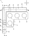
本実施形態に係る車両用シフタ装置3は、センターコンソール7の内方(裏面側)に設けられたロックプレート28を備える。ロックプレート28は、各シフトポジションにおいて、シフトレバー11の掛止レバー21,22を掛止し、シフトレバー11の位置を保持するレバー位置保持部として設けられている。このロックプレート28の構成について、図6から図8を用いて説明する。図6は、センターコンソール7の裏面側に設けられたロックプレート28の構成を車両1の下方側(-Z側)から示す模式平面図であり、図7は、図6のVII-VII断面を示す模式断面図であり、図8は、図6のVIII-VIII断面を示す模式断面図である。
6. Configuration of
図6に示すように、ロックプレート28は、-Z方向からの平面視において、全体として逆L字形状を有しており、センターコンソール7に設けられた開口部14の外縁に沿って設けられている。即ち、ロックプレート28は、X方向に延びる第1延伸部分28jと、Y方向に延びる第2延伸部分28kと、が一体形成されている。
As shown in FIG. 6, the
図6および図7に示すように、ロックプレート28の第1延伸部分28jには、+Z側に凹入した凹部28c,28dと、-Z側に突出した凸部28f,28g,28hと、が設けられている。図7に示すように、凸部28gは凸部28fよりも-Z側への突出高さが高くなっている。
As shown in FIGS. 6 and 7, the first extending
図6および図7に示すように、凸部28hは、X方向における凹部28cと凹部28dとの間に設けられている。
As shown in FIGS. 6 and 7, the
なお、図7に示すように、凹部28dは、-Z側に深く凹入された深底部分28d1と、深底部分28d1よりも凹入深さが浅く、深底部分28d1に対して+X側に配された浅底部分28d2と、を有する。
As shown in FIG. 7, the
一方、図6および図8に示すように、ロックプレート28の第2延伸部分28kには、+Z側に凹入した凹部28a,28bと、-Z側に突出した凸部28e,28fと、が設けられている。凸部28eは、Y方向における凹部28aと凹部28bとの間に設けられている。
On the other hand, as shown in FIGS. 6 and 8, the second extending
なお、図8に示すように、凹部28aは、-Y側に設けられ、Z方向に高低を有する斜面を以って構成された斜面部分28a1と、斜面部分28a1に対して+Y側に設けられ、底がY方向に沿った平面を以って構成された第2部分28a2と、を有する。
Incidentally, as shown in FIG. 8, the
図7および図8に示すように、ロックプレート28は、センターコンソール7の裏面側に配され、車両1の車体に接合された取付プレート29に対して接合されている。図7に示すように、取付プレート29の-Z側の表面29aを基準とする、凸部の高さをH4、凸部28gの高さをH5とする。また、凹部28cおよび凹部28dの深底部分28d1の底から凸部28hの頂部までの高さをH6とする。
As shown in FIGS. 7 and 8 , the
次に、図8に示すように、取付プレート29の-Z側の表面29aを基準とする凸部28eの高さをH7、凹部28bおよび凹部28aの平面部分28a2の底から凸部28e,28fの各頂部までの高さをH8とする。この場合に、本実施形態に係る車両シフタ装置3では、次の関係を満足する。
H4>H7 ・・(数1)
H6>H8 ・・(数2)
H4≒H5 ・・(数3)
次に、図7に示すように、ロックプレート28の第1延伸部分28jには、当該第1延伸部分28jの厚み方向(Y方向)に貫通する孔部28iが設けられている。図7の二点鎖線で囲んだ部分に示すように、孔部28iには、ソレノイド30のプランジャー30aが侵入した状態となっている。プランジャー30aは、矢印Cで示すように、Y方向に出没可能となっている。
Next, as shown in FIG. 8, the height of the
H 4 >H 7 (Equation 1)
H 6 >H 8 (Equation 2)
H 4 ≈H 5 (equation 3)
Next, as shown in FIG. 7, the first extending
なお、図7の二点鎖線で囲んだ部分に示すように、プランジャー30aが突出するのは、シフトレバー11のレバー本体17,18が可動する、ロックプレート28よりも-Y側の領域に対してである。
7, the
7.シフトポジション毎のロックプレート28に対する掛止レバー21,22の掛止
シフトポジション毎のロックプレート28に対する掛止レバー21,22の掛止形態について、図9および図10を用いて説明する。図9(a)は、シフトポジションがDポジションにある場合のロックプレート28に対する掛止レバー21,22の状態を示す模式平面図であり、図9(b)は、シフトポジションがNポジションにある場合のロックプレート28に対する掛止レバー21,22の状態を示す模式平面図であり、図10(a)は、シフトポジションがRポジションにある場合のロックプレート28に対する掛止レバー21,22の状態を示す模式平面図であり、図10(b)は、シフトポジションがPポジションにある場合のロックプレート28に対する掛止レバー21,22の状態を示す模式平面図である。
7. Hooking of the locking levers 21 and 22 to the
図9(a)に示すように、シフトポジションがDポジション3dである場合、第2掛止レバー22がロックプレート28における第2延伸部分28kの凹部28aに掛止された状態となる。この場合に、第1掛止レバー21は、ロックプレート28の第1延伸部分28jに対して掛止されていない。
As shown in FIG. 9A, when the shift position is the
次に、シフトレバー11を矢印D1のように動かすことにより、図9(b)に示すように、シフトポジションがNポジション3nとなる。なお、Dポジション3dからNポジション3nへの移動に際しては、運転者は押ボタン13を押し込む必要はなく、シフトノブ12を+Y側に向けて押すだけでよい。
Next, by moving the
図9(b)に示すように、シフトポジションがNポジション3nである場合、第2掛止レバー22が、ロックプレート28における第2延伸部分28kの凹部28aの+Y側の端部領域に位置する。
As shown in FIG. 9(b), when the shift position is the
次に、シフトレバー11を矢印D2のように動かすことにより、図10(a)に示すように、シフトポジションがRポジション3rとなる。なお、Nポジション3nからRポジション3rへの移動に際しては、運転者は押ボタン13を浅く押し込み(図4(b)の状態まで押し込み)、第2掛止レバー22が凸部28eを乗り越えるように操作する必要がある。
Next, by moving the
図10(a)に示すように、シフトポジションがRポジション3rである場合、第2掛止レバー22が、ロックプレート28における第2延伸部分28kの凹部28bに掛止され、且つ、第1掛止レバー21の先端部分21bが、ロックプレート28における第1延伸部分28jの凹部28cに掛止された状態となる。
As shown in FIG. 10(a), when the shift position is the
次に、シフトレバー11を矢印E1のように動かすことにより、図10(b)に示すように、シフトポジションがPポジション3pとなる。なお、Rポジション3rからPポジション3pへの移動に際しては、運転者は押ボタン13を深く押し込み(図4(c)の状態まで押し込み)、第1掛止レバー21の先端部分21bが凸部28hを乗り越えるように操作する必要がある。
Next, by moving the
図10(b)に示すように、シフトポジションがPポジション3pである場合、第1掛止レバー21の先端部分21bが、ロックプレート28における第1延伸部分28jの凹部28dに掛止された状態となる。
As shown in FIG. 10(b), when the shift position is the
なお、上記では、Dポジション3d⇒Nポジション3n⇒Rポジション3r⇒Pポジション3pの順にシフトポジションを移動させる形態を一例としたが、逆の移動、即ち、Pポジション3p⇒Rポジション3r⇒Nポジション3n⇒Dポジション3dの移動に際しても、上記同様の操作で実行が可能である。
In the above example, the shift positions are moved in the order of
8.Pポジション3pからRポジション3rへの移動
車両用シフタ装置3における、Pポジション3pからRポジション3rへの移動について、図11を用いて補足説明しておく。図11は、シフトポジションがPポジションにある場合のシフトレバー11に対するプランジャー30aの状態を示す模式平面図である。
8. Movement from
図11に示すように、シフトポジションがPポジション3pにある場合には、ソレノイド30のプランジャー30aがロックプレート28における第1延伸部分28jよりも-Y側に突出した状態となる。このため、仮に運転者が押ボタン13だけを押し込んでシフトレバー11を-X側に移動させようとしても、レバー本体17またはレバー本体18(図11では、レバー本体18の図示を省略。)に対してプランジャー30aが当接することとなり、シフトレバー11の-X側への移動を防止する。
As shown in FIG. 11, when the shift position is at the
シフトレバー11をPポジション3pからRポジション3rに移動させる場合には、運転者はブレーキペダル10を踏み込んだ状態で、上記操作を実行する必要がある。
When moving the
[変形例]
上記実施形態では、第1の操作の一例として、図4(b)に示すように押ボタン13を浅く押し込む操作を採用し、第2の操作の一例として、図4(c)に示すように押ボタン13を深く押し込む操作を採用したが、本発明は、これに限定を受けるものではない。例えば、第2の操作として、運転者がシフトノブ12自体を-Z側に押し込む操作を採用することなどができる。
[Modification]
In the above-described embodiment, as an example of the first operation, the operation of slightly pushing the
上記実施形態では、第1掛止レバー21が平面視L字形状であることとしたが、本発明は、これに限定を受けるものではない。例えば、第1掛止レバーについても、第2掛止レバーと同様に直線状に延びる形態を有することとしてもよい。
In the above embodiment, the
上記実施形態では、ロッド19に対して第1掛止レバー21と第2掛止レバー22との2つの掛止レバーが接合された構成を採用したが、本発明は、これに限定を受けるものではない。例えば、1つの掛止レバーが接合された形態を採用することもできる。
In the above embodiment, the structure in which two locking levers, ie, the
上記実施形態では、Dポジション3d、Nポジション3n、Rポジション3r、Pポジション3pの4つのポジションを有する車両用シフタ装置3を採用することとしたが、本発明は、これに限定を受けるものではない。例えば、マニュアルモードに対応するポジションをさらに有することとしてもよい。
In the above embodiment, the
上記実施形態では、車両の右側に運転席が設けられた右ハンドル車を一例として採用したが、本発明は、左ハンドル車に適用することも可能である。 In the above embodiment, a right-hand drive vehicle in which the driver's seat is provided on the right side of the vehicle is used as an example, but the present invention can also be applied to a left-hand drive vehicle.
1 車両
3 車両用シフタ装置
11 シフトレバー
12 シフトノブ
13 押ボタン
19 ロッド
21 第1掛止レバー(掛止レバー)
22 第2係止レバー(掛止レバー)
27 バネ
28 ロックプレート(レバー位置保持部)
28a,28b,28c,28d 凹部
28e,28f,28g,28h 凸部
28i 孔部
30 ソレノイド
30a プランジャー
REFERENCE SIGNS LIST 1
22 Second locking lever (locking lever)
27
28a, 28b, 28c,
Claims (8)
前記運転者の入力を受け付け、前記複数の変速レンジの各々に応じた複数のポジションが規定されたシフトレバーと、
前記シフトレバーの前記ポジションを、前記運転者が選択した各位置に保持するレバー位置保持部と、
を備え、
前記シフトレバーの上端部の移動経路は、前記リバースレンジ、前記ニュートラルレンジ、および前記ドライブレンジの各間を前記運転者が切り換える場合と、前記パーキングレンジと前記リバースレンジとを前記運転者が切り換える場合とで、方向が異なるように規定されており、
前記シフトレバーは、前記運転者が前記リバースレンジと前記ニュートラルレンジとの間を切り換える場合に前記上端部の移動に加えて第1の操作を要求し、前記運転者が前記パーキングレンジと前記リバースレンジとの間を切り換える場合に、前記上端部の移動に加えて、前記第1の操作と操作度合が異なるまたは前記第1の操作とは別操作である第2の操作を要求する、ように構成されており、
前記シフトレバーは、前記上端部に設けられ、前記運転者の操作を受け付ける押ボタンを有し、
前記第1の操作は、前記運転者が前記押ボタンを所定深さまで押し込む操作であり、
前記第2の操作は、前記運転者が前記押ボタンを前記所定深さよりも深い深さまで押し込む操作である、
車両用シフタ装置。 A vehicular shifter device for switching a gear shift range of a vehicle between a plurality of ranges including a parking range, a reverse range, a neutral range, and a drive range based on a driver's operation,
a shift lever that receives input from the driver and defines a plurality of positions corresponding to each of the plurality of shift ranges;
a lever position holding unit that holds the position of the shift lever at each position selected by the driver;
with
The movement path of the upper end of the shift lever is determined when the driver switches between the reverse range, the neutral range, and the drive range, and when the driver switches between the parking range and the reverse range. and are defined in different directions, and
The shift lever requires a first operation in addition to the movement of the upper end portion when the driver switches between the reverse range and the neutral range, and the driver switches between the parking range and the reverse range. When switching between, in addition to the movement of the upper end portion, a second operation that is different in degree of operation from the first operation or is a different operation from the first operation is configured. has been
The shift lever has a push button that is provided at the upper end and receives an operation by the driver,
The first operation is an operation by the driver pushing the push button to a predetermined depth,
The second operation is an operation in which the driver pushes the push button to a depth greater than the predetermined depth.
Vehicle shifter device.
前記シフトレバーは、筒状体であるレバー本体と、当該レバー本体の上端部分に取り付けられたシフトノブと、前記レバー本体に対して前記シフトノブよりも下部から、当該レバー本体の径方向外向きに突設された掛止レバーと、を更に有し、
前記押ボタンは、前記レバー本体における上端部分に設けられており、
前記掛止レバーは、前記運転者による前記押ボタンの押し込み操作に対応して、前記レバー本体の筒軸方向に上下動し、当該上下動により前記レバー位置保持部との掛止/掛止解除がなされる、
車両用シフタ装置。 In the vehicle shifter device according to claim 1 ,
The shift lever includes a lever body that is a cylindrical body, a shift knob attached to an upper end portion of the lever body, and a shift knob projecting radially outward of the lever body from below the shift knob with respect to the lever body. a locking lever provided;
The push button is provided at an upper end portion of the lever body,
The locking lever moves up and down in the cylinder axis direction of the lever body in response to the driver's pushing operation of the push button, and the vertical movement engages/disengages with the lever position holding portion. is made,
Vehicle shifter device.
前記掛止レバーは、前記レバー本体の径方向における一の方向に向けて突設された第1掛止レバーと、前記レバー本体の径方向における前記第1掛止レバーとは反対側に向けて突設された第2掛止レバーと、を有し、
前記シフトレバーを前記レバー本体の筒軸方向から平面視するとき、前記第1掛止レバーは、前記レバー本体側から前記一の方向に向けて直線状に延びる根元部分と、当該根元部分の先端部から交差する方向に曲折された先端部分と、が一体形成されており、前記第2掛止レバーは、前記反対側に向けて直線状に延びており、
前記レバー位置保持部は、前記シフトレバーの前記複数のポジションの各々に対応して上方に向けて凹入した複数の凹部が設けられたロックプレートであり、
前記ロックプレートは、前記パーキングレンジと前記リバースレンジとを前記運転者が切り換える場合の前記シフトレバーの移動経路に沿った第1延伸部分と、前記リバースレンジ、前記ニュートラルレンジ、および前記ドライブレンジの各間を前記運転者が切り換える場合の前記シフトレバーの移動経路に沿った第2延伸部分と、が一体形成されており、上方からの平面視で全体としてL字形状を有しており、
前記パーキングレンジおよび前記リバースレンジが選択された場合に、前記第1掛止レバーを掛止する各凹部が前記第1延伸部分に形成されており、
前記リバースレンジ、前記ニュートラルレンジ、および前記ドライブレンジが選択された場合に、前記第2掛止レバーを掛止する各凹部が前記第2延伸部分に形成されている、
車両用シフタ装置。 In the vehicle shifter device according to claim 1 ,
The locking lever includes a first locking lever projecting in one direction in the radial direction of the lever main body and a first locking lever projecting in the radial direction of the lever main body in the opposite direction to the first locking lever. a projecting second locking lever;
When the shift lever is viewed from above in the direction of the cylinder axis of the lever body, the first locking lever has a root portion extending linearly in the one direction from the lever body side and a tip end of the root portion. and a tip portion bent in a direction intersecting with the portion, and the second locking lever extends linearly toward the opposite side,
The lever position holding portion is a lock plate provided with a plurality of recesses recessed upward corresponding to each of the plurality of positions of the shift lever,
The lock plate has a first extending portion along a movement path of the shift lever when the driver switches between the parking range and the reverse range, and each of the reverse range, the neutral range, and the drive range. A second extending portion along the movement path of the shift lever when the driver switches between the two is integrally formed, and has an L shape as a whole when viewed from above in plan,
recesses for locking the first locking lever when the parking range and the reverse range are selected are formed in the first extending portion;
The second extending portion is formed with respective recesses for locking the second locking lever when the reverse range, the neutral range, and the drive range are selected.
Vehicle shifter device.
前記掛止レバーは、前記レバー本体の軸方向における上向きに弾性付勢されており、前記運転者が前記押ボタンの押し込み操作を行っていない場合に、当該掛止レバーの可動範囲の上端に位置し、
前記ロックプレートは、前記シフトレバーの前記複数のポジションの各々に対応して、前記第1掛止レバーおよび前記第2掛止レバーの少なくとも一方を掛止する、
車両用シフタ装置。 In the vehicle shifter device according to claim 3 ,
The locking lever is elastically biased upward in the axial direction of the lever body, and is positioned at the upper end of the movable range of the locking lever when the driver does not press the push button. death,
the lock plate latches at least one of the first latch lever and the second latch lever corresponding to each of the plurality of positions of the shift lever;
Vehicle shifter device.
前記ロックプレートの前記第1延伸部分に設けられた複数の凹部には、前記パーキングレンジが前記運転者により選択された場合に前記第1掛止レバーを掛止する第1凹部と、前記リバースレンジが前記運転者により選択された場合に前記第1掛止レバーを掛止する第2凹部と、が含まれており、
前記ロックプレートの前記第2延伸部分に設けられた複数の凹部には、前記リバースレンジが前記運転者により選択された場合に前記第2掛止レバーを掛止する第3凹部と、前記ニュートラルレンジが前記運転者により選択された場合に前記第2掛止レバーを掛止する第4凹部と、が含まれており、
前記ロックプレートの前記第1延伸部分には、前記第1凹部と前記第2凹部との間に、下方に向けて突出する第1凸部が設けられており、
前記ロックプレートの前記第2延伸部分には、前記第3凹部と前記第4凹部との間に、下方に向けて突出する第2凸部が設けられており、
前記第1凹部および前記第2凹部の底に対する前記第1凸部の相対的な高さは、前記第3凹部および前記第4凹部の底に対する前記第2凸部の相対的な高さよりも高い、
車両用シフタ装置。 In the vehicle shifter device according to claim 3 or 4 ,
A plurality of recesses provided in the first extending portion of the lock plate include a first recess for locking the first locking lever when the parking range is selected by the driver, and the reverse range. a second recess that latches the first latch lever when is selected by the driver;
A plurality of recesses provided in the second extending portion of the lock plate include a third recess for locking the second locking lever when the reverse range is selected by the driver, and the neutral range. a fourth recess for locking the second locking lever when is selected by the driver;
the first extending portion of the lock plate is provided with a first protrusion projecting downward between the first recess and the second recess,
a second protrusion projecting downward between the third recess and the fourth recess is provided in the second extending portion of the lock plate,
The relative height of the first protrusion to the bottoms of the first recess and the second recess is higher than the relative height of the second protrusion to the bottoms of the third recess and the fourth recess ,
Vehicle shifter device.
前記リバースレンジが前記運転者により選択された場合には、前記第1掛止レバーが前記第2凹部に掛止され、且つ、前記第2掛止レバーが前記第3凹部に掛止される、
車両用シフタ装置。 In the vehicle shifter device according to claim 5 ,
When the reverse range is selected by the driver, the first locking lever is locked in the second recess and the second locking lever is locked in the third recess,
Vehicle shifter device.
前記運転者の入力を受け付け、前記複数の変速レンジの各々に応じた複数のポジションが規定されたシフトレバーと、a shift lever that receives input from the driver and defines a plurality of positions corresponding to each of the plurality of shift ranges;
前記シフトレバーの前記ポジションを、前記運転者が選択した各位置に保持するレバー位置保持部と、a lever position holding unit that holds the position of the shift lever at each position selected by the driver;
を備え、with
前記シフトレバーの上端部の移動経路は、前記リバースレンジ、前記ニュートラルレンジ、および前記ドライブレンジの各間を前記運転者が切り換える場合と、前記パーキングレンジと前記リバースレンジとを前記運転者が切り換える場合とで、方向が異なるように規定されており、The movement path of the upper end of the shift lever is determined when the driver switches between the reverse range, the neutral range, and the drive range, and when the driver switches between the parking range and the reverse range. and are defined in different directions, and
前記シフトレバーは、前記運転者が前記リバースレンジと前記ニュートラルレンジとの間を切り換える場合に前記上端部の移動に加えて第1の操作を要求し、前記運転者が前記パーキングレンジと前記リバースレンジとの間を切り換える場合に、前記上端部の移動に加えて、前記第1の操作と操作度合が異なるまたは前記第1の操作とは別操作である第2の操作を要求する、ように構成されており、The shift lever requires a first operation in addition to the movement of the upper end portion when the driver switches between the reverse range and the neutral range, and the driver switches between the parking range and the reverse range. When switching between, in addition to the movement of the upper end portion, a second operation that is different in degree of operation from the first operation or is a different operation from the first operation is configured. has been
前記第2の操作は、前記運転者が前記シフトレバーに対して行う操作である、the second operation is an operation performed by the driver on the shift lever;
車両用シフタ装置。Vehicle shifter device.
前記シフトレバーは、筒状体であるレバー本体と、当該レバー本体の上端部分に取り付けられたシフトノブと、を有し、The shift lever has a lever body, which is a cylindrical body, and a shift knob attached to the upper end portion of the lever body,
前記第2の操作は、前記運転者が前記シフトノブを前記レバー本体の筒軸方向に押し込む操作である、The second operation is an operation by the driver pushing the shift knob in the cylinder axis direction of the lever body.
車両用シフタ装置。Vehicle shifter device.
Priority Applications (4)
| Application Number | Priority Date | Filing Date | Title |
|---|---|---|---|
| JP2018116922A JP7180136B2 (en) | 2018-06-20 | 2018-06-20 | Vehicle shifter device |
| CN201910505210.9A CN110617322B (en) | 2018-06-20 | 2019-06-12 | Gear shifting device for vehicle |
| EP19180929.2A EP3584469B1 (en) | 2018-06-20 | 2019-06-18 | Vehicle shifter device and method of providing the same |
| US16/447,795 US11168784B2 (en) | 2018-06-20 | 2019-06-20 | Vehicle shifter device |
Applications Claiming Priority (1)
| Application Number | Priority Date | Filing Date | Title |
|---|---|---|---|
| JP2018116922A JP7180136B2 (en) | 2018-06-20 | 2018-06-20 | Vehicle shifter device |
Publications (2)
| Publication Number | Publication Date |
|---|---|
| JP2019217911A JP2019217911A (en) | 2019-12-26 |
| JP7180136B2 true JP7180136B2 (en) | 2022-11-30 |
Family
ID=66998172
Family Applications (1)
| Application Number | Title | Priority Date | Filing Date |
|---|---|---|---|
| JP2018116922A Active JP7180136B2 (en) | 2018-06-20 | 2018-06-20 | Vehicle shifter device |
Country Status (4)
| Country | Link |
|---|---|
| US (1) | US11168784B2 (en) |
| EP (1) | EP3584469B1 (en) |
| JP (1) | JP7180136B2 (en) |
| CN (1) | CN110617322B (en) |
Families Citing this family (2)
| Publication number | Priority date | Publication date | Assignee | Title |
|---|---|---|---|---|
| CN111911620B (en) * | 2020-07-29 | 2021-11-12 | 中国航发湖南动力机械研究所 | Multifunctional push rod operating device |
| JP2022131693A (en) * | 2021-02-26 | 2022-09-07 | 株式会社東海理化電機製作所 | Shifter |
Citations (7)
| Publication number | Priority date | Publication date | Assignee | Title |
|---|---|---|---|---|
| JP2008183998A (en) | 2007-01-29 | 2008-08-14 | Tokai Rika Co Ltd | Shift lever device |
| JP2011168264A (en) | 2010-01-21 | 2011-09-01 | Tokai Rika Co Ltd | Shift lever device |
| US20150101439A1 (en) | 2013-10-10 | 2015-04-16 | Kia Motors Corp. | Apparatus for operating a shift lever for a vehicle |
| JP2016222158A (en) | 2015-06-01 | 2016-12-28 | トヨタ自動車株式会社 | Shift device for vehicle |
| US20180244155A1 (en) | 2017-02-24 | 2018-08-30 | Ford Global Technologies, Llc | Stalk mounted telescoping rotary shift knob |
| JP2018203233A (en) | 2017-05-31 | 2018-12-27 | パナソニックIpマネジメント株式会社 | Input device |
| JP2019142455A (en) | 2018-02-23 | 2019-08-29 | 株式会社東海理化電機製作所 | Shifting device |
Family Cites Families (20)
| Publication number | Priority date | Publication date | Assignee | Title |
|---|---|---|---|---|
| JPH055323Y2 (en) * | 1988-06-30 | 1993-02-12 | ||
| JP3187978B2 (en) * | 1992-09-10 | 2001-07-16 | マツダ株式会社 | Operating device for automatic transmission |
| JP3588676B2 (en) * | 2000-05-24 | 2004-11-17 | 日産自動車株式会社 | Shift lever device for automatic transmission |
| KR100494788B1 (en) * | 2002-10-24 | 2005-06-13 | 현대자동차주식회사 | shift lock device for a shift lever of an auto transmission |
| JP2005119381A (en) * | 2003-10-15 | 2005-05-12 | Tokai Rika Co Ltd | Shift lever device |
| US20050223834A1 (en) * | 2004-03-30 | 2005-10-13 | Nissan Technical Center North America, Inc. | Inline automatic/manual shifter |
| US20070068325A1 (en) * | 2005-09-06 | 2007-03-29 | Rudelic Joseph E | Shift mechanism for a vehicle |
| JP4681482B2 (en) | 2006-03-27 | 2011-05-11 | 本田技研工業株式会社 | Shifting device for automatic transmission |
| US7640823B2 (en) * | 2007-04-30 | 2010-01-05 | International Truck Intellectual Property Company, Llc | Integrated automatic manual transmission lever-type shift selector |
| DE102008030233A1 (en) * | 2008-06-25 | 2009-12-31 | GM Global Technology Operations, Inc., Detroit | Switching device for a motor vehicle gearbox |
| EP2728224B1 (en) * | 2012-10-30 | 2018-02-14 | Kongsberg Automotive AB | Shifter assembly having pivoting twin plungers |
| KR101575414B1 (en) * | 2013-11-18 | 2015-12-21 | 현대자동차주식회사 | Shifting apparatus for vehicle |
| JP6052211B2 (en) * | 2014-03-24 | 2016-12-27 | マツダ株式会社 | Vehicle shift device |
| JP6052214B2 (en) * | 2014-03-24 | 2016-12-27 | マツダ株式会社 | Vehicle shift device |
| CN204055371U (en) * | 2014-09-05 | 2014-12-31 | 丰田自动车株式会社 | Gear shift device |
| JP2016060326A (en) * | 2014-09-17 | 2016-04-25 | 株式会社東海理化電機製作所 | Shift device |
| JP6231518B2 (en) * | 2015-05-19 | 2017-11-15 | トヨタ自動車株式会社 | Vehicle shift device |
| KR102169364B1 (en) * | 2015-06-22 | 2020-10-26 | 현대자동차주식회사 | 2-Step Button Type Electronic Auto Shift Lever |
| JP2017109510A (en) * | 2015-12-14 | 2017-06-22 | トヨタ自動車株式会社 | Shift lever device |
| JP2019123432A (en) * | 2018-01-18 | 2019-07-25 | 株式会社東海理化電機製作所 | Shift device |
-
2018
- 2018-06-20 JP JP2018116922A patent/JP7180136B2/en active Active
-
2019
- 2019-06-12 CN CN201910505210.9A patent/CN110617322B/en active Active
- 2019-06-18 EP EP19180929.2A patent/EP3584469B1/en active Active
- 2019-06-20 US US16/447,795 patent/US11168784B2/en active Active
Patent Citations (7)
| Publication number | Priority date | Publication date | Assignee | Title |
|---|---|---|---|---|
| JP2008183998A (en) | 2007-01-29 | 2008-08-14 | Tokai Rika Co Ltd | Shift lever device |
| JP2011168264A (en) | 2010-01-21 | 2011-09-01 | Tokai Rika Co Ltd | Shift lever device |
| US20150101439A1 (en) | 2013-10-10 | 2015-04-16 | Kia Motors Corp. | Apparatus for operating a shift lever for a vehicle |
| JP2016222158A (en) | 2015-06-01 | 2016-12-28 | トヨタ自動車株式会社 | Shift device for vehicle |
| US20180244155A1 (en) | 2017-02-24 | 2018-08-30 | Ford Global Technologies, Llc | Stalk mounted telescoping rotary shift knob |
| JP2018203233A (en) | 2017-05-31 | 2018-12-27 | パナソニックIpマネジメント株式会社 | Input device |
| JP2019142455A (en) | 2018-02-23 | 2019-08-29 | 株式会社東海理化電機製作所 | Shifting device |
Also Published As
| Publication number | Publication date |
|---|---|
| US20190390763A1 (en) | 2019-12-26 |
| JP2019217911A (en) | 2019-12-26 |
| EP3584469A1 (en) | 2019-12-25 |
| EP3584469B1 (en) | 2022-01-05 |
| US11168784B2 (en) | 2021-11-09 |
| CN110617322A (en) | 2019-12-27 |
| CN110617322B (en) | 2021-08-24 |
Similar Documents
| Publication | Publication Date | Title |
|---|---|---|
| JP5963857B2 (en) | Vehicle shift device | |
| JP7180136B2 (en) | Vehicle shifter device | |
| WO2016042949A1 (en) | Vehicular shifter device | |
| US10774914B2 (en) | Automotive transmission | |
| US7971501B2 (en) | Shift lock assembly | |
| JP4205372B2 (en) | Automatic transmission selection system | |
| JP6610633B2 (en) | Vehicle shifter device | |
| JP5943477B2 (en) | Vehicle shift device | |
| JP2019123432A (en) | Shift device | |
| US7444899B2 (en) | Shifting apparatus for an automatic transmission of vehicle | |
| JP7063140B2 (en) | Vehicle shifter device | |
| JP6123767B2 (en) | Vehicle shifter device | |
| JP2002254952A (en) | Shift device | |
| JP6708977B2 (en) | Vehicle shift device | |
| CN112283335B (en) | Gear shifting device | |
| JP2019043467A (en) | Shifter device for vehicle | |
| JP5839918B2 (en) | Automatic transmission reverse shift limiting device | |
| JP2016113069A (en) | Vehicular shift device | |
| JP6060961B2 (en) | Vehicle shift device | |
| JP6060943B2 (en) | Vehicle shift device | |
| WO2017159179A1 (en) | Shift device | |
| JP4630191B2 (en) | Shift lock mechanism | |
| JP6060942B2 (en) | Vehicle shift device | |
| JP6090339B2 (en) | Vehicle shift device | |
| JP6210037B2 (en) | Vehicle shifter device |
Legal Events
| Date | Code | Title | Description |
|---|---|---|---|
| A621 | Written request for application examination |
Free format text: JAPANESE INTERMEDIATE CODE: A621 Effective date: 20210525 |
|
| A977 | Report on retrieval |
Free format text: JAPANESE INTERMEDIATE CODE: A971007 Effective date: 20220308 |
|
| A131 | Notification of reasons for refusal |
Free format text: JAPANESE INTERMEDIATE CODE: A131 Effective date: 20220405 |
|
| A521 | Request for written amendment filed |
Free format text: JAPANESE INTERMEDIATE CODE: A523 Effective date: 20220602 |
|
| TRDD | Decision of grant or rejection written | ||
| A01 | Written decision to grant a patent or to grant a registration (utility model) |
Free format text: JAPANESE INTERMEDIATE CODE: A01 Effective date: 20221018 |
|
| A61 | First payment of annual fees (during grant procedure) |
Free format text: JAPANESE INTERMEDIATE CODE: A61 Effective date: 20221031 |
|
| R150 | Certificate of patent or registration of utility model |
Ref document number: 7180136 Country of ref document: JP Free format text: JAPANESE INTERMEDIATE CODE: R150 |