JP7180062B2 - protective case - Google Patents
protective case Download PDFInfo
- Publication number
- JP7180062B2 JP7180062B2 JP2017176918A JP2017176918A JP7180062B2 JP 7180062 B2 JP7180062 B2 JP 7180062B2 JP 2017176918 A JP2017176918 A JP 2017176918A JP 2017176918 A JP2017176918 A JP 2017176918A JP 7180062 B2 JP7180062 B2 JP 7180062B2
- Authority
- JP
- Japan
- Prior art keywords
- mounting surface
- protective case
- support
- covering
- planar
- Prior art date
- Legal status (The legal status is an assumption and is not a legal conclusion. Google has not performed a legal analysis and makes no representation as to the accuracy of the status listed.)
- Active
Links
Images


Description
本発明は、携帯型の電子機器を保護すると共に、スタンドとして兼用できる保護ケースに関する。 The present invention relates to a protective case that protects a portable electronic device and also serves as a stand.
スマートフォンや電子辞書等の携帯型の電子機器を保護するための保護ケースが知られている。このような保護ケースは、例えば、電子機器の筐体を嵌め込んで収納するケース本体と、このケース本体に開閉自在に取り付けられた蓋部を有している。蓋部は、閉じることで電子機器の液晶表示パネルの表面に重なり、外部からの衝撃から液晶表示パネルを保護することができる(例えば、特許文献1参照。)。ケース本体は樹脂や金属製等の比較的硬い素材で形成され、蓋部は柔軟性のある素材で形成される場合があった。 Protective cases for protecting portable electronic devices such as smartphones and electronic dictionaries are known. Such a protective case has, for example, a case body into which a housing of an electronic device is fitted and accommodated, and a lid attached to the case body so as to be freely opened and closed. When the cover is closed, it overlaps the surface of the liquid crystal display panel of the electronic device, and can protect the liquid crystal display panel from external impact (see, for example, Patent Document 1). In some cases, the case body is made of a relatively hard material such as resin or metal, and the lid is made of a flexible material.
保護ケースは、蓋部を屈曲させてケース本体に引っ掛けて立て掛けることもできるように構成されている場合がある。この場合、蓋部に対しケース本体が所定位置いで留まるように蓋部側に凹凸部を形成し、ケース本体の側面を係合させるようにしていた。 The protective case may be configured so that the cover can be bent and hooked on the case body to stand. In this case, uneven portions are formed on the side of the lid so that the case body stays at a predetermined position with respect to the lid, and the side surfaces of the case body are engaged.
上述した保護ケースでは、装着された携帯端末を立て掛け支持するため、蓋部に保持部を形成する必要があった。また、背面側に内枠および背面部が設けられているので、全体的な厚みが大きくなっていた。 In the above-described protective case, it is necessary to form a holding portion in the lid portion in order to lean and support the attached portable terminal. In addition, since the inner frame and the back portion are provided on the back side, the overall thickness is increased.
本発明の一態様として、機器の保護ケースであって、前記保護ケースが前記機器へ装着された状態で前記機器の背面の一部を覆う被覆部と、前記被覆部に対して一端側が回動可能に接続され、前記機器が載置される載置面に対して当該機器を傾斜した状態で支持するときに、前記機器が前記載置面に対して立ち上がるように前記機器を支持する第1支持部と、前記被覆部における前記載置面側の下縁壁部から突出し、前記載置面側の面が平面状に形成された平面状部を有し、前記載置面に対して前記機器を傾斜した状態で支持するときに、前記載置面または前記載置面の上に置かれた板状部材と当接するように設けられた第2支持部と、を備え、前記下縁壁部において前記第2支持部が突出している位置は、前記載置面に対して前記機器を設定された角度で傾斜した状態で支持するときに、前記平面状部が前記載置面または前記載置面の上に置かれた板状部材と当接する位置であり、かつ、前記第2支持部における前記平面状部の面の角度は、前記載置面に対して前記機器を前記設定された角度で傾斜した状態で支持するときに、前記平面状部の面が前記載置面または前記載置面の上に置かれた板状部材の上面と平行になる角度である。 As one aspect of the present invention, there is provided a protective case for a device, comprising: a covering portion covering a part of the back surface of the device when the protective case is attached to the device; A first support device that is capable of supporting the device so that when the device is supported in an inclined state with respect to a mounting surface on which the device is mounted, the device stands up with respect to the mounting surface. a supporting portion; a second support provided so as to abut on the mounting surface or a plate-shaped member placed on the mounting surface when the device is supported in an inclined state; The position where the second support portion protrudes from the portion is such that when the device is supported in an inclined state with respect to the mounting surface at a set angle, the planar portion is located on the mounting surface or the above-described mounting surface. The angle of the surface of the planar portion of the second support portion is set so that the device is positioned with respect to the mounting surface. This is the angle at which the surface of the planar portion is parallel to the mounting surface or the upper surface of the plate-like member placed on the mounting surface when the plate-like member is supported in an inclined state.
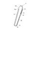
図1~図8は本発明の一実施の形態に係る保護ケース10についての説明図である。図11に示すように、保護ケース10は、図3に示すような電子辞書100の保護および載置面P上への立掛支持(スタンドとしての利用)を選択的に行う機能を有している。なお、これらの図中100は電子辞書(機器)を示している。図1および図2に示すように、電子辞書100は、略直方体状の筐体110を備えている。なお、図中111は筐体110の下端面を示している。この筐体110の正面側には、液晶表示パネル120およびスピーカ130が設けられている。また、上側面には電源等の操作スイッチ140、右側面にはボリューム等の操作スイッチ150、正面はカーソル等の操作スイッチ160が設けられている。
1 to 8 are explanatory diagrams of a
図1に示すように、保護ケース10は、電子辞書100の背面側を覆う皿形のケース本体(被覆部/背面保持部)20と、このケース本体20に取り付けられた板状の可動支持板50を備えている。ケース本体20は例えば樹脂材製、可動支持板50は例えば人工スエード製である。ケース本体20と可動支持板50はほぼ同じ厚さで形成されている。なお、図1中Gは、電子辞書100を保護ケース10に嵌め込んだ状態における電子辞書100の重心位置を示している。
As shown in FIG. 1, the
ケース本体20は、電子辞書100の背面に対向した面を形成する長方形板状の背面部(第1被覆部)30と、この背面部30の外縁に沿って正面視で手前側に向けて立設された外縁壁部40を備えている。
The case
図4に示すように、背面部30は、保護ケース10が電子辞書100へ装着された状態で、電子辞書100の背面の一部を覆う形状とされている。背面部30には、下縁側から切欠された長方形状の開口部31が形成されている(図4参照)。背面部30に接続された第1支持部60は、電子辞書100が載置される載置面Pに対して電子辞書100を支持するときに、電子辞書100が載置面Pに対して立ち上がるように電子辞書100を支持する。なお、背面部30の開口部31内には、背面部30に接続された第1支持部60の一部が格納される。上述したように、ケース本体20と可動支持板50はほぼ同じ厚さで形成されていることから、背面部30の厚さと第1支持部60の厚さは略同一である。
As shown in FIG. 4 , the
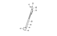
外縁壁部40は、図2中上側に位置する上縁壁部41、下側に位置する下縁壁部(下端面保持部)42、右側に位置する右縁壁部43、左側に位置する左縁壁部44を備えている。下縁壁部42の厚さは、第2可撓部64の厚さと、略同一に形成されている。下縁壁部42は、図2中左右方向に切欠部42aが形成されている。切欠部42aは開口部31が下縁壁部42まで延在して形成されている。切欠部42aの幅は、第2可撓部64の図2中左右方向における幅よりも僅かに大きく形成されている。
The outer
図5~図7に示すように、背面部30の開口部31の上端に沿った位置には、第1支持部60の一端側61が差し込まれる差込部32が形成されている。差込部32の上端部にはリブ33が形成されている。
As shown in FIGS. 5 to 7, an
可動支持板50は、図4に示すように、板状に形成され、横方向の寸法が開口部31に収まる寸法に設定されると共に電子辞書100の背面側に対向する第1支持部(第2被覆部)60と、この第1支持部60の図1中下端側に第2可撓部64を介して一体的に設けられた蓋部70とを備えている。すなわち、ケース本体20と載置面Pとの間には、電子辞書100を載置面P上に立掛支持する第1支持部60が位置している。また、下縁壁部42(電子辞書100の立て掛けた際における下端部111に対向)の外側面と載置面Pとの間には、電子辞書100を支持する第2支持部45が設けられている。第2支持部45の下面(電子辞書100を載置面P上へ立掛支持したときに当該載置面Pに対向する側の面)は、平面状に形成されている。また、下縁壁部42および第2支持部45は背面部30の開口部31を挟んで左右両側にそれぞれ1つずつ設けられている。
As shown in FIG. 4, the
第1支持部60の一端側61は厚さ方向に2分割され、上述した差込部32に差し込まれる。また、一端側61の近傍には、図1における載置面Pと平行な直線状に折曲自在な第1可撓部63が形成されることで、ケース本体20に対して回動可能に接続されている。さらに、第1支持部60の他端側62は、載置面P側に向けて配置されている。
One
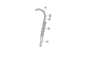
第1支持部60の他端側62と蓋部70との間に、載置面Pと平行な直線状に第2可撓部64が設けられている。蓋部70は、第1支持部60の他端側に、第1支持部60に対して第2可撓部64の位置で回動可能に接続されている。蓋部70は、電子辞書100の背面が第1支持部60によって載置面Pに対して立掛支持されているときに、第2支持部45と載置面Pとの間に介在可能に設けられている。また、蓋部70は、保護ケース10が電子辞書100へ装着された状態で電子辞書100の正面の少なくとも一部を覆う位置へ設置可能であり、かつ、第1支持部60の他端側に回動可能に接続されている。蓋部70の図1中上面側を第1の主面71、下面を第2の主面と称する。
A second
また、図3に示すように、第1支持部60を第1可撓部63および第2可撓部64の位置で折曲させず、下縁壁部42に沿って第2可撓部64を巻き付けて、蓋部70をケース本体20の正面側に位置させると、第1の主面71は液晶表示パネル120と対向する。これにより、蓋部70により、液晶表示パネル120を保護する。なお、蓋部70の先端70aは、スピーカ130を塞がない寸法に設定されている。
Further, as shown in FIG. 3 , the
保護ケース10が電子辞書100へ装着された状態で、蓋部70を電子辞書100の正面に対向させて配置させた際、第1支持部60は、電子辞書100の側面視において背面部30に重なり合う寸法である。
When the
このように構成された保護ケース10によれば、収納・保護と立掛支持(スタンド)を選択的に行うことができる。すなわち、図1に示すような立掛支持を行う場合、第1可撓部63および第2可撓部64を適切に回動させることで、ケース本体20に嵌合された電子辞書100の背面が第1支持部60によって載置面Pに対して支持される。また、ケース本体20および電子辞書100の自重によってケース本体20の第2支持部45が蓋部70側へと付勢されることで、第2支持部45の平面状の下面が蓋部70の第1の主面71に当接する状態になり、ひいては、第2支持部45の平面状の下面が載置面Pに平行に配置される。つまり、第2支持部45は、載置面P側の面が平面状に形成された平面状部を有し、電子辞書100を支持するときに、電子辞書100の下端部と載置面Pとの間に介在して、前記平面状部の載置面P側の面が載置面Pと略平行になるように電子辞書100を支持する。これにより、電子辞書100は、載置面Pに対して立掛支持されているときに、当該載置面Pに対する角度が一定に保持される。
According to the
また、電子辞書100の重心Gは、第1支持部60の表面を通る平面よりも下側にある、即ち、電子辞書100の重心Gは、第1支持部60の表面を通る平面と載置面Pがなす鋭角の範囲に存在するため、保護ケース10によって電子辞書100を立掛支持したときに安定する。
In addition, the center of gravity G of the
一方、収納時においては、第1可撓部63および第2可撓部64を、ケース本体20の下端面に沿って第2可撓部64を巻き付ける。そのようにして、保護ケース10が電子辞書100へ装着された状態で、蓋部70を電子辞書100の正面に対向させて配置させた際、第2可撓部64のうち電子辞書100に対向する少なくとも一部が、電子辞書100の下端部111に当接する。これにより、蓋部70は液晶表示パネル120面上に積層されて、保護が可能となる。また、背面部30と第1支持部60の厚さ、および、下縁壁部42と第2可撓部64の厚さはそれぞれほぼ同じ厚さとなっているため、ケース本体20の側面視では、第1支持部60の第1可撓部63と第2可撓部64との間の部分は背面部30に隠れて見えなくなり、第2可撓部64は下縁壁部42に隠れて見えなくなる。したがって、見栄えが良く、また、ケース本体20の図3中上下方向において寸法が大きくなることがないため、コンパクトな概観となる。
On the other hand, during storage, the first
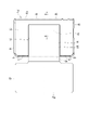
図9は変形例に係る保護ケース10Aを示す背面図である。なお、図9において図1~図8と同一機能部分には同一符号を付し、その詳細な説明は省略する。保護ケース10Aにおいては、開口部31の代わりに一対の開口部31Aが設けられたケース本体20Aを有し、可動支持板50の代わりに2列の可動支持板50Aを有し、第1支持部60の代わりに、一対の第1支持部60Aが設けられている。これら一対の第1支持部60Aは一対の開口部31Aに挿入される、一対の開口部31Aの開口面積の合計は、開口部31の開口面積よりも小さい。
FIG. 9 is a rear view showing a
このように形成された保護ケース10Aにあっては、ケース本体20Aが立掛支持された状態において、ケース本体20よりも重心が低くなるため、安定性を向上させることができる。
In the
なお、本発明は前記実施の形態に限定されるものではない。例えば、上述した例では、第2支持部45と載置面Pとの間には蓋部70が設けられているが、蓋部70を省略して、載置面P上に第2支持部45を直接載置させるようにしてもよい。また、上述した例では、電子辞書100の背面が第1支持部60によって載置面Pに対して支持されていて、かつ、第2支持部45を蓋部70の中央部に当接させているが、先端部70aに当接させた場合に、電子辞書100の載置面Pに対する角度が、他の角度に保持させるように寸法を設定してもよい。また、第2支持部45の表面に細かい凹凸を形成してもよい。この場合、凹凸の凸部の先端部の高さは同じになるように形成することで、第2支持部45の下面(凸部の先端部をつなぐ仮想的な面)が平面状になるようにしてよい。これらの凹凸によって、第2支持部45の下面と蓋部70の第1の主面71または載置面Pとの間の摩擦力を増大することができる。特に、蓋部70の第1の主面71または載置面Pが細かい凹凸を有する場合には、摩擦力を増大させる効果が大きい。さらに、機器として正面に液晶表示パネルを有する電子辞書を例示したが、携帯電話等の携帯端末や、液晶表示パネルが無いラジオ等であっても、同様に適用できるのは勿論である。この他、本発明の要旨を逸脱しない範囲で種々変形実施可能であるのは勿論である。
It should be noted that the present invention is not limited to the above embodiments. For example, in the above-described example, the
本発明の一実施形態を説明したが、本発明は特許請求の範囲に記載された発明とその均等の範囲に含まれる。以下に、本願出願の当初の特許請求の範囲に記載された発明を付記する。
[付記1]
機器の保護ケースであって、
前記保護ケースが前記機器へ装着された状態で前記機器の背面の一部を覆う被覆部と、
前記機器が載置される載置面に対して当該機器を支持するときに、前記機器が前記載置面に対して立ち上がるように前記機器を支持する第1支持部と、
前記載置面側の面が平面状に形成された平面状部を有し、前記機器を支持するときに、当該機器の下端部と前記載置面との間に介在して、前記平面状部の前記載置面側の面が前記載置面と略平行になるように前記機器を支持する第2支持部と、を備える保護ケース。
[付記2]
前記第1支持部の一端側は、前記被覆部に対して回動可能に接続されている[付記1]に記載の保護ケース。
[付記3]
前記第1支持部の一端側と前記被覆部との間には、第1可撓部が設けられている[付記1]に記載の保護ケース。
[付記4]
前記保護ケースが前記機器へ装着された状態で前記機器の正面の少なくとも一部を覆う位置へ設置可能であり、かつ、前記第1支持部の他端側に回動可能に接続された蓋部をさらに備える[付記1]に記載の保護ケース。
[付記5]
前記蓋部は、前記第1支持部によって前記機器が前記載置面に対して支持されている状態で、前記第2支持部と前記載置面との間に介在可能に設けられている[付記4]に記載の保護ケース。
[付記6]
前記第1支持部の他端側と前記蓋部との間に第2可撓部が介在する[付記4]に記載の保護ケース。
[付記7]
機器の保護ケースであって、
前記保護ケースが前記機器へ装着された状態で前記機器の背面の一部を覆う保持部を含み、前記保持部に開口部が形成された第1被覆部と、
前記第1被覆部の前記開口部内にその一部が配置され、前記第1被覆部に第1可撓部を介して接続された第2被覆部と、
前記第2被覆部に第2可撓部を介して回動可能に接続された蓋部を備え、
前記第1被覆部の厚みと前記第2被覆部の厚みとが略同一である保護ケース。
[付記8]
前記保持部は、前記機器の下端面をさらに覆う下端面保持部を有し、前記開口部が前記下端面保持部まで延在して形成されている[付記7]に記載の保護ケース。
[付記9]
前記下端面保持部の厚みは、前記第2可撓部の厚みと、略同一に形成されている[付記8]に記載の保護ケース。
[付記10]
前記保護ケースが前記機器へ装着された状態で前記蓋部を前記機器の正面に対向させて配置させた際、前記第2可撓部のうち前記機器と対向する部分の少なくとも一部が、前記機器の前記下端面に当接する[付記9]に記載の保護ケース。
[付記11]
前記保護ケースが前記機器へ装着された状態で前記蓋部を前記機器の正面に対向させて配置させた際、前記第2被覆部および前記第2可撓部は、前記機器の側面視において前記第1被覆部に重なり合う寸法である[付記9]に記載の保護ケース。
Although one embodiment of the present invention has been described, the present invention is included in the scope of the invention described in the claims and equivalents thereof. The invention described in the original claims of the present application is appended below.
[Appendix 1]
A protective case for equipment,
a covering part that covers a part of the back surface of the device when the protective case is attached to the device;
a first support that supports the device such that the device stands up from the mounting surface when the device is supported on the mounting surface on which the device is mounted;
The surface on the mounting surface side has a planar portion formed in a planar shape, and when the device is supported, the planar portion is interposed between the lower end portion of the device and the mounting surface. a second support portion that supports the device such that a surface of the portion facing the mounting surface is substantially parallel to the mounting surface.
[Appendix 2]
The protective case according to [Appendix 1], wherein one end side of the first support portion is rotatably connected to the covering portion.
[Appendix 3]
The protective case according to [Appendix 1], wherein a first flexible portion is provided between one end side of the first support portion and the covering portion.
[Appendix 4]
A cover portion which can be installed in a position covering at least a part of the front surface of the device when the protective case is attached to the device, and which is rotatably connected to the other end side of the first support portion. The protective case of [Appendix 1], further comprising:
[Appendix 5]
The lid portion is provided so as to be interposed between the second support portion and the mounting surface while the device is supported on the mounting surface by the first support portion. The protective case described in Supplementary note 4].
[Appendix 6]
The protective case according to [Note 4], wherein a second flexible portion is interposed between the other end side of the first support portion and the lid portion.
[Appendix 7]
A protective case for equipment,
a first covering portion including a holding portion that covers a portion of the back surface of the device when the protective case is attached to the device, the holding portion having an opening;
a second covering portion partly arranged in the opening of the first covering portion and connected to the first covering portion via a first flexible portion;
a lid portion rotatably connected to the second covering portion via a second flexible portion;
A protective case in which the thickness of the first covering portion and the thickness of the second covering portion are substantially the same.
[Appendix 8]
The protective case according to [Appendix 7], wherein the holding portion has a lower end surface holding portion that further covers the lower end surface of the device, and the opening is formed to extend to the lower end surface holding portion.
[Appendix 9]
The protective case according to [Appendix 8], wherein the thickness of the lower end surface holding portion is substantially the same as the thickness of the second flexible portion.
[Appendix 10]
When the protective case is attached to the device and the lid portion is arranged to face the front of the device, at least part of the portion of the second flexible portion facing the device The protective case according to [Appendix 9], which abuts on the lower end face of the device.
[Appendix 11]
When the protective case is attached to the device and the lid portion is arranged to face the front of the device, the second covering portion and the second flexible portion are the The protective case according to [Appendix 9], which is dimensioned to overlap the first cover.
10,10A…保護ケース、20…ケース本体(被覆部/背面保持部)、30…背面部(第1被覆部)、31…開口部,31A…開口部、32…差込部、33…リブ、40…外縁壁部、42…下縁壁部(下端面保持部)、45…第2支持部、50,50A…可動支持板、60,60A…第1支持部(第2被覆部)、63…第1可撓部、64…第2可撓部、70…蓋部、100…電子辞書(機器)、110…筐体、111…下端部、120…液晶表示パネル、130…スピーカ、140,150,160…操作スイッチ。
DESCRIPTION OF
Claims (6)
前記保護ケースが前記機器へ装着された状態で前記機器の背面の一部を覆う被覆部と、
前記被覆部に対して一端側が回動可能に接続され、前記機器が載置される載置面に対して当該機器を傾斜した状態で支持するときに、前記機器が前記載置面に対して立ち上がるように前記機器を支持する第1支持部と、
前記被覆部における前記載置面側の下縁壁部から突出し、前記載置面側の面が平面状に形成された平面状部を有し、前記載置面に対して前記機器を傾斜した状態で支持するときに、前記載置面または前記載置面の上に置かれた板状部材と当接するように設けられた第2支持部と、
を備え、
前記下縁壁部において前記第2支持部が突出している位置は、前記載置面に対して前記機器を設定された角度で傾斜した状態で支持するときに、前記平面状部が前記載置面または前記載置面の上に置かれた板状部材と当接する位置であり、かつ、前記第2支持部における前記平面状部の面の角度は、前記載置面に対して前記機器を前記設定された角度で傾斜した状態で支持するときに、前記平面状部の面が前記載置面または前記載置面の上に置かれた板状部材の上面と平行になる角度である、保護ケース。 A protective case for equipment,
a covering part that covers a part of the back surface of the device when the protective case is attached to the device;
One end side is rotatably connected to the covering portion, and when the device is supported in an inclined state with respect to a mounting surface on which the device is mounted, the device is positioned with respect to the mounting surface. a first support for supporting the device to stand up;
A planar portion protruding from a lower edge wall portion on the mounting surface side of the covering portion and having a planar surface on the mounting surface side is provided, and the device is tilted with respect to the mounting surface. a second support provided so as to come into contact with the mounting surface or a plate-shaped member placed on the mounting surface when supporting in the state;
with
The position where the second support portion protrudes from the lower edge wall portion is such that when the device is supported in a state of being inclined at a set angle with respect to the mounting surface, the planar portion is positioned so that the mounting surface is at a certain angle. The angle of the surface of the planar portion of the second support portion, which is the position where the plate-shaped member placed on the surface or the mounting surface abuts, and the angle of the surface of the device with respect to the mounting surface The angle at which the surface of the planar portion is parallel to the mounting surface or the upper surface of the plate-like member placed on the mounting surface when the plate-like member is supported in an inclined state at the set angle. protective case.
前記蓋部は、前記第1支持部によって前記機器が前記載置面に対して支持されている状態で、前記第2支持部と前記載置面との間に介在可能に設けられている前記板状部材として機能し、
前記板状部材である前記蓋部の上面には、前記第2支持部を決められた位置に係止するための凹凸が無く平坦である、請求項1に記載の保護ケース。 A cover portion which can be installed in a position covering at least a part of the front surface of the device when the protective case is attached to the device, and which is rotatably connected to the other end side of the first support portion. further comprising
The lid portion is provided so as to be interposed between the second support portion and the mounting surface in a state in which the device is supported on the mounting surface by the first support portion. It functions as a plate-shaped member,
2. The protective case according to claim 1, wherein an upper surface of said cover portion, which is said plate-like member, is flat without unevenness for locking said second support portion at a predetermined position.
前記保護ケースが前記機器へ装着された状態で前記機器の背面の一部を覆う被覆部と、
前記被覆部に対して一端側が回動可能に接続され、前記機器が載置される載置面に対して当該機器を傾斜した状態で支持するときに、前記機器が前記載置面に対して立ち上がるように前記機器を支持する第1支持部と、
前記被覆部における前記載置面側の下縁壁部から突出し、前記載置面側の仮想的な面が平面状に形成された平面状部を有し、前記載置面に対して前記機器を傾斜した状態で支持するときに、前記載置面または前記載置面の上に置かれた板状部材と当接するように設けられた第2支持部と、
を備え、
前記下縁壁部において前記第2支持部が突出している位置は、前記載置面に対して前記機器を設定された角度で傾斜した状態で支持するときに、前記平面状部が前記載置面または前記載置面の上に置かれた板状部材と当接する位置であり、かつ、前記第2支持部における前記平面状部の面には、凹凸が形成されており、凸部の先端部をつなぐ仮想的な面が平面状になっており、前記仮想的な面の角度は、前記載置面に対して前記機器を前記設定された角度で傾斜した状態で支持するときに、前記平面状部の面が前記載置面または前記載置面の上に置かれた板状部材の上面と平行になる角度である、
保護ケース。 A protective case for equipment,
a covering part that covers a part of the back surface of the device when the protective case is attached to the device;
One end side is rotatably connected to the covering portion, and when the device is supported in an inclined state with respect to a mounting surface on which the device is mounted, the device is positioned with respect to the mounting surface. a first support for supporting the device to stand up;
A planar portion protruding from a lower edge wall portion on the mounting surface side of the covering portion and having an imaginary surface on the mounting surface side formed in a planar shape; a second support provided so as to abut on the mounting surface or a plate-shaped member placed on the mounting surface when supporting the in an inclined state;
with
The position where the second support portion protrudes from the lower edge wall portion is such that when the device is supported in a state of being inclined at a set angle with respect to the mounting surface, the planar portion is positioned so that the mounting surface is at a certain angle. Concavities and convexities are formed on the surface of the planar portion of the second support portion, which is a position that abuts on the plate-like member placed on the surface or the mounting surface, and the tip of the convex portion is formed. A virtual surface connecting the parts is planar, and the angle of the virtual surface is such that when the device is supported in a state inclined at the set angle with respect to the mounting surface, the is an angle at which the surface of the planar portion is parallel to the mounting surface or the upper surface of the plate-like member placed on the mounting surface;
protective case.
前記保護ケースが前記機器へ装着された状態で前記機器の背面の一部を覆う保持部を含み、前記保持部に開口部が形成された第1被覆部と、
前記第1被覆部の前記開口部内にその一部が配置され、前記第1被覆部に第1可撓部を介して接続された第2被覆部と、
を含む請求項1乃至4のいずれか一項に記載の保護ケース。 The covering part is
a first covering portion including a holding portion that covers a portion of the back surface of the device when the protective case is attached to the device, the holding portion having an opening;
a second covering portion partly arranged in the opening of the first covering portion and connected to the first covering portion via a first flexible portion;
5. The protective case of any one of claims 1-4, comprising:
Priority Applications (1)
| Application Number | Priority Date | Filing Date | Title |
|---|---|---|---|
| JP2017176918A JP7180062B2 (en) | 2017-09-14 | 2017-09-14 | protective case |
Applications Claiming Priority (1)
| Application Number | Priority Date | Filing Date | Title |
|---|---|---|---|
| JP2017176918A JP7180062B2 (en) | 2017-09-14 | 2017-09-14 | protective case |
Publications (3)
| Publication Number | Publication Date |
|---|---|
| JP2019054097A JP2019054097A (en) | 2019-04-04 |
| JP2019054097A5 JP2019054097A5 (en) | 2020-10-22 |
| JP7180062B2 true JP7180062B2 (en) | 2022-11-30 |
Family
ID=66013912
Family Applications (1)
| Application Number | Title | Priority Date | Filing Date |
|---|---|---|---|
| JP2017176918A Active JP7180062B2 (en) | 2017-09-14 | 2017-09-14 | protective case |
Country Status (1)
| Country | Link |
|---|---|
| JP (1) | JP7180062B2 (en) |
Citations (7)
| Publication number | Priority date | Publication date | Assignee | Title |
|---|---|---|---|---|
| JP2012043182A (en) | 2010-08-19 | 2012-03-01 | Hakuba Shashin Sangyo Kk | Case for tablet computer |
| JP2013011978A (en) | 2011-06-28 | 2013-01-17 | Hakuba Shashin Sangyo Kk | Tablet computer case |
| WO2013018438A1 (en) | 2011-07-29 | 2013-02-07 | 日本電気株式会社 | Mobile terminal device and mobile terminal system |
| US20130098782A1 (en) | 2010-08-10 | 2013-04-25 | Incase Designs Corp. | Protective Cover for Electronic Tablet with Adjustable Viewing Stand |
| JP3188878U (en) | 2013-11-29 | 2014-02-13 | 林家豪 | Cell phone protective cover |
| JP2015050554A (en) | 2013-08-30 | 2015-03-16 | 株式会社ベネッセコーポレーション | Cover for portable information terminal |
| US20150188593A1 (en) | 2013-12-27 | 2015-07-02 | E Ink Holdings Inc. | Protective sheath |
Family Cites Families (1)
| Publication number | Priority date | Publication date | Assignee | Title |
|---|---|---|---|---|
| JPH10158595A (en) * | 1996-11-29 | 1998-06-16 | Konishi Kk | Adhesive tape or sheet for fixing or slipping prevention, and tape or sheet for fixing or slipping prevention |
-
2017
- 2017-09-14 JP JP2017176918A patent/JP7180062B2/en active Active
Patent Citations (8)
| Publication number | Priority date | Publication date | Assignee | Title |
|---|---|---|---|---|
| US20130098782A1 (en) | 2010-08-10 | 2013-04-25 | Incase Designs Corp. | Protective Cover for Electronic Tablet with Adjustable Viewing Stand |
| US20150069099A1 (en) | 2010-08-10 | 2015-03-12 | Incase Designs Corp. | Protective Cover for Electronic Tablet with Adjustable Viewing Stand |
| JP2012043182A (en) | 2010-08-19 | 2012-03-01 | Hakuba Shashin Sangyo Kk | Case for tablet computer |
| JP2013011978A (en) | 2011-06-28 | 2013-01-17 | Hakuba Shashin Sangyo Kk | Tablet computer case |
| WO2013018438A1 (en) | 2011-07-29 | 2013-02-07 | 日本電気株式会社 | Mobile terminal device and mobile terminal system |
| JP2015050554A (en) | 2013-08-30 | 2015-03-16 | 株式会社ベネッセコーポレーション | Cover for portable information terminal |
| JP3188878U (en) | 2013-11-29 | 2014-02-13 | 林家豪 | Cell phone protective cover |
| US20150188593A1 (en) | 2013-12-27 | 2015-07-02 | E Ink Holdings Inc. | Protective sheath |
Also Published As
| Publication number | Publication date |
|---|---|
| JP2019054097A (en) | 2019-04-04 |
Similar Documents
| Publication | Publication Date | Title |
|---|---|---|
| JP3198689U (en) | Protective cover | |
| US8960630B2 (en) | Support structure | |
| KR101862130B1 (en) | Cover Case For Portable Device | |
| US20090264160A1 (en) | Electronic device with display and mobile phone | |
| US20120308865A1 (en) | Cover member engaging device and portable terminal with battery cover engaging structure using the same | |
| KR20140007049A (en) | Case with support function for portable device | |
| US8149576B2 (en) | Information processing unit | |
| JP7180062B2 (en) | protective case | |
| JP5810807B2 (en) | Electronics | |
| JP2006237949A (en) | Electronic equipment | |
| CN216252870U (en) | Protective shell | |
| JP4333206B2 (en) | Display device structure | |
| TW201401971A (en) | Electronic device cover | |
| JP5216901B2 (en) | Electronics | |
| JP2013106195A (en) | Portable terminal | |
| US9013639B2 (en) | Electronic apparatus having a module protection buffer | |
| JP2014029376A (en) | Portable terminal | |
| US9402325B2 (en) | Portable electronic device and method of protecting portable electronic device | |
| JP5060664B2 (en) | Television receiver and electronic device | |
| CN219875802U (en) | Electronic equipment protective housing | |
| TWI450673B (en) | Electronic device | |
| TWI393539B (en) | Protecting sheath and electronic device using the same | |
| JP4531428B2 (en) | Electronics | |
| JP2009267123A (en) | Electronic apparatus, and grounding mechanism | |
| JP5638646B2 (en) | Electronics |
Legal Events
| Date | Code | Title | Description |
|---|---|---|---|
| A521 | Request for written amendment filed |
Free format text: JAPANESE INTERMEDIATE CODE: A523 Effective date: 20200908 |
|
| A621 | Written request for application examination |
Free format text: JAPANESE INTERMEDIATE CODE: A621 Effective date: 20200908 |
|
| A977 | Report on retrieval |
Free format text: JAPANESE INTERMEDIATE CODE: A971007 Effective date: 20210924 |
|
| A131 | Notification of reasons for refusal |
Free format text: JAPANESE INTERMEDIATE CODE: A131 Effective date: 20211005 |
|
| A521 | Request for written amendment filed |
Free format text: JAPANESE INTERMEDIATE CODE: A523 Effective date: 20211202 |
|
| A131 | Notification of reasons for refusal |
Free format text: JAPANESE INTERMEDIATE CODE: A131 Effective date: 20220412 |
|
| A521 | Request for written amendment filed |
Free format text: JAPANESE INTERMEDIATE CODE: A523 Effective date: 20220603 |
|
| TRDD | Decision of grant or rejection written | ||
| A01 | Written decision to grant a patent or to grant a registration (utility model) |
Free format text: JAPANESE INTERMEDIATE CODE: A01 Effective date: 20221018 |
|
| A61 | First payment of annual fees (during grant procedure) |
Free format text: JAPANESE INTERMEDIATE CODE: A61 Effective date: 20221031 |
|
| R150 | Certificate of patent or registration of utility model |
Ref document number: 7180062 Country of ref document: JP Free format text: JAPANESE INTERMEDIATE CODE: R150 |