JP7175673B2 - Inkjet recording method and inkjet recording apparatus - Google Patents
Inkjet recording method and inkjet recording apparatus Download PDFInfo
- Publication number
- JP7175673B2 JP7175673B2 JP2018157320A JP2018157320A JP7175673B2 JP 7175673 B2 JP7175673 B2 JP 7175673B2 JP 2018157320 A JP2018157320 A JP 2018157320A JP 2018157320 A JP2018157320 A JP 2018157320A JP 7175673 B2 JP7175673 B2 JP 7175673B2
- Authority
- JP
- Japan
- Prior art keywords
- mpa
- ink
- water
- mass
- viscosity
- Prior art date
- Legal status (The legal status is an assumption and is not a legal conclusion. Google has not performed a legal analysis and makes no representation as to the accuracy of the status listed.)
- Active
Links
Images


Description
本発明は、インクジェット記録方法、及びインクジェット記録装置に関する。 The present invention relates to an inkjet recording method and an inkjet recording apparatus.
近年、オフィスにおけるインクジェット記録装置の利用頻度が増加しつつある。そして、インクジェット記録装置に対しては、記録速度のさらなる高速化が要求されている。記録速度の向上にあたり、従来のシリアル方式の記録ヘッド(シリアルヘッド)を使用し、いわゆるマルチパスで画像を記録する方法に対して、ライン型の記録ヘッド(ラインヘッド)を使用し、いわゆる1パスで画像を記録する方法を採用する場合がある。 In recent years, the frequency of use of inkjet recording apparatuses in offices is increasing. In addition, the ink jet recording apparatus is required to have a higher recording speed. In order to improve the printing speed, a conventional serial printing head (serial head) is used to print an image in so-called multi-pass printing, whereas a line-type printing head (line head) is used to print an image in a so-called 1-pass printing method. In some cases, a method of recording an image with
オフィスで使用される記録装置のうち、電子写真方式の記録装置については、裏面を上に向けた状態で画像が記録された記録媒体(記録物)を排紙する、いわゆる裏面排紙が一般的である。例えば、2ページ分の文章を2枚の記録媒体の片面にそれぞれ記録して裏面排紙する場合、記録面を下側にした状態で1ページ目の記録物が排紙されるとともに、2ページ目の記録物がその上に排紙される。このため、記録物の束を排紙された状態のままひっくり返せば、ページの順番通りに並んで積層した記録物の束を得ることができる。一方、表面を上に向けた状態で記録物を排紙する、いわゆる表面排紙の場合、得られる記録物の束のページ順序は逆になってしまう。したがって、多数の記録物が一度に記録される機会の多いオフィス向けの記録装置の場合、ユーザビリティの観点から裏面排紙が採用されることが多い。 Of the recording devices used in offices, electrophotographic recording devices generally eject the recording medium (recorded matter) with the image printed on it with the back side facing up. is. For example, when two pages of text are recorded on one side of each of two recording media and are ejected from the reverse side, the first page is ejected with the recording surface facing down, and the second page is ejected. Eye recordings are ejected onto it. Therefore, by turning over the stack of printed materials in the discharged state, it is possible to obtain a stacked stack of printed materials arranged in the order of the pages. On the other hand, in the case of so-called surface ejection, in which printed matter is ejected with the front side facing upward, the page order of the resulting stack of printed matter is reversed. Therefore, in the case of a recording apparatus for office use, in which a large number of recorded materials are often recorded at one time, the reverse side ejection is often adopted from the viewpoint of usability.
従来のインクジェット記録装置を使用して、コート層を有しない普通紙などの記録媒体に画像を記録すると、記録の数時間後から数日の間に、インクが付与された面を内側にして記録媒体が凹状に変形する、いわゆるカール(プラスカール)が生じやすい。このようなカールの発生を抑制すべく、使用する水溶性有機化合物を規定したインクが提案されている(特許文献1)。また、5mPa・s以上の高粘度インクをインクジェット記録方法に用いることが提案されており、表面排紙により画像を記録することが開示されている(特許文献2)。 If you use a conventional inkjet recording device to record an image on a recording medium such as plain paper that does not have a coat layer, it will take several hours to several days after recording with the ink-applied side inside. So-called curl (plus curl), in which the medium is deformed into a concave shape, tends to occur. In order to suppress the occurrence of such curling, an ink containing a specified water-soluble organic compound has been proposed (Patent Document 1). In addition, it has been proposed to use high-viscosity ink of 5 mPa·s or more in an ink jet recording method, and recording of an image by surface discharge is disclosed (Patent Document 2).
従来のインクジェット記録装置では、以下の2つの理由から、裏面排紙ではなく、表面排紙が広く採用されてきた。まず、インクジェット記録装置は、記録順序を考慮しなくてもよい記録物(年賀状などの郵便物、写真など)や、並べ替えの手間がかからない、少ないページ数の記録物の出力に主に利用されていることが挙げられる。また、水性インクを用いるインクジェット記録方法の場合、インクを速やかに乾燥させる観点から、直前の記録面を上に向けた状態で排紙する表面排紙が有利であることが挙げられる。その一方で、上述の通り、裏面排紙には「ページの順番通りに並んで積層した記録物の束を得ることができる」といった利点がある。 For the following two reasons, conventional ink jet recording apparatuses have widely adopted front side paper ejection instead of rear side paper ejection. First, inkjet recording devices are mainly used for outputting printed matter (postal items such as New Year's cards, photographs, etc.) that do not require consideration of the printing order, and printed matter with a small number of pages that does not require much sorting. It is mentioned that Further, in the case of an inkjet recording method using water-based ink, from the viewpoint of drying the ink quickly, it is advantageous to discharge the paper with the immediately preceding recording surface facing upward. On the other hand, as described above, the back-side discharge has the advantage that "a bundle of recorded materials can be obtained in which the pages are arranged and stacked in order".
インクジェット記録方式を利用する場合においても、オフィス向けの記録装置などでは、多数の記録物が一度に記録されるような用途を想定して、裏面排紙の採用が検討されるようになってきている。加えて、裏面排紙機構を採用することにより、記録媒体の収容部の上方に記録部や排紙部を配置することが可能となり、装置の設置面積の小型化にもメリットがある。 Even in the case of using the inkjet recording method, the use of reverse paper ejection is now being considered for office recording devices, etc., assuming applications in which a large number of recorded materials are recorded at once. there is In addition, by adopting the back side paper ejection mechanism, it is possible to arrange the recording section and the paper ejection section above the storage section for the recording medium, which is advantageous in reducing the installation area of the apparatus.
本発明者らは、裏面排紙機構を備えたインクジェット記録装置に特許文献1で提案された組成のインクを適用し、種々の検討を行った。その結果、前述のプラスカールとは異なり、インクが付与された面を外側にして記録媒体が変形するカール(マイナスカール)が記録直後に生じやすくなることが判明した。また、特許文献2で提案された組成のインクを適用しても、マイナスカールが生ずる場合があることが判明した。
The inventors of the present invention applied the ink having the composition proposed in
したがって、本発明の目的は、マイナスカールの発生が抑制された記録物を得ることが可能な、裏面排紙を採用したインクジェット記録方法を提供することにある。また、本発明の別の目的は、このインクジェット記録方法に用いるインクジェット記録装置を提供することにある。 SUMMARY OF THE INVENTION Accordingly, it is an object of the present invention to provide an ink jet recording method that employs back-side ejection, and which is capable of obtaining recorded matter in which the occurrence of negative curl is suppressed. Another object of the present invention is to provide an inkjet recording apparatus for use in this inkjet recording method.
すなわち、本発明によれば、記録ヘッドから水溶性有機溶剤を含有する水性インクを吐出して、第1面及び第2面を持った記録媒体に画像を記録する記録工程を有するインクジェット記録方法であって、前記記録工程の後に、さらに、前記第1面及び前記第2面のうち後に記録した面を重力方向の下側にして排紙する排紙工程を有し、前記水性インクの粘度η1(mPa・s)が、5.0mPa・s以上15.0mPa・s以下であり、前記水性インクの20質量%を蒸発させた蒸発インクの粘度η2(mPa・s)と、前記水性インクの粘度η1(mPa・s)の差η2-η1が、4.0mPa・s以上15.0mPa・s以下であり、前記水性インクが、25℃で固体である多価アルコール化合物を含有し、前記水性インク中の前記多価アルコール化合物の含有量(質量%)が、インク全質量を基準として、10.0質量%以上であることを特徴とするインクジェット記録方法が提供される。 That is, according to the present invention, the inkjet recording method includes a recording step of recording an image on a recording medium having a first side and a second side by ejecting a water-based ink containing a water-soluble organic solvent from a recording head. and further comprising, after the recording step, a paper discharging step of discharging the paper with the later recorded surface of the first surface and the second surface facing downward in the direction of gravity, wherein the viscosity η of the water-based ink 1 (mPa s) is 5.0 mPa s or more and 15.0 mPa s or less , and the viscosity η 2 (mPa s) of the evaporated ink obtained by evaporating 20% by mass of the water-based ink and the water-based ink The difference η 2 −η 1 of the viscosity η 1 (mPa·s) of the water-based ink is 4.0 mPa·s or more and 15.0 mPa·s or less , and the water-based ink contains a polyhydric alcohol compound that is solid at 25° C. and the content (% by mass) of the polyhydric alcohol compound in the aqueous ink is 10.0% by mass or more based on the total mass of the ink . .
本発明によれば、マイナスカールの発生が抑制された記録物を得ることが可能な、裏面排紙を採用したインクジェット記録方法を提供することができる。また、本発明によれば、このインクジェット記録方法に用いるインクジェット記録装置を提供することができる。 According to the present invention, it is possible to provide an ink jet recording method that employs back side ejection, and that can obtain a recorded matter in which the occurrence of negative curl is suppressed. Further, according to the present invention, it is possible to provide an inkjet recording apparatus used for this inkjet recording method.
以下に、好ましい実施の形態を挙げて、さらに本発明を詳細に説明する。本発明においては、化合物が塩である場合は、インク中では塩はイオンに解離して存在しているが、便宜上、「塩を含有する」と表現する。また、インクジェット用の水性インクのことを、単に「インク」と記載することがある。物性値は、特に断りのない限り、常温(25℃)、常圧(1気圧)における値である。 The present invention will be further described in detail below with reference to preferred embodiments. In the present invention, when the compound is a salt, the salt is dissociated into ions in the ink, but for convenience, it is expressed as "containing the salt." In addition, water-based ink for inkjet is sometimes simply referred to as "ink". Unless otherwise specified, physical property values are values at normal temperature (25° C.) and normal pressure (1 atm).
前述の通り、本発明者らは、裏面排紙機構を備えたインクジェット記録装置に特許文献1で提案された組成のインクを適用して検討を行った。その結果、記録直後にマイナスカールが発生することが判明した。また、裏面排紙機構とともに、ラインヘッドを備えたインクジェット記録装置を使用して高速記録を行った場合には、マイナスカールがより発生しやすくなることが判明した。記録媒体の搬送経路において、記録ヘッドに対向する箇所を記録媒体が通過する平均速度(線速)が大きくなるほど、マイナスカールがより顕著に発生する。そして、連続記録の際にマイナスカールがひとたび発生すると、排紙トレイに先に排紙された記録物と、後から排紙される記録物とが干渉する。このため、ジャムが発生し、記録物が順序よく積載されなくなる。 As described above, the inventors applied the ink having the composition proposed in Japanese Patent Application Laid-Open No. 2002-300001 to an inkjet recording apparatus having a back surface ejection mechanism. As a result, it was found that negative curl occurred immediately after recording. In addition, it has been found that negative curling is more likely to occur when high-speed recording is performed using an inkjet recording apparatus equipped with a line head together with a back side discharge mechanism. As the average speed (linear velocity) at which the recording medium passes through the portion facing the recording head in the conveying path of the recording medium increases, negative curling occurs more remarkably. Then, once negative curl occurs during continuous recording, the recorded matter discharged first to the paper discharge tray interferes with the recorded matter discharged later. As a result, jams occur and the printed materials are not stacked in order.
マイナスカールが生ずる原因は、プラスカールが生ずる原因とは異なると考えられる。まず、裏面排紙機構を備えたインクジェット記録装置を使用した際に生ずるマイナスカールと、従来課題とされてきたプラスカールとの違いについて説明する。 The cause of minus curl is considered to be different from the cause of plus curl. First, the difference between the negative curl that occurs when using an ink jet recording apparatus having a back surface ejection mechanism and the positive curl that has been a problem in the past will be described.
インクが記録媒体に付与されると、インク中の液体成分(水や水溶性有機溶剤)によって、記録媒体を構成するセルロース間の水素結合が切断されるとともに、セルロースが膨潤する。その結果、インクが付与された面を外側にして記録媒体が凸状(排紙された状態でみると凹状)に変形するマイナスカールが生ずる。このマイナスカールは記録直後に生じ、数十秒で停止する。 When the ink is applied to the recording medium, the liquid components (water and water-soluble organic solvent) in the ink break hydrogen bonds between celluloses constituting the recording medium and swell the cellulose. As a result, a minus curl occurs in which the recording medium is deformed into a convex shape (concave shape when viewed in the ejected state) with the ink-applied surface facing outward. This minus curl occurs immediately after recording and stops in several tens of seconds.
一方、プラスカールは以下のようにして生ずる。インクが記録媒体に付与されると、記録媒体を構成するセルロースが膨潤する。通常、水性インク中の液体成分のうち、蒸気圧が高いのは水であるため、水溶性有機溶剤よりも先に水が蒸発しはじめる。セルロースを膨潤させていた水が蒸発することで、切断されていたセルロース間の水素結合が再度形成され、セルロースが収縮する。これにより、インクが付与された面を内側にして記録媒体が凹状に変形するプラスカールが生ずる。すなわち、プラスカールは水の蒸発とセルロースの収縮に起因して生ずるので、記録の数時間後から数日の間にゆっくりと進行する。 On the other hand, plus curl occurs as follows. When the ink is applied to the recording medium, cellulose forming the recording medium swells. Among the liquid components in water-based ink, water usually has a high vapor pressure, so water begins to evaporate before the water-soluble organic solvent. As the water that swells the cellulose evaporates, the broken hydrogen bonds between the celluloses are formed again, causing the cellulose to shrink. As a result, a positive curl occurs in which the recording medium is deformed into a concave shape with the ink-applied surface facing inward. That is, plus curl occurs due to evaporation of water and shrinkage of cellulose, and progresses slowly over a period of hours to days after recording.
以上の点を考慮すると、表面排紙機構を備えた従来のインクジェット記録装置を使用した場合においても、マイナスカールを生じさせようとする力は働いていると考えられる。しかし、表面排紙機構を備えたインクジェット記録装置の場合、記録面を上にして排紙されるので、記録媒体の自重のほうが、インクが付与された面を外側にして凸状に変形する力よりも勝る。このため、マイナスカールはほとんど生ずることがない。これに対して、裏面排紙機構を備えたインクジェット記録装置の場合、記録媒体を膨潤させる力がそのままマイナスカールを起こす力となるため、マイナスカールが著しく生ずることになる。また、線速が小さい場合、インクが記録媒体に付与された直後から記録媒体の排紙が完了するまでに、通常、数秒~数十秒の時間を要する。このため、インクが付与された瞬間に記録媒体は膨潤するが、記録媒体の両端部はローラなどによりニップされているため、排紙された際にはマイナスカールはほとんど生じていない状態となっている。 Considering the above points, it is considered that even in the case of using a conventional ink jet recording apparatus equipped with a surface discharge mechanism, there is a force that causes negative curling. However, in the case of an inkjet recording apparatus equipped with a surface ejection mechanism, since the paper is ejected with the recording surface facing up, the self-weight of the recording medium is the force that causes the ink-applied surface to face outward and deforms into a convex shape. Better than Therefore, minus curl hardly occurs. On the other hand, in the case of an ink jet recording apparatus having a back side discharge mechanism, the force that causes the recording medium to swell directly becomes the force that causes the minus curl, and thus the minus curl occurs significantly. Further, when the linear velocity is low, it usually takes several seconds to several tens of seconds from immediately after the ink is applied to the recording medium until the ejection of the recording medium is completed. For this reason, the recording medium swells the moment the ink is applied, but since both ends of the recording medium are nipped by rollers or the like, when the paper is ejected, there is almost no negative curl. there is
本発明者らは、裏面排紙機構を備えたインクジェット記録装置を使用する際に特異的に生じやすいマイナスカールを抑制すべく、種々検討した。インク中の液体成分のヒドロキシ基によって水素結合が切断されたセルロース同士の間に液体成分が入り込み、セルロースが膨潤することで、マイナスカールが引き起こされる。本発明者らは、水溶性有機溶剤の種類によって、コート層を有しない普通紙などの記録媒体の膨潤率に違いが生ずるか否かについて検証した。具体的には、インクジェット用の水性インクに一般的に使用される水溶性有機溶剤や水を記録媒体に一定量付与し、記録媒体の膨潤率を測定した。その結果、膨潤率が最も高いのは水であること、及び水溶性有機溶剤の種類によって膨潤率に差が生ずることが判明した。また、水溶性有機溶剤の様々な物性と、記録媒体の膨潤率との関係について検証した。その結果、蒸発粘度が高い水溶性有機溶剤ほど、記録媒体の膨潤率が小さくなる傾向にあることがわかった。そして、記録媒体の膨潤率が小さい水溶性有機溶剤を用いたインクは、記録媒体の膨潤率が大きい水溶性有機溶剤を用いたインクよりも、裏面排紙機構を備えたインクジェット記録装置を用いた場合にマイナスカールの発生を抑制できることを確認した。 The inventors of the present invention conducted various studies to suppress the negative curl that tends to occur peculiarly when using an ink jet recording apparatus having a back surface ejection mechanism. The hydroxy group of the liquid component in the ink enters between the celluloses whose hydrogen bonds have been cut, causing the cellulose to swell, thereby causing minus curl. The present inventors verified whether or not the type of water-soluble organic solvent causes a difference in the swelling rate of a recording medium such as plain paper having no coat layer. Specifically, a certain amount of a water-soluble organic solvent or water generally used for water-based ink for inkjet was applied to a recording medium, and the swelling rate of the recording medium was measured. As a result, it was found that water had the highest swelling rate, and that the swelling rate varied depending on the type of water-soluble organic solvent. Also, the relationship between various physical properties of the water-soluble organic solvent and the swelling rate of the recording medium was verified. As a result, it was found that the higher the evaporation viscosity of the water-soluble organic solvent, the smaller the swelling rate of the recording medium. Ink using a water-soluble organic solvent with a small swelling rate of the recording medium is used in an ink jet recording apparatus having a back paper discharge mechanism rather than ink using a water-soluble organic solvent with a high swelling rate of the recording medium. It was confirmed that the occurrence of negative curl can be suppressed in the case.
上述の通り、水性インクに使用される液体成分のうち、記録媒体の膨潤率が最も高いのは水である。このため、マイナスカールの発生を抑制するには、記録媒体を構成するセルロースにできるだけ水を浸透させないことが重要である。水と共存する水溶性有機溶剤は、蒸発した際の粘度が水よりも高まりやすいので、水よりも遅く記録媒体に浸透する。一方、水は、インクが付与された瞬間に記録媒体に浸透しはじめるとともに、蒸発しはじめる。このため、記録媒体への水溶性有機溶剤の浸透が遅くなった分、水の蒸発が進行する。そして、記録媒体に浸透する水の量が減ることで、記録媒体の膨潤率が小さくなると考えられる。 As described above, among liquid components used in water-based ink, water has the highest swelling rate of the recording medium. Therefore, in order to suppress the occurrence of negative curl, it is important to prevent water from penetrating the cellulose constituting the recording medium as much as possible. A water-soluble organic solvent that coexists with water tends to have a higher viscosity when evaporated than water, and thus permeates the recording medium slower than water. On the other hand, the moment the ink is applied, water begins to permeate the recording medium and evaporate. As a result, the penetration of the water-soluble organic solvent into the recording medium is delayed, and the evaporation of water proceeds. Then, it is considered that the swelling rate of the recording medium is reduced by reducing the amount of water that permeates the recording medium.
本発明者らは、インクが記録媒体に付与され、マイナスカールが発生し始めてから、その進行が停止するまでの数十秒の間に、インク中の液体成分がどの程度減少するかを検討した。具体的には、一般的な室内環境を想定した、25℃、相対湿度50%の条件で、各種の記録媒体(普通紙)を用いて検討した。その結果、インクが記録媒体に付与されてから60秒程度でマイナスカールの進行が落ち着くことを確認した。さらに、記録媒体にインクを付与してから60秒後までの記録物の重さを定期的に測定することで、この間に蒸発する液体成分の量を見積もったところ、記録媒体に付与したインクの約20質量%の液体成分が蒸発することがわかった。これらの結果から、マイナスカールが発生し、進行する間に蒸発する液体成分量を考慮すれば、マイナスカールが発生し、進行する状況を的確に捉えることができる。 The present inventors examined how much the liquid component in the ink is reduced during the several tens of seconds from when the ink is applied to the recording medium and when negative curling starts to stop. . Specifically, various types of recording media (plain paper) were used under the conditions of 25° C. and 50% relative humidity, assuming a general indoor environment. As a result, it was confirmed that the progress of the negative curl was settled in about 60 seconds after the ink was applied to the recording medium. Further, by periodically measuring the weight of the printed matter for 60 seconds after applying the ink to the recording medium, the amount of the liquid component that evaporates during this period was estimated. It was found that approximately 20% by weight of the liquid component was evaporated. From these results, if the amount of the liquid component that evaporates while negative curl occurs and progresses, it is possible to accurately grasp the situation in which negative curl occurs and progresses.
上述の点を考慮すると、液体成分が蒸発した状態のインクの粘度を高めることで、裏面排紙機構を備えたインクジェット記録装置を使用した場合に生じやすいマイナスカールを抑制しうることになる。そこで、本発明者らは、一定量の液体成分が蒸発したインク(蒸発インク)の粘度と、マイナスカールの発生程度との関係についてさらに検討した。その結果、以下に示す(i)及び(ii)の要件を満たすことで、裏面排紙を採用した場合であってもマイナスカールの発生を抑制できることを見出した。
(i)インクの粘度η1(mPa・s)が、5.0mPa・s以上である。
(ii)インクの20質量%を蒸発させた蒸発インクの粘度η2(mPa・s)と、インクの粘度η1(mPa・s)の差η2-η1が、4.0mPa・s以上である。
Considering the above points, by increasing the viscosity of the ink in which the liquid component has evaporated, it is possible to suppress the negative curl that tends to occur when using an inkjet recording apparatus equipped with a back surface ejection mechanism. Therefore, the present inventors further studied the relationship between the viscosity of ink (evaporated ink) in which a certain amount of liquid component has evaporated and the degree of occurrence of negative curl. As a result, the inventors have found that by satisfying the requirements (i) and (ii) shown below, it is possible to suppress the occurrence of negative curl even when the reverse side ejection is employed.
(i) The ink viscosity η 1 (mPa·s) is 5.0 mPa·s or more.
(ii) The difference η 2 −η 1 between the viscosity η 2 (mPa·s) of the evaporated ink obtained by evaporating 20% by mass of the ink and the viscosity η 1 (mPa·s) of the ink is 4.0 mPa·s or more. is.
インクの粘度η1が5.0mPa・s未満であると、蒸発インクの粘度を高めた場合であっても、マイナスカールの発生を抑制することはできない。また、インクの粘度η1が5.0mPa・s以上であっても、蒸発インクの粘度η2(mPa・s)と、インクの粘度η1(mPa・s)の差η2-η1が4.0mPa・s未満であると、マイナスカールの発生を抑制することはできない。 If the viscosity η 1 of the ink is less than 5.0 mPa·s, even if the viscosity of the evaporated ink is increased, the occurrence of negative curl cannot be suppressed. Even if the ink viscosity η 1 is 5.0 mPa·s or more, the difference η 2 -η 1 between the vaporized ink viscosity η 2 (mPa·s) and the ink viscosity η 1 (mPa·s) is If it is less than 4.0 mPa·s, it is not possible to suppress the generation of negative curl.
従来の一般的な水性インクは吐出特性への影響を考慮して、液体成分が多少蒸発しても粘度があまり上昇しないように設計されていることが多い。この場合、η2-η1は高くても3.0mPa・s程度である。すなわち、本発明のインクジェット記録方法で用いるインクは、蒸発により特に増粘しやすいタイプの水性インクであるということができる。 Conventional common water-based inks are often designed so that the viscosity does not increase much even if the liquid component evaporates to some extent, taking into consideration the effect on ejection characteristics. In this case, η 2 -η 1 is at most about 3.0 mPa·s. That is, it can be said that the ink used in the ink jet recording method of the present invention is a type of water-based ink that tends to thicken due to evaporation.
蒸発インクの粘度η2(mPa・s)と、インクの粘度η1(mPa・s)の差η2-η1(粘度差η2-η1)が大きくなると、連続記録した際に、排紙トレイに積載された記録物の記録面と反対側の面に汚れが生じやすくなることがわかった。裏面排紙により排紙トレイ上に置かれた1枚目の記録媒体の裏面(上面)には、画像が記録されていない、又は両面記録のはじめの記録から一定時間経過した状態の画像が記録されている。このため、2枚目の記録媒体の記録面(下面)は、排紙トレイ上の1枚目の記録媒体の裏面(上面)側と擦れながら排紙される。粘度差η2-η1が大きすぎると、2枚目の記録媒体に付与されたインクが記録媒体に十分に浸透していない状態で、1枚目の記録媒体の裏面と接触することになる。このため、2枚目の記録媒体に付与されたインクの一部が1枚目の記録媒体を汚してしまう、いわゆる「スミア」という現象が生じやすくなることが判明した。 If the difference η 2 −η 1 (viscosity difference η 2 −η 1 ) between the viscosity η 2 (mPa·s) of the evaporated ink and the viscosity η 1 (mPa·s) of the ink increases, the It has been found that the surface opposite to the recording surface of the recorded matter stacked on the paper tray tends to be stained. No image is recorded on the back side (upper side) of the first sheet of recording medium placed on the output tray by back side ejection, or an image is recorded after a certain amount of time has passed since the beginning of double-sided recording. It is Therefore, the recording surface (lower surface) of the second recording medium is ejected while rubbing against the back surface (upper surface) of the first recording medium on the ejection tray. If the viscosity difference η 2 −η 1 is too large, the ink applied to the second recording medium will come into contact with the back surface of the first recording medium before it has sufficiently permeated the recording medium. . For this reason, it has been found that a so-called "smear" phenomenon, in which part of the ink applied to the second sheet of recording medium smears the first sheet of recording medium, tends to occur.
インクの粘度η1が5.0mPa・s以上であるとともに、粘度差η2-η1が10.0mPa・s超であると、スミアが生じやすい。また、粘度差η2-η1が10.0mPa・s以下であっても、インクの粘度η1が10.0mPa・s超であるとスミアが生じやすい。すなわち、裏面排紙を採用した本発明のインクジェット記録方法においては、インクの粘度η1が10.0mPa・s以下であるとともに、粘度差η2-η1が10.0mPa・s以下であることが、スミアの発生を抑制することができるために好ましい。 If the viscosity η 1 of the ink is 5.0 mPa·s or more and the viscosity difference η 2 −η 1 is more than 10.0 mPa·s, smearing is likely to occur. Further, even if the viscosity difference η 2 −η 1 is 10.0 mPa·s or less, smearing is likely to occur if the ink viscosity η 1 exceeds 10.0 mPa·s. That is, in the ink jet recording method of the present invention that employs the back side ejection, the ink viscosity η 1 is 10.0 mPa·s or less and the viscosity difference η 2 −η 1 is 10.0 mPa·s or less. is preferable because it can suppress the occurrence of smear.
<インクジェット記録方法及びインクジェット記録装置>
本発明のインクジェット記録方法(以下、単に「記録方法」とも記す)は、記録ヘッドから水性インクを吐出して、第1面及び第2面を持った記録媒体に画像を記録する記録工程を有する記録方法である。本発明の記録方法は、記録工程の後に、さらに、第1面及び第2面のうち後に記録した面を重力方向の下側にして排紙する排紙工程を有する。そして、水性インクの粘度η1(mPa・s)が、5.0mPa・s以上であり、水性インクの20質量%を蒸発させた蒸発インクの粘度η2(mPa・s)と、水性インクの粘度η1(mPa・s)の差η2-η1が、4.0mPa・s以上である。
<Inkjet recording method and inkjet recording apparatus>
The inkjet recording method of the present invention (hereinafter also simply referred to as "recording method") has a recording step of ejecting water-based ink from a recording head to record an image on a recording medium having a first side and a second side. recording method. The recording method of the present invention further includes, after the recording step, a paper ejection step of ejecting the paper with the later recorded side of the first side and the second side facing downward in the direction of gravity. The viscosity η 1 (mPa·s) of the water-based ink is 5.0 mPa·s or more, and the viscosity η 2 (mPa·s) of the evaporated ink obtained by evaporating 20% by mass of the water-based ink and The difference η 2 -η 1 in viscosity η 1 (mPa·s) is 4.0 mPa·s or more.
また、本発明のインクジェット記録装置(以下、単に「記録装置」とも記す)は、記録ヘッドから水性インクを吐出して、第1面及び第2面を持った記録媒体に画像を記録するために用いる装置である。本発明の記録装置は、第1面及び前記第2面のうち後(排紙の直前)に記録した面を重力方向の下側にして排紙する裏面排紙機構を備える。そして、水性インクの粘度η1(mPa・s)が、5.0mPa・s以上であり、水性インクの20質量%を蒸発させた蒸発インクの粘度η2(mPa・s)と、水性インクの粘度η1(mPa・s)の差η2-η1が、4.0mPa・s以上である。以下、図面を参照しつつ、本発明のインクジェット記録装置及びインクジェット記録方法の詳細について説明する。 Further, the inkjet recording apparatus of the present invention (hereinafter also simply referred to as "recording apparatus") ejects water-based ink from a recording head to record an image on a recording medium having a first side and a second side. equipment used. The recording apparatus of the present invention is provided with a back surface ejection mechanism that ejects the sheet with the surface printed later (immediately before ejection) of the first surface and the second surface facing downward in the direction of gravity. The viscosity η 1 (mPa·s) of the water-based ink is 5.0 mPa·s or more, and the viscosity η 2 (mPa·s) of the evaporated ink obtained by evaporating 20% by mass of the water-based ink and The difference η 2 -η 1 in viscosity η 1 (mPa·s) is 4.0 mPa·s or more. Hereinafter, details of the inkjet recording apparatus and the inkjet recording method of the present invention will be described with reference to the drawings.
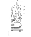
図1は、本発明のインクジェット記録装置の一実施形態を示す断面図である。図1中、xは水平方向、yは記録ヘッド8の吐出口の配列方向(奥行方向)、及びzは鉛直方向をそれぞれ示す。図1に示す実施形態のインクジェット記録装置1は、記録動作も読取動作も行っていない、いわゆる待機状態にある。
FIG. 1 is a cross-sectional view showing one embodiment of the inkjet recording apparatus of the present invention. In FIG. 1, x indicates the horizontal direction, y indicates the arrangement direction (depth direction) of the ejection openings of the
図1に示すインクジェット記録装置1は、記録部2とスキャナ部3を備える複合機であり、記録動作と読取動作に関する様々な処理を、記録部2とスキャナ部3で個別に又は連動して実行する。スキャナ部3は原稿の読み取り(スキャン)を行う。本発明のインクジェット記録装置は、スキャナ部を備えない形態であってもよい。
The
記録部2において、筐体4の鉛直方向下方の底部には、カットシート状の記録媒体Sを収容するための第1カセット5A及び第2カセット5Bが着脱可能に設置されている。第1カセット5Aには、A4サイズまでの比較的小さな記録媒体が平積みで収容されている。第2カセット5Bには、A3サイズまでの比較的大きな記録媒体が平積みで収容されている。第1カセット5Aの近傍には、収容されている記録媒体Sを1枚ずつ分離して給送する第1給送ユニット6Aが設けられている。同様に、第2カセット5Bの近傍には第2給送ユニット6Bが設けられている。記録動作が行われる際には、いずれか一方のカセットから選択的に記録媒体Sが給送される。
In the
搬送ローラ7、排出ローラ12、ピンチローラ7a、拍車7b、ガイド18、インナーガイド19、及びフラッパ11は、記録媒体Sを所定の方向に導くための搬送機構である。搬送ローラ7は、記録ヘッド8の上流側及び下流側に配され、不図示の搬送モータによって駆動される駆動ローラである。ピンチローラ7aは、搬送ローラ7とともに記録媒体Sをニップして回転する従動ローラである。排出ローラ12は、搬送ローラ7の下流側に配され、不図示の搬送モータによって駆動される駆動ローラである。拍車7bは、記録ヘッド8の下流側に配される搬送ローラ7及び排出ローラ12とともに記録媒体Sを挟持して搬送する。
The
ガイド18は、記録媒体Sの搬送経路に設けられ、記録媒体Sを所定の方向に案内する。インナーガイド19は、y方向に延在する部材で湾曲した側面を有し、その側面に沿って記録媒体Sを案内する。フラッパ11は、両面記録動作の際に、記録媒体Sが搬送される方向を切り替えるための部材である。排出トレイ13は、記録動作が完了し排出ローラ12によって排出された記録媒体Sを積載保持するためのトレイである。
The
記録ヘッド8はフルラインタイプの記録ヘッドであり、記録データにしたがってインクを吐出する吐出口が、y方向に沿って記録媒体Sの幅をカバーする範囲で複数配列されている。記録ヘッド8が待機位置にあるとき、記録ヘッド8の吐出口面8aは、図1に示すようにキャップユニット10によってキャップされている。記録動作を行う際は、吐出口面8aがプラテン9と対向するように記録ヘッド8の向きが変更される。プラテン9は、y方向に延在する平板によって構成され、記録ヘッド8によって記録動作が行われる際に、記録媒体Sを背面から支持する。
The
インクタンクユニット14は、記録ヘッド8へ供給される4種のインクをそれぞれ収容する。インク供給ユニット15は、インクタンクユニット14と記録ヘッド8を接続する流路の途中に設けられ、記録ヘッド8へのインクの流量を適切な範囲に調整する。メンテナンスユニット16は、キャップユニット10とワイピングユニット17を備え、所定のタイミングでこれらを作動させて、記録ヘッド8のメンテナンス動作を行う。
The
図1に示すインクジェット記録装置を使用すると、まず、第1カセット5A又は第2カセット5Bに収容されている記録媒体Sが装置内を搬送され、記録部2の記録ヘッド8により画像が記録される。画像が記録された記録媒体Sは、後(排紙の直前)に記録された面を重力方向の下側にして、すなわち、裏返しとなった状態で排紙トレイ13に排紙される。
When the inkjet recording apparatus shown in FIG. 1 is used, the recording medium S accommodated in the
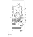
図2A~図2Cは、裏面排紙する際の記録媒体の搬送経路を説明する断面図である。第1カセット5Aの上から1枚目に積載されている記録媒体Sは、第1給送ユニット6Aによって2枚目以降の記録媒体から分離され、搬送ローラ7とピンチローラ7aにニップされながら、プラテン9と記録ヘッド8の間の記録領域Pに向けて搬送される。図2Aは、記録媒体Sの先端が記録領域Pに到達する直前の状態を示す。記録媒体Sの進行方向は、第1給送ユニット6Aに給送されて記録領域Pに到達する間に、水平方向(x方向)から、水平方向に対して約45度傾いた方向に変更される。
2A to 2C are cross-sectional views for explaining the conveying path of the recording medium when ejecting the back side of the sheet. The recording medium S loaded as the first sheet from the top of the
記録領域Pでは、記録ヘッド8に設けられた複数の吐出口から記録媒体Sに向けてインクが吐出される。インクの吐出方式としては、熱エネルギーを発生する吐出素子を利用し、気泡を発生させてインクを吐出するサーマル方式や、力学的エネルギーをインクに作用させてインクを吐出する、いわゆるピエゾ方式を挙げることができる。本発明では、サーマル方式でインクを吐出するラインヘッドを用いることが特に好ましい。インクが付与される領域の記録媒体Sは、プラテン9によってその背面が支持されている。このため、吐出口面と記録媒体Sの距離が一定に保たれている。インクが付与された記録媒体Sは、搬送ローラ7と拍車7bに案内されながら、先端が右に傾いているフラッパ11の左側を通り、ガイド18に沿ってインクジェット記録装置1の鉛直方向上方へと搬送される。図2Bは、記録媒体Sの先端が記録領域Pを通過して鉛直方向上方に搬送される状態を示す。記録媒体Sの進行方向は、水平方向に対し約45度傾いた記録領域Pの位置から、搬送ローラ7と拍車7bによって鉛直方向上方に変更されている。
In the recording area P, ink is ejected toward the recording medium S from a plurality of ejection openings provided in the
記録媒体Sは、鉛直方向上方に搬送された後、排出ローラ12と拍車7bによって排出トレイ13に排出される。図2Cは、記録媒体Sの先端が排出ローラ12を通過して排出トレイ13に裏面排紙の状態で排出される状態を示す。排出された記録媒体Sは、記録ヘッド8によって画像が記録された面を下にした状態で、排出トレイ13上に保持される。
After being transported vertically upward, the recording medium S is discharged to the
図3A~図3Dは、表面排紙する際の記録媒体の搬送経路を説明する断面図である。表面排紙の場合、図2A~図2Cで説明した方法と同様の方法で画像を記録した後、装置内で記録媒体を反転させて排紙する。画像を記録する際の搬送工程は図2A~図2Cと同様であるため、ここでは説明を省略する。以下、図2Cよりも後の搬送工程について、図3A~図3Dを用いて説明する。 3A to 3D are cross-sectional views for explaining the conveying path of the recording medium during surface discharge. In the case of surface discharge, after an image is recorded by a method similar to the method described with reference to FIGS. 2A to 2C, the recording medium is reversed and discharged within the apparatus. Since the conveying process for recording an image is the same as that shown in FIGS. 2A to 2C, the description is omitted here. The transfer process after FIG. 2C will be described below with reference to FIGS. 3A to 3D.
記録ヘッド8による記録動作が完了し、記録媒体Sの後端がフラッパ11を通過すると、搬送ローラ7を逆回転させて記録媒体Sをインクジェット記録装置1の内部へと搬送する。この際、フラッパ11は、不図示のアクチュエータによってその先端が左側に傾くように制御されるため、記録媒体Sの先端(第1面の記録動作における後端)は、フラッパ11の右側を通過して鉛直方向下方へと搬送される。図3Aは、記録媒体Sの先端(第1面の記録動作における後端)が、フラッパ11の右側を通過する状態を示す。その後、記録媒体Sは、インナーガイド19の湾曲した外周面に沿って搬送され、再び記録ヘッド8とプラテン9の間へと搬送される。
When the recording operation by the
以降の搬送経路は、図2B及び図2Cで示した第1面に画像を記録する場合と同様である。図3Cは、記録媒体Sの先端が記録領域Pを通過して鉛直方向上方に搬送される状態を示す。この際、フラッパ11は、不図示のアクチュエータにより先端が右側に傾いた位置に移動するように制御される。図3Dは、記録媒体Sの先端が排出ローラ12を通過して排出トレイ13に表面排紙の状態で排出される状態を示す。
The transport path thereafter is the same as in the case of recording an image on the first surface shown in FIGS. 2B and 2C. FIG. 3C shows a state in which the leading edge of the recording medium S passes through the recording area P and is transported vertically upward. At this time, the
本実施形態のインクジェット記録装置1を使用すれば、記録媒体の第1面及び第2面(両面)にそれぞれ画像を記録する、いわゆる両面記録を行うことができる。図3A~図3Dの場合、第1面(表面)に画像を記録した後、第2面(裏面)に画像を記録する。第1面に画像を記録する際の搬送工程は図2A~図2Cと同様であるため、ここでは説明を省略する。以下、図2Cよりも後の搬送工程について、図3A~図3Dを用いて説明する。
By using the
記録ヘッド8による第1面への記録動作が完了し、記録媒体Sの後端がフラッパ11を通過すると、搬送ローラ7を逆回転させて記録媒体Sをインクジェット記録装置1の内部へと搬送する。この際、フラッパ11は、不図示のアクチュエータによってその先端が左側に傾くように制御されるため、記録媒体Sの先端(第1面の記録動作における後端)はフラッパ11の右側を通過して鉛直方向下方へと搬送される。図3Aは、記録媒体Sの先端(第1面の記録動作における後端)が、フラッパ11の右側を通過する状態を示す。その後、記録媒体Sは、インナーガイド19の湾曲した外周面に沿って搬送され、再び記録ヘッド8とプラテン9の間の記録領域Pへと搬送される。この際、記録ヘッド8の吐出口面8aに、記録媒体Sの第2面が対向する。図3Bは、第2面の記録動作のために、記録媒体Sの先端が記録領域Pに到達する直前の搬送状態を示す。
When the recording operation on the first side by the
以降の搬送経路は、図2B及び図2Cで示した第1面に画像を記録する場合と同様である。図3Cは、記録媒体Sの先端が記録領域Pを通過して鉛直方向上方に搬送される状態を示す。この際、フラッパ11は、不図示のアクチュエータにより先端が右側に傾いた位置に移動するように制御される。図3Dは、記録媒体Sの先端が排出ローラ12を通過して排出トレイ13に排出される状態を示す。
The transport path thereafter is the same as in the case of recording an image on the first surface shown in FIGS. 2B and 2C. FIG. 3C shows a state in which the leading edge of the recording medium S passes through the recording area P and is transported vertically upward. At this time, the
記録媒体としては、普通紙や非コート紙などのコート層を有しない記録媒体、及び、光沢紙やアート紙などのコート層を有する記録媒体のような、浸透性を有する記録媒体を用いることが好ましい。なかでも、基材が紙である記録媒体が好ましく、コート層を有しない紙基材の記録媒体がさらに好ましい。 As the recording medium, a recording medium having no coat layer such as plain paper or uncoated paper, or a permeable recording medium such as a recording medium having a coat layer such as glossy paper or art paper can be used. preferable. Among them, a recording medium having a paper base is preferable, and a recording medium having a paper base without a coat layer is more preferable.
(インク)
本発明の記録方法で用いるインクは、インクジェット用の水性インクである。このインクの粘度η1(mPa・s)は、5.0mPa・s以上である。また、このインクの20質量%を蒸発させた蒸発インクの粘度η2(mPa・s)と、インクの粘度η1(mPa・s)の差η2-η1は、4.0mPa・s以上である。本発明の記録方法で用いるインクは、いわゆる「硬化型インク」である必要はない。したがって、本発明の記録方法で用いるインクは、外部エネルギーの付加により重合しうる重合性モノマーなどの化合物を含有しなくてもよい。以下、インクを構成する各成分やインクの物性について詳細に説明する。
(ink)
The ink used in the recording method of the present invention is a water-based ink for inkjet. The viscosity η 1 (mPa·s) of this ink is 5.0 mPa·s or more. Further, the difference η 2 −η 1 between the viscosity η 2 (mPa·s) of the evaporated ink obtained by evaporating 20 mass % of this ink and the viscosity η 1 (mPa·s) of the ink is 4.0 mPa·s or more. is. The ink used in the recording method of the present invention does not have to be a so-called "curable ink". Therefore, the ink used in the recording method of the present invention may not contain compounds such as polymerizable monomers that can be polymerized by the application of external energy. Each component constituting the ink and physical properties of the ink will be described in detail below.
[色材]
色材としては、顔料や染料を用いることができる。インク中の色材の含有量(質量%)は、インク全質量を基準として、0.5質量%以上15.0質量%以下であることが好ましく、1.0質量%以上10.0質量%以下であることがさらに好ましい。
[Color material]
A pigment or a dye can be used as the coloring material. The content (% by mass) of the coloring material in the ink is preferably 0.5% by mass or more and 15.0% by mass or less, and 1.0% by mass or more and 10.0% by mass or less, based on the total mass of the ink. More preferably:
顔料の具体例としては、カーボンブラック、酸化チタンなどの無機顔料;アゾ、フタロシアニン、キナクリドン、イソインドリノン、イミダゾロン、ジケトピロロピロール、ジオキサジンなどの有機顔料を挙げることができる。なかでも、カーボンブラック;アゾ顔料;フタロシアニン顔料;キナクリドン顔料などが好ましい。C.I.ナンバーが付された有機顔料の好適な具体例を以下に列挙する。アゾ顔料としては、C.I.ピグメントイエロー74などを挙げることができる。フタロシアニン顔料としては、C.I.ピグメントブルー15:3、C.I.ピグメントブルー15:4、C.I.ピグメントブルー15:6などを挙げることができる。キナクリドン顔料としては、C.I.ピグメントバイオレット19、C.I.ピグメントレッド122、C.I.ピグメントレッド202などの他、複数種のキナクリドン顔料の固溶体などを挙げることができる。
Specific examples of pigments include inorganic pigments such as carbon black and titanium oxide; and organic pigments such as azo, phthalocyanine, quinacridone, isoindolinone, imidazolone, diketopyrrolopyrrole and dioxazine. Among them, carbon black; azo pigments; phthalocyanine pigments; quinacridone pigments and the like are preferred. C. I. Preferred specific examples of numbered organic pigments are listed below. Examples of azo pigments include C.I. I. Pigment Yellow 74 and the like can be mentioned. Examples of phthalocyanine pigments include C.I. I. Pigment Blue 15:3, C.I. I. Pigment Blue 15:4, C.I. I. Pigment Blue 15:6 and the like can be mentioned. Examples of quinacridone pigments include C.I. I.
顔料の分散方式としては、分散剤として樹脂を用いた樹脂分散顔料や、顔料の粒子表面に親水性基が結合している自己分散顔料などを挙げることができる。また、顔料の粒子表面に樹脂を含む有機基を化学的に結合させた樹脂結合型顔料や、顔料の粒子の表面を樹脂などで被覆又は内包したマイクロカプセル顔料などを用いることができる。 Examples of the method of dispersing the pigment include a resin-dispersed pigment using a resin as a dispersant, and a self-dispersing pigment in which a hydrophilic group is bonded to the particle surface of the pigment. Moreover, a resin-bonded pigment in which an organic group containing a resin is chemically bonded to the particle surface of the pigment, or a microcapsule pigment in which the surface of the pigment particle is coated or encapsulated with a resin or the like can be used.
顔料を水性媒体中に分散させるための樹脂分散剤としては、アニオン性基の作用によって顔料を水性媒体中に分散させうるものを用いることが好ましい。樹脂分散剤としては、後述するような樹脂、なかでも水溶性樹脂を用いることができる。インク中の顔料の含有量(質量%)は、樹脂分散剤の含有量に対する質量比率で、0.3倍以上10.0倍以下であることが好ましい。 As the resin dispersant for dispersing the pigment in the aqueous medium, it is preferable to use one that can disperse the pigment in the aqueous medium by the action of an anionic group. As the resin dispersant, a resin as described later, especially a water-soluble resin can be used. The content (% by mass) of the pigment in the ink is preferably 0.3 times or more and 10.0 times or less as a mass ratio with respect to the content of the resin dispersant.
自己分散顔料としては、カルボン酸基、スルホン酸基、ホスホン酸基などのアニオン性基が、顔料の粒子表面に直接又は他の原子団(-R-)を介して結合しているものを用いることができる。アニオン性基は、酸型及び塩型のいずれであってもよく、塩型である場合は、その一部が解離した状態及び全てが解離した状態のいずれであってもよい。アニオン性基が塩型である場合において、カウンターイオンとなるカチオンとしては、アルカリ金属カチオン、アンモニウム、有機アンモニウムなどを挙げることができる。他の原子団(-R-)の具体例としては、炭素原子数1乃至12の直鎖又は分岐のアルキレン基;フェニレン基やナフチレン基などのアリーレン基;カルボニル基;イミノ基;アミド基;スルホニル基;エステル基;エーテル基などを挙げることができる。また、これらの基を組み合わせた基であってもよい。 As the self-dispersing pigment, those in which an anionic group such as a carboxylic acid group, a sulfonic acid group, or a phosphonic acid group is bonded directly to the particle surface of the pigment or through another atomic group (-R-) is used. be able to. The anionic group may be in either an acid form or a salt form, and in the case of a salt form, it may be in a partially dissociated state or in a completely dissociated state. When the anionic group is in the salt form, cations that serve as counter ions include alkali metal cations, ammonium and organic ammonium. Specific examples of other atomic groups (-R-) include linear or branched alkylene groups having 1 to 12 carbon atoms; arylene groups such as phenylene groups and naphthylene groups; carbonyl groups; imino groups; amide groups; groups; ester groups; ether groups, and the like. Moreover, the group which combined these groups may be sufficient.
染料としては、アニオン性基を有するものを用いることが好ましい。染料の具体例としては、アゾ、トリフェニルメタン、(アザ)フタロシアニン、キサンテン、アントラピリドンなどの染料を挙げることができる。 As the dye, it is preferable to use one having an anionic group. Specific examples of dyes include dyes such as azo, triphenylmethane, (aza)phthalocyanine, xanthene, and anthrapyridone.
色材としては、顔料を用いることが好ましい。なかでも、自己分散顔料や、分散剤として水溶性樹脂を利用した樹脂分散顔料を用いることがさらに好ましい。 A pigment is preferably used as the coloring material. Among them, it is more preferable to use a self-dispersed pigment or a resin-dispersed pigment using a water-soluble resin as a dispersant.
[樹脂]
インクには、樹脂を含有させることができる。インク中の樹脂の含有量(質量%)は、インク全質量を基準として、0.1質量%以上20.0質量%以下であることが好ましく、0.5質量%以上15.0質量%以下であることがさらに好ましい。
[resin]
The ink can contain a resin. The resin content (% by mass) in the ink is preferably 0.1% by mass or more and 20.0% by mass or less, and 0.5% by mass or more and 15.0% by mass or less, based on the total mass of the ink. is more preferable.
樹脂は、(i)顔料の分散状態を安定化させるため、すなわち、樹脂分散剤やその補助としてインクに添加することができる。また、(ii)記録される画像の各種特性を向上させるためにインクに添加することができる。樹脂の形態としては、ブロック共重合体、ランダム共重合体、グラフト共重合体、及びこれらの組み合わせなどを挙げることができる。また、樹脂は、水性媒体に溶解しうる水溶性樹脂であってもよく、水性媒体中に分散する樹脂粒子であってもよい。樹脂粒子は、色材を内包する必要はない。 The resin can be added to the ink to (i) stabilize the dispersed state of the pigment, that is, as a resin dispersant or as an adjunct thereto. In addition, (ii) it can be added to the ink in order to improve various characteristics of the recorded image. Forms of the resin include block copolymers, random copolymers, graft copolymers, combinations thereof, and the like. Moreover, the resin may be a water-soluble resin that is soluble in an aqueous medium, or resin particles that are dispersed in an aqueous medium. Resin particles do not need to contain a coloring material.
本明細書において「樹脂が水溶性である」とは、その樹脂を酸価と当量のアルカリで中和した場合に、動的光散乱法により粒子径を測定しうる粒子を形成しない状態で水性媒体中に存在することを意味する。樹脂が水溶性であるか否かについては、以下に示す方法にしたがって判断することができる。まず、酸価相当のアルカリ(水酸化ナトリウム、水酸化カリウムなど)により中和された樹脂を含む液体(樹脂固形分:10質量%)を用意する。次いで、用意した液体を純水で10倍(体積基準)に希釈して試料溶液を調製する。そして、試料溶液中の樹脂の粒子径を動的光散乱法により測定した場合に、粒子径を有する粒子が測定されない場合に、その樹脂は水溶性であると判断することができる。この際の測定条件は、例えば、以下のようにすることができる。 As used herein, the phrase "the resin is water-soluble" means that when the resin is neutralized with an alkali equivalent to its acid value, it is water-soluble in a state in which particles whose particle size can be measured by a dynamic light scattering method are not formed. means present in the medium. Whether or not the resin is water-soluble can be determined according to the method described below. First, a liquid (resin solid content: 10% by mass) containing a resin neutralized with an acid value equivalent alkali (sodium hydroxide, potassium hydroxide, etc.) is prepared. Next, the prepared liquid is diluted 10-fold (by volume) with pure water to prepare a sample solution. Then, when the particle size of the resin in the sample solution is measured by the dynamic light scattering method, if particles having the particle size are not measured, it can be determined that the resin is water-soluble. The measurement conditions at this time can be, for example, as follows.
[測定条件]
SetZero:30秒
測定回数:3回
測定時間:180秒
[Measurement condition]
SetZero: 30 seconds Number of measurements: 3 Measurement time: 180 seconds
粒度分布測定装置としては、動的光散乱法による粒度分析計(例えば、商品名「UPA-EX150」、日機装製)などを使用することができる。勿論、使用する粒度分布測定装置や測定条件などは上記に限られるものではない。 As the particle size distribution analyzer, a particle size analyzer using dynamic light scattering (for example, trade name “UPA-EX150” manufactured by Nikkiso Co., Ltd.) can be used. Of course, the particle size distribution measuring device and measurement conditions to be used are not limited to those described above.
水溶性樹脂の酸価は、100mgKOH/g以上250mgKOH/g以下であることが好ましい。樹脂粒子を構成する樹脂の酸価は、5mgKOH/g以上100mgKOH/g以下であることが好ましい。水溶性樹脂の重量平均分子量は、3,000以上15,000以下であることが好ましい。樹脂粒子を構成する樹脂の重量平均分子量は、1,000以上2,000,000以下であることが好ましい。動的光散乱法により測定される樹脂粒子の平均粒子径(体積基準の累積50%粒子径(D50))は、100nm以上500nm以下であることが好ましい。 The acid value of the water-soluble resin is preferably 100 mgKOH/g or more and 250 mgKOH/g or less. The acid value of the resin constituting the resin particles is preferably 5 mgKOH/g or more and 100 mgKOH/g or less. The weight average molecular weight of the water-soluble resin is preferably 3,000 or more and 15,000 or less. The weight-average molecular weight of the resin constituting the resin particles is preferably 1,000 or more and 2,000,000 or less. The average particle size (volume-based cumulative 50% particle size (D 50 )) of the resin particles measured by a dynamic light scattering method is preferably 100 nm or more and 500 nm or less.
樹脂としては、アクリル系樹脂、ウレタン系樹脂、オレフィン系樹脂などを挙げることができる。なかでも、アクリル系樹脂やウレタン系樹脂が好ましい。 Examples of resins include acrylic resins, urethane resins, and olefin resins. Among them, acrylic resins and urethane resins are preferable.
アクリル系樹脂としては、親水性ユニット及び疎水性ユニットを構成ユニットとして有するものが好ましい。なかでも、(メタ)アクリル酸に由来する親水性ユニットと、芳香環を有するモノマー及び(メタ)アクリル酸エステル系モノマーの少なくとも一方に由来する疎水性ユニットと、を有する樹脂が好ましい。特に、(メタ)アクリル酸に由来する親水性ユニットと、スチレン及びα-メチルスチレンの少なくとも一方のモノマーに由来する疎水性ユニットとを有する樹脂が好ましい。これらの樹脂は、顔料との相互作用が生じやすいため、顔料を分散させるための樹脂分散剤として好適に利用することができる。 As the acrylic resin, one having a hydrophilic unit and a hydrophobic unit as structural units is preferable. Among them, a resin having a hydrophilic unit derived from (meth)acrylic acid and a hydrophobic unit derived from at least one of a monomer having an aromatic ring and a (meth)acrylic acid ester-based monomer is preferable. In particular, a resin having a hydrophilic unit derived from (meth)acrylic acid and a hydrophobic unit derived from at least one monomer of styrene and α-methylstyrene is preferred. Since these resins easily interact with pigments, they can be suitably used as resin dispersants for dispersing pigments.
親水性ユニットは、アニオン性基などの親水性基を有するユニットである。親水性ユニットは、例えば、親水性基を有する親水性モノマーを重合することで形成することができる。親水性基を有する親水性モノマーの具体例としては、(メタ)アクリル酸、イタコン酸、マレイン酸、フマル酸などのカルボン酸基を有する酸性モノマー、これらの酸性モノマーの無水物や塩などのアニオン性モノマーなどを挙げることができる。酸性モノマーの塩を構成するカチオンとしては、リチウム、ナトリウム、カリウム、アンモニウム、有機アンモニウムなどのイオンを挙げることができる。疎水性ユニットは、アニオン性基などの親水性基を有しないユニットである。疎水性ユニットは、例えば、アニオン性基などの親水性基を有しない、疎水性モノマーを重合することで形成することができる。疎水性モノマーの具体例としては、スチレン、α-メチルスチレン、(メタ)アクリル酸ベンジルなどの芳香環を有するモノマー;(メタ)アクリル酸メチル、(メタ)アクリル酸ブチル、(メタ)アクリル酸2-エチルヘキシルなどの(メタ)アクリル酸エステル系モノマーなどを挙げることができる。さらに、アルキレンオキサイド基を有するモノマーを用いてもよい。 A hydrophilic unit is a unit having a hydrophilic group such as an anionic group. A hydrophilic unit can be formed, for example, by polymerizing a hydrophilic monomer having a hydrophilic group. Specific examples of hydrophilic monomers having hydrophilic groups include acidic monomers having carboxylic acid groups such as (meth)acrylic acid, itaconic acid, maleic acid and fumaric acid, and anions such as anhydrides and salts of these acidic monomers. organic monomers, and the like. Examples of cations constituting salts of acidic monomers include ions such as lithium, sodium, potassium, ammonium and organic ammonium. A hydrophobic unit is a unit that does not have a hydrophilic group such as an anionic group. A hydrophobic unit can be formed, for example, by polymerizing a hydrophobic monomer that does not have a hydrophilic group such as an anionic group. Specific examples of hydrophobic monomers include monomers having an aromatic ring such as styrene, α-methylstyrene, and benzyl (meth)acrylate; methyl (meth)acrylate, butyl (meth)acrylate, (meth)acrylic acid 2 - (Meth)acrylic acid ester monomers such as ethylhexyl. Furthermore, a monomer having an alkylene oxide group may be used.
ウレタン系樹脂は、例えば、ポリイソシアネートとポリオールとを反応させて得ることができる。また、鎖延長剤をさらに反応させたものであってもよい。オレフィン系樹脂としては、例えば、ポリエチレン、ポリプロピレンなどを挙げることができる。 A urethane-based resin can be obtained, for example, by reacting a polyisocyanate with a polyol. Moreover, what made the chain extension agent further react may be used. Examples of olefinic resins include polyethylene and polypropylene.
〔アルキレンオキサイド基を有するユニットを持つ樹脂粒子〕
本発明においては、インクの20質量%を蒸発させた蒸発インクの粘度η2(mPa・s)と、インクの粘度η1(mPa・s)の差η2-η1(粘度差η2-η1)が、4.0mPa・s以上である。後述する25℃で固体である多価アルコール化合物(以下、単に「多価アルコール化合物」とも記す)のみを用いて、蒸発インクの粘度がマイナスカールを低減しうる粘度となるようにインクの組成を調整しようとすると、多価アルコール化合物の量が多くなる。このため、粘度差η2-η1を高めようとするとη1も高くなりすぎてしまい、スミアを十分に抑制しにくくなる。すなわち、多価アルコール化合物のみを用いて蒸発インクの粘度を調整しようとすると、マイナスカールとスミアがトレードオフの関係になりやすいため、マイナスカールの抑制効果とスミアの抑制効果を高いレベルで両立しにくくなる場合がある。
[Resin Particle Having Unit Having Alkylene Oxide Group]
In the present invention, the difference η 2 −η 1 ( viscosity difference η 2 − η 1 ) is 4.0 mPa·s or more. Using only a polyhydric alcohol compound that is solid at 25° C. (hereinafter also simply referred to as a “polyhydric alcohol compound”), the composition of the ink is adjusted so that the viscosity of the evaporated ink can reduce negative curl. If you try to adjust it, the amount of polyhydric alcohol compound will increase. Therefore, if an attempt is made to increase the viscosity difference η 2 -η 1 , η 1 also becomes too high, making it difficult to sufficiently suppress smear. In other words, if you try to adjust the viscosity of the evaporated ink using only a polyhydric alcohol compound, there is likely to be a trade-off relationship between negative curl and smear. It may become difficult.
一方、スミアの発生を抑制すべく、多価アルコール化合物のみで粘度η1を調整したインクについては粘度差η2-η1を高めることが困難になり、マイナスカールの抑制効果がやや低くなることがある。マイナスカールの抑制効果とスミアの抑制効果を高いレベルで両立するには、インクの粘度η1を低くするとともに、粘度差η2-η1を高めることが好ましい。検討の結果、本発明者らは、多価アルコール化合物に加えて、アルキレンオキサイド基を有するユニットを含む樹脂粒子をインクに含有させることを見出した。アルキレンオキサイド基を有するユニットを含む樹脂粒子を用いることで、多価アルコール化合物のみを用いる場合に比して、インクの粘度η1を低くすることができるとともに、粘度差η2-η1を高めることができる。 On the other hand, it is difficult to increase the viscosity difference η 2 −η 1 for inks in which the viscosity η 1 is adjusted only with a polyhydric alcohol compound in order to suppress the occurrence of smear, and the effect of suppressing negative curl is slightly reduced. There is In order to achieve both the effect of suppressing negative curl and the effect of suppressing smear at a high level, it is preferable to lower the ink viscosity η 1 and increase the viscosity difference η 2 -η 1 . As a result of investigation, the present inventors found that the ink contains resin particles containing a unit having an alkylene oxide group, in addition to the polyhydric alcohol compound. By using resin particles containing a unit having an alkylene oxide group, the viscosity η 1 of the ink can be lowered and the viscosity difference η 2 −η 1 can be increased as compared with the case where only a polyhydric alcohol compound is used. be able to.
アルキレンオキサイド基を有するユニットを含む樹脂粒子は、同じ量の多価アルコール化合物と比べて、インクの粘度η1をより低下させやすい。これは、粒子形状であるため、25℃で固体である多価アルコール化合物や水溶性樹脂などと比較して、分子間の立体的な相互作用が少ないためであると考えられる。一方、インク中の水分の蒸発にしたがって、多価アルコール化合物と樹脂粒子とが相互作用しやすくなる。しかし、多価アルコール化合物のヒドロキシ基と、樹脂粒子のアルキレンオキサイド基とが水素結合により相互作用するため、粘度差η2-η1を高めることができると考えられる。 A resin particle containing a unit having an alkylene oxide group is more likely to reduce the ink viscosity η 1 than the same amount of polyhydric alcohol compound. It is considered that this is because, due to the particle shape, steric interaction between molecules is less than that of polyhydric alcohol compounds, water-soluble resins, and the like, which are solid at 25°C. On the other hand, as the water in the ink evaporates, the polyhydric alcohol compound and the resin particles tend to interact with each other. However, it is believed that the viscosity difference η 2 −η 1 can be increased because the hydroxy group of the polyhydric alcohol compound interacts with the alkylene oxide group of the resin particles through hydrogen bonding.
アルキレンオキサイド基を有するユニットを含む樹脂粒子は、アクリル系樹脂を構成する好適なユニットとして前述したような、親水性ユニット及び疎水性ユニットをさらに有することが好ましい。樹脂粒子中のアルキレンオキサイド基を有するユニットの占める割合(質量%)は、3.0質量%以上であることが好ましい。これにより、粘度差η2-η1を効率よく高めることが可能となり、マイナスカールの発生をより低減することができる。樹脂粒子中のアルキレンオキサイド基を有するユニットの占める割合(質量%)は、10.0質量%以下であることが好ましく、5.0質量%以下であることがさらに好ましい。 The resin particles containing units having an alkylene oxide group preferably further contain a hydrophilic unit and a hydrophobic unit as described above as suitable units constituting the acrylic resin. The ratio (% by mass) of units having an alkylene oxide group in the resin particles is preferably 3.0% by mass or more. This makes it possible to efficiently increase the viscosity difference η 2 -η 1 and further reduce the occurrence of negative curl. The ratio (% by mass) of units having an alkylene oxide group in the resin particles is preferably 10.0% by mass or less, more preferably 5.0% by mass or less.
〔アルキレンオキサイド基を有するモノマー〕
アルキレンオキサイド基としては、エチレンオキサイド基、プロピレンオキサイド基などを挙げることができる。アルキレンオキサイド基を有するユニットは、アルキレンオキサイド基を有するモノマーを重合することで形成することができる。アルキレンオキサイド基を有するモノマーとしては、エチレングリコール(メタ)アクリレート、トリエチレングリコール(メタ)アクリレート、プロピレングリコール(メタ)アクリレートなどの、(ポリ)アルキレングリコール(メタ)アクリレート類;メトキシエチレングリコール(メタ)アクリレート、メトキシトリエチレングリコール(メタ)アクリレート、エトキシエチレングリコール(メタ)アクリレート、メトキシプロピレングリコール(メタ)アクリレートなどの、アルコキシ(ポリ)アルキレングリコール(メタ)アクリレート類;フェノキシエチレングリコール(メタ)アクリレート、フェノキシトリエチレングリコール(メタ)アクリレート、フェノキシプロピレングリコール(メタ)アクリレートなどの、アリールオキシ(ポリ)アルキレングリコール(メタ)アクリレートなどを挙げることができる。また、アルキレンオキサイド基を有するモノマーとして、アルキレンオキサイド基を有する反応性界面活性剤などを用いることもできる。
[Monomer Having Alkylene Oxide Group]
Examples of the alkylene oxide group include an ethylene oxide group and a propylene oxide group. A unit having an alkylene oxide group can be formed by polymerizing a monomer having an alkylene oxide group. Examples of monomers having an alkylene oxide group include (poly)alkylene glycol (meth)acrylates such as ethylene glycol (meth)acrylate, triethylene glycol (meth)acrylate, and propylene glycol (meth)acrylate; methoxyethylene glycol (meth) Alkoxy (poly) alkylene glycol (meth) acrylates such as acrylate, methoxytriethylene glycol (meth) acrylate, ethoxyethylene glycol (meth) acrylate, methoxypropylene glycol (meth) acrylate; phenoxyethylene glycol (meth) acrylate, phenoxy Examples include aryloxy (poly)alkylene glycol (meth)acrylates such as triethylene glycol (meth)acrylate and phenoxypropylene glycol (meth)acrylate. Moreover, a reactive surfactant having an alkylene oxide group can also be used as the monomer having an alkylene oxide group.
アルキレンオキサイド基を有するユニットは、8個以上のアルキレンオキサイド基を有するモノマーに由来するユニットであることが好ましい。すなわち、アルキレンオキサイド基を有するモノマー中のアルキレンオキサイド基の数は、8個以上であることが好ましい。8個以上のアルキレンオキサイド基を有するモノマーに由来するユニットを含む樹脂粒子を用いることで、粘度差η2-η1をより高めることが可能となり、マイナスカールの発生をより低減することができる。アルキレンオキサイド基を有するモノマー中のアルキレンオキサイド基の数は、15個以下であることが好ましく、12個以下であることがさらに好ましい。ここで、アルキレンオキサイド基を有するモノマー中の「アルキレンオキサイド基の数」とは、例えば、エチレンオキサイド基及びプロピレンオキサイド基を用いる場合は、「エチレンオキサイド基及びプロピレンオキサイド基の合計数」を意味する。 A unit having an alkylene oxide group is preferably a unit derived from a monomer having 8 or more alkylene oxide groups. That is, the number of alkylene oxide groups in the monomer having alkylene oxide groups is preferably 8 or more. By using resin particles containing units derived from a monomer having 8 or more alkylene oxide groups, it is possible to further increase the viscosity difference η 2 -η 1 and further reduce the occurrence of negative curl. The number of alkylene oxide groups in the monomer having an alkylene oxide group is preferably 15 or less, more preferably 12 or less. Here, "the number of alkylene oxide groups" in the monomer having an alkylene oxide group means "total number of ethylene oxide groups and propylene oxide groups" when, for example, ethylene oxide groups and propylene oxide groups are used. .
アルキレンオキサイド基を有するユニットを含む樹脂粒子の表面電荷量(μmol/g)は、500μmol/g以下であることが好ましい。表面電荷量が500μmol/g超であると、樹脂粒子に起因してインク中に存在するイオンの量が多くなることがある。このため、水分の蒸発により顔料(特に、アニオン性基の作用によって分散させた顔料)が塩析されやすく、粘度差η2-η1が高まりすぎてしまい、スミアの発生を抑制する効果がやや低くなる場合がある。樹脂粒子の表面電荷量は、1μmol/g以上であることが好ましく、100μmol/g以上であることがさらに好ましい。 The surface charge amount (μmol/g) of the resin particles containing units having an alkylene oxide group is preferably 500 μmol/g or less. If the surface charge amount exceeds 500 μmol/g, the amount of ions present in the ink may increase due to the resin particles. For this reason, the evaporation of water tends to salt out the pigment (especially the pigment dispersed by the action of the anionic group), and the viscosity difference η 2 - η 1 becomes too high. may be lower. The surface charge amount of the resin particles is preferably 1 μmol/g or more, more preferably 100 μmol/g or more.
樹脂粒子の表面電荷量は、コロイド滴定により測定することができる。具体的には、まず、インクなどから適切な方法で分取した樹脂粒子を水に添加し、塩酸などの鉱酸でpH2に調整して24時間撹拌する。その後、遠心分離して沈殿した樹脂を回収し、乾固させる。粉砕した樹脂1gに0.1mol/L炭酸水素ナトリウム水溶液30gを添加し、15時間撹拌して樹脂を含む液体を得る。得られた液体1gに純水を加えて希釈し、希釈液15gを得る。この希釈液中の樹脂粒子について、電位差を利用したコロイド滴定を行い、樹脂粒子の単位質量当たりの電荷量を得る。そして、得られた電荷量を体積基準の累積50%粒子径(D50)から算出した樹脂粒子の表面積で除することで、樹脂粒子の表面電荷量を算出することができる。滴定は、流動電位滴定ユニット(PCD-500)を搭載した電位差自動滴定装置(商品名「AT510」、京都電子工業製)などの滴定装置を使用し、0.1mol/L塩酸などの滴定試薬を用いて行うことができる。勿論、使用する滴定装置や測定条件などは上記に限られるものではない。
The surface charge amount of resin particles can be measured by colloidal titration. Specifically, first, resin particles separated from ink or the like by an appropriate method are added to water, adjusted to
[水性媒体]
本発明の記録方法で用いるインクは、水性媒体として少なくとも水を含有する水性のインクである。インクには、水、又は水及び水溶性有機溶剤の混合溶媒である水性媒体を含有させることができる。水としては、脱イオン水やイオン交換水を用いることが好ましい。水性インク中の水の含有量(質量%)は、インク全質量を基準として、30.0質量%以上95.0質量%以下であることが好ましい。前述の通り、インクジェット用の水性インクを構成する液体成分のうち、記録媒体を最も膨潤させやすいのは水である。このため、インク中の水の量を減らすと、マイナスカールの発生をより有効に抑制することができる。したがって、水性インク中の水の含有量(質量%)は、インク全質量を基準として、66.0質量%以下であることが好ましく、35.0質量%以上65.0質量%以下であることがさらに好ましい。
[Aqueous medium]
The ink used in the recording method of the present invention is an aqueous ink containing at least water as an aqueous medium. The ink can contain water or an aqueous medium that is a mixed solvent of water and a water-soluble organic solvent. As water, it is preferable to use deionized water or ion-exchanged water. The water content (% by mass) in the water-based ink is preferably 30.0% by mass or more and 95.0% by mass or less based on the total mass of the ink. As described above, among the liquid components constituting the water-based ink for inkjet, water is the most likely to swell the recording medium. Therefore, by reducing the amount of water in the ink, the occurrence of negative curl can be more effectively suppressed. Therefore, the content (% by mass) of water in the water-based ink is preferably 66.0% by mass or less, more preferably 35.0% by mass or more and 65.0% by mass or less, based on the total mass of the ink. is more preferred.
インク中の水溶性有機溶剤の含有量(質量%)は、インク全質量を基準として、3.0質量%以上50.0質量%以下であることが好ましい。この「水溶性有機溶剤の含有量」は、後述する25℃で固体である多価アルコール化合物を含む値である。水溶性有機溶剤としては、アルコール類、(ポリ)アルキレングリコール類、グリコールエーテル類、含窒素化合物類、含硫黄化合物類などのインクジェット用のインクに使用可能なものをいずれも用いることができる。 The content (% by mass) of the water-soluble organic solvent in the ink is preferably 3.0% by mass or more and 50.0% by mass or less based on the total mass of the ink. This "water-soluble organic solvent content" is a value including a polyhydric alcohol compound that is solid at 25°C, which will be described later. As the water-soluble organic solvent, alcohols, (poly)alkylene glycols, glycol ethers, nitrogen-containing compounds, sulfur-containing compounds, and the like, which can be used for inkjet inks, can be used.
通常、「水溶性有機溶剤」とは液体を意味するが、本発明においては、25℃(常温)で固体であるものも水溶性有機溶剤に含めることとする。水性インクに汎用であり、25℃で固体である水溶性有機溶剤の具体例としては、1,6-ヘキサンジオール、トリメチロールプロパン、エチレン尿素、尿素、数平均分子量1,000のポリエチレングリコールなどを挙げることができる。これらのなかには、25℃で固体である多価アルコール化合物に分類されるものもある。 Normally, the term "water-soluble organic solvent" means a liquid, but in the present invention, a water-soluble organic solvent that is solid at 25°C (normal temperature) is also included in the water-soluble organic solvent. Specific examples of water-soluble organic solvents that are commonly used for water-based inks and are solid at 25° C. include 1,6-hexanediol, trimethylolpropane, ethylene urea, urea, and polyethylene glycol having a number average molecular weight of 1,000. can be mentioned. Some of these are classified as polyhydric alcohol compounds that are solid at 25°C.
〔25℃で固体である多価アルコール化合物〕
前述の通り、蒸発インクの粘度を高めることでマイナスカールの発生を抑制することができる一方、蒸発インクの粘度を高めすぎるとスミアが発生しやすくなる傾向にある。蒸発インクの粘度は、様々な方法で高めることができる。例えば、アニオン性基の作用によって分散させる顔料を用いる場合、以下のような成分の種類や含有量を制御することで、蒸発インクの粘度を調整することができる。具体的には、カルシウム塩などの水溶性の金属塩;貧溶媒などの水溶性有機溶剤;水溶性樹脂、樹脂粒子などの樹脂;25℃で固体である多価アルコール化合物;などを挙げることができる。
[Polyhydric alcohol compound that is solid at 25°C]
As described above, the occurrence of negative curl can be suppressed by increasing the viscosity of the evaporated ink, but if the viscosity of the evaporated ink is too high, smear tends to occur. The viscosity of vaporized ink can be increased in various ways. For example, when a pigment that is dispersed by the action of an anionic group is used, the viscosity of the evaporated ink can be adjusted by controlling the types and contents of the following components. Specifically, water-soluble metal salts such as calcium salts; water-soluble organic solvents such as poor solvents; resins such as water-soluble resins and resin particles; polyhydric alcohol compounds that are solid at 25°C; can.
なかでも、25℃で固体である多価アルコール化合物を用いることが好適であることがわかった。金属塩や樹脂(特に水溶性樹脂)を用いると、少量であっても蒸発インクの粘度が著しく上昇し、記録媒体の表面上にインクが残りやすくなって、スミアが発生しやすくなる傾向にある。一方、スミアの発生が抑制されるレベルまで金属塩や樹脂の含有量を減らすと、蒸発インクの粘度を高めることが困難になる。また、尿素やベタイン化合物などの化合物の場合も、蒸発インクの粘度を高めることが困難である。 Among them, it was found that it is preferable to use a polyhydric alcohol compound that is solid at 25°C. When metal salts or resins (especially water-soluble resins) are used, even if the amount is small, the viscosity of the evaporated ink increases significantly, and the ink tends to remain on the surface of the recording medium, tending to cause smearing. . On the other hand, if the content of the metal salt or resin is reduced to a level at which smearing is suppressed, it becomes difficult to increase the viscosity of the vaporized ink. In the case of compounds such as urea and betaine compounds, it is also difficult to increase the viscosity of vaporized ink.
これに対して、25℃で固体である多価アルコール化合物の適当量をインクに含有させることで、スミアの発生をより有効に抑制することができる。25℃で固体である多価アルコール化合物は、結晶性が高く、水が蒸発した際に複数の分子が相互作用しやすい。さらに、25℃で固体である多価アルコール化合物は、1分子中に複数のヒドロキシ基を有するため、水素結合による相互作用も生じている。これらの相互作用により、マイナスカールの発生を抑制するのに有効な範囲で、蒸発インクの粘度を高めることができる。インク中の多価アルコール化合物の含有量(質量%)は、インク全質量を基準として、10.0質量%以上であることが好ましく、35.0質量%以下であることがさらに好ましく、20.0質量%以下であることが特に好ましい。 In contrast, by adding an appropriate amount of a polyhydric alcohol compound that is solid at 25° C. to the ink, the occurrence of smear can be more effectively suppressed. A polyhydric alcohol compound that is solid at 25° C. has high crystallinity, and multiple molecules tend to interact with each other when water evaporates. Furthermore, since a polyhydric alcohol compound that is solid at 25° C. has a plurality of hydroxy groups in one molecule, interactions due to hydrogen bonding also occur. These interactions can increase the viscosity of the vaporized ink within an effective range for suppressing negative curling. The content (% by mass) of the polyhydric alcohol compound in the ink is preferably 10.0% by mass or more, more preferably 35.0% by mass or less, based on the total mass of the ink. It is particularly preferably 0% by mass or less.
25℃で固体である多価アルコール化合物としては、この条件を満たすものであれば限定されない。特に、主鎖(炭化水素鎖)の炭素数が1乃至6である化合物が好ましい。具体的には、1,6-ヘキサンジオール、トリメチロールプロパン、トリメチロールエタン、ソルビトールなどを挙げることができる。なかでも、トリメチロールプロパンが好ましい。 The polyhydric alcohol compound that is solid at 25° C. is not limited as long as it satisfies this condition. Compounds having a main chain (hydrocarbon chain) of 1 to 6 carbon atoms are particularly preferred. Specific examples include 1,6-hexanediol, trimethylolpropane, trimethylolethane, and sorbitol. Among them, trimethylolpropane is preferred.
インク中の、アルキレンオキサイド基を有するユニットを含む樹脂粒子の含有量(質量%)は、25℃で固体である多価アルコール化合物の含有量(質量%)に対する質量比率で、0.25倍以上1.00倍以下であることが好ましい。上記の質量比率が0.25倍未満であると、樹脂粒子に比して多価アルコール化合物が多いため、粘度差η2-η1をある程度まで高めようとすると、インクの粘度η1も高くなってしまい、スミアをやや抑制しづらくなることがある。一方、上記の質量比率が1.00倍超であると、樹脂粒子に比して多価アルコール化合物が少ないため、粘度差η2-η1を十分に高めることが困難になり、マイナスカールをやや抑制しづらくなることがある。 The content (% by mass) of resin particles containing a unit having an alkylene oxide group in the ink is 0.25 times or more as a mass ratio with respect to the content (% by mass) of the polyhydric alcohol compound that is solid at 25°C. It is preferably 1.00 times or less. If the mass ratio is less than 0.25 times , the amount of the polyhydric alcohol compound is greater than that of the resin particles. It may become a little difficult to suppress smear. On the other hand, if the mass ratio is more than 1.00 times, the polyhydric alcohol compound is less than the resin particles, so it becomes difficult to sufficiently increase the viscosity difference η 2 -η 1 , resulting in negative curl. It can be somewhat difficult to control.
[その他添加剤]
インクには、上記成分以外にも必要に応じて、界面活性剤、消泡剤、pH調整剤、粘度調整剤、防錆剤、防腐剤、防黴剤、酸化防止剤、還元防止剤など種々の添加剤を含有させてもよい。
[Other additives]
In addition to the above ingredients, various other agents such as surfactants, antifoaming agents, pH adjusters, viscosity adjusters, rust inhibitors, antiseptics, anti-mold agents, antioxidants, and anti-reduction agents may be added to the ink. may contain additives.
[インクの物性]
インクの粘度η1(mPa・s)は、5.0mPa・s以上であり、好ましくは15.0mPa・s以下、さらに好ましくは10.0mPa・s以下である。インクの20質量%を蒸発させた蒸発インクの粘度η2(mPa・s)は、9.0mPa・s以上であることが好ましく、10.0mPa・s以上であることがさらに好ましい。また、蒸発インクの粘度η2(mPa・s)は、25.0mPa・s以下であることが好ましく、20.0mPa・s以下であることがさらに好ましい。
[Physical properties of ink]
The viscosity η 1 (mPa·s) of the ink is 5.0 mPa·s or more, preferably 15.0 mPa·s or less, and more preferably 10.0 mPa·s or less. The viscosity η 2 (mPa·s) of the evaporated ink obtained by evaporating 20 mass % of the ink is preferably 9.0 mPa·s or more, more preferably 10.0 mPa·s or more. Also, the viscosity η 2 (mPa·s) of the evaporated ink is preferably 25.0 mPa·s or less, more preferably 20.0 mPa·s or less.
インクの20質量%を蒸発させた蒸発インクの粘度η2(mPa・s)と、インクの粘度η1(mPa・s)の差η2-η1は、4.0mPa・s以上であり、好ましくは15.0mPa・s以下、さらに好ましくは10.0mPa・s以下である。インク及び蒸発インクの粘度は、25℃で固体である多価アルコール化合物、水溶性有機溶剤、及び樹脂などの種類や含有量を調整することによって制御することができる。 The difference η 2 −η 1 between the viscosity η 2 (mPa·s) of the evaporated ink obtained by evaporating 20% by mass of the ink and the viscosity η 1 (mPa·s) of the ink is 4.0 mPa·s or more, It is preferably 15.0 mPa·s or less, more preferably 10.0 mPa·s or less. The viscosity of ink and evaporated ink can be controlled by adjusting the types and contents of polyhydric alcohol compounds, water-soluble organic solvents, and resins that are solid at 25°C.
一般に、インクジェット用の水性インクは、インクの蒸発を抑制するために、インクカートリッジやインクボトルなどの容器に収容された状態、又はこれらの容器がさらに密閉可能な袋に入れられた状態で保管される。したがって、これらの容器などから取り出したインクの粘度は調製時と同等の粘度であるため、このインクの粘度がη1であり、また、取り出したインクから20質量%を蒸発させたインクの粘度がη2であるということができる。 In general, water-based ink for inkjet is stored in a container such as an ink cartridge or an ink bottle, or the container is further placed in a sealable bag in order to suppress evaporation of the ink. be. Therefore, since the viscosity of the ink taken out from these containers is the same as that at the time of preparation, the viscosity of this ink is η1 , and the viscosity of the ink obtained by evaporating 20% by mass from the taken out ink is η2 .
本発明の記録方法で用いるインクは、インクジェット方式の記録ヘッドから吐出される水性インクである。したがって、信頼性の観点から、インクの物性値を適切に制御することが好ましい。具体的には、25℃におけるインクの表面張力は、20mN/m以上60mN/m以下であることが好ましい。また、25℃におけるインクのpHは、7.0以上9.5以下であることが好ましく、8.0以上9.5以下であることがさらに好ましい。 The ink used in the recording method of the present invention is a water-based ink ejected from an ink jet recording head. Therefore, from the viewpoint of reliability, it is preferable to appropriately control the physical properties of the ink. Specifically, the surface tension of the ink at 25° C. is preferably 20 mN/m or more and 60 mN/m or less. Further, the pH of the ink at 25° C. is preferably 7.0 or more and 9.5 or less, more preferably 8.0 or more and 9.5 or less.
以下、実施例、比較例、及び参考例を挙げて本発明をさらに詳細に説明するが、本発明は、その要旨を超えない限り、下記の実施例によって何ら限定されるものではない。成分量に関して「部」及び「%」と記載しているものは特に断らない限り質量基準である。 EXAMPLES The present invention will be described in more detail below with reference to examples, comparative examples, and reference examples, but the present invention is not limited by the following examples as long as it does not exceed the scope of the invention. "Parts" and "%" regarding component amounts are based on mass unless otherwise specified.
<物性の測定条件>
(表面電荷量)
測定対象の材料を含む液体に塩酸を添加してpHを2に調整し、24時間撹拌した。遠心分離して沈殿した固形物を分取し、乾燥させた後、粉砕して試料を調製した。調製した試料1gに0.1mol/L炭酸水素ナトリウム水溶液30gを添加して15時間撹拌した後、遠心分離して上澄みを分取した。上澄み1gに純水を添加して15gに希釈した液体を、電位差自動滴定装置(商品名「AT510」、京都電子工業製)を使用して0.1mol/L塩酸で滴定し、樹脂粒子の電荷量を測定した。測定した電荷量を、後述する方法で測定した体積基準の累積50%粒子径(D50)から算出した樹脂粒子の表面積で除して、樹脂粒子の表面電荷量を算出した。
<Conditions for measuring physical properties>
(Surface charge amount)
Hydrochloric acid was added to the liquid containing the material to be measured to adjust the pH to 2 and stirred for 24 hours. After centrifuging and precipitating the solid matter, it was dried and pulverized to prepare a sample. After adding 30 g of 0.1 mol/L sodium hydrogencarbonate aqueous solution to 1 g of the prepared sample and stirring for 15 hours, it centrifuged and the supernatant was fractionated. A liquid diluted to 15 g by adding pure water to 1 g of the supernatant is titrated with 0.1 mol / L hydrochloric acid using a potentiometric automatic titrator (trade name "AT510", manufactured by Kyoto Electronics Industry), and the charge of the resin particles amount was measured. The surface charge amount of the resin particles was calculated by dividing the measured charge amount by the surface area of the resin particles calculated from the volume-based cumulative 50% particle diameter (D 50 ) measured by the method described later.
(体積基準の累積50%粒子径(D50))
測定対象の材料を含む液体にイオン交換水を添加して、固形分の含有量が約1.0%である試料を調製した。調製した試料について、動的光散乱法による粒度分析計(商品名「UPA-EX150」、日機装製)を使用し、以下に示す測定条件にしたがって樹脂粒子の体積分布基準の50%粒子径(D50)を測定した。なお、この方法で粒子径が測定されなかった樹脂は、「水溶性」の樹脂であると判断する。
[測定条件]
SetZero:30秒
測定回数:3回
測定時間:180秒、屈折率:1.5
(Volume-based cumulative 50% particle size (D 50 ))
A sample having a solid content of about 1.0% was prepared by adding deionized water to a liquid containing the material to be measured. For the prepared sample, using a particle size analyzer (trade name "UPA-EX150", manufactured by Nikkiso) using the dynamic light scattering method, the 50% particle diameter (D 50 ) was measured. A resin whose particle size was not measured by this method is judged to be a "water-soluble" resin.
[Measurement condition]
SetZero: 30 seconds Number of measurements: 3 Measurement time: 180 seconds Refractive index: 1.5
<顔料分散液の調製>
(顔料分散液1~4)
0.3mm径のジルコニアビーズ200部を充填したバッチ式縦型サンドミル(アイメックス製)に、顔料25.0部、樹脂の水溶液25.0部、及び純水50.0部の混合物を入れて、水冷しながら5時間分散させた。顔料としては、C.I.ピグメントレッド122を用いた。樹脂の水溶液としては、酸価150mgKOH/g、重量平均分子量8,000のスチレン-アクリル酸エチル-アクリル酸共重合体を、その酸価と等モルの水酸化カリウムを含む水に溶解させた、樹脂(固形分)の含有量が20.0%である水溶液を用いた。ポアサイズ3.0μmのセルロースアセテートフィルター(アドバンテック製)にて加圧ろ過して、顔料分散液1を得た。顔料分散液1中の顔料の含有量は25.0%であり、樹脂の含有量は5.0%であった。
<Preparation of pigment dispersion>
(
A mixture of 25.0 parts of a pigment, 25.0 parts of an aqueous resin solution, and 50.0 parts of pure water is placed in a batch-type vertical sand mill (manufactured by Imex) filled with 200 parts of zirconia beads having a diameter of 0.3 mm. The mixture was dispersed for 5 hours while cooling with water. As a pigment, C.I. I. Pigment Red 122 was used. As the aqueous solution of the resin, a styrene-ethyl acrylate-acrylic acid copolymer having an acid value of 150 mgKOH/g and a weight average molecular weight of 8,000 was dissolved in water containing potassium hydroxide in an equimolar amount to the acid value. An aqueous solution with a resin (solid content) content of 20.0% was used. A
顔料の種類を、C.I.ピグメントブルー15:3、C.I.ピグメントイエロー74、及びカーボンブラックにそれぞれ変更した。このこと以外は、前述の顔料分散液1と同様の手順で、顔料の含有量が25.0%であり、樹脂の含有量が5.0%である顔料分散液2~4を調製した。
The type of pigment is C.I. I. Pigment Blue 15:3, C.I. I. pigment yellow 74 and carbon black. Except for this,
(顔料分散液5)
水5.5gに濃塩酸5.0gを溶かした溶液を5℃に冷却し、この状態で4-アミノフタル酸1.1gを加えた。この溶液の入った容器をアイスバスに入れ、撹拌して溶液の温度を10℃以下に保持しながら、5℃のイオン交換水9.0gに亜硝酸ナトリウム1.8gを溶かして得た溶液を加えた。15分間撹拌後、カーボンブラック(比表面積220m2/g、DBP吸油量105mL/100g)6.0gを撹拌下で加え、さらに15分間撹拌してスラリーを得た。得られたスラリーをろ紙(商品名「標準用濾紙No.2」、アドバンテック製)でろ過し、粒子を十分に水洗し、110℃のオーブンで乾燥させた。その後、イオン交換法によりナトリウムイオンをカリウムイオンに置換して、カーボンブラックの粒子表面に-C6H3-(COOK)2基が結合した自己分散顔料を得た。適量の水を添加して顔料の含有量を調整し、顔料の含有量が25.0%である顔料分散液5を得た。
(Pigment dispersion liquid 5)
A solution of 5.0 g of concentrated hydrochloric acid dissolved in 5.5 g of water was cooled to 5° C., and 1.1 g of 4-aminophthalic acid was added in this state. The container containing this solution was placed in an ice bath, and while stirring to keep the temperature of the solution below 10°C, a solution obtained by dissolving 1.8 g of sodium nitrite in 9.0 g of deionized water at 5°C was prepared. added. After stirring for 15 minutes, 6.0 g of carbon black (specific surface area: 220 m 2 /g, DBP oil absorption: 105 mL/100 g) was added with stirring, and the mixture was further stirred for 15 minutes to obtain a slurry. The resulting slurry was filtered through a filter paper (trade name “Standard Filter Paper No. 2”, manufactured by Advantech), and the particles were thoroughly washed with water and dried in an oven at 110°C. Thereafter, sodium ions were replaced with potassium ions by an ion exchange method to obtain a self-dispersing pigment in which —C 6 H 3 —(COOK) 2 groups were bonded to the carbon black particle surfaces. An appropriate amount of water was added to adjust the pigment content, and a pigment dispersion liquid 5 having a pigment content of 25.0% was obtained.
(顔料分散液6)
特許文献2の調製例1の記載にしたがって、「銅フタロシアニン顔料含有ポリマー微粒子分散体」を調製し、これを顔料分散液6とした。顔料分散液6中の顔料の含有量は13.0%であり、樹脂の含有量は7.0%であった。
(Pigment dispersion liquid 6)
A “copper phthalocyanine pigment-containing polymer fine particle dispersion” was prepared according to the description of Preparation Example 1 of
<樹脂の合成>
撹拌機、還流冷却装置、及び窒素ガス導入管を備えた四つ口フラスコに、イオン交換水78.8部、及び過硫酸カリウム(重合開始剤)0.2部を入れ、窒素ガスを導入して撹拌し、80℃に昇温させた。このフラスコに、表1-1及び1-2の上段に示す種類及び量(単位:部)の単量体の混合物を2時間かけて滴下した。2時間エージングした後、25℃に冷却した。適量の水酸化カリウムとイオン交換水を添加してpHを8.5に調整し、樹脂(固形分)の含有量が30.0%である、樹脂粒子の水分散液を得た。表1-1及び1-2の下段には樹脂粒子の物性を示した。界面活性剤1~6は、以下に示す構造を有する化合物である。下記式中、Rはアルキレンオキサイド基を表し、nはR(アルキレンオキサイド基)の数を表す。n=0の場合は、Rは単結合を表す。
<Synthesis of Resin>
78.8 parts of ion-exchanged water and 0.2 parts of potassium persulfate (polymerization initiator) were placed in a four-necked flask equipped with a stirrer, a reflux condenser, and a nitrogen gas inlet tube, and nitrogen gas was introduced. The mixture was stirred and heated to 80°C. Into this flask was added dropwise a mixture of monomers of types and amounts (unit: parts) shown in the upper part of Tables 1-1 and 1-2 over 2 hours. After aging for 2 hours, it was cooled to 25°C. Appropriate amounts of potassium hydroxide and ion-exchanged water were added to adjust the pH to 8.5 to obtain an aqueous dispersion of resin particles having a resin (solid content) content of 30.0%. The physical properties of the resin particles are shown in the lower part of Tables 1-1 and 1-2. Surfactants 1-6 are compounds having the structures shown below. In the formula below, R represents an alkylene oxide group, and n represents the number of R (alkylene oxide groups). When n=0, R represents a single bond.


(樹脂1の水溶液)
撹拌機、還流冷却装置、及び窒素ガス導入管を備えた四つ口フラスコにエチレングリコールモノブチルエーテル100.0部を入れた後、窒素ガスを導入し、撹拌して110℃に昇温させた。このフラスコに、アクリル酸17.0部、アクリル酸n-ブチル20.0部、及びスチレン63.0部の混合物と、t-ブチルパーオキサイド(重合開始剤)1.3部のエチレングリコールモノブチルエーテル溶液を3時間かけて滴下した。2時間エージングした後、エチレングリコールモノブチルエーテルを減圧下で除去して、固形の樹脂を得た。得られた樹脂に、その酸価と当量の水酸化カリウム及び適量のイオン交換水を加えた。80℃に加温して樹脂を溶させて、樹脂(固形分)の含有量が15.0%である樹脂1の水溶液を得た。樹脂1は水溶性の樹脂であった。
(Aqueous solution of resin 1)
After putting 100.0 parts of ethylene glycol monobutyl ether into a four-necked flask equipped with a stirrer, a reflux condenser and a nitrogen gas introduction tube, nitrogen gas was introduced and the temperature was raised to 110° C. with stirring. A mixture of 17.0 parts of acrylic acid, 20.0 parts of n-butyl acrylate, and 63.0 parts of styrene, and 1.3 parts of t-butyl peroxide (polymerization initiator) of ethylene glycol monobutyl ether were added to the flask. The solution was added dropwise over 3 hours. After aging for 2 hours, the ethylene glycol monobutyl ether was removed under reduced pressure to give a solid resin. Potassium hydroxide in an amount equivalent to the acid value and an appropriate amount of ion-exchanged water were added to the obtained resin. The resin was dissolved by heating to 80° C. to obtain an aqueous solution of
<インクの調製>
表2-1~2-4の上段に示す各成分(単位:%)を混合し、十分撹拌した後、ポアサイズ1.2μmのメンブレンフィルター(商品名「HDCIIフィルター」、ポール製)にて加圧ろ過して、各インクを調製した。表2-1~2-4中、ポリエチレングリコールに付した数値は数平均分子量であり、「アセチレノールE60」は、川研ファインケミカル製の界面活性剤の商品名である。表2-1~2-4の下段にはインクの特性を示した。粘度はE型粘度計(東機産業製)を用いて25℃で測定した。
<Ink preparation>
Each component (unit: %) shown in the upper part of Tables 2-1 to 2-4 was mixed, thoroughly stirred, and then pressurized with a membrane filter with a pore size of 1.2 μm (trade name “HDCII filter”, manufactured by Pall). Each ink was prepared by filtration. In Tables 2-1 to 2-4, the numbers attached to polyethylene glycol are number average molecular weights, and "Acetylenol E60" is a trade name of a surfactant manufactured by Kawaken Fine Chemicals. Ink properties are shown in the lower part of Tables 2-1 to 2-4. The viscosity was measured at 25° C. using an E-type viscometer (manufactured by Toki Sangyo).


<評価>
図1に示す構成を有するインクジェット記録装置1と、表3に示す各インクを使用し、以下に示す評価を行った。裏面排紙の場合は図2A~図2Cに示す搬送経路を利用し、表面排紙の場合は図3A~図3Dに示す搬送経路を利用した。線速は10インチ/秒とし、記録媒体の後端部分にインクが付与されてから排紙までの時間を2秒とした。表3中、「F/D」は「裏面排紙」を意味し、「F/U」は「表面排紙」を意味する。
<Evaluation>
Using the
A4サイズの記録媒体(普通紙、商品名「SW-101」、キヤノン製)の1/600インチ×1/600インチの単位領域に、10ngのインクを付与する条件で、19cm×26cmのベタ画像を10枚分連続して記録した。記録条件は、25℃、相対湿度50%の環境とした。本発明においては、以下に示す各項目の評価基準で、「AA」、「A」、及び「B」を許容できるレベルとし、「C」及び「D」を許容できないレベルとした。評価条件及び評価結果を表3に示す。 Solid image of 19 cm x 26 cm under the condition of applying 10 ng of ink to a unit area of 1/600 inch x 1/600 inch of A4 size recording medium (plain paper, product name “SW-101”, manufactured by Canon). was recorded continuously for 10 sheets. The recording conditions were an environment of 25° C. and a relative humidity of 50%. In the present invention, in the following evaluation criteria for each item, "AA", "A", and "B" were defined as acceptable levels, and "C" and "D" were defined as unacceptable levels. Table 3 shows evaluation conditions and evaluation results.
(マイナスカール)
10枚分の記録物が排紙された直後にマイナスカールの状態を確認し、以下に示す評価基準にしたがってマイナスカールを評価した。
AA:いずれの記録物にもマイナスカールが生じていなかった。
A:排紙直後、瞬間的にマイナスカールが生じた記録物があったが、次いで排紙される記録物が積載されるまでに、マイナスカールが生じていない状態に戻っていた。
B:少なくとも一部の記録物においてマイナスカールが生じていたが、排紙の際にジャムは発生しなかった。
C:少なくとも一部の記録物においてマイナスカールが生じ、排紙の際に1~5回のジャムが発生したが、記録物が筒状になる程度ではなかった。
D:少なくとも一部の記録物において記録物が筒状になる程度の顕著なマイナスカールが生じ、排紙の際に1~5回のジャムが発生した。
(minus curl)
Immediately after 10 sheets of recorded matter were discharged, the state of minus curl was checked, and the minus curl was evaluated according to the evaluation criteria shown below.
AA: No minus curl occurred in any of the printed matter.
A: Immediately after the paper was ejected, there was a recorded material that was instantaneously negatively curled.
B: Minus curl occurred in at least part of the recorded matter, but no jam occurred during paper ejection.
C: Minus curl occurred in at least part of the recorded matter, and jam occurred 1 to 5 times during paper ejection, but the recorded matter did not become cylindrical.
D: Significant negative curl to the extent that the printed matter became cylindrical occurred in at least a part of the printed matter, and jam occurred 1 to 5 times during paper discharge.
(スミア)
10枚分の記録物が排紙された直後に、9枚目の記録物の裏面側におけるスミアの状態を確認し、以下に示す評価基準にしたがってスミアを評価した。
AA:スミアが生じていなかった。
A:10本以下の線状のスミアが生じていた。
B:10本を超える線状のスミア生じていたが、ベタ状のスミアは生じていなかった。
C:ベタ状のスミアが生じていた。
(smear)
Immediately after the 10 sheets of recorded matter were discharged, the state of smear on the back side of the 9th recorded matter was checked, and the smear was evaluated according to the following evaluation criteria.
AA: No smear occurred.
A: 10 or less linear smears were observed.
B: More than 10 linear smears were observed, but no solid smears were observed.
C: A solid smear was observed.

1:インクジェット記録装置
2:記録部
5A:第1カセット
5B:第2カセット
7:搬送ローラ
8:記録ヘッド
13:排出トレイ
18:ガイド
S:記録媒体
P:記録領域
1: Inkjet recording device 2:
Claims (15)
前記記録工程の後に、さらに、前記第1面及び前記第2面のうち後に記録した面を重力方向の下側にして排紙する排紙工程を有し、
前記水性インクの粘度η1(mPa・s)が、5.0mPa・s以上15.0mPa・s以下であり、前記水性インクの20質量%を蒸発させた蒸発インクの粘度η2(mPa・s)と、前記水性インクの粘度η1(mPa・s)の差η2-η1が、4.0mPa・s以上15.0mPa・s以下であり、
前記水性インクが、25℃で固体である多価アルコール化合物を含有し、
前記水性インク中の前記多価アルコール化合物の含有量(質量%)が、インク全質量を基準として、10.0質量%以上であることを特徴とするインクジェット記録方法。 An inkjet recording method comprising a recording step of recording an image on a recording medium having a first side and a second side by ejecting a water-based ink containing a water-soluble organic solvent from a recording head,
After the recording step, the method further includes a paper ejection step of ejecting the paper with the later recorded surface of the first surface and the second surface facing downward in the direction of gravity,
The viscosity η 1 (mPa·s) of the water-based ink is 5.0 mPa·s or more and 15.0 mPa·s or less , and the viscosity η 2 (mPa·s) of the evaporated ink obtained by evaporating 20% by mass of the water-based ink ) and the viscosity η 1 (mPa s) of the aqueous ink, the difference η 2 - η 1 is 4.0 mPa s or more and 15.0 mPa s or less ,
the water-based ink contains a polyhydric alcohol compound that is solid at 25° C.,
An inkjet recording method , wherein the content (% by mass) of the polyhydric alcohol compound in the water-based ink is 10.0% by mass or more based on the total mass of the ink.
前記水性インクの20質量%を蒸発させた蒸発インクの粘度ηViscosity η of the evaporated ink obtained by evaporating 20% by mass of the water-based ink 22 (mPa・s)と、前記水性インクの粘度η(mPa s) and the viscosity η of the water-based ink 11 (mPa・s)の差η(mPa・s) difference η 22 -η-η 11 が、4.0mPa・s以上11.0mPa・s以下である請求項1に記載のインクジェット記録方法。is 4.0 mPa·s or more and 11.0 mPa·s or less.
前記樹脂粒子中の前記アルキレンオキサイド基を有するユニットの占める割合(質量%)が、3.0質量%以上である請求項1乃至6のいずれか1項に記載のインクジェット記録方法。 The water-based ink contains resin particles containing a unit having an alkylene oxide group,
7. The inkjet recording method according to any one of claims 1 to 6, wherein the ratio (% by mass) of the unit having the alkylene oxide group in the resin particles is 3.0% by mass or more.
前記第1面及び前記第2面のうち後に記録した面を重力方向の下側にして排紙する裏面排紙機構を備え、
前記水性インクの粘度η1(mPa・s)が、5.0mPa・s以上15.0mPa・s以下であり、前記水性インクの20質量%を蒸発させた蒸発インクの粘度η2(mPa・s)と、前記水性インクの粘度η1(mPa・s)の差η2-η1が、4.0mPa・s以上15.0mPa・s以下であり、
前記水性インクが、25℃で固体である多価アルコール化合物を含有し、
前記水性インク中の前記多価アルコール化合物の含有量(質量%)が、インク全質量を基準として、10.0質量%以上であることを特徴とするインクジェット記録装置。 An inkjet recording apparatus used for recording an image on a recording medium having a first side and a second side by ejecting water-based ink containing a water-soluble organic solvent from a recording head,
a back side paper ejection mechanism for ejecting paper with the later recorded side of the first side and the second side facing downward in the direction of gravity;
The viscosity η 1 (mPa·s) of the water-based ink is 5.0 mPa·s or more and 15.0 mPa·s or less , and the viscosity η 2 (mPa·s) of the evaporated ink obtained by evaporating 20% by mass of the water-based ink ) and the viscosity η 1 (mPa s) of the aqueous ink, the difference η 2 - η 1 is 4.0 mPa s or more and 15.0 mPa s or less ,
the water-based ink contains a polyhydric alcohol compound that is solid at 25° C.,
An inkjet recording apparatus , wherein the content (% by mass) of the polyhydric alcohol compound in the water-based ink is 10.0% by mass or more based on the total mass of the ink.
前記水性インクの20質量%を蒸発させた蒸発インクの粘度ηViscosity η of the evaporated ink obtained by evaporating 20% by mass of the water-based ink 22 (mPa・s)と、前記水性インクの粘度η(mPa s) and the viscosity η of the water-based ink 11 (mPa・s)の差η(mPa・s) difference η 22 -η-η 11 が、4.0mPa・s以上11.0mPa・s以下である請求項14に記載のインクジェット記録装置。is 4.0 mPa·s or more and 11.0 mPa·s or less.
Priority Applications (3)
| Application Number | Priority Date | Filing Date | Title |
|---|---|---|---|
| US16/138,432 US10654288B2 (en) | 2017-10-17 | 2018-09-21 | Ink jet recording method and ink jet recording apparatus |
| EP18197901.4A EP3473447B1 (en) | 2017-10-17 | 2018-10-01 | Ink jet recording method and apparatus |
| CN201811210899.4A CN109664614B (en) | 2017-10-17 | 2018-10-17 | Ink jet recording method and ink jet recording apparatus |
Applications Claiming Priority (2)
| Application Number | Priority Date | Filing Date | Title |
|---|---|---|---|
| JP2017200732 | 2017-10-17 | ||
| JP2017200732 | 2017-10-17 |
Publications (3)
| Publication Number | Publication Date |
|---|---|
| JP2019072998A JP2019072998A (en) | 2019-05-16 |
| JP2019072998A5 JP2019072998A5 (en) | 2021-09-09 |
| JP7175673B2 true JP7175673B2 (en) | 2022-11-21 |
Family
ID=66543607
Family Applications (1)
| Application Number | Title | Priority Date | Filing Date |
|---|---|---|---|
| JP2018157320A Active JP7175673B2 (en) | 2017-10-17 | 2018-08-24 | Inkjet recording method and inkjet recording apparatus |
Country Status (1)
| Country | Link |
|---|---|
| JP (1) | JP7175673B2 (en) |
Families Citing this family (2)
| Publication number | Priority date | Publication date | Assignee | Title |
|---|---|---|---|---|
| WO2023153425A1 (en) * | 2022-02-09 | 2023-08-17 | 株式会社Adeka | Reactive emulsifying agent-containing composition and method for storing reactive emulsifying agent |
| JP7322322B1 (en) | 2022-02-09 | 2023-08-07 | 株式会社Adeka | Storage method for reactive emulsifier |
Citations (10)
| Publication number | Priority date | Publication date | Assignee | Title |
|---|---|---|---|---|
| JP2007196466A (en) | 2006-01-25 | 2007-08-09 | Ricoh Co Ltd | Ink-jet recorder and ink-jet recording method |
| JP2008137365A (en) | 2006-12-05 | 2008-06-19 | Canon Inc | Liquid composition, set, and image recording method |
| JP2010059344A (en) | 2008-09-05 | 2010-03-18 | Ricoh Co Ltd | Ink for inkjet recording and inkjet recording method |
| JP2010248477A (en) | 2009-03-25 | 2010-11-04 | Seiko Epson Corp | Ink composition and recording method using the same, recorded matter |
| JP2011236424A (en) | 2010-05-11 | 2011-11-24 | Toshiba Corp | Aqueous inkjet ink |
| JP2012036389A (en) | 2010-08-04 | 2012-02-23 | Toshiba Corp | Aqueous inkjet ink |
| JP2014101419A (en) | 2012-11-19 | 2014-06-05 | Toshiba Tec Corp | Aqueous inkjet ink, and inkjet recording device |
| JP2015128903A (en) | 2015-02-09 | 2015-07-16 | セイコーエプソン株式会社 | Inkjet recording method |
| JP2016079359A (en) | 2014-10-22 | 2016-05-16 | 京セラドキュメントソリューションズ株式会社 | Inkjet ink and inkjet recording system |
| JP2016135849A (en) | 2014-12-24 | 2016-07-28 | 花王株式会社 | Method for producing modified polymer particles containing pigment |
-
2018
- 2018-08-24 JP JP2018157320A patent/JP7175673B2/en active Active
Patent Citations (10)
| Publication number | Priority date | Publication date | Assignee | Title |
|---|---|---|---|---|
| JP2007196466A (en) | 2006-01-25 | 2007-08-09 | Ricoh Co Ltd | Ink-jet recorder and ink-jet recording method |
| JP2008137365A (en) | 2006-12-05 | 2008-06-19 | Canon Inc | Liquid composition, set, and image recording method |
| JP2010059344A (en) | 2008-09-05 | 2010-03-18 | Ricoh Co Ltd | Ink for inkjet recording and inkjet recording method |
| JP2010248477A (en) | 2009-03-25 | 2010-11-04 | Seiko Epson Corp | Ink composition and recording method using the same, recorded matter |
| JP2011236424A (en) | 2010-05-11 | 2011-11-24 | Toshiba Corp | Aqueous inkjet ink |
| JP2012036389A (en) | 2010-08-04 | 2012-02-23 | Toshiba Corp | Aqueous inkjet ink |
| JP2014101419A (en) | 2012-11-19 | 2014-06-05 | Toshiba Tec Corp | Aqueous inkjet ink, and inkjet recording device |
| JP2016079359A (en) | 2014-10-22 | 2016-05-16 | 京セラドキュメントソリューションズ株式会社 | Inkjet ink and inkjet recording system |
| JP2016135849A (en) | 2014-12-24 | 2016-07-28 | 花王株式会社 | Method for producing modified polymer particles containing pigment |
| JP2015128903A (en) | 2015-02-09 | 2015-07-16 | セイコーエプソン株式会社 | Inkjet recording method |
Also Published As
| Publication number | Publication date |
|---|---|
| JP2019072998A (en) | 2019-05-16 |
Similar Documents
| Publication | Publication Date | Title |
|---|---|---|
| US9447298B2 (en) | Ink-jet printing method | |
| JP2017226218A (en) | Inkjet recording method | |
| WO2017217540A1 (en) | Ink-jet recording method | |
| JP5665940B2 (en) | Ink jet ink, ink cartridge, and ink jet recording method | |
| JP7175673B2 (en) | Inkjet recording method and inkjet recording apparatus | |
| JP2019119115A (en) | Inkjet recording method | |
| JP2017222143A (en) | Ink jet recording method | |
| JP5579767B2 (en) | Image forming method | |
| CN109664614B (en) | Ink jet recording method and ink jet recording apparatus | |
| JP2013199094A (en) | Image forming method | |
| JP5273434B2 (en) | Aqueous pigment dispersion and aqueous pigment ink for inkjet recording | |
| US20170348967A1 (en) | Ink jet recording method and ink jet recording apparatus | |
| US11242466B2 (en) | Ink set for inkjet recording | |
| JP2019181762A (en) | Inkjet recording method | |
| JP7330727B2 (en) | Inkjet recording method | |
| JP2019018561A (en) | Inkjet recording method and inkjet recording apparatus | |
| JP7392894B2 (en) | Post-processing device and method of controlling the post-processing device | |
| JP2024046610A (en) | Inkjet recording method, inkjet recording device, and water-based ink | |
| EP4357425A1 (en) | Aqueous ink, ink jet recording method and ink jet recording apparatus | |
| US20240100864A1 (en) | Ink jet recording method and ink jet recording apparatus | |
| EP4342677A1 (en) | Ink jet recording method, ink jet recording apparatus and aqueous ink | |
| JP7391592B2 (en) | Inkjet recording method and inkjet recording device | |
| JP2024059572A (en) | Water-based ink, ink-jet recording method, and ink-jet recording apparatus | |
| JP2023085094A (en) | Aqueous ink, ink cartridge, and inkjet recording method | |
| JP2023026903A (en) | Aqueous ink, ink cartridge and inkjet recording method |
Legal Events
| Date | Code | Title | Description |
|---|---|---|---|
| RD03 | Notification of appointment of power of attorney |
Free format text: JAPANESE INTERMEDIATE CODE: A7423 Effective date: 20200221 |
|
| A521 | Request for written amendment filed |
Free format text: JAPANESE INTERMEDIATE CODE: A523 Effective date: 20210727 |
|
| A621 | Written request for application examination |
Free format text: JAPANESE INTERMEDIATE CODE: A621 Effective date: 20210727 |
|
| A977 | Report on retrieval |
Free format text: JAPANESE INTERMEDIATE CODE: A971007 Effective date: 20220622 |
|
| A131 | Notification of reasons for refusal |
Free format text: JAPANESE INTERMEDIATE CODE: A131 Effective date: 20220705 |
|
| A521 | Request for written amendment filed |
Free format text: JAPANESE INTERMEDIATE CODE: A523 Effective date: 20220901 |
|
| TRDD | Decision of grant or rejection written | ||
| A01 | Written decision to grant a patent or to grant a registration (utility model) |
Free format text: JAPANESE INTERMEDIATE CODE: A01 Effective date: 20221011 |
|
| A61 | First payment of annual fees (during grant procedure) |
Free format text: JAPANESE INTERMEDIATE CODE: A61 Effective date: 20221109 |
|
| R151 | Written notification of patent or utility model registration |
Ref document number: 7175673 Country of ref document: JP Free format text: JAPANESE INTERMEDIATE CODE: R151 |