JP7170736B2 - interactive augmentation or virtual reality device - Google Patents
interactive augmentation or virtual reality device Download PDFInfo
- Publication number
- JP7170736B2 JP7170736B2 JP2020544355A JP2020544355A JP7170736B2 JP 7170736 B2 JP7170736 B2 JP 7170736B2 JP 2020544355 A JP2020544355 A JP 2020544355A JP 2020544355 A JP2020544355 A JP 2020544355A JP 7170736 B2 JP7170736 B2 JP 7170736B2
- Authority
- JP
- Japan
- Prior art keywords
- lens
- displays
- video
- display
- user
- Prior art date
- Legal status (The legal status is an assumption and is not a legal conclusion. Google has not performed a legal analysis and makes no representation as to the accuracy of the status listed.)
- Active
Links
- 230000002452 interceptive effect Effects 0.000 title description 3
- 230000003416 augmentation Effects 0.000 title 1
- 210000001508 eye Anatomy 0.000 claims description 98
- 238000012800 visualization Methods 0.000 claims description 55
- 230000003190 augmentative effect Effects 0.000 claims description 31
- 238000005259 measurement Methods 0.000 claims description 28
- 238000012545 processing Methods 0.000 claims description 24
- 230000003287 optical effect Effects 0.000 claims description 20
- 230000007246 mechanism Effects 0.000 claims description 12
- 238000005452 bending Methods 0.000 claims description 5
- 210000001747 pupil Anatomy 0.000 claims description 5
- 230000003278 mimic effect Effects 0.000 claims description 3
- 238000000034 method Methods 0.000 description 20
- 238000010586 diagram Methods 0.000 description 15
- 230000033001 locomotion Effects 0.000 description 15
- 230000003068 static effect Effects 0.000 description 13
- 238000006243 chemical reaction Methods 0.000 description 12
- 208000029257 vision disease Diseases 0.000 description 11
- 230000004393 visual impairment Effects 0.000 description 11
- 238000007654 immersion Methods 0.000 description 10
- 230000000670 limiting effect Effects 0.000 description 10
- 210000005252 bulbus oculi Anatomy 0.000 description 9
- 238000004891 communication Methods 0.000 description 9
- 238000005516 engineering process Methods 0.000 description 9
- 238000012937 correction Methods 0.000 description 8
- 206010047571 Visual impairment Diseases 0.000 description 7
- 238000013459 approach Methods 0.000 description 7
- 210000001331 nose Anatomy 0.000 description 7
- 238000012546 transfer Methods 0.000 description 7
- 230000004075 alteration Effects 0.000 description 6
- 230000008859 change Effects 0.000 description 6
- 230000004927 fusion Effects 0.000 description 6
- 230000008569 process Effects 0.000 description 6
- 238000012549 training Methods 0.000 description 6
- 241000282412 Homo Species 0.000 description 4
- 230000008901 benefit Effects 0.000 description 4
- 238000001514 detection method Methods 0.000 description 4
- 210000003128 head Anatomy 0.000 description 4
- 230000002688 persistence Effects 0.000 description 4
- 230000035943 smell Effects 0.000 description 4
- 230000000007 visual effect Effects 0.000 description 4
- 238000013473 artificial intelligence Methods 0.000 description 3
- 238000013461 design Methods 0.000 description 3
- 238000011161 development Methods 0.000 description 3
- 230000006870 function Effects 0.000 description 3
- 230000001179 pupillary effect Effects 0.000 description 3
- APTZNLHMIGJTEW-UHFFFAOYSA-N pyraflufen-ethyl Chemical compound C1=C(Cl)C(OCC(=O)OCC)=CC(C=2C(=C(OC(F)F)N(C)N=2)Cl)=C1F APTZNLHMIGJTEW-UHFFFAOYSA-N 0.000 description 3
- 230000002441 reversible effect Effects 0.000 description 3
- 230000009466 transformation Effects 0.000 description 3
- 238000000844 transformation Methods 0.000 description 3
- 230000002159 abnormal effect Effects 0.000 description 2
- 230000004438 eyesight Effects 0.000 description 2
- 238000009434 installation Methods 0.000 description 2
- 239000002184 metal Substances 0.000 description 2
- 210000001525 retina Anatomy 0.000 description 2
- 238000004088 simulation Methods 0.000 description 2
- 239000000126 substance Substances 0.000 description 2
- QSLFDILMORXPKP-UHFFFAOYSA-N (3-methylimidazol-3-ium-1-yl)-methylsulfanylphosphinate Chemical compound CSP([O-])(=O)N1C=C[N+](C)=C1 QSLFDILMORXPKP-UHFFFAOYSA-N 0.000 description 1
- 241000208140 Acer Species 0.000 description 1
- 206010028813 Nausea Diseases 0.000 description 1
- 206010034912 Phobia Diseases 0.000 description 1
- 206010040030 Sensory loss Diseases 0.000 description 1
- 206010045178 Tunnel vision Diseases 0.000 description 1
- 230000005856 abnormality Effects 0.000 description 1
- 230000002411 adverse Effects 0.000 description 1
- 230000004888 barrier function Effects 0.000 description 1
- 230000009286 beneficial effect Effects 0.000 description 1
- 238000000576 coating method Methods 0.000 description 1
- 238000010276 construction Methods 0.000 description 1
- 230000006378 damage Effects 0.000 description 1
- 230000007547 defect Effects 0.000 description 1
- 230000001934 delay Effects 0.000 description 1
- 230000009977 dual effect Effects 0.000 description 1
- 230000000694 effects Effects 0.000 description 1
- 230000007613 environmental effect Effects 0.000 description 1
- 238000001914 filtration Methods 0.000 description 1
- 230000004907 flux Effects 0.000 description 1
- 230000005484 gravity Effects 0.000 description 1
- 238000005286 illumination Methods 0.000 description 1
- 230000001771 impaired effect Effects 0.000 description 1
- 238000007689 inspection Methods 0.000 description 1
- 230000010354 integration Effects 0.000 description 1
- 230000007774 longterm Effects 0.000 description 1
- 238000004519 manufacturing process Methods 0.000 description 1
- 238000013507 mapping Methods 0.000 description 1
- 239000000463 material Substances 0.000 description 1
- 238000012986 modification Methods 0.000 description 1
- 230000004048 modification Effects 0.000 description 1
- 230000008693 nausea Effects 0.000 description 1
- 230000002093 peripheral effect Effects 0.000 description 1
- 230000005043 peripheral vision Effects 0.000 description 1
- 208000019899 phobic disease Diseases 0.000 description 1
- 208000020016 psychiatric disease Diseases 0.000 description 1
- 230000009467 reduction Effects 0.000 description 1
- 238000009877 rendering Methods 0.000 description 1
- 238000011160 research Methods 0.000 description 1
- 230000004044 response Effects 0.000 description 1
- 230000004043 responsiveness Effects 0.000 description 1
- 230000002207 retinal effect Effects 0.000 description 1
- 238000005070 sampling Methods 0.000 description 1
- 230000035807 sensation Effects 0.000 description 1
- 235000019615 sensations Nutrition 0.000 description 1
- 230000035945 sensitivity Effects 0.000 description 1
- 230000035939 shock Effects 0.000 description 1
- 230000011664 signaling Effects 0.000 description 1
- 239000007787 solid Substances 0.000 description 1
- 230000005236 sound signal Effects 0.000 description 1
- 238000001228 spectrum Methods 0.000 description 1
- 102000055046 tissue-factor-pathway inhibitor 2 Human genes 0.000 description 1
- 108010016054 tissue-factor-pathway inhibitor 2 Proteins 0.000 description 1
- 230000016776 visual perception Effects 0.000 description 1
Images


Classifications
-
- G—PHYSICS
- G02—OPTICS
- G02B—OPTICAL ELEMENTS, SYSTEMS OR APPARATUS
- G02B27/00—Optical systems or apparatus not provided for by any of the groups G02B1/00 - G02B26/00, G02B30/00
- G02B27/01—Head-up displays
- G02B27/017—Head mounted
- G02B27/0172—Head mounted characterised by optical features
-
- G—PHYSICS
- G02—OPTICS
- G02B—OPTICAL ELEMENTS, SYSTEMS OR APPARATUS
- G02B27/00—Optical systems or apparatus not provided for by any of the groups G02B1/00 - G02B26/00, G02B30/00
- G02B27/0093—Optical systems or apparatus not provided for by any of the groups G02B1/00 - G02B26/00, G02B30/00 with means for monitoring data relating to the user, e.g. head-tracking, eye-tracking
-
- G—PHYSICS
- G02—OPTICS
- G02B—OPTICAL ELEMENTS, SYSTEMS OR APPARATUS
- G02B27/00—Optical systems or apparatus not provided for by any of the groups G02B1/00 - G02B26/00, G02B30/00
- G02B27/01—Head-up displays
- G02B27/017—Head mounted
-
- G—PHYSICS
- G02—OPTICS
- G02B—OPTICAL ELEMENTS, SYSTEMS OR APPARATUS
- G02B27/00—Optical systems or apparatus not provided for by any of the groups G02B1/00 - G02B26/00, G02B30/00
- G02B27/09—Beam shaping, e.g. changing the cross-sectional area, not otherwise provided for
- G02B27/0938—Using specific optical elements
- G02B27/095—Refractive optical elements
- G02B27/0955—Lenses
-
- G—PHYSICS
- G06—COMPUTING; CALCULATING OR COUNTING
- G06T—IMAGE DATA PROCESSING OR GENERATION, IN GENERAL
- G06T19/00—Manipulating 3D models or images for computer graphics
- G06T19/006—Mixed reality
-
- G—PHYSICS
- G02—OPTICS
- G02B—OPTICAL ELEMENTS, SYSTEMS OR APPARATUS
- G02B27/00—Optical systems or apparatus not provided for by any of the groups G02B1/00 - G02B26/00, G02B30/00
- G02B27/01—Head-up displays
- G02B27/0101—Head-up displays characterised by optical features
- G02B2027/0138—Head-up displays characterised by optical features comprising image capture systems, e.g. camera
-
- G—PHYSICS
- G02—OPTICS
- G02B—OPTICAL ELEMENTS, SYSTEMS OR APPARATUS
- G02B27/00—Optical systems or apparatus not provided for by any of the groups G02B1/00 - G02B26/00, G02B30/00
- G02B27/01—Head-up displays
- G02B27/0101—Head-up displays characterised by optical features
- G02B2027/014—Head-up displays characterised by optical features comprising information/image processing systems
-
- G—PHYSICS
- G02—OPTICS
- G02B—OPTICAL ELEMENTS, SYSTEMS OR APPARATUS
- G02B27/00—Optical systems or apparatus not provided for by any of the groups G02B1/00 - G02B26/00, G02B30/00
- G02B27/01—Head-up displays
- G02B27/0179—Display position adjusting means not related to the information to be displayed
- G02B2027/0181—Adaptation to the pilot/driver
-
- G—PHYSICS
- G02—OPTICS
- G02B—OPTICAL ELEMENTS, SYSTEMS OR APPARATUS
- G02B27/00—Optical systems or apparatus not provided for by any of the groups G02B1/00 - G02B26/00, G02B30/00
- G02B27/01—Head-up displays
- G02B27/0179—Display position adjusting means not related to the information to be displayed
- G02B2027/0187—Display position adjusting means not related to the information to be displayed slaved to motion of at least a part of the body of the user, e.g. head, eye
-
- G—PHYSICS
- G02—OPTICS
- G02B—OPTICAL ELEMENTS, SYSTEMS OR APPARATUS
- G02B5/00—Optical elements other than lenses
- G02B5/20—Filters
- G02B5/208—Filters for use with infrared or ultraviolet radiation, e.g. for separating visible light from infrared and/or ultraviolet radiation
Description
本発明は、概して、1人または複数のユーザーのために双方向性拡張または仮想現実(AR/VR)環境を容易にするように構成された装置、方法、およびシステムに関し、より詳細には、究極の没入を容易にし、ユーザーがAR/VR環境で作業できるようにする可能性を有する双方向性AR/VR環境に関する。 The present invention relates generally to apparatus, methods, and systems configured to facilitate an augmented interactive or virtual reality (AR/VR) environment for one or more users, and more particularly to: It relates to an interactive AR/VR environment that facilitates ultimate immersion and has the potential to allow users to work in an AR/VR environment.
絶えず進化する技術の可能性により、人々は現在、単なる現実の世界以外の現実を体験することができる。これらの仮想現実を提供する多くの異なる技術が存在する。例えば、単純な音響スピーカーは、聞こえる音のために人々にどこか他の場所にいると信じ込ませることができる。人工的なにおいや触覚フィードバックを生じる装置および/またはAR/VRヘッドセットによって、同様の体験が提供できる。これらの驚異的な技術のいくつかを一緒に使用すると、ユーザーがAR/VR環境にいるような感覚をさらに増幅できる。代替現実が実際の現実を模倣する場合、人々は現実世界の感覚を失いうる。この感覚の喪失は、ユーザー、その周りの人々、および/または彼らの実際の環境に物理的危害をもたらしうる。 With ever-evolving technological possibilities, people are now able to experience realities other than just the real world. There are many different technologies that provide these virtual realities. For example, simple acoustic speakers can make people believe they are somewhere else because of the sounds they hear. Similar experiences can be provided by devices and/or AR/VR headsets that produce artificial smells or haptic feedback. Using some of these amazing technologies together can further amplify the user's feeling of being in an AR/VR environment. When an alternate reality mimics the actual reality, people can lose their sense of the real world. This loss of sensation can result in physical harm to the user, those around them, and/or their actual environment.
AR/VR環境は、携帯電話、仮想現実ヘッドセット、拡張現実ヘッドセット、および複合現実ヘッドセット(AR/VRおよび実際の現実の両方を組み合わせたヘッドセット)などのさまざまな電子装置を介してのみアクセス可能である。これらの電子装置は通常、視覚化を促進し、画像などのデータを内蔵ディスプレイまたはデータプロジェクターに供給できる強力なグラフィックプロセッサを備えたパーソナルコンピュータで構成される。これらの装置は、一般的に、ヘッドマウントディスプレイ(HMD)、視覚化装置、モジュール、および/またはユニットとしても知られる。装置は、例えば、ユーザーが感知することができるおよび/またはユーザーがやりとりすることができる様々な物体を説明するデータを表示する。これらの物体の例として、ユーザーが見るために表現および表示される物体、ユーザーが聞くために再生されるオーディオ、およびユーザーが感じるための触知または触覚フィードバックが挙げられる。これらの装置は、短焦点レンズが装備されており、人々は短い距離から投影データに焦点を合わせることができる。一般にトラッキングセンサーと称されるさまざまな種類のモーションセンサーも有しうる。これらのセンサーは、異なる電磁波または光波で主に動作し、回転および/または位置を測定し、したがって、環境内のユーザーまたは物体の動きをキャプチャする。動きをキャプチャすることにより、これらのセンサーはフィードバックループの入力信号を提供する。入力信号はコンピュータに転送され、AR/VR環境データを提供するアプリケーションによって処理される。没入感は、現実世界からのデータおよび仮想環境画像を組み合わせることによって作り出される。コンピューターゲーム、視覚化、ナビゲーションからシミュレーション、トレーニング、および工業デザインにいたるまで、HMDの多くの可能な利用方法がある。 AR/VR environments are only available through various electronic devices such as mobile phones, virtual reality headsets, augmented reality headsets, and mixed reality headsets (headsets that combine both AR/VR and actual reality). Is accessible. These electronic devices typically consist of personal computers with powerful graphics processors that facilitate visualization and can feed data such as images to an internal display or data projector. These devices are also commonly known as Head Mounted Displays (HMDs), visualization devices, modules and/or units. The device, for example, displays data describing various objects that the user can perceive and/or with which the user can interact. Examples of these objects include objects that are rendered and displayed for the user to see, audio that is played for the user to hear, and tactile or tactile feedback for the user to feel. These devices are equipped with short-throw lenses that allow people to focus the projection data from a short distance. There may also be various types of motion sensors commonly referred to as tracking sensors. These sensors primarily operate with different electromagnetic or light waves to measure rotation and/or position and thus capture the movement of users or objects within the environment. By capturing movement, these sensors provide the input signal for the feedback loop. The input signal is transferred to a computer and processed by an application that provides AR/VR environment data. Immersion is created by combining data from the real world and images of the virtual environment. There are many possible uses for HMDs, from computer games, visualization and navigation to simulation, training and industrial design.
既存のAR/VR装置は、基本的な光学システムを使用しており、手動で調整することは全くあるいは多くても1つしかできません。それらのレンズは静的な焦点距離を持っているため、装置の調整性能は限られており、ほとんどの集団にとって機能しない。この問題は特に、エンターテインメント業界など、所定の時間枠で体験を楽しむことができるようにユーザーがAR/VR装置をすばやく設定する必要がある業界に影響する。 Existing AR/VR equipment uses basic optical systems with no or at most one manual adjustment. Because their lenses have static focal lengths, the adjustability of the device is limited and does not work for most populations. This problem particularly affects industries such as the entertainment industry, where users need to quickly configure their AR/VR equipment so that they can enjoy the experience in a given time frame.
AR/VR視覚化を正確に使用して現実世界のシミュレーションを模倣するには、さまざまな物体の位置および方向のトラッキングが重要である。さらに、AR/VRでは、深い没入感のために正確かつ高速なトラッキングが重要である。応答性が高く正確なトラッキングを実現するために多くの方法がある。最も一般的なものは以下のとおりである:a)複数のカメラおよび画像処理を用いて正確な位置および方向のトラッキングが達成される、
「光学」。他のものよりも高価であり、高い計算能力を必要とし、かつ遅くなる傾向がある。また、トラッキングされた物体から複数のカメラへの直接の視野方向も必要である。b)無線信号の信号強度表示を受信するある程度正確な位置トラッキングシステムである「受信信号強度表示(RSSI)」。その方向トラッキングは精度が低いため問題があり、反射や干渉の影響を受けやすい。c)「飛行時間」は、RSSIよりも正確な位置トラッキングであり、無線信号を使用する。反射に対しては弾性であるが、金属物体によって覆われうる。d)「慣性計測(IMU)」は、外部センサーを必要としない。その方向トラッキングは高速かつかなり正確である。しかしながら、その統合性により、時間の経過とともにエラーを蓄積する傾向がある。位置トラッキングは、一般的なセンサーでは実際には使用できない。e)「全地球測位システム(GPS)」は、位置のある程度正確な測定である。しかしながら、これは時間がかかりかつ屋外での使用が必要である。
Tracking the positions and orientations of various objects is critical to accurately using AR/VR visualization to mimic real-world simulations. Furthermore, in AR/VR, accurate and fast tracking is important for deep immersion. There are many ways to achieve responsive and accurate tracking. The most common are: a) accurate position and orientation tracking is achieved using multiple cameras and image processing;
"Optics". It is more expensive than others, requires high computing power, and tends to be slow. A direct line of sight from the tracked object to the multiple cameras is also required. b) Received Signal Strength Indication (RSSI), which is a reasonably accurate position tracking system that receives signal strength indications of radio signals. Its directional tracking is problematic because it is inaccurate and susceptible to reflections and interference. c) "Time of Flight" is a more accurate position tracking than RSSI and uses radio signals. It is elastic to reflections, but can be covered by metal objects. d) "inertial measurement (IMU)" does not require external sensors. Its directional tracking is fast and fairly accurate. However, due to its integrity, it tends to accumulate errors over time. Positional tracking is practically not possible with common sensors. e) "Global Positioning System (GPS)" is a reasonably accurate measurement of position. However, this is time consuming and requires outdoor use.
方位測定のための最も一般的なセンサーは、携帯電話、自動車、AR/VR装置で使用されている「微小電気機械システム(MEMS)」技術である。これらのセンサーは、過去数年間で大幅に改良されたが、それでも信頼性は望まれているほど高くない。方位は通常、複数のタイプのセンサーを使用して推定される。例えば、レートジャイロスコープは実際の角速度を測定する。これらは、短時間の測定では正確である。しかしながら、方位測定を行うには、角速度を積分する必要がある。長時間の実行中に積分誤差が蓄積し、これらの測定値はますます不正確になる。加速度計は、現在の重力ベクトルを測定する。これらは、水平面の傾きの正確かち安定した測定を提供する。しかしながら、それらは、振動、衝撃、およびその他の短時間の障害の影響を受けやすい傾向がある。ジャイロスコープおよび加速度計からの測定値を組み合わせることにより、優れた短時間の精度および長時間の安定性を備えた感応性を実現できる。残念ながら、加速度計は垂直軸の周りの回転を認識できず、これについてジャイロスコープを補うことはできない。従来、これは磁力計を構成に組み込むことで解決できた。地球上の一般的な居住可能地域では、磁力計を使用して、垂直軸の周りの絶対回転を測定できる。しかしながら、磁力計は、磁束の乱れの影響を非常に受けやすい。典型的な屋内仮想現実環境は、金属物体および電流で満たされ、磁力計の測定は非常に不安定となる。 The most common sensor for orientation measurement is the Micro-Electro-Mechanical Systems (MEMS) technology used in mobile phones, automobiles and AR/VR devices. Although these sensors have improved significantly over the past few years, they are still not as reliable as desired. Orientation is typically estimated using multiple types of sensors. For example, a rate gyroscope measures actual angular velocity. These are accurate for short-term measurements. However, angular velocity needs to be integrated in order to take heading measurements. Integration errors accumulate over long runs, making these measurements increasingly inaccurate. An accelerometer measures the current gravity vector. They provide an accurate and stable measurement of horizontal plane tilt. However, they tend to be susceptible to vibration, shock, and other short-term disturbances. Combining measurements from gyroscopes and accelerometers can provide sensitivity with excellent short-term accuracy and long-term stability. Unfortunately, accelerometers cannot perceive rotation around a vertical axis, and gyroscopes cannot compensate for this. Traditionally, this could be resolved by incorporating a magnetometer into the configuration. Over a general habitable area on Earth, a magnetometer can be used to measure absolute rotation about a vertical axis. However, magnetometers are very susceptible to flux disturbances. A typical indoor virtual reality environment is filled with metal objects and electrical currents, making magnetometer measurements very unstable.
さらに、最先端のAR/VR装置は、アイトラッキング技術を使用して着用者の焦点を特定し、そのような領域のデータ品質を改良しかつ周辺領域のデータ品質を下げて、演算能力を節約する。十分な精度で、そのようなアイトラッキングシステムを使用して、AR/VR環境を制御し、着用者の興味に関する貴重な情報を取得できる。しかしながら、アイトラッキングは、メカニズムが複雑な構成を必要とし、装置全体を制限するため、達成が困難である。 Additionally, state-of-the-art AR/VR devices use eye-tracking techniques to identify the wearer's focus, improving data quality in such areas and reducing data quality in peripheral areas to save computing power. do. With sufficient accuracy, such an eye-tracking system can be used to control the AR/VR environment and obtain valuable information about the wearer's interests. However, eye-tracking is difficult to achieve as the mechanism requires a complex configuration and limits the overall device.
AR/VRは、最も一般的にはコンピューターゲーム内で、さまざまの異なる用途に適合する。さらに、仮想旅行、リモートトレーニング、および製品設計など、多くのさらに有益な用途がある。ソフトウェア業界内でも、AR/VRの利用可能性に対する認識の高まりによって、AR/VR環境で使用できるアプリケーションが生じた。しかしながら、例えば、技術者トレーニング、組立ライン品質チェック、シミュレータートレーニング、材料設計、製品検査、外科医のトレーニング、リラクゼーションシナリオ、軍事トレーニング、精神疾患および恐怖症の治療、マーケティング調査などの専門的使用のほとんどについては、現在のAR/VR装置では不十分である。これらのケースの多くでは、AR/VRモデルまたは環境が実際の製品または環境にできるだけ近いことが重要である。その結果初めて、AR/VR環境は適切な意思決定のための有益な根拠となり、実際の製品または環境が構築される前の見本として機能する。したがって、究極の没入を促進し、人がAR/VRで作業できるようにする性能を備えた装置が必要である。 AR/VR fits a variety of different uses, most commonly within computer games. Additionally, there are many more beneficial applications such as virtual travel, remote training, and product design. Even within the software industry, the growing awareness of the availability of AR/VR has resulted in applications that can be used in the AR/VR environment. However, for most professional uses such as technician training, assembly line quality checks, simulator training, material design, product inspection, surgeon training, relaxation scenarios, military training, mental illness and phobia treatment, marketing research, etc. is inadequate with current AR/VR devices. In many of these cases it is important that the AR/VR model or environment is as close as possible to the actual product or environment. As a result, for the first time, AR/VR environments can serve as a useful basis for appropriate decision-making, serving as exemplars before actual products or environments are built. Therefore, there is a need for devices with the ability to promote ultimate immersion and enable humans to work in AR/VR.
既存のVRヘッドセットには、視野が限られているなどの多くの制限があり、これによって、画像の歪みや色収差(レインボー効果)などのトンネルビジョンや視覚的アーチファクトが発生する。VRヘッドセットの最も一般的なセットアップは、1つまたは2つのディスプレイ、およびディスプレイと平行に配置された2つのレンズを使用する。別の一般的なVRヘッドセットのセットアップは、5~20度の範囲の特定の角度に配置された2つのディスプレイを使用する。200度以上の視野を主張する最先端のVRヘッドセットでさえ、人間の完全な視野をカバーするには十分ではない。したがって、現在利用可能なVRヘッドセットを装着しているユーザーが横を向くと、画像の端が黒く表示される、すなわち、現在利用可能なVRヘッドセットにおいては没入感が大きく欠ける。したがって、より優れた没入感を持ち、目に見える黒いエッジがないVRヘッドセットが必要とされる。 Existing VR headsets have many limitations, such as a limited field of view, which leads to tunnel vision and visual artifacts such as image distortion and chromatic aberration (rainbow effect). The most common setups for VR headsets use one or two displays and two lenses arranged parallel to the displays. Another common VR headset setup uses two displays positioned at specific angles ranging from 5 to 20 degrees. Even state-of-the-art VR headsets claiming a field of view of 200 degrees or more are not enough to cover the full human field of view. Therefore, when a user wearing currently available VR headsets turns sideways, the edges of the image appear black, i.e., there is a significant lack of immersion in currently available VR headsets. Therefore, there is a need for a VR headset with better immersion and no visible black edges.
既存のVRヘッドセットのほとんどは、ディスプレイの最大解像度を利用できない丸いレンズも使用しているため、没入感がさらに制限され、VR体験の有効解像度が低下する。これらのVRヘッドセットはまた、レンズの倍率および色収差による画像の歪みも受ける。画像の歪みおよび色収差は、レンズの端で最も見られる。画像の歪みおよび色収差の両方をソフトウェアアルゴリズムで補正できるが、レンズの位置に対するユーザーの眼の正確な位置の計算に依存するため、そのような補正は制限される。 Most existing VR headsets also use round lenses that cannot take advantage of the full resolution of the display, further limiting immersion and reducing the effective resolution of the VR experience. These VR headsets also suffer from image distortion due to lens magnification and chromatic aberration. Image distortion and chromatic aberration are most visible at the edges of the lens. Both image distortion and chromatic aberration can be corrected with software algorithms, but such correction is limited because it relies on calculating the exact position of the user's eye relative to the position of the lens.
追加の正面カメラを備えた既存の仮想現実装置を使用して、実環境からリアルタイムで画像などのデジタルデータを投影でき、したがって、仮想現実装置に拡張現実機能を補完できる。しかしながら、正面カメラの解像度が低く、ユーザーの頭の形状や眼の間の距離に適合することができないため、そのような体験は面白くない。 An existing virtual reality device with an additional front-facing camera can be used to project digital data, such as images, from the real environment in real time, thus complementing the virtual reality device with augmented reality capabilities. However, such an experience is uninteresting due to the low resolution of the front facing camera and its inability to adapt to the shape of the user's head and the distance between the eyes.
したがって、より現実的なAR/VR体験を提供する新しい解決法が必要である。また、これらのAR/VR装置は、ユーザーの頭の形状および眼の距離に合わせて自動的に調整可能であり、快適さを提供しより高い精度および品質を提供する。さらに、これらのAR/VR装置は、アイトラッキング視覚化装置の既存の複雑な構造を簡略化する必要がある。 Therefore, new solutions are needed to provide a more realistic AR/VR experience. Also, these AR/VR devices can automatically adjust to the user's head shape and eye distance, providing comfort and providing greater accuracy and quality. Moreover, these AR/VR devices should simplify the existing complex structures of eye-tracking visualization devices.
本発明の実施形態は、究極の没入を容易にし、人々がAR/VRで作業できることを可能にするウェアラブルAR/VR装置を含む。いくつかの実施形態では、AR/VR装置は、光学および電子機器の新しい技術的アプローチを組み合わせて、自動的に調整可能かつ正確なレンズを作成する。いくつかの実施形態では、AR/VR装置は、自動レンズ調整プロセスと共に光学系の複数のセットアップを含み得る。いくつかの実施形態では、AR/VR装置は、別個の最先端技術を利用して、AR/VR体験の最高の没入感および視覚的品質を作成しうる。これらの技術を自由に組み合わせて、幅広いユーザーと用途にサービスを提供しうる。以下で説明する技術は、AR/VR装置内で組み合わせてまたは別個に使用してもよい。 Embodiments of the present invention include wearable AR/VR devices that facilitate ultimate immersion and allow people to work in AR/VR. In some embodiments, AR/VR devices combine new technological approaches in optics and electronics to create automatically adjustable and precise lenses. In some embodiments, an AR/VR device may include multiple setups of optics along with an automatic lens adjustment process. In some embodiments, AR/VR devices may utilize separate state-of-the-art technologies to create the highest immersion and visual quality of AR/VR experiences. These technologies can be freely combined to provide services to a wide range of users and applications. The techniques described below may be used in combination or separately within an AR/VR device.
本発明の実施形態は、様々なAR/VR装置を詳述する。いくつかの実施形態では、AR/VR装置は、通信可能にリンクされ得る少なくとも1つの視覚化装置および少なくとも1つのコンピュータを備えてもよい。外部コンピュータはさらに、中央処理ユニットおよびビデオアダプタを備えてもよい。ビデオアダプタは、視覚化装置に複数のデータストリームを供給しうる。仮想または拡張現実装置はまた、視覚化装置に接続され得る少なくとも2つのディスプレイを備えてもよい。 Embodiments of the present invention detail various AR/VR devices. In some embodiments, an AR/VR device may comprise at least one visualization device and at least one computer that may be communicatively linked. The external computer may further comprise a central processing unit and a video adapter. A video adapter may provide multiple data streams to the visualization device. A virtual or augmented reality device may also comprise at least two displays that may be connected to the visualization device.
いくつかの実施形態では、AR/VR装置は、1つの多重化入力ビデオ信号、ビデオ信号スプリッタ、およびAR/VR装置内に配置された少なくとも1つのディスプレイを備えてもよい。ディスプレイは、パーソナルコンピュータ装置によって識別可能であり得る。いくつかの実施形態では、AR/VR装置内に複数のディスプレイが存在してもよい。いくつかの実施形態では、これらのディスプレイは、コンピュータ装置によって、様々なディスプレイに亘って物理的に利用可能なすべてのデータを組み合わせる1つの大きなディスプレイとして識別され得る。他の実施形態では、複数のディスプレイは、コンピュータ装置によって、いくつかの別個のディスプレイとして識別され得る。いくつかの実施形態では、AR/VR装置は、1つのビデオ信号チャネル、ビデオ信号スプリッタ、および別個のディスプレイを含んでもよい。いくつかの実施形態では、単一のビデオ信号チャネルおよびビデオ信号スプリッタを使用することにより、AR/VR装置の容易なインストールが可能になり、その性能を可能な限り最大限に活用することができる。いくつかの実施形態では、ディスプレイは可撓性であってもよく、ディスプレイの曲率を実質的に模倣するレンズを有してもよい。いくつかの実施形態では、AR/VR装置は、本明細書で説明されるように、VRビデオ変換ボックスに通信可能にリンクされ得る。 In some embodiments, an AR/VR device may comprise one multiplexed input video signal, a video signal splitter, and at least one display located within the AR/VR device. The display may be identifiable by a personal computing device. In some embodiments, there may be multiple displays within the AR/VR device. In some embodiments, these displays may be identified by the computing device as one large display that combines all the data physically available across the various displays. In other embodiments, the multiple displays may be identified by the computing device as several separate displays. In some embodiments, an AR/VR device may include one video signal channel, a video signal splitter, and a separate display. In some embodiments, the use of a single video signal channel and a video signal splitter allows easy installation of the AR/VR device and maximizes its performance possible. . In some embodiments, the display may be flexible and have lenses that substantially mimic the curvature of the display. In some embodiments, an AR/VR device may be communicatively linked to a VR video conversion box as described herein.
いくつかの実施形態では、AR/VR装置は、実環境とAR/VR環境との間の情報の一般的な転送を容易にしうる。いくつかの実施形態では、VR装置は、拡張/拡大現実(XR)のための高度なおよび/またはシミュレートされたモジュールを含んでもよく、これによって、VR装置がAR/XR体験を提供することが可能となる。 In some embodiments, AR/VR devices may facilitate general transfer of information between real and AR/VR environments. In some embodiments, the VR device may include advanced and/or simulated modules for Augmented/Augmented Reality (XR), whereby the VR device provides an AR/XR experience. becomes possible.
この概要および以下の詳細な説明は、単に例示的、例証的、および説明的であり、限定することを意図するものではなく、特許請求される本発明のさらなる説明を提供することを意図するものである。例示的な実施形態の他のシステム、方法、特徴、および利点は、以下の図面の説明および詳細な説明を検討することにより当業者に明らかであるかまたは明らかになるであろう。 This summary and the following detailed description are merely exemplary, illustrative, and explanatory and are not intended to be limiting, but are intended to provide further explanation of the invention as claimed. is. Other systems, methods, features and advantages of the illustrative embodiments will be or become apparent to one with skill in the art upon examination of the following drawing description and detailed description.
提供されている図は概略図であり、縮尺どおりに描かれていない。描かれた実施形態からの変形が考えられる。したがって、図中の説明は、本発明の範囲を限定することを意図していない。 Figures provided are schematic and not drawn to scale. Variations from the depicted embodiment are possible. Accordingly, the descriptions in the figures are not intended to limit the scope of the invention.
以下の開示は、本発明の様々な実施形態、および以下の説明でさらに詳細に定義される、その好ましい最良の実施形態の少なくとも1つにおける使用方法を説明する。当業者は、その精神および範囲から逸脱することなく、本明細書に記載されているものに変更および修正を加えることができるであろう。本発明は、異なる形態の異なる実施形態が可能であるが、本開示は本発明の原理の例示として考えられるべきであり本発明の広い態様を図示される実施形態に限定することを意図するものではないという理解の下で、本発明の好ましい実施形態が図面に示され以下に詳細に説明される。本明細書で提供される任意の実施形態に関して説明されるすべての特徴、要素、構成要素、機能、およびステップは、他に明記されない限り、任意の他の実施形態のものと自由に組み合わせることができ、代用可能であることが意図される。したがって、図示されているものは、例示の目的のためだけに示され、本発明の範囲を制限するものとして解釈されるべきではないことを理解されたい。 The following disclosure describes various embodiments of the invention and its method of use in at least one of its preferred and best embodiments, which is defined in more detail in the following description. Those skilled in the art will be able to make changes and modifications to what is described herein without departing from its spirit and scope. While the invention is capable of different embodiments in different forms, the present disclosure should be considered as an exemplification of the principles of the invention and is intended to limit the broad aspects of the invention to the illustrated embodiments. Preferred embodiments of the invention are shown in the drawings and will be described in detail below, with the understanding that they are not. All features, elements, components, functions, and steps described with respect to any embodiment provided herein may be freely combined with those of any other embodiment unless explicitly stated otherwise. are intended to be interchangeable. Accordingly, it should be understood that what is shown is for illustrative purposes only and should not be construed as limiting the scope of the invention.
以下の説明および図面では、同様の要素は同様の参照番号で同定される。「例えば」、「等」および「または」の使用は、他に記載がない限り、限定されない非排他的な代替物を示す。「含んでいる」または「含む」の使用は、他に記載されない限り、「含んでいるが、限定されない」または「含むが、限定されない」を意味する。 In the following description and drawings, like elements are identified with like reference numerals. The use of “for example,” “such as,” and “or” indicates non-limiting, non-exclusive alternatives, unless stated otherwise. The use of "including" or "including" means "including but not limited to" or "including but not limited to" unless stated otherwise.
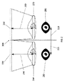
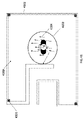
図1は、AR/VR光学システム100を示す。AR/VR光学システム100は、レンズ160、170からなり、これにより、ユーザーの眼180、190が、左ディスプレイ120および右ディスプレイ130に投影される集束データを見ることが可能となる。
左ディスプレイ120と右ディスプレイ130との間の焦点距離140、150は静的である。人間は鼻と眼との間の距離が異なるため、調整可能な瞳孔間距離110が必要である。
FIG. 1 shows an AR/VR
The
図2は、類似または異なるレンズ260、270、およびディスプレイ220、230を使用することができる調整可能なAR/VR光学システム200を示す。それらの間の距離は可変でもよく、左レンズ260、右レンズ270、左ディスプレイ220、および/または右ディスプレイ230を動かすことによって調整し得る。ユーザーの視野に合わせるために左レンズ260および右レンズ270を別々に回転させてもよい。左瞳孔距離215および右瞳孔距離210を別々に調整してもよい。左焦点240および右焦点250も別々に調整することができる。
FIG. 2 shows an adjustable AR/VR
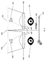
図3は、ディスプレイ323、324とレンズ329、330との間に、またはアイトラッキングのためにLED310’、311’によって示されるようにユーザーの眼のすぐ近くに配置される、追加のLED310、311を有する赤外線カメラ326、327を使用するアイトラッキング300を備えた標準AR/VRシステムを示す。各眼331、332は、別個の眼追跡カメラ、すなわち、左眼追跡カメラ326および右眼追跡カメラ327を有する。左半透過性ミラー325および右半透過性ミラー328によって提供される反射のため、カメラ326、327はユーザーの眼331、332を見る。これらのミラー325、328は、カメラがユーザーの眼331、332を見ることを可能とし、ディスプレイ323、324からの画像の反射を回避できるように配置および回転される。ミラー325、328は、カメラ326、327が見ることができるが人間の眼は見ることができない波長を反射することができる。瞳孔間距離の調節可能性は、主に、手動で調節可能な瞳孔間距離機構334によって提供され、これは、レンズ329、330の位置のフィードバックを提供する瞳孔間距離測定センサー333に接続されている。
FIG. 3 shows
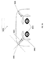
図4は、LEDありまたはなしの左眼追跡カメラ438およびLEDありまたはなしの右眼追跡カメラ439を使用しうる直接アイトラッキング400を備えたAR/VRシステムを示す。左レンズ440、右レンズ441、左ディスプレイ436、および右ディスプレイ437は、他の図に記載されているものと同様であってよい。カメラ438、439は、ユーザーの眼440、441を直接見てもよく、追加の半反射鏡を持たなくてもよい。カメラ438、439は、レンズ440、441と眼442、443との間、またはカメラ438’および439’によって示されるように異なる位置に配置されてもよい。カメラ438、439、438’、および/または439’は、任意のスペクトルで機能し得る。瞳孔間距離の調整可能性は、手動で調整可能な瞳孔間距離機構445によって行うことができ、これは、レンズ440、441の位置のフィードバックを提供する瞳孔間距離測定センサー444に接続されうる。利用可能なアイトラッキング装置の例として以下が挙げられる:SMIアイトラッキングシステム;半透過性ミラーを使用するFOVE;TOBII;およびPimax。
FIG. 4 shows an AR/VR system with direct eye tracking 400 that may use a left
図5は、自動調整可能な焦点549、左アクチュエータ560および右アクチュエータ561による自動調整可能な左レンズ552および右レンズ553、および、2つの追加のアクチュエータからなる各眼に対する自動調整可能な瞳孔間距離機構556を組み合わせる、高度なAR/VRアイトラッキングシステム500を示す。これらの自動調整可能な機構549、552、553、560、561、556は、センサーを備えたサーボモーターのような電気アクチュエータを使用し、アクチュエータの実際の位置のフィードバックを提供しうる。いくつかの実施形態では、追跡カメラ550、551は、ユーザーの眼554、555の位置を測定する。次いで、位置情報は、各ユーザーの鼻からの各眼554、555の距離を計算する、コンピュータのような演算装置に提供されうる。次に、この測定情報は、AR/VRヘッドセットを調整するためにユーザーに示されるか、または、レンズ552、553の位置を自動的に調整するサーボモーターのようなアクチュエータ560、561に提供される。他のセンサーが捕捉されてもよい。左眼追跡カメラ550および右眼追跡カメラ551は、左ディスプレイ547および右ディスプレイ548の反射を使用して、追加の構成要素を必要とせずにカメラがユーザーの眼554、555を見ることを可能とする。ディスプレイ547、548は、カメラのミラーとして機能し、反射を増強するために半透過性赤外線反射層でコーティングされてもよい。同様の結果を促進する他の形態のコーティングを使用することもできる。LED562、563は、追加の照明のために使用されてもよい。
FIG. 5 shows auto-
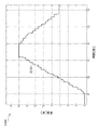
図6は、正しいレンズ位置の測定および校正中のセットアップモード時間グラフ600を示す。左眼追跡カメラ659および右眼追跡カメラはいずれも、全プロセスの間670にある。両方のカメラからキャプチャされたビデオは、処理ユニットに送信され、アルゴリズムがユーザーの眼球からの光の反射に基づいて正しいレンズ位置の見込みを検出する。アルゴリズムは、インプットとしてユーザーの眼のデジタル画像を取得しうる。次いで、楕円形を見つけるための画像認識を適用しうる。この認識は、画像の最も反射する部分の周りに配置された最大の楕円形の近似に基づいてもよい。楕円形が検出された場合、ユーザーの眼球の中心は、楕円形の中心にあると推定される。この測定は複数回繰り返される可能性があり、フィルターまたは単純平均を適用して、ユーザーの眼球の最も正確な位置を概算しうる。中心が定められた後、プロセッサは、サーボモーターのようなアクチュエータを使用して、レンズを理想位置に移動しうる。理想位置は、一般に利用可能な光学システムまたは任意の他の既知の方法により定められる。グラフ660は、左眼からのアルゴリズム認識結果を示し、グラフ671は、ユーザーの右眼からのアルゴリズム認識結果を示している。「最大REF」値は、検出されたレンズの理想位置を示す。グラフ661は、左レンズアクチュエータの動きを示し、グラフ672は、右レンズアクチュエータの動きを示している。左レンズアクチュエータは、最小位置で起動し、時間662においてアルゴリズムが最大位置を検出する。しかしながら、左レンズアクチュエータは、時間663および最大位置に達するまで測定を続ける。全体のスケールが測定された後、処理ユニットは、アクチュエータにコマンドを送信して、以前に検出された理想位置に到達する。アクチュエータは、時間664において理想位置に到達し、したがって左眼について正確な瞳孔距離(PD)を測定する。同様のプロセスは、右レンズおよびそのアクチュエータでも生じる。アクチュエータは、中央位置で起動し、時間673において到達する最小位置に移動する。その後、最大位置に移動を開始する。時間674において、アクチュエータはこの位置に到達し、処理ユニットは最大反射でその位置を検出するが、時間675で到達する最大位置に移動し続ける。次に、処理ユニットは、以前に検出された理想位置に到達するようにアクチュエータにコマンドを送信する。アクチュエータは、時間676においてその理想位置に到達し、右眼について正確なPDを測定する。
FIG. 6 shows a setup
図7は、低持続性ディスプレイを使用する動作モード時間グラフ700を示し、眼の位置はディスプレイの点滅の間で測定される。処理の間、グラフ765によって示されるように、レンズアクチュエータの位置は安定している(変化しない)。グラフ763は、低持続性のディスプレイが点滅し、ユーザーが画像を見ることが可能となることを示している。これらの点滅の間で、グラフ764によって示されるように、ユーザーの眼は、少なくとも1つのカメラおよび眼検出アルゴリズムを備えた少なくとも1つの処理ユニットを使用して測定される。アルゴリズムは、上記で説明したものと同様でもよい。ユーザーの眼球の視認性を高めるために、眼を測定しているときにLEDが点滅してもよい。
FIG. 7 shows an operating
図8は、眼の位置が連続的に測定されているフルレジスタンスディスプレイを使用する拡張モード時間グラフ800を示す。処理中、グラフ869によって示されるように、レンズアクチュエータの位置は安定している。グラフ867によって示されるように、フルレジスタンスディスプレイは、連続的に光ってユーザーに画像を表示する。グラフ868によって示されるように、眼を連続的に測定してもよく、眼検出アルゴリズムを備えた少なくとも1つの処理ユニットが、眼球の検出された位置を連続的に再集計してもよい。ユーザーの眼球を見やすくするために、LEDを点灯してもよい。
FIG. 8 shows an extended
したがって、図示されるように、いくつかの実施形態では、高度なAR/VRアイトラッキングは、3つの異なるモード、すなわち、セットアップモード(図6)、動作モード(図7)、および拡張モード(図8)で動作し得る。図6、7、および8は、3つの最も重要な信号を示している。グラフは、アイトラッキングシステムが低持続性および完全持続性の両方のタイプのディスプレイでどのように機能するかを示している。図6は、理想位置を見つけ、ユーザーにとって正確なPDを確保することを目的とする、レンズの位置決めの測定および調整プロセスを示している。 Thus, as illustrated, in some embodiments, advanced AR/VR eye tracking operates in three different modes: setup mode (Fig. 6), operational mode (Fig. 7), and extension mode (Fig. 8). Figures 6, 7 and 8 show the three most important signals. The graph shows how the eye tracking system works with both low persistence and full persistence types of displays. FIG. 6 shows the lens positioning measurement and adjustment process to find the ideal position and ensure the correct PD for the user.
図9は、アイトラッキング900を備えた自己補正型先進AR/VRシステムを示している。システム900は、左眼980用の極薄補正層975および右眼981用の極薄補正層979を使用することができる。これらの層は、両方のディスプレイ972、973に密接に取り付けられる。超薄型の補正層975、979を使用すると、非常に近い距離から左ディスプレイ972および右ディスプレイ973において、画像などの集束データを見ることが可能となる。このことは、画像のすべてのピクセルのようなすべてのデータを、光線が正確に眼980、981の位置に置いて焦点中心に向けるため、可能である。眼980と981との間の距離の調整は、左眼トラッキングシステム976および右眼トラッキングシステム978によって自動的に行われ、眼球を追跡し、瞳孔の中心に関する情報を自動調整アクチュエータ971、974に提供する。これらのシステムは、少なくとも1つのカメラおよびLEDで構成されてもよく、前の図で説明したように配置されてもよい。いくつかの実施形態では、自己補正型AR/VRアイトラッキングシステム900は、自動調整可能な焦点977も含み得る。自動調整可能な焦点977は、上記の図に記載されているようにサーボモーターを使用して、または任意の他の技術を使用して機能しうる。
FIG. 9 shows a self-correcting advanced AR/VR system with eye tracking 900 .
図10は、アイトラッキング1000を備えたコンタクトレンズベースの高度なVR/ARシステムを示す。コンタクトレンズベースのシステム1000は、ユーザーが近くの物体および/または左ディスプレイ1084および右ディスプレイ1085に焦点を合わせることを可能にし得る左コンタクトレンズ1097および右コンタクトレンズ1091を備えてもよい。コンタクトレンズベースのシステム1000は、レンズ1097、1091がユーザーの眼1092、1093と共に移動および回転するため、ユーザーの視野の側面における歪みを防止することができる。ディスプレイ1084、1085間の距離の調整は、左眼トラッキングシステム1089および右眼トラッキングシステム1090によって自動的に行われ、眼球を追跡し、瞳孔の中心についてのより多くの情報を自動調整アクチュエータ1083、1086に提供する。これらのシステムは、少なくとも1つのカメラおよびLEDから構成されてもよく、前の図で説明したように配置されてもよい。いくつかの実施形態では、システム1000はまた、自動調整可能な焦点1088を含んでもよい。
FIG. 10 shows a contact lens-based advanced VR/AR system with eye tracking 1000 . Contact lens-based
図11は、可撓性ディスプレイおよびアイトラッキング1100を備えたAR/VRシステムを示す。左可撓性ディスプレイ1196および右可撓性ディスプレイ1197は、レンズ1102、1103とディスプレイ1196、1197との間の異なる距離によって生じる、標準フラットディスプレイを使用することで起こりうる歪みを効果的に補正しうる。通常のフラットディスプレイを有する場合、問題は、ディスプレイのコーナーとレンズとの間の距離が、ディスプレイの中心とレンズとの間の距離と異なることである。この違いによって、追加の歪みが生じ、補正が必要となる。フレックススクリーンを使用すると、この違いを補正することができ、レンズとディスプレイの各位置との間の同距離を達成でき、有用である。ディスプレイ1196、1197間の距離およびレンズ1102、1103の位置の調整は、眼球を追跡し、瞳孔の中心に関する情報を自動調整アクチュエータ1195、1198、1104、1105に提供する左眼トラッキングシステム1110および右眼トラッキングシステムによって提供される。これらのシステムは、前の図で説明したように配置できる、少なくとも1つのカメラおよびLEDから構成されてもよい。いくつかの実施形態では、システム1100はまた、自動調整可能な焦点1199を含んでもよい。
FIG. 11 shows an AR/VR system with flexible display and eye tracking 1100. FIG. The left
図12は、視覚化AR/VR装置1207に通信可能に接続された外部コンピュータ1201を介して実行される高レベルブロック視覚化1200を有する既存のVR/AR装置を示す。コンピュータ1201は、中央処理ユニット1202、および、オーディオおよび他のデータ1204を供給する単一のビデオストリーム信号を供給するビデオアダプタ1203を備える。視覚化装置1207は、最大で3つのディスプレイ1209、1210、1211に信号を送信する少なくとも1つのビデオチップ1208を含む。ビデオチップ1208は、有限量のディスプレイ1209、1210、1211に信号を供給する潜在能力を有する。
FIG. 12 shows an existing VR/AR device with high-
図13は、視覚化装置1318に通信可能に接続された外部コンピュータ1312を介して実行される高レベルブロック視覚化1300を備えた複数ビデオストリームAR/VR装置を示す。コンピュータ1312は、中央処理ユニット1313およびビデオアダプタ1314を含む。コンピュータ1312のビデオアダプタ1314は、ビデオ信号を視覚化装置1318に供給する任意の有線または無線ストリームの形で複数ビデオストリーム1315を供給する。視覚化装置1318は、少なくとも1つの専用ビデオスプリッタ/デマルチプレクサ1319を含み、これは、1つ以上のビデオチップ1320、1322、1324を使用して信号をより多くのブランチに分割し、それらの各々が1つ以上のディスプレイ1321、1323、1325、1317に接続される。
FIG. 13 shows a multiple video stream AR/VR system with high
市販され開示されているすべての実験用視覚化装置は、次のいずれかを利用する:(i)1つのビデオ信号チャネルおよび1つのディスプレイ;(ii)複数のビデオ信号チャネルおよび複数のディスプレイ;または(iii)1つのビデオ信号チャネル、共通のブリッジコンバーター、および複数のディスプレイ。最後のケースでは、最初は1つのディスプレイのみを対象としたコンバーターの出力信号が、別個のディスプレイに供給される。既知の視覚化装置は、1つの多重化ビデオ信号チャネル、専用ビデオ信号スプリッタ、および別個のブリッジコンバーターおよびディスプレイを使用しない。使用可能な視覚化装置の例には、以下が挙げられる:1つのビデオ信号チャネル(ケーブル)を有し、スプリッタがなく、2つのディスプレイを有する、Oculus Rift;1つのビデオ信号チャネル(ケーブル)を有し、スプリッタがなく、2つのディスプレイを有する、HTC Vive;2つのビデオ信号チャネル(ケーブル)を有し、スプリッタがなく、2つのディスプレイを有する、Idealsee;2つのビデオ信号チャネル(ケーブル)を有し、スプリッタがなく、2つのディスプレイを有する、StarVR;および1つのビデオ信号チャネル(無線)を有し、スプリッタがなく、1つのディスプレイを有する、Samsung Gear VR;および1つのビデオ信号チャネル(ケーブル)を有し、スプリッタがなく、1つのディスプレイを有する、Sony Morpheus VR。 All commercially disclosed experimental visualization devices utilize either: (i) one video signal channel and one display; (ii) multiple video signal channels and multiple displays; or (iii) one video signal channel, common bridge converter and multiple displays; In the last case, the output signal of a converter originally intended for only one display is fed to a separate display. Known visualization devices do not use one multiplexed video signal channel, dedicated video signal splitters, and separate bridge converters and displays. Examples of visualization devices that can be used include: Oculus Rift with one video signal channel (cable), no splitter, two displays; HTC Vive with 2 video signal channels (cable) and no splitter with 2 displays; Idealsee with 2 video signal channels (cable) and StarVR with no splitter and two displays; and Samsung Gear VR with one video signal channel (wireless) and no splitter and one display; and one video signal channel (cable) , no splitter, and one display.
図14は、3つの別個のケーブルを介した少なくとも1つのコンピュータ1426と少なくとも1つの視覚化装置1430との間の例示的な接続1400を示す。分離されていてもいなくてもよい任意の数のケーブルを用いてもよい。ビデオ信号1427は、少なくとも1つのディスプレイポートを使用することができる。オーディオ信号および任意の他のデータ1428は、少なくとも1つのUSBまたは任意の他のコンピュータ通信プロトコルおよびケーブルを用いてもよい。電力は、別個の2分配電力ケーブル1429によって供給されてもよい。信号および電力を供給する任意の他の形態を用いてもよい。
FIG. 14 shows an
図15は、少なくとも1つのコンピュータ1531と少なくとも1つの視覚化装置1533との間の例示的な接続1500を示す。ビデオ、オーディオなどの信号1532、および電力は、Thunderbolt3プロトコルを使用して、USB3.0cケーブルのような1つのケーブルおよび/またはポートを介して転送できる。信号および電力を供給する任意の他の形態を用いてもよい。
FIG. 15 shows an
図16は、少なくとも1つのコンピュータと少なくとも1つの視覚化装置との間の例示的な接続1600を示す。ビデオ、オーディオなどの信号1635、および他のすべてのデータは、Wigig、Wifiなどの無線技術を介して転送できる。電源は、バッテリーパックのような外部電源1637を使用して別個に提供されてもよい。信号および電力を供給する任意の他の形態を用いてもよい。
FIG. 16 shows an
図17は、高レベルのブロック視覚化1700を備えた既存のAR/VRオールインワン装置を示す。標準のオールインワン装置1700は、中央処理ユニット1739、ビデオアダプタ1740、および統合ディスプレイ1743、1744、1745を備える。標準のオールインワン装置1700はまた、パワーバッテリーパック1741を含む。ビデオ信号1742は、MIPI DSIを介して少なくとも1つのディスプレイに直接転送される少なくとも1つのビデオアダプタ1740を使用して生成される。
FIG. 17 shows an existing AR/VR all-in-one device with high-
図18は、ビデオストリーム1849からのデータをMSPI CSI信号に変換することができる少なくとも1つのビデオチップ(入力ビデオコンバータ)1853、1854、1855に接続された少なくとも1つの任意のビデオスプリッタ1852を含むことができる拡張オールインワンVR/AR装置1800を示す。そのような信号は、少なくとも1つの中央処理ユニット1860および少なくとも1つのビデオアダプタ1861によってアクセス可能であり得る。拡張オールインワン装置1800は、それ自体でビデオ信号1863をディスプレイ1864、1865、1866に供給するか、または、外部モードにスイッチし、別個の中央処理ユニット1850およびビデオアダプタ1848を用いてコンピュータのような少なくとも1つの外部演算装置1847からディスプレイ1864、1865、1866に単一または複数のビデオストリーム1849を提供しうる。電力はバッテリーパック1862から供給されうる。
Figure 18 includes at least one
図19は、AR/VR装置のビデオ信号1900、すなわち、オールインワン装置1969のビデオ信号、テザー装置1970のビデオ信号、および拡張オールインワン装置1971のビデオ信号を示す。青い線1975は、装置に表示されている外部ビデオ信号を示す。オレンジ色の線1976は、装置で表示される内部生成ビデオ信号を示す。図示されているように、装置がオフにされると、どの装置でも信号はまったく表示されない。しかしながら、装置がON IMPULS 1974を受信すると、すぐにオンになり、オールインワン装置1969が内部グラフィックアダプタからのビデオ信号を表示しうる。上記の設定に依存して、テザー装置1970は外部グラフィックアダプタからのビデオ信号を表示し、拡張オールインワン装置1971は外部または内部グラフィックアダプタからのビデオ信号を表示する。SWITCH IMPULS 1972に到達すると、テザー装置は外部ビデオ信号のみを受け、オールインワン装置は内部グラフィックアダプタからの信号のみを表示するため、オールインワン装置およびテザー装置はそれを受けるまたは反応することができない。SWITCH IMPULS 1972は、信号/コマンドであり、データソースを変更する必要があることを通知するために装置に送信される。しかしながら、拡張オールインワン装置は、SWITCH IMPULS 1972を受け、すぐにビデオ信号を外部グラフィックアダプタから内部グラフィックアダプタへまたはその逆に変更する。第2のSWITCH IMPULS 1973に到達すると、オールインワン装置およびテザー装置は再びそれを無視し、拡張オールインワン装置がそれを受ける。その後、すべてのビデオチップを制御する内部プロセッサが、ビデオ信号を内部グラフィックアダプタから外部グラフィックアダプタにすぐにする。
FIG. 19 shows the
いくつかの実施形態では、視覚化装置はいくつかの別個のディスプレイを利用し、その結果、ディスプレイ1つの装置と比較して、より優れたデータ品質およびより広い立体視野がもたらされる。コンピュータからのビデオ信号は、ブリッジコンバーターおよび/または実際のディスプレイでさらに処理する前に、1つの単一チャネルを介して専用ビデオ信号スプリッタに供給されてもよい。これにより、インストールがより簡単になりプロトコル層上で自然にサポートされ、可能な限り広い範囲でディスプレイの性能を利用できるため、ユーザーフレンドリー性および使いやすさが実質的に改良される。1つの信号とは異なり、2つの別々の信号によって、リフレッシュ速度、タイミング、解像度、同期などを含む別々のディスプレイの設定の正確な制御が可能となる。 In some embodiments, the visualization device utilizes several separate displays, resulting in better data quality and a wider stereoscopic field of view compared to a single display device. A video signal from a computer may be fed through one single channel to a dedicated video signal splitter before further processing in a bridge converter and/or an actual display. This substantially improves user-friendliness and ease-of-use, as it is easier to install, is naturally supported on the protocol layer, and takes advantage of the widest possible range of display capabilities. Two separate signals, as opposed to one signal, allow precise control of separate display settings, including refresh rate, timing, resolution, synchronization, and the like.
いくつかの実施形態では、ビデオスプリッタは、複数のビデオストリームを受け入れることができ、次いで、これはX個の単一のビデオストリームに分割されうる。これは、DisplayPort 1.2以降を使用して1つの信号を複数のビデオ信号に分割するDisplayPort MSTプロトコルによって実行されうる。一方、既存の装置で使用されている標準のビデオチップ(HDMI(登録商標)からDSIへのコンバーター)は、単一のビデオストリームを受け入れ、信号をディスプレイ上に直接表示する。さらに、より多くのディスプレイを備えスプリッタがない既存の装置は、ビデオコンバータを使用してシングルストリームビデオ信号を半分にカットし、2つのディスプレイを動作可能にする。いくつかの実施形態では、視覚化装置は、ビデオ信号チャネル(通常はケーブルまたは無線インターフェース)によって転送される、コンピュータからビデオ信号スプリッタへの多重化信号を使用することができる。別々のブランチがビデオ信号スプリッターから続き、それぞれが1つのビデオコンバータおよび1つ以上のディスプレイにつながる、すなわち、ビデオ信号はいくつかの別々のブランチに分割されうる。ビデオ信号が分割されると、そのビデオ信号は標準のままであり、任意の装置(モニター、VRヘッドセット、テレビ)で表示できる。ビデオ信号がカットされると、どこにも転送できなくなり、標準信号ではなくなり、直接接続されたスクリーンでのみ表示できる。いくつかの実施形態では、逆方向通信(すなわち、ディスプレイからコンピュータに送信される構成、診断および他のデータ)中に、別個のブランチを介して通信されるディスプレイからの信号は、ビデオ信号スプリッタに合流され、単一のビデオ信号チャネルを介してコンピュータのビデオアダプターに送信され得る。逆方向通信およびそのすべてのデータは、DisplayPort通信プロトコル標準の一部である。逆方向通信は、ハンドシェイクおよび接続の確立のためのすべての視覚化装置の固有機能である。さらに、逆方向通信によって、DisplayPort AUXチャネルで定義されている異なるフォーマットでデータを送信できる。視覚化装置は、視覚化装置内の別個のディスプレイ間に物理的に分散された、画像のピクセルのようなデータに関するすべての情報を組み合わせる1つのディスプレイとして、または、いくつかの別個のディスプレイとして、コンピュータによって識別されうる。識別は、Video Electronics Standards Association(VESA)の標準である拡張ディスプレイ識別データ(EDID)によって行われる。いくつかの実施形態では、上述のように、装置は、コンピュータとヘッドセットの間のビデオ信号チャネルとしてDisplayPortインターフェースを使用することができる2つ以上の表示された仮想現実ヘッドセットを含んでもよい。しかしながら、DisplayPort以外の他の実施形態では、装置は、HDMI(登録商標)、USB-CサンダーボルトThunderbolt、Wigig、Wifi、または任意の他の現在または将来の有線または無線ビデオインターフェースも利用することができる。同様に、任意の数のディスプレイを装置で使用してもよい。市販され開示されているオールインワン視覚化装置はすべて、内部で生成されたビデオ信号のみを利用し、画像を大幅にダウングレードしたり、待ち時間を追加したりすることなく、外部コンピュータを直接接続するオプションはない。利用可能な視覚化装置のいくつかの例として以下が挙げられる:直接ビデオ入力のない携帯電話であるSamsung Gear;直接ビデオ入力のないスタンドアロンのオールインワンVRヘッドセットであるAzpen AZ-VR Nibiru Allwinner;直接ビデオ入力のないスタンドアロンのオールインワンVRヘッドセットであるVR-8;直接ビデオ入力のないスタンドアロンのオールインワンVRヘッドセットであるGenBasic Quad HD Androidバーチャルリアリティシステム。これらの標準的なオールインワンVR/ARヘッドセットは、1つのチップに統合されたビデオアダプターを備えたプロセッサーを利用する。このアプローチは完全に正しく機能する。しかしながら、そのパフォーマンスは制限されている。 In some embodiments, the video splitter may accept multiple video streams, which may then be split into X single video streams. This can be done by the DisplayPort MST protocol, which splits one signal into multiple video signals using DisplayPort 1.2 or later. On the other hand, standard video chips (HDMI to DSI converters) used in existing devices accept a single video stream and display the signal directly on the display. Additionally, existing devices with more displays and no splitters use video converters to cut the single-stream video signal in half to enable two displays. In some embodiments, the visualization device can use multiplexed signals from the computer to the video signal splitter that are transferred by a video signal channel (usually a cable or wireless interface). Separate branches follow from the video signal splitter, each leading to one video converter and one or more displays, ie the video signal can be split into several separate branches. Once the video signal is split, it remains standard and can be displayed on any device (monitor, VR headset, TV). When the video signal is cut, it cannot be transferred anywhere, it is no longer a standard signal and can only be displayed on directly connected screens. In some embodiments, during reverse communication (i.e., configuration, diagnostics and other data sent from the display to the computer), signals from the display communicated over a separate branch are routed to the video signal splitter. can be merged and sent to the computer's video adapter over a single video signal channel. Reverse communication and all its data are part of the DisplayPort communication protocol standard. Backward communication is an inherent feature of all visualization devices for handshake and connection establishment. Additionally, reverse communication allows data to be sent in different formats defined in the DisplayPort AUX channel. The visualization device can be either as one display that combines all the information about the data, such as the pixels of the image, physically distributed among the separate displays within the visualization device, or as several separate displays. It can be identified by a computer. Identification is provided by Extended Display Identification Data (EDID), a standard of the Video Electronics Standards Association (VESA). In some embodiments, as described above, the device may include two or more displayed virtual reality headsets capable of using the DisplayPort interface as a video signal channel between the computer and the headsets. However, in other embodiments besides DisplayPort, the device may also utilize HDMI, USB-C Thunderbolt Thunderbolt, Wigig, Wifi, or any other current or future wired or wireless video interface. can. Similarly, any number of displays may be used with the device. All of the commercially disclosed all-in-one visualization devices utilize only internally generated video signals and directly connect external computers without significantly downgrading the image or adding latency. No options. Some examples of available visualization devices include: Samsung Gear, a mobile phone without direct video input; Azpen AZ-VR Nibiru Allwinner, a standalone all-in-one VR headset without direct video input; VR-8, a standalone all-in-one VR headset with no video input; GenBasic Quad HD Android virtual reality system, a standalone all-in-one VR headset without direct video input. These standard all-in-one VR/AR headsets utilize processors with video adapters integrated into one chip. This approach works perfectly fine. However, its performance is limited.
これらの装置とは異なり、一部の実施形態では、AR/VR装置は、完全にスタンドアロンの使用に対して同じ性能を提供し、ユーザーがデスクトップコンピュータおよびサーバーによって提供される完全なパフォーマンスを使用することも可能にする。したがって、いくつかの実施形態では、すべてのテザーおよびアンテザー視覚化装置の利点を、AR/VR装置内に含めることができる。いくつかの実施形態では、外部ソースからのビデオ信号は、単一のビデオストリームおよび複数のビデオストリームでもよい。外部信号は、直接接続を可能にする任意のケーブルまたは任意の無線チャネルを介して転送できる。いくつかの実施形態では、AR/VR装置は、装置が内部ビデオ信号と外部ビデオ信号との間で切り替わることを可能する追加のチップを備えたオールインワンVR/ARヘッドセットを利用し得る。したがって、1つのAR/VR装置は、独立して動作するが、利用可能な場合は、外部コンピュータ、サーバーなどの外部処理能力を利用してもよい。コンピュータに接続されている場合、いくつかの実施形態では、AR/VR装置は、AR/VR装置内の別個のディスプレイ間で物理的に分散される、画像のピクセルなどのデータに関するすべての情報を組み合わせた1つのディスプレイとして、または、複数の別個のディスプレイとして識別され得る。したがって、いくつかの実施形態では、2つの機能を組み合わせてスタンドアロンのAR/VR視覚化装置を作成することができ、これは、外部モードへの切り替え機能と組み合わせて、独自の統合ハードウェアコンポーネントからビデオ信号を提供し、AR/VR装置は、テザー接続またはアンテザー接続と単一または複数のビデオストリームを使用して、任意の種類のソースからのビデオ信号を受け入れ、それを内部ディスプレイに投影する。 Unlike these devices, in some embodiments AR/VR devices offer the same performance for completely standalone use, allowing users to use the full performance provided by desktop computers and servers. also make it possible. Thus, in some embodiments, the benefits of all tethered and untethered visualization devices can be included within AR/VR devices. In some embodiments, the video signal from the external source may be a single video stream and multiple video streams. External signals can be transferred via any cable or any wireless channel that allows a direct connection. In some embodiments, AR/VR devices may utilize all-in-one VR/AR headsets with additional chips that allow the device to switch between internal and external video signals. Thus, one AR/VR device operates independently, but may utilize external processing power, such as an external computer, server, etc., if available. When connected to a computer, in some embodiments the AR/VR device stores all information about data, such as pixels of an image, that are physically distributed among separate displays within the AR/VR device. It may be identified as a combined display or as multiple separate displays. Therefore, in some embodiments, the two functions can be combined to create a stand-alone AR/VR visualization device, which in combination with the ability to switch to external modes can be used from its own integrated hardware component. Providing a video signal, the AR/VR device uses a tethered or untethered connection and single or multiple video streams to accept a video signal from any kind of source and project it onto an internal display.
図20は、プロセスとして開始から終了までのデータフロー操作2000を伴う標準的なIMUセットアップを示す。第1の動き2002がIMUセンサー2003によって認識されると、2004データが測定される。そのようなデータは、軸変換2005、2006によって正しい軸に変換される。次に、大部分のデータを統合してより正確な情報を取得するデータ融合2007が発生する。次に、予測アルゴリズム2008が適用され、最終方位2009が確立される。予測アルゴリズムは、実際の方位および測定値を使用して、将来の方位を予測する。これは、ユーザーが感じる遅延を緩和するのに役立つ。典型的な予測地平線は約20~60メートルである。予測を使用する場合、地平線について正しい値を見つけることが重要である。地平線が小さすぎる場合、予測は遅延を低減するのに役立たない。大きすぎると、推定にオーバーシュートが導入され、結果が非常に不安定に見える。
FIG. 20 shows a standard IMU setup with start-to-
図21は、データフロー操作2100の一部としての独自のIMUセットアップを示す。いくつかの実施形態では、第1の測定可能な動き2111が発生すると、IMUセンサー2112、IMUセンサー2113、および/またはIMUセンサー2114によって認識される。その後、データが測定される。そのようなデータは、軸変換2115、2116、2117によって正しい軸に変換する必要がある。次に、いくつかの実施形態では、データを一緒に統合するデータ融合2118が起こり得る。この特定のセットアップにおけるデータ融合2118は、2つの異なるモードで動作できる。第1のモードは、異なるアルゴリズムを使用して、IMUの自然周波数でより良好な品質を達成できる。単純な移動平均は、各IMUが上記のように配置されている場合、IMU構築の物理的なミスの影響を2/3だけ低減する。他のオプションは、3つのうち2つのIMUからの信号を使用することであり、第3のIMUはミスによる影響が最も大きく、他の2つとは異なることが予想される。別のアプローチは、1つのIMUから1つの軸で1つの回転信号のみを使用することであり、残りの信号は無視される。他のアプローチを使用してもよい。複数のIMUを使用してより正確な測定データを達成するためにIMU信号をフィルタリングおよび処理するこれらの異なるオプションは、個別に、または任意の他の方法と組み合わせて使用できる。他の実施形態では、3つすべてのIMUからのデータを同時に使用してもよい。このシナリオでは、各IMUは、他のIMUからのデータの間に間隔をあけてデータを測定および送信し、それにより周波数を3倍にする必要がありうる。いくつかの実施形態では、現在のステップで信号を測定した、IMUからの生データは、前のステップからの異なるIMUからの測定の予測の1/3およびその前のステップからの異なるIMUからの測定委の予測の2/3で要約され、したがって、製造ミスの影響を半分だけ低減する。データ融合2118の後、予測2119が適用され、最終方位2120が確立されうる。
FIG. 21 shows the unique IMU setup as part of
図22は、異なる座標フレーム2200における異なるセンサーからの測定値を示す。具体的には、不関軸において2つのIMU(それぞれセンサー#1およびセンサー#2)を使用する並列測定の例示的な信号2210、2220が示されている。
FIG. 22 shows measurements from different sensors in different coordinate
図23は、共通の座標に変換された2つのセンサーからの結合信号2330を有する結合された測定グラフ2300を示す。第1のIMUは信号2320を生成する。第2のIMUは信号2310を生成する。信号2310および2320はいずれも、すでに共通の座標(軸)に変換されている。具体的には、不関軸での2つのIMU(センサー#1)、(センサー#2)を使用する並列測定の結合信号2330が示されている。
FIG. 23 shows a combined
図24は、1つのIMUからの高い予測を伴うデータ予測セットアップグラフ2400を示す。図示のように、可視共鳴信号2410があり、予測アルゴリズムの地平線が高すぎることを示している。この信号は、調整の酷い予測アルゴリズムを有する。
FIG. 24 shows a data
図25は、自動予測グラフ2500を伴うデータ予測セットアップを示す。図示されているように、共鳴信号2510は非常に低く、変化に対してほとんど即時応答であり、セットアップの正しさを示している。この信号は、うまく調整された予測アルゴリズムを有する。
FIG. 25 shows a data prediction setup with
一部の実施形態では、AR/VR装置は、ジャイロスコープ、加速度計、および/または磁力計を使用する。複数のセンサーを一緒に使用することにより、これらの装置の効率、動作、丈夫さ、サンプリング周波数などを改良できる。いくつかの実施形態では、センサーの冗長性をデータ融合により利用して、より良好な全体精度を提供することができる。これを行うには、いくつかの線形または非線形ベイジアンフィルターを開発してテストしてもよい。いくつかの実施形態では、センサーは異なる座標フレームに配置されてもよく、したがって、最終的なデータ融合の前に軸変換が必要になる場合がある。センサーは、同じ座標フレームに配置されてもよい。センサーを非同期で読み出し、精度は低下するが速度を向上させうる。 In some embodiments, the AR/VR device uses gyroscopes, accelerometers, and/or magnetometers. Using multiple sensors together can improve the efficiency, operation, robustness, sampling frequency, etc. of these devices. In some embodiments, sensor redundancy can be exploited through data fusion to provide better overall accuracy. To do this, several linear or non-linear Bayesian filters may be developed and tested. In some embodiments, the sensors may be placed in different coordinate frames, thus axis transformations may be required prior to final data fusion. The sensors may be arranged in the same coordinate frame. Read the sensor asynchronously, which may increase speed at the expense of accuracy.
いくつかの実施形態では、予測アルゴリズムを使用することができる。予測アルゴリズムは、実際の方向と測定値を使用して将来の方向を予測する。これは、ユーザーが感じる遅延を緩和するのに役立つ。典型的な予測範囲は約20~60メートルである。しかしながら、予測範囲は20~60メートル未満またはそれ以上になる場合があります。予測を使用する場合、地平線について正しい値を見つけることが重要である。地平線が小さすぎる場合、予測は遅延を低減するのに役立たない。大きすぎると、推定にオーバーシュートが導入され、結果が非常に不安定に見える。したがって、いくつかの実施形態では、この問題を解決するために、実際の角速度に応じて予測地平線を設定するアルゴリズムを使用してもよい。このアルゴリズムは、最大で毎秒30度の速度まで20メートルの静的予測時間範囲を持つことができる。また、毎秒120度でメートルの線形進行範囲を有する場合もある。毎秒120度を超える速度はいずれも、60メートルの予測地平線で飽和する。したがって、HMDがゆっくりと回転すると、予測は低くなり、ブレを低減する。また、HMDが素早く回転する場合、予測はより高くなり、応答性が向上する。一部の実施形態では、少なくとも3つの組み合わされたIMUを使用し、かつ2つのIMUが同じ軸方向を有しない、IMUセンサメッシュが存在しうる。 In some embodiments, predictive algorithms can be used. Forecasting algorithms use actual directions and measurements to predict future directions. This helps mitigate the delay experienced by the user. A typical expected range is about 20-60 meters. However, the forecast range may be less than 20-60 meters or more. When using prediction, it is important to find the correct value for the horizon. If the horizon is too small, prediction will not help reduce delay. Too large introduces an overshoot in the estimation and the result looks very unstable. Therefore, in some embodiments, an algorithm that sets the predicted horizon depending on the actual angular velocity may be used to solve this problem. This algorithm can have a static prediction time range of 20 meters up to velocities of 30 degrees per second. It may also have a linear travel range of meters at 120 degrees per second. Any velocity above 120 degrees per second saturates at the 60 meter forecast horizon. Therefore, when the HMD rotates slowly, the prediction is low, reducing blur. Also, if the HMD rotates quickly, the prediction is higher and the responsiveness is improved. In some embodiments, there may be an IMU sensor mesh that uses at least three combined IMUs and no two IMUs have the same axial orientation.
図26は、実環境と仮想環境との間の情報トランスポートのためのシステム2600を示している。図示されるように、いくつかの実施形態では、人間が存在する実環境2620とユーザーが存在する仮想環境2622との間に情報フローが存在し得る。物理的環境2620の人間は、外界を聞く、見る、触る、匂いを嗅ぐ、および/または味わうことができる。これらすべての感覚は、聴覚用のマイクロフォン、匂いや味を検出するための化学センサー、触覚を検出するための張力センサー、視覚を感知するためのカメラなどのような、実世界のセンサー2608で測定できる。これらのセンサーは、デジタル信号の形式で情報をAI/論理ユニット2607に転送してもよい。論理ユニット2607は、AI(人工知能)を実行し、および/または所定の論理演算を実行することができる、任意の種類のプロセッサ、コプロセッサ、FPGAなどで構成することができる。論理ユニット2607は、どの信号を、どの形式および強度で、ある環境から別の環境に送信するかを決定する。仮想環境では、実環境からの信号は、信号マージャ2609によって、仮想信号ジェネレータ2611から生成された仮想信号と融合され、ディスプレイ、ヘッドフォン、匂いジェネレータ、フリッピングプラットフォーム、触覚グローブなどのアクチュエータ2613を介してユーザーに提供される。反対に、仮想信号はまた、論理ユニット2607を介して実環境2620に転送されてもよい。これが発生すると、2つの環境2620、2622間の障壁が克服され、これらの2つ以上の世界は互いに通信できる。仮想信号に関する情報を提供するために、実環境2620のアクチュエータ2623は、仮想環境2622のユーザーと通信するために使用される。
FIG. 26 shows a
したがって、いくつかの実施形態では、現実世界(物理環境2620)および仮想現実(仮想環境2622)は、AR/VR装置を使用して接続され得る。AR/VR装置は、両方の環境におけるイベントについての情報を取得することができ、この情報をさらに共有して、実環境2620と仮想環境2622との間の相互接続およびリスクの低減をもたらすことができる。2つの環境2620、2622間のこの相互接続は、AR/VR HMD装置だけでなく、視覚、聴覚、味覚、嗅覚、または触覚などの人間の感覚のいずれかに偽の情報を提供する任意の装置/アクチュエータによって提供されうる。いくつかの実施形態では、センサーを使用して情報を測定し、外界の危険または2つの環境2620、2622の間の重要な違いについてユーザーに警告することができる。さらに、いくつかの実施形態では、装置は、仮想環境2622で発生するイベントについて外部の観察者に通知することができてもよい。信号化は一方向または両方向で使用できる;それは一つまたは複数の感覚によって実感され得る;また、各環境2620、2622において、および/または環境2620、2620の間で、異なる感覚を使用することさえできる。
Thus, in some embodiments, the real world (physical environment 2620) and virtual reality (virtual environment 2622) may be connected using AR/VR equipment. The AR/VR device can obtain information about events in both environments and can further share this information to provide interconnection and risk reduction between the
例示的な実施形態では、人A(仮想現実のユーザー)は、高音響強度のオーディオヘッドホンを使用し、これにより、現実世界の音に注意を払うことが困難または不可能にさえなりうる。システムにマイクロフォン(センサー)も接続されている場合は、現実の環境を聞くために使用されうる。論理ユニット2607のような処理ユニットは、すべての外部音を判断し、異常な音(アラーム音、予期しない大きな音、異常な沈黙、またはAに向けられた音声)の場合、人Aにその異常な音を通知しうる。システム2600は、(緊急の場合に)仮想環境からの音を下げることにより、または、個人的なメッセージを作成することにより、人Aに通知することができ、これによってユーザー体験を大幅に中断することなく仮想音と共にシームレスに再生することができる。同時に、ユーザーのヘッドフォン(仮想環境)の音響強度に関する情報は、装置上のRGB LEDによって表示され、その情報を人B(ヘッドフォン自体の音を聞いていない外部の観察者)に転送しうる。したがって、いくつかの実施形態では、実環境2620から仮想環境2622への聴覚情報の転送は専用のメッセージを介して行われてもよい、および/または、仮想環境2622から実環境2620へのボリューム情報の転送はLEDまたは任意の他の光源(照準)により提供される視覚信号を介して行われてもよい。他の感覚および装置も、両方のプロセスに使用できる。
In an exemplary embodiment, Person A (the virtual reality user) uses high acoustic intensity audio headphones, which can make it difficult or even impossible to pay attention to real world sounds. If a microphone (sensor) is also connected to the system, it can be used to listen to the real environment. A processing unit, such as
いくつかの実施形態では、現実世界と仮想世界との間の情報の転送を容易にする装置は、以下を含んでもよい:仮想情報を提供する装置(ヘッドフォン、VRヘッドセット、触覚ウェアラブル、移動プラットフォームなど);外部(実世界)の情報を測定するセンサー(マイクロフォン、カメラ、化学センサー、環境追跡装置など)。いくつかの実施形態では、この情報は、事前に測定され、以下に格納されてもよい:意思決定ユニット(例えば、頻繁に更新する必要がない物理的環境に関する静的マッピングデータ);実世界に情報を提供する装置(RGB LED、オーディオスピーカー、ディスプレイなど);仮想情報を実世界のセンサーから取得したデータと統合する装置;および、すべての情報を評価し、重要なデータを実世界または仮想現実に送信する方法を決定する少なくとも1つの意思決定ユニット。 In some embodiments, devices that facilitate the transfer of information between the real and virtual worlds may include: devices that provide virtual information (headphones, VR headsets, haptic wearables, mobile platforms, ); sensors that measure external (real-world) information (microphones, cameras, chemical sensors, environmental trackers, etc.). In some embodiments, this information may be pre-measured and stored in: decision-making units (e.g., static mapping data about the physical environment that does not need to be updated frequently); devices that provide information (RGB LEDs, audio speakers, displays, etc.); devices that integrate virtual information with data obtained from sensors in the real world; at least one decision-making unit that determines how to transmit to
図27は、標準的なXR/ARモジュール2700を示す。標準のXR/ARモジュール2700は、両方が外を向いている静的な左カメラ2702および右カメラ2703を含む。それらのデータは収集され、USB、または、カメラを制御するプリント回路基板であるカメラ関連電子機器2704を使用する任意の他の通信プロトコルに変換される。カメラ関連電子機器2704は、HMDの内部電子機器に、またはUSBまたは任意の他のケーブル/コネクタ2705を使用してコンピュータに接続される。
FIG. 27 shows a standard XR/
図28は、高度なXR/ARモジュール2800を示す。高度なXR/ARモジュール2800は、いずれも外を向く自動調整可能な左カメラ2807および自動調整可能な右カメラ2808の両方を使用して、カメラの距離を調整することができる。カメラ2807、2808は、人間の眼の視覚に可能な限り近づけ、アクチュエータを使用してユーザーの眼の正確な測定位置に入ることができる。このモジュールは、上記の高度なアイトラッキングシステムとの接続に最適である。カメラからのデータが収集され、カメラ関連電子機器2809を使用して十分な帯域幅でUSBまたは任意の他のデータプロトコルに転送される。関連する電子機器2809には、プリント回路基板、フレックスケーブル、リジッドフレックスケーブル、制御カメラなどが含まれる。これには、カメラに電力を供給し、カメラへの信号を制御する装置が含まれてもよく、また、カメラからのデータを受け入れる、および/または、データがHMDまたはUSB、TCP/IPおよびその他などのコンピュータに転送されることを可能にする任意のプロトコル標準に変換する、装置が含まれてもよい。カメラ関連電子機器2809は、USB 2810などの任意の使用可能なコネクタを使用して、HMDの内部電子機器またはコンピュータに接続されてもよい。このセットアップは、ユーザーの眼の位置をシミュレートするため、より現実的で信頼できる、より快適な体験が提供される。
FIG. 28 shows an advanced XR/
図29は、シミュレートされたXR/ARモジュール2900を示す。シミュレートされたXR/ARモジュール2900は、左広角静止カメラ2912および右広角静止カメラ2913を含み得る。どちらのカメラも外側を向いており、人間の眼よりもはるかに広い視野をキャプチャできうる。カメラ関連電子機器2914または接続されたコンピュータは、画像をトリミングなどのデータ変更をし、ユーザーの眼の位置を模倣する位置に適合し、正しいカメラ位置をシミュレートすることができる。その後、データはUSB標準に変換され、USB 2915のような任意の使用可能なコネクタを使用してHMDの内部電子機器またはコンピュータに送信されうる。このセットアップは、人間の眼の位置をエミュレートするため、標準のセットアップよりも現実的で信頼できる、より快適な体験が提供される。
FIG. 29 shows a simulated XR/
図30は、ユーザーの眼3000の間のデジタル的にシミュレートされた距離を示す。図示されるように、ユーザーの眼3000間のデジタル的にシミュレートされた距離は、左広角カメラ3017および右広角カメラ3019からのビデオ信号がどのように見えるかを視覚化する。このような信号は、カメラ間で異なる距離をシミュレートするために、プロセッサまたはグラフィカルアダプターを使用してリアルタイムでトリミングされてもよい。左眼用のデジタルトリミングされた画像3018は、HMDに投影されている画像のサブセットを示し、鼻、カメラ、および左眼球の違いをエミュレートする。右眼用のデジタルトリミングされた画像3020は、HMDに投影されている画像のサブセットを示し、鼻、カメラ、および右眼球の違いをエミュレートする。眼の間隔が広い別のユーザーが同じ装置を使用する場合、赤い長方形3018がより左側に、黄色の長方形3020がより右側になり、したがって、新しいユーザーの眼の間の距離をエミュレートする。したがって、いくつかの実施形態では、実環境で知覚される正確なデータを提供することによって、またはそれをシミュレートすることによって、AR/VR体験が大幅に改良される。利用可能な視覚化装置のいくつかの例として以下が挙げられる:距離をデジタル的にシミュレートせずに、2つの静的カメラを使用するAcer Windows VRヘッドセット開発キット;距離をデジタル的にシミュレートせずに、2つの静的カメラを使用するHP Windows VRヘッドセット開発キット;および距離をデジタル的にシミュレートせずに、2つの静的カメラを使用するDELL Windows VRヘッドセット開発キット。
FIG. 30 shows the digitally simulated distance between the user's
図31は、2つの異なる既存のVRヘッドセット3100および3150の可視視野の例示的な画像を示す。図示のように、画像3101および3102は、ユーザーの視野を示している。第1のヘッドセット3100は広い視野を持ち、平均を超える150度の視野を提供する。3150のような現在利用可能なヘッドセットの典型的な視野は110度で、これは画像3102に示されている。
FIG. 31 shows exemplary images of the visible field of view of two different existing
図32は、VRヘッドセット3201および3205の最も一般的に利用可能な2つのセットアップを示す。VRヘッドセット3201は、ユーザーの眼3204に対するディスプレイ3202およびレンズ3203の標準的な位置を有するセットアップを示す。図示のように、ディスプレイ3202、レンズ3203、およびユーザーの眼は、それらが互いに平行になるように直線的に配置される。このセットアップは、画像の歪みを補正するのに最も簡単である。VRヘッドセット3205は、傾斜ディスプレイ3206のセットアップを示している。ディスプレイ3206、ならびにレンズ3207は、ユーザーの鼻に向かって焦点を合わせた角度で配置される。このセットアップにより、ディスプレイ3207が眼3208の後方につながることができるため、より広い視野を有する、より没入感のあるVRヘッドセットを作成できる。
FIG. 32 shows two of the most commonly available setups for
図31および32に示されるVRヘッドセットは、非可撓性ディスプレイおよびレンズのために、画像の歪みや色収差などの多くの問題に苦しむ。したがって、本明細書で説明する実施形態によって達成されるように、可撓性ディスプレイおよび新しいタイプのレンズが必要である。可撓性ディスプレイおよび新しいレンズにより、画像の歪みと色収差を最小限に抑え、他のすべての光学的欠陥を制限した、広い視野が可能となる。本明細書で説明する実施形態は、その屈曲の特性に応じて2つの方法で可撓性ディスプレイを利用する。1つの方法は、ディスプレイが全長に亘って連続的に屈曲するディスプレイに関し、もう1つの方法は、ディスプレイが全長に亘って少なくとも3つの異なる領域で異なる角度で屈曲するディスプレイに関する。 The VR headset shown in Figures 31 and 32 suffers from many problems such as image distortion and chromatic aberration due to the non-flexible display and lenses. Therefore, there is a need for flexible displays and new types of lenses, as achieved by the embodiments described herein. Flexible displays and new lenses allow wide fields of view with minimal image distortion and chromatic aberration, and limited all other optical imperfections. The embodiments described herein utilize flexible displays in two ways depending on their bending characteristics. One method relates to displays in which the display bends continuously over its entire length, and another method relates to displays in which it bends at different angles in at least three different regions over its entire length.
図33は、各眼3306のための1つの可撓性ディスプレイ3305および特別な三相レンズ3304、3307を含み得るVRヘッドセット3300を図示する。各レンズ3304および3307は、3つの異なる光学部品から作製され、各光学部品は、可撓性ディスプレイ3305の異なる部分からの光を転送する。ディスプレイ3305は、3つの部分3301、3302、3303に分かれている。ディスプレイ3305の第1の水平部分3301はほぼ直線であり、ユーザーの眼3306の前に実質的に位置する。次に、ディスプレイ3305は、レンズ3304の屈曲部分の実質的に後ろに位置する屈曲部分3302に曲がる。次に、ディスプレイ3305は、レンズ3304の垂直部分の実質的に後ろに位置する垂直部分3303に曲がる。レンズ3304の垂直部分は実質的に眼3306の側面に位置し、レンズ3304の水平部分は実質的に眼3306の前に位置する。屈曲部分3302は、実質的に90度の角度で屈曲し、その画像は、レンズ3304の屈曲部分によってカバーされる。水平部分3301で生成された画像は、レンズ3304の水平部分によってカバーされる。レンズ3304は、ディスプレイ3305の各屈曲を別個に補正する3つの異なる光学システムを含む。しかしながら、それらは連続的で接続されたシステムを形成する。
FIG. 33 illustrates a
図34は、各眼3404用の1つの可撓性ディスプレイおよび特別な一体成形レンズ3403、3405を含み得るVRヘッドセット3400を示す。ディスプレイ3401は、湾曲部分3402によって示されるように、弧状に徐々に屈曲する。レンズ3403は、ディスプレイ3401の湾曲を実質的に模倣する。実質的に同じ形状は、画像の歪みおよびユーザーの眼3404によって知覚される他の望ましくない光学効果を最小限に抑えることができる。ヘッドセット3400によって、周辺視野でユーザーがヘッドセット3400の黒いエッジではなく画像全体を見ることができるため、完全に没頭することが可能となる。可撓性ディスプレイ3401、独自のレンズ3403、およびディスプレイおよびレンズの円弧構造の機械的構成を組み合わせることによって、ヘッドセット3400はまた、光学的欠陥を最小限に抑えながら、視野およびヘッドセット3400のサイズの最適な比率を提供する。このようなヘッドセットアセンブリは、静的セットアップ、45度移動セットアップ、標準調整セットアップ、または屈曲可能セットアップを使用して実現しうる。
FIG. 34 shows a
最も簡単なメカニックセットアップは、ディスプレイに対するレンズの静的な位置によるものである。このようなセットアップでは、ディスプレイのフルサイズを利用する。ディスプレイは、光学システム/レンズの正確な中心に配置される。しかしながら、このアプローチでは、視覚に障害のあるユーザーがレンズを調整または再配置できないため、使用が制限される。図35は、ディスプレイが固体フレーム上のレンズ3501に接続されている静的セットアップ3500を示す。これらのコンポーネントはいずれの方向にも移動できず、それらの位置は、VRヘッドセットの残りの部分(他のプラスチック部品、電子機器など)および眼に対して固定されている。
The simplest mechanical setup is with a static position of the lens relative to the display. Such a setup utilizes the full size of the display. The display is placed in the exact center of the optical system/lens. However, this approach is of limited use because visually impaired users cannot adjust or reposition the lenses. Figure 35 shows a
視覚障害を補うには、レンズとディスプレイとの間の距離を調整して焦点を調整する必要がある。理想的な光学パラメータを実現するには、ディスプレイおよびレンズのすべての可視セグメント間の距離を一定に保つために、この調整可能角度を45度未満にする必要がある。 To compensate for the visual impairment, it is necessary to adjust the distance between the lens and the display to adjust the focus. To achieve ideal optical parameters, this adjustable angle should be less than 45 degrees to keep the distance between all visible segments of the display and lens constant.
図36は、画像品質に悪影響を与えることなくディスプレイ3601とレンズ3602との間の距離を変更することができる、45度の移動セットアップ3600を示す。ディスプレイ3601は、レンズ3602のより近くまたはより遠くに移動でき、あるいは、レンズ2602は、手動の機械システムを使用してまたは電気モーターや任意の他のアクチュエータ3603、3605によってディスプレイのより近くまたは遠くに移動できる。このシステムの重要な必要条件は、許容される移動調整機能が45度未満にすぎないことである。このような制限された45度の動きの下で、ユーザーの眼3604によって知覚されるすべての可視点の距離の変化を補正できる。45度の動きは、各眼3604について個別に調整できるため、各眼で異なる視覚障害を持つユーザーに対応できる。
FIG. 36 shows a 45
標準的な調整セットアップにより、ユーザーは、瞳孔間距離、並びに、画面とレンズとの間の距離を調整できる。人間は頭の形が異なり、したがって眼の中心間の距離も異なるため、瞳孔間距離を調整できることは重要である。最高の体験を得るには、瞳孔間距離がVRヘッドセットのレンズ間の距離、およびディスプレイとレンズとの間の距離内に適合する必要がある。瞳孔間距離を調整できることにより、さまざまな視覚障害を補う助けとなる。 A standard adjustment setup allows the user to adjust the interpupillary distance as well as the distance between the screen and the lens. The ability to adjust the interpupillary distance is important because humans have different head shapes and therefore different distances between the centers of the eyes. For the best experience, the interpupillary distance should fit within the distance between the lenses of the VR headset and the distance between the display and the lenses. Being able to adjust the interpupillary distance helps compensate for a variety of visual impairments.
図37は、標準的な調整セットアップ3700を示し、瞳孔間距離3704並びにスクリーンとレンズ3705との間の距離を変更することができる。瞳孔間距離3704は、手動でまたはアクチュエータによって操作することができる機械システム3701によって調整可能である。機械システム3701は、ディスプレイとレンズの両方と共に同じ距離だけ動く。したがって、レンズ3702とディスプレイ3706との間の位置は変化せず、ユーザーは依然としてまったく同じ画像を見る。視覚障害(焦点)の補正は、別の機械システムによって操作され、これは、手動並びに自動でよく、両方のレンズ3702が正確な角度の下で動いて可撓性ディスプレイ3706の屈曲をコピーすることを可能とし、したがって、ディスプレイ3706とレンズ3702との間の理想的な位置が維持される。
FIG. 37 shows a
いくつかの実施形態では、VRヘッドセットは、瞳孔間距離および視覚障害(焦点)の両方の調整を可能にしうる。これら2つの調整は、ディスプレイの一端(VRヘッドセットのエッジ上)に接続されているレンズと一緒に動く1つの機械システムを介して接続されうる。ディスプレイの他端(ユーザーの鼻の近くに位置する)は静的で、VRヘッドセットの残りの部分に接続されてもよい。したがって、いくつかの実施形態では、ディスプレイに対するレンズの動きを補正する唯一の方法は、ディスプレイの屈曲角度を変更することである。そうすることで、VRヘッドセットは、1組の機械ギアのみを使用して複数の光学的問題を補正でき、したがって、VRヘッドセットをより軽量で調整しやすくすることができる。 In some embodiments, the VR headset may allow adjustment of both interpupillary distance and visual impairment (focus). These two adjustments can be connected via one mechanical system that moves with the lens that is connected to one end of the display (on the edge of the VR headset). The other end of the display (located near the user's nose) is static and may be connected to the rest of the VR headset. Therefore, in some embodiments, the only way to compensate for lens movement relative to the display is to change the display's bend angle. In doing so, the VR headset can correct for multiple optical problems using only one set of mechanical gears, thus making the VR headset lighter and easier to adjust.
図38は、瞳孔間距離が視覚障害(焦点)調整の補正と関連している、屈曲可能なセットアップ3800を示す。開始位置3801では、システム全体が視覚障害のない平均的なユーザー向けに設定されている。ディスプレイ3807は、ユーザーの鼻に近い方の端の位置3804でVRヘッドセットに固定される。他端において、ディスプレイ3807は、レンズ3805に接続されている。他のディスプレイも同様に配置されている。レンズ3805は水平に移動することができ、したがって、ユーザーの眼3808間の瞳孔間距離の調整を容易にする。この調整は、手動でまたはアクチュエータ3806を使用して行うことができる。この調整は、眼ごとに個別に行ってもよい。仕上げ位置3802に示されているように、レンズ3810が移動した後、ディスプレイ3809が屈曲し、したがって、レンズに対するその角度が変化し、光学系全体が変化する。そのような動きは、一端でレンズ3810とディスプレイ3809との間の距離を短縮させかつ別の端で距離を拡大させ、それにより、ユーザーの視覚障害を補正することができる。
FIG. 38 shows a
今日、VRビデオコンテンツを再生するわずか2つの方法は、ケーブル接続されたVRヘッドセットを備えたコンピュータを介するか、スタンドアロンのVRヘッドセットを使用することである。これらの方法の両方について、コンピュータの側でまたはスタンドアロンのVRヘッドセット内に、特別なアプリケーションをインストールする必要がある。さらに、必要なコンテンツもインターネットからダウンロードまたはストリーミングする必要がある。したがって、HDMI(登録商標)やDisplayPortのような任意の種類のビデオケーブルを接続して、VRヘッドセット内のVRビデオコンテンツの視聴を可能とする別の装置が必要である。VRビデオ変換ボックスは、そのような装置の1つである。VRビデオ変換ボックスは、処理ユニット、および、受信したビデオ信号を取得してリアルタイムでネイティブの360度ビデオプレーヤーに投影する低レベルの運用システムを有しうる。このような360度ビデオプレーヤーは、ビデオがマッピングされている360度球全体のサブセットのみを使用する;しかしながら、適切なワーピングが追加されるため、ビデオストリームは自然で歪んでいないように見える。VRビデオ変換ボックスはまた、クォータニオン(IMU、または他の回転データ)を受け入れるためのUSB入力を備えたVRヘッドセット用のデジタルビデオ出力を含んでもよく、ユーザーがVRビデオを見ながら頭を回転することが可能となる。回転機能はいつでもオフにできる。 Today, the only two ways to play VR video content are via a computer with a cabled VR headset or using a standalone VR headset. Both of these methods require the installation of special applications either on the side of the computer or within the stand-alone VR headset. Additionally, the required content must also be downloaded or streamed from the Internet. Therefore, there is a need for another device that can connect any kind of video cable, such as HDMI or DisplayPort, to allow viewing of VR video content within a VR headset. A VR video conversion box is one such device. A VR video conversion box may have a processing unit and a low-level operating system that acquires the received video signal and projects it in real-time to a native 360-degree video player. Such a 360-degree video player uses only a subset of the full 360-degree sphere to which the video is mapped; however, appropriate warping is added so that the video stream looks natural and undistorted. The VR video conversion box may also include a digital video output for a VR headset with a USB input to accept quaternion (IMU, or other rotation data), allowing the user to rotate their head while watching the VR video. becomes possible. You can turn off the rotation feature at any time.
いくつかの実施形態では、VRビデオ変換ボックスは、特定のVRヘッドセットでのみ機能するようにプログラムされてもよいが、他の実施形態では、任意の数および種類のVRヘッドセット間で切り替えることができてもよい。VRビデオ変換ボックスは、追加のサウンドカードを有してもよく、別個のサウンドラインを任意の外部装置に接続するためのコネクタを有しても有しなくてもよい。VRビデオ変換ボックスには、バッテリーなどの追加の電源が必要な場合や、送電網に接続される必要がある場合がある。VRビデオ変換ボックスによって、任意のビデオコンテンツを任意のVRヘッドセット内で再生することが可能となる。また、VRコンテンツとの互換性の問題を解決しうる。VRヘッドセットおよびVR技術の使いやすさが全般的に拡張されうる。さらに、いくつかの実施形態では、VRビデオ変換ボックスによって、プレーヤーが互換性のあるVRビデオ変換ボックスケーブルの1つを有する任意の標準DVDまたはVHSコンテンツさえも再生することが可能となる。 In some embodiments, the VR Video Transform Box may be programmed to work only with specific VR headsets, but in other embodiments it can switch between any number and type of VR headsets. can be done. The VR video conversion box may have an additional sound card and may or may not have connectors for connecting separate sound lines to any external device. VR video conversion boxes may require additional power sources such as batteries, or may need to be connected to the power grid. The VR Video Transform Box allows any video content to be played within any VR headset. Also, compatibility issues with VR content can be resolved. The usability of VR headsets and VR technology in general can be enhanced. Additionally, in some embodiments, the VR Video Transform Box allows the player to play any standard DVD or even VHS content that has one of the compatible VR Video Transform Box cables.
図39は、VRビデオ変換ボックス3903の概略図3900を示す。VRビデオ変換ボックス3903は、WiFi、Bluetooth、任意の種類のケーブルなどを使用して、ビデオソース3901に通信可能にリンクされ得る。ビデオソース3901は、DVDプレーヤー、ゲームコンソール、コンピュータ、またはデジタルビデオ信号を生成することができる任意の装置であり得る。ビデオ信号は、ケーブル3902または任意の他の通信リンク機構を介して転送されてもよい。HDMI(登録商標)、DVI、DisplayPort、USB-c、またはその他のデジタルケーブルのような、任意の種類のケーブルを使用してもよい。VRビデオ変換ボックス3903はさらに、ビデオ信号をキャプチャし、プロセッサ3906によって処理され得るMIPI信号に変換するカメラシリアルインターフェース3904から構成され得る。プロセッサ3906は、任意の画像またはビデオを仮想球上に投影し、そのサイズを調整し、入力データに従って球を回転させることができる、C++ビデオプレーヤーを備えたLinux(登録商標)オペレーティングシステム上で実行することができる。このビデオプレーヤーは、USB、ケーブル、または無線接続などの通信機構3908を介してVRヘッドセット3909の慣性測定ユニット3910と通信するローカルI/Oインターフェース3907に接続され得る。プロセッサ3906とVRヘッドセットチップ3910との間の接続により、VRビデオ変換ボックス3900が、VRヘッドセット3909との接続を確立し、VRヘッドセット3909の回転に関するデータを受け入れることが可能となり、したがって、ビデオプレーヤーが投影球を回転させ、それに応じてビデオ信号3913を変更することが可能となる。そのようなビデオ信号3913は、VRヘッドセット3909に転送され、VRヘッドセットの画面3911上に視覚化され得る。VRヘッドセット3909は、外部電池3912によって、または、VRビデオ変換ボックス3903からのケーブルの1つを介して遠隔で、電力供給されてもよく、VRビデオ変換ボックス3903は、電池3905によって電力を供給されるかまたは電力網に接続されてもよい。
FIG. 39 shows a schematic diagram 3900 of a VR
アイトラッキングは、ユーザーの行動、マーケティング分析を研究するために、および生体認証測定ツールとして、多くの用途で長い間使用されてきた。いくつかの実施形態では、アイトラッキングは、VRヘッドセットのセキュリティ対策として使用されてもよく、VRヘッドセット内のストリーミングされているコンテンツをユーザーが見る資格があるかどうかをリアルタイムで特定する。 Eye tracking has long been used in many applications to study user behavior, marketing analytics, and as a biometric measurement tool. In some embodiments, eye tracking may be used as a security measure for VR headsets, identifying in real-time whether a user is entitled to view content being streamed within the VR headset.
アイトラッキングセキュリティ対策は、2つの異なる方法で機能しうる。第1の方法は、VRヘッドセット自体に接続されたセキュリティ対策を有してもよい。これにより、ユーザーの網膜の生体認証のフットプリントをVRヘッドセットのメモリ内に保存する安全な方法が可能となる。ユーザーの網膜が認識されない場合、VRヘッドセットが動作しない可能性がある。しかしながら、これはコンテンツを保護するものではなく、VRヘッドセットの誤用のみを保護するものである。第2の方法は、ユーザーが自分自身のセキュリティキーを作成することを可能とし、キーの秘密部分はユーザーの網膜である。秘密鍵は、分類された用途(すなわち、VRコンテンツ)とともにコンパイルする必要がありうる。セキュリティ対策の開発者は、秘密鍵とコンパイルされる前に、コンテンツの閲覧を許可されているすべてのユーザーの公開鍵を追加できる必要がありうる。この第2の方法によって、VR画像のすべての3Dオブジェクトに異なる権限を追加することが可能となる。各公開鍵は、これらの特権の1つに割り当てる必要がありうる。ユーザーに割り当てられた権限が低い場合、一部の3-Dオブジェクトはそのユーザーに対して適切に復号化されないため、グラフィカルカードレンダリングパイプライン中に認識できないブラーが作成され、ブラーが最終的なVR画像に表示される。セキュリティシステムは、ユーザーの眼をリアルタイムで追跡しうる。 Eye tracking security measures can work in two different ways. A first method may have security measures connected to the VR headset itself. This allows for a secure way to store the user's retinal biometric footprint in the memory of the VR headset. A VR headset may not work if the user's retina is not recognized. However, this does not protect the content, only the misuse of the VR headset. The second method allows users to create their own security keys, and the secret part of the key is the user's retina. Private keys may need to be compiled with classified uses (ie VR content). Developers of security measures may need to be able to add the public keys of all users allowed to view the content before it is compiled with the private keys. This second method allows adding different permissions to every 3D object in the VR image. Each public key may need to be assigned one of these privileges. If the privileges assigned to a user are low, some 3-D objects will not decode properly for that user, creating unrecognizable blur during the graphical card rendering pipeline and blurring in the final VR. displayed in the image. A security system may track a user's eyes in real time.
位置ベースのVRシステムは、人工的な環境の中で興味深い体験をユーザーに提供する。このような体験を提供するには、例えば数百平方メートルのより広いエリアで複数のユーザーが同時に体験することを可能にする正確なトラッキングソリューションをインストールする必要がある。現在利用可能な位置ベースのVRシステムは、主に光学系を使用しており、赤外線カメラ、サーバー、サポートインフラストラクチャなどの高価な機器が必要である。また、実行するためにかなりの電力を消費する。したがって、より優れた位置ベースのVRシステムが必要である。いくつかの実施形態では、位置ベースのVRシステムは、インサイドアウトトラッキングと組み合わせた位置三角測量用の超広帯域波の組み合わせを用いることにより、数百平方メートルのエリアをカバーすることができる、信頼性のある、手頃な価格の、正確なトラッキングソリューションを作成することが可能である。このアプローチは、数メートルの追跡スペースが増えるごとに数学的複雑さが増すので、より小さな領域にのみ適用できるインサイドアウトトラッキングの制限を排除する。また、超広帯域三角測量アプローチの精度の問題が取り除かれ、したがって、利便性と手頃な価格を提供し、VRヘッドセットだけでなくVR画像内の他のすべてのオブジェクトを追跡できる、独自の組み合わせの技術が作成される。 Location-based VR systems provide users with interesting experiences in artificial environments. Providing such an experience requires installing an accurate tracking solution that allows multiple users to experience it simultaneously over a larger area, say hundreds of square meters. Currently available position-based VR systems mainly use optics and require expensive equipment such as infrared cameras, servers and supporting infrastructure. It also consumes considerable power to run. Therefore, there is a need for better location-based VR systems. In some embodiments, the position-based VR system can cover an area of hundreds of square meters by using a combination of ultra-wideband waves for position triangulation combined with inside-out tracking. It is possible to create an affordable, accurate tracking solution. This approach removes the limitation of inside-out tracking, which is applicable only to smaller areas, as the mathematical complexity increases with each additional meter of tracking space. It also removes the accuracy problem of the ultra-wideband triangulation approach, thus offering a unique combination of convenience and affordability that can track not only VR headsets, but all other objects in VR images. technology is created.
図40は、位置ベースの体験エリアを制限する壁4002を有する地図4000を示す。このエリアは、標準の光学トラッキングによって追跡され、長方形4003によって視覚化される。このようなエリアを完全に追跡するには、約18台のカメラおよびケーブルおよびサーバーが必要である。エリアを追跡することにより、VRヘッドセット上の反射ポイントを着用する必要があるユーザー4004の位置が計算される。
FIG. 40 shows a
図41は、位置ベースの体験エリアを制限する壁4102を備えた地図4100を示す。このエリアは、UWBとしても知られる超広帯域トラッキングによって追跡され、これは、例示の目的で4101として図示されるビーコンによって視覚化される。このようなエリアを完全に追跡するために、約4つのビーコンおよびケーブルおよびサーバーが必要であり、図40に示される光学系に必要とされるカメラより著しく数が少ない。また、ユーザーの位置を分析および計算するために必要な計算能力ははるかに簡単である。しかしながら、UWBは、追跡精度という1つ大きな欠点を有する。エリア4103は、UWB、すなわち、ユーザーが最も位置している可能性が高いとUSBが判断するエリアにおいて、追跡精度の欠陥を示している。エリア内でUWBによって行われたユーザー位置の推定は、矢印4104で示されている。このような低い追跡精度では、VR技術にUWBを使用できなくなる、なぜならば、VR技術は、ユーザーに吐き気を催させることを避けるために、正確な位置データおよび回転データを必要とするからである。
FIG. 41 shows a
図42は、位置ベースの体験エリアを制限する壁4203を備えた地図4200を示す。このエリアは、ユーザー4005のVRヘッドセットに配置されたインサイドアウトトラッキング4004によって追跡される。このようなエリアを完全に追跡してユーザーの位置を特定するには、1つのセンサーおよび1つのコンピュータのみが必要なので、インサイドアウトトラッキングが最も手頃なソリューションになる。しかしながら、そのような追跡は制限される、なぜならば、ユーザーの以前の位置の以前に決定されたデータセットに基づいて、ユーザーの新しい位置の視覚的一致を決定することに依存するためである。したがって、ユーザーが移動すると、以前に決定されたデータセットが大きくなり、ユーザーの新しい位置の決定に大幅な遅延が発生する。したがって、インサイドアウトトラッキングは、ユーザーの位置、回転、および動きに関する正確な相対情報を提供するが、限られたスペース4002で動作する。
FIG. 42 shows a
図43は、位置ベースの体験エリアを制限する壁4302を備えた地図4300を示す。このエリアは、インサイドアウトトラッキング4303とともに、青い長方形のビーコン4301として描かれているUWBトラッキングによって追跡できる。UWBトラッキング4301は、青い円4304内のユーザー4305のおおよその位置に関する情報を提供する一方で、インサイドアウトトラッキング4303は、VRヘッドセットを装着しているユーザー4305の正確な位置を検出する。両方の追跡メカニズムを使用することにより、ユーザーの位置のデータセットをリアルタイムで交換できるため、ユーザーの移動に合わせて検索および照合する必要のあるデータの量を制限できる。つまり、ユーザーの新しい場所ごとにリアルタイムのデータ交換が行われる。この追跡メカニズムにより、ユーザーの正確な位置を特定し、ユーザーが吐き気を感じることを回避することが可能となる。
FIG. 43 shows a
本明細書で使用する場合、第1の存在と第2の存在との間に置かれる「および/または」という用語は、(1)第1の存在、(2)第2の存在、および(3)第1の存在および第2の存在の1つを意味する。「および/または」でリストされた複数の存在は、同じ態様で、つまりそのように結合された存在の「1つ以上」と解釈される。「および/または」句によって具体的に同定された存在以外に、それらの具体的に同定された存在に関連するかどうかに関係なく、他の存在が必要に応じあってもよい。したがって、非限定的な例として、「含む」などの制限のない言語と組み合わせて使用される場合の「Aおよび/またはB」への言及は、一実施形態では、Aのみ(必要に応じてB以外の存在を含む)を称し;別の実施形態では、Bのみ(必要に応じてA以外の存在を含む)を称し;さらに別の実施形態では、AおよびBの両方(必要に応じて他の存在を含む)を称する。これらの存在は、要素、動作、構造、ステップ、操作、値などを称してもよい。
他の実施形態
1. 仮想または拡張現実装置であって、
少なくとも1つの視覚化装置;
少なくとも1つの外部コンピュータ;
少なくとも2つのディスプレイ、
を備え、
少なくとも1つの外部コンピュータが、少なくとも1つの視覚化装置に通信可能にリンクされ、
前記外部コンピュータがさらに、中央処理ユニットおよびビデオアダプタを備え、
前記ビデオアダプタが、前記視覚化装置に複数のデータストリームを供給し、
前記少なくとも2つのディスプレイが、前記少なくとも1つの視覚化装置に接続される、
仮想または拡張現実装置。
2. 前記少なくとも1つの視覚化装置がさらに、少なくとも1つの専用ビデオスプリッタを備えることを特徴とする、実施形態1に記載の仮想または拡張現実装置。
3. 前記少なくとも1つの視覚化装置がさらに、少なくとも1つの直接外部ビデオ接続、少なくとも1つのグラフィカルアダプター、および少なくとも1つの処理ユニットを備えることを特徴とする、実施形態1に記載の仮想または拡張現実装置。
4. 前記少なくとも1つの外部コンピュータが、少なくとも1つのビデオ信号を提供することを特徴とする、実施形態1に記載の仮想または拡張現実装置。
5. 前記視覚化装置が、少なくとも2つのビデオ信号の間で切り替わることを特徴とする、実施形態2に記載の仮想または拡張現実装置。
6. 少なくとも2つのアイトラッキングシステムをさらに備えることを特徴とする、実施形態1に記載の仮想または拡張現実装置。
7. 前記少なくとも2つのアイトラッキングシステムがさらに、ミラーとして少なくとも1つの視覚化装置のディスプレイを使用する少なくとも2つのアイトラッキングカメラを備えることを特徴とする、実施形態6に記載の仮想または拡張現実装置。
8. 前記少なくとも2つのディスプレイの位置を調整する少なくとも2つのアクチュエータをさらに備えることを特徴とする、実施形態1に記載の仮想または拡張現実装置。
9. 少なくとも1つのレンズをさらに備えることを特徴とする、実施形態1に記載の仮想または拡張現実装置。
10. 少なくとも1つのコンタクトレンズをさらに備えることを特徴とする、実施形態1に記載の仮想または拡張現実装置。
11. 異なる軸上に配置された少なくとも3つのIMUをさらに備えることを特徴とする、実施形態1に記載の仮想または拡張現実装置。
12. 少なくとも1つの感知できるアクチュエータをさらに備えることを特徴とする、実施形態1に記載の仮想または拡張現実装置。
13. 少なくとも1つの感知できるセンサーをさらに備えることを特徴とする、実施形態12に記載の仮想または拡張現実装置。
14. 前記感知できるアクチュエータおよび前記感知できるセンサーが、少なくとも1つの感覚を仮想環境から実環境へまたはその逆に転送することを特徴とする、実施形態13に記載の仮想または拡張現実装置。
15. 仮想または拡張現実装置であって、
少なくとも1つの視覚化装置;および
少なくとも1つのXR/ARモジュール、
を備え、
少なくとも1つのXR/ARモジュールがさらに、調整可能に配置できる2つの正面カメラを備える、
仮想または拡張現実装置。
16. 前記正面カメラが、広角カメラであることを特徴とする、実施形態15に記載の仮想または拡張現実装置。
17. 仮想または拡張現実装置であって、
少なくとも1つの視覚化装置;および
少なくとも1つの外部コンピュータ;
少なくとも2つのディスプレイ、
を備え、
少なくとも1つの外部コンピュータが、少なくとも1つの視覚化装置に通信可能にリンクされ、
前記外部コンピューターがさらに、中央処理ユニットおよびビデオアダプタを備え、
前記ビデオアダプタが、前記視覚化装置に複数のデータストリームを供給し、
前記少なくとも2つのディスプレイが、前記少なくとも1つの視覚化装置に接続され、
前記少なくとも2つのディスプレイが可撓性である、
仮想または拡張現実装置。
18. さらにレンズを備えることを特徴とする、実施形態17に記載の仮想または拡張現実装置。
19. 前記レンズが、前記ディスプレイの屈曲を実質的に模倣することを特徴とする、実施形態18に記載の仮想または拡張現実装置。
20. 前記レンズが、一端において前記ディスプレイの各々に接続されることを特徴とする、実施形態19に記載の仮想または拡張現実装置。
As used herein, the term "and/or" placed between a first entity and a second entity refers to (1) the first entity, (2) the second entity, and ( 3) means one of a first entity and a second entity; Multiple entities listed with "and/or" shall be construed in the same manner, ie, "one or more" of the entities so conjoined. Other than the entities specifically identified by the "and/or" clause, other entities may optionally be present, whether or not related to those specifically identified entities. Thus, as a non-limiting example, references to "A and/or B" when used in combination with open-ended language such as "includes" are, in one embodiment, A only (and where appropriate in another embodiment, only B (optionally including entities other than A); in yet another embodiment, both A and B (optionally (including other entities). These entities may refer to elements, acts, structures, steps, operations, values, and the like.
Other embodiment
1. A virtual or augmented reality device,
at least one visualization device;
at least one external computer;
at least two displays,
with
at least one external computer communicatively linked to at least one visualization device;
said external computer further comprising a central processing unit and a video adapter;
the video adapter providing multiple data streams to the visualization device;
said at least two displays are connected to said at least one visualization device;
Virtual or Augmented Reality Devices.
2. 2. A virtual or augmented reality device as recited in
3. 2. A virtual or augmented reality device as recited in
4. 2. A virtual or augmented reality apparatus as recited in
5. 3. Virtual or augmented reality device according to
6. 2. A virtual or augmented reality device as in
7. 7. The virtual or augmented reality device of
8. 2. A virtual or augmented reality device as recited in
9. 2. A virtual or augmented reality device as recited in
10. 3. A virtual or augmented reality device as recited in
11. 2. A virtual or augmented reality device as in
12. 2. A virtual or augmented reality device as recited in
13. 13. A virtual or augmented reality device as recited in
14. 14. A virtual or augmented reality device according to embodiment 13, wherein the sensible actuators and the sensible sensors transfer at least one sensation from a virtual environment to a real environment or vice versa.
15. A virtual or augmented reality device,
at least one visualization device; and
at least one XR/AR module;
with
at least one XR/AR module further comprising two adjustably positionable front facing cameras;
Virtual or Augmented Reality Devices.
16. 16. A virtual or augmented reality device according to
17. A virtual or augmented reality device,
at least one visualization device; and
at least one external computer;
at least two displays,
with
at least one external computer communicatively linked to at least one visualization device;
said external computer further comprising a central processing unit and a video adapter;
the video adapter providing multiple data streams to the visualization device;
said at least two displays connected to said at least one visualization device;
wherein the at least two displays are flexible;
Virtual or Augmented Reality Devices.
18. 18. A virtual or augmented reality device as recited in embodiment 17, further comprising a lens.
19. 19. A virtual or augmented reality device according to
20. 20. A virtual or augmented reality device according to embodiment 19, wherein the lens is connected at one end to each of the displays.
Claims (1)
少なくとも1つの視覚化装置;
少なくとも1つの第1の外部コンピュータ;
半透過性赤外線反射層でコーティングされた少なくとも2つのディスプレイ;
自動調整可能な焦点;
前記少なくとも2つのディスプレイの前に配置された、少なくとも1つの左レンズおよび少なくとも1つの右レンズ;
少なくとも2つのアイトラッキングシステム、
を備え、
前記少なくとも1つの第1の外部コンピュータが、前記少なくとも1つの視覚化装置に通信可能にリンクされ、
前記少なくとも1つの第1の外部コンピュータがさらに、中央処理ユニットおよびビデオアダプタを備え、
前記ビデオアダプタが、前記少なくとも1つの視覚化装置に複数のデータストリームを供給し、
前記少なくとも2つのディスプレイが、前記少なくとも1つの視覚化装置に接続され、
前記少なくとも1つの左レンズおよび少なくとも1つの右レンズが、レンズの位置のフィードバックを提供する瞳孔間距離測定センサーに接続された調節可能な瞳孔間距離機構に接続され、前記調節可能な瞳孔間距離機構がレンズアクチュエータに接続され、
前記少なくとも2つのアイトラッキングシステムが、前記レンズアクチュエータに接続され、
前記少なくとも2つのアイトラッキングシステムがさらに、ミラーとして前記少なくとも2つのディスプレイを用いる少なくとも2つのアイトラッキングカメラを備え、瞳孔の中心に関する情報を提供し、
前記瞳孔間距離測定センサーおよび前記少なくとも2つのアイトラッキングシステムが、前記少なくとも1つの第1の外部コンピュータ、および、瞳孔の中心の前に前記少なくとも1つの左レンズおよび少なくとも1つの右レンズの中心を設定する第2のコンピュータの少なくとも1つと接続され、
前記少なくとも1つの第1の外部コンピュータ、および、前記少なくとも1つの左レンズおよび少なくとも1つの右レンズの中心を設定する前記第2のコンピュータの少なくとも1つが、調節可能な瞳孔間距離機構にさらに接続され、
前記少なくとも2つのディスプレイが、該ディスプレイの光軸の輻輳方向を目よりも鼻方向に向けて配置され、
前記少なくとも2つのディスプレイが可撓性であり、前記少なくとも1つの左レンズおよび少なくとも1つの右レンズが、前記少なくとも2つのディスプレイの屈曲を実質的に模倣することを特徴とする、
仮想または拡張現実システム。 a virtual or augmented reality system,
at least one visualization device;
at least one first external computer;
at least two displays coated with a transflective infrared reflective layer;
auto-adjustable focus;
at least one left lens and at least one right lens positioned in front of said at least two displays;
at least two eye tracking systems;
with
said at least one first external computer communicatively linked to said at least one visualization device;
said at least one first external computer further comprising a central processing unit and a video adapter;
said video adapter providing multiple data streams to said at least one visualization device;
said at least two displays connected to said at least one visualization device;
said at least one left lens and at least one right lens connected to an adjustable interpupillary distance mechanism connected to an interpupillary distance measuring sensor that provides feedback of lens position, said adjustable interpupillary distance mechanism is connected to the lens actuator,
the at least two eye tracking systems are connected to the lens actuator;
said at least two eye tracking systems further comprising at least two eye tracking cameras using said at least two displays as mirrors to provide information about the center of the pupil;
The interpupillary distance measurement sensor and the at least two eye tracking systems are configured to center the at least one left lens and the at least one right lens before the at least one first external computer and the center of the pupil. connected to at least one of the second computers that
At least one of said at least one first external computer and said second computer for setting the centers of said at least one left lens and at least one right lens is further connected to an adjustable interpupillary distance mechanism. ,
The at least two displays are arranged with the convergence direction of the optical axes of the displays directed toward the nose rather than the eyes ,
wherein said at least two displays are flexible and said at least one left lens and at least one right lens substantially mimic bending of said at least two displays;
virtual or augmented reality system.
Priority Applications (1)
| Application Number | Priority Date | Filing Date | Title |
|---|---|---|---|
| JP2022157574A JP7470164B2 (en) | 2017-11-01 | 2022-09-30 | Interactive augmented or virtual reality devices |
Applications Claiming Priority (3)
| Application Number | Priority Date | Filing Date | Title |
|---|---|---|---|
| US201762580203P | 2017-11-01 | 2017-11-01 | |
| US62/580,203 | 2017-11-01 | ||
| PCT/US2018/058533 WO2019089811A1 (en) | 2017-11-01 | 2018-10-31 | Interactive augmented or virtual reality devices |
Related Child Applications (1)
| Application Number | Title | Priority Date | Filing Date |
|---|---|---|---|
| JP2022157574A Division JP7470164B2 (en) | 2017-11-01 | 2022-09-30 | Interactive augmented or virtual reality devices |
Publications (3)
| Publication Number | Publication Date |
|---|---|
| JP2021508426A JP2021508426A (en) | 2021-03-04 |
| JP2021508426A5 JP2021508426A5 (en) | 2022-01-06 |
| JP7170736B2 true JP7170736B2 (en) | 2022-11-14 |
Family
ID=66244854
Family Applications (2)
| Application Number | Title | Priority Date | Filing Date |
|---|---|---|---|
| JP2020544355A Active JP7170736B2 (en) | 2017-11-01 | 2018-10-31 | interactive augmentation or virtual reality device |
| JP2022157574A Active JP7470164B2 (en) | 2017-11-01 | 2022-09-30 | Interactive augmented or virtual reality devices |
Family Applications After (1)
| Application Number | Title | Priority Date | Filing Date |
|---|---|---|---|
| JP2022157574A Active JP7470164B2 (en) | 2017-11-01 | 2022-09-30 | Interactive augmented or virtual reality devices |
Country Status (5)
| Country | Link |
|---|---|
| US (1) | US10816807B2 (en) |
| EP (1) | EP3740809A4 (en) |
| JP (2) | JP7170736B2 (en) |
| IL (1) | IL274294B (en) |
| WO (1) | WO2019089811A1 (en) |
Families Citing this family (14)
| Publication number | Priority date | Publication date | Assignee | Title |
|---|---|---|---|---|
| EP3725072A1 (en) * | 2017-12-21 | 2020-10-21 | Nokia Technologies Oy | Display apparatus and method |
| US11012681B2 (en) | 2018-03-02 | 2021-05-18 | Texas Instruments Incorporated | System and method for enhanced motion parallax in a 3D display |
| US10823970B2 (en) | 2018-08-23 | 2020-11-03 | Apple Inc. | Head-mounted electronic display device with lens position sensing |
| EP3899642A1 (en) * | 2018-12-20 | 2021-10-27 | Snap Inc. | Flexible eyewear device with dual cameras for generating stereoscopic images |
| US11740742B2 (en) * | 2019-09-23 | 2023-08-29 | Apple Inc. | Electronic devices with finger sensors |
| US11392112B2 (en) * | 2019-09-26 | 2022-07-19 | Rockwell Automation Technologies, Inc. | Virtual design environment |
| US11042362B2 (en) | 2019-09-26 | 2021-06-22 | Rockwell Automation Technologies, Inc. | Industrial programming development with a trained analytic model |
| ES2831385A1 (en) * | 2019-12-05 | 2021-06-08 | Ar Vr Meifus Eng S L | HELMET AND MIXED, VIRTUAL AND AUGMENTED REALITY SYSTEM (Machine-translation by Google Translate, not legally binding) |
| US10965931B1 (en) | 2019-12-06 | 2021-03-30 | Snap Inc. | Sensor misalignment compensation |
| US11860444B2 (en) * | 2020-04-15 | 2024-01-02 | Apple Inc. | Electronic devices with covering structures |
| CN111596763B (en) * | 2020-05-15 | 2023-12-26 | 京东方科技集团股份有限公司 | Control method and device of virtual reality equipment |
| US11831665B2 (en) | 2021-01-04 | 2023-11-28 | Bank Of America Corporation | Device for monitoring a simulated environment |
| US20230066962A1 (en) * | 2021-08-26 | 2023-03-02 | Canon Kabushiki Kaisha | Display device, control method thereof |
| US20230328494A1 (en) * | 2022-04-08 | 2023-10-12 | Shreyas Sen | Distributed body area network computing system, method and computer program products |
Citations (3)
| Publication number | Priority date | Publication date | Assignee | Title |
|---|---|---|---|---|
| JP2006108868A (en) | 2004-10-01 | 2006-04-20 | Canon Inc | Image display apparatus and image display system |
| WO2015198477A1 (en) | 2014-06-27 | 2015-12-30 | 株式会社Fove | Sight line detection device |
| JP2016033551A (en) | 2014-07-31 | 2016-03-10 | セイコーエプソン株式会社 | Display device, control method of the same and program |
Family Cites Families (36)
| Publication number | Priority date | Publication date | Assignee | Title |
|---|---|---|---|---|
| JPH06347731A (en) * | 1993-06-08 | 1994-12-22 | Menicon Co Ltd | Contact lens for near point observation |
| JPH0795622A (en) * | 1993-09-21 | 1995-04-07 | Olympus Optical Co Ltd | Stereo image photographing device, stereoscopic image display device and stereoscopic image recording and/or reproducing |
| JPH08234141A (en) * | 1994-12-01 | 1996-09-13 | Olympus Optical Co Ltd | Head mounted video display device |
| JPH1062712A (en) * | 1996-08-22 | 1998-03-06 | Nikon Corp | Observation optical system and observation method |
| US7852355B2 (en) * | 2003-11-10 | 2010-12-14 | Siemens Aktiengesellschaft | System and method for carrying out and visually displaying simulations in an augmented reality |
| US8965460B1 (en) | 2004-01-30 | 2015-02-24 | Ip Holdings, Inc. | Image and augmented reality based networks using mobile devices and intelligent electronic glasses |
| DE102004016331B4 (en) * | 2004-04-02 | 2007-07-05 | Siemens Ag | Apparatus and method for concurrently displaying virtual and real environmental information |
| US8029364B2 (en) | 2004-07-23 | 2011-10-04 | Wms Gaming Inc. | System, method, and apparatus for presenting media in a wagering game machine |
| US8130260B2 (en) | 2005-11-09 | 2012-03-06 | Johns Hopkins University | System and method for 3-dimensional display of image data |
| US9823737B2 (en) * | 2008-04-07 | 2017-11-21 | Mohammad A Mazed | Augmented reality personal assistant apparatus |
| US20090262074A1 (en) * | 2007-01-05 | 2009-10-22 | Invensense Inc. | Controlling and accessing content using motion processing on mobile devices |
| US8786675B2 (en) * | 2008-01-23 | 2014-07-22 | Michael F. Deering | Systems using eye mounted displays |
| WO2011084895A1 (en) | 2010-01-08 | 2011-07-14 | Kopin Corporation | Video eyewear for smart phone games |
| JP2012203114A (en) * | 2011-03-24 | 2012-10-22 | Olympus Corp | Head-mounted display device |
| US8998414B2 (en) | 2011-09-26 | 2015-04-07 | Microsoft Technology Licensing, Llc | Integrated eye tracking and display system |
| US9152226B2 (en) | 2012-06-15 | 2015-10-06 | Qualcomm Incorporated | Input method designed for augmented reality goggles |
| US20160292924A1 (en) * | 2012-10-31 | 2016-10-06 | Sulon Technologies Inc. | System and method for augmented reality and virtual reality applications |
| JP6094190B2 (en) * | 2012-12-10 | 2017-03-15 | ソニー株式会社 | Information processing apparatus and recording medium |
| EP2967322A4 (en) * | 2013-03-11 | 2017-02-08 | Magic Leap, Inc. | System and method for augmented and virtual reality |
| US9836122B2 (en) | 2014-01-21 | 2017-12-05 | Osterhout Group, Inc. | Eye glint imaging in see-through computer display systems |
| KR102292192B1 (en) * | 2014-02-17 | 2021-08-23 | 엘지전자 주식회사 | The Apparatus and Method for Display System displaying Augmented Reality image |
| US9691181B2 (en) * | 2014-02-24 | 2017-06-27 | Sony Interactive Entertainment Inc. | Methods and systems for social sharing head mounted display (HMD) content with a second screen |
| US9681804B2 (en) | 2015-01-12 | 2017-06-20 | X Development Llc | Hybrid lens system for head wearable display |
| US10593028B2 (en) * | 2015-12-03 | 2020-03-17 | Samsung Electronics Co., Ltd. | Method and apparatus for view-dependent tone mapping of virtual reality images |
| US10445860B2 (en) * | 2015-12-08 | 2019-10-15 | Facebook Technologies, Llc | Autofocus virtual reality headset |
| US10241569B2 (en) * | 2015-12-08 | 2019-03-26 | Facebook Technologies, Llc | Focus adjustment method for a virtual reality headset |
| US20180359463A1 (en) * | 2015-12-28 | 2018-12-13 | Sony Corporation | Information processing device, information processing method, and program |
| CN105700140A (en) * | 2016-01-15 | 2016-06-22 | 北京星辰万有科技有限公司 | Immersive video system with adjustable pupil distance |
| US20170236330A1 (en) * | 2016-02-15 | 2017-08-17 | Julie Maria Seif | Novel dual hmd and vr device with novel control methods and software |
| KR20180101496A (en) * | 2016-02-18 | 2018-09-12 | 애플 인크. | Head-mounted display for virtual and mixed reality with inside-out location, user body and environment tracking |
| US10192528B2 (en) | 2016-03-31 | 2019-01-29 | Sony Interactive Entertainment Inc. | Real-time user adaptive foveated rendering |
| US10169919B2 (en) * | 2016-09-09 | 2019-01-01 | Oath Inc. | Headset visual displacement for motion correction |
| US10394040B2 (en) * | 2016-10-12 | 2019-08-27 | Facebook Technologies, Llc | Head mounted display including pancake lens block |
| US10877556B2 (en) * | 2016-10-21 | 2020-12-29 | Apple Inc. | Eye tracking system |
| US10545347B2 (en) | 2017-02-23 | 2020-01-28 | Google Llc | Compact eye tracking using folded display optics |
| US10424082B2 (en) * | 2017-04-24 | 2019-09-24 | Intel Corporation | Mixed reality coding with overlays |
-
2018
- 2018-10-31 WO PCT/US2018/058533 patent/WO2019089811A1/en unknown
- 2018-10-31 EP EP18874899.0A patent/EP3740809A4/en active Pending
- 2018-10-31 JP JP2020544355A patent/JP7170736B2/en active Active
- 2018-10-31 US US16/177,111 patent/US10816807B2/en active Active
-
2020
- 2020-04-27 IL IL274294A patent/IL274294B/en unknown
-
2022
- 2022-09-30 JP JP2022157574A patent/JP7470164B2/en active Active
Patent Citations (3)
| Publication number | Priority date | Publication date | Assignee | Title |
|---|---|---|---|---|
| JP2006108868A (en) | 2004-10-01 | 2006-04-20 | Canon Inc | Image display apparatus and image display system |
| WO2015198477A1 (en) | 2014-06-27 | 2015-12-30 | 株式会社Fove | Sight line detection device |
| JP2016033551A (en) | 2014-07-31 | 2016-03-10 | セイコーエプソン株式会社 | Display device, control method of the same and program |
Also Published As
| Publication number | Publication date |
|---|---|
| JP2021508426A (en) | 2021-03-04 |
| US10816807B2 (en) | 2020-10-27 |
| EP3740809A1 (en) | 2020-11-25 |
| JP2022191313A (en) | 2022-12-27 |
| WO2019089811A1 (en) | 2019-05-09 |
| EP3740809A4 (en) | 2021-12-15 |
| US20190129181A1 (en) | 2019-05-02 |
| IL274294B (en) | 2021-08-31 |
| IL274294A (en) | 2020-06-30 |
| JP7470164B2 (en) | 2024-04-17 |
Similar Documents
| Publication | Publication Date | Title |
|---|---|---|
| JP7170736B2 (en) | interactive augmentation or virtual reality device | |
| US10410562B2 (en) | Image generating device and image generating method | |
| EP3008691B1 (en) | Head-mountable apparatus and systems | |
| US10681276B2 (en) | Virtual reality video processing to compensate for movement of a camera during capture | |
| EP3008548B1 (en) | Head-mountable apparatus and systems | |
| US20170153866A1 (en) | Audiovisual Surround Augmented Reality (ASAR) | |
| WO2020227254A1 (en) | Audio spatialization and reinforcement between multiple headsets | |
| KR20210141707A (en) | Determination of acoustic parameters for a headset using a mapping server | |
| KR20140125183A (en) | Eye-glasses which attaches projector and method of controlling thereof | |
| US11647354B2 (en) | Method and apparatus for providing audio content in immersive reality | |
| CN113366863B (en) | Compensating for head-related transfer function effects of a headset | |
| US11069137B2 (en) | Rendering captions for media content | |
| US11605191B1 (en) | Spatial audio and avatar control at headset using audio signals | |
| EP3264228A1 (en) | Mediated reality | |
| EP3465631B1 (en) | Capturing and rendering information involving a virtual environment | |
| US20180061136A1 (en) | Audio processing | |
| KR20090078085A (en) | Apparatus for displaying three-dimensional image and method for controlling location of display in the apparatus | |
| US10831443B2 (en) | Content discovery | |
| KR20200115631A (en) | Multi-viewing virtual reality user interface | |
| EP4083754B1 (en) | System and method for generating motion data comprising simulated gaze information | |
| EP4325476A1 (en) | Video display system, information processing method, and program | |
| KR20180050126A (en) | Method for providing Binocular Augmented Reality |
Legal Events
| Date | Code | Title | Description |
|---|---|---|---|
| A521 | Request for written amendment filed |
Free format text: JAPANESE INTERMEDIATE CODE: A523 Effective date: 20200915 |
|
| A621 | Written request for application examination |
Free format text: JAPANESE INTERMEDIATE CODE: A621 Effective date: 20200915 |
|
| A521 | Request for written amendment filed |
Free format text: JAPANESE INTERMEDIATE CODE: A523 Effective date: 20200910 |
|
| A977 | Report on retrieval |
Free format text: JAPANESE INTERMEDIATE CODE: A971007 Effective date: 20211008 |
|
| A521 | Request for written amendment filed |
Free format text: JAPANESE INTERMEDIATE CODE: A523 Effective date: 20211124 |
|
| A871 | Explanation of circumstances concerning accelerated examination |
Free format text: JAPANESE INTERMEDIATE CODE: A871 Effective date: 20211124 |
|
| A131 | Notification of reasons for refusal |
Free format text: JAPANESE INTERMEDIATE CODE: A131 Effective date: 20211208 |
|
| A521 | Request for written amendment filed |
Free format text: JAPANESE INTERMEDIATE CODE: A523 Effective date: 20220302 |
|
| A02 | Decision of refusal |
Free format text: JAPANESE INTERMEDIATE CODE: A02 Effective date: 20220531 |
|
| A521 | Request for written amendment filed |
Free format text: JAPANESE INTERMEDIATE CODE: A523 Effective date: 20220930 |
|
| C60 | Trial request (containing other claim documents, opposition documents) |
Free format text: JAPANESE INTERMEDIATE CODE: C60 Effective date: 20220930 |
|
| A911 | Transfer to examiner for re-examination before appeal (zenchi) |
Free format text: JAPANESE INTERMEDIATE CODE: A911 Effective date: 20221013 |
|
| C21 | Notice of transfer of a case for reconsideration by examiners before appeal proceedings |
Free format text: JAPANESE INTERMEDIATE CODE: C21 Effective date: 20221017 |
|
| TRDD | Decision of grant or rejection written | ||
| A01 | Written decision to grant a patent or to grant a registration (utility model) |
Free format text: JAPANESE INTERMEDIATE CODE: A01 Effective date: 20221031 |
|
| A61 | First payment of annual fees (during grant procedure) |
Free format text: JAPANESE INTERMEDIATE CODE: A61 Effective date: 20221101 |
|
| R150 | Certificate of patent or registration of utility model |
Ref document number: 7170736 Country of ref document: JP Free format text: JAPANESE INTERMEDIATE CODE: R150 |