JP7169447B2 - Press brake and how to operate the press brake - Google Patents
Press brake and how to operate the press brake Download PDFInfo
- Publication number
- JP7169447B2 JP7169447B2 JP2021528291A JP2021528291A JP7169447B2 JP 7169447 B2 JP7169447 B2 JP 7169447B2 JP 2021528291 A JP2021528291 A JP 2021528291A JP 2021528291 A JP2021528291 A JP 2021528291A JP 7169447 B2 JP7169447 B2 JP 7169447B2
- Authority
- JP
- Japan
- Prior art keywords
- work
- punch
- backup plate
- plate
- die
- Prior art date
- Legal status (The legal status is an assumption and is not a legal conclusion. Google has not performed a legal analysis and makes no representation as to the accuracy of the status listed.)
- Active
Links
Images


Classifications
-
- B—PERFORMING OPERATIONS; TRANSPORTING
- B21—MECHANICAL METAL-WORKING WITHOUT ESSENTIALLY REMOVING MATERIAL; PUNCHING METAL
- B21D—WORKING OR PROCESSING OF SHEET METAL OR METAL TUBES, RODS OR PROFILES WITHOUT ESSENTIALLY REMOVING MATERIAL; PUNCHING METAL
- B21D5/00—Bending sheet metal along straight lines, e.g. to form simple curves
- B21D5/02—Bending sheet metal along straight lines, e.g. to form simple curves on press brakes without making use of clamping means
- B21D5/0209—Tools therefor
-
- B—PERFORMING OPERATIONS; TRANSPORTING
- B21—MECHANICAL METAL-WORKING WITHOUT ESSENTIALLY REMOVING MATERIAL; PUNCHING METAL
- B21D—WORKING OR PROCESSING OF SHEET METAL OR METAL TUBES, RODS OR PROFILES WITHOUT ESSENTIALLY REMOVING MATERIAL; PUNCHING METAL
- B21D5/00—Bending sheet metal along straight lines, e.g. to form simple curves
- B21D5/02—Bending sheet metal along straight lines, e.g. to form simple curves on press brakes without making use of clamping means
- B21D5/0272—Deflection compensating means
-
- B—PERFORMING OPERATIONS; TRANSPORTING
- B21—MECHANICAL METAL-WORKING WITHOUT ESSENTIALLY REMOVING MATERIAL; PUNCHING METAL
- B21D—WORKING OR PROCESSING OF SHEET METAL OR METAL TUBES, RODS OR PROFILES WITHOUT ESSENTIALLY REMOVING MATERIAL; PUNCHING METAL
- B21D5/00—Bending sheet metal along straight lines, e.g. to form simple curves
- B21D5/02—Bending sheet metal along straight lines, e.g. to form simple curves on press brakes without making use of clamping means
- B21D5/0281—Workpiece supporting devices
Description
本発明は、ワークに曲げ加工を施すプレスブレーキおよびその運転方法に関する。 The present invention relates to a press brake for bending a work and a method of operating the same.
プレスブレーキでワークに多段曲げ加工を行う場合、いわゆるパーシャルベンディング方式(典型的エアーベンディング方式)が用いられる(例えば、特許文献1を参照)。パーシャルベンディング方式とは、パンチでワークをダイの溝に底当てさせずに、ワークの裏面が溝内に浮いた状態でワークを曲げる方式である。その他の方式として、ボトミング方式、コイニング方式、あるいはWING BEND(登録商標)などがあるが、いずれもワークがダイに底当てされる。ワークをダイに底当てさせる方式としては、この他さらに、ウレタンダイを用いて成形する方法も知られている。
A so-called partial bending method (a typical air bending method) is used when performing multi-step bending on a work with a press brake (see
パーシャルベンディング方式は、金型の溝形状に対してパンチの押し込み量を変えることで広範な角度から任意の曲げ角度が得られる点で、有利である。逆に、ワークは溝内で浮いた状態で押し込みを止めるため、金型の溝形状にワークを倣わせることができず、目標の曲げ角度が得られるように成形精度を高くすることが難しい。また、例えばV字形状の溝を有するダイの場合、溝を挟む両側の縁部分にワークが乗っていないと成形できないので、片側の縁部分でしか支持されないようなワークの端部分は、従来方式では曲げることが不可能である。一方、ボトミング、コイニング、及び、WING BEND等のダイ、あるいはウレタンダイに底当てさせるような成形の場合、ワーク板厚と、目標とする曲げ角度に対して、理想的なダイないし負荷時の角度は1種類であることから、特にワークの板厚がパンチの長手方向(すなわち、ワークの搬送方向に直交する幅方向)に変わるような場合に対応した適切なダイは存在しなかった。 The partial bending method is advantageous in that an arbitrary bending angle can be obtained from a wide range of angles by changing the pushing amount of the punch with respect to the groove shape of the die. Conversely, since the workpiece stops being pushed in the groove, it is difficult to make the workpiece conform to the groove shape of the mold, and it is difficult to improve the forming accuracy so that the target bending angle can be obtained. . In addition, for example, in the case of a die having a V-shaped groove, molding cannot be performed unless the workpiece is placed on the edges on both sides of the groove. It is impossible to bend. On the other hand, in the case of bottoming, coining, and WING BEND dies, or in the case of forming with a urethane die, the ideal die or load angle for the workpiece thickness and target bending angle Since there is only one type of die, there has been no die suitable for the case where the thickness of the work changes in the longitudinal direction of the punch (that is, the width direction perpendicular to the conveying direction of the work).
そこで、本発明は、板厚が長手方向で変わるようなワークであっても、曲げ加工精度を向上させることができるプレスブレーキ及びその運転方法を提供することを目的としている。 SUMMARY OF THE INVENTION Accordingly, it is an object of the present invention to provide a press brake and a method of operating the same that can improve the bending accuracy even for a workpiece whose plate thickness varies in the longitudinal direction.
本出願に係るプレスブレーキは、ダイ及びパンチによってワークに対する曲げ加工を行うプレスブレーキであって、ワークの搬送方向に離れて配置されて前記ワークの裏面を支持する一対の肩部、および前記一対の肩部間に形成される溝部を有するダイと、前記一対の肩部上に架け渡されて前記溝部を覆い、前記ダイと前記ワークとの間に介在するバックアッププレートと、前記ダイに対して相対移動し、前記バックアッププレートの弾性変形領域内で前記ワークを押圧し、当該ワークを曲げるパンチと、を備える。 A press brake according to the present application is a press brake that bends a work by a die and a punch, and includes a pair of shoulder portions that are arranged apart in a work conveying direction and support the back surface of the work, and the pair of shoulder portions that support the back surface of the work. a die having a groove formed between the shoulders; a backup plate spanning over the pair of shoulders to cover the groove and interposed between the die and the work; a punch that moves and presses the work within the elastic deformation region of the backup plate to bend the work.
前記構成によれば、押圧時にはワークの曲げに合わせて弾性変形するバックアッププレートからワークに対して反力を与えられるため、ダイに底当てして成形したときと同様の加工精度が得られるうえ、材料の端部であっても曲げることができる。一方で、パーシャルベンディング方式と同様に、押し込み量に応じてワークに付与される曲げ形状を制御することができ、板厚によらず自由な成形が可能であるとともに、成形精度が向上する。 According to the above configuration, since a reaction force is applied to the work from the backup plate that elastically deforms according to the bending of the work when the work is pressed, it is possible to obtain the same processing accuracy as when the work is formed by pressing the bottom against the die. Even the edges of the material can be bent. On the other hand, as with the partial bending method, the bending shape applied to the workpiece can be controlled according to the amount of pushing, allowing free forming regardless of plate thickness and improving forming accuracy.
本発明によれば、曲げ加工精度を向上できる。 According to the present invention, bending accuracy can be improved.
以下、図面を参照しながら実施形態について説明する。なお、全図を通じて同一のまたは対応する要素には同一の符号を付して重複する詳細な説明を省略する。 Hereinafter, embodiments will be described with reference to the drawings. Identical or corresponding elements are denoted by the same reference numerals throughout the drawings, and overlapping detailed descriptions are omitted.
(実施形態1)
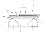
図1は実施形態1に係るプレスブレーキ1の側面図であり、図2は実施形態1に係るプレスブレーキ1を示すブロック図である。図1および図2に示すプレスブレーキ1は、板状の長尺(かつ幅広)のワーク90への多段曲げ加工が可能であり、かかるワーク90から例えば航空機胴体部分のスキンなどの比較的に大径の円筒体を製作することができる。プレスブレーキ1は、搬送機構(搬送装置)2、ダイ3、バックアッププレート4、反発力付与機構(反発力付与装置)5、パンチ6、パンチ駆動機構(パンチ駆動装置)7、および制御装置8を備える。(Embodiment 1)
FIG. 1 is a side view of a
搬送機構2は、ワーク90を間欠的に搬送する。搬送機構2の具体的構成は特に限定されない。例えば、コンベアや、ロボットアームの先端にハンドを有するロボットなどによって構成してもよい。
The
ダイ3は、ワーク90の搬送方向に離れて配置されてワーク90の裏面を支持する一対の肩部11,12、および一対の肩部11,12間に形成される溝部13を有する。本実施形態では、単なる一例として、ダイ3が、ベース板14、および、ベース板14から立設する一対の下型要素15,16を有する。下型要素15,16は搬送方向に離れて配置されており、下型要素15,16の頂部が肩部11,12を構成する。下型要素15,16は、互いに向き合う対向面を有するが、この対向面は、頂部から下方に向かうにつれて搬送方向において互いに近づくように傾斜するテーパ部15a,16aを含む。これらテーパ部15a,16aが溝部13を区画しており、溝部13は概略的にV字状の断面形状を有する。なお、対向面は、テーパ部15a,16aの下端から連続して鉛直下方に延びて平行に対向する鉛直部15b,16bを含む。また、図1に示すダイ3は上述したように一例であり、この構成に限定されない。例えば、ダイ3は、ベース板14及び一対の下型要素15,16が単一の部材により一体的に構成されていてもよいし、下型要素15,16はテーパ部15a,16aを有していなくてもよいし、鉛直部15b,16bを有していなくてもよく、ダイ3の形状は適宜設定することができる。
The die 3 has a pair of
バックアッププレート4は、一対の肩部11,12に架け渡されて溝部13を覆っている。バックアッププレート4は、複数枚の薄板を重ねた積層構造を有している。これにより、ワーク90がパンチ6により押圧されて塑性変形しても、バックアッププレート4は塑性変形せず弾性変形領域内で変形するにとどまらせることができる。各薄板の材質は特に限定されないが、弾性変形領域が比較的に大きな金属材、一例としてバネ鋼から成形されている。また、積層枚数も特に限定されず、少なくとも2枚以上であればよく、10枚以上とすることもできる。バックアッププレート4の弾性変形領域をより大きく確保するため、積層された各薄板は、接着剤等によって互いに接着せず、重ねたままにするのが好ましい。ただし、各薄板間の位置ズレを抑制するため、隣接する薄板同士を部分的に接続してもよい。
The
反発力付与機構5は、バックアッププレート4のうち、一対の肩部11,12の間の部位を下から支え、上向きの反発力をバックアッププレート4の裏面に付与する。
The repulsive
一例として、反発力付与機構5は、一対の下型要素15,16の間に配置されたバネ21を含む。一例として、バネ21はコイルバネであり、伸縮方向が上下方向に向けられる。バネ21の下端は、下型要素15,16の鉛直部15b,16bの間でベース板14に支持され、下型要素15,16と共に作業空間の床面に支持される。なお、本実施の形態では、バネ21の上端にプレート22を取り付けているが、プレート22は必須ではない。例えば、バックアッププレート4が無負荷の状態において、バネ21の上端をバックアッププレート4の裏面に直接接触させてもよいし、あるいは、両者を接触させず離れた状態としておいてもよい。
As an example, the repulsive
他例として、反発力付与機構5は、反発力の発生方向が上下方向になるように設置されたガスシリンダでもよく、この場合も、バックアッププレート4に対して反発力を発生させる部分の先端にプレート22が取り付けられるが、必須ではない。
As another example, the repulsive
後述のとおり、反発力付与機構5は、板厚が厚くて大きな加工力(パンチ6による押圧力)が必要なワーク90の端部をパンチ6で押圧する際などに用いられる。従って、ワーク90の非端部(中間部)の押圧時には使用しなくともよい。反発力付与機構5の使用時と不使用時の切換えにつき、その手法は特に限定されない。例えば、ベース板14が、下型要素15,16を支持する部分と、バネ21を支持する部分とで分割され、反発力付与機構5が上下方向あるいは水平方向に移動可能に構成されていてもよい。これにより、反発力付与機構5が下型要素15,16の間に位置してバックアッププレート4の裏面に面当たり可能な使用状態と、反発力付与機構5がバックアッププレート4の裏面に面当たりしない下方位置あるいは側方位置へ退避する不使用状態との間で、切換えを自動化できる。あるいは、作業員が適時に反発力付与機構5の取付けおよび取外し作業を手動で行ってもよい。
As will be described later, the repulsive force imparting
パンチ6は、ダイ3に対して上下方向に相対移動可能である。本実施形態では、ダイ3が床面に固定されてパンチ6が床面に対して上下方向に移動可能になっているが、パンチ6に加えてまたは代えて、ダイ3が上下方向に移動可能であってもよい。パンチ6は、ダイ3、バックアッププレート4およびワーク90の上方に配置されている。パンチ6が下動することで、ワーク90の表面が押圧される。このとき、ワーク90と共にバックアッププレート4が変形するが、これは弾性変形領域の範囲内での変形である。これによりワーク90のパンチ6直下では、応力が狙い通りに負荷され、正しく曲げ形状が付与される。前述のとおり、このプレスブレーキ1は多段曲げ加工に対応している。
The
パンチ駆動機構7は、パンチ6を上下動させるアクチュエータである。一例として、ロッドを上下方向に向けて配置された液圧シリンダで構成される。
The
制御装置8は、少なくとも搬送機構2およびパンチ駆動機構7の動作を制御する。反発力付与機構5の使用時/不使用時の切換えを自動で行う場合、制御装置8は、反発力付与機構5を移動させる移動機構(移動装置)9の動作も制御する。
The
以上のように構成されるプレスブレーキ1の作用について、図3を参照して説明する。以下の搬送機構2およびパンチ駆動機構7(あるいはパンチ6)の動作(運転方法)は制御装置8による駆動制御を通じて実行(実現)される。
The operation of the
初期状態では、バックアッププレート4がダイ3に設置され、また、バックアッププレート4は反発力付与機構5から反発力を付与される状態にある。ワーク90の搬送が開始してワーク90の端部がバックアッププレート4上、かつ、パンチ6の直下に差し掛かると、ワーク90の搬送が停止する。次いで、パンチ6を下降させる。すると、ワーク90をパンチ6とバックアッププレート4との間に挟んだ状態でバックアッププレート4が撓むことでバックアッププレート4の反力がワーク90に伝達される。また、反発力付与機構5が発揮する反発力がパンチ6の押し込みにつれて増大し、反発力が反力に上乗せされてワーク90に伝達される。これにより、大きな反力(反発力を含む)が得られる。つまり、バックアッププレート4上に位置するワーク90の押圧個所がワーク90の端部であるときには、反発力付与機構5により当該端部に反発力を付与する。よって、ワーク90の端部に目標の曲げ形状を精度よく付与できる。ただしこのとき、パンチ6にも強い負荷がかかっていることとなる。
In the initial state, the
一旦、パンチ6によるワーク90の押圧が終わると、パンチ6が上動してダイ3およびワーク90から退避する。そして、これを1回または複数回間欠的に繰り返した後、ワーク90が決められた搬送量だけ搬送され、ワーク90の非端部がバックアッププレート4上に支持された状態、つまり、ワーク90の端部が一対の肩部11,12よりも搬送方向の外側に存在する状態でワーク90の搬送が止まる。ワーク90の搬送が停止すると、再びパンチ6を下動してワーク90を押圧するが、このとき、反発力付与機構5はダイ3から退避した状態にしておく。そのため、バックアッププレート4で反力は高められるが、端部を曲げるときほど大きな反力は生じない。つまり、バックアッププレート4上に位置するワーク90の押圧個所がワーク90の非端部であるときには、反発力付与機構5により非端部に反発力を付与しない。これにより、非端部についてはバックアッププレート4の反力が得られることで、成形精度を向上しつつ、パンチ6に対する負荷が軽減され、パンチ6およびパンチ駆動機構7の長寿命化が図られる。なお、パンチ6による押圧は、バックアッププレート4の弾性変形領域で行わる。そのため、パンチ6が上動してワーク90およびバックアッププレート4が除荷されると、バックアッププレート4は元の形状に復元し、一対の肩部の上に水平に架け渡された姿勢となり、バックアッププレート4の変形によるパンチ6のストロークの変化などが発生しない。このため、当該プレスブレーキ1は、毎回同じストロークにより同じような曲げが得られ、再現性も高い装置となる。
Once the
ワーク90が間欠的に搬送され、ワーク90の搬送が止まるたびに、パンチ6はワーク90を押圧する。ワーク90の終端がバックアッププレート4上に支持された状態、つまり、ワーク90の端部が一対の肩部11,12に挟まれた領域に存在する状態とされると、再び、反発力付与機構5でバックアッププレート4に反発力を付与しながらパンチ6でワーク90の終端が押圧される。
The
以上の多段曲げ加工が実行されることで、ワーク90に所望の曲げ形状を精度よく付与でき、また、パンチ6にかかる負荷を極力軽減できる。
By executing the above-described multi-stage bending process, the desired bending shape can be imparted to the
また、ワーク90の裏面はバックアッププレート4によって面で支持され、かつ、パンチ6で押圧されたワーク90が変形する過程においても、ワーク90の裏面はバックアッププレート4によって面で支持される(図3B参照)。すなわち、ワーク90の裏面とバックアッププレート4の上面との間に大きな隙間が生じない。そのため、例えばワーク90において、搬送方向の上流側と下流側とで板厚に比較的大きな差がある部位(板厚段差部位)の近傍をパンチ6で押圧する場合であっても、板厚が変化する当該部位でキンクが生じるのを抑制でき、所望の曲率を付与することができる。すなわち、通常、このような板厚段差部位があると、パンチ6で押圧したときに段差部分に応力が集中し、これが原因で当該部分にてワークがキンクする可能性がある。しかし、本実施形態に係るプレスブレーキ1は上述したようにワーク90の裏面がバックアッププレート4によって広く面で支持する。そのため、ワーク90の裏面にて応力を分散できるため、板厚段差部位の近傍を押圧する場合であってもキンクの発生を防止することができる。
Further, the back surface of the
なお、反発力付与機構5は、ワーク90の非端部をパンチ6で押圧する際にも用いてもよい。例えば、バネ21の上端のプレート22を、バックアッププレート4の裏面から所定距離だけ下方に離して配置する。そして、ワーク90に大きな曲率半径を付与する場合には、パンチ6によって対象部分に小さな押圧力を付与する。すると、当該部分では、ワーク90の裏面にプレート22が当接せず、ワーク90に対してバックアッププレート4による反力のみが下方から付与され、比較的小さな押圧力で曲げ加工することができる。一方、ワークに小さな曲率半径を付与する場合には、パンチ6によって対象部分に大きな押圧力を付与する。すると、当該部分では、ワーク90の裏面にプレート22が当接し、ワーク90に対してバックアッププレート4の反力に加えてバネ21の反発力も付与される。従って、比較的大きな押圧力による曲げ加工であっても、適切にワーク90の裏面に面圧を付与することができる。
Note that the repulsive
また、反発力付与機構5のバネ21を、弾性係数の異なる2以上のバネ要素を直列に接続して構成してもよい。この場合、パンチ6のワーク90への押圧力が小さいときは、弾性係数の小さいバネ要素が収縮変形することで、ワーク90の裏面への面圧が過剰になるのを抑制できる。そして、パンチ6のワーク90への押圧力が大きいときは、弾性係数の大きなバネ要素がワーク90を支持することにより、ワーク90の裏面に適切な面圧を付与することができる。従って、この場合は、プレート22をバックアッププレート4の裏面に常時面当てさせた状態としてもよい。
Further, the
(実施形態2)
図4は実施形態2に係るプレスブレーキ1Aの側面図である。この実施形態2に係るプレスブレーキ1Aは、バックアッププレート4の構成が実施形態1で説明したものと異なるが、その他の構成は実施形態1で説明したものと同じである。また、ここで説明するプレスブレーキ1Aも、図2で説明した制御装置8により、実施形態1と同様に運転可能である。(Embodiment 2)
FIG. 4 is a side view of the
実施形態2に係るプレスブレーキ1Aのバックアッププレート4は、薄板を複数枚積層した積層構造を有している。そして、複数枚の薄板のうち、パンチ6に最も近い側に位置する薄板(以下、「表面板40」)は、他の薄板(以下、「内板41」)とは異なる構成になっている。より具体的には、内板41は、全面にわたって平坦な平板状に構成されている。これに対して表面板40は、平板部40aと湾曲部40bとを有している。平板部40aは、内板41とほぼ同じ面積を有する平板状を成し、湾曲部40bは、表面板40における搬送方向の両端部がパンチ6から離反する方向へ湾曲して構成されている。そして、この湾曲部40bにより、内板41の搬送方向の端部が覆われている。
The
このような構成により、表面板40の湾曲部40bにより、その下方の内板41の搬送方向の位置ズレを防止することができる。また、内板41の搬送方向の端部が露出しないため、当該端部との接触によりワーク90の裏面に掻傷が生じるのを防止することができる。
With such a configuration, the
本明細書で開示する要素の機能は、開示された機能を実行するよう構成またはプログラムされた汎用プロセッサ、専用プロセッサ、集積回路、ASIC(Application Specific Integrated Circuits)、従来の回路、および/または、それらの組み合わせ、を含む回路または処理回路を使用して実行できる。プロセッサは、トランジスタやその他の回路を含むため、処理回路または回路と見なされる。本開示において、回路、ユニット、または手段は、列挙された機能を実行するハードウェアであるか、または、列挙された機能を実行するようにプログラムされたハードウェアである。ハードウェアは、本明細書に開示されているハードウェアであってもよいし、あるいは、列挙された機能を実行するようにプログラムまたは構成されているその他の既知のハードウェアであってもよい。ハードウェアが回路の一種と考えられるプロセッサである場合、回路、手段、またはユニットはハードウェアとソフトウェアの組み合わせであり、ソフトウェアはハードウェアおよび/またはプロセッサの構成に使用される。 The functionality of the elements disclosed herein may be achieved by general purpose processors, special purpose processors, integrated circuits, Application Specific Integrated Circuits (ASICs), conventional circuits, and/or those configured or programmed to perform the disclosed functions. can be implemented using a circuit or processing circuit that includes a combination of A processor is considered a processing circuit or circuit because it includes transistors and other circuits. In this disclosure, a circuit, unit, or means is hardware that performs or is programmed to perform the recited functions. The hardware may be the hardware disclosed herein, or other known hardware programmed or configured to perform the recited functions. A circuit, means or unit is a combination of hardware and software where the hardware is a processor which is considered a type of circuit, the software being used to configure the hardware and/or the processor.
これまで、本発明の実施形態について説明したが、上記構成は本発明の範囲内で適宜追加、変更、および/または削除可能である。 Although the embodiments of the present invention have been described so far, the above configurations can be added, changed, and/or deleted as appropriate within the scope of the present invention.
1,1A プレスブレーキ
2 搬送機構
3 ダイ
4 バックアッププレート
5 反発力付与機構
6 パンチ
11,12 肩部
13 溝部
40 表面板
41 内板
90 ワーク1,
Claims (6)
ワークの搬送方向に離れて配置されて前記ワークの裏面を支持する一対の肩部、および前記一対の肩部間に形成される溝部を有するダイと、
連続する板形状を有し、前記一対の肩部上に架け渡されて前記溝部を覆い、前記ダイと前記ワークとの間に介在するバックアッププレートと、
前記ダイに対して相対移動し、前記バックアッププレートの弾性変形領域内で前記ワークを押圧し、当該ワークを曲げるパンチと、を備え、
前記バックアッププレートは、前記パンチが前記ワークを押圧する際に前記一対の肩部と前記パンチとを支点にして凹形状に撓み、当該バックアッププレートの復元力によって前記ワークに反力を与える、
プレスブレーキ。 A press brake that bends a workpiece with a die and a punch,
a die having a pair of shoulders spaced apart in a work conveying direction to support the back surface of the work, and a groove formed between the pair of shoulders;
a backup plate having a continuous plate shape , spanning over the pair of shoulders to cover the groove, and interposed between the die and the workpiece;
a punch that moves relative to the die, presses the work within the elastic deformation region of the backup plate, and bends the work ;
When the punch presses the work, the backup plate bends in a concave shape with the pair of shoulders and the punch as fulcrums, and the restoring force of the backup plate applies a reaction force to the work.
Press brake.
前記ワークの搬送方向に離れて配置されて前記ワークの裏面を支持する一対の肩部、および前記一対の肩部間に形成される溝部を有するダイと、
連続する板形状を有し、前記一対の肩部上に架け渡されて前記溝部を覆い、前記ダイと前記ワークとの間に介在するバックアッププレートと、
前記ダイに対して相対移動し、前記ワークを押圧するパンチと、を備えるプレスブレーキの運転方法であって、
前記ワークを搬送し、前記バックアッププレート上及び前記パンチの直下において搬送を停止させる工程と、
前記パンチを前記ダイに対して相対移動させ、前記バックアッププレートの弾性変形領域内で前記ワークを押圧しつつ、前記バックアッププレートを前記一対の肩部と前記パンチとを支点にして凹形状に撓ませることで当該バックアッププレートの復元力によって前記ワークに反力を与える工程と、を備えるプレスブレーキの運転方法。 a transport mechanism for transporting the workpiece;
a die having a pair of shoulders spaced apart in the conveying direction of the work and supporting the back surface of the work, and a groove formed between the pair of shoulders;
a backup plate having a continuous plate shape , spanning over the pair of shoulders to cover the groove, and interposed between the die and the workpiece;
A press brake operating method comprising a punch that moves relative to the die and presses the workpiece,
a step of conveying the work and stopping the conveyance on the backup plate and directly below the punch;
The punch is moved relative to the die, and the backup plate is bent into a concave shape with the pair of shoulders and the punch as fulcrums while pressing the workpiece within the elastic deformation region of the backup plate. and applying a reaction force to the work by the restoring force of the backup plate .
前記バックアッププレート上に位置する前記ワークの押圧箇所が当該ワークの端部であるときには、前記反発力付与機構を配置し、前記バックアッププレート上に位置する前記ワークの押圧箇所が当該ワークの非端部であるときには、前記反発力付与機構を退避させる工程をさらに備える、請求項5に記載のプレスブレーキの運転方法。 The press brake further includes a repulsive force imparting mechanism that imparts a repulsive force to the backup plate in a direction opposite to the pressing direction of the punch,
When the pressing portion of the work positioned on the backup plate is the end portion of the work, the repulsive force applying mechanism is arranged so that the pressing portion of the work positioned on the backup plate is the non-end portion of the work. 6. The method of operating a press brake according to claim 5, further comprising a step of retracting said repulsive force applying mechanism when .
Applications Claiming Priority (3)
| Application Number | Priority Date | Filing Date | Title |
|---|---|---|---|
| JP2019122092 | 2019-06-28 | ||
| JP2019122092 | 2019-06-28 | ||
| PCT/JP2020/025402 WO2020262684A1 (en) | 2019-06-28 | 2020-06-26 | Press brake, and method for operating press brake |
Publications (2)
| Publication Number | Publication Date |
|---|---|
| JPWO2020262684A1 JPWO2020262684A1 (en) | 2020-12-30 |
| JP7169447B2 true JP7169447B2 (en) | 2022-11-10 |
Family
ID=74061746
Family Applications (1)
| Application Number | Title | Priority Date | Filing Date |
|---|---|---|---|
| JP2021528291A Active JP7169447B2 (en) | 2019-06-28 | 2020-06-26 | Press brake and how to operate the press brake |
Country Status (4)
| Country | Link |
|---|---|
| US (1) | US20220118495A1 (en) |
| EP (1) | EP3991869A4 (en) |
| JP (1) | JP7169447B2 (en) |
| WO (1) | WO2020262684A1 (en) |
Citations (3)
| Publication number | Priority date | Publication date | Assignee | Title |
|---|---|---|---|---|
| WO2001053020A1 (en) | 2000-01-17 | 2001-07-26 | Amada Company, Limited | Bending method and bending device |
| JP3236310B2 (en) | 1991-06-27 | 2001-12-10 | 株式会社アマダ | Bending equipment |
| WO2018143302A1 (en) | 2017-01-31 | 2018-08-09 | 日軽金アクト株式会社 | Mold and processing method using mold |
Family Cites Families (18)
| Publication number | Priority date | Publication date | Assignee | Title |
|---|---|---|---|---|
| US2781849A (en) * | 1952-03-25 | 1957-02-19 | Hartford Nat Bank & Trust Co | Method of forming small apertures in thin metal plate-shaped articles |
| US3263319A (en) * | 1964-02-28 | 1966-08-02 | Varian Associates | Method of cold deep drawing metal foil |
| US3566661A (en) * | 1968-07-29 | 1971-03-02 | Budd Co | Metal forming |
| JPS4965978A (en) * | 1972-10-30 | 1974-06-26 | ||
| JPS5311273B2 (en) * | 1973-12-27 | 1978-04-20 | ||
| JPS5339183B2 (en) * | 1974-07-22 | 1978-10-19 | ||
| AT390575B (en) * | 1988-04-25 | 1990-05-25 | Haemmerle Ag | METHOD FOR BENDING A WORKPIECE |
| JPH0281717U (en) * | 1988-12-02 | 1990-06-25 | ||
| US5542282A (en) * | 1994-03-09 | 1996-08-06 | Inner Act, Inc. | Markless press brake material protector |
| JPH1058043A (en) * | 1996-08-26 | 1998-03-03 | Komatsu Ltd | Bending method and bending equipment |
| US5956991A (en) * | 1998-08-19 | 1999-09-28 | Tseng; Shao-Chien | Forming device for shaped decoration panels |
| US6865917B2 (en) * | 2003-03-27 | 2005-03-15 | Ford Motor Company | Flanging and hemming process with radial compression of the blank stretched surface |
| US8733145B1 (en) * | 2011-01-25 | 2014-05-27 | Valmont Newmark, Inc. | Method of forming a pole and saddle |
| AT512282B1 (en) * | 2012-06-18 | 2013-07-15 | Trumpf Maschinen Austria Gmbh | Bending press with angle detection device |
| JP2014004606A (en) * | 2012-06-25 | 2014-01-16 | Futaba:Kk | Metal mold for roll bending |
| JP6460695B2 (en) * | 2014-03-31 | 2019-01-30 | 東京精密発條株式会社 | Metal plate bending machine |
| JP6595163B2 (en) | 2014-09-17 | 2019-10-23 | 株式会社アマダホールディングス | Press brake and multistage bending method |
| JP6963387B2 (en) * | 2017-01-18 | 2021-11-10 | 川崎重工業株式会社 | Bending method |
-
2020
- 2020-06-26 EP EP20832991.2A patent/EP3991869A4/en active Pending
- 2020-06-26 WO PCT/JP2020/025402 patent/WO2020262684A1/en active Application Filing
- 2020-06-26 JP JP2021528291A patent/JP7169447B2/en active Active
-
2021
- 2021-12-28 US US17/563,087 patent/US20220118495A1/en active Pending
Patent Citations (3)
| Publication number | Priority date | Publication date | Assignee | Title |
|---|---|---|---|---|
| JP3236310B2 (en) | 1991-06-27 | 2001-12-10 | 株式会社アマダ | Bending equipment |
| WO2001053020A1 (en) | 2000-01-17 | 2001-07-26 | Amada Company, Limited | Bending method and bending device |
| WO2018143302A1 (en) | 2017-01-31 | 2018-08-09 | 日軽金アクト株式会社 | Mold and processing method using mold |
Also Published As
| Publication number | Publication date |
|---|---|
| WO2020262684A1 (en) | 2020-12-30 |
| EP3991869A4 (en) | 2023-07-12 |
| EP3991869A1 (en) | 2022-05-04 |
| US20220118495A1 (en) | 2022-04-21 |
| JPWO2020262684A1 (en) | 2020-12-30 |
Similar Documents
| Publication | Publication Date | Title |
|---|---|---|
| US9266162B2 (en) | Press-forming method of component with L shape | |
| JP4781380B2 (en) | Press working apparatus and press working method | |
| JP2010023078A (en) | Bending method of workpiece and device used for the same | |
| JP7133694B2 (en) | Bending method | |
| US11618133B2 (en) | Workpiece supporting device and workpiece supporting method | |
| JP2017170482A (en) | Manufacturing method and manufacturing apparatus of press part having hat cross section | |
| JP2011235356A (en) | Press forming die, and press forming method | |
| JP7169447B2 (en) | Press brake and how to operate the press brake | |
| JP6645519B2 (en) | Press apparatus and method for manufacturing press-formed product | |
| US20220097116A1 (en) | Press forming method and press apparatus | |
| JP6738055B2 (en) | Press-molded product design method, press-molding die, press-molded product, and press-molded product manufacturing method | |
| JP2018051608A (en) | Coining method, and coining device for product processed by burring method and metal component | |
| JP2020028886A (en) | Three-dimensional press device | |
| KR101575213B1 (en) | Press die apparatus and press forming method | |
| JP6658293B2 (en) | Ram head and press straightening method | |
| JP5942976B2 (en) | Processing apparatus and bending method | |
| KR20160141886A (en) | Transfer strip for asymmetry press workpiece | |
| JP6674273B2 (en) | Equivalent strain applying device | |
| JP2009166070A (en) | Workpiece machining apparatus and workpiece machining method | |
| JP5933299B2 (en) | Press forming equipment | |
| JP4751052B2 (en) | Die | |
| US20130004284A1 (en) | Transport method | |
| JP7050984B2 (en) | Method of reducing residual stress at the edge of the work | |
| JP6002547B2 (en) | Metal part processing method and processing apparatus | |
| JP4319652B2 (en) | Transfer feeder in forging press |
Legal Events
| Date | Code | Title | Description |
|---|---|---|---|
| A621 | Written request for application examination |
Free format text: JAPANESE INTERMEDIATE CODE: A621 Effective date: 20211206 |
|
| AA64 | Notification of invalidation of claim of internal priority (with term) |
Free format text: JAPANESE INTERMEDIATE CODE: A241764 Effective date: 20220301 |
|
| A521 | Request for written amendment filed |
Free format text: JAPANESE INTERMEDIATE CODE: A523 Effective date: 20220322 |
|
| A131 | Notification of reasons for refusal |
Free format text: JAPANESE INTERMEDIATE CODE: A131 Effective date: 20220705 |
|
| A521 | Request for written amendment filed |
Free format text: JAPANESE INTERMEDIATE CODE: A523 Effective date: 20220908 |
|
| TRDD | Decision of grant or rejection written | ||
| A01 | Written decision to grant a patent or to grant a registration (utility model) |
Free format text: JAPANESE INTERMEDIATE CODE: A01 Effective date: 20221004 |
|
| A61 | First payment of annual fees (during grant procedure) |
Free format text: JAPANESE INTERMEDIATE CODE: A61 Effective date: 20221028 |
|
| R150 | Certificate of patent or registration of utility model |
Ref document number: 7169447 Country of ref document: JP Free format text: JAPANESE INTERMEDIATE CODE: R150 |