JP7167015B2 - A method for transmitting and receiving a physical uplink control channel between a terminal and a base station in a wireless communication system, and an apparatus for supporting the same - Google Patents
A method for transmitting and receiving a physical uplink control channel between a terminal and a base station in a wireless communication system, and an apparatus for supporting the same Download PDFInfo
- Publication number
- JP7167015B2 JP7167015B2 JP2019521446A JP2019521446A JP7167015B2 JP 7167015 B2 JP7167015 B2 JP 7167015B2 JP 2019521446 A JP2019521446 A JP 2019521446A JP 2019521446 A JP2019521446 A JP 2019521446A JP 7167015 B2 JP7167015 B2 JP 7167015B2
- Authority
- JP
- Japan
- Prior art keywords
- pucch
- symbol
- uci
- symbols
- transmitted
- Prior art date
- Legal status (The legal status is an assumption and is not a legal conclusion. Google has not performed a legal analysis and makes no representation as to the accuracy of the status listed.)
- Active
Links
Images


Classifications
-
- H—ELECTRICITY
- H04—ELECTRIC COMMUNICATION TECHNIQUE
- H04L—TRANSMISSION OF DIGITAL INFORMATION, e.g. TELEGRAPHIC COMMUNICATION
- H04L5/00—Arrangements affording multiple use of the transmission path
- H04L5/003—Arrangements for allocating sub-channels of the transmission path
- H04L5/0048—Allocation of pilot signals, i.e. of signals known to the receiver
- H04L5/005—Allocation of pilot signals, i.e. of signals known to the receiver of common pilots, i.e. pilots destined for multiple users or terminals
-
- H—ELECTRICITY
- H04—ELECTRIC COMMUNICATION TECHNIQUE
- H04L—TRANSMISSION OF DIGITAL INFORMATION, e.g. TELEGRAPHIC COMMUNICATION
- H04L5/00—Arrangements affording multiple use of the transmission path
- H04L5/003—Arrangements for allocating sub-channels of the transmission path
- H04L5/0053—Allocation of signaling, i.e. of overhead other than pilot signals
-
- H—ELECTRICITY
- H04—ELECTRIC COMMUNICATION TECHNIQUE
- H04L—TRANSMISSION OF DIGITAL INFORMATION, e.g. TELEGRAPHIC COMMUNICATION
- H04L5/00—Arrangements affording multiple use of the transmission path
- H04L5/0001—Arrangements for dividing the transmission path
- H04L5/0003—Two-dimensional division
- H04L5/0005—Time-frequency
- H04L5/0007—Time-frequency the frequencies being orthogonal, e.g. OFDM(A), DMT
- H04L5/0012—Hopping in multicarrier systems
-
- H—ELECTRICITY
- H04—ELECTRIC COMMUNICATION TECHNIQUE
- H04L—TRANSMISSION OF DIGITAL INFORMATION, e.g. TELEGRAPHIC COMMUNICATION
- H04L9/00—Cryptographic mechanisms or cryptographic arrangements for secret or secure communications; Network security protocols
- H04L9/40—Network security protocols
-
- H—ELECTRICITY
- H04—ELECTRIC COMMUNICATION TECHNIQUE
- H04W—WIRELESS COMMUNICATION NETWORKS
- H04W4/00—Services specially adapted for wireless communication networks; Facilities therefor
- H04W4/70—Services for machine-to-machine communication [M2M] or machine type communication [MTC]
-
- H—ELECTRICITY
- H04—ELECTRIC COMMUNICATION TECHNIQUE
- H04W—WIRELESS COMMUNICATION NETWORKS
- H04W72/00—Local resource management
- H04W72/04—Wireless resource allocation
-
- H—ELECTRICITY
- H04—ELECTRIC COMMUNICATION TECHNIQUE
- H04W—WIRELESS COMMUNICATION NETWORKS
- H04W72/00—Local resource management
- H04W72/20—Control channels or signalling for resource management
- H04W72/21—Control channels or signalling for resource management in the uplink direction of a wireless link, i.e. towards the network
-
- H—ELECTRICITY
- H04—ELECTRIC COMMUNICATION TECHNIQUE
- H04L—TRANSMISSION OF DIGITAL INFORMATION, e.g. TELEGRAPHIC COMMUNICATION
- H04L5/00—Arrangements affording multiple use of the transmission path
- H04L5/003—Arrangements for allocating sub-channels of the transmission path
- H04L5/0048—Allocation of pilot signals, i.e. of signals known to the receiver
Landscapes
- Engineering & Computer Science (AREA)
- Signal Processing (AREA)
- Computer Networks & Wireless Communication (AREA)
- Computer Security & Cryptography (AREA)
- Mobile Radio Communication Systems (AREA)
Description
以下の説明は、無線通信システムに関し、端末と基地局との間の物理上りリンク制御チャンネルを送受信する方法及びそれを支援する装置に関する。 The following description relates to a wireless communication system, and relates to a method for transmitting and receiving a physical uplink control channel between a terminal and a base station, and an apparatus for supporting the same.
より具体的には、以下の説明は、1つのシンボルを介した物理上りリンク制御チャンネルの送受信を支援する無線通信システムにおいて、端末と基地局との間の複数のチャンネルを介して物理上りリンク制御チャンネルを送受信する方法及びそれを支援する装置に関する。 More specifically, the following description describes physical uplink control over multiple channels between a terminal and a base station in a wireless communication system that supports transmission and reception of a physical uplink control channel over one symbol. The present invention relates to a method for transmitting and receiving channels and an apparatus for supporting the same.
無線接続システムが音声やデータなどの種々の通信サービスを提供するために広範囲に展開されている。一般に、無線接続システムは利用可能なシステムリソース(帯域幅、送信電力など)を共有して複数のユーザとの通信を支援できる多重接続(multiple access)システムである。多重接続システムの例には、CDMA(code division multiple access)システム、FDMA(frequency division multiple access)システム、TDMA(time division multiple access)システム、OFDMA(orthogonal frequency division multiple access)システム、SC-FDMA(single carrier frequency division multiple access)システムなどがある。 Wireless access systems are widely deployed to provide various communication services such as voice and data. Generally, a wireless access system is a multiple access system that can share available system resources (bandwidth, transmission power, etc.) to support communication with multiple users.多重接続システムの例には、CDMA(code division multiple access)システム、FDMA(frequency division multiple access)システム、TDMA(time division multiple access)システム、OFDMA(orthogonal frequency division multiple access)システム、SC-FDMA(single carrier frequency division multiple access) system.
なお、多数の通信機器がより大きな通信容量を要求することにより、既存のRAT(radio access technology)に比べて向上したモバイルブロードバンド通信の必要性が高まっている。また、多数の機器及びモノを連結していつでもどこでも多様なサービスを提供する大規模(massive)MTC(Machine Type Communications)が次世代通信において考えられている。さらに信頼性(reliability)及び遅延(latency)などに敏感なサービス/UEを考慮した通信システムのデザインも考えられている。 In addition, the need for improved mobile broadband communication compared to existing radio access technology (RAT) is increasing as a large number of communication devices demand greater communication capacity. In addition, massive MTC (Machine Type Communications), which connects a large number of devices and things to provide various services anytime and anywhere, is being considered in next-generation communications. Further, communication system designs are also being considered that consider services/UEs that are sensitive to reliability, latency, and the like.
このように向上したモバイルブロードバンド通信、大規模MTC、URLLC(Ultra-Reliable and Low Latency Communication)などを考慮した次世代RATの導入が論議されている。 Considering such improved mobile broadband communication, large-scale MTC, URLLC (Ultra-Reliable and Low Latency Communication), etc., the introduction of the next-generation RAT is under discussion.
本発明の目的は、新たに提案される通信システムにおいて端末と基地局とで物理上りリンク制御チャンネルを送受信する方法を提供することである。 SUMMARY OF THE INVENTION An object of the present invention is to provide a method for transmitting and receiving a physical uplink control channel between a terminal and a base station in a newly proposed communication system.
特に、本発明は、新たに提案される通信システムにおいて、端末と基地局との間に1つ以上のシンボルを介して物理上りリンク制御チャンネルを送受信する場合、前記端末と基地局とで送受信する物理上りリンク制御チャンネルを構成する方法及びそれに基づいた物理上りリンク制御チャンネルの送受信方法を提供することを目的とする。 In particular, in a newly proposed communication system, when a physical uplink control channel is transmitted and received between a terminal and a base station via one or more symbols, the terminal and the base station transmit and receive It is an object of the present invention to provide a method of configuring a physical uplink control channel and a method of transmitting and receiving the physical uplink control channel based thereon.
本発明で遂げようとする技術的目的は以上で言及した事項に限定されず、言及していない別の技術的課題は、以下に説明する本発明の実施例から、本発明の属する技術の分野における通常の知識を有する者によって考慮され得る。 The technical object to be achieved by the present invention is not limited to the matters mentioned above. can be considered by those having ordinary knowledge in
本発明は、無線通信システムにおいて、端末と基地局が物理上りリンク制御チャンネルを送受信する方法及び装置を提供する。 The present invention provides a method and apparatus for transmitting and receiving a physical uplink control channel between a terminal and a base station in a wireless communication system.
本発明の一実施態様として、無線通信システムにおいて、端末が基地局に物理上りリンク制御チャンネル(PUCCH)を送信する方法であって、1つのシンボルを用いたPUCCH構成を複数用いて、複数のシンボルを介して送信される多重シンボルPUCCHを構成することと、前記構成された多重シンボルPUCCHを複数のシンボルを介して送信することと、を含む、物理上りリンク制御チャンネルの送信方法を提案する。 As one embodiment of the present invention, in a wireless communication system, a method for a terminal to transmit a physical uplink control channel (PUCCH) to a base station, using a plurality of PUCCH configurations using one symbol, a plurality of symbols and transmitting the constructed multi-symbol PUCCH over a plurality of symbols.
本発明の他の実施態様として、無線通信システムにおいて、基地局が端末から物理上りリンク制御チャンネル(PUCCH)を受信する方法であって、前記端末から複数のシンボルを介して多重シンボルPUCCHを受信して、前記多重シンボルは、1つのシンボルを用いたPUCCH構成を複数用いて構成される、物理上りリンク制御チャンネルの受信方法を提案する。 Another embodiment of the present invention is a method for a base station to receive a physical uplink control channel (PUCCH) from a terminal in a wireless communication system, the method comprising: receiving a multi-symbol PUCCH from the terminal via a plurality of symbols; Therefore, a method for receiving a physical uplink control channel is proposed, in which the multiple symbols are configured using a plurality of PUCCH configurations using one symbol.
本発明の他の実施態様として、無線通信システムにおいて、基地局に物理上りリンク制御チャンネル(PUCCH)を送信する端末であって、前記端末は、送信部と、前記送信部と連結され動作するプロセッサーと、を含み、前記プロセッサーは、1つのシンボルを用いたPUCCH構成を複数用いて、複数のシンボルを介して送信される多重シンボルPUCCHを構成し、前記構成された多重シンボルPUCCHを複数のシンボルを介して送信するように構成される、端末を提案する。 As another embodiment of the present invention, a terminal for transmitting a physical uplink control channel (PUCCH) to a base station in a wireless communication system, the terminal includes a transmitter and a processor connected and operable with the transmitter. and wherein the processor configures a multi-symbol PUCCH transmitted over a plurality of symbols using multiple PUCCH configurations using one symbol, and divides the configured multi-symbol PUCCH into a plurality of symbols. We propose a terminal configured to transmit via
本発明の他の実施態様として、無線通信システムにおいて、端末から物理上りリンク制御チャンネル(PUCCH)を受信する基地局であって、前記基地局は、受信部と、前記受信部と連結され動作するプロセッサーと、を含み、前記プロセッサーは、前記端末から複数のシンボルを介して多重シンボルPUCCHを受信するように構成され、前記多重シンボルは、1つのシンボルを用いたPUCCH構成を複数用いて構成される、基地局を提案する。 Another embodiment of the present invention is a base station for receiving a physical uplink control channel (PUCCH) from a terminal in a wireless communication system, wherein the base station is connected to and operates from a receiver. a processor, the processor configured to receive a multi-symbol PUCCH over multiple symbols from the terminal, the multi-symbol configured using multiple single-symbol PUCCH configurations. , proposes a base station.
このとき、前記1つのシンボルを用いたPUCCH構成は、前記1つのシンボルを介してDM-RS及びUCIが周波数分割多重化(Frequency Division Multiplexing,FDM)されて送信されるPUCCH構成が適用されてもよい。 At this time, the PUCCH configuration using the one symbol is a PUCCH configuration in which DM-RS and UCI are frequency division multiplexed (FDM) and transmitted via the one symbol. good.
また、前記1つのシンボルを用いたPUCCH構成が連続しない周波数リソースに割り当てられた複数の上りリンクリソース要素グループ(Resource Element Group,REG)で構成される場合、前記多重シンボルPUCCHに対する周波数ホッピング(frequency hopping)は許容されなくてもよい。 Also, when the PUCCH configuration using one symbol is composed of a plurality of uplink resource element groups (REG) allocated to discontinuous frequency resources, frequency hopping for the multi-symbol PUCCH ) may not be allowed.
一方、前記1つのシンボルを用いたPUCCH構成が連続する周波数リソースに割り当てられた複数の上りリンクリソース要素グループ(Resource Element Group,REG)で構成される場合、前記多重シンボルPUCCHに対する周波数ホッピング(frequency hopping)が適用されてもよい。 On the other hand, when the PUCCH configuration using one symbol is composed of a plurality of uplink resource element groups (REG) allocated to continuous frequency resources, frequency hopping for the multi-symbol PUCCH ) may be applied.
また、前記多重シンボルPUCCHは、周波数ホッピング(frequency hopping)が適用されて送信されてもよい。 Also, the multi-symbol PUCCH may be transmitted by applying frequency hopping.
具体的に、前記多重シンボルPUCCHが送信されるシンボル数がK(但し、Kは1より大きい自然数)個であり、前記多重シンボルPUCCHが周波数ホッピングが適用されて送信される場合、各周波数ホッピング単位は


![]()
![]()
前記多重シンボルPUCCHが送信される各シンボルごとに送信される上りリンク制御情報(Uplink Control Information,UCI)ビット情報は、前記多重シンボルPUCCHを介して送信されるUCIサイズによって、互いに同一である又は互いに異なるように設定されてもよい。 Uplink control information (UCI) bit information transmitted for each symbol in which the multi-symbol PUCCH is transmitted is identical to each other or mutually according to the UCI size transmitted via the multi-symbol PUCCH It may be set differently.
具体的に、前記多重シンボルPUCCHを介して送信される上りリンク制御情報(Uplink Control Information,UCI)のサイズが所定のビットサイズ以上である場合、前記多重シンボルPUCCHが送信される各シンボルごとに送信されるUCIビット情報は互いに異なるように設定されてもよい。 Specifically, when the size of uplink control information (UCI) transmitted through the multi-symbol PUCCH is equal to or larger than a predetermined bit size, transmission is performed for each symbol in which the multi-symbol PUCCH is transmitted. The UCI bit information to be sent may be set differently.
また、前記多重シンボルPUCCHは、他の端末が送信したPUCCHとコード分割多重化(符号分割多重化、Code Division Multiplexing,CDM)されて送信されてもよい。 Also, the multi-symbol PUCCH may be code division multiplexed (Code Division Multiplexing, CDM) with PUCCHs transmitted by other terminals and transmitted.
また、前記1つのシンボルを用いたPUCCH構成は、前記1つのシンボルを介してDM-RS及びUCIが時間分割多重化(Time Division Multiplexing,TDM)されて送信されるPUCCH構成であってもよい。 Also, the PUCCH configuration using the one symbol may be a PUCCH configuration in which the DM-RS and UCI are time division multiplexed (TDM) and transmitted via the one symbol.
本発明において、前記多重シンボルPUCCHは、2シンボルPUCCHであってもよい。 In the present invention, the multi-symbol PUCCH may be a 2-symbol PUCCH.
上述した本発明の様態は、本発明の好適な実施例の一部に過ぎず、本願発明の技術的特徴が反映された様々な実施例が、当該技術の分野における通常的な知識を有する者にとって、以下に詳述する本発明の詳細な説明に基づいて導出され理解され得るだろう。 The aspects of the present invention described above are only a part of the preferred embodiments of the present invention, and various embodiments reflecting the technical features of the present invention may be used by those who have ordinary knowledge in the relevant technical field. can be derived and understood based on the detailed description of the invention detailed below.
本発明の実施例によれば、次のような効果がある。 The embodiment of the present invention has the following effects.
本発明によれば、新たに提案される無線通信システム(例えば、NRシステム)において、可変のシンボル数を介した物理上りリンク制御チャンネルの送受信を支援する場合、端末と基地局は前記物理上りリンク制御チャンネルを介して送受信しようとする上りリンク制御チャンネルのサイズによって適切なPUCCH構造を活用して、物理上りリンク制御チャンネルを送受信することができる。 According to the present invention, when supporting transmission and reception of a physical uplink control channel through a variable number of symbols in a newly proposed wireless communication system (eg, NR system), a terminal and a base station can A physical uplink control channel can be transmitted/received using a suitable PUCCH structure according to the size of the uplink control channel to be transmitted/received through the control channel.
本発明の実施例から得られる効果は、以上で言及した効果に限定されず、言及していない別の効果は、以下の本発明の実施例に関する記載から、本発明の属する技術の分野における通常の知識を有する者に明確に導出され理解されるであろう。すなわち、本発明を実施することに伴う意図していない効果も、本発明の実施例から当該技術の分野における通常の知識を有する者によって導出され得る。 The effects obtained from the examples of the present invention are not limited to the effects mentioned above, and other effects not mentioned can be obtained from the following description of the examples of the present invention, which are common in the technical field to which the present invention belongs. will be clearly derived and understood by those who have knowledge of That is, unintended effects associated with practicing the invention may also be derived from the embodiments of the invention by those of ordinary skill in the art.
以下に添付する図面は、本発明に関する理解を助けるためのものであり、詳細な説明と共に本発明に関する実施例を提供する。ただし、本発明の技術的特徴が特定の図面に限定されるものではなく、各図面で開示する特徴が互いに組み合わせられて新しい実施例として構成されてもよい。各図面における参照番号(reference numerals)は構造的構成要素(structural elements)を意味する。
以下の実施例は本発明の構成要素と特徴を所定の形態で結合したものである。各構成要素又は特徴は、別の明示的言及がない限り、選択的なものとして考慮することができる。各構成要素又は特徴は別の構成要素や特徴と結合しない形態で実施されてもよく、一部の構成要素及び/又は特徴を結合させて本発明の実施例を構成してもよい。本発明の実施例において説明される動作の順序は変更されてもよい。ある実施例の一部の構成や特徴は他の実施例に含まれてもよく、他の実施例の対応する構成又は特徴に取り替えられてもよい。 The following examples combine elements and features of the present invention in certain forms. Each component or feature may be considered optional unless explicitly stated otherwise. Each component or feature may be implemented without being combined with another component or feature, or some components and/or features may be combined to form an embodiment of the present invention. The order of operations described in embodiments of the invention may be changed. Some configurations and features of one embodiment may be included in other embodiments, and may be replaced with corresponding configurations or features of other embodiments.
図面に関する説明において、本発明の要旨を曖昧にさせ得る手順又は段階などは記述を省略し、当業者のレベルで理解可能な程度の手順又は段階も記述を省略する。 In the description of the drawings, descriptions of procedures or steps that may obscure the gist of the present invention are omitted, and descriptions of procedures or steps that can be understood by a person skilled in the art are also omitted.
明細書全体を通じて、ある部分がある構成要素を「含む(comprising又はincluding)」というとき、これは、別に反対の記載がない限り、他の構成要素を除外するものではなく、他の構成要素をさらに含み得ることを意味する。また、明細書でいう「…部」、「…器」、「モジュール」などの用語は、少なくとも1つの機能や動作を処理する単位を意味し、これは、ハードウェア、ソフトウェア、又はハードウェア及びソフトウェアの結合によって実現することができる。また、「ある(a又はan)」、「1つ(one)」、「その(the)」及び類似の関連語は、本発明を記述する文脈において(特に、以下の請求項の文脈において)本明細書に別に指示されたり文脈によって明らかに反駁されない限り、単数及び複数の両方を含む意味で使うことができる。 Throughout the specification, when a part refers to "comprising or including" an element, this does not exclude other elements, unless stated to the contrary. It is meant to include further. In addition, terms such as "... unit", "... device", and "module" in the specification mean a unit that processes at least one function or operation, which can be hardware, software, or hardware and It can be realized by software combination. Also, the terms "a or an", "one", "the" and similar related terms in the context of describing the present invention (particularly in the context of the claims below) The terms include both the singular and the plural unless otherwise indicated herein or otherwise clearly contradicted by context.
本明細書において本発明の実施例は基地局と移動局との間のデータ送受信関係を中心に説明される。ここで、基地局は、移動局と通信を直接行うネットワークの終端ノード(terminal node)としての意味を有する。本文書において基地局によって行われるとされている特定動作は、場合によっては、基地局の上位ノード(upper node)によって行われてもよい。 In this specification, embodiments of the present invention are mainly described with respect to the data transmission/reception relationship between a base station and a mobile station. Here, the base station has a meaning as a terminal node of a network that directly communicates with mobile stations. Certain operations referred to in this document as being performed by the base station may possibly be performed by an upper node of the base station.
すなわち、基地局を含む複数のネットワークノード(network node)からなるネットワークにおいて、移動局との通信のために行われる様々な動作は、基地局、又は基地局以外の他のネットワークノードで行うことができる。このとき、「基地局」は、固定局(fixed station)、Node B、eNode B(eNB)、発展した基地局(ABS:Advanced Base Station)、new-generation Node B(gNB)、又はアクセスポイント(access point)などの用語に言い換えることができる。 That is, in a network composed of a plurality of network nodes including base stations, various operations performed for communication with mobile stations can be performed by the base stations or other network nodes other than the base stations. can. As used herein, a “base station” may be a fixed station, a Node B, an eNode B (eNB), an Advanced Base Station (ABS), a new-generation Node B (gNB), or an access point ( access point).
また、本発明の実施例において、端末(Terminal)は、ユーザ機器(UE:User Equipment)、移動局(MS:Mobile Station)、加入者端末(SS:Subscriber Station)、移動加入者端末(MSS:Mobile Subscriber Station)、移動端末(Mobile Terminal)、又は発展した移動端末(AMS:Advanced Mobile Station)などの用語に言い換えることができる。 In addition, in the embodiment of the present invention, terminals include User Equipment (UE), Mobile Station (MS), Subscriber Station (SS), and Mobile Subscriber Station (MSS). Mobile Subscriber Station), Mobile Terminal, or Advanced Mobile Station (AMS).
また、送信端はデータサービス又は音声サービスを提供する固定及び/又は移動ノードを意味し、受信端はデータサービス又は音声サービスを受信する固定及び/又は移動ノードを意味する。したがって、上りリンクでは移動局を送信端にし、基地局を受信端にすることができる。同様に、下りリンクでは移動局を受信端にし、基地局を送信端にすることができる。 Also, a transmitting end means a fixed and/or mobile node that provides data service or voice service, and a receiving end means a fixed and/or mobile node that receives data service or voice service. Therefore, in uplink, the mobile station can be the transmitting end and the base station can be the receiving end. Similarly, in the downlink, the mobile station can be the receiving end and the base station can be the transmitting end.
本発明の実施例は、無線接続システムであるIEEE 802.xxシステム、3GPP(3rd Generation Partnership Project)システム、3GPP LTEシステム及び3GPP2システムのうち少なくとも1つに開示されている標準文書によってサポートすることができ、特に、本発明の実施例は、3GPP TS 36.211、3GPP TS 36.212、3GPP TS 36.213、3GPP TS 36.321及び 3GPP TS 36.331の文書によってサポートすることができる。すなわち、本発明の実施例のうち、説明していない自明な段階又は部分は、上記文書を参照して説明することができる。また、本文書に開示している用語はいずれも、上記標準文書によって説明することができる。 Embodiments of the present invention are based on IEEE 802.2, which is a wireless access system. xx system, 3rd Generation Partnership Project (3GPP) system, 3GPP LTE system and/or 3GPP2 system. H.211, 3GPP TS 36.212, 3GPP TS 36.213, 3GPP TS 36.321 and 3GPP TS 36.331 documents. That is, the obvious steps or portions of the embodiments of the present invention that have not been described can be described with reference to the above documents. Also, any terms disclosed in this document can be explained by the above standard documents.
以下、本発明に係る好適な実施形態を添付の図面を参照して詳しく説明する。添付の図面と共に以下に開示する詳細な説明は、本発明の例示的な実施形態を説明するためのもので、本発明が実施され得る唯一の実施形態を表すことを意図するものではない。 Preferred embodiments of the present invention will now be described in detail with reference to the accompanying drawings. The detailed description, which is disclosed below in conjunction with the accompanying drawings, is intended to describe exemplary embodiments of the invention and is not intended to represent the only embodiments in which the invention may be practiced.
また、本発明の実施例で使われる特定用語は本発明の理解し易さのために提供されるものであり、このような特定用語の使用は本発明の技術的思想を逸脱しない範囲で他の形態に変更されてもよい。 In addition, specific terms used in the embodiments of the present invention are provided for easy understanding of the present invention, and the use of such specific terms may be used without departing from the technical spirit of the present invention. may be changed to the form of
例えば、送信機会区間(TxOP:Transmission Opportunity Period)という用語は、送信区間、送信バースト(Tx burst)又はRRP(Reserved Resource Period)という用語と同じ意味で使うことができる。また、LBT(Listen Before Talk)過程は、チャンネル状態が遊休であるか否かを判断するためのキャリアセンシング過程、CCA(Clear Channel Accessment)、チャンネル接続過程(CAP:Channel Access Procedure)と同じ目的で行うことができる。 For example, the term Transmission Opportunity Period (TxOP) can be used interchangeably with the terms Transmission Period, Transmission Burst (Tx burst) or Reserved Resource Period (RRP). In addition, the LBT (Listen Before Talk) process has the same purpose as the carrier sensing process for determining whether the channel state is idle, the CCA (Clear Channel Accessment), and the channel access procedure (CAP). It can be carried out.
以下では、本発明の実施例を利用可能な無線接続システムの一例として3GPP LTE/LTE-Aシステムについて説明する。 A 3GPP LTE/LTE-A system will be described below as an example of a wireless access system that can use embodiments of the present invention.
以下の技術は、CDMA(code division multiple access)、FDMA(frequency division multiple access)、TDMA(time division multiple access)、OFDMA(orthogonal frequency division multiple access)、SC-FDMA(single carrier frequency division multiple access)などのような様々な無線接続システムに適用することができる。 以下の技術は、CDMA(code division multiple access)、FDMA(frequency division multiple access)、TDMA(time division multiple access)、OFDMA(orthogonal frequency division multiple access)、SC-FDMA(single carrier frequency division multiple access)などcan be applied to various wireless access systems such as
CDMAは、UTRA(Universal Terrestrial Radio Access)やCDMA2000のような無線技術(radio technology)によって実現することができる。TDMAは、GSM(Global System for Mobile communications)/GPRS(General Packet Radio Service)/EDGE(Enhanced Data Rates for GSM Evolution)のような無線技術によって実現することができる。OFDMAは、IEEE 802.11(Wi-Fi)、IEEE 802.16(WiMAX)、IEEE 802-20、E-UTRA(Evolved UTRA)などのような無線技術によって実現することができる。 CDMA can be implemented by radio technology such as UTRA (Universal Terrestrial Radio Access) and CDMA2000. TDMA can be implemented by radio technologies such as GSM (Global System for Mobile communications)/GPRS (General Packet Radio Service)/EDGE (Enhanced Data Rates for GSM Evolution). OFDMA can be implemented by radio technologies such as IEEE 802.11 (Wi-Fi), IEEE 802.16 (WiMAX), IEEE 802-20, E-UTRA (Evolved UTRA), and so on.
UTRAはUMTS(Universal Mobile Telecommunications System)の一部である。3GPP LTE(Long Term Evolution)はE-UTRAを用いるE-UMTS(Evolved UMTS)の一部であり、下りリンクでOFDMAを採用し、上りリンクでSC-FDMAを採用する。LTE-A(Advanced)システムは3GPP LTEシステムを改良したシステムである。本発明の技術的特徴に関する説明を明確にするために、本発明の実施例は3GPP LTE/LTE-Aシステムを中心に述べられるが、IEEE 802.16e/mシステムなどに適用されてもよい。 UTRA is part of UMTS (Universal Mobile Telecommunications System). 3GPP Long Term Evolution (LTE) is part of Evolved UMTS (E-UMTS) that uses E-UTRA, which employs OFDMA on the downlink and SC-FDMA on the uplink. The LTE-A (Advanced) system is an improved version of the 3GPP LTE system. In order to clarify the description of the technical features of the present invention, the embodiments of the present invention are mainly described in the 3GPP LTE/LTE-A system, but may also be applied to the IEEE 802.16e/m system and the like.
1.3GPP LTE/LTE A システム1.3GPP LTE/LTE A system
1.1.物理チャンネル及びこれを用いた信号の送受信方法 1.1. Physical channel and signal transmission/reception method using the same
無線接続システムにおいて端末は下りリンク(DL:Downlink)で基地局から情報を受信し、上りリンク(UL:Uplink)で基地局に情報を送信する。基地局と端末とが送受信する情報は一般データ情報及び種々の制御情報を含み、基地局と端末とが送受信する情報の種類/用途によって様々な物理チャンネルが存在する。 In a wireless access system, a terminal receives information from a base station on the downlink (DL) and transmits information to the base station on the uplink (UL). Information transmitted/received between the base station and the terminal includes general data information and various control information, and there are various physical channels according to the type/use of information transmitted/received between the base station and the terminal.
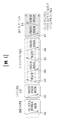
図1は、本発明の実施例で使用可能な物理チャンネル及びそれらを用いた信号送信方法を説明するための図である。 FIG. 1 is a diagram for explaining physical channels that can be used in an embodiment of the present invention and a signal transmission method using them.
電源が消えた状態で電源がついたり、新しくセルに進入したりした端末は、S11段階で、基地局と同期を取るなどの初期セル探索(Initial cell search)作業を行う。そのために、端末は基地局からプライマリ同期チャンネル(P-SCH:Primary Synchronization Channel)及びセカンダリ同期チャンネル(S-SCH:Secondary Synchronization Channel)を受信して基地局と同期を取り、セルIDなどの情報を取得する。 A terminal that is powered off or newly enters a cell performs an initial cell search such as synchronizing with a base station in step S11. For this purpose, the terminal receives a Primary Synchronization Channel (P-SCH) and a Secondary Synchronization Channel (S-SCH) from the base station, synchronizes with the base station, and acquires information such as a cell ID. get.
その後、端末は基地局から物理放送チャンネル(PBCH:Physical Broadcast Channel)信号を受信してセル内放送情報を取得することができる。 After that, the terminal can receive a Physical Broadcast Channel (PBCH) signal from the base station to acquire the intra-cell broadcast information.
一方、端末は初期セル探索段階で下りリンク参照信号(DL RS:Downlink Reference Signal)を受信して下りリンクチャンネル状態を確認することができる。 On the other hand, the terminal can check the downlink channel state by receiving a downlink reference signal (DL RS) in the initial cell search stage.
初期セル探索を終えた端末は、S12段階で、物理下りリンク制御チャンネル(PDCCH:Physical Downlink Control Channel)、及び物理下りリンク制御チャンネル情報に対応する物理下りリンク共有チャンネル(PDSCH:Physical Downlink Control Channel)を受信して、より具体的なシステム情報を取得することができる。 After completing the initial cell search, in step S12, the terminal connects a physical downlink control channel (PDCCH) and a physical downlink shared channel (PDSCH) corresponding to physical downlink control channel information. to get more specific system information.
その後、端末は基地局への接続を完了するために、段階S13~段階S16のようなランダムアクセス過程(Random Access Procedure)を行うことができる。そのために、端末は物理ランダムアクセスチャンネル(PRACH:Physical Random Access Channel)でプリアンブル(preamble)を送信し(S13)、物理下りリンク制御チャンネル及びそれに対応する物理下りリンク共有チャンネルでプリアンブルに対する応答メッセージを受信することができる(S14)。競合ベースのランダムアクセスでは、端末は、更なる物理ランダムアクセスチャンネル信号の送信(S15)、及び物理下りリンク制御チャンネル信号及びそれに対応する物理下りリンク共有チャンネル信号の受信(S16)のような衝突解決手順(Contention Resolution Procedure)を行うことができる。 After that, the terminal can perform a random access procedure such as steps S13 to S16 to complete connection to the base station. To this end, the terminal transmits a preamble through a physical random access channel (PRACH) (S13), and receives a response message to the preamble through a physical downlink control channel and a corresponding physical downlink shared channel. (S14). In contention-based random access, the terminal performs collision resolution, such as sending further physical random access channel signals (S15) and receiving physical downlink control channel signals and corresponding physical downlink shared channel signals (S16). A Contention Resolution Procedure can be performed.
上述したような手順を行った端末は、その後、一般的な上りリンク/下りリンク信号送信手順として、物理下りリンク制御チャンネル信号及び/又は物理下りリンク共有チャンネル信号の受信(S17)、及び物理上りリンク共有チャンネル(PUSCH:Physical Uplink Shared Channel)信号及び/又は物理上りリンク制御チャンネル(PUCCH:Physical Uplink Control Channel)信号の送信(S18)を行うことができる。 After performing the procedure as described above, the terminal then receives a physical downlink control channel signal and/or a physical downlink shared channel signal as a general uplink/downlink signal transmission procedure (S17), and physical uplink A link shared channel (PUSCH: Physical Uplink Shared Channel) signal and/or a physical uplink control channel (PUCCH: Physical Uplink Control Channel) signal can be transmitted (S18).
端末が基地局に送信する制御情報を総称して上りリンク制御情報(UCI:Uplink Control Information)という。UCIは、HARQ-ACK/NACK(Hybrid Automatic Repeat and reQuest Acknowledgement/Negative-ACK)、SR(Scheduling Request)、CQI(Channel Quality Indication)、PMI(Precoding Matrix Indication)、RI(Rank Indication)情報などを含む。 Control information transmitted from a terminal to a base station is generically called uplink control information (UCI). UCIは、HARQ-ACK/NACK(Hybrid Automatic Repeat and reQuest Acknowledgement/Negative-ACK)、SR(Scheduling Request)、CQI(Channel Quality Indication)、PMI(Precoding Matrix Indication)、RI(Rank Indication)情報などを含む.
LTEシステムにおいてUCIは一般的にPUCCHで周期的に送信されるが、制御情報とトラフィックデータが同時に送信されるべき場合にはPUSCHで送信されてもよい。また、ネットワークの要求/指示によってPUSCHでUCIを非周期的に送信することもできる。 UCI is generally transmitted periodically on PUCCH in the LTE system, but may be transmitted on PUSCH if control information and traffic data are to be transmitted simultaneously. Also, the UCI can be transmitted aperiodically on the PUSCH according to the network's request/instruction.
1.2.リソース構造 1.2. Resource structure
図2は、本発明の実施例で用いられる無線フレームの構造を示す図である。 FIG. 2 is a diagram showing the structure of a radio frame used in an embodiment of the invention.
図2(a)にはタイプ1フレーム構造(frame structure type1)を示す。タイプ1フレーム構造は、全二重(full duplex)FDD(Frequency Division Duplex)システムにも半二重(half duplex)FDDシステムにも適用可能である。
FIG. 2(a) shows a
1無線フレーム(radio frame)はTf=307200*Ts=10msの長さを有するものであり、Tslot=15360*Ts=0.5msの均等な長さを有し、0~19のインデックスが与えられた20個のスロットで構成される。1サブフレームは2つの連続したスロットで定義され、i番目のサブフレームは、2iと2i+1に該当するスロットで構成される。すなわち、無線フレーム(radio frame)は10個のサブフレーム(subframe)で構成される。1サブフレームを送信するためにかかる時間をTTI(transmission time interval)という。ここで、Tsはサンプリング時間を表し、Ts=1/(15kHz×2048)=3.2552×10-8(約33ns)と表示される。スロットは時間領域において複数のOFDMシンボル又はSC-FDMAシンボルを含み、周波数領域において複数のリソースブロック(Resource Block)を含む。 One radio frame has a length of T f =307200*T s =10 ms, an even length of T slot =15360*T s =0.5 ms, and 0-19 It consists of 20 indexed slots. One subframe is defined by two consecutive slots, and the i-th subframe consists of slots corresponding to 2i and 2i+1. That is, a radio frame consists of 10 subframes. The time required to transmit one subframe is called TTI (transmission time interval). Here, T s represents the sampling time and is denoted as T s =1/(15 kHz×2048)=3.2552×10 −8 (approximately 33 ns). A slot includes multiple OFDM symbols or SC-FDMA symbols in the time domain, and multiple resource blocks in the frequency domain.
1スロットは時間領域において複数のOFDM(orthogonal frequency division multiplexing)シンボルを含む。3GPP LTEは下りリンクにおいてOFDMAを用いるので、OFDMシンボルは1シンボル区間(symbol period)を表現するためのものである。OFDMシンボルは1つのSC-FDMAシンボル又はシンボル区間ということができる。リソースブロック(resource block)はリソース割り当て単位であり、1つのスロットで複数の連続した副搬送波(subcarrier)を含む。 One slot includes a plurality of OFDM (orthogonal frequency division multiplexing) symbols in the time domain. Since 3GPP LTE uses OFDMA in the downlink, an OFDM symbol is for expressing one symbol period. An OFDM symbol can be referred to as one SC-FDMA symbol or symbol period. A resource block is a resource allocation unit and includes multiple consecutive subcarriers in one slot.
全二重FDDシステムでは各10ms区間において10個のサブフレームを下りリンク送信と上りリンク送信のために同時に利用することができる。このとき、上りリンクと下りリンク送信は周波数領域において分離される。これに対し、半二重FDDシステムでは端末が送信と受信を同時に行うことができない。 In a full-duplex FDD system, 10 subframes can be used simultaneously for downlink and uplink transmissions in each 10 ms interval. Uplink and downlink transmissions are then separated in the frequency domain. In contrast, a half-duplex FDD system does not allow a terminal to transmit and receive at the same time.
上述した無線フレームの構造は1つの例示に過ぎず、無線フレームに含まれるサブフレームの数、サブフレームに含まれるスロットの数、又はスロットに含まれるOFDMシンボルの数は様々に変更されてもよい。 The structure of the radio frame described above is only one example, and the number of subframes included in the radio frame, the number of slots included in the subframe, or the number of OFDM symbols included in the slots may be changed in various ways. .
図2(b)にはタイプ2フレーム構造(frame structure type2)を示す。タイプ2フレーム構造はTDDシステムに適用される。1無線フレーム(radio frame)はTf=307200*Ts=10msの長さを有し、153600*Ts=5msの長さを有する2つのハーフフレーム(half-frame)で構成される。各ハーフフレームは30720*Ts=1msの長さを有する5つのサブフレームで構成される。i番目のサブフレームは2iと2i+1に該当する各Tslot=15360*Ts=0.5msの長さを有する2つのスロットで構成される。ここで、Tsはサンプリング時間を表し、Ts=1/(15kHz×2048)=3.2552×10-8(約33ns)と表示される。
FIG. 2(b) shows a
タイプ2フレームは、DwPTS(Downlink Pilot Time Slot)、保護区間(GP:Guard Period)、UpPTS(Uplink Pilot Time Slot)の3つのフィールドで構成される特別サブフレームを含む。ここで、DwPTSは、端末における初期セル探索、同期化又はチャンネル推定に用いられる。UpPTSは、基地局におけるチャンネル推定と端末の上り送信同期化に用いられる。保護区間は、上りリンクと下りリンクとの間に下りリンク信号の多重経路遅延によって上りリンクに生じる干渉を除去するための区間である。
The
次の表1は、特別フレームの構成(DwPTS/GP/UpPTSの長さ)を表す。 Table 1 below shows the structure of the special frame (length of DwPTS/GP/UpPTS).

図3は、本発明の実施例で利用可能な下りリンクスロットに対するリソースグリッド(resource grid)を例示する図である。 FIG. 3 is a diagram illustrating a resource grid for downlink slots available in an embodiment of the present invention.
図3を参照すると、1つの下りリンクスロットは時間領域において複数のOFDMシンボルを含む。ここで、1つの下りリンクスロットは7個のOFDMシンボルを含み、1つのリソースブロックは周波数領域において12個の副搬送波を含むとしているが、これに限定されるものではない。 Referring to FIG. 3, one downlink slot includes multiple OFDM symbols in the time domain. Here, one downlink slot includes 7 OFDM symbols and one resource block includes 12 subcarriers in the frequency domain, but is not limited to this.
リソースグリッド上で各要素(element)をリソース要素(resource element)といい、1つのリソースブロックは12×7個のリソース要素を含む。下りリンクスロットに含まれるリソースブロックの数NDLは、下りリンク送信帯域幅(bandwidth)に従属する。上りリンクスロット構造は、下りリンクスロットの構造と同様であってもよい。 Each element on the resource grid is called a resource element, and one resource block includes 12×7 resource elements. The number NDL of resource blocks included in a downlink slot depends on the downlink transmission bandwidth. The uplink slot structure may be similar to the downlink slot structure.
図4は、本発明の実施例で利用可能な上りリンクサブフレームの構造を示す。 FIG. 4 shows the structure of an uplink subframe available in an embodiment of the invention.
図4を参照すると、上りリンクサブフレームは、周波数領域において制御領域とデータ領域とに分けることができる。制御領域には、上りリンク制御情報を搬送するPUCCHが割り当てられる。データ領域には、ユーザデータを搬送するPUSCHが割り当てられる。単一搬送波特性を維持するために1つの端末はPUCCHとPUSCHを同時に送信しない。1つの端末に対するPUCCHにはサブフレーム内にRB対が割り当てられる。RB対に属するRBは2つのスロットのそれぞれにおいて異なる副搬送波を占める。このようなPUCCHに割り当てられたRB対は、スロット境界(slot boundary)で周波数ホッピング(frequency hopping)する、という。 Referring to FIG. 4, an uplink subframe can be divided into a control region and a data region in the frequency domain. The control region is assigned a PUCCH that carries uplink control information. The data area is assigned a PUSCH that carries user data. A terminal does not transmit PUCCH and PUSCH at the same time to maintain the single carrier property. A PUCCH for one terminal is assigned an RB pair within a subframe. RBs belonging to an RB pair occupy different subcarriers in each of the two slots. RB pairs allocated to such PUCCH are said to be frequency hopping on slot boundaries.
図5は、本発明の実施例で利用可能な下りリンクサブフレームの構造を示す図である。 FIG. 5 is a diagram showing the structure of a downlink subframe that can be used in embodiments of the present invention.
図5を参照すると、サブフレームにおける第1番目のスロットにおいてOFDMシンボルインデックス0から最大で3つまでのOFDMシンボルが、制御チャンネルが割り当てられる制御領域(control region)であり、残りのOFDMシンボルは、PDSCHが割り当てられるデータ領域(data region)である。3GPP LTEで用いられる下りリンク制御チャンネルの例に、PCFICH(Physical Control Format Indicator Channel)、PDCCH、PHICH(Physical Hybrid-ARQ Indicator Channel)などがある。
Referring to FIG. 5, OFDM symbols from
PCFICHはサブフレームの第1番目のOFDMシンボルで送信され、サブフレームにおいて制御チャンネルの送信のために用いられるOFDMシンボルの数(すなわち、制御領域のサイズ)に関する情報を搬送する。PHICHは、上りリンクに対する応答チャンネルであり、HARQ(Hybrid Automatic Repeat Request)に対するACK(Acknowledgement)/NACK(Negative-Acknowledgement)信号を搬送する。PDCCHで送信される制御情報を下りリンク制御情報(DCI:downlink control information)という。下りリンク制御情報は、上りリンクリソース割り当て情報、下りリンクリソース割り当て情報、又は任意の端末グループに対する上りリンク送信(Tx)電力制御命令を含む。 The PCFICH is sent in the first OFDM symbol of a subframe and carries information about the number of OFDM symbols used for control channel transmission in the subframe (ie, the size of the control region). PHICH is a response channel for uplink and carries ACK (Acknowledgement)/NACK (Negative-Acknowledgement) signals for HARQ (Hybrid Automatic Repeat Request). Control information transmitted on the PDCCH is called downlink control information (DCI). Downlink control information includes uplink resource allocation information, downlink resource allocation information, or uplink transmission (Tx) power control commands for any group of terminals.
1.3.CSIフィードバック 1.3. CSI feedback
3GPP LTE又はLTE-Aシステムでは、ユーザ機器(UE)がチャンネル状態情報(CSI)を基地局(BS又はeNB)に報告するように定義される。ここで、チャンネル状態情報(CSI)は、UEとアンテナポートとの間に形成される無線チャンネル(又は、リンク)の品質を示す情報を総称する。 In 3GPP LTE or LTE-A systems, it is defined that user equipment (UE) reports channel state information (CSI) to a base station (BS or eNB). Here, channel state information (CSI) collectively refers to information indicating the quality of a radio channel (or link) formed between a UE and an antenna port.
例えば、前記チャンネル状態情報(CSI)は、ランク指示子(rank indicator,RI)、プリコーディング行列指示子(precoding matrix indicator,PMI)、チャンネル品質指示子(channel quality indicator,CQI)などを含む。 For example, the channel state information (CSI) includes a rank indicator (RI), a precoding matrix indicator (PMI), a channel quality indicator (CQI), and the like.
ここで、RIは当該チャンネルのランク(rank)情報を示し、これはUEが同一の時間-周波数リソースを介して受信するストリーム数を意味する。この値は、チャンネルの長期フェーディング(Long Term Fading)によって従属されて決定される。次いで、 通常、RIはPMI、CQIより長い周期でUEによってBSにフィードバックされる。 Here, RI indicates rank information of the corresponding channel, which means the number of streams received by the UE through the same time-frequency resource. This value is determined dependent on the long term fading of the channel. Then, RI is usually fed back to BS by UE in a longer period than PMI and CQI.
PMIはチャンネル空間特性を反映した値であって、SINRなどのメトリック(metric)を基準としてUEが好ましいプリコーディングインデックスを示す。 PMI is a value reflecting channel spatial characteristics, and indicates a precoding index preferred by the UE based on a metric such as SINR.
CQIはチャンネルの強度を示す値であって、通常、BSがPMIを用いるときに得られる受信SINRを意味する。 CQI is a value that indicates the strength of a channel, and generally means received SINR obtained when a BS uses PMI.
3GPP LTE又はLTE-Aシステムにおいて、基地局は、複数のCSIプロセスをUEに設定して、各プロセスに対するCSIをUEから報告される。ここで、CSIプロセスは、基地局からの信号品質の特定のためのCSI-RSと干渉測定のためのCSI干渉測定(CSI-interference measurement,CSI-IM)リソースで構成する。 In a 3GPP LTE or LTE-A system, a base station configures multiple CSI processes in a UE and the CSI for each process is reported from the UE. Here, the CSI process consists of CSI-RS for specifying signal quality from the base station and CSI-interference measurement (CSI-IM) resources for interference measurement.
1.4.RRM測定 1.4. RRM measurement
LTEシステムでは、電力制御(Power control)、スケジューリング(Scheduling)、セル検索(Cell search)、セル再選択(Cell reselection)、ハンドオーバー(Handover)、ラジオリンク又は連結モニタリング(Radio link or Connection monitoring)、連結確立/再確立(Connection establish/re-establish)などを含むRRM(Radio Resource Management)動作を支援する。このとき、サービングセルは端末にRRM動作を行うための測定値であるRRM測定(measurement)情報を要求することができる。代表的な情報として、LTEシステムにおいて端末は各セルに対するセル検索(Cell search)情報、RSRP(reference signal received power)、RSRQ(reference signal received quality)などの情報を測定して報告することができる。具体的には、LTEシステムにおいて端末はサービングセルからRRM測定のための上位層信号として「measConfig」が伝達され、端末はこの「measConfig」の情報に従ってRSRP又はRSRQを測定する。 In the LTE system, power control, scheduling, cell search, cell reselection, handover, radio link or connection monitoring, It supports RRM (Radio Resource Management) operations including connection establishment/re-establishment. At this time, the serving cell can request RRM measurement information, which is a measurement value for performing an RRM operation, from the UE. As representative information, in the LTE system, the terminal measures and reports information such as cell search information for each cell, reference signal received power (RSRP), and reference signal received quality (RSRQ). Specifically, in the LTE system, a UE receives 'measConfig' as an upper layer signal for RRM measurement from a serving cell, and the UE measures RSRP or RSRQ according to the information of this 'measConfig'.
ここで、LTEシステムにおいて定義するRSRP、RSRQ、RSSIは、以下のように定義される。 Here, RSRP, RSRQ, and RSSI defined in the LTE system are defined as follows.
先ず、RSRPは考慮される測定周波数帯域内のセル固有の参照信号を送信するリソース要素の電力分布(power contribution、[W]単位)の線形平均で定義される。(Reference signal received power (RSRP), is defined as the linear average over the power contributions (in [W]) of the resource elements that carry cell-specific reference signals within the considered measurement frequency bandwidth.)一例として、RSRP決定のためにセル固有の参照信号R0が活用できる。(For RSRP determination the cell-specific reference signals R0 shall be used.)仮に、UEがセル固有の参照信号R1が利用可能であると検出する場合、UEはR1をさらに用いてRSRPを決定する。(If the UE can reliably detect that R1 is available it may use R1 in addition to R0 to determine RSRP.) First, RSRP is defined as the linear average of the power contribution (in units of [W]) of the resource elements transmitting the cell-specific reference signal within the considered measurement frequency band. (Reference signal received power (RSRP), is defined as the linear average over the power contributions (in [W]) of the resource elements that carry cell-specific reference signals within the considered measurement frequency bandwidth.)一例として、RSRP決定のA cell-specific reference signal R0 can be utilized for this purpose. (For RSRP determination the cell-specific reference signals R 0 shall be used.) If the UE detects that the cell-specific reference signal R 1 is available, the UE further uses R 1 to determine RSRP. . (If the UE can reliably detect that R1 is available it may use R1 in addition to R0 to determine RSRP.)
RSRPのための参照ポイントは、UEのアンテナコネクターとなり得る。(The reference point for the RSRP shall be the antenna connector of the UE.) The reference point for RSRP can be the UE's antenna connector. (The reference point for the RSRP shall be the antenna connector of the UE.)
仮に、UEが受信機ダイバーシティを用いる場合、報告される値は個別のダイバーシティブランチに対応するRSRPより小さくならないようにする。(If receiver diversity is in use by the UE, the reported value shall not be lower than the corresponding RSRP of any of the individual diversity branches.) If the UE uses receiver diversity, the reported value should not be less than the RSRP corresponding to the individual diversity branch. (If receiver diversity is in use by the UE, the reported value shall not be lower than the corresponding RSRP of any of the individual diversity branches.)
次いで、NがE-UTRA搬送波RSSI測定帯域幅のRBの数であるとき、RSRQはE-UTRA搬送波RSSIに対するRSRPの比率として、N*RSRP/(E-UTRA carrier RSSI)と定義される。(Reference Signal Received Quality (RSRQ) is defined as the ratio NかけるRSRP/(E-UTRA carrier RSSI), where N is the number of RB’s of the E-UTRA carrier RSSi measurement bandwidth.)この測定値の分母及び分子は、リソースブロックの同一のセットによって決定される。(The measurements in the numerator and denominator shall be made over the same set of resource blocks.) RSRQ is then defined as the ratio of RSRP to E-UTRA carrier RSSI as N*RSRP/(E-UTRA carrier RSSI), where N is the number of RBs in the E-UTRA carrier RSSI measurement bandwidth. (Reference Signal Received Quality (RSRQ) is defined as the ratio N times RSRP/(E-UTRA carrier RSSI), where Ni is the number of RB's of the E-UTRA carrier RSSI measurement value denominator) and the numerator are determined by the same set of resource blocks. (The measurements in the numerator and denominator shall be made over the same set of resource blocks.)
E-UTRA搬送波RSSIは共同チャンネル(co-channel)サービング及び非サービングセル、隣接チャンネルの干渉、熱雑音などを含む全てのソースからの受信信号に対して、N個のリソースブロックにわたって、測定帯域幅でアンテナポート0に対する参照シンボルを含むOFDMシンボルのみで端末によって測定された受信全電力([W]単位)の線形平均を含む。(E-UTRA Carrier Received Signal Strength Indicator (RSSI), comprises the linear average of the total received power (in [W]) observed only in OFDM symbols containing reference symbols for antenna port 0, in the measurement bandwidth, over N number of resource blocks by the UE from all sources, including co-channel SERVING and non-SERVING cells, adjacent channel interference, thermal noise etc.)仮に、上位層シグナリングがRSRQ測定のためにあるサブフレームを指示した場合、指示されたサブフレームにおける全てのOFDMシンボルに対してRSSIが測定される。(If higher-layer signalling indicates certain subframes for performing RSRQ measurements, then RSSI is measured over all OFDM symbols in the indicated subframes.)
E-UTRA carrier RSSI is measured bandwidth over N resource blocks for received signals from all sources including co-channel serving and non-serving cells, adjacent channel interference, thermal noise, etc. It contains the linear average of the total received power (in [W]) measured by the terminal over only the OFDM symbols including the reference symbol for
RSRQのための参照ポイントは、UEのアンテナコネクターになり得る。(The reference point for the RSRQ shall be the antenna connector of the UE.) The reference point for RSRQ can be the UE's antenna connector. (The reference point for the RSRQ shall be the antenna connector of the UE.)
仮に、UEが受信機ダイバーシティを用いる場合、報告される値は個別のダイバーシティブランチに対応するRSRQより小さくならないようにする。(If receiver diversity is in use by the UE, the reported value shall not be lower than the corresponding RSRQ of any of the individual diversity branches.) If the UE uses receiver diversity, the reported value should not be less than the RSRQ corresponding to the individual diversity branch. (If receiver diversity is in use by the UE, the reported value shall not be lower than the corresponding RSRQ of any of the individual diversity branches.)
次いで、RSSIは受信機パルス状フィルターによって定義された帯域幅内の熱雑音及び受信機から生成された雑音を含む受信された広帯域電力で定義される。(Received Signal Strength Indicator (RSSI) is defined as the received wide band power, including thermal noise and noise generated in the receiver, within the bandwidth defined by the receiver pulse shaping filter.) The RSSI is then defined as the received broadband power including thermal and receiver-generated noise within the bandwidth defined by the receiver pulsed filter. (Received Signal Strength Indicator (RSSI) is defined as the received wide band power, including thermal noise and noise generated in the receiver, within the bandwidth defined by the receiver pulse shaping filter.)
測定のための参照ポイントは、UEのアンテナコネクターになり得る。(The reference point for the measurement shall be the antenna connector of the UE.) The reference point for measurements can be the UE's antenna connector. (The reference point for the measurement shall be the antenna connector of the UE.)
仮に、UEが受信機ダイバーシティを用いる場合、報告される値は個別のダイバーシティブランチに対応するUTRA搬送波RSSIより小さくならないようにする。(If receiver diversity is in use by the UE, the reported value shall not be lower than the corresponding UTRA carrier RSSI of any of the individual receive antenna branches.) If the UE uses receiver diversity, the reported value should not be less than the UTRA carrier RSSI corresponding to the individual diversity branch. (If receiver diversity is in use by the UE, the reported value shall not be lower than the corresponding UTRA carrier RSSI of any of the individual receiving antennas.)
上述した定義に従って、LTEシステムにおいて動作する端末は、周波数間の測定(Intra-frequency measurement)の場合、SIB3(system information block type 3)から送信される許容された測定帯域幅(Allowed measurement bandwidth)関連のIE(information element)を介して指示される帯域幅でRSRPを測定することができる。また、周波数内の測定(Inter-frequency measurement)である場合、端末はSIB5から送信される許容された測定帯域幅を介して指示された6、15、25、50、75、100RB(resource block)のうち1つに対応する帯域幅でRSRPを測定することができる。また、上述したようなIEがない場合、端末はデフォルト動作として全体DL(downlink)システムの周波数帯域でRSRPを測定することができる。
According to the above definition, the terminal operating in the LTE system, in the case of intra-frequency measurement, SIB3 (system information block type 3) transmitted from the allowed measurement bandwidth (Allowed measurement bandwidth) related RSRP can be measured in the bandwidth indicated through the IE (information element) of. Also, in the case of intra-frequency measurement (Inter-frequency measurement), the terminal is indicated through the allowed measurement bandwidth transmitted from
このとき、端末が許容された測定帯域幅に対する情報を受信する場合、端末は当該値を最大の測定帯域幅(maximum measurement bandwidth)として当該値においてRSRPの値を自由に測定することができる。ただし、サービングセルがWB-RSRQと定義されるIEを端末に送信して、許容された測定帯域幅を50RB以上に設定する場合、端末は許容された測定帯域幅に対するRSRP値を全て算出する必要がある。一方、端末はRSSIを測定するとき、RSSI帯域幅の定義に従って端末の受信機が有する周波数帯域を用いてRSSIを測定する。 At this time, when the UE receives information on the allowed measurement bandwidth, the UE can freely measure the RSRP value at that value as the maximum measurement bandwidth. However, if the serving cell sends an IE defined as WB-RSRQ to the terminal and sets the allowed measurement bandwidth to 50 RB or more, the terminal needs to calculate all RSRP values for the allowed measurement bandwidth. be. On the other hand, when the terminal measures RSSI, it measures the RSSI using the frequency band of the receiver of the terminal according to the definition of the RSSI bandwidth.
2.新たな無線接続技術(New Radio Access Technology)システム2. New Radio Access Technology system
より多い通信機器がより大きい通信容量を要求するにつれて、従来の無線接続技術(radio access technology,RAT)に比べて向上した端末広帯域(mobile broadband)通信の必要性が高まっている。また、複数の機器及びモノを連結していつでもどこでも様々なサービスを提供する大規模(massive)MTC(Machine Type Communications)が考慮されている。のみならず、信頼性(reliability)及び遅延(latency)に敏感なサービス/UEを考慮した通信システムデザインも論議されている。 As more communication devices demand greater communication capacity, there is a growing need for improved terminal mobile broadband communication compared to conventional radio access technology (RAT). In addition, massive MTC (Machine Type Communications), which connects a plurality of devices and things to provide various services anytime and anywhere, is being considered. In addition, communication system design considering reliability and latency sensitive services/UEs is also discussed.
このように、向上した端末広帯域通信(enhanced mobile broadband communication)、大規模MTC、URLLC(Ultra-Reliable and Low Latency Communication)などを考慮した新たな無線接続技術の導入が論議されつつあり、本発明では、便宜のために、当該技術をNew RAT又はNR(New Radio)と称する。 Thus, the introduction of a new wireless access technology considering improved terminal broadband communication (enhanced mobile broadband communication), large-scale MTC, URLLC (Ultra-Reliable and Low Latency Communication), etc. is being discussed. , for convenience, the technology is referred to as New RAT or NR (New Radio).
2.1.セルフサブフレーム構造(Self-contained subframe structure) 2.1. Self-contained subframe structure
図6は、本発明に適用可能なセルフサブフレーム構造(Self-contained subframe structure)を示す図である。 FIG. 6 is a diagram showing a self-contained subframe structure applicable to the present invention.
本発明が適用可能なNRシステムでは、TDDシステムにおいてデータ送信遅延を最小化するために、図6のようなセルフサブフレーム構造を説明する。 In the NR system to which the present invention is applicable, a self-subframe structure as shown in FIG. 6 will be described in order to minimize the data transmission delay in the TDD system.
図6において、斜線領域(例えば、symbol index=0)は、下りリンク制御(downlink control)領域を示し、黒塗り領域(例えば、symbol index=13)は、上りリンク制御(uplink control)領域を示す。その他の領域(例えば、symbol index=1~12)は、下りリンクデータ送信のために用いられてもよく、上りリンクデータ送信のために用いられてもよい。 In FIG. 6, the shaded area (for example, symbol index=0) indicates a downlink control area, and the black area (for example, symbol index=13) indicates an uplink control area. . Other regions (eg, symbol index=1 to 12) may be used for downlink data transmission and may be used for uplink data transmission.
このような構造の特徴は、1つのサブフレームにおいてDL送信とUL送信とを順次に行うことができ、1つのサブフレームにおいてDLデータを送受信して、これに対するUL ACK/NACKを送受信することもできる。結果として、かかる構造は、データ送信エラー発生時にデータの再送信までかかる時間を減らし、これによって最終データ伝達の遅延を最小化することができる。 The feature of this structure is that DL transmission and UL transmission can be sequentially performed in one subframe, and DL data can be transmitted and received in one subframe and UL ACK/NACK for this can be transmitted and received. can. As a result, such a structure can reduce the time it takes to retransmit data in the event of a data transmission error, thereby minimizing the delay in final data transmission.
このようなセルフサブフレーム(self-contained subframe)構造において、基地局とUEが送信モードから受信モードに切り替えられ、又は受信モードから送信モードに切り替えられるためには、所定時間長さのタイムギャップ(time gap)が必要である。そのために、セルフサブフレーム構造において、DLからULに切り替えられる時点の一部のOFDMシンボルは、ガード区間(guard period,GP)として設定される。 In such a self-contained subframe structure, a time gap ( time gap) is required. Therefore, in the self-subframe structure, some OFDM symbols at the time of switching from DL to UL are set as a guard period (GP).
上では、セルフサブフレーム(self-contained subframe)構造がDL制御領域及びUL制御領域を両方含む場合を説明したが、制御領域はセルフサブフレーム構造に選択的に含まれてもよい。換言すれば、本発明によるセルフサブフレーム構造は、図6のように、DL制御領域及びUL制御領域を両方含む場合に限られず、DL制御領域又はUL制御領域のみを含む場合であってもよい。 Although the above describes the case where the self-contained subframe structure includes both the DL control region and the UL control region, the control region may be optionally included in the self-contained subframe structure. In other words, the self-subframe structure according to the present invention is not limited to including both the DL control area and the UL control area as shown in FIG. 6, and may include only the DL control area or the UL control area. .
また、説明の便宜のために、上述したようなフレーム構造をサブフレームと称したが、当該構成は、フレーム又はスロットなどと称されてもよい。一例として、NRシステムでは、複数のシンボルからなる1つの単位をスロットと称して、以下の説明では、サブフレーム又はフレームは、上述したスロットに置き換えてもよい。 Also, for convenience of explanation, the frame structure as described above is referred to as a subframe, but the structure may also be referred to as a frame, slot, or the like. As an example, in the NR system, one unit consisting of a plurality of symbols may be referred to as a slot, and in the following description subframes or frames may be replaced with slots described above.
2.2.OFDMニューマロロジー(numerology) 2.2. OFDM numerology
NRシステムは、OFDM送信方式又はこれと類似した送信方式を用いる。代表的に、NRシステムは、表2のようなOFDMニューマロロジーを有する。 The NR system uses an OFDM transmission scheme or a similar transmission scheme. Typically, an NR system has OFDM pneumatics as in Table 2.

また、NRシステムは、OFDM送信方式又はこれと類似した送信方式を用いて、表3のような多数のOFDMニューマロロジーから選ばれたOFDMニューマロロジーを用いることができる。具体的には、表3に示すように、NRシステムは、LTEシステムで用いられる15kHz副搬送波スペーシング(subcarrier-spacing)をベースとして、上述の15kHz副搬送波スペーシングの倍数の関係にある30、60、120kHzの副搬送波スペーシングを有するOFDMニューマロロジーを用いることができる。 Also, the NR system can use an OFDM neumalology selected from a number of OFDM neumalologies as shown in Table 3 using an OFDM transmission scheme or a similar transmission scheme. Specifically, as shown in Table 3, the NR system is based on the 15 kHz subcarrier-spacing used in the LTE system, and is a multiple of the 15 kHz sub-carrier spacing described above. OFDM pneumatics with subcarrier spacing of 60, 120 kHz can be used.
このとき、表3に示すサイクリックプレフィックス(Cyclic Prefix)、システム帯域幅(System BW)、利用可能な副搬送波(available subcarriers)の数は、本発明によるNRシステムに適用可能な一例に過ぎず、実現方式によって上述した値は変更されてもよい。代表的に、60kHzの副搬送波スペーシングの場合、システム帯域幅は100MHzと設定されてもよく、この場合、利用可能な副搬送波の数は1500超え1666未満の値である。また、表4に示すサブフレームの長さ(Subframe length)及びサブフレーム当たりOFDMシンボルの数も本発明によるNRシステムに適用可能な一例に過ぎず、実現方式によって上述した値は変更されてもよい。 At this time, the cyclic prefix (Cyclic Prefix), system bandwidth (System BW), and number of available subcarriers (available subcarriers) shown in Table 3 are only examples applicable to the NR system according to the present invention. The above values may be changed according to the implementation scheme. Typically, with a subcarrier spacing of 60 kHz, the system bandwidth may be set at 100 MHz, where the number of available subcarriers is greater than 1500 and less than 1666. In addition, the subframe length and the number of OFDM symbols per subframe shown in Table 4 are only examples applicable to the NR system according to the present invention, and the above values may be changed according to the implementation method. .

2.3.アナログビームフォーミング(Analog Beamforming) 2.3. Analog Beamforming
ミリ波(Millimeter Wave,mmW)では波長が短いので、同一面積に多数のアンテナ要素(element)の設置が可能である。即ち、30GHz帯域において波長は1cmであるので、5*5cmのパネル(panel)に0.5lambda(波長)間隔で2次元(2-dimension)配列する場合、全100個のアンテナ要素を設けることができる。これにより、ミリ波(mmW)では多数のアンテナ要素を使用してビームフォーミング(beamforming、BF)利得を上げてカバレッジを増加させるか、或いはスループット(throughput)を向上させることができる。 Since a millimeter wave (Millimeter Wave, mmW) has a short wavelength, it is possible to install a large number of antenna elements in the same area. That is, since the wavelength is 1 cm in the 30 GHz band, a total of 100 antenna elements can be provided in a 2-dimension array at intervals of 0.5 lambda (wavelength) on a 5*5 cm panel. can. Accordingly, in millimeter wave (mmW), multiple antenna elements can be used to increase beamforming (BF) gain to increase coverage or improve throughput.
この時、アンテナ要素ごとに送信パワー及び位相の調節ができるように、各々のアンテナ要素はTXRU(Transceiver Unit)を含む。これにより、各々のアンテナ要素は周波数リソースごとに独立したビームフォーミングを行うことができる。 At this time, each antenna element includes a TXRU (Transceiver Unit) so that transmission power and phase can be adjusted for each antenna element. This allows each antenna element to perform independent beamforming for each frequency resource.
しかし、100個余りの全てのアンテナ要素にTXRUを設けることは費用面で実効性が乏しい。従って、1つのTXRUに多数のアンテナ要素をマップし、アナログ位相シフター(analog phase shifter)でビーム(beam)方向を調節する方式が考えられている。かかるアナログビームフォーミング方式では全帯域において1つのビーム方向のみが形成できるので、周波数選択的なビームフォーミングが難しいというデメリットがある。 However, providing TXRUs for all 100-plus antenna elements is not cost effective. Therefore, a method of mapping multiple antenna elements to one TXRU and adjusting the beam direction with an analog phase shifter is being considered. This analog beamforming method has the disadvantage that frequency-selective beamforming is difficult because only one beam direction can be formed in the entire band.
これを解決するために、デジタルビームフォーミング及びアナログビームフォーミングの中間形態として、Q個のアンテナ要素より少ない数のB個のTXRUを有するハイブリッドビームフォーミング(hybrid BF)が考えられる。この場合、B個のTXRUとQ個のアンテナ要素の連結方式によって差はあるが、同時に送信可能なビーム(beam)の方向はB個以下に制限される。 To solve this, hybrid beamforming (hybrid BF) with B TXRUs, which is less than Q antenna elements, can be considered as an intermediate form of digital beamforming and analog beamforming. In this case, although there are differences depending on how B TXRUs and Q antenna elements are connected, the number of beam directions that can be simultaneously transmitted is limited to B or less.
図7及び図8は、TXRUとアンテナ要素(element)の代表的な連結方式を示す図である。ここで、TXRU仮想化(virtualization)モデルは、TXRUの出力信号とアンテナ要素の出力信号との関係を示す。 7 and 8 are diagrams illustrating representative connection schemes of TXRUs and antenna elements. Here, the TXRU virtualization model shows the relationship between the output signals of the TXRU and the output signals of the antenna elements.
図7はTXRUがサブアレイ(sub-array)に連結された方式を示している。図7の場合、アンテナ要素は1つのTXRUにのみ連結される。 FIG. 7 shows a scheme in which TXRUs are connected in sub-arrays. In the case of FIG. 7, an antenna element is coupled to only one TXRU.
一方、図8はTXRUが全てのアンテナ要素に連結された方式を示している。図8の場合、アンテナ要素は全てのTXRUに連結される。この時、アンテナ要素が全てのTXRUに連結されるためには、図8に示したように、別の加算器が必要である。 Meanwhile, FIG. 8 shows a scheme in which TXRUs are connected to all antenna elements. In the case of FIG. 8, the antenna elements are connected to all TXRUs. At this time, another adder is required as shown in FIG. 8 in order to connect the antenna elements to all TXRUs.
図7及び図8において、Wはアナログ位相シフター(analog phase shifter)により乗じられる位相ベクトルを示す。即ち、Wはアナログビームフォーミングの方向を決定する主要パラメータである。ここで、CSI-RSアンテナポートと複数のTXRUとのマッピングは1:1又は1:多(1-to-many)である。 7 and 8, W denotes the phase vector multiplied by an analog phase shifter. That is, W is the key parameter that determines the direction of analog beamforming. Here, the mapping between CSI-RS antenna ports and multiple TXRUs is 1:1 or 1-to-many.
図7の構成によれば、ビームフォーミングのフォーカシングが難しいというデメリットがあるが、全てのアンテナ構成を低価で構成できるというメリットがある。 According to the configuration of FIG. 7, there is a demerit that focusing of beam forming is difficult, but there is an advantage that all antenna configurations can be configured at a low cost.
図8の構成によれば、ビームフォーミングのフォーカシングが容易であるというメリットがある。但し、全てのアンテナ要素にTXRUが連結されるので、全体費用が増加するというデメリットがある。 The configuration of FIG. 8 has the advantage of facilitating beamforming focusing. However, since the TXRU is connected to all antenna elements, there is a disadvantage that the overall cost increases.
本発明が適用可能なNRシステムにおいて複数のアンテナが用いられる場合、デジタルビームフォーミング(Digital beamforming)とアナログビームフォーミング(Analog beamforming)とを組み合わせたハイブリッドビームフォーミング(Hybrid beamforming)法が適用される。このとき、アナログビームフォーミング(又は、RF(Radio Frequency)ビームフォーミング)は、RF端においてプリコーディング(又は、コンバイニング(Combining))を行う動作を意味する。また、ハイブリッドビームフォーミングでベースバンド(Baseband)端とRF端はそれぞれプリコーディング(又は、コンバイニング)を行う。これによって、RFチェーン数とD/A(Digital-to-Analog)(又は、A/D(Analog-to-Digital)コンバータ数を減らしながらもデジタルビームフォーミングに近づく性能が発揮できるというメリットがある。 When multiple antennas are used in the NR system to which the present invention is applicable, a hybrid beamforming method combining digital beamforming and analog beamforming is applied. At this time, analog beamforming (or RF (Radio Frequency) beamforming) means an operation of performing precoding (or combining) at the RF end. Also, in hybrid beamforming, precoding (or combining) is performed at both the baseband end and the RF end. As a result, the number of RF chains and the number of D/A (Digital-to-Analog) (or A/D (Analog-to-Digital)) converters can be reduced while achieving performance approaching that of digital beamforming.
説明の便宜のために、ハイブリッドビームフォーミング構造は、N個の送受信端(Transceiver unit,TXRU)とM個の物理アンテナで表現される。このとき、送信端から送信するL個のデータ階層(Data layer)に対するデジタルビームフォーミングはN*L(N by L)行列で表現される。この後、変換されたN個のデジタル信号はTXRUを経てアナログ信号に変換され、変換された信号に対してM*N(M by N)行列で表現されるアナログビームフォーミングが適用される。 For convenience of explanation, the hybrid beamforming structure is represented by N transceiver units (TXRUs) and M physical antennas. At this time, digital beamforming for L data layers transmitted from the transmitting end is represented by an N*L (N by L) matrix. After that, the converted N digital signals are converted into analog signals through the TXRU, and analog beamforming represented by M*N (M by N) matrix is applied to the converted signals.
図9は、本発明の一例によるTXRU及び物理アンテナの観点におけるハイブリッドビームフォーミングの構造を簡単に示す図である。このとき、図9においてデジタルビーム数はL個であり、アナログビーム数はN個である。 FIG. 9 is a simplified diagram illustrating the structure of hybrid beamforming in terms of TXRUs and physical antennas according to an example of the present invention. At this time, the number of digital beams is L and the number of analog beams is N in FIG.
さらに、本発明が適用可能なNRシステムでは、基地局がアナログビームフォーミングをシンボル単位に変更できるように設計して、特定の地域に位置した端末により効率的なビームフォーミングを支援する方法を考慮している。また、図9のように、特定のN個のTXRUとM個のRFアンテナを1つのアンテナパネル(panel)と定義するとき、本発明によるNRシステムでは、互いに独立したハイブリッドビームフォーミングが適用可能な複数のアンテナパネルを導入する方法まで考慮されている。 Furthermore, in the NR system to which the present invention is applicable, the base station is designed so that analog beamforming can be changed on a symbol-by-symbol basis, and a method of supporting more efficient beamforming by terminals located in a specific area is considered. ing. Also, as shown in FIG. 9, when specific N TXRUs and M RF antennas are defined as one antenna panel, the NR system according to the present invention can apply hybrid beamforming independently of each other. Even ways to introduce multiple antenna panels have been considered.
上述したように、基地局が複数のアナログビームを活用する場合、各々の端末において信号受信に有利なアナログビームが異なる。これにより、本発明が適用できるNRシステムでは、基地局が特定のサブフレーム(SF)においてシンボルごとに異なるアナログビームを適用して(少なくとも同期信号、システム情報、ページング(Paging)など)信号を送信することで、全ての端末が受信機会を得るようにするビームスイーピング(Beam sweeping)動作が考慮されている。 As described above, when a base station utilizes a plurality of analog beams, each terminal has a different analog beam that is advantageous for signal reception. As a result, in the NR system to which the present invention can be applied, the base station applies different analog beams for each symbol in a specific subframe (SF) to transmit signals (at least synchronization signals, system information, paging, etc.) By doing so, a beam sweeping operation is considered, which allows all terminals to have reception opportunities.
図10は、本発明の一例による下りリンク(Downlink,DL)送信過程において、同期信号(Synchronization signal)とシステム情報(System information)に対するビームスイーピング(Beam sweeping)動作を簡単に示す図である。 FIG. 10 is a diagram simply illustrating a beam sweeping operation for a synchronization signal and system information in a downlink (DL) transmission process according to an example of the present invention.
図10において、本発明が適用可能なNRシステムのシステム情報がブロードキャスティング(Broadcasting)方式で送信される物理的リソース(又は物理チャンネル)をxPBCH(physical broadcast channel)と称する。この時、1つのシンボル内で互いに異なるアンテナパネルに属する複数のアナログビームは同時に送信可能である。 In FIG. 10, a physical resource (or physical channel) through which system information of the NR system to which the present invention is applicable is transmitted by broadcasting is called xPBCH (physical broadcast channel). At this time, multiple analog beams belonging to different antenna panels can be transmitted simultaneously within one symbol.
また図10に示したように、本発明が適用可能なNRシステムにおいて、アナログビームごとのチャンネルを測定するための構成であって、(所定のアンテナパネルに対応する)単一のアナログビームが適用されて送信される参照信号(Reference signal,RS)であるビーム参照信号(Beam RS、BRS)の導入が論議されている。BRSは複数のアンテナポートに対して定義され、BRSの各々のアンテナポートは単一のアナログビームに対応する。この時、BRSとは異なり、同期信号又はxPBCHは、任意の端末がよく受信するようにアナログビームのグループ内の全てのアナログビームが適用されて送信される。 Also, as shown in FIG. 10, in an NR system to which the present invention is applicable, a configuration for measuring channels for each analog beam, wherein a single analog beam (corresponding to a given antenna panel) is applied The introduction of a beam reference signal (Beam RS, BRS), which is a reference signal (Reference signal, RS) that is transmitted after being transmitted, is being discussed. A BRS is defined for multiple antenna ports, with each antenna port of the BRS corresponding to a single analog beam. At this time, unlike the BRS, the synchronization signal or xPBCH is transmitted by applying all analog beams within the analog beam group so that any terminal can receive it well.
3.提案する実施例3. Suggested example
以下、上記のような技術的思想に基づいて本発明が提案する上りリンク制御チャンネルの送受信方法について詳しく説明する。 Hereinafter, a method for transmitting and receiving an uplink control channel proposed by the present invention based on the above technical idea will be described in detail.
先ず、説明の便宜のために、本発明において適用可能なPUCCH(Physical Uplink Control CHannel)の構造は大きく3つの種類に区分できる。 First, for convenience of explanation, the structure of a PUCCH (Physical Uplink Control Channel) applicable to the present invention can be roughly classified into three types.
(1)1シンボル(One symbol)PUCCH (1) One symbol PUCCH
(2)多重シンボル(Multi-symbol、複数シンボル)PUCCH(例えば、2シンボル以上のシンボルから送信されるPUCCH) (2) Multi-symbol PUCCH (for example, PUCCH transmitted from two or more symbols)
(3)LTEシステムのPUCCHの変形例 (3) Variation of PUCCH in LTE system
先ず、図6に示されたサブフレーム又はスロットの構造のように大体のシンボルが下りリンク(DL)で構成される場合、1シンボルPUCCHは前記サブフレーム又はスロットの構造の最後(又は、特定の)シンボルから送信される。 First, when most symbols are configured in the downlink (DL) as in the subframe or slot structure shown in FIG. ) symbol.
ただし、セル境界(又は、端部)に位置したUEを考慮するとき、1つのシンボルでのみ送信されるPUCCHはエネルギー(又は、送信電力)が十分ではなく、前記セル境界に位置したUEまで安定したPUCCH送信が保証できないことがある。この事項を考慮すれば、1シンボルPUCCHよりも多い時間領域に送信されるPUCCHである多重シンボル(multi-symbol)PUCCHが考えられる。 However, when considering the UE located at the cell boundary (or edge), the PUCCH transmitted only in one symbol does not have enough energy (or transmission power), and the UE located at the cell boundary is stable. It may not be possible to guarantee a consistent PUCCH transmission. Considering this matter, a multi-symbol PUCCH, which is a PUCCH transmitted in the time domain with more than one symbol PUCCH, can be considered.
このとき、多重シンボルPUCCHが送信される複数のシンボルは、特定のサブフレーム又は特定のスロットのうち一部のシンボルで構成されるか、サブフレーム又はスロット全体に含まれた全てのシンボルで構成されてもよい。また、多重シンボルPUCCHが送信される複数のシンボルは、複数のサブフレーム又はスロットにわたる複数のシンボルで構成されてもよい。 At this time, the plurality of symbols through which the multi-symbol PUCCH is transmitted consists of some symbols in a specific subframe or a specific slot, or consists of all symbols included in the entire subframe or slot. may Also, the multiple symbols over which the multi-symbol PUCCH is transmitted may consist of multiple symbols spanning multiple subframes or slots.
また、上述したように、複数のシンボルにわたってPUCCHが送信される場合、LTEシステムのPUCCH構造を最大に再活用するPUCCH構造も考えられる。このとき、1つのサブフレーム又はスロット内のUL領域が様々なサイズとして設定されるため、本発明によるNRシステムに適用可能なPUCCH構造は、LTEシステムのPUCCHが送信される時間領域シンボル数によって変形される構造で設計されてもよい。 Also, as described above, when the PUCCH is transmitted over multiple symbols, a PUCCH structure that maximizes reuse of the PUCCH structure of the LTE system is also conceivable. At this time, since the UL region in one subframe or slot is set to have various sizes, the PUCCH structure applicable to the NR system according to the present invention is modified according to the number of time domain symbols in which the PUCCH of the LTE system is transmitted. It may be designed with a structure that
以下、本発明において提案する各々のPUCCH構造の特徴について詳細に説明する。 The features of each PUCCH structure proposed in the present invention are described in detail below.
3.1.1シンボルPUCCH(One symbol PUCCH) 3.1.1 symbol PUCCH (One symbol PUCCH)
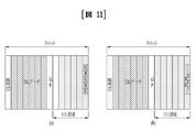
図11は、本発明の一例による1シンボルPUCCHの構造を示す図である。より詳細には、図11(a)では、1シンボルPUCCHを介して送信されるRS(Reference Signal)とUCI(Uplink Control Information)がFDM(Frequency Division Multiplexing)される構造を示し、図11(b)では、1シンボルPUCCHを介して送信されるRSとUCIがTDM(Time Division Multiplexing)される構造を示す。 FIG. 11 is a diagram illustrating the structure of a 1-symbol PUCCH according to an example of the present invention. More specifically, FIG. 11(a) shows a structure in which RS (Reference Signal) and UCI (Uplink Control Information) transmitted via 1-symbol PUCCH are subjected to FDM (Frequency Division Multiplexing), and FIG. ) shows a structure in which RS and UCI transmitted via 1-symbol PUCCH are TDM (Time Division Multiplexed).
先ず、図11(a)のように、RSとUCIが送信される副搬送波(subcarrier)又は副搬送波グループ(subcarrier group)は互いにFDMされることができる。このとき、UCIはHARQ-ACK及び/又はCSI(Channel State Information)及び/又はスケジューリング要求(scheduling request,SR)及び/又はビーム(beam)に関する情報などを含んでもよい。 First, as shown in FIG. 11(a), subcarriers or subcarrier groups through which RS and UCI are transmitted can be FDMed with each other. At this time, the UCI may include HARQ-ACK and/or Channel State Information (CSI) and/or scheduling request (SR) and/or beam information.
また、図11(b)のように、RSとUCIが送信されるシンボルは、シンボルに対する副搬送波間隔(subcarrier spacing)が増加して複数の副シンボル(sub-symbol)で構成されてもよい。このとき、複数の副シンボルのうちRSが送信される一部の副シンボルは、UCIが送信される他の副シンボルと互いにTDMされてもよい。 Also, as shown in FIG. 11(b), a symbol in which the RS and UCI are transmitted may be configured with a plurality of sub-symbols with increasing subcarrier spacing for the symbol. At this time, some sub-symbols in which the RS is transmitted among the plurality of sub-symbols may be TDMed with other sub-symbols in which the UCI is transmitted.
好ましい一例として、UEのUCI送信のためのデコーディング時間(decoding time)をさらに保証するための方法として、前記UEはRSをUCIより時間次元において先の副シンボルから送信する。 As a preferred example, the UE transmits the RS from an earlier sub-symbol in the time dimension than the UCI, as a method to further guarantee the decoding time for UCI transmission of the UE.
図11において、連続した副搬送波のグループ(又は、コンム(comb)構造である場合、一定間隔で離隔した副搬送波のグループ)をUL REG(resource element group)と定義すると仮定する。 In FIG. 11, it is assumed that a group of consecutive subcarriers (or a group of regularly spaced subcarriers in case of a comb structure) is defined as a UL REG (resource element group).
この場合、図11(a)によれば、UL REG内に一部の副搬送波を介してRSが送信され、UL REG内の他の副搬送波を介してUCIが送信される。また、各々のUL REGはRS又はUCIを送信する副搬送波のみを含むことができる。 In this case, according to FIG. 11(a), the RS is transmitted via some subcarriers within the UL REG and the UCI is transmitted via other subcarriers within the UL REG. Also, each UL REG may contain only subcarriers that transmit RS or UCI.
また、図11(b)によれば、UL REG内に一部の副シンボルの全ての副搬送波を介してRSが送信され、他の副シンボルの全ての副搬送波を介してUCIが送信される。 Also, according to FIG. 11(b), RS is transmitted through all subcarriers of some subsymbols in the UL REG, and UCI is transmitted through all subcarriers of other subsymbols. .
このような複数のUL REGは、1つのUL CCE(control channel element)を構成する。よって、1シンボルPUCCHの場合、UL CCEを構成する全てのUL REGは、同一のシンボルに存在する。このとき、説明の便宜のために、UL CCEを構成するUL REGが連続的な(consecutive)周波数リソースで構成される構造は、局部的な構造(localized structure)と称し、UL CCEを構成するUL REGが非連続的な周波数リソースで構成される構造は、分散的な構造(distributed structure)と称する。 A plurality of such UL REGs constitute one UL CCE (control channel element). Therefore, in case of 1-symbol PUCCH, all UL REGs constituting UL CCEs are present in the same symbol. At this time, for convenience of explanation, a structure in which UL REGs forming a UL CCE are configured with consecutive frequency resources is called a localized structure, and a UL forming a UL CCE is referred to as a localized structure. A structure in which a REG is composed of non-consecutive frequency resources is called a distributed structure.
上述した例示において、RSはザドフチューシーケンス(Zadoff-Chu sequence)ベースで生成又は送信されるか、疑似任意シーケンス(pseudo random seqUEnce)ベースで生成又は送信される。一例として、図11(b)のように、UEがPUCCHを送信する場合、RSがザドフチューシーケンスベースで送信されると、PAPR(Peak to Average Power Ratio)の減少面において利得があり得る。 In the above examples, the RS is generated or transmitted on a Zadoff-Chu sequence basis or a pseudo random sequence basis. As an example, as shown in FIG. 11(b), when the UE transmits PUCCH, there may be a gain in terms of reduction in PAPR (Peak to Average Power Ratio) if the RS is transmitted on a Zadovchu sequence basis.
さらに、UEは送信しようとするUCIペイロードサイズ(UCI payload size)によって互いに異なるフォーマット(format)で構成されたUCIを送信することができる。 In addition, the UE may transmit UCIs configured in different formats according to the UCI payload size to be transmitted.
一例として、UEはUCIペイロードサイズがKビット(例えば、K=2)以下である場合、シーケンスベース(例えば、ザドフチューシーケンス又は擬似任意シーケンス)で生成されたUCIを上述した1シンボルPUCCH構造又はその他の1シンボルPUCCH構造を用いて送信することができる。このとき、その他の1シンボルPUCCH構造は、RSなくシーケンスベースのUCIを送信するPUCCH構造を含んでもよい。 As an example, if the UCI payload size is K bits (e.g., K=2) or less, the UE may generate UCI on a sequence basis (e.g., Zadofuchu sequence or pseudo-arbitrary sequence) using the 1-symbol PUCCH structure described above or Other 1-symbol PUCCH structures may be used for transmission. At this time, other 1-symbol PUCCH structures may include PUCCH structures that transmit sequence-based UCI without RS.
別の例として、UEはUCIペイロードサイズがKビットを超える場合、コードされたビットをOFDM(Orthogonal Frequency Division Multiplexing)又はDFTS-OFDM(Discrete Fourier Transform-spread-OFDM)変換して送信する。上述した1シンボルPUCCH構造又はその他の1シンボルPUCCH構造を用いて送信することができる。ここで、UEがOFDM又はDFTS-OFDMのうちいずれの変換方法を適用するかは、後述する別の設定方法(4.1.欄)によって設定される。 As another example, if the UCI payload size exceeds K bits, the UE converts the coded bits to Orthogonal Frequency Division Multiplexing (OFDM) or Discrete Fourier Transform-spread-OFDM (DFTS-OFDM) and transmits them. It can be transmitted using the 1-symbol PUCCH structure described above or other 1-symbol PUCCH structures. Here, which conversion method, OFDM or DFTS-OFDM, the UE applies is set by another setting method (section 4.1.), which will be described later.
3.2.多重シンボルPUCCH(Multi-symbol PUCCH) 3.2. Multi-symbol PUCCH (Multi-symbol PUCCH)
図12は、本発明の一例による多重シンボルPUCCHの構造を示す図である。 FIG. 12 is a diagram showing the structure of a multi-symbol PUCCH according to an example of the present invention.
より具体的には、本発明に適用可能な多重シンボルPUCCH構造は、上述した1シンボルPUCCH構造を拡張適用して設計される。説明の便宜のために、図12は、本発明に適用可能な多重シンボルPUCCH構造が2シンボルPUCCH構造である場合を示す。 More specifically, the multi-symbol PUCCH structure applicable to the present invention is designed by extending the 1-symbol PUCCH structure described above. For convenience of explanation, FIG. 12 shows a case where the multi-symbol PUCCH structure applicable to the present invention is a 2-symbol PUCCH structure.
一例として、図12(a)では、各々のシンボルでRSとUCIがFDMされるPUCCH構造が時間領域において繰り返し(repetition)される構造を示し、図12(b)では、2つのシンボルに対してRSとUCIがTDMされる構造を示す。 As an example, FIG. 12(a) shows a structure in which a PUCCH structure in which RS and UCI are FDMed in each symbol is repeated in the time domain, and FIG. 12(b) shows a structure for two symbols. 1 shows a structure in which RS and UCI are TDMed;
UEは図12のRS及びUCIを送信するために、上述した送信方法を適用することができる。 The UE can apply the transmission method described above to transmit the RS and UCI of FIG.
より具体的には、UEはRSをザドフチューシーケンスベースとして生成して送信するか、擬似任意シーケンスベースとして生成して送信することができる。特に、UEが図12(b)のようなPUCCH構造でRS及びUCIを送信する場合、ザドフチューシーケンスベースで送信されるRSはPAPRを減少させることができる。 More specifically, the UE can generate and transmit the RS on a Zadoftu sequence basis or on a pseudo-arbitrary sequence basis. In particular, when the UE transmits RS and UCI in the PUCCH structure as shown in FIG. 12(b), the RS transmitted based on the Zadovchu sequence can reduce the PAPR.
また、UEはUCIペイロードサイズがKビット(例えば、K=2)以下である場合、シーケンスベース(例えば、ザドフチューシーケンス又は擬似任意シーケンス)で生成されたUCIを上述した2シンボルPUCCH構造又はその他の2シンボルPUCCH構造を用いて送信することができる。 Also, if the UCI payload size is less than or equal to K bits (e.g., K=2), the UE may transmit UCI generated on a sequence basis (e.g., Zadofuchu sequence or pseudo-arbitrary sequence) using the 2-symbol PUCCH structure described above or otherwise. 2-symbol PUCCH structure.
また、UEはUCIペイロードサイズがKビットを超える場合、コードされたビットをOFDM(Orthogonal Frequency Division Multiplexing)又はDFTS-OFDM(Discrete Fourier Transform-spread-OFDM)変換して送信することができる。上述した2シンボルPUCCH構造又はその他の2シンボルPUCCH構造を用いて送信することができる。ここで、UEがOFDM又はDFTS-OFDMのうちいずれの変換方法を適用するかは、後述する別の設定方法(4.1.欄)によって設定される。 Also, if the UCI payload size exceeds K bits, the UE can transform the coded bits into Orthogonal Frequency Division Multiplexing (OFDM) or Discrete Fourier Transform-spread-OFDM (DFTS-OFDM) and transmit them. It can be transmitted using the 2-symbol PUCCH structure described above or other 2-symbol PUCCH structures. Here, which conversion method, OFDM or DFTS-OFDM, the UE applies is set by another setting method (section 4.1.), which will be described later.
さらに、多重シンボルPUCCH構造は、4シンボル以上のPUCCH構造を有してもよい。 Furthermore, the multi-symbol PUCCH structure may have PUCCH structures of four or more symbols.
このとき、図12(a)に示された2シンボルPUCCH構造を拡張適用することができる。これによれば、本発明による多重シンボルPUCCH構造(例えば、4シンボルPUCCH構造)は、上述した2シンボルPUCCH構造が時間次元で繰り返される構造であってもよい。 At this time, the 2-symbol PUCCH structure shown in FIG. 12(a) can be extended and applied. Accordingly, a multi-symbol PUCCH structure (eg, a 4-symbol PUCCH structure) according to the present invention may be a structure in which the above-described 2-symbol PUCCH structure is repeated in the time dimension.
また、本発明による多重シンボルPUCCH構造(例えば、4シンボルPUCCH構造)は、図13のように拡張されてもよい。 Also, the multi-symbol PUCCH structure (eg, 4-symbol PUCCH structure) according to the present invention may be extended as shown in FIG.
図13は、本発明の別の例による多重シンボルPUCCHの構造を示す図である。 FIG. 13 is a diagram showing the structure of a multi-symbol PUCCH according to another example of the present invention.
図13に示しように、RSとUCIがTDMされて送信される多重シンボルPUCCH構造の場合、本発明による多重シンボルPUCCH構造はRSが最初のシンボルからのみ送信される図13(a)のようなPUCCH構造を有するか、RSが特定のシンボル(例えば、PUCCHが送信されるシンボルのうち第3番目のシンボル又は時間次元で最後から第2番目のシンボルなど)から送信される図13(b)のようなPUCCH構造を有してもよい。 As shown in FIG. 13, in the case of a multi-symbol PUCCH structure in which RS and UCI are TDM-transmitted, the multi-symbol PUCCH structure according to the present invention is such as FIG. 13(a) in which RS is transmitted only from the first symbol. 13(b) with a PUCCH structure or where the RS is transmitted from a particular symbol (eg, the third symbol in which the PUCCH is transmitted, or the penultimate symbol in the time dimension, etc.). It may have a PUCCH structure such as
UEが図13(a)のようなPUCCH構造によってRS及びUCIを送信する場合、先に送信されるRS(front-loaded RS)による早期デコーディング(early decoding)利得を極大化するために、UEはHARQ-ACK情報を時間次元で他の情報よりも先行して送信することができる。 When the UE transmits RS and UCI according to the PUCCH structure as shown in FIG. may send HARQ-ACK information ahead of other information in the time dimension.
一例として、UCIがHARQ-ACK情報とCSI情報(及びビーム関連情報など)を全て含む場合、UEはHARQ-ACKとCSI情報に対してそれぞれ分離コーディング(separate coding)を行った後、HARQ-ACKコーディングビットを時間軸に先行するシンボルからマップして送信する。この方法は、相対的に重要度の高いHARQ-ACK情報をRS近傍に配置することで、HARQ-ACK情報の信頼性(reliability)を増大させるというメリットがある。 For example, if the UCI includes both HARQ-ACK information and CSI information (and beam-related information, etc.), the UE performs separate coding on HARQ-ACK and CSI information, respectively, and then sends HARQ-ACK. Coding bits are mapped from the preceding symbol on the time axis and transmitted. This method has the advantage of increasing the reliability of HARQ-ACK information by arranging HARQ-ACK information with relatively high importance near the RS.
この変形例として、図13(b)のように、RSシンボルが他のUCIに比べて先に送信されない場合であっても、UEはHARQ-ACKとCSIに対する分離コーディングを行った後、RSシンボルに隣接したシンボル(さらに、時間軸に先行するシンボルにHARQ-ACK情報が優先してマップされてもよい )にHARQ-ACK情報をマップして送信する。 As a modification of this, as shown in FIG. 13(b), even if the RS symbol is not transmitted earlier than other UCI, the UE performs separate coding for HARQ-ACK and CSI, and then the RS symbol (In addition, the HARQ-ACK information may be preferentially mapped to the symbol preceding the time axis) and transmitted.
周波数ホッピング(frequency hopping)が適用される4シンボル以上の長い区間のPUCCH(long duration PUCCH)の場合、上述したようなマッピング/送信方法は、各ホップ(hop)ごとに適用されてもよい。 In the case of PUCCH (long duration PUCCH) of four or more symbols to which frequency hopping is applied, the mapping/transmission method as described above may be applied for each hop.
また、UEはHARQ-ACKとCSIに対する分離コーディングを行った後、2つのホップのうち先行するホップ(又は、周波数ホッピング有無には関係なく先行する一部のシンボル)にはHARQ-ACK情報のみマップし、後行するホップ(又は、周波数ホッピング可否には関係なく後行する一部のシンボル)にはCSI情報のみマップして送信してもよい。 In addition, after performing separate coding on HARQ-ACK and CSI, the UE maps only HARQ-ACK information to the preceding hop (or some preceding symbols regardless of whether frequency hopping is performed) of the two hops. However, only CSI information may be mapped and transmitted to subsequent hops (or some subsequent symbols regardless of whether frequency hopping is possible).
上述したような場合、HARQ-ACK情報が載せられる(又は、送信される)ホップ(又は、シンボル)とCSI情報のみが載せられる(又は、送信される)ホップ(又は、シンボル)との間のRS密度は異なってもよい。特に、HARQ-ACK情報が載せられる(又は、送信される)ホップ(又は、シンボル)にはより多いRSシンボルが含まれる。ただし、上述した例示にはHARQ-ACK情報とCSI情報が載せられる(又は、送信される)ホップ(又は、シンボル)間の相関関係に対してのみ方法を記述したが、様々なUCI情報からなるPUCCHにおいて優先順位の高いUCI情報(例えば、SR、HARQ-ACK、又は非周期的(aperiodic)CSI)は、上述した方法のHARQ-ACKに対応して、優先順位の低いUCI情報(例えば、周期的(periodic)CSI)は、上述した方法のCSIに対応する。 In the above case, between the hop (or symbol) on which HARQ-ACK information is carried (or transmitted) and the hop (or symbol) on which only CSI information is carried (or transmitted) RS densities may vary. In particular, hops (or symbols) on which HARQ-ACK information is carried (or transmitted) include more RS symbols. However, although the above examples describe the method only for the correlation between hops (or symbols) on which HARQ-ACK information and CSI information are carried (or transmitted), various UCI information High-priority UCI information (eg, SR, HARQ-ACK, or aperiodic CSI) in PUCCH corresponds to HARQ-ACK in the method described above, and low-priority UCI information (eg, periodic Periodic CSI) corresponds to the CSI of the method described above.
図13(b)のような送信方法の場合、図12(b)のように、互いに異なる長さのPUCCHと多重化(multiplexing)が可能であるというメリットがある。 In the case of the transmission method as shown in FIG. 13(b), as shown in FIG. 12(b), there is an advantage that PUCCHs of different lengths and multiplexing are possible.
このとき、RSシンボルの位置は、特定のサブフレーム又はスロットを成すシンボルのうち最後から第2番目のシンボルにのみ固定されてもよい。又は、RSシンボルの位置は、実際にPUCCHが送信されるシンボルのうち最後から第2番目のシンボル(及び、さらに前記シンボルをベースとして予め定められた間隔で離隔されたシンボル)と設定されてもよい。 At this time, the position of the RS symbol may be fixed only to the penultimate symbol among symbols forming a specific subframe or slot. Alternatively, the position of the RS symbol may be set to the penultimate symbol among the symbols in which PUCCH is actually transmitted (and further symbols separated by predetermined intervals based on the symbol). good.
一例として、2シンボルごとにRSが追加送信されるように設定されたと仮定する。このとき、RSはンボル10/11/12/13から送信されるPUCCH内のシンボル10/12から送信される。または、RSはシンボル9/10/11/12/13から送信されるPUCCH内のシンボル10/12から送信される。または、RSはシンボル8/9/10/11/12/13から送信されるPUCCH内のシンボル8/10/12から送信される。
As an example, assume that the RS is set to be additionally transmitted every two symbols. At this time, the RS is transmitted from
さらに、より柔軟な(flexible)方法として、UEがPUCCHを構成する複数のシンボルのうちいずれのシンボルからRSを送信するかはL1シグナリング(例えば、PHY)又は上位層シグナリング(例えば、RRC)によって設定されてもよい。 Furthermore, as a more flexible method, the UE uses L1 signaling (e.g., PHY) or higher layer signaling (e.g., RRC) to set which symbol to use to transmit the RS from a plurality of symbols that constitute the PUCCH. may be
図12(a)のようにFDMされたRS及びUCIが複数のシンボルにわたって送信されるか、図13のようにUCIが複数のシンボルにわたって送信される場合、各シンボル別に送信されるUCIは互いに同一であってもよく、互いに異なってもよい。 When the FDM RS and UCI are transmitted over multiple symbols as shown in FIG. 12(a), or the UCI is transmitted over multiple symbols as shown in FIG. 13, the UCI transmitted for each symbol is the same. may be different from each other.
具体的に、シンボル間の情報が同一の場合、OCC(orthogonal cover code)が適用されてUE間の多重化が許容(又は、支援)されてもよい。一例として、UE1とUE2が図12(a)のようにPUCCHを送信する場合、UE1が最後のシンボル(last symbol)及び最後から第2番目のシンボル(second last symbol)から送信するUCI(及び/又はRS)は互いに同一であり、UE2が最後のシンボル(last symbol)及び最後から第2番目のシンボル(second last symbol)から送信するUCI(及び/又はRS)は互いに同一であってもよい。このとき、各UE別のUCI(及び/又はRS)に対して長さ2(2-length)のOCC(例えば、[1,1]及び[1,-1])をシンボルごとに適用する場合、UE1とUE2のPUCCHは同一の周波数領域でCDMされて送信される。
Specifically, when information between symbols is the same, OCC (orthogonal cover code) may be applied to allow (or support) multiplexing between UEs. As an example, when UE1 and UE2 transmit PUCCH as shown in FIG. 12 (a), UCI (and/or or RS) may be identical to each other, and the UCI (and/or RS) transmitted by the
また、UE1とUE2が図13(a)のようにPUCCHを送信する場合、UE1が最後のシンボル(last symbol)、最後から第2番目のシンボル(second last symbol)及び最後から第3番目のシンボル(third last symbol)から送信するUCIは互いに同一であり、UE2が最後のシンボル(last symbol)、最後から第2番目のシンボル(second last symbol)及び最後から第3番目のシンボル(third last symbol)から送信するUCIは互いに同一であってもよい。このとき、各UE別のUCIに対して長さ3のOCCをシンボルごとに適用する場合、UE1とUE2(最大に3つのUEまで)のPUCCHは同一の周波数領域でCDMされて送信される。このとき、各UEが送信するRSは基本シーケンス(base seqUEnce)及び/又は循環シフト(cyclic shift)などの値を異ならせて適用することでUE間の直交性を満たすことができる。
Also, when UE1 and UE2 transmit PUCCH as shown in FIG. The UCIs transmitted from (third last symbol) are identical to each other, and the
また、PUCCHを構成するシンボル数の異なるPUCCH間のCDMを考慮する場合、各UE別にPUCCH内のUCIシンボル数より小さい長さのOCCが適用されてもよい。一例として、UE1がシンボル#12でRSを送信し、シンボル#10/11/13/14でUCIを送信する場合、UE1はシンボル#13/14に対して長さ2のOCCを適用して同一のUCIを送信することができる。この場合、UE2がシンボル#12でRSを送信して、シンボル#13/14で長さ2のOCCが適用されたUCIを送信する場合、各UEの5シンボルPUCCHと3シンボルPUCCHとのCDMが支援される。
Also, when considering CDM between PUCCHs having different numbers of symbols constituting PUCCH, OCC with a length smaller than the number of UCI symbols in PUCCH may be applied for each UE. As an example, if UE1 transmits RS on
図12(b)のようにRSとUCIがTDMされる場合、1つのPUCCHがシンボルにおいて用いる周波数領域は同一である必要がある。ただし、図12(a)のように、1つのUL REG内にRS及びUCIが含まれる場合、シンボル間の周波数ホッピングが適用(又は、許容)されて周波数ダイバーシティ利得(frequency diversity gain)を得ることもできる。 When RS and UCI are TDMed as shown in FIG. 12(b), the frequency domain used by one PUCCH in a symbol should be the same. However, as shown in FIG. 12(a), if RS and UCI are included in one UL REG, frequency hopping between symbols is applied (or allowed) to obtain frequency diversity gain (frequency diversity gain) can also
一例として、分散的構造(distributed structure)のPUCCHに対しては常に周波数ホッピングが許容されないように設定される。すなわち、PUCCHが分散的な構造の場合、UEは複数のシンボルにおいて同一の周波数リソース領域を介してPUCCHを送信するように設定される。何故ならば、分散的な構造は周波数ダイバーシティ利得を保証するためである。換言すれば、UE及びgNBは分散的な構造のPUCCHを活用することで既に周波数ダイバーシティ利得が得られるためである。 As an example, a PUCCH with a distributed structure is set such that frequency hopping is always not allowed. That is, if the PUCCH has a distributed structure, the UE is configured to transmit the PUCCH over the same frequency resource region in multiple symbols. This is because the distributed structure guarantees frequency diversity gain. In other words, the UE and the gNB can already obtain frequency diversity gain by utilizing the PUCCH with a distributed structure.
一方、局部的な構造(localized structure)は、PUCCHに対しては周波数ホッピングを適用するか否かが(L1シグナリング又は上位層シグナリングによって)設定されてもよい。 On the other hand, a localized structure may be configured (by L1 signaling or higher layer signaling) whether to apply frequency hopping to PUCCH.
このとき、UEごとにシンボル間において用いる周波数領域リソースが異なることにより、互いに異なる電力過渡区間(power transient period)を有するため、周波数ホッピングを適用するか否かはUEごとに設定されてもよい。 At this time, since each UE has a different power transient period due to different frequency domain resources used between symbols, whether to apply frequency hopping may be configured for each UE.
また、周波数ホッピングの適用は、PUCCHのシンボル長によって設定されてもよい。一例として、PUCCHのシンボル長がXシンボル以上である場合に限って周波数ホッピングが許容されてもよい。 Also, application of frequency hopping may be configured according to the symbol length of PUCCH. As an example, frequency hopping may be allowed only if the PUCCH symbol length is equal to or greater than X symbols.
参考として、図12(a)のような構造を4シンボルに拡張する場合、UEが(局部的な構造であるとき)2シンボル単位で周波数ホッピングを適用してPUCCHを送信すれば、電力過渡区間によって性能減少が生じ得る。ただし、これはgNBのPUCCH受信に大きな影響を与えないこともある。 For reference, when the structure shown in FIG. 12(a) is extended to 4 symbols, if the UE applies frequency hopping in units of 2 symbols (when the structure is local) and transmits the PUCCH, the power transition period can result in reduced performance. However, this may not have a significant impact on the gNB's PUCCH reception.
図12(b)のようにRSとUCIがTDMされる場合でも、周波数ダイバーシティ利得を得るために周波数ホッピングが適用(又は、許容)されてもよい。ただし、デコーディングのためにホップごとにRSシンボルが存在しなければならないという制約が伴われることがある。この場合、電力過渡区間を考えてPUCCHのシンボル長によって周波数ホッピングを行うか否かが設定されてもよい。 Even if RS and UCI are TDMed as in FIG. 12(b), frequency hopping may be applied (or allowed) to obtain frequency diversity gain. However, it may come with the constraint that there must be an RS symbol per hop for decoding. In this case, whether or not to perform frequency hopping may be determined according to the symbol length of the PUCCH considering the power transient period.
図14は、本発明の別の例による多重シンボルPUCCHの構造を示す図である。 FIG. 14 is a diagram showing the structure of a multi-symbol PUCCH according to another example of the present invention.
図14に示すように、本発明によれば、同一の周波数リソースを用いるPUCCH領域が3シンボル以上確保される場合に限って周波数ホッピングが適用(又は、設定)されてもよい。何故ならば、少なくともRSシンボルと隣接した両側のシンボルにUCIシンボルが存在することで電力過渡区間によるRS影響が最小化できるためである。 As shown in FIG. 14, according to the present invention, frequency hopping may be applied (or configured) only when three or more symbols of the PUCCH region using the same frequency resource are secured. This is because the presence of UCI symbols in at least the symbols on both sides adjacent to the RS symbol can minimize the impact of the RS due to the power transition period.
本発明による多重シンボルPUCCHに対してスロットにおいて周波数ホッピングを行うとき、当該PUCCHを構成するシンボル数によってホッピング単位(hopping unit、同一の周波数リソースで送信される連続シンボルで構成されたリソース単位)の数を設定する方法は、以下のように予め設定されてもよい。 When performing frequency hopping in a slot for multi-symbol PUCCH according to the present invention, the number of hopping units (hopping units, resource units composed of consecutive symbols transmitted on the same frequency resource) according to the number of symbols constituting the corresponding PUCCH. may be set in advance as follows.
一例として、PUCCHを構成するシンボル数がKである場合、各ホッピング単位はceiling{K/2}個のシンボル及びK-ceiling{K/2}個のシンボルで構成されてもよい。このとき、ceiling{a}とは、aと同一であるか、aよりも大きい整数のうち最小の整数値を意味する。 For example, if the number of symbols constituting the PUCCH is K, each hopping unit may consist of ceiling {K/2} symbols and K-ceiling {K/2} symbols. At this time, ceiling {a} means the smallest integer value among integers equal to or larger than a.
別の一例として、ホッピング単位はスロットの中心を基準として定義されてもよい。具体例として、14シンボルで構成されたスロットでシンボル#4~14(11シンボル)で構成されたPUCCHの場合、ホッピング単位はそれぞれシンボル#4~7及びシンボル#8~14で構成される。 As another example, the hopping unit may be defined based on the slot center. As a specific example, in the case of a PUCCH consisting of symbols #4-14 (11 symbols) in a slot consisting of 14 symbols, the hopping unit consists of symbols #4-7 and symbols #8-14, respectively.
別の一例として、ホッピング単位を区分するシンボルインデックスは予め定義されてもよい。具体例として、14シンボルで構成されたスロットにおいて特定のシンボルインデックスが9と定義される場合、ホッピング単位はそれぞれシンボル#4~8及びシンボル#9~14と構成される。 As another example, a symbol index that separates hopping units may be predefined. As a specific example, if a specific symbol index is defined as 9 in a slot composed of 14 symbols, the hopping units are composed of symbols #4-8 and symbols #9-14, respectively.
また、ホッピング単位の設定方法は、PUCCHを構成するRSシンボル数によって設定されてもよい。一例として、RSシンボルが1つである場合には、周波数ホッピングが行われない。別の一例として、RSシンボルが2つである場合には、ホッピング単位が2つで構成され、各ホッピング単位のRSシンボルが1つずつ含まれる。別の一例として、RSシンボルが3つである場合には、ホッピング単位が2つで構成され、いずれかのホッピング単位にはRSシンボルが1つ含まれ、他のホッピング単位にはRSシンボルが2つ含まれる。また、ホッピング単位が3つで構成され、各ホッピング単位ごとにRSシンボルが1つずつ含まれる。 Also, the method of setting the hopping unit may be set according to the number of RS symbols forming the PUCCH. As an example, if there is one RS symbol, no frequency hopping is performed. As another example, when there are two RS symbols, two hopping units are configured, and each hopping unit includes one RS symbol. As another example, when there are three RS symbols, two hopping units are configured, one hopping unit includes one RS symbol, and the other hopping unit includes two RS symbols. included. Also, the hopping unit is composed of three, and each hopping unit includes one RS symbol.
さらに、特定のホッピング単位にはRSシンボルが含まれなくてもよい。特定のホッピング単位にRSシンボルが含まれない場合、特定のホッピング単位はRSシンボルが含まれた他のホッピング単位と同一の(又は、含まれる)RB領域で送信されなければならないという制約が伴われることがある。換言すれば、同一の周波数領域を占める連続/不連続的なシンボルのうち少なくとも1つのシンボルにはRSが送信されるように設定されてもよい。このとき、RSシンボルは時間軸上に最も先行するシンボルにマップされるように設定されてもよい。 Furthermore, a particular hopping unit may not include RS symbols. If a particular hopping unit does not include RS symbols, it is accompanied by the constraint that the particular hopping unit must be transmitted in the same (or included) RB region as other hopping units that include RS symbols. Sometimes. In other words, the RS may be set to be transmitted in at least one of consecutive/discontinuous symbols occupying the same frequency region. At this time, the RS symbol may be set to be mapped to the most preceding symbol on the time axis.
上述のような周波数ホッピング方法は、PUSCHの場合にも同様に拡張適用される。このとき、更なるDM-RS送信は周波数ホッピングが設定又は指示される場合にトリガされてもよい。また、更なるDM-RS送信が設定又は指示される場合に限ってUEは周波数ホッピングが行われることを期待することができる。 The frequency hopping method as described above is extended to PUSCH as well. At this time, further DM-RS transmissions may be triggered if frequency hopping is configured or indicated. Also, the UE can expect frequency hopping to occur only if further DM-RS transmissions are configured or indicated.
先に送信される(Front-loaded)DM-RSの他に更なるDM-RSの送信は、周波数ホッピング用途の以外にも高い周波数帯域(high frequency band)特性又は高い移動性(high mobility)などの理由によって設定されてもよい。 Transmission of further DM-RS in addition to the front-loaded DM-RS is used for frequency hopping, high frequency band characteristics or high mobility, etc. may be set for the following reasons.
このように、他の用途の更なるDM-RSの位置は、用途に応じて異なってもよい。具体的には、周波数ホッピング用として追加されたDM-RSの位置は、高い移動性などの理由によって追加されたDM-RSの位置よりも時間上(ホッピングにおける電力過渡区間を考えて)後行してもよい。一例として、高い移動性などの理由で追加されたDM-RSの位置はスロット中心シンボル(例えば、14シンボルで構成されたスロットにおいて第8番目のシンボル)と設定されてもよく、周波数ホッピング用として追加されたDM-RSの位置は、先に送信される(front-load)DM-RSシンボルインデックス+7に対応するシンボルと設定されてもよい。 Thus, the location of additional DM-RSs for other applications may differ depending on the application. Specifically, the position of the DM-RS added for frequency hopping is temporally behind the position of the DM-RS added for reasons such as high mobility (considering the power transient section in hopping) You may As an example, the position of the DM-RS added for reasons such as high mobility may be set as the slot center symbol (eg, the 8th symbol in a slot consisting of 14 symbols) for frequency hopping. The position of the added DM-RS may be set to the symbol corresponding to the front-load DM-RS symbol index+7.
本発明が適用可能なNRシステムでは、同一のUEにもサービス要件(service requirement)が多様なタイプのデータ(例えば、eMBB(enhanced Mobile BroadBand)データ、URLLC(Ultra Reliable Low Latency Communications)データなど)を支援することができる。このとき、互いに異なるサービス要件を満たすために、eMBBデータ及びURLLCデータ間のニューマロロジー(例えば、副搬送波間隔(subcarrier spacing))が異なってもよい。また、互いに異なるタイプのデータが同一のスロットにおいて多重化されてもよい。 In the NR system to which the present invention can be applied, the same UE has various types of data (e.g., eMBB (enhanced Mobile BroadBand) data, URLLC (Ultra Reliable Low Latency Communications) data, etc.) with various service requirements. can support. At this time, the pneumarology (eg, subcarrier spacing) between eMBB data and URLLC data may be different in order to meet different service requirements. Also, different types of data may be multiplexed in the same slot.
図15は、本発明の一例によってPUCCH及びPUSCHを送信する構成を簡単に示す図である。 FIG. 15 is a diagram simply showing a configuration for transmitting PUCCH and PUSCH according to an example of the present invention.
図15に示すように、UEは15kHzの副搬送波間隔をベースとしてPUSCH(又は、PUCCH)を送信する途中に30kHzの副搬送波間隔をベースとしてPUCCH(又は、PUSCH)を送信することができる。このとき、電力過渡区間による性能劣化の問題を解決するための方法として、UEは一部の副シンボルを空けたままPUCCH(又は、PUSCH)を送信する。ここで、この空けた副シンボル領域が電力過渡区間内に含まれるように電力マスク(power mask)が設定されてもよい。 As shown in FIG. 15, the UE may transmit PUCCH (or PUSCH) based on 30 kHz sub-carrier spacing while transmitting PUSCH (or PUCCH) based on 15 kHz sub-carrier spacing. At this time, the UE transmits PUCCH (or PUSCH) while leaving some subsymbols blank as a method for solving the problem of performance degradation due to the power transition period. Here, a power mask may be set such that the empty sub-symbol region is included in the power transient period.
また、図15において、UEはシンボル#6内の2つの副シンボルの全てからPUCCHを送信して、シンボル#7(又は、その一部の領域)を電力過渡区間として活用してもよい。
Also, in FIG. 15, the UE may transmit PUCCH from all two sub-symbols in
上述のような方法は、同一のUEが同一のスロットにおいてニューマロロジーが互いに異なるチャンネルを同時に送信するときのみならず、同一のスロットにおいてニューマロロジーが互いに異なる同一のチャンネルを送信するときにも同様に適用できる。 The method as described above can be used not only when the same UE simultaneously transmits channels with different pneumatics in the same slot, but also when the same channel with different pneumatics is transmitted in the same slot. similarly applicable.
上述した1シンボルPUCCH及び/又は多重シンボルPUCCHを構成するRS及び/又はUCIを多重化する方法としては、以下のいずれか1つ以上の方法が適用できる。 Any one or more of the following methods can be applied as a method of multiplexing the RSs and/or UCIs forming the 1-symbol PUCCH and/or the multi-symbol PUCCH described above.
(1)FDM構造 (1) FDM structure
図11(a)のように、RSとUCIとの送信副搬送波(又は、副搬送波のグループ)はFDMされて送信されてもよい。一例として、PUCCH送信のために副搬送波間隔を増加させて1つのシンボル領域を複数の副シンボルに分ける場合、UEは副シンボルのうち一部の副シンボルでFDM構造のPUCCHを送信することもできる。 As in FIG. 11(a), the transmission subcarriers (or groups of subcarriers) of the RS and UCI may be FDM'd and transmitted. As an example, if one symbol region is divided into a plurality of subsymbols by increasing the subcarrier spacing for PUCCH transmission, the UE may transmit FDM-structured PUCCH in some of the subsymbols. .
(2)TDM構造 (2) TDM structure
図12(b)のように、RSとUCIはTDMされて送信されてもよい。一例として、図11(b)のように、PUCCH送信のために副搬送波間隔を増加させて1つのシンボル領域を複数の副シンボルに分ける場合、UEは副シンボルのうち一部の副シンボルからRSを送信し、その他の副シンボルからUCIを送信することができる。 As shown in FIG. 12(b), the RS and UCI may be TDM-transmitted. As an example, as shown in FIG. 11(b), if one symbol region is divided into a plurality of subsymbols by increasing the subcarrier interval for PUCCH transmission, the UE may select RS from some of the subsymbols. and UCI may be transmitted from other sub-symbols.
(3)FDM+TDM構造 (3) FDM+TDM structure
図16は、本発明の別の例による多重シンボルPUCCHの構造を示す図である。 FIG. 16 is a diagram showing the structure of a multi-symbol PUCCH according to another example of the present invention.
図16に示すように、RSとUCIはTDMされながらFDMされて送信されてもよい。一例として、PUCCH送信のために副搬送波間隔を増加させて1つのシンボル領域を複数の副シンボルに分ける場合、UEは副シンボルのうち一部の副シンボルを介してRSとUCIをFDM+TDMされた構造で送信することができる。 As shown in FIG. 16, the RS and UCI may be transmitted by FDM while being TDM. As an example, if one symbol region is divided into a plurality of subsymbols by increasing the subcarrier interval for PUCCH transmission, the UE uses some of the subsymbols to convert RS and UCI into a FDM+TDM structure. can be sent by
(4)CDM(Code Division Multiplexing)構造 (4) CDM (Code Division Multiplexing) structure
RSとUCIは同一のリソース領域においてCDMされて送信されてもよい。一例として、PUCCH送信のために副搬送波間隔を増加して1つのシンボル領域を複数の副シンボルに分ける場合、UEは副シンボルのうち一部の副シンボルを介してCDM構造のPUCCH(例えば、RS及びUCI)を送信することができる。 RS and UCI may be CDM-transmitted in the same resource region. As an example, if one symbol region is divided into a plurality of subsymbols by increasing the subcarrier spacing for PUCCH transmission, the UE transmits a CDM-structured PUCCH (eg, RS and UCI) can be transmitted.
(5)RS無し構造(RS-less structure) (5) RS-less structure
RSなくUCIに対応するシーケンスを予め設定し、UEが当該シーケンスのみを送信するPUCCH構造(例えば、OOK(on/off keying)と類似した構造)が考えられる。このとき、gNBは当該PUCCHを非相関検出(non-coherent detection)方法によって受信することができる。 A PUCCH structure (for example, a structure similar to OOK (on/off keying)) is conceivable in which a sequence corresponding to UCI without RS is preset and the UE transmits only this sequence. At this time, the gNB can receive the corresponding PUCCH by a non-coherent detection method.
このとき、UEはgNBから上述した様々な構造(及び上述しないその他の構造)のうちいずれのRS/UCI多重化構造に基づいたPUCCHが送信されるべきかについての指示を受信する。 At this time, the UE receives an indication from the gNB as to which RS/UCI multiplexing structure among the various structures mentioned above (and other structures not mentioned above) should be transmitted for the PUCCH.
一例として、UEはDCIなどのような動的シグナリング(dynamic signaling)を活用して各スロット(又はスロットのグループ)に対していずれの構造によるPUCCHを送信すべきかが指示される。このとき、各UEごとに予め上位層シグナリングを介して動的シグナリングとして選択可能な構造のセットが設定され、上位層シグナリングによって設定されたセットのうちUEがPUCCH送信に適用される1つのPUCCH構造が動的シグナリングによって指示される。 For example, the UE is instructed in which structure to transmit PUCCH for each slot (or group of slots) using dynamic signaling such as DCI. At this time, a set of structures that can be selected as dynamic signaling through higher layer signaling is set in advance for each UE, and one PUCCH structure that the UE applies to PUCCH transmission among the set set by the higher layer signaling. is dictated by dynamic signaling.
別の一例として、UEは準静的(semi-static)にL1シグナリング又は上位層シグナリングによって各スロット(又は、スロットのグループ)に対していずれの構造によるPUCCHを送信すべきかが指示される。 As another example, the UE is semi-statically instructed by L1 signaling or higher layer signaling in which structure the PUCCH should be transmitted for each slot (or group of slots).
別の一例として、UEは暗示的な方法(implicit manner)で各スロット(又は、スロットのグループ)に対していずれの構造によるPUCCHを送信すべきかが指示される。このとき、暗示的な方法とは、特定のパラメータ(例えば、DCI送信制御リソースインデックス、DLデータ送信リソース(例えば、RB)インデックス、DLデータ送信リソース量(例えば、シンボル又はRE数)、DLデータのTBS(Transmission Block Size)又はMCS(Modulation and Coding Scheme)、DL HARQプロセスID、UEのカバレッジ、UCIペイロードサイズ、UCIタイプ(例えば、HARQ-ACK、rank indicator、channel quality indicator、scheduling request、beam related information)によっていずれの構造によるPUCCHを送信すべきかが暗示的に設定される。 As another example, the UE is instructed in an implicit manner in which structure the PUCCH should be transmitted for each slot (or group of slots). At this time, the implicit method is a specific parameter (e.g., DCI transmission control resource index, DL data transmission resource (e.g., RB) index, DL data transmission resource amount (e.g., number of symbols or REs), DL data TBS (Transmission Block Size) or MCS (Modulation and Coding Scheme), DL HARQ process ID, UE coverage, UCI payload size, UCI type (e.g., HARQ-ACK, rank indicator, channel quality indicator, scheduling request, beam ) implicitly sets which structure should be used to transmit the PUCCH.
また、上述した1シンボルPUCCH及び/又は多重シンボルPUCCHを構成するRS及び/又はUCIを多重化する構造が複数のシンボル又は(周波数軸に)複数のREGで送信される場合、UCIの送信方法はUCIペイロードサイズによって異なってもよい。 In addition, when the structure for multiplexing the RS and/or UCI constituting the 1-symbol PUCCH and/or multi-symbol PUCCH described above is transmitted in a plurality of symbols or a plurality of REGs (on the frequency axis), the UCI transmission method is May vary depending on UCI payload size.
一例として、FDM構造又はCDM構造によってUCIが複数のシンボル(又は、周波数軸に複数のREG又はCCE)で送信される場合、UCIペイロードサイズによってシンボルごとに(又は、周波数領域REG又はCCEごとに)同一のUCIが送信されたり異なるUCIが送信されたりする。具体例として、複数のシンボルからなるFDM構造のPUCCHが設定され、各シンボルごとに(又は、周波数領域REG或いはCCEごとに)送信可能な最大のUCIペイロードサイズがKコーディングビット(例えば、K=2)である場合、UEは当該Kコーディングビット以下に構成されたUCIペイロードを送信するために、各シンボルごとに(又は、周波数領域REG或いはCCEごとに)送信するUCIを同様に構成する。このとき、UE間の多重化を考慮して、時間領域OCC(又は、周波数領域OCC)が適用されてもよい。ここで、OCCを適用するか否かは上位層シグナリング又はL1シグナリングによって設定される。次いで、UEはKコーディングビットを超えるサイズのUCIペイロードを送信するために、各シンボルごとに異なるUCIコーディングビットを送信してもよい。 As an example, if the UCI is transmitted in multiple symbols (or multiple REGs or CCEs in the frequency axis) with the FDM or CDM structure, then the UCI payload size per symbol (or per frequency domain REG or CCE) The same UCI or different UCIs may be sent. As a specific example, a PUCCH with an FDM structure consisting of a plurality of symbols is configured, and the maximum UCI payload size that can be transmitted for each symbol (or for each frequency domain REG or CCE) is K coding bits (for example, K=2 ), the UE similarly configures the UCI to transmit for each symbol (or for each frequency domain REG or CCE) to transmit a UCI payload composed of no more than the K coded bits. At this time, considering multiplexing between UEs, time domain OCC (or frequency domain OCC) may be applied. Here, whether to apply OCC is set by higher layer signaling or L1 signaling. The UE may then send different UCI coding bits for each symbol in order to send a UCI payload of size greater than K coding bits.
別の例として、TDM構造によってUCIが複数のシンボル(又は、周波数軸に複数のREG)で送信される場合、UCIペイロードサイズによってシンボルごとに(又は、周波数領域REG或いはCCEごとに)同一のUCIが送信されたり異なるUCIが送信されたりする。具体例として、複数のシンボルで(特に、UCIが複数のシンボルで)構成されたTDM構造のPUCCHが設定され(1シンボル内のリソース(又は、1REG或いはCCE内に設定された周波数リソース)を考慮するとき)、各シンボルごとに(又は、周波数領域REG或いはCCEごとに)送信可能な最大のUCIペイロードサイズがKコーディングビットである場合、UEは当該Kコーディングビット以下に構成されたUCIペイロードを送信するために、各シンボルごとに(又は、周波数領域REG或いはCCEごとに)送信するUCIを同様に構成する。このとき、UE間の多重化を考えて時間領域OCC(又は、周波数領域OCC)が適用されてもよい。ここで、OCCを適用するか否かは、上位層シグナリング又はL1シグナリングによって設定される。次いで、UEはKコーディングビットを超えるサイズのUCIペイロードを送信するために、各シンボルごとに異なるUCIコーディングビットを送信してもよい。 As another example, if the TDM structure causes UCI to be transmitted in multiple symbols (or multiple REGs in the frequency axis), then the UCI payload size allows the transmission of the same UCI per symbol (or per frequency domain REG or CCE). is sent or a different UCI is sent. As a specific example, a PUCCH with a TDM structure configured with a plurality of symbols (in particular, UCI is a plurality of symbols) is configured (resources within one symbol (or frequency resources configured within one REG or CCE) are considered. ), if the maximum UCI payload size that can be transmitted per symbol (or per frequency domain REG or CCE) is K coding bits, then the UE transmits a UCI payload consisting of no more than K coding bits. To do so, the UCI to be transmitted for each symbol (or for each frequency domain REG or CCE) is similarly constructed. At this time, considering multiplexing between UEs, time domain OCC (or frequency domain OCC) may be applied. Here, whether to apply OCC is set by higher layer signaling or L1 signaling. The UE may then send different UCI coding bits for each symbol in order to send a UCI payload of size greater than K coding bits.
別の例として、FDM+TDM構造によるPUCCHの送信可否は、UCIペイロードサイズによって決定されてもよい。例えば、特定のUEに対してFDM構造によって複数のシンボルを介したPUCCH送信が設定される場合、特定のUEは所定のビットサイズ(例えば、Pコーディングビット)を超えたUCIペイロードを送信するために予め定義された(又は、シグナルされた)規則によって設定されたシンボルのうち一部のシンボルをRS無しにUCI(coded bits)のみにして送信する。また、特定のUEに対してTDM構造によって複数のシンボルを介したPUCCH送信が設定される場合、特定のUEは所定のビットサイズ(例えば、Pコーディングビット)を超えたUCIペイロードを送信するために、予め定義された(又は、シグナルされた)規則によってRSのみ送信するように設定されたシンボルのうち一部の(又は、全ての)シンボルからRSのみならずUCIを送信してもよい。 As another example, whether or not to transmit PUCCH according to the FDM+TDM structure may be determined by the UCI payload size. For example, if the FDM structure configures PUCCH transmission over multiple symbols for a particular UE, the particular UE may transmit a UCI payload exceeding a predetermined bit size (eg, P-coded bits). Some symbols among symbols set according to a predefined (or signaled) rule are transmitted as only UCI (coded bits) without RS. Also, if the TDM structure configures PUCCH transmission over multiple symbols for a particular UE, the particular UE may transmit a UCI payload exceeding a predetermined bit size (e.g., P-coded bits). , the UCI as well as the RS may be transmitted from some (or all) of the symbols set to transmit only the RS according to a predefined (or signaled) rule.
上述した1シンボルPUCCH及び/又は多重シンボルPUCCHを構成するRS及び/又はUCIを多重化する方法のうちTDM構造のRSシンボルは、PUCCHリソース間で共有されるが、UCIシンボルはPUCCHリソース間で設定が異なってもよい。 Among the methods of multiplexing RS and/or UCI constituting 1-symbol PUCCH and/or multi-symbol PUCCH described above, RS symbols of the TDM structure are shared between PUCCH resources, but UCI symbols are configured between PUCCH resources. may differ.
図17は、本発明の別の例による多重シンボルPUCCHの構造を示す図である。 FIG. 17 is a diagram showing the structure of a multi-symbol PUCCH according to another example of the present invention.
一例として、図17に示すように、PUCCH resource #1はシンボル#11(RS only symbol)及びシンボル#12(UCI only symbol)で構成され、PUCCH resource #2はシンボル#11(RS only symbol)及びシンボル#13(UCI only symbol)で構成される。このとき、互いに異なるPUCCHリソース間のRS領域が同一であるとき、各PUCCHリソースごとにRSに対して(擬似[quasi])直交シーケンスが適用されるように設定されるか、コンム送信(例えば、PUCCH resource #1はodd REs、PUCCH resource #2はeven REs)が設定されてもよい。このように、互いに異なるPUCCHリソース間のRSシンボル領域を共有することでRSが送信されるリソース領域を減らすことができるというメリットがある。
As an example, as shown in FIG. 17,
別の例として、PUCCH resource #1はシンボル#11(UCI only symbol)及びシンボル#12(RS only symbol)で構成され、PUCCH resource #2はシンボル#12(RS only symbol)及びシンボル#13(UCI only symbol)で構成される。このとき、共有されたシンボル#12(RS only symbol)に対して、各PUCCHリソースごとにRSに対して(擬似[quasi])直交シーケンスが適用されるように設定されるか、コンム送信(例えば、PUCCH resource #1はodd REs、PUCCH resource #2はeven REs)が設定されてもよい。
As another example,
このようにRSシンボル領域をPUCCHリソース間で共有してRSとUCIがTDMされる構造は(副搬送波間隔を増加して)1つのシンボル領域を複数の副シンボルに分ける構造においても容易に拡張適用される。 Such a structure in which the RS symbol region is shared between PUCCH resources and the RS and UCI are TDM can be easily extended to a structure in which one symbol region is divided into a plurality of sub-symbols (by increasing the sub-carrier interval). be done.
以下、上述した1シンボルPUCCH及び/又は多重シンボルPUCCHを構成するRS及び/又はUCIを多重化する方法のうち、TDM構造のRSのみを送信するシンボル(RS only symbol)(又は、UCIのみを送信するシンボル(UCI only symbol))とSRS(sounding reference signal)シンボルを多重化する方法を詳述する。この方法として、PUCCHのためのRSをコンム形態で構成(例えば、even comb)して、SRSを他のコンム(例えば、odd comb)で構成して、多重化を支援することができる。これと同様な方法として、UCIをコンム形態で構成(例えば、even comb)して、SRSを他のコンム(例えば、odd comb)で構成して、多重化を支援することもできる。 Hereinafter, among the methods of multiplexing the RS and/or UCI constituting the 1-symbol PUCCH and/or multi-symbol PUCCH described above, a symbol (RS only symbol) for transmitting only the RS of the TDM structure (or transmitting only the UCI) A method of multiplexing symbols (UCI only symbols) and SRS (sounding reference signals) symbols will be described in detail. As this method, RSs for PUCCH can be configured in comb form (eg, even comb) and SRS can be configured in other combs (eg, odd comb) to support multiplexing. In a similar manner, the UCI can be configured in comb form (eg, even comb) and the SRS can be configured in another comb (eg, odd comb) to support multiplexing.
この方法を一般化すると、この方法は上述した1シンボルPUCCH及び/又は多重シンボルPUCCHに対して拡張適用できる。すなわち、(SRS送信のために)RSのみで構成されたシンボル上の一部RSを空けるか、UCIのみで構成されたシンボル上の一部UCIを空けるか、RSとUCIが全て構成されたシンボル上の(一部)RS及び/又は(一部)UCIを空けるように設定される。これによって、空けたRE上にSRSが送信され、SRSとの多重化利得があり、又は空けたRE上に他の(UE)PUCCHのRS(又は、UCI)が送信されることで(時間軸の長さが同一又は異なる)PUCCH間の多重化利得があり得る。 Generalizing this method, the method can be extended to 1-symbol PUCCH and/or multi-symbol PUCCH as described above. That is, (for SRS transmission), a part of the RS on the symbol composed of only the RS is vacated, a part of the UCI on the symbol composed of only the UCI is vacated, or a symbol composed of both the RS and the UCI is selected. It is set to leave the (partial) RS and/or (partial) UCI above. Thereby, the SRS is transmitted on the vacant RE, and there is a multiplexing gain with the SRS, or the other (UE) PUCCH RS (or UCI) is transmitted on the vacant RE (time axis There may be multiplexing gain between PUCCHs (of same or different lengths).
一例として、RS/UCIがFDMされる構造が適用される場合、2シンボルPUCCH(例えば、第1のPUCCH)に対して第1番目のシンボルのRSを空けるように設定されてもよく、第1番目のシンボルから送信される1シンボルPUCCH(例えば、第2のPUCCH)に対してはRSは2シンボルPUCCHに対して空けたRS位置から送信されるように設定されてもよい。これによって、PRS間の多重化容量(multiplexing capacity)が増大される。 As an example, when a structure in which RS/UCI is FDMed is applied, it may be configured to vacate the RS of the first symbol with respect to the 2-symbol PUCCH (eg, the first PUCCH). For 1-symbol PUCCH (eg, second PUCCH) transmitted from the 1-th symbol, RSs may be configured to be transmitted from RS positions vacant for 2-symbol PUCCH. This increases the multiplexing capacity between PRSs.
別の例として、RS/UCIがFDM+TDM構造である場合、2シンボルPUCCHであるPUCCH#Aに対して第1番目のシンボル上にRS/UCIがFDMされ、第2番目のシンボル上にUCIのみが送信されるように設定され、2シンボルPUCCHであるPUCCH#Bに対して第1番目のシンボル上にUCIのみが送信され、第2番目のシンボル上にRS/UCIがFDMされるように設定され、PUCCH#A及びPUCCH#Bが同一のシンボルに送信される。このとき、PUCCH#Aの第2番目のシンボル上の一部REを空けて、PUCCH#Bの第1番目のシンボル上の一部REを空けるように設定することで、両PUCCHを多重化することができる。 As another example, if RS/UCI is an FDM+TDM structure, RS/UCI is FDMed on the first symbol for PUCCH#A, which is a 2-symbol PUCCH, and only UCI is on the second symbol. Only UCI is transmitted on the first symbol for PUCCH #B, which is a 2-symbol PUCCH, and RS/UCI is set to be FDM on the second symbol. , PUCCH#A and PUCCH#B are transmitted in the same symbol. At this time, both PUCCHs are multiplexed by leaving some REs on the second symbol of PUCCH#A and leaving some REs on the first symbol of PUCCH#B. be able to.
上述した1シンボルPUCCH及び/又は多重シンボルPUCCHを構成するRS及び/又はUCIを多重化する方法のうちFDM+TDM構造において、RS/UCIシンボルとUCI onlyシンボルUCI送信方式の定義は異なってもよい。一例として、UCIとRSがFDMされるシンボルにおいて、UCIは互いに異なる情報に対して(擬似)直交シーケンス(例えば、root index又はcyclic shift値の異なるZCシーケンス又はシード(seed)値の異なる擬似任意シーケンスなど)が送信されるように設定され、UCI only シンボルで複数のシンボルが設定される場合、時間領域OCCが適用されるように設定されてもよい。 In the FDM+TDM structure among the methods of multiplexing the RS and/or UCI constituting the 1-symbol PUCCH and/or the multi-symbol PUCCH, the definition of the RS/UCI symbol and the UCI only symbol UCI transmission scheme may be different. As an example, in a symbol in which UCI and RS are FDMed, UCI is a (pseudo) orthogonal sequence (for example, a ZC sequence with different root index or cyclic shift value or a pseudo arbitrary sequence with different seed value) for different information. etc.) is set to be transmitted, and if multiple symbols are set in the UCI only symbol, time domain OCC may be set to be applied.
多重シンボルPUCCH(特に、2シンボルPUCCH)においてRS及び/又はUCIを多重化する方法のうち、FDM構造において、UCIは両シンボルに同一のUCIが繰り返し送信されるか(第1のオプション)、エンコードされたビットが両シンボルに分散されて送信(第2のオプション)される。このとき、第1のオプションによれば、同一のUCI間の時間領域OCCが適用されないこともある。又は、第2のオプションのように異なるコーディングビットが分散されて送信されてもRSには時間領域OCCが適用される。 Among the methods of multiplexing RS and/or UCI in multi-symbol PUCCH (especially 2-symbol PUCCH), in FDM structure, UCI is either repeatedly transmitted with the same UCI in both symbols (first option), encoded The modified bits are distributed over both symbols and transmitted (second option). At this time, according to the first option, time domain OCC between the same UCI may not be applied. Alternatively, even if different coding bits are distributed and transmitted like the second option, time domain OCC is applied to the RS.
具体的には、RSのUE間の多重化は各シンボル上(擬似)直交シーケンス(例えば、root index又はcyclic shift値の異なるZCシーケンス又はシード値の異なる擬似任意シーケンスなど)を介して支援して、時間領域OCCがさらに適用(第3のオプション)されるか、(擬似)直交シーケンスと時間領域OCCの組み合わせでUE間の多重化を支援(第4のオプション)することができる。このとき、CS値を活用して直交シーケンスを支援する場合、同一の多重化容量(multiplexing capacity)を考慮するとき、第3のオプションに比べて第4のオプションに対するCS間隔がより大きく設定されることができる。 Specifically, multiplexing of RSs between UEs is supported through (pseudo) orthogonal sequences on each symbol (e.g., ZC sequences with different root index or cyclic shift values, pseudo arbitrary sequences with different seed values, etc.). , time-domain OCC can be further applied (third option), or a combination of (pseudo-) orthogonal sequences and time-domain OCC can support multiplexing between UEs (fourth option). At this time, if the CS value is used to support orthogonal sequences, the CS interval for the fourth option is set larger than that for the third option when considering the same multiplexing capacity. be able to.
なお、第1のオプションにおいて同一のUCI間の時間領域OCCが適用されない場合、各シンボルのUCI間に他のインターリービング(interleaving)及び/又はスクランブリング(scrambling)が適用されてもよい。 Note that if time domain OCC between identical UCIs is not applied in the first option, other interleaving and/or scrambling may be applied between UCIs of each symbol.
また、多重シンボルPUCCH(例えば、2シンボルPUCCH)においてRS及び/又はUCIを多重化する方法のうちFDM構造のように両シンボルにRSが構成されるか、又はFDM+TDM構造のように両シンボルのうち一方の(例えば、最初又は最後)シンボルにのみ構成されるかは、以下のように決定される。 In addition, among methods of multiplexing RS and/or UCI in multi-symbol PUCCH (eg, 2-symbol PUCCH), RS is configured in both symbols as in FDM structure, or RS is configured in both symbols as in FDM+TDM structure. Whether it is configured in only one (eg, first or last) symbol is determined as follows.
一例として、基本的に、一方のシンボルにのみRSが構成されるか、又は両方のシンボルにRSが構成されるかが設定される(第1のRS設定方法)。 As an example, it is basically set whether RSs are configured in only one symbol or RSs are configured in both symbols (first RS configuration method).
別の例として、上述した第1のオプションのように同一のUCIが送信される場合は(時間領域OCC可否とは関係なく)、両方のシンボルにRSが構成され、第2のオプションのように他のコーディングビットが分散される場合は、一方のシンボルにのみRSが構成されるか、第1のRS設定方法のように設定される(第2のRS設定方法)。 As another example, if the same UCI is transmitted as in the first option above (regardless of time domain OCC availability), RS is configured in both symbols, and as in the second option If other coding bits are distributed, the RS is configured in only one symbol or is set like the first RS setting method (second RS setting method).
別の例として、第1のオプションにおいて時間領域OCCが適用される場合には、両方のシンボルにRSが構成され、第1のオプションにおいて時間領域OCCが適用されないか、又は第2のオプションのように他のコーディングビットが分散される場合には、一方のシンボルにのみRSが構成されるか、第1のRS設定方法のように設定される(第3のRS設定方法)。 As another example, if time domain OCC is applied in the first option, RS is configured on both symbols and no time domain OCC is applied in the first option, or If other coding bits are distributed in , the RS is configured in only one symbol or is set like the first RS setting method (third RS setting method).
上述した第1乃至第3のRS設定方法において、特定の一方のシンボルにRSが設定されない場合、当該RSのREにおいてはUCIが送信されるか、空けるように設定されてもよい。 In the above-described first to third RS configuration methods, if an RS is not configured in one specific symbol, the RE of that RS may be set to transmit UCI or leave it blank.
一方、1つのDCIがTDMされた2つの1シンボルPUCCH送信をトリガする場合、(2つの1シンボルPUCCHの周波数軸リソースが同一であるか、一部重なる場合に限って)RSを特定の一方のシンボルにのみ構成するか、第1のRS設定方法のように設定される。このとき、RSを特定の一方のシンボルにのみ構成する場合、RSシンボルは常に最初のシンボル又は最後のシンボルにのみ構成されるか、HARQ-ACK(又は、scheduling request或いはCSI)送信が含まれたPUCCHにのみRSが設定されるなどの規則が予め定義されてもよい。 On the other hand, if one DCI triggers two 1-symbol PUCCH transmissions that are TDMed, then (only if the frequency domain resources of the two 1-symbol PUCCHs are the same or partially overlap), the RS It is configured only in symbols or is set like the first RS setting method. At this time, if the RS is configured only in one specific symbol, the RS symbol is always configured only in the first symbol or the last symbol, or HARQ-ACK (or scheduling request or CSI) transmission was included. A rule may be defined in advance such that an RS is configured only for PUCCH.
上述した1シンボルPUCCH及び/又は多重シンボルPUCCHを構成するRS及び/又はUCIを多重化する方法のうちFDM又はFDM+TDM構造においてRSとUCIをFDMさせるシンボルにおけるRS/UCIマッピング方法は、セル間の干渉によって異なってもよい。 Among the methods of multiplexing the RS and/or UCI constituting the 1-symbol PUCCH and/or multi-symbol PUCCH described above, the RS/UCI mapping method in the symbol that FDMs the RS and UCI in the FDM or FDM+TDM structure is the interference between cells. may vary depending on
具体的には、各シンボル内のRSが占有するREパターン(又は、コンム)を互いに異なるシンボル/スロット/REG/セル間にホッピングさせる方式(例えば、even comb in sym1/slot1/REG1/cell1、odd comb in sym2/slot2/REG2/cell2、REパターンをsymbol/slot/REG/cell indexの関数で決定)が考えられる。 Specifically, the RE pattern (or comb) occupied by the RS in each symbol is hopped between different symbols/slots/REG/cells (eg, even comb in sym1/slot1/REG1/cell1, odd comb in sym2/slot2/REG2/cell2, the RE pattern is determined by the function of symbol/slot/REG/cell index).
一例として、N REごとに1つのRSが送信される構造の場合、セルごとにRSのRE位置はセルインデックスの関数(一例として、mod(cell index,N))によって決定されてもよい。また、N REごとにRS送信において割り当てられたREが(連続して)複数ある場合、RS送信の開始RE(及び/又はRSの送信RE)は、セルインデックスの関数(一例として、mod(cell index,N))によって決定されてもよい。 As an example, for a structure in which one RS is transmitted every N REs, the RE location of the RS for each cell may be determined by a function of the cell index (eg, mod (cell index, N)). In addition, when there are (consecutively) multiple REs allocated in RS transmission every N REs, the starting RE of RS transmission (and/or the transmission RE of RS) is a function of cell index (for example, mod (cell index, N)).
さらに、上述した構造において、RSとUCIがFDMされて送信されるシンボルにおけるRS密度は(同一のRB領域において)RSが送信されるシンボル数によって異なってもよい。具体的には、(同一のRB領域において)RSが送信されるシンボル数が多くなるほどRSとUCIがFDMされて送信されるシンボルにおけるRS密度を減らす。 Furthermore, in the structure described above, the RS density in the symbols in which the RS and UCI are FDM-transmitted may vary (in the same RB region) depending on the number of symbols in which the RS is transmitted. Specifically, as the number of symbols in which RSs are transmitted increases (in the same RB region), the RS and UCI are FDMed to reduce the RS density in transmitted symbols.
図18は、本発明の一例によってRSとUCIがFDM又はFDM+TDMされる構造を示す図である。 FIG. 18 illustrates a structure in which RS and UCI are FDM or FDM+TDM according to an example of the present invention.
一例として、RS/UCIがFDMされて送信される1シンボルPUCCH(例えば、図18(a))とRS/UCIがFDMされて送信される2シンボルPUCCH(例えば、図18(b))において、各シンボルのRSは、1シンボルPUCCHの場合、12REのうちK(例えば、K=6)REで構成され、2シンボルPUCCHの場合、12REのうちK/2REで構成される。 As an example, in a 1-symbol PUCCH (eg, FIG. 18(a)) in which RS/UCI is FDM-transmitted and a 2-symbol PUCCH (eg, FIG. 18(b)) in which RS/UCI is FDM-transmitted, The RS of each symbol is composed of K (eg, K=6) REs out of 12 REs in the case of 1-symbol PUCCH, and is composed of K/2 REs out of 12 REs in the case of 2-symbol PUCCH.
これによって、複数のシンボルを介して送信されるPUCCHのRSオーバーヘッドを減らすことができるというメリットがある。また、チャンネル測定(channel estimation)性能を向上させるために、上述したように、シンボル間のREパターンが異なってもよい。 This has the advantage of reducing the RS overhead of PUCCH transmitted over multiple symbols. Also, to improve channel estimation performance, the RE pattern between symbols may be different, as described above.
従来のLTEシステムにおいてPUCCH format 1のリソースインデックスが{PRB index、OCC、cyclic shift}などの組み合わせで決定されることから、本発明が適用可能なNRシステムにおいて1つのPUCCHリソースインデックスは、少なくとも以下のような情報(又は、その一部)の組み合わせによって決定される。
Since the resource index of
換言すれば、本発明によるPUCCHリソースインデックスは、PDCCH及び/又はPDSCHとPUCCHとの暗示的な連結(implicit linkage)が設定された場合のリソースインデックスであってもよい。また、従来のLTEシステムのARI(ACK/NACK resource indicator)と同様に、上位層シグナリング(又はブロードキャスト情報或いは動的L1シグナリング)によってPUCCHリソースの候補が設定され、DCIを介して候補のうち1つの値を実際のPUCCHリソースインデックスとして設定する場合、本発明によるPUCCHリソースインデックスは上位層シグナリングによって設定可能なPUCCHリソースインデックスであってもよい。 In other words, the PUCCH resource index according to the present invention may be a resource index when implicit linkage between PDCCH and/or PDSCH and PUCCH is configured. In addition, similar to the ARI (ACK/NACK resource indicator) of the conventional LTE system, PUCCH resource candidates are set by higher layer signaling (or broadcast information or dynamic L1 signaling), and one of the candidates is selected via DCI. If the value is set as the actual PUCCH resource index, the PUCCH resource index according to the present invention may be a PUCCH resource index that can be set by higher layer signaling.
- RS/UCIのためのシーケンスのOCC及び/又はルートインデックス(root index)及び/又は循環シフト(cyclic shift)及び/又はスクランブリングシード(scrambling seed) - OCC and/or root index and/or cyclic shift and/or scrambling seed of the sequence for RS/UCI
このとき、RS/UCIのためのシーケンスの場合、{ZC(Zadoff-Chu)or CAZAC(Constant Amplitude Zero Autocorrelation Waveform)}シーケンス、又は{PR(Psedo-Random)or Gold}シーケンスが考えられる。{ZC or CAZAC}シーケンスの場合には、OCC/CS/root indexとPUCCHリソースが区分され、{PR or Gold}シーケンスの場合には、OCC/scrambling seedとPUCCHリソースが区分される。 At this time, in the case of a sequence for RS/UCI, a {ZC (Zadoff-Chu) or CAZAC (Constant Amplitude Zero Autocorrelation Waveform)} sequence or a {PR (Psedo-Random) or Gold} sequence can be considered. In case of {ZC or CAZAC} sequence, OCC/CS/root index and PUCCH resource are separated, and in case of {PR or Gold} sequence, OCC/scrambling seed and PUCCH resource are separated.
- RSシンボルにおいてRSが占有するREパターン(例えば、comb) - the RE pattern that the RS occupies in the RS symbol (eg comb)
- UCIに適用される時間/周波数領域OCCコード - the time/frequency domain OCC code applied to the UCI;
- PUCCHを構成するシンボルインデックス及び/又はシンボル数 - the symbol index and/or the number of symbols that constitute the PUCCH;
- 上述した1シンボルPUCCH及び/又は多重シンボルPUCCHを構成するRS及び/又はUCIを多重化するPUCCH構造 - A PUCCH structure that multiplexes the RS and/or UCI that make up the 1-symbol PUCCH and/or multi-symbol PUCCH described above
3.3.LTEシステムのPUCCHの変形例 3.3. Modification of PUCCH in LTE system
図19は、LTEシステムにおけるPUCCH format 3の構造を簡単に示す図である。
FIG. 19 is a diagram simply showing the structure of
図19に示すように、従来のLTEシステムにおいて支援するPUCCH format 3の場合、12副搬送波とDFT拡散(Discrete Fourier Transform spreading)されたデータシンボルが各スロットごとに5シンボルにわたって繰り返し送信され、長さ5のOCCが時間軸に乗算される。これによって、最大5つのUEがCDMされる。このとき、REごとに1つのQPSK(Quadrature Phase Shift Keying)シンボルが送信されるため、1RB対(pair)内に48コーディングビットが送信される。
As shown in FIG. 19, in the case of
図20及び図21は、LTEシステムにおけるPUCCH format 3の送信方法を簡単に示す図である。
20 and 21 are diagrams simply showing a method of transmitting
先ず、48コーディングビットをエンコードすることにおいて、送信ビット数によって異なるチャンネルコーディング方法が定義される。 First, in encoding 48 coding bits, different channel coding methods are defined according to the number of transmission bits.
具体的には、UEは入力ビットストリームが11ビット以下である場合(32,A)single RMコーディングの後、循環繰り返し(circular repetition)によって48コーディングビットを生成する。 Specifically, the UE generates 48 coded bits by circular repetition after (32, A) single RM coding when the input bitstream is less than or equal to 11 bits.
また、UEは入力ビットストリームが11ビットを超え、21ビット以下である場合、dual RM codeを用いて、図20のように入力ビットストリームを2つのセグメント(segment)に分けて、各セグメントに対して(32,A)RM codeの後、切削(truncation)によって24ビット情報を生成する。次いで、UEは各セグメントの出力24ビットに対してシンボルインターリーブした後、当該情報を各スロットで送信する。
In addition, if the input bitstream exceeds 11 bits and is less than or equal to 21 bits, the UE divides the input bitstream into two segments as shown in FIG. After (32, A) RM code, 24-bit information is generated by truncation. The UE then transmits this information in each slot after symbol interleaving the
また、DFTを経ずにOFDMのみが設定されたUEにおいて、UEは図21に示したように、各セグメントの出力24ビットに対してシンボルインターリーブした後、IFFTを取り(適用して)当該情報を送信する。
In addition, in the UE in which only OFDM is set without DFT, the UE performs symbol interleaving on the
上述したように、LTEシステムのPUCCH format 3の場合、長さ5のOCCが時間軸に乗算されるため、OFDMを用いるUEとDFTS-OFDMを用いるUEとの多重化は依然として可能である。
As described above, for
図22及び図23は、LTEシステムにおけるPUCCH format 5の構造を簡単に示す図である。
22 and 23 are diagrams simply showing the structure of
図22及び図23に示すように、従来のLTEシステムにおいて支援するPUCCH format 5の場合、PUCCH構造は1RB単位でのみ構成され、1PRBを周波数軸上に6副搬送波単位で2つに分けて長さ2のOCCが適用される。このとき、PUCCH format 5によるPUCCHは72REによってHARQ-ACK情報を搬送することができる。また、PUCCH format 5によるPUCCHにおいて、最大2つのUEがCDMされる(図22を参照)。
As shown in FIGS. 22 and 23, in the case of
また、DFTを経ずにOFDMのみが設定されたUEの場合、UEは図23のように、PUCCH format 5によるPUCCHを送信する。
Also, in the case of a UE in which only OFDM is configured without DFT, the UE transmits PUCCH in
このとき、DFTS-OFDMが設定されたUEに対してOCCはDFT前端で(例えば、DFT適用の以前に)乗算されるが、OFDMが設定されたUEに対してOCCはIFFT前端で(例えば、IFFT適用の以前に)乗算される。よって、DFTS-OFDMを用いるUEとOFDMを用いるUEとがCDMされる場合、これを受信するgNBとしては直交性が維持されない問題がある。 At this time, OCC is multiplied at the DFT front end for DFTS-OFDM-configured UEs (eg, before applying DFT), but for OFDM-configured UEs, OCC is multiplied at the IFFT front end (eg, (before IFFT application). Therefore, when a UE using DFTS-OFDM and a UE using OFDM are CDMed, there is a problem that orthogonality is not maintained as a gNB receiving this.
よって、PUCCH format 5の場合、OFDMを用いるUEとDFTS-OFDMを用いるUEとの多重化が支援されないことがある。ここで、OFDMを適用するか、又はDFTS-OFDMを適用するかが別途設定されてもよい。この設定方法については後述する4.1.欄で詳細に説明する。
Therefore, for
本発明による多重シンボルPUCCH及び/又は後述するLTEシステムのPUCCHの変形例によるPUCCHは、セル境界UE(cell edge UE)を考慮して常にサブフレーム又はスロットの全体のシンボルにわたって送信されるように設定されてもよい。このとき、このようなPUCCH送信が設定されたUEは、当該PUCCH送信が設定されたサブフレーム又はスロットがULリソースでのみ構成されたと認知できる。換言すれば、UEはPUCCH送信が設定されたサブフレーム又はスロットにおいてDL制御モニタリング(DL control monitoring)を行わなくてもよい。 The multi-symbol PUCCH according to the present invention and/or the PUCCH according to a modification of the PUCCH of the LTE system, which will be described later, is set to always be transmitted over the entire symbols of a subframe or slot in consideration of cell edge UEs. may be At this time, the UE configured with such PUCCH transmission can recognize that the subframe or slot configured with the corresponding PUCCH transmission is configured only with UL resources. In other words, the UE may not perform DL control monitoring in subframes or slots configured for PUCCH transmission.
一方、当該サブフレーム又はスロットの間にgNBは緊急データ(urgent data)をスケジュールするためにDL制御信号などを送信することができる。この場合、gNBはDL制御信号を送信する時間及び/又は送信から受信への変更(Tx-to-Rx switching)のための時間の間にPUCCHが受信できないことがある。換言すれば、gNBは上述した時間区間の間にPUCCHをパンクチャーした後で受信することができる。 On the other hand, the gNB can transmit DL control signals and the like to schedule urgent data during the subframe or slot. In this case, the gNB may not be able to receive the PUCCH during the time it transmits DL control signals and/or the time for Tx-to-Rx switching. In other words, the gNB can receive the PUCCH after puncturing it during the time interval described above.
このような事項を考慮して、当該PUCCH送信のためのRSは、DL制御信号及び/又は送信から受信への変更(Tx-to-Rx switching)のための時間領域を考慮して、その後に送信されるように設定されてもよい。一例として、DL信号及び/又は送信から受信への変更のための時間領域が2シンボルである場合、当該PUCCHのRSは少なくとも第3番目のシンボル(又は、その後)に送信されるように設定されてもよい。 Considering such matters, the RS for the PUCCH transmission considers the DL control signal and / or the time domain for the change from transmission to reception (Tx-to-Rx switching), then may be set to be sent. As an example, if the time domain for the DL signal and / or change from transmission to reception is 2 symbols, the RS of the PUCCH is set to be transmitted at least in the third symbol (or after) may
以下、UL制御領域が1スロット又はサブフレームよりも小さく設定された場合、UEがLTEシステムのPUCCH構造を変形(例えば、短い構造に変形されたフォーマット(shortened format))として送信する方法について説明する。 Hereinafter, when the UL control region is set to be smaller than one slot or subframe, a method for the UE to transmit the PUCCH structure of the LTE system as a modified format (for example, a shortened format) will be described. .
3.3.1.Shortened PUCCH format 13.3.1. Shortened
図24は、本発明による7シンボルPUCCHの送信方法を簡単に示す図である。 FIG. 24 is a diagram simply showing a 7-symbol PUCCH transmission method according to the present invention.
図24に示すように、本発明による7シンボルPUCCHの場合、LTEシステムにおけるPUCCH format 1/1a/1bと同様に、7シンボルのうち3つのシンボルにわたってDM-RS(demodulation reference signal)が送信され、残りの4つのシンボルにわたってHARQ-ACKが送信される。HARQ-ACKが送信されるシンボルは周波数軸上に長さ12のCAZACシーケンスと変調されたHARQ-ACKシンボルが乗算されてIFFT変換された後に送信される。このとき、HARQ-ACKが1ビットである場合にはBPSK(Binary Phase Shift Keying)変調が適用され、2ビットである場合にはQPSK変調が適用される。
As shown in FIG. 24, in the case of 7-symbol PUCCH according to the present invention, DM-RS (demodulation reference signal) is transmitted over 3 symbols out of 7 symbols, similar to
また、より多いUEが同一のリソースでCDMされるように、HARQ-ACK情報は4シンボルにわたって同様に構成され、長さ4のOCCが時間軸上において乗算されて送信される。長さ12のCAZACシーケンスのCS(cyclic shift)の12個を最大に活用して、DM-RSの長さ3のOCCを考えて、最大に36のUEは上述のようなPUCCH構造を用いてHARQ-ACK送信を同時に試みることができる。
Also, HARQ-ACK information is similarly configured over 4 symbols and multiplied by OCC of
このような技術的特徴に基づいて、本発明に適用可能なPUCCHが6シンボルにわたって送信される場合、PUCCHは以下の2つの方法のうちいずれか1つによって送信される。 Based on these technical features, when the PUCCH applicable to the present invention is transmitted over 6 symbols, the PUCCH is transmitted by one of the following two methods.
図25は、本発明による6シンボルPUCCHの送信方法を簡単に示す図である。 FIG. 25 is a diagram simply showing a 6-symbol PUCCH transmission method according to the present invention.
図25に示すように、6シンボルPUCCHの場合、HARCK-ACKシンボル及びDM-RSシンボルはそれぞれ3シンボルで構成され、HARQ-ACKシンボル及びDM-RSシンボルのそれぞれに対して長さ3のOCCが適用され送信される。
As shown in FIG. 25, in the case of 6-symbol PUCCH, the HARCK-ACK symbol and the DM-RS symbol are each composed of 3 symbols, and the OCC of
図26は、本発明による5シンボルPUCCHの送信方法を簡単に示す図である。 FIG. 26 is a diagram simply showing a 5-symbol PUCCH transmission method according to the present invention.
図26に示すように、本発明による5シンボルPUCCHは、以下の3つの方法のうちいずれか1つによって送信される。 As shown in Figure 26, the 5-symbol PUCCH according to the present invention is transmitted by any one of the following three methods.
図26に示すように、5シンボルPUCCHの場合、HARCK-ACKシンボル及びDM-RSシンボルはそれぞれ2シンボル及び3シンボル(図26のPF1-symb5A又はPF1-symb5Bの場合)又は3シンボル及び2シンボル(図26のPF1-symb5Cの場合)で構成される。このとき、PF1-symb5A又はPF1-symb5Bの場合、HARQ-ACKシンボルに対しては長さ2のOCCが適用され、DM-RSシンボルに対しては長さ3のOCCが適用される。また、PF1-symb5Cの場合、HARQ-ACKシンボルに対しては長さ3のOCCが適用され、DM-RSシンボルに対しては長さ2のOCCが適用される。
As shown in FIG. 26, in the case of 5-symbol PUCCH, HARCK-ACK symbols and DM-RS symbols are respectively 2 symbols and 3 symbols (PF1-symb5A or PF1-symb5B in FIG. 26) or 3 symbols and 2 symbols ( PF1-symb5C in FIG. 26). At this time, in the case of PF1-symb5A or PF1-symb5B, OCC of
上述したように、1つのスロット又はサブフレームが7シンボルで構成され、7シンボルのうち5又は6シンボル領域のみがUL制御領域に設定される場合、図25及び図26に示された方法によってPUCCHが送信される。 As described above, when one slot or subframe consists of 7 symbols, and only 5 or 6 symbol regions out of 7 symbols are set to the UL control region, the PUCCH is controlled by the methods shown in FIGS. 25 and 26 . is sent.
なお、1つのスロット又はサブフレームが14シンボルで構成されてもよい。このとき、14シンボルのうち一部のシンボル領域のみがUL制御領域で構成される場合、図24乃至図26に示される方法が組み合わされて本発明に適用可能なPUCCH構造が構成されてもよい。 Note that one slot or subframe may consist of 14 symbols. At this time, if only some symbol regions among the 14 symbols are configured in the UL control region, the methods shown in FIGS. 24 to 26 may be combined to configure the PUCCH structure applicable to the present invention. .
一例として、UL制御領域が13シンボルである場合、本発明に適用可能なPUCCH構造はPF1-symb7+PF1-symb6A又はPF1-symb6B+PF1-symb7で構成される。 As an example, if the UL control region is 13 symbols, the PUCCH structure applicable to the present invention consists of PF1-symb7+PF1-symb6A or PF1-symb6B+PF1-symb7.
別の一例として、UL制御領域が12シンボルである場合、本発明に適用可能なPUCCH構造はPF1-symb7+PF1-symb5(A or B or C)又はPF1-symb5(A or B or C)+PF1-symb7又はPF1-symb6B+PF1-symb6Aで構成される。 As another example, if the UL control region is 12 symbols, the PUCCH structure applicable to the present invention is PF1-symb7+PF1-symb5 (A or B or C) or PF1-symb5 (A or B or C)+PF1-symb7 Or it consists of PF1-symb6B+PF1-symb6A.
別の一例として、UL制御領域が11シンボルである場合、本発明に適用可能なPUCCH構造はPF1-symb6B+PF1-symb5(A or B or C)又はPF1-symb(A or B or C)+PF1-symb6Aで構成される。 As another example, if the UL control region is 11 symbols, the PUCCH structure applicable to the present invention is PF1-symb6B+PF1-symb5 (A or B or C) or PF1-symb (A or B or C)+PF1-symb6A consists of
別の一例として、UL制御領域が10シンボルである場合、本発明に適用可能なPUCCH構造はPF1-symb5(A or B or C)+PF1-symb5(A or B or C)で構成される。 As another example, if the UL control region is 10 symbols, the PUCCH structure applicable to the present invention consists of PF1-symb5(A or B or C)+PF1-symb5(A or B or C).
3.3.2.Shortened PUCCH format 33.3.2. Shortened
図27は、本発明による7シンボルPUCCHの送信方法を簡単に示す図である。 FIG. 27 is a diagram simply showing a 7-symbol PUCCH transmission method according to the present invention.
図27に示すように、本発明による7シンボルPUCCHの場合、LTEシステムにおけるPUCCH format 3と同様に、7シンボルのうち2つのシンボルにわたってDM-RSが送信され、残りの5つのシンボルにわたってHARQ-ACKが送信される。このとき、HARQ-ACKが送信されるシンボルには長さ5のOCCが適用される。
As shown in FIG. 27, in the case of 7-symbol PUCCH according to the present invention, DM-RS is transmitted over 2 out of 7 symbols and HARQ-ACK is transmitted over the remaining 5 symbols, similar to
図28は、本発明による6シンボルPUCCHの送信方法を簡単に示す図である。 FIG. 28 is a diagram simply showing a 6-symbol PUCCH transmission method according to the present invention.
図28に示すように、本発明による6シンボルPUCCHは、以下の2つの方法のうちいずれか一方によって送信される。このとき、HARQ-ACKシンボルに対しては長さ4のOCCが適用される。ここで、DM-RSのためのCS値としては{0,3,6,9}又は{0,3,6,9}に同一のオフセット値が適用された値(例えば、オフセット値として1が適用される場合、{1,4,7,10})が適用されるように設定される。
As shown in Figure 28, the 6-symbol PUCCH according to the present invention is transmitted by either one of the following two methods. At this time, OCC of
図29は、本発明による5シンボルPUCCHの送信方法を簡単に示す図である。 FIG. 29 is a diagram simply showing a 5-symbol PUCCH transmission method according to the present invention.
図29に示すように、本発明による5シンボルPUCCHは、以下の3つの方法のうちいずれか1つによって送信される。このとき、PF3-symb5A又はPF3-symb5Bの場合、HARQ-ACKシンボルに対しては長さ3のOCCが適用される。ここで、DM-RSのためのCS値としては{0,4,8}又は{0,4,8}に同一のオフセット値が適用された値(例えば、オフセット値として1が適用される場合、{1,5,9})が適用されるように設定される。一方、PF3-symb5Cの場合、HARQ-ACKシンボルに対しては長さ4のOCCが適用される。ここで、DM-RSのためのCS値としては{0,3,6,9}又は{0,3,6,9}に同一のオフセット値が適用された値(例えば、オフセット値として1が適用される場合、{1,4,7,10})が適用されるように設定される。
As shown in Figure 29, the 5-symbol PUCCH according to the present invention is transmitted by any one of the following three methods. At this time, in case of PF3-symb5A or PF3-symb5B, OCC of
上述したように、1つのスロット又はサブフレームが7シンボルで構成され、7シンボルのうち5又は6シンボル領域のみがUL制御領域として設定される場合、図28及び図29に示す方法によってPUCCHが送信される。 As described above, one slot or subframe consists of 7 symbols, if only 5 or 6 symbol regions of the 7 symbols are set as the UL control region, PUCCH is transmitted by the method shown in FIGS. be done.
一方、1つのスロット又はサブフレームが14シンボルで構成されてもよい。このとき、14シンボルのうち一部のシンボル領域のみがUL制御領域として構成される場合、図27乃至図29に示す方法が組み合わされて本発明に適用可能なPUCCH構造が構成される。 On the other hand, one slot or subframe may consist of 14 symbols. At this time, when only a part of the 14 symbols is configured as the UL control region, the methods shown in FIGS. 27 to 29 are combined to configure the PUCCH structure applicable to the present invention.
一例として、UL制御領域が13シンボルである場合、本発明に適用可能なPUCCH構造はPF3-symb7+PF3-symb6A又はPF3-symb6B+PF3-symb7で構成される。 As an example, if the UL control region is 13 symbols, the PUCCH structure applicable to the present invention consists of PF3-symb7+PF3-symb6A or PF3-symb6B+PF3-symb7.
別の一例として、UL制御領域が12シンボルである場合、本発明に適用可能なPUCCH構造はPF3-symb7+PF3-symb5(A or B or C)又はPF3-symb5(A or B or C)+PF3-symb7又はPF3-symb6B+PF3-symb6Aで構成される。 As another example, if the UL control region is 12 symbols, the PUCCH structure applicable to the present invention is PF3-symb7+PF3-symb5 (A or B or C) or PF3-symb5 (A or B or C)+PF3-symb7 Or it consists of PF3-symb6B+PF3-symb6A.
別の一例として、UL制御領域が11シンボルである場合、本発明に適用可能なPUCCH構造はPF3-symb6B+PF3-symb5(A or B or C)又はPF3-symb5(A or B or C)+PF3-symb6Aで構成される。 As another example, if the UL control region is 11 symbols, the PUCCH structure applicable to the present invention is PF3-symb6B+PF3-symb5 (A or B or C) or PF3-symb5 (A or B or C)+PF3-symb6A consists of
別の一例として、UL制御領域が10シンボルである場合、本発明に適用可能なPUCCH構造はPF3-symb5(A or B or C)+PF3-symb5(A or B or C)で構成される。 As another example, if the UL control region is 10 symbols, the PUCCH structure applicable to the present invention consists of PF3-symb5(A or B or C)+PF3-symb5(A or B or C).
3.3.3.Shortened PUCCH format 4/53.3.3. Shortened
図30は、本発明による7シンボルPUCCHの送信方法を簡単に示す図である。 FIG. 30 is a diagram simply showing a 7-symbol PUCCH transmission method according to the present invention.
図30に示すように、本発明による7シンボルPUCCHの場合、LTEシステムにおけるPUCCH format 4/5と同様に、7シンボルのうち6つのシンボルにわたってコーディングビットに変換されたデータが送信され、残りの中央の シンボルからRSが送信される。
As shown in FIG. 30, in the case of 7-symbol PUCCH according to the present invention, data converted into coded bits is transmitted over 6 out of 7 symbols, similar to
図31は、本発明による6シンボルPUCCHの送信方法を簡単に示す図である。 FIG. 31 is a diagram simply showing a 6-symbol PUCCH transmission method according to the present invention.
図31に示すように、本発明による6シンボルPUCCHは、以下の2つの方法のうちいずれか一つによって送信される。このとき、RSシンボルの位置は、図31のPF4/5-symb6A又はPF4/5-symb6Bのように、時間領域において第4番目又は第3番目のシンボルに位置する。 As shown in Figure 31, the 6-symbol PUCCH according to the present invention is transmitted by either one of the following two methods. At this time, the position of the RS symbol is positioned at the 4th or 3rd symbol in the time domain, like PF4/5-symb6A or PF4/5-symb6B in FIG.
図32は、本発明による5シンボルPUCCHの送信方法を簡単に示す図である。 FIG. 32 is a diagram simply showing a 5-symbol PUCCH transmission method according to the present invention.
図32に示すように、本発明による5シンボルPUCCHは、以下の3つの方法のうちいずれか1つによって送信される。このとき、RSシンボルの位置は、図31のPF4/5-symb5A又はPF4/5-symb5B又はPF4/5-symb5Cのように、時間領域において第4番目、第2番目又は第3番目のシンボルに位置する。 As shown in Figure 32, the 5-symbol PUCCH according to the present invention is transmitted by any one of the following three methods. At this time, the position of the RS symbol is the 4th, 2nd or 3rd symbol in the time domain, such as PF4/5-symb5A, PF4/5-symb5B or PF4/5-symb5C in FIG. To position.
上述したように、1つのスロット又はサブフレームが7シンボルで構成され、7シンボルのうち5又は6シンボル領域のみがUL制御領域として設定される場合、図31及び図32に示す方法によってPUCCHが送信される。 As described above, one slot or subframe consists of 7 symbols, if only 5 or 6 symbol regions of the 7 symbols are set as the UL control region, PUCCH is transmitted by the method shown in FIGS. be done.
一方、1つのスロット又はサブフレームが14シンボルで構成されてもよい。このとき、14シンボルのうち一部のシンボル領域のみがUL制御領域として構成される場合、図30乃至図32に示す方法が組み合わされて本発明に適用可能なPUCCH構造が構成される。 On the other hand, one slot or subframe may consist of 14 symbols. At this time, when only a part of the 14 symbols is configured as the UL control region, the methods shown in FIGS. 30 to 32 are combined to configure the PUCCH structure applicable to the present invention.
一例として、UL制御領域が13シンボルである場合、本発明に適用可能なPUCCH構造は、PF4/5-symb7+PF4/5-symb6A又はPF4/5-symb6B+PF4/5-symb7で構成される。 As an example, if the UL control region is 13 symbols, the PUCCH structure applicable to the present invention consists of PF4/5-symb7+PF4/5-symb6A or PF4/5-symb6B+PF4/5-symb7.
別の一例として、UL制御領域が12シンボルである場合、本発明に適用可能なPUCCH構造はPF4/5-symb7+PF4/5-symb5(A or B or C)又はPF4/5-symb5(A or B or C)+PF4/5-symb7又はPF4/5-symb6B+PF4/5-symb6Aで構成される。 As another example, if the UL control region is 12 symbols, the PUCCH structure applicable to the present invention is PF4/5-symb7+PF4/5-symb5 (A or B or C) or PF4/5-symb5 (A or B or C) + PF4/5-symb7 or PF4/5-symb6B + PF4/5-symb6A.
別の一例として、UL制御領域が11シンボルである場合、本発明に適用可能なPUCCH構造はPF4/5-symb6B+PF4/5-symb5(A or B or C)又はPF4/5-symb5(A or B or C)+PF4/5-symb6Aで構成される。 As another example, if the UL control region is 11 symbols, the PUCCH structure applicable to the present invention is PF4/5-symb6B+PF4/5-symb5 (A or B or C) or PF4/5-symb5 (A or B or C)+PF4/5-symb6A.
別の一例として、UL制御領域が10シンボルである場合、本発明に適用可能なPUCCH構造はPF4/5-symb5(A or B or C)+PF4/5-symb5(A or B or C)で構成される。 As another example, if the UL control region is 10 symbols, the PUCCH structure applicable to the present invention consists of PF4/5-symb5 (A or B or C) + PF4/5-symb5 (A or B or C) be done.
以下、上述したPUCCH構造の決定又は設定において、さらに適用可能な構成について詳細に説明する。 In the following, further applicable configurations in determining or setting the PUCCH structure described above will be described in detail.
4.追加可能な特徴4. Additional features
4.1.OFDM又はDFTS-OFDMの設定方法 4.1. How to set up OFDM or DFTS-OFDM
従来のLTEシステムでは、UEのPAPRを減らすために、UEがDFTS-OFDM変換(変調)を適用してUL送信を行うように設定された。しかしながら、本発明が適用可能なNRシステムでは、UEのUL送信のためにDFTS-OFDMのみならず、OFDMも支援できる。よって、UEはPUCCH送信を行うために、いずれの多重化方法を適用するかを設定する必要がある。 In conventional LTE systems, UEs are configured to apply DFTS-OFDM conversion (modulation) for UL transmissions in order to reduce the PAPR of the UEs. However, in the NR system to which the present invention is applicable, not only DFTS-OFDM but also OFDM can be supported for the UL transmission of the UE. Therefore, the UE needs to configure which multiplexing method to apply in order to perform PUCCH transmission.
各UEごとにいずれの多重化方法(すなわち、OFDM又はDTFS-OFDM)を用いてPUCCHを送信するかは、要素搬送波(コンポーネントキャリア、component carrier,CC)ごとに及び/又は実際に送信されるPUCCHリソースごとに及び/又は送信されるPUCCHフォーマットごとに予め設定されるか、RRCシグナリングによって設定されてもよい。 Which multiplexing method (that is, OFDM or DTFS-OFDM) is used to transmit PUCCH for each UE is determined for each component carrier (component carrier, CC) and/or the actually transmitted PUCCH It may be pre-configured per resource and/or per PUCCH format transmitted or configured by RRC signaling.
また、各UEごとにいずれの多重化方法(すなわち、OFDM又はDTFS-OFDM)を用いてPUCCHを送信するかは、L1シグナリングによって動的に設定されてもよい。一例として、RSとUCIがFDMされるシンボル又はFDM PUCCH構造で送信されるPUCCHに対して、UEはUCI送信時にDFT拡散を行わないか、(UCI及びRS送信時)PRシーケンスを送信するように設定される。 Also, which multiplexing method (ie, OFDM or DTFS-OFDM) is used to transmit PUCCH for each UE may be dynamically configured by L1 signaling. As an example, for a symbol in which RS and UCI are FDMed or PUCCH transmitted in the FDM PUCCH structure, the UE does not perform DFT spreading when transmitting UCI, or transmits a PR sequence (when transmitting UCI and RS). set.
また、UCIのみが送信されるシンボル又はRSとUCIがTDMされるPUCCH構造で送信されるPUCCHに対して、UEはDTF拡散が行われた後、UCIを送信するか、(UCI及びRS送信時)ZCシーケンスを送信するように設定されてもよい。 In addition, for PUCCH transmitted in a PUCCH structure in which only a UCI is transmitted or a PUCCH structure in which RS and UCI are TDM, the UE transmits UCI after DTF spreading, or (when transmitting UCI and RS ) may be configured to transmit ZC sequences.
さらに、gNBは、以下のような情報をUEにシグナルしてもよい。このとき、以下の情報はUEがいずれの多重化方法を用いるかに対する設定と暗示的な連結関係(implicit linkage)が設定されてもよい。 Additionally, the gNB may signal the UE with information such as: At this time, the following information may have an implicit linkage with the setting of which multiplexing method the UE uses.
- PUCCH DM-RSはザドフチューシーケンスであるか、擬似任意(PR)(or computer generated)シーケンスであるか - Whether the PUCCH DM-RS is a Zadofuchu sequence or a pseudo arbitrary (PR) (or computer generated) sequence
- CS(cyclic shift)and/or OCC(orthogonal cover code)情報又はscrambling seed情報 - CS (cyclic shift) and/or OCC (orthogonal cover code) information or scrambling seed information
- PTRS(phase tracking RS)送信可否、このとき、PTRSは高い移動性又は基地局-UE間の周波数/位相/時間トラッキング又はオシレータの位相雑音(phase noise)などを考慮してチャンネル測定を助けるために送信される。 - PTRS (phase tracking RS) transmission availability, at this time, PTRS is used to help channel measurement considering high mobility or frequency/phase/time tracking between the base station and the UE or oscillator phase noise. sent to.
- PTRSが送信されるリソースの位置/密度及び/又は当該信号のシーケンス情報 - the location/density of the resource on which the PTRS is transmitted and/or the sequence information of the signal;
4.1.1.第1の例4.1.1. First example
gNBはPUCCH DM-RS送信に対する設定を指示する上位層シグナリング又はL1シグナリング上の特定の第1のフィールドを介してPUCCH DM-RSがZCシーケンスであるか、又はPRシーケンスであるかをUEに指示することができる。 The gNB indicates to the UE whether the PUCCH DM-RS is a ZC or PR sequence via higher layer signaling or a specific first field on the L1 signaling that indicates the configuration for PUCCH DM-RS transmission can do.
さらに、gNBは特定のシグナリング(例えば、第2のフィールドなど)を介してCS(cyclic shift)及び/又はOCC(orthogonal cover code)情報又はスクランブリングシード(scrambling seed)情報をUEにシグナルすることができる。このとき、PUCCH DM-RSがZCシーケンスであるとシグナルされた場合、UEはgNBの特定のシグナリングを介した情報をCS及び/又はOCC情報として解釈できる。逆に、PUCCH DM-RSがPRシーケンスであるとシグナルされた場合、UEはgNBの特定のシグナリングを介した情報をスクランブリングシート情報として解釈できる。 In addition, the gNB may signal CS (cyclic shift) and/or OCC (orthogonal cover code) information or scrambling seed information to the UE via specific signaling (e.g., second field, etc.). can. At this time, if the PUCCH DM-RS is signaled as a ZC sequence, the UE can interpret the information via gNB specific signaling as CS and/or OCC information. Conversely, if the PUCCH DM-RS is signaled to be a PR sequence, the UE can interpret the information via gNB specific signaling as scrambling sheet information.
まとめると、上述した第1のフィールドを介してZCシーケンス又はPRシーケンスが指示されたか否かによって、UEは第2のフィールドを介して指示される情報を異ならせて解釈することができる。 In summary, the UE can interpret the information indicated through the second field differently depending on whether the ZC sequence or the PR sequence is indicated through the first field described above.
4.1.2.第2の例4.1.2. Second example
PUCCH DM-RSがZCシーケンスであるか、又はPRシーケンスであるかは、別にシグナルされず、PUCCH送信のための多重化方法によってDM-RSに適用されるシーケンス種類が予め設定されてもよい。 Whether the PUCCH DM-RS is a ZC sequence or a PR sequence is not separately signaled, and the sequence type applied to the DM-RS may be preset according to the multiplexing method for PUCCH transmission.
例えば、UEがPUCCHをOFDMに基づいて送信する場合、UEはPRシーケンスを用いてDM-RSを送信することができる。また、UEがPUCCHをDFTS-OFDMに基づいて送信する場合、UEはZCシーケンスを用いてDM-RSを送信することができる。 For example, if the UE transmits PUCCH based on OFDM, the UE can transmit DM-RS using the PR sequence. Also, if the UE transmits PUCCH based on DFTS-OFDM, the UE may transmit DM-RS using ZC sequences.
このとき、gNBがPUCCH DM-RS送信に対する設定が指示される上位層シグナリング又はL1シグナリング上の特定のフィールドを介してCS及び/又はOCC情報又はスクランブリングシード情報をシグナルする場合、DFTS-OFDMベースのPUCCH送信が設定されたUEは当該情報をZCシーケンスのCS及び/又はOCC情報と解釈することができ、OFDMベースのPUCCH送信が設定されたUEは当該情報をPRシーケンスのスクランブリングシード情報として解釈できる。 At this time, if the gNB signals CS and/or OCC information or scrambling seed information via specific fields on higher layer signaling or L1 signaling indicated to be configured for PUCCH DM-RS transmission, DFTS-OFDM based UEs configured for PUCCH transmission can interpret this information as CS and/or OCC information for ZC sequences, and UEs configured for OFDM-based PUCCH transmission use this information as scrambling seed information for PR sequences. interpretable.
4.1.3.第3の例4.1.3. Third example
PTRSを送信するか否かはPUCCH送信のための多重化方法によって予め設定されてもよい。例えば、PUCCHがOFDMに基づいて送信される場合、PTRS送信がさらに設定される。このとき、PUCCH RS送信に対する設定が指示される上位層シグナリング又はL1シグナリング上の特定のフィールドによって{CS及び/又はOCC情報}又はスクランブリングシード情報又は{PTRSが送信されるリソースの位置/密度及び/又はPTRSシーケンス情報}がシグナルされてもよい。この場合、DFTS-OFDMベースのPUCCH送信が設定されたUEは、当該情報をZCシーケンスのCS及び/又はOCC情報として解釈することができ、OFDMベースのPUCCH送信が設定されたUEは当該情報をスクランブリングシード情報又はPTRSが送信されるリソースの位置/密度及び/又はPTRSシーケンス情報として解釈できる。 Whether to transmit PTRS may be preset according to the multiplexing method for PUCCH transmission. For example, if PUCCH is transmitted based on OFDM, PTRS transmission is additionally configured. At this time, {CS and/or OCC information} or scrambling seed information or {location/density of resources where PTRS is transmitted and {CS and/or OCC information} or scrambling seed information or {position/density and /or PTRS sequence information} may be signaled. In this case, the UE configured for DFTS-OFDM-based PUCCH transmission can interpret the information as CS and / or OCC information of the ZC sequence, the UE configured for OFDM-based PUCCH transmission the information It can be interpreted as scrambling seed information or the location/density of the resource on which the PTRS is transmitted and/or the PTRS sequence information.
4.2.UL REG、UL CCE、PUCCHの構成方法 4.2. How to configure UL REG, UL CCE and PUCCH
上述では、簡略化してUL REG(Resource Element Group)、UL CCE(Control Channel Element)及びPUCCHの構成方法について説明した。ここでは、UL REG、UL CCE、PUCCHの構成方法についてより詳細に説明して、この構成方法を上述した1シンボルPUCCH、多重シンボルPUCCH、LTEシステムのPUCCHの変形例のそれぞれにどのように適用するかについても詳細に説明する。 In the above, the UL REG (Resource Element Group), the UL CCE (Control Channel Element) and the PUCCH configuration method are described in a simplified manner. Here, the configuration method of UL REG, UL CCE, and PUCCH is described in more detail, and how this configuration method is applied to each of the above-mentioned one-symbol PUCCH, multi-symbol PUCCH, and variations of PUCCH in LTE systems. It will also be explained in detail.
4.2.1.UL REG4.2.1. UL REG
1つのUL REGは同一のシンボルにおける連続するK個の副搬送波(又は、resource element,RE)と定義されてもよい。一例として、K値は12又は12の整数倍である。このとき、1つのUL REGはRSのみで構成されるか、UCIのみで構成されるか、又はRSとUCIの組み合わせで構成される。 One UL REG may be defined as K consecutive subcarriers (or resource elements, REs) in the same symbol. As an example, the K value is 12 or an integral multiple of 12. At this time, one UL REG consists of RS only, UCI only, or a combination of RS and UCI.
UCIペイロードサイズによってUL REGを構成するRE数が異なるように設定されてもよい。具体的には、UCIペイロードが大きいほど1つのUL REGは多いREから構成される。また、UCIペイロードが大きいほど多いREから構成されたPUCCHリソースが設定される。一例として、UCIペイロードがXビット以下である場合、12REを1つのUL REGと定義して、Xビット超の場合は、48REを1つのREGと定義することができる。 The number of REs forming the UL REG may be set differently according to the UCI payload size. Specifically, one UL REG consists of more REs as the UCI payload is larger. In addition, PUCCH resources configured with more REs are configured as the UCI payload is larger. As an example, 12 REs can be defined as one UL REG if the UCI payload is less than or equal to X bits, and 48 REs can be defined as one REG if more than X bits.
また、1つのUL REGは1つのシンボルではなく複数のシンボルにわたって定義されてもよい。この場合、上述したように、UL REGを構成するRE数もUCIペイロードサイズと相関関係があり得る。一例として、UCIペイロードサイズがYビット以下である場合、1シンボルにわたってUL REGが設定され、Yビット超である場合、2シンボルにわたってUL REGが設定される。 Also, one UL REG may be defined over multiple symbols instead of one symbol. In this case, as described above, the number of REs that make up the UL REG may also be correlated with the UCI payload size. As an example, if the UCI payload size is Y bits or less, the UL REG is set over 1 symbol, and if it is greater than Y bits, the UL REG is set over 2 symbols.
このとき、1つのUL REGを構成する全体のRE数は同様に維持されるように設定されてもよい。一例として、1つのUL REGが48REで構成される場合、2つのシンボルにわたって送信されるUL REGは各シンボル当たり連続した24REで構成され、4つのシンボルにわたって送信されるUL REGは各シンボル当たり連続した12REで構成される。 At this time, the total number of REs constituting one UL REG may be set to be maintained in the same manner. As an example, if one UL REG consists of 48 REs, the UL REG transmitted over 2 symbols consists of 24 consecutive REs per symbol, and the UL REG transmitted over 4 symbols consists of 24 consecutive REs per symbol. It consists of 12RE.
また、UL REGを構成するRE数によって異なる規則が設定されてもよい。一例として、1つのUL REGを構成するRE数がQ個(例えば、Q=12)以下である場合、UL REGが複数のシンボルにわたって送信されても、UL REGの各々のシンボルのRE数はQ個に維持されるように構成される。 Also, different rules may be set depending on the number of REs that constitute the UL REG. As an example, when the number of REs constituting one UL REG is Q (eg, Q=12) or less, even if the UL REG is transmitted over a plurality of symbols, the number of REs in each symbol of the UL REG is Q. configured to be maintained individually.
Nシンボルから構成されたPUCCHリソースに対してUL REG及びUL CCEを構成する方法において、1つのUL REGを1つのシンボルで構成して、4.2.2.において後述するように、t-CCEを構成してPUCCH構成をNシンボルに拡張することができる。 In the method of configuring UL REG and UL CCE for PUCCH resource configured with N symbols, one UL REG is configured with one symbol, 4.2.2. t-CCE can be configured to extend the PUCCH configuration to N symbols, as described below.
また、1つのUL REGをNシンボルで構成して、4.2.2.において後述するように、f-CCEを構成して、局部的な構造又は分散的な構造にマップしてPUCCHリソースを構成することができる。 Also, one UL REG is composed of N symbols, and 4.2.2. f-CCE can be configured and mapped to a localized or distributed structure to configure PUCCH resources, as described later in .
また、1つのUL REGをNよりも小さい複数のシンボルで構成して、4.2.2.において後述するように、2D-CCEを構成する場合、PUCCH構成は時間軸にはNシンボルに拡張され、周波数軸には局部的な構造又は分散的な構造にマップできる。 Also, one UL REG is composed of a plurality of symbols smaller than N, and 4.2.2. , when configuring 2D-CCE, the PUCCH structure can be extended to N symbols on the time axis and mapped to a local or distributed structure on the frequency axis.
一例として、4シンボルで構成されたPUCCHリソースに対して、1つのUL REGが2シンボルで構成される場合、PUCCH構成は当該UL REGの2つを時間軸に拡張して、周波数軸には局部的な構造又は分散的な構造に拡張した2D-CCE形態で構成される。 As an example, for a PUCCH resource configured with 4 symbols, if one UL REG is configured with 2 symbols, the PUCCH configuration extends two of the UL REGs on the time axis, and locally on the frequency axis. It consists of 2D-CCE form extended to a static structure or distributed structure.
4.2.2.UL CCE4.2.2. UL CCE
1つのUL CCEはL個のUL REGで構成されてもよい。一例として、L値は6、7、8、12、14、16のうちいずれか1つの値に設定されてもよい。 One UL CCE may consist of L UL REGs. For example, the L value may be set to any one of 6, 7, 8, 12, 14, and 16.
4.2.2.1.第1の例 4.2.2.1. First example
1つのUL CCEは同一のシンボル内の(異なる周波数リソース上の)L個のUL REGで構成されてもよい。以下、説明の便宜のために、上述のようなUL CCEをf-CCEと定義する。このとき、L個のUL REGは(システム帯域又は特定のサブバンド内において)局部的な構造(localized structure)又は分散的な構造(distributed structure)にマップされる。上述した第1の例によるPUCCH構造の一例としては、上述した1シンボルPUCCHが該当する。 One UL CCE may consist of L UL REGs (on different frequency resources) in the same symbol. Hereinafter, for convenience of explanation, the above UL CCE is defined as f-CCE. The L UL REGs are then mapped to a localized structure (within the system band or a specific subband) or a distributed structure. An example of the PUCCH structure according to the first example described above corresponds to the 1-symbol PUCCH described above.
4.2.2.2.第2の例 4.2.2.2. Second example
1つのUL CCEは互いに異なるシンボル内の(同一の周波数リソース上の)L個のUL REGで構成されてもよい。以下、説明の便宜のために、上述のようなUL CCEをt-CCEと定義する。このとき、L個のUL REGは(システム帯域又は特定のサブバンド内において)固定されるか、周波数ホッピングが適用される。第2の例によるPUCCH構造の一例としては、上述したLTEシステムのPUCCHの変形例又は多重シンボルPUCCHのうちサブフレーム又はスロットの全体にわたって送信されるPUCCHが該当する。 One UL CCE may consist of L UL REGs (on the same frequency resource) in different symbols. Hereinafter, for convenience of explanation, the above UL CCE is defined as t-CCE. Then the L UL REGs are either fixed (within the system band or a specific subband) or frequency hopping is applied. An example of the PUCCH structure according to the second example corresponds to the PUCCH transmitted over the entire subframe or slot of the above-described modified PUCCH of the LTE system or the multi-symbol PUCCH.
4.2.2.3.第3の例 4.2.2.3. Third example
1つのUL CCEはm個のシンボルとn個のUL REG周波数リソース領域の組み合わせに属するL個のUL REGで構成されてもよい。このとき、m、nは互いに同一であるか異なってもよく、1よりも大きい整数値であってもよい。以下、説明の便宜のために、上述のようなUL CCEを2D-CCEと定義する。これによって、L=m*nと設定される。(例えば、{L=6,m=2,n=3}、{L=6,m=3,n=2}、{L=8,m=2,n=4}、{L=8,m=4,n=2}、{L=12,m=2,n=6}、{L=12,m=3,n=4}、{L=12,m=4,n=3}、{L=12,m=6,n=2}、{L=16,m=2,n=8}、{L=16,m=4,n=4}、{L=16,m=8,n=2})、このとき、L個のUL REGは周波数軸上に(システム帯域又は特定のサブバンド内において)l局部的な構造(localized structure)又は分散的な構造(distributed structure)形態で構成されてもよい。ただし、各々のシンボルに位置したUL REGの周波数上の位置は全て同一でなければならないという制約があり得る。また、L個のUL REGは周波数軸上にシステム帯域又は特定のサブバンド内に固定されるか、周波数ホッピングが適用されてもよい。 One UL CCE may consist of L UL REGs belonging to a combination of m symbols and n UL REG frequency resource regions. At this time, m and n may be the same or different, and may be integers greater than one. Hereinafter, for convenience of explanation, the above UL CCE is defined as 2D-CCE. This sets L=m*n. (For example, {L = 6, m = 2, n = 3}, {L = 6, m = 3, n = 2}, {L = 8, m = 2, n = 4}, {L = 8, m=4, n=2}, {L=12, m=2, n=6}, {L=12, m=3, n=4}, {L=12, m=4, n=3} , {L=12, m=6, n=2}, {L=16, m=2, n=8}, {L=16, m=4, n=4}, {L=16, m= 8, n=2}), at this time, the L UL REGs have a localized structure or a distributed structure (within the system band or a specific subband) on the frequency axis. It may be configured in the form However, there may be a constraint that the frequency positions of the UL REGs located in each symbol must be the same. Also, the L UL REGs may be fixed within the system band or a specific subband on the frequency axis, or frequency hopping may be applied.
上述した第1乃至第3の例において、1つのUL CCEを構成するUL REG数であるLは、全ての場合(例えば、第1乃至第3の例)に対して同一の値に設定されるか、各々の場合(例えば、第1乃至第3の例)において異なる値が設定されるか(例えば、第1の例では8又は16、第2の例では6又は12、第3の例では7又は14と設定される)、特定の場合でのみ同一の値に設定される(例えば、第1の例及び第2の例では6、8、12又は16と設定され、第3の例では7又は15と設定される)。 In the first to third examples described above, L, which is the number of UL REGs constituting one UL CCE, is set to the same value for all cases (eg, the first to third examples). or different values are set in each case (e.g. first to third examples) (e.g. 8 or 16 in the first example, 6 or 12 in the second example, and 7 or 14), set to the same value only in certain cases (e.g. 6, 8, 12 or 16 in the first and second examples, and 7 or 15).
UL CCEを構成することにおいて、具体的にUCI送信RE数の和は2n(又は、2n*3k*5j)と制約され得る。この構成はポーラーコード(ポーラー符号、polar code)送信が2nコーディングビットに適合することを考慮するとき、更なるパンクチャリング又はレートマッチングなくPUCCH上にUCIを送信できるというメリットがある。 Specifically, in configuring the UL CCE, the sum of the number of UCI transmitted REs may be constrained to be 2 n (or 2 n *3 k *5 j ). This configuration has the advantage of being able to transmit UCI on PUCCH without further puncturing or rate matching when considering that the polar code transmission fits into 2n coded bits.
4.2.3.PUCCH4.2.3. PUCCH
1つのPUCCHは1つ又は複数のUL CCEで構成されてもよい。 One PUCCH may consist of one or more UL CCEs.
UL CCEが4.2.2.において説明したf-CCEである場合、1つのPUCCHは同一のシンボルにおける(異なる周波数上の)複数のf-CCEで構成されてもよい。さらに、1つのPUCCHは互いに異なるシンボルにおける(同一周波数上の)複数のf-CCEで構成(すなわち、多重シンボルPUCCHである場合のように)されてもよい。 UL CCE is 4.2.2. , one PUCCH may consist of multiple f-CCEs (on different frequencies) in the same symbol. Furthermore, one PUCCH may be composed of multiple f-CCEs (on the same frequency) in different symbols (ie, as in the case of multi-symbol PUCCH).
UL CCEが4.2.2.において説明したt-CCEである場合、1つのPUCCHは互いに異なるシンボル区間(例えば、スロット)における(同一又は互いに異なる周波数上の)複数のt-CCEで構成されてもよい。さらに、1つのPUCCHは同一のシンボル区間(例えば、スロット)における(周波数軸上に連続する又は連続しない)複数のt-CCEで構成されてもよい。 UL CCE is 4.2.2. , one PUCCH may consist of multiple t-CCEs (on the same or different frequencies) in different symbol periods (eg, slots). Furthermore, one PUCCH may consist of a plurality of t-CCEs (continuous or non-continuous on the frequency axis) in the same symbol period (eg, slot).
UL CCEが4.2.2.において説明した2D-CCEである場合、1つのPUCCHは互いに異なるシンボル区間(例えば、スロット)における(同一又は互いに異なる周波数上の)複数の2D-CCEで構成されてもよい。さらに、1つのPUCCHは同一のシンボル区間(例えば、スロット)における(周波数軸上に連続する又は連続しない)複数の2D-CCEで構成されてもよい。また、1つのPUCCHは互いに異なるシンボル区間及び互いに異なる周波数軸に複数の2D-CCEで構成されてもよい。また、1つのPUCCHは一部のシンボル区間が重畳(overlap)され、一部の周波数軸上のリソースが重畳(overlap)される複数の2D-CCEで構成されてもよい。 UL CCE is 4.2.2. In the case of the 2D-CCE described in , one PUCCH may consist of a plurality of 2D-CCEs (on the same or different frequencies) in different symbol periods (eg, slots). Furthermore, one PUCCH may consist of a plurality of 2D-CCEs (continuous or non-continuous on the frequency axis) in the same symbol period (for example, slot). Also, one PUCCH may be composed of a plurality of 2D-CCEs in different symbol periods and different frequency axes. In addition, one PUCCH may be composed of a plurality of 2D-CCEs in which some symbol intervals are overlapped and some frequency domain resources are overlapped.
4.2.4.シーケンスの生成方法4.2.4. How to generate a sequence
上述したように、UL REG又はUL CCEの構成において、一部のREはRSを構成して、一部のREはUCIを構成することができる。このとき、UCIは種類によってシーケンス又はコーディングシンボルの形態で送信される。以下、UEがRS又はシーケンスベースのUCIを送信するとき、具体的なシーケンスの生成及び送信方法について詳細に説明する。 As described above, in the configuration of UL REGs or UL CCEs, some REs can configure RSs and some REs can configure UCIs. At this time, the UCI is transmitted in the form of a sequence or coding symbols according to its type. Hereinafter, when the UE transmits the RS or sequence-based UCI, specific sequence generation and transmission methods will be described in detail.
4.2.4.1.ザドフチューシーケンスベースの送信方法 4.2.4.1. Zadofuchu sequence-based transmission method
UCIがザドフチューシーケンスベースで送信される場合、UL REGごとに又はシンボルごとにルートインデックス(root index)の異なるシーケンスが設定されてもよい。また、UL REGごとに又はシンボルごとに(ルートインデックスは同一であるものの)CS値が異なるように設定されてもよい。このとき、ルートインデックス(又は、循環シフト(cyclic shift))値は1つのみ(L1シグナリング又は上位層シグナリングによって)設定され、当該値に対応するシーケンスは予め設定されたREG(又は、シンボル)から送信され、他のREG(又は、シンボル)から送信されるシーケンスに対しては、予め定義された規則によってルートインデックス(又は、循環シフト)値が決定されてもよい。 If the UCI is transmitted on a Zadoftu sequence basis, a different sequence with a root index may be configured for each UL REG or for each symbol. Also, different CS values may be set for each UL REG or for each symbol (although the root index is the same). At this time, only one root index (or cyclic shift) value is set (by L1 signaling or higher layer signaling), and the sequence corresponding to the value is from a preset REG (or symbol). For sequences transmitted and transmitted from other REGs (or symbols), the root index (or cyclic shift) value may be determined by a predefined rule.
一例として、DCIを介してルートインデックス(又は、循環シフト)値がシグナルされる場合、当該値に基づいたシーケンスは最低(lowest)(又は、最高(highest))のRBインデックスを有するRBを含むREGから送信され、次に高い(next high)(又は、次に低い(next low))RBインデックスを有するRBを含むREGに対しては予め設定されたオフセット値が加えられたルートインデックス(又は、循環シフト)値に基づいたシーケンスが送信される。 As an example, if a root index (or circular shift) value is signaled via DCI, the sequence based on that value is the REG containing the RB with the lowest (or highest) RB index. , and the root index (or cyclic A sequence based on the shift) value is transmitted.
4.2.4.2.擬似任意シーケンスベースの送信方法 4.2.4.2. Pseudo-arbitrary sequence-based transmission method
UCIが擬似任意シーケンスベースで送信される場合、UL REGごとに又はシンボルごとにスクランブリングシード(scrambling seed)の異なるシーケンスが設定されてもよい。また、UCIがUL REGごとに又はシンボルごとに同一のシーケンスを繰り返した後、OCCを介して送信されるように設定されてもよい。これによって、UE間CDMが支援されることができる。 If UCI is transmitted on a pseudo-arbitrary sequence basis, a different sequence of scrambling seeds may be configured per UL REG or per symbol. Also, UCI may be configured to be transmitted via OCC after repeating the same sequence for each UL REG or for each symbol. This allows inter-UE CDM to be supported.
このとき、スクランブリングシード値は1つのみ(L1シグナリング又は上位層シグナリングによって)設定され、当該値に対応するシーケンスは予め設定されたREG(又は、シンボル)から送信され、他のREG(又は、シンボル)から送信されるシーケンスに対しては、予め定義された規則によってスクランブリングシード値が決定されてもよい。 At this time, only one scrambling seed value is set (by L1 signaling or higher layer signaling), the sequence corresponding to this value is transmitted from a preset REG (or symbol), and another REG (or symbols), the scrambling seed value may be determined by a predefined rule.
一例として、DCIを介してスクランブリングシード値がシグナルされる場合、当該値に基づいたシーケンスは最低(lowest)(又は、最高(highest))のRBインデックスを有するRBを含むREGから送信され、次に高い(next high)(又は、次に低い(next low))RBインデックスを有するRBを含むREGに対しては予め設定されたオフセット値が加えられたスクランブリングシート値に基づいたシーケンスが送信される。 As an example, if a scrambling seed value is signaled via DCI, a sequence based on that value is sent from the REG containing the RB with the lowest (or highest) RB index, then A sequence based on the scrambling sheet value plus a preset offset value is sent for REGs containing RBs with the next high (or next low) RB index. be.
図33は、本発明による端末のPUCCHの送信方法を示すフローチャートである。 FIG. 33 is a flow chart illustrating a PUCCH transmission method of a terminal according to the present invention.
先ず、端末は送信するPUCCHを構成する(S3310)。このとき、端末が構成するPUCCH構造は、端末が送信しようとするUCIペイロードサイズ、基地局からのシグナリング(例えば、L1シグナリング又はRRCシグナリング)などに基づいて決定される。一例として、端末はPUCCHを上述した1シンボルPUCCH、多重シンボルPUCCH、LTEシステムのPUCCHを変形したPUCCHのうち1つの構造によって構成することができる。 First, the terminal configures PUCCH to be transmitted (S3310). At this time, the PUCCH structure configured by the terminal is determined based on the UCI payload size that the terminal intends to transmit, signaling from the base station (eg, L1 signaling or RRC signaling), and the like. For example, the terminal can configure the PUCCH with one of the above-described 1-symbol PUCCH, multi-symbol PUCCH, and PUCCH modified from the PUCCH of the LTE system.
具体例として、端末が複数のシンボルを介して送信される多重シンボルPUCCHを構成する場合、端末は、図12(a)のように、1つのシンボルを用いたPUCCH構成を複数用いて多重シンボルPUCCHを構成することができる。すなわち、端末は1シンボルPUCCH構造を時間領域において複数繰り返すことで、多重シンボルPUCCHを構成することができる。 As a specific example, when the terminal configures a multi-symbol PUCCH that is transmitted via a plurality of symbols, the terminal uses multiple PUCCH configurations using one symbol as shown in FIG. can be configured. That is, the terminal can configure the multi-symbol PUCCH by repeating the 1-symbol PUCCH structure multiple times in the time domain.
上述した1つのシンボルを用いたPUCCH構成は、1つのシンボルを介して復調参照信号(Demodulation Reference Signal,DM-RS)及び上りリンク制御情報(Uplink Control Information,UCI)が送信されるPUCCH構成であってもよい。 PUCCH configuration using one symbol described above is a PUCCH configuration in which a demodulation reference signal (Demodulation Reference Signal, DM-RS) and uplink control information (Uplink Control Information, UCI) are transmitted via one symbol. may
このとき、1つのシンボルを用いたPUCCH構成は、図11(a)のように、1つのシンボルを介してDM-RS及びUCIが周波数分割多重化(Frequency Division Multiplexing,FDM)されて送信されるPUCCH構成が適用される。さらに、1つのシンボルを用いたPUCCH構成は、図11(b)のように、1つのシンボルを介してDM-RS及びUCIが時間分割多重化(Time Division Multiplexing,TDM)されて送信されるPUCCH構成であってもよい。 At this time, the PUCCH configuration using one symbol is transmitted by frequency division multiplexing (FDM) of DM-RS and UCI through one symbol as shown in FIG. PUCCH configuration is applied. Furthermore, the PUCCH configuration using one symbol is, as shown in FIG. It may be a configuration.
また、1つのシンボルを用いたPUCCH構成が連続しない周波数リソースに割り当てられた複数の上りリンクリソース要素グループ(Resource Element Group,REG)で構成される場合、多重シンボルPUCCHに対する周波数ホッピング(frequency hopping)は許容されなくてもよい。 Also, when the PUCCH configuration using one symbol is composed of a plurality of uplink resource element groups (REG) allocated to discontinuous frequency resources, frequency hopping for multi-symbol PUCCH is May not be allowed.
これとは異なり、1つのシンボルを用いたPUCCH構成が連続する周波数リソースに割り当てられた複数の上りリンクリソース要素グループ(Resource Element Group,REG)で構成される場合、多重シンボルPUCCHに対する周波数ホッピング(frequency hopping)が適用されてもよい。 Unlike this, when the PUCCH configuration using one symbol is composed of a plurality of uplink resource element groups (REG) allocated to continuous frequency resources, frequency hopping (frequency) for multi-symbol PUCCH hopping) may be applied.
また、多重シンボルPUCCHが送信されるシンボル数がK(ただし、Kは1よりも大きい自然数)個であり、多重シンボルPUCCHが周波数ホッピングが適用されて送信される場合、各周波数ホッピング単位は


![]()
![]()
このとき、多重シンボルPUCCHを介して送信される上りリンク制御情報(Uplink Control Information,UCI)のサイズによって、多重シンボルPUCCHが送信される各シンボルごとに送信されるUCIビット情報は、同一であるか互いに異なってもよい。 At this time, depending on the size of uplink control information (UCI) transmitted through the multi-symbol PUCCH, is the UCI bit information transmitted for each symbol in which the multi-symbol PUCCH is transmitted the same? may differ from each other.
具体的には、多重シンボルPUCCHを介して送信される上りリンク制御情報(Uplink Control Information,UCI)のサイズが所定のビットサイズ以上である場合、多重シンボルPUCCHが送信される各シンボルごとに送信されるUCIビット情報は互いに異なってもよい。 Specifically, when the size of uplink control information (Uplink Control Information, UCI) transmitted via the multi-symbol PUCCH is equal to or greater than a predetermined bit size, the multi-symbol PUCCH is transmitted for each symbol. UCI bit information may be different from each other.
また、多重シンボルPUCCHは他の端末が送信したPUCCHとコード分割多重化(Code Division Multiplexing,CDM)されて送信されてもよい。 Also, the multiple symbol PUCCH may be transmitted by code division multiplexing (CDM) with PUCCH transmitted by other terminals.
次いで、端末は様々な方法で構成されたPUCCHを対応するシンボル区間を介して基地局へ送信する(S3330)。 Next, the terminal transmits PUCCHs configured in various ways to the base station through corresponding symbol intervals (S3330).
上述した提案方式に対する一例も本発明の実現方法の1つとして含まれてもよく、一種の提案方式と見なし得ることは明白な事実である。また、上述した提案方式は独立して実現されてもよく、一部の提案方式の組合せ(又は、併合)の形態で実現されてもよい。上記提案方法適用の有無に関する情報(又は、上記提案方法の規則に関する情報)は、基地局が端末に予め定義されたシグナル(例えば、物理層シグナル又は上位層シグナル)で知らせるように規則が定義されてもよい。 It is an obvious fact that an example of the proposed method described above may also be included as one of the implementation methods of the present invention and can be regarded as a kind of proposed method. Also, the proposed schemes described above may be implemented independently, or may be implemented in the form of a combination (or merging) of some of the proposed schemes. The information on whether to apply the proposed method (or the information on the rule of the proposed method) is defined by rules so that the base station notifies the terminal with a predefined signal (eg, physical layer signal or higher layer signal). may
5.装置構成5. Device configuration
図34は、提案する実施例を実現できる端末及び基地局の構成を示す図である。図34に示す端末及び基地局は、上述した端末と基地局との物理上りリンク制御チャンネルの送受信方法の実施例を実現するために動作する。 FIG. 34 is a diagram showing configurations of a terminal and a base station that can implement the proposed embodiment. The terminal and base station shown in FIG. 34 operate to implement the above-described method for transmitting and receiving a physical uplink control channel between the terminal and the base station.
端末(UE:User Equipment)1は、上りリンクでは送信端として動作し、下りリンクでは受信端として動作することができる。また、基地局(eNB又はgNB)100は、上りリンクでは受信端として動作し、下りリンクでは送信端として動作する。 A terminal (UE: User Equipment) 1 can operate as a transmitting end in uplink and as a receiving end in downlink. Also, the base station (eNB or gNB) 100 operates as a receiving end in uplink and as a transmitting end in downlink.
すなわち、端末及び基地局は、情報、データ及び/又はメッセージの送信及び受信を制御するためにそれぞれ、送信機(Transmitter)10,110及び受信機(Receiver)20,120を含むことができ、情報、データ及び/又はメッセージを送受信するためのアンテナ30,130などを含むことができる。
That is, the terminal and the base station can include
また、端末及び基地局はそれぞれ、上述した本発明の実施例を行うためのプロセッサー(Processor)40,140、及びプロセッサーの処理過程を臨時的に又は持続的に記憶できるメモリ50,150を含むことができる。
In addition, the terminal and the base station each include
このように構成された端末1はプロセッサー40を介して1つのシンボルを用いたPUCCH構成を複数用いて、複数のシンボルを介して送信される多重シンボルPUCCHを構成して、送信部10を介して構成された多重シンボルPUCCHを複数のシンボルを介して送信することができる。
The
これに対応して、基地局100は受信機110を介して端末1から複数のシンボルを介して多重シンボルPUCCHを受信することができる。このとき、多重シンボルは1つのシンボルを用いたPUCCH構成を複数用いて構成される。
Correspondingly, base station 100 can receive a multi-symbol PUCCH over multiple symbols from
端末及び基地局に含まれた送信機及び受信機は、データ送信のためのパケット変復調機能、高速パケットチャンネルコーディング機能、直交周波数分割多元接続(OFDMA:Orthogonal Frequency Division Multiple Access)パケットスケジューリング、時分割デュプレックス(時分割複信、TDD:Time Division Duplex)パケットスケジューリング及び/又はチャンネル多重化機能を行うことができる。また、図34の端末及び基地局は低電力RF(Radio Frequency)/IF(Intermediate Frequency)ユニットをさらに含んでもよい。 Transmitters and receivers included in terminals and base stations have packet modulation/demodulation functions for data transmission, high-speed packet channel coding functions, orthogonal frequency division multiple access (OFDMA) packet scheduling, and time division duplexing. (Time Division Duplex, TDD) packet scheduling and/or channel multiplexing functions may be performed. Also, the terminal and base station of FIG. 34 may further include a low-power RF (Radio Frequency)/IF (Intermediate Frequency) unit.
一方、本発明において端末として、個人携帯端末機(PDA:Personal Digital Assistant)、セルラーフォン、個人通信サービス(PCS:Personal Communication Service)フォン、GSM(Global System for Mobile)フォン、WCDMA(Wideband CDMA)フォン、MBS(Mobile Broadband System)フォン、ハンドヘルドPC(Hand-Held PC)、ノートブックPC、スマート(Smart)フォン又はマルチモードマルチバンド(MM-MB:Multi Mode-Multi Band)端末機などが用いられる。 On the other hand, the terminals in the present invention include a personal digital assistant (PDA), a cellular phone, a personal communication service (PCS) phone, a GSM (Global System for Mobile) phone, and a WCDMA (Wideband CDMA) phone. , Mobile Broadband System (MBS) phones, Hand-Held PCs, Notebook PCs, Smart phones, Multi Mode-Multi Band (MM-MB) terminals, and the like.
ここで、スマートフォンとは、移動通信端末機と個人携帯端末機のメリットを組み合わせた端末機であって、移動通信端末機に個人携帯端末機の機能である日程管理、ファックス送受信及びインターネット接続などのデータ通信機能を統合した端末機を意味することができる。また、マルチモードマルチバンド端末機器とは、マルチモデムチップを内装して携帯インターネットシステム及び他の移動通信システム(例えば、CDMA(Code Division Multiple Access)2000システム、WCDMA(Wideband CDMA)システムなど)のいずれにおいても動作できる端末機のことをいう。 Here, a smart phone is a terminal that combines the advantages of a mobile communication terminal and a personal portable terminal, and the mobile communication terminal has the functions of a personal portable terminal such as schedule management, fax transmission and reception, and Internet connection. It can mean a terminal integrated with a data communication function. In addition, the multi-mode multi-band terminal equipment includes a mobile Internet system and other mobile communication systems (for example, CDMA (Code Division Multiple Access) 2000 system, WCDMA (Wideband CDMA) system, etc.) with built-in multi-modem chips. It refers to a terminal that can operate even in
本発明の実施例は、様々な手段によって実現できる。例えば、本発明の実施例は、ハードウェア、ファームウェア(firmware)、ソフトウェア又はこれらの組み合わせなどによって実現できる。 Embodiments of the invention can be implemented by various means. For example, embodiments of the invention can be implemented in hardware, firmware, software, or a combination thereof.
ハードウェアによる実現の場合、本発明の実施例による方法は、1つ以上のASICs(application specific integrated circuits)、DSPs(digital signal processors)、DSPDs(digital signal processing devices)、PLDs(programmable logic devices)、FPGAs(field programmable gate arrays)、プロセッサー、コントローラ、マイクロコントローラ、マイクロプロセッサーなどによって実現できる。 In the case of a hardware implementation, methods according to embodiments of the present invention may be implemented using one or more ASICs (application specific integrated circuits), DSPs (digital signal processors), DSPDs (digital signal processing devices), PLDs (programmable It can be implemented by FPGAs (field programmable gate arrays), processors, controllers, microcontrollers, microprocessors, and the like.
ファームウェアやソフトウェアによる実現の場合、本発明の実施例による方法は、上述した機能又は動作を行うモジュール、手順又は関数などの形態として実現できる。例えば、ソフトウェアコードは、メモリユニット50、150に格納されてプロセッサー40、140によって駆動されてもよい。メモリユニットは、プロセッサーの内部又は外部に位置することができ、既知の様々な手段によってプロセッサーとデータをやり取りすることができる。 For a firmware or software implementation, the methods according to embodiments of the invention can be implemented in the form of modules, procedures, or functions that perform the functions or acts described above. For example, software code may be stored in the memory unit 50,150 and driven by the processor 40,140. The memory unit can be internal or external to the processor and can communicate data with the processor by various known means.
本発明は、本発明の技術的アイデア及び必須的特徴を逸脱しない範囲で他の特定の形態に具体化できることは当業者にとって自明である。よって、前記の詳細な説明は、全ての面で制限的に解釈してはならなく、例示的なものとして考慮しなければならない。本発明の範囲は、添付の請求項の合理的解釈によって決定しなければならなく、本発明の等価的範囲内での全ての変更は本発明の範囲に含まれる。また、特許請求の範囲で明示的な引用関係のない請求項を組み合せて実施例を構成するか、出願後の補正によって新しい請求項として含め得ることは自明である。 It is obvious to those skilled in the art that the present invention can be embodied in other specific forms without departing from the technical idea and essential features of the present invention. Accordingly, the foregoing detailed description should be considered in all respects as illustrative rather than restrictive. The scope of the invention should be determined by reasonable interpretation of the appended claims, and all changes that come within the equivalent scope of the invention are included in the scope of the invention. In addition, it is obvious that the embodiments can be configured by combining claims that have no explicit reference relationship in the claims, or that new claims can be included by amendment after filing the application.
本発明の実施例は、様々な無線接続システムに適用することができる。様々な無線接続システムの一例として、3GPP(3rd Generation Partnership Project)又は3GPP2システムなどがある。本発明の実施例は、様々な無線接続システムのみならず、様々な無線接続システムを応用する全ての技術分野に適用することができる。さらに、提案する方法は、超高周波帯域を用いるmmWave通信システムにも適用することができる。 Embodiments of the present invention can be applied to various wireless access systems. Examples of various wireless access systems include 3GPP (3rd Generation Partnership Project) or 3GPP2 systems. Embodiments of the present invention can be applied not only to various wireless access systems but also to all technical fields in which various wireless access systems are applied. Furthermore, the proposed method can also be applied to mmWave communication systems using very high frequency bands.
Claims (8)
UCI(Uplink Control Information)を含む1シンボルPUCCHに基づいて2シンボルPUCCHを構成することと、
前記2シンボルPUCCHを送信することと、を含み、
前記UCIのペイロードサイズに基づいて、前記2シンボルPUCCHは、(i)前記UCIのための第1シーケンス、又は(ii)前記UCI及び、RS(reference signal)のための第2シーケンスに構成され、
前記UCI及び、前記RSのための前記第2シーケンスは、FDM(frequency division multiplexing)に基づいて多重化される、方法。 A method for a UE (user equipment) to transmit a PUCCH (Physical Uplink Control Channel) in wireless communication,
Configuring a 2-symbol PUCCH based on a 1-symbol PUCCH including UCI (Uplink Control Information);
transmitting the 2-symbol PUCCH,
Based on the payload size of the UCI, the 2-symbol PUCCH is configured into (i) a first sequence for the UCI, or (ii) a second sequence for the UCI and RS (reference signal),
A method, wherein the UCI and the second sequence for the RS are multiplexed based on frequency division multiplexing (FDM).
前記UEから2シンボルPUCCHを受信することであって、前記2シンボルPUCCHはUCI(uplink control information)を含む1シンボルPUCCHに基づいて構成される、ことと、
前記2シンボルPUCCHから前記UCIを取得することと、を含み、
前記UCIのペイロードサイズに基づいて、前記2シンボルPUCCHは、(i)前記UCIのための第1シーケンス、又は(ii)前記UCI及び、RS(reference signal)のための第2シーケンスに構成され、
前記UCI及び、前記RSのための前記第2シーケンスは、FDM(frequency division multiplexing)に基づいて多重化される、方法。 In wireless communication, a method for BS (base station) to receive PUCCH (Physical Uplink Control Channel) from UE (user equipment),
receiving a 2-symbol PUCCH from the UE , wherein the 2-symbol PUCCH is configured based on a 1-symbol PUCCH including uplink control information (UCI) ;
obtaining the UCI from the two-symbol PUCCH;
Based on the payload size of the UCI, the 2-symbol PUCCH is configured into (i) a first sequence for the UCI, or (ii) a second sequence for the UCI and RS (reference signal),
A method, wherein the UCI and the second sequence for the RS are multiplexed based on frequency division multiplexing (FDM).
トランシーバと、
少なくとも一つのプロセッサーと、
前記少なくとも一つのプロセッサーと動作可能に連結可能であり、命令を格納する少なくとも一つのコンピュータメモリと、を含み、
前記命令は、前記少なくとも一つのプロセッサーにより実行されるとき、
UCI(uplink control information)を含む1シンボルPUCCHに基づいて2シンボルPUCCHを構成し、
前記2シンボルPUCCHを送信する、ことを含む動作を行い、
前記UCIのペイロードサイズに基づいて、前記2シンボルPUCCHは、(i)前記UCIのための第1シーケンス、又は(ii)前記UCI及び、RS(reference signal)のための第2シーケンスを構成し、
前記UCI及び、前記RSのための前記第2シーケンスは、FDM(frequency division multiplexing)に基づいて多重化される、UE。 In a wireless communication system, UE (user equipment) that transmits PUCCH (Physical Uplink Control Channel) to BS (base station),
a transceiver;
at least one processor;
at least one computer memory operatively couplable with the at least one processor and storing instructions;
The instructions, when executed by the at least one processor,
Configure 2-symbol PUCCH based on 1-symbol PUCCH including UCI (uplink control information),
transmitting the 2-symbol PUCCH, performing an operation including;
Based on the payload size of the UCI, the 2-symbol PUCCH constitutes (i) a first sequence for the UCI, or (ii) a second sequence for the UCI and RS (reference signal),
UE, wherein the UCI and the second sequence for the RS are multiplexed based on FDM (frequency division multiplexing).
Applications Claiming Priority (17)
| Application Number | Priority Date | Filing Date | Title |
|---|---|---|---|
| US201662417417P | 2016-11-04 | 2016-11-04 | |
| US62/417,417 | 2016-11-04 | ||
| US201662420574P | 2016-11-11 | 2016-11-11 | |
| US62/420,574 | 2016-11-11 | ||
| US201662423173P | 2016-11-16 | 2016-11-16 | |
| US62/423,173 | 2016-11-16 | ||
| US201762443779P | 2017-01-08 | 2017-01-08 | |
| US62/443,779 | 2017-01-08 | ||
| US201762454072P | 2017-02-03 | 2017-02-03 | |
| US62/454,072 | 2017-02-03 | ||
| US201762457887P | 2017-02-11 | 2017-02-11 | |
| US62/457,887 | 2017-02-11 | ||
| US201762501069P | 2017-05-03 | 2017-05-03 | |
| US62/501,069 | 2017-05-03 | ||
| US201762505121P | 2017-05-12 | 2017-05-12 | |
| US62/505,121 | 2017-05-12 | ||
| PCT/KR2017/012458 WO2018084661A1 (en) | 2016-11-04 | 2017-11-06 | Method for transmitting and receiving physical uplink control channel between terminal and base station in wireless communication system and apparatus for supporting same |
Publications (2)
| Publication Number | Publication Date |
|---|---|
| JP2020504470A JP2020504470A (en) | 2020-02-06 |
| JP7167015B2 true JP7167015B2 (en) | 2022-11-08 |
Family
ID=62076274
Family Applications (1)
| Application Number | Title | Priority Date | Filing Date |
|---|---|---|---|
| JP2019521446A Active JP7167015B2 (en) | 2016-11-04 | 2017-11-06 | A method for transmitting and receiving a physical uplink control channel between a terminal and a base station in a wireless communication system, and an apparatus for supporting the same |
Country Status (6)
| Country | Link |
|---|---|
| US (2) | US10523395B2 (en) |
| EP (2) | EP4007204A1 (en) |
| JP (1) | JP7167015B2 (en) |
| KR (2) | KR102216251B1 (en) |
| CN (1) | CN109923817B (en) |
| WO (1) | WO2018084661A1 (en) |
Families Citing this family (36)
| Publication number | Priority date | Publication date | Assignee | Title |
|---|---|---|---|---|
| US10333674B2 (en) * | 2016-02-26 | 2019-06-25 | Lg Electronics Inc. | Method and apparatus for transmitting uplink control information in a wireless communication system |
| TWI663863B (en) * | 2016-08-10 | 2019-06-21 | 諾基亞科技公司 | Signaling for uplink short transmission time interval transmissions and associated method, apparatus, computer program product and computer readable medium |
| WO2018093180A1 (en) * | 2016-11-16 | 2018-05-24 | 주식회사 케이티 | Method and apparatus for transmitting and receiving uplink control data in next generation wireless network |
| JP6918015B2 (en) * | 2016-12-14 | 2021-08-11 | 株式会社Nttドコモ | Terminals, wireless communication methods and base stations |
| CN110313206B (en) * | 2016-12-27 | 2023-05-23 | 株式会社Ntt都科摩 | Terminal, base station, wireless communication method, and wireless communication system |
| WO2018128367A1 (en) * | 2017-01-05 | 2018-07-12 | 엘지전자 주식회사 | Channel encoding method using polar code, and terminal |
| CN108366422B (en) * | 2017-01-26 | 2021-02-26 | 华为技术有限公司 | Inter-cell beam coordination scheduling method and related equipment |
| WO2018143395A1 (en) * | 2017-02-02 | 2018-08-09 | 株式会社Nttドコモ | User terminal and wireless communications method |
| US10368365B2 (en) * | 2017-02-02 | 2019-07-30 | Qualcomm Incorporated | Time mask techniques for shortened transmission time intervals |
| WO2018141201A1 (en) * | 2017-02-03 | 2018-08-09 | Guangdong Oppo Mobile Telecommunications Corp., Ltd. | Information transmission method and apparatus and storage medium |
| AU2017403798B2 (en) * | 2017-03-17 | 2022-06-02 | Guangdong Oppo Mobile Telecommunications Corp., Ltd. | Uplink transmission method, apparatus, terminal device, access network device and system |
| JP7284303B2 (en) * | 2017-03-17 | 2023-05-30 | オッポ広東移動通信有限公司 | UPLINK TRANSMISSION METHOD, DEVICE, TERMINAL DEVICE, ACCESS NETWORK DEVICE AND SYSTEM |
| US10903969B2 (en) * | 2017-03-23 | 2021-01-26 | Apple Inc. | Modular control channel formats for uplink control information in a cellular communication system |
| US10772085B2 (en) * | 2017-05-04 | 2020-09-08 | Sharp Kabushiki Kaisha | Short PUCCH formats and scheduling request (SR) transmission for 5th generation (5G) new radio access technology (NR) |
| US10659207B2 (en) | 2017-05-15 | 2020-05-19 | Qualcomm Incorporated | Uplink power control in new radio (NR) |
| US11038656B2 (en) * | 2017-05-31 | 2021-06-15 | Qualcomm Incorporated | Sequence based uplink control information design for new radio |
| CN109150438B (en) * | 2017-06-16 | 2020-12-25 | 展讯通信(上海)有限公司 | Frequency domain position configuration method, base station, computer readable medium and system |
| CN109150801B (en) * | 2017-06-16 | 2023-04-07 | 大唐移动通信设备有限公司 | Uplink control channel transmission method and device |
| CN109039965B (en) * | 2017-06-16 | 2019-09-20 | 华为技术有限公司 | The transmission method and transmitting device of reference signal |
| CN114401173A (en) * | 2017-08-01 | 2022-04-26 | 华为技术有限公司 | Reference signal transmission method and device |
| US11510184B2 (en) * | 2018-07-03 | 2022-11-22 | Qualcomm Incorporated | Physical uplink control channel repetition |
| US11552770B2 (en) * | 2018-07-20 | 2023-01-10 | Qualcomm Incorporated | Front loaded CSI-RS based feedback |
| US11412497B2 (en) * | 2019-03-27 | 2022-08-09 | Electronics And Telecommunications Research Institute | Method and apparatus for transmitting or receiving uplink feedback information in communication system |
| CN114009119A (en) * | 2019-06-25 | 2022-02-01 | 株式会社Ntt都科摩 | Terminal and wireless communication method |
| CN112673587B (en) * | 2019-08-16 | 2023-11-03 | Oppo广东移动通信有限公司 | Channel processing method, terminal equipment and storage medium |
| US11950237B2 (en) * | 2019-09-24 | 2024-04-02 | Qualcomm Incorporated | Sequence based physical uplink control channel transmission |
| JP2022188308A (en) * | 2019-10-03 | 2022-12-21 | シャープ株式会社 | Terminal device, base station device, and communication method |
| JP6877508B2 (en) * | 2019-10-03 | 2021-05-26 | シャープ株式会社 | Terminal equipment, base station equipment, and communication methods |
| US20230155765A1 (en) * | 2020-04-08 | 2023-05-18 | Apple Inc. | Sounding Reference Signal Resource Capacity Enhancement for Wireless Communications |
| WO2021258264A1 (en) * | 2020-06-22 | 2021-12-30 | 北京小米移动软件有限公司 | Information transmission method and apparatus for pucch, and communication device and storage medium |
| US20220217713A1 (en) * | 2021-01-06 | 2022-07-07 | Qualcomm Incorporated | Latency reduction and coverage enhancement for extended reality |
| KR20220101473A (en) * | 2021-01-11 | 2022-07-19 | 삼성전자주식회사 | Apparatus and method for control channe transmission in wireless communication system |
| WO2022151133A1 (en) * | 2021-01-14 | 2022-07-21 | Zte Corporation | Methods, apparatus and systems for uplink control information transmission |
| CN113017648B (en) * | 2021-03-18 | 2023-03-24 | 内蒙古工业大学 | Electroencephalogram signal identification method and system |
| WO2022213266A1 (en) * | 2021-04-06 | 2022-10-13 | Apple Inc. | Simultaneous pucch and pusch transmissions over different component carriers for new radio |
| US20240251413A1 (en) * | 2023-01-19 | 2024-07-25 | Qualcomm Incorporated | Coherent pucch format for the time-domain single-carrier waveform |
Family Cites Families (19)
| Publication number | Priority date | Publication date | Assignee | Title |
|---|---|---|---|---|
| US1609559A (en) * | 1924-07-03 | 1926-12-07 | Solar Sturges Mfg Co | Receptacle |
| EP2469784A4 (en) * | 2009-08-17 | 2016-01-13 | Lg Electronics Inc | Method and apparatus for allocating an uplink carrier for transmitting uplink control information in a wireless communication system |
| WO2012015218A2 (en) * | 2010-07-26 | 2012-02-02 | 엘지전자 주식회사 | Method and device for transmitting sounding reference signal and extended uplink control information in wireless communication system |
| KR101867311B1 (en) * | 2010-12-21 | 2018-07-19 | 주식회사 골드피크이노베이션즈 | Method And Apparatus For Allocating ACK/NACK Resource And ACK/NACK Signal Transmitting Method Using The Same |
| CN102098086B (en) * | 2010-12-30 | 2016-03-02 | 中兴通讯股份有限公司 | Data transmission method for uplink and device |
| WO2012093876A2 (en) * | 2011-01-08 | 2012-07-12 | 주식회사 팬택 | Method for configuring and transmitting an harq ack/nack signal, and device using same |
| US9106383B2 (en) * | 2011-04-11 | 2015-08-11 | Lg Electronics Inc. | Method and device for transmitting a signal in a mobile communication system |
| GB2498709B (en) * | 2012-01-17 | 2013-12-18 | Renesas Mobile Corp | Method and apparatus for scheduling an uplink data transmission |
| US9485758B2 (en) * | 2012-03-16 | 2016-11-01 | Lg Electronics Inc. | Method and apparatus for uplink transmission |
| CN103458513B (en) * | 2012-06-01 | 2016-09-14 | 华为技术有限公司 | Wireless communications method and base station and terminal |
| US20170366380A1 (en) * | 2014-12-08 | 2017-12-21 | Lg Electronics Inc. | Method and user equipment for transmitting pucch when more than five cells are used according to carrier aggregation |
| EP3242435B1 (en) * | 2014-12-31 | 2019-10-23 | LG Electronics Inc. | Method and apparatus for allocating resources in wireless communication system |
| US10516517B2 (en) | 2015-01-29 | 2019-12-24 | Intel IP Corporation | System and methods for support of frequency hopping for UEs with reduced bandwidth support |
| WO2016161629A1 (en) * | 2015-04-10 | 2016-10-13 | Mediatek Singapore Pte. Ltd. | Methods and apparatus for pucch resource allocation of mtc |
| EP3989466B1 (en) * | 2015-09-17 | 2024-03-20 | Apple Inc. | Transmission of uplink control information in wireless systems |
| TWI667934B (en) * | 2016-09-14 | 2019-08-01 | 聯發科技股份有限公司 | Methods for short pucch configuration |
| US10542558B2 (en) * | 2016-09-30 | 2020-01-21 | Qualcomm Incorporated | Devices and methods for uplink control channel design in regular bursts for new radio (NR) networks |
| US10708938B2 (en) * | 2016-10-31 | 2020-07-07 | Samsung Electronics Co., Ltd. | Transmission of UL control channels with dynamic structures |
| US20180132229A1 (en) * | 2016-11-04 | 2018-05-10 | Mediatek Inc. | Method And Apparatus For Multiplexing Physical Uplink Control Channels In Mobile Communications |
-
2017
- 2017-11-06 EP EP22151418.5A patent/EP4007204A1/en active Pending
- 2017-11-06 CN CN201780067871.7A patent/CN109923817B/en active Active
- 2017-11-06 EP EP17867981.7A patent/EP3396887B1/en active Active
- 2017-11-06 US US16/065,654 patent/US10523395B2/en active Active
- 2017-11-06 JP JP2019521446A patent/JP7167015B2/en active Active
- 2017-11-06 KR KR1020207011394A patent/KR102216251B1/en active IP Right Grant
- 2017-11-06 KR KR1020187020670A patent/KR102104901B1/en active IP Right Grant
- 2017-11-06 WO PCT/KR2017/012458 patent/WO2018084661A1/en active Application Filing
-
2019
- 2019-12-19 US US16/720,974 patent/US11038653B2/en active Active
Non-Patent Citations (2)
| Title |
|---|
| 3GPP TSG-RAN WG1 #86 Bis R1-1609559 |
| 3GPP TSG-RAN WG1 #86 Bis R1-1609740 |
Also Published As
| Publication number | Publication date |
|---|---|
| WO2018084661A1 (en) | 2018-05-11 |
| CN109923817B (en) | 2022-12-23 |
| US10523395B2 (en) | 2019-12-31 |
| JP2020504470A (en) | 2020-02-06 |
| KR20180089905A (en) | 2018-08-09 |
| CN109923817A (en) | 2019-06-21 |
| US20200127791A1 (en) | 2020-04-23 |
| EP3396887A4 (en) | 2019-08-14 |
| US20180331807A1 (en) | 2018-11-15 |
| EP4007204A1 (en) | 2022-06-01 |
| EP3396887B1 (en) | 2022-05-04 |
| US11038653B2 (en) | 2021-06-15 |
| KR20200044989A (en) | 2020-04-29 |
| KR102104901B1 (en) | 2020-04-27 |
| KR102216251B1 (en) | 2021-02-17 |
| EP3396887A1 (en) | 2018-10-31 |
Similar Documents
| Publication | Publication Date | Title |
|---|---|---|
| JP7167015B2 (en) | A method for transmitting and receiving a physical uplink control channel between a terminal and a base station in a wireless communication system, and an apparatus for supporting the same | |
| KR102264030B1 (en) | Method of transmitting and recieving physical uplink control channel between a user equipment and a base station in a wireless communication system and device supporting thereof | |
| JP7132275B2 (en) | Method and apparatus for transmitting and receiving physical uplink control channel between terminal and base station in wireless communication system | |
| KR101980715B1 (en) | A method of receiving a phase tracking reference signal of a terminal in a wireless communication system and a device supporting the same | |
| EP3605933B1 (en) | Method by which terminal and base station transmit/receive signal in wireless communication system, and device for supporting same | |
| US10944454B2 (en) | Method for transmitting and receiving a PUSCH and DMRS by terminal and base station in wireless communication system and device supporting same | |
| KR102229986B1 (en) | Method of receiving phase tracking reference signal by a user equipment in a wireless communication system and devicie supproting thereof | |
| KR102446263B1 (en) | Method for transmitting and receiving a physical uplink control channel between a terminal and a base station in a wireless communication system and an apparatus supporting the same | |
| JP2019526196A (en) | Method and apparatus for supporting transmission / reception of uplink signal between base station and terminal in wireless communication system |
Legal Events
| Date | Code | Title | Description |
|---|---|---|---|
| A521 | Request for written amendment filed |
Free format text: JAPANESE INTERMEDIATE CODE: A523 Effective date: 20190422 |
|
| A621 | Written request for application examination |
Free format text: JAPANESE INTERMEDIATE CODE: A621 Effective date: 20190422 |
|
| A977 | Report on retrieval |
Free format text: JAPANESE INTERMEDIATE CODE: A971007 Effective date: 20200515 |
|
| A131 | Notification of reasons for refusal |
Free format text: JAPANESE INTERMEDIATE CODE: A131 Effective date: 20200707 |
|
| A521 | Request for written amendment filed |
Free format text: JAPANESE INTERMEDIATE CODE: A523 Effective date: 20200914 |
|
| A131 | Notification of reasons for refusal |
Free format text: JAPANESE INTERMEDIATE CODE: A131 Effective date: 20201110 |
|
| A521 | Request for written amendment filed |
Free format text: JAPANESE INTERMEDIATE CODE: A523 Effective date: 20210108 |
|
| A02 | Decision of refusal |
Free format text: JAPANESE INTERMEDIATE CODE: A02 Effective date: 20210803 |
|
| A521 | Request for written amendment filed |
Free format text: JAPANESE INTERMEDIATE CODE: A523 Effective date: 20211014 |
|
| C60 | Trial request (containing other claim documents, opposition documents) |
Free format text: JAPANESE INTERMEDIATE CODE: C60 Effective date: 20211014 |
|
| A911 | Transfer to examiner for re-examination before appeal (zenchi) |
Free format text: JAPANESE INTERMEDIATE CODE: A911 Effective date: 20211021 |
|
| C21 | Notice of transfer of a case for reconsideration by examiners before appeal proceedings |
Free format text: JAPANESE INTERMEDIATE CODE: C21 Effective date: 20211026 |
|
| A912 | Re-examination (zenchi) completed and case transferred to appeal board |
Free format text: JAPANESE INTERMEDIATE CODE: A912 Effective date: 20211228 |
|
| C211 | Notice of termination of reconsideration by examiners before appeal proceedings |
Free format text: JAPANESE INTERMEDIATE CODE: C211 Effective date: 20220111 |
|
| C22 | Notice of designation (change) of administrative judge |
Free format text: JAPANESE INTERMEDIATE CODE: C22 Effective date: 20220215 |
|
| C22 | Notice of designation (change) of administrative judge |
Free format text: JAPANESE INTERMEDIATE CODE: C22 Effective date: 20220329 |
|
| C13 | Notice of reasons for refusal |
Free format text: JAPANESE INTERMEDIATE CODE: C13 Effective date: 20220510 |
|
| A521 | Request for written amendment filed |
Free format text: JAPANESE INTERMEDIATE CODE: A523 Effective date: 20220707 |
|
| C22 | Notice of designation (change) of administrative judge |
Free format text: JAPANESE INTERMEDIATE CODE: C22 Effective date: 20220816 |
|
| C23 | Notice of termination of proceedings |
Free format text: JAPANESE INTERMEDIATE CODE: C23 Effective date: 20220906 |
|
| C03 | Trial/appeal decision taken |
Free format text: JAPANESE INTERMEDIATE CODE: C03 Effective date: 20221004 |
|
| C30A | Notification sent |
Free format text: JAPANESE INTERMEDIATE CODE: C3012 Effective date: 20221004 |
|
| A61 | First payment of annual fees (during grant procedure) |
Free format text: JAPANESE INTERMEDIATE CODE: A61 Effective date: 20221026 |
|
| R150 | Certificate of patent or registration of utility model |
Ref document number: 7167015 Country of ref document: JP Free format text: JAPANESE INTERMEDIATE CODE: R150 |