JP7166980B2 - Optical system and imaging device having the same - Google Patents
Optical system and imaging device having the same Download PDFInfo
- Publication number
- JP7166980B2 JP7166980B2 JP2019076160A JP2019076160A JP7166980B2 JP 7166980 B2 JP7166980 B2 JP 7166980B2 JP 2019076160 A JP2019076160 A JP 2019076160A JP 2019076160 A JP2019076160 A JP 2019076160A JP 7166980 B2 JP7166980 B2 JP 7166980B2
- Authority
- JP
- Japan
- Prior art keywords
- lens group
- lens
- optical system
- focusing
- group
- Prior art date
- Legal status (The legal status is an assumption and is not a legal conclusion. Google has not performed a legal analysis and makes no representation as to the accuracy of the status listed.)
- Active
Links
Images


Classifications
-
- G—PHYSICS
- G02—OPTICS
- G02B—OPTICAL ELEMENTS, SYSTEMS OR APPARATUS
- G02B9/00—Optical objectives characterised both by the number of the components and their arrangements according to their sign, i.e. + or -
- G02B9/34—Optical objectives characterised both by the number of the components and their arrangements according to their sign, i.e. + or - having four components only
-
- G—PHYSICS
- G02—OPTICS
- G02B—OPTICAL ELEMENTS, SYSTEMS OR APPARATUS
- G02B9/00—Optical objectives characterised both by the number of the components and their arrangements according to their sign, i.e. + or -
- G02B9/64—Optical objectives characterised both by the number of the components and their arrangements according to their sign, i.e. + or - having more than six components
-
- G—PHYSICS
- G02—OPTICS
- G02B—OPTICAL ELEMENTS, SYSTEMS OR APPARATUS
- G02B13/00—Optical objectives specially designed for the purposes specified below
- G02B13/02—Telephoto objectives, i.e. systems of the type + - in which the distance from the front vertex to the image plane is less than the equivalent focal length
Description
本発明は、光学系に関し、デジタルビデオカメラ、デジタルスチルカメラ、放送用カメラ、銀塩フィルム用カメラ、監視用カメラ等の撮像装置に好適なものである。 The present invention relates to an optical system, and is suitable for imaging apparatuses such as digital video cameras, digital still cameras, broadcast cameras, silver-salt film cameras, surveillance cameras, and the like.
一般に、撮影倍率が高くなるにつれてフォーカシングに際しての収差変動は大きくなることが知られている。 Generally, it is known that the higher the imaging magnification, the greater the variation in aberration during focusing.
特許文献1には、正の屈折力の第1レンズ群、負の屈折力の第2レンズ群、正の屈折力の第3レンズ群、第3レンズ群の後方の後方レンズ系を有する光学系が記載されている。特許文献1に記載された光学系では無限遠から近距離へのフォーカシングに際して、第2レンズ群を像側へ移動させ、第3レンズ群を物体側へ移動させることで、無限遠から近距離へのフォーカシングに際しての収差変動の低減を図っている。 Patent Document 1 discloses an optical system having a first lens group with positive refractive power, a second lens group with negative refractive power, a third lens group with positive refractive power, and a rear lens system behind the third lens group. is described. In the optical system described in Patent Document 1, when focusing from infinity to a short distance, the second lens group is moved toward the image side and the third lens group is moved toward the object side, thereby focusing from infinity to a short distance. It is intended to reduce aberration fluctuations when
しかしながら、より広いフォーカシング範囲で更なる高画質化を行うためには、特許文献1に記載された光学系では不十分となる場合がある。 However, in some cases, the optical system described in Japanese Patent Laid-Open No. 2002-100003 is insufficient to achieve higher image quality in a wider focusing range.
一般に光学系を大口径比化しようとすると、球面収差を始めとする諸収差の発生が多く発生する傾向があり、諸収差を良好に補正することが難しくなる。このため、大口径比な光学系では、撮影倍率が高くなるにつれてフォーカシングに際しての収差変動が増大し易く、高い光学性能を得るのが難しかった。 In general, when attempting to increase the aperture ratio of an optical system, there is a tendency for many aberrations including spherical aberration to occur, making it difficult to satisfactorily correct various aberrations. For this reason, in an optical system with a large aperture ratio, aberration fluctuations during focusing tend to increase as the photographing magnification increases, making it difficult to obtain high optical performance.
そこで、本発明はフォーカシングに伴う収差変動が少ない光学系を提供することを目的とする。 SUMMARY OF THE INVENTION Accordingly, it is an object of the present invention to provide an optical system in which aberration fluctuations accompanying focusing are small.
本発明の光学系は、物体側から像側へ順に配置された、正の屈折力の第1レンズ群と、負の屈折力の第2レンズ群と、1以上のレンズ群を含む中間群と、負の屈折力の最終レンズ群からなり、フォーカシングに際して隣り合うレンズ群の間隔が変化する光学系であって、前記最終レンズ群の最も像側には負レンズが配置されており、無限遠合焦時から撮影倍率-0.5倍となる合焦状態までのフォーカシングに際し、前記第2レンズ群は像側へ移動し、前記中間群に含まれるレンズ群のうち最も像側に配置されたレンズ群は物体側へ移動し、無限遠合焦時から撮影倍率が-0.2倍となる合焦状態までのフォーカシングに伴う、前記第2レンズ群の移動量をMF1、前記中間群に含まれるレンズ群のうち最も像側に配置されたレンズ群の移動量をMF2、前記第2レンズ群の焦点距離をfF1、無限遠合焦時の前記光学系の焦点距離をfとするとき、
-0.4<MF1/MF2<0
-0.37<fF1/f<0
なる条件式を満たすことを特徴とする。
The optical system of the present invention comprises a first lens group with positive refractive power, a second lens group with negative refractive power, and an intermediate group including one or more lens groups, arranged in order from the object side to the image side. , a final lens group having a negative refractive power, wherein the distance between adjacent lens groups changes during focusing, wherein a negative lens is arranged closest to the image side of the final lens group, and is capable of focusing at infinity . During focusing from the in-focus state to the in-focus state where the photographing magnification is −0.5 times , the second lens group moves toward the image side, and the lens located closest to the image side among the lens groups included in the intermediate group. The group moves toward the object side, and the amount of movement of the second lens group accompanying focusing from the time of focusing at infinity to the in-focus state where the photographing magnification is -0.2 times is included in the intermediate group. Letting MF2 be the amount of movement of the lens group arranged closest to the image side among the lens groups , fF1 be the focal length of the second lens group, and f be the focal length of the optical system when focusing on infinity ,
-0.4<MF1/MF2<0
-0.37<fF1/f<0
It is characterized by satisfying the following conditional expression.
本発明の他の光学系は、物体側から像側へ順に配置された、正の屈折力の第1レンズ群と、負の屈折力の第2レンズ群と、1以上のレンズ群を含む中間群と、負の屈折力の最終レンズ群からなり、フォーカシングに際して隣り合うレンズ群の間隔が変化する光学系であって、前記最終レンズ群の最も像側には負レンズが配置されており、無限遠から近距離へのフォーカシングに際し、前記第2レンズ群は像側へ移動し、前記中間群に含まれるレンズ群のうち最も像側に配置されたレンズ群は物体側へ移動し、前記第2レンズ群の焦点距離をfF1、無限遠合焦時の前記光学系の焦点距離をfとするとき、
-0.37<fF1/f<0
なる条件式を満たすことを特徴とする。
Another optical system of the present invention includes an intermediate lens group including a first lens group with positive refractive power, a second lens group with negative refractive power, and one or more lens groups arranged in order from the object side to the image side. and a final lens group with negative refractive power, wherein the distance between adjacent lens groups changes during focusing, wherein the negative lens is arranged closest to the image side of the final lens group, and the lens is infinite. When focusing from a far distance to a short distance, the second lens group moves toward the image side, and the lens group located closest to the image side among the lens groups included in the intermediate group moves toward the object side, and the second lens group moves toward the object side. When the focal length of the group is fF1 and the focal length of the optical system at infinity is f,
-0.37<fF1/f<0
It is characterized by satisfying the following conditional expression.
本発明によれば、フォーカシングに伴う収差変動が少ない光学系を実現することができる。 According to the present invention, it is possible to realize an optical system in which aberration fluctuations accompanying focusing are small.
以下、本発明の光学系及びそれを有する撮像装置の実施例について、添付の図面に基づいて説明する。 BEST MODE FOR CARRYING OUT THE INVENTION Hereinafter, embodiments of an optical system of the present invention and an imaging apparatus having the optical system will be described with reference to the accompanying drawings.
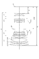
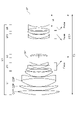
図1、3、5に、実施例1から3の光学系のレンズ断面図を示す。実施例1の光学系はFナンバー1.85、撮像画角18.76度の光学系である。実施例2の光学系はFナンバー1.85、撮像画角16.41度の光学系である。実施例3の光学系はFナンバー1.85、撮像画角23.29度の光学系である。 1, 3, and 5 show lens cross-sectional views of the optical systems of Examples 1 to 3. FIG. The optical system of Example 1 has an F number of 1.85 and an imaging angle of view of 18.76 degrees. The optical system of Example 2 has an F number of 1.85 and an imaging angle of view of 16.41 degrees. The optical system of Example 3 has an F number of 1.85 and an imaging angle of view of 23.29 degrees.
各実施例の光学系L0はデジタルスチルカメラ、ビデオカメラ、銀塩フィルムカメラ、放送用カメラなどの撮像装置やプロジェクタ等の投射装置に用いられるものである。レンズ断面図において、左方が物体側(拡大側)で、右方が像側(縮小側)である。 The optical system L0 of each embodiment is used in an imaging device such as a digital still camera, a video camera, a film camera, a broadcast camera, or a projection device such as a projector. In the sectional view of the lens, the left side is the object side (enlargement side) and the right side is the image side (reduction side).
各レンズ断面図において、SPは開放Fナンバー(Fno)の光束を決定(制限)する開口絞りである。IPは像面であり、ビデオカメラやデジタルスチルカメラの撮影光学系として使用する際にはCCDセンサやCMOSセンサ等の撮像素子(光電変換素子)の撮像面が置かれる。Focus(フォーカス)に関する矢印は無限遠から近距離へのフォーカシングに際してのレンズ群の移動方向を示している。 In each lens sectional view, SP is an aperture stop that determines (limits) the luminous flux of the open F number (Fno). IP is an image plane, on which an imaging plane of an imaging element (photoelectric conversion element) such as a CCD sensor or a CMOS sensor is placed when used as a photographing optical system of a video camera or a digital still camera. The arrow for Focus indicates the direction of movement of the lens group during focusing from infinity to short distance.
各実施例の光学系L0は、物体側より像側へ順に配置された、正の屈折力の第1レンズ群L1、負の屈折力の第2レンズ群LF1、1以上のレンズ群を含む中間群、負の屈折力の最終レンズ群LRを含んで構成される。また、各実施例の光学系L0において、フォーカシングに際して少なくとも2つのレンズ群が移動し、隣り合うレンズ群の間隔が変化する。また、無限遠から近距離へのフォーカシングに際して第2レンズ群LF1は像側へ、中間群に含まれるレンズ群のうち最も像側に配置されるレンズ群LF2は物体側へ移動する。なお、本願明細書におけるレンズ群とは1または複数のレンズから構成される光学系L0の構成要素である。 The optical system L0 of each embodiment includes a first lens group L1 with positive refractive power, a second lens group LF1 with negative refractive power, and an intermediate lens group including one or more lens groups, which are arranged in order from the object side to the image side. group, including a last lens group LR of negative refractive power. Further, in the optical system L0 of each embodiment, at least two lens groups move during focusing, and the distance between adjacent lens groups changes. Further, when focusing from infinity to a short distance, the second lens group LF1 moves toward the image side, and the lens group LF2 arranged closest to the image side among the lens groups included in the intermediate group moves toward the object side. Note that the lens group in the specification of the present application is a constituent element of the optical system L0 that is composed of one or more lenses.
実施例1の光学系L0は、正の屈折力の第1レンズ群L1、負の屈折力の第2レンズ群LF1、正の屈折力の第3レンズ群LF2、負の屈折力の第4レンズ群LRを有する。第3レンズ群LF2は中間群に相当し、第4レンズ群LRは最終レンズ群に相当する。無限遠から近距離へのフォーカシングに際して第2レンズ群LF1は像側へ移動し、第3レンズ群LF2は物体側へ移動し、第1レンズ群L1と第4レンズ群LRは不動である。 The optical system L0 of Example 1 includes a first lens group L1 with positive refractive power, a second lens group LF1 with negative refractive power, a third lens group LF2 with positive refractive power, and a fourth lens with negative refractive power. It has group LR. The third lens group LF2 corresponds to an intermediate group, and the fourth lens group LR corresponds to a final lens group. During focusing from infinity to short distance, the second lens group LF1 moves toward the image side, the third lens group LF2 moves toward the object side, and the first lens group L1 and the fourth lens group LR remain stationary.
実施例2の光学系L0は、正の屈折力の第1レンズ群L1、負の屈折力の第2レンズ群LF1、正の屈折力の第3レンズ群LC、正の屈折力の第4レンズ群LF2、負の屈折力の第5レンズ群LRを有する。第3レンズ群LCと第4レンズ群LF2は中間群に相当し、第5レンズ群LRは最終レンズ群に相当する。無限遠から近距離へのフォーカシングに際して第2レンズ群LF1は像側へ移動し、第4レンズ群LF2は物体側へ移動し、第5レンズ群LRは物体側に凸状の軌跡で移動する。第1レンズ群L1はフォーカシングに際して不動である。 The optical system L0 of Example 2 includes a first lens group L1 with positive refractive power, a second lens group LF1 with negative refractive power, a third lens group LC with positive refractive power, and a fourth lens with positive refractive power. The group LF2 has a negative refractive power fifth lens group LR. The third lens group LC and fourth lens group LF2 correspond to an intermediate group, and the fifth lens group LR corresponds to a final lens group. During focusing from infinity to short distance, the second lens unit LF1 moves toward the image side, the fourth lens unit LF2 moves toward the object side, and the fifth lens unit LR moves along a convex locus toward the object side. The first lens group L1 is stationary during focusing.
実施例3の光学系L0は、正の屈折力の第1レンズ群L1、負の屈折力の第2レンズ群LF1、正の屈折力の第3レンズ群LC、正の屈折力の第4レンズ群LF2、負の屈折力の第5レンズ群LRを有する。第3レンズ群LCと第4レンズ群LF2は中間群に相当し、第5レンズ群LRは最終レンズ群に相当する。無限遠から近距離へのフォーカシングに際して第2レンズ群LF1は像側へ移動し、第4レンズ群LF2は物体側へ移動し、第1レンズ群L1と第5レンズ群LRは不動である。 The optical system L0 of Example 3 includes a first lens group L1 with positive refractive power, a second lens group LF1 with negative refractive power, a third lens group LC with positive refractive power, and a fourth lens with positive refractive power. The group LF2 has a negative refractive power fifth lens group LR. The third lens group LC and fourth lens group LF2 correspond to an intermediate group, and the fifth lens group LR corresponds to a final lens group. During focusing from infinity to short distance, the second lens group LF1 moves toward the image side, the fourth lens group LF2 moves toward the object side, and the first lens group L1 and the fifth lens group LR remain stationary.
なお、実施例1、実施例3において、フォーカシングに際して最終レンズ群LRを移動させてもよい。また、実施例2において、フォーカシングに際して最終レンズ群LRを不動としてもよい。また、各実施例の光学系において、一部のレンズ又は一部のレンズ群を光軸に対して垂直方向に平行偏心させることにより、像ぶれ補正を行うようにしても良い。また、最も像側に配置された屈折力を持つレンズと撮像面との間に、ローパスフィルターや赤外カットフィルター等の実質的に屈折力を持たない素子を配置しても良い。 In the first and third embodiments, the final lens group LR may be moved during focusing. Further, in the second embodiment, the final lens group LR may be fixed during focusing. Further, in the optical system of each embodiment, image blur correction may be performed by parallel decentering some lenses or some lens groups in the direction perpendicular to the optical axis. Further, an element having substantially no refractive power, such as a low-pass filter or an infrared cut filter, may be arranged between the lens having refractive power arranged closest to the image side and the imaging surface.
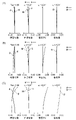
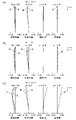
図2、4、6に、実施例1から3の光学系L0の収差図を示す。各収差図において、(A)は無限遠合焦時の収差図、(B)は撮影倍率β=-0.2倍となる合焦状態における収差図、(C)は撮影倍率β=-0.5倍となる合焦状態における収差図である。 2, 4, and 6 show aberration diagrams of the optical systems L0 of Examples 1 to 3. FIG. In each aberration diagram, (A) is an aberration diagram when focusing at infinity, (B) is an aberration diagram when the imaging magnification is β = -0.2 times, and (C) is an aberration diagram when the imaging magnification is β = -0. It is an aberration diagram in the in-focus state of 0.5 times.
収差図においてFnoはFナンバー、ωは半画角(度)であり、近軸計算による画角である。球面収差図において、dはd線(波長587.56nm)、gはg線(波長435.835nm)について示している。 In the aberration diagrams, Fno is the F number, and ω is the half angle of view (degrees), which is the angle of view obtained by paraxial calculation. In the spherical aberration diagrams, d is for the d-line (wavelength 587.56 nm) and g is for the g-line (wavelength 435.835 nm).
非点収差図においてΔSはサジタル像面におけるd線、ΔMはメリディオナル像面におけるd線について示している。歪曲収差図はd線について示している。色収差図においてg線のd線に対する倍率色収差量について示している。 In the astigmatism diagrams, ΔS indicates the d-line on the sagittal image plane, and ΔM indicates the d-line on the meridional image plane. Distortion aberration diagrams are shown for the d-line. The chromatic aberration diagrams show the amount of lateral chromatic aberration of the g-line with respect to the d-line.
次に、各実施例の光学系L0の特徴について説明する。 Next, features of the optical system L0 of each embodiment will be described.
各実施例の光学系L0では、フォーカシングに伴う収差変動を低減させるためにフォーカシングに際して第2レンズ群LF1と、中間群に含まれるレンズ群のうち最も像側に配置されるレンズ群LF2を移動させている。 In the optical system L0 of each embodiment, the second lens group LF1 and the lens group LF2, which is arranged closest to the image side among the lens groups included in the intermediate group, are moved during focusing in order to reduce aberration fluctuations due to focusing. ing.
また、各実施例の光学系L0では、大口径比化した際にも光学系L0が過度に大型化しないよう、第1レンズ群L1を正の屈折力としている。このとき、第1レンズ群L1の正の屈折力が大きくなると、第2レンズ群LF1に入射する光線の高さのフォーカシングに伴う変動が大きくなり易くなる。そうすると、第2レンズ群LF1を移動させてフォーカシングする際、光学系L0全体で収差変動が大きくなりやすくなる。 Further, in the optical system L0 of each embodiment, the first lens unit L1 has a positive refractive power so that the optical system L0 does not become excessively large even when the aperture ratio is increased. At this time, when the positive refractive power of the first lens group L1 increases, the height of the light rays incident on the second lens group LF1 tends to increase due to focusing. Then, when moving the second lens group LF1 for focusing, aberration fluctuations tend to increase in the entire optical system L0.
そこで、各実施例の光学系L0では、第2レンズ群LF1の移動量を小さくする、または屈折力を弱くすることで、他のフォーカス群であるレンズ群LF2に入射する光線の高さの変動を小さくしている。これにより、各実施例の光学系L0ではフォーカシングに伴う収差変動を低減している。 Therefore, in the optical system L0 of each embodiment, by reducing the amount of movement of the second lens group LF1 or by weakening the refractive power, the height of the light rays incident on the lens group LF2, which is another focus group, is changed. is made smaller. As a result, in the optical system L0 of each embodiment, aberration fluctuations due to focusing are reduced.
具体的には、各実施例の光学系L0は、以下の条件式(1)と条件式(2)を満足している。なお、本発明の効果は条件式(1)と条件式(2)の少なくとも一方を満足すれば得ることができ、必ずしも両方同時に満足する必要はない。
-0.40<MF1/MF2<0.00 (1)
-0.37<fF1/f<0.00 (2)
Specifically, the optical system L0 of each example satisfies the following conditional expressions (1) and (2). The effect of the present invention can be obtained by satisfying at least one of the conditional expressions (1) and (2), and it is not necessary to satisfy both at the same time.
-0.40<MF1/MF2<0.00 (1)
-0.37<fF1/f<0.00 (2)
ここで、無限遠合焦時から撮影倍率β=-0.2倍となる合焦状態までの、第2レンズ群LF1の移動量をMF1、中間群に含まれるレンズ群のうち最も像側に配置されたレンズ群LF2の移動量をMF2とする。また、第2レンズ群LF1の焦点距離をfF1、無限遠合焦時の光学系L0の焦点距離をfとする。なお、本願明細書では、無限遠合焦時におけるレンズ群の光軸上の位置とβ=-0.2倍となる物体に合焦した時におけるレンズ群の光軸上の位置の差を移動量とする。移動量の符号は無限遠合焦時に比べてβ=-0.2倍となる合焦状態においてレンズ群が像側に位置するときを正、物体側に位置するときを負とする。 Here, MF1 is the amount of movement of the second lens group LF1 from the time of focusing at infinity to the in-focus state where the photographing magnification β is -0.2 times, and the amount of movement of the second lens group LF1 is MF1, Let MF2 be the amount of movement of the arranged lens unit LF2. Let fF1 be the focal length of the second lens group LF1, and f be the focal length of the optical system L0 when focused on infinity. In this specification, the difference between the position of the lens group on the optical axis when focusing on infinity and the position of the lens group on the optical axis when focusing on an object with β = -0.2 times is moved. Quantity. The sign of the amount of movement is positive when the lens group is located on the image side and negative when located on the object side in a focused state where β is -0.2 times as large as that during focusing at infinity.
条件式(1)は、第2レンズ群LF1と、中間群に含まれるレンズ群のうち最も像側に配置されるレンズ群LF2の移動量の比に関する。条件式(1)の下限値を下回ると、第2レンズ群LF1の移動量が大きくなり、フォーカシングに伴う収差変動が大きくなってしまう。また、条件式(1)の上限値を超えると、第2レンズ群LF1とレンズ群LF2の移動方向が同一となる。この場合、レンズ群LF2への光線の入射高さが変わりやすく、フォーカシングに伴う収差変動の抑制が困難となる。 Conditional expression (1) relates to the ratio of the amount of movement between the second lens group LF1 and the lens group LF2 arranged closest to the image side among the lens groups included in the intermediate group. If the lower limit of conditional expression (1) is not reached, the amount of movement of the second lens unit LF1 becomes large, and aberration fluctuations accompanying focusing become large. Further, when the upper limit of conditional expression (1) is exceeded, the moving directions of the second lens group LF1 and the lens group LF2 become the same. In this case, the incident height of light rays to the lens unit LF2 is likely to change, making it difficult to suppress aberration fluctuations accompanying focusing.
なお、第2レンズ群LF1の移動量が小さすぎると特に近距離に合焦した際の諸収差を良好に補正することが困難となる。このため、式(1)の範囲は、以下の式(1a)の範囲とすることが好ましく、以下の式(1b)の範囲とすることがより好ましい。
-0.40<MF1/MF2<-0.05 (1a)
-0.38<MF1/MF2<-0.05 (1b)
If the amount of movement of the second lens unit LF1 is too small, it becomes difficult to satisfactorily correct various aberrations particularly when focusing on a short distance. Therefore, the range of formula (1) is preferably the range of formula (1a) below, and more preferably the range of formula (1b) below.
-0.40<MF1/MF2<-0.05 (1a)
-0.38<MF1/MF2<-0.05 (1b)
条件式(2)は、第2レンズ群LF1の焦点距離に関する。条件式(2)の下限値を下回ると、第2レンズ群LF1の屈折力が弱くなり、レンズ群LF2に入射する光線の高さのフォーカシングに伴う変動が大きくなる。その結果、フォーカシングに伴う収差変動が大きくなってしまう。 Conditional expression (2) relates to the focal length of the second lens unit LF1. If the lower limit of conditional expression (2) is not reached, the refractive power of the second lens group LF1 will become weak, and the fluctuation in the height of light rays incident on the lens group LF2 will increase with focusing. As a result, aberration fluctuations accompanying focusing become large.
なお、第2レンズ群LF1の焦点距離が小さすぎると第2レンズ群で発生する収差が増加し、光学系全系の諸収差を良好に補正することが困難となる。このため、式(2)の範囲は、以下の式(2a)の範囲とすることが好ましく、以下の式(2b)の範囲とすることがより好ましい。
-0.37<fF1/f<-0.10 (2a)
-0.37<fF1/f<-0.15 (2b)
If the focal length of the second lens group LF1 is too small, aberrations generated in the second lens group increase, making it difficult to satisfactorily correct various aberrations of the entire optical system. Therefore, the range of formula (2) is preferably the range of formula (2a) below, and more preferably the range of formula (2b) below.
-0.37<fF1/f<-0.10 (2a)
-0.37<fF1/f<-0.15 (2b)
以上述べたように、上述した条件式(1)または(2)の少なくとも一方を満足することでフォーカシングに伴う収差変動を低減させることができる。 As described above, by satisfying at least one of the conditional expressions (1) and (2) described above, it is possible to reduce aberration fluctuations accompanying focusing.
なお、各実施例の光学系L0において、第1レンズ群L1は3枚の正レンズを有して構成されることが好ましい。すなわち、第1レンズ群L1は物体側から像側へ順に配置された、正の屈折力の第1レンズGP1と、正の屈折力の第2レンズGP2と、正の屈折力の第3レンズGP3を有することが好ましい。これにより、第1レンズ群L1に適切な屈折力を付与しつつ諸収差の発生を抑えることができる。 In addition, in the optical system L0 of each embodiment, it is preferable that the first lens group L1 has three positive lenses. That is, the first lens unit L1 includes a first lens GP1 with positive refractive power, a second lens GP2 with positive refractive power, and a third lens GP3 with positive refractive power, which are arranged in order from the object side to the image side. It is preferred to have Accordingly, it is possible to suppress the occurrence of various aberrations while giving an appropriate refractive power to the first lens unit L1.
また、各実施例の光学系L0において、第1レンズ群L1はフォーカシングに際して不動であることが好ましい。これによって、フォーカス機構を簡易化できる。また、フォーカシングに際して光学系L0の全長を一定にできる。 Moreover, in the optical system L0 of each embodiment, it is preferable that the first lens unit L1 is stationary during focusing. This makes it possible to simplify the focus mechanism. Also, the total length of the optical system L0 can be kept constant during focusing.
また、フォーカス機構を簡易にする点においては最終レンズ群LRを不動とすることが好ましい。 In addition, from the viewpoint of simplifying the focusing mechanism, it is preferable to make the final lens group LR stationary.
また、各実施例の光学系L0は、以下の条件式のうち1つ以上を満足することが好ましい。ここで、第1レンズ群L1の焦点距離をf1とする。最終レンズ群LRの焦点距離をfRとする。レンズ群LF2の焦点距離をfF2とする。無限遠合焦時における最も像側に配置されたレンズの像側の面から像面IPまでの空気換算での光軸上の距離をskとする。無限遠合焦時において最も物体側に配置されるレンズの物体側のレンズ面から像面IPまでの空気換算での光軸上の距離をTDとする。無限遠合焦時における開口絞りSPから像面IPまでの空気換算での光軸上の距離をSTIPとする。
-0.7<fF1/f1<-0.4 (3)
0<fF2/f<0.7 (4)
-1.6<f/fR<-0.3 (5)
-0.6<MF2/fF2<0 (6)
0<sk/TD<0.3 (7)
0.50<STIP/TD<0.80 (8)
Also, the optical system L0 of each embodiment preferably satisfies one or more of the following conditional expressions. Here, the focal length of the first lens unit L1 is f1. Let fR be the focal length of the final lens group LR. Let fF2 be the focal length of the lens group LF2. Let sk be the distance on the optical axis in terms of air from the image side surface of the lens arranged closest to the image side to the image plane IP when focusing on infinity. Let TD be the distance on the optical axis in terms of air from the object side lens surface of the lens arranged closest to the object side to the image plane IP when focusing on infinity. Let STIP be the distance on the optical axis in terms of air from the aperture stop SP to the image plane IP when focusing on infinity.
-0.7<fF1/f1<-0.4 (3)
0<fF2/f<0.7 (4)
-1.6<f/fR<-0.3 (5)
-0.6<MF2/fF2<0 (6)
0<sk/TD<0.3 (7)
0.50<STIP/TD<0.80 (8)
条件式(3)は、第2レンズ群LF1の焦点距離と、第1レンズ群L1の焦点距離の比に関する。条件式(3)の下限値を下回る程に第2レンズ群LF1の負の屈折力が弱くなると、レンズ群LF2へ入射する光線のフォーカシングに伴う高さの変動が大きくなるため、フォーカシングに伴う収差変動を十分に低減することが難しくなる。また、条件式(3)の上限値を超える程に第2レンズ群LF1の負の屈折力が強くなると、球面収差等の諸収差の補正が困難となる。 Conditional expression (3) relates to the ratio of the focal length of the second lens group LF1 and the focal length of the first lens group L1. When the negative refractive power of the second lens group LF1 becomes weaker to the extent that the lower limit of conditional expression (3) is not reached, the height variation accompanying focusing of light rays incident on the lens group LF2 increases, resulting in aberrations accompanying focusing. Sufficiently reducing variation becomes difficult. Further, when the negative refractive power of the second lens unit LF1 becomes so strong that the upper limit of conditional expression (3) is exceeded, it becomes difficult to correct various aberrations such as spherical aberration.
条件式(4)は、レンズ群LF2の焦点距離に関する。条件式(4)の上限値を超える程にレンズ群LF2の正の屈折力が弱くなると、フォーカシングの際のレンズ群LF2の移動量が増加し、光学系L0が大型化してしまう。また、条件式(4)の下限値は、レンズ群LF2の屈折力が正であることを示している。レンズ群LF2の屈折力を正とすることで負の屈折力である最終レンズ群LRとテレフォトタイプの構成となり、光学系全系の小型化が容易となる。なお、レンズ群LF2の正の屈折力が大きすぎる場合フォーカシングに伴う収差変動を十分小さくすることが困難となる場合があるため条件式(4)に後述のように下限値を設定しても良い。 Conditional expression (4) relates to the focal length of the lens group LF2. If the positive refractive power of the lens group LF2 becomes weak enough to exceed the upper limit of conditional expression (4), the amount of movement of the lens group LF2 during focusing increases, resulting in an increase in the size of the optical system L0. Also, the lower limit of conditional expression (4) indicates that the refractive power of the lens unit LF2 is positive. By making the refractive power of the lens group LF2 positive, the final lens group LR, which has negative refractive power, and the telephoto type configuration are formed, which facilitates miniaturization of the entire optical system. If the positive refractive power of the lens unit LF2 is too large, it may be difficult to sufficiently reduce aberration fluctuations due to focusing. .
条件式(5)は、無限遠合焦時の光学系L0の焦点距離と、最終レンズ群LRの焦点距離の比に関する。条件式(5)の上限値または下限値を超えると、フォーカシングに際して像面湾曲の変動が増大し、全物体距離において高い光学性能を得ることが困難となる。 Conditional expression (5) relates to the ratio of the focal length of the optical system L0 and the focal length of the final lens group LR when focusing on infinity. If the upper limit or the lower limit of conditional expression (5) is exceeded, the variation in curvature of field increases during focusing, making it difficult to obtain high optical performance at all object distances.
条件式(6)は、レンズ群LF2の移動量と、レンズ群LF2の焦点距離の比に関する。条件式(6)の下限値を下回る程にレンズ群LF2の移動量が増大すると、光学系L0が大型化してしまう。また、条件式(6)の上限値は、レンズ群LF2の屈折力が正であることを示している。レンズ群LF2の屈折力を正とすることで負の屈折力である最終レンズ群LRとテレフォトタイプの構成となり、光学系全系の小型化が用意となる。なお、レンズ群LF2の正の屈折力が小さすぎる場合フォーカシングに伴うレンズ群LF2の移動量が大きくなりすぎ、光学系L0が大型化する場合があるため、条件式(6)に後述のように上限値を設定しても良い。 Conditional expression (6) relates to the ratio between the amount of movement of the lens group LF2 and the focal length of the lens group LF2. If the amount of movement of the lens group LF2 increases to the extent that the lower limit of conditional expression (6) is not reached, the optical system L0 becomes large. Also, the upper limit of conditional expression (6) indicates that the refractive power of the lens unit LF2 is positive. By making the refractive power of the lens group LF2 positive, the final lens group LR, which has negative refractive power, and a telephoto type configuration are formed, which makes it easy to reduce the size of the entire optical system. If the positive refractive power of the lens unit LF2 is too small, the amount of movement of the lens unit LF2 due to focusing may become too large, and the optical system L0 may become large. An upper limit value may be set.
条件式(7)は、無限遠合焦時のバックフォーカスに関する。条件式(7)の上限値を超える程にバックフォーカスが長くなると、光学系L0が大型化してしまう。なお、条件式(7)は各実施例の光学系L0をレンズ交換式カメラの交換レンズとして用いるために好適な範囲で下限値を設定しても良い。 Conditional expression (7) relates to back focus during focusing at infinity. If the back focus becomes long enough to exceed the upper limit of conditional expression (7), the optical system L0 becomes large. The lower limit of conditional expression (7) may be set within a range suitable for using the optical system L0 of each embodiment as an interchangeable lens of an interchangeable lens camera.
条件式(8)は、無限遠合焦時における開口絞りSPの配置に関する。条件式(8)の上限値または下限値を下回ると、開口絞りSPから最も物体側のレンズ面までの距離または最も像側のレンズ面までの距離が短くなりすぎ、コマ収差や歪曲収差等の軸外収差の補正が困難となる。 Conditional expression (8) relates to the arrangement of the aperture stop SP during focusing at infinity. If the upper or lower limit of conditional expression (8) is exceeded, the distance from the aperture stop SP to the lens surface closest to the object side or to the lens surface closest to the image side becomes too short, resulting in coma, distortion, and other aberrations. Correction of off-axis aberration becomes difficult.
なお、式(3)から(8)の範囲は、それぞれ以下の式(3a)から(8a)の範囲とすることがより好ましい。
-0.65<fF1/f1<-0.40 (3a)
0.1<fF2/f<0.6 (4a)
-1.55<f/fR<-0.50 (5a)
-0.6<MF2/fF2<-0.1 (6a)
0.1<sk/TD<0.3 (7a)
0.5<STIP/TD<0.70 (8a)
It is more preferable that the ranges of formulas (3) to (8) be the ranges of formulas (3a) to (8a) below.
-0.65<fF1/f1<-0.40 (3a)
0.1<fF2/f<0.6 (4a)
-1.55<f/fR<-0.50 (5a)
-0.6<MF2/fF2<-0.1 (6a)
0.1<sk/TD<0.3 (7a)
0.5<STIP/TD<0.70 (8a)
また、式(3)から(8)の範囲は、それぞれ以下の式(3b)から(8b)の範囲とすることがさらに好ましい。
-0.65<fF1/f1<-0.45 (3b)
0.3<fF2/f<0.6 (4b)
-1.55<f/fR<-0.70 (5b)
-0.5<MF2/fF2<-0.1 (6b)
0.1<sk/TD<0.2 (7b)
0.5<STIP/TD<0.65 (8b)
Further, it is more preferable that the ranges of the formulas (3) to (8) are set to the ranges of the following formulas (3b) to (8b), respectively.
-0.65<fF1/f1<-0.45 (3b)
0.3<fF2/f<0.6 (4b)
-1.55<f/fR<-0.70 (5b)
-0.5<MF2/fF2<-0.1 (6b)
0.1<sk/TD<0.2 (7b)
0.5<STIP/TD<0.65 (8b)
次に、実施例1から3のそれぞれに対応する数値実施例1から3を示す。各数値実施例において、面番号は物体側から数えた際の光学面の順序を示す。rはの光学面の曲率半径、dは面間隔である。nd、νdは、光学部材の屈折率、アッベ数である。 Numerical Examples 1 to 3 corresponding to Examples 1 to 3, respectively, are shown below. In each numerical example, the surface number indicates the order of the optical surfaces counted from the object side. r is the radius of curvature of the optical surface, and d is the surface distance. nd and νd are the refractive index and Abbe number of the optical member.
有効径は、軸上光線及び軸外光線の通過範囲によって決まるレンズの径をいう。入射瞳位置は最も物体側のレンズ面(第1面)から入射瞳までの距離、射出瞳位置は最も像側のレンズ面(最終レンズ面)から射出瞳までの距離、前側主点位置は第1面から前側主点までの距離である。後側主点位置は最終面から後側主点までの距離で、各数値は近軸量であり、符号は物体側から像側の向きを正とする。 Effective diameter refers to the diameter of a lens determined by the range of passage of on-axis and off-axis rays. The entrance pupil position is the distance from the most object side lens surface (1st surface) to the entrance pupil, the exit pupil position is the distance from the most image side lens surface (last lens surface) to the exit pupil, and the front principal point position is the 3rd It is the distance from surface 1 to the front principal point. The rear principal point position is the distance from the final surface to the rear principal point, each numerical value is a paraxial amount, and the sign is positive in the direction from the object side to the image side.
各数値実施例において、バックフォーカス(BF)は、光学系Lの最も像側の面から像面までの距離を、空気換算長により表したものである。 In each numerical example, the back focus (BF) represents the distance from the surface of the optical system L closest to the image side to the image plane in terms of air conversion length.
[数値実施例1]
単位 mm
面データ
面番号 r d nd νd 有効径
1 193.557 7.00 1.61800 63.4 70.81
2 -361.412 0.15 70.53
3 91.656 6.00 1.61800 63.4 67.55
4 237.665 0.15 66.57
5 57.624 15.30 1.43875 94.7 61.96
6 -144.282 2.70 1.80000 29.8 59.27
7 190.514 0.15 55.03
8 46.988 6.90 1.49700 81.5 50.76
9 116.289 (可変) 48.86
10 136.733 3.40 1.95906 17.5 47.20
11 971.695 0.10 45.98
12 110.549 2.00 1.80420 46.5 42.59
13 34.395 5.90 37.03
14 -970.336 1.80 1.72916 54.7 36.75
15 41.116 (可変) 34.16
16(絞り) ∞ (可変) 32.97
17 572.156 1.80 1.85478 24.8 35.79
18 46.877 6.70 1.76385 48.5 37.58
19 -345.228 0.15 38.47
20 84.551 5.60 1.90043 37.4 40.45
21 -160.008 (可変) 40.59
22 -142.632 5.80 1.59270 35.3 39.39
23 -38.358 1.90 1.53172 48.8 39.46
24 146.610 27.26 39.45
像面 ∞
焦点距離 131.00
Fナンバー 1.85
半画角(°) 9.38
像高 21.63
レンズ全長 155.01
BF 27.26
可変間隔
無限遠 -0.2倍 -0.5倍
d 9 1.90 4.34 8.59
d15 12.35 9.91 5.66
d16 27.20 15.61 2.10
d21 12.80 24.39 37.90
入射瞳位置 129.93
射出瞳位置 -63.50
前側主点位置 71.85
後側主点位置-103.74
レンズ群データ
群 始面 焦点距離 レンズ構成長 前側主点位置 後側主点位置
1 1 61.53 38.35 3.65 -21.06
2 10 -34.81 13.20 8.56 -1.37
3 17 56.05 14.25 5.85 -2.05
4 22 -160.40 7.70 1.91 -2.93
単レンズデータ
レンズ 始面 焦点距離
1 1 204.95
2 3 237.68
3 5 96.07
4 6 -102.26
5 8 153.57
6 10 165.59
7 12 -62.82
8 14 -54.06
9 17 -59.83
10 18 54.44
11 20 62.11
12 22 86.73
13 23 -56.98
[Numerical Example 1]
unit mm
Surface data Surface number rd nd νd Effective diameter
1 193.557 7.00 1.61800 63.4 70.81
2 -361.412 0.15 70.53
3 91.656 6.00 1.61800 63.4 67.55
4 237.665 0.15 66.57
5 57.624 15.30 1.43875 94.7 61.96
6 -144.282 2.70 1.80000 29.8 59.27
7 190.514 0.15 55.03
8 46.988 6.90 1.49700 81.5 50.76
9 116.289 (variable) 48.86
10 136.733 3.40 1.95906 17.5 47.20
11 971.695 0.10 45.98
12 110.549 2.00 1.80420 46.5 42.59
13 34.395 5.90 37.03
14 -970.336 1.80 1.72916 54.7 36.75
15 41.116 (variable) 34.16
16 (aperture) ∞ (variable) 32.97
17 572.156 1.80 1.85478 24.8 35.79
18 46.877 6.70 1.76385 48.5 37.58
19 -345.228 0.15 38.47
20 84.551 5.60 1.90043 37.4 40.45
21 -160.008 (variable) 40.59
22 -142.632 5.80 1.59270 35.3 39.39
23 -38.358 1.90 1.53172 48.8 39.46
24 146.610 27.26 39.45
Image plane ∞
Focal length 131.00
F number 1.85
Half angle of view (°) 9.38
Image height 21.63
Lens length 155.01
BF 27.26
Variable interval infinity -0.2x -0.5x
d9 1.90 4.34 8.59
d15 12.35 9.91 5.66
d16 27.20 15.61 2.10
d21 12.80 24.39 37.90
Entrance pupil position 129.93
Exit pupil position -63.50
Front principal point position 71.85
Rear principal point position -103.74
Lens group data group Starting surface Focal length Lens construction length Front principal point position Rear principal point position
1 1 61.53 38.35 3.65 -21.06
2 10 -34.81 13.20 8.56 -1.37
3 17 56.05 14.25 5.85 -2.05
4 22 -160.40 7.70 1.91 -2.93
Single lens data lens Starting surface Focal length
1 1 204.95
2 3 237.68
3 5 96.07
4 6 -102.26
5 8 153.57
6 10 165.59
7 12 -62.82
8 14 -54.06
9 17 -59.83
10 18 54.44
11 20 62.11
12 22 86.73
13 23 -56.98
[数値実施例2]
単位 mm
面データ
面番号 r d nd νd 有効径
1 156.397 8.70 1.61800 63.4 81.08
2 -596.930 0.15 80.68
3 98.758 7.60 1.61800 63.4 76.76
4 349.280 0.15 75.67
5 62.120 17.10 1.43875 94.7 68.70
6 -153.681 2.70 1.73800 32.3 65.61
7 126.090 0.30 59.11
8 46.522 9.30 1.49700 81.5 54.56
9 138.993 (可変) 51.66
10 128.047 4.90 1.95906 17.5 49.56
11 552.619 0.10 47.02
12 124.485 2.00 1.83481 42.7 43.81
13 32.185 6.10 37.22
14 1000.738 1.80 1.80400 46.6 36.93
15 42.828 (可変) 34.47
16(絞り) ∞ 4.90 33.02
17 -121.550 2.50 1.84666 23.8 32.43
18 -83.173 (可変) 32.51
19 81.632 1.80 1.84666 23.8 41.83
20 42.177 7.80 1.69680 55.5 42.10
21 1000.983 0.15 42.50
22 62.883 6.50 1.69680 55.5 43.72
23 -407.497 (可変) 43.47
24 262.582 5.40 1.85025 30.1 42.76
25 -80.645 1.90 1.76385 48.5 42.37
26 52.606 (可変) 40.02
像面 ∞
焦点距離 150.00
Fナンバー 1.85
半画角(°) 8.21
像高 21.63
レンズ全長 164.98
可変間隔
無限遠 -0.2倍 -0.5倍
d 9 1.50 3.43 8.14
d15 12.90 10.97 6.26
d18 31.50 8.60 1.00
d23 1.00 0.99 15.91
d26 26.23 49.14 41.82
入射瞳位置 173.30
射出瞳位置 -64.44
前側主点位置 75.17
後側主点位置-123.77
レンズ群データ
群 始面 焦点距離 レンズ構成長 前側主点位置 後側主点位置
1 1 63.23 46.00 4.13 -25.46
2 10 -31.52 14.90 9.05 -1.79
3 16 302.12 7.40 9.06 2.85
4 19 54.57 16.25 3.94 -5.83
5 24 -99.84 7.30 5.48 1.41
単レンズデータ
レンズ 始面 焦点距離
1 1 201.42
2 3 220.25
3 5 103.32
4 6 -93.47
5 8 136.15
6 10 172.80
7 12 -52.51
8 14 -55.70
9 17 302.12
10 19 -105.27
11 20 62.98
12 22 78.63
13 24 73.09
14 25 -41.42
[Numerical Example 2]
unit mm
Surface data Surface number rd nd νd Effective diameter
1 156.397 8.70 1.61800 63.4 81.08
2 -596.930 0.15 80.68
3 98.758 7.60 1.61800 63.4 76.76
4 349.280 0.15 75.67
5 62.120 17.10 1.43875 94.7 68.70
6 -153.681 2.70 1.73800 32.3 65.61
7 126.090 0.30 59.11
8 46.522 9.30 1.49700 81.5 54.56
9 138.993 (Variable) 51.66
10 128.047 4.90 1.95906 17.5 49.56
11 552.619 0.10 47.02
12 124.485 2.00 1.83481 42.7 43.81
13 32.185 6.10 37.22
14 1000.738 1.80 1.80400 46.6 36.93
15 42.828 (variable) 34.47
16 (Aperture) ∞ 4.90 33.02
17 -121.550 2.50 1.84666 23.8 32.43
18 -83.173 (variable) 32.51
19 81.632 1.80 1.84666 23.8 41.83
20 42.177 7.80 1.69680 55.5 42.10
21 1000.983 0.15 42.50
22 62.883 6.50 1.69680 55.5 43.72
23 -407.497 (variable) 43.47
24 262.582 5.40 1.85025 30.1 42.76
25 -80.645 1.90 1.76385 48.5 42.37
26 52.606 (variable) 40.02
Image plane ∞
Focal length 150.00
F number 1.85
Half angle of view (°) 8.21
Image height 21.63
Total lens length 164.98
Variable interval infinity -0.2x -0.5x
d9 1.50 3.43 8.14
d15 12.90 10.97 6.26
d18 31.50 8.60 1.00
d23 1.00 0.99 15.91
d26 26.23 49.14 41.82
Entrance pupil position 173.30
Exit pupil position -64.44
Front principal point position 75.17
Rear principal point position -123.77
Lens group data group Starting surface Focal length Lens construction length Front principal point position Rear principal point position
1 1 63.23 46.00 4.13 -25.46
2 10 -31.52 14.90 9.05 -1.79
3 16 302.12 7.40 9.06 2.85
4 19 54.57 16.25 3.94 -5.83
5 24 -99.84 7.30 5.48 1.41
Single lens data lens Starting surface Focal length
1 1 201.42
2 3 220.25
3 5 103.32
4 6 -93.47
5 8 136.15
6 10 172.80
7 12 -52.51
8 14 -55.70
9 17 302.12
10 19 -105.27
11 20 62.98
12 22 78.63
13 24 73.09
14 25 -41.42
[数値実施例3]
単位 mm
面データ
面番号 r d nd νd 有効径
1 382.997 2.70 1.88300 40.8 60.90
2 967.629 0.15 60.33
3 133.089 5.60 1.76385 48.5 58.83
4 -911.318 0.15 57.94
5 65.899 12.10 1.43875 94.7 53.03
6 -111.068 2.70 1.85478 24.8 50.94
7 985.624 0.30 48.98
8 50.416 5.70 1.53775 74.7 45.80
9 141.108 (可変) 44.38
10 152.399 3.30 1.95906 17.5 42.96
11 -975.547 0.10 42.00
12 172.070 2.00 1.74951 35.3 39.78
13 45.096 5.10 35.85
14 -143.645 1.80 1.69680 55.5 35.61
15 42.126 (可変) 33.31
16(絞り) ∞ 2.20 33.01
17 -950.175 1.70 1.91082 35.3 32.96
18 -278.944 (可変) 32.96
19 -358.707 1.80 1.85478 24.8 32.83
20 59.252 5.80 1.75500 52.3 34.75
21 -158.838 0.15 35.77
22 86.216 5.20 1.87070 40.7 37.92
23 -140.445 (可変) 38.12
24 -87.203 2.70 1.95375 32.3 37.85
25 -63.730 8.80 38.22
26 -49.885 1.90 1.51742 52.4 36.53
27 611.667 25.21 37.29
像面 ∞
焦点距離 105.00
Fナンバー 1.85
半画角(°) 11.64
像高 21.63
レンズ全長 145.01
可変間隔
無限遠 -0.2倍 -0.5倍
d 9 1.70 5.03 11.06
d15 14.75 11.42 5.39
d18 20.60 11.56 0.98
d23 10.80 19.84 30.42
入射瞳位置 92.84
射出瞳位置 -52.68
前側主点位置 56.30
後側主点位置 -79.79
レンズ群データ
群 始面 焦点距離 レンズ構成長 前側主点位置 後側主点位置
1 1 60.71 29.40 4.37 -14.55
2 10 -38.20 12.30 8.93 -0.35
3 16 433.00 3.90 3.46 0.37
4 19 58.41 12.95 6.25 -0.87
5 24 -148.83 13.40 13.79 2.23
単レンズデータ
レンズ 始面 焦点距離
1 1 716.34
2 3 152.39
3 5 96.27
4 6 -116.65
5 8 142.73
6 10 137.63
7 12 -82.09
8 14 -46.56
9 17 433.00
10 19 -59.37
11 20 57.82
12 22 62.02
13 24 235.04
14 26 -89.05
[Numerical Example 3]
unit mm
Surface data Surface number rd nd νd Effective diameter
1 382.997 2.70 1.88300 40.8 60.90
2 967.629 0.15 60.33
3 133.089 5.60 1.76385 48.5 58.83
4 -911.318 0.15 57.94
5 65.899 12.10 1.43875 94.7 53.03
6 -111.068 2.70 1.85478 24.8 50.94
7 985.624 0.30 48.98
8 50.416 5.70 1.53775 74.7 45.80
9 141.108 (variable) 44.38
10 152.399 3.30 1.95906 17.5 42.96
11 -975.547 0.10 42.00
12 172.070 2.00 1.74951 35.3 39.78
13 45.096 5.10 35.85
14 -143.645 1.80 1.69680 55.5 35.61
15 42.126 (variable) 33.31
16 (Aperture) ∞ 2.20 33.01
17 -950.175 1.70 1.91082 35.3 32.96
18 -278.944 (variable) 32.96
19 -358.707 1.80 1.85478 24.8 32.83
20 59.252 5.80 1.75500 52.3 34.75
21 -158.838 0.15 35.77
22 86.216 5.20 1.87070 40.7 37.92
23 -140.445 (variable) 38.12
24 -87.203 2.70 1.95375 32.3 37.85
25 -63.730 8.80 38.22
26 -49.885 1.90 1.51742 52.4 36.53
27 611.667 25.21 37.29
Image plane ∞
Focal length 105.00
F number 1.85
Half angle of view (°) 11.64
Image height 21.63
Lens length 145.01
Variable interval infinity -0.2x -0.5x
d9 1.70 5.03 11.06
d15 14.75 11.42 5.39
d18 20.60 11.56 0.98
d23 10.80 19.84 30.42
Entrance pupil position 92.84
Exit pupil position -52.68
Front principal point position 56.30
Rear principal point position -79.79
Lens group data group Starting surface Focal length Lens construction length Front principal point position Rear principal point position
1 1 60.71 29.40 4.37 -14.55
2 10 -38.20 12.30 8.93 -0.35
3 16 433.00 3.90 3.46 0.37
4 19 58.41 12.95 6.25 -0.87
5 24 -148.83 13.40 13.79 2.23
Single lens data lens Starting surface Focal length
1 1 716.34
2 3 152.39
3 5 96.27
4 6 -116.65
5 8 142.73
6 10 137.63
7 12 -82.09
8 14 -46.56
9 17 433.00
10 19 -59.37
11 20 57.82
12 22 62.02
13 24 235.04
14 26 -89.05
以下の表に各実施例における種々の値を示す。 The table below shows the various values for each example.

[撮像装置]
次に本発明の撮像装置の実施例について述べる。図7は、本実施例の撮像装置(デジタルスチルカメラ)10の概略図である。撮像装置10は、カメラ本体13と、上述した実施例1乃至3のいずれかと同様である光学系11と、光学系11によって形成される像を光電変換する受光素子(撮像素子)12を備える。
[Imaging device]
Next, an embodiment of the imaging apparatus of the present invention will be described. FIG. 7 is a schematic diagram of the imaging device (digital still camera) 10 of this embodiment. The
本実施例の撮像装置10は、フォーカシングに伴う収差変動が低減された光学系11によって形成された高品位な画像を得ることができる。
The
なお、受光素子12としては、CCDセンサやCMOSセンサ等の撮像素子を用いることができる。このとき、受光素子12により取得された画像の歪曲収差や色収差等の諸収差を電気的に補正することにより、出力画像を高画質化することもできる。
As the
なお、上述した各実施例の光学系Lは、図7に示したデジタルスチルカメラに限らず、銀塩フィルム用カメラやビデオカメラ、望遠鏡等の種々の光学機器に適用することができる。 The optical system L of each embodiment described above can be applied not only to the digital still camera shown in FIG. 7, but also to various optical devices such as a silver film camera, a video camera, and a telescope.
以上、本発明の好ましい実施形態及び実施例について説明したが、本発明はこれらの実施形態及び実施例に限定されず、その要旨の範囲内で種々の組合せ、変形及び変更が可能である。 Although preferred embodiments and examples of the present invention have been described above, the present invention is not limited to these embodiments and examples, and various combinations, modifications, and changes are possible within the scope of the gist.
L0 光学系
L1 第1レンズ群
LF1 第2レンズ群
LR 最終レンズ群
L0 optical system L1 first lens group LF1 second lens group LR final lens group
Claims (11)
前記最終レンズ群の最も像側には負レンズが配置されており、
無限遠合焦時から撮影倍率-0.5倍となる合焦状態までのフォーカシングに際し、前記第2レンズ群は像側へ移動し、前記中間群に含まれるレンズ群のうち最も像側に配置されたレンズ群は物体側へ移動し、
無限遠合焦時から撮影倍率が-0.2倍となる合焦状態までのフォーカシングに伴う、前記第2レンズ群の移動量をMF1、前記中間群に含まれるレンズ群のうち最も像側に配置されたレンズ群の移動量をMF2、前記第2レンズ群の焦点距離をfF1、無限遠合焦時の前記光学系の焦点距離をfとするとき、
-0.4<MF1/MF2<0
-0.37<fF1/f<0
なる条件式を満たすことを特徴とする光学系。 A first lens group with positive refractive power, a second lens group with negative refractive power, an intermediate group including one or more lens groups, and a final lens group with negative refractive power, arranged in order from the object side to the image side. An optical system consisting of lens groups, wherein the distance between adjacent lens groups changes during focusing,
a negative lens is disposed closest to the image side of the final lens group,
The second lens group moves toward the image side and is arranged closest to the image side among the lens groups included in the intermediate group during focusing from infinity to the in-focus state where the photographing magnification is −0.5 . , the lens group moves to the object side,
The amount of movement of the second lens group accompanying focusing from the time of focusing at infinity to the in-focus state where the photographing magnification is −0.2 times is MF1, and the lens group included in the intermediate group is closest to the image side. Let MF2 be the amount of movement of the arranged lens group , fF1 be the focal length of the second lens group, and f be the focal length of the optical system when focusing on infinity ,
-0.4<MF1/MF2<0
-0.37<fF1/f<0
An optical system characterized by satisfying the following conditional expression:
-0.7<fF1/f1<-0.4
なる条件式を満足することを特徴とする請求項1乃至3のいずれか一項に記載の光学系。 When the focal length of the first lens group is f1,
-0.7<fF1/f1<-0.4
4. The optical system according to any one of claims 1 to 3 , wherein the following conditional expression is satisfied.
0<fF2/f<0.7
なる条件式を満足することを特徴とする請求項1乃至4のいずれか一項に記載の光学系。 When fF2 is the focal length of the lens group arranged closest to the image side among the lens groups included in the intermediate group,
0<fF2/f<0.7
5. The optical system according to any one of claims 1 to 4 , wherein the following conditional expression is satisfied.
-1.6<f/fR<-0.3
なる条件式を満足することを特徴とする請求項1乃至5のいずれか一項に記載の光学系。 When the focal length of the final lens group is fR,
-1.6<f/fR<-0.3
6. The optical system according to any one of claims 1 to 5 , wherein the following conditional expression is satisfied.
-0.6<MF2/fF2<0
なる条件式を満足することを特徴とする請求項1乃至6のいずれか一項に記載の光学系。 When fF2 is the focal length of the lens group arranged closest to the image side among the lens groups included in the intermediate group,
-0.6<MF2/fF2<0
7. The optical system according to any one of claims 1 to 6 , wherein the following conditional expression is satisfied.
0<sk/TD<0.3
なる条件式を満足することを特徴とする請求項1乃至7のいずれか一項に記載の光学系。 sk is the distance on the optical axis from the image side surface of the lens closest to the image side to the image plane when focusing on infinity, and the distance on the object side of the lens closest to the object when focusing on infinity When the distance from the lens surface to the image plane is TD,
0<sk/TD<0.3
8. The optical system according to any one of claims 1 to 7 , wherein the following conditional expression is satisfied.
無限遠合焦時における前記開口絞りから像面までの光軸上の距離をSTIP、無限遠合焦時における最も物体側に配置されるレンズの物体側のレンズ面から像面までの光軸上の距離をTDとするとき、
0.5<STIP/TD<0.8
なる条件式を満足することを特徴とする請求項1乃至8のいずれか一項に記載の光学系。 having an aperture stop,
STIP is the distance on the optical axis from the aperture stop to the image plane when focusing on infinity, and STIP is the distance on the optical axis from the object-side lens surface of the lens located closest to the object side to the image plane when focusing on infinity. When the distance of is TD,
0.5<STIP/TD<0.8
9. The optical system according to any one of claims 1 to 8 , wherein the following conditional expression is satisfied.
Priority Applications (3)
| Application Number | Priority Date | Filing Date | Title |
|---|---|---|---|
| JP2019076160A JP7166980B2 (en) | 2019-04-12 | 2019-04-12 | Optical system and imaging device having the same |
| US16/838,932 US11500175B2 (en) | 2019-04-12 | 2020-04-02 | Optical system and image capturing apparatus including the same |
| US18/045,747 US20230061917A1 (en) | 2019-04-12 | 2022-10-11 | Optical system and image capturing apparatus including the same |
Applications Claiming Priority (1)
| Application Number | Priority Date | Filing Date | Title |
|---|---|---|---|
| JP2019076160A JP7166980B2 (en) | 2019-04-12 | 2019-04-12 | Optical system and imaging device having the same |
Publications (3)
| Publication Number | Publication Date |
|---|---|
| JP2020173384A JP2020173384A (en) | 2020-10-22 |
| JP2020173384A5 JP2020173384A5 (en) | 2022-04-28 |
| JP7166980B2 true JP7166980B2 (en) | 2022-11-08 |
Family
ID=72747854
Family Applications (1)
| Application Number | Title | Priority Date | Filing Date |
|---|---|---|---|
| JP2019076160A Active JP7166980B2 (en) | 2019-04-12 | 2019-04-12 | Optical system and imaging device having the same |
Country Status (2)
| Country | Link |
|---|---|
| US (2) | US11500175B2 (en) |
| JP (1) | JP7166980B2 (en) |
Citations (12)
| Publication number | Priority date | Publication date | Assignee | Title |
|---|---|---|---|---|
| JP2001033704A (en) | 1999-07-16 | 2001-02-09 | Sigma Corp | Macro lens |
| JP2006153942A (en) | 2004-11-25 | 2006-06-15 | Canon Inc | Photographic lens |
| JP2008257200A (en) | 2007-03-14 | 2008-10-23 | Nikon Corp | Close-up lens, imaging apparatus, and method for focusing close-up lens |
| JP2010145830A (en) | 2008-12-19 | 2010-07-01 | Canon Inc | Photographic lens and imaging apparatus having the same |
| JP2010181634A (en) | 2009-02-05 | 2010-08-19 | Tamron Co Ltd | Macro lens |
| JP2011013357A (en) | 2009-06-30 | 2011-01-20 | Sigma Corp | Inner focus type macro lens having vibration-proof function |
| JP2011118379A (en) | 2009-11-07 | 2011-06-16 | Nikon Corp | Photographic lens, optical apparatus with the photographic lens, and method for manufacturing the photographic lens |
| JP2014142601A (en) | 2012-12-27 | 2014-08-07 | Panasonic Corp | Inner focus lens system, interchangeable lens unit and camera system |
| JP2017173409A (en) | 2016-03-22 | 2017-09-28 | 株式会社シグマ | Large-aperture telephoto lens |
| JP2018132674A (en) | 2017-02-16 | 2018-08-23 | キヤノン株式会社 | Imaging optical system and imaging device having the same |
| JP2018141888A (en) | 2017-02-28 | 2018-09-13 | 富士フイルム株式会社 | Imaging lens and imaging device |
| WO2019187633A1 (en) | 2018-03-30 | 2019-10-03 | ソニー株式会社 | Imaging lens and imaging device |
Family Cites Families (4)
| Publication number | Priority date | Publication date | Assignee | Title |
|---|---|---|---|---|
| JP2004061680A (en) | 2002-07-26 | 2004-02-26 | Canon Inc | Macro lens |
| EP1970742B1 (en) * | 2007-03-14 | 2013-03-06 | Nikon Corporation | Close-up lens, imaging apparatus , and method for focusing close-up lens |
| US9063253B2 (en) * | 2011-12-12 | 2015-06-23 | Tamron Co., Ltd. | Imaging lens |
| JP2018205435A (en) | 2017-05-31 | 2018-12-27 | キヤノン株式会社 | Optical system and imaging apparatus having the same |
-
2019
- 2019-04-12 JP JP2019076160A patent/JP7166980B2/en active Active
-
2020
- 2020-04-02 US US16/838,932 patent/US11500175B2/en active Active
-
2022
- 2022-10-11 US US18/045,747 patent/US20230061917A1/en active Pending
Patent Citations (12)
| Publication number | Priority date | Publication date | Assignee | Title |
|---|---|---|---|---|
| JP2001033704A (en) | 1999-07-16 | 2001-02-09 | Sigma Corp | Macro lens |
| JP2006153942A (en) | 2004-11-25 | 2006-06-15 | Canon Inc | Photographic lens |
| JP2008257200A (en) | 2007-03-14 | 2008-10-23 | Nikon Corp | Close-up lens, imaging apparatus, and method for focusing close-up lens |
| JP2010145830A (en) | 2008-12-19 | 2010-07-01 | Canon Inc | Photographic lens and imaging apparatus having the same |
| JP2010181634A (en) | 2009-02-05 | 2010-08-19 | Tamron Co Ltd | Macro lens |
| JP2011013357A (en) | 2009-06-30 | 2011-01-20 | Sigma Corp | Inner focus type macro lens having vibration-proof function |
| JP2011118379A (en) | 2009-11-07 | 2011-06-16 | Nikon Corp | Photographic lens, optical apparatus with the photographic lens, and method for manufacturing the photographic lens |
| JP2014142601A (en) | 2012-12-27 | 2014-08-07 | Panasonic Corp | Inner focus lens system, interchangeable lens unit and camera system |
| JP2017173409A (en) | 2016-03-22 | 2017-09-28 | 株式会社シグマ | Large-aperture telephoto lens |
| JP2018132674A (en) | 2017-02-16 | 2018-08-23 | キヤノン株式会社 | Imaging optical system and imaging device having the same |
| JP2018141888A (en) | 2017-02-28 | 2018-09-13 | 富士フイルム株式会社 | Imaging lens and imaging device |
| WO2019187633A1 (en) | 2018-03-30 | 2019-10-03 | ソニー株式会社 | Imaging lens and imaging device |
Also Published As
| Publication number | Publication date |
|---|---|
| US20200326505A1 (en) | 2020-10-15 |
| US20230061917A1 (en) | 2023-03-02 |
| JP2020173384A (en) | 2020-10-22 |
| US11500175B2 (en) | 2022-11-15 |
Similar Documents
| Publication | Publication Date | Title |
|---|---|---|
| JP5804878B2 (en) | Zoom lens and imaging apparatus having the same | |
| US9684155B2 (en) | Optical system and image pickup apparatus including the same | |
| US20140055659A1 (en) | Zoom lens and image pickup apparatus | |
| JP6253239B2 (en) | Zoom lens, optical system, and imaging apparatus having the same | |
| JP2010060612A (en) | Zoom lens and image pickup device including the same | |
| JP6226611B2 (en) | Zoom lens and imaging apparatus having the same | |
| JP2015197593A (en) | Zoom lens and image capturing device having the same | |
| US20230258907A1 (en) | Zoom lens, optical apparatus, and method for manufacturing zoom lens | |
| JP2006293012A (en) | Zoom lens and imaging apparatus equipped with the same | |
| JP2015028530A5 (en) | ||
| US10101568B2 (en) | Zoom lens, optical device, and method for manufacturing the zoom lens | |
| CN111751965B (en) | Zoom lens and imaging apparatus having the same | |
| JP5858761B2 (en) | Zoom lens and imaging apparatus having the same | |
| JP2009037036A (en) | Zoom lens and image pickup device having it | |
| JP2021184030A (en) | Single focus lens and imaging apparatus | |
| JP7171224B2 (en) | Optical system and imaging device having the same | |
| JP2009008975A (en) | Zoom lens | |
| JP4817551B2 (en) | Zoom lens | |
| JP6108733B2 (en) | Zoom lens and imaging apparatus having the same | |
| JP7467082B2 (en) | Zoom lens and imaging device having the same | |
| JP7166980B2 (en) | Optical system and imaging device having the same | |
| JP2009210692A (en) | Wide converter lens and imaging apparatus having the same | |
| US11635602B2 (en) | Zoom lens and imaging apparatus including the same | |
| JP5500415B2 (en) | Zoom lens, optical equipment | |
| US11067779B2 (en) | Zoom lens and image pickup apparatus including the same |
Legal Events
| Date | Code | Title | Description |
|---|---|---|---|
| A521 | Request for written amendment filed |
Free format text: JAPANESE INTERMEDIATE CODE: A523 Effective date: 20220325 |
|
| A621 | Written request for application examination |
Free format text: JAPANESE INTERMEDIATE CODE: A621 Effective date: 20220325 |
|
| A521 | Request for written amendment filed |
Free format text: JAPANESE INTERMEDIATE CODE: A523 Effective date: 20220420 |
|
| A871 | Explanation of circumstances concerning accelerated examination |
Free format text: JAPANESE INTERMEDIATE CODE: A871 Effective date: 20220420 |
|
| A131 | Notification of reasons for refusal |
Free format text: JAPANESE INTERMEDIATE CODE: A131 Effective date: 20220705 |
|
| A521 | Request for written amendment filed |
Free format text: JAPANESE INTERMEDIATE CODE: A523 Effective date: 20220902 |
|
| TRDD | Decision of grant or rejection written | ||
| A01 | Written decision to grant a patent or to grant a registration (utility model) |
Free format text: JAPANESE INTERMEDIATE CODE: A01 Effective date: 20220927 |
|
| A61 | First payment of annual fees (during grant procedure) |
Free format text: JAPANESE INTERMEDIATE CODE: A61 Effective date: 20221026 |
|
| R151 | Written notification of patent or utility model registration |
Ref document number: 7166980 Country of ref document: JP Free format text: JAPANESE INTERMEDIATE CODE: R151 |