JP7166488B1 - Numerical controller, machining system, numerical control method and machining method - Google Patents

Numerical controller, machining system, numerical control method and machining method Download PDF

Info

Publication number
JP7166488B1
JP7166488B1 JP2022517516A JP2022517516A JP7166488B1 JP 7166488 B1 JP7166488 B1 JP 7166488B1 JP 2022517516 A JP2022517516 A JP 2022517516A JP 2022517516 A JP2022517516 A JP 2022517516A JP 7166488 B1 JP7166488 B1 JP 7166488B1
Authority
JP
Japan
Prior art keywords
parameter set
drive system
tool
machining
workpiece
Prior art date
Legal status (The legal status is an assumption and is not a legal conclusion. Google has not performed a legal analysis and makes no representation as to the accuracy of the status listed.)
Active
Application number
JP2022517516A
Other languages
Japanese (ja)
Other versions
JPWO2023053400A5 (en
JPWO2023053400A1 (en
Inventor
一樹 高幣
Current Assignee (The listed assignees may be inaccurate. Google has not performed a legal analysis and makes no representation or warranty as to the accuracy of the list.)
Mitsubishi Electric Corp
Original Assignee
Mitsubishi Electric Corp
Priority date (The priority date is an assumption and is not a legal conclusion. Google has not performed a legal analysis and makes no representation as to the accuracy of the date listed.)
Filing date
Publication date
Application filed by Mitsubishi Electric Corp filed Critical Mitsubishi Electric Corp
Application granted granted Critical
Publication of JP7166488B1 publication Critical patent/JP7166488B1/en
Publication of JPWO2023053400A1 publication Critical patent/JPWO2023053400A1/ja
Publication of JPWO2023053400A5 publication Critical patent/JPWO2023053400A5/ja
Active legal-status Critical Current
Anticipated expiration legal-status Critical

Links

Images

Classifications

    • BPERFORMING OPERATIONS; TRANSPORTING
    • B23MACHINE TOOLS; METAL-WORKING NOT OTHERWISE PROVIDED FOR
    • B23QDETAILS, COMPONENTS, OR ACCESSORIES FOR MACHINE TOOLS, e.g. ARRANGEMENTS FOR COPYING OR CONTROLLING; MACHINE TOOLS IN GENERAL CHARACTERISED BY THE CONSTRUCTION OF PARTICULAR DETAILS OR COMPONENTS; COMBINATIONS OR ASSOCIATIONS OF METAL-WORKING MACHINES, NOT DIRECTED TO A PARTICULAR RESULT
    • B23Q15/00Automatic control or regulation of feed movement, cutting velocity or position of tool or work
    • GPHYSICS
    • G05CONTROLLING; REGULATING
    • G05BCONTROL OR REGULATING SYSTEMS IN GENERAL; FUNCTIONAL ELEMENTS OF SUCH SYSTEMS; MONITORING OR TESTING ARRANGEMENTS FOR SUCH SYSTEMS OR ELEMENTS
    • G05B19/00Programme-control systems
    • G05B19/02Programme-control systems electric
    • G05B19/18Numerical control [NC], i.e. automatically operating machines, in particular machine tools, e.g. in a manufacturing environment, so as to execute positioning, movement or co-ordinated operations by means of programme data in numerical form
    • G05B19/404Numerical control [NC], i.e. automatically operating machines, in particular machine tools, e.g. in a manufacturing environment, so as to execute positioning, movement or co-ordinated operations by means of programme data in numerical form characterised by control arrangements for compensation, e.g. for backlash, overshoot, tool offset, tool wear, temperature, machine construction errors, load, inertia
    • GPHYSICS
    • G05CONTROLLING; REGULATING
    • G05BCONTROL OR REGULATING SYSTEMS IN GENERAL; FUNCTIONAL ELEMENTS OF SUCH SYSTEMS; MONITORING OR TESTING ARRANGEMENTS FOR SUCH SYSTEMS OR ELEMENTS
    • G05B19/00Programme-control systems
    • G05B19/02Programme-control systems electric
    • G05B19/18Numerical control [NC], i.e. automatically operating machines, in particular machine tools, e.g. in a manufacturing environment, so as to execute positioning, movement or co-ordinated operations by means of programme data in numerical form
    • G05B19/406Numerical control [NC], i.e. automatically operating machines, in particular machine tools, e.g. in a manufacturing environment, so as to execute positioning, movement or co-ordinated operations by means of programme data in numerical form characterised by monitoring or safety
    • G05B19/4069Simulating machining process on screen
    • GPHYSICS
    • G05CONTROLLING; REGULATING
    • G05BCONTROL OR REGULATING SYSTEMS IN GENERAL; FUNCTIONAL ELEMENTS OF SUCH SYSTEMS; MONITORING OR TESTING ARRANGEMENTS FOR SUCH SYSTEMS OR ELEMENTS
    • G05B19/00Programme-control systems
    • G05B19/02Programme-control systems electric
    • G05B19/18Numerical control [NC], i.e. automatically operating machines, in particular machine tools, e.g. in a manufacturing environment, so as to execute positioning, movement or co-ordinated operations by means of programme data in numerical form
    • G05B19/4155Numerical control [NC], i.e. automatically operating machines, in particular machine tools, e.g. in a manufacturing environment, so as to execute positioning, movement or co-ordinated operations by means of programme data in numerical form characterised by programme execution, i.e. part programme or machine function execution, e.g. selection of a programme

Abstract

数値制御装置(3)は、駆動系(20)を制御する制御器の制御特性を表す制御特性パラメータの組であるパラメータセットを生成する制御特性設定部(32)と、パラメータセットが示す制御特性を有する制御器を用いて工作機械(2)を制御した場合の加工をシミュレーションした結果を示すプロセス情報を、駆動系(20)の動作と、工作機械(2)の動作中に振動を生じる構造物のダイナミクスとが、工具(23)による加工対象物(W)の加工プロセス(M)に与える影響を含めて算出する連成シミュレーション部(34)と、プロセス情報に基づいてパラメータセットを用いたときの加工誤差の大きさを評価し、評価結果に基づいて工作機械(2)の制御に用いるパラメータセットを選択するプロセス評価部(35)と、を備えることを特徴とする。The numerical controller (3) includes a control characteristic setting unit (32) that generates a parameter set, which is a set of control characteristic parameters representing the control characteristic of a controller that controls the drive system (20), and a control characteristic indicated by the parameter set. The process information indicating the result of machining simulation when the machine tool (2) is controlled using the controller having the A coupled simulation unit (34) that calculates including the influence of the dynamics of the object on the machining process (M) of the workpiece (W) by the tool (23), and a parameter set based on the process information and a process evaluation unit (35) that evaluates the magnitude of the machining error and selects a parameter set to be used for controlling the machine tool (2) based on the evaluation result.

Description

本開示は、工作機械を制御する数値制御装置、加工システム、数値制御方法および加工方法に関する。 The present disclosure relates to a numerical controller, a machining system, a numerical control method, and a machining method for controlling machine tools.

工作機械は、工具を用いて加工対象物に力またはエネルギーを与えることで加工対象物から不要部分を除去する加工である除去加工を行うことができる加工装置である。工作機械は、工具または加工対象物を回転させる主軸駆動系と、工具および加工対象物の相対位置を変化させる送り駆動系とを有し、数値制御装置が数値制御プログラムに基づいて生成した運転指令に基づいて主軸駆動系および送り駆動系を駆動することで、加工対象物を加工する。ここで、数値制御プログラムに記述された指令の通りに工作機械を制御しても、様々な要因によって指令の通りに加工されず、加工誤差が生じることがある。 A machine tool is a processing device that can perform removal processing, which is processing for removing unnecessary portions from a processing object by applying force or energy to the processing object using a tool. A machine tool has a spindle drive system that rotates a tool or an object to be processed, and a feed drive system that changes the relative positions of the tool and the object to be processed. The workpiece is machined by driving the spindle drive system and the feed drive system based on. Here, even if the machine tool is controlled according to the commands written in the numerical control program, machining may not be performed according to the commands due to various factors, resulting in machining errors.

特許文献1には、切削加工中に工具に加わる切削抵抗によって生じる工具の変位を演算することで、加工面の性状を再現する技術が提案されている。特許文献1に記載の方法では、工具の動特性を表すパラメータを予め記憶しておくことで、シミュレーションで計算した工具の切り取り厚さに応じた切削抵抗が発生したときの工具中心の変位を加工誤差とみなしている。 Patent Literature 1 proposes a technique for reproducing the properties of a machined surface by calculating displacement of a tool caused by cutting resistance applied to the tool during cutting. In the method described in Patent Document 1, by pre-storing parameters that represent the dynamic characteristics of the tool, the displacement of the center of the tool when a cutting force corresponding to the cutting thickness of the tool calculated in the simulation is generated is machined. regarded as an error.

特開2013-132733号公報JP 2013-132733 A

しかしながら、上記従来の技術によれば加工誤差を精度よく低減することができないという問題があった。特許文献1に記載の技術では、工具のたわみ量を予測して、工具中心の変位を加工誤差とみなしていたが、実際には、工作機械の動作中には、加工プロセスと、駆動系の動作と、工作機械の動作中に振動を生じる構造物の機械ダイナミクスとが相互に影響し合う。ここで加工プロセスとは工具の刃先が加工対象物に侵入することで切りくずを生成しながら加工面を形成するという一連の過程を表し、機械ダイナミクスとは、工作機械内外の振動源から振動が伝搬したときに振動する構造物の動的な特性を表す。このため、特許文献1に記載の方法では、加工誤差を正確に評価することができず、加工誤差を精度よく低減することができなかった。 However, according to the above conventional technique, there is a problem that the machining error cannot be reduced accurately. In the technique described in Patent Document 1, the amount of deflection of the tool is predicted and the displacement of the tool center is regarded as the machining error. Motion interacts with the mechanical dynamics of a structure that produces vibrations during machine tool operation. Here, the machining process refers to a series of processes in which the cutting edge of the tool penetrates the workpiece to form a machined surface while generating chips. Machine dynamics refers to vibrations generated from sources inside and outside the machine tool. Represents the dynamic properties of a structure that vibrates when propagated. Therefore, in the method described in Patent Document 1, the machining error cannot be evaluated accurately, and the machining error cannot be accurately reduced.

本開示は、上記に鑑みてなされたものであって、工作機械の加工誤差を精度よく低減することが可能な数値制御装置を得ることを目的とする。 The present disclosure has been made in view of the above, and an object of the present disclosure is to obtain a numerical control device capable of accurately reducing machining errors of a machine tool.

上述した課題を解決し、目的を達成するために、本開示の数値制御装置は、加工対象物を加工するための工具または加工対象物を回転させる主軸を駆動する主軸駆動系と、工具および加工対象物の相対位置を変化させる送り軸を駆動する送り駆動系と、を含む駆動系を有する工作機械に運転指令を与えることによって、工作機械を制御する数値制御装置であって、駆動系を制御する制御器の制御特性を表す制御特性パラメータの組であるパラメータセットを生成する制御特性設定部と、パラメータセットが示す制御特性を有する制御器を用いて工作機械を制御した場合の加工をシミュレーションした結果を示すプロセス情報を、駆動系の動作と、工作機械の動作中に振動を生じる構造物のダイナミクスとが、工具による加工対象物の加工プロセスに与える影響を含めて算出する連成シミュレーション部と、複数のパラメータセットのそれぞれを用いたときのプロセス情報を評価し、複数のパラメータセットの中から評価結果に基づいて工作機械の制御に用いるパラメータセットを選択するプロセス評価部と、を備え、プロセス情報は、切り取り厚さ、切削力、および、外乱力のうちの1つ以上であり、パラメータセットは、送り駆動系と構造物とを合成した系のゲイン応答または位相応答が、送り駆動系の運動方向毎に互いに異なることを特徴とする。 In order to solve the above-described problems and achieve the object, the numerical control device of the present disclosure includes a spindle drive system for driving a tool for machining a workpiece or a spindle for rotating the workpiece; A numerical controller for controlling a machine tool by giving an operation command to a machine tool having a drive system including a feed drive system for driving a feed shaft that changes the relative position of an object, the drive system being controlled. Machining is simulated when a machine tool is controlled using a control characteristic setting unit that generates a parameter set, which is a set of control characteristic parameters representing the control characteristic of a controller that controls the A coupled simulation unit that calculates the process information indicating the results, including the influence of the operation of the drive system and the dynamics of the structure that causes vibration during the operation of the machine tool on the machining process of the workpiece by the tool. a process evaluation unit that evaluates process information when each of the plurality of parameter sets is used, and selects a parameter set to be used for controlling the machine tool from among the plurality of parameter sets based on the evaluation result; The information is one or more of cut thickness, cutting force, and disturbance force, and the parameter set is the gain response or phase response of the combined system of the feed drive system and the structure. different from each other for each motion direction .

本発明によれば、工作機械の加工誤差を精度よく低減することが可能であるという効果を奏する。 ADVANTAGE OF THE INVENTION According to this invention, it is effective in the ability to reduce the machining error of a machine tool accurately.

実施の形態1にかかる加工システムの機能構成を示す図1 is a diagram showing a functional configuration of a machining system according to a first embodiment; FIG. 図1に示す工作機械の物理構成の一例を示す図A diagram showing an example of the physical configuration of the machine tool shown in FIG. 図1に示す主軸駆動系と機械ダイナミクスと加工プロセスとの関係を示す図A diagram showing the relationship between the spindle drive system, machine dynamics, and machining process shown in FIG. 図3に示す物理量を工作機械の物理構成と共に示す図A diagram showing the physical quantities shown in FIG. 3 together with the physical configuration of the machine tool 図1に示す送り駆動系と機械ダイナミクスと加工プロセスとの関係を示す図A diagram showing the relationship between the feed drive system, machine dynamics, and machining process shown in FIG. 図5に示す物理量を工作機械の物理構成と共に示す図A diagram showing the physical quantities shown in FIG. 5 together with the physical configuration of the machine tool 図1の主軸駆動制御モデルの一例を説明するための図A diagram for explaining an example of the spindle drive control model of FIG. 図1の送り駆動制御モデルの一例を説明するための図A diagram for explaining an example of the feed drive control model in FIG. 図1に示す駆動系に運転指令が入力されたときの応答を周波数毎に表したゲイン曲線を示す図A diagram showing a gain curve representing the response for each frequency when an operation command is input to the drive system shown in FIG. 図1に示す駆動系に運転指令が入力されたときの応答を周波数毎に表した位相曲線を示す図A diagram showing a phase curve representing the response for each frequency when an operation command is input to the drive system shown in FIG. 図1に示す制御特性設定部が生成するパラメータセットの一例について説明するための図FIG. 2 is a diagram for explaining an example of a parameter set generated by the control characteristic setting unit shown in FIG. 1; 図1に示す工作機械の動作中における工具の状態と加工対象物の加工面の状態との関係の第1の例を示す図FIG. 2 is a diagram showing a first example of the relationship between the state of the tool and the state of the machined surface of the workpiece during operation of the machine tool shown in FIG. 1; 図1に示す工作機械の動作中における工具の状態と加工対象物の加工面の状態との関係の第2の例を示す図FIG. 2 is a diagram showing a second example of the relationship between the state of the tool and the state of the machined surface of the workpiece during operation of the machine tool shown in FIG. 1; 図1に示す工作機械の動作中における工具の状態と加工対象物の加工面の状態との関係の第3の例を示す図FIG. 3 is a diagram showing a third example of the relationship between the state of the tool and the state of the machined surface of the workpiece during operation of the machine tool shown in FIG. 1; 図1に示す数値制御装置の動作を説明するためのフローチャートFlowchart for explaining the operation of the numerical controller shown in FIG. 実施の形態2にかかる加工システムの機能構成を示す図The figure which shows the function structure of the processing system concerning Embodiment 2. 図16に示す数値制御装置の動作を説明するためのフローチャートFlowchart for explaining the operation of the numerical controller shown in FIG. 図16に示す数値制御装置に関する学習装置の構成の一例を示す図A diagram showing an example of a configuration of a learning device for the numerical control device shown in FIG. 図18に示す学習装置の学習処理を説明するためのフローチャートFlowchart for explaining learning processing of the learning device shown in FIG. 図16に示す数値制御装置に関する推論装置の構成の一例を示す図A diagram showing an example of the configuration of an inference device for the numerical control device shown in FIG. 図20に示す推論装置の動作を説明するためのフローチャートFlowchart for explaining the operation of the inference device shown in FIG. 実施の形態3にかかる加工システムの構成を示す図The figure which shows the structure of the processing system concerning Embodiment 3. 実施の形態1~3にかかる数値制御装置、学習装置、および、推論装置の機能を実現するための専用のハードウェアを示す図FIG. 2 shows dedicated hardware for implementing the functions of the numerical controller, learning device, and reasoning device according to the first to third embodiments; 実施の形態1~3にかかる数値制御装置、学習装置、および、推論装置の機能を実現するための制御回路の構成を示す図FIG. 3 is a diagram showing the configuration of a control circuit for realizing the functions of the numerical controller, learning device, and reasoning device according to the first to third embodiments;

以下に、本開示の実施の形態にかかる数値制御装置、加工システム、数値制御方法および加工方法を図面に基づいて詳細に説明する。なお、以下の説明中において、同様の機能を有する複数の構成要素に共通の数字の後にハイフンおよび数字を付して区別することがある。同様の機能を有する複数の構成要素のそれぞれを区別する必要がない場合、共通の数字のみを記す。 A numerical control device, a processing system, a numerical control method, and a processing method according to embodiments of the present disclosure will be described below in detail with reference to the drawings. In the following description, a plurality of components having similar functions may be distinguished by adding a hyphen and a number after a common number. When it is not necessary to distinguish between multiple components having similar functions, only common numerals are used.

実施の形態1.
図1は、実施の形態1にかかる加工システム1の機能構成を示す図である。加工システム1は、工作機械2と、数値制御装置3とを有する。数値制御装置3は、数値制御プログラム4に記述された指令に基づいて生成する運転指令を工作機械2に与えることによって、工作機械2を制御する。なお、工作機械2および数値制御装置3は、近接する場所に設置されてもよいし、数値制御装置3が工作機械2を制御することができるように接続されていれば、数値制御装置3は工作機械2と離れた場所に設置されてもよい。
Embodiment 1.
FIG. 1 is a diagram showing a functional configuration of a machining system 1 according to Embodiment 1. As shown in FIG. A machining system 1 has a machine tool 2 and a numerical controller 3 . The numerical control device 3 controls the machine tool 2 by giving the machine tool 2 an operation command generated based on the command described in the numerical control program 4 . The machine tool 2 and the numerical controller 3 may be installed in close proximity, or if the numerical controller 3 is connected so as to control the machine tool 2, the numerical controller 3 It may be installed at a location separate from the machine tool 2 .

工作機械2は、1つの主軸駆動系21と、1または複数の送り駆動系22と、加工対象物Wを加工するための工具23と、加工対象物Wを保持するテーブル24とを有する。 The machine tool 2 has one spindle drive system 21, one or more feed drive systems 22, a tool 23 for machining the workpiece W, and a table 24 holding the workpiece W.

主軸駆動系21は、主軸モータ211と、主軸モータ211によって駆動される主軸駆動機構212とを有する。主軸駆動系21には、工具23が接続されており、主軸駆動系21は、工具23を回転させることができる。主軸モータ211または主軸駆動機構212には、主軸駆動系21の角度情報を表すエンコーダ(不図示)が備わる。 The spindle drive system 21 has a spindle motor 211 and a spindle drive mechanism 212 driven by the spindle motor 211 . A tool 23 is connected to the spindle drive system 21 , and the spindle drive system 21 can rotate the tool 23 . The spindle motor 211 or the spindle drive mechanism 212 is provided with an encoder (not shown) that represents angle information of the spindle drive system 21 .

送り駆動系22は、サーボモータ221と、サーボモータ221によって駆動される送り駆動機構222とを有する。送り駆動系22は、工具23および加工対象物Wの相対位置を変化させることができる。サーボモータ221および送り駆動機構222には、送り駆動系22の位置情報を表すエンコーダ(不図示)が備わる。送り駆動系22には、加工対象物Wを載置するテーブル24または工具23が接続されており、送り駆動系22は、テーブル24または工具23を移動させることで、工具23および加工対象物Wの相対位置を変化させることができる。なお、図1に示す例では、工作機械2は、工具23を移動させる送り駆動系22-1と、テーブル24を移動させる送り駆動系22-2とを有し、工具23およびテーブル24の両方を移動させることとしたが、工具23だけを移動させてもよいし、テーブル24だけを移動させてもよい。工具23と、テーブル24に保持された加工対象物Wとの相対位置を変化させることができればよい。送り駆動系22が工具23および加工対象物Wの相対位置を変化させることで、工具23が加工経路に沿って加工対象物Wを切削することになる。 The feed drive system 22 has a servomotor 221 and a feed drive mechanism 222 driven by the servomotor 221 . The feed drive system 22 can change the relative positions of the tool 23 and the workpiece W. FIG. The servomotor 221 and the feed drive mechanism 222 are provided with encoders (not shown) that represent position information of the feed drive system 22 . A table 24 or a tool 23 on which the workpiece W is placed is connected to the feed drive system 22. By moving the table 24 or the tool 23, the feed drive system 22 moves the tool 23 and the workpiece W. can be changed. In the example shown in FIG. 1, the machine tool 2 has a feed drive system 22-1 for moving the tool 23 and a feed drive system 22-2 for moving the table 24. Both the tool 23 and the table 24 are is moved, only the tool 23 may be moved, or only the table 24 may be moved. It is sufficient if the relative position between the tool 23 and the workpiece W held on the table 24 can be changed. The feed drive system 22 changes the relative positions of the tool 23 and the workpiece W, so that the tool 23 cuts the workpiece W along the machining path.

主軸駆動系21および送り駆動系22は、数値制御装置3に接続され、数値制御装置3から与えられる運転指令によって主軸モータ211およびサーボモータ221が制御される。以下では、主軸駆動系21および送り駆動系22の両方を指す場合、単に駆動系20と称する。なお、工具23の刃先が加工対象物Wに侵入することで切りくずを生成しながら加工面を形成するという一連の過程は、加工プロセスMと呼ばれる。 The spindle drive system 21 and the feed drive system 22 are connected to the numerical controller 3 , and the spindle motor 211 and the servomotor 221 are controlled by operation commands given from the numerical controller 3 . Hereinafter, when both the spindle drive system 21 and the feed drive system 22 are referred to, they are simply referred to as the drive system 20 . A series of processes in which the cutting edge of the tool 23 penetrates the object W to form a machined surface while generating chips is called a machining process M.

図2は、図1に示す工作機械2の物理構成の一例を示す図である。テーブル24は、水平面を有し、この水平面に加工対象物Wが載置される。主軸駆動機構212は、工具23がテーブル24に保持された加工対象物Wの上方に位置するように設けられている。主軸モータ211は、主軸駆動機構212に隣接して設けられる。主軸モータ211および主軸駆動機構212を有する主軸駆動系21の主軸は、テーブル24の水平面と垂直な方向であり、主軸駆動系21は、主軸を中心に工具23を回転させる。 FIG. 2 is a diagram showing an example of the physical configuration of the machine tool 2 shown in FIG. 1. As shown in FIG. The table 24 has a horizontal surface on which the workpiece W is placed. The spindle drive mechanism 212 is provided so that the tool 23 is positioned above the workpiece W held on the table 24 . The spindle motor 211 is provided adjacent to the spindle drive mechanism 212 . The spindle of a spindle drive system 21 having a spindle motor 211 and a spindle drive mechanism 212 is perpendicular to the horizontal plane of the table 24, and the spindle drive system 21 rotates the tool 23 around the spindle.

工具23を移動させる送り駆動系22-1の送り駆動機構222-1は、工具23が取り付けられた主軸駆動機構212を含む構造物を介して工具23と接続されている。送り駆動系22-1のサーボモータ221-1は、送り駆動機構222-1に隣接して設けられる。送り駆動系22-1の送り軸は、主軸と平行であり、送り駆動系22-1は、工具23を送り軸に沿って上下に移動させる。 A feed drive mechanism 222-1 of a feed drive system 22-1 for moving the tool 23 is connected to the tool 23 via a structure including the spindle drive mechanism 212 to which the tool 23 is attached. The servomotor 221-1 of the feed drive system 22-1 is provided adjacent to the feed drive mechanism 222-1. The feed shaft of the feed drive system 22-1 is parallel to the main shaft, and the feed drive system 22-1 moves the tool 23 up and down along the feed shaft.

テーブル24を移動させる送り駆動系22-2の送り駆動機構222-2は、テーブル24と接続されている。送り駆動系22-2のサーボモータ221-2は、送り駆動機構222-2に隣接して設けられる。送り駆動系22-2の送り軸は、テーブル24の水平面内の方向であり、送り駆動系22-2は、テーブル24を水平方向に移動させる。なお、ここでは、テーブル24を移動させる送り駆動系22を1つだけ説明したが、工作機械2は、送り駆動系22-2の送り軸と垂直であってテーブル24の水平面内の方向に送り軸を有する送り駆動系22をさらに有してもよい。 A feed drive mechanism 222 - 2 of a feed drive system 22 - 2 that moves the table 24 is connected to the table 24 . The servomotor 221-2 of the feed drive system 22-2 is provided adjacent to the feed drive mechanism 222-2. The feed axis of the feed drive system 22-2 is in the horizontal plane of the table 24, and the feed drive system 22-2 moves the table 24 in the horizontal direction. Although only one feed drive system 22 for moving the table 24 has been described here, the machine tool 2 feeds in a direction perpendicular to the feed shaft of the feed drive system 22-2 and within the horizontal plane of the table 24. It may further have a feed drive system 22 having a shaft.

なお、ここで示す物理構成は説明を容易にするための一例であり、工作機械2の物理構成は図2に示す例に限定されるものではない。例えば、工作機械2の送り駆動系22は1つであってもよいし、3つ以上であってもよい。主軸および送り軸の方向についても、一例である。また、テーブル24は加工対象物Wを保持する機構の一例であり、加工対象物Wを保持することができ、工具23に対する相対的な位置を制御可能な構成であればよい。 The physical configuration shown here is an example for facilitating the explanation, and the physical configuration of the machine tool 2 is not limited to the example shown in FIG. For example, the number of feed drive systems 22 of the machine tool 2 may be one, or three or more. The directions of the main shaft and the feed shaft are also examples. Further, the table 24 is an example of a mechanism for holding the workpiece W, and may be configured so as to be able to hold the workpiece W and control the position relative to the tool 23 .

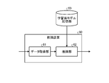
図1の説明に戻る。数値制御装置3は、指令生成部31と、制御特性設定部32と、記憶部33と、連成シミュレーション部34と、プロセス評価部35と、駆動制御部36とを有する。 Returning to the description of FIG. The numerical control device 3 has a command generation section 31 , a control characteristic setting section 32 , a storage section 33 , a coupled simulation section 34 , a process evaluation section 35 and a drive control section 36 .

数値制御プログラム4には、工作機械2の主軸および送り軸の運動を指示する複数の指令が含まれている。数値制御プログラム4に含まれる指令は、例えば、工具23が移動する経路を加工対象物Wに対する相対的な位置で指定する指令である。工具23の経路を指定する指令は、経路上の位置を指定する複数の位置指令を含む。また、数値制御プログラム4は、各位置指令が示す位置における、主軸の回転速度を示す主軸回転速度指令と、送り軸の移動速度を示す送り速度指令とをさらに含む。数値制御プログラム4は、数値制御装置3の外部から数値制御装置3に対して与えられてもよいし、数値制御装置3が内部に保持していてもよい。 Numerical control program 4 includes a plurality of commands for instructing movements of the main shaft and feed shaft of machine tool 2 . A command included in the numerical control program 4 is a command for designating a path along which the tool 23 moves by a position relative to the workpiece W, for example. The command specifying the path of the tool 23 includes a plurality of position commands specifying positions on the path. The numerical control program 4 further includes a spindle rotation speed command indicating the rotation speed of the spindle at the position indicated by each position command, and a feed speed command indicating the movement speed of the feed shaft. The numerical control program 4 may be given to the numerical controller 3 from the outside of the numerical controller 3 or may be held internally by the numerical controller 3 .

指令生成部31は、数値制御プログラム4に記述された指令を解析し、工作機械2を制御するために工作機械2に与えられる時々刻々の運転指令を生成する。指令生成部31は、数値制御プログラム4に記述された指令を工作機械2に実行させるための運転指令を生成する。指令生成部31は、生成した運転指令を連成シミュレーション部34および駆動制御部36のそれぞれに出力する。 The command generator 31 analyzes commands written in the numerical control program 4 and generates hourly operation commands given to the machine tool 2 to control the machine tool 2 . The command generation unit 31 generates an operation command for causing the machine tool 2 to execute a command written in the numerical control program 4 . The command generation unit 31 outputs the generated operation commands to the coupled simulation unit 34 and the drive control unit 36, respectively.

制御特性設定部32は、後述する駆動制御部36に備わる制御器の特性を表すパラメータである制御特性パラメータの組を生成する。制御特性パラメータの組のことをパラメータセットと称する。制御特性パラメータの詳細については、後述する。制御特性設定部32は、1または複数のパラメータセットを生成し、生成したパラメータセットを、連成シミュレーション部34および駆動制御部36のそれぞれに出力する。 The control characteristic setting unit 32 generates a set of control characteristic parameters, which are parameters representing the characteristics of controllers provided in the drive control unit 36, which will be described later. A set of control characteristic parameters is called a parameter set. Details of the control characteristic parameter will be described later. The control characteristic setting unit 32 generates one or more parameter sets and outputs the generated parameter sets to the coupled simulation unit 34 and the drive control unit 36, respectively.

記憶部33は、加工プロセスモデル331と、ダイナミクスモデル332と、主軸駆動制御モデル333と、送り駆動制御モデル334と、加工条件情報335とを記憶する。記憶部33は、記憶された情報を連成シミュレーション部34に出力することができる。加工条件情報335は、例えば、工具23の刃数、工具径およびねじれ角を含む工具形状情報と、その工具23を用いた場合の切り込み量とを含む。加工プロセスモデル331、ダイナミクスモデル332、主軸駆動制御モデル333および送り駆動制御モデル334の詳細については後述される。 The storage unit 33 stores a machining process model 331 , a dynamics model 332 , a spindle drive control model 333 , a feed drive control model 334 and machining condition information 335 . The storage unit 33 can output the stored information to the coupled simulation unit 34 . The machining condition information 335 includes, for example, tool shape information including the number of teeth of the tool 23, the tool diameter and the helix angle, and the depth of cut when the tool 23 is used. Details of the machining process model 331, the dynamics model 332, the spindle drive control model 333, and the feed drive control model 334 will be described later.

工作機械2が実行する切削加工は、加工プロセスMと機械ダイナミクスとが相互に影響する物理現象であるため、加工状態を管理または制御するためには、加工プロセスおよび機械ダイナミクスの両者を統合した解析を行うことが望ましい。ここで、加工プロセスとは、工具23の刃先が加工対象物Wに侵入することで切りくずを生成しながら加工面を形成するという一連の過程を表す。機械ダイナミクスとは、工作機械2の加工中に、内外の振動源によって振動を生じる構造物の動的な振る舞いを表す。ここでいう構造物は、工作機械2を構成する構造物に加えて、工具23および加工対象物Wを含むことができる。 Since the cutting process performed by the machine tool 2 is a physical phenomenon in which the machining process M and the machine dynamics affect each other, an integrated analysis of both the machining process and the machine dynamics is required in order to manage or control the machining state. It is desirable to Here, the machining process represents a series of processes in which the cutting edge of the tool 23 penetrates the object W to form a machined surface while generating chips. Machine dynamics represents the dynamic behavior of a structure that vibrates due to internal and external vibration sources during machining by the machine tool 2 . The structure here can include the tool 23 and the workpiece W in addition to the structure that constitutes the machine tool 2 .

駆動系20が数値制御装置3によって制御されることで、工具23が回転しながら加工対象物Wに対して予め定められた経路を通過するように運動する。工具23が加工対象物Wを切削している間、工具23と加工対象物Wとの間で発生する切削力Fcが構造物を通じて外乱力Fdとして送り駆動系22に伝達され、外乱トルクTdとして主軸駆動系21に伝達される。送り駆動系22に外乱力Fdが加わるため、送り駆動系22の位置は、工具23が加工対象物Wを切削していない場合の位置を基準としたときに、外乱力Fdの振幅および周波数に応じて変動する。同様に、主軸駆動系21に外乱トルクTdが加わると、主軸駆動系21の回転角度は、工具23が加工対象物Wを切削していない場合の回転角度に対して変動する。The drive system 20 is controlled by the numerical controller 3 so that the tool 23 rotates and moves along a predetermined path with respect to the workpiece W. As shown in FIG. While the tool 23 is cutting the workpiece W, the cutting force Fc generated between the tool 23 and the workpiece W is transmitted to the feed drive system 22 as a disturbance force Fd through the structure, and the disturbance torque It is transmitted to the spindle drive system 21 as Td . Since the disturbance force Fd is applied to the feed drive system 22, the position of the feed drive system 22 is determined by the amplitude of the disturbance force Fd and Varies according to frequency. Similarly, when a disturbance torque T d is applied to the spindle drive system 21, the rotation angle of the spindle drive system 21 changes relative to the rotation angle when the tool 23 is not cutting the workpiece W. FIG.

上記の関係について図を用いて説明する。図3は、図1に示す主軸駆動系21と機械ダイナミクスと加工プロセスMとの関係を示す図である。図4は、図3に示す物理量を工作機械2の物理構成と共に示す図である。数値制御装置3が運転指令を主軸駆動系21に与えると、主軸モータ211が主軸駆動機構212を駆動して、工具23を含めた工作機械2の構造物が回転し、加工対象物Wを加工する。ここで、主軸駆動系21が運転指令に基づいて主軸駆動系角度θ1に制御されると、実際の工具23の角度は、工具側機械ダイナミクスMD1の影響を受けて、工具角度θ2となる。工具23が加工対象物Wに侵入し、切りくずを生成しながら加工面を形成するという一連の加工プロセスMが実行される。このとき生じる切削トルクTcは、構造物を通じて工具側機械ダイナミクスMD1の影響を受けて外乱トルクTdとして主軸駆動系21に帰還する。工作機械2は、フィードバック信号を数値制御装置3に出力する。外乱トルクTdを受けた主軸駆動系21の状態が運転指令と異なる場合、数値制御装置3は、主軸駆動系21から伝達されるフィードバック信号に基づいて、運転指令を変化させる。The above relationship will be described with reference to the drawings. FIG. 3 is a diagram showing the relationship between the spindle drive system 21, machine dynamics, and machining process M shown in FIG. FIG. 4 is a diagram showing the physical quantities shown in FIG. 3 together with the physical configuration of the machine tool 2. As shown in FIG. When the numerical controller 3 gives an operation command to the spindle drive system 21, the spindle motor 211 drives the spindle drive mechanism 212, the structure of the machine tool 2 including the tool 23 rotates, and the workpiece W is machined. do. Here, when the spindle drive system 21 is controlled to the spindle drive system angle θ1 based on the operation command, the actual angle of the tool 23 becomes the tool angle θ2 under the influence of the tool-side mechanical dynamics MD1. A series of machining processes M are executed in which the tool 23 enters the workpiece W and forms a machined surface while generating chips. The cutting torque Tc generated at this time is fed back to the spindle drive system 21 as a disturbance torque Td through the structure under the influence of the tool-side mechanical dynamics MD1. Machine tool 2 outputs a feedback signal to numerical controller 3 . If the state of the spindle drive system 21 receiving the disturbance torque T d is different from the operation command, the numerical controller 3 changes the operation command based on the feedback signal transmitted from the spindle drive system 21 .

図5は、図1に示す送り駆動系22-2と機械ダイナミクスと加工プロセスMとの関係を示す図である。図6は、図5に示す物理量を工作機械2の物理構成と共に示す図である。数値制御装置3が運転指令を送り駆動系22-2に与えると、工具23と加工対象物Wとの相対運動によって加工対象物Wが加工される。このとき、送り駆動系22-2のサーボモータ221-2が運転指令に基づいて送り駆動機構222-2を駆動した結果、テーブル24に駆動系変位r1が生じる。加工対象物Wにおいて発生する実際の変位は、駆動系変位r1が生じたときの加工対象物側機械ダイナミクスMD2の影響を受けて、構造物変位r2となる。このとき生じる切削力Fcは、構造物を通じて外乱力Fdとして送り駆動系22-2に帰還する。外乱力Fdを受けた送り駆動系22-2の状態が運転指令と異なる場合、数値制御装置3は、送り駆動系22-2から伝達されるフィードバック信号に基づいて運転指令を変化させる。FIG. 5 is a diagram showing the relationship between the feed drive system 22-2, machine dynamics, and machining process M shown in FIG. FIG. 6 is a diagram showing the physical quantities shown in FIG. 5 together with the physical configuration of the machine tool 2. As shown in FIG. When the numerical controller 3 gives an operation command to the feed drive system 22-2, the workpiece W is machined by the relative motion between the tool 23 and the workpiece W. FIG. At this time, the servo motor 221-2 of the feed drive system 22-2 drives the feed drive mechanism 222-2 based on the operation command, and as a result, the table 24 undergoes drive system displacement r1. The actual displacement generated in the workpiece W becomes the structure displacement r2 under the influence of the workpiece-side mechanical dynamics MD2 when the drive system displacement r1 occurs. The cutting force F c generated at this time is fed back to the feed drive system 22-2 as a disturbance force F d through the structure. If the state of the feed drive system 22-2 receiving the disturbance force Fd is different from the operation command, the numerical controller 3 changes the run command based on the feedback signal transmitted from the feed drive system 22-2.

なお、上記では説明のため図3から図6を用いて、主軸駆動系21および送り駆動系22のそれぞれを分けて説明したが、加工中における変位と力の伝搬とは主軸駆動系21および送り駆動系22で同時になされる。 3 to 6, the spindle drive system 21 and the feed drive system 22 were separately described above for the purpose of explanation. The drive system 22 is performed simultaneously.

このように、切削加工では、加工プロセスMと機械ダイナミクスと駆動系20とが連成した系を成し、数値制御装置3は、駆動系20および機械ダイナミクスを介して加工プロセスMに関与する。また、工具23と加工対象物Wとの間の切削プロセスにおいて、切削力Fcが発生している加工点は、切りくずの生成と共に消失するため、センサを設置して切削力Fcを直接的に検出することはできない。したがって、工具23および加工対象物Wの運動を含めた切削加工を正確に評価するには、加工プロセスMおよび機械ダイナミクスに加えて、主軸駆動系21および送り駆動系22の動作を含めたシミュレーションを行う必要がある。Thus, in cutting, the machining process M, the mechanical dynamics, and the drive system 20 form a coupled system, and the numerical controller 3 participates in the machining process M via the drive system 20 and the mechanical dynamics. In addition, in the cutting process between the tool 23 and the workpiece W, the machining point where the cutting force Fc is generated disappears along with the generation of chips. cannot be detected. Therefore, in order to accurately evaluate the cutting including the motion of the tool 23 and the workpiece W, a simulation including the operation of the spindle drive system 21 and the feed drive system 22 is performed in addition to the machining process M and machine dynamics. There is a need to do.

続いて、記憶部33が記憶する加工プロセスモデル331、ダイナミクスモデル332、主軸駆動制御モデル333および送り駆動制御モデル334の具体例について説明する。これらのモデルは、後述の連成シミュレーション部34がシミュレーションを行う際に使用される。 Next, specific examples of the machining process model 331, the dynamics model 332, the spindle drive control model 333, and the feed drive control model 334 stored in the storage unit 33 will be described. These models are used when the joint simulation unit 34, which will be described later, performs a simulation.

加工プロセスモデル331は、工具23と加工対象物Wとの間の加工特性を表す。より具体的には、加工プロセスモデル331は、工具23および加工対象物Wの位置関係に応じて発生する切削力Fcを表現する数理モデルである。以下に示す数式(1)は、工具23の刃先が加工対象物Wに接触している間の切削力Fcを表現する数式の一例である。数式(1)は、比切削抵抗Kc、エッジフォース係数Ke、工具23の断面の微小厚さΔa、加工対象物Wの切り取り厚さh、工具23の回転角度φおよび時刻tを用いて工具23の断面あたりの微小切削力ΔFcを表している。工具23の切り込みによって発生する合計の切削力Fcは、数式(1)に示される微小切削力ΔFcを工具23の軸方向に足し合わせることで算出することができる。加工対象物Wの切り取り厚さhは、工具23の半径方向における前加工面と今回加工面との間の距離である。数式(1)は、切り取り厚さhに比例する力と、エッジフォースと呼ばれる一定量の力との和によって切削力Fcを算出することができることを表している。The machining process model 331 represents machining characteristics between the tool 23 and the workpiece W. FIG. More specifically, the machining process model 331 is a mathematical model that expresses the cutting force Fc generated according to the positional relationship between the tool 23 and the workpiece W. Formula (1) shown below is an example of a formula that expresses the cutting force Fc while the cutting edge of the tool 23 is in contact with the workpiece W. Formula (1) is calculated using the specific cutting force K c , the edge force coefficient K e , the minute thickness Δa of the cross section of the tool 23, the cut thickness h of the workpiece W, the rotation angle φ of the tool 23, and the time t. It represents the minute cutting force ΔF c per cross section of the tool 23 . The total cutting force Fc generated by the cutting of the tool 23 can be calculated by summing the minute cutting force ΔFc shown in Equation (1) in the axial direction of the tool 23. The cutting thickness h of the workpiece W is the distance between the previously machined surface and the current machined surface in the radial direction of the tool 23 . Equation (1) expresses that the cutting force Fc can be calculated from the sum of the force proportional to the cut thickness h and a constant amount of force called edge force.

Figure 0007166488000001

切り取り厚さhは、以下に示す数式(2)によって表現することができる。切り取り厚さhは、1刃あたりの工具23の送り量cによって決定されるノミナルな切り取り厚さを表す成分と、工具23および加工対象物Wの相対的な振動を表す成分と、工具23が複数の刃先を備える場合に各刃先の回転半径の差異による切り取り厚さの増減を表す成分との和で表される。工具23および加工対象物Wの相対的な振動を表す成分は、今回加工面を切り取る瞬間の工具23および加工対象物Wの間の相対変位の工具23の半径方向成分urと、前加工面に転写された工具23および加工対象物Wの間の相対変位の工具半径方向成分wrとの差異で表される。各刃先の回転半径の差異による切り取り厚さの増減を表す成分は、工具23の刃先の回転半径補正量Δeで表される。The cut thickness h can be expressed by Equation (2) below. The cut thickness h is composed of a component representing the nominal cut thickness determined by the feed amount c of the tool 23 per blade, a component representing the relative vibration of the tool 23 and the workpiece W, and a component representing the relative vibration of the tool 23. It is represented by the sum of the component representing the increase or decrease in the cut thickness due to the difference in the radius of rotation of each cutting edge when a plurality of cutting edges are provided. The components representing the relative vibration of the tool 23 and the workpiece W are the radial direction component u r of the tool 23 of the relative displacement between the tool 23 and the workpiece W at the moment when the machining surface is cut this time, and the previous machining surface and the tool radial direction component w r of the relative displacement between the tool 23 and the workpiece W transferred to . The component representing the increase or decrease in the cut thickness due to the difference in the radius of gyration of each cutting edge is represented by the radius of gyration correction amount Δe of the cutting edge of the tool 23 .

Figure 0007166488000002

数式(1)は加工プロセスモデル331の一例であり、加工プロセスモデル331は、上記のものに限定されない。例えば、工具23の形状と加工対象物Wの形状とを表現したボクセルを用いて切削力Fcを算出するモデルであってもよい。Formula (1) is an example of the machining process model 331, and the machining process model 331 is not limited to the above. For example, a model that calculates the cutting force Fc using voxels expressing the shape of the tool 23 and the shape of the workpiece W may be used.

ダイナミクスモデル332は、工作機械2の動作中に振動を生じる構造物の動特性を表す。具体的には、ダイナミクスモデル332は、構造物に動的な力が加わったときにその構造物が動的に変位することを表す数理モデルである。例えば、駆動系20に接続された加工対象物Wに対して切削力Fcがかかったときの加工対象物Wの挙動は、以下に示す数式(3)で表すことができる。The dynamics model 332 represents the dynamic properties of structures that vibrate during operation of the machine tool 2 . Specifically, the dynamics model 332 is a mathematical model representing dynamic displacement of the structure when dynamic force is applied to the structure. For example, the behavior of the workpiece W connected to the drive system 20 when the cutting force Fc is applied to the workpiece W can be expressed by the following formula (3).

Figure 0007166488000003

数式(3)は、加工対象物Wの振動を表現する数式の一例である。工具23および加工対象物Wの間で発生した切削力Fcは、工具23および加工対象物Wの間の相対変位uと、駆動系20の相対変位vと、加工対象物Wの等価質量mと、加工対象物Wの等価粘性係数Cと、加工対象物Wの等価ばね定数Kとを用いて表される。数式(3)は、切削力Fcが加工対象物Wを通じて駆動系20に外乱力Fdとして伝達する機械ダイナミクスを表す。Formula (3) is an example of a formula that expresses the vibration of the object W to be processed. The cutting force F c generated between the tool 23 and the workpiece W is the relative displacement u between the tool 23 and the workpiece W, the relative displacement v of the drive system 20, and the equivalent mass m of the workpiece W. , the equivalent viscosity coefficient C of the workpiece W, and the equivalent spring constant K of the workpiece W. Equation (3) expresses the mechanical dynamics in which the cutting force Fc is transmitted through the workpiece W to the drive system 20 as a disturbance force Fd .

なお、ダイナミクスモデル332は、数式(3)に限定されない。例えば、加工対象物Wの形状をボクセルで表現し、FEM(Finite Element Method)解析を用いて構造物が振動するときの変位を算出するモデルであってもよい。なお、ここで説明したダイナミクスモデル332は加工対象物Wの振動のみを表現しているが、ダイナミクスモデル332は、加工対象物Wの代わりに工具23、またはその他の構造物の振動を表現してもよい。或いは、ダイナミクスモデル332は、工具23および加工対象物Wの両方の振動を表現してもよい。 Note that the dynamics model 332 is not limited to Equation (3). For example, it may be a model that expresses the shape of the object W to be processed by voxels and calculates the displacement when the structure vibrates using FEM (Finite Element Method) analysis. Although the dynamics model 332 described here expresses only the vibration of the workpiece W, the dynamics model 332 expresses the vibration of the tool 23 or other structures instead of the workpiece W. good too. Alternatively, the dynamics model 332 may represent vibrations of both the tool 23 and the workpiece W.

主軸駆動制御モデル333は、工作機械2が有する主軸駆動系21と、数値制御装置3の駆動制御部36内に存在し、主軸駆動系21を制御する制御器である主軸駆動制御器とを表す数理モデルである。図7は、図1の主軸駆動制御モデル333の一例を説明するための図である。主軸駆動制御モデル333は、主軸回転角度指令が与えられたときに、切削トルクTcに起因する外乱トルクTdが主軸駆動系21に伝達される状況下において、主軸駆動制御器が有する位置制御器および速度制御器によって、主軸駆動系21の位置および速度が制御される場合の数理モデルである。この数理モデルは、制御器に主軸回転角度指令θrを入力すると、主軸実回転角度θを出力する。ここで、Kpp1,Kvp1,Kvi1は制御ゲインであり、それぞれ位置制御のための比例ゲインKpp1、速度制御のための比例ゲインKvp1、速度制御のための積分ゲインKvi1である。P1(s)は主軸駆動系21全体のトルクから位置の伝達関数であり、sは複素数である。P1(s)は既知のシステム同定手法によって主軸駆動系21の実際の応答から同定することができる。なお、ここでは主軸駆動系21を1慣性系としてモデル化しているが、主軸駆動系21は多慣性系としてモデル化してもよい。また、主軸駆動制御器にフィードフォワード制御器を追加してもよい。また制御器は、回転角度または回転角度に応じた摩擦などの誤差要因を補正する補正量を加算する構造であってもよい。The spindle drive control model 333 represents the spindle drive system 21 of the machine tool 2 and a spindle drive controller that exists in the drive control unit 36 of the numerical controller 3 and is a controller that controls the spindle drive system 21. It is a mathematical model. FIG. 7 is a diagram for explaining an example of the spindle drive control model 333 of FIG. The spindle drive control model 333 is based on the position control of the spindle drive controller under the condition that the disturbance torque Td caused by the cutting torque Tc is transmitted to the spindle drive system 21 when the spindle rotation angle command is given. It is a mathematical model in which the position and speed of the spindle drive system 21 are controlled by a controller and a speed controller. This mathematical model outputs the actual spindle rotation angle θ when a spindle rotation angle command θ r is input to the controller. Here, K pp1 , K vp1 , and K vi1 are control gains, which are proportional gain K pp1 for position control, proportional gain K vp1 for velocity control, and integral gain K vi1 for velocity control, respectively. P 1 (s) is the torque-to-position transfer function of the entire spindle drive system 21, and s is a complex number. P 1 (s) can be identified from the actual response of the spindle drive system 21 by known system identification techniques. Although the spindle drive system 21 is modeled as a one-inertia system here, the spindle drive system 21 may be modeled as a multi-inertia system. Also, a feedforward controller may be added to the spindle drive controller. The controller may also have a structure that adds a correction amount for correcting an error factor such as a rotation angle or friction according to the rotation angle.

送り駆動制御モデル334は、工作機械2が有する送り駆動系22と、数値制御装置3の駆動制御部36内に存在し、送り駆動系22を制御する制御器である送り駆動制御器とを表す数理モデルである。図8は、図1の送り駆動制御モデル334の一例を説明するための図である。送り駆動制御モデル334は、送り駆動系位置指令が与えられたときに、切削力Fcに起因する外乱力Fが送り駆動系22に伝達される状況下において、送り駆動制御器が有する位置制御器および速度制御器によって、送り駆動系22の位置および速度が制御される場合の数理モデルである。この数理モデルは、送り駆動系位置指令xrを入力すると、送り駆動系実位置xを出力する。ここで、Kpp2,Kvp2,Kvi2は制御ゲインであり、それぞれ位置制御のための比例ゲインKpp2、速度制御のための比例ゲインKvp2、速度制御のための積分ゲインKvi2である。P2(s)は送り駆動系22全体の力から位置の伝達関数であり、sは複素数である。P2(s)は既知のシステム同定手法によって送り駆動系22の実際の応答から同定することができる。なお、ここでは送り駆動系22を1慣性系としてモデル化しているが、送り駆動系22は多慣性系としてモデル化してもよい。また、送り駆動制御器にフィードフォワード制御器を追加してもよい。また制御器は、位置または速度に応じた摩擦などの誤差要因を補正する補正量を加算する構造であってもよい。この補正量は、例えば、位置または速度に係数パラメータを乗じた値である。また制御器は、周波数パラメータによって特定の帯域の振動を通過または除外するための信号処理フィルタを有する構造であってもよい。The feed drive control model 334 represents the feed drive system 22 of the machine tool 2 and the feed drive controller that exists in the drive control section 36 of the numerical controller 3 and is a controller that controls the feed drive system 22. It is a mathematical model. FIG. 8 is a diagram for explaining an example of the feed drive control model 334 of FIG. The feed drive control model 334 assumes that the position of the feed drive controller under the condition that the disturbance force Fd caused by the cutting force Fc is transmitted to the feed drive system 22 when the feed drive system position command is given. A mathematical model in which the position and speed of the feed drive system 22 are controlled by a controller and a speed controller. This mathematical model outputs a feed drive system actual position x when a feed drive system position command x r is input. Here, K pp2 , K vp2 , and K vi2 are control gains, which are proportional gain K pp2 for position control, proportional gain K vp2 for velocity control, and integral gain K vi2 for velocity control, respectively. P 2 (s) is the force-to-position transfer function of the entire feed drive system 22, where s is a complex number. P 2 (s) can be identified from the actual response of the feed drive system 22 by known system identification techniques. Although the feed drive system 22 is modeled as a one-inertia system here, the feed drive system 22 may be modeled as a multi-inertia system. Also, a feedforward controller may be added to the feed drive controller. The controller may also have a structure that adds a correction amount for correcting an error factor such as friction according to position or speed. This correction amount is, for example, a value obtained by multiplying the position or velocity by a coefficient parameter. The controller may also be a structure having a signal processing filter for passing or filtering out certain bands of vibration depending on the frequency parameter.

ここで、制御特性パラメータについて説明する。制御特性パラメータとは、駆動系20を制御する制御器の制御特性を表すパラメータである。図7および図8においては、制御特性パラメータは、制御器の制御ゲインである。なお、制御特性パラメータは、制御ゲインに限定されず、制御器が誤差要因を補正する補正量を加算する構造である場合、補正量を決定する係数パラメータが制御特性パラメータに相当する。また、制御器が特定の帯域の振動を通過または除外するための信号処理フィルタを有する構造である場合、信号処理フィルタの帯域を指定する周波数パラメータが制御特性パラメータに相当する。なお、制御特性パラメータは、一定値であるとは限らず、経時変化する値であってもよい。 Here, control characteristic parameters will be described. A control characteristic parameter is a parameter representing the control characteristic of a controller that controls the drive system 20 . 7 and 8, the control characteristic parameter is the control gain of the controller. Note that the control characteristic parameter is not limited to the control gain, and if the controller has a structure that adds a correction amount for correcting the error factor, the coefficient parameter that determines the correction amount corresponds to the control characteristic parameter. Also, if the controller has a structure having a signal processing filter for passing or excluding vibrations in a specific band, the frequency parameter specifying the band of the signal processing filter corresponds to the control characteristic parameter. Note that the control characteristic parameter is not limited to a constant value, and may be a value that changes with time.

制御特性パラメータの値が異なると、駆動系20は異なる周波数特性を示す。具体的には、駆動系20において、制御特性パラメータの値によって、運転指令に対する追従性や外乱に対する抑制性が変化する。続いて制御特性パラメータと駆動系20の周波数特性の対応関係について説明する。図9は、図1に示す駆動系20に運転指令が入力されたときの応答を周波数毎に表したゲイン曲線を示す図である。図9には、第1組、第2組および第3組と称される3組のパラメータセットに対するゲイン応答が表されている。パラメータセット毎にゲイン応答が異なり、第1組、第2組および第3組のそれぞれのゲイン応答のピークとなる周波数は互いに異なる。 The drive system 20 exhibits different frequency characteristics when the values of the control characteristic parameters are different. Specifically, in the drive system 20, the followability to the operation command and the suppression ability to the disturbance change depending on the value of the control characteristic parameter. Next, the correspondence relationship between the control characteristic parameter and the frequency characteristic of the drive system 20 will be described. FIG. 9 is a diagram showing a gain curve representing the response for each frequency when an operation command is input to the drive system 20 shown in FIG. FIG. 9 depicts the gain response for three sets of parameters, referred to as the first, second and third sets. Each parameter set has a different gain response, and the peak frequencies of the gain responses of the first, second and third sets are different from each other.

図10は、図1に示す駆動系20に運転指令が入力されたときの応答を周波数毎に表した位相曲線を示す図である。図10には、図9と同様に、第1組、第2組および第3組と称される3種類のパラメータセットに対する位相応答が表されている。パラメータセット毎に位相応答が異なり、第1組、第2組および第3組のそれぞれの位相応答において、位相が変化する周波数はそれぞれ異なる。図9および図10に示したように、制御特性パラメータの値が異なると、駆動系20は異なる周波数特性を示す。 FIG. 10 is a diagram showing a phase curve representing the response for each frequency when an operation command is input to the drive system 20 shown in FIG. Similar to FIG. 9, FIG. 10 shows phase responses for three different parameter sets, referred to as the first set, the second set and the third set. Each parameter set has a different phase response, and the frequency at which the phase changes in each of the first, second, and third sets of phase responses is different. As shown in FIGS. 9 and 10, the drive system 20 exhibits different frequency characteristics when the control characteristic parameter values are different.

ここで、制御特性設定部32が生成するパラメータセットについて詳述する。制御特性設定部32は、上述の通り、1つ以上のパラメータセットを生成する。制御器は、主軸駆動系21および送り駆動系22の数だけ存在する。パラメータセットは、工作機械2に備わる主軸駆動系21および送り駆動系22のそれぞれに対応する制御器の特性を決定づける制御特性パラメータの集合である。各パラメータセットは、1つの制御器について1つの種類の制御特性パラメータを含んでもよいし、1つの制御器について複数の種類の制御特性パラメータを含んでもよい。例えば、工作機械2が1つの主軸駆動系21と2つの送り駆動系22とを有する場合、数値制御装置3は、3つの制御器を有する。この場合、1つのパラメータセットは、3つの制御器のそれぞれに対応して1種類、3つの制御特性パラメータの値を含んでもよいし、制御器毎に複数の種類の制御特性パラメータの値を含んでもよい。上記の図7および図8に示す例では、工作機械2が1つの主軸駆動系21と2つの送り駆動系22とを有する場合、パラメータセットは、主軸駆動制御器について、位置制御のための比例ゲインKpp1、速度制御のための比例ゲインKvp1、および速度制御のための積分ゲインKvi1の値を1つずつ含み、送り駆動制御器について、位置制御のための比例ゲインKpp2、速度制御のための比例ゲインKvp2、および速度制御のための積分ゲインKvi2の値を2つずつ含むことができる。なお、図7および図8には、比例ゲインおよび積分ゲインを含む制御器を示しているが、微分ゲインを含む制御器が用いられてもよい。Here, the parameter set generated by the control characteristic setting unit 32 will be described in detail. The control characteristic setting unit 32 generates one or more parameter sets as described above. There are as many controllers as there are spindle drive systems 21 and feed drive systems 22 . A parameter set is a set of control characteristic parameters that determine the characteristics of controllers corresponding to the spindle drive system 21 and the feed drive system 22 provided in the machine tool 2 . Each parameter set may include one type of control characteristic parameter for one controller, or may include a plurality of types of control characteristic parameter for one controller. For example, if the machine tool 2 has one spindle drive system 21 and two feed drive systems 22, the numerical controller 3 has three controllers. In this case, one parameter set may include one type and three control characteristic parameter values corresponding to each of the three controllers, or may include a plurality of types of control characteristic parameter values for each controller. It's okay. In the example shown in FIGS. 7 and 8 above, when the machine tool 2 has one spindle drive system 21 and two feed drive systems 22, the parameter set is proportional to the position control for the spindle drive controller. One gain K pp1 , one proportional gain K vp1 for velocity control, and one integral gain K vi1 for velocity control. , and integral gain K vi2 for velocity control. Although FIGS. 7 and 8 show controllers including proportional gains and integral gains, controllers including differential gains may also be used.

制御特性設定部32は、複数の制御器のそれぞれに対して同じ値の制御特性パラメータを設定することができる。なお、ここで制御特性パラメータの値が同じとは、複数の制御器の間で、同じ種類の制御特性パラメータの値が同一であることを指す。制御特性設定部32は、複数の制御器のそれぞれに対して同じ種類の制御特性パラメータを設定可能である場合、複数の制御器のそれぞれに設定する同じ種類の制御特性パラメータの値を同一にすることができる。例えば、制御特性設定部32は、送り駆動系22-1を制御するための送り駆動制御器と送り駆動系22-2を制御するための送り駆動制御器との間で、比例ゲインKpp2、比例ゲインKvp2、および積分ゲインKvi2のそれぞれの値を同一にすることができる。このように、複数の制御器のそれぞれが同じ値の制御特性パラメータで動作する場合、複数の制御器が互いに等しい周波数特性を示すようになる。したがって、駆動系20と構造物とを含めた系は、加工対象物Wに対する工具23の相対的な送り方向によらず同じ周波数特性となる。The control characteristic setting unit 32 can set the same value of the control characteristic parameter for each of the plurality of controllers. Here, the same value of the control characteristic parameter means that the values of the same type of control characteristic parameter are the same among the plurality of controllers. When the same type of control characteristic parameter can be set for each of the plurality of controllers, the control characteristic setting unit 32 makes the values of the same type of control characteristic parameter to be set for each of the plurality of controllers the same. be able to. For example, the control characteristic setting unit 32 sets proportional gains K pp2 , The values of proportional gain K vp2 and integral gain K vi2 can be the same. In this way, when each of the plurality of controllers operates with the same value of the control characteristic parameter, the plurality of controllers exhibit the same frequency characteristics. Therefore, the system including the drive system 20 and the structure has the same frequency characteristics regardless of the relative feed direction of the tool 23 with respect to the object W to be processed.

或いは、制御特性設定部32は、複数の制御器のそれぞれに対して異なる値の制御特性パラメータを設定することができる。なお、ここで制御特性パラメータの値が異なるとは、複数の制御器の間で、同じ種類の制御特性パラメータの値が異なることを指す。1つの制御器について複数の種類の制御特性パラメータが設定可能である場合、制御特性設定部32は、複数の種類の制御特性パラメータの少なくとも一部に対して異なる値を設定することができる。このように、複数の制御器のそれぞれが異なる値の制御特性パラメータで動作する場合、複数の制御器がそれぞれ異なる周波数特性を示すようになる。したがって、駆動系20と構造物とを含めた系は、加工対象物Wに対する工具23の相対的な送り方向によって異なる周波数特性となる。 Alternatively, the control characteristic setting unit 32 can set control characteristic parameters with different values for each of the plurality of controllers. Here, the different values of the control characteristic parameters refer to different values of the same type of control characteristic parameters among the plurality of controllers. When multiple types of control characteristic parameters can be set for one controller, the control characteristic setting unit 32 can set different values for at least some of the multiple types of control characteristic parameters. In this way, when each of the plurality of controllers operates with control characteristic parameters having different values, the plurality of controllers exhibit different frequency characteristics. Therefore, the system including the drive system 20 and the structure has different frequency characteristics depending on the relative feed direction of the tool 23 with respect to the workpiece W. FIG.

また、制御特性設定部32は、制御器に対応する送り駆動系22の運動方向毎に異なる値の制御特性パラメータを設定してもよい。ここでは、図2に示すように1つの主軸駆動系21と、1つの主軸駆動系21に対応する複数の送り駆動系22とを備える工作機械2について説明したが、工作機械2が複数の主軸駆動系21を有する場合、工作機械2は、運動方向が同一である複数の送り駆動系22を備える場合もある。運動方向が同一である複数の送り駆動系22を備える工作機械2については、制御特性設定部32は、運動方向が同一である複数の送り駆動系22には同一の値の制御特性パラメータを設定し、運動方向が互いに異なる複数の送り駆動系22には、異なる値の制御特性パラメータを設定することができる。この場合、工作機械2の動作中に振動を生じる構造物と送り駆動系22とを合成した系のゲイン応答または位相応答は、送り駆動系22の運動方向毎に互いに異なる。 Further, the control characteristic setting section 32 may set a control characteristic parameter having a different value for each movement direction of the feed drive system 22 corresponding to the controller. Here, as shown in FIG. 2, the machine tool 2 having one spindle drive system 21 and a plurality of feed drive systems 22 corresponding to one spindle drive system 21 has been described. When having a drive system 21, the machine tool 2 may also have a plurality of feed drive systems 22 with the same direction of motion. For a machine tool 2 having a plurality of feed drive systems 22 with the same motion direction, the control characteristic setting unit 32 sets control characteristic parameters of the same value for the plurality of feed drive systems 22 with the same motion direction. However, different values of the control characteristic parameters can be set for the plurality of feed drive systems 22 that move in different directions. In this case, the gain response or phase response of the combined system of the structure that vibrates during operation of the machine tool 2 and the feed drive system 22 differs for each movement direction of the feed drive system 22 .

さらに別の例として、制御特性設定部32は、加工対象物Wに対する工具23の相対的な軌跡に応じて、複数の制御器のそれぞれに対する制御特性パラメータを時々刻々経時的に変化させることができる。図11は、図1に示す制御特性設定部32が生成するパラメータセットの一例について説明するための図である。図11には、工作機械2の動作中に工具23が加工対象物Wに対して描く相対軌跡Lが示されている。相対軌跡L上の各位置Pにおける送り方向R1と、送り方向R1の法線方向R2とは、それぞれの位置Pにおいて変化する。例えば、相対軌跡Lが曲線状であれば、位置P-1における送り方向R1-1と位置P-2における送り方向R1-2とは異なり、位置P-1における法線方向R2-1と位置P-2における法線方向R2-2とは異なる。ここで、法線方向R2とは、工具23のある位置Pにおける相対軌跡Lの法線方向を表し、その位置Pにおける送り方向R1に垂直である。制御特性設定部32は、工具23の送り方向R1と法線方向R2とで、周波数特性が互いに異なるように、各時点の制御特性パラメータを変化させる。この場合、工作機械2の動作中に振動を生じる構造物と送り駆動系22とを合成した系のゲイン応答または位相応答は、加工対象物Wに対する工具23の相対的な送り方向R1と、法線方向R2とで互いに異なる。 As yet another example, the control characteristic setting unit 32 can change the control characteristic parameter for each of the plurality of controllers over time according to the relative trajectory of the tool 23 with respect to the workpiece W. . FIG. 11 is a diagram for explaining an example of a parameter set generated by control characteristic setting section 32 shown in FIG. FIG. 11 shows the relative trajectory L drawn by the tool 23 with respect to the workpiece W during operation of the machine tool 2 . The feeding direction R1 at each position P on the relative trajectory L and the normal direction R2 of the feeding direction R1 change at each position P. For example, if the relative trajectory L is curved, the normal direction R2-1 at the position P-1 and the position It is different from the normal direction R2-2 at P-2. Here, the normal direction R2 represents the normal direction of the relative trajectory L at the position P of the tool 23, and is perpendicular to the feed direction R1 at that position P. The control characteristic setting unit 32 changes the control characteristic parameter at each time so that the frequency characteristics are different between the feed direction R1 and the normal direction R2 of the tool 23 . In this case, the gain response or phase response of the system obtained by synthesizing the structure that causes vibration during operation of the machine tool 2 and the feed drive system 22 is the relative feed direction R1 of the tool 23 with respect to the workpiece W and the law They are different from each other in the line direction R2.

ここで、機械ダイナミクスと連成した加工プロセスMのメカニズムについて説明する。図12は、図1に示す工作機械2の動作中における工具23の状態と加工対象物Wの加工面の状態との関係の第1の例を示す図である。図12には、加工対象物Wの第1の加工面a1と、第1の加工面a1を切削加工する際の工具23の移動軌跡b1とが示されている。移動軌跡b1は、切削加工中の工具23の振動を表している。第1の加工面a1を切削加工したときの切りくずの厚さv1は、第1の加工面a1と工具23の移動軌跡b1との差分で表される。 Here, the mechanism of machining process M coupled with machine dynamics will be described. FIG. 12 is a diagram showing a first example of the relationship between the state of the tool 23 and the state of the machined surface of the workpiece W during operation of the machine tool 2 shown in FIG. FIG. 12 shows the first processing surface a1 of the workpiece W and the movement locus b1 of the tool 23 when cutting the first processing surface a1. A movement locus b1 represents the vibration of the tool 23 during cutting. A thickness v1 of chips obtained by cutting the first machined surface a1 is represented by a difference between the first machined surface a1 and the movement locus b1 of the tool 23 .

続いて、第2の加工面a2は、工具23によって第1の加工面a1の表面が除去された後の加工対象物Wの表面であり、第1の加工面a1を切削したときの工具23の移動軌跡b1に応じた形状となる。第1の例では、工作機械2の動作中に工具23が振動しているため、第2の加工面a2には、第1の加工面a1を切削加工したときの工具23の振動が転写される。また、この第2の加工面a2を切削加工するときの切りくずの厚さv2は、第2の加工面a2と工具23の移動軌跡b2との差分で表される。このため、第2の加工面a2を切削加工するときの切りくずの厚さv2は、第2の加工面a2の形状と、第2の加工面a2を切削加工するときの工具23の振動とによって異なる。したがって、加工対象物Wの切りくずの厚さは、各加工面を切削加工するときの工具23の振動によって変化する。 Subsequently, the second processing surface a2 is the surface of the workpiece W after the surface of the first processing surface a1 has been removed by the tool 23, and the tool 23 when cutting the first processing surface a1. becomes a shape corresponding to the movement locus b1 of . In the first example, since the tool 23 vibrates during operation of the machine tool 2, the vibration of the tool 23 when cutting the first machining surface a1 is transferred to the second machining surface a2. be. Also, the thickness v2 of chips when cutting the second machining surface a2 is represented by the difference between the second machining surface a2 and the movement locus b2 of the tool 23 . Therefore, the thickness v2 of chips when cutting the second processing surface a2 depends on the shape of the second processing surface a2 and the vibration of the tool 23 when cutting the second processing surface a2. Varies depending on Therefore, the thickness of the chips of the workpiece W changes due to the vibration of the tool 23 when cutting each surface to be machined.

図12に示す第1の例において、第1の加工面a1を加工するときの切りくずの厚さv1と、第2の加工面a2を加工するときの切りくずの厚さv2とは同程度となっている。このような加工プロセスMは安定しており、振動が発散する可能性は低い。 In the first example shown in FIG. 12, the chip thickness v1 when machining the first machining surface a1 and the chip thickness v2 when machining the second machining surface a2 are approximately the same. It has become. Such a machining process M is stable and less likely to emanate vibrations.

図13は、図1に示す工作機械2の動作中における工具23の状態と加工対象物Wの加工面の状態との関係の第2の例を示す図である。図13には、加工対象物Wの第3の加工面a3と、第3の加工面a3を切削加工する際の工具23の移動軌跡b3とが示されている。第3の加工面a3を切削加工したときの切りくずの厚さv3は、第3の加工面a3と工具23の移動軌跡b3との差分で表される。 FIG. 13 is a diagram showing a second example of the relationship between the state of the tool 23 and the state of the machined surface of the workpiece W during operation of the machine tool 2 shown in FIG. FIG. 13 shows the third processing surface a3 of the workpiece W and the movement locus b3 of the tool 23 when cutting the third processing surface a3. A thickness v3 of chips when the third machined surface a3 is cut is represented by a difference between the third machined surface a3 and the movement locus b3 of the tool 23 .

続いて、第4の加工面a4は、工具23によって第3の加工面a3の表面が除去された後の加工対象物Wの表面であり、第3の加工面a3を切削加工したときの工具23の移動軌跡b3に応じた形状となる。第2の例では、工作機械2の動作中に工具23が第1の例よりも大きな振幅で振動しており、第4の加工面a4には、第3の加工面a3を切削加工したときの工具23の振動が転写される。また、この第4の加工面a4を切削加工するときの切りくずの厚さv4は、第4の加工面a4と工具23の移動軌跡b4との差分で表される。 Subsequently, the fourth machined surface a4 is the surface of the workpiece W after the surface of the third machined surface a3 has been removed by the tool 23, and the tool when cutting the third machined surface a3 23 becomes a shape corresponding to the movement locus b3. In the second example, the tool 23 vibrates with a larger amplitude than in the first example while the machine tool 2 is in operation, and the fourth machined surface a4 has an , the vibration of the tool 23 is transferred. Also, the thickness v4 of chips when cutting the fourth machined surface a4 is represented by the difference between the fourth machined surface a4 and the movement locus b4 of the tool 23 .

工具23の振動の振幅は、図12に示す第1の例よりも図13に示す第2の例の方が大きい。このため、第3の加工面a3を加工するときの切りくずの厚さv3と、第4の加工面a4を加工するときの切りくずの厚さv4との差は、第1の例における厚さv1と厚さv2との差よりも大きくなっている。このような加工プロセスMは不安定であり、ビビり振動を引き起こす可能性が高い。 The amplitude of vibration of the tool 23 is larger in the second example shown in FIG. 13 than in the first example shown in FIG. Therefore, the difference between the chip thickness v3 when machining the third machining surface a3 and the chip thickness v4 when machining the fourth machining surface a4 is the same as the thickness in the first example. It is larger than the difference between the thickness v1 and the thickness v2. Such a machining process M is unstable and likely to cause chatter vibration.

図14は、図1に示す工作機械2の動作中における工具23の状態と加工対象物Wの加工面の状態との関係の第3の例を示す図である。図14には、加工対象物Wの第5の加工面a5と、第5の加工面a5を切削加工する際の工具23の移動軌跡b5とが示されている。第5の加工面a5を切削加工したときの切りくずの厚さv5は、第5の加工面a5と工具23の移動軌跡b5との差分で表される。 FIG. 14 is a diagram showing a third example of the relationship between the state of the tool 23 and the state of the machined surface of the workpiece W during operation of the machine tool 2 shown in FIG. FIG. 14 shows the fifth processing surface a5 of the workpiece W and the movement locus b5 of the tool 23 when cutting the fifth processing surface a5. A thickness v5 of chips obtained by cutting the fifth machining surface a5 is represented by a difference between the fifth machining surface a5 and the movement locus b5 of the tool 23 .

続いて、第6の加工面a6は、工具23によって第5の加工面a5の表面が除去された後の加工対象物Wの表面であり、第5の加工面a5を切削加工したときの工具23の移動軌跡b5に応じた形状となる。第3の例では、工作機械2の動作中に工具23が振動しており、第6の加工面a6には、第5の加工面a5を切削加工したときの工具23の振動が転写される。また、この第6の加工面a6を切削加工するときの切りくずの厚さv6は、第6の加工面a6と工具23の移動軌跡b6との差分で表される。ここで、第5の加工面a5を切削加工するときの工具23の振動の位相と、第6の加工面a6を切削加工するときの工具23の振動の位相との差は、第1の例において、第1の加工面a1を切削加工するときの工具23の振動の位相と、第2の加工面a2を切削加工するときの工具23の振動の位相との差よりも大きくなっており、位相がほぼ逆転している。このため、第5の加工面a5を切削加工するときの切りくずの厚さv5と第6の加工面a6を切削加工するときの切りくずの厚さv6との差が、第1の例における厚さv1と厚さv2との差よりも大きくなっている。このような加工プロセスMは、第2の例と同様に不安定であり、びびり振動を引き起こす可能性が高い。 Subsequently, the sixth machined surface a6 is the surface of the workpiece W after the surface of the fifth machined surface a5 is removed by the tool 23, and the tool when cutting the fifth machined surface a5 23 becomes a shape corresponding to the movement locus b5. In the third example, the tool 23 vibrates during operation of the machine tool 2, and the vibration of the tool 23 when cutting the fifth machining surface a5 is transferred to the sixth machining surface a6. . Also, the thickness v6 of chips when cutting the sixth machined surface a6 is represented by the difference between the sixth machined surface a6 and the movement locus b6 of the tool 23 . Here, the difference between the phase of vibration of the tool 23 when cutting the fifth machining surface a5 and the phase of vibration of the tool 23 when cutting the sixth machining surface a6 is the first example. , the difference between the phase of vibration of the tool 23 when cutting the first machining surface a1 and the phase of vibration of the tool 23 when cutting the second machining surface a2 is larger than The phases are almost reversed. Therefore, the difference between the chip thickness v5 when cutting the fifth machined surface a5 and the chip thickness v6 when cutting the sixth machined surface a6 is the same as in the first example. It is larger than the difference between the thickness v1 and the thickness v2. Such a machining process M is unstable as in the second example, and is highly likely to cause chatter vibration.

図12から図14を用いて説明したように、工具23の振動状態によって、切りくずの厚さは変化する。特に、工具23の振動の振幅および位相が加工プロセスMの安定性に与える影響が大きい。したがって、工具23の振動の振幅および位相を適切に制御することで、加工プロセスMを安定化させることが可能である。 As described with reference to FIGS. 12 to 14, the thickness of the chips changes depending on the vibrating state of the tool 23. FIG. In particular, the amplitude and phase of vibration of the tool 23 greatly affect the stability of the machining process M. Therefore, it is possible to stabilize the machining process M by appropriately controlling the amplitude and phase of vibration of the tool 23 .

連成シミュレーション部34は、指令生成部31が出力した運転指令を工作機械2に与え、制御特性設定部32が生成したパラメータセットが示す制御特性を有する制御器を用いて工作機械2を制御した場合の加工をシミュレーションした結果を示すプロセス情報を算出する。プロセス情報は、加工誤差を比較可能なパラメータを含み、例えば、加工対象物Wの切り取り厚さ、切削力Fc、外乱力Fdなどを含む。ここで、加工対象物Wの切り取り厚さは、工具23により切り取られた切りくずの厚さとなる。連成シミュレーション部34は、主軸駆動系21および送り駆動系22を含む駆動系20の動作と、工作機械2の動作中に振動を生じる構造物のダイナミクスとが加工プロセスMに与える影響を含めて、工作機械2が行う加工をシミュレーションすることができる。連成シミュレーション部34は、制御特性設定部32が生成したパラメータセットの数だけシミュレーションを行い、シミュレーション結果を示すプロセス情報をパラメータセットの数だけ生成する。連成シミュレーション部34は、生成したプロセス情報をプロセス評価部35に出力する。The coupled simulation unit 34 gave the operation command output by the command generation unit 31 to the machine tool 2, and controlled the machine tool 2 using a controller having the control characteristics indicated by the parameter set generated by the control characteristics setting unit 32. Process information indicating the result of simulating machining in the case is calculated. The process information includes parameters with which machining errors can be compared, such as the cut thickness of the workpiece W, the cutting force Fc, the disturbance force Fd , and the like. Here, the cut thickness of the workpiece W is the thickness of chips cut by the tool 23 . The coupled simulation unit 34 simulates the effects of the operation of the drive system 20 including the spindle drive system 21 and the feed drive system 22 and the dynamics of the structure that causes vibration during operation of the machine tool 2 on the machining process M. , the machining performed by the machine tool 2 can be simulated. The coupled simulation unit 34 performs simulations for the number of parameter sets generated by the control characteristic setting unit 32, and generates process information indicating simulation results for the number of parameter sets. The coupled simulation unit 34 outputs the generated process information to the process evaluation unit 35 .

連成シミュレーション部34は、加工プロセスモデル331、ダイナミクスモデル332、主軸駆動制御モデル333、および、送り駆動制御モデル334を用いて、工作機械2が行う加工をパラメータセット毎にシミュレーションすることができる。具体的には、連成シミュレーション部34は、主軸駆動制御モデル333における主軸駆動制御器の制御特性パラメータと、送り駆動制御モデル334における送り駆動制御器の制御特性パラメータとを、制御特性設定部32が生成したパラメータセットが示す値とし、加工プロセスモデル331、ダイナミクスモデル332、主軸駆動制御モデル333、および、送り駆動制御モデル334に対して、指定された加工条件を用いて、指令生成部31が出力した運転指令を与えることで、工作機械2が行う加工をシミュレーションして、シミュレーション結果を示すプロセス情報を算出する。このとき連成シミュレーション部34は、記憶部33に記憶された加工プロセスモデル331、ダイナミクスモデル332、主軸駆動制御モデル333、送り駆動制御モデル334、および、加工条件情報335を用いることができる。記憶部33に記憶された加工条件情報335を用いる場合、指定された加工条件は、加工条件情報335が示す加工条件となる。 The coupled simulation unit 34 can use the machining process model 331, the dynamics model 332, the spindle drive control model 333, and the feed drive control model 334 to simulate the machining performed by the machine tool 2 for each parameter set. Specifically, the coupled simulation unit 34 sets the control characteristic parameter of the spindle drive controller in the spindle drive control model 333 and the control characteristic parameter of the feed drive controller in the feed drive control model 334 to the control characteristic setting unit 32 . is the value indicated by the generated parameter set, and the machining process model 331, the dynamics model 332, the spindle drive control model 333, and the feed drive control model 334, using the specified machining conditions, the command generation unit 31 By giving the output operation command, the machining performed by the machine tool 2 is simulated, and the process information indicating the simulation result is calculated. At this time, the coupled simulation unit 34 can use the machining process model 331 , dynamics model 332 , spindle drive control model 333 , feed drive control model 334 and machining condition information 335 stored in the storage unit 33 . When using the processing condition information 335 stored in the storage unit 33 , the designated processing condition becomes the processing condition indicated by the processing condition information 335 .

連成シミュレーション部34は、工具23および加工対象物Wの間の加工プロセスMと、工作機械2の構造物の機械ダイナミクスと、主軸駆動系21の動作と、送り駆動系22の動作とが連成されたシミュレーションを実行する。連成シミュレーション部34では、図3から図6に示した関係に基づいて、加工プロセスモデル331、ダイナミクスモデル332、主軸駆動制御モデル333および送り駆動制御モデル334の各モデルを組み合わせた連成モデルに対して、パラメータセットが示す制御特性パラメータの値を用いて、加工条件情報335に記述された加工条件の下、運転指令を与えたときの駆動信号と主軸駆動系角度θ1と駆動系変位r1と工具角度θ2と送り系の構造物変位r2と加工対象物Wの切り取り厚さhと切削トルクTcと切削力Fcと外乱トルクTdと外乱力Fdとフィードバック信号とをシミュレーションし、それらの時系列情報および周波数成分情報を演算する連成シミュレーションを行う。連成シミュレーション部34は、制御特性設定部32が生成したパラメータセットの数だけシミュレーションを行い、シミュレーション結果をプロセス情報として出力する。The coupled simulation unit 34 simulates the machining process M between the tool 23 and the workpiece W, the mechanical dynamics of the structure of the machine tool 2, the operation of the spindle drive system 21, and the operation of the feed drive system 22. run the generated simulation. In the coupled simulation unit 34, based on the relationships shown in FIGS. 3 to 6, a coupled model is created by combining each model of a machining process model 331, a dynamics model 332, a spindle drive control model 333, and a feed drive control model 334. On the other hand, using the values of the control characteristic parameters indicated by the parameter set, under the machining conditions described in the machining condition information 335, the drive signal, the spindle drive system angle θ1, and the drive system displacement r1 when the operation command is given are calculated. The tool angle θ2, the structural displacement r2 of the feed system, the cut thickness h of the workpiece W, the cutting torque Tc , the cutting force Fc , the disturbance torque Td , the disturbance force Fd , and the feedback signal are simulated, and these Co-simulation is performed to calculate the time-series information and frequency component information of . The coupled simulation unit 34 performs simulations for the number of parameter sets generated by the control characteristic setting unit 32, and outputs simulation results as process information.

プロセス評価部35は、連成シミュレーション部34が出力する複数のプロセス情報に基づいて、制御特性設定部32が生成したパラメータセットを用いたときの加工誤差の大きさをパラメータセット毎に評価し、評価結果に基づいて工作機械2の制御に用いるパラメータセットを選択する。プロセス評価部35は、選択したパラメータセットを示す選択信号を駆動制御部36に出力する。 The process evaluation unit 35 evaluates the magnitude of the machining error when using the parameter set generated by the control characteristic setting unit 32 based on a plurality of pieces of process information output by the coupled simulation unit 34 for each parameter set, A parameter set to be used for controlling the machine tool 2 is selected based on the evaluation result. The process evaluation unit 35 outputs a selection signal indicating the selected parameter set to the drive control unit 36 .

図12から図14を用いて説明したように、機械ダイナミクスと連成した加工プロセスMは、加工面と工具23の振動との関係によって不安定化する場合がある。制御特性設定部32が生成するパラメータセットが示す制御特性パラメータの値によって、主軸駆動系21および送り駆動系22の特性は変化する。工具23と、加工対象物Wが載置されるテーブル24とは、主軸駆動系21および送り駆動系22の少なくともいずれかに接続されているため、工具23および加工対象物Wの機械ダイナミクスは、制御特性設定部32が生成するパラメータセットによって間接的に変化させることができる。したがって、連成シミュレーション部34が、制御特性設定部32により生成されたパラメータセット毎に連成シミュレーションを実行することで、プロセス評価部35は、パラメータセット毎に加工プロセスMの安定性を評価することができる。プロセス評価部35は、生成された全てのパラメータセットのうち、最も加工プロセスMが安定するパラメータセットを選択する。これにより、加工誤差が最小となるパラメータセットを用いて、工作機械2を制御することが可能になる。 As described with reference to FIGS. 12 to 14, the machining process M coupled with machine dynamics may be destabilized by the relationship between the machined surface and the vibration of the tool 23 . The characteristics of the spindle drive system 21 and the feed drive system 22 change depending on the value of the control characteristic parameter indicated by the parameter set generated by the control characteristic setting unit 32 . Since the tool 23 and the table 24 on which the workpiece W is placed are connected to at least one of the spindle drive system 21 and the feed drive system 22, the mechanical dynamics of the tool 23 and the workpiece W are It can be changed indirectly by a parameter set generated by the control characteristic setting unit 32 . Therefore, the joint simulation unit 34 executes the joint simulation for each parameter set generated by the control characteristic setting unit 32, so that the process evaluation unit 35 evaluates the stability of the machining process M for each parameter set. be able to. The process evaluation unit 35 selects the parameter set with which the machining process M is most stable among all the generated parameter sets. This makes it possible to control the machine tool 2 using the parameter set that minimizes the machining error.

以下、プロセス評価部35における評価方法の一例を説明する。プロセス評価部35は、加工対象物Wの切り取り厚さhの時間変化に基づいて、加工誤差の大きさを評価することができる。連成シミュレーション部34が生成するプロセス情報は、運転指令に基づいて計算された加工対象物Wの切り取り厚さhを含むこととする。プロセス評価部35は、加工対象物Wの切り取り厚さhの増大が小さいほど加工誤差の大きさが小さいと評価する。プロセス評価部35は、切り取り厚さhの増大が最小となるパラメータセットを、工作機械2の制御に用いるパラメータセットとして選択することができる。ここで切り取り厚さhは、図12から図14を用いて説明した切りくずの厚さに相当し、加工面と工具23の移動軌跡との間の厚みを表す。工具23および加工対象物Wの間で、びびり振動と呼ばれる振動が発生すると、時間経過とともに振幅が増大して加工誤差の悪化を招く。このため、切り取り厚さhの経時変化を評価することで、プロセス評価部35は、工具23および加工対象物Wの間の振動が最小となるパラメータセットを選択することができる。工具23および加工対象物Wの間の振動が最小となるパラメータセットは、加工プロセスMを安定化させることができ、工具23および加工対象物Wの間の振動に起因する加工誤差を最小化することができる。 An example of an evaluation method in the process evaluation unit 35 will be described below. The process evaluation unit 35 can evaluate the magnitude of the machining error based on the change in the cut thickness h of the workpiece W over time. The process information generated by the coupled simulation unit 34 includes the cut thickness h of the workpiece W calculated based on the operation command. The process evaluation unit 35 evaluates that the smaller the increase in the cut thickness h of the workpiece W, the smaller the machining error. The process evaluation unit 35 can select the parameter set that minimizes the increase in the cut thickness h as the parameter set used for controlling the machine tool 2 . Here, the cutting thickness h corresponds to the thickness of chips described with reference to FIGS. When vibration called chatter vibration occurs between the tool 23 and the workpiece W, the amplitude increases with the lapse of time, leading to worsening of machining errors. Therefore, the process evaluation unit 35 can select a parameter set that minimizes the vibration between the tool 23 and the workpiece W by evaluating the change in the cut thickness h over time. A parameter set that minimizes vibration between the tool 23 and the workpiece W can stabilize the machining process M and minimize machining errors caused by vibration between the tool 23 and the workpiece W. be able to.

また、プロセス評価部35は、パラメータセット毎に運転指令を実行したときの外乱力Fdまたは外乱トルクTdの最大振幅に基づいて、加工誤差の大きさを評価することができる。プロセス評価部35は、外乱力Fdまたは外乱トルクTdの最大振幅が小さいほど加工誤差の大きさが小さいと評価する。プロセス評価部35は、最大振幅が最小となるパラメータセットを、工作機械2の制御に用いるパラメータセットとして選択することができる。外乱力Fdまたは外乱トルクTdの最大振幅が小さいほど、外乱力Fdまたは外乱トルクTdに起因する駆動系20の振動が小さくなる。このため、外乱力Fdまたは外乱トルクTdの最大振幅が最小となるパラメータセットを選択することで、駆動系20の振動に起因する加工誤差を最小化することができる。Also, the process evaluation unit 35 can evaluate the magnitude of the machining error based on the maximum amplitude of the disturbance force Fd or the disturbance torque Td when the operation command is executed for each parameter set. The process evaluation unit 35 evaluates that the smaller the maximum amplitude of the disturbance force Fd or the disturbance torque Td , the smaller the machining error. The process evaluation unit 35 can select the parameter set that minimizes the maximum amplitude as the parameter set used for controlling the machine tool 2 . The smaller the maximum amplitude of the disturbance force Fd or the disturbance torque Td , the smaller the vibration of the drive system 20 caused by the disturbance force Fd or the disturbance torque Td . Therefore, by selecting a parameter set that minimizes the maximum amplitude of the disturbance force Fd or the disturbance torque Td , the machining error caused by the vibration of the drive system 20 can be minimized.

また、プロセス評価部35は、連成シミュレーション部34が算出したプロセス情報の時間波形を、予め設定された目標プロファイルと比較して、目標プロファイルとの乖離に基づいて、加工誤差の大きさを評価することができる。目標プロファイルは、加工誤差が許容値以下となるプロファイルであり、例えば、プロセス評価部35の内部に予め設定される。プロセス評価部35は、目標プロファイルとの乖離が小さいほど加工誤差の大きさが小さいと評価する。プロセス評価部35は、2乗和誤差などの損失関数に基づいて、目標プロファイルとの乖離を評価してもよいし、パターンマッチングなどの機械学習手法に基づいて、目標プロファイルとの乖離を評価してもよい。プロセス評価部35は、目標プロファイルとの乖離が最小となるパラメータセットを選択することで、加工誤差を最小化することができる。 In addition, the process evaluation unit 35 compares the time waveform of the process information calculated by the coupled simulation unit 34 with a preset target profile, and evaluates the magnitude of the machining error based on the deviation from the target profile. can do. The target profile is a profile in which the machining error is equal to or less than the allowable value, and is preset inside the process evaluation unit 35, for example. The process evaluation unit 35 evaluates that the smaller the deviation from the target profile, the smaller the machining error. The process evaluation unit 35 may evaluate the deviation from the target profile based on a loss function such as a square sum error, or may evaluate the deviation from the target profile based on a machine learning method such as pattern matching. may The process evaluation unit 35 can minimize machining errors by selecting a parameter set that minimizes deviation from the target profile.

プロセス評価部35は、上記の複数の評価方法のいずれか1つを用いて加工誤差の大きさを評価してもよいし、上記の複数の評価方法を組み合わせて用いてもよい。 The process evaluation unit 35 may evaluate the magnitude of the machining error using any one of the plurality of evaluation methods described above, or may use a combination of the plurality of evaluation methods described above.

駆動制御部36は、指令生成部31が生成した運転指令に従って、工作機械2の駆動系20を制御する。駆動制御部36は、主軸駆動系21を制御するための制御器である主軸駆動制御器と、送り駆動系22を制御するための制御器である送り駆動制御器とを内部に有する。主軸駆動制御器は、主軸駆動系21に備わるエンコーダの信号を監視しながら、主軸駆動系21の位置および速度が運転指令で指定された量になるように、主軸モータ211に対して指令を出力する。送り駆動制御器は、送り駆動系22に備わるエンコーダの信号を監視しながら、送り駆動系22の位置および速度が運転指令で指定された量になるように、サーボモータ221に対して指令を出力する。駆動制御部36は、プロセス評価部35が出力する選択信号に基づいて、制御特性設定部32が出力したパラメータセットのうち、工作機械2の制御に用いるパラメータセットを選択し、主軸駆動制御器および送り駆動制御器の制御特性パラメータの値を、選択されたパラメータセットが示す制御特性パラメータの値とする。 The drive control unit 36 controls the drive system 20 of the machine tool 2 according to the operation commands generated by the command generation unit 31 . The drive control unit 36 internally includes a spindle drive controller that is a controller for controlling the spindle drive system 21 and a feed drive controller that is a controller for controlling the feed drive system 22 . The spindle drive controller outputs a command to the spindle motor 211 so that the position and speed of the spindle drive system 21 become the amounts specified by the operation command while monitoring the signal of the encoder provided in the spindle drive system 21. do. The feed drive controller outputs a command to the servo motor 221 while monitoring the signal of the encoder provided in the feed drive system 22 so that the position and speed of the feed drive system 22 are the amounts specified by the operation command. do. Based on the selection signal output by the process evaluation unit 35, the drive control unit 36 selects a parameter set to be used for controlling the machine tool 2 from among the parameter sets output by the control characteristic setting unit 32, and controls the spindle drive controller and Let the value of the control characteristic parameter of the feed drive controller be the value of the control characteristic parameter indicated by the selected parameter set.

図15は、図1に示す数値制御装置3の動作を説明するためのフローチャートである。加工システム1が運転を開始すると、数値制御装置3の指令生成部31は、数値制御プログラム4を読み込んで、読み込んだ数値制御プログラム4を解析し、数値制御プログラム4に基づく運転指令を生成する。また、制御特性設定部32は、制御特性パラメータの組であるパラメータセットを1つ以上生成する(ステップS101)。指令生成部31は、生成した運転指令を連成シミュレーション部34および駆動制御部36に出力し、制御特性設定部32は、生成したパラメータセットを連成シミュレーション部34および駆動制御部36に出力する。 FIG. 15 is a flow chart for explaining the operation of the numerical controller 3 shown in FIG. When the machining system 1 starts operating, the command generator 31 of the numerical control device 3 reads the numerical control program 4, analyzes the read numerical control program 4, and generates an operation command based on the numerical control program 4. In addition, the control characteristic setting unit 32 generates one or more parameter sets, which are groups of control characteristic parameters (step S101). The command generation unit 31 outputs the generated operation command to the coupled simulation unit 34 and the drive control unit 36, and the control characteristic setting unit 32 outputs the generated parameter set to the coupled simulation unit 34 and the drive control unit 36. .

連成シミュレーション部34は、指令生成部31が出力した運転指令と、制御特性設定部32が出力したパラメータセットとを用いて、パラメータセット毎に連成シミュレーションを実行してプロセス情報を算出する(ステップS102)。連成シミュレーション部34は、算出したプロセス情報をプロセス評価部35に出力する。 The coupled simulation unit 34 uses the operation command output by the command generation unit 31 and the parameter set output by the control characteristic setting unit 32 to perform a coupled simulation for each parameter set to calculate process information ( step S102). The coupled simulation unit 34 outputs the calculated process information to the process evaluation unit 35 .

プロセス評価部35は、プロセス情報を評価して、パラメータセット毎に加工誤差の大きさを評価し、工作機械2の制御に用いるパラメータセットを選択する(ステップS103)。プロセス評価部35は、選択したパラメータセットを示す選択信号を駆動制御部36に出力する。 The process evaluation unit 35 evaluates process information, evaluates the magnitude of machining error for each parameter set, and selects a parameter set to be used for controlling the machine tool 2 (step S103). The process evaluation unit 35 outputs a selection signal indicating the selected parameter set to the drive control unit 36 .

駆動制御部36は、プロセス評価部35が出力した選択信号に基づいて、選択されたパラメータセットを用いて工作機械2の運転を制御する(ステップS104)。指令生成部31は、数値制御プログラム4に記述された全ての指令の読み取りが完了したか否かを判断する(ステップS105)。読み取りが完了していない場合(ステップS105:No)、指令生成部31は、ステップS101から処理を繰り返す。読み取りが完了した場合(ステップS105:Yes)、加工システム1は運転を終了する。 The drive control unit 36 controls the operation of the machine tool 2 using the selected parameter set based on the selection signal output by the process evaluation unit 35 (step S104). The command generation unit 31 determines whether reading of all commands described in the numerical control program 4 has been completed (step S105). If the reading has not been completed (step S105: No), the command generator 31 repeats the process from step S101. When the reading is completed (step S105: Yes), the processing system 1 ends the operation.

以上説明したように、実施の形態1の加工システム1において、数値制御装置3は、数値制御プログラム4に基づいて生成した運転指令を工作機械2に与えた場合の加工をシミュレーションした結果を示すプロセス情報を、駆動系20の動作と、工作機械2の動作中に振動を生じる構造物のダイナミクスとが、工具23による加工対象物Wの加工プロセスMに与える影響を含めてパラメータセット毎に算出し、プロセス情報の評価結果に基づいて工作機械2の制御に用いるパラメータセットを選択する。数値制御装置3の駆動制御部36は、選択されたパラメータセットが示す制御特性パラメータを使用して、運転指令に基づいて工作機械2を制御する。したがって、数値制御装置3は、加工プロセスと、駆動系20の動作と、工作機械2の動作中に振動を生じる構造物の機械ダイナミクスとが相互に影響し合って加工誤差が生じる場合においても、加工誤差を低減することが可能になる。 As described above, in the machining system 1 of Embodiment 1, the numerical control device 3 provides the machine tool 2 with an operation command generated based on the numerical control program 4. Information is calculated for each parameter set including the influence of the operation of the drive system 20 and the dynamics of the structure that causes vibration during the operation of the machine tool 2 on the machining process M of the workpiece W by the tool 23. , selects a parameter set to be used for controlling the machine tool 2 based on the evaluation result of the process information. The drive control unit 36 of the numerical controller 3 uses the control characteristic parameters indicated by the selected parameter set to control the machine tool 2 based on the operation command. Therefore, even if the machining process, the operation of the drive system 20, and the mechanical dynamics of the structure that causes vibration during the operation of the machine tool 2 influence each other and machining errors occur, the numerical controller 3 Machining errors can be reduced.

制御特性設定部32が駆動系20の制御特性を決定づける制御特性パラメータの組であるパラメータセットを生成するため、加工システム1の加工能率は変化しない。特に、加工対象物Wに対する工具23の送り方向R1とその法線方向R2とで制御特性が異なる制御特性パラメータの組を生成する場合、駆動系20の作用により、工具23の送り方向R1の機械ダイナミクスの動特性と、法線方向R2の機械ダイナミクスの動特性との比率を工具23の各位置で保ったままの運転を実現することができる。 Since the control characteristic setting unit 32 generates a parameter set that is a set of control characteristic parameters that determine the control characteristic of the drive system 20, the machining efficiency of the machining system 1 does not change. In particular, when generating a set of control characteristic parameters having different control characteristics in the feed direction R1 of the tool 23 with respect to the workpiece W and in the normal direction R2 thereof, the action of the drive system 20 causes the machine in the feed direction R1 of the tool 23 to move. It is possible to realize operation while maintaining the ratio between the dynamics of the dynamics and the dynamics of the mechanical dynamics in the normal direction R2 at each position of the tool 23 .

連成シミュレーション部34は、工具23と加工対象物Wとの間の加工特性を表す加工プロセスモデル331と、工作機械2の動作中に振動を生じる構造物の動特性を表すダイナミクスモデル332と、主軸駆動系21と主軸駆動系21を制御する主軸駆動制御器とを表す主軸駆動制御モデル333と、送り駆動系22と送り駆動系22を制御する送り駆動制御器とを表す送り駆動制御モデル334と、に対して、制御特性設定部32が生成したパラメータセットを用いて、指定された加工条件で運転指令を与えたときのプロセス情報を算出する。数理モデルを用いて連成シミュレーションを行うことで、運転指令が駆動系20および機械ダイナミクスを介して加工プロセスMに与える影響を正確に評価することが可能になる。 The coupled simulation unit 34 includes a machining process model 331 representing machining characteristics between the tool 23 and the workpiece W, a dynamics model 332 representing dynamic characteristics of a structure that causes vibration during operation of the machine tool 2, A spindle drive control model 333 representing the spindle drive system 21 and the spindle drive controller that controls the spindle drive system 21, and a feed drive control model 334 representing the feed drive system 22 and the feed drive controller that controls the feed drive system 22. , and the parameter set generated by the control characteristic setting unit 32 is used to calculate the process information when the operation command is given under the designated machining conditions. By performing a coupled simulation using a mathematical model, it becomes possible to accurately evaluate the influence of the operation command on the machining process M via the drive system 20 and machine dynamics.

実施の形態1では、加工プロセスモデル331と、ダイナミクスモデル332と、主軸駆動制御モデル333と、送り駆動制御モデル334と、加工条件を示す加工条件情報335とを記憶する記憶部33は、数値制御装置3に備わることとしたが、記憶部33は、数値制御装置3の外部に備わっていてもよい。 In Embodiment 1, the storage unit 33 that stores the machining process model 331, the dynamics model 332, the spindle drive control model 333, the feed drive control model 334, and the machining condition information 335 indicating machining conditions is controlled numerically. Although it is provided in the device 3 , the storage unit 33 may be provided outside the numerical control device 3 .

なお、記憶部33は、数値制御プログラム4に記述された加工工程に応じて異なるモデルおよび加工条件を記憶してもよい。連成シミュレーション部34は、加工工程に応じて異なるモデルおよび加工条件を用いて、シミュレーションを行うことが可能になる。また、実施の形態1では、工作機械2が1つの主軸駆動系21と、1または複数の送り駆動系22とを備えることとしたが、工作機械2は複数の主軸駆動系21を有してもよい。工作機械2が複数の主軸駆動系21を有する場合であっても、図15に示した動作を同様に行えばよい。 Note that the storage unit 33 may store different models and machining conditions according to machining steps described in the numerical control program 4 . The coupled simulation unit 34 can perform simulations using different models and machining conditions depending on the machining process. Further, in Embodiment 1, the machine tool 2 has one spindle drive system 21 and one or more feed drive systems 22, but the machine tool 2 has a plurality of spindle drive systems 21. good too. Even if the machine tool 2 has a plurality of spindle drive systems 21, the operation shown in FIG. 15 may be performed in the same manner.

また、実施の形態1では、例えばマシニングセンタのように、主軸駆動系21に工具23が接続されており、工具23が回転する工作機械2について説明したが、工作機械2は、例えばNC(Numerically Control)旋盤のように主軸駆動系21に加工対象物Wが接続され、加工対象物Wが回転する構成であってもよい。 Further, in Embodiment 1, the machine tool 2 in which the tool 23 is connected to the spindle drive system 21 and rotates, such as a machining center, is described. ) The workpiece W may be connected to the spindle drive system 21 like a lathe, and the workpiece W may be rotated.

実施の形態2.
図16は、実施の形態2にかかる加工システム1aの機能構成を示す図である。実施の形態1と同様の機能を有する機能構成は実施の形態1と同一の符号を付して、重複する説明を省略する。以下、実施の形態1と異なる点について主に説明する。加工システム1aは、シミュレーション結果に基づいて運転指令を生成する点が、加工システム1と異なる。
Embodiment 2.
FIG. 16 is a diagram showing the functional configuration of a processing system 1a according to the second embodiment. Functional configurations having functions similar to those of the first embodiment are denoted by the same reference numerals as those of the first embodiment, and overlapping descriptions are omitted. Differences from the first embodiment will be mainly described below. The machining system 1a is different from the machining system 1 in that an operation command is generated based on the simulation result.

加工システム1aは、工作機械2と、数値制御装置3aとを有する。数値制御装置3aは、数値制御装置3と同様に、数値制御プログラム4に記述された指令に基づいて工作機械2を制御する。数値制御装置3aは、指令生成部31と、制御特性設定部32aと、記憶部33aと、連成シミュレーション部34aと、プロセス評価部35と、駆動制御部36とを有する。 The machining system 1a has a machine tool 2 and a numerical controller 3a. The numerical controller 3 a controls the machine tool 2 based on commands written in the numerical control program 4 , similarly to the numerical controller 3 . The numerical control device 3a has a command generation section 31, a control characteristic setting section 32a, a storage section 33a, a coupled simulation section 34a, a process evaluation section 35, and a drive control section .

記憶部33aは、記憶部33と同様に、加工プロセスモデル331と、ダイナミクスモデル332と、主軸駆動制御モデル333と、送り駆動制御モデル334と、加工条件情報335とを記憶し、記憶した情報を連成シミュレーション部34aに出力する。記憶部33aは、さらに、制御特性設定部32aにも記憶した情報を出力することができる。 Similarly to the storage unit 33, the storage unit 33a stores a machining process model 331, a dynamics model 332, a spindle drive control model 333, a feed drive control model 334, and machining condition information 335, and stores the stored information. Output to the coupled simulation unit 34a. The storage unit 33a can also output the stored information to the control characteristic setting unit 32a.

連成シミュレーション部34aは、連成シミュレーション部34と同様に、制御特性設定部32が生成したパラメータセットを用いて工作機械2を制御した場合の加工をシミュレーションした結果を示すプロセス情報を算出する。連成シミュレーション部34aは、算出したプロセス情報をプロセス評価部35に出力すると共に、制御特性設定部32aにも出力する。 Like the coupled simulation unit 34, the coupled simulation unit 34a calculates process information indicating the result of simulating machining when the machine tool 2 is controlled using the parameter set generated by the control characteristic setting unit 32. The coupled simulation unit 34a outputs the calculated process information to the process evaluation unit 35 and also to the control characteristic setting unit 32a.

制御特性設定部32aは、パラメータセットを1つ生成し、連成シミュレーション部34aに出力する。さらに、制御特性設定部32aは、生成したパラメータセットを用いて連成シミュレーション部34aが生成したプロセス情報を取得し、取得したプロセス情報に基づいて、パラメータセットを修正する。 The control characteristic setting unit 32a generates one parameter set and outputs it to the coupled simulation unit 34a. Further, the control characteristic setting unit 32a obtains process information generated by the coupled simulation unit 34a using the generated parameter set, and corrects the parameter set based on the obtained process information.

ここで、上記で説明した図12から図14を用いて、パラメータセットの修正について説明する。連成シミュレーション部34aから取得したプロセス情報が示すシミュレーション結果が、図13または図14のように、切りくずの厚さの変動が大きい場合、制御特性設定部32aは、駆動系20の周波数応答におけるゲインまたは位相の少なくとも一方が変化するように制御特性パラメータを変更する。例えば、図13に示した第2の例のように、工具23の振動の位相が同相であるが振幅が大きい場合、制御特性設定部32aは、制御ゲインを増減させたり、バンドストップフィルタの阻止帯域が当該周波数を含むように阻止帯域を変更したりする。このような変更を行うことで、制御特性設定部32aは、工具23の振動の周波数を含む帯域における振動の振幅を低下させることができる。 Here, correction of the parameter set will be described with reference to FIGS. 12 to 14 described above. When the simulation result indicated by the process information acquired from the coupled simulation unit 34a shows a large variation in chip thickness as shown in FIG. 13 or FIG. A control characteristic parameter is changed so that at least one of gain and phase is changed. For example, as in the second example shown in FIG. 13, when the vibrations of the tool 23 have the same phase but the amplitude is large, the control characteristic setting unit 32a increases or decreases the control gain or blocks the band stop filter. The stopband is changed so that the band includes the frequency of interest. By making such a change, the control characteristic setting unit 32a can reduce the amplitude of vibration in a band including the vibration frequency of the tool 23. FIG.

また、別の例として、図14に示す第3の例のように、工具23の振動の振幅は小さいが加工対象の加工面に転写された振動の位相と、その加工面を切削加工するときの工具23の振動の位相とが逆相である場合、制御特性設定部32aは、制御ゲインを増減したり、位相補償フィルタの位相補償量を変更したりする。このような変更を行うことで、加工対象の加工面に転写された振動の位相と、その加工面を切削加工するときの工具23の振動の位相との位相差を減少させることができる。制御特性設定部32aは、プロセス情報に基づいて、パラメータセットを上記の例のように変更することで、図12に示したように、切りくずの厚さの変動を小さくし、加工プロセスMを安定化させ、加工誤差を低減することが可能である。 As another example, as in the third example shown in FIG. 14, the amplitude of the vibration of the tool 23 is small, but the phase of the vibration transferred to the machined surface to be machined and the phase of the vibration when cutting the machined surface When the phase of the vibration of the tool 23 is opposite to the phase of the vibration of the tool 23, the control characteristic setting unit 32a increases or decreases the control gain or changes the phase compensation amount of the phase compensation filter. By making such a change, it is possible to reduce the phase difference between the phase of vibration transferred to the processing surface to be processed and the phase of vibration of the tool 23 when cutting the processing surface. Based on the process information, the control characteristic setting unit 32a changes the parameter set as in the above example, thereby reducing the variation in the thickness of the chips and adjusting the machining process M as shown in FIG. It is possible to stabilize and reduce machining errors.

図17は、図16に示す数値制御装置3aの動作を説明するためのフローチャートである。加工システム1aが運転を開始すると、数値制御装置3aの指令生成部31は、数値制御プログラム4を読み込んで、読み込んだ数値制御プログラム4を解析し、数値制御プログラム4に記述された指令を工作機械2に実行させるための運転指令を生成すると共に、第1のパラメータセットを生成する(ステップS201)。指令生成部31は、生成した運転指令を連成シミュレーション部34aおよび駆動制御部36に出力し、制御特性設定部32aは、生成した第1のパラメータセットを連成シミュレーション部34aおよび駆動制御部36に出力する。 FIG. 17 is a flow chart for explaining the operation of the numerical controller 3a shown in FIG. When the machining system 1a starts to operate, the command generator 31 of the numerical control device 3a reads the numerical control program 4, analyzes the read numerical control program 4, and outputs the commands described in the numerical control program 4 to the machine tool. 2 is generated, and a first parameter set is generated (step S201). The command generation unit 31 outputs the generated operation command to the coupled simulation unit 34a and the drive control unit 36, and the control characteristic setting unit 32a transmits the generated first parameter set to the combined simulation unit 34a and the drive control unit 36. output to

連成シミュレーション部34aは、制御特性設定部32aが生成した第1のパラメータセットを用いて、指令生成部31が出力した運転指令を工作機械2が実行するときの連成シミュレーションを実行してプロセス情報を生成する(ステップS202)。連成シミュレーション部34aは、生成したプロセス情報をプロセス評価部35および制御特性設定部32aのそれぞれに出力する。 The coupled simulation unit 34a uses the first parameter set generated by the control characteristic setting unit 32a to perform a coupled simulation when the machine tool 2 executes the operation command output by the command generation unit 31 to perform a process. Information is generated (step S202). The coupled simulation unit 34a outputs the generated process information to each of the process evaluation unit 35 and the control characteristic setting unit 32a.

制御特性設定部32aは、ステップS202を実行した結果出力されるプロセス情報に基づいてパラメータセットを修正して、第2のパラメータセットを生成する(ステップS203)。制御特性設定部32aは、生成した第2のパラメータセットを連成シミュレーション部34aおよび駆動制御部36に出力する。 The control characteristic setting unit 32a corrects the parameter set based on the process information output as a result of executing step S202 to generate a second parameter set (step S203). The control characteristic setting unit 32 a outputs the generated second parameter set to the coupled simulation unit 34 a and the drive control unit 36 .

連成シミュレーション部34aは、制御特性設定部32aが出力した第2のパラメータセットを用いて工作機械2を制御したときの連成シミュレーションを実行してプロセス情報を生成する(ステップS204)。連成シミュレーション部34aは、生成したプロセス情報をプロセス評価部35および制御特性設定部32aのそれぞれに出力する。 The coupled simulation unit 34a generates process information by executing a coupled simulation when the machine tool 2 is controlled using the second parameter set output by the control characteristic setting unit 32a (step S204). The coupled simulation unit 34a outputs the generated process information to each of the process evaluation unit 35 and the control characteristic setting unit 32a.

プロセス評価部35は、複数のプロセス情報を比較評価して、各パラメータセットを用いたときの加工誤差の大きさを評価し、工作機械2の制御に使用するパラメータセットを選択する(ステップS205)。プロセス評価部35は、選択したパラメータセットを示す選択信号を駆動制御部36に出力する。 The process evaluation unit 35 compares and evaluates a plurality of pieces of process information, evaluates the magnitude of machining error when each parameter set is used, and selects a parameter set to be used for controlling the machine tool 2 (step S205). . The process evaluation unit 35 outputs a selection signal indicating the selected parameter set to the drive control unit 36 .

駆動制御部36は、プロセス評価部35が出力した選択信号に基づいて、選択されたパラメータセットを用いて工作機械2の運転を制御する(ステップS206)。指令生成部31は、数値制御プログラム4に記述された全ての指令の読み取りが完了したか否かを判断する(ステップS207)。読み取りが完了していない場合(ステップS207:No)、指令生成部31は、ステップS201から処理を繰り返す。読み取りが完了した場合(ステップS207:Yes)、加工システム1aは運転を終了する。 The drive control unit 36 controls the operation of the machine tool 2 using the selected parameter set based on the selection signal output by the process evaluation unit 35 (step S206). The command generator 31 determines whether or not reading of all commands written in the numerical control program 4 has been completed (step S207). If the reading has not been completed (step S207: No), the command generator 31 repeats the process from step S201. If the reading is completed (step S207: Yes), the processing system 1a ends its operation.

なお、上記の例では、制御特性設定部32aは、第1のパラメータセットを用いて工作機械2を制御した場合のシミュレーション結果を示すプロセス情報に基づいて第1のパラメータセットを修正した第2のパラメータセットを生成し、プロセス評価部35は、第1のパラメータセットおよび第2のパラメータセットの中から、工作機械2の制御に用いるパラメータセットを選択することとしたが、制御特性設定部32aは、3つ以上のパラメータセットを生成してもよい。例えば、制御特性設定部32aは、1つのプロセス情報に基づいて、複数のパラメータセットを生成してもよい。或いは、制御特性設定部32aは、パラメータセットの修正を繰り返してもよい。例えば、制御特性設定部32aは、第2のパラメータセットを用いて工作機械2を制御した場合のシミュレーション結果を示すプロセス情報に基づいてさらに第3のパラメータセットを生成してもよい。この場合、加工対象物Wの切り取り厚さの振動成分の振幅または位相を評価値として機械学習手法を用いて、加工対象物Wの切り取り厚さの振動を低減することが可能なパラメータセットを探索する手法を採用することができる。 In the above example, the control characteristic setting unit 32a corrects the first parameter set based on the process information indicating the simulation results when the machine tool 2 is controlled using the first parameter set, thereby creating the second parameter set. A parameter set is generated, and the process evaluation unit 35 selects a parameter set to be used for controlling the machine tool 2 from the first parameter set and the second parameter set. , may generate more than two parameter sets. For example, the control characteristic setting unit 32a may generate a plurality of parameter sets based on one piece of process information. Alternatively, the control characteristic setting unit 32a may repeat modification of the parameter set. For example, the control characteristic setting unit 32a may further generate a third parameter set based on process information indicating simulation results when the machine tool 2 is controlled using the second parameter set. In this case, a machine learning method is used with the amplitude or phase of the vibration component of the cut thickness of the workpiece W as an evaluation value to search for a parameter set that can reduce the vibration of the cut thickness of the workpiece W. method can be adopted.

図18は、図16に示す数値制御装置3aに関する学習装置50の構成の一例を示す図である。学習装置50は、例えば、図16に示す数値制御装置3aが備えてもよいし、数値制御装置3aと異なる情報処理装置であってもよい。学習装置50は、学習用データ取得部51とモデル生成部52とを有する。 FIG. 18 is a diagram showing an example of the configuration of a learning device 50 related to the numerical control device 3a shown in FIG. 16. As shown in FIG. For example, the learning device 50 may be included in the numerical control device 3a shown in FIG. 16, or may be an information processing device different from the numerical control device 3a. The learning device 50 has a learning data acquisition unit 51 and a model generation unit 52 .

学習用データ取得部51は、制御特性設定部32aが生成したパラメータセットと、パラメータセットに対応するプロセス情報、つまり、パラメータセットが示す制御特性パラメータの値を用いて工作機械2を制御した場合のシミュレーション結果を示すプロセス情報とを学習用データとして取得する。学習用データ取得部51は、取得した学習用データをモデル生成部52に出力することができる。なお、学習用データ取得部51は、プロセス情報の全てを取得してもよいし、プロセス情報の一部を取得してもよい。例えば、学習用データ取得部51は、プロセス情報のうち、加工誤差の大きさを示すパラメータを学習用データとして取得することができる。例えば学習用データ取得部51は、加工対象物Wの切り取り厚さ、或いは、加工対象物Wの切り取り厚さの振動成分の振幅または位相を学習用データとして取得することができる。 The learning data acquisition unit 51 uses the parameter set generated by the control characteristic setting unit 32a and the process information corresponding to the parameter set, that is, the values of the control characteristic parameters indicated by the parameter set to control the machine tool 2. Process information indicating the simulation result is acquired as learning data. The learning data acquisition unit 51 can output the acquired learning data to the model generation unit 52 . Note that the learning data acquisition unit 51 may acquire all of the process information, or may acquire part of the process information. For example, the learning data acquisition unit 51 can acquire, as learning data, a parameter indicating the magnitude of the machining error from the process information. For example, the learning data acquisition unit 51 can acquire the cutout thickness of the workpiece W, or the amplitude or phase of the vibration component of the cutout thickness of the workpiece W as learning data.

モデル生成部52は、パラメータセットと、パラメータセットを用いて工作機械2を制御した場合のシミュレーション結果を示すプロセス情報とを含む学習用データに基づいて、新たなパラメータセットを学習する。すなわち、モデル生成部52は、数値制御装置3aのプロセス情報から新たなパラメータセットを推論するための学習済モデルを生成する。モデル生成部52は、生成した学習済モデルを学習済モデル記憶部53に出力する。 The model generating unit 52 learns a new parameter set based on learning data including a parameter set and process information indicating simulation results when the machine tool 2 is controlled using the parameter set. That is, the model generator 52 generates a learned model for inferring a new parameter set from the process information of the numerical controller 3a. The model generation unit 52 outputs the generated learned model to the learned model storage unit 53 .

モデル生成部52が用いる学習アルゴリズムは教師あり学習、教師なし学習、強化学習(Reinforcement Learning)等の公知のアルゴリズムを用いることができる。一例として、強化学習を適用した場合について説明する。強化学習では、ある環境内における行動主体であるエージェントが、現在の状態を示す環境のパラメータを観測し、取るべき行動を決定する。エージェントの行動により環境が動的に変化し、エージェントには環境の変化に応じて報酬が与えられる。エージェントはこれを繰り返し、一連の行動を通じて報酬が最も多く得られる行動方針を学習する。強化学習の代表的な手法として、Q学習(Q-Learning)やTD学習(TD-Learning)が知られている。例えば、Q学習の場合、行動価値関数Q(s,a)の一般的な更新式は以下に示す数式(4)で表される。 Known algorithms such as supervised learning, unsupervised learning, and reinforcement learning can be used as the learning algorithm used by the model generation unit 52 . As an example, a case where reinforcement learning is applied will be described. In reinforcement learning, an agent, who is the subject of action in an environment, observes the parameters of the environment that indicate the current state and decides what action to take. The environment dynamically changes according to the actions of the agent, and the agent is rewarded according to the change in the environment. The agent repeats this and learns the course of action that yields the most rewards through a series of actions. As representative methods of reinforcement learning, Q-learning and TD-learning are known. For example, in the case of Q-learning, a general update formula for the action-value function Q(s, a) is represented by Formula (4) below.

Figure 0007166488000004

数式(4)において、stは時刻tにおける環境の状態を表し、atは時刻tにおける行動を表す。行動atにより、状態はst+1に変わる。rt+1はその状態の変化によってもらえる報酬を表し、γは割引率を表し、αは学習係数を表す。なお、γは0<γ≦1、αは0<α≦1の範囲の値をとる。修正運転指令が行動atとなり、プロセス情報が状態stとなり、学習装置50は、時刻tの状態における最良の行動atを学習する。In equation (4), s t represents the state of the environment at time t, and a t represents the action at time t. Action a t changes the state to s t+1 . r t+1 represents the reward obtained by changing the state, γ represents the discount rate, and α represents the learning coefficient. γ takes a value in the range of 0<γ≦1, and α takes a value in the range of 0<α≦1. The corrective operation command becomes the action at, the process information becomes the state st , and the learning device 50 learns the best action at in the state at time t .

数式(4)で表される更新式は、時刻t+1における最もQ値の高い行動aの行動価値Qが、時刻tにおいて実行された行動aの行動価値Qよりも大きければ、行動価値Qを大きくし、逆の場合は、行動価値Qを小さくする。換言すれば、時刻tにおける行動aの行動価値Qを、時刻t+1における最良の行動価値に近づけるように、行動価値関数Q(S,a)を更新する。それにより、ある環境における最良の行動価値Qが、それ以前の環境における行動価値Qに順次伝搬していくようになる。 The update formula represented by formula (4) increases the action value Q if the action value Q of action a with the highest Q value at time t+1 is greater than the action value Q of action a executed at time t. On the contrary, the action value Q is decreased. In other words, the action value function Q(S, a) is updated so that the action value Q of action a at time t approaches the best action value at time t+1. As a result, the best action value Q in a certain environment is sequentially propagated to the action value Q in the previous environment.

上記のように、強化学習によって学習済モデルを生成する場合、モデル生成部52は、報酬計算部54と、関数更新部55とを備えている。 As described above, when generating a trained model by reinforcement learning, the model generator 52 includes a reward calculator 54 and a function updater 55 .

報酬計算部54は、パラメータセットと、プロセス情報とに基づいて報酬を計算する。報酬計算部54は、報酬増大基準D1および報酬減少基準D2を含む報酬基準Dに基づいて、報酬rを計算する。例えば、報酬基準Dは、プロセス情報が示す、加工誤差の大きさに基づいて定められる。加工誤差の大きさを示すパラメータとしては、例えば、加工対象物Wの切り取り厚さの振動成分の振幅が用いられる。例えば、報酬増大基準D1は、加工対象物Wの切り取り厚さの振動成分の振幅が閾値未満であることとし、報酬減少基準D2は、加工対象物Wの切り取り厚さの振動成分の振幅が閾値以上であることとすることができる。報酬計算部54は、報酬増大基準D1を満たす場合、例えば「+1」の報酬を与えることで、報酬rを増大させ、報酬減少基準D2を満たす場合、例えば「-1」の報酬を与えることで、報酬rを減少させる。報酬計算部54は、計算した報酬rを関数更新部55に出力する。また、別の例として、加工誤差の大きさを示すパラメータとしては、切りくず厚さの振動成分の振幅の他に、加工対象物Wの切り取り厚さの振動成分の位相を用いることもできる。ここで切り取り厚さの振動成分の位相とは、工具23の刃先が加工対象物Wを切り取り始める瞬間に切りくず形状に重畳する振動の位相である。この場合、報酬増大基準D1は加工対象物Wの切り取り厚さの振動成分の位相が予め定められた範囲内の値であることとし、報酬減少基準D2は加工対象物Wの切り取り厚さの振動成分の位相が上記の範囲外の値であることとすることができる。 A reward calculator 54 calculates a reward based on the parameter set and the process information. The remuneration calculator 54 calculates remuneration r based on remuneration criteria D including remuneration increase criteria D1 and remuneration decrease criteria D2. For example, the remuneration standard D is determined based on the size of the processing error indicated by the process information. As a parameter indicating the magnitude of the machining error, for example, the amplitude of the vibration component of the cut thickness of the workpiece W is used. For example, the reward increase criterion D1 is that the amplitude of the vibration component of the cut thickness of the workpiece W is less than the threshold value, and the reward decrease criterion D2 is that the amplitude of the vibration component of the cut thickness of the workpiece W is less than the threshold value. It can be said that it is more than. The reward calculation unit 54 increases the reward r by, for example, giving a reward of "+1" when the reward increase criterion D1 is satisfied, and gives a reward of, for example, "-1" when the reward decrease criterion D2 is satisfied. , decrease the reward r. The reward calculator 54 outputs the calculated reward r to the function updater 55 . As another example, as a parameter indicating the magnitude of the machining error, the phase of the vibration component of the cut thickness of the workpiece W can be used in addition to the amplitude of the vibration component of the chip thickness. Here, the phase of the vibration component of the cutting thickness is the phase of vibration superimposed on the chip shape at the moment when the cutting edge of the tool 23 starts cutting the workpiece W. FIG. In this case, the reward increase criterion D1 is set so that the phase of the vibration component of the cut thickness of the workpiece W is a value within a predetermined range, and the reward decrease criterion D2 is the vibration of the cut thickness of the workpiece W. It is possible that the phase of the component is a value outside the above range.

関数更新部55は、報酬計算部54によって計算される報酬rに従って、パラメータセットを決定するための関数を更新し、学習済モデル記憶部53に出力する。例えばQ学習の場合、数式(4)で表される行動価値関数Q(st,at)を、修正運転指令を算出するための関数として用いる。The function updating unit 55 updates the function for determining the parameter set according to the reward r calculated by the reward calculating unit 54 and outputs the function to the trained model storage unit 53 . For example, in the case of Q-learning, the action value function Q(s t , a t ) represented by Equation (4) is used as the function for calculating the corrective driving command.

以上のような学習を繰り返し実行する。学習済モデル記憶部53は、関数更新部55によって更新された行動価値関数Q(st,at)、すなわち、学習済モデルを記憶する。The above learning is repeatedly executed. The learned model storage unit 53 stores the action value function Q(s t , a t ) updated by the function updating unit 55, that is, the learned model.

次に、図19を用いて、学習装置50が学習する処理について説明する。図19は、図18に示す学習装置50の学習処理を説明するためのフローチャートである。 Next, a process of learning by the learning device 50 will be described with reference to FIG. 19 . FIG. 19 is a flow chart for explaining the learning process of the learning device 50 shown in FIG.

学習用データ取得部51は、制御特性設定部32aが生成したパラメータセットと、パラメータセットに対応するプロセス情報とを学習用データとして取得する(ステップS301)。 The learning data acquisition unit 51 acquires the parameter set generated by the control characteristic setting unit 32a and the process information corresponding to the parameter set as learning data (step S301).

モデル生成部52は、学習用データ取得部51が取得した学習用データに含まれるパラメータセットと、プロセス情報とに基づいて、報酬rを計算する(ステップS302)。具体的には、報酬計算部54は、パラメータセットおよびプロセス情報を取得し、予め定められた報酬基準Dに基づいて報酬rを増大させるかまたは報酬rを減少させるかを判断する(ステップS303)。 The model generation unit 52 calculates a reward r based on the parameter set and process information included in the learning data acquired by the learning data acquisition unit 51 (step S302). Specifically, the remuneration calculator 54 acquires the parameter set and process information, and determines whether to increase or decrease the remuneration r based on a predetermined remuneration standard D (step S303). .

報酬計算部54は、報酬rを増大させると判断した場合(ステップS303:増大)、報酬rを増大させる(ステップS304)。報酬計算部54は、報酬rを減少させると判断した場合(ステップS303:減少)、報酬rを減少させる(ステップS305)。 When the remuneration calculation unit 54 determines to increase the remuneration r (step S303: increase), the remuneration calculation unit 54 increases the remuneration r (step S304). If the remuneration calculation unit 54 determines to decrease the remuneration r (Step S303: Decrease), it decreases the remuneration r (Step S305).

関数更新部55は、報酬計算部54によって計算された報酬rに基づいて、学習済モデル記憶部53が記憶する行動価値関数Q(st,at)を更新する(ステップS306)。The function update unit 55 updates the action-value function Q(s t , a t ) stored in the learned model storage unit 53 based on the reward r calculated by the reward calculation unit 54 (step S306).

学習装置50は、以上のステップS301からステップS306までの処理を繰り返し実行し、生成された行動価値関数Q(st,at)を学習済モデルとして記憶する。The learning device 50 repeatedly executes the processes from step S301 to step S306, and stores the generated action-value function Q(s t , a t ) as a learned model.

なお、図18では学習済モデル記憶部53は、学習装置50の外部に備わることとしたが、学習装置50が学習済モデル記憶部53を内部に備えていてもよい。なお、学習装置50が数値制御装置3aに備わっている場合、学習済モデル記憶部53は、記憶部33aと同一の記憶装置に備わっていてもよいし、別の記憶装置に備わっていてもよい。 Although the learned model storage unit 53 is provided outside the learning device 50 in FIG. 18, the learning device 50 may include the learned model storage unit 53 inside. When the learning device 50 is provided in the numerical control device 3a, the learned model storage section 53 may be provided in the same storage device as the storage section 33a, or may be provided in a separate storage device. .

図20は、図16に示す数値制御装置3aに関する推論装置60の構成の一例を示す図である。推論装置60は、データ取得部61と、推論部62とを有する。推論装置60は、数値制御装置3aに備わっていてもよいし、数値制御装置3aと異なる情報処理装置であってもよい。推論装置60は、例えば数値制御装置3aの指令生成部31に備わる。 FIG. 20 is a diagram showing an example of the configuration of an inference device 60 relating to the numerical control device 3a shown in FIG. The inference device 60 has a data acquisition unit 61 and an inference unit 62 . The reasoning device 60 may be provided in the numerical control device 3a, or may be an information processing device different from the numerical control device 3a. The inference device 60 is provided, for example, in the command generator 31 of the numerical controller 3a.

データ取得部61は、連成シミュレーション部34aが出力するプロセス情報を取得する。データ取得部61は、取得したデータを推論部62に出力する。 The data acquisition unit 61 acquires process information output by the coupled simulation unit 34a. The data acquisition unit 61 outputs the acquired data to the inference unit 62 .

推論部62は、学習済モデル記憶部53に記憶された学習済モデルを利用して、データ取得部61が取得したプロセス情報から新たなパラメータセットを推論する。すなわち、推論部62は、学習済モデルにデータ取得部61が出力するプロセス情報を入力することで、プロセス情報に適したパラメータセットを推論することができる。 The inference unit 62 uses the learned model stored in the learned model storage unit 53 to infer a new parameter set from the process information acquired by the data acquisition unit 61 . That is, the inference unit 62 can infer a parameter set suitable for the process information by inputting the process information output by the data acquisition unit 61 to the trained model.

なお、上記では、推論装置60は、数値制御装置3aから取得したデータを用いて機械学習を行った結果の学習済モデルを用いて修正運転指令を出力することとしたが、他の数値制御装置3aから学習済モデルを取得して、この学習済モデルに基づいて新たなパラメータセットを出力するようにしてもよい。 In the above description, the inference device 60 outputs a corrective operation command using a learned model obtained by performing machine learning using data acquired from the numerical controller 3a. A trained model may be obtained from 3a and a new set of parameters may be output based on this trained model.

図21は、図20に示す推論装置60の動作を説明するためのフローチャートである。推論装置60のデータ取得部61は、プロセス情報を推論用のデータとして取得し(ステップS401)、取得したデータを推論部62に出力する。 FIG. 21 is a flow chart for explaining the operation of the inference device 60 shown in FIG. The data acquisition unit 61 of the inference device 60 acquires process information as data for inference (step S401) and outputs the acquired data to the inference unit 62 .

推論部62は、学習済モデル記憶部53に記憶された学習済モデルに、ステップS401で取得された推論用のデータであるプロセス情報を入力する(ステップS402)。推論部62は、学習済モデルにプロセス情報を入力した結果であるパラメータセットを出力する(ステップS403)。なお、数値制御装置3aの指令生成部31は、推論部62が出力するパラメータセットを取得して、取得したパラメータセットを、連成シミュレーション部34aに出力する。 The inference unit 62 inputs the process information, which is data for inference acquired in step S401, to the learned model stored in the learned model storage unit 53 (step S402). The inference unit 62 outputs a parameter set that is the result of inputting process information to the learned model (step S403). Note that the command generation unit 31 of the numerical controller 3a acquires the parameter set output by the inference unit 62 and outputs the acquired parameter set to the coupled simulation unit 34a.

なお、上記では、推論部62は学習アルゴリズムとして強化学習を用いることとしたが、推論部62が用いる学習アルゴリズムは強化学習に限られない。推論部62は、強化学習以外にも、教師あり学習、教師なし学習、または半教師あり学習等を学習アルゴリズムとして使用することもできる。 In the above description, the inference unit 62 uses reinforcement learning as a learning algorithm, but the learning algorithm used by the inference unit 62 is not limited to reinforcement learning. The inference unit 62 can also use supervised learning, unsupervised learning, or semi-supervised learning as learning algorithms other than reinforcement learning.

また、モデル生成部52が用いる学習アルゴリズムとしては、特徴量そのものの抽出を学習する、深層学習(Deep Learning)を用いることもでき、他の公知の方法、例えばニューラルネットワーク、遺伝的プログラミング、機能推理プログラミング、サポートベクターマシンなどに従って機械学習を実行してもよい。 In addition, as a learning algorithm used by the model generation unit 52, deep learning that learns to extract the feature amount itself can be used, and other known methods such as neural networks, genetic programming, and functional reasoning can be used. Machine learning may be performed according to programming, support vector machines, and the like.

なお、学習装置50および推論装置60のそれぞれは、例えば、ネットワークを介して数値制御装置3aに接続され、この数値制御装置3aとは別個の装置であってもよい。また、学習装置50および推論装置60のそれぞれは、数値制御装置3aに内蔵されていてもよい。さらに、学習装置50および推論装置60のそれぞれは、クラウドサーバ上に存在していてもよい。 Note that each of the learning device 50 and the reasoning device 60 may be connected to the numerical controller 3a via a network, for example, and may be a separate device from the numerical controller 3a. Further, each of the learning device 50 and the reasoning device 60 may be built in the numerical control device 3a. Furthermore, each of learning device 50 and reasoning device 60 may reside on a cloud server.

また、モデル生成部52は、複数の数値制御装置3aから取得される学習用データを用いて、パラメータセットを学習するようにしてもよい。なお、モデル生成部52は、同一のエリアで使用される複数の数値制御装置3aから学習用データを取得してもよいし、異なるエリアで独立して動作する複数の数値制御装置3aから収集される学習用データを利用してパラメータセットを学習してもよい。また、学習用データを収集する数値制御装置3aを途中で対象に追加したり、対象から除外することも可能である。さらに、ある数値制御装置3aに関してパラメータセットを学習した学習装置50を、これとは別の数値制御装置3aに適用し、当該別の数値制御装置3aに関してパラメータセットを再学習して更新するようにしてもよい。 In addition, the model generator 52 may learn the parameter set using learning data acquired from a plurality of numerical controllers 3a. The model generator 52 may acquire learning data from a plurality of numerical controllers 3a used in the same area, or may acquire learning data from a plurality of numerical controllers 3a independently operating in different areas. You may learn a parameter set using the training data which is known. It is also possible to add or exclude the numerical control device 3a that collects the learning data from the targets in the middle. Furthermore, the learning device 50 that has learned the parameter set for a certain numerical control device 3a is applied to another numerical control device 3a, and the parameter set is re-learned and updated for the other numerical control device 3a. may

以上説明したように、実施の形態2にかかる数値制御装置3aは、第1のパラメータセットと、プロセス情報を用いて第1のパラメータセットを修正した第2のパラメータセットとを生成し、それぞれのパラメータセットの評価結果に基づいて工作機械2の制御に用いるパラメータセットが選択される。制御特性設定部32aは、連成シミュレーション部34aで実行したシミュレーション結果に基づいて新たにパラメータセットを生成するため、駆動系20と機械ダイナミクスと加工プロセスMの特性に基づいたパラメータセットを生成することができる。したがって、数値制御装置3aは、効率的に加工誤差を低減することが可能になる。 As described above, the numerical control device 3a according to the second embodiment generates the first parameter set and the second parameter set obtained by modifying the first parameter set using the process information. A parameter set to be used for controlling the machine tool 2 is selected based on the evaluation result of the parameter set. The control characteristic setting unit 32a generates a new parameter set based on the results of the simulation performed by the coupled simulation unit 34a. can be done. Therefore, the numerical controller 3a can efficiently reduce machining errors.

また、数値制御装置3aは、修正後のパラメータセットのシミュレーション結果からさらに別のパラメータセットを生成してもよい。この場合、修正を繰り返すたびに、加工誤差をより小さくすることが可能なパラメータセットを生成することができる。パラメータセットの修正を繰り返す場合、学習装置50を用いて、機械学習により修正後のパラメータセットを学習することができる。数値制御装置3aは、学習装置50の学習結果である学習済モデルを用いてパラメータセットを推論する推論装置60が出力するパラメータセットを利用することができる。機械学習を用いることで、数値制御装置3aは、探索的にパラメータセットを生成することができるため、加工システム1aは、事前にパラメータセットを修正する規則を準備することなく、加工誤差を低減することができるパラメータセットを生成することが可能になる。 Further, the numerical controller 3a may generate another parameter set from the simulation result of the modified parameter set. In this case, it is possible to generate a parameter set that can reduce the machining error each time the correction is repeated. When repeatedly modifying the parameter set, the learning device 50 can be used to learn the modified parameter set through machine learning. Numerical control device 3 a can use the parameter set output by inference device 60 that infers the parameter set using the learned model that is the learning result of learning device 50 . By using machine learning, the numerical controller 3a can exploratoryly generate parameter sets, so the machining system 1a reduces machining errors without preparing rules for correcting parameter sets in advance. It becomes possible to generate a parameter set that can be

実施の形態3.
図22は、実施の形態3にかかる加工システム1bの構成を示す図である。なお、実施の形態1と同様の機能を有する構成要素は実施の形態1と同一の符号を付して重複する説明を省略する。以下、実施の形態1,2と異なる部分について主に説明する。
Embodiment 3.
FIG. 22 is a diagram showing the configuration of a processing system 1b according to the third embodiment. Components having functions similar to those of the first embodiment are denoted by the same reference numerals as those of the first embodiment, and overlapping descriptions are omitted. In the following, parts different from Embodiments 1 and 2 will be mainly described.

加工システム1bは、工作機械2bと、数値制御装置3bとを有する。工作機械2bは、主軸駆動系21と、送り駆動系22と、工具23と、テーブル24と、センサ25とを有する。 The machining system 1b has a machine tool 2b and a numerical controller 3b. The machine tool 2 b has a spindle drive system 21 , a feed drive system 22 , a tool 23 , a table 24 and a sensor 25 .

センサ25は、工作機械2bの動作中に振動を生じる構造物の振動を検知する。センサ25は、例えば、加速度センサ、力センサである。或いは、センサ25は、駆動系20のフィードバック制御のために予め駆動系20の内部に備わっているエンコーダであってもよい。センサ25は、数値制御装置3bに接続されており、センサ25が取得した信号であるセンサ信号は、数値制御装置3bに出力される。 The sensor 25 detects vibrations of structures that vibrate during operation of the machine tool 2b. The sensor 25 is, for example, an acceleration sensor or force sensor. Alternatively, the sensor 25 may be an encoder provided inside the drive system 20 in advance for feedback control of the drive system 20 . The sensor 25 is connected to the numerical controller 3b, and a sensor signal obtained by the sensor 25 is output to the numerical controller 3b.

数値制御装置3bは、指令生成部31と、制御特性設定部32bと、記憶部33と、連成シミュレーション部34と、プロセス評価部35と、駆動制御部36とを有する。数値制御装置3bは、センサ25の出力するセンサ信号に基づいてパラメータセットを生成する点が実施の形態1,2と異なる。 The numerical control device 3b has a command generation section 31, a control characteristic setting section 32b, a storage section 33, a coupled simulation section 34, a process evaluation section 35, and a drive control section . The numerical control device 3b differs from the first and second embodiments in that it generates a parameter set based on the sensor signal output from the sensor 25. FIG.

制御特性設定部32bは、実施の形態1にかかる制御特性設定部32と同様の方法で、第1のパラメータセットを生成することができる。また、制御特性設定部32bは、センサ25が出力するセンサ信号に基づいて、第1のパラメータセットを修正して新たなパラメータセットである第2のパラメータセットを生成することができる。具体的には、制御特性設定部32bは、センサ信号の振幅と、制御特性パラメータの値との対応表を予め内部に記憶しておき、その対応表に基づいて、センサ信号からパラメータセットを生成することができる。或いは、制御特性設定部32bは、センサ信号が入力されたときに、パターンマッチングなどの機械学習手法を用いて、制御特性パラメータの値を決定してもよい。 The control characteristic setting unit 32b can generate the first parameter set by the same method as the control characteristic setting unit 32 according to the first embodiment. Further, the control characteristic setting unit 32b can generate a second parameter set, which is a new parameter set, by correcting the first parameter set based on the sensor signal output by the sensor 25. FIG. Specifically, the control characteristic setting unit 32b stores in advance a correspondence table between the amplitude of the sensor signal and the value of the control characteristic parameter, and generates a parameter set from the sensor signal based on the correspondence table. can do. Alternatively, the control characteristic setting unit 32b may determine the value of the control characteristic parameter using a machine learning method such as pattern matching when the sensor signal is input.

数値制御装置3bの動作は、パラメータセットを修正する際にセンサ信号を用いる点以外は図17に示した数値制御装置3aの動作と同様であるため、ここでは詳細な説明を省略する。 The operation of the numerical control device 3b is the same as the operation of the numerical control device 3a shown in FIG. 17 except that the sensor signal is used when modifying the parameter set, so detailed description is omitted here.

なお、上記では、制御特性設定部32bは、センサ信号を用いて第1のパラメータセットを修正することで第2のパラメータセットを生成することとしたが、パラメータセットの修正は逐次的に行うこととしてもよい。すなわち、制御特性設定部32bは、センサ信号を用いて生成したパラメータセットを用いて工作機械2bを制御したときに検出したセンサ信号を用いて、さらにパラメータセットを修正してもよい。この場合、センサ信号の振動成分の振幅または位相を評価値として強化学習などの機械学習手法を用いて、センサ信号の振動を低減するパラメータセットを探索する手法を用いることができる。 In the above description, the control characteristic setting unit 32b generates the second parameter set by modifying the first parameter set using the sensor signal. may be That is, the control characteristic setting unit 32b may further modify the parameter set using the sensor signal detected when the machine tool 2b is controlled using the parameter set generated using the sensor signal. In this case, a method of searching for a parameter set that reduces the vibration of the sensor signal can be used using a machine learning method such as reinforcement learning using the amplitude or phase of the vibration component of the sensor signal as an evaluation value.

機械学習を用いる場合、例えば、図18に示した学習装置50を用いて学習済モデルを取得し、図20に示す推論装置60を用いて、学習済モデルからパラメータセットを得ることができる。この場合、上記の実施の形態2で行った説明のうち、学習用データ取得部51およびデータ取得部61が取得する「プロセス情報」を「センサ信号」と読み替えることにより、実施の形態3にかかる数値制御装置3bが用いるパラメータセットを生成する方法の説明を省略する。この場合、学習用データ取得部51が取得するパラメータセットは、センサ信号に対応するパラメータセット、具体的には、センサ信号を取得したときに工作機械2bの制御に用いられているパラメータセットとなる。 When machine learning is used, for example, a learned model can be acquired using the learning device 50 shown in FIG. 18, and a parameter set can be obtained from the learned model using the inference device 60 shown in FIG. In this case, by replacing the "process information" acquired by the learning data acquiring unit 51 and the data acquiring unit 61 with the "sensor signal" in the description given in the second embodiment, the third embodiment can be applied. Description of the method of generating the parameter set used by the numerical controller 3b is omitted. In this case, the parameter set acquired by the learning data acquisition unit 51 is the parameter set corresponding to the sensor signal, specifically, the parameter set used to control the machine tool 2b when the sensor signal was acquired. .

以上説明したように、実施の形態3にかかる数値制御装置3bは、工作機械2bがセンサ25を備え、数値制御装置3bの制御特性設定部32bは、センサ信号に基づいてパラメータセットを修正することができる。このため、制御特性設定部32bは、工作機械2bにおいて実際に発生する振動の状態に応じてパラメータセットを修正することが可能であり、効率的に加工誤差を低減するパラメータセットを生成することができる。 As described above, in the numerical controller 3b according to the third embodiment, the machine tool 2b has the sensor 25, and the control characteristic setting unit 32b of the numerical controller 3b corrects the parameter set based on the sensor signal. can be done. Therefore, the control characteristic setting unit 32b can modify the parameter set according to the state of vibration actually occurring in the machine tool 2b, and can generate a parameter set that efficiently reduces machining errors. can.

また、機械学習を用いて探索的にパラメータセットを生成することで、加工システム1bは、事前にパラメータセットの修正則を準備することなく、加工誤差を低減するパラメータセットを生成することが可能になる。 In addition, by exploratoryly generating a parameter set using machine learning, the machining system 1b can generate a parameter set that reduces machining errors without preparing a correction rule for the parameter set in advance. Become.

続いて、実施の形態1~3にかかる数値制御装置3,3a,3b、学習装置50、および、推論装置60のハードウェア構成について説明する。数値制御装置3,3a,3bの指令生成部31、制御特性設定部32,32a,32b、連成シミュレーション部34,34a、プロセス評価部35、および、駆動制御部36と、学習装置50の学習用データ取得部51およびモデル生成部52と、推論装置60のデータ取得部61および推論部62とは、処理回路により実現される。これらの処理回路は、専用のハードウェアにより実現されてもよいし、CPU(Central Processing Unit)を用いた制御回路であってもよい。 Next, hardware configurations of the numerical controllers 3, 3a, 3b, the learning device 50, and the inference device 60 according to the first to third embodiments will be described. Instruction generation unit 31, control characteristic setting unit 32, 32a, 32b, coupled simulation unit 34, 34a, process evaluation unit 35, drive control unit 36, and learning of learning device 50 of numerical controllers 3, 3a, 3b The data acquisition unit 51 and the model generation unit 52 for the application, and the data acquisition unit 61 and the inference unit 62 of the inference device 60 are implemented by processing circuits. These processing circuits may be implemented by dedicated hardware, or may be control circuits using a CPU (Central Processing Unit).

上記の処理回路が、専用のハードウェアにより実現される場合、これらは、図23に示す処理回路90により実現される。図23は、実施の形態1~3にかかる数値制御装置3,3a,3b、学習装置50、および、推論装置60の機能を実現するための専用のハードウェアを示す図である。処理回路90は、単一回路、複合回路、プログラム化したプロセッサ、並列プログラム化したプロセッサ、ASIC(Application Specific Integrated Circuit)、FPGA(Field Programmable Gate Array)、またはこれらを組み合わせたものである。 When the above processing circuits are implemented by dedicated hardware, they are implemented by a processing circuit 90 shown in FIG. FIG. 23 is a diagram showing dedicated hardware for realizing the functions of the numerical controllers 3, 3a, 3b, the learning device 50, and the inference device 60 according to the first to third embodiments. Processing circuitry 90 may be a single circuit, multiple circuits, a programmed processor, a parallel programmed processor, an Application Specific Integrated Circuit (ASIC), a Field Programmable Gate Array (FPGA), or a combination thereof.

上記の処理回路が、CPUを用いた制御回路で実現される場合、この制御回路は例えば図24に示す構成の制御回路91である。図24は、実施の形態1~3にかかる数値制御装置3,3a,3b、学習装置50、および、推論装置60の機能を実現するための制御回路91の構成を示す図である。図24に示すように、制御回路91は、プロセッサ92と、メモリ93とを備える。プロセッサ92は、CPUであり、演算装置、マイクロプロセッサ、マイクロコンピュータ、DSP(Digital Signal Processor)などとも呼ばれる。メモリ93は、例えば、RAM(Random Access Memory)、ROM(Read Only Memory)、フラッシュメモリ、EPROM(Erasable Programmable ROM)、EEPROM(登録商標)(Electrically EPROM)などの不揮発性または揮発性の半導体メモリ、磁気ディスク、フレキシブルディスク、光ディスク、コンパクトディスク、ミニディスク、DVD(Digital Versatile Disk)などである。 When the above processing circuit is realized by a control circuit using a CPU, this control circuit is, for example, the control circuit 91 having the configuration shown in FIG. FIG. 24 is a diagram showing the configuration of a control circuit 91 for implementing the functions of the numerical controllers 3, 3a, 3b, learning device 50, and reasoning device 60 according to the first to third embodiments. As shown in FIG. 24, the control circuit 91 has a processor 92 and a memory 93 . The processor 92 is a CPU, and is also called an arithmetic unit, microprocessor, microcomputer, DSP (Digital Signal Processor), or the like. The memory 93 is, for example, non-volatile or volatile semiconductor memory such as RAM (Random Access Memory), ROM (Read Only Memory), flash memory, EPROM (Erasable Programmable ROM), EEPROM (registered trademark) (Electrically EPROM), They include magnetic discs, flexible discs, optical discs, compact discs, mini discs, and DVDs (Digital Versatile Discs).

上記の処理回路が制御回路91により実現される場合、プロセッサ92がメモリ93に記憶された、各構成要素の処理に対応するプログラムを読み出して実行することにより実現される。また、メモリ93は、プロセッサ92が実行する各処理における一時メモリとしても使用される。 When the above processing circuit is realized by the control circuit 91, it is realized by the processor 92 reading and executing a program stored in the memory 93 and corresponding to the processing of each component. The memory 93 is also used as temporary memory in each process executed by the processor 92 .

なお、プロセッサ92が実行するプログラムは、記憶媒体に記憶されて提供されてもよいし、通信路を介して提供されてもよい。また、実施の形態1~3にかかる数値制御装置3,3a,3b、学習装置50、および、推論装置60の機能は、図23に示す処理回路90または図24に示す制御回路91のいずれか一方を用いて実現されてもよいし、処理回路90と制御回路91とが組み合わせて用いられてもよい。 Note that the program executed by the processor 92 may be stored in a storage medium and provided, or may be provided via a communication channel. Further, the functions of the numerical controllers 3, 3a, 3b, the learning device 50, and the reasoning device 60 according to the first to third embodiments are either the processing circuit 90 shown in FIG. 23 or the control circuit 91 shown in FIG. Either one may be used, or the processing circuit 90 and the control circuit 91 may be used in combination.

以上の実施の形態に示した構成は、一例を示すものであり、別の公知の技術と組み合わせることも可能であるし、実施の形態同士を組み合わせることも可能であるし、要旨を逸脱しない範囲で、構成の一部を省略、変更することも可能である。 The configurations shown in the above embodiments are only examples, and can be combined with other known techniques, or can be combined with other embodiments, without departing from the scope of the invention. It is also possible to omit or change part of the configuration.

1,1a,1b 加工システム、2,2b 工作機械、3,3a,3b 数値制御装置、4 数値制御プログラム、20 駆動系、21 主軸駆動系、22,22-1,22-2 送り駆動系、23 工具、24 テーブル、25 センサ、31 指令生成部、32,32a,32b 制御特性設定部、33,33a 記憶部、34,34a 連成シミュレーション部、35 プロセス評価部、36 駆動制御部、50 学習装置、51 学習用データ取得部、52 モデル生成部、53 学習済モデル記憶部、54 報酬計算部、55 関数更新部、60 推論装置、61 データ取得部、62 推論部、90 処理回路、91 制御回路、92 プロセッサ、93 メモリ、211 主軸モータ、212 主軸駆動機構、221,221-1,221-2 サーボモータ、222,222-1,222-2 送り駆動機構、331 加工プロセスモデル、332 ダイナミクスモデル、333 主軸駆動制御モデル、334 送り駆動制御モデル、335 加工条件情報、a1 第1の加工面、a2 第2の加工面、a3 第3の加工面、a4 第4の加工面、a5 第5の加工面、a6 第6の加工面、b1~b6 移動軌跡、c 送り量、Fc 切削力、Fd 外乱力、L 相対軌跡、M 加工プロセス、MD1 工具側機械ダイナミクス、MD2 加工対象物側機械ダイナミクス、P,P-1,P-2 位置、R1 送り方向、r1 駆動系変位、R2 法線方向、r2 構造物変位、Tc 切削トルク、Td 外乱トルク、v1~v6 厚さ、W 加工対象物、θ1 主軸駆動系角度、θ2 工具角度。1, 1a, 1b machining system, 2, 2b machine tool, 3, 3a, 3b numerical controller, 4 numerical control program, 20 drive system, 21 spindle drive system, 22, 22-1, 22-2 feed drive system, 23 tool, 24 table, 25 sensor, 31 command generator, 32, 32a, 32b control characteristic setting unit, 33, 33a storage unit, 34, 34a coupled simulation unit, 35 process evaluation unit, 36 drive control unit, 50 learning Apparatus, 51 learning data acquisition unit, 52 model generation unit, 53 trained model storage unit, 54 reward calculation unit, 55 function update unit, 60 inference device, 61 data acquisition unit, 62 inference unit, 90 processing circuit, 91 control Circuit, 92 processor, 93 memory, 211 spindle motor, 212 spindle drive mechanism, 221, 221-1, 221-2 servo motor, 222, 222-1, 222-2 feed drive mechanism, 331 machining process model, 332 dynamics model , 333 spindle drive control model, 334 feed drive control model, 335 machining condition information, a1 first machining surface, a2 second machining surface, a3 third machining surface, a4 fourth machining surface, a5 fifth machining surface Machining surface, a6 Sixth machining surface, b1 to b6 Movement trajectory, c Feed amount, F c Cutting force, F d Disturbance force, L Relative trajectory, M Machining process, MD1 Tool side machine dynamics, MD2 Workpiece side machine Dynamics, P, P-1, P-2 position, R1 feed direction, r1 drive system displacement, R2 normal direction, r2 structure displacement, T c cutting torque, T d disturbance torque, v1 to v6 thickness, W machining Object, θ1 spindle drive system angle, θ2 tool angle.

Claims (19)

加工対象物を加工するための工具または前記加工対象物を回転させる主軸を駆動する主軸駆動系と、前記工具および前記加工対象物の相対位置を変化させる送り軸を駆動する送り駆動系と、を含む駆動系を有する工作機械に運転指令を与えることによって、前記工作機械を制御する数値制御装置であって、
前記駆動系を制御する制御器の制御特性を表す制御特性パラメータの組であるパラメータセットを生成する制御特性設定部と、
前記パラメータセットが示す制御特性を有する制御器を用いて前記工作機械を制御した場合の加工をシミュレーションした結果を示すプロセス情報を、前記駆動系の動作と、前記工作機械の動作中に振動を生じる構造物のダイナミクスとが、前記工具による前記加工対象物の加工プロセスに与える影響を含めて算出する連成シミュレーション部と、
複数の前記パラメータセットのそれぞれを用いたときの前記プロセス情報を評価し、複数の前記パラメータセットの中から評価結果に基づいて前記工作機械の制御に用いる前記パラメータセットを選択するプロセス評価部と、
を備え、
前記プロセス情報は、切り取り厚さ、切削力、および、外乱力のうちの1つ以上であり、
前記パラメータセットは、前記送り駆動系と前記構造物とを合成した系のゲイン応答または位相応答が、前記送り駆動系の運動方向毎に互いに異なることを特徴とする数値制御装置。
a spindle drive system for driving a tool for machining a workpiece or a spindle for rotating the workpiece; and a feed drive system for driving a feed shaft for changing the relative positions of the tool and the workpiece. A numerical controller for controlling a machine tool by giving an operation command to the machine tool having a drive system including
a control characteristic setting unit that generates a parameter set, which is a set of control characteristic parameters representing control characteristics of a controller that controls the drive system;
process information indicating a result of simulating machining when the machine tool is controlled using a controller having the control characteristics indicated by the parameter set; A coupled simulation unit that calculates the dynamics of the structure including the influence of the tool on the machining process of the workpiece;
a process evaluation unit that evaluates the process information when each of the plurality of parameter sets is used, and selects the parameter set to be used for controlling the machine tool from among the plurality of parameter sets based on the evaluation result;
with
the process information is one or more of cut thickness, cutting force, and disturbance force ;
A numerical control apparatus according to claim 1, wherein, in said parameter set, a gain response or a phase response of a system obtained by synthesizing said feed drive system and said structure is different for each movement direction of said feed drive system .
前記連成シミュレーション部は、前記主軸駆動系と前記主軸駆動系を制御する前記制御器である主軸駆動制御器とを表す数理モデルである主軸駆動制御モデル、および、前記送り駆動系と前記送り駆動系を制御する前記制御器である送り駆動制御器とを表す数理モデルである送り駆動制御モデルにおける前記制御特性パラメータを前記パラメータセットが示す値とし、前記工具と前記加工対象物との間の加工特性を表す数理モデルである加工プロセスモデル、前記構造物の動特性を表す数理モデルであるダイナミクスモデル、前記主軸駆動制御モデル、および、前記送り駆動制御モデルに対して、指定された加工条件を用いて前記運転指令を与えたときの前記プロセス情報を、前記パラメータセット毎に算出することを特徴とする請求項1に記載の数値制御装置。 The coupled simulation unit includes a spindle drive control model that is a mathematical model representing the spindle drive system and a spindle drive controller that is the controller that controls the spindle drive system, and the feed drive system and the feed drive. The control characteristic parameter in the feed drive control model, which is a mathematical model representing the feed drive controller, which is the controller for controlling the system, is set to the value indicated by the parameter set, and the machining between the tool and the workpiece is performed. Designated machining conditions are used for a machining process model that is a mathematical model representing characteristics, a dynamics model that is a mathematical model representing dynamic characteristics of the structure, the spindle drive control model, and the feed drive control model. 2. The numerical controller according to claim 1, wherein the process information when the operation command is given is calculated for each parameter set. 前記加工プロセスモデルと、前記ダイナミクスモデルと、前記主軸駆動制御モデルと、前記送り駆動制御モデルと、前記加工条件を表す加工条件情報と、を記憶する記憶部、
をさらに備え、
前記連成シミュレーション部は、前記記憶部に記憶された前記加工プロセスモデル、前記ダイナミクスモデル、前記主軸駆動制御モデル、前記送り駆動制御モデル、および、前記加工条件情報を用いて、前記プロセス情報を生成することを特徴とする請求項2に記載の数値制御装置。
a storage unit for storing the machining process model, the dynamics model, the spindle drive control model, the feed drive control model, and machining condition information representing the machining conditions;
further comprising
The coupled simulation unit generates the process information using the machining process model, the dynamics model, the spindle drive control model, the feed drive control model, and the machining condition information stored in the storage unit. 3. The numerical controller according to claim 2, wherein:
前記制御特性設定部は、複数の制御器のそれぞれの前記制御特性パラメータの値が異なるパラメータセットを生成することを特徴とする請求項1から3のいずれか1項に記載の数値制御装置。 4. The numerical controller according to any one of claims 1 to 3, wherein the control characteristic setting section generates parameter sets in which the values of the control characteristic parameters of the plurality of controllers are different. 前記制御特性設定部は、制御特性パラメータを経時的に変化させることを特徴とする請求項1からのいずれか1項に記載の数値制御装置。 5. The numerical controller according to claim 1 , wherein the control characteristic setting unit changes the control characteristic parameter over time. 前記制御特性設定部は、前記送り駆動系と前記構造物とを合成した系のゲイン応答または位相応答が、前記加工対象物に対する前記工具の相対的な送り方向と、前記送り方向の法線方向とで互いに異なる前記パラメータセットを生成することを特徴とする請求項に記載の数値制御装置。 The control characteristic setting unit is configured such that the gain response or phase response of a system obtained by synthesizing the feed drive system and the structure is determined by the relative feed direction of the tool with respect to the workpiece and the normal direction of the feed direction. 6. The numerical controller according to claim 5 , wherein said parameter sets different from each other are generated by and. 前記制御特性設定部は、前記プロセス情報に基づいて、前記パラメータセットを生成することを特徴とする請求項1からのいずれか1項に記載の数値制御装置。 The numerical controller according to any one of claims 1 to 6 , wherein the control characteristic setting section generates the parameter set based on the process information. 前記プロセス情報と、前記プロセス情報に対応する前記パラメータセットとを含む学習用データを取得する学習用データ取得部と、
前記学習用データを用いて、前記プロセス情報から新たなパラメータセットを推論するための学習済モデルを生成するモデル生成部と、
をさらに備えることを特徴とする請求項に記載の数値制御装置。
a learning data acquisition unit that acquires learning data including the process information and the parameter set corresponding to the process information;
a model generation unit that uses the learning data to generate a trained model for inferring a new parameter set from the process information;
8. The numerical controller according to claim 7 , further comprising:
前記プロセス情報を取得するデータ取得部と、
前記プロセス情報から新たなパラメータセットを推論するための学習済モデルを用いて、前記データ取得部で取得した前記プロセス情報から新たなパラメータセットを出力する推論部と、
をさらに備えることを特徴とする請求項またはに記載の数値制御装置。
a data acquisition unit that acquires the process information;
an inference unit that outputs a new parameter set from the process information acquired by the data acquisition unit using a trained model for inferring a new parameter set from the process information;
The numerical controller according to claim 7 or 8 , further comprising:
前記工作機械は、加工中の前記構造物の振動を検出してセンサ信号を出力するセンサ、
をさらに備え、
前記制御特性設定部は、前記センサ信号に基づいて、前記パラメータセットを生成することを特徴とする請求項1からのいずれか1項に記載の数値制御装置。
the machine tool includes a sensor that detects vibration of the structure being processed and outputs a sensor signal;
further comprising
The numerical controller according to any one of claims 1 to 6 , wherein the control characteristic setting section generates the parameter set based on the sensor signal.
前記センサ信号と、前記センサ信号に対応するパラメータセットとを含む学習用データを取得する学習用データ取得部と、
前記学習用データを用いて、前記センサ信号から新たなパラメータセットを推論するための学習済モデルを生成するモデル生成部と、
をさらに備えることを特徴とする請求項10に記載の数値制御装置。
a learning data acquisition unit that acquires learning data including the sensor signal and a parameter set corresponding to the sensor signal;
a model generation unit that generates a trained model for inferring a new parameter set from the sensor signal using the learning data;
11. The numerical controller according to claim 10 , further comprising:
前記センサ信号を取得するデータ取得部と、
前記センサ信号から新たなパラメータセットを推論するための学習済モデルを用いて、前記データ取得部で取得した前記センサ信号から新たなパラメータセットを出力する推論部と、
をさらに備えることを特徴とする請求項10または11に記載の数値制御装置。
a data acquisition unit that acquires the sensor signal;
an inference unit that outputs a new parameter set from the sensor signal acquired by the data acquisition unit using a trained model for inferring a new parameter set from the sensor signal;
The numerical controller according to claim 10 or 11 , further comprising:
加工対象物を加工するための工具または前記加工対象物を回転させる主軸を駆動する主軸駆動系と、前記工具および前記加工対象物の相対位置を変化させる送り軸を駆動する送り駆動系と、を含む駆動系を有する工作機械と、
前記工作機械に運転指令を与えることによって、前記工作機械を制御する数値制御装置と、
を備え、
前記数値制御装置は、
前記駆動系を制御する制御器の制御特性を表す制御特性パラメータの組であるパラメータセットを複数生成する制御特性設定部と、
複数の前記パラメータセットのそれぞれについて、前記パラメータセットが示す制御特性を有する制御器を用いて前記工作機械を制御した場合の加工をシミュレーションした結果を示すプロセス情報を、前記駆動系の動作と、前記工作機械の動作中に振動を生じる構造物のダイナミクスとが、前記工具による前記加工対象物の加工プロセスに与える影響を含めて算出する連成シミュレーション部と、
複数の前記パラメータセットのそれぞれを用いたときの前記プロセス情報を評価し、複数の前記パラメータセットの中から評価結果に基づいて前記工作機械の制御に用いる前記パラメータセットを選択するプロセス評価部と、
を備え、
前記プロセス情報は、切り取り厚さ、切削力、および、外乱力のうちの1つ以上であり、
前記パラメータセットは、前記送り駆動系と前記構造物とを合成した系のゲイン応答または位相応答が、前記送り駆動系の運動方向毎に互いに異なることを特徴とする加工システム。
a spindle drive system for driving a tool for machining a workpiece or a spindle for rotating the workpiece; and a feed drive system for driving a feed shaft for changing the relative positions of the tool and the workpiece. a machine tool having a drive train including
a numerical controller that controls the machine tool by giving an operation command to the machine tool;
with
The numerical controller is
a control characteristic setting unit that generates a plurality of parameter sets, which are sets of control characteristic parameters representing control characteristics of a controller that controls the drive system;
For each of the plurality of parameter sets, the operation of the drive system and the a coupled simulation unit that calculates including the influence of the dynamics of a structure that causes vibration during operation of the machine tool on the machining process of the object to be machined by the tool;
a process evaluation unit that evaluates the process information when each of the plurality of parameter sets is used, and selects the parameter set to be used for controlling the machine tool from among the plurality of parameter sets based on the evaluation result;
with
the process information is one or more of cut thickness, cutting force, and disturbance force ;
A machining system , wherein in the parameter set, a gain response or a phase response of a combined system of the feed drive system and the structure differs for each movement direction of the feed drive system.
前記数値制御装置が生成した前記パラメータセットと、前記パラメータセットを用いて前記工作機械を制御した場合のシミュレーション結果を示す前記プロセス情報とを含む学習用データを取得する学習用データ取得部と、
前記学習用データを用いて、前記プロセス情報から新たなパラメータセットを推論するための学習済モデルを生成するモデル生成部と、
を有する学習装置をさらに備えることを特徴とする請求項13に記載の加工システム。
a learning data acquisition unit that acquires learning data including the parameter set generated by the numerical control device and the process information indicating a simulation result when the machine tool is controlled using the parameter set;
a model generation unit that uses the learning data to generate a trained model for inferring a new parameter set from the process information;
14. The processing system of claim 13 , further comprising a learning device having a.
前記数値制御装置が生成した前記プロセス情報を取得するデータ取得部と、
前記プロセス情報から新たなパラメータセットを推論するための学習済モデルを用いて、前記データ取得部で取得した前記プロセス情報から新たなパラメータセットを出力する推論部と、
を有する推論装置をさらに備えることを特徴とする請求項13または14に記載の加工システム。
a data acquisition unit that acquires the process information generated by the numerical controller;
an inference unit that outputs a new parameter set from the process information acquired by the data acquisition unit using a trained model for inferring a new parameter set from the process information;
15. The processing system of claim 13 or 14 , further comprising a reasoning device having a .
前記工作機械は、動作中の前記構造物の振動を検出してセンサ信号を出力するセンサをさらに有し、
前記数値制御装置が生成した前記パラメータセットと、前記パラメータセットを用いて前記工作機械を制御しているときの前記センサ信号とを含む学習用データを取得する学習用データ取得部と、
前記学習用データを用いて、前記センサ信号から新たなパラメータセットを推論するための学習済モデルを生成するモデル生成部と、
を有する学習装置をさらに備えることを特徴とする請求項13に記載の加工システム。
The machine tool further has a sensor that detects vibration of the structure during operation and outputs a sensor signal,
a learning data acquisition unit that acquires learning data including the parameter set generated by the numerical control device and the sensor signal when the machine tool is controlled using the parameter set;
a model generation unit that generates a trained model for inferring a new parameter set from the sensor signal using the learning data;
14. The processing system of claim 13 , further comprising a learning device having a.
前記工作機械は、動作中の前記構造物の振動を検出してセンサ信号を出力するセンサをさらに有し、
前記工作機械が動作中の前記センサ信号を取得するデータ取得部と、
前記センサ信号から新たなパラメータセットを推論するための学習済モデルを用いて、前記データ取得部が取得する前記センサ信号から新たなパラメータセットを出力する推論部と、
を有する推論装置をさらに備えることを特徴とする請求項13または16に記載の加工システム。
The machine tool further has a sensor that detects vibration of the structure during operation and outputs a sensor signal,
a data acquisition unit that acquires the sensor signal while the machine tool is in operation;
an inference unit that outputs a new parameter set from the sensor signal acquired by the data acquisition unit using a trained model for inferring a new parameter set from the sensor signal;
17. The processing system of claim 13 or 16 , further comprising a reasoning device having a .
加工対象物を加工するための工具または前記加工対象物を回転させる主軸を駆動する主軸駆動系と、前記工具および前記加工対象物の相対位置を変化させる送り軸を駆動する送り駆動系と、を含む駆動系を有する工作機械に運転指令を与えることによって、前記工作機械を制御する数値制御方法であって、
前記駆動系を制御する制御器の制御特性を表す制御特性パラメータの組であるパラメータセットを複数生成するステップと、
複数の前記パラメータセットのそれぞれについて、前記パラメータセットが示す制御特性を有する制御器を用いて前記工作機械を制御した場合の加工をシミュレーションした結果を示すプロセス情報を、前記駆動系の動作と、前記工作機械の動作中に振動を生じる構造物のダイナミクスとが、前記工具による前記加工対象物の加工プロセスに与える影響を含めて算出するステップと、
複数の前記パラメータセットのそれぞれを用いたときの前記プロセス情報を評価し、複数の前記パラメータセットの中から評価結果に基づいて前記工作機械の制御に用いる前記パラメータセットを選択するステップと、
を含み、
前記プロセス情報は、切り取り厚さ、切削力、および、外乱力のうちの1つ以上であり、
前記パラメータセットは、前記送り駆動系と前記構造物とを合成した系のゲイン応答または位相応答が、前記送り駆動系の運動方向毎に互いに異なることを特徴とする数値制御方法。
a spindle drive system for driving a tool for machining a workpiece or a spindle for rotating the workpiece; and a feed drive system for driving a feed shaft for changing the relative positions of the tool and the workpiece. A numerical control method for controlling a machine tool having a drive system comprising:
a step of generating a plurality of parameter sets, which are sets of control characteristic parameters representing control characteristics of a controller that controls the drive system;
For each of the plurality of parameter sets, the operation of the drive system and the calculating the dynamics of a structure that causes vibration during operation of the machine tool, including the impact on the machining process of the workpiece by the tool;
evaluating the process information when using each of the plurality of parameter sets, and selecting the parameter set to be used for controlling the machine tool from among the plurality of parameter sets based on the evaluation result;
including
the process information is one or more of cut thickness, cutting force, and disturbance force ;
A numerical control method according to claim 1, wherein in said parameter set, a gain response or a phase response of a system obtained by synthesizing said feed drive system and said structure is different for each movement direction of said feed drive system .
加工対象物を加工するための工具または前記加工対象物を回転させる主軸を駆動する主軸駆動系と、前記工具および前記加工対象物の相対位置を変化させる送り軸を駆動する送り駆動系と、を含む駆動系を有する工作機械の前記駆動系を制御することで、前記加工対象物を加工する加工方法であって、
前記駆動系を制御する制御器の制御特性を表す制御特性パラメータの組であるパラメータセットを複数生成するステップと、
複数の前記パラメータセットのそれぞれについて、前記パラメータセットが示す制御特性を有する制御器を用いて前記工作機械を制御した場合の加工をシミュレーションした結果を示すプロセス情報を、前記駆動系の動作と、前記工作機械の動作中に振動を生じる構造物のダイナミクスとが、前記工具による前記加工対象物の加工プロセスに与える影響を含めて算出するステップと、
複数の前記パラメータセットのそれぞれを用いたときの前記プロセス情報を評価し、複数の前記パラメータセットの中から評価結果に基づいて前記工作機械の制御に用いる前記パラメータセットを選択するステップと、
選択された前記パラメータセットを用いて前記工作機械を制御するステップと、
前記パラメータセットを用いた制御に従って、前記駆動系が動作し、前記工具を用いて前記加工対象物を加工するステップと、
を含み、
前記プロセス情報は、切り取り厚さ、切削力、および、外乱力のうちの1つ以上であり、
前記パラメータセットは、前記送り駆動系と前記構造物とを合成した系のゲイン応答または位相応答が、前記送り駆動系の運動方向毎に互いに異なることを特徴とする加工方法。
a spindle drive system for driving a tool for machining a workpiece or a spindle for rotating the workpiece; and a feed drive system for driving a feed shaft for changing the relative positions of the tool and the workpiece. A machining method for machining the workpiece by controlling the drive system of a machine tool having a drive system including
a step of generating a plurality of parameter sets, which are sets of control characteristic parameters representing control characteristics of a controller that controls the drive system;
For each of the plurality of parameter sets, the operation of the drive system and the calculating the dynamics of a structure that causes vibration during operation of the machine tool, including the impact on the machining process of the workpiece by the tool;
evaluating the process information when using each of the plurality of parameter sets, and selecting the parameter set to be used for controlling the machine tool from among the plurality of parameter sets based on the evaluation result;
controlling the machine tool using the selected set of parameters;
a step of operating the drive system according to the control using the parameter set to machine the workpiece using the tool;
including
the process information is one or more of cut thickness, cutting force, and disturbance force ;
A processing method according to claim 1, wherein in said parameter set, a gain response or a phase response of a system obtained by synthesizing said feed drive system and said structure is different for each movement direction of said feed drive system .
JP2022517516A 2021-09-30 2021-09-30 Numerical controller, machining system, numerical control method and machining method Active JP7166488B1 (en)

Applications Claiming Priority (1)

Application Number Priority Date Filing Date Title
PCT/JP2021/036266 WO2023053400A1 (en) 2021-09-30 2021-09-30 Numerical control device, processing system, numerical control method, and processing method

Publications (3)

Publication Number Publication Date
JP7166488B1 true JP7166488B1 (en) 2022-11-07
JPWO2023053400A1 JPWO2023053400A1 (en) 2023-04-06
JPWO2023053400A5 JPWO2023053400A5 (en) 2023-09-06

Family

ID=83931100

Family Applications (1)

Application Number Title Priority Date Filing Date
JP2022517516A Active JP7166488B1 (en) 2021-09-30 2021-09-30 Numerical controller, machining system, numerical control method and machining method

Country Status (2)

Country Link
JP (1) JP7166488B1 (en)
WO (1) WO2023053400A1 (en)

Families Citing this family (1)

* Cited by examiner, † Cited by third party
Publication number Priority date Publication date Assignee Title
CN117148783B (en) * 2023-10-30 2023-12-26 南通百盛精密机械有限责任公司 Automatic correction method for cutter parameters of numerical control machine tool

Citations (8)

* Cited by examiner, † Cited by third party
Publication number Priority date Publication date Assignee Title
JPS61120213A (en) * 1984-11-16 1986-06-07 Canon Inc Positioning controller
JPH0395605A (en) * 1989-09-08 1991-04-22 Toshiba Mach Co Ltd Nc servo simulator
JPH04302306A (en) * 1991-03-29 1992-10-26 Mitsubishi Electric Corp Automatic adjusting method and feature quantity criterion change method, and plural adjusting condition global decision methods and data sampling methods for numerical controller, numerical control system, and control parameter
JP2001125613A (en) * 1999-10-28 2001-05-11 Mitsubishi Electric Corp Numerical control simulation device
JP2005070940A (en) * 2003-08-21 2005-03-17 Yamatake Corp Pid parameter adjusting device
JP2009122779A (en) * 2007-11-12 2009-06-04 Mitsubishi Electric Corp Control system and control support device
JP2019021235A (en) * 2017-07-21 2019-02-07 ファナック株式会社 Mechanical learning device, numerical controller, numerical control system, and mechanical learning method
WO2019043852A1 (en) * 2017-08-30 2019-03-07 三菱電機株式会社 Numerical control system and motor controller

Family Cites Families (3)

* Cited by examiner, † Cited by third party
Publication number Priority date Publication date Assignee Title
JP4739556B2 (en) * 2001-03-27 2011-08-03 株式会社安川電機 Remote adjustment and abnormality judgment device for control target
JP2004188541A (en) * 2002-12-11 2004-07-08 Yamazaki Mazak Corp Feed shaft parameter adjusting system for machine tool
JP6606967B2 (en) * 2014-11-07 2019-11-20 株式会社ジェイテクト Gear processing apparatus and gear processing method

Patent Citations (8)

* Cited by examiner, † Cited by third party
Publication number Priority date Publication date Assignee Title
JPS61120213A (en) * 1984-11-16 1986-06-07 Canon Inc Positioning controller
JPH0395605A (en) * 1989-09-08 1991-04-22 Toshiba Mach Co Ltd Nc servo simulator
JPH04302306A (en) * 1991-03-29 1992-10-26 Mitsubishi Electric Corp Automatic adjusting method and feature quantity criterion change method, and plural adjusting condition global decision methods and data sampling methods for numerical controller, numerical control system, and control parameter
JP2001125613A (en) * 1999-10-28 2001-05-11 Mitsubishi Electric Corp Numerical control simulation device
JP2005070940A (en) * 2003-08-21 2005-03-17 Yamatake Corp Pid parameter adjusting device
JP2009122779A (en) * 2007-11-12 2009-06-04 Mitsubishi Electric Corp Control system and control support device
JP2019021235A (en) * 2017-07-21 2019-02-07 ファナック株式会社 Mechanical learning device, numerical controller, numerical control system, and mechanical learning method
WO2019043852A1 (en) * 2017-08-30 2019-03-07 三菱電機株式会社 Numerical control system and motor controller

Also Published As

Publication number Publication date
JPWO2023053400A1 (en) 2023-04-06
WO2023053400A1 (en) 2023-04-06

Similar Documents

Publication Publication Date Title
JP6169655B2 (en) Machine tool, simulation device, and machine learning device
JP6219897B2 (en) Machine tools that generate optimal acceleration / deceleration
US10921774B2 (en) Machine learning devices and methods for optimizing the speed and accuracy of thread mill, inner diameter, outer shape, and surface machine tools
JP7010877B2 (en) Machine learning equipment, numerical control system and machine learning method
US11179851B2 (en) Robot control device, robot control parameter adjustment method, and non-transitory storage medium storing program
JP6567205B1 (en) Machine learning device, correction parameter adjusting device, and machine learning method
JP6077617B1 (en) Machine tools that generate optimal speed distribution
JP6748135B2 (en) Machine learning device, servo control device, servo control system, and machine learning method
JP4918682B2 (en) Ultrasonic motor control method, ultrasonic motor control apparatus, and program for controlling ultrasonic motor
JP2018077778A (en) Numerical control system
JP6841801B2 (en) Machine learning equipment, control systems and machine learning methods
JP6841852B2 (en) Control device and control method
JP7166488B1 (en) Numerical controller, machining system, numerical control method and machining method
JPWO2020261581A1 (en) Numerical control device, machine learning device and numerical control method
US20220137591A1 (en) System and method for design and manufacture using multi-axis machine tools
JP7175403B2 (en) MACHINING PROGRAM CONVERTER, NUMERIC CONTROLLER AND MACHINING PROGRAM CONVERSION METHOD
JP6978452B2 (en) How to set the machine learning device, control device, and machine learning search range
JP6664561B1 (en) Positioning control device and positioning method
CN111722530B (en) Machine learning device, control system, and machine learning method
JP7224541B1 (en) Numerical controller, machining system, numerical control method and machining method
WO2022030346A1 (en) Control assistance device, control system, and control assistance method
JP7313585B1 (en) Drive condition determination device and drive condition determination method
JP7415100B1 (en) Parameter adjustment device and parameter adjustment method
WO2023067787A1 (en) Stability margin setting support device, control system, and setting support method
DiMarco Robust interpolation and iterative learning strategies for modulated tool path planning

Legal Events

Date Code Title Description
A521 Request for written amendment filed

Free format text: JAPANESE INTERMEDIATE CODE: A523

Effective date: 20220317

A621 Written request for application examination

Free format text: JAPANESE INTERMEDIATE CODE: A621

Effective date: 20220317

A871 Explanation of circumstances concerning accelerated examination

Free format text: JAPANESE INTERMEDIATE CODE: A871

Effective date: 20220317

A131 Notification of reasons for refusal

Free format text: JAPANESE INTERMEDIATE CODE: A131

Effective date: 20220621

A521 Request for written amendment filed

Free format text: JAPANESE INTERMEDIATE CODE: A523

Effective date: 20220726

TRDD Decision of grant or rejection written
A01 Written decision to grant a patent or to grant a registration (utility model)

Free format text: JAPANESE INTERMEDIATE CODE: A01

Effective date: 20220927

A61 First payment of annual fees (during grant procedure)

Free format text: JAPANESE INTERMEDIATE CODE: A61

Effective date: 20221025

R150 Certificate of patent or registration of utility model

Ref document number: 7166488

Country of ref document: JP

Free format text: JAPANESE INTERMEDIATE CODE: R150