本発明を実施するための形態(実施形態)につき、図面を参照しつつ詳細に説明する。
A form (embodiment) for carrying out the present invention will be described in detail with reference to the drawings.
実施形態1.
<油圧ショベルの全体構成>
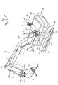
図1は、実施形態1に係る撮像装置の制御システムを備えた油圧ショベル1を示す斜視図である。図2は、実施形態1に係る油圧ショベル1の運転席付近を斜視図である。作業機械である油圧ショベル1は、車体1B及び作業機2を有する。車体1Bは、旋回体3、運転室4及び走行体5を有する。旋回体3は、旋回中心軸Zrを中心として走行体5に旋回可能に取り付けられている。旋回体3は、油圧ポンプ及びエンジン等の装置を収容している。
Embodiment 1.
<Overall Configuration of Hydraulic Excavator>
FIG. 1 is a perspective view showing a hydraulic excavator 1 equipped with an imaging device control system according to a first embodiment. FIG. 2 is a perspective view of the vicinity of the driver's seat of the hydraulic excavator 1 according to the first embodiment. A hydraulic excavator 1 as a working machine has a vehicle body 1B and a working machine 2 . The vehicle body 1</b>B has a revolving body 3 , an operator's cab 4 and a running body 5 . The revolving body 3 is attached to the traveling body 5 so as to be able to revolve around the revolving central axis Zr. The revolving body 3 accommodates devices such as a hydraulic pump and an engine.
旋回体3は、作業機2が取り付けられて旋回する。旋回体3の上部には手すり9が取り付けられている。手すり9には、アンテナ21,22が取り付けられる。アンテナ21,22は、RTK-GNSS(Real Time Kinematic - Global Navigation Satellite Systems、GNSSは全地球航法衛星システムをいう)用のアンテナである。アンテナ21,22は、車体座標系(Xm,Ym,Zm)のYm軸の方向に沿って、一定距離だけ離れて配置されている。アンテナ21,22は、GNSS電波を受信し、受信したGNSS電波に応じた信号を出力する。アンテナ21,22は、GPS(Global Positioning System)用のアンテナであってもよい。
The revolving body 3 is mounted with the work machine 2 and revolves. A handrail 9 is attached to the top of the revolving body 3 . Antennas 21 and 22 are attached to the handrail 9 . Antennas 21 and 22 are antennas for RTK-GNSS (Real Time Kinematic-Global Navigation Satellite Systems, GNSS means global navigation satellite system). The antennas 21 and 22 are arranged at a constant distance along the direction of the Ym axis of the vehicle body coordinate system (Xm, Ym, Zm). The antennas 21 and 22 receive GNSS radio waves and output signals according to the received GNSS radio waves. The antennas 21 and 22 may be GPS (Global Positioning System) antennas.
運転室4は旋回体3の前部に載置されている。運転室4の屋根には、通信用のアンテナ25Aが取り付けられている。走行体5は、履帯5a,5bを有している。履帯5a,5bが回転することにより油圧ショベル1が走行する。
The operator's cab 4 is mounted on the front portion of the revolving body 3 . A communication antenna 25A is attached to the roof of the cab 4 . The running body 5 has crawler belts 5a and 5b. The hydraulic excavator 1 travels as the crawler belts 5a and 5b rotate.
作業機2は、車体1Bの前部に取り付けられており、ブーム6、アーム7、作業具としてのバケット8、ブームシリンダ10、アームシリンダ11及びバケットシリンダ12を有する。実施形態において、車体1Bの前方は、図2に示される運転席4Sの背もたれ4SSから操作装置35に向かう方向側である。車体1Bの後方は、操作装置35から運転席4Sの背もたれ4SSに向かう方向側である。車体1Bの前部は、車体1Bの前方側の部分であり、車体1BのカウンタウエイトWTとは反対側の部分である。操作装置35は、作業機2及び旋回体3を操作するための装置であり、右側レバー35R及び左側レバー35Lを有する。
The working machine 2 is attached to the front part of the vehicle body 1B and has a boom 6, an arm 7, a bucket 8 as a working tool, a boom cylinder 10, an arm cylinder 11 and a bucket cylinder 12. In the embodiment, the front side of the vehicle body 1B is the direction side toward the operation device 35 from the backrest 4SS of the driver's seat 4S shown in FIG. The rear of the vehicle body 1B is the side in the direction from the operation device 35 toward the backrest 4SS of the driver's seat 4S. A front portion of the vehicle body 1B is a portion on the front side of the vehicle body 1B, and is a portion of the vehicle body 1B on the opposite side to the counterweight WT. The operating device 35 is a device for operating the work implement 2 and the revolving body 3, and has a right lever 35R and a left lever 35L.
ブーム6の基端部は、ブームピン13を介して車体1Bの前部に回動可能に取り付けられている。すなわち、ブームピン13は、ブーム6の旋回体3に対する回動中心に相当する。アーム7の基端部は、アームピン14を介してブーム6の先端部に回動可能に取り付けられている。すなわち、アームピン14は、アーム7のブーム6に対する回動中心に相当する。アーム7の先端部には、バケットピン15を介してバケット8が回動可能に取り付けられている。すなわち、バケットピン15は、バケット8のアーム7に対する回動中心に相当する。
A base end portion of the boom 6 is rotatably attached to the front portion of the vehicle body 1B via a boom pin 13 . That is, the boom pin 13 corresponds to the center of rotation of the boom 6 with respect to the revolving body 3 . The base end of the arm 7 is rotatably attached to the tip of the boom 6 via an arm pin 14 . That is, the arm pin 14 corresponds to the center of rotation of the arm 7 with respect to the boom 6 . A bucket 8 is rotatably attached to the tip of the arm 7 via a bucket pin 15 . That is, the bucket pin 15 corresponds to the center of rotation of the bucket 8 with respect to the arm 7 .
図1に示されるブームシリンダ10、アームシリンダ11及びバケットシリンダ12は、それぞれ油圧によって駆動される油圧シリンダである。ブームシリンダ10の基端部は、ブームシリンダフートピン10aを介して旋回体3に回動可能に取り付けられている。ブームシリンダ10の先端部は、ブームシリンダトップピン10bを介してブーム6に回動可能に取り付けられている。ブームシリンダ10は、油圧によって伸縮することによって、ブーム6を駆動する。
A boom cylinder 10, an arm cylinder 11, and a bucket cylinder 12 shown in FIG. 1 are hydraulic cylinders driven by hydraulic pressure. A base end portion of the boom cylinder 10 is rotatably attached to the revolving body 3 via a boom cylinder foot pin 10a. A tip portion of the boom cylinder 10 is rotatably attached to the boom 6 via a boom cylinder top pin 10b. The boom cylinder 10 drives the boom 6 by expanding and contracting with hydraulic pressure.
アームシリンダ11の基端部は、アームシリンダフートピン11aを介してブーム6に回動可能に取り付けられている。アームシリンダ11の先端部は、アームシリンダトップピン11bを介してアーム7に回動可能に取り付けられている。アームシリンダ11は、油圧によって伸縮することによって、アーム7を駆動する。
A base end of the arm cylinder 11 is rotatably attached to the boom 6 via an arm cylinder foot pin 11a. A tip portion of the arm cylinder 11 is rotatably attached to the arm 7 via an arm cylinder top pin 11b. The arm cylinder 11 drives the arm 7 by expanding and contracting with hydraulic pressure.
バケットシリンダ12の基端部は、バケットシリンダフートピン12aを介してアーム7に回動可能に取り付けられている。バケットシリンダ12の先端部は、バケットシリンダトップピン12bを介して第1リンク部材47の一端及び第2リンク部材48の一端に回動可能に取り付けられている。第1リンク部材47の他端は、第1リンクピン47aを介してアーム7の先端部に回動可能に取り付けられている。第2リンク部材48の他端は、第2リンクピン48aを介してバケット8に回動可能に取り付けられている。バケットシリンダ12は、油圧によって伸縮することによって、バケット8を駆動する。
A base end of the bucket cylinder 12 is rotatably attached to the arm 7 via a bucket cylinder foot pin 12a. The tip of the bucket cylinder 12 is rotatably attached to one end of the first link member 47 and one end of the second link member 48 via the bucket cylinder top pin 12b. The other end of the first link member 47 is rotatably attached to the tip of the arm 7 via a first link pin 47a. The other end of the second link member 48 is rotatably attached to the bucket 8 via a second link pin 48a. The bucket cylinder 12 drives the bucket 8 by expanding and contracting with hydraulic pressure.
バケット8は、複数の刃8Bを有する。複数の刃8Bは、バケット8の幅方向に沿って一列に並んでいる。刃8Bの先端は、刃先8BTである。バケット8は、作業具の一例である。作業具は、バケット8に限定されない。作業具は、例えば、単数の刃を有するチルトバケットであってもよいし、法面バケット又は削岩用のチップを備えた削岩用のアタッチメントであってもよいし、これら以外であってもよい。
Bucket 8 has a plurality of blades 8B. The plurality of blades 8B are arranged in a row along the width direction of the bucket 8. As shown in FIG. The tip of the blade 8B is the cutting edge 8BT. Bucket 8 is an example of a work tool. The work implement is not limited to the bucket 8. The work implement may, for example, be a tilt bucket with a single blade, a slope bucket or a rock drilling attachment with a rock drilling tip, or otherwise. good.
旋回体3は、位置検出装置23と、姿勢検出装置の一例であるIMU(Inertial Measurement Unit:慣性計測装置)24とを有する。位置検出装置23は、アンテナ21,22からの信号が入力される。位置検出装置23は、アンテナ21,22から取得した信号を用いて、グローバル座標系(Xg,Yg,Zg)におけるアンテナ21,22の現在位置及び旋回体3の方位を検出して、出力する。旋回体3の方位は、グローバル座標系における旋回体3の向きを表す。旋回体3の向きは、例えば、グローバル座標系のZg軸周りにおける旋回体3の前後方向の向きで表すことができる。方位角は、旋回体3の前後方向における基準軸の、グローバル座標系のZg軸周りにおける回転角である。方位角によって旋回体3の方位が表される。本実施形態において、位置検出装置23は、2個のアンテナ21,22の相対位置から方位角を算出する。
The revolving body 3 has a position detection device 23 and an IMU (Inertial Measurement Unit) 24 which is an example of an attitude detection device. Signals from the antennas 21 and 22 are input to the position detection device 23 . The position detection device 23 uses signals acquired from the antennas 21 and 22 to detect and output the current positions of the antennas 21 and 22 and the azimuth of the revolving body 3 in the global coordinate system (Xg, Yg, Zg). The orientation of the revolving superstructure 3 represents the orientation of the revolving superstructure 3 in the global coordinate system. The orientation of the revolving body 3 can be represented, for example, by the longitudinal direction of the revolving body 3 around the Zg axis of the global coordinate system. The azimuth angle is the rotation angle of the reference axis in the longitudinal direction of the revolving body 3 around the Zg axis of the global coordinate system. The azimuth angle represents the azimuth of the revolving body 3 . In this embodiment, the position detection device 23 calculates the azimuth from the relative positions of the two antennas 21 and 22 .
<撮像装置>
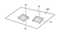
図2に示されるように、油圧ショベル1は、運転室4内に複数の撮像装置30a,30b,30c,30dを有する。複数の撮像装置30a,30b,30c,30dは、対象の形状を検出する検出装置の一例である。以下において、複数の撮像装置30a,30b,30c,30dを区別しない場合は適宜、撮像装置30と称する。複数の撮像装置30のうち撮像装置30a及び撮像装置30cは、作業機2側に配置される。撮像装置30の種類は限定されないが、実施形態では、例えば、CCD(Couple Charged Device)イメージセンサ又はCMOS(Complementary Metal Oxide Semiconductor)イメージセンサを備えた撮像装置が用いられる。
<Imaging device>
As shown in FIG. 2, the hydraulic excavator 1 has a plurality of imaging devices 30a, 30b, 30c, and 30d in the operator's cab 4. As shown in FIG. The multiple imaging devices 30a, 30b, 30c, and 30d are an example of a detection device that detects the shape of a target. Hereinafter, the plurality of imaging devices 30a, 30b, 30c, and 30d are appropriately referred to as the imaging device 30 when not distinguished. Among the plurality of imaging devices 30, the imaging device 30a and the imaging device 30c are arranged on the working machine 2 side. Although the type of imaging device 30 is not limited, in the embodiment, for example, an imaging device provided with a CCD (Couple Charged Device) image sensor or a CMOS (Complementary Metal Oxide Semiconductor) image sensor is used.
図2に示されるように、撮像装置30aと撮像装置30bとは所定の間隔をおいて同じ方向又は異なる方向を向いて運転室4内に配置される。撮像装置30cと撮像装置30dとは所定の間隔をおいて同じ方向又は異なる方向を向いて運転室4内に配置される。複数の撮像装置30a,30b,30c,30dは、2個が組み合わされてステレオカメラを構成する。実施形態では、撮像装置30a,30bの組合せのステレオカメラ、及び撮像装置30c,30dの組合せのステレオカメラが構成される。実施形態において、撮像装置30a及び撮像装置30bは上方を向いており、撮像装置30c及び撮像装置30dは下方を向いている。少なくとも撮像装置30a及び撮像装置30cは、油圧ショベル1、実施形態では旋回体3の正面を向いている。撮像装置30b及び撮像装置30dは、作業機2の方に若干向けられて、すなわち、撮像装置30a及び撮像装置30c側の方に若干向けられて配置されることもある。
As shown in FIG. 2, the imaging device 30a and the imaging device 30b are arranged in the operator's cab 4 facing the same direction or different directions with a predetermined gap therebetween. The imaging device 30c and the imaging device 30d are arranged in the driver's cab 4 facing the same direction or different directions at a predetermined interval. Two of the plurality of imaging devices 30a, 30b, 30c, and 30d are combined to form a stereo camera. In the embodiment, a stereo camera that is a combination of the imaging devices 30a and 30b and a stereo camera that is a combination of the imaging devices 30c and 30d are configured. In the embodiment, imaging devices 30a and 30b face upward, and imaging devices 30c and 30d face downward. At least the imaging device 30a and the imaging device 30c face the front of the hydraulic excavator 1, or the revolving body 3 in the embodiment. The image pickup device 30b and the image pickup device 30d may be arranged slightly facing the work machine 2, that is, slightly facing the image pickup device 30a and the image pickup device 30c.
実施形態において、油圧ショベル1は、4個の撮像装置30を有するが、油圧ショベル1が有する撮像装置30の数は少なくとも2個であればよく、4個に限定されない。油圧ショベル1は、少なくとも一対の撮像装置30でステレオカメラを構成して、対象をステレオ撮影するからである。
In the embodiment, the hydraulic excavator 1 has four imaging devices 30, but the number of imaging devices 30 that the hydraulic excavator 1 has may be at least two and is not limited to four. This is because the hydraulic excavator 1 configures a stereo camera with at least a pair of imaging devices 30 to stereo-photograph an object.
複数の撮像装置30a,30b,30c,30dは、運転室4内の前方かつ上方に配置される。上方とは、油圧ショベル1が有する履帯5a,5bの接地面と直交し、かつ接地面から離れる方向側である。履帯5a,5bの接地面は、履帯5a,5bのうち少なくとも一方が接地する部分の、同一直線上には存在しない少なくとも3点で規定される平面である。下方は、上方とは反対方向側、すなわち履帯5a,5bの接地面と直交し、かつ接地面に向かう方向側である。
A plurality of imaging devices 30 a , 30 b , 30 c , 30 d are arranged forward and upward in the driver's cab 4 . The upper side is perpendicular to the contact surfaces of the crawler belts 5a and 5b of the hydraulic excavator 1 and away from the contact surfaces. The ground contact surface of crawler belts 5a and 5b is a plane defined by at least three points that are not on the same straight line on which at least one of crawler belts 5a and 5b is grounded. The lower side is the side opposite to the upper side, that is, the side perpendicular to the contact surface of the crawler belts 5a and 5b and facing the contact surface.
複数の撮像装置30a,30b,30c,30dは、油圧ショベル1の車体1Bの前方に存在する対象をステレオ撮影する。対象は、例えば、油圧ショベル1、油圧ショベル1の作業機械及び施工現場で作業する作業者の少なくとも1つの施工対象である。複数の撮像装置30a,30b,30c,30dは、油圧ショベル1の所定の位置、本実施形態では運転室4内の前方かつ上方から対象を検出する。本実施形態においては、少なくとも一対の撮像装置30によるステレオ撮影の結果を用いて、対象が三次元計測される。複数の撮像装置30a,30b,30c,30dが配置される場所は、運転室4内の前方かつ上方に限定されるものではない。
A plurality of imaging devices 30 a , 30 b , 30 c , 30 d stereoscopically photograph an object present in front of the vehicle body 1 B of the hydraulic excavator 1 . The target is, for example, at least one of the hydraulic excavator 1, the working machine of the hydraulic excavator 1, and the worker working at the construction site. A plurality of imaging devices 30a, 30b, 30c, and 30d detect an object from a predetermined position of the hydraulic excavator 1, which is the front and upper part of the operator's cab 4 in this embodiment. In this embodiment, the object is three-dimensionally measured using the results of stereo imaging by at least a pair of imaging devices 30 . The locations where the plurality of imaging devices 30 a , 30 b , 30 c , and 30 d are arranged are not limited to the front and upper parts of the driver's cab 4 .
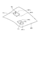
複数の撮像装置30a,30b,30c,30dのうち、例えば、撮像装置30cをこれらの基準とする。4個の複数の撮像装置30a,30b,30c,30dは、それぞれ座標系を有する。これらの座標系を適宜、撮像装置座標系と称する。図2では、基準となる撮像装置30cの座標系(xs,ys,zs)のみを示している。撮像装置座標系の原点は、各撮像装置30a,30b,30c,30dの中心である。
Among the plurality of imaging devices 30a, 30b, 30c, and 30d, for example, the imaging device 30c is used as a reference. Each of the four imaging devices 30a, 30b, 30c, and 30d has a coordinate system. These coordinate systems are appropriately referred to as imaging device coordinate systems. FIG. 2 shows only the coordinate system (xs, ys, zs) of the imaging device 30c that serves as a reference. The origin of the imaging device coordinate system is the center of each imaging device 30a, 30b, 30c, 30d.
本実施形態において、各撮像装置30a,30b,30c,30dの撮像範囲は、油圧ショベル1の作業機2が施工できる範囲よりも大きい。このようにすることで、各撮像装置30a,30b,30c,30dは、作業機2が掘削できる範囲の対象を確実にステレオ撮影することができる。
In this embodiment, the imaging range of each of the imaging devices 30a, 30b, 30c, and 30d is larger than the range in which the working machine 2 of the hydraulic excavator 1 can work. By doing so, each of the imaging devices 30a, 30b, 30c, and 30d can reliably stereo-photograph an object within a range that the work implement 2 can excavate.
前述した車体座標系(Xm,Ym,Zm)は、車体1B、本実施形態では旋回体3に固定された原点を基準とする座標系である。実施形態において、車体座標系(Xm,Ym,Zm)の原点は、例えば、旋回体3のスイングサークルの中心である。スイングサークルの中心は、旋回体3の旋回中心軸Zr上に存在する。車体座標系(Xm,Ym,Zm)のZm軸は旋回体3の旋回中心軸Zrとなる軸であり、Xm軸は旋回体3の前後方向に延び、かつZm軸と直交する軸である。Xm軸は、旋回体3の前後方向における基準軸である。Ym軸は、Zm軸及びXm軸と直交する、旋回体3の幅方向に延びる軸である。前述したグローバル座標系(Xg,Yg,Zg)は、GNSSによって計測される座標系であり、地球に固定された原点を基準とした座標系である。
The vehicle body coordinate system (Xm, Ym, Zm) described above is a coordinate system based on the origin fixed to the vehicle body 1B, which is the revolving body 3 in this embodiment. In the embodiment, the origin of the vehicle body coordinate system (Xm, Ym, Zm) is the center of the swing circle of the revolving body 3, for example. The center of the swing circle exists on the swing center axis Zr of the swing body 3 . The Zm-axis of the vehicle body coordinate system (Xm, Ym, Zm) is an axis that serves as the turning center axis Zr of the revolving body 3, and the Xm-axis extends in the longitudinal direction of the revolving body 3 and is perpendicular to the Zm-axis. The Xm axis is the reference axis of the revolving body 3 in the front-rear direction. The Ym-axis is an axis extending in the width direction of the revolving body 3 that is perpendicular to the Zm-axis and the Xm-axis. The global coordinate system (Xg, Yg, Zg) described above is a coordinate system measured by GNSS, and is a coordinate system based on the origin fixed to the earth.
車体座標系は、本実施形態の例には限定されない。車体座標系は、例えば、ブームピン13の中心を車体座標系の原点としてもよい。ブームピン13の中心とは、ブームピン13が延びる方向と直交する平面でブームピン13を切った時の断面の中心、かつブームピン13が延びる方向における中心である。
The vehicle body coordinate system is not limited to the example of this embodiment. For the vehicle body coordinate system, for example, the center of the boom pin 13 may be set as the origin of the vehicle body coordinate system. The center of the boom pin 13 is the center of the cross section of the boom pin 13 taken along a plane orthogonal to the direction in which the boom pin 13 extends and the center in the direction in which the boom pin 13 extends.
<作業機械の制御システム及び施工管理システム>
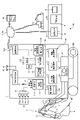
図3は、実施形態に係る作業機械の制御システム50及び施工管理システム100を示す図である。図3に示される制御システム50及び管理システム100の装置構成は一例であり、本実施形態の装置構成例には限定されない。例えば、制御システム50に含まれる各種の装置はそれぞれ独立していなくてもよい。すなわち、複数の装置の機能が1つの装置によって実現されてもよい。
<Work machine control system and construction management system>
FIG. 3 is a diagram showing a work machine control system 50 and a construction management system 100 according to the embodiment. The device configuration of the control system 50 and the management system 100 shown in FIG. 3 is an example, and is not limited to the device configuration example of this embodiment. For example, the various devices included in control system 50 may not be independent. That is, the functions of multiple devices may be implemented by one device.
作業機械の制御システム50(以下、適宜、制御システム50と称する)は、複数の撮像装置30a,30b,30c,30dと、油圧ショベル1を制御するための各種の制御装置とを含む。これらは、図1に示される油圧ショベル1の車体1B、本実施形態では旋回体3に備えられている。本実施形態において、制御システム50は、形状計測システムに相当する。
A work machine control system 50 (hereinafter referred to as the control system 50 as appropriate) includes a plurality of imaging devices 30a, 30b, 30c, and 30d and various control devices for controlling the hydraulic excavator 1 . These are provided on the vehicle body 1B of the hydraulic excavator 1 shown in FIG. 1, which is the revolving body 3 in this embodiment. In this embodiment, the control system 50 corresponds to a shape measuring system.
制御システム50が有する各種の制御装置は、図3に示される検出処理装置51、施工情報生成装置52、センサ制御装置53、機関制御装置54、ポンプ制御装置55及び作業機制御装置56を含む。この他に、制御システム50は、油圧ショベル1の状態及び油圧ショベル1による施工の状況を管理する施工管理装置57を有する。また、制御システム50は、油圧ショベル1の情報を表示したり施工のガイダンス画像を画面58Dに表示したりする表示装置58と、油圧ショベル1の外部に存在する管理施設60の管理装置61、他の作業機械70、携帯端末装置64及び管理施設60の管理装置61以外の装置のうち少なくとも1つと通信する通信装置25を有する。さらに、制御システム50は、油圧ショベル1の制御に必要な情報を取得するための位置検出装置23及び姿勢検出装置の一例であるIMU24を有する。本実施形態において、制御システム50は、少なくとも検出処理装置51及び施工情報生成装置52を有していればよい。
Various control devices included in the control system 50 include a detection processing device 51, a construction information generation device 52, a sensor control device 53, an engine control device 54, a pump control device 55, and a working machine control device 56 shown in FIG. In addition, the control system 50 has a construction management device 57 that manages the state of the hydraulic excavator 1 and the construction status of the hydraulic excavator 1 . The control system 50 also includes a display device 58 for displaying information about the hydraulic excavator 1 and a guidance image for construction on a screen 58D, a management device 61 for a management facility 60 existing outside the hydraulic excavator 1, and others. The communication device 25 communicates with at least one of the working machine 70 , the mobile terminal device 64 and the device other than the management device 61 of the management facility 60 . Further, the control system 50 has a position detection device 23 for acquiring information necessary for controlling the hydraulic excavator 1 and an IMU 24 that is an example of a posture detection device. In this embodiment, the control system 50 should just have the detection processing apparatus 51 and the construction information generation apparatus 52 at least.
実施形態において、検出処理装置51、施工情報生成装置52、センサ制御装置53、機関制御装置54、ポンプ制御装置55、作業機制御装置56、施工管理装置57、表示装置58、位置検出装置23及び通信装置25は、信号線59に接続されて、相互に通信する。実施形態1において、信号線59を用いた通信の規格はCAN(Controller Area Network)であるが、これに限定されない。以下において、油圧ショベル1というときには、油圧ショベル1が有する検出処理装置51及び施工情報生成装置52等の各種の電子装置を指すこともある。
In the embodiment, a detection processing device 51, a construction information generation device 52, a sensor control device 53, an engine control device 54, a pump control device 55, a work machine control device 56, a construction management device 57, a display device 58, a position detection device 23 and The communication devices 25 are connected to the signal line 59 to communicate with each other. In the first embodiment, the communication standard using the signal line 59 is CAN (Controller Area Network), but it is not limited to this. Hereinafter, when the hydraulic excavator 1 is mentioned, various electronic devices such as the detection processing device 51 and the construction information generation device 52 included in the hydraulic excavator 1 may also be referred to.
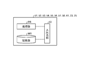
図4は、油圧ショベル1が有する各種の機器類及び管理装置61のハードウェア構成例を示す図である。実施形態において、油圧ショベル1が有する検出処理装置51、施工情報生成装置52、センサ制御装置53、機関制御装置54、ポンプ制御装置55、作業機制御装置56、施工管理装置57、表示装置58、位置検出装置23及び通信装置25、並びに管理装置61は、図4に示されるように、処理部PR、記憶部MR及び入出力部IOを有する。処理部PRは、例えば、CPU(Central Processing Unit)のようなプロセッサ及びメモリによって実現される。
FIG. 4 is a diagram showing a hardware configuration example of various devices and the management device 61 that the hydraulic excavator 1 has. In the embodiment, the hydraulic excavator 1 includes a detection processing device 51, a construction information generation device 52, a sensor control device 53, an engine control device 54, a pump control device 55, a work machine control device 56, a construction management device 57, a display device 58, The position detection device 23, the communication device 25, and the management device 61, as shown in FIG. 4, have a processing section PR, a storage section MR, and an input/output section IO. The processing unit PR is realized by, for example, a processor such as a CPU (Central Processing Unit) and a memory.
記憶部MRは、RAM(Random Access Memory)、ROM(Random Access Memory)、フラッシュメモリ、EPROM(Erasable Programmable Random Access Memory)、EEPROM(Electrically Erasable Programmable Random Access Memory)等の不揮発性又は揮発性の半導体メモリ、磁気ディスク、フレキシブルディスク及び光磁気ディスクのうち少なくとも1つが用いられる。
The storage unit MR is a non-volatile or volatile semiconductor memory such as RAM (Random Access Memory), ROM (Random Access Memory), flash memory, EPROM (Erasable Programmable Random Access Memory), EEPROM (Electrically Erasable Programmable Random Access Memory). , a magnetic disk, a flexible disk, and a magneto-optical disk.
入出力部IOは、油圧ショベル1又は管理装置61が、他の機器及び内部の装置とデータ及び信号等を送受信するためのインターフェース回路である。内部の装置には、油圧ショベル1内の信号線59も含まれる。
The input/output unit IO is an interface circuit for the hydraulic excavator 1 or the management device 61 to transmit and receive data, signals, and the like to and from other devices and internal devices. The internal device also includes a signal line 59 inside the excavator 1 .
油圧ショベル1と管理装置61とは、それぞれの機能を処理部PRに実現させるためのコンピュータプログラムを記憶部MRに記憶している。油圧ショベル1の処理部PRと管理装置61の処理部PRとは、記憶部MRから前述したコンピュータプログラムを読み出して実行することにより、それぞれの装置の機能を実現する。油圧ショベル1が有する各種の電子装置、機器及び管理装置61は、専用のハードウェアで実現されてもよいし、複数の処理回路が連携してそれぞれの機能を実現するものであってもよい。次に、油圧ショベル1が有する各種の電子装置及び機器について説明する。
The hydraulic excavator 1 and the management device 61 store computer programs in the storage unit MR for causing the processing unit PR to implement the respective functions. The processing unit PR of the hydraulic excavator 1 and the processing unit PR of the management device 61 implement the functions of the respective devices by reading and executing the above-described computer programs from the storage unit MR. The various electronic devices, devices, and management device 61 of the hydraulic excavator 1 may be implemented by dedicated hardware, or may be implemented by a plurality of processing circuits working together to achieve their respective functions. Next, various electronic devices and devices that the hydraulic excavator 1 has will be described.
検出処理装置51は、少なくとも一対の撮像装置30によって撮像された対象の一対の画像に、ステレオ方式における画像処理を施すことにより、対象の位置、具体的には三次元座標系における対象の座標を求める。このように、検出処理装置51は、同一の対象を少なくとも一対の撮像装置30で撮像することによって得られた一対の画像を用いて、対象を三次元計測することができる。すなわち、少なくとも一対の撮像装置30及び検出処理装置51は、ステレオ方式により対象を三次元計測するものである。ステレオ方式における画像処理とは、同一の対象を2つの異なる撮像装置30から観測して得られる2つの画像から、その対象までの距離を得る手法である。対象までの距離は、例えば、対象までの距離情報を濃淡により可視化した距離画像として表現される。
The detection processing device 51 performs stereoscopic image processing on a pair of images of the target captured by at least the pair of imaging devices 30 to determine the position of the target, specifically, the coordinates of the target in a three-dimensional coordinate system. Ask. In this way, the detection processing device 51 can three-dimensionally measure the object using a pair of images obtained by imaging the same object with at least a pair of imaging devices 30 . That is, at least a pair of the imaging device 30 and the detection processing device 51 performs three-dimensional measurement of the object in a stereo system. Image processing in the stereo system is a method of obtaining the distance to an object from two images obtained by observing the same object from two different imaging devices 30 . The distance to the object is expressed, for example, as a distance image in which distance information to the object is visualized by gradation.
検出処理装置51は、少なくとも一対の撮像装置30によって検出された対象の情報を取得し、取得した対象の情報から対象の三次元形状を示す形状情報を求める。本実施形態では、少なくとも一対の撮像装置30が対象を撮像することにより対象の情報を生成して出力する。対象の情報は、少なくとも一対の撮像装置30によって撮像された施工対象の画像である。検出処理装置51は、対象の画像にステレオ方式による画像処理を施すことにより、形状情報を求め、出力する。本実施形態において、少なくとも一対の撮像装置30を有する油圧ショベル1の施工対象が少なくとも一対の撮像装置30によって撮像されるが、他の作業機械の施工対象が、少なくとも一対の撮像装置30によって撮像されてもよい。
The detection processing device 51 acquires information on the object detected by at least the pair of imaging devices 30, and obtains shape information indicating the three-dimensional shape of the object from the acquired information on the object. In this embodiment, at least a pair of imaging devices 30 capture an image of a target to generate and output target information. The target information is an image of the construction target captured by at least a pair of imaging devices 30 . The detection processing device 51 obtains and outputs shape information by subjecting the target image to stereo image processing. In the present embodiment, the construction target of the hydraulic excavator 1 having at least a pair of imaging devices 30 is imaged by at least the pair of imaging devices 30, but the construction target of the other work machine is imaged by at least the pair of imaging devices 30. may
本実施形態において、撮像装置30が検出する対象は、施工の対象(以下、適宜、施工対象と称する)及び施工後の対象である。本実施形態において、施工対象及び施工後の対象は、撮像装置30を有する油圧ショベル1、他の油圧ショベル1ot、油圧ショベル以外の作業機械及び作業者のうち少なくとも1つの施工対象及び施工後の対象であればよい。
In the present embodiment, the targets detected by the imaging device 30 are the target of construction (hereinafter referred to as the target of construction as appropriate) and the target after construction. In the present embodiment, the construction target and the post-construction target are at least one of the hydraulic excavator 1 having the imaging device 30, another hydraulic excavator 1ot, a working machine other than the hydraulic excavator, and a worker. If it is
検出処理装置51は、演算部51A及び情報付与部51Bを有する。演算部51Aは、少なくとも一対の撮像装置30によって撮像された一対の画像に、ステレオ方式における画像処理を施して形状情報を求める。情報付与部51Bは、形状情報に各種の情報を付けて出力する。形状情報に付される各種の情報は、時刻情報がある。時刻情報は、対象が演算部51A及び少なくとも一対の撮像装置30によって検出された時刻から、形状情報が出力される時刻までの間に存在する少なくとも1つの時刻の情報を含む。時刻情報は、例えば、検出処理装置51内のタイマから取得される。各種の情報は、時刻情報の他に、少なくとも一対の撮像装置30が対象を撮像した位置を示す情報及び対象を撮像した撮像装置30を有する油圧ショベル1を識別するための情報のうち少なくとも一方をさらに含んでもよい。演算部51A及び情報付与部51Bの機能は、図4に示される処理部PRが実現する。
The detection processing device 51 has a calculation unit 51A and an information addition unit 51B. The calculation unit 51A obtains shape information by performing stereoscopic image processing on a pair of images captured by at least a pair of imaging devices 30 . The information attachment unit 51B attaches various information to the shape information and outputs the shape information. Various types of information attached to the shape information include time information. The time information includes information on at least one time that exists between the time when the object is detected by the calculation unit 51A and at least a pair of imaging devices 30 and the time when the shape information is output. Time information is acquired from a timer in the detection processing device 51, for example. In addition to the time information, the various types of information include at least one of information indicating the positions at which the target was imaged by at least a pair of imaging devices 30 and information for identifying the hydraulic excavator 1 having the imaging device 30 that imaged the target. It may contain further. The functions of the calculation unit 51A and the information addition unit 51B are implemented by the processing unit PR shown in FIG.
本実施形態において、少なくとも一対の撮像装置30は、油圧ショベル1に取り付けられて、対象を検出して対象の情報を出力する対象検出部に相当する。検出処理装置51は、少なくとも一対の撮像装置30によって検出された対象の情報を用いて、対象の三次元形状を表す形状情報を出力する形状検出部に相当する。少なくとも一対の撮像装置30の代わりにレーザスキャナのような3Dスキャナが用いられてもよい。3Dスキャナは、対象を検出して対象の三次元形状を示す形状情報を出力するので、前述した対象検出部及び形状検出部の機能を有している。
In the present embodiment, at least the pair of imaging devices 30 correspond to an object detection unit that is attached to the hydraulic excavator 1, detects an object, and outputs information about the object. The detection processing device 51 corresponds to a shape detection unit that outputs shape information representing the three-dimensional shape of a target using information about the target detected by at least a pair of imaging devices 30 . A 3D scanner, such as a laser scanner, may be used in place of at least one pair of imaging devices 30 . Since the 3D scanner detects an object and outputs shape information indicating the three-dimensional shape of the object, it has the functions of the object detection section and the shape detection section described above.
検出処理装置51には、ハブ31及び撮像スイッチ32が接続される。ハブ31は、複数の撮像装置30a,30b,30c,30dが接続されている。ハブ31を用いずに、撮像装置30a,30b,30c,30dと検出処理装置51とが接続されてもよい。撮像装置30a,30b,30c,30dの撮像した結果は、ハブ31を介して検出処理装置51に入力される。検出処理装置51は、ハブ31を介して、撮像装置30a,30b,30c,30dが撮像した結果、本実施形態では対象の画像を取得する。本実施形態において、撮像スイッチ32が操作されると、少なくとも一対の撮像装置30は対象を撮像する。撮像スイッチ32は、図2に示される運転室4内に設置される。例えば、撮像スイッチ32は、操作装置35の近傍に設置されるが、撮像スイッチ32の設置場所はこれに限定されない。
A hub 31 and an imaging switch 32 are connected to the detection processing device 51 . The hub 31 is connected with a plurality of imaging devices 30a, 30b, 30c, and 30d. The imaging devices 30 a , 30 b , 30 c , 30 d and the detection processing device 51 may be connected without using the hub 31 . The results of imaging by the imaging devices 30 a , 30 b , 30 c and 30 d are input to the detection processing device 51 via the hub 31 . The detection processing device 51 acquires an image of a target in this embodiment as a result of imaging by the imaging devices 30 a , 30 b , 30 c , and 30 d via the hub 31 . In the present embodiment, when the imaging switch 32 is operated, at least the pair of imaging devices 30 will image the target. The imaging switch 32 is installed inside the driver's cab 4 shown in FIG. For example, the imaging switch 32 is installed near the operation device 35, but the installation location of the imaging switch 32 is not limited to this.
制御システム50は、少なくとも一対の撮像装置30によって対象の画像を取得する場合、旋回体3を旋回開始と同時に撮像を開始し旋回停止によって撮像を終了し、その旋回中に取得した画像をもとにステレオ方式における画像処理を施して形状情報を求めるようにしてもよい。この場合、制御システム50は、例えば、操作装置35のうち旋回体3を旋回させるための操作装置の操作にともなって出力される、パイロット圧の変化を示す信号又は電気信号を検出処理装置51が受信し、旋回体3の旋回開始と旋回停止のタイミングとを判断し撮像する。
When acquiring an image of a target by at least a pair of imaging devices 30, the control system 50 starts imaging at the same time when the revolving body 3 starts revolving, and ends the imaging when the revolving body 3 stops revolving. may be subjected to image processing in a stereo system to obtain the shape information. In this case, the control system 50 detects, for example, a signal or an electrical signal indicating a change in the pilot pressure, which is output along with the operation of the operation device for rotating the revolving structure 3 among the operation devices 35. Then, the timing of starting and stopping the turning of the turning body 3 is determined and imaged.
施工情報生成装置52は、油圧ショベル1が施工対象を施工するときに目標とする形状の情報である目標施工情報を求めて、出力する。本実施形態において、施工情報生成装置52は、検出処理装置51が求めた施工対象の形状情報を用いて目標施工情報を求める。本実施形態において、目標施工情報は、施工対象が施工されるときに目標とされる形状を、グローバル座標系における三次元座標で表した位置情報である。目標施工情報は、グローバル座標系以外の座標系における三次元座標の情報であってもよい。本実施形態において、施工情報生成装置52は、施工情報生成部に相当する。
The construction information generation device 52 obtains and outputs target construction information, which is information on a target shape when the hydraulic excavator 1 constructs a construction target. In the present embodiment, the construction information generation device 52 obtains target construction information using the shape information of the object to be constructed obtained by the detection processing device 51 . In the present embodiment, the target construction information is position information that expresses the target shape of the object to be constructed by three-dimensional coordinates in the global coordinate system. The target construction information may be three-dimensional coordinate information in a coordinate system other than the global coordinate system. In this embodiment, the construction information generation device 52 corresponds to a construction information generation unit.
少なくとも一対の撮像装置30が取得した施工対象の情報が通信装置25を介して油圧ショベル1の外部に送信され、例えば、管理装置61が三次元座標系における対象の座標を求めてもよい。この場合、管理装置61は、検出処理装置51の機能を実現する。また、管理装置61は、施工情報生成装置52の機能を実現してもよい。通信装置25を介して、油圧ショベル1に搭載された検出処理装置51が求めた施工対象の形状情報が油圧ショベル1の外部に送信され、例えば管理装置61が目標施工情報を求めてもよい。この場合、管理装置61は、施工情報生成装置52の機能を実現する。
Information on the construction target acquired by at least one pair of imaging devices 30 may be transmitted to the outside of the hydraulic excavator 1 via the communication device 25, and for example, the management device 61 may obtain the coordinates of the target in the three-dimensional coordinate system. In this case, the management device 61 implements the functions of the detection processing device 51 . Moreover, the management device 61 may implement the function of the construction information generation device 52 . Through the communication device 25, the shape information of the construction object obtained by the detection processing device 51 mounted on the hydraulic excavator 1 may be transmitted to the outside of the hydraulic excavator 1, and for example, the management device 61 may obtain the target construction information. In this case, the management device 61 implements the function of the construction information generation device 52 .
センサ制御装置53は、油圧ショベル1の状態の情報及び油圧ショベル1の周囲の状態の情報を検出するためのセンサ類が接続される。センサ制御装置53は、センサ類から取得した情報を、他の電子装置及び機器が取り扱うことのできるフォーマットに変換して出力する。油圧ショベル1の状態の情報は、例えば、油圧ショベル1の姿勢の情報及び作業機2の姿勢の情報等である。図3に示される例では、油圧ショベル1の状態の情報を検出するセンサとして、IMU24、第1角度検出部18A、第2角度検出部18B及び第3角度検出部18Cがセンサ制御装置53に接続されているが、センサ類はこれらに限定されない。
The sensor control device 53 is connected to sensors for detecting information on the state of the excavator 1 and information on the state of the surroundings of the excavator 1 . The sensor control device 53 converts the information acquired from the sensors into a format that can be handled by other electronic devices and equipment, and outputs the format. The information on the state of the hydraulic excavator 1 is, for example, information on the posture of the hydraulic excavator 1 and information on the posture of the working machine 2 . In the example shown in FIG. 3, the IMU 24, the first angle detection section 18A, the second angle detection section 18B, and the third angle detection section 18C are connected to the sensor control device 53 as sensors for detecting information on the state of the hydraulic excavator 1. However, sensors are not limited to these.
IMU24は、自身に作用する加速度及び角速度、すなわち油圧ショベル1に作用する加速度及び角速度を検出して出力する。油圧ショベル1に作用する加速度及び角速度から、油圧ショベル1の姿勢が分かる。油圧ショベル1の姿勢を検出できれば、IMU24以外の装置であってもよい。本実施形態において、第1角度検出部18A、第2角度検出部18B及び第3角度検出部18Cは、例えばストロークセンサである。これらは、それぞれが、ブームシリンダ10、アームシリンダ11及びバケットシリンダ12のストローク長さを検出することにより、車体1Bに対するブーム6の回動角と、ブーム6に対するアーム7の回動角と、アーム7に対するバケット8の回動角とを間接的に検出する。第1角度検出部18A、第2角度検出部18B及び第3角度検出部18Cによって検出された車体1Bに対するブーム6の回動角、ブーム6に対するアーム7の回動角及びアーム7に対するバケット8の回動角と、作業機2の寸法とから、車体座標系における作業機2の部分の位置が分かる。例えば、作業機2の部分の位置としては、例えば、バケット8の刃先8BTの位置である。第1角度検出部18A、第2角度検出部18B及び第3角度検出部18Cは、ストロークセンサに代えてポテンショメータ又は傾斜計であってもよい。
The IMU 24 detects and outputs the acceleration and angular velocity acting on itself, that is, the acceleration and angular velocity acting on the hydraulic excavator 1 . The posture of the hydraulic excavator 1 can be known from the acceleration and angular velocity acting on the hydraulic excavator 1 . Any device other than the IMU 24 may be used as long as it can detect the posture of the hydraulic excavator 1 . In this embodiment, the first angle detection section 18A, the second angle detection section 18B, and the third angle detection section 18C are, for example, stroke sensors. By detecting the stroke lengths of the boom cylinder 10, the arm cylinder 11, and the bucket cylinder 12, respectively, these detect the rotation angle of the boom 6 with respect to the vehicle body 1B, the rotation angle of the arm 7 with respect to the boom 6, and the arm The rotation angle of the bucket 8 with respect to 7 is indirectly detected. The rotation angle of the boom 6 relative to the vehicle body 1B, the rotation angle of the arm 7 relative to the boom 6, and the angle of the bucket 8 relative to the arm 7 are detected by the first angle detection unit 18A, the second angle detection unit 18B, and the third angle detection unit 18C. The position of the work implement 2 in the vehicle body coordinate system can be determined from the rotation angle and the dimensions of the work implement 2 . For example, the position of the working machine 2 is the position of the cutting edge 8BT of the bucket 8, for example. The first angle detector 18A, the second angle detector 18B and the third angle detector 18C may be potentiometers or inclinometers instead of stroke sensors.
機関制御装置54は、油圧ショベル1の動力発生装置である内燃機関27を制御する。内燃機関27は、例えばディーゼルエンジンであるが、これに限定されない。また、油圧ショベル1の動力発生装置は、内燃機関27と発電電動機とを組み合わせたハイブリッド方式の装置であってもよい。内燃機関27は、油圧ポンプ28を駆動する。
The engine control device 54 controls the internal combustion engine 27 that is the power generation device of the hydraulic excavator 1 . The internal combustion engine 27 is, for example, a diesel engine, but is not limited to this. Further, the power generation device of the hydraulic excavator 1 may be a hybrid type device in which the internal combustion engine 27 and a generator motor are combined. Internal combustion engine 27 drives hydraulic pump 28 .
ポンプ制御装置55は、油圧ポンプ28から吐出される作動油の流量を制御する。本実施形態において、ポンプ制御装置55は、油圧ポンプ28から吐出される作動油の流量を調整するための制御指令の信号を生成する。ポンプ制御装置55は、生成した制御信号を用いて油圧ポンプ28の斜板角を変更することにより、油圧ポンプ28から吐出される作動油の流量を変更する。油圧ポンプ28から吐出された作動油は、コントロールバルブ29に供給される。コントロールバルブ29は、油圧ポンプ28から供給された作動油を、ブームシリンダ10、アームシリンダ11、バケットシリンダ12及び油圧モータ5M等の油圧機器に供給して、これらを駆動する。
The pump control device 55 controls the flow rate of hydraulic oil discharged from the hydraulic pump 28 . In this embodiment, the pump control device 55 generates a control command signal for adjusting the flow rate of hydraulic oil discharged from the hydraulic pump 28 . The pump control device 55 changes the flow rate of hydraulic oil discharged from the hydraulic pump 28 by changing the swash plate angle of the hydraulic pump 28 using the generated control signal. Hydraulic oil discharged from the hydraulic pump 28 is supplied to the control valve 29 . The control valve 29 supplies hydraulic fluid supplied from the hydraulic pump 28 to the boom cylinder 10, the arm cylinder 11, the bucket cylinder 12, and hydraulic equipment such as the hydraulic motor 5M to drive them.
作業機制御装置56は、例えば、バケット8の刃先8BTを目標とする施工面に沿って移動させる制御を実行する。作業機制御装置56は、作業機制御部に相当する。この制御を、以下においては適宜、作業機制御と称する。作業機制御装置56は、作業機制御を実行するにあたって、例えば、施工情報生成装置52が生成した目標施工情報を取得し、目標施工情報に含まれる目標施工面にバケット8の刃先8BTが沿うようにコントロールバルブ29を制御して作業機2を制御する。油圧ショベル1は、作業機制御装置56を備えずに、後述する方法で得られた目標施工情報と自身の作業機2との位置関係を、表示装置58の画面58Dに施工のガイダンス画像として表示可能であってもよい。
The work implement control device 56 performs control to move the cutting edge 8BT of the bucket 8 along the target construction surface, for example. The work implement control device 56 corresponds to a work implement control section. This control will hereinafter be referred to as work implement control as appropriate. The work machine control device 56 acquires, for example, the target construction information generated by the construction information generation device 52 when executing the work machine control, and controls the cutting edge 8BT of the bucket 8 so that it is aligned with the target construction surface included in the target construction information. , the control valve 29 is controlled to control the working machine 2 . The hydraulic excavator 1 does not include the work machine control device 56, and displays the positional relationship between the target construction information obtained by the method described later and the own work machine 2 on the screen 58D of the display device 58 as a guidance image for construction. It may be possible.
施工管理装置57は、例えば、検出処理装置51が求めた形状情報、施工情報生成装置52によって生成された目標施工情報、油圧ショベル1が施工対象を施工した施工結果の形状情報、及び油圧ショベル1がこれから施工しようとする施工対象の現況地形を示す形状情報の少なくとも1つを収集し、記憶部57Mに記憶させる。施工管理装置57は、記憶部57Mに記憶させた施工結果を、通信装置25を介して管理装置61又は携帯端末装置64に送信する。施工管理装置57は、記憶部57Mに記憶させた施工結果を、通信装置25を介して管理装置61又は携帯端末装置64に送信する。施工管理装置57は、検出処理装置51が求めた形状情報及び目標施工情報の少なくとも一方を収集し、記憶部57Mに記憶せずに管理装置61又は携帯端末装置64に送信してもよい。記憶部57Mは、図4に示される記憶部MRに相当する。
The construction management device 57 receives, for example, the shape information obtained by the detection processing device 51, the target construction information generated by the construction information generation device 52, the shape information of the construction result of the construction target executed by the hydraulic excavator 1, and the hydraulic excavator 1 collects at least one piece of shape information indicating the current topography to be constructed, and stores it in the storage unit 57M. The construction management device 57 transmits the construction result stored in the storage unit 57M to the management device 61 or the mobile terminal device 64 via the communication device 25 . The construction management device 57 transmits the construction result stored in the storage unit 57M to the management device 61 or the mobile terminal device 64 via the communication device 25 . The construction management device 57 may collect at least one of the shape information and the target construction information obtained by the detection processing device 51, and transmit it to the management device 61 or the portable terminal device 64 without storing it in the storage unit 57M. The storage unit 57M corresponds to the storage unit MR shown in FIG.
施工管理装置57は、油圧ショベル1の外部に設けられた、例えば管理装置61に設けられてもよい。この場合、施工管理装置57は、油圧ショベル1から通信装置25を介して形状情報又は施工結果を取得する。
The construction management device 57 may be provided in, for example, a management device 61 provided outside the hydraulic excavator 1 . In this case, the construction management device 57 acquires shape information or construction results from the hydraulic excavator 1 via the communication device 25 .
施工結果は、例えば、少なくとも一対の撮像装置30が施工後の施工対象を撮像し、検出処理装置51が撮像結果にステレオ方式による画像処理を施すことによって求められた形状情報である。以下、施工しようとする施工対象の現況地形を示す形状情報を、適宜、現況地形情報と称する。また、形状情報は、施工結果を示す形状情報である場合と、現況地形を示す形状情報である場合とがある。現況地形情報とは、例えば、油圧ショベル1、他の作業機械70又は作業者等が施工しようとする施工対象が少なくとも一対の撮像装置30によって撮像され、検出処理装置51によって求められた形状情報である。
The construction result is, for example, shape information obtained by at least a pair of imaging devices 30 capturing an image of the construction target after construction, and the detection processing device 51 performing stereoscopic image processing on the imaging result. Hereinafter, shape information indicating the current topography of a construction target to be constructed will be referred to as current topography information as appropriate. The shape information may be shape information indicating construction results or may be shape information indicating current landforms. The current topography information is, for example, shape information obtained by the detection processing device 51 after images of the hydraulic excavator 1, the other work machine 70, or a construction target to be constructed by a worker or the like are captured by at least a pair of imaging devices 30. be.
施工管理装置57は、例えば、一日の作業が終了した後に施工結果を収集して管理装置61及び携帯端末装置64の少なくとも一方に送信したり、一日の作業のうち複数回施工結果を収集して管理装置61及び携帯端末装置64の少なくとも一方に送信したりする。施工管理装置57は、例えば朝の作業前に、施工前の形状情報を管理装置61又は携帯端末装置64に送信してもよい。
For example, the construction management device 57 collects the construction results after the day's work is completed and transmits them to at least one of the management device 61 and the mobile terminal device 64, or collects the construction results multiple times during the day's work. and transmits it to at least one of the management device 61 and the mobile terminal device 64 . The construction management device 57 may transmit shape information before construction to the management device 61 or the portable terminal device 64, for example, before work in the morning.
本実施形態では、施工管理装置57は、例えば一日の作業のうち、正午と作業終了時との2回の施工結果を収集し、管理装置61又は携帯端末装置64に送信する。施工結果は、施工現場全体のうち、施工が行われた範囲が撮像されることによって得られた施工結果であってもよいし、施工現場全体が撮像されることによって得られた施工結果であってもよい。管理装置61又は携帯端末装置64に送信される施工結果を施工が行われた範囲のものとすることにより、撮像時間、画像処理時間及び施工結果の送信時間の増加を抑制できるので好ましい。
In this embodiment, the construction management device 57 collects the construction results of two times, for example, at noon and at the end of the work in one day, and transmits them to the management device 61 or the portable terminal device 64 . The construction result may be a construction result obtained by capturing an image of the range where construction was performed out of the entire construction site, or a construction result obtained by capturing an image of the entire construction site. may By setting the construction result to be transmitted to the management device 61 or the portable terminal device 64 within the range in which the construction was performed, it is possible to suppress an increase in the imaging time, the image processing time, and the transmission time of the construction result, which is preferable.
表示装置58は、液晶表示パネルのようなディスプレイの画面58Dに、油圧ショベル1の情報を表示したり施工のガイダンス画像を画面58Dに表示したりする他、本実施形態においては、前述した作業機制御が実行される場合に作業機2の位置を求める。表示装置58が求める刃先8BTの位置は、本実施形態はバケット8の刃先8BTの位置である。表示装置58は、位置検出装置23が検出したアンテナ21,22の現在位置と、第1角度検出部18A、第2角度検出部18B及び第3角度検出部18Cによって検出された回動角と、記憶部MRに記憶された作業機2の寸法と、IMU24の出力データとを取得し、これらを用いてバケット8の刃先8BTの位置を求める。本実施形態では、表示装置58がバケット8の刃先8BTの位置を求めているが、バケット8の刃先8BTの位置は表示装置58以外の装置が求めてもよい。
The display device 58 displays information of the hydraulic excavator 1 on a screen 58D of a display such as a liquid crystal display panel, and displays a guidance image for construction on the screen 58D. The position of the work implement 2 is obtained when the control is executed. The position of the cutting edge 8BT obtained by the display device 58 is the position of the cutting edge 8BT of the bucket 8 in this embodiment. The display device 58 displays the current positions of the antennas 21 and 22 detected by the position detection device 23, the rotation angles detected by the first angle detection section 18A, the second angle detection section 18B and the third angle detection section 18C, The dimensions of the working machine 2 stored in the storage unit MR and the output data of the IMU 24 are acquired, and the position of the cutting edge 8BT of the bucket 8 is obtained using these. In this embodiment, the position of the cutting edge 8BT of the bucket 8 is determined by the display device 58, but the position of the cutting edge 8BT of the bucket 8 may be determined by a device other than the display device 58. FIG.
通信装置25は、本実施形態における通信部である。通信装置25は、管理施設60の管理装置61、他の作業機械70及び携帯端末装置64の少なくとも1つと通信回線NTWを介して通信して、互いに情報をやり取りする。通信装置25がやり取りする情報のうち、制御システム50から管理装置61、他の作業機械70及び携帯端末装置64の少なくとも1つに送信する情報は、施工に関する情報がある。施工に関する情報は、前述した形状情報及び形状情報から得られた情報の少なくとも一方を含む。形状情報から得られた情報は、例えば、前述した目標施工情報及び形状情報を加工して得られた情報を含むが、これらに限定されるものではない。施工に関する情報は、検出処理装置51の記憶部、施工情報生成装置52の記憶部及び施工管理装置57の記憶部57Mに記憶されてから通信装置25によって送信されてもよいし、記憶されずに送信されてもよい。
The communication device 25 is a communication section in this embodiment. The communication device 25 communicates with at least one of the management device 61 of the management facility 60, the other work machine 70, and the mobile terminal device 64 via the communication line NTW to exchange information with each other. Among the information exchanged by the communication device 25, the information transmitted from the control system 50 to at least one of the management device 61, the other working machine 70, and the mobile terminal device 64 includes information on construction. The information about construction includes at least one of the above-described shape information and information obtained from the shape information. The information obtained from the shape information includes, for example, information obtained by processing the target construction information and the shape information described above, but is not limited to these. The information about construction may be transmitted by the communication device 25 after being stored in the storage unit of the detection processing device 51, the storage unit of the construction information generation device 52, and the storage unit 57M of the construction management device 57, or may be stored without being stored. may be sent.
本実施形態において、通信装置25は無線通信によって通信する。このため、通信装置25は、無線通信用のアンテナ25Aを有する。携帯端末装置64は、例えば、油圧ショベル1の作業を管理する管理者が所持しているものであるが、これに限定されない。他の作業機械70は、制御システム50を有する油圧ショベル1及び管理装置61の少なくとも一方と通信する機能を有している。他の作業機械70は、制御システム50を有する油圧ショベル1であってもよいし、制御システム50を有さない油圧ショベルであってもよいし、油圧ショベル以外の作業機械であってもよい。通信装置25は、管理施設60の管理装置61、他の作業機械70及び携帯端末装置64の少なくとも1つと有線通信を介して通信して、互いに情報をやり取りするようにしてもよい。
In this embodiment, the communication device 25 communicates by wireless communication. Therefore, the communication device 25 has an antenna 25A for wireless communication. The mobile terminal device 64 is, for example, owned by an administrator who manages the work of the hydraulic excavator 1, but is not limited to this. Another work machine 70 has a function of communicating with at least one of the hydraulic excavator 1 having the control system 50 and the management device 61 . The other working machine 70 may be the hydraulic excavator 1 having the control system 50, the hydraulic excavator not having the control system 50, or a working machine other than the hydraulic excavator. The communication device 25 may communicate with at least one of the management device 61 of the management facility 60, other work machines 70, and the mobile terminal device 64 via wired communication to exchange information with each other.
施工管理システム100は、管理施設60の管理装置61と、制御システム50と、制御システム50を有する油圧ショベル1とを含む。施工管理システム100は、さらに携帯端末装置64を含んでいてもよい。施工管理システム100に含まれる、制御システム50を有する油圧ショベル1は単数でもよいし、複数でもよい。管理施設60は、管理装置61と、通信装置62とを有する。管理装置61は、通信装置62及び通信回線NTWを介して、少なくとも油圧ショベル1と通信する。管理装置61は、携帯端末装置64と通信したり、他の作業機械70と通信したりしてもよい。油圧ショベル1と、他の油圧ショベル1ot及び作業機械の少なくとも一方とは、直接、車車間で無線通信できるように無線通信機器を搭載してもよい。そして、油圧ショベル1、他の油圧ショベル1ot及び作業機械の少なくとも1つは、管理施設60の管理装置61等で実行される処理を実行できるような機器又は電子装置を搭載してもよい。
The construction management system 100 includes a management device 61 of a management facility 60 , a control system 50 , and a hydraulic excavator 1 having the control system 50 . The construction management system 100 may further include a mobile terminal device 64 . The hydraulic excavator 1 having the control system 50 included in the construction management system 100 may be singular or plural. The management facility 60 has a management device 61 and a communication device 62 . The management device 61 communicates with at least the hydraulic excavator 1 via the communication device 62 and the communication line NTW. The management device 61 may communicate with the mobile terminal device 64 or other work machines 70 . The hydraulic excavator 1 and at least one of the other hydraulic excavator 1ot and the work machine may be equipped with a wireless communication device so as to enable direct vehicle-to-vehicle wireless communication. At least one of the hydraulic excavator 1, the other hydraulic excavator 1ot, and the work machine may be equipped with a device or electronic device capable of executing the processing executed by the management device 61 of the management facility 60 or the like.
管理装置61は、油圧ショベル1から施工結果及び現況地形情報の少なくとも一方を受け取り、施工の進捗状況を管理する。管理装置61は、油圧ショベル1から形状情報を受け取り、これを用いて目標施工情報を生成して油圧ショベル1に送信してもよい。管理装置61は、施工対象の設計情報から目標施工情報を生成し、油圧ショベル1に送信してもよい。管理装置61は、油圧ショベル1から受け取った施工結果を加工して、施工の進捗情報を動画にして表示装置67に表示したり、動画の情報を油圧ショベル1又は携帯端末装置64に送信して油圧ショベル1の表示装置58に表示させたり携帯端末装置64の画面に表示させたりしてもよい。前述したように、管理装置61で実行される目標施工情報の生成は、油圧ショベル1及び他の作業機械70の少なくとも1つで実行してもよい。
The management device 61 receives at least one of the construction results and current topographical information from the hydraulic excavator 1 and manages the progress of construction. The management device 61 may receive shape information from the hydraulic excavator 1 , generate target construction information using this information, and transmit the target construction information to the hydraulic excavator 1 . The management device 61 may generate target construction information from the design information of the construction target and transmit it to the hydraulic excavator 1 . The management device 61 processes the construction result received from the hydraulic excavator 1 , converts the construction progress information into a video and displays it on the display device 67 , or transmits the video information to the hydraulic excavator 1 or the portable terminal device 64 . It may be displayed on the display device 58 of the hydraulic excavator 1 or displayed on the screen of the mobile terminal device 64 . As described above, the generation of target construction information executed by the management device 61 may be executed by at least one of the hydraulic excavator 1 and the other work machine 70 .
<施工対象の施工>
実施形態1において、制御システム50は、図2に示される複数の撮像装置30のうち少なくとも2つによって施工対象を撮像することによって、施工対象の形状を示す情報である形状情報を得る。そして、制御システム50は、得られた形状情報を用いて目標施工情報を求める。油圧ショベル1が施工対象を施工する場合、制御システム50は、求めた目標施工情報に沿うように、作業機2を制御する。
<Construction for construction>
In Embodiment 1, the control system 50 obtains shape information, which is information indicating the shape of the construction target, by imaging the construction target with at least two of the plurality of imaging devices 30 shown in FIG. Then, the control system 50 obtains target construction information using the obtained shape information. When the hydraulic excavator 1 constructs a construction target, the control system 50 controls the work implement 2 so as to comply with the obtained target construction information.
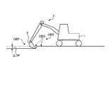
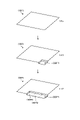
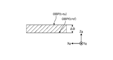
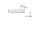
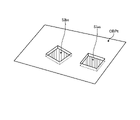
図5は、実施形態1に係る油圧ショベル1が施工する施工現場の一例を示す図である。実施形態1において、油圧ショベル1の施工対象OBPは、地面である。本実施形態において、施工対象OBPは、施工現場の少なくとも一部の領域である。本実施形態において油圧ショベル1が施工対象OBPに施す施工は、図5に示されるように、施工対象OBPの表面OBSから予め定められた深さΔDPだけ、表土を削り取る作業である。施工対象OBPのうち、施工が実行された部分は、施工実行部分OBFとなる。施工実行部分OBFは、施工計画によっては、施工が必要でない部分を示す場合もある。施工実行部分OBFは、施工対象OBPの少なくとも一部である。次に、制御システム50が求める形状情報を説明する。
FIG. 5 is a diagram showing an example of a construction site where the hydraulic excavator 1 according to Embodiment 1 constructs. In Embodiment 1, the construction target OBP of the hydraulic excavator 1 is the ground. In this embodiment, the construction target OBP is at least a partial area of the construction site. As shown in FIG. 5, the construction performed by the hydraulic excavator 1 on the OBP to be constructed in the present embodiment is the work of scraping off the topsoil by a predetermined depth ΔDP from the surface OBS of the OBP to be constructed. Of the construction target OBP, the part that has been constructed becomes the construction execution part OBF. The construction execution portion OBF may indicate a portion that does not require construction depending on the construction plan. The construction execution part OBF is at least part of the construction target OBP. Next, the shape information required by the control system 50 will be described.
<対象の撮像及び形状情報の生成>
図6は、実施形態1に係る作業機械の制御システムが求める形状情報について説明するための図である。この場合、形状情報は、油圧ショベル1がこれから施工しようとする部分である施工対象OBPは油圧ショベル1の前方にある。形状情報は、施工対象OBPから求められる。制御システム50は、施工対象OBPから形状情報を生成する場合、少なくとも一対の撮像装置30に施工対象OBPを撮像させる。本実施形態では、油圧ショベル1のオペレータが、図3に示される撮像スイッチ32を操作して撮像指令を検出処理装置51に入力すると、検出処理装置51は少なくとも一対の撮像装置30に施工対象OBPを撮像させる。
<Image capture of target and generation of shape information>
FIG. 6 is a diagram for explaining shape information required by the control system for the work machine according to the first embodiment. In this case, the shape information indicates that the construction target OBP, which is the portion that the hydraulic excavator 1 is about to construct, is located in front of the hydraulic excavator 1 . The shape information is obtained from the construction target OBP. The control system 50 causes at least a pair of imaging devices 30 to image the OBP to be constructed when the shape information is generated from the OBP to be constructed. In this embodiment, when the operator of the hydraulic excavator 1 operates the imaging switch 32 shown in FIG. is imaged.
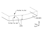
制御システム50の検出処理装置51は、少なくとも一対の撮像装置30が撮像した施工対象OBPの画像にステレオ方式による画像処理を施して、施工対象OBPの位置情報、本実施形態では三次元位置情報を求める。検出処理装置51が求めた施工対象OBPの位置情報は、撮像装置30の座標系における情報なので、グローバル座標系における位置情報に変換される。グローバル座標系における施工対象の位置情報が形状情報である。本実施形態において、形状情報は、グローバル座標系における施工対象OBPの表面OBSの位置Pr(Xg,Yg,Zg)を少なくとも1つ含む情報である。位置Pr(Xg,Yg,Zg)は、グローバル座標系における座標であり、三次元位置情報である。
The detection processing device 51 of the control system 50 performs stereo image processing on the images of the OBP to be constructed captured by at least a pair of imaging devices 30, and obtains the positional information of the OBP to be constructed, in this embodiment, the three-dimensional positional information. Ask. Since the position information of the OBP to be constructed obtained by the detection processing device 51 is information in the coordinate system of the imaging device 30, it is converted into position information in the global coordinate system. The positional information of the construction target in the global coordinate system is the shape information. In this embodiment, the shape information is information including at least one position Pr (Xg, Yg, Zg) of the surface OBS of the OBP to be constructed in the global coordinate system. The position Pr (Xg, Yg, Zg) is coordinates in the global coordinate system and three-dimensional position information.
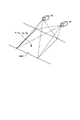
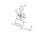
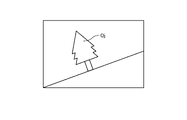
図7は、油圧ショベル1が重力の作用方向Gに対して傾斜している状態を示す図である。図8は、油圧ショベル1が重力の作用方向Gに対して傾斜している状態で、少なくとも一対の撮像装置30で対象Ojが撮像された画像の例を示す図である。傾斜面GDに油圧ショベル1が設置された状態で少なくとも一対の撮像装置30が対象Ojを撮像すると、撮像装置座標系(xs,ys,zs)は、重力の作用方向Gに対して傾く。この状態で得られた画像は、図8に示されるように対象Ojが傾斜するので、この画像にステレオ方式による画像処理が施されて形状情報が求められると、形状情報は傾きの影響を受ける可能性がある。制御システム50は、油圧ショベル1の姿勢をIMU24によって検出し、検出した油圧ショベル1の姿勢に関する情報を用いて形状情報を求める。
FIG. 7 is a diagram showing a state in which the hydraulic excavator 1 is tilted with respect to the action direction G of gravity. FIG. 8 is a diagram showing an example of an image of the target Oj captured by at least a pair of imaging devices 30 while the excavator 1 is tilted with respect to the direction G of gravity. When at least a pair of image capturing devices 30 capture an image of the object Oj with the hydraulic excavator 1 installed on the inclined surface GD, the image capturing device coordinate system (xs, ys, zs) is tilted with respect to the direction G of gravity. In the image obtained in this state, the object Oj is tilted as shown in FIG. there is a possibility. The control system 50 detects the posture of the hydraulic excavator 1 using the IMU 24 and obtains shape information using the information on the detected posture of the hydraulic excavator 1 .
図9は、実施形態1に係る制御システム50が形状情報を求めるための処理例を説明するための図である。図10は、実施形態1に係る制御システム50が求めた形状情報のデータファイルの一例を示す図である。少なくとも一対の撮像装置30によって撮像された画像から得られた施工対象OBPの位置Ps(xs,ys,zs)は、撮像装置座標系(xs,ys,zs)の座標である。形状情報は、グローバル座標系(Xg,Yg,Zg)における座標なので、検出処理装置51は、位置Ps(xs,ys,zs)をグローバル座標系(Xg,Yg,Zg)の位置Pg(xs,ys,zs)に変換する。位置Pg(xs,ys,zs)が、施工対象OBPの表面OBSの位置Pr(Xg,Yg,Zg)、すなわち形状情報である。
FIG. 9 is a diagram for explaining a processing example for obtaining shape information by the control system 50 according to the first embodiment. FIG. 10 is a diagram showing an example of a data file of shape information obtained by the control system 50 according to the first embodiment. The position Ps (xs, ys, zs) of the construction target OBP obtained from the images captured by at least one pair of imaging devices 30 is the coordinates of the imaging device coordinate system (xs, ys, zs). Since the shape information is coordinates in the global coordinate system (Xg, Yg, Zg), the detection processing device 51 converts the position Ps (xs, ys, zs) to the position Pg (xs, xs) in the global coordinate system (Xg, Yg, Zg). ys, zs). The position Pg (xs, ys, zs) is the position Pr (Xg, Yg, Zg) of the surface OBS of the object OBP, that is, the shape information.
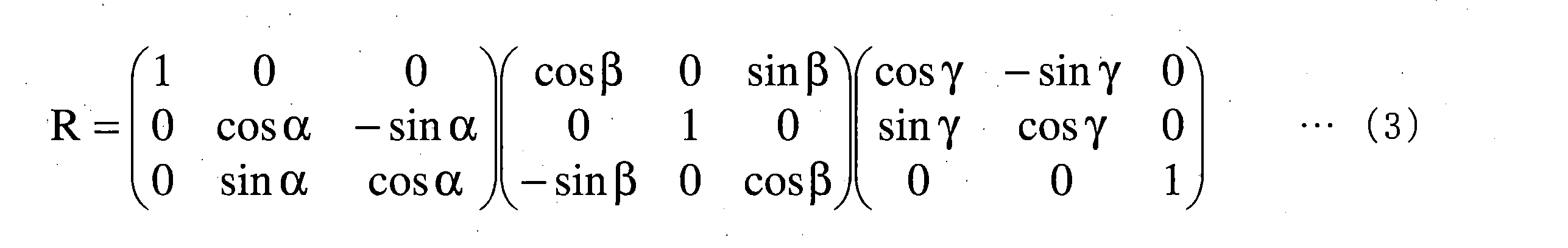
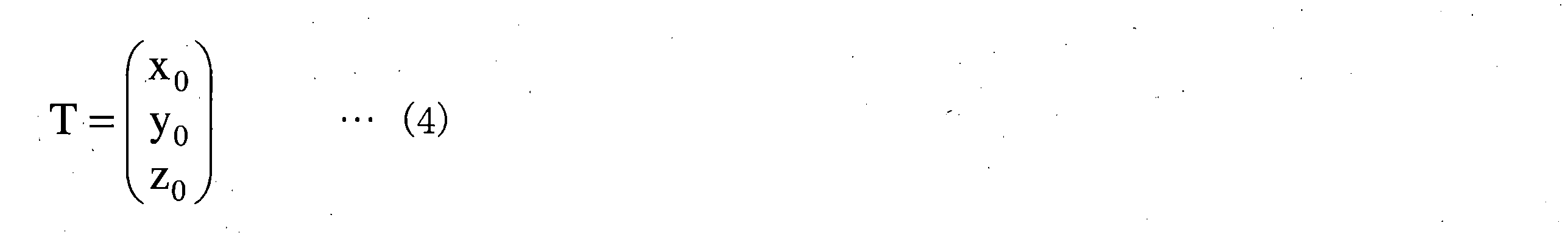
位置Ps(xs,ys,zs)は、式(1)によって撮像装置座標系(xs,ys,zs)から車体座標系(Xm,Ym,Zm)の位置Pm(xm、ym、zm)に変換される。車体座標系(Xm,Ym,Zm)の位置Pm(xm、ym、zm)は、式(2)によってグローバル座標系(Xg,Yg,Zg)の位置Pg(xs,ys,zs)に変換される。
Pm=R・Ps+T・・・(1)
Pg=Rimu・(Pm+Toff)+Tg・・・(2)
The position Ps (xs, ys, zs) is converted from the imaging device coordinate system (xs, ys, zs) to the position Pm (xm, ym, zm) in the vehicle body coordinate system (Xm, Ym, Zm) by Equation (1). be done. Position Pm (xm, ym, zm) in the vehicle body coordinate system (Xm, Ym, Zm) is converted to position Pg (xs, ys, zs) in the global coordinate system (Xg, Yg, Zg) by Equation (2). be.
Pm=R·Ps+T (1)
Pg=Rimu.(Pm+Toff)+Tg (2)
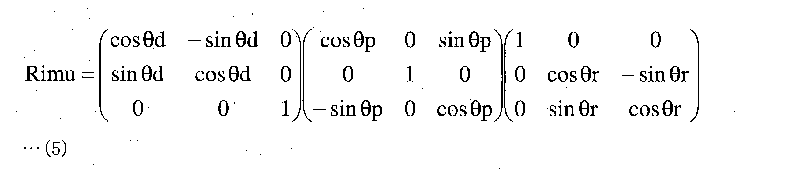
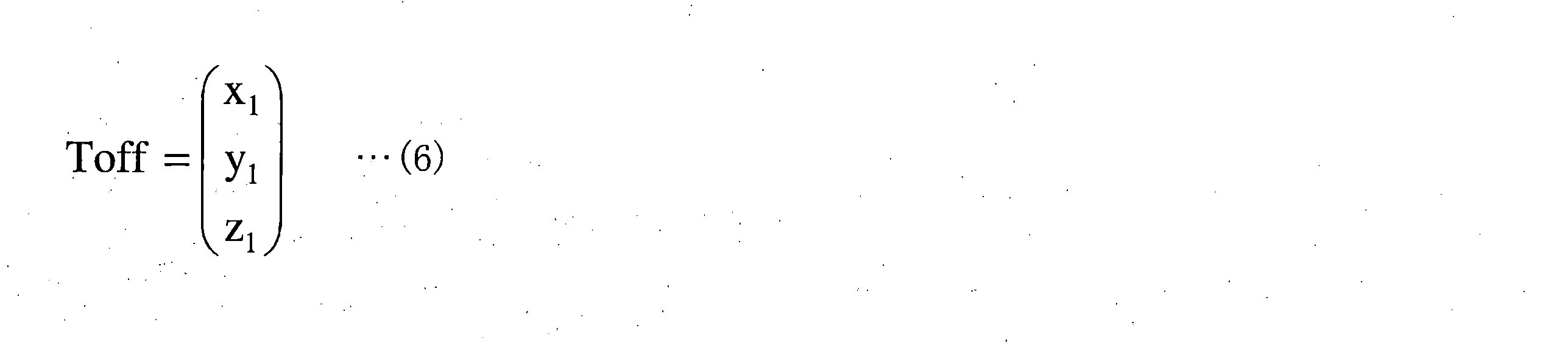
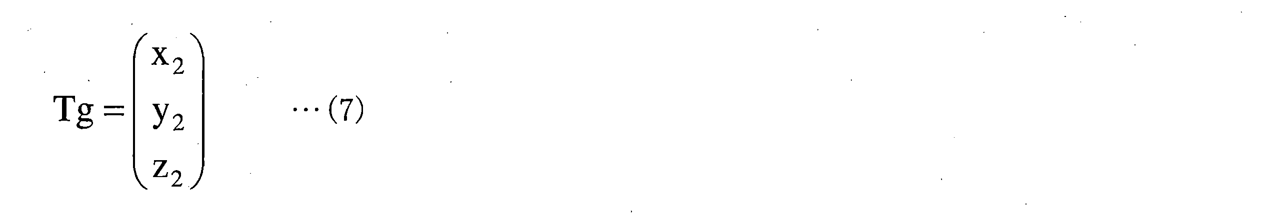
式(1)中のRは式(3)で表される回転行列、Tは式(4)の行列で表される並進ベクトルである。式(2)のRimuは式(5)で表される回転行列、Toffは式(6)の行列で表される並進ベクトルである。Toffは、車体座標系の原点からアンテナ21,22のいずれか一方までの距離のオフセット値を表す。Tgは式(7)の行列で表される、アンテナ21,22のいずれか一方の並進ベクトルである。回転行列R中の角度α、角度β及び角度γは、車体座標系に対する撮像装置座標系の傾きを表す。角度α、角度β及び角度γは、例えば、複数の撮像装置30が油圧ショベル1に取り付けられた後に予め求められて、検出処理装置51の記憶部に記憶される。行列Tのx0,y0,z0は撮像装置座標系の原点と車体座標系の原点との距離を表す。x0,y0,z0は、例えば、複数の撮像装置30が油圧ショベル1に取り付けられた後に計測されたり、油圧ショベル1の設計情報から予め求められたりして、検出処理装置51の記憶部に記憶される。
R in equation (1) is the rotation matrix represented by equation (3), and T is the translation vector represented by the matrix of equation (4). Rimu in Equation (2) is the rotation matrix represented by Equation (5), and Toff is the translation vector represented by the matrix of Equation (6). Toff represents the offset value of the distance from the origin of the vehicle body coordinate system to either one of the antennas 21 and 22 . Tg is the translation vector of either one of the antennas 21 and 22 represented by the matrix of Equation (7). The angles α, β, and γ in the rotation matrix R represent the tilt of the imaging device coordinate system with respect to the vehicle body coordinate system. The angles α, β, and γ are obtained in advance, for example, after the plurality of imaging devices 30 are attached to the hydraulic excavator 1 , and stored in the storage unit of the detection processing device 51 . x 0 , y 0 , and z 0 of the matrix T represent the distances between the origin of the imaging device coordinate system and the origin of the vehicle body coordinate system. For example, x 0 , y 0 , and z 0 are measured after the plurality of imaging devices 30 are attached to the hydraulic excavator 1 or obtained in advance from the design information of the hydraulic excavator 1, and stored in the detection processing device 51. stored in the part.
回転行列Rimu中の角度θr、角度θp及び角度θdは、油圧ショベル1のロール角、ピッチ角及び方位角である。ロール角θr、ピッチ角θp及び方位角θdは、油圧ショベル1の姿勢を表す。ロール角θr及びピッチ角θpは、図3に示されるIMU24が求めるか、IMU24の検出値から検出処理装置51が求めるものである。方位角θdは、図3に示されるアンテナ21,22及び位置検出装置23によって構成されたGPSコンパスによって求められる。より詳細には、方位角θdは、位置検出装置23によって2個のアンテナ21,22相対位置に基づいて求められる。ロール角θr、ピッチ角θp及び方位角θdは、油圧ショベル1の姿勢が変化することによって変化する。本実施形態においては、IMU24によって求められたヨー角θyが、GPSコンパスによって得られた方位角(方位データ)に代えて用いられてもよい。本実施形態において、ロール角θr、ピッチ角θp及び方位角θdは、少なくとも一対の撮像装置30が対象、例えば施工現場の施工対象及び施工後の施工現場等を検出したときにおいて、IMU24及び位置検出装置23によって検出された値である。ロール角θr、ピッチ角θp及びヨー各θy又は方位角θdは、IMU24以外又は位置検出装置23以外の装置、例えばジャイロ等によって求められてもよい。
The angles θr, θp, and θd in the rotation matrix Rimu are the roll angle, pitch angle, and azimuth angle of the hydraulic excavator 1 . A roll angle θr, a pitch angle θp, and an azimuth angle θd represent the attitude of the hydraulic excavator 1 . The roll angle .theta.r and the pitch angle .theta.p are obtained by the IMU 24 shown in FIG. The azimuth angle θd is determined by a GPS compass configured by the antennas 21 and 22 and the position detection device 23 shown in FIG. More specifically, the azimuth angle θd is obtained by the position detection device 23 based on the relative positions of the two antennas 21 and 22 . The roll angle θr, the pitch angle θp, and the azimuth angle θd change as the attitude of the hydraulic excavator 1 changes. In this embodiment, the yaw angle θy obtained by the IMU 24 may be used instead of the azimuth angle (azimuth data) obtained by the GPS compass. In the present embodiment, the roll angle θr, the pitch angle θp, and the azimuth angle θd are determined by the IMU 24 and position detection when at least a pair of imaging devices 30 detect targets, such as a construction target at a construction site and a construction site after construction. It is the value detected by the device 23 . The roll angle θr, pitch angle θp, yaw angle θy, or azimuth angle θd may be determined by a device other than the IMU 24 or the position detection device 23, such as a gyro.
行列Toffのx1,y1,z1は、車体座標系の原点と、図1及び図3に示されるアンテナ21,22の設置位置までの距離を表す。x1,y1,z1は、例えば、アンテナ21,22が油圧ショベル1に取り付けられた後に計測されたり、油圧ショベル1の設計情報から予め求められたりして、検出処理装置51の記憶部に記憶される。
x 1 , y 1 , and z 1 of the matrix Toff represent the distances between the origin of the vehicle body coordinate system and the installation positions of the antennas 21 and 22 shown in FIGS. For example, x 1 , y 1 , and z 1 are measured after the antennas 21 and 22 are attached to the hydraulic excavator 1, or obtained in advance from the design information of the hydraulic excavator 1, and stored in the storage unit of the detection processing device 51. stored in
行列Tgのx2,y2,z2は、図1及び図3に示されるアンテナ21,22及び位置検出装置23が検出したグローバル座標系におけるアンテナ21,22の位置を表す。x1,y1,z1は、油圧ショベル1の位置、より具体的にはアンテナ21,22の位置が変化することによって変化する。
x 2 , y 2 and z 2 of the matrix Tg represent the positions of the antennas 21 and 22 in the global coordinate system detected by the antennas 21 and 22 and the position detection device 23 shown in FIGS. x 1 , y 1 , and z 1 change as the position of the excavator 1, more specifically, the positions of the antennas 21 and 22 change.
検出処理装置51は、少なくとも一対の撮像装置30によって撮像された画像から得られた施工対象OBPの位置Ps(xs,ys,zs)を、式(1)から式(7)を用いてグローバル座標系における位置Pg(xg,yg,zg)に変換する。このとき、検出処理装置51は、IMU24からロール角θr及びピッチ角θpを取得し、位置検出装置23からアンテナ21,22のグローバル座標系における位置及び方位角θdを取得して、前述した変換に用いる。前述したように、検出処理装置51は、方位角θdの代わりに、IMU24が検出したヨー角θyを用いてもよい。検出処理装置51は、変換後の位置Pg(xg,yg,zg)を、施工対象OBPの表面OBSの位置Pr(Xg,Yg,Zg)、すなわち形状情報とする。本実施形態においては、形状情報の一例として施工対象OBPの表面OBSの位置Prを示しているが、形状情報はこれに限定されない。例えば、形状情報は、施工後における施工対象OBPの表面の位置及び施工途中における施工対象OBPの表面の位置であってもよい。
The detection processing device 51 converts the position Ps (xs, ys, zs) of the construction target OBP obtained from the images captured by at least the pair of imaging devices 30 to the global coordinates using equations (1) to (7). Transform to position Pg(xg, yg, zg) in the system. At this time, the detection processing device 51 acquires the roll angle θr and the pitch angle θp from the IMU 24, acquires the position and the azimuth angle θd of the antennas 21 and 22 in the global coordinate system from the position detection device 23, and converts them into use. As described above, the detection processing device 51 may use the yaw angle θy detected by the IMU 24 instead of the azimuth angle θd. The detection processing device 51 uses the converted position Pg (xg, yg, zg) as the position Pr (Xg, Yg, Zg) of the surface OBS of the OBP to be processed, that is, shape information. In this embodiment, the position Pr of the surface OBS of the construction target OBP is shown as an example of the shape information, but the shape information is not limited to this. For example, the shape information may be the position of the surface of the OBP to be constructed after construction and the position of the surface of the OBP to be constructed during construction.
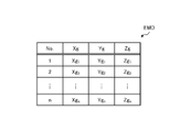
検出処理装置51は、少なくとも一対の撮像装置30によって撮像された施工対象OBPの領域全体にわたって、施工対象OBPの表面OBSの位置Pr(Xg,Yg,Zg)を求め、出力する。本実施形態において、検出処理装置51は、所定の単位毎に、図10に示されるように、求めた位置Pr(Xg,Yg,Zg)のデータファイルEMDを生成する。図10に示されるデータファイルEMDは、n個(nは1以上の整数)の位置Pr(Xg,Yg,Zg)の集合である。データファイルEMDも、本実施形態における形状情報に該当する。
The detection processing device 51 obtains and outputs the position Pr (Xg, Yg, Zg) of the surface OBS of the construction target OBP over the entire area of the construction target OBP imaged by at least the pair of imaging devices 30 . In this embodiment, the detection processing device 51 generates a data file EMD of the obtained position Pr (Xg, Yg, Zg) for each predetermined unit, as shown in FIG. The data file EMD shown in FIG. 10 is a set of n positions Pr(Xg, Yg, Zg) (where n is an integer equal to or greater than 1). The data file EMD also corresponds to shape information in this embodiment.
所定の単位は、例えば、一回の撮像によって得られた施工対象OBPの範囲、及び予め定めた施工対象OBPの範囲が挙げられる。予め定めた施工対象OBPの範囲は、一回の撮像によって得られた範囲の一部であってもよいし、一回の撮像によって得られた範囲を超える範囲であってもよい。後者の場合には複数回の撮像によって得られた範囲が対象となる。
The predetermined unit includes, for example, the range of the OBP to be constructed obtained by one imaging and the range of the OBP to be constructed in advance. The predetermined range of the OBP to be subjected to construction may be a part of the range obtained by one imaging, or may be a range exceeding the range obtained by one imaging. In the latter case, the target is the range obtained by multiple times of imaging.
本実施形態において、検出処理装置51はデータファイルEMDを生成したら、自身の記憶部に記憶させる。そして、検出処理装置51は、データファイルEMDの位置Prを用いて、目標施工情報を生成する。この他にも、施工管理装置57は、検出処理装置51が生成したデータファイルEMDを、通信装置25から図3に示される管理装置61、携帯端末装置64及び他の作業機械70の少なくとも一つに送信してもよい。
In this embodiment, when the detection processing device 51 generates the data file EMD, it stores it in its own storage unit. Then, the detection processing device 51 generates target construction information using the position Pr of the data file EMD. In addition, the construction management device 57 transfers the data file EMD generated by the detection processing device 51 from the communication device 25 to at least one of the management device 61, the mobile terminal device 64, and the other work machine 70 shown in FIG. may be sent to
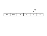
図11は、施工管理装置57によって送信される、データファイルEMDを含む情報の一例を示す図である。本実施形態において、図3に示される検出処理装置51の情報付与部51Bは、形状情報に、形状情報を特定するための時刻情報TMを付けて出力する。時刻情報TMは、時刻に基づいて、形状情報を特定する情報である。本実施形態では、情報付与部51Bは、図11に示されるように、時刻情報TM及び形状情報であるデータファイルEMDを含む作業情報LGを生成して、出力する。時刻情報TMは、例えば、少なくとも一対の撮像装置30が施工対象OBPを撮像した時刻であってもよいし、演算部51Aが形状情報を生成した時刻であってもよいし、情報付与部51Bが作業情報LGを出力する時刻であってもよいし、管理装置61及び携帯端末装置64のような油圧ショベル1の外部の装置が形状情報を取得した時刻であってもよい。すなわち、時刻情報TMは、施工前、施工途中又は施工後における施工対象OBPが、少なくとも一対の撮像装置30及び検出処理装置51によって検出された時刻から油圧ショベル1の外部の装置が形状情報を取得した時刻までの間に存在する少なくとも1つの時刻の情報である。時刻情報TMが、油圧ショベル1の外部の装置が形状情報を取得した時刻の情報である場合、情報付与部51Bが油圧ショベル1の外部の装置に設けられ、情報付与部51Bは、外部の装置が形状情報を取得した時刻を示す時刻情報TMを形状情報に付与する。
FIG. 11 is a diagram showing an example of information including the data file EMD, which is transmitted by the construction management device 57. As shown in FIG. In this embodiment, the information addition unit 51B of the detection processing device 51 shown in FIG. 3 outputs the shape information with time information TM for specifying the shape information. The time information TM is information specifying shape information based on time. In this embodiment, as shown in FIG. 11, the information providing unit 51B generates and outputs work information LG including time information TM and data file EMD that is shape information. The time information TM may be, for example, the time when at least a pair of imaging devices 30 captured images of the OBP to be constructed, the time when the calculation unit 51A generated the shape information, or the time when the information addition unit 51B It may be the time when the work information LG is output, or the time when a device external to the hydraulic excavator 1, such as the management device 61 and the portable terminal device 64, acquires the shape information. That is, the time information TM is obtained by a device external to the hydraulic excavator 1 from the time when the construction target OBP before construction, during construction, or after construction is detected by at least a pair of the imaging device 30 and the detection processing device 51. It is information of at least one time that exists until the time when the When the time information TM is information of the time when a device external to the hydraulic excavator 1 acquires the shape information, the information provision unit 51B is provided in the device external to the hydraulic excavator 1, and the information provision unit 51B is provided in the external device. attaches to the shape information time information TM indicating the time at which the shape information is obtained.
本実施形態において、作業情報LGは、時刻情報TM及びデータファイルEMDに加えて、目標施工情報TI、撮像位置PL及び油圧ショベル1の姿勢情報SIを含む。目標施工情報TIは、作業情報LGに含まれる形状情報、すなわちデータファイルEMDの情報から生成されたものである。撮像位置PLは、少なくとも一対の撮像装置30が、施工前、施工途中又は施工後における施工対象OBPを撮像した場所を示す情報である。撮像位置PLは、図3に示される位置検出装置23が検出したアンテナ21,22のグローバル座標における位置に基づいて求められる。姿勢情報SIは、油圧ショベル1の姿勢を示す情報であり、本実施形態ではロール角θr、ピッチ角θp及びヨー角θyである。ロール角θr、ヨー角θy及びヨー角θyは、IMU24の検出値であるが、ヨー角θyの代わりに位置検出装置23が検出した方位角θdが用いられてもよい。これらの他にも、作業情報LGは識別番号を含んでいてもよい。識別番号は、少なくとも一対の撮像装置30の位置を示す情報及び対象を撮像した撮像装置30を有する油圧ショベル1を識別するための情報である。識別番号としては、例えば、通信装置25のIPアドレスであってもよい。また、識別番号としては、少なくとも一対の撮像装置の製造番号及び油圧ショベル1の車体番号が用いられるが、これらに限定されない。
In this embodiment, the work information LG includes the target construction information TI, the imaging position PL, and the attitude information SI of the hydraulic excavator 1 in addition to the time information TM and the data file EMD. The target construction information TI is generated from the shape information included in the work information LG, that is, the information of the data file EMD. The imaging position PL is information indicating a location where at least a pair of imaging devices 30 captured an image of the construction target OBP before construction, during construction, or after construction. The imaging position PL is obtained based on the positions in the global coordinates of the antennas 21 and 22 detected by the position detection device 23 shown in FIG. The posture information SI is information indicating the posture of the hydraulic excavator 1, and in this embodiment, it is the roll angle θr, the pitch angle θp, and the yaw angle θy. The roll angle θr, yaw angle θy, and yaw angle θy are values detected by the IMU 24, but the azimuth angle θd detected by the position detection device 23 may be used instead of the yaw angle θy. In addition to these, the work information LG may contain an identification number. The identification number is information indicating the positions of at least a pair of imaging devices 30 and information for identifying the hydraulic excavator 1 having the imaging device 30 that has captured an image of the target. The identification number may be, for example, the IP address of the communication device 25 . Also, as the identification number, at least a pair of the manufacturing number of the imaging device and the vehicle body number of the hydraulic excavator 1 are used, but the identification number is not limited to these.
作業情報LGに含まれる情報は、前述した情報に限定されない。例えば、作業情報LGは、油圧ショベル1のオペレータを識別するためのオペレータIDを含んでいてもよい。作業情報LGは、検出処理装置51の情報付与部51Bがすべての情報を生成しなくてもよい。本実施形態では、情報付与部51Bは、少なくとも時刻情報TM及びデータファイルEMDを含む作業情報LGを生成して出力すればよい。時刻情報TM及びデータファイルEMD以外の情報は、例えば、施工管理装置57によって付与される。この場合、施工管理装置57は、施工情報生成装置52によって生成された目標施工情報TIを取得し、情報付与部51Bから取得した作業情報LGに追加する。また、施工管理装置57は、信号線59を介して識別番号及び撮像位置PLを取得して、作業情報LGに追加する。施工管理装置57は、作業情報LGを所定のタイミング、本実施形態では1日に2回、管理装置61及び携帯端末装置64の少なくとも一方に送信する。
Information included in the work information LG is not limited to the information described above. For example, the work information LG may include an operator ID for identifying the operator of the hydraulic excavator 1 . The work information LG does not have to be generated by the information adding section 51B of the detection processing device 51 . In the present embodiment, the information adding section 51B may generate and output the work information LG including at least the time information TM and the data file EMD. Information other than the time information TM and the data file EMD is provided by the construction management device 57, for example. In this case, the construction management device 57 acquires the target construction information TI generated by the construction information generation device 52, and adds it to the work information LG acquired from the information adding unit 51B. Also, the construction management device 57 acquires the identification number and the imaging position PL via the signal line 59 and adds them to the work information LG. The construction management device 57 transmits the work information LG to at least one of the management device 61 and the mobile terminal device 64 at a predetermined timing, twice a day in this embodiment.
本実施形態において、すくなくとも一対の撮像装置30が対象を撮像したら、検出処理装置51は、少なくとも時刻情報TM及びデータファイルEMDを含む作業情報LGを生成して出力し、通信装置25を介して油圧ショベル1の外部に送信する。油圧ショベル1の外部に送信された作業情報LGは、管理装置61が取得したり、携帯端末装置64が取得したりする。
In this embodiment, when at least a pair of imaging devices 30 have captured images of an object, the detection processing device 51 generates and outputs work information LG including at least time information TM and data file EMD, Send to the outside of Excavator 1. The work information LG transmitted to the outside of the hydraulic excavator 1 is acquired by the management device 61 or acquired by the mobile terminal device 64 .
本実施形態において、図3に示される撮像スイッチ32が操作されると、少なくとも一対の撮像装置30が対象を撮像する。検出処理装置51の演算部51Aは撮像装置30によって撮像された画像にステレオ方式による画像処理を施して形状情報を生成する。検出処理装置51の情報付与部51Bは、形状情報に時刻情報を付けた作業情報LGを出力する。作業情報LGは、施工管理装置57及び通信装置25を介して、又は通信装置25を介して管理装置61及び携帯端末装置64の少なくとも一方に送信する。
In this embodiment, when the imaging switch 32 shown in FIG. 3 is operated, at least a pair of imaging devices 30 will image the target. The calculation unit 51A of the detection processing device 51 performs stereoscopic image processing on the image captured by the imaging device 30 to generate shape information. The information addition unit 51B of the detection processing device 51 outputs work information LG in which time information is added to the shape information. The work information LG is transmitted to at least one of the management device 61 and the mobile terminal device 64 via the construction management device 57 and the communication device 25 or via the communication device 25 .
検出処理装置51は、油圧ショベル1の周辺を監視するため、所定の時間毎、例えば10分毎に少なくとも一対の撮像装置30に対象を撮像させる。少なくとも一対の撮像装置30によって撮像された二次元画像は、検出処理装置51の記憶部に記憶されて、ある程度の情報が蓄積されたら通信装置25を介して管理装置61に送信される。前述した二次元画像は、作業情報LGが管理装置61に送信されるタイミングで送信されてもよいし、撮像されたら速やかに管理装置61へ送信されてもよい。
In order to monitor the surroundings of the hydraulic excavator 1 , the detection processing device 51 causes at least a pair of imaging devices 30 to image an object every predetermined time, for example, every 10 minutes. The two-dimensional images captured by at least one pair of imaging devices 30 are stored in the storage unit of the detection processing device 51 and transmitted to the management device 61 via the communication device 25 when a certain amount of information is accumulated. The two-dimensional image described above may be transmitted at the timing when the work information LG is transmitted to the management device 61, or may be transmitted to the management device 61 immediately after being imaged.
本実施形態において、検出処理装置51が、例えば複数の撮像装置30が起動していることを認識していること、信号線59が断線していないこと、IMU24の出力が安定していること、及びGNSSによる測位がFIX(正常)であることを条件(許可条件)に、検出処理装置51は、撮像装置30を用いた三次元計測を許可する。許可条件が1つでも成立していない場合、撮像スイッチ32が操作されても、検出処理装置51は撮像装置30を用いた三次元計測を許可しない。IMU24の出力が安定しているとは、油圧ショベル1が静止している状態であることを意味する。撮像装置30による三次元計測に、前述した条件を設けることで、対象の計測精度の低下が抑制される。許可条件は、制御システム50が三次元計測を許可するための例示である。制御システム50は、許可条件のいずれか一つを用いてもよいし、許可条件を用いなくてもよい。
In this embodiment, the detection processing device 51 recognizes that, for example, a plurality of imaging devices 30 are activated, the signal line 59 is not disconnected, the output of the IMU 24 is stable, The detection processing device 51 permits three-dimensional measurement using the imaging device 30 on condition (permission condition) that positioning by GNSS is FIX (normal). If even one permission condition is not satisfied, the detection processing device 51 does not permit three-dimensional measurement using the imaging device 30 even if the imaging switch 32 is operated. That the output of the IMU 24 is stable means that the hydraulic excavator 1 is in a stationary state. By providing the above-described conditions for the three-dimensional measurement by the imaging device 30, a decrease in measurement accuracy of the target is suppressed. The permission conditions are examples for the control system 50 to permit three-dimensional measurement. Control system 50 may use any one of the permit conditions or may use no permit conditions.
図12は、データファイルEMDが管理装置61の記憶部に記憶される一例を示す図である。油圧ショベル1から送信された作業情報LGは、管理装置61の記憶部に記憶される。作業情報LGが携帯端末装置64に送信される場合、作業情報LGは携帯端末装置64の記憶部に記憶されてもよい。
FIG. 12 is a diagram showing an example in which the data file EMD is stored in the storage unit of the management device 61. As shown in FIG. The work information LG transmitted from the hydraulic excavator 1 is stored in the storage section of the management device 61 . When the work information LG is transmitted to the mobile terminal device 64 , the work information LG may be stored in the storage section of the mobile terminal device 64 .
管理装置61の記憶部内には、例えば、図12のデータテーブルTBに示されるように、時刻情報TMとデータファイルEMDとが対応付けられて記憶される。データテーブルTBは、管理装置61が新しい時刻情報TM及びデータファイルEMDを取得する毎に更新される。データファイルEMDに付される番号が同一の情報は、作業現場の同じ場所の形状情報を示す。管理装置61は、データテーブルTBに含まれるデータファイルEMDを用いて、施工現場の現状を示す情報(以下、適宜、現況情報と称する)を生成できる。この場合、データファイルEMDに付される番号が同一である場合、最新のデータファイルEMDを用いて現況情報が生成される。最新のデータファイルEMDであるか否かは、データファイルEMDに対応付けられた時刻情報TMによって判定される。例えば、2つのデータファイルEMD1が存在した場合、管理装置61は、それぞれのデータファイルEMD1に対応した時刻情報TMを比較し、新しい方のデータファイルEMD1を用いて現況情報を生成する。このようにすることで、管理装置61は、最新の現況情報を生成できる。
In the storage unit of the management device 61, for example, as shown in the data table TB of FIG. 12, the time information TM and the data file EMD are stored in association with each other. The data table TB is updated each time the management device 61 acquires new time information TM and data file EMD. Information with the same number attached to the data file EMD indicates the shape information of the same place in the work site. The management device 61 can use the data file EMD included in the data table TB to generate information indicating the current status of the construction site (hereinafter, appropriately referred to as current status information). In this case, if the numbers assigned to the data files EMD are the same, the current status information is generated using the latest data file EMD. Whether or not the data file EMD is the latest is determined by the time information TM associated with the data file EMD. For example, if two data files EMD1 exist, the management device 61 compares the time information TM corresponding to each data file EMD1 and generates the current status information using the newer data file EMD1. By doing so, the management device 61 can generate the latest current status information.
管理装置61は、時刻情報TMが付された形状情報、すなわちデータファイルEMDを用いて、油圧ショベル1の施工現場全体の現状の地形の情報、すなわち現況情報を出力する。例えば、管理装置61は、最新の時刻情報TMが付された各データファイルEMDを施工現場全体にわたって収集して結合することにより、油圧ショベル1の施工現場全体の現況情報を生成して出力する。施工現場全体の現況情報は、例えば、管理施設60の表示装置67に表示されたり、携帯端末装置64に表示されたりする。
The management device 61 uses the shape information to which the time information TM is attached, ie, the data file EMD, to output information on the current topography of the entire construction site of the hydraulic excavator 1, ie, current state information. For example, the management device 61 collects and combines the data files EMD with the latest time information TM over the entire construction site to generate and output current status information of the entire construction site of the hydraulic excavator 1 . The current status information of the entire construction site is displayed on the display device 67 of the management facility 60 or displayed on the mobile terminal device 64, for example.
施工現場全体の現況情報は、油圧ショベル1による施工結果を用いて生成されてもよいし、他の作業機械70による施工結果を用いて生成されてもよい。また、施工現場全体の現況情報は、油圧ショベル1及び他の作業機械70によらない施工結果、例えば、作業者がスコップ等によって施工した結果を用いて生成されてもよい。本実施形態において、施工現場全体の現況情報は、油圧ショベル1による施工結果と、他の作業機械70による施工結果と、油圧ショベル1及び他の作業機械70によらない施工結果との少なくとも一つを用いて生成されればよい。施工現場全体の現況情報は、油圧ショベルの施工管理装置57及び携帯端末装置64の少なくとも一方が生成して出力してもよい。
The current state information of the entire construction site may be generated using the construction result by the hydraulic excavator 1 or may be generated by using the construction result by the other working machine 70 . In addition, the current state information of the entire construction site may be generated using construction results that are not based on the hydraulic excavator 1 and other work machines 70, such as results of construction performed by workers using a shovel or the like. In the present embodiment, the current status information of the entire construction site is at least one of the construction result by the hydraulic excavator 1, the construction result by the other work machine 70, and the construction result not by the hydraulic excavator 1 and the other work machine 70. may be generated using At least one of the construction management device 57 and the portable terminal device 64 of the hydraulic excavator may generate and output the current status information of the entire construction site.
図13は、施工現場全体の施工対象OBPtとデータファイルEMDに対応した範囲との関係を示す図である。図13は、最新のデータファイルEMD1,EMD2,・・・EMDmに対応した範囲が施工現場全体の施工対象OBPt内に表示された例を示している。データファイルEMD1,EMD2,EMDmに対応した範囲は、データファイルEMD1,EMD2,・・・EMDmに含まれる三次元位置情報で特定される範囲である。
FIG. 13 is a diagram showing the relationship between the construction target OBPt of the entire construction site and the range corresponding to the data file EMD. FIG. 13 shows an example in which ranges corresponding to the latest data files EMD1, EMD2, . The ranges corresponding to the data files EMD1, EMD2, EMDm are ranges specified by the three-dimensional position information included in the data files EMD1, EMD2, . . . EMDm.
管理装置61は、例えば、施工現場全体の施工対象OBPtに、データファイルEMD1,EMD2,EMDmに対応した範囲を重ねた情報を生成する。そして、管理装置61は、例えば、管理施設60内の表示装置67に、生成した情報を表示させる。このようにすると、最新のデータファイルEMD1,EMD2,・・・EMDmが施工対象OBPt内に表示されるので、施工現場の現状が示される。管理装置61は、時刻情報TMが同一又は同一とみなせるデータファイルEMD同士を組み合わせることで、施工現場の現状の状況を得ることができる。時刻情報TMが同一とみなせるとは、予め定められた時間の範囲内の時刻情報TMに対応するデータファイルEMDは、同一の時刻に得られたものとして取り扱されることをいう。例えば、朝9時から夕方17:00までを予め定められた時間の範囲とした場合、ある曜日におけるこの時間の範囲内の時刻情報TMを持つデータファイルEMDは、同一の時刻に得られたものとして取り扱われ、曜日が変われば異なる時刻に得られたものとして取り扱われる。
For example, the management device 61 generates information in which ranges corresponding to the data files EMD1, EMD2, and EMDm are superimposed on the construction target OBPt of the entire construction site. The management device 61 then causes the display device 67 in the management facility 60 to display the generated information, for example. In this way, the latest data files EMD1, EMD2, . The management device 61 can obtain the current situation of the construction site by combining data files EMD that have the same time information TM or can be regarded as the same. The fact that the time information TM can be regarded as the same means that the data files EMD corresponding to the time information TM within a predetermined time range are treated as being obtained at the same time. For example, if a predetermined time range is from 9:00 in the morning to 17:00 in the evening, data files EMD having time information TM within this time range on a certain day of the week are those obtained at the same time. , and different days of the week are treated as having been obtained at different times.
図14は、施工現場全体の施工対象OBPtの変化を時系列に並べたものである。時刻t=tsは、施工現場の施工が開始される前の状態を示している。時刻t=t1において、施工対象OBPtは領域OBPf1が施工されている。領域OBPf1は、時刻t=t1における形状情報、すなわちデータファイルEMDに含まれる三次元情報によって特定されるので、施工前における施工対象OBPtに領域OBPf1を重ねることで、時刻t=t1における施工現場全体の状態が分かる。
FIG. 14 shows chronological changes in construction target OBPt for the entire construction site. Time t=ts indicates the state before construction of the construction site is started. At time t=t1, area OBPf1 is being constructed in OBPt to be constructed. The area OBPf1 is specified by the shape information at time t=t1, that is, the three-dimensional information included in the data file EMD. status is known.
時刻t=t2において、施工対象OBPtは領域OBPf1に加え、領域OBPf2及び領域OBPf3がさらに施工されている。領域OBPf2及び領域OBPf3は、時刻t=t2における形状情報、すなわちデータファイルEMDに含まれる三次元情報によって特定されるので、施工前における施工対象OBPに領域OBPf2及び領域OBPf3を重ねることで、時刻t=t2における施工現場全体の状態が分かる。時刻t=t2において、領域OBPf1はすでに施工されているので、時刻t=t2においては領域OBPf1に対応する形状情報、すなわち領域OBPf1に対応するデータファイルEMDが得られていなくてもよい。領域OBPf1に対応するデータファイルEMDが得られていない場合、領域OBPf1については時刻t=t1における情報が最新となる。
At time t=t2, in addition to the area OBPf1, the area OBPf2 and the area OBPf3 are further constructed in the construction target OBPt. The area OBPf2 and the area OBPf3 are specified by the shape information at the time t=t2, that is, the three-dimensional information included in the data file EMD. = The state of the entire construction site at t2 is known. At time t=t2, area OBPf1 has already been constructed, so shape information corresponding to area OBPf1, that is, data file EMD corresponding to area OBPf1 may not be obtained at time t=t2. If the data file EMD corresponding to the area OBPf1 has not been obtained, the information at the time t=t1 is the latest for the area OBPf1.
時刻t=t2においては、領域OBPf2及び領域OBPf3とともに、時刻t=t1における領域OBPf1が施工前における施工対象OBPtに重ねられる。時刻t=t2において、領域OBPf1に対応する形状情報、すなわち領域OBPf1に対応するデータファイルEMDが得られている場合、最新のデータファイルEMDに基づく領域OBPf1が、領域OBPf2及び領域OBPf3とともに、施工前における施工対象OBPtに重ねられる。
At time t=t2, along with the areas OBPf2 and OBPf3, the area OBPf1 at time t=t1 overlaps the construction target OBPt before construction. At time t=t2, when the shape information corresponding to the area OBPf1, that is, the data file EMD corresponding to the area OBPf1 is obtained, the area OBPf1 based on the latest data file EMD along with the area OBPf2 and the area OBPf3 have been processed before construction. is superimposed on the construction target OBPt in .
管理装置61は、時刻t=ts,t1,t2の順に、施工対象OBPt全体の現況情報を生成して、例えば管理施設60内の表示装置67に、生成した現況情報を三次元画像で表示させる。この場合、管理装置61は、現況情報を時刻毎にコマ送りで表示させることができる。このようにすることで、管理者は、日々の施工の進捗状況を容易に理解できる。携帯端末装置64は、通信回線NTWを介して管理装置61にアクセスして現況情報を取得し、現況情報を画面に表示してもよい。このようにすれば、管理施設60にいない施工現場の作業者も、日々の施工の進捗状況を容易に理解できる。
The management device 61 generates current status information of the entire construction target OBPt in the order of times t=ts, t1, and t2, and causes the display device 67 in the management facility 60, for example, to display the generated current status information as a three-dimensional image. . In this case, the management device 61 can display the current status information frame by frame. By doing so, the manager can easily understand the daily progress of construction. The mobile terminal device 64 may access the management device 61 via the communication line NTW, acquire the current status information, and display the current status information on the screen. In this way, even workers at the construction site who are not at the management facility 60 can easily understand the daily progress of construction.
図15及び図16は、異なる時刻に得られた形状情報の差分から、除去された土の量又は盛土の量を求める例を示す図である。本実施形態においては、異なる時刻に得られた形状情報に基づいて、除去された土の量又は盛土の量が求められる。施工前における時刻t=tsの施工対象OBPが施工されて、施工後の対象OBPfになったとする。グローバル座標系(Xg,Yg,Zg)において、施工後における時刻t=tfで得られた形状情報のZg座標と、施工前における時刻t=tsで得られた形状情報のZg座標との差分はΔDである。差分ΔDが負の場合は土を除去した場合であり、差分ΔDが正の場合は盛土の場合である。差分ΔDに、施工された範囲のXg方向における寸法及びYg軸方向における寸法を乗ずることにより、施工対象OBPの除去された土の量又は盛土の量(本実施形態において、土の量は体積)が得られる。本実施形態においては、異なる時刻に得られた形状情報に基づいて、油圧ショベル1のみならず、他の作業機械70によって除去された土の量又は盛土の量が求められてもよい。
15 and 16 are diagrams showing examples of determining the amount of removed soil or the amount of embankment from differences in shape information obtained at different times. In this embodiment, the amount of removed soil or the amount of embankment is obtained based on shape information obtained at different times. Assume that the pre-construction target OBP at time t=ts is constructed and becomes the post-construction target OBPf. In the global coordinate system (Xg, Yg, Zg), the difference between the Zg coordinate of the shape information obtained at time t=tf after construction and the Zg coordinate of the shape information obtained at time t=ts before construction is ΔD. When the difference ΔD is negative, the soil is removed, and when the difference ΔD is positive, the embankment is formed. By multiplying the difference ΔD by the dimension in the Xg direction and the dimension in the Yg axis direction of the construction target OBP, the amount of removed soil or the amount of embankment (in this embodiment, the amount of soil is the volume) is obtained. In the present embodiment, the amount of soil removed or the amount of embankment removed by not only the hydraulic excavator 1 but also other work machines 70 may be obtained based on shape information obtained at different times.
このように、形状情報であるデータファイルEMDと時刻情報TMとを対応付けることにより、施工現場の施工に関する様々な情報が得られる。データファイルEMD及び時刻情報TMを用いて現況情報を生成したり、盛土量又は除去された土の量を求めたりする処理は、管理装置61、携帯端末装置64及び油圧ショベル1の施工管理装置57のいずれが実行してもよい。また、管理装置61、携帯端末装置64又は油圧ショベル1の施工管理装置57のいずれかが前述した処理を実行し、通信回線NTWを介して他の機器に結果を送信してもよい。前述した処理の結果は、通信だけでなく、ストレージデバイスに記憶されて、他の機器に受け渡されてもよい。次に、目標施工情報について説明する。
In this way, by associating the data file EMD, which is shape information, with the time information TM, various information relating to construction at the construction site can be obtained. The processing of generating current status information using the data file EMD and time information TM and obtaining the amount of embankment or removed soil is performed by the management device 61, the portable terminal device 64, and the construction management device 57 of the hydraulic excavator 1. may be executed. Alternatively, any one of the management device 61, the mobile terminal device 64, or the construction management device 57 of the hydraulic excavator 1 may execute the above-described processing and transmit the results to other devices via the communication line NTW. The results of the above-described processing may be stored in a storage device and passed to other devices in addition to communication. Next, target construction information will be described.
<目標施工情報>
図17、図18及び図19は、実施形態1に係る作業機械の制御システム50が生成する目標施工情報を説明するための図である。本実施形態において、図3に示される施工情報生成装置52は、検出処理装置51によって生成された形状情報を用いて、目標施工情報、すなわち施工対象OBPが施工させる際に目標となる形状の位置情報を求める。本実施形態において、施工情報生成装置52は、図11及び図12に示されるように、形状情報に含まれる施工対象OBPの表面OBSの位置を示す情報を加工することによって、表面OBSの位置を変更して、目標施工情報を得る。
<Target construction information>
17, 18 and 19 are diagrams for explaining the target construction information generated by the work machine control system 50 according to the first embodiment. In this embodiment, the construction information generating device 52 shown in FIG. Ask for information. 11 and 12, the construction information generation device 52 processes the information indicating the position of the surface OBS of the construction target OBP included in the shape information, thereby determining the position of the surface OBS. Change to get target construction information.
図17に示される例は、施工対象OBPの表面OBSから距離ΔDPtの範囲を除去する施工例を示している。この場合、施工情報生成装置52は、施工対象OBPの表面OBSの位置Pra(Xga,Yga,Zga)を、距離ΔDPtだけ低くした位置Pta(Xta,Yta,Zta)を求める。本実施形態において、施工情報生成装置52は、位置Pra(Xga,Yga,Zga)のZgaをΔDPtだけ減じることにより、位置Pra(Xga,Yga,Zga)を、距離ΔDPtだけ低い位置に移動させる。したがって、位置Pta(Xta,Yta,Zta)は、位置Pta(Xga,Yga,Zga-ΔDPt)となる。このようにして得られた位置Pta(Xta,Yta,Zta)が、目標施工情報となる。施工情報生成装置52は、図3に示される検出処理装置51から形状情報、本実施形態ではデータファイルEMDを取得し、データファイルEMDに含まれるすべての位置Pr(Xg,Yg,Zg)に対してZgの値からΔDPtだけ減算することにより、目標施工情報を生成する。
The example shown in FIG. 17 shows a construction example in which a range of distance ΔDPt is removed from the surface OBS of the construction target OBP. In this case, the construction information generation device 52 obtains a position Pta (Xta, Yta, Zta) obtained by lowering the position Pra (Xga, Yga, Zga) of the surface OBS of the construction target OBP by a distance ΔDPt. In this embodiment, the construction information generating device 52 moves the position Pra (Xga, Yga, Zga) to a position lower by the distance ΔDPt by subtracting ΔDPt from Zga of the position Pra (Xga, Yga, Zga). Therefore, position Pta (Xta, Yta, Zta) becomes position Pta (Xga, Yga, Zga-ΔDPt). The position Pta (Xta, Yta, Zta) thus obtained becomes the target construction information. The construction information generation device 52 acquires the shape information, in this embodiment, the data file EMD, from the detection processing device 51 shown in FIG. The target construction information is generated by subtracting ΔDPt from the value of Zg.
図18に示される例は、施工対象OBPの表面OBSから距離ΔADtの範囲に、例えば土、砂又は岩石のような物体を盛る施工例を示している。この場合、施工情報生成装置52は、施工対象OBPの表面OBSの位置Prb(Xgb,Ygb,Zgb)を、距離ΔADtだけ高くした位置Ptb(Xtb,Ytb,Ztb)を求める。本実施形態において、施工情報生成装置52は、位置Prb(Xgb,Ygb,Zgb)のZgにΔADtを加算することにより、位置Prb(Xgb,Ygb,Zgb)を、距離ΔADtだけ高い位置に移動させる。したがって、位置Ptb(Xtb,Ytb,Ztb)は、位置Ptb(Xgb,Ygb,Zgb+ΔADt)となる。このようにして得られた位置Ptb(Xtb,Ytb,Ztb)が、目標施工情報となる。施工情報生成装置52は、図3に示される検出処理装置51から形状情報、本実施形態ではデータファイルEMDを取得し、データファイルEMDに含まれるすべての位置Pr(Xg,Yg,Zg)に対してZgの値にΔADtを加算することにより、目標施工情報を生成する。
The example shown in FIG. 18 shows a construction example in which an object such as soil, sand, or rock is piled up in the range of distance ΔADt from the surface OBS of the construction target OBP. In this case, the construction information generation device 52 obtains a position Ptb (Xtb, Ytb, Ztb) obtained by increasing the position Prb (Xgb, Ygb, Zgb) of the surface OBS of the construction target OBP by a distance ΔADt. In this embodiment, the construction information generating device 52 adds ΔADt to Zg of the position Prb (Xgb, Ygb, Zgb), thereby moving the position Prb (Xgb, Ygb, Zgb) to a position higher by the distance ΔADt. . Therefore, position Ptb (Xtb, Ytb, Ztb) becomes position Ptb (Xgb, Ygb, Zgb+ΔADt). The position Ptb (Xtb, Ytb, Ztb) thus obtained becomes the target construction information. The construction information generation device 52 acquires the shape information, in this embodiment, the data file EMD, from the detection processing device 51 shown in FIG. The target construction information is generated by adding ΔADt to the value of Zg.
このように、図17及び図18に示される施工は、施工対象OBPの表面OBSを一定の深さ(ΔDpt)又は一定の高さ(ΔADt)に変更(オフセット)する施工である。この他にも、例えば、施工対象OBPの表面OBSに所定の傾斜を有する勾配を設けるような施工に、制御システム50が適用されてもよい。このような施工は、例えば、施工後の地形が、水はけがよい地形になるように施工する場合に行われる。少なくとも一対の撮像装置30によって撮像された画像に基づき検出処理装置51が形状情報を生成した後、施工情報生成装置52は、形状情報が示す表面OBSの位置のZg座標について所定の距離を減算又は加算して、表面OBSに対し所定の勾配が設けられた目標施工情報を生成する。この場合も、施工情報生成装置52は、形状情報に含まれる施工対象OBPの表面OBSの位置を示す情報を加工することによって、表面OBSの位置を変更して、目標施工情報を得ることになる。
Thus, the construction shown in FIGS. 17 and 18 is construction that changes (offsets) the surface OBS of the OBP to be constructed to a constant depth (ΔDpt) or constant height (ΔADt). In addition to this, for example, the control system 50 may be applied to construction such that the surface OBS of the construction target OBP is provided with a predetermined slope. Such construction is performed, for example, when construction is performed so that the topography after construction is well-drained. After the detection processing device 51 generates shape information based on the images captured by at least a pair of imaging devices 30, the construction information generation device 52 subtracts or subtracts a predetermined distance from the Zg coordinate of the position of the surface OBS indicated by the shape information. Add to generate target construction information having a predetermined slope with respect to the surface OBS. Also in this case, the construction information generating device 52 processes the information indicating the position of the surface OBS of the construction target OBP included in the shape information, thereby changing the position of the surface OBS and obtaining the target construction information. .
施工現場は広い場合、図19に示されるように、少なくとも一対の撮像装置30が撮像する施工対象OBPa,OBPbは、施工現場全体の施工対象OBPtの一部となることがある。施工対象OBPa,OBPbの表面にある位置Pra,Prbから得られた位置Pta,Ptbを目標施工情報とする範囲OBPta,OBPtbも、施工現場全体の一部の情報となる。施工管理装置57は、形状情報と、この形状情報から得られた目標施工情報との差分を用いて、施工対象OBPから除去する土の量又は施工対象OBPに盛る土の量を求めることができる。
When the construction site is large, as shown in FIG. 19, the construction targets OBPa and OBPb captured by at least the pair of imaging devices 30 may be part of the construction targets OBPt of the entire construction site. Ranges OBPta and OBPtb in which positions Pta and Ptb obtained from positions Pra and Prb on the surface of the construction targets OBPa and OBPb are target construction information are also part of the entire construction site. The construction management device 57 can determine the amount of soil to be removed from the construction target OBP or the amount of soil to be piled up on the construction target OBP using the difference between the shape information and the target construction information obtained from this shape information. .
施工管理装置57が、油圧ショベル1の外部に設けられた、例えば管理装置61に設けられている場合、施工管理装置57は、油圧ショベル1から通信装置25を介して形状情報を取得する。施工管理装置57は、取得した形状情報と、この形状情報から得られた目標施工情報との差分を用いて、施工対象OBPから除去する土の量又は施工対象OBPに盛る土の量を求める。この場合、施工管理装置57は、油圧ショベル1から形状情報を取得して目標施工情報を生成する。施工管理装置57は、形状情報及び目標施工情報を油圧ショベル1から取得して、施工対象OBPから除去する土の量又は施工対象OBPに盛る土の量を求めてもよい。
When the construction management device 57 is provided outside the hydraulic excavator 1 , for example, in the management device 61 , the construction management device 57 acquires shape information from the hydraulic excavator 1 via the communication device 25 . The construction management device 57 uses the difference between the acquired shape information and the target construction information obtained from this shape information to determine the amount of soil to be removed from the OBP to be constructed or the amount of soil to be piled up on the OBP to be constructed. In this case, the construction management device 57 acquires shape information from the hydraulic excavator 1 and generates target construction information. The construction management device 57 may acquire the shape information and the target construction information from the hydraulic excavator 1 and obtain the amount of soil to be removed from the construction target OBP or the amount of soil to be piled up on the construction target OBP.
施工情報生成装置52は、目標施工情報を生成したら、自身の記憶部に記憶させる。施工情報生成装置52の記憶部に記憶された目標施工情報は、作業機制御装置56が作業機制御を実行する際の目標値として使用される。本実施形態において、作業機制御装置56は、作業機2、より具体的にはバケット8の刃先8BTが、目標施工情報に沿うように、油圧ショベル1の作業機2を制御する。すなわち、作業機制御装置56は、バケット8の刃先8BTを、目標施工情報によって表された、施工対象が施工されるときに目標とされる形状に沿って移動させる。施工管理装置57は、施工情報生成装置52が生成した目標施工情報を、通信装置25から図3に示される管理装置61、携帯端末装置64及び他の作業機械70の少なくとも一つに送信してもよい。次に、本実施形態に係る形状計測方法及び施工管理方法の処理例を説明する。
After generating the target construction information, the construction information generation device 52 stores it in its own storage unit. The target construction information stored in the storage unit of construction information generation device 52 is used as a target value when work implement control device 56 executes work implement control. In the present embodiment, the work implement control device 56 controls the work implement 2 of the hydraulic excavator 1 such that the work implement 2, more specifically the cutting edge 8BT of the bucket 8, conforms to the target construction information. That is, the work implement control device 56 moves the cutting edge 8BT of the bucket 8 along the shape targeted when the construction target is constructed, which is represented by the target construction information. The construction management device 57 transmits the target construction information generated by the construction information generation device 52 from the communication device 25 to at least one of the management device 61, the mobile terminal device 64, and the other work machine 70 shown in FIG. good too. Next, a processing example of the shape measurement method and the construction management method according to this embodiment will be described.
<実施形態1に係る形状計測方法及び施工管理方法の処理例>
図20は、実施形態1に係る形状計測方法及び施工管理方法の処理例を示すフローチャートである。制御システム50を有する油圧ショベル1は、本実施形態に係る形状計測方法を実行する。より詳細には、制御システム50は、施工対象OBPの形状情報を求め、得られた形状情報から目標施工情報を生成する。そして、制御システム50は、得られた目標施工情報に沿うように作業機2を制御する。施工管理システム100、本実施形態では管理装置61が、本実施形態に係る施工管理方法を実行する。
<Processing example of the shape measurement method and construction management method according to the first embodiment>
FIG. 20 is a flow chart showing a processing example of the shape measurement method and construction management method according to the first embodiment. A hydraulic excavator 1 having a control system 50 executes the shape measuring method according to the present embodiment. More specifically, the control system 50 obtains the shape information of the OBP to be constructed, and generates target construction information from the obtained shape information. Then, the control system 50 controls the work implement 2 in accordance with the obtained target construction information. The construction management system 100, which is the management device 61 in this embodiment, executes the construction management method according to this embodiment.
図3に示される撮像スイッチ32がオペレータによって操作されると、撮像スイッチ32から制御システム50に、施工対象OBPを撮像装置30に撮像させるための撮像指令が検出処理装置51に入力される。検出処理装置51は、撮像指令が入力されると、ステップS101において、少なくとも一対の撮像装置30に施工対象OBPを撮像させる。ステップS102において、検出処理装置51は、少なくとも一対の撮像装置30が撮像した画像にステレオ方式による画像処理を施して施工対象OBPの位置(三次元位置)を求め、得られた施工対象OBPの位置を用いて施工対象OBPの形状情報を生成する。検出処理装置51は、生成した目標施工情報を自身の記憶部及び施工管理装置57の記憶部57Mの少なくとも一方に記憶させる。形状情報を生成する手法は、前述した通りである。
When the imaging switch 32 shown in FIG. 3 is operated by the operator, an imaging command is input from the imaging switch 32 to the control system 50 to the detection processing device 51 to cause the imaging device 30 to capture an image of the construction target OBP. When the imaging command is input, the detection processing device 51 causes at least a pair of imaging devices 30 to image the construction target OBP in step S101. In step S102, the detection processing device 51 performs stereoscopic image processing on the images captured by at least the pair of imaging devices 30 to obtain the position (three-dimensional position) of the OBP to be worked. is used to generate the shape information of the OBP to be constructed. The detection processing device 51 stores the generated target construction information in at least one of its own storage unit and the storage unit 57M of the construction management device 57 . The method for generating shape information is as described above.
ステップS103において、施工情報生成装置52は、検出処理装置51から形状情報を取得し、目標施工情報を生成する。施工情報生成装置52は、生成した目標施工情報を自身の記憶部及び施工管理装置57の記憶部57Mの少なくとも一方に記憶させる。目標施工情報を生成する手法は、前述した通りである。本実施形態において、図3に示される施工管理装置57は、ステップS102で得られた形状情報及びステップS102で得られた目標施工情報を含む作業情報LGを、管理装置61及び携帯端末装置64の少なくとも一方に送信してもよい。
In step S103, the construction information generation device 52 acquires shape information from the detection processing device 51 and generates target construction information. The construction information generation device 52 stores the generated target construction information in at least one of its own storage unit and the storage unit 57M of the construction management device 57 . The method of generating the target construction information is as described above. In this embodiment, the construction management device 57 shown in FIG. You may send to at least one.
ステップS104において、油圧ショベル1は、施工対象OBPを施工する。このとき、作業機制御装置56は、作業機制御を実行する。すなわち、作業機制御装置56は、目標施工情報によって表された、施工対象OBPの施工時において目標とされる形状に沿って、バケット8の刃先8BTを移動させる。
In step S104, the hydraulic excavator 1 constructs the construction target OBP. At this time, the work implement control device 56 executes work implement control. That is, the work implement control device 56 moves the cutting edge 8BT of the bucket 8 along the target shape during construction of the OBP to be constructed, which is represented by the target construction information.
本実施形態では、油圧ショベル1が目標施工情報に基づき作業機制御を実行して施工する。施工現場では、作業者がスコップ等の作業具を使って手作業で掘削等をすることもある。このような場合、作業者は、油圧ショベル1から送信され、携帯端末装置64に取得された目標施工情報を確認して掘削等の施工を行ってもよい。
In this embodiment, the hydraulic excavator 1 performs work machine control based on the target construction information. At a construction site, workers may manually excavate using a work tool such as a shovel. In such a case, the worker may check the target construction information transmitted from the hydraulic excavator 1 and acquired by the portable terminal device 64 to perform construction such as excavation.
施工が終了したら、ステップS105において、検出処理装置51は施工後の施工対象OBPを少なくとも一対の撮像装置30に撮像させ、得られた画像を用いて形状情報を生成する。次に、ステップS106において、施工管理装置57は、検出処理装置51が生成した施工後の形状情報を、図3に示される通信装置25を介して管理装置61に送信する。施工管理装置57は、施工後の形状情報を、通信装置25を介して図3に示される携帯端末装置64に送信してもよい。施工後の形状情報を取得した管理装置61は、図3に示される携帯端末装置64に、通信装置62を介して施工後の形状情報を送信してもよい。図20に示される施工方法の処理例を示すフローチャートにおいて、ステップS106及びステップS107は実行されなくてもよい。
When the construction is finished, in step S105, the detection processing device 51 causes at least a pair of imaging devices 30 to image the construction target OBP after construction, and generates shape information using the obtained images. Next, in step S106, the construction management device 57 transmits the post-construction shape information generated by the detection processing device 51 to the management device 61 via the communication device 25 shown in FIG. The construction management device 57 may transmit the post-construction shape information to the mobile terminal device 64 shown in FIG. 3 via the communication device 25 . The management device 61 that has acquired the shape information after construction may transmit the shape information after construction to the portable terminal device 64 shown in FIG. 3 via the communication device 62 . In the flowchart showing the processing example of the construction method shown in FIG. 20, steps S106 and S107 may not be executed.
本実施形態においては、時刻情報TMが形状情報に付されているので、管理装置61及び携帯端末装置64の少なくとも一方は、制御システム50から送信された、所定の施行現場について施工前後の形状情報を表示装置67及び携帯端末装置64が有する表示装置の少なくとも一方の画面に表示させることにより、施工の進捗状況を表示させることができる。また、管理装置61及び携帯端末装置64の少なくとも一方は、施工現場の形状情報を時系列に並べて表示装置67及び携帯端末装置64が有する表示装置の少なくとも一方の画面に表示させたり、コマ送りで表示させたり、位置Prの座標の数値を表示させたりすることにより、日々の施工の進捗状況が分かりやすく表示される。油圧ショベル1の施工管理装置57も、時系列の施工現場の形状情報が管理装置61から得られていれば、表示装置58の画面58Dに施工現場の形状情報を時系列に並べて表示させることができる。すなわち、管理装置61、携帯端末装置64、施工管理装置及び施工管理装置57の少なくとも1つは、時刻情報が付された前記形状情報を複数用いて、前記作業機械の施工現場全体の地形の情報を時系列に表示する表示装置を有する。
In the present embodiment, since the time information TM is attached to the shape information, at least one of the management device 61 and the portable terminal device 64 receives the shape information before and after construction for the predetermined construction site, which is transmitted from the control system 50. is displayed on the screen of at least one of the display devices of the display device 67 and the mobile terminal device 64, the progress of construction can be displayed. At least one of the management device 61 and the mobile terminal device 64 arranges the shape information of the construction site in chronological order and displays it on the screen of at least one of the display device 67 and the display device of the mobile terminal device 64, or displays the information frame by frame. The daily progress of construction can be displayed in an easy-to-understand manner by displaying it or displaying the numerical values of the coordinates of the position Pr. The construction management device 57 of the hydraulic excavator 1 can also display the construction site shape information in chronological order on the screen 58D of the display device 58 if the time-series shape information of the construction site is obtained from the management device 61. can. That is, at least one of the management device 61, the mobile terminal device 64, the construction management device, and the construction management device 57 uses a plurality of pieces of the shape information to which the time information is attached to obtain topographical information of the entire construction site of the work machine. is displayed in chronological order.
本実施形態において、施工管理装置57は、施工後の形状情報に加え、目標施工情報を、通信装置25を介して管理装置61及び携帯端末装置64の少なくとも一方に送信してもよい。施工後の形状情報及び目標施工情報が、油圧ショベル1から管理装置61のみに送信される場合、管理装置61は、施工後の形状情報及び目標施工情報を、通信装置62を介して携帯端末装置64に送信してもよい。このようにすることで、管理装置61及び携帯端末装置64の少なくとも一方は、施工後の形状情報と目標施工情報とを表示装置67の画面に並べて表示したり、重ねて表示したりすることができるので、管理者等は、施工の進捗状況を迅速かつ容易に確認できる。
In the present embodiment, the construction management device 57 may transmit target construction information to at least one of the management device 61 and the mobile terminal device 64 via the communication device 25 in addition to the post-construction shape information. When the post-construction shape information and target construction information are transmitted from the hydraulic excavator 1 only to the management device 61, the management device 61 transmits the post-construction shape information and target construction information to the portable terminal device via the communication device 62. 64. By doing so, at least one of the management device 61 and the mobile terminal device 64 can display the post-construction shape information and the target construction information side by side on the screen of the display device 67, or display them in an overlapping manner. Therefore, the manager or the like can quickly and easily confirm the progress of construction.
<対象を検出する方法の変形例>
油圧ショベル1が有する少なくとも一対の撮像装置30が対象を検出する方法の変形例を説明する。少なくとも一対の撮像装置30は、油圧ショベル1の旋回体3に取り付けられる。旋回体3を旋回させながら少なくとも一対の撮像装置30が対象を撮像することにより、検出処理装置51は、油圧ショベル1の周囲全体の形状情報を得ることができる。
<Modified Example of Method for Detecting Target>
A modification of the method for detecting an object by at least a pair of imaging devices 30 of the hydraulic excavator 1 will be described. At least a pair of imaging devices 30 are attached to the revolving body 3 of the hydraulic excavator 1 . The detection processing device 51 can obtain shape information of the entire periphery of the hydraulic excavator 1 by capturing an image of the object with at least a pair of imaging devices 30 while the revolving body 3 is revolving.
旋回体3をさせながら少なくとも一対の撮像装置30が対象を撮像する場合、検出処理装置51は、撮像のタイミングで旋回体3の旋回を停止させてもよい。この場合、旋回体3は断続的に旋回する。旋回体3を連続して旋回させながら少なくとも一対の撮像装置30が対象を撮像する場合、次のようにする。
When at least a pair of imaging devices 30 capture an image of an object while rotating the revolving body 3, the detection processing device 51 may stop the revolving of the revolving body 3 at the timing of imaging. In this case, the revolving body 3 revolves intermittently. When at least a pair of imaging devices 30 capture images of an object while the revolving body 3 is continuously revolving, the following is done.
旋回体3を連続して旋回させながら少なくとも一対の撮像装置30が対象を撮像する場合、少なくとも一対の撮像装置30は、旋回体3が旋回を開始すると同時に撮像を開始し、旋回を停止することによって撮像を終了する。そして、検出処理装置51は、旋回体3の旋回中に取得した画像をもとにステレオ方式における画像処理を施して形状情報を求めてもよい。この場合、例えば、操作装置35のうち旋回体3を旋回させるための操作装置の操作にともなって出力される、パイロット圧の変化を示す信号又は電気信号を検出処理装置51が受信し、旋回体3の旋回開始のタイミング及び旋回停止のタイミングを判断し、少なくとも一対の撮像装置30に撮像を行わせる。
When at least a pair of imaging devices 30 capture an image of an object while the revolving body 3 is continuously revolving, the at least a pair of imaging devices 30 should start imaging and stop revolving at the same time when the revolving body 3 starts revolving. to end imaging. Then, the detection processing device 51 may obtain shape information by performing image processing in a stereo system based on an image acquired while the revolving body 3 is revolving. In this case, for example, the detection processing device 51 receives a signal indicating a change in the pilot pressure or an electric signal that is output in accordance with the operation of the operation device for rotating the revolving body 3 among the operation devices 35, and 3, the turning start timing and the turning stop timing are determined, and at least a pair of imaging devices 30 are caused to perform imaging.
旋回体3の旋回中に撮像装置30が対象を撮像することによる三次元計測が実行される場合、検出処理装置51は、撮像装置30のシャッターが切られる毎に時刻情報TMを生成して、撮像された画像と対応付ける。また、検出処理装置51は、旋回体3の旋回が開始された時刻又は旋回が停止した時刻を時刻情報TMとしてもよい。
When three-dimensional measurement is performed by imaging an object with the imaging device 30 while the revolving body 3 is turning, the detection processing device 51 generates time information TM each time the shutter of the imaging device 30 is released, Associate with the imaged image. Further, the detection processing device 51 may use the time when the swing body 3 starts swinging or stops swinging as the time information TM.
制御システム50は、少なくとも一対の撮像装置30によって撮像された対象の形状情報と、形状情報が得られた時刻情報とを対応付けるので、時刻情報に基づいて形状情報を組み合わせることで、作業現場の現状の状況を得ることができる。
The control system 50 associates the shape information of the object imaged by at least a pair of imaging devices 30 with the time information when the shape information was obtained. situation can be obtained.
油圧ショベル1のような作業機械は、複雑な地形の上で施工することも多く、撮像装置30が撮像する対象に対して大きく傾いている場合も多い。異なるタイミングで同じ場所で対象が撮像される場合、その場所は施工等が行われて地面の傾斜が変化してしまっていることも想定される。一対の撮像装置30は、油圧ショベル1が稼働している間に互いの相対的な位置関係がずれないように、油圧ショベル1に確実に取り付けられるので、油圧ショベル1の姿勢に応じて一対の撮像装置30の姿勢を変化させることは難しい。
A work machine such as the hydraulic excavator 1 is often constructed on complicated topography, and is often greatly inclined with respect to an object to be imaged by the imaging device 30 . When an object is imaged at the same place at different timings, it is assumed that construction or the like has been carried out at that place and the slope of the ground has changed. The pair of imaging devices 30 are securely attached to the hydraulic excavator 1 so that their relative positional relationship does not deviate while the hydraulic excavator 1 is in operation. It is difficult to change the posture of the imaging device 30 .
本実施形態において、制御システム50は、油圧ショベルの姿勢を用いて形状情報を求める。このとき、制御システム50は、IMU24の検出値と、位置検出装置23によって検出された油圧ショベル1の位置から得られた油圧ショベルの方位とを用いて、撮像装置30によって得られた三次元位置情報を、グローバル座標系における三次元位置情報に変換する。変換後の三次元位置情報が形状情報となる。このような処理により、制御システム50が求めた形状情報は、油圧ショベル1の傾斜の影響を抑制して、施工前後の地形の比較等を適切に行うことができる。
In this embodiment, the control system 50 obtains shape information using the posture of the hydraulic excavator. At this time, the control system 50 uses the detection value of the IMU 24 and the azimuth of the hydraulic excavator obtained from the position of the hydraulic excavator 1 detected by the position detection device 23 to detect the three-dimensional position obtained by the imaging device 30. Transform the information into three-dimensional positional information in a global coordinate system. The three-dimensional position information after conversion becomes the shape information. Through such processing, the shape information obtained by the control system 50 can suppress the influence of the inclination of the hydraulic excavator 1 and appropriately compare topography before and after construction.
制御システム50は、作業現場を撮像装置30によって撮像することで、作業現場の形状情報、すなわち作業現場の三次元位置情報を得ることができる。制御システム50は油圧ショベル1に設けられているので、作業現場の様々な場所に移動して形状情報を求めることができる。このようにして求めた複数の形状情報を、時刻情報に基づいて結合させることで、作業現場の状況及び作業現場の状況の変化を把握できるようになる。その結果、管理装置61は、対象の位置を検出する検出装置である少なくとも一対の撮像装置30及び検出処理装置51を有する作業機械である油圧ショベル1が得た検出結果を用いて施工状況を管理することができる。
The control system 50 can obtain shape information of the work site, that is, three-dimensional position information of the work site by imaging the work site with the imaging device 30 . Since the control system 50 is provided in the hydraulic excavator 1, the shape information can be obtained by moving to various places in the work site. By combining a plurality of pieces of shape information obtained in this way based on time information, it becomes possible to grasp the situation of the work site and changes in the situation of the work site. As a result, the management device 61 manages the construction status using the detection results obtained by the hydraulic excavator 1, which is a working machine having at least a pair of the imaging device 30 and the detection processing device 51, which are detection devices for detecting the position of the object. can do.
例えば、管理装置61は、同時刻とみなせる範囲内で得られた複数の異なる形状情報を抽出して結合させることにより、同時刻とみなせる範囲内における施工現場の施工状態を得ることができる。例えば、同時刻とみなせる範囲内における施工現場の施工状態を複数得ることにより、施工の進捗状況が把握される。このように、管理装置61は、撮像装置30及び検出処理装置51を有する作業機械と撮像装置30及び検出処理装置51を有さない作業機械とが混在する施工現場の施工状況を管理できる。このように、制御システム50を有する油圧ショベル1が作業現場に1台あれば、油圧ショベル1が自身の施工対象だけでなく、他の作業機械の施工対象についても形状情報を生成できるので、施工現場全体における施工の進捗管理及び出来高管理が可能になる。
For example, the management device 61 can obtain the construction state of the construction site within a range that can be considered to be the same time by extracting and combining a plurality of pieces of different shape information obtained within the range that can be considered to be the same time. For example, the progress of construction can be grasped by obtaining a plurality of construction states of construction sites within a range that can be regarded as being at the same time. In this way, the management device 61 can manage the construction status of a construction site where work machines having the imaging device 30 and the detection processing device 51 and work machines not having the imaging device 30 and the detection processing device 51 coexist. As described above, if there is one hydraulic excavator 1 having the control system 50 at the work site, the hydraulic excavator 1 can generate shape information not only for its own work target, but also for the work target of other work machines. It becomes possible to manage the progress of construction and the amount of work completed on the entire site.
制御システム50は、油圧ショベル1に設けられた少なくとも一対の撮像装置30を用いて施工対象を検出し、検出結果である少なくとも一対の画像から施工対象の形状情報を求め、得られた形状情報から対象を施工するときに目標とする形状の情報である形状情報を求める。したがって、制御システム50は、作業者が施工現場において、測量器等を使用して施工対象を測量して対象の形状を求めていた作業を不要にさせ、また、求められた施工対象に基づく目標とする形状の生成作業、つまり目標とする形状の情報を設計する作業を不要にさせる。その結果、制御システム50は、施工対象の現況地形を測量する手間及び施工対象の施工時に目標となる形状を求める際の手間を低減することができる。制御システム50は、作業者による、測量器等を使用した測量が困難である場所も、撮像装置30が撮像できる場所であれば目標施工情報を生成できるので、より効率的に作業機械による施工及び作業者の手による掘削等の施工が実現できる。また、制御システム50によって施工対象の測量ができるため、施工現場で測量を行う作業者の負担が軽減される。
The control system 50 detects a construction target using at least a pair of imaging devices 30 provided in the hydraulic excavator 1, obtains shape information of the construction target from at least a pair of images that are the detection results, and uses the obtained shape information. Shape information, which is information on a target shape when constructing an object, is obtained. Therefore, the control system 50 eliminates the need for the worker to survey the construction target using a surveying instrument or the like at the construction site to find the shape of the target, and also eliminates the need for the operator to measure the target shape. It eliminates the work of generating the desired shape, that is, the work of designing the information of the target shape. As a result, the control system 50 can reduce the labor for surveying the current topography of the construction target and the labor for obtaining the target shape during construction of the construction target. The control system 50 can generate target construction information even in locations where it is difficult for a worker to survey using a surveying instrument or the like, as long as the location can be imaged by the imaging device 30. Therefore, the control system 50 can more efficiently construct and perform construction by the work machine. Construction work such as excavation by workers can be realized. In addition, since the control system 50 can measure the construction target, the burden on the worker who performs the survey at the construction site is reduced.
例えば、CAD(Computer Aided Design)等の設計ツールで作成された、施工対象の目標施工情報が存在する場合、作業機械によって施工を行うために、その目標施工情報が示す場所、すなわちこれから施工しようとする場所に作業機械を移動させることが必要になる場合がある。制御システム50を有する油圧ショベル1は、少なくとも一対の撮像装置30を有し、これから施工する施工対象を少なくとも一対の撮像装置30によって撮像し、撮像結果に基づいて目標施工情報を生成する。このように、油圧ショベル1は、測量器として機能するとともに設計ツールとして機能する。つまり、施工する場所で、施工対象の目標施工情報を生成できるので、これから施工しようとする場所に移動しなくてもよい。その結果、移動時間及び設計期間が短縮できるので、作業効率が向上する。
For example, if there is target construction information for a construction target created with a design tool such as CAD (Computer Aided Design), the location indicated by the target construction information, that is, the location to be constructed in order to perform construction with a work machine. It may be necessary to move the work machine to a location where A hydraulic excavator 1 having a control system 50 has at least a pair of imaging devices 30, images a construction target to be constructed from now on with at least a pair of imaging devices 30, and generates target construction information based on imaging results. Thus, the hydraulic excavator 1 functions as a surveying instrument and as a design tool. In other words, since the target construction information for the construction target can be generated at the construction site, there is no need to move to the construction site. As a result, the travel time and design period can be shortened, thereby improving work efficiency.
本実施形態では、油圧ショベル1が有する制御システムが形状情報を生成したが、形状情報は管理装置61が生成してもよい。この場合、一対の撮像装置30によって撮像された画像にステレオ方式による画像処理が施された結果、油圧ショベル1の姿勢を示す情報及び油圧ショベル1のグローバル座標系における位置その他の形状情報を求めるために必要な情報が、通信装置25を介して管理装置61に送信される。
Although the shape information is generated by the control system of the excavator 1 in the present embodiment, the shape information may be generated by the management device 61 . In this case, as a result of subjecting the images picked up by the pair of imaging devices 30 to stereo image processing, information indicating the posture of the hydraulic excavator 1 and the position and other shape information of the hydraulic excavator 1 in the global coordinate system are obtained. is transmitted to the management device 61 via the communication device 25 .
油圧ショベル1等の作業機械は施工現場で移動するため、少なくとも一対の撮像装置30が撮像する現場の傾斜は様々であるし、撮像する場所の傾斜も施工によって時間の経過とともに変化することがある。このような施工現場においても、制御システム50は、油圧ショベル1の姿勢を表す情報、本実施形態ではロール角θr、ピッチ角θp及び方位角θdを用いて形状情報を生成するので、適切な施工管理を実現できる。
Since a working machine such as the hydraulic excavator 1 moves on a construction site, the site is photographed by at least a pair of imaging devices 30. Therefore, the inclination of the site to be imaged varies, and the inclination of the location to be imaged may change over time depending on the construction work. . Even at such a construction site, the control system 50 generates shape information using information representing the posture of the hydraulic excavator 1, in this embodiment, the roll angle θr, the pitch angle θp, and the azimuth angle θd. management can be achieved.
本実施形態において、制御システム50は、油圧ショベル1の姿勢を表すロール角θr、ピッチ角θp及び方位角θdを用いて形状情報を生成したが、油圧ショベル1の姿勢変化に対して一対の撮像装置30の相対的な位置関係を保持したまま、両者の姿勢が一定となる機構によって一対の撮像装置30が支持されるようにしてもよい。この場合、例えば、一対の撮像装置30の基線が常に水平を保つような機構で一対の撮像装置30が支持される。
In the present embodiment, the control system 50 generates the shape information using the roll angle θr, the pitch angle θp, and the azimuth angle θd representing the posture of the hydraulic excavator 1 . The pair of imaging devices 30 may be supported by a mechanism that maintains the postures of the two while maintaining the relative positional relationship of the devices 30 . In this case, for example, the pair of imaging devices 30 is supported by a mechanism that keeps the base lines of the pair of imaging devices 30 horizontal at all times.
本実施形態において、制御システム50は、制御システム50を有する油圧ショベル1及び制御システム50を有さない作業機械が施工する範囲及び施工された後の範囲を対象として形状情報を生成するが、制御システム50が形状情報を生成する対象はこれらに限定されない。例えば、制御システム50は、施工現場でスコップ等によって掘削等の作業する作業者が施工した範囲、又はこれから施工使用とする範囲の形状情報を生成することもできる。このようにすることで、制御システム50及び制御システム50を有する施工管理システム100は、施工現場全体の施工状況を管理することができる。前述のように、制御システム50は、施工前後の形状情報の差分から、作業者がスコップ等によって掘削や盛土を行った土量も求めることができる。
In the present embodiment, the control system 50 generates shape information for the range to be constructed by the hydraulic excavator 1 having the control system 50 and the work machine not having the control system 50 and the range after construction. The object for which the system 50 generates shape information is not limited to these. For example, the control system 50 can also generate shape information of a range that has been constructed by a worker who performs excavation or the like with a shovel or the like at a construction site, or a range that will be used for construction. By doing so, the control system 50 and the construction management system 100 having the control system 50 can manage the construction status of the entire construction site. As described above, the control system 50 can also obtain the amount of soil excavated or embanked by the worker using a shovel or the like from the difference in the shape information before and after construction.
本実施形態においては、制御システム50が作業機械である油圧ショベル1に備えられているが、形状情報を生成したり目標施工情報を生成したりするシステムは測量用の車両に備えられていてもよい。例えば、形状情報を生成する場合は、少なくとも一対の撮像装置30及び検出処理装置51が測量用の車両に備えられる。形状情報に加え、目標施工情報も生成する場合は、少なくとも一対の撮像装置30及び検出処理装置51に加え、施工情報生成装置52が測量用の車両に備えられる。いずれの場合でも、測量用の車両は、施工現場で作業する作業機械、管理装置61及び携帯端末装置64の少なくとも1つと通信できる通信装置25を有することが好ましい。
In this embodiment, the control system 50 is provided in the hydraulic excavator 1, which is a working machine. good. For example, when generating shape information, at least a pair of the imaging device 30 and the detection processing device 51 are provided in the vehicle for surveying. When target construction information is generated in addition to shape information, in addition to at least a pair of imaging device 30 and detection processing device 51, a construction information generation device 52 is provided in a vehicle for surveying. In any case, the surveying vehicle preferably has a communication device 25 capable of communicating with at least one of the work machines working at the construction site, the management device 61 and the mobile terminal device 64 .
本実施形態において、ステレオ方式における画像処理は、油圧ショベル1の外部、例えば管理施設60の管理装置61及び携帯端末装置64の少なくとも一つが行ってもよい。この場合、例えば、少なくとも一対の撮像装置30によって撮像された対象の一対の画像が、通信装置25を介して管理装置61及び携帯端末装置64の少なくとも一つに送信され、管理装置61及び携帯端末装置64の少なくとも一つは、対象の画像にステレオ方式による画像処理を施す。
In this embodiment, image processing in the stereo system may be performed by at least one of the outside of the hydraulic excavator 1, for example, the management device 61 of the management facility 60 and the mobile terminal device 64. FIG. In this case, for example, a pair of images of the object captured by at least a pair of imaging devices 30 are transmitted to at least one of the management device 61 and the mobile terminal device 64 via the communication device 25, and the management device 61 and the mobile terminal device At least one of the devices 64 performs stereoscopic image processing on the image of interest.
本実施形態において、油圧ショベル1の外部、例えば管理施設60の管理装置61及び携帯端末装置64の少なくとも一つが、形状情報を生成してもよい。特に、油圧ショベル1の姿勢を表すロール角θr、ピッチ角θp及び方位角θdを用いた変換を、油圧ショベル1の外部、例えば管理施設60の管理装置61及び携帯端末装置64の少なくとも一つが行ってもよい。この場合、少なくとも一対の撮像装置30によって撮像された対象の一対の画像にステレオ方式による画像処理が施された情報が、ロール角θr、ピッチ角θp及び方位角θdとともに、通信装置25を介して油圧ショベル1の外部、例えば管理施設60の管理装置61及び携帯端末装置64の少なくとも一つに送信される。
In this embodiment, the outside of the excavator 1, for example, at least one of the management device 61 of the management facility 60 and the mobile terminal device 64 may generate the shape information. In particular, the conversion using the roll angle θr, the pitch angle θp, and the azimuth angle θd representing the attitude of the hydraulic excavator 1 is performed by at least one of the outside of the hydraulic excavator 1, for example, the management device 61 of the management facility 60 and the portable terminal device 64. may In this case, information obtained by subjecting a pair of images of an object captured by at least a pair of imaging devices 30 to image processing by a stereo system is transmitted via the communication device 25 together with the roll angle θr, the pitch angle θp, and the azimuth angle θd. It is transmitted to at least one of the outside of the hydraulic excavator 1 , for example, the management device 61 of the management facility 60 and the mobile terminal device 64 .
本実施形態において、まず少なくとも一対の撮像装置30によって撮像された画像から得られた施工対象OBPの位置Psが求められ、その後、グローバル座標系の位置Pgに変換されるとともに、油圧ショベルの姿勢による傾きが補正されてもよい。本実施形態において、制御システム50は、例えばIMU24が油圧ショベル1の旋回体3の旋回及び油圧ショベル1の移動の少なくとも一方を検出したら、撮像装置30による撮像を禁止したり、検出処理装置51が形状情報を生成しないようにしたりする制御を実行してもよい。本実施形態において、油圧ショベル1が他の作業機械70に形状情報を送信し、他の作業機械70が目標施工情報を生成してもよい。
In this embodiment, first, the position Ps of the OBP to be worked is obtained from images captured by at least a pair of imaging devices 30, and is then converted to the position Pg of the global coordinate system. Tilt may be corrected. In this embodiment, for example, when the IMU 24 detects at least one of the turning of the revolving body 3 of the hydraulic excavator 1 and the movement of the hydraulic excavator 1, the control system 50 prohibits the imaging by the imaging device 30, or the detection processing device 51 You may perform control so that shape information may not be generated. In this embodiment, the hydraulic excavator 1 may transmit the shape information to the other work machine 70, and the other work machine 70 may generate the target construction information.
本実施形態で開示された構成は、以下の実施形態においても適宜適用することができる。
The configuration disclosed in this embodiment can also be appropriately applied to the following embodiments.
実施形態2.
実施形態2は、複数の作業機械が作業する施工現場において、制御システム50を有する作業機械である油圧ショベル1が施工対象OBPの情報を取得して形状情報及び目標施工情報の少なくとも一方を生成する。そして、油圧ショベル1は、生成した目標施工情報を他の作業機械、すなわち油圧ショベル1以外の作業機械に送信する。油圧ショベル1及び他の作業機械は、油圧ショベル1によって生成された目標施工情報を用いて施工対象OBPを施工する。他の作業機械は、図3に示される他の作業機械70の他、例えば、ブルドーザー、ホイールローダー及びグレーダーであってもよい。他の作業機械は、制御システム50を備えていてもよい。また、他の作業機械は、撮像装置30を備えていてもよいし、備えていなくてもよい。他の作業機械は、少なくとも通信装置を備えている。
Embodiment 2.
In the second embodiment, at a construction site where a plurality of work machines work, the hydraulic excavator 1, which is a work machine having a control system 50, acquires information on an OBP to be worked and generates at least one of shape information and target construction information. . The hydraulic excavator 1 then transmits the generated target construction information to other working machines, that is, working machines other than the hydraulic excavator 1 . The hydraulic excavator 1 and other work machines use the target construction information generated by the hydraulic excavator 1 to construct the construction target OBP. Other work machines may be, for example, bulldozers, wheel loaders and graders, as well as other work machines 70 shown in FIG. Other work machines may be equipped with control system 50 . Also, other work machines may or may not be equipped with the imaging device 30 . Other work machines have at least a communication device.
図21は、実施形態2に係る形状計測方法及び施工管理方法の処理例を示すフローチャートである。図22は、施工対象OBPの形状情報SIa,SIbと目標施工情報TIa,TIbとの関係を示す図である。図23は、施工対象OBPを施工した後における形状情報SIas,SIbsを示す図である。本実施形態に係る施工管理方法は、制御システム50によって実現される。本実施形態において、制御システム50は、施工管理システムとしても機能する。
FIG. 21 is a flow chart showing a processing example of the shape measurement method and construction management method according to the second embodiment. FIG. 22 is a diagram showing the relationship between the shape information SIa, SIb of the construction target OBP and the target construction information TIa, TIb. FIG. 23 is a diagram showing the shape information SIas and SIbs after construction of the construction target OBP. The construction management method according to this embodiment is implemented by the control system 50 . In this embodiment, the control system 50 also functions as a construction management system.
本実施形態及び以下の実施形態において、図3に示される制御システム50を有する油圧ショベル1が第1の作業機械に相当し、他の作業機械70が第2の作業機械に相当する。他の作業機械70は、制御システム50を有していないものとする。形状情報及び形状情報から生成される目標施工情報は、制御システム50の機器類が有する記憶部及び管理装置61の記憶部の少なくとも一方に記憶される。
In this embodiment and the following embodiments, the hydraulic excavator 1 having the control system 50 shown in FIG. 3 corresponds to the first working machine, and the other working machine 70 corresponds to the second working machine. Other work machines 70 do not have control systems 50 . The shape information and the target construction information generated from the shape information are stored in at least one of the storage unit of the equipment of the control system 50 and the storage unit of the management device 61 .
図3に示される撮像スイッチ32がオペレータによって操作されて撮像指令が検出処理装置51に入力されると、ステップS201において、検出処理装置51は、少なくとも一対の撮像装置30に施工対象OBPを撮像させる。少なくとも一対の撮像装置30が撮像する範囲は、油圧ショベル1が施工する範囲だけでなく、施工現場で作業する他の作業機械70が施工する範囲も撮像する。さらに、施工現場で作業する作業者が施工する範囲が撮像されてもよい。すなわち、制御システム50が有する少なくとも一対の撮像装置30が撮像する対象は、少なくとも一対の撮像装置30が取り付けられた油圧ショベル1の施工予定箇所とは異なる施工予定箇所と、油圧ショベル1の施工後の箇所とは異なる施工後の箇所とを少なくとも含む。油圧ショベル1以外の手段、例えば、作業者によるスコップ等の手段による施工予定箇所と、施工後の箇所との少なくとも一方が、少なくとも一対の撮像装置30が撮像する対象に含まれていてもよい。すなわち、制御システム50が有する少なくとも一対の撮像装置30が撮像する対象は、油圧ショベル1以外の手段による施工予定箇所と、油圧ショベル1以外の手段による施工後の箇所との少なくとも一方を含んでいてもよい。油圧ショベル1は、他の作業機械70が施工する範囲を撮像するために施工現場を移動したり、旋回体3を旋回させたりしてもよい。
When the imaging switch 32 shown in FIG. 3 is operated by the operator and an imaging command is input to the detection processing device 51, in step S201, the detection processing device 51 causes at least a pair of imaging devices 30 to image the construction target OBP. . The range captured by at least one pair of imaging devices 30 captures not only the range to be constructed by the hydraulic excavator 1 but also the range to be constructed by other work machines 70 working at the construction site. Furthermore, a range to be constructed by a worker working at a construction site may be imaged. In other words, the targets to be imaged by at least a pair of imaging devices 30 included in the control system 50 are a planned construction location different from the planned construction location of the excavator 1 to which the at least a pair of imaging devices 30 are attached, and a planned construction location of the hydraulic excavator 1 after construction. It includes at least a place after construction different from the place of. At least one of the location to be constructed by a means other than the excavator 1, such as a scoop by the operator, and the location after construction may be included in the targets captured by at least the pair of imaging devices 30. That is, the target imaged by at least one pair of imaging devices 30 included in the control system 50 includes at least one of a planned construction site by a means other than the hydraulic excavator 1 and a site after construction by a means other than the hydraulic excavator 1. good too. The hydraulic excavator 1 may move around the construction site or rotate the revolving body 3 in order to pick up an image of the range to be constructed by another work machine 70 .
ステップS202において、検出処理装置51は、少なくとも一対の撮像装置30が撮像した画像にステレオ方式による画像処理を施して施工対象OBPの位置(三次元位置)を求め、得られた施工対象OBPの位置を用いて施工対象OBPの形状情報を生成する。図22に示されるように、油圧ショベル1の施工対象OBPからは形状情報SIaが生成され、他の作業機械70の施工対象OBPからは形状情報SIbが生成される。検出処理装置51は、生成された形状情報SIa,SIbを、自身の記憶部及び施工管理装置57の記憶部57Mの少なくとも一方に記憶させる。形状情報を生成する手法は、実施形態1で説明した通りである。
In step S202, the detection processing device 51 performs stereoscopic image processing on the images captured by at least the pair of imaging devices 30 to determine the position (three-dimensional position) of the OBP to be worked. is used to generate the shape information of the OBP to be constructed. As shown in FIG. 22 , shape information SIa is generated from the OBP to be worked on by the hydraulic excavator 1 , and shape information SIb is generated from the OBP to be worked on by the other work machine 70 . The detection processing device 51 stores the generated shape information SIa and SIb in at least one of its own storage unit and the storage unit 57M of the construction management device 57 . The method for generating shape information is as described in the first embodiment.
ステップS203において、施工情報生成装置52は、検出処理装置51から形状情報SIa,SIbを取得し、目標施工情報TIa,TIbを生成する。形状情報SIaからは目標施工情報TIaが生成され、形状情報SIbからは目標施工情報TIbが生成される。目標施工情報を生成する手法は、実施形態1で説明した通りである。施工情報生成装置52は、生成した目標施工情報を自身の記憶部及び施工管理装置57の記憶部57Mの少なくとも一方に記憶させる。この場合、生成されたすべての目標施工情報、すなわち油圧ショベル1の施工対象OBPの目標施工情報及び他の作業機械70の施工対象OBPの目標施工情報が、施工情報生成装置52の記憶部に記憶される。ステップS203において、制御システム50は、生成された目標施工情報を記憶部に記憶せず、次のステップS204を実行するため、目標施工情報が生成されたら直ちに他の作業機械に送信するようにしてもよい。
In step S203, the construction information generation device 52 acquires the shape information SIa and SIb from the detection processing device 51 and generates target construction information TIa and TIb. Target construction information TIa is generated from the shape information SIa, and target construction information TIb is generated from the shape information SIb. The method of generating target construction information is as described in the first embodiment. The construction information generation device 52 stores the generated target construction information in at least one of its own storage unit and the storage unit 57M of the construction management device 57 . In this case, all the generated target construction information, that is, the target construction information of the construction target OBP of the hydraulic excavator 1 and the target construction information of the construction target OBP of the other work machine 70 are stored in the storage unit of the construction information generation device 52. be done. In step S203, the control system 50 does not store the generated target construction information in the storage unit, and executes the next step S204. good too.
ステップS204において、施工情報生成装置52又は施工管理装置57は、図3に示される通信装置25を介して他の作業機械70に目標施工情報を送信する。ステップS205Aにおいて、油圧ショベル1は、生成した目標施工情報を用いて施工対象OBPを施工する。ステップS205Bにおいて、他の作業機械70は、油圧ショベル1から取得した目標施工情報を用いて施工対象OBPを施工する。ステップS205A及びステップS205Bにおいて、油圧ショベル1及び他の作業機械70は、作業機制御装置56を備えており、目標施工情報に沿って作業機制御を実行可能である。油圧ショベル1及び他の作業機械70は、目標施工情報によって表された、施工対象OBPの施工時において目標とされる形状に沿って、バケット8の刃先8BT及び作業機を移動させる。
In step S204, the construction information generation device 52 or the construction management device 57 transmits the target construction information to the other work machine 70 via the communication device 25 shown in FIG. In step S205A, the hydraulic excavator 1 constructs the construction target OBP using the generated target construction information. In step S<b>205</b>B, the other work machine 70 uses the target construction information acquired from the hydraulic excavator 1 to construct the construction target OBP. In steps S205A and S205B, the hydraulic excavator 1 and other work machines 70 are equipped with the work machine control device 56, and can execute work machine control in accordance with the target construction information. The hydraulic excavator 1 and other work machine 70 move the cutting edge 8BT of the bucket 8 and the work machine along the target shape when constructing the OBP to be constructed, which is represented by the target construction information.
この場合、他の作業機械70が制御システム50を備えているのであれば、取得した目標施工情報に沿って作業機の動きが制御されてもよい。他の作業機械70が制御システム50を備えていないのであれば、他の作業機械70に備えられた表示装置に目標施工情報が表示され、オペレータが表示装置に表示された目標施工情報を見ながら作業機を操作してもよい。
In this case, if the other work machine 70 has the control system 50, the movement of the work machine may be controlled according to the acquired target construction information. If the other work machine 70 does not have the control system 50, the target construction information is displayed on the display device provided in the other work machine 70, and the operator looks at the target construction information displayed on the display device. You can operate the machine.
施工が終了したら、ステップS206において、検出処理装置51は施工後の施工対象OBPを少なくとも一対の撮像装置30に撮像させ、得られた画像を用いて図23に示される形状情報SIasを生成する。このとき、検出処理装置51は、他の作業機械が施工した施工対象OBPも撮像して図23に示される形状情報SIbsを生成する。検出処理装置51は、生成した形状情報を、自身の記憶部及び施工管理装置57の記憶部57Mの少なくとも一方に記憶させる。
When the construction is finished, in step S206, the detection processing device 51 causes at least a pair of imaging devices 30 to image the construction target OBP after construction, and generates the shape information SIas shown in FIG. 23 using the obtained images. At this time, the detection processing device 51 also images the construction target OBP constructed by the other work machine and generates the shape information SIbs shown in FIG. 23 . The detection processing device 51 stores the generated shape information in at least one of its own storage unit and the storage unit 57M of the construction management device 57 .
油圧ショベル1は、他の作業機械70が施工した範囲を撮像するために施工現場を移動したり、旋回体3を旋回させたりしてもよい。次に、ステップS207において、施工管理装置57は、検出処理装置51が生成した施工後の形状情報を、通信装置25を介して管理装置61に送信する。施工管理装置57が施工後の形状情報を図3に示される携帯端末装置64に送信してもよいこと、施工後の形状情報に加え、目標施工情報を、通信装置25を介して管理装置61及び携帯端末装置64の少なくとも一方に送信してもよいこと等は、実施形態1と同様である。本実施形態において、図21に示された施工方法の処理例を示すフローチャートにおいて、ステップS206及びステップS207は実行されなくてもよい。
The hydraulic excavator 1 may move the construction site or rotate the revolving body 3 in order to pick up an image of the range constructed by the other work machine 70 . Next, in step S<b>207 , the construction management device 57 transmits the post-construction shape information generated by the detection processing device 51 to the management device 61 via the communication device 25 . The construction management device 57 may transmit the post-construction shape information to the portable terminal device 64 shown in FIG. and at least one of the mobile terminal device 64 is the same as in the first embodiment. In the present embodiment, steps S206 and S207 may not be executed in the flowchart showing the processing example of the construction method shown in FIG.
本実施形態においては、制御システム50を有する少なくとも一台の作業機械、本実施形態では油圧ショベル1が、自身及び施工現場に存在する他の作業機械70の施工対象の形状情報を求める。このため、管理装置61は、制御システムを有する油圧ショベルによって得られた形状情報を用いて施工現場の施工状況を管理することができる。制御システム50は、作業機械の施工対象だけでなく、施工現場で作業する作業者の施工対象の形状情報も生成できるので、作業者による施工対象に対する測量が不要になる。その結果、施工現場全体の施工状況の管理が容易になる。
In this embodiment, at least one work machine having the control system 50, in this embodiment, the hydraulic excavator 1, obtains the shape information of the construction target of itself and other work machines 70 existing at the construction site. Therefore, the management device 61 can manage the construction status of the construction site using the shape information obtained by the hydraulic excavator having the control system. Since the control system 50 can generate not only the shape information of the construction target of the work machine but also the shape information of the construction target of the worker working at the construction site, the surveying of the construction target by the worker becomes unnecessary. As a result, it becomes easier to manage the construction status of the entire construction site.
制御システム50は、生成した形状情報に時刻情報を付けるので、施工管理システム100では、形状情報と時刻情報とが対応付けられて取り扱われる。このため、管理装置61は、時刻情報に基づいて施工状況の管理に用いる複数の形状情報を抽出することができる。例えば、管理装置61は、同時刻とみなせる範囲内で得られた複数の異なる形状情報を抽出して結合させることにより、同時刻とみなせる範囲内における施工現場の施工状態を得ることができる。例えば、同時刻とみなせる範囲内における施工現場の施工状態を複数得ることにより、施工の進捗状況が把握される。このように、施工管理システム100は、撮像装置30及び検出処理装置51を有する作業機械と撮像装置30及び検出処理装置51を有さない作業機械とが混在する施工現場の施工状況を管理できる。
Since the control system 50 attaches time information to the generated shape information, the construction management system 100 handles the shape information and the time information in association with each other. Therefore, the management device 61 can extract a plurality of pieces of shape information used for managing the construction status based on the time information. For example, the management device 61 can obtain the construction state of the construction site within a range that can be considered to be the same time by extracting and combining a plurality of pieces of different shape information obtained within the range that can be considered to be the same time. For example, the progress of construction can be grasped by obtaining a plurality of construction states of construction sites within a range that can be regarded as being at the same time. In this way, the construction management system 100 can manage the construction status of a construction site where work machines having the imaging device 30 and the detection processing device 51 and work machines not having the imaging device 30 and the detection processing device 51 coexist.
本実施形態においては、制御システム50を有している作業機械、本実施形態では油圧ショベル1が、施工現場に存在する他の作業機械70の施工対象の目標施工情報を生成する。このため、制御システム50を有している作業機械が施工現場に少なくとも1台存在すれば、この作業機械が施工現場の形状情報及び目標施工情報を生成し、他の作業機械は作成された目標施工情報を利用して施工することができる。このため、例えば、目標施工情報が存在しない施工現場を複数の作業機械で施工するときの効率が向上する。
In this embodiment, the work machine having the control system 50, which is the hydraulic excavator 1 in this embodiment, generates the target construction information of the construction target of another work machine 70 existing at the construction site. Therefore, if at least one work machine having the control system 50 exists at the construction site, this work machine generates the shape information and the target construction information of the construction site, and the other work machines generate the created targets. Construction can be performed using the construction information. For this reason, for example, efficiency is improved when a plurality of work machines are used to construct a construction site where target construction information does not exist.
本実施形態で開示された構成は、以下の実施形態においても適宜適用することができる。
The configuration disclosed in this embodiment can also be appropriately applied to the following embodiments.
実施形態3.
実施形態3は、油圧ショベル1が作業する施工現場において、制御システム50を有する油圧ショベル1が施工対象OBPの情報を取得して形状情報及び目標施工情報を生成し、生成した形状情報を、図3に示される管理施設60の管理装置61及び他の作業機械70に送信する。
Embodiment 3.
In the third embodiment, at the construction site where the hydraulic excavator 1 works, the hydraulic excavator 1 having the control system 50 acquires information on the OBP to be constructed, generates shape information and target construction information, and generates the generated shape information as shown in FIG. 3 to the management device 61 of the management facility 60 and other work machines 70 .
図24は、実施形態3に係る形状計測方法及び施工管理方法の処理例を示すフローチャートである。本実施形態に係る施工管理方法は、少なくとも制御システム50及び管理装置61によって実現される。本実施形態において、制御システム50及び管理装置61は、施工管理システムとしても機能する。
FIG. 24 is a flow chart showing a processing example of the shape measuring method and construction management method according to the third embodiment. The construction management method according to this embodiment is realized at least by the control system 50 and the management device 61 . In this embodiment, the control system 50 and management device 61 also function as a construction management system.
図3に示される撮像スイッチ32がオペレータによって操作されて撮像指令が検出処理装置51に入力されると、ステップS301において、検出処理装置51は、少なくとも一対の撮像装置30に施工対象OBPを撮像させる。少なくとも一対の撮像装置30が撮像する範囲は、油圧ショベル1が施工する範囲だけでなく、施工現場で作業する他の作業機械70施工する範囲も撮像する。油圧ショベル1は、他の作業機械70が施工する範囲を撮像するために施工現場を移動してもよい。
When the imaging switch 32 shown in FIG. 3 is operated by the operator and an imaging command is input to the detection processing device 51, in step S301, the detection processing device 51 causes at least a pair of imaging devices 30 to image the construction target OBP. . The range captured by at least one pair of imaging devices 30 captures not only the range to be constructed by the hydraulic excavator 1 but also the range to be constructed by other working machines 70 working at the construction site. The hydraulic excavator 1 may move around the construction site in order to take images of the range to be constructed by other work machines 70 .
ステップS302において、検出処理装置51は、少なくとも一対の撮像装置30が撮像した画像にステレオ方式による画像処理を施して施工対象OBPの位置(三次元位置)を求め、得られた施工対象OBPの位置を用いて施工対象OBPの形状情報を生成する。検出処理装置51は、生成された形状情報を、自身の記憶部及び施工管理装置57の記憶部57Mの少なくとも一方に記憶させる。形状情報を生成する手法は、実施形態1で説明した通りである。
In step S302, the detection processing device 51 performs stereoscopic image processing on the images captured by at least the pair of imaging devices 30 to obtain the position (three-dimensional position) of the OBP to be worked. is used to generate the shape information of the OBP to be constructed. The detection processing device 51 stores the generated shape information in at least one of its own storage unit and the storage unit 57M of the construction management device 57 . The method for generating shape information is as described in the first embodiment.
ステップS303において、施工情報生成装置52は、検出処理装置51から形状情報を取得し、目標施工情報を生成する。目標施工情報を生成する手法は、実施形態1で説明した通りである。施工情報生成装置52は、生成された目標施工情報を自身の記憶部及び施工管理装置57の記憶部57Mの少なくとも一方に記憶させる。この場合、生成されたすべての目標施工情報、すなわち油圧ショベル1の施工対象OBPの目標施工情報及び他の作業機械70の施工対象OBPの目標施工情報が、施工情報生成装置52の記憶部に記憶される。
In step S303, the construction information generation device 52 acquires shape information from the detection processing device 51 and generates target construction information. The method of generating target construction information is as described in the first embodiment. The construction information generation device 52 stores the generated target construction information in at least one of its own storage unit and the storage unit 57M of the construction management device 57 . In this case, all the generated target construction information, that is, the target construction information of the construction target OBP of the hydraulic excavator 1 and the target construction information of the construction target OBP of the other work machine 70 are stored in the storage unit of the construction information generation device 52. be done.
ステップS304において、検出処理装置51又は施工管理装置57は、図3に示される通信装置25を介して管理施設60の管理装置61に形状情報を送信する。施工情報生成装置52又は施工管理装置57は、他の作業機械70には目標施工情報を送信する。施工情報生成装置52又は施工管理装置57は、管理装置61に目標施工情報を送信してもよい。ステップS305において、管理装置61は、油圧ショベル1から取得した形状情報を記憶部57Mに記憶させる。油圧ショベル1から目標施工情報も取得している場合、管理装置61は、取得した目標施工情報を記憶部57Mに記憶させる。
In step S304, the detection processing device 51 or the construction management device 57 transmits the shape information to the management device 61 of the management facility 60 via the communication device 25 shown in FIG. The construction information generation device 52 or the construction management device 57 transmits target construction information to the other work machines 70 . The construction information generation device 52 or the construction management device 57 may transmit target construction information to the management device 61 . In step S305, the management device 61 stores the shape information acquired from the hydraulic excavator 1 in the storage unit 57M. When target construction information is also acquired from the hydraulic excavator 1, the management device 61 stores the acquired target construction information in the storage unit 57M.
ステップS306Aにおいて、油圧ショベル1は、制御システム50の施工情報生成装置52が生成した目標施工情報を用いて施工対象OBPを施工する。ステップS306Bにおいて、他の作業機械70は、油圧ショベル1から取得した目標施工情報を用いて施工対象OBPを施工する。ステップS306A及びステップS306Bにおいて、油圧ショベル1及び他の作業機械70は、目標施工情報によって表された、施工対象OBPの施工時において目標とされる形状に沿って、バケット8の刃先8BT及び作業機を移動させる。
In step S<b>306</b>A, the hydraulic excavator 1 uses the target construction information generated by the construction information generation device 52 of the control system 50 to construct the construction target OBP. In step S<b>306</b>B, the other work machine 70 uses the target construction information acquired from the hydraulic excavator 1 to construct the construction target OBP. In steps S306A and S306B, the hydraulic excavator 1 and other work machine 70 move the cutting edge 8BT of the bucket 8 and the work machine along the target shape during construction of the OBP to be constructed, which is represented by the target construction information. to move.
油圧ショベル1及び他の作業機械の少なくとも一方は、作業機制御装置56を備えずに、目標施工情報と自身の作業機2との位置関係が表示装置58の画面58Dに施工のガイダンス画像として表示可能なものであってもよい。実施形態2で説明したように、オペレータは、画面58Dを見ながら目標施工情報が示す形状に沿って作業機2を操作する。
At least one of the hydraulic excavator 1 and other work machines does not include the work machine control device 56, and the positional relationship between the target construction information and its own work machine 2 is displayed on the screen 58D of the display device 58 as a guidance image for construction. may be possible. As described in the second embodiment, the operator operates the work implement 2 along the shape indicated by the target construction information while viewing the screen 58D.
施工が終了したら、ステップS307において、油圧ショベル1の検出処理装置51は、施工後の施工対象OBPを少なくとも一対の撮像装置30に撮像させ、得られた画像を用いて形状情報を生成する。このとき、検出処理装置51は、他の作業機械が施工した施工対象OBPも撮像して形状情報を生成する。検出処理装置51は、生成された形状情報を自身の記憶部及び施工管理装置57の記憶部57Mの少なくとも一方に記憶させる。次に、ステップS308において、検出処理装置51又は施工管理装置57は、検出処理装置51によって生成された施工後の形状情報を管理装置61に送信する。このとき、検出処理装置51又は施工管理装置57は、図3に示される携帯端末装置64に施工後の形状情報を送信してもよい。施工後の形状情報を取得した管理装置61は、ステップS309において記憶部に施工後の形状情報を記憶させる。管理装置61は、図3に示される携帯端末装置64に施工後の形状情報を送信してもよい。
When the construction is finished, in step S307, the detection processing device 51 of the hydraulic excavator 1 causes at least a pair of imaging devices 30 to image the construction target OBP after construction, and generates shape information using the obtained images. At this time, the detection processing device 51 also images the construction target OBP constructed by another working machine to generate shape information. The detection processing device 51 stores the generated shape information in at least one of its own storage unit and the storage unit 57M of the construction management device 57 . Next, in step S<b>308 , the detection processing device 51 or the construction management device 57 transmits the post-construction shape information generated by the detection processing device 51 to the management device 61 . At this time, the detection processing device 51 or the construction management device 57 may transmit shape information after construction to the portable terminal device 64 shown in FIG. The management device 61 that has acquired the post-construction shape information stores the post-construction shape information in the storage unit in step S309. The management device 61 may transmit shape information after construction to the portable terminal device 64 shown in FIG.
第1変形例.
図25は、実施形態3の第1変形例に係る形状計測方法及び施工管理方法の処理例を示すフローチャートである。第1変形例は、制御システム50の施工情報生成装置52によって生成された目標施工情報が、管理装置61によって他の作業機械70に送信される点が実施形態3とは異なる。
First modification.
FIG. 25 is a flow chart showing a processing example of a shape measuring method and a construction management method according to the first modified example of the third embodiment. The first modified example differs from the third embodiment in that the target construction information generated by the construction information generation device 52 of the control system 50 is transmitted to the other work machine 70 by the management device 61 .
本変形例のステップS401からステップS405は、実施形態3のステップS301からステップS305と同一である。ステップS406において、管理装置61は、油圧ショベル1から取得した目標施工情報を、通信装置62を介して他の作業機械70に送信する。ステップS407A、ステップS407BからステップS410は、実施形態3のステップS406A、ステップS406BからステップS409と同一である。本変形例は、管理装置61と施工現場の作業機械との通信は可能であるが、油圧ショベル1と他の作業機械70との間の通信が実現できない場合に有効である。
Steps S401 to S405 of this modification are the same as steps S301 to S305 of the third embodiment. In step S<b>406 , the management device 61 transmits the target construction information acquired from the hydraulic excavator 1 to the other work machine 70 via the communication device 62 . Steps S407A, S407B to S410 are the same as steps S406A, S406B to S409 of the third embodiment. This modification is effective when communication between the management device 61 and the work machine at the construction site is possible, but communication between the hydraulic excavator 1 and the other work machine 70 cannot be realized.
本実施形態及びその変形例は、実施形態2と同様の作用効果を奏する。本実施形態で開示された構成は、以下の実施形態においても適宜適用することができる。
This embodiment and its modification have the same effect as the second embodiment. The configuration disclosed in this embodiment can also be appropriately applied to the following embodiments.
実施形態4.
図26は、実施形態4に係る形状計測方法及び施工管理方法の処理例を示すフローチャートである。実施形態4は、制御システム50を有する油圧ショベルから送信された形状情報を用いて、管理装置61が目標施工情報を生成する。本実施形態に係る施工管理方法は、少なくとも制御システム50及び管理装置61によって実現される。本実施形態において、制御システム50及び管理装置61は、施工管理システムとしても機能する。
Embodiment 4.
FIG. 26 is a flow chart showing a processing example of the shape measurement method and construction management method according to the fourth embodiment. In the fourth embodiment, the shape information transmitted from the hydraulic excavator having the control system 50 is used by the management device 61 to generate the target construction information. The construction management method according to this embodiment is realized at least by the control system 50 and the management device 61 . In this embodiment, the control system 50 and management device 61 also function as a construction management system.
実施形態4のステップS501及びステップS502は、実施形態3のステップS301及びステップS302と同一である。ステップS503において、油圧ショベル1は、生成された形状情報を、通信装置25を介して管理装置61に送信する。ステップS504において、管理装置61は、油圧ショベル1から取得した形状情報を記憶部に記憶させる。ステップS505において、管理装置61は、ステップS504出取得した形状情報を用いて目標施工情報を生成し、記憶部に記憶させる。ステップS506において、管理装置61は、生成した目標施工情報を、通信装置62を介して油圧ショベル1に送信する。
Steps S501 and S502 of the fourth embodiment are the same as steps S301 and S302 of the third embodiment. In step S<b>503 , the hydraulic excavator 1 transmits the generated shape information to the management device 61 via the communication device 25 . In step S504, the management device 61 stores the shape information acquired from the hydraulic excavator 1 in the storage unit. In step S505, the management device 61 generates target construction information using the shape information acquired in step S504, and stores it in the storage unit. In step S<b>506 , the management device 61 transmits the generated target construction information to the hydraulic excavator 1 via the communication device 62 .
ステップS507において、油圧ショベル1の施工管理装置57は、通信装置25を介して取得した目標施工情報を記憶部57Mに記憶するとともに、通信装置25を介して他の作業機械70に送信する。ステップS508A及びステップS508Bにおいて、油圧ショベル1及び他の作業機械70は、目標施工情報によって表された、施工対象OBPの施工時において目標とされる形状に沿って、バケット8の刃先8BT及び作業機を移動させる。ステップS509からステップS511は、実施形態3のステップS307からステップS309と同一である。
In step S<b>507 , the construction management device 57 of the hydraulic excavator 1 stores the target construction information acquired via the communication device 25 in the storage unit 57</b>M and transmits the information to the other work machine 70 via the communication device 25 . In steps S508A and S508B, the hydraulic excavator 1 and other work machine 70 move the cutting edge 8BT of the bucket 8 and the work machine along the target shape during construction of the OBP to be constructed, which is represented by the target construction information. to move. Steps S509 to S511 are the same as steps S307 to S309 of the third embodiment.
第1変形例.
図27は、実施形態4の第1変形例に係る形状計測方法及び施工管理方法の処理例を示すフローチャートである。第1変形例は、管理装置61によって生成された目標施工情報が、管理装置61によって油圧ショベル1及び他の作業機械70に送信される点が実施形態4とは異なる。
First modification.
FIG. 27 is a flow chart showing a processing example of a shape measuring method and a construction management method according to the first modified example of the fourth embodiment. The first modification differs from the fourth embodiment in that the target construction information generated by the management device 61 is transmitted to the hydraulic excavator 1 and other work machines 70 by the management device 61 .
本変形例のステップS601からステップS605は、実施形態4のステップS501からステップS505と同一である。ステップS606において、管理装置61は、生成した目標施工情報を、通信装置62を介して油圧ショベル1及び他の作業機械70に送信する。ステップS606A、ステップS606BからステップS610は、実施形態4のステップS507A、ステップS507BからステップS511と同一である。本変形例は、管理装置61と施工現場の作業機械との通信は可能であるが、油圧ショベル1と他の作業機械70との間の通信が実現できない場合に有効である。
Steps S601 to S605 of this modification are the same as steps S501 to S505 of the fourth embodiment. In step S<b>606 , the management device 61 transmits the generated target construction information to the hydraulic excavator 1 and other work machines 70 via the communication device 62 . Steps S606A, S606B to S610 are the same as steps S507A, S507B to S511 of the fourth embodiment. This modification is effective when communication between the management device 61 and the work machine at the construction site is possible, but communication between the hydraulic excavator 1 and the other work machine 70 cannot be realized.
本実施形態及びその変形例は、実施形態2と同様の作用効果を奏する。さらに、本実施形態及びその変形例は、管理装置61が目標施工情報を生成することにより、油圧ショベル1の制御システム50、より詳細には施工情報生成装置52の負荷を低減することができる。
This embodiment and its modification have the same effect as the second embodiment. Furthermore, according to this embodiment and its modification, the control system 50 of the hydraulic excavator 1, more specifically, the load on the construction information generation device 52 can be reduced by the management device 61 generating the target construction information.
以上、実施形態を説明したが、前述した内容により実施形態が限定されるものではない。また、前述した構成要素には、当業者が容易に想定できるもの、実質的に同一のもの、いわゆる均等の範囲のものが含まれる。前述した構成要素は適宜組み合わせることが可能である。実施形態の要旨を逸脱しない範囲で構成要素の種々の省略、置換及び変更のうち少なくとも1つを行うことができる。作業機械は、施工対象を施工、例えば掘削及び運搬等を行うことができれば油圧ショベルに限定されず、例えば、ホイールローダー及びブルドーザーのような作業機械であってもよい。
Although the embodiment has been described above, the embodiment is not limited by the contents described above. In addition, the components described above include those that can be easily assumed by those skilled in the art, those that are substantially the same, and those within the so-called equivalent range. The components described above can be combined as appropriate. At least one of various omissions, replacements, and modifications of components can be made without departing from the gist of the embodiments. The working machine is not limited to a hydraulic excavator as long as it can perform construction, such as excavation and transport, for example, and may be a working machine such as a wheel loader or a bulldozer.