JP7166316B2 - Multiuser power control method and procedure - Google Patents
Multiuser power control method and procedure Download PDFInfo
- Publication number
- JP7166316B2 JP7166316B2 JP2020168328A JP2020168328A JP7166316B2 JP 7166316 B2 JP7166316 B2 JP 7166316B2 JP 2020168328 A JP2020168328 A JP 2020168328A JP 2020168328 A JP2020168328 A JP 2020168328A JP 7166316 B2 JP7166316 B2 JP 7166316B2
- Authority
- JP
- Japan
- Prior art keywords
- sta
- frame
- power
- transmit
- transmission
- Prior art date
- Legal status (The legal status is an assumption and is not a legal conclusion. Google has not performed a legal analysis and makes no representation as to the accuracy of the status listed.)
- Active
Links
Images


Classifications
-
- H—ELECTRICITY
- H04—ELECTRIC COMMUNICATION TECHNIQUE
- H04W—WIRELESS COMMUNICATION NETWORKS
- H04W52/00—Power management, e.g. Transmission Power Control [TPC] or power classes
- H04W52/04—Transmission power control [TPC]
- H04W52/06—TPC algorithms
- H04W52/14—Separate analysis of uplink or downlink
- H04W52/146—Uplink power control
-
- H—ELECTRICITY
- H04—ELECTRIC COMMUNICATION TECHNIQUE
- H04W—WIRELESS COMMUNICATION NETWORKS
- H04W52/00—Power management, e.g. Transmission Power Control [TPC] or power classes
- H04W52/04—Transmission power control [TPC]
- H04W52/06—TPC algorithms
- H04W52/10—Open loop power control
-
- H—ELECTRICITY
- H04—ELECTRIC COMMUNICATION TECHNIQUE
- H04W—WIRELESS COMMUNICATION NETWORKS
- H04W52/00—Power management, e.g. Transmission Power Control [TPC] or power classes
- H04W52/04—Transmission power control [TPC]
- H04W52/18—TPC being performed according to specific parameters
- H04W52/24—TPC being performed according to specific parameters using SIR [Signal to Interference Ratio] or other wireless path parameters
- H04W52/242—TPC being performed according to specific parameters using SIR [Signal to Interference Ratio] or other wireless path parameters taking into account path loss
-
- H—ELECTRICITY
- H04—ELECTRIC COMMUNICATION TECHNIQUE
- H04W—WIRELESS COMMUNICATION NETWORKS
- H04W52/00—Power management, e.g. Transmission Power Control [TPC] or power classes
- H04W52/04—Transmission power control [TPC]
- H04W52/18—TPC being performed according to specific parameters
- H04W52/24—TPC being performed according to specific parameters using SIR [Signal to Interference Ratio] or other wireless path parameters
- H04W52/245—TPC being performed according to specific parameters using SIR [Signal to Interference Ratio] or other wireless path parameters taking into account received signal strength
-
- H—ELECTRICITY
- H04—ELECTRIC COMMUNICATION TECHNIQUE
- H04W—WIRELESS COMMUNICATION NETWORKS
- H04W52/00—Power management, e.g. Transmission Power Control [TPC] or power classes
- H04W52/04—Transmission power control [TPC]
- H04W52/18—TPC being performed according to specific parameters
- H04W52/24—TPC being performed according to specific parameters using SIR [Signal to Interference Ratio] or other wireless path parameters
- H04W52/246—TPC being performed according to specific parameters using SIR [Signal to Interference Ratio] or other wireless path parameters where the output power of a terminal is based on a path parameter calculated in said terminal
-
- H—ELECTRICITY
- H04—ELECTRIC COMMUNICATION TECHNIQUE
- H04W—WIRELESS COMMUNICATION NETWORKS
- H04W74/00—Wireless channel access
- H04W74/002—Transmission of channel access control information
- H04W74/006—Transmission of channel access control information in the downlink, i.e. towards the terminal
-
- H—ELECTRICITY
- H04—ELECTRIC COMMUNICATION TECHNIQUE
- H04W—WIRELESS COMMUNICATION NETWORKS
- H04W52/00—Power management, e.g. Transmission Power Control [TPC] or power classes
- H04W52/04—Transmission power control [TPC]
- H04W52/18—TPC being performed according to specific parameters
- H04W52/22—TPC being performed according to specific parameters taking into account previous information or commands
- H04W52/228—TPC being performed according to specific parameters taking into account previous information or commands using past power values or information
-
- H—ELECTRICITY
- H04—ELECTRIC COMMUNICATION TECHNIQUE
- H04W—WIRELESS COMMUNICATION NETWORKS
- H04W52/00—Power management, e.g. Transmission Power Control [TPC] or power classes
- H04W52/04—Transmission power control [TPC]
- H04W52/18—TPC being performed according to specific parameters
- H04W52/24—TPC being performed according to specific parameters using SIR [Signal to Interference Ratio] or other wireless path parameters
- H04W52/241—TPC being performed according to specific parameters using SIR [Signal to Interference Ratio] or other wireless path parameters taking into account channel quality metrics, e.g. SIR, SNR, CIR or Eb/lo
-
- H—ELECTRICITY
- H04—ELECTRIC COMMUNICATION TECHNIQUE
- H04W—WIRELESS COMMUNICATION NETWORKS
- H04W84/00—Network topologies
- H04W84/02—Hierarchically pre-organised networks, e.g. paging networks, cellular networks, WLAN [Wireless Local Area Network] or WLL [Wireless Local Loop]
- H04W84/10—Small scale networks; Flat hierarchical networks
- H04W84/12—WLAN [Wireless Local Area Networks]
-
- H—ELECTRICITY
- H04—ELECTRIC COMMUNICATION TECHNIQUE
- H04W—WIRELESS COMMUNICATION NETWORKS
- H04W88/00—Devices specially adapted for wireless communication networks, e.g. terminals, base stations or access point devices
- H04W88/02—Terminal devices
Landscapes
- Engineering & Computer Science (AREA)
- Computer Networks & Wireless Communication (AREA)
- Signal Processing (AREA)
- Mobile Radio Communication Systems (AREA)
Description
本発明は、マルチユーザ電力制御方法および手順に関する。 The present invention relates to multi-user power control methods and procedures.
関連出願の相互参照
本出願は、その内容が参照により本明細書に組み込まれている、2015年9月10日に出願した米国特許仮出願第62/216,666号、および2015年10月23日に出願した米国特許仮出願第62/245,325号の利益を主張するものである。
CROSS-REFERENCE TO RELATED APPLICATIONS This application is the subject of U.S. Provisional Patent Application Nos. 62/216,666, filed September 10, 2015, and October 23, 2015, the contents of which are incorporated herein by reference. It claims the benefit of US Provisional Patent Application No. 62/245,325, filed on May 1, 2004.
無線ローカルエリアネットワーク(WLAN)は、自宅、学校、コンピュータ実験室、またはオフィスビルなどの限られたエリア内で、無線配信方法(しばしばスペクトル拡散またはOFDM無線)を用いて、2つ以上のデバイスをリンクする無線コンピュータネットワークである。これはユーザに、ネットワークに接続されたままで、ローカルカバレージエリア内をあちこち移動する能力を与える。WLANはまた、より広いインターネットへの接続をもたらすことができる。最も現代的なWLANは、IEEE 802.11規格に基づく。 A wireless local area network (WLAN) connects two or more devices within a limited area, such as a home, school, computer lab, or office building, using wireless distribution methods (often spread spectrum or OFDM radio). A linking wireless computer network. This gives the user the ability to move around within the local coverage area while remaining connected to the network. WLANs can also provide connectivity to the wider Internet. Most modern WLANs are based on the IEEE 802.11 standard.
以下の説明は、無線ローカルエリアネットワーク(WLAN)において送信電力制御(TPC)手順を行うための方法、システム、および装置を含む。実施形態は、ステーション(STA)によってアクセスポイント(AP)から、STAが来たるべきアップリンク(UL)マルチユーザ(MU)送信機会の候補であることを示すトリガフレームを受信するステップであって、トリガフレームは、開ループ電力制御パラメータを示す第1のインデックス、および電力整合パラメータを示す第2のインデックスを備える、ステップと、STAによって、トリガフレーム、第1のインデックス、または第2のインデックスのうちの1つまたは複数に基づいて、ベースライン送信電力を決定するステップと、STAによってAPに、ベースライン送信電力を用いて、UL MU送信機会の1つまたは複数の割り当てられたリソースユニットにおいてデータ送信を送るステップとを含む。 The following description includes methods, systems, and apparatus for performing transmit power control (TPC) procedures in wireless local area networks (WLANs). An embodiment receives by a station (STA) from an access point (AP) a trigger frame indicating that the STA is a candidate for an upcoming uplink (UL) multi-user (MU) transmission opportunity, comprising: the trigger frame comprises a first index indicating an open loop power control parameter and a second index indicating a power matching parameter; and by the STA to the AP for data transmission in one or more assigned resource units of the UL MU transmission opportunity using the baseline transmit power. and sending.
さらに実施形態は、送信電力制御(TPC)手順を行うためのステーション(STA)を含む。STAは、アクセスポイント(AP)から、STAが来たるべきアップリンク(UL)マルチユーザ(MU)送信機会の候補であることを示すトリガフレームを受信するように構成された少なくとも1つの受信回路であって、トリガフレームは、開ループ電力制御パラメータを示す第1のインデックス、および電力整合パラメータを示す第2のインデックスを備える、受信回路と、トリガフレーム、第1のインデックス、または第2のインデックスのうちの1つまたは複数に基づいて、ベースライン送信電力を決定するように構成された少なくとも1つのプロセッサと、APに、ベースライン送信電力を用いて、UL MU送信機会の1つまたは複数の割り当てられたリソースユニットにおいてデータ送信を送るように構成された少なくとも1つの送信回路とを含むことができる。 Embodiments further include a station (STA) for performing transmit power control (TPC) procedures. The STA with at least one receiving circuit configured to receive from an access point (AP) a trigger frame indicating that the STA is a candidate for an upcoming uplink (UL) multi-user (MU) transmission opportunity. a receiving circuit, wherein the trigger frame comprises a first index indicative of an open loop power control parameter and a second index indicative of a power matching parameter; at least one processor configured to determine a baseline transmit power based on one or more of the APs to assign one or more of UL MU transmission opportunities using the baseline transmit power and at least one transmission circuit configured to send data transmissions in the allocated resource units.
実施形態はまた、ステーション(STA)によってアクセスポイント(AP)から、ダウンリンク(DL)データ送信を受信するステップであって、DLデータ送信のヘッダは、開ループ電力制御パラメータを示す第1のインデックス、および電力整合パラメータを示す第2のインデックスを備える、ステップと、STAによって、第1のインデックスおよび第2のインデックスのうちの1つまたは複数に基づいて、ベースライン送信電力を決定するステップと、STAによってAPに、ベースライン送信電力を用いて、アップリンク(UL)データ送信を送るステップとを含む。 An embodiment is also the step of receiving a downlink (DL) data transmission from an access point (AP) by a station (STA), the header of the DL data transmission having a first index indicating an open loop power control parameter , and a second index indicative of a power matching parameter; determining, by the STA, a baseline transmit power based on one or more of the first index and the second index; sending uplink (UL) data transmissions by the STAs to the AP using a baseline transmit power.
より詳細な理解は、添付の図面と共に例として示される以下の説明から得ることができる。 A more detailed understanding can be had from the following description given by way of example in conjunction with the accompanying drawings.
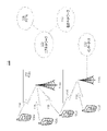
図1Aは、1つまたは複数の開示される実施形態が実施され得る、例示の通信システム100の図である。通信システム100は、複数の無線ユーザに音声、データ、ビデオ、メッセージング、ブロードキャストなどのコンテンツをもたらす、多元接続方式とすることができる。通信システム100は、複数の無線ユーザが、無線帯域幅を含むシステムリソースの共有を通じて、このようなコンテンツにアクセスすることを可能にすることができる。例えば通信システム100は、符号分割多元接続(CDMA)、時分割多元接続(TDMA)、周波数分割多元接続(FDMA)、直交FDMA(OFDMA)、シングルキャリアFDMA(SC-FDMA)などの1つまたは複数のチャネルアクセス方法を使用することができる。
FIG. 1A is a diagram of an
図1Aに示されるように通信システム100は、無線送信/受信ユニット(WTRU)102a、102b、102c、102d、無線アクセスネットワーク(RAN)104、コアネットワーク106、公衆交換電話ネットワーク(PSTN)108、インターネット110、および他のネットワーク112を含むことができるが、開示される実施形態は任意の数のWTRU、基地局、ネットワーク、および/またはネットワーク要素を企図することが理解されるであろう。WTRU102a、102b、102c、102dのそれぞれは、無線環境において動作および/または通信するように構成された任意のタイプのデバイスとすることができる。例としてWTRU102a、102b、102c、102dは、無線信号を送信および/または受信するように構成されてもよく、ユーザ機器(UE)、移動局、固定またはモバイル加入者ユニット、ページャ、携帯電話、携帯情報端末(PDA)、スマートフォン、ラップトップ、ネットブック、パーソナルコンピュータ、無線センサ、民生用電子機器などを含むことができる。
As shown in FIG. 1A, a
通信システム100はまた、基地局114aおよび基地局114bを含むことができる。基地局114a、114bのそれぞれは、コアネットワーク106、インターネット110、および/または他のネットワーク112などの、1つまたは複数の通信ネットワークへのアクセスを容易にするように、WTRU102a、102b、102c、102dの少なくとも1つと無線でインターフェース接続するように構成された任意のタイプのデバイスとすることができる。例として基地局114a、114bは、基地トランシーバ局(BTS)、ノードB、eノードB、ホームノードB、ホームeノードB、サイトコントローラ、アクセスポイント(AP)、無線ルータなどとすることができる。基地局114a、114bはそれぞれ単一の要素として示されるが、基地局114a、114bは、任意の数の相互接続された基地局および/またはネットワーク要素を含み得ることが理解されるであろう。
基地局114aは、基地局コントローラ(BSC)、無線ネットワークコントローラ(RNC)、中継ノードなどの、他の基地局および/またはネットワーク要素(図示せず)も含み得る、RAN104の一部とすることができる。基地局114aおよび/または基地局114bは、セル(図示せず)と呼ばれることがある特定の地理的領域内で、無線信号を送信および/または受信するように構成されてもよい。セルは、セルセクタにさらに分割されてもよい。例えば基地局114aに関連付けられたセルは、3つのセクタに分割され得る。従って一実施形態では基地局114aは、3つのトランシーバ、すなわちセルの各セクタに対して1つを含むことができる。他の実施形態において基地局114aは、多入力多出力(MIMO)技術を使用することができ、従ってセルの各セクタに対して複数のトランシーバを利用することができる。
Base station 114a may be part of RAN 104, which may also include other base stations and/or network elements (not shown) such as base station controllers (BSCs), radio network controllers (RNCs), relay nodes, and the like. can. Base station 114a and/or
基地局114a、114bは、任意の適切な無線通信リンク(例えば無線周波数(RF)、マイクロ波、赤外線(IR)、紫外線(UV)、可視光など)とすることができるエアインターフェース116を通して、WTRU102a、102b、102c、102dの1つまたは複数と通信することができる。エアインターフェース116は、任意の適切な無線アクセス技術(RAT)を用いて確立されてもよい。
The
より具体的には上記のように通信システム100は、多元接続方式とすることができ、CDMA、TDMA、FDMA、OFDMA、SC-FDMAなどの1つまたは複数のチャネルアクセス方式を使用することができる。例えばRAN104内の基地局114a、およびWTRU102a、102b、102cは、ユニバーサル移動体通信システム(UMTS)地上無線アクセス(UTRA)などの無線技術を実施することができ、これは広帯域CDMA(WCDMA)を用いてエアインターフェース116を確立することができる。WCDMAは、高速パケットアクセス(HSPA)および/またはEvolved HSPA(HSPA+)などの通信プロトコルを含むことができる。HSPAは、高速ダウンリンクパケットアクセス(HSDPA)および/または高速アップリンクパケットアクセス(HSUPA)を含むことができる。
More specifically, as noted above,
他の実施形態において基地局114aおよびWTRU102a、102b、102cは、Evolved UMTS地上無線アクセス(E-UTRA)などの無線技術を実施することができ、これはロングタームエボリューション(LTE)および/またはLTE-Advanced(LTE-A)を用いてエアインターフェース116を確立することができる。
In other embodiments, the base station 114a and WTRUs 102a, 102b, 102c may implement a radio technology such as Evolved UMTS Terrestrial Radio Access (E-UTRA), which is Long Term Evolution (LTE) and/or LTE- The
他の実施形態では基地局114aおよびWTRU102a、102b、102cは、IEEE 802.16(すなわちマイクロ波アクセス用世界規模相互運用性(WiMAX))、CDMA2000、CDMA2000 1X、CDMA2000 EV-DO、暫定標準2000(IS-2000)、暫定標準95(IS-95)、暫定標準856(IS-856)、移動体通信用グローバルシステム(GSM)、GSM進化型高速データレート(EDGE)、GSM EDGE(GERAN)などの無線技術を実施することができる。 In other embodiments, the base station 114a and the WTRUs 102a, 102b, 102c support IEEE 802.16 (i.e., Worldwide Interoperability for Microwave Access (WiMAX)), CDMA2000, CDMA2000 IX, CDMA2000 EV-DO, Interim Standard 2000 ( IS-2000), Interim Standard 95 (IS-95), Interim Standard 856 (IS-856), Global System for Mobile Communications (GSM), GSM Evolved High Data Rate (EDGE), GSM EDGE (GERAN), etc. Wireless technology may be implemented.
図1Aの基地局114bは、例えば無線ルータ、ホームノードB、ホームeノードB、またはアクセスポイントとすることができ、事業所、自宅、乗り物、キャンパスなどの局在したエリア内の無線接続性を容易にするための、任意の適切なRATを利用することができる。一実施形態において基地局114bおよびWTRU102c、102dは、IEEE 802.11などの無線技術を実施して、無線ローカルエリアネットワーク(WLAN)を確立することができる。他の実施形態において基地局114bおよびWTRU102c、102dは、IEEE 802.15などの無線技術を実施して、無線パーソナルエリアネットワーク(WPAN)を確立することができる。他の実施形態において基地局114bおよびWTRU102c、102dは、セルラベースのRAT(例えばWCDMA、CDMA2000、GSM、LTE、LTE-Aなど)を利用して、ピコセルまたはフェムトセルを確立することができる。図1Aに示されるように基地局114bは、インターネット110への直接接続を有することができる。従って基地局114bは、コアネットワーク106を経由してインターネット110にアクセスすることを不要とすることができる。
The
RAN104は、音声、データ、アプリケーション、および/またはボイスオーバインターネットプロトコル(VoIP)サービスをWTRU102a、102b、102c、102dの1つまたは複数にもたらすように構成された任意のタイプのネットワークとすることができる、コアネットワーク106と通信することができる。例えばコアネットワーク106は、呼制御、料金請求サービス、モバイル位置ベースのサービス、プリペイドコール、インターネット接続性、ビデオ配信などをもたらすことができ、および/またはユーザ認証などの高レベルセキュリティ機能を行うことができる。図1Aに示されないが、RAN104および/またはコアネットワーク106は、RAN104と同じRATまたは異なるRATを使用する他のRANと、直接または間接に通信できることが理解されるであろう。例えば、E-UTRA無線技術を利用し得るRAN104に接続されることに加えて、コアネットワーク106はまた、GSM無線技術を使用する他のRAN(図示せず)とも通信することができる。
RAN 104 may be any type of network configured to provide voice, data, applications, and/or Voice over Internet Protocol (VoIP) services to one or more of WTRUs 102a, 102b, 102c, 102d. , can communicate with the
コアネットワーク106はまた、PSTN108、インターネット110、および/または他のネットワーク112にアクセスするように、WTRU102a、102b、102c、102dのためのゲートウェイとして働くことができる。PSTN108は、基本電話サービス(plain old telephone service)(POTS)をもたらす回線交換電話ネットワークを含むことができる。インターネット110は、TCP/IPインターネットプロトコル群における伝送制御プロトコル(TCP)、ユーザデータグラムプロトコル(UDP)、およびインターネットプロトコル(IP)などの共通通信プロトコルを用いる、相互接続されたコンピュータネットワークおよびデバイスの地球規模のシステムを含むことができる。ネットワーク112は、他のサービスプロバイダによって所有および/または運用される有線もしくは無線通信ネットワークを含むことができる。例えばネットワーク112は、RAN104と同じRATまたは異なるRATを使用することができる1つまたは複数のRANに接続された、他のコアネットワークを含むことができる。
通信システム100内のWTRU102a、102b、102c、102dのいくつかまたはすべては、マルチモード能力を含むことができ、すなわちWTRU102a、102b、102c、102dは、異なる無線リンクを通して異なる無線ネットワークと通信するための複数のトランシーバを含むことができる。例えば図1Aに示されるWTRU102cは、セルラベースの無線技術を使用することができる基地局114aと、およびIEEE 802無線技術を使用することができる基地局114bと、通信するように構成されてもよい。
Some or all of the
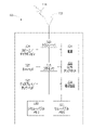
図1Bは、例示のWTRU102のシステム図である。図1Bに示されるようにWTRU102は、プロセッサ118、トランシーバ120、送信/受信要素122、スピーカ/マイクロフォン124、キーパッド126、ディスプレイ/タッチパッド128、非リムーバブルメモリ130、リムーバブルメモリ132、電源134、全地球測位システム(GPS)チップセット136、および他の周辺装置138を含むことができる。WTRU102は、実施形態と一貫性を保ちながら、上記の要素の任意のサブコンビネーションを含み得ることが理解されるであろう。
FIG. 1B is a system diagram of an
プロセッサ118は、汎用プロセッサ、専用プロセッサ、従来型プロセッサ、デジタル信号プロセッサ(DSP)、複数のマイクロプロセッサ、DSPコアに関連した1つまたは複数のマイクロプロセッサ、コントローラ、マイクロコントローラ、特定用途向け集積回路(ASIC)、フィールドプログラマブルゲートアレイ(FPGA)回路、任意の他のタイプの集積回路(IC)、状態機械などとすることができる。プロセッサ118は、信号符号化、データ処理、電力制御、入力/出力処理、および/またはWTRU102が無線環境において動作することを可能にする任意の他の機能を行うことができる。プロセッサ118は、送信/受信要素122に結合され得る、トランシーバ120に結合されてもよい。図1Bはプロセッサ118およびトランシーバ120を個別の構成要素として示すが、プロセッサ118およびトランシーバ120は、電子回路パッケージまたはチップ内に一緒に一体化され得ることが理解されるであろう。
送信/受信要素122は、エアインターフェース116を通して、基地局(例えば基地局114a)に信号を送信し、またはそれから信号を受信するように構成されてもよい。例えば一実施形態において送信/受信要素122は、RF信号を送信および/または受信するように構成されたアンテナとすることができる。他の実施形態において送信/受信要素122は、例えばIR、UV、または可視光信号を送信および/または受信するように構成された放射器/検出器とすることができる。他の実施形態では送信/受信要素122は、RFおよび光信号の両方を送信および受信するように構成されてもよい。送信/受信要素122は、無線信号の任意の組み合わせを送信および/または受信するように構成され得ることが理解されるであろう。
Transmit/receive
さらに図1Bでは送信/受信要素122は単一の要素として示されるが、WTRU102は任意の数の送信/受信要素122を含むことができる。より具体的にはWTRU102は、MIMO技術を使用することができる。従って一実施形態においてWTRU102は、エアインターフェース116を通して無線信号を送信および受信するための、2つ以上の送信/受信要素122(例えば複数のアンテナ)を含むことができる。
Further, although transmit/receive
トランシーバ120は、送信/受信要素122によって送信されることになる信号を変調するように、および送信/受信要素122によって受信された信号を復調するように構成されてもよい。上記のようにWTRU102は、マルチモード能力を有することができる。従ってトランシーバ120は、WTRU102が例えばUTRAおよびIEEE 802.11などの複数のRATによって通信することを可能にするための、複数のトランシーバを含むことができる。
WTRU102のプロセッサ118は、スピーカ/マイクロフォン124、キーパッド126、および/またはディスプレイ/タッチパッド128(例えば液晶表示(LCD)ディスプレイユニット、または有機発光ダイオード(OLED)ディスプレイユニット)に結合されてもよく、それらからユーザ入力データを受け取ることができる。プロセッサ118はまたユーザデータを、スピーカ/マイクロフォン124、キーパッド126、および/またはディスプレイ/タッチパッド128に出力することができる。さらにプロセッサ118は、非リムーバブルメモリ130および/またはリムーバブルメモリ132などの任意のタイプの適切なメモリからの情報にアクセスし、それにデータを記憶することができる。非リムーバブルメモリ130は、ランダムアクセスメモリ(RAM)、読み出し専用メモリ(ROM)、ハードディスク、または任意の他のタイプのメモリ記憶デバイスを含むことができる。リムーバブルメモリ132は、加入者識別モジュール(SIM)カード、メモリスティック、セキュアデジタル(SD)メモリカードなどを含むことができる。他の実施形態においてプロセッサ118は、サーバまたはホームコンピュータ(図示せず)上など、物理的にWTRU102上に位置しないメモリからの情報にアクセスし、それにデータを記憶することができる。
The
プロセッサ118は、電源134から電力を受け取ることができ、WTRU102内の他の構成要素に対する電力を分配および/または制御するように構成されてもよい。電源134は、WTRU102に電力供給するための任意の適切なデバイスとすることができる。例えば電源134は、1つまたは複数の乾電池(例えばニッケルカドミウム(NiCd)、ニッケル亜鉛(NiZn)、ニッケル水素(NiMH)、リチウムイオン(Liイオン)など)、太陽電池、燃料電池などを含むことができる。
プロセッサ118はまたGPSチップセット136に結合されてもよく、これはWTRU102の現在の位置に関する位置情報(例えば経度および緯度)をもたらすように構成されてもよい。GPSチップセット136からの情報に加えてまたはその代わりにWTRU102は、エアインターフェース116を通して基地局(例えば基地局114a、114b)から位置情報を受信することができ、および/または2つ以上の近くの基地局から受信される信号のタイミングに基づいてその位置を決定することができる。WTRU102は、実施形態と一貫性を保ちながら、任意の適切な位置決定方法によって位置情報を取得できることが理解されるであろう。
プロセッサ118はさらに、さらなる特徴、機能、および/または有線もしくは無線接続性をもたらす1つまたは複数のソフトウェアおよび/またはハードウェアモジュールを含み得る、他の周辺装置138に結合されてもよい。例えば周辺装置138は、加速度計、電子コンパス、衛星トランシーバ、デジタルカメラ(写真またはビデオ用)、ユニバーサルシリアルバス(USB)ポート、振動デバイス、テレビ送受信機、ハンズフリーヘッドセット、ブルートゥース(登録商標)モジュール、周波数変調(FM)ラジオユニット、デジタル音楽プレーヤ、メディアプレーヤ、ビデオゲームプレーヤモジュール、インターネットブラウザなどを含むことができる。
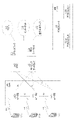
図1Cは、実施形態によるRAN104およびコアネットワーク106のシステム図である。上記のようにRAN104は、E-UTRA無線技術を使用して、エアインターフェース116を通してWTRU102a、102b、102cと通信することができる。RAN104はまた、コアネットワーク106と通信することができる。
FIG. 1C is a system diagram of
RAN104はeノードB140a、140b、140cを含むことができるが、RAN104は、実施形態と一貫性を保ちながら、任意の数のeノードBを含み得ることが理解されるであろう。eノードB140a、140b、140cはそれぞれ、エアインターフェース116を通してWTRU102a、102b、102cと通信するための、1つまたは複数のトランシーバを含むことができる。一実施形態においてeノードB140a、140b、140cは、MIMO技術を実施することができる。従ってeノードB140aは、例えば複数のアンテナを用いてWTRU102aに無線信号を送信し、それから無線信号を受信することができる。
eノードB140a、140b、140cのそれぞれは、特定のセル(図示せず)に関連付けられてもよく、無線リソース管理決定、ハンドオーバ決定、アップリンクおよび/またはダウンリンクにおけるユーザのスケジューリングなどを取り扱うように構成されてもよい。図1Cに示されるようにeノードB140a、140b、140cは、X2インターフェースを通して互いに通信することができる。 Each of the eNodeBs 140a, 140b, 140c may be associated with a particular cell (not shown) to handle radio resource management decisions, handover decisions, scheduling of users on the uplink and/or downlink, etc. may be configured. As shown in FIG. 1C, eNodeBs 140a, 140b, 140c may communicate with each other through the X2 interface.
図1Cに示されるコアネットワーク106は、モビリティ管理ゲートウェイ(MME)142、サービングゲートウェイ144、およびパケットデータネットワーク(PDN)ゲートウェイ146を含むことができる。上記の要素のそれぞれはコアネットワーク106の一部として示されるが、これらの要素のいずれの1つも、コアネットワークオペレータ以外のエンティティによって所有および/または運用され得ることが理解されるであろう。
The
MME142は、S1インターフェースを経由してRAN104内のeノードB140a、140b、140cのそれぞれに接続されてもよく、制御ノードとして働くことができる。例えばMME142は、WTRU102a、102b、102cのユーザを認証すること、ベアラ活動化/非活動化、WTRU102a、102b、102cの初期アタッチ時に特定のサービングゲートウェイを選択することなどを受け持つことができる。MME142はまた、RAN104と、GSMまたはWCDMAなどの他の無線技術を使用する他のRAN(図示せず)との間で切り換えるための、制御プレーン機能をもたらすことができる。
サービングゲートウェイ144は、S1インターフェースを経由してRAN104内のeノードB140a、140b、140cのそれぞれに接続されてもよい。サービングゲートウェイ144は一般に、WTRU102a、102b、102cへのまたはそれらからのユーザデータパケットを、経路指定および転送することができる。サービングゲートウェイ144はまた、eノードB間ハンドオーバ時にユーザプレーンをアンカリングすること、WTRU102a、102b、102cのためのダウンリンクデータが使用可能であるときにページングをトリガすること、WTRU102a、102b、102cのコンテキストを管理および記憶することなどの他の機能を行うことができる。
Serving
サービングゲートウェイ144はまた、WTRU102a、102b、102cとIP対応デバイスとの間の通信を容易にするためにインターネット110などのパケット交換ネットワークへのアクセスをWTRU102a、102b、102cにもたらすことができる、PDNゲートウェイ146に接続されてもよい。
Serving
コアネットワーク106は、他のネットワークとの通信を容易にすることができる。例えばコアネットワーク106は、WTRU102a、102b、102cと従来型の陸線通信デバイスとの間の通信を容易にするために、PSTN108などの回線交換ネットワークへのアクセスをWTRU102a、102b、102cにもたらすことができる。例えばコアネットワーク106は、コアネットワーク106とPSTN108との間のインターフェースとして働くIPゲートウェイ(例えばIPマルチメディアサブシステム(IMS)サーバ)を含むことができ、またはそれと通信することができる。さらにコアネットワーク106は、WTRU102a、102b、102cにネットワーク112へのアクセスをもたらすことができ、これは他のサービスプロバイダによって所有および/または運用される他の有線もしくは無線ネットワークを含むことができる。
他のネットワーク112はさらに、IEEE 802.11をベースとする無線ローカルエリアネットワーク(WLAN)160に接続されてもよい。WLAN160は、アクセスルータ165を含むことができる。アクセスルータは、ゲートウェイ機能を含むことができる。アクセスルータ165は、複数のアクセスポイント(AP)170a、170bと通信することができる。アクセスルータ165とAP170a、170bとの間の通信は、有線イーサネット(IEEE 802.3規格)、または任意のタイプの無線通信プロトコルを経由することができる。AP170aは、エアインターフェースを通してWTRU102dと無線通信する。
インフラストラクチャ基本サービスセット(BSS)モードでのWLANは、BSSのためのアクセスポイント(AP)、およびAPに関連付けられた1つまたは複数のステーション(STA)を有することができる。APは通常、分配システム(DS)、またはBSS内へのまたはそれから外へのトラフィックを運ぶ他のタイプの有線/無線ネットワークへの、アクセスまたはインターフェースを有することができる。BSSの外部から生じるSTAへのトラフィックは、APを通して到着することができ、STAに届けられ得る。STAから生じるBSSの外部の宛先へのトラフィックは、それぞれの宛先に届けられるようにAPに送られ得る。BSS内のSTA間のトラフィックはまた、APを通じて送られてもよく、ソースSTAはトラフィックをAPに送り、APはトラフィックを宛先STAに届ける。このようなBSS内のSTA間のトラフィックは、ピアツーピアトラフィックとすることができる。このようなピアツーピアトラフィックまた、IEEE 802.11e DLSまたはIEEE 802.11zトンネルDLS(TDLS)を用いた直接リンクセットアップ(DLS)によって、ソースと宛先STAとの間で直接送られ得る。独立BSS(IBSS)モードを用いるWLANはAPおよび/またはSTAをもたず、互いに直接通信する。この通信モードは、「アドホック」通信モードと呼ばれる。 A WLAN in infrastructure basic service set (BSS) mode may have an access point (AP) for the BSS and one or more stations (STAs) associated with the AP. An AP typically may have access or interface to a distribution system (DS) or other type of wired/wireless network that carries traffic into or out of the BSS. Traffic to the STA originating from outside the BSS can arrive through the AP and be delivered to the STA. Traffic originating from STAs to destinations external to the BSS may be sent to the AP so that the respective destinations are delivered. Traffic between STAs within a BSS may also be sent through the AP, with the source STA sending traffic to the AP and the AP delivering traffic to the destination STA. Traffic between STAs within such a BSS may be peer-to-peer traffic. Such peer-to-peer traffic can also be sent directly between the source and destination STAs by direct link setup (DLS) using IEEE 802.11e DLS or IEEE 802.11z tunnel DLS (TDLS). WLANs using Independent BSS (IBSS) mode do not have APs and/or STAs and communicate directly with each other. This communication mode is referred to as an "ad-hoc" communication mode.
IEEE 802.11acインフラストラクチャ動作モードを用いて、AP170aは固定のチャネル、通常はプライマリチャネル上にビーコンを送信することができる。このチャネルは20MHz幅とすることができ、BSSの動作チャネルとすることができる。このチャネルはまた、AP170aとの接続を確立するために1つまたは複数のステーション(STA)によって用いられ得る。IEEE 802.11システムにおける基本的チャネルアクセス機構は、キャリア検知多重アクセス/衝突回避(CSMA/CA)とすることができる。この動作モードにおいて、AP170aを含みあらゆるSTAは、プライマリチャネルを検知することができる。チャネルがビジーであることが検出された場合、STAはバックオフすることができる。従って、所与のBSS内で1つのSTAのみが、任意の所与の時点に送信することができる。 Using the IEEE 802.11ac infrastructure mode of operation, AP 170a can transmit beacons on a fixed channel, typically the primary channel. This channel may be 20 MHz wide and may be the operating channel of the BSS. This channel may also be used by one or more stations (STAs) to establish connections with AP 170a. The basic channel access mechanism in IEEE 802.11 systems can be Carrier Sense Multiple Access/Collision Avoidance (CSMA/CA). In this mode of operation, any STA, including AP 170a, can detect the primary channel. If the channel is detected to be busy, the STA can back off. Therefore, only one STA within a given BSS can transmit at any given time.
IEEE 802.11nにおいて高スループット(HT)STAはまた、通信のために40MHz幅のチャネルを用いることができる。これは、プライマリ20MHzチャネルを、隣接した20MHzチャネルと組み合わせて、40MHz幅の隣接するチャネルを形成することによって達成され得る。 High Throughput (HT) STAs in IEEE 802.11n can also use 40 MHz wide channels for communication. This can be accomplished by combining a primary 20 MHz channel with an adjacent 20 MHz channel to form a 40 MHz wide adjacent channel.
IEEE 802.11acにおいて超高スループット(VHT)STAは、20MHz、40MHz、80MHz、および160MHz幅のチャネルをサポートすることができる。40MHzおよび80MHzチャネルは、上述のIEEE 802.11n仕様と同様に、隣接する20MHzチャネルを組み合わることによって形成されてもよい。160MHzチャネルは、8つの隣接する20MHzチャネルを組み合わせることによって、または80+80構成と呼ばれ得る、2つの隣接しない80MHzチャネルを組み合わせることによって形成されてもよい。80+80構成に対して、データはチャネルエンコーディングの後、それを2つのストリームに分割するセグメントパーサに通過され得る。逆高速フーリエ変換(IFFT)および時間領域処理は、各ストリームに対して個別に行われてもよい。次いでストリームは2つのチャネルにマッピングされてもよく、データは送信されてもよい。受信機においてこの機構は逆にされてもよく、組み合わされたデータはMACに送られ得る。 Very high throughput (VHT) STAs in IEEE 802.11ac can support 20 MHz, 40 MHz, 80 MHz and 160 MHz wide channels. The 40 MHz and 80 MHz channels may be formed by combining adjacent 20 MHz channels, similar to the IEEE 802.11n specification mentioned above. A 160 MHz channel may be formed by combining eight adjacent 20 MHz channels or by combining two non-adjacent 80 MHz channels, which may be referred to as an 80+80 configuration. For the 80+80 configuration, the data, after channel encoding, can be passed to a segment parser that splits it into two streams. Inverse Fast Fourier Transform (IFFT) and time domain processing may be performed separately for each stream. The stream may then be mapped to the two channels and the data may be transmitted. At the receiver this mechanism may be reversed and the combined data sent to the MAC.
サブ1GHz動作モードは、IEEE 802.11afおよびIEEE 802.11ahによってサポートされ得る。これらの仕様に対してチャネル動作帯域幅およびキャリアは、IEEE 802.11nおよびIEEE 802.11acに比べて低減され得る。IEEE 802.11af仕様は、TVホワイトスペース(TVWS)スペクトル内の5MHz、10MHz、および20MHz帯域幅をサポートすることができる。IEEE 802.11ah仕様は、非TVWSスペクトルを用いた1MHz、2MHz、4MHz、8MHz、および16MHz帯域幅をサポートすることができる。IEEE 802.11ahに対する可能なユースケースは、マクロカバレージエリア内のメータタイプ制御(MTC)デバイスに対するサポートとすることができる。MTCデバイスは、限られた帯域幅のみに対するサポートを含む限られた能力を有することができるが、また非常に長い電池寿命に対する要件を含み得る。 A sub-1 GHz mode of operation may be supported by IEEE 802.11af and IEEE 802.11ah. Channel operating bandwidth and carriers for these specifications may be reduced compared to IEEE 802.11n and IEEE 802.11ac. The IEEE 802.11af specification can support 5 MHz, 10 MHz and 20 MHz bandwidths within the TV White Space (TVWS) spectrum. The IEEE 802.11ah specification can support 1 MHz, 2 MHz, 4 MHz, 8 MHz and 16 MHz bandwidths using non-TVWS spectrum. A possible use case for IEEE 802.11ah may be support for meter type control (MTC) devices in macro coverage areas. MTC devices may have limited capabilities, including support for only limited bandwidth, but may also include requirements for very long battery life.
IEEE 802.11n、IEEE 802.11ac、IEEE 802.11af、およびIEEE 802.11ahなどの、複数のチャネルおよびチャネル幅をサポートするWLANシステムは、プライマリチャネルとして指定されるチャネルを含むことができる。プライマリチャネルは、必ずしも必要なことではないが、BSS内のすべてのSTAによってサポートされる最も大きな共通動作帯域幅に等しい帯域幅を有することができる。従ってプライマリチャネルの帯域幅は、最小の帯域幅動作モードをサポートする、BSS内のSTAによって制限される。IEEE 802.11ahの例においてプライマリチャネルは、1MHzモードのみをサポートするSTA(例えばMTCタイプデバイス)が存在する場合、BSS内のAPおよび他のSTAが2MHz、4MHz、8MHz、16MHz、または他のチャネル帯域幅動作モードをサポートする場合でも、1MHz幅となり得る。すべてのキャリア検知およびNAV設定は、プライマリチャネルのステータスに依存し得る。例えばプライマリチャネルがビジーである場合(例えばSTAが、APに送信する1MHz動作モードのみをサポートすることにより)、使用可能な周波数帯域全体は、その大部分がアイドルで使用可能であっても、ビジーと見なされ得る。 WLAN systems that support multiple channels and channel widths, such as IEEE 802.11n, IEEE 802.11ac, IEEE 802.11af, and IEEE 802.11ah, may include a channel designated as the primary channel. The primary channel may, but need not, have a bandwidth equal to the largest common operating bandwidth supported by all STAs in the BSS. The bandwidth of the primary channel is therefore limited by the STAs within the BSS that support the minimum bandwidth mode of operation. The primary channel in the IEEE 802.11ah example is 2MHz, 4MHz, 8MHz, 16MHz, or any other channel for the AP and other STAs in the BSS if there are STAs (e.g. MTC type devices) that only support 1MHz mode. Even when supporting a bandwidth mode of operation, it can be 1 MHz wide. All carrier sense and NAV settings may depend on the status of the primary channel. For example, if the primary channel is busy (e.g., by STAs only supporting a 1 MHz operating mode transmitting to the AP), the entire available frequency band may be busy even if most of it is idle and available. can be regarded as
米国においてIEEE 802.11ahによって用いられ得る使用可能な周波数帯域は、902MHzから928MHzとすることができる。韓国において使用可能な周波数帯域は、917.5MHzから923.5MHzである。日本において使用可能な周波数帯域は916.5MHzから927.5MHzである。IEEE 802.11ahのために使用可能な総帯域幅は、国コードに応じて6MHzから26MHzとすることができる。 A usable frequency band that may be used by IEEE 802.11ah in the United States may be 902 MHz to 928 MHz. The frequency band available in Korea is 917.5 MHz to 923.5 MHz. The usable frequency band in Japan is from 916.5 MHz to 927.5 MHz. The total bandwidth available for IEEE 802.11ah can range from 6 MHz to 26 MHz depending on the country code.
無線ネットワークにおいて送信電力制御(TPC)は、ノード間の干渉を最小化すること、無線リンク品質を改善すること、エネルギー消費を低減すること、トポロジーを制御すること、5GHzモードでの衛星/レーダとの干渉を低減すること、およびネットワーク内のカバレージを改善することを含む、いくつかの理由により用いられ得る。 In wireless networks, transmission power control (TPC) is used to minimize interference between nodes, improve radio link quality, reduce energy consumption, control topology, satellite/radar in 5 GHz mode and can be used for several reasons, including to reduce interference in the network and to improve coverage within the network.
既存のセルラ規格は、TPCを実施するための異なる方法を有し得る。本明細書ではさらに、広帯域符号分割多元接続(WCDMA)/高速パケットアクセス(HSPA)において用いられ得るTPCのための従来型の方法が開示される。WCDMAおよびHSPAにおいてTPCは、開ループ電力制御、外側ループ電力制御、および内側ループ電力制御の組み合わせとすることができる。これはアップリンクにおける受信機での電力が、ノードBまたは基地局に関連付けられたすべてのWTRUに対して等しいことを確実にすることができる。これはCDMAの多元接続方式によって引き起こされる遠近問題により、重要となり得る。すべてのWTRUがスペクトル全体を利用するので、異なるWTRUの送信電力が管理されない場合、基地局から遠く離れたSTAの受信される電力は、基地局に近いものによって圧倒され得る。 Existing cellular standards may have different methods for implementing TPC. Further disclosed herein are conventional methods for TPC that can be used in Wideband Code Division Multiple Access (WCDMA)/High Speed Packet Access (HSPA). In WCDMA and HSPA, TPC can be a combination of open loop power control, outer loop power control, and inner loop power control. This may ensure that the power at the receiver in the uplink is equal for all WTRUs associated with a Node B or base station. This can be important due to the near-far problem caused by CDMA's multiple access scheme. Since all WTRUs utilize the entire spectrum, the received power of STAs far away from the base station may be overwhelmed by those close to the base station if the transmit powers of different WTRUs are not managed.
WTRUと無線ネットワークコントローラ(RNC)との間で生じる開ループ電力制御では、各WTRU送信機はその出力電力を、経路損失に対して補償するように特定の値に設定することができる。この電力制御方式は、WTRUがネットワークにアクセスするときに、初期アップリンクおよびダウンリンク送信電力を設定することができる。 With open-loop power control occurring between the WTRU and the radio network controller (RNC), each WTRU transmitter can set its output power to a specific value to compensate for path loss. This power control scheme may set the initial uplink and downlink transmit power when the WTRU accesses the network.
やはりWTRUとRNCとの間で生じる外側ループ電力制御では、長期間チャネル変動に対して補償がなされ得る。この電力制御方式は、できるだけ低い電力を用いながら、ベアラサービス品質要件のレベルに通信の品質を維持するために用いられてもよい。アップリンク外側ループ電力制御は、各個々のアップリンク内側ループ電力制御に対して、ノードBにおける目標信号対干渉比(SIR)を設定することを受け持つことができる。目標SIRは、10Hzと100Hzの間の周波数における各RRC接続に対するブロック誤り率(BLER)またはビット誤り率(BER)に従って、各WTRUに対して更新されてもよい。ダウンリンク外側ループ電力制御は、WTRUが、ダウンリンクにおいてネットワーク(RNC)によって設定された必要とされるリンク品質(BLER)に収束することを可能にすることができる。 Outer-loop power control, which also occurs between the WTRU and the RNC, may compensate for long-term channel variations. This power control scheme may be used to maintain the quality of communications at the level of bearer quality of service requirements while using as little power as possible. Uplink outer loop power control may be responsible for setting a target signal-to-interference ratio (SIR) at the Node B for each individual uplink inner loop power control. The target SIR may be updated for each WTRU according to the block error rate (BLER) or bit error rate (BER) for each RRC connection at frequencies between 10 Hz and 100 Hz. Downlink outer loop power control may allow the WTRU to converge on the required link quality (BLER) set by the network (RNC) on the downlink.
WTRUとノードBの間で生じることができる内側ループ電力制御(すなわち高速な閉ループ電力制御)では各WTRUは、短期間チャネル変動に対して補償することができる。アップリンクにおいてWTRUは、基地局からのダウンリンク信号上で受信される1つまたは複数のTPCコマンドに従って、例えば1500Hzにおいてその出力電力を調整することができる。これは受信されるアップリンクSIRを、所望のSIR目標に保つことができる。 With inner-loop power control (ie, fast closed-loop power control) that can occur between the WTRU and the Node-B, each WTRU can compensate for short-term channel variations. On the uplink, the WTRU may adjust its output power, eg, at 1500 Hz, according to one or more TPC commands received on the downlink signal from the base station. This can keep the received uplink SIR at the desired SIR target.
アップリンクユニバーサル移動体通信システム(UMTS)ロングタームエボリューション(LTE)において用いられ得るTPCのための従来型の方法が、本明細書において開示される。アップリンクLTEにおいて電力制御は、基本的開ループTPC、動的閉ループTPC、および帯域幅係数補償成分の組み合わせとすることができる。効果的な送信電力は以下のように計算され得る。
Txpower=Po+αPL+ΔTF+f(ΔTPC)+10log10M 式(1)
A conventional method for TPC that may be used in uplink Universal Mobile Telecommunications System (UMTS) Long Term Evolution (LTE) is disclosed herein. Power control in uplink LTE can be a combination of basic open-loop TPC, dynamic closed-loop TPC, and bandwidth factor compensation components. Effective transmit power can be calculated as follows.
Tx power = P o + αPL + Δ TF + f (Δ TPC ) + 10log 10 M formula (1)
LTEは、アップリンクにおいてシングルキャリア周波数分割多元接続(SC-FDMA)を用いることができ、従って厳格な電力制御に対する必要性は、WCDMA/HSPAにおけるほど重要でなくてよい。 LTE can use single-carrier frequency division multiple access (SC-FDMA) in the uplink, so the need for tight power control may not be as critical as in WCDMA/HSPA.
基本的開ループTPCは、部分的電力制御を実施することができ、そこではWTRUは経験される経路損失の一部分を補償することができ、以下のように計算され得る、
Txpower=Po+αPL 式(2)
ただしαは、部分的経路損失補償パラメータとすることができる。パラメータPoは、eノードBがWTRUの送信電力における系統的オフセットを補正することを可能にする、WTRUに特有のオフセット成分とすることができる。PLパラメータは、受信信号受信電力(RSRP)およびeノードB送信電力から導き出される経路損失の、WTRUの推定とすることができる。部分的経路損失補償係数αは、セル容量に対する公平性をトレードオフすることができる。これは通常0.7と0.8の間に設定され、セルエッジ送信の効果を低減することができ、それによって、セルエッジ性能への影響を最小にしながらシステム容量を増加させる。これは物理アップリンク共有チャネル(PUSCH)に対して用いられ得る。物理アップリンク制御チャネル(PUCCH)は、α=1に設定することができ、Poの異なる値を有することができる。
Basic open-loop TPC may implement partial power control, where the WTRU may compensate for a portion of the path loss experienced, which may be calculated as:
Tx power = P o + αPL Equation (2)
where α can be a partial path loss compensation parameter. The parameter P o may be a WTRU-specific offset component that allows the eNodeB to compensate for systematic offsets in the WTRU's transmit power. The PL parameter may be the WTRU's estimate of the pathloss derived from the received signal received power (RSRP) and the eNodeB transmit power. The partial path loss compensation factor α can trade off fairness against cell capacity. It is typically set between 0.7 and 0.8 and can reduce the effect of cell-edge transmissions, thereby increasing system capacity while minimizing impact on cell-edge performance. This may be used for the physical uplink shared channel (PUSCH). The physical uplink control channel (PUCCH) can be set to α=1 and can have different values of Po .
閉ループ電力制御は動的であり、干渉制御とチャネル条件適応との混合を行うことができる。閉ループ電力制御は以下の項を用いることができる。
ΔTF+f(ΔTPC) 式(3)
Closed-loop power control is dynamic and can provide a mixture of interference control and channel condition adaptation. Closed-loop power control can use the following terms.
Δ TF + f (Δ TPC ) Equation (3)
パラメータΔTFは、シャノン容量定理に基づく、変調および符号化方式(MCS)に依存するパラメータとすることができる。WTRUに特有のパラメータf(ΔTPC)は、WCDMA/HSPAでの閉ループTPC項と同様とすることができ、eNBで受信される電力に基づいて、WTRUにその電力を増加または減少するように指示することができる。 The parameter Δ TF can be a modulation and coding scheme (MCS) dependent parameter based on the Shannon capacity theorem. The WTRU-specific parameter f(Δ TPC ) may be similar to the closed-loop TPC term in WCDMA/HSPA, instructing the WTRU to increase or decrease its power based on the power received at the eNB. can do.
帯域幅係数は、実際にスケジューリングされたRBの数に基づいて送信電力をスケーリングする、係数10log10Mである。 The bandwidth factor is a factor 10log 10 M that scales the transmit power based on the number of RBs actually scheduled.
WLANに対するTPC要件は、いくつかの理由によりセルラとは異なり得る。CDMAでは、基地トランシーバ局(BTA)に近く、BTAから遠く離れた両方のWTRUが同時に送信している場合がある。これは「遠近問題」を生じ得る。WLANの場合は、時間領域システムであるので、所与の時点でBSS内で送信している1つだけのSTAが存在する。従って厳格な閉ループ電力制御は、必須でなくてよい。多元接続アルゴリズムを制御する中央スケジューラが存在するLTEと異なり、802.11 WLANにおけるプライマリ多元接続アルゴリズムは、分散型協調機能(DCF)または強化型分散チャネルアクセス(EDCA)多元接続方法において分散されてもよい。従って総セル容量に対して、セルエッジWTRUのアップリンクスケジューリングの公平性をトレードオフする必要性はそれほど高くなく、明示的な部分的経路損失補償はそれほど重要でなくてよい。さらに直交周波数領域多元接続(OFDMA)はない場合があり、各STA/APは帯域幅全体を占有することができる。従って帯域幅係数に対する必要性がない場合がある。IEEE 802.11規格本文は、受信機がTPC推奨をもたらし、各送信機が製造者自身の実装の関心事および規制要件に基づいてそれの特定の送信電力を決定する、アルゴリズムにおける簡潔性を強調している。 TPC requirements for WLAN may differ from cellular for several reasons. In CDMA, both WTRUs near and far from the base transceiver station (BTA) may be transmitting at the same time. This can create a "far-near problem". For WLAN, since it is a time domain system, there is only one STA transmitting within the BSS at a given time. Tight closed-loop power control may therefore not be essential. Unlike LTE, where there is a central scheduler that controls the multiple access algorithm, the primary multiple access algorithm in 802.11 WLAN can be distributed in distributed coordination function (DCF) or enhanced distributed channel access (EDCA) multiple access methods. good. Therefore, the need to trade off uplink scheduling fairness for cell-edge WTRUs against total cell capacity is less important, and explicit partial pathloss compensation may be less important. Additionally, there may be no Orthogonal Frequency Domain Multiple Access (OFDMA) and each STA/AP can occupy the entire bandwidth. Therefore there may be no need for a bandwidth factor. The IEEE 802.11 standard text emphasizes simplicity in algorithms, with the receiver providing TPC recommendations and each transmitter determining its specific transmit power based on the manufacturer's own implementation concerns and regulatory requirements. is doing.
それに従ってWLANシステムは、セルラベースのTPC手順に比べて異なるタイプのTPC手順を指定することができる。IEEE 802.11 WLAN仕様における従来型のTPC手順は、STAの電力能力に基づくSTAの、BSS内のAPへの関連付け、メッシュSTAの電力能力に基づいてメッシュSTAをピアリングすること、現在のチャネルに対する規制、およびローカル、最大送信電力レベルの仕様、規制およびローカル要件によって課される制約内でチャネルにおける各送信に対する送信電力の選択、ならびに経路損失およびリンクマージン推定を含むいくつかの情報要素(IE)に基づく送信電力の適合の、1つまたは複数をサポートすることができる。 Accordingly, WLAN systems can specify different types of TPC procedures compared to cellular-based TPC procedures. Conventional TPC procedures in the IEEE 802.11 WLAN specification include: association of STAs to APs in the BSS based on the STA's power capabilities; peering of mesh STAs based on their power capabilities; Several information elements (IEs) including regulatory and local, specification of maximum transmit power level, selection of transmit power for each transmission in the channel within the constraints imposed by regulatory and local requirements, and path loss and link margin estimation can support one or more of transmit power adaptation based on
本明細書で開示される実施形態は、指向性ミリ波送信を用いた、IEEE 802.11adによって仕様化されている指向性マルチギガビットWLAN送信を含むことができる。本明細書の以下において、IEEE 802.11-2012、IEEE 802.11ac、IEEE 802.11af、およびIEEE 802.11ahを含むすべての他の仕様によって管理されるWLAN送信は、無指向性IEEE 802.11 WLAN送信と定義され得る。 Embodiments disclosed herein may include directional multi-gigabit WLAN transmission as specified by IEEE 802.11ad using directional millimeter wave transmission. Hereafter, WLAN transmissions governed by all other specifications, including IEEE 802.11-2012, IEEE 802.11ac, IEEE 802.11af, and IEEE 802.11ah are referred to as omnidirectional IEEE 802.11ah. 11 WLAN transmissions.
無指向性IEEE 802.11 WLAN送信では、受信するSTAは、送信電力およびリンクマージンを含むTPCレポート要素を送出することができる。リンクマージンは、リンクを閉じるためにSTAによって必要とされるものに対する、受信される電力の比として定義される。送信機は、TPCレポート内で受信された情報を用いて、送信電力を決定することができる。STAは、送信電力を別のSTAに、STAからのフィードバックによって受信した情報に基づいて、任意の基準を用いて動的に適合させることができる。特定の方法は、実装依存とすることができる。これは開ループTPCとして表され得る。開ループTPCは、APまたは非STA送信機は、STAの手順に無関係に送信電力を決定できることを示唆する。 For omni-directional IEEE 802.11 WLAN transmissions, the receiving STA can send out a TPC report element containing transmit power and link margin. Link margin is defined as the ratio of power received to that required by the STA to close the link. The transmitter can use the information received in the TPC report to determine transmit power. A STA can dynamically adapt its transmit power to another STA based on information received through feedback from the STA using arbitrary criteria. The specific method may be implementation dependent. This can be expressed as open loop TPC. Open-loop TPC suggests that the AP or non-STA transmitter can determine transmit power independently of STA procedures.
TPCレポートは、明示的なTPC要求フレームが送信機によって送られ得る、受信機による応答型とすることができる。あるいはTPCレポートは、例えばBSS内のAP、またはIBSS内のSTAによる非応答型とすることができる。 The TPC report can be responsive by the receiver, where an explicit TPC request frame can be sent by the transmitter. Alternatively, the TPC report can be unacknowledged, for example by the AP in the BSS or the STA in the IBSS.
指向性マルチギガビットIEEE 802.11 WLAN送信モード、例えばIEEE 802.11adを用いて、指向性マルチギガビット(DMG)リンクマージン要素は、送信電力における増加または減少を推奨するフィールドを含むことができる。この場合送信機は、それが推奨を実施するか否かを示すために、DMGリンク適合肯定応答を送ることができる。 With a Directional Multi-Gigabit IEEE 802.11 WLAN transmission mode, eg IEEE 802.11ad, a Directional Multi-Gigabit (DMG) Link Margin element may contain a field recommending an increase or decrease in transmit power. In this case the sender can send a DMG link adaptation acknowledgment to indicate whether or not it implements the recommendation.
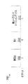
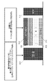
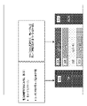
次に図2を参照して、IEEE 802.11ahにおける開ループリンクマージンが開示される。IEEE 802.11ah仕様は、開ループリンク適合および電力制御のための、サブ1GHz(S1G)開ループリンクマージンインデックスを導入している。図2は、S1G開ループリンクマージンインデックス要素フォーマット200であり、これは要素ID202、長さ204、開ループマージンインデックス206を含むことができる。
Referring now to FIG. 2, open loop link margin in IEEE 802.11ah is disclosed. The IEEE 802.11ah specification introduces a sub-1 GHz (S1G) open loop link margin index for open loop link adaptation and power control. FIG. 2 is an S1G open loop link margin
開ループリンクマージンΔOPLMは、送信電力Ptxと、受信機感度RXsensitivityの和として定義されてもよく、以下のように定義され得る。
ΔOPLM=Ptx+RXsensitivity 式(4)
受信機感度RXsensitivityは、1MHzチャネルに対するMCS10の受信のための最小必要受信電力とすることができる。開ループリンクマージンΔOPLMは、(-128+D×0.5)dBとして計算されてもよく、ただしDは開ループリンクマージンインデックス206とすることができる。
The open loop link margin Δ OPLM may be defined as the sum of the transmit power P tx and the receiver sensitivity RX sensitivity and may be defined as follows.
Δ OPLM = P tx + RX sensitivity formula (4)
Receiver sensitivity RX sensitivity may be the minimum required receive power for
S1G開ループリンクマージンインデックス要素206は、開ループリンク適合および開ループ送信電力制御のために用いられ得る。STAは、開ループリンクマージンインデックス206を受信したとき、(-128+D×0.5)dBを用いてS1G開ループリンクマージンΔOPLMを計算することができる。MCS10を通したSNRマージンは、S1G開ループリンクマージンインデックス206を含んだフレームを受信する、STAによって導き出されてもよい。これはSTA自体の送信電力Ptx2、およびS1G開ループリンクマージンインデックス206を含んだパケットに対して測定される受信信号強度インジケータ(RSSI)に基づくことができる。
SNRmargin=Ptx2-ΔOPLM+RSSI 式(5)
The S1G open loop link
SNR margin = P tx2 - ΔOPLM + RSSI Equation (5)
マルチユーザ(MU)送信および電力制御における開発が本明細書で開示される。IEEE標準ボードは、プロジェクト承認要求(PAR)、および高効率WLAN研究グループ(HEW SG)において開発された標準開発のための基準(Criteria for Standards Development)(CSD)に基づいて、IEEE 802.11axタスクグループ(TGax)を承認した。ダウンリンクおよびアップリンク送信の両方を含むMU送信は、TGax仕様フレームワークドキュメント(SFD)に含められた。 Developments in multi-user (MU) transmission and power control are disclosed herein. The IEEE standards board implements the IEEE 802.11ax task based on the Project Approval Request (PAR) and the Criteria for Standards Development (CSD) developed in the High Efficiency WLAN Study Group (HEW SG). Approved group (TGax). MU transmissions, including both downlink and uplink transmissions, were included in the TGax Specification Framework Document (SFD).
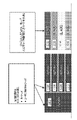
図3を参照すると、トリガフレームフォーマットの例が示される。トリガフレームは、共通情報フィールド内に電力制御情報を含まない場合がある。トリガフレームのユーザごとの情報フィールドが電力制御情報を含み得ることが提案されたが、この実装の詳細は未だ決定されていない。トリガフレームはまた、ランダムアクセスのためのリソースユニットの割り振りをサポートすることができる。ランダムアクセスのためのトリガフレームはTF-Rと呼ばれることがあり、提案されたランダムアクセスはスロット付きアロハと同様である。しかし電力制御は開示されていない。 Referring to FIG. 3, an example trigger frame format is shown. A trigger frame may not contain power control information in the common information field. It has been proposed that the per-user information field of the trigger frame may contain power control information, but the details of this implementation have not yet been determined. The trigger frame can also support allocation of resource units for random access. The trigger frame for random access is sometimes called TF-R, and the proposed random access is similar to slotted Aloha. However, power control is not disclosed.
従来型の技術は、以下の方法すなわち、マルチレベル電力制御および関連した手順、部分的に補償された電力制御および関連した手順、送信-受信セッションにおけるマルチレベル電力制御を可能にする連続した閉ループ電力制御および関連した手順、エネルギー検出のためのクリアチャネル評価(CCA)閾値変更、干渉により制限されたネットワークにおけるカバレージ調整、複数のチャネル/ユーザのための送信電力制御および関連した手順、マルチAP送信のための送信電力制御および関連した手順、節電モードからのウェイクアップ後すぐの電力レベル初期化および関連した手順、の1つまたは複数を含むことができる。 Conventional techniques use the following methods: multi-level power control and related procedures; partially compensated power control and related procedures; Control and related procedures, Clear Channel Assessment (CCA) threshold modification for energy detection, Coverage adjustment in interference limited networks, Transmit power control and related procedures for multiple channels/users, Multi-AP transmission power level initialization and related procedures upon wakeup from power save mode.
さらに従来型の技術は、以下の方法すなわち、送信電力制御ありまたはなしのCCA適合、CCA適合を有するユーティリティ機能ベースの送信電力制御、CCA適合を有する一般化送信電力制御、MCS依存TPC/CCA適合、およびBSS全体のTPC/CCA適合、の1つまたは複数を含むことができる。 Further conventional techniques use the following methods: CCA adaptation with or without transmit power control, utility function based transmit power control with CCA adaptation, generalized transmit power control with CCA adaptation, MCS dependent TPC/CCA adaptation , and TPC/CCA adaptation for the entire BSS.
本明細書で述べられる実施形態は、1つまたは複数の問題に対処することができる。1つの問題は、アップリンク(UL)MU送信を有する電力制御に関係し得る。同時のUL MU送信は、アップリンク電力制御を必要とし得る。電力制御なしの場合、複数の同時アップリンクSTAに対する、APでの受信される電力は大幅に変化し得る。これは自動利得制御、IQ不平衡、周波数オフセット、および縦続された送信を含む、APにおける受信に対する問題を引き起こし得る。 Embodiments described herein may address one or more issues. One issue may relate to power control with uplink (UL) MU transmissions. Simultaneous UL MU transmissions may require uplink power control. Without power control, the received power at the AP can vary significantly for multiple simultaneous uplink STAs. This can cause problems for reception at the AP, including automatic gain control, IQ imbalance, frequency offset, and cascaded transmissions.
自動利得制御(AGC)に関してAPは、複数のSTAからの受信の合計の受信される電力を、APの受信機フロントエンドのダイナミックレンジ内に維持しなければならない。STAの送信電力を制御するための対策がない場合、APでの受信される電力のダイナミックレンジは、受信機のフロントエンドの能力を超え得る。 For automatic gain control (AGC), the AP must keep the total received power of the reception from multiple STAs within the dynamic range of the AP's receiver front-end. Without measures to control the STA's transmit power, the dynamic range of received power at the AP may exceed the capabilities of the receiver front-end.
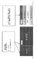
1つのサブチャネルにわたって送信される信号上の同相および直角位相(I/Q)成分振幅および位相不平衡は、そのサブチャネルのミラーイメージにおいて干渉を生じ得る。歪みの重大さは、I/Q振幅および位相不平衡のレベルに依存する。図4は、ミラーイメージ歪の周波数領域表示を示す。 In-phase and quadrature (I/Q) component amplitude and phase imbalances on signals transmitted over one subchannel can cause interference in the mirror image of that subchannel. The severity of distortion depends on the level of I/Q amplitude and phase imbalance. FIG. 4 shows a frequency domain representation of mirror image distortion.
隣接したサブチャネル上で送信された信号間の周波数オフセットは、直交性が失われることにより干渉を引き起こし得る。干渉のレベルは、隣接したサブチャネル上の信号間の電力差によってさらに悪化され得る。 A frequency offset between signals transmitted on adjacent subchannels can cause interference due to loss of orthogonality. The level of interference can be further exacerbated by power differences between signals on adjacent subchannels.
縦続された送信は、DL送信の最近の状態に対するUL送信への依存性を示唆する。この方式を用いたUL電力制御は、DL送信から受信された情報に依存することができる。 Cascaded transmissions imply a dependency of UL transmissions on the recent state of DL transmissions. UL power control using this scheme can rely on information received from DL transmissions.
IEEE 802.11仕様で定義された既存の電力制御機構に関連付けられる問題が存在し得る。例えば既存のTPC手順は高レベル(半静的)とすることができ、通常例えばビーコンフレームまたは関連付けられた要求/応答フレームにおいて行われ得る。従ってTPC情報は、頻繁に更新されない場合がある。しかし、例えば物理チャネルおよび/または送信帯域幅の関数となり得る受信される電力は、急速に変化し得る。古くなったTPC情報は、十分に正確な電力制御をもたらすことができない。 There may be problems associated with existing power control mechanisms defined in the IEEE 802.11 specification. For example, existing TPC procedures may be high-level (semi-static) and may typically occur, for example, in beacon frames or associated request/response frames. Therefore, TPC information may not be updated frequently. However, the received power, which can be a function of the physical channel and/or transmission bandwidth, for example, can vary rapidly. Stale TPC information cannot provide sufficiently accurate power control.
他の問題となり得るのは、大きな帯域幅の送信に対する電力制御である。大きな帯域幅の送信において、異なる帯域は異なるTPC調整レベルを必要とし得る。異なるTPC調整レベルに対する必要性があるかどうかを識別し、(a)TPCレベルを取得し、(b)TPCレベルをSTAに送るための、方法および手順が必要である。 Another potential problem is power control for large bandwidth transmissions. In large bandwidth transmissions, different bands may require different TPC adjustment levels. Methods and procedures are needed to identify whether there is a need for different TPC adjustment levels, (a) obtain the TPC level, and (b) send the TPC level to the STA.
他の問題となり得るのは、電力制御較正である。開ループTPCの使用においてAPは、STA応答を所望のTPCレベルに較正する必要があり得る。これは結果として、APがAP要件に基づいてSTAに変更を行うように命令する、望ましくない閉ループとなり得る。 Another potential issue is power control calibration. In using open-loop TPC, the AP may need to calibrate the STA response to the desired TPC level. This can result in an undesirable closed loop in which the AP instructs the STAs to make changes based on the AP requirements.
他の問題となり得るのは、高速で移動するSTAに対する送信電力制御である。IEEE 802.11nおよびIEEE 802.11acにおいてTPCレポートの使用は、受信機のRx感度を考慮に入れない。IEEE 802.11ahで提案された開ループリンクマージンは、この問題に対処するが、静止した低デューティサイクル送信機を想定している。従って、開ループリンクマージンインデックスの従来の使用は主として、ほとんど静止している低デューティサイクルセンサタイプおよびメータタイプデバイスのためのものである。その位置が急速に変化するSTAは、開ループリンクマージンインデックスを使用することを避ける、またはより慎重になるべきである。開ループリンクマージンインデックスを含めることは、ビーコンまたは他の管理フレームでは任意選択とすることができる。Rx感度を考慮に入れるために、高速で移動するSTAのために新しいTPCレポートが必要となり得る。 Another potential issue is transmit power control for fast moving STAs. The use of TPC reports in IEEE 802.11n and IEEE 802.11ac does not take into account the receiver's Rx sensitivity. The open loop link margin proposed in IEEE 802.11ah addresses this issue but assumes a stationary low duty cycle transmitter. Therefore, conventional use of the open-loop link margin index is primarily for low duty cycle sensor-type and meter-type devices that are mostly stationary. STAs whose positions change rapidly should avoid or be more cautious about using the open-loop link margin index. Including the open loop link margin index may be optional in beacons or other management frames. New TPC reports may be needed for fast moving STAs to take Rx sensitivity into account.
以下でより詳しく論じられるように、ULランダムアクセスのための電力制御方法および手順がもたらされ得る。UL MUランダムアクセス送信は、トリガフレームによって同期およびスケジューリングされてもよい。APとSTAの間のフレーム交換を用いて行われ得る、ランダムアクセスのためのTPC手順は、主として開ループベースの手順となり得る。これは、APは誰がUL MUランダムアクセスタイムスロットを用いて送信し得るかを知らない場合があるためであり得る。APがUL MUランダムアクセスへのアクセスを制限し得る場合、あるレベルの閉ループTPC手順が、開ループTPCと一緒に適用され得る。 As discussed in more detail below, power control methods and procedures for UL random access may be provided. UL MU random access transmissions may be synchronized and scheduled by trigger frames. The TPC procedure for random access, which may be performed using frame exchanges between APs and STAs, may be primarily an open-loop based procedure. This may be because the AP may not know who may transmit using the UL MU random access timeslot. If the AP can restrict access to UL MU random access, some level of closed-loop TPC procedure can be applied together with open-loop TPC.
実施形態において、一般のUL MUランダムアクセスに適用可能なTPC手順がもたらされ得る。他の実施形態において、MU TPCを容易にし得る、APが1つまたは複数の異なる基準によってUL MUランダムアクセスを制限し得る場合に対する、手順および方法が述べられる。この実施形態に対してもたらされる方法および手順は、任意のMU電力制御方式に適用されてもよく、ULランダムアクセスに制限されるべきでないことが留意されるべきである。 In embodiments, a TPC procedure applicable to general UL MU random access may be provided. In other embodiments, procedures and methods are described for cases where the AP may restrict UL MU random access by one or more different criteria, which may facilitate MU TPC. It should be noted that the methods and procedures provided for this embodiment may be applied to any MU power control scheme and should not be restricted to UL random access.
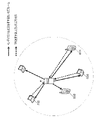
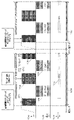
図5および6を参照すると、UL MUランダムアクセスを有するTPC手順を示す図が示される。この実施形態において、以下の送信電力制御概念が含められ得る。ベースライン送信(Tx)電力は、アップリンク送信電力をセットアップするためのベースラインとして、非AP STA側において計算されてもよい。ベースラインTx電力の計算は、開ループ、閉ループ、または組み合わされた開ループ/閉ループ電力制御手順に基づくことができる。さらに、より微細なTx電力調整のために、Tx電力調整値が用いられ得る。 5 and 6, diagrams illustrating TPC procedures with UL MU random access are shown. In this embodiment, the following transmit power control concepts may be included. Baseline transmit (Tx) power may be calculated at the non-AP STA side as a baseline for setting up uplink transmit power. The baseline Tx power calculation can be based on an open loop, closed loop, or combined open/closed loop power control procedure. Additionally, the Tx power adjustment value can be used for finer Tx power adjustment.
UL MUランダムアクセスを用いてSTAは、関連付けがトリガフレームによってトリガされる前であっても、WLANシステムにアクセスすることができる。ULフレームを送信しようとするSTAは、トリガフレームの指示に従って1つまたは複数のOFDMAリソースユニットをランダムに選ぶことができる。OFDMAリソースユニットは、STAに割り当てられ得る基本リソースユニット、例えばIEEE 802.11axシステムにおけるOFDMA RUである。トリガフレームは、専用送信およびランダムアクセス送信の両方を同時に可能にすることができる。本明細書で述べられる実施形態において、少なくとも1つのOFDMAリソースユニットが、ランダムアクセスのために割り当てられてもよい。 With UL MU random access, STAs can access the WLAN system even before the association is triggered by the trigger frame. A STA that intends to transmit a UL frame can randomly choose one or more OFDMA resource units as indicated in the trigger frame. An OFDMA resource unit is a basic resource unit that can be allocated to a STA, such as an OFDMA RU in IEEE 802.11ax system. A trigger frame can enable both dedicated and random access transmissions simultaneously. In the embodiments described herein, at least one OFDMA resource unit may be allocated for random access.
トリガフレームの後に送信するSTAは、本明細書で開示されるTPC手順を利用することができる。図5および6は、電力制御を用いたランダムアクセスのための例示的手順を示す。この例においてAP602は、4つのOFDMAリソースユニットを有するチャネルを取得している場合がある。ステップ1で送られるDLトリガフレーム502内に、AP602は、OFDMAリソースユニット1から3がUL MUランダムアクセスのために用いられ得ることを示すことでき、4番目のOFDMAリソースユニットはSTAk 608に割り当てられ得る。ステップ2および3、ならびにトリガフレーム502の終わりの短フレーム間スペース(SIFS)時間後において、第1のSTA604および第2のSTA606は、それらのランダムアクセスフレームをそれぞれリソースユニット504および506上に送信することができる。いかなるSTAも、リソースユニット508上に送信することはできない。ステップ4でSTAk 608は、リソースユニット510上で送信することができる。その後、ステップ5でAP602は、UL MU送信の肯定応答(ACK)フレーム512を送ることができる。
STAs transmitting after the trigger frame can utilize the TPC procedures disclosed herein. 5 and 6 show exemplary procedures for random access with power control. In this example,
上記のTPC手順においてAP側において行われるアクションが、本明細書で述べられ得る。AP602は、競合またはスケジューリングを通じてチャネル媒体を取得することができる。ステップ1でAP602は、少なくとも1つのアンテナに結合された少なくとも1つの送信回路を通じて、トリガフレーム502を送信することができる。トリガフレーム502は、来たるべきUL OFDMA送信におけるランダムアクセスのための、少なくとも1つのOFDMAリソースユニットの割り振りを含むことができる。トリガフレーム502は、本明細書で開示される方法の1つまたは複数を用いて送信され得る。
Actions taken on the AP side in the above TPC procedure may be described herein. The
トリガフレーム502は、図5に示されるように独立のフレームとして送信され得る。トリガフレーム502のDL送信は、OFDMモードとすることができる。MACフレームとしてトリガフレーム502は、集約型macプロトコルデータユニット(A-MPDU)フォーマットを用いて、データフレーム、制御フレーム、および管理フレームを含む他のフレームと集約され得る。送信はOFDMモード、OFDMAモード、または他のMUモードとすることができる。AP602は、トリガフレーム502、ならびにデータフレーム、制御フレーム、および管理フレームを含む他のフレームをMUモード、例えばDL OFDMAまたは他のMUモードで送信することができる。トリガフレーム502がDL OFDMAモードで送信される場合、トリガフレーム502の信号フィールドB(SIG-B)内のリソース割り振りフィールドは、予約されたブロードキャストまたはマルチキャスト識別子(ID)を用いて、対応するOFDMAリソースユニットがトリガフレーム502送信のために割り当てられることを示すことができる。SIG-Bフィールド内で利用されるブロードキャストまたはマルチキャストIDは、すべてのSTA604、606、608はリソースユニット上で運ばれる情報を監視し復号する必要があり得ることを示すことができる。
AP602は、トリガフレーム502内に開ループ電力制御インデックス(インデックス1)を含めることができる。1つの方法において開ループリンクマージンインデックスは、IEEE 802.11ahと同様なやり方で定義されてもよく、以下とすることができる。
ΔOPLM=Ptx+RXsensitivity 式(6)
Δ OPLM = P tx + RX sensitivity formula (6)
しかし受信機感度RXsensitivityは、基本チャネル帯域幅に対する最も低いMCSの受信のための最小必要受信電力として再定義され得る。例えばIEEE 802.11axの場合、これは20MHzまたは別の帯域幅を指すことができる。これは、STA602、606、608が定義を明示的に知り得るように、標準化されてもよい。開ループリンクマージンΔOPLMは、(-128+D×G)dBとして計算されてもよく、ただしDは開ループリンクマージンインデックスとすることができ、Gは基本細分性とすることができる。例えばG=0.25、または0.5である。
However, the receiver sensitivity RX sensitivity can be redefined as the minimum required received power for reception of the lowest MCS for the fundamental channel bandwidth. For IEEE 802.11ax, for example, this could refer to 20 MHz or another bandwidth. This may be standardized so that
AP602は、トリガフレーム502内に電力整合インデックス(インデックス2)を含めることができる。この電力整合インデックスは、目標とされるリンクマージンとすることができ、またはAP側で予想される受信電力とすることができる。UL MU送信の場合、STA604、606、608は、目標とされる電力レベルを用いてAP602に到達するように試みることができる。
AP602は、トリガフレーム502内にユーザに特有の電力調整パラメータを含めることができる。ランダムアクセスSTAに割り当てられたリソースユニットに対して、電力調整パラメータはランダムアクセスSTAの間で同じとすることができる。電力調整パラメータは、トリガフレーム502のすべての受信者に対して同じでも同じでなくてもよい。
SIFS時間の後に、およびステップ2~4に示されるようにAP602は、複数のSTA604、606、608からのUL送信を、少なくとも1つのアンテナに結合された少なくとも1つの受信回路によって受信することができる。STA604、606、608は、ベースライン送信電力、および先行するトリガフレーム502内で受信された送信電力調整値に従って、それらの送信電力を調整することができる。ランダムアクセスのために割り当てられた各OFDMAリソースユニット上でAP602は、STA604、606、608からの1つのランダムアクセスパケットを成功裏に、結果として特定のOFDMAリソースユニット上で衝突を生じ得る複数のSTA604、606、608からの複数のランダムアクセスパケットを受信することができ、またはこの特定のOFDMAリソースユニット上ではパケットを受信しない場合がある。専用STA604、606、608に割り当てられたOFDMAリソースユニット上でAP602は、割り当てられたSTA604、606、608からデータ、制御、または管理フレームを受信することができる。
After the SIFS time and as shown in steps 2-4, the
ステップ5、およびUL MU送信の受信のSIFS時間後に、AP602は、マルチSTA肯定応答フレームまたはブロックACKフレームを、STA604、606、608に送信することができる。
After step 5 and SIFS time of receipt of the UL MU transmission, the
上記のTPC手順においてSTA側で行われるアクションが、本明細書で述べられ得る。ステップ1でSTA604、606、608は、少なくとも1つのアンテナに結合された少なくとも1つの受信回路を通じてトリガフレーム502を検出することができる。トリガフレーム502は、来たるべきUL OFDMA送信におけるUL MUランダムアクセスのために、少なくとも1つのOFDMAリソースユニットを割り当てることができる。AP602からのDL送信がOFDMAモードである場合、STA604、606、608は、トリガフレーム502に対するリソース割り振りに対して、SIG-Bフィールドをチェックすることができる。STA604および606は、第1のSTA604および第2のSTA606が、送信するためのアップリンク制御、管理、またはデータフレームを有する場合、少なくとも1つのアンテナに結合された少なくとも1つの送信回路を用いて、割り当てられたUL MUランダムアクセスリソースにおける送信のための準備をすることができる。さらに第1のSTA604および第2のSTA606は、第1のSTA604および第2のSTA606が、トリガフレーム502においてランダムアクセスの要件があればそれに適格である場合、送信のための準備をすることができる。ステップ2および3において第1のSTA604および第2のSTA606は、少なくとも1つのアンテナに結合された少なくとも1つの送信回路を用いて、割り当てられたUL MUランダムアクセスリソースにおいて送信することができる。STAk 608は、来たるべきUL送信のためにAP602によって、STAk 608に専用OFDMAリソースユニット、または送信機会が割り当てられない場合、送信のための準備をすることができる。ステップ4で、STAk 608は送信することができる。
Actions taken on the STA side in the above TPC procedure may be described herein. At
第1のSTA604および第2のSTA606が、UL MUランダムアクセスプロトコルに従って、割り当てられたランダムアクセスリソースユニットの1つまたは複数において送信する場合、複数のユーザからの送信が同時にまたはおおよそ同時に完了できるように、パッディング方式がアップリンク送信に適用されてもよい。
When the
STA604、606、608は、本明細書で開示される方法に従って送信電力を設定することができる。STA604、606、608は、トリガフレーム502内で運ばれるインデックス1の値をチェックすることができる。STA604、606、608は、トリガフレーム502内で運ばれるインデックス2の値をチェックすることができる。STA604、606、608は、インデックス1およびインデックス2に基づいて、ベースライン送信電力を計算することができる。STA604、606、608は、トリガフレーム502内で運ばれる電力調整パラメータをチェックし、それに従ってベースライン送信電力を増加または減少することができる。
STA604、606、608が前に(例えば一定の期間内に)、AP602と通信したことがある場合、STA604、606、608は、履歴上の送信電力制御関連パラメータに記録を有し得る。STA604、606、608は、履歴上の送信電力制御関連パラメータの1つまたは複数を評価し、それらを、トリガフレーム502において受信される値またはパラメータのいずれか1つまたは複数から取得された瞬時送信電力と組み合わせることができる。
If the
STA604、606、608は、計算された送信電力を、送信帯域幅およびアンテナ設定に従って調整することができる。STA604、606、608は、計算された送信電力が最大許容送信電力および送信電力密度に反しないことを確認することができる。そうでない場合STA604、606、608は、代わりに最大許容送信電力を用いることができる。
送信のSIFS時間後にSTA604、606、608は、AP602から肯定応答フレームを受信することができる。
実施形態においてトリガフレーム502は、インデックス1およびインデックス2の両方を含むことができる。他の実施形態においてトリガフレーム502は、インデックス2を含み得るがインデックス1は含まない場合がある。その代わりにAP602は、ビーコンフレーム内でインデックス1をブロードキャストすることができる。STA604、606、608は、トリガフレーム502の前に少なくとも1つのビーコンフレームを検出する必要があり、これはSTA604、606、608からのアップリンクランダムアクセスを開始することができる。このシナリオではトリガフレーム502は、インデックス1を計算するために用いられる送信電力によって送信され得る。従ってSTA604、606、608は、トリガフレーム502の受信される電力を測定し、それに従ってベースライン送信電力を計算することができる。他の実施形態においてトリガフレーム502は、インデックス1もインデックス2も含まない場合がある。その代わりにAP602は、ビーコンフレーム内でインデックス1をブロードキャストすることができる。
In an embodiment,
上述のTPC手順は、ULデータ部分に適用され得る。しかしこれらの手順は、スケーラによってULプリアンブル部分にも適用され得ることが留意されるべきである。レガシープリアンブルおよび高効率(HE)プリアンブルは、異なるスケーラを用いることができる。 The TPC procedure described above may be applied to the UL data portion. However, it should be noted that these procedures can also be applied to the UL preamble part by the scaler. Legacy preambles and high efficiency (HE) preambles may use different scalers.
ベースライン送信電力を設定する方法および手順が、本明細書で開示される。ULランダムアクセスの場合AP602は、どのSTA604、606、608がどの時点で送信し得るかを知ることができない。従って、AP602が、STA604、606、608のための送信電力を調整することは難しくなり得る。その代わりにAP602は、STA604、606、608がベースライン送信電力をセットアップするため必要な情報を、ブロードキャストすることができる。これはAP602側での受信される電力が、来たるべきUL MU送信タイムスロットにおいて整合されることを可能にし得る。ベースライン電力設定は、非AP STA604、606、608が受信される電力を測定し、送信電力を設定するための、DL送信が関わる開ループ手順とすることができる。
Methods and procedures for setting baseline transmit power are disclosed herein. For UL random access, the
DL送信において、2つの電力制御関連パラメータが含められ、STA604、606、608にブロードキャストされてもよい。開ループ電力制御インデックス、インデックス1は、例えばAP602側での送信電力、AP602側での送信/受信アンテナ利得、DL送信のための必要帯域幅情報、および/またはケーブルおよびコネクタ損失に従って計算され得る。このインデックスに従って受信機は、STA604、606、608とAP602との間の経路損失、および一定のSTA604、606、608送信電力を所与としてAP602側での予想される受信電力レベルを推定することができる。
Two power control related parameters may be included in the DL transmission and broadcast to the
AP602は電力整合インデックス、インデックス2をセットアップすることができ、これはAP602側での受信される電力を整合するために、複数のSTA604、606、608によって用いられてもよい。このインデックスは、UL MU送信に対するAP602側での予想される受信される電力またはリンクマージンとすることができる。例えばインデックス1に従って第1のSTA604は、それが電力P_tx_1で送信する場合、P_rx_1のAP602側での受信される電力を予想することができる。一方、第2のSTA606は、それが電力P_tx_2で送信する場合、P_rx_2のAP602側での受信される電力を予想することができる。インデックス2に従って、第1のSTA604および第2のSTA606は共に、AP602は受信される電力をCとして予想し得ることを認識することができる。第1のSTA604はその送信電力をP_tx_1-(P_rx_1-C)として調整することができ、同様に第2のSTA606はその送信電力をP_tx_2-(P_rx_2-C)として調整することができる。
開ループ電力制御インデックス(インデックス1)および電力整合インデックス(インデックス2)を設定するためのいくつかの例が開示される。さらにマルチユーザ送信のための詳細なリンクバジェット計算が、以下で定式化され得る。 Some examples are disclosed for setting the open loop power control index (index 1) and the power matching index (index 2). Further detailed link budget calculations for multi-user transmission can be formulated below.
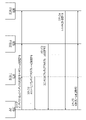
図7を参照すると、図はTPC情報、インデックス1およびインデックス2の送信、ならびに1つまたは複数のSTAによる送信電力の設定を示す。実施形態においてAP602は、TPC情報、インデックス1およびインデックス2をDLトリガフレーム内で、少なくともSTA604、606、608に送信することができる。STA604、606、608は、それに従って後のULランダムアクセス送信における送信電力を設定することができる。
Referring to FIG. 7, the diagram shows transmission of TPC information,
図7に示されるようにAP602は、ULランダムアクセスのために少なくとも1つのOFDMAリソースユニットを割り振るトリガフレームを、ブロードキャストすることができる。インデックス1およびインデックス2は、トリガフレーム内で示されてもよい。代替の方法においてインデックス2は含まれなくてもよく、デフォルトのインデックス2が指定され、またはAP602とSTA604、606、608の1つまたは複数との間で個別に取り決められ得る。DLトリガフレームの受信される電力を測定するとき、k番目のSTA702は、AP602とk番目のSTA702との間の経路損失(PL)を、以下のように推定することができ、
PLk=Ptx_ap+APtx_antenna_gain+STArx_antenna_gain_k-Prx_sta_k 式(7)
ただしPtx_apはAP602側での送信電力、APtx_antenna_gainはAP602側でのアンテナ利得、STArx_antenna_gain_kはk番目のSTA702側でのアンテナ利得、およびPrx_sta_kはk番目のSTA702側での受信される電力である。
As shown in FIG. 7,
PL k = P tx_ap + AP tx_antenna_gain + STA rx_antenna_gain_k −P rx_sta_k formula (7)
where P tx_ap is the transmit power at the
式(7)では、ケーブル損失およびコネクタ損失などの損失は考慮されていないことが留意されるべきである。しかしそれらが考慮される必要がある場合、それらはアンテナ利得パラメータに含まれると想定され得る。例えばAPtx_antenna_gainは、APtx_antenna_gain-APtx_cable_lossと解釈され得る。同様にSTArx_antenna_gain_kは、STArx_antenna_gain_k-STArx_cable_loss_kと解釈され得る。 It should be noted that equation (7) does not take into account losses such as cable loss and connector loss. However, if they need to be considered, they can be assumed to be included in the antenna gain parameters. For example, AP tx_antenna_gain may be interpreted as AP tx_antenna_gain - AP tx_cable_loss . Similarly, STA rx_antenna_gain_k can be interpreted as STA rx_antenna_gain_k - STA rx_cable_loss_k .
AP602はN_DL個のサブキャリアに対応する帯域幅M_DLを有するチャネル上で送信しており、k番目のSTA702は同じチャネル帯域幅上で、受信される電力測定を行い得ると想定され得る。
It can be assumed that the
次のタイムスロットにおいて、k番目のSTA702がN_UL個のサブキャリアに対応する帯域幅M_ULを有する1つまたは複数のOFDMAリソースユニット上で送信する場合、AP602側での予想される受信される電力は、以下のように表されてもよく、
Prx_ap_k=Ptx_sta_k+STAtx_antenna_gain_k+APrx_antenna_gain-PLk
=Ptx_sta_k+STAtx_antenna_gain_k+APrx_antenna_gain-(Ptx_ap+APtx_antenna_gain+STArx_antenn_gain_k-Prx_sta_k)
=(Ptx_sta_k+Prx_sta_k+STAtx_antenna_gain_k+STArx_antenna_k)+(APrx_antenna_gain-APtx_antenna_gain-Ptx_ap)
=A+B 式(8)
ただし
A=Ptx_sta_k+Prx_sta_k+STAtx_antenna_gain_k+STArx_antenna_k 式(9)
および
B=-Ptx_ap+APrx_antenna_gain-APtx_antenna_gain 式(10)
In the next timeslot, if the
P rx_ap_k = P tx_sta_k + STA tx_antenna_gain_k + AP rx_antenna_gain - PL k
= P tx_sta_k + STA tx_antenna_gain_k + AP rx_antenna_gain - (P tx_ap + AP tx_antenna_gain + STA rx_antenna_gain_k - P rx_sta_k )
= (P tx_sta_k + P rx_sta_k + STA tx_antenna_gain_k + STA rx_antenna_k ) + (AP rx_antenna_gain - AP tx_antenna_gain - P tx_ap )
=A+B Formula (8)
However, A = P tx_sta_k + P rx_sta_k + STA tx_antenna_gain_k + STA rx_antenna_k formula (9)
and B=−P tx_ap +AP rx_antenna_gain −AP tx_antenna_gain Equation (10)
列挙されるように、Ptx_sta_kはk番目のSTA702での送信電力とすることができ、Prx_sta_kはk番目のSTA702での受信される電力とすることができ、STAtx_antenna_gain_kはk番目のSTA702側での送信アンテナ利得とすることができ、およびSTArx_antenna_kはk番目のSTA702側での受信アンテナ利得とすることができる。Ptx_apはAP602側での送信電力とすることができ、APrx_antenna_gainはAP602側での受信アンテナ利得とすることができ、およびAPtx_antenna_gainはAP602側での送信アンテナ利得とすることができる。
As enumerated, P tx_sta_k can be the transmit power at the k-
STA側での予想されるリンクマージンは、
LMap_k=Prx_ap_k-sensitivityap=A+(B-sensitivityap) 式(11)
とすることができ、ただしsensitivityapはAP602側での感度とすることができる。Aの値はk番目のSTA702側で知られることがあり、Bの値はAP602側で知られることがある。AP602が、STA604、606、608、702が到達するための所望の受信される電力、インデックス2をブロードキャストできる場合、k番目のSTA702側はAおよびBの両方の値を知る必要があり得る。言い換えればAP602は、Bまたは関連のある情報をインデックス1として、DL送信に含めることができる。あるいはAP602が、604、606、608、702が到達するための所望のリンクマージン(インデックス2)をブロードキャストできる場合、AP602は、B-sensitivityapまたは関連のある情報をインデックス1として、DL送信に含めることができる。
The expected link margin on the STA side is
LM ap_k = P rx_ap_k - sensitivity ap = A + (B - sensitivity ap ) Equation (11)
where sensitivity ap can be the sensitivity on the
値Ptx_apおよびPrx_sta_kは、送信されたまたは、DL送信帯域幅とすることができる、同じ帯域幅で測定された電力とすることができる。 The values P tx_ap and P rx_sta_k can be the transmitted or measured power over the same bandwidth, which can be the DL transmission bandwidth.
AP602側で送信アンテナ利得および受信アンテナ利得が同じである、またはシステムがそれらは同じと想定できる場合、Bは以下のように簡略化され得る。
B=-Ptx_ap 式(12)
If the transmit and receive antenna gains at the
B=-P tx_ap formula (12)
k番目のSTA702側で送信アンテナ利得および受信アンテナ利得が同じである、またはシステムがそれらは同じと想定できる場合、Aは以下のように簡略化され得る。
A=Ptx_sta_k+Prx_sta_k 式(13)
If the transmit and receive antenna gains are the same at the k-
A=P tx_sta_k +P rx_sta_k formula (13)
インデックス1およびインデックス2を設定するための、異なるやり方があり得る。実施形態においてインデックス1およびインデックス2は、電力に基づいてセットアップされてもよい。例えばインデックス1は、式(10)または式(12)において定義される値Bに基づいて設定されてもよい。インデックス2は、予想される受信される電力またはリンクマージンとすることができる。OFDMA送信の場合、DLおよびUL送信帯域幅は同じではない場合があり、従ってBW調整が適用され得る。
There can be different ways to set index1 and index2.
実施形態においてAP602は、非対称な送信および受信アンテナ設定を有し得る。インデックス1は、1mWに対するデシベルの単位での、B=-Ptx_ap+APrx_antenna_gain-APtx_antenna_gainの量子化されたバージョンとすることができる。Ptx_apの詳細な定義は、インデックス1を含んだフレームを送信するために用いられる送信電力とすることができる。AP602はPLCPヘッダ内に送信帯域幅を含めることができ、Ptx_apは帯域全体にわたる送信電力とすることができる。Ptx_apは、インデックス1を含んだフレームを送信するために用いられる、サブキャリアごとの送信電力とすることができる。Ptx_apは、基本帯域幅に対して、インデックス1を含んだフレームを送信するために用いられる等価送信電力である。基本帯域幅は、強制的にサポートされる帯域幅として定義され得る。例えば基本帯域幅は20MHzとすることができ、一方AP602は40MHzチャネル上で送信することができる。次いで、Ptx_apは、20MHz基本チャネル上の送信電力とすることができ、これは40MHzチャネル上の合計送信電力より3dB低くなり得る。
In embodiments, the
インデックス2は、1mWに対するデシベルの単位で測定された所望の受信される電力Cの量子化されたバージョンまたは関数とすることができる。変数Cは、UL送信の帯域幅がAP602からの予想される帯域幅より狭いか同じであるかに関わらず、来たるべきUL MU送信のための、N_total個のサブキャリアを有する、予想される総帯域幅にわたる所望の受信される電力とすることができる。例えばAP602は、来たるべきUL MU送信のために80MHzチャネルを予約することができる。AP602は、いくつかのOFDMAリソースユニットを、UL MUランダムアクセス送信のために割り振ることができる。従ってOFDMAリソースユニットのいくつかは、STA604、606、608、702によって選択されない場合があり、これは実際のUL送信帯域幅を80MHzより低くし得る。しかしこの例でのCは、80MHzチャネルにわたる所望の受信される電力とすることができるが、UL MU送信において利用される帯域幅ではない場合がある。
変数Cは、来たるべきUL MU送信帯域幅に関連のない場合がある、基本帯域幅(N_basic個のサブキャリアを有する)にわたる所望の受信される電力とすることができる。基本帯域幅は、強制的なサポートされる帯域幅として定義され得る。例えば基本帯域幅は20MHzとすることができる。基本帯域幅は、標準において規定され、またはこの送信の前にAP602とすべてのSTA604、606、608、702との間で取り決められ得る。1つの方法においてAP602は、それをビーコンフレーム内でブロードキャストすることができる。
Variable C may be the desired received power over the basic bandwidth (with N_basic subcarriers), which may be irrelevant to the upcoming UL MU transmission bandwidth. A base bandwidth may be defined as the mandatory supported bandwidth. For example, the base bandwidth may be 20 MHz. The base bandwidth may be specified in a standard or negotiated between the
変数Cは、来たるべきUL MU送信帯域幅に関連のない場合がある、N_unit個のサブキャリアを有する最小のOFDMAリソースユニットにわたる所望の受信される電力とすることができる。 Variable C may be the desired received power over the smallest OFDMA resource unit with N_unit subcarriers, which may not be relevant for the upcoming UL MU transmission bandwidth.
変数Cは、来たるべきUL MU送信帯域幅に関連のない場合がある、サブキャリアにわたる所望の受信される電力とすることができる。 Variable C may be the desired received power across subcarriers, which may not be related to the upcoming UL MU transmission bandwidth.
k番目のSTA702は、インデックス1およびインデックス2の両方の受信機として、N個のサブキャリアを有する1つまたは複数のOFDMAリソースユニット上のベースライン送信電力を、本明細書で開示される手順を用いて設定することができる。k番目のSTA702は、値Bをインデックス1から取得することができる。k番目のSTA702は、値Cをインデックス2から取得することができる。このSTAの、1mWに対するデシベルの単位で測定されるベースライン送信電力は、下記とすることができる。
Pbaseline_k=C-B-Prx_sta_k-(STAtx_antenna_gain_k-STArx_antenna_gain_k)-10log10M+10log10N 式(14)
The k-
P baseline_k = CB-P rx_sta_k - (STA tx_antenna_gain_k - STA rx_antenna_gain_k ) - 10 log 10 M + 10 log 10 N Equation (14)
式(14)においてNは、UL送信のために利用される、k番目のSTA702の帯域幅またはサブキャリアの数とすることができる。Mは、インデックス2の帯域幅またはサブキャリアの数とすることができる。Cが、予想される総帯域幅を通した所望の受信される電力となり得る場合、M=N_totalである。Cが、基本帯域幅を通した所望の受信される電力となり得る場合、M=N_basicである。Cが、最小のOFDMAリソースユニットを通した所望の受信される電力となり得る場合、M=N_unitである。Cが、来たるべきUL MU送信帯域幅に関連のない場合があるサブキャリアを通した所望の受信される電力となり得る場合、M=1である。STA側での送信アンテナ利得および受信アンテナ利得が、同じとなり得るまたは同じと見なされ得る場合、式(14)は式(15)に示されるように簡略化され得る。
Pbaseline_k=C-B-Prx_sta_k-10log10M+10log10N 式(15)
In equation (14), N may be the bandwidth or number of subcarriers of the k-
Pbaseline_k =CB- Prx_sta_k - 10log10M+ 10log10N Equation (15)
実施形態においてAP602は、対称な送信および受信アンテナ設定を有することができる。この実施形態は、AP602側での送信アンテナ利得および受信アンテナ利得が同じとなり得るまたは同じと見なされ得ることが想定され得ることを除いて、非対称な送信および受信アンテナ設定に対して開示された方法と同様とすることができる。この場合インデックス1は、以下の量子化されたバージョンとすることができる。
B=-Ptx_ap 式(16)
In embodiments, the
B=-P tx_ap formula (16)
変数Bは、1mWに対するデシベルの単位とすることができる。ベースライン電力計算は、式(14)または式(15)に従うことができ、値Bは式(16)によって置き換えられ得る。 The variable B can be in units of decibels per mW. The baseline power calculation can follow equation (14) or equation (15), and the value B can be replaced by equation (16).
他の実施形態においてインデックス1およびインデックス2は、受信される電力と受信機感度との差であり、以下のように定義され得るリンクマージン(LM)に基づいてセットアップされてもよい。
LMap=Prx_ap_k-sensitivityap 式(17)
In other embodiments,
LM ap =P rx_ap_k - sensitivity ap formula (17)
sensitivityapは、AP602側での受信機感度とすることができる。インデックス1は、値Bから受信機感度の一定のレベルを差し引いたものに設定されてもよく、インデックス2は、AP602側での予想されるリンクマージンとすることができる。受信機感度は、MCSレベルおよびチャネル帯域幅の関数とすることができる。OFDMAシステムにおいて、異なるOFDMAリソースユニットサイズも感度値に影響を及ぼし得る。詳細な方法および手順は本明細書で開示される。
sensitivity ap can be the receiver sensitivity at the
APが非対称な送信および受信アンテナ設定を有し得る実施形態において、インデックス1は以下の、デシベルの単位での量子化されたバージョンとすることができる。
B1=B-sensitivityap
=-Ptx_ap-sensitivityap+APrx_antenna_gain-APtx_antenna_gain 式(18)
あるいはインデックス1はB1の関数とすることができる。Ptx_apおよびsensitivityapの詳細な定義は、本明細書で開示される定義の1つまたは複数とすることができる。Ptx_apは、インデックス1を含んだフレームを送信するために用いられる送信電力とすることができる。AP602は送信帯域幅をPLCPヘッダに含めることができ、Ptx_apは帯域全体を通した送信電力とすることができる。Ptx_apは、インデックス1を含んだフレームを送信するために用いられるサブキャリアごとの送信電力とすることができる。Ptx_apは、基本帯域幅に対して、インデックス1を含んだフレームを送信するために用いられる等価送信電力とすることができる。基本帯域幅は、強制的なサポートされる帯域幅として定義され得る。例えば基本帯域幅は20MHzとすることができる。sensitivityapは、インデックス1を含んだフレームを送信するために用いられる帯域幅に対する最も低いMCSの受信のための最小必要受信電力とすることができる。sensitivityapは、サブキャリアに対する最も低いMCSの受信のための最小必要受信電力とすることができる。sensitivityapは、基本帯域幅に対する最も低いMCSの受信のための最小必要受信電力とすることができる。基本帯域幅は、強制的にサポートされる帯域幅として定義され得る。例えば基本帯域幅は20MHzとすることができる。
In embodiments where the AP may have asymmetric transmit and receive antenna settings,
B 1 = B-sensitivity ap
=-P tx_ap -sensitivity ap +AP rx_antenna_gain -AP tx_antenna_gain Formula (18)
Alternatively,
インデックス2は、1mWに対するデシベルの単位での値C1を有する、所望の受信機リンクマージンの量子化されたバージョンとすることができる。あるいはインデックス2は、C1の関数とすることができる。C1の詳細な定義は、本明細書で開示される定義のいずれか1つとすることができる。C1は、UL送信の帯域幅がAP602からの予想される帯域幅と比べて狭いまたは同じ場合でも、来たるべきUL MU送信のための、N_total個のサブキャリアを有する、予想される総帯域幅を通した所望のリンクマージンとすることができる。
例えばAP602は、来たるべきUL MU送信のために80MHzチャネルを予約することができる。AP602は、UL MUランダムアクセス送信のために、いくつかのOFDMAリソースユニットを割り振ることができる。従ってOFDMAリソースユニットのいくつかは、いずれのSTA604、606、608、702によっても選択されない場合があり、これは実際のUL送信帯域幅を80MHz未満になし得る。しかしこの例でのC1は、80MHzチャネルを通した所望の受信される電力とすることができるが、UL MU送信において利用される帯域幅ではない場合がある。
For example,
C1は、来たるべきUL MU送信帯域幅に関連のない場合がある、N_basic個のサブキャリアを有する基本帯域幅にわたる所望のリンクマージンとすることができる。基本帯域幅は、強制的なサポートされる帯域幅として定義され得る。例えば基本帯域幅は20MHzとすることができる。この基本帯域幅は、標準化される、この送信の前にAP602によって例えばビーコンフレーム内でブロードキャストされる、またはこの送信の前にAP602とすべてのSTA604、606、608、702との間で取り決められ得る。C1は、来たるべきUL MU送信帯域幅に関連のない場合がある、N_unit個のサブキャリアを有する、最小のOFDMAリソースユニットを通した所望のリンクマージンとすることができる。あるいはC1は、来たるべきUL MU送信帯域幅に関連のない場合がある、サブキャリアを通した所望のリンクマージンとすることができる。
C 1 may be the desired link margin over the basic bandwidth with N_basic subcarriers, which may be irrelevant to the upcoming UL MU transmission bandwidth. A base bandwidth may be defined as the mandatory supported bandwidth. For example, the base bandwidth may be 20 MHz. This base bandwidth may be standardized, broadcast by the
k番目のSTA702は、インデックス1およびインデックス2の両方を受信するとすぐに、本明細書で開示される手順を用いて、N個のサブキャリアを有する、1つまたは複数のOFDMAリソースユニット上のベースライン送信電力を設定することができる。k番目のSTA702は、インデックス1から値B1を取得することができる。k番目のSTA702は、インデックス2から値C1を取得することができる。k番目のSTA702の、1mWに対するデシベルの単位での送信電力は、以下のように計算され得る。
Pbaseline=C1-B1-Prx_sta_k-(STAtx_antenna_gain_k-STArx_antenna_gain_k)-10log10M+10log10N 式(19)
As soon as the k-
P baseline = C 1 - B 1 - P rx_sta_k - (STA tx_antenna_gain_k - STA rx_antenna_gain_k ) - 10 log 10 M + 10 log 10 N Equation (19)
式(19)においてNは、UL送信のためにk番目のSTA702によって利用される帯域幅またはサブキャリアの数とすることができる。Mは、インデックス2の帯域幅またはサブキャリアの数とすることができる。C1が、UL送信の帯域幅がAP602からの予想される帯域幅と比べて狭いまたは同じ場合でも、来たるべきUL MU送信のための予想される総帯域幅(N_total個のサブキャリアを有する)を通した所望のリンクマージンとすることができる場合は、M=N_totalである。C1が、来たるべきUL MU送信帯域幅に関連のない場合がある、基本帯域幅(N_basic個のサブキャリアを有する)を通した所望のリンクマージンとなり得る場合、M=N_basicである。C1が、来たるべきUL MU送信帯域幅に関連のない場合がある、最小のOFDMAリソースユニット(N_unit個のサブキャリアを有する)を通した所望のリンクマージンとすることができる場合、M=N_unitである。C1が、来たるべきUL MU送信帯域幅に関連のない場合があるサブキャリアを通した所望のリンクマージンとすることができる場合、M=1である。
In equation (19), N may be the bandwidth or number of subcarriers utilized by the k-
k番目のSTA702側での送信アンテナ利得および受信アンテナ利得が同じとなり得るまたは同じと見なされ得る場合、式(19)は以下のように簡略化され得る。
Pbaseline_k=C1-B1-Prx_sta_k-10log10M+10log10N 式(20)
If the transmit and receive antenna gains at the k-
Pbaseline_k =C1- B1 - Prx_sta_k - 10log10M + 10log10N Equation (20)
実施形態においてAP602は、対称な送信および受信アンテナ設定を有することができる。これは、AP602側での送信アンテナ利得および受信アンテナ利得が同じとなり得るまたは同じと見なされ得ることが想定され得ることを除いて、非対称な送信および受信アンテナ設定が関わる実施形態と同様とすることができる。この場合インデックス1は以下の、デシベルの単位での量子化されたバージョンとすることができる。
B1=-Ptx_ap-sensitivityap 式(21)
ベースライン送信電力計算は、式(19)または式(20)に従うことができ、値Bは式(21)によって置き換えられ得る。式(21)は、開ループリンクマージンに対して、負であることが留意されるべきである。従ってこの方法の場合、開ループリンクマージンはまたインデックス1として用いられてもよく、式(19)および式(20)は負号を考慮するようにわずかに変更され得る。
In embodiments, the
B 1 =−P tx_ap −sensitivity ap formula (21)
A baseline transmit power calculation may follow equation (19) or equation (20), and the value B may be replaced by equation (21). It should be noted that equation (21) is negative for the open loop link margin. Therefore, for this method, the open loop link margin may also be used as
電力調整を設定する方法および手順が、本明細書で開示される。電力調整パラメータは、Dとして表されるデシベルの単位での整数または小数として設定されてもよい。あるいは電力調整パラメータは、Dの関数とすることができる。値Dは、AP602がSTAのための電力制御関連記録を有しない場合、またはAP602がどのSTAが例えばUL MUランダムアクセスを送信し得るかを知らない場合、デフォルト値を用いて設定されてもよい。リトライの数が増加される場合、値Dは増加され得る。例えばAP602は、ランダムアクセスを用いて再送信するようにSTA604、606、608、702をトリガすることができる。
Methods and procedures for setting power regulation are disclosed herein. The power adjustment parameter may be set as an integer or fractional number in units of decibels represented as D. Alternatively, the power adjustment parameter can be a function of D. The value D may be set with a default value if the
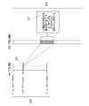
制限されたUL MUランダムアクセスを有するTPC手順が、本明細書で開示される。UL MUランダムアクセス手順がトリガフレームによって開始される、図5~7を考察すると、STA例えば第1のSTA604が、それがUL MUランダムアクセス機会の候補であるかどうかを決定することを可能する手順が開示される。このような手順の1つは、第1のSTA604が、それがUL MUランダムアクセス機会の候補であるかどうかを決定するために用いることができる、電力制御情報をトリガフレームに含めることができる。電力制御情報は、第1のSTA604での許容できる受信される電力の範囲、および/または第1のSTA604が加わることができるためのリンクマージンを示すことができる。これは図8に示される。
A TPC procedure with restricted UL MU random access is disclosed herein. The UL MU random access procedure is initiated by a trigger frame. Considering FIGS. 5-7, a procedure that allows a STA, such as the
図8は、Tx電力範囲802に対応するRx電力範囲804を有するSTA604、606、608、702が、UL MUランダムアクセスのために送信することが可能にされ得る、AP Tx電力範囲802を示す。Tx電力範囲802は、AP602が送信することができる、AP Tx電力範囲806全体の一部分とすることができる。Rx電力範囲804は、STA Rx電力範囲808全体の一部分とすることができる。
FIG. 8 shows AP Tx power ranges 802 that STAs 604, 606, 608, 702 with corresponding Rx power ranges 804 may be allowed to transmit for UL MU random access.
Rx電力範囲804および/またはリンクマージンを決定するために用いられる情報は、最大経路損失、ΔPLM、dBでのリンクマージン、正の整数値(例えば0から128)を有するリンクマージンインデックス、および受信機感度に対する受信されるSNRを含み得るSNRマージンを含むことができる。 The information used to determine the Rx power range 804 and/or link margin is the maximum path loss, ΔPLM, link margin in dB, link margin index with positive integer value (eg, 0 to 128), and receiver An SNR margin may be included that may include the received SNR for sensitivity.
次いで、本明細書で開示される情報の任意の組み合わせまたはすべてを用いて、範囲が指定され得る。例えばリンクマージンインデックス範囲は、以下のように定義され得る。
Link Margin Range(0-256)=Link Marginmax-Link Marginmin 式(22)
この定義に対して、STA604、606、608、702は、Link Marginminを超えることを予期し、それがUL MUランダムアクセスプールに加わるためにリンクマージン範囲内にあるようにする必要があり得る。
Ranges can then be specified using any combination or all of the information disclosed herein. For example, a link margin index range may be defined as follows.
Link Margin Range (0-256) = Link Margin max - Link Margin min Formula (22)
For this definition, the
AP602はまた、トリガフレームを送信するために用いられる、Ptx_apとして表される送信電力を示すことができる。範囲内の受信される電力を有するSTA604、606、608、702は、来たるべきランダムアクセスフレーム内で、それらの送信電力を、Ptx_sta=Ptx_apとして設定することができる。あるいはトリガフレームにおいてAP602は、トリガフレームを送信するために用いられる送信電力(Ptx_ap)、および電力オフセット(Pdelta)を示すことができる。範囲内の受信される電力を有するSTA604、606、608、702は、来たるべきランダムアクセスフレーム内で、それらの送信電力を、Ptx_sta=Ptx_ap-PΔとして設定することができる。追加の帯域幅およびアンテナ利得が考慮され得ることが留意されるべきである。
The
実施形態において、UL MUランダムアクセスのためのTPC能力が開示される。STA例えばk番目のSTA702、およびAP602は、UL MUランダムアクセスを有する電力制御のためのそれらの能力を示すことができる。AP602は、それのビーコン、プローブ応答、関連付け応答、または任意の他のタイプのフレーム内に、AP602が電力制御またはより具体的にはUL MUランダムアクセスのための電力制御の能力がある旨のインジケータを含めることができる。UL MUランダムアクセスTPC能力インジケータは、管理、制御、または他のフレームタイプにおける情報要素(IE)など、任意の既存のまたは新しいフィールド内に含められ得る。UL MUランダムアクセスTPC能力インジケータは、MACまたはPLCPヘッダ内に含められ得る。同様にk番目のSTA702も、プローブ要求、関連付け要求、または他の管理制御または他のフレームタイプにおける、1つまたは複数のインジケータを用いて、UL MUランダムアクセスのためのTPC能力を示すことができる。k番目のSTA702は、UL MUランダムアクセスのためのTPC能力を、MACまたはPLCPヘッダ内で示すことができる。
In embodiments, TPC capabilities for UL MU random access are disclosed. STAs such as the
以下の説明は、IEEE 802.11axのための更新されたTPCレポート、および開ループTPC較正を含み得る。本明細書で述べられる実施形態は、高速で移動するSTAに対する送信電力制御に対処することができる。 The following discussion may include updated TPC reports for IEEE 802.11ax and open-loop TPC calibration. Embodiments described herein can address transmit power control for fast moving STAs.
IEEE 802.11仕様において送信したいSTAは、受信するSTAにTPC要求を送ることができる。受信するSTAは次いで、送信したいSTAが正しい送信電力でそうすることを可能にするように、TPCレポートフレーム内の情報を用いて返答することができる。IEEE 802.11hにおけるTPCレポートフレームの使用は、結果として受信機感度を組み込まない情報となり得る。IEEE 802.11ahにおける開ループリンクマージンインデックスは、この問題に対処し得るが、高速で移動するSTAには適さない場合がある。異なるMCSを有する高速で移動するSTAのために受信機感度が必要となり得るIEEE 802.11axでは、完全な情報の送信を可能にするように、TPCレポートを変更する必要があり得る。一般性を失わずに、STAは受信機としてのAPに送信することを望むことが想定されるべきである。 A STA wishing to transmit in the IEEE 802.11 specification can send a TPC request to a receiving STA. The receiving STA can then reply with the information in the TPC report frame to allow the STA that wants to transmit to do so with the correct transmit power. The use of TPC report frames in IEEE 802.11h can result in information that does not incorporate receiver sensitivity. The open-loop link margin index in IEEE 802.11ah may address this issue, but may not be suitable for fast moving STAs. In IEEE 802.11ax, where receiver sensitivity may be required for fast moving STAs with different MCS, TPC reports may need to be modified to allow complete information transmission. Without loss of generality, it should be assumed that the STA wants to transmit to the AP as receiver.
ダウンリンク送信に対して、STAでの受信される信号強度RSSISTAは、以下のように定義されてもよく、
RSSISTA=Ptx-AP-Ploss→RSSISTA=Ploss=Ptx-AP-RSSISTA 式(23)
ただしPtx-APはAPでの送信電力とすることができ、Plossは経路損失とすることができ、これはSTAとAPとの間のシャドーイングおよび高速フェージングを含み得る。
For downlink transmissions, the received signal strength RSSI STA at a STA may be defined as
RSSI STA =P tx-AP -Ploss→RSSI STA =P loss =P tx-AP -RSSI STA formula (23)
where Ptx -AP can be the transmit power at the AP and Ploss can be the path loss, which can include shadowing and fast fading between the STA and the AP.
アップリンク送信に対して、APでの受信される信号強度RSSIAPは、以下のように定義されてもよく、
RSSIAP=Ptx-STA-Ploss 式(24)
ただしPtx-STAは、STAでの送信電力とすることができる。リンクマージン(ΔMCS)は以下のように、APでの受信される電力と、所望のMCS(Rreq)を復号するために必要な電力との差として定義され得る。
RSSIAP-Rreq=ΔMCS→RSSIAP=ΔMCS+Rreq 式(25)
For uplink transmissions, the received signal strength RSSI AP at the AP may be defined as
RSSIAP =Ptx -STA- Ploss Equation (24)
However, P tx-STA can be the transmit power at the STA. Link margin (ΔMCS) may be defined as the difference between the received power at the AP and the power required to decode the desired MCS (R req ) as follows.
RSSI AP −R req =ΔMCS→RSSI AP =ΔMCS+R req formula (25)
これらの式を組み合わせて、結果として以下となる。
Ptx-STA-Ptx-AP+RSSISTA=ΔMCS+Rreq 式(26)
および
Ptx-STA=ΔMCS+Ptx-AP+Rreq-RSSISTA 式(27)
Combining these equations results in:
P tx-STA −P tx-AP +RSSI STA =ΔMCS+R req formula (26)
and P tx-STA =ΔMCS+P tx-AP +R req −RSSI STA Equation (27)
ΔMCS、Ptx-AP、およびRreqを送ることは、STAが正しい送信電力を推定することを可能にすることができる。これらは新しいTPCレポートにおいて、フレーム内で個々にSTAに送られてもよい。あるいは既存のTPCレポートは、APすなわち受信機送信電力(Ptx-AP)およびMCSリンクマージン(ΔMCS)を送る。既存の開ループリンクマージンインデックスは、APすなわち受信機送信電力と、受信機要件との和(Ptx-AP+Rreq)を送る。従ってMCSリンクマージンおよび開ループリンクマージンインデックスの両方を送ることは、STAすなわち送信機に、その送信電力を、高速で移動するSTAに対しても正しく推定するための十分な情報を与える。 Sending ΔMCS, P tx-AP and R req can allow the STA to estimate the correct transmit power. These may be sent to the STAs individually in frames in new TPC reports. Alternatively, existing TPC reports carry the AP or receiver transmit power (P tx-AP ) and MCS link margin (ΔMCS). The existing open-loop link margin index conveys the sum of the AP, receiver transmit power, and the receiver requirement (P tx-AP +R req ). Sending both the MCS link margin and the open loop link margin index therefore gives the STA, the transmitter, enough information to correctly estimate its transmit power even for fast moving STAs.
実施形態において、例えばIEEE 802.11axでの使用のための新しいTPCレポートが用いられ得る。TPCレポートフレームフォーマットは、要素ID、長さ、下記に等しい開ループリンクマージンインデックス(OLLMI)
OLLMI=Ptx_ap+Rxsensitivity_mcs=Ptx_ap+ΔMCS 式(28)
を含むことができ、リンクマージンは下記に等しい。
Link Margin=RSSIAP-Rxsensitivity_mcs=RSSIAP-ΔMCS 式(29)
MCS依存Rxsensitivityおよび使用可能な送信電力ヘッドルームなどの追加の情報が送られ得る。MCS依存Rxsensitivityに対してTPC要求は、TPCレポート内でRx感度がそれに対して送られるべきであるMCSを含むように、更新され得る。
In embodiments, new TPC reports for use in IEEE 802.11ax, for example, may be used. The TPC report frame format is Element ID, Length, Open Loop Link Margin Index (OLLMI) equal to:
OLLMI=P tx_ap +Rx sensitivity_mcs =P tx_ap +ΔMCS Equation (28)
and the link margin is equal to:
Link Margin = RSSI AP - Rx sensitivity_mcs = RSSI AP - ΔMCS Equation (29)
Additional information such as MCS dependent Rx sensitivity and available transmit power headroom may be sent. The TPC request for MCS dependent Rx sensitivity can be updated to include the MCS for which the Rx sensitivity should be sent in the TPC report.
他の例示的フレームフォーマットにおいてフレームは、要素ID、長さ、送信電力=Ptx-AP、式(30)で上記に定義されるものに等しいリンクマージン、およびRxsensitivity=Rreqを含むことができる。第1のフォーマットのように、MCSused_for_Rx_sensitivity、および使用可能な送信電力ヘッドルームのためのフィールドも追加され得る。 In other exemplary frame formats, the frame may include element ID, length, transmit power = Ptx-AP , link margin equal to that defined above in equation (30), and Rxsensitivity = Rreq . can. As in the first format, fields for MCS used_for_Rx_sensitivity and available transmit power headroom may also be added.
APまたはSTAが特定のパラメータのどれを送り返すべきか(例えばΔMCS、Ptx-AP、またはRreq)を決定する場合、フィードバックされるフィールドの数を制限するように、3つのパラメータのどれが送られるかを示すビットマップを用いて、3つのパラメータの任意の組み合わせを送り返すフレームフォーマットが構築され得る。実施形態において表1に示されるように、送信電力、リンクマージン、および/またはリンクマージンインデックスかを指定するための用いられ得る、3ビットのビットマップが送られる。 When an AP or STA decides which of the specific parameters to send back (e.g., ΔMCS, P tx-AP , or R req ), which of the three parameters to send back limits the number of fields that are fed back. A frame format can be constructed that returns any combination of the three parameters, using a bitmap that indicates whether the A 3-bit bitmap is sent that can be used to specify either transmit power, link margin, and/or link margin index, as shown in Table 1 in an embodiment.
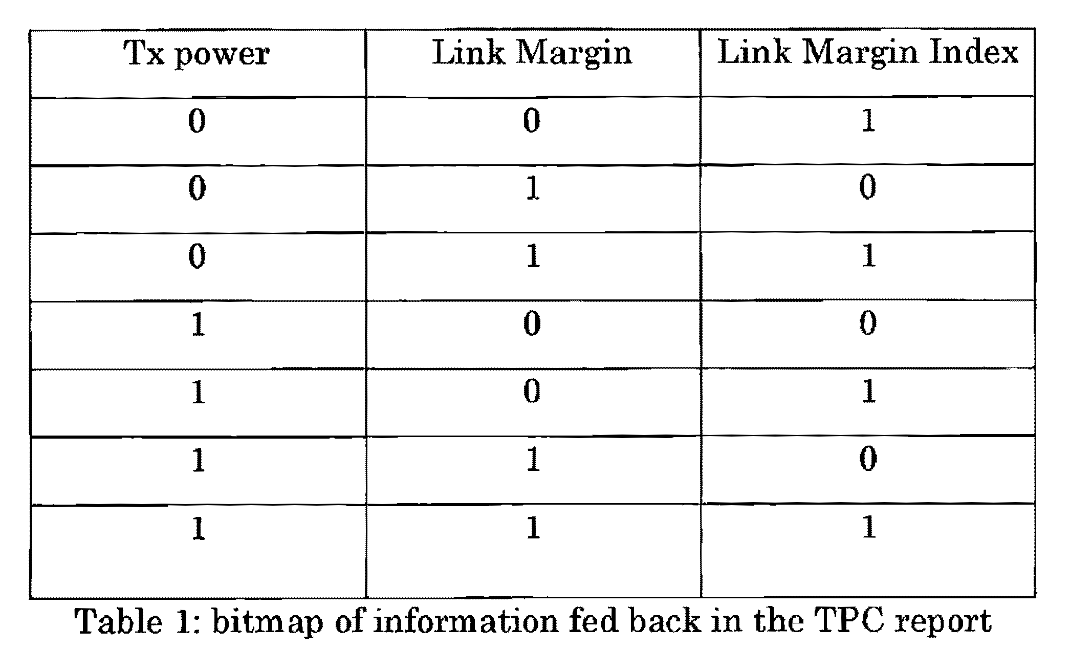
このビットフォーマットは、要素IDの一部として、またはフレーム自体の一部として含まれ得る。ビットマップは、フィードバックフレームのサイズを決定することができる。例としてAP送信電力が一定のままであるシナリオでは、AP送信電力をフィードバックする必要性はなく、最初のビットは常にゼロに設定される。 This bit format can be included as part of the element ID or as part of the frame itself. A bitmap can determine the size of the feedback frame. In scenarios where the AP transmit power remains constant as an example, there is no need to feed back the AP transmit power and the first bit is always set to zero.
異なるSTAは、異なるTPC実装形態を用いることができ、TPCレポートに基づいて推定される送信電力は、予想されるものとは異なるRSSIAPを結果として生じ得る。個々のSTAによって正しい電力レベルが設定されることを検証するために、追加の方法が必要となり得る。 Different STAs may use different TPC implementations, and transmit power estimated based on TPC reports may result in different RSSI APs than expected. Additional methods may be required to verify that the correct power levels are set by individual STAs.
実施形態において受信機は、所望の受信電力を決定し、送信機にそれの電力を所望の量だけ調整するように指示を送ることができる。これは閉ループ手法となり得る。 In embodiments, the receiver can determine the desired received power and send instructions to the transmitter to adjust its power by the desired amount. This can be a closed loop approach.
実施形態において送信機は、送信機でのRSSIのそれの推定が正しいかどうかを調べることを望み得る。これは、開ループ手法となり得る。以下の説明は、受信機によって受信される信号レベルのこの開ループ検証を可能にするための、開ループ較正手順を含み得る。開ループ較正フレームは、受信される電力が、受信機で予想されたものと等価であることを確実にするように、受信機に送られ得る。この場合、送信するSTAは較正要求を受信機に送出することができ、受信機は送信するSTAに、受信される電力を示すメトリックによって返答することができる。メトリックは、STAから受信される電力に基づく、APのRSSIのように簡単なものとすることができる。あるいは送信機は、受信機での所望のレベルについての情報を送ることができ、受信機は次いで、差についての情報、または観察される値が要求された値より高いかそれとも低いかで返答することができる。送信するSTAは次いでこの情報を用いて、それが用いるべき送信電力を補正することができる。 In embodiments, the transmitter may wish to check if its estimate of the RSSI at the transmitter is correct. This can be an open loop approach. The discussion below may include an open-loop calibration procedure to enable this open-loop verification of the signal level received by the receiver. An open-loop calibration frame may be sent to the receiver to ensure that the received power is equivalent to that expected at the receiver. In this case, the transmitting STA can send a calibration request to the receiver, and the receiver can reply to the transmitting STA with a metric indicating the power received. The metric can be as simple as the AP's RSSI, which is based on the power received from the STAs. Alternatively, the transmitter can send information about the desired level at the receiver, which then replies with information about the difference or whether the observed value is higher or lower than the requested value. be able to. The transmitting STA can then use this information to correct the transmit power it should use.
以下の説明は、送信-受信ペアの間で用いられ得る手順を含むことができる。送信機は、TPC要求を受信機に送ることができる。実施形態においてTPC要求は、特定の要素IDを有し、追加の情報はない簡単なフレームとすることができる。あるいはTPC要求は特定の情報、例えば送信電力、特定のMCSに対するリンクマージン、および/またはリンクマージンインデックスを明示的に要求することができる。受信機は、送信機から更新されたTPCレポートを送ることができる。直ちにまたは遅延された時点で送信機は、TPC較正要求を受信機に送ることができる。これは簡単な要求フレームとすることができ、またはこれはTPCレポート内で受信された情報に基づく、受信機での予想されるRSSIについての情報を含むことができる。 The following description may include procedures that may be used between transmit-receive pairs. A transmitter can send a TPC request to a receiver. In embodiments, a TPC request may be a simple frame with a specific element ID and no additional information. Alternatively, the TPC request can explicitly request specific information, eg, transmit power, link margin for a specific MCS, and/or link margin index. The receiver can send an updated TPC report from the transmitter. The transmitter can send the TPC calibration request to the receiver immediately or at a delayed time. This could be a simple request frame, or it could contain information about the expected RSSI at the receiver based on the information received in the TPC report.
受信機は、STAの開ループ電力制御を較正することを助けるための情報を含む、肯定応答を送ることができる。この情報は、受信信号レベルが所望の受信される電力と比べて高い、低い、それとも等しいかを示す簡単なビットとすることができる。あるいは情報は、所望の、および実際の受信される電力の間の電力の差とすることができる。実施形態においてフィードバックは、所望の電力が達成されるまで継続することができる。実施形態において較正フレームは、所望の量だけSTAの送信電力を増加または減少するための簡単な要求とすることができる。 The receiver may send an acknowledgment containing information to help calibrate the STA's open loop power control. This information can be a simple bit that indicates whether the received signal level is higher, lower, or equal to the desired received power. Alternatively, the information can be the power difference between the desired and actual received power. Feedback may continue in embodiments until the desired power is achieved. In embodiments, a calibration frame may be a simple request to increase or decrease the STA's transmit power by a desired amount.
以下の説明は、UL MU OFDMA送信のための電力制御方法および手順を含むことができる。実施形態は、UL MU送信を有する電力制御に関して提起される問題に対処することができる。実施形態において、データフレームまたは制御フレームを含むことができる、UL MU OFDMA送信のためのTPC手順が述べられる。方法および手順は、すべてのOFDMA送信がAPによって割り当てられるときに実施され得る。 The description below may include power control methods and procedures for UL MU OFDMA transmission. Embodiments may address the issues raised regarding power control with UL MU transmissions. In embodiments, a TPC procedure for UL MU OFDMA transmission, which may include data frames or control frames, is described. The methods and procedures may be implemented when all OFDMA transmissions are assigned by the AP.
TPC情報は、ULデータフレームに対して図9に示されるようにトリガフレーム内に、または制御フレームに対して図10および図11に示されるようにプリアンブルまたはDLデータ/DL MU RTS内に含めることができる。図11に示されるように縦続された送信に対して、縦続における各UL送信のための送信電力制御情報は、縦続されたトリガ内に配置されてもよい。縦続された送信の場合において、STAが繰り返される場合、もとの送信におけるエラーを訂正するために、開示される較正フレームでのようにTPC調整値が用いられ得る。送信電力制御情報は、本明細書で開示される情報のいずれかを含むことができる。 The TPC information shall be included in the trigger frame as shown in FIG. 9 for UL data frames or in the preamble or DL data/DL MU RTS as shown in FIGS. 10 and 11 for control frames. can be done. For cascaded transmissions as shown in FIG. 11, the transmit power control information for each UL transmission in the cascade may be placed within the cascaded trigger. In the case of cascaded transmissions, TPC adjustments can be used as in the disclosed calibration frame to correct errors in the original transmission if the STA is repeated. The transmit power control information can include any of the information disclosed herein.
図9を参照すると、ULデータフレームのためのTPC手順を示す図が示される。図9は、電力制御を有するUL MU-OFDMAデータ送信のための例示的手順を示す。この例においてAPは、4つのOFDMAリソースユニットを有するチャネルを取得することができる。DLトリガフレーム902内でAPは、OFDMAリソースユニット1から4を特定のユーザに割り当てることができる。トリガフレーム902の受信のSIFS持続時間後にSTAは、トリガフレーム902内でもたらされるTPCおよび割り当て情報を用いて、ULデータフレーム904~910内で情報をAPに送ることができる。その後にAPは、UL MU送信の肯定応答フレーム912を送ることができる。
Referring to FIG. 9, a diagram illustrating the TPC procedure for UL data frames is shown. FIG. 9 shows an exemplary procedure for UL MU-OFDMA data transmission with power control. In this example, the AP can acquire a channel with 4 OFDMA resource units. Within the
ULデータフレームのための上記のTPC手順のAP側処理が、本明細書で開示される。APは、競合またはスケジューリングを通じてチャネル媒体を取得することができる。APはトリガフレームを送信することができる。トリガフレームは、本明細書で開示される方法の1つまたは複数を用いて送信され得る。トリガフレームは、図9に示されるように独立のフレームとして送信され得る。DL送信は、OFDMモードとすることができる。実施形態において、MACフレームとしてトリガフレームは、A-MPDUフォーマットを用いた1つまたは複数のデータフレーム、制御フレーム、および/または管理フレームを含む他のフレームと集約され得る。送信はOFDMモード、OFDMAモード、または他のMUモードとすることができる。APは、トリガフレーム、ならびにデータフレーム、制御フレーム、および管理フレームを含む他のフレームをMUモード、例えばDL OFDMAまたは他のMUモードで送信することができる。トリガフレームがDL OFDMAモードで送信される場合、トリガフレームのSIG-B内のリソース割り振りフィールドは、予約されたブロードキャストまたはマルチキャストIDを用いて、対応するOFDMAリソースユニットがトリガフレーム送信のために割り当てられることを示すことができる。SIG-Bフィールド内で利用されるブロードキャストまたはマルチキャストIDは、すべてのSTAはリソースユニット上で運ばれる情報を監視し復号する必要があり得ることを示すことができる。 AP-side processing of the above TPC procedure for UL data frames is disclosed herein. APs can obtain the channel medium through contention or scheduling. The AP can send trigger frames. A trigger frame may be sent using one or more of the methods disclosed herein. The trigger frame may be sent as an independent frame as shown in FIG. DL transmission can be in OFDM mode. In embodiments, a trigger frame as a MAC frame may be aggregated with other frames including one or more data, control, and/or management frames using the A-MPDU format. Transmission can be in OFDM mode, OFDMA mode, or other MU mode. The AP may transmit trigger frames and other frames including data, control, and management frames in MU mode, eg, DL OFDMA or other MU modes. If the trigger frame is transmitted in DL OFDMA mode, the Resource Allocation field in SIG-B of the trigger frame uses the reserved broadcast or multicast ID to allocate the corresponding OFDMA resource units for trigger frame transmission. It can be shown that A broadcast or multicast ID utilized within the SIG-B field may indicate that all STAs may need to monitor and decode information carried on the resource unit.
APは、トリガフレーム内に、開ループ電力制御インデックス、インデックス1を含めることができる。1つの方法において開ループリンクマージンインデックスは、IEEE 802.11ahと同様なやり方で定義され得る。
ΔOPLM=Ptx+RXsensitivity 式(30)
The AP may include an open loop power control index,
Δ OPLM =P tx +RX sensitivity formula (30)
しかし受信機感度RXsensitivityは、基本チャネル帯域幅に対する最も低いMCSの受信のための最小必要受信電力として再定義され得る。例えばIEEE 802.11axの場合、これは20MHzまたは他の帯域幅を指すことができる。これは、STAが定義を明示的に知り得るように、標準化されてもよい。開ループリンクマージンΔOPLMは、(-128+D×G)dBとして計算されてもよく、ただしDは開ループリンクマージンインデックスとすることができ、Gは基本細分性とすることができる。例えばG=0.25、または0.5である。 However, the receiver sensitivity RX sensitivity can be redefined as the minimum required received power for reception of the lowest MCS for the fundamental channel bandwidth. For IEEE 802.11ax, for example, this could refer to 20 MHz or some other bandwidth. This may be standardized so that STAs may explicitly know the definition. The open loop link margin Δ OPLM may be calculated as (−128+D×G) dB, where D may be the open loop link margin index and G may be the base granularity. For example, G=0.25, or 0.5.
APは、トリガフレーム内に電力整合インデックス、インデックス2を含めることができる。この電力整合インデックスは、目標とされるリンクマージン、またはAP側で予想される受信電力とすることができる。UL MU送信の場合、すべてのSTAは、目標とされる電力レベルを用いてAPに到達するように試みることができる。
The AP may include a power matching index,
APは、トリガフレーム内にユーザに特有の電力調整パラメータを含めることができる。ランダムアクセスSTAに割り当てられたリソースユニットに対して、電力調整パラメータはランダムアクセスSTAの間で同じとすることができる。電力調整パラメータは、トリガフレームのすべての受信者に対して同じでも同じでなくてもよい。 The AP may include user-specific power adjustment parameters in the trigger frame. For resource units assigned to random access STAs, the power adjustment parameter may be the same among random access STAs. The power adjustment parameter may or may not be the same for all recipients of the trigger frame.
APは、上述の更新されたTPCレポートフレームのいずれかを含むことができる。SIFS時間の後にAPは複数のSTAからUL送信を受信することができ、一方STAはそれらの送信電力を、ベースライン送信電力、および先行するトリガフレーム内で受信された送信電力調整値に従って、調整することができる。専用STAに割り当てられたOFDMAリソースユニット上でAPは、割り当てられたSTAからデータ、制御、または管理フレームを受信することができる。 The AP may include any of the updated TPC report frames described above. After the SIFS time, the AP can receive UL transmissions from multiple STAs while the STAs adjust their transmit power according to the baseline transmit power and the transmit power adjustments received in the preceding trigger frame. can do. On OFDMA resource units assigned to dedicated STAs, the AP may receive data, control, or management frames from the assigned STAs.
UL MU送信の受信のSIFS時間後にAPは、マルチSTA肯定応答フレームまたはブロックACKフレームを、STAに送信することができる。 The AP may send a multi-STA acknowledgment frame or a block ACK frame to the STAs SIFS time after receipt of the UL MU transmission.
ULデータフレームのための上記のTPC手順のSTA側処理が、本明細書で開示される。STAは、それが来たるべきUL OFDMA送信におけるUL MUランダムアクセスのために少なくとも1つのOFDMAリソースユニットを割り当てることができる、トリガフレームを検出することができる。APからのDL送信がOFDMAモードである場合、STAは、トリガフレームのリソース割り振りに対してSIG-Bフィールドをチェックすることができる。 STA-side processing of the above TPC procedure for UL data frames is disclosed herein. A STA can detect a trigger frame in which it can allocate at least one OFDMA resource unit for UL MU random access in an upcoming UL OFDMA transmission. If the DL transmission from the AP is in OFDMA mode, the STA can check the SIG-B field for resource allocation in the trigger frame.
STAは、STAが、送信するための1つまたは複数のアップリンク制御、管理、またはデータフレームを有する場合、割り当てられたUL MUランダムアクセスリソースにおける送信のための準備をすることができる。 A STA may prepare for transmission on its assigned UL MU random access resources if it has one or more uplink control, management, or data frames to transmit.
STAは、本明細書で開示される方法のいずれかに従って送信電力を設定することができる。STAは、トリガフレーム内で運ばれるインデックス1の値をチェックすることができる。STAは、トリガフレーム内で運ばれるインデックス2の値をチェックすることができる。STAは、インデックス1およびインデックス2に基づいて、ベースライン送信電力を計算することができる。STAは、トリガフレーム内で運ばれる電力調整パラメータをチェックし、それに従ってベースライン送信電力を増加または減少することができる。STAが一定の期間内にAPと通信した場合、STAは記録において、送信電力制御関連パラメータを有し得る。STAは、履歴上の送信電力制御関連パラメータを評価し、トリガフレーム内で受信された値またはパラメータのいずれか1つまたは複数から取得された瞬時送信電力と組み合わせることができる。STAは、計算された送信電力を、送信帯域幅およびアンテナ設定に従って調整することができる。STAは、いずれかの開示された方法を通じて計算された送信電力が、最大許容送信電力および送信電力密度に反しないことを確認することができる。そうでない場合STAは、代わりに最大許容送信電力を用いることができる。
A STA may set its transmit power according to any of the methods disclosed herein. The STA can check the value of
送信のSIFS時間後にAPは、STAから肯定応答フレームを受信することができる。 After SIFS time of transmission, the AP can receive an acknowledgment frame from the STA.
図10を参照すると、UL制御フレーム、例えばACKフレームのためのTPC手順を示す図が示される。図10はさらに、電力制御を有するUL MU-OFDMA制御送信のための例示的手順を示す。この例においてAPは、4つのOFDMAリソースユニットを有するチャネルを取得することができ、4つの異なるSTAにDLデータ1004~1010を送信することができる。DLデータ1004~1010のSTAへの到達のSIFS持続時間後に、STAはAPに、DL MU送信の肯定応答フレーム1012~1018を送ることができる。STAは、すべてのSTAに送られたプリアンブル1002内に、またはDLデータフレーム1004~1010のそれぞれにおいて送られたユーザに特有のPHYヘッダ内に配置されたTPC情報を用いて、用いるための正しい送信電力をそれらが推定することを可能にすることができる。
Referring to FIG. 10, a diagram illustrating the TPC procedure for UL control frames, eg, ACK frames is shown. FIG. 10 further shows an exemplary procedure for UL MU-OFDMA controlled transmission with power control. In this example, the AP can acquire a channel with four OFDMA resource units and can send DL data 1004-1010 to four different STAs. After the SIFS duration of arrival of the DL data 1004-1010 to the STA, the STA may send the DL MU transmission acknowledgment frames 1012-1018 to the AP. STAs use the TPC information placed in the
UL制御フレームのための上記のTPC手順のAP側処理が、本明細書で開示される。APは、競合またはスケジューリングを通じてチャネル媒体を取得することができる。APはユーザに、プリアンブル1002および/または1つまたは複数のDLデータフレーム1004~1010を送信することができる。APは、開ループ電力制御インデックス、インデックス1を、プリアンブル1002またはDLデータフレーム1004~1010の1つまたは複数内に含めることができる。1つの方法において開ループリンクマージンインデックスは、IEEE 802.11ahと同様なやり方で定義され得る。
ΔOPLM=Ptx+RXsensitivity 式(31)
AP-side processing of the above TPC procedures for UL control frames is disclosed herein. APs can obtain the channel medium through contention or scheduling. The AP may transmit a
Δ OPLM = P tx + RX sensitivity formula (31)
しかし受信機感度RXsensitivityは、基本チャネル帯域幅に対する最も低いMCSの受信のための最小必要受信電力として再定義され得る。例えばIEEE 802.11axの場合、これは20MHzまたは別の帯域幅を指すことができる。これは、STAが定義を明示的に知り得るように、標準において指定されてもよい。開ループリンクマージンΔOPLMは、(-128+D×G)dBとして計算されてもよく、ただしDは開ループリンクマージンインデックスとすることができ、Gは基本細分性とすることができる。例えばG=0.25、または0.5である。 However, the receiver sensitivity RX sensitivity can be redefined as the minimum required received power for reception of the lowest MCS for the fundamental channel bandwidth. For IEEE 802.11ax, for example, this could refer to 20 MHz or another bandwidth. This may be specified in the standard so that the STA may explicitly know the definition. The open loop link margin Δ OPLM may be calculated as (−128+D×G) dB, where D may be the open loop link margin index and G may be the base granularity. For example, G=0.25, or 0.5.
APは、プリアンブル1002内に、またはDLデータフレーム1004~1010の1つまたは複数内に、電力整合インデックス、インデックス2を含めることができる。この電力整合インデックスは、目標とされるリンクマージン、またはAP側で予想される受信電力とすることができる。UL MU送信の場合、すべてのSTAは、目標とされる電力レベルを用いてAPに到達するように試みることができる。
The AP may include a power matching index,
APは、プリアンブル1002内に、またはDLデータフレーム1004~1010の1つまたは複数内に、ユーザに特有の電力調整パラメータを含めることができる。ランダムアクセスSTAに割り当てられたリソースユニットに対して、電力調整パラメータはランダムアクセスSTAの間で同じとすることができる。電力調整パラメータは、プリアンブル1002またはDLデータフレーム1004~1010の1つまたは複数の、すべての受信者に対して同じでも同じでなくてもよい。APは、上記で開示された更新されたTPCレポートフレームのいずれかを含むことができる。
The AP may include user-specific power adjustment parameters in the
SIFS時間の後にAPは複数のSTAからUL ACK1012~1018を受信することができ、一方STAはそれらの送信電力を、ベースライン送信電力、および先行するプリアンブル1002内、またはDLデータフレーム1004~1010の1つまたは複数内で受信された送信電力調整値に従って、調整することができる。 After the SIFS time, the AP can receive UL ACKs 1012-1018 from multiple STAs, while the STAs adjust their transmit power to the baseline transmit power and the Adjustments may be made according to transmit power adjustments received in one or more.
UL制御フレームのための上記のTPC手順のSTA側処理が、本明細書で開示される。STAは、トリガフレーム、またはプリアンブル1002、またはDLデータフレーム1004~1010の1つまたは複数を検出することができる。トリガフレームは、来たるべきUL OFDMA送信におけるUL MUランダムアクセスのために少なくとも1つのOFDMAリソースユニットを割り当てることができる。APからのDL送信がOFDMAモードである場合、STAは、トリガフレームのリソース割り振りに対してSIG-Bフィールドをチェックすることができる。
STA-side processing of the above TPC procedures for UL control frames is disclosed herein. The STA can detect one or more of the trigger frame, or
STAは、STAが、送信するための1つまたは複数のアップリンク制御、管理、またはデータフレームを有し得る場合、割り当てられたUL MUランダムアクセスリソースにおける送信のための準備をすることができる。 A STA may prepare for transmission on its assigned UL MU random access resource if the STA may have one or more uplink control, management, or data frames to transmit.
STAは、開示される方法に従って送信電力を設定することができる。STAは、プリアンブル1002内、またはDLデータフレーム1004~1010の1つまたは複数内で運ばれるインデックス1の値をチェックすることができる。STAは、プリアンブル1002内、またはDLデータフレーム1004~1010の1つまたは複数内で運ばれるインデックス2の値をチェックすることができる。STAは、インデックス1およびインデックス2に基づいて、ベースライン送信電力を計算することができる。STAは、プリアンブル1002内、またはDLデータフレーム1004~1010の1つまたは複数内で運ばれる電力調整パラメータをチェックし、それに従ってベースライン送信電力を増加または減少することができる。STAが一定の期間内にAPと通信した場合、STAは記録において、送信電力制御関連パラメータを有し得る。STAは、履歴上の送信電力制御関連パラメータを評価し、プリアンブル1002内、またはDLデータフレーム1004~1010の1つまたは複数内で受信された値またはパラメータのいずれか1つまたは複数から取得された瞬時送信電力と組み合わせることができる。STAは、計算された送信電力を、送信帯域幅およびアンテナ設定に従って調整することができる。STAは、いずれかの開示された方法を通じて計算された送信電力が、最大許容送信電力および送信電力密度に反しないことを確認することができる。そうでない場合STAは、代わりに最大許容送信電力を用いることができる。
A STA can set its transmit power according to the disclosed method. The STA can check the value of
送信のSIFS時間後にSTAは、APから肯定応答フレームを受信することができる。 After SIFS time of transmission, the STA can receive an acknowledgment frame from the AP.
図10を参照すると、図はUL送信可(CTS)を用いたUL制御フレームのためのTPC手順を示す。図11は、電力制御を有するUL MU-OFDMA制御送信のための例示的手順を示す。この例においてAPは、4つのSTAからチャネルを取得することができ、ダウンリンクマルチユーザ送信要求(RTS)1104を送信することができる。DL MU RTSのユーザへの到着のSIFS持続時間後にSTAは、UL CTSフレーム1106~1112として示されるMU CTSを、APに送ることができる。一実施形態において各UL CTS1106~1112は、個別のサブフレーム上で送られ得る。この場合手順は、図9を参照して上述されたULデータ送信方法と同様とすることができる。他の実施形態において各STAは、受信機においてRF結合された情報を有する全帯域幅CTSを送ることができる。この場合APは、結合されたCTSがAGCを圧倒するのを防ぐために、各STAがその推定された電力の一部分を送ることを要求することができる。上記一部分はAPによって明示的に提案することができ、またはMU RTS内にあるSTAの数に基づいてSTAによって暗示的に推定されてもよい。例えばMU-RTS内の4つのSTAの場合、送信電力は4によって、またはSTAのうちの2つは返答し得ないと推定される場合は2によって、スケーリングされてもよい。 Referring to FIG. 10, the diagram shows the TPC procedure for UL control frames with UL clear to send (CTS). FIG. 11 shows an exemplary procedure for UL MU-OFDMA controlled transmission with power control. In this example, the AP can acquire channels from four STAs and can send downlink multiuser request to send (RTS) 1104 . After the SIFS duration of the DL MU RTS arrival to the user, the STA can send the MU CTS shown as UL CTS frames 1106-1112 to the AP. In one embodiment, each UL CTS 1106-1112 may be sent on a separate subframe. In this case the procedure may be similar to the UL data transmission method described above with reference to FIG. In other embodiments, each STA may send a full bandwidth CTS with the information RF-combined at the receiver. In this case the AP may request that each STA send a fraction of its estimated power to prevent the combined CTS from overwhelming the AGC. The portion can be explicitly suggested by the AP or implicitly estimated by the STAs based on the number of STAs in the MU RTS. For example, for 4 STAs in an MU-RTS, the transmit power may be scaled by 4, or by 2 if it is estimated that 2 of the STAs may not reply.
図12を参照すると、縦続されたUL/DL MU OFDMA送信のためのTPC手順を示す図が示される。図12は、電力制御を有する縦続されたULおよびDL送信データ送信のための例示的手順を示す。この例においてAPは、4つのOFDMAリソースユニットを有するチャネルを取得することができる。プリアンブル1202内、またはDLデータフレーム1004~1010内で送られ得るDLトリガフレーム内で、APは、特定のユーザにOFDMAリソースユニット1から4を割り当てることができ、それらにおいてDLデータフレーム1004~1010として情報を送信することができる。トリガフレームのSIFS持続時間後に、STAはAPに、プリアンブル内またはユーザに特有のMACヘッダ内の、TPCおよび割り当て情報を用いて、ACKフレーム1112~1116および/またはACKおよびデータフレーム1118を送ることができる。APによるその後の送信は、STAへのDL ACKフレーム1120、DLデータフレーム1122~1124、および縦続されたトリガフレーム1126を含むことができる。STAは次いで、追加のTPC情報を含み得るこの縦続されたトリガフレームを用いて、APに追加のACKフレーム1128~1130、および追加のULデータ1132~1134を送ることができる。この場合のAPおよびSTA TPC手順は、上述の縦続されない構造のための手順と同様とすることができる。
Referring to FIG. 12, a diagram illustrating a TPC procedure for cascaded UL/DL MU OFDMA transmission is shown. FIG. 12 shows an exemplary procedure for cascaded UL and DL transmission data transmission with power control. In this example, the AP can acquire a channel with 4 OFDMA resource units. Within the preamble 1202 or within the DL trigger frame, which may be sent within the DL data frames 1004-1010, the AP may assign
次に図13を参照すると、図は送信機会(TXOP)をベースとするTPCを示す。実施形態においてTPCは、特定のTXOPに適用され得る。TXOP内で、ネットワーク割り振りベクトル(NAV)設定1310、およびTPC情報1312が更新され得る。
Referring now to FIG. 13, a diagram illustrates TPC based on transmission opportunity (TXOP). In embodiments, TPC may be applied to a particular TXOP. Within the TXOP, network allocation vector (NAV)
実施形態においてAP1306は、競合またはスケジューリングに基づく方法を用いてチャネル媒体を取得することができ、APは、複数のユーザに送られるDL MU-PPDUとすることができるDL送信1302によって、縦続するTXOPを開始することができる。DL送信1302においてTPC情報は、PLCPヘッダ、MACヘッダ、および/またはブロードキャスト/マルチキャスト/ユニキャストトリガフレーム内で運ばれ得る。実施形態においてAP1306は、DL送信1302に、開ループ電力制御インデックス(インデックス1)を含めることができる。実施形態において開ループ電力制御インデックス(インデックス1)は、個別のトリガフレーム内で運ばれ得る。他の実施形態において開ループ電力制御インデックス(インデックス1)は、DL送信1302における各DL MACフレームのMACヘッダ内で運ばれ得る。
In an embodiment, the
AP1306は、DL送信1302に電力整合インデックス(インデックス2)を含めることができる。実施形態において電力整合インデックス(インデックス2)は、個別のトリガフレーム内で運ばれ得る。他の実施形態において電力整合インデックス(インデックス2)は、DL送信1302における各DL MACフレームのMACヘッダ内で運ばれ得る。この電力整合インデックス(インデックス2)は、目標とされるリンクマージンまたはAP1306側において予想される受信電力とすることができる。後のUL MU送信において、1つまたは複数の対象とするSTA1308は、目標とされる電力レベルを用いてAPに到達するように試みることができる。
AP1306は、DL送信1302内にユーザに特有の電力調整パラメータを含めることができる。ランダムアクセス対象STA1308に割り当てられたリソースユニットに対して、電力調整パラメータはランダムアクセス対象STA1308の間で同じとすることができる。電力調整パラメータは、DL送信1302および/またはトリガフレーム内の、インデックス1および/またはインデックス2の、すべての受信者に対して同じでも同じでなくてもよい。AP1306は、上記で論じられた更新されたTPCレポートフレームのいずれかを含むことができる。
The
対象とするSTA1308は、受信されたTPC情報に従ってUL MU送信のための送信電力を調整することができる。SIFS時間の後にAP1306は、1つまたは複数の対象とするSTA1308からのUL MU送信1314において、トリガベースのUL PPDUまたはUL ACK/BAを受信することができる。1つまたは複数の対象とするSTA1308はそれらの送信電力を、ベースライン送信電力、および先行するDL送信1302において受信された送信電力調整値に従って、調整することができる。
The targeted
AP1306は、1つまたは複数の対象とするSTA1308からUL MU送信1314を受信した後、1つまたは複数のDL送信1304を縦続させることができる。AP1306は、縦続された送信1304を用いて、STA1308の他のセットにDL MU-PPDUを送信することができる。対象とする受信するSTA1308の新しいセットは、前のセット、または前のセットの一部分と同じでも同じでなくてもよい。AP1306は、縦続されたDLフレーム1304内のTPC情報を更新してもしなくてもよい。AP1306は、インデックス1、インデックス2、電力調整パラメータ、および/またはSTA1308の新しいセットへの更新されたTPCレポートなどの、更新された電力制御情報をPLCPヘッダ、MACヘッダ、および/またはトリガフレームに含めることができる。電力制御情報は、DL送信1302において送信されたものと同じでも同じでなくてもよい。AP1306が、更新された電力制御情報を含めない場合、STA1308は、DL送信1302において送信された情報を再使用することができる。縦続されたDLフレーム1304においてAP1306はまた、対象とされないSTA1316がそれに従ってNAV設定1310を更新できるように、持続時間情報を更新することができる。
SIFS時間の後にAPは、UL送信1318においてSTA1308から、トリガベースのUL PPDUまたはUL ACK/BAを受信することができる。STA1308はそれらの送信電力を、ベースライン送信電力、および先行する縦続されたDL送信1304において受信された送信電力調整値に従って、調整することができる。SIFS時間の後にAP1306は、MU BA1320をSTA1308に送信することができる。
After the SIFS time, the AP can receive trigger-based UL PPDU or UL ACK/BA from
その後にAP1306は、再び競合またはスケジューリングを通じてチャネル媒体を取得することができる。AP1306は新しいTXOP1322を開始することができる。このTXOP1322において電力制御関連情報は、TXOP内で運ばれ得る。実施形態において電力制御情報は、先行する縦続したTXOP1324でのステップと同様に交換され得る。電力制御情報がTXOP1322内で運ばれない場合、STA1308は、例えば先行する縦続したTXOP1324において受信された、最後の電力制御情報を用いてUL送信電力をセットアップすることができる。
上記では特徴および要素は特定の組み合わせにおいて述べられたが、当業者は各特徴または要素は単独で、または他の特徴および要素との任意の組み合わせにおいて用いられ得ることを理解するであろう。さらに本明細書で述べられる方法は、コンピュータまたはプロセッサによる実行のためにコンピュータ可読媒体に組み込まれたコンピュータプログラム、ソフトウェア、またはファームウェアにおいて実施されてもよい。コンピュータ可読媒体の例は、電子信号(有線または無線接続を通して送信される)、およびコンピュータ可読記憶媒体を含む。コンピュータ可読記憶媒体の例は、読み出し専用メモリ(ROM)、ランダムアクセスメモリ(RAM)、レジスタ、キャッシュメモリ、半導体メモリデバイス、内蔵ハードディスクおよびリムーバブルディスクなどの磁気媒体、光磁気媒体、ならびにCD-ROMディスクおよびデジタル多用途ディスク(DVD)などの光媒体を含むが、それらに限定されない。WTRU、UE、端末装置、基地局、RNC、または任意のホストコンピュータにおける使用のための無線周波数トランシーバを実施するように、ソフトウェアに関連してプロセッサが用いられてもよい。 Although features and elements are described above in particular combinations, those skilled in the art will appreciate that each feature or element can be used alone or in any combination with other features and elements. Further, the methods described herein may be embodied in a computer program, software, or firmware embodied on a computer readable medium for execution by a computer or processor. Examples of computer-readable media include electronic signals (transmitted over wired or wireless connections) and computer-readable storage media. Examples of computer-readable storage media include read-only memory (ROM), random-access memory (RAM), registers, cache memory, semiconductor memory devices, magnetic media such as internal hard disks and removable disks, magneto-optical media, and CD-ROM discs. and optical media such as Digital Versatile Discs (DVDs). A processor may be used in conjunction with software to implement a radio frequency transceiver for use in a WTRU, UE, terminal, base station, RNC, or any host computer.
Claims (14)
アンテナと、
前記アンテナと動作可能に結合されたプロセッサと
を備え、
前記プロセッサおよび前記アンテナは、アクセスポイント(AP)からダウンリンク(DL)フレームを受信ように構成され、前記DLフレームは、媒体アクセス制御(MAC)ヘッダ内に、前記APが前記DLフレームを送信するために使用した送信電力のインジケーション、前記STAと関連付けられた信号の前記APにおける第1の目標受信信号電力のインジケーション、を含み、前記DLフレームは、DLマルチユーザ物理レイヤ集中プロトコル(PLCP)プロトコルデータユニット(PPDU)MU-PPDUであり、前記DLフレームはアップリンク(UL)マルチユーザ(MU)送信をトリガし、
前記プロセッサおよび前記アンテナは、前記DLフレームの受信電力を測定するようにさらに構成され、
前記プロセッサは、前記APが前記DLフレームを送信するために使用した前記送信電力および前記DLフレームの前記測定した受信電力に基づいて、前記DLフレームのダウンリンク経路損失を計算するように構成され、
前記プロセッサは、前記ダウンリンク経路損失および前記APにおける前記第1の目標受信信号電力に基づいて、STA送信電力を決定するようにさらに構成され、
前記プロセッサおよび前記アンテナは、前記APへ、前記決定したSTA送信電力を使用して前記トリガされたUL MU送信の一部としてアップリンク(UL)フレームを送信するようにさらに構成された、
STA。 a station (STA),
an antenna;
a processor operably coupled to the antenna;
The processor and the antenna are configured to receive a downlink (DL) frame from an access point (AP), the DL frame being embedded in a medium access control (MAC) header from which the AP transmits the DL frame. a first target received signal power at the AP for signals associated with the STA, wherein the DL frame is a DL multi-user physical layer convergence protocol (PLCP) a protocol data unit (PPDU) MU-PPDU , said DL frame triggering an uplink (UL) multi-user (MU) transmission ;
the processor and the antenna are further configured to measure received power of the DL frames;
the processor is configured to calculate a downlink pathloss for the DL frame based on the transmit power used by the AP to transmit the DL frame and the measured received power of the DL frame;
the processor is further configured to determine a STA transmit power based on the downlink path loss and the first target received signal power at the AP;
The processor and the antenna are further configured to transmit uplink (UL) frames to the AP as part of the triggered UL MU transmission using the determined STA transmit power.
STAs.
アクセスポイント(AP)からダウンリンク(DL)フレームを受信することであり、前記DLフレームは、媒体アクセス制御(MAC)ヘッダ内に、前記APが前記DLフレームを送信するために使用した送信電力のインジケーション、前記STAと関連付けられた信号の前記APにおける第1の目標受信信号電力のインジケーション、を含み、前記DLフレームは、DLマルチユーザ物理レイヤ集中プロトコル(PLCP)プロトコルデータユニット(PPDU)MU-PPDUであり、前記DLフレームはアップリンク(UL)マルチユーザ(MU)送信をトリガする、ことと、
前記DLフレームの受信電力を測定することと、
前記APが前記DLフレームを送信するために使用した前記送信電力および前記DLフレームの前記測定した受信電力に基づいて、前記DLフレームのダウンリンク経路損失を計算することと、
前記ダウンリンク経路損失および前記APにおける前記第1の目標受信信号電力に基づいて、STA送信電力を決定することと、
前記APへ、前記決定したSTA送信電力を使用して前記トリガされたUL MU送信の一部としてULフレームを送信することと、
を含む、方法。 A method used in a station (STA), comprising:
Receiving a downlink (DL) frame from an access point (AP), said DL frame containing in a medium access control (MAC) header the transmit power that said AP used to transmit said DL frame. an indication of a first target received signal power at the AP of signals associated with the STA, wherein the DL frame is a DL Multi-User Physical Layer Convergence Protocol (PLCP) Protocol Data Unit (PPDU) MU - being a PPDU , said DL frame triggers an uplink (UL) multi-user (MU) transmission ;
measuring the received power of the DL frame;
calculating a downlink pathloss for the DL frame based on the transmit power used by the AP to transmit the DL frame and the measured received power of the DL frame;
determining a STA transmit power based on the downlink path loss and the first target received signal power at the AP;
transmitting to the AP a UL frame as part of the triggered UL MU transmission using the determined STA transmit power;
A method, including
Applications Claiming Priority (4)
| Application Number | Priority Date | Filing Date | Title |
|---|---|---|---|
| US201562216666P | 2015-09-10 | 2015-09-10 | |
| US62/216,666 | 2015-09-10 | ||
| US201562245325P | 2015-10-23 | 2015-10-23 | |
| US62/245,325 | 2015-10-23 |
Related Parent Applications (1)
| Application Number | Title | Priority Date | Filing Date |
|---|---|---|---|
| JP2018512518A Division JP6775007B2 (en) | 2015-09-10 | 2016-09-09 | Multi-user power control method and procedure |
Publications (2)
| Publication Number | Publication Date |
|---|---|
| JP2021005895A JP2021005895A (en) | 2021-01-14 |
| JP7166316B2 true JP7166316B2 (en) | 2022-11-07 |
Family
ID=56940450
Family Applications (2)
| Application Number | Title | Priority Date | Filing Date |
|---|---|---|---|
| JP2018512518A Active JP6775007B2 (en) | 2015-09-10 | 2016-09-09 | Multi-user power control method and procedure |
| JP2020168328A Active JP7166316B2 (en) | 2015-09-10 | 2020-10-05 | Multiuser power control method and procedure |
Family Applications Before (1)
| Application Number | Title | Priority Date | Filing Date |
|---|---|---|---|
| JP2018512518A Active JP6775007B2 (en) | 2015-09-10 | 2016-09-09 | Multi-user power control method and procedure |
Country Status (8)
| Country | Link |
|---|---|
| US (5) | US10499343B2 (en) |
| EP (4) | EP4311316B1 (en) |
| JP (2) | JP6775007B2 (en) |
| KR (3) | KR102574340B1 (en) |
| CN (4) | CN108055879A (en) |
| CA (1) | CA2997759C (en) |
| TW (1) | TWI710267B (en) |
| WO (1) | WO2017044696A1 (en) |
Families Citing this family (36)
| Publication number | Priority date | Publication date | Assignee | Title |
|---|---|---|---|---|
| CN105099621B (en) * | 2015-06-29 | 2018-05-22 | 珠海市魅族科技有限公司 | Communication means and communication equipment |
| WO2017058167A1 (en) * | 2015-09-29 | 2017-04-06 | Intel IP Corporation | Conditional random access |
| CN106559904B (en) | 2015-09-30 | 2021-08-03 | 中兴通讯股份有限公司 | Wireless network access method and device |
| US11082888B2 (en) * | 2015-10-20 | 2021-08-03 | Nxp Usa, Inc. | Single acknowledgment policy for aggregate MPDU |
| WO2017070393A1 (en) | 2015-10-20 | 2017-04-27 | Marvell World Trade Ltd. | Acknowledgment data unit for multiple uplink data units |
| EP3402257B1 (en) | 2016-01-07 | 2025-09-03 | Panasonic Intellectual Property Management Co., Ltd. | Communication device and communication method |
| US10873878B2 (en) | 2016-02-19 | 2020-12-22 | Nxp Usa, Inc. | Acknowledgement of transmissions in a wireless local area network |
| JP7297400B2 (en) * | 2016-03-18 | 2023-06-26 | キヤノン株式会社 | Communication device, information processing device, control method, and program |
| CN115942507B (en) | 2016-05-13 | 2025-05-09 | 松下电器(美国)知识产权公司 | Integrated circuit for first wireless station |
| FR3056066B1 (en) * | 2016-09-12 | 2018-08-31 | Sagemcom Broadband Sas | RANDOM ACCESS PROCEDURE COORDINATES TO A WIRELESS COMMUNICATION NETWORK |
| US10231194B2 (en) * | 2016-10-12 | 2019-03-12 | Qualcomm Incorporated | Reception of transmit power related information |
| EP3554149B1 (en) | 2016-12-13 | 2020-11-25 | Guangdong Oppo Mobile Telecommunications Corp., Ltd. | Uplink power control method and device |
| US10425900B2 (en) * | 2017-05-15 | 2019-09-24 | Futurewei Technologies, Inc. | System and method for wireless power control |
| WO2019027495A1 (en) * | 2017-08-04 | 2019-02-07 | Intel Corporation | Enhanced multi-user uplink power control during txop |
| WO2019125374A1 (en) * | 2017-12-18 | 2019-06-27 | Intel IP Corporation | Methods and apparatus to mitigate coexistence interference in a wireless network |
| US12225391B2 (en) | 2017-12-18 | 2025-02-11 | Intel Corporation | Methods and apparatus to mitigate coexistence interference in a wireless network |
| US11777539B2 (en) * | 2018-10-31 | 2023-10-03 | Avago Technologies International Sales Pte. Limited | Rate control with transmitter power optimization |
| CN109756965A (en) * | 2019-01-09 | 2019-05-14 | 安克创新科技股份有限公司 | Poewr control method, system, device and storage medium based on communication network |
| US10771185B1 (en) | 2019-02-19 | 2020-09-08 | Samsung Electronics Co., Ltd. | System and method for setting link parameters in a WiFi link |
| US11412455B2 (en) * | 2019-08-16 | 2022-08-09 | Ofinno, Llc | Power control for sidelink feedback |
| US12439342B2 (en) * | 2020-03-04 | 2025-10-07 | Beijing Xiaomi Mobile Software Co., Ltd. | Open-loop power control methods and apparatuses and computer readable storage media |
| US12088499B2 (en) * | 2020-04-15 | 2024-09-10 | Virewirx, Inc. | System and method for reducing data packet processing false alarms |
| CN113825167B (en) * | 2020-06-18 | 2024-06-11 | 华为技术有限公司 | Method and device for determining link reachability |
| US11595994B2 (en) * | 2020-06-19 | 2023-02-28 | Samsung Electronics Co., Ltd. | Apparatus and method for coordinated spatial reuse in wireless communication |
| CN115150865B (en) * | 2021-03-31 | 2025-04-08 | 华为技术有限公司 | Channel quality information determination method and device |
| CN115474263A (en) * | 2021-06-11 | 2022-12-13 | 华为技术有限公司 | Method and related device for determining transmission power in wireless local area network |
| CN115529659B (en) * | 2021-06-24 | 2024-11-08 | 展讯通信(上海)有限公司 | Method and device for triggering transmission power control report, access point and station |
| TWI825775B (en) * | 2022-06-09 | 2023-12-11 | 瑞昱半導體股份有限公司 | Orthogonal frequency division multiple access power control method and related access point |
| CN115474264B (en) * | 2022-08-04 | 2024-12-17 | 深圳市联平半导体有限公司 | Method, device, terminal and storage medium for adjusting transmitting power |
| CN115413007A (en) * | 2022-08-04 | 2022-11-29 | 深圳市联平半导体有限公司 | Transmission power adjusting method, device, terminal and storage medium |
| WO2024027494A1 (en) | 2022-08-04 | 2024-02-08 | 联洲集团有限公司 | Transmit power adjustment methods |
| CN115499904A (en) * | 2022-09-28 | 2022-12-20 | 努比亚技术有限公司 | Signal intensity dynamic regulation and control method, equipment and computer readable storage medium |
| CN120883710A (en) * | 2023-03-22 | 2025-10-31 | 华为技术有限公司 | Multi-user multiple-input multiple-output system, apparatus, and method for uplink transmission using beamforming pre-encoders |
| US12375190B2 (en) * | 2023-08-14 | 2025-07-29 | Hewlett Packard Enterprise Development Lp | Power compensation determination for radio frequency cable |
| CN121942272A (en) * | 2024-08-28 | 2026-04-28 | 北京小米移动软件有限公司 | Data receiving method, data transmitting method, communication device and communication system |
| CN119277498B (en) * | 2024-12-09 | 2025-03-04 | 西北工业大学 | A multi-user power allocation method for Internet of Things based on external information analysis |
Citations (2)
| Publication number | Priority date | Publication date | Assignee | Title |
|---|---|---|---|---|
| US20150124689A1 (en) | 2013-11-01 | 2015-05-07 | Qualcomm Incorporated | Protocols for multiple user frame exchanges |
| WO2016069568A1 (en) | 2014-10-28 | 2016-05-06 | Qualcomm Incorporated | Method and apparatus for uplink power control in multi-user unlicensed wireless networks |
Family Cites Families (26)
| Publication number | Priority date | Publication date | Assignee | Title |
|---|---|---|---|---|
| US6978151B2 (en) * | 2001-05-10 | 2005-12-20 | Koninklijke Philips Electronics N.V. | Updating path loss estimation for power control and link adaptation in IEEE 802.11h WLAN |
| GB2376381B (en) * | 2001-06-07 | 2004-06-16 | Cambridge Broadband Ltd | Wireless transmission system and method |
| JP4567628B2 (en) * | 2005-06-14 | 2010-10-20 | 株式会社エヌ・ティ・ティ・ドコモ | Mobile station, transmission method and communication system |
| KR101397135B1 (en) * | 2007-03-07 | 2014-05-22 | 인터디지탈 테크날러지 코포레이션 | Combined open loop / closed loop method for controlling uplink power of a mobile station |
| US9113491B2 (en) | 2009-07-22 | 2015-08-18 | Qualcomm Incorporated | Uplink control and data transmission in a mixed single and multiple carrier network |
| US8340593B2 (en) | 2009-11-10 | 2012-12-25 | Intel Corporation | Techniques to control uplink power |
| US8068868B2 (en) | 2009-12-28 | 2011-11-29 | Motorola Mobility, Inc. | Uplink power alignment estimation in a communication system |
| WO2011136770A1 (en) | 2010-04-29 | 2011-11-03 | Thomson Licensing | Method and apparatus for transmit power control in wireless networks based on monitoring multiple factors |
| CN102271389B (en) * | 2010-06-04 | 2014-03-19 | 中兴通讯股份有限公司 | Uplink power control method and system |
| EP2695454B1 (en) * | 2011-04-01 | 2020-09-09 | Intel Corporation | Performing multiple timing advance adjustments in a carrier aggregation communication system |
| US8849339B2 (en) * | 2011-08-12 | 2014-09-30 | Telefonaktiebolaget L M Ericsson (Publ) | Closed loop power control in a heterogeneous network by selecting among sets of accumulative power step values |
| JP6309900B2 (en) * | 2012-01-26 | 2018-04-11 | インターデイジタル パテント ホールディングス インコーポレイテッド | Dynamic parameter adjustment for LTE coexistence |
| JP5898376B2 (en) * | 2012-04-30 | 2016-04-06 | インターデイジタル パテント ホールディングス インコーポレイテッド | Method and apparatus for supporting COBRA (coordinated administrative block-based resource allocation) operation |
| KR102088927B1 (en) | 2012-06-13 | 2020-04-14 | 한국전자통신연구원 | Communication method and communication apparatus using open loop ling in wireless lan system supporting multi bandwidth |
| EP3236698A1 (en) * | 2012-11-02 | 2017-10-25 | Interdigital Patent Holdings, Inc. | Power control methods and procedures for wireless local area networks |
| WO2014074832A1 (en) * | 2012-11-09 | 2014-05-15 | Interdigital Patent Holdings, Inc. | Method and apparatus for coordinated orthogonal channel access (coca) |
| US20140362840A1 (en) * | 2013-06-07 | 2014-12-11 | Broadcom Corporation | Inter-AP coordination and synchronization within wireless communications |
| CN104284408B (en) * | 2013-07-02 | 2018-08-21 | 华为技术有限公司 | Uplink transmission power calibration method and its relevant device and system |
| CN103313367B (en) * | 2013-07-08 | 2016-08-31 | 东南大学 | A kind of uplink multi-user method being applicable to WLAN |
| US9860174B2 (en) * | 2013-08-28 | 2018-01-02 | Qualcomm Incorporated | Methods and apparatus for acknowledgment of multi-user uplink wireless transmissions |
| US9807699B2 (en) | 2013-09-13 | 2017-10-31 | Interdigital Patent Holdings, Inc. | Clear channel assessment (CCA) threshold adaptation method |
| JP6416257B2 (en) | 2013-11-25 | 2018-10-31 | エルジー エレクトロニクス インコーポレイティド | Method and apparatus for transmitting uplink frame in wireless LAN |
| US10063342B2 (en) * | 2013-12-27 | 2018-08-28 | Kabushiki Kaisha Toshiba | Wireless communication device and wireless communication method |
| US9967827B2 (en) | 2014-10-02 | 2018-05-08 | Futurewei Technologies, Inc. | System and method for power control |
| WO2016164912A1 (en) * | 2015-04-09 | 2016-10-13 | Marvell World Trade Ltd. | Contention-based orthogonal frequency division multiple access (ofdma) communication |
| US11032780B2 (en) | 2015-09-03 | 2021-06-08 | Qualcomm Incorporated | Power control in wireless networks |
-
2016
- 2016-09-09 EP EP23214875.9A patent/EP4311316B1/en active Active
- 2016-09-09 WO PCT/US2016/050882 patent/WO2017044696A1/en not_active Ceased
- 2016-09-09 CN CN201680051814.5A patent/CN108055879A/en active Pending
- 2016-09-09 CA CA2997759A patent/CA2997759C/en active Active
- 2016-09-09 KR KR1020187008196A patent/KR102574340B1/en active Active
- 2016-09-09 TW TW105129263A patent/TWI710267B/en active
- 2016-09-09 EP EP26157379.4A patent/EP4716362A3/en active Pending
- 2016-09-09 CN CN202311048070.XA patent/CN117336838B/en active Active
- 2016-09-09 EP EP23214895.7A patent/EP4311317A3/en active Pending
- 2016-09-09 JP JP2018512518A patent/JP6775007B2/en active Active
- 2016-09-09 CN CN202311048831.1A patent/CN117336839A/en active Pending
- 2016-09-09 EP EP16766798.9A patent/EP3348098B1/en active Active
- 2016-09-09 KR KR1020237029420A patent/KR102725615B1/en active Active
- 2016-09-09 US US15/755,804 patent/US10499343B2/en active Active
- 2016-09-09 CN CN202311048064.4A patent/CN117336837A/en active Pending
- 2016-09-09 KR KR1020247036260A patent/KR20240161217A/en active Pending
-
2019
- 2019-12-02 US US16/700,737 patent/US11122517B2/en active Active
-
2020
- 2020-10-05 JP JP2020168328A patent/JP7166316B2/en active Active
-
2021
- 2021-09-13 US US17/473,363 patent/US11778567B2/en active Active
-
2023
- 2023-08-15 US US18/233,940 patent/US12232044B2/en active Active
-
2025
- 2025-01-10 US US19/016,511 patent/US20250150976A1/en active Pending
Patent Citations (2)
| Publication number | Priority date | Publication date | Assignee | Title |
|---|---|---|---|---|
| US20150124689A1 (en) | 2013-11-01 | 2015-05-07 | Qualcomm Incorporated | Protocols for multiple user frame exchanges |
| WO2016069568A1 (en) | 2014-10-28 | 2016-05-06 | Qualcomm Incorporated | Method and apparatus for uplink power control in multi-user unlicensed wireless networks |
Also Published As
Similar Documents
| Publication | Publication Date | Title |
|---|---|---|
| JP7166316B2 (en) | Multiuser power control method and procedure | |
| US12356338B2 (en) | Clear channel assessment (CCA) threshold adaptation method | |
| US20150319700A1 (en) | Power control methods and procedures for wireless local area networks |
Legal Events
| Date | Code | Title | Description |
|---|---|---|---|
| A621 | Written request for application examination |
Free format text: JAPANESE INTERMEDIATE CODE: A621 Effective date: 20201104 |
|
| A131 | Notification of reasons for refusal |
Free format text: JAPANESE INTERMEDIATE CODE: A131 Effective date: 20211012 |
|
| A601 | Written request for extension of time |
Free format text: JAPANESE INTERMEDIATE CODE: A601 Effective date: 20220112 |
|
| A521 | Request for written amendment filed |
Free format text: JAPANESE INTERMEDIATE CODE: A523 Effective date: 20220412 |
|
| TRDD | Decision of grant or rejection written | ||
| A01 | Written decision to grant a patent or to grant a registration (utility model) |
Free format text: JAPANESE INTERMEDIATE CODE: A01 Effective date: 20220830 |
|
| A601 | Written request for extension of time |
Free format text: JAPANESE INTERMEDIATE CODE: A601 Effective date: 20220928 |
|
| A61 | First payment of annual fees (during grant procedure) |
Free format text: JAPANESE INTERMEDIATE CODE: A61 Effective date: 20221025 |
|
| R150 | Certificate of patent or registration of utility model |
Ref document number: 7166316 Country of ref document: JP Free format text: JAPANESE INTERMEDIATE CODE: R150 |
|
| R250 | Receipt of annual fees |
Free format text: JAPANESE INTERMEDIATE CODE: R250 |