JP7166130B2 - assembly toy - Google Patents
assembly toy Download PDFInfo
- Publication number
- JP7166130B2 JP7166130B2 JP2018187811A JP2018187811A JP7166130B2 JP 7166130 B2 JP7166130 B2 JP 7166130B2 JP 2018187811 A JP2018187811 A JP 2018187811A JP 2018187811 A JP2018187811 A JP 2018187811A JP 7166130 B2 JP7166130 B2 JP 7166130B2
- Authority
- JP
- Japan
- Prior art keywords
- component
- toy according
- shaped
- parts
- constitutes
- Prior art date
- Legal status (The legal status is an assumption and is not a legal conclusion. Google has not performed a legal analysis and makes no representation as to the accuracy of the status listed.)
- Active
Links
Images


Description
本発明は、第1形態と前記第1形態と異なる第2形態とに可逆的に変化可能な組立玩具に関する。 The present invention relates to an assembly toy reversibly changeable between a first form and a second form different from the first form.
後記特許文献1には、2個の半球状部材から成るカプセルの内部に複数の部品が収納された球状形態と、部品取り出し後のカプセルと複数の部品とを用いて構成された人形形態とに、可逆的に変化可能なカプセル玩具が開示されている。 In Patent Document 1 described later, there are a spherical form in which a plurality of parts are stored inside a capsule made up of two hemispherical members, and a doll form configured using the capsule after removing the parts and a plurality of parts. , a reversibly transformable capsule toy is disclosed.
前記のカプセル玩具のカプセル構成部材1には、部品の少なくとも一部が嵌入される切欠が形成され、カプセルの内部に複数の部品が収納された球状形態において、この切欠が露出した状態であるため、露出した切欠がカプセルとしての球状形態を妨げる要因となっている。 The capsule constituent member 1 of the capsule toy has a notch into which at least a part of the parts is inserted, and the notch is exposed in the spherical form in which a plurality of parts are accommodated inside the capsule. , the exposed notch is a factor that prevents the spherical shape of the capsule.
本発明が解決しようとする課題は、第1形態から第2形態への変化可能な組立玩具において、第1形態における形状に与える影響を抑制可能な組立玩具を提供することにある。 The problem to be solved by the present invention is to provide an assembly toy that can be changed from a first form to a second form and that can suppress the influence on the shape of the first form.
本発明に係る組立玩具は、複数の部品の少なくとも一部により組み立てられた第1形態と前記複数の部品の少なくとも一部により組み立てられ前記第1形態とは異なる第2形態とに可逆的に変化可能な組立玩具であって、前記複数の部品は、前記第1形態の外周の少なくとも一部分を構成する第1部品および第2部品と、前記第1部品および前記第2部品とは異なる第3部品と、を含み、前記第1形態において、前記第1部品は、前記第2部品に取り付け可能であり、前記第2形態において、前記第3部品は、前記第2部品に取り付け可能であり、 前記第2形態において前記第2部品に前記第3部品を取り付ける取付部の少なくとも一部は、前記第1形態において前記第1部品で覆われる。また、本発明に係る組立玩具は、複数の部品の少なくとも一部により組み立てられた第1形態と前記複数の部品の少なくとも一部により組み立てられ前記第1形態とは異なる第2形態とに可逆的に変化可能な組立玩具であって、前記複数の部品は、前記第1形態の外周の少なくとも一部分を構成する第1部品および第2部品と、前記第1部品および前記第2部品とは異なる第3部品と、を含み、前記第1形態において、前記第1部品は、前記第2部品に取り付け可能であり、前記第2形態において、前記第3部品は、前記第2部品に取り付け可能であり、前記第2形態において前記第2部品に前記第3部品を取り付ける取付部の少なくとも一部は、前記第1形態において前記第1部品で覆われ、前記第1部品は、前記第2形態の少なくとも一部分を構成する。 An assembly toy according to the present invention reversibly changes between a first form assembled by at least part of a plurality of parts and a second form assembled by at least part of the plurality of parts and different from the first form. A possible building toy, wherein the plurality of parts comprises a first part and a second part forming at least a portion of the outer circumference of the first configuration and a third part different from the first part and the second part. and wherein, in the first configuration, the first component is attachable to the second component; and in the second configuration, the third component is attachable to the second component; At least part of the mounting portion for mounting the third component to the second component in the second mode is covered with the first component in the first mode. Further, an assembly toy according to the present invention is reversible into a first form assembled by at least part of a plurality of parts and a second form assembled by at least part of the plurality of parts and different from the first form. , wherein the plurality of parts include a first part and a second part that constitute at least a part of the outer circumference of the first form, and a second part that is different from the first part and the second part and, in the first configuration, the first component is attachable to the second component, and in the second configuration, the third component is attachable to the second component. , at least a portion of an attachment portion for attaching the third component to the second component in the second configuration is covered with the first component in the first configuration, and the first component is at least the second configuration. constitute a part.
本発明に係る組立玩具によれば、第1形態から第2形態への変化する組立玩具の興趣性を向上させることができる。 According to the assembly toy according to the present invention, it is possible to improve the interest of the assembly toy that changes from the first form to the second form.
以下の説明では、便宜上、図1(A)の手前側を前、奥側を後、左側を右、右側を左、上側を上、下側を下と表記し、他の図についてもこれらに準じて向きを表記する。 In the following description, for the sake of convenience, the front side of FIG. Indicate the direction accordingly.
図1~図12は本発明を適用した組立玩具に係るものであり、図1は第1形態FR1を示し、図12は第2形態FR2を示す。第1形態FR1は、転動が可能な形態、具体的には球状の外観を有している。転動可能な形態とすることで、例えば、自動販売機で販売可能な形態となる。なお、前記の「球状」は完全な球形を意味するものではなく、自動販売機に収容された状態から転動するかたちで排出することが可能な形状であれば多少歪なものや表面凹凸がある形状であっても構わない。また、転動が可能な形態としては、球状の他に、円筒状を例示することができる。一方、第2形態FR2は、後記土台部品12による自立が可能な形態、具体的には無生物または生物を摸した外観を有する形象物を構成する。なお、前記の「生物」は人や人以外の動物等を意味し、「無生物」は生物に属さないキャラクターや乗り物や建物や食べ物等を意味する。ちなみに、図12に示した第2形態FR2は、キャラクター(ロボット)を摸した外観を有している。このように、例えば、球状の形態から形象物の形態へ変形可能とすることで、組立玩具の興趣性を向上させることが可能である。形態変化における興趣性の向上という観点では、第1形態FR1は、球状のような転動可能な形態以外にも、直方体等の他の幾何学的な立体形状とすることでも同様の効果が得られる。
1 to 12 relate to an assembly toy to which the present invention is applied, FIG. 1 showing a first form FR1 and FIG. 12 showing a second form FR2. The first form FR1 has a rollable form, specifically a spherical appearance. By making it rollable, for example, it becomes a form that can be sold in a vending machine. In addition, the above "spherical" does not mean a perfect spherical shape, as long as it is a shape that can be discharged in a rolling form from the state stored in the vending machine, there may be some distortion or unevenness on the surface. It may be in a certain shape. Moreover, as a shape which can roll, a cylindrical shape can be exemplified in addition to a spherical shape. On the other hand, the second form FR2 constitutes a form that can stand on its own by means of a
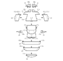
図1に示した第1形態FR1は、複数個の外郭構成部品から成る外郭体(符号省略)の内部空洞FR1aに外郭を構成しない非外郭構成部品が収容された形態である。第1形態FR1における組立玩具は、内部空洞FR1aを非外郭構成部品の収容空間とする収容部を備え、各外殻構成部品が収容部の少なくとも一部を構成しているともいえる。また、第1形態FR1において、各外殻構成部品は、第1形態FR1の外周の少なくとも一部を構成する部品であるともいえる。一方、図12に示した第2形態FR2は、複数個の外郭構成部品のうちの1個が後記土台部品12として用いられ、当該土台部品12に他の外郭構成部品と前記非外郭構成部品が取り付けられた形態である。
The first form FR1 shown in FIG. 1 is a form in which non-enclosure components that do not constitute an enclosure are accommodated in an internal cavity FR1a of an enclosure body (reference numerals omitted) made up of a plurality of enclosure components. It can also be said that the assembly toy in the first form FR1 comprises a housing section that uses the internal cavity FR1a as a housing space for the non-outer shell components, and each outer shell constituting part constitutes at least a part of the housing section. In addition, in the first embodiment FR1, each outer shell component can be said to be a part that constitutes at least part of the outer periphery of the first embodiment FR1. On the other hand, in the second form FR2 shown in FIG. 12, one of the plurality of outer shell components is used as a
まず、図1~図9を引用して、外郭構成部品と非外郭構成部品について説明する。 First, referring to FIGS. 1 to 9, shell components and non-shell components will be described.
外郭構成部品は、椀状の第1形象部品11(第2部品)と、環状の土台部品12(第5部品)と、環状の第2形象部品13(第7部品)と、椀状の補助部品14(第8部品)と、扇状の2個の第3形象部品15(第6部品)と、扇状の2個の第4形象部品16(第1部品)とを含んでいる(図1~図8を参照)。一方、非外郭構成部品は、柱状の第5形象部品17(第3部品)と、柱状の2個の第6形象部品18(第4部品)とを含んでいる(図1、図2および図9を参照)。なお、前記の「椀状」と「環状」と「扇状」と「柱状」は各部品の形を幾何学的に区別するために使用した広義なものであり、「椀」と「環」と「扇」と「柱」の語によって狭義に解されるべきものではない。 The outer shell components include a bowl-shaped first shaped part 11 (second part), an annular base part 12 (fifth part), an annular second shaped part 13 (seventh part), and a bowl-shaped auxiliary part. It includes a part 14 (eighth part), two fan-shaped third shaped parts 15 (sixth part), and two fan-shaped fourth shaped parts 16 (first part) (Figs. See Figure 8). On the other hand, the non-outer shell components include a columnar fifth shaped component 17 (third component) and two columnar sixth shaped components 18 (fourth component) (FIGS. 1, 2 and 3). 9). The above-mentioned "bowl-shaped", "annular", "fan-shaped", and "columnar" are broad definitions used to geometrically distinguish the shape of each part. The words ``fan'' and ``pillar'' should not be narrowly interpreted.
また、外郭構成部品である部品11~16と、非外郭構成部品である部品17および18は、部品相互を着脱可能に連結するための手段、具体的には着脱を可能とするための連結部としての凹部と凸部を適宜有しており、凸部が凹部に嵌め込み可能に構成されている。なお、前記の「凹部」には非貫通穴や溝や貫通孔等が含まれ、「凹部」および「凸部」の形は着脱が可能であれば図示例の形に限定されるものではない。
In addition, the
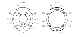
外郭構成部品である部品11~16について順に補足すると、図2および図3に示したように、第1形象部品11(第2部品)の左右面には、扇状の開放部11aが左右対称に1個ずつ設けられている。また、第1形象部品11の上面の左右位置には、扇状の窪み部11bが左右対称に1個ずつ設けられており、各窪み部11bの底面には、連結部としての凹部11cが2個ずつ設けられている。窪み部11bは、第1形象部品11に第4形象部品16を取り付ける際に、所定の位置に案内が可能な位置決め部として機能する。さらに、第1形象部品11の上面の前寄り位置には、連結部としての凹部11dが1個設けられている。さらに、第1形象部品11の上面の左右位置には、連結部としての凹部11eが左右対称に1個ずつ設けられている。凹部11c、11d、11eは、他の部品を取り付けるための取付部ともいえる。さらに、第1形象部品11の下面(開放部11aを除く)の前後位置には、連結部としての凸部11fが前後対称に1個ずつ設けられている。さらに、第1形象部品11の各開放部11aの上面には、連結部としての凹部11gが左右対称に2個ずつ設けられている。
As shown in FIGS. 2 and 3, fan-
図2および図4に示したように、土台部品12(第5部品)の上面の前後位置には、連結部としての凹部12aが前後対称に1個ずつ設けられている。当該凹部12aは、第1形象部品11の下面の凸部11fへの着脱を可能としている。また、土台部品12の上面の左右位置には、連結部としての凸部12bが左右対称に1個ずつ設けられている。さらに、土台部品12の下面の左右位置には、連結部としての凹部12cが左右対称に1個ずつ設けられている。
As shown in FIGS. 2 and 4, one
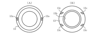
図2および図5に示したように、第2形象部品13(第7部品)の上面の左右位置には、連結部として凸部13aが左右対称に1個ずつ設けられている。当該凸部13aは、土台部品12の下面の凹部12cへの着脱を可能としている。また、第2部品13の下面の中央位置には、連結部としての円孔13bが設けられている。さらに、第2形象部品13の左右面には、連結部としての凹部13cが前後対称に2個ずつ設けられている。
As shown in FIGS. 2 and 5, the upper surface of the second shaped part 13 (seventh part) is provided with
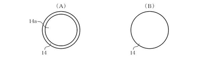
図2および図6に示したように、補助部品14の上面の中央には、連結部としての円柱部14aが設けられている。当該円柱部14aは、第2形象部品14の下面の円孔13bへの着脱を可能としている。ちなみに、補助部品14は、第2形態FR2には使用されない部品であるため、形象部品ではなく補助部品の名称を用いている。また、補助部品14は、第2形態FR2では仕様されないことが認識可能な態様してしておくことが好ましい。たとえば、第2形態FR2に使用する部品とは異なる色とする、第2形態FR2使用する部品とは異なる素材とする、または、使用しないことがわかる表示を施すことが例として挙げられる。
As shown in FIGS. 2 and 6, a
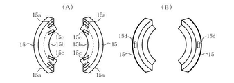
図2および図7に示したように、各第3形象部品15(第6部品)は、第1形象部品11の各開放部11aが形成された位置への連結が可能であり、連結状態で各開放部11aを閉塞することができる。また、各第3形象部品15の上面の前後位置には、連結部としての凸部15aが前後対称に1個ずつ設けられている。当該凸部15aは、第1形象部品11の各開放部11aの上面の凹部11gへの着脱を可能としている。さらに、各第3形象部品13の上面には、上面から内側に張り出した扇状の鍔部15bが一体形成されていて、各鍔部15bの上面の前後位置には、連結部としての凸部15cが前後対称に1個ずつ設けられている。さらに、各第3形象部品15の下面の中央位置には、連結部としての凹部15dが1個ずつ設けられている。当該凹部15dは、土台部品12の上面の凸部12bへの着脱を可能としている。
As shown in FIGS. 2 and 7, each third shaped part 15 (sixth part) can be connected to the position where each
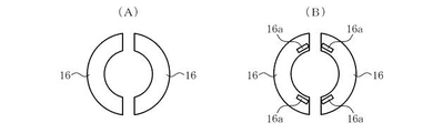
図2および図8に示したように、各第4形象部品16(第1部品)は、第1形象部品11の各窪み部11bが形成された位置への連結が可能であり、連結状態で各窪み部11bを閉塞することができる。したがって、第1形象部品11の各窪み部11bの底面内に形成され、他の部品を取り付け可能な取付部である第1形象部品11の凹部11cは、各第4形象部品16で覆われることになる。また、各第4形象部品16の下面の前後位置には、連結部としての凸部16aが前後対称に1個ずつ設けられている。当該凸部16aは、第1形象部品11の各窪み部11bの底面の凹部11cへの取り付けを可能としているとともに、第2形象部品13の左右面の凹部13cへの取り付けを可能としている。
As shown in FIGS. 2 and 8, each fourth shaped part 16 (first part) can be connected to the position where each
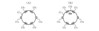
一方、非外郭構成部品である部品17(第3部品)および部品18(第4部品)について順に補足すると、図2および図9に示したように、第5形象部品17の左右面には、連結部としての凸部17aが左右対称に1個ずつ設けられている。また、第5形象部品17の上面の左右位置には、連結部としての凹部17bが、左右対称に2個ずつ設けられている。当該凹部17bは、各第3形象部品13の上面の凸部15cへの着脱を可能としている。さらに、第5形象部品17の下面の左右位置には、連結部としての凸部17cが左右対称に2個ずつ設けられている。当該凸部17cは、第1形象部品11の各窪み部11bの底面の凹部11cへの着脱を可能としている。さらに、第5形象部品17の下面の前寄り位置には、連結部としての凸部17dが1個設けられている。当該凸部17dは、第1形象部品11の上面の凹部11dへの着脱を可能としている。
On the other hand, supplementing the parts 17 (third part) and 18 (fourth part), which are non-outer shell components, as shown in FIGS. A
図2に示したように、各第6形象部品18の端面には、連結部としての凹部18aが1個設けられている。当該凹部18aは、第5形象部品17の左右面の凸部17aへのせを可能としている。
As shown in FIG. 2, the end surface of each sixth shaped
次に、図1に示した第1形態FR1、特に外郭構成部品である部品11~16の連結(取り付け)態様について説明する。
Next, the connection (attachment) aspect of the first embodiment FR1 shown in FIG. 1, particularly the
第1形態FR1にあっては、図1に示したように、第1形象部品11に土台部品12が着脱可能に連結され、土台部品12に第2形象部品13が着脱可能に連結され、第2形象部品13に補助部品14が連結されている。当該連結は、第1形象部品11の下面の凸部11fに土台部品12の上面の凹部12aを嵌め合わせ(図3および図4を参照)、土台部品12の下面の凹部12cに第2形象部品13の上面の凸部13aを嵌め合わせ(図4および図5を参照)、第2形象部品13の下面の円孔13bに補助部品14の上面の円柱部14aを嵌め合わせる(図5および図6を参照)ことによって為されている。
In the first form FR1, as shown in FIG. 1, the
また、第1形態FR1にあっては、図1に示したように、第1形象部品11の各開放部11aが形成された位置に第3形象部品15がそれぞれ連結され、第1形象部品11の各窪み部11bが形成された位置に第4形象部品16がそれぞれ連結されている。各第3形象部品15の連結は、第1形象部品11の各開放部11aの上面の凹部11gに各第3形象部品15の上面の凸部15aを嵌め合わせる(図3および図7を参照)とともに、土台部品12の上面の凸部12bに各第3形象部品15の下面の凹部15dを嵌め合わせる(図4および図7を参照)ことによって為されている。図1から分かるように、各第3形象部品15の連結によって第1形象部品11の各開放部11aは閉塞されている。各第4形象部品16の連結は、第1形象部品11の各窪み部11bの底面の凹部11cに各第4形象部品16の下面の凸部16aを嵌め合わせる(図3および図8を参照)ことによって為されている。図1から分かるように、各第4形象部品16の連結によって第1形象部品11の各窪み部11bは閉塞されている。また、第1形象部品11の各窪み部11bの底面内に形成され、他の部品を取り付け可能な取付部である第1形象部品11の凹部11cが、各第4形象部品16で覆われる。
Further, in the first form FR1, as shown in FIG. The fourth shaped
すなわち、図1に示した第1形態FR1にあっては、外郭構成部品である部品11~16によって外郭体(符号省略)が構成されている。当該外郭体(符号省略)は図1(D)に示した内部空洞FR1aを有しており、非外郭構成部品である部品17および18は当該内部空洞FR1aに収容されている。
That is, in the first embodiment FR1 shown in FIG. 1, the
次に、図1、図2、図10および図11を引用して、図1に示した第1形態FR1から図12に示した第2形態FR2に変化させる方法例について説明する。なお、ここで説明する方法例は好適な一例であって、第1形態FR1から第2形態FR2に変化させる方法を制限するものではない。 Next, referring to FIGS. 1, 2, 10 and 11, an example of a method for changing from the first form FR1 shown in FIG. 1 to the second form FR2 shown in FIG. 12 will be described. It should be noted that the method example described here is a preferred example, and does not limit the method of changing from the first configuration FR1 to the second configuration FR2.
最初に、図1に示した第1形態FR1の外郭体(符号省略)を図2に示したように分解する。当該分解は、第1形態FR1から補助部品14と第2形象部品13と土台部品12を取り外すとともに、第1形象部品11から各第3形象部品15と各第4形象部品16を取り外すことによって簡単に行うことができる。また、外郭体(符号省略)の分解により、第1形態FR1における収容部から第5形象部品17と各第6形象部品18が取り出される。
First, the outer shell (reference numerals omitted) of the first form FR1 shown in FIG. 1 is disassembled as shown in FIG. The disassembly can be easily done by removing the
そして、図10(A)に示したように、土台部品12を卓上等の平坦面FSに置き、土台部品12の上面の凹部12aに第1形象部品11の下面の凸部11fを嵌め合わせて、土台部品14に第1形象部品11を連結して取り付ける。
Then, as shown in FIG. 10A, the
そして、図10(B)に示したように、第1形象部品11の上面の凹部11eに、上下反転させた後の第2形象部品13の上面(図中は下面)の凸部13aを嵌め合わせて、第1形象部品11に第2形象部品13を連結して取り付ける。
Then, as shown in FIG. 10(B), the
そして、図10(C)に示したように、第1形象部品11の各窪み部11bの底面の凹部11cと第1形象部品11の上面前寄り位置の凹部11dに、第2形象部品13の内孔(符号省略)を通じて、第5形象部品17の下面の凸部17cと凸部17dをそれぞれ嵌め合わせて、第1形象部品11に第5形象部品17を連結して取り付ける。
Then, as shown in FIG. 10(C), the
そして、図10(C)に示したように、第5形象部品17の左右面の凸部17aそれぞれに、第6形象部品18の凹部18aを嵌め合わせて、第5形象部品17に各第6形象部品18を連結して取り付ける。
Then, as shown in FIG. 10(C), the
そして、図11(A)に示したように、第5形象部品17の上面の凹部17bに、上下反転させた後の各第3形象部品15の上面(図中は下面)の凸部15cを嵌め合わせて、第5形象部品17に各第3形象部品15を連結して取り付ける。
Then, as shown in FIG. 11(A), the
そして、図11(B)に示したように、第2形象部品13の左右面の凹部13cそれぞれに、各第4形象部品16の下面の凸部16aを嵌め合わせて、第2形象部品13に各第4形象部品16を連結して取り付ける。
Then, as shown in FIG. 11B, the
以上で、図12に示した第2形態FR2が得られる。先に述べたように第2形態FR2はキャラクター(ロボット)を摸した外観を有するものであるため、第1形象部品11は胸部に相当し、第2形象部品13は肩部に相当し、第5形象部品17は頭部に相当し、各第3形象部品15は頭装飾部に相当し、各第6形象部品18も頭装飾部に相当し、各第4形象部品16は、肩装飾部に相当する。
As described above, the second form FR2 shown in FIG. 12 is obtained. As described above, since the second form FR2 has an appearance imitating a character (robot), the first
次に、前述の組立玩具によって得られる主たる作用効果について説明する。 Next, the main functions and effects obtained by the assembly toy described above will be described.
〈作用効果1〉第2形態FR2において第1形象部品11に第5形象部品17を取り付ける凹部11cの少なくとも一部は、第1形態FR1において第4形象部品16で覆われることにより、凹部11cの少なくとも一部は、第1形態FR1において露出しない。したがって、凹部11cが第1形態FR1における形状に与える影響を抑制することが可能となることにより、第1形態FR1から第2形態FR2への変化する組立玩具の興趣性を向上させることができる。特に、第1形態FR1が球状を含む幾何学的な形態の場合は、凹部等が露出することによる美観への影響が大きくなり得るため、凹部等の露出が抑制される態様とすることが好ましい。また、凹部11cが第1形象部品11を貫通した孔である場合、凹部11cが大きく形成される場合、収容部に収容される非外郭構成部品が収容部から凹部11cを通って外部へ落下してしまう虞れがある。しかし、凹部11cを第4形象部品16で覆うことにより、外部への落下を防止することが可能となる。
<Function and Effect 1> At least part of the
〈作用効果2〉第1形態FR1の外郭体(符号省略)を構成する外郭構成部品11~16のうちの1個を土台部品12として使用できるようにし、第1形態FR1から第2形態FR2に変化させるときに当該土台部品12に他の外郭構成部品11、13、15および16と非外郭構成部品17および18を取り付ける方法を採用できるので、第1形態FR1から第2形態FR2への変化を安定した状態下で容易かつ的確に行うことができる。すなわち、第1形態FR1から第2形態FR2への変化の難しさが支障となって、形態変化に係る楽しさおよび面白さが半減してしまうようなことはなく、むしろ、前記の容易性および的確性によって第1形態FR1から第2形態FR2への変化に係る楽しさおよび面白さを増すことができる。
<Function and Effect 2> One of the outer
〈作用効果3〉第1形態FR1の外郭体(符号省略)を構成する外郭構成部品11~16のうちの土台部品12と補助部材14を除く他の外郭構成部品11、13、15および16を第2形態FR2を部分的に形象する部品として使用できるため、外郭体(符号省略)の内部空洞FR1aに収容される非外郭構成部品の個数を極力低減することができる。換言すれば、外郭体(符号省略)の大きさに制限がある場合でも、前記の外郭構成部品11~13、15および16を利用して趣向に富んだ第2形態FR2を得ることができる。
<Action and Effect 3> Out of the
〈作用効果4〉第2形態FR2において第5形象部品17が連結される第1形象部品11側の連結部(凹部11cおよび11d)のうちの凹部11cが、第1形態FR1において第1形象部品11に第4形象部品16を連結するための連結部を兼用しているため、当該兼用によって第1形象部品11に設けれる連結部の個数を減らして製作の容易化に貢献することができる。
<Effect 4> In the second embodiment FR2, the
次に、前述の組立玩具の変形例について説明する。 Next, a modification of the assembly toy described above will be described.
〈変形例1〉前述の組立玩具では、各第3形象部品15の上面に連結部としての凸部15aおよび凸部15cを設けたものを示したが、凸部15aを排除する一方、第1形象部品11の各開放部11aの上面から内側に張り出し鍔部を一体形成して、当該鍔部に、各第3形象部品15の上面の凸部15cとの嵌め合わせを可能とした凹部11g代替の凹部を設けるようにしてもよい。
<Modification 1> In the assembly toy described above, the
〈変形例2〉土台部品12と第2形態FR2を部分的に形象する第1~第6形象部品11、13、15および16~18に設けた連結部としての凹部と凸部は、同様の着脱自在な連結が可能であれば、凹部を凸部に変更したり、凸部を凹部に変更してもよい。ただし、土台部品12は卓上等の平坦面FSに置かれる最下位の部品であるため、その下面には凸部がない方が好ましい。
<Modification 2> The
〈変形例3〉土台部品12と第2形態FR2を部分的に形象する第1~第6形象部品11、13、15および16~18に設けた連結部としての凹部と凸部の個数は、同様の着脱自在可能な連結を実現することが可能であれば、適宜増減してもよい。
<Modification 3> The number of concave portions and convex portions as connecting portions provided in the
〈変形例4〉第2形態FR2を部分的に形象する部品として計6個の第1~第6形象部品11、13、15および16~18を例示したが、外郭構成部品11~16の個数を増加することによって、第2形態FR2を部分的に形象する部品の個数を増加することも可能である。
<Modification 4> A total of six first to
〈変形例5〉第1形象部品11として上面の左右位置に窪み部11bが左右対称に1個ずつ設けられたものを示したが、図13に示したように、第1形象部品11’の上面の中央位置に円状の窪み部11b’を形成してその底面に凹部11cと凹部11dを設けるとともに、当該窪み部11b’を円状の部品16’で着脱可能に被覆するようにしてもよい。言い換えると、位置決め部である窪み部11b’の内側に凹部11cと凹部11dを設けるようにしてもよい。この場合、図8に示した第4形象部品16が無くなってしまうが、円状の部品16’を半円状の2部品構成として当該2部品を第4形象部品16の代替部品として利用できるようにしてよく、あるいは、椀状の補助部品14を2部品構成として当該2部品を第4形象部品16の代替部品として利用できるようにしてもよい。このように、第1形態FR1において外殻構成部品である第1形象部品11が取り付けられる面内に第2形態FR2においてその他の部品を取り付けるための凹部11c、凹部11dを配置しておくことで、第1形態FR1において凹部11c、凹部11dが露出しなくなり、第1形態における形状に与える影響をさらに抑制することが可能となる。
<Modification 5> Although the
〈変形例6〉第1形象部品11として上面の左右位置に窪み部11b(図3(A)を参照)を設けたものと上面の中央位置に窪み部11b’(図13(B)を参照)を設けたものを示したが、図3(A)に示した窪み部11bを、図14(A)に示した窪み部11b1のような環状溝(窪み部11bの内周に沿う凹部11cを包含する環状溝)で代用してもよい。また、図13(B)に示した窪み部11b’を、図14(B)に示した窪み部11b1’のような内外2重の環状溝(外側は窪み部11b’の内周に沿った環状溝、内側は凹部11cを包含する環状溝)で代用してもよい。ちなみに、図14(A)に示した窪み部11b1を採用する場合には、第4形象部品16の下面に窪み部11b1に対応した凸部16a付きの環状突起を設けておいて、第1形態FR1では当該環状突起を窪み部11b1に嵌め合わせるようにするとよい。また、図14(B)に示した窪み部11b1’を採用する場合には、円状の部品16’の下面に窪み部11b1’に対応した内外2重の環状突起を設けておいて、第1形態FR1では当該環状突起を窪み部11b1’に嵌め合わせるようにするとよい。このように、位置決め部である窪みを窪み部11b1、窪み部11b1’のような環状溝とすることで、窪み部11bのように位置決め部全体を窪みで形成した場合よりも第1形態における形状に与える影響を抑制することが可能となる。
<Modification 6> As the
さらに、図14(A)に示した窪み部11b1と図14(B)に示した窪み部11b1’を採用する場合、第5形象部品17の下面に、窪み部11b1および11b1’の少なくとも一部への着脱自在な嵌め合わせを可能とした環状突起または非環状突起を形成しておいて、第1形象部品11の凹部11cおよび11dに第5形象部品17の凸部17cおよび凸部17dを嵌め合わせるときに、第5形象部品17の下面の環状突起または非環状突起を第1形象部品11および11’の窪み部11b1および11b1’に嵌め合わせるようにしてもよい。このようにすれば、第1形象部品11に第5形象部品17を連結したときの当該第5形象部品17の姿勢をより安定化することができる。
14(A) and 11b1' shown in FIG. 14(B), at least part of the recesses 11b1 and 11b1' Annular projections or non-annular projections are formed so that they can be detachably fitted to the
FR1…第1形態、FR1a…内部空洞、FR2…第2形態、11…第1形象部品、11a…開放部、11b,11b’,11b1,11b1’…窪み部、12…土台部品、13…第2形象部品、14…補助部品、15…第3形象部品、16…第4形象部品、17…第5形象部品、18…第6形象部品。 FR1... First form, FR1a... Internal cavity, FR2... Second form, 11... First shape component, 11a... Open part, 11b, 11b', 11b1, 11b1'... Recess part, 12... Base component, 13... Third 2 figurative parts, 14... auxiliary part, 15... third figurative part, 16... fourth figurative part, 17... fifth figurative part, 18... sixth figurative part.
Claims (16)
前記複数の部品は、前記第1形態の外周の少なくとも一部分を構成する第1部品および第2部品と、前記第1部品および前記第2部品とは異なる第3部品と、を含み、
前記第1形態において、前記第1部品は、前記第2部品に取り付け可能であり、
前記第2形態において、前記第3部品は、前記第2部品に取り付け可能であり、
前記第2形態において前記第2部品に前記第3部品を取り付ける取付部の少なくとも一部は、前記第1形態において前記第1部品で覆われ、
前記第1部品は、前記第2形態の少なくとも一部分を構成する、
組立玩具。 An assembly toy reversibly changeable between a first form assembled by at least part of a plurality of parts and a second form assembled by at least part of the plurality of parts and different from the first form,
The plurality of parts includes a first part and a second part that constitute at least part of the outer periphery of the first form, and a third part that is different from the first part and the second part,
In the first form, the first part is attachable to the second part,
In the second form, the third component is attachable to the second component,
At least a part of the attachment portion for attaching the third component to the second component in the second configuration is covered with the first component in the first configuration ,
The first part constitutes at least part of the second form,
assembly toy.
前記第1部品および前記第2部品は、前記収容部の少なくとも一部を構成し、
前記第3部品は、前記収容部へ収容可能である、
請求項1に記載の組立玩具。 In the first form, the assembly toy includes a storage section,
The first part and the second part constitute at least a part of the housing part,
The third component can be accommodated in the accommodation portion,
A construction toy according to claim 1.
前記第1形態において、前記第4部品は、前記収容部に収容可能であり、
前記第2形態において、前記第4部品は、前記第3部品に取り付け可能である、
請求項2に記載の組立玩具。 The plurality of parts includes a fourth part different from the first part, the second part and the third part,
In the first form, the fourth component can be accommodated in the accommodation section,
In the second form, the fourth part is attachable to the third part,
The assembly toy according to claim 2.
前記第1形態において、前記第5部品は、前記第1形態の外周の少なくとも一部分を構成し、
前記第2形態において、前記第5部品は、前記第2形態を構成する土台となる、
請求項1~3のいずれか1項に記載の組立玩具。 The plurality of parts includes a fifth part different from the first part, the second part and the third part,
In the first form, the fifth component constitutes at least part of the outer circumference of the first form,
In the second form, the fifth part serves as a base that constitutes the second form,
An assembly toy according to any one of claims 1 to 3.
請求項4に記載の組立玩具。 The fifth part is an annular part,
The assembly toy according to claim 4.
前記第2形態において、前記第2部品および前記第5部品は、前記第2部品と前記第6部品との間に開放部が形成された状態で連結し、
前記第1形態において、前記第6部品は、前記開放部を閉塞するように前記第1形態の外周の少なくとも一部分を構成する、
請求項4または5に記載の組立玩具。 The plurality of parts includes a sixth part different from the first part, the second part, the third part, and the fifth part;
In the second embodiment, the second part and the fifth part are connected with an opening formed between the second part and the sixth part,
In the first form, the sixth part constitutes at least part of the outer circumference of the first form so as to close the opening.
The assembly toy according to claim 4 or 5.
請求項6に記載の組立玩具。 In the second form, the sixth part is attachable to the third part,
A construction toy according to claim 6.
前記第1形態において、前記第7部品は、前記第1形態の外周の少なくとも一部分を構成し、
前記第2形態において、前記第7部品は、前記第2部品に取り付け可能である、
請求項1~6のいずれか1項に記載の組立玩具。 The plurality of parts includes a seventh part different from the first part, the second part and the third part,
In the first form, the seventh part constitutes at least part of the outer periphery of the first form,
In the second form, the seventh part is attachable to the second part,
A construction toy according to any one of claims 1-6.
請求項8に記載の組立玩具。 In the second form, the second part is attachable to the seventh part,
A construction toy according to claim 8.
前記第1形態において、前記第8部品は、前記第1形態の外周の少なくとも一部分を構成し、
前記第2形態において、前記第8部品は、使用されない、
請求項1~9のいずれか1項に記載の組立玩具。 The plurality of parts includes an eighth part different from the first part, the second part and the third part,
In the first form, the eighth part constitutes at least part of the outer circumference of the first form,
In the second form, the eighth part is not used,
A construction toy according to any one of claims 1-9.
請求項1~10のいずれか1項に記載の組立玩具。 The first form is a rollable form,
A construction toy according to any one of claims 1-10.
請求項1~11のいずれか1項に記載の組立玩具。 The second form constitutes a figure,
A construction toy according to any one of claims 1-11.
前記第2形態において、
前記第1部品は、前記人形体の肩部の少なくとも一部分を構成し、
前記第2部品は、前記人形体の胸部の少なくとも一部分を構成し、
前記第3部品は、前記人形体の頭部の少なくとも一部分を構成し、
請求項12に記載の組立玩具。 the figurine constitutes at least a portion of the doll body;
In the second form,
The first part constitutes at least part of the shoulder of the doll body,
The second part constitutes at least part of the chest of the doll body,
The third part constitutes at least part of the head of the doll body,
A constructional toy according to claim 12.
請求項1~13のいずれか1項に記載の組立玩具。 In the first form, the first component is attached to the second component using at least a portion of the attachment portion.
A construction toy according to any one of claims 1-13.
請求項1~14のいずれか1項に記載の組立玩具。 The second component is provided with a positioning portion that can guide the mounting position of the first component to a predetermined position.
A construction toy according to any one of claims 1-14.
請求項15に記載の組立玩具。 The mounting portion is formed inside the positioning portion,
16. A constructional toy according to claim 15.
Priority Applications (1)
| Application Number | Priority Date | Filing Date | Title |
|---|---|---|---|
| JP2018187811A JP7166130B2 (en) | 2018-10-02 | 2018-10-02 | assembly toy |
Applications Claiming Priority (1)
| Application Number | Priority Date | Filing Date | Title |
|---|---|---|---|
| JP2018187811A JP7166130B2 (en) | 2018-10-02 | 2018-10-02 | assembly toy |
Publications (3)
| Publication Number | Publication Date |
|---|---|
| JP2020054657A JP2020054657A (en) | 2020-04-09 |
| JP2020054657A5 JP2020054657A5 (en) | 2021-04-08 |
| JP7166130B2 true JP7166130B2 (en) | 2022-11-07 |
Family
ID=70105709
Family Applications (1)
| Application Number | Title | Priority Date | Filing Date |
|---|---|---|---|
| JP2018187811A Active JP7166130B2 (en) | 2018-10-02 | 2018-10-02 | assembly toy |
Country Status (1)
| Country | Link |
|---|---|
| JP (1) | JP7166130B2 (en) |
Families Citing this family (2)
| Publication number | Priority date | Publication date | Assignee | Title |
|---|---|---|---|---|
| JP7398527B1 (en) | 2022-07-21 | 2023-12-14 | 株式会社バンダイ | toy |
| JP7462706B2 (en) | 2022-07-21 | 2024-04-05 | 株式会社バンダイ | toy |
Citations (4)
| Publication number | Priority date | Publication date | Assignee | Title |
|---|---|---|---|---|
| JP2008036348A (en) | 2006-08-10 | 2008-02-21 | Murakami Keizo Jimusho:Kk | Capsule for toy |
| US20120094571A1 (en) | 2010-10-19 | 2012-04-19 | A&A Global Industries, Inc. | Toy Figure and Spherical Vending Capsule Combination |
| CN103143174A (en) | 2013-03-16 | 2013-06-12 | 广州天贝动漫科技有限公司 | Card type transformation toy |
| JP3192453U (en) | 2014-06-05 | 2014-08-14 | 有限会社イング二十一 | Combined deformation toy |
Family Cites Families (1)
| Publication number | Priority date | Publication date | Assignee | Title |
|---|---|---|---|---|
| JPH07148358A (en) * | 1993-12-01 | 1995-06-13 | Sega Enterp Ltd | Capsulate toy |
-
2018
- 2018-10-02 JP JP2018187811A patent/JP7166130B2/en active Active
Patent Citations (4)
| Publication number | Priority date | Publication date | Assignee | Title |
|---|---|---|---|---|
| JP2008036348A (en) | 2006-08-10 | 2008-02-21 | Murakami Keizo Jimusho:Kk | Capsule for toy |
| US20120094571A1 (en) | 2010-10-19 | 2012-04-19 | A&A Global Industries, Inc. | Toy Figure and Spherical Vending Capsule Combination |
| CN103143174A (en) | 2013-03-16 | 2013-06-12 | 广州天贝动漫科技有限公司 | Card type transformation toy |
| JP3192453U (en) | 2014-06-05 | 2014-08-14 | 有限会社イング二十一 | Combined deformation toy |
Also Published As
| Publication number | Publication date |
|---|---|
| JP2020054657A (en) | 2020-04-09 |
Similar Documents
| Publication | Publication Date | Title |
|---|---|---|
| US6511359B1 (en) | Bobbling head toy figurine with photo receiving chamber | |
| WO2019012843A1 (en) | Doll toy | |
| JP7166130B2 (en) | assembly toy | |
| US9457288B2 (en) | Magnetic block toy | |
| JP2011224202A (en) | Dice toy | |
| US20220401848A1 (en) | Toy | |
| JP2018086120A (en) | toy | |
| US6439945B1 (en) | Octopus-shaped built-up toy | |
| JP7226970B2 (en) | articulated toy | |
| JP7017191B2 (en) | Assembled model toys and their parts | |
| US20220401847A1 (en) | Toy | |
| WO2022070738A1 (en) | Toy | |
| JPS6341025Y2 (en) | ||
| KR200404640Y1 (en) | a cube for assembly | |
| JP3158461U (en) | 3D jigsaw puzzle | |
| JP6144119B2 (en) | Doll joint structure | |
| JP3216493U (en) | Mascot and capsule toy including the same | |
| JP5182905B1 (en) | Assembled eraser | |
| JP7253591B2 (en) | toy | |
| JP5492678B2 (en) | Assembled toy | |
| JP7066770B2 (en) | toy | |
| JP2004105553A (en) | Walking unit and walking toy | |
| JP3001079U (en) | Assembly toys | |
| JP7462706B2 (en) | toy | |
| JPH0315105Y2 (en) |
Legal Events
| Date | Code | Title | Description |
|---|---|---|---|
| A521 | Request for written amendment filed |
Free format text: JAPANESE INTERMEDIATE CODE: A523 Effective date: 20210215 |
|
| A621 | Written request for application examination |
Free format text: JAPANESE INTERMEDIATE CODE: A621 Effective date: 20210215 |
|
| A977 | Report on retrieval |
Free format text: JAPANESE INTERMEDIATE CODE: A971007 Effective date: 20211220 |
|
| A131 | Notification of reasons for refusal |
Free format text: JAPANESE INTERMEDIATE CODE: A131 Effective date: 20220201 |
|
| A601 | Written request for extension of time |
Free format text: JAPANESE INTERMEDIATE CODE: A601 Effective date: 20220329 |
|
| A521 | Request for written amendment filed |
Free format text: JAPANESE INTERMEDIATE CODE: A523 Effective date: 20220531 |
|
| A521 | Request for written amendment filed |
Free format text: JAPANESE INTERMEDIATE CODE: A523 Effective date: 20220601 |
|
| TRDD | Decision of grant or rejection written | ||
| A01 | Written decision to grant a patent or to grant a registration (utility model) |
Free format text: JAPANESE INTERMEDIATE CODE: A01 Effective date: 20221004 |
|
| A61 | First payment of annual fees (during grant procedure) |
Free format text: JAPANESE INTERMEDIATE CODE: A61 Effective date: 20221025 |
|
| R150 | Certificate of patent or registration of utility model |
Ref document number: 7166130 Country of ref document: JP Free format text: JAPANESE INTERMEDIATE CODE: R150 |