JP7162225B2 - Crossed short-pulse electrical stimulation of the brain - Google Patents
Crossed short-pulse electrical stimulation of the brain Download PDFInfo
- Publication number
- JP7162225B2 JP7162225B2 JP2020514143A JP2020514143A JP7162225B2 JP 7162225 B2 JP7162225 B2 JP 7162225B2 JP 2020514143 A JP2020514143 A JP 2020514143A JP 2020514143 A JP2020514143 A JP 2020514143A JP 7162225 B2 JP7162225 B2 JP 7162225B2
- Authority
- JP
- Japan
- Prior art keywords
- electrodes
- electrode
- stimulation
- brain
- neuronal
- Prior art date
- Legal status (The legal status is an assumption and is not a legal conclusion. Google has not performed a legal analysis and makes no representation as to the accuracy of the status listed.)
- Active
Links
- 230000000638 stimulation Effects 0.000 title claims description 123
- 210000004556 brain Anatomy 0.000 title claims description 53
- 238000000034 method Methods 0.000 claims description 72
- 230000000694 effects Effects 0.000 claims description 67
- 210000002569 neuron Anatomy 0.000 claims description 43
- 230000001537 neural effect Effects 0.000 claims description 35
- 230000005684 electric field Effects 0.000 claims description 28
- 210000004761 scalp Anatomy 0.000 claims description 28
- 239000012528 membrane Substances 0.000 claims description 26
- 210000003625 skull Anatomy 0.000 claims description 26
- 230000002518 glial effect Effects 0.000 claims description 12
- 230000010354 integration Effects 0.000 claims description 12
- 230000007246 mechanism Effects 0.000 claims description 11
- 230000004913 activation Effects 0.000 claims description 10
- 210000005013 brain tissue Anatomy 0.000 claims description 6
- 210000004498 neuroglial cell Anatomy 0.000 claims description 6
- 210000004027 cell Anatomy 0.000 claims description 5
- 230000009849 deactivation Effects 0.000 claims description 5
- 230000002123 temporal effect Effects 0.000 claims description 4
- 230000007420 reactivation Effects 0.000 claims description 2
- 210000001951 dura mater Anatomy 0.000 claims 1
- 238000000537 electroencephalography Methods 0.000 description 12
- 238000005259 measurement Methods 0.000 description 11
- 238000004590 computer program Methods 0.000 description 10
- 210000003128 head Anatomy 0.000 description 10
- 241000700159 Rattus Species 0.000 description 9
- 238000002474 experimental method Methods 0.000 description 9
- 230000000007 visual effect Effects 0.000 description 9
- 230000004044 response Effects 0.000 description 8
- 238000007920 subcutaneous administration Methods 0.000 description 8
- 230000007177 brain activity Effects 0.000 description 7
- 230000000763 evoking effect Effects 0.000 description 7
- 241001269524 Dura Species 0.000 description 6
- 230000010355 oscillation Effects 0.000 description 6
- 238000011282 treatment Methods 0.000 description 6
- 238000013459 approach Methods 0.000 description 5
- 238000010304 firing Methods 0.000 description 5
- 210000001320 hippocampus Anatomy 0.000 description 5
- 206010010904 Convulsion Diseases 0.000 description 4
- RYGMFSIKBFXOCR-UHFFFAOYSA-N Copper Chemical compound [Cu] RYGMFSIKBFXOCR-UHFFFAOYSA-N 0.000 description 4
- 230000002411 adverse Effects 0.000 description 4
- 230000008901 benefit Effects 0.000 description 4
- 208000037265 diseases, disorders, signs and symptoms Diseases 0.000 description 4
- 238000001727 in vivo Methods 0.000 description 4
- 230000001965 increasing effect Effects 0.000 description 4
- 230000004048 modification Effects 0.000 description 4
- 238000012986 modification Methods 0.000 description 4
- 238000012545 processing Methods 0.000 description 4
- 230000033764 rhythmic process Effects 0.000 description 4
- 230000035807 sensation Effects 0.000 description 4
- 235000019615 sensations Nutrition 0.000 description 4
- 210000004872 soft tissue Anatomy 0.000 description 4
- 230000004936 stimulating effect Effects 0.000 description 4
- 210000003582 temporal bone Anatomy 0.000 description 4
- 206010002091 Anaesthesia Diseases 0.000 description 3
- 230000037005 anaesthesia Effects 0.000 description 3
- 230000006399 behavior Effects 0.000 description 3
- 210000000170 cell membrane Anatomy 0.000 description 3
- 230000001054 cortical effect Effects 0.000 description 3
- 230000006870 function Effects 0.000 description 3
- 230000003287 optical effect Effects 0.000 description 3
- 230000000144 pharmacologic effect Effects 0.000 description 3
- 230000008569 process Effects 0.000 description 3
- 230000000644 propagated effect Effects 0.000 description 3
- 230000035484 reaction time Effects 0.000 description 3
- 230000002829 reductive effect Effects 0.000 description 3
- 238000005070 sampling Methods 0.000 description 3
- 238000001228 spectrum Methods 0.000 description 3
- 238000012360 testing method Methods 0.000 description 3
- 230000001225 therapeutic effect Effects 0.000 description 3
- 238000011491 transcranial magnetic stimulation Methods 0.000 description 3
- 206010052804 Drug tolerance Diseases 0.000 description 2
- 241000282412 Homo Species 0.000 description 2
- 238000012404 In vitro experiment Methods 0.000 description 2
- 241001465754 Metazoa Species 0.000 description 2
- 206010034962 Photopsia Diseases 0.000 description 2
- 208000003251 Pruritus Diseases 0.000 description 2
- 241000283984 Rodentia Species 0.000 description 2
- XUIMIQQOPSSXEZ-UHFFFAOYSA-N Silicon Chemical compound [Si] XUIMIQQOPSSXEZ-UHFFFAOYSA-N 0.000 description 2
- FAPWRFPIFSIZLT-UHFFFAOYSA-M Sodium chloride Chemical compound [Na+].[Cl-] FAPWRFPIFSIZLT-UHFFFAOYSA-M 0.000 description 2
- 238000004458 analytical method Methods 0.000 description 2
- 230000009286 beneficial effect Effects 0.000 description 2
- 230000008859 change Effects 0.000 description 2
- 238000007796 conventional method Methods 0.000 description 2
- 229910052802 copper Inorganic materials 0.000 description 2
- 239000010949 copper Substances 0.000 description 2
- 239000011889 copper foil Substances 0.000 description 2
- 230000000875 corresponding effect Effects 0.000 description 2
- 230000008878 coupling Effects 0.000 description 2
- 238000010168 coupling process Methods 0.000 description 2
- 238000005859 coupling reaction Methods 0.000 description 2
- 230000003247 decreasing effect Effects 0.000 description 2
- 230000001419 dependent effect Effects 0.000 description 2
- 230000001627 detrimental effect Effects 0.000 description 2
- 201000010099 disease Diseases 0.000 description 2
- 208000035475 disorder Diseases 0.000 description 2
- 238000004070 electrodeposition Methods 0.000 description 2
- 230000005670 electromagnetic radiation Effects 0.000 description 2
- 230000005284 excitation Effects 0.000 description 2
- 238000007667 floating Methods 0.000 description 2
- 230000026781 habituation Effects 0.000 description 2
- 210000004209 hair Anatomy 0.000 description 2
- 238000002347 injection Methods 0.000 description 2
- 239000007924 injection Substances 0.000 description 2
- 230000003993 interaction Effects 0.000 description 2
- 230000007803 itching Effects 0.000 description 2
- 230000000670 limiting effect Effects 0.000 description 2
- 239000002184 metal Substances 0.000 description 2
- 229910052751 metal Inorganic materials 0.000 description 2
- 210000000478 neocortex Anatomy 0.000 description 2
- 230000003534 oscillatory effect Effects 0.000 description 2
- 230000036407 pain Effects 0.000 description 2
- 206010033675 panniculitis Diseases 0.000 description 2
- 230000002093 peripheral effect Effects 0.000 description 2
- 210000000578 peripheral nerve Anatomy 0.000 description 2
- 229910000065 phosphene Inorganic materials 0.000 description 2
- 230000009467 reduction Effects 0.000 description 2
- 230000002207 retinal effect Effects 0.000 description 2
- 230000001020 rhythmical effect Effects 0.000 description 2
- 238000013515 script Methods 0.000 description 2
- 230000001953 sensory effect Effects 0.000 description 2
- 229910052710 silicon Inorganic materials 0.000 description 2
- 239000010703 silicon Substances 0.000 description 2
- 230000007480 spreading Effects 0.000 description 2
- 210000004304 subcutaneous tissue Anatomy 0.000 description 2
- 239000000758 substrate Substances 0.000 description 2
- 210000001519 tissue Anatomy 0.000 description 2
- 210000001213 vestibule labyrinth Anatomy 0.000 description 2
- 208000019901 Anxiety disease Diseases 0.000 description 1
- 229930003347 Atropine Natural products 0.000 description 1
- 208000014644 Brain disease Diseases 0.000 description 1
- JOYRKODLDBILNP-UHFFFAOYSA-N Ethyl urethane Chemical compound CCOC(N)=O JOYRKODLDBILNP-UHFFFAOYSA-N 0.000 description 1
- RKUNBYITZUJHSG-UHFFFAOYSA-N Hyosciamin-hydrochlorid Natural products CN1C(C2)CCC1CC2OC(=O)C(CO)C1=CC=CC=C1 RKUNBYITZUJHSG-UHFFFAOYSA-N 0.000 description 1
- 102000004310 Ion Channels Human genes 0.000 description 1
- 240000007594 Oryza sativa Species 0.000 description 1
- 235000007164 Oryza sativa Nutrition 0.000 description 1
- XYFCBTPGUUZFHI-UHFFFAOYSA-N Phosphine Chemical compound P XYFCBTPGUUZFHI-UHFFFAOYSA-N 0.000 description 1
- 206010039424 Salivary hypersecretion Diseases 0.000 description 1
- 208000025371 Taste disease Diseases 0.000 description 1
- 238000001793 Wilcoxon signed-rank test Methods 0.000 description 1
- 238000009825 accumulation Methods 0.000 description 1
- 230000036982 action potential Effects 0.000 description 1
- 230000006978 adaptation Effects 0.000 description 1
- 239000000654 additive Substances 0.000 description 1
- 230000000996 additive effect Effects 0.000 description 1
- 230000004075 alteration Effects 0.000 description 1
- 230000036506 anxiety Effects 0.000 description 1
- 238000003491 array Methods 0.000 description 1
- 210000001130 astrocyte Anatomy 0.000 description 1
- RKUNBYITZUJHSG-SPUOUPEWSA-N atropine Chemical compound O([C@H]1C[C@H]2CC[C@@H](C1)N2C)C(=O)C(CO)C1=CC=CC=C1 RKUNBYITZUJHSG-SPUOUPEWSA-N 0.000 description 1
- 229960000396 atropine Drugs 0.000 description 1
- 230000002238 attenuated effect Effects 0.000 description 1
- 238000009227 behaviour therapy Methods 0.000 description 1
- 230000003542 behavioural effect Effects 0.000 description 1
- 230000002457 bidirectional effect Effects 0.000 description 1
- 230000015572 biosynthetic process Effects 0.000 description 1
- 230000003925 brain function Effects 0.000 description 1
- 210000003169 central nervous system Anatomy 0.000 description 1
- 210000001175 cerebrospinal fluid Anatomy 0.000 description 1
- 238000006243 chemical reaction Methods 0.000 description 1
- 230000019771 cognition Effects 0.000 description 1
- 230000001149 cognitive effect Effects 0.000 description 1
- 238000004891 communication Methods 0.000 description 1
- 238000000205 computational method Methods 0.000 description 1
- 238000005094 computer simulation Methods 0.000 description 1
- 230000001276 controlling effect Effects 0.000 description 1
- 230000002596 correlated effect Effects 0.000 description 1
- 238000007428 craniotomy Methods 0.000 description 1
- 239000006071 cream Substances 0.000 description 1
- 230000001186 cumulative effect Effects 0.000 description 1
- 238000007405 data analysis Methods 0.000 description 1
- 210000001787 dendrite Anatomy 0.000 description 1
- 230000002951 depilatory effect Effects 0.000 description 1
- 238000013461 design Methods 0.000 description 1
- 238000010586 diagram Methods 0.000 description 1
- 238000009792 diffusion process Methods 0.000 description 1
- 230000008034 disappearance Effects 0.000 description 1
- 208000002173 dizziness Diseases 0.000 description 1
- 239000003814 drug Substances 0.000 description 1
- 229940079593 drug Drugs 0.000 description 1
- 230000002500 effect on skin Effects 0.000 description 1
- 238000005516 engineering process Methods 0.000 description 1
- 230000002708 enhancing effect Effects 0.000 description 1
- 206010015037 epilepsy Diseases 0.000 description 1
- 230000001037 epileptic effect Effects 0.000 description 1
- 208000028329 epileptic seizure Diseases 0.000 description 1
- 210000001723 extracellular space Anatomy 0.000 description 1
- 238000013290 female long evans rat Methods 0.000 description 1
- 229920005570 flexible polymer Polymers 0.000 description 1
- 230000004886 head movement Effects 0.000 description 1
- 210000002216 heart Anatomy 0.000 description 1
- 210000001879 hippocampal ca1 region Anatomy 0.000 description 1
- 239000007943 implant Substances 0.000 description 1
- 230000006698 induction Effects 0.000 description 1
- 230000005764 inhibitory process Effects 0.000 description 1
- 230000003834 intracellular effect Effects 0.000 description 1
- 238000007917 intracranial administration Methods 0.000 description 1
- 238000007912 intraperitoneal administration Methods 0.000 description 1
- 230000003447 ipsilateral effect Effects 0.000 description 1
- 230000007794 irritation Effects 0.000 description 1
- 238000002955 isolation Methods 0.000 description 1
- 238000009533 lab test Methods 0.000 description 1
- 230000013016 learning Effects 0.000 description 1
- 239000004973 liquid crystal related substance Substances 0.000 description 1
- 230000001404 mediated effect Effects 0.000 description 1
- 230000010387 memory retrieval Effects 0.000 description 1
- 235000019656 metallic taste Nutrition 0.000 description 1
- 238000002324 minimally invasive surgery Methods 0.000 description 1
- 210000003205 muscle Anatomy 0.000 description 1
- 210000005036 nerve Anatomy 0.000 description 1
- 230000007383 nerve stimulation Effects 0.000 description 1
- 230000008587 neuronal excitability Effects 0.000 description 1
- 230000008906 neuronal response Effects 0.000 description 1
- 239000002858 neurotransmitter agent Substances 0.000 description 1
- 230000003040 nociceptive effect Effects 0.000 description 1
- 231100000915 pathological change Toxicity 0.000 description 1
- 230000036285 pathological change Effects 0.000 description 1
- 230000037361 pathway Effects 0.000 description 1
- 230000000149 penetrating effect Effects 0.000 description 1
- 230000008447 perception Effects 0.000 description 1
- 230000000737 periodic effect Effects 0.000 description 1
- 230000000704 physical effect Effects 0.000 description 1
- 230000001766 physiological effect Effects 0.000 description 1
- 239000000902 placebo Substances 0.000 description 1
- 229940068196 placebo Drugs 0.000 description 1
- 239000004033 plastic Substances 0.000 description 1
- 230000010287 polarization Effects 0.000 description 1
- 208000028173 post-traumatic stress disease Diseases 0.000 description 1
- 230000001242 postsynaptic effect Effects 0.000 description 1
- 230000005855 radiation Effects 0.000 description 1
- 238000002673 radiosurgery Methods 0.000 description 1
- 238000011084 recovery Methods 0.000 description 1
- 230000011514 reflex Effects 0.000 description 1
- 230000003252 repetitive effect Effects 0.000 description 1
- 238000011160 research Methods 0.000 description 1
- 230000029058 respiratory gaseous exchange Effects 0.000 description 1
- 230000036390 resting membrane potential Effects 0.000 description 1
- 230000002441 reversible effect Effects 0.000 description 1
- 235000009566 rice Nutrition 0.000 description 1
- 208000026451 salivation Diseases 0.000 description 1
- 239000000523 sample Substances 0.000 description 1
- 238000009738 saturating Methods 0.000 description 1
- 239000004065 semiconductor Substances 0.000 description 1
- 238000000926 separation method Methods 0.000 description 1
- 210000002027 skeletal muscle Anatomy 0.000 description 1
- 230000003860 sleep quality Effects 0.000 description 1
- 239000000243 solution Substances 0.000 description 1
- 230000003595 spectral effect Effects 0.000 description 1
- 238000012421 spiking Methods 0.000 description 1
- 210000000278 spinal cord Anatomy 0.000 description 1
- 230000002269 spontaneous effect Effects 0.000 description 1
- 238000002719 stereotactic radiosurgery Methods 0.000 description 1
- 230000002739 subcortical effect Effects 0.000 description 1
- 238000006467 substitution reaction Methods 0.000 description 1
- 238000011477 surgical intervention Methods 0.000 description 1
- 230000000946 synaptic effect Effects 0.000 description 1
- 230000002195 synergetic effect Effects 0.000 description 1
- 230000009897 systematic effect Effects 0.000 description 1
- 230000008685 targeting Effects 0.000 description 1
- 239000010409 thin film Substances 0.000 description 1
- 238000012546 transfer Methods 0.000 description 1
- 238000013519 translation Methods 0.000 description 1
- 230000001960 triggered effect Effects 0.000 description 1
- 230000001720 vestibular Effects 0.000 description 1
- 210000003135 vibrissae Anatomy 0.000 description 1
Images


Classifications
-
- A—HUMAN NECESSITIES
- A61—MEDICAL OR VETERINARY SCIENCE; HYGIENE
- A61N—ELECTROTHERAPY; MAGNETOTHERAPY; RADIATION THERAPY; ULTRASOUND THERAPY
- A61N1/00—Electrotherapy; Circuits therefor
- A61N1/18—Applying electric currents by contact electrodes
- A61N1/32—Applying electric currents by contact electrodes alternating or intermittent currents
- A61N1/36—Applying electric currents by contact electrodes alternating or intermittent currents for stimulation
- A61N1/36014—External stimulators, e.g. with patch electrodes
- A61N1/3603—Control systems
-
- A—HUMAN NECESSITIES
- A61—MEDICAL OR VETERINARY SCIENCE; HYGIENE
- A61B—DIAGNOSIS; SURGERY; IDENTIFICATION
- A61B5/00—Measuring for diagnostic purposes; Identification of persons
- A61B5/24—Detecting, measuring or recording bioelectric or biomagnetic signals of the body or parts thereof
- A61B5/316—Modalities, i.e. specific diagnostic methods
- A61B5/369—Electroencephalography [EEG]
- A61B5/377—Electroencephalography [EEG] using evoked responses
- A61B5/383—Somatosensory stimuli, e.g. electric stimulation
-
- A—HUMAN NECESSITIES
- A61—MEDICAL OR VETERINARY SCIENCE; HYGIENE
- A61N—ELECTROTHERAPY; MAGNETOTHERAPY; RADIATION THERAPY; ULTRASOUND THERAPY
- A61N1/00—Electrotherapy; Circuits therefor
- A61N1/18—Applying electric currents by contact electrodes
- A61N1/32—Applying electric currents by contact electrodes alternating or intermittent currents
- A61N1/36—Applying electric currents by contact electrodes alternating or intermittent currents for stimulation
- A61N1/36014—External stimulators, e.g. with patch electrodes
- A61N1/36025—External stimulators, e.g. with patch electrodes for treating a mental or cerebral condition
-
- A—HUMAN NECESSITIES
- A61—MEDICAL OR VETERINARY SCIENCE; HYGIENE
- A61N—ELECTROTHERAPY; MAGNETOTHERAPY; RADIATION THERAPY; ULTRASOUND THERAPY
- A61N1/00—Electrotherapy; Circuits therefor
- A61N1/18—Applying electric currents by contact electrodes
- A61N1/32—Applying electric currents by contact electrodes alternating or intermittent currents
- A61N1/36—Applying electric currents by contact electrodes alternating or intermittent currents for stimulation
- A61N1/36014—External stimulators, e.g. with patch electrodes
- A61N1/3603—Control systems
- A61N1/36031—Control systems using physiological parameters for adjustment
-
- A—HUMAN NECESSITIES
- A61—MEDICAL OR VETERINARY SCIENCE; HYGIENE
- A61N—ELECTROTHERAPY; MAGNETOTHERAPY; RADIATION THERAPY; ULTRASOUND THERAPY
- A61N1/00—Electrotherapy; Circuits therefor
- A61N1/02—Details
- A61N1/04—Electrodes
- A61N1/0404—Electrodes for external use
- A61N1/0408—Use-related aspects
- A61N1/0456—Specially adapted for transcutaneous electrical nerve stimulation [TENS]
-
- A—HUMAN NECESSITIES
- A61—MEDICAL OR VETERINARY SCIENCE; HYGIENE
- A61N—ELECTROTHERAPY; MAGNETOTHERAPY; RADIATION THERAPY; ULTRASOUND THERAPY
- A61N1/00—Electrotherapy; Circuits therefor
- A61N1/02—Details
- A61N1/04—Electrodes
- A61N1/0404—Electrodes for external use
- A61N1/0472—Structure-related aspects
- A61N1/0476—Array electrodes (including any electrode arrangement with more than one electrode for at least one of the polarities)
-
- A—HUMAN NECESSITIES
- A61—MEDICAL OR VETERINARY SCIENCE; HYGIENE
- A61N—ELECTROTHERAPY; MAGNETOTHERAPY; RADIATION THERAPY; ULTRASOUND THERAPY
- A61N1/00—Electrotherapy; Circuits therefor
- A61N1/18—Applying electric currents by contact electrodes
- A61N1/32—Applying electric currents by contact electrodes alternating or intermittent currents
- A61N1/36—Applying electric currents by contact electrodes alternating or intermittent currents for stimulation
- A61N1/36014—External stimulators, e.g. with patch electrodes
- A61N1/36017—External stimulators, e.g. with patch electrodes with leads or electrodes penetrating the skin
-
- A—HUMAN NECESSITIES
- A61—MEDICAL OR VETERINARY SCIENCE; HYGIENE
- A61N—ELECTROTHERAPY; MAGNETOTHERAPY; RADIATION THERAPY; ULTRASOUND THERAPY
- A61N1/00—Electrotherapy; Circuits therefor
- A61N1/18—Applying electric currents by contact electrodes
- A61N1/32—Applying electric currents by contact electrodes alternating or intermittent currents
- A61N1/36—Applying electric currents by contact electrodes alternating or intermittent currents for stimulation
- A61N1/36014—External stimulators, e.g. with patch electrodes
- A61N1/3603—Control systems
- A61N1/36034—Control systems specified by the stimulation parameters
Description
(関連出願の相互参照)
本出願は、2017年5月18日出願の米国特許仮出願第62/508251号の優先利益を主張するものであり、あらゆる目的に対してその全体が参照により本明細書に組み込まれる。
(Cross reference to related applications)
This application claims priority benefit of US Provisional Patent Application No. 62/508,251, filed May 18, 2017, which is hereby incorporated by reference in its entirety for all purposes.
(技術分野)
本開示は一般に、経頭蓋電気刺激のシステム及び方法に関する。より詳細には、本開示は、空間的及び/又は時間的な選択手法でニューロン活動及び/又はグリア活動と相互作用する交差短パルス電気刺激のシステム及び方法に関する。
(Technical field)
The present disclosure relates generally to transcranial electrical stimulation systems and methods. More particularly, the present disclosure relates to systems and methods of cross-short pulse electrical stimulation that interact with neuronal and/or glial activity in a spatially and/or temporally selective manner.
神経精神性疾患は、脳の振動過程の病理学的変化に起因して悪化する場合がある。ほとんどの治療的介入は、生理学的活動パターンを回復させることを目的とする。薬理学的手法では、患者は、中枢神経系に作用する薬を服用する。薬理学的手法に対する付加的又は代替的手法として、電気変調手法において外部で発生させた電場によって、脳活動を修正することができる。薬理学的手法よりも優れた電気変調手法の有利な点は、電場が瞬時に構築及び破壊されることである。従って、電気刺激の効果は、非刺激期間中の有害な影響がなく、タイミングを正確に合わせることができることである。 Neuropsychiatric disorders can be exacerbated due to pathological changes in the brain's oscillatory processes. Most therapeutic interventions aim to restore physiological activity patterns. In pharmacological approaches, patients take drugs that act on the central nervous system. As an additional or alternative to pharmacological techniques, brain activity can be modified by externally generated electric fields in electrical modulation techniques. An advantage of electrical modulation techniques over pharmacological techniques is that the electric field builds up and breaks down instantaneously. Thus, the effect of electrical stimulation is that it can be precisely timed without detrimental effects during periods of non-stimulation.
現在のところ、電気的又は磁気的な手法を用いることにより、神経回路の活動に影響を与える3つの方法がある。第1の手法、脳深部刺激は、脳組織内に埋め込まれた電極を介して電流が脳の標的領域(複数可)に局所的に送達される侵襲性手法である。第2の手法、経頭蓋磁気刺激は、磁場を用いて電流を誘導し、ひいては脳内の神経細胞を間接的に刺激する非侵襲性処置である。経頭蓋磁気刺激は、磁場を発生させるのに使用される装置を恣意的に小型化することができないために困難な場合があり、これは、物理特性の制約により磁場を誘導するコイルに特定の最小サイズ要件があることに起因する。最後に、第3の手法、電気刺激は、電場を用いて脳内の神経細胞を刺激する非侵襲性又は低侵襲性の処置である。非侵襲性の電気刺激処置では、電極が皮膚上にあるのに対して、低侵襲性の電気刺激処置では、電極は皮下にある。これらの手法は、非侵襲性であるか、或いは、後者では皮膚の切開を必要として刺激電極が皮膚又は頭蓋表面に埋め込まれるが、そのどちらも開頭術を施すことで頭蓋の完全性を乱さないという点で、低侵襲性であると考えられる。電気刺激は、皮膚/頭蓋に適用される小電極が脳内に比較的拡散した非標的型効果しか誘起できないので、困難な場合がある。電気刺激手法では、直流、交流及びランダムノイズなど、様々な刺激波形を使用することができる。電気刺激手法の例には、経頭蓋電気刺激(TES)、経皮(頭皮)直流電流刺激(tDCS)、経皮(経頭蓋)交流電流刺激(tACS)及び経皮(経頭蓋)ランダムノイズ刺激(tRNS)が含まれるが、これらに限定されない。用語の曖昧さを避けるために、印加波形に関係なく、皮膚の外側表面に配置された電極を使用する非侵襲性手法は、経皮-経頭蓋電気刺激(tcTES)と呼ぶ。同様に、電極が皮膚より下、頭蓋の外側表面上又は頭蓋骨の外側セグメント内(すなわち、外部緻密層又は海綿質層の中)に配置され、少なくとも頭蓋の内部コンパクト層をそのままに残す低侵襲性手法を皮下-経頭蓋電気刺激(scTES)と名付ける。 There are currently three methods of influencing neural circuit activity by using electrical or magnetic techniques. The first technique, deep brain stimulation, is an invasive technique in which electrical current is locally delivered to target area(s) of the brain via electrodes implanted within brain tissue. A second approach, transcranial magnetic stimulation, is a non-invasive procedure that uses a magnetic field to induce currents and thus indirectly stimulate nerve cells in the brain. Transcranial magnetic stimulation can be difficult due to the inability to arbitrarily miniaturize the device used to generate the magnetic field, which is due to the specific limitations of the coils that induce the magnetic field due to physical property limitations. Due to minimum size requirements. Finally, a third technique, electrical stimulation, is a non-invasive or minimally invasive procedure that uses an electric field to stimulate nerve cells in the brain. In non-invasive electrical stimulation procedures the electrodes are on the skin, whereas in minimally invasive electrical stimulation procedures the electrodes are subcutaneous. These procedures are either non-invasive, or the latter requires an incision in the skin and the stimulation electrodes are implanted in the skin or the surface of the skull, neither of which disrupts the integrity of the skull by performing a craniotomy. Therefore, it is considered to be less invasive. Electrical stimulation can be difficult because small electrodes applied to the skin/cranium can only induce relatively diffuse, non-targeted effects in the brain. A variety of stimulus waveforms can be used in electrical stimulation techniques, including direct current, alternating current and random noise. Examples of electrical stimulation techniques include transcranial electrical stimulation (TES), transcutaneous (scalp) direct current stimulation (tDCS), transcutaneous (transcranial) alternating current stimulation (tACS) and transcutaneous (transcranial) random noise stimulation. (tRNS), including but not limited to. To avoid terminology ambiguity, the non-invasive technique using electrodes placed on the outer surface of the skin, regardless of the applied waveform, is referred to as transcutaneous-transcranial electrical stimulation (tcTES). Similarly, electrodes are placed below the skin, on the outer surface of the skull, or within the outer segment of the skull (i.e., in the outer compact layer or the cancellous layer), leaving at least the inner compact layer of the skull intact. The procedure is termed subcutaneous-transcranial electrical stimulation (scTES).
経皮直流電流刺激(文献ではtDCSと呼ばれる)と経皮交流電流刺激(文献ではtACSと呼ばれる)の両方が、認知行動に影響を与える試みで、並びに様々な形態の脳疾患で広く使用されている。ヒトのニューロン同調に対して直接的なサポートがないことを考えると、これまでのところ、これらの方法が認知又は疾患にどのように影響するかに関して一般に認められた生理学的な理論は存在しない。可能性のある目標の1つは、内因性の脳振動を調節することである。しかしながら、頭皮の電気刺激は、求心性神経、網膜及び前庭器官、星状グリア細胞並びに血管周囲要素の活性化を含めた複数の間接的な方法で、他の可能な未知の方法で、並びにプラセボ効果で脳活動に影響を与える可能性がある。多くの治療への応用では、直接及び局部的に制約された方法でニューロンに影響を与えて、即座に再現性よく最大限の狙い通りの効果に到達し、意図しない脳ネットワークへの悪影響を低減することが望ましいことになる。しかしながら、頭皮印可の電流により標的効果を実現するには、ヒトの頭部内での電場の広がりと、複数の電極を介した電流印加の交差法の利用とに関する正確な知識が必要とされる。 Both transcutaneous direct current stimulation (referred to as tDCS in the literature) and transcutaneous alternating current stimulation (referred to as tACS in the literature) are widely used in attempts to influence cognitive behavior, as well as in various forms of brain disease. there is Given the lack of direct support for neuronal entrainment in humans, so far there is no accepted physiological theory as to how these methods affect cognition or disease. One possible goal is to modulate endogenous brain oscillations. However, electrical stimulation of the scalp has been demonstrated in multiple indirect ways, including activation of afferent nerves, retinal and vestibular apparatus, astrocyte and perivascular elements, possibly in other unknown ways, and placebo. Effects can affect brain activity. Many therapeutic applications affect neurons in a direct and locally constrained manner to reach immediate, reproducible maximal targeted effects and reduce unintended adverse effects on brain networks. It would be desirable to However, achieving targeted effects with scalp-applied currents requires precise knowledge of the spread of the electric field within the human head and the use of crossover methods of current application via multiple electrodes. .
ニューロン自体によって生成されるか又は外部から印加される細胞外空間に広がる電場は、ニューロンの膜電位と、その結果としての活動電位の発生確率とに影響を与えることができる。局所的に(例えば、脳深部刺激の場合)、或いは頭皮を介した非侵襲的/低侵襲的に誘導される強制電場を利用して、脳の生理学的パターンを探ると共に、潜在的には脳疾患を改善するためにヒトの脳活動に影響を与えることができる。 Electric fields, either generated by the neuron itself or applied externally and extending into the extracellular space, can affect the membrane potential of the neuron and the consequent probability of action potential generation. Using forced electric fields induced locally (e.g., in the case of deep brain stimulation) or non-invasively/minimally invasively via the scalp to explore physiological patterns in the brain and potentially Human brain activity can be affected to ameliorate disease.
豊富な実験的証拠は、十分な大きさの電場が膜電位(Vm)とニューロンのスパイク生成の両方に影響を与えられることを示している。このようなエファプス効果は、ニューロンの形態、生物物理学的特性、及び電気双極子場に対する樹状突起の配向の組み合わせに依存する。生体外実験及び計算モデリングは、観察可能なニューロン応答を発生させるために、誘導される電気双極子場の電圧勾配が1mV/mmを超える必要があることを示唆する。生体内では、内因性のVm変動(例えば、シナプス入力又は細胞の内部ダイナミクスによる)及びエファプス効果が加算又は減算される可能性があるため、閾値の推定はより複雑である。原則として、Vmの極端に弱いエファプス強制でさえ、ネットワークの正常な状態で、例えばニューロン振動の適切な位相で適用されると、ニューロンのネットワークを同調させる可能性がある。行動している動物での測定では、経頭蓋的に印加された電流が、新皮質と海馬の両方でニューロンの位相同期発火を誘起し、細胞内で又は局所場電位(LFP)の振幅により間接的に測定される閾値以下のVmに影響を及ぼすことを示している。要約すると、脳組織内の十分な大きさの場が一貫してニューロン群に影響を与えることができるというのが、研究室実験からの一致した意見である。 A wealth of experimental evidence indicates that electric fields of sufficient magnitude can affect both the membrane potential (V m ) and neuronal spiking. Such ephemeral effects depend on a combination of neuronal morphology, biophysical properties, and dendrite orientation relative to the electric dipole field. In vitro experiments and computational modeling suggest that the voltage gradient of the induced electric dipole field must exceed 1 mV/mm to generate observable neuronal responses. In vivo, threshold estimation is more complex, as intrinsic V m variations (eg, due to synaptic inputs or the internal dynamics of the cell) and Ephatic effects can add or subtract. In principle, even an extremely weak ephasic forcing of V m can entrain a network of neurons if applied in the normal state of the network, eg, at the proper phase of neuronal oscillations. In measurements in behaving animals, transcranially applied currents evoked phase-locked firing of neurons in both the neocortex and hippocampus, either intracellularly or indirectly via local field potential (LFP) amplitudes. It is shown to affect V m below the threshold, which is typically measured. In summary, the consensus from laboratory experiments is that a sufficiently large field within brain tissue can consistently affect neuronal populations.
頭皮の電気刺激は、ヒトの脳内の生来のネットワークにバイアスをかける又はそれを同調させることができると仮定されてきた。しかしながら、動物での結果のヒトへの置き換えは、皮膚、皮下軟部組織、頭蓋、脳脊髄液、並びに電流拡散による脳の襞形成の未知特性によって複雑である。麻酔をかけた患者での頭蓋内ネジ電極を介した強い刺激(>50mA;0.5msパルス)は、確証的な脳ネットワーク誘起型の効果を示した。脳の活動を歪みなく同時に刺激し記録する方法がなかったために、最近まで、確かなニューロン作用を誘起する所与の強度範囲の正当性を示す手段がなかった。結果として、ヒトの脳に所望の電圧勾配を発生させるために頭皮に印加される最小電流の推定値は大きく変わり、ほとんどの臨床的及び実験的研究では、安全性を考慮して、並びに末梢的に誘発される感覚作用を低減するために、最大で1~2mAの電流が使用されてきた。最近、ヒトの死体の脳における直接的な電場測定により、ヒトの頭皮及び頭蓋の電気シャント作用は以前推定されたものよりも大きいことが明らかとなった。頭蓋の存在は、脳表面への直接刺激と比べて脳内電気勾配を約25%弱め、頭皮及び皮下軟部組織も存在する場合には、これは更に50%減少する。これらの測定により、選択された脳領域の活動を確実且つ即座に意のままにするためには、最低5mAの刺激電流が必要であることが確証され、この即効性は多くの用途で望まれている(例えば、てんかん発作を開始直後に迅速に終わらせること)。 It has been hypothesized that electrical stimulation of the scalp can bias or entrain innate networks in the human brain. However, translation of animal results to humans is complicated by the unknown properties of the skin, subcutaneous soft tissue, skull, cerebrospinal fluid, and brain fold formation by current diffusion. Intense stimulation (>50 mA; 0.5 ms pulse) via intracranial screw electrodes in anesthetized patients showed confirmatory brain network-induced effects. Until recently, there has been no means of validating a given intensity range to evoke a credible neuronal action, as there was no way to simultaneously stimulate and record brain activity without distortion. As a result, estimates of the minimum current applied to the scalp to generate the desired voltage gradient in the human brain vary widely, and most clinical and experimental studies focus on safety considerations as well as peripheral Currents up to 1-2 mA have been used to reduce the sensory effects induced by Recently, direct electric field measurements in human cadaver brains have revealed that the human scalp and skull electrical shunt effect is greater than previously estimated. The presence of the skull attenuates the intracerebral electrical gradient by approximately 25% compared to direct stimulation of the brain surface, and this is further reduced by 50% when the scalp and subcutaneous soft tissue are also present. These measurements establish that a minimum stimulation current of 5 mA is required to reliably and rapidly command activity in selected brain regions, and this immediate effect is desired in many applications. (e.g. ending an epileptic seizure quickly as soon as it starts).
標的領域に少なくとも1mV/mm強度の電場を発生させるために、非侵襲性の皮膚上電極を頭皮表面に位置合わせし、5mA以上の電流強度で使用する場合がある。標的領域に少なくとも1mV/mm強度の電場を発生させるために、低侵襲性の皮下電極を頭皮表面に位置合わせし、2mA以上の電流強度で使用する場合がある。しかしながら、2mAの電流を数十秒以上印加すると、皮膚及び皮下組織内の局所刺激により電極-皮膚の接触サイトに深刻な悪影響が生じるため、これらの手法は共に困難を伴う。特に、既存の経頭蓋刺激プロトコルを用いて内在性ネットワーク活動と相互作用するのに適度に十分な長さ(つまり、最低数十~数百ミリ秒)の持続時間の間、2mAを超える電流を印可することは、皮膚への悪影響(例えば、かゆみ、灼熱感、痛み)、網膜の刺激による眼内閃光(火花)、並びに電極近傍での大きな電気勾配で発生する前庭器官の刺激によるめまいのために、患者にとって容易には耐え難い。このように、5mA以上の強度(非侵襲性の皮膚上電極の場合)は従来の手法では許容できない又は不可能であり、2mA以上の強度(低侵襲性の皮下電極の場合)は従来の手法では困難を伴う。2mA以下の電流を使用する従来の電気刺激手法は、非ニューロン性の方法で作用する可能性が高く、長い刺激期間に亘る積み重ねの後に持ち越された効果を有するに過ぎない。従って、この手法は、例えばてんかん発作を迅速に終わらせるためなど、即座の介入で使用するには適していない。頭蓋の中又は下への侵襲的な電極位置合わせにより、遥かに小さい電流で1mV/mmの脳内電場強度に達するようにできる場合があるが、これには頭蓋の切開による大きな外科的介入が必要とされる。 Non-invasive epicutaneous electrodes may be aligned to the scalp surface and used at current strengths of 5 mA or greater to generate an electric field of at least 1 mV/mm strength in the target area. Minimally invasive subcutaneous electrodes may be aligned to the scalp surface and used at current strengths of 2 mA or higher to generate an electric field of at least 1 mV/mm strength in the target area. However, both of these approaches are fraught with difficulties, since local irritation within the skin and subcutaneous tissue can severely affect the electrode-skin contact site when a current of 2 mA is applied for tens of seconds or more. In particular, currents above 2 mA for durations reasonably long enough (i.e., at least tens to hundreds of milliseconds) to interact with endogenous network activity using existing transcranial stimulation protocols. Applying is recommended for adverse effects on the skin (e.g., itching, burning, pain), intraocular flashes (sparks) due to retinal stimulation, and dizziness due to stimulation of the vestibular apparatus produced by large electrical gradients near the electrodes. In addition, it is not easily tolerated by the patient. Thus, intensities of 5 mA and above (for non-invasive epidermal electrodes) are unacceptable or impossible with conventional techniques, and intensities of 2 mA and above (for minimally invasive subcutaneous electrodes) are not acceptable for conventional techniques. With difficulty. Conventional electrical stimulation techniques using currents of 2 mA or less are likely to work in a non-neuronal manner, having only carry-over effects after stacking over long stimulation periods. Therefore, this approach is not suitable for use in immediate interventions, eg to terminate epileptic seizures rapidly. Invasive electrode positioning in or below the skull may allow reaching intracerebral electric field strengths of 1 mV/mm with much smaller currents, but does not require major surgical intervention through an incision in the skull. Needed.
空間的及び時間的に選択するやり方でニューロン活動と相互作用する非侵襲性又は低侵襲性手法を開発するために、改良された技術が必要である。 Improved techniques are needed to develop non-invasive or minimally invasive approaches that interact with neuronal activity in a spatially and temporally selective manner.
様々な実施形態は、配置された複数の電極を含む電気脳刺激用のシステムに関する。複数の電極対は、複数の電極群を成して配置される。各電極群は2又は3以上の電極を含み、電極群の要素間に電圧差が発生するように、少なくとも1つの電極が別の電極と異なる電位レベルに設定される。電極は、患者の頭皮の外側表面(非侵襲性)、患者の頭蓋の外側表面(低侵襲性)、患者の頭蓋内の、患者の脳又は硬膜表面、或いは患者の脳内(侵襲性)の内の1つに配置される。本システムは、少なくとも1つの接地独立型スイッチを介して電極群を選択的に有効化及び無効化するように構成された接地独立型スイッチ回路を更に含む。各電極群内で異なる電位レベルに設定された電極を接続する軸線又は発生した電場の軸線は、1又は2以上の所定の焦点で交差する。独立型スイッチ回路は、電極群を順次的に有効化及び無効化するようにプログラムされる。本システムは、2又は3以上の有効化された電極を介して送達される複数の独立した連続電気パルスの効果を時間的に積分する電荷積分機構を実施するためにニューロン及び/又はグリア細胞膜の容量特性を利用する。 Various embodiments relate to systems for electrical brain stimulation that include a plurality of deployed electrodes. A plurality of electrode pairs are arranged in a plurality of electrode groups. Each electrode group includes two or more electrodes, and at least one electrode is set to a different potential level than another electrode such that a voltage difference is generated between the elements of the electrode group. The electrodes may be placed on the outer surface of the patient's scalp (non-invasive), on the outer surface of the patient's skull (minimally invasive), in the patient's skull, on the patient's brain or dura surface, or in the patient's brain (invasive). is placed in one of The system further includes ground independent switch circuitry configured to selectively enable and disable the electrode groups via at least one ground independent switch. The axes connecting the electrodes set at different potential levels within each electrode group or the axes of the generated electric field intersect at one or more predetermined focal points. A stand-alone switch circuit is programmed to sequentially enable and disable the electrode groups. The system may be used in neuronal and/or glial cell membranes to implement a charge integration mechanism that temporally integrates the effects of multiple independent sequential electrical pulses delivered via two or more enabled electrodes. Make use of capacity characteristics.
本システムの一部の態様では、複数の電極内の各電極は1又は2以上の電極群の要素である。 In some aspects of the system, each electrode in the plurality of electrodes is a member of one or more electrode groups.
本システムの一部の態様では、複数の電極内の各電極は、ただ1つの電極群の要素である。 In some aspects of the system, each electrode in the plurality of electrodes is a member of only one electrode group.
本システムの一部の態様では、1サイクルは、1つの電極群内の各電極について1つの有効化と1つの無効化とを含み、サイクルの持続時間は1~100ミリ秒である。 In some aspects of the system, one cycle includes one activation and one deactivation for each electrode in an electrode group, and the duration of the cycle is 1-100 milliseconds.
本システムの一部の態様では、各電極群は3.5ms未満の間、有効化される。 In some aspects of the system, each electrode group is enabled for less than 3.5 ms.
本システムの一部の態様では、どの電極群の連続する再有効化間の休止時間も、その先行する有効化の持続時間の少なくとも2倍の長さである。 In some aspects of the system, the pause time between successive reactivations of any electrode group is at least twice as long as the duration of its preceding activation.
本システムの一部の態様では、複数の高強度パルスは、ニューロン及び/又はグリア細胞膜の容量特性並びに結果として生じる時間的積分(時間的加算としても知られる)のために、焦点において滑らかな連続的統合刺激として、脳組織の何れかの細胞によって知覚される。 In some aspects of the system, multiple high intensity pulses are applied in a smooth succession at the focal point due to the capacitive properties of neuronal and/or glial membranes and the resulting temporal integration (also known as temporal summation). It is perceived by any cell of the brain tissue as a integrative stimulus.
本システムの一部の態様では、複数の高強度パルスは、電荷累積機構によるニューロン及び/又はグリア細胞膜の容量特性並びに結果として生じる時間的積分に起因して、焦点において滑らかな連続的統合刺激として、脳組織の何れかの細胞によって知覚される。 In some aspects of the present system, multiple high intensity pulses are delivered as a smooth continuous integrated stimulus at the focal point due to the capacitive properties of neuronal and/or glial membranes and the resulting temporal integration by charge accumulation mechanisms. , perceived by any cell of the brain tissue.
本システムの一部の態様では、1サイクルは、1つの電極群内の各電極について1つの有効化と1つの無効化とを含み、サイクルの持続時間は、ニューロン及び/又はグリア細胞膜の時定数より小さい。 In some aspects of the system, one cycle includes one activation and one deactivation for each electrode in an electrode group, the duration of the cycle being the time constant of the neuronal and/or glial membrane less than
本システムの一部の態様では、接地独立型スイッチ回路は、2又は3以上の信号線を接続又は切断するように構成された少なくとも1つの接地独立型スイッチと、少なくとも1つのダイオードと、少なくとも1つの接地独立型スイッチを駆動するように構成された指令回路と、を備える。 In some aspects of the system, the ground independent switch circuit includes at least one ground independent switch configured to connect or disconnect two or more signal lines, at least one diode, and at least one and a command circuit configured to drive one ground independent switch.
本システムの一部の態様では、少なくとも1つの接地独立型スイッチはフォトトランジスタを備える。 In some aspects of the system, the at least one ground independent switch comprises a phototransistor.
本システムの一部の態様では、接地独立型スイッチ回路は、2又は3以上の信号線を接続又は切断するように構成された少なくとも1つの接地独立型スイッチと、複数のダイオードと、複数の接地独立型スイッチを駆動するように構成された指令回路と、を備える。複数の接地独立型スイッチは複数のフォトトランジスタを備える。各電極の極は、直列に接続された2つのフォトトランジスタのコレクタ-エミッタ接続に接続される。 In some aspects of the system, the ground independent switch circuit comprises at least one ground independent switch configured to connect or disconnect two or more signal lines, a plurality of diodes, and a plurality of grounds. and a command circuit configured to drive the stand-alone switch. The multiple ground independent switches comprise multiple phototransistors. The pole of each electrode is connected to the collector-emitter connections of two phototransistors connected in series.
本システムの一部の態様では、複数の電極は、複数の小さな表面電極を備える。 In some aspects of the system, the plurality of electrodes comprises a plurality of small surface electrodes.
本システムの一部の態様では、複数の電極は複数の大きなスポンジ電極を備える。 In some aspects of the system, the plurality of electrodes comprises a plurality of large sponge electrodes.
本システムの一部の態様では、本システムは電流源又は電圧源を更に備える。 In some aspects of the system, the system further comprises a current source or voltage source.
本システムの一部の態様では、電極群は電極対を備え、その電極対の2つの電極は、第1の電極が電流源又は電圧源の1つの極に一時的に又は常に物理的に接続され、第2の電極が電流源又は電圧源の第2の極に接続されるように構成される。 In some aspects of the system, the electrode group comprises an electrode pair, two electrodes of the electrode pair being temporarily or permanently physically connected to one pole of a current or voltage source. and a second electrode configured to be connected to a second pole of a current or voltage source.
別の実施形態は、複数の電極を患者の頭皮の外側表面(非侵襲性)、患者の頭蓋の外側表面(低侵襲性)、患者の頭蓋内の、患者の脳又は硬膜表面、或いは患者の脳内(侵襲性)患者の頭皮の外側表面、前記患者の頭蓋の外側表面、前記患者の頭蓋内の前記患者の脳又は硬膜表面、又は前記患者の脳内に複数の電極群を成して配置するステップと、少なくとも1つの接地独立型スイッチを介して電極群を選択的に有効化及び無効化するステップとを含む、電気脳刺激の方法に関する。各電極群は少なくとも2又は3以上の電極を備え、少なくとも1つの電極は、電極群の要素間に電圧差が発生するように異なる電位レベルに設定される。各電極群内で異なる電位レベルに設定された電極を接続する軸線又は発生した電場の軸線は、1又は2以上の所定の焦点で交差する。2又は3以上の有効化された電極を介して送達される複数の独立した連続電気パルスの効果を時間的に積分する電荷積分機構を実施するためにニューロン及び/又はグリア細胞膜の容量特性を利用する。 Another embodiment attaches a plurality of electrodes to the outer surface of the patient's scalp (non-invasive), the outer surface of the patient's skull (minimally invasive), the patient's intracranium, the patient's brain or dura surface, or the patient's brain or dura surface. intracerebral (invasive) forming a plurality of electrode groups on the outer surface of the patient's scalp, the outer surface of the patient's skull, the patient's brain or dura surface in the patient's skull, or the patient's brain and selectively enabling and disabling electrode groups via at least one ground independent switch. Each electrode group comprises at least two or more electrodes, and at least one electrode is set to a different potential level to create a voltage difference between the elements of the electrode group. The axes connecting the electrodes set at different potential levels within each electrode group or the axes of the generated electric field intersect at one or more predetermined focal points. Utilizing the capacitive properties of neuronal and/or glial cell membranes to implement a charge integration mechanism that temporally integrates the effects of multiple independent sequential electrical pulses delivered via two or more enabled electrodes. do.
本システムの一部の態様では、無効化された電極を刺激回路から電気的に切り離して、接続された有効電極によって発生した電気勾配を分岐させないようにする。 In some aspects of the system, the disabled electrodes are electrically disconnected from the stimulation circuit so as not to shun the electrical gradient generated by the connected enabled electrodes.
本システムの一部の態様では、1サイクルは、1つの電極群内の各電極について1つの有効化と1つの無効化とを含み、サイクルの持続時間は、ニューロン及び/又はグリア細胞膜の時定数より小さい。ニューロン及び/又はグリア細胞膜の時定数は10~40ミリ秒とすることができる。 In some aspects of the system, one cycle includes one activation and one deactivation for each electrode in an electrode group, the duration of the cycle being the time constant of the neuronal and/or glial membrane less than Neuronal and/or glial membrane time constants can be 10-40 milliseconds.
本システムの一部の態様では、各電極群は3.5ms未満の間、有効化される。 In some aspects of the system, each electrode group is enabled for less than 3.5ms.
本システムの一部の態様では、電極は、処置内の何れの所与の時間にも2又は3以上の電極が有効化されるように、順次的に有効化され無効化される。別の態様では、電極は、処置内に少なくとも1回は全ての電極が無効化されるように、順次的に有効化され無効化される。別の態様では、電極は、処置内に少なくとも1回は全ての電極が有効化されるように、順次的に有効化され無効化される。 In some aspects of the system, the electrodes are activated and deactivated sequentially such that two or more electrodes are activated at any given time within the treatment. In another aspect, the electrodes are enabled and disabled sequentially such that all electrodes are disabled at least once within the treatment. In another aspect, the electrodes are enabled and disabled sequentially such that all electrodes are enabled at least once within the treatment.
上記の態様は必ずしも相互排他的ではない。上記態様の2又は3以上を組み合わせることができる。 The above aspects are not necessarily mutually exclusive. Two or more of the above aspects can be combined.
本明細書に記載する主題の1又は2以上実施態様の詳細は、添付の図面及び以下の説明で明らかにされる。本主題の他の特徴及び態様は、本明細書に提示する説明、図面、及び特許請求の範囲から明らかとなろう。 The details of one or more implementations of the subject matter described in this specification are set forth in the accompanying drawings and the description below. Other features and aspects of the present subject matter will become apparent from the description, drawings, and claims provided herein.
例示的な実施形態を詳細に示す図面に移る前に、本出願は、本明細書に記載され又は図面に示す詳細事項又は方法論に限定されない点を理解されたい。また、用語は、説明の目的であり、限定と見なすべきではないことも理解されたい。 Before turning to the drawings detailing exemplary embodiments, it is to be understood that the application is not limited to the details or methodology described herein or shown in the drawings. Also, it is to be understood that the terminology is for the purpose of description and should not be regarded as limiting.
一般に図面を参照しながら、頭皮/頭蓋/脳の複数箇所に電流を印加するためのシステム及び方法を以下の実施形態で説明する。以下の実施形態で説明するシステム又は方法は、電極が皮膚上にある非侵襲性電気刺激処置で、又は電極が皮下にある低侵襲性電気刺激処置で、或いは電極が頭蓋の中又は下に配置される侵襲的なやり方で使用することができる。一般に、本システムは、患者の頭皮/頭蓋/硬膜/脳の複数箇所に配列された複数の電極を含み、電極は1又は2以上の信号源に接続される。本システム及び方法は、2又は3以上の電極を介して送達される複数の独立した連続電気パルスの作用を一時的に積分する電荷積分機構を実施するためにニューロン細胞膜の容量特性を利用する経頭蓋電気刺激を含む。電極は、2又は3以上の電極から成る電極群として存在することができ、それらは電極群の要素(つまり、電極)が異なる電位レベルになる(すなわち、電極群の要素間に電圧差が発生する)態様で同時に有効となる。一部の態様では、電極対とは、1又は2以上の電極が一時的に又は常に何れかの電流又は電圧源の一方の極に物理的に接続されると同時に、別の1又は2以上の電極が他方の極に接続されるように構成された少なくとも2つの電極を指す。電極群は1つの電極対(すなわち、2つの電極)を指す場合があるが、別の例では、何れかの数の電極(例えば、3、4、5、6など)で構成されるとすることができる。例えば、トリプレットでは、電極群は3つの電極で構成され、3つの電極全てが異なる電位レベルにあるか、その内の2つが同じ電位レベルにあるのに対して3つ目が異なるレベルにある態様で同時に有効となる。以下の実施形態で説明するシステム及び方法は、2又は3以上の電極から成る電極群を介して送達される複数の独立した連続電気パルスの作用を一時的に積分する電荷積分機構を実施するためにニューロン及び/又はグリア細胞膜の容量特性を利用する、複数の電極を介した電気刺激を伴う。 Systems and methods for applying current to multiple locations on the scalp/cranium/brain are described in the following embodiments, generally with reference to the drawings. The systems or methods described in the following embodiments can be used in non-invasive electrical stimulation procedures in which the electrodes are on the skin, or in minimally invasive electrical stimulation procedures in which the electrodes are subcutaneous, or electrodes are placed in or under the skull. can be used in any invasive manner. In general, the system includes multiple electrodes arranged at multiple locations on the patient's scalp/cranium/dural/brain, and the electrodes are connected to one or more signal sources. The system and method utilize the capacitive properties of neuronal cell membranes to implement a charge integration mechanism that temporally integrates the effects of multiple independent sequential electrical pulses delivered via two or more electrodes. Includes cranial electrical stimulation. The electrodes can be present in electrode groups consisting of two or more electrodes, such that the elements of the electrode group (i.e. the electrodes) are at different potential levels (i.e. voltage differences are generated between the elements of the electrode group). be effective at the same time. In some aspects, an electrode pair is one or more electrodes that are temporarily or permanently physically connected to one pole of some current or voltage source while another one or more refers to at least two electrodes configured such that one electrode is connected to the other pole. An electrode group may refer to a single electrode pair (i.e., two electrodes), but in another example may consist of any number of electrodes (e.g., 3, 4, 5, 6, etc.). be able to. For example, in a triplet, the electrode group consists of three electrodes, all three of which are at different potential levels, or two of which are at the same potential level while the third is at a different level. is valid at the same time. The systems and methods described in the embodiments below implement a charge integration scheme that temporally integrates the effects of multiple independent sequential electrical pulses delivered via groups of two or more electrodes. involves electrical stimulation via multiple electrodes that exploits the capacitive properties of neuronal and/or glial cell membranes.
本システム及び方法は、望まれる焦点において高い有効性を維持しつつ、焦点外れの領域において末梢的な望ましくない悪影響を軽減する。特に、本システム及び方法は、非侵襲性又は低侵襲性の技法を用いて、制限された標的脳容積において脳内場の大きさを増加させる。電場の特性に由来する制約のため、共通の導電性媒体上の複数の同時刺激対は、個々の対によって発生した電場の空間特性を維持することができない。従って、複数の同時刺激対を設けることの統合的な効果が拡散される。本出願のシステム及び方法は、交差短パルス刺激を用いて複数の電極位置から高強度(例えば、5mAを超える)であるが非常に短いパルスを送達し、反復的な高速(例えば、>1kHz)の電気インパルスを滑らかな連続的統合刺激として知覚する、ニューロン細胞膜の電荷積分機構を利用する。各電極は短いデューティサイクルの間だけ有効なので、各電極下の皮膚で知覚される統合的な(「見かけの」)電流は、複数の電極対間で分配される。 The system and method reduce peripheral undesirable effects in out-of-focus regions while maintaining high efficacy in the desired focus. In particular, the present systems and methods use non-invasive or minimally invasive techniques to increase intracerebral field magnitude in a limited target brain volume. Due to constraints imposed by the properties of the electric field, multiple simultaneous stimulation pairs on a common conducting medium cannot preserve the spatial properties of the electric fields generated by the individual pairs. Thus, the synergistic effect of providing multiple simultaneous stimulus pairs is diffused. The systems and methods of the present application deliver high intensity (e.g., greater than 5 mA) but very short pulses from multiple electrode locations using crossed short-pulse stimulation and repetitive high-speed (e.g., >1 kHz) It utilizes the charge integration mechanism of the neuronal cell membrane to perceive the electrical impulses of neurons as a smooth continuous integrated stimulus. Since each electrode is active only for a short duty cycle, the integrated (“apparent”) current perceived at the skin under each electrode is distributed among multiple electrode pairs.
図1を参照すると、システムの一例は、12個の電極(6対)と接地独立型スイッチ回路とを含む。電極は、患者の頭皮又は頭蓋の外側表面に配列され、電極群(電極対など)を接続する軸線又は発生した電場の軸線が、1又は2以上の所定の焦点で交差する(5つの電極対と円で表される焦点とを示す、図2Bを参照されたい)。接地独立型スイッチ回路をプログラムして、治療中の何れか所与の時点で電極のサブセットが有効化されるように、電極群を順次的に有効化及び無効化する(つまり、少なくとも1つの電極が同じ電極群の他要素とは異なる電位レベルに設定される)。例えば、そのサブセットは、2又は3以上の電極を含む電極群とすることができる。電極群は相互排他的ではなく、1つの電極は1又は2以上の電極群に属することができる。例えば、3つの電極、電極1~6がある場合に、手順の時間t1で、電極1及び2(すなわち、群1)を有効化することができる。手順の時間t2で、電極2及び4(すなわち、群2)を有効化することができる。電極群内では、少なくとも1つの電極が別の電極と異なる電位レベルにある。残りの電極は等電位にあるとすることができる、或いは各々が少なくとも1つの電極とは異なる電位レベルにあるとすることができる。利用可能な電極群の全ては、ニューロン細胞膜及び/又はグリア細胞膜の時定数よりも短い時間内に切り替えられる。ニューロン細胞膜及び/又はグリア細胞膜の時定数は、一定の振幅及び持続時間の電流注入後にニューロン細胞膜及び/又はグリア細胞膜がどれだけ迅速に再分極するかの測定値である。言い換えれば、ニューロン細胞膜及び/又はグリア細胞膜の時定数は、ニューロン細胞膜及び/又はグリア細胞膜の膜電位レベルが、一定の振幅及び持続時間の電流注入によって生じる膜電位の、静止膜電位と比べた最大変化の1/eth(~37%)までどれだけ迅速に減衰するかの測定値である。時定数は細胞膜の抵抗及び静電容量の関数であり、抵抗はイオンチャンネルの種類及び数に関係する。ニューロン細胞膜及び/又はグリア細胞膜の時定数はニューロン細胞の種類によって異なるが、生体内の脳では、例えば1~100ms、好ましくは5~40ms、更に好ましくは10~40msなど、10msオーダーに及ぶとすることができる。一例では、ニューロン細胞膜の時定数は約10msとすることができ、利用可能な電極群の全ては1ミリ秒未満で切り替えることができる。いつでも、使用されない(つまり、無効化された)電極を刺激回路から電気的に切り離して、接続された有効電極によって発生した電気勾配を分岐させないようにする。システムの動作は、以下で更に詳しく説明する。
Referring to FIG. 1, an example system includes 12 electrodes (6 pairs) and a ground independent switch circuit. The electrodes are arranged on the outer surface of the patient's scalp or cranium such that the axes connecting the electrode groups (such as electrode pairs) or the axes of the generated electric fields intersect at one or more predetermined focal points (5 electrode pairs and the focus represented by the circle, see FIG. 2B). A ground independent switch circuit is programmed to sequentially enable and disable groups of electrodes such that a subset of electrodes are enabled at any given time during treatment (i.e., at least one electrode is set to a different potential level than other elements of the same electrode group). For example, the subset can be an electrode group containing two or more electrodes. Electrode groups are not mutually exclusive and one electrode can belong to one or more electrode groups. For example, if there are three electrodes, electrodes 1-6, then at time t1 of the procedure,
本システムは、指令回路(カウンタ集積回路など)によって駆動される複数の接地独立型スイッチ(例えば、フォトトランジスタ)を使用する。本明細書で使用する場合、用語「接地独立型スイッチ」とは、2又は3本以上の信号線を接続又は切断するように構成されたあらゆる構成部品を指す。一例では、本システムは、1つの「ブロック」で4つの接地独立型スイッチを用いて、双極性刺激の双方向伝導度を維持する。接地独立型スイッチがフォトトランジスタである例では、各電極の極は、直列に接続された2つのフォトトランジスタのコレクタ-エミッタ接続に対して接続される。第1フォトトランジスタのコレクタは、2つのダイオード(例えば、ショットキーダイオード)のカソードに接続され、第2フォトトランジスタのエミッタはアノードに接続される。ダイオードの他方の極は、刺激発生器の一方の極に一緒に接続される。このようにして、刺激波形の正の範囲が第1のダイオード-トランジスタ対に伝導される一方で、第2ダイオードは第2トランジスタへの伝導を妨げる。負の範囲では、伝導は逆に生じる。第2のダイオード-トランジスタ・ブロックが導通しているのに対して、第1のダイオード-トランジスタ・ブロックは高抵抗を有する。他の刺激極についても同じ回路が繰り返される。1つの刺激電極対に属する4つのフォトトランジスタのLED部分は、何れか通常のクロックジェネレータ(例えば、何れかのプログラム可能なマイクロチップ、555タイマなど)で駆動されるカウンタ集積回路の出力によって同時に有効化される。カウンタの各出力は、1つの刺激電極対に対応する、4トランジスタ-2ダイオードの1つのスイッチブロックを駆動することができる。この概念はまた、何れか他のバイポーラ接地独立型スイッチで実現することができ、頭部上の電極位置、電極群の割り当てパターン、並びにそれらの有効化順序は、被験者個々のばらつきと標的とする領域の位置とに関連して決定される。刺激発生器は、サードパーティの何れかの接地独立型刺激発生器とすることができる。 The system uses multiple ground independent switches (eg, phototransistors) driven by a command circuit (such as a counter integrated circuit). As used herein, the term "ground independent switch" refers to any component configured to connect or disconnect two or more signal lines. In one example, the system uses four ground independent switches in one "block" to maintain bidirectional conductance of bipolar stimulation. In the example where the ground independent switch is a phototransistor, each electrode pole is connected to the collector-emitter connections of two phototransistors connected in series. The collector of the first phototransistor is connected to the cathodes of two diodes (eg Schottky diodes) and the emitter of the second phototransistor is connected to the anode. The other pole of the diode is connected together with one pole of the stimulus generator. In this way, the positive range of the stimulus waveform is conducted to the first diode-transistor pair, while the second diode prevents conduction to the second transistor. In the negative range, conduction occurs in reverse. The first diode-transistor block has a high resistance while the second diode-transistor block is conducting. The same circuit is repeated for the other stimulation poles. The LED portions of the four phototransistors belonging to one stimulation electrode pair are enabled simultaneously by the output of a counter integrated circuit driven by any conventional clock generator (e.g. any programmable microchip, 555 timer, etc.). become. Each output of the counter can drive one switch block of 4 transistors-2 diodes, corresponding to one stimulation electrode pair. This concept can also be implemented with any other bipolar ground-independent switch, where the electrode locations on the head, the pattern of assignment of the electrode groups, as well as their activation order, can be targeted with individual subject variability. determined in relation to the location of the region. The stimulus generator can be any third party ground independent stimulus generator.
回路の刺激器側は、完全に受動的な接地独立型の構成部品で構成され、使用する刺激器のフローティング特性に影響を与えない。回路のカウンタ側は、低電圧レベルの低電力構成部品だけを収容し、従って市販のバッテリで動作させることができる(つまり、回路のカウンタ側は高出力電源を必要としない)。対応するカウンタレッグの電圧レベルが低いために有効でないスイッチブロックでは、フォトトランジスタは高抵抗状態にある。従って、対になった刺激電極は電気的に切断されていると見なすことができる。所定の周波数を持つ何れか任意の波形を刺激として伝達することができ、これにより、本システム/方法をあらゆる種類の電気刺激(例えば、直流、交流、又はランダムノイズ)で使用することが可能となる。 The stimulator side of the circuit consists of ground-independent components that are completely passive and do not affect the floating characteristics of the stimulator used. The counter side of the circuit contains only low power components at low voltage levels and can therefore be operated from commercially available batteries (ie the counter side of the circuit does not require a high output power supply). The phototransistor is in a high resistance state in the switch block which is ineffective due to the low voltage level on the corresponding counter leg. Therefore, the paired stimulating electrodes can be considered electrically disconnected. Any arbitrary waveform with a predetermined frequency can be delivered as a stimulus, allowing the system/method to be used with any type of electrical stimulation (e.g., direct current, alternating current, or random noise). Become.
本システムでは、大きなスポンジ電極とは対照的に、複数の小さな表面電極群が使用される。本明細書で使用する場合、「小さな表面電極」とは、短絡を回避するために対間に十分な間隔を残す配列において頭蓋表面に所望の数の電極、特に最低3対の配置を可能にするサイズの電極を指す。好ましくは、最低5~6対の電極が使用される。小さな電極には、5x5cm未満、直径5cm、又は面積20cm2未満の電極が含まれるとすることができる。例えば、2cmx2cmの小さな表面電極の5~6対を1つの平面に配置することができる。本明細書で使用する場合、「大きなスポンジ電極」は、例えば5cmx5cm、又は10cmx10cm、或いは同等のサイズなど、5~10cmx5~10cmのサイズを有する1つの電極構成(1対)又は3つの電極構成を指す。スポンジ電極は、頭部表面下の形状を容易に捉えるので、経皮使用に実用的である。皮下(埋込み)用途には、他の電極タイプが適している(例えば、硬膜外平板電極、可撓性の皮質脳波検査用電極、可撓性ポリマ基板上に堆積させた金属表面電極、頭蓋のコンパクトな部分を貫通する金属ネジ電極など)。電極は、刺激中、異なる電位レベルに設定される電極要素群によって決まる仮想軸線が、1つの平面又は3次元において所定の焦点で互いに交差するように位置合わせされる(図2B参照)。一例では、6~8個の電極対が使用される。電極対が互いに十分に離れて(つまり、電極対が互いに接触して短絡するのを防ぐ距離に)位置する場合、6~8個の電極対を使用することにより、各電極直下の皮膚で見かけの強度が理論的には6~8分の1に低下する。しかしながら脳内では、電極対全ての活動が存在する位置で見かけの電流が高くなり、待望の1mV/mmの電場強度に達する。 The system uses multiple small surface electrodes as opposed to large sponge electrodes. As used herein, "small surface electrodes" allow placement of the desired number of electrodes on the cranial surface, particularly a minimum of three pairs, in an array that leaves sufficient spacing between pairs to avoid shorting. It refers to an electrode that is sized to Preferably, a minimum of 5-6 pairs of electrodes are used. Small electrodes can include electrodes less than 5 x 5 cm, 5 cm in diameter, or less than 20 cm 2 in area. For example, 5-6 pairs of small 2 cm×2 cm surface electrodes can be placed in one plane. As used herein, a "large sponge electrode" refers to one electrode configuration (one pair) or three electrode configurations having a size of 5-10 cm x 5-10 cm, such as 5 cm x 5 cm, or 10 cm x 10 cm, or equivalent sizes. Point. Sponge electrodes are practical for percutaneous use because they easily capture the shape below the surface of the head. Other electrode types are suitable for subcutaneous (implanted) applications (e.g., epidural flat plate electrodes, flexible cortical electroencephalography electrodes, metal surface electrodes deposited on flexible polymer substrates, cranial (e.g. metal screw electrodes penetrating a compact part of the The electrodes are aligned such that the imaginary axes defined by electrode elements set to different potential levels during stimulation intersect each other at a given focal point in one plane or three dimensions (see FIG. 2B). In one example, 6-8 electrode pairs are used. Using 6 to 8 electrode pairs provides an apparent theoretically, the intensity of is reduced by 6 to 8 times. Within the brain, however, the apparent current is higher where there is activity across all electrode pairs, reaching the desired field strength of 1 mV/mm.
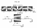
図2Aは、経頭蓋電気刺激(TES)の作用を空間的に集中させるために交差短パルス(ISP)刺激を空間時間的に回転させる原理を示す。刺激電流は、連続的に変化する脳内勾配パターンを生成する3つの独立した電極対を介して順次送達される。ニューロン細胞膜は、膜の時定数が比較的大きい(約10ms)ため、これらのパターンを統合することができる。結果として、電流流れ軸線の断面にあるニューロンは、全刺激の個々の閾値下効果を累積し、焦点の外側に位置するニューロンよりも強く同調する。本方法は経時的な電荷積分機構を仮定し、ここでは単純化されたリーキー積分発火ニューロンモデルを例に挙げる。高速パルス(つまり、同時ニューロン記録のサンプリング間隔と比べて少なくとも1桁短い、例えば、電極対の数に応じて5~50μsの休止に対して2.5~10μsのデューティサイクル)の付加的な利点は、その高周波が局所場電位(LFP)又はニューロンスパイクの同時電気記録(1Hz~5kHz;20kHzサンプリング)に最小限の影響しか与えないことであり、比較的高い強度でも交流結合式記録増幅器を飽和させない。 FIG. 2A illustrates the principle of spatiotemporal rotation of crossed short pulse (ISP) stimulation to spatially focus the effects of transcranial electrical stimulation (TES). Stimulation currents are delivered sequentially through three independent electrode pairs that generate continuously changing intracerebral gradient patterns. Neuronal cell membranes are able to integrate these patterns due to their relatively large membrane time constant (approximately 10 ms). As a result, neurons in the cross-section of the current flow axis accumulate the individual subthreshold effects of all stimuli and entrain more strongly than neurons located outside the focal point. The method assumes a charge integration mechanism over time, and here a simplified leaky integrate-and-fire neuron model is taken as an example. Additional benefits of fast pulses (i.e., duty cycles of at least an order of magnitude shorter than sampling intervals for simultaneous neuronal recordings, e.g., 2.5-10 μs for 5-50 μs pauses depending on the number of electrode pairs) is that its high frequency has minimal effect on local field potentials (LFPs) or simultaneous electrical recordings of neuronal spikes (1 Hz to 5 kHz; 20 kHz sampling), saturating AC-coupled recording amplifiers even at relatively high intensities. don't let
焦点効果のモデル予測をラットで検証するために、側頭骨表面に接着した3D印刷のゲル電極ストリップに接続された5つの独立してプログラム可能な絶縁電流発生器を介して、電流パルスを非対称的に送達した(図2B参照)。海馬CA1領域での細胞外ユニット活動の生体内記録中、経頭蓋双極構成を交互させた。図2Bを参照すると、左半球に焦点を合わせた500msの高速回転パルス列のシーケンスと1000msの停止と含み、その後に右半球に焦点を合わせた同じシーケンスが続く。単一ユニット活動の空間的標的型同調に対するISP刺激の有効性を2つの例示的なニューロンで示し(図2C)、それらは、ISP刺激の標的となる半球に応じてそれぞれに発火率を増減させた。非常に短い持続時間の刺激パルスのため、刺激及び無刺激の期間における同様のスパイク波形及びスパイク自己相関ヒストグラムで示されるように、単一ユニットのスパイク列は電気ノイズによって汚染されなかった(図2C)。全体として、3つの回転双極子のみを使用したISPの電流集中効果は、スパイク発生確率で測定される左右の半球集中「ビーム」間の興奮利得が約2~1の比率であるという結果になった(図2D;4匹のラットで記録された47個のニューロンの内、7.6±3.78%対2.1±0.59%の増加;興奮n=18に対してP<0.005、並びに0.59±0.2%対0.35±0.15%の減少;抑制n=7に対してP<0.05;Wilcoxon符号順位検定)。言い換えると、ISP技法は、更に皮質下組織の活動と電気活動の同時記録とを選択的に制御するために、見かけ上空間的に集中した電場(物理的にではなく、ニューロンの観点から)の生成を可能にする。 To validate the model prediction of the focal effect in rats, current pulses were delivered asymmetrically via five independently programmable isolated current generators connected to 3D-printed gel electrode strips adhered to the temporal bone surface. (see Figure 2B). Transcranial bipolar configurations were alternated during in vivo recordings of extracellular unit activity in the hippocampal CA1 region. Referring to FIG. 2B, a sequence of 500 ms fast rotating pulse trains focused on the left hemisphere, followed by a 1000 ms pause, followed by the same sequence focused on the right hemisphere. The efficacy of ISP stimulation on spatially targeted entrainment of single-unit activity was demonstrated in two exemplary neurons (Fig. 2C), which differed in their firing rate depending on the hemisphere targeted by ISP stimulation. rice field. Because of the very short duration stimulation pulses, single-unit spike trains were not contaminated by electrical noise, as shown by similar spike waveforms and spike autocorrelation histograms in the stimulation and non-stimulation periods (Fig. 2C). ). Overall, the current crowding effect of ISP using only three rotating dipoles results in a ratio of about 2-1 in excitation gain between the left and right hemispherically focused 'beams' as measured by spike probability. (Fig. 2D; increase of 7.6 ± 3.78% vs. 2.1 ± 0.59% of 47 neurons recorded in 4 rats; P < 0 for excitation n = 18) .005, and a reduction of 0.59±0.2% vs. 0.35±0.15%; P<0.05 for inhibition n=7; Wilcoxon signed-rank test). In other words, the ISP technique also uses the application of an apparent spatially focused electric field (in terms of neurons, not physically) to selectively control subcortical tissue activity and simultaneous recording of electrical activity. enable generation.
ISPによるヒト脳ネットワーク活動の同調 Entrainment of human brain network activity by ISP
ヒトの死体で行われた直接的な電場測定は、他の実験で脳ネットワークを瞬時に且つ再現性よく改変するために最低限必要であると示された所望の脳内電圧勾配(~1mV/mm)に達するために、約5mAの電流を頭皮に印可する必要があることを指摘した。この予測を検証するために、視覚誘発電位及び聴覚刺激に対する反応時間を、ISP法(図3a及び3b)と自発脳活動のパワースペクトル、並びに従来のtDCS法を用いた(小さな又は大きな皮膚上スポンジ電極で;それぞれ図5c及び5d)視覚ネットワークの律動的同調(定常状態の視覚誘発電位)の両方を使用して、健康な被験者で比較した。従来のtDCS法では、2つのスポンジ電極を頭部両側の頭皮上に配置し、通常2mAの電流強度で電極を介して直流電流を印加する。これらの実験の何れにおいても、2mAの電流では経皮刺激の有意な効果は観察されなかった。被験者は、刺激の開始時又は消去時の何れかに眼内閃光(視覚的な「火花」)の知覚を時折報告した。これらの否定的な結果は、その後のネットワークパターンに対する強い刺激の有効性と対比すべきである。 Direct electric field measurements made in human cadavers yielded the desired intracerebral voltage gradient (~1 mV/ mm), a current of about 5 mA needs to be applied to the scalp. To test this prediction, visual evoked potentials and reaction times to auditory stimuli were analyzed using the ISP method (Figs. 3a and 3b) and power spectra of spontaneous brain activity, as well as the conventional tDCS method (small or large skin sponges). At the electrodes; Figures 5c and 5d, respectively) both rhythmic entrainment of the visual network (steady-state visual evoked potentials) were used and compared in healthy subjects. In the conventional tDCS method, two sponge electrodes are placed on the scalp on each side of the head and direct current is applied through the electrodes at a current intensity of typically 2 mA. No significant effect of transcutaneous stimulation was observed at a current of 2 mA in any of these experiments. Subjects occasionally reported the perception of intraocular phosphenes (visual "sparks") either at the onset or at the end of the stimulus. These negative results should be contrasted with the efficacy of strong stimulation on subsequent network patterns.
最大で7.5mAの電流のISP刺激(図1)を用いて、19人の健康な被験者に対してさらなる実験を行った。12個の皮膚上刺激電極の円形配列(各側に6個)を頭部の周りに配置した。各刺激サイトは、2x3cmの銅メッシュに接続された0.9%NaCl溶液に浸したスポンジで構成された。頭皮EEGを2サイト・モンタージュ(P3、P4)でモニタした。各セッションでは、1分間のベースライン記録の後に、12秒の間、強度が増加し減少する1Hzの正弦波列(0、1.5、3、4.5、6、7.5、6、4.5、3、1.5、0mA)が続き、各被験者に対して60回繰り返され、更に1分間の回復セッションが続く。高周波パルスの1Hz変調波によって生成された刺激アーティファクトは、刺激トリガ式移動平均のオフライン減算で除去した。アーティファクトが除去された信号は、非零ピークの相互相関ヒストグラム(すなわち、位相に依存しない)と2つのEEGチャンネル間のアルファ波帯域の弱相関瞬時周波数とによって示されるように、非刺激制御の脳活動の主要な特徴を維持した(図6A)。 Further experiments were performed on 19 healthy subjects using ISP stimulation with currents up to 7.5 mA (Fig. 1). A circular array of 12 epicutaneous stimulation electrodes (6 on each side) was placed around the head. Each stimulation site consisted of a sponge soaked in 0.9% NaCl solution connected to a 2x3 cm copper mesh. Scalp EEG was monitored with a two-site montage (P3, P4). In each session, a 1-Hz sinusoidal train of increasing and decreasing intensity (0, 1.5, 3, 4.5, 6, 7.5, 6, 4.5, 3, 1.5, 0 mA) followed by 60 repetitions for each subject followed by a 1 minute recovery session. Stimulation artifacts produced by the 1 Hz modulated wave of high frequency pulses were removed by off-line subtraction of the stimulus-triggered moving average. The artefact-removed signal is similar to that of the unstimulated control brain, as indicated by the non-zero peak cross-correlation histogram (i.e., phase independent) and the weakly correlated instantaneous frequency in the alpha band between the two EEG channels. The main features of activity were maintained (Fig. 6A).
1Hzで4.5mA以上の刺激は、自覚的に許容できるレベルの皮膚のヒリヒリ感及び灼熱感を含めて、様々な自覚作用を誘起した。刺激の開始と特に消失は、眼内閃光を誘発した。目を閉じて半暗闇で試験を行った場合でも、刺激の周波数で、頭部運動及び視野内で水平方向に振動する光という自覚感覚が一貫して報告された。一部の被験者では、1Hzで水平面内を移動する騒音源という感覚が最高強度で存在した。高い強度で、各被験者は口内に「金属味」がするという感覚を報告した。全ての自覚作用は刺激の開始時に強くて減衰するが、刺激の過程で消えることはなかった。刺激の終了後、自覚的又は客観的後作用は一切報告されなかった。図4Aは、被験者における12秒長さの刺激の5回連続繰り返しを示している。左右の半球からの12~16Hzでフィルタ処理された(アルファ律動、内因性脳活動)EEG信号(色付きのトレース)は、ISP刺激が高い振幅(灰色のトレース)に達した時にだけ振幅が明らかに増加する。 Stimulation of 4.5 mA or higher at 1 Hz elicited a range of subjective effects, including subjectively acceptable levels of skin tingling and burning. The onset and especially the disappearance of the stimulus elicited an intraocular phosphene. Subjective sensations of head movement and horizontally oscillating light within the visual field were consistently reported at the frequency of the stimulus, even when tested in semi-darkness with the eyes closed. In some subjects, the sensation of a noise source moving in the horizontal plane at 1 Hz was present at the highest intensity. At high intensity, each subject reported a sensation of a "metallic taste" in the mouth. All subjective effects were strong and attenuated at the onset of stimulation, but did not disappear during the course of stimulation. No subjective or objective after-effects were reported after termination of stimulation. FIG. 4A shows five consecutive repetitions of a 12-second long stimulus in a subject. 12-16 Hz filtered (alpha rhythm, intrinsic brain activity) EEG signals from left and right hemispheres (colored traces) reveal amplitudes only when the ISP stimulation reaches high amplitudes (grey traces). To increase.
アルファ波の振幅のTES位相変調は、高いISP強度(6及び7.5mA;図4a及び4b)においてフィルタ処理済み信号上に視認できた。LFP変調は両半球に存在し、アノード-カソード電流方向の変化により、同位相で交番する(図6a及び6bのエポックを比較されたい)。グループ統計については、刺激のピーク付近(-135~45°)及び刺激の谷付近(45~135°)の平均アルファ波振幅を各電流強度においてP3及びP4で個別に測定した。好ましい電流方向を適用した場合に、TES位相によるLFP振幅の有意な変調が、各半球において4.5、6及び7.5mAの電流強度で観察された(図4C)。 A TES phase modulation of the alpha wave amplitude was visible on the filtered signal at high ISP intensities (6 and 7.5 mA; FIGS. 4a and 4b). The LFP modulation is present in both hemispheres and alternates in phase with changes in anode-cathode current direction (compare epochs in FIGS. 6a and 6b). For group statistics, mean alpha wave amplitudes near the stimulus peak (−135 to 45°) and near the stimulus trough (45 to 135°) were measured at P3 and P4 at each current intensity, respectively. A significant modulation of the LFP amplitude by the TES phase was observed at current intensities of 4.5, 6 and 7.5 mA in each hemisphere when the preferred current direction was applied (Fig. 4C).
より詳細な分析のために、ISP刺激の次の電流ステップ(tACS)を、それぞれ7分間、更に3人の被験者に使用した:0、2、4.5、7及び9mA。2mA及び4.5mAでは、4.5mAにおける短髪の被験者(P<0.05)を除いて、アルファ律動のパワーに有意な影響は観察されなかった(P>0.05;それぞれ7及び5セッション)。7mA及び9mAでは、各被験者のアルファ波パワーが有意に増加した(P<0.05;それぞれ11及び5セッション)。アルファ波パワーは、4.5、7、及び9mAに対してTESの位相の関数として変化した。刺激に対する馴化の自覚的報告がネットワーク活動への作用の減少によって説明できるかどうかを調べるために、7分の刺激期間の前半及び後半におけるアルファ波パワーの増加を比較した。連続刺激の全体を通して(図6B)、自覚的な馴化を説明することのできる、アルファ波パワー又はEEGスペクトルの何れか他の部分における体系的な変化は見出されなかった。 For more detailed analysis, the following current steps of ISP stimulation (tACS) were used for 7 min each and for 3 additional subjects: 0, 2, 4.5, 7 and 9 mA. At 2 mA and 4.5 mA, no significant effect on alpha rhythm power was observed (P>0.05; 7 and 5 sessions, respectively), except for short-haired subjects at 4.5 mA (P<0.05). ). At 7 mA and 9 mA, each subject's alpha wave power was significantly increased (P<0.05; 11 and 5 sessions, respectively). The alpha wave power varied as a function of TES phase for 4.5, 7, and 9 mA. To investigate whether subjective reports of habituation to stimuli could be explained by reduced effects on network activity, we compared increases in alpha wave power during the first and second halves of the 7 min stimulation period. Throughout the stimulus sequence (Fig. 6B), no systematic changes in alpha wave power or any other part of the EEG spectrum were found that could explain the subjective habituation.
ニューロンの興奮性は主として、神経伝達物質によって誘起されるシナプス後電位によってもたらされるイオン伝導度で決まる。しかしながら、ニューロンは電場も感知することができる。2つの分極機構の相加的性質のため、理論的には誘導電場の「最小有効閾値」は存在しない。ニューロンがスパイクを発射しかけている時に、非常に少量の電場がスパイク閾値にバイアスをかける可能性がある。従って、ニューロンのVmが既知の場合に、非常に弱いが完全にタイミングを合わせた強制場は、ニューロンの応答を最大にすることができる。内因性脳律動はローラーコースターのようなもので、ニューロンが興奮し易い律動の「アップ」状態と、抑制されていて活性化するのが最も困難な「ダウン」状態とが存在する。本明細書で使用する場合、「完全にタイミングを合わせた」とは、ニューロンが最も興奮し易い、すなわち、内因性入力(他のニューロン)によって最も脱分極した瞬間を指す。生体外実験では、細胞内で発生する振動への振動場の結合は、0.2mV/mm程度の小さな勾配で効力を生じることが示されている。しかしながら、何れか任意の瞬間に局所ネットワークに対して確実で再現性のある影響を及ぼすには、共通標的を持つニューロンの少なくとも一部の放電挙動を何らかの機構によって一時的に調整する必要がある。生体細胞内記録は、1mV/mm程度の弱い電場がスパイクに対して測定可能な効果を発揮できることを明らかにした。しかしながら、おそらくは印可場が振動ネットワークの影響されない多数要素の勢力と競合しなければならないため、生来のネットワーク律動に影響を及ぼすには、数倍大きい電流が必要とされた。このような弱い強制場を視野に入れて、生理学的動作中のコヒーレントに活性なニューロンは、海馬のシータ振動中及び新皮質の遅い振動中にCA1錐体層に亘って約2~4mV/mmの勾配を生成することができる。内因的に生成される場は、生理学的な激しい波の間、局所的に10mV/mmを超える場合があり、てんかん活性中にこれらの値は桁違いに増加する可能性がある。 Neuronal excitability is determined primarily by ionic conductance driven by postsynaptic potentials induced by neurotransmitters. However, neurons can also sense electric fields. Due to the additive nature of the two polarization mechanisms, theoretically there is no "minimum effective threshold" for the induced electric field. When a neuron is about to fire a spike, a very small amount of electric field can bias the spike threshold. Thus, if the neuron's Vm is known, a very weak but perfectly timed forcing field can maximize the neuron's response. The intrinsic brain rhythm is like a roller coaster, with a rhythmic "up" state in which neurons are readily excitable and a "down" state in which they are inhibited and most difficult to activate. As used herein, "perfectly timed" refers to the instant at which a neuron is most excitable, ie, most depolarized by intrinsic input (other neurons). In vitro experiments have shown that the coupling of an oscillating field to vibrations generated in cells is effective at gradients as small as 0.2 mV/mm. However, to reliably and reproducibly affect local networks at any given moment, the discharge behavior of at least some of the neurons with a common target must be temporally modulated by some mechanism. In vivo intracellular recordings revealed that electric fields as weak as 1 mV/mm can exert a measurable effect on spikes. However, several times larger currents were required to influence the native network rhythm, presumably because the applied field must compete with the unaffected multi-component forces of the oscillatory network. With such a weak forcing field in view, coherently active neurons during physiological operation have a potential of about 2-4 mV/mm across the CA1 pyramidal layer during theta oscillations of the hippocampus and during slow oscillations of the neocortex. can generate gradients of Endogenously generated fields can locally exceed 10 mV/mm during physiological surges, and these values can increase by orders of magnitude during epileptic activity.
複数の記録電極で脳容積を比較的大きくカバーしているにも関わらず、誘導場の絶対最低閾値を見出すのは簡単でないと強調することが重要である。一部のニューロンに時々影響を及ぼす要件と、ニューロン回路に効果的且つ一貫してバイアスをかける要件(一部の用途、例えば、てんかん発作を可能な限り迅速に確実に終わらせる場合に必要とされる)とは異なる。脳における電流拡散の複雑な経路と感知場におけるニューロンの幾何学的形態の重要性とを考えると、実験における効果の欠如を、少数のニューロンに影響がないことの証拠と見なすことはできない。このような弱い効果が脳機能に有益な又は有害な影響を与える可能性があるかどうかは、標的を絞った記録と付加的な挙動測定とによってのみ決定することができる。 It is important to emphasize that finding the absolute minimum threshold of the induced field is not trivial, despite the relatively large coverage of the brain volume with multiple recording electrodes. The requirement to affect some neurons occasionally and the requirement to effectively and consistently bias neuronal circuits (necessary for some applications, e.g., to reliably end epileptic seizures as quickly as possible). is different from Given the complex pathways of current spreading in the brain and the importance of neuronal geometry in the sensing field, the lack of effect in the experiment cannot be taken as evidence of the absence of effects in small numbers of neurons. Whether such weak effects can have beneficial or detrimental effects on brain function can only be determined by targeted recordings and additional behavioral measurements.
計算方法は長年に亘って次第に洗練されてきたが、実験データの不足によりモデルを正当化することが難しい。硬膜下の測定は有用であるとは言え、皮質表面の接線方向に場を測定するのに対して、最大の電圧勾配は皮質表面に対して垂直向きである。頭皮、頭蓋及び硬膜外の刺激電極、並びに複数の記録電極を用いて、齧歯類及びヒト死体の両方における電場の3次元的広がりが最近、本発明者により定量化された。本発明者の調査結果は、脳、頭蓋及び周囲の軟部組織における電流拡散の大部分がオーミック性であることを確証する。頭皮、皮下組織及び筋肉は効果的な分路として機能し、電流拡散の少なくとも50%低減をもたらす。頭蓋の抵抗は、頭蓋の厚さに応じて、電流を更に20~30%減衰させる。これらの減衰因子の重要性を考えると、脳に到達する有効電流を推定する際に軟部組織の量、髪の毛及び頭蓋の厚さを考慮すべきであり、これらの因子の変動だけで経皮電気刺激の有効性に関する大きな個人差を説明できる可能性がある。 Although computational methods have become increasingly sophisticated over the years, the lack of experimental data makes it difficult to justify the models. Although subdural measurements are useful, they measure the field tangential to the cortical surface, whereas the maximum voltage gradient is perpendicular to the cortical surface. Using scalp, cranial and epidural stimulating electrodes and multiple recording electrodes, the three-dimensional spread of the electric field in both rodent and human cadavers was recently quantified by the inventors. Our findings confirm that most of the current spreading in the brain, skull and surrounding soft tissues is ohmic. The scalp, subcutaneous tissue and muscle act as effective shunts, resulting in at least a 50% reduction in current spread. The resistance of the skull attenuates the current by an additional 20-30% depending on the thickness of the skull. Given the importance of these attenuation factors, the amount of soft tissue, hair and skull thickness should be considered when estimating the effective current reaching the brain, and variations in these factors alone should account for transcutaneous electrical currents. It may explain the large individual differences in stimulus effectiveness.
組織の制限された体積に強度を集中させるという概念は、頭蓋定位放射線手術などの放射線医学技術によって十分に確立されている。放射線とは対照的に、同時に印加される電場は、共通の導電性媒体のために集中させることができない。代わりに、ISPは、空間的選択性を確立するために、短くて空間的に急速に変化する逐次的な場を印可することにより、ニューロン細胞膜の時間積分特性(つまり、~10msのニューロン細胞膜時定数)を利用する。ISPを使用すると、ニューロンにおける膜電荷の最大積分が発現し、連続的に誘導された電場の複数「ビーム」が交差する。「ビーム」を多く使用するほど、「ビーム」が通過する他の領域への悪影響は小さくなる。僅かに3つの回転双極子をラットに用いて、経頭蓋的に印可された連続短パルスは、両半球を標的とするモンタージュが単一ニューロンの発火を選択的に活性化させる(又は抑制する)ように、1つの海馬に電場を十分に集中させることができると実証された。 The concept of concentrating intensity on a limited volume of tissue is well established by radiological techniques such as cranial stereotactic radiosurgery. In contrast to radiation, simultaneously applied electric fields cannot be focused due to a common conducting medium. Instead, ISPs apply short, spatially rapidly varying, sequential fields to establish spatial selectivity, by applying short, spatially rapidly varying sequential fields to the time-integrated properties of neuronal membranes (i.e., ~10 ms of neuronal membrane time). constant). Using ISP, the maximum integral of membrane charge in a neuron develops, intersecting multiple "beams" of sequentially induced electric fields. The more "beams" are used, the less adverse effects other areas through which the "beams" pass. Using as few as three rotating dipoles in rats, a series of short pulses applied transcranially, a montage targeting both hemispheres selectively activates (or inhibits) firing of single neurons. Thus, it was demonstrated that the electric field could be sufficiently concentrated in one hippocampus.
ISP技法によって作り出される無視できるほどのアーティファクトが、ヒト志願者の脳波に対する頭皮刺激の影響を直接調べることを可能にした。死体実験からの予測、及びネットワーク活動に影響を与える齧歯類の推定「最小」場(~1mV/mm)と一致して、後頭部領域のアルファ波パワーが4.5mAから影響を受け始め、7mAを超える電流では、1Hz周期場の位相の関数としてのアルファ波パワーの振幅変調を含めて、各被験者で一貫した効果が示された。 The negligible artifacts produced by the ISP technique allowed us to directly examine the effects of scalp stimulation on brain waves in human volunteers. Consistent with predictions from cadaver experiments, and the estimated 'minimum' field in rodents (~1 mV/mm) to influence network activity, alpha wave power in the occipital region began to be affected from 4.5 mA to 7 mA. Currents above 1 Hz showed consistent effects in each subject, including amplitude modulation of the alpha wave power as a function of the phase of the 1 Hz periodic field.
ラットに関する測定 Measurements on rats
細胞外記録実験のために、合計16匹のメスのLong-Evansラット(350~450g)に、ウレタン麻酔(1.3~1.5g/kg、腹腔内)の下でカスタムメイドの記録及び経頭蓋刺激用電極を埋め込んだ。麻酔導入後、唾液分泌を減らすためにアトロピン(0.05mg/kg、皮下)を投与し、DC温度コントローラ(TMP-5b;Supertech製)で直腸温度を36~37℃に一定に保った。鼻毛の動き及び侵害受容反射のないこと確認して、麻酔段階を維持した。頭部の皮膚を剃り、残りの毛は脱毛クリームを用いて完全に除去した。 For extracellular recording experiments, a total of 16 female Long-Evans rats (350-450 g) under urethane anesthesia (1.3-1.5 g/kg, intraperitoneal) underwent custom-made recordings and transfusions. Electrodes for cranial stimulation were implanted. After induction of anesthesia, atropine (0.05 mg/kg, s.c.) was administered to reduce salivation, and rectal temperature was kept constant at 36-37° C. with a DC temperature controller (TMP-5b; Supertech). The anesthesia phase was maintained by confirming the absence of nasal hair movement and nociceptive reflexes. The skin on the head was shaved and the rest of the hair was completely removed using depilatory cream.
ラットにおける集中型ISP刺激の空間選択性の測定 Measurement of spatial selectivity of focused ISP stimulation in rats
カスタム設計した2つの刺激ストリップを3D印刷し、左右両側の側頭骨表面に接着した。2つの対称ストリップ(幅13mm、高さ3.3mm及び壁厚0.7mm)の各々は、3.7、2.2、2.2及び3.7mmだけ互いに離れた5つの個別のポケット(図2B)から構成され、それらの中間表面は、ラット頭蓋のMRIデータに基づく3Dモデルの側頭骨湾曲と類似していた。中央ポケットをブレグマの後方5.16mmに位置決めした。2つのシリコン探針は、海馬のCA1領域に両側、ブレグマの後方5.16mmで正中線の側方4mmに埋め込んだ。以下で説明するカスタムメイドの電子機器を用いて、ISP刺激を電流制御モードで実行した。 Two custom-designed stimulation strips were 3D printed and adhered to the temporal bone surface on both the left and right sides. Two symmetrical strips (width 13 mm, height 3.3 mm and wall thickness 0.7 mm) each have five individual pockets (Fig. 2B), whose medial surface resembled the temporal bone curvature of the 3D model based on MRI data of the rat skull. A central pocket was positioned 5.16 mm posterior to bregma. Two silicon probes were implanted bilaterally in the CA1 region of the hippocampus, 5.16 mm posterior to bregma and 4 mm lateral to the midline. ISP stimulation was performed in current-controlled mode using custom-made electronics as described below.
ヒト被験者に関する実験 Experiments on human subjects
刺激方法 stimulation method
ISP用の皮膚上刺激スポンジ電極は、2x3cmの銅メッシュに接着した2x3x1.5cmのスポンジから作製し、スポンジ間に約2.5cmの距離を保ちながらスポンジを内側にした状態でゴムバンドに接着した。12個の電極を備えたゴムバンドを0.9%の生理食塩水に浸し、頭部の周りに優しく締めた。別の実施形態では、上記と同じサイズの可撓性銅箔をスポンジの「皮膚」面に接着し、スポンジを乾燥状態に保った。どちらの場合も、濡れたスポンジ又は銅箔と皮膚との間に電極ゲルを入れることにより、伝導度が更に向上した。正弦波又はDCの刺激波形は、定電流モード又は定電圧モードの何れかで、絶縁した刺激発生器で作り出した。従来の大型電極TES構成では、10cmx10cm大のスポンジ電極を使用した。 The on-skin stimulation sponge electrodes for the ISP were made from 2x3x1.5 cm sponges glued to a 2x3 cm copper mesh and glued to a rubber band with the sponges inside, keeping a distance of about 2.5 cm between the sponges. . A rubber band with 12 electrodes was soaked in 0.9% saline and tightened gently around the head. In another embodiment, a flexible copper foil of the same size as above was adhered to the "skin" side of the sponge to keep the sponge dry. In both cases, the conductivity was further enhanced by placing an electrode gel between a wet sponge or copper foil and the skin. Sinusoidal or DC stimulus waveforms were generated with an isolated stimulus generator in either constant current or constant voltage mode. A conventional large electrode TES configuration used a 10 cm×10 cm sponge electrode.
ヒト被験者の実験例 Examples of experiments on human subjects
挙動検査は全て、30分間の適応期間の後、騒音のない環境において半暗闇で行った。視覚誘発電位(VEP)及び定常状態VEPに対する刺激セットを60又は50フレーム/秒の速度の動画として再生した。モニタのリフレッシュレートを再生レートと一致するように調整した。フレームの変化をモニタの右上縁に取り付けたフォトダイオードでモニタし、ここでは、交互に替わる黒と白の正方形が連続するフレームの印となった。フォトダイオード信号をEEG信号と並行して記録した。モニタは、両眼で画面を観察するために、被験者の約15~20cm前方に位置決めした。VEP刺激の場合、フルスクリーンの10x10反転式市松模様を1200回提示した。市松模様の反転は500ms毎に行われた。定常状態(多焦点としても知られる)VEP刺激を5つの同心円x12個の扇形セクタ(合計60セクタ)で生成し、最大6セグメントを同時に視ることができた。各刺激を3フレームで提示し、20又は16.6Hzの刺激周波数という結果になった(それぞれ、60及び50Hzのリフレッシュレートの場合)。各セッションで8000の刺激を提示した。tcTES刺激は、VEP及びssVEP刺激の間、毎分交互にオンとオフに切り替えられた。モニタの電磁放射がEEGワイヤに拾われ、そのためにEEG信号内にVEP様の人工的な応答が生じるかどうかをテストするために、被験者の目を厚紙で覆い、測定を繰り返した。 All behavioral tests were performed in semi-darkness in a noise-free environment after a 30 minute adaptation period. Stimulus sets for visual evoked potentials (VEPs) and steady-state VEPs were played as movies at speeds of 60 or 50 frames per second. Adjusted monitor refresh rate to match playback rate. Frame changes were monitored by a photodiode attached to the upper right edge of the monitor, where alternating black and white squares marked successive frames. The photodiode signal was recorded in parallel with the EEG signal. The monitor was positioned approximately 15-20 cm in front of the subject for binocular viewing of the screen. For the VEP stimulus, a full-screen 10x10 inverted checkerboard pattern was presented 1200 times. A checkerboard inversion was performed every 500 ms. Steady-state (also known as multifocal) VEP stimuli were generated in 5 concentric circles x 12 sector sectors (60 sectors total), allowing up to 6 segments to be viewed simultaneously. Each stimulus was presented in 3 frames, resulting in stimulation frequencies of 20 or 16.6 Hz (for refresh rates of 60 and 50 Hz, respectively). 8000 stimuli were presented in each session. The tcTES stimulation was alternately switched on and off every minute during VEP and ssVEP stimulation. To test whether the monitor's electromagnetic radiation was picked up by the EEG wires and therefore caused a VEP-like artificial response in the EEG signal, the subject's eyes were covered with cardboard and the measurements were repeated.
脳のアルファ波同期を記録するために、被験者には目を閉じて楽にし、呼吸に注意するよう指示した。電気刺激が応答時間に及ぼす影響は、被験者に対して、短いビープ音がランダムに現れた後に左手か右手の何れかでボタンを押すように指示することで評価した。聴覚刺激は、各手及びISP標的半球の組み合わせに対して少なくとも100回提示した(合計で、被験者毎に400の刺激)。 To record brain alpha synchronization, subjects were instructed to close their eyes, relax, and pay attention to their breathing. The effect of electrical stimulation on response time was assessed by asking subjects to press a button with either their left or right hand after a short beep sound randomly appeared. Auditory stimuli were presented at least 100 times for each hand and ISP target hemisphere combination (a total of 400 stimuli per subject).
カスタムメイドの電子機器 custom electronics
交差短パルス(ISP)刺激用の電子回路 Electronic circuitry for cross-short pulse (ISP) stimulation
ISP刺激手法の場合、刺激発生器の正負両方のリード線を12-12「常時閉」タイプのTLP52-4フォトトランジスタに接続した。双方向の、接地独立型伝導性を以下の方法で実現した。2つのフォトトランジスタは、そのエミッタとコレクタを介して直列に結合され、波形発生器からの入力信号は、2つのショットキーダイオードを介してトランジスタダブレットのエミッタ端とコレクタ端の両方に供給され、これにより、信号の極性に応じてダブレットの適切な要素にのみ電流の流れが可能となった。トランジスタダブレットの共通セグメントを頭部の刺激電極に接続した。同じ回路を信号のもう一方の極にも構築した。LED側への共通ドライバ信号は4つのトランジスタ全てを開放するが、ダイオードのため、その内の2つは常にフローティングであるのに対して、他の2つは頭部を通って回路を閉じた。6つの電極ペアに対して6つのこのような回路を使用して、トランジスタの6つのクアドラプレット(ブロック)を形成した。ラットでは、3組のみを使用した。ブロックは、100kHzTTLジェネレータ(ADG3051C、Tektronix製)で駆動されるCD74HC4017・10進カウンタ(Texas Instruments製)により生成されたTTLパルスによって、擬似ランダム順に有効化された。
[NNN]
ヒト被験者において可変なISP強度を用いるセッションの代替実現では、フォトトランジスタ及びダイオードをADG412高速アナログスイッチ(Analog Devices、米国マサチューセッツ州ノーウッド)に置き換え、制御TTL信号をPIC18F4525(Microchip、米国アリゾナ州チャンドラー)マイクロコントローラで生成し、ADuM1400(Analog Devices)デジタルアイソレータで絶縁した。この後者の回路は、ISP及びTESパルスの空間効果を比較する際に、ラットの実験にも使用した。
For the ISP stimulation technique, both the positive and negative leads of the stimulus generator were connected to TLP52-4 phototransistors of the 12-12 "normally closed" type. Bi-directional, ground-independent conductivity was achieved in the following manner. Two phototransistors are coupled in series through their emitters and collectors, and the input signal from the waveform generator is fed through two Schottky diodes to both the emitter and collector ends of the transistor doublet, which allowed current to flow only through the appropriate element of the doublet, depending on the polarity of the signal. The common segment of the transistor doublet was connected to the stimulation electrode on the head. An identical circuit was constructed for the other pole of the signal. A common driver signal to the LED side opens all four transistors, but because of the diodes, two of them are always floating, while the other two are closed circuited through the head. . Six such circuits were used for six electrode pairs to form six quadruplets (blocks) of transistors. In rats, only triplicate pairs were used. Blocks were activated in pseudorandom order by TTL pulses generated by a CD74HC4017 decimal counter (Texas Instruments) driven by a 100 kHz TTL generator (ADG3051C, Tektronix).
[NNN]
An alternative implementation of a session with variable ISP intensity in human subjects replaced the phototransistor and diode with an ADG412 high-speed analog switch (Analog Devices, Norwood, Mass., USA) and the control TTL signal with a PIC18F4525 (Microchip, Chandler, Ariz., USA) microcontroller. It was generated with a controller and isolated with an ADuM1400 (Analog Devices) digital isolator. This latter circuit was also used in rat experiments when comparing the spatial effects of ISP and TES pulses.
データ解析 data analysis
ヒトの実験では、6対の頭皮刺激電極を使用して、必要な局所電流を6分の1に減らした。ISP方法の適用では、例えば2対、3対、4対、5対、7対、又は8対など、他の数の電極対も使用することができる。使用する電極の数を最大限にすることは有益な場合があるが、費用対効果の見積りを行う必要があり、それは、電極対の数が多いほど効果がより局所的となるが、頭蓋/頭皮のサイズ的制約のため、頭蓋/頭皮上の電極全てに適合するように電極のサイズを小さくする必要があるからである。小さな電極は、電流密度が大きいために、皮膚に大きな悪影響を生じる及び/又は患者が刺激を知覚した時に痛みが増す可能性がある。それでもやはり、有効な強度では有害な皮膚作用及び前庭反応が誘起された。頭皮刺激が脳ネットワークに及ぼす直接的な作用を実証できたとは言え、直接作用と末梢を介した間接作用との分離は、tDCS又はtACSの潜在的な治療機構を理解する上で最も重要である。ISP技法を前進させる上での次のステップは、刺激電極対により生成される交差する双極子の数を増やすこと、及び/又はそれらを皮膚の下に埋め込んで皮膚シャントを除去することである。例えば、32電極のモンタージュを用いると、多数の双極子を形成して、局所印可電流を潜在的には皮膚感覚閾値未満に低減しつつ、制限された3次元の交差焦点を作り出す、或いは2又は3以上の脳構造を標的にすることができる。電極を整合させて電極群を形成すると焦点が決まる。理論的には、多数の接触サイトを備えた電極ストリップを使用する/埋め込む場合、接触サイト全てを使い切って電極群を形成する必要はないかもしれない。サブセットのみを使用する場合には、様々な焦点を作り出す余地がある。図2Cのラット実験の図面を参照すると、10の接触サイトから3つの対を形成している。これにより、例えば、左半球に焦点を合わせた1つの構成と、右半球に焦点を合わせた別の構成とを作り出すことが可能となる。ヒト死体の脳からの「グランドトルース」測定値を頭部計算モデルと組み合わせることにより、脳構造の集中的な電気的活性化の理論的設計が可能となる。 In human experiments, six pairs of scalp stimulation electrodes were used to reduce the required local current by a factor of six. Other numbers of electrode pairs may also be used in ISP method applications, such as, for example, 2, 3, 4, 5, 7, or 8 pairs. Maximizing the number of electrodes used may be beneficial, but cost-effectiveness estimates need to be made, since the greater the number of electrode pairs, the more localized the effect, but the greater the number of cranial/ Due to the size constraints of the scalp, it is necessary to reduce the size of the electrodes to fit all the electrodes on the skull/scalp. Smaller electrodes can cause greater damage to the skin and/or increase pain when the patient perceives the stimulation due to the higher current density. Nonetheless, efficacious intensities induced adverse skin effects and vestibular reactions. Although we were able to demonstrate direct effects of scalp stimulation on brain networks, the separation of direct and peripherally-mediated indirect effects is of paramount importance in understanding the potential therapeutic mechanisms of tDCS or tACS. . The next step in advancing ISP technology is to increase the number of crossed dipoles generated by stimulating electrode pairs and/or to implant them under the skin to eliminate skin shunts. For example, using a 32-electrode montage, a large number of dipoles can be formed to create a limited three-dimensional cross-focus while potentially reducing the locally applied current below the cutaneous sensation threshold; Three or more brain structures can be targeted. Aligning the electrodes to form an electrode group determines the focus. In theory, when using/embedding electrode strips with multiple contact sites, it may not be necessary to use up all the contact sites to form an electrode group. If only a subset is used, there is room for creating different focal points. Referring to the drawing of the rat study in FIG. 2C, there are 3 pairs of 10 contact sites. This allows, for example, to create one configuration focused on the left hemisphere and another configuration focused on the right hemisphere. Combining 'ground truth' measurements from human cadaver brains with computational head models allows for the theoretical design of focused electrical activation of brain structures.
ISP法は、多くの用途に適用することができる。例えば、ISP法は、てんかん発作の管理と終息などにおいて、即時介入に使用することができる。ISP法はまた、数日間に亘る内因性脳活動パターンへの反復的な干渉(「治療」)を通して累積効果に達することにより、他の主要な神経精神疾患(例えば、うつ病又は不安症)の可能な治療として使用することができる。ISP法の他の用途には、以下が含まれる:脳卒中後のリハビリテーション、学習及び記憶想起の強化、睡眠の質の向上、心的外傷後ストレス障害の治療、神経科学の研究、機械-脳インタフェース用途での脳への一般警告信号の送信、或いは、経頭蓋直流刺激(tDCS)、経頭蓋交流刺激(tACS)、電極対を用いた他形態の経頭蓋電気刺激法、経頭蓋磁気刺激、脳深部刺激、又は末梢神経刺激を現在対象としている何れかの用途。ISP法はまた、例えば脊髄、心臓、末梢神経、骨格筋など、体の他部分を電気的に刺激するのにも適している。これらのリストは単なる例示であり、本明細書に記載するシステム及び方法はこれらの用途に限定されない。ISP法はまた、例えば(但し、排他的でなく)、皮膚表面、皮膚の中、皮膚の下、頭蓋、頭蓋骨の中、頭蓋の下、硬膜、硬膜の下、脳表面、脳組織の中、心室の中、又はこれらのあらゆる組み合わせなど、他の電極位置を使用して適用することもでき、それは、ISP法の概念、すなわち、ニューロン(又はグリア)細胞膜による複数の連続した電気パルスの電荷積分が電極位置に依存しないからである。電極の位置が異なると、所望の効果に達するために異なる電流強度が必要となる可能性がある。 The ISP method can be applied in many applications. For example, ISP methods can be used for immediate intervention, such as in the management and termination of epileptic seizures. ISP methods have also been used to treat other major neuropsychiatric disorders (e.g., depression or anxiety) by reaching cumulative effects through repeated interventions ("treatments") in endogenous brain activity patterns over several days. It can be used as a possible treatment. Other uses of ISP methods include: rehabilitation after stroke, enhancing learning and memory retrieval, improving sleep quality, treating post-traumatic stress disorder, neuroscience research, machine-brain interfaces. Transcranial direct current stimulation (tDCS), transcranial alternating current stimulation (tACS), other forms of transcranial electrical stimulation using electrode pairs, transcranial magnetic stimulation, brain Any application currently directed to deep stimulation or peripheral nerve stimulation. ISP methods are also suitable for electrically stimulating other parts of the body, such as the spinal cord, heart, peripheral nerves, and skeletal muscles. These lists are merely exemplary, and the systems and methods described herein are not limited to these uses. ISP methods may also be used, for example, but not exclusively, on the skin surface, in the skin, under the skin, in the skull, in the skull, under the skull, on the dura, below the dura, on the brain surface, in brain tissue. It can also be applied using other electrode locations, such as in the middle, in the ventricle, or any combination thereof, which incorporates the ISP method concept, i. This is because the charge integration does not depend on the electrode position. Different electrode positions may require different current intensities to reach the desired effect.
ISP法は、独立した電流発生器を介した複数電場の同時印加が、空間的に均一な導電性媒体のせいで空間的に集中した作用を誘起できないことを認める。図5を参照されたい。その代わりに、ISP法は、TESの作用を空間的に集中させるために交差短パルス(ISP)刺激を空間時間的に回転させるという原理を実証する。本方法は、経時的に電荷積分機構を仮定する。高速パルス(電極対の数に応じて、少なくとも2倍長い休止を備えた10μs未満のデューティサイクル)の付加的な利点は、その高周波が局所場電位(LFP)又はニューロンスパイクの同時電気記録(1Hz~5kHz;20kHzサンプリング)に最小限の影響しか与えないことであり、比較的高い強度でも記録用AC結合式増幅器を飽和させない。従って、ISP法を用いて、空間的及び時間的に選択する方法でニューロン及び/又はグリア活動と相互作用することが可能である。 The ISP method recognizes that the simultaneous application of multiple electric fields via independent current generators cannot induce spatially focused effects due to the spatially uniform conducting medium. See FIG. Instead, the ISP method demonstrates the principle of spatiotemporally rotating crossed short pulse (ISP) stimuli to spatially focus the effects of the TES. The method assumes a charge integration mechanism over time. An additional advantage of fast pulses (duty cycle less than 10 μs with pauses at least twice as long, depending on the number of electrode pairs) is that their high frequency can be used for local field potentials (LFPs) or simultaneous electrical recordings of neuronal spikes (1 Hz). ∼5 kHz; 20 kHz sampling) and does not saturate the recording AC-coupled amplifier even at relatively high intensities. Thus, using ISP methods, it is possible to interact with neuronal and/or glial activity in a spatially and temporally selective manner.
上記のシステム及び方法は、現在利用可能な非侵襲性脳刺激技法で生成される作用のより良い空間的集中を提供する。更に、上記のISPシステム及び方法は、かゆみ、皮膚灼熱などの耐えられない作用を患者が経験することなく、より大きな刺激電流強度の使用を可能にする。本出願に記載するシステム及び方法と従来の電気刺激技法と相違点には、1)大きなスポンジ電極ではなく小さな表面電極の使用、2)異なる電位に設定された同時に有効な電極の軸線が所定の焦点で互いに交差するように整列した複数の電極(例えば、電極対又は電極群など)の使用、3)2又は3以上の電極(例えば、電極のサブセット)を有効化することにより、刺激波形を時間的に区分化した態様で電極に送達すること、4)利用可能な電極全てを10ミリ秒未満内に切り替えること、並びに5)いつでも、使用されない又は無効化された電極を刺激回路から電気的に切り離して、シャントを回避すること、が含まれる。このリストは例示に過ぎない。当業者は、本出願に記載するシステム及び方法と従来の電気刺激技法との間に他の相違点が存在する可能性があることを理解しよう。 The systems and methods described above provide better spatial concentration of the effects produced by currently available non-invasive brain stimulation techniques. Further, the ISP system and method described above allow the use of greater stimulation current intensities without patient experiencing intolerable effects such as itching, skin burning, and the like. Differences between the systems and methods described in this application and conventional electrical stimulation techniques include: 1) the use of small surface electrodes rather than large sponge electrodes; 3) using multiple electrodes (e.g., electrode pairs or electrode groups) aligned to cross each other at the focal point; 4) switching all available electrodes within less than 10 milliseconds; and 5) removing unused or disabled electrodes from the stimulation circuit at any time. to avoid shunting. This list is exemplary only. Those skilled in the art will appreciate that there may be other differences between the systems and methods described in this application and conventional electrical stimulation techniques.
本発明の実施形態の上記説明を例示及び説明の目的で提示した。網羅的であること、又は開示したまさにその形態に本発明を限定することは意図しておらず、修正形態及び変形形態が上記の教示に照らして可能であり、或いは本発明の実践から取得できる。本発明の原理及びその実践的な応用を説明して、当業者が様々な実施形態において、並びに予期される特定の用途に適した様々な修正形態を用いて本発明を利用できるようにするために、実施形態を選択し説明した。本発明の範囲から逸脱することなく、開示の動作条件及び実施形態の配置において、他の置き換え、修正、変更、及び省略が可能である。 The foregoing descriptions of embodiments of the invention have been presented for purposes of illustration and description. It is not intended to be exhaustive or to limit the invention to the precise form disclosed, and modifications and variations are possible in light of the above teachings or may be acquired from practice of the invention. . To explain the principles of the invention and its practical application so that a person skilled in the art may utilize the invention in its various embodiments and with various modifications suitable for the particular applications contemplated. , an embodiment was selected and described. Other substitutions, modifications, variations, and omissions are possible in the operating conditions and arrangements of the embodiments disclosed without departing from the scope of the invention.
本明細書で利用する場合、用語「およそ」、「約」、「実質的に」、並びに類似の用語は、本開示の主題が関係する当業者に共通して容認された使用法と調和した広い意味を持つものとする。これらの用語により、これらの特徴の範囲を提供したまさにその数値範囲に制限することなく、記載し請求する特定の特徴の説明が可能となるように意図していることを、本開示を検討する当業者は理解すべきである。従って、これらの用語は、記載し請求する主題の実質のない又は重要でない修正又は変更が、添付の特許請求の範囲に列挙する本発明の範囲に入ると見なされるということを指摘するものとして解釈すべきである。 As used herein, the terms "approximately," "about," "substantially," and similar terms are consistent with commonly accepted usage by those of ordinary skill in the art to which the subject matter of this disclosure pertains. shall have a broad meaning. It is contemplated in the present disclosure that these terms are intended to allow for the description of the specific features described and claimed without limiting the scope of those features to the precise numerical ranges provided. Those skilled in the art should understand. Accordingly, these terms are to be construed as pointing out that any insubstantial or immaterial modification or alteration of the described and claimed subject matter is to be considered within the scope of the invention as recited in the appended claims. Should.
本明細書における実質的に何れか複数形及び/又は単数形の用語の使用に関して、当業者は、文脈及び/又は用途に相応しいように、複数形から単数形へ、及び/又は単数形から複数形へと移すことができる。本明細書では、明確にするために、様々な単数形/複数形の置き換えを明示的に述べる場合がある。 Regarding the use of substantially any plural and/or singular terms herein, those of ordinary skill in the art may adjust plural to singular and/or vice versa as appropriate to the context and/or application. It can be transformed into shape. In this specification, for the sake of clarity, various singular/plural permutations may be explicitly stated.
本明細書に記載する主題及び動作の実施形態は、機械式又は光学式スイッチを備えたデジタル又はアナログ電子回路で、或いは本明細書に開示する構造及びそれらの構造的等価物を含めて、有形媒体、ファームウェア、又はハードウェア上に具体化されたコンピュータソフトウェアで、又はそれらの1又は2以上の組み合わせで実装することができる。本明細書に記載する主題の実施形態は、1又は2以上のコンピュータプログラム、すなわち、データ処理装置による実行のために、又はデータ処理装置を制御するために1又は2以上のコンピュータ記憶媒体にコード化されたコンピュータプログラム命令の1又は2以上のモジュールとして実装することができる。代替的又は付加的に、プログラム命令は、人工的に生成された伝搬信号、例えば、データ処理装置での実行に適した受信装置へ送信する情報をコード化するために生成される機械生成の電気式、光学式、又は電磁式信号の上にコード化することができる。コンピュータ記憶媒体は、コンピュータ可読記憶デバイス、コンピュータ可読記憶基板、ランダム又はシリアルのアクセスメモリアレイ又はデバイス、或いはそれらの1又は2以上の組み合わせである、又はそれらに含めることができる。更に、コンピュータ記憶媒体は伝搬信号ではないが、人工的に生成された伝搬信号内にコード化されたコンピュータプログラム命令の送信元又は送信先となることができる。コンピュータ記憶媒体はまた、1又は2以上の別個の構成部品又は媒体(例えば、複数のCD、ディスク、又は他の記憶デバイス)である、或いはそれらに含めることができる。従って、コンピュータ記憶媒体は有形で非一時的であるとすることができる。 The subject matter and operational embodiments described herein may be tangible, including digital or analog electronic circuits with mechanical or optical switches, or structures disclosed herein and their structural equivalents. It can be implemented in computer software embodied on media, firmware, or hardware, or in any combination of one or more thereof. Embodiments of the subject matter described herein may be encoded in one or more computer programs, i.e., in one or more computer storage media, for execution by or for controlling a data processing apparatus. can be implemented as one or more modules of coded computer program instructions. Alternatively or additionally, the program instructions may be an artificially generated propagated signal, e.g. It can be encoded onto a type, optical, or electromagnetic signal. A computer storage medium may be or include a computer readable storage device, a computer readable storage substrate, a random or serial access memory array or device, or a combination of one or more thereof. Additionally, a computer storage medium is not a propagated signal, but can be the source or destination of computer program instructions encoded in an artificially generated propagated signal. A computer storage medium can also be or be included in one or more separate components or media (eg, multiple CDs, disks, or other storage devices). As such, computer storage media may be tangible and non-transitory.
本明細書に記載する動作は、1又は2以上のコンピュータ可読記憶デバイスに保存されたデータ又は他の送信元から受信したデータに対してデータ処理装置又は処理回路で実行される動作として実装することができる。 The operations described herein may be implemented as operations performed by data processing apparatus or circuitry on data stored in one or more computer readable storage devices or received from other sources. can be done.
この装置は、例えば、FPGA(フィールドプログラマブルゲートアレイ)又はASIC(特定用途向け集積回路)などの専用論理回路を含むことができる。装置はまた、ハードウェアに加えて、当該コンピュータプログラムの実行環境を生成するコード、例えば、プロセッサファームウェア、プロトコルスタック、データベース管理システム、オペレーティングシステム、クロスプラットフォームランタイム環境、仮想マシン、又はそれらの1又は2以上の組み合わせを構成するコードも含むことができる。装置及び実行環境は、ウェブサービス、分散コンピューティング及びグリッドコンピューティングのインフラストラクチャなど、様々な異なるコンピューティングモデル・インフラストラクチャを実現することができる。 The device may, for example, include dedicated logic circuits such as FPGAs (Field Programmable Gate Arrays) or ASICs (Application Specific Integrated Circuits). In addition to hardware, the apparatus also includes code that creates an execution environment for the computer program, such as processor firmware, protocol stacks, database management systems, operating systems, cross-platform runtime environments, virtual machines, or one or two thereof. Codes comprising combinations of the above may also be included. The devices and execution environments can implement a variety of different computing model infrastructures, such as web services, distributed computing and grid computing infrastructures.
コンピュータプログラム(プログラム、ソフトウェア、ソフトウェアアプリケーション、スクリプト、又はコードとしても知られる)は、コンパイル言語又はインタプリタ言語、宣言型言語又は手続き型言語を含めて、あらゆる形式のプログラミング言語で書くことができ、独立プログラムとして、或いはモジュール、コンポーネント、サブルーチン、オブジェクト、又はコンピューティング環境での使用に適した他のユニットとして、あらゆる形式で配備することができる。コンピュータプログラムは、ファイルシステム内のファイルに対応する場合があるが、そうである必要はない。プログラムは、他のプログラム又はデータを保持するファイルの一部(例えば、マークアップ言語文書に保存された1又は2以上のスクリプト)に、当該プログラム専用の単一ファイルに、或いは複数の連携ファイル(例えば、1又は2以上のモジュール、サブプログラム、又はコードの一部を保存するファイル)に保存することができる。1つのコンピュータ上で、或いは、1つのサイトに位置する又は複数のサイトに亘って分散されて通信ネットワークで相互接続される複数のコンピュータ上で実行するために、コンピュータプログラムを配備することができる。 Computer programs (also known as programs, software, software applications, scripts, or code) can be written in any form of programming language, including compiled or interpreted languages, declarative or procedural languages, and can stand alone. It can be deployed in any form as a program, or as a module, component, subroutine, object, or other unit suitable for use in a computing environment. Computer programs may, but need not, correspond to files in a file system. A program may be part of a file holding other programs or data (e.g., one or more scripts stored in a markup language document), a single file dedicated to that program, or multiple associated files (such as For example, files that store one or more modules, subprograms, or portions of code). A computer program can be deployed to be executed on one computer or on multiple computers located at one site or distributed across multiple sites and interconnected by a communication network.
本明細書に記載するプロセス及びロジックフローは、入力データに作用して出力を生成することで動作を行う1又は2以上のコンピュータプログラムを実行する1又は2以上のプログラム可能なプロセッサ又は処理回路によって遂行することができる。プロセス及びロジックフローはまた、例えばFPGA又はASICなどの専用論理回路で実行することができ、装置もそれらの専用回路として実装することができる。 The processes and logic flows described herein can be performed by one or more programmable processors or processing circuits executing one or more computer programs that operate by operating on input data and generating output. can be carried out. The processes and logic flows can also be implemented in dedicated logic circuits such as FPGAs or ASICs, and the devices can also be implemented as those dedicated circuits.
コンピュータプログラムの実行に適したプロセッサ又は処理回路は、例として、汎用及び専用マイクロプロセッサの両方、並びにあらゆる種類のデジタルコンピュータの何れか1又は2以上のプロセッサを含む。一般に、プロセッサは、読出し専用メモリ又はランダムアクセスメモリ、或いはその両方から命令とデータを受け取ることになる。コンピュータの必須要素は、命令に従って動作を実行するプロセッサと、命令及びデータを保存する1又は2以上のメモリデバイスである。一般に、コンピュータはまた、例えば磁気ディスク、光磁気ディスク、光ディスクなどのデータを保存するための1又は2以上の大容量記憶デバイスを含む、又はそれらとの間でデータを受信又は転送するように動作可能に結合される、或いはその両方となる。しかしながら、コンピュータはこのようなデバイスを有する必要がない。更に、コンピュータは、例えばほんの数例を挙げると、携帯電話、携帯情報端末(PDA)、モバイルオーディオ又はビデオプレーヤ、ゲームコンソール、全地球測位システム(GPS)受信機、又は可搬型記憶デバイス(例えば、ユニバーサルシリアルバス(USB)フラッシュドライブ)などの別デバイスに埋め込むことができる。コンピュータプログラム命令及びデータを保存するのに適したデバイスには、全ての形態の不揮発性メモリ、メディア及びメモリデバイスが含まれ、例として、EPROM、EEPROM、及びフラッシュメモリデバイスなどの半導体メモリデバイス、内蔵ハードディスク又はリムーバブルディスクなどの磁気ディスク、光磁気ディスク、並びにCD-ROM及びDVD-ROMディスクを含む。プロセッサ及びメモリを専用ロジック回路で補完する、又はその中に組み込むことができる。 Processors or processing circuitry suitable for the execution of a computer program include, by way of example, both general and special purpose microprocessors, and any one or more processors of any kind of digital computer. Generally, a processor will receive instructions and data from read-only memory, random-access memory, or both. The essential elements of a computer are a processor, which performs operations according to instructions, and one or more memory devices, which store instructions and data. Generally, a computer also includes, or operates to receive or transfer data from, one or more mass storage devices, such as magnetic, magneto-optical, or optical disks, for storing data. possibly combined, or both. However, a computer need not have such devices. Additionally, the computer may be, for example, a mobile phone, a personal digital assistant (PDA), a mobile audio or video player, a game console, a global positioning system (GPS) receiver, or a portable storage device (e.g., It can be embedded in another device such as a Universal Serial Bus (USB) flash drive). Devices suitable for storing computer program instructions and data include all forms of non-volatile memory, media and memory devices, for example semiconductor memory devices such as EPROM, EEPROM and flash memory devices; Includes magnetic disks, such as hard disks or removable disks, magneto-optical disks, and CD-ROM and DVD-ROM disks. The processor and memory may be supplemented with, or incorporated within, dedicated logic circuitry.
ユーザとの対話を提供するために、本明細書に記載する主題の実施形態は、例えばCRT(陰極線管)又はLCD(液晶ディスプレイ)、OLED(有機発光ダイオード)、TFT(薄膜トランジスタ)、プラズマ、他の可撓性構成、又はユーザに情報を示す何れか他のモニタなどのディスプレイデバイスと、キーボードと、例えばマウストラックボールなどのポインティングデバイス等を有する、或いはユーザがコンピュータに入力を与えることのできるタッチスクリーン、タッチパッドなどを有するコンピュータ上に実装することができる。他の種類のデバイスを用いてユーザとの対話を実現することもでき、例えば、ユーザに提供されるフィードバックは、視覚フィードバック、聴覚フィードバック、又は触覚フィードバックなど、あらゆる形態の感覚フィードバックとすることができ、ユーザからの入力は、音響、音声、又は触覚の入力を含めてあらゆる形態で受け取ることができる。更に、コンピュータは、ユーザが使用するデバイスとの間で文書を送受信することにより、例えば、ウェブブラウザから受信した要求に応えてユーザのクライアントデバイス上のウェブブラウザにウェブページを送信することによって、ユーザと対話することができる。 In order to provide user interaction, embodiments of the subject matter described herein are for example CRT (Cathode Ray Tube) or LCD (Liquid Crystal Display), OLED (Organic Light Emitting Diode), TFT (Thin Film Transistor), Plasma, etc. or any other display device that shows information to the user, a keyboard, a pointing device such as a mouse trackball, etc., or touch that allows the user to provide input to the computer It can be implemented on a computer with a screen, touchpad, etc. Other types of devices can also be used to achieve interaction with the user, for example the feedback provided to the user can be any form of sensory feedback, such as visual, auditory or tactile feedback. , input from the user may be received in any form, including acoustic, speech, or tactile input. In addition, the computer may be used by the user by sending and receiving documents to and from the device used by the user, for example, by sending web pages to the web browser on the user's client device in response to requests received from the web browser. can interact with
Claims (15)
複数の電極群を成して配置された複数の電極を備え、
各電極群は少なくとも2又は3以上の電極を備え、少なくとも1つの電極が、前記電極群の要素間に電圧差が発生するように異なる電位レベルに設定され、
前記複数の電極は、
患者の頭皮の外側表面、
前記患者の頭蓋の外側表面、
前記患者の頭蓋内の前記患者の脳又は硬膜表面、又は
前記患者の脳内の内の1つに配置され、
前記電気脳刺激用システムは、さらに、
少なくとも1つの接地独立型スイッチを介して前記電極群を選択的に有効化及び無効化するように構成された接地独立型スイッチ回路を備え、
前記各電極群内で異なる電位レベルに設定された前記電極を接続する軸線又は発生した電場の軸線は、1又は2以上の所定の焦点で交差し、
前記独立型スイッチ回路は、前記電極群を順次的に有効化及び無効化するようにプログラムされ、
前記システムは、前記2又は3以上の有効化された電極を介して送達される複数の独立した連続電気パルスの効果を時間的に積分する電荷積分機構を実施するためにニューロン及び/又はグリア細胞膜の容量特性を利用する、
ことを特徴とするシステム。 A system for electrical brain stimulation, comprising:
A plurality of electrodes arranged to form a plurality of electrode groups,
each electrode group comprising at least two or more electrodes, at least one electrode being set to a different potential level to create a voltage difference between the elements of said electrode group;
the plurality of electrodes,
the outer surface of the patient's scalp;
the outer surface of the patient's skull;
placed on one of the patient's brain or dura mater surface within the patient's cranium, or within the patient's brain;
The electrical brain stimulation system further comprises:
a ground independent switch circuit configured to selectively enable and disable the electrodes via at least one ground independent switch;
axes connecting the electrodes set at different potential levels within each electrode group or axes of the generated electric field intersect at one or more predetermined focal points;
the independent switch circuit is programmed to sequentially enable and disable the electrodes;
The system uses neuronal and/or glial cell membranes to implement a charge integration mechanism that temporally integrates the effects of multiple independent sequential electrical pulses delivered via the two or more enabled electrodes. Utilizing the capacitance characteristics of
A system characterized by:
2又は3以上の信号線を接続又は切断するように構成された、前記少なくとも1つの接地独立型スイッチと、
少なくとも1つのダイオードと、
前記少なくとも1つの接地独立型スイッチを駆動するように構成された指令回路と、
を備える、請求項1に記載のシステム。 The ground independent switch circuit comprises:
the at least one ground independent switch configured to connect or disconnect two or more signal lines;
at least one diode;
a command circuit configured to drive the at least one ground independent switch;
2. The system of claim 1, comprising:
前記複数の接地独立型スイッチは複数のフォトトランジスタを備え、
前記各電極の極は、直列に接続された2つのフォトトランジスタのコレクタ-エミッタ接続に接続される、請求項9に記載のシステム。 The ground independent switch circuit comprises a plurality of ground independent switches configured to connect or disconnect two or more signal lines, and a command circuit configured to drive the plurality of ground independent switches. and
the plurality of ground independent switches comprising a plurality of phototransistors;
10. The system of claim 9, wherein the pole of each electrode is connected to collector-emitter connections of two phototransistors connected in series.
Applications Claiming Priority (3)
| Application Number | Priority Date | Filing Date | Title |
|---|---|---|---|
| US201762508251P | 2017-05-18 | 2017-05-18 | |
| US62/508,251 | 2017-05-18 | ||
| PCT/US2018/033253 WO2018213622A1 (en) | 2017-05-18 | 2018-05-17 | Intersectional short-pulse electrical stimulation of the brain |
Publications (2)
| Publication Number | Publication Date |
|---|---|
| JP2020520778A JP2020520778A (en) | 2020-07-16 |
| JP7162225B2 true JP7162225B2 (en) | 2022-10-28 |
Family
ID=64274687
Family Applications (1)
| Application Number | Title | Priority Date | Filing Date |
|---|---|---|---|
| JP2020514143A Active JP7162225B2 (en) | 2017-05-18 | 2018-05-17 | Crossed short-pulse electrical stimulation of the brain |
Country Status (11)
| Country | Link |
|---|---|
| US (1) | US11452862B2 (en) |
| EP (1) | EP3624891B1 (en) |
| JP (1) | JP7162225B2 (en) |
| KR (1) | KR102633307B1 (en) |
| CN (1) | CN110913946B (en) |
| BR (1) | BR112019024086A2 (en) |
| CA (1) | CA3063716A1 (en) |
| DK (1) | DK3624891T3 (en) |
| HU (1) | HUE058278T2 (en) |
| IL (1) | IL270667B2 (en) |
| WO (1) | WO2018213622A1 (en) |
Families Citing this family (7)
| Publication number | Priority date | Publication date | Assignee | Title |
|---|---|---|---|---|
| US10736557B2 (en) | 2016-03-30 | 2020-08-11 | Brain F.I.T. Imaging, LLC | Methods and magnetic imaging devices to inventory human brain cortical function |
| CA3077705A1 (en) | 2017-10-03 | 2019-04-11 | Braint F.I.T. Imaging, Llc | Methods and magnetic imaging devices to inventory human brain cortical function |
| GB2579827A (en) * | 2018-12-14 | 2020-07-08 | Brainpatch Ltd | Brain interfacing apparatus and method |
| WO2020202105A1 (en) * | 2019-04-03 | 2020-10-08 | Brain F.I.T. Imaging, LLC | Methods and magnetic imaging devices to inventory human brain cortical function |
| US11445960B2 (en) * | 2019-10-09 | 2022-09-20 | Trustees Of Boston University | Electrography system employing layered electrodes for improved spatial resolution |
| JP2023541826A (en) * | 2020-09-08 | 2023-10-04 | オシロスケープ, エルエルシー | Method and system for nerve stimulation via music and synchronized rhythmic stimulation |
| DE102021106334A1 (en) | 2021-03-16 | 2022-09-22 | Technische Universität Ilmenau, Körperschaft des öffentlichen Rechts, vertreten durch den Rektor | Method and system for generating and applying stimulation configurations on humans and associated computer program |
Citations (3)
| Publication number | Priority date | Publication date | Assignee | Title |
|---|---|---|---|---|
| JP2014502900A (en) | 2010-12-28 | 2014-02-06 | エーベーエス テヒノロギーズ ゲーエムベーハー | Device for noninvasive deep brain stimulation |
| WO2016057855A1 (en) | 2014-10-08 | 2016-04-14 | Massachusetts Institute Of Technology | Methods and apparatus for stimulation of biological tissue |
| WO2016207246A1 (en) | 2015-06-22 | 2016-12-29 | Forschungszentrum Jülich GmbH | Device and method for effective invasive two-stage neurostimulation |
Family Cites Families (17)
| Publication number | Priority date | Publication date | Assignee | Title |
|---|---|---|---|---|
| US5782874A (en) * | 1993-05-28 | 1998-07-21 | Loos; Hendricus G. | Method and apparatus for manipulating nervous systems |
| US20040167586A1 (en) * | 2003-02-21 | 2004-08-26 | Overstreet Edward H. | Charge normalization for electrical stimulation of excitable tissue to facilitate the comparison of neural responses to behavioral measurements having different parameters |
| WO2004087256A1 (en) * | 2003-04-02 | 2004-10-14 | Neurostream Technologies Inc. | Implantable nerve signal sensing and stimulation device for treating foot drop and other neurological disorders |
| DE10318071A1 (en) * | 2003-04-17 | 2004-11-25 | Forschungszentrum Jülich GmbH | Device for desynchronizing neuronal brain activity |
| US20060106430A1 (en) * | 2004-11-12 | 2006-05-18 | Brad Fowler | Electrode configurations for reducing invasiveness and/or enhancing neural stimulation efficacy, and associated methods |
| US9913985B2 (en) * | 2006-04-28 | 2018-03-13 | Second Sight Medical Products, Inc. | Method and apparatus to provide safety checks for neural stimulation |
| US8606360B2 (en) * | 2006-03-09 | 2013-12-10 | The Cleveland Clinic Foundation | Systems and methods for determining volume of activation for spinal cord and peripheral nerve stimulation |
| EP2038004B1 (en) * | 2006-07-05 | 2018-01-24 | Precisis AG | System for treatment of neurological disorders via electrical stimulation |
| GB0709834D0 (en) | 2007-05-22 | 2007-07-04 | Gillbe Ivor S | Array stimulator |
| CA2754189A1 (en) | 2009-03-02 | 2010-09-10 | Yeda Research And Development Co. Ltd. | Magnetic configuration and timing scheme for transcranial magnetic stimulation |
| US20110000777A1 (en) * | 2009-07-03 | 2011-01-06 | Zhou yun yan | Vapor compression distillation system |
| US8452414B2 (en) * | 2009-09-29 | 2013-05-28 | Medtronic, Inc. | Steering stimulation current by employing steering current |
| EP2863986A4 (en) * | 2012-06-22 | 2016-01-20 | Thync Inc | Device and methods for noninvasive neuromodulation using targeted transcrannial electrical stimulation |
| KR20150135618A (en) * | 2014-05-22 | 2015-12-03 | 주식회사 유진엘이디 | Light Emitting Module for Therapeutic or Cosmetic |
| EP3197542A1 (en) * | 2014-09-23 | 2017-08-02 | Boston Scientific Neuromodulation Corporation | Neuromodulation specific to objective function of modulation field for targeted tissue |
| US10201708B2 (en) * | 2014-10-29 | 2019-02-12 | Dirk De Ridder | Method of treating a neurological disorder using network stimulation |
| WO2016095810A1 (en) * | 2014-12-19 | 2016-06-23 | Chongqing Derma Optic&Electronic Technique Co., Ltd. | Radio frequency treatment apparatus |
-
2018
- 2018-05-17 IL IL270667A patent/IL270667B2/en unknown
- 2018-05-17 BR BR112019024086-1A patent/BR112019024086A2/en unknown
- 2018-05-17 KR KR1020197037093A patent/KR102633307B1/en active IP Right Grant
- 2018-05-17 JP JP2020514143A patent/JP7162225B2/en active Active
- 2018-05-17 US US16/613,400 patent/US11452862B2/en active Active
- 2018-05-17 CA CA3063716A patent/CA3063716A1/en active Pending
- 2018-05-17 EP EP18803289.0A patent/EP3624891B1/en active Active
- 2018-05-17 CN CN201880045867.5A patent/CN110913946B/en active Active
- 2018-05-17 WO PCT/US2018/033253 patent/WO2018213622A1/en unknown
- 2018-05-17 HU HUE18803289A patent/HUE058278T2/en unknown
- 2018-05-17 DK DK18803289.0T patent/DK3624891T3/en active
Patent Citations (3)
| Publication number | Priority date | Publication date | Assignee | Title |
|---|---|---|---|---|
| JP2014502900A (en) | 2010-12-28 | 2014-02-06 | エーベーエス テヒノロギーズ ゲーエムベーハー | Device for noninvasive deep brain stimulation |
| WO2016057855A1 (en) | 2014-10-08 | 2016-04-14 | Massachusetts Institute Of Technology | Methods and apparatus for stimulation of biological tissue |
| WO2016207246A1 (en) | 2015-06-22 | 2016-12-29 | Forschungszentrum Jülich GmbH | Device and method for effective invasive two-stage neurostimulation |
Also Published As
| Publication number | Publication date |
|---|---|
| HUE058278T2 (en) | 2022-07-28 |
| JP2020520778A (en) | 2020-07-16 |
| EP3624891A4 (en) | 2020-12-16 |
| CA3063716A1 (en) | 2018-11-22 |
| KR102633307B1 (en) | 2024-02-05 |
| IL270667B2 (en) | 2023-09-01 |
| KR20200023289A (en) | 2020-03-04 |
| IL270667A (en) | 2019-12-31 |
| CN110913946A (en) | 2020-03-24 |
| EP3624891B1 (en) | 2021-12-08 |
| US11452862B2 (en) | 2022-09-27 |
| IL270667B1 (en) | 2023-05-01 |
| DK3624891T3 (en) | 2022-01-03 |
| WO2018213622A1 (en) | 2018-11-22 |
| BR112019024086A2 (en) | 2020-06-02 |
| CN110913946B (en) | 2023-08-01 |
| US20200164201A1 (en) | 2020-05-28 |
| EP3624891A1 (en) | 2020-03-25 |
Similar Documents
| Publication | Publication Date | Title |
|---|---|---|
| JP7162225B2 (en) | Crossed short-pulse electrical stimulation of the brain | |
| CN108697890B (en) | System and method for treating various neurological diseases by synchronously activating nerves | |
| Klooster et al. | Technical aspects of neurostimulation: focus on equipment, electric field modeling, and stimulation protocols | |
| US7684866B2 (en) | Apparatus and methods for applying neural stimulation to a patient | |
| Moreno-Duarte et al. | Transcranial electrical stimulation: Transcranial direct current stimulation (tDCS), transcranial alternating current stimulation (tACS), transcranial pulsed current stimulation (tPCS), and transcranial random noise stimulation (tRNS) | |
| Groppa et al. | Slow-oscillatory transcranial direct current stimulation can induce bidirectional shifts in motor cortical excitability in awake humans | |
| US20070088404A1 (en) | Methods and systems for improving neural functioning, including cognitive functioning and neglect disorders | |
| US20140303425A1 (en) | Method and apparatus for electromagnetic treatment of cognition and neurological injury | |
| Sudbrack-Oliveira et al. | Non-invasive cortical stimulation: Transcranial direct current stimulation (tDCS) | |
| WO2019033213A1 (en) | Contingent stimulation for augmentation of memory | |
| Bolognini et al. | Noninvasive brain stimulation of the parietal lobe for improving neurologic, neuropsychologic, and neuropsychiatric deficits | |
| WO2022146294A1 (en) | System and method where auricular vagus nerve is stimulated by intermittent direct current for treatment of diseases and disorders | |
| US11571541B2 (en) | Apparatus and methods of transcranial stimulation to adjust sensory cortical dendritic spine neck membrane potentials for altering consciousness | |
| Kamakari et al. | Non-invasive Electrical Brain Modulation: A New Avenue for Treatment? | |
| Chaieb et al. | Effects of transcranial electrical stimulation on sensory functions | |
| Vallar et al. | Noninvasive brain stimulation of the parietal lobe for improving neurologic, neuropsychologic, and neuropsychiatric deficits | |
| Current et al. | Non-invasive Electrical Brain Modulation: A New Avenue for Treatment? | |
| Bikson et al. | Ingrid Moreno-Duarte, Nigel Gebodh, Pedro Schestatsky, Berkan Guleyupoglu 2, Davide Reato 2 | |
| Bikson et al. | Ingrid Moreno-Duarte1, Nigel Gebodh1, 2, Pedro Schestatsky1, 3, Berkan Guleyupoglu2, Davide Reato2 | |
| Kulkova et al. | Non-invasive brain stimulation methods: Transcranial magnetic stimulation, transcranial electric stimulation, transcutaneous vagus nerve stimulation | |
| Pathare et al. | A Study Paper: Novel Approaches for Invasive and Non-Invasive Vagus Nerve Stimulation |
Legal Events
| Date | Code | Title | Description |
|---|---|---|---|
| A621 | Written request for application examination |
Free format text: JAPANESE INTERMEDIATE CODE: A621 Effective date: 20210514 |
|
| A131 | Notification of reasons for refusal |
Free format text: JAPANESE INTERMEDIATE CODE: A131 Effective date: 20220117 |
|
| A977 | Report on retrieval |
Free format text: JAPANESE INTERMEDIATE CODE: A971007 Effective date: 20220117 |
|
| A521 | Request for written amendment filed |
Free format text: JAPANESE INTERMEDIATE CODE: A523 Effective date: 20220415 |
|
| TRDD | Decision of grant or rejection written | ||
| A01 | Written decision to grant a patent or to grant a registration (utility model) |
Free format text: JAPANESE INTERMEDIATE CODE: A01 Effective date: 20220905 |
|
| A61 | First payment of annual fees (during grant procedure) |
Free format text: JAPANESE INTERMEDIATE CODE: A61 Effective date: 20221005 |
|
| R150 | Certificate of patent or registration of utility model |
Ref document number: 7162225 Country of ref document: JP Free format text: JAPANESE INTERMEDIATE CODE: R150 |