JP7162182B2 - Wireless communication system and communication terminal control method - Google Patents

Wireless communication system and communication terminal control method Download PDF

Info

Publication number
JP7162182B2
JP7162182B2 JP2018081740A JP2018081740A JP7162182B2 JP 7162182 B2 JP7162182 B2 JP 7162182B2 JP 2018081740 A JP2018081740 A JP 2018081740A JP 2018081740 A JP2018081740 A JP 2018081740A JP 7162182 B2 JP7162182 B2 JP 7162182B2
Authority
JP
Japan
Prior art keywords
communication
terminal
communicable area
communication terminal
unit
Prior art date
Legal status (The legal status is an assumption and is not a legal conclusion. Google has not performed a legal analysis and makes no representation as to the accuracy of the status listed.)
Active
Application number
JP2018081740A
Other languages
Japanese (ja)
Other versions
JP2019193021A (en
Inventor
幸司 今村
真一 岡田
元雄 中川
正啓 熊川
淳一 高橋
Current Assignee (The listed assignees may be inaccurate. Google has not performed a legal analysis and makes no representation or warranty as to the accuracy of the list.)
Panasonic Intellectual Property Management Co Ltd
Original Assignee
Panasonic Intellectual Property Management Co Ltd
Priority date (The priority date is an assumption and is not a legal conclusion. Google has not performed a legal analysis and makes no representation as to the accuracy of the date listed.)
Filing date
Publication date
Application filed by Panasonic Intellectual Property Management Co Ltd filed Critical Panasonic Intellectual Property Management Co Ltd
Priority to JP2018081740A priority Critical patent/JP7162182B2/en
Priority to US16/386,730 priority patent/US10769917B2/en
Priority to CN201910316021.7A priority patent/CN110392339B/en
Publication of JP2019193021A publication Critical patent/JP2019193021A/en
Application granted granted Critical
Publication of JP7162182B2 publication Critical patent/JP7162182B2/en
Active legal-status Critical Current
Anticipated expiration legal-status Critical

Links

Images

Classifications

    • HELECTRICITY
    • H04ELECTRIC COMMUNICATION TECHNIQUE
    • H04BTRANSMISSION
    • H04B17/00Monitoring; Testing
    • H04B17/30Monitoring; Testing of propagation channels
    • H04B17/309Measuring or estimating channel quality parameters
    • H04B17/336Signal-to-interference ratio [SIR] or carrier-to-interference ratio [CIR]
    • GPHYSICS
    • G08SIGNALLING
    • G08BSIGNALLING OR CALLING SYSTEMS; ORDER TELEGRAPHS; ALARM SYSTEMS
    • G08B13/00Burglar, theft or intruder alarms
    • G08B13/22Electrical actuation
    • G08B13/24Electrical actuation by interference with electromagnetic field distribution
    • G08B13/2402Electronic Article Surveillance [EAS], i.e. systems using tags for detecting removal of a tagged item from a secure area, e.g. tags for detecting shoplifting
    • G08B13/2451Specific applications combined with EAS
    • G08B13/2462Asset location systems combined with EAS
    • GPHYSICS
    • G08SIGNALLING
    • G08BSIGNALLING OR CALLING SYSTEMS; ORDER TELEGRAPHS; ALARM SYSTEMS
    • G08B25/00Alarm systems in which the location of the alarm condition is signalled to a central station, e.g. fire or police telegraphic systems
    • G08B25/01Alarm systems in which the location of the alarm condition is signalled to a central station, e.g. fire or police telegraphic systems characterised by the transmission medium
    • G08B25/08Alarm systems in which the location of the alarm condition is signalled to a central station, e.g. fire or police telegraphic systems characterised by the transmission medium using communication transmission lines
    • HELECTRICITY
    • H04ELECTRIC COMMUNICATION TECHNIQUE
    • H04WWIRELESS COMMUNICATION NETWORKS
    • H04W4/00Services specially adapted for wireless communication networks; Facilities therefor
    • H04W4/02Services making use of location information
    • H04W4/021Services related to particular areas, e.g. point of interest [POI] services, venue services or geofences
    • HELECTRICITY
    • H04ELECTRIC COMMUNICATION TECHNIQUE
    • H04WWIRELESS COMMUNICATION NETWORKS
    • H04W4/00Services specially adapted for wireless communication networks; Facilities therefor
    • H04W4/02Services making use of location information
    • H04W4/025Services making use of location information using location based information parameters
    • H04W4/027Services making use of location information using location based information parameters using movement velocity, acceleration information
    • HELECTRICITY
    • H04ELECTRIC COMMUNICATION TECHNIQUE
    • H04WWIRELESS COMMUNICATION NETWORKS
    • H04W4/00Services specially adapted for wireless communication networks; Facilities therefor
    • H04W4/80Services using short range communication, e.g. near-field communication [NFC], radio-frequency identification [RFID] or low energy communication
    • YGENERAL TAGGING OF NEW TECHNOLOGICAL DEVELOPMENTS; GENERAL TAGGING OF CROSS-SECTIONAL TECHNOLOGIES SPANNING OVER SEVERAL SECTIONS OF THE IPC; TECHNICAL SUBJECTS COVERED BY FORMER USPC CROSS-REFERENCE ART COLLECTIONS [XRACs] AND DIGESTS
    • Y02TECHNOLOGIES OR APPLICATIONS FOR MITIGATION OR ADAPTATION AGAINST CLIMATE CHANGE
    • Y02DCLIMATE CHANGE MITIGATION TECHNOLOGIES IN INFORMATION AND COMMUNICATION TECHNOLOGIES [ICT], I.E. INFORMATION AND COMMUNICATION TECHNOLOGIES AIMING AT THE REDUCTION OF THEIR OWN ENERGY USE
    • Y02D30/00Reducing energy consumption in communication networks
    • Y02D30/70Reducing energy consumption in communication networks in wireless communication networks

Description

本開示は、一般に無線通信システム及び通信端末の制御方法に関し、より詳細には、通信端末にて相手端末と無線通信を行う無線通信システム、及び通信端末の制御方法に関する。 TECHNICAL FIELD The present disclosure generally relates to a wireless communication system and a method of controlling a communication terminal, and more particularly, to a wireless communication system in which a communication terminal performs wireless communication with a counterpart terminal, and a method of controlling the communication terminal.

従来、通信端末(携帯端末)にて、複数の読取対象に付された相手端末(非接触通信媒体)の情報を無線通信で読み取る技術が知られている(例えば特許文献1)。 2. Description of the Related Art Conventionally, a technology is known in which a communication terminal (portable terminal) reads information of a partner terminal (non-contact communication medium) attached to a plurality of read targets by wireless communication (for example, Patent Document 1).

特許文献1には、整列して積み重ねられ一箇所に密集するように所定の位置に置かれた複数の収容箱を読取対象とし、複数の収容箱に付された相手端末としての電子タグ(RFIDタグ)の情報を、通信端末にて読み取ることが記載されている。特許文献1では、読取作業時において、読取作業者が、通信端末を各収容箱に向けた状態で、これら収容箱に付された電子タグの情報を読み取るための操作を行う。これにより、通信端末に対して無線通信可能な範囲に存在する電子タグの情報が、一括して通信端末で取得される。 In Patent Literature 1, a plurality of storage boxes stacked in a row and placed at a predetermined position so as to be densely packed in one place are targeted for reading, and an electronic tag (RFID) attached to the plurality of storage boxes as a counterpart terminal. tag) is read by a communication terminal. In Patent Literature 1, during the reading operation, a reading operator points a communication terminal at each storage box and performs an operation for reading information on an electronic tag attached to each storage box. As a result, the communication terminal collectively obtains the information of the electronic tags existing within the wireless communication range with respect to the communication terminal.

特開2012-173837号公報JP 2012-173837 A

上述したような読取作業においては、通信端末から送信される電波の反射等に起因した電波の干渉等により、電波の受信レベルが変動するフェージング(Fading)が生じ、通信端末の周囲に、通信が不安定になる空間(いわゆるヌル点)が生じることがある。そして、通信端末の周囲における通信が不安定な空間に相手端末が存在する場合には、この相手端末と通信端末との通信が正常に行われない可能性がある。 In the reading work as described above, fading occurs in which the reception level of radio waves fluctuates due to interference of radio waves caused by reflection of radio waves transmitted from communication terminals, etc. Spaces of instability (so-called null points) may occur. If the partner terminal exists in a space where communication is unstable around the communication terminal, communication between the partner terminal and the communication terminal may not be performed normally.

本開示は上記事由に鑑みてなされており、フェージングが生じるような場合でも、通信成功率の向上を図ることができる無線通信システム及び通信端末の制御方法を提供することを目的とする。 The present disclosure has been made in view of the above reasons, and aims to provide a radio communication system and a communication terminal control method capable of improving the communication success rate even when fading occurs.

本開示の一態様に係る無線通信システムは、通信端末と、検知部と、制御部と、を備える。前記通信端末は、相手端末と無線通信を行う通信部を有する。前記検知部は、前記通信端末の動きを検知する。前記制御部は、前記通信端末に対して相対的に設定される前記通信部の通信可能エリアを変化させるように前記通信端末を制御する。前記制御部は、少なくとも前記検知部で検知される前記動きの大きさに基づいて、前記通信可能エリアを変化させ、前記通信部における前記相手端末との通信状況が、前記通信部と前記相手端末との通信中を示す場合には、前記通信可能エリアを固定する。 A wireless communication system according to an aspect of the present disclosure includes a communication terminal, a detector, and a controller. The communication terminal has a communication unit that performs wireless communication with a counterpart terminal. The detection unit detects movement of the communication terminal. The control unit controls the communication terminal so as to change a communicable area of the communication unit set relative to the communication terminal. The control unit changes the communicable area based on at least the magnitude of the movement detected by the detection unit, and the communication status between the communication unit and the partner terminal is changed. When indicating that communication with is in progress, the communicable area is fixed .

本開示の一態様に係る通信端末の制御方法は、相手端末と無線通信を行う通信部を有する通信端末の制御方法である。この通信端末の制御方法では、前記通信端末に対して相対的に設定される前記通信部の通信可能エリアを、少なくとも前記通信端末の動きの大きさに基づいて、変化させ、前記通信部における前記相手端末との通信状況が、前記通信部と前記相手端末との通信中を示す場合には、前記通信可能エリアを固定するように前記通信端末を制御する。 A control method for a communication terminal according to one aspect of the present disclosure is a control method for a communication terminal having a communication unit that performs wireless communication with a partner terminal. In this communication terminal control method, the communicable area of the communication unit set relative to the communication terminal is changed based on at least the magnitude of movement of the communication terminal, and the When the communication status with the partner terminal indicates that the communication unit is communicating with the partner terminal, the communication terminal is controlled to fix the communicable area .

本開示によれば、フェージングが生じるような場合でも、通信成功率の向上を図ることができるという利点がある。 According to the present disclosure, there is an advantage that the communication success rate can be improved even when fading occurs.

図1は、実施形態1に係る無線通信システムの概略構成を示すブロック図である。FIG. 1 is a block diagram showing a schematic configuration of a radio communication system according to Embodiment 1. FIG. 図2は、同上の無線通信システムの使用状態を示す説明図である。FIG. 2 is an explanatory diagram showing the state of use of the wireless communication system of the same. 図3は、同上の無線通信システムの他の使用状態を示す説明図である。FIG. 3 is an explanatory diagram showing another state of use of the radio communication system of the same. 図4は、比較例に係る無線通信システムの使用状態を示す説明図である。FIG. 4 is an explanatory diagram showing a usage state of a wireless communication system according to a comparative example. 図5は、実施形態1に係る無線通信システムの動作の一例を示すフローチャートである。5 is a flowchart illustrating an example of the operation of the wireless communication system according to the first embodiment; FIG. 図6は、同上の無線通信システムに関し、X軸、Y軸及びZ軸の各方向についての加速度を上段に示し、強度を下段に示すグラフである。FIG. 6 is a graph showing the acceleration in each direction of the X-axis, Y-axis, and Z-axis in the upper part and the intensity in the lower part, relating to the wireless communication system. 図7は、同上の無線通信システムに通信可能エリアの変化パターンの第1の例を示す説明図である。FIG. 7 is an explanatory diagram showing a first example of a change pattern of a communicable area in the same radio communication system. 図8は、同上の無線通信システムに通信可能エリアの変化パターンの第2の例を示す説明図である。FIG. 8 is an explanatory diagram showing a second example of a change pattern of a communicable area in the same wireless communication system. 図9は、同上の無線通信システムに通信可能エリアの変化パターンの第3の例を示す説明図である。FIG. 9 is an explanatory diagram showing a third example of a change pattern of a communicable area in the same wireless communication system. 図10は、同上の無線通信システムに通信可能エリアの変化パターンの第4の例を示す説明図である。FIG. 10 is an explanatory diagram showing a fourth example of a change pattern of a communicable area in the same wireless communication system. 図11は、実施形態1の第1変形例に係る無線通信システムの動作を示す説明図である。11 is an explanatory diagram showing the operation of the radio communication system according to the first modification of the first embodiment; FIG. 図12は、実施形態1の第2変形例に係る無線通信システムに関し、X軸、Y軸及びZ軸の各軸まわりの角速度を上段に示し、強度を下段に示すグラフである。FIG. 12 is a graph showing angular velocities around the X-, Y-, and Z-axes in the upper part and intensities in the lower part, in relation to the wireless communication system according to the second modification of the first embodiment. 図13は、実施形態2に係る無線通信システムの動作の一例を示すフローチャートである。13 is a flowchart illustrating an example of the operation of the wireless communication system according to the second embodiment; FIG.

(実施形態1)
(1)概要
本実施形態に係る無線通信システム10は、図1に示すように、通信端末1にて相手端末2と無線通信を行うシステムである。この種の無線通信システム10の一例として、通信端末1は、電波を通信媒体として用いることにより、非接触にて、相手端末2との間で情報の伝送を行う。本実施形態では、相手端末2は無線通信システム10の構成要素に含まれないこととして説明するが、相手端末2は無線通信システム10の構成要素に含まれていてもよい。
(Embodiment 1)
(1) Outline As shown in FIG. 1, a wireless communication system 10 according to the present embodiment is a system in which a communication terminal 1 performs wireless communication with a counterpart terminal 2 . As an example of this type of wireless communication system 10, a communication terminal 1 uses radio waves as a communication medium to transmit information to and from a counterpart terminal 2 in a non-contact manner. Although the counterpart terminal 2 is not included in the wireless communication system 10 in this embodiment, the counterpart terminal 2 may be included in the wireless communication system 10 .

本実施形態に係る無線通信システム10は、通信端末1と、検知部11と、制御部12と、を備えている。通信端末1は、相手端末2と無線通信を行う通信部13を有する。 A wireless communication system 10 according to this embodiment includes a communication terminal 1 , a detection unit 11 and a control unit 12 . The communication terminal 1 has a communication unit 13 that performs wireless communication with the partner terminal 2 .

ここで、検知部11は、通信端末1の動きを検知する。制御部12は、通信部13の通信可能エリア8(図2参照)を変化させるように通信端末1を制御する。通信可能エリア8は、通信端末1に対して相対的に設定される。制御部12は、少なくとも検知部11で検知される(通信端末1の)動きの大きさに基づいて、通信可能エリア8を変化させる。 Here, the detection unit 11 detects movement of the communication terminal 1 . The control unit 12 controls the communication terminal 1 to change the communicable area 8 (see FIG. 2) of the communication unit 13 . A communicable area 8 is set relative to the communication terminal 1 . The control unit 12 changes the communicable area 8 based at least on the magnitude of movement (of the communication terminal 1 ) detected by the detection unit 11 .

本開示でいう「動き」は、通信端末1の三次元空間内における位置又は姿勢等の変化を意味する。例えば、加速度に着目した場合、通信端末1に作用する加速度が大きいほど、通信端末1の「動き」が大きいことになる。また、本開示でいう「通信可能エリア」は、通信端末1の周囲において、通信端末1との無線通信が可能になる領域である。例えば、通信可能エリア8内に存在する相手端末2は、通信端末1との無線通信が可能である。 “Movement” as used in the present disclosure means a change in the position or attitude of the communication terminal 1 in the three-dimensional space. For example, when focusing on the acceleration, the greater the acceleration acting on the communication terminal 1, the greater the “movement” of the communication terminal 1 is. Also, the “communicable area” referred to in the present disclosure is an area around the communication terminal 1 in which wireless communication with the communication terminal 1 is possible. For example, the partner terminal 2 existing within the communicable area 8 can wirelessly communicate with the communication terminal 1 .

すなわち、本実施形態に係る無線通信システム10では、通信端末1から見た、相手端末2と通信可能な領域(通信可能エリア8)が可変である。そして、通信可能エリア8は、通信端末1の動きの大きさに基づいて、制御部12によって変化させられる。したがって、例えば、通信端末1から送信される電波の反射等に起因した電波の干渉等により、電波の受信レベルが変動するフェージングが生じるような場合でも、相手端末2と通信端末1との間の通信成功率の向上を図ることができる。 That is, in the wireless communication system 10 according to the present embodiment, the area (communicable area 8) that can communicate with the partner terminal 2 seen from the communication terminal 1 is variable. The communicable area 8 is changed by the control unit 12 based on the magnitude of movement of the communication terminal 1 . Therefore, for example, even if fading occurs in which the reception level of radio waves fluctuates due to interference of radio waves caused by reflection of radio waves transmitted from communication terminal 1, etc., communication between remote terminal 2 and communication terminal 1 It is possible to improve the communication success rate.

要するに、本実施形態に係る無線通信システム10によれば、例えば、通信端末1に動きが無い場合には、通信可能エリア8を変化させることで、相手端末2と通信可能エリア8との相対的な位置関係を変化させることが可能である。また、例えば、通信端末1に動きが有る場合には、通信可能エリア8を変化させなくても、相手端末2と通信可能エリア8との相対的な位置関係を変化させることが可能である。そのため、本実施形態に係る無線通信システム10では、通信端末1の動きによらずに、相手端末2と通信可能エリア8との相対的な位置関係を適当に変化させることができる。よって、フェージングが生じて、通信端末1の周囲に通信が不安定になる空間(いわゆるヌル点)が生じるような場合でも、相手端末2と通信可能エリア8との相対的な位置関係が変化することで、相手端末2がヌル点から脱し易くなる。結果的に、相手端末2と通信端末1との間の通信成功率が向上する。 In short, according to the wireless communication system 10 according to the present embodiment, for example, when the communication terminal 1 does not move, by changing the communicable area 8, the communicable area 8 relative to the counterpart terminal 2 is changed. positional relationship can be changed. Also, for example, when the communication terminal 1 moves, it is possible to change the relative positional relationship between the partner terminal 2 and the communicable area 8 without changing the communicable area 8 . Therefore, in the radio communication system 10 according to this embodiment, the relative positional relationship between the partner terminal 2 and the communicable area 8 can be appropriately changed regardless of the movement of the communication terminal 1 . Therefore, even when fading occurs and a space (so-called null point) where communication becomes unstable occurs around the communication terminal 1, the relative positional relationship between the counterpart terminal 2 and the communicable area 8 changes. This makes it easier for the partner terminal 2 to escape from the null point. As a result, the communication success rate between the partner terminal 2 and the communication terminal 1 is improved.

本実施形態に係る無線通信システム10は、例えば、コンビニエンスストア、スーパーマーケット、百貨店、ドラッグストア、衣料品店、家電量販店又はホームセンター等の小売店の店舗に導入され、棚卸管理及び検品等に用いられる。すなわち、無線通信システム10は、例えば、店舗における商品9(図2参照)の在庫を管理する棚卸管理の目的で、在庫が有る商品9に関する商品情報等の読取作業に用いられる。また、無線通信システム10は、例えば、店舗において入荷した商品9の個数等を検査する検品の目的で、入荷した商品9に関する商品情報等の読取作業に用いられる。 The wireless communication system 10 according to the present embodiment is introduced into, for example, retail stores such as convenience stores, supermarkets, department stores, drug stores, clothing stores, home appliance mass retailers, and home centers, and is used for inventory management, inspection, and the like. . That is, the wireless communication system 10 is used, for example, for reading product information related to the products 9 (see FIG. 2) in stock for the purpose of inventory management of the products 9 (see FIG. 2) in the store. Further, the wireless communication system 10 is used, for example, for reading product information related to received products 9 for the purpose of inspecting the number of received products 9 at a store.

具体的には、無線通信システム10は、通信部13を有する通信端末1にて、相手端末2と電波を通信媒体とする無線通信を行う。相手端末2は、例えば、商品9に付された電子タグであって、少なくとも商品9に関する商品情報を記憶している。本開示でいう「商品情報」は、商品9を識別するための情報であって、例えば、日本国で用いられているJAN(Japanese Article Number)コード等の商品識別コードである。この種の商品識別コードには、JANコードの他、欧州等で用いられているEAN(European Article Number)コード、及び米国等で用いられているUPC(Universal Product Code)等がある。 Specifically, in the wireless communication system 10, the communication terminal 1 having the communication unit 13 performs wireless communication with the counterpart terminal 2 using radio waves as a communication medium. The counterpart terminal 2 is, for example, an electronic tag attached to the product 9 and stores at least product information related to the product 9 . The “product information” referred to in the present disclosure is information for identifying the product 9, and is, for example, a product identification code such as JAN (Japanese Article Number) code used in Japan. In addition to the JAN code, this type of product identification code includes an EAN (European Article Number) code used in Europe and the like, and a UPC (Universal Product Code) used in the United States and the like.

要するに、通信端末1は、商品9から直接的に商品情報を読み取るのではなく、商品9に付された相手端末2(電子タグ)から非接触で商品情報を読み取る。通信端末1で読み取られた商品情報は、通信端末1から、例えば、ストアコンピュータ等の上位装置に送信され、上位装置にて管理される。また、商品情報は、商品9の品種(種類)を識別する情報に限らず、同一品種の商品9を個別に識別するシリアル情報等の情報を含んでいてもよい。これにより、同一品種の商品9が複数ある場合にも、これら同一品種の複数の商品9の各々を商品情報にて特定可能である。 In short, the communication terminal 1 does not directly read product information from the product 9, but reads product information from the counterpart terminal 2 (electronic tag) attached to the product 9 in a non-contact manner. The product information read by the communication terminal 1 is transmitted from the communication terminal 1 to, for example, a host computer such as a store computer, and managed by the host device. Moreover, the product information is not limited to information identifying the product type (kind) of the product 9, and may include information such as serial information for individually identifying products 9 of the same product type. As a result, even when there are a plurality of products 9 of the same kind, each of the plurality of products 9 of the same kind can be specified by the product information.

このような無線通信システム10においては、通信端末1が、電波を通信媒体とする無線通信にて、複数の相手端末2(電子タグ)と通信することにより、複数の商品9についての商品情報をまとめて取得できる。そのため、無線通信システム10は、上述したような店舗での棚卸管理及び検品等のように、複数の商品9についての商品情報を取得する作業に特に有用である。そして、このような用途においては、例えば、アルバイト等、通信端末1の操作に不慣れなユーザ7(図2参照)が、通信端末1を使用する場面も多い。したがって、本実施形態に係る無線通信システム10のように、通信端末1の動きによらずに、相手端末2と通信可能エリア8との相対的な位置関係を適当に変化させ、相手端末2と通信端末1との間の通信成功率の向上を図ることで、作業効率の向上にもつながる。 In such a wireless communication system 10, the communication terminal 1 communicates with a plurality of partner terminals 2 (electronic tags) through wireless communication using radio waves as a communication medium, thereby providing product information on a plurality of products 9. Can be obtained in bulk. Therefore, the wireless communication system 10 is particularly useful for acquiring product information on a plurality of products 9, such as inventory management and inspection at stores as described above. In such applications, the communication terminal 1 is often used by a user 7 (see FIG. 2) who is unfamiliar with operating the communication terminal 1, such as a part-time worker. Therefore, as in the wireless communication system 10 according to the present embodiment, the relative positional relationship between the partner terminal 2 and the communicable area 8 is appropriately changed regardless of the movement of the communication terminal 1, Improving the success rate of communication with the communication terminal 1 also leads to improvement in work efficiency.

(2)構成
以下、本実施形態に係る無線通信システム10の構成について詳しく説明する。本実施形態では、無線通信システム10がコンビニエンスストアに導入される場合を例に説明する。
(2) Configuration The configuration of the wireless communication system 10 according to this embodiment will be described in detail below. In this embodiment, a case where the wireless communication system 10 is installed in a convenience store will be described as an example.

無線通信システム10は、上述したように、通信端末1と、検知部11と、制御部12と、を備えている。 The wireless communication system 10 includes the communication terminal 1, the detection unit 11, and the control unit 12, as described above.

本実施形態では、通信端末1は、商品9に付された相手端末2(電子タグ)と電波を通信媒体とする無線通信を行うことにより、商品9に関する商品情報を読み取る装置であって、RFID(Radio Frequency Identification)システムを構成するリーダである。すなわち、通信端末1は、RFIDシステムにおける電子タグからなる相手端末2との間で、無線通信を行うことにより、相手端末2に記憶されている商品情報を取得する。ただし、相手端末2は少なくとも1つの物品に付されていればよく、この物品が商品9であることは必須ではない。「商品情報」は、相手端末2が付された物品に関する情報である「物品情報」の一種である。つまり、商品9以外(例えば店舗の設備等)の物品に相手端末2が付されている場合、相手端末2は、この物品に関する物品情報を記憶することになる。すなわち、相手端末2は、少なくとも1つの物品(本実施形態では商品9)に付された電子タグである。通信端末1は、相手端末2との間で電波を媒体とする無線通信を行うことにより物品(本実施形態では商品9)に関する物品情報(本実施形態では商品情報)を読み取る。 In this embodiment, the communication terminal 1 is a device that reads product information about the product 9 by performing wireless communication with a counterpart terminal 2 (electronic tag) attached to the product 9 using radio waves as a communication medium. (Radio Frequency Identification) system. That is, the communication terminal 1 acquires product information stored in the counterpart terminal 2 by performing wireless communication with the counterpart terminal 2, which is an electronic tag in the RFID system. However, the counterpart terminal 2 may be attached to at least one article, and this article does not necessarily have to be the article 9 . The “merchandise information” is a kind of “merchandise information” that is information about the merchandise to which the counterpart terminal 2 is attached. That is, when the counterpart terminal 2 is attached to an article other than the article 9 (for example, store equipment, etc.), the counterpart terminal 2 stores the article information regarding this article. That is, the counterpart terminal 2 is an electronic tag attached to at least one article (the article 9 in this embodiment). The communication terminal 1 reads article information (product information in this embodiment) related to an article (product 9 in this embodiment) by performing wireless communication with the counterpart terminal 2 using radio waves as a medium.

相手端末2は、例えば、パッシブ型のRF(Radio Frequency)タグであって、少なくとも商品情報を記憶するメモリを有している。ここにおいて、複数の商品9には複数の相手端末2が一対一で対応付けられている。相手端末2には、対応する商品9についての商品情報が記憶されており、相手端末2は、対応する商品9に付されている。 The partner terminal 2 is, for example, a passive RF (Radio Frequency) tag, and has a memory for storing at least product information. Here, a plurality of counterpart terminals 2 are associated with a plurality of products 9 on a one-to-one basis. Product information about the corresponding product 9 is stored in the counterpart terminal 2 , and the counterpart terminal 2 is attached to the corresponding product 9 .

相手端末2は、商品9と一体に取り扱い可能な状態で商品9に付されていればよく、相手端末2が商品9に付される具体的な態様としては、様々な態様がある。本実施形態では一例として、相手端末2はシール状であって商品9に貼り付けられている。その他、相手端末2は、例えば、紐等で商品9に繋がっていてもよいし、商品9の梱包材に一体化されていてもよいし、商品9に埋め込まれていてもよいし、商品9に組み込まれていてもよい。さらに、例えば、塗布型半導体等の技術を用いることにより、相手端末2は、商品9自体、又は商品9の梱包材等の表面に、印刷にて直接的に形成されていてもよい。 The counterpart terminal 2 only needs to be attached to the product 9 in such a way that it can be handled together with the product 9, and there are various specific ways in which the counterpart terminal 2 is attached to the product 9. In this embodiment, as an example, the counterpart terminal 2 is in the form of a sticker and is attached to the product 9 . In addition, the counterpart terminal 2 may be connected to the product 9 by a string or the like, integrated with the packing material of the product 9, embedded in the product 9, or embedded in the product 9. may be incorporated in Further, for example, the mating terminal 2 may be printed directly on the product 9 itself or on the surface of the packing material of the product 9 by using a technique such as a coated semiconductor.

通信端末1は、図1に示すように、上述した通信部13に加えて、エリア調節部14、記憶部15、出力部16及び操作部17を有している。ここで、通信端末1は、据置型ではなく、持ち運び可能な移動式の端末である。本実施形態では一例として、通信端末1は、ユーザ7(図2参照)が携帯できる手持ち式(ハンディタイプ)の端末である。そのため、筐体101(図2参照)は、ユーザ7が手に持って使用できるサイズ及び形状である。手持ち式の通信端末1は、筐体101内に収容される電池(例えば、一次電池又は二次電池)を電源とて動作する。本実施形態では、検知部11及び制御部12は、通信部13等と共に、通信端末1の筐体101内に設けられている。言い換えれば、検知部11及び制御部12は、通信端末1と一体化されている。 As shown in FIG. 1 , the communication terminal 1 has an area adjustment section 14 , a storage section 15 , an output section 16 and an operation section 17 in addition to the communication section 13 described above. Here, the communication terminal 1 is not a stationary type but a mobile terminal that can be carried around. In this embodiment, as an example, the communication terminal 1 is a hand-held (handy type) terminal that can be carried by the user 7 (see FIG. 2). Therefore, the housing 101 (see FIG. 2) has a size and shape that can be held by the user 7 and used. The hand-held communication terminal 1 operates using a battery (for example, a primary battery or a secondary battery) housed in the housing 101 as a power supply. In this embodiment, the detection unit 11 and the control unit 12 are provided inside the housing 101 of the communication terminal 1 together with the communication unit 13 and the like. In other words, the detection unit 11 and the control unit 12 are integrated with the communication terminal 1 .

検知部11は、通信端末1の動きを検知する。検知部11は、制御部12に電気的に接続されており、検知部11の検知結果は制御部12に出力される。本実施形態では一例として、検知部11は、加速度センサ111及び角速度センサ112を備えている。 The detection unit 11 detects movement of the communication terminal 1 . The detection unit 11 is electrically connected to the control unit 12 , and the detection result of the detection unit 11 is output to the control unit 12 . As an example in this embodiment, the detection unit 11 includes an acceleration sensor 111 and an angular velocity sensor 112 .

加速度センサ111は、筐体101内に設けられており、筐体101に作用する加速度を検知し、加速度の大きさに対応する電気信号を出力する。本実施形態では一例として、加速度センサ111は、互いに直交するX軸、Y軸及びZ軸の3軸方向の加速度を測定可能な、3軸加速度センサである。つまり、加速度センサ111は、互いに直交するX軸、Y軸及びZ軸の各方向について、加速度の大きさを検知する。加速度センサ111は、これら3軸方向の加速度の各々に対応する電気信号を制御部12に出力する。 The acceleration sensor 111 is provided inside the housing 101, detects acceleration acting on the housing 101, and outputs an electrical signal corresponding to the magnitude of the acceleration. In this embodiment, as an example, the acceleration sensor 111 is a three-axis acceleration sensor capable of measuring acceleration in directions of three axes, the X-axis, the Y-axis, and the Z-axis, which are orthogonal to each other. In other words, the acceleration sensor 111 detects the magnitude of acceleration in each of the X-axis, Y-axis, and Z-axis directions that are orthogonal to each other. The acceleration sensor 111 outputs electrical signals corresponding to the accelerations in these three axial directions to the control unit 12 .

角速度センサ112は、筐体101内に設けられており、筐体101の姿勢の変化に伴う筐体101の角速度を検知し、角速度の大きさに対応する電気信号を出力する。本実施形態では一例として、角速度センサ112は、互いに直交するX軸、Y軸及びZ軸の3軸まわりの角速度を測定可能な、3軸角速度センサである。つまり、角速度センサ112は、互いに直交するX軸、Y軸及びZ軸の各軸まわりの回転について、角速度の大きさを検知する。角速度センサ112は、これら3軸まわりの角速度の各々に対応する電気信号を制御部12に出力する。 The angular velocity sensor 112 is provided inside the housing 101, detects the angular velocity of the housing 101 as the attitude of the housing 101 changes, and outputs an electrical signal corresponding to the magnitude of the angular velocity. In this embodiment, as an example, the angular velocity sensor 112 is a triaxial angular velocity sensor capable of measuring angular velocity around three mutually orthogonal X-, Y-, and Z-axes. In other words, the angular velocity sensor 112 detects the magnitude of the angular velocity of the rotation around each of the X-axis, Y-axis, and Z-axis, which are orthogonal to each other. The angular velocity sensor 112 outputs electrical signals corresponding to angular velocities about these three axes to the controller 12 .

制御部12は、後述する通信部13の通信可能エリア8(図2参照)を変化させるように通信端末1を制御する。通信可能エリア8は、通信端末1の周囲において、通信端末1との無線通信が可能になる領域であって、通信端末1に対して相対的に設定される。つまり、制御部12は、通信端末1に対して相対的に設定される通信可能エリア8を変化させるように、通信端末1を制御する。本実施形態では、制御部12は、エリア調節部14に電気的に接続されており、少なくともエリア調節部14を制御することによって、通信部13の通信可能エリア8を変化させる。また、制御部12は、エリア調節部14だけでなく、通信部13、出力部16及び操作部17等、通信端末1の各部位を制御する。 The control unit 12 controls the communication terminal 1 to change the communicable area 8 (see FIG. 2) of the communication unit 13, which will be described later. The communicable area 8 is an area around the communication terminal 1 in which wireless communication with the communication terminal 1 is possible, and is set relative to the communication terminal 1 . That is, the control unit 12 controls the communication terminal 1 so as to change the communicable area 8 set relative to the communication terminal 1 . In this embodiment, the control unit 12 is electrically connected to the area adjustment unit 14 and changes the communicable area 8 of the communication unit 13 by controlling at least the area adjustment unit 14 . Further, the control unit 12 controls not only the area adjustment unit 14 but also each part of the communication terminal 1 such as the communication unit 13, the output unit 16, the operation unit 17, and the like.

制御部12は、少なくとも検知部11で検知される(通信端末1の)動きの大きさに基づいて、通信可能エリア8を変化させる。つまり、制御部12は、検知部11から入力される検知部11の検知結果に基づいて、通信可能エリア8を変化させる。制御部12が、通信端末1に対して相対的に設定される通信可能エリア8を変化させることにより、通信端末1から見た、相手端末2と通信可能な領域が変化する。そのため、通信端末1の筐体101と相手端末2との位置関係(筐体101又は相手端末2の向きも含む)が固定されている場合でも、通信可能エリア8が変化することで、通信可能エリア8と相手端末2との相対的な位置関係が変化する。制御部12の機能及び動作について詳しくは「(3)動作」の欄で説明する。 The control unit 12 changes the communicable area 8 based at least on the magnitude of movement (of the communication terminal 1 ) detected by the detection unit 11 . That is, the control unit 12 changes the communicable area 8 based on the detection result of the detection unit 11 input from the detection unit 11 . By changing the communicable area 8 set relative to the communication terminal 1 by the control unit 12, the communicable area with the partner terminal 2 seen from the communication terminal 1 changes. Therefore, even when the positional relationship between the housing 101 of the communication terminal 1 and the remote terminal 2 (including the orientation of the housing 101 or the remote terminal 2) is fixed, communication is possible by changing the communicable area 8. The relative positional relationship between area 8 and partner terminal 2 changes. The functions and operations of the control unit 12 will be described in detail in the section "(3) Operations".

本実施形態では、制御部12は、例えば、CPU(Central Processing Unit)及びメモリを主構成とするマイクロコンピュータにて構成されている。言い換えれば、制御部12は、CPU及びメモリを有するコンピュータにて実現されており、CPUがメモリに格納されているプログラムを実行することにより、コンピュータが制御部12として機能する。プログラムは、ここでは制御部12のメモリに予め記録されているが、インターネット等の電気通信回線を通じて、又はメモリカード等の非一時的記録媒体に記録されて提供されてもよい。 In this embodiment, the control unit 12 is configured by, for example, a microcomputer having a CPU (Central Processing Unit) and a memory as main components. In other words, the control unit 12 is realized by a computer having a CPU and memory, and the computer functions as the control unit 12 by the CPU executing a program stored in the memory. Although the program is pre-recorded in the memory of the control unit 12 here, it may be provided through an electric communication line such as the Internet or recorded in a non-temporary recording medium such as a memory card.

通信部13は、相手端末2と無線通信を行う。本実施形態では、通信部13は、電波を通信媒体として、例えば、通信端末1から数メートル以下の距離にある相手端末2と無線通信を行う。通信部13は、アンテナ131及び通信回路132を含んでいる。 The communication unit 13 performs wireless communication with the partner terminal 2 . In the present embodiment, the communication unit 13 wirelessly communicates with the counterpart terminal 2 located at a distance of several meters or less from the communication terminal 1, for example, using radio waves as a communication medium. The communication section 13 includes an antenna 131 and a communication circuit 132 .

アンテナ131は、通信可能エリア8内に存在する相手端末2との間で、通信媒体となる電波を送受信する。アンテナ131は、通信回路132と電気的に接続されている。アンテナ131は、偏波面を考慮し、円偏波のアンテナにて構成されることが好ましい。アンテナ131は、楕円偏波のアンテナにて構成されてもよいし、直線偏波とし、偏波面が互いに異なるように構成されてもよい。アンテナ131は、例えば、パッチアンテナ、モノポールアンテナ、逆F形アンテナ又はスロットアンテナ等で構成される。アンテナ131は、筐体101の表面から露出していてもよいし、筐体101の内部に配置されていてもよい。 Antenna 131 transmits and receives radio waves as a communication medium to and from partner terminal 2 existing within communicable area 8 . Antenna 131 is electrically connected to communication circuit 132 . The antenna 131 is preferably configured with a circularly polarized antenna in consideration of the plane of polarization. The antenna 131 may be configured as an elliptically polarized antenna, or may be configured as a linearly polarized wave with different planes of polarization. The antenna 131 is composed of, for example, a patch antenna, a monopole antenna, an inverted F-shaped antenna, a slot antenna, or the like. The antenna 131 may be exposed from the surface of the housing 101 or may be arranged inside the housing 101 .

通信回路132は、アンテナ131から相手端末2に電波を送信し、この電波によって起動された相手端末2と、電波を通信媒体とする無線通信を行う。本実施形態では、通信端末1は相手端末2から商品情報を取得するので、通信回路132は、相手端末2との無線通信の成立時に、少なくとも商品情報を含む情報を相手端末2から受信する。 The communication circuit 132 transmits radio waves from the antenna 131 to the counterpart terminal 2, and performs wireless communication using radio waves as a communication medium with the counterpart terminal 2 activated by the radio waves. In this embodiment, communication terminal 1 acquires product information from partner terminal 2 , so communication circuit 132 receives information including at least product information from partner terminal 2 when wireless communication with partner terminal 2 is established.

エリア調節部14は、通信部13の通信可能エリア8を調節する機能を有する。つまり、通信端末1に対して相対的に設定される通信可能エリア8は、エリア調節部14にて調節される。本実施形態では、上述したように通信部13は電波を通信媒体として相手端末2と無線通信を行うので、通信可能エリア8は、少なくとも通信端末1(通信部13)と相手端末2との間で相互に必要十分な受信レベルで相手からの電波を受信可能となる領域である。 The area adjustment unit 14 has a function of adjusting the communicable area 8 of the communication unit 13 . In other words, the communicable area 8 set relative to the communication terminal 1 is adjusted by the area adjusting section 14 . In this embodiment, as described above, the communication unit 13 performs wireless communication with the partner terminal 2 using radio waves as a communication medium. This is the area where radio waves from the other party can be received at mutually necessary and sufficient reception levels.

本実施形態では、制御部12は、通信部13における相手端末2との通信用の通信媒体の指向性、通信媒体の送信強度、及び通信媒体の受信感度の少なくとも1つを変化させることにより、通信可能エリア8を変化させる。本実施形態では、上述した通り、通信媒体は電波である。そして、制御部12は、エリア調節部14を制御することによって、通信可能エリア8を変化させるのであって、実質的に通信可能エリア8を変化させるのはエリア調節部14である。すなわち、エリア調節部14は、通信媒体である電波の指向性、送信強度及び受信感度の少なくとも1つを変化させることにより、通信可能エリア8を変化させる。 In this embodiment, the control unit 12 changes at least one of the directivity of the communication medium for communication with the counterpart terminal 2 in the communication unit 13, the transmission strength of the communication medium, and the reception sensitivity of the communication medium. Change the communicable area 8. In this embodiment, as described above, the communication medium is radio waves. The control unit 12 changes the communicable area 8 by controlling the area adjusting unit 14 , and it is the area adjusting unit 14 that substantially changes the communicable area 8 . That is, the area adjustment unit 14 changes the communicable area 8 by changing at least one of the directivity, transmission intensity, and reception sensitivity of the radio wave that is the communication medium.

本実施形態では一例として、エリア調節部14は、通信部13の電波の指向性を変化させることにより、通信可能エリア8を変化させる。具体的には、エリア調節部14は、例えば、モータ等により通信部13のアンテナ131の向きを機械的に変化させる、いわゆるメカニカル走査により、アンテナ131の指向性を変化させ、通信部13の電波の指向性を変化させる。あるいは、エリア調節部14は、アンテナ131の向きを変えずに、例えば、電子走査方式でアンテナ131の指向性を変化させ、通信部13の電波の指向性を変化させてもよい。後者の場合、アンテナ131は、例えば、整列された複数のアンテナ素子を含むアレイアンテナ(Array Antenna)にて構成される。この場合に、エリア調節部14は、例えば、アレイアンテナの各アンテナ素子の間の相対的な位相を制御し、アンテナ131から放射されるビーム(電波)の方向を変えることで、アンテナ131の指向性を変化させる。電子走査方式であれば、アンテナ131の向きを機械的に変化させるメカニカル走査のための機構(モータ等を含む)が不要になる。また、エリア調節部14は、電子走査方式とメカニカル走査方式とを併用することにより、アンテナ131の指向性を変化させてもよい。 In this embodiment, as an example, the area adjustment unit 14 changes the communicable area 8 by changing the directivity of the radio waves of the communication unit 13 . Specifically, the area adjustment unit 14 mechanically changes the direction of the antenna 131 of the communication unit 13 by using a motor or the like, that is, mechanical scanning, so that the directivity of the antenna 131 is changed, and the radio wave of the communication unit 13 is changed. change the directivity of the Alternatively, the area adjustment unit 14 may change the directivity of the antenna 131 by, for example, an electronic scanning method without changing the orientation of the antenna 131 to change the directivity of the radio waves of the communication unit 13 . In the latter case, the antenna 131 is composed of, for example, an array antenna including a plurality of arrayed antenna elements. In this case, the area adjustment unit 14 controls, for example, the relative phase between each antenna element of the array antenna, and changes the direction of the beam (radio wave) emitted from the antenna 131, so that the directivity of the antenna 131 change gender. With the electronic scanning method, a mechanical scanning mechanism (including a motor or the like) for mechanically changing the orientation of the antenna 131 is not required. Also, the area adjustment unit 14 may change the directivity of the antenna 131 by using both the electronic scanning method and the mechanical scanning method.

また、エリア調節部14は、通信部13の電波の指向性を、基本的には、一方向に沿って一次元的に変化させる。これにより、通信可能エリア8は、例えば、上下方向、又は左右方向等に沿って、直線状に移動することが可能である。ここで、エリア調節部14は、二次元的又は三次元的に変化させてもよい。指向性が二次元的に変化する場合には、通信可能エリア8は、例えば、平面状に円を描くように回転移動すること等が可能である。また、指向性が三次元的に変化する場合には、通信可能エリア8は、例えば、三次元空間中を螺旋状に移動すること等が可能である。 In addition, the area adjustment unit 14 basically changes the directivity of the radio waves of the communication unit 13 one-dimensionally along one direction. As a result, the communicable area 8 can move linearly, for example, vertically or horizontally. Here, the area adjustment unit 14 may change two-dimensionally or three-dimensionally. If the directivity changes two-dimensionally, the communicable area 8 can, for example, rotate and move in a planar circular motion. In addition, when the directivity changes three-dimensionally, the communicable area 8 can, for example, spirally move in the three-dimensional space.

記憶部15は、一例としてEEPROM(Electrically Erasable Programmable Read-Only Memory)等の書き換え可能な不揮発性メモリである。記憶部15は、少なくとも通信部13が相手端末2から受信した商品情報を記憶する。記憶部15は、複数の商品情報を記憶可能である。そのため、通信部13が複数の相手端末2から商品情報を受信した場合、これら複数の商品情報が記憶部15に記憶される。 The storage unit 15 is, for example, a rewritable nonvolatile memory such as an EEPROM (Electrically Erasable Programmable Read-Only Memory). The storage unit 15 stores at least the product information received by the communication unit 13 from the counterpart terminal 2 . The storage unit 15 can store a plurality of item information. Therefore, when the communication unit 13 receives product information from a plurality of counterpart terminals 2 , the product information of the plurality of products is stored in the storage unit 15 .

出力部16は、記憶部15に記憶された情報、つまり通信部13が相手端末2から受信した商品情報等の情報を出力する。出力部16は、例えば、通信端末1に備わっているディスプレイに情報を表示することにより情報を出力する。さらに、出力部16は、商品情報等の情報を、例えば、上位装置(ストアコンピュータ等)、又は携帯情報端末(スマートフォン又はタブレット端末等)等の他装置へ送信(転送)することにより、情報を出力する機能を有する。ただし、出力部16による出力の態様は表示及び他装置への送信に限らず、出力部16は、例えば、音声出力又は印刷等の態様で、商品情報等の情報を出力してもよい。 The output unit 16 outputs information stored in the storage unit 15 , that is, information such as product information received by the communication unit 13 from the partner terminal 2 . The output unit 16 outputs information by displaying the information on a display provided in the communication terminal 1, for example. Furthermore, the output unit 16 transmits (transfers) information such as product information to another device such as a host device (store computer, etc.), or a mobile information terminal (smartphone, tablet terminal, etc.). It has a function to output. However, the form of output by the output unit 16 is not limited to display and transmission to another device, and the output unit 16 may output information such as product information in a form such as voice output or printing, for example.

操作部17は、ユーザ7(図2参照)の操作を受け付ける。操作部17は、複数のメカニカルスイッチを有していてもよいし、タッチパネル等で実現されてもよい。また、操作部17は、通信端末1と通信可能な携帯情報端末(スマートフォン又はタブレット端末等)から、ユーザ7の操作による操作信号を受け付ける構成であってもよい。 The operation unit 17 receives an operation by the user 7 (see FIG. 2). The operation unit 17 may have a plurality of mechanical switches, or may be realized by a touch panel or the like. Further, the operation unit 17 may be configured to receive an operation signal by the operation of the user 7 from a mobile information terminal (smartphone, tablet terminal, or the like) capable of communicating with the communication terminal 1 .

(3)動作
(3.1)基本動作
以下、本実施形態に係る無線通信システム10の動作について、比較例に係る無線通信システム10Aと対比しつつ、図2~図4を参照して説明する。図2及び図3は、本実施形態に係る無線通信システム10の使用状態を示す説明図である。図4は、比較例に係る無線通信システム10Aの使用状態を示す説明図である。
(3) Operation (3.1) Basic operation Hereinafter, the operation of the wireless communication system 10 according to the present embodiment will be described with reference to FIGS. 2 to 4 while comparing with the wireless communication system 10A according to the comparative example. . 2 and 3 are explanatory diagrams showing usage states of the wireless communication system 10 according to the present embodiment. FIG. 4 is an explanatory diagram showing a usage state of the wireless communication system 10A according to the comparative example.

ここでは一例として、図2及び図3に示すように、店舗の店員であるユーザ7が、商品9の棚卸管理の際に、無線通信システム10を用いて商品情報を通信端末1にて読み取る場合を想定する。この場合、ユーザ7は、複数の商品9が陳列された棚90の正面に立ち、棚90に向けて通信端末1を手に持った姿勢で、棚90に陳列された複数の商品9の全てについての商品情報を通信端末1に読み取らせるように通信端末1を操作する。このとき、通信端末1の通信部13の通信可能エリア8は、基本的に、棚90に向けて設定されることになる。ここで、通信端末1は、これら複数の商品9に付された相手端末2(電子タグ)から、順に商品情報を読み取ってもよいし、一斉に商品情報を読み取ってもよい。 Here, as an example, as shown in FIGS. 2 and 3, when a user 7 who is a store clerk manages an inventory of a product 9, the product information is read by the communication terminal 1 using the wireless communication system 10. assume. In this case, the user 7 stands in front of the shelf 90 on which a plurality of products 9 are displayed, holds the communication terminal 1 toward the shelf 90, and looks at all the products 9 displayed on the shelf 90. The communication terminal 1 is operated so as to cause the communication terminal 1 to read the product information about. At this time, the communicable area 8 of the communication unit 13 of the communication terminal 1 is basically set toward the shelf 90 . Here, the communication terminal 1 may sequentially read product information from the counterpart terminals 2 (electronic tags) attached to the plurality of products 9, or may read the product information all at once.

まず、図4に示す比較例に係る無線通信システム10Aの動作について説明する。無線通信システム10Aにおいては、通信端末1から送信される電波の反射等に起因した電波の干渉等により、電波の受信レベルが変動するフェージングが生じ、通信端末1の周囲に、通信が不安定になる空間(いわゆるヌル点)が生じることがある。そして、通信端末1の周囲における通信が不安定な空間に相手端末2が存在する場合には、この相手端末2と通信端末1との通信が正常に行われない可能性がある。そのため、図4に示すように、比較例に係る無線通信システム10Aでは、棚90に陳列されている複数の商品9のうちの一部の商品9について、商品9に付された相手端末2がヌル点に存在し、通信端末1と相手端末2との通信に失敗する状況が生じ得る。図4では、無線通信システム10Aでの商品情報の読み取りに失敗した商品9については「×」印を付して符号「9X」で示し、商品情報の読み取りに成功した商品9を符号「9Y」で示している。 First, the operation of the radio communication system 10A according to the comparative example shown in FIG. 4 will be described. In the wireless communication system 10A, fading occurs in which the reception level of radio waves fluctuates due to interference of radio waves caused by reflection of radio waves transmitted from the communication terminal 1, etc., and communication becomes unstable around the communication terminal 1. space (so-called null point) may occur. If the partner terminal 2 exists in a space where communication is unstable around the communication terminal 1, there is a possibility that the communication between the partner terminal 2 and the communication terminal 1 will not be performed normally. Therefore, as shown in FIG. 4, in the wireless communication system 10A according to the comparative example, for some of the products 9 displayed on the shelf 90, the counterpart terminal 2 attached to the product 9 is A situation may arise in which communication between the communication terminal 1 and the counterpart terminal 2 fails due to the presence of a null point. In FIG. 4, products 9 whose product information cannot be read by the wireless communication system 10A are marked with an "x" and indicated by a symbol "9X", and products 9 whose product information is successfully read are indicated by a symbol "9Y". is shown.

このような状況において、ユーザ7が自らの手を動かすことにより、通信端末1の三次元空間内における位置又は姿勢等の変化を通信端末1に与えることは可能である。これにより、通信端末1に適当な「動き」が生じれば、商品9に付された相手端末2と通信可能エリア8との相対的な位置関係が変化し、相手端末2がヌル点から脱することができて、相手端末2と通信端末1との間の通信成功率が向上する。ただし、通信端末1の動かし方、つまり、通信端末1の移動速度、通信端末1の移動方向又は通信端末1の移動経路等によっては、通信成功率の向上の効果にばらつきがある。例えば、通信端末1の動きが小さすぎると、商品9に付された相手端末2と通信可能エリア8との相対的な位置関係が十分に変化せず、相手端末2がヌル点から脱することができず、相手端末2と通信端末1との通信が正常に行われない可能性がある。結局、比較例に係る無線通信システム10Aでは、相手端末2と通信端末1との間の通信成功率は、ユーザ7における通信端末1の取り扱いの熟練度等によってばらつくことになり、安定して通信成功率の向上を図ることは困難である。 In such a situation, it is possible for the user 7 to move his or her own hand to give the communication terminal 1 a change in its position or attitude within the three-dimensional space. As a result, when appropriate "movement" occurs in the communication terminal 1, the relative positional relationship between the counterpart terminal 2 attached to the product 9 and the communicable area 8 changes, and the counterpart terminal 2 escapes from the null point. The communication success rate between the partner terminal 2 and the communication terminal 1 is improved. However, the effect of improving the communication success rate varies depending on how the communication terminal 1 is moved, that is, the speed of movement of the communication terminal 1, the direction of movement of the communication terminal 1, the movement route of the communication terminal 1, and the like. For example, if the movement of the communication terminal 1 is too small, the relative positional relationship between the partner terminal 2 attached to the product 9 and the communication area 8 does not change sufficiently, and the partner terminal 2 escapes from the null point. communication between the partner terminal 2 and the communication terminal 1 may not be performed normally. As a result, in the wireless communication system 10A according to the comparative example, the success rate of communication between the counterpart terminal 2 and the communication terminal 1 varies depending on the skill level of the user 7 handling the communication terminal 1, etc., and stable communication is possible. It is difficult to improve the success rate.

これに対して、本実施形態に係る無線通信システム10では、上述したように、制御部12が、少なくとも検知部11で検知される(通信端末1の)動きの大きさに基づいて、通信可能エリア8を変化させる機能を有する。本実施形態では一例として、制御部12は、検知部11で検知される動きの大きさを閾値と比較し、検知部11で検知される動きの大きさが閾値を超える場合、通信可能エリア8を固定する。反対に、通信端末1の動きの大きさが閾値以下であれば、制御部12は、通信可能エリア8を変化させる。 On the other hand, in the wireless communication system 10 according to the present embodiment, as described above, the control unit 12 determines whether communication is possible based on at least the magnitude of movement (of the communication terminal 1) detected by the detection unit 11. It has the function of changing the area 8. In this embodiment, as an example, the control unit 12 compares the magnitude of movement detected by the detection unit 11 with a threshold, and if the magnitude of movement detected by the detection unit 11 exceeds the threshold, the communicable area 8 is detected. fixed. Conversely, if the magnitude of motion of communication terminal 1 is equal to or less than the threshold, control unit 12 changes communicable area 8 .

そのため、例えば、図2に示すように、ユーザ7が通信端末1を持つ手を特に動かさなければ、検知部11で検知される(通信端末1の)動きの大きさが閾値以下となるため、制御部12によって、通信可能エリア8が変化させられる。すなわち、図2の例では、通信端末1は静止状態にあり、通信端末1自体に動きが無いものの、制御部12が、通信端末1に対して相対的に設定される通信可能エリア8を変化させることにより、通信端末1から見た、相手端末2と通信可能な領域が変化する。図2では、通信可能エリア8が図中「8A」、「8B」及び「8C」で示す3段階で変化する場合を例示し、通信可能エリア8が「8A」であるときに、通信端末1にて商品情報の読み取りに成功した商品9を符号「9A」で示している。同様に、通信可能エリア8が「8B」であるときに、通信端末1にて商品情報の読み取りに成功した商品9を符号「9B」で示し、通信可能エリア8が「8C」であるときに、通信端末1にて商品情報の読み取りに成功した商品9を符号「9C」で示す。 Therefore, for example, as shown in FIG. 2, unless the user 7 particularly moves the hand holding the communication terminal 1, the magnitude of movement (of the communication terminal 1) detected by the detection unit 11 is equal to or less than the threshold. The communicable area 8 is changed by the control unit 12 . That is, in the example of FIG. 2, the communication terminal 1 is in a stationary state, and the communication terminal 1 itself does not move. As a result, the area in which the communication terminal 2 can communicate with the communication terminal 1 changes. FIG. 2 illustrates a case where the communicable area 8 changes in three stages indicated by "8A", "8B" and "8C" in the figure. The code "9A" indicates the product 9 whose product information has been successfully read. Similarly, when the communicable area 8 is "8B", the product 9 whose product information has been successfully read by the communication terminal 1 is indicated by the code "9B", and when the communicable area 8 is "8C" , the product 9 whose product information has been successfully read by the communication terminal 1 is indicated by the code "9C".

このように、図2の例では、通信可能エリア8が変化することにより、棚90に陳列されている複数の商品9の全てについて、商品情報の読み取りが可能になる。要するに、通信端末1の筐体101と相手端末2との位置関係(筐体101又は相手端末2の向きも含む)が固定されていても、通信可能エリア8が変化することで、通信可能エリア8と相手端末2との相対的な位置関係が変化する。その結果、商品9に付された相手端末2と通信可能エリア8との相対的な位置関係が変化し、相手端末2がヌル点から脱することができて、相手端末2と通信端末1との間の通信成功率が向上する。 In this way, in the example of FIG. 2, by changing the communicable area 8, it becomes possible to read the product information of all the products 9 displayed on the shelf 90. FIG. In short, even if the positional relationship between the housing 101 of the communication terminal 1 and the remote terminal 2 (including the orientation of the housing 101 or the remote terminal 2) is fixed, the communicable area 8 can be changed by changing the communicable area. The relative positional relationship between 8 and the partner terminal 2 changes. As a result, the relative positional relationship between the partner terminal 2 attached to the product 9 and the communicable area 8 changes, the partner terminal 2 can escape from the null point, and the partner terminal 2 and the communication terminal 1 communication success rate between

一方、例えば、図3に示すように、ユーザ7が通信端末1を持つ手を動かすことにより、検知部11で検知される(通信端末1の)動きの大きさが閾値を超えると、制御部12によって、通信可能エリア8が固定される。すなわち、図3の例では、通信端末1自体に比較的大きな動きが有るので、制御部12が、通信端末1に対して相対的に設定される通信可能エリア8を固定し、通信端末1から見た、相手端末2と通信可能な領域は変化しない。図3では、通信端末1が、実線で示す基準位置にあるときの通信可能エリア8を「8A」で示し、通信可能エリア8が「8A」であるときに、通信端末1にて商品情報の読み取りに成功した商品9を符号「9A」で示している。そして、基準位置から通信端末1が矢印Bの方向に移動したときの通信可能エリア8を「8B」で示し、基準位置から通信端末1が矢印Cの方向に移動したときの通信可能エリア8を「8C」で示す。通信可能エリア8が「8B」であるときに、通信端末1にて商品情報の読み取りに成功した商品9を符号「9B」で示し、通信可能エリア8が「8C」であるときに、通信端末1にて商品情報の読み取りに成功した商品9を符号「9C」で示す。 On the other hand, for example, as shown in FIG. 3, when the user 7 moves the hand holding the communication terminal 1 and the magnitude of movement (of the communication terminal 1) detected by the detection unit 11 exceeds the threshold, the control unit 12 fixes the coverage area 8 . That is, in the example of FIG. 3, since the communication terminal 1 itself has a relatively large movement, the control unit 12 fixes the communicable area 8 set relative to the communication terminal 1, and See, the area where communication with the partner terminal 2 is possible does not change. In FIG. 3, the communicable area 8 when the communication terminal 1 is at the reference position indicated by the solid line is indicated by "8A", and when the communicable area 8 is "8A", the product information is displayed on the communication terminal 1. Goods 9 that have been successfully read are indicated by reference numeral "9A". The communicable area 8 when the communication terminal 1 moves in the direction of arrow B from the reference position is indicated by "8B", and the communicable area 8 when the communication terminal 1 moves in the direction of arrow C from the reference position is indicated by "8B". Indicated by "8C". When the communicable area 8 is "8B", the product 9 whose product information has been successfully read by the communication terminal 1 is indicated by the code "9B", and when the communicable area 8 is "8C", the communication terminal The product 9 whose product information was successfully read in 1 is indicated by the code "9C".

このように、図3の例では、通信端末1の「動き」により、棚90に陳列されている複数の商品9の全てについて、商品情報の読み取りが可能になる。要するに、通信端末1から見た、相手端末2と通信可能な領域(通信可能エリア8)が固定されていても、通信可能エリア8が通信端末1ごと移動することで、通信可能エリア8と相手端末2との相対的な位置関係が変化する。その結果、商品9に付された相手端末2と通信可能エリア8との相対的な位置関係が変化し、相手端末2がヌル点から脱することができて、相手端末2と通信端末1との間の通信成功率が向上する。 As described above, in the example of FIG. 3, it is possible to read the product information of all the products 9 displayed on the shelf 90 by the “movement” of the communication terminal 1 . In short, even if the communicable area (communicable area 8) with the partner terminal 2 is fixed as seen from the communication terminal 1, the communicable area 8 and the partner can be separated by moving the communicable area 8 together with the communication terminal 1. A relative positional relationship with the terminal 2 changes. As a result, the relative positional relationship between the partner terminal 2 attached to the product 9 and the communicable area 8 changes, the partner terminal 2 can escape from the null point, and the partner terminal 2 and the communication terminal 1 communication success rate between

以上説明したように、本実施形態に係る無線通信システム10によれば、少なくとも検知部11で検知される(通信端末1の)動きの大きさに基づいて、通信可能エリア8が変化するので、相手端末2と通信端末1との間の通信成功率の向上を図ることができる。すなわち、通信端末1に「動き」が無ければ通信端末1から見た通信可能エリア8を変化させることで、一方、通信端末1に「動き」が有れば通信可能エリア8が通信端末1ごと移動することで、相手端末2と通信可能エリア8との相対的な位置関係が変化する。したがって、通信端末1の動きの有無によらず、相手端末2と通信可能エリア8との相対的な位置関係を適当に変化させることができる。その結果、本実施形態に係る無線通信システム10では、ユーザ7における通信端末1の取り扱いの熟練度等によらずに、安定して相手端末2と通信端末1との間の通信成功率の向上を図ることができる。 As described above, according to the wireless communication system 10 according to the present embodiment, the communicable area 8 changes based on at least the magnitude of movement (of the communication terminal 1) detected by the detection unit 11. The communication success rate between the partner terminal 2 and the communication terminal 1 can be improved. That is, if the communication terminal 1 does not "move", the communicable area 8 seen from the communication terminal 1 is changed. By moving, the relative positional relationship between the partner terminal 2 and the communicable area 8 changes. Therefore, regardless of whether or not the communication terminal 1 moves, the relative positional relationship between the partner terminal 2 and the communicable area 8 can be appropriately changed. As a result, in the wireless communication system 10 according to the present embodiment, the success rate of communication between the counterpart terminal 2 and the communication terminal 1 is stably improved regardless of the skill level of the user 7 in handling the communication terminal 1. can be achieved.

図5は、上述したような本実施形態に係る無線通信システム10の動作の一例を示すフローチャートである。図5のフローチャートに示す一連の処理は、通信端末1の制御方法に相当する。 FIG. 5 is a flow chart showing an example of the operation of the radio communication system 10 according to this embodiment as described above. A series of processes shown in the flowchart of FIG. 5 corresponds to the control method of the communication terminal 1 .

すなわち、無線通信システム10は、まず検知部11にて通信端末1の動きを検知する(S1)。次に、制御部12は、検知部11の検知結果から、通信端末1の動きの大きさを表す強度を算出する(S2)。本開示でいう「強度」は、通信端末1の動きの大きさを表す値であって、通信端末1が静止状態のときに「0」であって、通信端末1の動きが大きくなるほど大きな値となる。 That is, the wireless communication system 10 first detects the movement of the communication terminal 1 by the detection unit 11 (S1). Next, the control unit 12 calculates an intensity representing the magnitude of movement of the communication terminal 1 from the detection result of the detection unit 11 (S2). The “strength” referred to in the present disclosure is a value representing the magnitude of movement of the communication terminal 1, and is “0” when the communication terminal 1 is in a stationary state, and increases as the movement of the communication terminal 1 increases. becomes.

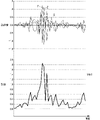
本実施形態では一例として、強度は、図6に示すように、加速度センサ111で検知された、X軸、Y軸及びZ軸の各方向についての加速度の大きさから算出される。図6は、横軸を時間軸として、X軸、Y軸及びZ軸の各方向についての加速度を上段に示し、強度を下段に示すグラフである。図6では、加速度のグラフにおいて、X軸、Y軸及びZ軸のグラフをそれぞれ「X」、「Y」及び「Z」と表記する。図6の例では、強度は、X軸、Y軸及びZ軸の各方向についての加速度の二乗和平方根で表される。つまり、制御部12は、X軸、Y軸及びZ軸の各方向についての加速度を二乗し、それらの和の平方根を演算することにより、強度を算出する。 In this embodiment, as an example, the intensity is calculated from the magnitude of acceleration in each of the X-axis, Y-axis, and Z-axis directions detected by the acceleration sensor 111, as shown in FIG. FIG. 6 is a graph showing the acceleration in each direction of the X-axis, Y-axis, and Z-axis in the upper stage and the intensity in the lower stage, with the horizontal axis as the time axis. In FIG. 6, in the acceleration graph, the X-axis, Y-axis, and Z-axis graphs are denoted by "X," "Y," and "Z," respectively. In the example of FIG. 6, the intensity is represented by the square root of the sum of squares of the accelerations in each of the X-, Y-, and Z-axis directions. That is, the control unit 12 squares the acceleration in each direction of the X-axis, Y-axis, and Z-axis, and calculates the square root of the sum of the squares to calculate the intensity.

制御部12は、このように算出された強度と閾値とを比較する(S3)。図6の例では、閾値Vth1は「1.4」に設定されている。そして、強度が閾値を超える場合には(S3:Yes)、制御部12は、通信可能エリア8を固定する(S4)。これにより、上述した図3の例のように、通信可能エリア8が通信端末1ごと移動することで、通信可能エリア8と相手端末2との相対的な位置関係が変化する。 The control unit 12 compares the intensity calculated in this way with the threshold value (S3). In the example of FIG. 6, the threshold Vth1 is set to "1.4". Then, when the intensity exceeds the threshold (S3: Yes), the control unit 12 fixes the communicable area 8 (S4). Accordingly, as in the example of FIG. 3 described above, the relative positional relationship between the communicable area 8 and the partner terminal 2 changes as the communicable area 8 moves together with the communication terminal 1 .

ここで、本実施形態では、制御部12が通信可能エリア8を固定する場合、少なくとも一定時間(例えば、数秒程度)は通信可能エリア8が固定されるように、制御部12は一定時間のカウントを行う(S5)。つまり、制御部12は、通信可能エリア8の固定を開始した後、一定時間が経過する(S5:Yes)ことをもって、一連の処理を終了する。 Here, in the present embodiment, when the control unit 12 fixes the communicable area 8, the control unit 12 counts the fixed time so that the communicable area 8 is fixed for at least a fixed time (for example, about several seconds). (S5). That is, the control unit 12 terminates a series of processing when a certain period of time elapses after starting to fix the communicable area 8 (S5: Yes).

一方、強度が閾値を超えない場合、つまり強度が閾値以下である場合に(S3:No)、制御部12は、通信可能エリア8を変化させる(S6)。これにより、上述した図2の例のように、通信可能エリア8が変化することで、通信可能エリア8と相手端末2との相対的な位置関係が変化する。この場合、制御部12は、一定時間の経過を待たず、一連の処理を終了する。 On the other hand, if the strength does not exceed the threshold, that is, if the strength is equal to or less than the threshold (S3: No), the controller 12 changes the communicable area 8 (S6). As a result, as in the example of FIG. 2 described above, the relative positional relationship between the communicable area 8 and the partner terminal 2 changes as the communicable area 8 changes. In this case, the control unit 12 ends the series of processes without waiting for the lapse of the predetermined time.

本実施形態に係る無線通信システム10は、上述した処理S1~S6を繰り返し実行する。ただし、図5における処理S1~S6の順番は一例に過ぎず、処理S1~S6の順番が適宜変更されてもよい。 The radio communication system 10 according to the present embodiment repeatedly executes the processes S1 to S6 described above. However, the order of the processes S1 to S6 in FIG. 5 is merely an example, and the order of the processes S1 to S6 may be changed as appropriate.

(3.2)通信可能エリアの変化パターン
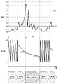
次に、検知部11で検知される通信端末1の動きの大きさに基づく通信可能エリア8の変化パターンについて、図7~図11を参照して説明する。本実施形態では、上述したように、エリア調節部14が、通信部13の電波の指向性を変化させることにより、通信可能エリア8を変化させる。そのため、以下では、電波の指向性の変化パターンにて、通信可能エリア8の変化パターンを示す。図7~図10は、いずれも横軸を時間軸として、通信端末1の動きの大きさを表す「強度」を上段に示し、「指向性」を下段に示すグラフである。
(3.2) Change pattern of communicable area Next, the change pattern of the communicable area 8 based on the magnitude of movement of the communication terminal 1 detected by the detection unit 11 will be described with reference to FIGS. 7 to 11. FIG. do. In this embodiment, as described above, the area adjustment unit 14 changes the communicable area 8 by changing the directivity of the radio waves of the communication unit 13 . Therefore, hereinafter, the change pattern of the communicable area 8 is indicated by the change pattern of the directivity of radio waves. 7 to 10 are graphs showing "intensity" representing the magnitude of movement of the communication terminal 1 in the upper part and "directivity" in the lower part, with the horizontal axis as the time axis.

(3.2.1)第1の例
第1の例では、図7に示すように、強度が閾値Vth1を超えるまでは、制御部12は、「指向性変化」の動作モードで動作し、「D1」、「D2」、「D3」及び「D4」の4段階で指向性を切り替えることにより、通信可能エリア8を変化させる。ここで、制御部12は、所定の切替周期ごとに、「D1」、「D2」、「D3」、「D4」、「D1」、「D2」…の順で指向性を切り替える。
(3.2.1) First Example In the first example, as shown in FIG. 7, the control unit 12 operates in the "directivity change" operation mode until the intensity exceeds the threshold value Vth1. The communicable area 8 is changed by switching the directivity in four stages of "D1", "D2", "D3" and "D4". Here, the control unit 12 switches the directivity in the order of “D1”, “D2”, “D3”, “D4”, “D1”, “D2”, . . . every predetermined switching period.

一方、強度が閾値Vth1を超えると、制御部12は、指向性を固定する。具体的には、制御部12は、「指向性固定」の動作モードで動作し、強度が閾値Vth1を上回った時点を始点として、一定時間T0にわたって指向性を固定する。このとき、指向性は、一例として、強度が閾値Vth1を上回った時点における指向性(図7の例では「D1」)に固定される。そして、一定時間T0が経過した時点において、制御部12は、改めて強度と閾値Vth1とを比較し、強度が閾値Vth1を超えていなければ、指向性を変化させる。ただし、強度が閾値Vth1を上回った時点における指向性に固定される構成に限らず、指向性は、「D1」~「D4」のうちの特定の指向性に固定されてもよい。 On the other hand, when the intensity exceeds the threshold Vth1, the control unit 12 fixes the directivity. Specifically, the control unit 12 operates in the "fixed directivity" operation mode, and fixes the directivity for a certain period of time T0 starting from the time when the intensity exceeds the threshold value Vth1. At this time, the directivity is, for example, fixed to the directivity (“D1” in the example of FIG. 7) at the time when the intensity exceeds the threshold Vth1. Then, when the fixed time T0 has passed, the control unit 12 again compares the intensity with the threshold value Vth1, and changes the directivity if the intensity does not exceed the threshold value Vth1. However, the configuration is not limited to fixing the directivity at the time when the intensity exceeds the threshold value Vth1, and the directivity may be fixed to a specific directivity among "D1" to "D4".

(3.2.2)第2の例
第2の例は、図8に示すように、制御部12が、検知部11で検知される動きの大きさが小さいほど、通信可能エリア8の変化量を大きくする点で、第1の例と相違する。言い換えれば、制御部12は、通信端末1の動きの大きさに応じて通信可能エリア8の変化量を決定するのであって、通信端末1の動き(の大きさ)が小さくなるにつれて、通信可能エリア8の変化量を大きくする。反対に、通信端末1の動き(の大きさ)が大きくなるにつれて、制御部12は、通信可能エリア8の変化量を小さくする。本開示でいう「変化量」はゼロ(0)を含んでおり、通信可能エリア8の変化量がゼロであれば、通信端末1に対して相対的に設定される通信可能エリア8は変化せず固定された状態となる。
(3.2.2) Second example In a second example, as shown in FIG. It differs from the first example in that the amount is increased. In other words, the control unit 12 determines the amount of change in the communicable area 8 according to the magnitude of movement of the communication terminal 1. As the movement (magnitude) of the communication terminal 1 decreases, the communication becomes Increase the amount of change in area 8. Conversely, as the movement (magnitude) of the communication terminal 1 increases, the control unit 12 reduces the amount of change in the communicable area 8 . The "change amount" in the present disclosure includes zero (0), and if the amount of change in the communication coverage area 8 is zero, the communication coverage area 8 set relative to the communication terminal 1 does not change. It will be in a fixed state.

そのため、検知部11で検知される動きの大きさが閾値を超える場合、制御部12は、通信可能エリア8の変化量をゼロとすることで、上述したように通信可能エリア8を固定する。したがって、検知部11で検知される動きの大きさが閾値を超えるほどに大きい場合には、通信端末1に対して相対的に設定される通信可能エリア8、つまり通信端末1から見た、相手端末2と通信可能な領域が固定される。 Therefore, when the magnitude of movement detected by the detection unit 11 exceeds the threshold, the control unit 12 sets the amount of change in the communication coverage area 8 to zero, thereby fixing the communication coverage area 8 as described above. Therefore, when the magnitude of the movement detected by the detection unit 11 is large enough to exceed the threshold, the communication area 8 set relatively to the communication terminal 1, that is, the A communicable area with the terminal 2 is fixed.

具体的には、第2の例では、図8に示すように、閾値として第1閾値Vth1及び第2閾値Vth2が設定され、制御部12は、強度と、第1閾値Vth1及び第2閾値Vth2の各々との比較結果に応じて、通信可能エリア8を変化させる。ここで、第2閾値Vth2は、第1閾値Vth1より小さい。すなわち、制御部12は、強度が第2閾値Vth2を超えるまでは、「D1」、「D2」、「D3」及び「D4」の4段階で指向性を切り替えることにより、通信可能エリア8を変化させる。ここで、制御部12は、「指向性変化(大)」の動作モードで動作し、所定の第1切替周期T1ごとに、「D1」、「D2」、「D3」、「D4」、「D1」、「D2」…の順で指向性を切り替える。 Specifically, in the second example, a first threshold Vth1 and a second threshold Vth2 are set as thresholds, as shown in FIG. The communicable area 8 is changed according to the result of comparison with each of the. Here, the second threshold Vth2 is smaller than the first threshold Vth1. That is, until the intensity exceeds the second threshold value Vth2, the control unit 12 changes the communicable area 8 by switching the directivity in four stages of "D1", "D2", "D3" and "D4". Let Here, the control unit 12 operates in the operation mode of "directivity change (large)", and performs "D1", "D2", "D3", "D4", " D1”, “D2” . . .

一方、強度が第2閾値Vth2(<Vth1)を超えると、制御部12は、指向性を切り替える周期を長くすることで、単位時間における通信可能エリア8の変化の頻度を小さくする。つまり、通信端末1の動きが大きくなると、制御部12は、通信可能エリア8の変化速度を小さくすることで、通信可能エリア8の変化量を小さくする。具体的には、制御部12は、強度が第2閾値Vth2を上回ると、「指向性変化(小)」の動作モードで動作し、第1切替周期T1よりも長い第2切替周期T2(>T1)ごとに、「D1」、「D2」、「D3」、「D4」、「D1」、「D2」…の順で指向性を切り替える。ここで、強度が第2閾値Vth2を上回ると、その後、一定時間T0が経過するか、又は強度が第1閾値Vth1を超えるまでは、制御部12は、第2切替周期T2ごとに指向性を変化させる。 On the other hand, when the intensity exceeds the second threshold Vth2 (<Vth1), the control unit 12 lengthens the directivity switching period, thereby reducing the frequency of change in the communicable area 8 per unit time. In other words, when the movement of the communication terminal 1 increases, the control unit 12 reduces the change rate of the communication area 8 to reduce the amount of change in the communication area 8 . Specifically, when the intensity exceeds the second threshold value Vth2, the control unit 12 operates in the operation mode of "change in directivity (small)", and the second switching period T2 (> The directivity is switched in the order of "D1", "D2", "D3", "D4", "D1", "D2", . . . every T1). Here, when the intensity exceeds the second threshold value Vth2, the control unit 12 changes the directivity every second switching cycle T2 until a certain time T0 has elapsed or until the intensity exceeds the first threshold value Vth1. change.

言い換えれば、通信可能エリア8の変化量は、単位時間における通信可能エリア8の変化の頻度を含んでいる。そして、第2の例では、通信端末1の動きが大きくなることをもって、制御部12が、指向性を切り替える周期を、第1切替周期T1から第2切替周期T2に変更することにより、単位時間における通信可能エリア8の変化の頻度を小さくする。これにより、通信可能エリア8の変化量が小さくなる。 In other words, the amount of change in the communication coverage area 8 includes the frequency of change in the communication coverage area 8 per unit time. In the second example, when the movement of the communication terminal 1 increases, the control unit 12 changes the directivity switching cycle from the first switching cycle T1 to the second switching cycle T2, thereby increasing the unit time to reduce the frequency of change in the communicable area 8 in . This reduces the amount of change in the communicable area 8 .

また、強度が第1閾値Vth1(>Vth2)を超えると、制御部12は、通信可能エリア8の変化量を更に小さくする。ここでは、制御部12は、「指向性固定」の動作モードで動作し、通信可能エリア8の変化量(単位時間における変化の頻度)がゼロになるように、指向性を固定する。具体的には、制御部12は、強度が第1閾値Vth1を上回った時点を始点として、一定時間T0にわたって指向性を固定する。このとき、指向性は、一例として、強度が第1閾値Vth1を上回った時点における指向性(図8の例では「D3」)に固定される。ただし、強度が第1閾値Vth1を上回った時点における指向性に固定される構成に限らず、指向性は、「D1」~「D4」のうちの特定の指向性に固定されてもよい。そして、一定時間T0が経過した時点において、制御部12は、改めて強度と第1閾値Vth1及び第2閾値Vth2の各々とを比較し、動作モードを決定する。 Also, when the intensity exceeds the first threshold Vth1 (>Vth2), the control unit 12 further reduces the amount of change in the communicable area 8 . Here, the control unit 12 operates in the "fixed directivity" operation mode, and fixes the directivity so that the amount of change in the communicable area 8 (frequency of change per unit time) becomes zero. Specifically, the control unit 12 fixes the directivity for a certain period of time T0, starting from the time when the intensity exceeds the first threshold value Vth1. At this time, the directivity is fixed, as an example, to the directivity (“D3” in the example of FIG. 8) at the time when the intensity exceeds the first threshold value Vth1. However, the configuration is not limited to fixing the directivity at the time when the intensity exceeds the first threshold value Vth1, and the directivity may be fixed to a specific directivity among "D1" to "D4". Then, after the predetermined time T0 has passed, the control unit 12 again compares the intensity with each of the first threshold value Vth1 and the second threshold value Vth2, and determines the operation mode.

(3.2.3)第3の例
第3の例は、図9に示すように、通信可能エリア8の変化量が、単位時間における通信可能エリア8の変化の幅を含んでいる点で第2の例と相違する。そして、第3の例では、通信端末1の動きが大きくなることをもって、制御部12が、指向性の変化の幅(振幅)を第1振幅A1から、第1振幅A1より小さい第2振幅A2に変更することにより、単位時間における通信可能エリア8の変化の幅を小さくする。これにより、通信可能エリア8の変化量が小さくなる。
(3.2.3) Third Example In the third example, as shown in FIG. 9, the amount of change in the communicable area 8 includes the width of change in the communicable area 8 per unit time. It differs from the second example. In the third example, when the movement of the communication terminal 1 increases, the control unit 12 changes the width (amplitude) of the directivity change from the first amplitude A1 to the second amplitude A2 smaller than the first amplitude A1. , the range of change in the communicable area 8 per unit time is reduced. This reduces the amount of change in the communicable area 8 .

具体的には、第3の例では、図9に示すように、閾値として第1閾値Vth1及び第2閾値Vth2(<Vth1)が設定され、制御部12は、強度と、第1閾値Vth1及び第2閾値Vth2の各々との比較結果に応じて、通信可能エリア8を変化させる。すなわち、制御部12は、強度が第2閾値Vth2を超えるまでは、「指向性変化(大)」の動作モードで動作し、「D1」、「D2」、「D3」及び「D4」の4段階で指向性を切り替えることにより、通信可能エリア8を変化させる。ここで、制御部12は、所定の切替周期ごとに、「D1」、「D2」、「D3」、「D4」、「D1」、「D2」…の順で指向性を切り替える。 Specifically, in the third example, a first threshold Vth1 and a second threshold Vth2 (<Vth1) are set as thresholds, as shown in FIG. The communicable area 8 is changed according to the result of comparison with each of the second threshold values Vth2. That is, until the intensity exceeds the second threshold value Vth2, the control unit 12 operates in the operation mode of "change in directivity (large)", and operates in the operation mode of "D1", "D2", "D3" and "D4". By switching the directivity in stages, the communicable area 8 is changed. Here, the control unit 12 switches the directivity in the order of “D1”, “D2”, “D3”, “D4”, “D1”, “D2”, . . . every predetermined switching period.

一方、強度が第2閾値Vth2(<Vth1)を超えると、制御部12は、指向性を切り替える段数を少なくすることで、単位時間における通信可能エリア8の変化の幅を小さくする。つまり、通信端末1の動きが大きくなると、制御部12は、通信可能エリア8の変化の振幅を小さくすることで、通信可能エリア8の変化量を小さくする。具体的には、制御部12は、強度が第2閾値Vth2を上回ると、「指向性変化(小)」の動作モードで動作し、「D2」及び「D3」の2段階で指向性を切り替えることにより、通信可能エリア8を変化させる。ここで、制御部12は、所定の切替周期ごとに、「D2」、「D3」、「D2」、「D3」、「D2」…の順で指向性を切り替える。これにより、指向性の変化の幅(振幅)が第1振幅A1から第2振幅A2(<A1)に変更されることになり、単位時間における通信可能エリア8の変化の幅が小さくなる。ここで、強度が第2閾値Vth2を上回ると、その後、一定時間T0が経過するか、又は強度が第1閾値Vth1を超えるまでは、制御部12は、指向性を2段階で変化させる。 On the other hand, when the intensity exceeds the second threshold Vth2 (<Vth1), the control unit 12 reduces the number of steps of directivity switching, thereby reducing the range of change in the communicable area 8 per unit time. In other words, when the movement of the communication terminal 1 increases, the control unit 12 reduces the amount of change in the communication coverage area 8 by reducing the amplitude of the change in the communication coverage area 8 . Specifically, when the intensity exceeds the second threshold value Vth2, the control unit 12 operates in the operation mode of "directivity change (small)" and switches the directivity in two stages of "D2" and "D3." Thereby, the communicable area 8 is changed. Here, the control unit 12 switches the directivity in the order of "D2", "D3", "D2", "D3", "D2", . . . every predetermined switching period. As a result, the width (amplitude) of change in directivity is changed from the first amplitude A1 to the second amplitude A2 (<A1), and the width of change in the communicable area 8 per unit time becomes smaller. Here, when the intensity exceeds the second threshold value Vth2, the control unit 12 changes the directivity in two steps until a certain period of time T0 elapses or until the intensity exceeds the first threshold value Vth1.

また、強度が第1閾値Vth1(>Vth2)を超えると、制御部12は、通信可能エリア8の変化量を更に小さくする。ここでは、制御部12は、「指向性固定」の動作モードで動作し、通信可能エリア8の変化量(単位時間における変化の幅)がゼロになるように、指向性を固定する。具体的には、制御部12は、強度が第1閾値Vth1を上回った時点を始点として、一定時間T0にわたって指向性を固定する。このとき、指向性は、一例として、強度が第1閾値Vth1を上回った時点における指向性(図9の例では「D3」)に固定される。ただし、強度が第1閾値Vth1を上回った時点における指向性に固定される構成に限らず、指向性は、「D1」~「D4」のうちの特定の指向性に固定されてもよい。そして、一定時間T0が経過した時点において、制御部12は、改めて強度と第1閾値Vth1及び第2閾値Vth2の各々とを比較し、動作モードを決定する。 Also, when the intensity exceeds the first threshold Vth1 (>Vth2), the control unit 12 further reduces the amount of change in the communicable area 8 . Here, the control unit 12 operates in the "fixed directivity" operation mode, and fixes the directivity so that the amount of change in the communicable area 8 (the width of change per unit time) becomes zero. Specifically, the control unit 12 fixes the directivity for a certain period of time T0, starting from the time when the intensity exceeds the first threshold value Vth1. At this time, the directivity is fixed, as an example, to the directivity (“D3” in the example of FIG. 9) at the time when the intensity exceeds the first threshold value Vth1. However, the configuration is not limited to fixing the directivity at the time when the intensity exceeds the first threshold value Vth1, and the directivity may be fixed to a specific directivity among "D1" to "D4". Then, after the predetermined time T0 has passed, the control unit 12 again compares the intensity with each of the first threshold value Vth1 and the second threshold value Vth2, and determines the operation mode.

また、通信可能エリア8の変化量は、単位時間における通信可能エリア8の変化の頻度と、単位時間における通信可能エリア8の変化の幅と、の両方を含んでいてもよい。この場合、第2の例と第3の例とを組み合わせた構成となる。 Also, the amount of change in the communicable area 8 may include both the frequency of change in the communicable area 8 per unit time and the width of change in the communicable area 8 per unit time. In this case, the configuration is a combination of the second example and the third example.

(3.2.4)第4の例
第4の例は、図10に示すように、通信可能エリア8が連続的に変化する点で第2の例と相違する。すなわち、第4の例では、指向性が段階的(不連続)に切り替わるのではなく「D1」と「D4」との間で連続的に変化する。
(3.2.4) Fourth Example A fourth example differs from the second example in that the communicable area 8 changes continuously as shown in FIG. That is, in the fourth example, the directivity does not switch stepwise (discontinuously), but changes continuously between "D1" and "D4."

具体的には、第4の例では、図10に示すように、閾値として第1閾値Vth1及び第2閾値Vth2(<Vth1)が設定され、制御部12は、強度と、第1閾値Vth1及び第2閾値Vth2の各々との比較結果に応じて、通信可能エリア8を変化させる。すなわち、制御部12は、強度が第2閾値Vth2を超えるまでは、「指向性変化(大)」の動作モードで動作し、「D1」と「D4」との間で指向性を連続的に変化させることにより、通信可能エリア8を変化させる。ここで、制御部12は、時間軸に対して比較的大きな傾きα1で、指向性を変化させる。 Specifically, in the fourth example, a first threshold Vth1 and a second threshold Vth2 (<Vth1) are set as thresholds, as shown in FIG. The communicable area 8 is changed according to the result of comparison with each of the second threshold values Vth2. That is, until the intensity exceeds the second threshold value Vth2, the control unit 12 operates in the operation mode of "directivity change (large)" and continuously changes the directivity between "D1" and "D4." By changing, the communicable area 8 is changed. Here, the control unit 12 changes the directivity with a relatively large slope α1 with respect to the time axis.

一方、強度が第2閾値Vth2(<Vth1)を超えると、制御部12は、時間軸に対する指向性の傾きを小さくすることで、単位時間における通信可能エリア8の変化の幅を小さくする。具体的には、制御部12は、強度が第2閾値Vth2を上回ると、「指向性変化(中)」の動作モードで動作し、時間軸に対する指向性の傾きを「α1」から「α2」(ただし、α1>α2)に変更する。これにより、指向性の変化の速度が変更されることになり、単位時間における通信可能エリア8の変化の幅が小さくなる。ここで、強度が第2閾値Vth2を上回ると、その後、一定時間T0が経過するか、又は強度が第1閾値Vth1を超えるまでは、制御部12は、傾きα2で指向性を変化させる。 On the other hand, when the intensity exceeds the second threshold Vth2 (<Vth1), the control unit 12 reduces the inclination of the directivity with respect to the time axis, thereby reducing the range of change in the communicable area 8 per unit time. Specifically, when the intensity exceeds the second threshold value Vth2, the control unit 12 operates in the operation mode of "directivity change (middle)", and changes the inclination of the directivity with respect to the time axis from "α1" to "α2". (However, α1>α2). As a result, the speed of change in directivity is changed, and the range of change in the communicable area 8 per unit time is reduced. Here, when the intensity exceeds the second threshold value Vth2, the control unit 12 changes the directivity with the inclination α2 until the fixed time T0 elapses or until the intensity exceeds the first threshold value Vth1.

また、強度が第1閾値Vth1(>Vth2)を超えると、制御部12は、通信可能エリア8の変化量を更に小さくする。ここでは、制御部12は、「指向性固定(小)」の動作モードで動作し、時間軸に対する指向性の傾きを「α2」から「α3」(ただし、α2>α3)に変更する。これにより、指向性の変化の速度が変更されることになり、単位時間における通信可能エリア8の変化の幅が更に小さくなる。制御部12は、強度が第1閾値Vth1を上回った時点を始点として、一定時間T0にわたって傾きα3で指向性を変化させる。そして、一定時間T0が経過した時点において、制御部12は、改めて強度と第1閾値Vth1及び第2閾値Vth2の各々とを比較し、動作モードを決定する。 Also, when the intensity exceeds the first threshold Vth1 (>Vth2), the control unit 12 further reduces the amount of change in the communicable area 8 . Here, the control unit 12 operates in the "fixed directivity (small)" operation mode, and changes the inclination of the directivity with respect to the time axis from "α2" to "α3" (where α2>α3). As a result, the speed of change in directivity is changed, and the range of change in the communicable area 8 per unit time is further reduced. The control unit 12 changes the directivity with a slope α3 over a certain period of time T0, starting from the time when the intensity exceeds the first threshold value Vth1. Then, after the predetermined time T0 has passed, the control unit 12 again compares the intensity with each of the first threshold value Vth1 and the second threshold value Vth2, and determines the operation mode.

(4)変形例
実施形態1は、本開示の様々な実施形態の一つに過ぎない。実施形態1は、本開示の目的を達成できれば、設計等に応じて種々の変更が可能である。また、無線通信システム10と同様の機能は、通信端末1の制御方法、(コンピュータ)プログラム、又はプログラムを記録した非一時的記録媒体等で具現化されてもよい。一態様に係る通信端末1の制御方法は、相手端末2と無線通信を行う通信部13を有する通信端末1の制御方法である。この制御方法は、通信端末1に対して相対的に設定される通信部13の通信可能エリア8を、少なくとも通信端末1の動きの大きさに基づいて、変化させるように通信端末1を制御する。以下に説明する変形例は、適宜組み合わせて適用可能である。
(4) Modifications Embodiment 1 is merely one of various embodiments of the present disclosure. Embodiment 1 can be modified in various ways according to design and the like, as long as the object of the present disclosure can be achieved. Also, functions similar to those of the wireless communication system 10 may be embodied by a control method for the communication terminal 1, a (computer) program, or a non-temporary recording medium recording the program. A control method of the communication terminal 1 according to one aspect is a control method of the communication terminal 1 having the communication unit 13 that wirelessly communicates with the counterpart terminal 2 . This control method controls the communication terminal 1 so as to change the communicable area 8 of the communication unit 13 set relative to the communication terminal 1 based on at least the magnitude of movement of the communication terminal 1. . Modifications described below can be applied in combination as appropriate.

(4.1)第1変形例
実施形態1の第1変形例に係る無線通信システム10では、制御部12は、通信端末1の動きの大きさだけでなく、通信端末1の動きの方向まで考慮して、通信可能エリア8を変化させる。
(4.1) First Modification In the radio communication system 10 according to the first modification of the first embodiment, the control unit 12 not only determines the magnitude of movement of the communication terminal 1, but also determines the direction of movement of the communication terminal 1. Considering this, the communicable area 8 is changed.

この場合に、制御部12は、例えば、図11に示すように、加速度センサ111で検知された、X軸、Y軸及びZ軸の各方向の加速度の大きさから、各方向についての通信可能エリア8の変化を決定する。図11は、横軸を時間軸として、上段から順に、X軸、Y軸及びZ軸の各軸について加速度センサ111で検知された加速度を示すグラフである。 In this case, for example, as shown in FIG. Determine the change in area 8. FIG. 11 is a graph showing the acceleration detected by the acceleration sensor 111 for each of the X, Y, and Z axes in order from the top, with the horizontal axis as the time axis.

具体的には、制御部12は、X軸、Y軸及びZ軸の各方向の加速度の大きさをそれぞれ閾値Vth1と比較する。ここで、加速度は「0.0」を基準に正又は負の値として検知されるので、加速度の大きさ、つまり絶対値が閾値Vth1を超える場合、加速度は正の閾値Vth1より大きな値、又は負の閾値-Vth1より小さな値となる。 Specifically, the control unit 12 compares the magnitude of the acceleration in each direction of the X-axis, Y-axis, and Z-axis with the threshold value Vth1. Here, since the acceleration is detected as a positive or negative value with reference to "0.0", when the magnitude of the acceleration, that is, the absolute value exceeds the threshold Vth1, the acceleration is a value larger than the positive threshold Vth1, or It becomes a value smaller than the negative threshold -Vth1.

そして、制御部12は、X軸、Y軸及びZ軸の各方向について、個別に通信可能エリア8を変化させる。すなわち、X軸方向の加速度の大きさが閾値Vth1以下であると、制御部12は、通信部13の電波の指向性を、X軸方向に沿って一次元的に変化させ、通信可能エリア8をX軸方向に沿って直線状に移動させる。同様に、制御部12は、Y軸方向の加速度の大きさが閾値Vth1以下であると、指向性をY軸方向に沿って一次元的に変化させ、Z軸方向の加速度の大きさが閾値Vth1以下であると、指向性をZ軸方向に沿って一次元的に変化させる。図11の例では、X軸及びY軸の各方向の加速度が、閾値Vth1を超えるため、X軸及びY軸の各方向については、指向性は固定されている。一方、Z軸方向の加速度は閾値Vth1以下であるので、Z軸方向については、指向性は固定されている。 Then, the control unit 12 individually changes the communicable area 8 in each of the X-axis, Y-axis, and Z-axis directions. That is, when the magnitude of the acceleration in the X-axis direction is equal to or less than the threshold value Vth1, the control unit 12 changes the directivity of the radio waves of the communication unit 13 one-dimensionally along the X-axis direction, and the communicable area 8 is linearly moved along the X-axis direction. Similarly, when the magnitude of the acceleration in the Y-axis direction is equal to or less than the threshold value Vth1, the control unit 12 changes the directivity one-dimensionally along the Y-axis direction, and the magnitude of the acceleration in the Z-axis direction is set to the threshold value. If Vth1 or less, the directivity is changed one-dimensionally along the Z-axis direction. In the example of FIG. 11, since the acceleration in each of the X-axis and Y-axis directions exceeds the threshold value Vth1, the directivity is fixed in each of the X-axis and Y-axis directions. On the other hand, since the acceleration in the Z-axis direction is equal to or less than the threshold value Vth1, the directivity in the Z-axis direction is fixed.

(4.2)第2変形例
実施形態1の第2変形例に係る無線通信システム10では、制御部12は、角速度センサ112で検知される角速度を、通信端末1の動きの大きさの判断に使用する。
(4.2) Second Modification In the wireless communication system 10 according to the second modification of the first embodiment, the control unit 12 uses the angular velocity detected by the angular velocity sensor 112 to determine the magnitude of movement of the communication terminal 1. used for

すなわち、本変形例では、強度は、図12に示すように、角速度センサ112で検知された、X軸、Y軸及びZ軸の各軸まわりの角速度の大きさから算出される。図12は、横軸を時間軸として、X軸、Y軸及びZ軸の各軸まわりの角速度を上段に示し、強度を下段に示すグラフである。図12では、角速度のグラフにおいて、X軸、Y軸及びZ軸のグラフをそれぞれ「X」、「Y」及び「Z」と表記する。図12の例では、強度は、X軸、Y軸及びZ軸の各軸まわりの角速度の絶対値の最大値で表される。つまり、制御部12は、X軸、Y軸及びZ軸の3軸まわりの角速度の絶対値を比較し、この中の最大値を演算することにより、強度を算出する。 That is, in this modification, the intensity is calculated from the magnitude of the angular velocity around each of the X, Y, and Z axes detected by the angular velocity sensor 112, as shown in FIG. FIG. 12 is a graph showing the angular velocities around the X, Y, and Z axes in the upper stage and the intensity in the lower stage, with the horizontal axis as the time axis. In FIG. 12, in the graph of angular velocities, the X-axis, Y-axis and Z-axis graphs are denoted by "X", "Y" and "Z", respectively. In the example of FIG. 12, the intensity is represented by the maximum absolute value of angular velocities around the X, Y, and Z axes. That is, the control unit 12 compares the absolute values of the angular velocities around the X, Y, and Z axes, and calculates the maximum value among them to calculate the intensity.

(4.3)その他の変形例
以下、第1変形例及び第2変形例以外の実施形態1の変形例を列挙する。
(4.3) Other Modifications Modifications of the first embodiment other than the first modification and the second modification are listed below.

本開示における無線通信システム10は、例えば、制御部12等に、コンピュータシステムを含んでいる。コンピュータシステムは、ハードウェアとしてのプロセッサ及びメモリを主構成とする。コンピュータシステムのメモリに記録されたプログラムをプロセッサが実行することによって、本開示における無線通信システム10としての機能が実現される。プログラムは、コンピュータシステムのメモリに予め記録されてもよく、電気通信回線を通じて提供されてもよく、コンピュータシステムで読み取り可能なメモリカード、光学ディスク、ハードディスクドライブ等の非一時的記録媒体に記録されて提供されてもよい。コンピュータシステムのプロセッサは、半導体集積回路(IC)又は大規模集積回路(LSI)を含む1ないし複数の電子回路で構成される。複数の電子回路は、1つのチップに集約されていてもよいし、複数のチップに分散して設けられていてもよい。複数のチップは、1つの装置に集約されていてもよいし、複数の装置に分散して設けられていてもよい。 A wireless communication system 10 according to the present disclosure includes a computer system in, for example, the control unit 12 and the like. A computer system is mainly composed of a processor and a memory as hardware. The functions of the wireless communication system 10 in the present disclosure are realized by the processor executing a program recorded in the memory of the computer system. The program may be recorded in advance in the memory of the computer system, may be provided through an electric communication line, or may be recorded in a non-temporary recording medium such as a computer system-readable memory card, optical disk, or hard disk drive. may be provided. A processor in a computer system consists of one or more electronic circuits, including semiconductor integrated circuits (ICs) or large scale integrated circuits (LSIs). A plurality of electronic circuits may be integrated into one chip, or may be distributed over a plurality of chips. A plurality of chips may be integrated in one device, or may be distributed in a plurality of devices.

また、無線通信システム10における複数の機能が、1つの筐体101内に集約されていることは無線通信システム10に必須の構成ではなく、無線通信システム10の構成要素は、複数の筐体に分散して設けられていてもよい。例えば、実施形態1では、検知部11及び制御部12は、通信端末1の筐体101内に設けられているが、検知部11及び制御部12の少なくとも一方は、通信端末1とは別の筐体に設けられていてもよい。さらに、無線通信システム10の少なくとも一部の機能は、例えば、サーバ装置及びクラウド(クラウドコンピューティング)等によって実現されてもよい。反対に、実施形態1において、複数の装置に分散されている無線通信システム10の少なくとも一部の機能が、1つの筐体内に集約されていてもよい。 In addition, it is not an essential configuration of the wireless communication system 10 that a plurality of functions in the wireless communication system 10 are integrated in one housing 101, and the components of the wireless communication system 10 are arranged in a plurality of housings. It may be distributed and provided. For example, in Embodiment 1, the detection unit 11 and the control unit 12 are provided inside the housing 101 of the communication terminal 1, but at least one of the detection unit 11 and the control unit 12 is separate from the communication terminal 1. It may be provided in the housing. Furthermore, at least part of the functions of the wireless communication system 10 may be realized by, for example, a server device and a cloud (cloud computing). Conversely, in Embodiment 1, at least part of the functions of the wireless communication system 10 distributed among multiple devices may be integrated into one housing.

また、実施形態1では、通信部13の電波の指向性を変化させることにより、通信可能エリア8を変化させる場合を例示したが、通信可能エリア8を変化させるためのパラメータは指向性に限らない。例えば、上述したように、制御部12は、通信部13における相手端末2との通信用の通信媒体の送信強度、及び通信媒体の受信感度の少なくとも一方を変化させることにより、通信可能エリア8を変化させてもよい。さらに、制御部12は、通信部13におけるチャネル(周波数帯域)、変調方式又は偏波面等を変化させることにより、通信可能エリア8を変化させてもよい。例えば、チャネルが変化すれば、電波の反射及び干渉の生じ方が変化するため、通信可能エリア8が変化する。この場合において、単位時間におけるチャネルの切り替えの周期が短くなれば、単位時間における通信可能エリア8の変化の頻度(変化量)が大きくなる。また、単位時間において切り替わるチャネル数が多くなれば、単位時間における通信可能エリア8の変化の幅(変化量)が大きくなる。 Further, in Embodiment 1, the case where the communicable area 8 is changed by changing the directivity of the radio wave of the communication unit 13 was exemplified, but the parameter for changing the communicable area 8 is not limited to the directivity. . For example, as described above, the control unit 12 changes at least one of the transmission strength of the communication medium for communication with the partner terminal 2 in the communication unit 13 and the reception sensitivity of the communication medium, thereby expanding the communicable area 8. You can change it. Furthermore, the control unit 12 may change the communicable area 8 by changing the channel (frequency band), modulation method, polarization plane, or the like in the communication unit 13 . For example, if the channel changes, the communicable area 8 will change because the way radio waves are reflected and interfered will change. In this case, the shorter the channel switching cycle per unit time, the greater the frequency (change amount) of change in the communicable area 8 per unit time. In addition, the greater the number of channels that are switched per unit time, the greater the width (change amount) of change in the communicable area 8 per unit time.

また、検知部11は、通信端末1に作用する加速度又は角速度に基づいて通信端末1の動きを検知する構成に限らず、例えば、通信端末1の移動速度、通信端末1の単なる動きの有無等に基づいて、通信端末1の動きを検知してもよい。さらに、検知部11が通信端末1の筐体101とは別体である場合には、検知部11は、例えば、通信端末1の外部から通信端末1を撮像した画像に基づいて、通信端末1の動きを検知する構成であってもよい。 Further, the detection unit 11 is not limited to the configuration that detects the movement of the communication terminal 1 based on the acceleration or angular velocity acting on the communication terminal 1. The movement of the communication terminal 1 may be detected based on. Furthermore, when the detection unit 11 is separate from the housing 101 of the communication terminal 1, the detection unit 11 detects the communication terminal 1 based on an image of the communication terminal 1 captured from the outside of the communication terminal 1, for example. may be configured to detect the movement of the

また、無線通信システム10の用途はコンビニエンスストアに限らず、コンビニエンスストア以外の店舗に無線通信システム10が導入されていてもよい。また、棚卸管理及び検品に限らず、例えば、店舗で購入された商品9についての商品情報の読み取りに、無線通信システム10が使用されてもよい。さらには、店舗に限らず、例えば、倉庫、工場又は税関等での棚卸管理及び検品等に、無線通信システム10が使用されてもよい。 Further, the use of the wireless communication system 10 is not limited to convenience stores, and the wireless communication system 10 may be installed in stores other than convenience stores. Moreover, the wireless communication system 10 may be used not only for inventory management and inspection, but also for reading product information on products 9 purchased at a store, for example. Furthermore, the wireless communication system 10 may be used for inventory management and inspection in warehouses, factories, customs, etc., as well as in stores.

また、通信端末1と相手端末2との間で無線通信によってやり取りされる情報は、商品情報に限らず、例えば、商品9以外の識別情報、画像データ、音声データ等であってもよい。 Information exchanged between the communication terminal 1 and the counterpart terminal 2 by wireless communication is not limited to product information, and may be, for example, identification information other than the product 9, image data, voice data, and the like.

また、相手端末2は、パッシブ型のRFタグに限らず、アクティブ型のRFタグであってもよい。さらに、相手端末2は、通信端末1と通信可能な端末であればよく、例えば、携帯情報端末等、電子タグ(RFタグ)以外の端末であってもよい。 Further, the counterpart terminal 2 is not limited to a passive RF tag, and may be an active RF tag. Furthermore, the partner terminal 2 may be any terminal capable of communicating with the communication terminal 1, and may be a terminal other than an electronic tag (RF tag) such as a mobile information terminal.

また、通信端末1は、相手端末2から商品情報等の情報を受信する装置に限らず、例えば、相手端末2に情報を送信する装置、又は相手端末2との間で情報の送受信、つまり双方向の通信を行う装置であってもよい。 Further, the communication terminal 1 is not limited to a device that receives information such as product information from the counterpart terminal 2, but is, for example, a device that transmits information to the counterpart terminal 2, or transmits and receives information to and from the counterpart terminal 2. It may be a device that performs communication between two directions.

また、通信端末1と相手端末2との間の無線通信は、電波を通信媒体にする方式に限らず、例えば、光を通信媒体とする方式であってもよい。 Further, the wireless communication between the communication terminal 1 and the counterpart terminal 2 is not limited to the method using radio waves as a communication medium, and may be a method using light as a communication medium, for example.

実施形態1において、2値の比較において、「を超える」としているところは、2値の一方が他方を超えている場合のみを含む意味に限らず、2値が等しい場合を含む「以上」であってもよい。つまり、2値が等しい場合を含むか否かは、閾値等の設定次第で任意に変更できるので、「を超える」か「以上」かに技術上の差異はない。同様に、「以下」としているところは「未満」であってもよい。 In Embodiment 1, in the comparison of two values, "exceeds" is not limited to the case where one of the two values exceeds the other, but "greater than or equal to" includes the case where the two values are equal. There may be. That is, whether the two values are equal can be arbitrarily changed depending on the setting of the threshold value, etc., so there is no technical difference between "exceeding" and "greater than or equal to". Similarly, "less than" may be used instead of "less than".

(実施形態2)
本実施形態に係る無線通信システム10は、通信可能エリア8を変化させるための判断条件に、通信部13における相手端末2との通信状況を含んでいる点で、実施形態1に係る無線通信システム10と相違する。以下、実施形態1と同様の構成については、共通の符号を付して適宜説明を省略する。
(Embodiment 2)
The wireless communication system 10 according to the present embodiment includes the communication status with the partner terminal 2 in the communication unit 13 as a determination condition for changing the communicable area 8. 10 different. In the following, configurations similar to those of the first embodiment are denoted by common reference numerals, and descriptions thereof are omitted as appropriate.

すなわち、本実施形態では、制御部12は、検知部11で検知される(通信端末1の)動きの大きさのみに基づいて通信可能エリア8を変化させるのではなく、通信部13における相手端末2との通信状況も考慮して通信可能エリア8を変化させる。言い換えれば、制御部12は、通信端末1の動きの大きさと、通信部13における相手端末2との通信状況との両方に基づいて、通信可能エリア8を変化させる。本開示でいう「通信状況」は、例えば、通信部13が相手端末2と通信中か否か、通信の継続時間等、通信部13と相手端末2との通信に関する状況である。 That is, in this embodiment, the control unit 12 does not change the communicable area 8 based only on the magnitude of movement (of the communication terminal 1) detected by the detection unit 11, but rather The communicable area 8 is changed in consideration of the communication status with 2 as well. In other words, the control unit 12 changes the communicable area 8 based on both the magnitude of movement of the communication terminal 1 and the communication status with the partner terminal 2 in the communication unit 13 . The “communication status” referred to in the present disclosure is, for example, a status regarding communication between the communication unit 13 and the partner terminal 2, such as whether or not the communication unit 13 is communicating with the partner terminal 2, communication duration time, and the like.

特に、本実施形態では、制御部12は、通信状況が、通信部13と相手端末2との通信中を示す場合には、通信可能エリア8を固定する。すなわち、図13に示すように、無線通信システム10は、検知部11にて通信端末1の動きを検知する(S11)前に、まず、通信部13における相手端末2との通信状況を確認する(S21)。そして、無線通信システム10は、通信状況が「通信中」であれば(S22:Yes)、処理S11には移行せず、通信状況が「通信中」でなければ(S22:No)、処理S11に移行する。その後の動作は、実施形態1で説明した図5のフローチャートと同様である。ここで、図13における処理S11~S16は、それぞれ図5における処理S1~S6に相当する。ただし、図13における処理S21,S22,S11~S16の順番は一例に過ぎず、処理S21,S22,S11~S16の順番が適宜変更されてもよい。 In particular, in this embodiment, the control unit 12 fixes the communicable area 8 when the communication status indicates that the communication unit 13 and the partner terminal 2 are communicating with each other. That is, as shown in FIG. 13, the wireless communication system 10 first checks the communication status with the partner terminal 2 in the communication unit 13 before detecting the movement of the communication terminal 1 in the detection unit 11 (S11). (S21). Then, if the communication status is "in communication" (S22: Yes), the wireless communication system 10 does not proceed to processing S11, and if the communication status is not "in communication" (S22: No), processing S11 is performed. transition to The subsequent operation is the same as the flowchart of FIG. 5 described in the first embodiment. Here, processes S11 to S16 in FIG. 13 correspond to processes S1 to S6 in FIG. 5, respectively. However, the order of the processes S21, S22, S11 to S16 in FIG. 13 is only an example, and the order of the processes S21, S22, S11 to S16 may be changed as appropriate.

また、本実施形態に係る無線通信システム10では、通信端末1は、通信部13における相手端末2との通信状況を、例えば、表示又は音声出力等の態様により、出力部16にて出力してもよい。これにより、通信状況がユーザ7に通知されることになり、ユーザ7は、例えば、通信中においては通信端末1を動かさず、通信中でなければ通信端末1を動かすというように、通信状況に応じて、通信端末1を動かすか否かを判断することが容易になる。 In addition, in the wireless communication system 10 according to the present embodiment, the communication terminal 1 outputs the communication status with the partner terminal 2 in the communication unit 13 through the output unit 16, for example, in a manner such as display or audio output. good too. As a result, the communication status is notified to the user 7, and the user 7, for example, does not move the communication terminal 1 during communication and moves the communication terminal 1 when communication is not in progress. Accordingly, it becomes easier to determine whether or not to move the communication terminal 1 .

実施形態2で説明した構成(変形例を含む)は、実施形態1で説明した種々の構成(変形例を含む)と適宜組み合わせて適用可能である。 The configuration (including modifications) described in the second embodiment can be applied in appropriate combination with the various configurations (including modifications) described in the first embodiment.

(まとめ)
以上説明したように、第1の態様に係る無線通信システム(10)は、通信端末(1)と、検知部(11)と、制御部(12)と、を備える。通信端末(1)は、相手端末(2)と無線通信を行う通信部(13)を有する。検知部(11)は、通信端末(1)の動きを検知する。制御部(12)は、通信端末(1)に対して相対的に設定される通信部(13)の通信可能エリア(8)を変化させるように通信端末(1)を制御する。制御部(12)は、少なくとも検知部(11)で検知される動きの大きさに基づいて、通信可能エリア(8)を変化させる。
(summary)
As described above, the wireless communication system (10) according to the first aspect includes a communication terminal (1), a detector (11), and a controller (12). A communication terminal (1) has a communication unit (13) that performs wireless communication with a counterpart terminal (2). A detection unit (11) detects movement of a communication terminal (1). A control unit (12) controls a communication terminal (1) so as to change a communicable area (8) of a communication unit (13) set relative to the communication terminal (1). A control unit (12) changes a communicable area (8) based at least on the magnitude of movement detected by the detection unit (11).

この態様によれば、例えば、通信端末(1)に動きが無い場合には、通信可能エリア(8)を変化させることで、相手端末(2)と通信可能エリア(8)との相対的な位置関係を変化させることが可能である。また、例えば、通信端末(1)に動きが有る場合には、通信可能エリア(8)を変化させなくても、相手端末(2)と通信可能エリア(8)との相対的な位置関係を変化させることが可能である。そのため、無線通信システム(10)では、通信端末(1)の動きによらずに、相手端末(2)と通信可能エリア(8)との相対的な位置関係を適当に変化させることができる。よって、フェージングが生じて、通信端末(1)の周囲に通信が不安定になる空間(いわゆるヌル点)が生じるような場合でも、相手端末(2)と通信可能エリア(8)との相対的な位置関係が変化することで、相手端末(2)がヌル点から脱し易くなる。結果的に、相手端末(2)と通信端末(1)との間の通信成功率が向上する。 According to this aspect, for example, when the communication terminal (1) does not move, by changing the communicable area (8), the relative relationship between the partner terminal (2) and the communicable area (8) It is possible to change the positional relationship. Also, for example, when the communication terminal (1) is moving, the relative positional relationship between the partner terminal (2) and the communication area (8) can be changed without changing the communication area (8). It is possible to change. Therefore, in the wireless communication system (10), the relative positional relationship between the partner terminal (2) and the communicable area (8) can be appropriately changed regardless of the movement of the communication terminal (1). Therefore, even if fading occurs and a space (so-called null point) in which communication becomes unstable occurs around the communication terminal (1), relative By changing the positional relationship, it becomes easier for the counterpart terminal (2) to escape from the null point. As a result, the communication success rate between the partner terminal (2) and the communication terminal (1) is improved.

第2の態様に係る無線通信システム(10)では、第1の態様において、制御部(12)は、検知部(11)で検知される動きの大きさが小さいほど、通信可能エリア(8)の変化量を大きくする。 In the wireless communication system (10) according to the second aspect, in the first aspect, the controller (12) increases the communication coverage area (8) as the movement detected by the detector (11) decreases. increase the amount of change in

この態様によれば、検知部(11)で検知される動きの大きさが小さいほどに、通信可能エリア(8)の変化量が大きくなるので、通信端末(1)の動きの大きさに応じた適当な変化量で通信可能エリア(8)を変化させることができる。これにより、無線通信システム(10)では、通信端末(1)の動きによらずに、相手端末(2)と通信可能エリア(8)との相対的な位置関係を安定的に変化させることができる。 According to this aspect, the smaller the magnitude of movement detected by the detection unit (11), the greater the amount of change in the communicable area (8). In addition, the communicable area (8) can be changed by an appropriate amount of change. As a result, in the wireless communication system (10), the relative positional relationship between the partner terminal (2) and the communicable area (8) can be stably changed regardless of the movement of the communication terminal (1). can.

第3の態様に係る無線通信システム(10)では、第2の態様において、変化量は、単位時間における通信可能エリア(8)の変化の幅を含む。 In the radio communication system (10) according to the third aspect, in the second aspect, the amount of change includes the width of change in the communicable area (8) per unit time.

この態様によれば、単位時間における通信可能エリア(8)の変化の幅によって、通信可能エリア(8)の変化量が調節されるので、通信可能エリア(8)の変化の頻度を変えにくい状況でも、通信可能エリア(8)の変化量を調節可能である。 According to this aspect, the amount of change in the communicable area (8) is adjusted according to the amount of change in the communicable area (8) per unit time, so it is difficult to change the frequency of change in the communicable area (8). However, it is possible to adjust the amount of change in the communicable area (8).

第4の態様に係る無線通信システム(10)では、第2又は3の態様において、変化量は、単位時間における通信可能エリア(8)の変化の頻度を含む。 In the wireless communication system (10) according to the fourth aspect, in the second or third aspect, the amount of change includes frequency of change of the communicable area (8) per unit time.

この態様によれば、単位時間における通信可能エリア(8)の変化の頻度によって、通信可能エリア(8)の変化量が調節されるので、通信可能エリア(8)の変化の幅を変えにくい状況でも、通信可能エリア(8)の変化量を調節可能である。 According to this aspect, the amount of change in the communicable area (8) is adjusted according to the frequency of change in the communicable area (8) per unit time. However, it is possible to adjust the amount of change in the communicable area (8).

第5の態様に係る無線通信システム(10)では、第1~4のいずれかの態様において、制御部(12)は、検知部(11)で検知される動きの大きさが閾値を超える場合、通信可能エリア(8)を固定する。 In the wireless communication system (10) according to the fifth aspect, in any one of the first to fourth aspects, the control unit (12) controls when the magnitude of the movement detected by the detection unit (11) exceeds the threshold , to fix the coverage area (8).

この態様によれば、通信端末(1)に比較的大きな動きが有る場合には、通信可能エリア(8)を固定して、相手端末(2)と通信可能エリア(8)との相対的な位置関係を安定させることが可能である。 According to this aspect, when the communication terminal (1) has a relatively large movement, the communicable area (8) is fixed, and the communicable area (8) relative to the partner terminal (2) is It is possible to stabilize the positional relationship.

第6の態様に係る無線通信システム(10)では、第1~5のいずれかの態様において、制御部(12)は、通信可能エリア(8)を変化させるための判断条件に、通信部(13)における相手端末(2)との通信状況を含む。 In the wireless communication system (10) according to the sixth aspect, in any one of the first to fifth aspects, the control unit (12) includes the communication unit ( 13) includes the communication status with the partner terminal (2).

この態様によれば、検知部(11)で検知される動きのみを判断条件とする場合に比べて、通信可能エリア(8)を適切に変化させることが可能である。 According to this aspect, it is possible to appropriately change the communicable area (8) as compared with the case where only the movement detected by the detection unit (11) is used as the determination condition.

第7の態様に係る無線通信システム(10)では、第6の態様において、制御部(12)は、通信状況が、通信部(13)と相手端末(2)との通信中を示す場合には、通信可能エリア(8)を固定する。 In the radio communication system (10) according to the seventh aspect, in the sixth aspect, when the communication status indicates that the communication unit (13) is communicating with the counterpart terminal (2), fixes the coverage area (8).

この態様によれば、通信部(13)と相手端末(2)との通信中に通信可能エリア(8)が変化することで、通信が切断されるような事態を回避しやすくなり、相手端末2と通信端末1との間の通信成功率が向上する。 According to this aspect, it becomes easier to avoid a situation in which communication is cut off due to a change in the communicable area (8) during communication between the communication unit (13) and the partner terminal (2). 2 and communication terminal 1, the communication success rate is improved.

第8の態様に係る無線通信システム(10)では、第1~7のいずれかの態様において、制御部(12)は、通信媒体の指向性、通信媒体の送信強度、及び通信媒体の受信感度の少なくとも1つを変化させることにより、通信可能エリア(8)を変化させる。通信媒体は、通信部(13)における相手端末(2)との通信用の通信媒体である。 In the wireless communication system (10) according to the eighth aspect, in any one of the first to seventh aspects, the controller (12) controls the directivity of the communication medium, the transmission strength of the communication medium, and the reception sensitivity of the communication medium. By changing at least one of , the communicable area (8) is changed. The communication medium is a communication medium for communication with the partner terminal (2) in the communication section (13).

この態様によれば、通信媒体の指向性、通信媒体の送信強度、及び通信媒体の受信感度の少なくとも1つによって、比較的簡単な構成で、通信可能エリア(8)を変化させることが可能である。 According to this aspect, it is possible to change the communicable area (8) with a relatively simple configuration by at least one of the directivity of the communication medium, the transmission intensity of the communication medium, and the reception sensitivity of the communication medium. be.

第9の態様に係る無線通信システム(10)では、第1~8のいずれかの態様において、相手端末(2)は、少なくとも1つの物品(商品9)に付された電子タグである。通信端末(1)は、相手端末(2)との間で電波を媒体とする無線通信を行うことにより物品に関する物品情報を読み取る。 In the wireless communication system (10) according to the ninth aspect, in any one of the first to eighth aspects, the partner terminal (2) is an electronic tag attached to at least one article (product 9). A communication terminal (1) reads article information about an article by performing radio communication with a counterpart terminal (2) using radio waves as a medium.

この態様によれば、相手端末(2)が付された物品に関する物品情報を、通信端末(1)にて容易に取得可能となる。 According to this aspect, the communication terminal (1) can easily acquire the article information on the article attached to the counterpart terminal (2).

第10の態様に係る通信端末(1)の制御方法は、相手端末(2)と無線通信を行う通信部(13)を有する通信端末(1)の制御方法である。この通信端末(1)の制御方法では、通信端末(1)に対して相対的に設定される通信部(13)の通信可能エリア(8)を、少なくとも通信端末(1)の動きの大きさに基づいて、変化させるように通信端末(1)を制御する。 A control method for a communication terminal (1) according to a tenth aspect is a control method for a communication terminal (1) having a communication unit (13) that performs wireless communication with a counterpart terminal (2). In this method of controlling communication terminal (1), the communication area (8) of communication unit (13) set relative to communication terminal (1) is set at least by the magnitude of movement of communication terminal (1). Based on, the communication terminal (1) is controlled to change.

この態様によれば、例えば、通信端末(1)に動きが無い場合には、通信可能エリア(8)を変化させることで、相手端末(2)と通信可能エリア(8)との相対的な位置関係を変化させることが可能である。また、例えば、通信端末(1)に動きが有る場合には、通信可能エリア(8)を変化させなくても、相手端末(2)と通信可能エリア(8)との相対的な位置関係を変化させることが可能である。そのため、通信端末(1)の制御方法によれば、通信端末(1)の動きによらずに、相手端末(2)と通信可能エリア(8)との相対的な位置関係を適当に変化させることができる。よって、フェージングが生じて、通信端末(1)の周囲に通信が不安定になる空間(いわゆるヌル点)が生じるような場合でも、相手端末(2)と通信可能エリア(8)との相対的な位置関係が変化することで、相手端末(2)がヌル点から脱し易くなる。結果的に、相手端末(2)と通信端末(1)との間の通信成功率が向上する。 According to this aspect, for example, when the communication terminal (1) does not move, by changing the communicable area (8), the relative relationship between the partner terminal (2) and the communicable area (8) It is possible to change the positional relationship. Also, for example, when the communication terminal (1) is moving, the relative positional relationship between the partner terminal (2) and the communication area (8) can be changed without changing the communication area (8). It is possible to change. Therefore, according to the control method of the communication terminal (1), the relative positional relationship between the partner terminal (2) and the communicable area (8) is appropriately changed regardless of the movement of the communication terminal (1). be able to. Therefore, even if fading occurs and a space (so-called null point) in which communication becomes unstable occurs around the communication terminal (1), relative By changing the positional relationship, it becomes easier for the counterpart terminal (2) to escape from the null point. As a result, the communication success rate between the partner terminal (2) and the communication terminal (1) is improved.

上記態様に限らず、実施形態1及び実施形態2に係る無線通信システム(10)の種々の態様(変形例を含む)は、通信端末(1)の制御方法にて具現化可能である。 Various aspects (including modifications) of the radio communication system (10) according to Embodiments 1 and 2 can be embodied in the control method of the communication terminal (1), not limited to the aspects described above.

第2~9の態様に係る構成については、無線通信システム(10)に必須の構成ではなく、適宜省略可能である。 The configurations according to the second to ninth aspects are not essential configurations for the wireless communication system (10), and can be omitted as appropriate.

1 通信端末
2 相手端末
8 通信可能エリア
9 商品(物品)
10 無線通信システム
11 検知部
12 制御部
13 通信部
1 Communication terminal 2 Remote terminal 8 Communication area 9 Goods (goods)
10 wireless communication system 11 detection unit 12 control unit 13 communication unit

Claims (8)

相手端末と無線通信を行う通信部を有する通信端末と、
前記通信端末の動きを検知する検知部と、
前記通信端末に対して相対的に設定される前記通信部の通信可能エリアを変化させるように前記通信端末を制御する制御部と、を備え、
前記制御部は、
少なくとも前記検知部で検知される前記動きの大きさに基づいて、前記通信可能エリアを変化させ
前記通信部における前記相手端末との通信状況が、前記通信部と前記相手端末との通信中を示す場合には、前記通信可能エリアを固定する
無線通信システム。
a communication terminal having a communication unit that performs wireless communication with a counterpart terminal;
a detection unit that detects movement of the communication terminal;
a control unit that controls the communication terminal so as to change the communicable area of the communication unit that is set relative to the communication terminal;
The control unit
changing the communicable area at least based on the magnitude of the movement detected by the detection unit ;
fixing the communicable area when the status of communication with the partner terminal in the communication unit indicates that the communication unit is communicating with the partner terminal;
wireless communication system.
前記制御部は、前記検知部で検知される前記動きの大きさが小さいほど、前記通信可能エリアの変化量を大きくする
請求項1に記載の無線通信システム。
The wireless communication system according to claim 1, wherein the controller increases the amount of change in the communicable area as the magnitude of the movement detected by the detector is smaller.
前記変化量は、単位時間における前記通信可能エリアの変化の幅を含む
請求項2に記載の無線通信システム。
3. The wireless communication system according to claim 2, wherein the amount of change includes a width of change in the communicable area per unit time.
前記変化量は、単位時間における前記通信可能エリアの変化の頻度を含む
請求項2又は3に記載の無線通信システム。
The wireless communication system according to claim 2 or 3, wherein the amount of change includes frequency of change of the communication coverage area per unit time.
前記制御部は、前記検知部で検知される前記動きの大きさが閾値を超える場合、前記通信可能エリアを固定する
請求項1~4のいずれか1項に記載の無線通信システム。
The wireless communication system according to any one of claims 1 to 4, wherein the control section fixes the communicable area when the magnitude of the movement detected by the detection section exceeds a threshold.
前記制御部は、前記通信部における前記相手端末との通信用の通信媒体の指向性、前記通信媒体の送信強度、及び前記通信媒体の受信感度の少なくとも1つを変化させることにより、前記通信可能エリアを変化させる The control unit changes at least one of directivity of a communication medium for communication with the counterpart terminal in the communication unit, transmission strength of the communication medium, and reception sensitivity of the communication medium, thereby enabling the communication. change area
請求項1~5のいずれか1項に記載の無線通信システム。 The radio communication system according to any one of claims 1-5.
前記相手端末は、少なくとも1つの物品に付された電子タグであって、 The counterpart terminal is an electronic tag attached to at least one article,
前記通信端末は、前記相手端末との間で電波を媒体とする無線通信を行うことにより前記物品に関する物品情報を読み取る The communication terminal reads article information about the article by performing radio communication with the counterpart terminal using radio waves as a medium.
請求項1~6のいずれか1項に記載の無線通信システム。 The radio communication system according to any one of claims 1-6.
相手端末と無線通信を行う通信部を有する通信端末の制御方法であって、 A control method for a communication terminal having a communication unit that performs wireless communication with a counterpart terminal,
前記通信端末に対して相対的に設定される前記通信部の通信可能エリアを、少なくとも前記通信端末の動きの大きさに基づいて、変化させ、前記通信部における前記相手端末との通信状況が、前記通信部と前記相手端末との通信中を示す場合には、前記通信可能エリアを固定するように前記通信端末を制御する changing the communicable area of the communication unit set relative to the communication terminal based on at least the magnitude of movement of the communication terminal, and the communication status of the communication unit with the partner terminal is Controlling the communication terminal so as to fix the communicable area when indicating that the communication unit is communicating with the counterpart terminal
通信端末の制御方法。 Communication terminal control method.
JP2018081740A 2018-04-20 2018-04-20 Wireless communication system and communication terminal control method Active JP7162182B2 (en)

Priority Applications (3)

Application Number Priority Date Filing Date Title
JP2018081740A JP7162182B2 (en) 2018-04-20 2018-04-20 Wireless communication system and communication terminal control method
US16/386,730 US10769917B2 (en) 2018-04-20 2019-04-17 Wireless communications system and method for controlling communications terminal
CN201910316021.7A CN110392339B (en) 2018-04-20 2019-04-18 Wireless communication system and control method for communication terminal

Applications Claiming Priority (1)

Application Number Priority Date Filing Date Title
JP2018081740A JP7162182B2 (en) 2018-04-20 2018-04-20 Wireless communication system and communication terminal control method

Publications (2)

Publication Number Publication Date
JP2019193021A JP2019193021A (en) 2019-10-31
JP7162182B2 true JP7162182B2 (en) 2022-10-28

Family

ID=68236467

Family Applications (1)

Application Number Title Priority Date Filing Date
JP2018081740A Active JP7162182B2 (en) 2018-04-20 2018-04-20 Wireless communication system and communication terminal control method

Country Status (3)

Country Link
US (1) US10769917B2 (en)
JP (1) JP7162182B2 (en)
CN (1) CN110392339B (en)

Families Citing this family (1)

* Cited by examiner, † Cited by third party
Publication number Priority date Publication date Assignee Title
US11800372B2 (en) * 2020-10-15 2023-10-24 Sequans Communications S.A. Antenna array installation

Citations (2)

* Cited by examiner, † Cited by third party
Publication number Priority date Publication date Assignee Title
US20120040611A1 (en) 2010-08-16 2012-02-16 Research In Motion Limited Mobile wireless communications device provided enhanced switching between active and power saving near field communication (nfc) modes and related methods
JP2012134830A (en) 2010-12-22 2012-07-12 Fujitsu Ltd Communication device

Family Cites Families (14)

* Cited by examiner, † Cited by third party
Publication number Priority date Publication date Assignee Title
US5119504A (en) * 1990-07-19 1992-06-02 Motorola, Inc. Position aided subscriber unit for a satellite cellular system
US5924040A (en) * 1996-11-20 1999-07-13 Telxon Corporation Wireless communication system having base station with adjustable power transceiver for locating mobile devices
US7228135B2 (en) * 2003-08-12 2007-06-05 Yury Alexeevich Gromakov Method for cellular communications
US7145454B2 (en) * 2004-01-26 2006-12-05 Nokia Corporation Method, apparatus and computer program product for intuitive energy management of a short-range communication transceiver associated with a mobile terminal
JP4978791B2 (en) 2007-08-27 2012-07-18 ブラザー工業株式会社 Wireless tag information reader
US8024013B2 (en) * 2008-07-09 2011-09-20 Sony Ericsson Mobile Communications Ab Regulating power duty cycle of an RF transmitter/receiver responsive to distance moved
JP4975791B2 (en) * 2009-08-26 2012-07-11 株式会社エヌ・ティ・ティ・ドコモ Movement determination apparatus and movement determination method
US8787830B2 (en) * 2010-08-16 2014-07-22 Blackberry Limited Near-field communication (NFC) system providing low power mode frequency cycling and related methods
EP2421233B1 (en) * 2010-08-16 2014-06-25 BlackBerry Limited Near-field communication (nfc) system providing low power mode frequency cycling and related methods
JP5609704B2 (en) 2011-02-18 2014-10-22 株式会社デンソーウェーブ Non-contact communication medium reader
US8880100B2 (en) * 2011-03-23 2014-11-04 Radium, Inc. Proximity based social networking
US9071282B1 (en) * 2012-02-02 2015-06-30 Google Inc. Variable read rates for short-range communication
KR102239090B1 (en) * 2014-06-05 2021-04-13 삼성전자 주식회사 Method and apparatus for providing location information
CN106293032B (en) * 2015-06-08 2021-09-24 北京三星通信技术研究有限公司 Portable terminal device, and control method and apparatus thereof

Patent Citations (2)

* Cited by examiner, † Cited by third party
Publication number Priority date Publication date Assignee Title
US20120040611A1 (en) 2010-08-16 2012-02-16 Research In Motion Limited Mobile wireless communications device provided enhanced switching between active and power saving near field communication (nfc) modes and related methods
JP2012134830A (en) 2010-12-22 2012-07-12 Fujitsu Ltd Communication device

Also Published As

Publication number Publication date
US10769917B2 (en) 2020-09-08
JP2019193021A (en) 2019-10-31
CN110392339B (en) 2023-07-14
US20190325723A1 (en) 2019-10-24
CN110392339A (en) 2019-10-29

Similar Documents

Publication Publication Date Title
US9727840B2 (en) Package physical characteristic identification system and method in supply chain management
US9471813B2 (en) Portable encoded information reading terminal configured to adjust transmit power level
US9443119B2 (en) Portable encoded information reading terminal configured to locate groups of RFID tags
ES2785073T3 (en) Portable data tag reader device, system and procedure to identify the location of a data tag
US8106746B2 (en) Method, apparatus, and system for selecting and locating objects having radio frequency identification (RFID) tags
EP3304121B1 (en) Systems and methods for locating and determining the orientation of a handheld device
US20120223816A1 (en) Rfid interrogator with adjustable signal characteristics
EP3746962B1 (en) Systems and methods for improved tag position tracking
US11132876B1 (en) Systems and methods of using multiple RFID devices to implement in-store point-of-sale buy-zones and related articles of manufacture
JP5343646B2 (en) Reading device, computer program, and reading system
JP7162182B2 (en) Wireless communication system and communication terminal control method
JP2021162560A (en) Information processing apparatus, display control method, and program
JP2021012033A (en) Position detection system, position specifying device, and position specifying program
JP5145123B2 (en) Object detection system and object detection method
US20220063109A1 (en) Determining the center position of a semiconductor wafer
WO2021140983A1 (en) Article management system and article management method
JP2009162700A (en) Temperature sensor, and temperature sensor management device and method
US9727841B1 (en) Systems and methods for reducing picking operation errors
JP6044256B2 (en) Management apparatus and management method
JP4968433B2 (en) Non-contact type data carrier device with non-contact type switch and sensor system using non-contact type data carrier device
KR102659215B1 (en) A method for measuring the performance of an antenna and an antenna chamber performing thereof
KR20210131057A (en) Electronic device for establishing wireless communication channel and operating method thereof
JP4147401B2 (en) Detection support device
JP2015021844A (en) Position detection system
JP2021111166A (en) Sales management system and sales management method

Legal Events

Date Code Title Description
A621 Written request for application examination

Free format text: JAPANESE INTERMEDIATE CODE: A621

Effective date: 20210330

A977 Report on retrieval

Free format text: JAPANESE INTERMEDIATE CODE: A971007

Effective date: 20220323

A131 Notification of reasons for refusal

Free format text: JAPANESE INTERMEDIATE CODE: A131

Effective date: 20220510

A521 Request for written amendment filed

Free format text: JAPANESE INTERMEDIATE CODE: A523

Effective date: 20220711

TRDD Decision of grant or rejection written
A01 Written decision to grant a patent or to grant a registration (utility model)

Free format text: JAPANESE INTERMEDIATE CODE: A01

Effective date: 20220906

A61 First payment of annual fees (during grant procedure)

Free format text: JAPANESE INTERMEDIATE CODE: A61

Effective date: 20220930

R151 Written notification of patent or utility model registration

Ref document number: 7162182

Country of ref document: JP

Free format text: JAPANESE INTERMEDIATE CODE: R151