JP7162003B2 - Multiple Dressing Negative Pressure Wound Therapy System with Calibrated Leak Paths - Google Patents
Multiple Dressing Negative Pressure Wound Therapy System with Calibrated Leak Paths Download PDFInfo
- Publication number
- JP7162003B2 JP7162003B2 JP2019550198A JP2019550198A JP7162003B2 JP 7162003 B2 JP7162003 B2 JP 7162003B2 JP 2019550198 A JP2019550198 A JP 2019550198A JP 2019550198 A JP2019550198 A JP 2019550198A JP 7162003 B2 JP7162003 B2 JP 7162003B2
- Authority
- JP
- Japan
- Prior art keywords
- fluid flow
- fluid
- flow path
- negative pressure
- flow
- Prior art date
- Legal status (The legal status is an assumption and is not a legal conclusion. Google has not performed a legal analysis and makes no representation as to the accuracy of the status listed.)
- Active
Links
- 238000009581 negative-pressure wound therapy Methods 0.000 title claims description 21
- 239000012530 fluid Substances 0.000 claims description 477
- 206010052428 Wound Diseases 0.000 claims description 256
- 208000027418 Wounds and injury Diseases 0.000 claims description 255
- 238000004891 communication Methods 0.000 claims description 41
- 238000005253 cladding Methods 0.000 claims description 17
- 230000002776 aggregation Effects 0.000 claims description 7
- 238000004220 aggregation Methods 0.000 claims description 7
- 238000000034 method Methods 0.000 description 232
- 230000008569 process Effects 0.000 description 180
- 239000003570 air Substances 0.000 description 101
- 238000002560 therapeutic procedure Methods 0.000 description 56
- 230000004044 response Effects 0.000 description 35
- 238000012544 monitoring process Methods 0.000 description 22
- 238000001514 detection method Methods 0.000 description 14
- 210000000416 exudates and transudate Anatomy 0.000 description 14
- 238000010586 diagram Methods 0.000 description 13
- 208000004221 Multiple Trauma Diseases 0.000 description 12
- 230000000694 effects Effects 0.000 description 12
- 239000000463 material Substances 0.000 description 12
- 239000008280 blood Substances 0.000 description 11
- 210000004369 blood Anatomy 0.000 description 11
- 230000007704 transition Effects 0.000 description 9
- 230000000007 visual effect Effects 0.000 description 8
- 230000003213 activating effect Effects 0.000 description 7
- 239000000945 filler Substances 0.000 description 7
- 230000008859 change Effects 0.000 description 6
- 230000035876 healing Effects 0.000 description 6
- 210000001519 tissue Anatomy 0.000 description 6
- 238000013459 approach Methods 0.000 description 5
- 230000001276 controlling effect Effects 0.000 description 5
- 238000003825 pressing Methods 0.000 description 5
- 238000012935 Averaging Methods 0.000 description 4
- 230000008901 benefit Effects 0.000 description 4
- 238000004364 calculation method Methods 0.000 description 4
- 230000001413 cellular effect Effects 0.000 description 4
- 238000006243 chemical reaction Methods 0.000 description 4
- 239000006260 foam Substances 0.000 description 4
- 230000000977 initiatory effect Effects 0.000 description 4
- 238000007726 management method Methods 0.000 description 4
- 230000007246 mechanism Effects 0.000 description 4
- 238000012545 processing Methods 0.000 description 4
- 238000003860 storage Methods 0.000 description 4
- 230000000699 topical effect Effects 0.000 description 4
- 230000029663 wound healing Effects 0.000 description 4
- 230000002159 abnormal effect Effects 0.000 description 3
- 230000000845 anti-microbial effect Effects 0.000 description 3
- 230000009977 dual effect Effects 0.000 description 3
- 230000006870 function Effects 0.000 description 3
- 239000012528 membrane Substances 0.000 description 3
- 238000012856 packing Methods 0.000 description 3
- 239000002245 particle Substances 0.000 description 3
- -1 polyethylene Polymers 0.000 description 3
- 208000034656 Contusions Diseases 0.000 description 2
- 206010030113 Oedema Diseases 0.000 description 2
- 239000004698 Polyethylene Substances 0.000 description 2
- 230000000712 assembly Effects 0.000 description 2
- 238000000429 assembly Methods 0.000 description 2
- 230000001580 bacterial effect Effects 0.000 description 2
- 230000009286 beneficial effect Effects 0.000 description 2
- 230000000903 blocking effect Effects 0.000 description 2
- 230000017531 blood circulation Effects 0.000 description 2
- 239000000872 buffer Substances 0.000 description 2
- 239000000701 coagulant Substances 0.000 description 2
- 239000003086 colorant Substances 0.000 description 2
- 238000011340 continuous therapy Methods 0.000 description 2
- 238000013500 data storage Methods 0.000 description 2
- 239000004744 fabric Substances 0.000 description 2
- 230000037313 granulation tissue formation Effects 0.000 description 2
- 230000002209 hydrophobic effect Effects 0.000 description 2
- 208000014674 injury Diseases 0.000 description 2
- 230000003993 interaction Effects 0.000 description 2
- 239000007788 liquid Substances 0.000 description 2
- 244000005700 microbiome Species 0.000 description 2
- 230000000737 periodic effect Effects 0.000 description 2
- 239000004033 plastic Substances 0.000 description 2
- 229920003023 plastic Polymers 0.000 description 2
- 229920000573 polyethylene Polymers 0.000 description 2
- 229920001296 polysiloxane Polymers 0.000 description 2
- 229920002635 polyurethane Polymers 0.000 description 2
- 239000004814 polyurethane Substances 0.000 description 2
- 230000003068 static effect Effects 0.000 description 2
- 238000012360 testing method Methods 0.000 description 2
- 230000008733 trauma Effects 0.000 description 2
- XLYOFNOQVPJJNP-UHFFFAOYSA-N water Chemical compound O XLYOFNOQVPJJNP-UHFFFAOYSA-N 0.000 description 2
- 208000019901 Anxiety disease Diseases 0.000 description 1
- 241000894006 Bacteria Species 0.000 description 1
- 206010011878 Deafness Diseases 0.000 description 1
- 208000035874 Excoriation Diseases 0.000 description 1
- 230000005355 Hall effect Effects 0.000 description 1
- 208000034693 Laceration Diseases 0.000 description 1
- 241001465754 Metazoa Species 0.000 description 1
- 239000004677 Nylon Substances 0.000 description 1
- 239000004695 Polyether sulfone Substances 0.000 description 1
- 208000004210 Pressure Ulcer Diseases 0.000 description 1
- 241000098700 Sarcocheilichthys parvus Species 0.000 description 1
- 208000002847 Surgical Wound Diseases 0.000 description 1
- 206010044546 Traumatic ulcer Diseases 0.000 description 1
- 208000025865 Ulcer Diseases 0.000 description 1
- 208000000558 Varicose Ulcer Diseases 0.000 description 1
- 206010048038 Wound infection Diseases 0.000 description 1
- 230000003187 abdominal effect Effects 0.000 description 1
- 238000005299 abrasion Methods 0.000 description 1
- 230000002745 absorbent Effects 0.000 description 1
- 239000002250 absorbent Substances 0.000 description 1
- NIXOWILDQLNWCW-UHFFFAOYSA-N acrylic acid group Chemical group C(C=C)(=O)O NIXOWILDQLNWCW-UHFFFAOYSA-N 0.000 description 1
- 230000009471 action Effects 0.000 description 1
- 230000004913 activation Effects 0.000 description 1
- 230000001154 acute effect Effects 0.000 description 1
- 239000012080 ambient air Substances 0.000 description 1
- 230000036506 anxiety Effects 0.000 description 1
- TZCXTZWJZNENPQ-UHFFFAOYSA-L barium sulfate Chemical compound [Ba+2].[O-]S([O-])(=O)=O TZCXTZWJZNENPQ-UHFFFAOYSA-L 0.000 description 1
- 238000003287 bathing Methods 0.000 description 1
- 230000005540 biological transmission Effects 0.000 description 1
- 230000001684 chronic effect Effects 0.000 description 1
- 230000001149 cognitive effect Effects 0.000 description 1
- 238000007596 consolidation process Methods 0.000 description 1
- 239000000356 contaminant Substances 0.000 description 1
- 230000009519 contusion Effects 0.000 description 1
- 230000003247 decreasing effect Effects 0.000 description 1
- 230000007547 defect Effects 0.000 description 1
- 230000023753 dehiscence Effects 0.000 description 1
- 230000001419 dependent effect Effects 0.000 description 1
- 206010012601 diabetes mellitus Diseases 0.000 description 1
- 239000000428 dust Substances 0.000 description 1
- 238000005516 engineering process Methods 0.000 description 1
- 238000001704 evaporation Methods 0.000 description 1
- 230000008020 evaporation Effects 0.000 description 1
- 239000000835 fiber Substances 0.000 description 1
- 238000001914 filtration Methods 0.000 description 1
- 229920002457 flexible plastic Polymers 0.000 description 1
- 208000015181 infectious disease Diseases 0.000 description 1
- 238000012423 maintenance Methods 0.000 description 1
- 238000005259 measurement Methods 0.000 description 1
- 239000012982 microporous membrane Substances 0.000 description 1
- 238000012986 modification Methods 0.000 description 1
- 230000004048 modification Effects 0.000 description 1
- 229920001778 nylon Polymers 0.000 description 1
- 230000037361 pathway Effects 0.000 description 1
- 230000002572 peristaltic effect Effects 0.000 description 1
- 230000035699 permeability Effects 0.000 description 1
- 229920000728 polyester Polymers 0.000 description 1
- 229920006393 polyether sulfone Polymers 0.000 description 1
- 229920000642 polymer Polymers 0.000 description 1
- 239000004810 polytetrafluoroethylene Substances 0.000 description 1
- 229920001343 polytetrafluoroethylene Polymers 0.000 description 1
- 229920000915 polyvinyl chloride Polymers 0.000 description 1
- 239000004800 polyvinyl chloride Substances 0.000 description 1
- 239000011148 porous material Substances 0.000 description 1
- APTZNLHMIGJTEW-UHFFFAOYSA-N pyraflufen-ethyl Chemical compound C1=C(Cl)C(OCC(=O)OCC)=CC(C=2C(=C(OC(F)F)N(C)N=2)Cl)=C1F APTZNLHMIGJTEW-UHFFFAOYSA-N 0.000 description 1
- 230000001105 regulatory effect Effects 0.000 description 1
- 230000004043 responsiveness Effects 0.000 description 1
- 238000010079 rubber tapping Methods 0.000 description 1
- 238000005070 sampling Methods 0.000 description 1
- 238000007789 sealing Methods 0.000 description 1
- 230000035945 sensitivity Effects 0.000 description 1
- 239000002453 shampoo Substances 0.000 description 1
- 239000007787 solid Substances 0.000 description 1
- 125000006850 spacer group Chemical group 0.000 description 1
- 230000007480 spreading Effects 0.000 description 1
- 238000003892 spreading Methods 0.000 description 1
- 238000006467 substitution reaction Methods 0.000 description 1
- 230000003319 supportive effect Effects 0.000 description 1
- 239000004094 surface-active agent Substances 0.000 description 1
- 239000004753 textile Substances 0.000 description 1
- 230000001225 therapeutic effect Effects 0.000 description 1
- 230000001052 transient effect Effects 0.000 description 1
- 230000000472 traumatic effect Effects 0.000 description 1
- 231100000397 ulcer Toxicity 0.000 description 1
- 238000011144 upstream manufacturing Methods 0.000 description 1
- 238000012795 verification Methods 0.000 description 1
- 230000035899 viability Effects 0.000 description 1
Images


Classifications
-
- A—HUMAN NECESSITIES
- A61—MEDICAL OR VETERINARY SCIENCE; HYGIENE
- A61M—DEVICES FOR INTRODUCING MEDIA INTO, OR ONTO, THE BODY; DEVICES FOR TRANSDUCING BODY MEDIA OR FOR TAKING MEDIA FROM THE BODY; DEVICES FOR PRODUCING OR ENDING SLEEP OR STUPOR
- A61M1/00—Suction or pumping devices for medical purposes; Devices for carrying-off, for treatment of, or for carrying-over, body-liquids; Drainage systems
- A61M1/71—Suction drainage systems
- A61M1/74—Suction control
- A61M1/75—Intermittent or pulsating suction
-
- A61F13/05—
-
- A—HUMAN NECESSITIES
- A61—MEDICAL OR VETERINARY SCIENCE; HYGIENE
- A61M—DEVICES FOR INTRODUCING MEDIA INTO, OR ONTO, THE BODY; DEVICES FOR TRANSDUCING BODY MEDIA OR FOR TAKING MEDIA FROM THE BODY; DEVICES FOR PRODUCING OR ENDING SLEEP OR STUPOR
- A61M1/00—Suction or pumping devices for medical purposes; Devices for carrying-off, for treatment of, or for carrying-over, body-liquids; Drainage systems
- A61M1/71—Suction drainage systems
- A61M1/74—Suction control
-
- A—HUMAN NECESSITIES
- A61—MEDICAL OR VETERINARY SCIENCE; HYGIENE
- A61M—DEVICES FOR INTRODUCING MEDIA INTO, OR ONTO, THE BODY; DEVICES FOR TRANSDUCING BODY MEDIA OR FOR TAKING MEDIA FROM THE BODY; DEVICES FOR PRODUCING OR ENDING SLEEP OR STUPOR
- A61M1/00—Suction or pumping devices for medical purposes; Devices for carrying-off, for treatment of, or for carrying-over, body-liquids; Drainage systems
- A61M1/90—Negative pressure wound therapy devices, i.e. devices for applying suction to a wound to promote healing, e.g. including a vacuum dressing
- A61M1/91—Suction aspects of the dressing
- A61M1/912—Connectors between dressing and drainage tube
-
- A—HUMAN NECESSITIES
- A61—MEDICAL OR VETERINARY SCIENCE; HYGIENE
- A61M—DEVICES FOR INTRODUCING MEDIA INTO, OR ONTO, THE BODY; DEVICES FOR TRANSDUCING BODY MEDIA OR FOR TAKING MEDIA FROM THE BODY; DEVICES FOR PRODUCING OR ENDING SLEEP OR STUPOR
- A61M1/00—Suction or pumping devices for medical purposes; Devices for carrying-off, for treatment of, or for carrying-over, body-liquids; Drainage systems
- A61M1/90—Negative pressure wound therapy devices, i.e. devices for applying suction to a wound to promote healing, e.g. including a vacuum dressing
- A61M1/91—Suction aspects of the dressing
- A61M1/918—Suction aspects of the dressing for multiple suction locations
-
- A—HUMAN NECESSITIES
- A61—MEDICAL OR VETERINARY SCIENCE; HYGIENE
- A61M—DEVICES FOR INTRODUCING MEDIA INTO, OR ONTO, THE BODY; DEVICES FOR TRANSDUCING BODY MEDIA OR FOR TAKING MEDIA FROM THE BODY; DEVICES FOR PRODUCING OR ENDING SLEEP OR STUPOR
- A61M1/00—Suction or pumping devices for medical purposes; Devices for carrying-off, for treatment of, or for carrying-over, body-liquids; Drainage systems
- A61M1/90—Negative pressure wound therapy devices, i.e. devices for applying suction to a wound to promote healing, e.g. including a vacuum dressing
- A61M1/96—Suction control thereof
- A61M1/962—Suction control thereof having pumping means on the suction site, e.g. miniature pump on dressing or dressing capable of exerting suction
-
- A—HUMAN NECESSITIES
- A61—MEDICAL OR VETERINARY SCIENCE; HYGIENE
- A61M—DEVICES FOR INTRODUCING MEDIA INTO, OR ONTO, THE BODY; DEVICES FOR TRANSDUCING BODY MEDIA OR FOR TAKING MEDIA FROM THE BODY; DEVICES FOR PRODUCING OR ENDING SLEEP OR STUPOR
- A61M1/00—Suction or pumping devices for medical purposes; Devices for carrying-off, for treatment of, or for carrying-over, body-liquids; Drainage systems
- A61M1/90—Negative pressure wound therapy devices, i.e. devices for applying suction to a wound to promote healing, e.g. including a vacuum dressing
- A61M1/98—Containers specifically adapted for negative pressure wound therapy
- A61M1/982—Containers specifically adapted for negative pressure wound therapy with means for detecting level of collected exudate
-
- A—HUMAN NECESSITIES
- A61—MEDICAL OR VETERINARY SCIENCE; HYGIENE
- A61M—DEVICES FOR INTRODUCING MEDIA INTO, OR ONTO, THE BODY; DEVICES FOR TRANSDUCING BODY MEDIA OR FOR TAKING MEDIA FROM THE BODY; DEVICES FOR PRODUCING OR ENDING SLEEP OR STUPOR
- A61M1/00—Suction or pumping devices for medical purposes; Devices for carrying-off, for treatment of, or for carrying-over, body-liquids; Drainage systems
- A61M1/90—Negative pressure wound therapy devices, i.e. devices for applying suction to a wound to promote healing, e.g. including a vacuum dressing
- A61M1/98—Containers specifically adapted for negative pressure wound therapy
- A61M1/984—Containers specifically adapted for negative pressure wound therapy portable on the body
-
- A—HUMAN NECESSITIES
- A61—MEDICAL OR VETERINARY SCIENCE; HYGIENE
- A61M—DEVICES FOR INTRODUCING MEDIA INTO, OR ONTO, THE BODY; DEVICES FOR TRANSDUCING BODY MEDIA OR FOR TAKING MEDIA FROM THE BODY; DEVICES FOR PRODUCING OR ENDING SLEEP OR STUPOR
- A61M2205/00—General characteristics of the apparatus
- A61M2205/15—Detection of leaks
-
- A—HUMAN NECESSITIES
- A61—MEDICAL OR VETERINARY SCIENCE; HYGIENE
- A61M—DEVICES FOR INTRODUCING MEDIA INTO, OR ONTO, THE BODY; DEVICES FOR TRANSDUCING BODY MEDIA OR FOR TAKING MEDIA FROM THE BODY; DEVICES FOR PRODUCING OR ENDING SLEEP OR STUPOR
- A61M2205/00—General characteristics of the apparatus
- A61M2205/33—Controlling, regulating or measuring
- A61M2205/3331—Pressure; Flow
- A61M2205/3334—Measuring or controlling the flow rate
-
- A—HUMAN NECESSITIES
- A61—MEDICAL OR VETERINARY SCIENCE; HYGIENE
- A61M—DEVICES FOR INTRODUCING MEDIA INTO, OR ONTO, THE BODY; DEVICES FOR TRANSDUCING BODY MEDIA OR FOR TAKING MEDIA FROM THE BODY; DEVICES FOR PRODUCING OR ENDING SLEEP OR STUPOR
- A61M2205/00—General characteristics of the apparatus
- A61M2205/50—General characteristics of the apparatus with microprocessors or computers
- A61M2205/502—User interfaces, e.g. screens or keyboards
-
- A—HUMAN NECESSITIES
- A61—MEDICAL OR VETERINARY SCIENCE; HYGIENE
- A61M—DEVICES FOR INTRODUCING MEDIA INTO, OR ONTO, THE BODY; DEVICES FOR TRANSDUCING BODY MEDIA OR FOR TAKING MEDIA FROM THE BODY; DEVICES FOR PRODUCING OR ENDING SLEEP OR STUPOR
- A61M2205/00—General characteristics of the apparatus
- A61M2205/84—General characteristics of the apparatus for treating several patients simultaneously
-
- A—HUMAN NECESSITIES
- A61—MEDICAL OR VETERINARY SCIENCE; HYGIENE
- A61M—DEVICES FOR INTRODUCING MEDIA INTO, OR ONTO, THE BODY; DEVICES FOR TRANSDUCING BODY MEDIA OR FOR TAKING MEDIA FROM THE BODY; DEVICES FOR PRODUCING OR ENDING SLEEP OR STUPOR
- A61M2209/00—Ancillary equipment
- A61M2209/08—Supports for equipment
- A61M2209/088—Supports for equipment on the body
Description
関連出願の相互参照
本出願は、「MULTIPLE DRESSING NEGATIVE PRESSURE WOUND THERAPY SYSTEM WITH CALIBRATED LEAK PATHS」と題した、2017年3月15日に出願された米国仮特許出願第62/471,595号に対する優先権を主張するものであり、その全体が参照により本明細書に組み込まれる。
CROSS-REFERENCE TO RELATED APPLICATIONS This application claims priority to U.S. Provisional Patent Application No. 62/471,595, entitled "MULTIPLE DRESSING NEGATIVE PRESSURE WOUND THERAPY SYSTEM WITH CALIBRATED LEAK PATHS," filed March 15, 2017 and is hereby incorporated by reference in its entirety.
本開示の実施形態は、減圧療法または局所陰圧(TNP)療法を用いて、創傷を被覆かつ治療するための方法及び装置に関する。具体的には、限定するものではないが、本明細書に開示された実施形態は、陰圧療法デバイス、TNPシステムの動作を制御するための方法、及びTNPシステムの使用方法に関する。 Embodiments of the present disclosure relate to methods and devices for dressing and treating wounds using reduced pressure therapy or topical negative pressure (TNP) therapy. In particular, but not by way of limitation, embodiments disclosed herein relate to negative pressure therapy devices, methods for controlling operation of TNP systems, and methods of using TNP systems.
様々な種類の創傷被覆材が、ヒトまたは動物の治癒過程を補助するものとして知られている。様々な種類の創傷被覆材には、様々な種類の材料及び層、例えば、ガーゼ、パッド、フォームパッド、または多層創傷被覆材が含まれる。局所陰圧(TNP)療法は、真空補助閉鎖療法、陰圧創傷療法、または減圧創傷療法とも称されることがあり、創傷の治癒率を改善するための有益な機構として広く認識されている。こうした療法は、切開創傷、開放創、及び腹部創などの広範な創傷に適用することができる。 Various types of wound dressings are known to assist the human or animal healing process. Different types of wound dressings include different types of materials and layers, such as gauze, pads, foam pads, or multi-layer wound dressings. Negative topical pressure (TNP) therapy, sometimes referred to as vacuum-assisted wound therapy, negative pressure wound therapy, or reduced pressure wound therapy, is widely recognized as a beneficial mechanism for improving wound healing rates. Such therapy can be applied to a wide variety of wounds, including incisional wounds, open wounds, and abdominal wounds.
TNP療法は、組織浮腫を軽減し、血流を促し、肉芽組織の形成を促進させ、過剰な滲出物を除去することによって創傷の閉鎖及び治癒を促し、細菌負荷つまり創傷への感染を低減し得る。その上、TNP療法は、創傷の外部障害を減らし、より迅速な治癒を促す。 TNP therapy reduces tissue edema, promotes blood flow, promotes granulation tissue formation, promotes wound closure and healing by removing excess exudate, and reduces bacterial load or wound infection. obtain. Moreover, TNP therapy reduces wound trauma and promotes faster healing.
いくつかの実施形態では、陰圧創傷療法装置は、陰圧源と、コントローラとを含む。陰圧源は、複数の創傷被覆材に複数の流体流路を介して結合して、複数の創傷被覆材に陰圧を与えるように構成され得る。複数の流体流路は、第一の流体流路と、第二の流体流路とを含む。第一の流体流路は、第一の創傷被覆材を、陰圧源と流体連通するように構成された第一の入口に流体接続するように構成される。第一の流体流路は、流体を第一の流体流路内に入るように構成された第一の流体リークを含む。第二の流体流路は、第二の創傷被覆材を、陰圧源と流体連通するように構成された第二の入口に流体接続するように構成される。第二の流体流路は、流体を第二の流体流路内に入るように構成された第二の流体リークを含む。第二の流体リークを介して第二の流体流路に入る流体の流れは、第一の流体リークを介して第一の流体流路に入る流体の流れとは異なる。コントローラは、陰圧源を操作するように構成されている。コントローラはまた、(i)複数の流体流路内の総流量を決定し、(ii)決定された総流量および第一の流体リークによる流体の流れまたは第二の流体リークによる流体の流れのうちの少なくとも一つに少なくとも部分的に基づいた、少なくとも一つの動作状態の有無を検知し、(iii)動作状態の表示を提供するよう構成される。 In some embodiments, a negative pressure wound therapy device includes a negative pressure source and a controller. A negative pressure source may be configured to couple to the plurality of wound dressings via the plurality of fluid flow paths to provide a negative pressure to the plurality of wound dressings. The plurality of fluid channels includes a first fluid channel and a second fluid channel. A first fluid flow path is configured to fluidly connect the first wound dressing to a first inlet configured to be in fluid communication with a negative pressure source. The first fluid flow path includes a first fluid leak configured to allow fluid to enter the first fluid flow path. A second fluid flow path is configured to fluidly connect the second wound dressing to a second inlet configured to be in fluid communication with the negative pressure source. The second fluid flow path includes a second fluid leak configured to allow fluid to enter the second fluid flow path. The fluid flow entering the second fluid flow path through the second fluid leak is different than the fluid flow entering the first fluid flow path through the first fluid leak. A controller is configured to operate the negative pressure source. The controller also (i) determines a total flow rate in the plurality of fluid flow paths; and (iii) to provide an indication of the operating condition based at least in part on at least one of:
前述の段落の装置はまた、本明細書の記載の中でも特に、本段落に記載される以下の特徴の、任意の組み合わせを含み得る。少なくとも一つの動作状態は、閉塞状態、システムの閉塞状態、または、通常動作状態のうちの一つまたは複数を含むことができる。いくつかの実施例では、コントローラは、(i)総流量が、第一、第二、または第三の流れ閾値のいずれも満たさないという決定に少なくとも部分的に基づいて、システム閉塞状態が存在するという表示、または、複数の流体流路のそれぞれにおいて閉塞状態が存在するという表示を提供し、(ii)総流量が第一の流れ閾値は満たすが、第二の閾値は満たさないという決定に少なくとも部分的に基づいて、第二の流体流路で閉塞状態が存在するという表示を提供し、(iii)総流量が第二の流れ閾値は満たすが、第三の閾値は満たさないという決定に少なくとも部分的に基づいて、第一の流体流路で閉塞状態が存在するという表示を提供し、(iv)総流量が第三の流れ閾値を満たすという決定に少なくとも部分的に基づいて、通常動作状態が存在するという表示を提供するようさらに構成される。第三の流れ閾値は、第一および第二の流れ閾値よりも高い流れに対応することができ、第二の流れ閾値は、第一の流れ閾値よりも高い流れに対応することができる。 The apparatus of the preceding paragraphs may also include any combination of the following features described in this paragraph, among others described herein. The at least one operating state may include one or more of a blocked state, a system blocked state, or a normal operating state. In some embodiments, the controller determines that (i) a system blockage condition exists based, at least in part, on determining that the total flow rate does not meet any of the first, second, or third flow thresholds; or an indication that an occlusion condition exists in each of the plurality of fluid flow paths, and (ii) determining that the total flow rate meets the first flow threshold but not the second threshold at least based, in part, on providing an indication that an occlusion condition exists in the second fluid flow path; providing, based in part, an indication that an occlusion condition exists in the first fluid flow path; and (iv) a normal operating condition, based at least in part on the determination that the total flow rate meets the third flow threshold. is further configured to provide an indication that there is a A third flow threshold can correspond to a flow higher than the first and second flow thresholds, and the second flow threshold can correspond to a flow higher than the first flow threshold.
前述の段落のいずれかの装置はまた、本明細書の記載の中でも特に、本段落に記載される以下の特徴の、任意の組み合わせを含み得る。いくつかの実施例では、第一の流れ閾値は、第一の流体流路内の予想される第一の流量に相当する。いくつかの実施例では、第二の流れ閾値は、第二の流体流路内の予想される第二の流量に相当する。いくつかの実施例では、第三の流れ閾値は、第一の流体流路内の予想される第一の流量と、第二の流体流路内の予想される第二の流量との集約に相当する。 The apparatus of any of the preceding paragraphs may also include any combination of the following features described in this paragraph, among others described herein. In some examples, the first flow threshold corresponds to an expected first flow rate in the first fluid flow path. In some examples, the second flow threshold corresponds to an expected second flow rate in the second fluid flow path. In some embodiments, the third flow threshold is the sum of the expected first flow rate in the first fluid flow path and the expected second flow rate in the second fluid flow path. Equivalent to.
前述の段落のいずれかの装置はまた、本明細書の記載の中でも特に、本段落に記載される以下の特徴の、任意の組み合わせを含み得る。いくつかの実施例では、予想される第一の流量は、通常動作状態下の第一の流体経路内の流量に相当する。いくつかの実施例では、予想される第二の流量は、通常動作状態下の第二の流体経路内の流量に相当する。 The apparatus of any of the preceding paragraphs may also include any combination of the following features described in this paragraph, among others described herein. In some examples, the expected first flow rate corresponds to the flow rate in the first fluid path under normal operating conditions. In some examples, the expected second flow rate corresponds to the flow rate in the second fluid path under normal operating conditions.
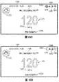
前述の段落のいずれかの装置はまた、本明細書の記載の中でも特に、本段落に記載される以下の特徴の、任意の組み合わせを含み得る。いくつかの実施例では、予想される第一の流量が第二の流体流路内の予想される第二の流量とは閾値量以上異なるように、第一の流体リークが流体流路内の第一の流量を修正する。いくつかの実施例では、コントローラは、複数の流体流路のうちの少なくとも一つにおける流量のグラフィック表示をディスプレイ上に提供するようにさらに構成される。いくつかの実施例では、流体流路内の流量のグラフィック表示は、ゲージを含む。 The apparatus of any of the preceding paragraphs may also include any combination of the following features described in this paragraph, among others described herein. In some embodiments, the first fluid leak is in the fluid flow path such that the expected first flow rate differs from the expected second flow rate in the second fluid flow path by a threshold amount or more. Modify the primary flow rate. In some examples, the controller is further configured to provide on the display a graphical representation of the flow rate in at least one of the plurality of fluid flow paths. In some examples, the graphical representation of the flow rate within the fluid flow path includes a gauge.
前述の段落のいずれかの装置はまた、本明細書の記載の中でも特に、本段落に記載される以下の特徴の、任意の組み合わせを含み得る。陰圧源はさらに、モータを含む真空ポンプを含む。コントローラは、モータの速度を測定することによって、流体流路内の流量を決定するようにさらに構成される。装置はさらに、モータの速度を測定するように構成されたタコメータを含む。コントローラは、第一の期間中に第一の複数のモータ速度を測定し、第一の複数のモータの速度を平均化するようにさらに構成される。いくつかの実施例では、モータ速度の平均は総流量を示す。装置はさらに、一つまたは複数の創傷から吸引された液体を回収するように構成されたキャニスタを含む。 The apparatus of any of the preceding paragraphs may also include any combination of the following features described in this paragraph, among others described herein. The negative pressure source further includes a vacuum pump including a motor. The controller is further configured to determine the flow rate within the fluid flow path by measuring the speed of the motor. The device also includes a tachometer configured to measure the speed of the motor. The controller is further configured to measure the first plurality of motor speeds during the first time period and average the speeds of the first plurality of motors. In some embodiments, the average motor speed is indicative of total flow. The device further includes a canister configured to collect fluid aspirated from one or more wounds.
前述の段落のいずれかの装置はまた、本明細書の記載の中でも特に、本段落に記載される以下の特徴の、任意の組み合わせを含み得る。装置はさらに、陰圧源を複数の流体流路に接続するように構成された装置を含む。装置は、接合部を介して陰圧取付部分に流体接続された、複数の被覆材導管取付け部分を含む。複数の被覆材導管取付部分は、第一の被覆材導管取付部分と、第二の被覆材導管取付部分とを含む。第一の被覆材導管取付部分は、接合部および接合部の遠位にある第一の入口から離れて延在する、第一のシャフトを含む。第一の入口は、第一の流体流路を陰圧源に流体接続するように構成される。第二の被覆材導管取付部分は、接合部および接合部の遠位にある第二の入口から離れて延在する、第二のシャフトを含む。第二の入口は、第二の流体流路を陰圧源に流体接続するように構成される。陰圧取付部分は、接合部および接合部の遠位にある第三の入口から離れて延在する、第三のシャフトを含む。第三の入口は、陰圧源に流体接続するように構成される。 The apparatus of any of the preceding paragraphs may also include any combination of the following features described in this paragraph, among others described herein. The device further includes a device configured to connect the negative pressure source to the plurality of fluid flow paths. The device includes a plurality of dressing conduit attachment portions fluidly connected to the negative pressure attachment portions via joints. The plurality of dressing conduit attachment portions includes a first dressing conduit attachment portion and a second dressing conduit attachment portion. The first cladding conduit attachment portion includes a first shaft extending away from the joint and a first inlet distal to the joint. The first inlet is configured to fluidly connect the first fluid flow path to the negative pressure source. The second cladding conduit attachment portion includes a second shaft extending away from the joint and a second inlet distal to the joint. The second inlet is configured to fluidly connect the second fluid flow path to the negative pressure source. The negative pressure attachment portion includes a third shaft extending away from the joint and a third inlet distal to the joint. A third inlet is configured to fluidly connect to a source of negative pressure.
前述の段落のいずれかの装置はまた、本明細書の記載の中でも特に、本段落に記載される以下の特徴の、任意の組み合わせを含み得る。装置はさらに、第三の創傷被覆材を、陰圧源と流体連通するように構成された第四の入口に流体接続するように構成された第三の流体流路を含む。第三の流体流路は、流体を第三の流体流路内に入るように構成された第三の流体リークを含む。第三の流体リークを介して第三の流体流路に入る流体の流れは、第一および第二の流体リークを介して第一および第二の流体流路に入る各流体の流れとは異なる。 The apparatus of any of the preceding paragraphs may also include any combination of the following features described in this paragraph, among others described herein. The device further includes a third fluid flow path configured to fluidly connect the third wound dressing to a fourth inlet configured to be in fluid communication with the negative pressure source. The third fluid flow path includes a third fluid leak configured to allow fluid to enter the third fluid flow path. A fluid flow entering the third fluid flow path through the third fluid leak is different than each fluid flow entering the first and second fluid flow paths through the first and second fluid leaks .
前述の段落の装置はまた、本明細書の記載の中でも特に、本段落に記載される以下の特徴の、任意の組み合わせを含み得る。複数の被覆材導管取付部分はさらに、接合部および接合部の遠位にある第四の入口から離れて延在する第四のシャフトを含む、第三の被覆材導管取付部分を含む。第四の入口は、第三の流体流路を陰圧源に流体接続するように構成される。コントローラは、本明細書に記述されるように、一つまたは複数のグラフィックユーザインターフェース(GUI)を生成するようにさらに構成される。 The apparatus of the preceding paragraphs may also include any combination of the following features described in this paragraph, among others described herein. The plurality of cladding conduit mounting portions further includes a third cladding conduit mounting portion including a fourth shaft extending away from the joint and a fourth inlet distal to the joint. A fourth inlet is configured to fluidly connect the third fluid flow path to the negative pressure source. The controller is further configured to generate one or more graphic user interfaces (GUIs) as described herein.
前述の段落のいずれかの装置を動作させる方法はまた、本明細書の記載の中でも特に、前述の特徴の、任意の組み合わせを含み得る。 A method of operating the apparatus of any of the preceding paragraphs may also include any combination of the aforementioned features, among others described herein.
いくつかの実施形態では、陰圧創傷療法装置を動作させる方法は、陰圧源を複数の創傷の上に配置されるように構成された複数の創傷被覆材に流体結合するように構成された複数の流体流路内の総流量を決定することを含む。総流量は、複数の流体流路と関連する複数の流量の集約に相当する。複数の流体流路は少なくとも、第一の創傷被覆材を圧力源と流体接続するように構成された第一の流体流路と、第二の創傷被覆材を陰圧源と流体接続するように構成された第二の流体流路とを含む。方法はさらに、総流量を監視することに応答して、少なくとも一つの動作状態の表示を提供することを含む。少なくとも一つの動作状態の表示は、総流量が、第一、第二、または第三の流れ閾値のいずれも満たさないと決定することに応答して、キャニスタフル状態が存在するという表示、または、複数の流体流路のそれぞれに閉塞状態が存在するという表示の少なくとも一つを提供することを含み得る。少なくとも一つの動作状態の表示は、総流量が第一の流れ閾値は満たすが、第二の流れ閾値は満たさないと決定することに応答して、第二の流体流路内に閉塞状態が存在するという表示を提供することを含み得る。少なくとも一つの動作状態の表示は、総流量が第二の流れ閾値は満たすが、第三の流れ閾値は満たさないと決定することに応答して、第一の流体流路内に閉塞状態が存在するという表示を提供することを含み得る。少なくとも一つの動作状態の表示は、総流量が第三の流れ閾値を満たすと決定することに応答して、通常動作状態が存在するという表示を提供することを含み得る。第三の流れ閾値は、第一および第二の流れ閾値よりも高い流れに一致することができ、第二の流れ閾値は、第一の流れ閾値よりも高い流れに一致することができる。方法は、陰圧創傷療法装置のコントローラによって実施され得る。 In some embodiments, a method of operating a negative pressure wound therapy device is configured to fluidly couple a negative pressure source to a plurality of wound dressings configured to be placed over a plurality of wounds. Determining a total flow rate in a plurality of fluid flow paths is included. A total flow rate corresponds to an aggregation of multiple flow rates associated with multiple fluid flow paths. The plurality of fluid flow paths includes at least a first fluid flow path configured to fluidly connect a first wound dressing with a pressure source and a second wound dressing to fluidly connect a negative pressure source. and a configured second fluid flow path. The method further includes providing an indication of at least one operating condition in response to monitoring the total flow rate. at least one operational condition indication is an indication that a canister full condition exists in response to determining that the total flow rate does not meet any of the first, second, or third flow thresholds; or Providing at least one indication that a blockage condition exists in each of the plurality of fluid flow paths. The at least one operating condition indication is in response to determining that the total flow rate meets the first flow threshold but does not meet the second flow threshold, wherein an occlusion condition exists in the second fluid flow path. providing an indication that the The at least one operating condition indication is that an occlusion condition exists in the first fluid flow path in response to determining that the total flow rate meets the second flow threshold but does not meet the third flow threshold. providing an indication that the Indicating at least one operating condition may include providing an indication that a normal operating condition exists in response to determining that the total flow rate meets the third flow threshold. A third flow threshold can correspond to a flow higher than the first and second flow thresholds, and the second flow threshold can correspond to a flow higher than the first flow threshold. The method may be performed by a controller of a negative pressure wound therapy device.
前述の段落の方法はまた、本明細書の記載の中でも特に、本段落に記載される以下の特徴の、任意の組み合わせを含み得る。第一の流れ閾値は、第一の流体流路内の予想される第一の流量に相当し、第二の流れ閾値は、第二の流体流路内の予想される第二の流量に相当する。第三の流れ閾値は、第一の流体流路内の予想される第一の流量と、第二の流体流路内の予想される第二の流量との集約に相当する。 The methods of the preceding paragraphs may also include any combination of the following features described in this paragraph, among others described herein. The first flow threshold corresponds to a first expected flow rate in the first fluid flow path, and the second flow threshold corresponds to a second expected flow rate in the second fluid flow path. do. The third flow threshold corresponds to the sum of the expected first flow rate in the first fluid flow path and the expected second flow rate in the second fluid flow path.
前述の段落のいずれかの方法はまた、本明細書の記載の中でも特に、本段落に記載される以下の特徴の、任意の組み合わせを含み得る。予想される第一の流量は、通常動作状態下の第一の流体経路内の流量に相当する。予想される第二の流量は、通常動作状態下の第二の流体経路内の流量に相当する。 The method of any of the preceding paragraphs can also include any combination of the following features described in this paragraph, among others described herein. The expected first flow rate corresponds to the flow rate in the first fluid path under normal operating conditions. The expected second flow rate corresponds to the flow rate in the second fluid path under normal operating conditions.
前述の段落のいずれかの方法はまた、本明細書の記載の中でも特に、本段落に記載される以下の特徴の、任意の組み合わせを含み得る。方法はさらに、陰圧源を動作させるモータの速度を測定することによって、総流量を決定することを含む。いくつかの実施例では、モータの速度を測定することは、第一の期間中に第一の複数のモータ速度を測定することと、第一の複数のモータ速度を平均化することとを含み得、平均は流量を示す。 The method of any of the preceding paragraphs may also include any combination of the following features described in this paragraph, among others described herein. The method further includes determining the total flow rate by measuring the speed of the motor that operates the negative pressure source. In some embodiments, measuring the speed of the motor includes measuring a first plurality of motor speeds during the first period of time and averaging the first plurality of motor speeds. and the average indicates the flow rate.
いくつかの実施形態では、陰圧創傷療法装置を動作させる方法は、陰圧源を複数の創傷の上に配置されるように構成された複数の創傷被覆材に流体結合するように構成された複数の流体流路内の総流量を決定することを含む。総流量は、複数の流体流路と関連する複数の流量の集約に相当する。複数の流体流路は少なくとも、第一の創傷被覆材を圧力源と流体接続するように構成された第一の流体流路と、第二の創傷被覆材を陰圧源と流体接続するように構成された第二の流体流路と、第三の創傷被覆材を陰圧源と流体接続するように構成された第三の流体流路とを含む。方法はさらに、総流量を監視することに応答して、少なくとも一つの動作状態の表示を提供することを含む。表示は、総流量が、第一、第二、第三、第四、第五、第六、第七、または第八の流れ閾値のいずれも満たさないと決定することに応答して、キャニスタフル状態が存在するという表示、または、複数の流体流路のそれぞれに閉塞状態が存在するという表示のうちの少なくとも一つを提供することによって、提供され得る。表示は、総流量が第一の流れ閾値は満たすが、第二の流れ閾値は満たさないと決定することに応答して、第二の流体流路および第三の流体流路に閉塞状態が存在するという表示を提供することによって、提供され得る。表示は、(a)総流量が第二の流れ閾値は満たすが、第三の閾値は満たさない、または、(b)総流量が第七の流れ閾値は満たすが、第八の流れ閾値は満たさないと決定することに応答して、異常状態が存在するという表示を提供することによって、提供され得る。表示は、総流量が第三の流れ閾値は満たすが、第四の流れ閾値は満たさないと決定することに応答して、第一の流体流路および第三の流体流路に閉塞状態が存在するという表示を提供することによって、提供され得る。表示は、総流量が第四の流れ閾値は満たすが、第五の流れ閾値は満たさないと決定することに応答して、第三の流体流路に閉塞状態が存在するという表示を提供することによって、提供され得る。表示は、総流量が第五の流れ閾値は満たすが、第六の流れ閾値は満たさないと決定することに応答して、第一の流体流路および第二の流体流路に閉塞状態が存在するという表示を提供することによって、提供され得る。表示は、総流量が第六の流れ閾値は満たすが、第七の流れ閾値は満たさないと決定することに応答して、第二の流体流路に閉塞状態が存在するという表示を提供することによって、提供され得る。表示は、総流量が第八の流れ閾値は満たすが、第九の流れ閾値は満たさないと決定することに応答して、第一の流体流路に閉塞状態が存在するという表示を提供することによって、提供され得る。表示は、総流量が第九の流れ閾値を満たすと決定することに応答して、通常動作状態が存在するという表示を提供することによって、提供され得る。第九から第一までの流れ閾値はそれぞれ、流れの降順レベルに対応する。方法は、陰圧創傷療法装置のコントローラによって実施される。 In some embodiments, a method of operating a negative pressure wound therapy device is configured to fluidly couple a negative pressure source to a plurality of wound dressings configured to be placed over a plurality of wounds. Determining a total flow rate in a plurality of fluid flow paths is included. A total flow rate corresponds to an aggregation of multiple flow rates associated with multiple fluid flow paths. The plurality of fluid flow paths includes at least a first fluid flow path configured to fluidly connect a first wound dressing with a pressure source and a second wound dressing to fluidly connect a negative pressure source. A configured second fluid flow path and a third fluid flow path configured to fluidly connect a third wound dressing with a negative pressure source. The method further includes providing an indication of at least one operating condition in response to monitoring the total flow rate. The display, in response to determining that the total flow rate does not meet any of the first, second, third, fourth, fifth, sixth, seventh, or eighth flow thresholds, canister full By providing at least one of an indication that a condition exists or an indication that a blockage condition exists in each of the plurality of fluid flow paths. The indication is that an occlusion condition exists in the second fluid flow path and the third fluid flow path in response to determining that the total flow rate meets the first flow threshold but does not meet the second flow threshold. can be provided by providing an indication that An indication is that (a) the total flow meets the second flow threshold but does not meet the third threshold, or (b) the total flow meets the seventh flow threshold but does not meet the eighth flow threshold. By providing an indication that an abnormal condition exists in response to determining that it does not. The indication is that an occlusion condition exists in the first fluid flow path and the third fluid flow path in response to determining that the total flow rate meets the third flow threshold but does not meet the fourth flow threshold. can be provided by providing an indication that The indication provides an indication that an occlusion condition exists in the third fluid flow path in response to determining that the total flow rate meets the fourth flow threshold but does not meet the fifth flow threshold. can be provided by The indication is that an occlusion condition exists in the first fluid flow path and the second fluid flow path in response to determining that the total flow rate meets the fifth flow threshold but does not meet the sixth flow threshold. can be provided by providing an indication that The indication provides an indication that an occlusion condition exists in the second fluid flow path in response to determining that the total flow rate meets the sixth flow threshold but does not meet the seventh flow threshold. can be provided by The indication provides an indication that an occlusion condition exists in the first fluid flow path in response to determining that the total flow rate meets the eighth flow threshold but does not meet the ninth flow threshold. can be provided by The indication may be provided by providing an indication that normal operating conditions exist in response to determining that the total flow rate meets the ninth flow threshold. Each of the ninth through first flow thresholds corresponds to a descending level of flow. The method is performed by a controller of a negative pressure wound therapy device.
前述の段落のいずれかの方法はまた、本明細書の記載の中でも特に、本段落に記載される以下の特徴の、任意の組み合わせを含み得る。第一の流れ閾値は、第一の流体流路内の予想される第一の流量に相当する。第三の流れ閾値は、第二の流体流路内の予想される第一の流量に相当する。第四の流れ閾値は、第一の流体流路内の予想される第一の流量と、第二の流体流路内の予想される第二の流量との集約に相当する。第五の流れ閾値は、第三の流体流路内の予想される第一の流量に相当する。第六の流れ閾値は、第一の流体流路内の予想される第一の流量と、第三の流体流路内の予想される第三の流量との集約に相当する。第八の流れ閾値は、第二の流体流路内の予想される第二の流量と、第三の流体流路内の予想される第三の流量との集約に相当する。第九の流れ閾値は、第一の流体流路内の予想される第一の流量と、第二の流体流路内の予想される第二の流量と、第三の流体流路内の予想される第三の流量との集約に相当する。 The method of any of the preceding paragraphs may also include any combination of the following features described in this paragraph, among others described herein. The first flow threshold corresponds to an expected first flow rate in the first fluid flow path. A third flow threshold corresponds to the expected first flow rate in the second fluid flow path. A fourth flow threshold corresponds to the sum of a first expected flow rate in the first fluid flow path and a second expected flow rate in the second fluid flow path. A fifth flow threshold corresponds to the expected first flow rate in the third fluid flow path. The sixth flow threshold corresponds to the sum of the expected first flow rate in the first fluid flow path and the expected third flow rate in the third fluid flow path. The eighth flow threshold corresponds to the sum of the expected second flow rate in the second fluid flow path and the expected third flow rate in the third fluid flow path. A ninth flow threshold is an expected first flow rate in the first fluid flow path, an expected second flow rate in the second fluid flow path, and an expected second flow rate in the third fluid flow path. corresponds to aggregation with the third flow rate
前述の段落のいずれかの方法はまた、本明細書の記載の中でも特に、本段落に記載される以下の特徴の、任意の組み合わせを含み得る。予想される第一の流量は、通常動作状態下の第一の流体経路内の流量に相当する。予想される第二の流量は、通常動作状態下の第二の流体経路内の流量に相当する。予想される第三の流量は、通常動作状態下の第三の流体経路内の流量に相当する。 The method of any of the preceding paragraphs can also include any combination of the following features described in this paragraph, among others described herein. The expected first flow rate corresponds to the flow rate in the first fluid path under normal operating conditions. The expected second flow rate corresponds to the flow rate in the second fluid path under normal operating conditions. The expected third flow rate corresponds to the flow rate in the third fluid path under normal operating conditions.
前述の段落のいずれかの方法はまた、本明細書の記載の中でも特に、本段落に記載される以下の特徴の、任意の組み合わせを含み得る。総流量を決定することは、陰圧源を動作させるモータの速度を測定することを含む。速度を測定することは、第一の期間中に第一の複数のモータ速度を測定し、第一の複数のモータ速度を平均化することを含み、平均は流量を示す。本方法はまた、本明細書に記載されるように、一つまたは複数のグラフィックユーザインターフェース(GUI)を生成することを含み得る。 The method of any of the preceding paragraphs can also include any combination of the following features described in this paragraph, among others described herein. Determining the total flow rate includes measuring the speed of the motor that operates the negative pressure source. Measuring the velocity includes measuring a first plurality of motor velocities during the first period of time and averaging the first plurality of motor velocities, the average being indicative of the flow rate. The method may also include generating one or more graphic user interfaces (GUIs) as described herein.
以下に開示されるポンプの実施形態のいずれも、および、陰圧創傷療法の実施形態のいずれも含むがこれらに限定しないものとし、本出願に開示された配置または実施形態のいずれかの特徴、構成要素、または詳細のいずれも、新しい配置および実施形態を形成するよう本明細書に開示された配置または実施形態のいずれかのその他の特徴、構成要素、または詳細のいずれとも相互に組み合わせ可能である。 Features of any of the arrangements or embodiments disclosed in this application, including but not limited to any of the pump embodiments disclosed below and any of the negative pressure wound therapy embodiments; Any element or detail can be combined with each other with any other feature, element or detail of any of the arrangements or embodiments disclosed herein to form new arrangements and embodiments. be.
本開示の実施形態は、単に例示として、添付図面を参照して、ここで以下に記載される。 Embodiments of the present disclosure will now be described, by way of example only, with reference to the accompanying drawings.
概要
本明細書に開示された実施形態は、減圧により創傷を治療するシステムおよび方法に関する。本明細書に使用する通り、-XmmHgなど、減圧または陰圧レベルは、760mmHg(または1atm、29.93inHg、101.325kPa、14.696psiなど)に相当し得る、平常の周囲気圧に対する圧力レベルを表す。したがって、-XmmHgの陰圧値は、760mmHgよりもXmmHg低い絶対圧力、または、言い換えれば、(760-X)mmHgの絶対圧力を反映する。さらに、XmmHgよりも「低い」または「小さい」陰圧は、大気圧により近い圧力に相当する(例えば、-40mmHgは-60mmHgよりも低くなる)。-XmmHgよりも「高い」または「大きい」陰圧は、大気圧からより遠い圧力に相当する(例えば、-80mmHgは-60mmHgよりも高くなる)。いくつかの実施形態では、局所的な周囲気圧は基準点として使用され、そのような局所的な気圧は、必ずしも、例えば、760mmHgでなくてもよい。
SUMMARY Embodiments disclosed herein relate to systems and methods for treating wounds with reduced pressure. As used herein, a reduced pressure or negative pressure level, such as −X mmHg, refers to a pressure level relative to normal ambient pressure, which can correspond to 760 mmHg (or 1 atm, 29.93 inHg, 101.325 kPa, 14.696 psi, etc.). show. Thus, a negative pressure value of −X mmHg reflects an absolute pressure of X mmHg less than 760 mmHg, or in other words, an absolute pressure of (760−X) mmHg. Further, negative pressures “lower” or “less than” X mmHg correspond to pressures closer to atmospheric pressure (eg, −40 mmHg becomes less than −60 mmHg). A negative pressure that is “higher” or “greater” than −X mmHg corresponds to a pressure farther from atmospheric pressure (eg, −80 mmHg is greater than −60 mmHg). In some embodiments, local ambient air pressure is used as a reference point, and such local air pressure need not be, for example, 760 mmHg.
本開示の実施形態は、概して、局所陰圧(TNP)または減圧療法システムで使用するように適用可能である。手短に言えば、陰圧創傷療法は、組織の浮腫を減少させ、血流および顆粒組織形成を促し、または、過度の滲出液を除去することによって、「治癒が困難な」創傷の多くの形態を閉鎖および治癒するのを支援し、細菌負荷(および、それゆえ感染リスク)を低減することができる。加えて、治療によって、創傷の不安を減らすことが可能になり、より早期の治癒に導く。TNPシステムはまた、流体を除去することによって、外科的に閉じられた創傷の治癒を支援することができる。いくつかの実施形態では、TNP療法は、閉鎖の反対位置の組織を安定化するのに役立つ。TNP治療のさらなる有益な使用は、過剰な流体を除去することが重要であり、組織の生存度を確保するために移植片が組織に近接していることが求められる、移植片及びフラップにおいて見出すことができる。 Embodiments of the present disclosure are generally applicable for use with local negative pressure (TNP) or reduced pressure therapy systems. Briefly, negative pressure wound therapy reduces tissue edema, promotes blood flow and granulation tissue formation, or removes excess exudate, thereby reducing many forms of "hard-to-heal" wounds. to close and heal, reducing the bacterial load (and therefore the risk of infection). In addition, treatment can reduce wound anxiety, leading to faster healing. The TNP system can also assist in the healing of surgically closed wounds by removing fluid. In some embodiments, TNP therapy helps stabilize tissue contralateral to closure. A further beneficial use of TNP therapy is found in grafts and flaps, where removal of excess fluid is critical and close proximity of the graft to the tissue is required to ensure tissue viability. be able to.
陰圧システム
図1は、創傷くぼみ110であって、創傷カバー120によって封止された創傷くぼみの内部に置かれた創傷充填材130を含む、陰性のまたは低減された圧力創傷治療(またはTNP)システム100の実施形態を示す。創傷カバー120と組み合わされた創傷充填材130は、創傷被覆材として言及され得る。単一または複数の内腔管または導管といった流路140は、例えばポンプアセンブリ150といった、減圧を供給するように構成された陰圧創傷療法装置を有する創傷カバー120に接続される。創傷カバー120は、創傷くぼみ110に流体連通することができる。図1に示される実施形態のような本明細書で開示されるいくつかのシステムの実施形態において、ポンプアセンブリは、キャニスタレスポンプアセンブリ(滲出液が、創傷被覆材に集められる、または別の位置に集めるために管140を介して運ばれることを意味する)であることができる。しかし、本明細書で開示されるいくつかのポンプアセンブリの実施形態は、キャニスタを含むまたは支持するように構成され得る。追加的に、本明細書で開示されるいくつかのシステムの実施形態において、いくつかのポンプアセンブリの実施形態は、被覆材に取付けられ、もしくは被覆材によって支持され、または被覆材に隣接することができる。創傷充填材130は、親水性または疎水性発泡体、ガーゼ、膨張可能なバッグ等の任意の好適なタイプであってもよい。創傷充填材130は、それが実質的にくぼみを充填するように、創傷くぼみ110に適合することができる。創傷カバー120は、創傷くぼみ110を覆う実質的に流体不浸透性のシールを提供することができる。創傷カバー120は、上面および下面を有することができ、下面は、創傷くぼみ110を粘着的に(または任意のその他の適切な手法において)封止する。本明細書で開示される導管140もしくは内腔またはいくつかのその他の導管もしくは内腔は、ポリウレタン、PVC、ナイロン、ポリエチレン、シリコーン、または任意のその他の適切な材料から形成され得る。
Negative Pressure System FIG. 1 depicts a negative or reduced pressure wound therapy (or TNP) wound
創傷カバー120の一部の実施形態は、導管140の端を受けるように構成される、ポート(図示せず)を有し得る。その他の実施形態では、導管140は、別のやり方では、創傷くぼみ内に所望のレベルの減圧圧力を維持するように、減圧圧力を創傷くぼみ110に供給するために創傷カバー120を通り抜けるまたはその下にあることができる。導管140は、ポンプアセンブリ150によって提供される減圧圧力を創傷くぼみ110に供給するように、ポンプアセンブリ150と創傷カバー120との間に少なくとも実質的に密封された流体流路を提供するように構成される、任意の好適な物品であることができる。
Some embodiments of wound covering 120 may have a port (not shown) configured to receive the end of
創傷カバー120および創傷充填材130は、単一な物品または一体型の単一なユニットとして提供され得る。いくつかの実施形態では、創傷充填材が提供されずに、創傷カバーがそれ自体として創傷被覆材とみなされてもよい。ついで、創傷被覆材は、導管140を介して、ポンプアセンブリ150といった陰圧源に接続され得る。ポンプアセンブリ150は小形化され、持ち運び可能とすることができるが、より大きな従来のそのようなポンプがまた使用されてもよい。
Wound covering 120 and wound
創傷カバー120は、治療されることになる創傷部位の上に置かれ得る。創傷カバー120は、創傷部位を覆う実質的に密封されたくぼみまたはエンクロージャを形成することができる。いくつかの実施形態では、創傷カバー120は、過剰流体の蒸発を可能にする高い水蒸気浸透性を持つフィルムを有するように構成されることができ、また創傷滲出液を安全に吸収するためにその中に含まれる超吸収性材料を有することができる。本明細書全体を通して、創傷に関して言及することが理解されるであろう。この点において、創傷という用語は広く解釈され、皮膚が断裂、切開、もしくは穿孔される、または外傷によって挫傷が引き起こされる開放創および閉鎖創、あるいは患者の皮膚における任意の他の表面もしくは他の状態または欠陥、あるいは減圧治療によって利益を得る他のものを包含することを理解されたい。よって、創傷は、流体が生成されることもされないこともある、組織の任意の損傷領域として広く定義される。そのような創傷の例としては、急性創傷、慢性創傷、外科切開およびその他の切開、亜急性創傷および裂開創傷、外傷性創傷、フラップおよび皮膚移植片、裂傷、擦傷、挫傷、火傷、糖尿病性潰瘍、褥瘡性潰瘍、ストーマ、外科創傷、外傷性潰瘍および静脈性潰瘍などが挙げられるが、それらに限定されない。本明細書に記載のTNPシステムの構成要素は、少量の創傷滲出液を滲出する切開創傷に特に適し得る。 A wound covering 120 may be placed over the wound site to be treated. The wound covering 120 can form a substantially sealed recess or enclosure over the wound site. In some embodiments, the wound covering 120 can be configured with a film that has a high water vapor permeability to allow evaporation of excess fluid, and can also be configured to absorb wound exudate safely. It can have superabsorbent materials contained therein. It will be appreciated that throughout this specification reference is made to wounds. In this respect, the term wound is interpreted broadly to include open and closed wounds in which the skin is torn, incised, or perforated, or in which trauma causes bruising, or any other surface or other condition in a patient's skin. or defects, or anything else that would benefit from reduced pressure treatment. A wound is thus broadly defined as any damaged area of tissue that may or may not produce fluid. Examples of such wounds include acute wounds, chronic wounds, surgical and other incisions, subacute and dehiscence wounds, traumatic wounds, flaps and skin grafts, lacerations, abrasions, contusions, burns, diabetic wounds. Ulcers, decubitus ulcers, stomas, surgical wounds, traumatic ulcers, venous ulcers and the like include, but are not limited to. Components of the TNP system described herein may be particularly suitable for incisional wounds that exude small amounts of wound exudate.
システムの一部の実施形態は、滲出液キャニスタを使用することなく動作するように設計される。いくつかの実施形態は、滲出液キャニスタを支持するように構成され得る。いくつかの実施形態では、管材料140がポンプアセンブリ150から迅速にかつ容易に取り除かれ得るようにポンプアセンブリ150および管材料140を構成することは、必要な場合、被覆材またはポンプを交換するプロセスを容易にする、または改善することができる。本明細書で開示されるいくつかのポンプの実施形態は、管材料とポンプとの間の任意の好適な接続を有するように構成され得る。
Some embodiments of the system are designed to operate without the use of exudate canisters. Some embodiments may be configured to support exudate canisters. In some embodiments, configuring the
いくつかの実施形態では、ポンプ組立品150は、およそ-80mmHg、または約-20mmHg~-200mmHgの陰圧を供給するように構成され得る。これらの圧力は、正常な大気圧に対する相対値であり、つまり、-200mmHgは、実際に則した用語において、約560mmHgであり得ることに留意されたい。圧力範囲は約-40mmHgから-150mmHgの間であり得る。代替として、最高-75mmHg、最高-80mmHgまたは-80mmHgを超える圧力範囲が使用され得る。また、-75mmHgを下回る圧力範囲が使用され得る。別の方法として、およそ-100mmHgまたはさらに150mmHgより上の圧力範囲が、ポンプアセンブリ150により供給され得る。
In some embodiments,
一部の実施形態では、ポンプアセンブリ150は、連続的または断続的な陰圧療法を提供するように構成される。連続療法は、-25mmHgより上、-25mmHg、-40mmHg、-50mmHg、-60mmHg、-70mmHg、-80mmHg、-90mmHg、-100mmHg、-120mmHg、-140mmHg、-160mmHg、-180mmHg、-200mmHg、または-200mmHgより下で送達され得る。断続的な療法は、低い陰圧設定値と高い陰圧設定値との間で送達され得る。低い設定値は、0mmHgより上、0mmHg、-25mmHg、-40mmHg、-50mmHg、-60mmHg、-70mmHg、-80mmHg、-90mmHg、-100mmHg、-120mmHg、-140mmHg、-160mmHg、-180mmHg、または-180mmHgより下に設定され得る。高い設定値は、-25mmHgより上、-40mmHg、-50mmHg、-60mmHg、-70mmHg、-80mmHg、-90mmHg、-100mmHg、-120mmHg、-140mmHg、-160mmHg、-180mmHg、-200mmHg、または-200mmHgより下に設定できる。断続的治療中、低い設定値での陰圧を第一の継続時間にわたって送達することができ、また第一の継続時間の終了時には、高い設定値での陰圧を第二の継続時間にわたって送達することができる。第二の継続時間の終了時には、低い設定値での陰圧を送達することができる。第一および第二の継続時間は、同一の値または異なる値とすることができる。第一および第二の継続時間は、以下の範囲から選択することができる:2分より短い、2分、3分、4分、6分、8分、10分、または10分よりも長い。いくつかの実施形態では、低い設定値と高い設定値との間の切り替えを行うことは、ステップ波形、矩形波、正弦波形等にしたがって実施することができる。
In some embodiments,
いくつかの実施形態では、TNPシステム100は、ポンプアセンブリ150に接続された複数の創傷被覆材を含み得る。ポンプアセンブリ150を用いた複数の創傷被覆材を有するTNPシステムの性能および創傷治癒能力(流体管理、等)は、単一ポンプのセットアップを伴う標準的な単一創傷被覆材のそれと同等であるか、または超えることができる。
In some embodiments,
動作時に、創傷充填材130は、創傷くぼみ110内に挿入され、創傷カバー120は、創傷くぼみ110を密封するように配置される。ポンプアセンブリ150は、創傷充填材130を介して創傷くぼみ110に送られる陰圧源を創傷カバー120に提供する。流体(例えば、創傷滲出液)は、導管140を通して引き出され、キャニスタ内に貯蔵され得る。いくつかの実施形態では、流体は、創傷充填材130または一つまたは複数の吸収性の層(図示せず)によって吸収される。
In operation, wound
本出願のポンプ組立品およびその他の実施形態とともに利用され得る創傷被覆材は、Smith&Nephewから入手可能なRenasys-F、Renasys-G、Renasys ABおよびPico被覆材を含む。本明細書に記載される被覆材のいずれも、被覆材とポンプアセンブリとの間の、Smith and NephewのRenasys Soft Portコネクタまたはインターフェースとともに使用できる。例えば、Renasys Soft Portコネクタは、流路140内に配置され、創傷被覆材のポートとして機能することができる。その他の実施形態では、その他の好適な創傷被覆材が利用され得る。
Wound dressings that may be utilized with pump assemblies and other embodiments of the present application include Renasys-F, Renasys-G, Renasys AB and Pico dressings available from Smith & Nephew. Any of the dressings described herein can be used with the Smith and Nephew Renasys Soft Port connector or interface between the dressing and the pump assembly. For example, a Renasys Soft Port connector can be placed in the
ポンプアセンブリおよびキャニスタ
図2は、いくつかの実施形態によるポンプアセンブリ230およびキャニスタ220の前面図200を示す。示されるように、ポンプアセンブリ230とキャニスタが接続され、それによって、TNP装置またはシステムを形成する。ポンプアセンブリ230は、アラームを示すように構成される視覚的インジケータ202およびTNPシステムの状態を示すように構成される視覚的インジケータ204などの一つまたは複数のインジケータを含む。インジケータ202および204は、通常のまたは適切な動作状態、ポンプ停止、ポンプまたは停電に供給される電力、創傷カバーまたは流れ経路内の漏れの検出、吸引閉塞、無流状態、キャニスタフル状態、またはその他の同様のまたは好適な状態またはそれらの組み合わせをユーザに警告することを含む、システムの様々な動作状態または停止状態を患者または医療提供者などのユーザに警告するように構成され得る。ポンプアセンブリ230は、追加のインジケータを含むことができる。ポンプアセンブリは、単一のインジケータまたは複数のインジケータを使用することができる。任意の好適なインジケータは、例えば、視覚的な、聴覚的な、触覚的なインジケータ等として使用され得る。インジケータ202は、例えば、キャニスタフル、低電力、導管140の接続解除、創傷シール120におけるシール破壊等の警告状態を示すように構成され得る。インジケータ202は、ユーザの注意を引くために赤のせん光を表示するように構成され得る。インジケータ204は、例えば、療法送達は正常である、漏れが検出された、等のTNPシステムの状態を示すように構成され得る。インジケータ204は、例えば、緑、黄などの一つまたは複数の異なる色の光を表示するように構成され得る。例えば、緑色の光は、TNPシステムが適切に動作している時に放出されてもよく、黄色の光は、警告を示すために放出され得る。
Pump Assembly and Canister FIG. 2 shows a
ポンプアセンブリ230は、ポンプアセンブリの場合に形成されるくぼみ208に取り付けられる、ディスプレイまたはスクリーン206を含む。ディスプレイ206は、タッチスクリーンディスプレイであってもよい。ディスプレイ206は、取扱い説明ビデオなどの視聴覚(AV)コンテンツの再生を支持することができる。本明細書で説明されるように、ディスプレイ206は、いくつかのスクリーンまたはグラフィックユーザインターフェース(GUI)がTNPシステムの動作を構成する、制御する、および監視するように構成され得る。ポンプアセンブリ230は、ポンプアセンブリの場合に形成されるグリップ部分210を含む。グリップ部分210は、例えば、キャニスタ220の取り外しの間などに、ユーザがポンプアセンブリ230を保持することを支持するように構成され得る。キャニスタ220は、例えば、キャニスタ220が流体で充填された時などに、別のキャニスタと取り替えられ得る。
Pump assembly 230 includes a display or
ポンプアセンブリ230は、ユーザがTNPシステムの動作を操作し、および監視することを可能にするように構成される、一つまたは複数のキーまたはボタン212を含む。図示されるように、ボタン212a、212b、および212cが含まれる。ボタン212aは、ポンプアセンブリ230の電源を入れる/切るための電源ボタンとして構成され得る。ボタン212bは、陰圧療法の供給のためのプレイ/ポーズボタンとして構成され得る。例えば、ボタン212bを押すことにより、療法を開始することができ、その後ボタン212bを押すことにより、療法を停止または終了することができる。ボタン212cは、ディスプレイ206またはボタン212をロックするように構成され得る。例えば、ボタン212cは、ユーザが故意でなく療法の供給を変えることがないように押され得る。ボタン212cは、制御をアンロックするために押下され得る。その他の実施形態では、追加的なボタンが、用いられてもよく、または示したボタン212a、212bまたは212cのうち一つまたは複数が、省かれてもよい。複数のキーの押下または連続的なキーの押下は、ポンプアセンブリ230を動作させるために使用され得る。
Pump assembly 230 includes one or more keys or
ポンプアセンブリ230は、カバーに形成される一つまたは複数のラッチ凹部222を含む。例示的実施形態では、二つのラッチ凹部222は、ポンプアセンブリ230の側部に形成され得る。ラッチ凹部222は、一つまたは複数のキャニスタラッチ221を使用してキャニスタ220の取付けおよび分離を可能にするように構成され得る。ポンプアセンブリ230は、創傷くぼみ110から取り除かれる空気が漏れ出ることを可能にするための空気出口224を含む。ポンプアセンブリに入る空気は、抗菌フィルタなどの一つまたは複数の適切なフィルタを通り抜けることができる。これは、ポンプアセンブリの再利用性を維持することができる。ポンプアセンブリ230は、ポンプアセンブリ230に携帯ストラップを接続するための、または受け台を取付けるための一つまたは複数のストラップ取付け部226を含む。例示的実施形態では、二つのストラップ取付け部226は、ポンプアセンブリ230の側部に形成され得る。いくつかの実施形態では、種々な特徴は省かれ、または種々の追加的な特徴がポンプアセンブリ230に加えられる。
Pump assembly 230 includes one or more latch recesses 222 formed in the cover. In an exemplary embodiment, two
キャニスタ220は、創傷くぼみ110から取り除かれる流体(例えば、滲出液)を保持するように構成される。キャニスタ220は、キャニスタをポンプアセンブリ230に取付けるための一つまたは複数のラッチ221を含む。例示的実施形態では、キャニスタ220は、キャニスタの側部に二つのラッチ221を含む。キャニスタ220の外部は、キャニスタが実質的に不透明であり、またキャニスタの中身が平面視で実質的に隠されるように、つや消しプラスチックから形成され得る。キャニスタ220は、キャニスタの場合に形成されるグリップ部分214を含む。グリップ部分214は、例えば、装置230からのキャニスタの取り外しの間などに、ユーザがポンプアセンブリ220を保持することを可能にするように構成され得る。キャニスタ220は、実質的に透明な窓216を含み、それはまた、量の目盛りを含むことができる。例えば、示される300mLのキャニスタ220は、50mL、100mL、150mL、200mL、250mLおよび300mLの目盛りを含む。キャニスタのその他の実施形態は、異なる量の流体を保持することができ、異なる目盛り尺度を含むことができる。例えば、キャニスタは、800mLのキャニスタであることができる。キャニスタ220は、導管140に接続するための管状のチャネル218を含む。いくつかの実施形態では、グリップ部分214などのこれらの特徴のうちの一つまたは複数が省かれ、または種々の追加的な特徴がキャニスタ220に加えられる。いくつかの開示されるキャニスタは、凝固剤を含んでもよく、または凝固剤を省いてもよい。
Canister 220 is configured to hold fluid (eg, exudate) that is removed from
電子機器およびソフトウェア
図3は、いくつかの実施形態による、ポンプアセンブリ230などの、ポンプアセンブリの電気的構成要素概略図300を示す。電気的構成要素は、ユーザ入力を受け入れ、ユーザに出力を提供し、ポンプアセンブリおよびTNPシステムを操作し、ネットワーク接続を提供するように動作することができる。電気的構成要素は、一つまたは複数のプリント回路基板(PCB)上に取付けることができる。図示されるように、ポンプアセンブリは複数のプロセッサを含み得る。様々なタスクを様々なプロセッサに配分する、または、割り当てるために、複数のプロセッサを利用することが有利であり得る。第一のプロセッサは、ユーザ活動に関与することができ、第二のプロセッサは、ポンプを制御することに関与することができる。このように、ポンプを制御する活動は、より高いレベルの応答性を必要とする場合(より高いリスクレベルに対応する)があるが、専用プロセッサに任せることができ、それによって、ユーザとのやりとりのため、完了により時間がかかる場合があるユーザインターフェースタスクに中断されなくなる。
Electronics and Software FIG. 3 shows an
ポンプアセンブリは、ユーザ入力を受け入れ、ユーザに出力を提供するための、ディスプレイ206、ボタン212などの一つまたは複数の構成要素を操作するように構成されたユーザインターフェースプロセッサまたはコントローラ310を含み得る。ポンプアセンブリへの入力およびポンプアセンブリからの出力は、入力/出力(I/O)モジュール320によって制御できる。例えば、I/Oモジュールは、シリアル、パラレル、ハイブリッドポートなどの一つまたは複数のポートからデータを受信し得る。プロセッサ310はまた、データを受信し、一つまたは複数のUSBポート、SDポート、コンパクトディスク(CD)ドライブ、DVDドライブ、FireWireポート、Thunderboltポート、PCI Expressポートなどの一つまたは複数の拡張モジュール360にデータを提供する。プロセッサ310は、他のコントローラまたはプロセッサとともに、プロセッサ310の内部または外部にあり得る、一つまたは複数のメモリモジュール350にデータを保存する。RAM、ROM、磁気メモリ、固体メモリ、磁気抵抗ランダムアクセスメモリ(MRAM)などの揮発性または不揮発性メモリを含む任意の適切なタイプのメモリを使用し得る。
The pump assembly may include a user interface processor or
いくつかの実施形態では、プロセッサ310は、低電力プロセッサなどの汎用コントローラとすることができる。他の実施形態では、プロセッサ310はアプリケーションに特化したプロセッサであり得る。プロセッサ310は、ポンプアセンブリの電子アーキテクチャ内の「中央」プロセッサとして構成され得、プロセッサ310は、ポンプ制御プロセッサ370、通信プロセッサ330、および一つまたは複数の追加的プロセッサ380(例えば、ディスプレイ206を制御するためのプロセッサ、ボタン212を制御するためのプロセッサ、など)などの他のプロセッサの動作を連携し得る。プロセッサ310は、Linux(登録商標)、Windows CE、VxWorksなどの適切なオペレーティングシステムを実行し得る。
In some embodiments,
ポンプ制御プロセッサ370は、陰圧源またはポンプ390の動作を制御するように構成され得る。ポンプ390は、膜ポンプ、蠕動ポンプ、回転ポンプ、回転ベーンポンプ、スクロールポンプ、ねじポンプ、液封式ポンプ、圧電気変換器によって操作されるポンプ(例えば、膜ポンプ)、ボイスコイルポンプなどの適切なポンプとし得る。ポンプ制御プロセッサ370は、一つまたは複数の圧力センサから受信したデータを使用して、流体流路内の圧力を測定し、流体流量を計算し、ポンプを制御し得る。ポンプ制御プロセッサ370は、所望のレベルの陰圧が創傷くぼみ110内で達成されるように、ポンプモータといったアクチュエータを制御し得る。所望のレベルの陰圧は、圧力設定またはユーザによって選択され得る。さまざまな実施形態では、ポンプ制御プロセッサ370は、パルス幅変調(PWM)を使用してポンプアクチュエータ(例えば、ポンプモータ)を制御する。ポンプアクチュエータを駆動するための制御信号は、0~100%のデューティサイクルPWM信号とし得る。ポンプ制御プロセッサ370は、流量計算を実行し、流路内の様々な条件を検出し得る。ポンプ制御プロセッサ370は、プロセッサ310に情報を伝達し得る。ポンプ制御プロセッサ370は、内部メモリを含むか、または、メモリ350を利用することができる。ポンプ制御プロセッサ370は、低電力プロセッサであってもよい。
通信プロセッサ330は、有線または無線接続を提供するように構成され得る。通信プロセッサ330は、データを送受信するために一つまたは複数のアンテナ340を利用し得る。通信プロセッサ330は、以下のタイプの接続のうちの一つまたは複数を提供することができる:全地球測位システム(GPS)技術、セルラー接続(2G、3G、LTE、4G)、Wifi接続、インターネット接続など。接続は、ポンプアセンブリ位置トラッキング、資産管理、コンプライアンス監視、遠隔選択、ログ、アラーム、その他の運転データのアップロード、治療設定の調整、ソフトウェア、またはファームウェアのアップグレードなど、様々な活動に使用し得る。通信プロセッサ330は、GPS/セルラー二つの機能を提供できる。セルラー機能は、例えば、3G機能であり得る。このような場合、GPSモジュールが大気条件、建物または地形の干渉、衛星ジオメトリなどの様々な要因により衛星接続を確立できない場合、装置の位置は、携帯電話認証、三角測量、フォワードリンクタイミングを使用することなどによる、3Gネットワーク接続を使用して決定できる。ポンプアセンブリはSIMカードを含み得、SIMベースの位置情報を取得し得る。
通信プロセッサ330は、プロセッサ310に情報を伝達し得る。通信プロセッサ330は、内部メモリを含むか、または、メモリ350を利用することができる。通信プロセッサ330は、低電力プロセッサであり得る。
いくつかの実施形態では、ポンプアセンブリは、位置決めデータ、療法パラメータ、ログ、デバイスデータなどのうちの一つまたは複数といった、様々なデータを追跡し、保存し得る。ポンプアセンブリは、療法およびその他の動作データを追跡およびログできる。データは、例えば、メモリ350内で保存され得る。
In some embodiments, the pump assembly may track and store various data such as one or more of positioning data, therapy parameters, logs, device data, and the like. The pump assembly can track and log therapy and other operational data. The data may be stored in
いくつかの実施形態では、通信プロセッサ330によって提供される接続を使用して、装置は、ポンプ組立品によって保存され、維持され、または追跡された任意のデータをアップロードできる。例えば、療法期間といった、療法送達情報を含む活動ログ、アラームタイプや発生時刻を含むアラームログ、内部エラー情報や送信エラー等を含むエラーログ、時間毎、日毎等で演算され得る療法期間情報、特定の療法プログラムを最初に適用してからの療法期間を含む療法合計時間、生涯の療法情報、シリアル番号やソフトウェアバージョン、電池レベル等といった装置情報、装置位置情報、患者情報、等の情報を、リモートコンピュータまたはサーバにアップロードすることができる。装置はまた、治療法選択およびパラメータ、ファームウェアおよびソフトウェアパッチおよびアップグレードなど、様々な運転データをダウンロードし得る。ポンプアセンブリは、一つまたは複数のブラウザプログラム、メールプログラム、アプリケーションソフトウェア(例えば、アプリケーション)等を使用して、インターネット閲覧機能を提供することができる。
In some embodiments, using the connection provided by
いくつかの実施形態では、通信プロセッサ330は、ポンプアセンブリのハウジングの位置といった、ポンプアセンブリの位置を、ポンプアセンブリに近接する(例えば、10メートル以内、20メートル以内、または50メートル以内、等)その他の装置に通信するために、アンテナ340を使用することができる。通信プロセッサ330は、実装に応じて他の装置と一方向または双方向の通信を実行できる。通信プロセッサ330によって送信される通信は、ポンプアセンブリの近傍にある一つまたは複数の他のポンプアセンブリに対してポンプアセンブリを一意的に識別するための情報を識別することを含み得る。例えば、情報を識別することは、シリアル番号、またはシリアル番号に由来する値を含むことができる。通信プロセッサ330によって送信された通信の信号強度が、制御されて(例えば、一定または実質的に一定のレベルで維持されて)、別の装置が、装置とポンプアセンブリとの間の距離といった、ポンプアセンブリまでの距離を決定することができる。
In some embodiments, the
いくつかの実施形態では、通信プロセッサ330は、通信プロセッサ330自体がポンプアセンブリから他の装置への距離を決定できるように、ポンプアセンブリの近傍にある他の装置と通信できる。このような実施形態では、通信プロセッサ330は、ポンプアセンブリから他の装置までの距離、または、経時的な距離変化の表示を記録し、保存することができ、通信プロセッサ330はその後、この情報を他の装置に提供することができる。例えば、通信プロセッサ330は、ポンプアセンブリが装置の被覆領域から取り外される時間を決定し、その後、被覆領域に戻される際に、この時間を装置に報告することができる。
In some embodiments,
複数の被覆材陰創傷治療
図4Aおよび図4Bは、いくつかの実施形態による、陰圧創傷療法システム400を示す。システム400a、400b(合わせて400)は、ポンプアセンブリ、または、陰圧を供給できる陰圧ユニット434を含み得る。いくつかの実施形態では、陰圧ユニット434は、図2に図示するものと同じである。陰圧ユニット434は、一つまたは複数の創傷に陰圧を供給するように、一つまたは複数の創傷被覆材406a、406b(合わせて406と称される)との流体接続にあり得る。いくつかの実施形態では、創傷被覆材406と陰圧ユニット434との間の流体接続は、流体流路(例えば、陰圧流を介して創傷から吸引される流体の経路)と称される。例えば、第一の流体流路は、陰圧ユニット434から第一の創傷被覆材406aへの流体接続を提供する構成要素を含み得る。非限定的な例として、第一の流体流路は、創傷被覆材406aから陰圧ユニット434までの経路、または、第一の創傷被覆材406aから陰圧ユニット434と流体接続にある分岐取付部444の入口までの経路を含み得る。図示したように、システム400は、複数のスミス アンド ネフューのRenasysソフトポートコネクタを介して、陰圧ユニット434と流体接続にある複数の創傷被覆材(および対応する流体流路)を含み得る。創傷被覆材および流体流路はそれぞれ、システム内の別の創傷被覆材または流体流路の特徴または要素と一致するか、または、それらに類似した様々な特徴または要素を含み得る。参照しやすいように、一つまたは複数の対応する特徴または要素(例えば、Renasysソフトポートコネクタのブリッジ402aおよびブリッジ402b)は、対応するアルファベットなしの参照番号を使用して集合的に称され得る。例えば、ブリッジ402aおよびブリッジ402bは、ブリッジ402と集合的に称され得る。しかしながら、いくつかの実施形態では、集合的に称された要素は同一ではなく、異なる特徴または属性を有することができることに留意されたい。
Multiple Dressing Negative Wound Treatment FIGS. 4A and 4B illustrate a negative pressure wound therapy system 400, according to some embodiments.
図4Aを参照すると、システム400aは、近位端403および遠位端405を有するブリッジ402と、可撓性の吸引インターフェースまたはアダプタを形成するブリッジ402の遠位端405にあるアプリケータ420とを含むRenasysソフトポートコネクタを含み得る。創傷被覆材406(図4Bに示す)と陰圧ユニット434との間に流体接続を提供するように、コネクタ404はブリッジ402の近位端403に配置され得る。キャップ436は、システム400に提供されてもよい(いくつかの事例では、図示する通り、コネクタ404に取付けられてもよい)。キャップ436は、コネクタが陰圧ユニット434から接続解除されると、流体が近位端403から漏れるのを防止するのに有用であり得る。陰圧ユニット434は、創傷滲出液および創傷からの取り除かれ得るその他の流体を保存するためのキャニスタまたは他の容器を含み得る。あるいは、または、さらに、創傷被覆材406が創傷滲出物およびその他の流体を回収することができ、キャニスタが存在しない場合がある。いくつかの実施形態では、例えば、一つのキャニスタが創傷被覆材毎に提供されている、といったように、複数のキャニスタが提供される。いくつかの実施形態では、陰圧ユニット434を、スミス アンド ネフューによって製造されるようなRenasysタッチデバイスとすることができる。いくつかの実施形態では、Renasys Soft Port以外のコネクタ、または、Renasys Touch以外の装置が使用されてもよい。
Referring to FIG. 4A,
ブリッジ402は、創傷から遠くに創傷滲出物を誘導し、陰圧または喚起された空気を創傷部位に送達するための、上部および下部チャネル層(図示せず)を含み得る。上部および下部チャネル層は、近位端403から遠位端405へ延在する細長い層とすることができ、例えば、ポリエチレンまたはポリウレタンといった連続気泡発泡体を含む多孔性材料をそれぞれ含み得る。上部および下部チャネル層のうちの一つまたは複数は、例えば編織物スペーサー布または不織布材料といった布を含み得る。好適な材料はまた、テリー織またはループパイル材料を含み得る。繊維は必ずしも織物である必要はなく、フェルトおよび植毛繊維材料を含んでもよい。いくつかの実施形態では、上部チャネル層は任意のであり、その代わりに、システムには開放上部チャネルが提供され得る。 Bridge 402 may include upper and lower channel layers (not shown) for directing wound exudate away from the wound and for delivering negative pressure or aspirated air to the wound site. The upper and lower channel layers can be elongated layers extending from the proximal end 403 to the distal end 405, and can each comprise a porous material including, for example, open cell foam such as polyethylene or polyurethane. One or more of the upper and lower channel layers may comprise a fabric such as, for example, a woven spacer fabric or a nonwoven material. Suitable materials may also include terry or loop pile materials. The fibers are not necessarily woven and may include felt and flocked textile materials. In some embodiments, the top channel layer is optional and instead the system can be provided with an open top channel.
図4Bは、図4Aの実施形態を図示し、可撓性の吸引アダプタが創傷の上に配置されている。いくつかの実施形態では、アプリケータ420は、好適に準備された創傷430の上に配置される、ドレープ431に形成されるアパーチャ435の上に配置され、それは、いくつかの事例では、発泡体またはガーゼなどの創傷パッキング材料で満たされてもよい。続いて、管440または入口マニホールド分岐取付部またはコネクタ444を介して陰圧ユニット434がコネクタ404に接続された状態で、陰圧ユニット434が起動され、それによって、流体流路を介して創傷に陰圧が供給される。陰圧の印加は、創傷430の所望するレベルの治癒が達成されるまで行われてもよい。二つの創傷および創傷被覆材が図4Aおよび図4Bに図示されているが、陰圧ユニット434は、いくつかの実施形態では二つより多い創傷への治療を提供できる。いくつかの実装では、陰圧創傷療法を一つの創傷に提供することができる。
Figure 4B illustrates the embodiment of Figure 4A with a flexible suction adapter placed over the wound. In some embodiments, the applicator 420 is placed over an aperture 435 formed in a drape 431 that is placed over a suitably prepared wound 430, which in some cases is made of foam. Or it may be filled with a wound packing material such as gauze. Subsequently, with the
添付文書
陰圧ユニット434は、一つまたは複数の管440、442、一つまたは複数のブリッジ402、または、入口マニホールド分岐取付部444を介して、創傷被覆材406と流体連結することができる。例えば、陰圧ユニット434は、管440と、入口マニホールド分岐取付部444と、管442と、ブリッジ402とを介して、複数の創傷被覆材406と流体接続し得る。別の例として、マニホールド分岐取付部444は、管440を使用することなく、陰圧ユニット434に直接接続され得る。図4Aおよび図4Bに示すように、入口マニホールド分岐取付部444は、複数の被覆材導管取付部分445a、445bを介して、陰圧ユニット434を複数の流体流路に接続するように構成され得る。入口マニホールド分岐取付部444は、接合部を介して陰圧取付部分446に流体接続されるよう構成された、任意の数の被覆材導管取付部分445を含み得る。例えば、入口マニホールド分岐取付部は、二つの被覆材導管取付部分445a、445b、三つの被覆材導管取付部分645a、645b、645c(図6に示す)、または、四つ以上の被覆材導管取付部分を含み得る。
Package Insert
複数の被覆材導管取付部分445は、第一の被覆材導管取付部分445aと、第二の被覆材取付部分445bとを含み得る。しかしながら、より多いかまたはより少ない被覆材導管取付部分が、入口マニホールド分岐取付部444に含まれ得ることが理解されよう。被覆材導管取付部分445はそれぞれ、接合部から離れて延在し、接合部の遠位にある入口を含むシャフトを含む。入口は、流体流路の少なくとも一部分を陰圧ユニット434へ流体接続するように構成される。
The plurality of dressing conduit attachment portions 445 may include a first dressing
入口マニホールド分岐取付部444はまた、一つまたは複数の陰圧取付部分446を含むことができる。陰圧取付部分446はそれぞれ、接合部から離れて延在するシャフトと、接合部の遠位にある入口とを含み得る。入口は、陰圧ユニット434に流体接続するように構成され得る。例えば、入口は、導管またはポンプの対応する雄または雌コネクタに取付ける、雄または雌非ルアーコネクタを含み得る。いくつかの実施形態では、陰圧取付部分446は、管440またはその他の導管を介して、陰圧ユニット434に取付けられる。陰圧取付部分446はまた、陰圧ユニット434のハウジングに直接取付けられてもよい(または一体化されてもよい)。
Inlet
入口マニホールド分岐取付部444または導管は、流体を流路に入れる、あるいは、流体流路を通る流体の流れまたは通過を遮断または制限するように構成され得る、組み込まれた一つまたは複数の弁、クランプ、キャップ、空気リーク、またはその他の流れレギュレータ機構を含み得る。いくつかの実施形態では、入口マニホールド分岐取付部444における弁、空気リーク、またはその他の流れ規制機構は、電子的に開閉され得る。例えば、陰圧ユニット434のコントローラは、弁、空気リーク、等と通信して、個々に、またはユニットとしてそれぞれを開閉することができる。この通信は、有線でも無線でもよい。
The inlet manifold branch fitting 444 or conduit incorporates one or more valves that may be configured to admit fluid into the flow path or block or restrict the flow or passage of fluid through the fluid flow path; It may include clamps, caps, air leaks, or other flow regulator mechanisms. In some embodiments, valves, air leaks, or other flow restriction mechanisms at inlet manifold bifurcation fitting 444 may be electronically opened and closed. For example, the controller of
被覆材導管取付部分445は、入口マニホールド分岐取付部のY(二つの創傷)、W(三つの創傷)またはその他の形状の頂部部分を形成するシャフトを含み得る。被覆材導管シャフトの近位端とポンプ導管シャフトの遠位端は、接合部で合わせることができる。いくつかの実施形態では、接合部を中心としたシャフトの回転を可能にするヒンジを含むことができる。いくつかの実施形態では、入口マニホールド分岐取付部は、W形状コネクタ(図6に図示)であり得る。これらなどの実施形態では、入口マニホールド分岐取付部は、三つ以上の被覆材導管取付部分と、一つの陰圧取付部分とを含み得る。 Dressing conduit attachment portion 445 may include a shaft that forms a Y (two wound), W (three wound) or other shaped top portion of the inlet manifold branch attachment. The proximal end of the dressing conduit shaft and the distal end of the pump conduit shaft can meet at a junction. Some embodiments may include a hinge that allows rotation of the shaft about the joint. In some embodiments, the inlet manifold branch fitting can be a W-shaped connector (shown in FIG. 6). In embodiments such as these, the inlet manifold branch fitting may include three or more dressing conduit fittings and one negative pressure fitting.
入口マニホールド分岐取付部は、硬質プラスチックまたは可撓性のプラスチック管を含むことができ、また、あるいは、患者の快適性を高め、入口マニホールド分岐取付部444が圧力点になるのを防止する、柔らかいシリコンスリーブで包み込むことができる。
The inlet manifold branch fittings can comprise rigid plastic or flexible plastic tubing, or alternatively, soft tubing that enhances patient comfort and prevents the inlet
いくつかの実施形態では、入口マニホールド分岐取付部を利用して陰圧ユニットを複数の創傷被覆材406に取付け、陰圧ユニットが複数の創傷430から同時に流体を吸引することができる。そのようなシステムの性能および創傷治癒能力(流体管理、等)は、単一ポンプのセットアップを伴う標準的な単一創傷被覆材のそれと同等であるか、または超えることができる。 In some embodiments, inlet manifold bifurcation attachments can be utilized to attach a negative pressure unit to multiple wound dressings 406 so that the negative pressure unit can aspirate fluid from multiple wounds 430 simultaneously. The performance and wound healing capabilities (fluid management, etc.) of such systems can match or exceed that of standard single wound dressings with a single pump setup.
いくつかの実施形態では、一体化した入口マニホールド(図示なし)が、入口マニホールド分岐取付部444の代わりに使用され得る。これらのような事例では、一つまたは複数の流体流路が、一体化した入口マニホールドの一つまたは複数の入口を介してポンプに流体接続できるように、陰圧ユニット434またはポンプハウジング内に入口マニホールドを組み込むことができる。一体化した入口マニホールドは、分割取付部(本明細書に記載のY形状またはW形状の分岐取付部と類似する)を含むか、または、ポンプと流体接続にある一つまたは複数の、別に一体化した入口を含むことができる。
In some embodiments, an integrated inlet manifold (not shown) may be used in place of inlet manifold bifurcation fitting 444 . In cases such as these, one or more fluid flow paths may be inlets within the
制御された空気/流体リーク
特定の実施形態では、空気リーク424(流体リークまたは制御された空気リークと称されることもある)は、ブリッジ部分402の近位端403において、等、流体流路内に配置され得る。空気リーク424がブリッジ402の上部層を通って延在する開口部またはチャネルを含み得るため、空気リーク424は、ブリッジ402の上部チャネル(図示せず)と流体連通する。いくつかの実施形態では、システム400に吸引を適用すると、空気、ガス、またはその他の流体は、空気リーク424を通って入り、流体流路内を流れることになる。いくつかの事例では、空気は、上部チャネルに沿って近位端403から遠位端405へと移動することになる。空気または流体は次に、ブリッジ402の一つまたは複数の層の遠位端を通して開口部を通過することによって、下部チャネル(図示せず)へと吸引され得る。
Controlled Air/Fluid Leaks In certain embodiments, air leaks 424 (sometimes referred to as fluid leaks or controlled air leaks) are present in the fluid flow path, such as at proximal end 403 of bridge portion 402 . can be placed within Air leak 424 is in fluid communication with a top channel (not shown) of bridge 402 because air leak 424 may include an opening or channel that extends through the top layer of bridge 402 . In some embodiments, when suction is applied to system 400, air, gas, or other fluid will enter through air leak 424 and flow within the fluid flow path. In some cases, air will move from the proximal end 403 to the distal end 405 along the upper channel. Air or fluid can then be aspirated into the lower channel (not shown) by passing through the opening through the distal end of one or more layers of bridge 402 .
いくつかの実施形態では、創傷滲出物またはその他の流体が空気リーク424に接触し、空気リーク424または空気リーク424と共に含まれる任意のフィルタ(臭気フィルタ、抗菌または抗微生物フィルタ、等)を塞ぐか、または、妨げる可能性を最小限にできるように、空気リーク424はブリッジ部分402の近位端403に位置され得る。ただし、一つまたは複数の空気リークは、システム内の任意の場所に、または、創傷被覆材406、ブリッジ402、管442、440、およびマニホールド分岐取付部444を含むがこれらに限らない流体流路内に、配置され得ることが理解されるべきである。
In some embodiments, wound exudate or other fluids contact air leak 424 and block air leak 424 or any filters included with air leak 424 (odor filters, antimicrobial or antimicrobial filters, etc.). Alternatively, the air leak 424 can be located at the proximal end 403 of the bridge portion 402 so that the possibility of obstruction can be minimized. However, one or more air leaks can occur anywhere in the system or in the fluid flow path, including but not limited to wound dressing 406, bridge 402,
フィルタ(図示せず)を空気リーク424内に配置して、微生物、粉塵、またはその他の異物といった外的汚染物質が創傷領域に入ることを防止することができる。いくつかの実施形態では、フィルタは、微生物および細菌を取り除くことができる微孔性膜であり、その膜は、45μmより大きい粒子を濾過することができる。いくつかの実施形態では、フィルタ425は、1.0μmより大きい粒子、または、0.2μmより大きい粒子を取り除くことができる。有利なことに、いくつかの実施形態は、例えば、水、シャンプーなどの一般的な家庭用液体、およびその他の界面活性剤に少なくとも部分的に耐化学性であるフィルタを提供し得る。したがって、いくつかの実施形態では、フィルタは、空気リーク424を塞ぐことなく、患者がシャワー中やその他の類似した環境においてシステム400を使用することができるように、設計され得る。いくつかの実施形態では、フィルタを塞ぐ如何なる異物も除去するには、システム400へ真空を再印加するか、または、フィルタの露出した外側部分をふき取ることで十分であり得る。フィルタは、アクリル、ポリエーテルサルフォン、または、ポリテトラフルオロエチレンといった、好適な抵抗性ポリマーから成り、疎油性または疎水性であってもよい。いくつかの実施形態では、フィルタには、例えば、不織布ポリエステル支持体といった、支持バッキング層が含まれ得る。 A filter (not shown) can be placed within the air leak 424 to prevent external contaminants such as microorganisms, dust, or other foreign objects from entering the wound area. In some embodiments, the filter is a microporous membrane capable of removing microorganisms and bacteria, and the membrane is capable of filtering particles larger than 45 μm. In some embodiments, filter 425 can remove particles larger than 1.0 μm or particles larger than 0.2 μm. Advantageously, some embodiments may provide filters that are at least partially chemically resistant to, for example, water, common household liquids such as shampoos, and other surfactants. Thus, in some embodiments, the filter may be designed to allow the patient to use system 400 in the shower or other similar environment without plugging air leak 424 . In some embodiments, reapplying vacuum to the system 400 or wiping the exposed outer portion of the filter may be sufficient to remove any foreign material blocking the filter. Filters are made of suitable resistant polymers such as acrylic, polyethersulfone, or polytetrafluoroethylene, and may be oleophobic or hydrophobic. In some embodiments, filters can include a supportive backing layer, such as, for example, a nonwoven polyester support.
特定の実施形態では、空気リーク424に提供されるフィルタはシステム400において、より多くの、歩行可能な、動く患者に使用するのに有用であり得る。例えば、耐薬品性のフィルタは、陰圧源に再接続されると、フィルタの機能性を損なうことなく、患者が入浴するかまたはシャワーを浴びることを可能にし得る。さらに、空気リーク424を塞ぐいかなる閉塞または流体も、例えば、フィルタを拭いたり、陰圧をシステム400に再印加したりすることによって、除去され得る。こうしたシステムは、例えば、入浴に付随して起こる、システム400および任意の様々な創傷被覆材材料の取り外し、およびその後の再印加が必要ではなく、患者が陰圧源の接続解除をする必要がないという利点を有し得る。これは、本治療システムの費用対効果および使いやすさの改善において、有意な利点を伴い得る。 In certain embodiments, a filter provided to air leak 424 may be useful in system 400 for use with more ambulatory, mobile patients. For example, a chemically resistant filter may allow the patient to bathe or shower when reconnected to the negative pressure source without compromising the functionality of the filter. Additionally, any blockage or fluid blocking air leak 424 may be removed by, for example, wiping the filter or reapplying negative pressure to system 400 . Such a system does not require removal and subsequent reapplication of the system 400 and any of the various wound dressing materials that accompanies bathing, for example, and does not require the patient to disconnect the negative pressure source. can have the advantage of This can have significant advantages in improving the cost effectiveness and ease of use of the therapeutic system.
いくつかの実施形態では、空気、ガス、またはその他の流体をシステムに入れるための代替または追加機構が使用され得る。例えば、一つまたは複数の弁が流体流路内に配置され得る。本明細書に記載の通り、一つまたは複数の弁はコントローラによって制御され得る。 In some embodiments, alternative or additional mechanisms for admitting air, gas, or other fluids into the system may be used. For example, one or more valves may be positioned within the fluid flow path. As described herein, one or more valves may be controlled by a controller.
動作状態の決定
いくつかの実施形態では、システム400は、陰圧を一つまたは複数の創傷に印加することができる。創傷の一つまたは複数における(例えば、一つまたは複数の創傷被覆材下)陰圧レベルは、陰圧源での陰圧レベルに十分に近い場合がある。例えば、創傷において維持される圧力の許容レベルは、陰圧設定値の±1mmHg、±5mmHg、±10mmHg、±25mmHg、等以内であり得る。いくつかの実施形態では、この圧力は、システム400がそれに印加される陰圧を有する時間の95%(または別の好適なパーセント)以内において、このレベルで維持され得る。いくつかの実施形態では、許容圧力レベルは、-40mmHg~-120mmHgの圧力範囲を含み得る。しかし、その他の圧力レベルを本明細書に記載するように使用してもよい。
Determining Operating Conditions In some embodiments, system 400 can apply negative pressure to one or more wounds. The negative pressure level at one or more of the wounds (eg, under one or more wound dressings) may be sufficiently close to the negative pressure level at the negative pressure source. For example, an acceptable level of pressure maintained at the wound can be within ±1 mmHg, ±5 mmHg, ±10 mmHg, ±25 mmHg, etc. of the negative pressure set point. In some embodiments, this pressure may be maintained at this level within 95% (or another suitable percentage) of the time that system 400 has negative pressure applied to it. In some embodiments, acceptable pressure levels may include a pressure range of -40mmHg to -120mmHg. However, other pressure levels may be used as described herein.
本明細書でより詳細に記載するように、システム400は、流体流路のうちの一つまたは複数における一つまたは複数の空気リークを利用して、システム400内の一つまたは複数の動作状態を決定することができる。例えば、空気リークは、比較的一定である空気、ガス、またはその他の流体流を流体流路へ入れることができる、制御された空気リークとすることができる。いくつかの実施形態では、空気リークから流体流路への流れは、システム400に印加される追加陰圧としてはそこまで増加しない。しかしながら、システム400における空気リークの存在は、定常状態が達成された時に(例えば、陰圧設定値に達したときに)システムを通して実質的に一定のベースライン流れを維持し得る。同様に、空気リークの存在は、創傷において所望の陰圧レベルを維持するよう、陰圧源をさらに作動させる必要があり得る。したがって、システムは、流体流路を通る流れを監視することによって、一つまたは複数の動作状態(閉塞、漏れ、キャニスタフル、等)の有無を決定し得、その動作状態は、例えば、陰圧源の活動を監視することに基づいて、直接的または間接的に測定され得る。 As described in more detail herein, system 400 utilizes one or more air leaks in one or more of the fluid flow paths to control one or more operating conditions within system 400 . can be determined. For example, the air leak can be a controlled air leak that allows a relatively constant flow of air, gas, or other fluid into the fluid flow path. In some embodiments, the flow from the air leak to the fluid flow path does not increase as much as the additional negative pressure applied to system 400 . However, the presence of an air leak in system 400 may maintain a substantially constant baseline flow through the system when steady state is achieved (eg, when a negative pressure setpoint is reached). Similarly, the presence of an air leak may require further activation of the negative pressure source to maintain the desired level of negative pressure at the wound. Accordingly, the system may determine the presence or absence of one or more operating conditions (blockage, leak, canister full, etc.) by monitoring flow through the fluid flow path, which operating conditions may be, for example, negative pressure. It can be measured directly or indirectly based on monitoring source activity.
いくつかの実施形態では、流体流路はそれぞれ、空気リークを含み得(図4Aおよび4Bに図示するように)、それぞれの流体流路の空気リークはそれぞれ、システムに異なる流量の空気、ガス、またはその他の流体を入れることができる。言い換えれば、システムの空気リークはそれぞれ、異なる漏れ量を有し得る。例えば、空気リークの漏れ量は、空気リークのサイズまたは形状、空気リークがフィルタを含むかどうか、サイズまたは多孔性レベルまたはフィルタ、空気リークまたはフィルタの閉塞レベル、等に少なくとも部分的に基づき得る。流体流路に入る流体は、流体流路の流量を増加させる。 In some embodiments, each fluid flow path can include an air leak (as illustrated in FIGS. 4A and 4B), and each air leak in each fluid flow path can introduce different flow rates of air, gas, Or other fluids can be put in. In other words, each air leak in the system may have a different leak rate. For example, the leak rate of an air leak may be based, at least in part, on the size or shape of the air leak, whether the air leak includes a filter, the size or porosity level or filter, the blockage level of the air leak or filter, and the like. Fluid entering the fluid channel increases the flow rate of the fluid channel.
したがって、システム400の流体流路はそれぞれ、異なる流量を有し得る。システム400の総流量(TFR)(例えば、各創傷被覆材への流れの集約)は、監視され、計算され、または決定され、さらに、システム400の動作状態を決定するために使用され得る。動作状態は、例えば、「無流」状態(例えば、全ての流路が塞がれる)と、一つまたは複数の流路の閉塞状態(例えば、閉塞状態が第一の流体流路内に存在する、閉塞状態が第二の流体流路内に存在する、等)と、キャニスタフル状態と、通常状態(例えば、流体流路のいずれにも閉塞が存在しない)等を含み得る。 Accordingly, each fluid flow path of system 400 may have a different flow rate. The total flow rate (TFR) of the system 400 (eg, aggregated flow to each wound dressing) can be monitored, calculated, or determined and used to determine the operating state of the system 400. Operating conditions may include, for example, a "no flow" condition (e.g., all flow paths are blocked) and one or more flow path blockages (e.g., a blockage exists in the first fluid flow path). a canister full condition, a normal condition (eg, no blockage in any of the fluid flow paths), and the like.
いくつかの実施形態では、システム400は、決定された総流量および一つまたは複数の流れ閾値の比較に基づいて、患者または介護者にシステム400の動作状態を伝える、警報などの表示を提供することができる。いくつかの実施形態では、システム400の動作状態に対応する流れ閾値は、予め決められている。いくつかの実施形態では、流れ閾値は、システムの特定のモード(例えば、校正モード)中の、流量や圧力といった、システム400の動的測定値または計算値に少なくとも部分的に基づいている。 In some embodiments, system 400 provides an indication, such as an alarm, that informs the patient or caregiver of the operating status of system 400 based on the determined total flow rate and the comparison of one or more flow thresholds. be able to. In some embodiments, flow thresholds corresponding to operating conditions of system 400 are predetermined. In some embodiments, the flow threshold is based, at least in part, on dynamic measurements or calculations of system 400, such as flow rate and pressure, during a particular mode of the system (eg, calibration mode).
図5Aおよび図5Bは、いくつかの実施形態による陰圧を印加するためのシステムの図を示す。図示したように、システム500a、500b(集合的に500)は、一つまたは複数の創傷部位に陰圧を供給できるよう、流体流路540d、入口マニホールド分岐取付部544、および流体流路540a、540bを介して、創傷被覆材506a、506bと流体接続にある陰圧源522を含む。第一の流体流路540aおよび第二の流体流路540bはそれぞれ、流体をそれぞれの流体流路内に入れるように構成された空気リーク512、514を含む。
5A and 5B show diagrams of systems for applying negative pressure according to some embodiments. As shown, the
図5Aおよび図5Bに示すように、空気リーク512、514は、流体流路内の任意の好適な位置に配置され得る。例えば、空気リークは、図5Bに示すように入口マニホールド分岐取付部544内に、または、図5Aに示すように上流(創傷近く)に組み込むことができる。いくつかの実施形態では、二重内腔コネクタ530および532の一つまたは複数は、空気リークを組み込むことができる。いくつかの実施形態では、空気リークは、システムのコントローラによって、電子的または電気機械的に調整されて、リークを閉じるか、または、広げることができる。例えば、コントローラは、空気リークと通信して、各空気リークを個別に、またはユニットとして、開閉することができる。例えば、空気リークはソレノイド弁であってもよい。空気リークとコントローラとの間の通信は、有線でも無線でもよい。
As shown in Figures 5A and 5B, the air leaks 512, 514 may be located at any suitable location within the fluid flow path. For example, an air leak can be incorporated into the inlet manifold branch fitting 544 as shown in FIG. 5B or upstream (near the wound) as shown in FIG. 5A. In some embodiments, one or more of
いくつかの実施形態では、陰圧が陰圧源を通して印加されている間は、システム500は空気リークを通して一定の漏れ量を維持することができる。いくつかの実施形態は、1、2、3、4、5、6、7、8、9ml/分またはそれ以上(+/-0.5mL/分、または別の好適な偏差)の空気リークを支持し得る。いくつかの実施形態は、10、20、30、40、50、60、70、80、90ml/分またはそれ以上(+/-数mL/分、または別の好適な偏差)の空気リークを支持し得る。いくつかの実施形態は、0.1、0.2、0.3、0.4、0.5、0.6、0.7、0.8、0.9L/分またはそれ以上(+/-数センチリットル/分、または別の好適な偏差)の空気リークを支持し得る。一部の実例では、漏れ量は、制御されたリーク経路(CLP)で考察することができ、ここではCLPは好適な定数である。例えば、空気リークは、0.25、0.5、1、2、3、4、5、6、7、8、9、10、またはそれ以上の漏れ量を有してもよい。例えば、漏れ量が0.1L/分の場合、1CLPは0.1L/分に相当し、5CLPは0.5L/分に対応し得る、等である。陰圧源は、より高負荷の空気リークが存在する場合は、より作動しなければならず、電源をより速く消耗させることになる。したがって、いくつかの実施形態では、比較的低い漏れ量が選択される。 In some embodiments, the system 500 can maintain a constant leak rate through the air leak while negative pressure is applied through the negative pressure source. Some embodiments have air leaks of 1, 2, 3, 4, 5, 6, 7, 8, 9 ml/min or more (+/- 0.5 ml/min, or another suitable deviation). supportable. Some embodiments support air leaks of 10, 20, 30, 40, 50, 60, 70, 80, 90 ml/min or more (+/- several mL/min, or another suitable deviation) can. Some embodiments provide 0.1, 0.2, 0.3, 0.4, 0.5, 0.6, 0.7, 0.8, 0.9 L/min or more (+/ - can support air leaks of a few centiliters/minute, or another suitable deviation); In some instances, the leak rate can be considered with a controlled leak path (CLP), where CLP is a suitable constant. For example, an air leak may have a leak rate of 0.25, 0.5, 1, 2, 3, 4, 5, 6, 7, 8, 9, 10, or more. For example, if the leakage rate is 0.1 L/min, 1 CLP may correspond to 0.1 L/min, 5 CLP may correspond to 0.5 L/min, and so on. The negative pressure source has to work harder when there is a higher load air leak, which will drain the power supply faster. Therefore, in some embodiments, a relatively low leakage rate is selected.
いくつかの実施形態では、第一の空気リーク512は、第二の空気リーク514とは異なる、異なる漏れ量を有する。例えば、第一の空気リークは1CLPの漏れ量を有し得、第二の空気リークは2CLPの漏れ量を有し得る。あるいは、第一の空気リークは0.5CLPの漏れ量を有し得、第二の空気リークは1CLPの漏れ量を有し得る。しかし、システムの漏れ量は、任意の好適な流量であり得ることに留意されたい。漏れ量が異なるため、第一の流体流路520aおよび第二の流体流路520bは、異なる流量を有し得る。あるいは、第一の空気リーク512および第二の空気リーク514は、等しいか、またはほぼ等しく(例えば、+/-0.1L/分、または別の好適な偏差)あってよい。例えば、第一の空気リーク512および第二の空気リーク514は1CLPの漏れ量を有し得る。しかし、システムの漏れ量は、任意の好適な流量であり得ることに留意されたい。漏れ量が等しいため、第一の流体流路520aおよび第二の流体流路520bは、類似の流量を有し得る。いくつかの実施形態では、システムの総流量(TFR)は、システムの一つまたは複数の創傷被覆材からの流れの集約である。したがって、一部の実例では、TFRは、流体流路520dの流量と同等であり得る。
流量監視
In some embodiments,
Flow monitoring
システム500は、例えば、陰圧源522の活動を監視することに基づいて、システム内のTFRを監視または決定できる。特定の実施形態では、流量監視は、ポンプ制御プロセッサ(図3のポンプ制御プロセッサ370など)を単独で、または、プロセッサ(図3のユーザインターフェースプロセッサ310など)との組み合わせによって実施され得る。流量を監視することは、とりわけ、一つまたは複数の創傷に対して療法が適切に送達されることを確実にするため、閉塞、キャニスタフル状態、無流状態、一つまたは複数の流体流路における漏れ、高圧を検出し、流量が非安全(例えば、危険なほど高い)ではないことを確実にするために、使用され得る。
System 500 can monitor or determine TFR in the system based on, for example, monitoring the activity of
特定の実装では、システムは、例えば、流体流路内に位置付けられた一つまたは複数の流量計を使用して、直接的に流量監視を実施する。いくつかの実施形態では、システムは、アクチュエータの活動を監視することによって、といった、陰圧源の活動を測定または監視することによって、間接的に流量監視を実施する。例えば、システムは、タコメータを使用して真空ポンプモータの速度を監視すること、ポンプに供給される電流または電圧(例えば、PWM信号の電流または電圧)を監視すること、等を含む、真空ポンプモータの活動を監視することができる。システムは、これらの特性のうちの一つまたは複数を連続的に監視して、陰圧源の活動を決定できる。 In certain implementations, the system performs flow monitoring directly, for example, using one or more flow meters positioned within the fluid flow path. In some embodiments, the system indirectly performs flow monitoring by measuring or monitoring the activity of a negative pressure source, such as by monitoring the activity of an actuator. For example, the system may monitor the speed of the vacuum pump motor using a tachometer, monitor the current or voltage supplied to the pump (eg, the current or voltage of the PWM signal), etc. activity can be monitored. The system can continuously monitor one or more of these characteristics to determine negative pressure source activity.
いくつかの実施形態では、ポンプモータの活動レベルを測定するためにタコメータ(ホール効果センサなど)を使用することができ、タコメータは、100ミリ秒または別の好適な期間のように、定期的に読み取ることができ、32秒間または別の好適な時間といった、ある時間にわたる定期的な読取値は、組み合わせられ得る(例えば、平均化される)。組み合わされたタコメータ読取値は、流量を決定するために使用され得、次いで、漏れ検出、閉塞検出、最大流量を制限する、等のために使用され得る。組み合わされたタコメータ読取値(例えば、カウントまたはパルス)は、システムのTFR(例えば創傷被覆材に関連する各流体流路の流れの集約)が決定されるように、一つまたは複数の変換方程式または表を使用して、流量(例えば、mL/分)に変換され得る。いくつかの実施形態では、TFRは、以下の方程式にしたがって決定される。
TFR=C1×F×P+C2
TFRが総流量である場合、Fはポンプタコメータ信号の周波数であり、Pはポンプによって生成される圧力(例えば、陰圧設定値)、C1およびC2は、好適な定数(所定の陰圧源に対して決定される)である。決定された流量は、一つまたは複数の閉塞閾値などの様々な流量閾値と比較して、閉塞、漏れ、キャニスタフル、等の特定の状態の有無を決定することができる。
In some embodiments, a tachometer (such as a Hall effect sensor) can be used to measure the activity level of the pump motor, the tachometer periodically measuring the Readings can be taken and periodic readings over a period of time, such as 32 seconds or another suitable time period, can be combined (eg, averaged). The combined tachometer readings can be used to determine flow rate, which in turn can be used for leak detection, occlusion detection, limiting maximum flow rate, and the like. The combined tachometer readings (e.g., counts or pulses) are combined with one or more conversion equations or A table can be used to convert to flow rate (eg, mL/min). In some embodiments, TFR is determined according to the following equation.
TFR=C1×F × P+ C2
Where TFR is the total flow, F is the frequency of the pump tachometer signal, P is the pressure produced by the pump (e.g. negative pressure setpoint), C1 and C2 are suitable constants (predetermined negative pressure source). The determined flow rate can be compared to various flow thresholds, such as one or more blockage thresholds, to determine the presence or absence of certain conditions such as blockages, leaks, canister full, and the like.
いくつかの実施形態では、システムのために総流量を決定することができる。TFRは、陰圧源によって見られる漏れ量の合計に相当し得る。例えば、予想されるTFRは、例えば、一つまたは複数の変換方式または表等を使用して、校正モードに決定され得る。予想されるTFRは、空気リークが存在しない、等の場合に、定常状態動作(例えば、陰圧設定値に達したとき)のTFRに相当し得る。その後、システムは、TFRを監視し、それを一つまたは複数の漏れまたは流量閾値と比較して、閉塞、無流、正常動作、キャニスタフル、等といった、特定の状態の有無を決定することができる。いくつかの実装では、予想されるTFRは、非定常状態に決定され得る。特定の事例では、二つ以上の、予想されるTFRが利用され得る。 In some embodiments, a total flow rate can be determined for the system. TFR may correspond to the total amount of leakage seen by the negative pressure source. For example, the expected TFR can be determined in calibration mode using, for example, one or more conversion formulas, tables, or the like. The expected TFR may correspond to the TFR for steady state operation (eg, when the negative pressure setpoint is reached), such as when there is no air leak. The system can then monitor the TFR and compare it to one or more leak or flow thresholds to determine the presence or absence of certain conditions such as blockage, no flow, normal operation, canister full, etc. can. In some implementations, the expected TFR may be determined non-steady state. In certain cases, more than one expected TFR may be utilized.
いくつかの実施形態では、決定された流量が一つまたは複数の流れ閾値を満たさないときに、閉塞状態が検出される。例えば、30秒または別の好適な期間といった一定期間に、閉塞状態が存在する場合、閉塞警報が有効にされ得る。このアプローチは、過渡事象によってシステムが一つまたは複数の動作状態の存在を誤って報告しないように、ヒステリシスを実施することができる。システムが複数の創傷被覆材を含む実施形態では、創傷被覆材毎に異なる閉塞警報が有効にされ得る。決定された流量が一つまたは複数の流れ閾値を超えると、閉塞警報が無効にされ得る。いくつかの実施形態では、システムは、一つまたは複数の流体流路における閉塞とキャニスタフル状態とを区別することができる。 In some embodiments, an occlusion condition is detected when the determined flow rate does not meet one or more flow thresholds. For example, an occlusion alarm may be enabled if an occlusion condition exists for a period of time, such as 30 seconds or another suitable period of time. This approach can implement hysteresis so that transient events do not cause the system to falsely report the presence of one or more operating conditions. In embodiments where the system includes multiple wound dressings, different occlusion alerts may be enabled for each dressing. If the determined flow rate exceeds one or more flow thresholds, the occlusion alarm may be disabled. In some embodiments, the system can distinguish between a blockage in one or more fluid flow paths and a canister full condition.
いくつかの実施形態では、一つまたは複数の流量流路における閉塞および流体の存在は、一つまたは複数の圧力センサ(図示せず)からのデータを処理することによって検出され、これは、流路内の任意の好適な位置に位置付けられ得る。いくつかの実施形態では、圧力センサは、陰圧源の入口に、またはその近くに位置付けられる。この検出は、ポンプによって送達される圧力レベルの増加、圧力レベルの低下、ポンプの停止、ポンプ速度の変更、ポンプのケイデンスの変更、等、ポンプの一つまたは複数の設定を変更することによって強化され得る。 In some embodiments, occlusions and the presence of fluid in one or more flow paths are detected by processing data from one or more pressure sensors (not shown), which It can be positioned at any suitable location within the path. In some embodiments, the pressure sensor is positioned at or near the inlet of the negative pressure source. This detection is enhanced by changing one or more settings of the pump, such as increasing the pressure level delivered by the pump, decreasing the pressure level, stopping the pump, changing the pump speed, changing the pump cadence, etc. can be
いくつかの実施形態では、標準温度および標準圧力(例えば、1atm)に正規化された時間当たりの、流体流路で移動する空気、ガス、またはその他の流体体積として、流量が推定され得る。流量は、次の式にしたがって、250ミリ秒毎、または、その他任意の好適な時間値など、定期的に演算され得る。
TFR=スロープ×タコメータ+インターセプト
In some embodiments, the flow rate may be estimated as the volume of air, gas, or other fluid moving in the fluid flow path per hour normalized to standard temperature and pressure (eg, 1 atm). Flow rate may be calculated periodically, such as every 250 milliseconds, or any other suitable time value, according to the following formula.
TFR = slope x tachometer + intercept
タコメータは、ショートタコメータ平均(例えば、最新のタコメータ読取値の平均(例えば、2.5秒以上、または別の好適な期間)であり、Hzで測定され得る)であり、スロープおよびインターセプトは、陰圧設定値に基づいた定数である。スロープおよびインターセプトの値は、所定の陰圧源のために、可能な圧力設定値(例えば、-25Mmhg、-40Mmhg、-50Mmhg、-60Mmhg、-70Mmhg、-80Mmhg、-90Mmhg、-100Mmhg、-120Mmhg、-140Mmhg、-160Mmhg、-180Mmhg、-200Mmhg)に設定され得る。ポンプ速度に応じた流れは、より低い流量でより効率的となるようポンプが設計され得るため、単一ラインとしては最適適合ではない場合がある。このため、スロープおよびインターセプト値は、様々な設定値および様々なポンプのために予め演算され得る。本明細書に記載されるように、決定された流量は、様々な流れ閾値と比較されて、閉塞状態、無流状態、キャニスタフル状態、異常状態、通常状態、等といった特定の動作状態の有無を決定し得る。 The tachometer is a short tachometer average (e.g., the average of the most recent tachometer readings (e.g., 2.5 seconds or longer, or another suitable period), which can be measured in Hz), and the slope and intercept are implicit. It is a constant based on the pressure setting. Slope and intercept values are based on possible pressure settings (e.g., -25 Mmhg, -40 Mmhg, -50 Mmhg, -60 Mmhg, -70 Mmhg, -80 Mmhg, -90 Mmhg, -100 Mmhg, -120 Mmhg) for a given negative pressure source. , -140 Mmhg, -160 Mmhg, -180 Mmhg, -200 Mmhg). Flow to pump speed may not be the best fit as a single line, as pumps may be designed to be more efficient at lower flow rates. Thus, slope and intercept values can be pre-computed for different settings and different pumps. As described herein, the determined flow rate is compared to various flow thresholds to determine the presence or absence of particular operating conditions such as blockage, no flow, canister full, abnormal, normal, etc. can be determined.
さらに、システムは、一つまたは複数のセンサを使用して、流体流路の圧力を決定および監視し得る。例えば、流体流路は、創傷被覆材406において、またはその近くに、入口マニホールド分岐取付部444において、またはその近くに、または流体流路上の任意の他の場所に、圧力センサを含むことができる。いくつかの実施形態では、ポンプアセンブリは、ポンプアセンブリの入口(またはキャニスタ接続)内またはその近くに圧力センサを含む。この圧力センサは、キャニスタ内の圧力(またはキャニスタレスシステムでは被覆材内またはその近くで)圧力を測定し得る。ポンプアセンブリは、ミリ秒またはその他任意の好適な時間等、キャニスタ内の圧力を継続的に測定し得る。最新の圧力センサ読取値の好適な数が平均化されて、一つまたは複数の誤った読取値による影響を軽減することができる。 Additionally, the system may use one or more sensors to determine and monitor pressure in the fluid flow path. For example, the fluid flow path can include a pressure sensor at or near the wound dressing 406, at or near the inlet manifold branch fitting 444, or anywhere else along the fluid flow path. . In some embodiments, the pump assembly includes a pressure sensor in or near the inlet (or canister connection) of the pump assembly. This pressure sensor may measure the pressure within the canister (or within or near the dressing for canisterless systems). The pump assembly may continuously measure the pressure within the canister, such as milliseconds or any other suitable time. A suitable number of recent pressure sensor readings may be averaged to mitigate the effects of one or more erroneous readings.
決定された総流量に基づいて、ポンプアセンブリは、本明細書に記載の様々な動作状態を監視および検出し得る。これらの状態のうちの一つまたは複数は、例えば、図7および図8に示すフロー図700または800によって検出され得る。一つまたは複数の流体流路における閉塞は、総流量を一つまたは複数の流れ閾値と比較することによって、決定され得る。比較は、2分間またはその他任意の好適な期間といった期間にわたり、またはそうした期間中に、継続的に、または実質的に連続的に実施されるような、ヒステリシスを実施し得る。予想されるTFRも設定値に依存し得るため、一つまたは複数の流れ閾値は、特定の圧力設定値に基づいて選択または決定され得る。すなわち、閉塞を検出するには、ポンプアセンブリは、特定の圧力設定値に相当する複数の流れ閾値を利用することができる。あるいは、または、さらに、流れ閾値は、一つまたは複数の空気リークの漏れ量に基づいて選択または決定され得る。本明細書で説明したように、流量は、ポンプ速度を検出および監視することによって、間接的に決定され得る。 Based on the determined total flow rate, the pump assembly may monitor and detect various operating conditions described herein. One or more of these conditions may be detected, for example, by flow diagrams 700 or 800 shown in FIGS. Blockage in one or more fluid flow paths may be determined by comparing the total flow rate to one or more flow thresholds. The comparison may be hysteresis such that it is performed continuously or substantially continuously over a period of time, such as two minutes or any other suitable period of time. Since the expected TFR may also depend on the setpoint, one or more flow thresholds may be selected or determined based on a particular pressure setpoint. That is, to detect an occlusion, the pump assembly can utilize multiple flow thresholds corresponding to particular pressure settings. Alternatively or additionally, the flow threshold may be selected or determined based on the leak rate of one or more air leaks. As described herein, flow rate may be determined indirectly by sensing and monitoring pump speed.
一つまたは複数の流れ閾値が、(例えば、ある期間にわたって)満足されている、または、満足されていない場合、システムは、流体流路のうちの少なくとも一つに閉塞があると決定し、警報(例えば、視覚的、聴覚的、または触覚的)を起動すること、陰圧の動作を一時停止すること、等を含み得る、表示を提供する。例えば、閉塞の有無を決定するため、ポンプアセンブリは、2分間の間、またはその他任意の好適な時間中に、総流量が流れ閾値を満足するか、超えるか、または下回るかどうかを決定し得る。タコメータの定期的なサンプリングによって、総流量は定期的な時間間隔で更新され得るため、ポンプアセンブリは、総流量を、2分間にわたって流れ閾値に更新されているものとして、比較し得る。2分の間隔の間に決定された総流量がそれぞれ、流れ閾値を満たすか、超えるか、または下回ると、閉塞が検出され得る。あるいは、または、さらには、10のうち9またはその他任意の好適な数といった、計算された総流量のうちの大部分が流れ閾値を満たすか、超えるか、または下回る場合、閉塞が検出され得る。検出された閉塞は、5秒間またはその他任意の好適な期間といった、一定期間において、一つまたは複数の流れ閾値を下回る(またはそれを超える)と、解消され得る。 If one or more flow thresholds are met (e.g., over a period of time) or not met, the system determines that there is an occlusion in at least one of the fluid flow paths and alerts Providing an indication, which may include activating (eg, visual, audible, or tactile), pausing negative pressure operation, and the like. For example, to determine the presence or absence of an occlusion, the pump assembly may determine whether the total flow meets, exceeds, or falls below the flow threshold for a period of two minutes, or any other suitable time period. . Periodic sampling of the tachometer allows the total flow to be updated at regular time intervals so that the pump assembly can compare the total flow as being updated to the flow threshold over a two minute period. An occlusion may be detected when the total flow determined during the two-minute interval meets, exceeds, or falls below the flow threshold, respectively. Alternatively, or additionally, an occlusion may be detected if a majority of the calculated total flow meets, exceeds, or falls below a flow threshold, such as nine out of ten or any other suitable number. A detected occlusion may be cleared by falling below (or above) one or more flow thresholds for a period of time, such as 5 seconds or any other suitable period of time.
閾値値は、本明細書に記載の通り決定され得る、流体流路の陰圧設定値および予想される流量に基づいて、選択または決定される値といった、任意の好適な流れ閾値であってよい。 The threshold value may be any suitable flow threshold value, such as a value selected or determined based on the negative pressure setting of the fluid flow path and the expected flow rate, which may be determined as described herein. .
いくつかの実施形態では、流体の流れを直接測定するために、一つまたは複数の流れセンサまたは流量計が使用され得る。いくつかの実施形態では、ポンプアセンブリは、本明細書に記載の技術のうちの一つまたは複数を利用して、ポンプを制御し、様々な条件を検出し得る。ポンプアセンブリは、様々な技術によって決定されたパラメータを使用することを、好適に調停するよう構成され得る。例えば、ポンプアセンブリは、タコメータによって測定されるポンプ速度に基づく等、間接的に、および、流量計を使用することによって等、直接的に決定される流量を調停することができる。特定の実施形態では、ポンプアセンブリは、流量を間接的に決定し、間接的に決定された流量が不正確または信頼できないと考えられる場合など、必要な場合には、流量の直接的な決定に頼ることができる。 In some embodiments, one or more flow sensors or flow meters may be used to directly measure fluid flow. In some embodiments, the pump assembly may utilize one or more of the techniques described herein to control the pump and detect various conditions. The pump assembly may be configured to preferably arbitrate using parameters determined by various techniques. For example, the pump assembly can mediate flow determined indirectly, such as based on pump speed measured by a tachometer, and directly, such as by using a flow meter. In certain embodiments, the pump assembly indirectly determines the flow rate and may be used to directly determine the flow rate when necessary, such as when the indirectly determined flow rate is deemed inaccurate or unreliable. You can rely on it.
いくつかの実施形態では、複数の創傷の治療のためにYまたはW接続特徴を選択すること、または起動させることは、閉塞、漏れ、キャニスタフル状態、等といった、一つまたは複数の動作状態の検出を変更または修正できる。YまたはW接続特徴を起動させることは、本明細書に記載の様々な閾値の一つまたは複数を調整することができる。いくつかの実施形態では、システムは、YまたはWコネクタが存在することを自動的に検出する。例えば、単一の創傷被覆材が、1CLPの漏れ量を有して接続される場合、システムは、予想される1CLP漏れよりも大きな漏れを検出することによって、Yコネクタが存在することを自動的に検出することができる。例えば、システムは、例えば、2CLPの漏れ量のある別の流路が存在することを確認するようユーザを促し得る。ユーザが確認したら、システムが閉塞を検出することを知ることになり、漏れ量の決定の少なくとも一部に基づいて流れ閾値を決定できる。三つの流路とのWコネクタに類似の決定を使用することができる。例えば、前の例に続き、システムが予想された3CLP漏れよりも大きい漏れを検出した場合、システムは、Wコネクタが存在することを検出し得、別の流路が、例えば、4CLPの漏れ量が存在することを確認するよう、ユーザに促し得る。いくつかの実施形態では、類似のアプローチを、四つ以上の創傷が治療されているときに利用することができる。 In some embodiments, selecting or activating the Y or W connection feature for treatment of multiple wounds is dependent on one or more operating conditions, such as occlusion, leakage, canister full, etc. Detection can be changed or modified. Activating the Y or W connection feature can adjust one or more of the various thresholds described herein. In some embodiments, the system automatically detects that a Y or W connector is present. For example, if a single wound dressing is connected with a leak rate of 1 CLP, the system automatically indicates that a Y connector is present by detecting a leak greater than the expected 1 CLP leak. can be detected. For example, the system may prompt the user to confirm that there is another flow path with a leak rate of, for example, 2 CLP. Once confirmed by the user, the system will know to detect an occlusion and can determine a flow threshold based at least in part on the determination of the leak rate. A similar determination can be used for W connectors with three channels. For example, following the previous example, if the system detects a leak greater than the expected 3 CLP leak, the system may detect that a W connector is present, and another flow path will leak, e.g. The user may be prompted to confirm that there is a In some embodiments, a similar approach can be utilized when four or more wounds are being treated.
図6は、いくつかの実施形態による、陰圧を印加するためのシステム600の図を示す。図示したように、システム600は、一つまたは複数の創傷部位に陰圧を供給できるよう、流体流路640d、入口マニホールド分岐取付部644、および流体流路640a、640b、640cを介して、創傷被覆材606a、606b、606cと流体接続にある陰圧源622を含む。第一の流体流路640a、第二の流体流路640b、第三の流体流路640cはそれぞれ、流体をそれぞれの流体流路内に入れるようにそれぞれ構成された、空気リーク612、614、616を含む。本明細書に記載されるように、第一の空気リーク612(第一の流体流路640aに対応する)は、第二の空気リーク614(第二の流体流路640bに対応する)および第三の空気リーク616(第三の流体流路640cに対応する)とは異なる漏れ量を有し得る。第二および第三の空気リークはまた、異なる漏れ量を有し得る。例えば、空気リーク612は1CLPであってもよく、空気リーク616は3CLPであってもよく、空気リーク614は5CLPであってもよい。したがって、システム600の総流量(例えば、流体流路640dの流量)が監視(例えば、測定または計算)され得、システム600の動作状態を決定するために使用され得る。本明細書で説明したように、いくつかの実施形態では、一つまたは複数の空気リーク612、614、および616は、流体流路内の任意の好適な位置に位置付けられ得る。
FIG. 6 shows a diagram of a
システムはまた、各流体流路620a、620b、620c、620d内に配置された複数の単一または二重内腔コネクタ630、632、634のうちの一つまたは複数を含むことができる。さまざまな実施例では、システムはユーザに、流体流路、創傷被覆材、入口分岐取付部644の出口、および内腔コネクタのいずれが互いに対応するか(例えば、同一の流体流路内にあるか)を表示するように構成された、一つまたは複数の識別子を含み得る。例えば、創傷被覆材、入口分岐取付け部の出口、および内腔はそれぞれ、プリントされたグリフ、プリントされたアイコン、エンボス加工されたグリフ、エンボス加工されたアイコン、点字、または色分けのうちの少なくとも一つを含み得る。対応する構成要素の識別子は、ユーザに何が接続されているかを示すよう、一致し得る。例えば、入口マニホールド分岐取付部644の出口624、コネクタ632、および創傷被覆材606bはそれぞれ、それらがそれぞれ第二の流体流路620bと関連付けられることを指定するよう、ピンクの色分けを含み得る。同様に、入口マニホールド分岐取付部644の出口626、コネクタ634、および創傷被覆材606cはそれぞれ、それらがそれぞれ第三の流体流路620cと関連付けられることを指定するよう、緑の色分けを含み得る。いくつかの実施形態では、システムは、検出した閉塞に色を関連付けて、ユーザを支援することができる。例えば、閉塞が第二の流体流路で検出される場合、ディスプレイは、ディスプレイ上に色付きアイコンを提示することができる。この例では、システムはピンク色のアイコンを提示し得る。いくつかの実施形態では、識別および表示のためのこれらのアプローチは、二つの創傷を治療するシステム(図5に図示したシステム等)、または、四つ以上の創傷を治療するシステムにおいて使用され得る。
The system can also include one or more of a plurality of single or
図4に関して記載したように、入口マニホールド分岐取付部644は、三つの被覆材導管取付部分645a、645b、645c、および、一つの陰圧取付部分645dを含むW形状コネクタであり得る。陰圧源622を創傷被覆材606に取付けるために入口マニホールド分岐取付部644を利用して、陰圧源622は複数の創傷被覆材606内で同時に圧力を引き出すことができる。そのようなシステムの性能および創傷治癒能力(流体管理、等)は、単一ポンプのセットアップを伴う標準的な単一創傷被覆材のそれと同等であるか、または超えることができる。
As described with respect to FIG. 4, inlet manifold branch fitting 644 can be a W-shaped connector that includes three dressing conduit
図7は、いくつかの実施形態による、一つまたは複数の動作状態を決定および表示するプロセス700のフロー図を示す。いくつかの実施形態では、プロセス700は、システムの一つまたは複数のコントローラといった、減圧創傷療法システム500によって実施される。
FIG. 7 illustrates a flow diagram of a
ブロック702では、プロセス700は一つまたは複数の動作パラメータを決定する。例えば、プロセス700は、取付けられた創傷被覆材の数、取付けられた創傷被覆材に対応する流体流路が空気リークを含むかどうか、一つまたは複数の空気リークの漏れ量、システムの予想される総流量(TFR)、流体流路それぞれの予想される流量、一つまたは複数の流れ閾値、陰圧源の動作のレベル、等を決定し得る。いくつかの実施形態では、プロセス600は、校正モードで、こうした決定のうちの一つまたは複数を実行できる。あるいは、これらの決定の一部またはすべては、それぞれの創傷被覆材の取付け時に、プロセスによって自動的に検出または受信され得る。いくつかの実施形態では、ユーザが動作パラメータのいくつかまたはすべてを入力することができ、または、プロセスが内部計算を実行するか、または、変換方程式または表を利用できる。
At
本明細書に記載されるように、いくつかの実施形態では、プロセス700は、予想よりも高い漏れ量を検出することによって、一つまたは複数の取付けられた創傷被覆材の有無を検出できる。例えば、プロセスは、予想よりも高い漏れ量を検出することによって、Yコネクタが存在することを自動的に検出し、別の流路が存在することをユーザに確認させるよう促し得る。ユーザが確認したら、プロセスは閉塞を検出する方法を決定することになる。その他の実施形態では、プロセスは創傷被覆材がいつ取付けられるかを検出し得、取り付けられた創傷被覆材に基づいて空気リークの仕様を知ることになる。
As described herein, in some embodiments,
プロセス700は、取付けられた創傷被覆材のそれぞれに対応する流体流路のそれぞれの予想される流量を決定することもできる。本明細書に記載されるように、流体流路はそれぞれ、空気リークが位置する流体流路の中へと流体を入れるよう構成され得る、一つまたは複数の空気リークを含み得る。さらに、空気リークはそれぞれ、異なる漏れ量(例えば、流体が流体流路内に入れられる量)を有し得る。したがって、流体流路はそれぞれ、異なる予想流量を有し得る。
創傷被覆材の数、または、一つまたは複数の空気リークの漏れ量に少なくとも部分的に基づいて、プロセス700は複数の流れ閾値を決定できる。例えば、プロセスは、それぞれが異なる流量を有する二つの創傷被覆材を有し得る。プロセスは、第一の流れ閾値が、第一の流体流路内の予想される流量と、第二の流体流路内の予想される流量との集約に等しい流量に相当することを決定し得る。第二の流れ閾値は、第二の流体流路内の予想される流量に相当する。第三の流れ閾値は、第一の流体流路内の予想される流量に相当する。したがって、次いで、監視されたTFRが第一の流れ閾値を満たす場合、システムは通常動作している。次いで、監視されたTFRが第二の流れ閾値は満たすが、第三の流れ閾値は満たさない場合、プロセスは第一の流体流路が塞がれていると決定し得る。流量が第二の流体流路の予想される流量と等しいとき、プロセスは第二の流体流路の流れを検出しているのみであるため、プロセスはこの決定をし得る。よって、プロセスは第一の流体流路からのいずれの流れも検出しないので、プロセスは第一の流体流路が塞がれていると決定し得る。いくつかの実施形態では、閾値の一つまたは複数は、例えば、動作中の変動性を許容するために、予想される流量よりも高く、またはより低くてもよい。
Based at least in part on the number of wound dressings or the leak rate of one or more air leaks,
いくつかの実施形態では、流れ閾値は、システムの漏れ量に相当し得る。例えば、システムは二つの創傷被覆材を有し得る。各創傷被覆材が、関連付けられた流体流路を有し得る。第一の創傷被覆材に関連付けられた第一の流体流路は、1CLPの空気リークを含む。第二の創傷被覆材に関連付けられた第二の流体流路は、2CLPの空気リークを含む。プロセス700は、第一の流れ閾値は3CLPの漏れ量に相当し、第二の流れ閾値は、2CLPの漏れ量に相当し、第三の流れ閾値は、1CLPに相当すると決定し得る。したがって、プロセスが1CLPのTFR(例えば、第三の閾値は満たすが、第二の閾値および第三の閾値は満たさない)を検出する場合、プロセスは第二の流体流路が塞がれていると決定し得る。プロセスは、TFRが1CLPに等しい場合、システムが第一の流体流路の流れを検出しているのみであるため、この決定をし得る。よって、プロセスは第二の流体流路からの流れを検出しないので、プロセスは第二の流体流路が塞がれていると決定し得る。同様に、プロセスが2CLPのTFR(例えば、TFRが第二の閾値は満たすが、第三の閾値は満たさない)を検出する場合、プロセスは第一の流体流路が塞がれていると決定し得る。同様に、プロセスが3CLPのTFR(例えば、TFRが第三の閾値を満たす)を検出する場合、プロセスは、第一の流体流路と第二の流体流路のどちらも塞がれておらず、システムが通常動作していると決定し得る。また、プロセスが流れを検出しない場合、プロセスは、例えば、流体流路すべてが塞がれているか、またはキャニスタがフルであるためのシステムの閉塞を決定し得る。これは、以下の表にまとめられている。
In some embodiments, the flow threshold may correspond to the leak rate of the system. For example, the system may have two wound dressings. Each wound dressing may have an associated fluid flow path. A first fluid flow path associated with the first wound dressing includes an air leak of 1 CLP. A second fluid flow path associated with the second wound dressing includes an air leak of 2CLP.

いくつかの実施形態では、誤りを説明できるよう、閾値のうちの一つまたは複数がより高い、または低い場合がある。例えば、第一の空気リークは1CLPと等しいが、第一の流れ閾値は、閾値が1CLPをわずかに下回るか、またはわずかに高くなるよう、わずかなバッファ(例えば、0.03、0.05、0.1、0.15、0.2、または0.25CLP)を提供する。類似のバッファを他の流れ閾値に使用することができる。例えば、第一および第二の閾値は、それぞれ0.5および1CLPとすることができ、プロセスは次の決定を行うことができる。 In some embodiments, one or more of the thresholds may be higher or lower to account for errors. For example, the first air leak is equal to 1 CLP, but the first flow threshold is a small buffer (e.g., 0.03, 0.05, 0.1, 0.15, 0.2, or 0.25 CLP). Similar buffers can be used for other flow thresholds. For example, the first and second thresholds can be 0.5 and 1 CLP, respectively, and the process can make the following determinations.

ブロック704では、プロセス700は、本明細書に記述される流量監視技術のうちの一つまたは複数を利用して、総流量(TFR)を監視する。このプロセスは、一つまたは複数のこうした技術が並列に実行される場合、複数の流量監視技術を使用して決定された流量の間で好適に調停し得る。特定の実施形態では、プロセスは、ポンプ速度に基づいた流量決定などの技術のうちの一つを実行し、必要に応じて一つまたは複数の他の技術を利用することができる。様々な実施形態では、プロセスは、決定された流量が誤っているかまたは信頼できないと考えられる場合に、一つまたは複数の他の技術を利用することができる。いくつかの実施形態では、総流量は、プロセスの流路それぞれの流れの集約に相当する。例えば、総流量は、第一の流体流路の流れと第二の流体流路の流れとの集約に相当し得る。
At
いくつかの実施形態では、監視されたTFRは、システムが通常動作しているかを判断するために、予想されるTFRと比較され得る。したがって、監視されたTFRを予測されたTFRと比較することによって(例えば、監視されたTFRから予想されたTFRを引くことによって)、プロセス700は、予想される流量からの現在の流量の偏差を決定できる。この偏差は、一つまたは複数の動作状態の有無によるものとすることができる。
In some embodiments, the monitored TFR can be compared to the expected TFR to determine if the system is operating normally. Thus, by comparing the monitored TFR to the predicted TFR (eg, by subtracting the predicted TFR from the monitored TFR),
ブロック706では、プロセス700は、監視されたTFRが第一の流れ閾値を満たすかどうか(例えば、実質的に等しい、またはそれを超える)を判断し、これは予想されるTFRに相当し得る。第一の流れ閾値が満たされる場合、次いで、ブロック708では、システムはシステムが通常動作していることを表示することができる。ブロック708での表示、またはプロセス700のその他任意のブロックは、本明細書に記載のアプローチのいずれかを使用して実施され得る。
At
監視されたTFRが第一の閾値を満たさない場合、プロセス700はブロック710に移行し、ここでは監視されたTFRが第二の流れ閾値を満たすかどうかを決定する。第二の流れ閾値が満たされる場合(例えば、TFRが第二の流れ閾値に等しいか、または上回る)、次いで、ブロック712では、プロセス700は、第一の流体流路内に閉塞状態が存在することを表示し得る。プロセスは、TFRが第二の閾値を満たす(および第一の流れ閾値は満たさない)と決定することに基づいて、プロセスは、それが第二の流体流路からの流れのみを検出していると決定することができる。
If the monitored TFR does not meet the first threshold,
監視されたTFRが第二の閾値を満たさない場合、プロセス700はブロック714に移行し、ここでは監視されたTFRが第三の流れ閾値を満たすかどうかを決定する。第三の流れ閾値が満たされる場合(例えば、TFRが第三の閾値に等しいか、または上回る)、次いで、ブロック716では、プロセスは、第二の流体流路内に閉塞状態が存在することを表示し得る。プロセスは、TFRが第三の閾値を満たす(および第一および第二の閾値は満たさない)と決定することに基づいて、プロセスは、それが第一の流体流路からの流れのみを検出していると決定することができる。
If the monitored TFR does not meet the second threshold,
監視されたTFRが第三の閾値を満たさない場合、プロセス700はブロック718に移行し、ここではそれが、システムがふさがれていることを決定し、表示する。
If the monitored TFR does not meet the third threshold,
プロセス700と併せて提供された実施例は、一般に第一および第二の創傷被覆材を有するシステムに関連するが、同様の技術を任意の数の創傷被覆材を有するシステムに対して実施され得ることに留意されたい。
Although the examples provided in conjunction with
さらに、プロセス700の一部として、より少ない、より多い、または様々なブロックが使用され得ることが理解されるであろう。例えば、プロセス700は、例えば、一つまたは複数の漏れ量が等しいか、またはほぼ等しい場合(例えば、±0.1L/分または別の好適な偏差)、より少ないブロックを含み得る。上述のように、システムは二つの創傷被覆材を有することができ、それぞれの創傷被覆材は関連する流体流路を有することができる。例えば、第一の創傷被覆材に関連付けられた第一の流体流路は、1CLPの空気リークを含むことができ、第二の創傷被覆材に関連付けられた第二の流体流路もまた、1CLPの空気リークを含むことができる。したがって、プロセス700は、2CLPの漏れ量に相当する第一の流れ閾値と、1CLPの漏れ量に相当する第二の流れ閾値という、二つの流れ閾値を利用できる。プロセス700が1CLPのTFR(例えば、第一の閾値は満たすが、第二の閾値は満たさない)を検出する場合、プロセスは第一または第二の流体流路のいずれかが塞がれていると決定し得る。プロセス700は、TFRが1CLPに等しい場合、プロセスが流体流路のうちの一つからの流れを検出しているのみであるため、この決定をし得る。一部の事例では、プロセスは流体流路が塞がれていると決定し得るが、その他の事例では、プロセスは、流体流路のうちの一つのどこかに閉塞が発生したことを決定または表示することができる。プロセス700が2CLPのTFR(例えば、TFRが第二の閾値を満たす)を検出する場合、プロセスは、第一の流体流路と第二の流体流路のどちらも塞がれておらず、システムが通常動作していると決定し得る。また、プロセスが流れを検出しない場合、プロセスは、例えば、流体流路すべてが塞がれているか、またはキャニスタがフルであるためのシステムの閉塞を決定し得る。これは、以下の表にまとめられている。
Additionally, it will be appreciated that fewer, more, or different blocks may be used as part of

図8は、いくつかの実施形態による、一つまたは複数の動作状態を決定および表示するプロセス800のフロー図を示す。いくつかの実施形態では、プロセス800は、システムの一つまたは複数のコントローラといった、減圧創傷療法システム600によって実施される。
FIG. 8 shows a flow diagram of a
ブロック802では、図7のブロック702を参照して説明されたものと類似して、プロセス800は、一つまたは複数の動作パラメータを決定する。例えば、プロセスは、取付けられた創傷被覆材の数、取付けられた創傷被覆材に対応する流体流路が空気リークを含むかどうか、一つまたは複数の空気リークの漏れ量、総流量、システムの予想される総流量(TFR)、流体流路それぞれの予想される流量、一つまたは複数の流れ閾値、ポンプの動作のレベル、等を決定し得る。いくつかの実施形態では、プロセスは、校正モードで、こうした決定のうちのいくつかまたはすべてを実行できる。あるいは、これらの動作パラメータの一部またはすべては、それぞれの創傷被覆材の取付け時に、プロセスによって自動的に検出または受信され得る。いくつかの実施形態では、ユーザが動作パラメータのいくつかまたはすべてを入力することができ、または、プロセスが内部計算を実行するか、または、変換方程式または表を利用できる。
At
本明細書に記載されるように、プロセス800は、予想よりも高い漏れ量を検出することによって、一つまたは複数の取付けられた創傷被覆材の有無を検出できる。例えば、プロセスは、予想よりも高い漏れ量を検出することによって、Wコネクタが存在することを自動的に検出し、別の流路が存在することをユーザに確認させるよう促し得る。ユーザが確認したら、プロセスは閉塞を検出する方法を知ることになる。その他の実施形態では、プロセスは創傷被覆材がいつ取付けられるかを検出し得、取り付けられた創傷被覆材に基づいて空気リークの仕様を知ることになる。
As described herein,
プロセス800は、複数の流れ閾値を決定できる。この事例では、プロセスは、少なくとも七つの流れ閾値を決定できる。しかし、より多くの、またはより少ない流れ閾値が決定され得ることに留意すべきである。図7のブロック702に関連して記載した通り、流れ閾値は、一つまたは複数の動作状態の存在下で、システムのTFRに相当することができる。
いくつかの実施形態では、第一の流れ閾値は、第一の流体流路の予想される流量(予想される第一の流量)と、第二の流体流路の予想される流量(予想される第二の流量)と、第三の流体流路の予想される流量(予想される第三の流量)との集約に等しい流量に相当する。第二の流れ閾値は、予想される第二の流量と予想される第三の流量との集約に等しい流量に相当する。第三の流れ閾値は、予想される第一の流量と予想される第三の流量との集約に等しい流量に相当する。第四の流れ閾値は、予想される第一の流量と予想される第二の流量との集約に等しい流量に相当する。第五の流れ閾値は、予想される第三の流量に等しい流量に相当する。第六の流れ閾値は、予想される第二の流量に等しい流量に相当する。第七の流れ閾値は、予想される第一の流量に等しい流量に相当する。 In some embodiments, the first flow threshold is the expected flow rate of the first fluid flow path (expected first flow rate) and the expected flow rate of the second fluid flow path (expected first flow rate). flow rate equal to the sum of the expected flow rate of the third fluid flow path (expected third flow rate). The second flow threshold corresponds to a flow rate equal to the sum of the expected second flow rate and the expected third flow rate. A third flow threshold corresponds to a flow rate equal to the sum of the expected first flow rate and the expected third flow rate. A fourth flow threshold corresponds to a flow rate equal to the sum of the expected first flow rate and the expected second flow rate. A fifth flow threshold corresponds to a flow rate equal to the expected third flow rate. A sixth flow threshold corresponds to a flow rate equal to the expected second flow rate. A seventh flow threshold corresponds to a flow rate equal to the expected first flow rate.
例えば、第一の流体流路は、1CLPの漏れレートを有し得、第二の流体流路は、3CLPの漏れ量を有し得、第三の流体流路は5CLPの漏れ量を有し得る。第一の流れ閾値は、9CLPに等しい(例えば、すべての漏れ量の集約)漏れ量に相当する。第二の流れ閾値は、8CLPに等しい漏れ量に相当する。第三の流れ閾値は、6CLPに等しい漏れ量に相当する。第四の流れ閾値は、5CLPに等しい漏れ量に相当する。第五の流れ閾値は、4CLPに等しい漏れ量に相当する。第六の流れ閾値は、3CLPに等しい漏れ量に相当する。第七の流れ閾値は、1CLPに等しい漏れ量に相当する。これは以下のようにまとめられている。 For example, a first fluid flow path may have a leak rate of 1 CLP, a second fluid flow path may have a leak rate of 3 CLP, and a third fluid flow path may have a leak rate of 5 CLP. obtain. The first flow threshold corresponds to a leak rate equal to 9 CLP (eg, aggregate of all leak rates). A second flow threshold corresponds to a leak rate equal to 8 CLP. A third flow threshold corresponds to a leak rate equal to 6 CLP. A fourth flow threshold corresponds to a leakage rate equal to 5 CLP. A fifth flow threshold corresponds to a leakage rate equal to 4 CLP. A sixth flow threshold corresponds to a leakage rate equal to 3 CLP. A seventh flow threshold corresponds to a leak rate equal to 1 CLP. This is summarized below.

いくつかの実施形態では、流れ閾値の順序は、空気リークの流量に基づいて変化し得る。 In some embodiments, the order of flow thresholds may vary based on air leak flow rate.
ブロック804では、図7のブロック704を参照して記載されるものにと類似して、プロセス800は、本明細書に記載の流量監視技術のうちの一つまたは複数を利用してTFRを監視する。
At
ブロック806では、プロセス800は、監視されたTFRが第一の流れ閾値を満たすかどうか(例えば、実質的に等しい、またはそれを超える)を判断する。第一の流れ閾値が満たされる場合、次いで、ブロック808では、プロセスはシステムが通常動作していることを表示することができる。ブロック808での表示、またはプロセス800のその他任意のブロックは、本明細書に記載のアプローチのいずれかを使用して実施され得る。
At
監視されたTFRが第一の流れ閾値を満たさない場合、プロセスはブロック810に移行し、それは、監視されたTFRが第二の流れ閾値を満たす(例えば、実質的に等しいか、またはそれを超える)かどうかを決定する。第二の流れ閾値が満たされる(および第一の流れ閾値は満たされていない)場合、次いで、ブロック812では、プロセスは、第一の流体流路内に閉塞状態が存在することを表示し得る。プロセスは、満たされた閾値に基づいて、プロセスは、それが第二および第三の流体流路からの流れのみを検出していると決定することができる。
If the monitored TFR does not meet the first flow threshold, the process moves to block 810, which determines if the monitored TFR meets (eg, substantially equals or exceeds) a second flow threshold. ) to determine whether If the second flow threshold is met (and the first flow threshold is not met), then at
監視されたTFRが第二の流れ閾値を満たさない場合、プロセスはブロック814に移行し、それは、監視されたTFRが第三の流れ閾値を満たす(例えば、実質的に等しいか、またはそれを超える)かどうかを決定する。第三の流れ閾値が満たされる(および第一および第二の流れ閾値は満たされていない)場合、次いで、ブロック816では、プロセスは、第二の流体流路内に閉塞状態が存在することを表示し得る。プロセスは、満たされた閾値に基づいて、プロセスは、それが第一および第三の流体流路からの流れのみを検出していると決定することができる。
If the monitored TFR does not meet the second flow threshold, the process moves to block 814, which determines if the monitored TFR meets (eg, substantially equals or exceeds) a third flow threshold. ) to determine whether If the third flow threshold is met (and the first and second flow thresholds are not met), then at
監視されたTFRが第三の流れ閾値を満たさない場合、プロセスはブロック818に移行し、それは、監視されたTFRが第四の流れ閾値を満たす(例えば、実質的に等しいか、またはそれを超える)かどうかを決定する。第四の流れ閾値が満たされる(および第一、第二、および第三の流れ閾値は満たされていない)場合、次いで、ブロック820では、プロセスは、第一および第二の流体流路内に閉塞状態が存在することを表示し得る。プロセスは、満たされた閾値に基づいて、プロセスは、それが第三の流体流路からの流れのみを検出していると決定することができる。
If the monitored TFR does not meet the third flow threshold, the process moves to block 818, which determines if the monitored TFR meets (eg, substantially equals or exceeds) a fourth flow threshold. ) to determine whether If the fourth flow threshold is met (and the first, second, and third flow thresholds are not met), then at
監視されたTFRが第四の流れ閾値を満たさない場合、プロセスはブロック822に移行し、それは、監視されたTFRが第五の流れ閾値を満たす(例えば、実質的に等しいか、またはそれを超える)かどうかを決定する。第五の流れ閾値が満たされる(および第一から第四の流れ閾値は満たされていない)場合、次いで、ブロック824では、プロセスは、第三の流体流路内に閉塞状態が存在することを表示し得る。プロセスは、満たされた閾値に基づいて、プロセスは、それが第一および第二の流体流路からの流れのみを検出していると決定することができる。
If the monitored TFR does not meet the fourth flow threshold, the process moves to block 822, which determines if the monitored TFR meets (eg, substantially equals or exceeds) a fifth flow threshold. ) to determine whether If the fifth flow threshold is met (and the first through fourth flow thresholds are not met), then at
監視されたTFRが第五の流れ閾値を満たさない場合、プロセスはブロック826に移行し、それは、監視されたTFRが第六の流れ閾値を満たす(例えば、実質的に等しいか、またはそれを超える)かどうかを決定する。第六の流れ閾値が満たされる(および第一から第五の流れ閾値は満たされていない)場合、次いで、ブロック828では、プロセスは、第一および第三の流体流路内に閉塞状態が存在することを表示し得る。プロセスは、満たされた閾値に基づいて、プロセスは、それが第二の流体流路からの流れのみを検出していると決定することができる。
If the monitored TFR does not meet the fifth flow threshold, the process moves to block 826, which determines if the monitored TFR meets (eg, substantially equals or exceeds) the sixth flow threshold. ) to determine whether If the sixth flow threshold is met (and the first through fifth flow thresholds are not met), then at
監視されたTFRが第六の流れ閾値を満たさない場合、プロセスはブロック830に移行し、それは、監視されたTFRが第七の流れ閾値を満たす(例えば、実質的に等しいか、またはそれを超える)かどうかを決定する。第七の流れ閾値が満たされる(および第一から第六の流れ閾値は満たされていない)場合、次いで、ブロック832では、プロセスは、第二および第三の流体流路内に閉塞状態が存在することを表示し得る。プロセスは、満たされた閾値に基づいて、プロセスは、それが第一の流体流路からの流れのみを検出していると決定することができる。
If the monitored TFR does not meet the sixth flow threshold, the process moves to block 830, which determines if the monitored TFR meets (eg, substantially equals or exceeds) the seventh flow threshold. ) to determine whether If the seventh flow threshold is met (and the first through sixth flow thresholds are not met), then at
ブロック834では、プロセス800は、どの流れ閾値も満たされていないと決定し、システムの閉塞状態を表示する。
At
プロセス800と併せて提供された実施例は、第一、第二、および第三の創傷被覆材を有するシステムに関連するが、同様の技術を任意の数の創傷被覆材を有するシステムに対して実施され得ることに留意されたい。
Although the examples provided in conjunction with
図9Aおよび図9Bは、いくつかの実施形態による、一つまたは複数の動作状態を決定および表示するプロセス900のフロー図を示す。いくつかの実施形態では、プロセス900は、システムの一つまたは複数のコントローラといった、減圧創傷療法システム600によって実施される。プロセス900は、一つ、二つ、または三つの創傷被覆材を有するシステム上に実装され得る。図9Aおよび図9Bに対応する実施形態では、第一創傷被覆材に接続された第一の流路は、1CLPのリークを含み、第二の創傷被覆材に接続された第二の流体流路は、2CLPのリークを含み、第三の創傷被覆材に接続された第三の流体流路は、4CLPのリークを含む。その他の実施形態では、空気リーク量の一つまたは複数は異なり得る。
Figures 9A and 9B show a flow diagram of a
ブロック902では、陰圧療法が開始される。例えば、ポンプは、スタンバイ、手動の一時停止、または非アクティブ状態からアクティブ状態へ移行され得る。いくつかの実施形態では、陰圧療法は、ユーザ入力を通して(例えば、ボタン212bから受信した信号を介して)手動で開始され得る。あるいは、またはさらには、ポンプは、例えば、設定した一定時間終了後に、アクティブ状態に自動的に移行し得る。
At
いくつかの実施形態では、プロセス900のこの段階では、プロセスは取付けられた創傷被覆材の数を決定していない。例えば、一つ、二つ、または三つの創傷被覆材が取り付けられ得るが、プロセス900は、約1CLPまたは別の好適な漏れ量など、閾値空気リークを含む流路を介して接続されていると仮定する。したがって、ブロック904では、プロセス900は、閾値漏れ量を有する一つの創傷被覆材のみが接続されると仮定して、システムが存在する標的陰圧を達成するのを確実にするよう、チェックする。標的陰圧を達成することは、創傷での設定値圧力を取得することに関連付けられ得る。標的陰圧が達成されていない場合、プロセス900は、陰圧が低い(例えば、被覆材、または被覆材と創傷の間の境界面における漏れのため)と決定し、ブロック906に移行し、そこでは、例えば、低圧(または漏れ)警報またはアラームを介して、ユーザに表示を提供する。アラームは、信頼性のあるシールの達成に問題がある可能性があることを、患者や、医師や看護師といった医療専門家に表示し得る。プロセス900は、創傷での圧力を(例えば、圧力センサで測定される)、第一の低圧、漏れ、または高流れ閾値と比較することに応答して、ブロック906に移行し得る。この比較は、一定期間にわたり実施することができる。創傷での圧力が、少なくとも第一の高流れ閾値と関連付けられた圧力を達成しない場合、プロセス900は、ブロック906へ移行し、漏れの存在を表示する。標的陰圧が達成される場合、プロセスはブロック908に移行し得る。標的陰圧は、本明細書に記載の任意の好適な圧力設定値とすることができる。
In some embodiments, at this stage of
設定値を達成した後、プロセス900はブロック910に移行し、ここでは、プロセスはTFRを決定し、TFRを使用して、漏れまたは閉塞があるかどうかを決定し得る。高流量または漏れを決定するために、プロセス900は、第一の高流れ閾値とは異なり得る第二の高流れ閾値を使用し得る。プロセスは、接続された被覆材の数と、被覆材を接続する流路に関連付けられたシステムにおける総流量とを決定していないため、第二の高流れ閾値は、接続された創傷被覆材の最大数を有するシステムの予想される流量とほぼ等しくなり得る。例えば、1CLP、2CLP、および4CLPの漏れ量を含む流路を有する多くて三つの創傷被覆材を支持するよう構成されたシステムは、約7CLPの第二の高流れ閾値を有し得る。いくつかの実施形態では、閾値の一つまたは複数は、例えば、動作中の変動性を許容するために、予想される流量よりも高く、またはより低くてもよい。
After achieving the set point, the
いくつかの実施形態では、プロセス900はまた、TFRが第二の高流れ閾値よりも大きいかどうかを決定し得、これは、第二の低圧、漏れ、または高流れ閾値に相当し得る。第二の高流れ閾値は、第一の高流れ閾値とは異なってもよい。例えば、第二の高流れ閾値は、システム内のより高い流れを容認する、第一の高流れ閾値より高く(または低く)てもよい。流れ閾値のこの差異は、信頼性のあるシールが達成されたら(プロセスがブロック908に移行したら)、医療専門家がシールの問題に対処するために患者の近くにいなくてもよい、という仮定によるものであり得る。このため、第二の高流れ閾値は、第一の高流れ閾値ほど敏感でなくてもよく、これは標的陰圧を達成した後にシステムがより高い漏れ量を許容する結果となり得る。
In some embodiments,
ブロック910では、プロセスがTFRが第二の高流れ閾値よりも高いと決定する場合、プロセスは、システム内に漏れが存在すると決定し、プロセス900がブロック912に移行し、ここでは、例えば、漏れ警報またはアラームを介してユーザに表示を提供する。プロセスは、メンテナンスが実施されるまで、漏れ警報を提供し続けることができる。あるいは、またはさらには、プロセス900は、ブロック910に移行して、漏れ状態が存在するかどうかを連続的にチェックすることができる。
At
漏れが検出されない場合、プロセス900はブロック914へ移行し得、ここでは、プロセス900は、システム内の閉塞があるかどうかをチェックする。いくつかの実施形態では、プロセスは、TFRが低流れ閾値を下回るかどうかを決定する。本明細書で言及したように、プロセスは、取付けられた創傷被覆材の数をまだ決定していない。プロセスは、単一の創傷被覆材が、約1CLPまたは別の好適な漏れ量といった、閾値空気リークを含んで接続されていると仮定できる。低流れ閾値が達成されていないか、満たされていない(たとえば、TFRが低流れ閾値を下回る)場合、プロセスは閉塞が存在すると決定する。プロセス900はブロック916に移行し、ここでは、それは、例えば、閉塞警報またはアラームを介してユーザに対して表示を提供する。
If no leaks are detected,
低流れ閾値が達成された場合、次いで、プロセス900はブロック918へ移行でき、ここでは、それは、定常状態の流量が達成されていると判断する。プロセスは、後に使用するため、定常状態の流量を記録することができる。 If the low flow threshold is achieved, then process 900 can transition to block 918, where it determines that steady state flow has been achieved. The process can record the steady state flow rate for later use.
プロセス900は、ブロック920、922、および924に移行し得、ここでは、プロセスは接続された創傷被覆材の数を決定する。いくつかの実施形態では、プロセスは、TFRが第二の創傷被覆材を接続する第二の流路の漏れ量よりも小さいかどうかを決定する(ブロック920)。例えば、いくつかの実施形態では、第二の流路の漏れ量は、2CLPに相当する。したがって、TFRが第二の流路の漏れ量(例えば、2CLP未満)を満たさない場合、次いで、プロセスは、単一の創傷被覆材のみが接続されていると判断できる(ブロック922)。いくつかの実施形態では、プロセスは、いくつの創傷被覆材が接続されているかを最初に決定したが、取り付けられた一つまたは複数の創傷被覆材の予想される流量はピオリとして周知である。そのため、ブロック922では、プロセスは、一つの被覆材が接続され(例えば、N=1)、予想されるTFRを約1CLP(例えば、CLP=1)に設定されていると決定し得る。
ブロック920では、TFRが第二創傷被覆材の予想される漏れ量(例えば、2CLPより大きいか、または等しい)を越える(例えば、それより大きいか、または等しい)場合、プロセス900は、二つ以上の創傷被覆材が接続されていると決定し得る。プロセスは、ブロック924に移行し得、ここでは、それは、ユーザに、接続された被覆材の数を提供するように促す。例えば、ユーザは、一つの被覆材が接続されている(例えば、N=1)、二つの被覆材が接続されている(例えば、N=2)、または三つの被覆材が接続されている(例えば、N=3)と提供し得る。ユーザはまた、接続された創傷被覆材に関連付けられた流路に含まれる漏れ量(またはCLP)を提供することができる。いくつかの実施形態では、接続された創傷被覆材についての情報を提供するようユーザを促す代わりに、プロセス900は、接続された創傷被覆材の様々な組み合わせに関連付けられた、予想される流れに対応する、流れ閾値の一式とTFRを比較することによって、ユーザの相互作用なく自動的にこれを決定できる。
At
プロセス900は、ブロック926に移行し得、ここでは、それは、陰圧源を動作させることによって陰圧を維持し続ける。
図9Bを参照すると、プロセス900は、TFRを監視するブロック930に移行し得る。図8のブロック806~834を参照して説明されるものと類似して、プロセスは、監視されたTFRまたは漏れ量が一つまたは複数の流れ閾値を満たすかどうかを決定し得る。
Referring to FIG. 9B,
例えば、第一の流体流路は、1CLPの漏れレートを有し得、第二の流体流路は、2CLPの漏れ量を有し得、第三の流体流路は4CLPの漏れ量を有し得る。第一の流れ閾値は、7CLPに等しい(例えば、すべての漏れ量の集約)漏れ量に相当する。第二の流れ閾値は、6CLPに等しい漏れ量に相当する。第三の流れ閾値は、5CLPに等しい漏れ量に相当する。第四の流れ閾値は、4CLPに等しい漏れ量に相当する。第五の流れ閾値は、3CLPに等しい漏れ量に相当する。第六の流れ閾値は、2CLPに等しい漏れ量に相当する。第七の流れ閾値は、1CLPに等しい漏れ量に相当する。これは以下のようにまとめられている。 For example, a first fluid flow path may have a leak rate of 1 CLP, a second fluid flow path may have a leak rate of 2 CLP, and a third fluid flow path may have a leak rate of 4 CLP. obtain. The first flow threshold corresponds to a leak rate equal to 7 CLP (eg, aggregate of all leak rates). A second flow threshold corresponds to a leak rate equal to 6 CLP. A third flow threshold corresponds to a leak rate equal to 5 CLP. A fourth flow threshold corresponds to a leak rate equal to 4 CLP. A fifth flow threshold corresponds to a leakage rate equal to 3 CLP. A sixth flow threshold corresponds to a leakage rate equal to 2CLP. A seventh flow threshold corresponds to a leak rate equal to 1 CLP. This is summarized below.

いくつかの実施形態では、流れ閾値の順序は、空気リークの流量に基づいて変化し得る。 In some embodiments, the order of flow thresholds may change based on the flow rate of the air leak.
ブロック930では、プロセス900は漏れ量を決定することができる。いくつかの実施形態では、漏れ量は、次の式から決定される。
漏れ=TFR-CLP
At
Leakage = TFR-CLP
TFRはシステムの総流量であり、CLPはシステムの予想される総CLPであり、漏れはシステムの総漏れ量である(流路に含まれる漏れ量を除く)。プロセス900は、漏れ量を使用して、一つまたは複数の動作状態を決定できる。例えば、プロセスは、接続された一つまたは複数の創傷被覆材と関連付けられた、一つまたは複数の流路における閉塞を決定することができる。
TFR is the total flow rate of the system, CLP is the expected total CLP of the system, and leak is the total leak rate of the system (excluding the leak rate contained in the flow path).
ブロック932では、プロセスは、漏れが高流れ閾値(例えば、第二の高流れ閾値)よりも大きいかどうかを決定できる。この条件が満たされている場合、次いで、プロセス900はブロック934に移行し、漏れ警報(ブロック912の漏れ警報に類似)を提供することができる。いくつかの実施形態では、漏れまたは高流の検出がすでにブロック910で実行されているため、プロセスはブロック932を実行しない場合がある。
At
ブロック936では、プロセス900は、(1)監視されたTFRまたは漏れ量が第一の流れ閾値より少ないかどうか、(2)監視されたTFRまたは漏れ量が第二の流れ閾値よりも大きいかまたは等しいかどうか、を決定し得る。TFRが第一の閾値よりも小さく、第二の閾値以上である場合、次いで、ブロック938では、プロセス900は、第一の流体流路内に閉塞状態が存在する(例えば、第1の創傷被覆材が塞がれている)ことを表示し得る。プロセスは、閾値に基づいて、プロセスは、それが第二および第三の流体流路からの流れのみを検出していると決定することができる。
At
監視されたTFRまたは漏れ量が第二の流れ閾値を満たさない(例えば、第二の流れ閾値より少ない)場合、プロセス900はブロック940に移行し、それは、監視されたTFRまたは漏れ量が第三の流れ閾値を満たす(例えば、実質的に等しいか、またはそれを超える)かどうかを決定する。第三の流れ閾値が満たされる(および第二の流れ閾値は満たされていない)場合、次いで、ブロック942では、プロセスは、第二の流体流路内に閉塞状態が存在する(例えば、第2の創傷被覆材が塞がれている)ことを表示し得る。プロセスは、閾値に基づいて、プロセスは、それが第一および第三の流体流路からの流れのみを検出していると決定することができる。
If the monitored TFR or leak rate does not meet the second flow threshold (e.g., is less than the second flow threshold),
監視されたTFRまたは漏れ量が第三の流れ閾値を満たさない場合、プロセスはブロック944に移行し、それは、監視されたTFRまたは漏れ量が第四の流れ閾値を満たす(例えば、実質的に等しいか、またはそれを超える)かどうかを決定する。第四の流れ閾値が満たされる(および第三の流れ閾値は満たされていない)場合、次いで、ブロック946では、プロセスは、第一および第二の流体流路内に閉塞状態が存在することを表示し得る。プロセスは、閾値に基づいて、プロセスは、それが第三の流体流路からの流れのみを検出していると決定することができる。
If the monitored TFR or leak rate does not meet the third flow threshold, the process moves to block 944, which determines that the monitored TFR or leak rate meets (e.g., substantially equals) a fourth flow threshold. or more). If the fourth flow threshold is met (and the third flow threshold is not met), then at
監視されたTFRまたは漏れ量が第四の流れ閾値を満たさない場合、プロセスはブロック948に移行し、それは、監視されたTFRまたは漏れ量が第五の流れ閾値を満たす(例えば、実質的に等しいか、またはそれを超える)かどうかを決定する。第五の流れ閾値が満たされる(および第四の流れ閾値は満たされていない)場合、次いで、ブロック950では、プロセスは、第三の流体流路内に閉塞状態が存在する(例えば、第3の創傷被覆材が塞がれている)ことを表示し得る。プロセスは、閾値に基づいて、プロセスは、それが第一および第二の流体流路からの流れのみを検出していると決定することができる。
If the monitored TFR or leak rate does not meet the fourth flow threshold, the process moves to block 948, which determines that the monitored TFR or leak rate meets (e.g., substantially equals) a fifth flow threshold. or more). If the fifth flow threshold is met (and the fourth flow threshold is not met), then at
監視されたTFRまたは漏れ量が第五の流れ閾値を満たさない場合、プロセスはブロック952に移行し、それは、監視されたTFRまたは漏れ量が第六の流れ閾値を満たす(例えば、実質的に等しいか、またはそれを超える)かどうかを決定する。第六の流れ閾値が満たされる(および第一から第五の流れ閾値は満たされていない)場合、次いで、ブロック954では、プロセスは、第一および第三の流体流路内に閉塞状態が存在することを表示し得る。プロセスは、閾値に基づいて、プロセスは、それが第二の流体流路からの流れのみを検出していると決定することができる。
If the monitored TFR or leak rate does not meet the fifth flow threshold, the process moves to block 952, which determines that the monitored TFR or leak rate meets (e.g., substantially equals) a sixth flow threshold. or more). If the sixth flow threshold is met (and the first through fifth flow thresholds are not met), then at
監視されたTFRまたは漏れ量が第六の流れ閾値を満たさない場合、プロセスはブロック956に移行し、それは、監視されたTFRまたは漏れ量が第七の流れ閾値を満たす(例えば、実質的に等しいか、またはそれを超える)かどうかを決定する。第七の流れ閾値が満たされる(および第六の流れ閾値は満たされていない)場合、次いで、ブロック958では、プロセスは、第二および第三の流体流路内に閉塞状態が存在することを表示し得る。プロセスは、満たされた閾値に基づいて、プロセスは、それが第一の流体流路からの流れのみを検出していると決定することができる。
If the monitored TFR or leak rate does not meet the sixth flow threshold, the process moves to block 956, which determines that the monitored TFR or leak rate meets (e.g., substantially equals) a seventh flow threshold. or more). If the seventh flow threshold is met (and the sixth flow threshold is not met), then at
監視されたTFRまたは漏れ量が第七の流れ閾値を満たさない場合、プロセスはブロック960に移行し、ブロック962では、流体流路すべてにおいて閉塞状態が存在することを表示し得る。プロセスは、満たされた閾値に基づいて、プロセスは、それが第一、第二、または第三の流体流路のいずれからの流れも検出していると決定することができる。 If the monitored TFR or leak rate does not meet the seventh flow threshold, the process may move to block 960 and block 962 may indicate that an occlusion condition exists in all fluid flow paths. Based on the thresholds that are met, the process can determine that it is detecting flow from either the first, second, or third fluid flow paths.
図9Aおよび図9Bに関連して記載された一つまたは複数の表示、警告、または警報は、本明細書に記載の表示、警報または警告のいずれかを提供することができる。プロセス900と併せて提供された実施例は、第一、第二、および第三の創傷被覆材を有するシステムに関連するが、同様の技術を任意の数の創傷被覆材を有するシステムに対して実施され得ることに留意されたい。
One or more of the indications, alerts, or alerts described in connection with FIGS. 9A and 9B can provide any of the indications, alerts, or alerts described herein. Although the examples provided in conjunction with
グラフィックユーザインターフェース
いくつかの実施形態では、ポンプアセンブリ230は、スクリーン206上に表示されたタッチスクリーンインターフェースを使用して操作され得る。さらに、またはあるいは、一つまたは複数のディスプレイは、ポンプアセンブリと有線または無線通信できる。ディスプレイは、例えば、TNPシステムの動作を構成、制御、または監視する、数多くのスクリーンまたはグラフィックユーザインターフェース(GUI)を提供するよう構成されてもよい。タッチスクリーンインターフェースは、指(またはスタイラスまたは別の好適な装置)で起動され、操作され得る。タッチスクリーンをタップすることにより、選択を行うことができる。スクロールするため、ユーザはスクリーンに触れ、保持およびドラッグして選択を見ることができる。タッチスクリーンインターフェースを操作するための追加的または代替的な方法は、複数の指でスクロールしたり、複数の指の幅でズームしたりすることによって実施され得る。
Graphic User Interface In some embodiments, pump assembly 230 may be operated using a touch screen interface displayed on
図10A~図10Dは、いくつかの実施形態による、TNPシステムのGUIスクリーンを示す。図示されたGUIスクリーンは、本明細書に記載されるTNPシステムの実施形態のいずれかと併用することができる。例えば、GUIスクリーンをスクリーン206上に表示することができ、これはタッチスクリーンインターフェースとして構成され得る。GUIに表示される情報は、ユーザから受信した入力に基づいて生成され得る。GUIは、装置を初期化し、療法設定を選択および調整し、装置の動作を監視し、データをネットワーク(例えば、クラウド)へアップロードする、等のために利用され得る。図示されたGUIは、プロセッサ310上で実行されているオペレーティングシステムによって、および/または、オペレーティングシステム上で実行されているGUI層または構成要素によって、直接生成され得る。例えば、スクリーンは、Digiaから入手可能なQtフレームワークを使用して、開発され得る。
10A-10D show GUI screens of the TNP system, according to some embodiments. The illustrated GUI screen can be used with any of the TNP system embodiments described herein. For example, a GUI screen can be displayed on
図10Aは、いくつかの実施形態による療法送達GUIを示す。本明細書に記載されるように、TNPシステムは、ポンプアセンブリ230を有する、複数の創傷(例えば、二つ、三つ、またはそれ以上の創傷)を治療するためのY、W、またはその他のコネクタを含み得る。図10AのGUIは、ボタン212bを押すこと等といった、療法を開始することによってアクセスされ得る。図示されているように、ラベル1078(「療法送達中」)は、120mmHgの減圧(ラベル1074)で連続療法が創傷に送達されていることを示す。 FIG. 10A shows a therapy delivery GUI according to some embodiments. As described herein, the TNP system has a pump assembly 230, a Y, W, or other type of wound for treating multiple wounds (e.g., two, three, or more wounds). may include connectors. The GUI of FIG. 10A may be accessed by initiating therapy, such as by pressing button 212b. As shown, label 1078 (“Delivering Therapy”) indicates that continuous therapy is being delivered to the wound at a reduced pressure of 120 mmHg (label 1074).
療法送達GUIは、装置の動作パラメータを表示するアイコンを含むステータスバー1060を含み得る。アニメーション化されたアイコン1084は、療法送達インジケータとすることができる。例えば、療法が送達されていないときは、アイコン1084は静的であり、グレーといった色で表示され得る。療法が送達されているとき、アイコン1084は、オレンジといった異なる色に変化し、アニメーション化され得る。例えば、アイコン1084は、回転し、振動し、色で塗り潰される、等が可能である。図示した実施例では、アイコン1084は、複数の花びらが広がるエネルギーであり、アニメーションは順番に花びらをオレンジ色で色付けする。ただし、その他任意の好適なアニメーションまたはアニメーションの組み合わせが使用され得る。
The therapy delivery GUI may include a
その他のステータスバーアイコン1060は、容積インジケータ1082およびバッテリーインジケータ1080を含み、無線接続といった、追加アイコンを含み得る。療法送達GUIは、日付/時間および情報1088を含み得る。メッセージ1086は、ポンプアセンブリ230上の、ボタン212bなどのボタンを押すことによって、療法設定が停止または一時停止され得ることを表示する。メニュー項目1072は、療法設定スクリーンまたはホーム画面に戻るように構成され得る。追加的または代替的な制御、インジケータ、メッセージ、アイコン、等が使用され得る。
Other
実施形態によっては、ポンプアセンブリ150は、ユーザにさまざまな動作状態を信号で知らせるように構成される、視覚、聴覚、触覚、触知、またはその他のタイプのインジケータまたは警報を含み得る。例えば、インジケータまたは警報は、閉塞状態、システムの閉塞状態、または通常動作状態のうちの一つまたは複数を表示することができる。
In some embodiments,
動作状態インジケータは、動作状態の変化に応答して、形状、色、含有量、等を動的に変化させ得る視覚的インジケータであってもよい。例えば、図示した実施形態では、GUIはアニメーション化されたYコネクタアイコン1090を含む。一部の事例では、ユーザが、アニメーション化されたYコネクタアイコン1090および被覆材またはコネクタの物理的外観に基づいて、存在する場合、被覆材または分岐のどちらが塞がれているかを識別できるよう、GUIのアニメーション化されたYコネクタアイコン1090が、被覆材またはコネクタの物理的外観に対応し得る。アニメーション化されたYコネクタアイコン1090と影響を受ける被覆材の物理的インジケータとの間の、このリンクは、有利なことに、影響を受ける被覆材を識別するために、ユーザが従う認知ステップの数を最小限にすることができる。
The operating state indicator may be a visual indicator that may dynamically change shape, color, content, etc. in response to changes in operating state. For example, in the illustrated embodiment, the GUI includes an animated Y-
GUI上のアニメーション化されたYコネクタアイコン1090の存在は、YコネクタがTNP装置に接続されている、および/または、一つまたは複数の創傷への治療を提供していることを表示し得る。さらに、またはあるいは、Yコネクタが接続されていない場合、アニメーション化されたYコネクタアイコン1090は静的であり、グレーなどの色で表示され得る。対照的に、Yコネクタが接続されていない場合、アニメーション化されたYコネクタアイコン1090は、アニメーション化され、色無し、緑、または黄色といった色で表示され得る。
The presence of an animated Y-
GUIは、アニメーション化されたYコネクタアイコン1090を使用して、TNPシステムの動作状態を表示することができる。例えば、正常動作状態(または非警報状態)を表示するために、GUIは、アニメーション化されたYコネクタアイコン1090の各分岐を通る流体流を表示するよう、それらの分岐を通って移動する矢印を提供し得る。さらに、またはあるいは、アニメーション化されたYコネクタアイコン1090は、通常動作状態を表示するために色分けされ得る。例えば、色なしまたは緑色といった、第一の色は、通常動作状態を表示し得る。通常動作状態を表示するために、追加的または代替的なアニメーション、インジケータ、等が使用され得る。
The GUI can use an animated Y-
別の例として、GUIは、アニメーション化されたYコネクタアイコン1090を利用して、閉塞状態またはシステムの閉塞状態を表示することができる。例えば、GUIは、分岐が塞がれていることを表示するため、塞がれた分岐において、固定矢印および/または「x」を図示し得る。さらに、またはあるいは、GUIは、アニメーション化されたYコネクタアイコン1090を色分けして、閉塞状態を表示し得る。例えば、第一の色(例えば、黄色)は、分岐がブロックされることを示し得る。いくつかの事例では、閉塞状態の色は、国際電気標準会議(IEC)60601-8警報標準に対応する色に対応することができる。追加的または代替的な制御、インジケータ、メッセージ、アイコン、等が使用され得る。例えば、類似したインジケータは、W形状またはその他のコネクタに利用され得る。
As another example, the GUI may utilize an animated Y-
いくつかの事例では、一つまたは複数の流体流路の流量に少なくとも部分的に基づいて、システムはシステム内の血液の存在を検出することができる。これに応答して、システムは、血液検出をユーザに示すよう構成された、視覚的、聴覚的、触覚的、触知的、またはその他のタイプのインジケータまたは警報を提供し得る。例えば、システムは、各流体流路上の、LEDなどの物理的インジケータを含み得る。流路内の血液の検出に基づいて、システムはLEDを起動または起動解除できる。例えば、高優先度インジケータまたは警報は、第一の色(例えば、赤)で点滅するか、または起動するLEDを含み得、中優先度インジケータまたは警報は、第二の色(例えば、黄)で点滅するか、または起動するLEDを含み得、通常状態の間は、LEDは起動または起動解除され得る。 In some cases, the system can detect the presence of blood in the system based at least in part on the flow rate of one or more fluid flow paths. In response, the system may provide a visual, audible, tactile, tactile, or other type of indicator or alarm configured to indicate blood detection to the user. For example, the system may include physical indicators, such as LEDs, on each fluid flow path. Based on the detection of blood in the channel, the system can activate or deactivate the LED. For example, a high priority indicator or alarm may include an LED flashing or activating in a first color (e.g., red) and a medium priority indicator or alarm may include an LED in a second color (e.g., yellow). It may include an LED that flashes or is activated, and during normal conditions the LED may be activated or deactivated.
さらに、またはあるいは、システムはGUIを利用して、ユーザに血液の検出を示すことができる。例えば、GUIは、流体流路内で血液が検出されたことを表示するラベル(例えば、「経路Bの血液を確認してください」)を提示することができる。追加または代替のラベルまたはメッセージが使用され得る。別の事例として、GUIは、アニメーション化されたYコネクタアイコン1090を利用して、血液検出を示すことができる。例えば、GUIは、アニメーション化されたYコネクタアイコン1090上に色付き(例えば、赤)インジケータを提示して、血液の存在を表示し得る。同様に、特定の流体流路上の血液の存在を表示するため、GUIは、アニメーション化されたYコネクタアイコン1090の分岐を通して移動する矢印を提示し得る。いくつかの事例では、矢印は、通常動作中に提示された矢印とは異なる色であってもよい。同様に、GUIは、アニメーション化されたYコネクタアイコン1090の分岐の少なくとも一部分の色を変更して、分岐が血液を含むことを表示し得る。例えば、GUIは分岐を赤色にすることができる。血液検出を表示するために、追加的または代替的な制御、インジケータ、メッセージ、アイコン、等が使用され得る。
Additionally or alternatively, the system can utilize a GUI to indicate blood detection to the user. For example, the GUI can present a label indicating that blood has been detected in the fluid flow path (eg, "Check Blood on Path B"). Additional or alternative labels or messages may be used. As another example, the GUI can utilize an animated Y-
図10Bは、アニメーション化されたYコネクタアイコン1090の別の例を示す。ただし、追加的または代替的な制御、インジケータ、メッセージ、アイコン、等が使用され得る。さらに、いくつかの事例では、図10Cおよび10Dに示すように、アニメーション化されたYコネクタアイコン1092は、追加的または代替的に、ステータスバーアイコン1060として含まれ得る。アニメーション化されたYコネクタアイコン1092は、本明細書に記載の、アニメーション化されたYコネクタアイコン1090と類似して提示され得る。
FIG. 10B shows another example of an animated
図11A~11Cは、いくつかの実施形態による、TNPシステムの複数のGUIスクリーンを示す。図示されたGUIスクリーンは、本明細書に記載されるTNPシステムの実施形態のいずれかと併用することができる。図10A~図10DのGUIと同様に、GUIスクリーンは、タッチスクリーンインターフェースとして構成され得るスクリーン206上に表示され得る。図11Aは、いくつかの実施形態による療法送達GUIを示す。GUIは、ユーザがホームスクリーン上で、ボタン212bを押すなどによって、所望の療法設定を選択した後に表示されてもよい。図示されるように、断続的療法が創傷に送達されている。ラベル1074およびタイマ1194はそれぞれ、-120mmHgの陰圧が5分間創傷に送達されていることを示す。タイマ1194は、例えば、数字として(例えば、「5分」)、相対量として(例えば、円の充填を調節することよって)、およびその二つの組み合わせとして、時間残量を示すよう構成され得る。ラベル1076は、陰圧の第一の量(例えば、-120mmHg)を送達するための期間(例えば、5分)が終了すると、0mmHg(または大気圧)を2分間、創傷に送達される予定であることを示し得る。メッセージ1178(「漏れチェック」)は、ポンプアセンブリ230が漏れチェックを実施していることを表示し得る。以下にさらに説明されるように、ポンプアセンブリ230は、陰圧療法の送達を開始するときに漏れチェックを実施して、流体流路に十分に漏れがない(例えば、適切に密封されている)かどうかを決定し得る。有意な漏れは存在しないと決定されたら、メッセージ1178は、メッセージ「密封達成」を表示すること等によって、この事実をユーザに表示し得る。メニュー項目1072は、療法設定スクリーン(またはホーム画面)に戻るように構成され得る。追加的または代替的な制御、インジケータ、メッセージ、アイコン、等が使用され得る。
11A-11C show multiple GUI screens of the TNP system, according to some embodiments. The illustrated GUI screen can be used with any of the TNP system embodiments described herein. Similar to the GUIs of FIGS. 10A-10D, the GUI screens can be displayed on
ポンプアセンブリ230は、漏れチェックテストを実施し得、これは、漏れまたは低真空の検出をもたらし得る。例えば、療法開始後45秒またはその他任意の好適な期間といった、療法開始後の時間中の任意の点で、ショートタコメータ平均量が漏れ閾値を下回る場合、漏れチェックテストに合格し、好適なシールが達成されたと見なされる。つまり、創傷における圧力に期間内に所望の設定値に達し、流量(ショートタコメータ平均またはその他任意の好適な測定基準によって示されるような)が漏れ閾値を満たさない、または超えない場合、流体流路は好適に密封され、有意な漏れは存在しない(例えば、創傷被覆材が適切に配置され、ポンプアセンブリ、キャニスタ、および創傷被覆材の間で適切な接続がなされた)と決定され得る。ただし、ショートタコメータ平均は、一定期間の終わりに漏れ閾値を上回って留まる場合、漏れが存在している可能性があり、ポンプアセンブリ(例えば、GUI)は漏れの存在を表示し得る。 Pump assembly 230 may perform a leak check test, which may result in detection of leaks or low vacuum. If the short tachometer average volume is below the leak threshold at any point during the time after therapy initiation, e.g., 45 seconds after therapy initiation or any other suitable time period, the leak check test is passed and a suitable seal is in place. considered accomplished. That is, if the pressure at the wound reaches the desired set point within a period of time and the flow rate (as indicated by the short tachometer average or any other suitable metric) does not meet or exceed the leakage threshold, the fluid flow path is suitably sealed and no significant leakage exists (e.g., the wound dressing was properly placed and proper connections were made between the pump assembly, canister, and wound dressing). However, if the short tachometer average remains above the leak threshold at the end of a period of time, a leak may be present and the pump assembly (eg, GUI) may indicate the presence of a leak.
いくつかの実施形態では、本明細書に記載されるように、TNPシステムは、一つのポンプアセンブリ230を有する、複数の創傷(例えば、二つ、三つ、またはそれ以上の創傷)を治療するためのY、W、またはその他のコネクタを含み得る。図11AのGUIは、Y接続特徴が複数の創傷の治療のために選択され、起動されたことを示し得る。Y接続特徴を起動させることは、上記に記載の様々な閾値の一つまたは複数を調整することができる。例えば、Y接続特徴を起動することは、閉塞閾値を増加させることによって、閉塞検出の感度を減少させることができ、これは上述のような閉塞検出に使用される。閉塞閾値は、二倍といった、好適な量だけ増加され得る。 In some embodiments, the TNP system treats multiple wounds (eg, two, three, or more wounds) with one pump assembly 230, as described herein. may include Y, W, or other connectors for The GUI of FIG. 11A may indicate that the Y connect feature has been selected and activated for treatment of multiple wounds. Activating the Y-connection feature can adjust one or more of the various thresholds described above. For example, activating the Y-connection feature can decrease the sensitivity of occlusion detection by increasing the occlusion threshold, which is used for occlusion detection as described above. The occlusion threshold may be increased by any suitable amount, such as double.
図10A~図10Dに関連して本明細書に記載されるように、ポンプアセンブリ150は、ユーザにさまざまな動作状態を信号で知らせるように構成される、視覚、聴覚、触覚、触知、またはその他のタイプのインジケータまたは警報を含み得る。例えば、図示した実施形態では、GUIはアニメーション化されたYコネクタステータスアイコン1092を含み、これは、図10A~図10Dに関して上述した特徴のいずれかを有することができる。図11Bおよび図11Cは、アニメーション化されたYコネクタアイコン1090の実施例を示しており、これは、追加的または代替的にアニメーション化されたYコネクタステータスアイコン1092に提示できる。ただし、追加的または代替的な制御、インジケータ、メッセージ、アイコン、等が使用され得る。
As described herein with respect to FIGS. 10A-10D ,
用語
実施形態によっては、本明細書に記載されるプロセスのいずれかの特定の操作、作用、事象、または機能は、異なる順序で実施され得、また全体として、(プロセスの実践に必要なもの等)、追加、融合、または除外され得る(例えば、本プロセスの実践にすべてが必要となるわけではない)。さらに、特定の実施形態では、動作、作用、機能、または事象は、例えば、マルチスレッド処理、割込処理、または複数のプロセッサもしくはプロセッサコアを通じて、または他のパラレルアーキテクチャー上で、シーケンシャルにではなく、同時に実行することができる。
Terminology In some embodiments, the specific operations, acts, events, or functions of any of the processes described herein may be performed in different orders and, as a whole, (such as those required to practice the process) ), may be added, merged, or excluded (eg, not all are required to practice the process). Moreover, in certain embodiments, operations, acts, functions, or events are performed rather than sequentially, for example, through multithreaded processing, interrupt processing, or multiple processors or processor cores, or on other parallel architectures. , can be executed simultaneously.
図示されたシステムのさまざまな構成要素の処理は、複数の機械、ネットワーク、およびその他の演算リソースにわたって分配され得る。さらに、システムの二つ以上の構成要素を、より少ない構成要素に組み合わせることができる。図示されたシステムの様々な構成要素を、専用コンピュータハードウェアシステムおよび/またはコンピューティングデバイスではなく、一つまたは複数の仮想マシンに実装することができる。同様に、図示されたデータレポジトリは、例えば、ストレージエリアネットワークまたはその他の分散ストレージシステムを含む、物理的および/またはロジカルデータストレージを表し得る。同様に、示されるデータレポジトリは、例えば、記憶エリアネットワークまたはその他の分散型記憶システムを含む、物理的および/または論理的データ保存を表すことができる。さらに、いくつかの実施形態では、図示した構成要素間の接続は、ハードウェア間の実際の接続ではなく、データフローの可能な経路を表す。 The processing of the various components of the illustrated system may be distributed across multiple machines, networks and other computing resources. Additionally, two or more components of the system can be combined into fewer components. Various components of the illustrated system can be implemented in one or more virtual machines rather than dedicated computer hardware systems and/or computing devices. Similarly, the illustrated data repository may represent physical and/or logical data storage including, for example, a storage area network or other distributed storage system. Similarly, a data repository shown can represent physical and/or logical data storage including, for example, a storage area network or other distributed storage system. Further, in some embodiments, the connections between the illustrated components represent possible paths for data flow, rather than actual connections between hardware.
可能な接続の一部の例が示されているが、図示された構成要素のサブセットのいずれかは、様々な実施の構成要素のその他任意のサブセットと通信できる。添付の出願書類に記載されている可能性のあるものを含む、上記の特許および用途およびその他の参考文献は、参照により本明細書に組み込まれる。 Although some examples of possible connections are shown, any subset of the components shown can communicate with any other subset of components in various implementations. The above patents and applications and other references, including those that may appear in accompanying filing papers, are hereby incorporated by reference.
特定の態様、実施形態、または実施例に関連して説明される特性、物質、特徴、または群は、本明細書に記載される他の任意の態様、実施形態、または実施例に、これらと両立できないことがない限り、適用可能であることを理解されたい。本明細書(添付の特許請求の範囲、要約書および図面のいずれをも含む)に開示する特徴のすべて、または同様に開示するいずれの方法もしくは過程のステップのすべては、そのような特徴またはステップの少なくとも一部が、互いに排他的である組み合わせを除き、いかなる組み合わせで組み合わせられてもよい。本発明の保護するものは、前述の任意の実施形態の詳細に限定されない。保護するものは、本明細書(添付の任意の特許請求の範囲、要約書、及び図面を含む)において開示される特徴のうちの任意の新規なもの、もしくは任意の新規な組み合わせに及び、または同様に開示される任意の方法またはプロセスのステップのうちの任意の新規なもの、もしくは任意の新規な組み合わせに及ぶ。 A property, material, feature, or group described in connection with a particular aspect, embodiment, or example may be used in conjunction with any other aspect, embodiment, or example described herein. It should be understood that they are applicable unless they are incompatible. All features disclosed in this specification (including any appended claims, abstract and drawings) or steps of any method or process similarly disclosed may be interpreted as including such features or steps. may be combined in any combination, except combinations that are mutually exclusive. What this invention covers is not limited to the details of any foregoing embodiments. What is covered is any novelty, or any novel combination, of the features disclosed in this specification (including any appended claims, abstract, and drawings), or It extends to any novel one or any novel combination of the steps of any method or process disclosed as well.
一定の実施形態が説明されてきたが、これらの実施形態は、単に例として提示されており、保護範囲を限定することを意図するものではない。実際、本明細書に記載の新規な方法及びシステムは、様々な他の形態で具現化されてもよい。さらに、本明細書に記載の方法及びシステムの形態において、様々な省略、置換、及び変形がなされ得る。実施形態によっては、図示または開示されたプロセスにおいて実施される実際のステップは、図に示されたステップとは異なりうることを、当業者は認識するであろう。実施形態によっては、上述したステップのうちの特定のステップが除去される場合があり、別のものが加えられる場合もある。例えば、開示されるプロセスで実施される実際のステップまたはステップの順序は、図で示したものとは異なっていてもよい。実施形態によっては、上述したステップのうちの特定のステップが除去される場合があり、別のものが加えられる場合もある。例えば、図に示した様々な構成要素が、プロセッサ、コントローラ、ASIC、FPGA、または専用ハードウェア上のソフトウェアまたはファームウェアとして実装されてもよい。プロセッサ、ASIC、FPGA等のハードウェア構成要素には論理回路が含まれ得る。さらに、上記に開示された特定の実施形態の特徴及び特性は、様々な方法で組み合わせることができ、さらなる実施形態を形成することができるが、その全てが本開示の範囲内に収まることになる。 Although certain embodiments have been described, these embodiments are presented by way of example only and are not intended to limit the scope of protection. Indeed, the novel methods and systems described herein may be embodied in various other forms. Moreover, various omissions, substitutions, and variations may be made in the form of the methods and systems described herein. Those skilled in the art will recognize that, depending on the embodiment, the actual steps performed in the processes illustrated or disclosed may differ from those depicted in the figures. In some embodiments, certain of the steps described above may be removed and others added. For example, the actual steps or order of steps performed in the disclosed processes may differ from that shown in the figures. In some embodiments, certain of the steps described above may be removed and others added. For example, the various components shown in the figures may be implemented as software or firmware on a processor, controller, ASIC, FPGA, or dedicated hardware. Hardware components such as processors, ASICs, FPGAs, etc. may include logic circuits. Moreover, the features and characteristics of the particular embodiments disclosed above can be combined in various ways to form additional embodiments, all of which will fall within the scope of the present disclosure. .
本開示には、特定の実施形態、実施例、及び用途が含まれるが、本開示は、具体的に開示された実施形態の範囲を超えて、他の代替の実施形態または使用ならびにその明らかな変更形及びその等価物にまで及び、これには本明細書に記載された特徴および利点の全てを提供しているとは限らない実施形態が含まれることは、当業者に理解されるであろう。したがって、本開示の範囲は、実施形態によって限定されることを意図するものではなく、本明細書に提示されるまたはこの後に提示される特許請求の範囲によって定義され得る。 Although this disclosure includes specific embodiments, examples, and applications, this disclosure goes beyond the specifically disclosed embodiments and covers other alternative embodiments or uses and the obvious Those skilled in the art will appreciate that this extends to modifications and equivalents, including embodiments that do not provide all of the features and advantages described herein. deaf. Accordingly, the scope of the present disclosure is not intended to be limited by the embodiments, but may be defined by the claims presented herein or hereinafter presented.
「し得る(can)」、「できる(could)」、「可能性がある(might)」、または「場合がある(may)」などの条件付き言い回しは、別途具体的に記載されない限り、または使用される文脈の範囲内で別途解釈されない限り、一定の実施形態が、特定の特徴、要素、またはステップを含む一方で、他の実施形態は含まないということの伝達を意図するのが通例である。したがって、こうした条件付き言い回しは、特徴、要素、またはステップが一つまたは複数の実施形態に多少なりとも必要とされるという示唆、またはこれらの特徴、要素、もしくはステップが特定の任意の実施形態に含まれているかどうか、もしくは該実施形態で実施されるべきかどうかを、ユーザ入力または命令の有無にかかわらず決定するためのロジックが、一つまたは複数の実施形態に必然的に含まれているという示唆を必ずしも意図するものではない。「備える(comprising)」、「含む(including)」、及び「有する(having)」等の用語は、同義語であり、包含的に非限定様式で用いられ、追加の要素、特徴、行為、及び動作等を排除するものではない。また、用語「または(or)」は、包括的な意味で(排他的な意味ではなく)用いられることで、例えば要素の列記をつなぐのに使用される場合、列記の要素のうちの一つ、一部、または全てを意味することになる。同様に、「および(and)/または(or)」という用語は、二つ以上の項目の列挙に関して、言葉の以下の解釈のすべて:列挙内の項目も任意の一つ、列挙内のすべての項目、および列挙内の項目の任意の組み合わせ、を網羅する。さらに、用語「各々」は、本明細書で使用される場合、通常の意味を有するのに加えて、用語「各々」が適用されている一連の要素の任意のサブセットも意味し得る。さらに、本明細書で使用される場合、「本明細書での(herein)」、「上記(above)」、「下記(below)」および類似する言葉は、本出願で使用される場合、本明細書の全体を指し、本明細書の特定の部分を指すものではないことを意味する。 Conditional phrases such as "can," "could," "might," or "may," unless specifically stated otherwise, or Unless otherwise construed within the context of use, it is generally intended to convey that certain embodiments include certain features, elements, or steps, while others do not. be. Thus, such conditional language should not be used to imply that the features, elements or steps are required in some degree in one or more embodiments or that these features, elements or steps may be required in any particular embodiment. One or more embodiments necessarily include logic for determining whether to include or to be implemented in the embodiment, with or without user input or instruction It is not necessarily intended to suggest that Terms such as “comprising,” “including,” and “having” are synonymous and are used in an inclusive, non-limiting manner to include additional elements, features, acts, and It does not exclude actions and the like. Also, the term "or" is used in an inclusive (rather than exclusive) sense, e.g., when used to join a list of elements, one of the listed elements , some or all. Similarly, the term "and/or", with respect to an enumeration of two or more items, includes all of the following interpretations of the word: any one of the items in the enumeration; Covers items, and any combination of items in an enumeration. Further, the term "each" as used herein, in addition to having its ordinary meaning, may also refer to any subset of the series of elements to which the term "each" is applied. Further, as used herein, the terms “herein,” “above,” “below,” and like words, when used in this application, refer to It is meant to refer to the specification as a whole and not to any particular part of the specification.
語句「X、Y、およびZのうちの少なくとも一つ」などの連言的言い回しは、別途具体的に記載されない限り、ある項目や用語などが、Xか、Yか、Zのいずれかであり得ることを伝えるのに一般的に用いられる文脈と共に、別途解釈されるものである。したがって、こうした連言的言い回しは、特定の実施形態が、少なくともXのうちの一つと、少なくともYのうちの一つと、少なくともZのうちの一つとを含むことを必要とするという示唆を必ずしも意図するものではない。 Conjunctive phrases such as the phrase "at least one of X, Y, and Z" mean that an item, term, etc. is either X, Y, or Z, unless specifically stated otherwise. It is to be construed differently, along with the context in which it is commonly used to convey acquisition. Thus, such conjunctive language is not necessarily intended to imply that a particular embodiment requires inclusion of at least one of X, at least one of Y, and at least one of Z. not something to do.
本明細書で使用される「およそ」、「約」、「概して」、および「実質的に」という用語などの、本明細書で使用される程度を表す言い回しは、所望の機能を依然として果たすかまたは所望の結果をもたらす所定の値、量、または特性に近い値、量、または特性を表すものである。例えば、「およそ」、「約」、「概して」、及び「実質的に」という用語は、所定の量の10%未満以内、5%未満以内、1%未満以内、0.1%未満以内、及び0.01%未満以内の量を意味し得る。別の例として、一定の実施形態において、「概して平行」及び「実質的に平行」という用語は、丁度平行である状態から15度以下、10度以下、5度以下、3度以下、1度以下、または0.1度以下ずれている値、量、または特性を意味する。 The terms used herein, such as the terms "approximately," "about," "generally," and "substantially," as used herein, still perform their desired functions. or represents a value, quantity or property that approximates a given value, quantity or property that produces a desired result. For example, the terms “approximately,” “about,” “generally,” and “substantially” refer to a given amount within 10%, within 5%, within 1%, within 0.1%, and an amount within 0.01%. As another example, in certain embodiments, the terms "generally parallel" and "substantially parallel" refer to 15 degrees or less, 10 degrees or less, 5 degrees or less, 3 degrees or less, 1 degree from being exactly parallel. means a value, quantity, or property that deviates by less than or equal to 0.1 degrees.
本明細書に記載の実施形態のいずれも、キャニスタあり、または、キャニスタなしで使用することができる。本明細書に記載される被覆材実施形態のいずれかも、創傷滲出液を吸収および保存することができる。 Any of the embodiments described herein can be used with or without a canister. Any of the dressing embodiments described herein can absorb and store wound exudate.
本開示の範囲は、特定の実施形態の説明によって制限されることは意図されておらず、請求項によって定義されてもよい。本特許請求の範囲の言い回しは、本特許請求の範囲で用いられている言い回しに基づいて広い意味で解釈されるべきであり、本明細書で説明されている例または本出願の手続きの間に説明される例に限定されるものではなく、それらの例は非排他的なものとして解釈されるべきである。
[付記項1]
陰圧創傷療法装置であって、
複数の流体流路を介して複数の創傷被覆材に結合して、陰圧を前記複数の創傷被覆材に提供するよう構成された陰圧源であって、前記複数の流体流路が、
前記陰圧源と流体連通するように構成された第一の入口に第一の創傷被覆材を流体接続するよう構成された第一の流体流路であって、前記第一の流体流路が、前記第一の流体流路内に流体を入れるように構成された第一の流体リークを含む、第一の流体流路と、
前記陰圧源と流体連通するように構成された第二の入口に第二の創傷被覆材を流体接続するよう構成された第二の流体流路であって、前記第二の流体流路が、前記第二の流体流路内に流体を入れるように構成された第二の流体リークを含み、前記第二の流体リークを介して前記第二の流体流路に入れられた流体の流れが、前記第一の流体リークを介して前記第一の流体流路に入れられた流体の流れとは異なる第二の流体流路と、
前記陰圧源を動作させるように構成されたコントローラであって、さらに、
前記複数の流体流路内の総流量を決定し、
前記決定された総流量、および、前記第一の流体リークによる流体の流れ、または、前記第二の流体リークによる流体の流れのうちの少なくとも一つに、少なくとも部分的に基づいて、少なくとも一つの動作状態の存在を検知し、
前記動作状態の表示を提供するよう構成されたコントローラと、を備える流路流体である、陰圧源を備える陰圧創傷療法装置。
[付記項2]
前記少なくとも一つの動作状態が、閉塞状態、システムの閉塞状態、または通常動作状態のうちの一つまたは複数を備える、付記項1に記載の装置。
[付記項3]
前記コントローラがさらに、
前記総流量が、第一、第二、または第三の流れ閾値のいずれも満たさないという決定に少なくとも部分的に基づいて、前記システム閉塞状態が存在するという表示、または、前記複数の流体流路のそれぞれにおいて前記閉塞状態が存在するという表示を提供し、
前記総流量が前記第一の流れ閾値は満たすが、前記第二の閾値は満たさないという決定に少なくとも部分的に基づいて、前記第二の流体流路内に前記閉塞状態が存在するという表示を提供し、
前記総流量が前記第二の流れ閾値は満たすが、前記第三の閾値は満たさないという決定に少なくとも部分的に基づいて、前記第一の流体流路内に前記閉塞状態が存在するという表示を提供し、
前記総流量が前記第三の流れ閾値を満たすという決定に少なくとも部分的に基づいて、前記通常動作状態が存在するという表示を提供し、
前記第三の流れ閾値が、前記第一および第二の流れ閾値よりも高い流れに相当し、前記第二の流れ閾値が、前記第一の流れ閾値よりも高い流れに相当する、付記項1または2のいずれかに記載の装置。
[付記項4]
前記第一の流れ閾値が、前記第一の流体流路内の予想される第一の流量に相当し、前記第二の流れ閾値が、前記第二の流体流路内の予想される第二の流量に相当し、前記第三の流れ閾値が、前記第一の流体流路内の前記予想される第一の流量と前記第二の流体流路内の前記予想される第二の流量との集約に相当する、付記項3に記載の装置。
[付記項5]
前記予想される第一の流量が、前記通常動作状態下での前記第一の流体路内の前記流量に相当し、前記予想される第二の流量が、前記通常動作状態下での前記第二の流体路内の前記流量に相当する、付記項4に記載の装置。
[付記項6]
前記予想される第一の流量が、閾値より多い量、前記第二の流体流路内の予想される第
二の流量とは異なるよう、前記第一の流体リークが前記流体流路内の第一の流量を修正する、付記項1~5のいずれかに記載の装置。
[付記項7]
電子ディスプレイをさらに備え、前記コントローラが、前記複数の流体流路のうちの少なくとも一つにおける前記流量のグラフィック表示を、前記ディスプレイ上に提供するよう構成される、付記項1~6のいずれかに記載の装置。
[付記項8]
前記流体流路内の前記流量の前記グラフィック表示が、ゲージを備える、付記項7に記載の装置。
[付記項9]
前記陰圧源が、モータを含む真空ポンプを備え、前記コントローラが、前記モータの速度を測定することによって、前記流体流路内の前記流量を決定するよう構成される、付記項1~8のいずれかに記載の装置。
[付記項10]
前記モータの前記速度を測定するように構成されたタコメータをさらに備える、付記項9に記載の装置。
[付記項11]
前記コントローラが、第一の期間中に第一の複数のモータ速度を測定し、前記第一の複数のモータ速度を平均化するようさらに構成され、前記平均が前記総流量を示す、付記項9か10のいずれかに記載の装置。
[付記項12]
前記一つまたは複数の創傷から吸引される流体を回収するよう構成されたキャニスタをさらに備える、付記項1~11のいずれかに記載の装置。
[付記項13]
前記陰圧源を前記複数の流体流路に接続するよう構成された装置をさらに備え、前記装置が、
接合部を介して陰圧取付部分に流体接続された複数の被覆材導管取付部分であって、前記複数の被覆材導管取付部分が、
前記接合部から離れて延在する第一のシャフトを含み、前記第一の入口を前記接合部の遠位に含む第一の被覆材導管取付部分であって、前記第一の入口が、前記第一の流体流路を前記陰圧源に流体接続するよう構成された、第一の被覆材導管取付部分と、
前記接合部から離れて延在する第二のシャフトを含み、前記第二の入口を前記接合部の遠位に含む第二の被覆材導管取付部分であって、前記第二の入口が、前記第二の流体流路を前記陰圧源に流体接続するよう構成された、第二の被覆材導管取付部分と、を備え、
前記接合部から離れて延在する第三のシャフトを含み、第三の入口を前記接合部の遠位に含み、前記第三の入口が、前記陰圧源に流体接続するよう構成された、前記複数の被覆材導管取付部分を備える、付記項1~12のいずれかに記載の装置。
[付記項14]
第三の創傷被覆材を、前記陰圧源と流体連通するよう構成された第四の入口に流体接続するよう構成された第三の流体流路をさらに備え、前記第三の流体流路が、流体を前記第三の流体流路に入れるよう構成された第三の流体リークを含み、前記第三の流体リークを介して前記第三の流体流路に入れられる流体の流れが、前記第一および第二の流体リークを介して前記第一および第二の流体流路内に入れられる各流体の流れとは異なる、付記項1~13のいずれかに記載の装置。
[付記項15]
前記陰圧源を前記複数の流体流路に接続するよう構成された前記装置の前記複数の被覆材導管取付部分が、前記接合部から離れて延在する第四のシャフトを含み、前記第四の入口を前記接合部の遠位に含む第三の被覆材導管取付部分をさらに備え、前記第四の入口が、前記第三の流体流路を前記陰圧源に流体接続するよう構成された、付記項1~14のいずれかに記載の装置。
[付記項16]
前記コントローラがさらに、本明細書に記載のように、一つまたは複数のグラフィックユーザインターフェース(GUI)を生成するよう構成される、付記項1~15のいずれかに記載の装置。
[付記項17]
陰圧創傷療法装置を動作させる方法であって、
複数の創傷の上に配置されるよう構成された複数の創傷被覆材に陰圧源を流体結合するよう構成された複数の流体流路における総流量を決定することであって、前記総流量が、前記複数の流体流路に関連づけられた複数の流量の集約に相当し、前記複数の流体流路が、少なくとも、第一の創傷被覆材を前記陰圧源に流体接続するよう構成された第一の流体流路と、第二の創傷被覆材を前記陰圧源に流体接続するよう構成された第二の流体流路と、を備える、決定することと、
前記総流量を監視することに応答して、少なくとも一つの動作状態の表示を提供することであって、
前記総流量が、第一、第二、または第三の流れ閾値のいずれも満たさないと決定することに応答して、前記複数の流体流路のそれぞれにおいて、キャニスタフル状態が存在するという表示、または、閉塞状態が存在するという表示のうちの少なくとも一つを提供することと、
前記総流量が前記第一の流れ閾値は満たすが、前記第二の流れ閾値は満たさないと決定することに応答して、前記第二の流体流路において前記閉塞状態が存在するという表示を提供することと、
前記総流量が前記第二の流れ閾値は満たすが、前記第三の流れ閾値は満たさないと決定することに応答して、前記第一の流体流路において前記閉塞状態が存在するという表示を提供することと、
前記総流量が前記第三の流れ閾値を満たすと決定することに応答して、通常動作状態が存在するという表示を提供することによって、前記総流量を監視することに応答して、少なくとも一つの動作状態の表示を提供することと、を含み、
前記第三の流れ閾値が、前記第一および第二の流れ閾値より高い流れに相当し、前記第二の流れ閾値が、前記第一の流れ閾値よりも高い流れに相当し、
前記方法が、前記陰圧創傷療法装置のコントローラによって実施される、方法。
[付記項18]
前記第一の流れ閾値が、前記第一の流体流路内の予想される第一の流量に相当し、前記第二の流れ閾値が、前記第二の流体流路内の予想される第二の流量に相当し、前記第三の流れ閾値が、前記第一の流体流路内の前記予想される第一の流量と前記第二の流体流路内の前記予想される第二の流量との集約に相当する、付記項17に記載の方法。
[付記項19]
前記予想される第一の流量が、前記通常動作状態下での前記第一の流体路内の前記流量に相当し、前記予想される第二の流量が、前記通常動作状態下での前記第二の流体路内の前記流量に相当する、付記項18に記載の方法。
[付記項20]
前記総流量を決定することが、前記陰圧源を動作させるモータの速度を測定することを含む、付記項17~19のいずれかに記載の方法。
[付記項21]
第一の期間中に第一の複数のモータ速度を測定することと、前記第一の複数のモータ速度を平均化することとをさらに含み、前記平均が前記流量を示す、付記項20に記載の方法。
[付記項22]
陰圧創傷療法装置を動作させる方法であって、
複数の創傷の上に配置されるよう構成された複数の創傷被覆材に陰圧源を流体結合するよう構成された複数の流体流路における総流量を決定することであって、前記総流量が、
前記複数の流体流路に関連づけられた複数の流量の集約に相当し、前記複数の流体流路が、少なくとも、第一の創傷被覆材を前記陰圧源に流体接続するよう構成された第一の流体流路と、第二の創傷被覆材を前記陰圧源に流体接続するよう構成された第二の流体流路と、第三の創傷被覆材を前記陰圧源に流体接続するよう構成された第三の流体流路と、を備える、決定することと、
前記総流量を監視することに応答して、少なくとも一つの動作状態の表示を提供することであって、
前記総流量が、第一、第二、第三、第四、第五、第六、第七、または第八の流れ閾値のいずれも満たさないと決定することに応答して、キャニスタフル状態が存在するという表示、または、前記複数の流体流路のそれぞれに前記閉塞状態が存在するという表示の少なくとも一つを提供することと、
前記総流量が第一の流れ閾値は満たすが、第二の流れ閾値は満たさないと決定することに応答して、第二の流体流路および第三の流体流路において前記閉塞状態が存在するという表示を提供することと、
(a)前記総流量が前記第二の流れ閾値は満たすが、前記第三の閾値は満たさない、または、(b)前記総流量が前記第七の流れ閾値は満たすが、前記第八の流れ閾値は満たさないと決定することに応答して、異常状態が存在するという表示を提供することと、
前記総流量が前記第三の流れ閾値は満たすが、前記第四の流れ閾値は満たさないと決定することに応答して、前記第一の流体流路および前記第三の流体流路に前記閉塞状態が存在するという表示を提供することと、
前記総流量が前記第四の流れ閾値は満たすが、前記第五の流れ閾値は満たさないと決定することに応答して、前記第三の流体流路において前記閉塞状態が存在するという表示を提供することと、
前記総流量が前記第五の流れ閾値は満たすが、前記第六の流れ閾値は満たさないと決定することに応答して、前記第一の流体流路および前記第二の流体流路に前記閉塞状態が存在するという表示を提供することと、
前記総流量が前記第六の流れ閾値は満たすが、前記第七の流れ閾値は満たさないと決定することに応答して、前記第二の流体流路において前記閉塞状態が存在するという表示を提供することと、
前記総流量が前記第八の流れ閾値は満たすが、前記第九の流れ閾値は満たさないと決定することに応答して、前記第一の流体流路において前記閉塞状態が存在するという表示を提供することと、
前記総流量が前記第九の流れ閾値を満たすと決定することに応答して、通常動作状態が存在するという表示を提供することによって、前記総流量を監視することに応答して、少なくとも一つの動作状態の表示を提供することと、を含み、
前記第九から第一までの流れ閾値はそれぞれ、流れの降順レベルに対応し、
前記方法が、前記陰圧創傷療法装置のコントローラによって実施される、方法。
[付記項23]
前記第一の流れ閾値は、前記第一の流体流路内の予想される第一の流量に相当し、
前記第三の流れ閾値は、前記第二の流体流路内の予想される第一の流量に相当し、
前記第四の流れ閾値は、前記第一の流体流路内の前記予想される第一の流量と、前記第二の流体流路内の前記予想される第二の流量との集約に相当し、
前記第五の流れ閾値は、前記第三の流体流路内の予想される第一の流量に相当し、
前記第六の流れ閾値は、前記第一の流体流路内の前記予想される第一の流量と、前記第三の流体流路内の前記予想される第三の流量との集約に相当し、
前記第八の流れ閾値は、前記第二の流体流路内の前記予想される第二の流量と、前記第三の流体流路内の前記予想される第三の流量との集約に相当し、
前記第九の流れ閾値は、前記第一の流体流路内の前記予想される第一の流量と、前記第二の流体流路内の前記予想される第二の流量と、前記第三の流体流路内の前記予想される第三の流量との集約に相当する、付記項22に記載の方法。
[付記項24]
前記予想される第一の流量が、前記通常動作状態下での前記第一の流体路内の前記流量に相当し、前記予想される第二の流量が、前記通常動作状態下での前記第二の流体路内の前記流量に相当し、前記予想される第三の流量が、前記通常動作状態下での前記第三の流体路内の前記流量に相当する、付記項23に記載の方法。
[付記項25]
前記総流量を決定することが、前記陰圧源を動作させるモータの速度を測定することを含む、付記項22~24のいずれかに記載の方法。
[付記項26]
第一の期間中に第一の複数のモータ速度を測定することと、前記第一の複数のモータ速度を平均化することとをさらに含み、前記平均が前記流量を示す、付記項25に記載の方法。
[付記項27]
本明細書に記載されるように、一つまたは複数のグラフィックユーザーインターフェース(GUI)を生成することをさらに含む、付記項17~26のいずれかに記載の方法。
The scope of the disclosure is not intended to be limited by the description of particular embodiments, but may be defined by the claims. The language of the claims is to be interpreted broadly based on the language used in the claims; The illustrated examples are not intended to be limiting, and those examples should be construed as non-exclusive.
[Appendix 1]
A negative pressure wound therapy device comprising:
a negative pressure source coupled to a plurality of wound dressings via a plurality of fluid flow paths and configured to provide a negative pressure to the plurality of wound dressings, wherein the plurality of fluid flow paths are configured to:
a first fluid flow path configured to fluidly connect a first wound dressing to a first inlet configured to be in fluid communication with the negative pressure source, the first fluid flow path comprising: , a first fluid flow path including a first fluid leak configured to admit fluid within the first fluid flow path;
a second fluid flow path configured to fluidly connect a second wound dressing to a second inlet configured to be in fluid communication with the negative pressure source, the second fluid flow path comprising: and a second fluid leak configured to admit fluid into said second fluid flow path, wherein fluid flow admitted into said second fluid flow path via said second fluid leak is a second fluid flow path different from the flow of fluid admitted into said first fluid flow path via said first fluid leak;
a controller configured to operate the negative pressure source, further comprising:
determining a total flow rate in the plurality of fluid flow paths;
based at least in part on the determined total flow rate and at least one of fluid flow through the first fluid leak or fluid flow through the second fluid leak. Detecting the presence of operating conditions,
A negative pressure wound therapy device comprising a source of negative pressure, the flow path fluid comprising a controller configured to provide an indication of said operational status.
[Appendix 2]
2. The apparatus of
[Appendix 3]
The controller further
an indication that said system occlusion condition exists; providing an indication that said occlusion condition exists in each of
providing an indication that the occlusion condition exists in the second fluid flow path based at least in part on the determination that the total flow rate meets the first flow threshold but does not meet the second threshold. Offer to,
providing an indication that the occlusion condition exists in the first fluid flow path based at least in part on the determination that the total flow rate meets the second flow threshold but does not meet the third threshold. Offer to,
providing an indication that the normal operating condition exists based at least in part on the determination that the total flow rate meets the third flow threshold;
[Appendix 4]
The first flow threshold corresponds to a first expected flow rate in the first fluid flow path, and the second flow threshold corresponds to a second expected flow rate in the second fluid flow path. and the third flow threshold is equal to the expected first flow rate in the first fluid flow path and the expected second flow rate in the second fluid flow path 4. Apparatus according to clause 3, which corresponds to an aggregation of
[Appendix 5]
The expected first flow rate corresponds to the flow rate in the first fluid path under the normal operating conditions, and the expected second flow rate corresponds to the first flow rate under the normal operating conditions. 5. Apparatus according to clause 4, corresponding to said flow rates in two fluid paths.
[Appendix 6]
The expected first flow rate in the second fluid flow path is greater than a threshold amount by an expected second flow rate.
Apparatus according to any preceding clause, wherein the first fluid leak modifies the first flow rate in the fluid flow path to be different than the second flow rate.
[Appendix 7]
7. Any of clauses 1-6, further comprising an electronic display, wherein the controller is configured to provide on the display a graphical representation of the flow rate in at least one of the plurality of fluid flow paths. Apparatus as described.
[Appendix 8]
8. The apparatus of clause 7, wherein the graphical representation of the flow rate within the fluid flow path comprises a gauge.
[Appendix 9]
9. The method of clauses 1-8, wherein the negative pressure source comprises a vacuum pump including a motor, and the controller is configured to determine the flow rate in the fluid flow path by measuring the speed of the motor. A device according to any one of the preceding claims.
[Appendix 10]
10. The apparatus of
[Appendix 11]
[Appendix 12]
12. The apparatus of any of clauses 1-11, further comprising a canister configured to collect fluid aspirated from the one or more wounds.
[Appendix 13]
further comprising a device configured to connect the negative pressure source to the plurality of fluid flow paths, the device comprising:
a plurality of dressing conduit mounting portions fluidly connected to the negative pressure mounting portion via joints, the plurality of dressing conduit mounting portions comprising:
a first cladding conduit mounting portion including a first shaft extending away from the joint and including the first inlet distal to the joint, wherein the first inlet is connected to the a first dressing conduit attachment portion configured to fluidly connect a first fluid flow path to the negative pressure source;
a second cladding conduit mounting portion including a second shaft extending away from the joint and including the second inlet distal to the joint, wherein the second inlet is connected to the a second dressing conduit attachment portion configured to fluidly connect a second fluid flow path to the negative pressure source;
a third shaft extending away from the joint and including a third inlet distal to the joint, the third inlet configured to fluidly connect to the negative pressure source; 13. The apparatus of any preceding clause, comprising the plurality of dressing conduit attachment portions.
[Appendix 14]
further comprising a third fluid flow path configured to fluidly connect a third wound dressing to a fourth inlet configured to be in fluid communication with the negative pressure source, the third fluid flow path comprising: and a third fluid leak configured to admit fluid into said third fluid flow path, wherein fluid flow admitted into said third fluid flow path via said third fluid leak causes said third fluid flow path to enter said third fluid flow path. 14. The apparatus of any preceding clause, wherein each fluid flow is distinct from being admitted into said first and second fluid flow paths via first and second fluid leaks.
[Appendix 15]
the plurality of dressing conduit attachment portions of the apparatus configured to connect the negative pressure source to the plurality of fluid flow paths includes a fourth shaft extending away from the junction; distal to the joint, the fourth inlet configured to fluidly connect the third fluid flow path to the negative pressure source; 15. A device according to any one of clauses 1-14.
[Appendix 16]
16. Apparatus according to any preceding clause, wherein the controller is further configured to generate one or more Graphic User Interfaces (GUIs) as described herein.
[Appendix 17]
A method of operating a negative pressure wound therapy device comprising:
Determining a total flow rate in a plurality of fluid flow paths configured to fluidly couple a negative pressure source to a plurality of wound dressings configured to be placed over a plurality of wounds, wherein the total flow rate is , corresponding to a collection of a plurality of flow rates associated with said plurality of fluid flow paths, said plurality of fluid flow paths configured to fluidly connect at least a first wound dressing to said negative pressure source; determining comprising a fluid flow path and a second fluid flow path configured to fluidly connect a second wound dressing to the negative pressure source;
providing at least one operating condition indication in response to monitoring the total flow rate, comprising:
an indication that a canister full condition exists in each of the plurality of fluid flow paths in response to determining that the total flow rate does not meet any of the first, second, or third flow thresholds; Alternatively, providing at least one of the indications that an occlusion condition exists;
providing an indication that the blockage condition exists in the second fluid flow path in response to determining that the total flow rate meets the first flow threshold but does not meet the second flow threshold. and
providing an indication that the blockage condition exists in the first fluid flow path in response to determining that the total flow rate meets the second flow threshold but does not meet the third flow threshold. and
at least one in response to monitoring the total flow rate by providing an indication that a normal operating condition exists in response to determining that the total flow rate meets the third flow threshold; providing an indication of operational status;
said third flow threshold corresponding to a flow higher than said first and second flow thresholds, said second flow threshold corresponding to a flow higher than said first flow threshold;
A method, wherein said method is performed by a controller of said negative pressure wound therapy device.
[Appendix 18]
The first flow threshold corresponds to a first expected flow rate in the first fluid flow path, and the second flow threshold corresponds to a second expected flow rate in the second fluid flow path. and the third flow threshold is equal to the expected first flow rate in the first fluid flow path and the expected second flow rate in the second fluid flow path 18. The method of clause 17, which corresponds to aggregation of
[Appendix 19]
The expected first flow rate corresponds to the flow rate in the first fluid path under the normal operating conditions, and the expected second flow rate corresponds to the first flow rate under the normal operating conditions. 19. The method of claim 18, corresponding to said flow rate in two fluid paths.
[Appendix 20]
20. The method of any of clauses 17-19, wherein determining the total flow rate comprises measuring the speed of a motor operating the negative pressure source.
[Appendix 21]
Clause 21. Claimed in clause 20, further comprising measuring a first plurality of motor speeds during a first period of time and averaging said first plurality of motor speeds, said average being indicative of said flow rate. the method of.
[Appendix 22]
A method of operating a negative pressure wound therapy device comprising:
Determining a total flow rate in a plurality of fluid flow paths configured to fluidly couple a negative pressure source to a plurality of wound dressings configured to be placed over a plurality of wounds, wherein the total flow rate is ,
a first wound dressing corresponding to an aggregation of a plurality of flow rates associated with said plurality of fluid flow paths, said plurality of fluid flow paths configured to fluidly connect at least a first wound dressing to said negative pressure source; a second fluid flow path configured to fluidly connect a second wound dressing to the negative pressure source; and a third wound dressing configured to fluidly connect to the negative pressure source. determining a third fluid flow path formed by
providing at least one operating condition indication in response to monitoring the total flow rate, comprising:
in response to determining that the total flow rate does not satisfy any of the first, second, third, fourth, fifth, sixth, seventh, or eighth flow thresholds, the canister full condition is providing at least one of an indication that there is or an indication that the blockage condition exists in each of the plurality of fluid flow paths;
The blockage condition exists in the second fluid flow path and the third fluid flow path in response to determining that the total flow rate meets the first flow threshold but does not meet the second flow threshold. providing an indication that
(a) the total flow meets the second flow threshold but does not meet the third threshold, or (b) the total flow meets the seventh flow threshold but does not meet the eighth flow. providing an indication that an abnormal condition exists in response to determining that the threshold is not met;
the blockage of the first fluid flow path and the third fluid flow path in response to determining that the total flow rate meets the third flow threshold but does not meet the fourth flow threshold; providing an indication that a condition exists;
providing an indication that the blockage condition exists in the third fluid flow path in response to determining that the total flow rate meets the fourth flow threshold but does not meet the fifth flow threshold. and
the blockage of the first fluid flow path and the second fluid flow path in response to determining that the total flow rate meets the fifth flow threshold but does not meet the sixth flow threshold; providing an indication that a condition exists;
providing an indication that the blockage condition exists in the second fluid flow path in response to determining that the total flow rate meets the sixth flow threshold but does not meet the seventh flow threshold. and
providing an indication that the blockage condition exists in the first fluid flow path in response to determining that the total flow rate meets the eighth flow threshold but does not meet the ninth flow threshold. and
In response to monitoring the total flow rate by providing an indication that a normal operating condition exists in response to determining that the total flow rate meets the ninth flow threshold, at least one providing an indication of operational status;
each of said ninth through first flow thresholds corresponding to a descending level of flow;
A method, wherein said method is performed by a controller of said negative pressure wound therapy device.
[Appendix 23]
the first flow threshold corresponds to an expected first flow rate in the first fluid flow path;
the third flow threshold corresponds to an expected first flow rate in the second fluid flow path;
The fourth flow threshold corresponds to the sum of the expected first flow rate in the first fluid flow path and the expected second flow rate in the second fluid flow path. ,
the fifth flow threshold corresponds to an expected first flow rate in the third fluid flow path;
The sixth flow threshold corresponds to the sum of the expected first flow rate in the first fluid flow path and the expected third flow rate in the third fluid flow path. ,
The eighth flow threshold corresponds to the sum of the expected second flow rate in the second fluid flow path and the expected third flow rate in the third fluid flow path. ,
The ninth flow threshold is the expected first flow rate in the first fluid flow path, the expected second flow rate in the second fluid flow path, and the third 23. The method of clause 22, corresponding to consolidation with said expected third flow rate in a fluid flow path.
[Appendix 24]
The expected first flow rate corresponds to the flow rate in the first fluid path under the normal operating conditions, and the expected second flow rate corresponds to the first flow rate under the normal operating conditions. 24. The method of clause 23, wherein said flow rate in a second fluid path corresponds to said flow rate and said expected third flow rate corresponds to said flow rate in said third fluid path under said normal operating conditions. .
[Appendix 25]
25. The method of any of clauses 22-24, wherein determining the total flow rate comprises measuring the speed of a motor operating the negative pressure source.
[Appendix 26]
Clause 26. Clause 26, further comprising measuring a first plurality of motor speeds during a first period of time and averaging the first plurality of motor speeds, wherein the average is indicative of the flow rate. the method of.
[Appendix 27]
27. The method of any of clauses 17-26, further comprising generating one or more graphical user interfaces (GUIs) as described herein.
Claims (14)
・複数の流体流路を介して複数の創傷被覆材に結合して、陰圧を前記複数の創傷被覆材に提供するよう構成された陰圧源であって、前記複数の流体流路が、
前記陰圧源と流体連通するように構成された第一の入口に第一の創傷被覆材を流体接続するよう構成された第一の流体流路であって、前記第一の流体流路が、前記第一の流体流路内に流体を入れるように構成された第一の流体リークを含む、第一の流体流路、及び
前記陰圧源と流体連通するように構成された第二の入口に第二の創傷被覆材を流体接続するよう構成された第二の流体流路であって、前記第二の流体流路が、前記第二の流体流路内に流体を入れるように構成された第二の流体リークを含み、前記第二の流体リークを介して前記第二の流体流路に入れられた流体の流れが、前記第一の流体リークを介して前記第一の流体流路に入れられた流体の流れとは異なり、予想される第一の流量が、閾値より多い量だけ、前記第二の流体流路内の予想される第二の流量とは異なるよう、前記第一の流体リークが前記流体流路内の第一の流量を修正する、第二の流体流路、
を備える流路流体を備える陰圧源と、
・前記陰圧源を動作させるように構成されたコントローラであって、さらに、
前記複数の流体流路内の総流量を決定し、
前記決定された総流量、および、前記第一の流体リークによる流体の流れ、または、前記第二の流体リークによる流体の流れのうちの少なくとも一つに、少なくとも部分的に基づいて、少なくとも一つの動作状態の存在を検知し、
前記動作状態の表示を提供するよう構成されたコントローラと、
を備える陰圧創傷療法装置。 A negative pressure wound therapy device comprising:
- a source of negative pressure coupled to a plurality of wound dressings via a plurality of fluid flow paths and configured to provide a negative pressure to the plurality of wound dressings, wherein the plurality of fluid flow paths are configured to:
a first fluid flow path configured to fluidly connect a first wound dressing to a first inlet configured to be in fluid communication with the negative pressure source, the first fluid flow path comprising: , a first fluid leak configured to admit fluid within said first fluid flow path; and a second fluid flow path configured to be in fluid communication with said negative pressure source. a second fluid flow path configured to fluidly connect a second wound dressing to the inlet, the second fluid flow path configured to admit fluid into the second fluid flow path a second fluid leak connected to said second fluid leak, said fluid flow being admitted into said second fluid flow path through said second fluid leak to cause said fluid flow to enter said first fluid flow through said first fluid leak The first flow rate expected differs from the expected second flow rate in the second fluid flow path by an amount greater than a threshold amount, unlike the flow of fluid admitted to the channel. a second fluid flow path, wherein a fluid leak modifies a first flow rate in said fluid flow path;
a negative pressure source comprising a flow path fluid comprising
- a controller configured to operate the negative pressure source, further comprising:
determining a total flow rate in the plurality of fluid flow paths;
based at least in part on the determined total flow rate and at least one of fluid flow through the first fluid leak or fluid flow through the second fluid leak. Detecting the presence of operating conditions,
a controller configured to provide an indication of said operational status;
a negative pressure wound therapy device comprising:
前記総流量が、第一、第二、または第三の流れ閾値のいずれも満たさないという決定に少なくとも部分的に基づいて、前記システム閉塞状態が存在するという表示、または、前記複数の流体流路のそれぞれにおいて前記閉塞状態が存在するという表示を提供し、
前記総流量が前記第一の流れ閾値は満たすが、前記第二の閾値は満たさないという決定に少なくとも部分的に基づいて、前記第二の流体流路内に前記閉塞状態が存在するという表示を提供し、
前記総流量が前記第二の流れ閾値は満たすが、前記第三の閾値は満たさないという決定に少なくとも部分的に基づいて、前記第一の流体流路内に前記閉塞状態が存在するという表示を提供し、
前記総流量が前記第三の流れ閾値を満たすという決定に少なくとも部分的に基づいて、前記通常動作状態が存在するという表示を提供し、
前記第三の流れ閾値が、前記第一および第二の流れ閾値よりも高い流れに相当し、前記第二の流れ閾値が、前記第一の流れ閾値よりも高い流れに相当する、請求項2に記載の装置。 The controller further
an indication that said system occlusion condition exists; providing an indication that said occlusion condition exists in each of
providing an indication that the occlusion condition exists in the second fluid flow path based at least in part on the determination that the total flow rate meets the first flow threshold but does not meet the second threshold. Offer to,
providing an indication that the occlusion condition exists in the first fluid flow path based at least in part on the determination that the total flow rate meets the second flow threshold but does not meet the third threshold. Offer to,
providing an indication that the normal operating condition exists based at least in part on the determination that the total flow rate meets the third flow threshold;
3. The third flow threshold corresponds to a flow higher than the first and second flow thresholds, and the second flow threshold corresponds to a flow higher than the first flow threshold. The apparatus described in .
接合部を介して陰圧取付部分に流体接続された複数の被覆材導管取付部分であって、前記複数の被覆材導管取付部分が、
前記接合部から離れて延在する第一のシャフトを含み、前記第一の入口を前記接合部の遠位に含む第一の被覆材導管取付部分であって、前記第一の入口が、前記第一の流体流路を前記陰圧源に流体接続するよう構成された、第一の被覆材導管取付部分と、
前記接合部から離れて延在する第二のシャフトを含み、前記第二の入口を前記接合部の遠位に含む第二の被覆材導管取付部分であって、前記第二の入口が、前記第二の流体流路を前記陰圧源に流体接続するよう構成された、第二の被覆材導管取付部分と、を備え、
前記接合部から離れて延在する第三のシャフトを含み、第三の入口を前記接合部の遠位に含み、前記第三の入口が、前記陰圧源に流体接続するよう構成された、前記複数の被覆材導管取付部分を備える、請求項1~11のいずれかに記載の装置。 further comprising a device configured to connect the negative pressure source to the plurality of fluid flow paths, the device comprising:
a plurality of dressing conduit mounting portions fluidly connected to the negative pressure mounting portion via joints, the plurality of dressing conduit mounting portions comprising:
a first cladding conduit mounting portion including a first shaft extending away from the joint and including the first inlet distal to the joint, wherein the first inlet is connected to the a first dressing conduit attachment portion configured to fluidly connect a first fluid flow path to the negative pressure source;
a second cladding conduit mounting portion including a second shaft extending away from the joint and including the second inlet distal to the joint, wherein the second inlet is connected to the a second dressing conduit attachment portion configured to fluidly connect a second fluid flow path to the negative pressure source;
a third shaft extending away from the joint and including a third inlet distal to the joint, the third inlet configured to fluidly connect to the negative pressure source; 12. The apparatus of any preceding claim, comprising the plurality of dressing conduit attachment portions.
前記陰圧源を前記複数の流体流路に接続するよう構成された前記装置の前記複数の被覆材導管取付部分が、前記接合部から離れて延在する第四のシャフトを含み、前記第四の入口を前記接合部の遠位に含む第三の被覆材導管取付部分をさらに備え、前記第四の入口が、前記第三の流体流路を前記陰圧源に流体接続するよう構成された、請求項12に記載の装置。 further comprising a third fluid flow path configured to fluidly connect a third wound dressing to a fourth inlet configured to be in fluid communication with the negative pressure source;
the plurality of dressing conduit attachment portions of the apparatus configured to connect the negative pressure source to the plurality of fluid flow paths includes a fourth shaft extending away from the junction; distal to the joint, the fourth inlet configured to fluidly connect the third fluid flow path to the negative pressure source; 13. The device according to claim 12.
Applications Claiming Priority (3)
| Application Number | Priority Date | Filing Date | Title |
|---|---|---|---|
| US201762471595P | 2017-03-15 | 2017-03-15 | |
| US62/471,595 | 2017-03-15 | ||
| PCT/EP2018/056494 WO2018167199A1 (en) | 2017-03-15 | 2018-03-15 | Multiple dressing negative pressure wound therapy system with calibrated leak paths |
Publications (3)
| Publication Number | Publication Date |
|---|---|
| JP2020511226A JP2020511226A (en) | 2020-04-16 |
| JP2020511226A5 JP2020511226A5 (en) | 2021-04-22 |
| JP7162003B2 true JP7162003B2 (en) | 2022-10-27 |
Family
ID=61691486
Family Applications (1)
| Application Number | Title | Priority Date | Filing Date |
|---|---|---|---|
| JP2019550198A Active JP7162003B2 (en) | 2017-03-15 | 2018-03-15 | Multiple Dressing Negative Pressure Wound Therapy System with Calibrated Leak Paths |
Country Status (5)
| Country | Link |
|---|---|
| US (2) | US11642448B2 (en) |
| EP (1) | EP3595734B1 (en) |
| JP (1) | JP7162003B2 (en) |
| AU (1) | AU2018234981B2 (en) |
| WO (1) | WO2018167199A1 (en) |
Families Citing this family (35)
| Publication number | Priority date | Publication date | Assignee | Title |
|---|---|---|---|---|
| WO2018009880A1 (en) | 2016-07-08 | 2018-01-11 | Convatec Technologies Inc. | Flexible negative pressure system |
| EP3582821A1 (en) | 2017-02-15 | 2019-12-25 | Smith&nephew Pte. Limited | Negative pressure wound therapy apparatuses and methods for using the same |
| JP2020508767A (en) | 2017-02-28 | 2020-03-26 | ティージェイ スミス アンド ネフュー リミテッド | Multiple dressings negative pressure wound therapy system |
| US11389582B2 (en) | 2017-09-29 | 2022-07-19 | T.J. Smith And Nephew, Limited | Negative pressure wound therapy apparatus with removable panels |
| GB201813282D0 (en) | 2018-08-15 | 2018-09-26 | Smith & Nephew | System for medical device activation and opertion |
| US10624794B2 (en) | 2018-02-12 | 2020-04-21 | Healyx Labs, Inc. | Negative pressure wound therapy systems, devices, and methods |
| GB201804347D0 (en) | 2018-03-19 | 2018-05-02 | Smith & Nephew Inc | Securing control of settings of negative pressure wound therapy apparatuses and methods for using the same |
| WO2019211731A1 (en) | 2018-04-30 | 2019-11-07 | Smith & Nephew Pte. Limited | Systems and methods for controlling dual mode negative pressure wound therapy apparatus |
| USD888225S1 (en) | 2018-04-30 | 2020-06-23 | Smith & Nephew Asia Pacific Pte. Limited | Pump and canister assembly for negative pressure wound therapy |
| GB201806988D0 (en) | 2018-04-30 | 2018-06-13 | Quintanar Felix Clarence | Power source charging for negative pressure wound therapy apparatus |
| GB201808438D0 (en) | 2018-05-23 | 2018-07-11 | Smith & Nephew | Systems and methods for determining blockages in a negative pressure wound therapy system |
| GB201811449D0 (en) | 2018-07-12 | 2018-08-29 | Smith & Nephew | Apparatuses and methods for negative pressure wound therapy |
| GB201814158D0 (en) | 2018-08-31 | 2018-10-17 | Smith & Nephew | Blockage and leak detection in multiple dressing reduced pressure wound therapy systems |
| RU2734442C2 (en) * | 2018-10-02 | 2020-10-16 | Общество с ограниченной ответственностью "ВИТ МЕДИКАЛ" | Device for treating infected and purulent wounds |
| GB2588482B (en) * | 2019-07-03 | 2022-01-05 | Smith & Nephew | Negative pressure wound therapy dressing recognition, wound status detection, and therapy adjustment |
| AU2021213463A1 (en) | 2020-01-29 | 2022-07-21 | Convatec Limited | A pump assembly and a wound therapy apparatus |
| GB202004181D0 (en) | 2020-03-23 | 2020-05-06 | Smith & Nephew | Self-tesing for negative pressure wound therapy devices |
| GB202005928D0 (en) | 2020-04-23 | 2020-06-10 | Smith & Nephew | Dual mode negative pressure source operation for provision of negative pressure wound therapy |
| EP3915532B1 (en) * | 2020-05-25 | 2024-04-17 | Mölnlycke Health Care AB | A negative pressure wound therapy (npwt) dressing |
| CN116547016A (en) * | 2020-08-05 | 2023-08-04 | 凯希制造无限公司 | Multi-canister module for negative pressure therapy |
| CA3212570A1 (en) | 2021-03-23 | 2022-09-29 | T.J. Smith And Nephew, Limited | Negative pressure wound therapy devices |
| GB202104021D0 (en) | 2021-03-23 | 2021-05-05 | Smith & Nephew | Negative pressure wound therapy devices |
| EP4327579A1 (en) | 2021-04-21 | 2024-02-28 | T.J. Smith and Nephew, Limited | Communication systems and methods for negative pressure wound therapy devices |
| EP4326358A2 (en) | 2021-04-21 | 2024-02-28 | T.J.Smith and Nephew,Limited | Canister status determination for negative pressure wound therapy devices |
| WO2023277710A1 (en) * | 2021-07-02 | 2023-01-05 | Aroa Biosurgery Limited | Fluid drainage and delivery device for wound treatment |
| WO2023072704A2 (en) | 2021-10-26 | 2023-05-04 | T.J. Smith And Nephew, Limited | User-friendly negative pressure wound therapy devices and methods of operating such devices |
| GB202117771D0 (en) | 2021-12-09 | 2022-01-26 | Smith & Nephew | User-friendly negative pressure wound therapy devices and methods of operating such devices |
| GB202117977D0 (en) | 2021-12-13 | 2022-01-26 | Smith & Nephew | Smart battery pack with power saving modes for negative pressure wound therapy devices |
| WO2023117577A1 (en) | 2021-12-21 | 2023-06-29 | T.J. Smith And Nephew, Limited | Systems and methods for controlling pressure delivery by negative pressure wound therapy devices |
| CN114469521B (en) * | 2022-01-27 | 2022-09-06 | 长沙海润生物技术有限公司 | Extraction structure of negative-pressure coupling electric field dressing |
| GB202204887D0 (en) | 2022-04-04 | 2022-05-18 | Smith & Nephew | Distributed negative pressure wound therapy systems and methods |
| GB202205753D0 (en) | 2022-04-20 | 2022-06-01 | Smith & Nephew | Canister status determination for negative pressure wound therapy device |
| GB202211530D0 (en) | 2022-08-08 | 2022-09-21 | Smith & Nephew | Status indicationusing a disposable accessory for negative pressure wound therapy and treatment |
| WO2024068771A1 (en) | 2022-09-27 | 2024-04-04 | T.J. Smith And Nephew, Limited | Canister status determination for negative pressure wound therapy devices |
| GB202214074D0 (en) | 2022-09-27 | 2022-11-09 | Smith & Nephew | Protection and isolation of sensing circuitry for negative pressure wound therapy devices |
Citations (4)
| Publication number | Priority date | Publication date | Assignee | Title |
|---|---|---|---|---|
| JP2014533182A (en) | 2011-11-11 | 2014-12-11 | ケーシーアイ ライセンシング インコーポレイテッド | Dressing and system for treating wounds in a patient's limb employing fluid control |
| JP2014533583A (en) | 2011-11-23 | 2014-12-15 | ケーシーアイ ライセンシング インコーポレイテッド | Negative pressure system, method and apparatus for treating multiple tissue sites simultaneously |
| US20150231021A1 (en) | 2014-02-20 | 2015-08-20 | Kci Licensing, Inc. | Method and system to evacuate one or more dressings using two or more vacuum pumps |
| WO2016018448A1 (en) | 2014-07-31 | 2016-02-04 | Smith & Nephew, Inc. | Systems and methods for applying reduced pressure therapy |
Family Cites Families (10)
| Publication number | Priority date | Publication date | Assignee | Title |
|---|---|---|---|---|
| US7857806B2 (en) * | 2005-07-14 | 2010-12-28 | Boehringer Technologies, L.P. | Pump system for negative pressure wound therapy |
| US7438705B2 (en) | 2005-07-14 | 2008-10-21 | Boehringer Technologies, L.P. | System for treating a wound with suction and method detecting loss of suction |
| TW200821001A (en) * | 2006-09-19 | 2008-05-16 | Kci Licensing Inc | Reduced pressure treatment system having blockage clearing and dual-zone pressure protection capabilities |
| GB0715211D0 (en) | 2007-08-06 | 2007-09-12 | Smith & Nephew | Apparatus |
| GB0723855D0 (en) * | 2007-12-06 | 2008-01-16 | Smith & Nephew | Apparatus and method for wound volume measurement |
| EP2640436B1 (en) | 2010-11-17 | 2016-03-30 | KCI Licensing, Inc. | Systems for managing reduced pressure at a plurality of wound sites and method of manufacture |
| EP2782614B1 (en) * | 2011-11-23 | 2017-05-03 | KCI Licensing, Inc. | Reduced pressure tissue treatment systems and methods having a reduced pressure dressing and associated valve |
| US10342564B2 (en) * | 2012-09-27 | 2019-07-09 | Nico Corporation | Variable aspiration control device |
| EP3320926B1 (en) * | 2016-11-10 | 2023-03-01 | Mölnlycke Health Care AB | Connector device for a negative pressure wound therapy system |
| JP2020508767A (en) | 2017-02-28 | 2020-03-26 | ティージェイ スミス アンド ネフュー リミテッド | Multiple dressings negative pressure wound therapy system |
-
2018
- 2018-03-15 JP JP2019550198A patent/JP7162003B2/en active Active
- 2018-03-15 AU AU2018234981A patent/AU2018234981B2/en active Active
- 2018-03-15 EP EP18711903.7A patent/EP3595734B1/en active Active
- 2018-03-15 US US16/494,224 patent/US11642448B2/en active Active
- 2018-03-15 WO PCT/EP2018/056494 patent/WO2018167199A1/en unknown
-
2023
- 2023-04-21 US US18/137,725 patent/US20230277749A1/en active Pending
Patent Citations (4)
| Publication number | Priority date | Publication date | Assignee | Title |
|---|---|---|---|---|
| JP2014533182A (en) | 2011-11-11 | 2014-12-11 | ケーシーアイ ライセンシング インコーポレイテッド | Dressing and system for treating wounds in a patient's limb employing fluid control |
| JP2014533583A (en) | 2011-11-23 | 2014-12-15 | ケーシーアイ ライセンシング インコーポレイテッド | Negative pressure system, method and apparatus for treating multiple tissue sites simultaneously |
| US20150231021A1 (en) | 2014-02-20 | 2015-08-20 | Kci Licensing, Inc. | Method and system to evacuate one or more dressings using two or more vacuum pumps |
| WO2016018448A1 (en) | 2014-07-31 | 2016-02-04 | Smith & Nephew, Inc. | Systems and methods for applying reduced pressure therapy |
Also Published As
| Publication number | Publication date |
|---|---|
| AU2018234981B2 (en) | 2023-09-28 |
| WO2018167199A1 (en) | 2018-09-20 |
| EP3595734B1 (en) | 2023-11-29 |
| US20210187171A1 (en) | 2021-06-24 |
| AU2018234981A1 (en) | 2019-09-26 |
| US20230277749A1 (en) | 2023-09-07 |
| JP2020511226A (en) | 2020-04-16 |
| EP3595734A1 (en) | 2020-01-22 |
| US11642448B2 (en) | 2023-05-09 |
Similar Documents
| Publication | Publication Date | Title |
|---|---|---|
| JP7162003B2 (en) | Multiple Dressing Negative Pressure Wound Therapy System with Calibrated Leak Paths | |
| US11707385B2 (en) | Systems and methods for applying reduced negative pressure therapy | |
| US11819386B2 (en) | Apparatuses and methods for negative pressure wound therapy | |
| US20230321335A1 (en) | Negative pressure wound therapy apparatuses and methods for using the same | |
| CA3179001A1 (en) | Systems and methods for applying reduced pressure therapy | |
| EP3595736A1 (en) | Pressure control in negative pressure wound therapy systems | |
| US20230037943A1 (en) | Self-testing for negative pressure wound therapy devices | |
| US20230054181A1 (en) | Systems and methods for measuring and tracking wound volume | |
| US20230338638A1 (en) | Fluidic connectors for negative pressure wound therapy | |
| WO2024033313A1 (en) | Status indication using a disposable accessory for negative pressure wound therapy and treatment |
Legal Events
| Date | Code | Title | Description |
|---|---|---|---|
| RD03 | Notification of appointment of power of attorney |
Free format text: JAPANESE INTERMEDIATE CODE: A7423 Effective date: 20191107 |
|
| RD04 | Notification of resignation of power of attorney |
Free format text: JAPANESE INTERMEDIATE CODE: A7424 Effective date: 20191112 |
|
| A521 | Request for written amendment filed |
Free format text: JAPANESE INTERMEDIATE CODE: A523 Effective date: 20210308 |
|
| A621 | Written request for application examination |
Free format text: JAPANESE INTERMEDIATE CODE: A621 Effective date: 20210308 |
|
| A977 | Report on retrieval |
Free format text: JAPANESE INTERMEDIATE CODE: A971007 Effective date: 20211124 |
|
| A131 | Notification of reasons for refusal |
Free format text: JAPANESE INTERMEDIATE CODE: A131 Effective date: 20211206 |
|
| A521 | Request for written amendment filed |
Free format text: JAPANESE INTERMEDIATE CODE: A523 Effective date: 20220302 |
|
| A131 | Notification of reasons for refusal |
Free format text: JAPANESE INTERMEDIATE CODE: A131 Effective date: 20220322 |
|
| A521 | Request for written amendment filed |
Free format text: JAPANESE INTERMEDIATE CODE: A523 Effective date: 20220621 |
|
| TRDD | Decision of grant or rejection written | ||
| A01 | Written decision to grant a patent or to grant a registration (utility model) |
Free format text: JAPANESE INTERMEDIATE CODE: A01 Effective date: 20220920 |
|
| A61 | First payment of annual fees (during grant procedure) |
Free format text: JAPANESE INTERMEDIATE CODE: A61 Effective date: 20221017 |
|
| R150 | Certificate of patent or registration of utility model |
Ref document number: 7162003 Country of ref document: JP Free format text: JAPANESE INTERMEDIATE CODE: R150 |