JP7159465B2 - catalytic converter - Google Patents
catalytic converter Download PDFInfo
- Publication number
- JP7159465B2 JP7159465B2 JP2021520476A JP2021520476A JP7159465B2 JP 7159465 B2 JP7159465 B2 JP 7159465B2 JP 2021520476 A JP2021520476 A JP 2021520476A JP 2021520476 A JP2021520476 A JP 2021520476A JP 7159465 B2 JP7159465 B2 JP 7159465B2
- Authority
- JP
- Japan
- Prior art keywords
- upstream
- cylindrical portion
- catalyst
- inner liner
- downstream
- Prior art date
- Legal status (The legal status is an assumption and is not a legal conclusion. Google has not performed a legal analysis and makes no representation as to the accuracy of the status listed.)
- Active
Links
Images


Classifications
-
- F—MECHANICAL ENGINEERING; LIGHTING; HEATING; WEAPONS; BLASTING
- F01—MACHINES OR ENGINES IN GENERAL; ENGINE PLANTS IN GENERAL; STEAM ENGINES
- F01N—GAS-FLOW SILENCERS OR EXHAUST APPARATUS FOR MACHINES OR ENGINES IN GENERAL; GAS-FLOW SILENCERS OR EXHAUST APPARATUS FOR INTERNAL COMBUSTION ENGINES
- F01N3/00—Exhaust or silencing apparatus having means for purifying, rendering innocuous, or otherwise treating exhaust
- F01N3/02—Exhaust or silencing apparatus having means for purifying, rendering innocuous, or otherwise treating exhaust for cooling, or for removing solid constituents of, exhaust
- F01N3/021—Exhaust or silencing apparatus having means for purifying, rendering innocuous, or otherwise treating exhaust for cooling, or for removing solid constituents of, exhaust by means of filters
-
- B—PERFORMING OPERATIONS; TRANSPORTING
- B01—PHYSICAL OR CHEMICAL PROCESSES OR APPARATUS IN GENERAL
- B01D—SEPARATION
- B01D53/00—Separation of gases or vapours; Recovering vapours of volatile solvents from gases; Chemical or biological purification of waste gases, e.g. engine exhaust gases, smoke, fumes, flue gases, aerosols
- B01D53/34—Chemical or biological purification of waste gases
- B01D53/92—Chemical or biological purification of waste gases of engine exhaust gases
- B01D53/94—Chemical or biological purification of waste gases of engine exhaust gases by catalytic processes
- B01D53/9445—Simultaneously removing carbon monoxide, hydrocarbons or nitrogen oxides making use of three-way catalysts [TWC] or four-way-catalysts [FWC]
- B01D53/9454—Simultaneously removing carbon monoxide, hydrocarbons or nitrogen oxides making use of three-way catalysts [TWC] or four-way-catalysts [FWC] characterised by a specific device
-
- B—PERFORMING OPERATIONS; TRANSPORTING
- B01—PHYSICAL OR CHEMICAL PROCESSES OR APPARATUS IN GENERAL
- B01D—SEPARATION
- B01D53/00—Separation of gases or vapours; Recovering vapours of volatile solvents from gases; Chemical or biological purification of waste gases, e.g. engine exhaust gases, smoke, fumes, flue gases, aerosols
- B01D53/34—Chemical or biological purification of waste gases
- B01D53/92—Chemical or biological purification of waste gases of engine exhaust gases
- B01D53/94—Chemical or biological purification of waste gases of engine exhaust gases by catalytic processes
- B01D53/9445—Simultaneously removing carbon monoxide, hydrocarbons or nitrogen oxides making use of three-way catalysts [TWC] or four-way-catalysts [FWC]
- B01D53/945—Simultaneously removing carbon monoxide, hydrocarbons or nitrogen oxides making use of three-way catalysts [TWC] or four-way-catalysts [FWC] characterised by a specific catalyst
-
- F—MECHANICAL ENGINEERING; LIGHTING; HEATING; WEAPONS; BLASTING
- F01—MACHINES OR ENGINES IN GENERAL; ENGINE PLANTS IN GENERAL; STEAM ENGINES
- F01N—GAS-FLOW SILENCERS OR EXHAUST APPARATUS FOR MACHINES OR ENGINES IN GENERAL; GAS-FLOW SILENCERS OR EXHAUST APPARATUS FOR INTERNAL COMBUSTION ENGINES
- F01N13/00—Exhaust or silencing apparatus characterised by constructional features ; Exhaust or silencing apparatus, or parts thereof, having pertinent characteristics not provided for in, or of interest apart from, groups F01N1/00 - F01N5/00, F01N9/00, F01N11/00
- F01N13/009—Exhaust or silencing apparatus characterised by constructional features ; Exhaust or silencing apparatus, or parts thereof, having pertinent characteristics not provided for in, or of interest apart from, groups F01N1/00 - F01N5/00, F01N9/00, F01N11/00 having two or more separate purifying devices arranged in series
- F01N13/0097—Exhaust or silencing apparatus characterised by constructional features ; Exhaust or silencing apparatus, or parts thereof, having pertinent characteristics not provided for in, or of interest apart from, groups F01N1/00 - F01N5/00, F01N9/00, F01N11/00 having two or more separate purifying devices arranged in series the purifying devices are arranged in a single housing
-
- F—MECHANICAL ENGINEERING; LIGHTING; HEATING; WEAPONS; BLASTING
- F01—MACHINES OR ENGINES IN GENERAL; ENGINE PLANTS IN GENERAL; STEAM ENGINES
- F01N—GAS-FLOW SILENCERS OR EXHAUST APPARATUS FOR MACHINES OR ENGINES IN GENERAL; GAS-FLOW SILENCERS OR EXHAUST APPARATUS FOR INTERNAL COMBUSTION ENGINES
- F01N3/00—Exhaust or silencing apparatus having means for purifying, rendering innocuous, or otherwise treating exhaust
- F01N3/02—Exhaust or silencing apparatus having means for purifying, rendering innocuous, or otherwise treating exhaust for cooling, or for removing solid constituents of, exhaust
- F01N3/021—Exhaust or silencing apparatus having means for purifying, rendering innocuous, or otherwise treating exhaust for cooling, or for removing solid constituents of, exhaust by means of filters
- F01N3/022—Exhaust or silencing apparatus having means for purifying, rendering innocuous, or otherwise treating exhaust for cooling, or for removing solid constituents of, exhaust by means of filters characterised by specially adapted filtering structure, e.g. honeycomb, mesh or fibrous
- F01N3/0222—Exhaust or silencing apparatus having means for purifying, rendering innocuous, or otherwise treating exhaust for cooling, or for removing solid constituents of, exhaust by means of filters characterised by specially adapted filtering structure, e.g. honeycomb, mesh or fibrous the structure being monolithic, e.g. honeycombs
-
- F—MECHANICAL ENGINEERING; LIGHTING; HEATING; WEAPONS; BLASTING
- F01—MACHINES OR ENGINES IN GENERAL; ENGINE PLANTS IN GENERAL; STEAM ENGINES
- F01N—GAS-FLOW SILENCERS OR EXHAUST APPARATUS FOR MACHINES OR ENGINES IN GENERAL; GAS-FLOW SILENCERS OR EXHAUST APPARATUS FOR INTERNAL COMBUSTION ENGINES
- F01N3/00—Exhaust or silencing apparatus having means for purifying, rendering innocuous, or otherwise treating exhaust
- F01N3/02—Exhaust or silencing apparatus having means for purifying, rendering innocuous, or otherwise treating exhaust for cooling, or for removing solid constituents of, exhaust
- F01N3/021—Exhaust or silencing apparatus having means for purifying, rendering innocuous, or otherwise treating exhaust for cooling, or for removing solid constituents of, exhaust by means of filters
- F01N3/033—Exhaust or silencing apparatus having means for purifying, rendering innocuous, or otherwise treating exhaust for cooling, or for removing solid constituents of, exhaust by means of filters in combination with other devices
- F01N3/035—Exhaust or silencing apparatus having means for purifying, rendering innocuous, or otherwise treating exhaust for cooling, or for removing solid constituents of, exhaust by means of filters in combination with other devices with catalytic reactors, e.g. catalysed diesel particulate filters
-
- F—MECHANICAL ENGINEERING; LIGHTING; HEATING; WEAPONS; BLASTING
- F01—MACHINES OR ENGINES IN GENERAL; ENGINE PLANTS IN GENERAL; STEAM ENGINES
- F01N—GAS-FLOW SILENCERS OR EXHAUST APPARATUS FOR MACHINES OR ENGINES IN GENERAL; GAS-FLOW SILENCERS OR EXHAUST APPARATUS FOR INTERNAL COMBUSTION ENGINES
- F01N3/00—Exhaust or silencing apparatus having means for purifying, rendering innocuous, or otherwise treating exhaust
- F01N3/08—Exhaust or silencing apparatus having means for purifying, rendering innocuous, or otherwise treating exhaust for rendering innocuous
- F01N3/10—Exhaust or silencing apparatus having means for purifying, rendering innocuous, or otherwise treating exhaust for rendering innocuous by thermal or catalytic conversion of noxious components of exhaust
- F01N3/101—Three-way catalysts
-
- F—MECHANICAL ENGINEERING; LIGHTING; HEATING; WEAPONS; BLASTING
- F01—MACHINES OR ENGINES IN GENERAL; ENGINE PLANTS IN GENERAL; STEAM ENGINES
- F01N—GAS-FLOW SILENCERS OR EXHAUST APPARATUS FOR MACHINES OR ENGINES IN GENERAL; GAS-FLOW SILENCERS OR EXHAUST APPARATUS FOR INTERNAL COMBUSTION ENGINES
- F01N3/00—Exhaust or silencing apparatus having means for purifying, rendering innocuous, or otherwise treating exhaust
- F01N3/08—Exhaust or silencing apparatus having means for purifying, rendering innocuous, or otherwise treating exhaust for rendering innocuous
- F01N3/10—Exhaust or silencing apparatus having means for purifying, rendering innocuous, or otherwise treating exhaust for rendering innocuous by thermal or catalytic conversion of noxious components of exhaust
- F01N3/18—Exhaust or silencing apparatus having means for purifying, rendering innocuous, or otherwise treating exhaust for rendering innocuous by thermal or catalytic conversion of noxious components of exhaust characterised by methods of operation; Control
- F01N3/20—Exhaust or silencing apparatus having means for purifying, rendering innocuous, or otherwise treating exhaust for rendering innocuous by thermal or catalytic conversion of noxious components of exhaust characterised by methods of operation; Control specially adapted for catalytic conversion ; Methods of operation or control of catalytic converters
- F01N3/2006—Periodically heating or cooling catalytic reactors, e.g. at cold starting or overheating
- F01N3/2013—Periodically heating or cooling catalytic reactors, e.g. at cold starting or overheating using electric or magnetic heating means
-
- F—MECHANICAL ENGINEERING; LIGHTING; HEATING; WEAPONS; BLASTING
- F01—MACHINES OR ENGINES IN GENERAL; ENGINE PLANTS IN GENERAL; STEAM ENGINES
- F01N—GAS-FLOW SILENCERS OR EXHAUST APPARATUS FOR MACHINES OR ENGINES IN GENERAL; GAS-FLOW SILENCERS OR EXHAUST APPARATUS FOR INTERNAL COMBUSTION ENGINES
- F01N3/00—Exhaust or silencing apparatus having means for purifying, rendering innocuous, or otherwise treating exhaust
- F01N3/08—Exhaust or silencing apparatus having means for purifying, rendering innocuous, or otherwise treating exhaust for rendering innocuous
- F01N3/10—Exhaust or silencing apparatus having means for purifying, rendering innocuous, or otherwise treating exhaust for rendering innocuous by thermal or catalytic conversion of noxious components of exhaust
- F01N3/24—Exhaust or silencing apparatus having means for purifying, rendering innocuous, or otherwise treating exhaust for rendering innocuous by thermal or catalytic conversion of noxious components of exhaust characterised by constructional aspects of converting apparatus
- F01N3/28—Construction of catalytic reactors
- F01N3/2803—Construction of catalytic reactors characterised by structure, by material or by manufacturing of catalyst support
- F01N3/2825—Ceramics
-
- B—PERFORMING OPERATIONS; TRANSPORTING
- B01—PHYSICAL OR CHEMICAL PROCESSES OR APPARATUS IN GENERAL
- B01D—SEPARATION
- B01D2255/00—Catalysts
- B01D2255/90—Physical characteristics of catalysts
- B01D2255/915—Catalyst supported on particulate filters
-
- F—MECHANICAL ENGINEERING; LIGHTING; HEATING; WEAPONS; BLASTING
- F01—MACHINES OR ENGINES IN GENERAL; ENGINE PLANTS IN GENERAL; STEAM ENGINES
- F01N—GAS-FLOW SILENCERS OR EXHAUST APPARATUS FOR MACHINES OR ENGINES IN GENERAL; GAS-FLOW SILENCERS OR EXHAUST APPARATUS FOR INTERNAL COMBUSTION ENGINES
- F01N2470/00—Structure or shape of gas passages, pipes or tubes
- F01N2470/08—Gas passages being formed between the walls of an outer shell and an inner chamber
-
- F—MECHANICAL ENGINEERING; LIGHTING; HEATING; WEAPONS; BLASTING
- F01—MACHINES OR ENGINES IN GENERAL; ENGINE PLANTS IN GENERAL; STEAM ENGINES
- F01N—GAS-FLOW SILENCERS OR EXHAUST APPARATUS FOR MACHINES OR ENGINES IN GENERAL; GAS-FLOW SILENCERS OR EXHAUST APPARATUS FOR INTERNAL COMBUSTION ENGINES
- F01N2470/00—Structure or shape of gas passages, pipes or tubes
- F01N2470/18—Structure or shape of gas passages, pipes or tubes the axis of inlet or outlet tubes being other than the longitudinal axis of apparatus
-
- F—MECHANICAL ENGINEERING; LIGHTING; HEATING; WEAPONS; BLASTING
- F01—MACHINES OR ENGINES IN GENERAL; ENGINE PLANTS IN GENERAL; STEAM ENGINES
- F01N—GAS-FLOW SILENCERS OR EXHAUST APPARATUS FOR MACHINES OR ENGINES IN GENERAL; GAS-FLOW SILENCERS OR EXHAUST APPARATUS FOR INTERNAL COMBUSTION ENGINES
- F01N2470/00—Structure or shape of gas passages, pipes or tubes
- F01N2470/20—Dimensional characteristics of tubes, e.g. length, diameter
-
- Y—GENERAL TAGGING OF NEW TECHNOLOGICAL DEVELOPMENTS; GENERAL TAGGING OF CROSS-SECTIONAL TECHNOLOGIES SPANNING OVER SEVERAL SECTIONS OF THE IPC; TECHNICAL SUBJECTS COVERED BY FORMER USPC CROSS-REFERENCE ART COLLECTIONS [XRACs] AND DIGESTS
- Y02—TECHNOLOGIES OR APPLICATIONS FOR MITIGATION OR ADAPTATION AGAINST CLIMATE CHANGE
- Y02A—TECHNOLOGIES FOR ADAPTATION TO CLIMATE CHANGE
- Y02A50/00—TECHNOLOGIES FOR ADAPTATION TO CLIMATE CHANGE in human health protection, e.g. against extreme weather
- Y02A50/20—Air quality improvement or preservation, e.g. vehicle emission control or emission reduction by using catalytic converters
-
- Y—GENERAL TAGGING OF NEW TECHNOLOGICAL DEVELOPMENTS; GENERAL TAGGING OF CROSS-SECTIONAL TECHNOLOGIES SPANNING OVER SEVERAL SECTIONS OF THE IPC; TECHNICAL SUBJECTS COVERED BY FORMER USPC CROSS-REFERENCE ART COLLECTIONS [XRACs] AND DIGESTS
- Y02—TECHNOLOGIES OR APPLICATIONS FOR MITIGATION OR ADAPTATION AGAINST CLIMATE CHANGE
- Y02T—CLIMATE CHANGE MITIGATION TECHNOLOGIES RELATED TO TRANSPORTATION
- Y02T10/00—Road transport of goods or passengers
- Y02T10/10—Internal combustion engine [ICE] based vehicles
- Y02T10/12—Improving ICE efficiencies
Landscapes
- Engineering & Computer Science (AREA)
- Chemical & Material Sciences (AREA)
- Chemical Kinetics & Catalysis (AREA)
- Combustion & Propulsion (AREA)
- General Engineering & Computer Science (AREA)
- Mechanical Engineering (AREA)
- Health & Medical Sciences (AREA)
- Toxicology (AREA)
- Biomedical Technology (AREA)
- Environmental & Geological Engineering (AREA)
- Analytical Chemistry (AREA)
- General Chemical & Material Sciences (AREA)
- Oil, Petroleum & Natural Gas (AREA)
- Ceramic Engineering (AREA)
- Materials Engineering (AREA)
- Exhaust Gas After Treatment (AREA)
Description
この発明は、内燃機関の排気浄化に用いられる触媒コンバータに関する。 The present invention relates to a catalytic converter used for purifying exhaust gas of an internal combustion engine.
例えば、自動車用内燃機関にあっては、排気の浄化のために、三元触媒や酸化触媒等の触媒材料を用いた触媒コンバータが排気通路の途中に設けられている。このような触媒コンバータとして、エンジンルーム内でのスペースの制約等を考慮して、2つの触媒担体を互いに直交するように、つまり略L字形をなすように配置した構成のものが知られている。 For example, in an internal combustion engine for automobiles, a catalytic converter using a catalytic material such as a three-way catalyst or an oxidation catalyst is provided in the middle of an exhaust passage in order to purify exhaust gas. As such a catalytic converter, there is known a configuration in which two catalyst carriers are arranged perpendicular to each other, that is, in a substantially L-shape, in consideration of space restrictions in an engine room. .
例えば、特許文献1には、上流側となる第1触媒の周面の一部と下流側となる第2触媒の端面の一部とが重複するように2つの触媒担体を配置するとともに、第2触媒の終端側の排気ガス出口を第1触媒との重複部分側に片寄って配置した触媒コンバータが開示されている。 For example, in Patent Document 1, two catalyst carriers are arranged so that a part of the circumferential surface of a first catalyst on the upstream side and a part of the end face of a second catalyst on the downstream side overlap, A catalytic converter is disclosed in which the exhaust gas outlet on the end side of the two catalysts is arranged to be biased toward the overlapping portion side with the first catalyst.
例えば近年のハイブリッド車両などでは、車両の走行中にしばしば内燃機関が停止するので、車両走行風を受けて触媒が温度低下し、次に内燃機関の運転が開始したときに排気組成が一時的に悪化する、という問題がある。また一方で、内燃機関が継続的に運転されたときに触媒温度が過度に上昇すると、触媒の熱的劣化が進行する。 For example, in recent hybrid vehicles, the internal combustion engine often stops while the vehicle is running, so the temperature of the catalyst drops due to the vehicle running wind, and the next time the internal combustion engine starts operating, the exhaust composition temporarily changes. The problem is that it gets worse. On the other hand, if the catalyst temperature rises excessively while the internal combustion engine is continuously operated, thermal deterioration of the catalyst progresses.
特許文献1においては、このような触媒の保温や過度の温度上昇の回避について、何ら開示がない。 Japanese Patent Laid-Open No. 2002-200003 does not disclose anything about keeping the temperature of the catalyst warm or avoiding an excessive temperature rise.
また、特許文献1の触媒コンバータにおいては、第1触媒の出口側端面に隣接してケースの一部を局部的に膨らませることで、第1触媒を出た排気が重複部分における第2触媒の入口側端面に流れることができるように構成されているが、このような構成では、第1触媒から第2触媒への円滑な流れと外形寸法の小型化とを両立することができない。 In addition, in the catalytic converter of Patent Document 1, by locally inflating a part of the case adjacent to the outlet side end surface of the first catalyst, the exhaust gas emitted from the first catalyst flows into the second catalyst at the overlapped portion. Although it is configured so that it can flow to the inlet side end face, such a configuration cannot achieve both smooth flow from the first catalyst to the second catalyst and miniaturization of the external dimensions.
この発明に係る触媒コンバータは、
互いに直交する方向に向かって配設された入口側ディフューザ部および出口側ディフューザ部と、
上記入口側ディフューザ部に一端が連続した上流側円筒部および上記出口側ディフューザ部に一端が連続した下流側円筒部を含み、これら2つの円筒部の中心軸線は互いに直交し、下流側円筒部の他端側の端部が上流側円筒部の他端側の周面の周方向の一部に連続するとともに、当該部分を除く上流側円筒部の周面が底壁部を介して下流側円筒部に連続するケースと、
上記上流側円筒部の上流側端部に一端が固定され、かつ他端が上記ケース内で上記底壁部に向かって自由端として開放されているとともに、上記上流側円筒部との間に流路となる隙間を有する二重管構造を構成するインナライナと、
上記インナライナ内に保持された触媒担体もしくは微粒子捕集フィルタとなる円柱形の上流側セラミック部材と、
上記下流側円筒部内に保持され、上流側の端面が上記インナライナの周面に対向するとともに、該端面の直径の半分以上が上記インナライナの周面とオーバラップした触媒担体もしくは微粒子捕集フィルタとなる円柱形の下流側セラミック部材と、
上記インナライナの端部の周方向の複数箇所において該インナライナと上記上流側円筒部との間に配置された熱伝導性を有する支持部材と、
上記上流側セラミック部材および上記下流側セラミック部材の少なくとも一方に担持された触媒材料と、
を備えて構成されている。The catalytic converter according to the present invention is
an inlet-side diffuser section and an outlet-side diffuser section arranged in directions orthogonal to each other;
An upstream cylindrical portion having one end connected to the inlet side diffuser portion and a downstream cylindrical portion having one end connected to the outlet side diffuser portion are included, and the central axes of these two cylindrical portions are orthogonal to each other, and the downstream cylindrical portion The end on the other end side is continuous with a part of the peripheral surface on the other end side of the upstream cylindrical part in the circumferential direction, and the peripheral surface of the upstream cylindrical part excluding the part is connected to the downstream cylindrical part through the bottom wall part. a case that is continuous with the part
One end is fixed to the upstream end of the upstream cylindrical portion, and the other end is open as a free end toward the bottom wall portion within the case, and flows between the upstream cylindrical portion and the upstream cylindrical portion. an inner liner having a double pipe structure having a gap that serves as a passage;
a cylindrical upstream ceramic member that serves as a catalyst carrier or a particulate collection filter held in the inner liner;
A catalyst carrier or a particulate collection filter that is held in the downstream cylindrical portion, has an upstream end face facing the peripheral surface of the inner liner, and overlaps the peripheral surface of the inner liner by half or more of the diameter of the end face. a cylindrical downstream ceramic member;
a support member having thermal conductivity disposed between the inner liner and the upstream cylindrical portion at a plurality of locations in the circumferential direction of the end portion of the inner liner;
a catalyst material carried on at least one of the upstream ceramic member and the downstream ceramic member;
is configured with
このような構成では、上流側セラミック部材がケースの上流側円筒部とインナライナとの二重管構造の中に位置し、両者間に隙間が存在することから、外気ないし車両走行風による冷却作用を受けるケースに対して断熱ないし保温される。従って、車両走行風による温度低下が少ない。 In such a configuration, the upstream ceramic member is positioned in the double pipe structure of the upstream cylindrical portion of the case and the inner liner, and since there is a gap between the two, the cooling effect of the outside air or the vehicle wind is prevented. Insulated or warmed to the receiving case. Therefore, there is little temperature drop due to the running wind of the vehicle.
また、上流側セラミック部材の下流側の端面から出た排気は、インナライナと上流側円筒部との間の隙間からなる流路を通って下流側セラミック部材の上流側の端面へと流れる。このような隙間からなる流路によれば、上流側円筒部の径を極端に大きくしなくても十分な流路断面積を確保することができる。そして、下流側セラミック部材の端面の直径の半分以上がインナライナの周面とオーバラップした配置であっても、上流側円筒部の内周面に沿って螺旋形に円滑な排気の流れが得られる。従って、排気の円滑な流れと外形寸法の小型化との両立が図れる。 Further, the exhaust gas emitted from the downstream end face of the upstream ceramic member flows to the upstream end face of the downstream ceramic member through the flow path formed by the gap between the inner liner and the upstream cylindrical portion. According to the channel formed by such a gap, a sufficient cross-sectional area of the channel can be ensured without excessively increasing the diameter of the upstream cylindrical portion. Even if half or more of the diameter of the end face of the downstream side ceramic member overlaps the peripheral surface of the inner liner, a smooth helical exhaust flow can be obtained along the inner peripheral surface of the upstream cylindrical portion. . Therefore, it is possible to achieve both a smooth flow of exhaust gas and a reduction in external dimensions.
以下、この発明の一実施例を図面に基づいて詳細に説明する。 An embodiment of the present invention will be described in detail below with reference to the drawings.
図1は、この発明の一実施例である触媒コンバータが用いられる自動車用内燃機関1の構成説明図である。一実施例では、シリーズハイブリッド車両においてジェネレータを駆動する発電用の内燃機関の触媒コンバータとして本発明が適用されている。シリーズハイブリッド車両においては、車両側からの発電要求に応じて間欠的に内燃機関1の運転が行われる。なお、本発明は、シリーズハイブリッド車両の内燃機関に限らず、パラレルハイブリッド車両の内燃機関、あるいは、単に内燃機関の出力でもって走行する車両の内燃機関にも適用が可能である。 FIG. 1 is a structural explanatory view of an automotive internal combustion engine 1 using a catalytic converter according to one embodiment of the present invention. In one embodiment, the present invention is applied as a catalytic converter of an internal combustion engine for power generation that drives a generator in a series hybrid vehicle. In a series hybrid vehicle, the internal combustion engine 1 is intermittently operated in response to a power generation request from the vehicle. The present invention is applicable not only to internal combustion engines of series hybrid vehicles, but also to internal combustion engines of parallel hybrid vehicles, or to internal combustion engines of vehicles that simply run on the output of an internal combustion engine.
この内燃機関1は、例えば4ストロークサイクルの火花点火内燃機関であって、燃焼室3の天井壁面に、一対の吸気弁4および一対の排気弁5が配置されているとともに、これらの吸気弁4および排気弁5に囲まれた中央部に点火プラグ6が配置されている。 The internal combustion engine 1 is, for example, a four-stroke cycle spark ignition internal combustion engine, and has a pair of intake valves 4 and a pair of exhaust valves 5 arranged on the ceiling wall surface of a combustion chamber 3. , and an ignition plug 6 is arranged in a central portion surrounded by the exhaust valve 5 .
上記吸気弁4によって開閉される吸気ポート15の下方には、主燃料噴射弁として燃焼室3内に燃料を直接に噴射する筒内噴射用燃料噴射弁16が配置されている。また吸気ポート15には、特定の条件下で動作する副燃料噴射弁として吸気ポート15内へ向けて燃料を噴射するポート噴射用燃料噴射弁12が各気筒毎に配置されている。これらの筒内噴射用燃料噴射弁16およびポート噴射用燃料噴射弁12は、いずれも駆動パルス信号が印加されることによって開弁する電磁式ないし圧電式の噴射弁であって、駆動パルス信号のパルス幅に実質的に比例した量の燃料を噴射する。なお、このようなデュアルインジェクション形式とせずに、筒内噴射用燃料噴射弁16およびポート噴射用燃料噴射弁12のいずれかのみを具備する構成であってもよい。 An in-cylinder
上記吸気ポート15に接続された吸気通路14のコレクタ部18上流側には、図示しないエンジンコントローラからの制御信号によって開度が制御される電子制御型スロットルバルブ19が介装されている。スロットルバルブ19の上流側に、吸入空気量を検出するエアフロメータ20が配設されており、さらに上流側に、エアクリーナ21が配設されている。 An electronically controlled
また、排気ポート17に接続された排気通路25には、本発明の一実施例であるプリ触媒コンバータ26が設けられており、このプリ触媒コンバータ26の下流側にメイン触媒コンバータ27が配置されている。プリ触媒コンバータ26の上流側には、空燃比を検出する空燃比センサ28が配置されている。プリ触媒コンバータ26は、排気系の比較的上流側に位置し、車両のエンジンルーム内に収容されている。メイン触媒コンバータ27は、車両の床下に配置されている。 A
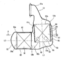
図2は、一実施例のプリ触媒コンバータ26(以下、単に触媒コンバータ26という)の側面図であり、図3は、その内部の構成を示した断面図である。これらの図に示すように、触媒コンバータ26は、上流側の排気通路(例えば排気マニホルドの集合部出口)に接続される入口側ディフューザ部51と、下流側の排気通路に接続される出口側ディフューザ部52と、入口側ディフューザ部51と出口側ディフューザ部52との間のケース53と、ケース53内の一部に二重管構造を構成するように設けられたインナライナ54と、ケース53内に配置されたそれぞれ円柱状をなす第1触媒55および第2触媒56と、を備えている。 FIG. 2 is a side view of a pre-catalytic converter 26 (hereinafter simply referred to as catalytic converter 26) of one embodiment, and FIG. 3 is a cross-sectional view showing its internal configuration. As shown in these figures, the
入口側ディフューザ部51は、排気管部51aから相対的に径が大きい円形の大径部51bへとテーパ状に径が拡大していく形状をなし、出口側ディフューザ部52は、逆に円形の大径部52aから排気管部52bへとテーパ状に径が縮小していく形状をなしている。図2に示すように、排気管部52bには、EGR通路用の分岐管57が接続されている。 The inlet
上記入口側ディフューザ部51の大径部51bおよび上記出口側ディフューザ部52の大径部52aは、ほぼ等しい径を有し、かつ互いに直交する方向に向かって配設されている。 The large-
ケース53は、入口側ディフューザ部51と出口側ディフューザ部52とを接続しており、略L字形に屈曲している。詳しくは、ケース53は、入口側ディフューザ部51の大径部51bに一端が連続した円筒形の上流側円筒部61と、出口側ディフューザ部52の大径部52aに一端が連続した円筒形の下流側円筒部62と、を有し、上流側円筒部61の中心軸線L1と下流側円筒部62の中心軸線L1とは互いに直交している。なお、本発明において「直交」とは幾何学的に厳密に「90°」であることを意味せず、例えば85°~95°程度であれば直交しているものとみなし得る。上流側円筒部61と下流側円筒部62とは、L字形をなすように組み合わされており、下流側円筒部62の出口側ディフューザ部52とは反対側の端部が、上流側円筒部61の入口側ディフューザ部51とは反対側の端部における周面の一部(周方向の一部)に、一対の三日月状部分62aを介して連続している。 The
上流側円筒部61の径は、入口側ディフューザ部51の大径部51bの径よりも僅かに大きく、環状のテーパ部61aを介して上流側円筒部61が入口側ディフューザ部51に接続されている。下流側円筒部62は、出口側ディフューザ部52の大径部52aと実質的に等しい径を有し、直線状に延びた下流側円筒部62の端部に出口側ディフューザ部52が接続されている。従って、上流側円筒部61の径は下流側円筒部62の径よりも僅かに大きい。そのため、三日月状部分62aは、上流側円筒部61の周面の中で180°よりも小さい角度範囲に接続されている。また、上流側円筒部61の入口側ディフューザ部51とは反対側の端部は、中心軸線L1と斜めに交差する底壁部63によって閉じている。換言すれば、上流側円筒部61の端部の周面は、上記の三日月状部分62aが占める部分を除いて、上記底壁部63を介して下流側円筒部62に滑らかに連続している。 The diameter of the upstream
なお、図示例のケース53は、上流側円筒部61および三日月状部分62aを含む部分と、下流側円筒部62の直線状部分と、が互いに別個の部品として成形され、両者が一体に組み立てられているが、ケース53を一部品として一体に成形するか、適当な複数個に分割して成形するか、などは任意である。 In the illustrated
インナライナ54は、入口側ディフューザ部51の大径部51bに対応した径を有する円筒形をなしており、ケース53の上流側円筒部61の上流側端部に一端が固定されて支持されている。詳しくは、入口側ディフューザ部51の大径部51bに接続されるテーパ部61aの小径部側の端部にインナライナ54の一端が固定されている。なお、図示例では、図3に示すように、テーパ部61aの内周面に入口側ディフューザ部51の大径部51bが重なり、該入口側ディフューザ部51の内周面にインナライナ54の端部が重なっているが、これら3つの部材の重なり方は任意である。また、例えば、入口側ディフューザ部51と上流側円筒部61とを一つの部品として一体に形成したり、入口側ディフューザ部51とインナライナ54とを一つの部品として一体に形成したりしてもよい。 The
インナライナ54の他端は、ケース53内において自由端として底壁部63に向かって開放されている。インナライナ54の中心軸線は、上流側円筒部61の中心軸線L1に合致する。従って、インナライナ54と上流側円筒部61とでいわゆる二重管構造が構成され、両者間には、環状の流路64となる隙間が存在している。インナライナ54の先端は底壁部63から離れており、従って、この環状の流路64は、インナライナ54先端と底壁部63との間に生じる空間に連通している。なお、三日月状部分62aの内側空間を除いて、環状の流路64の流路断面積(中心軸線L1と直交する断面での断面積)は、インナライナ54の軸方向に沿って一定である。換言すれば、三日月状部分62aを除いて、インナライナ54と上流側円筒部61との間の隙間の間隔は各部で一定である。 The other end of the
また、インナライナ54の先端部の周面と上流側円筒部61との間には、複数(例えば5個)の熱伝導性を有する支持部材65が配置されている。一実施例においては、支持部材65は、金属メッシュを円柱状ないし円盤状に形成したものであり、従って、弾性変形が可能であるとともに制振性を有している。支持部材65は、インナライナ54の先端縁に近い位置にあり、かつ、周方向の複数箇所(例えば5箇所)に配置されている(図4参照)。この支持部材65が複数点に位置することで、自由端であるインナライナ54の先端部分の振動が抑制される。 A plurality of (for example, five)
第1触媒55は、軸方向に沿って微細な通路を多数形成した触媒担体となる円柱形の上流側セラミック部材に触媒材料(例えば三元触媒)をコーティング層として担持させたものであり、インナライナ54の内側に緩衝用のマット部材67を介して保持されている。換言すれば、第1触媒55は、いわゆるモノリス触媒担体を用いた一般的な三元触媒である。第1触媒55の下流側(つまり出口側)の端面55aは、インナライナ54の先端縁の位置に合致した位置にある。同様に、第1触媒55の上流側(つまり入口側)の端面55bは、インナライナ54の基端縁に合致した位置にある。つまり、第1触媒55の全長は、実質的にインナライナ54の全長に等しい。上流側の端面55bは、入口側ディフューザ部51に隣接して位置し、この端面55bを覆うように入口側ディフューザ部51が構成されている。 The
第2触媒56は、軸方向に沿って微細な通路を多数形成するとともにこれら微細通路の端部を交互に封止した円柱形の下流側セラミック部材に、触媒材料(例えば三元触媒)をコーティング層として担持させた微粒子捕集フィルタである。換言すれば、第2触媒56は、いわゆる目封じ型のモノリス触媒担体に触媒材料を担持させた一般的なGPF(ガソリン・パティキュレート・フィルタ)である。なお、触媒材料を担持させていない微粒子捕集フィルタであってもよい。第2触媒56は、緩衝用のマット部材68を介して、下流側円筒部62の内側に保持されている。第2触媒56の全長は、下流側円筒部62の直線状部分の長さに基本的に等しい。つまり第2触媒56の下流側(つまり出口側)の端面56aは、出口側ディフューザ部52に隣接して位置し、この端面56aを覆うように出口側ディフューザ部52が構成されている。そして、第2触媒56の上流側(つまり入口側)の端面56bは、下流側円筒部62の直線状部分と三日月状部分62aとの境界付近に位置し、ケース53の中で開口している。なお、図示の実施例では、第1触媒55と第2触媒56の径はほぼ等しく、第1触媒55と第2触媒56の軸方向の長さもほぼ等しい。 The
詳しくは、第2触媒56の上流側の端面56bは、インナライナ54の周面に対向しており、かつ端面56bの直径の半分以上がインナライナ54の周面とオーバラップしている。つまり、図3において、インナライナ54の先端縁よりも下方へ突出する端面56bの領域の径方向寸法は、第2触媒56の半径よりも小さい。この第2触媒56の端面56bとインナライナ54の周面との間には、上述した二重管構造における流路64となる隙間(つまりインナライナ54と上流側円筒部61との間の距離)と同程度かこれよりも僅かに大きな間隔が存在する。 Specifically, the
このように構成された触媒コンバータ26においては、排気マニホルドを出た排気が第1触媒55を通過した後、ケース53内で流れの方向を変えて第2触媒56を通過し、車両床下のメイン触媒コンバータ27へと向かうこととなる。これらの触媒55,56が暖まった後に内燃機関1の運転が停止すると、触媒55,56は外気により冷却される。特に、車両走行中に内燃機関1が停止すると、車両走行風による冷却作用を受ける。ここで、第1触媒55は、インナライナ54と上流側円筒部61とがいわゆる二重管構造をなし、両者間に流路64となる隙間が存在することから、断熱作用ないし保温作用を受け、内燃機関1の停止中における車両走行風による温度低下が緩慢となる。従って、次に内燃機関1の運転が開始したときに、比較的早期に触媒作用が得られる。 In the
一方、内燃機関1の高負荷運転が継続したような場合に、上流側に位置する第1触媒55の温度が上昇しやすい。特に、過度の温度上昇が自由端である第1触媒55の先端部分で生じやすい。このように第1触媒55の温度が上昇したときには、熱伝導性を有する支持部材65を介して第1触媒55の熱がケース53へと伝わる。そのため、温度上昇しやすい第1触媒55の先端部分における過度の温度上昇が抑制される。これにより、第1触媒55の熱的劣化が抑制される。 On the other hand, when the high-load operation of the internal combustion engine 1 continues, the temperature of the
さらに、図5に排気の流れを模式的に示すように、第1触媒55の下流側の端面55aを出た排気は、一部が底壁部63に沿うように流れて第2触媒56に流入するほか、一部がインナライナ54と上流側円筒部61との間の環状の流路64を軸方向かつ周方向に(つまり、いわば螺旋形に沿って)流れて第2触媒56に流入する。そのため、インナライナ54の周面とオーバラップしている第2触媒56の領域にあっても、第1触媒55を通過した排気が円滑に流れる。従って、第2触媒56の端面56bに広く分散して排気が案内され、局部的な排気の片寄りが比較的少なくなる。 Furthermore, as the flow of exhaust gas is schematically shown in FIG. In addition to flowing in, part of it flows axially and circumferentially through the
このように二重管構造による環状の流路64を介して第2触媒56の端面56bのインナライナ54とのオーバラップ部分にも排気が確実に案内されることから、端面56bとインナライナ54とのオーバラップを比較的大きく設定することが可能となる。上述したように、第2触媒56の端面56bの直径の半分以上がインナライナ54とオーバラップしていても、十分に円滑な排気の流れが得られる。一実施例では、オーバラップは、端面56bの直径の60~70%程度である。このようにオーバラップを大きく設定することで、触媒コンバータ26の外形寸法(とりわけ図3の上下方向寸法)が小型化する。 In this manner, the exhaust gas is reliably guided to the overlapping portion of the
また、環状の流路64がインナライナ54の全周に均等な幅で形成されているので、上流側円筒部61の径をインナライナ54に対して僅かに大きく設定することで比較的大きな流路断面積を得ることができる。従って、触媒コンバータ26の外形寸法(とりわけ上流側円筒部61の外形寸法)を比較的小型にしつつ第2触媒56への円滑な排気の流れを確保することができる。 In addition, since the
上記実施例の支持部材65は、流路64における外形が円形をなすので、排気の流れを損なうことがない。 Since the
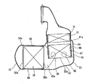
支持部材65の形状としては、図示の円形のものに限らず、他の種々の形状が可能である。図6は、その一例として、第1触媒55の端面55aから第2触媒56の端面56bへと流路64を通して流れる排気の流れに沿うように、上流側円筒部61の中心軸線L1に対して傾いた細長い形状の支持部材65を示している。この支持部材65は、やはり熱伝導性を有する金属メッシュを細長い棒状に形成したものである。なお、図6に示す周面部分と反対側に設けられる支持部材65は、図6に示した支持部材65と対称をなすように傾いている。また、第2触媒56の端面56bとは反対側となる周面に位置する支持部材65Aについては、中心軸線L1と平行となすように配置することができる。 The shape of the
さらに、図6の実施例では、複数の支持部材65が並んで配置されているインナライナ54の軸方向位置よりも僅かに上流側の位置において、上流側円筒部61が外側に膨らんだビード部69を有している。このビード部69は、上流側円筒部61の周方向に連続して形成されており、かつ、支持部材65の端部に隣接して位置している。 Furthermore, in the embodiment shown in FIG. 6, the upstream
このようにビード部69を備えることによって、環状の流路64の流路断面積(中心軸線L1と直交する断面での断面積)が部分的に拡大する。これにより、流路64に支持部材65が存在することによる通路抵抗の増加が相殺される。 By providing the
図3,図4に示した実施例では、第1触媒55が1つのモノリス触媒として構成されているが、複数のモノリス触媒に分割されていてもよい。例えば、特性が異なる前段触媒と後段触媒とを直列に配置し、両者をインナライナ54の中に収容した構成が可能である。同様に、第2触媒56を複数個に分割した構成も可能である。 In the embodiment shown in FIGS. 3 and 4, the
次に、図7は、入口側ディフューザ部51と第1触媒55との間に電気加熱式触媒(EHC)71を備えた第2実施例の触媒コンバータ26を示している。電気加熱式触媒71は、軸方向寸法が比較的短い円柱状つまり偏平な円盤状をなしており、第1触媒55の上流側に該第1触媒55と直列に並ぶように配置されている。電気加熱式触媒71としては種々の形式のものを適用することができるが、例えば金属製触媒担体に触媒材料をコーティングし、通電により発熱するように構成したものが用いられる。図示例では、電気加熱式触媒71は、第1触媒55とともにインナライナ54の内側にマット部材72を介して保持されている。 Next, FIG. 7 shows a
電気加熱式触媒71は、冷間時に通電により触媒の活性化を図ることができるので、基本的に、断熱・保温構造は不要である。そのため、電気加熱式触媒71が収容されている部分においてはインナライナ54がいわゆる単管構造をなしており、環状の流路64を構成する上流側円筒部61に覆われることなく外部に露出している。換言すれば、上流側円筒部61の端部となるテーパ部61aが、電気加熱式触媒71と第1触媒55との境界付近に位置している。 Since the electrically
このような構成によれば、電気加熱式触媒71が不必要に高温となることがない。さらに、電気加熱式触媒71へ電気を供給するための図示しないコネクタ等を外部へ引き出すことが容易となる。 With such a configuration, the electrically
なお、図示例では、電気加熱式触媒71を付加したことで第1触媒55に必要な容量が少なくなることから、図3,図4に示す第1実施例に比較して、第1触媒55の軸方向寸法が小さくなっている。勿論、図3,図4の第1触媒55と同等の大きさの第1触媒55と組み合わせてもよい。 In the illustrated example, since the addition of the electrically
Claims (7)
上記入口側ディフューザ部に一端が連続した上流側円筒部および上記出口側ディフューザ部に一端が連続した下流側円筒部を含み、これら2つの円筒部の中心軸線は互いに直交し、下流側円筒部の他端側の端部が上流側円筒部の他端側の周面の周方向の一部に連続するとともに、当該部分を除く上流側円筒部の周面が底壁部を介して下流側円筒部に連続するケースと、
上記上流側円筒部の上流側端部に一端が固定され、かつ他端が上記ケース内で上記底壁部に向かって自由端として開放されているとともに、上記上流側円筒部との間に流路となる隙間を有する二重管構造を構成するインナライナと、
上記インナライナ内に保持された触媒担体もしくは微粒子捕集フィルタとなる円柱形の上流側セラミック部材と、
上記下流側円筒部内に保持され、上流側の端面が上記インナライナの周面に対向するとともに、該端面の直径の半分以上が上記インナライナの周面とオーバラップした触媒担体もしくは微粒子捕集フィルタとなる円柱形の下流側セラミック部材と、
上記インナライナの端部の周方向の複数箇所において該インナライナと上記上流側円筒部との間に配置された熱伝導性を有する支持部材と、
上記上流側セラミック部材および上記下流側セラミック部材の少なくとも一方に担持された触媒材料と、
を備えてなる触媒コンバータであって、
二重管構造をなす上記インナライナと上記上流側円筒部との間の隙間からなる流路の断面積が、上記インナライナの軸方向に沿って一定であり、かつ、
上記支持部材の上流側に隣接した位置において上記流路の断面積が部分的に拡大している、触媒コンバータ。an inlet-side diffuser section and an outlet-side diffuser section arranged in directions orthogonal to each other;
An upstream cylindrical portion having one end connected to the inlet side diffuser portion and a downstream cylindrical portion having one end connected to the outlet side diffuser portion are included, and the central axes of these two cylindrical portions are orthogonal to each other, and the downstream cylindrical portion The end on the other end side is continuous with a part of the peripheral surface on the other end side of the upstream cylindrical part in the circumferential direction, and the peripheral surface of the upstream cylindrical part excluding the part is connected to the downstream cylindrical part through the bottom wall part. a case that is continuous with the part
One end is fixed to the upstream end of the upstream cylindrical portion, and the other end is open as a free end toward the bottom wall portion within the case, and flows between the upstream cylindrical portion and the upstream cylindrical portion. an inner liner having a double pipe structure having a gap that serves as a passage;
a cylindrical upstream ceramic member that serves as a catalyst carrier or a particulate collection filter held in the inner liner;
A catalyst carrier or a particulate collection filter that is held in the downstream cylindrical portion, has an upstream end face facing the peripheral surface of the inner liner, and overlaps the peripheral surface of the inner liner by half or more of the diameter of the end face. a cylindrical downstream ceramic member;
a support member having thermal conductivity disposed between the inner liner and the upstream cylindrical portion at a plurality of locations in the circumferential direction of the end portion of the inner liner;
a catalyst material carried on at least one of the upstream ceramic member and the downstream ceramic member;
A catalytic converter comprising:
the cross-sectional area of the flow passage formed by the gap between the inner liner having a double-tube structure and the upstream cylindrical portion is constant along the axial direction of the inner liner, and
A catalytic converter, wherein the cross-sectional area of the flow path is partially enlarged at a position adjacent to the upstream side of the support member.
一対の三日月状部分を介して上記下流側円筒部の端部が上記上流側円筒部の周面に連続している、
請求項1に記載の触媒コンバータ。The diameter of the upstream cylindrical portion is larger than the diameter of the downstream cylindrical portion,
the end of the downstream cylindrical portion is continuous with the peripheral surface of the upstream cylindrical portion via a pair of crescent-shaped portions;
2. The catalytic converter of claim 1.
請求項1または2に記載の触媒コンバータ。The support member has a columnar or disk shape,
3. A catalytic converter according to claim 1 or 2.
請求項1または2に記載の触媒コンバータ。The support member has an elongated shape inclined with respect to the central axis of the upstream cylindrical portion,
3. A catalytic converter according to claim 1 or 2.
この電気加熱式触媒が位置する部分は、上記流路が介在しない単管構造をなしている、
請求項1、2、5、6のいずれかに記載の触媒コンバータ。An electrically heated catalyst is further provided between the inlet-side diffuser portion and the upstream-side ceramic member,
The portion where the electrically heated catalyst is located has a single-tube structure in which the flow path does not intervene.
A catalytic converter according to any one of claims 1, 2, 5 and 6.
Applications Claiming Priority (1)
| Application Number | Priority Date | Filing Date | Title |
|---|---|---|---|
| PCT/IB2019/000566 WO2020234618A1 (en) | 2019-05-22 | 2019-05-22 | Catalytic converter |
Publications (3)
| Publication Number | Publication Date |
|---|---|
| JPWO2020234618A1 JPWO2020234618A1 (en) | 2020-11-26 |
| JPWO2020234618A5 JPWO2020234618A5 (en) | 2022-03-17 |
| JP7159465B2 true JP7159465B2 (en) | 2022-10-24 |
Family
ID=73458078
Family Applications (1)
| Application Number | Title | Priority Date | Filing Date |
|---|---|---|---|
| JP2021520476A Active JP7159465B2 (en) | 2019-05-22 | 2019-05-22 | catalytic converter |
Country Status (5)
| Country | Link |
|---|---|
| US (1) | US11623180B2 (en) |
| EP (1) | EP3974628B1 (en) |
| JP (1) | JP7159465B2 (en) |
| CN (1) | CN113906199B (en) |
| WO (1) | WO2020234618A1 (en) |
Families Citing this family (1)
| Publication number | Priority date | Publication date | Assignee | Title |
|---|---|---|---|---|
| US11473466B2 (en) * | 2019-01-09 | 2022-10-18 | Marelli Corporation | Exhaust gas processing device |
Citations (3)
| Publication number | Priority date | Publication date | Assignee | Title |
|---|---|---|---|---|
| JP2011117409A (en) | 2009-12-07 | 2011-06-16 | Ngk Insulators Ltd | Exhaust gas treatment device |
| US20150330279A1 (en) | 2014-05-15 | 2015-11-19 | GM Global Technology Operations LLC | External exhaust guiding flow chambers for multiple catalyst architecture |
| DE102016114283A1 (en) | 2016-08-02 | 2018-02-08 | Benteler Automobiltechnik Gmbh | exhaust aftertreatment arrangement |
Family Cites Families (22)
| Publication number | Priority date | Publication date | Assignee | Title |
|---|---|---|---|---|
| DE3524775C1 (en) * | 1985-07-11 | 1986-09-04 | Daimler-Benz Ag, 7000 Stuttgart | Monolithic catalytic converter arranged in a metal housing |
| JPH06101465A (en) * | 1992-09-22 | 1994-04-12 | Nissan Motor Co Ltd | Double pipe catalyst converter |
| JPH0725212U (en) * | 1993-09-30 | 1995-05-12 | 株式会社小松製作所 | Exhaust gas purification device for internal combustion engine |
| US5693295A (en) * | 1996-01-16 | 1997-12-02 | General Motors Corporation | Catalytic converter |
| JP3099733B2 (en) * | 1996-05-09 | 2000-10-16 | 株式会社ディー・ビー・エス | Exhaust gas purifier for small engines |
| US6713025B1 (en) * | 1999-09-15 | 2004-03-30 | Daimlerchrysler Corporation | Light-off and close coupled catalyst |
| JP2003049634A (en) * | 2001-08-03 | 2003-02-21 | Calsonic Kansei Corp | Particulate filter for vehicle |
| JP2005264769A (en) * | 2004-03-17 | 2005-09-29 | Nissan Motor Co Ltd | Catalytic converter of internal combustion engine |
| JP2007083189A (en) * | 2005-09-22 | 2007-04-05 | Mazda Motor Corp | Catalytic converter and exhaust system |
| JP2009156071A (en) * | 2007-12-25 | 2009-07-16 | Mitsubishi Motors Corp | Exhaust emission control device for internal combustion engine |
| JP5032409B2 (en) * | 2008-07-28 | 2012-09-26 | 三菱ふそうトラック・バス株式会社 | Exhaust purification device |
| DE102009024718A1 (en) * | 2009-06-12 | 2010-12-16 | Emitec Gesellschaft Für Emissionstechnologie Mbh | Exhaust gas treatment device for use close to the engine |
| DE102011075643A1 (en) * | 2011-05-11 | 2012-11-15 | J. Eberspächer GmbH & Co. KG | Exhaust system component |
| EP2770177B1 (en) * | 2011-10-18 | 2018-01-31 | Toyota Jidosha Kabushiki Kaisha | Electrically heated catalyst |
| WO2013137105A1 (en) * | 2012-03-13 | 2013-09-19 | 日産自動車株式会社 | Catalytic converter |
| JP2014031743A (en) * | 2012-08-02 | 2014-02-20 | Bosch Corp | Exhaust emission control system of internal combustion engine |
| CN104066942B (en) * | 2013-01-17 | 2015-09-16 | 株式会社小松制作所 | Reducing agent aqueous solution device and possess its exhaust aftertreatment device |
| US9223715B2 (en) * | 2013-08-21 | 2015-12-29 | Via Alliance Semiconductor Co., Ltd. | Microprocessor mechanism for decompression of cache correction data |
| JP2015098834A (en) * | 2013-11-19 | 2015-05-28 | トヨタ自動車株式会社 | Catalyst device for internal combustion engine |
| EP2960456B1 (en) * | 2014-06-27 | 2017-04-12 | Volvo Car Corporation | Angled and compact exhaust gas aftertreatment device |
| JP6299856B1 (en) | 2016-12-16 | 2018-03-28 | マツダ株式会社 | Engine exhaust system |
| CN108571368B (en) * | 2017-03-10 | 2020-06-16 | 马自达汽车株式会社 | Exhaust device of engine |
-
2019
- 2019-05-22 US US17/612,769 patent/US11623180B2/en active Active
- 2019-05-22 CN CN201980096477.5A patent/CN113906199B/en active Active
- 2019-05-22 JP JP2021520476A patent/JP7159465B2/en active Active
- 2019-05-22 EP EP19929204.6A patent/EP3974628B1/en active Active
- 2019-05-22 WO PCT/IB2019/000566 patent/WO2020234618A1/en unknown
Patent Citations (3)
| Publication number | Priority date | Publication date | Assignee | Title |
|---|---|---|---|---|
| JP2011117409A (en) | 2009-12-07 | 2011-06-16 | Ngk Insulators Ltd | Exhaust gas treatment device |
| US20150330279A1 (en) | 2014-05-15 | 2015-11-19 | GM Global Technology Operations LLC | External exhaust guiding flow chambers for multiple catalyst architecture |
| DE102016114283A1 (en) | 2016-08-02 | 2018-02-08 | Benteler Automobiltechnik Gmbh | exhaust aftertreatment arrangement |
Also Published As
| Publication number | Publication date |
|---|---|
| CN113906199A (en) | 2022-01-07 |
| WO2020234618A1 (en) | 2020-11-26 |
| US11623180B2 (en) | 2023-04-11 |
| EP3974628A4 (en) | 2022-06-01 |
| CN113906199B (en) | 2023-11-28 |
| EP3974628A1 (en) | 2022-03-30 |
| US20220274060A1 (en) | 2022-09-01 |
| JPWO2020234618A1 (en) | 2020-11-26 |
| EP3974628B1 (en) | 2023-08-16 |
Similar Documents
| Publication | Publication Date | Title |
|---|---|---|
| US5408828A (en) | Integral cast diffuser for a catalytic converter | |
| JP6299856B1 (en) | Engine exhaust system | |
| US5307628A (en) | Exhaust line allowing a faster triggering of the catalyst | |
| US10626781B2 (en) | Exhaust device of engine | |
| KR100549979B1 (en) | Engine EGR apparatus | |
| JP7159465B2 (en) | catalytic converter | |
| US6024928A (en) | By-pass flow catalytic converter | |
| JP6773129B2 (en) | Engine exhaust | |
| EP1695757B1 (en) | Exhaust purification device and exhaust purification method for an internal combustion engine | |
| US10371037B2 (en) | Internal combustion engine with exhaust-gas aftertreatment system and method for operating an internal combustion engine of said type | |
| JP6729721B2 (en) | Engine exhaust system | |
| US10557443B2 (en) | Exhaust device of engine | |
| JP6319412B1 (en) | Engine exhaust system | |
| JP4291646B2 (en) | Engine exhaust gas purification device | |
| JP2002285916A (en) | Exhaust gas recirculation apparatus | |
| JP2005083304A (en) | Exhaust emission control device of internal combustion engine | |
| JP2004084481A (en) | Exhaust pipe | |
| JP2002188436A (en) | Exhaust gas purifying device of internal combustion engine | |
| JP2018123786A (en) | Exhaust emission control device |
Legal Events
| Date | Code | Title | Description |
|---|---|---|---|
| A529 | Written submission of copy of amendment under article 34 pct |
Free format text: JAPANESE INTERMEDIATE CODE: A5211 Effective date: 20211104 |
|
| A621 | Written request for application examination |
Free format text: JAPANESE INTERMEDIATE CODE: A621 Effective date: 20211104 |
|
| TRDD | Decision of grant or rejection written | ||
| A01 | Written decision to grant a patent or to grant a registration (utility model) |
Free format text: JAPANESE INTERMEDIATE CODE: A01 Effective date: 20221011 |
|
| A61 | First payment of annual fees (during grant procedure) |
Free format text: JAPANESE INTERMEDIATE CODE: A61 Effective date: 20221012 |
|
| R150 | Certificate of patent or registration of utility model |
Ref document number: 7159465 Country of ref document: JP Free format text: JAPANESE INTERMEDIATE CODE: R150 |