JP7159136B2 - System execution support method and device - Google Patents
System execution support method and device Download PDFInfo
- Publication number
- JP7159136B2 JP7159136B2 JP2019173122A JP2019173122A JP7159136B2 JP 7159136 B2 JP7159136 B2 JP 7159136B2 JP 2019173122 A JP2019173122 A JP 2019173122A JP 2019173122 A JP2019173122 A JP 2019173122A JP 7159136 B2 JP7159136 B2 JP 7159136B2
- Authority
- JP
- Japan
- Prior art keywords
- request
- authentication
- log
- service
- transit
- Prior art date
- Legal status (The legal status is an assumption and is not a legal conclusion. Google has not performed a legal analysis and makes no representation as to the accuracy of the status listed.)
- Active
Links
Images


Landscapes
- Debugging And Monitoring (AREA)
Description
本発明は、概して、情報通信に関し、特に、一または複数の開発者により開発された複数のサービスモジュールのうちの一つ以上のサービスモジュールをマッシュアップさせたサービスシステムの実行支援に関する。 TECHNICAL FIELD The present invention relates generally to information communication, and more particularly to supporting execution of a service system in which one or more service modules among a plurality of service modules developed by one or more developers are mashed up.
近年、マーケットプレイスなどを通じて調達可能な機能部品といったサービスモジュール(例えば音声解析)を、バックエンドサービスとして活用したサービスシステム(例えば、文書解析と機械学習を連携および活用した自動応対サービス)の開発が浸透している。サービス提供者は、例えば音声解析のバックエンドサービスと機械学習のバックエンドサービスを調達し、それらを連携させるための制御ルールを準備し、自動応対サービスを開発する。サービスシステムのパッケージ化(例えば、テンプレート化)およびデプロイメント自動化を通じて迅速な展開(例えば、同一企業内の複数の部署への展開)を実現することができることが望ましい。 In recent years, the development of service systems (for example, automatic response services that link and utilize document analysis and machine learning) that utilize service modules (for example, speech analysis) as backend services, such as functional components that can be procured through marketplaces, has spread. is doing. Service providers, for example, procure voice analysis backend services and machine learning backend services, prepare control rules for linking them, and develop automatic response services. It is desirable to be able to achieve rapid deployment (eg, to multiple departments within the same company) through service system packaging (eg, templating) and deployment automation.
サービス提供者によっては、サービスシステムの価値(効果)に基づいたマネタイズを実現するために、機能部品毎の使用量(例えば、解析時間、機械学習のための入力データ量)に基づいた従量課金を行いたい者がいると考えられる。 Depending on the service provider, in order to realize monetization based on the value (effect) of the service system, pay-as-you-go billing based on the usage amount of each functional component (e.g., analysis time, amount of input data for machine learning) It is conceivable that there are those who wish to do so.
特許文献1に開示の方法は、複数のユーザがストレージサービスに対しアクセス要求を出す状況下で、ストレージの状態情報とアクセスの履歴情報とを突き合わせて、実際にアクセスしたアカウントを特定し、当該アカウントの課金額などとして計上する方法である。
In the method disclosed in
しかし、マーケットプレイスなどを通じて提供される各サービスモジュール(機能部品)はマルチユーザを想定した機能(典型的には、認証認可(認証および認可のうちの少なくとも一つ)、および、ユーザ情報を含むログ出力、のうちの少なくとも一つ)を備えるとは限らない。その理由の一つとして、サービスモジュールの開発者は、通常、価値向上に繋がると利用者から評価される可能性の高い機能/非機能要件(例えば、多言語対応、応答時間短縮)に対して集中投資をし、マルチユーザを想定した機能(例えば、あるサービス提供者が定めたログ出力仕様への対応)に対する投資を回避する傾向にあると考えられる。 However, each service module (functional component) provided through a marketplace, etc. is a multi-user function (typically, authentication and authorization (at least one of authentication and authorization), and a log containing user information. at least one of the outputs). One of the reasons for this is that service module developers usually do It is thought that there is a tendency to concentrate investment and avoid investment in functions that assume multiple users (for example, support for log output specifications determined by a certain service provider).
このため、マルチユーザを想定した機能を備えていないサービスモジュールを含んだサービスシステムについて従量課金を行うことが困難であるという技術的課題が存在する。 Therefore, there is a technical problem that it is difficult to perform pay-as-you-go billing for a service system that includes a service module that does not have a multi-user function.
予めサービス要件(例えば、利用規模またはサービスレベル)が決まっていればそのサービス要件を満たすサービスシステムを構築して提供することが可能であると考えられる。しかし、予めサービス要件が確定しているとは限らない。この場合、サービスシステムを使用しながら課題や要件を定め、必要に応じてサービスシステムをスケールすることが好ましい。故に、この場合、いわゆるスモールスタートでサービスシステムを使用することが好ましく、そのためには、サービスシステムの従量課金の実現が望まれる。従量課金の実現は、ユーザ情報を含んだログ出力や認証認可といった機能(つまり、マルチユーザを想定した機能)を備えていないサービスモジュールを含んだサービスシステムをマルチユーザ仕様とすることの一例と考えることができる。 If service requirements (for example, scale of use or service level) are determined in advance, it is possible to construct and provide a service system that satisfies the service requirements. However, the service requirements are not always determined in advance. In this case, it is preferable to determine issues and requirements while using the service system and scale the service system as necessary. Therefore, in this case, it is preferable to use the service system with a so-called small start, and for that purpose, realization of pay-as-you-go billing for the service system is desired. The realization of pay-as-you-go billing is an example of making a service system with multi-user specifications a service system that includes service modules that do not have functions such as log output and authentication authorization that include user information (that is, functions that assume multi-users). be able to.
サービスシステムにおける各サービスモジュールは、当該サービスモジュールについての要求を実行した場合に当該要求の実行における使用量を含む実行内容と当該要求のメタ情報とを含んだログである実行ログを第1のログ情報に書き込むようになっている。対象のサービスモジュールについて、ゲートウェイが、認証および認可の少なくとも一つのためのデータである認証認可データを持つ要求を受けた場合、当該要求に対し当該要求の通過IDを付与し、当該要求のメタ情報に当該要求の認証認可データに代えて当該付与した通過IDを設定する。ゲートウェイが、当該通過IDを含んだメタ情報を持つ要求を、対象のサービスモジュールに転送し、当該通過IDと上記認証認可データとを含んだログである通過ログを第2のログ情報に書き込む。 Each service module in the service system stores an execution log, which is a log containing execution contents including the usage amount in execution of the request and meta information of the request when executing a request for the service module, as a first log. It is designed to be written in information. For the target service module, when the gateway receives a request with authentication and authorization data, which is data for at least one of authentication and authorization, it gives the request a transit ID and sends meta information of the request. , the given passage ID is set in place of the authentication/authorization data of the request. The gateway transfers a request having meta information including the transit ID to the target service module, and writes a transit log, which is a log including the transit ID and the authentication authorization data, in the second log information.
認証認可とユーザ情報を含んだログの出力といった機能を持たないサービスモジュールを含んだサービスシステムをマルチユーザ仕様にできる。 A service system that includes service modules that do not have functions such as log output including authentication and authorization and user information can be made multi-user.
以下の説明では、「インターフェース装置」は、一つ以上のインターフェースデバイスでよい。当該一つ以上のインターフェースデバイスは、下記のうちの少なくとも一つでよい。
・一つ以上のI/O(Input/Output)インターフェースデバイス。I/O(Input/Output)インターフェースデバイスは、I/Oデバイスと遠隔の表示用計算機とのうちの少なくとも一つに対するインターフェースデバイスである。表示用計算機に対するI/Oインターフェースデバイスは、通信インターフェースデバイスでよい。少なくとも一つのI/Oデバイスは、ユーザインターフェースデバイス、例えば、キーボードおよびポインティングデバイスのような入力デバイスと、表示デバイスのような出力デバイスとのうちのいずれでもよい。
・一つ以上の通信インターフェースデバイス。一つ以上の通信インターフェースデバイスは、一つ以上の同種の通信インターフェースデバイス(例えば一つ以上のNIC(Network Interface Card))であってもよいし二つ以上の異種の通信インターフェースデバイス(例えばNICとHBA(Host Bus Adapter))であってもよい。
In the following description, an "interface device" may be one or more interface devices. The one or more interface devices may be at least one of the following:
- One or more I/O (Input/Output) interface devices. An I/O (Input/Output) interface device is an interface device for at least one of an I/O device and a remote display computer. The I/O interface device to the display computer may be a communications interface device. The at least one I/O device may be any of a user interface device, eg, an input device such as a keyboard and pointing device, and an output device such as a display device.
- One or more communication interface devices. The one or more communication interface devices may be one or more of the same type of communication interface device (e.g., one or more NICs (Network Interface Cards)) or two or more different types of communication interface devices (e.g., NIC and It may be an HBA (Host Bus Adapter).
また、以下の説明では、「メモリ」は、一つ以上のメモリデバイスであり、典型的には主記憶デバイスでよい。メモリにおける少なくとも一つのメモリデバイスは、揮発性メモリデバイスであってもよいし不揮発性メモリデバイスであってもよい。 Also, in the following description, "memory" may be one or more memory devices, typically a main memory device. At least one memory device in the memory may be a volatile memory device or a non-volatile memory device.
また、以下の説明では、「永続記憶装置」は、一つ以上の永続記憶デバイスである。永続記憶デバイスは、典型的には、不揮発性の記憶デバイス(例えば補助記憶デバイス)であり、具体的には、例えば、HDD(Hard Disk Drive)またはSSD(Solid State Drive)である。 Also, in the following description, a "persistent storage device" is one or more persistent storage devices. A permanent storage device is typically a non-volatile storage device (for example, an auxiliary storage device), and specifically, for example, an HDD (Hard Disk Drive) or SSD (Solid State Drive).
また、以下の説明では、「記憶装置」は、メモリと永続記憶装置の少なくともメモリでよい。 Also, in the following description, "storage" may be at least memory of memory and persistent storage.
また、以下の説明では、「プロセッサ」は、一つ以上のプロセッサデバイスである。少なくとも一つのプロセッサデバイスは、典型的には、CPU(Central Processing Unit)のようなマイクロプロセッサデバイスであるが、GPU(Graphics Processing Unit)のような他種のプロセッサデバイスでもよい。少なくとも一つのプロセッサデバイスは、シングルコアでもよいしマルチコアでもよい。少なくとも一つのプロセッサデバイスは、プロセッサコアでもよい。少なくとも一つのプロセッサデバイスは、処理の一部または全部を行うハードウェア回路(例えばFPGA(Field-Programmable Gate Array)またはASIC(Application Specific Integrated Circuit))といった広義のプロセッサデバイスでもよい。 Also, in the following description, a "processor" is one or more processor devices. The at least one processor device is typically a microprocessor device such as a CPU (Central Processing Unit), but may be another type of processor device such as a GPU (Graphics Processing Unit). At least one processor device may be single-core or multi-core. At least one processor device may be a processor core. At least one processor device may be a broadly defined processor device such as a hardware circuit (for example, FPGA (Field-Programmable Gate Array) or ASIC (Application Specific Integrated Circuit)) that performs part or all of processing.
また、以下の説明では、「xxxテーブル」といった表現にて、入力に対して出力が得られる情報を説明することがあるが、当該情報は、どのような構造のデータでもよいし、入力に対する出力を発生するニューラルネットワークのような学習モデルでもよい。従って、「xxxテーブル」を「xxx情報」と言うことができる。また、以下の説明において、各テーブルの構成は一例であり、一つのテーブルは、二つ以上のテーブルに分割されてもよいし、二つ以上のテーブルの全部または一部が一つのテーブルであってもよい。 In the following description, the expression "xxx table" may be used to describe information that provides an output for an input. A learning model such as a neural network that generates Therefore, the "xxx table" can be called "xxx information". Also, in the following description, the configuration of each table is an example, and one table may be divided into two or more tables, or all or part of two or more tables may be one table. may
また、以下の説明では、「プログラム」を主語として処理を説明する場合があるが、プログラムは、プロセッサによって実行されることで、定められた処理を、適宜に記憶装置及び/又はインターフェース装置等を用いながら行うため、処理の主語が、プロセッサ(或いは、そのプロセッサを有するコントローラのようなデバイス)とされてもよい。プログラムは、プログラムソースから計算機のような装置にインストールされてもよい。プログラムソースは、例えば、プログラム配布サーバ又は計算機が読み取り可能な(例えば非一時的な)記録媒体であってもよい。また、以下の説明において、二つ以上のプログラムが一つのプログラムとして実現されてもよいし、一つのプログラムが二つ以上のプログラムとして実現されてもよい。 Further, in the following explanation, the processing may be explained with the subject of "program". As it occurs while in use, the subject of processing may be a processor (or a device, such as a controller, having that processor). A program may be installed on a device, such as a computer, from a program source. The program source may be, for example, a program distribution server or a computer-readable (eg, non-temporary) recording medium. Also, in the following description, two or more programs may be implemented as one program, and one program may be implemented as two or more programs.
また、以下の説明では、「kkk部」の表現にて機能を説明することがあるが、機能は、一つ以上のコンピュータプログラムがプロセッサによって実行されることで実現されてもよいし、一つ以上のハードウェア回路(例えばFPGAまたはASIC)によって実現されてもよい。プログラムがプロセッサによって実行されることで機能が実現される場合、定められた処理が、適宜に記憶装置および/またはインターフェース装置等を用いながら行われるため、機能はプロセッサの少なくとも一部とされてもよい。機能を主語として説明された処理は、プロセッサあるいはそのプロセッサを有する装置が行う処理としてもよい。プログラムは、プログラムソースからインストールされてもよい。プログラムソースは、例えば、プログラム配布計算機または計算機が読み取り可能な記録媒体(例えば非一時的な記録媒体)であってもよい。各機能の説明は一例であり、複数の機能が一つの機能にまとめられたり、一つの機能が複数の機能に分割されたりしてもよい。 In addition, in the following description, the function may be described using the expression “kkk unit”, but the function may be realized by executing one or more computer programs by a processor, or may be realized by executing one or more computer programs. It may be realized by the above hardware circuits (FPGA or ASIC, for example). When a function is realized by executing a program by a processor, the defined processing is performed while appropriately using a storage device and/or an interface device, etc., so the function may be at least part of the processor. good. A process described with a function as the subject may be a process performed by a processor or a device having the processor. Programs may be installed from program sources. The program source may be, for example, a program distribution computer or a computer-readable recording medium (for example, a non-temporary recording medium). The description of each function is an example, and multiple functions may be combined into one function, or one function may be divided into multiple functions.
また、以下の説明では、同種の要素を区別しないで説明する場合には、参照符号のうちの共通部分を使用し、同種の要素を区別する場合は、参照符号を使用することがある。例えば、認証認可ゲートウェイを区別しない場合には、「認証認可ゲートウェイ312」と言い、認証認可ゲートウェイを区別する場合には、「認証認可ゲートウェイ312A」、「認証認可ゲートウェイ312B」のように言うことがある。
In the following description, common parts of reference numerals may be used when similar elements are not distinguished, and reference numerals may be used when similar elements are distinguished. For example, when the authentication and authorization gateways are not distinguished, they are referred to as "authentication and
以下、本発明の実施の形態を添付図面に基づいて説明する。
[実施形態1]
BEST MODE FOR CARRYING OUT THE INVENTION Hereinafter, embodiments of the present invention will be described with reference to the accompanying drawings.
[Embodiment 1]
図1および図2は、本発明の実施形態1に係るシステム全体の構成と当該システム全体における関係とを示す。
1 and 2 show the configuration of the entire system according to
コーディネータ110と、システム実行基盤提供者(以下、提供者)120と、バックエンドサービス開発者(以下、開発者)130と、テナント100とが存在する。テナント100内にテナント管理者(以下、管理者)101およびシステム利用者(以下、利用者)102が存在する。
There are a
テナント100は、企業または企業内の部門でよい。管理者101は、テナント用システム104を管理する一従業員でよい。利用者102は、テナント用システム104を利用する一従業員でよい。
A
コーディネータ110は、提供者120および開発者130とテナント100と間をコーディネートする。例えば、コーディネータ110は、コーディネーションサービス113を操作して、一または複数の開発者130により開発された複数のサービスモジュールのうちの二つ以上のサービスモジュールを組み合わせたテナント用システム104(サービスシステムの一例)を設計し、テナント用システム104をテナント100に提供する。また、コーディネータ110は、テナント用システム104の従量課金によりテナント100から利用料を取得する。また、コーディネータ110は、テナント用システム104の実行に関し計算資源の使用量に応じた料金を提供者120に支払う。また、コーディネータ110は、当該テナント用システム104の構成要素である一つ以上のバックエンドサービスの各々について、当該バックエンドサービスの使用量に応じた料金を開発者130に支払う。
提供者120が提供するシステム実行基盤サービス122は、例えば、クラウドコンピューティングサービスでよい。コーディネーションサービス113およびシステム実行基盤サービス122の少なくとも一つは、複数の計算資源(例えば、インターフェース装置、記憶装置およびプロセッサ)を有する物理的な計算機システム(例えば、一つ以上の物理計算機)でもよいし、当該複数の計算資源上に構築された論理的な計算機システム(例えば、一つ以上の仮想計算機)でもよい。
The system
矢印A131によれば、一または複数の開発者130が、複数のバックエンドサービスのイメージをイメージリポジトリ124に登録する。
According to arrow A 131 , one or
矢印A112によれば、コーディネータ110は、テナント100との契約に基づいて、テナント100に対し、サービス一式の提供を行う。「サービス一式」とは、少なくともテナント100用のシステム104を含む。
According to arrow A112, the
矢印A117によれば、コーディネータ110は、前述のサービス一式を具現化するために、一または複数の開発者130からは一つ以上のバックエンドサービスを調達し(例えば、マーケットプレイス経由で調達し)、提供者120からはそれらのバックエンドサービスを稼動させるためのシステム実行基盤サービス122を調達する。調達されたバックエンドサービスをテナント用システム104が含み、テナント用システム104が、調査津されたシステム実行基盤サービス122のうちのシステム実行領域126で実行される。
According to arrow A117, the
矢印A111によれば、コーディネータ110は、テナント用システム104をシステム実行領域126へ配備(デプロイメント)するための操作をコーディネーションサービス113に対して行う。
According to the arrow A111, the
矢印A118によれば、コーディネーションサービス113は、矢印A111が示す操作に対しシステム実行基盤サービス122を制御する。
According to arrow A118, the
矢印A105によれば、テナント用システム104は、CPUやメモリなどの計算資源を持つシステム実行領域126上で稼働する。
According to the arrow A105, the tenant system 104 runs on the
矢印A103によれば、管理者101や利用者102はテナント用システム104が提供するインターフェース(例えば、GUI(Graphical User Interface)、REST(Representational State Transfer)など)を通じてテナント用システム104を利用する。コーディネーションサービス113は、テンプレート部114と、デプロイメント要求部115と、ログ分類部117と、ログ管理部116とを含む。
According to arrow A103, the administrator 101 and the user 102 use the tenant system 104 through an interface provided by the tenant system 104 (for example, GUI (Graphical User Interface), REST (Representational State Transfer), etc.).
矢印A121によれば、提供者120は、システム実行基盤サービス122を所有および運営する。システム実行基盤サービス122は、システム実行領域126と、デプロイメント実行部123と、イメージリポジトリ124と、認証認可サービス群125とを含む。システム実行領域126は、複数の計算資源(例えば、インターフェース装置、記憶装置およびプロセッサ)に基づく論理的な領域であり、テナント用システム104が実行される領域である。
According to arrow A121,
図2によれば、テナント用システム104(具体的には、当該システム104が実行されるシステム実行領域126)と、コーディネーションサービス113とは、ネットワーク200にて接続されている。
According to FIG. 2, the tenant system 104 (specifically, the
矢印A201によれば、デプロイメント要求部115は、デプロイメント実行部123に対し、テナント用システム104のデプロイメント要求を送信する。矢印A202によれば、デプロイメント実行部123は、システム実行領域126へ、デプロイメント要求に従ってテナント用システム104のデプロイメントを実行する。矢印A203によれば、テナント用システム104のデプロイメント実行の際に、テナント用システムを構成するバックエンドサービスのイメージ(例えば、コンテナイメージ)がイメージリポジトリ124からロードされ、起動される。矢印A204によれば、デプロイメントされたテナント用システム104は、必要に応じて認証および認可を行うために認証認可サービス群125にアクセスする。
According to arrow A201, the
図3は、システム実行基盤サービス122およびログ管理部116の構成の例を示す図である。
FIG. 3 is a diagram showing an example of the configuration of the system
ログ管理部116は、実行ログテーブル300と、通過ログテーブル301とを格納する。実行ログテーブル300は、矢印A340が示すように、バックエンドサービス311(インスタンス)の実行ログが格納されるテーブルである。通過ログテーブル301は、矢印A341が示すように、認証認可ゲートウェイ312(インスタンス)の通過ログが格納されるテーブルである。
The
テナントA用システム領域310は、テナントA100A用に、システム実行領域126が持つ計算資源や権限などが論理的に分割されたことにより得られた領域である。テナントA用システム領域310には、一つ以上のバックエンドサービス311のインスタンスと、バックエンドサービス制御プログラム313と、認証認可ゲートウェイ312のインスタンスとが展開される。
The
バックエンドサービス制御プログラム313は、利用者クライアント350およびバックエンドサービス311間の連携を行う。例えば、バックエンドサービス制御プログラム313は、事前に定義された制御ルール314(例えば、ロジック、処理フローまたはステップ)に従って、要求および応答データの相互通信を制御する。なお、利用者クライアント350は、利用者が使用する物理的または仮想的な情報処理端末でよい。
The backend
認証認可ゲートウェイ312は、矢印A343が示すように、バックエンドサービス311およびバックエンドサービス制御プログラム313の代わりに認証認可サービス群125にアクセスする。
イメージリポジトリ124は、イメージの実態(例えばコンテナファイル)となるイメージファイル322と、イメージのメタ情報を管理するイメージ管理部323とを持つ。
The
デプロイメント実行部123は、デプロイ処理部320と、アンデプロイ処理321とを備える。デプロイ処理部320は、イメージファイル322を用いて、システム実行領域126に、テナント用システム104を構成する各バックエンドサービスなどのインスタンスを作成する。アンデプロイ処理321は、テナント用システム104の廃棄時に、システム実行領域126から、当該テナント用システム104のバックエンドサービスなどのインスタンスを削除する。
The
認証認可サービス群125は、認証部360と認可部361とを含む。認証部360は、要求(例えば、利用者クライアント350からバックエンドサービス311(または、当該サービス311を含むテナント用システム104)への要求)の認証を行う。認可部361は、要求の認可を行う。「認証認可」は、上述したように、認証および認可のうちの少なくとも一つを意味するが、本実施形態では両方を意味する。本実施形態では、要求の認証認可は、認証認可ゲートウェイ312が認証認可サービス群125(認証部360と認可部361)にアクセスすることにより行われる。
The authentication
バックエンドサービス311は、矢印A340が示すように、バックエンドサービス311の実行ログを実行ログテーブル300に転送する。認証認可ゲートウェイ312は、図8で示すような内部処理による結果を表す通過ログを、矢印A341が示すように、通過ログテーブル301に転送する。矢印A340および矢印A341は、直接転送(例えば、HTTP通信)を意味してもよいし、間接転送(例えば、転送用エージェントや、システム実行基盤サービス122に別途用意されるログ転送部による転送)を意味してもよい。
The
本実施形態では、例えば、テナントA用システム104Aが、一つ以上のサービスモジュールを含むサービスシステムの一例である。テナントA用システム104AがテナントA用システム領域310にデプロイされ、かつ、認証認可ゲートウェイ312が当該領域310にデプロイされる。具体的には、例えば、バックエンドサービス311毎の認証認可ゲートウェイ312と、利用者クライアント350から要求を受け付ける認証認可ゲートウェイ312とがデプロイされる。また、一つのサービスモジュールが複数のテナント用システム104の部品とされることもある。具体的には、一つのサービスモジュールの複数の複製がそれぞれ複数のテナント用システム104の部品とされることもある。
In this embodiment, for example, the tenant A system 104A is an example of a service system including one or more service modules. Tenant A system 104 A is deployed in tenant
図4は、コーディネーションサービス113の構成の例を示す図である。
FIG. 4 is a diagram showing an example of the configuration of the
コーディネーションサービス113は、ログ分類部117、テンプレート部114、デプロイメント要求部115、ログ管理部116、および、ロググルーピング部401を含む。コーディネーションサービス113には、ネットワーク200などを通じて、コーディネータ110の情報処理端末の一例である作業用端末530から操作される。
テンプレート部114により用意されたテンプレート(例えば、テナント用システムのテンプレート)には、デプロイメントに必要な情報の一例として、テナント用システム104の構成要素となるバックエンドサービス311の情報(例えば、イメージ名称や稼働に必要な設定情報(環境変数、起動時引数、システム実行領域126に要求するリソース量など))の集合が含まれる。
The template prepared by the template unit 114 (for example, a tenant system template) includes, as an example of information required for deployment, information on the
ゲートウェイ制御部400は、ゲートウェイデプロイメント部410、転送設定部411、認可設定部412、ヘッダ設定部413、認証認可要件テーブル420、追加ヘッダテーブル421、および、ゲートウェイインスタンステーブル422を含む。ロググルーピング部401は、認証検知部430、ユーザ判定部431、ロググループ出力部432、確認状態テーブル440、追加ヘッダテーブル421、および、ロググループテーブル442を含む。追加ヘッダテーブル421は、図示の例の通り、ゲートウェイ制御部400とロググルーピング部401に共通でよい。ゲートウェイ制御部400およびロググルーピング部401が有する機能およびテーブルの詳細は後述する。
Gateway control unit 400 includes
図5は、実行ログテーブル300および通過ログテーブル301の構成の例と、要求の転送とログの出力との関係の例とを示す図である。 FIG. 5 is a diagram showing an example of the configuration of the execution log table 300 and the passage log table 301, and an example of the relationship between request transfer and log output.
実行ログテーブル300は、実行ログ毎にエントリを有する。実行ログは、バックエンドサービス311のタスクの実行のログである。各レコードは、バックエンドサービスを識別するためのバックエンドサービスID500と、実行ログの出力時刻を示す時刻501と、要求に従い実行されたタスクを識別するためのタスク名502と、バックエンドサービス311に送信された要求(HTTP要求)のヘッダを示す要求ヘッダ503と、タスクの実行内容(例えば、要求から抽出した引数、処理の概要、実行結果)を示すタスク内容504とを含む。図5では、複数のバックエンドサービスの実行ログを集約することとし、バックエンドサービスID500を設けたが、実行ログテーブル300は、バックエンドサービス毎に設けられてもよい。また、タスク名502やタスク内容504は統合および分割(例えば、タスク内容504から引数情報のみを別のカラムにするなど)されてもよい。
The execution log table 300 has an entry for each execution log. The execution log is a log of task execution of the
通過ログテーブル301は、通過ログ毎にエントリを有する。通過ログは、利用者クライアント350から認証認可ゲートウェイ312を経由してバックエンドサービス311に要求が送信される際の、認証認可ゲートウェイ312の要求受信履歴に関するログである。各レコードは、受信した要求の通過ID(言い換えれば、通過ログを識別するID)を示す通過ID510、要求を受信したゲートウェイのゲートウェイIDであるゲートウェイID511、要求から抽出したアクセストークンであるアクセストークン512、および、要求から抽出した親の通過ID(1つ前の認証認可ゲートウェイ312が残した通過ログの通過ID)を示す親通過ID513を持つ。「通過ID」としての値は、認証認可ゲートウェイ312が要求受信時に発行したUUID(Universally Unique Identifier)としての値でよい。認証認可ゲートウェイ312が、要求受信時に事前に定めた要求ヘッダに、当該ゲートウェイ312が発行した通過IDが埋め込まれる。この要求ヘッダを持つ要求を次の認証認可ゲートウェイ312が受けた場合、当該次の認証認可ゲートウェイ312が、当該要求の要求ヘッダから、1つ前の認証認可ゲートウェイ312により埋め込まれた通過IDを抽出できる。この抽出された通過IDが、親通過IDである。アクセストークンや親通過IDの埋め込み先となる要求ヘッダのヘッダ名は、図6に示すように、追加ヘッダテーブル421にて管理される。
The transit log table 301 has an entry for each transit log. The passage log is a log relating to the request reception history of the authentication and
図5によれば、一例として、以下の処理が行われる。なお、図5の説明では、ID“α”を持つ要素を、要素“α”と言うことがある。
・利用者クライアント350から要求01を認証認可ゲートウェイ“gw-312a”312Cが受ける。認証認可ゲートウェイ“gw-312a”312Cが、当該要求からアクセストークン“3SUJBZl…”を取得し、かつ、通過ID“Da417013df”を付与する。認証認可ゲートウェイ“gw-312a”312Cが、アクセストークン“3SUJBZl…”および通過ID“Da417013df”を含んだ通過ログ#1を通過ログテーブル301に格納する。認証認可ゲートウェイ“gw-312a”312Cが、要求01のヘッダに通過ID“Da417013df”を設定し、当該要求01をバックエンドサービス制御プログラム313へと転送する。
・バックエンドサービス制御プログラム313が、制御ルール314に従い、最初のバックエンドサービス311Aに要求01を転送する。転送した要求01のアクセストークンは、例えば、利用者クライアント350からのアクセストークン“3SUJBZl…”(利用者のアクセストークン)に代えて、制御ルール314で指定されているアクセストークン“LS0u9tL…”(テナントAのアクセストークン)が採用される。
・その要求01を、バックエンドサービス311Aについての認証認可ゲートウェイ“gw-312b”312Aが受ける。認証認可ゲートウェイ“gw-312b”312Aが、要求01からアクセストークン“LS0u9tL…”を取得し、要求01のヘッダから通過ID“Da417013df”を取得し、かつ、通過ID“60ed6bf4oPp”を付与する。認証認可ゲートウェイ“gw-312b”312Aが、アクセストークン“LS0u9tL…”、親通過ID“Da417013df”および通過ID“60ed6bf4oPp”を含んだ通過ログ#2を通過ログテーブル301に格納する。認証認可ゲートウェイ“gw-312b”312Aが、要求01のヘッダに通過ID“60ed6bf4oPp”を設定し(ヘッダにおける親通過ID“Da417013df”を通過ID“60ed6bf4oPp”に差し替え)、当該要求01をバックエンドサービス311Aへと転送する。
・バックエンドサービス311Aが、認証認可ゲートウェイ“gw-312b”312Aから要求01を受け、当該要求01に従いタスクを実行する。バックエンドサービス311Aが、要求01の要求ヘッダとタスク内容とを含む実行ログ#3を、実行ログテーブル300に格納する。
・バックエンドサービス311Aが、要求01の実行結果に従う応答02を返す。応答02は、例えば、要求01のヘッダ、つまり、通過ID“60ed6bf4oPp”を含む。応答02は、バックエンドサービス制御プログラム313が受ける。
・バックエンドサービス制御プログラム313が、制御ルール314に従い、応答02が持つ実行結果に基づく要求03を、次のバックエンドサービス311Bに転送する。要求03のヘッダは、応答02が持つ通過ID“60ed6bf4oPp”を持つ。
・その要求03を、バックエンドサービス311Bについての認証認可ゲートウェイ“gw-312c”312Bが受ける。以降、認証認可ゲートウェイ“gw-312c”312Bにより、要求01を受けた認証認可ゲートウェイ“gw-312b”312Aが行った処理と同様の処理が行われる。故に、要求03から取得された親通過ID“60ed6bf4oPp”と、要求03を受けたときに認証認可ゲートウェイ“gw-312c”312Bが付与した通過IDとを含む通過ログが、通過ログテーブル301に格納される。そして、要求03がバックエンドサービス311Bに転送される。
According to FIG. 5, the following processing is performed as an example. Note that in the description of FIG. 5, the element having the ID "α" may be referred to as the element "α".
・Authentication authorization gateway “gw-312a” 312C receives
• The backend
- The
- The
- The
- The backend
• The
図6は、ゲートウェイ制御部400が持つテーブルの構成の例を示す図である。 FIG. 6 is a diagram showing an example of the configuration of a table held by the gateway control unit 400. As shown in FIG.
認証認可要件テーブル420は、バックエンドサービス311およびバックエンドサービス制御プログラム313が認証認可およびその両方を必要とするかを示すテーブルである。認証認可要件テーブル420の各レコードは、バックエンドサービス311およびバックエンドサービス制御プログラム313のイメージを識別するサービスイメージ名600、サービスイメージ名600が示すイメージによって作成されたインスタンスが認証を必要または不要とするかを示す認証連携601、および、サービスイメージ名600が示すイメージによって作成されたインスタンスが認可を必要または不要とするかを示す認可連携602を持つ。
The authentication/authorization requirement table 420 is a table indicating whether the
追加ヘッダテーブル421は、要求ヘッダの役割を示すメタ情報である。追加ヘッダテーブル421の各レコードは、認証認可ゲートウェイ312のゲートウェイIDであるゲートウェイID610、要求ヘッダの役割を示す用途611、および、要求ヘッダの名称を示す要求ヘッダ名612を持つ。
The additional header table 421 is meta information indicating the role of request headers. Each record in the additional header table 421 has a
ゲートウェイインスタンステーブル422は、バックエンドサービス311およびバックエンドサービス制御プログラム313と、認証認可ゲートウェイ312のインスタンスとの関連を管理するテーブルである。ゲートウェイインスタンステーブル422の各レコードは、認証認可ゲートウェイ312のゲートウェイIDであるゲートウェイID620、および、バックエンドサービス311およびバックエンドサービス制御プログラム313のインスタンスのIDであるサービスID621を持つ。
The gateway instance table 422 is a table for managing the relationship between the
図7は、ロググルーピング部401が持つテーブルの構成の例を示す図である。なお、追加ヘッダテーブル421の図示は省略されている。 FIG. 7 is a diagram showing an example of the configuration of a table held by the log grouping unit 401. As shown in FIG. Note that the illustration of the additional header table 421 is omitted.
確認状態テーブル440は、実行ログテーブル300に蓄積された各実行ログに関して、どの実行ログまでを確認したか、または次にどの実行ログを確認するかを特定するための情報を保持する。図7では、実行ログが時系列順に蓄積され、実行ログ間で時系列関係を示す情報(例えば、タイムスタンプのような時刻)は重複しないものとして説明する。キー700は、実行ログの出力元(例えば、インスタンス名など)を識別する文字列である。位置関連701は、確認した最も新しい実行ログまたは次に確認すべき最も古い実行ログの時刻(タイムスタンプ)である。実行ログが時系列順に蓄積されない場合は、エントリ番号(行番号)またはそれに類する値が、位置関連701の値となる。
The confirmation state table 440 holds information for specifying which execution log has been confirmed or which execution log is to be confirmed next, regarding each execution log accumulated in the execution log table 300 . In FIG. 7, it is assumed that execution logs are accumulated in chronological order, and information (for example, times such as time stamps) indicating chronological relationships among execution logs do not overlap. The key 700 is a character string that identifies an execution log output source (for example, an instance name). The
ロググループテーブル442は、実行ログテーブル300の各実行ログを、利用者(ユーザ)観点でグループ化するための情報を保持する。ロググループテーブル442の各レコードにおいて、ラベル710は、ロググループを識別するための文字列である。ユーザ識別711は、アクセストークンなどユーザを識別できる情報である。通過ID712は、通過ログテーブル301と関連付けるための情報である。
The log group table 442 holds information for grouping each execution log in the execution log table 300 from the user's point of view. In each record of the log group table 442, the
図8は、認証認可ゲートウェイ312の動作の流れの例を示す図である。
FIG. 8 is a diagram showing an example of the operation flow of the
認証認可ゲートウェイ312は、バックエンドサービス制御の要求元800(利用者クライアント350またはバックエンドサービス制御プログラム313)と、認可部361と、認証部360と、ロール管理サービス810と連携する。認証認可ゲートウェイ312は、認証を行う役割を持つ(要求元800の認証連携601が“Y”である)場合は、要求元800からの要求801について認証向け制御803を行う。また、認証認可ゲートウェイ312は、認可を行う役割を持つ(要求元800の認可連携602が“Y”である)場合は、要求801について認可向け制御804を実行する。図8は、認証認可ゲートウェイ312が認証と認可の両方の役割を持つ場合を例示する。また、本実施形態では、要求801は、HTTP要求である。
The
まず、認証認可ゲートウェイ312は、要求元800より、バックエンドサービス311向けのHTTP要求801を受信する(矢印A802)。
First, the
次に、認証認可ゲートウェイ312は、認証結果取得処理805を行う。具体的には、例えば、認証認可ゲートウェイ312は、HTTP要求801から認証の入力情報(例えば、要求ヘッダ内のアクセストークンとユーザ識別情報)を取得する。認証認可ゲートウェイ312は、取得した認証入力情報を認証部360に送信し認証を要求する。認証部360は、入力情報と認証テーブル809(例えば、ユーザ識別情報とトークンの関係を表すテーブル)を照らし合わせて認証を行い、その結果を認証認可ゲートウェイ312に返す(矢印A807)。
Next, the
続いて、認証認可ゲートウェイ312は、認証結果取得処理805において認証成功であった場合(認証入力情報内のユーザの識別情報とアクセストークンとのペアの承認が得られた場合)に、認可引数取得処理806へ処理を移す(矢印A813)。認可引数取得処理806では、認証認可ゲートウェイ312は、ユーザの識別情報を入力として、ロール管理サービス810に対し当該ユーザのロール情報取得を要求する。ロール管理サービス810は、入力をキーとしてロールテーブル811(例えば、ユーザの識別情報とロール名の関係を表すテーブル)よりロール名を取得し返す(矢印A812)。その後、認証認可ゲートウェイ312は、ヘッダ付与処理816へ処理を移す(矢印A814)。
Subsequently, the
認証認可ゲートウェイ312は、ヘッダ付与処理816において、ヘッダ設定部413を通じて事前に定められたルールに従って、HTTP要求801のヘッダに、前述のロール名を少なくとも含む追加ヘッダ情報を付与する(矢印A817)。
その後、認証認可ゲートウェイ312は、要求送信処理819を行う。具体的には、例えば、認証認可ゲートウェイ312は、転送エントリ824の内容に従って、追加ヘッダ情報つきHTTP要求821を認可部361へ送信する(矢印A820)。また、認証認可ゲートウェイ312は、要求801から取得されたアクセストークンと追加ヘッダ情報に含まれる通過ID(認証認可ゲートウェイ312が付与したID)とを含む通過ログを通過ログテーブル301に格納する(矢印A818)。
After that, the
認可部361は、ロール名と認可ルール822を照らし合わせて認可を行い、認可成功(入力のロール名はバックエンドサービスのアクセス権限を持つ)の場合は、バックエンドサービス311へHTTP要求821を送信する(矢印A823)。
The
認可向け制御804が不要の場合、認証結果取得処理805の後、処理が、ヘッダ付与処理816に移動する(矢印A815)。
If the control for
図9は、ロググルーピング部401の動作の流れの例を示す図である。 FIG. 9 is a diagram showing an example of the operation flow of the log grouping unit 401. As shown in FIG.
認証検知部430は、確認状態テーブル440にアクセスし、次に確認すべき実行ログテーブル300の位置を特定する。その後、認証検知部430は、特定した位置より実行ログテーブル300から実行ログ(実行ログレコード)を取得する。認証検知部430は、新規に受けた要求について認証があった場合は、ユーザ判定部431を開始する。
The
ユーザ判定部431は、通過ログテーブル301を辿り、アクセストークン512がユーザ用である通過ログ(通過ログレコード)を特定し、特定された通過ログから通過ID510を抽出する。
The
ロググループ出力部432は、抽出された通過IDと、当該通過IDに対応したユーザ識別情報(当該通過IDをキーに実行ログ中の要求ヘッダから取得されたユーザ識別情報)とを入力として起動する。ロググループ出力部432は、通過IDとユーザ識別情報のセットに任意のラベル(例えば、UUIDや連番などの一意性が保証できる文字列)を付与する。ロググループ出力部432は、ラベル、通過IDおよびユーザ識別情報の組を、ロググループテーブル442に格納する。
The log
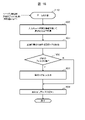
図10は、ゲートウェイデプロイメント部410の処理フローチャートの例を示す。
FIG. 10 shows an example of a processing flowchart of the
ゲートウェイデプロイメント部410は、情報Aを引数として起動する。情報Aは、イメージ名と、認証認可ゲートウェイ312からの転送先APIエンドポイントと、外部公開用のAPIエンドポイントと、領域名称(デプロイメント先となるシステム実行領域の名称)とを含む。
The
ゲートウェイデプロイメント部410は、認証実行要求のためのメタ情報を認証部360より取得する(ステップ1000)。ゲートウェイデプロイメント部410は、認証認可ゲートウェイ312からの接続受付のためのメタ情報を認証部360に送信する(ステップ1001)。
The
ゲートウェイデプロイメント部410は、情報A内のイメージ名に対応した認証連携601および認可連携602を認証認可要件テーブル420から取得する(ステップ1002)。
ゲートウェイデプロイメント部410は、情報A内の領域名称をデプロイメントの第一引数とする(ステップ1004)。
The
ゲートウェイデプロイメント部410は、ステップ1002で取得した認証連携601の値が“Y”か確認する(ステップ1005)。認証連携601の値が“Y”であれば、ゲートウェイデプロイメント部410は、ステップ1000とステップ1001で取得したメタ情報をデプロイメントの第2の引数(環境変数など)とする(ステップ1006)。
The
ゲートウェイデプロイメント部410は、デプロイメントの引数を用いて、デプロイメント要求部115に対して、認証認可ゲートウェイ312のデプロイメントを依頼し完了を待つ(ステップ1007)。
The
ゲートウェイデプロイメント部410は、情報A内の転送先APIエンドポイントと外部公開用APIエンドポイントと領域名称とを引数として、転送設定部411を開始し完了を待つ(ステップ1008)。
The
ゲートウェイデプロイメント部410は、ステップ1002で取得した認可連携602の値が“Y”か確認する(ステップ1009)。認可連携602の値が“Y”であれば、ゲートウェイデプロイメント部410は、認可部361のAPIエンドポイントを引数として認可設定部412を開始し完了を待つ(ステップ1010)。
The
図11は、転送設定部411および認証認可ゲートウェイ311の処理フローチャートの例を示す図である。
FIG. 11 is a diagram showing an example of a processing flowchart of the
転送設定部411は、情報Bを引数として起動する。情報Bは、図10のステップ1008について説明した通り、転送先APIエンドポイント、外部公開用APIエンドポイント、および、領域名称(システム実行領域の名称)を含む。
転送設定部411は、情報B内の転送先APIエンドポイント、外部公開用APIエンドポイントおよび領域名称のセットを転送エントリとする(ステップ1100)。
The
転送設定部411は、転送エントリを引数に認証認可ゲートウェイの転送エントリ追加APIにアクセスする(ステップ1101)。
The
認証認可ゲートウェイ311は、環境変数などより、認証部360に接続するためのメタ情報を取得する(ステップ1110)。認証認可ゲートウェイ311は、当該取得したメタ情報を認証結果取得処理805(図8参照)に設定する(ステップ1111)。
The
認証認可ゲートウェイ311は、APIサービスを開始し要求受信を待つ(ステップ1112)。認証認可ゲートウェイ311は、転送エントリ追加APIが呼ばれた(要求を受信した)場合(ステップ1113:Y)、当該APIの呼び出しの引数とされ受信した転送エントリを転送エントリ824(例えば、メモリ上の変数、外部DB、設定ファイルなど)に追加し、再び要求受信を待つ(ステップ1112)。
Authentication and
図12は、認可設定部412および認証認可ゲートウェイの処理フローチャートの例を示す図である。
FIG. 12 is a diagram showing an example of a processing flowchart of the
認可設定部412は、情報Cを引数として起動する。情報Cは、領域名称(システム実行領域の名称)、転送先APIエンドポイント、ロール名、およびユーザ名を含む。ここで言う転送先APIエンドポイントは、図10のステップ1010において引数とされた、認可部361のAPIエンドポイントである。領域名称は、ゲートウェイデプロイメント部410に入力された情報A内の領域名称である。ロール名およびユーザ名は、ロール管理サービス810から取得された情報である。
The
認可設定部412は、情報Cを認可エントリとする(ステップ1200)。認可設定部412は、認可エントリを引数に認証認可ゲートウェイ311の認可エントリ追加APIにアクセスする(ステップ1201)。
The
認証認可ゲートウェイ312のステップ1210~1212は、図11のステップ1110~1112と同じである。認証認可ゲートウェイ312は、認可エントリ追加APIが呼ばれた(要求を受信した)場合(ステップ1213:Y)、認可エントリを引数に認可部361の認可ルール追加APIにアクセス(要求を送信)する(ステップ1214)。
Steps 1210-1212 of authentication and
認可部361の認可ルール追加API1220は、認証認可ゲートウェイ312から受けた要求より認可エントリを取得し、取得した認可エントリを認可ルール822に追加する(ステップ1221)。
The authorization
図13は、ヘッダ設定部413の処理フローチャートの例を示す図である。
FIG. 13 is a diagram showing an example of a processing flowchart of the
ヘッダ設定部413は、通過ID用のヘッダ名“auth_id”を引数に起働する。ヘッダ設定部413は、ヘッダ付与処理816に対して、入力のヘッダ名で通過IDをHTTP要求のヘッダに付与するための設定を行う(ステップ1300)。
The
図14は、認証検知部430の処理フローチャートの例を示す図である。
FIG. 14 is a diagram showing an example of a processing flowchart of the
認証検知部430は、タスク実行ログキー(バックエンドサービス311のインスタンス名など)を入力に起動する。
The
認証検知部430は、追加ヘッダテーブル421より、用途611が“ゲートウェイ通過識別”のレコードのヘッダ名612を取得する(ステップ1400)。認証検知部430は、タスク実行ログキーを用いて、確認状態テーブル440より位置関連701を取得する(ステップ1401)。認証検知部430は、タスク実行ログキーと取得された位置関連701より、実行ログテーブル300の読み取り開始点を決定する(ステップ1402)。
The
認証検知部430は、実行ログテーブル300の次の実行ログレコード(開始点に属するレコードの次のレコード)を取得する(ステップ1403)。認証検知部430は、当該取得した実行ログレコードの要求ヘッダ503より、ステップ1400で取得したヘッダ名に関するヘッダ値を取得する(ステップ1404)。認証検知部430は、ロググループテーブル442の通過ID712内に、ステップ1404で取得したヘッダ値が存在するか確認する(ステップ1405)。
The
当該ヘッダ値が存在する場合(ステップ1406:Y)、認証検知部430は、当該ヘッダ値(通過ID)を引数に図15のユーザアクセストークン特定を開始する(ステップ1407)。
If the header value exists (step 1406: Y), the
当該ヘッダ値が存在しない場合(ステップ1406:N)、または、ステップ1407の後、認証検知部430は、ステップ1403で取得した実行ログレコードがタスク実行ログキーに関して実行ログテーブル300の最後のレコードか確認する(ステップ1408)。確認結果が真であれば、処理が終了する。確認結果が偽であれば、処理がステップ1403へ移動する。
If the header value does not exist (step 1406: N), or after
図15は、ユーザアクセストークン特定の処理フローチャートの例を示す。 FIG. 15 shows an example of a processing flowchart for identifying a user access token.
認証検知部430は、引数とされた通過IDを持つ通過ログレコードを通過ログテーブル331から取得する(ステップ1500)。認証検知部430は、ステップ1500で取得した通過ログレコードよりゲートウェイIDを取得する(ステップ1501)。認証検知部430は、ステップ1501で取得したゲートウェイIDと同じゲートウェイID620を持つレコードを、ゲートウェイインスタンステーブル422から取得する(ステップ1502)。認証検知部430は、ステップ1502で取得したレコードのサービスID621に属するサービスイメージ名600を持つレコードを認証認可要件テーブル420から取得する(ステップ1503)。ステップ1503で取得したレコードの認証連携601が“Y”の場合(ステップ1504:Y)、処理がステップ1508へ移動する。当該認証連携601が“N”であるが当該レコードの認可連携602が“Y”の場合(ステップ1504:N、ステップ1505:Y)、処理がステップ1506へ移動する。認証連携601と認可連携602のいずれも“N”の場合は(ステップ1504:N、ステップ1505:N)、処理が終了する。
The
ステップ1505:Yの場合、認証検知部430は、ステップ1501で取得した通過ログレコードより親通過ID513を取得する(ステップ1506)。認証検知部430は、ステップ1506で取得した親通過IDを通過IDとし(ステップ1507)、ステップ1500以降を実施する。
Step 1505: In the case of Y, the
ステップ1504:Yの場合、認証検知部430は、ステップ1500で取得した通過ログレコードのアクセストークン512をユーザ識別情報とする(ステップ1508)。認証検知部430は、通過IDとユーザ識別情報を引数としてロググループ出力部432を開始する(ステップ1509)。認証検知部430は、ゲートウェイインスタンステーブル422に次のレコードがあるか確認する(ステップ1510)。確認結果が真であれば、処理がステップ1501に移動する。確認結果が偽であれば、処理が終了する。
Step 1504: In the case of Y, the
図16は、ロググループ出力部432の処理フローチャートの例を示す図である。
FIG. 16 is a diagram showing an example of a processing flowchart of the log
ロググループ出力部432は、通過IDと、ユーザ識別情報を入力として起動する。ロググループ出力部432は、通過IDとユーザ識別情報のセットに任意のラベル(UUIDや連番などの一意性が保証できる文字列)を付与する(ステップ1600)。ロググループ出力部432は、通過ID、ユーザ識別情報およびラベルをロググループテーブル442のレコードとして出力する(ステップ1601)。
The log
本実施形態によれば、バックエンドサービス311は認証認可機能を持たず、かつ複数のユーザで共用する場合でも、ユーザ(利用者)毎の利用明細を出力できる。
[実施形態2]
According to this embodiment, even if the
[Embodiment 2]
実施形態2を説明する。その際、実施形態1との相違点を主に説明し、実施形態1との共通点については説明を省略または簡略する。 A second embodiment will be described. At that time, the points of difference from the first embodiment will be mainly described, and the explanations of the points in common with the first embodiment will be omitted or simplified.
実施形態1では、バックエンドサービス311への要求にあるアクセストークンと、各要求が認証認可ゲートウェイ312(インスタンス)を通過する際に当該要求のヘッダに自動的に埋め込まれた要求IDと、要求ID間の親子関係を用いて、バックエンドサービス311が出力する実行ログをユーザ(利用者)毎に分類するためのグループ情報が生成される。本実施形態では、前述の実行ログとグループ情報を用いて、業務(例えば、ユーザ毎の課金や利用状況の可視化など)に向けたデータが出力される。
In the first embodiment, the access token in the request to the
図17は、本実施形態におけるコーディネーションサービス1701の構成の例を示す図である。
FIG. 17 is a diagram showing an example of the configuration of the
コーディネーションサービス1701は、課金用データ出力部1700を備える。課金用データ出力部1700は、前述の実行ログとグループ情報を用いて業務に向けたデータを出力するデータ出力部1710を持つ。
図18は、データ出力部1710の処理フローチャートの例を示す図である。
FIG. 18 is a diagram showing an example of a processing flowchart of the
データ出力部1710は、ユーザ識別情報と追加のフィルタ情報(時刻範囲など)を入力として起動する。追加のフィルタ情報は必須ではない。
The
データ出力部1710は、入力のユーザ識別情報を用いてロググループテーブル442から通過IDの集合を取得する(ステップ1800)。データ出力部1710は、ステップ1800で取得した通過ID集合のいずれかの通過IDを要求ヘッダ503に持つ実行ログを実行ログテーブル300から取得する(ステップ1801)。
The
データ出力部1710は、追加のフィルタ情報が入力されているかを確認する(ステップ1802)。確認結果が偽であれば、処理がステップ1804に移動する。
The
確認結果が真であれば、データ出力部1710は、ステップ1801で取得した実行ログに対して追加のフィルタ情報でフィルタする(ステップ1803)。
If the confirmation result is true, the
データ出力部1710は、要求元に実行ログを返す(ステップ1804)。
The
図18では、実行ログの出力先として実行ログの要求元としたが、既定のディレクトリやテーブルなどへの実行ログが出力されてもよい。
[実施形態3]
In FIG. 18, the execution log output destination is the execution log request source, but the execution log may be output to a predetermined directory, table, or the like.
[Embodiment 3]
実施形態3を説明する。その際、実施形態2との相違点を主に説明し、実施形態2との共通点については説明を省略または簡略する。 A third embodiment will be described. At that time, the points of difference from the second embodiment will be mainly described, and the explanations of the points in common with the second embodiment will be omitted or simplified.
実施形態2では、ログとそのグループ情報を用いて、業務(例えば、ユーザ毎の課金や利用状況の可視化など)に向けたデータが出力される。本実施形態では、請求実行などに必要な契約関連情報が、前述のデータに付与される。 In the second embodiment, the log and its group information are used to output data for business (for example, billing for each user, visualization of usage status, etc.). In the present embodiment, contract-related information necessary for executing billing or the like is added to the data described above.
図19は、本実施形態におけるコーディネーションサービス1910の構成の例を示す図である。
FIG. 19 is a diagram showing an example of the configuration of the
コーディネーションサービス1910において、課金用データ出力部1920が、データ出力部1950と、契約マッピングテーブル1900とを備える。また、契約管理サービス1902が備えられる。契約管理サービス1902は、契約ID、および、契約内容(例えば、利用するバックエンドサービスとその利用単価などといった情報)を持つ。契約マッピングテーブル1900は、前述の契約IDと、課金用データ(例えば、実行ログレコードの集合)を関連付けるためのマッピングテーブルである。矢印A1901が示すように、データ出力部1950は、契約マッピングテーブル1900から、課金用データのラベルに対応した契約IDを取得し、契約管理サービス1902から、当該契約IDに対応した契約内容を取得し、取得した契約内容を基に課金用データを加工する(例えば、契約内容の情報を付与する)。
In
図20は、契約マッピングテーブル1900の構成の例を示す図である。 FIG. 20 is a diagram showing an example of the configuration of the contract mapping table 1900. As shown in FIG.
契約マッピングテーブル1900は、契約ID2000とラベル2001の対応関係を管理する。
The contract mapping table 1900 manages correspondence between
図21は、本実施形態におけるデータ出力部1950の処理フローチャートの例を示す図である。
FIG. 21 is a diagram showing an example of a processing flowchart of the
図18との違いは、ステップ2100、2101、2102の追加である。データ出力部1950は、ロググループテーブル442のラベル710をキーに、ラベル710に一致するラベル2001に対応した契約ID2000を契約マッピングテーブル1900から取得する(ステップ2100)。データ出力部1950は、契約管理サービス1902から、取得した契約ID2000に一致する契約IDに対応した契約内容を取得する(ステップ2101)。データ出力部1950は、ステップ2101で取得した契約内容を用いて課金用データを加工する(ステップ2102)。
The difference from FIG. 18 is the addition of
以上の実施形態1~3の説明を、例えば以下のように総括することができる。また、以下では、上述の説明が必要に応じて補足されてよい。
The above descriptions of
一または複数の開発者130により開発された複数のバックエンドサービス311(複数のサービスモジュールの一例)うちの一つ以上のバックエンドサービス311により構成されたテナント用システム104(サービスシステムの一例)が、複数種類の計算資源に基づく実行基盤サービス122にデプロイされる。実行基盤サービス122に、コーディネーションサービス113(システム実行支援装置の一例)のゲートウェイ制御部400により、テナント用システム104について一つ以上のゲートウェイ312がデプロイされる。
Tenant system 104 (an example of a service system) configured by one or
各バックエンドサービス311は、当該バックエンドサービス311についての要求を実行した場合に当該要求の実行における使用量を含む実行内容と当該要求のヘッダ情報(要求のヘッダが有する情報)とを含んだログである実行ログを実行ログテーブル300(第1のログ情報の一例)に書き込むようになっている。「使用量」は、時間、計算資源量およびデータ量の少なくとも一種類の量を含んでよい。また、「使用量」は、バックエンドサービス311の実行により使用された物理的な計算資源の使用量でもよいし、バックエンドサービス311の使用量でもよい。
Each
テナント用システム104におけるバックエンドサービス311A(対象のサービスモジュールの一例)について、ゲートウェイ312Aが、アクセストークン(認証および認可の少なくとも一つのためのデータである認証認可データの一例)を持つ要求を受ける。すると、ゲートウェイ312Aは、受けた要求に対し当該要求の通過IDを付与し、当該要求のヘッダに、アクセストークンに代えて当該付与した通過IDを設定する。ゲートウェイ312Aは、当該通過IDを含んだヘッダを持つ要求を、対象のバックエンドサービス311Aに転送し、当該通過IDと上記アクセストークンとを含んだログである通過ログを通過ログテーブル301(第2のログ情報の一例)に書き込む。
For
各バックエンドサービス311が上述の実行ログを書き込むようになっていても、実行ログは、利用者の識別情報相当の情報を含んでいない。一方、ゲートウェイ312が、アクセストークンを含む上述の通過ログを書き込むようになっていても、通過ログは、バックエンドサービス311の実行に従う使用量を表す情報を含んでいない。実行ログと通過ログが、通過IDを介して互いに関連付けられる。具体的には、実行ログ内のヘッダ情報に設定された通過IDと、通過ログに設定された通過IDとにより、実行ログと通過ログとが関連付けられる。結果として、通過IDをキーに使用量の特定が可能となり、故に、使用量に応じた従量課金が可能となる。
Even if each
なお、アクセストークンは、認証認可に使用されるデータでありログに記録されることは避ける方が好ましい。バックエンドサービス311に転送される要求のヘッダ情報は、アクセストークンに代えて通過IDを持つので、実行ログにヘッダ情報が含まれても、アクセストークンが実行ログに含まれずに済む。
Note that the access token is data used for authentication and authorization and should preferably be avoided from being recorded in logs. The header information of the request transferred to the
実行ログテーブル300および通過ログテーブル301は、ログ管理部116により管理されてよい。ログ管理部116は、例えばファイルシステムでよい。
Execution log table 300 and passage log table 301 may be managed by
また、要求のメタ情報として、ヘッダ情報以外の情報でもよいが、メタ情報がヘッダ情報であることで、要求としてHTTP要求の採用が可能である。また、認証認可データは、アクセストークン以外のデータでもよいが、認証認可データがアクセストークンであることで、要求としてHTTP要求の採用が可能である。 Further, information other than header information may be used as the meta information of the request, but since the meta information is header information, an HTTP request can be adopted as the request. Also, the authentication and authorization data may be data other than the access token, but since the authentication and authorization data is the access token, it is possible to employ an HTTP request as the request.
テナント用システム104を構成するバックエンドサービス311Aおよび311Bにそれぞれ用意されるゲートウェイ312Aおよび312B(第2のゲートウェイの一例)の他に、テナント用システム104についてのゲートウェイ312C(第1のゲートウェイの一例)がある。ゲートウェイ312Cが、クライアント350から、利用者のアクセストークンを持つ要求を受ける。ゲートウェイ312Cが、当該要求に対し通過IDを付与し、当該要求のヘッダに当該付与した通過IDを設定する。ゲートウェイ312Cが、当該通過IDを含んだヘッダ情報を持つ要求を転送し、当該要求IDと利用者のアクセストークンとを含んだ通過ログを通過ログテーブル301に書き込む。ゲートウェイ312Cにより転送された要求を、ゲートウェイ312Aが受ける。
In addition to
このようにゲートウェイ312間で要求が転送され、個々のゲートウェイ312により通過ログが蓄積される。通過ログを辿ることで、利用者のアクセストークンについて実行ログ毎の使用量を算出することが期待できる。
Requests are forwarded between
また、テナント用システム104に関し一連の要求の転送について、最初の通過ログには、クライアント350からの要求が持つアクセストークンが含まれる。この場合、仮に、バックエンドサービス制御プログラム313を通じてバックエンドサービス311が受ける要求のアクセストークンが、テナントのアクセストークンであるとしても、ゲートウェイ312Cがクライアント350から受ける要求が持つアクセストークンは、利用者のアクセストークンである可能性が高い。このため、テナント用システム104についてテナント単位のアクセストークンが発行されているケースでも、利用者単位で、テナント用システム104の実行に従う使用量の集計が可能であることが期待される。
Also, regarding the transfer of a series of requests regarding the tenant system 104, the first passage log contains the access token that the request from the
通過ログは、当該通過ログに対応し要求を転送したゲートウェイより付与された通過IDと、当該要求から抽出された認証認可データと、当該要求の転送元のゲートウェイにより付与された通過IDである親通過IDとを含む。ゲートウェイ312Cが受けた要求のアクセストークンについて、通過IDを用いて通過ログを辿ることができる。
The passage log contains the passage ID assigned by the gateway that forwarded the request corresponding to the passage log, the authentication authorization data extracted from the request, and the passage ID assigned by the gateway that forwarded the request. Passage ID. The transit log can be traced using the transit ID for the access token of the request received by the
具体的には、例えば、親通過IDの無いアクセストークンについて、ロググルーピング部401が、当該アクセストークンに対応した通過IDに関連付いている一つ以上の通過IDの集合である通過ID集合を通過ログテーブル301から特定してよい。ロググルーピング部401が、当該通過ID集合を構成する通過ID毎に、当該通過IDを含んだヘッダ情報に対応する実行内容(タスク内容504)を特定してよい。ログテーブル301が、当該通過ID集合について特定された実行内容に従う使用量を表す情報である利用情報を生成してよい。このようにして、親通過IDの無いアクセストークン毎に、使用量を表す利用情報の生成が可能である。 Specifically, for example, for an access token without a parent transit ID, the log grouping unit 401 selects a transit ID set, which is a set of one or more transit IDs associated with the transit ID corresponding to the access token. It may be specified from the log table 301 . The log grouping unit 401 may specify the execution content (task content 504) corresponding to the header information including the passage ID for each passage ID forming the passage ID set. The log table 301 may generate usage information, which is information representing the amount of usage according to the execution content specified for the passage ID set. In this way, it is possible to generate usage information representing the amount of usage for each access token that does not have a parent transit ID.
また、例えば、親通過IDの無いアクセストークンについて、さらに、課金用データ出力部1700が、生成され利用情報を基に、当該利用情報が表す使用量に応じた課金額を決定し、決定した課金額を出力してよい。このようにして、親通過IDの無いアクセストークン毎に、使用量に応じた従量課金が可能である。
Further, for example, for an access token without a parent transit ID, the billing
また、例えば、親通過IDの無いアクセストークンについて、さらに、課金用データ出力部1920が、当該アクセストークンに対応した契約内容を特定し、上記決定した課金額に上記特定した契約内容を関連付けて出力してよい。このようにして、課金額の根拠の一例となる契約内容を表す情報も一緒に出力することが可能である。
Further, for example, for an access token without a parent passing ID, the billing
ゲートウェイ制御部400が、テナント用システム104を構成する一つ以上のバックエンドサービス311の各々を、実行基盤サービス122にデプロイし、当該テナント用システム104についてゲートウェイ312Cを実行基盤サービス122にデプロイし、当該テナント用システム104を構成するバックエンドサービス311Aおよび312B(一つ以上のサービスモジュールの一例)についてゲートウェイ312Aおよび312B(一つ以上の第2のゲートウェイの一例)を実行基盤サービス122にデプロイする。このようにして、テナント用システム104の窓口としてゲートウェイ312Cと、テナント用システム104を構成するバックエンドサービス311A(311B)のゲートウェイ312A(312B)とを配備することができる。例えば、ゲートウェイ制御部400は、テナント用システム104のテンプレート情報またはイメージといった情報から、テナント用システム104を構成する個々のバックエンドサービス311を特定し、特定したバックエンドサービス311毎にゲートウェイ312をデプロイし、テナント用システム104についてゲートウェイ312Cをデプロイすることができる。
The gateway control unit 400 deploys each of the one or
各ゲートウェイ312は、要求を受けた場合、必要に応じて(例えば、転送先サービスモジュールのサービスイメージ名600に対応した認証連携601と認可連携602の値に応じて)、当該要求が持つアクセストークンを、テナント用システム104の外部に設けられ認証認可を行う機能である認証認可サービス群125に送信することで、当該認証認可サービス群125に認証認可を実行させる。このため、いずれのバックエンドサービス311が認証認可機能を持たなくても、認証認可を行うことができる。
Upon receiving a request, each
以上の説明は、本発明の説明のための例示であって、本発明の範囲を上述の実施形態にのみ限定する趣旨ではない。本発明は、他の種々の形態でも実施することが可能である。 The above description is an example for explanation of the present invention, and is not intended to limit the scope of the present invention only to the above-described embodiments. The present invention can also be implemented in various other forms.
例えば、テナント用システム104は、それぞれがアプリケーションサービスに関連付けられている複数のノードと当該複数のノードにおける各ノード間の結線とで表現されたアプリケーションソフトウェアフローでよい。ノードに関連付いたアプリケーションサービスは、サービスモジュールの一例でよい。アプリケーションソフトウェアフローは、ビジュアルプログラミングツールで記述されてよい。ビジュアルプログラミングツールは、「モデル開発環境」と呼ばれてもよい。ソフトウェアの構成要素や処理単位がノードであり、ノード同士の結線は「エッジ」と呼ばれてもよい。 For example, tenant system 104 may be an application software flow represented by a plurality of nodes, each associated with an application service, and connections between nodes in the plurality of nodes. An application service associated with a node may be an example of a service module. Application software flows may be written in visual programming tools. A visual programming tool may be referred to as a "model development environment." A software component or processing unit is a node, and a connection between nodes may be called an "edge".
また、本発明は、要求にメタ情報を付与できる環境全般に適用することが期待できる。例えば、WEBシステムに代えて、クライアントプログラムがライブラリにデータを記述する環境であって、関数の引数に独自の引数を追加することが許容されている環境にも、本発明を適用可能である。 Moreover, the present invention can be expected to be applied to all environments in which meta information can be added to requests. For example, instead of a WEB system, the present invention can also be applied to an environment in which a client program writes data in a library and in which it is permitted to add unique arguments to function arguments.
Claims (12)
前記複数のサービスモジュールの各々は、当該サービスモジュールについての要求を実行した場合に当該要求の実行における使用量を含む実行内容と当該要求のメタ情報とを含んだログである実行ログを第1のログ情報に書き込むようになっており、
(B)前記受けた要求に対し当該要求の通過IDを付与し、
(C)当該要求のメタ情報に当該要求の認証認可データに代えて当該付与した通過IDを設定し、
(D)当該通過IDを含んだメタ情報を持つ要求を、前記対象のサービスモジュールに転送し、
(E)当該通過IDと前記認証認可データとを含んだログである通過ログを第2のログ情報に書き込む、
システム実行支援方法。 (A) data for at least one of authentication and authorization for a target service module in a service system configured by one or more service modules out of a plurality of service modules developed by one or more developers; receive a request with certain authentication authorization data,
Each of the plurality of service modules stores an execution log, which is a log including execution contents including usage amount in execution of the request and meta information of the request when executing the request for the service module, as a first It is designed to write to the log information,
(B) assigning the passage ID of the request to the received request;
(C) setting the given passage ID in place of the authentication authorization data of the request in the meta information of the request;
(D) forwarding a request having meta information including the transit ID to the target service module;
(E) writing a transit log, which is a log containing the transit ID and the authentication and authorization data, into the second log information;
System execution support method.
前記第1のゲートウェイにより、当該要求に対し通過IDを付与し、
前記第1のゲートウェイにより、当該要求のメタ情報に当該要求の認証認可データに代えて当該付与した通過IDを設定し、
前記第1のゲートウェイにより、当該通過IDを含んだメタ情報を持つ要求を転送し、
前記第1のゲートウェイにより、当該要求IDと当該要求が持つ認証認可データとを含んだ通過ログを前記第2のログ情報に書き込み、
前記第1のゲートウェイにより転送された要求を、(A)において、前記一つ以上のサービスモジュールについてそれぞれ用意された一つ以上の第2のゲートウェイのうちの前記対象のサービスモジュールの第2のゲートウェイにより受け、
(B)~(E)は、前記対象のサービスモジュールの第2のゲートウェイにより実行される、
請求項1に記載のシステム実行支援方法。 receiving, by a first gateway, a request from a client with authentication and authorization data of the client for the service system;
assigning a transit ID to the request by the first gateway;
setting the given transit ID in place of the authentication/authorization data of the request in the meta information of the request by the first gateway;
forwarding a request with meta information including the transit ID by the first gateway;
writing a transit log containing the request ID and authentication authorization data of the request to the second log information by the first gateway;
the second gateway of the target service module among one or more second gateways respectively prepared for the one or more service modules in (A) received by
(B)-(E) are performed by a second gateway of the target service module;
2. The system execution support method according to claim 1.
請求項2に記載のシステム実行支援方法。 The passage log includes a passage ID assigned by the gateway that transferred the request corresponding to the passage log, authentication authorization data extracted from the request, and a passage ID assigned by the gateway that transferred the request. a parent transit ID;
3. The system execution support method according to claim 2.
当該認証認可データに対応した通過IDに関連付いている一つ以上の通過IDの集合である通過ID集合を前記第2のログ情報から特定し、
当該通過ID集合を構成する通過ID毎に、当該通過IDを含んだメタ情報に対応する実行内容を特定し、
当該通過ID集合について特定された実行内容に従う使用量を表す情報である利用情報を生成する、
請求項3に記載のシステム実行支援方法。 For authentication authorization data without parent transit ID,
identifying from the second log information a transit ID set, which is a set of one or more transit IDs associated with the transit ID corresponding to the authentication authorization data;
specifying, for each transit ID constituting the transit ID set, execution content corresponding to meta information including the transit ID;
generating usage information, which is information representing the amount of usage according to the execution content specified for the transit ID set;
4. The system execution support method according to claim 3.
前記生成した利用情報を基に、当該利用情報が表す使用量に応じた課金額を決定し、
前記決定した課金額を出力する、
請求項4に記載のシステム実行支援方法。 For authentication authorization data without a parent transit ID, further:
Based on the generated usage information, determine a billing amount according to the amount of usage represented by the usage information,
outputting the determined billing amount;
5. The system execution support method according to claim 4.
当該認証認可データに対応した契約内容を特定し、
前記決定した課金額に前記特定した契約内容を関連付けて出力する、
請求項5に記載のシステム実行支援方法。 For authentication authorization data without a parent transit ID, further:
Identify the contract content corresponding to the authentication and authorization data,
outputting the determined billing amount in association with the identified contract content;
6. The system execution support method according to claim 5.
前記サービスシステムについて前記第1のゲートウェイを前記実行基盤サービスにデプロイし、前記一つ以上のサービスモジュールについてそれぞれ前記一つ以上の第2のゲートウェイを前記実行基盤サービスにデプロイする、
請求項2に記載のシステム実行支援方法。 deploying each of the one or more service modules constituting the service system to an execution infrastructure service based on a plurality of types of computational resources;
deploying the first gateway to the execution infrastructure service for the service system, and deploying the one or more second gateways to the execution infrastructure service for each of the one or more service modules;
3. The system execution support method according to claim 2.
請求項1に記載のシステム実行支援方法。 When a request is received, the authentication and authorization data included in the request is sent to the authentication and authorization service group, which is a function that is provided outside the service system and performs authentication and authorization, thereby executing authentication and authorization for the authentication and authorization service group. let
2. The system execution support method according to claim 1.
請求項1に記載のシステム実行支援方法。 the meta information of the request is header information included in the header of the request;
2. The system execution support method according to claim 1.
請求項1に記載のシステム実行支援方法。 the authentication authorization data is an access token;
2. The system execution support method according to claim 1.
前記複数のサービスモジュールの各々は、当該サービスモジュールについての要求を実行した場合に当該要求の実行における使用量を含む実行内容と当該要求のメタ情報とを含んだログである実行ログを第1のログ情報に書き込むようになっており、
(B)前記受けた要求に対し当該要求の通過IDを付与し、
(C)当該要求のメタ情報に当該要求の認証認可データに代えて当該付与した通過IDを設定し、
(D)当該通過IDを含んだメタ情報を持つ要求を、前記対象のサービスモジュールに転送し、
(E)当該通過IDと前記認証認可データとを含んだログである通過ログを第2のログ情報に書き込む、
ことをコンピュータに実行させるコンピュータプログラム。 (A) data for at least one of authentication and authorization for a target service module in a service system configured by one or more service modules out of a plurality of service modules developed by one or more developers; receive a request with certain authentication authorization data,
Each of the plurality of service modules stores an execution log, which is a log including execution contents including usage amount in execution of the request and meta information of the request when executing the request for the service module, as a first It is designed to write to the log information,
(B) assigning the passage ID of the request to the received request;
(C) setting the given passage ID in place of the authentication authorization data of the request in the meta information of the request;
(D) forwarding a request having meta information including the transit ID to the target service module;
(E) writing a transit log, which is a log containing the transit ID and the authentication and authorization data, into the second log information;
A computer program that makes a computer do something.
第1のログ情報と第2のログ情報とを管理するログ管理部と
を備え、
前記サービスシステムは、一または複数の開発者により開発された複数のサービスモジュールのうちの一つ以上のサービスモジュールにより構成され、
前記複数のサービスモジュールの各々は、当該サービスモジュールについての要求を実行した場合に当該要求の実行における使用量を含む実行内容と当該要求のメタ情報とを含んだログである実行ログを第1のログ情報に書き込むようになっており、
前記一つ以上のゲートウェイのうちのいずれかのゲートウェイが、
認証および認可の少なくとも一つのためのデータである認証認可データを持つ要求を受け、
前記受けた要求に対し当該要求の通過IDを付与し、
当該要求のメタ情報に当該要求の認証認可データに代えて当該付与した通過IDを設定し、
当該通過IDを含んだメタ情報を持つ要求を、対象のサービスモジュールに転送し、
当該通過IDと前記認証認可データとを含んだログである通過ログを第2のログ情報に書き込む、
システム実行支援装置。 a gateway control unit that deploys one or more gateways to a service system deployed in an execution infrastructure service based on multiple types of computational resources;
A log management unit that manages the first log information and the second log information,
The service system is composed of one or more service modules out of a plurality of service modules developed by one or more developers,
Each of the plurality of service modules stores an execution log, which is a log including execution contents including usage amount in execution of the request and meta information of the request when executing the request for the service module, as a first It is designed to write to the log information,
any gateway of the one or more gateways,
receiving a request with authentication and authorization data that is data for at least one of authentication and authorization;
assigning a passage ID of the request to the received request;
setting the given passage ID in place of the authentication authorization data of the request in the meta information of the request;
forwarding a request with meta information containing the transit ID to the target service module;
writing a transit log, which is a log containing the transit ID and the authentication and authorization data, into the second log information;
System execution support device.
Priority Applications (1)
| Application Number | Priority Date | Filing Date | Title |
|---|---|---|---|
| JP2019173122A JP7159136B2 (en) | 2019-09-24 | 2019-09-24 | System execution support method and device |
Applications Claiming Priority (1)
| Application Number | Priority Date | Filing Date | Title |
|---|---|---|---|
| JP2019173122A JP7159136B2 (en) | 2019-09-24 | 2019-09-24 | System execution support method and device |
Publications (2)
| Publication Number | Publication Date |
|---|---|
| JP2021051461A JP2021051461A (en) | 2021-04-01 |
| JP7159136B2 true JP7159136B2 (en) | 2022-10-24 |
Family
ID=75157929
Family Applications (1)
| Application Number | Title | Priority Date | Filing Date |
|---|---|---|---|
| JP2019173122A Active JP7159136B2 (en) | 2019-09-24 | 2019-09-24 | System execution support method and device |
Country Status (1)
| Country | Link |
|---|---|
| JP (1) | JP7159136B2 (en) |
Citations (4)
| Publication number | Priority date | Publication date | Assignee | Title |
|---|---|---|---|---|
| JP2002116928A (en) | 2000-06-16 | 2002-04-19 | Fujitsu Ltd | Recording system for recording processing information of multiple systems |
| JP2013011995A (en) | 2011-06-28 | 2013-01-17 | Fujitsu Ltd | Information processing apparatus, log processing method, and program |
| JP2014075084A (en) | 2012-10-05 | 2014-04-24 | Fuji Xerox Co Ltd | Communication system, client device, relay device and program |
| JP2017199145A (en) | 2016-04-26 | 2017-11-02 | キヤノン株式会社 | Server apparatus, system, information processing method, and program |
-
2019
- 2019-09-24 JP JP2019173122A patent/JP7159136B2/en active Active
Patent Citations (4)
| Publication number | Priority date | Publication date | Assignee | Title |
|---|---|---|---|---|
| JP2002116928A (en) | 2000-06-16 | 2002-04-19 | Fujitsu Ltd | Recording system for recording processing information of multiple systems |
| JP2013011995A (en) | 2011-06-28 | 2013-01-17 | Fujitsu Ltd | Information processing apparatus, log processing method, and program |
| JP2014075084A (en) | 2012-10-05 | 2014-04-24 | Fuji Xerox Co Ltd | Communication system, client device, relay device and program |
| JP2017199145A (en) | 2016-04-26 | 2017-11-02 | キヤノン株式会社 | Server apparatus, system, information processing method, and program |
Also Published As
| Publication number | Publication date |
|---|---|
| JP2021051461A (en) | 2021-04-01 |
Similar Documents
| Publication | Publication Date | Title |
|---|---|---|
| JP7092736B2 (en) | Dynamic routing using container orchestration services | |
| US11281457B2 (en) | Deployment of infrastructure in pipelines | |
| JP5963957B2 (en) | Development environment system, development environment device, development environment providing method and program | |
| US8136146B2 (en) | Secure audit log access for federation compliance | |
| CN103703443B (en) | Powerful permission management for computing application functions | |
| US7249354B2 (en) | System and method for deploying a software build from a plurality of software builds to a target computer | |
| CN109656538A (en) | Generation method, device, system, equipment and the medium of application program | |
| CN100428168C (en) | Method and system for managing central processing unit utilization of virtual machines | |
| JP2018010642A (en) | Annotations of resources | |
| WO2021067156A1 (en) | Nested tenancy that permits a hierarchy having a plurality of levels | |
| US11195137B2 (en) | Model-driven and automated system for shared resource solution design | |
| CN110750243A (en) | Project code development method and system | |
| CN105141702A (en) | Model-based mixed cloud construction method | |
| US20210073676A1 (en) | Model improvement support system | |
| US11509730B1 (en) | Analyzing web service frontends to extract security-relevant behavior information | |
| JP7159136B2 (en) | System execution support method and device | |
| KR101977219B1 (en) | Apparatus and method for providing virtualized data service based on gis | |
| JP2019003477A (en) | Information processing system, control method, and program thereof | |
| KR102797857B1 (en) | Workspace-Based Server Integration and Management Platform Provision System | |
| US20240362048A1 (en) | Kubernetes Integrated Chargeback and Limits Management | |
| US20240330709A1 (en) | Shadow satisfiability modulo theories solver systems | |
| JP5214108B2 (en) | System and method for capturing the structure of a data model using entity patterns | |
| CN116566946A (en) | A friendly domain name system generation and management method and related equipment | |
| CN120494706A (en) | Government resource management method and computer equipment | |
| CN119577724A (en) | A data authority management method and device for data collection process |
Legal Events
| Date | Code | Title | Description |
|---|---|---|---|
| A621 | Written request for application examination |
Free format text: JAPANESE INTERMEDIATE CODE: A621 Effective date: 20211111 |
|
| A977 | Report on retrieval |
Free format text: JAPANESE INTERMEDIATE CODE: A971007 Effective date: 20220929 |
|
| TRDD | Decision of grant or rejection written | ||
| A01 | Written decision to grant a patent or to grant a registration (utility model) |
Free format text: JAPANESE INTERMEDIATE CODE: A01 Effective date: 20221004 |
|
| A61 | First payment of annual fees (during grant procedure) |
Free format text: JAPANESE INTERMEDIATE CODE: A61 Effective date: 20221012 |
|
| R150 | Certificate of patent or registration of utility model |
Ref document number: 7159136 Country of ref document: JP Free format text: JAPANESE INTERMEDIATE CODE: R150 |