JP7157732B2 - Aerosol generating system with cartridge containing gel - Google Patents
Aerosol generating system with cartridge containing gel Download PDFInfo
- Publication number
- JP7157732B2 JP7157732B2 JP2019503565A JP2019503565A JP7157732B2 JP 7157732 B2 JP7157732 B2 JP 7157732B2 JP 2019503565 A JP2019503565 A JP 2019503565A JP 2019503565 A JP2019503565 A JP 2019503565A JP 7157732 B2 JP7157732 B2 JP 7157732B2
- Authority
- JP
- Japan
- Prior art keywords
- chamber
- cartridge
- aerosol
- gel
- heater
- Prior art date
- Legal status (The legal status is an assumption and is not a legal conclusion. Google has not performed a legal analysis and makes no representation as to the accuracy of the status listed.)
- Active
Links
Images


Classifications
-
- A—HUMAN NECESSITIES
- A24—TOBACCO; CIGARS; CIGARETTES; SIMULATED SMOKING DEVICES; SMOKERS' REQUISITES
- A24B—MANUFACTURE OR PREPARATION OF TOBACCO FOR SMOKING OR CHEWING; TOBACCO; SNUFF
- A24B15/00—Chemical features or treatment of tobacco; Tobacco substitutes, e.g. in liquid form
- A24B15/10—Chemical features of tobacco products or tobacco substitutes
- A24B15/16—Chemical features of tobacco products or tobacco substitutes of tobacco substitutes
- A24B15/167—Chemical features of tobacco products or tobacco substitutes of tobacco substitutes in liquid or vaporisable form, e.g. liquid compositions for electronic cigarettes
-
- A—HUMAN NECESSITIES
- A24—TOBACCO; CIGARS; CIGARETTES; SIMULATED SMOKING DEVICES; SMOKERS' REQUISITES
- A24F—SMOKERS' REQUISITES; MATCH BOXES; SIMULATED SMOKING DEVICES
- A24F40/00—Electrically operated smoking devices; Component parts thereof; Manufacture thereof; Maintenance or testing thereof; Charging means specially adapted therefor
- A24F40/30—Devices using two or more structurally separated inhalable precursors, e.g. using two liquid precursors in two cartridges
-
- A—HUMAN NECESSITIES
- A24—TOBACCO; CIGARS; CIGARETTES; SIMULATED SMOKING DEVICES; SMOKERS' REQUISITES
- A24F—SMOKERS' REQUISITES; MATCH BOXES; SIMULATED SMOKING DEVICES
- A24F40/00—Electrically operated smoking devices; Component parts thereof; Manufacture thereof; Maintenance or testing thereof; Charging means specially adapted therefor
- A24F40/40—Constructional details, e.g. connection of cartridges and battery parts
- A24F40/42—Cartridges or containers for inhalable precursors
-
- A—HUMAN NECESSITIES
- A24—TOBACCO; CIGARS; CIGARETTES; SIMULATED SMOKING DEVICES; SMOKERS' REQUISITES
- A24F—SMOKERS' REQUISITES; MATCH BOXES; SIMULATED SMOKING DEVICES
- A24F40/00—Electrically operated smoking devices; Component parts thereof; Manufacture thereof; Maintenance or testing thereof; Charging means specially adapted therefor
- A24F40/20—Devices using solid inhalable precursors
Description
本発明は、エアロゾル形成基体を加熱してエアロゾルを発生するエアロゾル発生システムに関する。特に、本発明はゲルを加熱してエアロゾル形成するエアロゾル発生システムに関する。 The present invention relates to an aerosol-generating system that heats an aerosol-forming substrate to generate an aerosol. More particularly, the present invention relates to an aerosol generating system that heats a gel to form an aerosol.
液体製剤を加熱してユーザーによる吸入用にエアロゾルを発生することによって動作する、eシガレットなどのエアロゾル発生システムが幅広く使用されている。これらは典型的に、装置部分およびカートリッジを備える。一部のシステムにおいて、装置部分は電源と、制御電子回路とを収容し、またカートリッジは、液体製剤を保持する液体貯蔵部と、液体製剤を気化するためのヒーターと、液体を液体貯蔵部からヒーターに移動させる芯とを収容する。このタイプのシステムは人気が高まってきている一方で、不都合な点を有する。一つの不都合な点は、移動中および貯蔵中の両方に、ならびにカートリッジが装置部分に接続されている時に、液体貯蔵部からの液体の漏れが起こりうることである。液体を貯蔵部からヒーターに移動させるための芯の使用は、システムを複雑にしうる。 Aerosol generating systems, such as e-cigarettes, are widely used that operate by heating a liquid formulation to generate an aerosol for inhalation by the user. These typically comprise device parts and cartridges. In some systems, the instrument portion contains the power supply and control electronics, and the cartridge contains a liquid reservoir to hold the liquid formulation, a heater to vaporize the liquid formulation, and a liquid from the liquid reservoir. It contains a wick that moves to the heater. While this type of system is becoming more popular, it has disadvantages. One disadvantage is that liquid leakage from the liquid reservoir can occur both during transportation and storage, and when the cartridge is connected to the device part. The use of a wick to move liquid from the reservoir to the heater can complicate the system.
本発明の第一の態様において、エアロゾル発生システムのためにエアロゾル発生カートリッジが提供されており、エアロゾル発生カートリッジは、
第一のチャンバーと、第一のチャンバーとは分離している第二のチャンバーとを備え、第一のチャンバーはゲルの形態のエアロゾル形成基体を収容し、また第二のチャンバーは吸入用の化合物の供与源を収容する。
In a first aspect of the invention, an aerosol-generating cartridge is provided for an aerosol-generating system, the aerosol-generating cartridge comprising:
comprising a first chamber and a second chamber separate from the first chamber, the first chamber containing an aerosol-forming substrate in the form of a gel, and the second chamber containing a compound for inhalation. contain sources of
吸入用の化合物の供与源は、ニコチンの供与源と風味供与源のうちの一方または両方を備えてもよい。 The source of compound for inhalation may comprise a source of nicotine and/or a flavor source.
有利なことにゲルは室温で固体である。この文脈において「固体」とは、ゲルが安定したサイズおよび形状を有し、かつ流れないことを意味する。第一および第二のチャンバーは、異なる組成物を収容してもよい。第一のチャンバーと第二のチャンバーの両方はゲルを収容してもよい。第二のチャンバーは固体材料を収容してもよい。有利なことに、第一のチャンバーも第二のチャンバーも室温で固体でない材料を収容しない。 Advantageously, the gel is solid at room temperature. "Solid" in this context means that the gel has a stable size and shape and does not flow. The first and second chambers may contain different compositions. Both the first chamber and the second chamber may contain gel. A second chamber may contain the solid material. Advantageously, neither the first chamber nor the second chamber contain materials that are not solid at room temperature.
この文脈においてエアロゾル形成基体は、エアロゾルを形成することができる揮発性化合物を放出する能力を有する材料または材料の混合物である。ゲルの形態のエアロゾル形成基体の提供は、貯蔵および移動のために、または使用中に有利である場合がある。エアロゾル形成基体をゲルで提供することによって、装置からの漏れのリスクが低減される場合がある。枯渇した時または使い果たした時にエアロゾル形成基体を装置に補充することはまた、例えば漏れまたはこぼれのリスクを低減することによって改善される場合がある。 An aerosol-forming substrate in this context is a material or mixture of materials that has the ability to release volatile compounds capable of forming an aerosol. Providing an aerosol-forming substrate in the form of a gel may be advantageous for storage and transport or during use. By providing the aerosol-forming substrate with a gel, the risk of leakage from the device may be reduced. Replenishing the device with aerosol-forming substrate when depleted or depleted may also be improved, for example by reducing the risk of leaks or spills.
エアロゾル形成基体はエアロゾル形成体を含んでもよい。本明細書で使用される「エアロゾル形成体」という用語は、使用時に高密度でかつ安定したエアロゾルの形成を容易にする任意の適切な周知の化合物または化合物の混合物を指す。エアロゾル形成体は、カートリッジの動作温度で熱分解に対して実質的に耐性がある。適切なエアロゾル形成体は当業界で周知であり、多価アルコール(トリエチレングリコール、1、3-ブタンジオール、およびグリセリンなど)、多価アルコールのエステル(グリセロールモノアセテート、ジアセテート、またはトリアセテートなど)、およびモノカルボン酸、ジカルボン酸、またはポリカルボン酸の脂肪族エステル(ドデカン二酸ジメチルおよびテトラデカン二酸ジメチルなど)を含むが、これらに限定されない。好ましいエアロゾル形成体は、多価アルコールまたはその混合物(トリエチレングリコール、1、3-ブタンジオールなど)であり、最も好ましくはグリセリンまたはポリエチレングリコールである。 The aerosol-forming substrate may comprise an aerosol former. The term "aerosol former" as used herein refers to any suitable known compound or mixture of compounds that facilitates the formation of a dense and stable aerosol in use. The aerosol former is substantially resistant to thermal decomposition at the operating temperature of the cartridge. Suitable aerosol formers are well known in the art and include polyhydric alcohols (such as triethylene glycol, 1,3-butanediol, and glycerin), esters of polyhydric alcohols (such as glycerol monoacetate, diacetate, or triacetate). , and aliphatic esters of monocarboxylic, dicarboxylic, or polycarboxylic acids, such as dimethyl dodecanedioate and dimethyl tetradecanedioate. Preferred aerosol formers are polyhydric alcohols or mixtures thereof such as triethylene glycol, 1,3-butanediol, most preferably glycerin or polyethylene glycol.
特定の温度でエアロゾル形成体を放出するのに適切であるゲル製剤または組成物は、他の化合物を保持しその後放出するために理想的に適していない場合がある。エアロゾル形成体を収容するチャンバーと、他の化合物(例えばニコチンまたは風味供与源化合物)を収容する一つ以上の他のチャンバーという別個のチャンバーを提供することによって、保持および放出の両方の改善を実現できる。 A gel formulation or composition that is suitable for releasing an aerosol former at a particular temperature may not be ideally suited for retaining and then releasing other compounds. Improvements in both retention and release are achieved by providing separate chambers, one containing the aerosol former and one or more other chambers containing other compounds (e.g., nicotine or flavor-providing compounds). can.
第一のチャンバーは、ゲルに加えて追加的な材料または構成成分を収容してもよい。 The first chamber may contain additional materials or components in addition to the gel.
本明細書で使用される「エアロゾル発生カートリッジ」という用語は、エアロゾルを形成することができる揮発性化合物を放出するために、燃焼ではなく加熱されることが意図されるエアロゾル形成基体を含む物品を指す。結果として得られるエアロゾルがニコチンを含有する時、ニコチンの供与源がゲル内に含有されることは有利である。ニコチンの供与源は、第一のチャンバーおよび第二のチャンバーのうちの一方または両方の中に含まれてもよい。ニコチンは、第一のチャンバーの中のエアロゾル形成体を有するゲル内に含まれてもよく、または第二のチャンバーの中の第二のゲル内に含まれてもよく、または両方のチャンバーの中のゲル内に含まれてもよい。従って、室温でゲル内にニコチンを保持することによってニコチン含有材料のシステムからの漏れのリスクを低減することが望ましい。代替の構成において、ニコチンの供与源は、第二のチャンバー内に、例えば液体または固体材料内に収容されてもよい。 As used herein, the term "aerosol-generating cartridge" refers to an article containing an aerosol-forming substrate that is intended to be heated, rather than combusted, to release volatile compounds capable of forming an aerosol. Point. When the resulting aerosol contains nicotine, it is advantageous if the source of nicotine is contained within the gel. A source of nicotine may be contained within one or both of the first and second chambers. Nicotine may be contained within the gel with the aerosol former in the first chamber, or within a second gel within the second chamber, or within both chambers. may be contained within the gel of Therefore, it is desirable to reduce the risk of leakage of nicotine-containing materials from the system by retaining nicotine within the gel at room temperature. In an alternative arrangement, the source of nicotine may be contained within the second chamber, eg within a liquid or solid material.
風味化合物は第二のチャンバーの中のゲル内に含有されてもよい。別の方法として、または追加的に、風味化合物は別の形態で提供されてもよい。例えば、第二のチャンバーは、加熱された時に風味化合物を放出する固体たばこ材料を収容してもよい。第二のチャンバーは、例えば薬草の葉、たばこの葉、たばこの茎の破片、再構成たばこ、均質化したたばこ、押出成形たばこ、および膨化たばこのうち一つ以上を含む、粉末、顆粒、ペレット、断片、スパゲッティ、細片またはシートのうちの一つ以上を含んでもよい。第二のチャンバー内の固体たばこ材料はまとめられていない形態であってもよい。たばこはゲルまたは液体内に含有されてもよい。第二のチャンバーは、加熱に伴い放出される追加的なたばこまたは非たばこの揮発性風味化合物を収容してもよい。 A flavoring compound may be contained within the gel in the second chamber. Alternatively or additionally, the flavor compounds may be provided in another form. For example, the second chamber may contain a solid tobacco material that releases flavor compounds when heated. The second chamber contains powders, granules, pellets containing one or more of, for example, herb leaves, tobacco leaves, tobacco stem fragments, reconstituted tobacco, homogenized tobacco, extruded tobacco, and puffed tobacco. , pieces, spaghetti, strips or sheets. The solid tobacco material in the second chamber may be in unconsolidated form. Tobacco may be contained within the gel or liquid. The second chamber may contain additional tobacco or non-tobacco volatile flavor compounds released upon heating.
第一のチャンバーまたは第二のチャンバーは、例えば揮発性風味化合物を含むカプセルを収容してもよく、またこうしたカプセルは、例えば加熱中に溶融することによってその内容物を放出してもよい。 The first chamber or the second chamber may, for example, contain capsules containing volatile flavor compounds, and such capsules may release their contents, for example by melting during heating.
有利なことに、ゲルは熱可逆性ゲルを含む。これは、ゲルが溶融温度まで加熱された時に流体になり、ゲル化温度で再度ゲルへと固まることを意味する。ゲル化温度は室温以上であり、かつ大気圧以上であることが好ましい。この文脈において室温は摂氏25度を意味する。大気圧は1気圧の圧力を意味する。溶融温度はゲル化温度より高いことが好ましい。ゲルの溶融温度は摂氏50度、または摂氏60度、または摂氏70度より高いことが好ましく、また摂氏80度より高いことがより好ましい。この文脈において溶融温度は、ゲルがもはや固体ではなくなり、流れ始める温度を意味する。ゲルは、寒天またはアガロースまたはアルギン酸ナトリウムを含むことが好ましい。ゲルはジェランガムを含んでもよい。ゲルは材料の混合物を含んでもよい。ゲルは水を含んでもよい。 Advantageously, the gel comprises a thermoreversible gel. This means that the gel becomes fluid when heated to its melting temperature and solidifies again into a gel at its gelling temperature. The gelation temperature is preferably room temperature or higher and atmospheric pressure or higher. Room temperature in this context means 25 degrees Celsius. Atmospheric pressure means a pressure of 1 atmosphere. Preferably, the melting temperature is above the gelling temperature. The melting temperature of the gel is preferably above 50 degrees Celsius, or 60 degrees Celsius, or above 70 degrees Celsius, and more preferably above 80 degrees Celsius. Melting temperature in this context means the temperature at which the gel is no longer solid and starts to flow. Preferably the gel comprises agar or agarose or sodium alginate. The gel may contain gellan gum. A gel may comprise a mixture of materials. The gel may contain water.
ゲルは単一のブロックとして提供されてもよく、または複数のゲル要素(例えば、ビーズまたはカプセル)として提供されてもよい。ビーズまたはカプセルの使用は、第一の(または第二の)チャンバーをエンドユーザーによって単純に再充填することを可能にする場合がある。カプセルまたはビーズの使用はまた、加熱およびそれに続く冷却の後のゲル化の際にゲルが同一のカプセルまたはビーズを形成しないため、カートリッジが既に使用されている時にユーザーが気付くことを可能にする場合がある。 A gel may be provided as a single block, or may be provided as multiple gel elements (eg, beads or capsules). The use of beads or capsules may allow the first (or second) chamber to be simply refilled by the end user. If the use of capsules or beads also allows the user to notice when the cartridge has already been used, as the gel does not form identical capsules or beads upon gelation after heating and subsequent cooling. There is
ゲル化剤として寒天が使用される時、ゲルは0.5~5重量%の寒天を含むことが好ましい(および0.8~1%重量の寒天を含むことがより好ましい)。ゲルは0.1~2重量%のニコチンをさらに含んでもよい。ゲルは30重量%~90重量%のグリセリンをさらに含んでもよい(および70~90重量%のグリセリンを含むことがより好ましい)。ゲルの残りの部分は水および任意の風味剤を含んでもよい。 When agar is used as the gelling agent, the gel preferably contains 0.5-5% by weight agar (and more preferably 0.8-1% by weight). The gel may further comprise 0.1-2% nicotine by weight. The gel may further comprise 30% to 90% glycerine (and more preferably 70-90% glycerine). The remaining portion of the gel may contain water and optional flavors.
ゲル化剤としてジェランガムが使用される時、ゲルは0.5~5重量%のジェランガムを含むことが好ましい。ゲルは0.1~2重量%のニコチンをさらに含んでもよい。ゲルは30重量%~99.4重量%のグリセリンをさらに含んでもよい。ゲルの残りの部分は水および任意の風味剤を含んでもよい。 When gellan gum is used as the gelling agent, the gel preferably contains 0.5-5% by weight gellan gum. The gel may further comprise 0.1-2% nicotine by weight. The gel may further comprise 30% to 99.4% glycerin by weight. The remaining portion of the gel may contain water and optional flavors.
一実施形態において、ゲルは2重量%のニコチンと、70重量%のグリセロールと、27重量%の水と、1重量%の寒天とを含む。別の実施形態において、ゲルは65重量%のグリセロールと、20重量%の水と、14.3%重量のたばこと、0.7重量%の寒天とを含む。 In one embodiment, the gel comprises 2% nicotine, 70% glycerol, 27% water, and 1% agar by weight. In another embodiment, the gel comprises 65% by weight glycerol, 20% by weight water, 14.3% by weight tobacco, and 0.7% by weight agar.
有利なことに、カートリッジは、熱源またはヒーターにエアロゾル形成体を移動するための移動要素または機構を備えない。第一のチャンバーまたは第二のチャンバーの内容物は有利なことに、望ましいエアロゾルを発生するためにインサイチューで加熱される。この文脈においてインサイチューとは、内容物が使用前に保持される第一のチャンバーおよび第二のチャンバー内の同一の位置であることを意味する。毛細管芯またはポンプに対するいかなる要件もない。有利なことに、第一のチャンバーも第二のチャンバーも、ヒーターの近傍に液体もしくはゲルを保持する、または保つための不揮発性構造を備えていない。 Advantageously, the cartridge does not comprise a moving element or mechanism for moving the aerosol former to the heat source or heater. The contents of the first chamber or the second chamber are advantageously heated in situ to generate the desired aerosol. In situ in this context means the same location within the first and second chambers where the contents are held prior to use. There are no requirements for capillary wicks or pumps. Advantageously, neither the first chamber nor the second chamber are provided with non-volatile structures to hold or keep liquids or gels in the vicinity of the heater.
第一のチャンバーおよび第二のチャンバーは隣り合って位置付けられるか、もしくは一つがもう一方の中に位置付けられてもよく、または気流がまず一方のチャンバーを通過し、もしくは通り過ぎ、その後にもう一方のチャンバー通過し、もしくは通り過ぎるように、直列に配置されてもよい。 The first and second chambers may be positioned next to each other, or may be positioned one within the other, or the airflow may flow through or past one chamber first and then the other. They may be arranged in series, passing through or past the chambers.
カートリッジは第一のチャンバーと第二のチャンバーの間にスロットを備えてもよい。スロットは発熱体を受け入れるように構成されてもよい。発熱体は、例えばカートリッジがエアロゾル形成装置内に設置された時、スロット内に受け入れられてもよい。発熱体が中に受け入れられるスロットの提供は、発熱体からの熱エネルギーが、例えばシステムの他の要素または周囲空気を加熱するのではなく、第一のチャンバーおよび第二のチャンバーに直接的に送られるのを容易にすることによって、効率的な加熱を提供する場合がある。有利なことに、スロットは出口のないスロットである。この文脈において「出口のない」とは、一方の端が閉じていることを意味する。出口のないスロットの提供は、システムによって発生したベイパーまたはエアロゾルから発熱体が遮蔽されることを可能にし、またヒーター上の凝縮物の堆積を防止することを助けることができる。 The cartridge may have a slot between the first chamber and the second chamber. The slot may be configured to receive a heating element. The heating element may be received within the slot, for example when the cartridge is installed in the aerosol forming device. The provision of slots into which the heating elements are received allows the thermal energy from the heating elements to be sent directly to the first and second chambers rather than heating, for example, other elements of the system or the ambient air. Efficient heating may be provided by facilitating heating. Advantageously, the slots are exitless slots. "Outletless" in this context means closed at one end. Providing an exitless slot allows the heating element to be shielded from vapors or aerosols generated by the system and can help prevent condensate buildup on the heater.
カートリッジは、カートリッジ組立品と呼ばれてもよく、およびチャンバーを備えてもよく、このチャンバーは別々にエアロゾル発生システムの他の要素に挿入される、または接続される、およびエアロゾル発生システムの他の要素から取り外すことができる。カートリッジ組立品は、第一のチャンバーおよび第二のチャンバーに加えて構成要素を備えてもよい。カートリッジはハウジングを備えてもよい。カートリッジのハウジングは、一つ以上の材料で形成されてもよい。適切な材料には例えば、金属、アルミニウム、ポリマー、ポリエーテルエーテルケトン(PEEK)、ポリイミド(Kapton(登録商標)など)、ポリエチレンテレフタラート(PET)、ポリエチレン(PE)、ポリプロピレン(PP)、ポリスチレン(PS)、フッ化エチレンプロピレン(FEP)、ポリテトラフルオロエチレン(PTFE)、エポキシ樹脂、ポリウレタン樹脂およびビニル樹脂などが含まれるがこれらに限定されない。 A cartridge may be referred to as a cartridge assembly and may comprise a chamber that is separately inserted or connected to other elements of the aerosol generation system and other components of the aerosol generation system. Can be removed from an element. The cartridge assembly may comprise components in addition to the first and second chambers. The cartridge may comprise a housing. The housing of the cartridge may be made of one or more materials. Suitable materials include, for example, metals, aluminum, polymers, polyetheretherketone (PEEK), polyimides (such as Kapton®), polyethylene terephthalate (PET), polyethylene (PE), polypropylene (PP), polystyrene ( PS), fluoroethylene propylene (FEP), polytetrafluoroethylene (PTFE), epoxy resins, polyurethane resins and vinyl resins, and the like.
カートリッジのハウジングは、一つ以上の熱伝導性材料で形成されてもよい。第一のチャンバーまたは第二のチャンバーの内部は、一つ以上の熱伝導性材料を含むように被覆または処理されてもよい。カートリッジを形成するために、または第一のチャンバーおよび第二のチャンバーの内部を被覆するために一つ以上の熱伝導性材料を使用することは有利なことに、ヒーターからチャンバーの内容物(例えば、ゲル)への熱伝達を増加させることができる。適切な熱伝導性材料には例えば、金属(例えばアルミニウム、クロム、銅、金、鉄、ニッケルおよび銀)、合金(真鍮および鋼など)、およびセラミック、またはこれらの組み合わせが含まれるがこれらに限定されない。有利なことに、ハウジングの少なくとも一つの壁は、室温で10ワット/メートル/ケルビンより高い熱伝導率を有する。好ましい実施形態において、ハウジングはアルミニウムで形成された少なくとも一つの壁を備える。 The cartridge housing may be formed of one or more thermally conductive materials. The interior of the first chamber or the second chamber may be coated or treated to contain one or more thermally conductive materials. The use of one or more thermally conductive materials to form the cartridge or to coat the interior of the first and second chambers can advantageously be used to remove the contents of the chambers (e.g. , gel) can be increased. Examples of suitable thermally conductive materials include, but are not limited to, metals (such as aluminum, chromium, copper, gold, iron, nickel and silver), alloys (such as brass and steel), and ceramics, or combinations thereof. not. Advantageously, at least one wall of the housing has a thermal conductivity of greater than 10 Watts/meter/Kelvin at room temperature. In a preferred embodiment, the housing has at least one wall made of aluminum.
カートリッジが誘導で加熱されるように構成されている実施形態において、カートリッジのハウジングはサセプタ、例えばサセプタ層を備えてもよい。サセプタ層は、例えばハウジングの壁を形成してもよく、またはハウジングの内部または外部に被覆が塗布されてもよい。サセプタは第一のチャンバーまたは第二のチャンバー内に位置してもよい。例えば、ゲルはサセプタ材料を含んでもよい。 In embodiments in which the cartridge is configured to be heated by induction, the housing of the cartridge may comprise a susceptor, eg, a susceptor layer. The susceptor layer may, for example, form the walls of the housing, or a coating may be applied to the interior or exterior of the housing. The susceptor may be located within the first chamber or the second chamber. For example, the gel may contain a susceptor material.
本発明によるエアロゾル発生システムで使用するためのカートリッジは、任意の適切な方法によって形成されてもよい。適切な方法には、深絞り、射出成形、ブリスタリング、吹き込み成形および押し出しが含まれるがこれらに限定されない。 Cartridges for use in aerosol generating systems according to the invention may be formed by any suitable method. Suitable methods include, but are not limited to, deep drawing, injection molding, blistering, blow molding and extrusion.
カートリッジは、ユーザーがマウスピースで吸煙してエアロゾルを自身の口または肺の中に引き出すことを可能にするように構成されたマウスピースを備えてもよい。カートリッジがマウスピースを備える場合、マウスピースはフィルターを備えてもよい。フィルターは、低い粒子濾過効率または非常に低い粒子濾過効率を有してもよい。別の方法として、マウスピースは中空管を備えてもよい。マウスピースは気流修正器、例えば制限器を備えてもよい。 The cartridge may comprise a mouthpiece configured to allow a user to inhale at the mouthpiece to draw the aerosol into their mouth or lungs. If the cartridge comprises a mouthpiece, the mouthpiece may comprise a filter. The filter may have a low particle filtration efficiency or a very low particle filtration efficiency. Alternatively, the mouthpiece may comprise a hollow tube. The mouthpiece may comprise an airflow modifier, such as a restrictor.
カートリッジはマウスピース管内に提供されてもよい。マウスピース管エアロゾル形成チャンバーを備えてもよい。マウスピース管は気流制限器を備えてもよい。マウスピース管はフィルターを備えてもよい。マウスピース管は厚紙ハウジングを備えてもよい。マウスピース管は厚紙管の中に一つ以上のベイパー不透過性要素を備えてもよい。マウスピース管は、従来の紙巻たばこと類似する直径、例えばおよそ7mmの直径を有してもよい。マウスピース管は、ユーザーの口の中に定置されるように構成された口側端を有してもよく、エアロゾルはこれを通って吸入される。カートリッジは、マウスピース管の中に、例えば口側端と反対側の端に保持されてもよい。 A cartridge may be provided within the mouthpiece tube. A mouthpiece tube aerosol forming chamber may be provided. The mouthpiece tube may be equipped with an airflow restrictor. The mouthpiece tube may be equipped with a filter. The mouthpiece tube may comprise a cardboard housing. The mouthpiece tube may comprise one or more vapor impermeable elements within the cardboard tube. The mouthpiece tube may have a diameter similar to that of a conventional cigarette, for example a diameter of approximately 7 mm. The mouthpiece tube may have a mouth end configured to be placed in a user's mouth through which the aerosol is inhaled. The cartridge may be retained in the mouthpiece tube, for example at the end opposite the mouth end.
第一のチャンバーおよび第二のチャンバーのうちの一方または両方は出口のないチャンバーであってもよい。この文脈において「出口のない」とは一方の端が閉じていることを意味する。有利なことに、チャンバーからの出口開口部が一つだけある。カートリッジハウジングは、出口のないチャンバーを画定する少なくとも一つの液体およびベイパー不透過性外部壁を備えてもよい。有利なことに、第一のチャンバーと第二のチャンバーの両方は、出口のないチャンバーである。出口のないチャンバーの使用は漏れのリスクを低減する場合がある。チャンバーのうちの一方または両方は一つ以上の壊れやすいバリアによって密封されてもよい。 One or both of the first and second chambers may be closed chambers. "Outletless" in this context means closed at one end. Advantageously, there is only one exit opening from the chamber. The cartridge housing may comprise at least one liquid and vapor impermeable exterior wall defining an exitless chamber. Advantageously, both the first and second chambers are outletless chambers. The use of chambers without outlets may reduce the risk of leaks. One or both of the chambers may be sealed by one or more frangible barriers.
一つ以上の壊れやすいバリアは任意の適切な材料で形成されてもよい。例えば、一つ以上の壊れやすいバリアは、例えば金属を含む箔またはフィルムで形成されてもよい。カートリッジが、第一のチャンバーおよび第二のチャンバーのうちの一方または両方を密封する一つ以上の壊れやすいバリアを備える場合、装置本体は一つ以上の壊れやすいバリアを破るように構成された貫通部材をさらに備えることが好ましい。 One or more frangible barriers may be formed of any suitable material. For example, one or more frangible barriers may be formed of a foil or film comprising, for example, metal. If the cartridge comprises one or more frangible barriers sealing one or both of the first and second chambers, the device body has a penetrating element configured to break the one or more frangible barriers. It is preferable to further include a member.
別の方法として、または追加的に、第一のチャンバーおよび第二のチャンバーのうちの一方または両方は、一つ以上の取り外し可能なバリアによって密封されてもよい。例えば、第一のチャンバーおよび第二のチャンバーのうちの一方または両方は、一つ以上の剥ぎ取り式シールによって密封されてもよい。 Alternatively or additionally, one or both of the first and second chambers may be sealed by one or more removable barriers. For example, one or both of the first and second chambers may be sealed by one or more tear-away seals.
一つ以上の取り外し可能なバリアは任意の適切な材料で形成されてもよい。例えば、一つ以上の取り外し可能なバリアは、例えば金属を含む箔またはフィルムで形成されてもよい。 One or more removable barriers may be formed of any suitable material. For example, one or more removable barriers may be formed of a foil or film comprising, for example, metal.
第一のチャンバーおよび第二のチャンバーのうちの一方または両方は、ベイパー透過性要素、例えば第一のチャンバーおよび第二のチャンバーから膜またはメッシュを通してベイパーが漏れ出ることを可能にするように構成された膜またはメッシュによって密封されてもよい。別の方法として、第一のチャンバーおよび第二のチャンバーのうちの一方または両方は、弁の両側の圧力差が閾値圧力差を超えた時に、弁を通してベイパーを放出すること可能にする圧力起動式弁によって密封されてもよい。 One or both of the first chamber and the second chamber are configured to allow vapor to escape from the vapor permeable element, e.g., the first chamber and the second chamber, through the membrane or mesh. It may be sealed by a membrane or mesh. Alternatively, one or both of the first and second chambers are pressure activated to allow the vapor to be released through the valve when the pressure difference across the valve exceeds a threshold pressure difference. It may be sealed by a valve.
第一のチャンバーと第二のチャンバーは一緒に固定されていてもよいが、互いに分離可能であってもよい。第一のチャンバーと第二のチャンバーは別々に提供されてもよく、またユーザーによってスナップ嵌めまたはねじ結合などの適切な機械的な相互係止を使用して一緒に固定されてもよい。別の方法として、第一のチャンバーと第二のチャンバーは、それぞれ別個の保持要素または固定要素を使用して一緒に保持されてもよい。別の方法として、第一のチャンバーと第二のチャンバーは使用中に分離されたままでもよい。 The first and second chambers may be fixed together, but may be separable from each other. The first and second chambers may be provided separately or secured together by the user using a suitable mechanical interlock such as a snap fit or threaded connection. Alternatively, the first and second chambers may be held together using separate retaining or securing elements. Alternatively, the first and second chambers may remain separate during use.
第一のチャンバーおよび第二のチャンバーを分離して提供することによって、「様々な組み合わせ」タイプの一連の選択肢をユーザーが利用できるようにしてもよい。第一のチャンバーの内容物は、ユーザーに対する送達のための特定の用量の標的化合物(ニコチンまたは特定の密度のエアロゾルなど)を提供してもよく、また広範な選択肢をユーザーが利用できるようにしてもよい。第二のチャンバーの内容物は風味化合物を主に提供してもよく、また第二のチャンバーに対する広範な選択肢をユーザーが利用できるようにしてもよい。ユーザーは、さまざまな第一のチャンバーの中から一つのチャンバーを選ぶことができ、またさまざまな第二のチャンバーの中から一つのチャンバーを選ぶことができ、これらを組み合わせて完全なカートリッジを形成してもよい。 By providing separate first and second chambers, a series of "mix and match" type options may be available to the user. The contents of the first chamber may provide a specific dose of the target compound (such as nicotine or a specific density aerosol) for delivery to the user, and may provide a wide range of options available to the user. good too. The contents of the second chamber may primarily provide flavor compounds and may allow a wide range of choices for the second chamber to be available to the user. The user can choose one of a variety of first chambers and one of a variety of second chambers, which are combined to form a complete cartridge. may
第一のチャンバーおよび第二のチャンバーが一緒に提供され、かつ互いに恒久的に固定される時でさえ、製造者が広範な異なるカートリッジ組立品を提供することによって同一の様々な組み合わせの手法が取られてもよい。 Even when the first and second chambers are provided together and permanently affixed to each other, the same variety of combinatorial approaches are taken by manufacturers providing a wide range of different cartridge assemblies. may be
第一のチャンバーおよび第二のチャンバーは、互いと同一のサイズおよび形状であってもよく、または互いに異なるサイズまたは形状を有してもよい。第一のチャンバーおよび第二のチャンバーのサイズおよび形状は、その内容物に適合するように、また使用時に特定の加熱速度を提供するように選ばれてもよい。 The first and second chambers may be the same size and shape as each other, or may have different sizes or shapes. The size and shape of the first and second chambers may be chosen to match their contents and to provide a particular heating rate in use.
三つ以上のチャンバーを有することも可能である。カートリッジ組立品内に三つ以上のチャンバーを有し、それらチャンバーのうちの少なくとも二つは異なる内容物を有することが望ましい場合がある。 It is also possible to have more than two chambers. It may be desirable to have three or more chambers in the cartridge assembly, at least two of which have different contents.
カートリッジは任意の適切な形状を有してもよい。 The cartridge may have any suitable shape.
カートリッジは実質的に円筒状であることが好ましい。 Preferably, the cartridge is substantially cylindrical.
カートリッジは任意の適切なサイズを有してもよい。 A cartridge may have any suitable size.
カートリッジは、例えば約5mm~約30mmの長さを有してもよい。特定の実施形態において、カートリッジは約12mmの長さを有してもよい。 A cartridge may have a length of, for example, about 5 mm to about 30 mm. In certain embodiments, the cartridge may have a length of approximately 12 mm.
カートリッジは、例えば約4mm~約10mmの直径を有してもよい。ある特定の実施形態において、カートリッジは約7mmの直径を有してもよい。 A cartridge may have a diameter of, for example, about 4 mm to about 10 mm. In certain embodiments, the cartridge may have a diameter of approximately 7 mm.
エアロゾル発生装置と、上述の実施形態のうちのいずれかによるカートリッジとを備えるエアロゾル発生システムが提供されてもよい。エアロゾル発生装置は、電気的に作動するエアロゾル発生装置であることが好ましい。エアロゾル発生システムは、ユーザーによる吸入のためのエアロゾルを発生するように構成されていることが好ましい。エアロゾル発生システムは手持ち式システムであってもよく、また使用時にユーザーが吸うまたは吸い出すマウスピースを備えてもよい。 An aerosol generation system may be provided comprising an aerosol generation device and a cartridge according to any of the embodiments described above. Preferably, the aerosol generator is an electrically operated aerosol generator. The aerosol generating system is preferably configured to generate an aerosol for inhalation by the user. The aerosol-generating system may be a hand-held system and may include a mouthpiece that is sucked or exhaled by the user during use.
一実施形態において、二つの分離したチャンバーであって、一つのチャンバーはゲルの形態のエアロゾル形成基体を収容し、もう一方のチャンバーは吸入用の化合物の供与源を収容する、二つのチャンバーを備えるカートリッジと、電気ヒーター用の電源を備えるエアロゾル発生装置とを備えるエアロゾル発生システムが提供され、カートリッジはエアロゾル発生装置に取り外し可能なように接続するように、またはエアロゾル発生装置内に取り外し可能なように受け入れられるように構成されている。分離されているチャンバーは別々に、エアロゾル発生装置に接続されてもよく、またエアロゾル発生装置から取り外されてもよい。一部の実施形態において、カートリッジはマウスピース管内に保持され、またマウスピース管はエアロゾル発生装置内に取り外し可能なように受け入れられる。 In one embodiment, it comprises two separate chambers, one chamber containing an aerosol-forming substrate in the form of a gel and the other chamber containing a source of a compound for inhalation. An aerosol generation system is provided comprising a cartridge and an aerosol generator with a power source for an electric heater, the cartridge being removably connected to or removably within the aerosol generator. configured to be accepted. Separate chambers may be separately connected to the aerosol generator and detached from the aerosol generator. In some embodiments, the cartridge is retained within the mouthpiece tube, and the mouthpiece tube is removably received within the aerosol generator.
吸入用の化合物の供与源は、ニコチンの供与源と風味供与源のうちの一方または両方を備えてもよい。 The source of compound for inhalation may comprise a source of nicotine and/or a flavor source.
電気ヒーターは、カートリッジを加熱してカートリッジ内でエアロゾル形成基体からベイパーを発生するように構成されてもよい。装置本体は、電源および電気ヒーターを備えてもよい。別の方法として、カートリッジは電気ヒーターのすべてまたは一部分を備えてもよい。 The electric heater may be configured to heat the cartridge to generate vapor from the aerosol-forming substrate within the cartridge. The device body may include a power source and an electric heater. Alternatively, the cartridge may include all or part of the electric heater.
エアロゾル発生システムのエアロゾル発生装置は、カートリッジを受け入れるためのくぼみを有するハウジングを備えてもよい。エアロゾル発生装置は、電源から電気ヒーターの電気発熱体への電力供給を制御するように構成された電気回路を備えてもよい。 The aerosol generator of the aerosol generation system may comprise a housing having a recess for receiving the cartridge. The aerosol generating device may comprise an electrical circuit configured to control the power supply from the power source to the electrical heating element of the electrical heater.
電気発熱体は一つ以上の発熱体を含んでもよい。 An electrical heating element may include one or more heating elements.
好ましい実施形態において、電気的に作動するエアロゾル発生装置は、電気発熱体と、くぼみを有するハウジングとを備え、加熱式カートリッジは空洞内に受け入れられる。発熱体は好都合なことに、カートリッジ組立品によって画定されたスロット(複数可)の中へと挿入されてもよい針、ピン、ロッド、またはブレードの形状にされてもよい。 In a preferred embodiment, an electrically actuated aerosol generating device comprises an electrical heating element and a housing having a recess with a heated cartridge received within the cavity. The heating element may conveniently be in the form of a needle, pin, rod or blade which may be inserted into the slot(s) defined by the cartridge assembly.
電気発熱体は、一つ以上の外部発熱体、一つ以上の内部発熱体、または一つ以上の外部発熱体および一つ以上の内部発熱体を備えてもよい。この文脈において「外部」とはくぼみの外側を意味し、また「内部」はカートリッジを受け入れるためのくぼみの内側を意味する。 The electrical heating element may comprise one or more external heating elements, one or more internal heating elements, or one or more external heating elements and one or more internal heating elements. In this context "external" means outside the cavity and "internal" means inside the cavity for receiving the cartridge.
一つ以上の外部発熱体は、くぼみの内表面の周囲に配置された外部発熱体のアレイを備えてもよい。特定の実施例において、外部発熱体は、くぼみの長軸方向に沿って延びる。この構成で発熱体は、カートリッジがくぼみの中へと挿入され、そのくぼみから取り外される方向と同一方向に沿って延びてもよい。これは、発熱体がくぼみの長さと一致していない装置と比較して、発熱体とカートリッジの間の干渉を低減する場合がある。一部の実施形態において、外部発熱体は、くぼみの長さ方向に沿って延び、かつ円周方向に間隙を介している。発熱体が一つ以上の内部発熱体を備える場合、一つ以上の内部発熱体は、任意の適切な数の発熱体を備えてもよい。例えば、発熱体は単一の内部発熱体を備えてもよい。単一の内部発熱体は、くぼみの長軸方向に沿って延びてもよい。 The one or more external heating elements may comprise an array of external heating elements arranged around the inner surface of the cavity. In certain embodiments, the external heating element extends along the long axis of the cavity. In this configuration the heating element may extend along the same direction as the cartridge is inserted into and removed from the recess. This may reduce interference between the heating element and the cartridge compared to devices where the heating element does not match the length of the recess. In some embodiments, the external heating elements extend along the length of the recess and are circumferentially spaced apart. When the heating elements comprise one or more internal heating elements, the one or more internal heating elements may comprise any suitable number of heating elements. For example, the heating element may comprise a single internal heating element. A single internal heating element may extend along the longitudinal axis of the cavity.
電気発熱体は電気抵抗性材料を含んでもよい。適切な電気抵抗性の材料には例えば、ドープされたセラミックなどの半導体、「導電性」のセラミック(例えば、二ケイ化モリブデンなど)、炭素、黒鉛、金属、合金、およびセラミック材料製・金属材料製の複合材料が挙げられるが、これに限定されない。こうした複合材料は、ドープされたセラミックまたはドープされていないセラミックを含んでもよい。適切なドープされたセラミックの例としては、ドープ炭化ケイ素が挙げられる。適切な金属の例としては、チタン、ジルコニウム、タンタル、および白金族の金属が挙げられる。適切な合金の例には、ステンレス鋼、コンスタンタン、ニッケル含有、コバルト含有、クロミウム含有、アルミニウム含有、チタン含有、ジルコニウム含有、ハフニウム含有、ニオビウム含有、モリブデン含有、タンタル含有、タングステン含有、スズ含有、ガリウム含有、マンガン含有、および鉄含有の合金、ならびにニッケル、鉄、コバルト、ステンレス鋼系の超合金、Timetal(登録商標)、鉄-アルミニウム系合金および鉄-マンガン-アルミニウム系合金が含まれる。Timetal(登録商標)は、Titanium Metals Corporation(1999 Broadway Suite 4300,Denver Colorado)の登録商標である。複合材料では、電気抵抗性の材料は、必要とされるエネルギー伝達の動態学および外部の物理化学的性質に応じて、随意に断熱材料に包埋、封入、または断熱材料で被覆されてもよく、もしくはその逆であってもよい。発熱体は、二層の不活性材料の間で絶縁された、金属製でエッチング加工が施された箔を含んでもよい。その場合、不活性材料はKapton(登録商標)、全層ポリイミドまたはマイカ箔を含んでもよい。Kapton(登録商標)は、E.I.du Pont de Nemours and Company(1007 Market Street,Wilmington,Delaware 19898,United States of America)の登録商標である。 The electric heating element may comprise an electrically resistive material. Suitable electrically resistive materials include, for example, semiconductors such as doped ceramics, "conductive" ceramics (such as molybdenum disilicide), carbon, graphite, metals, alloys, and ceramic/metallic materials. Composite materials made of, but not limited to. Such composite materials may include doped or undoped ceramics. Examples of suitable doped ceramics include doped silicon carbide. Examples of suitable metals include titanium, zirconium, tantalum, and platinum group metals. Examples of suitable alloys include stainless steel, constantan, nickel-containing, cobalt-containing, chromium-containing, aluminum-containing, titanium-containing, zirconium-containing, hafnium-containing, niobium-containing, molybdenum-containing, tantalum-containing, tungsten-containing, tin-containing, gallium containing, manganese-containing, and iron-containing alloys, as well as nickel-, iron-, cobalt-, stainless steel-based superalloys, Timetal®, iron-aluminum-based alloys and iron-manganese-aluminum-based alloys. Timetal® is a registered trademark of Titanium Metals Corporation, 1999 Broadway Suite 4300, Denver Colorado. In composites, the electrically resistive material may optionally be embedded, encapsulated, or coated with an insulating material, depending on the required energy transfer kinetics and external physicochemical properties. , or vice versa. The heating element may comprise a metallic, etched foil insulated between two layers of inert material. In that case, the inert material may include Kapton®, all-layer polyimide or mica foil. Kapton® is manufactured by E.I. I. Du Pont de Nemours and Company, 1007 Market Street, Wilmington, Delaware 19898, United States of America.
電気発熱体は、温度と比抵抗の間で明確な関係を持つ金属を使用して形成しうる。こうした実施形態において、金属は適切な絶縁材料の二つの層の間のトラックとして形成されてもよい。この手法で形成された電気発熱体は、ヒーターとしておよび温度センサーとして使用されてもよい。 Electrical heating elements can be formed using metals that have a well-defined relationship between temperature and resistivity. In such embodiments, the metal may be formed as tracks between two layers of suitable insulating material. An electrical heating element formed in this manner may be used as a heater and as a temperature sensor.
電気発熱体がサセプタを備える場合、エアロゾル発生装置は、くぼみ内に変動電磁場を発生させるように配置されたインダクタと、インダクタに接続された電源とを備えることが好ましい。インダクタは変動電磁場を発生させる一つ以上のコイルを備えうる。コイル(単一または複数)はくぼみを囲みうる。 Where the electrical heating element comprises a susceptor, the aerosol generator preferably comprises an inductor arranged to generate a varying electromagnetic field within the cavity and a power supply connected to the inductor. An inductor may comprise one or more coils that generate a varying electromagnetic field. The coil(s) may surround the cavity.
装置は1~30MHzの変動電磁場、例えば2~10MHz、例えば5~7MHzの変動電磁場を発生させる能力があることが好ましい。装置は、1~5kA/mの磁界強度(H場)、例えば2~3kA/m、例えば約2.5kA/mの磁界強度を有する変動電磁場を発生させる能力があることが好ましい。 Preferably, the device is capable of generating a varying electromagnetic field between 1 and 30 MHz, such as between 2 and 10 MHz, such as between 5 and 7 MHz. Preferably, the device is capable of generating a varying electromagnetic field having a magnetic field strength (H-field) of 1-5 kA/m, eg 2-3 kA/m, eg about 2.5 kA/m.
本発明によるエアロゾル発生システムおよびエアロゾル発生装置は、単一のヒーターを備えてもよい。これは有利なことに、単純な装置の構造を提供する。単一のヒーターは、使用時にくぼみに対して外部に位置付けられる外部ヒーターとして構成されてもよい。別の方法として、単一のヒーターは、使用時にくぼみの内部に位置付けられ、かつカートリッジ内のスロット内に受け入れられる内部ヒーターとして構成されてもよい。単一のヒーターは内部ヒーターとして構成されていることが好ましい。 Aerosol-generating systems and aerosol-generating devices according to the invention may comprise a single heater. This advantageously provides a simple device construction. A single heater may be configured as an external heater that is positioned external to the cavity when in use. Alternatively, the single heater may be configured as an internal heater that is positioned inside the recess and received within a slot in the cartridge when in use. The single heater is preferably configured as an internal heater.
単一のヒーターが内部ヒーターとして構成される場合、エアロゾル発生装置は有利なことに、内部ヒーターとカートリッジの適正な一致を容易にする案内手段を備えてもよい。 Where the single heater is configured as an internal heater, the aerosol generating device may advantageously comprise guiding means to facilitate proper alignment of the internal heater and the cartridge.
単一のヒーターは、電気抵抗性材料を含む電気発熱体であることが好ましい。電気発熱体は、例えばガラス、アルミナ(Al2O3)および窒化珪素(Si3N4)などのセラミック焼結材料、またはプリント基板もしくはシリコンゴムなどといった非弾性材料を含んでもよい。別の方法として、電気発熱体は、例えば鉄合金またはニッケルクロム合金などの弾性金属材料を含んでもよい。 The single heater is preferably an electrical heating element comprising an electrically resistive material. The electric heating element may comprise, for example, glass, ceramic sintered materials such as alumina (Al2O3) and silicon nitride (Si3N4), or inelastic materials such as printed circuit boards or silicon rubber. Alternatively, the electric heating element may comprise a resilient metallic material such as an iron alloy or a nickel-chromium alloy.
単一のヒーターは、カートリッジの両方のチャンバーを加熱するために、任意の適切な形状を有してもよい。カートリッジが装置本体に接続される時、または装置本体内に受け入れられる時、電気ヒーターは第一のチャンバーと第二のチャンバーの間に位置付けられてもよい。好ましい実施形態において、単一のヒーターは細長い内部電気発熱体である。特に好ましい実施形態において、単一のヒーターは、細長い内部電気発熱体がヒーターブレードの形態を取るように、その厚さより大きい幅を有する細長い内部電気発熱体である。 A single heater may have any suitable shape for heating both chambers of the cartridge. An electric heater may be positioned between the first and second chambers when the cartridge is connected to or received within the device body. In a preferred embodiment, the single heater is an elongated internal electrical heating element. In a particularly preferred embodiment, the single heater is an elongated internal electric heating element having a width greater than its thickness such that the elongated internal electric heating element takes the form of a heater blade.
ヒーターはエアロゾル発生装置から突出しないことが好ましい。 Preferably, the heater does not protrude from the aerosol generator.
エアロゾル発生システムは、第一のチャンバーおよび第二のチャンバーの異なる加熱または選択的加熱を可能にするために二つ以上のヒーターを備えてもよい。例えば、第一のチャンバーを第二のチャンバーとは異なる温度に加熱することが望ましい場合がある。 The aerosol generation system may comprise two or more heaters to allow differential or selective heating of the first and second chambers. For example, it may be desirable to heat the first chamber to a different temperature than the second chamber.
本発明によるエアロゾル発生システムおよびエアロゾル発生装置は、電気ヒーターのうちの少なくとも一つの温度を感知するように構成された一つ以上の温度センサーをさらに備えてもよい。こうした実施形態において、コントローラは、感知した温度に基づいて電気ヒーターへの電力の供給を制御するように構成されてもよい。 Aerosol-generating systems and aerosol-generating devices according to the present invention may further comprise one or more temperature sensors configured to sense the temperature of at least one of the electric heaters. In such embodiments, the controller may be configured to control power delivery to the electric heater based on the sensed temperature.
電気発熱体への電力の供給を制御するために、任意の適切な電子回路を使用してもよい。電子回路は単純なスイッチであってもよい。別の方法として、電子回路は一つ以上のマイクロプロセッサまたはマイクロコントローラーを含んでもよい。電子回路はプログラム可能であってもよい。 Any suitable electronic circuitry may be used to control the supply of power to the electrical heating elements. The electronic circuit may be a simple switch. Alternatively, the electronic circuitry may include one or more microprocessors or microcontrollers. The electronic circuit may be programmable.
電源はDC電圧供給源であってもよい。好ましい実施形態において、電源は電池である。例えば、電源はニッケル水素電池、ニッケルカドミウム電池、またはリチウム系の電池、例えばリチウムコバルト電池、リン酸鉄リチウム電池またはリチウムポリマー電池であってもよい。別の方法として、電源はコンデンサーなど別の形態の電荷蓄積装置としうる。電源は再充電を必要とすることがあり、またエアロゾル発生装置を一つ以上のエアロゾル発生カートリッジとともに使用するのに十分なエネルギーの蓄積を可能にする容量を有してもよい。 The power supply may be a DC voltage supply. In preferred embodiments, the power source is a battery. For example, the power source may be a nickel metal hydride battery, a nickel cadmium battery, or a lithium-based battery such as a lithium cobalt battery, a lithium iron phosphate battery, or a lithium polymer battery. Alternatively, the power source can be another form of charge storage device, such as a capacitor. The power source may require recharging and may have a capacity to allow storage of sufficient energy for use of the aerosol generating device with one or more aerosol generating cartridges.
エアロゾル発生装置は、電源と、本体部分との係合のために構成されたマウスピース部分とを収容する本体部分を備えることが好ましい。本体部分は、カートリッジまたはカートリッジ組立品を本体部分のくぼみ内に受け入れるように構成されてもよい。カートリッジと分離された再使用可能なマウスピースを提供することによって、カートリッジの構造を単純かつ安価なものとすることができる。 The aerosol generating device preferably comprises a body portion housing a power source and a mouthpiece portion configured for engagement with the body portion. The body portion may be configured to receive a cartridge or cartridge assembly within a recess of the body portion. By providing a reusable mouthpiece separate from the cartridge, the construction of the cartridge can be simple and inexpensive.
エアロゾル発生装置のくぼみは実質的に円筒状であることが好ましい。 Preferably, the cavity of the aerosol generator is substantially cylindrical.
本発明に関連して本明細書で使用される「円筒」および「円筒状の」という用語は、実質的に一対の対向する実質的に平面の端面を有する正円筒を指す。 The terms "cylinder" and "cylindrical" as used herein in connection with the present invention refer to a substantially regular cylinder having a pair of opposing substantially planar end faces.
エアロゾル発生装置のくぼみは、カートリッジの直径と実質的に等しいかまたはわずかに大きい直径を有することが好ましい。 The cavity of the aerosol generator preferably has a diameter substantially equal to or slightly larger than that of the cartridge.
有利なことに、システムはエアロゾル形成体をヒーターに移動させるための移動機構を備えない。カートリッジの内容物は有利なことに、望ましいエアロゾルを発生するためにインサイチューで加熱される。この文脈においてインサイチューとは、内容物が使用前に保持される第一のチャンバーおよび第二のチャンバー内の同一の位置であることを意味する。毛細管芯またはポンプに対するいかなる要件もない。 Advantageously, the system does not comprise a transfer mechanism for transferring the aerosol former to the heater. The contents of the cartridge are advantageously heated in situ to generate the desired aerosol. In situ in this context means the same location within the first and second chambers where the contents are held prior to use. There are no requirements for capillary wicks or pumps.
カートリッジが、第一のチャンバーおよび第二のチャンバーのうちの一方または両方を密封する一つ以上の壊れやすいバリアを備える場合、エアロゾル発生装置は一つ以上の壊れやすいバリアを破るように構成された貫通部材をさらに備えることが好ましい。 Where the cartridge comprises one or more frangible barriers sealing one or both of the first and second chambers, the aerosol generator was configured to break the one or more frangible barriers. Preferably, a penetrating member is further provided.
エアロゾル発生装置は、ユーザーが片手の指の間で快適に保持できる携帯式または手持ち式のエアロゾル発生装置であることが好ましい。 The aerosol-generating device is preferably a portable or hand-held aerosol-generating device that the user can comfortably hold between the fingers of one hand.
エアロゾル発生装置は実質的に円筒状の形状であってもよい。エアロゾル発生装置は、およそ70ミリメートル~およそ120ミリメートルの長さを有してもよい。 The aerosol generator may be substantially cylindrical in shape. The aerosol generator may have a length of approximately 70 millimeters to approximately 120 millimeters.
ここで、本発明による実施形態をさらに図示する添付図面を参照しながら本発明に関してさらに説明する。 The invention will now be further described with reference to the accompanying drawings which further illustrate embodiments according to the invention.
図1は、本発明の第一の実施形態によるエアロゾル発生システムの概略図である。システムは、エアロゾル発生装置10および交換可能なカートリッジ20を備える。エアロゾル発生装置は、装置本体12およびマウスピース部分14を備える。
1 is a schematic diagram of an aerosol generation system according to a first embodiment of the invention; FIG. The system comprises an
装置本体12は、リチウムイオン電池16である電源および電子制御回路18を備える。装置本体はまた、装置本体のハウジング内のくぼみ24の中へと突出するブレードの形態であるヒーター22を含む。ヒーターは、セラミック基板材料上に電気抵抗性トラックを備える電気ヒーターである。制御回路は、電池16から電気ヒーター22への電力の供給を制御するように構成されている。
The
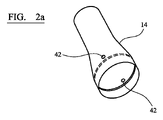
マウスピース部分14は、単純な押し嵌めを使用して装置本体と係合されるが、スナップ嵌めまたはねじ結合などの任意のタイプの接続が使用されてもよい。この実施形態においてマウスピース部分は、いかなるフィルター要素も有しない単純なテーパー付き中空管であり、図2aで詳細に示されている。しかしながら、一つ以上のフィルター要素をマウスピース部分内に含むことが可能である。マウスピース部分は、空気吸込み穴42を備え、エアロゾル形成チャンバー40(図1に示す)を囲み、このエアロゾル形成チャンバー内でベイパーはユーザーの口に入る前の気流中で凝縮できる。
The
カートリッジ20は、出口のないチャンバーを画定するハウジングを備える。二つのチャンバー30、32は、マウスピース端で開口する。膜37(図1に示す)はチャンバーの開放端を密封する。使用前にユーザーが剥ぎ取る除去可能な密封が膜の上にわたって提供されてもよい。ヒーター22を中に受け入れるために、出口のないスロット34が二つのチャンバーの間に提供されている。出口のないスロット34はマウスピース端で閉じられている。第一のチャンバー30は、ニコチンおよびエアロゾル形成体を含む第一のゲルを保持し、また第二のチャンバー32は、細かく切られたたばこの葉を含む第二のゲルを保持する。
図2bは、カートリッジ組立品ハウジングの下部の斜視図である。図2cは、カートリッジ組立品ハウジングの斜視図である。カートリッジ20は概して円筒形状である。第一のチャンバー33および第二のチャンバー35は分離しており、かつ等しいサイズおよび形状であり、また接合部分36で一緒に保持されている。第一のチャンバー33および第二のチャンバー35は、保持リング39によって一緒に保持されている。両方のチャンバーハウジングは、保持リング39を係合する。別個のクリップもしくはブラケット、またはチャンバーの各々の相互係止またはスナップ嵌め機能の提供など、チャンバーを一緒に保持する他の手段が可能である。チャンバーが一緒に保持された時、チャンバーの間に出口のないスロット34が形成される。対応するリブをくぼみ24の中に係合するために、一つのチャンバー35の壁の中にチャネル38が提供されている。これは、ヒーターブレードがスロット34の中に受け入れられる一つの向きでのみカートリッジ組立品がくぼみ24へと挿入されうることを確実にする。
Figure 2b is a perspective view of the lower portion of the cartridge assembly housing. Figure 2c is a perspective view of the cartridge assembly housing.
図2dは、出口のないスロット34の形状を示す図2bおよび図2cに示すチャンバーのうちの一つのハウジングを示す。スロットの形状はヒーターのブレード形状と合致する。
Figure 2d shows the housing of one of the chambers shown in Figures 2b and 2c showing the shape of the
第一のチャンバー30内の第一のゲルは、グリセリンおよびポリエチレングリコールなどの一つまたは二つのエアロゾル形成体を含む。エアロゾル形成体の相対濃度を、システムの特定の要件に適合させることができる。この実施形態において第一のチャンバー30内のゲルは、2重量%のニコチン、70重量%のグリセリン、27重量%の水、1重量%の寒天を含む。
A first gel in the
ゲル化剤は寒天であることが好ましい。これは85℃より高い温度で溶融し、またおよそ40℃でゲルに戻る特性を有する。この特性によって寒天は高温環境で適切である。このゲルは50℃で溶融せず、これは例えばシステムが日の当たる所にある高温の自動車内に残された場合に有用である。およそ85℃での液体への相転移は、ゲルがエアロゾル化を誘発するために比較的低温まで加熱されることしか必要としないことを意味し、これは低エネルギー消費を可能にする。寒天の代わりに寒天の構成成分のうちの一つであるアガロースのみを使用することが有益である場合がある。 Preferably, the gelling agent is agar. It has the property of melting above 85°C and reverting to gel at approximately 40°C. This property makes agar suitable for high temperature environments. This gel does not melt at 50°C, which is useful, for example, when the system is left in a hot car in the sun. A phase transition to a liquid at approximately 85° C. means that the gel only needs to be heated to relatively low temperatures to induce aerosolization, which allows for low energy consumption. It may be beneficial to use only agarose, one of the constituents of agar, instead of agar.
第二のチャンバー32の中の第二のゲルは、65重量%のグリセリン、20重量%の水、14.3重量%の固体粉末たばこ、0.7重量%の寒天を含む。
The second gel in the
メントールなどのさらなる風味または異なる風味は、いずれかのゲルの形成の前に、水、またはプロピレングリコールもしくはグリセリンのいずれかに添加できる。 Additional or different flavors such as menthol can be added to either the water or the propylene glycol or glycerin prior to formation of any gels.
各々のカートリッジ内に提供されるゲルの量はまた、特定のニーズに合わせて選ぶことができる。各々のカートリッジは、ユーザーに対して単一の投与または使用セッションを提供するために十分なゲルを収容してもよく、または幾つかのもしくは数多くの投与または使用セッションのために十分なゲルを収容してもよい。 The amount of gel provided in each cartridge can also be chosen to suit specific needs. Each cartridge may contain enough gel to provide the user with a single administration or use session, or contain enough gel for several or many administration or use sessions. You may
動作時にシステムは連続的な加熱モードで動作するように構成されている。これは、感知されたユーザーの吸煙に応答してヒーター22がカートリッジを加熱するのではなく、動作セッション中ずっとカートリッジを加熱することを意味する。ユーザーは単純なスイッチ(図示せず)を使用してシステムをオンに切り替え、ヒーターがカートリッジを加熱する。エアロゾルが発生される動作温度にいつ達したかを示す表示をユーザーに提供できるように、温度センサーがシステム内に含まれてもよい。ゲルは85℃より高温に加熱されると液体になる。ニコチンおよびグリセリンを含有するエアロゾルは、180℃~250℃の温度で発生する。動作中、ヒーターはおよそ250℃で動作する。ヒーターは起動後に一定時間、例えば6分間動作してもよく、またはユーザーがシステムのスイッチをオフにするまで動作してもよい。動作時間は、カートリッジ内に収容されたゲルの量に依存してもよい。
In operation the system is configured to operate in continuous heating mode. This means that the
カートリッジハウジングは、良好な熱導体であるアルミニウムで形成される。ヒーターは、ゲルまたはいかなる発生したベイパーもしくはエアロゾルと決して接触しない。ヒーターは出口のないスロット34内に保持され、そのため発生したエアロゾルから分離される。これは、動作時に望ましくない化合物発生をもたらす可能性のあるヒーター上の凝縮物の堆積が生じないことを確実にする。
The cartridge housing is made of aluminum, which is a good heat conductor. The heater never contacts the gel or any generated vapor or aerosol. The heater is held in an
図3は、カートリッジのチャンバーの各々が壊れやすい密封要素によって密封された実施形態を図示する。マウスピース部分は、密封要素を貫通して、チャンバー内に発生したベイパーが二つのチャンバーから漏れ出ることを可能にするために使用される。 Figure 3 illustrates an embodiment in which each of the chambers of the cartridge is sealed by a frangible sealing element. The mouthpiece portion is used to penetrate the sealing element to allow vapor generated in the chambers to escape from the two chambers.
図3aは、装置12の中へのカートリッジ20の挿入を図示する。図1の通り、カートリッジは第一のチャンバー30と、第二のチャンバー32と、チャンバーの間の出口のないスロット34とを備える。チャンバーは密封要素50によって密封される。
3a illustrates the insertion of
図3bは、装置の中へと挿入されたカートリッジを、チャンバーの間のスロット34内に受け入れられたヒーター22とともに示す。次いで、マウスピース部分14が装置本体部分12に接続される。図3bは、マウスピース部分の挿入の方向を図示する。マウスピース部分には壊れやすい密封要素を貫通し、第一のチャンバーおよび第二のチャンバー内で発生したベイパーが漏れ出るための通路54を提供するように作用する貫通要素52が提供されている。
Figure 3b shows the cartridge inserted into the device with
図3cは、貫通要素52が第一のチャンバーおよび第二のチャンバーの中へと延び、かつベイパーが第一のチャンバー30および第二のチャンバー32からマウスピース部分内のエアロゾル形成チャンバーの中へと漏れ出ることを可能にする、完全に挿入された位置にあるマウスピース部分14を示す。ベイパーは冷やされ、マウスピース部分内の気流の中に同伴されて、ユーザーによって吸い込まれる前にエアロゾルを形成する。図1の実施形態の通り、マウスピース部分には空気吸込みが提供されてもよい。別の方法として、または追加的に、マウスピース部分の中への気流経路が装置を通して提供されてもよい。別の方法として、または追加的に、気流経路が第一のチャンバーおよび第二のチャンバーを通して提供されてもよい。
FIG. 3c shows that the piercing
図4は、本発明のさらなる実施形態によるエアロゾル発生システムの概略図である。図4の実施形態において、ヒーター122は、カートリッジ組立品内に形成されたスロットの中へと延びるのではなく、装置部分のくぼみの外側上にあり、その中にカートリッジ組立品が受け入れられる。装置本体112は、リチウムイオン電池116である電源および電子制御回路118を備える。装置本体はまた、装置本体のハウジング内のくぼみ124の周囲に延びるヒーター122を含む。ヒーターは、可撓性基板上に提供された電気抵抗性トラックを備える電気ヒーターである。具体的には、発熱体は、Kapton(登録商標)の二つの層の間に保持された、トラックを形成する金属のエッチングされた箔を備える。可撓性基板上に提供された電気抵抗性のあるトラックを備えたヒーターを提供することで、くぼみに適合するようにヒーターを要求される形状へと製造および形成することがより簡単になる場合がある。制御回路は、電池116から電気ヒーター122への供給電力を制御するように構成されている。
Figure 4 is a schematic diagram of an aerosol generation system according to a further embodiment of the invention; In the embodiment of FIG. 4, rather than extending into a slot formed in the cartridge assembly, the
図4のカートリッジは、図1に示すカートリッジと類似している。カートリッジの二つのチャンバー内のゲルの組成物は、図1の実施形態でのものと同一であってもよい。カートリッジハウジングはまた、アルミニウムで形成される。しかしながら、図4の実施形態において、出口のないスロットではなく、端部が開口しているスロット134が提供されている。端部が開口しているスロット134は、装置本体内の空気吸込み口142からマウスピース部分114内のエアロゾル形成チャンバー140への気流経路を提供する。マウスピース部分114を使用してカートリッジを開口するために、異なる気流経路のために作製された適切な適合を有して、図3に示すものと類似のカートリッジ貫通構成が使用されてもよい。二つのチャンバーは、図1の実施形態でのように分離されかつ一緒に保持されてもよく、またはその使用を通して互いに分離されたままでもよい。
The cartridge of FIG. 4 is similar to the cartridge shown in FIG. The composition of the gel in the two chambers of the cartridge may be the same as in the FIG. 1 embodiment. The cartridge housing is also formed of aluminum. However, in the embodiment of FIG. 4, an open-ended
動作時にシステムは、図1の実施形態でのように連続的な加熱モードで動作するように構成されている。これは、感知されたユーザーの吸煙に応答してヒーター122がカートリッジを加熱するのではなく、動作セッション中ずっとカートリッジを加熱することを意味する。ユーザーは単純なスイッチ(図示せず)を使用してシステムをオンに切り替え、ヒーターがカートリッジを加熱する。動作温度にいつ達したかを示す表示をユーザーに提供できるように、温度センサーがシステム内に含まれてもよい。ゲルは85℃より高温に加熱されると液体になる。ニコチンおよびグリセリンを含有するエアロゾルは、180℃~250℃の温度で発生する。動作中、ヒーターはおよそ250℃で動作する。ヒーターは起動後に一定時間、例えば6分間動作してもよく、またはユーザーがシステムのスイッチをオフにするまで動作してもよい。
In operation the system is configured to operate in continuous heating mode as in the embodiment of FIG. This means that the
図5は、本発明のなおさらなる実施形態によるエアロゾル発生システムの概略図である。図5の実施形態は、抵抗加熱を使用することによってではなく、誘導加熱を使用することによって動作される。カートリッジが受け入れられるくぼみの周囲か内側かのいずれかで抵抗ヒーターを使用する代わりに、装置本体は、この実施例においてカートリッジの一部として、くぼみを包囲するインダクターコイルを備え、かつサセプタがくぼみ内に提供されている。 Figure 5 is a schematic diagram of an aerosol generation system according to a still further embodiment of the invention; The embodiment of FIG. 5 is operated by using inductive heating rather than by using resistive heating. Instead of using resistive heaters either around or inside the cavity in which the cartridge is received, the device body is provided in this embodiment as part of the cartridge with an inductor coil surrounding the cavity, and the susceptor is in the cavity. provided within.
装置本体212は、リチウムイオン電池216である電源および電子制御回路218を備える。装置本体はまた、装置本体のハウジング内のくぼみの周囲に延びる誘導コイル224を含む。装置本体はまた、誘導コイル224に提供されるAC信号を発生するための電気回路220を備える。
The
マウスピース部分214は、図1に示すマウスピース部分と類似しており、エアロゾル形成チャンバー240を囲む。この実施例において、空気吸込み口242は、マウスピース部分と装置本体の接合部で提供されている。
図4のカートリッジは、図1に示すカートリッジと類似している。カートリッジの二つのチャンバー内のゲルの組成物は、図1の実施形態でのものと同一であってもよい。しかしながら、二つのチャンバーの隣接する壁は、ヒーターを受け入れるための出口のないくぼみを有するのではなく、交番磁界(鉄の層など)で加熱するサセプタ材料222を含む。この実施例におけるサセプタ材料は、装置本体の一部ではなくカートリッジの一部として提供されているが、サセプタ材料を装置本体の一部としてまたはカートリッジと装置本体の両方で提供することが可能である。カートリッジハウジング全体はサセプタ材料で形成されてもよく、またはサセプタ材料はカートリッジの一つ以上の表面上の被覆として提供されてもよい。サセプタ材料を第一のチャンバーおよび第二のチャンバーの中に提供して、その中に含まれたゲルまたは他の材料内で懸濁させることも可能である。
The cartridge of FIG. 4 is similar to the cartridge shown in FIG. The composition of the gel in the two chambers of the cartridge may be the same as in the FIG. 1 embodiment. However, the adjacent walls of the two chambers contain a
第一のチャンバーおよび第二のチャンバーを密封するために、図1を参照しながら説明したのと同一の手法で密封要素が提供されている。マウスピース部分114を使用してカートリッジを開口するために、異なる気流経路のために作製された適切な適合を有して、図3に示すものと類似のカートリッジ貫通構成が使用されてもよい。別の方法として、単純な剥離可能な密封が使用されてもよく、またベイパー透過性膜が第一のチャンバー230および第二のチャンバー232の開放端にわたって提供されている。
To seal the first and second chambers, sealing elements are provided in the same manner as described with reference to FIG. To open the cartridge using
動作時にシステムは、図1の実施形態でのように連続的な加熱モードで動作するように構成されている。これは、ユーザーが装置のスイッチをオンにした時に、くぼみ内で交番磁界を発生するために、装置が誘導コイルへとAC信号を供給することを意味する。これはサセプタ内に電流の流れを誘発し、結果としてサセプタの加熱をもたらす。強磁性材料がサセプタとして使用される場合、ヒステリシス損失は加熱にも寄与する場合がある。この文脈において誘導コイルは誘導ヒーターとして記述されてもよい。AC信号の大きさおよび周波数を制御することによって、第一のチャンバーおよび第二のチャンバーの中の温度を制御することができる。くぼみの中に温度センサーが提供されてもよく、またフィードバック制御ループが使用される。この場合もまた、誘導ヒーターは起動後に一定時間、例えば6分間動作してもよく、またはユーザーがシステムのスイッチをオフにするまで動作してもよい。 In operation the system is configured to operate in continuous heating mode as in the embodiment of FIG. This means that the device supplies an AC signal to the induction coil to generate an alternating magnetic field within the cavity when the user switches on the device. This induces current flow in the susceptor, resulting in heating of the susceptor. Hysteresis losses may also contribute to heating when ferromagnetic materials are used as susceptors. In this context an induction coil may be described as an induction heater. By controlling the magnitude and frequency of the AC signal, the temperature in the first and second chambers can be controlled. A temperature sensor may be provided in the well and a feedback control loop is used. Again, the induction heater may operate for a period of time, eg, 6 minutes, after activation, or until the user switches off the system.
図6aは、本発明のさらなる実施形態の概略図である。図6aの実施形態において、カートリッジ330はマウスピース管300の中に保持されている。流量制限器350およびライニング管340、360、370もマウスピース管内に保持されている。マウスピース管330の中に保持される構成要素を図6bの分解組立図に示す。
Figure 6a is a schematic diagram of a further embodiment of the invention. In the embodiment of FIG. 6a,
カートリッジ330は、図2cに示すカートリッジと類似しており、かつ分離したチャンバーハウジングを備える。しかしながら、カートリッジ330には膜または密封要素がないが、第一のチャンバーおよび第二のチャンバーの開放端の中へと空気が入ることを可能にするために、カートリッジの壁の中に形成された気流チャネル335と、気流チャネルの上部における空気吸込み口334とを含む。
マウスピース管は厚紙で形成され、直径が6.6mmであり、長さが45mmである。ライニング管340は、ポリエーテルエーテルケトン(PEEK)で形成され、また厚紙マウスピース管がマウスピース管の中から水分を吸収するのを防止するために提供されている。ライニング管は非常に薄く作製することができ、この実施形態において厚さは0.3mmである。制限器350は、空気とカートリッジからのベイパーとの混合を確実にするために、およびライニング管360内で、制限器後に続く空間の中でのエアロゾルの発生を確実にするために、気流を制限するために提供されている。
The mouthpiece tube is made of cardboard and has a diameter of 6.6 mm and a length of 45 mm. A lining
図7は、動作中の図6aのマウスピース管内の気流を図示する。マウスピース管は、図1に示すタイプの装置12のくぼみ24の中に示されているが、マウスピース14を有しない。図7は、マウスピース管を受け入れる装置の端のみを図示する。電池および制御回路は示されていない。装置は、装置内のくぼみ24の周囲の周りに形成された内部気流通路365の中へと空気が入ることを可能にする装置空気吸込み口355を含む。スペーサー要素352はくぼみの基部に位置付けられて、空気が内部気流通路365からくぼみ24の中へと流れ、次にカートリッジ330内の気流チャネル335の中へと流れ、そして空気吸込み口334を通ってマウスピース管の内部へと流れることを可能にする
Figure 7 illustrates the airflow within the mouthpiece tube of Figure 6a during operation. A mouthpiece tube is shown in
図6aおよび図6bに示すカートリッジは、図1に示すタイプのヒーターまたは図4または図5に示すタイプのヒーターによって加熱されてもよい。動作時にシステムは、図1でのように連続的な加熱モードで動作するように構成されている。これは、感知されたユーザーの吸煙に応答してヒーターがカートリッジを加熱するのではなく、動作セッション中ずっとカートリッジを加熱することを意味する。ユーザーは単純なスイッチ(図示せず)を使用してシステムをオンに切り替え、ヒーターがカートリッジを加熱する。第一のチャンバーおよび第二のチャンバー内のゲルは加熱されると液体になり、180℃~250℃の温度でニコチンおよびグリセリンを含有するベイパーが発生する。 The cartridge shown in FIGS. 6a and 6b may be heated by a heater of the type shown in FIG. 1 or a heater of the type shown in FIGS. In operation the system is configured to operate in continuous heating mode as in FIG. This means that the heater does not heat the cartridge in response to sensed user puffing, but instead heats the cartridge throughout the operating session. The user turns the system on using a simple switch (not shown) and the heater heats the cartridge. The gels in the first and second chambers become liquid when heated, generating vapors containing nicotine and glycerin at temperatures between 180°C and 250°C.
システムが動作温度である時、ユーザーはマウスピース管の口側端を吸い、マウスピース管を通して空気を引き出す。空気は内部通路365から、マウスピース管のマウスピース端とは反対側の遠位端へと引き出される。空気は気流チャネル335まで移動し、空気吸込み口334を通って、空間345の中へと入る。空気は空間345内で、第一のチャンバーおよび第二のチャンバーからのベイパーと混合する。混合した空気およびベイパーはその後、制限器350を通過し、その後冷えて、ユーザーの口の中へと引き出される前にエアロゾルを形成し続ける。動作後、カートリッジを含むマウスピース管を装置から離脱し、廃棄することができる。このタイプのマウスピース管は、システムの複数の動作を提供するために、パックで販売されても良い。
When the system is at operating temperature, the user sucks on the mouth end of the mouthpiece tube, drawing air through the mouthpiece tube. Air is drawn from the
説明された実施形態は各々、連続的な加熱スキームを動作するように構成されたものとして説明され、これにおいてヒーターは所定の時間にわたって起動され、この間にユーザーは数回の吸煙を行ってもよい。しかしながら、説明されたシステムは、異なる方法で動作するように構成されてもよい。例えば、電力は、システム内の気流センサーからの信号に基づいて、各々のユーザーの吸煙の期間のみ、ヒーターまたは誘導コイルに提供されてもよい。別の方法として、または追加的に、ヒーターまたは誘導コイルへの電力のスイッチは、ユーザーによるボタンまたはスイッチの起動に応答してオンおよびオフに切り替えられてもよい。 Each of the described embodiments is described as being configured to operate a continuous heating scheme, in which the heater is activated for a predetermined period of time during which the user may take several puffs. . However, the system described may be configured to operate in different ways. For example, power may be provided to heaters or induction coils only during each user's puff based on signals from airflow sensors in the system. Alternatively or additionally, power to the heater or induction coil may be switched on and off in response to button or switch activation by the user.
図は本発明の特定の実施形態を示す。しかし、本発明の範囲の中で説明された実施形態に対する変更がなされてもよいことが明確であるべきである。特に、システムを通る気流の異なる構成が提供されてもよく、また非電気的なヒーターなどの異なる加熱構成が想定されうる。 The figures show specific embodiments of the invention. However, it should be clear that changes may be made to the described embodiments within the scope of the invention. In particular, different configurations of airflow through the system may be provided, and different heating configurations such as non-electrical heaters may be envisaged.
Claims (19)
第一のチャンバーハウジングを有する第一のチャンバーと、前記第一のチャンバーとは分離しており、かつ第二のチャンバーハウジングを有する第二のチャンバーとを備え、前記第一のチャンバーがゲルの形態の前記エアロゾル形成基体を収容し、また前記第二のチャンバーが吸入用の化合物の供与源を収容し、
前記第一のチャンバーハウジングおよび前記第二のチャンバーハウジングが互いに分離している、または互いに分離可能であり、
前記カートリッジが前記第一のチャンバーと第二のチャンバーの間にスロットを備える、
カートリッジ。 A cartridge for an aerosol generating system that heats an aerosol-forming substrate to form an aerosol, comprising:
a first chamber having a first chamber housing and a second chamber separate from the first chamber and having a second chamber housing, wherein the first chamber is in the form of a gel and said second chamber contains a source of a compound for inhalation,
said first chamber housing and said second chamber housing are separate or separable from each other ;
said cartridge comprises a slot between said first and second chambers;
cartridge.
Applications Claiming Priority (3)
| Application Number | Priority Date | Filing Date | Title |
|---|---|---|---|
| EP16181953 | 2016-07-29 | ||
| EP16181953.7 | 2016-07-29 | ||
| PCT/EP2017/067449 WO2018019578A1 (en) | 2016-07-29 | 2017-07-11 | Aerosol-generating system comprising a cartridge containing a gel |
Publications (3)
| Publication Number | Publication Date |
|---|---|
| JP2019526242A JP2019526242A (en) | 2019-09-19 |
| JP2019526242A5 JP2019526242A5 (en) | 2020-08-13 |
| JP7157732B2 true JP7157732B2 (en) | 2022-10-20 |
Family
ID=56555332
Family Applications (1)
| Application Number | Title | Priority Date | Filing Date |
|---|---|---|---|
| JP2019503565A Active JP7157732B2 (en) | 2016-07-29 | 2017-07-11 | Aerosol generating system with cartridge containing gel |
Country Status (10)
| Country | Link |
|---|---|
| EP (1) | EP3490390B1 (en) |
| JP (1) | JP7157732B2 (en) |
| KR (1) | KR102470874B1 (en) |
| CN (1) | CN109414056A (en) |
| CA (1) | CA3031999A1 (en) |
| IL (1) | IL263446A (en) |
| MX (1) | MX2019000957A (en) |
| RU (1) | RU2736842C2 (en) |
| TW (1) | TW201808123A (en) |
| WO (1) | WO2018019578A1 (en) |
Families Citing this family (25)
| Publication number | Priority date | Publication date | Assignee | Title |
|---|---|---|---|---|
| GB201718031D0 (en) * | 2017-11-01 | 2017-12-13 | British American Tobacco Investments Ltd | Aerosolisable gel |
| US11425930B2 (en) | 2017-12-28 | 2022-08-30 | Altria Client Services Llc | Cartridge for use with aerosol generating device |
| KR102262489B1 (en) * | 2018-01-03 | 2021-06-09 | 주식회사 케이티앤지 | An article for generating aerosols and an apparatus for generating aerosols |
| US20190274354A1 (en) * | 2018-03-09 | 2019-09-12 | Rai Strategic Holdings, Inc. | Electronically heated heat-not-burn smoking article |
| WO2019178448A1 (en) * | 2018-03-16 | 2019-09-19 | Bond Street Manufacturing Llc | Vaporizable tobacco wax compositions and container thereof |
| EP4190186A1 (en) | 2018-05-17 | 2023-06-07 | Philip Morris Products S.A. | Aerosol-generating device having improved inductor coil |
| EA202092913A1 (en) * | 2018-05-31 | 2021-03-01 | ДжейТи ИНТЕРНЭШНЛ СА | AEROSOL-GENERATING PRODUCT, AEROSOL-GENERATING SYSTEM, AND METHOD FOR GENERATING AROMATIC AEROSOL |
| MX2020013331A (en) * | 2018-06-21 | 2021-03-09 | Philip Morris Products Sa | Resealable cartridge assembly for an aerosol-generating system. |
| CN112312784A (en) * | 2018-06-28 | 2021-02-02 | Jt国际股份公司 | Electronic smoking device, dispenser, smoking system, and method of supplying a tobacco mousse formulation |
| KR20210105338A (en) * | 2018-12-19 | 2021-08-26 | 제이티 인터내셔널 소시에떼 아노님 | electronic cigarette |
| GB201903247D0 (en) * | 2019-03-11 | 2019-04-24 | Nicoventures Trading Ltd | Aerosol provision device |
| CN113905623A (en) * | 2019-06-21 | 2022-01-07 | 日本烟草国际股份有限公司 | Heated non-burning wand comprising a foamed aerosol-generating material arranged in a container |
| CN110432544A (en) * | 2019-07-23 | 2019-11-12 | 云南美纳生物科技有限公司 | A kind of suction unit and method heating not burning tobacco |
| KR102272408B1 (en) * | 2019-10-14 | 2021-07-02 | 주식회사 케이티앤지 | Aerosol generating article comprising vaporizing substrate and aerosol generating system using the same |
| KR102533744B1 (en) * | 2020-06-04 | 2023-05-18 | 주식회사 케이티앤지 | Airflow path structure and aerosol generating device comprising same |
| GB202011952D0 (en) * | 2020-07-31 | 2020-09-16 | Nicoventures Trading Ltd | Consumable for an aerosol provision system |
| GB202011953D0 (en) * | 2020-07-31 | 2020-09-16 | Nicoventures Trading Ltd | Consumable for an aerosol provision sysytem |
| CN214103227U (en) * | 2020-09-10 | 2021-09-03 | 深圳雾芯科技有限公司 | Atomization device and electronic cigarette |
| KR102533274B1 (en) * | 2020-11-24 | 2023-05-15 | 주식회사 케이티앤지 | Device for generating aerosol |
| JPWO2022123650A1 (en) * | 2020-12-08 | 2022-06-16 | ||
| JP2023553962A (en) * | 2020-12-11 | 2023-12-26 | ジュール・ラブズ・インコーポレイテッド | Insert for vaporizable materials with internal air flow path |
| CN112806622A (en) * | 2021-02-04 | 2021-05-18 | 云南中烟工业有限责任公司 | Gel-state tobacco tar preparation device and preparation method for reducing bubbles |
| KR20240027615A (en) * | 2021-06-30 | 2024-03-04 | 제이티 인터내셔널 소시에떼 아노님 | Flat tobacco articles comprising at least two layers and aerosol generating devices having such articles |
| KR20230154669A (en) * | 2022-05-02 | 2023-11-09 | 주식회사 케이티앤지 | Aerosol generating device and system |
| EP4302618A1 (en) * | 2022-07-05 | 2024-01-10 | JT International SA | Dried tobacco article manufacturing |
Citations (5)
| Publication number | Priority date | Publication date | Assignee | Title |
|---|---|---|---|---|
| WO2015177043A1 (en) | 2014-05-21 | 2015-11-26 | Philip Morris Products S.A. | An aerosol-generating system comprising a planar induction coil |
| WO2015197627A1 (en) | 2014-06-24 | 2015-12-30 | Philip Morris Products S.A. | Aerosol-generating system for delivering nicotine salt particles |
| US20160120225A1 (en) | 2014-10-29 | 2016-05-05 | Munmaya K. Mishra | Ethanol-free gel formulation cartridge for e-vaping device |
| WO2016076178A1 (en) | 2014-11-10 | 2016-05-19 | 日本たばこ産業株式会社 | Non-combusting flavor inhaler and package |
| WO2017167932A1 (en) | 2016-03-30 | 2017-10-05 | British American Tobacco (Investments) Limited | Apparatus for heating aerosol generating material and a cartridge for the apparatus |
Family Cites Families (14)
| Publication number | Priority date | Publication date | Assignee | Title |
|---|---|---|---|---|
| US5240016A (en) * | 1991-04-19 | 1993-08-31 | Philip Morris Incorporated | Thermally releasable gel-based flavor source for smoking articles |
| US7578298B2 (en) * | 2005-02-04 | 2009-08-25 | Philip Morris Usa Inc. | Flavor capsule for enhanced flavor delivery in cigarettes |
| CA2807635C (en) * | 2010-08-24 | 2015-11-24 | Hirofumi Matsumoto | Non-heating type flavor inhalator and method of manufacturing flavor cartridge |
| EP2460424A1 (en) * | 2010-12-03 | 2012-06-06 | Philip Morris Products S.A. | An aerosol generating system with leakage prevention |
| WO2013164704A1 (en) * | 2012-04-30 | 2013-11-07 | Philip Morris Products S.A. | Tobacco substrate |
| EP2732713A4 (en) * | 2012-08-31 | 2015-07-22 | Kimree Hi Tech Inc | Electronic cigarette with multiple tastes |
| AU2014230132B2 (en) * | 2013-03-15 | 2018-03-08 | Philip Morris Products S.A. | Aerosol-generating system with differential heating |
| CN105473012B (en) * | 2013-06-14 | 2020-06-19 | 尤尔实验室有限公司 | Multiple heating elements with individual vaporizable materials in electronic vaporization devices |
| CA2924114A1 (en) * | 2013-09-13 | 2015-03-19 | Nicodart, Inc. | Programmable electronic vaporizing apparatus and smoking cessation system |
| ES2682751T3 (en) * | 2014-09-26 | 2018-09-21 | Philip Morris Products S.A. | Aerosol generating system comprising a source of compound to improve novel delivery |
| CN107072310B (en) * | 2014-11-10 | 2020-08-04 | 日本烟草产业株式会社 | Cigarette cartridge and non-combustion type flavor extractor |
| CN107404939B (en) * | 2014-11-19 | 2021-03-16 | 富特姆4有限公司 | Device for functionalizing aerosols from non-combustible smoking articles |
| CN104824830A (en) * | 2015-03-17 | 2015-08-12 | 湖北中烟工业有限责任公司 | Carbon heating low-temperature cigarette compound atomization agent, preparing method and application of same |
| CN105342013A (en) * | 2015-11-06 | 2016-02-24 | 浙江中烟工业有限责任公司 | Solid smoke cartridge of novel electronic cigarette |
-
2017
- 2017-07-11 EP EP17736965.9A patent/EP3490390B1/en active Active
- 2017-07-11 WO PCT/EP2017/067449 patent/WO2018019578A1/en active Search and Examination
- 2017-07-11 CN CN201780042394.9A patent/CN109414056A/en active Pending
- 2017-07-11 CA CA3031999A patent/CA3031999A1/en not_active Abandoned
- 2017-07-11 MX MX2019000957A patent/MX2019000957A/en unknown
- 2017-07-11 RU RU2019103839A patent/RU2736842C2/en active
- 2017-07-11 KR KR1020197001338A patent/KR102470874B1/en active IP Right Grant
- 2017-07-11 JP JP2019503565A patent/JP7157732B2/en active Active
- 2017-07-27 TW TW106125309A patent/TW201808123A/en unknown
-
2018
- 2018-12-03 IL IL263446A patent/IL263446A/en unknown
Patent Citations (5)
| Publication number | Priority date | Publication date | Assignee | Title |
|---|---|---|---|---|
| WO2015177043A1 (en) | 2014-05-21 | 2015-11-26 | Philip Morris Products S.A. | An aerosol-generating system comprising a planar induction coil |
| WO2015197627A1 (en) | 2014-06-24 | 2015-12-30 | Philip Morris Products S.A. | Aerosol-generating system for delivering nicotine salt particles |
| US20160120225A1 (en) | 2014-10-29 | 2016-05-05 | Munmaya K. Mishra | Ethanol-free gel formulation cartridge for e-vaping device |
| WO2016076178A1 (en) | 2014-11-10 | 2016-05-19 | 日本たばこ産業株式会社 | Non-combusting flavor inhaler and package |
| WO2017167932A1 (en) | 2016-03-30 | 2017-10-05 | British American Tobacco (Investments) Limited | Apparatus for heating aerosol generating material and a cartridge for the apparatus |
Also Published As
| Publication number | Publication date |
|---|---|
| KR102470874B1 (en) | 2022-11-25 |
| RU2736842C2 (en) | 2020-11-20 |
| IL263446A (en) | 2019-01-31 |
| RU2019103839A (en) | 2020-08-28 |
| CA3031999A1 (en) | 2018-02-01 |
| EP3490390B1 (en) | 2024-03-13 |
| RU2019103839A3 (en) | 2020-09-22 |
| JP2019526242A (en) | 2019-09-19 |
| EP3490390C0 (en) | 2024-03-13 |
| CN109414056A (en) | 2019-03-01 |
| TW201808123A (en) | 2018-03-16 |
| WO2018019578A1 (en) | 2018-02-01 |
| MX2019000957A (en) | 2019-08-01 |
| KR20190035683A (en) | 2019-04-03 |
| EP3490390A1 (en) | 2019-06-05 |
Similar Documents
| Publication | Publication Date | Title |
|---|---|---|
| JP7157732B2 (en) | Aerosol generating system with cartridge containing gel | |
| JP2022136153A (en) | Aerosol-generating system including gel-containing cartridge and device for heating cartridge | |
| JP2023014170A (en) | Aerosol-generating system including heated gel container | |
| US11792894B2 (en) | Aerosol-generating system including a cartridge containing a gel | |
| US11839706B2 (en) | Aerosol-generating system including a heated gel container | |
| JP6496312B2 (en) | Multi-use aerosol generation system | |
| KR20150132112A (en) | Aerosol-generating device comprising multiple solid-liquid phase-change materials | |
| EP3890528B1 (en) | Aerosol-generating system | |
| KR102656761B1 (en) | Aerosol-generating system comprising heated gel container | |
| KR20240052071A (en) | Aerosol-generating system comprising a heated gel container |
Legal Events
| Date | Code | Title | Description |
|---|---|---|---|
| A521 | Request for written amendment filed |
Free format text: JAPANESE INTERMEDIATE CODE: A523 Effective date: 20200703 |
|
| A621 | Written request for application examination |
Free format text: JAPANESE INTERMEDIATE CODE: A621 Effective date: 20200703 |
|
| A977 | Report on retrieval |
Free format text: JAPANESE INTERMEDIATE CODE: A971007 Effective date: 20210727 |
|
| A131 | Notification of reasons for refusal |
Free format text: JAPANESE INTERMEDIATE CODE: A131 Effective date: 20210804 |
|
| A521 | Request for written amendment filed |
Free format text: JAPANESE INTERMEDIATE CODE: A523 Effective date: 20211102 |
|
| A02 | Decision of refusal |
Free format text: JAPANESE INTERMEDIATE CODE: A02 Effective date: 20220322 |
|
| A521 | Request for written amendment filed |
Free format text: JAPANESE INTERMEDIATE CODE: A523 Effective date: 20220722 |
|
| C60 | Trial request (containing other claim documents, opposition documents) |
Free format text: JAPANESE INTERMEDIATE CODE: C60 Effective date: 20220722 |
|
| A911 | Transfer to examiner for re-examination before appeal (zenchi) |
Free format text: JAPANESE INTERMEDIATE CODE: A911 Effective date: 20220801 |
|
| C21 | Notice of transfer of a case for reconsideration by examiners before appeal proceedings |
Free format text: JAPANESE INTERMEDIATE CODE: C21 Effective date: 20220803 |
|
| TRDD | Decision of grant or rejection written | ||
| A01 | Written decision to grant a patent or to grant a registration (utility model) |
Free format text: JAPANESE INTERMEDIATE CODE: A01 Effective date: 20220907 |
|
| A61 | First payment of annual fees (during grant procedure) |
Free format text: JAPANESE INTERMEDIATE CODE: A61 Effective date: 20221007 |
|
| R150 | Certificate of patent or registration of utility model |
Ref document number: 7157732 Country of ref document: JP Free format text: JAPANESE INTERMEDIATE CODE: R150 |