JP7157246B2 - A Side Information Signaling Method for Inter Prediction Using Geometric Partitioning - Google Patents
A Side Information Signaling Method for Inter Prediction Using Geometric Partitioning Download PDFInfo
- Publication number
- JP7157246B2 JP7157246B2 JP2021523349A JP2021523349A JP7157246B2 JP 7157246 B2 JP7157246 B2 JP 7157246B2 JP 2021523349 A JP2021523349 A JP 2021523349A JP 2021523349 A JP2021523349 A JP 2021523349A JP 7157246 B2 JP7157246 B2 JP 7157246B2
- Authority
- JP
- Japan
- Prior art keywords
- video
- block
- prediction
- mode
- motion
- Prior art date
- Legal status (The legal status is an assumption and is not a legal conclusion. Google has not performed a legal analysis and makes no representation as to the accuracy of the status listed.)
- Active
Links
Images


Classifications
-
- H—ELECTRICITY
- H04—ELECTRIC COMMUNICATION TECHNIQUE
- H04N—PICTORIAL COMMUNICATION, e.g. TELEVISION
- H04N19/00—Methods or arrangements for coding, decoding, compressing or decompressing digital video signals
- H04N19/50—Methods or arrangements for coding, decoding, compressing or decompressing digital video signals using predictive coding
- H04N19/503—Methods or arrangements for coding, decoding, compressing or decompressing digital video signals using predictive coding involving temporal prediction
- H04N19/51—Motion estimation or motion compensation
- H04N19/513—Processing of motion vectors
- H04N19/517—Processing of motion vectors by encoding
- H04N19/52—Processing of motion vectors by encoding by predictive encoding
-
- H—ELECTRICITY
- H04—ELECTRIC COMMUNICATION TECHNIQUE
- H04N—PICTORIAL COMMUNICATION, e.g. TELEVISION
- H04N19/00—Methods or arrangements for coding, decoding, compressing or decompressing digital video signals
- H04N19/10—Methods or arrangements for coding, decoding, compressing or decompressing digital video signals using adaptive coding
- H04N19/102—Methods or arrangements for coding, decoding, compressing or decompressing digital video signals using adaptive coding characterised by the element, parameter or selection affected or controlled by the adaptive coding
- H04N19/103—Selection of coding mode or of prediction mode
- H04N19/109—Selection of coding mode or of prediction mode among a plurality of temporal predictive coding modes
-
- H—ELECTRICITY
- H04—ELECTRIC COMMUNICATION TECHNIQUE
- H04N—PICTORIAL COMMUNICATION, e.g. TELEVISION
- H04N19/00—Methods or arrangements for coding, decoding, compressing or decompressing digital video signals
- H04N19/10—Methods or arrangements for coding, decoding, compressing or decompressing digital video signals using adaptive coding
- H04N19/169—Methods or arrangements for coding, decoding, compressing or decompressing digital video signals using adaptive coding characterised by the coding unit, i.e. the structural portion or semantic portion of the video signal being the object or the subject of the adaptive coding
- H04N19/17—Methods or arrangements for coding, decoding, compressing or decompressing digital video signals using adaptive coding characterised by the coding unit, i.e. the structural portion or semantic portion of the video signal being the object or the subject of the adaptive coding the unit being an image region, e.g. an object
- H04N19/176—Methods or arrangements for coding, decoding, compressing or decompressing digital video signals using adaptive coding characterised by the coding unit, i.e. the structural portion or semantic portion of the video signal being the object or the subject of the adaptive coding the unit being an image region, e.g. an object the region being a block, e.g. a macroblock
-
- H—ELECTRICITY
- H04—ELECTRIC COMMUNICATION TECHNIQUE
- H04N—PICTORIAL COMMUNICATION, e.g. TELEVISION
- H04N19/00—Methods or arrangements for coding, decoding, compressing or decompressing digital video signals
- H04N19/10—Methods or arrangements for coding, decoding, compressing or decompressing digital video signals using adaptive coding
- H04N19/102—Methods or arrangements for coding, decoding, compressing or decompressing digital video signals using adaptive coding characterised by the element, parameter or selection affected or controlled by the adaptive coding
- H04N19/103—Selection of coding mode or of prediction mode
- H04N19/105—Selection of the reference unit for prediction within a chosen coding or prediction mode, e.g. adaptive choice of position and number of pixels used for prediction
-
- H—ELECTRICITY
- H04—ELECTRIC COMMUNICATION TECHNIQUE
- H04N—PICTORIAL COMMUNICATION, e.g. TELEVISION
- H04N19/00—Methods or arrangements for coding, decoding, compressing or decompressing digital video signals
- H04N19/10—Methods or arrangements for coding, decoding, compressing or decompressing digital video signals using adaptive coding
- H04N19/102—Methods or arrangements for coding, decoding, compressing or decompressing digital video signals using adaptive coding characterised by the element, parameter or selection affected or controlled by the adaptive coding
- H04N19/119—Adaptive subdivision aspects, e.g. subdivision of a picture into rectangular or non-rectangular coding blocks
-
- H—ELECTRICITY
- H04—ELECTRIC COMMUNICATION TECHNIQUE
- H04N—PICTORIAL COMMUNICATION, e.g. TELEVISION
- H04N19/00—Methods or arrangements for coding, decoding, compressing or decompressing digital video signals
- H04N19/10—Methods or arrangements for coding, decoding, compressing or decompressing digital video signals using adaptive coding
- H04N19/134—Methods or arrangements for coding, decoding, compressing or decompressing digital video signals using adaptive coding characterised by the element, parameter or criterion affecting or controlling the adaptive coding
- H04N19/136—Incoming video signal characteristics or properties
- H04N19/137—Motion inside a coding unit, e.g. average field, frame or block difference
-
- H—ELECTRICITY
- H04—ELECTRIC COMMUNICATION TECHNIQUE
- H04N—PICTORIAL COMMUNICATION, e.g. TELEVISION
- H04N19/00—Methods or arrangements for coding, decoding, compressing or decompressing digital video signals
- H04N19/10—Methods or arrangements for coding, decoding, compressing or decompressing digital video signals using adaptive coding
- H04N19/134—Methods or arrangements for coding, decoding, compressing or decompressing digital video signals using adaptive coding characterised by the element, parameter or criterion affecting or controlling the adaptive coding
- H04N19/157—Assigned coding mode, i.e. the coding mode being predefined or preselected to be further used for selection of another element or parameter
- H04N19/159—Prediction type, e.g. intra-frame, inter-frame or bidirectional frame prediction
-
- H—ELECTRICITY
- H04—ELECTRIC COMMUNICATION TECHNIQUE
- H04N—PICTORIAL COMMUNICATION, e.g. TELEVISION
- H04N19/00—Methods or arrangements for coding, decoding, compressing or decompressing digital video signals
- H04N19/10—Methods or arrangements for coding, decoding, compressing or decompressing digital video signals using adaptive coding
- H04N19/169—Methods or arrangements for coding, decoding, compressing or decompressing digital video signals using adaptive coding characterised by the coding unit, i.e. the structural portion or semantic portion of the video signal being the object or the subject of the adaptive coding
- H04N19/18—Methods or arrangements for coding, decoding, compressing or decompressing digital video signals using adaptive coding characterised by the coding unit, i.e. the structural portion or semantic portion of the video signal being the object or the subject of the adaptive coding the unit being a set of transform coefficients
-
- H—ELECTRICITY
- H04—ELECTRIC COMMUNICATION TECHNIQUE
- H04N—PICTORIAL COMMUNICATION, e.g. TELEVISION
- H04N19/00—Methods or arrangements for coding, decoding, compressing or decompressing digital video signals
- H04N19/10—Methods or arrangements for coding, decoding, compressing or decompressing digital video signals using adaptive coding
- H04N19/169—Methods or arrangements for coding, decoding, compressing or decompressing digital video signals using adaptive coding characterised by the coding unit, i.e. the structural portion or semantic portion of the video signal being the object or the subject of the adaptive coding
- H04N19/184—Methods or arrangements for coding, decoding, compressing or decompressing digital video signals using adaptive coding characterised by the coding unit, i.e. the structural portion or semantic portion of the video signal being the object or the subject of the adaptive coding the unit being bits, e.g. of the compressed video stream
-
- H—ELECTRICITY
- H04—ELECTRIC COMMUNICATION TECHNIQUE
- H04N—PICTORIAL COMMUNICATION, e.g. TELEVISION
- H04N19/00—Methods or arrangements for coding, decoding, compressing or decompressing digital video signals
- H04N19/10—Methods or arrangements for coding, decoding, compressing or decompressing digital video signals using adaptive coding
- H04N19/169—Methods or arrangements for coding, decoding, compressing or decompressing digital video signals using adaptive coding characterised by the coding unit, i.e. the structural portion or semantic portion of the video signal being the object or the subject of the adaptive coding
- H04N19/186—Methods or arrangements for coding, decoding, compressing or decompressing digital video signals using adaptive coding characterised by the coding unit, i.e. the structural portion or semantic portion of the video signal being the object or the subject of the adaptive coding the unit being a colour or a chrominance component
-
- H—ELECTRICITY
- H04—ELECTRIC COMMUNICATION TECHNIQUE
- H04N—PICTORIAL COMMUNICATION, e.g. TELEVISION
- H04N19/00—Methods or arrangements for coding, decoding, compressing or decompressing digital video signals
- H04N19/10—Methods or arrangements for coding, decoding, compressing or decompressing digital video signals using adaptive coding
- H04N19/169—Methods or arrangements for coding, decoding, compressing or decompressing digital video signals using adaptive coding characterised by the coding unit, i.e. the structural portion or semantic portion of the video signal being the object or the subject of the adaptive coding
- H04N19/1883—Methods or arrangements for coding, decoding, compressing or decompressing digital video signals using adaptive coding characterised by the coding unit, i.e. the structural portion or semantic portion of the video signal being the object or the subject of the adaptive coding the unit relating to sub-band structure, e.g. hierarchical level, directional tree, e.g. low-high [LH], high-low [HL], high-high [HH]
-
- H—ELECTRICITY
- H04—ELECTRIC COMMUNICATION TECHNIQUE
- H04N—PICTORIAL COMMUNICATION, e.g. TELEVISION
- H04N19/00—Methods or arrangements for coding, decoding, compressing or decompressing digital video signals
- H04N19/10—Methods or arrangements for coding, decoding, compressing or decompressing digital video signals using adaptive coding
- H04N19/189—Methods or arrangements for coding, decoding, compressing or decompressing digital video signals using adaptive coding characterised by the adaptation method, adaptation tool or adaptation type used for the adaptive coding
- H04N19/196—Methods or arrangements for coding, decoding, compressing or decompressing digital video signals using adaptive coding characterised by the adaptation method, adaptation tool or adaptation type used for the adaptive coding being specially adapted for the computation of encoding parameters, e.g. by averaging previously computed encoding parameters
-
- H—ELECTRICITY
- H04—ELECTRIC COMMUNICATION TECHNIQUE
- H04N—PICTORIAL COMMUNICATION, e.g. TELEVISION
- H04N19/00—Methods or arrangements for coding, decoding, compressing or decompressing digital video signals
- H04N19/42—Methods or arrangements for coding, decoding, compressing or decompressing digital video signals characterised by implementation details or hardware specially adapted for video compression or decompression, e.g. dedicated software implementation
-
- H—ELECTRICITY
- H04—ELECTRIC COMMUNICATION TECHNIQUE
- H04N—PICTORIAL COMMUNICATION, e.g. TELEVISION
- H04N19/00—Methods or arrangements for coding, decoding, compressing or decompressing digital video signals
- H04N19/46—Embedding additional information in the video signal during the compression process
-
- H—ELECTRICITY
- H04—ELECTRIC COMMUNICATION TECHNIQUE
- H04N—PICTORIAL COMMUNICATION, e.g. TELEVISION
- H04N19/00—Methods or arrangements for coding, decoding, compressing or decompressing digital video signals
- H04N19/50—Methods or arrangements for coding, decoding, compressing or decompressing digital video signals using predictive coding
- H04N19/503—Methods or arrangements for coding, decoding, compressing or decompressing digital video signals using predictive coding involving temporal prediction
- H04N19/51—Motion estimation or motion compensation
- H04N19/513—Processing of motion vectors
- H04N19/521—Processing of motion vectors for estimating the reliability of the determined motion vectors or motion vector field, e.g. for smoothing the motion vector field or for correcting motion vectors
-
- H—ELECTRICITY
- H04—ELECTRIC COMMUNICATION TECHNIQUE
- H04N—PICTORIAL COMMUNICATION, e.g. TELEVISION
- H04N19/00—Methods or arrangements for coding, decoding, compressing or decompressing digital video signals
- H04N19/50—Methods or arrangements for coding, decoding, compressing or decompressing digital video signals using predictive coding
- H04N19/503—Methods or arrangements for coding, decoding, compressing or decompressing digital video signals using predictive coding involving temporal prediction
- H04N19/51—Motion estimation or motion compensation
- H04N19/583—Motion compensation with overlapping blocks
-
- H—ELECTRICITY
- H04—ELECTRIC COMMUNICATION TECHNIQUE
- H04N—PICTORIAL COMMUNICATION, e.g. TELEVISION
- H04N19/00—Methods or arrangements for coding, decoding, compressing or decompressing digital video signals
- H04N19/70—Methods or arrangements for coding, decoding, compressing or decompressing digital video signals characterised by syntax aspects related to video coding, e.g. related to compression standards
-
- G—PHYSICS
- G06—COMPUTING; CALCULATING OR COUNTING
- G06T—IMAGE DATA PROCESSING OR GENERATION, IN GENERAL
- G06T7/00—Image analysis
- G06T7/20—Analysis of motion
- G06T7/223—Analysis of motion using block-matching
-
- G—PHYSICS
- G06—COMPUTING; CALCULATING OR COUNTING
- G06T—IMAGE DATA PROCESSING OR GENERATION, IN GENERAL
- G06T9/00—Image coding
- G06T9/40—Tree coding, e.g. quadtree, octree
-
- H—ELECTRICITY
- H04—ELECTRIC COMMUNICATION TECHNIQUE
- H04N—PICTORIAL COMMUNICATION, e.g. TELEVISION
- H04N19/00—Methods or arrangements for coding, decoding, compressing or decompressing digital video signals
- H04N19/10—Methods or arrangements for coding, decoding, compressing or decompressing digital video signals using adaptive coding
- H04N19/134—Methods or arrangements for coding, decoding, compressing or decompressing digital video signals using adaptive coding characterised by the element, parameter or criterion affecting or controlling the adaptive coding
- H04N19/136—Incoming video signal characteristics or properties
- H04N19/137—Motion inside a coding unit, e.g. average field, frame or block difference
- H04N19/139—Analysis of motion vectors, e.g. their magnitude, direction, variance or reliability
Description
(関連出願の相互参照)
パリ条約に基づく適用可能な特許法および/または規則に基づいて、本願は、2018年11月6日出願の国際特許出願PCT/CN2018/114099号、2018年12月30日出願の国際特許出願PCT/CN2018/125956号、2019年1月10日出願の国際特許出願PCT/CN2019/071160、および2019年1月15日出願の国際特許出願PCT/CN2019/071747号の優先権および利益を適時に主張することを目的とする。米国法に基づくすべての目的のために、上記出願の開示全体は、本明細書の開示の一部として参照により援用される。
本明細書は、映像および画像の符号化および復号化技術に関する。
(Cross reference to related applications)
Under applicable patent law and/or regulations under the Paris Convention, this application is based on International Patent Application No. PCT/CN2018/114099 filed November 6, 2018, International Patent Application PCT filed December 30, 2018 /CN2018/125956, International Patent Applications PCT/CN2019/071160 filed on January 10, 2019, and International Patent Applications PCT/CN2019/071747 filed on January 15, 2019, claiming timely priority and benefit from intended to For all purposes under US law, the entire disclosure of the above application is incorporated by reference as part of the disclosure of this specification.
The present specification relates to video and image encoding and decoding techniques.
デジタル映像は、インターネットおよび他のデジタル通信ネットワークにおける最大の帯域幅の使用を占める。映像の受信および表示が可能な接続されたユーザ機器の数が増加するにつれ、デジタル映像の使用に対する帯域幅需要は増大し続けることが予測される。 Digital video accounts for the greatest bandwidth usage on the Internet and other digital communication networks. It is expected that the bandwidth demand for digital video usage will continue to grow as the number of connected user devices capable of receiving and displaying video increases.
開示された技術は、映像または画像デコーダまたはエンコーダの実施形態によって使用されてもよく、その実施形態において、ジオメトリ分割は、映像符号化または復号化に使用してもよい。 The disclosed techniques may be used by embodiments of a video or image decoder or encoder, in which embodiment geometry partitioning may be used for video encoding or decoding.
1つの例示的な態様において、映像処理方法が開示される。この方法は、映像の映像領域の映像ブロックとこの映像の符号化表現との間での変換が、この映像ブロックを、少なくとも第1の予測分割(Partition)を含む複数の予測分割に分割するジオメトリ分割モードを使用しているとの判定を行うことと、この映像ブロックに関連付けられた1つ以上のサブブロックマージ候補を使用して、この映像ブロックの動き候補リストにN個の動き情報候補を加えることであって、Nは正の整数である、加えることと、この動き候補リストから複数の予測分割に対する動き候補を導出することと、この複数の予測分割の動き候補に基づいて変換を行うことと、を含む。 In one exemplary aspect, a video processing method is disclosed. The method uses a geometry in which transforming between a video block of a video domain of a video and a coded representation of the video divides the video block into a plurality of prediction partitions including at least a first prediction partition. Adding N motion information candidates to a motion candidate list for this video block using determining that a split mode is being used and one or more sub-block merging candidates associated with this video block. adding, where N is a positive integer; deriving motion candidates for a plurality of prediction partitions from the motion candidate list; and performing a transform based on the motion candidates for the plurality of prediction partitions. including.
別の例示的な態様において、別の映像処理方法が開示される。この方法は、映像の映像ブロックとこの映像の符号化表現との間で変換を行うために、この映像ブロックが、少なくとも第1の予測分割を含む複数の予測分割に分割されることを判定することと、第1の動き情報候補を第1の予測分割に関連付けられた第1の候補リストに、そして、第2の動き情報候補を第2の予測分割に関連付けられた第2の候補リストに加えることであって、第1の動き情報候補および第2の動き情報候補が1つの動き候補から継承される、加えることと、第1の動き情報候補および/または第2の動き情報候補を使用して変換を行うことと、を含む。 In another exemplary aspect, another video processing method is disclosed. The method determines that the video block is divided into a plurality of prediction partitions including at least a first prediction partition for transforming between a video block of the video and an encoded representation of the video. and the first candidate motion information to a first candidate list associated with the first prediction partition, and the second candidate motion information to a second candidate list associated with the second prediction partition. Adding and using the first candidate motion information and/or the second candidate motion information, wherein the first candidate motion information and the second candidate motion information are inherited from one candidate motion information and performing the conversion.
別の例示的な態様において、別の映像処理方法が開示される。この方法は、映像の映像ブロックとこの映像の符号化表現との間での変換が、この映像ブロックが1つの予測分割を含むように分割されるサブブロックが有効なジオメトリ分割モードを使用して、この予測分割の1つのサブブロックにこの予測分割の1つのサブブロックの動き情報を割り当てるように判定することと、この判定に基づいてこの変換を行うこととを含む。 In another exemplary aspect, another video processing method is disclosed. The method transforms between a video block of a video and a coded representation of this video using a sub-block enabled geometry partitioning mode in which this video block is partitioned to contain one prediction partition. , determining to assign motion information of one sub-block of this prediction partition to one sub-block of this prediction partition, and performing this transformation based on this determination.
別の例示的な態様において、別の映像処理方法が開示される。この方法は、映像ブロックを複数の予測分割に分割するジオメトリ分割モードを使用して、映像の映像ブロックと映像の符号化表現との間で変換を行うために、継承規則に従って、映像ブロックのサンプル位置において、予測分割のための動き情報導出に使用される動き候補からの一般化双予測(GBi)重み係数の継承を有効にするかどうかを判定することと、この判定に基づいて、この変換を行うこととを含む。GBiは、符号化ユニットに基づく重み付け’(BCW)を用いた双予測としても知られている。 In another exemplary aspect, another video processing method is disclosed. The method uses a geometry partitioning mode that partitions a video block into multiple predictive partitions to convert between the video block of the video and the coded representation of the video, using inheritance rules to sample the video block. At a location, determining whether to enable inheritance of generalized bi-predictive (GBi) weighting factors from motion candidates used to derive motion information for prediction partitioning; and GBi is also known as bi-prediction with coding unit-based weighting' (BCW).
別の例示的な態様において、別の映像処理方法が開示される。この方法は、映像ブロックが複数の予測分割に分割されるジオメトリ分割モードを使用して映像の映像ブロックとこの映像の符号化表現との間で変換を行うために、規則に従って、映像ブロックの少なくともサンプル位置において双予測を使用することが有効であるかどうかを判定することと、この判定に基づいてこの変換を行うことと、を含む。 In another exemplary aspect, another video processing method is disclosed. The method follows a rule to convert between a video block of a video and a coded representation of the video using a geometry partitioning mode in which a video block is partitioned into multiple prediction partitions. Determining if it is valid to use bi-prediction at the sample locations, and performing this transform based on this determination.
別の例示的な態様において、別の映像処理方法が開示される。この方法は、映像ブロックが少なくとも第1の予測分割および第2の予測分割に分割されるジオメトリ分割モードを使用して、映像の映像ブロックと映像の符号化表現との間で変換を行うために、第1の予測分割のサンプル位置に対して導出された第1の動き情報のセットと第2の予測分割のサンプル位置に対して導出された第2の動き情報のセットとは異なる動き情報から、第1の予測ブロックおよび第2の予測ブロックからの最終予測ブロックを判定することと、最終予測ブロックに基づいて、変換を行うこととを含み、多重仮説技法を使用して映像ブロックを符号化する。 In another exemplary aspect, another video processing method is disclosed. The method uses a geometry partitioning mode in which the video block is partitioned into at least a first prediction partition and a second prediction partition to transform between the video block of the video and the coded representation of the video. , from motion information different from the first set of motion information derived for the sample positions of the first prediction partition and the second set of motion information derived for the sample positions of the second prediction partition. , determining a final prediction block from the first prediction block and the second prediction block, and performing a transform based on the final prediction block, encoding the video block using a multiple hypothesis technique. do.
別の例示的な態様において、別の映像処理方法が開示される。この方法は、映像の映像領域の映像ブロックと映像のビットストリーム表現との間で変換を行うために、(1)映像ブロックを少なくとも1つの予測分割が非長方形且つ非正方形の分割になるような予測分割に分割するための分割パターンと、(2)変換に使用される分割の候補をマージするためのインデックスとの間の関係を判定することと、ビットストリーム表現の形式によって、映像領域レベルでの関係を変更することができることと、この判定に基づいて変換を行うことと、を含む。 In another exemplary aspect, another video processing method is disclosed. The method includes, in order to convert between video blocks of a video domain of a video and a bitstream representation of the video: (1) a video block such that at least one predictive partition is a non-rectangular and non-square partition; Determining the relationship between the splitting pattern for splitting into the prediction splits and (2) the indices for merging the candidate splits used in the transform and the format of the bitstream representation at the video domain level and making a transformation based on this determination.
別の例示的な態様において、別の映像処理方法が開示される。この方法は、符号化表現の構文要素を定義する構文規則に従って、映像の映像ブロックと映像の符号化表現との間で変換を行うことを含み、構文規則は、映像ブロックに対してジオメトリ分割モードを使用することを示す第1のフラグと、映像ブロックに対してマージモードを使用することを示す第2のフラグの信号通知順序を規定し、ジオメトリ分割モードは、映像ブロックを、複数の予測分割、非長方形且つ非正方形の形状を有する少なくとも1つの予測分割に分割することを含み、マージモードは映像ブロックの近傍のブロックから動きベクトル情報を継承することを可能にする。 In another exemplary aspect, another video processing method is disclosed. The method includes transforming between video blocks of the video and the coded representation of the video according to syntactic rules defining syntactic elements of the coded representation, the syntactic rules for the video blocks being geometry split modes. and a second flag indicating to use merge mode for a video block, wherein the geometry split mode divides the video block into multiple prediction splits , into at least one prediction partition having a non-rectangular and non-square shape, the merge mode allows inheriting motion vector information from neighboring blocks of the video block.
別の例示的な態様において、別の映像処理方法が開示される。この方法は、符号化表現の構文を定義する構文規則に従って、映像の映像ブロックと映像の符号化表現との間で変換を行うことを含み、構文規則は、ジオメトリ分割モードを使用することを示すフラグの信号通知を規定し、映像ブロックの変換に別の符号化ツールが使用されるかどうかに基づいて、映像ブロックが、別の符号羽化ツールが映像ブロックの変換に使用されるかどうかにもとづいて選択的に含まれ、ジオメトリ分割モードは、映像ブロックを、複数の予測分割、非長方形且つ非正方形の形状を有する少なくとも1つの予測分割に分割することを含む。 In another exemplary aspect, another video processing method is disclosed. The method includes converting between video blocks of the video and the coded representation of the video according to syntactic rules defining the syntax of the coded representation, the syntactic rules indicating to use a geometry split mode. Specifies the signaling of a flag, based on whether a different coding tool is used to transform the video block, determines whether a different coding tool is used to transform the video block. The geometry partitioning mode optionally included in the method includes partitioning the video block into a plurality of prediction partitions, at least one prediction partition having a non-rectangular and non-square shape.
別の例示的な態様において、別の映像処理方法が開示される。この方法は、映像の映像ブロックとこの映像の符号化表現との間で変換を行うために、近傍のブロックのジオメトリ分割モードに基づく分割パターンに基づいて複数の予測分割に分割されるジオメトリ分割モードが有効であることを判定することと、この判定に基づいてこの変換を行うこととを含む。 In another exemplary aspect, another video processing method is disclosed. The method uses a geometry partitioning mode that is split into a plurality of predictive partitions based on a partitioning pattern based on the geometry partitioning modes of neighboring blocks to transform between a video block of a video and a coded representation of this video. is valid, and performing this transformation based on this determination.
別の例示的な態様において、別の映像処理方法が開示される。この方法は、近傍のブロックの分割パターンに基づく分割パターンに基づいて、映像ブロックを複数の予測分割に分割するジオメトリ分割モードに基づいて、映像の映像ブロックと映像の符号化表現の間で変換するための分割パターンを判定することと、この判定に基づいて変換を行うことを含む。 In another exemplary aspect, another video processing method is disclosed. The method transforms between a video block of the video and a coded representation of the video based on a geometry partitioning mode that partitions the video block into multiple predictive partitions based on a partitioning pattern based on partitioning patterns of neighboring blocks. determining a splitting pattern for and performing a transform based on this determination.
別の例示的な態様において、別の映像処理方法が開示される。この方法は、映像の映像ブロックと映像の符号化表現との間で変換を行うことを含み、この映像ブロックは、第1の予測分割を含むジオメトリ分割モードの分割パターンに基づいて、複数の予測分割に分割され、この符号化表現は、1つの構文要素がこの分割パターンに対応し、他の構文要素がこの複数の予測分割のためのマージインデックスに対応する複数の構文要素を含む。 In another exemplary aspect, another video processing method is disclosed. The method includes transforming between a video block of the video and a coded representation of the video, the video block being subjected to multiple predictions based on a partitioning pattern of a geometry partitioning mode including a first prediction partitioning. Divided into partitions, the coded representation includes multiple syntax elements, one syntax element corresponding to the split pattern, and other syntax elements corresponding to merge indices for the multiple prediction splits.
別の例示的な態様において、別の映像処理方法が開示される。この方法は、映像の映像ブロックとこの映像の符号化表現との間で変換を行うために、第1の予測分割を含む分割パターンに基づいて、この映像ブロックを複数の予測分割に分割するジオメトリ分割モードに基づくことを判定することと、この判定に基づいて変換を行うこととを含み、映像ブロックのためのこのジオメトリ分割モードを、この映像ブロックの符号化条件に依存するコンテキストに基づく符号化を使用してこの符号化表現で信号通知する。 In another exemplary aspect, another video processing method is disclosed. The method divides the video block into a plurality of predictive partitions based on a partitioning pattern comprising a first predictive partition for transforming between a video block of a video and a coded representation of the video. context-based coding comprising determining a partition mode and performing a transform based on the determination, wherein the geometry partition mode for a video block is dependent on the coding conditions of the video block. to signal with this encoded representation.
別の例示的な態様において、別の映像処理方法が開示される。この方法は、映像の映像ブロックとこの映像の符号化表現との間で変換を行うことを含み、この映像ブロックは、第1の予測分割を有する分割パターンに従って、幾何的予測モードを使用して複数の予測分割に分割され、候補リストの2つの候補インデックスエントリには、この符号化表現における1つのコード名が割り当てられ、この符号化表現のフォーマットは、この映像の1つのセグメントにわたってこのコード名の割り当てを変更することを可能にする。 In another exemplary aspect, another video processing method is disclosed. The method includes transforming between a video block of a video and a coded representation of the video, the video block using a geometric prediction mode according to a partitioning pattern having a first prediction partition. Divided into multiple prediction partitions, the two candidate index entries in the candidate list are assigned a codename in this coded representation, and the format of this coded representation is this codename over a segment of the video. allows you to change the allocation of
別の例示的な態様において、別の映像処理方法が開示される。この方法は、映像の映像ブロックとこの映像の符号化表現との間で変換するために、この映像ブロックの特徴を使用する規則に基づいて、ジオメトリ分割モードの使用が有効であるかどうかを判定することと、この判定に基づいて、この映像ブロックを複数の予測分割に分割する変換を行うこととを含む。 In another exemplary aspect, another video processing method is disclosed. The method determines whether use of a geometry split mode is valid based on rules that use features of this video block to transform between a video block of the video and an encoded representation of this video. and performing a transform that divides the video block into a plurality of prediction partitions based on the determination.
別の例示的な態様において、別の映像処理方法が開示される。この方法は、符号化表現の構文要素のフォーマットを規定する規則に従って、映像の映像ブロックと映像の符号化表現との間で変換を行うことを含み、この規則は、第1の符号化モードの使用の表示が信号通知されるかどうか、またはこの表示を信号通知するかは映像ブロックに対する第2の符号化モード使用に基づき、第2の符号化モードはマージモードであり、このマージモードにより、映像ブロック全体の動きベクトル差なしに、マージ候補リストにおけるマージ候補からの動き情報を継承することを可能にする。 In another exemplary aspect, another video processing method is disclosed. The method includes transforming between video blocks of the video and a coded representation of the video according to rules defining the format of syntax elements of the coded representation, the rules specifying the format of the first coding mode. whether or not an indication of use is signaled or whether this indication is signaled is based on the second coding mode use for the video block, the second coding mode being a merge mode, which merge mode causes: Allows inheriting motion information from merge candidates in the merge candidate list without motion vector differences across video blocks.
別の例示的な態様において、別の映像処理方法が開示される。この方法は、映像の映像ブロックとこの映像の符号化表現との間で変換を行うことを含み、符号化表現のフォーマットは、複数の符号化モードを信号通知する構文要素が符号化表現に含まれるかどうかを指定する第1の規則に準拠し、且つ/または、複数の符号化モードを信号通知する構文要素が符号化表現に含まれる順序を指定する第2の規則に準拠し、この複数の符号化モードは、ジオメトリ分割モード、インター-イントラ(MHIntra)モード、サブブロックマージモード、または動きベクトル差分法(MMVD)モードを含み、インター符号化モードにおいて、この映像ブロックの予測ブロックは、イントラ予測信号およびインター予測信号から導出され、このサブブロックマージモードにおいて、この変換は、このブロック内のサブブロックごとに導出された動き情報を使用し、MVDでは、マージと動きベクトル差分(MVD)を組み合わせた符号化モードが使用され、マージモードは、映像ブロック全体のためにMVDなしでマージ候補リストにおける動き情報を継承することを可能にする。 In another exemplary aspect, another video processing method is disclosed. The method includes converting between video blocks of a video and an encoded representation of the video, the format of the encoded representation being such that the encoded representation includes syntax elements signaling multiple encoding modes. and/or conforming to a second rule specifying the order in which syntax elements signaling multiple encoding modes are included in the encoded representation; coding modes include geometry split mode, inter-intra (MHIntra) mode, sub-block merge mode, or motion vector difference method (MMVD) mode, and in inter-coding mode, the prediction block of this video block is an intra Derived from the prediction and inter-prediction signals, in this sub-block merge mode this transform uses motion information derived for each sub-block within this block, and in MVD it combines merging and motion vector difference (MVD). A combined encoding mode is used, and a merge mode allows inheriting motion information in the merge candidate list without MVD for the entire video block.
別の例示的な態様において、別の映像処理方法が開示される。この方法は、映像の現在の映像ブロックとこの映像の符号化表現との間で変換を行うために、この映像ブロックの近傍のブロックの近傍の動きベクトル精度情報が、この近傍のブロックの位置に基づいてこの現在のブロックの動きベクトル精度を判定するために利用可能であるかどうかをチェックすることと、チェックに基づいて変換を行うことと、を含む。 In another exemplary aspect, another video processing method is disclosed. The method converts between a current video block of a video and a coded representation of this video so that the motion vector accuracy information of the neighboring blocks of this video block is translated to the positions of the neighboring blocks. and performing a transform based on the check.
別の例示的な態様において、別の映像処理方法が開示される。この方法は、映像の現在の映像ブロックとこの映像の符号化表現との間で変換を行うために、この現在の映像ブロックの最大符号化ユニット(LCU)行に対するこの近傍のブロックの位置に基づいて、この符号化表現に使用されるコンテキスト符号化モードを判定することと、この判定に基づいて変換を行うことを含む。 In another exemplary aspect, another video processing method is disclosed. The method bases the position of this neighboring block relative to the largest coding unit (LCU) row of this current video block to transform between the current video block of the video and the coded representation of this video. determining the context encoding mode to be used for this encoded representation; and performing a transform based on this determination.
別の例示的な態様において、別の映像処理方法が開示される。この方法は、映像の現在の映像ブロックと映像の符号化表現との間で変換を行うことを含む、符号化表現は、コンテキストモデリングが、現在の映像ブロックを復号化するために使用されるおよび/または位置基準を満たす近傍のブロックからの情報に制限されることを規定する規則に準拠する。 In another exemplary aspect, another video processing method is disclosed. The method includes transforming between a current video block of the video and a coded representation of the video, the coded representation being the context modeling used to decode the current video block and /or comply with rules that stipulate that information from neighboring blocks that satisfy the location criteria is restricted.
別の例示的な態様において、別の映像処理方法が開示される。この方法は、映像の現在の映像ブロックと映像の符号化表現との間で変換を行うことを含み、符号化表現は、現在の映像のブロックの符号化表現を表す1つ以上の構文要素のコンテキストモデリングのために、近傍のブロックからの符号化された情報を使用することを指定する規則に準拠する。 In another exemplary aspect, another video processing method is disclosed. The method includes transforming between a current video block of the video and a coded representation of the video, the coded representation of one or more syntax elements representing the coded representation of the current block of video. Conform to rules that specify using encoded information from neighboring blocks for context modeling.
別の例示的な態様において、映像を処理する方法が開示される。この方法は、処理装置によって、第1の映像ブロックが、非長方形且つ非正方形の第1の予測部分を含むように分割される判定を行うことと、第1の映像ブロックに関連付けられた動き候補リストに、第1の予測部分に関連付けられた第1の動きベクトル(MV)予測候補を加えることであって、第1のMV予測候補は、サブブロックに基づく動き候補から導出される、加えることと、動き候補リストを使用して第1の映像ブロックに対し、さらなる処理を行うことと、を含む。 In another exemplary aspect, a method of processing video is disclosed. The method includes, by a processing unit, determining that a first video block is partitioned to include a non-rectangular and non-square first prediction portion; motion candidates associated with the first video block; adding to the list a first motion vector (MV) prediction candidate associated with the first prediction portion, the first MV prediction candidate being derived from the sub-block-based motion candidates; and further processing the first video block using the motion candidate list.
別の例示的な態様において、映像処理方法は、第1の分割パターンに基づいて、第1の予測部分を含むように第1の映像ブロックを分割することであって、予測第1の部分は、第1のマージインデックスおよび第1の符号化値に関連付けられた、分割することと、第2の分割パターンに基づいて、第2の予測部分を含むように第2の映像ブロックを分割することであって、予測第2の部分は、第2のマージインデックスおよび第2の符号化値に関連付けられ、第1の符号化値が前記第2の符号化値と等しく、前記第2の分割パターン、前記第2のマージインデックス、前記第2の映像ブロックの1つ以上が、前記第1の映像ブロックとは異なるシーケンス、ピクチャ、タイル、スライス、符号化ツリーユニット(CTU)、またはブロック内にあることに基づいて、前記第2の映像ブロックが前記第1の映像ブロックとは異なるものである、分割することと、第1の映像ブロックおよび第2の映像ブロックの処理をさらに行うことと、を含む。 In another exemplary aspect, a video processing method is partitioning a first video block to include a first predicted portion based on a first partitioning pattern, wherein the predicted first portion is , associated with the first merge index and the first coding value, and partitioning the second video block to include the second prediction portion based on the second partitioning pattern. wherein the prediction second portion is associated with a second merge index and a second encoded value, the first encoded value equal to the second encoded value, and the second split pattern , the second merge index, and one or more of the second video blocks are in a different sequence, picture, tile, slice, coding tree unit (CTU), or block than the first video block. wherein the second video block is different than the first video block; and further processing the first video block and the second video block. include.
別の例示的な態様において、映像処理方法は、処理装置によって、第1の映像ブロックの特徴を識別することと、この特徴に基づいて、第1の映像ブロックに適用されるべき幾何学的予測モードの状態を判定することであって、幾何学的予測モードの状態は、第1の映像ブロックに幾何学的予測モードを適用することを有効にする状態と、第1の映像ブロックに幾何学的予測モードを適用することを無効にする状態のうちの一方である、判定することと、第1の映像ブロックに対して、幾何学的予測モードの状態に整合的に第1の映像ブロックのさらなる処理を行うことと、を含む。 In another exemplary aspect, a video processing method comprises, by a processor, identifying a feature of a first video block; based on the feature, a geometric prediction to be applied to the first video block; Determining the state of the mode, wherein the state of the geometric prediction mode is a state that enables applying the geometric prediction mode to the first video block, and a state that enables the geometric prediction mode to be applied to the first video block. determining, for the first video block, one of states that disable applying the geometric prediction mode; and performing further processing.
別の例示的な態様において、映像処理方法は、処理装置によって、第1の映像ブロックが、第1の予測部分および第2の予測部分を含むように分割されているとの判定を行うことであって、第1の予測部分と第2の予測部分は、非長方形且つ非正方形である、判定を行うことと、第1の映像ブロックに関連付けられた動き候補リストに、第1の予測部分に関連付けられた第1のMV予測候補および第2の予測部分に関連付けられた第2のMV予測候補を加えることであって、第1のMV予測候補と第2のMV予測候補は、前述の符号化されたブロックに関連付けられた1つのMV予測候補から導出される、加えることと、動き候補リストを使用して第1の映像ブロックに対し、さらなる処理を行うことと、を含む。 In another exemplary aspect, a video processing method includes determining, by a processing device, that a first video block has been partitioned to include a first prediction portion and a second prediction portion. determining that the first predicted portion and the second predicted portion are non-rectangular and non-square; adding an associated first MV prediction candidate and a second MV prediction candidate associated with the second prediction portion, wherein the first MV prediction candidate and the second MV prediction candidate are represented by the aforementioned code and further processing the first video block using the motion candidate list.
別の例示的な態様において、映像処理方法は、処理装置によって、第1の映像ブロックが、非長方形且つ非正方形の第1の予測部分を含むように分割される判定を行うことと、第1の映像ブロックに関連付けられた動き候補リストに、第1の予測部分に関連付けられた第1の動きベクトル(MV)予測候補を加えることと、第1のMV予測候補を修正して、第1の映像ブロックに対する最終予測ブロックを導出するために使用するMV候補を修正することと、最終予測ブロックを使用して第1の映像ブロックに対してさらなる処理を行うことと、を含む。 In another exemplary aspect, a video processing method comprises determining, by a processor, that a first video block is partitioned to include a non-rectangular and non-square first prediction portion; adding a first motion vector (MV) prediction candidate associated with the first prediction portion to a motion candidate list associated with the video block of and modifying the first MV prediction candidate to produce a first Modifying the MV candidates used to derive a final prediction block for the video block; and performing further processing on the first video block using the final prediction block.
別の例示的な態様において、映像処理方法は、処理装置によって、第1の映像ブロックが、非長方形且つ非正方形の第1の予測部分を含むように分割されているとの判定を行うことと、第1の映像ブロックに関連付けられた動き候補リストに、第1の予測部分に関連付けられた第1の動きベクトル(MV)予測候補を加えることであって、第1のMV予測候補が、重み係数を有する双予測MV予測候補から導出される、加えることと、重み係数を用いずに、動き候補リストを使用して、第1の映像ブロックの処理をさらに行うこととを含む。 In another exemplary aspect, a video processing method includes determining, by a processor, that a first video block has been partitioned to include a non-rectangular and non-square first prediction portion. , to a motion candidate list associated with the first video block, a first motion vector (MV) prediction candidate associated with the first prediction portion, wherein the first MV prediction candidate is weighted and further processing the first video block using the motion candidate list without weighting factors.
別の例示的な態様において、映像処理方法は、処理装置によって、第1の映像ブロックが、非長方形且つ非正方形の第1の予測部分を含むように分割され、第1の映像ブロックが多重仮説と整合的に符号化されているとの判定を行うことを含む。 In another exemplary aspect, a video processing method includes, by a processor, partitioning a first video block to include a non-rectangular and non-square first prediction portion, and dividing the first video block into multiple hypotheses. , including determining that it is encoded consistently with
別の例示的な態様において、映像処理方法は、処理装置によって、第1の映像ブロックが、非長方形且つ非正方形の第1の予測部分を含むように分割され、重複ブロック動き補償(OBMC)が適用されないとの判定を行うことを含む。 In another exemplary aspect, a video processing method includes, by a processor, partitioning a first video block to include a non-rectangular and non-square first prediction portion, and performing overlapping block motion compensation (OBMC). Including making a determination that it does not apply.
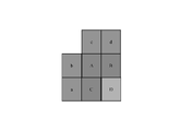
別の例示的な態様において、映像を処理する方法は、処理装置によって、第1の映像ブロックが2つよりも多い予測部分を含むように分割されているとの判定を行うことを含む。一例において、第1の映像ブロックは、それぞれが非長方形且つ非正方形である第1の予測部分、第2の予測部分、第3の予測部分、および第4の予測部分に分割され、第1の予測部分、第2の予測部分、第3の予測部分、および第4の予測部分を使用して、第1の映像ブロックのさらなる処理を実行する。 In another exemplary aspect, a method of processing video includes determining, by a processing device, that a first video block has been partitioned to include more than two prediction portions. In one example, a first video block is divided into a first prediction portion, a second prediction portion, a third prediction portion, and a fourth prediction portion, each of which is non-rectangular and non-square; Further processing of the first video block is performed using the prediction portion, the second prediction portion, the third prediction portion, and the fourth prediction portion.
別の例示的な態様において、映像処理方法が開示される。この方法は、スキップ/符号化のマージモードを第2の符号化モードとは別個に扱うことを規定する符号化規則に準拠して、映像ブロックとこの映像ブロックのビットストリーム表現との間で変換を行うことを含み、第2の符号化モードは、三角分割モードまたはMHIntra(複合インターイントラモードまたはCIIPと呼ばれることもある)モードまたはサブブロックマージリストモードである。 In another exemplary aspect, a video processing method is disclosed. The method converts between a video block and a bitstream representation of this video block in accordance with encoding rules that specify that skip/encode merge modes are treated separately from secondary encoding modes. and the second encoding mode is triangulation mode or MHIntra (sometimes called complex inter-intra mode or CIIP) mode or sub-block merge list mode.
別の例示的な態様において、別の映像処理方法が開示される。この方法は、映像ブロックとこの映像ブロックのビットストリーム表現との間で変換を行うこととであって、変換における複数のサブブロック符号化ツールの使用の具体的な表示の特定の順序を規定する規則に準拠して変換を行うことを含み、この具体的な順序は、(a.)動きベクトル差(MMVD)とのマージ、サブブロックマージリスト、三角形分割モードTPM、MHIntraの順、または(b.)MMVD、サブブロックマージリスト、MHIntra、TPMの順の一方である。 In another exemplary aspect, another video processing method is disclosed. The method comprises transforming between a video block and a bitstream representation of this video block, and prescribing a particular order of concrete indications of the use of multiple sub-block coding tools in the transform. The specific order is (a.) merge with motion vector difference (MMVD), sub-block merge list, triangulation mode TPM, MHIntra order, or (b .) MMVD, sub-block merge list, MHIntra, TPM.
さらに別の例示的な態様において、別の映像処理方法が開示される。この方法は、符号化規則に準拠して、映像ブロックと現在の映像ブロックのビットストリーム表現との間で変換を行うことを含み、規則は、この映像ブロックの適応動きベクトル解像度(AMVR)符号化モードにおいて、動きベクトル予測を指定するために、近傍のブロックを選択的に使用することを規定し、この規則は、(1)異なる最大符号化ユニット(LCU)行にある近傍のブロックを除外する、または(2)固定解像度値を指定する、または(3)映像ブロックを、アフィンモードを使用して符号化する、を含み、異なるLCU行にあるアフィン符号化された近傍のブロックを利用不可能とする。 In yet another exemplary aspect, another video processing method is disclosed. The method includes transforming between a video block and a bitstream representation of the current video block according to encoding rules, the rules being adaptive motion vector resolution (AMVR) encoding of the video block. mode specifies the selective use of neighboring blocks to specify motion vector prediction, and the rules are: (1) exclude neighboring blocks that are in different largest coding unit (LCU) rows; or (2) specify a fixed resolution value, or (3) encode the video block using an affine mode where affine-encoded neighboring blocks in different LCU rows are not available. and
さらに別の例示的な態様において、別の映像処理方法が開示される。この方法は、映像ブロックと符号化規則に準拠した前記現在の映像ブロックのビットストリーム表現との間で変換を行うこととを含み、規則は、前記映像ブロックの適応動きベクトル解像度(AMVR)符号化モードでの動きベクトル予測を指定するための近傍のブロックの選択的使用を規定し、規則は、近傍のブロックを、(a)近傍のブロックが異なる最大符号化ユニット(LCU)行にある場合に、近傍の映像ブロックの情報を映像ブロックのコンテキストモデリングのために使用することを無効にすること、または、(b)変換中に構文要素を符号化するために1つのコンテキストのみを使用すること、または(c)バイパス符号化を適用することは、1つの構文要素のみに適用すること、として、選択的に使用することを含む。 In yet another exemplary aspect, another video processing method is disclosed. The method includes transforming between a video block and a bitstream representation of the current video block compliant with encoding rules, the rules comprising adaptive motion vector resolution (AMVR) encoding of the video block. The rules specify the selective use of neighboring blocks to specify motion vector prediction in the mode, and the rules define neighboring blocks as: (a) if the neighboring blocks are in different largest coding unit (LCU) rows; , disabling the use of information from neighboring video blocks for context modeling of video blocks, or (b) using only one context for encoding syntax elements during transformation; or (c) applying bypass encoding includes selectively using, as applying to only one syntax element.
さらに別の例示的な態様において、別の映像処理方法が開示される。この方法は、映像ブロックと符号化規則に準拠した前記現在の映像ブロックのビットストリーム表現との間で変換を行うこととを含み、符号化の規則は、映像ブロックの適応動きベクトル解像度(AMVR)符号化モードにおける動きベクトル予測を指定するために、近傍の映像ブロックを選択的に使用することを規定しており、規則は、近傍の映像ブロックに関する情報が、現在の映像ブロックを復号化するために使用される近傍の映像ブロックに基づいてコンテキストモデリングのために使用されることを含む。 In yet another exemplary aspect, another video processing method is disclosed. The method includes transforming between a video block and a bitstream representation of the current video block that conforms to encoding rules, the encoding rules being adaptive motion vector resolution (AMVR) of the video block. It specifies the selective use of neighboring video blocks to specify motion vector prediction in coding modes, and the rule states that information about neighboring video blocks is used to decode the current video block. used for context modeling based on neighboring video blocks used for
さらに別の例示的な態様において、別の映像処理方法が開示される。この方法は、符号化の規則に準拠して、映像ブロックと、現在の映像ブロックのビットストリーム表現との間で変換を行うことを含み、符号化の規則は、映像ブロックの適応動きベクトル解像度(AMVR)符号化モードにおける動きベクトル予測を指定するために、近傍の映像ブロックを選択的に使用することを規定しており、規則は、近傍の映像ブロックに関する情報が、現在の映像ブロックを復号化するために使用される、近傍の映像ブロックに基づいたコンテキストモデリングのために使用され、近傍の映像ブロックは、現在のCTU行とは異なるCTU行内、または現在のCTUとは異なるCTU内の映像ブロックを除外して使用されることを含む。 In yet another exemplary aspect, another video processing method is disclosed. The method includes transforming between a video block and a bitstream representation of the current video block according to encoding rules, the encoding rules being the adaptive motion vector resolution ( AMVR) coding mode, which specifies the selective use of neighboring video blocks to specify motion vector prediction, and the rule states that information about neighboring video blocks is used to decode the current video block. used for context modeling based on neighboring video blocks, where the neighboring video block is a video block in a CTU row different from the current CTU row or in a CTU different from the current CTU row including being used to the exclusion of
別の例示的な態様において、上記方法は、処理装置を備えるビデオエンコーダによって実装されてもよい。 In another exemplary aspect, the above method may be implemented by a video encoder comprising a processing unit.
さらに別の例示的な態様において、これらの方法は、処理装置実行可能命令の形式で実施されてもよく、コンピュータ可読プログラム媒体に記憶されてもよい。 In yet another exemplary aspect, these methods may be embodied in the form of processor-executable instructions and stored on a computer-readable program medium.
これらの、および他の態様は、本明細書でさらに説明される。 These and other aspects are further described herein.
本明細書は、伸張または復号化されたデジタル映像または画像の品質を向上させるために、画像または映像ビットストリームのデコーダによって使用され得る様々な技術を提供する。簡潔にするために、本明細書では、用語「映像」は、一連のピクチャ(従来から映像と呼ばれる)および個々の画像の両方を含んで使用する。さらに、ビデオエンコーダは、さらなる符号化に使用される復号化されたフレームを再構成するために、符号化の処理中にこれらの技術を実装してもよい。 This specification provides various techniques that may be used by image or video bitstream decoders to improve the quality of decompressed or decoded digital video or images. For brevity, the term "video" is used herein to include both a sequence of pictures (conventionally called video) and individual images. Additionally, video encoders may implement these techniques during the encoding process to reconstruct decoded frames that are used for further encoding.
本明細書では、理解を容易にするために章見出しを使用しているが、実施形態および技術を対応する章に限定するものではない。このように、一つの章からの実施形態は、他の章からの実施例と組み合わせることができる。 Section headings are used herein for ease of understanding, but are not intended to limit embodiments and techniques to corresponding sections. Thus, embodiments from one chapter can be combined with examples from other chapters.
1. 概要 1. Overview
本特許明細書は、映像符号化技術に関する。具体的には、本発明は、映像符号化におけるジオメトリ分割における動きベクトル符号化に関する。HEVCのような既存の映像符号化規格に適用してもよいし、規格(汎用映像符号化)を確定させるために適用してもよい。本発明は、将来の映像符号化規格またはビデオコーデックにも適用可能である。 This patent specification relates to video coding technology. Specifically, the present invention relates to motion vector coding in geometry partitioning in video coding. It may be applied to an existing video coding standard such as HEVC, or may be applied to establish a standard (general-purpose video coding). The invention is also applicable to future video coding standards or video codecs.
2. 詳解 2. detailed explanation
映像符号化規格は、主に周知のITU-TおよびISO/IEC規格の開発によって発展してきた。ITU-TはH.261とH.263を、ISO/IECはMPEG-1とMPEG-4Visualを、両団体はH.262/MPEG-2VideoとH.264/MPEG-4高度映像符号化(AVC)とH.265/HEVC「1」規格を共同で作成した。映像符号化規格、H.262は、時間予測プラス変換符号化が利用されるハイブリッド映像符号化構造に基づく。HEVCを超えた将来の映像符号化技術を探索するため、2015年には、VCEGとMPEGが共同で共同映像探索チーム(Joint Video Exploration Team:JVET)を設立した。それ以来、多くの新しい方法がJVETによって採用され、共同探索モデル(JEM)と呼ばれる参照ソフトウェアに組み込まれてきた。2018年4月、VCEG(Q6/16)とISO/IEC JTC1 SC29/WG11(MPEG)の間に共同映像探索チーム(JVET)が作られ、HEVCと比較してビットレートを50%低減することを目標としたVVC規格に取り組むことになった。 Video coding standards have evolved primarily through the development of well-known ITU-T and ISO/IEC standards. The ITU-T is H.264. 261 and H. 263, ISO/IEC MPEG-1 and MPEG-4 Visual, and both bodies H.263. 262/MPEG-2 Video and H.262/MPEG-2 Video. 264/MPEG-4 Advanced Video Coding (AVC) and H.264. H.265/HEVC '1' standard. video coding standard, H.264; H.262 is based on a hybrid video coding structure in which temporal prediction plus transform coding is utilized. In 2015, VCEG and MPEG jointly established the Joint Video Exploration Team (JVET) to explore future video coding technologies beyond HEVC. Since then, many new methods have been adopted by JVET and incorporated into the reference software called the Joint Exploration Model (JEM). In April 2018, a Joint Video Search Team (JVET) was created between VCEG (Q6/16) and ISO/IEC JTC1 SC29/WG11 (MPEG) to reduce the bitrate by 50% compared to HEVC. It was decided to work on the target VVC standard.
図32は、ビデオエンコーダの例示的な実装のブロック図を示す。図32は、エンコーダ実装が、ビデオエンコーダが映像復号化機能も実行する(次の映像データの符号化に使用するために映像データの圧縮表現を再構築する)フィードバック経路を組み込むことを示す。 FIG. 32 shows a block diagram of an exemplary implementation of a video encoder. FIG. 32 shows that an encoder implementation incorporates a feedback path in which the video encoder also performs video decoding functions (reconstructing a compressed representation of video data for use in encoding subsequent video data).
2.1 HEVC/H.265におけるインター予測 2.1 HEVC/H. Inter prediction in H.265
各インター予測PUは、1つまたは2つの参照ピクチャリストのための動きパラメータを有する。動きパラメータは、動きベクトルおよび参照ピクチャインデックスを含む。2つの参照ピクチャリストのうちの1つの参照ピクチャリストの使用は、inter_pred_idcを使用して信号通知されてもよい。動きベクトルは、予測子に対してデルタとして明確に符号化されてもよい。 Each inter-predicted PU has motion parameters for one or two reference picture lists. Motion parameters include motion vectors and reference picture indices. The use of one of the two reference picture lists may be signaled using inter_pred_idc. Motion vectors may be explicitly encoded as deltas to predictors.
1つのCUがスキップモードで符号化される場合、1つのPUがこのCUに関連付けられ、有意な残差係数がなく、符号化動きベクトルデルタも参照ピクチャインデックスもない。マージモードを指定し、これにより、現在のPUのための動きパラメータを、空間的および時間的候補を含む近傍のPUから取得する。マージモードは、スキップモードのためだけでなく、任意のインター予測されたPUに適用することができる。マージモードの代替は、動きパラメータを明確に送信することであり、動きベクトル(より正確には、動きベクトル予測子と比較して動きベクトルの差)、各参照ピクチャリストに対応する参照ピクチャインデックス、および参照ピクチャリストの使用量が、PUごとに明確に信号通知される。このようなモードを、本開示では高度動きベクトル予測(AMVP)と呼ぶ。 If a CU is coded in skip mode, then a PU is associated with this CU and has no significant residual coefficients, no coded motion vector deltas, and no reference picture indices. Specify merge mode, whereby the motion parameters for the current PU are obtained from neighboring PUs, including spatial and temporal candidates. Merge mode can be applied to any inter-predicted PU, not just for skip mode. An alternative to merge mode is to send the motion parameters explicitly, the motion vector (more precisely, the motion vector difference compared to the motion vector predictor), the reference picture index corresponding to each reference picture list, and reference picture list usage are explicitly signaled per PU. Such a mode is referred to as Advanced Motion Vector Prediction (AMVP) in this disclosure.
2つの参照ピクチャリストのうちの1つを使用することを信号通知が示す場合、1つのサンプルのブロックからPUを生成する。これを「単一予測」と呼ぶ。PスライスおよびBスライスの両方に対して単一予測が利用可能である。 If the signaling indicates to use one of the two reference picture lists, generate a PU from a block of one sample. This is called "single prediction". Single prediction is available for both P and B slices.
両方の参照ピクチャリストを使用することを信号通知が示す場合、2つのサンプルのブロックからPUを生成する。これを「双予測」と呼ぶ。Bスライスのみに双予測が利用可能である。 If the signaling indicates to use both reference picture lists, then generate a PU from a block of two samples. This is called "bi-prediction". Bi-prediction is available only for B slices.
以下、HEVCに規定されるインター予測モードについて詳細に説明する。まず、マージモードについて説明する。 Inter-prediction modes defined in HEVC will be described in detail below. First, let's talk about merge mode.
2.1.1. 参照ピクチャリスト 2.1.1. Reference picture list
HEVCにおいて、インター予測という用語は、現在の復号化されたピクチャ以外の参照ピクチャのデータ要素(例えば、サンプル値または動きベクトル)から導出された予測を示すために使用される。H.264/AVCと同様に、複数の参照ピクチャから1つのピクチャを予測することができる。インター予測に使用される参照ピクチャは、1つ以上の参照ピクチャリストにまとめられる。参照インデックスは、リストにおけるいずれの参照ピクチャを使用して予測信号を生成するかを識別する。 In HEVC, the term inter-prediction is used to denote prediction derived from data elements (eg, sample values or motion vectors) of reference pictures other than the current decoded picture. H. As with H.264/AVC, one picture can be predicted from multiple reference pictures. Reference pictures used for inter prediction are organized into one or more reference picture lists. The reference index identifies which reference picture in the list is used to generate the prediction signal.
1つの参照ピクチャリストList0はPスライスに用いられ、2つの参照ピクチャリストList0およびList1はBスライスに使用される。なお、List0/1に含まれる参照ピクチャは、撮影/表示順にしてみても、過去および将来のピクチャからのものであってもよい。 One reference picture list List0 is used for P slices, and two reference picture lists List0 and List1 are used for B slices. Note that the reference pictures included in List0/1 may be from past and future pictures, even in the order of shooting/display.
2.1.2 マージモード 2.1.2 Merge mode
2.1.2.1 マージモードの候補の導出 2.1.2.1 Derivation of merge mode candidates
マージモードを使用してPUを予測する場合、ビットストリームからマージ候補リストにおけるエントリを指すインデックスを構文解析し、これを使用して動き情報を検索する。このリストの構成は、HEVC規格で規定されており、以下のステップのシーケンスに基づいてまとめることができる。 When predicting a PU using merge mode, we parse from the bitstream an index pointing to an entry in the merge candidate list and use this to retrieve motion information. The structure of this list is specified in the HEVC standard and can be summarized based on the following sequence of steps.
ステップ1:初期候補導出
ステップ1.1:空間的候補導出
ステップ1.2:空間的候補の冗長性チェック
ステップ1.3:時間的候補導出
ステップ2:追加候補挿入
ステップ2.1:双予測候補の作成
ステップ2.2:動きゼロ候補の挿入
Step 1: Initial Candidate Derivation Step 1.1: Spatial Candidate Derivation Step 1.2: Spatial Candidate Redundancy Check Step 1.3: Temporal Candidate Derivation Step 2: Additional Candidate Insertion Step 2.1: Bi-Predictive Candidates step 2.2: insert zero motion candidate
これらのステップは図1にも概略的に示されている。空間的マージ候補導出のために、5つの異なる位置にある候補の中から最大4つのマージ候補を選択する。時間的マージ候補導出のために、2つの候補の中から最大1つのマージ候補を選択する。デコーダ側ではPUごとに一定数の候補を想定しているので、ステップ1で得られた候補の数が、スライスヘッダにおいて信号通知されるマージ候補の最大数(MaxNumMergeCand)に達しない場合、追加の候補を生成する。候補の数は一定であるので、短縮された単項2値化(TU)を使用して最良マージ候補のインデックスを符号化する。CUのサイズが8に等しい場合、現在のCUのすべてのPUは、2N×2N予測ユニットのマージ候補リストと同じ1つのマージ候補リストを共有する。
These steps are also shown schematically in FIG. For spatial merge candidate derivation, we select up to 4 merge candidates out of 5 candidates at different locations. For temporal merge candidate derivation, select at most one merge candidate out of two candidates. Since we expect a fixed number of candidates per PU on the decoder side, if the number of candidates obtained in
以下、上述したステップに関連付けられた動作を詳しく説明する。 The operations associated with the above steps are described in detail below.
図1は、マージ候補リスト構築の導出処理の一例を示す。 FIG. 1 shows an example of derivation processing for constructing a merge candidate list.
2.1.2.2. 空間的候補導出 2.1.2.2. Spatial candidate derivation
空間的マージ候補の導出において、図2に示す位置にある候補の中から、最大4つのマージ候補を選択する。導出の順序はA1、B1、B0、A0、B2である。位置A1、B1、B0、A0のいずれかのPUが利用可能でない場合(例えば、別のスライスまたはタイルに属しているため)、またはイントラ符号化された場合にのみ、位置B2が考慮される。位置A1の候補を加えた後、残りの候補を加えると、冗長性チェックを受け、それにより、同じ動き情報を有する候補を確実にリストから排除でき、符号化効率を向上させることができる。計算の複雑性を低減するために、前述の冗長性チェックにおいて、考えられる候補対のすべてを考慮することはしない。代わりに、図3において矢印でリンクされた対のみを考慮し、冗長性チェックに使用される対応する候補が同じ動き情報を有していない場合にのみ、その候補をリストに加える。重複した動き情報の別のソースは、2N×2Nとは異なる分割に関連付けられた「第2のPU」である。一例として、図4は、それぞれN×2Nおよび2N×Nの場合の第2のPUを示す。現在のPUをN×2Nに分割する場合、リスト構築に位置A1の候補は考慮されない。実際、この候補を加えることにより、2つの予測ユニットが同じ動き情報を有するようになり、1つの符号化ユニットに1つのPUのみを有することは冗長である。同様に、現在のPUを2N×Nに分割する場合、位置B1は考慮されない。 In deriving spatial merge candidates, we select up to four merge candidates from among the candidates at the positions shown in FIG. The order of derivation is A 1 , B 1 , B 0 , A 0 , B 2 . Position B 2 only if a PU in any of positions A 1 , B 1 , B 0 , A 0 is not available (e.g., because it belongs to another slice or tile) or is intra-coded. is considered. After adding the candidate at position A1, adding the remaining candidates undergoes a redundancy check, which ensures that candidates with the same motion information are eliminated from the list, which can improve the coding efficiency. To reduce computational complexity, we do not consider all possible candidate pairs in the redundancy check described above. Instead, we consider only the pairs linked by arrows in FIG. 3 and add the candidate to the list only if the corresponding candidate used for redundancy check does not have the same motion information. Another source of duplicated motion information is a "second PU" associated with a partition different than 2Nx2N. As an example, FIG. 4 shows the second PU for the N×2N and 2N×N cases, respectively. If the current PU is split into Nx2N , the candidate for position A1 is not considered for list construction. In fact, adding this candidate causes the two prediction units to have the same motion information, and having only one PU in one coding unit is redundant. Similarly, when dividing the current PU into 2N×N, location B1 is not considered.
図2に、空間的マージ候補の位置の例を示す。 FIG. 2 shows an example of the location of spatial merge candidates.
図3は、空間的マージ候補の冗長性チェックに考慮される候補対の例を示す。 FIG. 3 shows an example of candidate pairs considered for redundancy checking of spatial merge candidates.
図4は、Nx2Nおよび2NxN分割の第2のPUの位置の例を示す。 FIG. 4 shows an example of the location of the second PU for Nx2N and 2NxN partitions.
2.1.2.3. 時間的候補導出 2.1.2.3. temporal candidate derivation
このステップにおいて、1つの候補のみがリストに追加される。具体的には、この時間的マージ候補の導出において、所与の参照ピクチャリストにおける現在のピクチャとの間に最小のPOC差を有するピクチャに属する同一位置PUに基づいて、スケーリングされた動きベクトルを導出する。スライスヘッダにおいて、同一位置PUの導出に使用される参照ピクチャリストが明確に信号通知される。図5に点線で示すように、時間的マージ候補のスケーリングされた動きベクトルが得られる。これは、POC距離tbおよびtdを利用して、同一位置PUの動きベクトルからスケーリングしたものである。tbは、現在のピクチャの参照ピクチャと現在のピクチャのPOC差として規定し、tdは、同一位置PUの参照ピクチャと同一位置ピクチャのPOC差として規定する。時間的マージ候補の参照ピクチャインデックスをゼロに等しく設定する。このスケーリング処理の実際的な実現については、HEVC仕様に記載されている。Bスライスの場合、2つの動きベクトル、即ち、1つは参照ピクチャリスト0のためのもの、もう1つは参照ピクチャリスト1のためのものを取得し、これらを組み合わせることによって、双予測マージ候補を形成する。
Only one candidate is added to the list in this step. Specifically, in deriving this temporal merge candidate, we compute the scaled motion vector based on the co-located PU belonging to the picture that has the smallest POC difference with the current picture in the given reference picture list. derive In the slice header, the reference picture list used for deriving the co-located PU is explicitly signaled. The scaled motion vectors of the temporal merge candidates are obtained, as indicated by the dashed lines in FIG. This is scaled from the motion vector of the co-located PU using the POC distances tb and td. tb is defined as the POC difference between the reference picture of the current picture and the current picture, and td is defined as the POC difference between the reference picture of the co-located PU and the co-located picture. Set the reference picture index of the temporal merge candidate equal to zero. A practical implementation of this scaling process is described in the HEVC specification. For the B slice, we take two motion vectors, one for
図5に、時間的マージ候補のための動きベクトルのスケーリングの例を示す。 FIG. 5 shows an example of motion vector scaling for temporal merge candidates.
参照フレームに属する同一位置PU(Y)において、図6に示すように、候補C0と候補C1との間で時間的候補の位置を選択する。位置C0のPUが利用可能でない場合、イントラ符号化されている場合、または現在のCTU行の外側にある場合、位置C1が使用される。そうでない場合、位置C0が時間的マージ候補の導出に使用される。 At the same position PU(Y) belonging to the reference frame, select the position of the temporal candidate between candidate C0 and candidate C1, as shown in FIG. If the PU at position C0 is not available, is intra - coded, or is outside the current CTU row, then position C1 is used. Otherwise, position C0 is used to derive temporal merge candidates.
図6は、時間的マージ候補の候補位置C0およびC1の一例を示す図である。 FIG. 6 is a diagram showing an example of candidate positions C0 and C1 of temporal merge candidates.
2.1.2.4. 追加候補挿入 2.1.2.4. Insert additional suggestions
時空間的マージ候補の他に、2つの追加のタイプのマージ候補、すなわち、結合双予測マージ候補およびゼロマージ候補がある。空間的および時間的マージ候補を利用することで、結合双予測マージ候補を生成する。結合双予測マージ候補は、Bスライスのみに使用される。最初の候補の第1の参照ピクチャリスト動きパラメータと別の候補の第2の参照ピクチャリスト動きパラメータとを組み合わせることで、結合双予測候補を生成する。これら2つのタプルが異なる動き仮説を提供する場合、これらのタプルは、新しい双予測候補を形成する。一例として、図7は、オリジナルリスト(左側)における、mvL0、refIdxL0またはmvL1、refIdxL1を有する2つの候補を使用して、最終リスト(右側)に加えられる結合双予測マージ候補を生成する場合を示す。これらの追加のマージ候補を生成するために考慮される組み合わせについては、様々な規則が存在する。 Besides spatio-temporal merge candidates, there are two additional types of merge candidates: joint bi-predictive merge candidates and zero merge candidates. Spatial and temporal merge candidates are utilized to generate joint bi-predictive merge candidates. Joint bi-predictive merge candidates are used only for B slices. A combined bi-prediction candidate is generated by combining the first reference picture list motion parameter of the first candidate and the second reference picture list motion parameter of another candidate. If these two tuples provide different motion hypotheses, they form new bi-prediction candidates. As an example, FIG. 7 shows the case where two candidates with mvL0, refIdxL0 or mvL1, refIdxL1 in the original list (left) are used to generate a combined bi-predictive merge candidate that is added to the final list (right). . Various rules exist for the combinations that are considered to generate these additional merge candidates.
図7は、結合双予測マージ候補の例を示す。 FIG. 7 shows an example of combined bi-predictive merge candidates.
動きゼロ候補を挿入し、マージ候補リストにおける残りのエントリを埋めることにより、MaxNumMergeCand容量にヒットする。これらの候補は、空間的変位がゼロであり、新しいゼロ動き候補をリストに加える度にゼロから始まり増加する参照ピクチャインデックスを有する。これらの候補が使用する参照フレームの数は、それぞれ、一方向予測の場合は1つ、双方向予測の場合は2つである。最終的には、これらの候補に対して冗長性チェックは行われない。 MaxNumMergeCand capacity is hit by inserting zero motion candidates and filling the remaining entries in the merge candidate list. These candidates have zero spatial displacement and have reference picture indices that start at zero and increase each time a new zero motion candidate is added to the list. The number of reference frames used by these candidates is one for uni-prediction and two for bi-prediction, respectively. Finally, no redundancy check is performed on these candidates.
2.1.2.5. 並列処理のための動き推定領域 2.1.2.5. Motion estimation region for parallel processing
符号化処理を高速化するために、動き推定を並列に行うことができ、それによって、所与の領域内のすべての予測ユニットの動きベクトルを同時に導出する。1つの予測ユニットは、その関連する動き推定が完了するまで、隣接するPUから動きパラメータを導出することができないので、空間的近傍からのマージ候補の導出は、並列処理に干渉する可能性がある。符号化効率と処理待ち時間との間のトレードオフを緩和するために、HEVCは、動き推定領域(MER)を規定し、そのサイズは、「log2_parallel_merge_level_minus2」構文要素「1」を使用してピクチャパラメータセットにおいて信号通知される。1つのMERを規定するとき、同じ領域にあるマージ候補は利用不可能であるとしてマークされ、それゆえにリスト構築においては考慮されない。 To speed up the encoding process, motion estimation can be performed in parallel, thereby simultaneously deriving motion vectors for all prediction units within a given region. Since one prediction unit cannot derive motion parameters from neighboring PUs until its associated motion estimation is complete, deriving merge candidates from spatial neighbors can interfere with parallel processing. . To ease the trade-off between coding efficiency and processing latency, HEVC defines a Motion Estimation Region (MER), whose size is determined by the picture parameters using the 'log2_parallel_merge_level_minus2' syntax element '1'. Signaled in set. When defining one MER, merge candidates in the same region are marked as unavailable and therefore not considered in list construction.
2.1.3. AMVP 2.1.3. AMVP
AMVPは、動きパラメータの明確な伝送に使用される、動きベクトルの近傍のPUとの時空間的相関を利用する。各参照ピクチャリストにおいて、まず、左側の時間的に近傍のPU位置の可用性をチェックし、冗長な候補を取り除き、ゼロベクトルを加えることで、候補リストの長さを一定にすることで、動きベクトル候補リストを構成する。次いで、エンコーダは、候補リストから最良の予測子を選択し、選択された候補を示す対応するインデックスを送信することができる。マージインデックスの信号通知と同様に、最良の動きベクトル候補のインデックスは、短縮された単項を使用してエンコードされる。この場合に符号化されるべき最大値は2である(図8)。以下の章では、動きベクトル予測候補の導出処理の詳細を説明する。 AMVP exploits the spatio-temporal correlation of motion vectors with neighboring PUs, which is used for unambiguous transmission of motion parameters. In each reference picture list, we first check the availability of left temporally neighboring PU positions, remove redundant candidates, and add zero vectors to keep the length of the candidate list constant so that the motion vector configure the candidate list; The encoder can then select the best predictor from the candidate list and send the corresponding index indicating the selected candidate. Similar to the merge index signaling, the index of the best motion vector candidate is encoded using a shortened unary. The maximum value to be encoded in this case is 2 (FIG. 8). The following chapters describe the details of the motion vector prediction candidate derivation process.
2.1.3.1 AMVP候補の導出 2.1.3.1 Derivation of AMVP candidates
図8に、動きベクトル予測候補の導出処理をまとめる。 FIG. 8 summarizes the motion vector prediction candidate derivation process.
動きベクトル予測において、空間的動きベクトル候補と時間的動きベクトル候補という2つのタイプの動きベクトル候補が考えられる。空間的動きベクトル候補を導出するために、図2に示したように、5つの異なる位置にある各PUの動きベクトルに基づいて、最終的には2つの動きベクトル候補を導出する。 Two types of motion vector candidates are considered in motion vector prediction: spatial motion vector candidates and temporal motion vector candidates. To derive the spatial motion vector candidates, we finally derive two motion vector candidates based on the motion vectors of each PU at five different positions, as shown in FIG.
時間的動きベクトル候補を導出するために、2つの異なる同一位置に配置された位置に基づいて導出された2つの候補から1つの動きベクトル候補を選択する。第1の時空間的候補リストを作成した後、リストにおける重複した動きベクトル候補を除去する。候補の数が2よりも多い場合、関連づけられた参照ピクチャリストにおける参照ピクチャインデックスが1よりも大きい動きベクトル候補をリストから削除する。時空間的動きベクトル候補の数が2未満である場合は、追加のゼロ動きベクトル候補をリストに加える。 To derive a temporal motion vector candidate, one motion vector candidate is selected from two candidates derived based on two different co-located positions. After creating the first spatio-temporal candidate list, remove duplicate motion vector candidates in the list. If the number of candidates is greater than 2, remove motion vector candidates whose reference picture index in the associated reference picture list is greater than 1 from the list. If the number of spatio-temporal motion vector candidates is less than two, add additional zero motion vector candidates to the list.
2.1.3.2. 空間的動きベクトル候補 2.1.3.2. Spatial motion vector candidates
空間的動きベクトル候補の導出において、図2に示したような位置にあるPUから導出された5つの潜在的な候補のうち、動きマージと同じ位置にあるものを最大2つの候補を考慮する。現在のPUの左側のための導出の順序は、A0、A1、スケーリングされたA0、スケーリングされたA1として規定される。現在のPUの上側のための導出の順序は、B0、B1、B2、スケーリングされたB0、スケーリングされたB1、スケーリングされたB2として規定される。そのため、辺ごとに、動きベクトル候補として使用できる場合は4つ、すなわち空間的スケーリングを使用する必要がない2つの場合と、空間的スケーリングを使用する2つの場合とがある。4つの異なる場合をまとめると、以下のようになる。 In the derivation of spatial motion vector candidates, we consider up to two of the five potential candidates derived from PUs in positions such as those shown in Figure 2 that are in the same position as motion merge. The order of derivation for the left side of the current PU is defined as A0, A1, scaled A0, scaled A1. The order of derivation for the upper side of the current PU is defined as B0, B1, B2, scaled B0, scaled B1, scaled B2. So, for each edge, there are 4 possible motion vector candidates: 2 without the need to use spatial scaling and 2 with spatial scaling. Summarizing the four different cases, we have:
空間的スケーリングなし
(1)同じ参照ピクチャリスト、および同じ参照ピクチャインデックス(同じPOC)
(2)異なる参照ピクチャリストであるが、同じ参照ピクチャ(同じPOC)
空間的スケーリング
(3)同じ参照ピクチャリストであるが、異なる参照ピクチャ(異なるPOC)
(4)異なる参照ピクチャリスト、および異なる参照ピクチャ(異なるPOC)
No spatial scaling (1) same reference picture list and same reference picture index (same POC)
(2) different reference picture list but same reference picture (same POC)
Spatial scaling (3) same reference picture list but different reference pictures (different POC)
(4) Different Reference Picture Lists and Different Reference Pictures (Different POCs)
最初に非空間的スケーリングの場合をチェックし、次に空間的スケーリングを行う。参照ピクチャリストにかかわらず、POCが近傍のPUの参照ピクチャと現在のPUの参照ピクチャとで異なる場合、空間的スケーリングを考慮する。左側候補のすべてのPUが利用可能でないか、またはイントラ符号化されている場合、上側の動きベクトルのスケーリングは、左側および上側MV候補の並列導出に役立つ。そうでない場合、上側の動きベクトルに対して空間的スケーリングは許可されない。 First check for non-spatial scaling cases, then spatial scaling. Spatial scaling is considered if the POC is different between the reference picture of the neighboring PU and the reference picture of the current PU, regardless of the reference picture list. Scaling the upper motion vector helps parallel derivation of the left and upper MV candidates when all PUs of the left candidate are not available or are intra-coded. Otherwise, no spatial scaling is allowed for the upper motion vector.
図9に、空間的動きベクトル候補のための動きベクトルのスケーリングの例を示す。 FIG. 9 shows an example of motion vector scaling for spatial motion vector candidates.
空間的スケーリング処理において、図9に示すように、時間的スケーリングと同様にして、近傍のPUの動きベクトルをスケーリングする。主な違いは、現在のPUの参照ピクチャリストおよびインデックスを入力として与え、実際のスケーリング処理は時間的スケーリングと同じであることである。 In spatial scaling processing, motion vectors of neighboring PUs are scaled in the same manner as temporal scaling, as shown in FIG. The main difference is that given the current PU's reference picture list and index as input, the actual scaling process is the same as temporal scaling.
2.1.3.3. 時間的動きベクトル候補 2.1.3.3. Temporal motion vector candidates
参照ピクチャインデックスを導出する以外は、時間的マージ候補を導出するための処理は、すべて、空間的動きベクトル候補を導出するための処理と同じである(図6参照)。参照ピクチャインデックスはデコーダに信号通知される。 Except for deriving the reference picture index, the process for deriving temporal merge candidates is all the same as the process for deriving spatial motion vector candidates (see FIG. 6). The reference picture index is signaled to the decoder.
2.2. JEMにおける新しいインター予測方法 2.2. New inter-prediction method in JEM
2.2.1. サブCUに基づく動きベクトル予測 2.2.1. Motion vector prediction based on sub-CU
QTBTを有するJEMにおいて、各CUは、各予測方向に対して最大1つの動きパラメータのセットを有することができる。エンコーダにおいて、ラージCUをサブCUに分割し、ラージCUのすべてのサブCUの動き情報を導出することにより、2つのサブCUレベルの動きベクトル予測方法を考慮する。サブブロック時間的動きベクトル予測(SbTMVP)代替的な時間的動きベクトル予測(ATMVP)法により、各CUが、配列された参照ピクチャにおける現在のCUよりも小さい複数のブロックから複数の動き情報のセットをフェッチすることが可能となる。時空間的動きベクトル予測(STMVP)法において、時間的動きベクトル予測子および空間的近傍動きベクトルを使用して、サブCUの動きベクトルを再帰的に導出する。 In JEM with QTBT, each CU can have at most one set of motion parameters for each prediction direction. At the encoder, we consider two sub-CU level motion vector prediction methods by dividing a large CU into sub-CUs and deriving motion information for all sub-CUs of the large CU. Sub-Block Temporal Motion Vector Prediction (SbTMVP) Alternative Temporal Motion Vector Prediction (ATMVP) method allows multiple sets of motion information from multiple blocks where each CU is smaller than the current CU in the aligned reference picture can be fetched. In the spatio-temporal motion vector prediction (STMVP) method, temporal motion vector predictors and spatial neighbor motion vectors are used to recursively derive motion vectors of sub-CUs.
サブCU動き予測のためにより正確な動きフィールドを維持するために、参照フレームの動き圧縮は現在無効にされている。 In order to maintain a more accurate motion field for sub-CU motion estimation, motion compression of reference frames is currently disabled.
図10は、CUのための例示的なATMVP動き予測を示す。 FIG. 10 shows exemplary ATMVP motion estimation for a CU.
2.2.1.1. 代替の時間的動きベクトル予測 2.2.1.1. Alternative temporal motion vector prediction
代替的な時間的動きベクトル予測(ATMVP)において、動きベクトル時間的動きベクトル予測(TMVP)法は、現在のCUより小さいブロックから複数の動き情報のセット(動きベクトルおよび参照インデックスを含む)を取り出すことで修正される。いくつかの実施形態において、サブCUは、N×N個のブロックの正方形である(Nは、デフォルトで4に設定される)。 In alternative temporal motion vector prediction (ATMVP), the motion vector temporal motion vector prediction (TMVP) method retrieves multiple sets of motion information (including motion vectors and reference indices) from blocks smaller than the current CU. is corrected by In some embodiments, a sub-CU is a square of N×N blocks (N is set to 4 by default).
ATMVPは、CU内のサブCUの動きベクトルを2つのステップで予測する。第1のことは、参照ピクチャにおける対応するブロックを、いわゆる時間的ベクトルで特定することである。この参照ピクチャをモーションソースピクチャと呼ぶ。第2のステップでは、現在のCU1000をサブCU1001に分割し、各サブCUに対応するブロックから、各サブCUの動きベクトルおよび参照インデックスを得る。 ATMVP predicts motion vectors of sub-CUs within a CU in two steps. The first is to identify the corresponding block in the reference picture with a so-called temporal vector. This reference picture is called a motion source picture. In the second step, the current CU 1000 is divided into sub-CUs 1001, and the motion vector and reference index of each sub-CU are obtained from the blocks corresponding to each sub-CU.
第1のステップにおいて、現在のCUの空間的に近傍のブロックの動き情報によって、参照ピクチャおよび対応するブロックを判定する。近傍のブロックの繰り返し走査処理を回避するために、現在のCUのマージ候補リストにおける第1のマージ候補を使用する。第1の利用可能な動きベクトルおよびその関連する参照インデックスを、時間的ベクトルおよびモーションソースピクチャのインデックスに設定する。このように、ATMVPでは、TMVPに比べて、対応するブロックをより正確に特定することができ、対応するブロック(配列されたブロックと呼ばれることがある)は、常に現在のCUに対して右下または中心位置にある。 In the first step, the motion information of spatially neighboring blocks of the current CU determines the reference picture and corresponding block. To avoid the repeated scanning process of neighboring blocks, we use the first merge candidate in the current CU's merge candidate list. Set the first available motion vector and its associated reference index to the index of the temporal vector and the motion source picture. Thus, in ATMVP, the corresponding block can be specified more accurately than in TMVP, and the corresponding block (sometimes called the ordered block) is always the lower right corner for the current CU. or centered.
第2のステップにおいて、現在のCUの座標に時間ベクトルを加えることで、モーションソースピクチャにおける時間的ベクトルによって、サブCUの対応するブロックを特定する。サブCUごとに、その対応するブロックの動き情報(中心サンプルを覆う最小の動きグリッド)を使用して、サブCUの動き情報を導出する。対応するN×Nブロックの動き情報を特定した後、HEVCのTMVPと同様に、現在のサブCUの動きベクトルおよび参照インデックスに変換され、動きスケーリングや他の手順が適用される。例えば、デコーダは、低遅延条件(現在のピクチャのすべての参照ピクチャのPOCが現在のピクチャのPOCよりも小さい)が満たされているかどうかをチェックし、場合によっては、動きベクトルMVx(参照ピクチャリストXに対応する動きベクトル)を使用して、各サブCUの動きベクトルMVy(Xが0または1に等しく、Yが1-Xに等しい)を予測する。 In the second step, identify the corresponding block of the sub-CU by the temporal vector in the motion source picture by adding the temporal vector to the coordinates of the current CU. For each sub-CU, the motion information of its corresponding block (the smallest motion grid covering the center sample) is used to derive the motion information of the sub-CU. After identifying the motion information of the corresponding N×N block, it is transformed into motion vectors and reference indices of the current sub-CU, similar to HEVC's TMVP, and motion scaling and other procedures are applied. For example, the decoder checks whether the low-delay condition (the POC of all reference pictures of the current picture is less than the POC of the current picture) is met, and possibly the motion vector MV x (reference picture The motion vector corresponding to list X) is used to predict the motion vector MV y (where X equals 0 or 1 and Y equals 1−X) for each sub-CU.
2.2.1.2. 時空間的動きベクトル予測(STMVP) 2.2.1.2. Spatio-Temporal Motion Vector Prediction (STMVP)
この方法において、サブCUの動きベクトルは、ラスタスキャンの順に沿って再帰的に導出される。図11は、この概念を示す。4つの4×4サブCU、A、B、C、およびDを含む8×8CUを考える。現在のフレームの近傍の4×4ブロックには、a、b、c、dというラベルが付けられている。 In this method, motion vectors of sub-CUs are recursively derived along the raster scan order. FIG. 11 illustrates this concept. Consider an 8x8 CU containing four 4x4 sub-CUs, A, B, C, and D. The neighboring 4x4 blocks of the current frame are labeled a, b, c, d.
サブCU Aの動きの導出は、その2つの空間的近傍を特定することで始まる。第1の近傍は、サブCU Aの上のN×Nブロックである(ブロックc)。このブロックcが利用可能でないか、またはイントラ符号化されている場合、サブCU Aより上の他のN×N個のブロックをチェックする(ブロックcから始まり、左から右へ)。第2の近傍は、サブCU Aの左側のブロックである(ブロックb)。ブロックbが利用可能でないか、またはイントラ符号化されている場合、サブCU Aの左側の他のブロックをチェックする(ブロックbを中心に、上から下へ)。各リストの近傍のブロックから得られた動き情報を、所与のリストの第1の参照フレームにスケーリングする。次に、HEVCで規定されているTMVP導出と同じ手順に従って、サブブロックAの時間的動きベクトル予測子(TMVP)を導出する。ロケーションDにおける配列されたブロックの動き情報をフェッチし、それに応じてスケーリングする。最後に、動き情報を検索し、スケーリングした後、参照リストごとにすべての利用可能な動きベクトル(3まで)を別個に平均する。この平均化された動きベクトルを現在のサブCUの動きベクトルとする。 Deriving the motion of sub-CU A begins by identifying its two spatial neighbors. The first neighbor is the N×N block above sub-CU A (block c). If this block c is not available or is intra-coded, check the other N×N blocks above sub-CU A (starting from block c, left to right). The second neighbor is the left block of sub-CU A (block b). If block b is not available or is intra-coded, check other blocks to the left of sub-CU A (from top to bottom, centered on block b). The motion information obtained from neighboring blocks in each list is scaled to the first reference frame in the given list. Next, the temporal motion vector predictor (TMVP) of sub-block A is derived according to the same procedure as the TMVP derivation specified in HEVC. Fetch the motion information for the aligned block at location D and scale accordingly. Finally, after retrieving and scaling the motion information, we average all available motion vectors (up to 3) separately for each reference list. This averaged motion vector is used as the motion vector of the current sub-CU.
2.2.1.3. サブCU動き予測モード信号通知 2.2.1.3. Sub-CU motion prediction mode signaling
サブCUモードは追加のマージ候補として有効とされ、モードを信号通知するために追加の構文要素は必要とされない。ATMVPモードおよびSTMVPモードを表すように、各CUのマージ候補リストに2つの追加のマージ候補を加える。シーケンスパラメータセットがATMVPおよびSTMVPが有効であることを示す場合、7個までのマージ候補を使用する。追加のマージ候補の符号化ロジックは、HMにおけるマージ候補の場合と同じであり、つまり、PまたはBスライスにおける各CUについて、2つの追加のマージ候補に対して2回以上のRDチェックが必要となる。 Sub-CU modes are enabled as additional merge candidates and no additional syntax elements are required to signal the mode. Add two additional merge candidates to each CU's merge candidate list to represent ATMVP mode and STMVP mode. If the sequence parameter set indicates that ATMVP and STMVP are valid, use up to 7 merge candidates. The encoding logic for additional merging candidates is the same as for merging candidates in HM, i.e. for each CU in P or B slices, 2 or more RD checks are required for the two additional merging candidates. Become.
JEMにおいて、マージインデックスのすべての2値は、CABACによってコンテキスト符号化される。一方、HEVCにおいては、第1の2値のみがコンテキスト符号化され、残りの2値はコンテキストバイパス符号化される。 In JEM, all binaries of the merge index are context-encoded by CABAC. In HEVC, on the other hand, only the first binary is context coded and the remaining bins are context bypass coded.
2.2.2. 適応動きベクトル差解像度 2.2.2. Adaptive motion vector difference resolution
HEVCにおいて、use_integer_mv_flagがスライスヘッダにおいて0であるとき、1/4輝度サンプルの単位で動きベクトルの差(MVD)(動きベクトルとPUの予測動きベクトルとの差)が信号通知される。JEMにおいて、ローカル適応動きベクトル解像度(LAMVR)が導入される。JEMにおいて、MVDは、1/4輝度サンプル、整数輝度サンプルまたは4つの輝度サンプルの単位で符号化できる。MVD分解能は符号化ユニット(CU)レベルで制御され、MVD解像度フラグは、少なくとも1つのノンゼロMVDモジュールを有する各CUに対して条件付きで信号通知される。 In HEVC, when the use_integer_mv_flag is 0 in the slice header, the motion vector difference (MVD) (the difference between the motion vector and the predicted motion vector of the PU) is signaled in units of quarter luma samples. In JEM, Local Adaptive Motion Vector Resolution (LAMVR) is introduced. In JEM, MVD can be encoded in units of quarter luma samples, integer luma samples or four luma samples. MVD resolution is controlled at the coding unit (CU) level, and the MVD resolution flag is conditionally signaled for each CU that has at least one non-zero MVD module.
少なくとも1つのノンゼロMVDモジュールを有するCUの場合、1/4輝度サンプルMV精度がCUにおいて使用されるかどうかを示すために、第1のフラグが信号通知される。第1のフラグ(1に等しい)が、1/4輝度サンプルMV精度が使用されていないことを示す場合、整数輝度サンプルMV精度が使用されるかまたは4輝度サンプルMV精度が使用されるかを示すために、別のフラグが信号通知される。 For CUs with at least one non-zero MVD module, a first flag is signaled to indicate whether quarter luminance sample MV precision is used in the CU. If the first flag (equal to 1) indicates that 1/4 luma sample MV precision is not used, then whether integer luma sample MV precision or 4 luma sample MV precision is used. Another flag is signaled to indicate.
CUの第1のMVD解像度フラグがゼロであるか、またはCUに対して符号化されていない(つまり、CUにおけるすべてのMVDがゼロである)場合、CUに対して1/4輝度サンプルMV解像度が使用される。CUが整数輝度サンプルMV精度または4輝度サンプルMV精度を使用する場合、CUのAMVP候補リストにおけるMVPを対応する精度に丸める。 Quarter luma-sample MV resolution for a CU if the CU's first MVD resolution flag is zero or not coded for the CU (i.e., all MVDs in the CU are zero) is used. If the CU uses integer luma sample MV precision or 4 luma sample MV precision, round the MVPs in the CU's AMVP candidate list to the corresponding precision.
エンコーダにおいて、CUレベルのRDチェックは、どのMVD解像度をCUに使用するかを判定するために使用される。すなわち、1つのMVD解像度ごとに3回、CUレベルのRDチェックを行う。エンコーダの速度を速めるために、JEMにおいては、以下の符号化方式が適用される。 At the encoder, a CU-level RD check is used to determine which MVD resolution to use for the CU. That is, the CU level RD check is performed three times for each MVD resolution. To speed up the encoder, the following encoding scheme is applied in JEM.
通常の1/4輝度サンプルMVD解像度を有するCUのRDチェック中、現在のCUの動き情報(整数輝度サンプル精度)が記憶される。整数輝度サンプルおよび4輝度サンプルのMVD解像度を有する同じCUのRDチェック中に、記憶された動き情報(丸められた後)は、更なる小範囲の動きベクトル微調整の開始点として使用されるので、時間がかかる動き推定処理が3回重複することはない。 During the RD check of a CU with normal quarter luminance sample MVD resolution, the current CU's motion information (integer luminance sample precision) is stored. Since during the RD check of the same CU with MVD resolution of integer luma samples and 4 luma samples, the stored motion information (after being rounded) is used as a starting point for further small-range motion vector refinement. , the time-consuming motion estimation process is not duplicated three times.
4輝度サンプルMVD解像度を有するCUのRDチェックを条件付きで呼び出す。CUの場合、整数輝度サンプルMVD解像度のRDコストが1/4輝度サンプルMVD解像度のそれよりもはるかに大きい場合、CUのための4輝度サンプルMVD解像度のRDチェックはスキップされる。 Conditionally invoke RD check for CUs with 4 luma sample MVD resolution. For a CU, if the RD cost for the integer luma-sample MVD resolution is much greater than that for the quarter luma-sample MVD resolution, the RD check for the 4 luma-sample MVD resolution for the CU is skipped.
符号化処理を図12に示す。まず、1/4画素MVをテストし、RDコストを計算し、RDCost0と表し、次に、整数MVをテストし、RDコストをRDCost1と表す。RDCost1<th*RDCost0(ただし、thは正の値である)である場合、4画素MVをテストし、そうでない場合、4画素MVをスキップする。基本的に、整数または4画素MVをチェックするときには、1/4画素MVに対して動き情報およびRDコスト等が既知であり、これを再利用して整数または4画素MVの符号化処理を高速化することができる。 The encoding process is shown in FIG. First, test the quarter pixel MV and compute the RD cost, denoted as RDCost0, then test the integer MV and denote the RD cost as RDCost1. If RDCost1<th*RDCost0, where th is a positive value, then test 4-pixel MV, else skip 4-pixel MV. Basically, when checking an integer or 4-pixel MV, the motion information, RD cost, etc. are known for a 1/4-pixel MV, which can be reused to speed up the encoding process of an integer or 4-pixel MV. can be
2.2.3. 三角形予測モード 2.2.3. triangle prediction mode
三角形予測モード(TPM)の概念は、動き補償予測のために新しい三角形分割を導入することである。図13に示すように、CUは、対角線方向または逆対角線方向に沿って2つの三角形予測ユニットに分割される。CUにおける各三角形予測ユニットは、1つの単一予測候補リストから導出された独自の単一予測動きベクトルおよび参照フレームインデックスを使用して、インター予測される。三角形予測ユニットを予測した後、対角エッジに対して適応重み付け処理を行う。そして、CU全体に対して変換および量子化処理を行う。なお、このモードは、スキップモードおよびマージモードにのみ適用される。 The concept of Triangular Prediction Mode (TPM) is to introduce a new triangulation for motion compensated prediction. As shown in FIG. 13, the CU is split into two triangle prediction units along the diagonal or anti-diagonal direction. Each triangle prediction unit in a CU is inter-predicted using its own single predictor motion vector and reference frame index derived from one single prediction candidate list. After predicting the triangle prediction unit, an adaptive weighting process is performed on the diagonal edges. Transformation and quantization processing is then performed on the entire CU. Note that this mode only applies to skip and merge modes.
2.2.3.1 TPMの単一予測候補リスト 2.2.3.1 TPM Single Prediction Candidate List
この単一予測候補リストは、5つの単一予測動きベクトル候補からなる。これは、図14に示すように、5つの空間的に近傍のブロック(1~5)および2つの時間的に同一位置にあるブロック(6~7)を含むCUの7つの近傍のブロックから導出される。図14は、近傍のブロックの位置の例を示す。単一予測動きベクトル、双予測動きベクトルのL0動きベクトル、双予測動きベクトルのL1動きベクトル、およびタイルグループ動きベクトルのL0、L1動きベクトルの平均動きベクトルの順に、7つの近傍のブロックの動きベクトルを収集し、単一予測候補リストに入れる。候補の数が5未満である場合、動きベクトルゼロをリストに加える。 This single predictor candidate list consists of five single motion vector predictor candidates. This is derived from the 7 neighboring blocks of the CU, including 5 spatially neighboring blocks (1-5) and 2 temporally co-located blocks (6-7), as shown in FIG. be done. FIG. 14 shows an example of the positions of neighboring blocks. The motion vectors of the seven neighboring blocks in the order of the single predictor motion vector, the L0 motion vector of the bi-predictor motion vector, the L1 motion vector of the bi-predictor motion vector, and the average motion vector of the L0, L1 motion vector of the tile group motion vector are collected and put into a single-prediction candidate list. If the number of candidates is less than 5, add motion vector zero to the list.
具体的には、以下のステップが含まれる。 Specifically, the following steps are included.
プルーニング操作を行わずに、A1、B1、B0、A0、B2、Col、Col2(図14のブロック1-7に対応)から動き候補を取得する。 Obtain motion candidates from A1, B1, B0, A0, B2, Col, Col2 (corresponding to blocks 1-7 in FIG. 14) without performing a pruning operation.
変数numCurrMergeCand=0を設定する。 Set the variable numCurrMergeCand=0.
A1、B1、B0、A0、B2、Col、Col2、から導出された各動き候補で、numCurrMergeCandが5未満のものに対し、動き候補が単一予測である(List0またはList1のいずれかから)場合、であり、numCurrMergeCandを1だけ増加させたマージリストに加えられる。このように追加された動き候補を「本来単予測候補」と呼ぶ。 For each motion candidate derived from A1, B1, B0, A0, B2, Col, Col2, where numCurrMergeCand is less than 5, if the motion candidate is a single prediction (either from List0 or List1) , and is added to the merge list with numCurrMergeCand incremented by one. A motion candidate added in this way is called an “original uni-prediction candidate”.
フルプルーニングを適用する。 Apply full pruning.
A1,B1,B0,B0,A0,B2,Col,Col2から導出され、numCurrMergeCandが5未満である各動き候補について、動き候補が双予測である場合には、List0からの動き情報をマージリストに追加し(つまり、List0からの単一予測となるように修正され)、numCurrMergeCandを1だけ増加させる。このように追加された動き候補を「Truncated List0-predicted candidate」と呼ぶ。 For each motion candidate derived from A1, B1, B0, B0, A0, B2, Col, Col2 with numCurrMergeCand less than 5, if the motion candidate is bi-predictive, add the motion information from List0 to the merge list. Add (i.e. amended to be a single prediction from List0) and increment numCurrMergeCand by one. The motion candidate added in this way is called “Truncated List0-predicted candidate”.
フルプルーニングを適用する。 Apply full pruning.
A1,B1,B0,B0,A0,B2,Col,Col2から導出され、numCurrMergeCandが5未満である各動き候補について、動き候補が双予測である場合には、リスト1からの動き情報をマージリストに追加し(つまり、リスト1からの単一予測となるように修正され)、numCurrMergeCandを1だけ増加させる。このように追加された動き候補を「Truncated List1-predicted candidate」と呼ぶ。
For each motion candidate derived from A1, B1, B0, B0, A0, B2, Col, Col2 with numCurrMergeCand less than 5, if the motion candidate is bi-predictive, the motion information from
フルプルーニングを適用する。 Apply full pruning.
A1、B1、B0、A0、B2、Col、Col2、から導出され、numCurrMergeCandが5未満である各動き候補について、動き候補が双予測である場合、List0参照ピクチャスライスQPがList1参照ピクチャスライスQPよりも小さい場合、List1の動き情報をまずList0参照ピクチャにスケーリングし、2つのMVの平均(一方はオリジナルList0からのもので、他方はList1からのスケーリングされたMV)をマージリストに加える。それが、List0動き候補からの平均単一予測であり、numCurrMergeCandを1だけ増加させる。 For each motion candidate derived from A1, B1, B0, A0, B2, Col, Col2, with numCurrMergeCand less than 5, the List0 reference picture slice QP is higher than the List1 reference picture slice QP if the motion candidate is bi-predictive. If is also smaller, first scale the motion information of List1 to the List0 reference picture and add the average of the two MVs (one from the original List0 and the other scaled MV from List1) to the merge list. That is the average single prediction from List0 motion candidates, incrementing numCurrMergeCand by one.
そうでない場合、List0の動き情報をまずList1参照ピクチャにスケーリングし、2つのMVの平均(一方はオリジナルList1からのものであり、他方はList0からのスケーリングされたMVである)をマージリストに加える。すなわち、List1動き候補とnumCurrMergeCandとからの単一予測を平均し、1だけ増加させる。 Otherwise, first scale the motion information of List0 to the List1 reference picture and add the average of the two MVs (one is from the original List1 and the other is the scaled MV from List0) to the merge list. . That is, average single predictions from List1 motion candidates and numCurrMergeCand and increment by one.
フルプルーニングを適用する。 Apply full pruning.
numCurrMergeCandが5未満である場合、ゼロ動きベクトル候補を加える。 If numCurrMergeCand is less than 5, add zero motion vector candidates.
2.2.3.2. 適応重み付け処理 2.2.3.2. adaptive weighting
各三角形予測ユニットを予測した後、2つの三角形予測ユニット間の対角エッジに適応重み付け処理を施し、CU全体の最終予測を導出する。2つの重み係数群を以下のように定義する。 After predicting each triangle prediction unit, the diagonal edges between two triangle prediction units are adaptively weighted to derive the final prediction for the entire CU. Two groups of weighting factors are defined as follows.
第1の重み係数群は、{7/8、6/8、4/8、2/8、1/8}および{7/8、4/8、1/8}をそれぞれ輝度および色差サンプルに使用する。 A first group of weighting factors assigns {7/8, 6/8, 4/8, 2/8, 1/8} and {7/8, 4/8, 1/8} to luminance and chrominance samples, respectively. use.
第2の重み係数群は、{7/8、6/8、5/8、4/8,3/8、2/8、1/8}および{6/8、4/8、2/8}をそれぞれ輝度およびクロミナンスサンプルに使用する。 The second group of weighting factors are {7/8, 6/8, 5/8, 4/8, 3/8, 2/8, 1/8} and {6/8, 4/8, 2/8 } for luminance and chrominance samples respectively.
2つの三角形予測ユニットの動きベクトルの比較に基づいて、重み係数群を選択する。第2の重み係数群は、2つの三角形予測ユニットの参照ピクチャが異なる場合、またはその動きベクトルの差が16画素よりも大きい場合に使用される。そうでない場合、第1の重み係数群を使用する。一例を図15に示す。図15は、第1の重み係数群を適用するCUの例を示す。 A set of weighting factors is selected based on a comparison of the motion vectors of the two triangle prediction units. A second set of weighting factors is used when the reference pictures of the two triangle prediction units are different or when their motion vectors differ by more than 16 pixels. Otherwise, use the first set of weighting factors. An example is shown in FIG. FIG. 15 shows an example of a CU to which the first set of weighting factors are applied.
2.2.3.3. 動きベクトル記憶装置 2.2.3.3. motion vector storage
図16は、動きベクトル記憶装置の一例を示す。三角形予測ユニットの動きベクトル(図16のMv1、Mv2)は、4×4個のグリッドに記憶される。各4×4グリッドに対して、CUにおける4×4グリッドの位置に基づいて、単一予測または双予測動きベクトルを記憶する。図16に示すように、重み付けされていない領域に位置する(すなわち、対角エッジに位置しない)4×4グリッドに対して、Mv1またはMv2のいずれか一方の単一予測動きベクトルを記憶する。一方、重み付け領域に位置する4×4グリッドについては、双予測動きベクトルを記憶する。以下の規則に基づいて、Mv1およびMv2から双予測動きベクトルを導出する。 FIG. 16 shows an example of a motion vector storage device. The motion vectors of the triangle prediction unit (Mv1, Mv2 in FIG. 16) are stored in 4×4 grids. For each 4x4 grid, store a uni-predictive or bi-predictive motion vector based on the position of the 4x4 grid in the CU. As shown in FIG. 16, for a 4×4 grid located in an unweighted region (ie, not located on a diagonal edge), we store a single motion vector predictor, either Mv1 or Mv2. On the other hand, the bi-predictive motion vector is stored for the 4×4 grid located in the weighting area. A bi-predictive motion vector is derived from Mv1 and Mv2 based on the following rules.
Mv1およびMv2が異なる方向(L0またはL1)の動きベクトルを有する場合、Mv1およびMv2を単に組み合わせることで、双予測動きベクトルが形成される。 If Mv1 and Mv2 have motion vectors in different directions (L0 or L1), simply combining Mv1 and Mv2 forms a bi-predictive motion vector.
Mv1とMv2の両方が同じL0(またはL1)方向から来ている場合、Mv2の参照ピクチャがL1(またはL0)参照ピクチャリストにおけるピクチャと同じである場合、Mv2はそのピクチャにスケーリングされる。Mv1とスケーリングされたMv2とを組み合わせ、双予測動きベクトルを形成する。 If both Mv1 and Mv2 come from the same L0 (or L1) direction, Mv2 is scaled to the picture if the reference picture of Mv2 is the same as the picture in the L1 (or L0) reference picture list. Combine Mv1 with the scaled Mv2 to form the bi-predictive motion vector.
Mv1の参照ピクチャがL1(またはL0)参照ピクチャリストにおけるピクチャと同じである場合、Mv1はそのピクチャにスケーリングされる。スケーリングされたMv1およびMv2を組み合わせ、双予測動きベクトルを形成する。 If the reference picture of Mv1 is the same as a picture in the L1 (or L0) reference picture list, Mv1 is scaled to that picture. Combine the scaled Mv1 and Mv2 to form the bi-predictive motion vector.
そうでない場合、重み付け領域のためにMv1のみが記憶される。 Otherwise, only Mv1 is stored for weighting regions.
2.2.3.4. 三角形予測モード(TPM)の信号伝達 2.2.3.4. Triangle Prediction Mode (TPM) Signaling
TPMが使用されているかどうかを示すための1つのビットフラグが、まず信号通知されてもよい。その後、2つの分割パターンの表示の信号伝達(図13に示す)、および2つの分割の各々に対して選択されたマージインデックスをさらに信号通知する。 A one-bit flag to indicate whether the TPM is in use may be signaled first. Thereafter, the signaling of the indication of the two splitting patterns (shown in FIG. 13) and the merge index selected for each of the two splittings are further signaled.
なお、TPMは、マージモードの特殊サブモードとして扱われる。そのため、まず、マージフラグを信号通知する。マージフラグが真である場合、ブロックがTPMを選択したかどうかをさらに信号通知することができる。 Note that TPM is treated as a special submode of merge mode. So, first, the merge flag is signaled. If the merge flag is true, it can further signal whether the block has chosen the TPM.
以下の表(VVCコーデックの現在のバージョンの仕様を参照)は、現在の構文を修正する例を示す(太字のエントリは変更を示す)。 The table below (see the specification for the current version of the VVC codec) shows an example of modifying the current syntax (bold entries indicate changes).
7.3.4.6 符号化ユニット構文


7.3.4.8 データ構文のマージ


2.2.3.4.1 TPMフラグの信号通知 2.2.3.4.1 TPM Flag Signaling
1つの輝度ブロックの幅および高さを、それぞれWおよびHで表すことにする。W*H<64の場合、三角形予測モードは無効になる。 Let W and H denote the width and height of one luminance block, respectively. If W*H<64, triangle prediction mode is disabled.
1つのブロックをアフィンモードで符号化する場合、三角形予測モードも無効にされる。 When encoding a block in affine mode, triangle prediction mode is also disabled.
1つのブロックがマージモードで符号化されるとき、1つのビットフラグを信号通知して、このブロックに対して三角形予測モードが有効とされるか無効とされるかを示すことができる。 When a block is encoded in merge mode, a bit flag can be signaled to indicate whether triangle prediction mode is enabled or disabled for this block.
このフラグは、次式に基づいて、3つのコンテキストで符号化される。 This flag is encoded in three contexts based on the following equations.
Ctx index=((left block L available && L is coded with TPM?)1:0)+((Above block A available && A is coded with TPM?)1:0); Ctx index = ((left block Available && Lis coded with TPM?) 1:0) + ((Above block Available && A is coded with TPM?) 1:0);
図17は、TPMフラグ符号化におけるコンテキスト選択に使用される近傍のブロック(AおよびL)の例を示す。 FIG. 17 shows an example of neighboring blocks (A and L) used for context selection in TPM flag encoding.
2.2.3.4.2. 2つの分割パターンの表示の信号通知(図13に示す)、および2つの分割の各々に対して選択されたマージインデックス 2.2.3.4.2. Signaling of the indication of the two split patterns (shown in FIG. 13) and the merge index chosen for each of the two splits
なお、分割パターンと、2つの分割のマージインデックスとは、互いに符号化される。[5]において、2つの分割が同じ参照インデックスを使用できないように制限される。そのため、2つの(分割パターン)*N(マージ候補の最大数)*(N-1)個の可能性があり、Nが5に設定される。1つの表示を符号化し、分割タイプと、2つのマージインデックスとの間のマッピングを、以下に定義されるアレイから導出する。 Note that the split pattern and the merge indices of the two splits are encoded with each other. In [5] it is restricted that no two partitions can use the same reference index. Therefore, there are 2 (split pattern)*N(maximum number of merge candidates)*(N−1) possibilities, where N is set to five. Encoding one representation, the mapping between split types and two merging indices is derived from the arrays defined below.
const uint8_t g_TriangleCombination[TRIANGLE_MAX_NUM_CANDS][3]={
{0,1,0},{1,0,1},{1,0,2},{0,0,1},{0,2,0},
{1,0,3},{1,0,4},{1,1,0},{0,3,0},{0,4,0},
{0,0,2},{0,1,2},{1,1,2},{0,0,4},{0,0,3},
{0,1,3},{0,1,4},{1,1,4},{1,1,3},{1,2,1},
{1,2,0},{0,2,1},{0,4,3},{1,3,0},{1,3,2},
{1,3,4},{1,4,0},{1,3,1},{1,2,3},{1,4,1},
{0,4,1},{0,2,3},{1,4,2},{0,3,2},{1,4,3},
{0,3,1},{0,2,4},{1,2,4},{0,4,2},{0,3,4}};
const uint8_t g_TriangleCombination [TRIANGLE_MAX_NUM_CANDS] [3] = {
{0,1,0}, {1,0,1}, {1,0,2}, {0,0,1}, {0,2,0},
{1,0,3}, {1,0,4}, {1,1,0}, {0,3,0}, {0,4,0},
{0,0,2}, {0,1,2}, {1,1,2}, {0,0,4}, {0,0,3},
{0,1,3}, {0,1,4}, {1,1,4}, {1,1,3}, {1,2,1},
{1,2,0}, {0,2,1}, {0,4,3}, {1,3,0}, {1,3,2},
{1,3,4}, {1,4,0}, {1,3,1}, {1,2,3}, {1,4,1},
{0,4,1}, {0,2,3}, {1,4,2}, {0,3,2}, {1,4,3},
{0,3,1}, {0,2,4}, {1,2,4}, {0,4,2}, {0,3,4}};
Partition type(45degree or 135degree)=g_TriangleCombination[signaled indication][0]; Partition type (45 degree or 135 degree) = g_TriangleCombination[signaled indication][0];
Merge index of candidate A=g_TriangleCombination[signaled indication][1]; Merge index of candidate A = g_Triangle Combination [signaled indication] [1];
Merge index of candidate B=g_TriangleCombination[signaled indication][2]; Merge index of candidate B=g_TriangleCombination[signaled indication][2];
2つの動き候補A、Bを導出すると、AまたはBのいずれか一方から2つの分割の(PU1、PU2)動き情報を設定することができ、PU1がマージ候補AまたはBの動き情報を使用するかどうかは、2つの動き候補の予測方向に依存する。表6は、2つの分割を有する、2つの導出された動き候補AおよびBの間の関係を示す。 Deriving the two motion candidates A, B, we can set the motion information of the two splits (PU1, PU2) from either A or B, and PU1 uses the motion information of the merging candidate A or B. depends on the prediction directions of the two motion candidates. Table 6 shows the relationship between two derived motion candidates A and B with two partitions.

2.2.3.4.3.(merge_triangle_idxで示す)表示のエントロピー符号化 2.2.3.4.3. entropy encoding of the representation (denoted by merge_triangle_idx)
merge_triangle_idxは、[0,39](それぞれを含む)の範囲内にある。K_th order Exponential Golomb(EG)コードは、merge_triangle_idxの2値化に使用される(Kは1に設定される)。 merge_triangle_idx is in the range [0,39] (inclusive). The K_th order Exponential Golomb (EG) code is used to binarize merge_triangle_idx (K is set to 1).
K次EG K next EG
より少ないビットでより大きな数を符号化するために(より多くのビットを使用してより小さな数を符号化することを犠牲にして)、これは、非負の整数パラメータkを使用して一般化されてもよい。非負の整数xを次数kのexp-Golombコードで符号化するには、次のようにする。 In order to encode larger numbers with fewer bits (at the expense of encoding smaller numbers using more bits), this can be generalized using a non-negative integer parameter k may be To encode a non-negative integer x with an exp-Golomb code of order k, do the following.
前述のorder-0 exp-Golombコードを使用して[x/2k]を符号化する。次に、 Encode [x/2 k ] using the order-0 exp-Golomb code described above. next,
x mod 2kをバイナリでエンコードする。
Encode x

2.2.4. 重複ブロック動き補償 2.2.4. Overlapping block motion compensation
H.263では、以前から重複ブロック動き補償(OBMC)が使用されている。JEMにおいて、H.263とは異なり、OBMCは、CUレベルの構文を使用してオン/オフを切り替えることができる。JEMにおいてOBMCを使用する場合、OBMCは、CUの右下の境界を除くすべての動き補償(MC)ブロック境界に対して行われる。また、輝度およびクロマ成分の両方に適用される。JEMにおいて、1つのMCブロックは1つの符号化ブロックに対応する。CUがサブCUモードで符号化された(サブCUマージ、アフィン、およびFRUCモードを含む)場合、CUの各サブブロックは1つのMCブロックである。均一にCU境界を処理するために、OBMCは、すべてのMCブロック境界に対してサブブロックレベルで実行され、ここで、サブブロックサイズは、図18に示すように、4×4に等しく設定される。 H. Overlapping Block Motion Compensation (OBMC) has been used in H.263 for some time. In JEM, H. Unlike H.263, OBMC can be turned on/off using CU-level syntax. When using OBMC in JEM, OBMC is performed for all motion compensated (MC) block boundaries except the bottom right boundary of the CU. It also applies to both luminance and chroma components. In JEM, one MC block corresponds to one coding block. If the CU is coded in sub-CU mode (including sub-CU merge, affine, and FRUC modes), each sub-block of the CU is one MC block. In order to process CU boundaries uniformly, OBMC is performed at the sub-block level for all MC block boundaries, where the sub-block size is set equal to 4×4, as shown in FIG. be.
OBMCが現在のサブブロックに適用される場合、現在の動きベクトルの他に、4つの接続された近傍のサブブロックの動きベクトルも、利用可能であり、現在の動きベクトルと同一でない場合には、現在のサブブロックのための予測ブロックを導出するために使用される。複数の動きベクトルに基づくこれらの複数の予測ブロックを組み合わせ、現在のサブブロックの最終予測信号を生成する。 When OBMC is applied to the current sub-block, besides the current motion vector, the motion vectors of four connected neighboring sub-blocks are also available, if not identical to the current motion vector: Used to derive the predictive block for the current sub-block. These multiple prediction blocks based on multiple motion vectors are combined to generate a final prediction signal for the current sub-block.
近傍のサブブロックの動きベクトルに基づく予測ブロックをPN(Nは、近傍の上、下、左、右のサブブロックのインデックス)とし、現在のサブブロックの動きベクトルに基づく予測ブロックをPCとする。PNが現在のサブブロックと同じ動き情報を含む近傍のサブブロックの動き情報に基づく場合、OBMCはPNから行われない。そうでない場合、PNのすべてのサンプルをPC内の同じサンプルに加える。すなわち、PNの4つの行/列をPCに加える。PNには重み係数{1/4,1/8,1/16,1/32}を用い、PCには重み係数{3/4,7/8,15/16,31/32}を使用する。例外は、小さなMCブロック(すなわち、符号化ブロックの高さまたは幅が4に等しいか、または1つのCUがサブCUモードで符号化された場合)であり、その場合、2つの行/列のPNのみがPCに追加される。この場合、PNに対して重み係数{1/4,1/8}が使用され、PCに対して重み係数{3/4,7/8}が使用される。垂直(水平)方向に近傍のサブブロックの動きベクトルに基づいて生成されたPNに対して、PNの同じ行(列)におけるサンプルを、同じ重み係数でPCに加算する。 Let P N be the predicted block based on the motion vector of the neighboring sub-block (where N is the index of the upper, lower, left and right sub-blocks in the neighborhood), and let P C be the predicted block based on the motion vector of the current sub-block. do. OBMC is not performed from PN if it is based on motion information of neighboring sub - blocks that contain the same motion information as the current sub-block. Otherwise, add all samples in P N to the same sample in P C . That is, add the four rows/columns of P N to P C . Weighting factors {1/4, 1/8, 1/16, 1/32} are used for P N and weighting factors {3/4, 7/8, 15/16, 31/32} are used for P C. use. The exception is small MC blocks (i.e. if the height or width of the encoded block is equal to 4 or if one CU was encoded in sub-CU mode), in which case two rows/columns Only P N is added to P C . In this case, weighting factors {1/4, 1/8} are used for P N and weighting factors {3/4, 7/8} are used for P C . For PN generated based on the motion vectors of vertically (horizontally) neighboring sub-blocks, the samples in the same row (column) of PN are added to P C with the same weighting factors.
JEMにおいて、サイズが256輝度サンプル以下のCUの場合、現在のCUに対してOBMCが適用されているかどうかを示すように、CUレベルフラグが信号通知される。サイズが256輝度サンプルよりも大きい、またはAMVPモードで符号化されていないCUの場合、OBMCがデフォルトで適用される。エンコーダにおいて、OBMCがCUに適用される場合、その影響は動き推定ステージ中に考慮される。上側近傍のブロックおよび左側近傍のブロックの動き情報を使用してOBMCにより形成された予測信号は、現在のCUの元の信号の上側および左側の境界を補償するために用いられ、その後、通常の動き推定処理が適用される。 In JEM, for CUs of size 256 luma samples or less, a CU level flag is signaled to indicate whether OBMC is applied to the current CU. For CUs whose size is greater than 256 luma samples or not coded in AMVP mode, OBMC is applied by default. At the encoder, if OBMC is applied to a CU, its effects are considered during the motion estimation stage. The prediction signal formed by OBMC using the motion information of the upper and left neighbor blocks is used to compensate the upper and left boundaries of the original signal of the current CU, and then the normal A motion estimation process is applied.
2.2.5. 局所照明補償 2.2.5. local illumination compensation
ローカル照明補償(LIC)は、倍率aおよびオフセットbを使用して、照明変化の線形モデルに基づく。そして、各インターモード符号化ユニット(CU)に対して適応的に有効または無効とされる。図19は、ICパラメータを導出するために使用される近傍のサンプルの例を示す。 Local Illumination Compensation (LIC) is based on a linear model of illumination change using a scale factor a and an offset b. It is then adaptively enabled or disabled for each inter-mode coding unit (CU). FIG. 19 shows an example of neighborhood samples used to derive IC parameters.
ICがCUに適用される場合、最小二乗誤差法が使用され、現在のCUの近傍のサンプルおよびそれらに対応する基準サンプルを使用することによって、パラメータaおよびbを導出する。具体的には、図19に示すように、CUのサブサンプリング(2:1サブサンプリング)された近傍のサンプルと、参照ピクチャにおける対応するサンプル(現在のCUまたはサブCUの動き情報によって特定される)とを使用する。ICパラメータは、各予測方向に対して別個に導出され、適用される。 When IC is applied to a CU, the least squared error method is used to derive the parameters a and b by using neighboring samples of the current CU and their corresponding reference samples. Specifically, as shown in FIG. 19, subsampled (2:1 subsampled) neighbor samples of a CU and corresponding samples in a reference picture (specified by the motion information of the current CU or sub-CU ) and . The IC parameters are derived and applied separately for each prediction direction.
CUがマージモードで符号化される場合、ICフラグは、マージモードにおける動き情報のコピーと同様に、近傍のブロックからコピーされ、そうでない場合、LICフラグがCUに信号通知され、LICが適用されるかどうかを示す。 If the CU is coded in merge mode, the IC flag is copied from neighboring blocks, similar to copying motion information in merge mode, otherwise the LIC flag is signaled to the CU and LIC is applied. indicates whether or not
1つのピクチャに対してLICが有効化されるとき、1つのCUに対してLICが適用されるかどうかを判定するために、追加のCUレベルRDチェックが必要である。CUのためにLICが有効化される場合、整数画素動き探索および端数画素動き探索のために、SADおよびSATDの代わりに、それぞれ、絶対差の平均除去和(MR-SAD)および絶対アダマール変換差の平均除去和(MR-SATD)が使用される。 When LIC is enabled for a picture, an additional CU-level RD check is required to determine if LIC is applied for a CU. If LIC is enabled for the CU, mean-removed sum of absolute differences (MR-SAD) and absolute Hadamard transform difference instead of SAD and SATD, respectively, for integer-pixel motion search and fraction-pixel motion search is used (MR-SATD).
符号化の複雑性を低減するために、JEMにおいては、以下の符号化方式が適用される。 To reduce the coding complexity, the following coding scheme is applied in JEM.
現在のピクチャとその参照ピクチャとの間に明瞭な照度変化がない場合、LICはピクチャ全体に対して無効にされる。この状況を識別するために、エンコーダにおいて、現在のピクチャおよび現在のピクチャのすべての参照ピクチャのヒストグラムを計算する。現在のピクチャと現在のピクチャのすべての参照ピクチャとの間のヒストグラム差が所与の閾値よりも小さい場合、現在のピクチャに対してLICを無効化し、そうでない場合、現在のピクチャに対してLICを有効化する。 If there is no clear illumination change between the current picture and its reference picture, LIC is disabled for the entire picture. To identify this situation, the encoder computes the histograms of the current picture and all reference pictures of the current picture. Disable LIC for the current picture if the histogram difference between the current picture and all reference pictures of the current picture is less than a given threshold, otherwise LIC for the current picture to enable.
2.2.6. アフィン動き補償予測 2.2.6. Affine motion compensated prediction
HEVCにおいて、動き補償予測(MCP)のために並進運動モデルのみが適用される。実際の世界ではあるが、動きには様々な種類があり、例えば、ズームイン/ズームアウト、回転、透視運動、および他の不規則な動きがある。JEMにおいて、簡易アフィン変換動き補償予測が適用される。図20に示すように、ブロックのアフィン動きフィールドは、2つの制御点動きベクトルで表される。 In HEVC, only translational motion models are applied for motion compensated prediction (MCP). Although in the real world, there are various types of movements, such as zoom in/zoom out, rotation, perspective movements, and other irregular movements. In JEM, simple affine transform motion compensated prediction is applied. As shown in FIG. 20, the affine motion field of a block is represented by two control point motion vectors.
ブロックの動きベクトルフィールド(MVF)は、以下の式で表される。 A motion vector field (MVF) of a block is represented by the following equation.

6パラメータアフィンの場合、

ここで、(v0x,v0y)は、左上隅の制御点の動きベクトルであり、(v1x,v1y)は、右上隅の制御点の動きベクトルであり、(v2x,v2y)は、左下隅の制御点の動きベクトルであり、(x,y)は、現在のブロックにおける左上サンプルに対する代表点の座標を表す。VTMにおいて、代表点をサブブロックの中心位置とする。例えば、現在のブロックにおけるサブブロックの左上の角の左上のサンプルの座標が(xs,ys)である場合、代表点の座標を(xs+2,ys+2)とする。 where (v 0x , v 0y ) is the motion vector of the upper left corner control point, (v 1x , v 1y ) is the motion vector of the upper right corner control point, and (v 2x , v 2y ) is the motion vector of the lower left corner control point, and (x,y) represents the coordinates of the representative point for the upper left sample in the current block. In VTM, the representative point is the center position of the sub-block. For example, if the coordinates of the upper left sample of the upper left corner of the sub-block in the current block are (xs, ys), let the coordinates of the representative point be (xs+2, ys+2).
動き補償予測をさらに簡単にするために、サブブロックに基づくアフィン変換予測が適用される。サブブロックのサイズM×Nは、式(2)のように導出され、MvPreは、動きベクトルの端数精度(JEMでは、1/16)であり、(v2x,v2y)は、式(1)に従って算出された、左下制御点の動きベクトルである。 To further simplify motion compensated prediction, sub-block based affine transform prediction is applied. The sub-block size M×N is derived as in equation (2), MvPre is the fractional precision of the motion vector (1/16 in JEM), and (v 2x , v 2y ) is given by equation (1 ) is the motion vector of the lower left control point.

式(2)によって導出された後、MおよびNは、それぞれwおよびhの除数とするために、必要に応じて下方向に調整されるべきである。 After being derived by equation (2), M and N should be adjusted downward as necessary to be divisors of w and h, respectively.
各M×N個のサブブロックの動きベクトルを導出するために、図21に示すように、式(1)に基づいて、各サブブロックの中心サンプルの動きベクトルを計算し、1/16の端数精度に丸める。次に、本明細書の他の箇所で述べた動き補償補間フィルタを適用して、導出された動きベクトルを使用して各サブブロックの予測を生成する。 To derive the motion vector of each M×N sub-block, we calculate the motion vector of the central sample of each sub-block according to equation (1), as shown in FIG. Round to precision. A motion-compensated interpolation filter, described elsewhere herein, is then applied to generate predictions for each sub-block using the derived motion vectors.
MCPの後、各サブブロックの高精度動きベクトルを丸め、通常の動きベクトルと同じ精度で保存する。 After MCP, the high-precision motion vectors for each sub-block are rounded and stored with the same precision as normal motion vectors.
2.2.6.1. AF_INTERモード 2.2.6.1. AF_INTER mode
JEMにおいて、2つのアフィン動きモード、AF_INTERモードおよびAF_MERGEモードがある。幅と高さの両方が8より大きいCUの場合、AF_INTERモードを適用することができる。AF_INTERモードが使用されるかどうかを示すために、ビットストリームにおいてCUレベルのアフィンフラグが信号通知される。本モードにおいて、近傍のブロックを使用して動きベクトル対{(v0,v1|v0={vA,vB,vC},v1=){vD,vE}}を有する候補リストを構築する。図23に示すように、ブロックA、BまたはCの動きベクトルからv0を選択し、近傍のブロックからの動きベクトルを、参照リストおよび近傍のブロックへの参照のPOCと、現在のCUへの参照のPOCと、現在のCUのPOCとの関係に基づいてスケーリングする。そして、近傍のブロックDおよびEからv1を選択する方法は類似している。候補リストの数が2未満である場合、AMVP候補の各々を複製した動きベクトル対でリストを埋める。候補リストが2よりも大きい場合、まず、近傍の動きベクトルの整合性(対候補における2つの動きベクトルの類似性)に基づいて候補をソートし、最初の2つの候補のみを保持する。RDコストチェックを使用して、どの動きベクトル対候補を現在のCUの制御点動きベクトル予測(CPMVP)として選択するかを判定する。そして、候補リストにおけるCPMVPの位置を示すインデックスをビットストリームにおいて信号通知する。現在のアフィンCUのCPMVPを判定した後、アフィン動き推定を適用し、制御点動きベクトル(CPMV)を求める。次に、CPMVとCPMVPとの差をビットストリームにおいて信号通知する。 In JEM, there are two affine motion modes, AF_INTER mode and AF_MERGE mode. For CUs with both width and height greater than 8, AF_INTER mode can be applied. A CU-level affine flag is signaled in the bitstream to indicate whether AF_INTER mode is used. In this mode, we use neighboring blocks to have motion vector pairs {(v0, v1 | v0 ={ vA , vB , vC }, v1 = ){ vD , vE }} Build a candidate list. As shown in FIG. 23, we select v 0 from the motion vector of block A, B or C, and the motion vectors from the neighboring blocks to the reference list and the POC of the reference to the neighboring block and the Scale based on the relationship between the POC of the reference and the POC of the current CU. And the method of selecting v1 from neighboring blocks D and E is similar. If the number of candidate lists is less than 2, fill the list with motion vector pairs that replicate each of the AMVP candidates. If the candidate list is greater than 2, first sort the candidates based on nearby motion vector consistency (similarity of two motion vectors in pairs) and keep only the first two candidates. The RD cost check is used to determine which motion vector pair candidate to select as the control point motion vector prediction (CPMVP) for the current CU. An index is then signaled in the bitstream indicating the position of the CPMVP in the candidate list. After determining the CPMVP of the current affine CU, we apply affine motion estimation to find the control point motion vector (CPMV). The difference between CPMV and CPMVP is then signaled in the bitstream.
AF_INTERモードにおいて、4/6パラメータアフィンモードが使用される場合、2/3個の制御点が必要であり、従って、図22に示すように、これらの制御点のために2/3個のMVDを符号化することが必要である。いくつかの実施形態において、MVを以下のように導出することが提案され、即ち、mvd1およびmvd2はmvd0から予測される。 In AF_INTER mode, if a 4/6 parameter affine mode is used, 2/3 control points are needed, so 2/3 MVDs for these control points, as shown in FIG. need to be encoded. In some embodiments, it is proposed to derive MV as follows: mvd1 and mvd2 are predicted from mvd0.
mv0=m ̄v0 ̄+mvd0
mv1=m ̄v1 ̄+mvd1+mvd0
mv2=m ̄v2 ̄+mvd2+mvd0
mv 0 = m ~ v 0 ~ + mvd 0
mv 1 = m v 1 + mvd 1 + mvd 0
mv 2 = m v 2 + mvd 2 + mvd 0
ここでm ̄vi ̄、mvdi、mv1は、それぞれ、図22(b)に示すように、左上の画素(i=0)、右上の画素(i=1)、左下の画素(i=2)の予測動きベクトル、動きベクトルの差分、動きベクトルである。なお、2つの動きベクトル(例えば、mvA(xA,yA)およびmvB(xB,yB))の加算は、2つの成分を別個に合計したものに等しく、即ち、newMV=mvA+mvBであり、newMVの2つのコンポーネントをそれぞれ(xA+xB)および(yA+yB)に設定する。 Here, m ~ vi ~, mvd i and mv 1 are, as shown in FIG. 2) the predicted motion vector, the motion vector difference, and the motion vector. Note that adding two motion vectors (e.g., mvA(xA, yA) and mvB(xB, yB)) is equivalent to summing the two components separately, i.e., newMV=mvA+mvB, where newMV equals Set the two components to (xA+xB) and (yA+yB), respectively.
2.2.6.2. AF_MERGEモード 2.2.6.2. AF_MERGE mode
AF_MERGEモードでCUを適用する場合、CUは、有効な近傍の再構築ブロックから、アフィンモードで符号化された第1のブロックを得る。そして、候補ブロックの選択順は、図24aに示すように、左、上、右上、左下、左上から左上へとなる。図24のキャプション(b)に示すように、左下隣のブロックAをアフィンモードで符号化すると、ブロックAを含むCUの左上隅、右上隅、左下隅の動きベクトルv2、v3、v4が導出される。そして、v2、v3、v4に基づいて、現在のCUにおける左上隅の動きベクトルv0を算出する。次に、現在のCUの右上の動きベクトルv1を算出する。
When applying a CU in AF_MERGE mode, the CU obtains the first block encoded in affine mode from valid neighboring reconstructed blocks. Then, the selection order of the candidate blocks is left, top, top right, bottom left, top left to top left, as shown in FIG. 24a. As shown in caption (b) of FIG. 24, when the lower left neighbor block A is encoded in affine mode, the motion vectors v 2 , v 3 , v 4 of the upper left corner, upper right corner, and lower left corner of the CU containing block A are is derived. Based on v 2 , v 3 and v 4 , the
現在のCU、v0,v1のCPMVを導出した後、簡易アフィン動きモデル式(1)に基づいて、現在のCUのMVFを生成する。現在のCUがAF_MERGEモードで符号化されているかどうかを識別するために、アフィンモードで符号化された近傍のブロックが少なくとも1つある場合、ビットストリーム内にアフィンフラグを信号通知する。 After deriving the CPMV of the current CU, v 0 , v 1 , we generate the MVF of the current CU based on the simple affine motion model equation (1). To identify whether the current CU is coded in AF_MERGE mode, an affine flag is signaled in the bitstream if there is at least one neighboring block coded in affine mode.
いくつかの実施形態において、アフィンマージ候補リストは次のことを含む。 In some embodiments, the affine merge candidate list includes:
継承されたアフィン候補を挿入する。 Insert inherited affine candidates.
継承されたアフィン候補は、その有効な近傍アフィン符号化ブロックのアフィン動きモデルからその候補を導出することを意味する。共通ベースにおいて、図25に示すように、候補位置の走査順序は、A1,B1、B0、A0、B2である。 Inherited affine candidate means to derive the candidate from the affine motion models of its valid neighboring affine coded blocks. On a common basis, the scanning order of the candidate positions is A1, B1, B0, A0, B2, as shown in FIG.
候補を導出した後、フルプルーニング処理を行い、同じ候補がリストに挿入されているかを確認する。同じ候補が存在する場合、導出された候補を廃棄する。 After deriving the candidates, we do a full pruning process to see if the same candidates are inserted into the list. If the same candidate exists, discard the derived candidate.
構築されたアフィン候補を挿入する。 Insert the constructed affine candidates.
アフィンマージ候補リストにおける候補の数がMaxNumAffineCand未満である(この寄与において5に設定される)場合、構築されたアフィン候補を候補リストに挿入する。構築されたアフィン候補は、各制御点の近傍動き情報を組み合わせることで候補を構築することを意味する。 If the number of candidates in the affine merge candidate list is less than MaxNumAffineCand (set to 5 in this contribution), insert the constructed affine candidate into the candidate list. Constructed affine candidates means constructing candidates by combining neighboring motion information of each control point.
まず、図25に示される特定された空間的近傍および時間的近傍から、制御点の動き情報を導出する。CPk(k=1,2,3,4)は、k番目の制御点を表す。A0,A1、A2、B0、B1、B2、B3は、CPk(k=1、2、3)を予測するための空間的位置であり、Tは、CP4を予測するための時間的位置である。 First, the motion information of the control points is derived from the identified spatial and temporal neighborhoods shown in FIG. CPk (k=1, 2, 3, 4) represents the k-th control point. A0, A1, A2, B0, B1, B2, B3 are the spatial positions for predicting CPk (k=1, 2, 3) and T is the temporal position for predicting CP4 .
CP1、CP2、CP3、CP4の座標は、それぞれ、(0、0)、(W、0)、(H、0)、(W、H)であり、W、Hは、現在のブロックの幅および高さである。 The coordinates of CP1, CP2, CP3, CP4 are respectively (0,0), (W,0), (H,0), (W,H), where W,H are the current block width and Height.
各制御点の動き情報は、以下の優先順位に従って取得される。 Motion information for each control point is acquired according to the following priority.
CP1の場合、チェックの優先順位はB2->B3->A2である。利用可能であれば、B2を使用する。そうではなく、B2が利用可能である場合、B3が使用される。B2とB3の両方が利用不可能である場合、A2が使用される。3つの候補のすべてが利用不可能である場合、CP1の動き情報を取得することができない。 For CP1, the check priority is B2->B3->A2. If available, use B2. Otherwise, if B2 is available, B3 is used. If both B2 and B3 are unavailable, A2 is used. If all three candidates are unavailable, CP1's motion information cannot be obtained.
CP2の場合、チェックの優先順位はB1->B0である。 For CP2, the check priority is B1->B0.
CP3の場合、チェックの優先順位はA1->A0である。 For CP3, the check priority is A1->A0.
CP4にはTを使用する。 Use T for CP4.
次に、これらの制御点の組み合わせを使用して、アフィンマージ候補を構築する。 These control point combinations are then used to construct affine merge candidates.
6パラメータアフィン候補を構築するためには、3つの制御点の動き情報が必要である。3つの制御点は、以下の4つの組み合わせ({CP1、CP2、CP4}、{CP1、CP2、CP3}、{CP2、CP3、CP4}、{CP1、CP3、CP4})のうち1つを選択することができる。{CP1、CP2、CP3}、{CP2、CP3、CP4}、{CP1、CP3、CP4}の組み合わせを、左上、右上、左下の制御点で表される6パラメータ動きモデルに変換する。 To construct a 6-parameter affine candidate, we need motion information for three control points. Three control points select one of the following four combinations ({CP1, CP2, CP4}, {CP1, CP2, CP3}, {CP2, CP3, CP4}, {CP1, CP3, CP4}) can do. The combination {CP1, CP2, CP3}, {CP2, CP3, CP4}, {CP1, CP3, CP4} is transformed into a 6-parameter motion model represented by the upper left, upper right, and lower left control points.
4パラメータアフィン候補を構築するためには、2つの制御点の動き情報が必要である。2つの制御点は、以下の6つの組み合わせ({CP1,CP4}、{CP2,CP3},{CP1,CP2}、{CP2,CP4},{CP1,CP3}、{CP3,CP4})のうち1つを選択することができる。{CP1,CP4}、{CP2,CP3}、{CP2,CP4}、{CP1,CP3}、{CP3,CP4}の組み合わせを、左上および右上の制御点で表される4パラメータ動きモデルに変換する。 To construct a 4-parameter affine candidate, we need motion information for two control points. Two control points are selected from the following six combinations ({CP1, CP4}, {CP2, CP3}, {CP1, CP2}, {CP2, CP4}, {CP1, CP3}, {CP3, CP4}) You can choose one. Convert the combination {CP1,CP4}, {CP2,CP3}, {CP2,CP4}, {CP1,CP3}, {CP3,CP4} into a 4-parameter motion model represented by the upper left and upper right control points. .
構築されたアフィン候補の組み合わせを以下の順に候補リストに挿入する。 Insert the constructed affine candidate combinations into the candidate list in the following order.
{CP1,CP2,CP3},{CP1,CP2,CP4},{CP1,CP3,CP4},{CP2,CP3,CP4},{CP1,CP2},{CP1,CP3},{CP2,CP3},{CP1,CP4},{CP2,CP4},{CP3,CP4} {CP1, CP2, CP3}, {CP1, CP2, CP4}, {CP1, CP3, CP4}, {CP2, CP3, CP4}, {CP1, CP2}, {CP1, CP3}, {CP2, CP3}, {CP1, CP4}, {CP2, CP4}, {CP3, CP4}
ある組み合わせの参照リストX(Xは0または1)に対して、制御点における使用率が最も高い参照インデックスをリストXの参照インデックスとして選択し、差分参照ピクチャに対する動きベクトルのポイントをスケーリングする。 For some combination of reference lists X (where X is 0 or 1), select the reference index with the highest usage rate at the control point as the reference index of list X, and scale the motion vector points for the differential reference pictures.
候補を導出した後、フルプルーニング処理を行い、同じ候補がリストに挿入されているかを確認する。同じ候補が存在する場合、導出された候補を廃棄する。 After deriving the candidates, we do a full pruning process to see if the same candidates are inserted into the list. If the same candidate exists, discard the derived candidate.
動きベクトルがゼロのパディング Padding with zero motion vectors
アフィンマージ候補リストにおける候補の数が5未満である場合、リストが一杯になるまで、参照インデックスがゼロのゼロ動きベクトルを候補リストに挿入する。 If the number of candidates in the affine merge candidate list is less than 5, insert zero motion vectors with reference index zero into the candidate list until the list is full.
2.2.7. 双方向オプティカルフロー 2.2.7. Bi-directional optical flow
双方向オプティカルフロー(BIO)は、双予測のためにブロック単位の動き補償の上で実行されるサンプル単位の動きの微調整である。サンプルレベルの動きの微調整は、信号通知を使用しない。 Bi-directional optical flow (BIO) is sample-wise motion fine-tuning performed on top of block-wise motion compensation for bi-prediction. Sample-level motion fine-tuning does not use signaling.
ブロックの動き補償の後、I(k)を基準k(k=0,1)からの輝度値、そして∂I(k)/∂xと∂I(k)/∂yを、それぞれ、I(k)勾配の水平および垂直方向成分とする。オプティカルフローが有効であると仮定すると、動きベクトルフィールド(vx,vy)は、次式で与えられる。 After block motion compensation, let I ( k) be the luminance value from reference k (k=0, 1), and let ∂I (k) /∂x and ∂I (k) /∂y be I ( k)/∂y, respectively. k) be the horizontal and vertical components of the gradient; Assuming optical flow is valid, the motion vector field (v x , v y ) is given by

このオプティカルフロー方程式と各試料の動き軌跡のエルミート補間を組み合わせると、関数値I(k)と導関数∂I(k)/∂xと∂I(k)/∂yの両方に一致するユニークな3次多項式が得られる。t=0におけるこの多項式の値がBIO予測である。 Combining this optical flow equation with the Hermitian interpolation of the motion trajectory of each sample, we obtain a unique A third order polynomial is obtained. The value of this polynomial at t=0 is the BIO prediction.

τ0およびτ1は、図26に示すように、参照フレームまでの距離を示す。距離τ0およびτ1は、Ref0およびRef1のτ0=POC(current)-POC(Ref0),τ1=POC(Ref1)-POC(current)のPOCに基づいて、算出される。両方の予測が同じ時間方向から来たものである場合(両方とも過去から来たものであるか、または両方とも将来から来たものである)、符号が異なっている(すなわちτ0・τ1<0)。BIOは、予測が同じ時間モーメントからのものではない(即ち、τ0≠τ1)場合にのみ適用され、両方の参照領域は、非ゼロの動き(MVx0,MVy0,MVx1,MVy1≠0)を有し、ブロックの動きベクトルは、時間的間隔(MVx0/MVx1=MVy0/MVy1=-τ0/τ1)に比例する。 τ 0 and τ 1 indicate the distance to the reference frame, as shown in FIG. The distances τ 0 and τ 1 are calculated based on the POC of τ 0 =POC(current)−POC(Ref0) of Ref0 and Ref1 and τ 1 =POC(Ref1)−POC(current). If both predictions come from the same time direction (either both from the past or both from the future), they have different signs (i.e., τ 0 τ 1 <0). BIO is applied only if the predictions are not from the same moment of time (i.e., τ 0 ≠ τ 1 ), and both reference regions have non-zero motion (MVx 0 , MVy 0 , MVx 1 , MVy 1 ≠0), and the motion vectors of the blocks are proportional to the temporal intervals (MVx 0 /MVx 1 =MVy 0 /MVy 1 =−τ 0 /τ 1 ).
点Aと点Bとの間(図9における動き軌跡と基準フレーム平面との交差)の差△を最小にすることで、動きベクトルフィールド(vx,vy)を判定する。モデルは、△に対してローカルテイラー展開の第1の線形項のみを使用する。 Determine the motion vector field (v x , v y ) by minimizing the difference Δ between points A and B (the intersection of the motion trajectory and the reference frame plane in FIG. 9). The model uses only the first linear term of the local Taylor expansion for Δ.

式(5)におけるすべての値は、サンプル位置(i’,j’)に依存し、これまでの表記から省略した。動きがローカル周辺エリアにおいて一貫していると仮定すると、現在の予測点(i,j)を中心とする(2M+1)×(2M+1)個の正方形窓の内側で、△を最小限に抑える。Mは2に等しい。 All values in equation (5) depend on the sample position (i',j') and have been omitted from the notation so far. Assuming motion is consistent in the local surrounding area, minimize Δ inside a (2M+1)×(2M+1) square window centered at the current prediction point (i,j). M is equal to two.

この最適化問題に対して、JEMは、まず垂直方向に最小化し、次に水平方向に最小化する簡単なアプローチを使用する。その結果 For this optimization problem, JEM uses a simple approach of minimizing first vertically and then horizontally. as a result


ここで
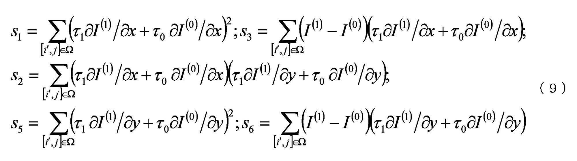
ゼロで割るかまたは非常に小さな値になることを回避するために、式(7)および式(8)に正則化パラメータrおよびmを導入する。 To avoid dividing by zero or going to very small values, we introduce regularization parameters r and m in equations (7) and (8).


dは映像サンプルのビット深さである。 d is the bit depth of the video samples.
BIOのメモリアクセスを通常の二重予測運動き補償と同じにするために、すべての予測値と勾配値であるI(k)、(∂I(k))/∂x、(∂I(k))/∂yは、現在のブロック内の位置について計算される。式(9)において、予測ブロックの境界上の現在の予測点を中心とする(2M+1)×(2M+1)個の正方形窓は、ブロックの外側の位置にアクセスする必要がある(図27の左側(a)に示す)。JEMでは、ブロック外のI(k)、(∂I(k))/∂x、(∂I(k))/∂yの値は、ブロック内で最も近い利用可能な値に等しくなるように設定されている。例えば、これは、図27の右側(b)に示すように、パディング(padding)として実装されてもよい。 In order to make the memory access of BIO the same as that of normal double prediction motion compensation, all prediction and gradient values I(k), (∂I (k) )/∂x, (∂I (k ) )/∂y is computed for the position within the current block. In equation (9), (2M+1)×(2M+1) square windows centered on the current prediction point on the boundary of the prediction block are required to access locations outside the block (left side of FIG. 27 ( a)). In JEM, the values of I (k) , (∂I (k) )/∂x, (∂I (k) )/∂y outside the block are equal to the nearest available values inside the block. is set. For example, this may be implemented as padding, as shown on the right side (b) of FIG.
BIOを使用することで、サンプルごとに動きフィールドを微調整することができる。計算の複雑性を低減するために、JEMではブロックに基づくBIOの設計が用いられている。4×4ブロックに基づいて動きの微調整を計算する。ブロックに基づくBIOにおいて、4×4ブロックにおけるすべてのサンプルの、式(9)におけるsnの値を統合し、次いで、sn inの統合した値を使用して、4×4ブロックのためのBIO動きベクトルオフセットを導出する。具体的には、ブロックに基づくBIO導出には、以下の式が使用される。 By using BIO, the motion field can be fine-tuned on a sample-by-sample basis. To reduce computational complexity, JEM uses a block-based BIO design. Calculate motion refinements based on 4x4 blocks. In block-based BIO, integrate the value of s n in equation (9) for all samples in the 4×4 block, then use the integrated value of s n in for the 4×4 block Derive the BIO motion vector offset. Specifically, the following equations are used for block-based BIO derivation.

bkは、予測ブロックのk番目の4×4のブロックに属するサンプルのセットを示す。式(7)および式(8)におけるsnを((sn,bk)>>4)に置き換え、関連する動きベクトルオフセットを導出する。
b k denotes the set of samples belonging to the k-
場合によっては、BIOのMV管理は、雑音または不規則な動きのために信頼できない場合がある。従って、BIOにおいて、MVレジメンの大きさは閾値thBIOにクリップされる。閾値は、現在のピクチャの参照ピクチャがすべて一方向からのものであるかどうかに基づいて判定される。例えば、現在のピクチャの参照ピクチャが全て一方向からのものであれば、閾値は12×2(14-d)に設定され、そうでなければ12×2(13-d)に設定される。 In some cases, BIO MV management may be unreliable due to noise or erratic motion. Therefore, in BIO, the magnitude of the MV regimen is clipped to the threshold thBIO. The threshold is determined based on whether the current picture's reference pictures are all from one direction. For example, if the reference pictures of the current picture are all from one direction, the threshold is set to 12×2 (14−d) , otherwise it is set to 12×2 (13−d) .
HEVC動き補償処理(2D分離可能FIR)に整合的に演算を使用して、動き補償補間と同時にBIOの勾配を算出する。この2D分離可能FIRの入力は、ブロック動きベクトルの端数部分に基づいて、動き補償処理および端数位置(fracX,fracY)の場合と同じ参照フレームサンプルである。水平勾配∂I/∂x信号の場合、まず、デスケーリングシフトd-8によって、端数位置fracYに対応するBIOfilterSを使用して、垂直方向に補間し、次に、勾配フィルタBIOfilterGを、端数位置fracXに対応する水平方向に適用し、デスケーリングシフトを18-dだけ行う。垂直方向勾配∂I/∂yのとき、デスケーリングシフトd-8で端数位置fracYに対応するBIOfilterGを使用して垂直に第1の勾配フィルタを適用し、次に、BIOfilterSを使用して、端数位置fracXに対応する水平方向に18-dだけデスケーリングシフトさせて信号を移動させる。妥当な複雑性を維持するために、勾配計算BIOfilterGおよび信号変位BIOfilterFのための補間フィルタの長さはより短い(6タップ)。表8は、BIOにおけるブロック動きベクトルの異なる端数位置のための勾配計算に使用されるフィルタを示す。表9は、BIOにおける予測信号の生成に使用される補間フィルタを示す。 Arithmetic is used consistently with the HEVC motion compensation process (2D separable FIR) to compute the gradient of the BIO simultaneously with the motion compensated interpolation. The input of this 2D separable FIR is the same reference frame samples as in the motion compensation process and the fractional positions (fracX,fracY) based on the fractional part of the block motion vector. For horizontal gradient ∂I/∂x signals, first interpolate vertically by descaling shift d−8 using BIOfilterS corresponding to fractional position fracY, then apply gradient filter BIOfilterG to fractional position fracX with a descaling shift of 18-d. For vertical gradients ∂I/∂y, apply the first gradient filter vertically using BIOfilterG corresponding to fractional position fracY with descaling shift d−8, then apply the first gradient filter using BIOfilterS to apply fractional The signal is moved by a descaling shift of 18-d in the horizontal direction corresponding to position fracX. In order to maintain reasonable complexity, the interpolation filter lengths for gradient computation BIOfilterG and signal displacement BIOfilterF are shorter (6 taps). Table 8 shows the filters used in gradient computation for different fractional positions of block motion vectors in BIO. Table 9 shows the interpolation filters used to generate prediction signals in BIO.


本JEMにおいて、2つの予測が異なる参照ピクチャからのものである場合、BIOをすべての双予測されたブロックに適用することができる。CUに対してLICが有効になっている場合、BIOは無効になる。 In this JEM, BIO can be applied to all bi-predicted blocks if the two predictions are from different reference pictures. BIO is disabled when LIC is enabled for the CU.
JEMにおいて、OBMCは、通常のMC処理の後のブロックに適用される。計算の複雑性を低減するために、OBMC処理中にBIOを適用しない。つまり、BIOは、それ自身のMVを使用する場合、1つのブロックのMC処理において適用され、OBMC処理において近傍のブロックのMVを使用する場合、MC処理においては適用されない。 In JEM, OBMC is applied to blocks after normal MC processing. To reduce computational complexity, we do not apply BIO during OBMC processing. That is, BIO is applied in the MC processing of one block when using its own MV, and is not applied in the MC processing when using the MVs of neighboring blocks in the OBMC processing.
2.2.8. デコーダ側動きベクトル微調整 2.2.8. Decoder side motion vector fine adjustment
双予測演算において、1つのブロック領域を予測するために、list0の動きベクトル(MV)およびlist1のMVをそれぞれ使用して構成される双予測ブロックを組み合わせ、1つの予測信号を形成する。デコーダ側動きベクトル微調整(DMVR)方法において、バイラテラルテンプレートマッチング処理によって、双予測の2つの動きベクトルをさらに微調整する。追加の動き情報を送信することなく微調整されたMVを得るために、デコーダにおいてバイラテラルテンプレートマッチングを適用し、バイラテラルテンプレートと参照ピクチャにおける再構成サンプルとの間でひずみに基づく検索を行う。 In a bi-prediction operation, to predict one block region, bi-prediction blocks constructed using motion vectors (MVs) of list0 and MVs of list1 are combined to form one prediction signal. In the Decoder Side Motion Vector Refinement (DMVR) method, the two motion vectors of bi-prediction are further refined by a bilateral template matching process. To obtain fine-tuned MVs without transmitting additional motion information, we apply bilateral template matching at the decoder and perform a distortion-based search between the bilateral templates and the reconstructed samples in the reference pictures.
DMVRにおいて、図28に示すように、list0の最初のMV0とlist1のMV1とから、それぞれ双予測ブロックの重み付け結合(すなわち、平均)としてバイラテラルテンプレートを生成する。テンプレートマッチング操作は、生成されたテンプレートと参照ピクチャにおけるサンプル領域(最初の予測ブロックの付近)との間のコスト尺度を計算することからなる。2つの参照ピクチャの各々について、テンプレートコストが最小となるMVを、そのリストの更新されたMVと見なし、元のMVに置き換える。JEMにおいて、各リストに対して9つのMV候補を検索する。9つのMV候補は、元のMVと、水平または垂直方向のいずれかまたは両方向に元のMVに対してオフセットしている1つの輝度サンプルを有する8つの周囲のMVを含む。最後に、2つの新しいMV、即ち、図28に示すようなMV0’およびMV1’を使用して、最終的な双予測結果を生成する。絶対差の合計(SAD)をコスト尺度として使用する。なお、1つの周囲のMVによって生成された予測ブロックのコストを計算する場合、実際のMVの代わりに、丸められたMV(整数画素)を使用して予測ブロックを得る。 In DMVR, as shown in FIG. 28, a bilateral template is generated from the first MV0 of list0 and MV1 of list1, respectively, as a weighted combination (ie, average) of bi-predictive blocks. The template matching operation consists of computing a cost measure between the generated template and the sample region in the reference picture (near the first prediction block). For each of the two reference pictures, the MV with the lowest template cost is considered the updated MV in the list and replaces the original MV. In JEM, search 9 MV candidates for each list. The 9 MV candidates include the original MV and 8 surrounding MVs with one luma sample offset from the original MV in either or both horizontal and vertical directions. Finally, two new MVs, namely MV0' and MV1' as shown in Fig. 28, are used to generate the final bi-prediction result. Sum of Absolute Differences (SAD) is used as a cost measure. Note that when calculating the cost of a predictive block generated by one surrounding MV, instead of the actual MV, we use the rounded MV (integer pixels) to obtain the predictive block.
DMVRは、追加の構文要素を送信することなく、過去の参照ピクチャからの1つのMVと、将来の参照ピクチャからの1つのMVとの間の双予測のマージモードに適用される。JEMにおいて、CUに対してLIC、アフィン動き、FRUCまたはサブCUマージ候補が有効である場合、DMVRは適用されない。 DMVR applies to the bi-predictive merge mode between one MV from a past reference picture and one MV from a future reference picture without sending additional syntax elements. In JEM, if LIC, affine motion, FRUC or sub-CU merge candidates are valid for a CU, DMVR is not applied.
2.2.9. サブブロックマージ候補リスト 2.2.9. Sub-block merge candidate list
なお、非サブブロックマージ候補の通常マージリストに加え、すべてのサブブロック関連動き候補を別個のマージリストに入れることが推薦される。 Note that it is recommended to put all sub-block related motion candidates in a separate merge list in addition to the normal merge list of non-sub-block merge candidates.
サブブロック関連動き候補を別個のマージリストに入れ、esub-blockマージ候補リストfとする。 Put the sub-block related motion candidates into a separate merge list, called esub-block merge candidate list f.
一例において、サブブロックマージ候補リストは、アフィンマージ候補、ATMVP候補、および/またはサブブロックに基づくSTMVP候補を含む。 In one example, the sub-block merge candidate list includes affine merge candidates, ATMVP candidates, and/or STMVP candidates based on sub-blocks.
2.2.9.1 サブブロックマージ候補リストの構築 2.2.9.1 Construction of sub-block merge candidate list
この寄与において、通常マージリストにおけるATMVPマージ候補をアフィンマージリストの第1の位置に移動させる。新しいリストにおけるすべてのマージ候補(すなわち、サブブロックに基づくマージ候補リスト)は、サブブロック符号化ツールに基づく。 In this contribution, we move the ATMVP merge candidate in the normal merge list to the first position in the affine merge list. All merge candidates in the new list (ie sub-block based merge candidate list) are based on the sub-block coding tools.
2.2.10. 一般化された双予測の例 2.2.10. Generalized bi-prediction example
GBiを使用して、式(1)を使用して双予測Pbi-predを生成する。(1)1つの重み付けパラメータが符号化ユニットに信号通知され、ここで、P0およびP1は、それぞれ、list-0およびlist-1における参照ピクチャを使用した動き補償予測である。wは、1/8精度で表されるlist-1予測のための重みパラメータである。GBiは、符号化ユニットに基づく重み付け’(BCW)を用いた双予測としても知られている。 GBi is used to generate the bi-prediction Pbi-pred using equation (1). (1) One weighting parameter is signaled to the encoding unit, where P0 and P1 are motion-compensated predictions using the reference pictures in list-0 and list-1, respectively. w is the weight parameter for list-1 prediction expressed in 1/8 precision. GBi is also known as bi-prediction with coding unit-based weighting' (BCW).

現在のGBi設計において、低遅延ピクチャに利用可能な5つの重み{-2/8、3/8、4/8、5/8、10/8}があり、非低遅延ピクチャには3つの重み{3/8、4/8、5/8}がある。 In the current GBi design, there are 5 weights {−2/8, 3/8, 4/8, 5/8, 10/8} available for low-delay pictures and 3 weights for non-low-delay pictures. There are {3/8, 4/8, 5/8}.
符号化ユニットのための重み値を判定するために、以下の規則が適用される。 To determine the weight values for the coding units, the following rules apply.
信号通知MVD(すなわち、通常のインター予測モード)を必要とする各双予測PUについて、その重み値は、明確に信号通知されたものに等しく設定される。 For each bi-prediction PU that requires signaling MVD (ie, normal inter-prediction mode), its weight value is set equal to that explicitly signaled.
マージモードで符号化される各双予測PUについて、その重み値wは、関連するマージ候補に使用される重み値から直接推論される。 For each bi-predictive PU encoded in merge mode, its weight value w is inferred directly from the weight values used for the associated merge candidates.
2.3 近傍の構文要素を用いたコンテキストモデリング 2.3 Context Modeling Using Nearby Syntactic Elements
1つのタイプのコンテキストモデリングは、現在の構文要素の過去において符号化するために、2つまでの近傍の構文要素を有するコンテキストテンプレートを含み、この場合、近傍の種類の具体的な定義は構文要素に依存する。通常、特定のビンに対するこの種のコンテキストモデルの仕様は、図25のA2およびB3に示すように、現在の構文要素の左上の近傍の要素の関連するビン値のモデル化関数に基づく。 One type of context modeling involves a context template with up to two neighboring syntactic elements to encode in the past of the current syntactic element, where the concrete definition of the neighborhood kind is the syntactic element depends on The specification of this kind of context model for a particular bin is typically based on a modeling function of the relevant bin values of the elements in the upper left neighborhood of the current syntax element, as shown in FIG. 25A2 and B3.
9.5.4.2.2 左上の構文要素を使用したctxIncの導出処理 9.5.4.2.2 Derivation of ctxInc using upper left syntax element
この処理の入力は、現在のピクチャの左上のサンプルに対する現在の輝度ブロックの左上の輝度サンプル、色成分cIdx、現在の符号化4分木の深さcqDepth、並びに輝度サンプルcbWidthおよびcbHeighにおける現在の符号化ブロックの幅および高さを指定する輝度位置(x0,y0)である。 The inputs for this process are the upper left luma sample of the current luma block for the upper left sample of the current picture, the color component cIdx, the depth of the current coding quadtree cqDepth, and the current code at the luma samples cbWidth and cbHeight. is a luminance position (x0, y0) that specifies the width and height of the block.
この処理の出力はctxInc.である。 The output of this process is ctxInc. is.
位置(xNbL,yNbL)は(x0-1,y0)に等しく設定され、現在のブロックのすぐ左側に位置する符号化ブロックの可用性を指定する変数availableLは、位置(xCurr,yCurr)を(x0,y0)と等しく設定し、近傍位置(xNbY,yNbY)を(xNbL,yNbL)と等しく設定したものを入力として、副章6.4で規定されているzスキャン順のブロックの可用性導出処理を呼び出すことで導出され、出力はavailableLに割り当てる。 Location (xNbL, yNbL) is set equal to (x0-1, y0), and the variable availableL, which specifies the availability of the encoding block located immediately to the left of the current block, sets location (xCurr, yCurr) to (x0, y0) and the neighboring positions (xNbY, yNbY) set equal to (xNbL, yNbL), invoke the z-scan order block availability derivation process defined in subchapter 6.4 and the output is assigned to availableL.
位置(xNbA,yNbA)は(x0,y0-1)に等しく設定され、現在のブロックの直上に位置する符号化ブロックの可用性を指定する変数availableAは、位置(xCurr,yCurr)を(x0,y0)と等しく設定し、近傍位置(xNbY,yNbY)を(xNbA,yNbA)と等しく設定したものを入力として、副章6.4で規定されているzスキャン順のブロックの可用性導出処理を呼び出すことで導出され、出力はavailableAに割り当てる。 Location (xNbA, yNbA) is set equal to (x0, y0-1), and the variable availableA, which specifies the availability of the encoding block located directly above the current block, sets location (xCurr, yCurr) to (x0, y0 ) and set the neighborhood positions (xNbY, yNbY) equal to (xNbA, yNbA) to invoke the z-scan-ordered block availability derivation process defined in subchapter 6.4. and assign the output to availableA.
変数sizeC、sizeTh2、sizeTh1は、以下のように導出される。 Variables sizeC, sizeTh2, and sizeTh1 are derived as follows.
sizeTh2=(MaxBtSizeY==128)?1024:((MaxBtSizeY==64)?512:256) (9-19) sizeTh2=(MaxBtSizeY==128)? 1024: ((MaxBtSizeY==64)?512:256) (9-19)
sizeTh1=(MaxBtSizeY==128)?128:64 (9-20) sizeTh1=(MaxBtSizeY==128)? 128:64 (9-20)
sizeC=cbWidth*cbHeight (9-21) sizeC=cbWidth*cbHeight (9-21)
ctxIncの割り当ては、表10で規定された構文要素alf_ctb_flag[x0][y0][cIdx]、qt_split_cu_flag[x0][y0],mtt_split_cu_flag[x0][y0],cu_skip_flag[x0][y0],amvr_mode[x0][y0],inter_affine_flag[x0][y0],merge_triangle_flag[x0][y0]およびmerge_subblock_flag[x0][y0]に対するcondL,condAで、以下のように指定される。 The assignment of ctxInc is defined in Table 10 using the syntax elements alf_ctb_flag[x0][y0][cIdx], qt_split_cu_flag[x0][y0], mtt_split_cu_flag[x0][y0], cu_skip_flag[x0][y0], amvr_mode[ x0][y0], inter_affine_flag[x0][y0], merge_triangle_flag[x0][y0] and condL, condA for merge_subblock_flag[x0][y0] are specified as follows.
ctxInc=(condL && availableL)+(condA && availableA)+ctxSetIdx*3 (9-22) ctxInc = (condL && availableL) + (condA && availableA) + ctxSetIdx*3 (9-22)

2.4 予測モードフラグに対する改良されたコンテキスト 2.4 Improved context for prediction mode flags
VVC草案3において、予測モードフラグ、即ち、pred_mode_flagは、1つのコンテキストのみを使用して符号化される。いくつかの実施形態において、現在のブロックのpred_mode_flagを符号化するコンテキストは、近傍のブロックのpred_mode_flagの値を利用して導出される。図43に示すように、上記(A)または左(L)のブロックをイントラ予測モードで符号化する場合、コンテキスト値を1だけ増加させるので、pred_mode_flagを符号化する場合、コンテキストの数を2だけ増加させる。
In
VTM-3.0において、結合されたマージおよびインター予測モード、即ち、インターイントラモードも有効にされる。そのため、コンテキスト導出に近傍のブロックを使用する場合、イントラモードをイントラモードと見なすべきか、インターモードと見なすべきかが問題となる。この寄与において、異なる解を試験して結論を得る。 In VTM-3.0, a combined merge and inter-prediction mode, or inter-intra mode, is also enabled. Therefore, when using neighboring blocks for context derivation, the question is whether intra modes should be considered intra or inter modes. In this contribution, different solutions are tested to reach conclusions.
いくつかの実施形態において、pred_mode_flagの符号化に使用されるコンテキストを導出するために、以下に説明するように、4つの異なる方法を試験する。 In some embodiments, four different methods are tested to derive the context used to encode the pred_mode_flag, as described below.

3. 実施形態による発明が解決しようとする課題の例 3. Examples of problems to be solved by the invention according to the embodiment
三角形分割の設計において、1つのブロックを2つの分割に分割することができる。動き補償に起因するメモリ帯域幅を節約するために、2つの分割は単一予測されるべきであることが必要である。動き補償処理中、対角エッジに対して双予測が使用され、他のすべての部分に対して単一予測が使用される。各分割に対して双予測が許可される場合、対角エッジに位置するサンプルは、4つのMVを有し、そのうちの2つは1つの分割からのものであり、2つは別の分割からのものである。このような設計には、以下のような問題がある。 In a triangulation design, one block can be divided into two partitions. To save memory bandwidth due to motion compensation, it is necessary that the two partitions should be uni-predicted. During the motion compensation process, bi-prediction is used for diagonal edges and uni-prediction for all other parts. If bi-prediction is allowed for each split, the samples located on the diagonal edges have 4 MVs, 2 from one split and 2 from another split. belongs to. Such a design has the following problems.
TPMリストを構築するとき、サブブロックマージ候補を利用してTPM候補を導出するのではなく、空間的ブロックおよび時間的ブロックから導出された非サブブロックマージ候補のみを利用する。 When constructing the TPM list, we do not utilize sub-block merge candidates to derive TPM candidates, but only non-sub-block merge candidates derived from spatial and temporal blocks.
三角形分割の場合、サブブロックに基づく方法は許可されない。 For triangulation, subblock-based methods are not allowed.
非対角エッジに対して単一予測のみを許可する制限は、符号化効率を低下させる可能性がある。 The restriction of only allowing uniprediction for off-diagonal edges can reduce coding efficiency.
DMVR、三角形分割とのBIO対話 DMVR, BIO interaction with triangulation
2つの分割は、異なるTPM候補インデックスを選択することができるが、2つのTPM候補が同じ正規の動き候補からのものであるかどうかを確信できなかった。例えば、1つの双方向正規の動き候補を使用して2つのTPM候補を導出し、その各々を1つの分割に割り当ててもよい。この場合、2つの分割は、同じ双予測の正規の動き候補を非TPMモードとして使用することができるが、これはあまり効率的でない可能性がある。 The two partitions could choose different TPM candidate indices, but could not be sure if the two TPM candidates were from the same regular motion candidate. For example, one bidirectional regular motion candidate may be used to derive two TPM candidates, each of which is assigned to one partition. In this case, the two partitions can use the same bi-predictive regular motion candidate as the non-TPM mode, but this may not be very efficient.
TPMは、ブロック幅*高さが64より小さい場合、無効にされる。しかしながら、4×16または16×4に等しいサイズおよび4:2:0カラーフォーマットを有するブロックの場合、TPMを有効にした2×8クロマブロックが得られ、これはハードウェアの複雑性を増大させる。 The TPM is disabled if block width*height is less than 64. However, for blocks with size equal to 4x16 or 16x4 and 4:2:0 color format, we get 2x8 chroma blocks with TPM enabled, which increases hardware complexity. .
MMVD、サブブロックマージリスト、CIIP(組み合わせインターイントラ予測)モードとも呼ばれるMHIntra(inter-intra)モードを含む、VTM3.0における新しいツールを、特殊マージモードとして扱う。従って、5つのマージモードがある。5つのマージモードを表示する前に、マージフラグ/スキップフラグを信号通知する。そのため、元のスキップ/マージモードに到達するために、MMVD/サブブロックマージリスト/MHIntra(inter-intra)/TPMの表示を0に復号化する。 New tools in VTM 3.0, including MHIntra (inter-intra) mode, also called MMVD, Sub-Block Merge List, CIIP (Combined Inter-Intra Prediction) mode, are treated as special merge modes. Therefore, there are five merge modes. Signal the merge flag/skip flag before displaying the 5 merge modes. So, to arrive at the original skip/merge mode, decode the MMVD/sub-block merge list/MHIntra (inter-intra)/TPM representation to 0.
CABACのコンテキストモデリングにおいて、異なるCTU行からの近傍の要素が必要とされ得、これは、CTU行の上からの要素を記憶するために追加のラインバッファを必要とする。 In CABAC context modeling, neighboring elements from different CTU rows may be required, which requires additional line buffers to store elements from above the CTU row.
いくつかの構文要素の場合、コンテキストモデリングに使用される近傍のブロックは、再構成ブロックに使用される近傍のブロックとは異なる。 For some syntax elements, the neighboring blocks used for context modeling are different from the neighboring blocks used for reconstruction block.
4. 実施形態の例 4. Example of embodiment
提案された方法は、任意の非正方形/非長方形の分割、例えばジオメトリ分割に適用されてもよい。以下の説明において、非正方形/非長方形分割モード(TPM)の一例として、三角形分割モードを使用し、TPM候補リストに挿入される動きベクトル予測候補をeTPM candidatesfと呼ぶ。そして、前述の符号化されたブロックに関連付けられた動き情報を、正規の動き候補とする。なお、その他の分割であってもよい。 The proposed method may be applied to any non-square/non-rectangular partition, eg geometry partition. In the following description, triangulation mode is used as an example of non-square/non-rectangular partitioning mode (TPM), and motion vector prediction candidates inserted into the TPM candidate list are referred to as eTPM candidatesf. Then, the motion information associated with the encoded block is taken as a regular motion candidate. Note that other divisions may be used.
以下の詳細な技術は、一般的な概念を説明するための例と見なされるべきである。これらの技術は狭い意味で解釈されるべきではない。さらに、これらの技術は、任意の方法で組み合わせることができる。 The detailed techniques below should be considered examples to illustrate the general concepts. These techniques should not be interpreted narrowly. Moreover, these techniques can be combined in any way.
TPMの拡大 Expansion of TPM
1. TPMリストに、サブブロック候補から導出された1つまたは複数のTPM候補を加えることが提案される。
a. 一例において、TPM候補は、ATMVP候補から導出されてもよい。
b. 一例において、TPM候補は、アフィン候補から導出されてもよい。
c. サブブロック候補(例えば、ATMVP)の場合、それは、複数の動き情報のセットを含んでもよく、各セットは、1つのサブブロックに対応する(例えば、ATMVPの場合、8×8、アフィンの場合、4×4)。1つの代表セットを正規の動き候補として扱い、これを使用してTPM候補を導出することができる。
i. 代表セットは、動き情報のセットが関連付けられたサブブロック位置に基づいて定義されてもよい。例えば、1つのブロックの左上、右上、左下、右下のサブブロックに関連付けられた動き情報を選択してもよい。
ii. M個の代表セットを選択することができ、例えば、Mを分割の数に設定する。一例において、各分割の中心サブブロックに関連付けられた動き情報を選択してもよい。
1. It is proposed to add to the TPM list one or more TPM candidates derived from the sub-block candidates.
a. In one example, TPM candidates may be derived from ATMVP candidates.
b. In one example, TPM candidates may be derived from affine candidates.
c. For a sub-block candidate (e.g. ATMVP), it may contain multiple sets of motion information, each set corresponding to one sub-block (e.g. 8x8 for ATMVP, 4x4). One representative set can be treated as canonical motion candidates and used to derive TPM candidates.
i. A representative set may be defined based on the sub-block position with which the set of motion information is associated. For example, motion information associated with the upper left, upper right, lower left, and lower right sub-blocks of a block may be selected.
ii. M representative sets can be selected, eg, set M to the number of splits. In one example, motion information associated with the center sub-block of each partition may be selected.
2. 複数の分割(例えば、三角形分割設計における2つの分割)は、1つの正規の動き候補から継承可能とすることが提案される。
a. 一例において、各分割のための分割パターンおよび選択されたマージインデックスの表示の範囲は、拡大されてもよい。M個に分割された分割があり、N個の許容されるマージ候補があり、この表示の範囲は、現在の三角形設計においてM*N*(N-1)に等しいのではなく、M*N*Nとして定義されるとする。
b. 一例において、1つのフラグは、まず、1つの単一の正規の動き候補から複数の分割が予測されたかどうかを示すように信号通知されてもよい。
c. 一例において、1つの正規の動き候補から複数の分割を予測する場合、このような正規の動き候補を双予測された動き候補とすることが制限される。
i. 代替的に、2つの分割に、それぞれ正規の動き候補のList0動き情報およびList1動き情報を割り当ててもよい。
ii. 代替的に、重み付け領域に位置するサンプルについて、重み係数群は、異なる動き候補から2つの分割を予測する場合に使用される重み係数群と異なってもよい。一例において、平均値が常に使用される。
d. そのような方法は、従来のAMVPまたはマージまたはTPMに加えて、追加の符号化モードとして扱われてもよい。
2. It is proposed that multiple partitions (eg, two partitions in a triangulation design) can inherit from one regular motion candidate.
a. In one example, the range of display of the split pattern and selected merge index for each split may be expanded. There are M divided partitions, there are N allowed merge candidates, and the range of this representation is M*N * be defined as N.
b. In one example, a flag may first be signaled to indicate whether multiple splits were predicted from one single canonical motion candidate.
c. In one example, when predicting multiple splits from a single regular motion candidate, such regular motion candidates are constrained to be bi-predicted motion candidates.
i. Alternatively, the two partitions may be assigned List0 and List1 motion information of regular motion candidates, respectively.
ii. Alternatively, for samples located in the weighting region, the set of weighting factors may differ from the set of weighting factors used when predicting the two partitions from different motion candidates. In one example, the average value is always used.
d. Such methods may be treated as additional coding modes in addition to conventional AMVP or merge or TPM.
3. ビットストリームから導出された各分割の動きベクトルは、1つのTPM符号化ブロックの最終予測ブロックを導出するために使用される前に、さらに微調整されてもよい。
a. 一例において、DMVR技術は、2つの分割の動き情報をブロック全体の動き情報として適用してもよい。
b. 一例において、BIOは、TPM予測の後に適用される。
c. 一例において、1つの分割がLXから単一予測され、他の分割がL(1-X)から双予測されるまたは予測される場合、リストL(1-X)における他の分割の動き情報を使用することで、DMVRまたはBIO技術を適用してもよい。
d. 一例において、微調整された動き情報を記憶してもよい。
e. 一例において、分割がLXから単一予測されたものである場合、LXにおける微調整された動き情報を記憶してもよい。
a. TPMにおける1つ以上の分割は、イントラ予測と組み合わされ得ることが提案される。例えば、TPM予測とイントラ予測とを重み付け加算することで、最終的な予測が得られる。
f. TPMに使用される1つ以上の参照ピクチャは、現在のピクチャであることが提案される。
3. The motion vector for each partition derived from the bitstream may be further refined before being used to derive the final predicted block for one TPM-coded block.
a. In one example, the DMVR technique may apply the motion information of the two partitions as the motion information of the entire block.
b. In one example, BIO is applied after TPM prediction.
c. In one example, if one partition is uni-predicted from LX and the other partition is bi-predicted or predicted from L(1-X), the motion information of the other partition in list L(1-X) is The use may apply DMVR or BIO technology.
d. In one example, fine-tuned motion information may be stored.
e. In one example, if the partition is uni-predicted from LX, fine-tuned motion information in LX may be stored.
a. It is proposed that one or more partitions in TPM can be combined with intra-prediction. For example, a final prediction is obtained by weighted addition of TPM prediction and intra prediction.
f. One or more reference pictures used for TPM is proposed to be the current picture.
4. 1つの分割内の各サブブロックにそれ自体の動き情報を割り当てることができるTPM符号化ブロックのために、サブブロックに基づく技術を有効にできるようにすることが提案される。
a. 一例において、サブブロックに基づくマージ候補は、TPM符号化ブロックのリストに追加してもよい。
b. 一例において、1つのブロックがTPMで符号化されている場合であっても、アフィンモードを有効にしてもよい。
c. 代替的に、重み付け領域に位置するサブブロックを除くすべてのサブブロックに対して、単一予測を利用することが制限される。
d. 代替的に、1つの分割内の異なるサブブロックのすべての参照ピクチャが同じであることが制限される。
e. 1つのATMVP候補から1つまたは複数のTPM候補を導出することができ、例えば、1つの分割内の各サブブロックは、ATMVP候補のList0動き情報の動き情報を継承することができる。
f. サブブロックTPM符号化ブロックのマージリストは、サブブロックマージ候補リスト構築処理で使用されたのと同じ空間的ブロックおよび/または時間的ブロックをチェックしてもよい。
4. It is proposed to enable sub-block based techniques for TPM coded blocks where each sub-block within one partition can be assigned its own motion information.
a. In one example, merging candidates based on sub-blocks may be added to the list of TPM-coded blocks.
b. In one example, affine mode may be enabled even if one block is encoded with TPM.
c. Alternatively, the use of single prediction is restricted for all sub-blocks except sub-blocks located in the weighting region.
d. Alternatively, all reference pictures for different sub-blocks within one partition are constrained to be the same.
e. One or more TPM candidates may be derived from one ATMVP candidate, eg, each sub-block within a partition may inherit the motion information of the ATMVP candidate's List0 motion information.
f. A merge list for a sub-block TPM encoded block may check the same spatial and/or temporal blocks used in the sub-block merge candidate list construction process.
5. 一般化された双予測が有効である場合、双予測正規の動き候補は、2つの重み係数にさらに関連付けられる。しかしながら、このような双予測の正規の動き候補を使用してTPM候補を導出する場合、重み係数を継承しないことが提案されている。
a. 一例において、1つのTPM候補は、任意の重み係数に関連付けられない。そのため、非重み付け領域に位置するサンプルの予測値を導出する場合、動き補償結果をそのまま使用する。重み付け領域に位置するサンプルについて、選択された重み係数群を利用する。
b. 代替的に、重み係数を継承する。代替的に、重み付け領域に位置するサンプルの最終予測値を生成する時に、対応する領域のTPM候補から導出された予測値に、継承された重み係数の1つを適用してもよい。
5. If generalized bi-prediction is enabled, the bi-prediction normal motion candidate is further associated with two weighting factors. However, when using such bi-predictive canonical motion candidates to derive TPM candidates, it is proposed not to inherit the weighting factors.
a. In one example, one TPM candidate is not associated with any weighting factor. Therefore, the motion compensation results are used as is when deriving the prediction values of the samples located in the non-weighted regions. A selected set of weighting factors is utilized for the samples located in the weighting region.
b. Alternatively, inherit the weighting factor. Alternatively, one of the inherited weighting factors may be applied to the predictions derived from the TPM candidates in the corresponding regions when generating the final predictions for the samples located in the weighting regions.
6. 1つのTPM符号化ブロックの重み付け領域に位置しないサンプルに対して、双予測を有効にすることが提案される。
a. 一例において、2つの参照ピクチャは同じであることが必要である。
b. 一例において、各分割に対して、1つの参照ピクチャを割り当てることができる(例えば、現在の設計に従い、2つの分割に対して同じであってもよいし、異なってもよい)。一方、第3参照ピクチャおよび動きベクトルをさらに割り当ててもよい。
6. It is proposed to enable bi-prediction for samples that are not located in the weighting region of one TPM coded block.
a. In one example, the two reference pictures need to be the same.
b. In one example, one reference picture can be assigned for each partition (eg, it can be the same or different for the two partitions, according to the current design). On the other hand, a third reference picture and motion vector may also be assigned.
7. TPM符号化ブロックに多重仮説を適用することができることが提案される。
a. 一例において、現在の設計を使用する1つの第1の最終予測ブロックをまず生成することができる。別の参照ピクチャおよび動きベクトルに基づいて、単一予測を使用して第2の予測ブロックも生成される。そして、第1の最終予測ブロックと第2の予測ブロックとから、1つのブロックの最終予測ブロックを導出する。
b. 代替的に、まず、現在の設計を用いた1つの第1の最終予測ブロックを生成してもよい。2つの追加の参照ピクチャおよび動きベクトルに基づいて、双予測を使用して第2の予測ブロックも生成される。そして、第1の最終予測ブロックと第2の予測ブロックとから、1つのブロックの最終予測ブロックを導出する。
c. 代替的に、各分割に対して、まず双予測または多重仮説予測を適用する。そして、重み付け領域に対して、双/多重仮説予測による予測ブロックの重み付け結果を最終予測値として使用する。
7. It is proposed that multiple hypotheses can be applied to TPM coded blocks.
a. In one example, one first final prediction block using the current design can be generated first. A second predictive block is also generated using uni-prediction, based on another reference picture and motion vector. Then, a final predicted block of one block is derived from the first final predicted block and the second predicted block.
b. Alternatively, one may first generate one first final prediction block using the current design. A second predictive block is also generated using bi-prediction based on two additional reference pictures and motion vectors. Then, a final predicted block of one block is derived from the first final predicted block and the second predicted block.
c. Alternatively, for each partition, we first apply bi-prediction or multi-hypothesis prediction. Then, for the weighted region, the weighted result of the prediction block by bi/multiple hypothesis prediction is used as the final prediction value.
8. 1つのブロックに対してTPMが有効にされるとき、OBMCは無効にされてもよい。
a. 代替的に、OBMCは、重み付け領域に位置するサンプルについては無効にされるが、非重み付け領域に位置するサンプルについては有効にされてもよい。
8. OBMC may be disabled when TPM is enabled for a block.
a. Alternatively, OBMC may be disabled for samples located in the weighted region, but enabled for samples located in the non-weighted region.
9. 1つのブロックを2つより多い非正方形/非三角形の分割に分割することができる。
a. 1つのブロックを4つの非正方形/非三角形の分割に分割することができる。一例において、一例を図29に示す。
b. 2つよりも多い非正方形/非三角形の分割がある場合、それらのうちの2つのみをインター符号化できるように制限される。
c. 2つの近傍の分割のエッジ付近に位置するサンプルに対して、ブレンド(例えば、2つの予測ブロックの重み付け平均)を適用することができる。
図29は、1つのブロック内の複数のジオメトリ分割の例を示す。
9. A block can be divided into more than two non-square/non-triangular partitions.
a. A block can be divided into four non-square/non-triangular partitions. In one example, an example is shown in FIG.
b. If there are more than two non-square/non-triangular partitions, we are restricted to only being able to inter-code two of them.
c. A blend (eg, a weighted average of the two predictive blocks) can be applied to samples located near the edges of two neighboring partitions.
FIG. 29 shows an example of multiple geometry divisions within one block.
TPMが必要とするサイド情報の信号通知 Signaling of side information required by the TPM
10. 分割パターン、2つのマージインデックス、および符号化値(例えば、_TriangleCombination)の間のマッピングは、シーケンスからシーケンスへ、ピクチャ間、タイル間、スライス間、CTU間、ブロック間で適応的に変更されてもよい。
a. 一例において、マッピングは、構築されたマージ候補リストに依存してもよい。
b. 一例において、このマッピングは、マージ候補に関連付けられた符号化モードに依存してもよい。
10. The mapping between the partitioning pattern, the two merging indices, and the coded value (e.g., _TriangleCombination) may be adaptively changed from sequence to sequence, between pictures, between tiles, between slices, between CTUs, and between blocks. good.
a. In one example, the mapping may depend on a constructed merge candidate list.
b. In one example, this mapping may depend on the coding modes associated with the merge candidates.
11. TPM使用の表示フラグは、マージフラグの前に符号化されてもよい。すなわち、TPMはまた、非マージモードのために有効にされてもよい。
a. 代替的に、ブロックがTPM符号化されている場合、マージフラグを通知しなくてもよい。
b. 代替的に、ブロックがインター符号化されている場合(例えば、ブロックがAMVPモードであるかまたはマージモードであるかを示すため)、マージフラグをさらに通知してもよい。
c. TPMは、非スキップモードに対してのみ許可されてもよい。
11. The TPM usage indication flag may be encoded before the merge flag. That is, the TPM may also be enabled for non-merge mode.
a. Alternatively, the merge flag may not be signaled if the block is TPM coded.
b. Alternatively, a merge flag may also be signaled if the block is inter-coded (eg, to indicate whether the block is in AMVP mode or merge mode).
c. TPM may only be enabled for non-skip mode.
12. 1つのブロックがAMVPモードで符号化されている場合、TPM使用の表示フラグを符号化してもよい。
a. 代替的に、1つのブロックがマージモードで符号化されている場合、TPMフラグを通知しなくてもよい。
b. 代替的に、TPM使用フラグは、空間的または時間的に近傍のまたは非隣接ブロックから継承されてもよい。
12. If a block is coded in AMVP mode, the TPM usage indication flag may be coded.
a. Alternatively, if one block is encoded in merge mode, the TPM flag may not be signaled.
b. Alternatively, the TPM usage flag may be inherited from spatially or temporally neighboring or non-adjacent blocks.
13. 分割パターンは、空間的に近傍のブロックから継承されてもよい。
a. 代替的に、分割パターンは、時間的ブロックから継承されてもよい。
b. 一例において、分割パターンは、動き情報とともに記憶される。1つの正規の動き候補から導出された各TPM候補について、該正規の動き候補に関連付けられた分割パターンも継承される。
i. この場合、TPM符号化ブロックは、近傍のTPM符号化ブロックから動き情報(または符号化モード)および分割パターンの両方を継承してもよい。
13. The partitioning pattern may be inherited from spatially neighboring blocks.
a. Alternatively, the partitioning pattern may be inherited from the temporal block.
b. In one example, the split pattern is stored along with the motion information. For each TPM candidate derived from one canonical motion candidate, the partitioning pattern associated with that canonical motion candidate is also inherited.
i. In this case, a TPM coded block may inherit both motion information (or coding mode) and partitioning pattern from neighboring TPM coded blocks.
14. ジオメトリ分割に使用される分割パターンおよびマージインデックスは、別個に信号通知されてもよいことが提案される。
a. 一例において、1つのビットフラグは、TPM分割パターンを示すように別個に符号化されてもよい。
i. ビットを符号化するコンテキストを導出するために、近傍のブロックのTPM分割パターンを使用できる。
b. 一例において、各分割のための複数のマージインデックスは、別個に符号化されてもよい。
i. 代替的に、異なる分割のマージインデックス間の予測を利用してもよい。
c. 一例において、マージインデックスの符号化は、分割パターンのための符号化された1ビットフラグに依存してもよい。
d. 代替的に、マージインデックスは、まず符号化され(結合してまたは別個に)、分割パターンのための1つのビットフラグは、マージインデックスに基づいて符号化されてもよい。
14. It is proposed that the splitting pattern and merge index used for geometry splitting may be signaled separately.
a. In one example, one bit flag may be encoded separately to indicate the TPM split pattern.
i. The TPM partitioning pattern of neighboring blocks can be used to derive the context for encoding bits.
b. In one example, the multiple merge indices for each partition may be encoded separately.
i. Alternatively, predictions between merge indices of different partitions may be used.
c. In one example, the encoding of the merge index may depend on the encoded 1-bit flag for the split pattern.
d. Alternatively, the merging index may be coded first (jointly or separately) and the one bit flag for the split pattern may be coded based on the merging index.
15. TPM使用の表示フラグに対してバイパス符号化を使用することが提案される。
a. 代替的に、このフラグは依然としてコンテキストで符号化されるが、このコンテキストはブロックの幅/高さに依存する。
b. 代替的に、このフラグは依然としてコンテキストで符号化されるが、コンテキストは符号化された深さ(例えば、4分木の深さ、2分木の深さ、および/または3分木の深さ)に依存する。
c. 代替的に、このフラグは依然としてコンテキストで符号化されるが、このコンテキストは、ブロックの幅/高さ、例えばブロックの形状(例えば、正方形または非正方形)および/またはブロックの幅と高さの比(例えば、1に等しい、1/4に等しい、または4に等しい、1/2または2に等しい)などに依存する。
d. 代替的に、このフラグは依然としてコンテキストで符号化されるが、このコンテキストは、1つのブロック内の左上位置の隣にあるとは限らない近傍のブロックの符号化された情報に依存する。ブロックの幅および高さをそれぞれWおよびHで表し、(0,0)は、現在のブロックにおける左上のサンプルの座標である。
i. 一例において、上側近傍のブロックは、(W/2、-1)、(W/2-1、-1)、(W-1、-1)として定義されてもよい。
ii. 一例において、左側近傍のブロックは、(-1,H/2),(-1,H/2-1),(-1,H-1)として定義してもよい。
iii. コンテキスト選択において使用され得る、上側および左側近傍のブロックのいくつかの組み合わせが、図30に示される。
iv. 一例において、上側近傍のブロックのみを選択してもよい。代替的に、このような場合は、ブロックの幅と高さの比が閾値よりも大きい(例えば、1または2)場合に有効になる。
v. 一例において、左側近傍のブロックのみを選択してもよい。代替的に、このような場合は、ブロックの高さと幅との比が閾値よりも大きい(例えば、1または2)場合に有効になる。
図30は、TPMフラグのコンテキスト選択に使用される近傍のブロックの例を示す。左上の例(a)は、(W/2、-1)、(-1、H/2)である。右上の例(b)は、(W/2-1,-1)、(-1,H/2-1)である。左下の例(c)は、(0,-1)、(-1,H/2-1)である。右下の例(d)は、(W-1,-1)、(-1,H/2-1)である。
15. It is proposed to use bypass encoding for the TPM use indication flag.
a. Alternatively, this flag is still encoded in context, but this context depends on the width/height of the block.
b. Alternatively, this flag is still encoded in the context, but the context is encoded in depth (e.g., quadtree depth, binary tree depth, and/or ternary depth). ).
c. Alternatively, this flag is still encoded in the context, but the context is the width/height of the block, e.g. the shape of the block (e.g. square or non-square) and/or the width-to-height ratio of the block. (e.g. equal to 1, equal to 1/4, or equal to 4, equal to 1/2 or equal to 2) and so on.
d. Alternatively, this flag is still coded in context, but this context depends on the coded information of neighboring blocks that are not necessarily next to the top left position within one block. Denote the width and height of the block by W and H respectively, where (0,0) are the coordinates of the top left sample in the current block.
i. In one example, the upper neighborhood blocks may be defined as (W/2,-1), (W/2-1,-1), (W-1,-1).
ii. In one example, the left neighbor blocks may be defined as (-1, H/2), (-1, H/2-1), (-1, H-1).
iii. Some combinations of upper and left neighborhood blocks that can be used in context selection are shown in FIG.
iv. In one example, only blocks in the upper neighborhood may be selected. Alternatively, such a case is valid if the width-to-height ratio of the block is greater than a threshold (eg, 1 or 2).
v. In one example, only left-neighbor blocks may be selected. Alternatively, such a case is valid if the height-to-width ratio of the block is greater than a threshold (eg, 1 or 2).
FIG. 30 shows an example of neighboring blocks used for context selection of TPM flags. The upper left example (a) is (W/2, -1), (-1, H/2). The upper right example (b) is (W/2-1, -1), (-1, H/2-1). The lower left example (c) is (0, -1), (-1, H/2-1). The lower right example (d) is (W-1, -1), (-1, H/2-1).
16. TPMリストにおける2つの候補インデックス(例えば、a0、a1、b0、b1)を一緒に符号化する(またはさらに他の情報と結合する)場合、コード名は、ブロック間、CTU間、タイル間、ピクチャ間、シーケンス間で適応的に変更されてもよい。
a. 一例において、2つのインデックスに関連付けられた2つのTPM候補が同じ正規の動き候補からのものであるかどうかに基づいて、コード名を割り当ててもよい。
i. 一例において、以下が発生する場合、コード名C(a0,a1)は、C(b0,b1)よりも小さくてもよい。
1. a0に等しいインデックスを有するTPM候補およびa1に等しいインデックスを有するTPM候補は、異なる正規の動き候補から導出され、b0に等しいインデックスを有するTPM候補およびb1に等しいインデックスを有するTPM候補は、同じ正規の動き候補から導出される。
b. 一例において、2つのインデックスに関連付けられた2つのTPM候補が、同じ予測方向(または参照ピクチャリスト)からのものであるかどうかに基づいて、コード名を割り当ててもよい。
i. 一例において、以下が発生する場合、コード名C(a0,a1)は、C(b0,b1)よりも小さくてもよい。
1. a0に等しいインデックスを有するTPM候補およびa1に等しいインデックスを有するTPM候補は、2つの予測方向からのものであり、b0に等しいインデックスを有するTPM候補およびb1に等しいインデックスを有するTPM候補は、同じ予測方向からのものである。
16. When encoding two candidate indices (e.g., a0, a1, b0, b1) in the TPM list together (or combined with further information), the code names are interblock, interCTU, intertile, picture may be adaptively changed between sequences.
a. In one example, codenames may be assigned based on whether the two TPM candidates associated with the two indices are from the same canonical motion candidate.
i. In one example, codename C(a0,a1) may be less than C(b0,b1) if the following occurs:
1. The TPM candidate with index equal to a0 and the TPM candidate with index equal to a1 are derived from different canonical motion candidates, and the TPM candidate with index equal to b0 and TPM candidate with index equal to b1 are derived from the same canonical motion candidate. Derived from motion candidates.
b. In one example, code names may be assigned based on whether two TPM candidates associated with two indices are from the same prediction direction (or reference picture list).
i. In one example, codename C(a0,a1) may be less than C(b0,b1) if the following occurs:
1. The TPM candidate with index equal to a0 and the TPM candidate with index equal to a1 are from two prediction directions, and the TPM candidate with index equal to b0 and TPM candidate with index equal to b1 are from the same prediction It is from the direction.
17. TPMにおいて分割された2つの分割は、異なるモードで符号化されてもよい。
a. 一例において、一方はイントラ符号化され、他方はインター符号化される。
b. 別の例において、1つはマージ符号化され、他方はAMVP符号化される。
17. The two partitions split in the TPM may be encoded in different modes.
a. In one example, one is intra-coded and the other is inter-coded.
b. In another example, one is merge encoded and the other is AMVP encoded.
TPMの有効化 Enable TPM
18. TPM使用フラグが信号通知されない色成分の場合、TPMを自動的に無効にすることができる。
a. 一例において、クロマブロックの場合、幅または高さのいずれかが閾値(例えば、2)以下であるかどうかを判断する。
18. For color components for which the TPM usage flag is not signaled, the TPM can be automatically disabled.
a. In one example, for a chroma block, determine if either the width or height is less than or equal to a threshold (eg, 2).
19. TPMは、サイズがN×MまたはL×Nに等しい(例えば、Nが4に等しい)ブロックに対して無効にされてもよい。
a. 一例において、MおよびNは8,16に設定される。
b. 代替的に、カラーフォーマットが4:2:0である場合、無効にされる。
c. 一例において、幅または高さのいずれか一方または幅および高さの両方を有するブロックが閾値Lよりも大きい(または等しい)場合、TPMは無効にされてもよい。
vi. 一例において、Lは64である。
d. 一例において、幅または高さのいずれか一方または両方または幅および高さの両方を有するブロックが、閾値Lよりも小さい(または等しい)場合、上記方法は無効にされてもよい。
vii. 一例において、Lは4または8である。
e. 一例において、それは、幅/高さまたは高さ/幅が閾値Lよりも大きい、例えば、Lが16である場合、無効にされる。
f. 閾値Lは、予め規定されてもよく、またはSPS/PPS/ピクチャ/スライス/タイルグループ/タイルレベルで信号通知されてもよい。
g. 代替的に、閾値は、ブロックサイズ、ピクチャタイプ、時間層インデックス等の特定の符号化された情報に依存してもよい。
19. The TPM may be disabled for blocks of size equal to NxM or LxN (eg, N equals 4).
a. In one example, M and N are set to 8,16.
b. Alternatively, it is disabled if the color format is 4:2:0.
c. In one example, if a block with either width or height or both width and height is greater than (or equal to) a threshold L, the TPM may be disabled.
vi. In one example, L is 64.
d. In one example, if a block with either or both width or height or both width and height is less than (or equal to) a threshold L, the above method may be disabled.
vii. In one example, L is 4 or 8.
e. In one example, it is disabled when width/height or height/width is greater than a threshold L, eg, L=16.
f. The threshold L may be predefined or signaled at the SPS/PPS/picture/slice/tile group/tile level.
g. Alternatively, the threshold may depend on specific coded information such as block size, picture type, temporal layer index.
20. 1つのブロックに対して異なる色成分に対してTPMを有効および無効にすることができる。
a. 一例において、輝度ブロックのサイズがN×MまたはL×Nに等しい(例えば、Nが4に等しい)場合、TPMは、この輝度ブロックのために有効にされてもよいが、しかしながら、クロマブロックのために無効にされてもよく、例えば、4:2:0のカラーフォーマットのために有効にされてもよい。
b. 一例において、1つの色成分に対して無効にされた場合、1つの分割、例えば第1の分割の動き情報または予測モードに基づいて、関連する予測ブロックを導出することができる。
c. 一例において、1つの色成分に対して無効にされた場合、2つの分割の動き情報に基づいて、関連する予測ブロックを直接導出することができる。
viii. 一例において、2つの分割の動き情報は、双予測動きベクトルに形成されてもよく、例えば、第1の分割の場合、Mv1、第2の分割の場合、Mv2は、異なる方向からの動きベクトルを有する。
ix. 一例において、2つの分割の動き情報は、1つの単一予測動きベクトルに形成されてもよく、例えば、第1の分割のMv1および第2の分割のMv2は、同じ方向からの動きベクトルを有し、また、分割Aの一方の動きベクトルを分割Bの他方の参照ピクチャに対してスケーリングし、分割Bの動きベクトルと分割AのスケーリングされたMVの平均値を使用してもよい。
x. 一例において、2つの分割の動き情報を1つの双予測動きベクトルに形成することができ、例えば、第1の分割のためのMv1および第2の分割のためのMv2は、同じ方向からの動きベクトルを有し、分割Aの1つの動きベクトルを別の参照ピクチャに別の方向にスケーリングすることができ、分割Bの動きベクトルおよび分割AのスケーリングされたMVを使用してもよい。
xi. 上記例において、動き情報は、色フォーマットに基づいてさらにスケーリングされてもよい。
20. TPM can be enabled and disabled for different color components for one block.
a. In one example, if the size of a luma block is equal to N×M or L×N (eg, N equals 4), TPM may be enabled for this luma block; may be disabled for the 4:2:0 color format, for example.
b. In one example, if disabled for one color component, the associated predictive block can be derived based on the motion information or prediction mode of one partition, eg, the first partition.
c. In one example, if disabled for one color component, the associated predictive block can be directly derived based on the motion information of the two partitions.
viii. In one example, the motion information of the two partitions may be formed into a bi-predictive motion vector, for example, Mv1 for the first partition, Mv2 for the second partition, representing motion vectors from different directions. have.
ix. In one example, the motion information of two partitions may be formed into one single predicted motion vector, for example, Mv1 of the first partition and Mv2 of the second partition have motion vectors from the same direction. Alternatively, one motion vector of partition A may be scaled with respect to the other reference picture of partition B, and the average of the motion vector of partition B and the scaled MV of partition A may be used.
x. In one example, motion information of two partitions can be formed into one bi-predictive motion vector, for example, Mv1 for the first partition and Mv2 for the second partition are motion vectors from the same direction , one motion vector of partition A can be scaled to another reference picture in the other direction, and the motion vector of partition B and the scaled MV of partition A may be used.
xi. In the example above, the motion information may be further scaled based on the color format.
21. 上述した方法の場合、それらを有効にするかおよび/またはどのように有効にするかは、SPS/PPS/VPS/ピクチャヘッダ/スライスヘッダ/タイルグループヘッダ/CTU行/CTU領域群において信号通知されてもよい。
a. 一例において、幅または高さのいずれか一方または幅および高さの両方を有するブロックが、閾値Lまたは幅*高さよりも大きい(または等しい)場合、上記方法は無効にされてもよい。
i. 一例において、Lは、64、4096である。
b. 一例において、幅若しくは高さのいずれか、または幅と高さの両方、または幅*高さの両方を有するブロックが、閾値Lよりも小さい(または等しい)場合、上記方法は無効にされてもよい。
i. 一例において、Lは、4または8、64である。
c. 閾値Lは、予め規定されてもよく、またはSPS/PPS/ピクチャ/スライス/タイルグループ/タイルレベルで信号通知されてもよい。
d. 代替的に、閾値は、ブロックサイズ、ピクチャタイプ、時間層インデックス等の特定の符号化された情報に依存してもよい。
e. 一例において、TPMを適用するかどうかは、ブロックの幅/高さ、例えば形状(例えば正方形であるかまたは非正方形である)および/またはブロックの幅と高さとの間の比率(例えば1、1/4または4、1/2または2)に依存する。
f. TPMをスキップ/マージモードとは異なるモードとして扱うことが提案される。従って、1つのブロックに対してTPMが有効にされるとき、関連するマージフラグは偽であると信号通知される。
21. For the methods described above, whether and/or how to enable them is signaled in the SPS/PPS/VPS/picture header/slice header/tile group header/CTU row/CTU region group. may
a. In one example, if a block with either width or height or both width and height is greater than (or equal to) a threshold L or width*height, the above method may be disabled.
i. In one example, L is 64,4096.
b. In one example, if a block with either width or height, or both width and height, or both width*height is less than (or equal to) threshold L, the above method may be disabled. good.
i. In one example, L is 4 or 8,64.
c. The threshold L may be predefined or signaled at the SPS/PPS/picture/slice/tile group/tile level.
d. Alternatively, the threshold may depend on specific coded information such as block size, picture type, temporal layer index.
e. In one example, whether a TPM is applied depends on the width/height of the block, e.g. shape (e.g. square or non-square) and/or the ratio between the width and height of the block (e.g. 1, 1 /4 or 4, 1/2 or 2).
f. It is proposed to treat TPM as a different mode than skip/merge mode. Therefore, when TPM is enabled for a block, the associated merge flag is signaled as false.
22. TPMをスキップ/マージモードとは異なるモードとして扱うことが提案される。従って、1つのブロックに対してTPMが有効にされるとき、関連するマージフラグは偽であると信号通知される。 22. It is proposed to treat TPM as a different mode than skip/merge mode. Therefore, when TPM is enabled for a block, the associated merge flag is signaled as false.
23. また、スキップ/マージモードとは異なるモードとして、MHIntraが提案されている。そのため、1つのブロックに対してMHIntraが有効になっている場合、対応するマージフラグが偽であることが信号通知される。 23. MHIntra is proposed as a mode different from the skip/merge mode. So, if MHIntra is enabled for a block, it signals that the corresponding merge flag is false.
24. スキップ/マージモードとは異なるモードとして、リストをサブブロックマージすることが提案される。従って、1つのブロックに対してサブブロックマージリストが有効にされるとき、関連するマージフラグは偽であると信号通知される。 24. As a mode different from skip/merge mode, list sub-block merging is proposed. Therefore, when a sub-block merge list is enabled for a block, the associated merge flag is signaled as false.
25. 黒丸(bullet)22~24の方法において、1つのブロックをマージ/スキップモードに復号化するとき、TPM/MHIntra/サブブロックマージリストの表示の信号通知をスキップし、偽であると推測する。 25. In the method of bullets 22-24, when decoding one block into merge/skip mode, the signaling of the TPM/MHIntra/subblock merge list indication is skipped and assumed to be false.
26. TPM/MHIntra/サブブロックマージリスト/MMVDの使用の表示の符号化順序は、以下のようとすることが提案される。
a. MMVD、サブブロックマージリスト、TPM、MHIntra
b. MMVD、サブブロックマージリスト、MHIntra、TPM
c. その他の順序
26. It is proposed that the coding order of the indication of use of TPM/MHIntra/sub-block merge list/MMVD is as follows.
a. MMVD, sub-block merge list, TPM, MHIntra
b. MMVD, sub-block merge list, MHIntra, TPM
c. Other order
27. TPM/MHIntra/サブブロックマージリストt/MMVDの使用の表示の符号化順序は、1つの映像ユニットから別の映像ユニットへと異なってもよく、例えば、ブロック/CU/PU/CTU/LCUの行/領域/スライス/ピクチャ/シーケンスでもよい。
a. 一例において、この順番は、低遅延チェックフラグに依存してもよい。
b. 一例において、この順序は、前述の符号化された情報に依存してもよい。
c. 一例において、この順番は、1つのブロックの次元に依存してもよい。
27. The coding order of the display using TPM/MHIntra/sub-block merge list t/MMVD may vary from one video unit to another, e.g. block/CU/PU/CTU/LCU row /region/slice/picture/sequence.
a. In one example, this order may depend on the low latency check flag.
b. In one example, this order may depend on the previously encoded information.
c. In one example, this order may depend on the dimensions of a block.
28. ラインバッファのサイズを節約するために、現在のブロックのAMVR情報を符号化するために、近傍のブロックのAMVR情報(即ち、MV精度)を使用する場合、近傍のブロックが異なるLCU行に位置する場合、この近傍のブロックには利用不可能とマークが付けられる。
a. 一例において、関連するAMVR情報は、デフォルト値、即ち、1/4画素に設定される。
b. 代替的に、近傍のブロックは、異なるスライス/タイルに位置するブロックとして扱われる。
c. 一例において、近傍のブロックが異なる領域に位置する場合(例えば、一般的には64×64に設定される映像処理データユニット)、このようなブロックは、上述したのと同様に処理される。
28. In order to save the line buffer size, when using the AMVR information (i.e. MV accuracy) of neighboring blocks to encode the AMVR information of the current block, the neighboring blocks are located in different LCU rows. , the neighboring blocks are marked as unavailable.
a. In one example, the associated AMVR information is set to a default value, ie, 1/4 pixel.
b. Alternatively, neighboring blocks are treated as blocks located in different slices/tiles.
c. In one example, if neighboring blocks are located in different regions (eg, video processing data units commonly set to 64×64), such blocks are processed in the same manner as described above.
29. ラインバッファのサイズを節約するために、現在のアフィン符号化ブロックのAMVR情報を符号化するために、隣接するアフィン符号化ブロックのAMVR情報(即ち、MV精度)を使用する場合、近傍のブロックが異なるLCU行に位置する場合、この隣接するアフィン符号化ブロックには、使用不可能とマークが付けられる。
a. 一例において、関連するAMVR情報は、デフォルト値、即ち、1/4画素に設定される。
b. 代替的に、近傍のアフィン符号化ブロックを、異なるスライス/タイルに位置するブロックとして扱う。
c. 一例において、近傍のアフィン符号化されたアフィン符号化ブロックが異なる領域(例えば、一般的には64×64に設定される映像処理データユニット)に位置する場合、このようなブロックは、上述したものと同様に扱われる。
29. In order to save the size of the line buffer, if we use the AMVR information (i.e., MV precision) of neighboring affine coded blocks to encode the AMVR information of the current affine coded block, then the neighboring blocks are If located in a different LCU row, this adjacent affine coded block is marked as unusable.
a. In one example, the associated AMVR information is set to a default value, ie, 1/4 pixel.
b. Alternatively, neighboring affine-coded blocks are treated as blocks located in different slices/tiles.
c. In one example, if neighboring affine-encoded affine-encoded blocks are located in different regions (e.g., video processing data units, which are typically set to 64x64), such blocks are represented by treated in the same way as
30. また、近傍のブロックが異なるLCU行にある場合、コンテキストモデリングのために近傍のブロックの情報を利用することを使用不可にすることが提案される。代替的に、1つのコンテキストのみが、以下に記載される構文要素を符号化するために使用される。代替的に、バイパス符号化は、以下に述べる構文要素を符号化するために適用される。
a. 情報はalf_ctb_flagを含む。
b. 情報はqt_split_cu_flagを含む。
c. 情報はmtt_split_cu_flagを含む。
d. 情報はmtt_split_cu_flagを含む。
e. 情報はcu_skip_flagを含む。
f. 情報はamvr_modeを含む。
g. 情報はmerge_subblock_flagを含む。
h. 情報はmerge_triangle_flagを含む。
i. 情報はinter_afine_flagを含む。
j. 情報はu_skip_flag,pred_mode_flag,pcm_flag,intra_luma_ref_idx,intra_luma_mpm_flag,intra_luma_mpm_idx,intra_luma_mpm_remainder,intra_chroma_pred_mode,merge_flag,inter_pred_idc,inter_affine_flag,cu_affine_type_flag,ref_idx_l0,mvp_l0_flag,ref_idx_l1 mvp_l1_flag,amvr_flag,amvr_4pel_flag,gbi_idx,cu_cbf,mmvd_flag,mmvd_merge_flag,などを含む。
30. It is also proposed to disable the use of neighboring block information for context modeling if the neighboring blocks are in different LCU rows. Alternatively, only one context is used to encode the syntax elements described below. Alternatively, bypass encoding is applied to encode the syntax elements described below.
a. Information includes alf_ctb_flag.
b. Information includes qt_split_cu_flag.
c. Information includes mtt_split_cu_flag.
d. Information includes mtt_split_cu_flag.
e. Information includes cu_skip_flag.
f. The information includes amvr_mode.
g. Information includes merge_subblock_flag.
h. Information includes merge_triangle_flag.
i. Information includes inter_afine_flag.
j.情報はu_skip_flag,pred_mode_flag,pcm_flag,intra_luma_ref_idx,intra_luma_mpm_flag,intra_luma_mpm_idx,intra_luma_mpm_remainder,intra_chroma_pred_mode,merge_flag,inter_pred_idc,inter_affine_flag,cu_affine_type_flag,ref_idx_l0,mvp_l0_flag,ref_idx_l1 mvp_l1_flag,amvr_flag,amvr_4pel_flag,gbi_idx,cu_cbf,mmvd_flag,mmvd_merge_flag,などを含む。
CABACコンテキストモデリングの簡単化 Simplifying CABAC Context Modeling
31. コンテキストモデリングにおいて使用される近傍の情報は、現在のブロックを復号化するために使用されるブロックのみからのものであってもよいと提案される。
a. 一例において、cu_skip_flagのために、図25においてA3およびB3で示される2つの近傍のブロックの情報を使用する代わりに、図42における2つの他のブロック(例えば、A1およびB1)を利用してもよい。
b. 代替的に、近傍のブロックが現在のCTU/CTUの行/領域/映像データ処理ユニットまたはスライス/タイル/タイルグループ/ピクチャ境界等の他の映像ユニットの外側にある場合、このような近傍のブロックからの近傍の情報は、構文解析処理での使用が許可されない。
c. 代替的に、近傍のブロックが現在のCTU/CTUの行/領域/映像データ処理ユニットまたは他の映像ユニット、例えばスライス/タイル/タイルグループ/ピクチャ境界の外側にある場合、このような近傍のブロックからの近傍の情報を利用不可能として構文解析処理で利用することができる。
d. 代替的に、近傍のブロックが現在のCTU/CTUの行/領域/映像データ処理ユニットまたは他の映像ユニット、例えば、スライス/タイル/タイルグループ/ピクチャ境界の外側にある場合、このような近傍のブロックからの近傍の情報をデフォルト値に設定し、構文解析処理において利用してもよい。
e. 代替的に、近傍のブロックが現在のCTU/CTUの行/領域/映像データ処理ユニットまたは他の映像ユニット、例えばスライス/タイル/タイルグループ/ピクチャ境界の外側にある場合、現在のCTU/CTUの行/領域/映像データ処理ユニットにある他の1つ以上の近傍のブロック、または他の映像ユニット、例えばスライス/タイル/タイルグループ/ピクチャ境界からの近傍の情報を構文解析処理において代替として利用してもよい。
31. It is proposed that the neighborhood information used in context modeling may only come from blocks used to decode the current block.
a. In one example, instead of using the information of the two neighboring blocks indicated by A3 and B3 in FIG. 25 for cu_skip_flag, two other blocks (eg, A1 and B1) in FIG. good.
b. Alternatively, if the neighboring block is outside the current CTU/CTU row/region/video data processing unit or other video unit such as slice/tile/tile group/picture boundary, such neighboring block Neighborhood information from is not allowed to be used in the parsing process.
c. Alternatively, if the neighboring block is outside the current CTU/CTU row/region/video data processing unit or other video unit, e.g. slice/tile/tile group/picture boundary, such neighboring block Neighborhood information from can be used in the parsing process as unavailable.
d. Alternatively, if neighboring blocks are outside the current CTU/CTU row/region/video data processing unit or other video unit, e.g., slice/tile/tile group/picture boundary, such neighboring blocks Neighborhood information from blocks may be set to default values and utilized in the parsing process.
e. Alternatively, if the neighboring block is outside the current CTU/CTU's row/region/video data processing unit or other video unit, e.g. slice/tile/tile group/picture boundary, the current CTU/CTU One or more other neighboring blocks in a row/region/video data processing unit or neighboring information from other video units, e.g. slices/tiles/tile groups/picture boundaries are alternatively utilized in the parsing process. may
32. コンテキストモデリングにおいて使用される近傍の情報(例えば、近傍のブロックの構文要素(略して、近傍の要素))は、近傍のブロックの符号化された情報に依存するすべての構文要素のために、ある予め定義された近傍位置からのものであってもよい。一例において、このような近傍の位置は、1つのブロックの再構成処理中にアクセスされてもよい。
a. 一例において、図2のA1およびB1に由来する近傍の要素は、全ての構文要素のコンテキストモデリングに使用される。
b. 一例において、図2のA0およびB0からの近傍の要素は、すべての構文要素のコンテキストモデリングに使用される。
c. 一例において、図2のA1およびB2に由来する近傍の要素は、全ての構文要素のコンテキストモデリングに使用される。
d. 一例において、図2のA0およびB1に由来する近傍の要素は、全ての構文要素のコンテキストモデリングに使用される。
e. 一例において、図2のA0およびB2に由来する近傍の要素は、すべての構文要素のコンテキストモデリングに使用される。
f. 一例において、図2のA0およびA1に由来する近傍の要素は、全ての構文要素のコンテキストモデリングに使用される。
g. 一例において、図2のA1およびB0からの近傍の要素は、すべての構文要素のコンテキストモデリングに使用される。
h. 一例において、図2のB0およびB1に由来する近傍の要素は、全ての構文要素のコンテキストモデリングに使用される。
i. 一例において、図2のB0およびB2に由来する近傍の要素は、全ての構文要素のコンテキストモデリングに使用される。
j. 一例において、図2のB1およびB2に由来する近傍の要素は、全ての構文要素のコンテキストモデリングに使用される。
k. 一例において、1つの近傍の要素のみが、すべての構文要素のためのコンテキストモデリングにおいて使用される。
32. Neighborhood information used in context modeling (e.g., neighborhood block syntactic elements (abbreviated, neighborhood elements)) is It may be from a predefined nearby location. In one example, such nearby locations may be accessed during the reconstruction process of a single block.
a. In one example, neighboring elements from A1 and B1 in FIG. 2 are used for context modeling of all syntactic elements.
b. In one example, neighboring elements from A0 and B0 of FIG. 2 are used for context modeling of all syntactic elements.
c. In one example, neighboring elements from A1 and B2 in FIG. 2 are used for context modeling of all syntactic elements.
d. In one example, neighboring elements from A0 and B1 in FIG. 2 are used for context modeling of all syntactic elements.
e. In one example, neighboring elements from A0 and B2 in FIG. 2 are used for context modeling of all syntactic elements.
f. In one example, neighboring elements from A0 and A1 in FIG. 2 are used for context modeling of all syntactic elements.
g. In one example, neighboring elements from A1 and B0 of FIG. 2 are used for context modeling of all syntactic elements.
h. In one example, neighboring elements from B0 and B1 in FIG. 2 are used for context modeling of all syntactic elements.
i. In one example, neighboring elements from B0 and B2 in FIG. 2 are used for context modeling of all syntactic elements.
j. In one example, neighboring elements from B1 and B2 in FIG. 2 are used for context modeling of all syntactic elements.
k. In one example, only one neighborhood element is used in context modeling for all syntactic elements.
33. 現在のCTU行またはCTUと異なるCTU行またはCTUにおける近傍のブロックからの近傍の要素は、コンテキストモデリングにおいて使用されなくてもよいことが提案される。
a. 代替的に、現在のCTU行またはCTUとは異なるCTU行またはCTUにおける近傍のブロックからの近傍の要素は、コンテキストモデリングにおいて使用されなくてもよい。
b. 一例において、近傍の要素が、CTU行またはCTUにおける現在のCTU行またはCTUと異なる近傍のブロックからのものである場合、該隣接要素は、利用不可能であると見なされる。
c. 一例において、近傍の要素が、現在のCTU行またはCTUとは異なるCTU行またはCTUにおける近傍のブロックからのものである場合、デフォルト値が使用される。
d. 一例において、近傍の要素が、現在のCTU行またはCTUとは異なるCTU行またはCTU内の近傍のブロックに由来するものである場合、別の隣接する素子が、現在のCTU行またはCTUとは異なるCTU行またはCTU内の別の近傍のブロックに由来するものであるとして、近傍の要素トを置き換えるべきである。
e. 一例において、近傍の要素が、現在のCTUの行またはCTUとは異なるCTUの行またはCTUにおける近傍のブロックからのものである場合、同じCTUの行またはCTU内にあるN(N>0)の代替の近傍の要素を、1つの利用可能な近傍の要素が見つかるまで、またはN個の近傍の要素すべてが利用不可能となるまで、順にさらにチェックしてもよい。例えば、Nは、1、2、3、または4に等しくてもよい。
33. It is proposed that neighboring elements from neighboring blocks in CTU rows or CTUs different from the current CTU row or CTU may not be used in context modeling.
a. Alternatively, neighboring elements from neighboring blocks in CTU rows or CTUs different from the current CTU row or CTU may not be used in context modeling.
b. In one example, a neighboring element is considered unavailable if the neighboring element is from a different neighboring block than the CTU row or current CTU row or CTU in the CTU.
c. In one example, if the neighboring element is from a neighboring block in a different CTU row or CTU than the current CTU row or CTU, the default value is used.
d. In one example, if the neighboring element is from a neighboring block in a CTU row or CTU that is different from the current CTU row or CTU, then another neighboring element is different from the current CTU row or CTU. The neighboring element t should be replaced as coming from another neighboring block in the CTU row or CTU.
e. In one example, if the neighboring element is from a neighboring block in the current CTU row or CTU row or CTU that is different from the CTU, then N (N>0) in the same CTU row or CTU. Alternate neighborhood elements may be further checked in order until one available neighborhood element is found or all N neighborhood elements are unavailable. For example, N may be equal to 1, 2, 3, or 4.
34. 提案された方法は、alf_ctb_flag,qt_split_cu_flag,mtt_split_cu_flag,cu_skip_flag,amvr_mode,inter_affine_flag,merge_triangle_flag and merge_subblock_flag,cu_skip_flag,pred_mode_flag,pcm_flag,intra_luma_ref_idx,intra_luma_mpm_flag,intra_luma_mpm_idx,intra_luma_mpm_remainder,intra_chroma_pred_mode,merge_flag,inter_pred_idc,inter_affine_flag,cu_affine_type_flag,ref_idx_l0,mvp_l0_flag,ref_idx_l1 mvp_l1_flag,amvr_flag,amvr_4pel_flag,gbi_idx,cu_cbf,mmvd_flag,mmvd_merge_flag,pred_mode_flag等のような一部の構文要素にのみ適用されてもよい。
a. 一例において、pred_mode_flagのコンテキストモデリングは、以下の方法から導出される。
34.提案された方法は、alf_ctb_flag,qt_split_cu_flag,mtt_split_cu_flag,cu_skip_flag,amvr_mode,inter_affine_flag,merge_triangle_flag and merge_subblock_flag,cu_skip_flag,pred_mode_flag,pcm_flag,intra_luma_ref_idx,intra_luma_mpm_flag,intra_luma_mpm_idx,intra_luma_mpm_remainder,intra_chroma_pred_mode,merge_flag,inter_pred_idc,inter_affine_flag,cu_affine_type_flag,ref_idx_l0,mvp_l0_flag, ref_idx_l1 may only be applied to some syntax elements such as mvp_l1_flag, amvr_flag, amvr_4pel_flag, gbi_idx, cu_cbf, mmvd_flag, mmvd_merge_flag, pred_mode_flag, etc.
a. In one example, context modeling for pred_mode_flag is derived from the following method.

b. 代替的に、pred_mode_flagのコンテキストモデリングは、A1および/またはB1の代わりに、他の近傍のブロック、例えば図25のA2/B3またはA0/B0から導出されてもよい。
c. 上記のsyntax pred_mode_flagは、その他の構文要素に置き換えられてもよい。
d. 一例において、1つの近傍のブロックが利用不可能である場合、コンテキストを導出するとき、近傍のブロックはインター符号化されたものとして扱われる。
e. 一例において、1つの近傍のブロックが利用不可能である場合、コンテキストを導出するとき、それはイントラ符号化されたものとして扱われる。
f. 一例において、1つの近傍のブロックが利用不可能である場合、コンテキストを導出するとき、近傍のブロックはインターイントラ符号化されたものとして扱われる。
g. 一例において、1つの近傍のブロックが現在のブロックと同じCTU行にない場合、コンテキストを導出するとき、それはインター符号化されたものとして扱われる。
h. 一例において、1つの近傍のブロックが現在のブロックと同じCTU行にない場合、コンテキストを導出するとき、それはイントラ符号化されたものとして扱われる。
i. 一例において、1つの近傍のブロックが現在のブロックと同じCTU行にない場合、コンテキストを導出するとき、それをインターイントラ符号化(結合されたイントラインター予測モードとしても知られる)として扱われる。
b. Alternatively, context modeling for pred_mode_flag may be derived from other neighboring blocks, eg A2/B3 or A0/B0 in FIG. 25, instead of A1 and/or B1.
c. The syntax pred_mode_flag above may be replaced by other syntax elements.
d. In one example, if one neighboring block is unavailable, the neighboring block is treated as inter-coded when deriving the context.
e. In one example, if one neighboring block is unavailable, it is treated as intra-coded when deriving the context.
f. In one example, if one neighboring block is unavailable, the neighboring block is treated as inter-intra coded when deriving the context.
g. In one example, if one neighboring block is not in the same CTU row as the current block, it is treated as inter-coded when deriving the context.
h. In one example, if one neighboring block is not in the same CTU row as the current block, it is treated as intra-coded when deriving the context.
i. In one example, if one neighboring block is not in the same CTU row as the current block, it is treated as inter-intra coding (also known as combined intra-inter prediction mode) when deriving context.
5. 追加の実施形態の例
5.1 実施形態#1
5. Additional Embodiment Examples 5.1
マージモードとは異なるモードとしてTPMを信号通知する例を以下に示す。新しく追加された部品は太字のイタリック体で強調表示され、削除された部品には大文字で印す。 An example of signaling the TPM as a different mode than the merge mode is shown below. Newly added parts are highlighted in bold italic type and removed parts are marked in upper case.
7.3.4.6 符号化ユニット構文


7.3.4.8 データ構文のマージ


5.2 実施形態#2
5.2
本実施形態において、コンテキストモデリングのためにラインバッファのサイズを小さくする。この変化は、太字の斜体で以下のように強調されている。 In this embodiment, the size of the line buffer is reduced for context modeling. This change is highlighted in bold italics as follows:
9.5.4.2.2 左上の構文要素を使用したctxInc の導出処理 9.5.4.2.2 Derivation of ctxInc using upper left syntax element
この処理の入力は、現在のピクチャの左上のサンプルに対する現在の輝度ブロックの左上の輝度サンプル、色成分cIdx、現在の符号化4分木の深さcqDepth、並びに輝度サンプルcbWidthおよびcbHeighにおける現在の符号化ブロックの幅および高さを指定する輝度位置(x0,y0)である。 The inputs for this process are the upper left luma sample of the current luma block for the upper left sample of the current picture, the color component cIdx, the depth of the current coding quadtree cqDepth, and the current code at the luma samples cbWidth and cbHeight. is a luminance position (x0, y0) that specifies the width and height of the block.
この処理の出力はctxInc.である。 The output of this process is ctxInc. is.
位置(xNbL,yNbL)は(x0-1,y0)に等しく設定され、現在のブロックのすぐ左側に位置する符号化ブロックの可用性を指定する変数availableLは、位置(xCurr,yCurr)を(x0,y0)と等しく設定し、近傍位置(xNbY,yNbY)を(xNbL,yNbL)と等しく設定したものを入力として、副章6.4で規定されているzスキャン順のブロックの可用性導出処理を呼び出すことで導出され、出力はavailableLに割り当てる。 Location (xNbL, yNbL) is set equal to (x0-1, y0), and the variable availableL, which specifies the availability of the encoding block located immediately to the left of the current block, sets location (xCurr, yCurr) to (x0, y0) and the neighboring positions (xNbY, yNbY) set equal to (xNbL, yNbL), invoke the z-scan order block availability derivation process defined in subchapter 6.4 and the output is assigned to availableL.
位置(xNbA,yNbA)は(x0,y0-1)に等しく設定され、現在のブロックの直上に位置する符号化ブロックの可用性を指定する変数availableAは、位置(xCurr,yCurr)を(x0,y0)と等しく設定し、近傍位置(xNbY,yNbY)を(xNbA,yNbA)と等しく設定したものを入力として、副章6.4で規定されているzスキャン順のブロックの可用性導出処理を呼び出すことで導出され、出力はavailableAに割り当てる。 Location (xNbA, yNbA) is set equal to (x0, y0-1), and the variable availableA, which specifies the availability of the encoding block located directly above the current block, sets location (xCurr, yCurr) to (x0, y0 ) and set the neighborhood positions (xNbY, yNbY) equal to (xNbA, yNbA) to invoke the z-scan-ordered block availability derivation process defined in subchapter 6.4. and assign the output to availableA.
(x0,y0-1)が(x0,y0)と比較して異なるLCU行にある場合、availableAは偽にリセットされる。 If (x0,y0-1) is in a different LCU row compared to (x0,y0), availableA is reset to false.
変数sizeC、sizeTh2、sizeTh1は、以下のように導出される。
sizeTh2=(MaxBtSizeY==128)?1024:((MaxBtSizeY==64)?512:256) (9-19)
sizeTh1=(MaxBtSizeY==128)?128:64 (9-20)
sizeC=cbWidth*cbHeight (9-21)
Variables sizeC, sizeTh2, and sizeTh1 are derived as follows.
sizeTh2=(MaxBtSizeY==128)? 1024: ((MaxBtSizeY==64)?512:256) (9-19)
sizeTh1=(MaxBtSizeY==128)? 128:64 (9-20)
sizeC=cbWidth*cbHeight (9-21)
ctxIncの割り当ては、表19で規定された構文要素alf_ctb_flag[x0][y0][cIdx]、qt_split_cu_flag[x0][y0],mtt_split_cu_flag[x0][y0],cu_skip_flag[x0][y0],amvr_mode[x0][y0],inter_affine_flag[x0][y0],merge_triangle_flag[x0][y0]およびmerge_subblock_flag[x0][y0]に対するcondL,condAで、以下のように指定される。 The assignment of ctxInc is defined in Table 19 using the syntax elements alf_ctb_flag[x0][y0][cIdx], qt_split_cu_flag[x0][y0], mtt_split_cu_flag[x0][y0], cu_skip_flag[x0][y0], amvr_mode[ x0][y0], inter_affine_flag[x0][y0], merge_triangle_flag[x0][y0] and condL, condA for merge_subblock_flag[x0][y0] are specified as follows.
ctxInc=(condL && availableL)+(condA && availableA)+ctxSetIdx*3(9-22) ctxInc = (condL && availableL) + (condA && availableA) + ctxSetIdx * 3 (9-22)

図31は、映像処理装置3100のブロック図である。装置3100は、本明細書で説明される方法の1つ以上を実装するために使用してもよい。装置3100は、スマートフォン、タブレット、コンピュータ、モノのインターネット(IoT)受信機等に実施されてもよい。装置3100は、1つ以上の処理装置3102と、1つ以上のメモリ3104と、映像処理ハードウェア3106と、を含んでもよい。1つ以上の処理装置3102は、本明細書に記載される1つ以上の方法を実装するように構成されてもよい。メモリ(複数可)3104は、本明細書で説明される方法および技術を実装するために使用されるデータおよびコードを記憶するために使用してもよい。映像処理ハードウェア3106は、本明細書に記載される技術をハードウェア回路にて実装するために使用してもよい。
FIG. 31 is a block diagram of the
図33は、映像を処理する方法3300のフローチャートである。方法3300は、第1の映像ブロックが、非長方形且つ非正方形の第1の予測部分を含むように分割されるように判定を行うこと(3305)と、第1の映像ブロックに関連付けられた動き候補リストに第1の予測部分に関連付けられた第1の動きベクトル(MV)予測候補を加えること(3310)であって、第1のMV予測候補が、サブブロックに基づく動き候補から導出される、加えることと、動き候補リストを使用して第1の映像ブロックの更なる処理を行う(3315)ことと、を含む。
FIG. 33 is a flowchart of a
図34は、映像を処理する方法3400のフローチャートである。方法3400は、第1の分割パターンに基づく予測部分を含むように第1の映像ブロックを分割すること(3405)であって、予測部分は第1のマージインデックスと第1の符号化値に関連付けられている、分割することと、第2の分割パターンに基づいて、予測部分を含むように第2の映像ブロックを分割すること(3410)であって、第2の映像ブロックの予測部分は、第2のマージインデックスおよび第2の符号化値に関連付けられ、第1の符号化値が前記第2の符号化値と等しく、前記第2の分割パターン、または第2の映像ブロックの第2のマージインデックスの1つ以上が第1の映像ブロックとは異なるシーケンス、ピクチャ、タイル、スライス、符号化ツリーユニット(CTU)、またはブロック内にある第2の映像ブロックに基づいた第1の映像ブロックとは異なるものである、分割することと、第1の映像ブロックおよび第2の映像ブロックの処理をさらに行うこと(3415)と、を含む。
FIG. 34 is a flowchart of a
図35は、映像を処理する方法3500のフローチャートである。この方法3500は、映像処理方法は、第1の映像ブロックの特徴を識別すること(3505)と、この特徴に基づいて、第1の映像ブロックに適用されるべき幾何学的予測モードの状態を判定すること(3510)であって、幾何学的予測モードの状態は、第1の映像ブロックに幾何学的予測モードを適用することを有効にする状態と、第1の映像ブロックに幾何学的予測モードを適用することを無効にする状態のうちの一方である、判定することと、第1の映像ブロックに対して、幾何学的予測モードの状態に整合的に第1の映像ブロックのさらなる処理を行うこと(3515)と、を含む。
FIG. 35 is a flowchart of a
図36は、映像を処理する方法3600のフローチャートである。方法3600は、第1の映像ブロックは、第1の予測部分と第2の予測部分を含むように分割されていることの判定を行う(3605)ことであって、第1の予測部分および第2の予測部分は、非長方形且つ非正方形である、判定を行うことと、第1の予測部分に関連付けられた第1のMV予測候補と、第2の予測部分に関連付けられた第2のMV予測候補を第1の映像ブロックに関連付けられた動き候補リストに加えること(3610)であって、第1のMV予測候補と第2のMV予測候補は、前述の符号化されたブロックに関連付けられた1つのMV予測候補から導出されている、加えることと、動き候補リストを使用して第1の映像ブロックの処理をさらに行うこと(3615)と、を含む。
FIG. 36 is a flowchart of a
図37は、映像を処理する方法3700のフローチャートである。方法3700は、処理装置によって、第1の映像ブロックが、非長方形且つ非正方形の第1の予測部分を含むように分割される判定を行うことと、第1の映像ブロックに関連付けられた動き候補リストに、第1の予測部分に関連付けられた第1の動きベクトル(MV)予測候補を加えることと、第1のMV予測候補を修正して、第1の映像ブロックに対する最終予測ブロックを導出するために使用するMV候補を修正することと、最終予測ブロックを使用して第1の映像ブロックに対してさらなる処理を行うことと、を含む。
FIG. 37 is a flowchart of a
図38は、映像を処理する方法3800のフローチャートである。方法3800は、非長方形且つ非正方形の第1の予測部分を含むように第1の映像ブロックを分割していることの判定を行うこと(3805)と、第1の映像ブロックに関連付けられた動き候補リストに、第1の予測部分に関連付けられた第1の動きベクトル(MV)予測候補を加えること(3810)であって、第1のMV予測候補が、重み係数を有する双予測MV予測候補から導出される、加えることと、重み係数を用いずに、動き候補リストを使用して、第1の映像ブロックの処理をさらに行うこと(3815)とを含む。
FIG. 38 is a flowchart of a
図39は、映像を処理する方法3900のフローチャートである。方法3900は、第1の映像ブロックが、非長方形且つ非正方形の第1の予測部分を含むように分割され、第1の映像ブロックがTMPおよび多重仮説と整合的に符号化されているとの判定を行う(3905)ことと、第1の映像ブロックに関連付けられた動き候補リストに、第1の予測部分に関連付けられた第1の動きベクトル(MV)予測候補を加えること(3910)と、動き候補リストを使用して第1の映像ブロックの処理をさらに行うこと(3915)と、を含む。
FIG. 39 is a flowchart of a
図40は、映像を処理する方法4000のフローチャートである。方法4000は、第1の映像ブロックが、非長方形且つ非正方形の第1の予測部分を含むように分割され、重複ブロック動き補償(OBMC)が適用されないとの判定を行うこと(4005)と、第1の予測部分を使用して第1の映像ブロックのさらなる処理を行うこと(4010)と、を含む。
FIG. 40 is a flowchart of a
図41は、映像を処理する方法4100のフローチャートである。方法4100は、第1の映像ブロックは、2つ以上の予測部分を含むように分割されていることの判定を行うこと(4105)であって、第1の映像ブロックが第1の予測部分、第2の予測部分、第3の予測部分、および第4の予測部分に分割されていることを判定することを含み、各予測部分は非長方形且つ非正方形である、判定を行うことと、第1の予測部分、第2の予測部分、第3の予測部分、および第4の予測部分を使用して、第1の映像ブロックに対してさらなる処理を行うこと(4110)と、を含む。
FIG. 41 is a flowchart of a
方法3300、3400、3500、3600、3700、3800、3900、4000、および4100を参照すると、符号化の候補を判定することおよびその使用のいくつかの例が、本明細書の第4章に記載されている。例えば、第4章で説明したように、非正方形かつ非長方形の予測部分を使用して映像ブロックを処理することができる。
Some examples of determining encoding candidates and their use, see
方法3300、3400、3500、3600、3700、3800、3900、4000および4100を参照すると、1つの映像ブロックは、ビット効率は、動き情報予測に関連したビットストリーム生成規則を使用することで達成されてもよい、映像ビットストリームにおいて符号化されてもよい。
Referring to
この方法は、第1のMV予測候補が代替の時間的動きベクトル予測(ATMVP)候補から導出されることを含むことができる。 The method may include the first MV prediction candidate being derived from alternate temporal motion vector prediction (ATMVP) candidates.
この方法は、第1のMV候補がアフィン候補から導出されることを含むことができる。 The method can include the first MV candidates being derived from the affine candidates.
この方法は、動き候補リストに追加された第1のMV予測候補が、複数の動き情報のセットを含み、複数の動き情報のセットのうちの1つは、前述の符号化された映像ブロックに基づく正規の動き候補を示し、正規の動き候補は、第1のMV予測候補を導出するために使用されることを含むことができる。 The method is such that the first MV prediction candidate added to the motion candidate list includes a plurality of sets of motion information, one of the plurality of sets of motion information being associated with the encoded video block. can include the canonical motion candidate based on the canonical motion candidate used to derive the first MV prediction candidate.
この方法は、複数の動き情報のセットが、第1の映像ブロック内の第1の予測部分の位置に基づくことを含むことができる。 The method may include the plurality of sets of motion information being based on the position of the first predicted portion within the first video block.
この方法は、第1の映像ブロックが、第1の予測部分を含むM個の予測部分を含むように分割され、複数の動き情報のセットの数がMであることを含むことができる。 The method may include that the first video block is partitioned to include M prediction portions including the first prediction portion, and the number of sets of motion information is M.
この方法は、第1の映像ブロックが、非長方形且つ非正方形の第2の予測部分をも含むように分割されることと、動き候補リストを使用して第1の映像ブロックをさらに処理することは、第1のMV予測候補を使用して第1の予測部分および第2の予測部分をさらに処理することを含むことができる。 The method comprises partitioning the first video block to also include a non-rectangular and non-square second prediction portion, and further processing the first video block using the motion candidate list. can include further processing the first prediction portion and the second prediction portion using the first MV prediction candidate.
この方法は、第1の予測部分および第2の予測部分のための分割パターンの表示の範囲がM*N*Nであることと、Mは、第1の映像ブロックが分割される予測部分の数であることと、Nは、動き候補リストに追加できるマージ候補の数であることとを含むことができる。 This method assumes that the range of display of the partitioning patterns for the first prediction portion and the second prediction portion is M*N*N, and M is the number of prediction portions into which the first video block is partitioned. and N being the number of merge candidates that can be added to the motion candidate list.
この方法は、処理装置によって、フラグが、動き候補リストにおける1つのMV予測候補を、第1の予測部分および第2の予測部分に使用することを示していることを判定することを含むことができる。 The method may include determining, by the processing device, that the flag indicates to use one MV prediction candidate in the motion candidate list for the first prediction portion and the second prediction portion. can.
この方法は、本明細書では、動き候補リストにおける各MV予測候補が、第1の予測部分に基づいて双予測された動き候補であり、第2の予測部分が別個のMV予測候補に基づいていることを含むことができる。 The method here is that each MV prediction candidate in the motion candidate list is a bi-predicted motion candidate based on a first prediction part, and the second prediction part is based on a separate MV prediction candidate can include being
この方法は、第1の映像ブロックが、非長方形且つ非正方形の第2の予測部分をも含むように分割されていることと、第1の予測部分にList0の動き情報が割り当てられ、第2の予測部分にList1の動き情報が割り当てられることと、を含むことができる。 The method comprises partitioning the first video block to also include a non-rectangular and non-square second prediction portion, assigning the motion information of List0 to the first prediction portion; are assigned the motion information of List1.
この方法は、重み係数群は、異なるMV予測候補からのを予測された第1の予測部分と第2の予測部分に基づいた重み付け領域に位置するサンプルごとに異なることを含むことができる。 The method can include that the weighting factors are different for each sample located in a weighting region based on predicted first and second prediction portions from different MV prediction candidates.
この方法は、高度動きベクトル予測(AMVP)または、三角形分割モード(TMP)に加えた追加の符号化モードとして適用されることを含むことができる。 The method can include advanced motion vector prediction (AMVP) or applied as an additional coding mode in addition to triangulation mode (TMP).
この方法は、第1の映像ブロックのための最終予測ブロックを導出するために使用されるMV候補を微調整するように、動き候補リストを修正することを含むことができる。 The method may include modifying the motion candidate list to refine the MV candidates used to derive the final predictive block for the first video block.
この方法は、デコーダ側動きベクトル微調整(DMVR)に、第1の予測分割の動き情報および第2の予測分割の動き情報を適用して第1の映像ブロックの動き情報を導出することを含むことができる。 The method includes applying decoder-side motion vector refinement (DMVR) to motion information for a first prediction partition and motion information for a second prediction partition to derive motion information for a first video block. be able to.
この方法は、TPMの後に双方向オプティカルフロー(BIO)を適用することを含むことができる。 The method can include applying bidirectional optical flow (BIO) after the TPM.
この方法は、微調整された動き情報を記憶することを含むことができる。 The method may include storing fine-tuned motion information.
この方法は、第1の予測部分が三角形の形状であり、第1の予測部分がイントラ予測と組み合わされることを含むことができる。 The method can include the first prediction portion being triangular in shape and the first prediction portion being combined with intra prediction.
この方法は、TPMに従って、第1の予測部分を分割し、TPMに使用される1つ以上の参照ピクチャが現在のピクチャであることを含むことができる。 The method may include partitioning the first prediction portion according to the TPM and one or more reference pictures used for the TPM being the current picture.
この方法は、TPMに従って、第1の映像ブロックが第1の予測部分を含むように分割され、第1の予測部分には、第1の映像ブロックの第2の予測部分とは異なる動き情報が割り当てられることを含むことができる。 According to the TPM, the first video block is partitioned to include a first predicted portion, the first predicted portion having different motion information than the second predicted portion of the first video block. Can include being assigned.
この方法は、動き候補リストがTPM符号化映像ブロックのマージ候補を含むことを含むことができる。 The method may include the motion candidate list including merge candidates for TPM encoded video blocks.
この方法は、TPMに従って、符号化されている第1の映像ブロックに基づいて、アフィンモードを有効にすることを含むことができる。 The method can include enabling an affine mode based on the first video block being encoded according to the TPM.
この方法は、第1の予測部分に対して単一予測を使用し、第1の予測部分が重み付け領域に位置しないことを含むことができる。 The method can include using a uniprediction for the first prediction portion, the first prediction portion not located in the weighting region.
この方法は、第1の予測部分内の異なるサブブロックの参照ピクチャが同じであることを含むことができる。 The method can include that reference pictures for different sub-blocks within the first prediction portion are the same.
この方法は、動き候補リストにおけるMV予測候補の各々をATMVP候補から導出することを含むことができる。 The method can include deriving each of the MV prediction candidates in the motion candidate list from the ATMVP candidates.
この方法は、マージ候補リスト構築処理で使用される空間的ブロックまたは時間的ブロックの一方または両方についてマージリストをチェックすることを含むことができる。 The method may include checking the merge list for one or both of the spatial and temporal blocks used in the merge candidate list building process.
この方法は、双予測を有効にし、且つ双予測正規の動き候補に重み係数を関連付け、且つ重み係数を使用せずにTPM候補を導出することを含むことができる。 The method may include enabling bi-prediction and associating weighting factors with bi-predictive regular motion candidates and deriving TPM candidates without using weighting factors.
この方法は、双予測を有効にし、且つ双予測正規の動き候補に重み係数を関連付け、且つ重み係数を使用してTPM候補を導出することを含むことができる。 The method may include enabling bi-prediction and associating weighting factors with bi-prediction normal motion candidates, and using the weighting factors to derive TPM candidates.
この方法は、第1の映像ブロックの重み付け領域に位置しないサンプルに対して、TPMに従って符号化された第1の映像ブロックを対象として、双予測を有効にすることを含むことができる。 The method may include enabling bi-prediction for a first video block encoded according to TPM for samples not located in a weighting region of the first video block.
この方法は、2つの参照ピクチャが同じであることを含むことができる。 The method can include that the two reference pictures are the same.
この方法は、第1の映像ブロックの分割ごとに1つの参照ピクチャを割り当てることを含むことができる。 The method may include assigning one reference picture for each partition of the first video block.
この方法は、第1の映像ブロックをTPMに従って符号化し、この第1の映像ブロックに多重仮説を適用することを含むことができる。 The method can include encoding a first video block according to the TPM and applying multiple hypotheses to the first video block.
この方法は、現在の設計を使用して最終予測ブロックを生成し、一方向に従って、且つ最終予測ブロックとは異なる別の参照ピクチャおよび動きベクトルに基づいて、第2の予測ブロックを生成することを含むことができる。 The method includes generating a final predictive block using the current design and generating a second predictive block according to one direction and based on another reference picture and motion vector different from the final predictive block. can contain.
この方法は、現在の設計を使用して最終予測ブロックを生成し、双方向に従って、且つ最終予測ブロックとは異なる別の参照ピクチャおよび動きベクトルに基づいて、第2の予測ブロックを生成することを含むことができる。 The method includes generating a final predictive block using the current design and generating a second predictive block according to both directions and based on another reference picture and motion vector different from the final predictive block. can contain.
この方法は、第1の映像ブロックの分割ごとに、双予測または多重仮説予測を適用し、双予測または多重仮説がある場合に重み付け領域の予測ブロックの重み付け結果を最終予測値として使用することを含むことができる。 The method applies bi-prediction or multi-hypothesis prediction for each division of the first video block, and uses the weighted result of the prediction block in the weighting region as the final prediction when there is bi-prediction or multi-hypothesis. can contain.
この方法は、第1の映像ブロックをTPMに従って符号化し、重複ブロック動き補償(OBMC)を適用しないことを含むことができる。 The method may include encoding the first video block according to TPM and not applying Overlapping Block Motion Compensation (OBMC).
この方法は、重み付け領域に位置するサンプルに対してOBMCを適用せず、非重み付け領域に位置するサンプルに対してOBMCを適用することを含むことができる。 The method may include not applying OBMC to samples located in weighted regions and applying OBMC to samples located in non-weighted regions.
この方法は、第1の映像ブロックを分割することができ、また、非長方形且つ非正方形である第2の予測部分を含むことを含むことができる。 The method may partition the first video block and may include including a second prediction portion that is non-rectangular and non-square.
この方法は、第1の映像ブロックが、第3の予測部分および第4の予測部分をも含むように分割され、第3の予測部分および第4の予測部分は、非長方形で且つ非正方形であることを含むことができる。 The method includes partitioning the first video block to also include a third predicted portion and a fourth predicted portion, wherein the third predicted portion and the fourth predicted portion are non-rectangular and non-square. can include being
この方法は、第1、第2、第3、または第4の予測部分のうちの2つがインター符号化され、他の2つがインター符号化されないことを含むことができる。 The method may include two of the first, second, third, or fourth prediction portions being inter-coded and the other two not being inter-coded.
この方法は、第1の予測部分と第2の予測部分との間のエッジの付近に位置するサンプルにブレンドを適用することを含むことができる。 The method may include applying the blend to samples located near an edge between the first predicted portion and the second predicted portion.
この方法は、構築されたマージ候補リストに基づいて、第1の分割パターン、第1のマージインデックス、および第1の符号化値に関連付けられたマッピングを行うことを含むことができる。 The method can include performing a mapping associated with the first split pattern, the first merge index, and the first encoded value based on the constructed merge candidate list.
この方法は、第1の分割パターンと、第1のマージインデックスと、第1の符号化値と、に関連付けられたマッピングが、マージ候補に関連付けられた符号化モードに基づくことを含むことができる。 The method can include mapping associated with the first splitting pattern, the first merging index, and the first encoding value based on the encoding mode associated with the merging candidate. .
この方法は、マージフラグの前に符号化されたTPMの使用を示すフラグに基づいて、TPMが非マージモードに対して有効となるようにすることを含むことができる。 The method may include enabling the TPM for non-merge mode based on a flag indicating TPM usage encoded before the merge flag.
この方法は、TPMが、符号化されたTPMの使用を示すフラグに基づいて、非マージモードに対して有効にされ、TPMで符号化されていない第1の映像ブロックに基づいて、マージフラグが信号通知されないことを含むことができる。 The method is such that the TPM is enabled for non-merge mode based on a flag indicating use of the encoded TPM and the merge flag is enabled based on the first video block not encoded with the TPM. It can include not being signaled.
この方法は、第1の映像ブロックがインター符号化されることに基づいて、マージフラグを信号通知することを含むことができる。 The method may include signaling a merge flag based on the first video block being inter-coded.
この方法は、第1の分割パターンを第1の映像ブロックの近傍のブロックから継承されることを含むことができる。 The method may include inheriting the first partitioning pattern from neighboring blocks of the first video block.
この方法は、第1の分割パターンが第1の映像ブロックの時間的ブロックから継承されることを含むことができる。 The method may include inheriting the first partitioning pattern from the temporal block of the first video block.
この方法は、第1の分割パターンと第1のマージインデックスとを別個に信号通知することを含むことができる。 The method may include separately signaling the first splitting pattern and the first merging index.
この方法は、第1の分割パターンのためのTPMの使用を示すフラグが、バイパス符号化を使用することを含むことができる。 The method may include the flag indicating TPM usage for the first splitting pattern using bypass coding.
この方法は、第1の映像ブロックの幅または高さの一方または両方に基づくコンテキストでフラグを符号化することを含むことができる。 The method may include encoding the flag in context based on one or both of the width and height of the first video block.
この方法は、フラグが、符号化された奥行きに基づくコンテキストで符号化されることを含むことができる。 The method can include the flag being encoded in the encoded depth-based context.
この方法は、第1の映像ブロックのブロック形状または第1の映像ブロックの幅と高さの比に基づくコンテキストでフラグを符号化することを含むことができる。 The method may include encoding the flag in context based on the block shape of the first video block or the width-to-height ratio of the first video block.
この方法は、第1の映像ブロックの近傍のブロックの符号化された情報に基づくコンテキストでフラグを符号化することを含むことができる。 The method may include encoding the flag in context based on encoded information of neighboring blocks of the first video block.
この方法は、第1の分割パターンがTPMに従って、第1の映像ブロックの分割が、第1の領域と第2の領域とを含み、第1の領域と第2の領域とが異なるモードで符号化されることを含むことができる。 The method comprises: a first partitioning pattern according to a TPM, a partitioning of the first video block comprising a first region and a second region, the first region and the second region being coded in different modes. can include being transformed.
この方法は、第1の領域または第2の領域の一方がイントラ符号化され、他方がインター符号化されることを含むことができる。 The method may include one of the first region or the second region being intra-coded and the other being inter-coded.
この方法は、第1の領域または第2の領域の一方がマージ符号化され、他方がAMVP符号化されることを含むことができる。 The method may include one of the first region or the second region being merge coded and the other being AMVP coded.
この方法は、第1の映像ブロックの特徴が色成分を含み、幾何学的予測モードの状態が無効状態であり、且つ幾何学的予測モードが無効状態にあることを示すフラグを使用せずに幾何学的予測モードが無効状態にあることを信号通知することを含むことができる。 The method does not use a flag indicating that the feature of the first video block includes a color component, the state of the geometric prediction mode is disabled, and the geometric prediction mode is in the disabled state. Signaling that the geometric prediction mode is in a disabled state may be included.
この方法は、第1の映像ブロックの特徴が、閾値範囲未満の幅または高さを有するクロマブロックを含むことを含むことができる。 The method may include the first video block feature including a chroma block having a width or height less than a threshold range.
この方法は、特徴が、第1の映像ブロックのサイズがNxMまたはLxNであることを含むことができ、Nが4である。 The method may include the characteristic that the size of the first video block is NxM or LxN, where N=4.
この方法は、特徴が4:2:0のカラーフォーマットを含むことを含むことができる。 The method can include the feature including a 4:2:0 color format.
この方法は、特徴が、幅、高さ、または幅および高さの両方が閾値L以上である第1の映像ブロックを含むことを含むことができる。 The method may include that the features include first video blocks whose width, height, or both width and height are greater than or equal to a threshold L.
この方法は、閾値Lが64であることを含むことができる。 The method may include the threshold L being 64.
この方法は、特徴が、幅、高さ、または幅および高さの両方が閾値L以下である第1の映像ブロックを含むことを含むことができる。 The method may include that the features include first video blocks whose width, height, or both width and height are less than or equal to a threshold L.
この方法は、閾値Lが4または8であることを含むことができる。 The method can include the threshold L being four or eight.
この方法は、閾値Lが、ブロックサイズ、ピクチャタイプ、または時間層インデックスのうちの1つ以上を含む符号化された情報に基づくことを含むことができる。 The method may include basing the threshold L on encoded information including one or more of block size, picture type, or temporal layer index.
この方法は、特徴が第1の映像ブロックの色成分であることを含むことができる。 The method may include the feature being a color component of the first video block.
この方法は、映像パラメータセット(VPS)、シーケンスパラメータセット(SPS)、ピクチャパラメータセット(PPS)、ピクチャヘッダ、タイルグループヘッダ、スライスヘッダ、符号化ツリーユニット(CTU)の行群、領域、またはCTUの群において信号通知されることに基づいて、TPMを有効にする、または適用することを含むことができる。 The method includes a video parameter set (VPS), a sequence parameter set (SPS), a picture parameter set (PPS), a picture header, a tile group header, a slice header, a group of rows of a coding tree unit (CTU), a region, or a CTU. enabling or applying the TPM based on being signaled in the group of
この方法は、幾何学的予測モードがTPMであることを含むことができる。 The method may include the geometric prediction mode being TPM.
この方法は、非長方形且つ非正方形の予測部分が三角形であることを含むことができる。 The method may include that the non-rectangular and non-square predicted portion is triangular.
いくつかの実施形態において、映像処理方法は、スキップ/符号化のマージモードを第2の符号化モードとは別個に扱うことを規定する符号化規則に準拠して、映像ブロックと映像ブロックのビットストリーム表現との間で変換を行うことを含み、第2の符号化モードは、三角形分割モード、MHIntraモードまたはサブブロックマージリストモードである。 In some embodiments, the video processing method includes processing video blocks and bit The second encoding mode is triangulation mode, MHIntra mode or sub-block merge list mode, including converting to and from stream representation.
いくつかの実施形態において、ビットストリーム表現は次のように構成される。(1)映像ブロックに対して第2の符号化モードが有効にされる場合、ビットストリーム表現におけるマージフラグが偽値を有するように信号通知され、または(2)現在のブロックがスキップ/マージモードを使用する場合、第2の符号化モードのためのマージリストの対応する表示がビットストリーム表現において明確に信号通知されない。 In some embodiments, the bitstream representation is constructed as follows. (1) the merge flag in the bitstream representation is signaled to have a false value if the second encoding mode is enabled for the video block, or (2) the current block is in skip/merge mode. , the corresponding representation of the merge list for the second coding mode is not explicitly signaled in the bitstream representation.
別の映像符号化方法は、変換における複数のサブブロック符号化ツールの使用の表示の特定の順序を指定する規則に準拠して、映像ブロックと映像ブロックのビットストリーム表現との間で変換を行うことを含み、特定の順序は、(a)動きベクトル差(MMVD)とマージした後、サブブロックマージリスト、続いて三角形分割モードTPM、続いてMHIntra、またはMMVD、サブブロックマージリスト、MHIntra、TPMの順の一方である。 Another video coding method converts between a video block and a bitstream representation of the video block according to rules specifying a particular order of display of the use of multiple sub-block coding tools in the transform. (a) after merging with motion vector difference (MMVD), sub-block merge list, followed by triangulation mode TPM, followed by MHIntra, or MMVD, sub-block merge list, MHIntra, TPM is one of the order of
いくつかの実施形態において、この規則は、他の映像部分のために、または異なる映像条件に基づいて、異なる特定の順序を使用することをさらに規定する。 In some embodiments, the rules further provide for using different specific orders for other video portions or based on different video conditions.
いくつかの実施形態において、他の映像部分は、他の映像スライス、または他の映像符号化ユニット、他の映像予測ユニット、または他の映像符号化ユニットの行、または他の映像ピクチャ、または映像ブロックのもの以外の映像シーケンスを含む。 In some embodiments, the other video portion is another video slice, or another video coding unit, another video prediction unit, or another video coding unit row, or another video picture or video. Contains video sequences other than those of blocks.
いくつかの実施形態において、異なる映像状態は、異なる値の低遅延チェックフラグ、または前述の符号化された情報または他の映像ブロックの寸法の異なる値を含む。 In some embodiments, different video states include different values of low-latency check flags, or different values of dimensions of the aforementioned encoded information or other video blocks.
別の映像処理方法は、映像ブロックと、符号化の規則に準拠した現在の映像ブロックのビットストリーム表現との間で変換を行うことを含み、規則は、前記映像ブロックの適応動きベクトル解像度(AMVR)符号化モードでの動きベクトル予測を指定するための近傍のブロックを選択的に使用することを規定し、規則は、(1)異なる最大符号化ユニット(LCU)行にある近傍のブロックを除外する、または(2)固定解像度値を指定する、または(3)映像ブロックを、アフィンモードを使用して符号化する、を含み、異なるLCU行にあるアフィン符号化された近傍のブロックを利用不可能とする。 Another video processing method comprises converting between a video block and a bitstream representation of the current video block that conforms to coding rules, the rules being adaptive motion vector resolution (AMVR ) specifies the selective use of neighboring blocks for specifying motion vector prediction in coding mode, the rules being that: (1) exclude neighboring blocks that are in different largest coding unit (LCU) rows; or (2) specify a fixed resolution value, or (3) encode the video block using an affine mode that does not utilize affine-encoded neighboring blocks in different LCU rows. make it possible.
別の映像処理方法は、映像ブロックと現在の映像ブロックのビットストリーム表現との間で、符号化規則に準拠した変換を行うことを含み、規則は、前記映像ブロックの適応動きベクトル解像度(AMVR)符号化モードでの動きベクトル予測を指定するための近傍のブロックの選択的使用を規定し、この規則は、(a)近傍のブロックが異なる最大符号化ユニット(LCU)の行にある場合、近傍のブロックのコンテキストモデリングのためにこの近傍の映像ブロックの情報を使用しないようにすること、または(b)変換中に構文要素を符号化するために1つのコンテキストのみを使用すること、または(c)バイパス符号化を適用することは、1つの構文要素のみに適用すること、として、選択的に使用することを含む。 Another video processing method includes performing a coding rule-compliant transformation between a video block and a bitstream representation of the current video block, the rule being adaptive motion vector resolution (AMVR) of said video block. It specifies the selective use of neighboring blocks to specify motion vector prediction in encoding mode, and this rule is: (a) if the neighboring blocks are in different largest coding unit (LCU) rows, the or (b) using only one context to encode the syntax elements during the transform, or (c ) applying bypass encoding includes selectively using as applying to only one syntax element.
いくつかの実施形態において、唯一の構文要素は、a. alf_ctb_flag、b. qt_split_cu_flag、c. mtt_split_cu_flag、d. mtt_split_cu_flag、e. cu_skip_flag、f. amvr_mode、g. merge_subblock_flag、h. merge_triangle_flag、またはi. inter_affine_flagを含む。 In some embodiments, the only syntactic elements are a. alf_ctb_flag, b. qt_split_cu_flag, c. mtt_split_cu_flag, d. mtt_split_cu_flag, e. cu_skip_flag, f. amvr_mode, g. merge_subblock_flag, h. merge_triangle_flag, or i. Contains inter_affine_flag.
いくつかの実施形態において、変換は、ビットストリーム表現から映像ブロックの画素値を生成することまたは映像ブロックの画素値からビットストリーム表現を生成することを含む。 In some embodiments, transforming includes generating pixel values of the video block from the bitstream representation or generating a bitstream representation from the pixel values of the video block.
別の映像処理方法は、映像ブロックと符号化規則に準拠した前記現在の映像ブロックのビットストリーム表現との間で変換を行うこととを含み、符号化の規則は、映像ブロックの適応動きベクトル解像度(AMVR)符号化モードにおける動きベクトル予測を指定するために、近傍の映像ブロックを選択的に使用することを規定しており、規則は、近傍の映像ブロックに関する情報が、現在の映像ブロックを復号化するために使用される近傍の映像ブロックに基づいてコンテキストモデリングのために使用されることを含む。 Another video processing method includes converting between a video block and a bitstream representation of said current video block compliant with encoding rules, wherein the encoding rules are adaptive motion vector resolution of the video block. It specifies the selective use of neighboring video blocks to specify motion vector prediction in (AMVR) coding modes, and the rule states that information about neighboring video blocks is used to decode the current video block. used for context modeling based on the neighboring video blocks used for rendering.
この方法は、近傍の映像ブロックが現在の映像ブロックを含む部分の外側にあると判定することを含むことができ、この部分は、符号化ツリーユニット(CTU)、CTU行、領域、映像データ処理ユニット、スライス、タイル、タイルグループ、またはピクチャ境界であり、この規則は、(1)近傍の映像ブロックに関する情報は構文解析技法から排除される、または(2)近傍の映像ブロックに関する情報を構文解析技法で使用する、または(3)近傍の映像ブロックに関する情報を構文解析技法のデフォルト値として設定する、または(4)同じ部分にある他の近傍の映像ブロックに関する情報を構文解析技法で代替として使用する、を含む。 The method may include determining that the neighboring video block is outside the portion containing the current video block, the portion being a coding tree unit (CTU), CTU row, region, video data processing. A unit, slice, tile, tile group, or picture boundary, the rule is that (1) information about neighboring video blocks is excluded from the parsing technique, or (2) information about neighboring video blocks is parsed. or (3) set information about neighboring video blocks as the default value for the parsing technique, or (4) alternatively use information about other neighboring video blocks in the same part in the parsing technique. to, including
この方法は、近傍の映像ブロックに関する情報が、近傍の映像ブロックの符号化された情報に基づく構文要素のための予め定義された近傍の位置からのものであることを含むことができる。 The method can include that the information about the neighboring video blocks is from predefined neighboring positions for syntax elements based on encoded information of the neighboring video blocks.
別の映像処理方法は、映像ブロックと符号化規則に準拠した前記現在の映像ブロックのビットストリーム表現との間で変換を行うこととを含み、符号化の規則は、映像ブロックの適応動きベクトル解像度(AMVR)符号化モードにおける動きベクトル予測を指定するために、近傍の映像ブロックを選択的に使用することを規定しており、規則は、近傍の映像ブロックに関する情報が、現在の映像ブロックをデコードするために使用される近傍の映像ブロックに基づいてコンテキストモデリングのために使用されることを含み、近傍の映像ブロックは、現在のCTU行とは異なるCTU行内の映像ブロック、または現在のCTUとは異なるCTU内の映像ブロックを除外して使用される。 Another video processing method includes converting between a video block and a bitstream representation of said current video block compliant with encoding rules, wherein the encoding rules are adaptive motion vector resolution of the video block. It specifies the selective use of neighboring video blocks to specify motion vector prediction in (AMVR) coding mode, and the rule is that information about neighboring video blocks is used to decode the current video block. A neighboring video block is a video block in a CTU row that is different from the current CTU row, or a video block that is different from the current CTU row. Used to exclude video blocks in different CTUs.
この方法は、近傍の映像ブロックからの排除された情報がコンテキストモデリングに利用不可能となるようにすることを含むことができる。 The method may include making excluded information from neighboring video blocks unavailable for context modeling.
この方法は、近傍の映像ブロックの情報を除外する代わりに、デフォルト値を使用することを含むことができる。 The method may include using default values instead of excluding information of neighboring video blocks.
この方法は、現在のCTU行内の代替の近傍の映像ブロックまたは現在のCTUからの情報を、排除される映像ブロックの代わりに使用することを含むことができる。 The method may include using alternative neighboring video blocks in the current CTU row or information from the current CTU in place of the excluded video blocks.
この方法は、構文要素が、alf_ctb_flag、qt_split_cu_flag、mtt_split_cu_flag、cu_skip_flag、amvr_mode、inter_affine_flag、merge_triangle_flag andmerge_subblock_flag、cu_skip_flag、pred_mode_flag、pcm_flag、intra_luma_ref_idx、intra_luma_mpm_flag、intra_luma_mpm_idx、intra_luma_mpm_remainder、intra_chroma_pred_mode、merge_flag、inter_pred_idc、inter_affine_flag、cu_affine_type_flag、ref_idx_l0、mvp_l0_flag、ref_idx_l1 mvp_l1_flag、amvr_flag、amvr_4pel_flag、gbi_idx、cu_cbf、mmvd_flag、ormmvd_merge_flag.のうちの1つ以上を含むことを含むことができる。 この方法は、構文要素が、alf_ctb_flag、qt_split_cu_flag、mtt_split_cu_flag、cu_skip_flag、amvr_mode、inter_affine_flag、merge_triangle_flag andmerge_subblock_flag、cu_skip_flag、pred_mode_flag、pcm_flag、intra_luma_ref_idx、intra_luma_mpm_flag、intra_luma_mpm_idx、intra_luma_mpm_remainder、intra_chroma_pred_mode、merge_flag、inter_pred_idc、inter_affine_flag、cu_affine_type_flag、ref_idx_l0、mvp_l0_flag , ref_idx_l1 mvp_l1_flag, amvr_flag, amvr_4pel_flag, gbi_idx, cu_cbf, mmvd_flag, ormmvd_merge_flag. can include including one or more of
この方法は、コンテキストモデリングがpred_mode_flagの使用を含むことを含むことができる。 The method may include context modeling including use of pred_mode_flag.
この方法は、pred_mode_flagが、ctx=A1がintraであることのうちの1つ以上から導出されることを含むことができる。1:0 and ctx +=B1 is intra?1:0,ctx=(A1 is intra)| |(B1 is intra)?1:0,ctx=A1 is intra or inter-intra?1:0 and ctx +=B1 is intra or inter-intra?1:0,or ctx=(A1 is intra or inter-intra)| |(B1 is intra or inter-intra)?1:0. The method may include pred_mode_flag being derived from one or more of ctx=A1 being intra. 1:0 and ctx += B1 is intra? 1:0, ctx=(A1 is intra)||(B1 is intra)? 1:0, ctx=A1 is intra or inter-intra? 1:0 and ctx += B1 is intra or inter-intra? 1:0,or ctx=(A1 is intra or inter-intra)||(B1 is intra or inter-intra)? 1:0.
この方法は、pred_mode_flagが、現在の映像ブロックの角に隣接して位置する近傍のブロックから導出されることを含むことができる。 The method may include the pred_mode_flag being derived from neighboring blocks located adjacent corners of the current video block.
この方法は、pred-mode_flagをその他の構文要素に置き換えることを含むことができる。 The method may include replacing pred-mode_flag with other syntax elements.
この方法は、コンテキストを導出する時に、利用不可能である近傍のブロックをインター符号化として処理することを含むことができる。 The method may include treating neighboring blocks that are unavailable as inter-coded when deriving the context.
この方法は、コンテキストを導出する時に、利用不可能である近傍のブロックをイントラ符号化として処理することを含むことができる。 The method may include treating neighboring blocks that are unavailable as intra-coded when deriving the context.
この方法は、コンテキストを導出する時に、利用不可能である近傍のブロックをインター符号化として処理することを含むことができる。 The method may include treating neighboring blocks that are unavailable as inter-coded when deriving the context.
この方法は、近傍の映像ブロックが現在の映像ブロックと同じ符号化ツリーユニット(CTU)の行内になく、コンテキストを導出する時に、この近傍の映像ブロックをインター符号化されたものとして扱うことを含むことができる。 The method includes treating the neighboring video block as inter-coded when the neighboring video block is not in the same coding tree unit (CTU) row as the current video block and when deriving the context. be able to.
この方法は、近傍の映像ブロックが現在の映像ブロックと同じCTU行内になく、コンテキストを導出する時に、この近傍の映像ブロックをイントラ符号化として扱うことを含むことができる。 The method may include treating the neighboring video block as intra-coded when deriving the context if the neighboring video block is not in the same CTU row as the current video block.
この方法は、近傍の映像ブロックが現在の映像ブロックと同じCTU行内になく、コンテキストを導出する時に、この近傍の映像ブロックをインターイントラ符号化として扱うことを含むことができる。 The method may include treating the neighboring video block as inter-intra coded when deriving the context if the neighboring video block is not in the same CTU row as the current video block.
技術案の以下のリストは、好ましくは、ビデオエンコーダまたはデコーダ装置のいくつかの実施形態に組み込まれてもよい。 The following list of technical solutions may preferably be incorporated into some embodiments of video encoder or decoder devices.
前章(例えば、項目1~4、17、および21)では、以下の案の追加の特徴および変形が提供される。 The previous chapters (eg, items 1-4, 17, and 21) provide additional features and variations of the following scheme.
例示的な解決案の集合A A set of exemplary solutions
1.映像処理方法(例えば、図44に示す方法4400)であって、映像の映像領域の映像ブロックとこの映像の符号化表現との間での変換が、この映像ブロックを、少なくとも第1の予測分割を含む複数の予測分割に分割するジオメトリ分割モードを使用していることの判定を行うこと(4402)と、この映像ブロックに関連付けられた1つ以上のサブブロックマージ候補を使用して、この映像ブロックの動き候補リストにN個の動き情報候補を加えることであって、Nは正の整数である、加えること(4404)と、この動き候補リストから複数の予測分割に対する動き候補を導出すること(4406)と、この複数の予測分割の動き候補に基づいて変換を行うこと(4408)と、を含む方法。
1. A video processing method (eg,
2.N個のMV候補を導出するために、サブブロック時間的動きベクトル予測子候補を使用する、案1に記載の方法。
2. The method of
3.アフィン動き候補を使用してN個のMV候補を導出する、案1に記載の方法。
3. The method of
4.M個のMV候補を導出するために、1つ以上のサブブロックの1つ以上のサブブロック動き候補からのM個の代表的なMV候補を使用し、Mが正の整数である、案1に記載の方法。
4.
5.M個の代表的なMV候補は、1つ以上のサブブロックの位置に基づいて選択される、案4に記載の方法。
5. The method of
6.Mが、変換のために映像ブロックを分割する分割の数に等しい、案4~5のいずれかに記載の方法。 6. 6. The method of any of Schemes 4-5, wherein M equals the number of divisions into which the video block is divided for conversion.
7.M=1であり、かつ代表的なMV候補が、第1の予測部分の中心サブブロックに関連付けられた動き情報から選択される、案4~5のいずれかに記載の方法。 7. 6. The method of any of schemes 4-5, wherein M=1 and representative MV candidates are selected from motion information associated with the central sub-block of the first prediction portion.
8.映像を処理する方法(例えば、図45に示す方法4500方法)であって、映像の映像ブロックとこの映像の符号化表現との間で変換するために、この映像ブロックが、少なくとも第1の予測分割を含む複数の予測分割に分割されることを判定すること(4502)と、第1の予測分割に関連付けられた第1の候補リストに第1の動き情報候補を、また、関連する第2の動き情報候補を第2の予測分割に関連付けられた第2の候補リストに加えること(4504)であって、第1の動き情報候補と第2の動き情報候補は、1つの動き候補から継承されたものである、加えることと、第1の動き情報候補および/または第2の動き情報候補を使用して変換を行うこと(4506)と、を含む方法。
8. A method of processing video (eg,
9.第1の予測部分および第2の予測部分の分割パターンおよびMV候補インデックスの表示範囲をM*N*Nであり、ここで、Mは、第1の映像ブロックが分割される予測部分の数であり、Nは、動き候補リストに追加されるマージ候補の許容数である、案8に記載の方法。
9. The display range of the partitioning pattern of the first prediction part and the second prediction part and the MV candidate index is M*N*N, where M is the number of prediction parts into which the first video block is partitioned. 9. The method of
10.ビットストリーム表現におけるフラグは、動き候補リストにおける1つのMV予測候補を第1の予測部分および第2の予測部分の両方に使用することを示す、案8または9に記載の方法。
10. 10. The method of
11.動き候補リストにおける予測候補は、双予測された動き候補である、案8に記載の方法。
11. 9. The method of
12.第1のMV候補にList0動き情報を割り当て、第2のMV候補にList1動き情報を割り当てる、案8に記載の方法。
12. 9. The method of
13.分割パターンに基づいて、映像ブロックの重み付け領域に位置するサンプルに対して特定の重み係数群を使用し、この特定の重み係数群は、別の映像ブロックの予測部分のための候補動きベクトルを判定するために異なる動き候補を使用する別の映像ブロックに使用される別の重み係数群とは異なる、案8~12に記載の方法。 13. Using a specific set of weighting factors for samples located in a weighted region of a video block based on the partitioning pattern, the specific set of weighting factors determining candidate motion vectors for a predicted portion of another video block. 13. The method of scheme 8-12, wherein different sets of weighting factors are used for different video blocks that use different motion candidates to achieve.
14.特定の重み係数群は、重み付け領域に位置するサンプルの平均に対応する、案13に記載の方法。 14. 14. The method of Scheme 13, wherein the particular set of weighting factors corresponds to the mean of the samples located in the weighting region.
15.変換は、変換の間に使用される高度動きベクトル予測(AMVP)、マージ、または三角形分割モード(TPM)に加え、追加の符号化モードとして方法を使用する、案8に記載の方法。
15. The method of
16.変換を行うことは、映像ブロックのための予測ブロックのための微調整された最終的動きベクトルを導出することを含む、案1~15のいずれかに記載の方法。 16. 16. The method of any of schemes 1-15, wherein transforming comprises deriving a final fine-tuned motion vector for a predictive block for a video block.
17.微細化された最終的動きベクトルを導出することは、デコーダ側動きベクトル微調整(DMVR)ツールを使用して、第1の予測分割の動き情報と、第1の映像ブロックの第2の予測分割の動き情報とを結合し、該映像ブロックの動き情報を導出することを含む、案16に記載の方法。 17. Deriving the final refined motion vector is performed by combining the motion information of the first prediction partition and the second prediction partition of the first video block using a decoder-side motion vector refinement (DMVR) tool. 17. The method of scheme 16, comprising combining the motion information of the video block with the motion information of the video block.
18.変換を行うことは、三角形分割モード予測の後に、結果に双方向オプティカルフロー(BIO)ツールを適用することを含む、案16に記載の方法。 18. 17. The method of scheme 16, wherein transforming comprises applying a bidirectional optical flow (BIO) tool to the result after triangulation mode prediction.
19.第1の予測部分は第1の参照リストから単一予測され、第2の予測部分は第2の参照リストを使用して双予測または単一予測され、次に、第2の参照リストにおける第2の予測部分の動き情報を使用してDMVRツールまたはBIOツールを適用する案17または案18の方法。 19. The first prediction portion is uni-predicted from the first reference list, the second prediction portion is bi-predicted or uni-predicted using the second reference list, then the second prediction portion in the second reference list is uni-predicted. The method of Scheme 17 or Scheme 18 applying the DMVR tool or the BIO tool using the motion information of the prediction part of 2.
20.第1の予測部分が参照リストLXから単一予測される場合に、変換中の参照リストLXの動き情報を記憶することをさらに含み、Xは0または1である、案16に記載の方法。 20. 17. The method of scheme 16, further comprising storing motion information of the reference list LX during transformation, where X is 0 or 1, if the first prediction portion is uni-predicted from the reference list LX.
21.変換は、ジオメトリ分割モードに基づく予測結果とイントラ予測モードに基づく予測結果との重み付け和である最終予測を使用する、案16に記載の方法。 21. 17. The method of scheme 16, wherein the transformation uses a final prediction that is a weighted sum of prediction results based on geometry split mode and intra prediction mode.
22.ジオメトリ分割モードで使用される1つ以上の参照ピクチャは、現在のピクチャである、案16に記載の方法。 22. 17. The method of scheme 16, wherein the one or more reference pictures used in the geometry split mode are current pictures.
23.映像処理方法(例えば、図46に示す方法4600)であって、映像の映像ブロックとこの映像の符号化表現との間での変換が、この映像ブロックを1つの予測分割を含むように分割するサブブロックが有効なジオメトリ分割モードを使用して、この予測分割の1つのサブブロックにこの予測分割の1つのサブブロックの動き情報を割り当てるようにしていることを判定すること(4602)と、この判定に基づいてこの変換を行うこと(4604)とを含む方法。
23. A video processing method (eg,
24.サブブロック動き情報は、映像ブロックの変換に使用される候補リストにおける候補として使用される、案23に記載の方法。
24. 24. The method of
25.ジオメトリ分割モードに従って符号化されている第1の映像ブロックに基づいて、アフィンモードを有効にする、案23に記載の方法。
25. 24. The method of
26.変換は、映像ブロックの重み付けられた領域にないサブブロックに対して、単一予測のみを使用するように制限する、案23~25のいずれかに記載の方法。 26. 26. The method of any of schemes 23-25, wherein the transform is restricted to using only a single prediction for sub-blocks not in weighted regions of the video block.
27.変換は、映像ブロックの任意の所与の予測部分内のすべてのサブブロックに対して同じ参照ピクチャを使用することを指定する規則に基づく、案23に記載の方法。
27. 24. The method of
28.変換は、サブブロックに関連付けられたサブブロックの時間的動きベクトル予測子(SbTMVP)候補から動き候補リストにおける1つ以上の動きベクトル予測候補を導出することを含む、案23~27のいずれかに記載の方法。 28. 28. Any of schemes 23-27, wherein the transforming comprises deriving one or more motion vector predictor candidates in the motion candidate list from temporal motion vector predictor (SbTMVP) candidates of sub-blocks associated with the sub-blocks. described method.
29.変換は、予測分割内の各サブブロックがSbTMVP候補のList0動き情報の動き情報を継承する規則をさらに使用する、案28に記載の方法。 29. 29. The method of scheme 28, wherein the transform further uses the rule that each sub-block in the prediction partition inherits the motion information of the List0 motion information of the SbTMVP candidate.
30.変換は、さらに、予測分割のためのマージリストを、映像の変換中に使用されるサブブロックマージ候補リスト処理と同じ順にチェックする規則を使用する、案23に記載の方法。
30. 24. The method of
31.ジオメトリ分割モードは、映像ブロックの予測分割を表すために異なる符号化モードを使用する、案1~30のいずれかに記載の方法。 31. 31. The method of any of schemes 1-30, wherein the geometry partitioning modes use different coding modes to represent predictive partitioning of video blocks.
32.第1の分割モードはイントラ符号化を使用し、第2の分割モードはインター符号化を使用する、案31に記載の方法。 32. 32. The method of scheme 31, wherein the first partitioning mode uses intra-coding and the second partitioning mode uses inter-coding.
33.第1の予測分割はマージ符号化を使用し、第2の予測分割はアドバンスド動きベクトル予測子を使用する、案31に記載の方法。 33. 32. The method of scheme 31, wherein the first prediction partition uses merge coding and the second prediction partition uses an advanced motion vector predictor.
34.ビットストリーム表現信号における表示は、映像ブロックのためにジオメトリ分割モードを使用する、案1~33のいずれかに記載の方法。 34. 34. The method of any of schemes 1-33, wherein the representation in the bitstream representation signal uses a geometry division mode for video blocks.
35.表示は、シーケンスパラメータセットレベル、またはピクチャパラメータセットレベル、または映像パラメータセットレベル、またはピクチャヘッダ、スライスヘッダ、またはタイルグループヘッダ、または符号化ツリーユニットレベルである、案34に記載の方法。 35. 35. The method of scheme 34, wherein the indication is at sequence parameter set level, or picture parameter set level, or video parameter set level, or picture header, slice header, or tile group header, or coding tree unit level.
36.映像ブロックがサイズ条件を満たす場合に、ジオメトリ分割モードを有効にする、案1~35のいずれかに記載の方法。 36. 36. The method of any of schemes 1-35, wherein the geometry split mode is enabled if the video block meets the size condition.
37.サイズ条件は、閾値よりも大きいサイズを有する映像ブロックがある場合に、ジオメトリ分割モードを使用することを指定する、案36に記載の方法。 37. 37. The method of scheme 36, wherein the size condition specifies to use the geometry split mode if any video block has a size greater than the threshold.
38.サイズ条件は、映像ブロックのサイズが閾値未満である場合に、ジオメトリ分割モードを使用することを規定する、案36に記載の方法。 38. 37. The method of scheme 36, wherein the size condition specifies to use the geometry split mode if the size of the video block is less than a threshold.
39.閾値は、シーケンスパラメータセットまたはピクチャパラメータセットまたはピクチャまたはスライスまたはタイルグループまたはタイルレベルで、符号化表現で信号通知される、案37~38に記載の方法。 39. 39. The method of scheme 37-38, wherein the threshold is signaled in the coded representation at the sequence parameter set or picture parameter set or picture or slice or tile group or tile level.
40.サイズは、映像ブロックに関連付けられたピクチャタイプまたは時間層インデックスの関数である、案37~38のいずれかに記載の方法。 40. 39. The method of any of schemes 37-38, wherein the size is a function of picture type or temporal layer index associated with the video block.
41.予め規定された幅対高さの比を有する映像ブロックがある場合に、ジオメトリ分割モードを変換に使用する、案1~33のいずれかに記載の方法。 41. 34. The method of any of schemes 1-33, wherein the geometry split mode is used for conversion when there is a video block with a predefined width-to-height ratio.
以下の案の追加の特徴および変形が、前章(例えば、項目5、7、8、9、および21)に提供される。
Additional features and variations of the following scheme are provided in previous chapters (eg,
例示的な解決案の集合B A set of exemplary solutions B
1.映像処理方法(例えば、図47Aに示す方法4700)であって、映像ブロックを複数の予測分割に分割するジオメトリ分割モードを使用して、映像の映像ブロックと映像の符号化表現との間で変換を行うために、継承規則に従って、映像ブロックのサンプル位置において、予測分割のための動き情報導出に使用される動き候補からの一般化双予測(GBi)重み係数の継承を有効にするかどうかを判定すること(4702)と、この判定に基づいて、この変換を行うことと(4704)、を含む方法。
1. A video processing method (e.g.,
2.継承規則は、映像ブロックのすべての位置に対して継承を無効にすることを規定する、案1に記載の方法。
2. 2. The method of
3.変換は、動き候補に関連付けられたGBi重み係数にかかわらず実行されることをさらに含む、案2に記載の方法。
3. 2. The method of
4.映像ブロックのためのGBi重み係数インデックスが0に設定される、案2に記載の方法。
4. The method of
5.継承規則は、映像ブロックのすべての位置に対して継承を有効にすることを規定する、案1に記載の方法。
5. 2. The method of
6.予測分割のために、対応するGBi重み係数を、映像ブロックの動き情報を導出するために使用される動き候補に関連付けられるGBi重み係数に等しく設定することをさらに含む、案5に記載の方法。
6. 5. The method of
7.継承は、映像ブロックの重み付け領域の外側のサンプル位置に対して無効にされ、重み付け領域におけるサンプル位置において有効にされ、重み付け領域が2つの予測分割の境界を横切る、案1に記載の方法。
7. The method of
8.重み付け領域を除く、予測分割におけるサンプル位置に対して、対応するGBi重み係数を0に等しく設定することをさらに含む、案7に記載の方法。
8. 7. The method of
9.予測分割における重み付けられた領域に対して、対応するGBi重み係数を、映像ブロックの動き情報を導出するために使用される動き候補に関連付けられたGBi重み係数に等しく設定することをさらに含む、案4に記載の方法。 9. for the weighted regions in the prediction partition, setting the corresponding GBi weighting factor equal to the GBi weighting factor associated with the motion candidate used to derive motion information for the video block. 4. The method described in 4.
10.映像処理方法(例えば、図47Bに示す方法4750)であって、映像ブロックが複数の予測分割に分割されるジオメトリ分割モードを使用した、映像の映像ブロックと映像の符号化表現との間での変換のために、規則に従って映像ブロックの少なくともサンプル位置で双予測の使用が有効であるかどうかを判定すること(4752)と、判定に基づいて、この映像ブロックとこの映像の符号化表現との間の変換を行うこと(4754)、を含む方法。
10. A video processing method (e.g.,
11.規則は、映像ブロックの非重み付け領域におけるサンプル位置に対して双予測を有効にすることを規定する、案10に記載の方法。 11. 11. The method of Scheme 10, wherein the rules specify enabling bi-prediction for sample locations in unweighted regions of the video block.
12.規則は、互いに同じ2つの参照ピクチャのみを使用することによって、映像ブロックの非重み付け領域におけるサンプル位置に対して双予測を有効にすることをさらに指定する、案11に記載の方法。 12. 12. The method of scheme 11, wherein the rules further specify enabling bi-prediction for sample positions in unweighted regions of the video block by using only two reference pictures that are identical to each other.
13.双予測は、第1の予測分割のために第1の参照フレームと、第2の予測分割のために第2の参照フレームと、第1の予測分割および第2の予測分割の両方のために第3の参照フレームとを使用し、映像ブロックが、第1の予測分割および第2の予測分割からなる、案11~12のいずれかに記載の方法。 13. Bi-prediction is the first reference frame for the first prediction partition, the second reference frame for the second prediction partition, and the 13. The method of any of schemes 11-12, using a third reference frame and wherein the video block consists of a first prediction partition and a second prediction partition.
14.映像処理方法(例えば、方法4800、図48に示す)、であって、映像ブロックが少なくとも第1の予測分割および第2の予測分割に分割されるジオメトリ分割モードを使用して、映像の映像ブロックと映像の符号化表現との間で変換を行うために、第1の予測ブロックからの最終予測ブロックおよび分割のサンプル位置に対して導出された第1の動き情報のセット、第2の予測分割のサンプル位置に対して導出された第2の動き情報のセットとは異なる動き情報からの第2の予測ブロックを判定すること(4802)と、最終予測ブロックに基づいた変換を行うこと(4804)であって、映像ブロックは多重仮説技法を使用して符号化されている、変換を行うことと、を含む、方法。
14. A video processing method (eg,
15.第2の予測ブロックは、第1の動き情報のセットおよび第2の動き情報のセットとは異なる動きベクトルまたは参照ピクチャを使用して単予測生成される、案14に記載の方法。 15. 15. The method of scheme 14, wherein the second predictive block is uni-predictively generated using a different motion vector or reference picture than the first set of motion information and the second set of motion information.
16.第2の予測ブロックは、2つの追加の参照ピクチャを使用して双予測的に生成される、案14に記載の方法。 16. 15. The method of scheme 14, wherein the second prediction block is bi-predictively generated using two additional reference pictures.
17.第2の予測ブロックは、第1の予測分割のための第3の動き情報のセットと、第2の予測分割のための第4の動き情報のセットと、を使用して生成される、案14に記載の方法。 17. The second prediction block is generated using a third set of motion information for the first prediction partition and a fourth set of motion information for the second prediction partition. 14. The method according to 14.
18.第1の予測ブロックまたは第2の予測ブロックから、重み付け領域を除いた、第1および第2の予測分割における最終予測ブロックのサンプルを生成し、重み付け領域におけるサンプルに対して、第1の予測ブロックおよび第2の予測ブロックからの重み付け予測が使用され、重み付け領域は2つの予測分割の境界を横切る、案14~17のいずれかに記載の方法。 18. Generate samples of the final prediction block in the first and second prediction partitions, excluding the weighting region, from the first prediction block or the second prediction block, and for the samples in the weighting region, the first prediction block 18. The method of any of schemes 14-17, wherein weighted prediction from and a second prediction block is used, the weighted region crossing the boundary of the two prediction partitions.
19.変換は、映像ブロックのサンプル位置においてOBMC符号化の使用が有効であるかどうかを指定する重複ブロック動き補償(OBMC)規則にさらに基づく、上記案のいずれかに記載の方法。 19. A method as in any of the preceding proposals, wherein the transform is further based on Overlapping Block Motion Compensation (OBMC) rules that specify whether use of OBMC coding is valid at sample positions of the video block.
20.OBMC規則は、ジオメトリ分割モードを使用して、映像ブロックがある場合にOBMC符号化が変換のために無効にされることを規定する、案19に記載の方法。 20. 19. The method of scheme 19, wherein the OBMC rules specify that OBMC encoding is disabled for transform if there are video blocks using geometry split mode.
21.OBMC規則は、映像ブロックの重み付け領域におけるサンプル位置でのOBMC符号化を無効にし、残りのサンプル位置でのOBMCを有効にすることを規定する、案19に記載の方法。 21. 19. The method of scheme 19, wherein the OBMC rule provides for disabling OBMC coding at sample locations in the weighted region of the video block and enabling OBMC at remaining sample locations.
22.映像ブロックは、2つ以上の分割に分割される、案1~21に記載の方法。 22. 22. The method of schemes 1-21, wherein the video block is divided into two or more divisions.
23.映像ブロックは、4つの三角形予測分割に分割される、案22に記載の方法。 23. 23. The method of scheme 22, wherein the video block is divided into four triangular prediction partitions.
24.映像ブロックは、少なくとも2つの分割のうちの多くても1つの分割がインター符号化されるように、非長方形且つ非正方形の分割である少なくとも2つの分割に分割される、案1~23のいずれかに記載の方法。 24. Any of Schemes 1-23, wherein the video block is divided into at least two partitions that are non-rectangular and non-square partitions such that at most one partition of the at least two partitions is inter-coded. The method described in Crab.
25.変換は、4つの分割のうちの近傍の分割のエッジにおけるサンプル位置での重み付け予測平均を使用することを含む、案22~24のいずれかに記載の方法。 25. 25. The method of any of schemes 22-24, wherein the transformation comprises using weighted prediction averages at sample locations at edges of neighboring splits of the four splits.
26.ビットストリーム表現信号における表示は、映像ブロックのためにジオメトリ分割モードを使用する、案1~25のいずれかに記載の方法。 26. 26. The method of any of schemes 1-25, wherein the representation in the bitstream representation signal uses a geometry split mode for video blocks.
27.表示は、シーケンスパラメータセットレベル、またはピクチャパラメータセットレベル、または映像パラメータセットレベル、またはピクチャヘッダ、スライスヘッダ、またはタイルグループヘッダ、または符号化ツリーユニットレベルである、案26に記載の方法。 27. 27. The method of scheme 26, wherein the indication is at sequence parameter set level, or picture parameter set level, or video parameter set level, or picture header, slice header, or tile group header, or coding tree unit level.
28.映像ブロックがサイズ条件を満たす場合に、ジオメトリ分割モードを有効にする、案1~25のいずれかに記載の方法。 28. 26. The method of any of schemes 1-25, wherein the geometry split mode is enabled if the video block satisfies the size condition.
29.サイズ条件は、閾値よりも大きいサイズを有する映像ブロックがある場合に、ジオメトリ分割モードを使用することを指定する、案26に記載の方法。 29. 27. The method of scheme 26, wherein the size condition specifies to use the geometry split mode if any video block has a size greater than the threshold.
30.サイズ条件は、映像ブロックのサイズが閾値未満である場合に、ジオメトリ分割モードを使用することを指定する、案26に記載の方法。 30. 27. The method of scheme 26, wherein the size condition specifies to use the geometry split mode if the size of the video block is less than a threshold.
31.閾値は、シーケンスパラメータセットまたはピクチャパラメータセットまたはピクチャまたはスライスまたはタイルグループまたはタイルレベルで、符号化表現で信号通知される、案29~30に記載の方法。 31. 31. The method of scheme 29-30, wherein the threshold is signaled in the coded representation at the sequence parameter set or picture parameter set or picture or slice or tile group or tile level.
32.サイズは、映像ブロックに関連付けられたピクチャタイプまたは時間層インデックスの関数である、案29~30のいずれかに記載の方法。 32. 31. The method of any of schemes 29-30, wherein the size is a function of picture type or temporal layer index associated with the video block.
33.予め規定された幅対高さの比を有する映像ブロックがある場合に、ジオメトリ分割モードを変換に使用する、案1~32のいずれかに記載の方法。 33. 33. The method of any of schemes 1-32, wherein the geometry split mode is used for conversion when there is a video block with a predefined width-to-height ratio.
前章(例えば、項目10、11、12、13、21)において、以下の案の追加の特徴および変形が提供される。
In previous sections (eg,
例示的な解決案の集合C A set of exemplary solutions C
1.映像処理方法(例えば、図49に示す方法4900)であって、映像の映像領域の映像ブロックを映像のビットストリーム表現の間で変換するために、(1)少なくとも1つの予測分割が非長方形且つ非正方形の分割になるように、映像ブロックを予測分割に分割するための分割パターンと、(2)変換に使用される分割の候補をマージするためのインデックスとの間の関係を判定することであって、ビットストリーム表現のフォーマットは、映像領域レベルにおける関係を許可する、判定すること(4902)と、判定に基づいて、変換を行うこと(4904)と、を含む、方法。
1. A video processing method (e.g.,
2.映像領域は、映像ピクチャ、映像タイル、または映像スライス、または映像符号化ツリーユニット、または符号化ユニットの映像シーケンスに対応する、案1に記載の方法。
2. The method of
3.関係が、映像ブロックの変換中に使用されるマージ候補リストの特徴に依存する、案1~2のいずれかに記載の方法。 3. 3. The method of any of schemes 1-2, wherein the relationship depends on features of a merge candidate list used during transformation of the video block.
4.関係が、マージ候補に関連する符号化モードに依存する、案1~3のいずれかに記載の方法。 4. 4. The method of any of schemes 1-3, wherein the relationship depends on the coding modes associated with the merge candidates.
5.1つの映像処理方法(例えば、図50に示す方法5000)であって、符号化表現の構文要素を定義する構文規則に従って、映像の映像ブロックと映像の符号化表現との間で変換を行うこと(5002)を含み、構文規則は、映像ブロックに対してジオメトリ分割モードを使用することを示す第1のフラグと、映像ブロックに対してマージモードを使用することを示す第2のフラグの信号通知順序を規定し、ジオメトリ分割モードは、映像ブロックを、複数の予測分割、非長方形で非正方形の形状を有する少なくとも1つの予測分割に分割することを含み、マージモードは映像ブロックの近傍のブロックから動きベクトル情報を継承することを可能にする、方法。
5. A video processing method (eg,
6.第2のフラグは、第1のフラグの後に信号通知される、案5に記載の方法。
6. 5. The method of
7.構文規則は、第1のフラグの信号通知がある場合に第2のフラグの信号通知を省略することを規定する、案5に記載の方法。
7. 6. The method of
8.第2のフラグは、映像ブロックの符号化モードに基づいて条件付きで信号通知される、案5に記載の方法。
8. 6. The method of
9.第2のフラグは、映像ブロックがインター符号化されている場合に信号通知される、案8に記載の方法。
9. 9. The method of
10.構文規則は、映像ブロックがスキップモード符号化されるために、第1のフラグが省略されることを規定する、案5に記載の方法。
10. 6. The method of
11.映像処理方法(例えば、図51に示す方法5100)であって、符号化表現の構文を定義する構文規則に従って、映像の映像ブロックと映像の符号化表現との間で変換を行うこと(5102)を含み、構文規則は、ジオメトリ分割モードを使用することを示すフラグの信号通知を規定し、映像ブロックの変換に別の符号化ツールが使用されるかどうかに基づいて、映像ブロックが、別の符号羽化ツールが映像ブロックの変換に使用されるかどうかにもとづいて選択的に含まれ、ジオメトリ分割モードは、映像ブロックを、複数の予測分割、非長方形且つ非正方形の形状を有する少なくとも1つの予測分割に分割することを含む。
11. A video processing method (e.g.,
12.構文規則は、映像ブロックの変換に高度動きベクトル予測ツールを使用する場合、フラグを含むように規定する、案11に記載の方法。 12. 12. The method of Scheme 11, wherein the syntax rules specify to include a flag if advanced motion vector prediction tools are used to transform the video block.
13.構文規則は、映像ブロックがマージモードを使用して符号化されている場合、フラグの信号通知を無効にすることを規定する、案11に記載の方法。 13. 12. The method of Scheme 11, wherein the syntax rules provide that flag signaling is disabled if the video block is encoded using merge mode.
14.映像処理方法(例えば、図52に示す方法5200)であって、近傍のブロックのジオメトリ分割モードに基づいて分割パターンに基づいて映像ブロックを複数の予測分割に分割する、映像の映像ブロックと映像の符号化表現との間で変換を行うためにジオメトリ分割モードを有効になっていることを判定すること(5202)と、判定に基づいて、変換を行うこと(5204)と、を含む、方法。
14. A video processing method (e.g.,
15.映像処理方法(例えば、図53に示す方法5300)において、近傍のブロックの分割パターンに基づいて分割パターンに基づいて映像ブロックを複数の予測分割に分割するジオメトリ分割モードに基づいて、映像の映像ブロックと映像の符号化表現との間で変換するための分割パターンを判定すること(5302)と、この判定に基づいて変換を行うこと(5304)と、を含む。
15. In a video processing method (eg,
16.近傍のブロックは、空間的に近傍のブロックである、案14または15に記載の方法。 16. 16. The method of scheme 14 or 15, wherein the neighboring blocks are spatially neighboring blocks.
17.近傍のブロックは、時間的に近傍のブロックである、案14または15に記載の方法。 17. 16. The method of scheme 14 or 15, wherein the neighboring blocks are temporally neighboring blocks.
18.分割パターンを映像ブロックのための動き情報とともに記憶することをさらに含む、案2~4のいずれかに記載の方法。 18. 5. The method of any of schemes 2-4, further comprising storing the partitioning pattern along with the motion information for the video block.
19.変換は、正規動き候補から複数のパーティションの動き候補を導出し、導出された動き候補によって正規の動き候補に関連する分割パターンを継承することを含む、案2~5のいずれかに記載の方法。 19. 6. The method of any of schemes 2-5, wherein transforming comprises deriving motion candidates for a plurality of partitions from the regular motion candidates, and inheriting by the derived motion candidates a partitioning pattern associated with the regular motion candidates. .
20.映像ブロックは、近傍のブロックからの動き情報および分割パターンの両方を継承する、案14または15に記載の方法。 20. 16. The method of scheme 14 or 15, wherein a video block inherits both motion information and partitioning patterns from neighboring blocks.
21.ビットストリーム表現信号における1つの表示は、映像ブロックのためにジオメトリ分割モードを使用する、案1~20のいずれかに記載の方法。 21. 21. The method of any of schemes 1-20, wherein one representation in the bitstream representation signal uses a geometry split mode for video blocks.
22.表示は、シーケンスパラメータセットレベル、またはピクチャパラメータセットレベル、または映像パラメータセットレベル、またはピクチャヘッダ、スライスヘッダ、またはタイルグループヘッダ、または符号化ツリーユニットレベルである、案21に記載の方法。 22. 22. The method of scheme 21, wherein the indication is at sequence parameter set level, or picture parameter set level, or video parameter set level, or picture header, slice header, or tile group header, or coding tree unit level.
23.映像ブロックがサイズ条件を満たす場合に、ジオメトリ分割モードを有効にする、案1~20のいずれかに記載の方法。 23. 21. The method of any of schemes 1-20, wherein the geometry split mode is enabled if the video block satisfies the size condition.
24.サイズ条件は、サイズが閾値よりも大きい映像ブロックがある場合に、ジオメトリ分割モードを使用することを指定する、案21に記載の方法。 24. 22. The method of scheme 21, wherein the size condition specifies to use the geometry split mode if there is a video block whose size is greater than the threshold.
25.サイズ条件は、映像ブロックのサイズが閾値未満である場合に、ジオメトリ分割モードを使用することを指定する、案21に記載の方法。 25. 22. The method of scheme 21, wherein the size condition specifies to use the geometry split mode if the size of the video block is less than a threshold.
26.閾値は、シーケンスパラメータセットまたはピクチャパラメータセットまたはピクチャ若しくはスライスまたはタイルグループまたはタイルレベルで、符号化表現で信号通知される、案24~25に記載の方法。 26. 26. The method of scheme 24-25, wherein the threshold is signaled in the encoded representation at the sequence parameter set or picture parameter set or picture or slice or tile group or tile level.
27.サイズは、映像ブロックに関連付けられたピクチャタイプまたは時間層インデックスの関数である、案4~5のいずれかに記載の方法。 27. 6. The method of any of schemes 4-5, wherein the size is a function of picture type or temporal layer index associated with the video block.
28.予め規定された幅対高さの比を有する映像ブロックがある場合に、ジオメトリ分割モードを変換に使用する、案1~20のいずれかに記載の方法。 28. 21. The method of any of schemes 1-20, wherein if there is a video block with a predefined width-to-height ratio, the geometry split mode is used for conversion.
以下の案の追加の特徴および変形は、前章(例えば、項目14、15、16、21)に提供される。 Additional features and variations of the following scheme are provided in previous sections (eg, items 14, 15, 16, 21).
例示的な解決案の集合D A set of exemplary solutions D
1.映像処理方法(例えば、図54に示す方法5400)であって、映像の映像ブロックと映像の符号化表現との間で変換を行うこと(5402)を含み、この映像ブロックは、第1の予測分割を含むジオメトリ分割モードの分割パターンに基づいて、複数の予測分割に分割され、この符号化表現は、複数の構文要素を含み、この複数の構文要素のうちの1つの構文要素がこの分割パターンに対応し、他の構文要素がこの複数の予測分割のためのマージインデックスに対応する方法。
1. A video processing method (e.g.,
2.分割パターンは、1つのビットフラグを使用して信号通知される、案1に記載の方法。
2. The method of
3.1つのビットフラグのコンテキスト符号化のために、近傍の映像ブロックの近傍の分割パターンを使用する、案2に記載の方法。
3. The method of
4.複数のマージインデックスが、複数の予測分割の各々に対して信号通知される、案1~3のいずれかに記載の方法。 4. 4. The method of any of schemes 1-3, wherein multiple merge indices are signaled for each of multiple prediction partitions.
5.複数の予測分割のための複数のマージインデックスが、予測符号化を使用して信号通知される、案1~3のいずれかに記載の方法。 5. 4. The method of any of schemes 1-3, wherein multiple merging indices for multiple prediction partitions are signaled using predictive coding.
6.マージインデックスを信号通知するために使用される符号化方式は、分割パターンを信号通知するために使用される符号化方式に依存する。案1に記載の方法。
6. The coding scheme used to signal the merge index depends on the coding scheme used to signal the splitting pattern. The method described in
7.分割パターンを信号通知するために使用される符号化方式は、マージインデックスを信号通知するために使用される符号化方式に依存する、案1に記載の方法。
7. The method of
8.変換は、符号化表現から複数の構文要素を構文解析することを含む、案1に記載の方法。
8. The method of
9.映像処理方法(例えば、図55に示す方法5500)であって、映像の映像ブロックと映像の符号化表現との間での変換は、第1の予測分割を含む分割パターンに基づいて、映像ブロックを複数の予測分割に分割するジオメトリ分割モードに基づいていることを判定すること(5502)であって、映像ブロックは、第1の予測分割を含むジオメトリ分割モードの分割パターンによって、複数の予測分割に分割される、判定することと、この判定に基づいて、判定することに基づいて変換を行うこと(5504)と、を含み、映像ブロックのジオメトリ分割モードは、コンテキストが映像ブロックの符号化条件に依存するコンテキストベースの符号化を使用して符号化表現で信号通知される、方法。
9. A video processing method (e.g.,
10.符号化条件は、映像ブロックの高さまたは幅、または高さと幅の比に対応する、案9に記載の方法。 10. 9. The method of scheme 9, wherein the encoding condition corresponds to the height or width of the video block or the ratio of height to width.
11.コンテキストは、分割ツリーにおける映像ブロックの符号化された深さに依存する、案9に記載の方法。 11. 9. The method of scheme 9, wherein the context depends on the coded depth of the video block in the split tree.
12.符号化条件は、近傍のブロックの符号化された情報に対応する、案9に記載の方法。 12. 9. The method of scheme 9, wherein the coding conditions correspond to coded information of neighboring blocks.
13.映像ブロックは、幅Wおよび高さHを有する。ここで、映像ブロックの左上のサンプル位置は、(0,0)として表され、近傍のブロックは、位置(W/2、-1)、(W/2-1、-1)、または(W-1,-1)にある上側近傍のブロックに対応する、案12に記載の方法。
13. A video block has a width W and a height H. Here, the upper left sample position of a video block is denoted as (0,0) and neighboring blocks are represented by positions (W/2,−1), (W/2−1,−1), or (W The method of
14.コンテキストは、幅と高さとの間の比が閾値よりも大きい場合に、上側近傍のブロックによって完全に判定される、案13に記載の方法。 14. 14. The method of scheme 13, wherein the context is completely determined by the upper neighboring block if the ratio between width and height is greater than a threshold.
15.映像ブロックは、幅Wおよび高さHを有し、映像ブロックの左上のサンプル位置が(0,0)として表され、近傍のブロックが、位置(-1,H/2),(-1,H/2-1),(-1,H-1)における左側近傍のブロックに対応する、案13に記載の方法。 15. A video block has a width W and a height H, with the upper left sample position of the video block represented as (0,0) and the neighboring blocks at positions (-1,H/2), (-1, H/2-1), (-1, H-1), corresponding to left-neighbor blocks in scheme 13.
16.コンテキストは、高さと幅との間の比が閾値よりも大きい場合に、左側近傍のブロックによって完全に判定される、案15に記載の方法。 16. 16. The method of scheme 15, wherein the context is completely determined by the left neighbor block if the ratio between height and width is greater than a threshold.
17.コンテキストは、上側近傍のブロックと左側近傍のブロックとの組み合わせに依存する、案13および15に記載の方法。 17. 16. The method of schemes 13 and 15, wherein the context depends on the combination of the upper neighbor block and the left neighbor block.
18.映像処理方法(例えば、図56に示す方法5600)であって、映像の映像ブロックとこの映像の符号化表現との間で変換を行うこと(5602)を含み、この映像ブロックは、第1の予測分割を有する分割パターンに基づいて、幾何的予測モードを使用して複数の予測分割に分割され、候補リストの2つの候補インデックスエントリには、この符号化表現における1つのコード名が割り当てられ、この符号化表現のフォーマットは、この映像の1つのセグメントにわたってこのコード名の割り当てを変更することを可能にする、方法。
18. A video processing method (e.g.,
19.映像のセグメントは、映像ブロック、映像符号化ツリーユニット、または映像タイル、または映像ピクチャ、または映像シーケンスに対応する、案18に記載の方法。 19. 19. The method of scheme 18, wherein a segment of video corresponds to a video block, video coding tree unit, or video tile, or video picture, or video sequence.
20.2つの候補インデックスエントリが、同じ正規の動き候補からの2つの候補に対応するかどうかに基づいて、割り当てを変更する、案18または19に記載の方法。 20. The method of scheme 18 or 19, wherein the assignment is changed based on whether two candidate index entries correspond to two candidates from the same canonical motion candidate.
21.割り当ては、異なる正規の動き候補から導出された候補を表す第1の候補インデックス対に割り当てられた第1のコード名が、同じ正規の動き候補から導出された候補を表す第2の候補インデックス対に割り当てられた第2のコード名よりも小さくなるように選択される、案20に記載の方法。 21. The assignment is such that a first code name assigned to a first candidate index pair representing candidates derived from different canonical motion candidates is assigned to a second candidate index pair representing candidates derived from the same canonical motion candidate. 21. The method of scheme 20, wherein is selected to be less than the second codename assigned to .
22.2つの候補インデックスエントリが、同じ予測方向からの2つの候補に対応するか、または同じ参照ピクチャリストからの2つの候補に対応するかに基づいて、割り当てを変更する、案18または19に記載の方法。 22. Change the assignment based on whether the two candidate index entries correspond to two candidates from the same prediction direction or two candidates from the same reference picture list, scheme 18 or 19 described method.
23.割り当ては、異なる予測方向を有する候補を表す第1の候補インデックス対に割り当てられた第1のコード名が、同じ予測方向を有する候補を表す第2の候補インデックス対に割り当てられた第2のコード名よりも小さくなるように選択される、案20に記載の方法。 23. The assignment is such that a first code name assigned to a first candidate index pair representing candidates with different prediction directions is assigned a second code name assigned to a second candidate index pair representing candidates having the same prediction direction. The method of scheme 20, wherein the name is selected to be less than the first name.
24.ビットストリーム表現信号における1つの表示は、映像ブロックのためにジオメトリ分割モードを使用する、案1~23のいずれかに記載の方法。 24. 24. The method of any of schemes 1-23, wherein one representation in the bitstream representation signal uses a geometry split mode for video blocks.
25.表示は、シーケンスパラメータセットレベル、またはピクチャパラメータセットレベル、または映像パラメータセットレベル、またはピクチャヘッダ、スライスヘッダ、またはタイルグループヘッダ、または符号化ツリーユニットレベルである、案24に記載の方法。 25. 25. The method of scheme 24, wherein the indication is at sequence parameter set level, or picture parameter set level, or video parameter set level, or picture header, slice header, or tile group header, or coding tree unit level.
26.映像ブロックがサイズ条件を満たす場合に、ジオメトリ分割モードを有効にする、案1~25のいずれかに記載の方法。 26. 26. The method of any of schemes 1-25, wherein the geometry split mode is enabled if the video block satisfies the size condition.
27.サイズ条件は、閾値よりも大きいサイズを有する映像ブロックがある場合に、ジオメトリ分割モードを使用することを指定する、案26に記載の方法。 27. 27. The method of scheme 26, wherein the size condition specifies to use the geometry split mode if any video block has a size greater than the threshold.
28.サイズ条件は、映像ブロックのサイズが閾値未満である場合に、ジオメトリ分割モードを使用することを指定する、案26に記載の方法。 28. 27. The method of scheme 26, wherein the size condition specifies to use the geometry split mode if the size of the video block is less than a threshold.
29.閾値は、シーケンスパラメータセットまたはピクチャパラメータセットまたはピクチャ若しくはスライスまたはタイルグループまたはタイルレベルで、符号化表現で信号通知される、案27~28に記載の方法。 29. 29. The method of scheme 27-28, wherein the threshold is signaled in the encoded representation at the sequence parameter set or picture parameter set or picture or slice or tile group or tile level.
30.サイズは、映像ブロックに関連付けられたピクチャタイプまたは時間層インデックスの関数である、案27~28のいずれかに記載の方法。 30. 29. The method of any of schemes 27-28, wherein the size is a function of picture type or temporal layer index associated with the video block.
31.予め規定された幅対高さの比を有する映像ブロックがある場合に、ジオメトリ分割モードを変換に使用する、案1~30のいずれかに記載の方法。 31. 31. The method of any of schemes 1-30, wherein the geometry split mode is used for conversion when there is a video block with a predefined width-to-height ratio.
以下の案の追加の特徴および変形は、前章(例えば、項目18~21)に提供される。 Additional features and variations of the proposal below are provided in the previous section (eg, items 18-21).
例示的な解決案の集合E A set of exemplary solutions E
1.映像処理方法(例えば、方法5700、図57に示す)であって、映像の映像ブロックと映像の符号化表現との間で変換を行うために、映像ブロックの特徴を使用する規則に基づいて、ジオメトリ分割モードの使用が有効であるかどうかを判定すること(5702)と、この判定によって変換を行うこと(5704)と、を含みジオメトリ分割モードは、映像ブロックを複数の予測分割に分割する、方法。
1. A video processing method (e.g.,
2.規則は、映像の色成分を表す映像ブロックがある場合に、ジオメトリ分割モードを無効にすることを規定する、案1に記載の方法。
2. 2. The method of
3.規則は、サイズまたは幅が閾値よりも小さいクロマブロックである映像ブロックがある場合に、ジオメトリ分割モードを無効にすることを規定する、案1に記載の方法。
3. 2. The method of
4.規則は、K、M、Nは互いに異なる整数である場合のサイズNxMまたはKxNを有する映像ブロックがある場合に、ジオメトリ分割モードを無効にすることを規定する、案1に記載の方法。
4. The method of
5.Nが4または128に等しい、案4に記載の方法。
5. The method of
6.規則は、幅および/または高さが閾値Lよりも大きく、Lが整数である映像ブロックがある場合に、ジオメトリ分割モードを無効にすることを規定する、案1に記載の方法。
6. 2. The method of
7.Lが64に等しい、案6に記載の方法。
7. The method of
8.規則は、幅および/または高さが閾値Lよりも小さく、Lが整数である映像ブロックがある場合に、ジオメトリ分割モードを無効にすることを規定する、案1に記載の方法。
8. 2. The method of
9.規則は、幅を高さで割った値が閾値Lよりも大きく、Lが整数である比率を有する映像ブロックがある場合に、ジオメトリ分割モードを禁止することを規定する、案1に記載の方法。
9. The method of
10.規則は、高さを幅で割った値が閾値Lよりも大きく、Lが整数である比を有する映像ブロックがある場合に、ジオメトリ分割モードを無効にすることを規定する、案1に記載の方法。
10. The rule of
11.10.Lが8に等しい、8~10のいずれかの案の方法。 11.10. The method of any one of 8-10, wherein L is equal to 8.
12.閾値L、M、N、およびKのうちの少なくとも1つが、シーケンスパラメータセットまたはピクチャパラメータセットまたはピクチャヘッダ、スライスヘッダ、またはタイルグループヘッダ、またはタイルヘッダにおける符号化表現で信号通知される、案5~10に記載の方法。
12. At least one of the thresholds L, M, N, and K is signaled in the encoded representation in the sequence parameter set or picture parameter set or picture header, slice header or tile group header or tile header,
13.閾値L、M、N、およびKのうちの少なくとも1つが、映像ブロックに関連付けられたブロックサイズ、ピクチャタイプ、または時間層インデックスの関数である、案5~12のいずれかに記載の方法。 13. 13. The method of any of schemes 5-12, wherein at least one of thresholds L, M, N, and K is a function of block size, picture type, or temporal layer index associated with the video block.
14.符号化表現は、映像ブロックのためにジオメトリ分割モードが無効にされていると判定された場合、ジオメトリ分割モードの使用の表示を含むことを省略する、案1~13のいずれかに記載の方法。 14. 14. The method of any of schemes 1-13, wherein the encoded representation omits including an indication of the use of the geometry partitioning mode if it is determined that the geometry partitioning mode is disabled for the video block. .
15.映像ブロックの特徴は、映像ブロックが属する映像の映像成分を含む、案1に記載の方法。
15. The method of
16.映像ブロックは、複数の色成分を有するサンプルを含み、規則は、1つの色成分に対するジオメトリ分割モードを無効にし、他の色成分に対するジオメトリ分割モードを有効にすることを規定する、案15に記載の方法。 16. The video block contains samples with multiple color components, and the rule provides that the geometry split mode for one color component is disabled and the geometry split mode for the other color components is enabled, according to proposal 15. the method of.
17.規則は、サイズNxMまたはLxNを有する輝度ブロックに対するジオメトリ分割モードを有効にし、L、M、Nが正の整数である一方、映像が4:2:0フォーマットを有する場合、対応するクロマブロックに対するジオメトリ分割モードを無効にすることを規定する、案1に記載の方法。
17. The rule enables geometry split mode for luma blocks with size NxM or LxN, and while L, M, N are positive integers, geometry for the corresponding chroma blocks if the video has a 4:2:0 format. The method of
18.映像ブロックに対するジオメトリ分割モードが無効にされていると判定された場合、変換は、映像ブロックの1つの予測分割の動き情報または予測モードを使用して、映像ブロックのための予測ブロックを導出することを含む、案1に記載の方法。
18. If it is determined that the geometry partition mode for the video block is disabled, the transform uses the motion information or the prediction mode of one prediction partition of the video block to derive a prediction block for the video block. The method of
19.映像ブロックに対するジオメトリ分割モードが無効にされていると判定された場合、変換は、映像ブロックの2つの予測分割に関連付けられた動き情報から導出された動き情報を使用して、映像ブロックのための予測ブロックを導出することを含む、案1に記載の方法。
19. If it is determined that the geometry partition mode for the video block is disabled, the transform uses motion information derived from motion information associated with the two prediction partitions of the video block to The method of
20.2つの異なる方向の動きベクトルを有する2つの予測分割の動き情報を使用して、映像ブロックに対する双予測動きベクトルを生成する、案19に記載の方法。 20. The method of scheme 19, wherein motion information of two prediction partitions with motion vectors in two different directions is used to generate a bi-predictive motion vector for the video block.
21.同じ方向の動きベクトルを有する2つの予測分割の動き情報を使用して、第2の分割の参照ピクチャに基づいて第1の分割の第1の動きベクトルをスケーリングし、スケーリングされた動きベクトルと第2の分割の第2の動きベクトルの平均を使用するスケーリング演算を使用して、映像ブロックに対する単一予測動きベクトルを生成する、案19に記載の方法。 21. Scale the first motion vector of the first partition based on the reference picture of the second partition using the motion information of the two prediction partitions with motion vectors in the same direction; 20. The method of Scheme 19, wherein a scaling operation using an average of the second motion vectors of the divide by two is used to generate a single motion vector predictor for the video block.
22.2つの予測分割の動き情報が2つの方向に動きベクトルを有する方法は、第1の分割の第1の動きベクトルを第2の分割の参照ピクチャに基づいてスケーリングし、スケーリングされた動きベクトルと第2の分割の第2の動きベクトルの平均を使用するスケーリング演算を使用して、映像ブロックのための双予測動きベクトルを生成する、案16に記載の方法。 22. A method in which the motion information of two prediction partitions has motion vectors in two directions is to scale the first motion vector of the first partition based on the reference picture of the second partition, and obtain the scaled motion vector 17. The method of scheme 16, generating a bi-predictive motion vector for the video block using a scaling operation using the average of the second motion vector of the second partition and the second partition.
23.スケーリング演算は、映像のカラーフォーマットに依存する、案21および22に記載の方法。 23. 23. The method of schemes 21 and 22, wherein the scaling operation depends on the color format of the video.
24.ビットストリーム表現信号における1つの表示は、映像ブロックのためにジオメトリ分割モードを使用する、案1~23のいずれかに記載の方法。 24. 24. The method of any of schemes 1-23, wherein one representation in the bitstream representation signal uses a geometry split mode for video blocks.
25.表示は、シーケンスパラメータセットレベル、またはピクチャパラメータセットレベル、または映像パラメータセットレベル、またはピクチャヘッダ、スライスヘッダ、またはタイルグループヘッダ、または符号化ツリーユニットレベルである、案24に記載の方法。 25. 25. The method of scheme 24, wherein the indication is at sequence parameter set level, or picture parameter set level, or video parameter set level, or picture header, slice header, or tile group header, or coding tree unit level.
26.サイズは、映像ブロックに関連付けられたピクチャタイプまたは時間層インデックスの関数である、案24~25のいずれかに記載の方法。 26. 26. The method of any of schemes 24-25, wherein the size is a function of the picture type or temporal layer index associated with the video block.
以下の案の追加の特徴および変形は、前章(例えば、項目22~27)に提供される。 Additional features and variations of the following scheme are provided in previous sections (eg, items 22-27).
例示的な解決策の集合F A set of exemplary solutions F
1.映像処理方法(例えば、図58に示す方法5800)であって、符号化表現の構文要素のフォーマットを規定する規則に従って、映像の映像ブロックと映像の符号化表現との間で変換を行うこと(5802)を含み、規則は、第1の符号化モードの使用の表示が信号通知されているか、または、指示を信号通知するかどうかは映像ブロックに対する第2の符号化モードの使用に基づいているかに基づき、第2の符号化モードはマージモードであり、このマージモードにより、映像ブロック全体の動きベクトル差なしに、マージ候補リストにおけるマージ候補からの動き情報を継承することを可能にする、方法。
1. A video processing method (e.g.,
2.第1の符号化モードは、映像ブロックを複数の予測分割に分割するジオメトリ分割モードを含む、案1に記載の方法。
2. The method of
3.複数の予測分割のうちの少なくとも1つが、非長方形且つ非正方形の予測分割である、案2に記載の方法。
3. 2. The method of
4.第1の符号化モードは、映像ブロックの予測ブロックがイントラ予測信号およびインター予測信号から導出されるインターイントラ符号化モードを含む、案1に記載の方法。
4. The method of
5.第1の符号化モードは、サブブロックマージ符号化モードを含み、サブブロックマージモードにおいて、変換は、ブロック内のサブブロックごとに導出された動き情報を使用する、案1に記載の方法。
5. The method of
6.規則は、映像ブロックに対して第2の符号化モードが有効にされる場合に、第1の符号化モードの使用を示す表示の値が偽に設定されることを規定する、案1~5のいずれかに記載の方法。 6. The rules stipulate that if the second coding mode is enabled for a video block, the value of the indication indicating use of the first coding mode shall be set to false, schemes 1-5 The method according to any one of
7.規則は、映像ブロックに対して第2の符号化モードが有効にされる場合に、第1の符号化モードの使用の表示が符号化表現から除外されることを規定する、案1~5のいずれかに記載の方法。 7. The rules of proposals 1-5 stipulate that indications of use of the first coding mode are excluded from the coded representation when the second coding mode is enabled for a video block. Any method described.
8.変換は、規則に従って符号化表現を構文解析することを含む、案1~7のいずれかに記載の方法。 8. 8. The method of any of schemes 1-7, wherein transforming comprises parsing the encoded representation according to rules.
9.映像処理方法(例えば、図59に示す方法5900)であって、であって、映像の映像ブロックと映像の符号化表現との間で変換を行うこと(5902)を含み、符号化表現のフォーマットは、複数の符号化モードを信号通知する構文要素が符号化表現に含まれるかどうかを指定する第1の規則に準拠し、且つ/または、複数の符号化モードを信号通知する構文要素が符号化表現に含まれる順序を指定する第2の規則に準拠し、この複数の符号化モードは、ジオメトリ分割モード、インター-イントラ(MHIntra)モード、サブブロックマージモード、または動きベクトル差分法(MMVD)モードを含み、インター符号化モードにおいて、この映像ブロックの予測ブロックは、イントラ予測信号およびインター予測信号から導出され、このサブブロックマージモードにおいて、この変換は、このブロック内のサブブロックごとに導出された動き情報を使用し、MVDでは、マージと動きベクトル差分(MVD)を組み合わせた符号化モードが使用され、マージモードは、映像ブロック全体のためにMVDなしでマージ候補リストにおける動き情報を継承することを可能にする、方法。
9. 59. A video processing method (eg,
10.第2の規則は、構文要素の次の順序、すなわち、MMVDモード、サブブロックマージモード、ジオメトリ分割モード、およびMHIntraモードを規定する、案9に記載の方法。 10. The method of scheme 9, wherein the second rule prescribes the following order of syntax elements: MMVD mode, sub-block merge mode, geometry split mode, and MHIntra mode.
11.第2の規則は、構文要素の次の順序、すなわち、MMVDモード、サブブロックマージモード、MHIntraモード、およびジオメトリ分割モードを規定する、案9に記載の方法。 11. The method of Scheme 9, wherein the second rule prescribes the following order of syntax elements: MMVD mode, sub-block merge mode, MHIntra mode, and geometry split mode.
12.第2の規則は、構文要素の順序を規定する、MMVDモードの前にサブブロックマージモードを信号通知する、案9に記載の方法。 12. 9. The method of scheme 9, wherein the second rule signals sub-block merge mode before MMVD mode, which specifies the order of syntax elements.
13.第2の規則は、構文要素の順序を、サブブロックマージモード、MMVDモード、MHIntraモード、ジオメトリ分割モードに規定する、案9に記載の方法。 13. The method of scheme 9, wherein the second rule prescribes the order of syntax elements to sub-block merge mode, MMVD mode, MHIntra mode, geometry split mode.
14.映像の符号化条件に基づいて、映像ユニットレベルでの符号化表現において順序を変更する、案9に記載の方法。 14. 9. The method of scheme 9, wherein the order is changed in the coded representation at the video unit level based on the coding conditions of the video.
15.映像ユニットは、ブロック、符号化ユニット、予測ユニット、符号化ツリーユニット、または最大符号化ユニット行、映像スライス、ピクチャ、またはシーケンスレベルに対応する、案12に記載の方法。
15. 13. The method of
16.符号化条件は、低遅延チェックフラグの値、前述の符号化された映像ブロックの符号化された情報、または映像ブロックの次元を含む、案12~15のいずれかに記載の方法。 16. 16. The method of any of schemes 12-15, wherein the encoding conditions include the value of a low-latency check flag, encoded information of said encoded video block, or dimensions of the video block.
17.映像処理方法(例えば、図60に示す方法6000)であって、映像の現在の映像ブロックと映像の符号化表現との間で変換を行うため、映像の現在の映像ブロックとこの映像の符号化表現との間の変換のために、この映像ブロックの近傍のブロックの近傍の動きベクトル精度情報が、この近傍のブロックの位置に基づいてこの現在のブロックの動きベクトル精度を判定するために利用可能であるかどうかをチェックすること(6002)と、このチェックに基づいてこの変換を行う(6004)ことと、を含む方法。
17. A video processing method (e.g.,
18.近傍のブロックと現在の映像ブロックとが、異なる最大符号化ユニット(LCU)の行にある、または映像の異なる領域にある場合、近傍の動きベクトル精度情報が利用不可能であると見なされる、案17に記載の方法。 18. If the neighboring block and the current video block are in different Maximum Coding Unit (LCU) rows or in different regions of the video, the neighboring motion vector accuracy information is considered unavailable. 17. The method according to 17.
19.近傍の動きベクトル精度情報が利用不可能であると判定される場合に、現在のブロックの動きベクトル精度をデフォルト値に設定する、案18に記載の方法。 19. 19. The method of Scheme 18, wherein the motion vector accuracy of the current block is set to a default value if it is determined that the motion vector accuracy information of the neighbors is unavailable.
20.近傍のブロックと現在の映像ブロックとが異なる最大符号化ユニット(LCU)行にある場合、現在の映像ブロックの動きベクトル精度は、近傍のブロックが異なるスライスにあるかまたは異なるタイルにあると仮定することによって判定される、案17に記載の方法。 20. If the neighboring block and the current video block are in different largest coding unit (LCU) rows, the motion vector accuracy of the current video block assumes that the neighboring blocks are in different slices or different tiles. 17. The method of Scheme 17, wherein the method is determined by
21.現在の映像ブロックと近傍のブロックとをアフィン符号化モードを使用して符号化する、案17~20のいずれかに記載の方法。 21. 21. The method of any of schemes 17-20, wherein the current video block and neighboring blocks are encoded using an affine coding mode.
22.映像処理方法(例えば、図61に示される方法6100)であって、映像の現在の映像ブロックとこの映像の符号化表現との間で変換を行うために、この現在の映像ブロックの最大符号化ユニット(LCU)行に対するこの近傍のブロックの位置に基づいて、この符号化表現に使用されるコンテキスト符号化モードを判定すること(6102)と、この判定に基づいてこの変換を行うこと(6104)とを含む。
22. A video processing method (e.g.,
23.異なるLCU行にある場合に、近傍のブロックが利用不可能であると見なされ、コンテキスト符号化モードは、1つの構文要素を符号化するために1つのコンテキストを使用する、案22に記載の方法。 23. The method of scheme 22, wherein neighboring blocks are considered unavailable if they are in different LCU rows, and the context encoding mode uses one context to encode one syntax element. .
24.異なるLCU行にある場合に、近傍のブロックが利用不可能であると見なされ、コンテキスト符号化モードは、1つの構文要素を符号化するために1つのコンテキストを使用する、案22に記載の方法。 24. The method of scheme 22, wherein neighboring blocks are considered unavailable if they are in different LCU rows, and the context encoding mode uses one context to encode one syntax element. .
25.構文要素は、alf_ctb_flag、qt_split_cu_flag、mtt_split_cu_flag、mtt_split_cu_flag、cu_skip_flag、amvr_mode、merge_subblock_flag、merge_triangle_flag、inter_affine_flag、cu_skip_flag、pred_mode_flag、pcm_flag、intra_luma_ref_idx、intra_luma_mpm_flag、intra_luma_mpm_idx、intra_luma_mpm_remainder、intra_chroma_pred_mode、merge_flag、inter_pred_idc、inter_affine_flag、cu_affine_type_flag、ref_idx_l0、mvp_l0_flag、ref_idx_l1 mvp_l1_flag、amvr_flag、amvr_4pel_flag、gbi_idx、cu_cbf、mmvd_flag、または、mmvd_merge_flagのうちの1つである、案23~24のいずれかに記載の方法。 25.構文要素は、alf_ctb_flag、qt_split_cu_flag、mtt_split_cu_flag、mtt_split_cu_flag、cu_skip_flag、amvr_mode、merge_subblock_flag、merge_triangle_flag、inter_affine_flag、cu_skip_flag、pred_mode_flag、pcm_flag、intra_luma_ref_idx、intra_luma_mpm_flag、intra_luma_mpm_idx、intra_luma_mpm_remainder、intra_chroma_pred_mode、merge_flag、inter_pred_idc、inter_affine_flag、cu_affine_type_flag、ref_idx_l0、mvp_l0_flag、 25. The method of any of schemes 23-24, which is one of ref_idx_l1 mvp_l1_flag, amvr_flag, amvr_4pel_flag, gbi_idx, cu_cbf, mmvd_flag, or mmvd_merge_flag.
前章(例えば、項1~4、17、および21)では、以下の案の追加の特徴および変形が提供される。 The previous sections (eg, Sections 1-4, 17, and 21) provide additional features and variations of the following scheme.
例示的な解決策の集合G A set of exemplary solutions G
1.映像処理方法(例えば、図62に示される方法6200)であって、映像の現在の映像ブロックと映像の符号化表現との間で変換を行うこと(6202)を含み、符号化表現は、コンテキストモデリングが、現在の映像ブロックを復号化するために使用されるおよび/または位置基準を満たす近傍のブロックからの情報に制限されることを規定する規則に準拠する、方法。
1. A video processing method (eg,
2.近傍のブロックは、左下ブロックまたは右上ブロックである、案1に記載の方法。
2. The method of
3.規則は、現在の映像ブロックを含む現在の映像ユニットの外側にある近傍のブロックの使用を禁止することを規定する、案1に記載の方法。
3. 2. The method of
4.規則は、現在の映像ブロックを含む現在の映像ユニットの外側にある近傍のブロックを利用不可能なブロックとして使用することを規定する、案1に記載の方法。
4. 2. The method of
5.規則は、現在の映像ブロックを、デフォルト値を有するものとして含む現在の映像ユニットの外側にある近傍のブロックを使用することを規定する、案1に記載の方法。
5. 2. The method of
6.規則は、現在の映像ブロックを含む現在の映像ユニットの外側にある近傍のブロックを置換ブロックとして使用することを規定する、案1に記載の方法。
6. 2. The method of
7.現在の映像ユニットは、符号化ツリーユニット、符号化ツリーユニットの行、映像領域、または映像データ処理ユニット、またはスライス、タイル、タイルグループ、またはピクチャ境界である、案3に記載の方法。
7. The method of
8.映像処理方法(例えば、図63に記載の方法6300)であって、映像の現在の映像ブロックと映像の符号化表現との間で変換を行うこと(6302)を含み、符号化表現は、現在の映像のブロックの符号化表現を表す1つ以上の構文要素のコンテキストモデリングのために、近傍のブロックからの符号化された情報を使用することを指定する規則に準拠する。
8. A method of video processing (eg,
9.近傍のブロックからの符号化された情報は、ビットストリーム表現における近傍のブロックを表す構文要素に基づく、案8に記載の方法。
9. 9. The method of
10.近傍のブロックは、符号化表現から現在の映像ブロックを再構成するためにアクセスされるブロックに対応する、案8または9に記載の方法。
10. 10. The method of
11.近傍のブロックが、空間的マージ候補構築に使用される5つの位置からのちょうど2つのブロックに対応する、案8~10のいずれかに記載の方法。 11. 11. The method of any of schemes 8-10, wherein the neighboring blocks correspond to exactly 2 blocks from the 5 positions used for spatial merge candidate construction.
12.近傍のブロックが、空間的マージ候補構築に使用される5つの位置からのちょうど1つのブロックに対応する、案8~10のいずれかの方法。 12. 11. The method of any of schemes 8-10, wherein the neighboring blocks correspond to exactly one block from five locations used for spatial merge candidate construction.
13.規則は、現在の映像ブロックの符号化ツリーユニットまたは符号化ツリーユニット行の外側にある近傍のブロックを使用することを排除することを規定する、案8に記載の方法。
13. 9. The method of
14.規則は、現在の映像ブロックの符号化ツリーユニットまたは符号化ツリーユニット行の外側にある構文要素の近傍のブロックを、コンテキストモデリングに利用できないと見なすことを規定する、案8に記載の方法。
14. 9. The method of
15.規則は、現在の映像ブロックの符号化ツリーユニットまたは符号化ツリーユニット行の外側にある構文要素の近傍のブロックを使用することを規定し、該近傍のブロックは、コンテキストモデリングのためのデフォルト値を有すると見なされる、案8に記載の方法。
15. The rules specify to use neighboring blocks of syntax elements outside the coding tree unit or coding tree unit row of the current video block, where the neighboring blocks have default values for context modeling. The method of
16.規則は、コンテキストモデリングのために、現在の映像ブロックの符号化ツリーユニットまたは符号化ツリー単位の行の外側にある構文要素近傍のブロックを、外側の近傍のブロックに置き換えて使用することを規定する、案8に記載の方法。
16. The rules specify that syntax element neighborhood blocks that are outside the coding tree unit or row of coding tree units of the current video block are replaced with outer neighborhood blocks and used for context modeling. ,
17.規則は、符号化ツリーユニットの外側にある構文要素近傍のブロック、または現在の映像ブロックの符号化ツリーユニットの行を、符号化ツリーユニットにおけるN個の利用可能な近傍のブロックの1つに置き換えることを規定し、または符号化ツリーユニットは、コンテキストモデリングのための利用可能な符号化された情報を含み、Nは整数である、案8に記載の方法。 17. The rule replaces a syntax element neighborhood block outside the coding tree unit or row of the coding tree unit of the current video block with one of the N available neighboring blocks in the coding tree unit. or the encoding tree unit contains available encoded information for context modeling, and N is an integer.
18.1つ以上の構文要素は、alf_ctb_flag、qt_split_cu_flag、mtt_split_cu_flag、cu_skip_flag、amvr_mode、inter_affine_flag、merge_triangle_flagandmerge_subblock_flag、cu_skip_flag、pred_mode_flag、pcm_flag、intra_luma_ref_idx、intra_luma_mpm_flag、intra_luma_mpm_idx、intra_luma_mpm_remainder、intra_chroma_pred_mode、merge_flag、inter_pred_idc、inter_affine_flag、cu_affine_type_flag、ref_idx_l0、mvp_l0_flag、ref_idx_l1mvp_l1_flag、amvr_flag、amvr_4pel_flag、gbi_idx、cu_cbf、mmvd_flag、mmvd_merge_flag、または、pred_mode_flagを含む、案8~17のいずれかに記載の方法。 18.1つ以上の構文要素は、alf_ctb_flag、qt_split_cu_flag、mtt_split_cu_flag、cu_skip_flag、amvr_mode、inter_affine_flag、merge_triangle_flagandmerge_subblock_flag、cu_skip_flag、pred_mode_flag、pcm_flag、intra_luma_ref_idx、intra_luma_mpm_flag、intra_luma_mpm_idx、intra_luma_mpm_remainder、intra_chroma_pred_mode、merge_flag、inter_pred_idc、inter_affine_flag、cu_affine_type_flag、ref_idx_l0、 18. The method of any of schemes 8-17 comprising mvp_l0_flag, ref_idx_l1mvp_l1_flag, amvr_flag, amvr_4pel_flag, gbi_idx, cu_cbf, mmvd_flag, mmvd_merge_flag, or pred_mode_flag.
19.構文要素のコンテキストctxが
ctx=A1 is intra?1:0;ctx +=B1 is intra?1:0
のように導出され、A1は左下の近傍のブロックであり、B1は右上の近傍のブロックである、案18に記載の方法。
19. If the context ctx of the syntax element is ctx=A1 is intra? 1:0;ctx+=B1 is intra? 1:0
The method of scheme 18, wherein A1 is the lower left neighboring block and B1 is the upper right neighboring block.
20.pred_mode_flagのコンテキストctxが、
ctx=(A1 is intra)| |(B1 is intra)?1:0
のように導出され、A1は左下の近傍のブロックであり、B1は右上の近傍のブロックである、案18に記載の方法。
20. The context ctx of pred_mode_flag is
ctx=(A1 is intra)||(B1 is intra)? 1:0
The method of scheme 18, wherein A1 is the lower left neighboring block and B1 is the upper right neighboring block.
21.構文要素のコンテキストctxが
ctx=A1 is intra or inter-intra?1:0;ctx +=B1 is intra or inter-intra?1:0;
のように導出され、A1は左下の近傍のブロックであり、B1は右上の近傍のブロックである、案18に記載の方法。
21. If the context ctx of the syntax element is ctx=A1 is intra or inter-intra? 1:0;ctx+=B1 is intra or inter-intra? 1:0;
The method of scheme 18, wherein A1 is the lower left neighboring block and B1 is the upper right neighboring block.
22.構文要素のコンテキストctxが
ctx=(A1 is intra or inter-intra)| |(B1 is intra or inter-intra)?1:0;
のように導出され、A1は左下の近傍のブロックであり、B1は右上の近傍のブロックである、案18に記載の方法。
22. If the context ctx of the syntax element is ctx=(A1 is intra or inter-intra)||(B1 is intra or inter-intra)? 1:0;
The method of scheme 18, wherein A1 is the lower left neighboring block and B1 is the upper right neighboring block.
23.空間的マージ候補構築に使用される5つの位置の近傍のブロックを使用しないで、構文要素のコンテキストctxを導出する、案18に記載の方法。 23. 19. The method of scheme 18, wherein the context ctx of a syntax element is derived without using the five-position neighborhood block used for spatial merge candidate construction.
24.構文要素は、pred_mode_flagに対応する、案23に記載の方法。
24. 24. The method of
25.コンテキストは、利用不可能な近傍のブロックをインター符号化されたブロックとして取り扱うことによって導出される、案18~24のいずれかに記載の方法。 25. 25. The method of any of schemes 18-24, wherein context is derived by treating unavailable neighboring blocks as inter-coded blocks.
26.コンテキストは、利用不可能な近傍のブロックをイントラ符号化されたブロックとして扱うことによって導出される、案18~24のいずれかに記載の方法。 26. 25. The method of any of schemes 18-24, wherein context is derived by treating unavailable neighboring blocks as intra-coded blocks.
27.コンテキストは、利用不可能な近傍のブロックをイントラ符号化されたブロックとして扱うことによって導出される、案18~24のいずれかに記載の方法。 27. 25. The method of any of schemes 18-24, wherein context is derived by treating unavailable neighboring blocks as intra-coded blocks.
28.異なる符号化ツリーユニット行にある近傍のブロックを現在の映像ブロックとしてインター符号化ブロックとして取り扱うことによって、コンテキストを導出する、案18~24のいずれかに記載の方法。 28. 25. The method of any of schemes 18-24, wherein context is derived by treating neighboring blocks in different coding tree unit rows as current video blocks as inter-coded blocks.
29.異なる符号化ツリーユニット行にある近傍のブロックを現在の映像ブロックとしてイントラ符号化されたブロックとして取り扱うことによって、コンテキストを導出する、案18~24のいずれかに記載の方法。 29. 25. The method of any of schemes 18-24, wherein context is derived by treating neighboring blocks in different coding tree unit rows as intra-coded blocks as the current video block.
30.異なる符号化ツリーユニット行にある近傍のブロックを現在の映像ブロックとしてインターイントラ符号化されたブロックとして扱うことによって、コンテキストを導出する、案18~24のいずれかに記載の方法。 30. 25. The method of any of schemes 18-24, wherein context is derived by treating neighboring blocks in different coding tree unit rows as current video blocks as inter-intra coded blocks.
上述した解決案の集合を参照し、いくつかの実施形態において、ジオメトリ分割モード(本明細書では、ジオメトリ分割モードとも呼ばれる)は、1つの映像ブロックを複数の分割に分割することを含んでもよく、少なくとも1つの分割は、非正方形且つ非長方形の分割である。本明細書全体にわたってさらに開示されるように、予測分割と呼ばれるこれらの分割は、映像ブロックの符号化または復号化中に使用される予測ブロックを形成するために使用してもよい。 Referring to the set of solutions described above, in some embodiments, the geometry partitioning mode (also referred to herein as the geometry partitioning mode) may include partitioning one video block into multiple partitions. , at least one partition is a non-square and non-rectangular partition. As further disclosed throughout this specification, these partitions, referred to as prediction partitions, may be used to form prediction blocks used during encoding or decoding of video blocks.
上記に列挙された解決案の集合を参照すると、いくつかの実施形態において、この変換は、映像画素値または他の表現(例えば、コード変換)から符号化表現を生成する映像を符号化することを含んでもよい。 Referring to the set of solutions listed above, in some embodiments, the transformation is encoding the video to generate an encoded representation from video pixel values or other representations (e.g., transcoding). may include
上述した解決案の集合を参照すると、いくつかの実施形態において、一部の実施例において、この変換は、復号化ロジックが符号化表現またはビットストリームを構文解析し、映像サンプルを生成または再構成する映像復号化動作を含んでもよい。この点に関して、この変換は、本明細書に記載される様々な規則に従って構文要素を構文解析する構文解析処理を含む。 Referring to the set of solutions described above, in some embodiments, in some implementations, this transformation is performed by decoding logic parsing the encoded representation or bitstream to generate or reconstruct video samples. It may also include a video decoding operation to perform. In this regard, the conversion includes a parsing process that parses syntactic elements according to various rules described herein.
いくつかの実施形態において、開示された技術は、ビデオデコーダ装置(例えば、図31に示されるようなもの)によって実装される。いくつかの実施形態において、ビデオエンコーダは、本明細書に記載される様々な技術を実装してもよい。いくつかの実施形態において、開示された案は、処理装置を使用して上記案を実装するためのコードを記憶するコンピュータプログラム製品として実施されてもよい。 In some embodiments, the disclosed techniques are implemented by a video decoder device (eg, such as that shown in FIG. 31). In some embodiments, a video encoder may implement various techniques described herein. In some embodiments, the disclosed schemes may be implemented as a computer program product storing code for implementing the schemes using a processing device.
開示される技術のいくつかの実施形態は、映像処理ツールまたはモードを有効にするように決定または判定することを含む。一例において、映像処理ツールまたはモードが有効にされる場合、エンコーダは、1つの映像ブロックを処理する際にこのツールまたはモードを使用するまたは実装するが、このツールまたはモードの使用に基づいて、結果として得られるビットストリームを必ずしも修正しなくてもよい。すなわち、映像のブロックから映像のビットストリーム表現への変換は、決定または判定に基づいて映像処理ツールまたはモードが有効にされる場合に、この映像処理ツールまたはモードを使用する。別の例において、映像処理ツールまたはモードが有効にされる場合、デコーダは、ビットストリームが映像処理ツールまたはモードに基づいて修正されたことを認識して、ビットストリームを処理する。すなわち、決定または判定に基づいて有効にされた映像処理ツールまたはモードを使用して、映像のビットストリーム表現から映像のブロックへの変換を行う。 Some embodiments of the disclosed technology involve determining or determining to enable a video processing tool or mode. In one example, if a video processing tool or mode is enabled, the encoder uses or implements this tool or mode in processing one video block, but based on the use of this tool or mode, the result It is not necessary to modify the bitstream obtained as That is, the conversion from a block of video to a bitstream representation of video uses the video processing tool or mode if the video processing tool or mode is enabled based on the determination or determination. In another example, if a video processing tool or mode is enabled, the decoder processes the bitstream recognizing that the bitstream has been modified based on the video processing tool or mode. That is, the video processing tools or modes enabled based on the determination or determination are used to convert from a bitstream representation of the video to blocks of the video.
開示される技術の一部の実施形態は、映像処理ツールまたはモードを無効にする決定または判定を行うことを含む。一例において、映像処理ツールまたはモードが無効にされている場合、エンコーダは、映像のブロックを映像のビットストリーム表現に変換する際に、このツールまたはモードを使用しない。別の例において、映像処理ツールまたはモードが無効にされている場合、デコーダは、ビットストリームが、決定または判定に基づいて有効にされた映像処理ツールまたはモードを使用して修正されていないことを認識して、ビットストリームを処理する。 Some embodiments of the disclosed technology involve making a decision or determination to disable a video processing tool or mode. In one example, if a video processing tool or mode is disabled, the encoder does not use this tool or mode in converting blocks of video into a bitstream representation of the video. In another example, if a video processing tool or mode is disabled, the decoder may determine that the bitstream has not been modified using the enabled video processing tool or mode based on the decision or determination. Recognize and process bitstreams.
図64は、開示される技術が実装され得る例示的な映像処理システムのブロック図である。 FIG. 64 is a block diagram of an exemplary video processing system in which the disclosed techniques may be implemented;
図64は、本明細書で開示される様々な技術が実装され得る例示的な映像処理システム1900を示すブロック図である。様々な実装形態は、システム1900のモジュールの一部または全部を含んでもよい。システム1900は、映像コンテンツを受信するための入力ユニット1902を含んでもよい。映像コンテンツは、未加工または非圧縮フォーマット、例えば、8または10ビットのマルチモジュール画素値で受信されてもよく、または圧縮または符号化フォーマットで受信されてもよい。入力ユニット1902は、ネットワークインターフェース、周辺バスインターフェース、または記憶インターフェースを表してもよい。ネットワークインターフェースの例としては、イーサネット(登録商標)、受動光ネットワーク(PON)等の有線インターフェース、およびWi-Fi(登録商標)またはセルラーインターフェース等の無線インターフェースが挙げられる。
FIG. 64 is a block diagram illustrating an exemplary
システム1900は、本明細書に記載される様々な符号化または符号化方法を実装することができる符号化モジュール1904を含んでもよい。符号化モジュール1904は、入力ユニット1902からの映像の平均ビットレートを符号化モジュール1904の出力に低減し、映像の符号化表現を生成してもよい。従って、この符号化技術は、映像圧縮または映像コード変換技術と呼ばれることがある。符号化モジュール1904の出力は、モジュール1906によって表されるように、記憶されてもよいし、接続された通信を介して送信されてもよい。入力ユニット1902において受信された、記憶されたまたは通信された映像のビットストリーム(または符号化)表現は、モジュール1908によって使用されて、表示インターフェースユニット1910に送信される画素値または表示可能な映像を生成してもよい。ビットストリーム表現からユーザが見ることができる映像を生成する処理は、映像展開と呼ばれることがある。さらに、特定の映像処理動作を「符号化」動作またはツールと呼ぶが、符号化ツールまたは動作は、エンコーダおよびそれに対応する、復号化の結果を逆にする復号化ツールまたは動作が、デコーダによって行われることが理解されよう。
周辺バスインターフェースユニットまたは表示インターフェースユニットの例は、ユニバーサルシリアルバス(USB)または高精細マルチメディアインターフェース(HDMI(登録商標))またはディスプレイポート等を含んでもよい。ストレージインターフェースの例は、シリアルアドバンスドテクノロジーアタッチメント(SATA)、PCI、IDEインターフェース等を含む。本明細書に記載される技術は、携帯電話、ノートパソコン、スマートフォン、またはデジタルデータ処理および/または映像表示を実施可能な他のデバイス等の様々な電子デバイスに実施されてもよい。 Examples of a peripheral bus interface unit or display interface unit may include a universal serial bus (USB) or a high definition multimedia interface (HDMI®) or a display port or the like. Examples of storage interfaces include Serial Advanced Technology Attachment (SATA), PCI, IDE interfaces, and the like. The techniques described herein may be implemented in various electronic devices such as mobile phones, laptops, smart phones, or other devices capable of digital data processing and/or video display.
開示された技術は、圧縮されている符号化ユニットが、従来の正方形のブロックまたは半正方形の長方形のブロックとは大きく異なる形状を有する場合、圧縮効率を向上させるために、ビデオエンコーダまたはデコーダに実施されてもよいことは、理解されよう。例えば、4×32または32×4サイズのユニットのような長いまたは背の高い符号化ユニットを使用する新しい符号化ツールは、開示された技術から恩恵を受けることができる。 The disclosed techniques can be implemented in a video encoder or decoder to improve compression efficiency when the coding units being compressed have shapes that differ significantly from traditional square blocks or half-square rectangular blocks. It should be understood that For example, new encoding tools that use long or tall encoding units, such as 4x32 or 32x4 sized units, can benefit from the disclosed techniques.
さらに、サブブロック符号化モードが一緒に使用されるか、または一緒に使用されることから除外されるかなど、映像処理のための様々な規則が規定されることが、理解されよう。 Furthermore, it will be appreciated that various rules are defined for video processing, such as whether sub-block coding modes are used together or excluded from being used together.
本明細書に記載された開示されたそして他の解決案、実施例、実施形態、モジュール、および機能操作は、本明細書に開示された構造およびその構造的等価物を含め、デジタル電子回路、またはコンピュータソフトウェア、ファームウェア、若しくはハードウェアで実施されてもよく、またはそれらの1つ以上の組み合わせで実装されてもよい。開示された、そして他の実施形態は、1つ以上のコンピュータプログラム製品、すなわち、データ処理装置によって実装されるため、またはデータ処理装置の操作を制御するために、コンピュータ可読媒体上に符号化されたコンピュータプログラム命令の1つ以上のモジュールとして実装することができる。このコンピュータ可読媒体は、機械可読記憶装置、機械可読記憶基板、メモリデバイス、機械可読伝播信号をもたらす物質の組成物、またはこれらの1つ以上の組み合わせであってもよい。「データ処理装置」という用語は、例えば、プログラマブル処理装置、コンピュータ、または複数の処理装置若しくはコンピュータを含め、データを処理するためのすべての装置、デバイス、および機械を含む。この装置は、ハードウェアの他に、当該コンピュータプログラムの実行環境を作るコード、例えば、処理装置ファームウェア、プロトコルスタック、データベース管理システム、オペレーティングシステム、またはこれらの1つ以上の組み合わせを構成するコードを含むことができる。伝播信号は、適切な受信装置に送信するための情報を符号化するように生成される、人工的に生成した信号、例えば、機械で生成した電気、光、または電磁信号である。 The disclosed and other solutions, examples, embodiments, modules, and functional operations described herein, including the structures disclosed herein and their structural equivalents, include digital electronic circuits, Or may be implemented in computer software, firmware, or hardware, or in a combination of one or more thereof. The disclosed and other embodiments may be encoded on computer readable media for implementation by, or for controlling the operation of, one or more computer program products, i.e., data processing devices. can be implemented as one or more modules of computer program instructions. The computer-readable medium may be a machine-readable storage device, a machine-readable storage substrate, a memory device, a composition of matter that provides a propagating machine-readable signal, or a combination of one or more of these. The term "data processor" includes all apparatus, devices and machines for processing data including, for example, a programmable processor, computer, or multiple processors or computers. In addition to hardware, the apparatus includes code that creates an execution environment for the computer program, such as code that constitutes processor firmware, protocol stacks, database management systems, operating systems, or combinations of one or more of these. be able to. Propagated signals are artificially generated signals, such as machine-generated electrical, optical, or electromagnetic signals, which are generated to encode information for transmission to an appropriate receiving device.
コンピュータプログラム(プログラム、ソフトウェア、ソフトウェアアプリケーション、スクリプト、またはコードとも呼ばれる)は、コンパイルされた言語または解釈された言語を含む任意の形式のプログラミング言語で記述することができ、また、それは、スタンドアロンプログラムとして、またはコンピューティング環境で使用するのに適したモジュール、コンポーネント、サブルーチン、または他のユニットとして含む任意の形式で展開することができる。コンピュータプログラムは、必ずしもファイルシステムにおけるファイルに対応するとは限らない。プログラムは、他のプログラムまたはデータを保持するファイルの一部(例えば、マークアップ言語文書に格納された1つ以上のスクリプト)に記録されていてもよいし、当該プログラム専用の単一のファイルに記憶されていてもよいし、複数の調整ファイル(例えば、1つ以上のモジュール、サブプログラム、またはコードの一部を格納するファイル)に記憶されていてもよい。1つのコンピュータプログラムを、1つのサイトに位置する1つのコンピュータ、または複数のサイトに分散され通信ネットワークによって相互接続される複数のコンピュータで実行させるように展開することも可能である。 A computer program (also called a program, software, software application, script, or code) can be written in any form of programming language, including compiled or interpreted language, and it can be written as a stand-alone program. , or in any form including as modules, components, subroutines or other units suitable for use in a computing environment. Computer programs do not necessarily correspond to files in a file system. A program may be recorded in part of a file holding other programs or data (e.g., one or more scripts stored in a markup language document), or in a single file dedicated to that program. It may be stored in multiple coordination files (eg, files containing one or more modules, subprograms, or portions of code). A computer program may also be deployed to run on one computer located at one site or on multiple computers distributed across multiple sites and interconnected by a communication network.
本明細書に記載された処理およびロジックフローは、入力データ上で動作し、出力を生成することによって機能を実行するための1つ以上のコンピュータプログラムを実行する1つ以上のプログラマブル処理装置によって行うことができる。処理およびロジックフローはまた、特定用途のロジック回路、例えば、FPGA(フィールドプログラマブルゲートアレイ)またはASIC(特定用途向け集積回路)によって行うことができ、装置はまた、特別目的のロジック回路として実装することができる。 The processes and logic flows described herein are performed by one or more programmable processing devices executing one or more computer programs to perform functions by operating on input data and generating output. be able to. The processing and logic flow can also be performed by special purpose logic circuits, such as FPGAs (Field Programmable Gate Arrays) or ASICs (Application Specific Integrated Circuits), and the device can also be implemented as special purpose logic circuits. can be done.
コンピュータプログラムの実行に適した処理装置は、例えば、汎用および専用マイクロ処理装置、並びに任意の種類のデジタルコンピュータの任意の1つ以上の処理装置を含む。一般的に、処理装置は、読み出し専用メモリまたはランダムアクセスメモリまたはその両方から命令およびデータを受信する。コンピュータの本質的な要素は、命令を行うための処理装置と、命令およびデータを記憶するための1つ以上のメモリデバイスである。一般的に、コンピュータは、データを記憶するための1つ以上の大容量記憶デバイス、例えば、磁気、光磁気ディスク、または光ディスクを含んでもよく、またはこれらの大容量記憶デバイスからデータを受信するか、またはこれらにデータを転送するように動作可能に結合されてもよい。しかしながら、コンピュータは、このようなデバイスを有する必要はない。コンピュータプログラム命令およびデータを記憶するのに適したコンピュータ可読媒体は、あらゆる形式の不揮発性メモリ、媒体、およびメモリデバイスを含み、例えば、EPROM、EEPROM、およびフラッシュメモリデバイス、磁気ディスク、例えば内部ハードディスクまたはリムーバブルディスク、光磁気ディスク、およびCD-ROMおよびDVD-ROMディスク等の半導体記憶装置を含む。処理装置およびメモリは、専用ロジック回路によって補完されてもよく、または特定用途のロジック回路に組み込まれてもよい。 Processors suitable for the execution of a computer program include, for example, general and special purpose microprocessors, and any one or more processors of any kind of digital computer. Generally, a processing unit receives instructions and data from read-only memory and/or random-access memory. The essential elements of a computer are a processing unit for executing instructions and one or more memory devices for storing instructions and data. Generally, a computer may include one or more mass storage devices, such as magnetic, magneto-optical or optical disks, for storing data on or receiving data from these mass storage devices. , or may be operatively coupled to transfer data to them. However, a computer need not have such devices. Computer readable media suitable for storing computer program instructions and data include all forms of non-volatile memories, media and memory devices such as EPROM, EEPROM and flash memory devices, magnetic disks such as internal hard disks or It includes semiconductor storage devices such as removable disks, magneto-optical disks, and CD-ROM and DVD-ROM disks. The processing unit and memory may be supplemented by dedicated logic circuitry or may be incorporated into application-specific logic circuitry.
本特許明細書は多くの詳細を含むが、これらは、任意の主題または特許請求され得るものの範囲を限定するものと解釈されるべきではなく、特定の技術の特定の実施形態に特有であり得る特徴の説明と解釈されるべきである。本特許明細書において別個の実施形態のコンテキストで説明されている特定の特徴は、1つの例において組み合わせて実装してもよい。逆に、1つの例のコンテキストで説明された様々な特徴は、複数の実施形態において別個にまたは任意の適切なサブコンビネーションで実装してもよい。さらに、特徴は、特定の組み合わせで作用するものとして上記に記載され、最初にそのように主張されていてもよいが、主張された組み合わせからの1つ以上の特徴は、場合によっては、組み合わせから抜粋されることができ、主張された組み合わせは、サブコンビネーションまたはサブ組み合わせのバリエーションに向けられてもよい。 While this patent specification contains many details, these should not be construed as limiting the scope of any subject matter or what may be claimed, and may be specific to particular embodiments of particular technologies. should be construed as a description of the features. Certain features that are described in this patent specification in the context of separate embodiments may also be implemented in combination in a single example. Conversely, various features that are described in the context of a single example can also be implemented in multiple embodiments separately or in any suitable subcombination. Further, although features are described above as working in particular combinations, and may initially be claimed as such, one or more of the features from the claimed combination may sometimes be omitted from the combination. A claimed combination may be excerpted and directed to sub-combinations or variations of sub-combinations.
同様に、動作は図面において特定の順番で示されているが、これは、所望の結果を達成するために、このような動作が示された特定の順番でまたは連続した順番で実行されること、または示された全ての操作が実行されることを必要とするものと理解されるべきではない。また、本特許明細書に記載されている実施形態における様々なシステムモジュールの分離は、全ての実施形態においてこのような分離を必要とするものと理解されるべきではない。 Similarly, although acts have been shown in the figures in a particular order, it is understood that such acts are performed in the specific order shown or in a sequential order to achieve the desired result. , or to require that all operations shown be performed. Also, the separation of various system modules in the embodiments described in this patent specification should not be understood to require such separation in all embodiments.
いくつかの実装形態および例のみが記載されているが、本特許明細書に記載され図示されている内容に基づいて、他の実施形態、拡張および変形が可能である。 Although only some implementations and examples have been described, other embodiments, extensions and variations are possible based on what is described and illustrated in this patent specification.
Claims (17)
映像の現在のブロックと前記映像のビットストリームとの間で変換するために、前記現在のブロックは、サイズ条件に基づいてジオメトリ分割モードでコーディングされるか否かを判定することであって、前記現在のブロックが前記サイズ条件を満たす場合に前記ジオメトリ分割モードが無効にされる、判定することと、
前記判定に基づいて前記変換を行うことと、
を含み、
前記現在のブロックが前記ジオメトリ分割モードでコーディングされる場合、前記ビットストリームは、複数の構文要素を含み、前記複数の構文要素のうちの1つの構文要素は、現在のブロックに対する前記ジオメトリ分割モードの分割パターンを示し、他の構文要素は、前記現在のブロックに対する複数のマージインデックスを示し、前記ジオメトリ分割モードが有効にされるかどうかを規定する表示が、前記ビットストリームにおけるシーケンスパラメータセットレベルに含まれ、
前記複数のマージインデックス間の予測を利用する、
方法。 A method of processing video data, comprising:
determining whether the current block is coded in a geometry split mode based on a size condition to convert between a current block of video and a bitstream of the video; determining that the geometry split mode is disabled if the current block meets the size condition ;
performing the conversion based on the determination;
including
When the current block is coded in the geometry partitioning mode, the bitstream includes a plurality of syntax elements, one syntax element of the plurality of syntax elements being the geometry partitioning mode for the current block. indicating a splitting pattern, other syntax elements indicating multiple merging indices for the current block , and an indication specifying whether the geometry splitting mode is enabled at the sequence parameter set level in the bitstream. included,
utilizing predictions between the plurality of merge indices;
Method.
請求項1に記載の方法。 the indication is sequence parameter set level, picture parameter set level, video parameter set level, picture header, slice header, tile group header, or coding tree unit level;
The method of claim 1 .
請求項1に記載の方法。 the size condition provides that the size of the current block is greater than a first threshold and the first threshold is equal to 64, thereby not using the geometry split mode for the current block;
The method of claim 1 .
請求項1に記載の方法。 the size condition specifies that the size of the current block is less than a second threshold, and the second threshold is 8, so that the geometry partitioning mode is not used for the current block;
The method of claim 1 .
請求項1~4のいずれか1項に記載の方法。 the size condition specifies that the current block has a predefined width-to-height ratio such that the geometry partitioning mode is not used for the current block ;
The method according to any one of claims 1-4 .
請求項1~5のいずれか1項に記載の方法。 the transforming includes parsing the plurality of syntactic elements from the bitstream;
The method according to any one of claims 1-5 .
請求項1~5のいずれか1項に記載の方法。 whether to use the geometry split mode for the transformation depends on the height of the current block, the width of the current block, or the ratio of the height and the width;
The method according to any one of claims 1-5 .
請求項1~7のいずれか1項に記載の方法。 the syntax elements indicating multiple merging indices are separately coded in the bitstream;
The method according to any one of claims 1-7 .
少なくとも1つの分割パターンは、前記現在のブロックを2つに分割し、そのうちの少なくとも一方は、非正方形かつ非長方形である、
請求項1~8のいずれか1項に記載の方法。 the geometry split mode includes a plurality of split patterns;
at least one splitting pattern splits the current block into two, at least one of which is non-square and non-rectangular;
The method according to any one of claims 1-8 .
請求項1~9のいずれか1項に記載の方法。 the number of multiple merge indices is equal to the number of divisions of the current block according to the division pattern of the geometry division mode;
The method according to any one of claims 1-9 .
請求項1~10のいずれか1項に記載の方法。 the geometry partitioning mode includes a triangulation mode;
The method according to any one of claims 1-10 .
請求項1~11のいずれか1項に記載の方法。 the transforming includes encoding the video into the bitstream;
A method according to any one of claims 1-11 .
請求項1~11のいずれか1項に記載の方法。 the transforming includes decoding the bitstream to generate pixel values of the video;
A method according to any one of claims 1-11 .
請求項13に記載の方法。 the decoding includes parsing the syntactical elements of the bitstream;
14. The method of claim 13 .
前記命令は、前記処理装置によって実行されると、前記処理装置に、
映像の現在のブロックと前記映像のビットストリームとの間で変換するために、前記現在のブロックは、サイズ条件に基づいてジオメトリ分割モードでコーディングされるか否かを判定することであって、前記現在のブロックが前記サイズ条件を満たす場合に前記ジオメトリ分割モードが無効にされる、判定することと、
前記判定に基づいて前記変換を行うことと、
を実施させ、
前記現在のブロックが前記ジオメトリ分割モードでコーディングされる場合、前記ビットストリームは、複数の構文要素を含み、前記複数の構文要素のうちの1つの構文要素は、現在のブロックに対する前記ジオメトリ分割モードの分割パターンを示し、他の構文要素は、前記現在のブロックに対する複数のマージインデックスを示し、前記ジオメトリ分割モードが有効にされるかどうかを規定する表示が、前記ビットストリームにおけるシーケンスパラメータセットレベルに含まれ、
前記複数のマージインデックス間の予測を利用する、
装置。 1. An apparatus for processing video data, comprising a processor and a non-transitory memory containing instructions, the apparatus comprising:
The instructions, when executed by the processing unit, cause the processing unit to:
determining whether the current block is coded in a geometry split mode based on a size condition to convert between a current block of video and a bitstream of the video; determining that the geometry split mode is disabled if the current block meets the size condition ;
performing the conversion based on the determination;
to carry out
When the current block is coded in the geometry partitioning mode, the bitstream includes a plurality of syntax elements, one syntax element of the plurality of syntax elements being the geometry partitioning mode for the current block. indicating a splitting pattern, other syntax elements indicating multiple merge indices for the current block , and an indication specifying whether the geometry splitting mode is enabled at the sequence parameter set level in the bitstream. included,
utilizing predictions between the plurality of merge indices;
Device.
前記命令は、処理装置に、
映像の現在のブロックと前記映像のビットストリームとの間で変換するために、前記現在のブロックは、サイズ条件に基づいてジオメトリ分割モードでコーディングされるか否かを判定することであって、前記現在のブロックが前記サイズ条件を満たす場合に前記ジオメトリ分割モードが無効にされる、判定することと、
前記判定に基づいて前記変換を行うことと、
を実施させ、
前記現在のブロックが前記ジオメトリ分割モードでコーディングされる場合、前記ビットストリームは、複数の構文要素を含み、前記複数の構文要素のうちの1つの構文要素は、現在のブロックに対する前記ジオメトリ分割モードの分割パターンを示し、他の構文要素は、前記現在のブロックに対する複数のマージインデックスを示し、前記ジオメトリ分割モードが有効にされるかどうかを規定する表示が、前記ビットストリームにおけるシーケンスパラメータセットレベルに含まれ、
前記複数のマージインデックス間の予測を利用する、
非一時的なコンピュータ可読記憶媒体。 A non-transitory computer-readable storage medium storing instructions ,
The instructions instruct the processing unit to:
determining whether the current block is coded in a geometry split mode based on a size condition to convert between a current block of video and a bitstream of the video; determining that the geometry split mode is disabled if the current block meets the size condition;
performing the conversion based on the determination;
to carry out
When the current block is coded in the geometry partitioning mode, the bitstream includes a plurality of syntax elements, one syntax element of the plurality of syntax elements being the geometry partitioning mode for the current block. indicating a splitting pattern, other syntax elements indicating multiple merge indices for the current block , and an indication specifying whether the geometry splitting mode is enabled at the sequence parameter set level in the bitstream. included,
utilizing predictions between the plurality of merge indices;
A non-transitory computer-readable storage medium.
映像の現在のブロックと前記映像のビットストリームとの間で変換するために、前記現在のブロックは、サイズ条件に基づいてジオメトリ分割モードでコーディングされるか否かを判定することであって、前記現在のブロックが前記サイズ条件を満たす場合に前記ジオメトリ分割モードが無効にされる、判定することと、
前記判定に基づいて前記変換を行うことと、
前記ビットストリームを非一時的なコンピュータ可読記録媒体に記憶することと、
を含み、
前記現在のブロックが前記ジオメトリ分割モードでコーディングされる場合、前記ビットストリームは、複数の構文要素を含み、前記複数の構文要素のうちの1つの構文要素は、現在のブロックに対する前記ジオメトリ分割モードの分割パターンを示し、他の構文要素は、前記現在のブロックに対する複数のマージインデックスを示し、前記ジオメトリ分割モードが有効にされるかどうかを規定する表示が、前記ビットストリームにおけるシーケンスパラメータセットレベルに含まれ、
前記複数のマージインデックス間の予測を利用する、
方法。 A method of storing a bitstream of video , comprising:
determining whether the current block is coded in a geometry split mode based on a size condition to convert between a current block of video and a bitstream of the video; determining that the geometry split mode is disabled if the current block meets the size condition;
performing the conversion based on the determination;
storing the bitstream on a non-transitory computer-readable recording medium;
including
When the current block is coded in the geometry partitioning mode, the bitstream includes a plurality of syntax elements, one syntax element of the plurality of syntax elements being the geometry partitioning mode for the current block. indicating a splitting pattern, other syntax elements indicating multiple merging indices for the current block , and an indication specifying whether the geometry splitting mode is enabled at the sequence parameter set level in the bitstream. included,
utilizing predictions between the plurality of merge indices;
How .
Priority Applications (1)
| Application Number | Priority Date | Filing Date | Title |
|---|---|---|---|
| JP2022161281A JP7436597B2 (en) | 2018-11-06 | 2022-10-05 | Side information signaling method for inter prediction using geometric partitioning |
Applications Claiming Priority (9)
| Application Number | Priority Date | Filing Date | Title |
|---|---|---|---|
| CNPCT/CN2018/114099 | 2018-11-06 | ||
| CN2018114099 | 2018-11-06 | ||
| CNPCT/CN2018/125956 | 2018-12-30 | ||
| CN2018125956 | 2018-12-30 | ||
| CN2019071160 | 2019-01-10 | ||
| CNPCT/CN2019/071160 | 2019-01-10 | ||
| CNPCT/CN2019/071747 | 2019-01-15 | ||
| CN2019071747 | 2019-01-15 | ||
| PCT/CN2019/115969 WO2020094052A1 (en) | 2018-11-06 | 2019-11-06 | Side information signaling for inter prediction with geometric partitioning |
Related Child Applications (1)
| Application Number | Title | Priority Date | Filing Date |
|---|---|---|---|
| JP2022161281A Division JP7436597B2 (en) | 2018-11-06 | 2022-10-05 | Side information signaling method for inter prediction using geometric partitioning |
Publications (2)
| Publication Number | Publication Date |
|---|---|
| JP2022506152A JP2022506152A (en) | 2022-01-17 |
| JP7157246B2 true JP7157246B2 (en) | 2022-10-19 |
Family
ID=70610794
Family Applications (2)
| Application Number | Title | Priority Date | Filing Date |
|---|---|---|---|
| JP2021523349A Active JP7157246B2 (en) | 2018-11-06 | 2019-11-06 | A Side Information Signaling Method for Inter Prediction Using Geometric Partitioning |
| JP2022161281A Active JP7436597B2 (en) | 2018-11-06 | 2022-10-05 | Side information signaling method for inter prediction using geometric partitioning |
Family Applications After (1)
| Application Number | Title | Priority Date | Filing Date |
|---|---|---|---|
| JP2022161281A Active JP7436597B2 (en) | 2018-11-06 | 2022-10-05 | Side information signaling method for inter prediction using geometric partitioning |
Country Status (6)
| Country | Link |
|---|---|
| US (8) | US11070821B2 (en) |
| EP (2) | EP4307678A2 (en) |
| JP (2) | JP7157246B2 (en) |
| KR (1) | KR20210087450A (en) |
| CN (5) | CN112970263A (en) |
| WO (5) | WO2020094051A1 (en) |
Families Citing this family (65)
| Publication number | Priority date | Publication date | Assignee | Title |
|---|---|---|---|---|
| CN116567265A (en) | 2017-08-22 | 2023-08-08 | 松下电器(美国)知识产权公司 | Image encoding method, image decoding method, and non-transitory computer readable medium |
| KR20240005240A (en) | 2018-06-29 | 2024-01-11 | 베이징 바이트댄스 네트워크 테크놀로지 컴퍼니, 리미티드 | Checking order of motion candidates in lut |
| CN110662053B (en) | 2018-06-29 | 2022-03-25 | 北京字节跳动网络技术有限公司 | Video processing method, apparatus and storage medium using lookup table |
| TWI723445B (en) | 2018-06-29 | 2021-04-01 | 大陸商北京字節跳動網絡技術有限公司 | Update of look up table: fifo, constrained fifo |
| EP3791589A1 (en) | 2018-06-29 | 2021-03-17 | Beijing Bytedance Network Technology Co. Ltd. | Which lut to be updated or no updating |
| CA3105330C (en) | 2018-06-29 | 2023-12-05 | Beijing Bytedance Network Technology Co., Ltd. | Interaction between lut and amvp |
| CA3101730A1 (en) | 2018-06-29 | 2020-01-02 | Beijing Bytedance Network Technology Co., Ltd. | Partial/full pruning when adding a hmvp candidate to merge/amvp |
| BR112020025916A2 (en) * | 2018-06-30 | 2021-03-16 | Guangdong Oppo Mobile Telecommunications Corp., Ltd. | METHOD FOR DECODING A VIDEO SIGNAL |
| CN110677666B (en) | 2018-07-02 | 2022-06-14 | 北京字节跳动网络技术有限公司 | Order of rounding and pruning in LAMVR |
| GB2590310B (en) | 2018-09-12 | 2023-03-22 | Beijing Bytedance Network Tech Co Ltd | Conditions for starting checking HMVP candidates depend on total number minus K |
| CN111083484A (en) | 2018-10-22 | 2020-04-28 | 北京字节跳动网络技术有限公司 | Sub-block based prediction |
| CN111147855A (en) | 2018-11-02 | 2020-05-12 | 北京字节跳动网络技术有限公司 | Coordination between geometric partitioning prediction modes and other tools |
| WO2020094051A1 (en) | 2018-11-06 | 2020-05-14 | Beijing Bytedance Network Technology Co., Ltd. | Signaling of side information for inter prediction with geometric partitioning |
| IL282761B2 (en) * | 2018-11-08 | 2024-04-01 | Guangdong Oppo Mobile Telecommunications Corp Ltd | Method for encoding/decoding image signal, and apparatus therefor |
| CA3235103A1 (en) | 2018-11-08 | 2020-05-14 | Guangdong Oppo Mobile Telecommunications Corp., Ltd. | Partitioning of a coding block to obtain a plurality of prediction blocks in encoding/decoding a video signal |
| WO2020098644A1 (en) | 2018-11-12 | 2020-05-22 | Beijing Bytedance Network Technology Co., Ltd. | Bandwidth control methods for inter prediction |
| CN113170191B (en) * | 2018-11-16 | 2022-05-27 | 寰发股份有限公司 | Prediction method and prediction device for video encoding and decoding |
| CN117319644A (en) | 2018-11-20 | 2023-12-29 | 北京字节跳动网络技术有限公司 | Partial position based difference calculation |
| WO2020103877A1 (en) | 2018-11-20 | 2020-05-28 | Beijing Bytedance Network Technology Co., Ltd. | Coding and decoding of video coding modes |
| CN113056920A (en) | 2018-11-22 | 2021-06-29 | 北京字节跳动网络技术有限公司 | Inter-frame prediction coordination method based on sub-blocks |
| WO2020114405A1 (en) | 2018-12-03 | 2020-06-11 | Beijing Bytedance Network Technology Co., Ltd. | Indication method of maximum number of candidates |
| CN111294601A (en) * | 2018-12-07 | 2020-06-16 | 华为技术有限公司 | Video image decoding and encoding method and device |
| US11394989B2 (en) * | 2018-12-10 | 2022-07-19 | Tencent America LLC | Method and apparatus for video coding |
| GB2580084B (en) * | 2018-12-20 | 2022-12-28 | Canon Kk | Video coding and decoding |
| WO2020139903A1 (en) * | 2018-12-25 | 2020-07-02 | Beijing Dajia Internet Information Technology Co., Ltd. | Video coding with triangular shape prediction units |
| US11122272B2 (en) * | 2018-12-26 | 2021-09-14 | Mediatek Inc. | Triangle prediction with applied-block settings and motion storage settings |
| WO2020140862A1 (en) | 2018-12-30 | 2020-07-09 | Beijing Bytedance Network Technology Co., Ltd. | Conditional application of inter prediction with geometric partitioning in video processing |
| KR20220113836A (en) * | 2018-12-31 | 2022-08-16 | 베이징 다지아 인터넷 인포메이션 테크놀로지 컴퍼니 리미티드 | System and method for signaling of motion merge modes in video coding |
| KR20240010576A (en) | 2019-01-10 | 2024-01-23 | 베이징 바이트댄스 네트워크 테크놀로지 컴퍼니, 리미티드 | Invoke of lut updating |
| WO2020143824A1 (en) | 2019-01-13 | 2020-07-16 | Beijing Bytedance Network Technology Co., Ltd. | Interaction between lut and shared merge list |
| CN113330739A (en) | 2019-01-16 | 2021-08-31 | 北京字节跳动网络技术有限公司 | Insertion order of motion candidates in LUT |
| BR112021017154A2 (en) * | 2019-03-05 | 2021-11-09 | Fraunhofer Ges Forschung | Apparatus comprising an encoder or decoder, method for encoding or decoding image or video data, and computer program product |
| WO2020177756A1 (en) | 2019-03-06 | 2020-09-10 | Beijing Bytedance Network Technology Co., Ltd. | Size dependent inter coding |
| WO2020192611A1 (en) | 2019-03-22 | 2020-10-01 | Beijing Bytedance Network Technology Co., Ltd. | Interaction between merge list construction and other tools |
| US20220166968A1 (en) * | 2019-03-22 | 2022-05-26 | Lg Electronics Inc. | Intra prediction method and apparatus based on multi-reference line in image coding system |
| KR20230169434A (en) | 2019-04-02 | 2023-12-15 | 베이징 바이트댄스 네트워크 테크놀로지 컴퍼니, 리미티드 | Decoder side motion vector derivation |
| CN117395397A (en) | 2019-06-04 | 2024-01-12 | 北京字节跳动网络技术有限公司 | Motion candidate list construction using neighboring block information |
| EP3963889A4 (en) | 2019-06-04 | 2023-01-25 | Beijing Bytedance Network Technology Co., Ltd. | Conditional implementation of motion candidate list construction process |
| CN117354507A (en) | 2019-06-06 | 2024-01-05 | 北京字节跳动网络技术有限公司 | Motion candidate list construction for video coding and decoding |
| US11172212B2 (en) * | 2019-06-06 | 2021-11-09 | Qualcomm Incorporated | Decoder-side refinement tool on/off control |
| WO2021008513A1 (en) | 2019-07-14 | 2021-01-21 | Beijing Bytedance Network Technology Co., Ltd. | Transform block size restriction in video coding |
| EP3997877A4 (en) | 2019-08-13 | 2023-05-24 | Beijing Bytedance Network Technology Co., Ltd. | Motion precision in sub-block based inter prediction |
| CN114365487A (en) * | 2019-08-29 | 2022-04-15 | 日本放送协会 | Encoding device, decoding device, and program |
| WO2021054424A1 (en) * | 2019-09-18 | 2021-03-25 | Panasonic Intellectual Property Corporation Of America | System and method for video coding |
| WO2021052507A1 (en) | 2019-09-22 | 2021-03-25 | Beijing Bytedance Network Technology Co., Ltd. | Sub-picture coding and decoding of video |
| US11412264B2 (en) * | 2019-09-24 | 2022-08-09 | Qualcomm Incorporated | Parameter set signaling for video coding |
| CN117596389A (en) | 2019-09-28 | 2024-02-23 | 北京字节跳动网络技术有限公司 | Geometric partitioning modes in video coding and decoding |
| US11533498B2 (en) * | 2019-11-21 | 2022-12-20 | Tencent America LLC | Geometric partitioning mode in video coding |
| CN114930819A (en) * | 2019-12-18 | 2022-08-19 | 交互数字Vc控股法国公司 | Subblock merging candidates in triangle merging mode |
| WO2021160165A1 (en) | 2020-02-14 | 2021-08-19 | Beijing Bytedance Network Technology Co., Ltd. | Collocated picture indication in video bitstreams |
| CN115699736A (en) * | 2020-06-03 | 2023-02-03 | 北京达佳互联信息技术有限公司 | Geometric partitioning mode with motion vector refinement |
| WO2022213988A1 (en) * | 2021-04-05 | 2022-10-13 | Beijing Bytedance Network Technology Co., Ltd. | Duplicate partitioning prevention |
| WO2022217159A1 (en) * | 2021-04-09 | 2022-10-13 | Beijing Dajia Internet Information Technology Co., Ltd. | Geometric partition mode with explicit motion signaling |
| CN117321995A (en) * | 2021-04-22 | 2023-12-29 | 抖音视界有限公司 | Method, apparatus and medium for video processing |
| EP4356607A1 (en) * | 2021-06-14 | 2024-04-24 | Beijing Dajia Internet Information Technology Co., Ltd. | Methods and devices for geometric partition mode with motion vector refinement |
| KR20240013796A (en) * | 2021-06-23 | 2024-01-30 | 베이징 다지아 인터넷 인포메이션 테크놀로지 컴퍼니 리미티드 | Geometric partition mode using motion vector fine-tuning |
| CN117730535A (en) * | 2021-07-06 | 2024-03-19 | 北京达佳互联信息技术有限公司 | Geometric partitioning for affine motion compensated prediction in video codec |
| WO2023055032A1 (en) * | 2021-09-28 | 2023-04-06 | 엘지전자 주식회사 | Image coding method and device based on geometric partitioning mode (gpm) |
| WO2023055172A1 (en) * | 2021-10-01 | 2023-04-06 | 엘지전자 주식회사 | Ciip-based prediction method and device |
| WO2023055126A1 (en) * | 2021-10-01 | 2023-04-06 | 엘지전자 주식회사 | Gpm-based image coding method and device |
| WO2023075124A1 (en) * | 2021-10-25 | 2023-05-04 | 현대자동차주식회사 | Video coding method and device using geometric intra prediction mode |
| WO2023143119A1 (en) * | 2022-01-28 | 2023-08-03 | Mediatek Inc. | Method and apparatus for geometry partition mode mv assignment in video coding system |
| WO2023154574A1 (en) * | 2022-02-14 | 2023-08-17 | Beijing Dajia Internet Information Technology Co., Ltd. | Methods and devices for geometric partitioning mode with adaptive blending |
| WO2023195762A1 (en) * | 2022-04-05 | 2023-10-12 | 한국전자통신연구원 | Method, apparatus, and recording medium for image encoding/decoding |
| EP4258664A1 (en) * | 2022-04-07 | 2023-10-11 | Beijing Xiaomi Mobile Software Co., Ltd. | Encoding/decoding video picture data |
Citations (2)
| Publication number | Priority date | Publication date | Assignee | Title |
|---|---|---|---|---|
| WO2020083403A1 (en) | 2018-10-27 | 2020-04-30 | 华为技术有限公司 | Image prediction method and device |
| WO2020142378A1 (en) | 2018-12-31 | 2020-07-09 | Tencent America LLC | Method and apparatus for video coding |
Family Cites Families (95)
| Publication number | Priority date | Publication date | Assignee | Title |
|---|---|---|---|---|
| US9288504B2 (en) * | 2007-04-12 | 2016-03-15 | Thomson Licensing | Method and apparatus for fast geometric mode desicion in a video encoder |
| US8953684B2 (en) * | 2007-05-16 | 2015-02-10 | Microsoft Corporation | Multiview coding with geometry-based disparity prediction |
| BRPI0818344A2 (en) | 2007-10-12 | 2015-04-22 | Thomson Licensing | Methods and apparatus for encoding and decoding video of geometrically partitioned bi-predictive mode partitions |
| BRPI0818649A2 (en) * | 2007-10-16 | 2015-04-07 | Thomson Licensing | Methods and apparatus for encoding and decoding video in geometrically partitioned superblocks. |
| WO2009050638A2 (en) * | 2007-10-16 | 2009-04-23 | Nxp B.V. | Video encoding using pixel decimation pattern according to best intra mode |
| US9538176B2 (en) | 2008-08-08 | 2017-01-03 | Dolby Laboratories Licensing Corporation | Pre-processing for bitdepth and color format scalable video coding |
| JP5826747B2 (en) | 2009-06-26 | 2015-12-02 | トムソン ライセンシングThomson Licensing | Video encoding and decoding method and apparatus using adaptive geometric partitioning |
| EP2449784A1 (en) * | 2009-07-03 | 2012-05-09 | France Telecom | Prediction of a movement vector of a current image partition having a different geometric shape or size from that of at least one adjacent reference image partition and encoding and decoding using one such prediction |
| US20110075724A1 (en) * | 2009-09-29 | 2011-03-31 | Qualcomm Incorporated | Encoding parameters with unit sum |
| JP5581688B2 (en) * | 2009-12-24 | 2014-09-03 | ソニー株式会社 | Image processing apparatus and method, and program |
| US8879632B2 (en) * | 2010-02-18 | 2014-11-04 | Qualcomm Incorporated | Fixed point implementation for geometric motion partitioning |
| TWI678916B (en) * | 2010-04-13 | 2019-12-01 | 美商Ge影像壓縮有限公司 | Sample region merging |
| CN105704490B (en) | 2010-04-16 | 2018-07-31 | Sk电信有限公司 | Video encoder |
| CN106851292A (en) * | 2010-07-02 | 2017-06-13 | 数码士有限公司 | For the method for the decoding image of infra-frame prediction |
| JP2012023597A (en) * | 2010-07-15 | 2012-02-02 | Sony Corp | Image processing device and image processing method |
| US20120082225A1 (en) | 2010-10-01 | 2012-04-05 | Qualcomm Incorporated | Selective indication of transform sizes |
| JP2012080369A (en) * | 2010-10-01 | 2012-04-19 | Sony Corp | Image processing apparatus and image processing method |
| US20120147961A1 (en) * | 2010-12-09 | 2012-06-14 | Qualcomm Incorporated | Use of motion vectors in evaluating geometric partitioning modes |
| US9071851B2 (en) * | 2011-01-10 | 2015-06-30 | Qualcomm Incorporated | Adaptively performing smoothing operations |
| US9532066B2 (en) * | 2011-01-21 | 2016-12-27 | Qualcomm Incorporated | Motion vector prediction |
| CN104054338B (en) | 2011-03-10 | 2019-04-05 | 杜比实验室特许公司 | Locating depth and color scalable video |
| CN106686378B (en) * | 2011-06-14 | 2019-10-08 | 三星电子株式会社 | The method and apparatus that image is decoded |
| KR20140011481A (en) * | 2011-06-15 | 2014-01-28 | 미디어텍 인크. | Method and apparatus of motion and disparity vector prediction and compensation for 3d video coding |
| DK3606076T3 (en) * | 2011-06-27 | 2021-01-18 | Samsung Electronics Co Ltd | Encoding and decoding motion information |
| EP2740263B1 (en) * | 2011-09-16 | 2019-02-27 | HFI Innovation Inc. | Method and apparatus for prediction mode and partition mode syntax coding for coding units in hevc |
| US9736489B2 (en) * | 2011-09-17 | 2017-08-15 | Qualcomm Incorporated | Motion vector determination for video coding |
| US9332283B2 (en) * | 2011-09-27 | 2016-05-03 | Broadcom Corporation | Signaling of prediction size unit in accordance with video coding |
| US9083983B2 (en) | 2011-10-04 | 2015-07-14 | Qualcomm Incorporated | Motion vector predictor candidate clipping removal for video coding |
| AU2012325419B2 (en) * | 2011-10-19 | 2015-11-05 | Hfi Innovation Inc. | Method and apparatus for derivation of motion vector predictor candidate set |
| US9451287B2 (en) * | 2011-11-08 | 2016-09-20 | Qualcomm Incorporated | Context reduction for context adaptive binary arithmetic coding |
| US10805617B2 (en) * | 2012-01-19 | 2020-10-13 | Texas Instruments Incorporated | Scalable prediction type coding |
| CN102547290B (en) * | 2012-01-20 | 2013-12-18 | 厦门大学 | Video image coding/decoding method based on geometric partitioning |
| US9426463B2 (en) * | 2012-02-08 | 2016-08-23 | Qualcomm Incorporated | Restriction of prediction units in B slices to uni-directional inter prediction |
| US9451277B2 (en) * | 2012-02-08 | 2016-09-20 | Qualcomm Incorporated | Restriction of prediction units in B slices to uni-directional inter prediction |
| US9621921B2 (en) | 2012-04-16 | 2017-04-11 | Qualcomm Incorporated | Coefficient groups and coefficient coding for coefficient scans |
| RS56675B1 (en) | 2012-06-11 | 2018-03-30 | Samsung Electronics Co Ltd | Method for encoding videos sharing sao parameter according to color component |
| US9906786B2 (en) * | 2012-09-07 | 2018-02-27 | Qualcomm Incorporated | Weighted prediction mode for scalable video coding |
| US9491459B2 (en) | 2012-09-27 | 2016-11-08 | Qualcomm Incorporated | Base layer merge and AMVP modes for video coding |
| US9491460B2 (en) | 2013-03-29 | 2016-11-08 | Qualcomm Incorporated | Bandwidth reduction for video coding prediction |
| WO2014163458A1 (en) * | 2013-04-05 | 2014-10-09 | 삼성전자주식회사 | Method for determining inter-prediction candidate for interlayer decoding and encoding method and apparatus |
| US20140307780A1 (en) * | 2013-04-11 | 2014-10-16 | Mitsubishi Electric Research Laboratories, Inc. | Method for Video Coding Using Blocks Partitioned According to Edge Orientations |
| WO2015004606A1 (en) * | 2013-07-09 | 2015-01-15 | Nokia Corporation | Method and apparatus for video coding involving syntax for signalling motion information |
| WO2015006922A1 (en) * | 2013-07-16 | 2015-01-22 | Mediatek Singapore Pte. Ltd. | Methods for residual prediction |
| CN103561276B (en) | 2013-11-07 | 2017-01-04 | 北京大学 | A kind of image/video decoding method |
| US10327001B2 (en) | 2014-06-19 | 2019-06-18 | Qualcomm Incorporated | Systems and methods for intra-block copy |
| US9918105B2 (en) * | 2014-10-07 | 2018-03-13 | Qualcomm Incorporated | Intra BC and inter unification |
| CN112188207B (en) * | 2014-10-31 | 2023-10-20 | 三星电子株式会社 | Video encoding apparatus and video decoding apparatus using high precision skip coding and methods thereof |
| US10182240B2 (en) * | 2014-11-18 | 2019-01-15 | Mediatek Inc. | Method of bi-prediction video coding based on motion vectors from uni-prediction and merge candidate |
| SG11201703551VA (en) | 2014-12-09 | 2017-05-30 | Mediatek Inc | Method of motion vector predictor or merge candidate derivation in video coding |
| CN104717513B (en) * | 2015-03-31 | 2018-02-09 | 北京奇艺世纪科技有限公司 | A kind of bidirectional interframe predictive method and device |
| CN106303543B (en) | 2015-05-15 | 2018-10-30 | 华为技术有限公司 | Encoding video pictures and decoded method, encoding device and decoding device |
| KR20180008445A (en) | 2015-06-10 | 2018-01-24 | 삼성전자주식회사 | Method and apparatus for encoding or decoding an image using syntax signaling for adaptive weight prediction |
| US10142627B2 (en) | 2015-06-18 | 2018-11-27 | Qualcomm Incorporated | Intra prediction and intra mode coding |
| US10841593B2 (en) | 2015-06-18 | 2020-11-17 | Qualcomm Incorporated | Intra prediction and intra mode coding |
| US10812822B2 (en) | 2015-10-02 | 2020-10-20 | Qualcomm Incorporated | Intra block copy merge mode and padding of unavailable IBC reference region |
| WO2017118411A1 (en) * | 2016-01-07 | 2017-07-13 | Mediatek Inc. | Method and apparatus for affine inter prediction for video coding system |
| WO2017195554A1 (en) | 2016-05-13 | 2017-11-16 | シャープ株式会社 | Predicted image generation device, video decoding device and video encoding device |
| EP4060992A1 (en) * | 2016-05-13 | 2022-09-21 | Vid Scale, Inc. | Systems and methods for generalized multi-hypothesis prediction for video coding |
| CN106131546B (en) | 2016-07-26 | 2018-12-18 | 王靖韬 | A method of determining that HEVC merges and skip coding mode in advance |
| US11095922B2 (en) | 2016-08-02 | 2021-08-17 | Qualcomm Incorporated | Geometry transformation-based adaptive loop filtering |
| US10326986B2 (en) | 2016-08-15 | 2019-06-18 | Qualcomm Incorporated | Intra video coding using a decoupled tree structure |
| US11284089B2 (en) | 2016-09-02 | 2022-03-22 | Vid Scale, Inc. | Method and system for signaling of 360-degree video information |
| US10728572B2 (en) | 2016-09-11 | 2020-07-28 | Lg Electronics Inc. | Method and apparatus for processing video signal by using improved optical flow motion vector |
| US10979732B2 (en) | 2016-10-04 | 2021-04-13 | Qualcomm Incorporated | Adaptive motion vector precision for video coding |
| US10951912B2 (en) | 2016-10-05 | 2021-03-16 | Qualcomm Incorporated | Systems and methods for adaptive selection of weights for video coding |
| WO2018067952A1 (en) | 2016-10-07 | 2018-04-12 | Vid Scale, Inc. | Geometry conversion and frame packing associated with 360-degree videos |
| WO2018092869A1 (en) * | 2016-11-21 | 2018-05-24 | パナソニック インテレクチュアル プロパティ コーポレーション オブ アメリカ | Coding device, decoding device, coding method, and decoding method |
| JPWO2018092870A1 (en) * | 2016-11-21 | 2019-10-17 | パナソニック インテレクチュアル プロパティ コーポレーション オブ アメリカPanasonic Intellectual Property Corporation of America | Image encoding device, image decoding device, image encoding method, and image decoding method |
| FI20166017A (en) * | 2016-12-22 | 2018-06-23 | Nokia Technologies Oy | An apparatus, a method and a computer program for video coding and decoding |
| EP3343925A1 (en) | 2017-01-03 | 2018-07-04 | Thomson Licensing | Method and apparatus for encoding and decoding motion information |
| US10701366B2 (en) | 2017-02-21 | 2020-06-30 | Qualcomm Incorporated | Deriving motion vector information at a video decoder |
| US20180242024A1 (en) * | 2017-02-21 | 2018-08-23 | Mediatek Inc. | Methods and Apparatuses of Candidate Set Determination for Quad-tree Plus Binary-tree Splitting Blocks |
| US10523964B2 (en) | 2017-03-13 | 2019-12-31 | Qualcomm Incorporated | Inter prediction refinement based on bi-directional optical flow (BIO) |
| US10904565B2 (en) * | 2017-06-23 | 2021-01-26 | Qualcomm Incorporated | Memory-bandwidth-efficient design for bi-directional optical flow (BIO) |
| WO2019004283A1 (en) | 2017-06-28 | 2019-01-03 | シャープ株式会社 | Video encoding device and video decoding device |
| US20200137422A1 (en) | 2017-06-30 | 2020-04-30 | Sharp Kabushiki Kaisha | Systems and methods for geometry-adaptive block partitioning of a picture into video blocks for video coding |
| CN107147911B (en) | 2017-07-05 | 2019-07-26 | 中南大学 | Quick interframe coding mode selection method and device based on local luminance compensation LIC |
| CN111886867B (en) * | 2018-01-09 | 2023-12-19 | 夏普株式会社 | Motion vector deriving device, motion image decoding device, and motion image encoding device |
| WO2019151279A1 (en) * | 2018-01-30 | 2019-08-08 | パナソニック インテレクチュアル プロパティ コーポレーション オブ アメリカ | Encoding device, decoding device, encoding method, and decoding method |
| CN108322741B (en) | 2018-01-31 | 2020-08-28 | 北京奇艺世纪科技有限公司 | Method and device for determining coding mode, encoder and readable storage medium |
| US10721465B2 (en) * | 2018-02-14 | 2020-07-21 | Qualcomm Incorporated | Motion compensation for cubemap packed frames |
| CN108174204B (en) | 2018-03-06 | 2020-01-03 | 中南大学 | Decision tree-based inter-frame rapid mode selection method |
| CN108632615A (en) | 2018-04-09 | 2018-10-09 | 首都师范大学 | A method of the HEVC based on motion vector analysis judges SKIP patterns in advance |
| CN116456080A (en) * | 2018-04-16 | 2023-07-18 | 联发科技股份有限公司 | Method and apparatus for video processing with overlapped block motion compensation in video codec system |
| CN116668677A (en) | 2018-05-10 | 2023-08-29 | Lg电子株式会社 | Decoding device, encoding device, and data transmitting device |
| WO2020009419A1 (en) * | 2018-07-02 | 2020-01-09 | 인텔렉추얼디스커버리 주식회사 | Video coding method and device using merge candidate |
| US11051010B2 (en) | 2018-07-18 | 2021-06-29 | Mediatek Inc. | Merge candidates with multiple hypothesis |
| EP3850849A1 (en) | 2018-09-13 | 2021-07-21 | InterDigital VC Holdings, Inc. | Improved virtual temporal affine candidates |
| CN111147855A (en) | 2018-11-02 | 2020-05-12 | 北京字节跳动网络技术有限公司 | Coordination between geometric partitioning prediction modes and other tools |
| WO2020094051A1 (en) | 2018-11-06 | 2020-05-14 | Beijing Bytedance Network Technology Co., Ltd. | Signaling of side information for inter prediction with geometric partitioning |
| KR20210084479A (en) | 2018-11-06 | 2021-07-07 | 베이징 바이트댄스 네트워크 테크놀로지 컴퍼니, 리미티드 | Position-dependent storage of motion information |
| CN113170112A (en) | 2018-11-22 | 2021-07-23 | 北京字节跳动网络技术有限公司 | Construction method for inter-frame prediction with geometric partitioning |
| US11115652B2 (en) * | 2018-12-07 | 2021-09-07 | Tencent America LLC | Method and apparatus for further improved context design for prediction mode and coded block flag (CBF) |
| WO2020140862A1 (en) | 2018-12-30 | 2020-07-09 | Beijing Bytedance Network Technology Co., Ltd. | Conditional application of inter prediction with geometric partitioning in video processing |
| EP3987795A4 (en) * | 2019-08-15 | 2023-02-08 | Alibaba Group Holding Limited | Block partitioning methods for video coding |
-
2019
- 2019-11-06 WO PCT/CN2019/115966 patent/WO2020094051A1/en active Application Filing
- 2019-11-06 CN CN201980073166.7A patent/CN112970263A/en active Pending
- 2019-11-06 WO PCT/CN2019/115972 patent/WO2020094054A1/en active Application Filing
- 2019-11-06 EP EP23213601.0A patent/EP4307678A2/en active Pending
- 2019-11-06 CN CN201980073733.9A patent/CN112997489B/en active Active
- 2019-11-06 CN CN201980073162.9A patent/CN112956202A/en active Pending
- 2019-11-06 CN CN201980073157.8A patent/CN112970255A/en active Pending
- 2019-11-06 WO PCT/CN2019/115958 patent/WO2020094050A1/en active Application Filing
- 2019-11-06 JP JP2021523349A patent/JP7157246B2/en active Active
- 2019-11-06 CN CN201980073156.3A patent/CN113056917B/en active Active
- 2019-11-06 KR KR1020217012420A patent/KR20210087450A/en not_active Application Discontinuation
- 2019-11-06 EP EP19882537.4A patent/EP3857890A4/en active Pending
- 2019-11-06 WO PCT/CN2019/115969 patent/WO2020094052A1/en unknown
- 2019-11-06 WO PCT/CN2019/115955 patent/WO2020094049A1/en active Application Filing
-
2020
- 2020-09-24 US US17/031,208 patent/US11070821B2/en active Active
- 2020-09-24 US US17/031,125 patent/US11070820B2/en active Active
- 2020-10-15 US US17/071,292 patent/US11166031B2/en active Active
- 2020-10-15 US US17/071,210 patent/US11159808B2/en active Active
-
2021
- 2021-04-09 US US17/226,400 patent/US11570450B2/en active Active
- 2021-04-13 US US17/228,903 patent/US11611763B2/en active Active
- 2021-06-29 US US17/361,747 patent/US11457226B2/en active Active
-
2022
- 2022-10-05 JP JP2022161281A patent/JP7436597B2/en active Active
-
2023
- 2023-03-21 US US18/187,318 patent/US20230283786A1/en active Pending
Patent Citations (2)
| Publication number | Priority date | Publication date | Assignee | Title |
|---|---|---|---|---|
| WO2020083403A1 (en) | 2018-10-27 | 2020-04-30 | 华为技术有限公司 | Image prediction method and device |
| WO2020142378A1 (en) | 2018-12-31 | 2020-07-09 | Tencent America LLC | Method and apparatus for video coding |
Non-Patent Citations (5)
| Title |
|---|
| Max Blaser, Johannes Sauer, and Mathias Wien,Description of SDR and 360° video coding technology proposal by RWTH Aachen University,Joint Video Experts Team (JVET) of ITU-T SG 16 WP 3 and ISO/IEC JTC 1/SC 29/WG 11,JVET-J0023-v1,10th Meeting: San Diego, US,2018年04月,pp.i-iv,1-14 |
| Meng Xu, Xiang Li, and Shan Liu,CE4-related: Triangle merge index signaling,Joint Video Experts Team (JVET) of ITU-T SG 16 WP 3 and ISO/IEC JTC 1/SC 29/WG 11,JVET-M0448-v1,13th Meeting: Marrakech, MA,2019年01月03日,pp.1-3 |
| Ru-Ling Liao and Chong Soon Lim,CE10.3.1.b: Triangular prediction unit mode,Joint Video Exploration Team (JVET) of ITU-T SG 16 WP 3 and ISO/IEC JTC 1/SC 29/WG 11,JVET-L0124-v1,12th Meeting: Macao, CN,2018年09月,pp.1-6 |
| Ru-Ling Liao and Chong Soon Lim,CE10: Triangular prediction unit mode (CE10.3.1 and CE10.3.2),Joint Video Exploration Team (JVET) of ITU-T SG 16 WP 3 and ISO/IEC JTC 1/SC 29/WG 11,JVET-K0144-v2,11th Meeting: Ljubljana, SI,2018年07月,pp.1-6 |
| Yongjo Ahn, and Donggyu Sim,CE10-related: Diagonal motion partitions on top of MTT block structure,Joint Video Experts Team (JVET) of ITU-T SG 16 WP 3 and ISO/IEC JTC 1/SC 29/WG 11,JVET-K0270,11th Meeting: Ljubljana, SI,2018年07月,pp.1-9 |
Also Published As
Similar Documents
| Publication | Publication Date | Title |
|---|---|---|
| JP7157246B2 (en) | A Side Information Signaling Method for Inter Prediction Using Geometric Partitioning | |
| KR102608615B1 (en) | Maintain votes to save HMVP candidates | |
| JP2023159148A (en) | Position-dependent storage device for motion information | |
| KR20210024503A (en) | Reset the lookup table per slice/tile/LCU row | |
| CN113170166B (en) | Use of inter prediction with geometric partitioning in video processing | |
| WO2020143742A1 (en) | Simplified context modeling for context adaptive binary arithmetic coding | |
| CN113366839B (en) | Refinement quantization step in video codec | |
| KR102662449B1 (en) | Apply size selection of decoder side refinement tools | |
| CN117979023A (en) | Side information signaling with inter prediction of geometric partitioning |
Legal Events
| Date | Code | Title | Description |
|---|---|---|---|
| A521 | Request for written amendment filed |
Free format text: JAPANESE INTERMEDIATE CODE: A523 Effective date: 20210428 |
|
| A621 | Written request for application examination |
Free format text: JAPANESE INTERMEDIATE CODE: A621 Effective date: 20210428 |
|
| A131 | Notification of reasons for refusal |
Free format text: JAPANESE INTERMEDIATE CODE: A131 Effective date: 20220510 |
|
| A521 | Request for written amendment filed |
Free format text: JAPANESE INTERMEDIATE CODE: A523 Effective date: 20220810 |
|
| A521 | Request for written amendment filed |
Free format text: JAPANESE INTERMEDIATE CODE: A821 Effective date: 20220812 |
|
| TRDD | Decision of grant or rejection written | ||
| A01 | Written decision to grant a patent or to grant a registration (utility model) |
Free format text: JAPANESE INTERMEDIATE CODE: A01 Effective date: 20220906 |
|
| A61 | First payment of annual fees (during grant procedure) |
Free format text: JAPANESE INTERMEDIATE CODE: A61 Effective date: 20221006 |
|
| R150 | Certificate of patent or registration of utility model |
Ref document number: 7157246 Country of ref document: JP Free format text: JAPANESE INTERMEDIATE CODE: R150 |