JP7154207B2 - Reinforcing element, elastomeric composite and tire comprising said reinforcing element - Google Patents
Reinforcing element, elastomeric composite and tire comprising said reinforcing element Download PDFInfo
- Publication number
- JP7154207B2 JP7154207B2 JP2019515481A JP2019515481A JP7154207B2 JP 7154207 B2 JP7154207 B2 JP 7154207B2 JP 2019515481 A JP2019515481 A JP 2019515481A JP 2019515481 A JP2019515481 A JP 2019515481A JP 7154207 B2 JP7154207 B2 JP 7154207B2
- Authority
- JP
- Japan
- Prior art keywords
- tire
- reinforcing element
- twist
- composite
- reinforcing
- Prior art date
- Legal status (The legal status is an assumption and is not a legal conclusion. Google has not performed a legal analysis and makes no representation as to the accuracy of the status listed.)
- Active
Links
Images


Classifications
-
- B—PERFORMING OPERATIONS; TRANSPORTING
- B60—VEHICLES IN GENERAL
- B60C—VEHICLE TYRES; TYRE INFLATION; TYRE CHANGING; CONNECTING VALVES TO INFLATABLE ELASTIC BODIES IN GENERAL; DEVICES OR ARRANGEMENTS RELATED TO TYRES
- B60C9/00—Reinforcements or ply arrangement of pneumatic tyres
- B60C9/005—Reinforcements made of different materials, e.g. hybrid or composite cords
-
- B—PERFORMING OPERATIONS; TRANSPORTING
- B60—VEHICLES IN GENERAL
- B60C—VEHICLE TYRES; TYRE INFLATION; TYRE CHANGING; CONNECTING VALVES TO INFLATABLE ELASTIC BODIES IN GENERAL; DEVICES OR ARRANGEMENTS RELATED TO TYRES
- B60C17/00—Tyres characterised by means enabling restricted operation in damaged or deflated condition; Accessories therefor
- B60C17/0009—Tyres characterised by means enabling restricted operation in damaged or deflated condition; Accessories therefor comprising sidewall rubber inserts, e.g. crescent shaped inserts
-
- B—PERFORMING OPERATIONS; TRANSPORTING
- B60—VEHICLES IN GENERAL
- B60C—VEHICLE TYRES; TYRE INFLATION; TYRE CHANGING; CONNECTING VALVES TO INFLATABLE ELASTIC BODIES IN GENERAL; DEVICES OR ARRANGEMENTS RELATED TO TYRES
- B60C3/00—Tyres characterised by the transverse section
- B60C3/04—Tyres characterised by the transverse section characterised by the relative dimensions of the section, e.g. low profile
-
- B—PERFORMING OPERATIONS; TRANSPORTING
- B60—VEHICLES IN GENERAL
- B60C—VEHICLE TYRES; TYRE INFLATION; TYRE CHANGING; CONNECTING VALVES TO INFLATABLE ELASTIC BODIES IN GENERAL; DEVICES OR ARRANGEMENTS RELATED TO TYRES
- B60C9/00—Reinforcements or ply arrangement of pneumatic tyres
- B60C9/0042—Reinforcements made of synthetic materials
-
- D—TEXTILES; PAPER
- D02—YARNS; MECHANICAL FINISHING OF YARNS OR ROPES; WARPING OR BEAMING
- D02G—CRIMPING OR CURLING FIBRES, FILAMENTS, THREADS, OR YARNS; YARNS OR THREADS
- D02G3/00—Yarns or threads, e.g. fancy yarns; Processes or apparatus for the production thereof, not otherwise provided for
- D02G3/02—Yarns or threads characterised by the material or by the materials from which they are made
-
- D—TEXTILES; PAPER
- D02—YARNS; MECHANICAL FINISHING OF YARNS OR ROPES; WARPING OR BEAMING
- D02G—CRIMPING OR CURLING FIBRES, FILAMENTS, THREADS, OR YARNS; YARNS OR THREADS
- D02G3/00—Yarns or threads, e.g. fancy yarns; Processes or apparatus for the production thereof, not otherwise provided for
- D02G3/22—Yarns or threads characterised by constructional features, e.g. blending, filament/fibre
- D02G3/26—Yarns or threads characterised by constructional features, e.g. blending, filament/fibre with characteristics dependent on the amount or direction of twist
-
- D—TEXTILES; PAPER
- D02—YARNS; MECHANICAL FINISHING OF YARNS OR ROPES; WARPING OR BEAMING
- D02G—CRIMPING OR CURLING FIBRES, FILAMENTS, THREADS, OR YARNS; YARNS OR THREADS
- D02G3/00—Yarns or threads, e.g. fancy yarns; Processes or apparatus for the production thereof, not otherwise provided for
- D02G3/44—Yarns or threads characterised by the purpose for which they are designed
- D02G3/48—Tyre cords
-
- B—PERFORMING OPERATIONS; TRANSPORTING
- B60—VEHICLES IN GENERAL
- B60C—VEHICLE TYRES; TYRE INFLATION; TYRE CHANGING; CONNECTING VALVES TO INFLATABLE ELASTIC BODIES IN GENERAL; DEVICES OR ARRANGEMENTS RELATED TO TYRES
- B60C9/00—Reinforcements or ply arrangement of pneumatic tyres
- B60C2009/0071—Reinforcements or ply arrangement of pneumatic tyres characterised by special physical properties of the reinforcements
- B60C2009/0078—Modulus
-
- B—PERFORMING OPERATIONS; TRANSPORTING
- B60—VEHICLES IN GENERAL
- B60C—VEHICLE TYRES; TYRE INFLATION; TYRE CHANGING; CONNECTING VALVES TO INFLATABLE ELASTIC BODIES IN GENERAL; DEVICES OR ARRANGEMENTS RELATED TO TYRES
- B60C9/00—Reinforcements or ply arrangement of pneumatic tyres
- B60C2009/0071—Reinforcements or ply arrangement of pneumatic tyres characterised by special physical properties of the reinforcements
- B60C2009/0092—Twist structure
-
- B—PERFORMING OPERATIONS; TRANSPORTING
- B60—VEHICLES IN GENERAL
- B60C—VEHICLE TYRES; TYRE INFLATION; TYRE CHANGING; CONNECTING VALVES TO INFLATABLE ELASTIC BODIES IN GENERAL; DEVICES OR ARRANGEMENTS RELATED TO TYRES
- B60C9/00—Reinforcements or ply arrangement of pneumatic tyres
- B60C9/02—Carcasses
- B60C9/04—Carcasses the reinforcing cords of each carcass ply arranged in a substantially parallel relationship
- B60C2009/0416—Physical properties or dimensions of the carcass cords
- B60C2009/0425—Diameters of the cords; Linear density thereof
-
- B—PERFORMING OPERATIONS; TRANSPORTING
- B60—VEHICLES IN GENERAL
- B60C—VEHICLE TYRES; TYRE INFLATION; TYRE CHANGING; CONNECTING VALVES TO INFLATABLE ELASTIC BODIES IN GENERAL; DEVICES OR ARRANGEMENTS RELATED TO TYRES
- B60C9/00—Reinforcements or ply arrangement of pneumatic tyres
- B60C9/02—Carcasses
- B60C9/04—Carcasses the reinforcing cords of each carcass ply arranged in a substantially parallel relationship
- B60C2009/0416—Physical properties or dimensions of the carcass cords
- B60C2009/0433—Modulus
-
- B—PERFORMING OPERATIONS; TRANSPORTING
- B60—VEHICLES IN GENERAL
- B60C—VEHICLE TYRES; TYRE INFLATION; TYRE CHANGING; CONNECTING VALVES TO INFLATABLE ELASTIC BODIES IN GENERAL; DEVICES OR ARRANGEMENTS RELATED TO TYRES
- B60C9/00—Reinforcements or ply arrangement of pneumatic tyres
- B60C9/02—Carcasses
- B60C9/04—Carcasses the reinforcing cords of each carcass ply arranged in a substantially parallel relationship
- B60C2009/0416—Physical properties or dimensions of the carcass cords
- B60C2009/0441—Density in width direction
-
- B—PERFORMING OPERATIONS; TRANSPORTING
- B60—VEHICLES IN GENERAL
- B60C—VEHICLE TYRES; TYRE INFLATION; TYRE CHANGING; CONNECTING VALVES TO INFLATABLE ELASTIC BODIES IN GENERAL; DEVICES OR ARRANGEMENTS RELATED TO TYRES
- B60C9/00—Reinforcements or ply arrangement of pneumatic tyres
- B60C9/02—Carcasses
- B60C9/04—Carcasses the reinforcing cords of each carcass ply arranged in a substantially parallel relationship
- B60C2009/0416—Physical properties or dimensions of the carcass cords
- B60C2009/0466—Twist structures
-
- B—PERFORMING OPERATIONS; TRANSPORTING
- B60—VEHICLES IN GENERAL
- B60C—VEHICLE TYRES; TYRE INFLATION; TYRE CHANGING; CONNECTING VALVES TO INFLATABLE ELASTIC BODIES IN GENERAL; DEVICES OR ARRANGEMENTS RELATED TO TYRES
- B60C9/00—Reinforcements or ply arrangement of pneumatic tyres
- B60C9/02—Carcasses
- B60C9/04—Carcasses the reinforcing cords of each carcass ply arranged in a substantially parallel relationship
- B60C2009/0475—Particular materials of the carcass cords
-
- B—PERFORMING OPERATIONS; TRANSPORTING
- B60—VEHICLES IN GENERAL
- B60C—VEHICLE TYRES; TYRE INFLATION; TYRE CHANGING; CONNECTING VALVES TO INFLATABLE ELASTIC BODIES IN GENERAL; DEVICES OR ARRANGEMENTS RELATED TO TYRES
- B60C13/00—Tyre sidewalls; Protecting, decorating, marking, or the like, thereof
- B60C2013/005—Physical properties of the sidewall rubber
- B60C2013/007—Thickness
-
- B—PERFORMING OPERATIONS; TRANSPORTING
- B60—VEHICLES IN GENERAL
- B60C—VEHICLE TYRES; TYRE INFLATION; TYRE CHANGING; CONNECTING VALVES TO INFLATABLE ELASTIC BODIES IN GENERAL; DEVICES OR ARRANGEMENTS RELATED TO TYRES
- B60C17/00—Tyres characterised by means enabling restricted operation in damaged or deflated condition; Accessories therefor
- B60C17/0009—Tyres characterised by means enabling restricted operation in damaged or deflated condition; Accessories therefor comprising sidewall rubber inserts, e.g. crescent shaped inserts
- B60C2017/0054—Physical properties or dimensions of the inserts
- B60C2017/0072—Thickness
-
- D—TEXTILES; PAPER
- D10—INDEXING SCHEME ASSOCIATED WITH SUBLASSES OF SECTION D, RELATING TO TEXTILES
- D10B—INDEXING SCHEME ASSOCIATED WITH SUBLASSES OF SECTION D, RELATING TO TEXTILES
- D10B2331/00—Fibres made from polymers obtained otherwise than by reactions only involving carbon-to-carbon unsaturated bonds, e.g. polycondensation products
- D10B2331/02—Fibres made from polymers obtained otherwise than by reactions only involving carbon-to-carbon unsaturated bonds, e.g. polycondensation products polyamides
- D10B2331/021—Fibres made from polymers obtained otherwise than by reactions only involving carbon-to-carbon unsaturated bonds, e.g. polycondensation products polyamides aromatic polyamides, e.g. aramides
-
- D—TEXTILES; PAPER
- D10—INDEXING SCHEME ASSOCIATED WITH SUBLASSES OF SECTION D, RELATING TO TEXTILES
- D10B—INDEXING SCHEME ASSOCIATED WITH SUBLASSES OF SECTION D, RELATING TO TEXTILES
- D10B2331/00—Fibres made from polymers obtained otherwise than by reactions only involving carbon-to-carbon unsaturated bonds, e.g. polycondensation products
- D10B2331/04—Fibres made from polymers obtained otherwise than by reactions only involving carbon-to-carbon unsaturated bonds, e.g. polycondensation products polyesters, e.g. polyethylene terephthalate [PET]
-
- D—TEXTILES; PAPER
- D10—INDEXING SCHEME ASSOCIATED WITH SUBLASSES OF SECTION D, RELATING TO TEXTILES
- D10B—INDEXING SCHEME ASSOCIATED WITH SUBLASSES OF SECTION D, RELATING TO TEXTILES
- D10B2505/00—Industrial
- D10B2505/02—Reinforcing materials; Prepregs
- D10B2505/022—Reinforcing materials; Prepregs for tyres
Description
本発明は、芳香族ポリアミド又は芳香族コポリアミド製のマルチフィラメント・ストランドと、ポリエステル製のマルチフィラメント・ストランドとを含み、それらストランドが互いに組み立てられた、補強要素に関する。本発明はまた、この補強要素を含むエラストマー複合体、及びこの複合体から得られるカーカス・プライを含むタイヤに関する。 The present invention relates to a reinforcing element comprising multifilament strands made of aromatic polyamide or copolyamide and multifilament strands made of polyester, which strands are assembled together. The invention also relates to an elastomeric composite comprising this reinforcing element and a tire comprising a carcass ply obtained from this composite.
多年にわたり、タイヤ製造者は、特に縁石、窪み等のタイプの「ロードハザード(road hazard)」と称されるものに対抗することにおいて、破断力を高めると同時に良好な耐久性を維持するためにタイヤカーカス補強体を改善しようと努めてきた。カーカス補強体の耐久性は、タイヤの長期寿命を保証するために必須である。 For many years, tire manufacturers have sought to increase breaking strength while maintaining good durability, especially in combating what are termed "road hazards" of the type curbs, potholes, etc. Attempts have been made to improve tire carcass reinforcements. Durability of the carcass reinforcement is essential to ensure long tire life.
いくつかの補強要素を含む単一カーカス・プライを含むカーカス補強体を含むタイヤが従来技術で知られている。各補強要素は、互いに組み立てられた、270撚り毎メートルの撚りで互いのまわりにらせん状に巻き付けられた、ポリエステル製の2本のマルチフィラメント・ストランドを含む。各マルチフィラメント・カーカス・ストランドは、334テックスに等しい比較的高い番手を有する。この補強要素は、7.3に等しい撚り係数及び0.96mmに等しい直径を有する。 Tires comprising a carcass reinforcement comprising a single carcass ply comprising several reinforcing elements are known in the prior art. Each reinforcing element comprises two multifilament strands made of polyester, assembled together and helically wound around each other with a twist of 270 twists per meter. Each multifilament carcass strand has a relatively high count equal to 334 tex. This reinforcing element has a twist factor equal to 7.3 and a diameter equal to 0.96 mm.
このカーカス・プライは、補強要素が埋設されたエラストマー組成物を含む複合体から得られる。この複合体を例えばスキミングにより製造する際に、補強要素が前進し、エラストマースキムと称されるエラストマー組成物で作られた2つのストリップが補強要素の各側に1つずつ導入され、補強要素が2つのエラストマースキムの間に挟まれるようになっている。これら2つのエラストマースキムは比較的厚く、エラストマー組成物によって達成される補強要素間の凝集に必要なエラストマー組成物のブリッジの適正な形成を保証するのに十分な量のエラストマー組成物が、2つの隣接する補強要素の間の空間を充填するようになっている。 This carcass ply is obtained from a composite comprising an elastomeric composition with embedded reinforcing elements. During the manufacture of this composite, for example by skimming, the reinforcing element is advanced and two strips made of an elastomeric composition called elastomer skim are introduced, one on each side of the reinforcing element, and the reinforcing element is It is sandwiched between two elastomeric skims. These two elastomeric skims are relatively thick, and a sufficient amount of the elastomeric composition is present between the two to ensure proper formation of elastomeric composition bridges necessary for the cohesion between the reinforcing elements achieved by the elastomeric composition. It is adapted to fill the space between adjacent reinforcing elements.
このようにして得られた複合体は、1.47mmという比較的厚い厚さを有し、密度は複合体1デシメートル当たり80補強要素である。 The composite thus obtained has a relatively high thickness of 1.47 mm and a density of 80 reinforcing elements per decimeter of composite.
したがって、複合体及びこの複合体から得られるカーカス・プライは、補強要素の直径が比較的大きいことと、これらの補強要素の適正なスキミングに必要な2つのエラストマースキンの厚さとが理由で、比較的重くなる。 Therefore, the composite and the resulting carcass ply from this composite are relatively uncomparable due to the relatively large diameter of the reinforcing elements and the thickness of the two elastomer skins required for proper skimming of these reinforcing elements. become heavy.
したがって当業者は、とりわけカーカス・プライの厚さを削減することによって、タイヤの質量を低減しようと努めている。 Those skilled in the art therefore seek to reduce the mass of the tire, inter alia by reducing the thickness of the carcass plies.
習慣的に実施されている2つの解決策がある。第1には、補強要素の密度を小さくすることである。第2には、各補強要素の破断力を高めることである。 There are two solutions that are customarily implemented. The first is to reduce the density of the reinforcing elements. The second is to increase the breaking strength of each reinforcing element.
カーカス・プライの中の補強要素の密度を、例えば60補強要素毎デシメートルまで低減することによって、カーカス・プライは軽量化されるが、これはこのプライの破断力の低下につながる。このカーカス・プライの破断力の低下は、ロードハザードに関してタイヤの性能の低下につながり、これは明らかに望ましくない。 By reducing the density of the reinforcing elements in the carcass ply, for example to 60 reinforcing elements per decimeter, the carcass ply is made lighter, which leads to a lower breaking strength of this ply. This reduction in breaking strength of the carcass ply leads to reduced performance of the tire with respect to road hazards, which is clearly undesirable.
各補強要素の破断力を、特に撚りを例えば230撚り毎メートルまで減らすことによって高めることにより、耐久性は著しく低下することになり、これはタイヤ寿命によって有害である。 By increasing the breaking strength of each reinforcing element, especially by reducing the twist to, for example, 230 twists per meter, the durability will be significantly reduced, which is detrimental to tire life.
したがって、これら2つの解決策、特に撚りを減らすことによりカーカス・プライにとって必須の性能態様である耐久性が低下することを伴う第2の解決策は、カーカス・プライの所望の性能とは相容れない。 Therefore, these two solutions, particularly the second one, which involves reducing twist to reduce durability, an essential performance aspect for the carcass ply, are incompatible with the desired performance of the carcass ply.
他の解決策は、特に特許文献1において開発されている。とはいえ、これらの解決策は、工業的に複雑であり、主として非スポーツ車両での使用に対応する大部分のタイヤ用途にとっては、コスト及び/又は性能の面で不適当である。 Another solution has been developed in particular in US Pat. However, these solutions are industrially complex and cost and/or performance unsuitable for most tire applications, primarily for use on non-sport vehicles.
本発明の目的は、極めて多様な用途、例えば都市型車両(urban vehicle)に対応するものからスポーツ用車両に対応するものに渡る用途に対応する多くのタイプのタイヤでの使用が可能な比較的軽量のカーカス・プライを得ることを可能にするエラストマー複合体の製造を可能にする、補強要素を見いだすことである。本発明の別の目的は、ロードハザードに対抗することができる満足すべき破断力を有するカーカス・プライを得ることを可能にするエラストマー複合体の製造を可能にするとともに、タイヤ設計者が、他のタイヤ性能態様、例えば耐久性を、そのタイヤが意図する用途に合うように適合させることを可能にする番手及び撚り特性を有する、補強要素を見いだすことである。 It is an object of the present invention to provide a relatively wide range of tires that can be used with many types of tires for a wide variety of applications, e.g. The aim is to find reinforcing elements that allow the production of elastomeric composites that make it possible to obtain lightweight carcass plies. Another object of the present invention is to enable the production of elastomeric composites that allow obtaining carcass plies with satisfactory breaking strength capable of withstanding road hazards, while allowing tire designers to The objective is to find reinforcing elements having count and twist properties that allow the tire performance aspects of the tire, such as durability, to be matched to the tire's intended use.
この目的で、本発明の1つの主題は、
-芳香族ポリアミド又は芳香族コポリアミド製のマルチフィラメント・ストランドと、
-ポリエステル製のマルチフィラメント・ストランドと、
で構成された組立体を含む補強要素であり、これら2本のストランドは、互いにらせん状に巻き付けられ、補強要素は、撚り平衡化され(twist-balanced)、補強要素の撚り係数Kは、5.5から6.5までの範囲であり、Kは、式K=(R×Ti1/2)/957により定義され、ここでRは、撚り毎メートルで表された補強要素の撚りであり、Tiは、テックスで表された補強要素のマルチフィラメント・ストランドの番手の合計である。
To this end, one subject of the invention is
- multifilament strands made of aromatic polyamides or aromatic copolyamides,
- multifilament strands made of polyester;
The two strands are helically wound around each other, the reinforcing element is twist-balanced and the twist factor K of the reinforcing element is 5 .5 to 6.5, where K is defined by the formula K=(R×Ti 1/2 )/957, where R is the twist of the reinforcing element expressed in twists per meter. , Ti is the sum of the counts of the multifilament strands of the reinforcing element expressed in tex.
芳香族ポリアミド又は芳香族コポリアミド製のフィラメントに関して、周知のように、これは、アミド結合で互いに結合された芳香族基で形成され、アミド結合の85%は2つの芳香核を直接接続する、線形高分子のフィラメントであり、より具体的には、長期にわたって光学異方性紡糸組成物から製造されてきたポリ(p-フェニレンテレフタレート)(すなわちPPTA)製のフィラメントであることを想起されたい。芳香族ポリアミド又は芳香族コポリアミドの中でも、特に、ポリアリールアミド(すなわちPPA、特にSolvay社の商品名Ixefで知られる)、ポリ(メタキシリレンアヂパミド)、ポリフタルアミド(すなわちPPA、Solvay社の商品名Amodelで知られる)、アモルファス半芳香族ポリアミド(すなわちPA6-3T、Evonik社の商品名Trogamidで知られる)、メタアラミド(すなわちポリ(メタフェニレンイソフタルアミド又はPA MPD-I、特にDu Pont de Nemours社の商品名Nomexで知られる)又はパラアラミド(すなわちポリ(パラフェニレンテレフタルアミド又はPA PPD-T、特にDu Pont de Nemours社の商品名Kevlar又はTeijin社の商品名Twaron)が挙げられる。 Regarding filaments made of aromatic polyamides or aromatic copolyamides, as is well known, this is formed of aromatic groups linked together by amide bonds, 85% of the amide bonds directly connecting two aromatic nuclei. Recall that filaments of linear polymers, and more specifically filaments made of poly(p-phenylene terephthalate) (ie, PPTA), have long been produced from optically anisotropic spinning compositions. Among the aromatic polyamides or copolyamides, in particular polyarylamides (i.e. PPA, known in particular by the Solvay company under the trade name Ixef), poly(meta-xylyleneadipamide), polyphthalamides (i.e. PPA, Solvay Amorphous semi-aromatic polyamides (i.e. PA6-3T, known by Evonik under the trade name Trogamid), meta-aramids (i.e. poly(metaphenylene isophthalamide or PA MPD-I, especially Du Pont de Nemours under the trade name Nomex) or para-aramids (ie poly(paraphenylene terephthalamide or PA PPD-T, especially Du Pont de Nemours under the trade name Kevlar or Teijin under the trade name Twaron).
ポリエステル・フィラメントに関して、これはエステル結合で互いに結合された基で形成された線形高分子のフィラメントであることを想起されたい。ポリエステルは、カルボン二酸又はその誘導体のうちの1つとジオールとの間のエステル化による重縮合によって生成される。例えば、ポリエチレンテレフタレートは、テレフタル酸とエチレングリコールとの重縮合によって製造することができる。既知のポリエステルの例には、ポリエチレンテレフタレート(PET)、ポリエチレンナフタレート(PEN)、ポリブチレンテレフタレート(PBT)、ポリブチレンナフタレート(PBN)、ポリプロピレンテレフタレート(PPT)又はポリプロピレンナフタレート(PPN)が含まれる。 Recall that with respect to polyester filaments, this is a filament of linear macromolecules formed of groups linked together by ester bonds. Polyesters are produced by polycondensation by esterification between a carboxylic diacid or one of its derivatives and a diol. For example, polyethylene terephthalate can be produced by polycondensation of terephthalic acid and ethylene glycol. Examples of known polyesters include polyethylene terephthalate (PET), polyethylene naphthalate (PEN), polybutylene terephthalate (PBT), polybutylene naphthalate (PBN), polypropylene terephthalate (PPT) or polypropylene naphthalate (PPN). be
撚り平衡化(twist-balanced)とは、2本のマルチフィラメント・ストランドが実質的に同じ撚りで巻き付けられ、各マルチフィラメント・ストランドのモノフィラメントの撚り、すなわち芳香族ポリアミド又はコポリアミド製のマルチフィラメント・ストランドのモノフィラメントの撚り及びポリエステル製のストランドのモノフィラメントの撚りが、実質的にゼロであることを意味する。詳細には、従来技術で周知のこれらの補強要素の製造方法は、第1のステップを伴い、その間に、モノフィラメントの各紡績糸(より適切には「ヤーン」と称される)が、最初にそれ自体個別に(初期撚りR1’及びR2’(R1’=R2’)で)所与の方向D’=D1’=D2’(それぞれS方向又はZ方向であり、これは巻きの向きをS又はZの横断する棒線に従って表す公知の用語に従う)に撚糸され、モノフィラメントそれ自体がストランドの軸線のまわりでらせんを形成する、ストランド又はオーバーツイスト(overtwist)(より適切には「ストランド」と称される)を形成する。次いで、第2のステップの間に、2本のストランドが次に、R3=R1’=R2’となるような最終撚りR3で、D’=D1’=D2’(それぞれZ又はS方向)とは反対の方向D3に一緒に撚り合わされて、補強要素(より適切には「コード」と称される)が得られる。この補強要素は、このとき撚り平衡化されていると言われ、なぜならR1’=R2’なので2本のストランドのモノフィラメントが最終補強要素内で同じ残留撚り(residual twist)を有しているからである。R3=R1’=R2’であり方向D’=D1’=D2’がD3とは逆であるので、この残留撚りはゼロ又はゼロに近い。ゼロに近い残留撚りとは、残留撚りが、撚りR3の2.5%を厳密に下回ることを意味する。 Twist-balanced means that the two multifilament strands are wound with substantially the same twist and the monofilament twist of each multifilament strand, i.e. the aromatic polyamide or copolyamide multifilament It means that the monofilament twist of the strand and the monofilament twist of the polyester strand is substantially zero. In particular, the method of manufacturing these reinforcing elements known in the prior art involves a first step, during which each monofilament spun yarn (more properly called a "yarn") is first As such individually (with initial twists R1′ and R2′ (R1′=R2′)) given direction D′=D1′=D2′ (respectively S or Z direction, which sets the winding direction to S or according to known terminology expressed according to the transverse bar line of Z), and the monofilament itself forms a helix around the axis of the strand, a strand or overtwist (more properly called a "strand"). to form). Then, during a second step, the two strands are then D'=D1'=D2' (Z or S direction respectively) with a final twist R3 such that R3=R1'=R2'. are twisted together in the opposite direction D3 to obtain reinforcing elements (more properly called "cords"). This reinforcing element is then said to be twist-balanced because the monofilaments of the two strands have the same residual twist in the final reinforcing element since R1'=R2'. be. Since R3=R1'=R2' and the direction D'=D1'=D2' is opposite to D3, this residual twist is zero or close to zero. A residual twist close to zero means that the residual twist is strictly below 2.5% of the twist R3.
「で構成された組立体」とは、その組立体が芳香族ポリアミド又は芳香族コポリアミド製及びポリエステル製の2本のマルチフィラメント・ストランド以外のマルチフィラメントを含まないことを意味する。 "Assemblage composed of" means that the assembly does not contain multifilaments other than two multifilament strands made of aromatic polyamide or aromatic copolyamide and polyester.
選択された撚り係数の区間内で、所与の番手に対して、タイヤ補強要素は比較的一定の破断力を有し、それにより、タイヤ設計者は、補強要素の他の特性、特に撚りを、そのタイヤが意図する1つ又は複数の用途に合うように適合させることが可能になる。さらに、選択された撚り係数の区間内で、補強要素は、今日の大部分のタイヤ用途に適合した耐久性を有する。 Within the selected twist factor interval, for a given number, the tire reinforcing element has a relatively constant breaking force, thereby allowing the tire designer to adjust other properties of the reinforcing element, particularly twist. , to suit one or more uses for which the tire is intended. Moreover, within the selected twist factor interval, the reinforcing element has a durability compatible with most tire applications today.
本発明の補強要素を含む複合体は、タイヤ設計者がタイヤ内で単一のカーカス・プライを使用することを可能にするという利点と同時に、一方でロードハザードに対抗するのに十分な破断力、他方で今日の大部分のタイヤ用途に適合した耐久性を提供する。 Composites containing the reinforcing elements of the present invention have the advantage of allowing tire designers to use a single carcass ply in the tire while providing sufficient breaking strength to combat road hazards. while providing durability that is compatible with most of today's tire applications.
所与の番手に対して、撚りが高いほど、補強要素の破断力において高レベルのスプレッド(spread)を経験するという工業的リスクが高くなる。それゆえ、所与の番手に対して、高い撚り係数(これは要するに厳密に6.5より高いことを意味する)を有する補強要素と比べて、選択された撚り係数区間は、より低い撚りを有する、したがって補強要素の破断力に対してスプレッドがより小さくなり易い補強要素を選ぶことを可能にする。 For a given count, the higher the twist, the higher the industrial risk of experiencing a high level of spread in the breaking force of the reinforcing element. Therefore, for a given count, the selected twist factor section has a lower twist compared to a reinforcing element with a high twist factor (which in short means strictly higher than 6.5). It is therefore possible to choose reinforcing elements that have a smaller spread relative to the breaking force of the reinforcing element.
芳香族ポリアミド又は芳香族コポリアミド製のマルチフィラメント・ストランドとポリエステル製のマルチフィラメント・ストランドとを互いに組み立てて、互いの周りにらせん状に巻き付ける。 A multifilament strand of aromatic polyamide or aromatic copolyamide and a multifilament strand of polyester are assembled together and helically wound around each other.
撚り係数は、以後、文字Kで示され(撚り乗数としても知られる)、式:
K=(R×Ti1/2)/957
で定義され、ここでRは、撚り毎メートルで表された補強要素の撚り(上述の撚りR3)であり、Tiは、テックスで表された補強要素のマルチフィラメント・ストランドの番手の合計である。
The twist factor is hereinafter denoted by the letter K (also known as the twist multiplier) and has the formula:
K=(R×Ti 1/2 )/957
where R is the twist of the reinforcing element in twists per meter (twist R3 above) and Ti is the total count of the multifilament strands of the reinforcing element in tex .
補強要素の撚りRは、当業者に知られた任意の方法を用いて、例えば2010年1月のASTM D1423 又は ASTM D 885/D 885MA規格(パラグラフ30)に従って、例えばねじり動力計を用いて測定することができる。 The twist R of the reinforcing element is measured using any method known to those skilled in the art, for example according to the ASTM D1423 of January 2010 or ASTM D 885/D 885MA standards (paragraph 30), for example using a torsional dynamometer. can do.
各ストランドの番手(又は線形密度)は、ASTM D1423規格に従って決定される。番手は、テックス(tex)(製品1000mの重量をグラムで表したもの。0.111テックスが1デニールに等しいことに留意)で与えられる。 The count (or linear density) of each strand is determined according to the ASTM D1423 standard. The count is given in tex (the weight of 1000m of product in grams, noting that 0.111 tex equals 1 denier).
1つの有利な実施形態において、補強要素はまた、2本のストランドで構成された組立体を被覆する接着剤組成物の層も含む。このような接着剤組成物は、例えばRFL(レソルシノール-ホルムアルデヒド-ラテックス)タイプである。 In one advantageous embodiment, the reinforcing element also includes a layer of adhesive composition covering the two-strand assembly. Such adhesive compositions are for example of the RFL (resorcinol-formaldehyde-latex) type.
有利には、補強要素の撚り係数Kは、5.5から6.5までの範囲であり、値5.5は除外され、すなわち区間]5.5;6.5](これは要するに値5.5を除外することを意味する)に属する。補強要素の撚り係数Kは、好ましくは5.6から6.1まで、さらにより好ましくは5.9から6.1までの範囲である。このようにして、所与の番手に対して、補強要素の破断力に対するスプレッドのリスクがさらに軽減される。 Advantageously, the twist factor K of the reinforcing element ranges from 5.5 to 6.5, excluding the value 5.5, i.e. the interval ]5.5; .5). The twist factor K of the reinforcing element preferably ranges from 5.6 to 6.1, even more preferably from 5.9 to 6.1. In this way, for a given count, the risk of spread to breaking force of the reinforcing element is further reduced.
有利には、補強要素の撚りは、有利には275から365撚り毎メートル(twists per metre)、好ましくは275から350撚り毎メートル、より好ましくは300から330撚り毎メートルの範囲である。所与の番手に対して、この撚り区間内で、補強要素は、今日の大部分の用途に適したタイヤで用いられる十分な耐久性と、その破断力におけるスプレッドの比較的低いリスクとを有する。 Advantageously, the twist of the reinforcing element advantageously ranges from 275 to 365 twists per meter, preferably from 275 to 350 twists per meter, more preferably from 300 to 330 twists per meter. Within this lay section, for a given count, the reinforcing element has sufficient durability to be used in tires suitable for most applications today, and a relatively low risk of spread in its breaking strength. .
有利には、芳香族ポリアミド又は芳香族コポリアミド製のマルチフィラメント・ストランドの番手は、140から210テックス、好ましくは150から190テックス、より好ましくは160から180テックスの範囲である。本発明による撚り係数区間内で上述の区間より低い番手を用いると、補強要素は、比較的高い撚りを示すことになり、このことが破断力におけるスプレッドのリスクに至らしめる。逆に、本発明による撚り係数区間内で上述の区間よりも高い番手を用いると、補強要素は比較的低い撚りを示すことになり、このことが耐久性の低下のリスクに至らしめる。それゆえ、上述の芳香族ポリアミド又は芳香族コポリアミド製のマルチフィラメント・ストランドに対する番手区間は、好ましくは破断力と耐久性との間の良好な妥協点を得ることを可能にする。 Advantageously, the number of multifilament strands made of aromatic polyamide or aromatic copolyamide ranges from 140 to 210 tex, preferably from 150 to 190 tex, more preferably from 160 to 180 tex. Using lower counts within the twist factor section according to the invention than the sections described above, the reinforcing element will exhibit a relatively high twist, which leads to the risk of spread in breaking strength. Conversely, if a higher count is used within the twist factor section according to the invention than the sections described above, the reinforcing element will exhibit a relatively low twist, which leads to the risk of reduced durability. Therefore, the above-mentioned count sections for multifilament strands made of aromatic polyamides or aromatic copolyamides preferably make it possible to obtain a good compromise between breaking strength and durability.
有利には、ポリエステル製のマルチフィラメント・ストランドの番手は、100から210テックス、好ましくは120から190テックス、より好ましくは130から180テックス、さらにより好ましくは160から180テックスの範囲である。芳香族ポリアミド又は芳香族コポリアミド製のマルチフィラメント・ストランドの番手と同様に、上述のポリエステル製のマルチフィラメント・ストランドに対する番手区間内で、補強要素は、好ましくは破断力と耐久性との間の良好な妥協点を示す。 Advantageously, the count of the multifilament strands made of polyester ranges from 100 to 210 tex, preferably from 120 to 190 tex, more preferably from 130 to 180 tex, even more preferably from 160 to 180 tex. Similar to the count of multifilament strands made of aromatic polyamides or aromatic copolyamides, within the count section for the multifilament strands made of polyester described above, the reinforcing elements preferably have a strength between breaking strength and durability. Show a good compromise.
有利には、補強要素の初期引張りモジュラスは、5.0から10.5cN/テックスの範囲である。初期モジュラスは、小さい変形に関する補強要素の特定の性能態様、特にタイヤの剛性に関連する。そのため、タイヤ設計者は、補強要素、したがってタイヤを、そのタイヤが意図する用途に合うように適合させるように初期モジュラスを選択することができる。 Advantageously, the initial tensile modulus of the reinforcing element ranges from 5.0 to 10.5 cN/tex. The initial modulus relates to a particular performance aspect of the reinforcing element with respect to small deformations, in particular the stiffness of the tire. As such, the tire designer can select the initial modulus to match the reinforcing element, and thus the tire, to the intended use of the tire.
好ましくは、補強要素の初期引張りモジュラスは、5.7から8.5cN/テックス、より好ましくは6.2から7.8cN/テックス、さらにより好ましくは6.8から7.5cN/テックスの範囲である。事実上、従来技術によるタイヤの製造方法中に、カーカス・プライは、巻き付けられ、その2つの端部は互いに1センチメートル程度の長さにわたって重ね合わされる。この重ね合わされた区域内では、カーカス・プライは2倍の厚さを有し、したがって、カーカス・プライが単一の厚さを有する(したがって補強要素密度K/2を有する)隣接区域の2倍の高さの補強要素密度Kを有する。この重ね合わせ区域と隣接区域との間の補強要素密度の違いは、これらの区域の各々の補強要素間の応力荷重の差をもたらし、したがってこれらの区域の各々の補強要素間の比較的顕著な伸びの差をもたらし、タイヤのサイドウォールの好ましくない変形をもたらす。 Preferably, the initial tensile modulus of the reinforcing element is in the range 5.7 to 8.5 cN/tex, more preferably 6.2 to 7.8 cN/tex, even more preferably 6.8 to 7.5 cN/tex. be. In fact, during the manufacturing process of tires according to the prior art, the carcass ply is wound and its two ends are overlapped with each other over a length of the order of a centimeter. Within this superimposed area, the carcass plies have twice the thickness and thus twice the thickness of the adjacent areas where the carcass plies have a single thickness (thus having a reinforcing element density of K/2). has a reinforcing element density K with a height of The difference in reinforcing element density between this overlapping area and the adjacent area results in a difference in stress loading between the reinforcing elements in each of these areas, and thus is relatively pronounced between the reinforcing elements in each of these areas. This leads to differential elongation and undesirable deformation of the sidewalls of the tire.
有利には比較的高い初期モジュラスを有する、これらの好ましい初期モジュラス区間内で、各区域の補強要素間の応力荷重の差は、比較的小さい伸びの差をもたらし、したがって、タイヤのサイドウォール変形の好ましくない問題を低減することを可能にする。 Within these preferred initial modulus sections, which advantageously have relatively high initial modulus, the difference in stress load between the reinforcing elements in each section results in a relatively small difference in elongation and thus in sidewall deformation of the tire. Allows to reduce unwanted problems.
有利には、補強要素の最終引張りモジュラスは、14.0から21.5cN/テックスの範囲である。最終モジュラスは、大きい変形に関する補強要素の特定の性能態様、特に補強要素がロードハザードに曝されたときの補強要素の強度に関連する。タイヤ設計者は、補強要素が可能な限り大部分のロードハザードに対して耐性となり、それにより他の性能態様が犠牲にならないように、最終モジュラスを選択することができる。 Advantageously, the final tensile modulus of the reinforcing element ranges from 14.0 to 21.5 cN/tex. Ultimate modulus relates to a particular performance aspect of a reinforcing element with respect to large deformations, particularly the strength of the reinforcing element when the reinforcing element is exposed to load hazards. The tire designer can choose the final modulus so that the reinforcing element is resistant to as many road hazards as possible, thereby not sacrificing other performance aspects.
好ましくは、補強要素の最終引張りモジュラスは、15.0から19.0cN/テックス、より好ましくは15.8から18.5cN/テックス、さらにより好ましくは16.6から17.9cN/テックスの範囲である。 Preferably, the final tensile modulus of the reinforcing element is in the range 15.0 to 19.0 cN/tex, more preferably 15.8 to 18.5 cN/tex, still more preferably 16.6 to 17.9 cN/tex. be.
初期モジュラスは、標準的な引張り予荷重0.5cN/テックスの直後に生じる力-伸び曲線の線形部分の原点における勾配として定義される。最終モジュラスは、力-伸び曲線の破断力の80%に対応する点における勾配として定義される。力-伸び曲線は、「4D」クランプを装着した「INSTRON」引張試験機を用いて、公知の方法による測定によって得られる。試験される試料は、標準引張り予荷重0.5cN/テックスの下で、初期長さ400mm、公称速度200mm/分で引張り応力に供される。 Initial modulus is defined as the slope at the origin of the linear portion of the force-elongation curve that occurs immediately after a standard tensile preload of 0.5 cN/tex. The final modulus is defined as the slope of the force-elongation curve at the point corresponding to 80% of the breaking force. The force-elongation curves are obtained by measurements according to known methods using an "INSTRON" tensile tester fitted with a "4D" clamp. The specimens to be tested are subjected to tensile stress with an initial length of 400 mm and a nominal speed of 200 mm/min under a standard tensile preload of 0.5 cN/tex.
有利には、初期モジュラスに対する最終モジュラスの比は、2.10から2.75、好ましくは2.15から2.45、より好ましくは2.20から2.40、さらにより好ましくは2.25から2.40の範囲である。 Advantageously, the ratio of final modulus to initial modulus is from 2.10 to 2.75, preferably from 2.15 to 2.45, more preferably from 2.20 to 2.40, even more preferably from 2.25 to 2.40 range.
本発明の別の主題は、エラストマー組成物に埋設された上記定義の少なくとも1つの補強要素を含むエラストマー複合体である。 Another subject of the invention is an elastomer composite comprising at least one reinforcing element as defined above embedded in an elastomer composition.
エラストマー組成物とは、エラストマー、好ましくはジエンエラストマー、例えば天然ゴムと、補強用フィラー、例えばカーボンブラック及び/又はシリカと、架橋系、例えば好ましくは硫黄を含む加硫系とを含む、組成物を意味する。 An elastomer composition is a composition comprising an elastomer, preferably a diene elastomer, such as natural rubber, a reinforcing filler, such as carbon black and/or silica, and a cross-linking system, such as a vulcanization system, preferably containing sulfur. means.
有利には、複合体における補強要素の密度は、複合体1デシメートル当たり80から145補強要素、好ましくは複合体1デシメートル当たり90から130補強要素、より好ましくは複合体1デシメートル当たり100から125補強要素、さらにより好ましくは複合体1デシメートル当たり105から120補強要素の範囲である。これらの補強要素密度区間内では、複合体は、比較的高い破断力及び比較的低いコストを有し、大部分の用途に適したタイヤでの使用を可能にする。 Advantageously, the density of the reinforcing elements in the composite is from 80 to 145 reinforcing elements per decimeter of composite, preferably from 90 to 130 reinforcing elements per decimeter of composite, more preferably from 100 to 100 reinforcing elements per decimeter of composite. 125 reinforcing elements, even more preferably in the range of 105 to 120 reinforcing elements per decimeter of composite. Within these reinforcing element density intervals, the composite has relatively high breaking strength and relatively low cost, allowing use in tires suitable for most applications.
複合体における補強要素の密度は、補強要素が互いに平行に延びる方向に対して垂直な方向における複合体1デシメートル内に含まれる補強要素の数である。 The density of reinforcing elements in a composite is the number of reinforcing elements contained within 1 decimeter of the composite in a direction perpendicular to the directions in which the reinforcing elements extend parallel to each other.
有利には、複合体の厚さに対する補強要素の直径の比は、厳密に0.65未満、好ましくは0.62以下である。このようにして、複合体の厚さ、それゆえタイヤのヒステリシスは、このようなタイヤを装着した車両にエネルギー消費を削減するために低減される。 Advantageously, the ratio of the reinforcing element diameter to the composite thickness is strictly less than 0.65, preferably less than or equal to 0.62. In this way the thickness of the composite and hence the hysteresis of the tire is reduced to reduce energy consumption in vehicles fitted with such tires.
有利には、補強要素の直径は、0.95mm以下、好ましくは0.80mm以下、より好ましくは0.70mm以下である。本発明による補強要素は、全体方向Gに延び、この補強要素の直径は、方向Gに対して垂直な切断面内でこの補強要素が内接することができる直径である。 Advantageously, the reinforcing element has a diameter of 0.95 mm or less, preferably 0.80 mm or less, more preferably 0.70 mm or less. The reinforcing element according to the invention extends in the general direction G and the diameter of this reinforcing element is the diameter which it can inscribe in a cutting plane perpendicular to the direction G.
有利には、複合体の厚さは、1.45mm以下、好ましくは1.30mm以下、より好ましくは1.20mm以下である。複合体の厚さは、複合体の2つの外面間の最短距離であり、すなわち複合体の2つの外面に対して垂直方向に測定した距離である。 Advantageously, the thickness of the composite is 1.45 mm or less, preferably 1.30 mm or less, more preferably 1.20 mm or less. The thickness of the composite is the shortest distance between the two outer surfaces of the composite, i.e. the distance measured perpendicular to the two outer surfaces of the composite.
本発明のさらに別の主題は、上記定義のようなエラストマー複合体から得られる少なくとも1つのカーカス・プライを含むカーカス補強体を含む、タイヤである。 Yet another subject of the invention is a tire comprising a carcass reinforcement comprising at least one carcass ply obtained from an elastomer composite as defined above.
本発明のタイヤは具体的には、乗用車、4×4及びSUV(スポーツ・ユーティリティ・ビークル)タイプの自動車用として意図することができるが、バイクのような二輪車用、又は地下鉄、バス、大型道路運搬車両(トラック、トラクタ、トレイラー)、オフロード車両及び農業若しくは土木機械のような産業車両用としても意図することができる。 The tire according to the invention can be intended in particular for passenger car, 4x4 and SUV (Sport Utility Vehicle) type automobiles, but also for two-wheeled vehicles like motorbikes, or for subways, buses, highways. It can also be intended for transport vehicles (trucks, tractors, trailers), off-road vehicles and industrial vehicles such as agricultural or earthmoving machines.
好ましくは、タイヤは、乗用車、4×4又はSUV(スポーツ・ユーティリティ・ビークル)タイプの自動車用として意図することができる。 Preferably, the tire can be intended for passenger car, 4x4 or SUV (Sport Utility Vehicle) type vehicles.
有利には、カーカス補強体は、単一のカーカス・プライを含む。芳香族ポリアミド又は芳香族コポリアミドとポリエステルとを組み合わせた使用は、機械的強度特性、特に破断力及び耐久性を示すカーカス・プライを得ることを可能にし、この特性は、タイヤ設計者がカーカス補強体の中のカーカス・プライの数を(いくつかではなく)1つだけに制限することを可能にするのに十分なほど高い。それゆえ、カーカス・プライの数を削減することにより、タイヤのコスト、質量そしてまたヒステリシス、したがって転がり抵抗が低減される。さらに、単一のカーカス・プライの存在は、いくつかのカーカス・プライを含むカーカス補強体を有するタイヤよりも可撓性のカーカス補強体を有するタイヤを得ることを可能にする。そのためタイヤの垂直方向剛性が制限される。 Advantageously, the carcass reinforcement comprises a single carcass ply. The combined use of aromatic polyamides or aromatic copolyamides with polyesters makes it possible to obtain carcass plies which exhibit mechanical strength properties, in particular breaking strength and durability, which properties the tire designer has chosen to use in the carcass reinforcement. High enough to allow limiting the number of carcass plies in the body to only one (instead of several). Therefore, reducing the number of carcass plies reduces tire cost, mass and also hysteresis and therefore rolling resistance. Furthermore, the presence of a single carcass ply makes it possible to obtain a tire with a more flexible carcass reinforcement than a tire with a carcass reinforcement comprising several carcass plies. This limits the vertical stiffness of the tire.
1つの実施形態において、タイヤは、半径方向内側に2つのサイドウォールによって延びたクラウンを含み、各サイドウォールは、半径方向内側に2つのビードによって延びており、各ビードは少なくとも1つの環状補強構造体を含み、カーカス補強体は、環状補強構造体を取り巻くターンアップによって各ビードに固定される。 In one embodiment, the tire includes a crown extending radially inwardly with two sidewalls, each sidewall extending radially inwardly with two beads, each bead having at least one annular reinforcing structure. A carcass reinforcement, including a body, is secured to each bead by turn-ups surrounding the annular reinforcement structure.
好ましくは、カーカス・プライの補強要素は、カーカス・プライの補強要素が延びる全体方向に対して実質的に垂直な主方向に横並びに互いに平行に配置され、全体方向は、タイヤの円周方向に対して80°から90°までの範囲の角度を成す。 Preferably, the reinforcing elements of the carcass plies are arranged parallel to each other side by side in a main direction substantially perpendicular to the general direction of extension of the reinforcing elements of the carcass plies, the general direction being in the circumferential direction of the tire. angle in the range of 80° to 90°.
別の実施形態において、タイヤは、カーカス補強体の半径方向外側に配置されたクラウン補強体を含み、クラウン補強体は、少なくとも1つ、好ましくは2つのワーキング・プライを含む、ワーキング補強体を含む。随意的に、各ワーキング・プライは、横並びに互いに実質的に平行に配置された、好ましくは金属製の、いくつかのワーキング補強要素を含む。このようなワーキング補強要素は、タイヤの円周方向に対して10°から45°の範囲の角度を成す。有利には、ワーキング補強要素は、1つのワーキング・プライから他のワーキング・プライまで交差する。 In another embodiment, the tire comprises a crown reinforcement arranged radially outwardly of the carcass reinforcement, the crown reinforcement comprising a working reinforcement comprising at least one, preferably two working plies. . Optionally, each working ply includes several working reinforcing elements, preferably made of metal, arranged side by side and substantially parallel to each other. Such working reinforcing elements form an angle in the range from 10° to 45° with respect to the circumferential direction of the tire. Advantageously, the working reinforcing element crosses from one working ply to another working ply.
好ましくは、クラウン補強体は、ワーキング補強体の半径方向外側に配置されたフープ補強体を含む。有利には、フーピング・プライは、横並びに互いに実質的に平行に配置された、好ましくはテキスタイル製の、フープ補強要素を含む。このようなフープ補強要素は、タイヤの円周方向に対して、高々10°に等しい、好ましくは5°から10°までの範囲の角度を形成する。 Preferably, the crown reinforcement includes a hoop reinforcement located radially outwardly of the working reinforcement. Advantageously, the hoop plies comprise hoop reinforcing elements, preferably made of textile, arranged side by side and substantially parallel to each other. Such hoop reinforcing elements form an angle with the circumferential direction of the tire equal to at most 10°, preferably in the range from 5° to 10°.
本出願において「テキスタイル」という用語は、なんらかの適切な変換プロセスによってスレッド、ファイバ又はフィルムへの変換が可能な、天然物質又は合成物質のいずれであれ金属物質以外の物質で作られた任意の材料を意味する、極めて全般的な用語である。例えば、以下の例は限定的ではないが、例えば溶融紡糸、溶液紡糸又はゲル紡糸のようなポリマー紡糸プロセスを挙げることができる。 In this application, the term "textile" refers to any material made of substances other than metallic substances, whether natural or synthetic, that can be converted into threads, fibers or films by some suitable conversion process. is a very general term meaning For example, the following examples may include, but are not limited to, polymer spinning processes such as melt spinning, solution spinning or gel spinning.
非ポリマー物質で作られた(例えば、ガラスのような無機物質、又はカーボンのような非ポリマー有機物質で作られた)材料は、テキスタイル材料の定義には含まれるが、本発明は、熱可塑性タイプ及び非熱可塑性タイプ両方のポリマー物質で作られた材料で行われることが好ましい。 Although materials made of non-polymeric substances (e.g., made of inorganic substances such as glass or non-polymeric organic substances such as carbon) are included in the definition of textile materials, the present invention also includes thermoplastic It is preferably done with materials made of polymeric substances of both type and non-thermoplastic type.
熱可塑性又は非熱可塑性タイプのポリマー材料の例として、例えば、セルロース、特にレーヨン、ポリビニルアルコール(「PVA」と略記」、ポリケトン、アラミド(芳香族ポリアミド)、芳香族ポリエステル、ポリベンザゾール(「PBO」と略記)、ポリイミド、ポリエステル、特にPET(ポリエチレンテレフタレート)、PEN(ポリエチレンナフタレート)、PBT(ポリブチレンテレフタレート)、PBN(ポリブチレンナフタレート)、PPT(ポリプロピレンテレフタレート)又はPPN(ポリプロピレンナフタレート)の中から選択されるポリエステルが挙げられる。 Examples of thermoplastic or non-thermoplastic type polymeric materials include, for example, cellulose, especially rayon, polyvinyl alcohol (abbreviated as "PVA"), polyketones, aramids (aromatic polyamides), aromatic polyesters, polybenzazoles ("PBO "), polyimide, polyester, especially PET (polyethylene terephthalate), PEN (polyethylene naphthalate), PBT (polybutylene terephthalate), PBN (polybutylene naphthalate), PPT (polypropylene terephthalate) or PPN (polypropylene naphthalate) polyester selected from.
好ましくは、タイヤは、タイヤが駆動するとき地面に接触することが意図された、クラウン補強体の半径方向外側に配置されたトレッドを含む。 Preferably, the tire includes a tread arranged radially outwardly of the crown reinforcement intended to contact the ground when the tire drives.
特定の実施形態において、カーカス・プライは、未硬化タイヤを成形することによって複合体から得られる。これらの実施形態において、ビルディング・ドラムが使用され、その全体の形状はドラムの軸線の周囲でトロイド状であり、ドラムは、敷設面を有し、本発明による複合体は、この敷設面に接触して巻き付けられ、この複合体は、次いで軸線方向及び円周方向に連続した円筒巻きを形成する。複合体は、敷設面に直接接触して敷設されてもよく、あるいは、それ自体が敷設面に接触して巻き付けられた半径方向内側プライ、例えば気密内側ライナプライの上に敷設されてもよい。大部分の実施形態において、複合体は、ひと巻きだけ円筒に巻き付けるだけで敷設される。随意に、複合体の上に他のプライが敷設される。 In certain embodiments, carcass plies are obtained from the composite by molding an uncured tire. In these embodiments, a building drum is used, the overall shape of which is toroidal around the axis of the drum, the drum having a laying surface, the composite according to the invention contacting this laying surface. This composite then forms a continuous axially and circumferentially cylindrical winding. The composite may be laid in direct contact with the laying surface, or it may be laid over a radially inner ply, such as an airtight inner liner ply, which itself is wrapped in contact with the laying surface. In most embodiments, the composite is laid down by wrapping only one turn around the cylinder. Optionally, other plies are laid over the composite.
敷設面は次いで、例えば、敷設面の内側の環状空間を、膨張ガスを用いて、例えば空気を用いて加圧することによって、ドラムの軸線から半径方向に離間される。このステップは、未硬化タイヤがその後のクラウン補強体及びトレッドの敷設に適した形状を得るように変形されるので、成形と称される。この成形は、本発明による複合体から得られるカーカス・プライ中の補強要素の密度を、それがビード内にあるか又はクラウン補強体の半径方向下方にあるかによって変化させる。これは次いで、成形された未硬化形態のタイヤを生じる。 The laying surface is then radially spaced from the axis of the drum, for example by pressurizing the inner annular space of the laying surface with an expanding gas, for example with air. This step is called shaping because the uncured tire is deformed to obtain a shape suitable for subsequent laying of the crown reinforcement and tread. This molding changes the density of the reinforcing elements in the carcass ply resulting from the composite according to the invention, depending on whether they are in the bead or radially below the crown reinforcement. This then results in a molded uncured form of the tire.
次に、クラウン補強体及びトレッドが成形された未硬化形態のタイヤに付加される。 The crown reinforcement and tread are then added to the molded, uncured form of the tire.
最後に、敷設面は、例えば環状空間を減圧することによって、ドラムの軸線の半径方向でより近くに来ることになる。 Finally, the laying surface is brought radially closer to the axis of the drum, for example by decompressing the annular space.
生の状態のタイヤがこのようにして得られる。最後に、タイヤは、硬化状態のタイヤを得るために、例えば加硫によって架橋される。 A green tire is thus obtained. Finally, the tire is crosslinked, for example by vulcanization, to obtain a tire in the cured state.
特定の実施形態において、タイヤは、30から55まで、好ましくは30から50までの範囲のアスペクト比を有するアスペクト比又は公称アスペクト比は、ETRTO(European Tyre and Rim Technical Organization)文書「Engineering Design Information」2010年、パラグラフD、ページGI.5で定義された通り、タイヤの横断面の公称幅に対するタイヤの断面の高さの、百分率で表された比である。他のすべてのことが等しければ、アスペクト比が低いほど、タイヤはロードハザード、特にカーカス・プライがピンチされること(より正確に言えば「ピンチショック」)を伴うロードハザードに対してより敏感になる。そのため、アスペクト比が55以下のタイヤは、ピンチショックに対して特に敏感である。驚くべきことに、アスペクト比が55以下であるが本発明によるカーカス・プライ補強要素を含むタイヤは、より高い、例えば55より高いアスペクト比を有する類似のタイヤよりも敏感ということはなく、このことは、アスペクト比55以下においてはピンチショックに対して極めて敏感である一方で、この感度が、より高い、例えば55より高いアスペクト比を有する類似のタイヤについては穏やかであるような、例えばポリエステル製のカーカス・プライ補強要素を含む従来技術のタイヤとは異なる。 In a particular embodiment, the tire has an aspect ratio ranging from 30 to 55, preferably from 30 to 50. 2010, paragraph D, page GI. It is the ratio, expressed as a percentage, of the height of the tire section to the nominal width of the tire cross section, as defined in paragraph 5. All other things being equal, the lower the aspect ratio, the more sensitive the tire is to road hazards, especially those involving pinching of the carcass plies (more precisely, "pinch shock"). Become. Therefore, tires with aspect ratios of 55 or less are particularly sensitive to pinch shock. Surprisingly, tires with aspect ratios of 55 or less but containing carcass ply reinforcing elements according to the invention are no more sensitive than similar tires with higher aspect ratios, e.g. is very sensitive to pinch shock at aspect ratios of 55 and below, while this sensitivity is moderate for similar tires with higher aspect ratios, e.g. This differs from prior art tires that include carcass ply reinforcing elements.
他の実施形態において、タイヤは、55以上、好ましくは55から75まで、より好ましくは60から70までの範囲のアスペクト比を有する。このようなアスペクト比を有するタイヤは、一般に4×4又はSUVタイプの車両で用いられ、特定の用途、特にオフロード及び/又は重い積荷を積載する用途に遭遇することが意図される。このようなアスペクト比を有する従来技術のタイヤは、このような特定の用途に対処するために、2つのカーカス・プライを含むカーカス補強体を含む。上述の複合体によれば、このようなタイヤが、単一カーカス・プライを1つだけ含み、遭遇することが意図される特定の用途に対処することが可能である。 In another embodiment, the tire has an aspect ratio of 55 or greater, preferably in the range of 55-75, more preferably 60-70. Tires having such aspect ratios are commonly used on 4x4 or SUV type vehicles and are intended to encounter specific applications, particularly off-road and/or heavy load applications. Prior art tires having such aspect ratios include a carcass reinforcement comprising two carcass plies to accommodate such specific applications. The composites described above allow such a tire to contain only one single carcass ply and to address the particular application it is intended to be encountered.
1つの実施形態において、タイヤは、2つのサイドウォールを含み、各サイドウォールは、タイヤの正中正接面(median tangential plane)内で測定して10mm未満のタイヤの平均厚さを有する。このようなタイヤは、ランフラットとして設計されたものではない。このサイドウォールの厚さは、タイヤの外面とタイヤの内面との間を正中正接面内で測定した距離である。タイヤの正中正接面は、正中円周面に対して垂直であり、かつトレッドの外面を通る第1の正接面及びタイヤの半径方向内端部を通る第2の正接面から半径方向に等距離な平面である。 In one embodiment, the tire includes two sidewalls, each sidewall having an average tire thickness of less than 10 mm, measured in the median tangential plane of the tire. Such tires are not designed as runflats. The sidewall thickness is the distance measured in the mid-tangent plane between the outer surface of the tire and the inner surface of the tire. The mid-tangential plane of the tire is perpendicular to the mid-circumferential plane and radially and so on from a first tangential plane through the outer surface of the tread and a second tangential plane through the radially inner edge of the tire. It is a distant plane.
別の実施形態において、タイヤは、ランフラットタイヤとして設計される。一般に、ランフラットとして設計されたタイヤの能力は、タイヤのサイドウォール上に、特にロゴ又は区別するマークによって、例えば「SSR」(Self Supporting Runflat)、「SST(Self Supporting Tyre)、「RFT」、「ROF」(Run On Flat)、「RME」(Extended Mobility Technology)、「Run-On-Flat」又は代替的に「ZP」(zero Pressure)、又はよりシンプルに「Run Flat」によって示される。 In another embodiment the tire is designed as a runflat tire. Generally, the ability of a tire designed as a runflat is indicated on the sidewall of the tire by, inter alia, a logo or distinguishing mark, e.g. Denoted by "ROF" (Run On Flat), "RME" (Extended Mobility Technology), "Run-On-Flat" or alternatively "ZP" (zero Pressure), or simply "Run Flat".
好ましくは、タイヤがランフラットとして設計された実施形態において、タイヤは、カーカス補強体の軸方向内側に配置されたサイドウォール・インサートを含む。 Preferably, in embodiments in which the tire is designed as a runflat, the tire comprises a sidewall insert arranged axially inside the carcass reinforcement.
好ましくは、タイヤがランフラットとして設計された実施形態において、タイヤは、2つのサイドウォールを含み、各サイドウォールは、タイヤの正中正接面内で測定して10mm以上の平均厚さを有する。各サイドウォールの厚さ及び正中正接面は、上記定義の通りである。 Preferably, in embodiments in which the tire is designed as a runflat, the tire comprises two sidewalls, each sidewall having an average thickness of 10 mm or more measured in the mid-tangent plane of the tire. The thickness and midline tangential surface of each sidewall are as defined above.
詳細には、幾年にもわたって、タイヤ製造者は、車両に搭載するスペア車輪の存在を排除しようと努める一方で同時に、1つ又は複数のタイヤの圧力が著しく又は完全に失われても車両がその走行を続けることを保証しようとしてきた。このことは、例えば、スペア車輪を装着するために、危険であることが多い状況下で停車することを要さずにサービスセンタに到着することを可能にする。 In particular, over the years, tire manufacturers have sought to eliminate the presence of spare wheels on vehicles, while at the same time causing significant or complete loss of pressure in one or more tires. We have tried to ensure that the vehicle continues its run. This makes it possible, for example, to reach a service center without having to stop under often dangerous conditions in order to fit a spare wheel.
1つの想定される解決策は、ランフラットとして設計された、自己支持型(self-supporting)サイドウォールを備えたタイヤの使用である。 One envisioned solution is the use of tires with self-supporting sidewalls designed as runflats.
膨張圧力がサービス圧力に近いとき(これは以後「正常走行」モードと称する)、タイヤは、可能な限り良好な「IM(inflated mode)」(膨張モード)走行性能と称される性能を示すことが望ましい。このIM走行性能は、とりわけ、質量(mass)、転がり抵抗、又は快適性されも含む。 When the inflation pressure is close to the service pressure (this is hereinafter referred to as "normal driving" mode), the tire should exhibit the best possible performance called "IM" (inflated mode) driving performance. is desirable. This IM driving performance also includes mass, rolling resistance, or comfort, among others.
膨張圧力がサービス圧力に比べて著しく低減したとき、さらにはゼロのとき(これは以後「ランフラット」モードと称する)、タイヤは、所与の速度で所与の距離を走破することを可能にしなければならない。この性能は、「EM(extended mobility)」(延長移動)走行性能と称され、法令により又は自動車製造者により、生産者がそのタイヤをランフラットタイヤとして広告することを許容するために要求される。この性能は、カーカス補強体の補強要素の耐久性に大いに依存し、その耐久性は、本発明による補強要素を用いると十分である。 When the inflation pressure is significantly reduced compared to the service pressure, or even zero (hereafter referred to as "runflat" mode), the tire is capable of covering a given distance at a given speed. There must be. This performance is referred to as "extended mobility" (EM) driving performance and is required by law or by automobile manufacturers to allow manufacturers to advertise their tires as run-flat tires. . This performance largely depends on the durability of the reinforcing elements of the carcass reinforcement, which durability is sufficient with the reinforcing elements according to the invention.
詳細には、補強要素は、低変形(正常走行モード)において比較的低いモジュラス、この例では、IM走行性能に適合していることが証明されているポリエステル・ストランドのモジュラスを有する。補強要素は、高変形(ランフラットモード)において比較的高いモジュラス、この例では、それ自体でEM走行性能を提供するのに十分であることが証明されている芳香族ポリアミド又は芳香族コポリアミドストランドのモジュラスを有する。 Specifically, the reinforcing element has a relatively low modulus at low deformation (normal running mode), in this example the modulus of polyester strands which has been proven to meet IM running performance. The reinforcing element is a relatively high modulus at high deformation (runflat mode), in this example an aromatic polyamide or aromatic copolyamide strand that has proven itself sufficient to provide EM running performance. has a modulus of
本発明は、単に非限定的な例として、図面を参照して与えられる、以下の説明に照らしてより良く理解されるであろう。 The invention will be better understood in the light of the following description, given by way of non-limiting example only and with reference to the drawings.
「半径(方向)/ラジアル(radial)」という用語を用いるとき、当業者によるこの語のいくつかの異なる用法の間を区別すべきである。第一に、この表現はタイヤの半径を指す。この意味で、点Aがタイヤの回転軸に対して点Bより近くにある場合、点Aは点Bの「半径方向内側」である(又は点Bの「半径方向内側にある」)と言われる。逆に、点Cがタイヤの回転軸から点Dより遠くにある場合、点Cは点Dの「半径方向外側」である(又は「又は半径方向外側にある」)と言われる。「半径方向内方(又は外方)」に進むとは、より小さい(又はより大きい)半径に向かって進むことを意味する。半径方向距離が論じられるときにもこの意味の語が適用される。 When using the term "radial/radial" one should distinguish between several different uses of this term by those skilled in the art. First, this expression refers to the radius of the tire. In this sense, point A is said to be "radially inside" point B (or "radially inside" point B) if point A is closer to the tire's axis of rotation than point B. will be Conversely, point C is said to be "radially outward" (or "radially outward") of point D if point C is further from the tire's axis of rotation than point D. To go "radially inwardly (or outwardly)" means to go to a smaller (or larger) radius. This sense of the term also applies when radial distances are discussed.
「半径方向横断面」又は「半径方向断面」は、本明細書では、タイヤの回転軸を含む平面内の横断面又は断面を意味する。 "Radial cross-section" or "radial cross-section" as used herein means a cross-section or cross-section in a plane containing the tire's axis of rotation.
タイヤの「正中円周面」Mは、タイヤの回転軸に対して垂直であるとともに各ビードの環状補強構造から等距離に位置する平面である。 The "median circumferential plane" M of the tire is the plane perpendicular to the tire's axis of rotation and equidistant from the annular reinforcing structure of each bead.
既に上で説明したように、タイヤの「正中正接面」Tは、「正中円周面」Mに対して垂直であるとともに、トレッドの外面を通る第1の正接面T1及びタイヤの半径方向内端部を通る第2の正接面T2から半径方向に等距離な平面である。 As already explained above, the "median tangential plane" T of the tire is perpendicular to the "median circumferential plane" M and the first tangent plane T1 through the outer surface of the tread and the radial direction of the tire It is a plane radially equidistant from the second tangent plane T2 passing through the inner end.
「軸」方向は、タイヤの回転軸に対して平行な方向である。 An "axial" direction is a direction parallel to the axis of rotation of the tire.
「円周」方向は、タイヤの半径及び軸方向の双方に対して垂直な方向である。 The "circumferential" direction is the direction perpendicular to both the radial and axial directions of the tire.
既に上で説明したように、Fは、正中正接面で測定されたタイヤのサイドウォールの平均厚さであり、すなわち正中正接面のタイヤの外壁と内壁との間で測定された距離である。この厚さは、タイヤ上で円周方向に均一に配分された5つの断面上で測定した5つの値に対して計算されることから、平均厚さである。 As already explained above, F is the average thickness of the sidewall of the tire measured in the mid-tangential plane, i.e. the distance measured between the outer and inner walls of the tire in the mid-tangential plane. be. This thickness is an average thickness as it is calculated for 5 values measured on 5 cross-sections evenly distributed circumferentially on the tire.
本出願において、特段の指示のない限り、「aからbまで」という表現で表される値の範囲は、いずれも終点「a」から終点「b」までに及ぶ値の範囲を意味し、すなわち厳密に終点「a」及び「b」を含む。 In this application, unless otherwise indicated, any range of values expressed in the expression "a to b" means a range of values extending from the endpoint "a" to the endpoint "b", i.e. Strictly includes endpoints 'a' and 'b'.
「本発明の第1の実施形態によるタイヤ」
通常のそれぞれタイヤの軸方向(X)、半径方向(Y)及び円周方向(Z)に対応する座標系X、Y、Zが、図中に描かれている。
"Tire according to the first embodiment of the invention"
A coordinate system X, Y, Z corresponding to the usual axial (X), radial (Y) and circumferential (Z) directions of the tire, respectively, is depicted in the figure.
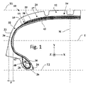
図1は、全般的な符号10で示される本発明の第1の実施形態によるタイヤの、半径方向断面を模式的に示す。タイヤ10は、軸方向Xに実質的に平行な軸の周りでの回転を実質的に示す。タイヤ10は、ここでは乗用車用であることが意図されている。タイヤ10は、30から55まで、好ましくは30から50までの範囲のアスペクト比を有する。この具体的な例では、タイヤは、サイズ245/40 R18のものであり、したがって40に等しいアスペクト比を有する。第1の実施形態によるタイヤ10は、ランフラットとして設計されたものではない。
FIG. 1 schematically shows a radial section through a tire according to a first embodiment of the invention, indicated generally by 10 . The
タイヤ10は、クラウン補強体14を含むクラウン12を含み、クラウン補強体14は、ワーキング補強要素の2つのワーキング・プライ16、18を含むワーキング補強体15と、フープ補強要素のフーピング・プライ19を含むフープ補強体17とを含む。クラウン補強体14は、クラウン補強体14の半径方向外側に配置されたトレッド20を載置している。この事例では、フープ補強体17、この事例ではフーピング・プライ19は、ワーキング補強体15とトレッド20との間に半径方向に挟まれている。
The
タイヤはまた、クラウン12を半径方向内方に延長する2つのサイドウォール22も含む。タイヤ10は、サイドウォール22の半径方向内側に2つのビード24をさらに含み、ビード24の各々は、環状補強構造26、この例ではビードワイヤ28を含み、これにはビード頂点充填ゴム30の塊が載置されており、タイヤ10は、半径方向カーカス補強体32も含む。
The tire also includes two
カーカス補強体32は、いくつかの補強要素を含む少なくとも1つのカーカス・プライを含み、プライは、ビードワイヤ28を取り巻くターンアップによってビード24の各々に固定され、各ビード24内で、ビードからサイドウォールを通ってクラウン12に向かう主ストランド38と、ターンアップ・ストランド40とを形成するようになっており、ターンアップ・ストランド40の半径方向外端部42は、環状補強構造26の半径方向外側にある。カーカス補強体32は、このようにしてビード24からサイドウォール22を通ってクラウン12の中まで延びている。カーカス補強体32は、クラウン補強体14及びフープ補強体17の半径方向内側に配置される。カーカス補強体32は、単一のカーカス・プライ34を含む。
The
タイヤ10はまた、サイドウォール22の軸方向内側かつクラウン補強体14の半径方向内側に位置するとともに2つのビード24間に延びる、好ましくはブチル製の、気密内側ライナ43も含む。
The
正中正接面Tで測定したタイヤ10の各サイドウォール22の平均厚さFは、10mm未満である。この特定の例において、平均厚さFは、ここでは5mmに等しい。
The average thickness F of each
各ワーキング・プライ16、18、フーピング・プライ19及びカーカス・プライ34は、対応するプライの補強要素が埋設されたポリマー組成物を含む。ワーキング・プライ16、18、フーピング・プライ19及びカーカス・プライ34の各ポリマー組成物、ここではエラストマー組成物は、補強要素のスキミング用の従来の組成物から作られ、この組成物は、従来、ジエンエラストマー、例えば天然ゴムと、補強用フィラー、例えばカーボンブラック及び/又はシリカと、架橋系、例えば加硫系とを含み、加硫系は、好ましくは硫黄と、ステアリン酸と、酸化亜鉛と、場合によっては加硫促進剤及び/又は遅延剤及び/又は種々の添加剤とを含む。
Each working
「本発明による複合体」
カーカス・プライ34を得るための複合体を、ここで図2、図3a及び図4を参照して説明する。
"Composite according to the invention"
The composite for obtaining the carcass ply 34 will now be described with reference to FIGS. 2, 3a and 4. FIG.
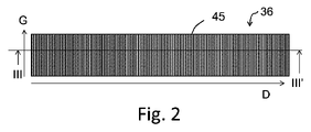
複合体は、いくつかの補強要素を含む。補強要素は、カーカス・プライの補強要素が延びる全体方向Gに対して実質的に垂直な主方向Dに、横並びに互いに平行に配置され、全体方向Gは、ひとたびカーカス・プライ34を形成する複合体がタイヤ10内に入ると、タイヤ10の円周方向Zに対して80°から90°までの範囲の角度を成す。この具体的な例において、全体方向Gは、ひとたびカーカス・プライ34を形成する複合体がタイヤ10内に入ると、タイヤ10の円周方向Zに対して実質的に90°に等しい角度を成す。
The composite includes several reinforcing elements. The reinforcing elements are arranged side by side and parallel to each other in a main direction D substantially perpendicular to the general direction G in which the reinforcing elements of the carcass plies extend, the general directions G once forming the carcass plies 34 of the composite. As the body enters the
補強要素45及び対応する組立体49を以下で説明する。補強要素45に対応する複合体36も説明する。
Reinforcing
補強要素のストランドの性質
図4に模式的に示すように、補強要素45は、芳香族ポリアミド又は芳香族コポリアミドで作られたマルチフィラメント・ストランド46と、ポリエステルで作られたマルチフィラメント・ストランド48とで構成された組立体49を含み、2本のストランド46、48は、互いの周りにらせん状に巻き付けられている。補強要素45は、撚り平衡化されている。説明の正確さのために、図5は、本発明による補強要素45の横断面図であり、各ストランドのモノフィラメントを識別することができる。
Properties of the Strands of the Reinforcing Element As shown schematically in FIG. 4, the reinforcing
選択された芳香族ポリアミドは、この例では、好ましくは、Teijin社による商品名Twaron1000として知られるパラアラミドである。ポリエステルは、Hyosung社又はHailide社による商品名PET HMLS(高モジュール低収縮(High Module Low Shrinkage))として知られるポリエチレンテレフタレート(PET)である。 The aromatic polyamide chosen, in this example, is preferably para-aramid, known under the trade name Twaron 1000 by Teijin. The polyester is polyethylene terephthalate (PET) known under the tradename PET HMLS (High Module Low Shrinkage) by Hyosung or Hailide.
図示していない特定の実施形態において、補強要素45は、組立体49に加えて、組立体49を被覆する接着剤組成物の層を含む。
In certain embodiments not shown, reinforcing
補強要素の番手
芳香族ポリアミド又は芳香族コポリアミド製のマルチフィラメント・ストランド46の番手は、140から210テックス、好ましくは150から190テックス、より好ましくは160から180テックスの範囲である。
Reinforcement element count The count of the
補強要素45において、ストランド46の番手は、167テックスに等しい。
In the reinforcing
ポリエステル製のマルチフィラメント・ストランド48の番手は、100から210テックス、好ましくは120から190テックス、より好ましくは130から180テックス、さらにより好ましくは160から180テックスの範囲である。
Polyester
補強要素45において、ストランド48の番手は、167テックスに等しい。
In the reinforcing
補強要素の撚り
補強要素45において、補強要素の撚りは、275から365撚り毎メートル、好ましくは275から350撚り毎メートル、より好ましくは300から330撚り毎メートルの範囲である。この具体的な例において、補強要素45の撚りは、315撚り毎メートルに等しい。
Twist of Reinforcing Elements In the reinforcing
補強要素の初期及び最終モジュラス
各補強要素45の初期引張りモジュラスは、5.0から10.5cN/テックスの範囲である。
Initial and Final Modulus of Reinforcing Elements The initial tensile modulus of each reinforcing
補強要素45において、補強要素の初期引張りモジュラスは、有利には5.7から8.5cN/テックス、好ましくは6.2から7.8cN/テックス、より好ましくは6.8から7.5cN/テックスの範囲である。この特定の例において、補強要素45の初期モジュラスは、7.2cN/テックスに等しい。
In the reinforcing
補強要素45の最終引張りモジュラスは、14.0から21.5cN/テックスの範囲である。
The final tensile modulus of reinforcing
補強要素45において、補強要素の最終引張りモジュラスは、有利には15.0から19.0cN/テックス、好ましくは15.8から18.5cN/テックス、より好ましくは16.6から17.9cN/テックスの範囲である。この具体的な例において、補強要素45の最終モジュラスは、16.9cN/テックスに等しい。
In the reinforcing
初期モジュラスに対する最終モジュラスの比は、2.10から2.75の範囲である。 The ratio of final modulus to initial modulus ranges from 2.10 to 2.75.
補強要素45において、初期モジュラスに対する最終モジュラスの比は、有利には2.15から2.45、好ましくは2.20から2.40、より好ましくは2.25から2.40の範囲である。この具体な例において、補強要素45の初期モジュラスに対する最終モジュラスの比は、2.34に等しい。
In the reinforcing
補強要素の撚り係数
補強要素45の撚り係数Kは、5.5から6.5までの範囲である。
Twist Factor of Reinforcing Elements The twist factor K of the reinforcing
好ましくは、補強要素45において、撚り係数Kは、区間]5.5;6.5](これは要するに値5.5を除外することを意味する)に属し、好ましくは5.6から6.1まで、さらにより好ましくは5.9から6.1までである。この具体的な事例において、補強要素45の撚り係数Kは、6.0に等しい。
Preferably, in the reinforcing
複合体の幾何学的特性
図3aに戻ると、複合体36は、厚さEを有し、補強要素45は直径dを有する。直径dは、補強要素が内接することができる理論的な円の直径に対応する。図3aにおいて、各ストランドは、説明を簡単にするために、あえて模式的に描かれている。図5は、補強要素45を実際に見えるように示す。
Composite Geometry Returning to FIG. 3a, the composite 36 has a thickness E and the reinforcing
補強要素45の直径は、0.95mm以下、好ましくは0.80mm以下、より好ましくは0.70mm以下である。補強要素45は、直径d=0.67mmを有する。
The diameter of the reinforcing
複合体36の厚さEは、1.45mm以下、好ましくは1.30mm以下、より好ましくは1.20mm以下である。補強要素45は、厚さE=1.10mmを有する。
The thickness E of the composite 36 is 1.45 mm or less, preferably 1.30 mm or less, more preferably 1.20 mm or less. The reinforcing
それゆえ、比d/Eは、厳密に0.65未満、好ましくは0.62以下である。補強要素45は、比d/E=0.61を有する。
The ratio d/E is therefore strictly less than 0.65, preferably less than or equal to 0.62. The reinforcing
複合体36における補強要素45の密度は、各複合体36の1デシメートル当たり90から130補強要素、好ましくは複合体36の1デシメートル当たり100から125補強要素、より好ましくは複合体36の1デシメートル当たり105から120補強要素の範囲である。複合体36について、補強要素45の密度は、複合体36の1デシメートル当たり110補強要素に等しい。
The density of reinforcing
図3aは、2つの隣接する補強要素45の2つの類似の点を隔てる距離であるピッチPを示す。ピッチPは、一般に、補強要素が複合体内に敷設される敷設ピッチのことを指す。ピッチPと、複合体1デシメートル当たりの補強要素の密度とは、複合体1デシメートル当たりの補強要素の密度が100/Pに等しくなるようになっている。
3a shows the pitch P, which is the distance separating two similar points of two adjacent reinforcing
上述の補強要素の密度及び厚さは、前に説明したように、補強要素45の密度及び複合体36の厚さEである。タイヤ10において、カーカス・プライ34は、未硬化タイヤを成形することによって複合体36から得られるので、補強要素の密度及びカーカス・プライ34の厚さは、複合体のそれらとは異なり、タイヤの回転軸からのその距離に従って変化する。これらの変動は、特にタイヤの未硬化形態の形状要因及びまたその幾何学的形状に依存する。当業者は、特にタイヤの未硬化形態の形状要因及びその幾何学的形状に基づいて、対応する複合体の特性を決定することができる。
The density and thickness of the reinforcement elements mentioned above are the density of the
「補強要素の製造方法」
上述のように、補強要素45は、撚り平衡化されており、これは要するに、2本のマルチフィラメント・ストランドが実質的に同じ撚りで巻き付けられ、各マルチフィラメント・ストランド内のモノフィラメントの撚りが実質的にゼロであることを意味する。第1のステップにおいて、モノフィラメントの各紡績糸(より適切には「ヤーン」と称される)が最初にそれ自体個別に315撚り毎メートルに等しい初期撚りで、所与の方向、この例ではZ方向に撚糸され、ストランド又はオーバーツイスト(より適切には「ストランド」と称される)を形成する。次いで、第2のステップの間に、2本のストランドが次に315撚り毎メートルに等しい最終撚りでS方向に一緒に撚り合わされて、補強要素の組立体(より適切には「コード」と称される)が得られる。
"Method for Manufacturing Reinforcing Elements"
As noted above, the reinforcing
後のステップにおいて、各組立体は、接着剤組成物、例えばRFL(レソルシノール-ホルムアルデヒド-ラテックス)タイプの接着剤組成物で被覆され、接着剤組成物を少なくとも部分的に架橋するために熱処理ステップに供される。 In a later step, each assembly is coated with an adhesive composition, for example an RFL (resorcinol-formaldehyde-latex) type adhesive composition, and subjected to a heat treatment step to at least partially crosslink the adhesive composition. provided.
「本発明による複合体の製造方法」
複合体36は、いくつかの補強要素45をエラストマー組成物に、例えばスキミングにより埋設することによって製造される。このような当業者に周知のスキミングステップの間に、補強要素が前進し、スキムと称されるエラストマー組成物で作られた2つのストップが、補強要素の各側に1つずつ導入され、補強要素が2つのスキムの間に挟まれるようになっている。補強要素は、このようにしてエラストマー組成物の中に埋設される。
"Method for producing a composite according to the present invention"
「本発明によるタイヤの製造方法」
タイヤの製造方法は、当業者が従来用いている方法である。この方法の工程の間に、既に上で説明したように、タイヤ10のカーカス・プライ34を形成することを意図した本発明による複合体を含む種々のプライ及び複合体が、最初の一連のタイヤ構築ステップ中に連続的に敷設される。このようにして得られた未硬化物は、次いで成形される。次に、タイヤ10のクラウン12を形成することを意図した他のプライ及び複合体が敷設される。最後に、このようにして得られた未硬化物は、タイヤ10を得るために加硫される。
"Method for manufacturing a tire according to the present invention"
The method of manufacturing the tire is the method conventionally used by those skilled in the art. During the steps of this method, as already explained above, the various plies and composites, including composites according to the invention intended to form the carcass plies 34 of the
「本発明の第2の実施形態によるタイヤ」
図6は、本発明の第2の実施形態によるタイヤを示す。
第1の実施形態の要素と同様の要素は、同一の符号で示す。
"Tire according to a second embodiment of the invention"
Figure 6 shows a tire according to a second embodiment of the invention.
Elements similar to those of the first embodiment are indicated with the same reference numerals.
第1の実施形態によるタイヤ10とは異なり、第2の実施形態によるタイヤ10は、55以上、好ましくは55から75までの範囲のアスペクト比を有する。この具体的な例において、タイヤはサイズ205/55 R16のものであり、したがってアスペクト比は55に等しい。
Unlike the
「本発明の第3の実施形態によるタイヤ」
図7は、本発明の第3の実施形態によるタイヤを示す。第1の実施形態の要素と同様の要素は、同一の符号で示す。
"Tire according to the third embodiment of the invention"
Figure 7 shows a tire according to a third embodiment of the invention. Elements similar to those of the first embodiment are indicated with the same reference numerals.
第1の実施形態によるタイヤ10とは異なり、第3の実施形態によるタイヤ10は、ランフラットとして設計されたタイヤである。そのため、タイヤは、ランフラット状況の間、車両の重量の一部に対応する荷重に耐えるように、すなわち大気圧に実質的に等しい圧力を有するように構成される。
Unlike the
第3の実施形態によるタイヤ10は、クラウン12を半径方向内方に延長する2つの自己支持型サイドウォール22を含む。この目的で、タイヤ10は、カーカス補強体32の軸方向内側かつ気密内側ライナ43の軸方向外側に、2つのサイドウォール・インサート50を含む。このように、サイドウォール・インサート50は、軸方向でカーカス補強体32と気密内側ライナ43との間に配置される。
The
その特徴的な三日月形の半径方向断面を有するこれらのインサート50は、サイドウォール22を補強することを意図する。各インサート50は、特定のエラストマー組成物から作られる。特許文献2は、このようなインサートを形成するために用いることができる特定のエラストマー組成物のいくつかの例を与える。各サイドウォール・インサート50は、ランフラット状態の間、車両の重量の一部に対応する荷重に耐えることに寄与することが可能である。
These inserts 50 with their characteristic crescent-shaped radial cross-section are intended to stiffen the
タイヤの第1の実施形態とは異なり、各サイドウォール22は、正中正接面で測定して10mm以上の平均厚さFを有する。この具体的な例において、平均厚さFは、ここでは17mmに等しい。
Unlike the first embodiment of the tire, each
「比較試験及び測定」
比較例として、図3bは、従来技術のタイヤの、全般的な符号NTで示される従来技術の複合体を示す。複合体NTは、補強要素ETを含み、各補強要素ETは、ポリエステル製の2本のマルチフィラメント・ストランドで構成された組立体を含み、2本のマルチフィラメント・ストランドは、互いに組み立てられ、270撚り毎メートルの撚りで互いのまわりにらせん状に巻き付けられている。各補強要素ETは、撚り平衡化されている。補強要素ETの各マルチフィラメント・ストランドは、334テックスに等しい番手を有する。
"Comparative test and measurement"
As a comparative example, FIG. 3b shows a prior art composite, generally designated NT, of a prior art tire. The composite NT comprises reinforcing elements ET, each reinforcing element ET comprising an assembly made up of two multifilament strands made of polyester, the two multifilament strands assembled together, 270 They are spirally wound around each other with a twist per meter. Each reinforcing element ET is twist balanced. Each multifilament strand of the reinforcing element ET has a count equal to 334 tex.
対照補強要素ET’を含む対照複合体NT’も使用され、各補強要素ET’は、芳香族ポリアミド又は芳香族コポリアミド製のマルチフィラメント・ストランドとポリエステル製のマルチフィラメント・ストランドとで構成され、これらのマルチフィラメント・ストランドは、互いに組み立てられ、290撚り毎メートルの撚りで互いのまわりにらせん状に巻き付けられている。各補強要素ET’は、撚り平衡化されている。芳香族ポリアミド又は芳香族コポリアミド、この事例では補強要素45のものと同一のパラアミドのマルチフィラメント・ストランドは、167テックスに等しい番手を有する。ポリエステル、この事例では補強要素45のものと同一のPETのマルチフィラメント・ストランドは、144テックスに等しい番手を有する。
A control composite NT' containing control reinforcing elements ET' is also used, each reinforcing element ET' consisting of multifilament strands made of aromatic polyamide or aromatic copolyamide and multifilament strands made of polyester, These multifilament strands are assembled together and helically wound around each other with a twist of 290 twists per meter. Each reinforcing element ET' is twist balanced. Multifilament strands of aromatic polyamide or aromatic copolyamide, in this case paraamide identical to that of the reinforcing
補強要素間の比較
表1に、本発明によるタイヤ10の補強要素45、対照補強要素ET’及び従来技術の補強要素ETの特性をまとめる。破断力測定値は、ISO6892規格(1984年)に準拠した引張試験下で取得される。

補強要素45は、従来技術の補強要素ETよりも有意に高い初期及び最終モジュラス値を有することに注目されたい。
Note that reinforcing
補強要素45の破断力値は、ロードハザードに効果的に対処するのに十分なほど高い。補強要素45の破断力は、対照補強要素ET’の破断力を上回り、補強要素ETの破断力とほぼ同じであることが注目される。
The breaking force value of the reinforcing
複合体の比較
補強要素45を含む本発明による複合体36を、対照補強要素ET’を含む対照複合体NT’及び補強要素ETを含む従来技術の複合体NTと比較した。これらの複合体の幾何学的性質を下記の表2において照合する。

従来技術の補強要素ETは、本発明による複合体の補強要素45の直径よりも非常に大きい直径dを有することに注目されたい。本発明による複合体36は、複合体NTよりもはるかに薄く、複合体NT’よりも薄い。複合体36の比d/Eは、従来技術の複合体の比d/Eよりも小さく、それは複合体36の重さがより軽いことを意味する。
It should be noted that the prior art reinforcing element ET has a diameter d that is much larger than the diameter of the reinforcing
より軽量であることに加えて、複合体36は、複合体NT及び複合体NT’よりも有意に高い破断力を有することが注目される。
In addition to being lighter,
補強要素の破断力
表3は、167テックスに等しい番手を有するアラミド(Teijin社によるTwaron 1000)製のマルチフィラメント・ストランドと、144テックスに等しい番手を有するPET(Hyosung社によるPET HMLS)製のマルチフィラメント・ストランドとを含み、2つのストランドが互いにらせん状に巻き付き、各補強要素が撚り平衡化されている、補強要素の破断力を示す。撚りは、撚り係数Kが3.7から7.0まで変化するように変化させた。破断力測定値は、ISO6892規格(1984年)に準拠した引張試験下で取得する。

表4は、167テックスに等しい番手を有するアラミド(Teijin社によるTwaron 1000)製のマルチフィラメント・ストランドと、167テックスに等しい番手を有するPET(Hailide社によるPET HMLS)製のマルチフィラメント・ストランドとを含み、2つのストランドが互いにらせん状に巻き付き、各補強要素が撚り平衡化されている補強要素の破断力を示す。撚りは、撚り係数Kが4.6から7.0まで変化するように変化させた。破断力測定値は、ISO6892規格(1984年)に準拠した引張試験下で取得する。

表3及び表4は、所与の番手に対して、5.5から6.5までの範囲の撚り係数Kの区間内で、各補強要素の破断力が実質的に一定であることを示す。それゆえ、上述のように、選択された撚り係数区間内で、タイヤ設計者は、補強要素の他の特性、特に撚りを、そのタイヤが意図する1つ又は複数の用途に合うように、特に後述のように耐久性を変更するために適合させることができる。 Tables 3 and 4 show that for a given count, the breaking force of each reinforcing element is substantially constant within the interval of twist factor K ranging from 5.5 to 6.5. . Therefore, as described above, within the selected twist factor interval, the tire designer can adjust other properties of the reinforcing elements, particularly the twist, to suit the tire's intended use or uses. It can be adapted to change durability as described below.
補強要素の耐久性
補強要素45の耐久性を、他のアラミド/PET補強要素I、II、III及びET’の耐久性と比較した。補強要素II及び45は、本発明によるものである。補強要素I、III及びET’は、本発明によるものではない。耐久性を評価するために、補強要素をエラストマー組成物に埋設して厚さが30mmに等しいストリップの形態の試験片を形成し、これを円筒形のバーの周りでサイクルさせた。190,000サイクル後、各補強要素の最終破断力を測定した。190,000サイクル後の破断力における損失に対応するドロップオフを%として計算した。ドロップオフが高いほど、耐久性が低い。試験の結果及び試験された補強要素の特性を下記の表5において照合する。

補強要素II及び45についての結果は、所与のストランド番手に対して、5.5から6.5までの範囲の撚り係数Kの区間内で、耐久性を、タイヤの所望の用途に従って、例えば撚りを変えることによって変更することができることを示す。それゆえ、タイヤ設計者は、タイヤが意図する特定の用途、例えばスポーツ用途に応じて撚りを増大することによって耐久性を変更することができ、あるいは、より低い撚りを選択することによって今日の大部分のタイヤ用途に適合した耐久性を選択することができる。 The results for reinforcing elements II and 45 show that for a given strand number, within the interval of twist factor K ranging from 5.5 to 6.5, the durability depends on the desired application of the tire, e.g. We show that it can be modified by changing the twist. Therefore, a tire designer can alter durability by increasing the twist depending on the specific use for which the tire is intended, e.g., sporting applications, or choose a lower twist to meet today's demands. Durability can be selected to suit the particular tire application.
これらの結果は、補強要素45が、比較的高い初期破断力と、はるかに高い撚り係数を有する補強要素IIIの耐久性に近い耐久性との両方を兼ね備えることを示す。さらに、5.5から6.5までの範囲の撚り係数Kの区間において、初期破断力は、この区間よりも高い撚り係数を有する補強要素IIIの初期破断力よりはるかに高い。
These results show that
タイヤの比較
本発明によるタイヤ10を、複合体NTから得られるカーカス・プライを含む従来技術のタイヤPTに対して比較した。
Tire
タイヤ10及びPTの質量を、試験されるタイヤを秤量することによって比較した。この試験の結果を下記の表6において照合する。

このように、タイヤ10は、従来技術のタイヤPTと比べて質量が低いことを示すことが注目される。
It is thus noted that the
本発明は、上述の実施形態に限定されない。 The invention is not limited to the embodiments described above.
上述していない実施形態において、タイヤは、60から70までの範囲のアスペクト比を有し得る。 In embodiments not described above, the tire may have an aspect ratio in the range of 60-70.
上記で説明した又は想定される種々の実施形態及び代替的形態の特性を組み合わせることも、それらの特性が互いに両立できる条件で可能である。 Combinations of features of various embodiments and alternative forms described or contemplated above are also possible, provided those features are compatible with each other.
10:タイヤ
12:クラウン
14:クラウン補強体
15:ワーキング補強体
16、18:ワーキング・プライ
17:フープ補強体
19:フーピング・プライ
20:トレッド
22:サイドウォール
24:ビード
28:ビードワイヤ
32:カーカス補強体
34:カーカス・プライ
36:エラストマー複合体
38:主ストランド
40:ターンアップ・ストランド
43:気密内側ライナ
45:補強要素
46:芳香族ポリアミド又は芳香族コポリアミド製のマルチフィラメント・ストランド
48:ポリエステル製のマルチフィラメント・ストランド
49:組立体
50:サイドウォール・インサート
10: Tire 12: Crown 14: Crown Reinforcement 15: Working
Claims (9)
前記組立体(49)は、
・芳香族ポリアミド又は芳香族コポリアミド製のマルチフィラメント・ストランド(46)と、
・ポリエステル製のマルチフィラメント・ストランド(48)と、
で構成され、
前記2本のストランド(46、48)は、互いにらせん状に巻き付けられ、前記補強要素(45)は、撚り平衡化され、前記補強要素(45)の撚り係数Kは、5.5から6.5までの範囲であり、Kは、式
K=(R×Ti1/2)/957により定義され、
ここでRは、撚り毎メートルで表された前記補強要素(45)の撚りであり、Tiは、テックスで表された前記補強要素(45)の前記マルチフィラメント・ストランドの番手の合計であり、前記補強要素(45)の撚りが300から330撚り毎メートルの範囲であり、前記補強要素(45)の初期引張りモジュラスが、5.0から10.5cN/テックスである、ことを特徴とする、補強要素(45)。 a reinforcing element (45) comprising an assembly (49);
Said assembly (49) comprises:
- multifilament strands (46) made of aromatic polyamide or aromatic copolyamide;
- multifilament strands (48) made of polyester;
consists of
Said two strands (46, 48) are helically wound around each other and said reinforcing element (45) is twist balanced and said reinforcing element (45) has a twist factor K of between 5.5 and 6.5. 5, where K is defined by the formula K = (R x Ti 1/2 )/957,
where R is the twist of the reinforcing element (45) expressed in twists per meter and Ti is the sum of the counts of the multifilament strands of the reinforcing element (45) expressed in tex; characterized in that the twist of said reinforcing element (45) is in the range of 300 to 330 twists per meter and the initial tensile modulus of said reinforcing element (45) is from 5.0 to 10.5 cN/tex. , reinforcing elements (45).
Applications Claiming Priority (3)
| Application Number | Priority Date | Filing Date | Title |
|---|---|---|---|
| FR1658764 | 2016-09-19 | ||
| FR1658764A FR3056149A1 (en) | 2016-09-19 | 2016-09-19 | REINFORCING ELEMENT, ELASTOMER COMPOSITE AND PNEUMATIC COMPRISING THIS REINFORCING ELEMENT |
| PCT/FR2017/052467 WO2018051032A1 (en) | 2016-09-19 | 2017-09-15 | Reinforcing element, elastomer composite and tyre comprising said reinforcing element |
Publications (3)
| Publication Number | Publication Date |
|---|---|
| JP2019533093A JP2019533093A (en) | 2019-11-14 |
| JP2019533093A5 JP2019533093A5 (en) | 2020-10-22 |
| JP7154207B2 true JP7154207B2 (en) | 2022-10-17 |
Family
ID=57348972
Family Applications (1)
| Application Number | Title | Priority Date | Filing Date |
|---|---|---|---|
| JP2019515481A Active JP7154207B2 (en) | 2016-09-19 | 2017-09-15 | Reinforcing element, elastomeric composite and tire comprising said reinforcing element |
Country Status (4)
| Country | Link |
|---|---|
| US (1) | US20190248184A1 (en) |
| JP (1) | JP7154207B2 (en) |
| FR (1) | FR3056149A1 (en) |
| WO (1) | WO2018051032A1 (en) |
Families Citing this family (7)
| Publication number | Priority date | Publication date | Assignee | Title |
|---|---|---|---|---|
| EP3868572A4 (en) * | 2018-10-17 | 2023-05-10 | Bridgestone Corporation | Tire |
| EP3868570B1 (en) | 2018-10-17 | 2024-01-24 | Bridgestone Corporation | Tire |
| JP7367488B2 (en) * | 2019-11-26 | 2023-10-24 | 住友ゴム工業株式会社 | pneumatic tires |
| DE102019218579A1 (en) * | 2019-11-29 | 2021-06-02 | Contitech Antriebssysteme Gmbh | Drive belt, use of such a drive belt as a V-ribbed belt and manufacturing method |
| CN116249626A (en) * | 2020-06-17 | 2023-06-09 | 倍耐力轮胎股份公司 | Self-supporting tyre for vehicle wheels |
| JP2023147478A (en) * | 2022-03-30 | 2023-10-13 | 住友ゴム工業株式会社 | tire |
| FR3137868A1 (en) * | 2022-07-18 | 2024-01-19 | Compagnie Generale Des Etablissements Michelin | Tire fabric comprising reinforcing elements comprising an assembly consisting of two multifilament strands of polyamide 5.6 |
Citations (3)
| Publication number | Priority date | Publication date | Assignee | Title |
|---|---|---|---|---|
| JP2013154766A (en) | 2012-01-30 | 2013-08-15 | Yokohama Rubber Co Ltd:The | Pneumatic radial tire |
| JP2015027849A (en) | 2013-07-30 | 2015-02-12 | 東洋ゴム工業株式会社 | Pneumatic tire |
| JP2015536269A (en) | 2012-10-12 | 2015-12-21 | コンパニー ゼネラール デ エタブリッスマン ミシュラン | Tire designed to run flat with hybrid carcass ply |
Family Cites Families (4)
| Publication number | Priority date | Publication date | Assignee | Title |
|---|---|---|---|---|
| JPS6171204A (en) * | 1984-09-13 | 1986-04-12 | Bridgestone Corp | Ply for carcass in pneumatic radial tire |
| EP0661179B1 (en) * | 1993-12-28 | 1997-05-21 | Sumitomo Rubber Industries Limited | Pneumatic radial tyre |
| WO2002096677A1 (en) | 2001-05-29 | 2002-12-05 | Societe De Technologie Michelin | Runflat tire |
| US20100263781A1 (en) | 2007-11-13 | 2010-10-21 | Eiji Yamaguchi | Pneumatic tire |
-
2016
- 2016-09-19 FR FR1658764A patent/FR3056149A1/en active Pending
-
2017
- 2017-09-15 WO PCT/FR2017/052467 patent/WO2018051032A1/en active Application Filing
- 2017-09-15 JP JP2019515481A patent/JP7154207B2/en active Active
- 2017-09-15 US US16/333,332 patent/US20190248184A1/en not_active Abandoned
Patent Citations (3)
| Publication number | Priority date | Publication date | Assignee | Title |
|---|---|---|---|---|
| JP2013154766A (en) | 2012-01-30 | 2013-08-15 | Yokohama Rubber Co Ltd:The | Pneumatic radial tire |
| JP2015536269A (en) | 2012-10-12 | 2015-12-21 | コンパニー ゼネラール デ エタブリッスマン ミシュラン | Tire designed to run flat with hybrid carcass ply |
| JP2015027849A (en) | 2013-07-30 | 2015-02-12 | 東洋ゴム工業株式会社 | Pneumatic tire |
Also Published As
| Publication number | Publication date |
|---|---|
| FR3056149A1 (en) | 2018-03-23 |
| JP2019533093A (en) | 2019-11-14 |
| WO2018051032A1 (en) | 2018-03-22 |
| US20190248184A1 (en) | 2019-08-15 |
Similar Documents
| Publication | Publication Date | Title |
|---|---|---|
| JP7154207B2 (en) | Reinforcing element, elastomeric composite and tire comprising said reinforcing element | |
| JP6202581B2 (en) | Tire designed to run flat with hybrid carcass ply | |
| CN110072708B (en) | Elastomer composite and tire comprising said composite | |
| CN111954600B (en) | Tire comprising a single carcass ply and having improved depth of sidewall deformation after running-in | |
| CN107531095B (en) | Hybrid reinforcing element with different twists | |
| EP3898275B1 (en) | Tyre for vehicle wheels | |
| JP2023544768A (en) | Mounting assembly including pneumatic tires | |
| US20230137115A1 (en) | Tire with low rolling resistance and method for producing same | |
| CN115066340B (en) | Agricultural vehicle tire including hybrid carcass reinforcing elements | |
| EP2777948A1 (en) | Radial tire for motorcycle | |
| CN112672892B (en) | Tyre with carcass reinforcement formed by a single layer of textile reinforcing elements | |
| CN113195256B (en) | Tyre for vehicle wheels | |
| JP2005343301A (en) | Pneumatic radial tire | |
| KR20230079088A (en) | Tires with two carcass layers | |
| US11932063B2 (en) | Tire for two-wheeled vehicle comprising a hybrid hooping reinforcement | |
| US20220169078A1 (en) | Hybrid cord and tyre with such cord | |
| WO2023223246A1 (en) | Tyre for vehicle wheels | |
| WO2023223247A1 (en) | Tyre for vehicle wheels | |
| US20130118670A1 (en) | Pneumatic tire with tackified wrapped reinforcement | |
| KR20230129233A (en) | Tire fabric comprising tangled weft reinforcing elements with low moisture absorption | |
| CN115916548A (en) | Tyre for vehicle wheels | |
| KR20230084164A (en) | Tires with two carcass layers | |
| US20150059954A1 (en) | Pneumatic tire with coated reinforcement |
Legal Events
| Date | Code | Title | Description |
|---|---|---|---|
| A521 | Request for written amendment filed |
Free format text: JAPANESE INTERMEDIATE CODE: A523 Effective date: 20200908 |
|
| A621 | Written request for application examination |
Free format text: JAPANESE INTERMEDIATE CODE: A621 Effective date: 20200908 |
|
| A977 | Report on retrieval |
Free format text: JAPANESE INTERMEDIATE CODE: A971007 Effective date: 20211020 |
|
| A131 | Notification of reasons for refusal |
Free format text: JAPANESE INTERMEDIATE CODE: A131 Effective date: 20211027 |
|
| A521 | Request for written amendment filed |
Free format text: JAPANESE INTERMEDIATE CODE: A523 Effective date: 20220118 |
|
| A131 | Notification of reasons for refusal |
Free format text: JAPANESE INTERMEDIATE CODE: A131 Effective date: 20220525 |
|
| A521 | Request for written amendment filed |
Free format text: JAPANESE INTERMEDIATE CODE: A523 Effective date: 20220615 |
|
| TRDD | Decision of grant or rejection written | ||
| A01 | Written decision to grant a patent or to grant a registration (utility model) |
Free format text: JAPANESE INTERMEDIATE CODE: A01 Effective date: 20220905 |
|
| A61 | First payment of annual fees (during grant procedure) |
Free format text: JAPANESE INTERMEDIATE CODE: A61 Effective date: 20221004 |
|
| R150 | Certificate of patent or registration of utility model |
Ref document number: 7154207 Country of ref document: JP Free format text: JAPANESE INTERMEDIATE CODE: R150 |