JP7153570B2 - Printable composition containing high viscosity components and method of producing 3D articles therefrom - Google Patents
Printable composition containing high viscosity components and method of producing 3D articles therefrom Download PDFInfo
- Publication number
- JP7153570B2 JP7153570B2 JP2018567709A JP2018567709A JP7153570B2 JP 7153570 B2 JP7153570 B2 JP 7153570B2 JP 2018567709 A JP2018567709 A JP 2018567709A JP 2018567709 A JP2018567709 A JP 2018567709A JP 7153570 B2 JP7153570 B2 JP 7153570B2
- Authority
- JP
- Japan
- Prior art keywords
- weight
- printable composition
- printable
- article
- temporary solvent
- Prior art date
- Legal status (The legal status is an assumption and is not a legal conclusion. Google has not performed a legal analysis and makes no representation as to the accuracy of the status listed.)
- Active
Links
- 239000000203 mixture Substances 0.000 title claims description 208
- 238000000034 method Methods 0.000 title claims description 112
- 239000002904 solvent Substances 0.000 claims description 118
- 238000004519 manufacturing process Methods 0.000 claims description 28
- 238000006116 polymerization reaction Methods 0.000 claims description 22
- KFZMGEQAYNKOFK-UHFFFAOYSA-N Isopropanol Chemical compound CC(C)O KFZMGEQAYNKOFK-UHFFFAOYSA-N 0.000 claims description 15
- 150000001252 acrylic acid derivatives Chemical class 0.000 claims description 15
- XLYOFNOQVPJJNP-UHFFFAOYSA-N water Substances O XLYOFNOQVPJJNP-UHFFFAOYSA-N 0.000 claims description 14
- 238000010521 absorption reaction Methods 0.000 claims description 13
- OKKJLVBELUTLKV-UHFFFAOYSA-N Methanol Chemical compound OC OKKJLVBELUTLKV-UHFFFAOYSA-N 0.000 claims description 12
- 239000000654 additive Substances 0.000 claims description 12
- 239000003607 modifier Substances 0.000 claims description 12
- 239000003112 inhibitor Substances 0.000 claims description 11
- 229920000193 polymethacrylate Polymers 0.000 claims description 11
- 238000002156 mixing Methods 0.000 claims description 10
- 238000009835 boiling Methods 0.000 claims description 9
- 238000010438 heat treatment Methods 0.000 claims description 9
- JOYRKODLDBILNP-UHFFFAOYSA-N Ethyl urethane Chemical compound CCOC(N)=O JOYRKODLDBILNP-UHFFFAOYSA-N 0.000 claims description 8
- RUOJZAUFBMNUDX-UHFFFAOYSA-N propylene carbonate Chemical compound CC1COC(=O)O1 RUOJZAUFBMNUDX-UHFFFAOYSA-N 0.000 claims description 7
- 230000000996 additive effect Effects 0.000 claims description 6
- WAEVWDZKMBQDEJ-UHFFFAOYSA-N 2-[2-(2-methoxypropoxy)propoxy]propan-1-ol Chemical compound COC(C)COC(C)COC(C)CO WAEVWDZKMBQDEJ-UHFFFAOYSA-N 0.000 claims description 5
- 239000003505 polymerization initiator Substances 0.000 claims description 4
- 238000002791 soaking Methods 0.000 claims description 3
- 239000000463 material Substances 0.000 description 47
- 238000011282 treatment Methods 0.000 description 40
- 239000010410 layer Substances 0.000 description 34
- 238000010146 3D printing Methods 0.000 description 29
- 229920005989 resin Polymers 0.000 description 27
- 239000011347 resin Substances 0.000 description 27
- 230000008569 process Effects 0.000 description 26
- 238000007639 printing Methods 0.000 description 20
- -1 Rohm Plex 6661-0) Chemical class 0.000 description 19
- 239000007788 liquid Substances 0.000 description 19
- 239000000758 substrate Substances 0.000 description 16
- NIXOWILDQLNWCW-UHFFFAOYSA-M Acrylate Chemical compound [O-]C(=O)C=C NIXOWILDQLNWCW-UHFFFAOYSA-M 0.000 description 12
- PEDCQBHIVMGVHV-UHFFFAOYSA-N Glycerine Chemical compound OCC(O)CO PEDCQBHIVMGVHV-UHFFFAOYSA-N 0.000 description 12
- 210000002455 dental arch Anatomy 0.000 description 12
- 210000004513 dentition Anatomy 0.000 description 12
- 239000012530 fluid Substances 0.000 description 12
- 230000036346 tooth eruption Effects 0.000 description 12
- 230000005855 radiation Effects 0.000 description 11
- VYPSYNLAJGMNEJ-UHFFFAOYSA-N silicon dioxide Inorganic materials O=[Si]=O VYPSYNLAJGMNEJ-UHFFFAOYSA-N 0.000 description 10
- 239000000049 pigment Substances 0.000 description 9
- CERQOIWHTDAKMF-UHFFFAOYSA-M Methacrylate Chemical compound CC(=C)C([O-])=O CERQOIWHTDAKMF-UHFFFAOYSA-M 0.000 description 8
- 239000008199 coating composition Substances 0.000 description 8
- 238000013461 design Methods 0.000 description 8
- 239000003999 initiator Substances 0.000 description 8
- OZAIFHULBGXAKX-UHFFFAOYSA-N 2-(2-cyanopropan-2-yldiazenyl)-2-methylpropanenitrile Chemical group N#CC(C)(C)N=NC(C)(C)C#N OZAIFHULBGXAKX-UHFFFAOYSA-N 0.000 description 7
- 125000001931 aliphatic group Chemical group 0.000 description 7
- 150000001875 compounds Chemical class 0.000 description 7
- 238000000151 deposition Methods 0.000 description 7
- 239000000945 filler Substances 0.000 description 7
- 238000003860 storage Methods 0.000 description 7
- ZJCCRDAZUWHFQH-UHFFFAOYSA-N Trimethylolpropane Chemical compound CCC(CO)(CO)CO ZJCCRDAZUWHFQH-UHFFFAOYSA-N 0.000 description 6
- 230000008859 change Effects 0.000 description 6
- 230000008021 deposition Effects 0.000 description 6
- RGLYKWWBQGJZGM-ISLYRVAYSA-N diethylstilbestrol Chemical compound C=1C=C(O)C=CC=1C(/CC)=C(\CC)C1=CC=C(O)C=C1 RGLYKWWBQGJZGM-ISLYRVAYSA-N 0.000 description 6
- VFHVQBAGLAREND-UHFFFAOYSA-N diphenylphosphoryl-(2,4,6-trimethylphenyl)methanone Chemical compound CC1=CC(C)=CC(C)=C1C(=O)P(=O)(C=1C=CC=CC=1)C1=CC=CC=C1 VFHVQBAGLAREND-UHFFFAOYSA-N 0.000 description 6
- 230000001815 facial effect Effects 0.000 description 6
- 229920000642 polymer Polymers 0.000 description 6
- 238000011417 postcuring Methods 0.000 description 6
- 210000001519 tissue Anatomy 0.000 description 6
- 239000004322 Butylated hydroxytoluene Substances 0.000 description 5
- NLZUEZXRPGMBCV-UHFFFAOYSA-N Butylhydroxytoluene Chemical compound CC1=CC(C(C)(C)C)=C(O)C(C(C)(C)C)=C1 NLZUEZXRPGMBCV-UHFFFAOYSA-N 0.000 description 5
- 229940095259 butylated hydroxytoluene Drugs 0.000 description 5
- 235000010354 butylated hydroxytoluene Nutrition 0.000 description 5
- 238000005516 engineering process Methods 0.000 description 5
- MHCLJIVVJQQNKQ-UHFFFAOYSA-N ethyl carbamate;2-methylprop-2-enoic acid Chemical class CCOC(N)=O.CC(=C)C(O)=O MHCLJIVVJQQNKQ-UHFFFAOYSA-N 0.000 description 5
- 238000005259 measurement Methods 0.000 description 5
- 239000000523 sample Substances 0.000 description 5
- LAQYHRQFABOIFD-UHFFFAOYSA-N 2-methoxyhydroquinone Chemical compound COC1=CC(O)=CC=C1O LAQYHRQFABOIFD-UHFFFAOYSA-N 0.000 description 4
- YGUMVDWOQQJBGA-VAWYXSNFSA-N 5-[(4-anilino-6-morpholin-4-yl-1,3,5-triazin-2-yl)amino]-2-[(e)-2-[4-[(4-anilino-6-morpholin-4-yl-1,3,5-triazin-2-yl)amino]-2-sulfophenyl]ethenyl]benzenesulfonic acid Chemical group C=1C=C(\C=C\C=2C(=CC(NC=3N=C(N=C(NC=4C=CC=CC=4)N=3)N3CCOCC3)=CC=2)S(O)(=O)=O)C(S(=O)(=O)O)=CC=1NC(N=C(N=1)N2CCOCC2)=NC=1NC1=CC=CC=C1 YGUMVDWOQQJBGA-VAWYXSNFSA-N 0.000 description 4
- UQSXHKLRYXJYBZ-UHFFFAOYSA-N Iron oxide Chemical compound [Fe]=O UQSXHKLRYXJYBZ-UHFFFAOYSA-N 0.000 description 4
- GWEVSGVZZGPLCZ-UHFFFAOYSA-N Titan oxide Chemical compound O=[Ti]=O GWEVSGVZZGPLCZ-UHFFFAOYSA-N 0.000 description 4
- 239000003963 antioxidant agent Substances 0.000 description 4
- IISBACLAFKSPIT-UHFFFAOYSA-N bisphenol A Chemical compound C=1C=C(O)C=CC=1C(C)(C)C1=CC=C(O)C=C1 IISBACLAFKSPIT-UHFFFAOYSA-N 0.000 description 4
- PXKLMJQFEQBVLD-UHFFFAOYSA-N bisphenol F Chemical compound C1=CC(O)=CC=C1CC1=CC=C(O)C=C1 PXKLMJQFEQBVLD-UHFFFAOYSA-N 0.000 description 4
- 229910052804 chromium Inorganic materials 0.000 description 4
- 239000011651 chromium Substances 0.000 description 4
- 238000004590 computer program Methods 0.000 description 4
- 238000011960 computer-aided design Methods 0.000 description 4
- 239000011521 glass Substances 0.000 description 4
- 238000003384 imaging method Methods 0.000 description 4
- 238000007641 inkjet printing Methods 0.000 description 4
- 150000002734 metacrylic acid derivatives Chemical class 0.000 description 4
- 238000012545 processing Methods 0.000 description 4
- 230000002829 reductive effect Effects 0.000 description 4
- 239000007787 solid Substances 0.000 description 4
- 239000003381 stabilizer Substances 0.000 description 4
- 239000004094 surface-active agent Substances 0.000 description 4
- 238000012360 testing method Methods 0.000 description 4
- 238000005406 washing Methods 0.000 description 4
- MYWOJODOMFBVCB-UHFFFAOYSA-N 1,2,6-trimethylphenanthrene Chemical compound CC1=CC=C2C3=CC(C)=CC=C3C=CC2=C1C MYWOJODOMFBVCB-UHFFFAOYSA-N 0.000 description 3
- VYZAMTAEIAYCRO-UHFFFAOYSA-N Chromium Chemical compound [Cr] VYZAMTAEIAYCRO-UHFFFAOYSA-N 0.000 description 3
- CERQOIWHTDAKMF-UHFFFAOYSA-N Methacrylic acid Chemical compound CC(=C)C(O)=O CERQOIWHTDAKMF-UHFFFAOYSA-N 0.000 description 3
- 239000002202 Polyethylene glycol Substances 0.000 description 3
- INXWLSDYDXPENO-UHFFFAOYSA-N [2-(hydroxymethyl)-3-prop-2-enoyloxy-2-[[3-prop-2-enoyloxy-2,2-bis(prop-2-enoyloxymethyl)propoxy]methyl]propyl] prop-2-enoate Chemical compound C=CC(=O)OCC(COC(=O)C=C)(CO)COCC(COC(=O)C=C)(COC(=O)C=C)COC(=O)C=C INXWLSDYDXPENO-UHFFFAOYSA-N 0.000 description 3
- NIXOWILDQLNWCW-UHFFFAOYSA-N acrylic acid group Chemical group C(C=C)(=O)O NIXOWILDQLNWCW-UHFFFAOYSA-N 0.000 description 3
- 125000003118 aryl group Chemical group 0.000 description 3
- ISAOCJYIOMOJEB-UHFFFAOYSA-N benzoin Chemical compound C=1C=CC=CC=1C(O)C(=O)C1=CC=CC=C1 ISAOCJYIOMOJEB-UHFFFAOYSA-N 0.000 description 3
- 238000004364 calculation method Methods 0.000 description 3
- 238000005266 casting Methods 0.000 description 3
- 238000006243 chemical reaction Methods 0.000 description 3
- 239000003795 chemical substances by application Substances 0.000 description 3
- 238000010586 diagram Methods 0.000 description 3
- MTHSVFCYNBDYFN-UHFFFAOYSA-N diethylene glycol Chemical compound OCCOCCO MTHSVFCYNBDYFN-UHFFFAOYSA-N 0.000 description 3
- 238000001035 drying Methods 0.000 description 3
- 239000000975 dye Substances 0.000 description 3
- 150000002170 ethers Chemical class 0.000 description 3
- 239000007850 fluorescent dye Substances 0.000 description 3
- 238000002844 melting Methods 0.000 description 3
- 230000008018 melting Effects 0.000 description 3
- 230000003287 optical effect Effects 0.000 description 3
- 239000012071 phase Substances 0.000 description 3
- 229920001223 polyethylene glycol Polymers 0.000 description 3
- 239000011342 resin composition Substances 0.000 description 3
- 239000000377 silicon dioxide Substances 0.000 description 3
- 238000010998 test method Methods 0.000 description 3
- YIKSHDNOAYSSPX-UHFFFAOYSA-N 1-propan-2-ylthioxanthen-9-one Chemical compound S1C2=CC=CC=C2C(=O)C2=C1C=CC=C2C(C)C YIKSHDNOAYSSPX-UHFFFAOYSA-N 0.000 description 2
- KWVGIHKZDCUPEU-UHFFFAOYSA-N 2,2-dimethoxy-2-phenylacetophenone Chemical compound C=1C=CC=CC=1C(OC)(OC)C(=O)C1=CC=CC=C1 KWVGIHKZDCUPEU-UHFFFAOYSA-N 0.000 description 2
- PUGOMSLRUSTQGV-UHFFFAOYSA-N 2,3-di(prop-2-enoyloxy)propyl prop-2-enoate Chemical compound C=CC(=O)OCC(OC(=O)C=C)COC(=O)C=C PUGOMSLRUSTQGV-UHFFFAOYSA-N 0.000 description 2
- LEJBBGNFPAFPKQ-UHFFFAOYSA-N 2-(2-prop-2-enoyloxyethoxy)ethyl prop-2-enoate Chemical compound C=CC(=O)OCCOCCOC(=O)C=C LEJBBGNFPAFPKQ-UHFFFAOYSA-N 0.000 description 2
- ZWEHNKRNPOVVGH-UHFFFAOYSA-N 2-Butanone Chemical compound CCC(C)=O ZWEHNKRNPOVVGH-UHFFFAOYSA-N 0.000 description 2
- ZCDADJXRUCOCJE-UHFFFAOYSA-N 2-chlorothioxanthen-9-one Chemical compound C1=CC=C2C(=O)C3=CC(Cl)=CC=C3SC2=C1 ZCDADJXRUCOCJE-UHFFFAOYSA-N 0.000 description 2
- XMLYCEVDHLAQEL-UHFFFAOYSA-N 2-hydroxy-2-methyl-1-phenylpropan-1-one Chemical compound CC(C)(O)C(=O)C1=CC=CC=C1 XMLYCEVDHLAQEL-UHFFFAOYSA-N 0.000 description 2
- LWRBVKNFOYUCNP-UHFFFAOYSA-N 2-methyl-1-(4-methylsulfanylphenyl)-2-morpholin-4-ylpropan-1-one Chemical compound C1=CC(SC)=CC=C1C(=O)C(C)(C)N1CCOCC1 LWRBVKNFOYUCNP-UHFFFAOYSA-N 0.000 description 2
- KUDUQBURMYMBIJ-UHFFFAOYSA-N 2-prop-2-enoyloxyethyl prop-2-enoate Chemical compound C=CC(=O)OCCOC(=O)C=C KUDUQBURMYMBIJ-UHFFFAOYSA-N 0.000 description 2
- VPWNQTHUCYMVMZ-UHFFFAOYSA-N 4,4'-sulfonyldiphenol Chemical compound C1=CC(O)=CC=C1S(=O)(=O)C1=CC=C(O)C=C1 VPWNQTHUCYMVMZ-UHFFFAOYSA-N 0.000 description 2
- 239000004342 Benzoyl peroxide Substances 0.000 description 2
- OMPJBNCRMGITSC-UHFFFAOYSA-N Benzoylperoxide Chemical compound C=1C=CC=CC=1C(=O)OOC(=O)C1=CC=CC=C1 OMPJBNCRMGITSC-UHFFFAOYSA-N 0.000 description 2
- QIGBRXMKCJKVMJ-UHFFFAOYSA-N Hydroquinone Chemical compound OC1=CC=C(O)C=C1 QIGBRXMKCJKVMJ-UHFFFAOYSA-N 0.000 description 2
- WOBHKFSMXKNTIM-UHFFFAOYSA-N Hydroxyethyl methacrylate Chemical compound CC(=C)C(=O)OCCO WOBHKFSMXKNTIM-UHFFFAOYSA-N 0.000 description 2
- XEEYBQQBJWHFJM-UHFFFAOYSA-N Iron Chemical compound [Fe] XEEYBQQBJWHFJM-UHFFFAOYSA-N 0.000 description 2
- PWHULOQIROXLJO-UHFFFAOYSA-N Manganese Chemical compound [Mn] PWHULOQIROXLJO-UHFFFAOYSA-N 0.000 description 2
- BAPJBEWLBFYGME-UHFFFAOYSA-N Methyl acrylate Chemical compound COC(=O)C=C BAPJBEWLBFYGME-UHFFFAOYSA-N 0.000 description 2
- ATUOYWHBWRKTHZ-UHFFFAOYSA-N Propane Chemical compound CCC ATUOYWHBWRKTHZ-UHFFFAOYSA-N 0.000 description 2
- 244000028419 Styrax benzoin Species 0.000 description 2
- 235000000126 Styrax benzoin Nutrition 0.000 description 2
- PPBRXRYQALVLMV-UHFFFAOYSA-N Styrene Chemical compound C=CC1=CC=CC=C1 PPBRXRYQALVLMV-UHFFFAOYSA-N 0.000 description 2
- 235000008411 Sumatra benzointree Nutrition 0.000 description 2
- RTAQQCXQSZGOHL-UHFFFAOYSA-N Titanium Chemical compound [Ti] RTAQQCXQSZGOHL-UHFFFAOYSA-N 0.000 description 2
- DAKWPKUUDNSNPN-UHFFFAOYSA-N Trimethylolpropane triacrylate Chemical compound C=CC(=O)OCC(CC)(COC(=O)C=C)COC(=O)C=C DAKWPKUUDNSNPN-UHFFFAOYSA-N 0.000 description 2
- XLOMVQKBTHCTTD-UHFFFAOYSA-N Zinc monoxide Chemical compound [Zn]=O XLOMVQKBTHCTTD-UHFFFAOYSA-N 0.000 description 2
- MCMNRKCIXSYSNV-UHFFFAOYSA-N Zirconium dioxide Chemical compound O=[Zr]=O MCMNRKCIXSYSNV-UHFFFAOYSA-N 0.000 description 2
- XRMBQHTWUBGQDN-UHFFFAOYSA-N [2-[2,2-bis(prop-2-enoyloxymethyl)butoxymethyl]-2-(prop-2-enoyloxymethyl)butyl] prop-2-enoate Chemical compound C=CC(=O)OCC(COC(=O)C=C)(CC)COCC(CC)(COC(=O)C=C)COC(=O)C=C XRMBQHTWUBGQDN-UHFFFAOYSA-N 0.000 description 2
- 229920003232 aliphatic polyester Polymers 0.000 description 2
- 230000008901 benefit Effects 0.000 description 2
- 229960002130 benzoin Drugs 0.000 description 2
- 235000019400 benzoyl peroxide Nutrition 0.000 description 2
- WERYXYBDKMZEQL-UHFFFAOYSA-N butane-1,4-diol Chemical compound OCCCCO WERYXYBDKMZEQL-UHFFFAOYSA-N 0.000 description 2
- 239000007795 chemical reaction product Substances 0.000 description 2
- 239000003086 colorant Substances 0.000 description 2
- 239000002131 composite material Substances 0.000 description 2
- 238000002591 computed tomography Methods 0.000 description 2
- 238000007796 conventional method Methods 0.000 description 2
- 238000004132 cross linking Methods 0.000 description 2
- 238000013500 data storage Methods 0.000 description 2
- 230000005670 electromagnetic radiation Effects 0.000 description 2
- UHESRSKEBRADOO-UHFFFAOYSA-N ethyl carbamate;prop-2-enoic acid Chemical class OC(=O)C=C.CCOC(N)=O UHESRSKEBRADOO-UHFFFAOYSA-N 0.000 description 2
- 230000009969 flowable effect Effects 0.000 description 2
- 238000009472 formulation Methods 0.000 description 2
- 230000006870 function Effects 0.000 description 2
- 238000009499 grossing Methods 0.000 description 2
- 235000019382 gum benzoic Nutrition 0.000 description 2
- WJSATVJYSKVUGV-UHFFFAOYSA-N hexane-1,3,5-triol Chemical compound CC(O)CC(O)CCO WJSATVJYSKVUGV-UHFFFAOYSA-N 0.000 description 2
- 125000002887 hydroxy group Chemical group [H]O* 0.000 description 2
- AMWRITDGCCNYAT-UHFFFAOYSA-L hydroxy(oxo)manganese;manganese Chemical compound [Mn].O[Mn]=O.O[Mn]=O AMWRITDGCCNYAT-UHFFFAOYSA-L 0.000 description 2
- 229910052748 manganese Inorganic materials 0.000 description 2
- 239000011572 manganese Substances 0.000 description 2
- 230000007246 mechanism Effects 0.000 description 2
- 210000001724 microfibril Anatomy 0.000 description 2
- SLCVBVWXLSEKPL-UHFFFAOYSA-N neopentyl glycol Chemical compound OCC(C)(C)CO SLCVBVWXLSEKPL-UHFFFAOYSA-N 0.000 description 2
- 238000000643 oven drying Methods 0.000 description 2
- WXZMFSXDPGVJKK-UHFFFAOYSA-N pentaerythritol Chemical compound OCC(CO)(CO)CO WXZMFSXDPGVJKK-UHFFFAOYSA-N 0.000 description 2
- 125000001997 phenyl group Chemical group [H]C1=C([H])C([H])=C(*)C([H])=C1[H] 0.000 description 2
- 229920000728 polyester Polymers 0.000 description 2
- 239000002243 precursor Substances 0.000 description 2
- 230000000750 progressive effect Effects 0.000 description 2
- 239000001294 propane Substances 0.000 description 2
- 230000002787 reinforcement Effects 0.000 description 2
- 230000000717 retained effect Effects 0.000 description 2
- 238000005070 sampling Methods 0.000 description 2
- 238000007493 shaping process Methods 0.000 description 2
- 235000012239 silicon dioxide Nutrition 0.000 description 2
- 239000007790 solid phase Substances 0.000 description 2
- 238000003756 stirring Methods 0.000 description 2
- 230000001225 therapeutic effect Effects 0.000 description 2
- OGIDPMRJRNCKJF-UHFFFAOYSA-N titanium oxide Inorganic materials [Ti]=O OGIDPMRJRNCKJF-UHFFFAOYSA-N 0.000 description 2
- 150000004072 triols Chemical class 0.000 description 2
- 239000011701 zinc Substances 0.000 description 2
- 229910052725 zinc Inorganic materials 0.000 description 2
- QNODIIQQMGDSEF-UHFFFAOYSA-N (1-hydroxycyclohexyl)-phenylmethanone Chemical compound C=1C=CC=CC=1C(=O)C1(O)CCCCC1 QNODIIQQMGDSEF-UHFFFAOYSA-N 0.000 description 1
- LGPAKRMZNPYPMG-UHFFFAOYSA-N (3-hydroxy-2-prop-2-enoyloxypropyl) prop-2-enoate Chemical compound C=CC(=O)OC(CO)COC(=O)C=C LGPAKRMZNPYPMG-UHFFFAOYSA-N 0.000 description 1
- OAKFFVBGTSPYEG-UHFFFAOYSA-N (4-prop-2-enoyloxycyclohexyl) prop-2-enoate Chemical compound C=CC(=O)OC1CCC(OC(=O)C=C)CC1 OAKFFVBGTSPYEG-UHFFFAOYSA-N 0.000 description 1
- 229920002818 (Hydroxyethyl)methacrylate Polymers 0.000 description 1
- MSAHTMIQULFMRG-UHFFFAOYSA-N 1,2-diphenyl-2-propan-2-yloxyethanone Chemical compound C=1C=CC=CC=1C(OC(C)C)C(=O)C1=CC=CC=C1 MSAHTMIQULFMRG-UHFFFAOYSA-N 0.000 description 1
- BCMCBBGGLRIHSE-UHFFFAOYSA-N 1,3-benzoxazole Chemical compound C1=CC=C2OC=NC2=C1 BCMCBBGGLRIHSE-UHFFFAOYSA-N 0.000 description 1
- 239000012956 1-hydroxycyclohexylphenyl-ketone Substances 0.000 description 1
- SMZOUWXMTYCWNB-UHFFFAOYSA-N 2-(2-methoxy-5-methylphenyl)ethanamine Chemical compound COC1=CC=C(C)C=C1CCN SMZOUWXMTYCWNB-UHFFFAOYSA-N 0.000 description 1
- XMNIXWIUMCBBBL-UHFFFAOYSA-N 2-(2-phenylpropan-2-ylperoxy)propan-2-ylbenzene Chemical compound C=1C=CC=CC=1C(C)(C)OOC(C)(C)C1=CC=CC=C1 XMNIXWIUMCBBBL-UHFFFAOYSA-N 0.000 description 1
- LAINPTZBIXYTIZ-UHFFFAOYSA-N 2-(3-hydroxy-2,4,5,7-tetraiodo-6-oxo-9-xanthenyl)benzoic acid Chemical compound OC(=O)C1=CC=CC=C1C1=C2C=C(I)C(=O)C(I)=C2OC2=C(I)C(O)=C(I)C=C21 LAINPTZBIXYTIZ-UHFFFAOYSA-N 0.000 description 1
- YIJYFLXQHDOQGW-UHFFFAOYSA-N 2-[2,4,6-trioxo-3,5-bis(2-prop-2-enoyloxyethyl)-1,3,5-triazinan-1-yl]ethyl prop-2-enoate Chemical compound C=CC(=O)OCCN1C(=O)N(CCOC(=O)C=C)C(=O)N(CCOC(=O)C=C)C1=O YIJYFLXQHDOQGW-UHFFFAOYSA-N 0.000 description 1
- LCZVSXRMYJUNFX-UHFFFAOYSA-N 2-[2-(2-hydroxypropoxy)propoxy]propan-1-ol Chemical compound CC(O)COC(C)COC(C)CO LCZVSXRMYJUNFX-UHFFFAOYSA-N 0.000 description 1
- HWSSEYVMGDIFMH-UHFFFAOYSA-N 2-[2-[2-(2-methylprop-2-enoyloxy)ethoxy]ethoxy]ethyl 2-methylprop-2-enoate Chemical compound CC(=C)C(=O)OCCOCCOCCOC(=O)C(C)=C HWSSEYVMGDIFMH-UHFFFAOYSA-N 0.000 description 1
- UEKHZPDUBLCUHN-UHFFFAOYSA-N 2-[[3,5,5-trimethyl-6-[2-(2-methylprop-2-enoyloxy)ethoxycarbonylamino]hexyl]carbamoyloxy]ethyl 2-methylprop-2-enoate Chemical compound CC(=C)C(=O)OCCOC(=O)NCCC(C)CC(C)(C)CNC(=O)OCCOC(=O)C(C)=C UEKHZPDUBLCUHN-UHFFFAOYSA-N 0.000 description 1
- UHFFVFAKEGKNAQ-UHFFFAOYSA-N 2-benzyl-2-(dimethylamino)-1-(4-morpholin-4-ylphenyl)butan-1-one Chemical compound C=1C=C(N2CCOCC2)C=CC=1C(=O)C(CC)(N(C)C)CC1=CC=CC=C1 UHFFVFAKEGKNAQ-UHFFFAOYSA-N 0.000 description 1
- LRRQSCPPOIUNGX-UHFFFAOYSA-N 2-hydroxy-1,2-bis(4-methoxyphenyl)ethanone Chemical compound C1=CC(OC)=CC=C1C(O)C(=O)C1=CC=C(OC)C=C1 LRRQSCPPOIUNGX-UHFFFAOYSA-N 0.000 description 1
- BQZJOQXSCSZQPS-UHFFFAOYSA-N 2-methoxy-1,2-diphenylethanone Chemical compound C=1C=CC=CC=1C(OC)C(=O)C1=CC=CC=C1 BQZJOQXSCSZQPS-UHFFFAOYSA-N 0.000 description 1
- RIWRBSMFKVOJMN-UHFFFAOYSA-N 2-methyl-1-phenylpropan-2-ol Chemical compound CC(C)(O)CC1=CC=CC=C1 RIWRBSMFKVOJMN-UHFFFAOYSA-N 0.000 description 1
- QTWJRLJHJPIABL-UHFFFAOYSA-N 2-methylphenol;3-methylphenol;4-methylphenol Chemical compound CC1=CC=C(O)C=C1.CC1=CC=CC(O)=C1.CC1=CC=CC=C1O QTWJRLJHJPIABL-UHFFFAOYSA-N 0.000 description 1
- 125000003903 2-propenyl group Chemical group [H]C([*])([H])C([H])=C([H])[H] 0.000 description 1
- GGRBZHPJKWFAFZ-UHFFFAOYSA-N 3,4-bis(2-methylprop-2-enoyloxy)butyl 2-methylprop-2-enoate Chemical compound CC(=C)C(=O)OCCC(OC(=O)C(C)=C)COC(=O)C(C)=C GGRBZHPJKWFAFZ-UHFFFAOYSA-N 0.000 description 1
- HTWRFCRQSLVESJ-UHFFFAOYSA-N 3-(2-methylprop-2-enoyloxy)propyl 2-methylprop-2-enoate Chemical compound CC(=C)C(=O)OCCCOC(=O)C(C)=C HTWRFCRQSLVESJ-UHFFFAOYSA-N 0.000 description 1
- WUPHOULIZUERAE-UHFFFAOYSA-N 3-(oxolan-2-yl)propanoic acid Chemical compound OC(=O)CCC1CCCO1 WUPHOULIZUERAE-UHFFFAOYSA-N 0.000 description 1
- WJIOHMVWGVGWJW-UHFFFAOYSA-N 3-methyl-n-[4-[(3-methylpyrazole-1-carbonyl)amino]butyl]pyrazole-1-carboxamide Chemical compound N1=C(C)C=CN1C(=O)NCCCCNC(=O)N1N=C(C)C=C1 WJIOHMVWGVGWJW-UHFFFAOYSA-N 0.000 description 1
- GFLJTEHFZZNCTR-UHFFFAOYSA-N 3-prop-2-enoyloxypropyl prop-2-enoate Chemical compound C=CC(=O)OCCCOC(=O)C=C GFLJTEHFZZNCTR-UHFFFAOYSA-N 0.000 description 1
- WXQZLPFNTPKVJM-UHFFFAOYSA-N 4-[(4-hydroxycyclohexyl)methyl]cyclohexan-1-ol Chemical compound C1CC(O)CCC1CC1CCC(O)CC1 WXQZLPFNTPKVJM-UHFFFAOYSA-N 0.000 description 1
- CDBAMNGURPMUTG-UHFFFAOYSA-N 4-[2-(4-hydroxycyclohexyl)propan-2-yl]cyclohexan-1-ol Chemical compound C1CC(O)CCC1C(C)(C)C1CCC(O)CC1 CDBAMNGURPMUTG-UHFFFAOYSA-N 0.000 description 1
- RTNUTCOTGVKVBR-UHFFFAOYSA-N 4-chlorotriazine Chemical class ClC1=CC=NN=N1 RTNUTCOTGVKVBR-UHFFFAOYSA-N 0.000 description 1
- AIXZBGVLNVRQSS-UHFFFAOYSA-N 5-tert-butyl-2-[5-(5-tert-butyl-1,3-benzoxazol-2-yl)thiophen-2-yl]-1,3-benzoxazole Chemical compound CC(C)(C)C1=CC=C2OC(C3=CC=C(S3)C=3OC4=CC=C(C=C4N=3)C(C)(C)C)=NC2=C1 AIXZBGVLNVRQSS-UHFFFAOYSA-N 0.000 description 1
- JTHZUSWLNCPZLX-UHFFFAOYSA-N 6-fluoro-3-methyl-2h-indazole Chemical compound FC1=CC=C2C(C)=NNC2=C1 JTHZUSWLNCPZLX-UHFFFAOYSA-N 0.000 description 1
- FHVDTGUDJYJELY-UHFFFAOYSA-N 6-{[2-carboxy-4,5-dihydroxy-6-(phosphanyloxy)oxan-3-yl]oxy}-4,5-dihydroxy-3-phosphanyloxane-2-carboxylic acid Chemical compound O1C(C(O)=O)C(P)C(O)C(O)C1OC1C(C(O)=O)OC(OP)C(O)C1O FHVDTGUDJYJELY-UHFFFAOYSA-N 0.000 description 1
- 229910002012 Aerosil® Inorganic materials 0.000 description 1
- 239000005995 Aluminium silicate Substances 0.000 description 1
- UUEYEUDSRFNIQJ-UHFFFAOYSA-N CCOC(N)=O.CCOC(N)=O.CC(=C)C(O)=O.CC(=C)C(O)=O Chemical compound CCOC(N)=O.CCOC(N)=O.CC(=C)C(O)=O.CC(=C)C(O)=O UUEYEUDSRFNIQJ-UHFFFAOYSA-N 0.000 description 1
- OYPRJOBELJOOCE-UHFFFAOYSA-N Calcium Chemical compound [Ca] OYPRJOBELJOOCE-UHFFFAOYSA-N 0.000 description 1
- OKTJSMMVPCPJKN-UHFFFAOYSA-N Carbon Chemical compound [C] OKTJSMMVPCPJKN-UHFFFAOYSA-N 0.000 description 1
- 239000004215 Carbon black (E152) Substances 0.000 description 1
- 229910052684 Cerium Inorganic materials 0.000 description 1
- 102000008186 Collagen Human genes 0.000 description 1
- 108010035532 Collagen Proteins 0.000 description 1
- FBPFZTCFMRRESA-FSIIMWSLSA-N D-Glucitol Natural products OC[C@H](O)[C@H](O)[C@@H](O)[C@H](O)CO FBPFZTCFMRRESA-FSIIMWSLSA-N 0.000 description 1
- FBPFZTCFMRRESA-JGWLITMVSA-N D-glucitol Chemical compound OC[C@H](O)[C@@H](O)[C@H](O)[C@H](O)CO FBPFZTCFMRRESA-JGWLITMVSA-N 0.000 description 1
- 239000004641 Diallyl-phthalate Substances 0.000 description 1
- LCGLNKUTAGEVQW-UHFFFAOYSA-N Dimethyl ether Chemical compound COC LCGLNKUTAGEVQW-UHFFFAOYSA-N 0.000 description 1
- QXNVGIXVLWOKEQ-UHFFFAOYSA-N Disodium Chemical class [Na][Na] QXNVGIXVLWOKEQ-UHFFFAOYSA-N 0.000 description 1
- 102000004190 Enzymes Human genes 0.000 description 1
- 108090000790 Enzymes Proteins 0.000 description 1
- 239000004593 Epoxy Substances 0.000 description 1
- JIGUQPWFLRLWPJ-UHFFFAOYSA-N Ethyl acrylate Chemical compound CCOC(=O)C=C JIGUQPWFLRLWPJ-UHFFFAOYSA-N 0.000 description 1
- KRHYYFGTRYWZRS-UHFFFAOYSA-M Fluoride anion Chemical compound [F-] KRHYYFGTRYWZRS-UHFFFAOYSA-M 0.000 description 1
- VVQNEPGJFQJSBK-UHFFFAOYSA-N Methyl methacrylate Chemical compound COC(=O)C(C)=C VVQNEPGJFQJSBK-UHFFFAOYSA-N 0.000 description 1
- 206010027940 Mood altered Diseases 0.000 description 1
- 229910019142 PO4 Inorganic materials 0.000 description 1
- ISWSIDIOOBJBQZ-UHFFFAOYSA-N Phenol Chemical compound OC1=CC=CC=C1 ISWSIDIOOBJBQZ-UHFFFAOYSA-N 0.000 description 1
- 229910052581 Si3N4 Inorganic materials 0.000 description 1
- FEWJPZIEWOKRBE-UHFFFAOYSA-N Tartaric acid Natural products [H+].[H+].[O-]C(=O)C(O)C(O)C([O-])=O FEWJPZIEWOKRBE-UHFFFAOYSA-N 0.000 description 1
- UWHCKJMYHZGTIT-UHFFFAOYSA-N Tetraethylene glycol, Natural products OCCOCCOCCOCCO UWHCKJMYHZGTIT-UHFFFAOYSA-N 0.000 description 1
- WGLPBDUCMAPZCE-UHFFFAOYSA-N Trioxochromium Chemical compound O=[Cr](=O)=O WGLPBDUCMAPZCE-UHFFFAOYSA-N 0.000 description 1
- 241001024096 Uleiota Species 0.000 description 1
- 241000271897 Viperidae Species 0.000 description 1
- TVXBFESIOXBWNM-UHFFFAOYSA-N Xylitol Natural products OCCC(O)C(O)C(O)CCO TVXBFESIOXBWNM-UHFFFAOYSA-N 0.000 description 1
- HCHKCACWOHOZIP-UHFFFAOYSA-N Zinc Chemical compound [Zn] HCHKCACWOHOZIP-UHFFFAOYSA-N 0.000 description 1
- 239000005083 Zinc sulfide Substances 0.000 description 1
- HVVWZTWDBSEWIH-UHFFFAOYSA-N [2-(hydroxymethyl)-3-prop-2-enoyloxy-2-(prop-2-enoyloxymethyl)propyl] prop-2-enoate Chemical compound C=CC(=O)OCC(CO)(COC(=O)C=C)COC(=O)C=C HVVWZTWDBSEWIH-UHFFFAOYSA-N 0.000 description 1
- YIMQCDZDWXUDCA-UHFFFAOYSA-N [4-(hydroxymethyl)cyclohexyl]methanol Chemical compound OCC1CCC(CO)CC1 YIMQCDZDWXUDCA-UHFFFAOYSA-N 0.000 description 1
- MSCSENAVCUWVAQ-UHFFFAOYSA-N [Mn].[W].[Ti] Chemical compound [Mn].[W].[Ti] MSCSENAVCUWVAQ-UHFFFAOYSA-N 0.000 description 1
- WGLNLIPRLXSIEL-UHFFFAOYSA-N [Sn].[Cr] Chemical compound [Sn].[Cr] WGLNLIPRLXSIEL-UHFFFAOYSA-N 0.000 description 1
- RENIMWXTRZPXDX-UHFFFAOYSA-N [Ti].[Ni].[W] Chemical compound [Ti].[Ni].[W] RENIMWXTRZPXDX-UHFFFAOYSA-N 0.000 description 1
- GUCYFKSBFREPBC-UHFFFAOYSA-N [phenyl-(2,4,6-trimethylbenzoyl)phosphoryl]-(2,4,6-trimethylphenyl)methanone Chemical compound CC1=CC(C)=CC(C)=C1C(=O)P(=O)(C=1C=CC=CC=1)C(=O)C1=C(C)C=C(C)C=C1C GUCYFKSBFREPBC-UHFFFAOYSA-N 0.000 description 1
- 238000005299 abrasion Methods 0.000 description 1
- 239000002253 acid Substances 0.000 description 1
- 150000001266 acyl halides Chemical class 0.000 description 1
- 238000012644 addition polymerization Methods 0.000 description 1
- 239000000853 adhesive Substances 0.000 description 1
- 230000001070 adhesive effect Effects 0.000 description 1
- 229940072056 alginate Drugs 0.000 description 1
- 229920000615 alginic acid Polymers 0.000 description 1
- 235000010443 alginic acid Nutrition 0.000 description 1
- PNEYBMLMFCGWSK-UHFFFAOYSA-N aluminium oxide Inorganic materials [O-2].[O-2].[O-2].[Al+3].[Al+3] PNEYBMLMFCGWSK-UHFFFAOYSA-N 0.000 description 1
- 235000012211 aluminium silicate Nutrition 0.000 description 1
- 238000004458 analytical method Methods 0.000 description 1
- 210000003484 anatomy Anatomy 0.000 description 1
- 229940035674 anesthetics Drugs 0.000 description 1
- 239000003945 anionic surfactant Substances 0.000 description 1
- 239000003242 anti bacterial agent Substances 0.000 description 1
- 239000002260 anti-inflammatory agent Substances 0.000 description 1
- 229940121363 anti-inflammatory agent Drugs 0.000 description 1
- 229940121375 antifungal agent Drugs 0.000 description 1
- 239000003429 antifungal agent Substances 0.000 description 1
- 229910052787 antimony Inorganic materials 0.000 description 1
- 229910000410 antimony oxide Inorganic materials 0.000 description 1
- 239000002246 antineoplastic agent Substances 0.000 description 1
- 230000003078 antioxidant effect Effects 0.000 description 1
- 238000003491 array Methods 0.000 description 1
- 230000001174 ascending effect Effects 0.000 description 1
- 239000012298 atmosphere Substances 0.000 description 1
- 125000000751 azo group Chemical group [*]N=N[*] 0.000 description 1
- IRERQBUNZFJFGC-UHFFFAOYSA-L azure blue Chemical compound [Na+].[Na+].[Na+].[Na+].[Na+].[Na+].[Na+].[Na+].[Al+3].[Al+3].[Al+3].[Al+3].[Al+3].[Al+3].[S-]S[S-].[O-][Si]([O-])([O-])[O-].[O-][Si]([O-])([O-])[O-].[O-][Si]([O-])([O-])[O-].[O-][Si]([O-])([O-])[O-].[O-][Si]([O-])([O-])[O-].[O-][Si]([O-])([O-])[O-] IRERQBUNZFJFGC-UHFFFAOYSA-L 0.000 description 1
- 229910052788 barium Inorganic materials 0.000 description 1
- JRPBQTZRNDNNOP-UHFFFAOYSA-N barium titanate Chemical compound [Ba+2].[Ba+2].[O-][Ti]([O-])([O-])[O-] JRPBQTZRNDNNOP-UHFFFAOYSA-N 0.000 description 1
- 229910002113 barium titanate Inorganic materials 0.000 description 1
- 239000011324 bead Substances 0.000 description 1
- 239000011230 binding agent Substances 0.000 description 1
- 230000015572 biosynthetic process Effects 0.000 description 1
- VCCBEIPGXKNHFW-UHFFFAOYSA-N biphenyl-4,4'-diol Chemical group C1=CC(O)=CC=C1C1=CC=C(O)C=C1 VCCBEIPGXKNHFW-UHFFFAOYSA-N 0.000 description 1
- PIPBVABVQJZSAB-UHFFFAOYSA-N bis(ethenyl) benzene-1,2-dicarboxylate Chemical compound C=COC(=O)C1=CC=CC=C1C(=O)OC=C PIPBVABVQJZSAB-UHFFFAOYSA-N 0.000 description 1
- AJCHRUXIDGEWDK-UHFFFAOYSA-N bis(ethenyl) butanedioate Chemical compound C=COC(=O)CCC(=O)OC=C AJCHRUXIDGEWDK-UHFFFAOYSA-N 0.000 description 1
- JZQAAQZDDMEFGZ-UHFFFAOYSA-N bis(ethenyl) hexanedioate Chemical compound C=COC(=O)CCCCC(=O)OC=C JZQAAQZDDMEFGZ-UHFFFAOYSA-N 0.000 description 1
- QUDWYFHPNIMBFC-UHFFFAOYSA-N bis(prop-2-enyl) benzene-1,2-dicarboxylate Chemical compound C=CCOC(=O)C1=CC=CC=C1C(=O)OCC=C QUDWYFHPNIMBFC-UHFFFAOYSA-N 0.000 description 1
- MQDJYUACMFCOFT-UHFFFAOYSA-N bis[2-(1-hydroxycyclohexyl)phenyl]methanone Chemical compound C=1C=CC=C(C(=O)C=2C(=CC=CC=2)C2(O)CCCCC2)C=1C1(O)CCCCC1 MQDJYUACMFCOFT-UHFFFAOYSA-N 0.000 description 1
- 239000005388 borosilicate glass Substances 0.000 description 1
- 239000000872 buffer Substances 0.000 description 1
- DGJPPCSCQOIWCP-UHFFFAOYSA-N cadmium mercury Chemical compound [Cd].[Hg] DGJPPCSCQOIWCP-UHFFFAOYSA-N 0.000 description 1
- 229910052980 cadmium sulfide Inorganic materials 0.000 description 1
- UHYPYGJEEGLRJD-UHFFFAOYSA-N cadmium(2+);selenium(2-) Chemical compound [Se-2].[Cd+2] UHYPYGJEEGLRJD-UHFFFAOYSA-N 0.000 description 1
- 229910052791 calcium Inorganic materials 0.000 description 1
- 239000011575 calcium Substances 0.000 description 1
- 238000004422 calculation algorithm Methods 0.000 description 1
- 239000006229 carbon black Substances 0.000 description 1
- 239000004075 cariostatic agent Substances 0.000 description 1
- 229920006317 cationic polymer Polymers 0.000 description 1
- 239000003093 cationic surfactant Substances 0.000 description 1
- 210000004027 cell Anatomy 0.000 description 1
- 239000000919 ceramic Substances 0.000 description 1
- 239000002738 chelating agent Substances 0.000 description 1
- OIQPTROHQCGFEF-UHFFFAOYSA-L chembl1371409 Chemical compound [Na+].[Na+].OC1=CC=C2C=C(S([O-])(=O)=O)C=CC2=C1N=NC1=CC=C(S([O-])(=O)=O)C=C1 OIQPTROHQCGFEF-UHFFFAOYSA-L 0.000 description 1
- 238000010382 chemical cross-linking Methods 0.000 description 1
- AXTNPHLCOKUMDY-UHFFFAOYSA-N chromium cobalt Chemical compound [Co][Cr][Co] AXTNPHLCOKUMDY-UHFFFAOYSA-N 0.000 description 1
- 229910000423 chromium oxide Inorganic materials 0.000 description 1
- 238000004140 cleaning Methods 0.000 description 1
- 239000000701 coagulant Substances 0.000 description 1
- 239000011248 coating agent Substances 0.000 description 1
- 238000000576 coating method Methods 0.000 description 1
- 229910017052 cobalt Inorganic materials 0.000 description 1
- 239000010941 cobalt Substances 0.000 description 1
- GUTLYIVDDKVIGB-UHFFFAOYSA-N cobalt atom Chemical compound [Co] GUTLYIVDDKVIGB-UHFFFAOYSA-N 0.000 description 1
- 229910052681 coesite Inorganic materials 0.000 description 1
- 229920001436 collagen Polymers 0.000 description 1
- 238000004891 communication Methods 0.000 description 1
- 238000005094 computer simulation Methods 0.000 description 1
- 238000010276 construction Methods 0.000 description 1
- 238000001816 cooling Methods 0.000 description 1
- 229930003836 cresol Natural products 0.000 description 1
- 229910052906 cristobalite Inorganic materials 0.000 description 1
- 229940127089 cytotoxic agent Drugs 0.000 description 1
- 230000007423 decrease Effects 0.000 description 1
- 230000003247 decreasing effect Effects 0.000 description 1
- 239000003975 dentin desensitizing agent Substances 0.000 description 1
- 238000009795 derivation Methods 0.000 description 1
- 230000001627 detrimental effect Effects 0.000 description 1
- 125000004386 diacrylate group Chemical group 0.000 description 1
- PHGMGTWRSNXLDV-UHFFFAOYSA-N diethyl furan-2,5-dicarboxylate Chemical compound CCOC(=O)C1=CC=C(C(=O)OCC)O1 PHGMGTWRSNXLDV-UHFFFAOYSA-N 0.000 description 1
- 125000005594 diketone group Chemical group 0.000 description 1
- 238000007865 diluting Methods 0.000 description 1
- DGXKDBWJDQHNCI-UHFFFAOYSA-N dioxido(oxo)titanium nickel(2+) Chemical compound [Ni++].[O-][Ti]([O-])=O DGXKDBWJDQHNCI-UHFFFAOYSA-N 0.000 description 1
- KPUWHANPEXNPJT-UHFFFAOYSA-N disiloxane Chemical class [SiH3]O[SiH3] KPUWHANPEXNPJT-UHFFFAOYSA-N 0.000 description 1
- IVKWXPBUMQZFCW-UHFFFAOYSA-L disodium;2-(2,4,5,7-tetraiodo-3-oxido-6-oxoxanthen-9-yl)benzoate;hydrate Chemical compound O.[Na+].[Na+].[O-]C(=O)C1=CC=CC=C1C1=C2C=C(I)C(=O)C(I)=C2OC2=C(I)C([O-])=C(I)C=C21 IVKWXPBUMQZFCW-UHFFFAOYSA-L 0.000 description 1
- 239000003814 drug Substances 0.000 description 1
- 206010013781 dry mouth Diseases 0.000 description 1
- 230000000694 effects Effects 0.000 description 1
- 238000010894 electron beam technology Methods 0.000 description 1
- 239000003822 epoxy resin Substances 0.000 description 1
- 229940011411 erythrosine Drugs 0.000 description 1
- 235000012732 erythrosine Nutrition 0.000 description 1
- 239000004174 erythrosine Substances 0.000 description 1
- STVZJERGLQHEKB-UHFFFAOYSA-N ethylene glycol dimethacrylate Chemical compound CC(=C)C(=O)OCCOC(=O)C(C)=C STVZJERGLQHEKB-UHFFFAOYSA-N 0.000 description 1
- 238000001704 evaporation Methods 0.000 description 1
- 230000008020 evaporation Effects 0.000 description 1
- 230000001747 exhibiting effect Effects 0.000 description 1
- 229940051147 fd&c yellow no. 6 Drugs 0.000 description 1
- 239000010433 feldspar Substances 0.000 description 1
- SZVJSHCCFOBDDC-UHFFFAOYSA-N ferrosoferric oxide Chemical compound O=[Fe]O[Fe]O[Fe]=O SZVJSHCCFOBDDC-UHFFFAOYSA-N 0.000 description 1
- 239000000835 fiber Substances 0.000 description 1
- 238000001914 filtration Methods 0.000 description 1
- 239000006260 foam Substances 0.000 description 1
- 238000013467 fragmentation Methods 0.000 description 1
- 238000006062 fragmentation reaction Methods 0.000 description 1
- 239000003193 general anesthetic agent Substances 0.000 description 1
- 238000007429 general method Methods 0.000 description 1
- 230000009477 glass transition Effects 0.000 description 1
- 239000001056 green pigment Substances 0.000 description 1
- 230000036541 health Effects 0.000 description 1
- XXMIOPMDWAUFGU-UHFFFAOYSA-N hexane-1,6-diol Chemical compound OCCCCCCO XXMIOPMDWAUFGU-UHFFFAOYSA-N 0.000 description 1
- LNMQRPPRQDGUDR-UHFFFAOYSA-N hexyl prop-2-enoate Chemical compound CCCCCCOC(=O)C=C LNMQRPPRQDGUDR-UHFFFAOYSA-N 0.000 description 1
- 150000007857 hydrazones Chemical class 0.000 description 1
- 229930195733 hydrocarbon Natural products 0.000 description 1
- 150000002430 hydrocarbons Chemical class 0.000 description 1
- 125000002768 hydroxyalkyl group Chemical group 0.000 description 1
- 150000002460 imidazoles Chemical class 0.000 description 1
- 230000028993 immune response Effects 0.000 description 1
- 239000004615 ingredient Substances 0.000 description 1
- 238000002347 injection Methods 0.000 description 1
- 239000007924 injection Substances 0.000 description 1
- 229910052500 inorganic mineral Inorganic materials 0.000 description 1
- 229910052742 iron Inorganic materials 0.000 description 1
- YOBAEOGBNPPUQV-UHFFFAOYSA-N iron;trihydrate Chemical compound O.O.O.[Fe].[Fe] YOBAEOGBNPPUQV-UHFFFAOYSA-N 0.000 description 1
- 210000001847 jaw Anatomy 0.000 description 1
- NLYAJNPCOHFWQQ-UHFFFAOYSA-N kaolin Chemical compound O.O.O=[Al]O[Si](=O)O[Si](=O)O[Al]=O NLYAJNPCOHFWQQ-UHFFFAOYSA-N 0.000 description 1
- 238000003698 laser cutting Methods 0.000 description 1
- 230000000670 limiting effect Effects 0.000 description 1
- CDOSHBSSFJOMGT-UHFFFAOYSA-N linalool Chemical compound CC(C)=CCCC(C)(O)C=C CDOSHBSSFJOMGT-UHFFFAOYSA-N 0.000 description 1
- 238000002595 magnetic resonance imaging Methods 0.000 description 1
- 230000014759 maintenance of location Effects 0.000 description 1
- 230000013011 mating Effects 0.000 description 1
- HEBKCHPVOIAQTA-UHFFFAOYSA-N meso ribitol Natural products OCC(O)C(O)C(O)CO HEBKCHPVOIAQTA-UHFFFAOYSA-N 0.000 description 1
- 229910052751 metal Inorganic materials 0.000 description 1
- 239000002184 metal Substances 0.000 description 1
- 125000005395 methacrylic acid group Chemical group 0.000 description 1
- MYWUZJCMWCOHBA-VIFPVBQESA-N methamphetamine Chemical compound CN[C@@H](C)CC1=CC=CC=C1 MYWUZJCMWCOHBA-VIFPVBQESA-N 0.000 description 1
- CMIAIUZBKPLIOP-YZLZLFLDSA-N methyl (1r,4ar,4br,10ar)-7-(2-hydroperoxypropan-2-yl)-4a-methyl-2,3,4,4b,5,6,10,10a-octahydro-1h-phenanthrene-1-carboxylate Chemical compound C1=C(C(C)(C)OO)CC[C@@H]2[C@]3(C)CCC[C@@H](C(=O)OC)[C@H]3CC=C21 CMIAIUZBKPLIOP-YZLZLFLDSA-N 0.000 description 1
- 238000003801 milling Methods 0.000 description 1
- 239000011707 mineral Substances 0.000 description 1
- 238000012986 modification Methods 0.000 description 1
- 230000004048 modification Effects 0.000 description 1
- MEFBJEMVZONFCJ-UHFFFAOYSA-N molybdate Chemical compound [O-][Mo]([O-])(=O)=O MEFBJEMVZONFCJ-UHFFFAOYSA-N 0.000 description 1
- 150000004682 monohydrates Chemical class 0.000 description 1
- 239000000178 monomer Substances 0.000 description 1
- 230000007510 mood change Effects 0.000 description 1
- SYSQUGFVNFXIIT-UHFFFAOYSA-N n-[4-(1,3-benzoxazol-2-yl)phenyl]-4-nitrobenzenesulfonamide Chemical class C1=CC([N+](=O)[O-])=CC=C1S(=O)(=O)NC1=CC=C(C=2OC3=CC=CC=C3N=2)C=C1 SYSQUGFVNFXIIT-UHFFFAOYSA-N 0.000 description 1
- 150000004767 nitrides Chemical class 0.000 description 1
- 150000002832 nitroso derivatives Chemical class 0.000 description 1
- 239000002736 nonionic surfactant Substances 0.000 description 1
- 229920003986 novolac Polymers 0.000 description 1
- 239000001053 orange pigment Substances 0.000 description 1
- 239000012766 organic filler Substances 0.000 description 1
- 150000001451 organic peroxides Chemical class 0.000 description 1
- 239000003960 organic solvent Substances 0.000 description 1
- 150000002923 oximes Chemical class 0.000 description 1
- 239000005022 packaging material Substances 0.000 description 1
- 238000004806 packaging method and process Methods 0.000 description 1
- 239000000123 paper Substances 0.000 description 1
- 230000036961 partial effect Effects 0.000 description 1
- 230000035515 penetration Effects 0.000 description 1
- PNJWIWWMYCMZRO-UHFFFAOYSA-N pent‐4‐en‐2‐one Natural products CC(=O)CC=C PNJWIWWMYCMZRO-UHFFFAOYSA-N 0.000 description 1
- 210000002379 periodontal ligament Anatomy 0.000 description 1
- JZDGWLGMEGSUGH-UHFFFAOYSA-N phenyl-(2,4,6-trimethylbenzoyl)phosphinic acid Chemical compound CC1=CC(C)=CC(C)=C1C(=O)P(O)(=O)C1=CC=CC=C1 JZDGWLGMEGSUGH-UHFFFAOYSA-N 0.000 description 1
- NBIIXXVUZAFLBC-UHFFFAOYSA-K phosphate Chemical compound [O-]P([O-])([O-])=O NBIIXXVUZAFLBC-UHFFFAOYSA-K 0.000 description 1
- 239000010452 phosphate Substances 0.000 description 1
- 239000011505 plaster Substances 0.000 description 1
- 229920000058 polyacrylate Polymers 0.000 description 1
- 229920000647 polyepoxide Polymers 0.000 description 1
- 229920005862 polyol Polymers 0.000 description 1
- 150000003077 polyols Chemical class 0.000 description 1
- 229920001296 polysiloxane Polymers 0.000 description 1
- 229920002635 polyurethane Polymers 0.000 description 1
- 239000004814 polyurethane Substances 0.000 description 1
- 238000012805 post-processing Methods 0.000 description 1
- 238000002203 pretreatment Methods 0.000 description 1
- 238000004886 process control Methods 0.000 description 1
- QTECDUFMBMSHKR-UHFFFAOYSA-N prop-2-enyl prop-2-enoate Chemical compound C=CCOC(=O)C=C QTECDUFMBMSHKR-UHFFFAOYSA-N 0.000 description 1
- BOQSSGDQNWEFSX-UHFFFAOYSA-N propan-2-yl 2-methylprop-2-enoate Chemical compound CC(C)OC(=O)C(C)=C BOQSSGDQNWEFSX-UHFFFAOYSA-N 0.000 description 1
- WQGWDDDVZFFDIG-UHFFFAOYSA-N pyrogallol Chemical class OC1=CC=CC(O)=C1O WQGWDDDVZFFDIG-UHFFFAOYSA-N 0.000 description 1
- WVIICGIFSIBFOG-UHFFFAOYSA-N pyrylium Chemical class C1=CC=[O+]C=C1 WVIICGIFSIBFOG-UHFFFAOYSA-N 0.000 description 1
- 239000010453 quartz Substances 0.000 description 1
- 150000004053 quinones Chemical class 0.000 description 1
- 238000002601 radiography Methods 0.000 description 1
- PYWVYCXTNDRMGF-UHFFFAOYSA-N rhodamine B Chemical compound [Cl-].C=12C=CC(=[N+](CC)CC)C=C2OC2=CC(N(CC)CC)=CC=C2C=1C1=CC=CC=C1C(O)=O PYWVYCXTNDRMGF-UHFFFAOYSA-N 0.000 description 1
- 239000011435 rock Substances 0.000 description 1
- 210000003296 saliva Anatomy 0.000 description 1
- 230000003678 scratch resistant effect Effects 0.000 description 1
- 238000000926 separation method Methods 0.000 description 1
- 238000004904 shortening Methods 0.000 description 1
- HQVNEWCFYHHQES-UHFFFAOYSA-N silicon nitride Chemical compound N12[Si]34N5[Si]62N3[Si]51N64 HQVNEWCFYHHQES-UHFFFAOYSA-N 0.000 description 1
- 201000002859 sleep apnea Diseases 0.000 description 1
- 238000007711 solidification Methods 0.000 description 1
- 230000008023 solidification Effects 0.000 description 1
- LJFWQNJLLOFIJK-UHFFFAOYSA-N solvent violet 13 Chemical compound C1=CC(C)=CC=C1NC1=CC=C(O)C2=C1C(=O)C1=CC=CC=C1C2=O LJFWQNJLLOFIJK-UHFFFAOYSA-N 0.000 description 1
- 239000000600 sorbitol Substances 0.000 description 1
- 239000007921 spray Substances 0.000 description 1
- 229910052682 stishovite Inorganic materials 0.000 description 1
- 229910052712 strontium Inorganic materials 0.000 description 1
- 239000000126 substance Substances 0.000 description 1
- 239000013589 supplement Substances 0.000 description 1
- 239000002344 surface layer Substances 0.000 description 1
- 230000001360 synchronised effect Effects 0.000 description 1
- 229920002994 synthetic fiber Polymers 0.000 description 1
- 239000000454 talc Substances 0.000 description 1
- 229910052623 talc Inorganic materials 0.000 description 1
- 239000011975 tartaric acid Substances 0.000 description 1
- 235000002906 tartaric acid Nutrition 0.000 description 1
- 238000002560 therapeutic procedure Methods 0.000 description 1
- 229920001187 thermosetting polymer Polymers 0.000 description 1
- 229910052718 tin Inorganic materials 0.000 description 1
- 239000010936 titanium Substances 0.000 description 1
- 229910052719 titanium Inorganic materials 0.000 description 1
- 238000003325 tomography Methods 0.000 description 1
- 210000000332 tooth crown Anatomy 0.000 description 1
- 238000013519 translation Methods 0.000 description 1
- 238000011269 treatment regimen Methods 0.000 description 1
- QORWJWZARLRLPR-UHFFFAOYSA-H tricalcium bis(phosphate) Chemical class [Ca+2].[Ca+2].[Ca+2].[O-]P([O-])([O-])=O.[O-]P([O-])([O-])=O QORWJWZARLRLPR-UHFFFAOYSA-H 0.000 description 1
- 229910052905 tridymite Inorganic materials 0.000 description 1
- ZIBGPFATKBEMQZ-UHFFFAOYSA-N triethylene glycol Chemical compound OCCOCCOCCO ZIBGPFATKBEMQZ-UHFFFAOYSA-N 0.000 description 1
- 239000010981 turquoise Substances 0.000 description 1
- 238000004506 ultrasonic cleaning Methods 0.000 description 1
- 238000012285 ultrasound imaging Methods 0.000 description 1
- 238000007738 vacuum evaporation Methods 0.000 description 1
- 125000000391 vinyl group Chemical group [H]C([*])=C([H])[H] 0.000 description 1
- 229920002554 vinyl polymer Polymers 0.000 description 1
- 230000004580 weight loss Effects 0.000 description 1
- 239000000080 wetting agent Substances 0.000 description 1
- 239000002023 wood Substances 0.000 description 1
- 239000000811 xylitol Substances 0.000 description 1
- HEBKCHPVOIAQTA-SCDXWVJYSA-N xylitol Chemical compound OC[C@H](O)[C@@H](O)[C@H](O)CO HEBKCHPVOIAQTA-SCDXWVJYSA-N 0.000 description 1
- 229960002675 xylitol Drugs 0.000 description 1
- 235000010447 xylitol Nutrition 0.000 description 1
- 239000011787 zinc oxide Substances 0.000 description 1
- LRXTYHSAJDENHV-UHFFFAOYSA-H zinc phosphate Chemical compound [Zn+2].[Zn+2].[Zn+2].[O-]P([O-])([O-])=O.[O-]P([O-])([O-])=O LRXTYHSAJDENHV-UHFFFAOYSA-H 0.000 description 1
- 229910000165 zinc phosphate Inorganic materials 0.000 description 1
- 229910052984 zinc sulfide Inorganic materials 0.000 description 1
- NDKWCCLKSWNDBG-UHFFFAOYSA-N zinc;dioxido(dioxo)chromium Chemical compound [Zn+2].[O-][Cr]([O-])(=O)=O NDKWCCLKSWNDBG-UHFFFAOYSA-N 0.000 description 1
- DRDVZXDWVBGGMH-UHFFFAOYSA-N zinc;sulfide Chemical compound [S-2].[Zn+2] DRDVZXDWVBGGMH-UHFFFAOYSA-N 0.000 description 1
- 229910052726 zirconium Inorganic materials 0.000 description 1
- 229910000859 α-Fe Inorganic materials 0.000 description 1
Images


Classifications
-
- B—PERFORMING OPERATIONS; TRANSPORTING
- B29—WORKING OF PLASTICS; WORKING OF SUBSTANCES IN A PLASTIC STATE IN GENERAL
- B29C—SHAPING OR JOINING OF PLASTICS; SHAPING OF MATERIAL IN A PLASTIC STATE, NOT OTHERWISE PROVIDED FOR; AFTER-TREATMENT OF THE SHAPED PRODUCTS, e.g. REPAIRING
- B29C64/00—Additive manufacturing, i.e. manufacturing of three-dimensional [3D] objects by additive deposition, additive agglomeration or additive layering, e.g. by 3D printing, stereolithography or selective laser sintering
-
- G—PHYSICS
- G03—PHOTOGRAPHY; CINEMATOGRAPHY; ANALOGOUS TECHNIQUES USING WAVES OTHER THAN OPTICAL WAVES; ELECTROGRAPHY; HOLOGRAPHY
- G03F—PHOTOMECHANICAL PRODUCTION OF TEXTURED OR PATTERNED SURFACES, e.g. FOR PRINTING, FOR PROCESSING OF SEMICONDUCTOR DEVICES; MATERIALS THEREFOR; ORIGINALS THEREFOR; APPARATUS SPECIALLY ADAPTED THEREFOR
- G03F7/00—Photomechanical, e.g. photolithographic, production of textured or patterned surfaces, e.g. printing surfaces; Materials therefor, e.g. comprising photoresists; Apparatus specially adapted therefor
- G03F7/004—Photosensitive materials
- G03F7/027—Non-macromolecular photopolymerisable compounds having carbon-to-carbon double bonds, e.g. ethylenic compounds
- G03F7/028—Non-macromolecular photopolymerisable compounds having carbon-to-carbon double bonds, e.g. ethylenic compounds with photosensitivity-increasing substances, e.g. photoinitiators
- G03F7/031—Organic compounds not covered by group G03F7/029
-
- B—PERFORMING OPERATIONS; TRANSPORTING
- B29—WORKING OF PLASTICS; WORKING OF SUBSTANCES IN A PLASTIC STATE IN GENERAL
- B29C—SHAPING OR JOINING OF PLASTICS; SHAPING OF MATERIAL IN A PLASTIC STATE, NOT OTHERWISE PROVIDED FOR; AFTER-TREATMENT OF THE SHAPED PRODUCTS, e.g. REPAIRING
- B29C64/00—Additive manufacturing, i.e. manufacturing of three-dimensional [3D] objects by additive deposition, additive agglomeration or additive layering, e.g. by 3D printing, stereolithography or selective laser sintering
- B29C64/10—Processes of additive manufacturing
- B29C64/106—Processes of additive manufacturing using only liquids or viscous materials, e.g. depositing a continuous bead of viscous material
-
- B—PERFORMING OPERATIONS; TRANSPORTING
- B29—WORKING OF PLASTICS; WORKING OF SUBSTANCES IN A PLASTIC STATE IN GENERAL
- B29C—SHAPING OR JOINING OF PLASTICS; SHAPING OF MATERIAL IN A PLASTIC STATE, NOT OTHERWISE PROVIDED FOR; AFTER-TREATMENT OF THE SHAPED PRODUCTS, e.g. REPAIRING
- B29C64/00—Additive manufacturing, i.e. manufacturing of three-dimensional [3D] objects by additive deposition, additive agglomeration or additive layering, e.g. by 3D printing, stereolithography or selective laser sintering
- B29C64/20—Apparatus for additive manufacturing; Details thereof or accessories therefor
-
- B—PERFORMING OPERATIONS; TRANSPORTING
- B33—ADDITIVE MANUFACTURING TECHNOLOGY
- B33Y—ADDITIVE MANUFACTURING, i.e. MANUFACTURING OF THREE-DIMENSIONAL [3-D] OBJECTS BY ADDITIVE DEPOSITION, ADDITIVE AGGLOMERATION OR ADDITIVE LAYERING, e.g. BY 3-D PRINTING, STEREOLITHOGRAPHY OR SELECTIVE LASER SINTERING
- B33Y70/00—Materials specially adapted for additive manufacturing
-
- G—PHYSICS
- G03—PHOTOGRAPHY; CINEMATOGRAPHY; ANALOGOUS TECHNIQUES USING WAVES OTHER THAN OPTICAL WAVES; ELECTROGRAPHY; HOLOGRAPHY
- G03F—PHOTOMECHANICAL PRODUCTION OF TEXTURED OR PATTERNED SURFACES, e.g. FOR PRINTING, FOR PROCESSING OF SEMICONDUCTOR DEVICES; MATERIALS THEREFOR; ORIGINALS THEREFOR; APPARATUS SPECIALLY ADAPTED THEREFOR
- G03F7/00—Photomechanical, e.g. photolithographic, production of textured or patterned surfaces, e.g. printing surfaces; Materials therefor, e.g. comprising photoresists; Apparatus specially adapted therefor
- G03F7/0037—Production of three-dimensional images
-
- G—PHYSICS
- G03—PHOTOGRAPHY; CINEMATOGRAPHY; ANALOGOUS TECHNIQUES USING WAVES OTHER THAN OPTICAL WAVES; ELECTROGRAPHY; HOLOGRAPHY
- G03F—PHOTOMECHANICAL PRODUCTION OF TEXTURED OR PATTERNED SURFACES, e.g. FOR PRINTING, FOR PROCESSING OF SEMICONDUCTOR DEVICES; MATERIALS THEREFOR; ORIGINALS THEREFOR; APPARATUS SPECIALLY ADAPTED THEREFOR
- G03F7/00—Photomechanical, e.g. photolithographic, production of textured or patterned surfaces, e.g. printing surfaces; Materials therefor, e.g. comprising photoresists; Apparatus specially adapted therefor
- G03F7/004—Photosensitive materials
- G03F7/0045—Photosensitive materials with organic non-macromolecular light-sensitive compounds not otherwise provided for, e.g. dissolution inhibitors
-
- G—PHYSICS
- G03—PHOTOGRAPHY; CINEMATOGRAPHY; ANALOGOUS TECHNIQUES USING WAVES OTHER THAN OPTICAL WAVES; ELECTROGRAPHY; HOLOGRAPHY
- G03F—PHOTOMECHANICAL PRODUCTION OF TEXTURED OR PATTERNED SURFACES, e.g. FOR PRINTING, FOR PROCESSING OF SEMICONDUCTOR DEVICES; MATERIALS THEREFOR; ORIGINALS THEREFOR; APPARATUS SPECIALLY ADAPTED THEREFOR
- G03F7/00—Photomechanical, e.g. photolithographic, production of textured or patterned surfaces, e.g. printing surfaces; Materials therefor, e.g. comprising photoresists; Apparatus specially adapted therefor
- G03F7/004—Photosensitive materials
- G03F7/0048—Photosensitive materials characterised by the solvents or agents facilitating spreading, e.g. tensio-active agents
-
- G—PHYSICS
- G03—PHOTOGRAPHY; CINEMATOGRAPHY; ANALOGOUS TECHNIQUES USING WAVES OTHER THAN OPTICAL WAVES; ELECTROGRAPHY; HOLOGRAPHY
- G03F—PHOTOMECHANICAL PRODUCTION OF TEXTURED OR PATTERNED SURFACES, e.g. FOR PRINTING, FOR PROCESSING OF SEMICONDUCTOR DEVICES; MATERIALS THEREFOR; ORIGINALS THEREFOR; APPARATUS SPECIALLY ADAPTED THEREFOR
- G03F7/00—Photomechanical, e.g. photolithographic, production of textured or patterned surfaces, e.g. printing surfaces; Materials therefor, e.g. comprising photoresists; Apparatus specially adapted therefor
- G03F7/004—Photosensitive materials
- G03F7/027—Non-macromolecular photopolymerisable compounds having carbon-to-carbon double bonds, e.g. ethylenic compounds
- G03F7/032—Non-macromolecular photopolymerisable compounds having carbon-to-carbon double bonds, e.g. ethylenic compounds with binders
- G03F7/035—Non-macromolecular photopolymerisable compounds having carbon-to-carbon double bonds, e.g. ethylenic compounds with binders the binders being polyurethanes
-
- G—PHYSICS
- G03—PHOTOGRAPHY; CINEMATOGRAPHY; ANALOGOUS TECHNIQUES USING WAVES OTHER THAN OPTICAL WAVES; ELECTROGRAPHY; HOLOGRAPHY
- G03F—PHOTOMECHANICAL PRODUCTION OF TEXTURED OR PATTERNED SURFACES, e.g. FOR PRINTING, FOR PROCESSING OF SEMICONDUCTOR DEVICES; MATERIALS THEREFOR; ORIGINALS THEREFOR; APPARATUS SPECIALLY ADAPTED THEREFOR
- G03F7/00—Photomechanical, e.g. photolithographic, production of textured or patterned surfaces, e.g. printing surfaces; Materials therefor, e.g. comprising photoresists; Apparatus specially adapted therefor
- G03F7/20—Exposure; Apparatus therefor
- G03F7/2051—Exposure without an original mask, e.g. using a programmed deflection of a point source, by scanning, by drawing with a light beam, using an addressed light or corpuscular source
- G03F7/2053—Exposure without an original mask, e.g. using a programmed deflection of a point source, by scanning, by drawing with a light beam, using an addressed light or corpuscular source using a laser
- G03F7/2055—Exposure without an original mask, e.g. using a programmed deflection of a point source, by scanning, by drawing with a light beam, using an addressed light or corpuscular source using a laser for the production of printing plates; Exposure of liquid photohardening compositions
-
- B—PERFORMING OPERATIONS; TRANSPORTING
- B33—ADDITIVE MANUFACTURING TECHNOLOGY
- B33Y—ADDITIVE MANUFACTURING, i.e. MANUFACTURING OF THREE-DIMENSIONAL [3-D] OBJECTS BY ADDITIVE DEPOSITION, ADDITIVE AGGLOMERATION OR ADDITIVE LAYERING, e.g. BY 3-D PRINTING, STEREOLITHOGRAPHY OR SELECTIVE LASER SINTERING
- B33Y10/00—Processes of additive manufacturing
Description
3次元物品を製造するための光造形法及びインクジェットプリンティングの使用は比較的長年にわたって知られており、これらのプロセスは一般に、いわゆる3Dプリンティングの方法として知られている。光造形技術では、交互に繰り返される連続した2つのステップを用いて液体の硬化性組成物から所望の3D物品を作り上げる。第1のステップでは、液体の硬化性組成物の層であって、片側の境界がその組成物の表面である層を、形成される成形物品のその層の頂部での所望の断面積に対応する表面領域内で適切な放射を用いて硬化させ、第2のステップでは、硬化した層を液体の硬化性組成物の新しい層で覆い、この連続するステップを、所望の形状のいわゆる素地(green body)が完成するまで繰り返す。この素地は、一般にはまだ完全に硬化しておらず、通常は後硬化を施される。硬化直後の素地の機械的強度は生強度としても知られ、プリントされた物品のその後の処理に関連する。 The use of stereolithography and inkjet printing to manufacture three-dimensional articles has been known for relatively many years, and these processes are commonly known as methods of so-called 3D printing. Stereolithography techniques use two successive, alternating steps to build up a desired 3D article from a liquid, curable composition. In the first step, a layer of liquid curable composition, bounded on one side by the surface of the composition, is formed to correspond to the desired cross-sectional area at the top of that layer of the shaped article to be formed. In a second step the cured layer is covered with a new layer of liquid curable composition, this successive step being the so-called green body of the desired shape. Repeat until the body) is complete. This green body is generally not yet fully cured and is usually post-cured. The mechanical strength of the substrate immediately after curing, also known as green strength, is related to subsequent processing of the printed article.
他の3Dプリンティング技術は、プリントヘッドを通して液体として噴射されるインクを使用して、様々な3次元物品を形成する。運転中、プリントヘッドは硬化性フォトポリマーを1層ずつ堆積させてもよい。いくつかのジェットプリンタは、ポリマーを支持材料又は結合剤と共に堆積させる。いくつかの例では、構築材料は室温で固体であり、噴射温度に上昇すると液体に変化する。他の例では、構築材料は室温で液体である。 Other 3D printing technologies use ink that is jetted as a liquid through a printhead to form various three-dimensional objects. During operation, the printhead may deposit the curable photopolymer layer by layer. Some jet printers deposit a polymer together with a support material or binder. In some examples, the build material is solid at room temperature and changes to liquid when the injection temperature is raised. In other examples, the build material is liquid at room temperature.
3Dプリンティング向けの特に魅力的な機会は、歯列矯正用の透明トレイアライナの直接形成である。これらのトレイは、アライナ及びポリマー又はシェル装具としても知られ、連なって提供され、歯を、漸増的な段階を経て所望の目標配置に向けて徐々に動かすために、継続的に装着されるように意図される。透明なトレイ型アライナのいくつかのタイプは、患者の歯列弓の各歯を受容する歯の形の受け部の列を有し、この受け部は、ポリマー材料の弾力特性によって各歯を所望の目標位置に向けて漸増的に動くように促すために、装具ごとに少しずつ異なる位置に方向付けされる。透明トレイアライナ及びその他の弾性装具を製造するために、様々な方法がこれまでに提案されてきた。通常、前述した光造形法などの付加製造方法を使用して、それぞれの歯列弓についてポジティブ型(positive)の歯列弓モデルを製作する。続いて、各歯列弓モデルの上にポリマー材料のシートを置き、熱、圧力及び/又は負圧を加えて、各モデル歯列弓のモデル歯に適合するように形成する。形成されたシートを洗浄し、必要に応じてトリミングし、得られた歯列弓形状の装具を、所望の数の他の装具と共に治療専門家に発送する。 A particularly attractive opportunity for 3D printing is the direct formation of clear orthodontic tray aligners. These trays, also known as aligners and polymer or shell appliances, are provided in series and are intended to be worn continuously in order to gradually move the teeth toward the desired target placement in incremental steps. intended to Some types of transparent tray-type aligners have rows of tooth-shaped receptacles that receive each tooth of the patient's dental arch, the receptacles being shaped by the elastic properties of the polymeric material to hold each tooth as desired. Each brace is oriented to slightly different positions to encourage incremental movement toward the target position of the . Various methods have been proposed in the past for manufacturing transparent tray aligners and other elastic braces. A positive arch model is typically fabricated for each arch using additive manufacturing methods such as stereolithography as described above. Subsequently, a sheet of polymeric material is placed over each dental arch model and heat, pressure and/or vacuum are applied to form it to fit the model teeth of each model dental arch. The formed sheet is cleaned, trimmed if necessary, and the resulting arch-shaped appliance is shipped along with the desired number of other appliances to the treating professional.
3Dプリンティングによって直接形成されるアライナ又は他の弾性装具によって、歯列弓の金型をプリントしてから更に装具を熱形成する必要がなくなるであろう。更に、新たなアライナ設計が可能となり、治療計画の自由度が増すであろう。透明トレイアライナ及び他の弾性歯列矯正装具を直接プリントする例示的な方法が、国際出願PCT/US2015/068054(Rabyら)、PCT/US2016/021239(Cinaderら)、PCT/US2016/021583(Cinaderら)、並びに米国公開番号2011/0091832(Kimら)及びUS2013/0095446(Kitching)に明記されている。 An aligner or other elastic appliance formed directly by 3D printing would eliminate the need to print a mold of the dental arch and then thermoform the appliance. Furthermore, new aligner designs will become possible, increasing the degree of freedom in treatment planning. Exemplary methods for directly printing clear tray aligners and other elastic orthodontic appliances are described in International Applications PCT/US2015/068054 (Raby et al.), PCT/US2016/021239 (Cinader et al.), PCT/US2016/021583 (Cinader et al.). et al.), and US Publication Nos. 2011/0091832 (Kim et al.) and US2013/0095446 (Kitching).
しかし、既存のプリント可能な樹脂は、アライナなどの弾性口腔装具のためには、過度に砕けやすい(すなわち、小さい伸び、短鎖架橋結合、熱硬化性組成物、高いガラス転移温度)。そのような樹脂を使ってプリントされたアライナ又は他の装具は治療中に患者の口内で容易に破断して、露出した組織を摩損又は穿刺するか、飲み込まれることのある材料片を作り出す可能性がある。こうした破砕は少なくとも治療を中断させ、また、患者に健康に関する重大な影響を与える可能性もある。既存の樹脂の砕けやすい性質は、プリント可能樹脂内で架橋が少なく、伸びの大きい重合性成分(例えば、ヒドロキシエチルメタクリレート)を使用することによって矯正することはできるが、そのような樹脂は水に浸されたときに強度を失いやすく、この問題は人の口内などの湿度の高い環境によって悪化する。 However, existing printable resins are too brittle (ie, low elongation, short chain crosslinks, thermosetting compositions, high glass transition temperatures) for elastic oral appliances such as aligners. Aligners or other appliances printed with such resins can easily rupture in the patient's mouth during treatment, abrading or puncturing exposed tissue, or creating pieces of material that can be swallowed. There is Such fragmentation at least interrupts therapy and can also have serious health implications for the patient. The brittle nature of existing resins can be remedied by using less cross-linked, more elongating polymerizable components (e.g., hydroxyethyl methacrylate) in the printable resin, but such resins are water resistant. They tend to lose strength when soaked, a problem exacerbated by humid environments such as the human mouth.
よって、3Dプリンティング法を使用した弾性装具の形成に適合し、それにふさわしい、硬化性で液体の樹脂組成物の必要性が存在する。好ましくは、3Dプリンティング工程で使用される硬化性で液体の樹脂組成物は、素地と最終的な硬化後の物品の両方で、低粘度、適切な硬化速度及び、優れた機械的特性を有する。 Accordingly, a need exists for curable, liquid resin compositions that are compatible and suitable for forming elastic prostheses using 3D printing methods. Preferably, the curable liquid resin composition used in the 3D printing process has low viscosity, adequate cure speed and excellent mechanical properties both in the substrate and in the final cured article.
本開示は、それ以外の場合には3Dプリンティング工程、特に光造形法で主要な重合性成分の役割を果たすには適さない高粘度の重合性成分を含む、プリント可能な組成物を提供する。高粘度の樹脂では、通常、例えば光造形工程の再塗布ステップが、より困難で時間のかかるものになる。更に、高粘度の硬化性樹脂で作られた硬化後の3次元物品は、光造形工程が終了した後に「素地」パーツから抜き取ることが、より難しくなる可能性がある。加えて、樹脂の粘度を下げるために高い温度を使用することは、3Dプリンティング設備の制限又は不十分な工程制御に起因して、一般的に3Dプリンティング工程には適さない。高粘度樹脂と混合する除去可能な仮の溶媒のレベルを上げることによって、樹脂のプリント適性を犠牲にすることなく、硬化後の物品において重合性成分の材料特性を維持することができる。更に、本開示のプリント可能な組成物から製作された物品は、水又は唾液の存在下で明らかには膨張しない。したがって、本開示のプリント可能な組成物は、弾性口腔治療装具を形成するために特に有用であり、これには透明トレイアライナが含まれる。 The present disclosure provides printable compositions comprising high viscosity polymerizable components that are otherwise unsuitable to serve as the primary polymerizable component in 3D printing processes, particularly stereolithography. Highly viscous resins typically make the reapplication step of, for example, a stereolithography process more difficult and time consuming. Additionally, a cured three-dimensional article made from a highly viscous curable resin can be more difficult to extract from the "green" part after the stereolithography process is complete. In addition, using high temperatures to reduce resin viscosity is generally not suitable for 3D printing processes due to 3D printing equipment limitations or poor process control. By increasing the level of temporary removable solvent mixed with the high viscosity resin, the material properties of the polymerizable component can be maintained in the article after curing without sacrificing the printability of the resin. Additionally, articles made from the printable compositions of the present disclosure do not appreciably swell in the presence of water or saliva. Accordingly, the printable compositions of the present disclosure are particularly useful for forming elastic oral care appliances, including transparent tray aligners.
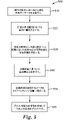
一態様では、本開示は3次元物品を造形する方法を提供し、この方法は、a)高粘度の重合性成分、仮の溶媒、及び重合開始剤を含むプリント可能な組成物を提供することと、b)プリント可能な組成物を選択的に硬化させて3次元物体の形状を表す物品を形成することと、c)物品から相当量の仮の溶媒を除去することと、及びd)任意に、ステップc)の前又は後に残存する未重合の重合性成分を硬化させることとを含む。 In one aspect, the present disclosure provides a method of building a three-dimensional article comprising: a) providing a printable composition comprising a high viscosity polymerizable component, a temporary solvent, and a polymerization initiator; b) selectively curing the printable composition to form an article representing the shape of the three-dimensional object; c) removing a substantial amount of the temporary solvent from the article; and d) optionally and curing any remaining unpolymerized polymerizable components before or after step c).
別の態様では、本開示は付加製造に有用なプリント可能な組成物を提供し、この組成物は、組成物の総重量に基づいて、(a)25℃で少なくとも20,000cPの粘度を有する45~95重量%の重合性成分と、(b)5~50重量%の仮の溶媒と、(c)0.1~5重量%の光重合開始剤と、(d)0.001~1重量%の重合禁止剤と、及び任意で(e)0.01~1重量%の吸収調整剤とを含む。 In another aspect, the present disclosure provides a printable composition useful for additive manufacturing, the composition having (a) a viscosity of at least 20,000 cP at 25° C., based on the total weight of the composition; 45-95% by weight of a polymerizable component, (b) 5-50% by weight of a temporary solvent, (c) 0.1-5% by weight of a photoinitiator, and (d) 0.001-1 and optionally (e) 0.01-1% by weight of an absorption modifier.
別の態様では、本開示は、液槽と、液槽内のプリント可能な組成物とを含む光造形装置を提供し、プリント可能な組成物は、組成物の総重量に基づいて、
(a)25℃で少なくとも20,000cPの粘度を有する45~95重量%の重合性成分と、(b)5~50重量%の仮の溶媒と、(c)0.1~5重量%の光重合開始剤と、(d)0.001~1重量%の重合禁止剤と、及び任意で(e)0.01~1重量%の吸収調整剤とを含む。
In another aspect, the present disclosure provides a stereolithography device including a reservoir and a printable composition within the reservoir, wherein the printable composition, based on the total weight of the composition, comprises:
(a) 45-95% by weight of a polymerizable component having a viscosity of at least 20,000 cP at 25° C.; (b) 5-50% by weight of a temporary solvent; and (c) 0.1-5% by weight of (d) 0.001-1% by weight polymerization inhibitor; and optionally (e) 0.01-1% by weight absorption control agent.
本明細書で使用されるとき、「硬質化可能」という用語は、例えば、加熱して溶媒を除去することや、加熱して重合、化学的架橋、放射線誘起重合若しくは架橋を生じさせることなどにより、硬化又は凝固され得る材料を指す。 As used herein, the term "hardenable" means, for example, by heating to remove solvent, heating to cause polymerization, chemical cross-linking, radiation-induced polymerization or cross-linking, and the like. , refers to a material that can be hardened or solidified.
本明細書で使用されるとき、「硬化」とは、例えば、熱、光、放射線、電子ビーム、マイクロ波、化学反応、又はこれらの組み合わせなどの何らかの機構による組成物の硬質化又は部分的硬質化を意味する。 As used herein, "curing" means hardening or partially hardening the composition by some mechanism such as, for example, heat, light, radiation, electron beam, microwave, chemical reaction, or combinations thereof. means change.
本明細書で使用されるとき、「硬化した」は、硬化によって硬質化又は部分的硬質化されている(例えば、重合又は架橋)材料又は組成物を指す。 As used herein, "cured" refers to a material or composition that has been hardened or partially hardened (eg, polymerized or crosslinked) by curing.
本明細書で使用されるとき、「(メタ)アクリレート」という用語は、アクリレート、メタクリレート、又はこれらの組み合わせの略記であり、「(メタ)アクリル」は、アクリル、メタクリル、又はこれらの組み合わせの略記である。本明細書で使用されるとき、「(メタ)アクリレート官能性化合物」は、とりわけ(メタ)アクリレート部分を含む化合物である。 As used herein, the term "(meth)acrylate" is an abbreviation for acrylate, methacrylate, or combinations thereof, and "(meth)acrylic" is an abbreviation for acrylic, methacrylic, or combinations thereof. is. As used herein, a "(meth)acrylate-functional compound" is, inter alia, a compound that contains a (meth)acrylate moiety.
本明細書で使用されるとき、「プリント可能」とは、硬質化可能な組成物が、重合(すなわち、硬質化)の前に、例えば光造型法(SLA)液槽重合工程及びインクジェット3Dプリンティングなどに向けたものを含む、1つ以上の3Dプリンティングシステムの要件及びパラメータにふさわしい粘度プロファイルを有することを意味する。 As used herein, "printable" means that the hardenable composition can be used prior to polymerization (i.e., hardening), such as in stereolithography (SLA) bath polymerization processes and inkjet 3D printing. It means having a viscosity profile that is suitable for the requirements and parameters of one or more 3D printing systems, including those intended for the like.
本明細書で使用されるとき、「プリント」及び「プリンティング」は、液槽重合(光造型法及びデジタル光処理など)及びインクジェット3Dプリンティングを含む、3Dプリンティングの文脈で意味をもち、液体の硬化性組成物から3次元物品を造形する工程である。 As used herein, "printing" and "printing" have meaning in the context of 3D printing, including liquid bath polymerization (such as stereolithography and digital light processing) and inkjet 3D printing, and liquid curing. It is a process of shaping a three-dimensional article from a physical composition.
本明細書で使用されるとき、「樹脂」は、硬化可能でプリント可能な組成物の中に存在する全ての重合性成分(モノマー、オリゴマー及び/又はポリマー)を含有する。樹脂は、ただ1つの重合性成分化合物を含有してもよいし、又は異なる重合性化合物の混合物を含有してもよい。 As used herein, "resin" includes all polymerizable components (monomers, oligomers and/or polymers) present in the curable, printable composition. The resin may contain only one polymerizable component compound or may contain a mixture of different polymerizable compounds.
本明細書で使用する場合、「近心側」は、患者の湾曲した歯列弓の中心に向かう方向を意味し、「遠心側」は、患者の湾曲した歯列弓の中心から離れる方向を意味し、「咬合側」は、患者の歯の外側先端部に向かう方向を意味し、「歯肉側」は、患者の歯茎又は歯肉に向かう方向を意味し、「顔面側」は、患者の唇又は頬に向かう方向を意味し、「舌側」は、患者の舌に向かう方向を意味する。 As used herein, "mesial" means a direction toward the center of a patient's curved dental arch, and "distal" means a direction away from the patient's curved dental arch. "occlusal" means the direction toward the outer tips of the patient's teeth; "gingival" means the direction toward the patient's gums or gums; and "facial" means the direction toward the patient's lips. or buccal, and "lingual" means toward the patient's tongue.
「好ましい」及び「好ましくは」という言葉は、一定の状況下で一定の利益を提供できる、本開示の実施形態を指す。しかし、他の実施形態もまた、同じ又は他の状況において好ましい場合がある。更には、1つ以上の好ましい実施形態の記載は、他の実施形態が有用ではないことを示唆するものではなく、本開示の範囲から他の実施形態を排除することを意図するものではない。 The words "preferred" and "preferably" refer to embodiments of the disclosure that may provide certain benefits under certain circumstances. However, other embodiments may also be preferred in the same or other circumstances. Furthermore, a description of one or more preferred embodiments is not intended to suggest that other embodiments are not useful, nor is it intended to exclude other embodiments from the scope of the present disclosure.
本出願では、「a」、「an」、及び「the」等の用語は、単数の実体のみを指すことを意図するものではなく、例示のために具体例の使用が可能な、一般分類を含む。用語「a」、「an」、及び「the」は、用語「少なくとも1つの」と互換的に使用される。列挙が後続する「~のうちの少なくとも1つ(at least one of)」及び「~のうちの少なくとも1つを含む(comprises at least one of)」という語句は、列挙内の項目のうちのいずれか1つ、及び、列挙内の2つ以上の項目のいずれかの組み合わせを指す。 In this application, terms such as "a," "an," and "the" are not intended to refer to singular entities only, but rather to define a general classification in which specific examples may be used for purposes of illustration. include. The terms "a," "an," and "the" are used interchangeably with the term "at least one." The phrases "at least one of" and "comprises at least one of" followed by an enumeration refer to any of the items in the enumeration. or one, and any combination of two or more items in the enumeration.
本明細書で使用する場合、用語「又は」は、内容がそうでない旨を特に明示しない限り、概して「及び/又は」を含む通常の意味で使用される。 As used herein, the term "or" is used in its ordinary sense, generally including "and/or," unless the content clearly dictates otherwise.
用語「及び/又は」は、列挙された要素のうちの1つ若しくは全て、又は列挙された要素のうちの任意の2つ以上の組み合わせを意味する。 The term "and/or" means one or all of the listed elements or any combination of two or more of the listed elements.
また、本明細書においては、全ての数は「約」という用語で修飾されるものと想定され、好ましくは「厳密に」という用語で修飾されると想定される。本明細書で、測定量に関して使用する場合、用語「約」は、当業者が測定を行い、測定の目的にふさわしい程度の注意を払ったこと、及び使用された測定機器の精度によって予想されるであろう、測定量のばらつきを指す。 Also, in this specification all numbers are assumed to be modified by the term "about" and preferably by the term "exactly". As used herein with respect to a measurand, the term "about" is to be expected by those of ordinary skill in the art in making the measurements and due diligence appropriate to the purpose of the measurements and the accuracy of the measuring equipment used. It refers to the variability of the measured quantity.
また、本明細書では、端点による数値範囲の記載は、その範囲内に包含される全ての数及びその端点を含む(例えば、1~5は、1、1.5、2、2.75、3、3.80、4、5などを含む)。 Also, herein, the recitation of numerical ranges by endpoints includes all numbers subsumed within that range and their endpoints (eg, 1 to 5, 1, 1.5, 2, 2.75, 3, 3.80, 4, 5, etc.).
特性又は属性に対する修飾語として本明細書で使用する場合、用語「概して」とは、特に定めのない限り、その特性又は属性が、当業者によって容易に認識されるものであるが、絶対的な精度又は完全な一致を必要とするものではないこと(例えば、定量化可能な特性に関しては、+/-20%の範囲内)を意味する。用語「実質的に」とは、特に定めのない限り、高い近似度(例えば、定量化可能な特性に関しては、+/-10%の範囲内)を意味するが、この場合もまた、絶対的な精度又は完全な一致を必要とするものではない。同一、等しい、均一な、一定の、厳密に、などの用語は、絶対的な精度又は完全な一致を必要とするものではなく、特定の状況に適用可能な、通常の許容誤差又は計測誤差の範囲内にあるものと理解される。 When used herein as a modifier to a property or attribute, the term "generally" means that the property or attribute is readily recognized by one of skill in the art, but not absolute Means not requiring precision or perfect agreement (eg, within +/-20% for quantifiable properties). The term "substantially" means a high degree of approximation (e.g., within +/−10% for quantifiable properties) unless otherwise specified, but again, absolute It does not require exact precision or perfect agreement. Terms such as identical, equal, uniform, constant, exact, etc., do not require absolute precision or perfect correspondence, but are within the ordinary tolerances or errors of measurement applicable to a particular situation. It is understood to be within range.
本開示の上記の概要は、開示される各々の実施形態、又は本開示の全ての実装形態を説明することを目的としたものではない。以下の説明は、例示的な実施形態をより具体的に例示する。本出願を通していくつかの箇所において、例を列挙することによって指針が示されるが、それらの例は様々な組み合わせで使用することができる。いずれの場合にも、記載された列挙は、代表的な群としての役割のみを果たすものであり、排他的な列挙として解釈されるべきではない。 The above summary of the present disclosure is not intended to describe each disclosed embodiment or every implementation of the present disclosure. The description that follows more particularly exemplifies illustrative embodiments. In several places throughout the application, guidance is provided through lists of examples, which examples can be used in various combinations. In any event, the set forth list serves only as a representative group and is not to be construed as an exclusive list.
上記で特定された図は、本開示のいくつかの実施形態を記載するものであるが、本明細書で言及されるとおり、他の実施形態もまた企図される。全ての場合において、本開示は、限定ではなく、代表例の提示によって、本発明を提示する。当業者によって多数の他の改変及び実施形態が考案され得、それらは、本発明の原理の範囲内及び趣旨内に含まれることを理解されたい。 While the figures identified above set forth certain embodiments of the present disclosure, other embodiments are also contemplated, as noted herein. In all cases, this disclosure presents the invention by way of representation and not limitation. It is to be understood that numerous other modifications and embodiments can be devised by those skilled in the art and are included within the scope and spirit of the principles of the invention.
本開示のプリント可能な組成物は、3Dプリンティング技術で一般的に使用される、より低濃度の主要な重合性成分において通常見られる、高粘度の重合性成分を含む。高粘度樹脂と混合する除去可能な仮の溶媒のレベルを上げることによって、樹脂のプリント適性を犠牲にすることなく、硬化後の本体においてこの高粘度の重合性成分の材料特性を維持することができる。 The printable compositions of the present disclosure comprise high viscosity polymerizable components typically found in lower concentrations of the primary polymerizable components commonly used in 3D printing technology. By increasing the level of temporary removable solvent that mixes with the high viscosity resin, it is possible to maintain the material properties of this high viscosity polymerizable component in the body after curing without sacrificing the printability of the resin. can.
本開示は、硬質化可能でプリント可能な組成物を提供し、この組成物は通常、組成物の総重量に基づいて、(a)45~95重量%の重合性成分と、(b)5~50重量%の仮の溶媒と、(c)0.1~5重量%の光重合開始剤と、(d)0.001~1重量%の重合禁止剤と、及び任意で(e)0.01~1重量%の吸収調整剤とを含む。 The present disclosure provides hardenable and printable compositions, which typically comprise (a) 45 to 95 weight percent polymerizable components, and (b) 5 ~50% by weight of a temporary solvent, (c) 0.1-5% by weight of a photoinitiator, (d) 0.001-1% by weight of an inhibitor, and optionally (e) 0 .01-1% by weight of absorption modifiers.
重合性成分
本開示のプリント可能な組成物は、少なくとも1つの重合性成分を含む。本明細書で参照する目的では、「重合性成分」は、プリントされた3D物品を提供するために硬化することのできる、硬質化可能成分を含む。例えば、いくつかの実施形態では、硬質化は、重合又は架橋結合反応を開始するために十分なエネルギーを有する電磁放射線を照射することを含む。例えば、いくつかの実施形態では、紫外線(UV)放射を使用することができる。
Polymerizable Component The printable composition of the present disclosure includes at least one polymerizable component. For purposes of reference herein, "polymerizable component" includes hardenable components that can be cured to provide a printed 3D article. For example, in some embodiments, hardening includes applying electromagnetic radiation having sufficient energy to initiate a polymerization or cross-linking reaction. For example, in some embodiments, ultraviolet (UV) radiation can be used.
好適な重合性成分は、少なくとも1個のエチレン性不飽和結合を含有し、付加重合を経ることができる。このようなフリーラジカル重合性材料は、メチルアクリレート、メチルメタクリレート、アクリル酸エチル、イソプロピルメタクリレート、n-アクリル酸ヘキシル、ステアリルアクリレート、アリルアクリレート、グリセロールジアクリレート、2-ヒドロキシエチルメタクリレート(HEMA)と2,2,4-トリメチルヘキサメチレンジイソシアネート(TMDI)との反応生成物であるUDMA(例えば、Rohm Plex 6661-0などの異性体の混合物)と呼ばれるジウレタンジメタクリレート、グリセロールトリアクリレート、エチレングリコールジアクリレート、ジエチレングリコールジアクリレート、トリエチレングリコールジメタクリレート、1,3-プロパンジオールジアクリレート、1,3-プロパンジオールジメタクリレート、トリメチロールプロパントリアクリレート、1,2,4-ブタントリオールトリメタクリレート、1,4-シクロヘキサンジオールジアクリレート、ペンタエリスリトールトリアクリレート、ペンタエリスリトールテトラアクリレート、ペンタエリスリトールテトラメタクリレート、ソルビトールヘキサクリレート、ビス[1-(2-アクリルオキシ)]-p-エトキシフェニルジメチルメタン、ビス[1-(3-アクリルオキシ-2-ヒドロキシ)]-p-プロポキシフェニルジメチルメタン、及びトリスヒドロキシエチル-イソシアヌレートトリメタクリレートなどのモノ、ジ、又はポリアクリレート及びメタクリレートと、分子量200~500のポリエチレングリコール、米国特許第4652274号(Boettcherら)に記載のものなどのアクリレート化モノマー共重合性混合物、及び、米国特許第4642126号(Zadorら)に記載のものなどのアクリレート化オリゴマーのビス-アクリレート及びビス-メタクリレートと、スチレン、ジアリルフタレート、ジビニルスクシネート、ジビニルアジパート、及びジビニルフタレートなどのビニル化合物と、欧州特許出願公開第2008636号(Hechtら)に記載のものなどの、ウレタン、尿素、又はアミド基を含む多官能性(メタ)アクリレートと、を含む。重合性成分は、シリコーンアクリレートオリゴマー、エポキシ(メタ)アクリレートオリゴマー、ポリエステル(メタ)アクリレートオリゴマー又は塩素化ポリエステル(メタ)アクリレート、アリル系オリゴマー及び(メタ)アクリルオリゴマーを更に含んでもよい。所望により、これらのフリーラジカル重合性材料の2つ以上の混合物を使用することができる。 Suitable polymerizable components contain at least one ethylenically unsaturated bond and are capable of undergoing addition polymerization. Such free radically polymerizable materials include methyl acrylate, methyl methacrylate, ethyl acrylate, isopropyl methacrylate, n-hexyl acrylate, stearyl acrylate, allyl acrylate, glycerol diacrylate, 2-hydroxyethyl methacrylate (HEMA) and 2, diurethane dimethacrylate called UDMA (mixture of isomers such as Rohm Plex 6661-0), which is a reaction product with 2,4-trimethylhexamethylene diisocyanate (TMDI), glycerol triacrylate, ethylene glycol diacrylate, Diethylene glycol diacrylate, triethylene glycol dimethacrylate, 1,3-propanediol diacrylate, 1,3-propanediol dimethacrylate, trimethylolpropane triacrylate, 1,2,4-butanetriol trimethacrylate, 1,4-cyclohexane Diol diacrylate, pentaerythritol triacrylate, pentaerythritol tetraacrylate, pentaerythritol tetramethacrylate, sorbitol hexaacrylate, bis[1-(2-acryloxy)]-p-ethoxyphenyldimethylmethane, bis[1-(3- Acryloxy-2-hydroxy)]-p-propoxyphenyldimethylmethane, and mono-, di-, or polyacrylates and methacrylates such as trishydroxyethyl-isocyanurate trimethacrylate with polyethylene glycol of molecular weight 200-500, US Pat. No. 4,652,274 (Boettcher et al.), and acrylated oligomeric bis-acrylates and bis-methacrylates, such as those described in US Pat. No. 4,642,126 (Zador et al.), and styrene. , vinyl compounds such as diallyl phthalate, divinyl succinate, divinyl adipate, and divinyl phthalate; and functional (meth)acrylates. The polymerizable component may further include silicone acrylate oligomers, epoxy (meth)acrylate oligomers, polyester (meth)acrylate oligomers or chlorinated polyester (meth)acrylates, allyl oligomers and (meth)acrylic oligomers. Mixtures of two or more of these free radically polymerizable materials can be used if desired.
重合性成分は、好ましくは1つ以上のポリ(メタ)アクリレートを含み、例えば、ジ、トリ、テトラ又はペンタ官能性のモノマー又はオリゴマーの脂肪族、脂環式又は芳香族のアクリレート又はメタクリレートなどである。現在好ましい実装形態では、重合性成分は高粘度ポリ(メタ)アクリレートを含む。プリント可能な組成物に使用するための好ましいポリ(メタ)アクリレートは、室温では流動性でなく、25℃で20,000cPより高い粘度を有する。本明細書で使用されるとき、「流動性である」とは、室温(例えば、20~25℃)において重合性成分が自重で変形又は流動することを意味する。本明細書に記載されるいくつかの実施形態では、ウレタン(メタ)アクリレート又は他のポリ(メタ)アクリレートは、下記の例で述べるように、ASTM D4287に従う様式で測定したときに、約25℃で約20,000cP~300,000cPの範囲の粘度を有する。 The polymerizable component preferably comprises one or more poly(meth)acrylates, such as di-, tri-, tetra- or penta-functional monomeric or oligomeric aliphatic, cycloaliphatic or aromatic acrylates or methacrylates. be. In currently preferred implementations, the polymerizable component comprises a high viscosity poly(meth)acrylate. Preferred poly(meth)acrylates for use in printable compositions are not flowable at room temperature and have viscosities greater than 20,000 cP at 25°C. As used herein, "flowable" means that the polymerizable components deform or flow under their own weight at room temperature (eg, 20-25°C). In some embodiments described herein, the urethane (meth)acrylate or other poly(meth)acrylate is about 25° C. has a viscosity in the range of about 20,000 cP to 300,000 cP.
例えば、重合性成分は、多官能性ウレタンアクリレート又はウレタンメタクリレートを含むことができる。これらのウレタン(メタ)アクリレートは当業者に知られており、例えば、ヒドロキシル基末端ポリウレタンとアクリル酸若しくはメタクリル酸を反応させるか、又は、イソシアネート末端プレポリマーとヒドロキシアルキル(メタ)アクリレートを反応させてウレタン(メタ)アクリレートを得ることによって調製することができる。好適な工程が、とりわけ、米国特許第8329776号(Hechtら)及び9295617号(Cubら)に開示されている。好適なウレタンメタクリレートは、PEGDMA(約400の分子量を有するポリエチレングリコールジメタクリレート)、脂肪族ウレタンメタクリレート、脂肪族ポリエステルウレタンメタクリレート、脂肪族ポリエステルトリウレタンアクリレートを含むことができる。 For example, the polymerizable component can include multifunctional urethane acrylates or urethane methacrylates. These urethane (meth)acrylates are known to those skilled in the art, for example by reacting hydroxyl-terminated polyurethanes with acrylic or methacrylic acid, or by reacting isocyanate-terminated prepolymers with hydroxyalkyl (meth)acrylates. It can be prepared by obtaining a urethane (meth)acrylate. Suitable processes are disclosed, inter alia, in US Pat. Nos. 8,329,776 (Hecht et al.) and 9,295,617 (Cub et al.). Suitable urethane methacrylates can include PEGDMA (polyethylene glycol dimethacrylate having a molecular weight of about 400), aliphatic urethane methacrylates, aliphatic polyester urethane methacrylates, aliphatic polyester triurethane acrylates.
分子内に2つ以上の(メタ)アクリレート基を有する好適な脂肪族ポリ(メタ)アクリレートの例は、ヘキサン-2,4,6-トリオールのトリアクリレート及びトリメタクリレート、グリセロール又は1,1,1-トリメチロールプロパン、エトキシル化又はプロポキシル化グリセロール又は1,1,1-トリメチロールプロパン、並びに、例えば上記トリオールのトリグリシジルエーテルなどのトリエポキシド化合物を(メタ)アクリレートと反応させて得られる、ヒドロキシル含有トリ(メタ)アクリレートなどである。更に、例えば、ペンタエリスリトールテトラアクリレート、ビストリメチロールプロパンテトラアクリレート、ペンタエリスリトールモノヒドロキシトリアクリレート若しくはメタクリレート、又はジペンタエリスリトールモノヒトロキシペンタアクリレート若しくはメタクリレートを使用することも可能である。 Examples of suitable aliphatic poly(meth)acrylates having two or more (meth)acrylate groups in the molecule are triacrylate and trimethacrylate of hexane-2,4,6-triol, glycerol or 1,1,1 - hydroxyls obtained by reacting trimethylolpropane, ethoxylated or propoxylated glycerol or 1,1,1-trimethylolpropane and triepoxide compounds such as triglycidyl ethers of the above triols with (meth)acrylates. containing tri(meth)acrylate and the like. Furthermore, it is also possible to use, for example, pentaerythritol tetraacrylate, bistrimethylolpropane tetraacrylate, pentaerythritol monohydroxytriacrylate or methacrylate, or dipentaerythritol monohydroxypentaacrylate or methacrylate.
フリーラジカル重合性化合物の別の好適なクラスには、芳香族ジ(メタ)アクリレート化合物及び3官能以上の(メタ)アクリレート化合物が含まれる。3官能以上のメタ(アクリレート)は、トリ、テトラ又はペンタ官能性のモノマー又はオリゴマーの脂肪族、脂環式又は芳香族のアクリレート又はメタクリレートであることができる。 Another suitable class of free radically polymerizable compounds includes aromatic di(meth)acrylate compounds and tri- or higher functional (meth)acrylate compounds. Tri- or higher functional meth(acrylates) can be tri-, tetra- or penta-functional monomeric or oligomeric aliphatic, cycloaliphatic or aromatic acrylates or methacrylates.
分子内に2つ以上の(メタ)アクリレート基を有する好適な脂肪族トリ、テトラ、及びペンタアクリレートの例は、ヘキサン-2,4,6-トリオールのトリアクリレート及びトリメタクリレート、グリセロール又は1,1,1-トリメチロールプロパン、エトキシル化又はプロポキシル化グリセロール又は1,1,1-トリメチロールプロパン、並びに、例えば上記トリオールのトリグリシジルエーテルなどのトリエポキシド化合物を(メタ)アクリル酸と反応させて得られる、ヒドロキシル含有トリ(メタ)アクリレートなどである。更に、例えば、ペンタエリスリトールテトラアクリレート、ビストリメチロールプロパンテトラアクリレート、ペンタエリスリトールモノヒドロキシトリアクリレート若しくはメタクリレート、又はジペンタエリスリトールモノヒトロキシペンタアクリレート若しくはメタクリレートを使用することも可能である。いくつかの実施形態では、トリ(メタ)アクリレートは、1,1-トリメチロールプロパントリアクリレート若しくはメタクリレート、エトキシル化若しくはプロポキシル化1,1,1-トリメチロールプロパントリアクリレート若しくはメタクリレート、エトキシル化若しくはプロポキシル化グリセロールトリアクリレート、ペンタエチルトリオールモノヒドロキシトリアクリレート若しくはメタクリレート、又は、トリス(2-ヒドロキシエチル)イソシアヌレートトリアクリレートを含む。 Examples of suitable aliphatic tri-, tetra- and pentaacrylates with two or more (meth)acrylate groups in the molecule are triacrylate and trimethacrylate of hexane-2,4,6-triol, glycerol or 1,1 ,1-trimethylolpropane, ethoxylated or propoxylated glycerol or 1,1,1-trimethylolpropane, and triepoxide compounds such as the triglycidyl ethers of the above triols, for example, by reacting them with (meth)acrylic acid. and hydroxyl-containing tri(meth)acrylates. Furthermore, it is also possible to use, for example, pentaerythritol tetraacrylate, bistrimethylolpropane tetraacrylate, pentaerythritol monohydroxytriacrylate or methacrylate, or dipentaerythritol monohydroxypentaacrylate or methacrylate. In some embodiments, the tri(meth)acrylate is 1,1-trimethylolpropane triacrylate or methacrylate, ethoxylated or propoxylated 1,1,1-trimethylolpropane triacrylate or methacrylate, ethoxylated or propoxylated glycerol triacrylate, pentaethyltriol monohydroxy triacrylate or methacrylate, or tris(2-hydroxyethyl) isocyanurate triacrylate.
好適な芳香族トリ(メタ)アクリレートの更なる例は、3つの水酸基を含むトリヒドロキシベンゼンとフェノール又はクレゾールノボラックのトリグリシジルエーテルと、(メタ)アクリル酸との反応生成物である。 Further examples of suitable aromatic tri(meth)acrylates are the reaction products of trihydroxybenzenes containing three hydroxyl groups and triglycidyl ethers of phenol or cresol novolacs and (meth)acrylic acid.
いくつかの事例では、重合性成分は、脂肪族、脂環式又は芳香族ジオールのジアクリレート及び/又はジメタクリレートを含み、これには、1,3-若しくは1,4-ブタンジオール、ネオペンチルグリコール、1,6-ヘキサンジオール、ジエチレングリコール、トリエチレングリコール、テトラエチレングリコール、ポリエチレングリコール、トリプロピレングリコール、エトキシル化若しくはプロポキシル化ネオペンチルグリコール、1,4-ジヒドロキシメチルシクロヘキサン、2,2-ビス(4-ヒドロキシシクロヘキシル)プロパン若しくはビス(4-ヒドロキシシクロヘキシル)メタン、ヒドロキノン、4,4’-ジヒドロキシビフェニル、ビスフェノールA、ビスフェノールF、ビスフェノールS、エトキシル化若しくはプロポキシル化ビスフェノールA、エトキシル化若しくはプロポキシル化ビスフェノールF、又は、エトキシル化若しくはプロポキシル化ビスフェノールSを含む。 In some cases, the polymerizable component includes diacrylates and/or dimethacrylates of aliphatic, cycloaliphatic, or aromatic diols, including 1,3- or 1,4-butanediol, neopentyl glycol, 1,6-hexanediol, diethylene glycol, triethylene glycol, tetraethylene glycol, polyethylene glycol, tripropylene glycol, ethoxylated or propoxylated neopentyl glycol, 1,4-dihydroxymethylcyclohexane, 2,2-bis( 4-hydroxycyclohexyl)propane or bis(4-hydroxycyclohexyl)methane, hydroquinone, 4,4′-dihydroxybiphenyl, bisphenol A, bisphenol F, bisphenol S, ethoxylated or propoxylated bisphenol A, ethoxylated or propoxylated Bisphenol F or Bisphenol S ethoxylated or propoxylated.
いくつかの事例では、本明細書に記載のプリント可能な重合性成分は、ジペンタエリスリトールモノヒドロキシペンタアクリレート又はビス(トリメチロールプロパン)テトラアクリレートなどの1つ以上の高官能性のアクリレート又はメタクリレートを含む。 In some cases, the printable polymerizable components described herein contain one or more higher functional acrylates or methacrylates such as dipentaerythritol monohydroxypentaacrylate or bis(trimethylolpropane)tetraacrylate. include.
特に好適な、高官能性の(メタ)アクリレート化合物の1つはExothane 108であり、これはEsschem Europe LTD(Seaham,UK)から入手可能な二官能ウレタンアクリレートで、38,000のcP粘度を有する。別の好適な高官能性の(メタ)アクリレート化合物はExothane 10で、粘度は70,000cPである。更に別の好適な高官能性アクリレート化合物はCN9005であり、これはSartomer Arkema(Exton,Pa)から入手可能な脂肪族ウレタンオリゴマーで、60℃で9,100cP、25℃で232,000cPの粘度を有する。更に別の好適な高官能性アクリレート化合物はCN9009であり、これはSartomer Arkema(Exton,Pa)から入手可能な脂肪族ウレタンオリゴマーで、60℃で3,000cPの粘度を有する。 One particularly suitable high functionality (meth)acrylate compound is Exothane 108, a difunctional urethane acrylate available from Esschem Europe LTD, Seaham, UK, having a cP viscosity of 38,000. . Another suitable high functionality (meth)acrylate compound is Exothane 10, which has a viscosity of 70,000 cP. Yet another suitable high-functional acrylate compound is CN9005, an aliphatic urethane oligomer available from Sartomer Arkema (Exton, Pa.) with a viscosity of 9,100 cP at 60°C and 232,000 cP at 25°C. have. Yet another suitable high-functional acrylate compound is CN9009, an aliphatic urethane oligomer available from Sartomer Arkema (Exton, Pa.) having a viscosity of 3,000 cP at 60°C.
ポリ(メタ)アクリレート重合性成分は通常、プリント可能な組成物の中に、プリント可能な組成物の総重量に基づき約45重量%以上、約50重量%以上、約60重量%以上、又は約70重量%以上の量で存在する。 The poly(meth)acrylate polymerizable component is typically present in the printable composition in an amount of about 45% or more, about 50% or more, about 60% or more, or about It is present in an amount of 70% or more by weight.
ポリ(メタ)アクリレート重合性成分の量は通常、組成物の総重量に基づき約95重量%まで、又は約90重量%まで、又は約85重量%までである。 The amount of poly(meth)acrylate polymerizable component is typically up to about 95 weight percent, or up to about 90 weight percent, or up to about 85 weight percent based on the total weight of the composition.
通常、重合性成分は、プリント可能な材料の組成物全体の重量の約45%~約95%、より好ましくは約60%~約95%を構成する。 Generally, the polymerizable component constitutes from about 45% to about 95%, more preferably from about 60% to about 95%, by weight of the total composition of the printable material.
仮の溶媒
重合性成分の粘度は、非反応性の溶媒の中で成分を希釈することにより大幅に低下させることができる。本明細書で使用されるとき、「非反応性の溶媒」は、プリント可能な樹脂に重合しない溶媒である(例えば、ポリ(メタ)アクリレート、重合開始剤、及び、任意で充填剤などの他の添加剤)。溶媒は非反応性なので、例えば高粘度の重合性成分樹脂の材料特性に有害な影響を及ぼすことなく、下記に説明する方法に従って、プリントされた物品から抜き取ることができる。したがって、本開示で有用な溶媒を、本明細書では仮の溶媒と称する。
Temporary Solvents The viscosity of the polymerizable component can be significantly reduced by diluting the component in a non-reactive solvent. As used herein, a "non-reactive solvent" is a solvent that does not polymerize into the printable resin (e.g., poly(meth)acrylates, polymerization initiators, and optionally other solvents such as fillers). additives). Because the solvent is non-reactive, it can be stripped from the printed article according to the methods described below without detrimentally affecting the material properties of, for example, high viscosity polymerizable component resins. Solvents useful in the present disclosure are therefore referred to herein as phantom solvents.
仮の溶媒は、通常、沸点が50℃以上の有機溶媒である。多くの場合、沸点は、100℃以上、200℃以上、かつ、通常は300℃以下である。好適な仮の溶媒は、通常、常温(20~25℃)で不揮発性で、20℃で約150.0hPaより低く(好ましくは、20℃で約15.0hPaより低い)、より好ましくは20℃で約1.5hPaより低く、最も好ましくは20℃で約0.15hPaより低い蒸気圧を有する。上記の特性を示す仮の溶媒は通常、プリント工程中はプリント可能な組成物の中に高温下でも保持可能でありながら、プリントされた物品からは真空蒸発などの従来技術を使用して除去することができる。 The temporary solvent is usually an organic solvent with a boiling point of 50°C or higher. In many cases, the boiling point is 100°C or higher, 200°C or higher, and usually 300°C or lower. Suitable temporary solvents are generally non-volatile at ambient temperature (20-25°C) and below about 150.0 hPa at 20°C (preferably below about 15.0 hPa at 20°C), more preferably at 20°C. and most preferably less than about 0.15 hPa at 20°C. Temporary solvents exhibiting the above properties are generally capable of being retained in the printable composition at elevated temperatures during the printing process, yet are removed from the printed article using conventional techniques such as vacuum evaporation. be able to.
現在好ましい実装形態では、仮の溶媒は、炭酸プロピレン、メタノール、イソプロピルアルコール、及びトリプロピレングリコールメチルエーテル(TPM)のうちの1つ以上、及びそれらの混合物を含むことができる。現在好ましい状況においては、溶媒は炭酸プロピレンである。 In currently preferred implementations, the temporary solvent can include one or more of propylene carbonate, methanol, isopropyl alcohol, and tripropylene glycol methyl ether (TPM), and mixtures thereof. In the presently preferred situation the solvent is propylene carbonate.
仮の溶媒は通常、プリント可能な組成物の中に、プリント可能な組成物の総重量に基づいて、約5重量%以上、約10重量%以上、又は約20重量%以上の量で存在する。 The temporary solvent is typically present in the printable composition in an amount of about 5% or more, about 10% or more, or about 20% or more by weight, based on the total weight of the printable composition. .
仮の溶媒の量は通常、プリント可能な組成物の総重量に基づいて、約30重量%まで、約30重量%まで、40重量%まで、又は約50重量%までである。 The amount of temporary solvent is typically up to about 30%, up to about 30%, up to 40%, or up to about 50% by weight, based on the total weight of the printable composition.
通常、仮の溶媒は、プリント可能な組成物全体の重量に基づき、重量の約10%~約40%、より好ましくは約15%~約30%を構成する。一定の条件下では、仮の溶媒を5~10重量%未満を有するプリント可能な組成物は3Dプリンティングに適した粘度を有さないことがあり、その場合は、重合性成分の粘度が適切に低減されていない。逆に、仮の溶媒を40~50重量%を超えて含むプリント可能な組成物では、一定の条件下で、素地の生強度が不十分になる可能性があり、プリントされた物品から仮の溶媒を適切に除去することが困難になることがある。 Generally, the temporary solvent constitutes from about 10% to about 40%, more preferably from about 15% to about 30% by weight, based on the weight of the total printable composition. Under certain conditions, a printable composition having less than 5-10 wt% temporary solvent may not have a viscosity suitable for 3D printing, in which case the viscosity of the polymerizable component may not reduced. Conversely, printable compositions containing more than 40-50 wt. Adequate solvent removal can be difficult.
添加剤
本明細書に記載のプリント可能な組成物は、いくつかの例では1つ以上の添加剤を更に含み、それらは、光開始剤、禁止剤、安定剤、増感剤、吸収調整剤、充填剤及びそれらの組み合わせからなるグループから選択される1つ以上の添加剤などである。例えば、いくつかの実施形態では、プリント可能な組成物は、1つ以上の光開始剤を更に含む。好適な例示的光開始剤は商品名IRGACURE及びDAROCURでBASF(Ludwigshafen,Germany)から入手可能なもので、1-ヒドロキシシクロヘキシルフェニルケトン(IRGACURE184)、2,2-ジメトキシ-1,2-ジフェニルエタン-1-オン(IRGACURE651)、ビス(2,4,6-トリメチルベンゾイル)フェニルホスフィンオキシド(IRGACURE819)、1-[4-(2-ヒドロキシエトキシ)フェニル]-2-ヒドロキシ-2-メチル-1-プロパン-1-オン(IRGACURE2959)、2-ベンジル-2-ジメチルアミノ-1-(4-モルホリノフェニル)ブタノン(IRGACURE369)、2-メチル-1-[4-(メチルチオ)フェニル]-2-モルホリノプロパン-1-オン(IRGACURE907)、オリゴ[2-ヒドロキシ-2-メチル-1-[4-(1-メチルビニル)フェニル]プロパン]ESACURE ONE(Lamberti S.p.A.,Gallarate,Italy)、2-ヒドロキシ-2-メチル-1-フェニルプロパン-1-オン(DAROCUR1173)、2,4,6-トリメチルベンゾイルジフェニルフォスフィンオキシド(IRGACURE TPO)、及び2,4,6-トリメチルベンゾイルフェニルホスフィネート(IRGACURE TPO-L)を含む。更なる好適な光開始剤には、例えば、ベンジルジメチルケタール、2-メチル-2-ヒドロキシプロピオフェノン、ベンゾインメチルエーテル、ベンゾインイソプロピルエーテル、アニソインメチルエーテル、芳香族塩化スルホニル、光活性オキシム、及びこれらの組み合わせが挙げられるが、これらに限定されない。
Additives The printable compositions described herein in some examples further comprise one or more additives, which are photoinitiators, inhibitors, stabilizers, sensitizers, absorption modifiers. , one or more additives selected from the group consisting of fillers and combinations thereof. For example, in some embodiments the printable composition further comprises one or more photoinitiators. Suitable exemplary photoinitiators are those available from BASF (Ludwigshafen, Germany) under the tradenames IRGACURE and DAROCUR, 1-hydroxycyclohexylphenyl ketone (IRGACURE 184), 2,2-dimethoxy-1,2-diphenylethane- 1-one (IRGACURE651), bis(2,4,6-trimethylbenzoyl)phenylphosphine oxide (IRGACURE819), 1-[4-(2-hydroxyethoxy)phenyl]-2-hydroxy-2-methyl-1-propane -1-one (IRGACURE2959), 2-benzyl-2-dimethylamino-1-(4-morpholinophenyl)butanone (IRGACURE369), 2-methyl-1-[4-(methylthio)phenyl]-2-morpholinopropane- 1-one (IRGACURE907), oligo[2-hydroxy-2-methyl-1-[4-(1-methylvinyl)phenyl]propane]ESACURE ONE (Lamberti S.p.A., Gallarate, Italy), 2- Hydroxy-2-methyl-1-phenylpropan-1-one (DAROCUR1173), 2,4,6-trimethylbenzoyldiphenylphosphine oxide (IRGACURE TPO), and 2,4,6-trimethylbenzoylphenylphosphinate (IRGACURE TPO) -L). Further suitable photoinitiators include, for example, benzyl dimethyl ketal, 2-methyl-2-hydroxypropiophenone, benzoin methyl ether, benzoin isopropyl ether, anisoin methyl ether, aromatic sulfonyl chlorides, photoactive oximes, and Combinations of these include, but are not limited to.
光開始剤は、本明細書に記載のプリント可能な組成物の中に、3Dプリンタの特定の制約に従うどのような量でも存在することができる。いくつかの実施形態では、光開始剤は、プリント可能な組成物の総重量に基づき、約5重量%までの量でプリント可能な組成物の中に存在する。いくつかの事例では、光開始剤は、プリント可能な組成物の総重量に基づき、約0.1~5重量%の量で存在する。 The photoinitiator can be present in the printable compositions described herein in any amount subject to the specific constraints of the 3D printer. In some embodiments, the photoinitiator is present in the printable composition in an amount up to about 5% by weight, based on the total weight of the printable composition. In some cases, the photoinitiator is present in an amount of about 0.1-5% by weight, based on the total weight of the printable composition.
本開示の別の実施形態では、重合開始剤の系は、プリントされた素地の硬化を補助するために任意で熱開始剤を含んでもよい。好適な熱開始剤には、有機過酸化物(例えば、過酸化ベンゾイル)、アゾ化合物、キノン、ニトロソ化合物、ハロゲン化アシル、ヒドラゾン、メルカプト化合物、ピリリウム化合物、イミダゾール、クロロトリアジン、ベンゾイン、ベンゾインアルキルエーテル、ジケトン、フェノン、及びこれらの混合物が含まれる。好適な熱開始剤の例は、アゾ化合物熱開始剤のVazo 52、Vazo 64、及びVazo 67で、これらは全てDuPontから入手可能である。特に適切な熱開始剤には、過酸化ベンゾイル、ジクミルペルオキシド、及び、アゾビスイソブチロニトリル(AIBN)が含まれる。熱開始剤を使用する場合は、組成物の総重量に基づき、約0.01~2.5重量%の量で存在する。特定の実装形態では、光開始剤は、高温下で熱開始剤として働くこともできる。 In another embodiment of the present disclosure, the initiator system may optionally include a thermal initiator to aid in curing the printed substrate. Suitable thermal initiators include organic peroxides (e.g., benzoyl peroxide), azo compounds, quinones, nitroso compounds, acyl halides, hydrazones, mercapto compounds, pyrylium compounds, imidazoles, chlorotriazines, benzoin, benzoin alkyl ethers. , diketones, phenones, and mixtures thereof. Examples of suitable thermal initiators are the azo compound thermal initiators Vazo 52, Vazo 64, and Vazo 67, all of which are available from DuPont. Particularly suitable thermal initiators include benzoyl peroxide, dicumyl peroxide and azobisisobutyronitrile (AIBN). When used, a thermal initiator is present in an amount of about 0.01-2.5% by weight, based on the total weight of the composition. In certain implementations, photoinitiators can also act as thermal initiators at elevated temperatures.
加えて、本明細書に記載のプリント可能材料の組成物は、1つ以上の増感剤を更に含んで、これもまた存在してもよい1つ以上の光開始剤の有効性を増加させることもできる。いくつかの実施形態では、増感剤は、イソプロピルチオキサントン(ITX)又は2-クロロチオキサントン(CTX)を含む。他の増感剤もまた使用されてもよい。プリント可能な組成物の中で使用する場合、増感剤は、プリント可能な組成物の総重量に基づいて、約0.01重量%又は約1重量%の範囲の量で存在することができる。 In addition, the compositions of printable materials described herein further comprise one or more sensitizers to increase the effectiveness of one or more photoinitiators that may also be present. can also In some embodiments, the sensitizer comprises isopropylthioxanthone (ITX) or 2-chlorothioxanthone (CTX). Other sensitizers may also be used. When used in the printable composition, the sensitizer can be present in an amount ranging from about 0.01 weight percent or about 1 weight percent, based on the total weight of the printable composition. .
本明細書に記載のプリント可能な組成物はまた、1つ以上の重合禁止剤又は安定剤を含むことができる。重合禁止剤は、組成物に更なる熱安定性を加えるために組成物に添加することができる。いくつかの例では、安定剤は1つ以上の抗酸化剤を含む。本開示の目的に反さない酸化防止剤は、いずれも使用してよい。例えば、いくつかの実施形態では、好適な抗酸化剤は様々なアリール化合物を含み、これにはブチル化ヒドロキシトルエン(BHT)が含まれ、これは、本明細書に記載の実施形態で重合禁止剤としてもまた使用することができる。加えて、又は代替として、重合禁止剤は、メトキシヒドロキノン(MEHQ)を含む。 The printable compositions described herein can also contain one or more polymerization inhibitors or stabilizers. Polymerization inhibitors can be added to the composition to add additional thermal stability to the composition. In some examples, stabilizers include one or more antioxidants. Any antioxidant not inconsistent with the objectives of this disclosure may be used. For example, in some embodiments, suitable antioxidants include various aryl compounds, including butylated hydroxytoluene (BHT), which is polymerized in the embodiments described herein. It can also be used as an agent. Additionally or alternatively, the polymerization inhibitor includes methoxyhydroquinone (MEHQ).
いくつかの実施形態では、重合禁止剤を使用する場合は、プリント可能な組成物の総重量に基づいて、約0.001~2重量%又は約0.01~1重量%の量で存在する。更に、安定剤を使用する場合は、本明細書に記載のプリント可能な組成物の中に、プリント可能な組成物の総重量に基づいて、約0.1~5重量%、約0.5~4重量%、又は約1~3重量%の量で存在する。 In some embodiments, a polymerization inhibitor, if used, is present in an amount of about 0.001 to 2 weight percent, or about 0.01 to 1 weight percent, based on the total weight of the printable composition. . Additionally, if a stabilizer is used, about 0.1 to 5% by weight, about 0.5% by weight, based on the total weight of the printable composition, in the printable compositions described herein. It is present in an amount of ~4 wt%, or about 1-3 wt%.
本明細書に記載のプリント可能な組成物はまた、化学線の貫入深さを制御するために、1つ以上の吸収調整剤(例えば、染料、光学的光沢剤、顔料、微粒子充填剤など)を含むことができる。特に好適な吸収調整剤の1つはTinopal OBで、BASF Corporation(Florham Park,NJ)から入手可能なベンゾオキサゾール、2,2’-(2、5-チオフェンジイル)ビス[5-(1,1-ジメチルエチル)]である。吸収調整剤を使用する場合は、プリント可能な組成物の総重量に基づいて、約0.01~5重量%、約0.1~3重量%又は約0.1~1重量%の量で存在する。 The printable compositions described herein also contain one or more absorption modifiers (e.g., dyes, optical brighteners, pigments, particulate fillers, etc.) to control the depth of penetration of actinic radiation. can include One particularly suitable absorption modifier is Tinopal OB, a benzoxazole, 2,2′-(2,5-thiophenediyl)bis[5-(1,1) available from BASF Corporation, Florham Park, NJ. -dimethylethyl)]. Absorption modifiers, if used, in amounts of about 0.01 to 5 weight percent, about 0.1 to 3 weight percent, or about 0.1 to 1 weight percent, based on the total weight of the printable composition. exist.
プリント可能な組成物は充填剤を含んでもよく、これにはナノスケールの充填剤を含む。適切な充填剤の例は自然発生又は合成の材料で、石英(すなわち、シリカ、SiO2)と、窒化物(例えば、窒化ケイ素)と、例えばZr、Sr、Ce、Sb、Sn、Ba、Zn、及びAlから得られたガラス及び充填剤と、長石と、ホウケイ酸塩ガラスと、カオリン(陶土)と、タルクと、ジルコニアと、チタニアと、サブミクロンシリカ粒子(例えば商標名AEROSILで入手可能なものなどの発熱性シリカで、Degussa Corp.(Akron,OH)の「OX50」、「130」、「150」及び「200」シリカと、Cabot Corp.(Tuscola,IL)のCAB-O-SIL M5及びTS-720シリカを含む)とを含むが、これらに限定されない。国際公開第WO09/045752号(Kalgutkarら)に開示されるものなどの、ポリマー材料から製造される有機充填剤もまた可能である。 The printable composition may contain fillers, including nanoscale fillers. Examples of suitable fillers are naturally occurring or synthetic materials such as quartz (i.e. silica, SiO2 ), nitrides (e.g. silicon nitride) and, for example, Zr, Sr, Ce, Sb, Sn, Ba, Zn , and glasses and fillers derived from Al, feldspar, borosilicate glass, kaolin, talc, zirconia, titania, and submicron silica particles (e.g., available under the tradename AEROSIL). "OX50", "130", "150" and "200" silicas from Degussa Corp. (Akron, OH) and CAB-O-SIL M5 from Cabot Corp. (Tuscola, IL). and TS-720 silica). Organic fillers made from polymeric materials are also possible, such as those disclosed in WO09/045752 (Kalgutkar et al.).
組成物は、繊維強化材並びに、染料、顔料及び色素染料等の着色剤を更に含んでもよい。好適な繊維強化材の例には、PGAミクロフィブリル、コラーゲンミクロフィブリル、及び米国特許第6183593号(Narangら)に記載されるその他のものが含まれる。米国特許第5981621号(Clarkら)に記載される好適な着色剤の例には、1-ヒドロキシ-4-[4-メチルフェニルアミノ]-9,10-アントラセンジオン(FD&C紫色2号)、6-ヒドロキシ-5-[(4-スルホフェニル)オキソ]-2-ナフタレンスルホン酸の二ナトリウム塩(FD&C黄色6号)、9-(o-カルボキシフェニル)-6-ヒドロキシ-2,4,5,7-テトラヨード-3H-キサンテン-3-オン、二ナトリウム塩、一水和物(FD&C赤色3号)などが含まれる。 The composition may further comprise fibrous reinforcement and colorants such as dyes, pigments and pigment dyes. Examples of suitable fiber reinforcements include PGA microfibrils, collagen microfibrils, and others described in US Pat. No. 6,183,593 (Narang et al.). Examples of suitable colorants described in US Pat. No. 5,981,621 (Clark et al.) include 1-hydroxy-4-[4-methylphenylamino]-9,10-anthracenedione (FD&C Purple No. 2), 6 - disodium salt of hydroxy-5-[(4-sulfophenyl)oxo]-2-naphthalenesulfonic acid (FD&C Yellow No. 6), 9-(o-carboxyphenyl)-6-hydroxy-2,4,5, 7-tetraiodo-3H-xanthen-3-one, disodium salt, monohydrate (FD&C Red No. 3), and the like.
有用な顔料の非限定的な例には、酸化チタン、リン酸亜鉛、硫化亜鉛、酸化亜鉛及びリトポンなどの白色顔料と、酸化鉄(栗色、赤色、明るい赤色)、鉄/クロム酸化物、硫セレン化カドミウム及び水銀カドミウム(栗色、赤色、橙色)などの赤色及び赤橙色顔料と、ウルトラマリン(青色、ピンク色及び紫色)、クロム錫(ピンク色)、マンガン(紫色)、コバルト(紫色)と、チタン酸バリウム、硫化カドミウム(黄色)、クロム(橙色、黄色)、モリブデン酸塩(橙色)、クロム酸亜鉛(黄色)、チタン酸ニッケル(黄色)、酸化鉄(黄色)、ニッケルタングステンチタン、亜鉛フェライト及びチタン酸クロムなどの橙色、黄色及びバフ色の顔料と、酸化鉄(バフ色、褐色)、酸化マンガン/酸化アンチモン/酸化チタン、チタン酸マンガン、天然シエナ(アンバー色)、チタンタングステンマンガンなどの茶色顔料と、アルミン酸クロム(青色)、クロムコバルトアルミナ(ターコイズ色)、アイアンブルー(青色)、マンガン(青色)、クロム及びクロム酸化物(緑色)及びチタングリーンなどのなどの青緑色顔料と、酸化鉄ブラック及びカーボンブラックなどの黒色顔料とを含む。硬化した組成物で所望の色調を実現するために、顔料の組み合わせが一般に使用される。 Non-limiting examples of useful pigments include white pigments such as titanium oxide, zinc phosphate, zinc sulfide, zinc oxide and lithopone; Red and red-orange pigments such as cadmium selenide and mercury cadmium (maroon, red, orange), ultramarine (blue, pink and purple), chromium tin (pink), manganese (purple), cobalt (purple) , barium titanate, cadmium sulfide (yellow), chromium (orange, yellow), molybdate (orange), zinc chromate (yellow), nickel titanate (yellow), iron oxide (yellow), nickel tungsten titanium, zinc Orange, yellow and buff pigments such as ferrite and chromium titanate, iron oxide (buff color, brown), manganese oxide/antimony oxide/titanium oxide, manganese titanate, natural sienna (amber color), titanium tungsten manganese, etc. and blue-green pigments such as chromium aluminate (blue), chromium cobalt alumina (turquoise), iron blue (blue), manganese (blue), chromium and chromium oxide (green) and titanium green, etc. , and black pigments such as iron oxide black and carbon black. A combination of pigments is commonly used to achieve the desired shade in the cured composition.
プリントされた組成物を不可視光下で見えるようにするときに、蛍光染料及び顔料の使用が有用な場合もある。特に有用な炭化水素系可溶性蛍光染料の1つに、2,5-ビス(5-tert-ブチル-2-ベンゾオキザゾリル)1チオフェンがある。また、ローダミン等の蛍光染料をカチオン性ポリマーに結合させ、樹脂の一部として組み込んでもよい。 The use of fluorescent dyes and pigments may also be useful when making printed compositions visible under invisible light. One particularly useful hydrocarbon-based soluble fluorescent dye is 2,5-bis(5-tert-butyl-2-benzoxazolyl)-1-thiophene. A fluorescent dye such as rhodamine may also be attached to the cationic polymer and incorporated as part of the resin.
望ましい場合は、本発明の組成物は他の添加剤を含有してもよく、それらは、指示薬、促進剤、界面活性剤、湿潤剤、酸化防止剤、酒石酸、キレート化剤、緩衝剤、及び当業者に明らかであろう他の類似成分などである。界面活性剤、例えば、非イオン性界面活性剤、カチオン性界面活性剤、アニオン性界面活性剤、及びそれらの組み合わせを、必要に応じて組成物に使用してもよい。有用な界面活性剤には、非重合性及び重合性の界面活性剤が挙げられる。加えて、医薬又は他の治療用物質を、プリントされた組成物に任意で添加することができる。その例には、フッ化物供給源、増白剤類、抗カリエス剤類(例えば、キシリトール)、無機成分補給剤類(例えば、リン酸カルシウム化合物、並びにその他のカルシウム供給源及びホスフェート供給源)、酵素類、気分転換剤類、麻酔剤類、凝固剤類、酸中和剤類、化学療法剤類、免疫反応調整剤類、チキソトロープ類、ポリオール類、抗炎症剤類、抗菌剤類、抗カビ剤類、口内乾燥処理剤、減感剤類、など、多くの場合、歯科用組成物にて使用されるタイプのものが含まれるが、これらに限定されない。 If desired, the compositions of the present invention may contain other additives such as indicators, accelerators, surfactants, wetting agents, antioxidants, tartaric acid, chelating agents, buffers, and other similar ingredients, etc., which will be apparent to those skilled in the art. Surfactants, such as nonionic surfactants, cationic surfactants, anionic surfactants, and combinations thereof, may optionally be used in the composition. Useful surfactants include non-polymeric and polymeric surfactants. Additionally, pharmaceuticals or other therapeutic substances can optionally be added to the printed composition. Examples include fluoride sources, brighteners, anti-caries agents (e.g., xylitol), mineral component supplements (e.g., calcium phosphate compounds and other calcium and phosphate sources), enzymes. , mood change agents, anesthetics, coagulants, acid neutralizers, chemotherapeutic agents, immune response modifiers, thixotropes, polyols, anti-inflammatory agents, antibacterial agents, antifungal agents , dry mouth treatments, desensitizing agents, etc., of the type often used in dental compositions.
上記の添加剤のうちの任意のもの組み合わせもまた、利用され得る。当業者であれば、所望される結果を達成するために、過度な実験を行うことなく、そのような添加剤のいずれかを選び、その量を選択することができる。 Combinations of any of the above additives may also be utilized. One of ordinary skill in the art can select any such additive and select the amount thereof to achieve the desired result without undue experimentation.
本明細書に記載のプリント可能な組成物材料はまた、未硬化の素地として、また、硬化後の3D物品として、種々の望ましい特性を示すことができる。プリント可能な組成物は、未硬化の時点では、1つ以上の3Dプリンティングシステムの要件及びパラメータに従う粘度プロファイルを有する。いくつかの例では、本明細書に記載のプリント可能な組成物は、未硬化時に、下記の例で述べるように、ASTM D4287に従う様式で測定したときに、25℃で約0.1~15,000cP、約100~5,000cP、又は約200~3,000cPの動的粘度を示す。いくつかの事例では、本明細書に記載のプリント可能な組成物は、未硬化時に、ASTM D4287に従う様式で測定したときに、約100cPより低いか約1,000cPより高い動的粘度を示す。一定のインクジェットプリント可能な組成物では、未硬化時の動的粘度は、噴射温度において、約10cPと約30cPの間であることができる。 The printable composition materials described herein can also exhibit various desirable properties both as an uncured substrate and as a cured 3D article. The printable composition, when uncured, has a viscosity profile that conforms to the requirements and parameters of one or more 3D printing systems. In some examples, the printable compositions described herein, when uncured, have a viscosity of about 0.1 to 15 at 25° C., measured in a manner according to ASTM D4287, as set forth in the examples below. ,000 cP, about 100-5,000 cP, or about 200-3,000 cP. In some cases, the printable compositions described herein, when uncured, exhibit a dynamic viscosity of less than about 100 cP or greater than about 1,000 cP when measured in a manner according to ASTM D4287. For certain inkjet printable compositions, the uncured dynamic viscosity can be between about 10 cP and about 30 cP at the jetting temperature.
加えて、本明細書に記載のプリント可能な組成物は、3Dプリンティングシステムで遭遇する噴射温度では、流体であることができる。更に、いくつかの実施形態では、プリント可能な組成物は、3次元プリントされた物品又は物体の製作中に表面上に堆積されると、凝固する。あるいは、他の例では、プリント可能な組成物は、表面上に堆積したとき、ほぼ流体のままである。いくつかの実施形態では、プリント可能な組成物の凝固は、プリント可能な組成物又はプリント可能な組成物の構成成分の相変化を通して発生する。相変化には、液体から固体への相変化又は液体から半固体への相変化を含むことができる。更に、いくつかの例では、プリント可能な組成物の凝固は、低粘度状態から高粘度状態への粘度の上昇などの、プリント可能な組成物の粘度の上昇を含む。 Additionally, the printable compositions described herein can be fluid at jetting temperatures encountered in 3D printing systems. Further, in some embodiments, the printable composition solidifies when deposited onto a surface during fabrication of the three-dimensional printed article or object. Alternatively, in other examples, the printable composition remains substantially fluid when deposited on the surface. In some embodiments, solidification of the printable composition occurs through a phase change of the printable composition or components of the printable composition. A phase change can include a liquid-to-solid phase change or a liquid-to-semi-solid phase change. Further, in some instances solidifying the printable composition includes increasing the viscosity of the printable composition, such as increasing the viscosity from a low viscosity state to a high viscosity state.
更に、硬化した状態の本明細書中に記載のプリント可能な組成物は、いくつかの実施形態では、1つ以上の所望の特性を示すことができる。「硬化した」状態のプリント可能な組成物は、少なくとも部分的に重合及び/又は架橋結合されている重合性成分を含むプリント可能な組成物を含むことができる。例えば、いくつかの例では、硬化した物品は、少なくとも約10%重合又は架橋結合されているか、少なくとも約30%重合又は架橋結合されている。いくつかの事例では、硬化したプリント可能な組成物は、少なくとも約50%、少なくとも約70%、少なくとも約80%、又は少なくとも約90%重合又は架橋結合されている。硬化したプリント可能な組成物はまた、約10%と約99%の間で重合又は架橋結合されていることもできる。 Additionally, the printable compositions described herein in the cured state can, in some embodiments, exhibit one or more desirable properties. A printable composition in a "cured" state can include a printable composition comprising polymerizable components that are at least partially polymerized and/or crosslinked. For example, in some instances, the cured article is at least about 10% polymerized or crosslinked, or at least about 30% polymerized or crosslinked. In some cases, the cured printable composition is at least about 50%, at least about 70%, at least about 80%, or at least about 90% polymerized or crosslinked. The cured printable composition can also be between about 10% and about 99% polymerized or crosslinked.
本開示のプリント可能な組成物から作られた硬化した物品の適合性及び耐久性は、部分的には標準の引張伸び試験によって判断することができる。プリント可能な組成物は通常、硬質化の後に、下記のパラメータの少なくとも1つによって特徴付けることができる。硬化した物品の破断伸びは、80%から600%の範囲であることができる。いくつかの実施形態では、破断伸びは、100%以上かつ500%以下である。最大引張強度は、通常、2、3、又は4MPa以上で、通常、80MPa以下である。ヤングの弾性率は、通常、3.0、5.0、7.0、又は8.0MPa以上で、通常、約500MPa以下である。いくつかの実施形態では、硬化した物品のヤングの弾性率は、5.0MPa以上で、通常、350MPa以下である。このような引張伸び特性は、例えば、ASTM D638-10に概説されている方法によって、試験片タイプVを使用して測定することができる。 The conformability and durability of cured articles made from the printable compositions of the present disclosure can be judged in part by standard tensile elongation tests. A printable composition can typically be characterized by at least one of the following parameters after hardening. The elongation at break of the cured article can range from 80% to 600%. In some embodiments, the elongation to break is greater than or equal to 100% and less than or equal to 500%. The ultimate tensile strength is usually 2, 3 or 4 MPa or more and usually 80 MPa or less. Young's modulus is typically greater than or equal to 3.0, 5.0, 7.0, or 8.0 MPa and typically less than or equal to about 500 MPa. In some embodiments, the Young's modulus of the cured article is greater than or equal to 5.0 MPa and typically less than or equal to 350 MPa. Such tensile elongation properties can be measured using Specimen Type V, for example, by the methods outlined in ASTM D638-10.
上記の機械的性質は、適度な摩耗強度及び低吸湿性に加えて弾力性及び柔軟性を必要とする物品に特によく適している。 The above mechanical properties are particularly well suited for articles requiring elasticity and flexibility in addition to moderate abrasion strength and low moisture absorption.
本明細書に記載のプリント可能な組成物は、知られている技術によって混合することができる。いくつかの実施形態では、例えば、本明細書に記載のプリント可能な組成物を調製するための方法は、プリント可能な組成物の全て又はほぼ全ての成分を混合し、混合物を溶融し、溶融混合物を濾過するステップを含む。いくつかの実施形態では、混合物の溶融は、約50℃又は約50℃~約85℃の範囲内の温度で行われる。いくつかの実施形態では、本明細書に記載のプリント可能な組成物は、組成物の全て又はほぼ全ての成分を反応容器に入れて、結果の混合物を約50℃~ら約85℃の範囲内の温度まで攪拌しながら加熱することによって生産される。加熱及び攪拌は、混合物がほぼ均質化された溶融状態に達するまで継続される。 The printable compositions described herein can be mixed by known techniques. In some embodiments, for example, a method for preparing a printable composition described herein includes mixing all or substantially all components of the printable composition, melting the mixture, and melting including filtering the mixture. In some embodiments, the melting of the mixture is performed at a temperature of about 50°C or within the range of about 50°C to about 85°C. In some embodiments, the printable compositions described herein are prepared by placing all or substantially all of the components of the composition in a reaction vessel and heating the resulting mixture at a temperature ranging from about 50°C to about 85°C. It is produced by heating with stirring to an internal temperature. Heating and stirring are continued until the mixture reaches a substantially homogenized molten state.
物品の製作
上記のとおりに調製した後は、本開示のプリント可能な組成物を多様な付加製造工程に使用して、様々な物品を形成することができる。3次元物品を形成するための一般化された方法100が、図1に示されている。方法の各ステップについて、下記に詳細に説明する。まず、ステップ110で、所望のプリント可能な組成物が提供され、3Dプリンタによって使用されるように、又は3Dプリンタ内で使用されるように、リザーバ、カートリッジ、又は他の適切な容器に導入される。3Dプリンティング装置はステップ120で、指定のコンピュータ化された設計指示のセットに従ってプリント可能な組成物を選択的に硬化させて、所望の物品を表現する素地を形成する。初期の硬化工程が完了すると、ステップ130で、加熱、溶媒の抜き取り、又は当技術分野で知られている溶媒を除去するための他の方法を通して、硬化した物品から仮の溶媒が除去される。ステップ130の溶媒除去工程に続いて、ステップ140で、素地に追加の硬化が施され、残存している未硬化の重合性成分が重合化される。
Fabrication of Articles Once prepared as described above, the printable compositions of the present disclosure can be used in a variety of additive manufacturing processes to form various articles. A
本明細書に記載の3次元物品又は物体をプリントする方法は、一層ずつ重ねる方式で、本明細書に記載のプリント可能な組成物の複数の層から物品を形成することを含むことができる。更に、構築される材料組成物の層は、コンピュータ可読形式の3次元物品の画像に従って堆積させることができる。いくつか又は全ての実施形態で、プリント可能な組成物は、予め選択されたコンピュータ支援設計(CAD)パラメータに従って堆積される。 A method of printing a three-dimensional article or object described herein can include forming the article from multiple layers of the printable compositions described herein in a layer-by-layer fashion. Further, the layers of material composition to be constructed can be deposited according to a computer-readable image of the three-dimensional article. In some or all embodiments, the printable composition is deposited according to preselected computer aided design (CAD) parameters.
加えて、本明細書に記載の3D物品をプリントする方法は、いわゆる「インクジェット」又は「光造型法/液槽重合」3Dプリンティング方法を含むことができる。例えば、いくつかの実装形態では、3D物品をプリントするインクジェットプリンティング方法は、流体状態にある本明細書に記載のプリント可能な組成物の層を、3Dプリンティングシステムのビルドパッドなどの基板上に選択的に堆積させることを含む。これらの製作技法のそれぞれについて、下記に詳細に説明する。3次元製造のための他の技法が知られており、本明細書に記載の適用例で使用するために適切に適合されてもよい。より一般的には、3次元製作技法が次々と利用可能になってきている。そのような技法は全て、指定された物品特性にかなう製作粘度及び分解能を提供する限り、本明細書に記載のプリント可能な組成物と共に使用するように適合されてもよい。製作は、本明細書に記載の製作技術のいずれかを、単独で、又は様々な組み合わせで使用し、3次元物体を表現するデータを使用して行われてもよく、このデータは必要に応じて、特定のプリンティング技術又は他の製作技術に合わせてフォーマットし直すか、あるいは他の方法で適合させてもよい。 Additionally, methods of printing 3D articles described herein can include so-called "inkjet" or "stereolithography/bath polymerization" 3D printing methods. For example, in some implementations, an inkjet printing method of printing a 3D article selects a layer of a printable composition described herein in a fluid state onto a substrate, such as a build pad of a 3D printing system. including selective deposition. Each of these fabrication techniques is described in detail below. Other techniques for three-dimensional fabrication are known and may be suitably adapted for use in the applications described herein. More generally, three-dimensional fabrication techniques are becoming increasingly available. All such techniques may be adapted for use with the printable compositions described herein so long as they provide fabrication viscosities and resolutions that meet the specified article properties. Fabrication may be performed using any of the fabrication techniques described herein, alone or in various combinations, using data representing the three-dimensional object, which data may optionally be As such, it may be reformatted or otherwise adapted for a particular printing or other manufacturing technology.
本明細書に記載のプリント可能な組成物から光造型法(例えば、液槽重合)を使用して3D物品を形成することは、完全に可能である。例えば、いくつかの事例では、3D物品をプリントする方法は、本明細書に記載のプリント可能な組成物を流体状態で容器内に保持し、容器内のプリント可能な組成物に選択的にエネルギーを加えてプリント可能な組成物の流体層の少なくとも一部分を凝固させ、それによって、3D物品の断面を画定する硬質化された層を形成することを含む。加えて、本明細書に記載の方法は、プリント可能な組成物の硬質化された層を上昇又は下降させて、未硬化のプリント可能な組成物の新たな、つまり第2の流体層を容器内の流体の表面に提供し、続いて、容器内のプリント可能な組成物に再び選択的にエネルギーを加えて、プリント可能な組成物の新たな、つまり第2の流体層の少なくとも一部分を凝固させ、3D物品の第2の断面を画定する第2の硬質化された層を形成することを更に含む。更に、プリント可能な組成物を凝固させるためのエネルギーの印加によって、3D物品の第1及び第2の断面をz方向(つまり、上記の上昇又は下降の方向に相当する構築方向)に互いに接着又は接合することができる。更に、コンテナ内のプリント可能な組成物に選択的にエネルギーを加えることは、プリント可能な組成物を硬化させるのに十分なエネルギーを有する、紫外線放射などの電磁放射を加えることを含むことができる。本明細書に記載の方法はまた、昇降機のプラットフォームを昇降させることによって提供される、プリント可能な組成物の流体の新たな層を平坦化することを含むことができる。このような平坦化は、いくつかの事例では、ワイパー若しくはローラ又はリコータビーズを利用することにより行うことができる。平坦化では、分注された材料を平らにして余分の材料を除去し、プリンタの支持プラットフォーム上に一様かつ円滑に露出された、又は平らな上向きの面を作り出すことによって、1つ以上の層の厚みを硬化の前に補正する。 It is entirely possible to form 3D articles from the printable compositions described herein using stereolithography (eg, bath polymerization). For example, in some instances, a method of printing a 3D article includes maintaining a printable composition described herein in a fluid state within a container and selectively applying energy to the printable composition within the container. to solidify at least a portion of the fluid layer of the printable composition, thereby forming a hardened layer that defines a cross-section of the 3D article. In addition, the methods described herein raise or lower the hardened layer of printable composition to deposit a new or second fluid layer of uncured printable composition in the container. and then selectively applying energy again to the printable composition in the container to solidify at least a portion of the new or second fluid layer of the printable composition. forming a second hardened layer defining a second cross section of the 3D article. Further, the application of energy to solidify the printable composition causes the first and second cross-sections of the 3D article to adhere or adhere to each other in the z-direction (i.e., the build direction, which corresponds to the ascending or descending directions described above). can be spliced. Additionally, selectively applying energy to the printable composition within the container can include applying electromagnetic radiation, such as ultraviolet radiation, having sufficient energy to cure the printable composition. . The methods described herein can also include leveling the new layer of printable composition fluid provided by raising and lowering the elevator platform. Such flattening can be accomplished in some cases by utilizing wipers or rollers or recoater beads. Flattening involves flattening the dispensed material to remove excess material and create a uniform and smooth exposed or flat upward facing surface on the support platform of the printer, thereby creating one or more surfaces. The layer thickness is corrected prior to curing.
3D物品を提供するために上記の工程を選択された回数だけ繰り返すことができることが、更に理解される。例えば、いくつかの事例では、この工程を「n」回繰り返すことができる。更に、プリント可能な組成物の層に選択的にエネルギーを加えるステップなどの、本明細書に記載の方法の1つ以上のステップをコンピュータ可読形式の3D物品の画像に従って行うことができることが理解される。好適な光造型プリンタには、3D Systems(Rock Hill,SC)から入手可能なViper Pro SLA及び、Asiga USA(Anaheim Hills,CA)から入手可能なAsiga Pico Plus39が含まれる。 It is further understood that the above steps can be repeated a selected number of times to provide a 3D article. For example, in some cases, this process can be repeated 'n' times. Further, it is understood that one or more steps of the methods described herein, such as selectively applying energy to a layer of printable composition, can be performed according to an image of a 3D article in computer readable form. be. Suitable stereolithographic printers include the Viper Pro SLA available from 3D Systems (Rock Hill, SC) and the Asiga Pico Plus 39 available from Asiga USA (Anaheim Hills, Calif.).
図2は、本明細書に記載のプリント可能な組成物及び方法と共に使用されてもよい、光造形法(SLA)による液槽重合のための例示的な装置を示す。一般に、SLA 200は、レーザ202、光学系204、ステアリングレンズ206、昇降機208、プラットフォーム210、及び、直線状の縁部212をプリント可能な組成物で満たされた液槽214内に含んでもよい。動作において、レーザ202がプリント可能な組成物の表面にわたって操舵されてプリント可能な組成物の断面が硬化され、その後、昇降機208がプラットフォーム210をわずかに降下させ、別の断面が硬化される。直線状の縁部212が層と層の間の硬化した組成物の表面を掃引して、新たな層を追加する前に表面を平滑化及び正規化してもよい。他の実施形態では、プリント可能な組成物の上面に1層ずつ物品が描かれる間に、液槽214に液体の樹脂を、ゆっくりと満たしてもよい。
FIG. 2 shows an exemplary apparatus for liquid bath polymerization by stereolithography (SLA) that may be used with the printable compositions and methods described herein. In general,
関連技術である、デジタル光処理(DLP)を使用する液槽重合は、硬化性ポリマー(例えば、プリント可能な組成物)の容器を使用する。しかし、DLPに基づくシステムでは、デジタル制御されたマイクロミラーの配列の使用により、硬化性材料の上に2次元の断面を投影して、投影されたビームに直交する平面全体の所望の部分を一度に硬化させる。本明細書に記載のプリント可能な組成物と共に使用するように適合されてもよい硬化性ポリマーシステムは全て、本明細書で使用するとき「光造型システム」、「3Dインクジェットプリンティング」、及び「デジタル光処理」を含む「液槽重合」という用語の範囲内にあることが意図される。 A related technology, bath polymerization using digital light processing (DLP), uses a container of curable polymer (eg, printable composition). However, in DLP-based systems, the use of an array of digitally controlled micromirrors projects a two-dimensional cross-section onto the curable material such that the desired portion of the entire plane orthogonal to the projected beam is captured at once. Cure to The curable polymer systems that may be adapted for use with the printable compositions described herein are all referred to herein as "stereolithography systems," "3D inkjet printing," and "digital printing systems." It is intended to be within the term "liquid bath polymerization" which includes "light treatment".
現在の好ましい実装形態では、プリント可能な組成物は特に光造型法システムで使用するように設計されるが、当業者は、そうでない場合に、本明細書に記載のプリント可能な組成物がインクジェット3Dプリンタでの使用に適用可能であると企図する。このように、予め選択された量のプリント可能な組成物を適切な温度に加熱し、適切なインクジェットプリンタのプリントヘッド又は複数のプリントヘッドを通して噴射して、プリントチャンバ内のプリントパッド上に構築材料の層を形成することができる。いくつかの事例では、構築材料の層は、予め選択されたCADパラメータに従って堆積される。本明細書に記載の構築材料及び支持材料の堆積に好適なプリントヘッドは、様々なインクジェットプリンティング装置製造業者から商業的に入手可能である。好適なインクジェットプリンタには、例えば、Objet 30Pro、Objet Eden 260VS、及びObjet Eden 500Vが含まれ、これらは全てStratasys(Eden Prairie,MN)から入手可能である。 In currently preferred implementations, the printable compositions are specifically designed for use in stereolithography systems, although it will be appreciated by those skilled in the art that otherwise the printable compositions described herein may be ink jet. It is contemplated that it is applicable for use with 3D printers. Thus, a preselected amount of the printable composition is heated to a suitable temperature and jetted through the printhead or printheads of a suitable ink jet printer to deposit the build material onto the print pad within the print chamber. layer can be formed. In some cases, layers of build material are deposited according to preselected CAD parameters. Printheads suitable for depositing the build and support materials described herein are commercially available from a variety of inkjet printing equipment manufacturers. Suitable inkjet printers include, for example, the Objet 30Pro, the Objet Eden 260VS, and the Objet Eden 500V, all available from Stratasys (Eden Prairie, Minn.).
更に、インクジェット3Dプリンタを特徴とするいくつかの実施形態では、本明細書に記載のプリント可能な組成物は、堆積時にほぼ流体のままである。あるいは、他の例では、プリント可能な組成物は、堆積の際に相変化を示し、かつ/又は堆積の際に凝固する。更に、いくつかの場合では、噴射されたプリント可能な組成物の液滴が受容面に接触すると凝固するようにプリンティング環境の温度を制御することができる。他の実施形態では、噴射された液滴は受容面に接触しても凝固せず、ほぼ流体の状態のままとなる。加えて、いくつかの例では、各層が堆積された後、堆積された材料は、次の層の堆積の前に平坦化され、電磁(例えば、UV)放射によって硬化される。任意で、平坦化と硬化の前にいくつかの層を堆積させること、又は、複数の層を堆積させて硬化させてから続いて1つ以上の層を堆積させ、次に硬化させずに平坦化させることができる。 Further, in some embodiments featuring inkjet 3D printers, the printable compositions described herein remain substantially fluid upon deposition. Alternatively, in other examples, the printable composition exhibits a phase change upon deposition and/or solidifies upon deposition. Further, in some cases, the temperature of the printing environment can be controlled such that the jetted droplets of printable composition solidify upon contact with the receiving surface. In other embodiments, the ejected droplets do not solidify upon contact with the receiving surface and remain substantially fluid. Additionally, in some examples, after each layer is deposited, the deposited material is planarized and cured by electromagnetic (eg, UV) radiation prior to deposition of the next layer. Optionally, several layers may be deposited before planarization and curing, or multiple layers may be deposited and cured, followed by one or more layers and then planarized without curing. can be made
図3は、インクジェット3Dプリンタの全体概略図を示す。3Dプリンタ300は、プリントヘッド302、材料供給304、プラットフォーム306、及び昇降機、アーム、ベルトなどの位置決め機構(図示せず)を含んでもよく、位置決め機構はプリント動作中にプリントされる品目308に対してプリントヘッド302の位置決めを行うために使用されてもよい。動作において、プリントヘッド302はプリント可能な組成物を1層ずつ堆積させてもよい。
FIG. 3 shows an overall schematic diagram of an inkjet 3D printer. The
支持材料を使用するときは、プリント可能な組成物について本明細書で前述した様式に矛盾しない様式で堆積させることができる。支持材料は、例えば、プリント可能な組成物の1つ以上の層に支持材料が隣接又は連続するように、予め選択されたCADパラメータに従って堆積させることができる。噴射された支持材料の液滴は、いくつかの実施形態では、受容面に接触すると凝固又は凍結する。いくつかの事例では、堆積された支持材料はまた、平坦化も施される。 When a support material is used, it can be deposited in a manner consistent with that previously described herein for the printable composition. The support material can be deposited according to preselected CAD parameters, for example, such that the support material is adjacent or continuous with one or more layers of the printable composition. The jetted droplets of support material, in some embodiments, solidify or freeze upon contact with the receiving surface. In some cases, the deposited support material is also subjected to planarization.
3D物品が形成されるまで、プリント可能な組成物と支持材料の層状堆積を繰り返すことができる。いくつかの実施形態では、3D物品をプリントする方法は、構築材料から支持材料を除去することを更に含む。 Layered deposition of the printable composition and support material can be repeated until a 3D article is formed. In some embodiments, the method of printing a 3D article further comprises removing the support material from the build material.
3D物品は、形成された後に、通常、3Dプリント装置から取り外されて洗浄され(例えば、溶媒(プリント可能な組成物内の仮の溶媒と同じでも異なってもよい)内での超音波洗浄、泡沫洗浄又は噴霧洗浄など)、硬化した固体の素地を除いて一部の未硬化のプリント可能な組成物を溶解する。物品を洗浄し、物品表面の未硬化物を除去するための、どのような他の従来の方法を利用してもよい。この段階で、3次元物品は通常、方法100の残りのステップでの取り扱いのために十分な生強度を有する。
After the 3D article is formed, it is typically removed from the 3D printing apparatus and cleaned (e.g., ultrasonic cleaning in a solvent (which may be the same or different than the temporary solvent in the printable composition); foam washing or spray washing) dissolves some of the uncured printable composition except for the cured solid substrate. Any other conventional method for cleaning the article and removing uncured material from the surface of the article may be utilized. At this stage, the three-dimensional article typically has sufficient green strength for handling in the remaining steps of
図1に戻ると、仮の溶媒は、ステップ130で、素地からほぼ除去される。現在好ましい実施形態では、仮の溶媒の除去は、ステップ140での後硬化工程の前に行われる。あるいは、仮の溶媒は、後硬化の後又は後硬化の間に除去されてもよい。溶媒除去には、知られているどのような手段でも使用することができる。素地には、例えば、オーブン乾燥、真空加圧、及び溶媒交換のうち少なくとも1つを施すことができる。仮の溶媒は、ホットエアガン、ホットプレート、蒸気、従来型のオーブン、赤外線ヒーター、高周波(RF)源、又はマイクロ波源などの熱源を用いて素地から除去してもよい。いくつかの実施形態では、ステップ130の溶媒除去工程の間、硬化した物品を、室温より高い温度、例えば約60℃に加熱する。ただし、様々な温度及び時間が用いられてもよい。
Returning to FIG. 1, the temporary solvent is substantially removed from the substrate at
いくつかの実施形態では、溶媒は、オーブン乾燥プロセスによって除去される。例えば、物品は、従来型のオーブン内で、30℃以上、40℃以上、60℃以上、70℃以上に等しい温度で乾燥させることができる。乾燥時間は、多くの場合、6時間超、12時間超、24時間超、又は36時間超である。いくつか又は全ての実施形態では、温度はオーブン内で徐々に上げられる。例えば、温度上昇の速度は、毎分約0.5℃~約10℃の範囲であることもできる。現在好ましい実装形態では、温度は、温度上昇と温度上昇の間に所与の温度で少なくとも10分間の休止時間を挟んで段階的に上げられる。 In some embodiments, the solvent is removed by an oven drying process. For example, the article can be dried in a conventional oven at a temperature equal to 30° C. or higher, 40° C. or higher, 60° C. or higher, 70° C. or higher. Drying times are often greater than 6 hours, greater than 12 hours, greater than 24 hours, or greater than 36 hours. In some or all embodiments, the temperature is gradually raised within the oven. For example, the rate of temperature increase can range from about 0.5°C to about 10°C per minute. In a currently preferred implementation, the temperature is stepped up with at least 10 minutes of rest at a given temperature between temperature increases.
あるいは、装具を溶解させず、歪曲させない適切な不活性液体(例えば、水)の入った加熱浴内に装具を浸してもよい。更に、不活性液体は通常、仮の溶媒よりも低い沸点を有するため、不活性液体は仮の溶媒より簡単に素地から除去することができる。仮の溶媒の除去の実施形態で溶媒交換を利用するものでは、素地を、例えば33℃で24~48時間、液浴に浸すことができる。除去の際には、素地を最長で48時間まで室温(約20~25℃)に置いて乾燥させることができる。ただし、様々な温度及び時間を利用して、乾燥時間、浸漬時間、及びそれらの組み合わせを短縮又は延長することもできる。 Alternatively, the appliance may be immersed in a heated bath with a suitable inert liquid (eg, water) that does not dissolve or distort the appliance. In addition, inert liquids typically have a lower boiling point than the temporary solvent, so the inert liquid can be removed from the substrate more easily than the temporary solvent. For temporary solvent removal embodiments that utilize solvent exchange, the substrate can be immersed in a liquid bath, for example, at 33° C. for 24-48 hours. Upon removal, the substrate can be left to dry at room temperature (about 20-25° C.) for up to 48 hours. However, different temperatures and times can also be used to shorten or lengthen drying times, soaking times, and combinations thereof.
上記の溶媒除去の技法を真空圧と組み合わせて、硬化した物品からの仮の溶媒の蒸発を増進させてもよい。いくつかの実施形態では加えられる真空圧は500hPa以下、いくつかの実施形態では200hPa以下、いくつかの実施形態では100hPa以下、更に別の実施形態では20hPa未満である。一定の状況では、溶媒の除去は、1hPa以下の真空圧で行われてもよい。素地内の仮の溶媒が沸騰すると成形された物品に発泡領域をもたらす可能性があるので、真空圧上昇の速度は、通常、沸騰を回避するように選択される。
The solvent removal techniques described above may be combined with vacuum pressure to enhance evaporation of temporary solvent from the cured article. In some embodiments, the applied vacuum pressure is 500 hPa or less, in some
いくつか又は全ての実施形態で、仮の溶媒のうち相当な部分が素地から除去される。プリントされた物品の中に余分な仮の溶媒を残したままにすると、そうでない場合には望まれる硬化した材料の特性に、特定の適用例及び樹脂組成に応じて有害な影響が及ぼされる可能性がある。現在好ましい実装形態では、仮の溶媒の60パーセント以上が除去される。他の実装形態では、仮の溶媒の80パーセント以上、90パーセント以上、95パーセント以上、98パーセント以上、及び99パーセント以上が3次元物体から除去される。溶媒除去の割合は、下記の実施例に明記されるように、硬化の前後の物品の質量を記録することによって確認することができる。一定の実施形態、特に、仮の溶媒のレベルが比較的高い実施形態では、仮の溶媒のいくらかの部分が初期の溶媒3D印刷工程の間に除去されてもよい。したがって、後続の溶媒除去ステップの間に除去される仮の溶媒の量は、関連するプリント可能な組成物内の溶媒の濃度を与えられたときに予想される量よりも少なくなる。 In some or all embodiments, a substantial portion of the temporary solvent is removed from the substrate. Leaving excess temporary solvent in the printed article can have a detrimental effect on otherwise desired properties of the cured material, depending on the particular application and resin composition. have a nature. In currently preferred implementations, 60 percent or more of the temporary solvent is removed. In other implementations, 80 percent or more, 90 percent or more, 95 percent or more, 98 percent or more, and 99 percent or more of the temporary solvent is removed from the three-dimensional object. The rate of solvent removal can be ascertained by recording the weight of the article before and after curing, as specified in the examples below. In certain embodiments, particularly those with relatively high levels of temporary solvent, some portion of the temporary solvent may be removed during the initial solvent 3D printing process. Therefore, the amount of interim solvent removed during the subsequent solvent removal step is less than would be expected given the concentration of solvent in the relevant printable composition.
一定の実装形態では、ある量の仮の溶媒を物品の中に残しておくことが許容される。その理由は、特にプリント前にプリント可能な樹脂内の仮の溶媒の濃度が低い場合には、これによって工程及び製造時間が短縮されることがあるからである。更に、許容量の仮の溶媒が存在すると、その結果、より柔らかい3次元物品が得られることがあり、これは一定の実装形態では有利であり得る。 In certain implementations, it is acceptable to leave some amount of temporary solvent in the article. The reason for this is that this may reduce the process and manufacturing time, especially if the temporary solvent concentration in the printable resin is low prior to printing. Additionally, the presence of an acceptable amount of temporary solvent may result in softer three-dimensional articles, which may be advantageous in certain implementations.
仮の溶媒の除去に部分的に起因して、本開示の一定の実施形態では、ステップ120で得られるプリントされた物品は収縮し(すなわち、体積が減少する)、ステップ130の後の物品の寸法が予想よりも小さくなる。例えば、プリントされた物品は、溶媒除去の際に約6~8%収縮するが、通常、これに起因して最終的な物体の際に形状に著しい歪みが生じることはない。したがって、硬化された最終的な物品のデジタル表現の中の寸法は、この収縮を補償する全体的な倍率に従って拡大されてもよいことが、特に企図される。例えば、いくつかの実施形態では、デジタルの物品表現の少なくとも一部は、プリントされた装具の所望のサイズの101%以上、いくつかの実施形態では102%以上、いくつかの実施形態では105%以上、いくつかの実施形態では110%以上、いくつかの実施形態では120%以上であることができる。
Due in part to the removal of the temporary solvent, in certain embodiments of the present disclosure, the printed article obtained in
全体的な倍率は、ステップ210及び220に従って校正用部品を形成することにより、所与のプリント可能な組成物の処方に対して計算することができる。ステップ230での溶剤除去及びステップ240での後硬化の前に校正用物品の寸法を測定することができる。
An overall scale factor can be calculated for a given printable composition formulation by forming a proof part according to
一般に、ステップ120の初期の3Dプリンティングステップによって形成された3次元物品は、前述したように、完全には硬化しておらず、それは、洗浄及び溶剤除去の後であっても組成物内の全ての重合性材料が重合しているわけではないことを意味する。ステップ130の仮の溶媒の除去に先行する洗浄工程の間に、通常、プリントされた物品の表面からいくらかの未硬化の重合性材料が除去される。通常、物品の表面及び、かさばった物品そのものに未硬化の重合性材料が保持されており、追加の硬化が示唆される。追加の硬化は、更なる化学線放射、加熱、又はその両方によって行うことができる。化学線放射への暴露は、約10分~60分超の範囲の時間の、どのような好都合な放射源で行ってもよく、一般にはUV放射である。加熱は一般に、不活性雰囲気下で約10分~60分超の範囲の時間、約75~150℃の範囲の温度で行われる。UV放射と熱エネルギーとを組み合わせる、いわゆる後硬化オーブンは、ステップ140の後硬化工程での使用に特に好適である。一般に、後硬化は、素地に比較して3次元物品の安定性及び機械物性を向上させる。
In general, the three-dimensional article formed by the initial 3D printing step of
下記に、透明トレイアライナをプリントされた装具400として形成する一般的な方法を記載する。ただし、類似の技法及び本開示のプリント可能な組成物を使用して、他の歯科及び歯列矯正用の物品を形成することができる。代表例には、国際出願PCT/US2015/068054号(Rabyら)に記載の咬合窓を有する取り外し可能な装具、米国特許出願第20140/356799号(Cinaderら)に記載の口蓋床を備えた取り外し可能な装具、及び、国際出願PCT/US2016/021239号及びPCT/US2016/021583号(Cinaderら)並びに米国特許出願公開第2008/0248442号(Cinaderら)に記載の弾性高分子歯列弓部材が含まれるが、これらに限定されない。更に、このプリント可能な組成物は、国際公開第2015/094842(Paehlら)及び米国特許出願公開第2011/0091832号(Kimら)に記載のものなどのボンディングトレー、並びに、クラウン、ブリッジ、ベニア、インレー、オンレー、充填材、及びプロテーゼ(例えば、部分義歯又は総義歯)を非限定的に含む他の歯科用物品に使用することができる。他のプリント可能な歯列矯正の装具及び装置には、歯科矯正ブラケット、頬面管、下側リテーナ、歯列矯正バンド、クラスII及びクラスIII矯正器、睡眠時無呼吸用装置、開口器、ボタン、クリート、その他の付属装置が含まれるが、これらに限定されない。
A general method of forming a clear tray aligner as a printed
あるいは、このプリント可能な組成物は、航空宇宙、アニメーションと娯楽、建築と芸術、自動車、消費財と包装、教育、エレクトロニクス、補聴器、スポーツ用品、宝飾品、医療、製造などの他の産業で使用することができる。 Alternatively, this printable composition can be used in other industries such as aerospace, animation and entertainment, architecture and art, automotive, consumer goods and packaging, education, electronics, hearing aids, sporting goods, jewelry, medical, and manufacturing. can do.
その中では、別の代替例として、このプリント可能な組成物を、接着剤として、又はコーティング組成物として使用することが可能である。この新規の混合物をコーティング組成物として使用すると、その結果、木材、紙、金属、セラミック、ポリマー、又は他の表面上に得られるコーティングは耐擦傷性であることができ、適用例に応じて他の望ましい品質を有する。本明細書に記載のコーティング組成物は、コーティング組成物を(例えば、基板又は物品の)表面に塗布し、コーティング組成物の重合性成分を硬化させることなどによって、(例えば、硬化した)表面層、コーティングされた物品、又はコーティングされた表面を形成するために用いることができる。コーティング組成物中に存在する重合性成分が硬化した後は、好適な溶媒(いくつかの実施形態での水など)を使用して、コーティングされた表面又は硬化したコーティング組成物から非反応性の仮の溶媒を抜き取ることができる。したがって、プリントされた物品及び他のいずれかの方法によって製造された物品の特性を高めるために、このプリント可能な組成物をコーティング組成物として塗布してもよい。 Therein, as another alternative, the printable composition can be used as an adhesive or as a coating composition. Using this novel mixture as a coating composition, the resulting coating on wood, paper, metal, ceramic, polymer, or other surfaces can be scratch resistant and other materials depending on the application. have the desired quality of The coating compositions described herein can be formed by applying the coating composition to a surface (e.g., of a substrate or article), curing a polymerizable component of the coating composition, or otherwise forming a surface layer (e.g., cured). , coated articles, or coated surfaces. After the polymerizable components present in the coating composition are cured, a suitable solvent (such as water in some embodiments) is used to remove the non-reactive solvent from the coated surface or cured coating composition. Temporary solvent can be drawn off. Accordingly, the printable composition may be applied as a coating composition to enhance the properties of printed articles and articles made by any other method.
本プリント可能な組成物での歯列矯正装具の製作
プリントされる物品の特に興味深い実装例の概要を図4に示す。プリントされる物品400は透明なトレイアライナで、患者の歯の一部又は全部にわたって取り外し可能に配置することができる。いくつかの実施形態では、装具400は、複数の段階的調整装具のうちの1つである。プリントされた装具400は、内部に空洞を有するシェルを含むことができる。内部空洞は、歯を受け入れ、1つの歯の配列から連続する歯の配列に弾性的に再配置するように形成される。内部空洞は複数の受け部を含んでよく、その各々は、患者の歯列弓のそれぞれの歯と接続し、受け入れるようになっている。隣接する受け部の付近の領域は互いに連通し得るが、受け部は空洞の長さに沿って互いに離隔される。いくつかの実施形態では、シェルは上顎又は下顎に存在する全ての歯に嵌合する。通常、歯のうちの特定の1つのみが再配置され、他の歯は治療対象の歯に対して弾性的な再配置力を加えながら歯科装具を所定の位置に保持する基部又はアンカーの領域を提供することになる。
Fabrication of Orthodontic Appliances with the Printable Composition A particularly interesting implementation of the printed article is outlined in FIG. The printed
患者の歯の位置決めを容易にするために、受け部の少なくとも1つは、患者の対応する歯に対して整列していなくてもよい。このように、装具本体がプリントされた装具400は、プリントされた装具400が患者によって装着されているときに患者の対応する歯に回転力及び/又は並進力を加えるように構成されてもよい。いくつかの特定の例では、プリントされた装具400は、圧縮力又は直線力のみを付与するように構成されてもよい。同じ例又は異なる例では、プリントされた装具400は、受け部内の歯の1つ又は複数に並進力を印加するように構成されてもよい。
To facilitate positioning of the patient's teeth, at least one of the receivers may be misaligned with respect to the patient's corresponding teeth. In this manner, the
いくつかの実施形態では、プリントされた装具400のシェルは上顎又は下顎に存在する一部又は全ての前方歯にわたって嵌合する。通常、歯のうちの特定の1つのみが再配置され、他の歯は治療対象の歯に対して弾性的な再配置力を加えながら装具を所定の位置に保持する基部又はアンカーの領域を提供することになる。したがって、プリントされた装具400は、いずれの受け部も、歯の現在の位置を維持するために特定の位置での歯の保定を容易にする形状になるように設計することができる。
In some embodiments, the printed
本開示のプリント可能な組成物を使用して歯科矯正装具を形成する方法500は、図5に概要を示す全体的な一般的なステップを含むことができる。プロセスの個々の態様は、下記で更に詳細に説明する。プロセスは、患者の歯を再配置する治療計画を形成することを含む。簡潔に説明すると、治療計画は、患者の歯の初期の配列を表現するデータを得ること(ステップ510)を含むことができ、これは通常、治療開始に先立って患者の歯の印象又は走査画像を得ることを含む。治療計画はまた、患者の前方歯及び後方歯の最終配列又は目標配列を所望されるとおりに特定すること(ステップ520)、並びに、少なくとも前方歯を初期の配列から治療経路に沿って選択された最終配列又は目標配列に向けて移動させるための、計画された複数の連続的又は中継的な歯の配列を特定すること(ステップ530)を含む。1つ以上の装具を治療計画に基づいて設計し(ステップ540)、その装具を表現する画像データを、STLフォーマット又は他の適切なコンピュータ処理可能フォーマットで3Dプリンティングシステムにエクスポートすることができる(ステップ550)。3Dプリンタ内に保持される本開示のプリント可能な組成物を使用して、装具をプリントすることができる(ステップ560)。
A
透明トレイアライナなどのプリントされた装具は、単一の装具として、又は1組若しくは複数の装置の一部として設計され、かつ/又は提供されることができる。各装置は、歯を受容する空洞が、装置のために意図される中間的又は最終的な歯の配列に対応する幾何形状を有するように構成されてもよい。患者の一部又は全部の歯は、患者の歯の上にわたる装具の幾何学配列(例えば、歯を受容する空洞の幾何学配列)を修正することによって、初期の歯の配列から目標の歯の配列まで漸進的に再配置することができる。目標の歯の配列は、計画された全ての矯正治療の最後における患者の歯に対して選択された、計画された最終的な歯の配列であることができる。あるいは、目標の配列は、矯正治療経過中の患者の歯の、多くの中間配列のうちの1つとすることができる。このように、目標の歯の配列は、1つ以上の漸進的な再配置段階に従う患者の歯の、任意の計画された結果の配列であり得ることが理解される。同様に、初期の歯の配列は、その後に1つ以上の漸増的な再配置段階が続く、患者の歯の任意の初期の配列であり得る。2つ以上のプリントされた装具を全て同時に作製することもできるし、又はセット若しくはバッチで作製することもできる。患者は通常、処方する医師によって指示される決められた期間の間、各装具を装着する。下記に詳細に明記する方法に従って、患者が装具又は一連の装具のうちいずれかの装置を装着する前に複数の異なる装具構成を設計して製造することができる。あるいは、プリントされた装具を一度に引き渡すこともできる。患者は、一連の装具構成を全て装着し終わるまで、ある装具構成を適切な期間にわたって装着した後に現在の装置構成を次の装置に交換する。満足な治療結果が達成されるまで、追加の一連の装具が製作され、装着されてもよい。 A printed appliance, such as a clear tray aligner, can be designed and/or provided as a single appliance or as part of a set or multiple devices. Each appliance may be configured so that the tooth-receiving cavities have a geometry that corresponds to the intermediate or final tooth arrangement intended for the appliance. Some or all of the patient's teeth may be shifted from the initial tooth alignment to the target teeth by modifying the geometry of the appliances over the patient's teeth (e.g., the geometry of the tooth-receiving cavities). Arrays can be progressively rearranged. The target tooth alignment can be the planned final tooth alignment selected for the patient's teeth at the end of all planned orthodontic treatment. Alternatively, the target alignment can be one of many intermediate alignments of the patient's teeth during the course of orthodontic treatment. Thus, it is understood that the target tooth alignment can be any planned resulting alignment of the patient's teeth following one or more progressive repositioning steps. Similarly, the initial tooth alignment can be any initial alignment of the patient's teeth followed by one or more incremental repositioning steps. Two or more printed appliances can be made all at the same time, or they can be made in sets or batches. Patients typically wear each brace for a set period of time as directed by the prescribing physician. A number of different brace configurations can be designed and manufactured prior to the patient wearing any device in the brace or series of braces, according to the methods specified in detail below. Alternatively, the printed brace can be handed over all at once. The patient replaces the current device configuration with the next device after wearing one device configuration for an appropriate period of time, until the patient has worn the entire series of device configurations. Additional series of appliances may be fabricated and worn until a satisfactory therapeutic result is achieved.
治療計画の作成及び装置の設計
患者の歯科矯正治療のための、プリントされた装具を含めた治療計画の規定及び作成の過程のステップは、1つ以上のコンピュータプログラムで実行するためのコンピュータプログラムとして実装することができる。治療計画を作成するシステム及び方法を、例えば、米国特許第7435083号(Chistiら)、米国特許第7134874号(Chistiら)、米国特許出願公開第2009/0286296号(Wenら)、同第2010/0260405号(Cinader,Jr.)、及び米国特許出願公開第2012/0061868号(Rabyら)に見出すことができる。
Treatment Planning and Appliance Design The steps in the process of defining and creating a treatment plan, including printed appliances, for orthodontic treatment of a patient can be described as a computer program for execution in one or more computer programs. can be implemented. Systems and methods for developing treatment plans are disclosed, for example, in US Pat. No. 7,435,083 (Chisti et al.), US Pat. 0260405 (Cinader, Jr.), and US Patent Application Publication No. 2012/0061868 (Raby et al.).
最初のステップとして、患者の歯(及び場合によっては、口腔組織)の型又は走査写真を取得する。これは一般的に、患者の歯及び歯茎の型を取ることを含み、追加又は代替で、ワックスバイトを取ること、直接接触走査、X線撮像、断層撮像、ソノグラフ撮像、並びに歯、顎、歯茎及び他の歯科矯正に関する組織の位置並びに構造についての情報を得るための、他の技法を含む。初期の(例えば事前治療)の患者の歯の配列及び他の組織を表わすこのデータから、デジタルデータのセットが導出される。次に歯列弓のコンピュータモデルが、走査データに基づいて再構築され得る。 As a first step, a mold or scan of the patient's teeth (and possibly oral tissue) is obtained. This generally involves taking impressions of the patient's teeth and gums, additionally or alternatively taking wax bites, direct contact scanning, X-ray imaging, tomography, sonographic imaging, and tooth, jaw and gum imaging. and other techniques for obtaining information about tissue location and structure for other orthodontics. A digital data set is derived from this data representing the initial (eg, pre-treatment) patient's tooth alignment and other anatomy. A computer model of the dental arch can then be reconstructed based on the scan data.
初期の配列(又は任意のその後の配列)の少なくとも一部分を取得するための1つの例示的な技法はデジタル走査である。患者の歯科構造体を表す仮想歯科モデルを、デジタル口腔内走査を用いて、又は、印象若しくは他の物理的な歯科モデルをデジタル走査することによって、取り込むことができる。デジタル画像は、例えば、Brontes Technologies,Inc.(Lexington,MA)によって開発され、PCT国際公開第2007/084727号(Boerjesら)に記載される、能動波面サンプリングを使用する口腔内スキャナなどの、手持ち式口腔内スキャナを使用して提供され得る。仮想歯科用モデルをデジタルデータとして提供することを考慮した走査装置は、例えば、Lava(商標)Scan ST及びLava(商標)Chairside Oral Scanner C.O.S.の商標名で、共に3M Deutschland GmbHから入手可能である。あるいは、3M Companyから入手可能な、3M True Definition(商標)スキャナなどの、他の口腔内スキャナ又は口腔内接触プローブが使用され得る。1つ以上の実施形態では、他の口腔内スキャナ又は口腔内接触プローブを使用し得る。別の選択肢として、デジタル構造データは、患者の歯のネガティブな印象を走査することによって提供され得る。更に別の選択肢として、デジタル構造データは、患者の歯のポジティブな物理的モデルを撮像することにより、又は患者の歯のモデル上で接触プローブを使用することにより提供され得る。スキャニングのために使用されるモデルは、例えば、アルギネート又はポリビニルシロキサン(PVS)などのような適切な印象材から患者の歯列の印象をキャスティングし、キャスティング材料(例えば、歯科矯正石膏又はエポキシ樹脂など)を印象の中へ注ぎ、キャスティング材料を硬化させることによって作製され得る。X線撮影、レーザスキャニング、コンピュータ断層撮影(CT)、磁気共鳴映像法(MRI)、超音波画像診断を含む任意の他の適切な走査技法を、モデル又は実際の歯列を走査するために使用することができる。他の可能な走査方法が、例えば米国特許出願公開第2007/0031791号(Cinader,Jr.ら)に記載されている。 One exemplary technique for acquiring at least a portion of the initial array (or any subsequent array) is digital scanning. A virtual dental model representing the patient's dental structure can be captured using a digital intraoral scan or by digitally scanning an impression or other physical dental model. Digital images are available from Brontes Technologies, Inc., for example. (Lexington, Mass.) and described in PCT Publication No. WO 2007/084727 (Boerjes et al.) using a handheld intraoral scanner using active wavefront sampling. . Scanning devices that allow for providing virtual dental models as digital data include, for example, Lava™ Scan ST and Lava™ Chairside Oral Scanner C.I. O. S. are available from 3M Deutschland GmbH under the trade names of Alternatively, other intraoral scanners or intraoral contact probes may be used, such as the 3M True Definition™ scanner available from 3M Company. In one or more embodiments, other intraoral scanners or intraoral contact probes may be used. Alternatively, the digital structural data can be provided by scanning negative impressions of the patient's teeth. As yet another option, the digital structural data can be provided by imaging a positive physical model of the patient's teeth or by using touch probes on models of the patient's teeth. The model used for scanning is made by casting an impression of the patient's dentition from a suitable impression material such as alginate or polyvinyl siloxane (PVS) and applying the casting material (such as orthodontic plaster or epoxy resin). ) into the impression and curing the casting material. Any other suitable scanning technique, including radiography, laser scanning, computed tomography (CT), magnetic resonance imaging (MRI), ultrasound imaging, is used to scan the model or actual dentition. can do. Other possible scanning methods are described, for example, in US Patent Application Publication No. 2007/0031791 (Cinader, Jr. et al.).
初期のデジタルデータのセットは走査操作からの生データ、及び生データから導出した表面モデルを表すデータの両方を含んでもよく、この初期のデジタルデータのセットを、組織組成を互いから分割するように処理することができ、それには個別の歯科オブジェクトを画定することを含む。例えば、個々の歯冠をデジタルで表わすデータ構造が形成され得る。いくつかの実施形態において、計測又は推定される隠された表面及び根の構造を含む、歯全体のデジタルモデルが作成される。 The initial digital data set may include both the raw data from the scanning operation and the data representing the surface model derived from the raw data, the initial digital data set being divided from each other by dividing the tissue composition. can be processed, including defining individual dental objects. For example, a data structure can be created that digitally represents an individual tooth crown. In some embodiments, a digital model of the entire tooth is created, including measured or estimated hidden surfaces and root structures.
初期のデータセットが処理されると、前方歯及び後方歯の所望の位置が決定される。前方歯及び後方歯(例えば、1つ以上のプリントされた装具を使用して治療される歯)の所望の最終位置は、例えば、記載された処方箋の形で施術者から受け取ること、歯科矯正処方を用いて計算すること、又は臨床処方からコンピュータで推定することができる。所望の最終的な歯の位置の指定、及び歯自体のデジタル表現を用いることにより、各歯の最終的位置及び表面形状を指定し、所望の治療目標又は治療段階における歯の完全なモデルを形成することができる。このステップの結果は、推定される安定した組織に対してモデル化した歯の、所望の、及び/又は歯科矯正的に正しい再配置を表わす、デジタルデータ構造のセットである。歯及び周囲の組織は共に、デジタルデータとして表現される。目標の歯列の導出に使用可能なソフトウェア及びプロセスについての更なる詳細が、例えば、米国特許第6739870号(Laiら)、並びに米国特許出願公開第2005/0170309号、同第2006/0073435号、同第2006/0073436号、同第2006/0105286号、及び同第2008/0233531号(Rabyら)に開示されている。 Once the initial data set has been processed, the desired positions of the anterior and posterior teeth are determined. The desired final positions of the anterior and posterior teeth (e.g., teeth to be treated using one or more printed appliances) are received from the practitioner, e.g., in the form of a written prescription, an orthodontic prescription or can be computationally estimated from clinical prescriptions. Specifying the desired final tooth positions and using digital representations of the teeth themselves to specify the final position and surface geometry of each tooth to form a complete model of the tooth at the desired treatment goal or treatment stage. can do. The result of this step is a set of digital data structures representing the desired and/or orthodontically correct repositioning of the modeled tooth relative to the presumed stable tissue. Both teeth and surrounding tissue are represented as digital data. Further details about software and processes that can be used to derive target dentitions are found, for example, in US Pat. No. 6,739,870 (Lai et al.), 2006/0073436; 2006/0105286; and 2008/0233531 (Raby et al.).
それぞれの歯について開始位置と最終目標位置の両方が得られたら、プロセスは次に、それぞれの歯が受容され再配置されるべき治療経路又は歯の経路を定める。これには、歯を初期の配列から治療経路に沿って選択された最終配列に向けて移動させるための、計画された複数の連続的な歯の配列を画定することが含まれる。 Once both the starting position and the final target position are obtained for each tooth, the process next defines the treatment path or tooth path through which each tooth should be received and repositioned. This involves defining a planned plurality of successive tooth arrangements for moving the teeth from an initial arrangement along the treatment path toward a selected final arrangement.
初めの位置と所望の最終的位置との間の、各歯の移動経路は、歯の移動の合計距離、歯を移動させる困難さ(例えば周囲の構造、移動させる歯の種類及び箇所等に基づく)、及び提供され得る他の対象者固有データを含む、多数のパラメータに基づいて計算され得る。この種の情報に基づき、使用者又はコンピュータプログラムは、適切な数の中間ステップ(治療ステップに対応する)を作成することができる。いくつかの変形形態において、使用者はステップの数を特定することができ、ソフトウェアはそれに応じて異なる装具構成をマッピングすることができる。あるいは、移動経路は使用者によって誘導(又は設定)され得る。 The path of movement of each tooth between its initial position and its desired final position is based on the total distance of movement of the tooth, the difficulty of moving the tooth (e.g., surrounding structure, type and location of tooth to be moved, etc.). ), and other subject-specific data that may be provided. Based on this type of information, the user or computer program can create an appropriate number of intermediate steps (corresponding to treatment steps). In some variations, the user can specify the number of steps and the software can map different brace configurations accordingly. Alternatively, the movement route may be guided (or set) by the user.
移動経路によって、歯が所定の量(例えば、X又はYの平行移動において0.3mm未満)よりも多く動くことが必要となる場合、動きの経路は複数のステップに分割されてよく、各ステップは別々の目標配列に対応する。所定の量は一般に、プリントされた装具がそれぞれの治療ステップに必要とされる時間の間、歯を特定の方向に移動させることができる量である。例えばステップの規定と計算は、その前の別のステップによって達成した歯の位置から直線的な歯の移動又は単純な回転によって、離散した各位置へ進むことができるように、かつ、各ステップに必要な再配置の量に伴って患者の歯列にかかる力の量が歯科矯正的に最適になるように行うことができる。治療計画の他のステップと同様に、この算出ステップは施術者との連係を含むことができる。施術者の連係は、歯の位置及びモデルを受け入れるようにプログラムされたクライアントプロセス、並びにプロセスの他のステップが実施されるサーバコンピュータ又はウェブベースのポータルからの経路情報を用いて実施され得る。 If the movement path requires the tooth to move more than a predetermined amount (eg, less than 0.3 mm in X or Y translation), the movement path may be divided into multiple steps, each step correspond to different target sequences. The predetermined amount is generally the amount by which the printed appliance can move the tooth in a particular direction for the time required for each treatment step. For example, the definition and calculation of steps so that each discrete position can be reached by linear tooth movement or simple rotation from a tooth position achieved by another step before it, and The amount of force on the patient's dentition can be orthodontically optimized along with the amount of repositioning required. As with other steps of treatment planning, this calculation step may involve communication with the practitioner. Practitioner coordination may be performed using a client process programmed to accept tooth positions and models, and path information from a server computer or web-based portal where other steps of the process are performed.
他の例では、治療計画を作成することは、所定の設計制約のセットに従って受け部の寸法及び形状を選択することを含む。所定の設計制約のセットは1つ以上の因子を含んでもよく、それらは、包囲される歯が初期の位置にある時に患者によって装着された場合に、包囲される歯のうちの1本以上に印加される最大局所力、包囲される歯のうちの1本以上に印加される最大回転力、包囲される歯のうちの1本以上に印加される最大並進力、包囲される歯のうちの1本以上に印加される最大合力、包囲される歯の歯周靭帯に伝えられる最大応力及び歪み、並びにプリントされた装具に印加される最大歪みを含むが、これらに限定されない。 In another example, developing the treatment plan includes selecting the size and shape of the receptacle according to a predetermined set of design constraints. The set of predetermined design constraints may include one or more factors that affect one or more of the surrounded teeth when applied by the patient when the surrounded teeth are in their initial positions. maximum applied local force, maximum rotational force applied to one or more of the enclosed teeth, maximum translational force applied to one or more of the enclosed teeth, Including, but not limited to, the maximum resultant force applied to one or more, the maximum stress and strain imparted to the periodontal ligament of the surrounding tooth, and the maximum strain applied to the printed appliance.
同じ例又は異なる例では、プリントされた装具の寸法及び形状を決定することは、取り外し可能な歯科装具が患者によって装着された時に患者の1本以上の歯を初期の位置から調節された位置へ再配置するのに適した剛性を提供するために、シェルの厚さを選択することを含む。このように選択された厚さは、厚さ約0.5~約1.0ミリメートルなど、厚さ約0.25ミリメートル~約2.0ミリメートルの範囲であってもよい。いくつかの例では、シェルの少なくとも一部分のために、材料を、所定の設計制約に従って、又は必ずしも厚さを増さなくても所望の剛性特性を得られるように選択することができる。シェルの厚さは、通常、結果の装具内の材料に、臨床的に適切な厚さが得られるように選ばれる。シェルの厚さは、通常、装具が歯に十分な力を加えるに足りる弾性を有するために十分な厚さでありながら、快適に装着するために十分な薄さであるべきである。 In the same or a different example, determining the size and shape of the printed appliance moves one or more of the patient's teeth from the initial position to the adjusted position when the removable dental appliance is worn by the patient. This includes selecting the thickness of the shell to provide adequate stiffness for repositioning. Such selected thicknesses may range from about 0.25 millimeters to about 2.0 millimeters thick, such as from about 0.5 millimeters to about 1.0 millimeters thick. In some examples, materials can be selected for at least a portion of the shell to achieve desired stiffness properties according to predetermined design constraints or without necessarily increasing thickness. The thickness of the shell is typically chosen to provide a clinically relevant thickness for the material within the resulting prosthesis. The thickness of the shell should generally be thick enough so that the appliance is elastic enough to exert sufficient force on the teeth, yet thin enough to be worn comfortably.
いくつか又は全ての実施形態では、取り外し可能な歯科装置の寸法及び形状の決定時に、患者の歯及び取り外し可能な歯科装置にかかる力を解析するために、有限要素解析(finite element analysis、FEA)が用いられ得る。例えば、FEAは、モデル化された歯が初期の位置からそれらの最終的位置へ移動する際の患者の歯のソリッドモデルを解析するために用いられ得る。いくつか又は全ての実施形態において、本明細書に記載の治療計画は、臨床医のコンピューティング装置及び/又は製造者のコンピュータのコンピュータ可読記憶媒体等の、コンピュータ可読記憶媒体内で具現化することができる。コンピュータ可読記憶媒体は、実行されると上述の技法を実行するようにプロセッサを構成する、コンピュータ実行可能命令を記憶する。装置設計におけるFEAの使用が、例えば、米国特許第6739870号(Laiら)に記載されている。 In some or all embodiments, finite element analysis (FEA) is used to analyze the forces on the patient's teeth and removable dental appliance when determining the size and shape of the removable dental appliance. can be used. For example, FEA can be used to analyze a solid model of a patient's teeth as the modeled teeth move from their initial positions to their final positions. In some or all embodiments, the treatment regimens described herein are embodied in a computer readable storage medium, such as a clinician's computing device and/or a computer readable storage medium of a manufacturer's computer. can be done. A computer-readable storage medium stores computer-executable instructions that, when executed, configure a processor to perform the techniques described above. The use of FEA in device design is described, for example, in US Pat. No. 6,739,870 (Lai et al.).
装具を製造するために使用する完成した治療計画は、初期の配列と所望の最終的配列との間に、複数の連続した配列を含む。複数の連続した歯列は、単一の装具に組み込まれてよく、又は連続して装着される複数の装具間に割り当てられてもよい。したがって、好適な治療計画は、許容される一連の装具の中の取り外し可能部分、アンカー、及び歯列弓部材の数、並びに一連の装具のうち各装具の目標配列及び開始時の配列を特定する。計画された複数の連続的配列は、目標の配列と開始時の配列との間に収納され得る。本明細書で定義する「目標配列」は、所望の最終的歯列、又は装具を用いた治療の後で患者が到達するべき、計画した連続する歯列であり得る。対照的に、「開始時の配列」は、装具が最初に患者の口に設置される時に、装具が対応するように構成される歯列である。このように、開始時の配列は、患者の歯の初期の配列又は現在の配列に方向が最も近く、いくつかの実施形態では、現在の配列を表現する。 The completed treatment plan used to manufacture the brace includes a plurality of sequential sequences between the initial sequence and the desired final sequence. Multiple consecutive dentitions may be incorporated into a single appliance or may be allocated between multiple successively worn appliances. Accordingly, a preferred treatment plan specifies the number of removable portions, anchors, and arch members in the series of appliances allowed, as well as the target and starting arrangement of each appliance in the series of appliances. . A plurality of planned sequential sequences can be accommodated between the target sequence and the starting sequence. A "target sequence", as defined herein, can be the desired final dentition or the planned sequential dentition that the patient is to reach after treatment with the appliance. In contrast, the "starting alignment" is the dentition that the appliance is configured to correspond to when the appliance is first placed in the patient's mouth. Thus, the starting alignment is closest in direction to the initial or current alignment of the patient's teeth, and in some embodiments represents the current alignment.
複数の配列(初期の配列と最後の配列を含む)のいずれか1つ、いくつか、又は全てに従って、装具のデジタル表現が作成されてもよい。別の代替例として、米国特許出願公開第2011/0091832号(Kimら)に記載されているものなどの方法を用いて、歯の仮想モデルから仮想の装置構成が直接導出されてもよい。そのような方法の一例では、導出はガイダンスラインを画定することにより行うことができ、ガイダンスラインは、初期、連続的、又は目標の所与の構成の中のモデル歯列弓の少なくとも一部分にわたって延在し、歯列弓及び設置されたアンカーから離して配置される。例えばガイダンスラインは、仮想の歯の顔面側表面に概ね平行で、かつ概ね咬合平面内に存在する曲線経路をたどる。コンピュータ支援された一実施形態では、ガイダンスラインは、咬合方向から見た歯の最も顔面側のエッジをつなぐラインセグメントをトレースし、そのラインセグメントを一定の距離だけ顔面方向へ外側にオフセットさせてから、ラインセグメントに平滑化操作を施すことによって画定される。所望する場合、一定の距離を使用して、所望の装置の厚さを画定することができる。例えば、いくつか又は全ての実装形態では、形成されるオフセットは、各クラウンの表面から約0.05mm以上である。プロセスは、一連の嵌合弓を画定することによって継続してもよく、嵌合弓のそれぞれは、仮想歯列弓モデルの舌側、咬合側、及び顔側面にわたり延在し、かつ、それぞれの嵌合弓が仮想モデルに接触せずに仮想モデルの上を越えるように、各ガイダンスラインと概ね直交の関係で交差する。 A digital representation of the appliance may be created according to any one, some, or all of the multiple sequences (including the initial sequence and the final sequence). As another alternative, virtual appliance configurations may be derived directly from virtual tooth models using methods such as those described in US Patent Application Publication No. 2011/0091832 (Kim et al.). In one example of such a method, the derivation can be performed by defining a guidance line, the guidance line being initial, continuous, or extending across at least a portion of the model dental arch in a given target configuration. located and spaced apart from the dental arch and anchors placed. For example, the guidance line follows a curvilinear path that lies generally parallel to the facial surfaces of the virtual teeth and generally in the occlusal plane. In one computer-assisted embodiment, the guidance line traces a line segment connecting the most facial edges of the teeth in the occlusal direction, offsets the line segment outward in the facial direction by a fixed distance, and then , is defined by applying a smoothing operation to the line segment. If desired, a constant distance can be used to define the desired device thickness. For example, in some or all implementations, the offset formed is about 0.05 mm or greater from the surface of each crown. The process may continue by defining a series of interdigitated arches, each extending over the lingual, occlusal, and facial sides of the virtual arch model, and each It intersects each guidance line in a generally orthogonal relationship so that the mating arch passes over the virtual model without contacting it.
仮想装具シェルの外面は、表面を嵌合弧のセットに嵌合させることによって形成されてもよい。装具の外側面の計算は、内側面からオフセットされた指定の距離であることができ、個々の歯の予定された動きに応じて、全体的に、又は目標の位置で増減させることができる。いくつかの実施形態では、外面は、モデル歯を含む仮想モデルの咬合側、舌側、及び顔面側を完全に覆う、開放型のシェルである。任意選択的に、その後、表面平滑化操作が外面に対して実行される。次いで、外面を使用して仮想シェルの残りの部分が導出される。外面、及び外面によって形成される空洞にわたって延在する平坦な表面を含む複合表面を画定することによって、ソリッドなシェルが形成され得る。仮想トレイ本体は、仮想の結合モデルと仮想的に整列されると、1本以上の歯を包囲する。次に、歯の結合モデルを仮想的に仮想のトランスファートレイから取り去って仮想の装置プリカーサを作り出してもよい。仮想の装置プリカーサは最終的にプリントされる装具のデジタル表現で、この例では凹状シェル構成を有する本体を含む。仮想のプリカーサは好ましくはコンピュータ処理可能な3次元データファイルの形で存在し、本明細書に記載の製造技法によって仮想のプリカーサに基づき物理的な装具を製造する3Dプリンタに伝送されてもよい。 The outer surface of the virtual orthotic shell may be formed by fitting a surface to a set of fitting arcs. The calculation of the lateral surface of the appliance can be a specified distance offset from the medial surface and can be increased or decreased globally or at a target location depending on the intended movement of individual teeth. In some embodiments, the outer surface is an open shell that completely covers the occlusal, lingual, and facial sides of the virtual model including the model teeth. Optionally, a surface smoothing operation is then performed on the outer surface. The outer surface is then used to derive the remainder of the virtual shell. A solid shell may be formed by defining a composite surface that includes an outer surface and a planar surface that extends across a cavity formed by the outer surface. The virtual tray body encloses one or more teeth when virtually aligned with the virtual bond model. The combined tooth model may then be virtually removed from the virtual transfer tray to create a virtual device precursor. The virtual device precursor is a digital representation of the final printed appliance, which in this example includes a body with a concave shell configuration. The virtual precursors preferably exist in the form of a computer-processable three-dimensional data file, which may be transmitted to a 3D printer that manufactures physical appliances based on the virtual precursors according to the manufacturing techniques described herein.
いくつか又は全ての実施形態で、前述したデジタル形状サンプリングと処理のソフトウェアは、プリントされた物品の収縮などの材料特性を、特に溶媒除去の後に、分析して補正するために使用されてもよい。ソフトウェア及びデジタルデータの処理は、装具の製造業者によって使用される特定の製造方法に合わせてカスタマイズすることもできる。 In some or all embodiments, the digital shape sampling and processing software described above may be used to analyze and correct for material properties such as shrinkage in printed articles, particularly after solvent removal. . The software and digital data processing can also be customized to the specific manufacturing methods used by the appliance manufacturer.
装具の製造
所望のプリントされた装具構成はそれぞれ、そのプリントされた装具構成の、コンピュータシステムによって作成されたデジタルモデルに基づいて自動製造システムを使用して製造されてもよい。デジタルモデルはSTLファイルフォーマットでもよいが、3Dプリンティングシステムで使用するために適した他のフォーマットもまた企図される。異なる例では、プリントされた装具は、3Dプリンティングを使用して形成されるか熱形成されてから、5軸ミリング加工又はレーザ切削加工によるトリミングなどのようなトリミングを施されてもよい。3Dプリンティングでは、プリントされた装具は3Dプリンティングシステムによって直接3Dプリントされてもよいが、他の例では、プリントされた装置は、3Dプリンティングを使用して形成された歯の金型の上で熱形成されてもよい。例えば、最終的歯列を、コンピューターアルゴリズム、又は治療専門家からの上述の治療計画への入力を用いて決定することができ、治療を一連の個別のステップに細分化することによって導出される1つ以上の中間歯列を作り出すことができる。1つ以上の実施形態では、中間歯列のうちの1つ以上は、例えば、米国特許出願公開第2010/0260405号(Cinader,Jr.)に説明されているように、縮小画像を含むことができる。中間又は最終の歯列がそのような様式で導出された後は、それぞれの歯科的モデル及び/又は装具を、前述した方法を使用して直接製作してもよい。
Manufacture of the Appliance Each desired printed appliance configuration may be manufactured using an automated manufacturing system based on a digital model of the printed appliance configuration created by a computer system. The digital model may be in STL file format, although other formats suitable for use in 3D printing systems are also contemplated. In different examples, the printed appliance may be formed using 3D printing or thermoformed and then trimmed, such as by 5-axis milling or laser cutting. In 3D printing, a printed appliance may be 3D printed directly by a 3D printing system, but in other examples, the printed device is heated over a tooth mold formed using 3D printing. may be formed. For example, the final dentition can be determined using a computer algorithm, or input from the treating professional to the treatment plan described above, and is derived by breaking down the treatment into a series of discrete steps. More than one intermediate dentition can be created. In one or more embodiments, one or more of the intermediate dentitions can include reduced images, for example, as described in US Patent Application Publication No. 2010/0260405 (Cinader, Jr.). can. After the intermediate or final dentition has been derived in such manner, the respective dental models and/or appliances may be directly fabricated using the methods described above.
製造は、例えば、支持部材を除去するため、又は様々な構成要素を組み立てるための後処理を含んでもよく、後処理は、臨床的環境において必要なこともあり、実行されることもある。 Manufacture may include post-processing, for example, to remove support members or to assemble various components, which may be necessary or performed in a clinical setting.
3Dプリントされた装具を使用した治療
施術者又は患者によって受け取られた後、第1のプリントされた装具は歯列弓上に設置される。第1のプリントされた装具は、第1の装着期間を定める処方された時間にわたって継続的に装着される。第1の装着期間の終わりに、患者(又は施術者)はプリントされた装具を口から取り外し、患者の治療計画における次の連続的な中間配列に患者の歯を移動させるように構成された新しいプリントされた装具と交換する。
Treatment Using 3D Printed Appliances After being received by the practitioner or patient, the first printed appliance is placed on the dental arch. The first printed brace is worn continuously for a prescribed period of time defining a first wearing period. At the end of the first wearing period, the patient (or practitioner) removes the printed appliance from the mouth and uses a new appliance configured to move the patient's teeth to the next successive intermediate arrangement in the patient's treatment plan. Replace with printed braces.
患者はいくつかの数のプリントされた装具を装着した後、施術者の元に戻ってもよく、施術者は治療の第1の繰り返しの結果を評価してもよい。治療の第1の繰り返しの結果、患者の歯の最終的な配置に成功した場合には、治療を終了してもよい。しかしながら、治療の第1の繰り返しによって、患者の歯の所望の移動が完了しなかった場合、1回以上の追加の治療の繰り返しを実施してもよい。治療の次の繰り返しを開始するために、施術者は、発注する取り外し可能な歯科装具のセットの設計を容易にするように、患者の歯の走査をもう一度行ってもよい。いくつかの例において、治療の第1の繰り返しの結果の評価には、患者の歯の走査をもう一度行うことを含んでもよく、この場合、治療の次の繰り返しを開始することには、新しく得られた患者の歯の位置に基づいて、患者の別のプリントされた装具又は一連のプリントされた装具を製造するために、患者の歯のデジタルモデルを製造施設に送ることを単に含んでもよい。更に他の例では、新たに取得した走査画像を用いて、プリントされた装具の1つ以上の繰り返しを施術者の施設で形成してもよい。 After wearing some number of printed braces, the patient may return to the practitioner, who may evaluate the results of the first iteration of treatment. If the first iteration of treatment resulted in successful final placement of the patient's teeth, treatment may be terminated. However, if the first iteration of treatment did not complete the desired movement of the patient's teeth, one or more additional iterations of treatment may be performed. To begin the next iteration of treatment, the practitioner may take another scan of the patient's teeth to facilitate the design of the set of removable dental appliances to be ordered. In some examples, assessing the results of the first iteration of treatment may include performing another scan of the patient's teeth, in which case starting the next iteration of treatment may include obtaining a new It may simply involve sending a digital model of the patient's teeth to a manufacturing facility for manufacturing another printed appliance or series of printed appliances for the patient based on the positions of the patient's teeth obtained. In yet another example, the newly acquired scanned image may be used to form one or more iterations of the printed brace at the practitioner's facility.
患者の歯の漸進的治療を利用する1つ以上の実施形態では、歯の、第2、第3、又はそれ以降の中間走査が、任意の適切な技法又は技法の組み合わせを使用して行われてもよい。次に、施術者又は製造者はこれらの中間走査を利用して1つ以上の追加的な装具を提供することができ、1つ以上の追加的な装具は、1つ以上の歯が後続の中間配列又は最終的な目標配列のいずれかに再配置されるように、1つ以上の矯正力を歯に提供するようになっている。例えば、例えば、米国特許出願公開第2010/0260405号(Cinader Jr.)及び米国仮特許出願第62/097733号(代理人整理番号75174US002)に説明されている技法などの、任意の適切な技法又は技法の組み合わせを利用して、これらの中間走査、モデル、及び歯列弓部材を提供することができる。 In one or more embodiments utilizing progressive treatment of a patient's teeth, second, third, or subsequent intermediate scans of the teeth are performed using any suitable technique or combination of techniques. may The practitioner or manufacturer can then utilize these intermediate scans to provide one or more additional appliances, the one or more additional appliances providing one or more teeth to follow. One or more corrective forces are provided to the teeth so that they are repositioned to either an intermediate alignment or a final target alignment. Any suitable technique or A combination of techniques can be used to provide these intermediate scans, models and arch members.
本開示の様々な技法は、サーバ(クラウドを含む)、ラップトップコンピュータ、デスクトップコンピュータ、ノートブックコンピュータ、タブレットコンピュータ、ハンドヘルドコンピュータ、スマートフォン、及び同様のものなどの、多様なコンピュータデバイスにおいて実施してもよい。いずれの構成要素、モジュール又はユニットも機能的な側面を強調して記載されており、異なるハードウェアユニットによる実現化は必ずしも必要としない。また、本明細書に記載の技法は、ハードウェア、ソフトウェア、ファームウェア、又はこれらの任意の組み合わせによって実施され得る。モジュール、ユニット又は構成要素として説明した任意の特徴部は、集積論理デバイス中に一緒に実装してもよく、又は、個別であるが相互使用可能な論理デバイスとして別々に実装してもよい。いくつかの事例では、集積回路チップ又はチップセットなどの集積回路デバイスとして、様々な特徴を実装してもよい。更に、本明細書全体にわたって、それらの多くが固有の機能を実行するいくつかの別個のモジュールについて説明してきたが、モジュールの全ての全機能を単一のモジュールへと組み合わせてもよく、又は更なる追加のモジュールへと分割してもよい。本明細書で説明したモジュールは、例示的なものにすぎず、理解をより一層容易にするように記載したものである。 The various techniques of this disclosure may be implemented in a variety of computing devices, such as servers (including clouds), laptop computers, desktop computers, notebook computers, tablet computers, handheld computers, smart phones, and the like. good. Any component, module or unit is described with an emphasis on functional aspects and does not necessarily require realization by different hardware units. Also, the techniques described herein may be implemented in hardware, software, firmware, or any combination thereof. Any features described as modules, units or components may be implemented together in an integrated logic device or separately as separate but interoperable logic devices. In some cases various features may be implemented as an integrated circuit device such as an integrated circuit chip or chipset. Furthermore, although throughout this specification several separate modules have been described, many of which perform unique functions, the full functionality of all of the modules may be combined into a single module, or more. may be split into additional modules. The modules described herein are exemplary only and are set forth for greater ease of understanding.
ソフトウェアで実施される場合、この技法は、プロセッサで実行される時に、上述の方法のうちの1つ以上を実行する命令を含む、非一時的コンピュータ可読媒体によって少なくとも部分的に実現され得る。コンピュータ可読媒体は、有形のコンピュータ可読記録媒体を含んでよく、梱包材料を含み得るコンピュータプログラム製品の一部を形成してよい。コンピュータ可読記憶媒体は、同期型ダイナミックランダムアクセスメモリ(SDRAM)等のランダムアクセスメモリ(RAM)、読み取り専用メモリ(ROM)、不揮発性ランダムアクセスメモリ(NVRAM)、電気的消去型再書き込み可能な読み出し専用メモリ(EEPROM)、フラッシュメモリ、磁気又は光学データ記憶媒体等を含み得る。また、コンピュータ可読記憶媒体は、ハードディスク、磁気テープ、コンパクトディスク(CD)、デジタル多用途ディスク(DVD)、ブルーレイディスク、ホログラフィックデータ記憶媒体又は他の不揮発性記憶デバイス等の不揮発性記憶デバイスを含み得る。本明細書で使用する場合「プロセッサ」という用語は、前述の構造のうちのいずれか、あるいは本明細書で説明した技法の実施に適した任意の他の構造を指し得る。加えて、いくつかの態様において、本明細書で説明した機能は、本開示の技法を実行するように構成された専用のソフトウェアモジュール又はハードウェアモジュール内に提供され得る。ソフトウェアで実施される場合であっても、当該技法は、ソフトウェアを実行するプロセッサ等のハードウェア、又はソフトウェアを記憶するメモリを使用し得る。このような場合には、本明細書で説明したコンピュータは、本明細書で説明した特定の機能を実行することが可能な特定のマシンを規定し得る。また、当該技法は、プロセッサと見なしてもよい1つ以上の回路又は論理素子に完全に実装してもよい。 When implemented in software, the techniques may be realized at least in part by a non-transitory computer-readable medium containing instructions that, when executed by a processor, perform one or more of the methods described above. Computer-readable media may include tangible computer-readable recording media and may form part of a computer program product, which may include packaging materials. Computer readable storage media include random access memory (RAM) such as synchronous dynamic random access memory (SDRAM), read only memory (ROM), nonvolatile random access memory (NVRAM), electrically erasable rewritable read only It may include memory (EEPROM), flash memory, magnetic or optical data storage media, and the like. Computer-readable storage media also includes non-volatile storage devices such as hard disks, magnetic tapes, compact discs (CDs), digital versatile discs (DVDs), Blu-ray discs, holographic data storage media or other non-volatile storage devices. obtain. The term "processor" as used herein may refer to any of the structures described above, or any other structure suitable for implementing the techniques described herein. Additionally, in some aspects the functionality described herein may be provided in dedicated software or hardware modules configured to perform the techniques of this disclosure. Even when implemented in software, the techniques may use hardware, such as a processor executing software, or memory storing software. In such cases, the computers described herein may define specific machines capable of performing the specific functions described herein. Also, the techniques may be fully implemented in one or more circuits or logic elements that may be considered a processor.
実施形態
1. 3次元物品を造形する方法であって、a)高粘度の重合性成分、仮の溶媒、及び重合開始剤を含むプリント可能な組成物を提供することと、b)プリント可能な組成物を選択的に硬化させて前記3次元物体の形状を表す物品を形成することと、c)物品から相当量の前記仮の溶媒を除去することと、及びd)任意に、ステップc)の前又は後に残存する未重合の前記重合性成分を硬化させることとを含む方法。
Embodiment 1. A method of building a three-dimensional article comprising: a) providing a printable composition comprising a high viscosity polymerizable component, a temporary solvent, and a polymerization initiator; and b) selecting a printable composition. dynamically curing to form an article representing the shape of said three-dimensional object; c) removing a substantial amount of said temporary solvent from said article; and d) optionally before or after step c). and curing the remaining unpolymerized polymerizable components.
2. プリント可能な組成物は25℃で15,000cP以下の粘度を有する、実施形態1の方法。 2. 2. The method of embodiment 1, wherein the printable composition has a viscosity of 15,000 cP or less at 25[deg.]C.
3. プリント可能な組成物は25℃で10,000cP以下の粘度を有する、実施形態2の方法。 3. 3. The method of embodiment 2, wherein the printable composition has a viscosity of 10,000 cP or less at 25[deg.]C.
4. プリント可能な組成物は25℃で5,000cP以下の粘度を有する、実施形態3の方法。 4. 4. The method of embodiment 3, wherein the printable composition has a viscosity of 5,000 cP or less at 25[deg.]C.
5. 仮の溶媒はプリント可能な組成物の樹脂内で非反応性である、実施形態1~4のいずれかの方法。 5. 5. The method of any of embodiments 1-4, wherein the temporary solvent is non-reactive within the resin of the printable composition.
6. 仮の溶媒はプリント可能な組成物の総重量に基づいて10~40重量%を組成する、実施形態5の方法。 6. 6. The method of embodiment 5, wherein the temporary solvent comprises 10-40% by weight based on the total weight of the printable composition.
7. 仮の溶媒はプリント可能な組成物の総重量に基づいて15~30重量%を組成する、実施形態6の方法。 7. 7. The method of embodiment 6, wherein the temporary solvent comprises 15-30% by weight based on the total weight of the printable composition.
8. 仮の溶媒は、炭酸プロピレン、イソプロピルアルコール、メタノール、及びトリプロピレングリコールメチルエーテル、並びにこれらの組み合わせから成るグループから選択される、実施形態1~7のいずれかの方法。 8. The method of any of embodiments 1-7, wherein the temporary solvent is selected from the group consisting of propylene carbonate, isopropyl alcohol, methanol, and tripropylene glycol methyl ether, and combinations thereof.
9. 仮の溶媒は50℃以上の沸点を有する、実施形態1~8のいずれかの方法。 9. The method of any of embodiments 1-8, wherein the temporary solvent has a boiling point of 50° C. or higher.
10. 相当量の仮の溶媒を除去することは、仮の溶媒の60%以上を除去することを含む、実施形態1~9のいずれかの方法。 10. 10. The method of any of embodiments 1-9, wherein removing a substantial amount of the temporary solvent comprises removing 60% or more of the temporary solvent.
11. 相当量の仮の溶媒を除去することは、仮の溶媒の90%以上を除去することを含む、実施形態10の方法。 11. 11. The method of embodiment 10, wherein removing a substantial amount of the temporary solvent comprises removing 90% or more of the temporary solvent.
12. 相当量の仮の溶媒を除去することは、仮の溶媒の95%以上を除去することを含む、実施形態11の方法。 12. 12. The method of embodiment 11, wherein removing a substantial amount of the temporary solvent comprises removing 95% or more of the temporary solvent.
13. 相当量の仮の溶媒を除去することは、物品を25℃より高く90℃より低い温度で12時間以上加熱することを含む、実施形態1~12のいずれかの方法。 13. 13. The method of any of embodiments 1-12, wherein removing the substantial amount of temporary solvent comprises heating the article to a temperature greater than 25° C. and less than 90° C. for 12 hours or more.
14. 相当量の仮の溶媒を除去することは、物品を12時間以上水に浸漬し、物品を水から取り出し、物品を室温に置いて乾燥させることを含む、実施形態1~13のいずれかの方法。 14. 14. The method of any of embodiments 1-13, wherein removing the substantial amount of temporary solvent comprises soaking the article in water for 12 hours or more, removing the article from the water, and allowing the article to dry at room temperature. .
15. 高粘度の重合性成分は仮の溶媒と混合する前に25℃で20,000cP以上の粘度を有する、実施形態1~14のいずれかの方法。 15. The method of any of embodiments 1-14, wherein the high viscosity polymerizable component has a viscosity of 20,000 cP or greater at 25° C. prior to mixing with the temporary solvent.
16. 高粘度の重合性成分は仮の溶媒と混合する前に25℃で30,000cP以上かつ300,000cP以下の粘度を有する、実施形態15の方法。 16. 16. The method of embodiment 15, wherein the high viscosity polymerizable component has a viscosity of greater than or equal to 30,000 cP and less than or equal to 300,000 cP at 25° C. prior to mixing with the temporary solvent.
17. 高粘度の重合性成分はポリ(メタ)アクリレートを含む、実施形態1~16のいずれかの方法。 17. 17. The method of any of embodiments 1-16, wherein the high viscosity polymerizable component comprises a poly(meth)acrylate.
18. 高粘度の重合性成分は1つ以上の多官能性ウレタン(メタ)アクリレートを含む、実施形態17の方法。 18. 18. The method of embodiment 17, wherein the high viscosity polymerizable component comprises one or more multifunctional urethane (meth)acrylates.
19. 高粘度の重合性成分はプリント可能な組成物の総重量に基づいて45~95重量%を組成する、実施形態1~18のいずれかの方法。 19. 19. The method of any of embodiments 1-18, wherein the high viscosity polymerizable component comprises 45-95% by weight based on the total weight of the printable composition.
20. プリント可能な組成物は重合禁止剤及び吸収調整剤を更に含む、実施形態1~19のいずれかの方法。 20. 20. The method of any of embodiments 1-19, wherein the printable composition further comprises a polymerization inhibitor and an absorption modifier.
21. 付加製造に有用なプリント可能な組成物であって、
組成物の総重量に基づいて、(a)25℃で少なくとも20,000cPの粘度を有する45~95重量%の重合性成分と、(b)5~50重量%の仮の溶媒と、(c)0.1~5重量%の光重合開始剤と、(d)0.001~1重量%の重合禁止剤と、及び任意で(e)0.01~1重量%の吸収調整剤とを含む、プリント可能な組成物。
21. A printable composition useful for additive manufacturing, comprising:
Based on the total weight of the composition, (a) 45-95% by weight of a polymerizable component having a viscosity of at least 20,000 cP at 25° C.; (b) 5-50% by weight of a temporary solvent; ) 0.1-5% by weight of a photoinitiator, (d) 0.001-1% by weight of a polymerization inhibitor, and optionally (e) 0.01-1% by weight of an absorption modifier. A printable composition comprising:
22. プリント可能な組成物は25℃で15,000cP以下の粘度を有する、実施形態21のプリント可能な組成物。 22. 22. The printable composition of embodiment 21, wherein the printable composition has a viscosity of 15,000 cP or less at 25[deg.]C.
23. 仮の溶媒はプリント可能な組成物の樹脂内で非反応性である、実施形態21又は22のプリント可能な組成物。 23. 23. The printable composition of embodiment 21 or 22, wherein the temporary solvent is non-reactive within the resin of the printable composition.
24. 仮の溶媒はプリント可能な組成物の総重量に基づいて10~40重量%を組成する、実施形態1~23のいずれかのプリント可能な組成物。 24. 24. The printable composition of any of embodiments 1-23, wherein the temporary solvent comprises 10-40% by weight based on the total weight of the printable composition.
25. 仮の溶媒はプリント可能な組成物の総重量に基づいて15~30重量%を組成する、実施形態24のプリント可能な組成物。 25. 25. The printable composition of embodiment 24, wherein the temporary solvent comprises 15-30% by weight based on the total weight of the printable composition.
26. 仮の溶媒は、炭酸プロピレン、イソプロピルアルコール、メタノール、及びトリプロピレングリコールメチルエーテル、並びにこれらの組み合わせから成るグループから選択される、実施形態21~25のいずれかのプリント可能な組成物。 26. 26. The printable composition of any of embodiments 21-25, wherein the temporary solvent is selected from the group consisting of propylene carbonate, isopropyl alcohol, methanol, and tripropylene glycol methyl ether, and combinations thereof.
27. 仮の溶媒は50℃以上の沸点を有する、実施形態21~25のいずれかのプリント可能な組成物。 27. 26. The printable composition of any of embodiments 21-25, wherein the temporary solvent has a boiling point of 50° C. or higher.
28. 高粘度の重合性成分は仮の溶媒と混合する前に25℃で20,000cP以上の粘度を有する、実施形態21~27のいずれかのプリント可能な組成物。 28. The printable composition of any of embodiments 21-27, wherein the high viscosity polymerizable component has a viscosity of 20,000 cP or greater at 25° C. prior to mixing with the temporary solvent.
29. 高粘度の重合性成分は仮の溶媒と混合する前に25℃で30,000cP以上かつ300,000cP以下の粘度を有する、実施形態28のプリント可能な組成物。 29. 29. The printable composition of embodiment 28, wherein the high viscosity polymerizable component has a viscosity of greater than or equal to 30,000 cP and less than or equal to 300,000 cP at 25°C prior to mixing with the temporary solvent.
30. 高粘度の重合性成分はポリ(メタ)アクリレートを含む、実施形態1~29のいずれかのプリント可能な組成物。 30. The printable composition of any of embodiments 1-29, wherein the high viscosity polymerizable component comprises poly(meth)acrylate.
31. 高粘度の重合性成分は1つ以上の多官能性ウレタン(メタ)アクリレートを含む、実施形態30のプリント可能な組成物。 31. 31. The printable composition of embodiment 30, wherein the high viscosity polymerizable component comprises one or more multifunctional urethane (meth)acrylates.
32. 高粘度の重合性成分はプリント可能な組成物の総重量に基づいて60~90重量%を組成する、実施形態1~31のいずれかのプリント可能な組成物。 32. 32. The printable composition of any of embodiments 1-31, wherein the high viscosity polymerizable component comprises 60-90% by weight based on the total weight of the printable composition.
33. 液槽と、液槽内のプリント可能な組成物とを含む光造形装置であって、プリント可能な組成物が、組成物の総重量に基づいて、(a)25℃で少なくとも20,000cPの粘度を有する45~95重量%の重合性成分と、(b)5~50重量%の仮の溶媒と、(c)0.1~5重量%の光重合開始剤と、(d)0.001~1重量%の重合禁止剤と、及び任意で(e)0.01~1重量%の吸収調整剤とを含む、光造形装置。 33. A stereolithographic apparatus comprising a fluid bath and a printable composition within the fluid bath, wherein the printable composition has, based on the total weight of the composition, (a) at least 20,000 cP at 25°C; 45-95% by weight of a polymerizable component having a viscosity; (b) 5-50% by weight of a temporary solvent; (c) 0.1-5% by weight of a photoinitiator; 001-1% by weight of a polymerization inhibitor, and optionally (e) 0.01-1% by weight of an absorption modifier.
本開示の目的及び利点を、以下の実施例によって更に例示するが、これらの実施例において列挙する特定の材料及びそれらの量、並びに他の条件及び詳細が、本開示を必要以上に限定するものと解釈すべきではない。 Objects and advantages of the present disclosure are further illustrated by the following examples, in which the specific materials and amounts thereof recited in these examples, as well as other conditions and details, should not be construed as limiting the disclosure unnecessarily. should not be interpreted as
試験方法
粘度試験の方法
組成物の粘度を、Brookfield AMETEK,Inc.(Middleboro,MA,USA.)製のCAP2000+Viscometerを使用し、ASTM D4287に従って試験した。また、そのように試験することができる。
TEST METHODS Viscosity Test Method The viscosity of the composition was measured using a Brookfield AMETEK, Inc. (Middleboro, Mass., USA.) using a CAP2000+ Viscometer and tested according to ASTM D4287. It can also be tested as such.
引張強度、伸張及び弾性率の試験方法
ASTM D638-10に記載のタイプVの引張試験片形状に準拠する試験片をプリントすることにより、物体の機械的特性を試験した。また、そのように試験することができる。狭部の幅Wは公称3.18mm、狭部の長さLは9.53mmである。試験片の厚さは1mmである。試験片の全長LOを、各グリップ部を7.75mmずつ短縮することによって、63.5mmから48mmに縮小させた。これを行ったのは、Asiga PicoPlus39プリンタの利用可能なプリント領域に引張試験片を収めるためである。試験片を、MTS Systems Corp.(Eden Prairie,MN)製の引張試験機モデルInsight 5SLで、5kNの負荷セルを使用して5.1mm/minの速度で試験した。
Test Methods for Tensile Strength, Elongation and Modulus Objects were tested for mechanical properties by printing specimens conforming to the Type V tensile specimen geometry described in ASTM D638-10. It can also be tested as such. The width W of the narrow portion is nominally 3.18 mm and the length L of the narrow portion is 9.53 mm. The thickness of the specimen is 1 mm. The total length LO of the specimen was reduced from 63.5 mm to 48 mm by shortening each grip portion by 7.75 mm. This was done to fit the tensile bars into the available print area of the Asiga PicoPlus39 printer. Specimens were obtained from MTS Systems Corp. (Eden Prairie, Minn.) on a tensile tester model Insight 5SL using a 5 kN load cell at a speed of 5.1 mm/min.
例示的組成物の試験
以降の実施例で使用される材料を表1に要約する。

特に断りのない限り、プリントされる実施例は全て、Asiga USA(Anaheim Hills,CA)から入手可能な液槽重合3Dプリンタ、Asiga PicoPlus39でプリントした。 All printed examples were printed with an Asiga PicoPlus 39, a liquid bath polymerization 3D printer available from Asiga USA (Anaheim Hills, Calif.), unless otherwise noted.
実施例1~3
DESMA及びExothane 108を水槽内で50℃に加熱して粘度を低下させ、樹脂の取り扱いが容易になるようにした。125g褐色ガラス瓶内で、DESMA及びExothane 108を、表2に示される重量だけ計量した。次に、PC、TPO、Tinopal及びBHTを、表2に示される重量だけ追加し、瓶を閉じて、1日間、回転バンクミキサーに置いた。
Examples 1-3
The DESMA and Exothane 108 were heated in a water bath to 50°C to reduce viscosity and make the resin easier to handle. Into a 125 g amber glass bottle, DESMA and Exothane 108 were weighed by the weight shown in Table 2. PC, TPO, Tinopal and BHT were then added by the weights shown in Table 2, the jars were closed and placed in a rotating bank mixer for 1 day.
次に各混合物をAsiga PicoPlus39 3Dプリンタのビルドトレイに移し、8本の引張試験片のプリント情報のデジタルファイルをAsigaプリンタ制御ソフトウェアにロードした。設計ソフトウェアで、50マイクロメートルの層高さと3秒の露光時間を選択した。次に、一般的なプリンタ指示に従ってプリント工程を開始し、実行した。プリントが終了した後に、引張試験片を除去し、IPAで洗浄した。

観察結果:
実施例1は団結せず、プリントされた物体を形成しなかった。
Observations:
Example 1 did not coalesce and form a printed object.
実施例2及び3の混合物はどちらもプリント可能で、引張試験片を形成した。 Both the mixtures of Examples 2 and 3 were printable and formed tensile bars.
実施例4~8
上記の方法を使用して、実施例2の組成物を有する追加の引張試験片をプリントした。これらの引張試験片に様々な溶媒除去方法を施し、続いて機械的特性を試験した。結果及び溶媒除去パラメータを下記の表3に報告する。

Additional tensile bars with the composition of Example 2 were printed using the method described above. These tensile bars were subjected to various solvent removal methods and subsequently tested for mechanical properties. Results and solvent removal parameters are reported in Table 3 below.
実施例9
追加のサンプルを調製し、実施例7の溶媒除去パラメータに従って処理してから、再度水に浸漬し、水吸収があれば、その程度と影響を調べた。乾燥させた物品を周囲温度及び圧力で48時間水に浸漬した。未乾燥の物品で機械的特性を試験し、下記の表4に報告する結果を得た。

Additional samples were prepared and treated according to the solvent removal parameters of Example 7 and then re-immersed in water to determine the extent and effect of water absorption, if any. The dried article was immersed in water for 48 hours at ambient temperature and pressure. The wet articles were tested for mechanical properties with the results reported in Table 4 below.
実施例10~12
高粘度ウレタンメタクリレートの混合物を3種類の異なる溶媒で希釈して粘度を測定した。DESMA及びExothane 10を水槽内で50℃に加熱して粘度を低下させ、樹脂の取り扱いが容易になるようにした。次に、125g褐色ガラス瓶内で、8.0gのDESMA及び72.0gのExothane 108を計量した。次に、20.0gの溶媒、TPO、Tinopal及びBHTを追加し、瓶を閉じて、2日間、回転バンクミキサーに置いた。
Examples 10-12
A mixture of high viscosity urethane methacrylates was diluted with three different solvents and the viscosities were measured. The DESMA and Exothane 10 were heated to 50°C in a water bath to reduce viscosity and make the resin easier to handle. Next, weigh 8.0 g of DESMA and 72.0 g of Exothane 108 in a 125 g amber glass bottle. Then 20.0 g of solvent, TPO, Tinopal and BHT were added and the bottle was closed and placed in a rotating bank mixer for 2 days.
CAP 20000+粘度計を使用し、スピンドル#1を使用して、粘度を測定した。温度を22℃に設定し、機械を10分間で平衡させた。運転時間を30秒、続くホールド時間を10秒に設定した。各試験で、約0.1mlの樹脂をスピンドルに追加した。RPMは、測定値が測定範囲の20%~80%になるように選択した。各組成について試験を2回行い、両方の測定値の平均を報告した。

実施例13~15
高粘度ウレタンメタクリレートの混合物を3つの異なる分量の炭酸プロピレンで希釈し、オーブンにおける溶剤除去とその結果の引張特性を測定した。DESMA及びExothane 108を水槽内で50℃に加熱して粘度を低下させ、樹脂の取り扱いが容易になるようにした。125g褐色ガラス瓶内で、DESMA及びExothane 108を、表に示される重量だけ計量した。次に、炭酸プロピレン、TPO、Tinopal及びBHTを追加し、瓶を閉じて、2日間、回転バンクミキサーに置いた。各サンプルの組成を、下記の表6に示す。

A mixture of high viscosity urethane methacrylate was diluted with three different amounts of propylene carbonate and the solvent removal in the oven and the resulting tensile properties were measured. The DESMA and Exothane 108 were heated in a water bath to 50°C to reduce viscosity and make the resin easier to handle. In a 125 g amber glass bottle, DESMA and Exothane 108 were weighed by the weight indicated in the table. Propylene carbonate, TPO, Tinopal and BHT were then added and the bottle was closed and placed on a rotating bank mixer for 2 days. The composition of each sample is shown in Table 6 below.
次いで、実施例13~15のプリント可能な組成物を使用して、引張試験片(すなわち、タイプVサンプルプルジオメトリ)をプリントした。これらの引張試験片をIPAで洗浄し、10分間空気乾燥させて、計量した。次に引張試験片を60℃のオーブンに2日間置き、次いで温度を90℃に上げて、引き続き引張試験片をその温度に28日間置いた。次に引張試験片を取り出し、計量し、引張試験を行った。結果を、下記の表7に要約する。


実施例16~17
充填される樹脂(すなわち、プリント用組成物)を、表8に示す配合に従って、Thinky(Laguna Hills,CA)プラネタリーミキサー内で2000rpmで1分間混合することにより調製した。混合は4回繰り返し、各混合サイクルの間にプリント用組成物を室温まで冷却した。
Examples 16-17
Filled resins (ie, printing compositions) were prepared according to the formulations shown in Table 8 by mixing in a Thinky (Laguna Hills, Calif.) planetary mixer at 2000 rpm for 1 minute. Mixing was repeated four times, cooling the printing composition to room temperature between each mixing cycle.
液槽重合を使用して室温でプリント可能となるためには、実施例16の粘度は高すぎた。下に記載する方法を用いて実施例17をプリントして試験した。 The viscosity of Example 16 was too high to be printable at room temperature using liquid bath polymerization. Example 17 was printed and tested using the method described below.
プリント及び機械的特性の測定
実施例17に記載の充填される樹脂を、385nm、約23mW/cm2のパワーのLED光源を使用して、Asiga Pico 2プリンタでプリントした。ISO-4049に従う曲げ試験片(2x2x25mm)を、2x2がビルドプレートに面した状態でプリントした。使用した設定は、スライス厚=50μm、バーンイン層=3、分離速度=10mm/s、層当たりのスライド量=1、露光時間=15.0s、通常露光時間=1.5秒である。次に試験片をイソプロピルアルコールで洗浄し、各側で90分間ずつ融合ランプの下で後硬化させた。次に、真空オーブンの中で、サンプルを100℃で48時間超乾燥させた。オーブンで乾燥した後、10%の重量損失が観察された。次に、後硬化された試験片を、ISO-4049に従う3点曲げ治具内で試験した。後硬化された試験片の曲げ強度を、メガパスカル(Mpa)単位で表9に報告する。

上記の特許及び特許出願の全てを、参照により本明細書に明確に援用するものである。上述の実施形態は本発明を例示するものであり、他の構造もまた可能である。したがって、本発明は、上記に詳細に説明し、添付図面に示した実施形態に限定されるものと見なされるべきではなく、均等物を併せた以下の特許請求の範囲の正当な範囲によってのみ限定されるものである。 All of the above patents and patent applications are expressly incorporated herein by reference. The embodiments described above are illustrative of the invention, and other constructions are also possible. Accordingly, the present invention should not be viewed as limited to the embodiments described in detail above and illustrated in the accompanying drawings, but only by the fair scope of the following claims along with equivalents. It is what is done.
Claims (10)
a)(a)45~95重量%の高粘度の重合性成分、(b)5~50重量%の仮の溶媒、及び(c)0.1~5重量%の重合開始剤を含み、ただし(a)~(c)の合計は100重量%を超えない、プリント可能な組成物を提供することと、
b)前記プリント可能な組成物を選択的に硬化させて前記3次元物体の形状を表す物品を形成することと、
c)前記物品から相当量の前記仮の溶媒を除去することと、及び
d)任意に、ステップc)の前又は後に残存する未重合の重合性成分を硬化させることとを含み、
前記高粘度の重合性成分が、前記仮の溶媒と混合する前に、25℃で少なくとも20,000cPの粘度を有し、及び
前記仮の溶媒が、少なくとも50℃の沸点を有し、かつ20℃で150.0hPaより低い蒸気圧を有する、方法。 A method for modeling a three-dimensional object, comprising:
a) comprising (a) 45-95% by weight of a highly viscous polymerizable component, (b) 5-50% by weight of a temporary solvent, and (c) 0.1-5% by weight of a polymerization initiator , providing a printable composition wherein the sum of (a)-(c) does not exceed 100% by weight ;
b) selectively curing the printable composition to form an article representing the shape of the three-dimensional object;
c) removing a substantial amount of said temporary solvent from said article; and d) optionally curing any remaining unpolymerized polymerizable components before or after step c),
The high viscosity polymerizable component has a viscosity of at least 20,000 cP at 25° C. prior to mixing with the temporary solvent; and the temporary solvent has a boiling point of at least 50° C.; A method having a vapor pressure of less than 150.0 hPa at °C.
前記組成物の総重量に基づいて、(a)25℃で少なくとも20,000cPの粘度を有する45~95重量%の重合性成分と、(b)20~50重量%の仮の溶媒と、(c)0.1~5重量%の光重合開始剤と、(d)0.001~1重量%の重合禁止剤と、及び任意で(e)0.01~1重量%の吸収調整剤とを含み、ただし、前記(a)~(e)の合計は100重量%を超えることはなく、
前記仮の溶媒が、少なくとも50℃の沸点を有し、かつ20℃で150.0hPaより低い蒸気圧を有する、プリント可能な組成物。 A printable composition useful for additive manufacturing, comprising:
Based on the total weight of the composition, (a) 45-95% by weight of a polymerizable component having a viscosity of at least 20,000 cP at 25° C.; (b) 20-50 % by weight of a temporary solvent; c) 0.1-5% by weight of a photoinitiator, (d) 0.001-1% by weight of a polymerization inhibitor, and optionally (e) 0.01-1% by weight of an absorption modifier. with the proviso that the sum of (a) to (e) does not exceed 100% by weight,
A printable composition, wherein said temporary solvent has a boiling point of at least 50°C and a vapor pressure at 20°C of less than 150.0 hPa.
10. The printable composition of Claim 9, wherein the polymerizable component comprises one or more multifunctional urethane (meth)acrylates.
Applications Claiming Priority (3)
| Application Number | Priority Date | Filing Date | Title |
|---|---|---|---|
| US201662356871P | 2016-06-30 | 2016-06-30 | |
| US62/356,871 | 2016-06-30 | ||
| PCT/US2017/039515 WO2018005501A1 (en) | 2016-06-30 | 2017-06-27 | Printable compositions including highly viscous components and methods of creating 3d articles therefrom |
Publications (3)
| Publication Number | Publication Date |
|---|---|
| JP2019519405A JP2019519405A (en) | 2019-07-11 |
| JP2019519405A5 JP2019519405A5 (en) | 2020-08-06 |
| JP7153570B2 true JP7153570B2 (en) | 2022-10-14 |
Family
ID=59313317
Family Applications (1)
| Application Number | Title | Priority Date | Filing Date |
|---|---|---|---|
| JP2018567709A Active JP7153570B2 (en) | 2016-06-30 | 2017-06-27 | Printable composition containing high viscosity components and method of producing 3D articles therefrom |
Country Status (10)
| Country | Link |
|---|---|
| US (1) | US11650498B2 (en) |
| EP (1) | EP3479171A1 (en) |
| JP (1) | JP7153570B2 (en) |
| KR (1) | KR20190022777A (en) |
| CN (1) | CN109716234A (en) |
| AU (1) | AU2017289257B2 (en) |
| BR (1) | BR112018077517A2 (en) |
| MX (1) | MX2019000134A (en) |
| RU (1) | RU2715224C1 (en) |
| WO (1) | WO2018005501A1 (en) |
Families Citing this family (39)
| Publication number | Priority date | Publication date | Assignee | Title |
|---|---|---|---|---|
| US9918813B2 (en) * | 2012-02-27 | 2018-03-20 | Bay Materials Llc | Dental products and procedures |
| US9427291B2 (en) | 2012-10-30 | 2016-08-30 | University Of Southern California | Orthodontic appliance with snap fitted, non-sliding archwire |
| EP3547951A4 (en) | 2016-12-02 | 2020-07-01 | Swift Health Systems Inc. | Indirect orthodontic bonding systems and methods for bracket placement |
| US11602412B2 (en) | 2016-12-23 | 2023-03-14 | 3M Innovative Properties Company | Printable compositions including polymeric and polymerizable components, articles, and methods of making articles therefrom |
| EP3595572B1 (en) | 2017-03-15 | 2022-06-01 | 3M Innovative Properties Company | Removable orthodontic appliance system |
| US11612458B1 (en) | 2017-03-31 | 2023-03-28 | Swift Health Systems Inc. | Method of tongue preconditioning in preparation for lingual orthodontic treatment |
| US11058517B2 (en) | 2017-04-21 | 2021-07-13 | Swift Health Systems Inc. | Indirect bonding trays, non-sliding orthodontic appliances, and registration systems for use thereof |
| BR112020001626A2 (en) | 2017-07-25 | 2020-07-21 | 3M Innovative Properties Company | photopolymerizable compositions including a urethane component and a reactive diluent, articles and methods |
| BR112020004265B1 (en) * | 2017-09-07 | 2023-01-10 | Gc Corporation | LIGHT CURING DENTAL COMPOSITION |
| JP7350738B2 (en) | 2017-11-22 | 2023-09-26 | スリーエム イノベイティブ プロパティズ カンパニー | Photopolymerizable compositions, articles, and methods comprising a urethane component and a monofunctional reactive diluent |
| US11904031B2 (en) | 2017-11-22 | 2024-02-20 | 3M Innovative Properties Company | Orthodontic articles comprising polymerized composition comprising at least two free-radical initiators |
| JP7086654B2 (en) * | 2018-03-15 | 2022-06-20 | マクセル株式会社 | Composition for model material and composition set for stereolithography containing it |
| US20210009750A1 (en) * | 2018-03-22 | 2021-01-14 | Tissium Sa | 3d printing composition for biomaterials |
| CN112352002B (en) | 2018-06-19 | 2022-10-14 | 3M创新有限公司 | Aqueous dispersions comprising polyester particles, photopolymerizable compositions, articles, and methods |
| EP3813763A1 (en) | 2018-06-29 | 2021-05-05 | 3M Innovative Properties Company | Orthodontic articles comprising cured free-radically polymerizable composition with improved strength in aqueous environment |
| WO2020005411A1 (en) | 2018-06-29 | 2020-01-02 | 3M Innovative Properties Company | Photopolymerizable compositions including a polyurethane methacrylate polymer prepared using a polycarbonate diol, articles, and methods |
| US11104758B2 (en) | 2018-06-29 | 2021-08-31 | 3M Innovative Properties Company | Orthodontic articles prepared using a polycarbonate diol, and methods of making same |
| CN112384188A (en) | 2018-06-29 | 2021-02-19 | 3M创新有限公司 | Orthodontic articles made using polycarbonate diols, polymerizable compositions, and methods of making articles |
| EP3820398A4 (en) * | 2018-07-11 | 2022-03-16 | Structo Pte. Ltd. | Methods and composition of a dental model for the manufacture of orthodontic appliances without the use of separator |
| US11524445B2 (en) * | 2018-08-16 | 2022-12-13 | Carbon, Inc. | Dental model and reusable die assembly for thermoforming of dental aligners |
| EP3626201A1 (en) * | 2018-09-20 | 2020-03-25 | Covestro Deutschland AG | 3d-printed orthodontic dental splint made of cross-linked polymers |
| DK3636207T3 (en) | 2018-10-11 | 2022-04-04 | Dreve Prodimed Gmbh | Materials for making three-dimensional objects and methods for making and using them |
| MX2021005981A (en) * | 2018-11-21 | 2021-09-23 | Adaptive 3D Tech Llc | Using occluding fluids to augment additive manufacturing processes. |
| US11911956B2 (en) * | 2018-11-21 | 2024-02-27 | Adaptive 3D Technologies | Using occluding fluids to augment additive manufacturing processes |
| FR3092242B1 (en) * | 2019-02-04 | 2022-08-05 | Maneuf Bernard | Method for manufacturing a dental element and device for manufacturing a dental element |
| US20200317870A1 (en) * | 2019-04-04 | 2020-10-08 | Lawrence Livermore National Security, Llc | Curable polymer resins for 3d-printable hierarchical nanoporous foams and aerogels |
| KR102254001B1 (en) * | 2019-04-10 | 2021-05-20 | 오스템임플란트 주식회사 | Curable resin composition for 3d printing and moldings made therefrom |
| JP2021021008A (en) * | 2019-07-26 | 2021-02-18 | 株式会社ミマキエンジニアリング | Photohardenable ink for discharging |
| CN114207057B (en) * | 2019-07-26 | 2023-06-30 | 株式会社御牧工程 | Photocurable discharge ink and method for producing three-dimensional molded article |
| JP7437893B2 (en) * | 2019-07-26 | 2024-02-26 | 株式会社ミマキエンジニアリング | Photocurable 3D dispenser ink and method for producing three-dimensional objects |
| US20220325121A1 (en) * | 2019-10-11 | 2022-10-13 | Hewlett-Packard Development Company, L.P. | Multi-fluid kits for three-dimensional printing |
| EP4034029A4 (en) * | 2019-10-31 | 2023-09-06 | Swift Health Systems Inc. | Indirect orthodontic bonding systems and methods |
| CN110951000A (en) * | 2019-11-26 | 2020-04-03 | 嘉兴饶稷科技有限公司 | Process for preparing transparent ceramic through 3D printing |
| CN111110922B (en) * | 2019-12-25 | 2020-10-27 | 四川大学 | Periodontal biological module for 3D biological printing and construction method and application thereof |
| US11931213B2 (en) | 2020-01-31 | 2024-03-19 | James R. Glidewell Dental Ceramics, Inc. | Semi-automatic system and method using boundary loop segments for segmenting teeth |
| IT202000014725A1 (en) * | 2020-06-19 | 2021-12-19 | Mat3D S R L | Composition of photo-polymerizable resins, manufacturing method of an article using the same and article thus obtained |
| CN112936867A (en) * | 2021-01-29 | 2021-06-11 | 江苏威拉里新材料科技有限公司 | 3D printing consumables edulcoration device |
| WO2022173227A1 (en) * | 2021-02-10 | 2022-08-18 | 전남대학교 산학협력단 | Method for preparing solid drug formulation on basis of ultraviolet printing |
| KR102579547B1 (en) | 2021-09-10 | 2023-09-19 | 주식회사 에스엠티랩 | Photocurable resin composition for 3D printing and urethane elastomer manufactured therefrom |
Citations (7)
| Publication number | Priority date | Publication date | Assignee | Title |
|---|---|---|---|---|
| JP2003053847A (en) | 2001-06-22 | 2003-02-26 | Three D Syst Inc | Recoating system for using high viscosity build material in solid freeform fabrication |
| JP2005526896A (en) | 2002-05-24 | 2005-09-08 | ハンツマン・アドヴァンスト・マテリアルズ・(スイッツランド)・ゲーエムベーハー | Injectable composition |
| US20050218549A1 (en) | 2004-04-02 | 2005-10-06 | Isaac Farr | Solid freeform compositions, methods of application thereof, and systems for use thereof |
| JP2008534256A (en) | 2005-03-22 | 2008-08-28 | ネーデルランド オルガニサティ フォール トウゲパストナチュールウェテンスカッペリューク オンデルツォイック ティーエヌオー | Method for printing liquid materials using continuous ink jet printing technology and curable composition for use in the method |
| JP2015036420A (en) | 2013-08-09 | 2015-02-23 | ディーエスエム アイピー アセッツ ビー.ブイ. | Resin composition for molding low viscosity fluid radiation curable dentistry aligner for laminate molding |
| JP2015221566A (en) | 2010-11-01 | 2015-12-10 | 株式会社キーエンス | Model material, support material and combination of model material and support material used in inkjet photo-molding method |
| CN105164210A (en) | 2013-06-19 | 2015-12-16 | 惠普发展公司,有限责任合伙企业 | Compositions for three-dimensional (3d) printing |
Family Cites Families (70)
| Publication number | Priority date | Publication date | Assignee | Title |
|---|---|---|---|---|
| US4642126A (en) | 1985-02-11 | 1987-02-10 | Norton Company | Coated abrasives with rapidly curable adhesives and controllable curvature |
| US4652274A (en) | 1985-08-07 | 1987-03-24 | Minnesota Mining And Manufacturing Company | Coated abrasive product having radiation curable binder |
| US5639413A (en) | 1995-03-30 | 1997-06-17 | Crivello; James Vincent | Methods and compositions related to stereolithography |
| US5981621A (en) | 1996-02-29 | 1999-11-09 | Closure Medical Corporation | Monomeric compositions effective as wound closure devices |
| JPH09241311A (en) | 1996-03-13 | 1997-09-16 | Olympus Optical Co Ltd | Powder-containing photocurable flowable resin composition |
| ATE191090T1 (en) | 1996-07-29 | 2000-04-15 | Ciba Sc Holding Ag | LIQUID, RADIATION-CURED COMPOSITION, PARTICULARLY FOR STEREOLITHOGRAPHY |
| WO1998006560A1 (en) | 1996-08-08 | 1998-02-19 | Sri International | Apparatus for automated fabrication of three-dimensional objects, and associated methods of use |
| US5980813A (en) | 1997-04-17 | 1999-11-09 | Sri International | Rapid prototyping using multiple materials |
| US5975893A (en) | 1997-06-20 | 1999-11-02 | Align Technology, Inc. | Method and system for incrementally moving teeth |
| US6322728B1 (en) | 1998-07-10 | 2001-11-27 | Jeneric/Pentron, Inc. | Mass production of dental restorations by solid free-form fabrication methods |
| US6821462B2 (en) | 1998-07-10 | 2004-11-23 | Jeneric/Pentron, Inc. | Mass production of shells and models for dental restorations produced by solid free-form fabrication methods |
| US6808659B2 (en) | 1998-07-10 | 2004-10-26 | Jeneric/Pentron Incorporated | Solid free-form fabrication methods for the production of dental restorations |
| US6318994B1 (en) | 1999-05-13 | 2001-11-20 | Align Technology, Inc | Tooth path treatment plan |
| US6730156B1 (en) | 1999-10-28 | 2004-05-04 | 3M Innovative Properties Company | Clustered particle dental fillers |
| CA2387215C (en) | 1999-10-28 | 2010-02-09 | 3M Innovative Properties Company | Dental materials with nano-sized silica particles |
| US6183593B1 (en) | 1999-12-23 | 2001-02-06 | Closure Medical Corporation | 1,1-disubstituted ethylene adhesive compositions containing polydimethylsiloxane |
| US20020195746A1 (en) * | 2001-06-22 | 2002-12-26 | Hull Charles W. | Recoating system for using high viscosity build materials in solid freeform fabrication |
| US6739870B2 (en) | 2001-09-26 | 2004-05-25 | 3M Innovative Properties Company | Use of finite element analysis for orthodontic mechanics and appliance selection |
| EP1375618A1 (en) | 2002-06-19 | 2004-01-02 | 3M Innovative Properties Company | Radiation-curable, solvent-free and printable precursor of an adhesive |
| RU2244335C2 (en) * | 2002-12-10 | 2005-01-10 | Московский государственный технический университет им. Н.Э. Баумана | Photopolymerizable composition for visible-region laser stereolithography |
| US20040170923A1 (en) | 2003-02-27 | 2004-09-02 | 3D Systems, Inc. | Colored stereolithographic resins |
| US7232850B2 (en) * | 2003-10-03 | 2007-06-19 | Huntsman Advanced Materials Americas Inc. | Photocurable compositions for articles having stable tensile properties |
| JP4875834B2 (en) * | 2003-12-24 | 2012-02-15 | ローム・アンド・ハース・エレクトロニック・マテリアルズ,エル.エル.シー. | mask |
| US8194067B2 (en) | 2004-02-04 | 2012-06-05 | 3M Innovative Properties Company | Planar guides to visually aid orthodontic appliance placement within a three-dimensional (3D) environment |
| US20050277084A1 (en) | 2004-06-10 | 2005-12-15 | 3M Innovative Properties Company | Orthodontic brace with polymeric arch member |
| US7354268B2 (en) | 2004-10-06 | 2008-04-08 | 3M Innovative Properties Company | Movement of orthodontic objects along a virtual archwire within a three-dimensional (3D) environment |
| US7291011B2 (en) | 2004-10-06 | 2007-11-06 | 3M Innovative Properties Company | Placing orthodontic objects along an archwire within a three-dimensional (3D) environment |
| US7869983B2 (en) | 2004-11-17 | 2011-01-11 | 3M Innovative Properties Company | Computing final occlusion with respect to torque loss in a three-dimensional virtual orthodontic system |
| JP2007035405A (en) * | 2005-07-26 | 2007-02-08 | Jsr Corp | Electrode for solid polymer fuel cell and membrane/electrode assembly |
| US20070031791A1 (en) | 2005-08-03 | 2007-02-08 | 3M Innovative Properties Company | Scanning models for digital orthodontics |
| KR101291891B1 (en) | 2005-09-13 | 2013-07-31 | 3디 시스템즈 인코오퍼레이티드 | Photocurable compositions for preparing ABS-like articles |
| RU2408627C2 (en) * | 2005-10-27 | 2011-01-10 | Хантсман Эдвантс Матириалз (Свитзерланд) Гмбх | Antimony-free photocurable polymeric composition and three-dimensional article |
| JP5250776B2 (en) | 2005-10-27 | 2013-07-31 | スリーディー システムズ インコーポレーテッド | Photocurable resin composition not containing antimony and three-dimensional article |
| US20070116311A1 (en) | 2005-11-16 | 2007-05-24 | Henkel Corporation | High strength curable compositions for the solid freeform fabrication of hearing aids |
| US7813591B2 (en) | 2006-01-20 | 2010-10-12 | 3M Innovative Properties Company | Visual feedback of 3D scan parameters |
| US7726968B2 (en) | 2007-03-22 | 2010-06-01 | 3M Innovative Properties Company | Methods and assemblies for making an orthodontic bonding tray using rapid prototyping |
| EP2008636A1 (en) | 2007-06-29 | 2008-12-31 | 3M Innovative Properties Company | Dental composition containing a polyfunctional (meth)acrylate comprising urethane, urea or amide groups, method of production and use thereof |
| EP2211753A1 (en) | 2007-09-27 | 2010-08-04 | 3M Innovative Properties Company | Digitally forming a dental model for fabricating orthodontic laboratory appliances |
| WO2009045752A2 (en) | 2007-10-01 | 2009-04-09 | 3M Innovative Properties Company | Orthodontic composition with polymeric fillers |
| US8377623B2 (en) | 2007-11-27 | 2013-02-19 | 3D Systems, Inc. | Photocurable resin composition for producing three dimensional articles having high clarity |
| JP5416132B2 (en) | 2007-12-21 | 2014-02-12 | スリーエム イノベイティブ プロパティズ カンパニー | Orthodontic treatment monitoring based on reduced images |
| US8827697B2 (en) | 2008-04-09 | 2014-09-09 | 3M Innovative Properties Company | Lingual orthodontic appliance with removable section |
| US8058058B2 (en) | 2008-05-19 | 2011-11-15 | Coskata, Inc. | Submerged membrane supported bioreactor for conversion of syngas components to liquid products |
| JP5911303B2 (en) | 2008-06-26 | 2016-04-27 | スリーエム イノベイティブ プロパティズ カンパニー | Rapid prototype transfer tray for orthodontic appliances |
| RU2395827C2 (en) * | 2008-09-08 | 2010-07-27 | Учреждение Российской академии наук Институт проблем лазерных и информационных технологий РАН | Liquid photopolymerised composition for laser stereolithography |
| EP2376573B1 (en) | 2008-10-22 | 2019-12-18 | 3M Innovative Properties Company | Dental composition comprising biphenyl di(meth)acrylate monomer comprising urethane moieties |
| EP2406318B1 (en) | 2009-03-13 | 2021-04-21 | DSM IP Assets B.V. | Radiation curable resin composition and rapid three-dimensional imaging process using the same |
| US9259295B2 (en) | 2010-09-09 | 2016-02-16 | 3M Innovative Properties Company | Methods and apparatus for making a polymeric orthodontic appliance |
| JP5890990B2 (en) | 2010-11-01 | 2016-03-22 | 株式会社キーエンス | Model material for optical modeling product formation, support material for shape support during optical modeling of optical modeling product, and manufacturing method of optical modeling product in inkjet optical modeling method |
| EP2481390A1 (en) | 2011-01-31 | 2012-08-01 | 3M Innovative Properties Company | Dental composition, method of producing and use thereof |
| US9394441B2 (en) | 2011-03-09 | 2016-07-19 | 3D Systems, Inc. | Build material and applications thereof |
| US9157007B2 (en) | 2011-03-09 | 2015-10-13 | 3D Systems, Incorporated | Build material and applications thereof |
| US10383704B2 (en) | 2011-10-12 | 2019-08-20 | Ormco Corporation | Direct manufacture of orthodontic aligner appliance |
| US10011050B2 (en) | 2011-10-12 | 2018-07-03 | Ormco Corporation | Fabrication of an orthodontic aligner from a negative mold designed by a computational device |
| JP2013081785A (en) | 2011-10-12 | 2013-05-09 | Ormco Corp | Direct manufacture of orthodontic aligner appliance |
| CA3081240A1 (en) | 2012-11-14 | 2014-05-22 | Dentsply International Inc. | Three-dimensional fabricating material systems for producing dental products |
| US10357435B2 (en) | 2012-12-18 | 2019-07-23 | Dentca, Inc. | Photo-curable resin compositions and method of using the same in three-dimensional printing for manufacturing artificial teeth and denture base |
| ES2792224T3 (en) * | 2013-04-18 | 2020-11-10 | Dentca Inc | Compositions of photocurable resin and method of using them in three-dimensional impression to manufacture artificial teeth and denture base |
| WO2014203254A1 (en) * | 2013-06-18 | 2014-12-24 | Polymertal Ltd. | Treatment of polymeric surfaces of objects |
| EP2886077A1 (en) | 2013-12-18 | 2015-06-24 | 3M Innovative Properties Company | Method of making a transfer tray |
| MX2016016630A (en) | 2014-06-23 | 2017-06-06 | Carbon Inc | Methods of producing polyurethane three-dimensional objects from materials having multiple mechanisms of hardening. |
| US9650526B2 (en) | 2014-09-09 | 2017-05-16 | 3D Systems, Inc. | Method of printing a three-dimensional article |
| BR112017008731A2 (en) | 2014-11-04 | 2018-01-02 | Dws Srl | stereolithographic method and composition |
| CN107106260A (en) | 2014-12-30 | 2017-08-29 | 3M创新有限公司 | The dental instrument of the occlusal surface of exposure is provided |
| WO2016148960A1 (en) | 2015-03-13 | 2016-09-22 | 3M Innovative Properties Company | Orthodontic appliance including arch member |
| US20180049847A1 (en) | 2015-03-13 | 2018-02-22 | 3M Innovative Properties Company | Orthodontic appliance including arch member |
| KR20180008681A (en) * | 2015-05-18 | 2018-01-24 | 프레지던트 앤드 펠로우즈 오브 하바드 칼리지 | Foam ink composition and 3D printed hierarchical porous structure |
| US11230053B2 (en) | 2016-01-21 | 2022-01-25 | 3M Innovative Properties Company | Additive processing of fluoropolymers |
| US11602412B2 (en) | 2016-12-23 | 2023-03-14 | 3M Innovative Properties Company | Printable compositions including polymeric and polymerizable components, articles, and methods of making articles therefrom |
| BR112020001626A2 (en) | 2017-07-25 | 2020-07-21 | 3M Innovative Properties Company | photopolymerizable compositions including a urethane component and a reactive diluent, articles and methods |
-
2017
- 2017-06-27 BR BR112018077517-7A patent/BR112018077517A2/en not_active Application Discontinuation
- 2017-06-27 RU RU2018147627A patent/RU2715224C1/en active
- 2017-06-27 US US16/309,533 patent/US11650498B2/en active Active
- 2017-06-27 CN CN201780040070.1A patent/CN109716234A/en active Pending
- 2017-06-27 MX MX2019000134A patent/MX2019000134A/en unknown
- 2017-06-27 EP EP17737682.9A patent/EP3479171A1/en active Pending
- 2017-06-27 KR KR1020197002567A patent/KR20190022777A/en unknown
- 2017-06-27 AU AU2017289257A patent/AU2017289257B2/en not_active Ceased
- 2017-06-27 JP JP2018567709A patent/JP7153570B2/en active Active
- 2017-06-27 WO PCT/US2017/039515 patent/WO2018005501A1/en unknown
Patent Citations (7)
| Publication number | Priority date | Publication date | Assignee | Title |
|---|---|---|---|---|
| JP2003053847A (en) | 2001-06-22 | 2003-02-26 | Three D Syst Inc | Recoating system for using high viscosity build material in solid freeform fabrication |
| JP2005526896A (en) | 2002-05-24 | 2005-09-08 | ハンツマン・アドヴァンスト・マテリアルズ・(スイッツランド)・ゲーエムベーハー | Injectable composition |
| US20050218549A1 (en) | 2004-04-02 | 2005-10-06 | Isaac Farr | Solid freeform compositions, methods of application thereof, and systems for use thereof |
| JP2008534256A (en) | 2005-03-22 | 2008-08-28 | ネーデルランド オルガニサティ フォール トウゲパストナチュールウェテンスカッペリューク オンデルツォイック ティーエヌオー | Method for printing liquid materials using continuous ink jet printing technology and curable composition for use in the method |
| JP2015221566A (en) | 2010-11-01 | 2015-12-10 | 株式会社キーエンス | Model material, support material and combination of model material and support material used in inkjet photo-molding method |
| CN105164210A (en) | 2013-06-19 | 2015-12-16 | 惠普发展公司,有限责任合伙企业 | Compositions for three-dimensional (3d) printing |
| JP2015036420A (en) | 2013-08-09 | 2015-02-23 | ディーエスエム アイピー アセッツ ビー.ブイ. | Resin composition for molding low viscosity fluid radiation curable dentistry aligner for laminate molding |
Also Published As
| Publication number | Publication date |
|---|---|
| EP3479171A1 (en) | 2019-05-08 |
| JP2019519405A (en) | 2019-07-11 |
| US20190163060A1 (en) | 2019-05-30 |
| CN109716234A (en) | 2019-05-03 |
| MX2019000134A (en) | 2019-04-01 |
| AU2017289257B2 (en) | 2019-10-10 |
| BR112018077517A2 (en) | 2019-04-02 |
| RU2715224C1 (en) | 2020-02-26 |
| US11650498B2 (en) | 2023-05-16 |
| WO2018005501A1 (en) | 2018-01-04 |
| AU2017289257A9 (en) | 2019-08-01 |
| KR20190022777A (en) | 2019-03-06 |
| WO2018005501A9 (en) | 2019-02-07 |
| AU2017289257A1 (en) | 2019-01-17 |
Similar Documents
| Publication | Publication Date | Title |
|---|---|---|
| JP7153570B2 (en) | Printable composition containing high viscosity components and method of producing 3D articles therefrom | |
| JP7350738B2 (en) | Photopolymerizable compositions, articles, and methods comprising a urethane component and a monofunctional reactive diluent | |
| US11584827B2 (en) | Photopolymerizable compositions including a urethane component and a reactive diluent, articles, and methods | |
| JP7223693B2 (en) | Printable compositions, articles comprising polymers and polymerizable components, and methods of making articles therefrom | |
| Piedra-Cascón et al. | 3D printing parameters, supporting structures, slicing, and post-processing procedures of vat-polymerization additive manufacturing technologies: A narrative review | |
| US20240008956A1 (en) | Methods and systems for fabricating dental appliances having variable stiffnesses | |
| JP6316300B2 (en) | Artificial tooth manufacturing method | |
| JP7283933B2 (en) | Three-dimensional printing material for dental stereolithography used for the production of three-dimensional dental objects | |
| Revilla-León et al. | Influence of printing angulation on the surface roughness of additive manufactured clear silicone indices: An in vitro study | |
| Ling et al. | A novel low-shrinkage resin for 3D printing | |
| Oliveira | ACCURACY AND PRECISION OF 3-DIMENSIONAL PRINTED DENTAL MODELS PRODUCED BY DIFFERENT ADDITIVE MANUFACTURING TECHNOLOGIES. | |
| Alikhasi et al. | Additional manufactured interim restorations: A review on the literature | |
| US20230100712A1 (en) | Palatal expansion appliances and methods of producing and using the same | |
| JP7244990B2 (en) | Method for manufacturing a dental impression mold | |
| WO2024052875A1 (en) | Transfer apparatus for orthodontic appliances and related methods of manufacturing |
Legal Events
| Date | Code | Title | Description |
|---|---|---|---|
| RD03 | Notification of appointment of power of attorney |
Free format text: JAPANESE INTERMEDIATE CODE: A7423 Effective date: 20200330 |
|
| RD04 | Notification of resignation of power of attorney |
Free format text: JAPANESE INTERMEDIATE CODE: A7424 Effective date: 20200401 |
|
| A521 | Request for written amendment filed |
Free format text: JAPANESE INTERMEDIATE CODE: A523 Effective date: 20200625 |
|
| A621 | Written request for application examination |
Free format text: JAPANESE INTERMEDIATE CODE: A621 Effective date: 20200625 |
|
| A977 | Report on retrieval |
Free format text: JAPANESE INTERMEDIATE CODE: A971007 Effective date: 20210618 |
|
| A131 | Notification of reasons for refusal |
Free format text: JAPANESE INTERMEDIATE CODE: A131 Effective date: 20210622 |
|
| A521 | Request for written amendment filed |
Free format text: JAPANESE INTERMEDIATE CODE: A523 Effective date: 20210921 |
|
| A131 | Notification of reasons for refusal |
Free format text: JAPANESE INTERMEDIATE CODE: A131 Effective date: 20220104 |
|
| RD03 | Notification of appointment of power of attorney |
Free format text: JAPANESE INTERMEDIATE CODE: A7423 Effective date: 20220309 |
|
| A521 | Request for written amendment filed |
Free format text: JAPANESE INTERMEDIATE CODE: A523 Effective date: 20220331 |
|
| A131 | Notification of reasons for refusal |
Free format text: JAPANESE INTERMEDIATE CODE: A131 Effective date: 20220531 |
|
| A521 | Request for written amendment filed |
Free format text: JAPANESE INTERMEDIATE CODE: A523 Effective date: 20220830 |
|
| TRDD | Decision of grant or rejection written | ||
| A01 | Written decision to grant a patent or to grant a registration (utility model) |
Free format text: JAPANESE INTERMEDIATE CODE: A01 Effective date: 20220906 |
|
| A61 | First payment of annual fees (during grant procedure) |
Free format text: JAPANESE INTERMEDIATE CODE: A61 Effective date: 20221003 |
|
| R150 | Certificate of patent or registration of utility model |
Ref document number: 7153570 Country of ref document: JP Free format text: JAPANESE INTERMEDIATE CODE: R150 |
|
| S111 | Request for change of ownership or part of ownership |
Free format text: JAPANESE INTERMEDIATE CODE: R313111 |