JP7152870B2 - steamer - Google Patents

steamer Download PDF

Info

Publication number
JP7152870B2
JP7152870B2 JP2018064636A JP2018064636A JP7152870B2 JP 7152870 B2 JP7152870 B2 JP 7152870B2 JP 2018064636 A JP2018064636 A JP 2018064636A JP 2018064636 A JP2018064636 A JP 2018064636A JP 7152870 B2 JP7152870 B2 JP 7152870B2
Authority
JP
Japan
Prior art keywords
steam
main body
steamer
temperature
cover
Prior art date
Legal status (The legal status is an assumption and is not a legal conclusion. Google has not performed a legal analysis and makes no representation as to the accuracy of the status listed.)
Active
Application number
JP2018064636A
Other languages
Japanese (ja)
Other versions
JP2019170846A (en
Inventor
正人 栗林
晃一 庭山
浩文 笠原
均 高木
一也 三宅
幸久 小林
Current Assignee (The listed assignees may be inaccurate. Google has not performed a legal analysis and makes no representation or warranty as to the accuracy of the list.)
Toshiba Home Technology Corp
Original Assignee
Toshiba Home Technology Corp
Priority date (The priority date is an assumption and is not a legal conclusion. Google has not performed a legal analysis and makes no representation as to the accuracy of the date listed.)
Filing date
Publication date
Application filed by Toshiba Home Technology Corp filed Critical Toshiba Home Technology Corp
Priority to JP2018064636A priority Critical patent/JP7152870B2/en
Publication of JP2019170846A publication Critical patent/JP2019170846A/en
Application granted granted Critical
Publication of JP7152870B2 publication Critical patent/JP7152870B2/en
Active legal-status Critical Current
Anticipated expiration legal-status Critical

Links

Images

Landscapes

  • Irons (AREA)

Description

本発明は、衣類などの繊維製品にスチームを噴出し、当該繊維製品の布地をプレスして皺伸ばしをするスチーマーに関する。 TECHNICAL FIELD The present invention relates to a steamer that blows steam onto a textile product such as clothing and presses the fabric of the textile product to smooth out wrinkles.

従来この種のスチーマーは多数報告されており、例えばスチーマーと同様にスチームを噴出し布地をプレスして皺伸ばしをするスチームアイロンとして、布地をプレスするための掛け面部材と、この掛け面部材に設けられ、スチームを放出するスチーム噴出孔と、を備えたものが報告されている(例えば、特許文献1)。 Conventionally, many steamers of this type have been reported. and a steam ejection hole for discharging steam has been reported (for example, Patent Document 1).

特開2017-042554号公報JP 2017-042554 A

特許文献1のスチームアイロンでは、スチーム噴出時に掛け面部材にスチームが当たってしまい、掛け面部材の温度が上昇してしまうため、溶解温度の異なる繊維製品の布地にスチームしてプレスする場合に、掛け面部材の掛け面の温度調整をする必要があり面倒であった。また気化室を備えたベースと掛け面部材が密着しており、双方が熱伝導率の良好な部材で構成され、気化室の温度を上昇させると掛け面部材の掛け面の温度も追従して上昇するため、気化室の温度は最高で200℃が限界であり、スチームを発生することができる時間であるスチーム持続時間も、この200℃からの持続時間より長く保つことができなかった。 In the steam iron of Patent Document 1, the steam hits the hanging surface member when the steam blows out, and the temperature of the hanging surface member rises. It was troublesome because it was necessary to adjust the temperature of the hanging surface of the hanging surface member. In addition, the base with the vaporization chamber and the hanging surface member are in close contact with each other, and both are made of members with good thermal conductivity. Since the temperature rises, the maximum temperature of the vaporization chamber is limited to 200°C, and the duration of steam, which is the time during which steam can be generated, cannot be maintained longer than this duration from 200°C.

そこで本発明は上記事情に鑑み、掛け面の温度上昇を抑制することができるスチーマーを提供することを第1の目的とする。 SUMMARY OF THE INVENTION Accordingly, it is a primary object of the present invention to provide a steamer capable of suppressing the temperature rise of the hanging surface.

また本発明は上記事情に鑑み、スチーム持続時間をより長く保つことができるスチーマーを提供することを第2の目的とする。 A second object of the present invention is to provide a steamer capable of keeping the duration of steam longer.

本発明のスチーマーは、スチームを噴出するスチーム噴出孔を備えるスチーマー本体と、前記スチーマー本体に電源電圧を供給する給電装置と、を備え、前記スチーマー本体は、当該スチーマー本体の底部を形成する遮熱カバーの底面に固着される金属板を有し、前記スチーマー本体は、液体を気化させるスチーム発生装置と、当該スチーム発生装置および前記金属板の間に設けられ、前記スチーム噴出孔を有するスチーム継手と、をさらに備え、前記金属板は、前記スチーム噴出孔の口径よりも大きい内径のスチーム孔を有し、前記遮熱カバーは、前記スチーム継手を挿通可能な挿通孔部を有し、当該挿通孔部に前記スチーム継手を挿通させたときに前記スチーム継手が前記遮熱カバーの前記底面よりも突出し、前記遮熱カバーに前記金属板を固着したときに前記スチーム継手が前記金属板に弾性的に接触し、前記スチーム噴出孔の周囲にそれぞれ対応する前記スチーム孔が位置するように前記スチーマー本体が前記金属板を具備する構成としたことを特徴とする。 A steamer according to the present invention comprises a steamer body having steam ejection holes for ejecting steam, and a power supply device for supplying a power supply voltage to the steamer body. The steamer body has a metal plate fixed to the bottom surface of the cover, and the steamer body includes a steam generator for vaporizing a liquid, and a steam joint provided between the steam generator and the metal plate and having the steam ejection hole. Further, the metal plate has a steam hole with an inner diameter larger than the diameter of the steam ejection hole, and the heat shield cover has an insertion hole through which the steam joint can be inserted. The steam joint protrudes from the bottom surface of the heat shield cover when the steam joint is inserted into the heat shield cover, and the steam joint elastically contacts the metal plate when the metal plate is fixed to the heat shield cover. and the steamer main body is provided with the metal plate so that the corresponding steam holes are positioned around the steam ejection holes.

請求項1の発明によれば、スチーム噴出時に金属板にスチームが当たることがなく、そのため金属板の温度上昇を抑制することができる。したがって溶解温度の異なる繊維製品でも、金属板の掛け面の温度調整をすることなく、繊維製品の布地をスチーム後に金属板の掛け面でプレスして皺伸ばしができる。 According to the invention of claim 1, the steam does not hit the metal plate when the steam is ejected, so that the temperature rise of the metal plate can be suppressed. Therefore, even with textiles having different melting temperatures, wrinkles can be smoothed by pressing the cloth of the textile product after steaming with the metal plate hanging surface without adjusting the temperature of the metal plate hanging surface.

請求項2の発明によれば、コードレスで、スチーム後に金属板の掛け面でプレスして皺伸ばしができる。 According to the invention of claim 2, wrinkles can be smoothed out cordlessly by pressing with the hanging surface of the metal plate after steaming.

請求項3の発明によれば、スチーム発生装置の熱が金属板に伝わることを抑制して、この金属板からの熱の外気への放出を抑制することができる。さらにスチーム発生装置の温度を上げても金属板の温度が上がることはなく、スチーム発生装置の温度をより高く設定することができ、スチーム使い始めの温度をより高温からスタートさせることができるため、スチームを発生することができる時間であるスチーム持続時間をより長く保つことができ、スチーマーのコードレスでのスチーム発生持続性を高めることができる。 According to the invention of claim 3, it is possible to suppress the heat of the steam generator from being transmitted to the metal plate, thereby suppressing the release of heat from the metal plate to the outside air. Furthermore, even if the temperature of the steam generator is raised, the temperature of the metal plate does not rise, and the temperature of the steam generator can be set higher, and the temperature at the beginning of using steam can be started from a higher temperature. The duration of steam, which is the time during which steam can be generated, can be kept longer, and the durability of steam generation in a cordless steamer can be increased.

本発明の第1実施例におけるスチーマー本体の斜視図である。1 is a perspective view of a steamer main body according to a first embodiment of the present invention; FIG. 同上、スチーマー本体および載置台の側面図である。It is a side view of a steamer main body and a mounting base same as the above. 同上、スチーマー本体の縦断面図および底面図である。Same as the above, it is a vertical cross-sectional view and a bottom view of a steamer main body. 同上、スチーマー本体の下方からの分解斜視図である。Fig. 3 is an exploded perspective view of the steamer main body from below; 同上、気化室からスチーム継手の貫通孔に至るスチームの経路を示す要部の縦断面図である。Fig. 2 is a vertical cross-sectional view of a main part showing the path of steam from the vaporization chamber to the through-hole of the steam joint; 本発明の第2実施例におけるスチーマー本体の縦断面図である。Fig. 10 is a vertical cross-sectional view of a steamer main body according to a second embodiment of the present invention; 同上、PTCヒータおよびボイラーヒータの、ON/OFF切換えの制御方法を示した図である。Same as the above, it is the figure which showed the control method of ON/OFF switching of a PTC heater and a boiler heater. 従来のスチームアイロンおよび図6のアイロン本体の、スチーム量と掛け面温度の関係を示したグラフである。FIG. 7 is a graph showing the relationship between the amount of steam and the temperature of the ironing surface of the conventional steam iron and the iron body of FIG. 6. FIG. 本発明の第3実施例におけるアイロン本体の上面図である。Fig. 10 is a top view of an iron body according to a third embodiment of the present invention; 同上、アイロン本体の縦断面図である。It is a longitudinal cross-sectional view of an iron main body same as the above. 同上、温度調節レバーが切位置のときのアイロン本体の要部拡大断面図である。Fig. 4 is an enlarged cross-sectional view of a main part of the main body of the iron when the temperature control lever is at the OFF position; 同上、温度調節レバーが通電位置のときのアイロン本体の要部拡大断面図である。Fig. 3 is an enlarged cross-sectional view of main parts of the main body of the iron when the temperature control lever is at the energized position; 本発明の第4実施例におけるアイロン本体の縦断面図である。It is a longitudinal cross-sectional view of the iron main body in 4th Example of this invention. 同上、可動モータ、山谷部および回転軸95の動作を示す要部拡大概略図である。FIG. 11 is an enlarged schematic diagram of a main part showing the operation of the movable motor, the ridges and valleys, and the rotary shaft 95; 本発明の第5実施例におけるスチーマー本体の縦断面図である。FIG. 10 is a vertical cross-sectional view of a steamer main body according to a fifth embodiment of the present invention;

以下、添付図面を参照しつつ、本発明の好ましいスチーマーの実施例について説明する。ここでいうスチーマーとは、衣類などの繊維製品に向けてスチームを噴出できるあらゆる製品を含む。 Preferred embodiments of the steamer of the present invention will now be described with reference to the accompanying drawings. A steamer as used herein includes any product capable of blowing steam toward a textile product such as clothing.

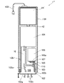
図1~図5は、本発明の第1実施例のスチーマーを示している。先ず図1~図3に基づいてスチーマーの全体構成から説明する。なお、図1は本実施例のスチーマー本体1の斜視図であり、図2は本実施例のスチーマー本体1および載置台2の側面図であり、図3(A)は本実施例のスチーマーの縦断面図であり、図3(B)は本実施例のスチーマーの底面図である。 1 to 5 show a steamer according to a first embodiment of the invention. First, the overall structure of the steamer will be described with reference to FIGS. 1 to 3. FIG. 1 is a perspective view of the steamer main body 1 of the present embodiment, FIG. 2 is a side view of the steamer main body 1 and the mounting table 2 of the present embodiment, and FIG. 3(A) is the steamer of the present embodiment. FIG. 3B is a bottom view of the steamer of this embodiment.

1はスチーマー本体であり、このスチーマー本体1は載置台2に着脱自在に載置される。スチーマー本体1の後部には凹状の受電部3が設けられ、スチーマー本体1を載置台2に載置して、受電部3を載置台2の給電部4に嵌合させたときに、載置台2から給電部4経由で、電源電圧が受電部3を通してスチーマー本体1に供給される構成となっている。なお、本実施例は載置台2を中継してスチーマー本体1に給電するコードレス式のスチーマーであるが、載置台2を用いずに電源電圧をスチーマー本体1に直接供給する電源コード付きのスチーマーでも構わない。 A steamer main body 1 is detachably mounted on a mounting table 2 . A recessed power receiving portion 3 is provided at the rear portion of the steamer body 1. When the steamer body 1 is placed on the mounting table 2 and the power receiving portion 3 is fitted to the power feeding portion 4 of the mounting table 2, the mounting table The power supply voltage is supplied from 2 to the steamer main body 1 via the power supply unit 4 and the power receiving unit 3 . Although this embodiment is a cordless steamer that supplies power to the steamer main body 1 via the mounting table 2, a steamer with a power cord that supplies power supply voltage directly to the steamer main body 1 without using the mounting table 2 can also be used. I do not care.

12は、スチーマー本体1の底部を形成する耐熱プラスチック製の遮熱カバー下であり、11は、遮熱カバー下12に被せるように形成される耐熱プラスチック製の遮熱カバー上である。また17は、遮熱カバー下12にさらに被せるように形成される外カバーであり、スチーマー本体1は、遮熱カバー上11、遮熱カバー下12および外カバー17で外面部が構成されている。13は、外カバー17上部に設けられ、側面から見て後端を開放した略U字状に形成された把手である。また把手13の後述する連結部13B前方には液体を貯留するタンクとなる、例えば合成樹脂製の水タンク14が外カバー17内に設けられる。なお貯留する液体は水だけでなく、他のスチーム用の液体でもよい。15は、水タンク14の前部に相当する外カバー17前面に取付自在に設けられた注水口蓋であり、ここから水タンク14内に水を収容したり、水タンク14内の不要水を廃棄したりすることができる。また16は、外カバー17前面で注水口蓋15下方に設けられた窓部であり、この窓部16を通して、水タンク14内の水の量を視認することができる。 Reference numeral 12 denotes a heat-resistant plastic heat-shielding cover that forms the bottom of the steamer main body 1, and 11 a heat-resistant plastic heat-shielding cover top that is formed to cover the heat-shielding cover lower 12. As shown in FIG. An outer cover 17 is further formed to cover the lower heat shield cover 12 , and the outer surface of the steamer body 1 is composed of the upper heat shield cover 11 , the lower heat shield cover 12 and the outer cover 17 . . A handle 13 is provided on the upper portion of the outer cover 17 and has a substantially U shape with an open rear end when viewed from the side. A water tank 14 made of synthetic resin, for example, is provided in the outer cover 17 in front of the connecting portion 13B of the handle 13, which will be described later. The liquid to be stored is not limited to water, and may be another liquid for steam. Reference numeral 15 denotes a water inlet cover which is detachably attached to the front surface of an outer cover 17 corresponding to the front portion of the water tank 14, from which water is stored in the water tank 14 and unnecessary water in the water tank 14 is discarded. You can Reference numeral 16 denotes a window provided on the front surface of the outer cover 17 and below the water inlet lid 15. Through this window 16, the amount of water in the water tank 14 can be visually recognized.

水タンク14の前面には、注液口としての注水口21が開口形成され、この注水口21に臨んで、取付可能な注水口蓋15が設けられる。注水口蓋15の下端部と外カバー17の前面との間には、注水口蓋15を指で取り外しやすくするのに、凹状の指掛け部22が形成される。そして、この指掛け部22に指を差し入れて、注水口蓋15の上端部を支点として注水口蓋15の下端部に力を加えることで注水口蓋15を取り外すと、開放した注水口21から水タンク14の内部に水を適宜注入することができ、その後で注水口蓋15を注水口21に嵌合させると、注水口蓋15が注水口21を密着状態で塞ぐことにより、注水口21からの水の漏出を防止する構成となっている。 A water inlet 21 as a liquid inlet is formed in the front surface of the water tank 14 , and an attachable water inlet cover 15 is provided facing the water inlet 21 . A recessed finger hook 22 is formed between the lower end of the spout lid 15 and the front surface of the outer cover 17 so that the spout lid 15 can be easily removed with a finger. Then, inserting a finger into the finger hook portion 22 and applying force to the lower end of the water pouring spout 15 with the upper end of the water pouring spout 15 as a fulcrum to remove the water pouring spout 15, the water tank 14 is removed from the opened water pouring spout 21. Water can be appropriately injected into the interior. After that, when the water filling port cover 15 is fitted to the water filling port 21, the water filling port cover 15 closes the water filling port 21 in a tight state, thereby preventing water from leaking from the water filling port 21. It is configured to prevent

25は、上述の把手13と、把手13の上部に配置される把手カバー26との二部品からなるハンドルとしての握り部である。把手部に相当する棒状の握り部25は、スチーマー本体1の腹部27との間に空洞28を有しており、握り部25の後部には、スチーマー本体1の後部から空洞28に手を差し入れて、握り部25を手で握ることができるように、空洞28に連通する開口部29が開口形成される。つまり、ここでの握り部25は、その後部がスチーマー本体1のどの部位にも連結せずに、開口部29を形成して開放した形状を有する。また、ここでいう腹部27は、握り部25に対向したスチーマー本体1の平坦状の中央上面部を指すものであり、本実施例では把手13の基部13aとして形成される。把手13は、この基部13aに加えて、基部13aの前側でU次状に立ち上がる連結部13bと、連結部13bより後側に延び、握り部25の下面部を形成する延設部13cとからなり、延設部13cを把手カバー26で覆うことで、スチーマー本体1の握り部25が構成される。また30は、スチーマー本体1下面に配置されているスチーム噴出孔としての貫通孔38b(図4(A)参照)からスチーム噴出を行なうスチームレバーであり、連結部13b近傍の基部13aに設置されている。このスチームレバー30を引き上げることで、水タンク14内の滴下口42の弁43が開口し、一定速度で気化室9に水が滴下するように構成されている。 Reference numeral 25 denotes a grip portion as a handle, which is composed of two parts, the handle 13 and a handle cover 26 arranged on the upper part of the handle 13 . A rod-shaped grip portion 25 corresponding to a grip portion has a cavity 28 between it and an abdomen 27 of the steamer body 1, and a hand is inserted into the cavity 28 from the rear portion of the steamer body 1 to the rear portion of the grip portion 25. An opening 29 communicating with the cavity 28 is formed so that the grip 25 can be grasped by hand. That is, the grip part 25 here has a shape in which the rear part is not connected to any part of the steamer main body 1 and an opening part 29 is formed to open. The abdomen 27 here refers to the flat central upper surface of the steamer body 1 facing the grip 25, and is formed as the base 13a of the handle 13 in this embodiment. In addition to this base portion 13a, the handle 13 includes a connecting portion 13b that rises in a U-shape on the front side of the base portion 13a and an extending portion 13c that extends rearward from the connecting portion 13b and forms the lower surface portion of the grip portion 25. By covering the extended portion 13c with the handle cover 26, the grip portion 25 of the steamer main body 1 is configured. 30 is a steam lever for ejecting steam from a through hole 38b (see FIG. 4(A)) as a steam ejection hole arranged on the lower surface of the steamer main body 1. there is By pulling up the steam lever 30, the valve 43 of the drip port 42 in the water tank 14 is opened, and water drips into the vaporization chamber 9 at a constant speed.

33は、スチーマー本体1の上部に設けられた操作部としての電源スイッチで、この電源スイッチ33を操作することで、スチーマー本体1の電源ON・OFFが行なわれる。また34は、表示部としての通電ランプであり、スチーマー本体1の電源がONの際に点灯または点滅表示し、後述する基体8の温度が低いときは点滅表示し、適温になると点灯表示になる。そして把手13の内部には、後述するシーズヒータ7を適宜通断電制御することにより、基体8を所定の温度に維持するように制御する温度制御装置35が設けられる。 Reference numeral 33 denotes a power switch as an operation unit provided on the upper portion of the steamer main body 1. By operating this power switch 33, the power of the steamer main body 1 is turned on and off. Reference numeral 34 denotes a power supply lamp as a display unit, which lights or blinks when the steamer main body 1 is powered on, blinks when the temperature of the base body 8, which will be described later, is low, and turns on when the temperature reaches an appropriate temperature. . Inside the handle 13, a temperature control device 35 is provided for controlling to maintain the substrate 8 at a predetermined temperature by appropriately controlling the energization/disconnection of the sheathed heater 7, which will be described later.

スチーマー本体1は、アルミダイキャスト成形品による基体8を遮熱カバー上11に固定して備えている。基体8には、加熱手段となるシーズヒータ7が上面視略U字状に屈曲して埋設される。また基体8の上面側には、スチームを発生させるための気化室9がシーズヒータ7近傍に形成され、基体8の下面側には、後述するスチーム継手38を嵌合する嵌合溝部18が形成される。嵌合孔部18はスチーム継手38の上縁部と接触する段部18aを有して、嵌合溝部18の底面18bにスチーム継手38が接触しないように構成しており、スチーム継手38を嵌合溝部18に嵌合したとき、嵌合溝部18とスチーム継手38上面とで囲まれたスチーム室19が形成される。気化室9と嵌合溝部18は、孔部20を介して連通しており、気化室9で発生したスチームが孔部20を通ってスチーム室19へと流れるように構成される。また基体8は、この基体8に取付け固定される金属板状の気化室蓋44を備え、この気化室蓋44により気化室9の上面が形成される。 The steamer main body 1 has a base body 8 made of an aluminum die-cast molded product fixed to a heat shield cover upper part 11 . A sheathed heater 7 serving as a heating means is bent and embedded in the substrate 8 in a substantially U shape when viewed from above. A vaporization chamber 9 for generating steam is formed near the sheathed heater 7 on the upper surface of the base 8, and a fitting groove 18 for fitting a steam joint 38, which will be described later, is formed on the lower surface of the base 8. be done. The fitting hole portion 18 has a step portion 18a that contacts the upper edge portion of the steam joint 38, and is configured so that the steam joint 38 does not come into contact with the bottom surface 18b of the fitting groove portion 18, so that the steam joint 38 is fitted. A steam chamber 19 surrounded by the fitting groove portion 18 and the upper surface of the steam joint 38 is formed when the fitting groove portion 18 is fitted. The vaporization chamber 9 and the fitting groove 18 communicate with each other through the hole 20 so that the steam generated in the vaporization chamber 9 flows through the hole 20 into the steam chamber 19 . The substrate 8 is also provided with a metal plate-like vaporization chamber lid 44 attached and fixed to the substrate 8 , and the vaporization chamber lid 44 forms the upper surface of the vaporization chamber 9 .

39は、遮熱カバー下12の底面、すなわちスチーマー本体1の底面に固着されるステンレス製でプレート状の掛け面部材であり、加飾とスチーマー本体1の走行性を兼ねて使用され、スチーム孔41がこの掛け面部材39に開口形成される。スチーム孔41は、掛け面部材39の上面の口径よりも掛け面部材39の下面の口径の方が大きい円錐台状に形成される。 Reference numeral 39 denotes a stainless steel plate-like hanging surface member fixed to the bottom surface of the lower heat shield cover 12, that is, the bottom surface of the steamer main body 1. An opening 41 is formed in this hanging surface member 39 . The steam hole 41 is formed in a truncated cone shape in which the diameter of the lower surface of the hanging surface member 39 is larger than the diameter of the upper surface of the hanging surface member 39 .

本実施例では、基体8と掛け面部材39の間にシリコーンパッキンとしてのスチーム継手38を挟設している。一般的にシリコーンゴムは熱伝導率が低く、また気化室9と掛け面部材39の間にスチーム継手38を経由するため、基体8の熱が掛け面部材39に直接伝わらない。また基体8と遮熱カバー下12は接触しておらず、遮熱カバー上11と遮熱カバー下12で囲まれた空間内、特に遮熱カバー下12上面全てと基体8との間に、空気層である空間54が形成されて両者の間に介在し、気化室9の熱、すなわち基体8の熱が遮熱カバー下12や掛け面部材39に伝わることを抑制する。そして上述したように、遮熱カバー上11および遮熱カバー下12は耐熱プラスチック製であり、一般的にプラスチックは熱伝導率が低いため、基体8の熱が、遮熱カバー上11や遮熱カバー下12を経由して掛け面部材39に伝わることを抑制している。このような構成により、気化室9の熱が掛け面部材39に伝わることを抑制することで掛け面部材39は低温に保て、さらに、掛け面部材39からの熱の外気への放出を抑制することで、スチームを発生することができる時間であるスチーム発生時間を増加させて、スチーマー本体1のコードレスでのスチーム発生持続性を高めている。 In this embodiment, a steam joint 38 as a silicone packing is sandwiched between the base 8 and the hanging surface member 39 . Silicone rubber generally has a low thermal conductivity, and the heat of the substrate 8 is not directly transmitted to the hanging surface member 39 because the vaporization chamber 9 and the hanging surface member 39 pass through the steam joint 38 . In addition, the base body 8 and the lower heat shield cover 12 are not in contact with each other, and in the space surrounded by the upper heat shield cover 11 and the lower heat shield cover 12, especially between the entire upper surface of the lower heat shield cover 12 and the base body 8, A space 54, which is an air layer, is formed between the two to suppress the heat of the vaporization chamber 9, that is, the heat of the substrate 8 from being transferred to the lower heat shield cover 12 and the hanging surface member 39. As described above, the upper heat shield cover 11 and the lower heat shield cover 12 are made of heat-resistant plastic, and plastic generally has low thermal conductivity. It suppresses transmission to the hanging surface member 39 via the under cover 12. - 特許庁With such a configuration, the heat of the vaporization chamber 9 is suppressed from being transferred to the hanging surface member 39, so that the hanging surface member 39 can be kept at a low temperature, and further, the release of heat from the hanging surface member 39 to the outside air is suppressed. By doing so, the steam generation time, which is the time during which steam can be generated, is increased, and the steam generation durability of the cordless steamer main body 1 is enhanced.

次に図4の(A)~(C)の各図に基づいて、基体8および遮熱カバー下12の構造をさらに詳細に説明する。ここで、図4はスチーマー本体1の下方からの分解斜視図を示しており、図4(A)は掛け面部材39を取り外した分解斜視図、図4(B)は掛け面部材39および遮熱カバー下12を取り外した分解斜視図、図4(C)は掛け面部材39、遮熱カバー下12およびスチーム継手38を取り外した分解斜視図を示している。 Next, the structures of the base body 8 and the lower heat shield cover 12 will be described in more detail with reference to FIGS. 4(A) to 4(C). Here, FIG. 4 shows an exploded perspective view of the steamer main body 1 from below, FIG. 4A is an exploded perspective view with the hanging surface member 39 removed, and FIG. FIG. 4C shows an exploded perspective view with the lower heat cover 12 removed, and FIG. 4C shows an exploded perspective view with the hanging surface member 39, the lower heat shield cover 12 and the steam joint 38 removed.

図4(C)に示されるように、本実施例の嵌合溝部18は、段部18aまでスチーム継手38と断面略同形状に形成され、段部18aから底面18bまでは断面が一回り小さく形成されている。そのため、スチーム継手38を嵌合溝部18に挿入したとき、段部18aにスチーム継手38の上縁部が接触して、これ以上奥に行かないように構成され、嵌合溝部18とスチーム継手38上面とで囲まれたスチーム室19が形成される。 As shown in FIG. 4(C), the fitting groove portion 18 of the present embodiment is formed to have substantially the same cross-sectional shape as the steam joint 38 up to the stepped portion 18a, and the cross section is one size smaller from the stepped portion 18a to the bottom surface 18b. formed. Therefore, when the steam joint 38 is inserted into the fitting groove portion 18, the upper edge of the steam joint 38 contacts the stepped portion 18a and does not go any further. A steam chamber 19 surrounded by the upper surface is formed.

図4(B)に示されるように、スチーム継手38は、掛け面部材39と接触する接触面38aと、接触面38aに開口形成され、スチーム室19からのスチームを噴出する貫通孔38bを有している。本実施例の貫通孔38bはスチーム孔41と同数だけ形成され、スチーム室19とスチーム孔41が、貫通孔38bを介して連通するように構成される。また貫通孔38bの口径はスチーム孔41の内径よりも小さく形成され、掛け面部材39を遮熱カバー下12に設置した時、貫通孔38bの周囲にスチーム孔41が配設されるように構成される。そして上述したように、遮熱カバー下12上面全てと基体8との間に、空気層である空間54が形成されて両者の間に介在し、気化室9の熱、すなわち基体8の熱が遮熱カバー下12や掛け面部材39に伝わることを抑制し、また掛け面部材39からの熱の外気への放出を抑制している。 As shown in FIG. 4B, the steam joint 38 has a contact surface 38a that comes into contact with the hanging surface member 39, and a through hole 38b formed in the contact surface 38a and through which the steam from the steam chamber 19 is ejected. is doing. The through holes 38b of this embodiment are formed in the same number as the steam holes 41, and the steam chamber 19 and the steam holes 41 are configured to communicate with each other through the through holes 38b. The diameter of the through-hole 38b is formed smaller than the inner diameter of the steam hole 41, and when the hanging surface member 39 is installed under the heat shield cover 12, the steam hole 41 is arranged around the through-hole 38b. be done. As described above, the space 54, which is an air layer, is formed between the entire upper surface of the lower heat shield cover 12 and the substrate 8, and is interposed between the two, so that the heat of the vaporization chamber 9, that is, the heat of the substrate 8 is dissipated. This suppresses the transmission of heat to the lower heat shield cover 12 and the hanging surface member 39, and suppresses the release of heat from the hanging surface member 39 to the outside air.

図4(A)に示されるように、遮熱カバー下12は、底面12aと、この底面12aに開口形成された、スチーム継手38と断面略同形状の挿通孔部12bを有しており、基体8にスチーム継手38を取付け、遮熱カバー上11に遮熱カバー下12を設置してスチーム継手38を挿通孔部12bに挿通させた時、接触面38aが底面12aよりも僅かに高くなるように構成される。そのため、掛け面部材39を遮熱カバー下12に設置した時、先ず接触面38aが掛け面部材39に接触し、次に底面12aがスチーム継手38の弾性力に抗して接触する。そして貫通孔38bの周囲にスチーム孔41が位置し、スチーム室19とスチーム孔41が、貫通孔38bを介して連通する。そのため基体8はスチーム孔41、すなわち掛け面部材39に接触せず、気化室9を備えた基体8の熱がスチーム管10を通して掛け面部材39に直接伝わらない。したがって、気化室9の温度を上げても掛け面部材39の温度が上がることはなく、気化室9の温度をより高く設定することができ、スチーム使い始めの温度をより高温からスタートさせることができるため、スチーム持続時間をより長く保つことができる。またスチーマー本体1使用時の掛け面部材39の温度が常に低いため、耐熱温度、溶解温度の異なる各種布地の皺伸ばしが掛け面部材39の掛け面の温度調節なく可能であり、そしてスチーマー本体1の使用後は、掛け面部材39を下にして台の上に直接置け、耐熱性を有する置台などを不要にできる。 As shown in FIG. 4(A), the lower heat shield cover 12 has a bottom surface 12a and an insertion hole 12b having a cross section substantially the same shape as the steam joint 38, which is formed in the bottom surface 12a. When the steam joint 38 is attached to the base 8, the lower heat shield cover 12 is placed on the upper heat shield cover 11, and the steam joint 38 is inserted into the insertion hole 12b, the contact surface 38a becomes slightly higher than the bottom surface 12a. configured as Therefore, when the hanging surface member 39 is installed under the heat shield cover 12 , the contact surface 38 a first contacts the hanging surface member 39 , and then the bottom surface 12 a contacts against the elastic force of the steam joint 38 . A steam hole 41 is positioned around the through hole 38b, and the steam chamber 19 and the steam hole 41 communicate with each other through the through hole 38b. Therefore, the substrate 8 does not come into contact with the steam hole 41 , that is, the hanging surface member 39 , and the heat of the substrate 8 provided with the vaporization chamber 9 is not directly transmitted to the hanging surface member 39 through the steam pipe 10 . Therefore, even if the temperature of the vaporization chamber 9 is raised, the temperature of the hanging surface member 39 does not rise, and the temperature of the vaporization chamber 9 can be set higher, and the temperature at the beginning of steam use can be started from a higher temperature. Because you can, you can keep the steam duration longer. In addition, since the temperature of the hanging surface member 39 is always low when the steamer main body 1 is in use, wrinkles of various fabrics with different heat resistance temperatures and melting temperatures can be smoothed without adjusting the temperature of the hanging surface of the steamer main body 1. After use, it can be placed directly on a table with the hanging surface member 39 facing downward, eliminating the need for a heat-resistant table.

次に上記構成において、特にスチーム機能に関する作用を説明すると、注水口蓋15を開けて、所定量の水を水タンク14に収容し、注水口蓋15を閉める。続いて、スチーマー本体1を載置台2に載置し、載置台2の図示しない電源プラグをコンセントに差し込むことで、スチーマー本体1に電源電圧を供給する。この給電状態の時に電源スイッチ33を押動操作すると、スチーマー本体1の内部では、図示しない温度検知手段としてのサーミスタで検知される基体8の温度が所定の温度となるように、温度制御装置35がシーズヒータ7を通断電制御して、気化室9を含む基体8を加熱し、通電ランプ34を点滅表示させる。その一方で、基体8の温度が所定の温度に達したことを、温度制御装置35が温度検知手段で検知すると、温度制御装置35は通電ランプ34を点灯表示させる。そのため、ユーザーはスチーマー本体1の使用可否の目安を一目で理解することができる。なおスチーマー本体1使用時にも、電源スイッチ33を押動操作すると、サーミスタで検知される基体8の温度が所定の温度となるように、温度制御装置35がシーズヒータ7を通断電制御して、気化室9を含む基体8を加熱し、通電ランプ34を点滅表示させるように構成してもよい。 Next, in the above construction, the operation of the steam function will be described. Subsequently, the steamer main body 1 is placed on the mounting table 2, and a power plug (not shown) of the mounting table 2 is inserted into an outlet, thereby supplying power supply voltage to the steamer main body 1. FIG. When the power switch 33 is pressed in this state of power supply, the temperature control device 35 controls the temperature of the substrate 8 inside the steamer body 1 so that the temperature of the substrate 8 detected by a thermistor (not shown) as temperature detecting means reaches a predetermined temperature. controls the energization of the sheathed heater 7 to heat the substrate 8 including the vaporization chamber 9, causing the energization lamp 34 to blink. On the other hand, when the temperature control device 35 detects that the temperature of the substrate 8 has reached a predetermined temperature, the temperature control device 35 causes the energization lamp 34 to light up. Therefore, the user can understand at a glance whether the steamer main body 1 can be used or not. When the power switch 33 is pressed while the steamer main body 1 is in use, the temperature control device 35 controls the power supply to the sheathed heater 7 so that the temperature of the substrate 8 detected by the thermistor reaches a predetermined temperature. Alternatively, the substrate 8 including the vaporization chamber 9 may be heated to cause the energization lamp 34 to blink.

次にスチーマー本体1の使用に関する作用を説明すると、握り部25を手で握ってスチーマー本体1を載置台2から離脱させ、スチーム噴出の対象物となる布地に掛け面部材39を向けてスチームレバー30を引き上げると、水タンク14内の滴下口42の弁43が開口し、一定速度で気化室9に水が滴下する。この時、基体8の温度が所定の温度に達している場合は、加熱した気化室9で水が気化されてスチームが発生し、図5の矢印で示すように、このスチームが孔部20を通過してスチーム室19へと流れ、スチーム室19と連通した貫通孔38bを通過して、布地に所定量のスチームを噴出させることができる。したがって、気化室9およびシーズヒータ7を有する基体8は、液体としての水を気化させるスチーム発生装置として作用している。 Next, the action of using the steamer main body 1 will be described. Grasping the grip portion 25, the steamer main body 1 is separated from the mounting table 2, and the hanging surface member 39 is directed toward the cloth to be steam-spouted, and the steam lever is pressed. 30 is pulled up, the valve 43 of the drip port 42 in the water tank 14 is opened, and water drips into the vaporization chamber 9 at a constant speed. At this time, if the temperature of the substrate 8 has reached a predetermined temperature, the water is vaporized in the heated vaporization chamber 9 to generate steam, and as indicated by the arrow in FIG. The steam passes through the steam chamber 19 and passes through the through hole 38b communicating with the steam chamber 19, so that a predetermined amount of steam can be jetted onto the fabric. Therefore, the base body 8 having the vaporization chamber 9 and the sheathed heater 7 functions as a steam generator for vaporizing liquid water.

その一方で、上述のようにスチーマー本体1では、気化室9、すなわち基体8の熱が掛け面部材39に伝わることを抑制しているため、掛け面部材39を低温に保て、溶解温度の異なる繊維製品でも、掛け面部材39の掛け面の温度調整をすることなく、繊維製品の布地をプレスして皺伸ばしができる。また、スチーマー本体1の使用後は、掛け面部材39を下にして台の上に直接置くことができる。さらに、気化室9の温度を上げても掛け面部材39の温度が上がることはなく、気化室9の温度をより高く設定することができ、スチーム使い始めの温度としての所定の温度をより高温からスタートさせることができるため、スチーム持続時間をより長く保つことができる。 On the other hand, as described above, in the steamer main body 1, since the heat of the vaporization chamber 9, that is, the base body 8 is suppressed from being transferred to the hanging surface member 39, the hanging surface member 39 can be kept at a low temperature, and the melting temperature can be lowered. Even if a different textile product is used, wrinkles can be smoothed out by pressing the fabric of the textile product without adjusting the temperature of the hanging surface of the hanging surface member 39.例文帳に追加After the steamer body 1 is used, it can be placed directly on a table with the hanging surface member 39 facing downward. Furthermore, even if the temperature of the vaporization chamber 9 is raised, the temperature of the hanging surface member 39 does not rise, and the temperature of the vaporization chamber 9 can be set higher, and the predetermined temperature as the temperature at which steam is first used can be set higher. Since it can be started from , the steam duration can be kept longer.

以上のように、本実施例のスチーマーは、スチームを噴出するスチーム噴出孔としての貫通孔38bを備えるスチーマー本体1と、スチーマー本体1に電源電圧を供給する給電装置としての載置台2と、を備え、スチーマー本体1はさらに、金属板としての掛け面部材39を底面に有し、掛け面部材39は、貫通孔38bと同数だけ形成されて貫通孔38bの口径よりも大きい内径のスチーム孔41を有し、前記スチーム噴出孔の周囲にそれぞれ対応する前記スチーム孔が位置するようにスチーマー本体1が掛け面部材39を具備する構成としており、スチーム噴出時に掛け面部材39にスチームが当たることがなく、そのため掛け面部材39の温度上昇を抑制することができる。したがって溶解温度の異なる繊維製品でも、掛け面部材39の掛け面の温度調整をすることなく、繊維製品の布地をスチーム後に掛け面部材39でプレスして皺伸ばしができる。 As described above, the steamer of this embodiment includes the steamer main body 1 having the through holes 38b as steam ejection holes for ejecting steam, and the mounting table 2 as a power supply device for supplying power supply voltage to the steamer main body 1. In addition, the steamer body 1 further has a hanging surface member 39 as a metal plate on the bottom surface. , and the steamer body 1 is provided with a hanging surface member 39 so that the corresponding steam holes are positioned around the steam ejection holes, and the steam hits the hanging surface member 39 when the steam is ejected. Therefore, the temperature rise of the hanging surface member 39 can be suppressed. Therefore, even for textile products having different melting temperatures, wrinkles can be smoothed by pressing the cloth of the textile product with the hanging surface member 39 after steaming without adjusting the temperature of the hanging surface of the hanging surface member 39. - 特許庁

また本実施例のスチーマー本体1は、気化室9およびシーズヒータ7を有して液体としての水を気化させるスチーム発生装置としての基体8をさらに備え、基体8への給電後に、載置台2から取り外して、基体8への給電を断った状態でスチーム噴出する構成としており、コードレスで、スチーム後に掛け面部材39でプレスして皺伸ばしができる。 The steamer main body 1 of this embodiment further includes a base body 8 as a steam generating device having a vaporization chamber 9 and a sheathed heater 7 to vaporize liquid water. It is detached and steam is ejected in a state in which power supply to the base body 8 is cut off, and it is cordless and can be pressed by the hanging surface member 39 after steaming to smooth out wrinkles.

また本実施例のスチーマーは、掛け面部材39を具備する遮熱カバー下12と、基体8との間に熱の外気放出抑制用の空間54を形成した構成としている。そのため、基体8の熱が遮熱カバー下12や掛け面部材39に伝わることを抑制して、この掛け面部材39からの熱の外気への放出を抑制することができる。さらに基体8の気化室9の温度を上げても掛け面部材39の温度が上がることはなく、掛け面部材39を低温に保つことができるため、気化室9の温度をより高く設定することができ、スチーム使い始めの温度をより高温からスタートさせて、スチームを発生することができる時間であるスチーム持続時間をより長く保つことができ、スチーマー本体1のコードレスでのスチーム発生持続性を高めることができる。 Further, the steamer of this embodiment has a structure in which a space 54 for suppressing the release of heat to the outside air is formed between the lower heat insulating cover 12 having the hanging surface member 39 and the base body 8 . Therefore, it is possible to suppress the heat of the base body 8 from being transmitted to the lower heat shield cover 12 and the hanging surface member 39, and to suppress the release of heat from the hanging surface member 39 to the outside air. Furthermore, even if the temperature of the vaporizing chamber 9 of the substrate 8 is raised, the temperature of the hanging surface member 39 does not rise, and the hanging surface member 39 can be kept at a low temperature, so that the temperature of the vaporizing chamber 9 can be set higher. To increase the durability of steam generation in a cordless steamer main body 1 by starting the temperature at the beginning of using steam from a higher temperature to keep the duration of steam, which is the time during which steam can be generated, longer. can be done.

図6~図8は、本発明の第2実施例のスチーマーを示している。なお、第1実施例のスチーマーと共通する構成には、同一の符号を付し、同一の説明は重複を避けるため極力省略する。 Figures 6-8 show a steamer according to a second embodiment of the invention. In addition, the same code|symbol is attached|subjected to the structure which is common in the steamer of 1st Example, and the same description is abbreviate|omitted as much as possible in order to avoid duplication.

図6は本実施例のスチーマー本体1IIの縦断面図を示している。本実施例では、第1実施例の基体8に相当するベース部がPTCヒータ71によって構成されている。 FIG. 6 shows a longitudinal sectional view of the steamer main body 1II of this embodiment. In this embodiment, a base portion corresponding to the substrate 8 of the first embodiment is composed of a PTC heater 71. As shown in FIG.

従来、スチーマーやスチームアイロンのスチーム構造において、掛け面温度に比例して、発生させることができるスチーム噴出量は決められていた。そこで掛け面が低い温度で水分の供給を求める際、先ずミストなどにより、水タンクの水を気化させずに直接衣類などの繊維製品に吹きかけることにより繊維の膨潤を促し、その後、掛け面が低温状態で少ない量のスチームを噴出させてこの繊維製品に当てることにより、この繊維製品の皺伸ばしを行なう方法が提案されている。 Conventionally, in the steam structure of steamers and steam irons, the amount of steam that can be generated was determined in proportion to the temperature of the surface to be applied. Therefore, when the application surface needs to be supplied with water at a low temperature, first, the water in the water tank is sprayed directly on the textile products such as clothing without vaporizing with mist or the like to promote the swelling of the fibers, and then the application surface is cooled. A method has been proposed for smoothing out the wrinkles of the textile product by blowing a small amount of steam onto the textile product.

しかしながら、ミストなどで直接水を吹きかけ、また低温状態のスチームを噴出させる従来の構成では、繊維製品に与える水分量が不十分であり、また、ユーザーの使い勝手の悪いものであった。また従来の構成はベース部の内部に加熱手段としてのシーズヒータを埋め込んだものが主流であり、このシーズヒータをダイキャストで覆うと、必然的にシーズヒータのパイプ径よりも厚みを持ち、大きいサイズのベース部の形状になってしまい、ベース部の容量を増やしてしまっていた。そこで本実施例では加熱手段としてPTCヒータを採用することによりベース部の厚みを抑制し、かつ温度制御を細かく設定できるように構成される。 However, the conventional structure in which water is directly sprayed with a mist or the like and low-temperature steam is jetted out is insufficient in the amount of moisture given to the textile product, and is inconvenient for the user. In addition, the mainstream of the conventional structure is that a sheathed heater as a heating means is embedded in the inside of the base portion. The shape of the base part of the size was increased, and the capacity of the base part was increased. Therefore, in this embodiment, a PTC heater is employed as the heating means so that the thickness of the base portion can be suppressed and the temperature control can be finely set.

本実施例の構成を、図6を参照しながら説明すると、1IIはスチーマーの本体に相当するアイロン本体であり、このアイロン本体1IIは、ベース部を兼ねる加熱手段としてのPTCヒータ71を下部に備えている。72は温度検知手段としてのサーミスタであり、このサーミスタ72で検知されるPTCヒータ71の温度がアイロン温度調節機構75で設定した設定温度となるように、温度制御装置35がPTCヒータ71を通断電制御している。このように構成することで、ベース部の厚さは搭載しているPTCヒータ71の厚さのみであるため、ベース部の厚みを薄くすることができ、その分ベース容量を抑制することができる。またPTCヒータ71がベース部を兼ねているため、温度制御を行った際に熱源であるPTCヒータ71と掛け面と略同一の温度であるベース部としてのPTCヒータ71との温度差をなくすことができるので、設定温度に対するPTCヒータ71の温度のディファレンシャルを小さくすることができ、安定時の温度の差を小さくできる。したがって、複数の設定温度を設けることができるようになる。 The structure of this embodiment will be explained with reference to FIG. 6. 1 II is an iron body corresponding to the main body of a steamer . prepared for. Reference numeral 72 denotes a thermistor as temperature detecting means, and the temperature control device 35 turns on the PTC heater 71 so that the temperature of the PTC heater 71 detected by the thermistor 72 becomes the set temperature set by the iron temperature control mechanism 75. It's electrically controlled. With this configuration, the thickness of the base portion is only the thickness of the mounted PTC heater 71, so the thickness of the base portion can be reduced, and the base capacitance can be suppressed accordingly. . In addition, since the PTC heater 71 also serves as the base portion, the temperature difference between the PTC heater 71, which is the heat source, and the PTC heater 71 as the base portion, which has approximately the same temperature as the hanging surface, can be eliminated when performing temperature control. Therefore, the temperature differential of the PTC heater 71 with respect to the set temperature can be reduced, and the temperature difference at the time of stability can be reduced. Therefore, it becomes possible to set a plurality of set temperatures.

73は、PTCヒータ71上方に設けられ、液体を貯留するタンクおよびスチーム発生装置となるボイラー式タンクである。また74は、このボイラー式タンク73内の下部に設けられる、PTCヒータ71とは別の発熱源であるボイラーヒータであり、温度制御装置35によりON/OFF制御されて、ボイラー式タンク73内部の液体を気化している。そして気化されたスチームはスチーム管10’を通過するとそのままスチーム孔41を通って噴射される構成となっている。このように構成することで、PTCヒータ71およびボイラーヒータ74を独立して動作させることができる。 A boiler type tank 73 is provided above the PTC heater 71 and serves as a tank for storing liquid and a steam generator. Reference numeral 74 denotes a boiler heater, which is a heat source different from the PTC heater 71 and is provided in the lower part of the boiler tank 73, and is ON/OFF controlled by the temperature control device 35 to control the inside of the boiler tank 73. evaporating the liquid. The vaporized steam is jetted through the steam hole 41 as it is after passing through the steam pipe 10'. By configuring in this way, the PTC heater 71 and the boiler heater 74 can be operated independently.

図7は、本実施例の一例として、PTCヒータ71およびボイラーヒータ74の、ON/OFF切換えの制御方法を示している。同図に示されるように、温度制御装置35は一方のヒータがON状態のとき、他方のヒータをOFF状態に制御し、2つのヒータを交互に通電している。そのため、OFF状態のヒータで消費する電力をON状態のヒータに供給でき、片方ずつON/OFFを繰り返すことにより、1つのヒータに供給可能な最大消費電力を増加させ、また消費電力による負荷を軽減させることができる。 FIG. 7 shows a method of controlling ON/OFF switching of the PTC heater 71 and the boiler heater 74 as an example of this embodiment. As shown in the figure, when one heater is ON, the temperature control device 35 controls the other heater to be OFF, alternately energizing the two heaters. Therefore, the power consumed by the heater in the OFF state can be supplied to the heater in the ON state, and by repeating ON/OFF one by one, the maximum power consumption that can be supplied to one heater is increased and the load due to power consumption is reduced. can be made

図8は従来のスチームアイロンおよび本実施例のアイロン本体1IIのスチーム量と掛け面温度の関係をグラフで示したものである。同図を参照しながら説明すると、従来は、掛け面部材39は気化室を設けたベース部と密着しているため、気化室の温度を上下させると掛け面部材39の温度も追従して上下していた。そのため、従来のスチームアイロンの掛け面部材39の温度が225℃のときは、気化室も高温であるためスチーム量は50mlと多く、掛け面部材39の温度が200℃のときはスチーム量が40ml、掛け面部材39の温度が150℃のときはスチーム量が20mlと、掛け面部材39の温度に比例してスチーム量が減少していき、掛け面部材39の温度が100℃を下回ると、気化室も100℃前後となって水を気化できなくなり、スチームを発生させることができなくなってしまっていた。 FIG. 8 is a graph showing the relationship between the steam amount and the application surface temperature of the conventional steam iron and the iron body 1II of the present embodiment. Referring to FIG. 1, conventionally, the hanging surface member 39 is in close contact with the base portion provided with the vaporization chamber. Was. Therefore, when the temperature of the hanging surface member 39 of the conventional steam iron is 225°C, the amount of steam is as large as 50 ml because the vaporization chamber is also at a high temperature. When the temperature of the hanging surface member 39 is 150°C, the amount of steam is 20 ml, and the amount of steam decreases in proportion to the temperature of the hanging surface member 39. The temperature in the vaporization chamber reached around 100°C, and the water could not be vaporized, and steam could not be generated.

それに対して本実施例のアイロン本体1IIでは、掛け面部材39の温度を上昇させる熱源としてのPTCヒータ71と、スチームを発生させる熱源としてのボイラーヒータ74を別に設けているため、掛け面部材39の温度に左右されず、多量のスチームを発生させることができるように構成している。そのため、掛け面部材39の温度が0℃~225℃まで可変しても、噴出するスチーム量は変化せず50mlであり、掛け面部材39の温度に関わらず、安定したスチーム量を確保することができる。したがって、掛け面部材39が低温状態でも、高圧多量のスチームの噴出を可能にしている。 On the other hand, in the iron body 1 II of this embodiment, since the PTC heater 71 as a heat source for raising the temperature of the hanging surface member 39 and the boiler heater 74 as a heat source for generating steam are provided separately, It is constructed so that a large amount of steam can be generated without being affected by the temperature of 39. Therefore, even if the temperature of the hanging surface member 39 varies from 0°C to 225°C, the amount of steam ejected does not change and is 50 ml. can be done. Therefore, even when the hanging surface member 39 is in a low temperature state, a large amount of high-pressure steam can be ejected.

以上のように、本実施例のスチーマーの本体に相当するアイロン本体1IIでは、ベース部がPTCヒータ71によって構成されており、シーズヒータを採用するスチームアイロンよりもベース部の厚みを薄く構成できる。そのため、設定温度に対するPTCヒータ71の温度のディファレンシャルを小さくすることができ、安定時の温度の差を小さくできる。したがって、複数の設定温度を設けることができるようになる。 As described above, in the iron main body 1 II corresponding to the main body of the steamer of this embodiment, the base portion is composed of the PTC heater 71, and the thickness of the base portion can be thinner than that of the steam iron employing the sheathed heater. . Therefore, the differential of the temperature of the PTC heater 71 with respect to the set temperature can be reduced, and the temperature difference at the time of stability can be reduced. Therefore, it becomes possible to set a plurality of set temperatures.

また、本実施例のアイロン本体1IIでは、スチーム発生装置としてボイラー式タンク73を搭載し、ベース部としてのPTCヒータ71とは別の発熱源としてのボイラーヒータ74により構成されている。そのため、掛け面部材39の温度を上昇させる熱源としてのPTCヒータ71と、スチームを発生させる熱源としてのボイラーヒータ74を別に設けることにより、掛け面部材39の温度に関わらず、高圧多量のスチームの噴出を可能にしている。 The iron main body 1 II of this embodiment is equipped with a boiler type tank 73 as a steam generating device, and is composed of a boiler heater 74 as a heat source separate from the PTC heater 71 as a base portion. Therefore, by separately providing a PTC heater 71 as a heat source for raising the temperature of the hanging surface member 39 and a boiler heater 74 as a heat source for generating steam, a large amount of high pressure steam can be generated regardless of the temperature of the hanging surface member 39. Allows for ejection.

また、本実施例のアイロン本体1IIでは、PTCヒータ71およびボイラーヒータ74の一方のヒータがON状態のとき、他方のヒータをOFF状態に制御することができる。そのため、片方ずつON/OFFを繰り返すことにより、1つのヒータに供給可能な最大消費電力を増加させ、また消費電力による負荷を軽減させることができる。 Further, in the iron body 1 II of the present embodiment, when one of the PTC heater 71 and the boiler heater 74 is ON, the other heater can be controlled to be OFF. Therefore, by repeating ON/OFF one by one, the maximum power consumption that can be supplied to one heater can be increased, and the load due to the power consumption can be reduced.

本発明の第3実施例のスチーマーについて、図9~図12を参照しながら説明する。なお、上記実施例と共通する構成には、同一の符号を付し、同一の説明は重複を避けるため極力省略する。 A steamer according to a third embodiment of the present invention will now be described with reference to FIGS. 9-12. It should be noted that the same reference numerals are given to the structures common to the above embodiment, and the same descriptions are omitted as much as possible to avoid duplication.

従来、電源コード付きのスチーマーでは、コードリールで電源コードを巻き取るもので、コードリール巻取釦を押圧することにより、コードリールを作動させて電源コードを巻き取る構成が提案されている。しかしながら、このコードリールによる巻き取りはスチーマー本体が通電状態でも可能であり、誤ってこのコードリール巻取釦に触れた場合、電源コードが巻き取られ、スチーマーの使用上において危険な状態をもたらす虞があった。そこで本実施例ではスチーマー本体の通電時にはコードリール巻取ボタンがロックされ、巻き取り操作ができない状態にして安全性を向上させている。 Conventionally, in a steamer with a power cord, the power cord is wound on a cord reel, and a configuration has been proposed in which the cord reel is operated by pressing a cord reel winding button to wind the power cord. However, winding with this cord reel is possible even when the steamer main body is energized, and if the cord reel winding button is touched by mistake, the power cord will be wound up, and there is a danger that the use of the steamer will be in a dangerous state. was there. Therefore, in this embodiment, the cord reel winding button is locked when the steamer main body is energized, and the winding operation is disabled to improve safety.

図9は本実施例のアイロンの上面図を示し、図10は本実施例のアイロンの縦断面図を示している。同図を参照しつつ、本実施例の構成を説明すると、1IIIはスチーマーの本体に相当するアイロン本体であり、76は、電源電圧をアイロン本体1IIIに直接供給する電源コードを巻き取るコードリールである。コードリール76は、握り部25後方から外カバー17’後方にわたって配設されており、内部の電源コードがシーズヒータ7と電気的に接続されている。そのため、アイロン本体1IIIでは開口部29が形成されず、本実施例の空洞28は把手13とコードリール76とで囲まれて形成される。 FIG. 9 shows a top view of the iron of this embodiment, and FIG. 10 shows a vertical sectional view of the iron of this embodiment. 1 III is an iron main body corresponding to the main body of a steamer, and 76 is a cord for winding a power cord that directly supplies a power supply voltage to the iron main body 1 III . is the reel. The cord reel 76 is arranged from the rear side of the grip portion 25 to the rear side of the outer cover 17 ′, and the internal power cord is electrically connected to the sheathed heater 7 . Therefore, the opening 29 is not formed in the iron body 1 III , and the cavity 28 of this embodiment is formed by being surrounded by the handle 13 and the cord reel 76 .

77は、アイロン本体1IIIの掛け面部材39、すなわち基体8の温度を調節する温度調節部としての温度調節レバーであり、握り部25の側面に配設され、握り部25に沿って前後にスライドできるように構成される。本実施例では、この温度調節レバー77の位置により基体8の温度が設定されており、アイロン本体1IIIをON/OFFする電源スイッチの機能も兼ねている。温度調節レバー77をスライドさせてアイロン本体1IIIが通電状態になると、温度制御装置35は、当該設定温度に維持するように、シーズヒータ7を適宜通断電制御する。 Reference numeral 77 denotes a temperature control lever as a temperature control part for controlling the temperature of the hooking surface member 39 of the iron body 1 III , that is, the base body 8 . configured to slide. In this embodiment, the temperature of the substrate 8 is set by the position of the temperature control lever 77, which also functions as a power switch for turning on/off the iron body 1III . When the temperature control lever 77 is slid to turn on the iron main body 1 III , the temperature control device 35 appropriately controls the power supply to the sheathed heater 7 so as to maintain the set temperature.

78は、把手13の連接部13B近傍に設けられる操作部であり、握り部25の側面に配設される温度調節レバー77に加えて、握り部25の上面に配設される、押圧するとスチームを噴出させる釦である操作釦79と、押圧すると噴出させるスチームが一時的に多量になる釦である操作釦80と、押圧するとコードリール76が作動し、電源コードが巻き取られるコードリール巻取釦81と、が主な構成要素となっている。 Reference numeral 78 denotes an operating portion provided near the connecting portion 13B of the handle 13. In addition to the temperature control lever 77 provided on the side surface of the grip portion 25, it is provided on the upper surface of the grip portion 25, and steam is generated when pressed. and an operation button 80, which is a button that temporarily increases the amount of steam to be ejected when pressed, and a cord reel 76 that operates when pressed to wind the power cord. A button 81 is the main component.

コードリール76は、回転可能に設けられ、電源コードを複数列で巻くことのできる幅に形成されたリール82と、上下動できるように設けられ、リール82の回転を一時的に止める巻取り金具83と、を備えている。巻取り金具83は、図示しないスプリングにより常時下方へ付勢されており、このスプリングの付勢力に抗して巻取り金具83を上方に移動させることで、リール82が回転して電源コードを巻き取る構成となっており、巻取り金具83は、上方を前方へ折り曲げて折り曲げ部83aを形成する。84は、握り部25内に設けられる中継シャフトであり、一端である持ち上げ部84aが巻取り金具83の折り曲げ部83aの下面に接し、他端で上方に突出させた突出部84bがコードリール巻取釦81の下方に位置するように、中継シャフト84が配設されている。 The cord reel 76 includes a reel 82 which is rotatably provided and has a width that allows the power cord to be wound in a plurality of rows, and a winding metal fitting which is provided so as to be able to move up and down to temporarily stop the rotation of the reel 82. 83 and . The winding metal fitting 83 is always biased downward by a spring (not shown). By moving the winding metal fitting 83 upward against the biasing force of the spring, the reel 82 rotates to wind the power cord. The winding fitting 83 is bent forward at its upper portion to form a bent portion 83a. Reference numeral 84 denotes a relay shaft provided in the grip portion 25, one end of which is a lifting portion 84a in contact with the lower surface of a bent portion 83a of the winding fitting 83, and the other end of which a projecting portion 84b projecting upward is used for winding the cord reel. A relay shaft 84 is arranged so as to be positioned below the take-up button 81 .

図11および図12を参照して、握り部25内部の構成をさらに詳細に説明する。中継シャフト84は、上述した持ち上げ部84aおよび突出部84bに加えて、中継シャフト84を握り部25に軸支する軸支部84cと、持ち上げ部84aと突出部84bの間を延びる中継シャフト本体84dと、からなり、軸支部84cを軸にして、中継シャフト本体84dをシーソーのように回動可能に構成している。 11 and 12, the internal configuration of grip portion 25 will be described in further detail. In addition to the lifting portion 84a and the projecting portion 84b described above, the relay shaft 84 includes a shaft support portion 84c that supports the relay shaft 84 on the grip portion 25, and a relay shaft main body 84d that extends between the lifting portion 84a and the projecting portion 84b. , and the relay shaft main body 84d is configured to be rotatable like a seesaw about the shaft support portion 84c.

温度調節レバー77は、温度調節時にユーザーが操作する釦部77aと、複数の段を備える段部77bと、貫通孔86を有するレバー本体77cと、を備えており、段部77bとレバー本体77cはアイロン本体1IIIの横方向(図11、図12では手前と奥方向)に並べて設けられる。 The temperature control lever 77 includes a button portion 77a operated by the user when adjusting the temperature, a stepped portion 77b having a plurality of steps, and a lever main body 77c having a through hole 86. The stepped portion 77b and the lever main body 77c are arranged side by side in the horizontal direction of the iron body 1 III (front and back directions in FIGS. 11 and 12).

87は、レバー本体77cが所定の位置で止まるためのストッパであり、ストッパ87の上端である摺動部87aがレバー本体77cの段部77bの段の下面に嵌合している。またストッパ87は、図示しないスプリングにより常時上方へ付勢されており、レバー本体77cを前後にスライドさせると、摺動部87aが、このスプリングの付勢力に抗して段部77bの下面に沿って摺動し、所定の位置である隣の段にスライドしたところでストッパ87がスプリングに付勢されて上昇し、この隣の段の下面に摺動部87aが嵌合することでレバー本体77cが所定の位置で止まるように構成されている。 Reference numeral 87 denotes a stopper for stopping the lever body 77c at a predetermined position. A sliding portion 87a, which is the upper end of the stopper 87, is fitted to the lower surface of the stepped portion 77b of the lever body 77c. The stopper 87 is always biased upward by a spring (not shown), and when the lever body 77c is slid forward and backward, the sliding portion 87a moves along the lower surface of the stepped portion 77b against the biasing force of the spring. When the stopper 87 slides to the next step, which is a predetermined position, the stopper 87 is urged by the spring to rise. It is designed to stop in place.

コードリール巻取釦81は、コードリール巻取時にユーザーが操作する釦部81aと、この釦部81aから下方に延びる延長部81bからなり、温度調節レバー77の位置が切位置のときは、釦部81aを押し下げると延長部81bが貫通孔86を通過して中継シャフト84の突出部84bと接触し、この突出部84bを下降させるように構成されている。またコードリール巻取釦81は、図示しないスプリングにより常時上方へ付勢されており、押圧されない時は延長部81bと突出部84bとは所定の間隔を空けるように構成される。そして図11に示されるように、温度調節レバー77が切位置の時、延長部81bと突出部84bの間に貫通孔86が位置するように、この延長部81bと突出部84bの間に温度調節レバー77のレバー本体77cが配設される。なお貫通孔86の大きさは、延長部81bや突出部84bの断面積よりも大きくなるように形成されている。 The cord reel winding button 81 consists of a button portion 81a operated by the user when winding the cord reel, and an extension portion 81b extending downward from the button portion 81a. When the portion 81a is pushed down, the extended portion 81b passes through the through hole 86 and comes into contact with the protruding portion 84b of the relay shaft 84, thereby lowering the protruding portion 84b. The cord reel take-up button 81 is always urged upward by a spring (not shown), and when not pressed, the extended portion 81b and the projecting portion 84b are separated by a predetermined distance. As shown in FIG. 11, when the temperature control lever 77 is in the OFF position, the temperature is adjusted between the extension 81b and the protrusion 84b so that the through hole 86 is positioned between the extension 81b and the protrusion 84b. A lever body 77c of the adjustment lever 77 is provided. The size of the through-hole 86 is formed so as to be larger than the cross-sectional area of the extended portion 81b and the projecting portion 84b.

次に図11および図12を参照して、アイロン本体1IIIの、特に電源コード巻き取りに関する作用を説明すると、アイロン本体1IIIの電源がOFFのときは、図11に示されるように、温度調節レバー77の位置が最も前方にある切位置であり、ストッパ87の摺動部87aはレバー本体77cの段部77bの最も後方の段に嵌合している。このとき、上述したように延長部81bと突出部84bの間に貫通孔86が位置しており、コードリール巻取釦81を押圧して釦部81aを押し下げると、延長部81bが貫通孔86を通過して中継シャフト84の突出部84bと接触して下降させる。すると、軸支部84cを支点として持ち上げ部84aが上昇し、折り曲げ部83aを持ち上げることにより巻取り金具83を上方に移動させ、リール82が回転して電源コードを巻き取る。 Next, referring to FIGS. 11 and 12, the action of the iron body 1 III , particularly regarding the winding of the power cord, will be described. When the iron body 1 III is powered off, the temperature The position of the adjustment lever 77 is the forwardmost off position, and the sliding portion 87a of the stopper 87 is fitted to the rearmost step of the stepped portion 77b of the lever body 77c. At this time, as described above, the through hole 86 is positioned between the extension portion 81b and the projecting portion 84b. , contact the projecting portion 84b of the relay shaft 84, and descend. Then, the lifting portion 84a rises with the shaft support portion 84c as a fulcrum, lifting the bent portion 83a to move the winding fitting 83 upward, and the reel 82 rotates to wind the power cord.

その一方で、温度調節レバー77をスライドさせてアイロン本体1IIIの電源をONさせると、温度調節レバー77の位置が前方から移動した通電位置になる。なお図12では温度調節レバー77を最も後方にスライドさせた位置を示している。このとき図12に示されるように、摺動部87aは段部77bの最も前方の段に接触しており、温度調節レバー77のスライドに伴い貫通孔86が後方に移動し、延長部81bと突出部84bの間には、レバー本体77cが位置している。そのため、コードリール巻取釦81を押圧しても、延長部81bがレバー本体77cと干渉して釦部81aを押し下げることができず、突出部84bが下降しないので、折り曲げ部83aは元の位置のままである。したがって、アイロン本体1IIIがONである通電時には、コードリール巻取釦81がロックされ、コードリール76の巻き取り操作ができない状態になっている。なお、段部77bとレバー本体77cはアイロン本体1IIIの横方向に並べて設けられているため、図12に示されるように、温度調節レバー77のスライド時に、段部77bが延長部81bや突出部84bに干渉することはない。 On the other hand, when the temperature control lever 77 is slid to turn on the iron main body 1 III , the position of the temperature control lever 77 is moved from the front to the energized position. Note that FIG. 12 shows the position where the temperature control lever 77 is slid most rearward. At this time, as shown in FIG. 12, the sliding portion 87a is in contact with the frontmost step of the stepped portion 77b. A lever body 77c is positioned between the projecting portions 84b. Therefore, even if the cord reel take-up button 81 is pressed, the extended portion 81b interferes with the lever body 77c and the button portion 81a cannot be pushed down. remains Therefore, when the iron main body 1 III is energized, the cord reel winding button 81 is locked, and the winding operation of the cord reel 76 is disabled. Since the stepped portion 77b and the lever body 77c are arranged side by side in the horizontal direction of the iron body 1III , as shown in FIG. It does not interfere with the portion 84b.

以上のように、本実施例のコードリール付スチーマーの本体に相当するアイロン本体1IIIでは、非通電時であるアイロン本体1IIIがOFFのときのみ、コードリール巻取釦81を押圧して巻取り金具83を上方に移動させ、リール82を回転させて電源コードを巻き取らせるコードリール76の巻き取り操作を可能としており、アイロン本体1IIIがONである通電時には、コードリール巻取釦81がロックされ、コードリール76の巻き取り操作ができない状態にしている。そのため、通電時におけるコードリール76の巻き取り操作を不可とし、安全性を向上させることができる。 As described above, in the iron main body 1 III corresponding to the main body of the steamer with cord reel of the present embodiment, the cord reel winding button 81 is pressed to wind the iron main body 1 III only when the iron main body 1 III is turned off. The take-up metal fitting 83 is moved upward, and the reel 82 is rotated to wind the power cord. The cord reel 76 can be wound up. is locked, and the winding operation of the cord reel 76 is disabled. Therefore, the winding operation of the cord reel 76 is disabled while the power is on, and the safety can be improved.

また本実施例のアイロン本体1IIIでは、コードリール巻取釦81を温度調節部としての温度調節レバー77の近傍である操作部78に位置させ、また操作釦79,80と共に操作部78をひとまとまりにしている。操作時に釦やレバーを探す必要が無く、アイロン本体1IIIの操作性を向上させている。 In addition, in the iron body 1 III of the present embodiment, the cord reel winding button 81 is positioned at the operating portion 78 near the temperature adjusting lever 77 as the temperature adjusting portion, and the operating portion 78 is positioned along with the operating buttons 79 and 80. It is organized. There is no need to look for buttons or levers when operating the iron, which improves the operability of the iron body 1 III .

本発明の第4実施例のスチーマーについて、図13および図14を参照しながら説明する。なお、上記実施例と共通する構成には、同一の符号を付し、同一の説明は重複を避けるため極力省略する。 A steamer according to a fourth embodiment of the present invention will now be described with reference to FIGS. 13 and 14. FIG. It should be noted that the same reference numerals are given to the structures common to the above embodiment, and the same descriptions are omitted as much as possible to avoid duplication.

従来、スチームアイロンにおける衣服などの皺伸ばしには、スチームおよび熱を用いたプレスにより行われてきた。このプレスを行なうためには、アイロン自体の重量も重要な要素であり、アイロンの重量が重すぎるとユーザーの手首への負担となり、その一方でアイロンの重量が軽すぎると、ユーザーが力を込めてこのアイロンを衣服などによく押し付けなければ、衣服などの皺が伸びない虞があった。そこで本実施例では、熱板部が遮熱カバー上に対して上下動できるように設けられており、熱板部が、衣服などに対して熱の効果に加えてたたきの効果を与えるように構成される。 Conventionally, wrinkles of clothes, etc., have been smoothed out with a steam iron by pressing using steam and heat. For this press, the weight of the iron itself is also an important factor. If the weight of the iron is too heavy, it will be a burden on the user's wrist. There is a risk that wrinkles in the clothes may not be straightened unless the iron is firmly pressed against the clothes. Therefore, in this embodiment, the hot plate portion is provided so as to be able to move up and down with respect to the heat shield cover, so that the hot plate portion imparts a beating effect to the clothes, etc. in addition to the heat effect. Configured.

図13は本実施例のアイロン本体の縦断面図を示している。同図において、1IVはスチーマーの本体に相当するアイロン本体であり、17”は外カバーである。本実施例の外カバー17”は、内側の断面形状が後述する遮熱カバー部下12’の輪郭と略同一である筒状部17”aと、筒状部17”aの上部を覆うように形成される蓋状部17”bと、遮熱カバー下12’および後述する熱板部91への配線を挿通させる配線部17”cと、を主な構成要素としている。なお、筒状部17”aの内壁は摺動しやすい材料からなるのが望ましい。 FIG. 13 shows a longitudinal sectional view of the iron body of this embodiment. In the figure, 1 IV is an iron main body corresponding to the main body of the steamer, and 17 ″ is an outer cover. A cylindrical portion 17''a having substantially the same contour, a lid-like portion 17''b formed so as to cover the upper portion of the cylindrical portion 17''a, a heat shield cover lower portion 12', and a hot plate portion 91 described later. and a wiring portion 17″c through which the wiring to be inserted is the main component. It is desirable that the inner wall of the cylindrical portion 17''a be made of a material that slides easily.

91は、第1実施例の基体8および掛け面部材39に相当し、加熱手段としてのシーズヒータ7を備える熱板部であり、12’は遮熱カバー下である。本実施例の遮熱カバー下12’は、断面蓋形状であるカバー本体12’aと、このカバー本体12’aの外周に設けられる外周部12’bと、カバー本体12’aの上面に設けられ、上部に傾斜カム面94aを有する山谷部94と、を備え、カバー本体12’aの下面に配設される支持部93,93により熱板部91に対して取付け固定されている。ここで、遮熱カバー部下12’が筒状部17”aに対して略垂直に上下動するように、遮熱カバー部下12’の輪郭をなす外周部12’bが摺動しやすい材料からなり、この外周部12’bが筒状部17”aの内壁に対して、面で接触して垂直に摺動するように構成されるのが望ましい。また本実施例の山谷部94は筒状に形成され、それに伴い傾斜カム面94aは上面視環状に形成されるが、傾斜カム面94aを上面視円状に形成してもよい。 91 corresponds to the base 8 and the hanging surface member 39 of the first embodiment, and is a hot plate portion provided with a sheathed heater 7 as a heating means, and 12' is under the heat insulating cover. The lower heat shield cover 12' of this embodiment includes a cover main body 12'a having a lid-shaped cross section, an outer peripheral portion 12'b provided on the outer periphery of the cover main body 12'a, and an upper surface of the cover main body 12'a. A ridge/valley portion 94 having an inclined cam surface 94a on the upper portion thereof is provided, and is attached and fixed to the hot plate portion 91 by support portions 93, 93 provided on the lower surface of the cover main body 12'a. Here, the outer peripheral portion 12'b forming the contour of the lower heat shield cover portion 12' is made of a material that slides easily so that the lower heat shield cover portion 12' moves up and down substantially perpendicularly to the cylindrical portion 17''a. Therefore, it is desirable that the outer peripheral portion 12'b contacts the inner wall of the cylindrical portion 17''a at the surface and slides vertically. In this embodiment, the ridges and valleys 94 are formed in a cylindrical shape, and along with this, the inclined cam surface 94a is formed in an annular shape when viewed from above, but the inclined cam surface 94a may be formed in a circular shape when viewed from above.

13’は、蓋状部11b’上部に設けられ、側面から見て棒状に形成された把手である。また95は、蓋状部11b’内側の上部に設けられ、外カバー17”に対して回転可能に取り付けられる回転軸であり、後述する第1のかさ歯車97bとかみ合う第2のかさ歯車95aと、第2のかさ歯車95aと共に回転する回転軸本体95bと、回転軸本体95bと共に回転し、上面視環状の傾斜カム面95dを有する筒状の回転部95cと、を主な構成要素としている。本実施例の回転軸本体95bは傾斜カム面95dから突出しない長さであるが、カバー本体12’aおよび山谷部94に貫通孔を形成し、回転軸本体95bが回転部95cを挿通して下方に延び、カバー本体12’aおよび山谷部94の貫通孔に回転可能かつ上下可能に挿通するように構成してもよい。 A handle 13' is provided on the upper portion of the lid-shaped portion 11b' and has a bar shape when viewed from the side. Reference numeral 95 denotes a rotating shaft provided at the upper part of the inner side of the lid-shaped portion 11b' and rotatably attached to the outer cover 17''. , a rotary shaft main body 95b that rotates together with the second bevel gear 95a, and a tubular rotating portion 95c that rotates together with the rotary shaft main body 95b and has an annular inclined cam surface 95d when viewed from above. The rotary shaft main body 95b of this embodiment has a length that does not protrude from the inclined cam surface 95d, but through holes are formed in the cover main body 12'a and the ridges and valleys 94, and the rotary shaft main body 95b is inserted through the rotating portion 95c. It may be configured so as to extend downward and be inserted through the through holes of the cover main body 12'a and the ridges and valleys 94 so as to be rotatable and vertically movable.

また97は、熱板部91の上下動の駆動手段として把手13’内に配設される可動モータであり、回転軸97aに第1のかさ歯車97bを備えて構成される。回転軸本体95bは蓋状部11b’に設けられる貫通孔96を挿通しており、第2のかさ歯車95aは第1のかさ歯車97bに対して軸角を直角にし、第1のかさ歯車97bの回転を精度よく伝達して、可動モータ97の駆動により回転軸95の回転が行われるように構成される。 Reference numeral 97 denotes a movable motor disposed within the handle 13' as a driving means for vertically moving the hot plate portion 91, and is constructed by equipping a rotating shaft 97a with a first bevel gear 97b. The rotating shaft main body 95b is inserted through a through hole 96 provided in the lid-shaped portion 11b', and the second bevel gear 95a has an axial angle perpendicular to the first bevel gear 97b. is transmitted with high accuracy, and the rotating shaft 95 is rotated by driving the movable motor 97 .

回転軸95の回転部95cは遮熱カバー部下12’の山谷部94と上面視略同径であり、図14(B)に示されるように、山谷部94の傾斜カム面94aの山部A’,A’と回転軸95の傾斜カム面95dの谷部B,Bとを合わせ、傾斜カム面94aの谷部B’,B’と傾斜カム面95dの山部A,Aとを合わせた際には、両方の傾斜カム面94a,95aがぴったりと合い、回転部95cと山谷部94とで略円柱形状になるように形成される。 The rotating portion 95c of the rotating shaft 95 has substantially the same diameter as the ridges and valleys 94 of the lower heat insulating cover portion 12' when viewed from above, and as shown in FIG. ', A' and the troughs B, B of the inclined cam surface 95d of the rotary shaft 95 are aligned, and the troughs B', B' of the slanted cam surface 94a and the peaks A, A of the slanted cam surface 95d are aligned. In practice, both of the inclined cam surfaces 94a, 95a are closely matched, and the rotary portion 95c and the peak-and-valley portion 94 are formed in a substantially cylindrical shape.

98は、一端が蓋状部17”bの内側上部に取付け固定され、他端がカバー本体12’aの上面に取付け固定されるバネであり、同軸に配設される回転軸95および山谷部94の周囲を囲うように配設される。このバネ98は、外カバー17”および遮熱カバー部下12’に取付け固定した際に、これらの外カバー17”および遮熱カバー部下12’への張力が働くように構成されている。 Reference numeral 98 denotes a spring having one end attached and fixed to the inner upper portion of the lid-like portion 17''b and the other end attached and fixed to the upper surface of the cover body 12'a. 94. When the spring 98 is attached and fixed to the outer cover 17'' and the lower heat insulating cover portion 12', the spring 98 is applied to the outer cover 17'' and the lower heat insulating cover portion 12'. It is configured to work in tension.

図14の(A)~(D)は、可動モータ97、山谷部94、および回転軸95の動作を示す要部拡大概略図である。ここで、図14(A)は、可動モータ97、山谷部94、および回転軸95の位置関係を示しており、図14(B)~(D)は、山谷部94および回転軸95の動作によるお互いの位置関係を示している。 FIGS. 14A to 14D are enlarged schematic diagrams showing the operations of the movable motor 97, the ridges and valleys 94, and the rotating shaft 95. FIG. Here, FIG. 14A shows the positional relationship between the movable motor 97, the ridges and valleys 94, and the rotating shaft 95, and FIGS. shows the mutual positional relationship by

これらの図を参照し、上記構成において、特に熱板部91の上下動に関する作用を説明すると、先ず傾斜カム面95dの山部A,Aが傾斜カム面94aの谷部B’,B’の位置のときは、図14(B)に示すように、バネ98の張力により両方の傾斜カム面94a,95dがぴったりと合い、回転部95cと山谷部94とで略円筒形状をなして、遮熱カバー部下12’が外カバー17”に最も接近し、それに伴い、熱板部91が最も上昇する最上点に到達する。 With reference to these figures, the operation of the above-described configuration, particularly regarding the vertical movement of the hot plate portion 91, will be described. At the position, as shown in FIG. 14B, the tension of the spring 98 brings the inclined cam surfaces 94a and 95d into close contact with each other, and the rotating portion 95c and the ridges and valleys 94 form a substantially cylindrical shape, blocking the contact. The lower heat cover portion 12' comes closest to the outer cover 17'', and accordingly the hot plate portion 91 reaches the highest point where it rises the most.

可動モータ97の駆動により回転軸97aが回転し、第1のかさ歯車97bが回転すると、第1のかさ歯車97bの回転が伝達されて第2のかさ歯車95aが回転し、それに伴い回転軸本体95bおよび回転部95cが回転する。そして回転部95cの回転が行われ、傾斜カム面95dの山部A,Aが傾斜カム面94aの谷部B’,B’から移動するに伴い、図14(C)に示すように、バネ98の張力に抗して傾斜カム面95dの山部A,Aが傾斜カム面94aを押すことにより、山谷部94が回転部95cから離れる方向に移動するため、遮熱カバー部下12’が、筒状部17”a内壁に沿って外カバー17”から離れる方向に移動する。そして遮熱カバー部下12’が移動するに伴い、熱板部91も下降していく。 When the rotating shaft 97a is rotated by the drive of the movable motor 97 and the first bevel gear 97b is rotated, the rotation of the first bevel gear 97b is transmitted to rotate the second bevel gear 95a. 95b and rotating part 95c rotate. Then, as the rotating portion 95c rotates and the crests A, A of the inclined cam surface 95d move from the troughs B', B' of the inclined cam surface 94a, as shown in FIG. When the ridges A, A of the inclined cam surface 95d push the inclined cam surface 94a against the tension of the 98, the ridges and troughs 94 move away from the rotating portion 95c. It moves away from the outer cover 17 ″ along the inner wall of the cylindrical portion 17 ″a. As the heat insulating cover lower portion 12' moves, the heat plate portion 91 also descends.

回転軸本体95bおよび回転部95cがさらに回転し、傾斜カム面95dの山部A,Aが傾斜カム面94aの山部A’,A’の位置に移動すると、図14(D)に示すように、山谷部94が回転部95cから最も離れるため、遮熱カバー部下12’が外カバー17”から最も離れ、それに伴い、熱板部91が最も下降する最下点に到達する。 When the rotating shaft main body 95b and the rotating portion 95c are further rotated and the ridges A, A of the inclined cam surface 95d move to the positions of the ridges A', A' of the inclined cam surface 94a, as shown in FIG. 14(D). Further, since the ridges and valleys 94 are the farthest from the rotating part 95c, the heat insulating cover lower portion 12' is the furthest from the outer cover 17'', and accordingly the hot plate portion 91 reaches the lowest point where it descends the furthest.

その後、回転軸本体95bおよび回転部95cがさらに回転し、傾斜カム面95dの山部A,Aが傾斜カム面94aの山部A’,A’の位置から移動するに伴い、バネ98の張力により、遮熱カバー部下12’が、筒状部17”a内壁に沿って外カバー17”に近づく方向に移動し、それに伴い、熱板部91も上昇していく。そして、回転軸本体95bおよび回転部95cがさらに回転して、傾斜カム面95dの山部A,Aが傾斜カム面94aの谷部B’,B’の位置のときは、上述した図14(B)に示すように遮熱カバー部下12’が外カバー17”に最も接近し、それに伴い、熱板部91が最も上昇する最上点に再び到達する。 Thereafter, the rotating shaft main body 95b and the rotating portion 95c are further rotated, and the tension of the spring 98 is increased as the ridges A, A of the inclined cam surface 95d move from the positions of the ridges A', A' of the inclined cam surface 94a. As a result, the lower heat insulating cover portion 12' moves toward the outer cover 17'' along the inner wall of the cylindrical portion 17''a, and the heat plate portion 91 also rises accordingly. Then, when the rotating shaft body 95b and the rotating portion 95c are further rotated and the peaks A, A of the inclined cam surface 95d are positioned at the valleys B', B' of the inclined cam surface 94a, the above-described FIG. As shown in B), the heat insulating cover lower part 12' comes closest to the outer cover 17'', and along with this, the hot plate part 91 rises to the highest point again.

以上のように、本実施例のスチーマーの本体に相当するアイロン本体1IVでは、外カバー17”に対して熱板部91が上下に可動することにより、衣類などの繊維製品に熱を加えながらたたき効果を与えて、皺伸ばしを行なっている。そのため、アイロン本体1IVの重量が軽量であっても、たたき効果により繊維製品にプレスを与えて皺伸ばしを行なうことができる。 As described above, in the iron main body 1 IV , which corresponds to the main body of the steamer of the present embodiment, the hot plate portion 91 moves up and down with respect to the outer cover 17'', thereby heating textile products such as clothes while applying heat. A beating effect is applied to smooth out wrinkles, so even if the iron body 1 IV is light in weight, it is possible to press the textile product by the beating effect and smooth out wrinkles.

本発明の第5実施例のスチーマーについて、図15を参照しながら説明する。なお、上記実施例と共通する構成には、同一の符号を付し、同一の説明は重複を避けるため極力省略する。 A steamer according to a fifth embodiment of the present invention will now be described with reference to FIG. It should be noted that the same reference numerals are given to the structures common to the above embodiment, and the same descriptions are omitted as much as possible to avoid duplication.

従来のしみ抜き方法として、家庭で一般的な方法が、衣類などの繊維製品のシミの部分に水や洗剤を付与し、そのシミの部分の表に当て布を当ててシミの部分の裏から叩き、この当て布へシミを移動させる方法であり、業務用では、スチームを用いてシミを繊維製品から浮かせ、その浮かせたシミを飛ばす、あるいは吸い込む方法が挙げられる。しかしながら、家庭で一般的な方法では、シミが付いてから時間が経過した場合は、水や洗剤を付与してもこのシミを分解できず、シミが当て布に十分に移動しない虞があった。この場合は、業務用の方法でしみ抜きをするしかなく、この繊維製品をクリーニング等に出してしみ抜きをしなければならなかった。そこで本実施例では、たたき部分としての叩打部材102の叩打部材本体102aからスチームが噴出するように構成される。 As a conventional stain removal method, a common method at home is to apply water or detergent to the stained part of textile products such as clothing, apply a pressing cloth to the front of the stained part, and beat the stained part from the back side. , is a method of transferring stains to this patch cloth, and for commercial use, steam is used to float the stains from the textile product, and the lifted stains are blown off or sucked. However, in a general household method, if a long time has passed since the stain was formed, even if water or detergent is applied, the stain cannot be decomposed, and there is a risk that the stain will not be sufficiently transferred to the patch cloth. . In this case, there is no choice but to remove the stain by a method for business use, and the textile product has to be taken out for cleaning or the like to remove the stain. Therefore, in this embodiment, steam is jetted out from the striking member main body 102a of the striking member 102 as the striking portion.

図15は本実施例のスチーマー本体の縦断面図を示している。同図において、1Vはスチーマー本体であり、このスチーマー本体1Vは、外郭を覆う部材および把手部としての、筒状のカバー部101と、カバー部101の底面開口部に配設され、カバー部101に対して上下動する可動面としての叩打部材102と、で外面部が構成される。またカバー部101の上面部には、スチーマー本体1Vの各部へ給電するための電源プラグ付きコード103が設けられる。なお、カバー部101の内壁は摺動しやすい材料からなるのが望ましい。 FIG. 15 shows a longitudinal sectional view of the steamer main body of this embodiment. In the figure, 1V is a steamer main body, and this steamer main body 1V is arranged in a cylindrical cover portion 101 and a bottom opening portion of the cover portion 101 as a member for covering the outer shell and a handle portion. An outer surface portion is constituted by a striking member 102 as a movable surface that moves up and down with respect to the portion 101 . A cord 103 with a power plug for supplying power to each part of the steamer main body 1 V is provided on the upper surface of the cover part 101 . In addition, it is desirable that the inner wall of the cover portion 101 be made of a material that slides easily.

14’は、第1実施例の水タンク14に相当する着脱タンクであり、カバー部101内最上部に着脱自在に設けられる。また104は気化器であり、滴下口42を介して着脱タンク14’と連通し、重力により一定速度で着脱タンク14’から滴下してきた水を気化させ、スチームを発生させるように構成される。 Reference numeral 14' denotes a detachable tank corresponding to the water tank 14 of the first embodiment, which is detachably provided at the uppermost portion of the cover portion 101. As shown in FIG. A vaporizer 104 communicates with the detachable tank 14' through the drip port 42, and is configured to evaporate water dripping from the detachable tank 14' at a constant speed by gravity to generate steam.

105は蒸気通路であり、気化器104から下方に延びるように形成されるスチーム管10”と、このスチーム管10”と連通し、カバー部101の底面開口部近傍に位置して形成されるスチーム室105aとからなる。スチーム室105aの底面は開口しており、スチーム室105aと叩打部材102とで空間106を形成している。叩打部材102は、上面が開口された断面凹字状に形成され、たたき部分としての叩打部材本体102aと、この叩打部材本体102a周縁部がら上方に延びて設けられる筒状部102bと、叩打部材本体102aに開口形成されるスチーム孔102cとからなり、叩打部材102が上下動しても空間106が形成されるように、筒状部102bの高さは、叩打部材102の上下の移動距離よりも高く形成される。なお筒状部102bの外面部は、摺動しやすい材料からなるのが望ましい。 A steam passage 105 includes a steam pipe 10 ″ extending downward from the vaporizer 104 and a steam pipe 10 ″ communicating with the steam pipe 10 ″ and formed near the bottom opening of the cover portion 101 . and a chamber 105a. The bottom surface of the steam chamber 105a is open, and the steam chamber 105a and the tapping member 102 form a space 106. As shown in FIG. The striking member 102 is formed to have a U-shaped cross section with an open upper surface, and comprises a striking member main body 102a as a striking portion, a cylindrical portion 102b extending upward from the peripheral edge of the striking member main body 102a, and a striking member. A steam hole 102c is formed in the main body 102a, and the height of the tubular portion 102b is larger than the vertical movement distance of the striking member 102 so that the space 106 is formed even if the striking member 102 moves up and down. is also formed high. It is desirable that the outer surface of the cylindrical portion 102b be made of a material that slides easily.

106は、叩打部材102の駆動手段としてのタタキモータであり、回転軸106aに第1のかさ歯車107を備えて構成される。また108は、第1のかさ歯車107とかみ合う第2のかさ歯車であり、第1のかさ歯車に対して軸角を直角にし、第1のかさ歯車の回転を精度よく伝達するように構成される。109はクランクシャフトであり、一端をクランクピン110により第2のかさ歯車108に接続し、他端を叩打部材102の筒状部102bに接続して、第2のかさ歯車108の回転運動を叩打部材102の上下の往復運動に変換している。 Reference numeral 106 denotes a tapping motor as driving means for the tapping member 102, and is constructed by providing a first bevel gear 107 on a rotating shaft 106a. Reference numeral 108 denotes a second bevel gear that meshes with the first bevel gear 107. The shaft angle of the first bevel gear is perpendicular to the first bevel gear, and the rotation of the first bevel gear is accurately transmitted. be. A crankshaft 109 has one end connected to the second bevel gear 108 by a crank pin 110 and the other end connected to the cylindrical portion 102b of the striking member 102 to drive the rotary motion of the second bevel gear 108 to strike. This is converted into up and down reciprocating motion of the member 102 .

次に上記構成のスチーマー本体1Vについて、その作用を説明する。先ず着脱タンク14’を取り外して所定量の水を収容し、着脱タンク14’をカバー部101に取付ける。そして、電源プラグ付きコード103をコンセントに差し込むことで、スチーマー本体1Vに電源電圧を供給し、気化器104が所定の温度になるように、図示しない加熱手段で加熱される。このとき、気化器104が所定の温度に達すると、図示しない表示手段に表示されるように構成してもよい。 Next, the operation of the steamer main body 1 V having the above configuration will be described. First, the detachable tank 14 ′ is detached to contain a predetermined amount of water, and the detachable tank 14 ′ is attached to the cover portion 101 . Then, by inserting the cord 103 with a power plug into an outlet, a power voltage of 1 V is supplied to the steamer main body, and the vaporizer 104 is heated by a heating means (not shown) so as to reach a predetermined temperature. At this time, when the vaporizer 104 reaches a predetermined temperature, it may be displayed on display means (not shown).

気化器104が所定の温度に達すると、気化器104は、重力により一定速度で着脱タンク14’から滴下してきた水を気化させ、スチームを発生させることができるようになる。このとき発生させたスチームは、図19における白抜き矢印で示されるように、スチーム管10”およびスチーム室105aを経由して、叩打部材102からスチーム孔102cを通して噴出する。このスチームにより、叩打部材102はわずかに温度上昇するが、気化器104と叩打部材102は別体であり、離して配設しているため、気化器104の熱が叩打部材102に直接伝わらない。そのため、叩打部材102はやけどをまねくような温度にまで上昇しない。なお、第1実施例のように弁43を設け、図示しない操作部の操作により弁を開閉させて気化器104への滴下を操作してもよい。 When the vaporizer 104 reaches a predetermined temperature, the vaporizer 104 vaporizes water dripping from the detachable tank 14' at a constant speed due to gravity, thereby generating steam. The steam generated at this time passes through the steam pipe 10″ and the steam chamber 105a, and is ejected from the tapping member 102 through the steam holes 102c, as indicated by the white arrows in FIG. Although the temperature of 102 rises slightly, the vaporizer 104 and the tapping member 102 are separate bodies and arranged separately, so the heat of the vaporizer 104 is not directly transmitted to the tapping member 102. Therefore, the tapping member 102 It should be noted that the valve 43 may be provided as in the first embodiment, and the dripping to the vaporizer 104 may be controlled by opening and closing the valve by operating an operation unit (not shown). .

またスチーマー本体1Vに電源電圧が供給されると、タタキモータ106が駆動して第1のかさ歯車107が回転し、第1のかさ歯車107の回転が伝達されて第2のかさ歯車108が回転する。そして、第2のかさ歯車108の回転運動が叩打部材102の上下の往復運動に変換されて、図19における矢印で示されるように、叩打部材102が上下運動する。このように構成することで、たたき部分としての叩打部材102の叩打部材本体102aに設けられたスチーム孔102cからスチームを噴出させることができ、噴出させたスチームにより衣類などの繊維製品に付いたシミを分解して浮かせ、さらに外力としての叩打部材本体102aでのたたき効果により、このシミを布から押し出すことができる。そのため、スチームによる除菌に加えて、このスチームにより布内部まで速やかに水を浸透させることができ、シミ抜き時間の短縮をすることができる。なお、図示しない操作部の操作によりタタキモータ106の駆動を操作してもよい。 When a power supply voltage of 1V is supplied to the steamer main body 106, the tapping motor 106 is driven to rotate the first bevel gear 107, and the rotation of the first bevel gear 107 is transmitted to rotate the second bevel gear 108. Rotate. Then, the rotational motion of the second bevel gear 108 is converted into a vertical reciprocating motion of the striking member 102, and the striking member 102 moves vertically as indicated by the arrows in FIG. With this configuration, steam can be jetted from the steam holes 102c provided in the tapping member main body 102a of the tapping member 102 as the tapping portion, and the jetted steam can stain textile products such as clothing. is decomposed and floated, and the stain can be pushed out from the cloth by the beating effect of the beating member main body 102a as an external force. Therefore, in addition to sterilization by steam, water can be quickly permeated into the inside of the cloth by this steam, and the stain removal time can be shortened. It should be noted that the driving of the tapping motor 106 may be operated by operating an operation unit (not shown).

以上のように、本実施例のスチーマー本体1Vは、たたき部分としての叩打部材102の叩打部材本体102aに設けられたスチーム孔102cからスチームを噴出させる構成であり、噴出させたスチームにより繊維製品に付いたシミを分解して浮かせ、叩打部材本体102aでのたたき効果によりこのシミを布から押し出すことでシミ抜き時間の短縮をすることができ、繊維製品へのダメージを最小限とすることができる。 As described above, the steamer main body 1V of the present embodiment is configured such that steam is jetted from the steam holes 102c provided in the tapping member body 102a of the tapping member 102 as the tapping portion, and the jetted steam is used for the textile product. By decomposing and floating the stains attached to the fabric and pushing out the stains from the cloth by the beating effect of the hitting member main body 102a, the stain removal time can be shortened, and the damage to the textile product can be minimized. can.

また本実施例のスチーマー本体1Vは気化器104を備え、気化器104と叩打部材102の叩打部材本体102aとは離して構成されており、気化器104の熱が叩打部材102に直接伝わらない。そのため、叩打部材102はやけどをまねくような温度にまで上昇しない。 The steamer main body 1 V of this embodiment is provided with a vaporizer 104, and the vaporizer 104 is separated from the tapping member main body 102a of the tapping member 102, so that the heat of the vaporizer 104 is not directly transmitted to the tapping member 102. . Therefore, the striking member 102 does not rise to a temperature that could cause burns.

なお、本発明は上記実施例に限定されるものではなく、本発明の趣旨を逸脱しない範囲で種々の変更可能である。例えば、第1実施例~第5実施例の構成を組み合わせて構成してもよい。また、第1実施例~第5実施例の各部の構成や形状は、図示したものに限定されず、適宜変更が可能である。 It should be noted that the present invention is not limited to the above embodiments, and can be modified in various ways without departing from the scope of the present invention. For example, the configurations of the first to fifth embodiments may be combined. Also, the configuration and shape of each part of the first to fifth embodiments are not limited to those shown in the drawings, and can be changed as appropriate.

1 スチーマー本体
2 載置台(給電装置)
8 基体(スチーム発生装置)
12 遮熱カバー下(遮熱カバー)
12a 底面
12b 挿通孔部
38 スチーム継手
38b 貫通孔(スチーム噴出孔)
39 掛け面部材(金属板)
41 スチーム孔
1 steamer body 2 mounting table (power feeding device)
8 base (steam generator)
12 Under heat shield cover (heat shield cover)
12a bottom
12b insertion hole
38 steam joint
38b through hole (steam ejection hole)
39 Hanging surface member (metal plate)
41 steam hole

Claims (3)

スチームを噴出するスチーム噴出孔を備えるスチーマー本体と、
前記スチーマー本体に電源電圧を供給する給電装置と、を備え、
前記スチーマー本体は、当該スチーマー本体の底部を形成する遮熱カバーの底面に固着される金属板を有し、
前記スチーマー本体は、液体を気化させるスチーム発生装置と、当該スチーム発生装置および前記金属板の間に設けられ、前記スチーム噴出孔を有するスチーム継手と、をさらに備え、
前記金属板は、前記スチーム噴出孔の口径よりも大きい内径のスチーム孔を有し、
前記遮熱カバーは、前記スチーム継手を挿通可能な挿通孔部を有し、当該挿通孔部に前記スチーム継手を挿通させたときに前記スチーム継手が前記遮熱カバーの前記底面よりも突出し、
前記遮熱カバーに前記金属板を固着したときに前記スチーム継手が前記金属板に弾性的に接触し、前記スチーム噴出孔の周囲にそれぞれ対応する前記スチーム孔が位置するように前記スチーマー本体が前記金属板を具備する構成としたことを特徴とするスチーマー。
a steamer body having steam ejection holes for ejecting steam;
a power supply device that supplies power supply voltage to the steamer main body,
The steamer main body has a metal plate fixed to the bottom surface of a heat shielding cover that forms the bottom of the steamer main body ,
The steamer main body further includes a steam generator for vaporizing a liquid, and a steam joint provided between the steam generator and the metal plate and having the steam ejection hole,
The metal plate has a steam hole with an inner diameter larger than the diameter of the steam ejection hole,
The heat shield cover has an insertion hole through which the steam joint can be inserted, and when the steam joint is inserted through the insertion hole, the steam joint protrudes from the bottom surface of the heat shield cover,
When the metal plate is fixed to the heat shield cover, the steam joint elastically contacts the metal plate, and the steamer main body is positioned such that the corresponding steam holes are positioned around the steam ejection holes. A steamer comprising a metal plate.
記スチーマー本体は、前記スチーム発生装置への給電後に前記給電装置から取り外し、前記スチーム発生装置への給電を断った状態でスチーム噴出することを特徴とする請求項1記載のスチーマー。 2. The steamer according to claim 1, wherein said steamer main body is removed from said power supply device after power is supplied to said steam generator, and steam is spouted in a state in which power supply to said steam generator is cut off. 前記スチーム発生装置と前記金属板の間に、熱の外気放出抑制用の空間を形成したことを特徴とする請求項2記載のスチーマー。 3. The steamer according to claim 2, wherein a space for suppressing release of heat to the outside air is formed between said steam generator and said metal plate.
JP2018064636A 2018-03-29 2018-03-29 steamer Active JP7152870B2 (en)

Priority Applications (1)

Application Number Priority Date Filing Date Title
JP2018064636A JP7152870B2 (en) 2018-03-29 2018-03-29 steamer

Applications Claiming Priority (1)

Application Number Priority Date Filing Date Title
JP2018064636A JP7152870B2 (en) 2018-03-29 2018-03-29 steamer

Publications (2)

Publication Number Publication Date
JP2019170846A JP2019170846A (en) 2019-10-10
JP7152870B2 true JP7152870B2 (en) 2022-10-13

Family

ID=68166090

Family Applications (1)

Application Number Title Priority Date Filing Date
JP2018064636A Active JP7152870B2 (en) 2018-03-29 2018-03-29 steamer

Country Status (1)

Country Link
JP (1) JP7152870B2 (en)

Citations (6)

* Cited by examiner, † Cited by third party
Publication number Priority date Publication date Assignee Title
JP2000042299A (en) 1999-08-06 2000-02-15 Matsushita Electric Ind Co Ltd Iron
JP2002282599A (en) 2001-03-22 2002-10-02 Matsushita Electric Ind Co Ltd Iron
CN202688727U (en) 2012-05-09 2013-01-23 佛山市顺德区盛熙电器制造有限公司 Steam jet of garment steamer
JP2015085193A (en) 2013-10-30 2015-05-07 エイタイド・コーポレーション Steam iron
US20150361611A1 (en) 2014-06-12 2015-12-17 Tsann Kuen (Zhangzhou) Enterprise Co., Ltd. Electrothermal Device for a Steam Iron
CN206680786U (en) 2017-04-28 2017-11-28 广东美的环境电器制造有限公司 Panel of perming, Garment Steamer Machine for Garment Steamer Machine are permed and Garment Steamer Machine

Patent Citations (6)

* Cited by examiner, † Cited by third party
Publication number Priority date Publication date Assignee Title
JP2000042299A (en) 1999-08-06 2000-02-15 Matsushita Electric Ind Co Ltd Iron
JP2002282599A (en) 2001-03-22 2002-10-02 Matsushita Electric Ind Co Ltd Iron
CN202688727U (en) 2012-05-09 2013-01-23 佛山市顺德区盛熙电器制造有限公司 Steam jet of garment steamer
JP2015085193A (en) 2013-10-30 2015-05-07 エイタイド・コーポレーション Steam iron
US20150361611A1 (en) 2014-06-12 2015-12-17 Tsann Kuen (Zhangzhou) Enterprise Co., Ltd. Electrothermal Device for a Steam Iron
CN206680786U (en) 2017-04-28 2017-11-28 广东美的环境电器制造有限公司 Panel of perming, Garment Steamer Machine for Garment Steamer Machine are permed and Garment Steamer Machine

Also Published As

Publication number Publication date
JP2019170846A (en) 2019-10-10

Similar Documents

Publication Publication Date Title
US7475504B2 (en) Steamer and hot iron appliance
JP6091491B2 (en) Ironing device with cordless iron and power supply stand
CN104233743B (en) steam ejector
JP7152870B2 (en) steamer
JP2024102358A (en) Steamer
JP7010677B2 (en) iron
JP6077525B2 (en) Iron with steam operation button
JP2010279485A (en) Steam iron
JP2011078615A (en) Steam iron
CN204023262U (en) Iron arrangement
JP2011030717A (en) Steam iron
JP7137956B2 (en) steamer
JP6383934B2 (en) Steam blower
JP2001204998A (en) Iron
KR102359484B1 (en) A Steam Iron in Which Steam is Supplied through a Iron Board
JP7486915B2 (en) Cordless iron
JP7475939B2 (en) Cordless iron
KR101414622B1 (en) Dryer
JP6762902B2 (en) Steamer
JP7157947B2 (en) steam ejector
JP7392073B2 (en) steamer
JP4348743B2 (en) Iron
JP4715532B2 (en) Steam iron
JP2017213302A (en) Iron
JP2020137619A (en) Steam jetting unit and steam iron

Legal Events

Date Code Title Description
RD02 Notification of acceptance of power of attorney

Free format text: JAPANESE INTERMEDIATE CODE: A7422

Effective date: 20200703

A621 Written request for application examination

Free format text: JAPANESE INTERMEDIATE CODE: A621

Effective date: 20201127

A977 Report on retrieval

Free format text: JAPANESE INTERMEDIATE CODE: A971007

Effective date: 20210924

A131 Notification of reasons for refusal

Free format text: JAPANESE INTERMEDIATE CODE: A131

Effective date: 20211005

A521 Request for written amendment filed

Free format text: JAPANESE INTERMEDIATE CODE: A523

Effective date: 20211116

A131 Notification of reasons for refusal

Free format text: JAPANESE INTERMEDIATE CODE: A131

Effective date: 20220412

A521 Request for written amendment filed

Free format text: JAPANESE INTERMEDIATE CODE: A523

Effective date: 20220530

TRDD Decision of grant or rejection written
A01 Written decision to grant a patent or to grant a registration (utility model)

Free format text: JAPANESE INTERMEDIATE CODE: A01

Effective date: 20220920

A61 First payment of annual fees (during grant procedure)

Free format text: JAPANESE INTERMEDIATE CODE: A61

Effective date: 20220930

R150 Certificate of patent or registration of utility model

Ref document number: 7152870

Country of ref document: JP

Free format text: JAPANESE INTERMEDIATE CODE: R150