JP7150730B2 - Energy storage devices and systems - Google Patents
Energy storage devices and systems Download PDFInfo
- Publication number
- JP7150730B2 JP7150730B2 JP2019536201A JP2019536201A JP7150730B2 JP 7150730 B2 JP7150730 B2 JP 7150730B2 JP 2019536201 A JP2019536201 A JP 2019536201A JP 2019536201 A JP2019536201 A JP 2019536201A JP 7150730 B2 JP7150730 B2 JP 7150730B2
- Authority
- JP
- Japan
- Prior art keywords
- energy storage
- layer
- substrate
- deposition
- anode
- Prior art date
- Legal status (The legal status is an assumption and is not a legal conclusion. Google has not performed a legal analysis and makes no representation as to the accuracy of the status listed.)
- Active
Links
- 238000004146 energy storage Methods 0.000 title claims description 136
- 239000000758 substrate Substances 0.000 claims description 90
- 229920000642 polymer Polymers 0.000 claims description 59
- 238000004806 packaging method and process Methods 0.000 claims description 55
- 239000003792 electrolyte Substances 0.000 claims description 45
- -1 poly(para-xylylene) Polymers 0.000 claims description 37
- 239000010409 thin film Substances 0.000 claims description 28
- 229920000052 poly(p-xylylene) Polymers 0.000 claims description 25
- 229920000139 polyethylene terephthalate Polymers 0.000 claims description 10
- 229920002379 silicone rubber Polymers 0.000 claims description 10
- 239000004952 Polyamide Substances 0.000 claims description 8
- 229920002647 polyamide Polymers 0.000 claims description 8
- 239000003990 capacitor Substances 0.000 claims description 7
- 239000004814 polyurethane Substances 0.000 claims description 7
- 229920002313 fluoropolymer Polymers 0.000 claims description 6
- 229920001228 polyisocyanate Polymers 0.000 claims description 6
- 239000005056 polyisocyanate Substances 0.000 claims description 6
- 239000004593 Epoxy Substances 0.000 claims description 5
- 229920000058 polyacrylate Polymers 0.000 claims description 5
- 229920000647 polyepoxide Polymers 0.000 claims description 5
- 229920002635 polyurethane Polymers 0.000 claims description 5
- 125000003700 epoxy group Chemical group 0.000 claims description 4
- 229920001296 polysiloxane Polymers 0.000 claims description 4
- 239000010410 layer Substances 0.000 description 167
- OKTJSMMVPCPJKN-UHFFFAOYSA-N Carbon Chemical compound [C] OKTJSMMVPCPJKN-UHFFFAOYSA-N 0.000 description 130
- 238000000034 method Methods 0.000 description 68
- 239000002245 particle Substances 0.000 description 64
- 238000000151 deposition Methods 0.000 description 55
- 230000008021 deposition Effects 0.000 description 48
- 238000001652 electrophoretic deposition Methods 0.000 description 48
- 239000002131 composite material Substances 0.000 description 47
- 210000004027 cell Anatomy 0.000 description 45
- 229910021389 graphene Inorganic materials 0.000 description 43
- 239000010408 film Substances 0.000 description 42
- 229910001416 lithium ion Inorganic materials 0.000 description 36
- CSCPPACGZOOCGX-UHFFFAOYSA-N Acetone Chemical compound CC(C)=O CSCPPACGZOOCGX-UHFFFAOYSA-N 0.000 description 34
- 239000000463 material Substances 0.000 description 33
- HBBGRARXTFLTSG-UHFFFAOYSA-N Lithium ion Chemical compound [Li+] HBBGRARXTFLTSG-UHFFFAOYSA-N 0.000 description 32
- 229910002804 graphite Inorganic materials 0.000 description 30
- 239000010439 graphite Substances 0.000 description 30
- XUIMIQQOPSSXEZ-UHFFFAOYSA-N Silicon Chemical compound [Si] XUIMIQQOPSSXEZ-UHFFFAOYSA-N 0.000 description 28
- 239000012528 membrane Substances 0.000 description 28
- 229910052710 silicon Inorganic materials 0.000 description 24
- 239000010703 silicon Substances 0.000 description 24
- LFQSCWFLJHTTHZ-UHFFFAOYSA-N Ethanol Chemical compound CCO LFQSCWFLJHTTHZ-UHFFFAOYSA-N 0.000 description 23
- 229910052799 carbon Inorganic materials 0.000 description 21
- 229910052744 lithium Inorganic materials 0.000 description 21
- 239000000725 suspension Substances 0.000 description 20
- WHXSMMKQMYFTQS-UHFFFAOYSA-N Lithium Chemical compound [Li] WHXSMMKQMYFTQS-UHFFFAOYSA-N 0.000 description 19
- KFZMGEQAYNKOFK-UHFFFAOYSA-N Isopropanol Chemical compound CC(C)O KFZMGEQAYNKOFK-UHFFFAOYSA-N 0.000 description 18
- 239000002033 PVDF binder Substances 0.000 description 18
- 239000003960 organic solvent Substances 0.000 description 17
- 229920002981 polyvinylidene fluoride Polymers 0.000 description 17
- 229910052782 aluminium Inorganic materials 0.000 description 16
- XAGFODPZIPBFFR-UHFFFAOYSA-N aluminium Chemical compound [Al] XAGFODPZIPBFFR-UHFFFAOYSA-N 0.000 description 16
- 239000004094 surface-active agent Substances 0.000 description 16
- 238000012360 testing method Methods 0.000 description 16
- 229920003171 Poly (ethylene oxide) Polymers 0.000 description 15
- 238000004519 manufacturing process Methods 0.000 description 15
- 239000002041 carbon nanotube Substances 0.000 description 13
- 239000006185 dispersion Substances 0.000 description 13
- 230000000670 limiting effect Effects 0.000 description 13
- XLYOFNOQVPJJNP-UHFFFAOYSA-N water Chemical compound O XLYOFNOQVPJJNP-UHFFFAOYSA-N 0.000 description 13
- ZCYVEMRRCGMTRW-UHFFFAOYSA-N 7553-56-2 Chemical compound [I] ZCYVEMRRCGMTRW-UHFFFAOYSA-N 0.000 description 12
- ZMXDDKWLCZADIW-UHFFFAOYSA-N N,N-Dimethylformamide Chemical compound CN(C)C=O ZMXDDKWLCZADIW-UHFFFAOYSA-N 0.000 description 12
- PXHVJJICTQNCMI-UHFFFAOYSA-N Nickel Chemical compound [Ni] PXHVJJICTQNCMI-UHFFFAOYSA-N 0.000 description 12
- 238000000576 coating method Methods 0.000 description 12
- 239000011630 iodine Substances 0.000 description 12
- 229910052740 iodine Inorganic materials 0.000 description 12
- 229920003229 poly(methyl methacrylate) Polymers 0.000 description 12
- 239000004926 polymethyl methacrylate Substances 0.000 description 12
- 230000008569 process Effects 0.000 description 12
- 238000007789 sealing Methods 0.000 description 12
- 239000007787 solid Substances 0.000 description 12
- 239000002904 solvent Substances 0.000 description 12
- 239000011230 binding agent Substances 0.000 description 11
- 239000003795 chemical substances by application Substances 0.000 description 11
- 239000011244 liquid electrolyte Substances 0.000 description 11
- 239000000178 monomer Substances 0.000 description 11
- 239000004810 polytetrafluoroethylene Substances 0.000 description 11
- 229920001343 polytetrafluoroethylene Polymers 0.000 description 11
- 239000011856 silicon-based particle Substances 0.000 description 11
- 239000000243 solution Substances 0.000 description 11
- 239000011248 coating agent Substances 0.000 description 10
- 239000000539 dimer Substances 0.000 description 10
- 239000008151 electrolyte solution Substances 0.000 description 10
- 229940021013 electrolyte solution Drugs 0.000 description 10
- 239000007789 gas Substances 0.000 description 10
- 239000000203 mixture Substances 0.000 description 10
- 229920000049 Carbon (fiber) Polymers 0.000 description 9
- 229920002873 Polyethylenimine Polymers 0.000 description 9
- VYPSYNLAJGMNEJ-UHFFFAOYSA-N Silicium dioxide Chemical compound O=[Si]=O VYPSYNLAJGMNEJ-UHFFFAOYSA-N 0.000 description 9
- 229910021393 carbon nanotube Inorganic materials 0.000 description 9
- 239000002608 ionic liquid Substances 0.000 description 9
- 229910052751 metal Inorganic materials 0.000 description 9
- 239000002184 metal Substances 0.000 description 9
- 239000005020 polyethylene terephthalate Substances 0.000 description 9
- 229910052814 silicon oxide Inorganic materials 0.000 description 9
- 238000000527 sonication Methods 0.000 description 9
- CBCKQZAAMUWICA-UHFFFAOYSA-N 1,4-phenylenediamine Chemical compound NC1=CC=C(N)C=C1 CBCKQZAAMUWICA-UHFFFAOYSA-N 0.000 description 8
- RYGMFSIKBFXOCR-UHFFFAOYSA-N Copper Chemical compound [Cu] RYGMFSIKBFXOCR-UHFFFAOYSA-N 0.000 description 8
- KMTRUDSVKNLOMY-UHFFFAOYSA-N Ethylene carbonate Chemical compound O=C1OCCO1 KMTRUDSVKNLOMY-UHFFFAOYSA-N 0.000 description 8
- 239000010405 anode material Substances 0.000 description 8
- 239000004917 carbon fiber Substances 0.000 description 8
- 239000000084 colloidal system Substances 0.000 description 8
- 229910052802 copper Inorganic materials 0.000 description 8
- 239000010949 copper Substances 0.000 description 8
- 239000011888 foil Substances 0.000 description 8
- 239000002048 multi walled nanotube Substances 0.000 description 8
- 239000002070 nanowire Substances 0.000 description 8
- 239000005518 polymer electrolyte Substances 0.000 description 8
- 239000002153 silicon-carbon composite material Substances 0.000 description 8
- 239000003570 air Substances 0.000 description 7
- 239000002482 conductive additive Substances 0.000 description 7
- 239000002105 nanoparticle Substances 0.000 description 7
- 239000011148 porous material Substances 0.000 description 7
- 239000007784 solid electrolyte Substances 0.000 description 7
- VAYTZRYEBVHVLE-UHFFFAOYSA-N 1,3-dioxol-2-one Chemical compound O=C1OC=CO1 VAYTZRYEBVHVLE-UHFFFAOYSA-N 0.000 description 6
- WEVYAHXRMPXWCK-UHFFFAOYSA-N Acetonitrile Chemical compound CC#N WEVYAHXRMPXWCK-UHFFFAOYSA-N 0.000 description 6
- XKRFYHLGVUSROY-UHFFFAOYSA-N Argon Chemical compound [Ar] XKRFYHLGVUSROY-UHFFFAOYSA-N 0.000 description 6
- OIFBSDVPJOWBCH-UHFFFAOYSA-N Diethyl carbonate Chemical compound CCOC(=O)OCC OIFBSDVPJOWBCH-UHFFFAOYSA-N 0.000 description 6
- QAOWNCQODCNURD-UHFFFAOYSA-N Sulfuric acid Chemical compound OS(O)(=O)=O QAOWNCQODCNURD-UHFFFAOYSA-N 0.000 description 6
- PNEYBMLMFCGWSK-UHFFFAOYSA-N aluminium oxide Inorganic materials [O-2].[O-2].[O-2].[Al+3].[Al+3] PNEYBMLMFCGWSK-UHFFFAOYSA-N 0.000 description 6
- 230000015572 biosynthetic process Effects 0.000 description 6
- 239000011852 carbon nanoparticle Substances 0.000 description 6
- IEJIGPNLZYLLBP-UHFFFAOYSA-N dimethyl carbonate Chemical compound COC(=O)OC IEJIGPNLZYLLBP-UHFFFAOYSA-N 0.000 description 6
- 238000012983 electrochemical energy storage Methods 0.000 description 6
- JBTWLSYIZRCDFO-UHFFFAOYSA-N ethyl methyl carbonate Chemical compound CCOC(=O)OC JBTWLSYIZRCDFO-UHFFFAOYSA-N 0.000 description 6
- 239000000835 fiber Substances 0.000 description 6
- 239000007788 liquid Substances 0.000 description 6
- NUJOXMJBOLGQSY-UHFFFAOYSA-N manganese dioxide Chemical compound O=[Mn]=O NUJOXMJBOLGQSY-UHFFFAOYSA-N 0.000 description 6
- 229910052759 nickel Inorganic materials 0.000 description 6
- 230000001681 protective effect Effects 0.000 description 6
- 150000003839 salts Chemical class 0.000 description 6
- 238000001878 scanning electron micrograph Methods 0.000 description 6
- 239000002109 single walled nanotube Substances 0.000 description 6
- 239000000126 substance Substances 0.000 description 6
- XMWRBQBLMFGWIX-UHFFFAOYSA-N C60 fullerene Chemical class C12=C3C(C4=C56)=C7C8=C5C5=C9C%10=C6C6=C4C1=C1C4=C6C6=C%10C%10=C9C9=C%11C5=C8C5=C8C7=C3C3=C7C2=C1C1=C2C4=C6C4=C%10C6=C9C9=C%11C5=C5C8=C3C3=C7C1=C1C2=C4C6=C2C9=C5C3=C12 XMWRBQBLMFGWIX-UHFFFAOYSA-N 0.000 description 5
- RTAQQCXQSZGOHL-UHFFFAOYSA-N Titanium Chemical compound [Ti] RTAQQCXQSZGOHL-UHFFFAOYSA-N 0.000 description 5
- HMDDXIMCDZRSNE-UHFFFAOYSA-N [C].[Si] Chemical class [C].[Si] HMDDXIMCDZRSNE-UHFFFAOYSA-N 0.000 description 5
- 239000000919 ceramic Substances 0.000 description 5
- 229910010293 ceramic material Inorganic materials 0.000 description 5
- 238000010586 diagram Methods 0.000 description 5
- 229910003472 fullerene Inorganic materials 0.000 description 5
- 150000002500 ions Chemical class 0.000 description 5
- 229910003002 lithium salt Inorganic materials 0.000 description 5
- 159000000002 lithium salts Chemical class 0.000 description 5
- 238000006116 polymerization reaction Methods 0.000 description 5
- 239000004800 polyvinyl chloride Substances 0.000 description 5
- IJGRMHOSHXDMSA-UHFFFAOYSA-N Atomic nitrogen Chemical compound N#N IJGRMHOSHXDMSA-UHFFFAOYSA-N 0.000 description 4
- CURLTUGMZLYLDI-UHFFFAOYSA-N Carbon dioxide Chemical compound O=C=O CURLTUGMZLYLDI-UHFFFAOYSA-N 0.000 description 4
- MHAJPDPJQMAIIY-UHFFFAOYSA-N Hydrogen peroxide Chemical compound OO MHAJPDPJQMAIIY-UHFFFAOYSA-N 0.000 description 4
- 229910001290 LiPF6 Inorganic materials 0.000 description 4
- 239000004743 Polypropylene Substances 0.000 description 4
- LSNNMFCWUKXFEE-UHFFFAOYSA-N Sulfurous acid Chemical compound OS(O)=O LSNNMFCWUKXFEE-UHFFFAOYSA-N 0.000 description 4
- MCMNRKCIXSYSNV-UHFFFAOYSA-N Zirconium dioxide Chemical compound O=[Zr]=O MCMNRKCIXSYSNV-UHFFFAOYSA-N 0.000 description 4
- 239000000010 aprotic solvent Substances 0.000 description 4
- 230000004888 barrier function Effects 0.000 description 4
- DFFDSQBEGQFJJU-UHFFFAOYSA-M butyl carbonate Chemical compound CCCCOC([O-])=O DFFDSQBEGQFJJU-UHFFFAOYSA-M 0.000 description 4
- 239000011203 carbon fibre reinforced carbon Substances 0.000 description 4
- 150000001768 cations Chemical class 0.000 description 4
- 230000008859 change Effects 0.000 description 4
- 238000006243 chemical reaction Methods 0.000 description 4
- 238000005229 chemical vapour deposition Methods 0.000 description 4
- 239000004020 conductor Substances 0.000 description 4
- 239000000356 contaminant Substances 0.000 description 4
- 238000007796 conventional method Methods 0.000 description 4
- 230000001351 cycling effect Effects 0.000 description 4
- 238000013461 design Methods 0.000 description 4
- 239000004205 dimethyl polysiloxane Substances 0.000 description 4
- 239000007772 electrode material Substances 0.000 description 4
- 238000004070 electrodeposition Methods 0.000 description 4
- PCHJSUWPFVWCPO-UHFFFAOYSA-N gold Chemical compound [Au] PCHJSUWPFVWCPO-UHFFFAOYSA-N 0.000 description 4
- 229910052737 gold Inorganic materials 0.000 description 4
- 239000010931 gold Substances 0.000 description 4
- AMWRITDGCCNYAT-UHFFFAOYSA-L hydroxy(oxo)manganese;manganese Chemical compound [Mn].O[Mn]=O.O[Mn]=O AMWRITDGCCNYAT-UHFFFAOYSA-L 0.000 description 4
- AMXOYNBUYSYVKV-UHFFFAOYSA-M lithium bromide Chemical compound [Li+].[Br-] AMXOYNBUYSYVKV-UHFFFAOYSA-M 0.000 description 4
- PAZHGORSDKKUPI-UHFFFAOYSA-N lithium metasilicate Chemical compound [Li+].[Li+].[O-][Si]([O-])=O PAZHGORSDKKUPI-UHFFFAOYSA-N 0.000 description 4
- 229910052912 lithium silicate Inorganic materials 0.000 description 4
- 230000007774 longterm Effects 0.000 description 4
- 239000011777 magnesium Substances 0.000 description 4
- VNWKTOKETHGBQD-UHFFFAOYSA-N methane Chemical compound C VNWKTOKETHGBQD-UHFFFAOYSA-N 0.000 description 4
- 239000011859 microparticle Substances 0.000 description 4
- 239000005022 packaging material Substances 0.000 description 4
- 239000003495 polar organic solvent Substances 0.000 description 4
- 229920000435 poly(dimethylsiloxane) Polymers 0.000 description 4
- 229920001155 polypropylene Polymers 0.000 description 4
- RUOJZAUFBMNUDX-UHFFFAOYSA-N propylene carbonate Chemical compound CC1COC(=O)O1 RUOJZAUFBMNUDX-UHFFFAOYSA-N 0.000 description 4
- 239000000376 reactant Substances 0.000 description 4
- 238000006479 redox reaction Methods 0.000 description 4
- 238000004626 scanning electron microscopy Methods 0.000 description 4
- 239000002620 silicon nanotube Substances 0.000 description 4
- 229910021430 silicon nanotube Inorganic materials 0.000 description 4
- VWDWKYIASSYTQR-UHFFFAOYSA-N sodium nitrate Chemical compound [Na+].[O-][N+]([O-])=O VWDWKYIASSYTQR-UHFFFAOYSA-N 0.000 description 4
- 229910001220 stainless steel Inorganic materials 0.000 description 4
- 239000010935 stainless steel Substances 0.000 description 4
- 229920002134 Carboxymethyl cellulose Polymers 0.000 description 3
- 235000013162 Cocos nucifera Nutrition 0.000 description 3
- 244000060011 Cocos nucifera Species 0.000 description 3
- 241000196324 Embryophyta Species 0.000 description 3
- DGAQECJNVWCQMB-PUAWFVPOSA-M Ilexoside XXIX Chemical compound C[C@@H]1CC[C@@]2(CC[C@@]3(C(=CC[C@H]4[C@]3(CC[C@@H]5[C@@]4(CC[C@@H](C5(C)C)OS(=O)(=O)[O-])C)C)[C@@H]2[C@]1(C)O)C)C(=O)O[C@H]6[C@@H]([C@H]([C@@H]([C@H](O6)CO)O)O)O.[Na+] DGAQECJNVWCQMB-PUAWFVPOSA-M 0.000 description 3
- 241000208125 Nicotiana Species 0.000 description 3
- 235000002637 Nicotiana tabacum Nutrition 0.000 description 3
- 239000004698 Polyethylene Substances 0.000 description 3
- 239000002202 Polyethylene glycol Substances 0.000 description 3
- KWYUFKZDYYNOTN-UHFFFAOYSA-M Potassium hydroxide Chemical compound [OH-].[K+] KWYUFKZDYYNOTN-UHFFFAOYSA-M 0.000 description 3
- 239000000654 additive Substances 0.000 description 3
- 229910052786 argon Inorganic materials 0.000 description 3
- QVGXLLKOCUKJST-UHFFFAOYSA-N atomic oxygen Chemical compound [O] QVGXLLKOCUKJST-UHFFFAOYSA-N 0.000 description 3
- 239000006229 carbon black Substances 0.000 description 3
- 239000001768 carboxy methyl cellulose Substances 0.000 description 3
- 235000010948 carboxy methyl cellulose Nutrition 0.000 description 3
- 239000008112 carboxymethyl-cellulose Substances 0.000 description 3
- 150000001875 compounds Chemical class 0.000 description 3
- 229920001577 copolymer Polymers 0.000 description 3
- 238000007599 discharging Methods 0.000 description 3
- 238000001035 drying Methods 0.000 description 3
- 238000001962 electrophoresis Methods 0.000 description 3
- 238000005538 encapsulation Methods 0.000 description 3
- 239000004744 fabric Substances 0.000 description 3
- 150000003949 imides Chemical class 0.000 description 3
- 230000006872 improvement Effects 0.000 description 3
- 229910000625 lithium cobalt oxide Inorganic materials 0.000 description 3
- BFZPBUKRYWOWDV-UHFFFAOYSA-N lithium;oxido(oxo)cobalt Chemical compound [Li+].[O-][Co]=O BFZPBUKRYWOWDV-UHFFFAOYSA-N 0.000 description 3
- 230000007246 mechanism Effects 0.000 description 3
- 150000002739 metals Chemical class 0.000 description 3
- 239000005543 nano-size silicon particle Substances 0.000 description 3
- 229910052757 nitrogen Inorganic materials 0.000 description 3
- 229920000620 organic polymer Polymers 0.000 description 3
- 229910052760 oxygen Inorganic materials 0.000 description 3
- 239000001301 oxygen Substances 0.000 description 3
- 230000035515 penetration Effects 0.000 description 3
- 229920000573 polyethylene Polymers 0.000 description 3
- 229920001223 polyethylene glycol Polymers 0.000 description 3
- 239000000843 powder Substances 0.000 description 3
- 239000002243 precursor Substances 0.000 description 3
- 239000011241 protective layer Substances 0.000 description 3
- 238000004904 shortening Methods 0.000 description 3
- 229910052708 sodium Inorganic materials 0.000 description 3
- 239000011734 sodium Substances 0.000 description 3
- 239000002023 wood Substances 0.000 description 3
- KEQGZUUPPQEDPF-UHFFFAOYSA-N 1,3-dichloro-5,5-dimethylimidazolidine-2,4-dione Chemical compound CC1(C)N(Cl)C(=O)N(Cl)C1=O KEQGZUUPPQEDPF-UHFFFAOYSA-N 0.000 description 2
- IDTCZPKYVMKLRZ-UHFFFAOYSA-N 1-(2-methoxyethyl)-1-methylpyrrolidin-1-ium Chemical compound COCC[N+]1(C)CCCC1 IDTCZPKYVMKLRZ-UHFFFAOYSA-N 0.000 description 2
- DADKKHHMGSWSPH-UHFFFAOYSA-N 1-butyl-3-methylpyridin-1-ium Chemical compound CCCC[N+]1=CC=CC(C)=C1 DADKKHHMGSWSPH-UHFFFAOYSA-N 0.000 description 2
- WACRAFUNNYGNEQ-UHFFFAOYSA-N 1-ethyl-1-methylpiperidin-1-ium Chemical compound CC[N+]1(C)CCCCC1 WACRAFUNNYGNEQ-UHFFFAOYSA-N 0.000 description 2
- NJMWOUFKYKNWDW-UHFFFAOYSA-N 1-ethyl-3-methylimidazolium Chemical compound CCN1C=C[N+](C)=C1 NJMWOUFKYKNWDW-UHFFFAOYSA-N 0.000 description 2
- SBLRHMKNNHXPHG-UHFFFAOYSA-N 4-fluoro-1,3-dioxolan-2-one Chemical compound FC1COC(=O)O1 SBLRHMKNNHXPHG-UHFFFAOYSA-N 0.000 description 2
- UGFAIRIUMAVXCW-UHFFFAOYSA-N Carbon monoxide Chemical compound [O+]#[C-] UGFAIRIUMAVXCW-UHFFFAOYSA-N 0.000 description 2
- 229910013188 LiBOB Inorganic materials 0.000 description 2
- 229910000552 LiCF3SO3 Inorganic materials 0.000 description 2
- 229910013870 LiPF 6 Inorganic materials 0.000 description 2
- 239000004677 Nylon Substances 0.000 description 2
- BPQQTUXANYXVAA-UHFFFAOYSA-N Orthosilicate Chemical compound [O-][Si]([O-])([O-])[O-] BPQQTUXANYXVAA-UHFFFAOYSA-N 0.000 description 2
- 229910019142 PO4 Inorganic materials 0.000 description 2
- 239000004793 Polystyrene Substances 0.000 description 2
- BQCADISMDOOEFD-UHFFFAOYSA-N Silver Chemical compound [Ag] BQCADISMDOOEFD-UHFFFAOYSA-N 0.000 description 2
- ATJFFYVFTNAWJD-UHFFFAOYSA-N Tin Chemical compound [Sn] ATJFFYVFTNAWJD-UHFFFAOYSA-N 0.000 description 2
- GWEVSGVZZGPLCZ-UHFFFAOYSA-N Titan oxide Chemical compound O=[Ti]=O GWEVSGVZZGPLCZ-UHFFFAOYSA-N 0.000 description 2
- 229920004890 Triton X-100 Polymers 0.000 description 2
- 230000004913 activation Effects 0.000 description 2
- 230000000996 additive effect Effects 0.000 description 2
- 230000001070 adhesive effect Effects 0.000 description 2
- 239000012080 ambient air Substances 0.000 description 2
- 150000001412 amines Chemical class 0.000 description 2
- 150000001450 anions Chemical class 0.000 description 2
- 230000008901 benefit Effects 0.000 description 2
- RWCIVBBAADOXMK-UHFFFAOYSA-N bis(fluorosulfonyl)azanide 1-butyl-1-methylpyrrolidin-1-ium Chemical compound FS(=O)(=O)[N-]S(F)(=O)=O.CCCC[N+]1(C)CCCC1 RWCIVBBAADOXMK-UHFFFAOYSA-N 0.000 description 2
- 229910002092 carbon dioxide Inorganic materials 0.000 description 2
- 239000001569 carbon dioxide Substances 0.000 description 2
- 229910002091 carbon monoxide Inorganic materials 0.000 description 2
- 239000003575 carbonaceous material Substances 0.000 description 2
- 229910000420 cerium oxide Inorganic materials 0.000 description 2
- 238000007156 chain growth polymerization reaction Methods 0.000 description 2
- 229920001940 conductive polymer Polymers 0.000 description 2
- 238000005137 deposition process Methods 0.000 description 2
- 238000000157 electrochemical-induced impedance spectroscopy Methods 0.000 description 2
- 239000008393 encapsulating agent Substances 0.000 description 2
- 238000005516 engineering process Methods 0.000 description 2
- 229920005570 flexible polymer Polymers 0.000 description 2
- 239000000499 gel Substances 0.000 description 2
- 229910021385 hard carbon Inorganic materials 0.000 description 2
- 238000010438 heat treatment Methods 0.000 description 2
- 239000004615 ingredient Substances 0.000 description 2
- 238000002347 injection Methods 0.000 description 2
- 239000007924 injection Substances 0.000 description 2
- 238000003780 insertion Methods 0.000 description 2
- 230000037431 insertion Effects 0.000 description 2
- 150000002576 ketones Chemical class 0.000 description 2
- 229910001540 lithium hexafluoroarsenate(V) Inorganic materials 0.000 description 2
- HSZCZNFXUDYRKD-UHFFFAOYSA-M lithium iodide Inorganic materials [Li+].[I-] HSZCZNFXUDYRKD-UHFFFAOYSA-M 0.000 description 2
- GELKBWJHTRAYNV-UHFFFAOYSA-K lithium iron phosphate Chemical compound [Li+].[Fe+2].[O-]P([O-])([O-])=O GELKBWJHTRAYNV-UHFFFAOYSA-K 0.000 description 2
- 229910001496 lithium tetrafluoroborate Inorganic materials 0.000 description 2
- QSZMZKBZAYQGRS-UHFFFAOYSA-N lithium;bis(trifluoromethylsulfonyl)azanide Chemical compound [Li+].FC(F)(F)S(=O)(=O)[N-]S(=O)(=O)C(F)(F)F QSZMZKBZAYQGRS-UHFFFAOYSA-N 0.000 description 2
- YIXJRHPUWRPCBB-UHFFFAOYSA-N magnesium nitrate Chemical group [Mg+2].[O-][N+]([O-])=O.[O-][N+]([O-])=O YIXJRHPUWRPCBB-UHFFFAOYSA-N 0.000 description 2
- 229940099596 manganese sulfate Drugs 0.000 description 2
- 239000011702 manganese sulphate Substances 0.000 description 2
- 235000007079 manganese sulphate Nutrition 0.000 description 2
- SQQMAOCOWKFBNP-UHFFFAOYSA-L manganese(II) sulfate Chemical compound [Mn+2].[O-]S([O-])(=O)=O SQQMAOCOWKFBNP-UHFFFAOYSA-L 0.000 description 2
- 238000002156 mixing Methods 0.000 description 2
- 238000012986 modification Methods 0.000 description 2
- 230000004048 modification Effects 0.000 description 2
- KTQDYGVEEFGIIL-UHFFFAOYSA-N n-fluorosulfonylsulfamoyl fluoride Chemical compound FS(=O)(=O)NS(F)(=O)=O KTQDYGVEEFGIIL-UHFFFAOYSA-N 0.000 description 2
- 229910021382 natural graphite Inorganic materials 0.000 description 2
- 229920001778 nylon Polymers 0.000 description 2
- 239000005486 organic electrolyte Substances 0.000 description 2
- 230000003647 oxidation Effects 0.000 description 2
- 238000007254 oxidation reaction Methods 0.000 description 2
- BMMGVYCKOGBVEV-UHFFFAOYSA-N oxo(oxoceriooxy)cerium Chemical compound [Ce]=O.O=[Ce]=O BMMGVYCKOGBVEV-UHFFFAOYSA-N 0.000 description 2
- 230000035699 permeability Effects 0.000 description 2
- 239000010452 phosphate Substances 0.000 description 2
- 229920003023 plastic Polymers 0.000 description 2
- 239000004033 plastic Substances 0.000 description 2
- 229920003223 poly(pyromellitimide-1,4-diphenyl ether) Polymers 0.000 description 2
- 239000004417 polycarbonate Substances 0.000 description 2
- 229920000515 polycarbonate Polymers 0.000 description 2
- 229920000728 polyester Polymers 0.000 description 2
- 239000012286 potassium permanganate Substances 0.000 description 2
- 150000003254 radicals Chemical class 0.000 description 2
- 230000002829 reductive effect Effects 0.000 description 2
- 230000002441 reversible effect Effects 0.000 description 2
- 229920005573 silicon-containing polymer Polymers 0.000 description 2
- 229910052709 silver Inorganic materials 0.000 description 2
- 239000004332 silver Substances 0.000 description 2
- 239000002356 single layer Substances 0.000 description 2
- 239000004317 sodium nitrate Substances 0.000 description 2
- 235000010344 sodium nitrate Nutrition 0.000 description 2
- 238000004528 spin coating Methods 0.000 description 2
- 238000005507 spraying Methods 0.000 description 2
- 238000003860 storage Methods 0.000 description 2
- 210000000352 storage cell Anatomy 0.000 description 2
- 238000000427 thin-film deposition Methods 0.000 description 2
- XOLBLPGZBRYERU-UHFFFAOYSA-N tin dioxide Chemical compound O=[Sn]=O XOLBLPGZBRYERU-UHFFFAOYSA-N 0.000 description 2
- 229910001887 tin oxide Inorganic materials 0.000 description 2
- 239000010936 titanium Substances 0.000 description 2
- 229910052719 titanium Inorganic materials 0.000 description 2
- OGIDPMRJRNCKJF-UHFFFAOYSA-N titanium oxide Inorganic materials [Ti]=O OGIDPMRJRNCKJF-UHFFFAOYSA-N 0.000 description 2
- 125000001889 triflyl group Chemical group FC(F)(F)S(*)(=O)=O 0.000 description 2
- GETQZCLCWQTVFV-UHFFFAOYSA-N trimethylamine Chemical group CN(C)C GETQZCLCWQTVFV-UHFFFAOYSA-N 0.000 description 2
- QXRRAZIZHCWBQY-UHFFFAOYSA-N 1,1-bis(isocyanatomethyl)cyclohexane Chemical compound O=C=NCC1(CN=C=O)CCCCC1 QXRRAZIZHCWBQY-UHFFFAOYSA-N 0.000 description 1
- FKTHNVSLHLHISI-UHFFFAOYSA-N 1,2-bis(isocyanatomethyl)benzene Chemical compound O=C=NCC1=CC=CC=C1CN=C=O FKTHNVSLHLHISI-UHFFFAOYSA-N 0.000 description 1
- ODWNBAWYDSWOAF-UHFFFAOYSA-N 2,4,4-trimethylpentan-2-yloxybenzene Chemical compound CC(C)(C)CC(C)(C)OC1=CC=CC=C1 ODWNBAWYDSWOAF-UHFFFAOYSA-N 0.000 description 1
- 229910018072 Al 2 O 3 Inorganic materials 0.000 description 1
- BVKZGUZCCUSVTD-UHFFFAOYSA-L Carbonate Chemical compound [O-]C([O-])=O BVKZGUZCCUSVTD-UHFFFAOYSA-L 0.000 description 1
- XTEGARKTQYYJKE-UHFFFAOYSA-M Chlorate Chemical class [O-]Cl(=O)=O XTEGARKTQYYJKE-UHFFFAOYSA-M 0.000 description 1
- VGGSQFUCUMXWEO-UHFFFAOYSA-N Ethene Chemical compound C=C VGGSQFUCUMXWEO-UHFFFAOYSA-N 0.000 description 1
- 239000005977 Ethylene Substances 0.000 description 1
- 229910012851 LiCoO 2 Inorganic materials 0.000 description 1
- 229910032387 LiCoO2 Inorganic materials 0.000 description 1
- 229910003327 LiNbO3 Inorganic materials 0.000 description 1
- 229910000572 Lithium Nickel Cobalt Manganese Oxide (NCM) Inorganic materials 0.000 description 1
- 239000004697 Polyetherimide Substances 0.000 description 1
- PMZURENOXWZQFD-UHFFFAOYSA-L Sodium Sulfate Chemical compound [Na+].[Na+].[O-]S([O-])(=O)=O PMZURENOXWZQFD-UHFFFAOYSA-L 0.000 description 1
- QTHKJEYUQSLYTH-UHFFFAOYSA-N [Co]=O.[Ni].[Li] Chemical compound [Co]=O.[Ni].[Li] QTHKJEYUQSLYTH-UHFFFAOYSA-N 0.000 description 1
- FBDMTTNVIIVBKI-UHFFFAOYSA-N [O-2].[Mn+2].[Co+2].[Ni+2].[Li+] Chemical compound [O-2].[Mn+2].[Co+2].[Ni+2].[Li+] FBDMTTNVIIVBKI-UHFFFAOYSA-N 0.000 description 1
- XHCLAFWTIXFWPH-UHFFFAOYSA-N [O-2].[O-2].[O-2].[O-2].[O-2].[V+5].[V+5] Chemical compound [O-2].[O-2].[O-2].[O-2].[O-2].[V+5].[V+5] XHCLAFWTIXFWPH-UHFFFAOYSA-N 0.000 description 1
- 239000006096 absorbing agent Substances 0.000 description 1
- 230000002378 acidificating effect Effects 0.000 description 1
- 239000012190 activator Substances 0.000 description 1
- 239000011149 active material Substances 0.000 description 1
- 230000001464 adherent effect Effects 0.000 description 1
- 239000000853 adhesive Substances 0.000 description 1
- 238000005275 alloying Methods 0.000 description 1
- 230000004075 alteration Effects 0.000 description 1
- NDPGDHBNXZOBJS-UHFFFAOYSA-N aluminum lithium cobalt(2+) nickel(2+) oxygen(2-) Chemical compound [Li+].[O--].[O--].[O--].[O--].[Al+3].[Co++].[Ni++] NDPGDHBNXZOBJS-UHFFFAOYSA-N 0.000 description 1
- 150000003863 ammonium salts Chemical class 0.000 description 1
- 230000000712 assembly Effects 0.000 description 1
- 238000000429 assembly Methods 0.000 description 1
- 239000012298 atmosphere Substances 0.000 description 1
- 230000003416 augmentation Effects 0.000 description 1
- 238000005452 bending Methods 0.000 description 1
- 238000003763 carbonization Methods 0.000 description 1
- 238000005266 casting Methods 0.000 description 1
- 239000010406 cathode material Substances 0.000 description 1
- 150000001805 chlorine compounds Chemical class 0.000 description 1
- MMIVZWZHLDUCKH-UHFFFAOYSA-N chloromethane;chloromethylbenzene Chemical group ClC.ClCC1=CC=CC=C1 MMIVZWZHLDUCKH-UHFFFAOYSA-N 0.000 description 1
- 238000004140 cleaning Methods 0.000 description 1
- 238000004891 communication Methods 0.000 description 1
- 230000021615 conjugation Effects 0.000 description 1
- 238000010276 construction Methods 0.000 description 1
- OMZSGWSJDCOLKM-UHFFFAOYSA-N copper(II) sulfide Chemical compound [S-2].[Cu+2] OMZSGWSJDCOLKM-UHFFFAOYSA-N 0.000 description 1
- 239000002537 cosmetic Substances 0.000 description 1
- 238000005336 cracking Methods 0.000 description 1
- 230000003247 decreasing effect Effects 0.000 description 1
- 230000000593 degrading effect Effects 0.000 description 1
- 230000032798 delamination Effects 0.000 description 1
- 239000003599 detergent Substances 0.000 description 1
- 238000009792 diffusion process Methods 0.000 description 1
- 239000002270 dispersing agent Substances 0.000 description 1
- 238000009826 distribution Methods 0.000 description 1
- 230000005684 electric field Effects 0.000 description 1
- 238000010292 electrical insulation Methods 0.000 description 1
- 238000001523 electrospinning Methods 0.000 description 1
- 230000007613 environmental effect Effects 0.000 description 1
- 239000003822 epoxy resin Substances 0.000 description 1
- 238000000605 extraction Methods 0.000 description 1
- 238000011049 filling Methods 0.000 description 1
- 238000009501 film coating Methods 0.000 description 1
- 238000009459 flexible packaging Methods 0.000 description 1
- 239000004811 fluoropolymer Substances 0.000 description 1
- LNEPOXFFQSENCJ-UHFFFAOYSA-N haloperidol Chemical compound C1CC(O)(C=2C=CC(Cl)=CC=2)CCN1CCCC(=O)C1=CC=C(F)C=C1 LNEPOXFFQSENCJ-UHFFFAOYSA-N 0.000 description 1
- 238000010348 incorporation Methods 0.000 description 1
- 238000009830 intercalation Methods 0.000 description 1
- 230000002687 intercalation Effects 0.000 description 1
- 150000004694 iodide salts Chemical class 0.000 description 1
- 239000012948 isocyanate Substances 0.000 description 1
- 150000002513 isocyanates Chemical class 0.000 description 1
- 238000002955 isolation Methods 0.000 description 1
- 235000015110 jellies Nutrition 0.000 description 1
- 239000008274 jelly Substances 0.000 description 1
- 229910002102 lithium manganese oxide Inorganic materials 0.000 description 1
- FUJCRWPEOMXPAD-UHFFFAOYSA-N lithium oxide Chemical compound [Li+].[Li+].[O-2] FUJCRWPEOMXPAD-UHFFFAOYSA-N 0.000 description 1
- 229910001947 lithium oxide Inorganic materials 0.000 description 1
- VLXXBCXTUVRROQ-UHFFFAOYSA-N lithium;oxido-oxo-(oxomanganiooxy)manganese Chemical compound [Li+].[O-][Mn](=O)O[Mn]=O VLXXBCXTUVRROQ-UHFFFAOYSA-N 0.000 description 1
- 238000011068 loading method Methods 0.000 description 1
- 239000003550 marker Substances 0.000 description 1
- 230000007935 neutral effect Effects 0.000 description 1
- 150000002823 nitrates Chemical class 0.000 description 1
- 150000002826 nitrites Chemical class 0.000 description 1
- 238000010943 off-gassing Methods 0.000 description 1
- 239000003973 paint Substances 0.000 description 1
- 238000005268 plasma chemical vapour deposition Methods 0.000 description 1
- 229920001992 poloxamer 407 Polymers 0.000 description 1
- 229920000867 polyelectrolyte Polymers 0.000 description 1
- 229920001601 polyetherimide Polymers 0.000 description 1
- 229920006254 polymer film Polymers 0.000 description 1
- 230000000379 polymerizing effect Effects 0.000 description 1
- 238000012545 processing Methods 0.000 description 1
- BDERNNFJNOPAEC-UHFFFAOYSA-N propan-1-ol Chemical compound CCCO BDERNNFJNOPAEC-UHFFFAOYSA-N 0.000 description 1
- 239000011253 protective coating Substances 0.000 description 1
- 238000001953 recrystallisation Methods 0.000 description 1
- 238000011160 research Methods 0.000 description 1
- 238000005096 rolling process Methods 0.000 description 1
- 239000000565 sealant Substances 0.000 description 1
- 239000011863 silicon-based powder Substances 0.000 description 1
- 239000004945 silicone rubber Substances 0.000 description 1
- 229910052938 sodium sulfate Inorganic materials 0.000 description 1
- 235000011152 sodium sulphate Nutrition 0.000 description 1
- 238000003980 solgel method Methods 0.000 description 1
- 230000003068 static effect Effects 0.000 description 1
- 238000007155 step growth polymerization reaction Methods 0.000 description 1
- 238000003786 synthesis reaction Methods 0.000 description 1
- 230000009897 systematic effect Effects 0.000 description 1
- 238000010998 test method Methods 0.000 description 1
- 231100000331 toxic Toxicity 0.000 description 1
- 230000002588 toxic effect Effects 0.000 description 1
- GPRLSGONYQIRFK-MNYXATJNSA-N triton Chemical group [3H+] GPRLSGONYQIRFK-MNYXATJNSA-N 0.000 description 1
- 229910001935 vanadium oxide Inorganic materials 0.000 description 1
- 238000007740 vapor deposition Methods 0.000 description 1
- 238000005019 vapor deposition process Methods 0.000 description 1
- 230000008016 vaporization Effects 0.000 description 1
- 239000000080 wetting agent Substances 0.000 description 1
Images


Classifications
-
- H—ELECTRICITY
- H01—ELECTRIC ELEMENTS
- H01M—PROCESSES OR MEANS, e.g. BATTERIES, FOR THE DIRECT CONVERSION OF CHEMICAL ENERGY INTO ELECTRICAL ENERGY
- H01M4/00—Electrodes
- H01M4/02—Electrodes composed of, or comprising, active material
- H01M4/04—Processes of manufacture in general
- H01M4/0438—Processes of manufacture in general by electrochemical processing
- H01M4/045—Electrochemical coating; Electrochemical impregnation
- H01M4/0457—Electrochemical coating; Electrochemical impregnation from dispersions or suspensions; Electrophoresis
-
- C—CHEMISTRY; METALLURGY
- C25—ELECTROLYTIC OR ELECTROPHORETIC PROCESSES; APPARATUS THEREFOR
- C25D—PROCESSES FOR THE ELECTROLYTIC OR ELECTROPHORETIC PRODUCTION OF COATINGS; ELECTROFORMING; APPARATUS THEREFOR
- C25D13/00—Electrophoretic coating characterised by the process
- C25D13/02—Electrophoretic coating characterised by the process with inorganic material
-
- C—CHEMISTRY; METALLURGY
- C25—ELECTROLYTIC OR ELECTROPHORETIC PROCESSES; APPARATUS THEREFOR
- C25D—PROCESSES FOR THE ELECTROLYTIC OR ELECTROPHORETIC PRODUCTION OF COATINGS; ELECTROFORMING; APPARATUS THEREFOR
- C25D13/00—Electrophoretic coating characterised by the process
- C25D13/22—Servicing or operating apparatus or multistep processes
-
- H—ELECTRICITY
- H01—ELECTRIC ELEMENTS
- H01G—CAPACITORS; CAPACITORS, RECTIFIERS, DETECTORS, SWITCHING DEVICES OR LIGHT-SENSITIVE DEVICES, OF THE ELECTROLYTIC TYPE
- H01G11/00—Hybrid capacitors, i.e. capacitors having different positive and negative electrodes; Electric double-layer [EDL] capacitors; Processes for the manufacture thereof or of parts thereof
- H01G11/78—Cases; Housings; Encapsulations; Mountings
- H01G11/82—Fixing or assembling a capacitive element in a housing, e.g. mounting electrodes, current collectors or terminals in containers or encapsulations
-
- H—ELECTRICITY
- H01—ELECTRIC ELEMENTS
- H01M—PROCESSES OR MEANS, e.g. BATTERIES, FOR THE DIRECT CONVERSION OF CHEMICAL ENERGY INTO ELECTRICAL ENERGY
- H01M10/00—Secondary cells; Manufacture thereof
- H01M10/05—Accumulators with non-aqueous electrolyte
- H01M10/052—Li-accumulators
-
- H—ELECTRICITY
- H01—ELECTRIC ELEMENTS
- H01M—PROCESSES OR MEANS, e.g. BATTERIES, FOR THE DIRECT CONVERSION OF CHEMICAL ENERGY INTO ELECTRICAL ENERGY
- H01M10/00—Secondary cells; Manufacture thereof
- H01M10/05—Accumulators with non-aqueous electrolyte
- H01M10/052—Li-accumulators
- H01M10/0525—Rocking-chair batteries, i.e. batteries with lithium insertion or intercalation in both electrodes; Lithium-ion batteries
-
- H—ELECTRICITY
- H01—ELECTRIC ELEMENTS
- H01M—PROCESSES OR MEANS, e.g. BATTERIES, FOR THE DIRECT CONVERSION OF CHEMICAL ENERGY INTO ELECTRICAL ENERGY
- H01M10/00—Secondary cells; Manufacture thereof
- H01M10/05—Accumulators with non-aqueous electrolyte
- H01M10/056—Accumulators with non-aqueous electrolyte characterised by the materials used as electrolytes, e.g. mixed inorganic/organic electrolytes
- H01M10/0564—Accumulators with non-aqueous electrolyte characterised by the materials used as electrolytes, e.g. mixed inorganic/organic electrolytes the electrolyte being constituted of organic materials only
- H01M10/0565—Polymeric materials, e.g. gel-type or solid-type
-
- H—ELECTRICITY
- H01—ELECTRIC ELEMENTS
- H01M—PROCESSES OR MEANS, e.g. BATTERIES, FOR THE DIRECT CONVERSION OF CHEMICAL ENERGY INTO ELECTRICAL ENERGY
- H01M10/00—Secondary cells; Manufacture thereof
- H01M10/05—Accumulators with non-aqueous electrolyte
- H01M10/056—Accumulators with non-aqueous electrolyte characterised by the materials used as electrolytes, e.g. mixed inorganic/organic electrolytes
- H01M10/0564—Accumulators with non-aqueous electrolyte characterised by the materials used as electrolytes, e.g. mixed inorganic/organic electrolytes the electrolyte being constituted of organic materials only
- H01M10/0566—Liquid materials
- H01M10/0569—Liquid materials characterised by the solvents
-
- H—ELECTRICITY
- H01—ELECTRIC ELEMENTS
- H01M—PROCESSES OR MEANS, e.g. BATTERIES, FOR THE DIRECT CONVERSION OF CHEMICAL ENERGY INTO ELECTRICAL ENERGY
- H01M10/00—Secondary cells; Manufacture thereof
- H01M10/05—Accumulators with non-aqueous electrolyte
- H01M10/058—Construction or manufacture
- H01M10/0585—Construction or manufacture of accumulators having only flat construction elements, i.e. flat positive electrodes, flat negative electrodes and flat separators
-
- H—ELECTRICITY
- H01—ELECTRIC ELEMENTS
- H01M—PROCESSES OR MEANS, e.g. BATTERIES, FOR THE DIRECT CONVERSION OF CHEMICAL ENERGY INTO ELECTRICAL ENERGY
- H01M4/00—Electrodes
- H01M4/02—Electrodes composed of, or comprising, active material
- H01M4/13—Electrodes for accumulators with non-aqueous electrolyte, e.g. for lithium-accumulators; Processes of manufacture thereof
- H01M4/131—Electrodes based on mixed oxides or hydroxides, or on mixtures of oxides or hydroxides, e.g. LiCoOx
-
- H—ELECTRICITY
- H01—ELECTRIC ELEMENTS
- H01M—PROCESSES OR MEANS, e.g. BATTERIES, FOR THE DIRECT CONVERSION OF CHEMICAL ENERGY INTO ELECTRICAL ENERGY
- H01M4/00—Electrodes
- H01M4/02—Electrodes composed of, or comprising, active material
- H01M4/13—Electrodes for accumulators with non-aqueous electrolyte, e.g. for lithium-accumulators; Processes of manufacture thereof
- H01M4/133—Electrodes based on carbonaceous material, e.g. graphite-intercalation compounds or CFx
-
- H—ELECTRICITY
- H01—ELECTRIC ELEMENTS
- H01M—PROCESSES OR MEANS, e.g. BATTERIES, FOR THE DIRECT CONVERSION OF CHEMICAL ENERGY INTO ELECTRICAL ENERGY
- H01M4/00—Electrodes
- H01M4/02—Electrodes composed of, or comprising, active material
- H01M4/13—Electrodes for accumulators with non-aqueous electrolyte, e.g. for lithium-accumulators; Processes of manufacture thereof
- H01M4/134—Electrodes based on metals, Si or alloys
-
- H—ELECTRICITY
- H01—ELECTRIC ELEMENTS
- H01M—PROCESSES OR MEANS, e.g. BATTERIES, FOR THE DIRECT CONVERSION OF CHEMICAL ENERGY INTO ELECTRICAL ENERGY
- H01M4/00—Electrodes
- H01M4/02—Electrodes composed of, or comprising, active material
- H01M4/13—Electrodes for accumulators with non-aqueous electrolyte, e.g. for lithium-accumulators; Processes of manufacture thereof
- H01M4/139—Processes of manufacture
- H01M4/1391—Processes of manufacture of electrodes based on mixed oxides or hydroxides, or on mixtures of oxides or hydroxides, e.g. LiCoOx
-
- H—ELECTRICITY
- H01—ELECTRIC ELEMENTS
- H01M—PROCESSES OR MEANS, e.g. BATTERIES, FOR THE DIRECT CONVERSION OF CHEMICAL ENERGY INTO ELECTRICAL ENERGY
- H01M4/00—Electrodes
- H01M4/02—Electrodes composed of, or comprising, active material
- H01M4/13—Electrodes for accumulators with non-aqueous electrolyte, e.g. for lithium-accumulators; Processes of manufacture thereof
- H01M4/139—Processes of manufacture
- H01M4/1393—Processes of manufacture of electrodes based on carbonaceous material, e.g. graphite-intercalation compounds or CFx
-
- H—ELECTRICITY
- H01—ELECTRIC ELEMENTS
- H01M—PROCESSES OR MEANS, e.g. BATTERIES, FOR THE DIRECT CONVERSION OF CHEMICAL ENERGY INTO ELECTRICAL ENERGY
- H01M4/00—Electrodes
- H01M4/02—Electrodes composed of, or comprising, active material
- H01M4/13—Electrodes for accumulators with non-aqueous electrolyte, e.g. for lithium-accumulators; Processes of manufacture thereof
- H01M4/139—Processes of manufacture
- H01M4/1395—Processes of manufacture of electrodes based on metals, Si or alloys
-
- H—ELECTRICITY
- H01—ELECTRIC ELEMENTS
- H01M—PROCESSES OR MEANS, e.g. BATTERIES, FOR THE DIRECT CONVERSION OF CHEMICAL ENERGY INTO ELECTRICAL ENERGY
- H01M4/00—Electrodes
- H01M4/02—Electrodes composed of, or comprising, active material
- H01M4/36—Selection of substances as active materials, active masses, active liquids
- H01M4/38—Selection of substances as active materials, active masses, active liquids of elements or alloys
- H01M4/386—Silicon or alloys based on silicon
-
- H—ELECTRICITY
- H01—ELECTRIC ELEMENTS
- H01M—PROCESSES OR MEANS, e.g. BATTERIES, FOR THE DIRECT CONVERSION OF CHEMICAL ENERGY INTO ELECTRICAL ENERGY
- H01M4/00—Electrodes
- H01M4/02—Electrodes composed of, or comprising, active material
- H01M4/36—Selection of substances as active materials, active masses, active liquids
- H01M4/48—Selection of substances as active materials, active masses, active liquids of inorganic oxides or hydroxides
- H01M4/483—Selection of substances as active materials, active masses, active liquids of inorganic oxides or hydroxides for non-aqueous cells
-
- H—ELECTRICITY
- H01—ELECTRIC ELEMENTS
- H01M—PROCESSES OR MEANS, e.g. BATTERIES, FOR THE DIRECT CONVERSION OF CHEMICAL ENERGY INTO ELECTRICAL ENERGY
- H01M4/00—Electrodes
- H01M4/02—Electrodes composed of, or comprising, active material
- H01M4/36—Selection of substances as active materials, active masses, active liquids
- H01M4/48—Selection of substances as active materials, active masses, active liquids of inorganic oxides or hydroxides
- H01M4/485—Selection of substances as active materials, active masses, active liquids of inorganic oxides or hydroxides of mixed oxides or hydroxides for inserting or intercalating light metals, e.g. LiTi2O4 or LiTi2OxFy
-
- H—ELECTRICITY
- H01—ELECTRIC ELEMENTS
- H01M—PROCESSES OR MEANS, e.g. BATTERIES, FOR THE DIRECT CONVERSION OF CHEMICAL ENERGY INTO ELECTRICAL ENERGY
- H01M4/00—Electrodes
- H01M4/02—Electrodes composed of, or comprising, active material
- H01M4/36—Selection of substances as active materials, active masses, active liquids
- H01M4/58—Selection of substances as active materials, active masses, active liquids of inorganic compounds other than oxides or hydroxides, e.g. sulfides, selenides, tellurides, halogenides or LiCoFy; of polyanionic structures, e.g. phosphates, silicates or borates
- H01M4/583—Carbonaceous material, e.g. graphite-intercalation compounds or CFx
- H01M4/587—Carbonaceous material, e.g. graphite-intercalation compounds or CFx for inserting or intercalating light metals
-
- H—ELECTRICITY
- H01—ELECTRIC ELEMENTS
- H01M—PROCESSES OR MEANS, e.g. BATTERIES, FOR THE DIRECT CONVERSION OF CHEMICAL ENERGY INTO ELECTRICAL ENERGY
- H01M4/00—Electrodes
- H01M4/02—Electrodes composed of, or comprising, active material
- H01M4/64—Carriers or collectors
- H01M4/66—Selection of materials
- H01M4/661—Metal or alloys, e.g. alloy coatings
-
- H—ELECTRICITY
- H01—ELECTRIC ELEMENTS
- H01M—PROCESSES OR MEANS, e.g. BATTERIES, FOR THE DIRECT CONVERSION OF CHEMICAL ENERGY INTO ELECTRICAL ENERGY
- H01M4/00—Electrodes
- H01M4/02—Electrodes composed of, or comprising, active material
- H01M4/64—Carriers or collectors
- H01M4/66—Selection of materials
- H01M4/663—Selection of materials containing carbon or carbonaceous materials as conductive part, e.g. graphite, carbon fibres
-
- H—ELECTRICITY
- H01—ELECTRIC ELEMENTS
- H01M—PROCESSES OR MEANS, e.g. BATTERIES, FOR THE DIRECT CONVERSION OF CHEMICAL ENERGY INTO ELECTRICAL ENERGY
- H01M4/00—Electrodes
- H01M4/02—Electrodes composed of, or comprising, active material
- H01M4/64—Carriers or collectors
- H01M4/66—Selection of materials
- H01M4/665—Composites
- H01M4/667—Composites in the form of layers, e.g. coatings
-
- H—ELECTRICITY
- H01—ELECTRIC ELEMENTS
- H01M—PROCESSES OR MEANS, e.g. BATTERIES, FOR THE DIRECT CONVERSION OF CHEMICAL ENERGY INTO ELECTRICAL ENERGY
- H01M50/00—Constructional details or processes of manufacture of the non-active parts of electrochemical cells other than fuel cells, e.g. hybrid cells
- H01M50/10—Primary casings, jackets or wrappings of a single cell or a single battery
- H01M50/116—Primary casings, jackets or wrappings of a single cell or a single battery characterised by the material
- H01M50/121—Organic material
-
- H—ELECTRICITY
- H01—ELECTRIC ELEMENTS
- H01M—PROCESSES OR MEANS, e.g. BATTERIES, FOR THE DIRECT CONVERSION OF CHEMICAL ENERGY INTO ELECTRICAL ENERGY
- H01M50/00—Constructional details or processes of manufacture of the non-active parts of electrochemical cells other than fuel cells, e.g. hybrid cells
- H01M50/10—Primary casings, jackets or wrappings of a single cell or a single battery
- H01M50/116—Primary casings, jackets or wrappings of a single cell or a single battery characterised by the material
- H01M50/124—Primary casings, jackets or wrappings of a single cell or a single battery characterised by the material having a layered structure
- H01M50/1243—Primary casings, jackets or wrappings of a single cell or a single battery characterised by the material having a layered structure characterised by the internal coating on the casing
-
- H—ELECTRICITY
- H01—ELECTRIC ELEMENTS
- H01M—PROCESSES OR MEANS, e.g. BATTERIES, FOR THE DIRECT CONVERSION OF CHEMICAL ENERGY INTO ELECTRICAL ENERGY
- H01M50/00—Constructional details or processes of manufacture of the non-active parts of electrochemical cells other than fuel cells, e.g. hybrid cells
- H01M50/10—Primary casings, jackets or wrappings of a single cell or a single battery
- H01M50/131—Primary casings, jackets or wrappings of a single cell or a single battery characterised by physical properties, e.g. gas-permeability or size
- H01M50/133—Thickness
-
- H—ELECTRICITY
- H01—ELECTRIC ELEMENTS
- H01M—PROCESSES OR MEANS, e.g. BATTERIES, FOR THE DIRECT CONVERSION OF CHEMICAL ENERGY INTO ELECTRICAL ENERGY
- H01M50/00—Constructional details or processes of manufacture of the non-active parts of electrochemical cells other than fuel cells, e.g. hybrid cells
- H01M50/20—Mountings; Secondary casings or frames; Racks, modules or packs; Suspension devices; Shock absorbers; Transport or carrying devices; Holders
- H01M50/233—Mountings; Secondary casings or frames; Racks, modules or packs; Suspension devices; Shock absorbers; Transport or carrying devices; Holders characterised by physical properties of casings or racks, e.g. dimensions
- H01M50/24—Mountings; Secondary casings or frames; Racks, modules or packs; Suspension devices; Shock absorbers; Transport or carrying devices; Holders characterised by physical properties of casings or racks, e.g. dimensions adapted for protecting batteries from their environment, e.g. from corrosion
-
- H—ELECTRICITY
- H01—ELECTRIC ELEMENTS
- H01M—PROCESSES OR MEANS, e.g. BATTERIES, FOR THE DIRECT CONVERSION OF CHEMICAL ENERGY INTO ELECTRICAL ENERGY
- H01M50/00—Constructional details or processes of manufacture of the non-active parts of electrochemical cells other than fuel cells, e.g. hybrid cells
- H01M50/40—Separators; Membranes; Diaphragms; Spacing elements inside cells
- H01M50/409—Separators, membranes or diaphragms characterised by the material
- H01M50/446—Composite material consisting of a mixture of organic and inorganic materials
-
- H—ELECTRICITY
- H01—ELECTRIC ELEMENTS
- H01M—PROCESSES OR MEANS, e.g. BATTERIES, FOR THE DIRECT CONVERSION OF CHEMICAL ENERGY INTO ELECTRICAL ENERGY
- H01M6/00—Primary cells; Manufacture thereof
- H01M6/40—Printed batteries, e.g. thin film batteries
-
- H—ELECTRICITY
- H01—ELECTRIC ELEMENTS
- H01M—PROCESSES OR MEANS, e.g. BATTERIES, FOR THE DIRECT CONVERSION OF CHEMICAL ENERGY INTO ELECTRICAL ENERGY
- H01M4/00—Electrodes
- H01M4/02—Electrodes composed of, or comprising, active material
- H01M2004/026—Electrodes composed of, or comprising, active material characterised by the polarity
- H01M2004/027—Negative electrodes
-
- H—ELECTRICITY
- H01—ELECTRIC ELEMENTS
- H01M—PROCESSES OR MEANS, e.g. BATTERIES, FOR THE DIRECT CONVERSION OF CHEMICAL ENERGY INTO ELECTRICAL ENERGY
- H01M10/00—Secondary cells; Manufacture thereof
- H01M10/04—Construction or manufacture in general
- H01M2010/0495—Nanobatteries
-
- H—ELECTRICITY
- H01—ELECTRIC ELEMENTS
- H01M—PROCESSES OR MEANS, e.g. BATTERIES, FOR THE DIRECT CONVERSION OF CHEMICAL ENERGY INTO ELECTRICAL ENERGY
- H01M50/00—Constructional details or processes of manufacture of the non-active parts of electrochemical cells other than fuel cells, e.g. hybrid cells
- H01M50/10—Primary casings, jackets or wrappings of a single cell or a single battery
- H01M50/102—Primary casings, jackets or wrappings of a single cell or a single battery characterised by their shape or physical structure
- H01M50/105—Pouches or flexible bags
-
- H—ELECTRICITY
- H01—ELECTRIC ELEMENTS
- H01M—PROCESSES OR MEANS, e.g. BATTERIES, FOR THE DIRECT CONVERSION OF CHEMICAL ENERGY INTO ELECTRICAL ENERGY
- H01M50/00—Constructional details or processes of manufacture of the non-active parts of electrochemical cells other than fuel cells, e.g. hybrid cells
- H01M50/10—Primary casings, jackets or wrappings of a single cell or a single battery
- H01M50/131—Primary casings, jackets or wrappings of a single cell or a single battery characterised by physical properties, e.g. gas-permeability or size
-
- Y—GENERAL TAGGING OF NEW TECHNOLOGICAL DEVELOPMENTS; GENERAL TAGGING OF CROSS-SECTIONAL TECHNOLOGIES SPANNING OVER SEVERAL SECTIONS OF THE IPC; TECHNICAL SUBJECTS COVERED BY FORMER USPC CROSS-REFERENCE ART COLLECTIONS [XRACs] AND DIGESTS
- Y02—TECHNOLOGIES OR APPLICATIONS FOR MITIGATION OR ADAPTATION AGAINST CLIMATE CHANGE
- Y02E—REDUCTION OF GREENHOUSE GAS [GHG] EMISSIONS, RELATED TO ENERGY GENERATION, TRANSMISSION OR DISTRIBUTION
- Y02E60/00—Enabling technologies; Technologies with a potential or indirect contribution to GHG emissions mitigation
- Y02E60/10—Energy storage using batteries
-
- Y—GENERAL TAGGING OF NEW TECHNOLOGICAL DEVELOPMENTS; GENERAL TAGGING OF CROSS-SECTIONAL TECHNOLOGIES SPANNING OVER SEVERAL SECTIONS OF THE IPC; TECHNICAL SUBJECTS COVERED BY FORMER USPC CROSS-REFERENCE ART COLLECTIONS [XRACs] AND DIGESTS
- Y02—TECHNOLOGIES OR APPLICATIONS FOR MITIGATION OR ADAPTATION AGAINST CLIMATE CHANGE
- Y02P—CLIMATE CHANGE MITIGATION TECHNOLOGIES IN THE PRODUCTION OR PROCESSING OF GOODS
- Y02P70/00—Climate change mitigation technologies in the production process for final industrial or consumer products
- Y02P70/50—Manufacturing or production processes characterised by the final manufactured product
Description
関連出願
本出願は、2017年1月2日に出願された米国仮特許出願第62/441,462号及び同第62/441,463号の優先権の利益を主張し、その内容は本明細書に完全に記載されているかのように参照により組み込まれる。
RELATED APPLICATIONS This application claims the benefit of priority from U.S. Provisional Patent Application Nos. 62/441,462 and 62/441,463, filed January 2, 2017, the contents of which are incorporated herein by reference. incorporated by reference as if set forth in full.
本発明の分野及び背景
本発明のいくつかの実施形態は、エネルギー貯蔵装置及びシステムに関し、より詳細には、これに限定されないが、電極、電解質及び包装材料を含む、エネルギー貯蔵装置及びシステム用の構成要素に関する。
FIELD AND BACKGROUND OF THE INVENTION Some embodiments of the present invention relate to energy storage devices and systems, and more particularly, for energy storage devices and systems including, but not limited to, electrodes, electrolytes and packaging materials. Concerning the components.
エネルギー貯蔵システムは、コンピュータ、携帯機器、携帯情報端末、電動工具、ナビゲーション及び通信機器、電力貯蔵及び自動車管理システムを含む広範囲の電子用途に利用することができる。このようなシステムの構造は、一般に、アノード層、カソード層、及びこれらの間に配置された膜(電解質、セパレータ)層を含む層からなるセルから構成される。例えば、シリンダー型セル又はより高度なシステムは、セルをポーチ又は囲いの内側に巻いて及び/又は折り畳んでエネルギー貯蔵装置の保護包装を提供することができる「ゼリーロール(Jelly roll)」又は「スイスロール(Swiss roll)」構成を利用することができ、空気、酸素、一酸化炭素、二酸化炭素、窒素、水分及び有機溶媒を含む外部環境への層の曝露を排除する。しかしながら、大容量を実現するには、典型的には大きな設置面積が必要である。 Energy storage systems can be used in a wide variety of electronic applications including computers, portable devices, personal digital assistants, power tools, navigation and communication equipment, power storage and vehicle management systems. The structure of such systems generally consists of a cell consisting of layers comprising an anode layer, a cathode layer and a membrane (electrolyte, separator) layer disposed therebetween. For example, cylindrical cells or more advanced systems can be rolled and/or folded inside a pouch or enclosure to provide protective packaging for the energy storage device, such as a "Jelly roll" or "Swiss roll". A "Swiss roll" configuration can be utilized, eliminating exposure of the layer to the external environment including air, oxygen, carbon monoxide, carbon dioxide, nitrogen, moisture and organic solvents. However, achieving high capacity typically requires a large footprint.
スマート絆創膏(Smart bandage)、着用可能物、化粧品、スマートウォッチ、携帯用電子機器、ワイヤレスセンサー、医療用使い捨て用品、及びマイクロエレクトロメカニカルシステム(MEMS)を含む、例えば、着用可能電子機器、及びモノのインターネット(IoT)などの新しい製品カテゴリーの導入によるエネルギー貯蔵装置の進化は、薄さ、柔軟性、軽量、及び低い充電閾値などの特性を改善することをますます要求している。エネルギー貯蔵装置の標準的な設計上の制限は、例えば、エネルギー貯蔵装置の重量及び体積を実質的に増加させ、結果としてそのエネルギー密度を減少させる包装層のために、大容量を必要とする製品に対して大きな設置面積を要求する。 Wearable electronics and objects, including smart bandages, wearables, cosmetics, smartwatches, portable electronics, wireless sensors, medical disposables, and microelectromechanical systems (MEMS) The evolution of energy storage devices with the introduction of new product categories such as the Internet of Things (IoT) increasingly demands improved properties such as thinness, flexibility, light weight, and low charging threshold. Standard design limitations of energy storage devices are, for example, products that require large volumes due to packaging layers that substantially increase the weight and volume of the energy storage device and consequently reduce its energy density. requires a large footprint for
エネルギー貯蔵装置に伴う他の課題は、セルの層の特性に関する。例えば、典型的には装置の動作中に膨張及び収縮するアノード層は、最終的には、機械的及び/又は化学的な不良を招き、エネルギー貯蔵装置の寿命を短くし及び/又は性能を低下させる可能性がある。 Another challenge with energy storage devices relates to the properties of the layers of the cells. For example, the anode layer, which typically expands and contracts during operation of the device, eventually leads to mechanical and/or chemical failure, shortening the life and/or degrading the performance of the energy storage device. may cause
発明の概要
本発明のいくつかの実施形態の態様によれば、ポリマー層を含み10~200μmの厚さを有する包装要素が提供され、この場合に、包装要素は、エネルギー貯蔵装置の本質的に封止された、空隙のない囲いを提供するのに使用するためのものであり、ポリマーは、ポリ(パラ-キシリレン)、ポリ-m-キシリレンアジパミド、誘電性ポリマー、シリコーン系ポリマー、ポリウレタン、アクリルポリマー、硬質ガス不透過性ポリマー、フッ素化ポリマー、エポキシ、ポリイソシアネート、PET、シリコーンゴム、シリコーンエラストマー、ポリアミド及びこれらの任意の組み合わせから選択される。
SUMMARY OF THE INVENTION According to aspects of some embodiments of the present invention, there is provided a packaging element comprising a polymer layer and having a thickness of 10-200 μm, wherein the packaging element is essentially an energy storage device. For use in providing a sealed, void-free enclosure, the polymers include poly(para-xylylene), poly-m-xylylene adipamide, dielectric polymers, silicone-based polymers, selected from polyurethanes, acrylic polymers, rigid gas impermeable polymers, fluorinated polymers, epoxies, polyisocyanates, PET, silicone rubbers, silicone elastomers, polyamides and any combination thereof.
本発明のいくつかの実施形態の態様によれば、2つの電極層とこれらの間に配置されたセパレータ層とを含むアセンブリを含むエネルギー貯蔵モジュールが提供され、前述のエネルギー貯蔵モジュールは薄膜ポリマー層を含み10~200μmの厚さを有する包装要素によって囲まれ、包装要素は、前述のエネルギー貯蔵モジュールの本質的に封止された、空隙のない囲いを提供するように構成され、ポリマーは、ポリ(パラ-キシリレン)、ポリ-m-キシリレンジアジパミド、誘電性ポリマー、シリコーン系ポリマー、ポリウレタン、アクリルポリマー、硬質ガス不透過性ポリマー、フッ素化ポリマー、エポキシ、ポリイソシアネート、PET、シリコーンゴム、シリコーンエラストマー、ポリアミド及びこれらの任意の組み合わせから選択される。 According to an aspect of some embodiments of the present invention there is provided an energy storage module comprising an assembly comprising two electrode layers and a separator layer disposed therebetween, said energy storage module comprising a thin film polymer layer is surrounded by a packaging element having a thickness of 10-200 μm, the packaging element being configured to provide an essentially sealed, void-free enclosure of the aforementioned energy storage module, the polymer comprising: (para-xylylene), poly-m-xylylenediadipamide, dielectric polymer, silicone polymer, polyurethane, acrylic polymer, hard gas-impermeable polymer, fluorinated polymer, epoxy, polyisocyanate, PET, silicone rubber, Selected from silicone elastomers, polyamides and any combination thereof.
本発明のいくつかの実施形態の態様によれば、(i)複数の内面穿孔を備えた、又は2を超えるアスペクト比を有する多孔質構造を備えた基板と、(ii)アノードと、(iii)カソードと、(iv)アノード層とカソード層との間に配置された電解質層と、を含むエネルギー貯蔵モジュールが提供され、前述の層は、前述の基板の表面領域において及び前述の穿孔の内面全体に渡って、又は前述の多孔質構造全体に渡って形成され、前述のエネルギー貯蔵モジュールは、10~200μmの厚さを有し、ポリマーを含む薄膜包装要素によって囲まれ、前述のエネルギー貯蔵モジュールの本質的に封止された、空隙のない囲いを提供するように構成され、ポリマーは、ポリ(パラ-キシリレン)、ポリ-m-キシリレンアジパミド、誘電性ポリマー、シリコーン系ポリマー、ポリウレタン、アクリルポリマー、硬質ガス不透過性ポリマー、フッ素化ポリマー、エポキシ、ポリイソシアネート、PET、シリコーンゴム、シリコーンエラストマー、ポリアミド及びこれらの任意の組み合わせから選択される。 According to aspects of some embodiments of the present invention, (i) a substrate comprising a plurality of internal perforations or comprising a porous structure having an aspect ratio greater than 2; (ii) an anode; a) a cathode; and (iv) an electrolyte layer disposed between the anode layer and the cathode layer, said layer at a surface region of said substrate and at an inner surface of said perforations. Formed all over or over said porous structure said energy storage module has a thickness of 10-200 μm and is surrounded by a thin film packaging element comprising a polymer, said energy storage module The polymer is poly(para-xylylene), poly-m-xylylene adipamide, dielectric polymer, silicone-based polymer, polyurethane , acrylic polymers, rigid gas impermeable polymers, fluorinated polymers, epoxies, polyisocyanates, PET, silicone rubbers, silicone elastomers, polyamides and any combination thereof.
本発明のいくつかの実施形態の態様によれば、基板に電極膜を電気泳動的に堆積させるための方法が提供され、この方法は、(i)溶媒を含む分散液を提供することであって、前述の分散液はその中に分散された帯電剤及び帯電粒子を含むことと、(ii)粒子を含む膜を基板の表面領域に堆積させるのに十分な電流を印加することと、を含み、前述の粒子は、官能化多孔質カーボン、グラファイト、グラフェン、カーボンナノ粒子、カーボンナノチューブ、カーボン繊維、及びカーボンロッド、ナノワイヤ、フラーレン、ケイ素粒子、及びチタン酸リチウム(LTO)粒子の1つ以上を含み、帯電粒子と帯電剤との前述の比は、1:10~10:1重量/重量%である。 According to an aspect of some embodiments of the present invention there is provided a method for electrophoretically depositing an electrode film on a substrate, the method comprising: (i) providing a dispersion comprising a solvent; (ii) applying a current sufficient to deposit a film containing the particles on the surface region of the substrate; Said particles include one or more of functionalized porous carbon, graphite, graphene, carbon nanoparticles, carbon nanotubes, carbon fibers, and carbon rods, nanowires, fullerenes, silicon particles, and lithium titanate (LTO) particles. and the aforementioned ratio of charged particles to charging agent is from 1:10 to 10:1 weight/weight percent.
本発明のいくつかの実施形態の態様によれば、基板と膜とを含む電極が提供され、この膜は基板の表面領域に堆積された材料の粒子を含み、前述の粒子は、官能化多孔質炭素、グラファイト、グラフェン、カーボンナノ粒子、カーボンナノチューブ、カーボン繊維、及びカーボンロッド、ナノワイヤ、フラーレン、ケイ素粒子、チタン酸リチウム(LTO)粒子の1つ以上を含み、前述の電極は、エネルギー貯蔵装置に使用するためのものであり、リチウムイオンカソード又はリチウム金属に対してサイクル時に200~2000mAh/gの容量を有する。 According to an aspect of some embodiments of the present invention there is provided an electrode comprising a substrate and a membrane, the membrane comprising particles of material deposited on a surface region of the substrate, said particles comprising a functionalized porous carbon, graphite, graphene, carbon nanoparticles, carbon nanotubes, carbon fibers, and one or more of carbon rods, nanowires, fullerenes, silicon particles, lithium titanate (LTO) particles, said electrodes are energy storage devices. and has a capacity of 200-2000 mAh/g when cycled for lithium ion cathodes or lithium metal.
他に定義されない限り、本明細書中で使用される全ての技術的及び/又は科学的用語は、本発明が属する当技術分野の当業者によって一般的に理解されるのと同じ意味を有する。本明細書に記載のものと類似又は同等の方法及び材料を、本発明の実施形態の実施又は試験に使用することができ、例示的な方法及び/又は材料を以下に記載する。矛盾がある場合は、定義を含む特許明細書が優先する。更に、材料、方法、及び実施例は、例示的なものにすぎず、必ずしも限定的であることを意図するものではない。 Unless defined otherwise, all technical and/or scientific terms used herein have the same meaning as commonly understood by one of ordinary skill in the art to which this invention belongs. Methods and materials similar or equivalent to those described herein can be used in the practice or testing of embodiments of the invention, and exemplary methods and/or materials are described below. In case of conflict, the patent specification, including definitions, will control. In addition, the materials, methods, and examples are illustrative only and not necessarily intended to be limiting.
図面のいくつかの図の簡単な説明
本発明のいくつかの実施形態は、添付の図及び画像を参照して、例としてのみ本明細書に記載される。ここで詳細に図を具体的に参照すると、示されている詳細は、例示であり本発明の実施形態の例示的な記載のためであることが強調される。この点に関して、図と共に行われる記載は、本発明の実施形態がどのように実施され得るかを当業者に明らかにする。
BRIEF DESCRIPTION OF SOME OF THE FIGURES OF THE FIGURES Some embodiments of the invention are described herein, by way of example only, with reference to the accompanying figures and images. Referring now in detail to the figures, it is emphasized that the details shown are exemplary and for illustrative descriptions of embodiments of the invention. In this regard, the description taken together with the figures will make it clear to those skilled in the art how embodiments of the invention can be implemented.
詳細な説明
本発明のいくつかの実施形態は、エネルギー貯蔵装置及びシステムに関し、より具体的には、これに限定されないが、エネルギー貯蔵装置及びシステム用の構成要素、電極、電解質及び包装材料を含むエネルギー貯蔵装置及びシステム用の構成要素に関する。
DETAILED DESCRIPTION Some embodiments of the present invention relate to energy storage devices and systems, and more particularly include, but are not limited to, components, electrodes, electrolytes and packaging materials for energy storage devices and systems. It relates to components for energy storage devices and systems.
本発明の少なくとも1つの実施形態を詳細に説明する前に、本発明は、その適用において、以下の説明に記載される及び/又は図示及び/又は実施例に例示される構成要素及び/又は方法の構築及び配列の詳細に必ずしも限定されないことを理解されたい。本発明は、他の実施形態及び/又は様々な方法で実施及び/又は実行することができる。 Before describing at least one embodiment of the invention in detail, the invention may be applied to the components and/or methods described in the following description and/or illustrated in the drawings and/or examples. is not necessarily limited to the details of the construction and sequence of The invention can be practiced and/or carried out in other embodiments and/or in various ways.
本発明のいくつかの態様のいくつかの実施形態は、エネルギー容量、エネルギー密度、厚さ(例えば、薄い)、重量、コスト、安全性、信頼性、耐久性、及び製造の容易さなどの改善された属性の組み合わせを有するエネルギー貯蔵装置及び/又はシステムを提供することを目的とする。いくつかの実施形態は、熱負荷、再充電率及び他の性能特性などの更なる改善された属性を有する再充電可能なエネルギー貯蔵装置を提供する。例えば、設計及び/又は工学的要因などを含むその他の属性は、コンピュータ、モバイル機器などの民生用電子機器用の小規模エネルギー貯蔵システム(例えば、電池)と比較して、例えば、輸送用及び/又は産業用電力システム用の大規模エネルギー貯蔵システムなどのエネルギー貯蔵用途に基づいて決定されることができる。 Some embodiments of some aspects of the present invention provide improvements such as energy capacity, energy density, thickness (e.g., thin), weight, cost, safety, reliability, durability, and ease of manufacture. It is an object of the present invention to provide an energy storage device and/or system with a combination of attributes. Some embodiments provide rechargeable energy storage devices with further improved attributes such as heat load, recharge rate and other performance characteristics. Other attributes, including, for example, design and/or engineering factors, may be compared to small-scale energy storage systems (e.g., batteries) for consumer electronics such as computers, mobile devices, e.g., transportation and/or Or it can be determined based on energy storage applications such as large scale energy storage systems for industrial power systems.
本発明のいくつかの態様のいくつかの実施形態は、様々な動作構成及び/又は用途に渡るサイクル寿命及び/又は性能が向上した、改善されたエネルギー貯蔵装置及び/又はシステムを提供する。本発明のいくつかの実施形態は、増大したエネルギー容量及び/又はエネルギー密度などの改善された属性を有する薄膜エネルギー貯蔵装置を提供する。本発明のいくつかの実施形態による薄膜エネルギー貯蔵装置は、アノード層、カソード層、及びこれらの間に配置された膜層を有する複数の層を含む積層セル構造からなる。薄膜エネルギー貯蔵装置は、装置及び/又はその構成要素が、例えば、空気、酸素、一酸化炭素、二酸化炭素、窒素、水分及び有機溶媒などの、外部環境に存在する揮発性物質に曝されることから適切に保護するために、及び/又は構造支持のために、薄層(例えば、外面/囲い)で封入されることができる。 Some embodiments of some aspects of the present invention provide improved energy storage devices and/or systems with improved cycle life and/or performance across various operating configurations and/or applications. Some embodiments of the present invention provide thin film energy storage devices with improved attributes such as increased energy capacity and/or energy density. A thin film energy storage device according to some embodiments of the present invention consists of a stacked cell structure that includes multiple layers having an anode layer, a cathode layer, and a membrane layer disposed therebetween. A thin film energy storage device is one in which the device and/or its components are exposed to volatile substances present in the external environment, such as air, oxygen, carbon monoxide, carbon dioxide, nitrogen, moisture and organic solvents. can be encapsulated with a thin layer (eg, exterior/enclosure) to adequately protect from damage and/or for structural support.
エネルギー貯蔵装置の積層包装は、エネルギー貯蔵装置の重量及び体積を実質的に増加させ、結果として、装置のエネルギー密度を減少させる可能性がある。例えば、積層された包装層は、適切な保護及び/又は構造支持を提供するために、典型的には数百マイクロメートルの厚さであり得、一方、エネルギー貯蔵構成要素(例えば、アノード、カソード、及びセパレータ)は数マイクロメートルの厚さであり得る。本発明者らは、本発明のいくつかの実施形態によるエネルギー貯蔵装置を封入する際に包装要素を利用することによって、エネルギー密度及び性能の実質的な向上をもたらすことを見出した。 Laminated packaging of energy storage devices can substantially increase the weight and volume of the energy storage device, resulting in reduced energy density of the device. For example, laminated packaging layers can typically be several hundred micrometers thick to provide adequate protection and/or structural support, while energy storage components (e.g., anodes, cathodes, etc.) , and separator) can be several microns thick. The inventors have found that utilizing packaging elements in encapsulating energy storage devices according to some embodiments of the present invention provides substantial improvements in energy density and performance.
ポリマーの保護層/膜を装置の構造に対して積層して、エネルギー貯蔵装置を封入することができ、それ自体で保護パッケージ要素として機能することができる。所望の厚さ(例えば、元の装置の全体の厚さと比較して減少した厚さ)を有する積層構造を提供するために、本発明のいくつかの態様のいくつかの実施形態は、外部環境において有害な材料に装置の層が曝されることを効果的に排除するよう適合される保護層(例えば包装層)を有し、望ましい厚さ及び/又は重量を有するエネルギー貯蔵装置を提供する。 A polymeric protective layer/film can be laminated to the structure of the device to encapsulate the energy storage device and can serve as a protective packaging element itself. In order to provide a laminate structure having a desired thickness (e.g., reduced thickness compared to the overall thickness of the original device), some embodiments of some aspects of the present invention are applied to the external environment. To provide an energy storage device having a desired thickness and/or weight, with a protective layer (eg, a packaging layer) adapted to effectively eliminate exposure of the layers of the device to materials harmful to the environment.
本発明のいくつかの態様のいくつかの実施形態の目的は、エネルギー貯蔵システム、具体的には電池を完全かつ共形的に封入することができる薄い囲い層(本明細書では包装要素ともいう)を提供し、これによりシステムの本質的な封止をもたらすことであり、一方、環境からシステムへのガス又は他の汚染物質の漏れを排除することによって、他方、ポリマー層を通してシステム内から物質(例えば、電解質又は反応ガス)の浸出を排除するために前述のシステムを封止することによって。エネルギー貯蔵システムの任意の種類の形態又は設計は、その上に前述の囲い層を共形的に堆積させることによって本質的に封止することができる。 It is an object of some embodiments of some aspects of the present invention to provide a thin enclosing layer (also referred to herein as a packaging element) that can completely and conformally enclose an energy storage system, specifically a battery. ), thereby providing an intrinsic seal of the system, on the one hand by eliminating leakage of gases or other contaminants from the environment into the system, on the other hand, by allowing substances from within the system through the polymer layer. By sealing the aforementioned system to eliminate seepage of (eg, electrolyte or reactive gases). Any type of configuration or design of energy storage system can be essentially sealed by conformally depositing the aforementioned enclosing layer thereon.
更に、本発明の目的は、体積制限を最小限に抑えながらエネルギー密度及び効率を最大にするように設計され、様々な温度及び条件で長期間の動作が可能である、耐久性があり費用効果の高いエネルギー貯蔵モジュールを提供することである。これは、本発明のいくつかの実施形態によれば、空気及び水蒸気などの汚染物質の侵入に対するバリアを提供する包装要素を含むエネルギー貯蔵システムを提供することによって実現可能である。包装要素は、エネルギー貯蔵モジュール全体を囲み、これにより長期間に渡って外部環境からの保護シールを提供する保護可撓性ポリマーコーティングの薄いバリア膜を含む。 Further, it is an object of the present invention to provide a durable, cost-effective battery designed to maximize energy density and efficiency while minimizing volume limitations, capable of long-term operation at a variety of temperatures and conditions. is to provide an energy storage module with high . This can be accomplished, according to some embodiments of the present invention, by providing an energy storage system that includes a packaging element that provides a barrier to ingress of contaminants such as air and water vapor. The packaging element includes a thin barrier membrane of protective flexible polymer coating that surrounds the entire energy storage module thereby providing a long-term protective seal from the external environment.
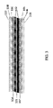
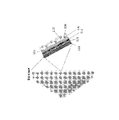
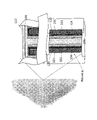
ここで図を参照する。図3~図6は、本発明のいくつかの実施形態による包装要素を示す。図3は、本発明のいくつかの実施形態の例示的なエネルギー貯蔵装置による2D(平面)層状構造の薄膜電池100における、本発明のいくつかの実施形態による包装要素の断面図である。参照番号は、電池100の以下の構成要素を示す:101は集電体であり、102はアノード又はカソードであり、104はセパレータであり、106はカソード又はアノードであり、108は導電性物質であり、110は封止層である。電池100は、基板に対して製造された又は構築された構成要素を含む。構成要素はそれぞれ、基板に堆積された膜によって提供されることができる。図4は、本発明のいくつかの実施形態による初期骨格基板120を示す包装要素の断面図である。初期骨格120基板は、導電性及び/又は非導電性であり得る。図5は、本発明のいくつかの実施形態による細孔の内側に対向電極を有する3D層状構造を示す包装要素の図である。図6は、本発明のいくつかの実施形態による細孔の外側に対向電極を有する3D層状構造を示す包装要素の図である。
Now refer to the figure. Figures 3-6 show packaging elements according to some embodiments of the present invention. FIG. 3 is a cross-sectional view of a packaging element according to some embodiments of the present invention in a 2D (planar) layered structure thin film battery 100 according to an exemplary energy storage device of some embodiments of the present invention. Reference numerals indicate the following components of battery 100: 101 is the current collector, 102 is the anode or cathode, 104 is the separator, 106 is the cathode or anode, and 108 is the conductive material. and 110 is a sealing layer. Battery 100 includes components that are manufactured or built against a substrate. Each component can be provided by a film deposited on a substrate. FIG. 4 is a cross-sectional view of a packaging element showing an
本発明の更なる目的は、長期間に渡って保護され、適切な構造支持を有するエネルギー貯蔵構成要素を提供することである。従って、本発明のいくつかの態様のいくつかの実施形態によれば、ポリマーを含む包装要素が提供され、この場合に、包装要素は、10~200μmの総厚さを有し(例えば、薄膜)、前述の包装要素は、エネルギー貯蔵装置の本質的に封止された、空隙のない囲いを提供するのに使用するためのものである。 It is a further object of the present invention to provide an energy storage component that is protected over time and has adequate structural support. Thus, according to some embodiments of some aspects of the present invention, there is provided a packaging element comprising a polymer, wherein the packaging element has a total thickness of 10-200 μm (e.g. thin film ), the aforementioned packaging element is for use in providing an essentially sealed, void-free enclosure for an energy storage device.
本明細書で使用される場合、本質的に封止されるとは、汚染物質(空気、水蒸気、ガス、電解質など)がシステムに侵入し又はシステムから漏れることができないように、エネルギー貯蔵装置の面の周りに連続的に(例えば、空隙のない)延在する薄いポリマー封入材料を提供することによって前述のエネルギー貯蔵装置を密閉して封止することを指す。 As used herein, inherently sealed refers to the energy storage device so that contaminants (air, water vapor, gases, electrolytes, etc.) cannot enter or escape from the system. Refers to hermetically sealing such energy storage devices by providing a thin polymeric encapsulant material that extends continuously (eg, without voids) around the surface.
このように、包装要素は、耐湿性である、即ち、約10g/(ミル×100インチ2)/日未満、場合には8g/(ミル×100インチ2)/日未満、場合には約5g/(ミル×100インチ2)/日未満、場合には3g/(ミル×100インチ2)/日未満の透湿性を有するエネルギー貯蔵システムを得ることを可能にする。更に場合には2g/(ミル×100インチ2)/日未満、更に場合には1.5g/(ミル×100インチ2)/日未満である。 Thus, the packaging element is moisture resistant, i.e., less than about 10 g/(mil x 100 inch2 )/day, sometimes less than 8 g/(mil x 100 inch2 )/day, sometimes about 5 g It makes it possible to obtain an energy storage system with a moisture permeability of less than /(mil x 100 inch2 )/day, in some cases less than 3 g/(mil x 100 inch2 )/day. More in some cases less than 2 g/(mil x 100 in 2 )/day, more in some cases less than 1.5 g/(mil x 100 in 2 )/day.
包装要素は、共に接合されたエネルギー貯蔵装置の構成要素アセンブリの封止層を提供するのに適している可撓性ポリマーを含む。理論に縛られることなく、本発明者らは又、包装要素によって、エネルギー貯蔵装置の動作中(即ち、充電及び放電中)に電極が体積を変えることを可能にし、従って長期サイクル中にエネルギー貯蔵装置の動作を可能にすることを実感した。包装要素に適したポリマーのいくつかの非限定的な例としては、エポキシ樹脂、パリレン(ポリ(p-キシリレン))及びポリアミド誘導体が挙げられる。いくつかの実施形態において、ポリマーは、ポリ(パラ-キシリレン)(グレードN、C、D、HT、及びこれらの任意の組み合わせ)、ポリ-m-キシリレンアジパミド、誘電性ポリマー、シリコーン系ポリマー、ポリウレタン、アクリルポリマー、硬質ガス不透過性ポリマー、硬化性フッ素化ポリマー、硬化性エポキシ、ポリイソシアネート、PET及びこれらの任意の組み合わせ、シリコーンゴム、シリコーンエラストマー、ポリアミドから選択される。いくつかの実施形態において、ポリ(パラ-キシリレン)は、ポリモノクロロ-p-キシリレン及びポリ-ジクロロ-p-キシリレンなどのクロロ置換パリレンである。 The packaging element comprises a flexible polymer suitable for providing a sealing layer for an energy storage device component assembly that is bonded together. Without being bound by theory, we also believe that the packaging element allows the electrodes to change volume during operation of the energy storage device (i.e., during charging and discharging), thus storing energy during long-term cycling. I realized that I could operate the device. Some non-limiting examples of polymers suitable for packaging elements include epoxy resins, parylene (poly(p-xylylene)) and polyamide derivatives. In some embodiments, the polymer is poly(para-xylylene) (grades N, C, D, HT, and any combination thereof), poly-m-xylylene adipamide, dielectric polymers, silicone-based Polymers, polyurethanes, acrylic polymers, rigid gas impermeable polymers, curable fluorinated polymers, curable epoxies, polyisocyanates, PET and any combination thereof, silicone rubbers, silicone elastomers, polyamides. In some embodiments, poly(para-xylylene) is a chloro-substituted parylene such as polymonochloro-p-xylylene and poly-dichloro-p-xylylene.
本発明のいくつかの態様のいくつかの実施形態は、エネルギー貯蔵装置をポリマー、例えばパリレンでコーティングする方法を提供する。いくつかの実施形態において、この方法は、ポリマーではなくダイマーから開始し、市販の機器では、それを物体の表面にて重合させるプロセス第1工程を含む。これを達成するために、ダイマーは最初に2工程加熱プロセスを経る。固体ダイマーは、モノマーの反応性蒸気に変換され、次いで、室温の物体を通過すると、蒸気はポリマーコーティングとして凝縮する。パリレンは、様々な形態で気相堆積によって生成することができる。水性系で重合を行うことにより、パリレンは粒状形態で得ることができる。これは又、低温凝縮器に堆積され、次いで遊離膜として剥がされ得る、又は0.2ミクロン~3mm以上の範囲の厚さで連続的な接着コーティングとして物体の表面に対して堆積され得る。 Some embodiments of some aspects of the present invention provide methods of coating an energy storage device with a polymer, such as parylene. In some embodiments, the method includes a process first step of starting with a dimer rather than a polymer and polymerizing it on the surface of the object in commercial instruments. To achieve this, the dimer first undergoes a two-step heating process. The solid dimer is converted to a reactive vapor of the monomer, which then condenses as a polymer coating when passed through a room temperature object. Parylene can be produced by vapor deposition in various forms. Parylene can be obtained in particulate form by conducting the polymerization in an aqueous system. It can also be deposited on a cryogenic condenser and then peeled off as a free film or deposited to the surface of an object as a continuous adherent coating in thicknesses ranging from 0.2 microns to 3 mm or more.
いくつかの実施形態において、ポリイソシアネートは、キシリレンジイソシアネート及びビス(イソシアナトメチル)シクロヘキサンからなる群から選択される少なくとも1つのイソシアネートから誘導される。 In some embodiments, the polyisocyanate is derived from at least one isocyanate selected from the group consisting of xylylene diisocyanate and bis(isocyanatomethyl)cyclohexane.
上述のように、本開示のいくつかの実施形態は、高い体積エネルギー密度を有するエネルギー貯蔵システムを提供する。これは、本発明によれば、例えば、当技術分野で知られる従来の比較的厚い包装に代わる超薄型で共形的な包装の囲いを提供することによって得られる。いくつかの実施形態において、エネルギー貯蔵装置は、10μm~200μm、20μm~200μm、30μm~200μm、40μm~200μm、50μm~200μm、60μm~200μm、70μm~200μm、80μm~200μm、90μm~200μm、100μm~200μm;10μm~80μm、場合には10μm~70μm、場合には15μm~60μm、場合には20μm~50μm、場合には20μm~40μm、更に場合には20μm~35μm;30μm~180μm、40μm~180μm、50μm~180μm、60μm~180μm、70μm~180μm、90μm~180μm、100μm~180μm、110μm~180μm、120μm~180μm、130μm~180μm、140μm~180μm;20μm~150μm、30μm~150μm、40μm~150μm、50μm~150μm、60μm~150μm、70μm~150μm、20μm~160μm、30μm~160μm、40μm~160μm、50μm~160μm;20μm~100μmの範囲の厚さを有する包装要素を含む。 As noted above, some embodiments of the present disclosure provide energy storage systems with high volumetric energy densities. This is obtained according to the present invention, for example, by providing an ultra-thin, conformal packaging enclosure that replaces conventional relatively thick packaging known in the art. In some embodiments, the energy storage device is 10 μm to 200 μm, 20 μm to 200 μm, 30 μm to 200 μm, 40 μm to 200 μm, 50 μm to 200 μm, 60 μm to 200 μm, 70 μm to 200 μm, 80 μm to 200 μm, 90 μm to 200 μm, 100 μm to 200 μm; 10 μm to 80 μm, optionally 10 μm to 70 μm, optionally 15 μm to 60 μm, optionally 20 μm to 50 μm, optionally 20 μm to 40 μm, further optionally 20 μm to 35 μm; 30 μm to 180 μm, 40 μm to 180 μm, 50 μm to 180 μm, 60 μm to 180 μm, 70 μm to 180 μm, 90 μm to 180 μm, 100 μm to 180 μm, 110 μm to 180 μm, 120 μm to 180 μm, 130 μm to 180 μm, 140 μm to 180 μm; 150 μm, 60 μm to 150 μm, 70 μm to 150 μm, 20 μm to 160 μm, 30 μm to 160 μm, 40 μm to 160 μm, 50 μm to 160 μm; 20 μm to 100 μm;
典型的な電気化学エネルギー貯蔵システムは、2つの電極層及びイオン透過性層、即ちこれらの間に配置されたセパレータ層、及び/又は両電極をイオン的に接続する電解質(電解質とも称される)を含むアセンブリを含む。セルの反応物は酸化還元反応を受ける。電気化学エネルギー貯蔵システムの1つのタイプは、スーパーキャパシタであり、この場合に、電極が印加電圧によって分極されると、電解質中のイオンが電極の極性と反対の極性の電気二重層を形成する。このようにして、正の極性の電極は、負の層に吸着する陽イオンの電荷平衡化層と共に、電極/電解質界面に陰イオンの層を有する。負の極性の電極についても逆のことが言える。 A typical electrochemical energy storage system consists of two electrode layers and an ion-permeable layer, i.e. a separator layer disposed between them, and/or an electrolyte (also called electrolyte) that ionically connects both electrodes. Including assemblies that contain The cell reactants undergo redox reactions. One type of electrochemical energy storage system is a supercapacitor, in which when the electrodes are polarized by an applied voltage, ions in the electrolyte form an electrical double layer of polarity opposite that of the electrodes. Thus, a positive polarity electrode has a layer of anions at the electrode/electrolyte interface with a charge balancing layer of cations adsorbed on the negative layer. The opposite is true for negative polarity electrodes.
本発明によって利用することができるエネルギー貯蔵システムのいくつかの例としては、電池、リチウム電池、リチウムイオン電池、全固体リチウムイオン電池、スーパーキャパシタ、ハイブリッドキャパシタ、リチウムイオンキャパシタ、ウルトラキャパシタ、固体電解質スーパーキャパシタ、固体電解質ハイブリッドリチウムイオンスーパーキャパシタ等などの任意の電気化学エネルギー貯蔵セルが挙げられる。 Some examples of energy storage systems that can be utilized by the present invention include batteries, lithium batteries, lithium ion batteries, all solid state lithium ion batteries, supercapacitors, hybrid capacitors, lithium ion capacitors, ultracapacitors, solid electrolyte supercapacitors. Any electrochemical energy storage cell such as a capacitor, solid electrolyte hybrid lithium ion supercapacitor, and the like.
エネルギー貯蔵システムが電池の場合、アセンブリは以下の構成要素を含む:アノード層(負極)、カソード層(正極)、及び電極間に配置されたセパレータ層(「電解質」とも称される)。アノード及びカソードはそれぞれ、典型的には、カソード及びアノード用にそれぞれアルミニウム及び銅などの集電体を含む。セルの反応物は酸化還元反応を受ける。 When the energy storage system is a battery, the assembly includes the following components: an anode layer (negative electrode), a cathode layer (positive electrode), and a separator layer (also called "electrolyte") disposed between the electrodes. The anode and cathode each typically include current collectors such as aluminum and copper for the cathode and anode respectively. The cell reactants undergo redox reactions.
本発明のいくつかの実施形態によるエネルギー貯蔵装置を製造する方法は、基板にベース層を形成すること、及びベース層にエネルギー貯蔵スタックを形成することを含む。エネルギー貯蔵スタックは、以下の層:2つの電極層、及びアノードとカソードとの間の電解質層の別々の構成要素の少なくとも1つの接合を含む。 A method of manufacturing an energy storage device according to some embodiments of the present invention includes forming a base layer on a substrate and forming an energy storage stack on the base layer. The energy storage stack comprises at least one junction of separate components of the following layers: two electrode layers and an electrolyte layer between the anode and the cathode.
エネルギー貯蔵システムは、典型的には、エネルギー貯蔵スタックに対する電気コネクタを含み、これは、スタック(又はセルの多層スタック)を電子装置に接続するように、例えば電池で構成され、アノード電極コネクタ及びカソード電極コネクタは、それぞれアノード層及びカソード層に結合される。 The energy storage system typically includes an electrical connector to the energy storage stack, which consists of, for example, a battery, an anode electrode connector and a cathode, to connect the stack (or multi-layer stack of cells) to an electronic device. Electrode connectors are coupled to the anode layer and the cathode layer, respectively.
本開示によるエネルギー貯蔵システムを製造する更なる方法は、ベース層(例えば、アルミニウム箔)を提供し、その上に連続的に層を形成することによる。例えば、アルミニウム箔上にカソード層を形成し、その後にその上に電解質層を形成し、更にその後カソード層にアノード層を形成する(又は集電体にアノード層を形成し、前記層を電解質層に接合する)。又、形成は、逆の順序で、即ち最初にアノード層、次いで電解質層、次いでカソード層を形成することによって行うことができる。形成は、当技術分野において公知の任意の従来の方法、例えば、電気泳動堆積又は簡易な流延(例えばドクターブレードによる)によって実施することができる。 A further method of manufacturing an energy storage system according to the present disclosure is by providing a base layer (eg, aluminum foil) and successively forming layers thereon. For example, forming a cathode layer on an aluminum foil, then forming an electrolyte layer thereon, and then forming an anode layer on the cathode layer (or forming an anode layer on a current collector and forming the anode layer on the electrolyte layer). ). Formation can also be performed in the reverse order, ie, forming the anode layer first, then the electrolyte layer, and then the cathode layer. Forming can be performed by any conventional method known in the art, such as electrophoretic deposition or simple casting (eg, by doctor blade).
又、エネルギー貯蔵システムは、導電性基板にコーティングされた電極のうちの1つからなるセルとして本明細書で設計された3D電極セル、3次元電極の表面にコーティングされたセパレータ若しくはポリマー電解質の平型層、及び反対の極性の電極の平型層、又は両面から堆積された導電性箔若しくは膜を含む。 The energy storage system may also be a 3D electrode cell, designed herein as a cell consisting of one of the electrodes coated on a conductive substrate, a separator or polymer electrolyte plane coated on the surface of a three-dimensional electrode. It includes a mold layer and flat layers of electrodes of opposite polarity, or a conductive foil or film deposited from both sides.
平型基板と比較して三次元の基板を使用すると、基板の表面積が増加する。増加率は、文献では面積利得(AG)として知られている。例えば、0.1mm~5mmの厚さの穿孔された基板のAGは、3~200のAGとなる。 Using a three-dimensional substrate as compared to a flat substrate increases the surface area of the substrate. The rate of increase is known in the literature as area gain (AG). For example, a perforated substrate with a thickness of 0.1 mm to 5 mm will have an AG of 3-200.
更に、この装置は、3つの活性層:カソード、セパレータ及びアノードが、導電性薄膜の両側に共形的に堆積される平型可撓性電池であり得る。得られる電気化学装置は、1層として、又は巻き取られた/丸められた構成で使用することができる。このような電池構成は、標準的な厚さの電極を有する電池、又は着用可能な電子機器用の超薄型可撓性電池、IoT用のエネルギー貯蔵及び表面実装型エネルギー貯蔵装置として機能することができる。両面からコーティングされた箔基板の面積利得は、本明細書では2のAGを有すると称される。 Further, the device can be a flat flexible battery in which the three active layers: cathode, separator and anode are conformally deposited on both sides of the conductive thin film. The resulting electrochemical device can be used as a single layer or in a rolled/rolled configuration. Such battery configurations can serve as batteries with standard thickness electrodes, or ultra-thin flexible batteries for wearable electronics, energy storage for IoT and surface-mounted energy storage devices. can be done. The area gain of a foil substrate coated from both sides is referred to herein as having an AG of 2.
平型基板は、本明細書では1のAGを有する基板と称される。平型基板のいくつかの非限定的な例としては、ニッケル、アルミニウム、ステンレス鋼、銅、及び金などの金属;金属布地;ポリエチレンテレフタレート(PET)、ポリジメチルシロキサン(PDMS)、ポリアミド(ナイロン)、ポリエチレン(PE)、ポリプロピレン(PP)、ポリ(メチルメタクリレート)(PMMA)、ポリスチレン(PS)、ポリテトラフルオロエチレン(PTFE)、ポリ塩化ビニル(PVC)、ポリウレタン(PU)、ポリカーボネート(PC)などのポリマー;カーボン繊維マット、カーボンナノチューブマット、カーボン布地、及びカーボン紙などのカーボン材料が挙げられる。 A planar substrate is referred to herein as a substrate with an AG of 1. Some non-limiting examples of flat substrates include metals such as nickel, aluminum, stainless steel, copper, and gold; metal fabrics; polyethylene terephthalate (PET), polydimethylsiloxane (PDMS), polyamide (nylon) , polyethylene (PE), polypropylene (PP), poly(methyl methacrylate) (PMMA), polystyrene (PS), polytetrafluoroethylene (PTFE), polyvinyl chloride (PVC), polyurethane (PU), polycarbonate (PC), etc. polymers; carbon materials such as carbon fiber mats, carbon nanotube mats, carbon cloth, and carbon paper.
[01]本発明のいくつかの実施形態によるエネルギー貯蔵システムは、リチウムイオン二次電池を含む。本発明のいくつかの実施形態によれば、電解質は、材料を還元してアノード表面に不溶性固体電解質界面(SEI)を形成するのに適した溶媒を含む。このような溶媒としては、エチレンカーボネート(EC)、ジエチルカーボネート(DEC)、ジメチルカーボネート(DMC)、エチルメチルカーボネート(EMC)、ブチルカーボネート、プロピレンカーボネート、ビニルカーボネート、ジアルキルサルファイト及びこれらの任意の混合物などの非プロトン性溶媒が挙げられる。更に、良好なSEI前駆体として適していることが当技術分野において公知の金属塩としては、LiPF6、LiBF4、LiAsF6、LiCF3、及びLiN(CF3SO2)2、LiCF3SO3、LiI、LiBOB及びLiBrが挙げられる。 [01] An energy storage system according to some embodiments of the present invention includes a lithium-ion secondary battery. According to some embodiments of the invention, the electrolyte comprises a solvent suitable for reducing materials to form an insoluble solid electrolyte interface (SEI) at the anode surface. Such solvents include ethylene carbonate (EC), diethyl carbonate (DEC), dimethyl carbonate (DMC), ethyl methyl carbonate (EMC), butyl carbonate, propylene carbonate, vinyl carbonate, dialkyl sulfite and any mixture thereof. aprotic solvents such as Additionally, metal salts known in the art to be suitable as good SEI precursors include LiPF6, LiBF4, LiAsF6, LiCF3, and LiN(CF3SO2)2, LiCF3SO3, LiI, LiBOB and LiBr.
いくつかの実施形態において、リチウムイオン電池は液体電解質を含む。例えば、液体電解質は、上記のリストからの非プロトン性溶媒及びLiPF6などのリチウム塩を含み得る。いくつかの実施形態において、液体電解質は、有機溶媒に少なくとも1つのリチウム塩を含む。このような実施形態においては、有機溶媒は、エチレンカーボネート、ジメチルカーボネート、ジエチルカーボネート、エチルメチルカーボネート、ブチルカーボネート、プロピレンカーボネート、ビニルカーボネート、ジアルキルサルファイト及びフルオロエチレンカーボネートの少なくとも1つを含む。更なる実施形態においては、液体電解質はイオン液体を含む。 In some embodiments, a lithium ion battery includes a liquid electrolyte. For example, the liquid electrolyte can include an aprotic solvent from the list above and a lithium salt such as LiPF6. In some embodiments, the liquid electrolyte comprises at least one lithium salt in an organic solvent. In such embodiments, the organic solvent comprises at least one of ethylene carbonate, dimethyl carbonate, diethyl carbonate, ethyl methyl carbonate, butyl carbonate, propylene carbonate, vinyl carbonate, dialkyl sulfite and fluoroethylene carbonate. In further embodiments, the liquid electrolyte comprises an ionic liquid.
本明細書で使用されるイオン液体は、有機成分との塩であり、100℃未満の温度で液体である。これらは、蒸気圧がほとんどなく、非常に安定であり、従って不揮発性である。カチオンの存在は、イオン液体に高いイオン導電率を与える傾向があり、イオン液体を従来の電池の液体電解質の優れた代替品にする。いくつかの非限定的な例としては、1-エチル-3-メチルイミダゾリウム、1-ブチル-3-メチルピリジニウムビス(トリフルオロメチルスルホニル)、1-ブチル-1-メチルピロリジニウムビス(フルオロスルホニル)イミド、1-メチル-1-(2-メトキシエチル)ピロリジニウムビス(フルオロスルホニル)イミド、1-エチル-3-メチルイミダゾリウムテトラフルオロボレート、N-エチル-N-メチルピペリジニウムビス(フルオロスルホニル)イミドを含むイオン液体が挙げられる。 As used herein, ionic liquids are salts with organic components and are liquid at temperatures below 100°C. They have little vapor pressure and are very stable and therefore non-volatile. The presence of cations tends to give ionic liquids high ionic conductivity, making them excellent alternatives to liquid electrolytes in conventional batteries. Some non-limiting examples include 1-ethyl-3-methylimidazolium, 1-butyl-3-methylpyridinium bis(trifluoromethylsulfonyl), 1-butyl-1-methylpyrrolidinium bis(fluoro sulfonyl)imide, 1-methyl-1-(2-methoxyethyl)pyrrolidinium bis(fluorosulfonyl)imide, 1-ethyl-3-methylimidazolium tetrafluoroborate, N-ethyl-N-methylpiperidinium bis Ionic liquids containing (fluorosulfonyl)imides can be mentioned.
いくつかの他の実施形態においては、本明細書に開示されるリチウムイオン電池は、固体又はゲルポリマー電解質を含む。即ち、ポリマー電解質は、金属塩(例えば、上記のリストから)との錯体を形成するように適合されたポリマー、好ましくはポリエチレンオキシド、及び場合により、複合材料ポリマー電解質を形成するためにナノサイズのセラミック粉末を含む。 In some other embodiments, the lithium ion batteries disclosed herein include solid or gel polymer electrolytes. That is, the polymer electrolyte is a polymer, preferably polyethylene oxide, adapted to form a complex with a metal salt (e.g., from the list above) and, optionally, a nano-sized polyelectrolyte to form a composite polymer electrolyte. Contains ceramic powder.
いくつかの実施形態において、それぞれ、単位体積及び重量当たりの電池のエネルギー容量を表す可撓性電池のエネルギー密度及び比エネルギーは、重要な性能パラメータであり、従って、このような電池のエネルギー密度及び比エネルギーを増加させることが望ましい。極薄包装要素を有する本発明のエネルギー貯蔵モジュールを利用することによって、このようなモジュールの高い体積エネルギー密度及び比エネルギーが得られる。 In some embodiments, the energy density and specific energy of a flexible battery, which represent the energy capacity of a battery per unit volume and weight, respectively, are important performance parameters and thus the energy density and specific energy of such a battery. It is desirable to increase the specific energy. By utilizing the energy storage modules of the present invention with ultra-thin packaging elements, high volumetric energy densities and specific energies of such modules are obtained.
いくつかの実施形態において、エネルギー貯蔵モジュールは、前述の電池モジュールが0.01mA/cm2の電流で放電されたときに、少なくとも1リットル当たり200mAhの体積エネルギー密度(mAh/1)を有する。 In some embodiments, the energy storage module has a volumetric energy density of at least 200 mAh per liter (mAh/1) when said battery module is discharged at a current of 0.01 mA/cm2.
いくつかの実施形態において、電池モジュールは、公称電圧まで充電し、公称電圧の50%まで、又はリチウムに対して0.1Vまで放電することによって測定される、少なくとも1g当たり40mAhの重量エネルギー密度(mAh/g)を有する。 In some embodiments, the battery module has a gravimetric energy density of at least 40 mAh per gram ( mAh/g).
又、以下の特性、0.2kN荷重セル又はこれに等価のものを用いた引張り試験機(Tensile Tester)によって測定される高い引張り強度を有すること、合計1000回の曲げサイクルにかけられることによって測定される高い靭性を有すること、の少なくとも1つを有するエネルギー貯蔵モジュールが、本発明により提供され、ISO/IEC 10373-1及び国際規格ISO/IEC 7810に記載の試験方法に従ってセルを試験した後に、セルは試験可能な機能を維持し、割れた部分を示さない。これに加えて又はこの代わりに、合計1000回のねじれサイクルを受けたとき、ISO/IEC 10373-1に記載の試験方法に従って試験した後に、セルは試験可能な機能を維持し、割れた部分を示さない。これに加えて又はこの代わりに、曲げサイクルは、45°、90°及び120°の曲げ角度で100~1000回のネンディング(nending)の後にセル容量を測定することによって測定された。 It also has the following properties, having a high tensile strength as measured by a Tensile Tester using a 0.2 kN load cell or its equivalent, measured by being subjected to a total of 1000 bending cycles. An energy storage module is provided by the present invention having at least one of: having a high toughness, wherein the cell is maintains testable functionality and shows no cracks. Additionally or alternatively, when subjected to a total of 1000 torsion cycles, the cell remains testable and free of cracks after being tested according to the test method described in ISO/IEC 10373-1. not shown. Additionally or alternatively, the bend cycle was measured by measuring the cell capacity after 100-1000 nendings at bend angles of 45°, 90° and 120°.
これに加えて又はこの代わりに、エネルギー貯蔵モジュールは、約10g/(ミル×100インチ2)/日未満の透湿性を有する。 Additionally or alternatively, the energy storage module has a moisture vapor permeability of less than about 10 g/(mil x 100 in2)/day.
これに加えて又はこの代わりに、薄膜コーティング(包装)要素は、約0.1μmを超える構造を明らかにする倍率で見たときに材料の異なる構成要素間に隙間を有さない。 Additionally or alternatively, the thin film coating (packaging) element has no gaps between different components of the material when viewed at magnifications that reveal structures greater than about 0.1 μm.
これに加えて又はこの代わりに、薄膜包装要素は、パリレン層と塗料などの接着剤との良好な接着性を有する。 Additionally or alternatively, the thin film packaging element has good adhesion between the parylene layer and adhesives such as paint.
これに加えて又はこの代わりに、エネルギー貯蔵モジュールは、サイクル寿命の10%毎のサイクル前に、サイクル中に電気化学セル及び/又は半セルで測定された安定した機械的特性を有する。 Additionally or alternatively, the energy storage module has stable mechanical properties measured in the electrochemical cells and/or half-cells during cycling before cycling every 10% of the cycle life.
又、本発明のエネルギー貯蔵モジュールは、その引張り弾性率(tensile modulus of elasticity)(場合には弾性率(elastic modules)又は引張り弾性率(tensile modulus)という用語でも称される)によって特徴付けられ得る。一般的に、引張り弾性率は、力が加えられるときに弾性的に(即ち非永久的に)変形する材料の抵抗によって定義される。必要な力が大きいほど、材料は硬くなる。典型的には、エネルギー貯蔵モジュールは高い引張り弾性率を有する。従って、本明細書で提供される可撓性ポリマーの囲いは、所望の形状を有する構造として形成されることができる。 Energy storage modules of the invention may also be characterized by their tensile modulus of elasticity (sometimes also referred to by the terms elastic modules or tensile modulus). . Tensile modulus is generally defined by the resistance of a material to elastically (ie, non-permanently) deform when a force is applied. The greater the force required, the stiffer the material. Typically, energy storage modules have a high tensile modulus. Accordingly, the flexible polymeric enclosures provided herein can be formed into structures having desired shapes.
又、本発明の電池モジュールは、以下の特徴の1つ以上によって特徴付けられ得る:
引張り強度、即ち、材料が張力下で破損する又は永久的に変形する応力。
屈曲強度(場合には曲げ強度という用語でも称される)、即ち、破断の瞬間に材料にかかる応力。
屈曲弾性率は、材料の曲げ剛性、即ち、加えられた力による変形に対する材料の抵抗を指す。
シャルピー衝撃(シャルピーVノッチ試験)は、屈曲衝撃下で試験片を破壊するのに必要な単位面積当たりのエネルギーを指す。
Battery modules of the invention may also be characterized by one or more of the following features:
Tensile strength, ie the stress at which a material fails or permanently deforms under tension.
Flexural strength (sometimes also referred to by the term flexural strength), i.e. the stress exerted on a material at the moment of breakage.
Flexural modulus refers to the flexural stiffness of a material, ie, the material's resistance to deformation due to an applied force.
Charpy impact (Charpy V-notch test) refers to the energy per unit area required to break a specimen under flexural impact.
表面エネルギーは、材料の表面張力を指す。2つの材料が互いに接着するために、これらの表面エネルギー(表面張力)が類似しているべきであることは十分に理解される。 Surface energy refers to the surface tension of a material. It is well understood that in order for two materials to adhere to each other, their surface energies (surface tensions) should be similar.
又、剥離試験は、エネルギー貯蔵装置における接着性を測定するための一般的な手段である。離層する装置における任意の界面は、水の浸入に対する経路を潜在的に作り出す可能性があるので、層間の接着強度を決定することが重要である。当技術分野において公知のいくつかの方法を使用して、薄膜の接着力を測定することができる。「スコッチ試験テープ」は、一片の感圧テープを膜に貼り付けてテープを引き剥がすことによって、基板に堆積された膜の接着性を定性的に試験する。堆積された膜の上部層が(部分的に又は断片的に)剥がれた場合、試験に「不合格」であったと言われる。又、膜の接着力は、膜の自由端に接続された荷重セルを使用して決定することができ、これを次いで固定された基板に対して90°の角度で、又は第2の取り付けられた可撓性膜に対して180°で引張り、膜を基板から分離するのに必要な力を測定する。剥離強度は、2つの材料を徐々に分離するのに必要とされる結合線の単位幅当たりの平均荷重として定義される。 Peel testing is also a common means of measuring adhesion in energy storage devices. Determining the bond strength between layers is important because any interface in a delaminating device can potentially create a path for water ingress. Adhesion of thin films can be measured using several methods known in the art. The "Scotch Test Tape" qualitatively tests the adhesion of a film deposited on a substrate by applying a piece of pressure sensitive tape to the film and pulling the tape away. A test is said to have "failed" if the top layer of the deposited film delaminates (partially or fragmentarily). Alternatively, the adhesion of the membrane can be determined using a load cell connected to the free end of the membrane, which is then attached at a 90° angle to a fixed substrate or a second attached The flexible membrane is pulled through 180° and the force required to separate the membrane from the substrate is measured. Peel strength is defined as the average load per unit width of bondline required to gradually separate two materials.
電気化学インピーダンス分光法(EIS)は、トレース間のインピーダンス(横方向のインピーダンス)及びトレースと外部対向電極との間のインピーダンス(横断方向のインピーダンス)を測定することによって、装置における不具合の兆候(例えば、離層、水又はガスの浸透)を識別する。 Electrochemical Impedance Spectroscopy (EIS) measures the impedance between traces (transverse impedance) and the impedance between traces and an external counter electrode (transverse impedance) to detect failure indications (e.g., , delamination, water or gas permeation).
又、本発明は、ポリマーを含む包装要素を含むエネルギー貯蔵モジュールを提供し、この場合に、ポリマーはエネルギー貯蔵モジュールの面の側面の周り及び周囲の周りに連続的に延びる空隙のない均質な囲いを提供する。従って、本発明によれば、「空隙のない」という用語は、特に、走査型電子顕微鏡によって、又はこのような隙間を明らかにするための当技術分野において公知の他の適切な技術によって観察された場合、隙間がある場合には、隙間は0.1μm未満のサイズ(幅)であるように、表面に形成された(例えば、堆積された)ポリマー粒子が周囲の媒体と非常に密接に結び付いていることを指す。理論に拘束されることを望まないが、これは前述の周囲の媒体に含まれるポリマー包装材料の接着特性(表面エネルギー)の結果であると考えられる。 The present invention also provides an energy storage module comprising a packaging element comprising a polymer, wherein the polymer is a void-free homogeneous enclosure extending continuously around the sides and perimeter of the face of the energy storage module. I will provide a. Thus, according to the present invention, the term "void-free" is specifically observed by scanning electron microscopy or by other suitable techniques known in the art for revealing such voids. In this case, the polymer particles formed (e.g., deposited) on the surface are very closely associated with the surrounding medium such that the gap, if any, is less than 0.1 μm in size (width). It means that While not wishing to be bound by theory, it is believed that this is a result of the adhesive properties (surface energy) of the polymeric encapsulant material contained in the aforementioned surrounding medium.
電池モジュールは、2つの以下の構成要素の層を含む:カソード層、セパレータ(電解質)及びアノード層。カソード層は、リチウムコバルト酸化物、リチウム鉄リン酸、リチウムマンガン酸化物、リチウムニッケルコバルト酸化物、リチウムニッケルコバルトアルミニウム酸化物、リチウムニッケルコバルトマンガン酸化物を含むがこれらに限定されないカソード材料を含む。いくつかの実施形態において、カソードは、LiNbO3、硫化銅、2D層状酸化物、バナジウム酸化物から選択される導電性材料を含む薄層で更にコーティングされる。いくつかの実施形態において、カソード層は、リチウムコバルト酸化物又はリチウム鉄リン酸を含む。 A battery module contains two following component layers: a cathode layer, a separator (electrolyte) and an anode layer. The cathode layer comprises a cathode material including, but not limited to, lithium cobalt oxide, lithium iron phosphate, lithium manganese oxide, lithium nickel cobalt oxide, lithium nickel cobalt aluminum oxide, lithium nickel cobalt manganese oxide. In some embodiments, the cathode is further coated with a thin layer comprising a conductive material selected from LiNbO3, copper sulfide, 2D layered oxide, vanadium oxide. In some embodiments, the cathode layer comprises lithium cobalt oxide or lithium iron phosphate.
いくつかの実施形態において、カソードは、ココナッツ、タール、木材、タバコの葉、植物、有機ポリマーなどの天然資源からの活性炭を含む。
In some embodiments, the cathode comprises activated carbon from natural sources such as coconut, tar, wood, tobacco leaves, plants, organic polymers.
カソードは、0~15重量/重量%の濃度を有するバインダー及び0~15重量/重量%の濃度を有する導電性添加剤を更に含む。導電性添加剤のいくつかの非限定的な例としては、カーボンブラック、多壁カーボンナノチューブ(MWCNT)、単壁カーボンナノチューブ(SWCNT)、グラフェンフレーク、グラフェン酸化物フレーク、活性炭及びグラファイトが挙げられる。 The cathode further comprises a binder having a concentration of 0-15% weight/weight and a conductive additive having a concentration of 0-15% weight/weight. Some non-limiting examples of conductive additives include carbon black, multi-wall carbon nanotubes (MWCNT), single-wall carbon nanotubes (SWCNT), graphene flakes, graphene oxide flakes, activated carbon and graphite.
バインダーのいくつかの非限定的な例としては、ポリマー又はコポリマーが挙げられる:セルロース系ポリマー、ポリエチレンオキシド、ポリフッ化ビニリデン(PVDF)、ポリエチレンオキシド(PEO)、ポリエチレンイミン(PEI)、ポリ塩化ビニル(PVC)、ポリテトラフルオロエチレン(PTFE)、オルトシリケートポリマー誘導体の複合材料、ナトリウム/リチウムカルボキシメチルセルロース(NaCMC/LiCMC)、セルロース系バインダー及びポリメチルメタクリレート(PMMA)。 Some non-limiting examples of binders include polymers or copolymers: cellulosic polymers, polyethylene oxide, polyvinylidene fluoride (PVDF), polyethylene oxide (PEO), polyethyleneimine (PEI), polyvinyl chloride ( PVC), polytetrafluoroethylene (PTFE), composites of orthosilicate polymer derivatives, sodium/lithium carboxymethylcellulose (NaCMC/LiCMC), cellulosic binders and polymethyl methacrylate (PMMA).
集電体又はセパレータ層へのカソード層の堆積は、電着又はスピンコーティング、AC電場(AC-EPD)における電気泳動堆積プロセス又は水性電気泳動堆積、化学気相堆積(CVD)、又は電気化学的にゾル-ゲルプロセスを誘発するプロセスを含むがこれらに限定されない、当技術分野において公知の任意の従来の方法によって行うことができる。 Deposition of the cathode layer onto the current collector or separator layer can be by electrodeposition or spin coating, an electrophoretic deposition process in an AC electric field (AC-EPD) or aqueous electrophoretic deposition, chemical vapor deposition (CVD), or electrochemical deposition. It can be done by any conventional method known in the art, including, but not limited to, processes that induce a sol-gel process.
アノード層は、グラファイト、リチウムイオンを注入したグラファイト、ケイ素、ケイ素-カーボン複合材料、ナノ粒子、ケイ素ナノチューブ又はカーボン-ケイ素複合材料凝集物、スズ及びスズ酸化物粒子、グラフェン、硬質カーボン、リチウム、リチウムチタン酸化物(LTO)を含むがこれらに限定されない、アノード材料を含む。対称型スーパーキャパシタ又はウルトラキャパシタの場合:ココナッツ、タール、木材、タバコの葉、植物、有機ポリマーなどの天然資源からの活性炭。 The anode layer may be graphite, graphite implanted with lithium ions, silicon, silicon-carbon composites, nanoparticles, silicon nanotubes or carbon-silicon composite aggregates, tin and tin oxide particles, graphene, hard carbon, lithium, lithium Anode materials including, but not limited to, titanium oxide (LTO). For symmetrical supercapacitors or ultracapacitors: activated carbon from natural sources such as coconut, tar, wood, tobacco leaves, plants, organic polymers.
アノードは、0~15重量/重量%の濃度を有するバインダー及び0~15重量/重量%の濃度を有する導電性添加剤を更に含む。導電性添加剤のいくつかの非限定的な例としては、カーボンブラック、多壁カーボンナノチューブ(MWCNT)、単壁カーボンナノチューブ(SWCNT)、グラフェンフレーク、グラフェン酸化物フレーク、活性炭及びグラファイトが挙げられる。 The anode further comprises a binder having a concentration of 0-15% weight/weight and a conductive additive having a concentration of 0-15% weight/weight. Some non-limiting examples of conductive additives include carbon black, multi-wall carbon nanotubes (MWCNT), single-wall carbon nanotubes (SWCNT), graphene flakes, graphene oxide flakes, activated carbon and graphite.
バインダーのいくつかの非限定的な例としては、ポリマー又はコポリマー:セルロース系ポリマー、ポリエチレンオキシド、ポリフッ化ビニリデン(PVDF)、ポリエチレンオキシド(PEO)、ポリエチレンイミン(PEI)、ポリ塩化ビニル(PVC)、ポリテトラフルオロエチレン(PTFE)、ナトリウム/リチウムカルボキシメチルセルロース(NaCMC/LiCMC)、セルロース系バインダー及びポリメチルメタクリレート(PMMA)が挙げられる。 Some non-limiting examples of binders include polymers or copolymers: cellulosic polymers, polyethylene oxide, polyvinylidene fluoride (PVDF), polyethylene oxide (PEO), polyethyleneimine (PEI), polyvinyl chloride (PVC), Polytetrafluoroethylene (PTFE), sodium/lithium carboxymethylcellulose (NaCMC/LiCMC), cellulosic binders and polymethylmethacrylate (PMMA).
集電体又はセパレータ層へのアノード層の堆積は、電着、スピンコーティング、電気泳動堆積プロセスを含むがこれらに限定されない、当技術分野において公知の任意の従来の方法によって行うことができる。いくつかの実施形態において、アノードはケイ素粒子を含む。 Deposition of the anode layer onto the current collector or separator layer can be done by any conventional method known in the art including, but not limited to, electrodeposition, spin coating, electrophoretic deposition processes. In some embodiments, the anode comprises silicon particles.
本発明の更なる目的は、高出力密度、高容量及び高エネルギー密度のうちの少なくとも1つを有するエネルギー貯蔵システム(例えば、三次元マイクロ電池)を提供することである。 A further object of the present invention is to provide an energy storage system (eg, a three-dimensional microbattery) that has at least one of high power density, high capacity and high energy density.
上記の目的は、本発明により、基板の構造に貫通孔を有する基板(本明細書では「三次元基板」又は「三次元電池」とも称される)を利用することにより達成される。このような基板の使用は、薄膜堆積において利用可能な面積を増加させ、このため、体積の増加、即ちセルの容量の増加をもたらす。 The above objectives are achieved according to the present invention by utilizing a substrate (also referred to herein as a "three-dimensional substrate" or "three-dimensional battery") having through holes in the structure of the substrate. The use of such substrates increases the area available for thin film deposition, thus resulting in an increase in volume, ie an increase in cell capacity.
本明細書に記載の3D電池技術は、完全な薄膜セル構造を平面形状から小さい設置面積及び小さい容積で配置された3Dネットワークに変える設計であり、拡散経路の長さを短くすることによって出力を増大させる。 The 3D battery technology described herein is a design that transforms an entirely thin-film cell structure from a planar geometry into a 3D network arranged with a small footprint and volume, which reduces the power output by shortening the diffusion path length. Increase.
従って、その態様の更に別の態様では、本開示は、2~200を超えるアスペクト比を有する複数の内面穿孔を備えた基板、薄層アノード、薄層カソード、アノード層とカソード層の間に配置された電解質層又はセパレータ層を含むエネルギー貯蔵モジュールを提供し、前述の層は、前述の基板の表面領域に及び前述の穿孔の内面全体に渡って形成され、前述のエネルギー貯蔵モジュールは、ポリマーを含む薄膜包装要素によって囲まれ、薄膜包装要素は、前述のエネルギー貯蔵モジュールの本質的に封止された、空隙のない囲いを提供するように構成され、包装要素は、10μm~200μmの厚さを有する。 Thus, in still another of its aspects, the present disclosure provides a substrate with a plurality of internal perforations having an aspect ratio of 2 to greater than 200, a thin layer anode, a thin layer cathode, disposed between an anode layer and a cathode layer. providing an energy storage module comprising an electrolyte layer or a separator layer, said layer being formed on a surface area of said substrate and over the inner surface of said perforations, said energy storage module comprising a polymer The thin film packaging element is configured to provide an essentially sealed, void-free enclosure of the aforementioned energy storage module, the packaging element having a thickness of 10 μm to 200 μm. have.
いくつかの実施形態において、エネルギー貯蔵モジュールはオンチップ電池である。いくつかの実施形態において、エネルギー貯蔵装置は、2つの電極及び電解質を含浸させたセパレータを含む対称型又はハイブリッド型スーパーキャパシタである。対称型スーパーキャパシタの場合、電極は、電極固形分の70~100重量/重量%のグラム当たり700~2500平方メートルの表面積を有する活性炭、ポリフッ化ビニリデン(PVDF)、ポリエチレンオキシド(PEO)、ポリテトラフルオロエチレン(PTFE)、又はポリメチルメタクリレート(PMMA)などのバインダー、0~20重量/重量%の電極固形分及び0~10重量/重量%の電極固形分の導電性添加剤、例えばカーボンナノチューブ又はカーボンブラックを含む。 In some embodiments, the energy storage module is an on-chip battery. In some embodiments, the energy storage device is a symmetrical or hybrid supercapacitor that includes two electrodes and an electrolyte-impregnated separator. For symmetrical supercapacitors, the electrodes are activated carbon, polyvinylidene fluoride (PVDF), polyethylene oxide (PEO), polytetrafluoro Binder such as ethylene (PTFE), or polymethyl methacrylate (PMMA), 0-20 wt/wt % electrode solids and 0-10 wt/wt % electrode solids conductive additives such as carbon nanotubes or carbon Including black.
ハイブリッドスーパーキャパシタは、正極としてリチウムイオンカソードと、負極として活性炭とを含む。対称型及び非対称型スーパーキャパシタの両方における電解質は、水性又は有機性であり得る。水性電解質は、硫酸、水酸化カリウム及び硫酸ナトリウムなどの、酸性、塩基性、又は中性の電解質である。スーパーキャパシタ用の有機電解質は、対称型スーパーキャパシタ用のアンモニウム塩系電解質を有する、又はハイブリッドスーパーキャパシタ用のリチウム塩を有する炭酸塩系電解質を有するアセトニトリルであり得る。 A hybrid supercapacitor contains a lithium ion cathode as the positive electrode and activated carbon as the negative electrode. The electrolyte in both symmetric and asymmetric supercapacitors can be aqueous or organic. Aqueous electrolytes are acidic, basic or neutral electrolytes such as sulfuric acid, potassium hydroxide and sodium sulfate. Organic electrolytes for supercapacitors can be acetonitrile with ammonium salt-based electrolytes for symmetrical supercapacitors, or with carbonate-based electrolytes with lithium salts for hybrid supercapacitors.
いくつかの実施形態において、エネルギー貯蔵装置、電池又はスーパーキャパシタは、並列又は直列に接続された少なくとも2つの積層セルの形態である。積層構成では、セルは、それぞれの連続セルの上部に又は互いに隣接して配置される。上記電気化学装置は、直列構成において、スタック内の最初のセルの1つの極性から最後のセルの反対の極性までの電気回路に接続され、並列構成において、スタック内のそれぞれのセルは、正と負のポートの両方によって回路に接続される。並列及び直列構成の両方において、セルは、セル電極の重量バランスによって又は能動的BMS装置によって受動的にバランスがとられている。 In some embodiments, the energy storage device, battery or supercapacitor is in the form of at least two stacked cells connected in parallel or series. In a stacked configuration, the cells are arranged on top of each successive cell or adjacent to each other. The electrochemical devices are connected in an electrical circuit from one polarity of the first cell in the stack to the opposite polarity of the last cell in a series configuration, and in a parallel configuration each cell in the stack is positive and positive. It is connected to the circuit by both negative ports. In both parallel and series configurations, the cells are passively balanced by the weight balance of the cell electrodes or by an active BMS device.
標準的なエネルギー貯蔵装置は、電極として様々な形態の炭素(例えば、リチウム電池では炭素膜がアノードとして使用される)、及びセルガード(Celgard)などの市販のセパレータを利用する。グラファイトなどのアノード材料は、Liイオン二次電池などのエネルギー貯蔵装置(例えば、電池)に使用することができる。グラファイトは、低コスト、良好なサイクル性能、並びに低い電気化学ポテンシャルを有するが、その比較的低い比貯蔵容量は、現在の電池を様々な潜在的用途から制限する。より高い容量又はより高いエネルギー密度を有する新しい電極材料を見出すことは、最も重要な研究の焦点の1つであってきた。ケイ素は、その高容量(4,200mAh/g)及び最大Li取り込みのために魅力的な合金タイプのアノード材料である。これはグラファイトによって提供される372mAh/gを超える著しい改善である。残念なことに、ケイ素へのリチウムの挿入及びケイ素からのリチウムの抽出は、大きな体積変化(300%まで)を伴い、これはケイ素粒子に強い応力を引き起こし、粉砕及び急速な容量低下(例えば、サイクルに渡る容量の損失)を引き起こす。 Standard energy storage devices utilize various forms of carbon as electrodes (eg, carbon membranes are used as anodes in lithium batteries) and commercially available separators such as Celgard. Anode materials such as graphite can be used in energy storage devices (eg, batteries) such as Li-ion secondary batteries. Graphite has low cost, good cycling performance, and low electrochemical potential, but its relatively low specific storage capacity limits current batteries from a variety of potential applications. Finding new electrode materials with higher capacities or higher energy densities has been one of the most important research focuses. Silicon is an attractive alloy-type anode material due to its high capacity (4,200 mAh/g) and maximum Li uptake. This is a significant improvement over the 372 mAh/g offered by graphite. Unfortunately, lithium insertion into and extraction from silicon involve large volume changes (up to 300%), which cause strong stresses on the silicon particles, leading to crushing and rapid capacity loss (e.g. loss of capacity over cycles).
近年、ケイ素は、カーボンアノードに比べて10倍を超えるエネルギー密度を提供することが判明している。しかしながら、ケイ素には2つの主な欠点を伴う:(1)低い電子導電性、(2)充電中の3倍の体積膨張、(3)Liの低い拡散率、及び機械的破損(亀裂)。その欠点を最小限に抑えながら高エネルギー密度のケイ素を利用するために、様々な形態のケイ素-炭素複合材料が開発され、制限された性能で実証されてきた。これらの複合材料のほとんどは、高コストで多段階の化学気相堆積(CVD)法で製造された。これらの方法は、洗練された高価な設備を必要とし、これにより製造環境での実装には望ましくない又は実用的ではない。又、これらは、高い加工温度及び有毒な前駆体の使用を伴う。 In recent years, silicon has been found to provide over ten times the energy density compared to carbon anodes. However, silicon suffers from two major drawbacks: (1) low electronic conductivity, (2) 3-fold volume expansion during charging, (3) low diffusivity of Li, and mechanical failure (cracking). In order to take advantage of the high energy density of silicon while minimizing its drawbacks, various forms of silicon-carbon composites have been developed and demonstrated with limited performance. Most of these composites were produced by a costly, multi-step chemical vapor deposition (CVD) process. These methods require sophisticated and expensive equipment, making them undesirable or impractical for implementation in a manufacturing environment. They also involve high processing temperatures and the use of toxic precursors.
本発明のいくつかの実施形態は、電気泳動堆積のオープンリール式の連続操作システム、及びリチウムイオン電池用のケイ素系アノード材料を製造するための方法を提供する。 Some embodiments of the present invention provide reel-to-reel continuous operation systems for electrophoretic deposition and methods for manufacturing silicon-based anode materials for lithium-ion batteries.
本発明のいくつかの実施形態は、リチウムイオン電池用のケイ素-炭素アノード材料の製造方法を提供し、この方法は、(1)電気泳動堆積法によりケイ素-炭素複合材料を形成することと、(2)電極からケイ素-炭素複合材料を剥離し乾燥処理を実施することと、(3)乾燥したケイ素-炭素複合材料を不活性雰囲気で炭化処理を実施してリチウムイオン電池用のケイ素-炭素アノード材料を得ることと、を含む。 Some embodiments of the present invention provide a method of making a silicon-carbon anode material for a lithium ion battery, comprising (1) forming a silicon-carbon composite material by electrophoretic deposition; (2) exfoliating the silicon-carbon composite material from the electrode and performing a drying process; and (3) performing a carbonization process on the dried silicon-carbon composite material in an inert atmosphere to silicon-carbon for lithium ion batteries. obtaining an anode material.
本発明のいくつかの実施形態は、平面(2D)及び三次元(3D)の両方の基板に複合材料膜を作製するための、安価で、工業的に簡易で、時間のかかる方法で作製される新規な方法を提供し、従って、所望の特性、例えば、所望の厚さ、均一な粒子分布、粒径、可撓性の共形膜(即ち、基板の輪郭に実質的に従うコーティング)、優れた電子導電性を有し、膜構造内に本質的に凝集物を有さない、本明細書に開示される種類の複合材料膜を提供する。 Some embodiments of the present invention provide an inexpensive, industrially simple, and time-consuming method for fabricating composite films on both planar (2D) and three-dimensional (3D) substrates. provide a novel method for achieving desired properties, such as desired thickness, uniform particle distribution, particle size, flexible conformal films (i.e., coatings that substantially follow the contours of a substrate), excellent Composite membranes of the type disclosed herein are provided that have improved electronic conductivity and are essentially free of aggregates within the membrane structure.
孔の直径は数十ミクロンである、1を超える、5を超える、更には10を超えるアスペクト比(AR)を有する孔の内側に複合材料の共形膜を電気化学的に堆積することは、非常に困難である。 Electrochemically depositing conformal films of composite materials inside pores with aspect ratios (AR) greater than 1, greater than 5, and even greater than 10, where the pores are tens of microns in diameter, Very difficult.
本発明者らは、平面基板の表面領域に、且つ、例えば、300μm未満の直径を有し、100μm超の長さを有する孔が存在する、10~50の高いARを有する穿孔又は多孔質構造を有する、複雑な幾何学形状を有する三次元基板の表面領域上及び全体に渡って、複合材料の共形膜を電気泳動堆積(EPD)することによって、所望の特性を有する平面基板及び3D基板に複合材料膜を首尾よく製造した。平面基板上及び全体に渡って、複雑な構造を有する基板はもちろんのこと、本明細書に開示される種類の電極材料を共形的に堆積させることが技術的に困難であるため、このような膜の堆積は、本発明の分野における主要な課題と考えられる。 The inventors have found perforated or porous structures with a high AR of 10-50, in the surface area of a planar substrate and, for example, pores with a diameter of less than 300 μm and a length of more than 100 μm. Planar and 3D substrates with desired properties by electrophoretic deposition (EPD) of conformal films of composite materials on and over surface areas of three-dimensional substrates with complex geometries having have successfully fabricated composite membranes. This is because it is technically difficult to conformally deposit electrode materials of the type disclosed herein on and across planar substrates, let alone substrates with complex structures. Deposition of thin films is considered a major challenge in the field of the present invention.
本明細書では、複合材料膜は、電極材料(例えば、エネルギー貯蔵装置用のアノード材料)及びエネルギー貯蔵装置用のセラミック-ポリマー複合材料セパレータ材料と称される。 Composite membranes are referred to herein as electrode materials (eg, anode materials for energy storage devices) and ceramic-polymer composite separator materials for energy storage devices.
本発明者らは、本明細書に記載の種類の粒子を含む高品質複合材料膜が安定な粒子懸濁液を必要とすることを認識した。しかしながら、本明細書に開示される種類の粒子用の公知の安定な懸濁液は存在しない。本開示では、再結晶化後に高品質の複合材料膜を達成するために分散液が開発されており、一態様では、例えば、アノード材料:官能化多孔質カーボン、グラファイト、グラフェン、カーボンナノ粒子、カーボンナノチューブ、カーボン繊維、カーボンロッド、ナノワイヤ、フラーレン、ケイ素粒子、酸化ケイ素粒子に言及する場合、本明細書に開示される種類の粒子の高い安定性(時間で)が達成される。セパレータ材料に言及する場合、ポリマー材料は、ポリエチレンオキシド、ポリエチレンイミン、ポリエチレンイミド、ポリエチレングリコール又はこれらの任意の混合物からなる群から選択され、セラミック材料は、アルミナ、ジルコニア、酸化セリウム粒子、YSZ、酸化リチウム又はこれらの任意の混合物からなる群から選択される。 The inventors have recognized that high quality composite membranes containing particles of the type described herein require stable particle suspensions. However, there are no known stable suspensions for particles of the type disclosed herein. In the present disclosure, dispersions have been developed to achieve high quality composite films after recrystallization, and in one aspect include, for example, anode materials: functionalized porous carbon, graphite, graphene, carbon nanoparticles, When referring to carbon nanotubes, carbon fibers, carbon rods, nanowires, fullerenes, silicon particles, silicon oxide particles, high stability (over time) of the types of particles disclosed herein is achieved. When referring to the separator material, the polymeric material is selected from the group consisting of polyethylene oxide, polyethyleneimine, polyethyleneimide, polyethylene glycol or any mixture thereof; the ceramic material is alumina, zirconia, cerium oxide particles, YSZ, oxide selected from the group consisting of lithium or any mixture thereof;
その態様の別の態様では、本発明は、異なる種類のエネルギー貯蔵システムに使用することができる低コストで高性能の複合材料を提供する。このような用途の例としては、電子装置、自動車及び他の用途のためのリチウムイオン電池用のアノードが挙げられる。本発明は、製造コストが高いこと、及び複合材料ケイ素アノードなどの現在の複合材料アノードにおける実用化の困難さを解決する。 In another of its aspects, the present invention provides low cost, high performance composite materials that can be used in different types of energy storage systems. Examples of such applications include anodes for lithium ion batteries for electronic devices, automotive and other applications. The present invention overcomes the high manufacturing costs and practical difficulties of current composite anodes, such as composite silicon anodes.
従って、本明細書に開示された方法によって得られる電極膜が本明細書で提供される。これに加えて又はこの代わりに、本明細書に開示される方法によって得られる複合材料セパレータ膜が本明細書で提供される。いくつかの実施形態において、電極膜(及び/又はセパレータ)は本質的に凝集物を含まない。このような実施形態においては、5000の倍率及び11.6mmの作動距離で走査型電子顕微鏡によって決定される場合、凝集物は50μm以下である。 Accordingly, provided herein are electrode films obtained by the methods disclosed herein. Additionally or alternatively, provided herein is a composite separator membrane obtainable by the method disclosed herein. In some embodiments, the electrode membrane (and/or separator) is essentially free of agglomerates. In such embodiments, the aggregates are 50 μm or less as determined by scanning electron microscopy at 5000 magnification and a working distance of 11.6 mm.
いくつかの実施形態において、電極膜(及び/又はセパレータ)は、本質的にバインダーを含まない。 In some embodiments, the electrode film (and/or separator) is essentially binder-free.
又、基板と膜とを含む電極が提供され、膜は基板の表面領域に堆積された材料の粒子を含み、前述の粒子は、官能化多孔質炭素、グラファイト、グラフェン、カーボンナノ粒子、カーボンナノチューブ、カーボン繊維、及びカーボンロッド、ナノワイヤ、フラーレン、ケイ素粒子、チタン酸リチウム(LTO)粒子の1つ以上を含み、前述の電極は、エネルギー貯蔵装置に使用するためのものであり、リチウムイオンカソード又はリチウム金属に対してサイクル時に200~2000mAh/gの容量を有する。 Also provided is an electrode comprising a substrate and a film, the film comprising particles of material deposited on a surface region of the substrate, said particles being functionalized porous carbon, graphite, graphene, carbon nanoparticles, carbon nanotubes. , carbon fibers, and carbon rods, nanowires, fullerenes, silicon particles, lithium titanate (LTO) particles, the aforementioned electrode for use in an energy storage device, a lithium ion cathode or It has a capacity of 200-2000 mAh/g when cycled for lithium metal.
前述したように、本明細書に開示される複合材料電極活物質(及び/又はセパレータ)の製造方法は、簡便であり、工業的大量生産に適しており、本明細書に開示される電気泳動堆積法を介して、材料の合成プロセス及び組立プロセスが一体に組み合わされる。 As described above, the method of manufacturing the composite electrode active material (and/or separator) disclosed herein is simple and suitable for industrial mass production, and the electrophoresis disclosed herein Via the deposition method, material synthesis and assembly processes are combined together.
2つの電極層と、その間に配置されたイオン透過性層、即ちセパレータ層と、両電極をイオン的に接続する電解質(本明細書では「電解質」とも称される)とを含むアセンブリを含む典型的な電気化学エネルギー貯蔵装置。セルの反応物は、酸化還元反応を受ける。電気化学的エネルギー貯蔵装置の1つのタイプは、スーパーキャパシタであり、この場合に、電極が印加電圧によって分極されると、電解質中のイオンが電極の極性と反対の極性の電気二重層を形成する。このように、正の極性の電極は、負電荷層に対して吸着する正イオンの電荷平衡層と共に、電極/電解質界面に負のイオンの層を有する。負の極性の電極についても逆のことが言える。 A typical assembly includes an assembly comprising two electrode layers, an ion permeable layer or separator layer disposed therebetween, and an electrolyte (also referred to herein as the "electrolyte") ionically connecting the electrodes. electrochemical energy storage device. The cell reactants undergo redox reactions. One type of electrochemical energy storage device is a supercapacitor, in which when the electrodes are polarized by an applied voltage, ions in the electrolyte form an electrical double layer of opposite polarity to that of the electrodes. . Thus, a positive polarity electrode has a layer of negative ions at the electrode/electrolyte interface along with a charge balancing layer of positive ions that adsorb to the negatively charged layer. The opposite is true for negative polarity electrodes.
本発明の電極(及び/又はセパレータ)によって利用することができるエネルギー貯蔵装置のいくつかの例としては、電池、リチウム電池、リチウムイオン電池、全固体リチウムイオン電池、スーパーキャパシタ、ハイブリッドキャパシタ、リチウムイオンキャパシタ、ウルトラキャパシタ、固体電解質スーパーキャパシタ、固体電解質ハイブリッドリチウムイオンスーパーキャパシタ等などの任意の電気化学エネルギー貯蔵セルが挙げられる。 Some examples of energy storage devices that can be utilized with the electrodes (and/or separators) of the present invention include batteries, lithium batteries, lithium ion batteries, all solid state lithium ion batteries, supercapacitors, hybrid capacitors, lithium ion Any electrochemical energy storage cell such as a capacitor, ultracapacitor, solid electrolyte supercapacitor, solid electrolyte hybrid lithium ion supercapacitor, and the like.
エネルギー貯蔵装置が電池の場合、アセンブリは以下の構成要素を含む:アノード層(本発明の負極)、カソード層(正極)及びこれらの電極間に配置されたセパレータ層(本明細書では「電解質」とも称される)。アノード及びカソードのそれぞれは、典型的には、カソード及びアノード用にそれぞれアルミニウム及び銅などの集電体を含む。セルの反応物は、酸化還元反応を受ける。 When the energy storage device is a battery, the assembly includes the following components: an anode layer (negative electrode of the present invention), a cathode layer (positive electrode) and a separator layer (herein "electrolyte") disposed between these electrodes. also called). Each of the anode and cathode typically includes current collectors such as aluminum and copper for the cathode and anode respectively. The cell reactants undergo redox reactions.
エネルギー貯蔵装置を製造する方法は、基板にベース層を形成すること、及びベース層にエネルギー貯蔵スタックを形成することを含む。エネルギー貯蔵スタックは、以下の層の別々の構成要素の少なくとも1つの接合を含む:2つの電極層、及びアノードとカソードとの間の電解質層。アノードは、本発明の電極であり得る。セパレータは、本発明のセパレータであり得る。 A method of manufacturing an energy storage device includes forming a base layer on a substrate and forming an energy storage stack on the base layer. The energy storage stack comprises at least one junction of separate components of the following layers: two electrode layers and an electrolyte layer between the anode and cathode. The anode can be an electrode of the invention. The separator can be the separator of the present invention.
エネルギー貯蔵システムは、典型的には、エネルギー貯蔵スタックに対する電気コネクタを含み、これは、例えば電池内で、スタック(又はセルの多層スタック)を電子装置に接続するように構成され、アノード電極コネクタ及びカソード電極コネクタは、それぞれアノード層及びカソード層に結合されている。 Energy storage systems typically include an electrical connector to the energy storage stack, which is configured to connect the stack (or multi-layer stack of cells) to an electronic device, such as in a battery, an anode electrode connector and an electrical connector. Cathode electrode connectors are coupled to the anode and cathode layers, respectively.
本開示によるエネルギー貯蔵装置を製造する更なる方法は、ベース層(例えば、アルミニウム箔)を提供し、その上に連続的に層を形成することによる。例えば、アルミニウム箔にカソード層を形成し、続いてその上に電解質層を形成し、更に続いてカソード層に本発明のアノード層を形成する(又は集電体上にアノード層を形成し、この層を電解質層に接合することによる)。又、カソードの形成は、逆の順序で、即ち最初に本発明のアノード層を形成し、次いで電解質層、次いでカソード層を形成することによって行うことができる。カソードの形成は、当技術分野で公知の任意の従来の方法、例えば電気泳動堆積又は簡易な塗布(例えば、ドクターブレードによる)によって行うことができる。 A further method of manufacturing an energy storage device according to the present disclosure is by providing a base layer (eg, aluminum foil) and successively forming layers thereon. For example, forming a cathode layer on an aluminum foil, followed by forming an electrolyte layer thereon, and then forming an anode layer of the present invention on the cathode layer (or forming an anode layer on a current collector and layer to the electrolyte layer). Formation of the cathode can also be carried out in the reverse order, ie by forming the anode layer of the present invention first, then the electrolyte layer, and then the cathode layer. Formation of the cathode can be done by any conventional method known in the art, such as electrophoretic deposition or simple coating (eg, by doctor blade).
又、本発明のエネルギー貯蔵装置は、導電性基板にコーティングされた電極のうちの1つ、三次元の電極の表面にコーティングされたセパレータ又はポリマー電解質の平型層、及び反対極性の電極の平型層、或いは両面から堆積された導電箔又は膜からなるセルとして本明細書で指定される「3D電極セル」を含む。 The energy storage device of the present invention also includes one of the electrodes coated on a conductive substrate, a planar layer of separator or polymer electrolyte coated on the surface of the three-dimensional electrode, and a planar layer of electrodes of opposite polarity. Includes a "3D electrode cell", designated herein as a cell consisting of a mold layer, or a conductive foil or film deposited from both sides.
平型基板と比較して三次元の基板を使用すると、基板の表面積が増加する。増加係数は、面積利得(「AG」)として文献に知られている。例えば、0.1mm~5mmの厚さの穿孔された基板のAGは、3~200のAGとなる。 Using a three-dimensional substrate as compared to a flat substrate increases the surface area of the substrate. The augmentation factor is known in the literature as area gain (“AG”). For example, a perforated substrate with a thickness of 0.1 mm to 5 mm will have an AG of 3-200.
更に、この装置は、3つの活性層、カソード、本発明のセパレータ、及び本発明のアノードが、共形的に導電性薄膜の両側に堆積される平型可撓性電池であり得る。得られる電気化学装置は、1層として、又は巻き取られた/丸められた構成で使用することができる。このような電池構成は、標準的な厚さの電極を有する電池、又は着用可能な電子機器用の超薄可撓性電池、IoT用のエネルギー貯蔵及び表面実装型エネルギー貯蔵装置として機能することができる。両面からコーティングされた箔基板の面積利得は、本明細書では2のAGを有すると称される。 Further, the device can be a flat flexible battery in which the three active layers, a cathode, a separator of the invention, and an anode of the invention, are conformally deposited on both sides of a conductive thin film. The resulting electrochemical device can be used as a single layer or in a rolled/rolled configuration. Such battery configurations can serve as batteries with standard thickness electrodes, or ultra-thin flexible batteries for wearable electronics, energy storage for IoT and surface-mounted energy storage devices. can. The area gain of a foil substrate coated from both sides is referred to herein as having an AG of 2.
平型基板は、本明細書において、1のAGを有する基板と称される。平型基板のいくつかの非限定的な例としては、ニッケル、アルミニウム、ステンレス鋼、銅、及び金などの金属;金属布地;ポリエチレンテレフタレート(PET)、ポリジメチルシロキサン(PDMS)、ポリアミド(ナイロン)、ポリエチレン(PE)、ポリプロピレン(PP)、ポリ(メチルメタクリレート)(PMMA)、ポリスチレン(PS)、ポリテトラフルオロエチレン(PTFE)、ポリ塩化ビニル(PVC)、ポリウレタン(PU)、ポリカーボネート(PC)などのポリマー;カーボン繊維マット、カーボンナノチューブマット、カーボン布地、カーボン紙などのカーボン材料が挙げられる。 A planar substrate is referred to herein as a substrate with an AG of 1. Some non-limiting examples of flat substrates include metals such as nickel, aluminum, stainless steel, copper, and gold; metal fabrics; polyethylene terephthalate (PET), polydimethylsiloxane (PDMS), polyamide (nylon) , polyethylene (PE), polypropylene (PP), poly(methyl methacrylate) (PMMA), polystyrene (PS), polytetrafluoroethylene (PTFE), polyvinyl chloride (PVC), polyurethane (PU), polycarbonate (PC), etc. polymers; carbon materials such as carbon fiber mats, carbon nanotube mats, carbon fabrics, and carbon papers.
前述のように、本発明によるエネルギー貯蔵システムは、リチウムイオン二次電池を含む。 As mentioned above, the energy storage system according to the invention includes lithium ion secondary batteries.
本発明によれば、電解質は、材料を還元して不溶性固体電解質界面(SEI)をアノード表面に形成するのに適した溶媒を含む。このような溶媒としては、エチレンカーボネート(EC)、ジエチルカーボネート(DEC)、ジメチルカーボネート(DMC)、エチルメチルカーボネート(EMC)、ブチルカーボネート、プロピレンカーボネート、ビニルカーボネート、ジアルキルサルファイト及びこれらの任意の混合物などの非プロトン性溶媒が挙げられる。更に、良好なSEI前駆体として適していると当技術分野において公知の金属塩としては、LiPF6、LiBF4、LiAsF6、LiCF3、及びLiN(CF3SO2)2、LiCF3SO3、LiI、LiBOB、炭酸ビニル(VC)、及びLiBrが挙げられる。 According to the invention, the electrolyte comprises a solvent suitable for reducing materials to form an insoluble solid electrolyte interface (SEI) at the anode surface. Such solvents include ethylene carbonate (EC), diethyl carbonate (DEC), dimethyl carbonate (DMC), ethyl methyl carbonate (EMC), butyl carbonate, propylene carbonate, vinyl carbonate, dialkyl sulfite and any mixture thereof. aprotic solvents such as Additionally, metal salts known in the art to be suitable as good SEI precursors include LiPF6, LiBF4, LiAsF6, LiCF3, and LiN(CF3SO2)2, LiCF3SO3, LiI, LiBOB, vinyl carbonate (VC), and LiBr.
いくつかの実施形態において、本明細書に開示のリチウムイオン電池は液体電解質を含む。例えば、液体電解質は、上記のリストからの非プロトン性溶媒、及びLiPF6などのリチウム塩を含み得る。 In some embodiments, the lithium ion batteries disclosed herein contain a liquid electrolyte. For example, the liquid electrolyte can include an aprotic solvent from the list above and a lithium salt such as LiPF6.
いくつかの実施形態において、液体電解質は、有機溶媒に少なくとも1つのリチウム塩を含む。 In some embodiments, the liquid electrolyte comprises at least one lithium salt in an organic solvent.
このような実施形態においては、有機溶媒は、エチレンカーボネート、ジメチルカーボネート、ジエチルカーボネート、エチルメチルカーボネート、ブチルカーボネート、プロピレンカーボネート、ビニルカーボネート、ジアルキルサルファイト及びフルオロエチレンカーボネートの少なくとも1つを含む。 In such embodiments, the organic solvent comprises at least one of ethylene carbonate, dimethyl carbonate, diethyl carbonate, ethyl methyl carbonate, butyl carbonate, propylene carbonate, vinyl carbonate, dialkyl sulfite and fluoroethylene carbonate.
更なる実施形態においては、液体電解質はイオン液体を含む。 In further embodiments, the liquid electrolyte comprises an ionic liquid.
本明細書で使用されるイオン液体は、有機成分との塩であり、100℃未満の温度で液体である。イオン液体は、蒸気圧がほとんどなく非常に安定であり、これより不揮発性である。カチオンの存在は、イオン液体に高いイオン導電率を与える傾向があり、イオン液体を従来の電池の液体電解質の優れた代替品にする。いくつかの非限定的な例としては、1-エチル-3-メチルイミダゾリウム、1-ブチル-3-メチルピリジニウムビス(トリフルオロメチルスルホニル)、1-ブチル-1-メチルピロリジニウムビス(フルオロスルホニル)イミド、1-メチル-1-(2-メトキシエチル)ピロリジニウムビス(フルオロスルホニル)イミド、1-エチル-3-メチルイミダゾリウムテトラフルオロボレート、N-エチル-N-メチルピペリジニウムビス(フルオロスルホニル)イミドを含むイオン液体が挙げられる。 As used herein, ionic liquids are salts with organic components and are liquid at temperatures below 100°C. Ionic liquids are very stable with little vapor pressure and are thus non-volatile. The presence of cations tends to give ionic liquids high ionic conductivity, making them excellent alternatives to liquid electrolytes in conventional batteries. Some non-limiting examples include 1-ethyl-3-methylimidazolium, 1-butyl-3-methylpyridinium bis(trifluoromethylsulfonyl), 1-butyl-1-methylpyrrolidinium bis(fluoro sulfonyl)imide, 1-methyl-1-(2-methoxyethyl)pyrrolidinium bis(fluorosulfonyl)imide, 1-ethyl-3-methylimidazolium tetrafluoroborate, N-ethyl-N-methylpiperidinium bis Ionic liquids containing (fluorosulfonyl)imides can be mentioned.
いくつかの他の実施形態においては、本明細書に開示のリチウムイオン電池は、固体又はゲルポリマー電解質を含む。即ち、ポリマー電解質は、金属塩(例えば、上記のリストから)と錯体を形成するように適合されたポリマー、好ましくはポリエチレンオキシド、及び場合により、ナノサイズのセラミック粉末を含み、複合材料ポリマー電解質を形成する。 In some other embodiments, the lithium ion batteries disclosed herein include solid or gel polymer electrolytes. That is, the polymer electrolyte comprises a polymer, preferably polyethylene oxide, and optionally a nano-sized ceramic powder, adapted to form a complex with a metal salt (e.g., from the list above) to provide a composite polymer electrolyte. Form.
上記のように、単位体積及び重量当たりの電池のエネルギー容量を表す可撓性電池のエネルギー密度及び比エネルギーは、それぞれ、重要な性能パラメータであり、結果として、このような電池のエネルギー密度及び比エネルギーを増加させることが望ましい。本発明の電極をエネルギー貯蔵装置に利用することによって、このような装置の高い体積エネルギー密度及び比エネルギーが得られる。 As noted above, the energy density and specific energy of flexible batteries, which describe the energy capacity of a battery per unit volume and weight, respectively, are important performance parameters and, as a consequence, the energy density and specific energy of such batteries. Increasing energy is desirable. Utilization of the electrodes of the present invention in energy storage devices results in high volumetric energy densities and specific energies of such devices.
いくつかの実施形態において、エネルギー貯蔵装置は、前述の電池モジュールが0.01mA/cm2の電流で放電されたときに少なくとも1リットル当たり200mAh(mAh/l)の体積エネルギー密度を有する。 In some embodiments, the energy storage device has a volumetric energy density of at least 200 mAh per liter (mAh/l) when said battery module is discharged at a current of 0.01 mA/cm2.
いくつかの実施形態において、電池装置は、公称電圧まで充電し、公称電圧の50%まで、又はリチウムに対して0.1Vまで放電することによって測定される、少なくとも1g当たり40mAh(mAh/g)の重量エネルギー密度を有する。 In some embodiments, the battery device is at least 40 mAh per gram (mAh/g) measured by charging to nominal voltage and discharging to 50% of nominal voltage or 0.1 V vs. lithium has a gravimetric energy density of
これに加えて又はこの代わりに、電極膜(及び/又はセパレータ)は、約0.1μmを超える構造を明らかにする倍率で見たときに材料の異なる構成要素間に隙間を有さない。 Additionally or alternatively, the electrode films (and/or separators) do not have gaps between different components of the material when viewed under magnification that reveal structures greater than about 0.1 μm.
又、剥離試験は、電極膜(及び/又はセパレータ)の基板への接着性を測定するための一般的な手段である。「スコッチ試験テープ」は、一片の感圧テープを膜に貼り付けてテープを引き剥がすことによって、基板に堆積された膜の接着性を定性的に試験する。堆積膜の上部層が(部分的に又は断片的に)剥がれるとき、試験に「不合格」であったと言われる。又、電極膜の接着力は、膜の自由端に接続された荷重セルを使用して決定することができ、これを次いで固定された基板に対して90°の角度で、又は第2の取り付けられた可撓性膜に対して180°で引張り、膜を基板から分離するのに必要な力を測定する。剥離強度は、2つの材料を徐々に分離するのに必要とされる結合線の単位幅当たりの平均荷重として定義される。 A peel test is also a common means of measuring the adhesion of electrode films (and/or separators) to substrates. The "Scotch Test Tape" qualitatively tests the adhesion of a film deposited on a substrate by applying a piece of pressure sensitive tape to the film and pulling the tape away. A test is said to have "failed" when the top layer of the deposited film delaminates (partially or fragmentarily). Also, the adhesion of the electrode film can be determined using a load cell connected to the free end of the film, which is then mounted at a 90° angle to the fixed substrate or in a second mounting. A 180° pull is applied to the flexible membrane and the force required to separate the membrane from the substrate is measured. Peel strength is defined as the average load per unit width of bondline required to gradually separate two materials.
又、本発明は、空隙のない電極膜(及び/又はセパレータ)を提供する。本発明によれば、「空隙のない」という用語は、特に、走査型電子顕微鏡によって、又はこのような隙間を明らかにするための当技術分野において公知の他の適切な技術によって観察された場合、隙間がある場合には、隙間は0.1μm未満のサイズ(幅)であるように、表面に形成された(例えば、堆積された)電極粒子が周囲の媒体と非常に密接に結び付いていることを指す。 The present invention also provides void-free electrode membranes (and/or separators). According to the present invention, the term "void-free" is used in particular when observed by scanning electron microscopy or other suitable techniques known in the art for revealing such voids. , the electrode particles formed (e.g. deposited) on the surface are very closely associated with the surrounding medium such that the gap, if any, is less than 0.1 μm in size (width) point to
本発明の電極に含まれ得るバインダーのいくつかの非限定的な例としては、ポリマー又はコポリマー:セルロース系ポリマー、ポリエチレンオキシド、ポリフッ化ビニリデン(PVDF)、ポリエチレンオキシド(PEO)、ポリエチレンイミン(PEI)、ポリ塩化ビニル(PVC)、ポリテトラフルオロエチレン(PTFE)、オルトシリケートポリマー誘導体の複合材料、ナトリウム/リチウムカルボキシメチルセルロース(NaCMC/LiCMC)、セルロース系バインダー及びポリメチルメタクリレート(PMMA)が挙げられる。 Some non-limiting examples of binders that can be included in the electrodes of the present invention include polymers or copolymers: cellulosic polymers, polyethylene oxide, polyvinylidene fluoride (PVDF), polyethylene oxide (PEO), polyethyleneimine (PEI) , polyvinyl chloride (PVC), polytetrafluoroethylene (PTFE), composites of orthosilicate polymer derivatives, sodium/lithium carboxymethyl cellulose (NaCMC/LiCMC), cellulosic binders and polymethyl methacrylate (PMMA).
電極膜は、グラファイト、リチウムイオンを注入したグラファイト、ケイ素、ケイ素-カーボン複合材料、ナノ粒子、ケイ素ナノチューブ又はカーボン-ケイ素複合材料凝集体、スズ及びスズ酸化物粒子、グラフェン、硬質カーボン、リチウム、リチウムチタン酸化物(LTO)を含むがこれらに限定されない材料を含む。対称型スーパーキャパシタ又はウルトラキャパシタの場合、ココナッツ、タール、木材、タバコの葉、植物、有機ポリマーなどの天然資源からの活性炭である。 Electrode films include graphite, lithium ion-implanted graphite, silicon, silicon-carbon composites, nanoparticles, silicon nanotubes or carbon-silicon composite aggregates, tin and tin oxide particles, graphene, hard carbon, lithium, lithium Including materials including but not limited to titanium oxide (LTO). For symmetrical supercapacitors or ultracapacitors, activated carbon from natural sources such as coconut, tar, wood, tobacco leaves, plants, organic polymers.
いくつかの実施形態において、ケイ素粒子は、酸化ケイ素粒子、ケイ素ナノワイヤ、ケイ素ナノチューブ、ケイ素マイクロ粒子、及びケイ素ナノ粒子から選択される材料を含む。 In some embodiments, the silicon particles comprise materials selected from silicon oxide particles, silicon nanowires, silicon nanotubes, silicon microparticles, and silicon nanoparticles.
いくつかの実施形態において、電極は、約1:10~10:1のモル比で炭素対ケイ素を含む。 In some embodiments, the electrode comprises carbon to silicon in a molar ratio of about 1:10 to 10:1.
いくつかの実施形態において、炭素は、グラファイト、グラフェン、カーボンナノ粒子、カーボンナノチューブ、カーボン繊維及びカーボンロッドから選択される形態である電極。 In some embodiments, the electrode wherein the carbon is in a form selected from graphite, graphene, carbon nanoparticles, carbon nanotubes, carbon fibers and carbon rods.
別の実施形態において、ケイ素は、Si粉末、Siナノワイヤ、Siナノ粒子、Siゾル粒子、及びSiロッドから選択される形態である電極。 In another embodiment, the electrode wherein the silicon is in a form selected from Si powder, Si nanowires, Si nanoparticles, Si sol particles, and Si rods.
いくつかの実施形態において、電極(及び/又はセパレータ)は本質的に均質である。 In some embodiments, the electrodes (and/or separators) are homogeneous in nature.
いくつかの実施形態において、電極(及び/又はセパレータ)は可撓性である。 In some embodiments, the electrodes (and/or separators) are flexible.
いくつかの実施形態において、電極膜(及び/又はセパレータ)は本質的に凝集物を含まない。 In some embodiments, the electrode membrane (and/or separator) is essentially free of agglomerates.
このような実施形態においては、5000の倍率及び11.6mmの作動距離で走査型電子顕微鏡によって決定される場合、凝集物は直径で50μm以下である。 In such embodiments, the aggregates are 50 μm or less in diameter as determined by scanning electron microscopy at a magnification of 5000 and a working distance of 11.6 mm.
いくつかの実施形態において、電極膜(及び/又はセパレータ)は、本質的にバインダーを含まない。 In some embodiments, the electrode film (and/or separator) is essentially binder-free.
いくつかの実施形態において、基板は平面状である。いくつかの実施形態において、基板は穿孔された3D基板である。 In some embodiments, the substrate is planar. In some embodiments, the substrate is a perforated 3D substrate.
いくつかの実施形態において、基板は、銀、金、銅、アルミニウム、ニッケル、ステンレス鋼、チタン、導電性紙、導電性繊維、多孔質導電性支持体及び導電性ポリマーから選択される導電性材料を含む、又はこれからなる。 In some embodiments, the substrate is a conductive material selected from silver, gold, copper, aluminum, nickel, stainless steel, titanium, conductive paper, conductive fibers, porous conductive supports, and conductive polymers. comprising or consisting of
いくつかの実施形態において、膜は、0.5~20mg/cm2の荷重密度で粒子を含む。 In some embodiments, the membrane comprises particles at a loading density of 0.5-20 mg/cm2.
電極(及び/又はセパレータ)は、0~15重量/重量%の濃度を有するバインダーと、0~15重量/重量%の濃度を有する導電性添加剤とを更に含む。 The electrode (and/or separator) further comprises a binder having a concentration of 0-15% w/w and a conductive additive having a concentration of 0-15% w/w.
本発明の電極に含まれ得る導電性添加剤のいくつかの非限定的な例としては、カーボンブラック、多壁カーボンナノチューブ(MWCNT)、単壁カーボンナノチューブ(SWCNT)、グラフェンフレーク、グラフェン酸化物フレーク、活性炭及びグラファイトが挙げられる。 Some non-limiting examples of conductive additives that can be included in the electrodes of the present invention include carbon black, multi-wall carbon nanotubes (MWCNT), single-wall carbon nanotubes (SWCNT), graphene flakes, graphene oxide flakes. , activated carbon and graphite.
本発明の更なる目的は、高出力密度、高容量及び高エネエギー密度の少なくとも1つを有する、本明細書に開示される電極(及び/又はセパレータ)を含むエネルギー貯蔵装置(例えば、三次元マイクロ電池)を提供することである。 A further object of the present invention is an energy storage device (e.g., a three-dimensional microstructure) comprising the electrodes (and/or separators) disclosed herein, having at least one of high power density, high capacity and high energy density. battery).
上記の目的は、本発明により、基板の構造に貫通孔を有する基板(本明細書では、三次元基板又は三次元電池とも称される)を利用することにより達成される。このような基板の使用は、薄膜堆積において利用可能な面積を増加させ、このため、体積の増加、即ちセルの容量の増加をもたらす。いくつかの実施形態において、エネルギー貯蔵装置はオンチップ電池である。 The above objectives are achieved according to the present invention by utilizing a substrate (also referred to herein as a three-dimensional substrate or three-dimensional battery) having through-holes in the structure of the substrate. The use of such substrates increases the area available for thin film deposition, thus resulting in an increase in volume, ie an increase in cell capacity. In some embodiments, the energy storage device is an on-chip battery.
いくつかの実施形態において、エネルギー貯蔵装置は、2つの電極及び電解質を含浸させたセパレータを含む対称型又はハイブリッド型スーパーキャパシタである。 In some embodiments, the energy storage device is a symmetrical or hybrid supercapacitor that includes two electrodes and an electrolyte-impregnated separator.
ハイブリッドスーパーキャパシタは、本発明の電極を含む正の極性としてリチウムイオンカソード及び負の極性として活性炭を含む。 A hybrid supercapacitor comprises a lithium ion cathode as the positive polarity and activated carbon as the negative polarity comprising the electrodes of the present invention.
いくつかの実施形態において、エネルギー貯蔵装置、電池又はスーパーキャパシタは、並列又は直列に接続された少なくとも2つの積層セルの形態である。積層構成では、セルはそれぞれの連続セルの上部に又は互いに隣接して配置される。上記電気化学装置は、直列構成において、スタック内の最初のセルの1つの極性から最後のセルの反対の極性までの電気回路に接続され、並列構成において、スタック内のそれぞれのセルは両方の正と負のポートによって回路に接続される。並列及び直列構成の両方において、セルは、セル電極の重量バランスによって又は能動的BMS装置によって受動的にバランスがとられている。 In some embodiments, the energy storage device, battery or supercapacitor is in the form of at least two stacked cells connected in parallel or series. In a stacked configuration, the cells are arranged on top of each successive cell or adjacent to each other. The electrochemical devices are connected in an electrical circuit from one polarity of the first cell in the stack to the opposite polarity of the last cell in a series configuration, and in a parallel configuration each cell in the stack has both positives. and the negative port to the circuit. In both parallel and series configurations, the cells are passively balanced by the weight balance of the cell electrodes or by an active BMS device.
上述のように、本発明は、様々な種類のエネルギー貯蔵システムで使用することができる低コストで高性能の電極を提供する。このような用途の例としては、電子機器、自動車及び他の用途におけるリチウムイオン電池用のアノードが挙げられる。 As noted above, the present invention provides low cost, high performance electrodes that can be used in various types of energy storage systems. Examples of such applications include anodes for lithium ion batteries in electronics, automotive and other applications.
従って、いくつかの実施形態において、本明細書に記載の少なくとも1つの電極(及び/又はセパレータ)を含むエネルギー貯蔵装置が提供される。 Accordingly, in some embodiments, an energy storage device is provided that includes at least one electrode (and/or separator) described herein.
いくつかの実施形態において、電極(及び/又はセパレータ)は、エネルギー貯蔵装置に使用するためのものである。いくつかの実施形態において、エネルギー貯蔵装置は、Liイオン電池、太陽光吸収体、薄膜トランジスタ、太陽電池、及びスーパーキャパシタの1つ以上で使用するためのものである。いくつかの実施形態において、エネルギー貯蔵装置は、Liイオン電池及び/又はスーパーキャパシタで使用するためのものである。いくつかの実施形態において、エネルギー貯蔵装置は、Liイオン電池に使用するためのものである。 In some embodiments, the electrodes (and/or separators) are for use in energy storage devices. In some embodiments, the energy storage device is for use in one or more of Li-ion batteries, solar absorbers, thin film transistors, solar cells, and supercapacitors. In some embodiments, the energy storage device is for use with Li-ion batteries and/or supercapacitors. In some embodiments, the energy storage device is for use with Li-ion batteries.
又、本発明は、高品質の電極膜(及び/又はセパレータ膜)を得るための新規な電気泳動堆積懸濁液に関する。 The invention also relates to novel electrophoretic deposition suspensions for obtaining high quality electrode films (and/or separator films).
従って、その態様の更に別の態様では、本発明は(i)アセトン、イソプロパノール、エタノール、アセトニトリルから選択される溶媒と、(ii)帯電剤と、(iii)官能化多孔質カーボン、グラファイト、グラフェン、カーボンナノ粒子、カーボンナノチューブ、カーボン繊維、カーボンロッド、ナノワイヤ、フラーレン、ケイ素粒子、酸化ケイ素粒子、帯電剤の1つ以上を含む複数の粒子であって、前述の複数の粒子は前述の有機溶媒に分散している粒子と、を含む分散液を開示し、分散液は、帯電剤と複数の粒子との比が1:2~1:4重量/重量%であり、分散液は、電極活物質を電気泳動的に堆積させるのに使用するためのものである。 Thus, in yet another of its aspects, the present invention provides (i) a solvent selected from acetone, isopropanol, ethanol, acetonitrile, (ii) a charging agent, and (iii) functionalized porous carbon, graphite, graphene. , carbon nanoparticles, carbon nanotubes, carbon fibers, carbon rods, nanowires, fullerenes, silicon particles, silicon oxide particles, charging agents, said plurality of particles comprising said organic solvent. wherein the dispersion has a ratio of the charging agent to the plurality of particles of 1:2 to 1:4 weight/weight percent; For use in electrophoretically depositing substances.
いくつかの実施形態において、分散液は、本質的にケイ素粒子からなる帯電粒子を含む。いくつかの実施形態において、分散液は、非プロトン性非極性有機溶媒、非プロトン性極性有機溶媒、ケトン又はこれらの組み合わせ、及び複数のナノ粒子を含む有機溶媒から本質的になり、この場合に、複数の粒子は、ケイ素、合金化ケイ素、又は酸化ケイ素粒子を含む。一実施形態においては、粒子はSi粒子である。いくつかの実施形態において、分散液は安定なナノ粒子分散液である。いくつかの実施形態において、分散液は少なくとも30時間安定である。 In some embodiments, the dispersion comprises charged particles that consist essentially of silicon particles. In some embodiments, the dispersion consists essentially of an organic solvent comprising an aprotic non-polar organic solvent, an aprotic polar organic solvent, a ketone or a combination thereof, and a plurality of nanoparticles, where , the plurality of particles comprises silicon, alloyed silicon, or silicon oxide particles. In one embodiment, the particles are Si particles. In some embodiments, the dispersion is a stable nanoparticle dispersion. In some embodiments, the dispersion is stable for at least 30 hours.
いくつかの実施形態において、分散液は安定であり、本質的にバインダーなどの添加剤を含まない。 In some embodiments, the dispersion is stable and essentially free of additives such as binders.
いくつかの実施形態において、帯電粒子と帯電剤との比が、1:5~5:1重量/重量%である方法。 In some embodiments, the method wherein the ratio of charged particles to charging agent is from 1:5 to 5:1 weight/weight percent.
いくつかの実施形態において、帯電粒子と帯電剤との比が、2:1~4:1重量/重量%である方法。 In some embodiments, the method wherein the ratio of charged particles to charging agent is from 2:1 to 4:1 weight/weight percent.
いくつかの実施形態において、帯電粒子と帯電剤との比が、3:1重量/重量%である方法。 In some embodiments, the method wherein the ratio of charged particles to charging agent is 3:1 weight/weight percent.
いくつかの実施形態において、ケイ素粒子が、酸化ケイ素粒子、ケイ素ナノワイヤ、ケイ素ナノチューブ、ケイ素マイクロ粒子、及びケイ素ナノ粒子から選択される材料を含む方法。 The method, in some embodiments, wherein the silicon particles comprise a material selected from silicon oxide particles, silicon nanowires, silicon nanotubes, silicon microparticles, and silicon nanoparticles.
いくつかの実施形態において、溶媒が水系である方法。 In some embodiments, the method wherein the solvent is aqueous.
いくつかの実施形態において、溶媒が、非プロトン性非極性有機溶媒、非プロトン性極性有機溶媒、及びケトンの群から選択される有機溶媒である方法。 In some embodiments, the method wherein the solvent is an organic solvent selected from the group of aprotic non-polar organic solvents, aprotic polar organic solvents, and ketones.
いくつかの実施形態において、有機溶媒が、エタノール、プロパノール及びイソプロパノールの群から選択される方法。 In some embodiments, the method wherein the organic solvent is selected from the group of ethanol, propanol and isopropanol.
いくつかの実施形態において、帯電剤が、アミン、硝酸、亜硝酸、塩化物、塩素酸及びヨウ化物の群から選択される方法。 In some embodiments, the method wherein the charging agent is selected from the group of amines, nitrates, nitrites, chlorides, chlorates and iodides.
いくつかの実施形態において、アミンはトリメチルアミンである方法。 In some embodiments, the method wherein the amine is trimethylamine.
いくつかの実施形態において、帯電剤は硝酸マグネシウムである方法。 In some embodiments, the charging agent is magnesium nitrate.
いくつかの実施形態において、分散液が、湿潤剤、界面活性剤及び分散剤から選択される少なくとも1つの添加剤を更に含む方法。 In some embodiments, the method wherein the dispersion further comprises at least one additive selected from wetting agents, surfactants and dispersing agents.
いくつかの実施形態において、添加剤が、Triton X100(商標)(ポリエチレングリコールtert-オクチルフェニルエーテル)、ポリエチレンイミン、Pluronic F-127、ポリエーテルイミドから選択される方法。 In some embodiments, the method wherein the additive is selected from Triton X100™ (polyethylene glycol tert-octylphenyl ether), polyethyleneimine, Pluronic F-127, polyetherimide.
いくつかの実施形態において、ナノ粒子を含むアノード膜(及び/又はセパレータ膜)を基板に堆積させるのに十分な電流を誘導するために印加される電圧が30V~120Vである方法。 In some embodiments, the method wherein the applied voltage is between 30V and 120V to induce a current sufficient to deposit the nanoparticle-containing anode film (and/or separator film) on the substrate.
このような実施形態において、電圧は、50V~110V、場合には70V~110V、場合には80V~110V、場合には80V~100Vである。 In such embodiments, the voltage is 50V-110V, sometimes 70V-110V, sometimes 80V-110V, sometimes 80V-100V.
いくつかの実施形態において、基板が平面状である方法。いくつかの実施形態において、基板は穿孔された3D基板である方法。 In some embodiments, the method wherein the substrate is planar. A method wherein, in some embodiments, the substrate is a perforated 3D substrate.
いくつかの実施形態において、基板が、銀、金、銅、アルミニウム、ニッケル、ステンレス鋼、チタン、導電性紙、導電性繊維、多孔質導電性支持体、導電性ポリマー及び金属化プラスチックから選択される導電性材料を含む、又はこれからなる方法。 In some embodiments, the substrate is selected from silver, gold, copper, aluminum, nickel, stainless steel, titanium, conductive paper, conductive fibers, porous conductive supports, conductive polymers and metallized plastics. a method comprising or consisting of a conductive material that
いくつかの実施形態において、分散液は本質的にバインダーを含まない方法。 In some embodiments, the dispersion is essentially binder-free.
いくつかの実施形態において、電気泳動堆積がカソード電着又はアノード電気泳動堆積である方法。いくつかの実施形態において、電気泳動堆積がカソード電着である方法。 In some embodiments, the method wherein the electrophoretic deposition is cathodic or anodic electrophoretic deposition. In some embodiments, the method wherein the electrophoretic deposition is cathodic electrodeposition.
[02]その態様の更に別の態様では、本開示は、基板に複合絶縁セラミック材料を電気泳動的に堆積させるための方法を提供し、この方法は、i)溶媒を含む分散液を提供することであって、前述の分散液はその中に分散された帯電剤及び帯電粒子を含むことと、ii)粒子を含む膜を基板の表面領域に堆積させるのに十分な電流を印加することと、を含み、前述の粒子は、ポリエチレンオキシド、ポリエチレンイミン、ポリエチレンイミド、ポリエチレングリコール、又はこれらの任意の混合物からなる群から選択されるポリマー材料、及びアルミナ、ジルコニア、酸化セリウム粒子、YSZ、酸化リチウム又はこれらの任意の混合物からなる群から選択されるセラミック材料の1つ以上を含み、帯電粒子と帯電剤との前述の比は、10:1~100:1重量/重量%である。 [02] In still another of its aspects, the present disclosure provides a method for electrophoretically depositing a composite insulating ceramic material on a substrate, the method comprising: i) providing a dispersion comprising a solvent; ii) applying a current sufficient to deposit a film comprising the particles on the surface area of the substrate; wherein said particles are polymeric materials selected from the group consisting of polyethylene oxide, polyethylene imine, polyethylene imide, polyethylene glycol, or any mixture thereof, and alumina, zirconia, cerium oxide particles, YSZ, lithium oxide or one or more ceramic materials selected from the group consisting of any mixture thereof, wherein said ratio of charged particles to charging agent is from 10:1 to 100:1 weight/weight percent.
いくつかの実施形態において、前述のポリマー材料はPVDFであり、前述のセラミック材料はアルミナである方法。いくつかの実施形態において、前述のポリマー材料及び前述のセラミック材料の濃度は、それぞれ5~10g/l及び0.2~1.5g/lである方法。 In some embodiments, the method wherein said polymeric material is PVDF and said ceramic material is alumina. In some embodiments, the method wherein the concentrations of said polymeric material and said ceramic material are 5-10 g/l and 0.2-1.5 g/l, respectively.
実施形態の詳細な記載(包装要素)
実施例1及び2:本発明のいくつかの実施形態による包装要素を含む薄膜電池の製造(連続層)
基板、ポリマー-セラミックセパレータ(アルミナ及びPVDFバインダー)及びグラファイトアノードへのLiCoO2カソードの電気泳動堆積(EPD)によって2つの試料を調製した。実施例1は、アルミニウム基板に調製し、実施例2は57%のポリエステル、23%の銅及び20%のニッケルからなる導電性繊維に調製した。
Detailed description of the embodiment (packaging element)
Examples 1 and 2: Fabrication of Thin Film Batteries (Continuous Layers) Containing Packaging Elements According to Some Embodiments of the Invention
Two samples were prepared by electrophoretic deposition (EPD) of LiCoO 2 cathodes onto substrates, polymer-ceramic separators (alumina and PVDF binders) and graphite anodes. Example 1 was prepared on an aluminum substrate and Example 2 on a conductive fiber consisting of 57% polyester, 23% copper and 20% nickel.
又、純粋な(neat)アルミニウム基板(実施例3)及び純粋な導電性繊維基板(実施例4)の2つの更なる試料を参照試料として取り、パリレン層を堆積させた。 Two additional samples, a neat aluminum substrate (Example 3) and a pure conductive fiber substrate (Example 4), were also taken as reference samples and deposited with a parylene layer.
試料はそれぞれ、パリレンの堆積の前にマーカーを用いて印を付けた。 Each sample was marked with a marker prior to parylene deposition.
図1は、本発明の実施例1による包装要素を含む薄膜電池を示し、図2は、本発明の実施例2による包装要素を含む薄膜電池を示す。 1 shows a thin film battery including a packaging element according to Example 1 of the present invention, and FIG. 2 shows a thin film battery including a packaging element according to Example 2 of the present invention.
パリレン包装要素を用いた実施例1の薄膜電池の堆積
パリレンポリマーを約0.1トールの圧力で堆積させ、これにより堆積チャンバ内のガス分子の平均自由経路を約0.1cmとした。電池の全ての面に、均一に気体状のモノマーが衝突し、真に共形的なピンホールのないコーティングが生成する。パリレン堆積プロセスは、3つの異なる工程からなる:(i)約150℃で固体ダイマーを蒸発させる工程、(ii)約680℃で2つのメチレン-メチレン結合にてダイマー蒸気を熱分解し、安定なモノマージラジカル、パラ-キシリレンを得る工程、(iii)モノマー蒸気が室温堆積チャンバに入り、基板上で自発的に重合する工程。
Deposition of the Thin Film Battery of Example 1 Using Parylene Packaging Elements Parylene polymer was deposited at a pressure of about 0.1 Torr, which resulted in a mean free path for gas molecules in the deposition chamber of about 0.1 cm. All surfaces of the cell are uniformly bombarded with gaseous monomer to produce a truly conformal, pinhole-free coating. The parylene deposition process consists of three different steps: (i) vaporizing the solid dimer at about 150° C., (ii) pyrolyzing the dimer vapor at about 680° C. at two methylene-methylene bonds to form a stable Obtaining the monomer diradical, para-xylylene, (iii) the monomer vapor enters the room temperature deposition chamber and spontaneously polymerizes on the substrate.
浸透試験:
本発明の実施例3及び実施例4によるアルミニウム基板及び純粋な導電性繊維基板における純粋な試料を、パリレン包装層を通る溶媒浸透について試験した。使用した溶媒は、アセトンと、市販の電解質、体積比1:1で1M LiPF6エチレンカーボネート及びジメチルカーボネートであった。試料それぞれを、両方の溶媒中で、密閉して封止したフラスコに、(i)室温、(ii)60℃の温度で1時間、個別に入れた。印は、全ての試料で実質的に消えなかった。
Penetration test:
Pure samples in aluminum substrates and pure conductive fiber substrates according to Examples 3 and 4 of the present invention were tested for solvent penetration through the parylene wrap layer. The solvents used were acetone and a commercial electrolyte, 1M LiPF 6 ethylene carbonate and dimethyl carbonate in a 1:1 volume ratio. Each sample was individually placed in a hermetically sealed flask in both solvents at a temperature of (i) room temperature and (ii) 60° C. for 1 hour. The marks were virtually non-erasable on all samples.
実施例5及び6:本発明のいくつかの実施形態による包装要素を含む薄膜電池の製造(層の接合)
LiCoO2カソード層をアルミニウム基板のEPDによって調製し、グラファイトアノードをEPD又はドクターブレードによって調製し、Celgard(登録商標)(25μm厚)セパレータ層を、アノード層とカソード層との間に配置した。実施例5は、アルミニウム基板に調製し、実施例6は、57%のポリエステル、23%の銅及び20%のニッケルからなる導電性繊維に調製した。
Examples 5 and 6: Fabrication of Thin Film Batteries (Layer Bonding) Containing Packaging Elements According to Some Embodiments of the Invention
A LiCoO2 cathode layer was prepared by EPD on an aluminum substrate, a graphite anode was prepared by EPD or doctor blade, and a Celgard® (25 μm thick) separator layer was placed between the anode and cathode layers. Example 5 was prepared on an aluminum substrate and Example 6 on a conductive fiber consisting of 57% polyester, 23% copper and 20% nickel.
上記の構成要素(カソード、セパレータ、アノード)を共に接合することによって完全なセルを組み立てた。 A complete cell was assembled by bonding together the above components (cathode, separator, anode).
セルの内側のセパレータ層内に液体電解質を含浸させるために、針を層の間に配置した。 A needle was placed between the layers to impregnate the liquid electrolyte into the separator layers inside the cell.
上記の実施例1及び実施例2に記載の手順に従って、パリレン包装層を堆積させた。 A parylene wrapping layer was deposited according to the procedures described in Examples 1 and 2 above.
電解質漏れ試験:
1:1の体積比で1M LiPF6エチレンカーボネート及びジメチルカーボネートを含む電解質0.5mlを、実施例5に詳述された試料中の針を通して挿入した(セルを本発明のパリレン包装要素で覆った)。試料を7日間室温に保った。試料からの電解質漏れは見られなかった。
Electrolyte leakage test:
0.5 ml of electrolyte containing 1 M LiPF 6 ethylene carbonate and dimethyl carbonate in a 1:1 volume ratio was inserted through the needle in the sample detailed in Example 5 (the cell was covered with the parylene packaging element of the present invention). ). The samples were kept at room temperature for 7 days. No electrolyte leakage from the sample was observed.
実施例7:水性電気泳動浴からの複合材料グラフェン及びケイ素-グラフェンアノードの電気泳動堆積
p-フェニレンジアミンの酸化生成物(OPPD)によって改質された安定なグラフェンコロイドを合成する。剥離されたグラフェンオキシド(rGO)/グラフェンオキシド(GO)を天然グラファイトから調製する。グラファイト酸化物は、粉末フレーク状グラファイトと硝酸ナトリウムとを2:1の重量比で硫酸に添加することによって調製した。酸化グラファイトに対して3:1の重量比の過マンガン酸カリウムを懸濁液に添加した。30分後、懸濁液を希釈し、過酸化水素で処理して残留した過マンガン酸塩及び二酸化マンガンを無色の可溶性硫酸マンガンに還元した。懸濁液を濾過して酸化グラファイトを収集した。
Example 7 Electrophoretic Deposition of Composite Graphene and Silicon-Graphene Anodes from Aqueous Electrophoretic Baths A stable graphene colloid modified by the oxidation product of p-phenylenediamine (OPPD) is synthesized. Exfoliated graphene oxide (rGO)/graphene oxide (GO) is prepared from natural graphite. Graphite oxide was prepared by adding powdered flake graphite and sodium nitrate to sulfuric acid in a 2:1 weight ratio. A 3:1 weight ratio of potassium permanganate to graphite oxide was added to the suspension. After 30 minutes, the suspension was diluted and treated with hydrogen peroxide to reduce residual permanganate and manganese dioxide to colorless soluble manganese sulfate. The suspension was filtered to collect the graphite oxide.
水での0.5~2g/lの濃度のGOを、N,Nジメチルホルムアミド(DMF)又はTriton X100界面活性剤に溶解した5~10g/lのp-フェニレンジアミン(PPD)と混合し超音波処理する。コロイド及び溶液を混合し、90℃の水浴中で24時間還流してrGOを形成する。 GO at a concentration of 0.5-2 g/l in water was mixed with 5-10 g/l of p-phenylenediamine (PPD) dissolved in N,N dimethylformamide (DMF) or Triton X100 surfactant. Sonicate. The colloid and solution are mixed and refluxed in a 90° C. water bath for 24 hours to form rGO.
1:10体積/体積のHF:水の溶液に0.1~5g/lのケイ素ナノ粉末を混合することによって、ケイ素ナノ粉末を酸化し帯電する。電気泳動浴は、超音波処理によってエタノール、アセトン又はイソプロパノールに分散された、0.1~5g/lの酸化グラフェン及び0.1~1g/lの酸化ケイ素、0~1体積/体積%の界面活性剤及び3~50mMのヨウ素(I2)を含んだ。ケイ素-グラフェン複合材料アノード膜は、電気泳動カソード堆積によって得られる。堆積電圧は10~100Vである。層の厚さは、堆積時間、浴中の堆積粒子の濃度、印加実効電圧、電極表面積及び懸濁液中の粒子移動度によって制御される。得られた複合材料アノードは、電子導電基板又はセパレータ層にメッキされる。 Silicon nanopowder is oxidized and charged by mixing 0.1-5 g/l of silicon nanopowder in a 1:10 v/v HF:water solution. The electrophoresis bath consists of 0.1-5 g/l graphene oxide and 0.1-1 g/l silicon oxide, 0-1 v/v % interface dispersed in ethanol, acetone or isopropanol by sonication. Activator and 3-50 mM iodine (I 2 ) were included. Silicon-graphene composite anode films are obtained by electrophoretic cathode deposition. The deposition voltage is 10-100V. The thickness of the layer is controlled by the deposition time, concentration of deposited particles in the bath, applied effective voltage, electrode surface area and particle mobility in the suspension. The resulting composite anode is plated onto an electronically conductive substrate or separator layer.
実施例8:有機溶媒電気泳動堆積浴からの複合材料グラフェン及びケイ素-グラフェンアノードの電気泳動堆積
電気泳動浴は、超音波処理によりアセトン系溶液(エタノール、イソプロパノール、DDH2O又はアセトン)に分散された、0.1~5g/lの酸化グラフェン(実施例7に記載の通り調製)及び0.1~5g/lの酸化ケイ素(実施例7に記載の通り処理)、0~1体積/体積%の界面活性剤、及び0.01~0.5g/lのヨウ素(I2)、0.001~0.5g/lのMg(NO3)2又はTEAを含んだ。
Example 8 Electrophoretic Deposition of Composite Graphene and Silicon-Graphene Anodes from Organic Solvent Electrophoretic Deposition Baths Electrophoretic baths were dispersed in acetone-based solutions (ethanol, isopropanol, DDH 2 O or acetone) by sonication. 0.1-5 g/l graphene oxide (prepared as described in Example 7) and 0.1-5 g/l silicon oxide (treated as described in Example 7), 0-1 v/v % surfactant and 0.01-0.5 g/l iodine (I 2 ), 0.001-0.5 g/l Mg(NO 3 ) 2 or TEA.
ケイ素-グラフェン複合材料アノード膜は、電気泳動カソード堆積(I2及びMg系帯電用)又はアノード堆積(TEA帯電系)によって得られる。堆積電圧は10~100Vである。層の厚さは、堆積時間、浴中の堆積粒子の濃度、印加実効電圧、電極表面積及び懸濁液中の粒子移動度によって制御される。得られた複合材料アノードは、電子導電基板又はセパレータ層にメッキされる。 Silicon-graphene composite anode films are obtained by electrophoretic cathodic deposition (for I2 and Mg-based charging) or anodic deposition (TEA charging system). The deposition voltage is 10-100V. The thickness of the layer is controlled by the deposition time, concentration of deposited particles in the bath, applied effective voltage, electrode surface area and particle mobility in the suspension. The resulting composite anode is plated onto an electronically conductive substrate or separator layer.
実施例9:有機溶媒電気泳動堆積浴-ヨウ素系浴からの複合材料グラフェン及びケイ素-グラフェンアノードの電気泳動堆積
電気泳動浴は、超音波処理によってアセトン系溶液(エタノール、イソプロパノール、DDH2O又はアセトン)に分散された、0.01~5g/lの界面活性剤でコーティングされたCNT(多壁、二重壁、及び単壁)、及び0.1~5g/lのケイ素マイクロ粒子、0~1体積/体積%の界面活性剤、及び0.01~0.5g/lのヨウ素(I2)を含んだ。
Example 9: Electrophoretic Deposition of Composite Graphene and Silicon - Graphene Anodes from Organic Solvent Electrophoretic Deposition Baths--Iodine-Based Baths ), 0.01-5 g/l of surfactant-coated CNTs (multi-walled, double-walled and single-walled) and 0.1-5 g/l of silicon microparticles, 0- It contained 1% v/v surfactant and 0.01-0.5 g/l iodine (I 2 ).
ケイ素-MWCNT複合材料アノード膜は、電気泳動カソード堆積によって得られる。堆積電圧は10~100Vである。層の厚さは、堆積時間、浴中の堆積粒子の濃度、印加実効電圧、電極表面積及び懸濁液中の粒子移動度によって制御される。得られた複合材料アノードは、電子導電基板又はセパレータ層にメッキされる。 Silicon-MWCNT composite anode membranes are obtained by electrophoretic cathode deposition. The deposition voltage is 10-100V. The thickness of the layer is controlled by the deposition time, concentration of deposited particles in the bath, applied effective voltage, electrode surface area and particle mobility in the suspension. The resulting composite anode is plated onto an electronically conductive substrate or separator layer.
実施例10:有機溶媒電気泳動堆積浴からの対称型スーパーキャパシタ用の活性炭電極の電気泳動堆積
電気泳動浴は、超音波処理によってアセトン系溶液(エタノール、イソプロパノール、DDH2O又はアセトン)に分散された、0.01~5g/lの界面活性剤でコーティングされたCNT(多壁、二重壁、及び単壁)及び0.1~5g/lの活性炭粉末、0~1体積/体積%の界面活性剤及び0.01~0.5g/lのヨウ素(I2)を含んだ。
Example 10: Electrophoretic deposition of activated carbon electrodes for symmetrical supercapacitors from organic solvent electrophoretic deposition baths Electrophoretic baths were dispersed in acetone-based solutions (ethanol, isopropanol, DDH2O or acetone) by sonication. Also, 0.01-5 g/l of surfactant-coated CNTs (multi-wall, double-wall, and single-wall) and 0.1-5 g/l of activated carbon powder, 0-1 v/v % It contained a surfactant and 0.01-0.5 g/l iodine (I 2 ).
活性炭膜は電気泳動カソード堆積によって得られる。堆積電圧は10~100Vである。層の厚さは、堆積時間、浴中の堆積粒子の濃度、印加実効電圧、電極表面積及び懸濁液中の粒子移動度によって制御される。得られた複合材料電極は、電子導電基板又はセパレータ層にメッキされる。 Activated carbon films are obtained by electrophoretic cathode deposition. The deposition voltage is 10-100V. The thickness of the layer is controlled by the deposition time, concentration of deposited particles in the bath, applied effective voltage, electrode surface area and particle mobility in the suspension. The resulting composite electrode is plated onto an electronically conductive substrate or separator layer.
実施例11:グラフェン/活性炭/MnO2複合材料の電気泳動堆積によって調製されたスーパーキャパシタ
水での5~50g/lの濃度のMnO2粉末を、エタノールに溶解した0.1~1g/lのリン酸エステル(PE)と混合し、超音波処理した。実施例7に記載した通りPPDで活性化した後、0.1~1g/lの酸化グラフェンをEPD浴に添加した。更に、粒径1~10マイクロメートルの活性炭を0~1g/lの濃度で添加し、0~1体積/体積%の界面活性剤を添加した。
Example 11 : Supercapacitors prepared by electrophoretic deposition of graphene/activated carbon/ MnO2 composites It was mixed with phosphate ester (PE) and sonicated. After activation with PPD as described in Example 7, 0.1-1 g/l graphene oxide was added to the EPD bath. In addition, activated carbon with a particle size of 1-10 micrometers was added at a concentration of 0-1 g/l, and a surfactant was added at 0-1% v/v.
コロイドと溶液とを混合し、エタノール中で安定なコロイドを超音波処理によって形成する。電気泳動カソード堆積によって複合材料酸化マンガンカソード膜を得た。堆積電圧は80~100Vである。 The colloid and solution are mixed to form a stable colloid in ethanol by sonication. Composite manganese oxide cathode films were obtained by electrophoretic cathode deposition. The deposition voltage is 80-100V.
実施例12に記載の電気泳動堆積によってカソード層にセパレータ層を形成した。実施例10に従ってセパレータ層に活性炭のアノード層を堆積させた。 A separator layer was formed on the cathode layer by electrophoretic deposition as described in Example 12. An anode layer of activated carbon was deposited on the separator layer according to Example 10.
層の厚さは、堆積時間、浴中の堆積粒子の濃度、印加実効電圧、電極表面積及び懸濁液中の粒子移動度によって制御された。 Layer thickness was controlled by deposition time, concentration of deposited particles in the bath, applied effective voltage, electrode surface area and particle mobility in the suspension.
実施例12:有機溶媒EPD浴からのリチウムイオン電池又は有機電解質系スーパーキャパシタ用のセパレータ層の電気泳動堆積
電気泳動浴は、超音波処理によりアセトン系溶液(エタノール、イソプロパノール、DDH2O又はアセトン)に分散された、0~1g/lのアルミナ分散粉末及び0.1~5g/lのポリフッ化ビニリデン(PVDF)、0~1体積/体積%の界面活性剤及び0.01~0.5g/lのヨウ素(I2)を含んだ。
Example 12: Electrophoretic deposition of separator layers for lithium-ion batteries or organic electrolyte-based supercapacitors from organic solvent EPD baths Electrophoretic baths are acetone-based solutions (ethanol, isopropanol, DDH2O or acetone) by sonication. 0-1 g/l alumina dispersion powder and 0.1-5 g/l polyvinylidene fluoride (PVDF), 0-1% v/v surfactant and 0.01-0.5 g/ 1 of iodine (I 2 ).
セパレータ膜は、電気泳動カソード堆積によって得られる。堆積電圧は10~100Vである。層の厚さは、堆積時間、浴中の堆積粒子の濃度、印加実効電圧、電極表面積及び懸濁液中の粒子移動度によって制御される。得られた複合材料電極は、電子導電基板又はセパレータ層にメッキされる。 Separator membranes are obtained by electrophoretic cathode deposition. The deposition voltage is 10-100V. The thickness of the layer is controlled by the deposition time, concentration of deposited particles in the bath, applied effective voltage, electrode surface area and particle mobility in the suspension. The resulting composite electrode is plated onto an electronically conductive substrate or separator layer.
別の課題は、典型的には電池の充電及び放電サイクル中に膨張及び収縮することが知られているアノードに関連する。当技術分野において公知の可撓性包装膜は、このような膨張を受けやすく、従って、最終的には機械的又は化学的破損を招き、エネルギー貯蔵装置(例えば、電池)の寿命を短くする又は性能を低下させるアノードの機械的応力をもたらす。このような包装は、典型的には厚く及び/又は重く、このため、エネルギー貯蔵装置のエネルギー密度及び比エネルギーを減少させる。 Another challenge relates to the anode, which is typically known to expand and contract during the charge and discharge cycles of the battery. Flexible packaging membranes known in the art are susceptible to such expansion, thus ultimately leading to mechanical or chemical failure, shortening the life of energy storage devices (e.g., batteries) or Leads to mechanical stress on the anode that degrades performance. Such packaging is typically thick and/or heavy, thus reducing the energy density and specific energy of the energy storage device.
リチウムイオン電池などのエネルギー貯蔵システム用の包装システムは、一方では空気及び水蒸気の浸透に対するバリアを提供するべきであり、他方ではエネルギー貯蔵装置、特に、電解質、電解質溶液、集電体、電極構成要素及びセパレータ構成要素、例えば(スタック)などの、包装と直接接触しているこれらの内部成分のいずれに対しても不活性であるべきであり、エネルギー貯蔵システムの全サイクル寿命に対して十分な封止特性及び非反応特性を提供すべきである。更に、リチウムイオン電池のサイクル寿命の一部であるが、これに限定されない、活物質中のリチウムの挿入及び/又は合金化のために、小さな体積変化が起こり、場合によっては、特に、これだけでないが、初期の形成過程の間、ガスの放出が、固体電解質界面(SEI)を構築しているこれらのような化学反応によって起こる。これらの体積変化は系統的であり、このため、包装/封止は又、スタックの体積変化と共に伸縮することができるべきである。 Packaging systems for energy storage systems such as lithium-ion batteries should on the one hand provide a barrier against the penetration of air and water vapor, and on the other hand energy storage devices, in particular electrolytes, electrolyte solutions, current collectors, electrode components. and separator components, e.g. (stacks), should be inert to any of these internal components that are in direct contact with the packaging, and should provide sufficient sealing for the entire cycle life of the energy storage system. It should provide static and non-reactive properties. Furthermore, due to intercalation and/or alloying of lithium in the active material, which is part of, but not limited to, the cycle life of a lithium-ion battery, small volume changes occur in some cases, especially but not exclusively. However, during the initial formation process, outgassing occurs due to chemical reactions such as these building up the solid electrolyte interface (SEI). These volume changes are systematic, so the wrap/seal should also be able to stretch with the volume changes of the stack.
現在利用可能なエネルギー貯蔵装置のほとんどは、様々な形態の封止方法を使用しており、その中に、ポリマーの既製のポーチ、金属、プラスチック材料等などの様々な形状の硬質保護コーティングがある。前者は柔軟性を有することができるが、依然として上記の封止方法は全て厚く、ほとんどの場合、最も薄いポーチは約100~125マイクロメートルであり、それぞれのバッテリーに2つの側面を有し、ポーチがエネルギー貯蔵システムに寄与する最小の合計厚さは、約200マイクロメートルである。 Most of the currently available energy storage devices use various forms of sealing methods, among which are hard protective coatings of various shapes, such as prefabricated pouches of polymers, metals, plastic materials, etc. . The former can be flexible, but still all of the above sealing methods are thick, and in most cases the thinnest pouches are about 100-125 micrometers, each battery has two sides, and the pouches The minimum total thickness that contributes to the energy storage system is about 200 microns.
本発明のいくつかの態様のいくつかの実施形態は、エネルギー貯蔵装置(例えば、薄膜電池)を封止するために、ポリマーを含む薄膜層を堆積するための改良された方法を提供する。例えば、本発明のいくつかの実施形態は、装置内への空気及び/又は水蒸気の侵入を防ぐ保護薄膜バリア層でエネルギー貯蔵装置をコーティングする方法を提供し、これは最終的に装置の構成要素の1つ以上の劣化を引き起こす可能性がある(例えば、電池のリチウムアノード)。このような方法は、可撓性で効率的な保護包装材料を必要とする可撓性エネルギー貯蔵装置において特に有利である。しかしながら、このような工業的に適用可能で製造が容易で安価な方法には多くの課題がある。本発明のいくつかの実施形態は、エネルギー貯蔵装置に、例えば、125μm未満、又は100μm未満、又は60μm未満、更には40μm未満の薄膜封止層を作製するための独自のロールツーロール方法を提供する。場合により、この方法は工業的方法である。いくつかの実施形態において、この方法は、エネルギー貯蔵装置、例えば、リチウムイオン電池及び/又はキャパシタなどの、本質的に封止された、場合により空隙のない囲いを形成することができる1工程又は多工程コーティング方法である。この方法は、固体及び/又は液体エネルギー貯蔵装置を封止するのに適し得る。 Some embodiments of some aspects of the present invention provide improved methods for depositing thin film layers comprising polymers for encapsulating energy storage devices (eg, thin film batteries). For example, some embodiments of the present invention provide a method of coating an energy storage device with a protective thin film barrier layer that prevents ingress of air and/or water vapor into the device, which ultimately constitutes a component of the device. (eg lithium anodes in batteries). Such methods are particularly advantageous in flexible energy storage devices that require flexible and efficient protective packaging materials. However, such an industrially applicable, easy-to-manufacture and inexpensive method has many problems. Some embodiments of the present invention provide a unique roll-to-roll method for making thin film encapsulation layers, e.g. do. Optionally, the method is an industrial method. In some embodiments, the method is a one-step or It is a multi-step coating method. This method may be suitable for sealing solid and/or liquid energy storage devices.
この方法はポリマー気相堆積プロセスに基づく。このプロセスは、ポリマーではなく固体又は液体のモノマー/ダイマーから始まり、市販の機器にて、モノマー/ダイマーを物体の表面で重合させる。これを達成するために、モノマー/ダイマーは、最初に2工程加熱プロセスを経る。固体又は液体のモノマー/ダイマーは、モノマー/ダイマーの反応性蒸気に変換され、次いで室温の物体を通過すると、蒸気はポリマーコーティングとして凝縮する。 This method is based on a polymer vapor deposition process. The process starts with a solid or liquid monomer/dimer rather than a polymer and polymerizes the monomer/dimer on the surface of the object in commercial equipment. To achieve this, the monomer/dimer first undergoes a two-step heating process. The solid or liquid monomer/dimer is converted to a monomer/dimer reactive vapor, which then condenses as a polymer coating when passed through a room temperature object.
封止は、ポリマーを含む包装要素を提供することによって行われ、この場合に、包装要素は、いくつかの場合には、25μm~50μmの全厚を有し、汚染物質(空気、水蒸気、ガス、電解質など)がシステム内に侵入し、又はシステムから漏れることができないように、リチウムイオン電池の面の周りに連続的に伸びる薄いポリマー封入を提供することによって、リチウムイオン電池の本質的に封止された、空隙のない囲い、即ちリチウムイオン電池の密閉封止を依然として提供する。このように、包装要素は、耐湿性であるリチウムイオン電池を得ることを可能にする。又、包装要素は、エネルギー貯蔵装置の動作中(即ち、充電及び放電中)に電極が体積を変化させることを可能にし、従って、長期間のサイクル中にエネルギー貯蔵装置の動作を可能にする。 Sealing is performed by providing a packaging element comprising a polymer, which in some cases has a total thickness of 25 μm to 50 μm and is free from contaminants (air, water vapor, gas , electrolyte, etc.) cannot enter or escape from the system. It still provides a sealed, void-free enclosure or hermetic seal for the lithium-ion battery. Thus, the packaging element makes it possible to obtain a lithium-ion battery that is moisture-resistant. The packaging element also allows the electrodes to change volume during operation of the energy storage device (ie during charging and discharging), thus enabling operation of the energy storage device during long term cycles.
重合機構ポリマーは、ポリマーを生成するために使用される重合速度論に基づいて多くの場合に分類される。このスキームによれば、全ての重合機構は、段階成長又は連鎖成長のいずれかに分類される。段階成長重合は、モノマー、オリゴマー(10単位未満のポリマー鎖)、又は長鎖分子の任意の組み合わせであり得る2つの分子のランダム反応を有すると定義されるものである。連鎖成長重合は、鎖末端へのモノマーの結合によって、一度に1単位だけ成長するポリマー鎖を有すると定義されるものである。鎖末端は、ラジカル、カチオン、又はアニオンであり得る。連鎖成長重合は、3つの一般的な段階-開始、成長、及び終了-で起こる。パリレン重合は、鎖が成長中に停止しないことを除いて、鎖成長型である。未反応の鎖末端は、成長するにつれて膜に埋め込まれる。ラジカル鎖末端のその後の停止は、ポリマー膜中に拡散した大気中の酸素となどの反応を介した堆積後に起こり得る。 Polymerization Mechanism Polymers are often classified based on the polymerization kinetics used to produce the polymer. According to this scheme, all polymerization mechanisms are classified as either step growth or chain growth. A step-growth polymerization is defined as having a random reaction of two molecules that can be monomers, oligomers (polymer chains of less than 10 units), or any combination of long-chain molecules. Chain growth polymerization is defined as having a polymer chain grow one unit at a time by attaching a monomer to the chain end. Chain ends can be radicals, cations, or anions. Chain growth polymerization occurs in three general stages--initiation, propagation, and termination. Parylene polymerization is chain-growing, except that the chains do not terminate during growth. Unreacted chain ends become embedded in the membrane as they grow. Subsequent termination of radical chain ends can occur after deposition via reactions such as with atmospheric oxygen diffused into the polymer film.
図7は、本発明の方法のいくつかの実施形態による多工程コーティング及び封止手順を表し、この場合に、いくつかの封止剤は、これに限定されないが、パリレン、Kapton、ケイ酸リチウム又はメタケイ酸リチウムを有する又は有さないケイ素ポリマーであり得る。封止方法は、以下のスキームフローを含む。 FIG. 7 depicts a multi-step coating and sealing procedure according to some embodiments of the method of the present invention, where several sealants include, but are not limited to parylene, Kapton, lithium silicate or silicon polymers with or without lithium metasilicate. The encapsulation method includes the following scheme flow.
A.乾燥:
アノード、セパレータ、及びカソードを含み得る電極スタックは、リチウムイオン電池適合レベルまで乾燥される。ほとんどの場合、この工程は真空下で行われる。
A. Drying:
The electrode stack, which may include anodes, separators, and cathodes, is dried to a level compatible with lithium ion batteries. In most cases, this step is performed under vacuum.
この工程は、例えば、一般的に使用されるリチウムイオン電池において乾燥が必要な場合にのみ行われるが、いくつかの実施形態において、これは必要な工程ではない。 This step is only performed when drying is required, for example in commonly used lithium-ion batteries, but in some embodiments this is not a necessary step.
B.環境ガスの乾燥アルゴン環境への変化(アルゴン洗浄/真空周囲からのアルゴンチャンバへの挿入):
この工程は、エネルギー貯蔵システムに必要な量の電解質溶液をスタックに噴霧(例えば)することによって電解質溶液を挿入する前のものである。
B. Change of environmental gas to dry argon environment (argon cleaning/insertion into argon chamber from vacuum ambient):
This step is prior to inserting the electrolyte solution by spraying (for example) the stack with the required amount of electrolyte solution for the energy storage system.
いくつかの場合には、電解質が注入によって堆積される場合、電解質溶液が周囲の空気及び水分に敏感である場合には、電解質溶液が周囲の空気に曝されない限り、このプロセスは必要ではない。 In some cases, if the electrolyte is deposited by injection, this process may not be necessary unless the electrolyte solution is exposed to ambient air if the electrolyte solution is sensitive to ambient air and moisture.
電解質溶液及びスタックが湿気に敏感でない場合、この工程も排除することができる。 This step can also be eliminated if the electrolyte solution and stack are not moisture sensitive.
C.電解質充填:
これは、電極スタックに電解質溶液を直接スプレーすることによって、又は注入によって、又はエネルギー貯蔵装置の将来の正しい動作のためにスタックに適切な量の電解質溶液を与える任意の他の方法によって行うことができる。
C. Electrolyte filling:
This can be done by spraying the electrolyte solution directly onto the electrode stack, or by injection, or any other method that provides the stack with the appropriate amount of electrolyte solution for the future correct operation of the energy storage device. can.
D.第1の封止層堆積:
この段階は、液体含有スタック(例えば電解質溶液)にて直接第1の保護層を形成し、次の段階の前に電解質を保護することを意味する。
この層は、
Dl.パリレン膜
D2.Kapton/PETテープ(又はスタック及び電解質溶液に対して反応性がない他のテープ)
D3.プラズマ有り又は無しの大気圧パリレン堆積
D4.ケイ酸リチウム/メタケイ酸リチウムを有する又は有さないシリコーンポリマー
であることができる。
E.第2の封止層堆積:
この段階は厚さと安定性を増し、エネルギー貯蔵装置の必要性に適するように封止層を完成することを目的とする。
これは、
El.プラズマ有り又は無しの低圧パリレン堆積
E2.いくつかの方法でのフルオロポリマー
E2a.電界紡糸
E2b.プラズマCVD
E2c.電気泳動堆積(EPD)で行うことができる。
Eは、同じ又は異なる物質でn回繰り返すことができる。
D. First sealing layer deposition:
This step means forming a first protective layer directly on the liquid-containing stack (eg electrolyte solution) to protect the electrolyte before the next step.
This layer is
Dl. parylene film D2. Kapton/PET tape (or other tapes not reactive with stacks and electrolyte solutions)
D3. Atmospheric pressure parylene deposition with or without plasma D4. It can be a silicone polymer with or without lithium silicate/lithium metasilicate.
E. Second sealing layer deposition:
This step aims to increase the thickness and stability of the encapsulation layer to suit the needs of the energy storage device.
this is,
El. Low pressure parylene deposition with or without plasma E2. Fluoropolymer E2a. in several ways. Electrospinning E2b. plasma CVD
E2c. It can be done by electrophoretic deposition (EPD).
E can be repeated n times with the same or different substances.
実施形態の詳細な説明(電気泳動堆積)
実施例1:水性電気泳動浴からの複合材料グラフェン及びケイ素-グラフェンアノードの電気泳動堆積
p-フェニレンジアミンの酸化生成物(OPPD)によって改質された安定なグラフェンコロイドを合成する。剥離されたグラファイト酸化物(GO)/グラフェン酸化物は、天然グラファイトから調製される。グラファイト酸化物は、粉末フレーク状グラファイトと硝酸ナトリウムとを2:1の重量比で硫酸中に添加することによって調製した。酸化グラファイトに対して3:1の重量比の過マンガン酸カリウムを懸濁液に添加した。30分後、懸濁液を希釈し、過酸化水素で処理して残留した過マンガン酸及び二酸化マンガンを無色の可溶性硫酸マンガンに還元した。懸濁液を濾過して酸化グラファイトを収集した。水での0.5~2g/lの濃度のGOを、N,N-ジメチルホルムアミド(DMF)又はTriton X100界面活性剤に溶解した5~10g/lのp-フェニレンジアミン(PPD)と混合し超音波処理する。コロイドと溶液とを混合し、水浴中90℃で24時間還流する。
Detailed Description of Embodiments (Electrophoretic Deposition)
Example 1 Electrophoretic Deposition of Composite Graphene and Silicon-Graphene Anodes from an Aqueous Electrophoretic Bath A stable graphene colloid modified by the oxidation product of p-phenylenediamine (OPPD) is synthesized. Exfoliated graphite oxide (GO)/graphene oxide is prepared from natural graphite. Graphite oxide was prepared by adding powdered flake graphite and sodium nitrate in a 2:1 weight ratio to sulfuric acid. A 3:1 weight ratio of potassium permanganate to graphite oxide was added to the suspension. After 30 minutes, the suspension was diluted and treated with hydrogen peroxide to reduce residual permanganate and manganese dioxide to colorless soluble manganese sulfate. The suspension was filtered to collect the graphite oxide. GO at a concentration of 0.5-2 g/l in water was mixed with 5-10 g/l of p-phenylenediamine (PPD) dissolved in N,N-dimethylformamide (DMF) or Triton X100 detergent. Sonicate. The colloid and solution are mixed and refluxed in a water bath at 90° C. for 24 hours.
1:10体積/体積のHF:水の溶液中に0.1~5g/lのケイ素ナノ粉末を混合することによって、ケイ素ナノ粉末を酸化し帯電させる。電気泳動浴は、超音波処理によってエタノール、アセトン又はイソプロパノールに分散された0.1~5g/lの酸化グラフェン及び0.1~1g/lの酸化ケイ素、0~1体積/体積%の界面活性剤及び3~50mMのヨウ素(I2)を含んだ。ケイ素-グラフェン複合材料アノード膜は、電気泳動カソード堆積によって得られる。堆積電圧は10~100Vである。層の厚さは、堆積時間、浴中の堆積粒子の濃度、印加実効電圧、電極表面積及び懸濁液中の粒子移動度によって制御される。得られた複合材料アノードは、電子導電基板又はセパレータ層にメッキされる。 Silicon nanopowder is oxidized and charged by mixing 0.1-5 g/l of silicon nanopowder in a 1:10 v/v HF:water solution. The electrophoretic bath consists of 0.1-5 g/l graphene oxide and 0.1-1 g/l silicon oxide, 0-1 v/v % surfactant dispersed in ethanol, acetone or isopropanol by sonication. agent and 3-50 mM iodine (I 2 ). Silicon-graphene composite anode films are obtained by electrophoretic cathode deposition. The deposition voltage is 10-100V. The thickness of the layer is controlled by the deposition time, concentration of deposited particles in the bath, applied effective voltage, electrode surface area and particle mobility in the suspension. The resulting composite anode is plated onto an electronically conductive substrate or separator layer.
複合材料グラファイトアノードのSEM画像を、(上述の実施例1による)倍率5,000倍及び15kVの動作電圧で図8に示す。 An SEM image of the composite graphite anode is shown in FIG. 8 at a magnification of 5,000 (according to Example 1 above) and an operating voltage of 15 kV.
実施例2:有機溶媒電気泳動堆積浴からの複合材料グラフェン及びケイ素-グラフェンアノードの電気泳動堆積
電気泳動浴は、超音波処理によってアセトン系溶液(エタノール、イソプロパノール、DDH2O又はアセトン)に分散させた、0.1~5g/lの酸化グラフェン(実施例1に記載の通り調製)及び0.1~5g/lの酸化ケイ素(実施例1に記載の通り処理)、0~1体積/体積%の界面活性剤及び0.01~0.5g/lのヨウ素(I2)、0.001~0.5g/lのMg(NO3)2又はTEAを含んだ。
Example 2 Electrophoretic Deposition of Composite Graphene and Silicon-Graphene Anodes from Organic Solvent Electrophoretic Deposition Baths Electrophoretic baths were dispersed in acetone-based solutions (ethanol, isopropanol, DDH 2 O or acetone) by sonication. 0.1-5 g/l graphene oxide (prepared as described in Example 1) and 0.1-5 g/l silicon oxide (treated as described in Example 1), 0-1 v/v % surfactant and 0.01-0.5 g/l iodine (I 2 ), 0.001-0.5 g/l Mg(NO 3 ) 2 or TEA.
ケイ素-グラフェン複合材料アノード膜は、電気泳動カソード堆積(I2及びMg系帯電用)又はアノード堆積(TEA帯電系)によって得られる。堆積電圧は10~100Vである。層の厚さは、堆積時間、浴中の堆積粒子の濃度、印加実効電圧、電極表面積及び懸濁液中の粒子移動度によって制御される。得られた複合材料アノードは、電子導電基板又はセパレータ層にメッキされる。 Silicon-graphene composite anode films are obtained by electrophoretic cathodic deposition (for I2 and Mg-based charging) or anodic deposition (TEA charging system). The deposition voltage is 10-100V. The thickness of the layer is controlled by the deposition time, concentration of deposited particles in the bath, applied effective voltage, electrode surface area and particle mobility in the suspension. The resulting composite anode is plated onto an electronically conductive substrate or separator layer.
図9は、電気泳動堆積に関する本発明のいくつかの実施形態による実施例2によるケイ素アノードのSEM画像である。 FIG. 9 is an SEM image of a silicon anode according to Example 2 according to some embodiments of the invention for electrophoretic deposition.
実施例3:有機溶媒電気泳動堆積浴-ヨウ素系浴からの複合材料グラフェン及びケイ素-グラフェンアノードの電気泳動堆積
電気泳動浴は、超音波処理によってアセトン系溶液(エタノール、イソプロパノール、DDH2O又はアセトン)に分散された、0.01~5g/lの界面活性剤でコーティングされたCNT(多壁、二重壁、及び単壁)、及び0.1~5g/lのケイ素マイクロ粒子、0~1体積/体積%の界面活性剤、及び0.01~0.5g/lのヨウ素(I2)を含んだ。
Example 3: Electrophoretic Deposition of Composite Graphene and Silicon - Graphene Anodes from Organic Solvent Electrophoretic Deposition Baths—Iodine-Based Baths ), 0.01-5 g/l of surfactant-coated CNTs (multi-walled, double-walled and single-walled) and 0.1-5 g/l of silicon microparticles, 0- It contained 1% v/v surfactant and 0.01-0.5 g/l iodine (I 2 ).
ケイ素-MWCNT複合材料アノード膜は、電気泳動カソード堆積によって得られる。堆積電圧は10~100Vである。層の厚さは、堆積時間、浴中の堆積粒子の濃度、印加実効電圧、電極表面積及び懸濁液中の粒子移動度によって制御される。得られた複合材料アノードは、電子導電基板又はセパレータ層にメッキされる。 Silicon-MWCNT composite anode membranes are obtained by electrophoretic cathode deposition. The deposition voltage is 10-100V. The thickness of the layer is controlled by the deposition time, concentration of deposited particles in the bath, applied effective voltage, electrode surface area and particle mobility in the suspension. The resulting composite anode is plated onto an electronically conductive substrate or separator layer.
実施例4:有機溶媒電気泳動堆積浴からの対称型スーパーキャパシタ用の活性炭電極の電気泳動堆積
電気泳動浴は、超音波処理によってアセトン系溶液(エタノール、イソプロパノール、DDH2O又はアセトン)に分散された、0.01~5g/lの界面活性剤でコーティングされたCNT(多壁、二重壁、及び単壁)、及び0.1~5g/lの活性炭粉末、0~1体積/体積%の界面活性剤、及び0.01~0.5g/lのヨウ素(I2)を含んだ。
Example 4: Electrophoretic deposition of activated carbon electrodes for symmetrical supercapacitors from organic solvent electrophoretic deposition baths Electrophoretic baths were dispersed in acetone-based solutions (ethanol, isopropanol, DDH2O or acetone) by sonication. Also, 0.01-5 g/l surfactant coated CNTs (multi-wall, double-wall and single-wall) and 0.1-5 g/l activated carbon powder, 0-1 v/v % of surfactant and 0.01-0.5 g/l iodine (I 2 ).
活性炭膜は、電気泳動カソード堆積によって得られる。堆積電圧は10~100Vである。層の厚さは、堆積時間、浴中の堆積粒子の濃度、印加実効電圧、電極表面積及び懸濁液中の粒子移動度によって制御される。得られた複合材料電極は、電子導電基板又はセパレータ層にメッキされる。 Activated carbon films are obtained by electrophoretic cathode deposition. The deposition voltage is 10-100V. The thickness of the layer is controlled by the deposition time, concentration of deposited particles in the bath, applied effective voltage, electrode surface area and particle mobility in the suspension. The resulting composite electrode is plated onto an electronically conductive substrate or separator layer.
実施例5:グラフェン/活性炭/MnO2複合材料の電気泳動堆積によって調製されたスーパーキャパシタ
水での5~50g/lの濃度のMnO2粉末を、エタノールに溶解した0.1~1g/lのリン酸エステル(PE)と混合して超音波処理した。実施例4に記載した通りPPDで活性化した後、0.1~1g/lの酸化グラフェンをEPD浴に添加した。更に、粒径1~10マイクロメートルの活性炭を0~1g/lの濃度で添加し、0~1体積/体積%の界面活性剤を添加した。
Example 5 : Supercapacitors prepared by electrophoretic deposition of graphene/activated carbon/ MnO2 composites It was mixed with phosphate ester (PE) and sonicated. After activation with PPD as described in Example 4, 0.1-1 g/l graphene oxide was added to the EPD bath. In addition, activated carbon with a particle size of 1-10 micrometers was added at a concentration of 0-1 g/l, and a surfactant was added at 0-1% v/v.
コロイドと溶液とを混合し、エタノール中で安定なコロイドを超音波処理によって形成する。電気泳動カソード堆積によって複合材料酸化マンガンカソード膜を得た。堆積電圧は80~100Vである。電気泳動堆積によってカソード層にセパレータ層を形成した。実施例4に従ってセパレータ層に活性炭のアノード層を堆積させた。 The colloid and solution are mixed to form a stable colloid in ethanol by sonication. Composite manganese oxide cathode films were obtained by electrophoretic cathode deposition. The deposition voltage is 80-100V. A separator layer was formed on the cathode layer by electrophoretic deposition. An anode layer of activated carbon was deposited on the separator layer according to Example 4.
層の厚さは、堆積時間、浴中の堆積粒子の濃度、印加実効電圧、電極表面積及び懸濁液中の粒子移動度によって制御された。 Layer thickness was controlled by deposition time, concentration of deposited particles in the bath, applied effective voltage, electrode surface area and particle mobility in the suspension.
実施例6:ポリフッ化ビニリデン(PVDF)系セパレータ複合材料の電気泳動堆積
カソード電気泳動堆積プロセスを使用して、ポリフッ化ビニリデン(PVDF)系セパレータを堆積させた。電気泳動プロセスによってセパレータ層を堆積させるために、固体ヨウ素(I2)を帯電体として添加した。反応(1)及び(2)によれば、ヨウ素及びアセトンは、以下の機構を介して反応してヒドロニウムイオンを生成し、これは次に帯電体として機能する:
CH3COCH3⇔CH3C(OH)CH2 (1)
CH3C(OH)CH2+I2⇔CH3COCH2I+H++I- (2)
Example 6 Electrophoretic Deposition of Polyvinylidene Fluoride (PVDF)-Based Separator Composite Polyvinylidene fluoride (PVDF)-based separators were deposited using a cathodic electrophoretic deposition process. Solid iodine (I 2 ) was added as a charge to deposit the separator layer by an electrophoretic process. According to reactions (1) and (2), iodine and acetone react via the following mechanism to produce hydronium ions, which then act as charged bodies:
CH3COCH3 <-> CH3C ( OH) CH2 (1)
CH 3 C(OH)CH 2 +I 2 CH 3 COCH 2 I+H + +I − (2)
優れた特性を有するセパレータコーティングは、アセトンに分散された、浴組成:8g/lのPVDF、0.5g/lのAl2O3及び0.13g/lのヨウ素から達成された。 A separator coating with excellent properties was achieved from a bath composition: 8 g/l PVDF, 0.5 g/l Al 2 O 3 and 0.13 g/l iodine dispersed in acetone.
セパレータ層をアルミニウム基板及びリチウムイオン電池電極-グラファイトアノード及びリチウムコバルト酸化物カソードに堆積させた。 Separator layers were deposited on aluminum substrates and lithium ion battery electrodes—graphite anode and lithium cobalt oxide cathode.
最適堆積条件は、10分間100V DCの電圧を印加することにより実施した。初期電流密度は、基板の表面積に依存するが、堆積プロセスの間、絶縁層の形成の結果として電流密度は桁違いに減少した。アルミナとPVDFとからなる、厚さ10~16マイクロメートルの絶縁分離層が達成された。 Optimal deposition conditions were performed by applying a voltage of 100 V DC for 10 minutes. The initial current density depends on the surface area of the substrate, but during the deposition process the current density decreased by orders of magnitude as a result of the formation of an insulating layer. A 10-16 micrometer thick insulating isolation layer of alumina and PVDF was achieved.
図10A~10Bは、(電気泳動堆積に関する)上記の実施例6に従って堆積されたセラミック複合材料セパレータのSEM画像を示す。 10A-10B show SEM images of a ceramic composite separator deposited according to Example 6 above (for electrophoretic deposition).
得られた別々の層を、以下の電気機械試験について首尾よく試験した:(1)鉛筆試験(2)テープ試験(3)電気絶縁試験。 The resulting separate layers were successfully tested for the following electromechanical tests: (1) pencil test (2) tape test (3) electrical insulation test.
本出願から期限が来る特許の存続期間中に、多くの関連するエネルギー貯蔵構成要素、装置、システム、及び方法が開発され、電極、アノード、カソード、電解質、膜、エネルギー貯蔵装置、及び包装材料という用語のいずれかの範囲は、先験的に全てのこのような新しい技術を含むように意図される。 Many related energy storage components, devices, systems, and methods have been developed during the life of the patents that expire from this application, including electrodes, anodes, cathodes, electrolytes, membranes, energy storage devices, and packaging materials. Any scope of the term is intended to include all such new technology a priori.
本明細書で使用される場合、「約」という用語は、±10%を指す。 As used herein, the term "about" refers to ±10%.
「含む(comprises)」、「含む(comprising)」、「含む(includes)」、「含む(including)」、「有する(having)」という用語、及びこれらの活用形は、「含むが、これに限定されない」を意味する。この用語は、「からなる(consisting of)」及び「から本質的になる(consisting essentially of)」という用語を包含する。 The terms "comprises," "comprising," "includes," "including," "having," and their conjugations, mean "including but not limited to" means "not limited". This term encompasses the terms "consisting of" and "consisting essentially of."
「から本質的になる」という句は、組成物又は方法が、更なる成分及び/又は工程を含み得るが、この更なる成分及び/又は工程は、特許請求される組成物又は方法の基本的及び新規な特徴を大きく変化させない場合に限ることを意味する。 The phrase "consisting essentially of" means that the composition or method may include additional ingredients and/or steps, but the additional ingredients and/or steps are essential to the claimed composition or method. and only if it does not significantly change the novel features.
本明細書で使用される場合、「1つの(a)」、「1つの(an)」、及び「その(the)」という単数形は、文脈と明らかに矛盾しないかぎり、複数の言及されるものを含む。例えば、「化合物(a compound)」又は「少なくとも1つの化合物(at least one compound)」という用語は、これらの混合物を含む複数の化合物を含み得る。 As used herein, the singular forms "a," "an," and "the" refer to the plural unless the context clearly contradicts. Including things. For example, the terms "a compound" or "at least one compound" can include multiple compounds, including mixtures thereof.
本出願を通して、本発明の様々な実施形態は、範囲形式で表されることができる。範囲形式での記載は、単に便宜上及び簡潔さのためのものであり、本発明の範囲に対する柔軟性のない限定として解釈されるべきではないことを理解されたい。従って、範囲の記載は、その範囲内の個々の数値だけでなく、全ての可能な部分範囲を具体的に開示していると見なされるべきである。例えば、1~6などの範囲の記載は、その範囲内の個々の数、例えば、1、2、3、4、5、及び6だけでなく、1~3、1~4、1~5、2~4、2~6、3~6等などの部分的範囲を具体的に開示していると見なされるべきである。これは、範囲の幅に関係なく適用される。 Throughout this application, various embodiments of this invention can be presented in a range format. It should be understood that the description in range format is merely for convenience and brevity and should not be construed as an inflexible limitation on the scope of the invention. Accordingly, the description of a range should be considered to have specifically disclosed all the possible subranges as well as individual numerical values within that range. For example, the recitation of a range such as 1 to 6 includes not only individual numbers within that range, such as 1, 2, 3, 4, 5, and 6, but also 1 to 3, 1 to 4, 1 to 5, It should be considered to specifically disclose subranges such as 2-4, 2-6, 3-6, and so on. This applies regardless of the width of the range.
数値範囲が本明細書に示されるときはいつでも、それは示された範囲内の任意の引用された数字(分数又は整数)を含むことを意味する。第1の指示番号と第2の指示番号との間の「範囲/範囲(ranging/ranges between)」及び第1の指示番号から第2の指示番号までの「範囲/範囲(ranging/ranges from)」は、本明細書では互換的に使用され、第1及び第2の指示番号、並びにこれらの間の全ての分数及び整数の数字を含むことを意味する。 Whenever a numerical range is indicated herein, it is meant to include any cited number (fractional or integral) within the indicated range. "ranging/ranges between" the first and second designation number and "ranging/ranges from" the first designation number to the second designation number ' are used interchangeably herein and are meant to include the first and second designated numbers and all fractional and integer digits therebetween.
「例示的(exemplary)」という語は、本明細書において、「例、実例、又は図として機能すること」を意味するために使用される。「例示的」として記載された任意の実施形態は、必ずしも他の実施形態よりも好ましい又は有利であると解釈される必要はなく、及び/又は他の実施形態からの特徴の組み込みを排除するものと解釈される必要はない。 The word "exemplary" is used herein to mean "serving as an example, instance, or diagram." Any embodiment described as "exemplary" is not necessarily to be construed as preferred or advantageous over other embodiments and/or excludes incorporation of features from other embodiments. need not be interpreted as
「場合により(optionally)」という語は、本明細書において、「いくつかの実施形態において提供され、他の実施形態において提供されない」ことを意味するために使用される。本発明の任意の特定の実施形態は、このような特徴が矛盾しない限り、複数の「任意の(optional)」特徴を含み得る。 The word "optionally" is used herein to mean "provided in some embodiments and not provided in others." Any particular embodiment of the invention may include multiple "optional" features unless such features are inconsistent.
明確にするために、別々の実施形態の文脈において記載される、本発明の特定の複数の特徴は、単一の実施形態の中で組み合わせても提供できることを理解されたい。逆に又、簡潔にするために、単一の実施形態の文脈で記載される本発明の種々の特徴は、別々に提供することができ、又は、任意の適切な副次的な組み合わせで提供することができ、又は、任意の他の記載される本発明の実施形態で適切に提供することができる。種々の実施形態の文脈で記載される特定の特徴は、実施形態がこれらの要素なしでは作動不能でない限り、これらの実施形態の本質的な特徴と見なされるべきではない。 It is to be understood that certain features of the invention, which are, for clarity, described in the context of separate embodiments, can also be provided in combination in a single embodiment. Conversely, various features of the invention which, for brevity, are described in the context of a single embodiment, may also be provided separately or in any suitable subcombination. or may be suitably provided in any other described embodiment of the invention. Certain features described in the context of various embodiments should not be considered essential features of those embodiments unless the embodiments are inoperable without these elements.
本発明をその特定の実施形態と併せて記載してきたが、多くの代替形態、修正形態及び変形形態が当業者には明らかであろうことは明白である。従って、添付の特許請求の範囲の精神及び広い範囲内に含まれる全てのこのような代替形態、修正形態及び変形形態を包含することが意図される。 Although the invention has been described in conjunction with specific embodiments thereof, it is evident that many alternatives, modifications and variations will be apparent to those skilled in the art. Accordingly, it is intended to embrace all such alterations, modifications and variations that fall within the spirit and broad scope of the appended claims.
本明細書に記載の全ての刊行物、特許及び特許出願は、個々の刊行物、特許又は特許出願がそれぞれ、参照により本明細書に組み込まれることを具体的及び個別に示しているかと同程度に、その全体が参照により本明細書に組み込まれる。更に、本出願における任意の参考文献の引用又は特定は、このような参考文献が本発明に対する従来技術として利用可能であることの承認として解釈されるべきではない。セクションの見出しが使用される限りにおいて、これらは必ずしも限定的であると解釈されるべきではない。 All publications, patents and patent applications mentioned in this specification are to the same extent as if each individual publication, patent or patent application was specifically and individually indicated to be incorporated herein by reference. , which is incorporated herein by reference in its entirety. In addition, citation or identification of any reference in this application shall not be construed as an admission that such reference is available as prior art to the present invention. To the extent section headings are used, they should not necessarily be construed as limiting.
Claims (4)
(ii)アノード層と、
(iii)カソード層と、
(iv)前記アノード層と前記カソード層の間に配置された電解質層と、
を含むエネルギー貯蔵モジュールであって、前記アノード層、前記カソード層及び前記電解質層は、前記基板の表面領域において及び前記穿孔の内面全体に渡って、又は前記多孔質構造全体に渡って形成され、前記エネルギー貯蔵モジュールは、10~200μmの厚さを有しポリマーを含む薄膜包装要素によって囲まれ、前記エネルギー貯蔵モジュールの本質的に封止された、空隙のない囲いを提供するように構成され、前記ポリマーは、ポリ(パラ-キシリレン)、ポリ-m-キシリレンアジパミド、誘電性ポリマー、シリコーン系ポリマー、ポリウレタン、アクリルポリマー、硬質ガス不透過性ポリマー、フッ素化ポリマー、エポキシ、ポリイソシアネート、PET、シリコーンゴム、シリコーンエラストマー、ポリアミド及びこれらの任意の組み合わせから選択される、エネルギー貯蔵モジュール。 (i) a substrate with a plurality of internal perforations or with a porous structure having an aspect ratio greater than 2;
(ii) an anode layer ;
(iii) a cathode layer ;
(iv) an electrolyte layer disposed between said anode layer and said cathode layer;
wherein the anode layer, the cathode layer and the electrolyte layer are formed in the surface area of the substrate and over the inner surface of the perforations or over the porous structure; said energy storage module is surrounded by a thin film packaging element having a thickness of 10-200 μm and comprising a polymer, configured to provide an essentially sealed, void-free enclosure of said energy storage module; Said polymers include poly(para-xylylene), poly-m-xylylene adipamide, dielectric polymers, silicone-based polymers, polyurethanes, acrylic polymers, rigid gas-impermeable polymers, fluorinated polymers, epoxies, polyisocyanates, An energy storage module selected from PET, silicone rubbers, silicone elastomers, polyamides and any combination thereof.
Priority Applications (1)
| Application Number | Priority Date | Filing Date | Title |
|---|---|---|---|
| JP2022068516A JP2022106800A (en) | 2017-01-02 | 2022-04-18 | Energy storage devices and systems |
Applications Claiming Priority (5)
| Application Number | Priority Date | Filing Date | Title |
|---|---|---|---|
| US201762441462P | 2017-01-02 | 2017-01-02 | |
| US201762441463P | 2017-01-02 | 2017-01-02 | |
| US62/441,462 | 2017-01-02 | ||
| US62/441,463 | 2017-01-02 | ||
| PCT/IB2018/050027 WO2018122827A1 (en) | 2017-01-02 | 2018-01-02 | Energy storage devices and systems |
Related Child Applications (1)
| Application Number | Title | Priority Date | Filing Date |
|---|---|---|---|
| JP2022068516A Division JP2022106800A (en) | 2017-01-02 | 2022-04-18 | Energy storage devices and systems |
Publications (2)
| Publication Number | Publication Date |
|---|---|
| JP2020516011A JP2020516011A (en) | 2020-05-28 |
| JP7150730B2 true JP7150730B2 (en) | 2022-10-11 |
Family
ID=62707251
Family Applications (2)
| Application Number | Title | Priority Date | Filing Date |
|---|---|---|---|
| JP2019536201A Active JP7150730B2 (en) | 2017-01-02 | 2018-01-02 | Energy storage devices and systems |
| JP2022068516A Pending JP2022106800A (en) | 2017-01-02 | 2022-04-18 | Energy storage devices and systems |
Family Applications After (1)
| Application Number | Title | Priority Date | Filing Date |
|---|---|---|---|
| JP2022068516A Pending JP2022106800A (en) | 2017-01-02 | 2022-04-18 | Energy storage devices and systems |
Country Status (7)
| Country | Link |
|---|---|
| US (2) | US20190341584A1 (en) |
| EP (1) | EP3563445A4 (en) |
| JP (2) | JP7150730B2 (en) |
| KR (1) | KR102553859B1 (en) |
| CN (1) | CN110574205A (en) |
| IL (2) | IL267787B2 (en) |
| WO (1) | WO2018122827A1 (en) |
Families Citing this family (15)
| Publication number | Priority date | Publication date | Assignee | Title |
|---|---|---|---|---|
| KR102238829B1 (en) * | 2018-02-07 | 2021-04-09 | 주식회사 엘지화학 | Lithium metal secondary battery and battery module including the same |
| WO2020037235A1 (en) * | 2018-08-17 | 2020-02-20 | The Trustees Of Dartmouth College | Solar receiver, selectively absorbing material, and associated fabrication methods |
| WO2020154053A2 (en) * | 2018-12-20 | 2020-07-30 | Pimems, Inc | Mems anode battery |
| CN109713272A (en) * | 2018-12-27 | 2019-05-03 | 北京旭碳新材料科技有限公司 | Graphene-lithium titanate composite material and preparation method thereof |
| US11245157B2 (en) * | 2019-02-28 | 2022-02-08 | Innosense Llc | Lithium oxyhalide battery separator material |
| US20220223354A1 (en) * | 2019-05-30 | 2022-07-14 | Sekisui Chemical Co., Ltd. | Power storage device |
| US20210143417A1 (en) * | 2019-11-11 | 2021-05-13 | International Business Machines Corporation | Solid state lithium ion rechargeable battery |
| KR20210073078A (en) * | 2019-12-10 | 2021-06-18 | 한국과학기술원 | Reinforced composite polymer electrolyte for flexible lithium ion secondary battery and methode of manufacturing the same |
| KR102422011B1 (en) * | 2020-03-30 | 2022-07-18 | 주식회사 뉴배터리월드 | Graphene cell and manufacturing method |
| US20230155104A1 (en) * | 2020-04-07 | 2023-05-18 | Ramot At Tel-Aviv University Ltd. | Concurrent electrophoretic deposition of membrane-electrode-assembly |
| CN112225858B (en) * | 2020-09-17 | 2022-08-16 | 陕西科技大学 | Hyperbranched waterborne polyurethane solid-solid phase change material and preparation method thereof |
| CN113410383B (en) * | 2021-06-19 | 2022-09-16 | 西北工业大学 | Battery type electrochemical synapse transistor based on polythiophene and preparation method thereof |
| CN113725425A (en) * | 2021-08-27 | 2021-11-30 | 昆明理工大学 | High-safety and high-performance battery negative electrode material |
| WO2023184362A1 (en) * | 2022-03-31 | 2023-10-05 | 宁德新能源科技有限公司 | Electrochemical device and electronic device comprising same |
| DE102022110199A1 (en) | 2022-04-27 | 2023-11-02 | Bundesrepublik Deutschland, vertreten durch den Bundesminister für Wirtschaft und Energie, dieser vertreten durch den Präsidenten der Bundesanstalt für Materialforschung und –prüfung (BAM) | Anode material for an alkaline ion battery |
Citations (2)
| Publication number | Priority date | Publication date | Assignee | Title |
|---|---|---|---|---|
| JP2008505434A (en) | 2004-04-27 | 2008-02-21 | テル アビブ ユニバーシティ フューチャー テクノロジー ディベロップメント リミティド パートナーシップ | 3-D micro battery based on interlaced micro container structure |
| US20150188186A1 (en) | 2012-07-06 | 2015-07-02 | Commissariat A L'energie Atomique Et Aux Energies Alternatives | Method For Assembling And Encapsulating Lithium Microbatteries And Microbatteries Produced Thereby |
Family Cites Families (22)
| Publication number | Priority date | Publication date | Assignee | Title |
|---|---|---|---|---|
| JPS49109841A (en) * | 1973-02-22 | 1974-10-18 | ||
| EP1244168A1 (en) * | 2001-03-20 | 2002-09-25 | Francois Sugnaux | Mesoporous network electrode for electrochemical cell |
| US20060032046A1 (en) * | 2002-10-17 | 2006-02-16 | Menachem Nathan | Thin-film cathode for 3-dimensional microbattery and method for preparing such cathode |
| US7527897B2 (en) * | 2003-10-14 | 2009-05-05 | Tel Aviv University Future Technology Development L.P. | Three-dimensional thin-film microbattery |
| DE102008023571A1 (en) * | 2008-05-03 | 2009-11-05 | Varta Microbattery Gmbh | Thin housing film for galvanic elements |
| US8486562B2 (en) * | 2009-02-25 | 2013-07-16 | Applied Materials, Inc. | Thin film electrochemical energy storage device with three-dimensional anodic structure |
| US20110027648A1 (en) * | 2009-07-30 | 2011-02-03 | The Government of the States of America, as represented by the Secretary of the Navy | Three-dimensional microbattery with tricontinuous components |
| US20110045351A1 (en) * | 2009-08-23 | 2011-02-24 | Ramot At Tel-Aviv University Ltd. | High-Power Nanoscale Cathodes for Thin-Film Microbatteries |
| WO2011060024A2 (en) * | 2009-11-11 | 2011-05-19 | Amprius, Inc. | Open structures in substrates for electrodes |
| CN102074721A (en) * | 2009-11-20 | 2011-05-25 | 柴中南 | Micro-battery |
| US9249522B2 (en) * | 2010-12-05 | 2016-02-02 | Ramot At Tel-Aviv University Ltd. | Electrophoretic deposition of thin film batteries |
| US8828608B2 (en) * | 2011-01-06 | 2014-09-09 | Springpower International Inc. | Secondary lithium batteries having novel anodes |
| EP2686897A4 (en) * | 2011-03-15 | 2014-10-08 | Nano Nouvelle Pty Ltd | Batteries |
| FR2982084B1 (en) * | 2011-11-02 | 2013-11-22 | Fabien Gaben | PROCESS FOR PRODUCING BATTERY ELECTRODES ENTIRELY SOLID |
| FR2992461B1 (en) * | 2012-06-25 | 2014-07-25 | Commissariat Energie Atomique | SUPERCONDENSER DEVICE ARRANGEMENT, SUPERCONDENSER DEVICE COMPRISING THE ARRANGEMENT, METHOD OF MANUFACTURING AN ARRANGEMENT |
| FR3000616B1 (en) * | 2012-12-31 | 2015-01-02 | I Ten | PROCESS FOR MANUFACTURING SOLID BATTERIES IN MULTILAYER STRUCTURE |
| WO2015100414A1 (en) * | 2013-12-27 | 2015-07-02 | Arizona Board Of Regents On Behalf Of Arizona State University | Deformable origami batteries |
| JP6098568B2 (en) * | 2014-04-04 | 2017-03-22 | トヨタ自動車株式会社 | Active material powder and method for producing the same |
| JP2016058257A (en) * | 2014-09-10 | 2016-04-21 | 三菱マテリアル株式会社 | Positive electrode for lithium ion secondary battery, and lithium ion secondary battery |
| JP2016131104A (en) * | 2015-01-14 | 2016-07-21 | 凸版印刷株式会社 | Outer package body for power storage device |
| CN105161694A (en) * | 2015-06-12 | 2015-12-16 | 南通彩都新能源科技有限公司 | Preparation method for silicon-carbon-graphene composite negative electrode for lithium ion battery |
| EP3261157A1 (en) * | 2016-06-23 | 2017-12-27 | Nederlandse Organisatie voor toegepast- natuurwetenschappelijk onderzoek TNO | A method of manufacturing a lithium battery |
-
2018
- 2018-01-02 IL IL267787A patent/IL267787B2/en unknown
- 2018-01-02 CN CN201880015414.8A patent/CN110574205A/en active Pending
- 2018-01-02 EP EP18734003.9A patent/EP3563445A4/en active Pending
- 2018-01-02 WO PCT/IB2018/050027 patent/WO2018122827A1/en active Application Filing
- 2018-01-02 JP JP2019536201A patent/JP7150730B2/en active Active
- 2018-01-02 IL IL303199A patent/IL303199A/en unknown
- 2018-01-02 KR KR1020197022464A patent/KR102553859B1/en active IP Right Grant
- 2018-01-02 US US16/475,556 patent/US20190341584A1/en not_active Abandoned
-
2021
- 2021-12-13 US US17/643,909 patent/US20220102791A1/en not_active Abandoned
-
2022
- 2022-04-18 JP JP2022068516A patent/JP2022106800A/en active Pending
Patent Citations (2)
| Publication number | Priority date | Publication date | Assignee | Title |
|---|---|---|---|---|
| JP2008505434A (en) | 2004-04-27 | 2008-02-21 | テル アビブ ユニバーシティ フューチャー テクノロジー ディベロップメント リミティド パートナーシップ | 3-D micro battery based on interlaced micro container structure |
| US20150188186A1 (en) | 2012-07-06 | 2015-07-02 | Commissariat A L'energie Atomique Et Aux Energies Alternatives | Method For Assembling And Encapsulating Lithium Microbatteries And Microbatteries Produced Thereby |
Also Published As
| Publication number | Publication date |
|---|---|
| CN110574205A (en) | 2019-12-13 |
| KR102553859B1 (en) | 2023-07-11 |
| IL267787A (en) | 2019-09-26 |
| IL267787B1 (en) | 2023-07-01 |
| US20190341584A1 (en) | 2019-11-07 |
| KR20190123265A (en) | 2019-10-31 |
| WO2018122827A1 (en) | 2018-07-05 |
| JP2022106800A (en) | 2022-07-20 |
| US20220102791A1 (en) | 2022-03-31 |
| EP3563445A4 (en) | 2020-12-09 |
| IL303199A (en) | 2023-07-01 |
| EP3563445A1 (en) | 2019-11-06 |
| IL267787B2 (en) | 2023-11-01 |
| JP2020516011A (en) | 2020-05-28 |
Similar Documents
| Publication | Publication Date | Title |
|---|---|---|
| JP7150730B2 (en) | Energy storage devices and systems | |
| Kammoun et al. | Flexible thin-film battery based on graphene-oxide embedded in solid polymer electrolyte | |
| Foreman et al. | A review of inactive materials and components of flexible lithium‐ion batteries | |
| EP2387805B1 (en) | A process for producing carbon nanostructure on a flexible substrate, and energy storage devices comprising flexible carbon nanostructure electrodes | |
| Anothumakkool et al. | Electrodeposited polyethylenedioxythiophene with infiltrated gel electrolyte interface: a close contest of an all-solid-state supercapacitor with its liquid-state counterpart | |
| KR101217562B1 (en) | Flexible battery and flexible electronic device including the same | |
| US20220069349A1 (en) | Corrugated structural zinc batteries having a solid-state electrolyte | |
| EP3610522A1 (en) | Secondary battery with long cycle life | |
| US20180301290A1 (en) | Electricity storage device | |
| CN111095645A (en) | Multilayer electrode film compositions and methods | |
| US11108106B2 (en) | Stretchable fabric based electrode-polymer electrolyte battery | |
| Dai et al. | A solid state energy storage device with supercapacitor–battery hybrid design | |
| US20180294518A1 (en) | Solid State Integrated Electrode/Electrolyte System | |
| WO2020018790A1 (en) | Metal coated structures for use as electrodes for batteries and methods of production thereof | |
| Raja et al. | High performance multi-functional trilayer membranes as permselective separators for lithium–sulfur batteries | |
| US20230136622A1 (en) | Current collector, electrochemical device containing same, and electronic device | |
| Salian et al. | Electrodeposition of polymer electrolyte into porous LiNi0. 5Mn1. 5O4 for high performance all-solid-state microbatteries | |
| JP2006108113A (en) | Nonaqueous electrolyte secondary battery | |
| Li et al. | Stretchable hydrogel electrolyte films based on moisture Self-absorption for flexible Quasi-solid-state batteries | |
| WO2022000308A1 (en) | Bipolar current collector, electrochemical device, and electronic device | |
| US11081761B2 (en) | Flexible electrode-separator elements and processes for their preparation | |
| TW201409801A (en) | Nonaqueous electrolyte secondary battery, secondary battery module and usage of the battery | |
| EP3783716A1 (en) | Lithium-ion secondary battery, lithium-ion capacitor, and methods for manufacturing same | |
| US20220407042A1 (en) | Rechargeable solid-state lithium ion battery | |
| Pandey | Mohit Pandey, Poonam Sundriyal, Shreyansh Tatiya, and Shantanu Bhattacharya |
Legal Events
| Date | Code | Title | Description |
|---|---|---|---|
| A621 | Written request for application examination |
Free format text: JAPANESE INTERMEDIATE CODE: A621 Effective date: 20201201 |
|
| A977 | Report on retrieval |
Free format text: JAPANESE INTERMEDIATE CODE: A971007 Effective date: 20210915 |
|
| A131 | Notification of reasons for refusal |
Free format text: JAPANESE INTERMEDIATE CODE: A131 Effective date: 20210916 |
|
| A521 | Request for written amendment filed |
Free format text: JAPANESE INTERMEDIATE CODE: A523 Effective date: 20211207 |
|
| A131 | Notification of reasons for refusal |
Free format text: JAPANESE INTERMEDIATE CODE: A131 Effective date: 20220125 |
|
| A521 | Request for written amendment filed |
Free format text: JAPANESE INTERMEDIATE CODE: A523 Effective date: 20220418 |
|
| TRDD | Decision of grant or rejection written | ||
| A01 | Written decision to grant a patent or to grant a registration (utility model) |
Free format text: JAPANESE INTERMEDIATE CODE: A01 Effective date: 20220914 |
|
| A61 | First payment of annual fees (during grant procedure) |
Free format text: JAPANESE INTERMEDIATE CODE: A61 Effective date: 20220928 |
|
| R150 | Certificate of patent or registration of utility model |
Ref document number: 7150730 Country of ref document: JP Free format text: JAPANESE INTERMEDIATE CODE: R150 |