JP7149926B2 - Wheel-shaped gear cutting tool - Google Patents
Wheel-shaped gear cutting tool Download PDFInfo
- Publication number
- JP7149926B2 JP7149926B2 JP2019501583A JP2019501583A JP7149926B2 JP 7149926 B2 JP7149926 B2 JP 7149926B2 JP 2019501583 A JP2019501583 A JP 2019501583A JP 2019501583 A JP2019501583 A JP 2019501583A JP 7149926 B2 JP7149926 B2 JP 7149926B2
- Authority
- JP
- Japan
- Prior art keywords
- wheel
- cutting
- cutting tool
- plane
- gear cutting
- Prior art date
- Legal status (The legal status is an assumption and is not a legal conclusion. Google has not performed a legal analysis and makes no representation as to the accuracy of the status listed.)
- Active
Links
Images


Classifications
-
- B—PERFORMING OPERATIONS; TRANSPORTING
- B23—MACHINE TOOLS; METAL-WORKING NOT OTHERWISE PROVIDED FOR
- B23F—MAKING GEARS OR TOOTHED RACKS
- B23F21/00—Tools specially adapted for use in machines for manufacturing gear teeth
- B23F21/12—Milling tools
- B23F21/122—Milling tools having a shape similar to that of a gear or part thereof, with cutting edges situated on the tooth contour lines
-
- B—PERFORMING OPERATIONS; TRANSPORTING
- B23—MACHINE TOOLS; METAL-WORKING NOT OTHERWISE PROVIDED FOR
- B23F—MAKING GEARS OR TOOTHED RACKS
- B23F19/00—Finishing gear teeth by other tools than those used for manufacturing gear teeth
- B23F19/05—Honing gear teeth
- B23F19/055—Honing gear teeth by making use of a tool in the shape of a bevel gear or a crown gear
-
- B—PERFORMING OPERATIONS; TRANSPORTING
- B23—MACHINE TOOLS; METAL-WORKING NOT OTHERWISE PROVIDED FOR
- B23F—MAKING GEARS OR TOOTHED RACKS
- B23F5/00—Making straight gear teeth involving moving a tool relatively to a workpiece with a rolling-off or an enveloping motion with respect to the gear teeth to be made
- B23F5/12—Making straight gear teeth involving moving a tool relatively to a workpiece with a rolling-off or an enveloping motion with respect to the gear teeth to be made by planing or slotting
- B23F5/16—Making straight gear teeth involving moving a tool relatively to a workpiece with a rolling-off or an enveloping motion with respect to the gear teeth to be made by planing or slotting the tool having a shape similar to that of a spur wheel or part thereof
- B23F5/163—Making straight gear teeth involving moving a tool relatively to a workpiece with a rolling-off or an enveloping motion with respect to the gear teeth to be made by planing or slotting the tool having a shape similar to that of a spur wheel or part thereof the tool and workpiece being in crossed axis arrangement, e.g. skiving, i.e. "Waelzschaelen"
-
- B—PERFORMING OPERATIONS; TRANSPORTING
- B23—MACHINE TOOLS; METAL-WORKING NOT OTHERWISE PROVIDED FOR
- B23F—MAKING GEARS OR TOOTHED RACKS
- B23F5/00—Making straight gear teeth involving moving a tool relatively to a workpiece with a rolling-off or an enveloping motion with respect to the gear teeth to be made
- B23F5/20—Making straight gear teeth involving moving a tool relatively to a workpiece with a rolling-off or an enveloping motion with respect to the gear teeth to be made by milling
- B23F5/202—Making straight gear teeth involving moving a tool relatively to a workpiece with a rolling-off or an enveloping motion with respect to the gear teeth to be made by milling the tool having a shape similar to that of a gear or part thereof, with cutting edges situated on the tooth contour lines
Landscapes
- Engineering & Computer Science (AREA)
- Mechanical Engineering (AREA)
- Gear Processing (AREA)
- Dental Tools And Instruments Or Auxiliary Dental Instruments (AREA)
- Turning (AREA)
Description
本発明は、ホイール状歯車切削工具に関し、特に、被加工切削刃に対向した加工ハンドルに切れ刃を備えた刃部を有する、特にスカイビング法の運動学において切削刃を加工するためのピーリングホイールに関する。 The present invention relates to a wheel-like gear cutting tool, in particular a peeling wheel for machining the cutting edge, in particular in the kinematics of the skiving method, having a cutting part with a cutting edge on a working handle facing the cutting edge to be machined. Regarding.
このような歯車切削工具は、例えば、独国特許出願公開第102011009027(A1)号明細書のスカイビングの使用方法において公知である。さらに、そのように構成された歯車切削工具は、いわゆるハードピーリング(Bausch、「Innovative Zahnradfertigung」、第3版、408頁参照)において、予め歯切りされた、既に硬化された被加工物を加工するために使用することもできる。 Such a gear cutting tool is known, for example, from DE 102 011 009 027 A1 for the use of skiving. Furthermore, gear cutting tools so configured machine pre-toothed and already hardened workpieces in so-called hard peeling (cf. Bausch, "Innovative Zahnradfertigung", 3rd edition, p. 408). can also be used for
本発明は、そのような歯車切削工具を用いて実行される加工プロセスの改善を、特に、複数の被加工物の連続した加工を考慮に入れて達成すること、を課題とする。 It is an object of the present invention to achieve improvements in machining processes carried out with such gear cutting tools, in particular taking into account the continuous machining of a plurality of workpieces.
この課題は、実質的に、切断歯の第1の切れ刃が、切断歯の歯面と、この第1の切れ刃のすくい面に属する第1の、特に平らな面との交差によって形成され、第1の切れ刃における第1の面に対する法線ベクトルは、その向きが、切削歯の他方の歯面との交差によって切削歯の第2の切れ刃を形成し、第2の切れ刃のすくい面に属する第2の、特に平坦な面に対する法線ベクトルの向きと異なり、第2の切れ刃における第2の面に対する法線ベクトルは、歯車切削工具の回転軸から、第1の面に対する法線ベクトルと同じ半径方向距離で開始していることを特徴とする、上述の種類の歯車切削工具の発展形態によって達成される。 The task is essentially that the first cutting edge of the cutting tooth is formed by the intersection of the tooth flank of the cutting tooth and a first, in particular flat surface belonging to the rake face of this first cutting edge. , the normal vector to the first face at the first cutting edge, whose orientation forms the second cutting edge of the cutting tooth by intersection with the other tooth flank of the cutting tooth, and Unlike the orientation of the normal vector to the second, particularly flat surface belonging to the rake face, the normal vector to the second surface at the second cutting edge is directed from the axis of rotation of the gear cutting tool to the first surface This is achieved by a development of a gear cutting tool of the kind described above, characterized by starting at the same radial distance as the normal vector.
本発明による歯車切削工具の構成では、被加工物の切削屑を除去する際、各切れ刃の加工操作において効果的な刃先角の構成自由度が増す。よって、大きさの異なるすくい角を有する左右の切れ刃を用いた加工時に、広い範囲で相互に独立して、切削屑除去のため作業することができ、また、例えば負のすくい角でも両側において作業することができる。法線ベクトル(第1の面の第1の法線ベクトルおよび第2の面の第2の法線ベクトル)は、外向き法線ベクトルとして理解することができる。この法線ベクトルは、同じ開始点で開始される歯面の外側の法線ベクトルとともに、この位置で刃先角とともに180°となる角度を挟む。 The configuration of the gear cutting tool according to the present invention increases the degree of freedom in configuring the effective included angle in the machining operation of each cutting edge when removing chips from a workpiece. Therefore, when machining with left and right cutting edges with different rake angles, it is possible to work for chip removal independently of each other to a large extent, and for example even with a negative rake angle can work. The normal vectors (first normal vector of the first surface and second normal vector of the second surface) can be understood as outward normal vectors. This normal vector, with the normal vector outside the tooth flank starting at the same starting point, encloses an angle that makes 180° with the included angle at this position.
第1のおよび/または第2の表面が湾曲し、湾曲は、歯車切削工具の回転軸の法線平面上の投影に見られるように、例えば属する歯面の延長方向に続く。しかし、第1の面は平面状に形成され、第2の面も同様に平面状に形成されることが特に好ましい。これは、いくつかの加工後に、通常は再研磨によって行われる、歯車切削工具を再研削する際の取り扱い上の利点を提供する。 The first and/or second surface is curved, the curvature following eg the direction of extension of the associated tooth flank, as seen in projection onto the normal plane of the axis of rotation of the gear cutting tool. However, it is particularly preferred that the first surface is planar and the second surface is likewise planar. This provides handling advantages when regrinding gear cutting tools, which is usually done by regrinding after several operations.
さらに特に好ましい形態では、2つの法線ベクトルが分岐する。具体的には、第1および/または第2の法線ベクトル、特に、両方の法線ベクトルが、切断歯の中心を通り、第1の切れ刃の点と、第2の切れ刃の点との間の連結線に直交する平面から離れる方向に向けられ、これら2つの点は、歯車切削工具の回転軸からの半径方向距離が同じである。これにより、大きい刃先角に加え、両方の切れ刃において負のすくい角が生じ、歯車切削工具の耐用年数の改善を達成することができる。ここで、それぞれの法線ベクトルと、上記で定義した面とで挟まれた角度は、実質的に同じ大きさであることが好ましい。 In a further particularly preferred form, the two normal vectors diverge. Specifically, the first and/or second normal vector, in particular both normal vectors, pass through the center of the cutting tooth and point to the first cutting edge and to the point of the second cutting edge. are oriented away from a plane perpendicular to the connecting line between and these two points are at the same radial distance from the axis of rotation of the gear cutting tool. This results in a large included angle as well as a negative rake angle at both cutting edges, and improved service life of the gear cutting tool can be achieved. Here, it is preferable that the angle between each normal vector and the plane defined above has substantially the same magnitude.
2つの歯の縁部において、それぞれのすくい面(第1/第2の面)と、それぞれの歯面との間の歯の縁部における法線ベクトルは、好ましくは90°未満、好ましくは85°未満、より好ましくは80°未満の角度を挟む。 At two tooth edges, the normal vector at the tooth edge between the respective rake face (first/second face) and the respective tooth flank is preferably less than 90°, preferably 85 less than 80°, more preferably less than 80°.
例えば予め歯切りされた被加工物を加工する際、被加工物の足部の加工が行われない場合、有効な切れ刃を、すなわち工具切断歯の左右の側面領域においてそのように形成するだけで十分であり、その場合、歯車切削工具の歯先は、使用の際に非切断となる。 When machining pre-toothed workpieces, for example, if no machining of the foot of the workpiece takes place, the effective cutting edges, i.e. in the left and right flank regions of the cutting tooth of the tool, can only be so formed. is sufficient, in which case the tooth tip of the gear cutting tool is non-cutting in use.
上記のように定義された2つの法線ベクトルは、好ましくは20°より大きい角度、より好ましくは25°より大きい角度、特に30°より大きい角度を挟み、この角度は、好ましくは70°未満、より好ましくは65°未満、特に60°未満である。この角度は、45°±10°の範囲内であることが特に好ましい。 The two normal vectors defined above preferably enclose an angle greater than 20°, more preferably greater than 25°, especially greater than 30°, which angle is preferably less than 70°, More preferably less than 65°, especially less than 60°. It is particularly preferred that this angle is within the range of 45°±10°.
さらに好ましい実施形態では、第1のまたは第2の法線ベクトルは、歯車切削工具の回転軸に平行に延びている。これは、同一の研削処理において複数の切断歯のすくい面を平行に加工することができるため、歯車切削工具を再研削する際に、さらなる利点を提供する。 In a further preferred embodiment the first or second normal vector extends parallel to the axis of rotation of the gear cutting tool. This provides a further advantage when regrinding gear cutting tools as the rake faces of multiple cutting teeth can be machined in parallel in the same grinding process.
本発明による歯車切削工具の構成は、切削歯の正負の、およびゼロの値の先端すくい角に対して使用可能であるが、歯車切削工具全体の幾何学形状を総じて簡素化し、ひいては付属する被加工物を設計する際の計算も簡素化するため、先端すくい角はゼロであることが好ましい。 The gear cutting tool configuration according to the invention is usable for positive, negative, and zero value tip rake angles of the cutting teeth, but generally simplifies the geometry of the overall gear cutting tool and thus reduces the associated wear. A tip rake angle of zero is preferred as it also simplifies the calculations when designing the workpiece.
好ましい変形形態では、歯車切削工具は、特に10°より大きい、好ましくは15°より大きい、特に30°より小さい、好ましくは25°より小さい値のねじれ角を有する斜歯である。この構成を用いると、平歯の被加工物もスカイビング法の運動学において良好に加工することができる。 In a preferred variant, the gear cutting tool is a helical tooth with a helix angle of a value, in particular greater than 10°, preferably greater than 15°, in particular less than 30°, preferably less than 25°. With this configuration, spur-toothed workpieces can also be machined well in the kinematics of the skiving method.
特に好ましい実施形態では、歯車切削工具の回転軸からの半径方向距離が同じである第1の切れ刃の点と、第2の切れ刃の点との間の接続線の、歯車切削工具の回転軸の法線面に対する角度が、ねじれ角から10°未満ずれた、特に5°未満ずれた、特にねじれ角と等しい角度を挟む。 In a particularly preferred embodiment, the rotation of the gear cutting tool of the connecting line between the point of the first cutting edge and the point of the second cutting edge at the same radial distance from the axis of rotation of the gear cutting tool The angle to the normal plane of the axis encloses an angle which deviates from the torsion angle by less than 10°, in particular less than 5°, in particular equal to the torsion angle.
さらに目的にかなう構成では、歯車切削工具は、中実材料から、特に中実鋼または中実超硬合金から形成される。このような工具は、個々の工具歯間の隙間が狭いにもかかわらず、本発明にかかる発展形態によって、再研削工具へのアクセスが比較的容易である。 Further expediently, the gear cutting tool is formed from solid material, in particular from solid steel or solid cemented carbide. Despite the narrow gaps between the individual tool teeth, such tools have relatively easy access to the regrinding tool due to the development according to the invention.
特にスカイビング法の運動学における、特に硬化され、予め歯切りされた被加工物の加工としての、上述の態様によって構成された歯車切削工具を用いた切削刃加工法に加えて、上述の態様によって構成された歯車切削工具の再研削方法も本発明によって保護され、ここでは、第1の、および第2の、特に平らな面から、特にそれぞれの法線ベクトルを変更することなく材料が除去される。ここで、第1の、および第2の面の構成は、またしても平面であることが好ましく、再研削のための研削工具の使用は平面で行うことができ、特に10%以上、特に25%以上、または40%以上の第1および第2の面が、研削工具によって同時に平面で加工される。曲面を有する変形形態では、例えば、再研削のための研削工具を、この湾曲に続く滑り面に沿って案内することができる。好ましくは、法線ベクトルが外部方向に分岐することが確保されるべきである。 A cutting edge machining method using a gear cutting tool constructed according to the above aspects, in particular in the kinematics of the skiving method, in particular as machining of hardened and pre-toothed workpieces, in addition to the above aspects. Also covered by the invention is a method for regrinding a gear cutting tool, constituted by be done. Here, the configuration of the first and second surfaces is again preferably planar, and the use of the grinding tool for regrinding can be performed planar, in particular more than 10%, in particular 25% or more, or 40% or more of the first and second surfaces are machined flat simultaneously by the grinding tool. In variants with curved surfaces, for example, a grinding tool for regrinding can be guided along the sliding surface following this curvature. Preferably, it should be ensured that the normal vectors diverge in the outward direction.
本発明はさらに、切削刃加工の被加工物を収容するための被加工物収容部と、上述の態様のうち1つによって構成された歯車切削工具を有する、回転可能に駆動される工具収容部と、を備えた、切削刃加工のための歯車切削機械を保護する。歯車切削機械は、非接触式センサなどの中央寄せ/心合わせ装置を有することが好ましい。 The invention further provides a workpiece receiver for receiving a workpiece for cutting blade machining and a rotatably driven tool receiver having a gear cutting tool constructed according to one of the above aspects. and to protect the gear cutting machine for cutting edge machining. The gear cutting machine preferably has a centering/centering device such as a non-contact sensor.
本発明のさらなる詳細、特徴および利点は、添付図面を参照した以下の説明から明らかになる。
図1のすくい面の平面図に示すピーリングホイール10は、例えば、中実鋼または中実超硬合金で作られている。歯5の中央にそれぞれ、左右の歯面4R、4L(図2)とともに、断面図で切れ刃2Rまたは2Lを形成する面1R、1L間の移行部が認識できる。示されているピーリングホイール10の回転軸は、図1の紙面に対し垂直に延び、Cと呼ばれる。
The
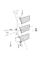
図2では、図面を簡素化するため、画像上での円筒状断面は平坦に、つまり巻き出して表示されている。先端すくい角がゼロである変形形態を示す。 In FIG. 2, the cylindrical cross section on the image is displayed flat, that is, rolled out, for the sake of simplicity of drawing. A variant with zero tip rake angle is shown.
図2からわかるように、(図示された断面図に有効な)ねじれ角βを有する、左向き斜歯工具が記載されている。回転軸Cに対し半径方向距離が同じである、左右の切れ刃の2点間の接続線は、工具回転軸に直交する平面に対して角度ζで延びる(この接続線は、従来のピーリングホイールのすくい面の位置に相当する)。 As can be seen from FIG. 2, a leftward bevel tool is described with a helix angle β (valid for the cross-section shown). The connecting line between the two points of the left and right cutting edges, which have the same radial distance to the axis of rotation C, extends at an angle (corresponds to the position of the rake face).
図2から明らかなように、切れ刃2Rのすくい面1R上の法線ベクトルnRと、切り刃2Lのすくい面1L上の法線ベクトルnLとは分岐し、約40°の角度を挟んでいる。この実施形態では、切れ刃に比較的大きい刃先角が生じる。
As is clear from FIG. 2, the normal vector n R on the
さらに、すくい面1L、1Rは、図2の断面図単独ではわからなくても、平坦面として形成されている。さらに、左側のすくい面1Lは、工具回転軸Cに直交する共通の平面上にある。この構成では、ピーリングホイールの再研磨が特に容易である。
Furthermore, the rake faces 1L and 1R are formed as flat faces, even though it cannot be seen from the cross-sectional view of FIG. 2 alone. Furthermore, the
図3からは、図1と同様に図3では、ピーリングホイール10の足部下側の対応する断面(B-B)によって明らかなように、平坦面1R、1Lが、ピーリングホイール10の足部を越えて、ピーリングホイールの回転軸の方向に延びていることが認識できる。これにより、再研削時の可動範囲がさらに広がる。
3, as in FIG. 1, the
図4に示す実施形態では、各すくい面平面と、同じ半径方向距離の切れ刃上の2つの点間の接続線との間の角度(λR、λL)は、図2に示す実施形態の角度より小さい。これに対応して刃先角が小さくなるが、負のすくい角がもたらされ、工具の耐用年数が改善される。 In the embodiment shown in FIG. 4, the angle (λ R , λ L ) between each rake face plane and the connecting line between two points on the cutting edge at the same radial distance is less than the angle of The included angle is correspondingly reduced, but a negative rake angle is provided and tool life is improved.
図5に示す実施形態では、特定の用途に望まれる、両側が正のすくい角が意図される場合、2つの切れ刃に著しく小さい刃先角が設定されるという新たな柔軟性が利用される。それにもかかわらず、すくい面はそれぞれ平坦面を形成し、再研削を比較的容易に行うことができる。 The embodiment shown in FIG. 5 takes advantage of the new flexibility of setting significantly smaller included angles on the two cutting edges when positive rake angles on both sides are intended, as desired for a particular application. Nevertheless, the rake faces each form a flat surface and can be reground relatively easily.
図6に示される別の可能な実施形態は、先の実施形態に示された対称的な変形例とは異なり、各すくい面の異なる方位角延長部を使用可能であり、(同様の半径方向距離を有する2点間の接続線に対する直交平面に関して)両面のすくい面上の、異なる向きの法線ベクトルについても使用可能であることを明示している。この実施例ではまた、負のすくい角をもたらす刃先角を備えている。 Another possible embodiment shown in FIG. 6 can use different azimuthal extensions of each rake face, unlike the symmetrical variant shown in the previous embodiment (similar radial It is demonstrated that different orientations of the normal vectors on both rake faces (with respect to the orthogonal plane to the connecting line between the two points with distance) can also be used. This embodiment also has an included angle that provides a negative rake angle.
図7に示される実施形態は、先行する実施例とは異なり、平坦なすくい面1L、1Rが互いに直接合流する必要がないことを示している。むしろ、2つの切れ刃間の方位角の中間領域の正確な構成は問題ではなく、切削プロセスに対して重要でもなく、被加工物から取り除かれた切削屑の特性に重大な影響をおよぼすものでもない。また、図7に示す実施形態では、すくい面は、歯の縁部の半径方向延長部にわたって平坦面を形成し、ひいては、2つの切れ刃に共通するすくい面の基本形状から、2つのすくい面を形成するために一様に材料が除去される、個々の断面図において同じに見える構成とは異なる。そのような変形形態では、歯面が湾曲しているためすくい面も同様に湾曲し、上述の実施形態と比べて、再研削の際に滑り面を通さなければならない。 The embodiment shown in FIG. 7 shows that, unlike the preceding examples, the flat rake faces 1L, 1R need not directly merge with each other. Rather, the exact configuration of the azimuthal intermediate region between the two cutting edges does not matter, is not critical to the cutting process, or has a significant effect on the properties of the chips removed from the workpiece. do not have. Also, in the embodiment shown in FIG. 7, the rake face forms a flat surface over the radial extension of the tooth edge and thus from the basic shape of the rake face common to the two cutting edges, the two rake faces In contrast to configurations that appear the same in individual cross-sectional views, material is uniformly removed to form a . In such a variant, since the tooth flanks are curved, the rake face is also curved and must pass through the sliding face during regrinding compared to the previous embodiment.
上述したスカイビングおよびハードピーリングの変形に加えて、本発明による構造を備えた工具を、例えば、硬いまたは硬化した、予め歯切りされた被加工物を加工するためのシェーピングにおいて使用することも可能である。 In addition to the variants of skiving and hard peeling described above, it is also possible to use tools with a structure according to the invention, for example, in shaping for machining hard or hardened pre-toothed workpieces. is.
本発明は、上記の例で説明した個々の構成に限定されない。むしろ、上記の説明の特徴および以下の特許請求の範囲は、単独または組み合わせて、様々な実施形態において本発明の実現にとって基本となり得る。 The invention is not limited to the specific configurations described in the examples above. Rather, the features of the above description and the claims that follow, alone or in combination, may be essential to the practice of the invention in various embodiments.
Claims (12)
切削歯の第1の切れ刃(2R)が、前記切削歯の歯面(4R)と、この第1の切れ刃のすくい面に属する第1の平面(1R)との交差によって形成され、前記第1の切れ刃(2R)における前記第1の平面に対する法線ベクトル(nR)は、その向きが、前記切削歯の他方の歯面(4L)との交差によって切削歯の第2の切れ刃を形成し、第2の切れ刃(2L)のすくい面に属する第2の平面(1L)に対する法線ベクトル(nL)の向きと異なり、前記第2の切れ刃(2L)における前記第2の平面(1L)に対する前記法線ベクトル(nL)は、前記ホイール状歯車切削工具の回転軸(C)から、前記第1の平面(1R)に対する前記法線ベクトル(nR)と同じ半径方向距離で開始していることを特徴とする、ホイール状歯車切削工具(10)。 A wheel-like gear cutting tool (10), being a skiving wheel for machining gear teeth in the kinematics of the skiving method, comprising cutting teeth (5) and said gear machined during machining engagement. In a wheel-shaped gear cutting tool (10) comprising cutting edges (2R, 2L) on the side of said cutting teeth facing the blades,
A first cutting edge (2R) of a cutting tooth is formed by the intersection of a tooth flank (4R) of said cutting tooth and a first plane (1R) belonging to the rake face of said first cutting edge, said The normal vector (n R ) to said first plane at the first cutting edge (2R) is oriented so that the second cutting edge of the cutting tooth by intersection with the other tooth flank (4L) of said cutting tooth. Different from the orientation of the normal vector (n L ) to the second plane (1L) forming the blade and belonging to the rake face of the second cutting edge (2L), the second The normal vector (n L ) to the second plane (1L) is the same as the normal vector (n R ) to the first plane (1R) from the rotation axis (C) of the wheel-shaped gear cutting tool. A wheel-like gear cutting tool (10), characterized in that it starts at a radial distance.
Applications Claiming Priority (3)
| Application Number | Priority Date | Filing Date | Title |
|---|---|---|---|
| DE102016008435.9 | 2016-07-11 | ||
| DE102016008435.9A DE102016008435A1 (en) | 2016-07-11 | 2016-07-11 | Radial gear tool |
| PCT/EP2017/000815 WO2018010838A1 (en) | 2016-07-11 | 2017-07-10 | Wheel-shaped gear cutting tool, method for machining sets of teeth, method for resharpening a gear cutting tool, and gear cutting machine |
Publications (3)
| Publication Number | Publication Date |
|---|---|
| JP2019524461A JP2019524461A (en) | 2019-09-05 |
| JPWO2018010838A5 JPWO2018010838A5 (en) | 2022-02-24 |
| JP7149926B2 true JP7149926B2 (en) | 2022-10-07 |
Family
ID=59315579
Family Applications (1)
| Application Number | Title | Priority Date | Filing Date |
|---|---|---|---|
| JP2019501583A Active JP7149926B2 (en) | 2016-07-11 | 2017-07-10 | Wheel-shaped gear cutting tool |
Country Status (5)
| Country | Link |
|---|---|
| EP (1) | EP3481575B1 (en) |
| JP (1) | JP7149926B2 (en) |
| CN (1) | CN109475954B (en) |
| DE (1) | DE102016008435A1 (en) |
| WO (1) | WO2018010838A1 (en) |
Families Citing this family (3)
| Publication number | Priority date | Publication date | Assignee | Title |
|---|---|---|---|---|
| CH713065B1 (en) | 2016-10-21 | 2020-11-30 | Reishauer Ag | Tool for power skiving of pre-cut workpieces. |
| DE102018112865B3 (en) | 2018-05-29 | 2019-10-17 | Hartmetall-Werkzeugfabrik Paul Horn Gmbh | Wälzschälwerkzeug |
| JP7031529B2 (en) * | 2018-08-16 | 2022-03-08 | 三菱マテリアル株式会社 | Skying cutter |
Citations (2)
| Publication number | Priority date | Publication date | Assignee | Title |
|---|---|---|---|---|
| JP2016000453A (en) | 2014-06-11 | 2016-01-07 | クリンゲルンベルク・アクチェンゲゼルシャフトKlingelnberg AG | Method and device for tooth face-side chamfering of gear teeth of workpiece |
| DE102015106354A1 (en) | 2014-12-16 | 2016-06-16 | Profilator Gmbh & Co. Kg | Wälzschälverfahren and cutting tool for producing at least partially rounded tooth heads |
Family Cites Families (6)
| Publication number | Priority date | Publication date | Assignee | Title |
|---|---|---|---|---|
| US2258849A (en) * | 1938-09-27 | 1941-10-14 | Nat Tool Company | Gear cutter |
| US2324003A (en) * | 1938-12-30 | 1943-07-13 | Farrel Birmingham Co Inc | Double helical gear cutter |
| JPS58113421U (en) * | 1982-01-27 | 1983-08-03 | 株式会社神戸製鋼所 | Pinion cutter for spur gear processing |
| DE102011009027A1 (en) | 2011-01-20 | 2012-07-26 | Gleason-Pfauter Maschinenfabrik Gmbh | Method for machining a workpiece and machine tool designed for this purpose |
| EP2596893A1 (en) * | 2011-11-25 | 2013-05-29 | Klingelnberg AG | Semi-completing skiving method with two axis intersection angles and use of a corresponding skiving tool for semi-completing skiving |
| ES2641223T3 (en) * | 2012-03-14 | 2017-11-08 | Siemens Aktiengesellschaft | Procedure for machining a workpiece with chip removal |
-
2016
- 2016-07-11 DE DE102016008435.9A patent/DE102016008435A1/en not_active Withdrawn
-
2017
- 2017-07-10 WO PCT/EP2017/000815 patent/WO2018010838A1/en unknown
- 2017-07-10 JP JP2019501583A patent/JP7149926B2/en active Active
- 2017-07-10 CN CN201780041853.1A patent/CN109475954B/en active Active
- 2017-07-10 EP EP17737721.5A patent/EP3481575B1/en active Active
Patent Citations (2)
| Publication number | Priority date | Publication date | Assignee | Title |
|---|---|---|---|---|
| JP2016000453A (en) | 2014-06-11 | 2016-01-07 | クリンゲルンベルク・アクチェンゲゼルシャフトKlingelnberg AG | Method and device for tooth face-side chamfering of gear teeth of workpiece |
| DE102015106354A1 (en) | 2014-12-16 | 2016-06-16 | Profilator Gmbh & Co. Kg | Wälzschälverfahren and cutting tool for producing at least partially rounded tooth heads |
Also Published As
| Publication number | Publication date |
|---|---|
| JP2019524461A (en) | 2019-09-05 |
| EP3481575A1 (en) | 2019-05-15 |
| DE102016008435A1 (en) | 2018-01-11 |
| EP3481575B1 (en) | 2020-06-03 |
| WO2018010838A1 (en) | 2018-01-18 |
| CN109475954B (en) | 2021-07-09 |
| CN109475954A (en) | 2019-03-15 |
Similar Documents
| Publication | Publication Date | Title |
|---|---|---|
| US10682712B2 (en) | Cutting tool with enhanced chip evacuation capability and method of making same | |
| CA2956392C (en) | Double-sided cutting insert and milling tool | |
| TWI451926B (en) | Internal gear machining method | |
| KR101496436B1 (en) | Method and device for removing a secondary burr on end-cut work piece wheel | |
| JP7149926B2 (en) | Wheel-shaped gear cutting tool | |
| WO2013099954A1 (en) | Radius end mill | |
| US10295039B2 (en) | Convex gear tooth edge break | |
| CN110121393A (en) | For to tooth-profile of gear device, specifically internal parts of tooth carries out the method for hard surface processing and the lathe of suitable this method | |
| JP2012035383A (en) | Method for manufacturing bandsaw blade, and the bandsaw blade | |
| JP5222125B2 (en) | Barrel-shaped tool for internal gear machining | |
| JP2012030354A (en) | Method and system for milling bevel gear tooth system in continuous milling process | |
| JP5346827B2 (en) | End mill | |
| US6261096B1 (en) | Dental tool having triple toothing | |
| JP5974954B2 (en) | Roughing end mill | |
| CN106660143B (en) | The processing method of ditch portion | |
| JP2006525877A (en) | Method for milling bent bevel gears and hypoid gears, bar-shaped cutting blades and methods for using such bar-shaped cutting blades | |
| JP6695284B2 (en) | How to grind gears | |
| JP2008207332A (en) | Cutting method | |
| CN210548363U (en) | Anti-vibration milling cutter | |
| US6709318B2 (en) | Dual-grinding method for bar blades and grinding disc for carrying out said method | |
| JP5895654B2 (en) | End mill | |
| JP2008229764A (en) | Rotary tool and machining method | |
| JP6248748B2 (en) | Roughing end mill | |
| JP6959117B2 (en) | Machining tools, machining equipment and machining methods | |
| CZ22318U1 (en) | Milling tool |
Legal Events
| Date | Code | Title | Description |
|---|---|---|---|
| A621 | Written request for application examination |
Free format text: JAPANESE INTERMEDIATE CODE: A621 Effective date: 20200710 |
|
| A977 | Report on retrieval |
Free format text: JAPANESE INTERMEDIATE CODE: A971007 Effective date: 20210831 |
|
| A131 | Notification of reasons for refusal |
Free format text: JAPANESE INTERMEDIATE CODE: A131 Effective date: 20210914 |
|
| A601 | Written request for extension of time |
Free format text: JAPANESE INTERMEDIATE CODE: A601 Effective date: 20211214 |
|
| A524 | Written submission of copy of amendment under article 19 pct |
Free format text: JAPANESE INTERMEDIATE CODE: A524 Effective date: 20220214 |
|
| A131 | Notification of reasons for refusal |
Free format text: JAPANESE INTERMEDIATE CODE: A131 Effective date: 20220510 |
|
| A521 | Request for written amendment filed |
Free format text: JAPANESE INTERMEDIATE CODE: A523 Effective date: 20220810 |
|
| TRDD | Decision of grant or rejection written | ||
| A01 | Written decision to grant a patent or to grant a registration (utility model) |
Free format text: JAPANESE INTERMEDIATE CODE: A01 Effective date: 20220830 |
|
| A61 | First payment of annual fees (during grant procedure) |
Free format text: JAPANESE INTERMEDIATE CODE: A61 Effective date: 20220927 |
|
| R150 | Certificate of patent or registration of utility model |
Ref document number: 7149926 Country of ref document: JP Free format text: JAPANESE INTERMEDIATE CODE: R150 |