JP7149852B2 - Selective catalytic reduction system and power unit provided with the same - Google Patents
Selective catalytic reduction system and power unit provided with the same Download PDFInfo
- Publication number
- JP7149852B2 JP7149852B2 JP2018562188A JP2018562188A JP7149852B2 JP 7149852 B2 JP7149852 B2 JP 7149852B2 JP 2018562188 A JP2018562188 A JP 2018562188A JP 2018562188 A JP2018562188 A JP 2018562188A JP 7149852 B2 JP7149852 B2 JP 7149852B2
- Authority
- JP
- Japan
- Prior art keywords
- fuel
- engine
- unit
- catalyst
- exhaust gas
- Prior art date
- Legal status (The legal status is an assumption and is not a legal conclusion. Google has not performed a legal analysis and makes no representation as to the accuracy of the status listed.)
- Active
Links
Images


Classifications
-
- F—MECHANICAL ENGINEERING; LIGHTING; HEATING; WEAPONS; BLASTING
- F01—MACHINES OR ENGINES IN GENERAL; ENGINE PLANTS IN GENERAL; STEAM ENGINES
- F01N—GAS-FLOW SILENCERS OR EXHAUST APPARATUS FOR MACHINES OR ENGINES IN GENERAL; GAS-FLOW SILENCERS OR EXHAUST APPARATUS FOR INTERNAL COMBUSTION ENGINES
- F01N3/00—Exhaust or silencing apparatus having means for purifying, rendering innocuous, or otherwise treating exhaust
- F01N3/08—Exhaust or silencing apparatus having means for purifying, rendering innocuous, or otherwise treating exhaust for rendering innocuous
- F01N3/10—Exhaust or silencing apparatus having means for purifying, rendering innocuous, or otherwise treating exhaust for rendering innocuous by thermal or catalytic conversion of noxious components of exhaust
- F01N3/18—Exhaust or silencing apparatus having means for purifying, rendering innocuous, or otherwise treating exhaust for rendering innocuous by thermal or catalytic conversion of noxious components of exhaust characterised by methods of operation; Control
- F01N3/20—Exhaust or silencing apparatus having means for purifying, rendering innocuous, or otherwise treating exhaust for rendering innocuous by thermal or catalytic conversion of noxious components of exhaust characterised by methods of operation; Control specially adapted for catalytic conversion ; Methods of operation or control of catalytic converters
- F01N3/2066—Selective catalytic reduction [SCR]
-
- F—MECHANICAL ENGINEERING; LIGHTING; HEATING; WEAPONS; BLASTING
- F01—MACHINES OR ENGINES IN GENERAL; ENGINE PLANTS IN GENERAL; STEAM ENGINES
- F01N—GAS-FLOW SILENCERS OR EXHAUST APPARATUS FOR MACHINES OR ENGINES IN GENERAL; GAS-FLOW SILENCERS OR EXHAUST APPARATUS FOR INTERNAL COMBUSTION ENGINES
- F01N3/00—Exhaust or silencing apparatus having means for purifying, rendering innocuous, or otherwise treating exhaust
- F01N3/08—Exhaust or silencing apparatus having means for purifying, rendering innocuous, or otherwise treating exhaust for rendering innocuous
- F01N3/10—Exhaust or silencing apparatus having means for purifying, rendering innocuous, or otherwise treating exhaust for rendering innocuous by thermal or catalytic conversion of noxious components of exhaust
- F01N3/18—Exhaust or silencing apparatus having means for purifying, rendering innocuous, or otherwise treating exhaust for rendering innocuous by thermal or catalytic conversion of noxious components of exhaust characterised by methods of operation; Control
- F01N3/20—Exhaust or silencing apparatus having means for purifying, rendering innocuous, or otherwise treating exhaust for rendering innocuous by thermal or catalytic conversion of noxious components of exhaust characterised by methods of operation; Control specially adapted for catalytic conversion ; Methods of operation or control of catalytic converters
- F01N3/2006—Periodically heating or cooling catalytic reactors, e.g. at cold starting or overheating
-
- F—MECHANICAL ENGINEERING; LIGHTING; HEATING; WEAPONS; BLASTING
- F01—MACHINES OR ENGINES IN GENERAL; ENGINE PLANTS IN GENERAL; STEAM ENGINES
- F01N—GAS-FLOW SILENCERS OR EXHAUST APPARATUS FOR MACHINES OR ENGINES IN GENERAL; GAS-FLOW SILENCERS OR EXHAUST APPARATUS FOR INTERNAL COMBUSTION ENGINES
- F01N9/00—Electrical control of exhaust gas treating apparatus
-
- F—MECHANICAL ENGINEERING; LIGHTING; HEATING; WEAPONS; BLASTING
- F02—COMBUSTION ENGINES; HOT-GAS OR COMBUSTION-PRODUCT ENGINE PLANTS
- F02D—CONTROLLING COMBUSTION ENGINES
- F02D19/00—Controlling engines characterised by their use of non-liquid fuels, pluralities of fuels, or non-fuel substances added to the combustible mixtures
- F02D19/06—Controlling engines characterised by their use of non-liquid fuels, pluralities of fuels, or non-fuel substances added to the combustible mixtures peculiar to engines working with pluralities of fuels, e.g. alternatively with light and heavy fuel oil, other than engines indifferent to the fuel consumed
- F02D19/0602—Control of components of the fuel supply system
- F02D19/0613—Switch-over from one fuel to another
-
- F—MECHANICAL ENGINEERING; LIGHTING; HEATING; WEAPONS; BLASTING
- F01—MACHINES OR ENGINES IN GENERAL; ENGINE PLANTS IN GENERAL; STEAM ENGINES
- F01N—GAS-FLOW SILENCERS OR EXHAUST APPARATUS FOR MACHINES OR ENGINES IN GENERAL; GAS-FLOW SILENCERS OR EXHAUST APPARATUS FOR INTERNAL COMBUSTION ENGINES
- F01N2570/00—Exhaust treating apparatus eliminating, absorbing or adsorbing specific elements or compounds
- F01N2570/14—Nitrogen oxides
-
- F—MECHANICAL ENGINEERING; LIGHTING; HEATING; WEAPONS; BLASTING
- F01—MACHINES OR ENGINES IN GENERAL; ENGINE PLANTS IN GENERAL; STEAM ENGINES
- F01N—GAS-FLOW SILENCERS OR EXHAUST APPARATUS FOR MACHINES OR ENGINES IN GENERAL; GAS-FLOW SILENCERS OR EXHAUST APPARATUS FOR INTERNAL COMBUSTION ENGINES
- F01N2610/00—Adding substances to exhaust gases
- F01N2610/14—Arrangements for the supply of substances, e.g. conduits
- F01N2610/1453—Sprayers or atomisers; Arrangement thereof in the exhaust apparatus
-
- Y—GENERAL TAGGING OF NEW TECHNOLOGICAL DEVELOPMENTS; GENERAL TAGGING OF CROSS-SECTIONAL TECHNOLOGIES SPANNING OVER SEVERAL SECTIONS OF THE IPC; TECHNICAL SUBJECTS COVERED BY FORMER USPC CROSS-REFERENCE ART COLLECTIONS [XRACs] AND DIGESTS
- Y02—TECHNOLOGIES OR APPLICATIONS FOR MITIGATION OR ADAPTATION AGAINST CLIMATE CHANGE
- Y02T—CLIMATE CHANGE MITIGATION TECHNOLOGIES RELATED TO TRANSPORTATION
- Y02T10/00—Road transport of goods or passengers
- Y02T10/10—Internal combustion engine [ICE] based vehicles
- Y02T10/12—Improving ICE efficiencies
-
- Y—GENERAL TAGGING OF NEW TECHNOLOGICAL DEVELOPMENTS; GENERAL TAGGING OF CROSS-SECTIONAL TECHNOLOGIES SPANNING OVER SEVERAL SECTIONS OF THE IPC; TECHNICAL SUBJECTS COVERED BY FORMER USPC CROSS-REFERENCE ART COLLECTIONS [XRACs] AND DIGESTS
- Y02—TECHNOLOGIES OR APPLICATIONS FOR MITIGATION OR ADAPTATION AGAINST CLIMATE CHANGE
- Y02T—CLIMATE CHANGE MITIGATION TECHNOLOGIES RELATED TO TRANSPORTATION
- Y02T10/00—Road transport of goods or passengers
- Y02T10/10—Internal combustion engine [ICE] based vehicles
- Y02T10/30—Use of alternative fuels, e.g. biofuels
-
- Y—GENERAL TAGGING OF NEW TECHNOLOGICAL DEVELOPMENTS; GENERAL TAGGING OF CROSS-SECTIONAL TECHNOLOGIES SPANNING OVER SEVERAL SECTIONS OF THE IPC; TECHNICAL SUBJECTS COVERED BY FORMER USPC CROSS-REFERENCE ART COLLECTIONS [XRACs] AND DIGESTS
- Y02—TECHNOLOGIES OR APPLICATIONS FOR MITIGATION OR ADAPTATION AGAINST CLIMATE CHANGE
- Y02T—CLIMATE CHANGE MITIGATION TECHNOLOGIES RELATED TO TRANSPORTATION
- Y02T10/00—Road transport of goods or passengers
- Y02T10/10—Internal combustion engine [ICE] based vehicles
- Y02T10/40—Engine management systems
Landscapes
- Engineering & Computer Science (AREA)
- Chemical & Material Sciences (AREA)
- Combustion & Propulsion (AREA)
- Mechanical Engineering (AREA)
- General Engineering & Computer Science (AREA)
- Chemical Kinetics & Catalysis (AREA)
- Health & Medical Sciences (AREA)
- Toxicology (AREA)
- Oil, Petroleum & Natural Gas (AREA)
- Exhaust Gas After Treatment (AREA)
- Exhaust-Gas Circulating Devices (AREA)
- Output Control And Ontrol Of Special Type Engine (AREA)
- Combined Controls Of Internal Combustion Engines (AREA)
- Exhaust Gas Treatment By Means Of Catalyst (AREA)
Description
本発明は、選択的触媒還元反応を用いて排気ガスに含有された窒素酸化物を低減させる、選択的触媒還元システム及びこれを備えた動力装置に関する。 The present invention relates to a selective catalytic reduction system that reduces nitrogen oxides contained in exhaust gas using a selective catalytic reduction reaction, and a power plant having the same.
一般に、船舶などに使用される動力装置は、動力を発生させるディーゼルエンジン、ディーゼルエンジンに掃気用空気を供給するターボチャージャ(turbocharger)、及び、ディーゼルエンジンから排出される排気ガスに含有された窒素酸化物を低減させるための選択的触媒還元(Selective Catalytic Reduction、SCR)システムなどを含む。 2. Description of the Related Art Generally, a power unit used in a ship or the like includes a diesel engine that generates power, a turbocharger that supplies scavenging air to the diesel engine, and a nitrogen oxide contained in exhaust gas discharged from the diesel engine. Selective Catalytic Reduction (SCR) systems for reducing substances and the like.
選択的触媒還元システムは、内部に触媒が設置された反応器に、排気ガスと還元剤とを通過させながら、排気ガスに含有された窒素酸化物と還元剤とを反応させることで、窒素と水蒸気とに還元する処理が行われる。 The selective catalytic reduction system reacts nitrogen oxides contained in the exhaust gas with the reducing agent while passing the exhaust gas and the reducing agent through a reactor in which a catalyst is installed, thereby reducing nitrogen and A process of reduction to water vapor is performed.
なお、船舶の場合、船舶から排出される窒素酸化物(NOx)及び硫黄酸化物(SOx)の排出量が、排出規制海域(Emission Control Area、ECA)において、エンジンによる大気汚染の防止のための国際3次規制(IMO Tier-III)を満すことができるように、ディーゼルエンジン及び選択的触媒還元システムの性能及び運用が求められている。 In the case of ships, the amount of nitrogen oxides (NOx) and sulfur oxides (SOx) emitted from ships is within the Emission Control Area (ECA) to prevent air pollution caused by engines. The performance and operation of diesel engines and selective catalytic reduction systems are required so that they can meet international Tier-III regulations (IMO Tier-III).
そして、船舶用ディーゼルエンジンの運用を効率良く行うため、通常、排出規制海域の内外において、ディーゼルエンジンにそれぞれ異なる燃料の供給が行われている。 In order to operate marine diesel engines efficiently, different fuels are normally supplied to the diesel engines inside and outside the emission control sea area.
具体的には、排出規制海域の外では、高硫黄燃料油(High sulfur Feul Oil、HFO)を使用し、船舶が排出規制海域内に進入する前に、低硫黄燃料油(Marine Gas Oil、MGO)に交換することが行われている。一例として、低硫黄燃料油とは、硫黄の含有量が、0.1%以下となるように脱硫された燃料油である。 Specifically, high sulfur fuel oil (HFO) is used outside the emission control area, and low sulfur fuel oil (Marine Gas Oil, MGO) is used before the vessel enters the emission control area. ) are being exchanged for As an example, low-sulfur fuel oil is fuel oil that has been desulfurized so that the sulfur content is 0.1% or less.
しかし、排出規制海域内において窒素酸化物(NOx)排出量の規制を満たすためには、ディーゼルエンジンへの供給燃料を交換するだけでは、規制を満たすことが困難である。 However, in order to meet the regulation of nitrogen oxide (NOx) emissions in the emission control area, it is difficult to meet the regulation only by replacing the fuel supplied to the diesel engine.
即ち、船舶用ディーゼルエンジン及び選択的触媒還元システムの運用を効率よく行うためには、ディーゼルエンジンへの供給燃料の交換に加え、ディーゼルエンジン及び選択的触媒還元システムの効果的な運転制御を行うことが求められている。 In other words, in order to efficiently operate marine diesel engines and selective catalytic reduction systems, in addition to exchanging the fuel supplied to the diesel engines, effective operation control of the diesel engines and selective catalytic reduction systems must be performed. is required.
本発明の実施例では、効率的な運用を行うことができる選択的触媒還元システム及び動力装置を提供する。 Embodiments of the present invention provide a selective catalytic reduction system and a power plant capable of efficient operation.
本発明の実施例によれば、互いに異なる種類の燃料がそれぞれ貯蔵された複数の燃料タンクのうちのいずれか1つの燃料タンクから選択的に燃料を供給されて動力を発生させるエンジンから排出される排気ガスの窒素酸化物(NOx)を低減させる選択的触媒還元システムは、前記エンジンに供給される前記燃料の種類を感知する燃料感知部と、前記エンジンから排出される前記排気ガスに含有された窒素酸化物を低減させるための触媒が設置された反応器と、前記反応器に設置された前記触媒を予熱する触媒予熱部と、前記反応器に流入される前記排気ガスに還元剤を供給する還元剤供給部と、前記燃料感知部の感知結果に基づいて前記燃料を変更するか否かを判断し、前記判断結果に応じて前記触媒予熱部及び前記還元剤供給部のうちの少なくともいずれか1つの作動が必要かどうかを判断する制御部と、表示部と、使用者から前記触媒予熱部及び前記還元剤供給部のうちの少なくとも1つを作動するか否かを指示する信号が入力される使用者入力部と、を含み、前記制御部は、前記燃料が変更されたと判断される場合、前記触媒予熱部及び前記還元剤供給部のうちの少なくともいずれか1つの作動が必要かどうかの判断結果を前記表示部に表示させ、前記使用者入力部の入力結果に応じて前記触媒予熱部及び前記還元剤供給部のうちの少なくともいずれか1つを作動させ、前記燃料感知部は、前記燃料の硫黄濃度を測定する硫黄濃度センサである。 According to an embodiment of the present invention, fuel is selectively supplied from any one of a plurality of fuel tanks in which different types of fuel are respectively stored and discharged from an engine that generates power. A selective catalytic reduction system for reducing nitrogen oxides (NOx) in exhaust gas includes a fuel sensor that senses the type of fuel supplied to the engine and a fuel sensor contained in the exhaust gas discharged from the engine. A reactor installed with a catalyst for reducing nitrogen oxides, a catalyst preheating unit for preheating the catalyst installed in the reactor, and supplying a reducing agent to the exhaust gas flowing into the reactor. determining whether or not to change the fuel based on the sensing result of the reducing agent supply unit and the fuel sensing unit, and at least one of the catalyst preheating unit and the reducing agent supply unit according to the determination result; A control unit for determining whether one operation is necessary, a display unit, and a signal from a user for instructing whether or not to operate at least one of the catalyst preheating unit and the reducing agent supply unit are inputted. and a user input unit, wherein the control unit determines whether operation of at least one of the catalyst preheating unit and the reducing agent supply unit is necessary when it is determined that the fuel has been changed. displaying the determination result on the display unit, operating at least one of the catalyst preheating unit and the reducing agent supply unit according to the input result of the user input unit ; A sulfur concentration sensor that measures the sulfur concentration of fuel .
前記燃料感知部は、外部から前記エンジンに供給される前記燃料の物性値情報を受信する燃料情報受信部と、前記複数の燃料タンク内の異種燃料のうちのいずれか1つを前記エンジンに選択的に供給するための燃料切替弁の切替状態情報を受信する弁情報受信部とのうちの少なくともいずれか1つの受信部を含むことができる。 The fuel sensing unit includes a fuel information receiving unit that receives physical property information of the fuel supplied to the engine from the outside, and selects one of different types of fuel in the plurality of fuel tanks for the engine. and a valve information receiving section for receiving switching state information of the fuel switching valve for supplying fuel.
本発明の参考例としての発明においては、前記燃料感知部は、前記エンジンに供給される前記燃料の物性値を測定する1つ以上のセンサを含むことができる。 In the invention as a reference example of the present invention, the fuel sensor may include one or more sensors for measuring physical property values of the fuel supplied to the engine.
前記物性値は、前記燃料の温度及び粘度のうちの少なくともいずれか1つを含み、前記センサは、温度センサ及び粘度センサのうちのいずれか1つ以上を含むことができる。 The physical property value may include at least one of temperature and viscosity of the fuel, and the sensor may include one or more of a temperature sensor and a viscosity sensor.
上述の選択的触媒還元システムは、表示部と、使用者から前記触媒予熱部及び前記還元剤供給部のうちの少なくとも1つを作動するか否かを指示する信号が入力される使用者入力部とをさらに含む。また、前記制御部は、前記燃料が変更されたと判断される場合、前記触媒予熱部及び前記還元剤供給部のうちの少なくともいずれか1つの作動が必要かどうかの判断結果を前記表示部に表示させ、前記使用者入力部の入力結果に応じて前記触媒予熱部及び前記還元剤供給部のうちの少なくともいずれか1つを作動させる。 The above-described selective catalytic reduction system includes a display unit and a user input unit through which a user inputs a signal indicating whether to operate at least one of the catalyst preheating unit and the reducing agent supply unit. and further including Further, when it is determined that the fuel has been changed, the control unit displays a determination result as to whether or not at least one of the catalyst preheating unit and the reducing agent supply unit needs to be operated on the display unit. and operates at least one of the catalyst preheating unit and the reducing agent supply unit according to the input result of the user input unit .
前記制御部は、前記還元剤供給部を作動させる前に、前記触媒予熱部を先に作動させることができる。 The control unit may operate the catalyst preheating unit before operating the reducing agent supply unit.
前記触媒予熱部は、前記反応器の後端と前記反応器の前端とを連結する予熱流路と、前記予熱流路の上に設けられ、前記予熱流路を移動する流体を昇温させる加熱装置と、前記予熱流路の上に設けられ、前記加熱装置により昇温された流体を循環させるブロワと、を含むことができる。 The catalyst preheating unit includes a preheating channel that connects a rear end of the reactor and a front end of the reactor, and a heater that is provided above the preheating channel and raises the temperature of a fluid moving in the preheating channel. and a blower provided above the preheating channel for circulating the fluid heated by the heating device.
また、本発明の実施例によれば、動力装置は、異なる成分の燃料がそれぞれ貯蔵された複数の燃料タンクと、前記複数の燃料タンクから燃料を供給されて動力を発生させるエンジンと、前記複数の燃料タンクと前記エンジンとを連結する燃料供給ラインと、前記燃料供給ラインに設けられ、前記エンジンに供給される燃料の種類を変更させる燃料切替弁と、前記エンジンに供給される前記燃料の種類を感知する燃料感知部と、前記エンジンの排気ガスに含有された窒素酸化物(NOx)を低減させるための窒素酸化物低減装置と、前記燃料感知部の感知結果に基づいて前記燃料を変更するか否かを判断し、前記判断結果に応じて前記エンジンの運転状態の変更が必要かどうか、又は、前記窒素酸化物低減装置の作動が必要かどうかを判断する制御部と、表示部と、使用者から前記窒素酸化物低減装置を作動するか否かが入力される入力部とを含み、前記窒素酸化物低減装置は、前記エンジンから排出される排気ガスに含有された窒素酸化物を低減させるために前記エンジンに設けられた排気ガス再循環装置、前記エンジンから排出される前記排気ガスに含有された窒素酸化物を低減させるための触媒が設置された反応器、及び、前記反応器に流入される前記排気ガスに還元剤を供給する還元剤供給部を備えた選択的触媒還元システムのうちの少なくともいずれか1つを含み、前記制御部は、前記エンジンの運転状態の変更が必要かどうか、又は、前記選択的触媒還元システム及び前記排気ガス再循環装置のうちの少なくともいずれか1つの作動が必要かどうかを前記表示部に表示させ、前記入力部の入力結果に応じて前記エンジン状態を変更させ、又は、前記選択的触媒還元システム及び前記排気ガス再循環装置のうちの少なくともいずれか1つを作動させ、前記燃料感知部は前記燃料の硫黄濃度を測定する硫黄濃度センサである。 Further, according to the embodiment of the present invention, the power plant comprises a plurality of fuel tanks storing fuels of different components, an engine supplied with the fuel from the plurality of fuel tanks to generate power, and the plurality of a fuel supply line connecting the fuel tank and the engine; a fuel switching valve provided in the fuel supply line for changing the type of fuel supplied to the engine; and the type of fuel supplied to the engine a nitrogen oxide reduction device for reducing nitrogen oxides (NOx) contained in the exhaust gas of the engine; and changing the fuel based on the sensing result of the fuel sensor. a control unit for determining whether or not it is necessary to change the operating state of the engine or whether it is necessary to operate the nitrogen oxide reduction device according to the determination result; a display unit; an input unit for inputting whether or not to operate the nitrogen oxide reduction device from a user, the nitrogen oxide reduction device reducing nitrogen oxides contained in the exhaust gas discharged from the engine. a reactor provided with a catalyst for reducing nitrogen oxides contained in the exhaust gas discharged from the engine; and at least one of a selective catalytic reduction system having a reducing agent supply unit that supplies a reducing agent to the inflowing exhaust gas, wherein the control unit determines whether it is necessary to change the operating state of the engine. or whether at least one of the selective catalytic reduction system and the exhaust gas recirculation device needs to be operated on the display unit, and the engine state according to the input result of the input unit or operate at least one of the selective catalytic reduction system and the exhaust gas recirculation device, and the fuel sensing unit is a sulfur concentration sensor that measures the sulfur concentration of the fuel .
前記燃料感知部は、外部から前記エンジンに供給される前記燃料の物性値情報を受信する燃料情報受信部と、前記燃料切替弁の切替状態情報を受信する弁情報受信部とのうちの少なくともいずれか1つの受信部を含むことができる。 The fuel sensing unit includes at least one of a fuel information receiving unit that receives physical property value information of the fuel supplied to the engine from the outside, and a valve information receiving unit that receives switching state information of the fuel switching valve. or one receiver.
本発明の参考例としての発明においては、前記燃料感知部は、前記エンジンに供給される前記燃料の物性値を測定する1つ以上のセンサを含むことができる。
In the invention as a reference example of the present invention, the fuel sensor may include one or more sensors for measuring physical property values of the fuel supplied to the engine.
前記物性値は、前記燃料の温度及び粘度のうちの少なくともいずれか1つを含み、前記センサは、温度センサ及び粘度センサのうちの1つ以上を含むことができる。 The physical property value may include at least one of temperature and viscosity of the fuel, and the sensor may include one or more of a temperature sensor and a viscosity sensor.
前記窒素酸化物低減装置は、前記エンジンから排出される排気ガスに含有された窒素酸化物を低減させるために前記エンジンに設けられた排気ガス再循環装置、前記エンジンから排出される前記排気ガスに含有された窒素酸化物を低減させるための触媒が設置された反応器、及び前記反応器に流入される前記排気ガスに還元剤を供給する還元剤供給部を備えた選択的触媒還元システムのうちの少なくともいずれか1つを含む。また、前記動力装置は、表示部、及び、使用者から前記窒素酸化物低減装置を作動するか否かが入力される入力部をさらに含むことができる。さらに、前記制御部は、前記エンジンの運転状態の変更が必要かどうか、又は、前記選択的触媒還元システム及び前記排気ガス再循環装置のうちの少なくともいずれか1つの作動が必要かどうかを前記表示部に表示させ、前記入力部の入力結果に応じて前記エンジン状態を変更させ、又は、前記選択的触媒還元システム及び前記排気ガス再循環装置のうちの少なくともいずれか1つを作動させる。 The nitrogen oxide reduction device includes an exhaust gas recirculation device provided in the engine for reducing nitrogen oxides contained in the exhaust gas discharged from the engine, A selective catalytic reduction system comprising a reactor installed with a catalyst for reducing contained nitrogen oxides and a reducing agent supply unit supplying a reducing agent to the exhaust gas flowing into the reactor including at least one of Also, the power unit may further include a display unit and an input unit through which a user inputs whether or not to operate the nitrogen oxide reduction device. Further, the control unit displays whether or not it is necessary to change the operating state of the engine or whether or not operation of at least one of the selective catalytic reduction system and the exhaust gas recirculation device is necessary. to change the engine state or to operate at least one of the selective catalytic reduction system and the exhaust gas recirculation device according to the input result of the input unit .
前記窒素酸化物低減装置は、前記エンジンから排出される排気ガスに含有された窒素酸化物を低減させるために前記エンジンに設けられた排気ガス再循環装置、前記エンジンから排出される前記排気ガスに含有された窒素酸化物を低減させるための触媒が設置された反応器、及び、前記反応器に流入される前記排気ガスに還元剤を供給する還元剤供給部を備えた選択的触媒還元システムのうちの少なくともいずれか1つを含むことができる。また、前記制御部は、前記エンジンの運転状態の変更が必要である、又は、前記窒素酸化物低減装置の作動が必要であると判断される場合、前記エンジンの出力を制限し、又は、前記排気ガス再循環装置及び前記選択的触媒還元システムのうちの少なくともいずれか1つを作動させることができる。 The nitrogen oxide reduction device includes an exhaust gas recirculation device provided in the engine for reducing nitrogen oxides contained in the exhaust gas discharged from the engine, A selective catalytic reduction system comprising a reactor installed with a catalyst for reducing contained nitrogen oxides and a reducing agent supply unit supplying a reducing agent to the exhaust gas flowing into the reactor at least any one of Further, when it is determined that it is necessary to change the operating state of the engine or to operate the nitrogen oxide reduction device, the control unit limits the output of the engine, or At least one of an exhaust gas recirculation device and the selective catalytic reduction system can be operated.
前記選択的触媒還元システムは、前記エンジンから排出される前記排気ガスに含有された窒素酸化物を低減させるための触媒が設置された反応器、及び、前記反応器に流入される前記排気ガスに還元剤を供給する還元剤供給部を含むことができる。また、前記制御部は、前記燃料感知部により測定された前記エンジンに供給される前記燃料の物性値の変化に応じて前記還元剤供給部を作動させるか否かを制御することができる。 The selective catalytic reduction system includes a reactor equipped with a catalyst for reducing nitrogen oxides contained in the exhaust gas discharged from the engine, and reducing the exhaust gas flowing into the reactor. A reducing agent supply can be included for supplying a reducing agent. Also, the control unit may control whether to operate the reducing agent supply unit according to a change in a physical property value of the fuel supplied to the engine, which is measured by the fuel sensing unit .
前記選択的触媒還元システムは、前記反応器に設置された触媒を予熱する触媒予熱部をさらに含むことができる。また、前記制御部は、前記還元剤供給部を作動させる前に、前記触媒予熱部を先に作動させることができる。 The selective catalytic reduction system may further include a catalyst preheating unit for preheating the catalyst installed in the reactor. Also, the control unit can operate the catalyst preheating unit before operating the reducing agent supply unit.
前記選択的触媒還元システムは、前記エンジンから排出される前記排気ガスに含有された窒素酸化物を低減させるための触媒が設置された反応器、及び、前記反応器に設置された触媒を予熱する触媒予熱部を含むことができる。また、前記制御部は、前記燃料感知部により測定された前記エンジンに供給される前記燃料の物性値の変化に応じて前記触媒予熱部を作動させるか否かを制御することができる。
The selective catalytic reduction system includes a reactor installed with a catalyst for reducing nitrogen oxides contained in the exhaust gas discharged from the engine, and preheating the catalyst installed in the reactor. A catalyst preheat section may be included. Also, the control unit may control whether to operate the catalyst preheating unit according to a change in physical properties of the fuel supplied to the engine, which is measured by the fuel sensing unit .
前記触媒予熱部は、前記反応器の後端と前記反応器の前端とを連結する予熱流路と、前記予熱流路の上に設けられ、前記予熱流路を移動する流体を昇温させる加熱装置と、前記予熱流路の上に設けられ、前記加熱装置により昇温された流体を循環させるブロワと、を含むことができる。 The catalyst preheating unit includes a preheating channel that connects a rear end of the reactor and a front end of the reactor, and a heater that is provided above the preheating channel and raises the temperature of a fluid moving in the preheating channel. and a blower provided above the preheating channel for circulating the fluid heated by the heating device.
本発明の実施例によれば、選択的触媒還元システム及びこれを備えた動力装置の運用を効率よく行うことが可能である。 ADVANTAGE OF THE INVENTION According to the Example of this invention, it is possible to operate a selective catalytic reduction system and a power plant provided with the same efficiently.
以下、添付の図面を参照して、本発明の属する技術分野で通常の知識を有する者が容易に実施し得るように本発明を詳述する。本発明は、種々に変更して実施することができ、本明細書中の実施例に限定されるものではない。 Hereinafter, the present invention will be described in detail with reference to the accompanying drawings so that those skilled in the art can easily implement the present invention. The present invention can be implemented in various modifications and is not limited to the examples herein.
なお、これらの実施例において、同様な構成を有する構成要素には同じ符号を付して、代表的に第1の実施例において説明し、他の実施例においては、第1の実施例と異なる構成についてのみ説明する。 In these embodiments, constituent elements having similar configurations are denoted by the same reference numerals, and are typically described in the first embodiment, and other embodiments differ from the first embodiment. Only the configuration will be described.
図面は、概略的に示されるものであり、縮尺を合わせて示されていない。図面中の相対的な寸法及び比率は、図面の明確性及び便宜性を図るため、その大きさを誇張又は縮小して示し、任意の寸法は、例示的なものに過ぎず、限定的なものではない。また、2つ以上の図面において、同様な構造物、要素又は部品には、同じ参照符号を付することで、その特性が類似していることを示す。 The drawings are schematic representations and are not drawn to scale. Relative dimensions and proportions in the drawings are exaggerated or reduced in size for clarity and convenience, and any dimensions are illustrative only and are limiting. is not. Also, similar structures, elements or parts in more than one drawing are labeled with the same reference numerals to indicate similar characteristics.
本発明の実施例は、本発明の好適な実施例を具体的に示すものである。そして、様々な図面解釈があり得る。従って、実施例は、図示した特定の形態に局限されず、例えば、製造による形態の変形を含む。
以下、図1を参照して本発明の第1の実施例に係る選択的触媒還元システム(Selective Catalytic Reduction。「SCR」と略する。)301及びこれを含む動力装置101について説明する。
The embodiments of the present invention specifically illustrate preferred embodiments of the present invention. And various drawing interpretations are possible. Accordingly, embodiments are not limited to the particular forms shown and include, for example, variations in form due to manufacture.
Hereinafter, a selective catalytic reduction system (abbreviated as "SCR") 301 and a
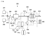
図1に示されるように、動力装置101は、複数の燃料タンク281、282、燃料供給ライン285、燃料切替弁270、エンジン200、及び、選択的触媒還元システム301を含むことができる。
As shown in FIG. 1 ,
複数の燃料タンク281、282は、それぞれ異なる成分の燃料を貯蔵する。具体的には、複数の燃料タンク281、282は、第1の燃料タンク281と第2の燃料タンク282とを含むことができる。また、第1の燃料タンク281には、第1の燃料を貯蔵し、第2の燃料タンク282には、第2の燃料を貯蔵することができる。例えば、第1の燃料は、高硫黄燃料油(High sulfur Feul Oil。「HFO」と略する。)であることができ、第2の燃料は、低硫黄燃料油(Marine Gas Oil。「MGO」と略する。)であることができる。
A plurality of
しかし、本発明の第1の実施例は、上記に限定されない。即ち、複数の燃料タンク281、282は、3つ以上の燃料タンクを含むことができ、第1の燃料及び第2の燃料として、当該技術分野で当業者にとって公知の様々な燃料を使用することができる。
However, the first embodiment of the present invention is not limited to the above. That is, the plurality of
エンジン200は、複数の燃料タンク281、282から燃料が供給されることで、動力を発生させながら、排気ガスを排出する。この時、エンジン200から排出される排気ガスには、硫黄酸化物(SOx)及び窒素酸化物(NOx)が含まれている。
Fuel is supplied from the plurality of
具体的には、エンジン200は、2行程式の低速ディーゼルエンジンであることができる。しかし、本発明の第1の実施例がこれに限定されるのではなく、エンジン200は、4行程式の中速ディーゼルエンジンであることもできる。また、複数のエンジン200を使用することもでき、この場合、2行程式の低速ディーゼルエンジンと4行程式の中速ディーゼルエンジンとを混用することができる。この時、2行程式の低速ディーゼルエンジンは、船舶に推進力を発生させる主動力源として使用することができ、4行程式の中速ディーゼルエンジンは、発電用又は補助動力源として使用することができる。
Specifically,
また、エンジン200は、船舶用エンジンに限定されず、車両用エンジンであることができる。即ち、エンジン200としては、当該技術分野で当業者にとって公知の様々なエンジンを使用することができる。
Also, the
また、動力装置101は、ターボチャージャ(不図示)をさらに含むことができる。ターボチャージャは、エンジン200の排気口に連結されている。具体的には、ターボチャージャは、エンジン200から排出される排気ガスの圧力により回転されるタービンと、タービンから動力を伝達されてエンジン200に供給される空気を圧縮する圧縮機とを含むことができる。
Also, the
燃料供給ライン285は、複数の燃料タンク281、282とエンジン200とを連結する。即ち、燃料供給ライン285は、複数の燃料タンク281、282に貯蔵された燃料をエンジン200に供給する。
燃料切替弁270は、燃料供給ライン285の上に設けられている。また、燃料切替弁270は、エンジン200に供給される燃料の種類を変更させることができる。具体的には、燃料切替弁270は、第1の燃料タンク281に貯蔵された第1の燃料と、第2の燃料タンク282に貯蔵された第2の燃料とのうちのいずれか1つを選択的にエンジン200に供給することができる。
即ち、燃料切替弁270は、第1の位置にある時は第1の燃料を前記エンジン200に供給し、第2の位置にある時は第2の燃料をエンジン200に供給するように設けられている。ここで、燃料切替弁270の作動位置は、第1の位置と第2の位置との間で変更され、このような燃料切替弁270の位置情報は、後述の制御部700、後述の燃料感知部810、又は弁情報受信部(不図示)のうちのいずれか一つに提供される。なお、燃料切替弁270は、2種類の燃料を選択的にエンジン200に供給するように示されているが、必要に応じて、3種類以上の燃料を選択的にエンジン200に供給することができる。この場合、燃料切替弁270は、1つ以上の弁から構成することができる。
That is, the
排気流路610は、エンジン200から排出される排気ガスを移動させる。また、動力装置101がターボチャージャを含む場合、排気流路610は、エンジン200とターボチャージャ、及び後述の選択的触媒還元システム301の反応器300を順次連結する。即ち、エンジン200から排出される排気ガスは、排気流路610に沿って移動し、反応器300に流入される。
選択的触媒還元(SCR)システム301は、エンジン200の動力発生過程で排出される排気ガスに含有された窒素酸化物(NOx)を低減させる。
A selective catalytic reduction (SCR)
本発明の第1の実施例に係る選択的触媒還元システム301は、燃料感知部810、反応器300、還元剤供給部500、触媒予熱部400、及び制御部700を含む。
A selective
反応器300は、排気流路610の上に設けられている。また、反応器300は、エンジン200から排出される排気ガスに含有された窒素酸化物(NOx)を低減させるための触媒350を含む。触媒350は、排気ガスに含有された窒素酸化物(NOx)と還元剤との反応を促進させ、窒素酸化物(NOx)を窒素と水蒸気とに還元する処理を行う。
また、反応器300の内部に設置された触媒350は、排気ガスの移動方向を基準に、多層構造で配置することができる。即ち、触媒350を複数の触媒モジュール形態で設置することができ、複数の触媒モジュールは、排気ガスの移動方向に沿って配置することができる。
Also, the
触媒350としては、ゼオライト(Zeolite)、バナジウム(Vanadium)、白金(Platinum)などのように、当該技術分野で当業者にとって公知の様々な素材を採用することができる。一例として、触媒350は、摂氏250度乃至摂氏350度の範囲内の活性温度を有することができる。ここで、活性温度とは、触媒350が被毒されることなく安定的に窒素酸化物を還元し得る温度である。触媒350が活性温度範囲から外れた環境で反応する場合、触媒350の被毒が起こり、効率が低下する。
例えば、摂氏150度以上摂氏250度未満の相対的に低い温度で排気ガスが含有した窒素酸化物を低減させるための還元反応が生じる場合、排気ガスの硫黄酸化物(SOx)とアンモニア(NH3)とが反応し、触媒被毒物質が生成される。 For example, when a reduction reaction for reducing nitrogen oxides contained in the exhaust gas occurs at a relatively low temperature of 150 degrees Celsius or more and less than 250 degrees Celsius, sulfur oxides (SOx) and ammonia (NH 3 ) in the exhaust gas ) react with each other to produce a catalyst poisoning substance.
具体的には、触媒350を被毒させる被毒物質は、硫酸アンモニウム(Ammonium sulfate、(NH4)2SO4)、亜硫酸水素アンモニウム(Ammonium bisulfate、NH4HSO4)のうちの1つ以上とすることができる。このような触媒被毒物質は、触媒350に吸着され、触媒350の活性を低下させる。触媒被毒物質は、相対的に高い温度、即ち、摂氏350度乃至摂氏450度の範囲内の温度で分解するため、反応器300内の触媒350を昇温させ、被毒された触媒350を再生することができる。
Specifically, the poisoning substance that poisons the
還元剤としては、アンモニア(NH3)又はウレア(Urea、CO(NH2)2)を使用することができる。還元剤としてウレアが使用される場合、ウレア(Urea、CO(NH2)2)を加水分解又は熱分解させ、アンモニア(NH3)とイソシアン酸(Isocyanic acid、HNCO)とを生成する。また、イソシアン酸(HNCO)は、さらに、アンモニア(NH3)と二酸化炭素(CO2)とに分解する。このように、ウレアを分解させ、最終的にアンモニアを生成する。なお、アンモニア(NH3)は、窒素酸化物と直接反応する最終の還元剤としての役割を果たす。即ち、ウレア(Urea、CO(NH2)2)とイソシアン酸(Isocyanic acid、HNCO)とは、還元剤前駆体に相当する。 As a reducing agent, ammonia ( NH3 ) or urea (Urea, CO( NH2 ) 2 ) can be used. When urea is used as the reducing agent, it hydrolyzes or thermally decomposes urea (Urea, CO( NH2 ) 2 ) to produce ammonia ( NH3 ) and isocyanic acid (HNCO). Isocyanic acid (HNCO) is further decomposed into ammonia (NH 3 ) and carbon dioxide (CO 2 ). Thus, urea is decomposed and finally ammonia is produced. Ammonia (NH 3 ) serves as the final reducing agent that directly reacts with nitrogen oxides. That is, urea (CO(NH 2 ) 2 ) and isocyanic acid (HNCO) correspond to reducing agent precursors.
また、反応器300のハウジングは、例えば、耐熱性に優れたステンレススチール(stainless steel)素材で作製することができる。
還元剤供給部500は、反応器300に流入される排気ガスに還元剤を供給する。一例として、還元剤供給部500は、反応器300前方の排気流路600の上で排気ガスに向けて還元剤前駆体であるウレア(Urea、CO(NH2)2)又は還元剤であるアンモニア(NH3)を噴射することができる。本明細書中、前方とは、排気ガスの移動方向を基準に、上向き方向を意味し、後方とは、排気ガスの移動方向を基準に、下向き方向を意味する。
In addition, the housing of the
The reducing
還元剤供給部500は、エンジン200の負荷に応じて変動する還元剤の要求量を考慮して、適正量のウレアを供給することができる。
Reducing
また、図示していないが、還元剤供給部500は、貯蔵タンク、噴霧用圧縮空気供給装置など、当該技術分野で当業者にとって公知の種々の構成を含むことができる。
Also, although not shown, the reducing
また、図示していないが、選択的触媒還元システム301は、ミキシング部材をさらに含むことができる。ミキシング部材は、排気流路610の上に設けられ、還元剤供給部500から噴射された還元剤又は還元剤前駆体が反応器300に流入される前に、排気ガスと効果的に混合させる。
Also, although not shown, the selective
触媒予熱部400は、反応器300に設置された触媒350を予熱する。
The
具体的には、触媒予熱部400は、反応器300の後端と反応器300の前端とを連結する予熱流路480と、予熱流路480の上に設けられ、予熱流路480に沿って移動する流体を昇温させる加熱装置410と、予熱流路480の上に設けられ、加熱装置410により昇温された流体を循環させるブロワ450とを含むことができる。
Specifically, the
一例として、加熱装置410は、オイルバーナー(Oil burner)又はプラズマバーナー(Plasma burner)とすることができる。このように、加熱装置410としてオイルバーナー又はプラズマバーナーが使用される場合、加熱装置410の作動には酸素が必要となる。従って、加熱装置410としてオイルバーナー又はプラズマバーナーが使用される場合、酸素を供給する外気供給部(不図示)をさらに含むことができる。即ち、外気供給部は、加熱装置410の作動のために必要な酸素が供給される程度の空気を、加熱装置410又は予熱流路480に供給することができる。
As an example, the
ブロワ450は、加熱装置410により昇温された流体の流量と流速を制御することができる。
しかし、触媒予熱部400としては、上記に限定されない。触媒予熱部400は、触媒350を直接加熱する電気ヒータとすることができ、触媒予熱部400は、当該技術分野で当業者に公知の種々の方法で触媒350を予熱させることができる。
However, the
さらに、必要に応じて、触媒予熱部400は、触媒350を加熱して再生させることも可能である。
Furthermore, the
燃料感知部810は、エンジン200に供給される燃料の種類を感知することができる。具体的には、燃料感知部810は、燃料の物性値(Material property)に基づいて燃料の種類を感知することができる。なお、物性値としては、燃料の温度(temperature)、粘度(viscosity)、燃料に含まれた硫黄(sulfur)の成分比、燃料成分の組成比などを含むことができる。その他、燃料の種類を判別可能なものであれば、いずれも物性値情報に相当する。
また、燃料感知部810は、燃料の物性値を測定するセンサを含むことができる。なお、センサとしては、燃料の温度を測定する温度センサ、燃料の粘度を測定する粘度センサ、及び燃料の硫黄濃度を測定する硫黄濃度センサが挙げられ、これらの2つ以上を組み合わせたマルチセンサとすることができる。
Also, the
一方、上述のセンサが、選択的触媒還元システム301が設けられる船舶に既設されている場合、燃料感知部810は、前記既設されたセンサから燃料の物性値情報を受信する燃料情報受信部(不図示)を含むことができる。
On the other hand, when the above-mentioned sensor is already installed in the ship on which the selective
他方、燃料感知部810は、選択的触媒還元システム301が設けられる船舶のエンジン101の燃料切替弁810の切替状態情報を受信する弁情報受信部(不図示)を含むことができる。燃料切替弁810は、作業者により手動で又はアクチュエータ(不図示)により、自動で切替が行われる。ここで、切替状態情報とは、燃料切替弁270の作動位置情報であり、燃料切替弁270の作動位置に基づいて、前記エンジン101に供給されている燃料の種類を確認することができる。
On the other hand, the
必要に応じて、燃料感知部810は、燃料の物性値を測定するセンサ及び弁情報受信部の両方を含むこともできる。即ち、制御部700は、センサにより測定された燃料の物性値と、弁情報受信部から受信した情報とを組み合わせることで、燃料の種類及び燃料の変更が行われたかどうかを判断することができる。
If necessary, the
例えば、燃料感知部810として温度センサが使用される場合は、燃料感知部810は、エンジン200に供給される燃料の温度測定を行う。具体的には、温度センサは、燃料切替弁270とエンジン200との間の燃料供給ライン285の上に設けられている。なお、場合によっては、温度センサをエンジン200に設けることもできる。この時、制御部700は、燃料感知部810である温度センサにより測定される燃料の温度変化に応じて還元剤供給部500を作動するか否かを制御する。
For example, when a temperature sensor is used as
具体的には、制御部700は、温度センサで測定された燃料の温度が設定値未満になると、還元剤供給部500を作動させる。また、制御部700は、燃料感知部810で測定した燃料の温度が設定値以上になると、再度還元剤供給部500の作動を中断することができる。なお、設定値は、複数の燃料タンク281、282に貯蔵された燃料の種類に応じて種々に設定することができる。
Specifically, the
選択的触媒還元システム301は、図1に示されるように、表示部780と、使用者入力部770とをさらに含むことができる。
The selective
表示部780は、制御部700によって制御される。表示部780としては、ブラウン管(CRT)表示装置、液晶表示装置(LCD)、有機発光表示装置(OLED)などの種々のディスプレイモジュールが挙げられる。
使用者入力部770には、選択的触媒還元システム301の構成要素である触媒予熱部400及び還元剤供給部500のうちの少なくともいずれか1つの作動が必要かどうかが使用者により入力される。使用者入力部770としては、キーボード、マウス、タッチスクリーン、タッチパッド、電子ペンなど、公知の様々な入力手段が挙げられる。
The user inputs whether or not at least one of the
制御部700は、燃料感知部810の感知信号から燃料の変更があったと判断される場合、触媒予熱部400及び還元剤供給部500のうちの少なくともいずれか1つの作動が必要かどうかを判断する。そして、判断結果を表示部780に表示させ、使用者からの入力を待つ。
When it is determined that the fuel is changed from the sensing signal of the
使用者入力部770を通じて使用者からの入力がある場合、入力結果に応じて触媒予熱部400及び還元剤供給部500のうちの少なくともいずれか1つを作動させる。即ち、制御部700は、燃料の種類変更があったと判断される場合、自動に触媒予熱部400及び還元剤供給部500のうちの少なくともいずれか1つを作動させることができるが、使用者が作動するか否かを判断するように表示部780に表示させ、使用者からの指示がある場合にのみ触媒予熱部400及び還元剤供給部500のうちの少なくともいずれか1つを作動させるようにすることもできる。
When there is an input from the user through the
図2に示されるように、エンジン200に供給される燃料が、燃料切替弁270の動作によって、高硫黄燃料油である第1の燃料から低硫黄燃料油である第2の燃料に交換される場合、エンジン200に供給される燃料の温度が変化することがわかる。
As shown in FIG. 2 , the fuel supplied to
本発明の第1の実施例によれば、燃料感知部810で測定した燃料の温度に基づいて、制御部700は、燃料の交換時点を判断し、燃料の交換に合わせて、選択的触媒還元システム301を作動させるか否かを決定することができる。
According to the first embodiment of the present invention, based on the fuel temperature measured by the
従って、排出規制海域内に進入する時、燃料を交換して硫黄酸化物(SOx)排出量の規制を満たすと共に、選択的触媒還元システム301を作動して窒素酸化物(NOx)排出量の規制を満たすことができる。
Therefore, when entering an emission control sea area, the fuel is changed to meet the sulfur oxide (SOx) emission regulation, and the selective
また、選択的触媒還元システム301は、常時作動するのではなく、必要な場合にのみ作動させることができ、また、還元剤供給部500の作動時点と中断時点とを、燃料の温度を測定する方法だけで簡単に決定することができる。
In addition, the selective
即ち、本発明の第1の実施例によれば、選択的触媒還元システム301の運用を効率よく行うことが可能である。
That is, according to the first embodiment of the present invention, it is possible to operate the selective
また、本発明の第1の実施例において、制御部700は、還元剤供給部500を作動させる前に、触媒予熱部400を先に作動させることができる。
Also, in the first embodiment of the present invention, the
この時、触媒予熱部400の作動時点は、還元剤供給部500の作動時点の基準となる、予め設定された温度値より高い温度に設定することができる。燃料交換によって燃料の温度が低くなり、還元剤供給部500の作動前に触媒予熱部400を作動させることができる。
At this time, the operating time point of the
また、触媒予熱部400の作動時点は、燃料の温度でなく、燃料を交換するための事前作業を基準とすることができる。例えば、燃料交換する前に行われる点検ステップで触媒予熱部400を作動させるか、燃料切替弁270への操作信号の伝達時点で触媒予熱部400を作動させることができる。このように、燃料切替弁270が動作して燃料交換が開始された後、燃料の温度が上昇して還元剤供給部500が作動するまでに所定時間を要するため、燃料切替弁270に操作信号が伝達される時点で触媒予熱部400を作動させることで、還元剤供給部500の作動に先行して触媒予熱部400の作動を行うことができる。
In addition, the operating time of the
上述の構成によって、本発明の第1の実施例によれば、選択的触媒還元システム301の運用を効率よく行うことができる。
With the above configuration, according to the first embodiment of the present invention, the selective
以下、本発明の第1の実施例の変形例を説明する。
本発明の第1の実施例の変形例によれば、制御部700は、燃料感知部810で測定した燃料の温度変化に応じて触媒予熱部400を作動するか否かを制御する。即ち、本発明の第1の実施例の変形例では、制御部700が、還元剤供給部500に優先して、燃料の温度変化に応じて触媒予熱部400を作動するか否かを制御すること以外は、第1の実施例と同様である。
A modification of the first embodiment of the present invention will be described below.
According to a modification of the first embodiment of the present invention, the
具体的には、制御部700は、燃料感知部810で測定した燃料の温度が設定値未満となると、触媒予熱部400を作動させる。
Specifically,
触媒予熱部400は、所定時間の作動により触媒350が予熱されると、作動を中断する。
The
この時、触媒予熱部400の作動時間は、触媒350の現在温度、気候環境及び加熱装置410の性能によって変化する。
At this time, the operating time of the
一例として、触媒350は、触媒予熱部400によって摂氏200度以上の温度上昇が行われる。
As an example, the temperature of the
上述のように、本発明の第1の実施例の変形例によれば、燃料感知部810で測定した燃料の物性値又は燃料切替弁270の弁切替状態情報に基づいて、制御部270は、燃料の交換時点を判断し、燃料の交換に合わせて、選択的触媒還元システム301の作動のための予熱を開始させることができる。なお、燃料の物性値は、燃料の温度、燃料の粘度、燃料の硫黄成分比、又は燃料構成成分の組成比のうちのいずれか1つ以上を含むことができる。
As described above, according to the modified example of the first embodiment of the present invention, based on the fuel physical property value measured by the
従って、排出規制海域内に進入する時、燃料を交換して硫黄酸化物(SOx)排出量の規制を満たすと共に、選択的触媒還元システム301を作動して窒素酸化物(NOx)排出量の規制を満たすことができる。
Therefore, when entering an emission control sea area, the fuel is changed to meet the sulfur oxide (SOx) emission regulation, and the selective
また、選択的触媒還元システム301を、常時作動するのではなく必要な場合にのみ作動させることができ、また、触媒350の予熱時点を、燃料の物性値を直接測定、又は間接的に測定情報を受信、又は燃料切替弁270の弁切替状態情報を受信することで、簡単に決定することができる。
In addition, the selective
即ち、本発明の第1の実施例の変形例によれば、選択的触媒還元システム301の運用を効率よく行うことが可能である。
That is, according to the modification of the first embodiment of the present invention, the selective
また、本発明の第1の実施例において、制御部700は、触媒予熱部400を作動させた後、還元剤供給部500を作動させることができる。
Also, in the first embodiment of the present invention, the
この時、還元剤供給部500の作動時点は、触媒350の予熱後であることができる。
At this time, the operating point of the reducing
上述の構成によれば、本発明の第1の実施例の変形例においても、選択的触媒還元システム301の運用を効率よく行うことが可能である。
According to the above configuration, it is possible to efficiently operate the selective
以下、図3を参照して本発明の第2の実施例について説明する。
図3に示されるように、本発明の第2の実施例に係る動力装置102は、窒素酸化物低減装置を含む。なお、窒素酸化物低減装置は、選択的触媒還元システム301及び排気ガス再循環装置240を含む。場合によっては、窒素酸化物低減装置は、選択的触媒還元システム301と排気ガス再循環システム240のうちのいずれか1つのみを含むことができる。
A second embodiment of the present invention will be described below with reference to FIG.
As shown in FIG. 3, a
本発明の第2の実施例に係る動力装置102においては、制御部700が、燃料感知部810で測定した燃料の物性値変化に応じてエンジン200の運転制御を行う。この時、燃料感知部810は、第1の実施例において選択的触媒還元システム301に設けられた燃料感知部810と同様であるため、重複する説明を省略する。
In the
具体的には、制御部700は、燃料感知部810で測定した燃料の温度が設定値未満となると、エンジン200の出力(Power)、回転速度(RPM)、負荷(Load)のうちのいずれか1つ以上を制限し、又は、排気ガス再循環(EGR)率を高めることができる。
Specifically, when the temperature of the fuel measured by the
上述のように、エンジン200の運転制御が行われることで、エンジン200から排出される排気ガスに含有された窒素酸化物の含有量が減少する。即ち、エンジン200の出力、回転速度、又は負荷を低くするか、排気ガス再循環率を高くすると、エンジン200から排出される排気ガスに含有された窒素酸化物の含有量が減少する。
By controlling the operation of
例えば、再循環された排気ガスには、窒素(N2)より熱容量の高い二酸化炭素(CO2)が多く含有されているため、同量の燃料を燃焼させても温度上昇率が低い。また、空気より酸素含有量の少ない排気ガスが燃焼に関与することで、燃焼速度が低下し、燃焼最高温度が低くなる。これによって、窒素酸化物(NOx)の量が顕著に減少する。代わりに、エンジン200の出力が低下するようになる。
For example, the recirculated exhaust gas contains more carbon dioxide (CO 2 ), which has a higher heat capacity than nitrogen (N 2 ), so the rate of temperature rise is low even if the same amount of fuel is burned. In addition, since the exhaust gas, which contains less oxygen than air, participates in the combustion, the combustion speed is lowered and the maximum combustion temperature is lowered. This significantly reduces the amount of nitrogen oxides (NOx). Instead, the output of
また、図3に示されるように、本発明の第2の実施例に係る動力装置102は、窒素酸化物低減装置として、選択的触媒還元システム302の他、排気ガスを再循環させるための排気ガス再循環装置240をさらに含むことができる。
Further, as shown in FIG. 3, the
排気ガス再循環装置240は、エンジン200から排出される排気ガスを再度エンジン200に流入させるための再循環流路248と、再循環流路248を介して再循環される排気ガスの流量を調節し得る再循環弁247とを含むことができる。また、再循環弁247は、制御部700の制御を受けることができる。
The exhaust
また、制御部700は、燃料感知部810で測定した燃料の物性値(例えば、温度)が設定値以上となると、エンジンの出力(Power)、回転速度(RPM)、及び負荷(Load)に対する制限を解除し、又は、排気ガス再循環(EGR)率を低下させることができる。
In addition, when the physical property value (e.g., temperature) of the fuel measured by the
図2に示されるように、エンジン200に供給される燃料が、燃料切替弁270の動作によって、高硫黄燃料油である第1の燃料から低硫黄燃料油である第2の燃料に交換される場合、エンジン200に供給される燃料の温度が変化することがわかる。なお、図2は、燃料の種類変更による温度変化を示す一例であって、燃料の種類変更が行われる場合、燃料の物性値である温度の他、粘度、硫黄成分比、燃料構成成分の組成比などが変化するようになる。
As shown in FIG. 2 , the fuel supplied to
本発明の第2の実施例によれば、燃料感知部810で測定した燃料の物性値(例えば、温度)に基づいて、制御部700は、燃料の交換時点を判断し、燃料の交換に合わせて、エンジン200の運転制御を行うことで、排出規制海域内に進入する時、燃料を交換して硫黄酸化物(SOx)排出量の規制を満たすと共に、窒素酸化物(NOx)排出量の規制を満たすことができる。
According to the second embodiment of the present invention, the
即ち、本発明の第2の実施例によれば、エンジン200の運用を効率よく行うことができる。
That is, according to the second embodiment of the present invention, the
なお、本発明の第2の実施例においては、制御部700が、燃料感知部810で測定した燃料の物性値(例えば、温度)の変化に応じて窒素酸化物低減装置の作動が必要かどうかを制御することができる。より詳しくは、制御部700は、排気ガス再循環装置240及び選択的触媒還元システム302のうちの少なくともいずれか1つを制御することができる。制御部700は、排気ガス再循環装置240のみ、又は、選択的触媒還元システム302のみを制御することもできる。例えば、制御部700は、燃料感知部810を通じて燃料の種類変更があったと判断される場合、排気ガス再循環装置240のみを制御し、選択的触媒還元システム302は、窒素酸化物(NOx)濃度、エンジン負荷など、他の判断条件に応じて個別に独立して制御することができる。
In addition, in the second embodiment of the present invention, the
制御部700が排気ガス再循環装置240を制御しようとする場合、制御部700は、排気ガス再循環装置240の再循環弁247の制御を行うことができる。
When the
なお、制御部700が選択的触媒還元システム302の制御を行う場合、制御部700は、選択的触媒還元システム302の還元剤供給部500及び触媒予熱部400の作動が必要かどうかを制御することができる。ここで、制御部700は、触媒予熱部400を還元剤供給部500より先に作動させることができる。
When the
また、制御部700は、燃料の種類変更があったと判断される場合、自動的に直接前記窒素酸化物低減装置を制御することもできるが、場合によっては、窒素酸化物低減装置を作動するかを使用者に問い合わせ、使用者の指示に基づいて窒素酸化物低減装置を作動させることもできる。より詳しくは、第2の実施例に係る動作装置102は、窒素酸化物低減装置を作動するか否かを使用者に問い合わせるための表示部780と、使用者が窒素酸化物低減装置を作動するか否かを入力するための入力部770とをさらに含むことができる。制御部700は、入力部770の入力結果に応じて、窒素酸化物低減装置を作動、又は停止状態を維持、又は作動を停止することができる。
Further, when the
上述のように、制御部700は、燃料感知部810で測定した燃料の物性値(例えば、温度)変化情報に基づいて還元剤供給部500及び触媒予熱部400を制御しないこと以外は、選択的触媒還元システム302は、第1の実施例における選択的触媒還元システム301と同様である。
As described above, the
上述の構成によって、本発明の第2の実施例によれば、動力装置102の運用を効率よく行うことができる。
With the above configuration, according to the second embodiment of the present invention, the
以下、図4を参照して本発明の第3の実施例について説明する。
図4に示されるように、本発明の第3の実施例に係る動力装置103においては、制御部700は、燃料感知部810で測定した燃料の物性値(例えば、温度)の変化に応じてエンジン200の運転を制御すると共に、選択的触媒還元システム301を制御する。なお、第1の実施例において詳述したように、燃料感知部810は、自身が直接測定することなく外部から燃料の物性値情報を受信し、又は、燃料切替弁270の弁切替状態情報を受信することで、燃料の種類を検知することもできることは勿論である。
A third embodiment of the present invention will be described below with reference to FIG.
As shown in FIG. 4, in the
この時、制御部700は、エンジン200を制御するエンジン制御部720と、選択的触媒還元システム301を制御する後処理制御部730とをさらに含むことができる。後処理制御部730は、還元剤供給部500又は触媒予熱部400のうちの1つ以上を制御することができる。
At this time, the
エンジン制御部720は、図4に示されるように、排気ガス再循環装置240を制御し、後処理制御部730は、選択的触媒還元システム301を制御するように役割が分担されている。エンジン制御部720と後処理制御部730とは、情報を互いに通信可能とすることもできる。
Engine control 720 controls exhaust
例えば、後処理制御部730は、エンジン制御部720から燃料切替弁720の切替状態情報を受信することができる。逆に、エンジン制御部720は、後処理制御部730から選択的触媒還元システム301の作動状態情報を入手することができる。なお、選択的触媒還元システム301の作動状態情報とは、還元剤供給部500又は触媒予熱部400のうちの1つ以上の作動が必要かどうかに関する情報のことをいう。
For example,
第3の実施例に係る動力装置103は、第1及び第2の実施例において詳述した表示部780及び入力部770をさらに含むことができる。なお、表示部780及び入力部770は、後処理制御部730により制御することができる。勿論、必要に応じて、エンジン制御部720により制御することがあり得る。
The
なお、本発明の第3の実施例は、上記に限定されず、1つの制御部700が、エンジン200と選択的触媒還元システム301との両方を制御することもできる。
Note that the third embodiment of the present invention is not limited to the above, and one
エンジン制御部720の動作は、第2の実施例において説明した制御部700の動作と同様とすることができ、後処理制御部730の動作は、第1の実施例及び第1の実施例の変形例において説明した制御部700の動作と同様とすることができる。
The operation of the engine control unit 720 can be the same as the operation of the
また、第3の実施例における選択的触媒還元システム301は、第1の実施例と同様とすることができる。
Also, the selective
従って、本発明の第3の実施例によれば、燃料感知部810で測定した燃料の物性値(例えば、温度)に基づいて、制御部300は、燃料の交換時点を判断し、燃料の交換に合わせて、エンジン200の運転を制御すると共に、選択的触媒還元システム301及び排気ガス再循環装置240のうちの少なくともいずれか一方を作動するか否かを決定し、又は、選択的触媒還元システム301の作動のための予熱を開始させることができる。
Therefore, according to the third embodiment of the present invention, the
即ち、本発明の第3の実施例によれば、エンジン200と窒素酸化物低減装置である選択的触媒還元システム301及び/又は排気ガス再循環装置240の運用を効率よく行うことができる。
That is, according to the third embodiment of the present invention, it is possible to efficiently operate the
上述の構成によって、本発明の第3の実施例によれば、選択的触媒還元システム301及びこれを含む動力装置103の運用を効率よく行うことができる。
With the above configuration, according to the third embodiment of the present invention, the selective
以上、添付の図面を参照して本発明の実施例を説明してきたが、本発明が属する技術分野の当業者であれば、本発明がその技術的思想や必須の特徴を逸脱することなく種々に変更して実施できることが理解できるであろう。 Although the embodiments of the present invention have been described with reference to the accompanying drawings, it will be appreciated by those skilled in the art to which the present invention pertains that the present invention may be modified in various ways without departing from its technical spirit or essential features. It will be understood that it can be implemented by changing to
上述の実施例は、例示に過ぎず、限定的なものではなく、本発明の範囲は、上述の発明の詳細な説明及び後述の特許請求の範囲によって示され、特許請求の範囲の意味及び範囲、並びにその等価概念から導出される全ての変更又は変形の形態は、本発明の範疇に含まれるものと解釈されるべきである。 The foregoing embodiments are illustrative only and not limiting, the scope of the invention being indicated by the foregoing detailed description of the invention and the following claims, given the meaning and scope of the claims. , and all modifications or variations derived from the equivalent concept thereof, are to be construed as included within the scope of the present invention.
本発明の実施例によれば、選択的触媒還元システム及びこれを備えた動力装置の運用を効率よく行うことができるため、選択的触媒還元システム及びこれを備えた動力装置の運用において省エネルギーを図るために使用することができる。 According to the embodiment of the present invention, since the selective catalytic reduction system and the power plant having the same can be efficiently operated, energy can be saved in the operation of the selective catalytic reduction system and the power plant having the same. can be used for
Claims (11)
前記エンジンに供給される前記燃料の種類を感知する燃料感知部と、
前記エンジンから排出される前記排気ガスに含有された窒素酸化物を低減させるための触媒が設置された反応器と、
前記反応器に設置された前記触媒を予熱する触媒予熱部と、
前記反応器に流入される前記排気ガスに還元剤を供給する還元剤供給部と、
前記燃料感知部の感知結果に基づいて前記燃料を変更するか否かを判断し、前記判断結果に応じて前記触媒予熱部及び前記還元剤供給部のうちの少なくともいずれか1つの作動が必要かどうかを判断する制御部と、
表示部と、
使用者から前記触媒予熱部及び前記還元剤供給部のうちの少なくとも1つを作動するか否かを指示する信号が入力される使用者入力部と、を含み、
前記制御部は、前記燃料が変更されたと判断される場合、前記触媒予熱部及び前記還元剤供給部のうちの少なくともいずれか1つの作動が必要かどうかの判断結果を前記表示部に表示させ、前記使用者入力部の入力結果に応じて前記触媒予熱部及び前記還元剤供給部のうちの少なくともいずれか1つを作動させ、
前記燃料感知部は、前記燃料の硫黄濃度を測定する硫黄濃度センサである選択的触媒還元システム。 Nitrogen oxides (NOx) in exhaust gas emitted from an engine that generates power by selectively supplying fuel from any one of a plurality of fuel tanks storing different types of fuel respectively A selective catalytic reduction system that reduces
a fuel sensor that senses the type of fuel supplied to the engine;
a reactor equipped with a catalyst for reducing nitrogen oxides contained in the exhaust gas discharged from the engine;
a catalyst preheating unit that preheats the catalyst installed in the reactor;
a reducing agent supply unit that supplies a reducing agent to the exhaust gas flowing into the reactor;
determining whether or not to change the fuel based on the sensing result of the fuel sensing unit, and whether at least one of the catalyst preheating unit and the reducing agent supply unit needs to be operated according to the determination result; a control unit for determining whether
a display unit;
a user input unit into which a user inputs a signal indicating whether to operate at least one of the catalyst preheating unit and the reducing agent supply unit;
The control unit causes the display unit to display a determination result as to whether or not at least one of the catalyst preheating unit and the reducing agent supply unit needs to be operated when it is determined that the fuel has been changed; operating at least one of the catalyst preheating unit and the reducing agent supply unit according to the input result of the user input unit ;
The selective catalytic reduction system , wherein the fuel sensor is a sulfur concentration sensor that measures the sulfur concentration of the fuel .
前記反応器の後端と前記反応器の前端とを連結する予熱流路と、
前記予熱流路の上に設けられ、前記予熱流路を移動する流体を昇温させる加熱装置と、
前記予熱流路の上に設けられ、前記加熱装置により昇温された流体を循環させるブロワと、を含むことを特徴とする請求項1に記載の選択的触媒還元システム。 The catalyst preheating section is
a preheating channel connecting the rear end of the reactor and the front end of the reactor;
a heating device provided above the preheating channel for raising the temperature of the fluid moving in the preheating channel;
2. The selective catalytic reduction system according to claim 1, further comprising a blower provided above the preheating flow path and configured to circulate the fluid heated by the heating device.
前記複数の燃料タンクから燃料を供給されて動力を発生させるエンジンと、
前記複数の燃料タンクと前記エンジンとを連結する燃料供給ラインと、
前記燃料供給ラインに設けられ、前記エンジンに供給される燃料の種類を変更させる燃料切替弁と、
前記エンジンに供給される前記燃料の種類を感知する燃料感知部と、
前記エンジンの排気ガスに含有された窒素酸化物(NOx)を低減させるための窒素酸化物低減装置と、
前記燃料感知部の感知結果に基づいて前記燃料を変更するか否かを判断し、前記判断結果に応じて前記エンジンの運転状態の変更が必要かどうか、又は、前記窒素酸化物低減装置の作動が必要かどうかを判断する制御部と、
表示部と、
使用者から前記窒素酸化物低減装置を作動するか否かが入力される入力部とを含み、
前記窒素酸化物低減装置は、前記エンジンから排出される排気ガスに含有された窒素酸化物を低減させるために前記エンジンに設けられた排気ガス再循環装置、前記エンジンから排出される前記排気ガスに含有された窒素酸化物を低減させるための触媒が設置された反応器、及び、前記反応器に流入される前記排気ガスに還元剤を供給する還元剤供給部を備えた選択的触媒還元システムのうちの少なくともいずれか1つを含み、
前記制御部は、前記エンジンの運転状態の変更が必要かどうか、又は、前記選択的触媒還元システム及び前記排気ガス再循環装置のうちの少なくともいずれか1つの作動が必要かどうかを前記表示部に表示させ、前記入力部の入力結果に応じて前記エンジン状態を変更させ、又は、前記選択的触媒還元システム及び前記排気ガス再循環装置のうちの少なくともいずれか1つを作動させ、
前記燃料感知部は前記燃料の硫黄濃度を測定する硫黄濃度センサである動力装置。 a plurality of fuel tanks each storing fuel of different composition;
an engine that receives fuel from the plurality of fuel tanks to generate power;
a fuel supply line connecting the plurality of fuel tanks and the engine;
a fuel switching valve provided in the fuel supply line for changing the type of fuel supplied to the engine;
a fuel sensor that senses the type of fuel supplied to the engine;
a nitrogen oxide reduction device for reducing nitrogen oxides (NOx) contained in exhaust gas of the engine;
determining whether or not to change the fuel based on the sensing result of the fuel sensor, and depending on the determination result, whether or not it is necessary to change the operating state of the engine, or operate the nitrogen oxide reduction device; a control unit for determining whether a
a display unit;
an input unit for inputting whether or not to operate the nitrogen oxide reduction device from the user,
The nitrogen oxide reduction device includes an exhaust gas recirculation device provided in the engine for reducing nitrogen oxides contained in the exhaust gas discharged from the engine, and the exhaust gas discharged from the engine. A selective catalytic reduction system comprising a reactor installed with a catalyst for reducing contained nitrogen oxides and a reducing agent supply unit supplying a reducing agent to the exhaust gas flowing into the reactor including at least one of
The control unit displays on the display unit whether it is necessary to change the operating state of the engine or whether it is necessary to operate at least one of the selective catalytic reduction system and the exhaust gas recirculation device. display, change the engine state according to the input result of the input unit, or operate at least one of the selective catalytic reduction system and the exhaust gas recirculation device ;
The power plant , wherein the fuel sensor is a sulfur concentration sensor that measures the sulfur concentration of the fuel .
前記制御部は、前記エンジンの運転状態の変更が必要である、又は、前記窒素酸化物低減装置の作動が必要であると判断される場合、前記エンジンの出力を制限し、又は、前記排気ガス再循環装置及び前記選択的触媒還元システムのうちの少なくともいずれか1つを作動させることを特徴とする請求項5に記載の動力装置。 The nitrogen oxide reduction device includes an exhaust gas recirculation device provided in the engine for reducing nitrogen oxides contained in the exhaust gas discharged from the engine, A selective catalytic reduction system comprising a reactor installed with a catalyst for reducing contained nitrogen oxides and a reducing agent supply unit supplying a reducing agent to the exhaust gas flowing into the reactor including at least one of
When it is determined that the operating state of the engine needs to be changed or the nitrogen oxide reduction device needs to be operated, the control unit limits the output of the engine or controls the exhaust gas. 6. A power plant according to claim 5 , wherein at least one of a recirculation device and said selective catalytic reduction system is operated.
前記制御部は、前記燃料感知部により測定された前記エンジンに供給される前記燃料の物性値の変化に応じて前記還元剤供給部を作動させるか否かを制御することを特徴とする請求項7に記載の動力装置。 The selective catalytic reduction system includes a reactor equipped with a catalyst for reducing nitrogen oxides contained in the exhaust gas discharged from the engine, and reducing the exhaust gas flowing into the reactor. including a reducing agent supply unit that supplies a reducing agent;
3. The control unit controls whether or not to operate the reducing agent supply unit according to a change in physical properties of the fuel supplied to the engine measured by the fuel sensing unit. 7. The power plant according to 7.
前記制御部は、前記還元剤供給部を作動させる前に、前記触媒予熱部を先に作動させることを特徴とする請求項8に記載の動力装置。 The selective catalytic reduction system further includes a catalyst preheating unit that preheats the catalyst installed in the reactor,
9. The power plant according to claim 8 , wherein the control unit operates the catalyst preheating unit before operating the reducing agent supply unit.
前記制御部は、前記燃料感知部により測定された前記エンジンに供給される前記燃料の物性値の変化に応じて前記触媒予熱部を作動させるか否かを制御することを特徴とする請求項7に記載の動力装置。 The selective catalytic reduction system includes a reactor installed with a catalyst for reducing nitrogen oxides contained in the exhaust gas discharged from the engine, and preheating the catalyst installed in the reactor. including a catalyst preheating section,
8. The control unit controls whether or not to operate the catalyst preheating unit according to changes in the physical properties of the fuel supplied to the engine, which are measured by the fuel sensing unit. The power unit according to .
前記反応器の後端と前記反応器の前端とを連結する予熱流路と、
前記予熱流路の上に設けられ、前記予熱流路を移動する流体を昇温させる加熱装置と、
前記予熱流路の上に設けられ、前記加熱装置により昇温された流体を循環させるブロワと、を含むことを特徴とする請求項10に記載の動力装置。 The catalyst preheating section is
a preheating channel connecting the rear end of the reactor and the front end of the reactor;
a heating device provided above the preheating channel for raising the temperature of the fluid moving in the preheating channel;
11. The power unit according to claim 10 , further comprising a blower provided above the preheating flow path and configured to circulate the fluid heated by the heating device.
Applications Claiming Priority (3)
| Application Number | Priority Date | Filing Date | Title |
|---|---|---|---|
| KR1020160065787A KR102042887B1 (en) | 2016-05-27 | 2016-05-27 | Selective catalytic reuction system and power generating apparatus |
| KR10-2016-0065787 | 2016-05-27 | ||
| PCT/KR2017/005501 WO2017204589A1 (en) | 2016-05-27 | 2017-05-26 | Selective catalytic reduction system and power apparatus having same |
Publications (2)
| Publication Number | Publication Date |
|---|---|
| JP2019525047A JP2019525047A (en) | 2019-09-05 |
| JP7149852B2 true JP7149852B2 (en) | 2022-10-07 |
Family
ID=60411384
Family Applications (1)
| Application Number | Title | Priority Date | Filing Date |
|---|---|---|---|
| JP2018562188A Active JP7149852B2 (en) | 2016-05-27 | 2017-05-26 | Selective catalytic reduction system and power unit provided with the same |
Country Status (4)
| Country | Link |
|---|---|
| JP (1) | JP7149852B2 (en) |
| KR (1) | KR102042887B1 (en) |
| CN (1) | CN109312652A (en) |
| WO (1) | WO2017204589A1 (en) |
Families Citing this family (5)
| Publication number | Priority date | Publication date | Assignee | Title |
|---|---|---|---|---|
| KR102447700B1 (en) * | 2018-04-30 | 2022-09-29 | 에이치에스디엔진 주식회사 | SELECTIVE CATALYTIC REDUCTION SYSTEM AND NOx REDUCTION METHOD |
| KR102481140B1 (en) * | 2018-06-29 | 2022-12-27 | 에이치에스디엔진 주식회사 | Exhaust gas purifying system of ship and methode for controlling the same |
| KR102137323B1 (en) * | 2018-11-20 | 2020-07-23 | 에이치에스디엔진 주식회사 | Selective catalytic reduction system |
| EP4048880A4 (en) * | 2019-11-26 | 2023-08-02 | Cummins, Inc. | Engine aftertreatment recycling apparatus, and system and method using same |
| CN112682226A (en) * | 2020-12-21 | 2021-04-20 | 中国北方发动机研究所(天津) | Combined pollutant emission reduction system for dual-fuel marine diesel engine |
Citations (5)
| Publication number | Priority date | Publication date | Assignee | Title |
|---|---|---|---|---|
| WO2010032739A1 (en) | 2008-09-17 | 2010-03-25 | ヤンマー株式会社 | Exhaust gas purifying system for vessel engine |
| WO2012057036A1 (en) | 2010-10-29 | 2012-05-03 | 三菱重工業株式会社 | Navigation aid system |
| US20130226438A1 (en) | 2010-08-31 | 2013-08-29 | Caterpillar Motoren Gmbh & Co. Kg | Controlling multifuel common rail engines |
| JP2015169103A (en) | 2014-03-05 | 2015-09-28 | トヨタ自動車株式会社 | Internal combustion engine controller |
| WO2015147521A1 (en) | 2014-03-25 | 2015-10-01 | 현대중공업 주식회사 | System and method for reducing harmful substances of ship and ship using same |
Family Cites Families (10)
| Publication number | Priority date | Publication date | Assignee | Title |
|---|---|---|---|---|
| JP3518348B2 (en) * | 1998-07-07 | 2004-04-12 | トヨタ自動車株式会社 | Exhaust gas purification device for internal combustion engine |
| JP2006112347A (en) * | 2004-10-15 | 2006-04-27 | Toyota Motor Corp | Exhaust emission control device of internal combustion engine |
| JP2006250120A (en) * | 2005-03-14 | 2006-09-21 | Nissan Motor Co Ltd | Fuel injection control device of diesel engine |
| JP5181972B2 (en) * | 2008-09-25 | 2013-04-10 | マツダ株式会社 | Engine exhaust gas purification device |
| KR101366937B1 (en) * | 2012-06-25 | 2014-02-25 | 두산엔진주식회사 | Power plant for ship with selective catalytic reuction system and auxiliary power generation system |
| KR101417296B1 (en) * | 2012-06-25 | 2014-07-08 | 두산엔진주식회사 | Power plant for ship with selective catalytic reuction system for internal combustion engine |
| KR101367024B1 (en) * | 2012-06-28 | 2014-02-24 | 두산엔진주식회사 | Urea hydrolysis apparatus using fuel cell and selective catalytic reuction system with the same |
| CN104736821B (en) * | 2012-10-23 | 2017-07-07 | 西港能源有限公司 | Fuel system protection in multifuel engine |
| KR101563678B1 (en) * | 2012-11-22 | 2015-10-28 | 삼성중공업 주식회사 | Device for Purifying Exhaust and Vessel having the Same |
| JP6015685B2 (en) * | 2014-01-30 | 2016-10-26 | 株式会社デンソー | Reducing agent addition device |
-
2016
- 2016-05-27 KR KR1020160065787A patent/KR102042887B1/en active IP Right Grant
-
2017
- 2017-05-26 CN CN201780032902.5A patent/CN109312652A/en active Pending
- 2017-05-26 WO PCT/KR2017/005501 patent/WO2017204589A1/en active Application Filing
- 2017-05-26 JP JP2018562188A patent/JP7149852B2/en active Active
Patent Citations (5)
| Publication number | Priority date | Publication date | Assignee | Title |
|---|---|---|---|---|
| WO2010032739A1 (en) | 2008-09-17 | 2010-03-25 | ヤンマー株式会社 | Exhaust gas purifying system for vessel engine |
| US20130226438A1 (en) | 2010-08-31 | 2013-08-29 | Caterpillar Motoren Gmbh & Co. Kg | Controlling multifuel common rail engines |
| WO2012057036A1 (en) | 2010-10-29 | 2012-05-03 | 三菱重工業株式会社 | Navigation aid system |
| JP2015169103A (en) | 2014-03-05 | 2015-09-28 | トヨタ自動車株式会社 | Internal combustion engine controller |
| WO2015147521A1 (en) | 2014-03-25 | 2015-10-01 | 현대중공업 주식회사 | System and method for reducing harmful substances of ship and ship using same |
Also Published As
| Publication number | Publication date |
|---|---|
| KR20170134070A (en) | 2017-12-06 |
| WO2017204589A1 (en) | 2017-11-30 |
| KR102042887B1 (en) | 2019-12-02 |
| CN109312652A (en) | 2019-02-05 |
| JP2019525047A (en) | 2019-09-05 |
Similar Documents
| Publication | Publication Date | Title |
|---|---|---|
| JP7149852B2 (en) | Selective catalytic reduction system and power unit provided with the same | |
| KR101487178B1 (en) | On-vehicle nitrogen oxide aftertreatment system | |
| US8225600B2 (en) | Method for remediating emissions | |
| US20190203629A1 (en) | Method and device for the exhaust gas aftertreatment of an internal combustion engine | |
| CN101994553B (en) | Method for urea injection control | |
| CN102444450B (en) | For the vent systems of internal-combustion engine | |
| US9945278B2 (en) | Exhaust gas mixer | |
| US20150113961A1 (en) | Diesel Engine Nox Reduction | |
| CN103362606B (en) | Exhaust aftertreatment and exhaust gas recycling system | |
| US10724460B2 (en) | Method and system for treatment of an exhaust gas stream | |
| CN103590876B (en) | Diesel motor exhaust purification method | |
| CN103857890A (en) | Low-concentration methane gas oxidation system using gas turbine engine waste heat | |
| CN106988843B (en) | Method and device for exhaust gas aftertreatment of an internal combustion engine | |
| US10464234B1 (en) | Method and apparatus for carbon dioxide sequestration | |
| KR102466787B1 (en) | Selective catalytic reduction system and power generating apparatus | |
| JP5878336B2 (en) | Exhaust gas purification device | |
| KR102466783B1 (en) | Selective catalytic reduction system and power generating apparatus | |
| CN115667683A (en) | Motor vehicle with an internal combustion engine driven by a carbon-free fuel and an exhaust system connected thereto | |
| US20090308056A1 (en) | Procedure and device for the purification of exhaust gas | |
| KR102429015B1 (en) | Fuel reforming system and control method of exhaust gas supply | |
| KR102107910B1 (en) | Combined sncr and scr system | |
| KR102264968B1 (en) | Selective catalytic reduction system | |
| KR102063677B1 (en) | Power plant with selective catalytic reduction system | |
| KR102652534B1 (en) | Nitrogen oxide reduction and inert gas supply integrated system | |
| US20170254240A1 (en) | Limiting nox emissions using two catalysts |
Legal Events
| Date | Code | Title | Description |
|---|---|---|---|
| A621 | Written request for application examination |
Free format text: JAPANESE INTERMEDIATE CODE: A621 Effective date: 20200522 |
|
| A131 | Notification of reasons for refusal |
Free format text: JAPANESE INTERMEDIATE CODE: A131 Effective date: 20210511 |
|
| A521 | Request for written amendment filed |
Free format text: JAPANESE INTERMEDIATE CODE: A523 Effective date: 20210804 |
|
| A131 | Notification of reasons for refusal |
Free format text: JAPANESE INTERMEDIATE CODE: A131 Effective date: 20220105 |
|
| A521 | Request for written amendment filed |
Free format text: JAPANESE INTERMEDIATE CODE: A523 Effective date: 20220330 |
|
| TRDD | Decision of grant or rejection written | ||
| A01 | Written decision to grant a patent or to grant a registration (utility model) |
Free format text: JAPANESE INTERMEDIATE CODE: A01 Effective date: 20220830 |
|
| A61 | First payment of annual fees (during grant procedure) |
Free format text: JAPANESE INTERMEDIATE CODE: A61 Effective date: 20220927 |
|
| R150 | Certificate of patent or registration of utility model |
Ref document number: 7149852 Country of ref document: JP Free format text: JAPANESE INTERMEDIATE CODE: R150 |