JP7149529B2 - How to design a fiber fuse suppressing fiber - Google Patents
How to design a fiber fuse suppressing fiber Download PDFInfo
- Publication number
- JP7149529B2 JP7149529B2 JP2019038951A JP2019038951A JP7149529B2 JP 7149529 B2 JP7149529 B2 JP 7149529B2 JP 2019038951 A JP2019038951 A JP 2019038951A JP 2019038951 A JP2019038951 A JP 2019038951A JP 7149529 B2 JP7149529 B2 JP 7149529B2
- Authority
- JP
- Japan
- Prior art keywords
- fiber
- melted
- fuse
- mfd
- haf
- Prior art date
- Legal status (The legal status is an assumption and is not a legal conclusion. Google has not performed a legal analysis and makes no representation as to the accuracy of the status listed.)
- Active
Links
Images


Description
特許法第30条第2項適用 2018年3月20日~23日東京電機大学において開催された一般社団法人電子情報通信学会2018年総合大会(講演論文集発行日:2018年3月6日)で発表Application of
本開示は、数W(ワット)オーダの高パワーの光を光ファイバに入力、伝送したときに生じうるファイバヒューズ現象を停止もしくは抑制するファイバヒューズ抑制ファイバ、ヒューズストッパ及びその設計方法に関する。 The present disclosure relates to a fiber fuse suppressing fiber, a fuse stopper, and a design method thereof for stopping or suppressing a fiber fuse phenomenon that can occur when high-power light on the order of several W (watts) is input to and transmitted through an optical fiber.
現在、インターネットの進展などによって光ファイバ通信の伝送容量の拡大の要求は、日々強まっており、既にコア系の光ネットワークに布設された光ファイバに入力される光の全パワーは1Wに近づいてきており、将来的にはさらなる増大が予想される。一方、関連技術に係る光ファイバに、数Wオーダの光が入力している状況で、曲げ、切断、加熱などの何らかのきっかけが与えられると、ファイバのコアのガラス部分の加熱による溶融が発生し、これが高温のプラズマ状態となって、光源側に向かって伝搬していく現象(ファイバヒューズ現象)が生じることが知られている。 At present, the demand for expanding the transmission capacity of optical fiber communication is increasing day by day due to the development of the Internet, etc., and the total power of light input to optical fibers already installed in core optical networks is approaching 1 W. and is expected to increase further in the future. On the other hand, when light of the order of several watts is input to the optical fiber according to the related art, if some trigger such as bending, cutting, or heating is given, the glass portion of the core of the fiber is heated and melted. It is known that a phenomenon (fiber fuse phenomenon) occurs in which this becomes a high-temperature plasma state and propagates toward the light source side.
図1は、ファイバヒューズ現象の概念図である。図1に示す光ファイバは、互いに異なる比屈折率差を有するクラッドとコアで構成されている。このファイバヒューズ現象の発生自体は確率的に起こるものであり、特定の条件下においても必ず発生するものではない。しかし、ファイバヒューズの発生を防止、もしくは発生したファイバヒューズを停止させないと、発生点から光源までの光ファイバ伝送路を破壊するだけに留まらず、光源(伝送装置)までも破壊してしまう。このため、ファイバヒューズ現象を防止、あるいは発生したヒューズを停止させる方法が強く求められるようになってきている。ファイバヒューズの伝搬を停止させるには、次の2つの手段がある。
(手段1)光源からの入力光のパワーをある閾値(ヒューズ伝搬閾値Pth)よりも相対的に小さくする
(手段2)ヒューズが伝搬する前に伝送路自体を切断する
FIG. 1 is a conceptual diagram of the fiber fuse phenomenon. The optical fiber shown in FIG. 1 is composed of a clad and a core having different relative refractive index differences. The occurrence of this fiber fuse phenomenon itself occurs stochastically and does not necessarily occur even under specific conditions. However, unless the generation of the fiber fuse is prevented or the generated fiber fuse is stopped, not only the optical fiber transmission line from the generation point to the light source is destroyed, but also the light source (transmission device) is destroyed. Therefore, there is a strong demand for a method of preventing the fiber fuse phenomenon or stopping the fuse that has occurred. There are two ways to stop propagation of fiber fuses.
(Means 1) Make the power of the input light from the light source relatively smaller than a certain threshold (fuse propagation threshold P th ) (Means 2) Cut the transmission line itself before the fuse propagates
手段1におけるヒューズの伝搬閾値Pthは、関連技術に係る光ファイバでは、光ファイバの種類によって多少の幅があるが、SMF(1.3μm帯ゼロ分散ファイバ、ITU-T、G.652)における伝搬閾値は1.5W、DSF(分散シフトファイバ、ITU-T、G.653)では1.2W程度であると報告されている。関連技術に係る光ファイバでは、この伝搬閾値は、モードフィールド直径(MFD:Mode Field Diameter)と強い相関を持ち、両者はほぼ比例の関係にあることが知られている(例えば、非特許文献1、4を参照)。
The propagation threshold P th of the fuse in
そこで、伝送路における対策として、関連技術では、各種の光ファイバ型のヒューズストッパが提案されている。ヒューズストッパを用いる際は、入力光のパワーをストッパ部分の伝搬閾値以下に設定しておけば、仮にストッパ以外の部分でヒューズが発生したとしても、ストッパ部でヒューズが停止し、残った伝送路と光源部が保護できる。ヒューズストッパとしては、光伝送路の一部に伝搬閾値が特に高いファイバを小型の停止用の光部品(ヒューズストッパ)として挿入するものが提案されている。 Therefore, various optical fiber type fuse stoppers have been proposed in the related art as a countermeasure in the transmission line. When using a fuse stopper, if the power of the input light is set below the propagation threshold of the stopper portion, even if a fuse occurs in a portion other than the stopper portion, the fuse will stop at the stopper portion and the remaining transmission path will remain. And the light source can be protected. As a fuse stopper, it has been proposed to insert a fiber having a particularly high propagation threshold into a part of the optical transmission line as a small optical component for stopping (fuse stopper).
例えば、非特許文献1では、MFDの大きいマルチモードファイバ(GIF:グレッテッドインデックスファイバ)をSMFに融着接続したもので、2~3W程度の入力パワー条件で、伝搬してきたファイバヒューズの停止を実現している。また、非特許文献2では、分散シフトファイバ(DSF:Dispersion Shift Fiber)の一部分を加熱し、コア径とMFDを拡大し、TEC(Thermally-diffused Expanded Core)ファイバ化する手法が提案されている。非特許文献3では、SMFの125μmφのクラッド部分をエッチングによって外径10~30μmφ程度まで細くし、ヒューズ伝搬閾値を向上させる方法が提案されている。
For example, in Non-Patent
しかしながら、関連技術には、以下に具体的に述べるような課題がある。第1の関連技術では、ファイバヒューズストッパに関して、MFDの大きいGIFをSMFに融着接続したものを用い、2~3W程度の入力パワー条件でファイバヒューズの停止を実現しているが、挿入損失を低減するためにはGIFを数100μmオーダで最適長に調節する必要があり、作製が容易ではない。具体的には、最適長から500μm程度ずれると5dB程度余剰の損失が生じることになる。またコア径の大きく異なるSMFとGIFを接続するため、GIFの部分で高次のモードが発生する要因にもなり、高速信号の伝送時の伝送エラーを回避しなければならない、また改善量も2~3W程度と比較的低いレベルに留まっているという課題もある。 However, the related art has problems as specifically described below. In the first related art, regarding the fiber fuse stopper, a GIF with a large MFD is fusion-spliced to an SMF, and the fiber fuse is stopped under an input power condition of about 2 to 3 W. However, the insertion loss is reduced. In order to reduce it, it is necessary to adjust the GIF to an optimum length on the order of several hundred μm, which is not easy to fabricate. Specifically, if the length is deviated from the optimum length by about 500 μm, a surplus loss of about 5 dB occurs. In addition, since SMF and GIF, which have significantly different core diameters, are connected, it becomes a factor in the generation of higher-order modes in the GIF part, and transmission errors must be avoided during high-speed signal transmission. There is also a problem that it remains at a relatively low level of about 3W.
また、第2の関連技術に係る、光ファイバの一部分を加熱してTEC(Thermally-diffused Expanded Core)ファイバ化する手法では、ストッパの小型部品化が可能であるが、単一モード条件を保ちながら、MFDを拡大する際の上限値があり(20~30μm程度)、従ってヒューズ伝搬閾値を向上させるにも限界が生じるという課題がある。実際に、第2の関連技術でもTECファイバを用いたヒューズストッパの検討結果が示されているが、入力パワーが2W程度の条件での有効性の確認に留まっている。また、TEC化はコア部に含まれるドーパントを加熱拡散させて行うため、作製時に細かな条件の制御と設定が必要で、MFD特性、つまりはヒューズ伝搬閾値を再現性良く作製することは困難であり、コスト面でも不利である。 In the method of heating a part of the optical fiber to form a TEC (Thermally-diffused Expanded Core) fiber according to the second related technique, the stopper can be made into a small component, but the single mode condition is maintained. , there is an upper limit (approximately 20 to 30 μm) when enlarging the MFD, and therefore there is a problem that there is a limit to improving the fuse propagation threshold. In fact, the second related technique also shows the result of examination of a fuse stopper using a TEC fiber, but only confirms its effectiveness under the condition that the input power is about 2W. In addition, since the TEC is formed by heating and diffusing the dopant contained in the core part, it is necessary to control and set detailed conditions at the time of fabrication, making it difficult to fabricate the MFD characteristics, that is, the fuse propagation threshold, with good reproducibility. It is also disadvantageous in terms of cost.
また、第3の関連技術に係る、ファイバのクラッド部分をエッチングによって外径10~30μmφ程度まで細くする方法では、MFDを初期状態の一定の値に保ちつつ、挿入損失を低くすることも可能であるが、硬質な石英ガラスをエッチングによって十分に細径化加工するには長時間が必要となりコスト面で不利である。また、細径化した部分では、ファイバの樹脂被覆も除去してしまうので、ガラス部分の細径化の影響に加えて、ガラス表面に傷が生じやすくなるため、機械的な強度の低下が課題となる。また、第3の関連技術においても、入力パワーが最大3Wの条件での有効性の確認に留まっている。 Further, in the third related technique, in which the cladding portion of the fiber is thinned to an outer diameter of about 10 to 30 μmφ by etching, it is possible to reduce the insertion loss while maintaining the MFD at a constant value in the initial state. However, it takes a long time to sufficiently reduce the diameter of hard quartz glass by etching, which is disadvantageous in terms of cost. In addition, since the resin coating of the fiber is also removed at the portion where the diameter is reduced, in addition to the effects of the reduction in the diameter of the glass portion, the surface of the glass is more likely to be scratched, resulting in a decrease in mechanical strength. becomes. Also, in the third related art, the effectiveness has only been confirmed under the condition that the input power is 3W maximum.
以上のように、関連技術に係る方法では、4W付近、さらには4W付近を大きく超えるような大入力パワー時にも有効であるヒューズストッパの実現は極めて困難である。さらには、挿入損失が十分に低く、高次モード発生や機械的強度の低下の懸念などが小さく、且つ低いコストで性能の歩留まりの良く作製が可能という条件をすべて満たすファイバヒューズストッパの実現は極めて困難であった。 As described above, with the method according to the related art, it is extremely difficult to realize a fuse stopper that is effective even when the input power is around 4W, or even at a high input power that greatly exceeds around 4W. Furthermore, it is extremely difficult to realize a fiber fuse stopper that satisfies all of the following conditions: insertion loss is sufficiently low, high-order mode generation and mechanical strength are less likely to occur, and production is possible at low cost and with high performance yield. It was difficult.
さらに、従来技術においては、伝送用の光ファイバとしては汎用のSMF(波長1550nmでのMFDの典型値10.0μm)だけを想定した実験検証に基づくもので、これよりもMFDの小さいDSF(波長1550nmでのMFDの典型値8.0μm)や汎用のSMFよりもMFDの大きな光ファイバ伝送路に対する構造条件は明確にされていない。また、例えば波長1550nmで10Wを超える入力パワー条件での空孔構造条件も明確にされていない。
Furthermore, in the prior art, it is based on experimental verification assuming only general-purpose SMF (typical value of MFD at
加えて、空孔アシスト型光ファイバ(HAF:Hole Assisted Fiber)を用いたファイバヒューズストッパはSMFなどの伝送路用の光ファイバに融着技術などによって接続して用いるので、伝送路用の光ファイバとの接続性についても考慮する必要があった。しかし、HAF自体を通信用あるいは光給電などの高い光パワーの伝送用の光ファイバとして用いる際は上記の接続性の問題は考慮する必要がなく、MFDの値の制限が緩和されるため、最適な構造条件もファイバヒューズストッパとは異なる。しかし、これまで耐ファイバヒューズ光伝送路として、HAFの最適な空孔構造条件を検討した例は知る限り見当たらない。 In addition, a fiber fuse stopper using a hole-assisted optical fiber (HAF: Hole Assisted Fiber) is used by connecting it to an optical fiber for a transmission line such as SMF by a fusion splicing technique. It was also necessary to consider connectivity with However, when the HAF itself is used as an optical fiber for transmission of high optical power such as for communication or optical power supply, there is no need to consider the above connectivity problem, and the restriction on the value of MFD is eased. Such structural requirements are also different from fiber fuse stoppers. However, as far as I know, there is no example of studying the optimum hole structure condition of HAF as a fiber fuse resistant optical transmission line.
そこで、前記課題を解決するために、本発明は、ファイバヒューズの発生を確実に防止できる空孔構造条件を持つHAF、もしくは伝搬を確実に停止できる空孔構造条件を持つHAFを備えるファイバヒューズ抑制ファイバ、ヒューズストッパ及びその設計方法を提供することを目的とする。 Therefore, in order to solve the above-mentioned problems, the present invention provides a fiber fuse suppressing apparatus having an HAF having a hole structure condition that can reliably prevent the occurrence of a fiber fuse, or a HAF having a hole structure condition that can reliably stop propagation. It is an object of the present invention to provide a fiber, a fuse stopper and a design method thereof.
上記目的を達成するため、本発明では、ファイバヒューズ自体の熱分布の広がりを表すパラメータであるDmeltedを空孔構造設計の際の重要なパラメータとして用いることとした。 In order to achieve the above object, the present invention uses D melted , which is a parameter representing the spread of the heat distribution of the fiber fuse itself, as an important parameter in designing the hole structure.
具体的には、本発明に係るファイバヒューズ抑制ファイバは、屈折率が均一なクラッド領域と、前記クラッド領域の中央に配置された前記クラッド領域よりも高い屈折率を有するコアと、前記クラッド領域内の前記コアの外周に、直径cの円に外接するように等間隔に配置された直径dのN個の空孔と、を有する空孔アシスト型光ファイバ(HAF:Hole Assisted Fiber)を備え、ファイバヒューズを停止させるファイバヒューズ抑制ファイバであって、
所望のモードフィールド直径MFDと入力光パワーPに基づいて式(A)より計算された、ファイバヒューズが発生するファイバヒューズ発生領域の直径Dmeltedに対して、
前記HAFの断面における、前記ファイバヒューズ発生領域の面積と全ての前記空孔が占める面積との比S(=N(d/Dmelted)2)が式(B)を満足するように、直径c、直径d及び前記空孔の数Nが設定されていることを特徴とする。
[式(A)]
Pが2.0W以下の場合:
Dmelted=(62.76P/(11.44P+16.55))0.5×MFD
Pが2.0W以上の場合:
Dmelted=((62.76P-52.72)/11.44P)0.5×MFD
[式(B)]
c/Dmeltedが0.81以下の場合:
S≧0.12
c/Dmeltedが0.81~1.13の場合:
S≧0.750(c/Dmelted)-0.488
c/Dmeltedが1.13~1.22の場合:
S≧2.778(c/Dmelted)-2.779
c/Dmeltedが1.22~1.29の場合:
S≧22.85(c/Dmelted)-27.26
c/Dmeltedが1.29の場合:
S≧2.21。
Specifically, a fiber fuse-suppressed fiber according to the present invention includes a cladding region of uniform refractive index, a core centrally located in the cladding region and having a higher refractive index than the cladding region, and a core within the cladding region. A hole assisted optical fiber (HAF: Hole Assisted Fiber) having N holes with a diameter d arranged at equal intervals so as to circumscribe a circle with a diameter c on the outer periphery of the core of A fiber fuse inhibiting fiber for deactivating a fiber fuse,
For the diameter D melted of the fiber fuse generation region where the fiber fuse is generated, calculated from the formula (A) based on the desired mode field diameter MFD and the input optical power P,
In the cross section of the HAF , the diameter c , the diameter d and the number N of the holes are set.
[Formula (A)]
If P is less than 2.0W:
Dmelted = (62.76P/(11.44P+16.55)) 0.5 x MFD
When P is 2.0 W or more:
D melted = ((62.76P-52.72)/11.44P) 0.5 x MFD
[Formula (B)]
When c/D melted is 0.81 or less:
S≧0.12
When c/D melted is 0.81 to 1.13:
S≧0.750(c/D melted )−0.488
When c/D melted is 1.13 to 1.22:
S≧2.778(c/D melted )−2.779
When c/D melted is 1.22 to 1.29:
S≧22.85(c/D melted )−27.26
If c/D melted is 1.29:
S≧2.21.
また、本発明に係るファイバヒューズ抑制ファイバの設計方法は、屈折率が均一なクラッド領域と、前記クラッド領域の中央に配置された前記クラッド領域よりも高い屈折率を有するコアと、前記クラッド領域内の前記コアの外周に、直径cの円に外接するように等間隔に配置された直径dのN個の空孔と、を有する空孔アシスト型光ファイバ(HAF:Hole Assisted Fiber)を備え、ファイバヒューズを停止させるファイバヒューズ抑制ファイバの設計方法であって、
所望のモードフィールド直径MFDと入力光パワーPに基づいて式(A)より、ファイバヒューズが発生するファイバヒューズ発生領域の直径Dmeltedを計算する計算工程と、
前記HAFの断面における、前記ファイバヒューズ発生領域の面積と全ての前記空孔が占める面積との比S(=N(d/Dmelted)2)が式(B)を満足する直径c、直径d及び前記空孔の数Nを検出する検出工程と、
を行うことを特徴とする。
Further, a method for designing a fiber fuse-suppressed fiber according to the present invention includes a cladding region having a uniform refractive index, a core having a higher refractive index than the cladding region disposed in the center of the cladding region, and A hole assisted optical fiber (HAF: Hole Assisted Fiber) having N holes with a diameter d arranged at equal intervals so as to circumscribe a circle with a diameter c on the outer periphery of the core of 1. A method of designing a fiber fuse suppressing fiber that terminates a fiber fuse, comprising:
a calculation step of calculating the diameter D melted of the fiber fuse generation region where the fiber fuse is generated from the equation (A) based on the desired mode field diameter MFD and the input optical power P;
Diameter c and diameter d where the ratio S (=N(d/D melted ) 2 ) of the area of the fiber fuse generation region to the area occupied by all the holes in the cross section of the HAF satisfies formula (B) and a detection step of detecting the number N of the holes;
characterized by performing
まずファイバヒューズ伝搬後に生じるコア周辺の溶融・気化領域の直径Dmeltedの入力パワーPおよびMFDに対する近似関数評価式を導出する。次にファイバヒューズを停止可能なHAFの構造を、Dmeltedの近似値と空孔に内接する円の直径(ファイバ中心から空孔までの距離の2倍)に対する比(パラメータX)と、溶融領域面積(π(Dmelted/2)2)に対する空孔の面積比(パラメータY)で表す。そして、パラメータXとパラメータYの平面上においてファイバヒューズが伝搬しない範囲となるように直径c、直径d及び空孔の数Nを設定することで、HAFにおいてファイバヒューズの伝搬を停止することができる。 First, an approximation function evaluation formula for input power P and MFD of the diameter D melted of the molten/vaporized region around the core generated after fiber fuse propagation is derived. Next, the structure of the HAF capable of stopping the fiber fuse is determined by the ratio (parameter X) to the approximate value of D melted and the diameter of the circle inscribed in the hole (twice the distance from the center of the fiber to the hole), and the melting area It is expressed by the area ratio (parameter Y) of vacancies to the area (π(D melted /2) 2 ). Then, by setting the diameter c, the diameter d, and the number N of holes so that the fiber fuse does not propagate on the plane of the parameter X and the parameter Y, the propagation of the fiber fuse can be stopped at the HAF. .
従って、本発明は、ファイバヒューズの発生を確実に防止できる空孔構造条件を持つHAF、もしくは伝搬を確実に停止できる空孔構造条件を持つHAFを備えるファイバヒューズ抑制ファイバ及びその設計方法を提供することができる。 Accordingly, the present invention provides a fiber fuse suppression fiber having an HAF having a hole structure condition that can reliably prevent the occurrence of fiber fuses, or a fiber fuse suppression fiber that has a HAF having a hole structure condition that can reliably stop propagation, and a design method thereof. be able to.
本発明に係るファイバヒューズ抑制ファイバは、前記モードフィールド直径MFDが10μm以上、より好ましくは15μm以上であり、使用を想定する最大入力パワーをPmax、Pth=0.135(W/μm)×MFDとしたとき、Pth以上且つPmax以下の範囲の入力パワーPにおいて、前記式(A)及び前記式(B)の空孔構造条件を満たすことを特徴とする。 In the fiber fuse suppressing fiber according to the present invention, the mode field diameter MFD is 10 μm or more, more preferably 15 μm or more, and the maximum input power assumed to be used is P max , P th =0.135 (W/μm)× It is characterized by satisfying the hole structure conditions of the above formulas (A) and (B) at an input power P in the range of Pth or more and Pmax or less when MFD is used.
前記モードフィールド直径MFDは、前記HAFに接続する単一モード光ファイバのモードフィールド直径と概略等しいことを特徴とする。HAFと単一モード光ファイバとを接続したときの接続損失を低減することができる。 The mode field diameter MFD is characterized by being approximately equal to the mode field diameter of a single mode optical fiber connected to the HAF. It is possible to reduce the connection loss when connecting the HAF and the single mode optical fiber.
本発明に係るヒューズストッパは、前記ファイバヒューズ抑圧ファイバを備える。 A fuse stopper according to the present invention comprises the fiber fuse suppressing fiber.
本発明は、ファイバヒューズの発生を確実に防止できる空孔構造条件を持つHAF、もしくは伝搬を確実に停止できる空孔構造条件を持つHAFを備えるファイバヒューズ抑制ファイバ、ヒューズストッパ及びその設計方法を提供することができる。 The present invention provides a fiber fuse suppressing fiber, a fuse stopper, and a method for designing the HAF having a hole structure condition that can reliably prevent the occurrence of a fiber fuse, or a HAF that has a hole structure condition that can reliably stop propagation. can do.
以下、本発明の実施形態について、図面を参照しながら詳細に説明する。なお、本発明は以下に示す実施形態に限定されるものではない。これらの実施の例は例示に過ぎず、本発明は当業者の知識に基づいて種々の変更、改良を施した形態で実施することができる。なお、本明細書及び図面において符号が同じ構成要素は、相互に同一のものを示すものとする。 BEST MODE FOR CARRYING OUT THE INVENTION Hereinafter, embodiments of the present invention will be described in detail with reference to the drawings. In addition, the present invention is not limited to the embodiments shown below. These implementation examples are merely illustrative, and the present invention can be implemented in various modified and improved forms based on the knowledge of those skilled in the art. In addition, in this specification and the drawings, constituent elements having the same reference numerals are the same as each other.
(実施形態1)
本実施形態は本発明に係るHAFの空孔設計の基準となる、光ファイバにファイバヒューズが発生した際に断面内に生じる溶融・気化領域の直径Dmeltedを推定評価する近似式とその方法に関するものである。先述したように、Dmeltedは入力パワーPとファイバのMFDに依存して変化するファイバヒューズ自体の熱分布の広がりを表すパラメータである。
(Embodiment 1)
This embodiment relates to an approximation formula and method for estimating and evaluating the diameter D melted of the melting/vaporization region that occurs in the cross section when a fiber fuse occurs in an optical fiber, which is a reference for hole design of the HAF according to the present invention. It is. As described above, D melted is a parameter representing the spread of the heat distribution of the fiber fuse itself, which varies depending on the input power P and the MFD of the fiber.
図2(A)にファイバヒューズの伝搬実験系を示す。商用の単一モード光ファイバ(SMF)41と試験用の単一モード光ファイバ42を融着接続し、試験用の単一モード光ファイバ42の終端でファイバヒューズを発生させてファイバヒューズの伝搬評価実験を行った。評価において、光源44の波長は光通信の代表的な使用波長である1550nm付近とした。ファイバヒューズ伝搬の状況を撮影した動画から伝搬速度vを求め、Dmeltedは伝搬後のファイバ断面の顕微鏡写真から見積もった。図2(B)に伝搬後のファイバ断面写真の一例を示す。図2(B1)は長手方向に垂直な面での断面である。図2(B2)は長手方向に平行な面での断面である。伝搬後のファイバ断面では、溶融・気化領域が冷却されて再びガラス化したためリング状の痕跡が生じ、このリングの直径をDmeltedとして決定した。
FIG. 2A shows a propagation experimental system of a fiber fuse. A commercial single-mode optical fiber (SMF) 41 and a test single-mode
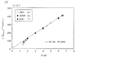
試験用の単一モード光ファイバ42として3種の単一モード光ファイバを用いてファイバヒューズの伝搬実験を行った。その内訳は、汎用の市販SMF、市販の短波長用単一モードファイバ(SSMF)、市販の分散シフトファイバDSFである。波長1550nmでのMFDの値はSMFが10.1μm、SSMFが9.2μm、DSFが7.7μmであった。また実験時の入力パワーPの範囲は1.4~6.6Wである。
A fiber fuse propagation experiment was conducted using three types of single-mode optical fibers as the test single-mode
図3にv(Dmelted)2(伝搬速度vとDmeltedの2乗の積)と入力パワーPとの関係を示す。図4にv(MFD)2(vとMFDの二乗の積)の入力パワーPとの関係を示す。図よりv(Dmelted)2とv(MFD)2の値は、MFDが十分に異なるにも関わらず3種の光ファイバで良好に一致した。各図中の直線は、Pが2.0W以上の条件(i)を満たすデータ(n=13)に対して最小二乗法を用いて求めた直線である。特に、条件(i)では、下記の近似式(1-1)(1-2)(2)が非常に良い精度で成立する。ここでKは比例係数であるが、式(1-2)の通り、条件(i)ではKは定数の62.76であるためDmeltedの近似式は 式(3)で与えられる。 FIG. 3 shows the relationship between v(D melted ) 2 (the product of the propagation velocity v and D melted squared) and the input power P. As shown in FIG. FIG. 4 shows the relationship between v(MFD) 2 (the product of v and the square of MFD) and input power P. In FIG. As can be seen from the figure, the values of v(D melted ) 2 and v(MFD) 2 are in good agreement for the three types of optical fibers although the MFDs are sufficiently different. A straight line in each figure is obtained by using the method of least squares for data (n=13) that satisfies the condition (i) that P is 2.0 W or more. In particular, under condition (i), the following approximations (1-1), (1-2), and (2) hold with very good accuracy. Here, K is a proportionality coefficient, and since K is a constant of 62.76 under condition (i) as shown in equation (1-2), the approximation of D melted is given by equation (3).
係数K(= v(Dmelted)2/P)は光源パワーPによるプラズマ化の効率を表すと考えられる。すなわち、ファイバヒューズ現象では光源が単位時間tあたりに行う仕事P×t(J)が、
(a)コア周辺のDmelted領域内の温度上昇およびプラズマ化と、
(b)Dmelted領域外部の温度上昇などに消費される過程と考えられる。
The coefficient K (= v(D melted ) 2 /P) is considered to represent the plasmatization efficiency due to the light source power P. That is, in the fiber fuse phenomenon, the work P×t(J) performed by the light source per unit time t is
(a) temperature rise and plasmatization in the D melted region around the core;
(b) This process is considered to be consumed by the temperature rise outside the D melted region.
条件(i)ではDmelted(プラズマの大きさ)が大きいので光源からの光が高い効率的で熱に変換されるので、光源の仕事P×t(J)の主な部分は上記(a)のDmelted領域の内部で消費され、上記(b)(伝熱・輻射によるクラッドや被覆の温度上昇と光の散逸)の寄与分は比較的小さいと推測される。この時、上記(a)の寄与分は、時間t(s)の間にプラズマ化した円柱領域の体積(=π(Dmelted/2)2・vt)に比例するので、(1-1)式の関係が生じたと考えられる。 Since in condition (i) D melted (plasma size) is large, the light from the light source is converted to heat with high efficiency, so the main part of the light source work P×t(J) is given above in (a) is consumed inside the D melted region of , and the contribution of the above (b) (increase in temperature of the clad and coating due to heat transfer and radiation and dissipation of light) is presumed to be relatively small. At this time, the contribution of the above (a) is proportional to the volume of the cylindrical region (=π(D melted /2) 2 vt) turned into plasma during the time t (s), so (1-1) It is thought that the relationship of the formula arose.
[数式欄]
v(Dmelted)2=K×P ・・・(1-1)
条件(i)において
K(i)=62.76 ・・・(1-2)
v(i)(MFD)2=11.44P(i)+16.55 ・・・(2)
Dmelted(i)
=(62.76P(i)/(11.44P(i)+16.55))0.5MFD
・・・(3)
条件(ii)において
K(ii)=19.70(Dmelted(ii)/MFD)2 ・・・(1-3)
P(ii)= K(i)P(i)/K(ii) ・・・(4)
Dmelted(ii)
=((62.76P(ii)-52.72 )/11.44P(ii))0.5MFD
・・・(5)
[Formula column]
v(D melted ) 2 = K×P (1-1)
K (i) = 62.76 in condition (i) (1-2)
v (i) (MFD) 2 =11.44P (i) +16.55 (2)
D melted (i)
=(62.76P (i) /(11.44P (i) +16.55)) 0.5 MFD
... (3)
K (ii) = 19.70 (D melted (ii) /MFD) 2 (1-3) in condition (ii)
P (ii) =K (i) P (i) /K (ii) (4)
D melted (ii)
= ((62.76P (ii) −52.72 )/11.44P (ii) ) 0.5 MFD
... (5)
一方、P=2.0W以下の条件(ii)でのKと(Dmelted/MFD)2との関係を図5に示す。図より、両者の間には、比例の関係が成り立つと考えられる。これは、Pの低下に伴い、プラズマの高温度部の面積((Dmelted 2に比例すると考えられる)が減少し、効率Kが低下するためと考えられる。図中の直線は、近似の連続性を考慮して、境界のP=2.0Wの時にK(i)=K(ii)=62.76であることを仮定して決定した直線であり、(1-3)式で与えられる。 On the other hand, FIG. 5 shows the relationship between K and (D melted /MFD) 2 under condition (ii) of P=2.0 W or less. From the figure, it is considered that there is a proportional relationship between the two. This is probably because the area of the high-temperature portion of the plasma (considered to be proportional to D melted 2 ) decreases as P decreases, and the efficiency K decreases. This is a straight line determined by assuming that K (i) = K (ii) = 62.76 when the boundary P = 2.0 W, taking into account the property, and is given by equation (1-3) .
図6にDmelted/MFDとPとの関係を示す。条件(i)では、測定値の各点と式(3)による近似予測値(点線)は良く一致した。しかし、条件(ii)では、特にSMFのP=1.4,1.5Wで両者の乖離が大きくなる。その主な原因は、式(1-2)ではK(i)=62.76を仮定したが、測定値は式(1-3)のK(ii)に従い62.76以下になるためである(図5)。そこで、K(ii)の低減分を補償するために(4)式を仮定し、条件(ii)では、これを予測値P(ii)とした。すなわち式(3)に式(1-3)と式(4)を代入してP(ii)とDmelted/MFDの関係を表す近似式(5)を決定した。図中に式(5)による近似値を実線で示している。なお、各式に用いた添え字(i)と(ii)は、条件(i)と条件(ii)をそれぞれ表している。 FIG. 6 shows the relationship between D melted /MFD and P. In FIG. Under the condition (i), each point of the measured value and the approximate predicted value (dotted line) by the formula (3) agreed well. However, under condition (ii), the divergence between the two increases particularly at SMF P=1.4 and 1.5W. The main reason is that K (i) = 62.76 was assumed in formula (1-2), but the measured value is 62.76 or less according to K (ii) in formula (1-3). (Fig. 5). Therefore, equation (4) is assumed to compensate for the reduction in K (ii ), and this is used as the predicted value P (ii) under condition (ii). That is, by substituting equations (1-3) and (4) into equation (3), approximate equation (5) representing the relationship between P (ii) and D melted /MFD was determined. In the figure, the solid line indicates the approximation value obtained by the equation (5). The suffixes (i) and (ii) used in each formula represent the condition (i) and the condition (ii), respectively.
実験値(各プロット点)と予測値(条件(i):点線、条件(ii):実線)は良好な一致傾向を示し、特に条件(ii)の範囲でのSMFのDmeltedの急減も式(5)によって良く再現された。P=1.4~6.6Wの全データ(n=18)に対して、真値(実測値)と推定値の相対誤差は、-8.7~+8.6%(RMS=3.4%)となり、良好な推定精度を確認した。上記の近似式(3)と(5)を用いることで、任意の入力パワーPと光ファイバのMFDの値に対してDmeltedの値を高い精度で推定することが可能となる。 The experimental values (each plotted point) and the predicted values (condition (i): dotted line, condition (ii): solid line) tend to agree well, especially in the range of condition ( ii ). (5) reproduces well. The relative error between the true value (measured value) and the estimated value is -8.7% to +8.6% (RMS = 3.4 %), confirming good estimation accuracy. By using the approximate expressions (3) and (5) above, it is possible to estimate the value of D melted with high accuracy for any input power P and MFD value of the optical fiber.
(実施形態2)
本実施形態は、ヒューズストッパが備えるHAFの断面内の構造の例と光伝送路内での使用例に関するものである。
図7は、HAFの断面図の一例を示す図である。図中に示す光ファイバ(HAF)は、クラッド11、コア12及び空孔13を有し、クラッド11内にコア12と円環形状に配列された複数の空孔13とで構成されている。図7では、それぞれ空孔直径をd、空孔13の内接円直径cを示した。
(Embodiment 2)
The present embodiment relates to an example of the cross-sectional structure of the HAF provided in the fuse stopper and an example of use in an optical transmission line.
FIG. 7 is a diagram showing an example of a cross-sectional view of the HAF. The optical fiber (HAF) shown in the figure has a clad 11, a
前述のようにDmeltedはファイバヒューズによって溶融・気化された断面内の円状領域の直径であり、その外側近傍は、ファイバヒューズ伝搬時に、仮にガラス状態を保っていたとしても非常に高温・高圧になるため容易に変形・破壊される。従ってcとDmeltedの比c/Dmeltedの値が小さいほどファイバヒューズの中心の最も高温な領域の近傍に空孔が存在することとなる。 As described above, D melted is the diameter of the circular region in the cross section melted and vaporized by the fiber fuse, and the vicinity of the outside is exposed to extremely high temperatures and pressures even if the glass state is maintained during propagation through the fiber fuse. It is easily deformed and destroyed. Therefore, the smaller the value of c/D melted , the ratio of c to D melted , the more holes exist in the vicinity of the hottest region in the center of the fiber fuse.
その際、ファイバヒューズによって生じる高温気体及びプラズマが空孔領域に流入、急激に膨張し、そのエネルギーを失うため低温になりやすい。つまり、c/Dmeltedが小さい空孔構造ほどファイバヒューズを容易に停止するため、c/Dmeltedの値はファイバヒューズストッパに用いられるHAF構造の指標となる。 At that time, high-temperature gas and plasma generated by the fiber fuse flow into the void region, expand rapidly, and lose their energy, so that the temperature tends to be low. In other words, the c/D melted value is an index of the HAF structure used for the fiber fuse stopper because the hole structure with a smaller c/D melted is easier to terminate the fiber fuse.
もう一つの指標として空孔面積(=Nπ(d/2)2)と溶融・気化された領域の面積(=π(Dmelted/2)2)との比Sがある。Sが大きいほどファイバヒューズは停止しやすい。これは高温の気体及びプラズマの体積膨張が起こりやすく、そのエネルギーを失うため低温になりやすいからである。なお空孔総数をNとするとS=N(d/Dmelted)2である。 Another index is the ratio S between the pore area (=Nπ(d/2) 2 ) and the area of the melted/vaporized region (=π(D melted /2) 2 ). The larger S is, the easier it is for the fiber fuse to stop. This is because high-temperature gas and plasma are likely to expand in volume and lose their energy, so they tend to be low in temperature. Note that S=N(d/D melted ) 2 where N is the total number of vacancies.
図8は、HAFの伝搬閾値を測定評価する系の一例を示す図である。HAF45と商用の単一モード光ファイバ(SMF)46を融着接続し、単一モード光ファイバ46(SMF)の終端でファイバヒューズを発生させ、接続点43を通過して、ファイバヒューズがHAF45を伝搬するか否かを確認評価した。評価において、光源44の波長は光通信の代表的な使用波長である1550nm付近とした。HAFにおいては、入力パワーが小さい時の方が、ファイバヒューズがHAFに侵入する距離が長い、つまり伝搬通過しやすいという結果が報告されているため、標準的な単一モード光ファイバ(SMF)の伝搬閾値に近いP=2.0Wで評価を行った。2.0Wの条件でファイバヒューズが停止したHAFについては、さらに15.0Wでの評価も行い、15.0Wの条件においてもファイバヒューズが停止することを確認した。
FIG. 8 is a diagram showing an example of a system for measuring and evaluating the HAF propagation threshold.
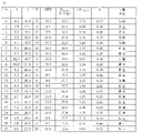
図9における表は、21種類のHAFを、図8の実験系においてファイバヒューズ伝搬の有無を確認した実験の結果である。表中には、空孔直径d、空孔の内接円直径c、空孔数N、HAF45についての波長1550nmにおけるMFD、P=2.0Wにおいて前述の近似式(3)から得られた、それぞれのHAFについて想定されるDmelted(計算値)、c/Dmelted、溶融・気化された領域の面積に対する空孔の面積比をS(=N(d/Dmelted)2)として記載した。また、図8で伝送路ファイバとして想定しているのは、単一モードファイバ(SMF)46であり、その波長1550nmにおけるMFDは約10μmであった。ヒューズの伝搬を確認した8種のHAFについては、ヒューズの伝搬閾値も評価したところ、すべて約1.5Wであった。 The table in FIG. 9 shows the results of an experiment in which 21 kinds of HAFs were checked for the presence or absence of fiber fuse propagation in the experimental system of FIG. In the table, the hole diameter d, the hole inscribed circle diameter c, the number of holes N, the MFD at a wavelength of 1550 nm for HAF45, P = 2.0 W, obtained from the approximate expression (3) above, The assumed D melted (calculated value), c/D melted , and the area ratio of the vacancies to the area of the melted/vaporized region for each HAF were described as S (=N(d/D melted ) 2 ). 8 is a single mode fiber (SMF) 46 assumed as a transmission line fiber, and its MFD at a wavelength of 1550 nm is about 10 μm. The fuse propagation threshold was also evaluated for the eight types of HAFs for which fuse propagation was confirmed, and all of them were about 1.5W.
図10は、HAF45におけるファイバヒューズの伝搬または停止と、空孔の溶融・気化された領域に対する面積比Sおよびc/Dmeltedとの関係を示す図である。図からc/Dmeltedの値が1.29以下かつSの値が0.12(12%)以上の構造領域に本発明のファイバヒューズストッパもしくはファイバヒューズ抑制ファイバとして好適となる構造が含まれる。
FIG. 10 is a graph showing the relationship between fiber fuse propagation or termination in the
しかし、上記領域には、実験においてファイバヒューズが伝搬してしまう領域も含まれている。従って、HAF45の構造を座標(c/Dmelted,S)で表記した場合、A1(0.81,0.12)、A2(1.13,0.36)、A3(1.22,0.61)、A4(1.24,1.07)、A5(1.29,2.21)とすると、直線c/Dmelted=1.29と、直線S=0.12と、座標A1とA2を含む直線と、座標A2とA3を含む直線と、座標A3とA4とA5を含む直線とで囲まれた構造領域を選定することで、HAF45はファイバヒューズを停止でき、本発明のファイバヒューズストッパもしくはファイバヒューズ抑制ファイバとして好適となる。座標A3とA4とA5はほぼ同一直線上にあるため、この直線を最小二乗法によって決定し、上記の領域を等式(A)と不等式(B)を用いて定義すると、下記のようになる。図10には、上記の「ファイバヒューズ停止」の構造領域の境界を点線にて示している。
However, the above region also includes a region where the fiber fuse propagates in the experiment. Therefore, when the structure of HAF45 is represented by coordinates (c/D melted , S), A1 (0.81, 0.12), A2 (1.13, 0.36), A3 (1.22, 0. 61), A4(1.24, 1.07), A5(1.29, 2.21), the straight line c/D melted = 1.29, the straight line S = 0.12, and the coordinates A1 and A2 , a straight line including coordinates A2 and A3, and a straight line including coordinates A3, A4, and A5,
[数式欄]
条件(ii)の場合
Dmelted=(62.76P/(11.44P+16.55))0.5MFD
条件(i)の場合
Dmelted
=((62.76P-52.72 )/11.44P)0.5MFD ・・・(A)
c/Dmeltedが0.81以下の場合
S≧0.12
c/Dmeltedが0.81~1.13の場合
S≧0.750(c/Dmelted)-0.488
c/Dmeltedが1.13~1.22の場合
S≧2.778(c/Dmelted)-2.779
c/Dmeltedが1.22~1.29の場合
S≧22.85(c/Dmelted)-27.26
c/Dmeltedが1.29の場合
S≧2.21 ・・・(B)
[Formula column]
For condition (ii) D melted = (62.76P/(11.44P+16.55)) 0.5 MFD
In case of condition (i) D melted = ((62.76P-52.72)/11.44P) 0.5 MFD (A)
When c/D melted is 0.81 or less S≧0.12
When c/D melted is 0.81 to 1.13 S≧0.750 (c/D melted )−0.488
When c/D melted is 1.13 to 1.22 S≧2.778(c/D melted )−2.779
When c/D melted is 1.22 to 1.29 S≧22.85(c/D melted )−27.26
When c/D melted is 1.29 S≧2.21 (B)
なおSの値については、ファイバヒューズを停止するには値が大きい程好ましいが、cの値に依存する幾何学的な上限値が存在する。またSの値が過剰に大きすぎると製造精度の劣化や機械強度の低減を招きやすくなる。従って、これらの要因を勘案して、上記の「ファイバヒューズ停止」の条件範囲の構造領域でSの値を適宜設定すれば良い。また図6に示したようにDmeltedは入力パワーPの減少に伴って減少するため、Pの値が比較的小さい時はcの値を小さくして、空孔の位置をファイバの中心に近づけて配置する必要がある。従って、入力パワーの下限値Pminもしくはファイバヒューズの伝搬閾値Pthを式(3)もしくは(5)に代入して得られるDmeltedの値を基準に、cの値を決定すればよい。しかし、逆に例えば、Pminが4W以上の時は常にDmeltedはMFDの2倍以上、Pが6W以上の時は常にDmeltedはMFDの2.1倍以上になる。従って、想定している入力パワーの下限値Pminが比較的大きく5W付近の場合、cの値は比較的大きくても良い。一般にcの値が小さいとHAFの設計や製造が困難になる傾向があるので、このような場合、上記の「ファイバヒューズ停止」の条件範囲の中で、cがMFDの2~2.1倍以上の領域がHAFの設計や製造性の観点から好適となる。 Regarding the value of S, a larger value is more preferable for stopping the fiber fuse, but there is a geometrical upper limit value that depends on the value of c. On the other hand, if the value of S is excessively large, deterioration of manufacturing accuracy and reduction of mechanical strength are likely to occur. Therefore, taking these factors into consideration, the value of S may be appropriately set in the structural region within the conditional range of "stopping the fiber fuse". Also, as shown in FIG. 6, D melted decreases as the input power P decreases. Therefore, when the value of P is relatively small, the value of c should be decreased to bring the position of the hole closer to the center of the fiber. must be placed Therefore, the value of c can be determined based on the value of D melted obtained by substituting the lower limit value P min of the input power or the propagation threshold value P th of the fiber fuse into the equation (3) or (5). Conversely, for example, when P min is 4 W or more, D melted is always 2 times or more of MFD, and when P is 6 W or more, D melted is always 2.1 times or more of MFD. Therefore, when the lower limit Pmin of the assumed input power is relatively large, around 5 W, the value of c may be relatively large. In general, if the value of c is small, it tends to be difficult to design and manufacture the HAF. The above regions are suitable from the viewpoint of HAF design and manufacturability.
図10に示した構造のHAFにおいて、図8の実験系で検証を行ったところ、ファイバヒューズがHAF内に侵入した侵入長は大半が0.5mm以下であり、最長でも5mmに到達することはなかった。従って、前記構造のHAFをヒューズストッパとして用いる場合、HAFの長さを0.5~5mm程度とすることが好適となる。また、前記長さのHAFに適当な長さの単一モード光ファイバを融着接続する構成とすることも可能である。ただし、この場合は融着接続時に、条件によっては接続の近傍で空孔が放電によって潰れてしまうことがあり、融着条件に留意するか、融着後にHAFの空孔部の長さが0.5mm以上確保されているかを確認する必要がある。また、融着接続損失を抑制するためには、HAFのMFDと前記単一モード光ファイバのMFDとが、概略等しいことが好ましい。例えば、HAFのMFDと単一モード光ファイバのMFDとの誤差は±5~10%であることが好ましい。 In the HAF having the structure shown in FIG. 10, when verification was performed using the experimental system shown in FIG. I didn't. Therefore, when the HAF having the structure described above is used as a fuse stopper, it is preferable to set the length of the HAF to about 0.5 to 5 mm. Moreover, it is also possible to adopt a configuration in which a single-mode optical fiber having an appropriate length is fusion-spliced to the HAF having the above length. However, in this case, depending on the conditions, the holes in the vicinity of the connection may be crushed by electric discharge during fusion splicing. It is necessary to confirm whether 5 mm or more is secured. Also, in order to suppress the fusion splicing loss, it is preferable that the MFD of the HAF and the MFD of the single mode optical fiber are substantially equal. For example, the error between the MFD of the HAF and the MFD of the single mode optical fiber is preferably ±5-10%.
前記のように本発明において用いられるHAFは0.5mm~数mmのごく短尺で良いため、単一モードファイバとの接続点をコネクタの内部に含めて、これを保護する構成にしても良い。このような光コード化した構成の場合、伝送装置の近傍や伝送路途中に挿入することが容易である。仮に、光ファイバ伝送路中でファイバヒューズが発生した場合も、前記のヒューズストッパでファイバヒューズを停止できるので、伝送装置や光ファイバ伝送路を、ファイバヒューズによる破壊から保護することができる。 As described above, the HAF used in the present invention may be very short, from 0.5 mm to several mm, so the connection point with the single mode fiber may be included inside the connector to protect it. In the case of such an optically coded structure, it is easy to insert in the vicinity of a transmission device or in the middle of a transmission line. Even if a fiber fuse occurs in the optical fiber transmission line, the fuse stopper can stop the fiber fuse, so that the transmission device and the optical fiber transmission line can be protected from destruction by the fiber fuse.
(実施形態3)
本実施形態は、本発明に係るHAFの断面内の構造の例に関するものである。
本発明において、ファイバヒューズストッパに用いられるHAFは幅広い光パワー領域を想定している。従って、入力パワーPを特定の使用範囲で変えた時も、前記実施形態に記載したパラメータ(c/Dmelted,S)の組み合わせが、「ファイバヒューズ停止」の条件範囲に含まれていることを確認する必要がある。そのために、以下の検証実験を行った。
(Embodiment 3)
This embodiment relates to an example of a cross-sectional structure of the HAF according to the present invention.
In the present invention, the HAF used for the fiber fuse stopper assumes a wide optical power range. Therefore, even when the input power P is changed within a specific range of use, it is confirmed that the combination of the parameters (c/D melted , S) described in the above embodiment is included in the "fiber fuse stop" condition range. It is necessary to confirm. For this purpose, the following verification experiment was conducted.
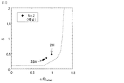
図9の表中No.2のHAFと図8の実験系を用いてファイバヒューズの停止実験を行った。その際の入力パワー条件は、P=2W,5W,10W,15W,22Wとした。実際の停止実験においてファイバヒューズはすべての条件で停止し、ファイバヒューズがHAF内に侵入した侵入長は0.3mm以下(Pが22Wの時に最大値0.3mm)であった。これらの条件に関して、No.2のHAFのMFD=9.7μmとそれぞれのPの値に対する、(c/Dmelted,S)の座標点を図11に示した。図中には図10と同じく「ファイバヒューズ停止」の範囲を示す境界を点線で示した。図より、No.2のHAFについてPの値を大きく変化させても、(c/Dmelted,S)の各座標はすべて「ファイバヒューズ停止」の範囲に含まれた。これは、本発明のHAFおよびHAFの空孔構造の規定方法の妥当性を裏付ける結果である。 No. in the table of FIG. 2 HAF and the experimental system of FIG. 8, a fiber fuse termination experiment was conducted. The input power conditions at that time were P=2W, 5W, 10W, 15W, and 22W. In an actual termination experiment, the fiber fuse terminated under all conditions, and the penetration depth of the fiber fuse into the HAF was 0.3 mm or less (maximum value of 0.3 mm when P was 22 W). Regarding these conditions, no. The coordinate points of (c/D melted , S) are shown in FIG. In the drawing, as in FIG. 10, the boundary indicating the range of "fiber fuse stop" is indicated by a dotted line. From the figure, No. Each coordinate of (c/D melted , S) was all within the range of "fiber fuse stop" even when the value of P was greatly changed for the HAF of 2. This result supports the validity of the HAF and the method for defining the pore structure of the HAF of the present invention.
(実施形態4)
本実施形態は、本発明に係るHAFの断面内の構造の例に関するものである。
HAF自体を単独で通信用あるいは光給電などの高い光パワーの伝送用のファイバヒューズ抑制ファイバとして用いる際はSMFなどの伝送用光ファイバとの接続性の問題は考慮する必要がない。この場合に主に問題となるのは、光パワーの制限要因である非線形光学現象(主に誘導ラマン散乱)とファイバヒューズの発生の2点となる。例えば、誘導ラマン散乱によって1550nm近傍の波長の光を使って伝送できる光パワーは、1kmの伝送距離を想定した際にSMFでは最大15W程度に、10kmの伝送距離を想定した際に最大1.5W程度に制限される。
(Embodiment 4)
This embodiment relates to an example of a cross-sectional structure of the HAF according to the present invention.
When the HAF itself is used alone as a fiber fuse suppression fiber for communication or high optical power transmission such as optical feeding, it is not necessary to consider the problem of connectivity with transmission optical fibers such as SMF. In this case, there are two main problems: nonlinear optical phenomena (mainly stimulated Raman scattering), which are factors limiting optical power, and occurrence of fiber fuses. For example, the optical power that can be transmitted using light with a wavelength near 1550 nm by stimulated Raman scattering is about 15 W at maximum for SMF when a transmission distance of 1 km is assumed, and 1.5 W at maximum when a transmission distance of 10 km is assumed. limited to an extent.
非線形光学現象を回避するためには実効断面積Aeff(近似的にMFDの2乗に比例する)、つまりMFDを拡大する方法が考えられる。また、これらの使用想定パワー領域1.5W~15W以上はSMFのファイバヒューズ伝搬閾値(Pth)の約1.5Wをはるかに超える場合があるため、前述のファイバヒューズ発生の対策も必要となる。 In order to avoid the nonlinear optical phenomenon, a method of enlarging the effective cross-sectional area A eff (approximately proportional to the square of the MFD), that is, the MFD can be considered. In addition, since the assumed use power range of 1.5 W to 15 W or more may greatly exceed the SMF fiber fuse propagation threshold (P th ) of about 1.5 W, it is necessary to take measures against the occurrence of fiber fuses as described above. .
上記の観点から、MFDをSMFの値(約10μm)以上、好ましくは15μm以上に拡大したHAFはその際の伝送路ファイバとして有望である。しかしながら、図6に示すように伝搬閾値近傍でDmeltedが急減するため、空孔の内接円直径cを比較的小さくする必要がある。これは空孔がコア中心の近い位置に配置されることを意味するためMFD及び実効断面積Aeffの拡大が困難になってしまう。つまり、非線形光学現象を回避するために実効断面積Aeffを拡大することと、ファイバヒューズを停止させるために空孔の内接円直径cを小さくする(実効断面積Aeffが拡大できない)こととがトレードオフの状態になっている。 From the above point of view, the HAF, in which the MFD is expanded to the value of the SMF (approximately 10 μm) or more, preferably 15 μm or more, is promising as a transmission line fiber in that case. However, as shown in FIG. 6, D melted sharply decreases near the propagation threshold, so it is necessary to make the diameter c of the inscribed circle of the holes relatively small. This means that the holes are arranged near the center of the core, which makes it difficult to expand the MFD and the effective cross-sectional area Aeff . In other words, it is necessary to increase the effective cross-sectional area A eff to avoid the nonlinear optical phenomenon and to reduce the diameter c of the inscribed circle of the air hole to stop the fiber fuse (the effective cross-sectional area A eff cannot be increased). is in a trade-off state.
本実施形態では、このトレードオフを大きく緩和するHAF構造を説明する。非特許文献4に示されている通り、通常の(空孔型ではない)各種の単一モード光ファイバにおいて、ファイバヒューズ伝搬閾値PthはMFDに比例することが知られており、その関係は概略、以下の式(6)で与えられる。
[数式欄]
Pth=0.135MFD ・・・(6)
In this embodiment, we describe an HAF structure that greatly alleviates this trade-off. As shown in
[Formula column]
Pth= 0.135MFD (6)
従って、図6のDmeltedの変化率が緩やかになる特異点である2.0W付近までは、MFD拡大の効果によってファイバヒューズの発生を回避する構造を用いれば上記のHAFの空孔設計上のトレードオフが緩和できる。すなわち式(6)にPth=2.0Wを代入した結果より、使用波長におけるMFDを15μm程度以上に拡大すれば良い。この時、想定する最大入力パワー(例えば、光源の最大出力パワー)をPmaxとすると、P=Pth~Pmaxの条件範囲で式(3)からDmeltedの値を計算し、(c/Dmelted,S)の座標が図11の「ファイバヒューズ停止」の範囲内に含まれるように、c、d、空孔数Nといった構造パラメータを選択する。 Therefore, up to around 2.0 W, which is a singular point where the change rate of D melted in FIG. Trade-offs can be mitigated. That is, from the result of substituting P th =2.0 W into Equation (6), the MFD at the working wavelength should be increased to about 15 μm or more. At this time, assuming that the assumed maximum input power (for example, the maximum output power of the light source) is P max , the value of D melted is calculated from Equation (3) in the condition range of P = P th ~ P max , and (c/ Structural parameters such as c, d, number of holes N are chosen such that the coordinates of D melted , S) fall within the range of "fiber fuse stop" in FIG.
選択された構造パラメータであれば、P= 1.5W~Pmaxの条件範囲でファイバヒューズは発生せず、かつMFDの拡大によって非線形光学現象の閾値もSMFの約2.3倍(=MFD比1.5の2乗倍)以上に拡大されるため、約1.5W以上でファイバヒューズ発生の懸念があるSMFを用いる際と比較して大幅に有利となり、好適となる。つまり、この構造ではP=1.5W~Pthの範囲の条件ではMFDの拡大効果によって、P=Pth~Pmaxの範囲の条件では空孔の効果によってファイバヒューズが発生しない。 With the selected structural parameters, fiber fuses do not occur in the condition range of P = 1.5 W to P max , and the expansion of the MFD also increases the threshold of nonlinear optical phenomena by about 2.3 times that of the SMF (= MFD ratio 1.5 squared) or more, it is greatly advantageous and suitable compared to the case of using SMF, which is about 1.5 W or more and has a concern of fiber fuse occurrence. That is, in this structure, fiber fuses do not occur due to the expansion effect of the MFD under the condition of P=1.5 W to P th and due to the effect of air holes under the condition of P=P th to P max .
この際、Dmeltedの予測を行う際に、HAFのMFDを15μm以上、Pを2.0W以上と設定すれば良いので、式(3)から決まるDmeltedの値は26.8μm以上となる。なお上記HAFは使用波長において単一モードでも数モードでも良い。数モード構造の場合は基本伝搬モードであるLP01モードを伝送に用いれば良い。 In this case, when predicting D melted , the MFD of HAF should be set to 15 μm or more and P should be set to 2.0 W or more. The above HAF may be single mode or several modes at the wavelength used. In the case of a few-mode structure, the LP 01 mode, which is the fundamental propagation mode, should be used for transmission.
[付記]
以下は、本実施形態のファイバヒューズ抑制ファイバ及びヒューズストッパに使用されるHAFを説明したものである。
(1):
当該HAFは、屈折率が均一なクラッドと、前記クラッド領域の中央に配置された前記クラッドよりも高い屈折率を有するコアと、前記クラッド領域内の前記コアの外周に、直径がcの円周上に外接するように等間隔に配置された直径dのN個の空孔とを有する光ファイバであって、
前記クラッドおよびコアおよび使用波長で規定されるモードフィールド直径をMFD、入力光パワーをP、ファイバヒューズ発生時に光ファイバが溶融・気化する領域の直径をDmelted、前記Dmeltedで規定される円の面積と前記空孔が占める面積との比をS(=N(d/Dmelted)2)とするとき、前記c、MFD、Dmelted、P、Sが上述の式(A)および式(B)を同時に満たすように設定されることを特徴とする。
[Appendix]
The following is a description of the HAF used in the fiber fuse suppressing fiber and fuse stopper of this embodiment.
(1):
The HAF includes a cladding having a uniform refractive index, a core having a higher refractive index than the cladding and located in the center of the cladding region, and a circumference having a diameter of c an optical fiber having N holes of diameter d equally spaced circumscribing thereon,
MFD is the mode field diameter defined by the cladding and core and the wavelength used, P is the input optical power, D melted is the diameter of the region where the optical fiber melts and vaporizes when the fiber fuse occurs, and the circle defined by D melted When the ratio of the area to the area occupied by the vacancies is S (=N(d/D melted ) 2 ), the c, MFD, D melted , P, and S are the above formulas (A) and (B). ) at the same time.
(2):
使用波長における基本伝搬モード(LP01モード)のMFDが10μm以上、好ましくは概略15μm以上であり、使用を想定する最大入力パワーをPmaxとするとき、Pth=0.135MFDで規定されるPth以上でPmax以下の範囲の入力パワーにおいて、上記(1)に記載の空孔構造条件を満たすことを特徴とする。
(2):
When the MFD of the fundamental propagation mode (LP 01 mode) at the wavelength used is 10 μm or more, preferably approximately 15 μm or more, and the maximum input power assumed to be used is P max , P th = 0.135 MFD. The pore structure condition described in (1) above is satisfied at an input power in the range of th or more and P max or less.
(効果)
本発明は、ファイバヒューズの伝搬を確実に停止するHAF、およびこれを用いたファイバヒューズストッパ、光コネクタ、光伝送システム、光ファイバ、及びファイバヒューズ停止方法を提供することができる。また挿入損失が十分に低く、高次モード発生や機械的強度の低下の懸念などが小さく、低いコストで性能の歩留まりの良く作製が可能で、任意の入力パワーPと、ファイバのMFDの条件に対して、発生したファイバヒューズを停止させるファイバヒューズストッパ、および光コネクタ、およびファイバヒューズの発生を抑制する光ファイバ伝送路を提供することができる。
(effect)
INDUSTRIAL APPLICABILITY The present invention can provide a HAF that reliably stops propagation of a fiber fuse, a fiber fuse stopper using the HAF, an optical connector, an optical transmission system, an optical fiber, and a fiber fuse stopping method. In addition, the insertion loss is sufficiently low, there is little concern about the occurrence of higher-order modes and the decrease in mechanical strength, etc., and it can be manufactured at a low cost with a high performance yield. On the other hand, it is possible to provide a fiber fuse stopper that stops the generated fiber fuse, an optical connector, and an optical fiber transmission line that suppresses the generation of the fiber fuse.
11:クラッド
12:コア
13:空孔
41:単一モード光ファイバ
42:単一モード光ファイバ(試験用)
43:接続点
44:光源
45:HAF
11: Cladding 12: Core 13: Hole 41: Single-mode optical fiber 42: Single-mode optical fiber (for testing)
43: Connection point 44: Light source 45: HAF
Claims (3)
所望のモードフィールド直径MFDと入力光パワーPに基づいて式(A)より、ファイバヒューズが発生するファイバヒューズ発生領域の直径Dmeltedを計算する計算工程と、
前記HAFの断面における、前記ファイバヒューズ発生領域の面積と全ての前記空孔が占める面積との比S(=N(d/Dmelted)2)が式(B)を満足する直径c、直径d及び前記空孔の数Nを検出する検出工程と、
を行うことを特徴とする設計方法。
[式(A)]
Pが2.0W以上の場合:
Dmelted=(62.76P/(11.44P+16.55))0.5×MFD
Pが2.0W以下の場合:
Dmelted=((62.76P-52.72)/11.44P)0.5×MFD
[式(B)]
c/Dmeltedが0.81の場合:
S≧0.12
c/Dmeltedが0.81~1.13の場合:
S≧0.750(c/Dmelted)-0.488
c/Dmeltedが1.13~1.22の場合:
S≧2.778(c/Dmelted)-2.779
c/Dmeltedが1.22~1.29の場合:
S≧22.85(c/Dmelted)-27.26
c/Dmeltedが1.29の場合:
S≧2.21 a cladding region with a uniform refractive index; a core having a higher refractive index than the cladding region and disposed in the center of the cladding region; 1. A method for designing a fiber fuse suppressing fiber comprising a hole assisted optical fiber (HAF) having N holes of diameter d equally spaced at , wherein the fiber fuse is stopped, comprising: ,
a calculation step of calculating the diameter D melted of the fiber fuse generation region where the fiber fuse is generated from the equation (A) based on the desired mode field diameter MFD and the input optical power P;
Diameter c and diameter d where the ratio S (=N(d/D melted ) 2 ) of the area of the fiber fuse generation region to the area occupied by all the holes in the cross section of the HAF satisfies formula (B) and a detection step of detecting the number N of the holes;
A design method characterized by performing
[Formula (A)]
When P is 2.0 W or more :
Dmelted = (62.76P/(11.44P+16.55)) 0.5 x MFD
If P is less than 2.0W:
D melted = ((62.76P-52.72)/11.44P) 0.5 x MFD
[Formula (B)]
If c/D melted is 0.81 :
S≧0.12
When c/D melted is 0.81 to 1.13:
S≧0.750(c/D melted )−0.488
When c/D melted is 1.13 to 1.22:
S≧2.778(c/D melted )−2.779
When c/D melted is 1.22 to 1.29:
S≧22.85(c/D melted )−27.26
If c/D melted is 1.29:
S≧2.21
Priority Applications (1)
| Application Number | Priority Date | Filing Date | Title |
|---|---|---|---|
| JP2019038951A JP7149529B2 (en) | 2019-03-04 | 2019-03-04 | How to design a fiber fuse suppressing fiber |
Applications Claiming Priority (1)
| Application Number | Priority Date | Filing Date | Title |
|---|---|---|---|
| JP2019038951A JP7149529B2 (en) | 2019-03-04 | 2019-03-04 | How to design a fiber fuse suppressing fiber |
Publications (2)
| Publication Number | Publication Date |
|---|---|
| JP2020144170A JP2020144170A (en) | 2020-09-10 |
| JP7149529B2 true JP7149529B2 (en) | 2022-10-07 |
Family
ID=72354137
Family Applications (1)
| Application Number | Title | Priority Date | Filing Date |
|---|---|---|---|
| JP2019038951A Active JP7149529B2 (en) | 2019-03-04 | 2019-03-04 | How to design a fiber fuse suppressing fiber |
Country Status (1)
| Country | Link |
|---|---|
| JP (1) | JP7149529B2 (en) |
Citations (3)
| Publication number | Priority date | Publication date | Assignee | Title |
|---|---|---|---|---|
| US20020114554A1 (en) | 2000-12-22 | 2002-08-22 | Maroney Andrew V. | Fiber fuse protection |
| WO2010023881A1 (en) | 2008-08-26 | 2010-03-04 | 株式会社フジクラ | Fiber-fuse breaking member, fiber laser, and optical transmission line |
| JP2017111173A (en) | 2015-12-14 | 2017-06-22 | 日本電信電話株式会社 | Fiber fuse suppression fiber and optical connector |
-
2019
- 2019-03-04 JP JP2019038951A patent/JP7149529B2/en active Active
Patent Citations (3)
| Publication number | Priority date | Publication date | Assignee | Title |
|---|---|---|---|---|
| US20020114554A1 (en) | 2000-12-22 | 2002-08-22 | Maroney Andrew V. | Fiber fuse protection |
| WO2010023881A1 (en) | 2008-08-26 | 2010-03-04 | 株式会社フジクラ | Fiber-fuse breaking member, fiber laser, and optical transmission line |
| JP2017111173A (en) | 2015-12-14 | 2017-06-22 | 日本電信電話株式会社 | Fiber fuse suppression fiber and optical connector |
Non-Patent Citations (3)
| Title |
|---|
| KUROKAWA et al.,Fiber Fuse Propagation and Its Suppression in Hole-Assisted Fibers,IEICE Transactions on Communications,Vol.E94-B, No.2,日本,2011年02月,p.384-p.391 |
| TAKENAGA et al.,Fiber Fuse Phenomenon in Hole-Assisted Fibers,Fujikura Technical Review,No.40,日本,株式会社フジクラ,2011年,p.12-p.15 |
| 竹永勝宏 他,空孔アシストファイバにおけるファイバヒューズ現象,フジクラ技報,第118号,日本,株式会社フジクラ,2010年,p.1-p.5 |
Also Published As
| Publication number | Publication date |
|---|---|
| JP2020144170A (en) | 2020-09-10 |
Similar Documents
| Publication | Publication Date | Title |
|---|---|---|
| JP4551981B2 (en) | Fiber fuse breaker, fiber laser, and optical transmission line | |
| EP2388871B1 (en) | Multiclad optical fiber, optical fiber module, fiber laser, and fiber amplifier | |
| JP4954737B2 (en) | Optical amplification system, optical fiber laser and optical fiber amplifier using the same | |
| Galvanauskas et al. | High peak power pulse amplification in large-core Yb-doped fiber amplifiers | |
| JP4744489B2 (en) | Optical fiber for high power applications | |
| JP5786143B2 (en) | Fiber parts and laser equipment | |
| Dong | Limits of stimulated Brillouin scattering suppression in optical fibers with transverse acoustic waveguide designs | |
| US10833470B2 (en) | Optical fiber and fiber laser | |
| André et al. | Thermal effects in optical fibres | |
| JP7149529B2 (en) | How to design a fiber fuse suppressing fiber | |
| JP2017111173A (en) | Fiber fuse suppression fiber and optical connector | |
| JP6918983B2 (en) | Multimode fiber optics optimized to operate around 1060 nm, and corresponding multimode optics | |
| Shuto | End face damage and fiber fuse phenomena in single-mode fiber-optic connectors | |
| RU2561766C2 (en) | Device for protection of fibre components against destruction by laser emission (versions) | |
| Röhrer et al. | Analysis of fundamental-mode beam transport in highly multimode fibers | |
| de la Rosa et al. | Effect of the surrounding refractive index and fusion-depth on side-pump combiners | |
| US11493690B2 (en) | Optical fiber line, module, and method for manufacturing optical fiber line | |
| JP2012163802A (en) | Fiber fuse stopper, optical connector, optical transmission system and fiber fuse stop method | |
| Leidner et al. | The impact of thermal mode instability on core diameter scaling in high-power fiber amplifiers | |
| JP2019040131A (en) | Optical fiber, optical device, and manufacturing method of optical device | |
| Han et al. | Quantitative evaluation of the heat induced by fusion splices in high-power fiber lasers | |
| Mizuno et al. | Plastic optical fiber fuse: Observation, characterization, and applications | |
| Mizuno et al. | Plastic optical fiber fuse and its impact on sensing applications | |
| Ahmad et al. | Polarization-maintained guidance of large-effective-area, higher-order-modes in fiber | |
| Chowdhury et al. | Choice of step and near step profiles from splice loss analysis of trapezoidal index single mode fibers leading to a proposal of a longitudinal displacement sensor |
Legal Events
| Date | Code | Title | Description |
|---|---|---|---|
| A521 | Request for written amendment filed |
Free format text: JAPANESE INTERMEDIATE CODE: A523 Effective date: 20190312 |
|
| A80 | Written request to apply exceptions to lack of novelty of invention |
Free format text: JAPANESE INTERMEDIATE CODE: A80 Effective date: 20190329 |
|
| A621 | Written request for application examination |
Free format text: JAPANESE INTERMEDIATE CODE: A621 Effective date: 20210430 |
|
| A977 | Report on retrieval |
Free format text: JAPANESE INTERMEDIATE CODE: A971007 Effective date: 20220330 |
|
| A131 | Notification of reasons for refusal |
Free format text: JAPANESE INTERMEDIATE CODE: A131 Effective date: 20220405 |
|
| A521 | Request for written amendment filed |
Free format text: JAPANESE INTERMEDIATE CODE: A523 Effective date: 20220524 |
|
| TRDD | Decision of grant or rejection written | ||
| A01 | Written decision to grant a patent or to grant a registration (utility model) |
Free format text: JAPANESE INTERMEDIATE CODE: A01 Effective date: 20220913 |
|
| A61 | First payment of annual fees (during grant procedure) |
Free format text: JAPANESE INTERMEDIATE CODE: A61 Effective date: 20220915 |
|
| A711 | Notification of change in applicant |
Free format text: JAPANESE INTERMEDIATE CODE: A712 Effective date: 20220928 |
|
| R150 | Certificate of patent or registration of utility model |
Ref document number: 7149529 Country of ref document: JP Free format text: JAPANESE INTERMEDIATE CODE: R150 |
|
| A521 | Request for written amendment filed |
Free format text: JAPANESE INTERMEDIATE CODE: A821 Effective date: 20221003 |
|
| R150 | Certificate of patent or registration of utility model |
Ref document number: 7149529 Country of ref document: JP Free format text: JAPANESE INTERMEDIATE CODE: R150 |