JP7149192B2 - head-up display device - Google Patents
head-up display device Download PDFInfo
- Publication number
- JP7149192B2 JP7149192B2 JP2019010985A JP2019010985A JP7149192B2 JP 7149192 B2 JP7149192 B2 JP 7149192B2 JP 2019010985 A JP2019010985 A JP 2019010985A JP 2019010985 A JP2019010985 A JP 2019010985A JP 7149192 B2 JP7149192 B2 JP 7149192B2
- Authority
- JP
- Japan
- Prior art keywords
- driver
- light
- head
- display device
- viewpoint
- Prior art date
- Legal status (The legal status is an assumption and is not a legal conclusion. Google has not performed a legal analysis and makes no representation as to the accuracy of the status listed.)
- Active
Links
- 238000001514 detection method Methods 0.000 claims description 71
- 238000004891 communication Methods 0.000 claims description 26
- 238000012544 monitoring process Methods 0.000 claims description 24
- 238000005286 illumination Methods 0.000 claims description 9
- 230000001678 irradiating effect Effects 0.000 claims description 2
- 238000000034 method Methods 0.000 description 9
- 238000010586 diagram Methods 0.000 description 8
- 238000012545 processing Methods 0.000 description 8
- 238000005516 engineering process Methods 0.000 description 7
- 230000008569 process Effects 0.000 description 7
- 230000003287 optical effect Effects 0.000 description 5
- 210000001508 eye Anatomy 0.000 description 4
- 238000004458 analytical method Methods 0.000 description 3
- 210000005252 bulbus oculi Anatomy 0.000 description 2
- 238000012937 correction Methods 0.000 description 2
- 230000006870 function Effects 0.000 description 2
- 230000004313 glare Effects 0.000 description 2
- 239000011521 glass Substances 0.000 description 2
- 238000010191 image analysis Methods 0.000 description 2
- 239000004973 liquid crystal related substance Substances 0.000 description 2
- 230000007246 mechanism Effects 0.000 description 2
- 230000004044 response Effects 0.000 description 2
- 230000008859 change Effects 0.000 description 1
- 239000003086 colorant Substances 0.000 description 1
- 238000011161 development Methods 0.000 description 1
- 230000000694 effects Effects 0.000 description 1
- 230000004438 eyesight Effects 0.000 description 1
- 230000001815 facial effect Effects 0.000 description 1
- 238000003780 insertion Methods 0.000 description 1
- 230000037431 insertion Effects 0.000 description 1
- 238000012806 monitoring device Methods 0.000 description 1
Images


Classifications
-
- A—HUMAN NECESSITIES
- A61—MEDICAL OR VETERINARY SCIENCE; HYGIENE
- A61B—DIAGNOSIS; SURGERY; IDENTIFICATION
- A61B5/00—Measuring for diagnostic purposes; Identification of persons
- A61B5/16—Devices for psychotechnics; Testing reaction times ; Devices for evaluating the psychological state
- A61B5/163—Devices for psychotechnics; Testing reaction times ; Devices for evaluating the psychological state by tracking eye movement, gaze, or pupil change
-
- A—HUMAN NECESSITIES
- A61—MEDICAL OR VETERINARY SCIENCE; HYGIENE
- A61B—DIAGNOSIS; SURGERY; IDENTIFICATION
- A61B5/00—Measuring for diagnostic purposes; Identification of persons
- A61B5/68—Arrangements of detecting, measuring or recording means, e.g. sensors, in relation to patient
- A61B5/6801—Arrangements of detecting, measuring or recording means, e.g. sensors, in relation to patient specially adapted to be attached to or worn on the body surface
- A61B5/6813—Specially adapted to be attached to a specific body part
- A61B5/6814—Head
- A61B5/6821—Eye
-
- B—PERFORMING OPERATIONS; TRANSPORTING
- B60—VEHICLES IN GENERAL
- B60K—ARRANGEMENT OR MOUNTING OF PROPULSION UNITS OR OF TRANSMISSIONS IN VEHICLES; ARRANGEMENT OR MOUNTING OF PLURAL DIVERSE PRIME-MOVERS IN VEHICLES; AUXILIARY DRIVES FOR VEHICLES; INSTRUMENTATION OR DASHBOARDS FOR VEHICLES; ARRANGEMENTS IN CONNECTION WITH COOLING, AIR INTAKE, GAS EXHAUST OR FUEL SUPPLY OF PROPULSION UNITS IN VEHICLES
- B60K35/00—Arrangement of adaptations of instruments
-
- B60K35/23—
-
- B60K35/50—
-
- B60K35/60—
-
- G—PHYSICS
- G02—OPTICS
- G02B—OPTICAL ELEMENTS, SYSTEMS OR APPARATUS
- G02B27/00—Optical systems or apparatus not provided for by any of the groups G02B1/00 - G02B26/00, G02B30/00
- G02B27/0093—Optical systems or apparatus not provided for by any of the groups G02B1/00 - G02B26/00, G02B30/00 with means for monitoring data relating to the user, e.g. head-tracking, eye-tracking
-
- G—PHYSICS
- G02—OPTICS
- G02B—OPTICAL ELEMENTS, SYSTEMS OR APPARATUS
- G02B27/00—Optical systems or apparatus not provided for by any of the groups G02B1/00 - G02B26/00, G02B30/00
- G02B27/01—Head-up displays
- G02B27/0101—Head-up displays characterised by optical features
-
- G—PHYSICS
- G02—OPTICS
- G02B—OPTICAL ELEMENTS, SYSTEMS OR APPARATUS
- G02B27/00—Optical systems or apparatus not provided for by any of the groups G02B1/00 - G02B26/00, G02B30/00
- G02B27/01—Head-up displays
- G02B27/0149—Head-up displays characterised by mechanical features
-
- B60K2360/23—
-
- B60K2360/785—
Description
本発明は、ヘッドアップディスプレイ装置の技術に関し、特に、透明なガラス等に画像を投影するヘッドアップディスプレイ装置に適用して有効な技術に関するものである。 TECHNICAL FIELD The present invention relates to technology of a head-up display device, and more particularly to technology effectively applied to a head-up display device that projects an image onto transparent glass or the like.
例えば、自動車等の車両において、通常、車速やエンジン回転数等の情報は、ダッシュボード内の計器盤(インパネ)に表示される。また、カーナビゲーション等の画面は、ダッシュボードに組み込まれもしくはダッシュボード上に設置されたディスプレイに表示される。運転者がこれらの情報を視認する場合に視線を大きく移動させることが必要となることから、視線の移動量を低減させる技術として、車速等の情報やカーナビゲーションに係る指示等の情報をフロントガラス(ウィンドシールド)等に投射して表示するヘッドアップディスプレイ(Head Up Display、以下では「HUD」と記載する場合がある)装置が知られている。 For example, in a vehicle such as an automobile, information such as vehicle speed and engine speed is normally displayed on a dashboard (instrument panel) within a dashboard. Screens for car navigation and the like are displayed on a display incorporated in or installed on the dashboard. Since it is necessary for the driver to move his or her line of sight significantly when viewing this information, technology to reduce the amount of movement of the line of sight has been developed by displaying information such as vehicle speed and information such as instructions related to car navigation on the windshield. 2. Description of the Related Art A head-up display (hereinafter sometimes referred to as "HUD") device that projects and displays an image on a windshield or the like is known.
このようなHUDに関連する技術として、例えば、以下の特許文献1~3には、HUDと視点検出カメラを組み合わせた技術が開示されている。
As technologies related to such HUDs, for example,
また、以下の特許文献4には、簡易な構成により、観察者の視点の位置に対応して虚像である投射画像の表示位置を変更するための技術が記載されている。 Further, Patent Document 4 below describes a technique for changing the display position of a projection image, which is a virtual image, in accordance with the position of the observer's viewpoint using a simple configuration.
上述した従来技術、特に、特許文献4に記載されたような従来技術では、観察者に対して画像光を効率よく向けるため、赤外線カメラ等の視点位置検出手段により運転者の視点位置を検出し、当該検出された視点位置に従って投射画像の表示位置を移動する旨が記載されている。しかしながら、その場合、当該視点位置検出手段として、運転中のドライバの姿勢や視線などを検知して安全運転をサポートするための通常のドライバモニタリングシステムに加えて、更に、赤外線の発生装置と赤外線カメラ等を運転席近傍の狭小な空間内に取り付ける必要が生じるため、装置のコスト上昇にも繋がってしまい、必ずしも最適なものではなかった。 In the above-described conventional technology, particularly the conventional technology described in Patent Document 4, in order to efficiently direct the image light toward the observer, the viewpoint position of the driver is detected by viewpoint position detection means such as an infrared camera. , the display position of the projection image is moved according to the detected viewpoint position. However, in that case, in addition to the normal driver monitoring system for supporting safe driving by detecting the driver's posture and line of sight during driving, an infrared generator and an infrared camera are used as the viewpoint position detection means. etc., must be installed in a narrow space near the driver's seat, which leads to an increase in the cost of the device, and is not always optimal.
そこで本発明の目的は、赤外線などの専用の光源を利用せず、既存の室内灯やHUD装置の光源を利用して、通常の可視光で作動して運転者の位置を確認する視点検出装置によって虚像投射画像の観察者である運転者の視点位置を検出すると共に、HUD装置による白色光を不要に発生することなく、好適な虚像投射画像の制御を行うことが可能な、実用的で経済性にも優れたヘッドアップディスプレイ装置を提供することにある。 SUMMARY OF THE INVENTION Accordingly, an object of the present invention is to provide a viewpoint detection device that operates with ordinary visible light and confirms the position of a driver by using an existing room light or a light source of a HUD device without using a dedicated light source such as infrared rays. It is possible to detect the viewpoint position of the driver, who is the observer of the virtual image projection image, and to perform suitable control of the virtual image projection image without unnecessary generation of white light by the HUD device. To provide a head-up display device excellent in performance.
本発明のうち、代表的なものの概要を簡単に説明すれば、乗り物のウィンドシールドに映像を投射することで、運転者に対して前記映像による虚像を表示するヘッドアップディスプレイ装置であって、光源および表示素子を有して前記映像を形成する映像表示手段と、前記映像表示手段から出射された映像光を前記ウィンドシールド上に投射して反射させることで前記虚像を前記乗り物の前方に表示する手段と、前記運転者の視点を検知する運転者視点検知手段と、前記運転者視点検知手段により検知した前記運転者の視点の情報に基づいて、前記映像表示手段により投射される前記虚像の位置を移動する手段と、を備えたヘッドアップディスプレイ装置において、前記乗り物は、運転席の近傍に室内灯装置を備えており、前記運転者視点検知手段は、前記乗り物の所定の環境下において、前記室内灯装置の光、または、前記映像表示手段の光源の光を照明光として前記運転者の顔面に対して照射して前記運転者の視点を検知するヘッドアップディスプレイ装置が提供される。 Briefly explaining the outline of the typical one of the present invention, a head-up display device for displaying a virtual image based on the image to the driver by projecting the image on the windshield of a vehicle, the head-up display device comprising: and image display means having a display element to form the image, and image light emitted from the image display means is projected onto the windshield and reflected to display the virtual image in front of the vehicle. driver viewpoint detection means for detecting the viewpoint of the driver; and the position of the virtual image projected by the image display means based on the information of the driver's viewpoint detected by the driver viewpoint detection means. In the head-up display device comprising means for moving the vehicle, the vehicle includes an interior lighting device near the driver's seat, and the driver's viewpoint detection means detects the A head-up display device is provided that detects the viewpoint of the driver by irradiating the driver's face with light from an interior lighting device or light from the light source of the image display means as illumination light.
本発明のうち、代表的なものによって得られる効果を簡単に説明すれば以下のとおりである。即ち、本発明の代表的な実施の形態によれば、夜間などの十分な可視光が得られない環境下においても運転者の視点位置を確実に確認して良好な虚像投射画像の制御が可能な実用的にも経済性にも優れたヘッドアップディスプレイ装置を提供することが可能となる。 Among the present invention, the effects obtained by representative ones are briefly described as follows. That is, according to the representative embodiment of the present invention, even in an environment where sufficient visible light cannot be obtained, such as at night, it is possible to reliably confirm the driver's viewpoint position and control the virtual image projection image satisfactorily. Therefore, it is possible to provide a head-up display device that is excellent both practically and economically.
以下、本発明の実施の形態を図面に基づいて詳細に説明する。なお、実施の形態を説明するための全図において、同一部には原則として同一の符号を付し、その繰り返しの説明は省略する。一方で、ある図において符号を付して説明した部位について、他の図の説明の際に再度の図示はしないが同一の符号を付して言及する場合がある。また、以下に示す各実施の形態では、ヘッドアップディスプレイ(HUD)装置が自動車等の車両に設置される場合を例として説明するが、電車や航空機等の他の乗り物にも適用可能である。 BEST MODE FOR CARRYING OUT THE INVENTION Hereinafter, embodiments of the present invention will be described in detail with reference to the drawings. In principle, the same parts are denoted by the same reference numerals throughout the drawings for describing the embodiments, and repeated descriptions thereof will be omitted. On the other hand, parts that have been described with reference numerals in one drawing may be referred to with the same reference numerals, although they are not shown again in the description of other drawings. Further, in each embodiment shown below, a case where the head-up display (HUD) device is installed in a vehicle such as an automobile will be described as an example, but it can also be applied to other vehicles such as trains and airplanes.
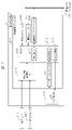
図1は、本発明の一実施の形態に係るヘッドアップディスプレイ(HUD)装置の構成の一例について概要を示した図である。このHUD装置1は、図示しない筐体内に配置されて光源からの光を変調して投射する映像表示装置30の光を、必要な光学素子43を介し、更には、凹面ミラー52により反射させて、車両2のウィンドシールド3に投射して観察者(運転者)の視点5へ入射することにより、所望の投射画像を観察者の視点の位置に対応して表示するものである。なお、この図では、異なる観察者(運転者)の視点5の位置(A,B,C)に対応した凹面ミラー52の回転位置、投射画像のウィンドシールド3(内面側)への投射位置、更には、それによって表示される虚像が、それぞれ、A,B,Cにより示されている。
FIG. 1 is a diagram showing an overview of an example configuration of a head-up display (HUD) device according to one embodiment of the present invention. The
また、図には、映像表示装置30や凹面ミラー52を含むHUD装置1を制御する制御部20が、更には、運転者の視点等を含めた姿勢を監視するための車内カメラを含むドライバモニタリングシステム(DMS)等の視点検出装置6が示されている。また、図中の符号120は、運転席の近傍、より具体的には運転席上部の天井に取り付けられ、車両のドアの開閉に連動すると共に、運転者の必要に応じて点灯/消灯が可能な既存の室内灯を示しており、以下の説明からも明らかとなるが、この室内灯120は、その点灯中において運転者の視点位置検出用の光源としての役割も有している。
Further, in the figure, the
なお、ここで、被投射部材はウィンドシールド3に限られず、映像が投射される部材であれば、コンバイナなど他の部材とすることも可能である。また、映像表示装置30は、例えば、バックライト(光源)31(図2)を有するプロジェクタやLCD(Liquid Crystal Display)等により構成される。自発光型のVFD(Vacuum Fluorescent Display)等であってもよく、或いは、投射装置によりスクリーンに映像を表示するものであってもよい。このようなスクリーンとしては、例えば、マイクロレンズを2次元状に配置したマイクロレンズアレイにより構成してもよい。
Here, the projected member is not limited to the
凹面ミラー52は、例えば、自由曲面ミラーや光軸非対称の形状を有するミラー等により構成される。より具体的には、凹面ミラー52の形状は、虚像の歪みを低減するために、例えば、その上部の領域(即ち、ここで反射した光線はウィンドシールド3の下方で反射するため、相対的に運転者の視点5との距離が短くなる)では、拡大率が大きくなるように相対的に曲率半径を小さくする。一方、凹面ミラー52の下部の領域(即ち、ここで反射した光線はウィンドシールド3の上方で反射するため、相対的に運転者の視点5との距離が長くなる)では、拡大率が小さくなるように相対的に曲率半径を大きくする。映像表示装置30を凹面ミラー52の光軸に対して傾斜させて配置することで、像倍率の違いを補正して、発生する歪みそのものを低減するようにしてもよい。
The
運転者は、視点5からウィンドシールド3に投射された映像を見ることで、透明のウィンドシールド3を通してその前方に虚像として映像を視認する。その際、凹面ミラー52の角度を調整することで映像をウィンドシールド3に投射する位置を調整することにより、視点5の位置に対して、虚像の表示位置を上下方向に調整可能となっている。なお、虚像として表示する内容は特に限定されず、例えば、車両情報やナビゲーション情報、図示しないカメラ映像(監視カメラやアラウンドビュアー等)で撮影した前方の風景の映像などを適宜表示することができる。
The driver sees the image projected on the
また、符号6は、ハンドルの一部に取り付けられ、例えば、通常の可視光下で運転者の視点や姿勢を検出する視点検出装置である。ただし、この車内カメラを含むドライバモニタリングシステム(DMS)等の視点検出装置6は、必ずしも、上述したようにハンドルの一部に取り付けられる必要はなく、運転者の視点等を検出が可能であればよく、例えば、ダッシュボードの一部、または、ウィンドシールド3の一部に取り付けられてもよい。
Further,
図2には、HUD装置1の詳細構造の一例が示されており、ここでは筐体が符号61と65で示され、HUD装置1は映像表示装置30と凹面ミラー52と合わせて構成される。更に、ここでは、必要な光学素子としての歪み補正レンズ等が符号43により示されている。
An example of the detailed structure of the
また、本例では、図からも明らかなように、筐体61、65の内部には、側面に一対で形成された軸によって、凹面ミラー52が、僅かな角度範囲で回動可能に配置されている。更には、下部の筐体65の底部には、制御部等が実装されるメイン基板70と共に、モータやワームギアやホイル等の移動機構からなるミラー駆動部42がネジ等の着脱機構により取り付けられている。即ち、このミラー駆動部42により、上述した凹面ミラー52の傾斜角度を僅かな角度範囲で変化させることが可能となっている。
Further, in this example, as is clear from the drawing, inside the
図3は、凹面ミラー52の傾斜角度を変化させるためのミラー駆動部42の実装例について概要を示した図である。ここでは、ミラー駆動部42は、図3(a)にも示すように、ケース421内に、少なくとも、高速回転から低速回転まで広い範囲でその回転速度が制御可能な電動モータ422、ワームギア423、当該モータの出力軸とワームギアの間に組み合わせた複数の歯車424を備えている。このミラー駆動部42は、図3(b)にも示すように、筺体の外周部、より具体的には、上述した光学部品保持外装ケース65の下端部において、そのワームギア423が、一部の切欠き部を介して、凹面ミラー52の下端部に形成されたワームホイル411と噛み合うように取り付けられる。図3(c)は、接合側から見た図である。
FIG. 3 is a diagram showing an outline of a mounting example of the
なお、上述したミラー駆動部42の構成によれば、図4にも示すように、低速から高速までの広い範囲で回転制御が可能な電動モータ422の回転が、複数の歯車424を介して所望の回転速度/駆動力に変換されてワームギア423に伝達され、更に、凹面ミラー52の下端部に形成されたワームホイル411により、凹面ミラー52を、回転軸を中心に回転しながら前後方向に移動して(図の矢印を参照)、凹面ミラー52を所望の傾斜角度に調整することができる。なお、この図では、複数の歯車424は、図示を容易にするため間隔をもって示されているが、実際には、これらは噛み合っていることは、当業者であれば当然であろう。
According to the configuration of the
続いて、HUD装置1の制御部(1)(ECU1)20は、HUD装置1の動作を制御する機能を有している。制御部(1)(ECU1)20は、例えば図5に示すように、車両情報取得部(1)21、CPU(Central Processing Unit)(1)22、不揮発性メモリ(1)23、揮発性メモリ(1)24、音声用インターフェース25、表示用インターフェース26、通信用インターフェース(1)27などから構成される。なお、図において、当該CPU(1)22が不揮発性メモリ(1)23に格納したソフトウェアを揮発性メモリ(1)24によって実行する機能が音声データ生成部221、映像データ生成部222、歪み補正部223、光源調整部(1)224、ミラー調整部225、通信部(1)226のブロックによって示されている。音声データ生成部221で生成されたデータは、音声用インターフェース25を介してスピーカ60へ出力され、そして、映像データ生成部222で生成されたデータは、歪み補正部223で歪みを補正し、表示用インターフェース26を介して映像表示部の映像表示装置30へ出力される。なお、光源調整部(1)224からのデータは、直接、映像表示装置30へ出力される。また、ミラー調整部225からのデータはミラー駆動部42へ出力される。
Next, the control unit ( 1 ) (ECU 1 ) 20 of the
一方、CPU(1)22の通信部(1)226へは、車両2内に設けられた通信バス(CANなど)300からの各種の信号が通信用インターフェース(1)27を介して入力される。即ち、制御部(1)(ECU1)20は、この図にも示すように、車両情報取得部(1)21から取得した車両情報等に基づいて、虚像として表示する映像を、映像表示装置30を駆動することにより形成し、そして、これをミラー駆動部42により制御する凹面ミラー52(図1)によって反射させることでウィンドシールド3(図1)に投射する。これと共に、上述したミラー駆動部42により、凹面ミラー52の傾斜角度の制御を行う。
On the other hand, to the communication unit (1) 226 of the CPU (1) 22, various signals from a communication bus (CAN, etc.) 300 provided in the
車両情報取得部(1)21は、例えば、図6にも示すように、車速センサ101、シフトポジションセンサ102、ヘッドライトセンサ104、照度センサ105、色度センサ106、エンジン始動センサ109、加速度センサ110、ジャイロセンサ111、温度センサ112を含んでおり、更には、路車間通信用無線受信機113、車車間通信用無線受信機114、カメラ(車外)116、GPS受信機117、VICS受信機118等を有する。しかしながら、これらのデバイスは、必ずしも、全てを備えている必要はなく、或いは、更に他の種類のデバイスを備えていてもよい。加えて、これらの備えたデバイスによって取得できる車両情報は、適宜、用いることができる。このように、HUD制御システムは、車両2(図2)の各部に設置された各種のセンサ等の情報取得デバイスからなり、車両2で生じた各種イベントを検知したり、所定の間隔で走行状況に係る各種パラメータの値を検知・取得したりすることで車両情報を取得して出力することができる。
Vehicle information acquisition unit (1) 21 includes, for example, as shown in FIG. 110, a
なお、車速センサ101は、車速を把握するために設けられており、そして、エンジン始動センサ109は、エンジンの始動を把握するためであり、エンジン始動時にシステムを開始する。カメラ(車外)は前方の車両や人物および障害物を検知するために設けられている。
The
図7は、車内カメラを含むドライバモニタリングシステム(DMS)等の視点検出装置6の構成の一例を示す。本例においては、車内カメラを含むドライバモニタリングシステム(DMS)等の視点検出装置6は、温度センサ112やハンドル操舵角センサ602からの信号と共に、カメラ(視点検出用)115からの信号を入力して所定の演算処理を行う制御部(2)(ECU2)610を備えており、この制御部(2)(ECU2)610は、温度センサ112やハンドル操舵角センサ602からの信号を入力するための車両情報取得部(2)611、カメラ(視点検出用)115からの信号を入力するためのカメラ用インターフェース612、CPU(2)613、不揮発性メモリ(2)614、揮発性メモリ(2)615、そして、通信用インターフェース(2)616等によって構成されている。
FIG. 7 shows an example of the configuration of a
CPU(2)613の通信部(2)617は、通信用インターフェース(2)616を介して車両2内に設けられた通信バス(CANなど)300との通信を行うと共に、その映像解析部618は、不揮発性メモリ(2)614に格納したソフトウェアや揮発性メモリ(2)615を使用し、カメラ用インターフェース612を介してカメラ(視点検出用)115からの信号を入力して映像解析を行い、そして、カメラ制御部619によりカメラ(視点検出用)115を制御する。即ち、視点検出装置6を構成する制御部(2)(ECU2)610は、カメラ(視点検出用)115を操作・制御すると同時に、当該カメラ(視点検出用)115からの映像信号を基にして運転者の視点位置を検出する。なお、その検出信号は、通信用インターフェース(2)616や上述した車両2内に設けられた通信バス(CANなど)300を介して、上述したHUD装置1の制御部(1)(ECU1)20(図5)へ送信される。
A communication unit (2) 617 of the CPU (2) 613 communicates with a communication bus (CAN, etc.) 300 provided in the
なお、以上に述べたHUD装置1は、ハンドルの一部に取り付けられた車内カメラを含むドライバモニタリングシステム(DMS)等の視点検出装置6から運転者の視点5の情報を受け取り、凹面ミラー52の傾斜角度を運転者の視点の位置に対応して制御し、車両2のウィンドシールド3に投射する虚像の位置を調整/制御することは言うまでもない。
The
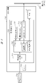
更に、図8には、車両2内において室内灯120の制御を行う室内灯装置700のブロック図を示す。室内灯装置700は、例えば、室内灯120の内部に設置されている。図8からも明らかなように、この室内灯装置700は、車両2のドアの開閉に連動して室内灯のオン/オフを行うためにドアの開閉を検知するドア開閉センサ710からの信号を入力とすると共に、当該ドアの開閉とは独立に室内灯のオン/オフを行うためのスイッチ720、そして、これらセンサやスイッチからの信号に基づいて室内灯120(図1を参照)の光源121を制御する制御部(3)(ECU3)730から構成されている。更に、この制御部(3)(ECU3)730は、ドア開閉センサ710やスイッチ720からの信号を入力する車両情報取得部(3)731、CPU(3)732、不揮発性メモリ(3)733、揮発性メモリ(3)734、通信用インターフェース(3)735を備えている。そして、CPU(3)732は光源調整部(2)736などから構成されている。
Further, FIG. 8 shows a block diagram of an
そして、CPU(3)732は、通信用インターフェース(3)735を介して車両2内に設けられた通信バス(CANなど)300との通信を行うと共に、その光源調整部(2)736は、不揮発性メモリ(3)733に格納したソフトウェアや揮発性メモリ(3)734を使用して光源の状態を決定し、光源121を制御する。即ち、室内灯装置700の制御部(3)(ECU3)730は、ドアの開閉と共に、運転者によるスイッチ720のオン/オフに応答して車両2内の光源121を点灯/消灯する。加えて、この室内灯装置700では、以下にも詳細に述べるように、その制御部(3)(ECU3)730を構成するCPU(3)732は室内灯120の状態を監視しており、その状態(オン/オフ)を通信部(3)737により、通信用インターフェース(3)735を介して、車両情報として通信バス(CANなど)300へ出力する。
The CPU (3) 732 communicates with the communication bus (CAN, etc.) 300 provided in the
<運転者の視点位置検出>
続いて、HUD装置1における運転者の視点位置検出について説明する。なお、本実施の形態では、運転者の視点位置検出を、別途、赤外線LED等の光源を設けることなしに、即ち、本来HUD装置1を構成する主要な要素である映像表示装置30の照射光を利用することにより、夜間や屋内駐車場のような暗い環境下においても検出を可能とするものであり、その全体構成を図9に示す。
<Detection of driver's viewpoint position>
Next, detection of the driver's viewpoint position in the
本実施の形態では、室内灯120の光を利用すると共に、この図からも明らかなように、HUD装置1により白色光(全白)を発生し、当該白色光を運転者の視点位置検出のための照明光として選択的に利用する。即ち、虚像を運転者に対して表示するHUD装置1からの光(映像光)は、本来、運転者51の視点に向けられており、そのため、当該HUD装置1からの白色光は、運転者の眼を中心としてその近傍に向けて照射される。そこで、この照射される白色光を照明光として利用することによれば、別途、赤外線LED等の光源を使用することなしに、上述した車内カメラを含むドライバモニタリングシステム(DMS)等の視点検出装置6を利用して運転者の視点位置を検知することが可能となる。これによれば、別途、赤外線LED等の光源を必要としないことから、その構成部品の増大を抑制してより経済的な装置を実現することが可能となる。
In the present embodiment, the light of the
また、照明光としてHUD装置1による白色光を照射することから、後にも詳述するが、運転者が運転席に着座して運転を開始するタイミング(例えば、エンジンキーを挿入した場合等)で行うことが好ましい。また、夜間に限らず、昼間でも暗めの環境(屋内駐車場のような場所)であれば利用が可能である。他方、昼間の明るい環境下、または、室内灯の点灯下では、HUD装置1による白色光を利用することなく、車内カメラを含むドライバモニタリングシステム(DMS)等の視点検出装置6により運転者の視点位置を検知してもよく、更には、車外の明るさを検知するために設けられた照度センサ(図6の符号105を参照)からの検知信号に基づき、適宜、HUD装置1による白色光を、その必要に応じて、点灯するようにしてもよい。
In addition, since the
加えて、実際の車両2では、室内灯120のオン/オフは、例えば、夜間などにおいては、車両2のドアの開閉に連動して行われることが多く、また、運転中においても、必要に応じて点灯が行われる。そこで、この点灯時の室内灯120の光を運転者の視点位置検出のための照明光として利用することも有効である。これによれば、別途赤外線LED等の専用の光源等を必要とせずに、運転者に眩しさを感じさせる可能性のあるHUD装置1による白色光を不要に発生することなく、車内カメラを含むドライバモニタリングシステム(DMS)等の視点検出装置6を利用して運転者の視点位置を検知することが可能となる。なお、室内灯120のオン/オフ状態は、図8でも述べたように、室内灯装置700の制御部(3)(ECU3)730により車両情報として通信バス(CANなど)300へ出力されている。
In addition, in the
<運転者の視点位置検出動作(位置調整)>
次に、上述したHUD装置1における運転者の視点位置検出動作(位置調整)の詳細について、図10のフローチャートを参照しながら以下に説明する。なお、本発明の実施の形態になるHUD装置では、HUD装置1により白色光(全白)を照射する(以下、「全白表示」や「HUD光」とも言う)ことにより運転者の視点位置を検出し、その結果、ミラー駆動部42(図3または4を参照)によって虚像表示する映像光の視点位置に対する方向を調整する。このことから、基本的には、車両が走行していないことを前提としており、例えば、車速センサ101(図6参照)からの車両の走行速度を監視しており、例えば、走行速度が所定の値に達したと判定された場合には、直ちに調整を中断してHUD装置の通常表示を行い、または、HUD装置による表示はしないようにすることが好ましい。
<Driver's viewpoint position detection operation (position adjustment)>
Next, the details of the driver's viewpoint position detection operation (position adjustment) in the
まず、図10において、HUD装置1による運転者51の視点位置検出動作(位置調整)を開始すると、車両が始動状態であることを確認するため、例えば、エンジンキーの挿入に対応して、電源(イグニッション)がONであるか否かを判定する(S1001)。続いて、室内灯120がOFFであるか否かを判定する(S1002)。S1002での判定の結果、「Yes」と判定された場合には、HUD装置1による表示を全白表示(「全面ホワイト表示」とも言う)にする(S1003)。具体的には、演算処理部であるCPU(1)22によって映像表示装置30へ入力される映像信号を制御することにより、プロジェクタやLCD(Liquid Crystal Display)等から投射されるHUD光を、全体が単一色で横長矩形状の、即ち、運転者である人間の顔の横幅に対応した表示光である、例えば、全白表示光に変更する。他方、S1001の判定で「No」と判定された場合には、再び、同じ判定を繰り返すこととなる。また、S1002の判定の結果、「No」と判定された場合には、室内灯120の点灯下において、以下にもその詳細を説明する通常視点位置調整を行う。
First, in FIG. 10, when the
次に、全面ホワイト表示の状態で、HUD装置1のミラー駆動部42(図5)を駆動することにより、凹面ミラー52を回転移動する(S1004)。続いて、再度、室内灯120がOFFであるか否かを判定し(S1005)、S1005の判定の、「No」と判定された場合には、通常視点位置調整を行うが、この回転移動は、運転者の顔面上の一定範囲を往復運動しながら、その後、運転者の視点を検出する(「Yes」と判定される)まで行う(S1006)。即ち、HUD装置1からの全面ホワイト表示は、図13(a)にも示すように、通常、運転者51の顔面上の眼球の近傍において行うように設定されている。そのため、凹面ミラー52を一定範囲で往復して移動することによれば、図13(b)~(c)に示すように、HUD装置1の全面ホワイト表示を運転者51の顔面上を移動しながら、最終的には、図13(d)に示すように、運転者51の眼球の近傍に、確実に、照射することが可能となる。この時、車内カメラを含むドライバモニタリングシステム(DMS)等の視点検出装置6により、運転者に当るHUD光を確認しながら、HUD光が目の中心に来るように凹面ミラー52を調整する(図13(d)の位置)ことが好ましいであろう。
Next, in the state of full white display, the
このことによれば、上述した車内カメラを含むドライバモニタリングシステム(DMS)等の視点検出装置6を利用しての運転者51の視点位置の検出を確実に実行することが可能となる。他方、S1006の運転者の視点を検出の判定の結果、「No」が所定の時間継続した場合、より具体的には、視点未検出時間が10秒以上経過したか否かを判定し(S1007)、その結果「No」の場合には、処理は、再度、HUDミラーの移動(S1004)へ戻る。他方、「Yes」の場合、即ち、運転者の検出に失敗した場合には、凹面ミラー52をデフォルト位置に戻し(S1008)、一連の処理を終了(位置調整終了)する。そして、その後、HUD通常表示へ移行する。なお、車内カメラを含むドライバモニタリングシステム(DMS)等の視点検出装置6を利用しての運転者の視点位置の検出は、得られた運転者51の顔面映像を画像分析により抽出することにより実現可能であることは、当業者であれば容易に理解されるであろう。
This makes it possible to reliably detect the viewpoint position of the
また、S1006の運転者の視点を検出の判定の結果、「Yes」の場合には、本実施の形態では、更に、車内カメラを含むドライバモニタリングシステム(DMS)等の視点検出装置6により撮像された映像の画像分析により、運転席での運転者51の着座状態を検知または判定して、その結果を表示する。即ち、本実施の形態では、まず、S1006で検出した運転者51の視点がHUD装置1からの全面白色光の中心にあるか否かを判定する(S1009)。更に、運転者51の視点の奥行方向の位置が、ヘッドレストの近くにあるか、即ち、正しい位置に着席しているか否かを判定する(S1010)。
Further, if the result of the determination of detecting the viewpoint of the driver in S1006 is "Yes", in the present embodiment, the driver's viewpoint is further captured by the
その後、S1009およびS1010の判定の結果、いずれも「Yes」と判定された場合には、凹面ミラー52の移動を停止し(S1011)、一連の処理を終了する。この時、HUD装置1による全面ホワイト表示も、同時に、停止する。他方、S1009の判定の結果、「No」と判定された場合には、HUDミラーの移動(S1004)へ戻り、更に、室内灯OFFの判定:S1005、運転者の視点の検出:S1006、視点がHUD光の中心かの判定:S1009を繰り返す。
After that, if the results of the determinations in S1009 and S1010 are both "Yes", the movement of the
一方、S1010の判定の結果、「No」と判定された場合には、運転者51が正しい位置に着席していないことを意味しており、HUD装置1の表示を「正しい位置に着席して下さい」等、正しい位置に着席することを促す警告表示に、例えば、3秒間のような所定の期間だけ変更する(S1012)。なお、この状態では、たとえHUD装置1により警告を表示しても、見てもらえない可能性が高いことから、かかる場合には、HUD装置1による表示に替えて、または、それに加えて、例えば、図5のスピーカ60により、音声出力による警告をも行うことがより有効であろう。
On the other hand, if the result of determination in S1010 is "No", it means that the
その後、更に、S1012での警告の表示が最初の警告(初回)であるか否かを判定し(S1013)、S1013の判定の結果、初回(「Yes」)と判定された場合には、凹面ミラー52の移動(S1004)へ戻ってS1004からのステップを繰り返す。なお、その際には、警告表示を全面ホワイト表示に戻す。他方、S1013の判定の結果、最初の警告(初回)ではなく、警告は既に行われている(「No」)と判断された場合には、運転者の位置が不正であるとして、凹面ミラー52をデフォルト位置に戻し(S1014)、一連の処理を終了し(位置調整終了)、その後、HUD通常表示へと移行する。
After that, it is further determined whether or not the warning display in S1012 is the first warning (first time) (S1013). Returning to the movement of the mirror 52 (S1004), the steps from S1004 are repeated. In this case, the warning display is returned to full white display. On the other hand, as a result of the determination in S1013, if it is determined that the warning has already been given (“No”) instead of the first warning (first time), the
<その他の実施の形態(照度センサ制御)>
なお、上述したように、車内カメラを含むドライバモニタリングシステム(DMS)等の視点検出装置6からのカメラ画像のみで運転者の視点の位置を検知する場合、特に、夜間においては、室内灯の点灯時でも照度が不十分となり、十分な精度を得ることができない場合が生じる。そこで、運転者51の視点の位置に加えて、照度センサ(図6の105)からの信号により照度が十分であるか否か(例えば、50ルクス未満であるか否か)を判定し、その結果に基づいて運転者の視点位置検出動作を行うことが好ましく、図11にはその詳細について述べる。
<Other embodiments (illuminance sensor control)>
As described above, when the position of the driver's viewpoint is detected only by the camera image from the
なお、この図11に示す運転者の視点位置検出動作(位置調整)は、基本的に図10に示す動作と同様であるが、室内灯がOFFであるか否かの判定(S1002)に続いて、更に、照度センサ105からの信号が所定の照度未満(例えば、50ルクス未満)であるか否かを判定し(S1101)、S1101の判定の結果、「Yes」と判定された場合には、HUD装置1による全面ホワイト表示にする(S1003)。他方、S1002での判定またはS1101での照度の判定の結果、「No」と判定された場合には、室内灯の点灯下において、以下にもその詳細を述べる通常視点位置調整を行う。
Note that the driver's viewpoint position detection operation (position adjustment) shown in FIG. 11 is basically the same as the operation shown in FIG. Further, it is determined whether or not the signal from the
更に、図11に示す運転者の視点位置検出動作(位置調整)では、その後の室内灯OFFの判定(S1005)に続いて、再度、照度センサ105からの信号が所定のルクス未満(例えば、50ルクス未満)であるか否かを判定する(S1102)。S1102の判定の結果、「Yes」と判定された場合には、運転者の視点を検出:S1006へ移行し、他方、「No」と判定された場合には、室内灯の点灯下における通常視点位置調整へ移行する。 Furthermore, in the driver's viewpoint position detection operation (position adjustment) shown in FIG. less than lux) (S1102). If the result of determination in S1102 is "Yes", the driver's viewpoint is detected: S1006. Move to position adjustment.
このように、本実施の形態に係る照度センサ制御を加えた運転者の視点位置検出動作では、照度が十分であるか否か(例えば、50ルクス未満であるか否か)の判定を加えることにより、夜間における室内灯の点灯時にその照度が不十分な場合でも、HUD装置1による全白表示により、運転者の視点位置を十分な精度で検出することが可能となる。
Thus, in the driver's viewpoint position detection operation to which the illuminance sensor control according to the present embodiment is added, the determination of whether or not the illuminance is sufficient (for example, whether or not it is less than 50 lux) is added. As a result, even when the illuminance of the room light is insufficient at night, the all-white display by the
<通常視点位置調整>
続いて、以下には、図10のフローにおいて室内灯がOFFであるか否かの判定(S1002やS1005)の結果、「No」と判定された場合、更には、図11のフローにおける照度の判定(S1101やS1102)の結果、「No」と判定された場合に実行される処理である、いわゆる、通常視点位置調整について述べる。
<Normal viewpoint position adjustment>
Subsequently, in the flow of FIG. 10, if the result of the determination (S1002 or S1005) of whether or not the interior light is OFF is determined to be "No", the illuminance of the flow of FIG. The so-called normal viewpoint position adjustment, which is processing executed when the result of determination (S1101 or S1102) is "No", will be described.
図12は、通常視点位置調整の手順の一例を示すフロー図であり、図からも明らかなように、通常視点位置調整が開始すると、運転者の視点を検出したか否かを判定し(S1201)、S1201の判定の結果、「Yes」と判定された場合には、凹面ミラー52を検出した運転者の視点に合わせて移動する(S1202)。その後、運転者51の視点の奥行方向の位置が、ヘッドレストの近くにあるか、即ち、正しい位置に着席しているか否かを判定し(S1203)、S1203の判定の結果、「Yes」と判定された場合には、一連の位置調整を終了してHUD通常表示へ移行する。
FIG. 12 is a flow chart showing an example of the procedure for normal viewpoint position adjustment. As is clear from the figure, when the normal viewpoint position adjustment is started, it is determined whether or not the driver's viewpoint is detected (S1201). ), if the result of the determination in S1201 is "Yes", the
一方、S1201の判定の結果、「No」と判定された場合には、その視点未検出の時間が所定の時間(例えば、10秒またはそれ以上)を経過したか否かを判定し(S1204)、S1204の判定の結果、「Yes」と判定された場合には、凹面ミラー52をデフォルト位置に戻し(S1205)、その後、一連の位置調整を終了してHUD通常表示へ移行する。他方、S1204の判定の結果、「No」と判定された場合には、S1201へ戻り、S1201以降の処理を繰り返す。
On the other hand, if the result of determination in S1201 is "No", it is determined whether or not the time during which the viewpoint has not been detected has passed a predetermined time (for example, 10 seconds or more) (S1204). , S1204, the
また、S1203の判定の結果、「No」と判定された場合には、運転者51が正しい位置に着席していないことから、HUD装置1の表示を正しい位置に着席することを促す警告表示に変更する(S1206)。その後、警告表示の開始から所定の期間(例えば、3秒またはそれ以上)が経過したか否かを判定し(S1207)、S1207の判定の結果、「Yes」の場合には、凹面ミラー52をデフォルト位置に戻し(S1208)、一連の処理(位置調整)を終了して、HUD装置1の通常表示に移行する。他方、S1207の判定の結果、所定の期間(例えば、3秒またはそれ以上)が経過していない「No」の場合には、視点検出判定処理(S1201)へ戻って一連の処理を、再度、実行することとなる。
If the result of the determination in S1203 is "No", the
なお、以上の説明では、運転者の視点位置検出動作(位置調整)を行うためにHUD装置1によって発生するHUD光については、これを白色光(全白)であるとして説明したが、これは、車内カメラを含むドライバモニタリングシステム(DMS)等の視点検出装置6から運転者の視点までの距離をより正確に測るために選択されたものである。しかしながら、本発明では、これに限定されることなく、白色光に代えて、例えば、人間の眼にとって優しい黄緑等の他の色の全体単一色光を採用することも可能である。また、HUD光を、全体が単一色の横長矩形状だけではなく、更に、車内カメラを含むドライバモニタリングシステム(DMS)等の視点検出装置6からの映像の分析(例えば、移動量の分析)等を考慮して、矩形形状の光内において、更に、縦横に横切る格子状のグリッド表示を加えることも可能であろう。
In the above description, the HUD light generated by the
以上に詳細に述べたように、本発明の実施の形態に係るHUD装置1によれば、昼間のような十分な外光が得られない状況下でも、運転者の視点位置検出のための専用の光源等を必要とせず、車両2内に設けられた既存の室内灯、または、HUD装置1の光源を選択的に利用して、通常の可視光で作動する車内カメラを含むドライバモニタリングシステム(DMS)等の視点検出装置6による運転者の視点位置の検出が可能となる。より具体的には、室内灯のオン/オフ状態を車両内に設けられたCAN等の通信バスの車両情報として監視し、室内灯がオンの場合には当該室内灯からの光を利用し、室内灯がオフの場合には、HUD装置1からの白色光(全白)を利用する。これにより、当該装置において通常に搭載される可視光で作動して運転者の位置を確認する車内カメラを含むドライバモニタリングシステム(DMS)等の視点検出装置6等を利用することが可能となると共に、視覚に眩しさを与える可能性のあるHUD装置1による白色光を不要に発生することなく、虚像投射画像の観察者である運転者の視線位置を確実に検出することが可能となる。即ち、より好適に運転者の視線位置を確実に検出して虚像投射画像位置の制御を行うことが可能であり、かつ、実用的にも経済的にも優れたヘッドアップディスプレイ装置が実現される。
As described in detail above, according to the
以上、本発明者によってなされた発明を実施の形態に基づき具体的に説明したが、本発明は本実施の形態に限定されるものではなく、その要旨を逸脱しない範囲で種々変更可能であることはいうまでもない。例えば、本実施の形態は本発明を分かりやすく説明するために詳細に説明したものであり、必ずしも説明した全ての構成を備えるものに限定されるものではない。また、ある実施の形態の構成の一部を他の実施の形態の構成に置き換えることが可能であり、また、ある実施の形態の構成に他の実施の形態の構成を加えることも可能である。また、各実施の形態の構成の一部について、他の構成の追加・削除・置換をすることが可能である。 The invention made by the present inventor has been specifically described above based on the embodiment, but the present invention is not limited to the embodiment, and can be variously changed without departing from the gist of the invention. Needless to say. For example, the present embodiment has been described in detail in order to explain the present invention in an easy-to-understand manner, and is not necessarily limited to those having all the described configurations. Also, part of the configuration of one embodiment can be replaced with the configuration of another embodiment, and the configuration of another embodiment can be added to the configuration of one embodiment. . Moreover, it is possible to add, delete, or replace a part of the configuration of each embodiment with another configuration.
本発明は、透明なガラス板等に画像を投影するヘッドアップディスプレイ装置に利用可能である。 INDUSTRIAL APPLICABILITY The present invention can be used for a head-up display device that projects an image onto a transparent glass plate or the like.
1…HUD装置、2…車両、3…ウィンドシールド、4…車両情報、5…運転者(視点)、6…視点検出装置、20…制御部(1)、21…車両情報取得部(1)、22…CPU(1)、23…不揮発性メモリ(1)、24…揮発性メモリ(1)、30…映像表示装置、31…バックライト(光源)、42…ミラー駆動部、60…スピーカ、115…カメラ(視点検出用)、120…室内灯、300…通信バス(CANなど)、700…室内灯装置。
DESCRIPTION OF
Claims (18)
光源および表示素子を有して前記映像を形成する映像表示手段と、
前記映像表示手段から出射された映像光を前記ウィンドシールド上に投射して反射させることで前記虚像を前記乗り物の前方に表示する映像投射手段と、
前記運転者の視点を検知する運転者視点検知手段と、
前記運転者視点検知手段により検知した前記運転者の視点の情報に基づいて、前記映像投射手段により投射される前記虚像の位置を移動する移動手段と、
を備えたヘッドアップディスプレイ装置において、
前記乗り物は、運転席の近傍に室内灯装置を備えており、
前記運転者視点検知手段は、前記乗り物の所定の環境下に応じて、前記室内灯装置の光、または、前記映像表示手段の光源の光を照明光として前記運転者の顔面に対して照射して前記運転者の視点を検知し、前記室内灯装置が点灯している場合、前記室内灯装置の光を照明光として前記運転者の顔面に対して照射して前記運転者の視点を検知する、ヘッドアップディスプレイ装置。 A head-up display device that displays a virtual image of the video to the driver by projecting the video onto the windshield of the vehicle,
an image display means having a light source and a display element to form the image;
an image projection means for displaying the virtual image in front of the vehicle by projecting and reflecting the image light emitted from the image display means on the windshield;
driver viewpoint detection means for detecting the viewpoint of the driver;
moving means for moving the position of the virtual image projected by the video projection means based on the information of the driver's viewpoint detected by the driver's viewpoint detection means;
In a head-up display device comprising
The vehicle includes an interior lighting device near the driver's seat,
The driver's viewpoint detection means irradiates the driver's face with the light from the interior lighting device or the light from the light source of the image display means as illumination light according to a predetermined environment of the vehicle. and detecting the viewpoint of the driver by irradiating the face of the driver with the light from the room lighting device as illumination light when the interior lighting device is on. , head-up display device.
前記乗り物の前記所定の環境とは、前記運転者視点検知手段による視点検知が前記乗り物の外光だけでは不可能な環境である、ヘッドアップディスプレイ装置。 In the head-up display device according to claim 1,
In the head-up display device, the predetermined environment of the vehicle is an environment in which it is impossible for the driver's viewpoint detection means to detect the viewpoint using only external light from the vehicle.
前記室内灯装置は、前記室内灯装置の状態を監視する室内灯状態監視手段を有しており、
前記運転者視点検知手段は、前記室内灯装置が消灯している場合に、前記映像表示手段の光源の光を照明光として前記運転者の顔面に対して照射する、ヘッドアップディスプレイ装置。 In the head-up display device according to claim 1 ,
The room light device has room light state monitoring means for monitoring the state of the room light device,
In the head-up display device, the driver's viewpoint detection means irradiates the driver's face with light from the light source of the image display means as illumination light when the room light device is turned off.
前記室内灯状態監視手段は、監視した前記室内灯装置の状態を前記乗り物内に設けられた通信手段に出力する、ヘッドアップディスプレイ装置。 In the head-up display device according to claim 3,
The head-up display device, wherein the room light state monitoring means outputs the monitored state of the room light device to communication means provided in the vehicle.
前記運転者視点検知手段は、前記通信手段を介して前記室内灯装置の状態を入手する、ヘッドアップディスプレイ装置。 In the head-up display device according to claim 4,
The head-up display device, wherein the driver's viewpoint detection means obtains the state of the room light device via the communication means.
前記映像表示手段の光源からの光は、全体が単一色の光からなる、ヘッドアップディスプレイ装置。 In the head-up display device according to claim 1,
The head-up display device according to claim 1, wherein the light from the light source of the image display means is composed entirely of single-color light.
前記映像表示手段の光源からの光は、白色光である、ヘッドアップディスプレイ装置。 In the head-up display device according to claim 6,
The head-up display device, wherein the light from the light source of the image display means is white light.
前記映像表示手段の光源からの光は、前記運転者の顔の横幅に対応した横幅を有する矩形形状の光である、ヘッドアップディスプレイ装置。 In the head-up display device according to claim 6,
The head-up display device according to claim 1, wherein the light from the light source of the image display means is rectangular light having a width corresponding to the width of the driver's face.
前記移動手段により前記映像投射手段を移動することで、前記映像表示手段の光源からの光を前記運転者の顔に沿って上下に移動する、ヘッドアップディスプレイ装置。 In the head-up display device according to claim 1 ,
The head -up display device moves the light from the light source of the image display means vertically along the face of the driver by moving the image projection means by the movement means.
前記運転者視点検知手段は、更に、その検出結果を音声により警告する手段を備えている、ヘッドアップディスプレイ装置。 In the head-up display device according to claim 1,
The head-up display device, wherein the driver's viewpoint detection means further includes means for warning the detection result by voice.
光源および表示素子を有して前記映像を形成する映像表示手段と、an image display means having a light source and a display element to form the image;
前記映像表示手段から出射された映像光を前記ウィンドシールド上に投射して反射させることで前記虚像を前記乗り物の前方に表示する映像投射手段と、an image projection means for displaying the virtual image in front of the vehicle by projecting and reflecting the image light emitted from the image display means on the windshield;
前記運転者の視点を検知する運転者視点検知手段と、driver viewpoint detection means for detecting the viewpoint of the driver;
前記運転者視点検知手段により検知した前記運転者の視点の情報に基づいて、前記映像投射手段により投射される前記虚像の位置を移動する移動手段と、を備えたヘッドアップディスプレイ装置において、moving means for moving the position of the virtual image projected by the video projection means based on the information of the driver's viewpoint detected by the driver's viewpoint detection means;
前記乗り物は、運転席の近傍に室内灯装置を備えており、The vehicle includes an interior lighting device near the driver's seat,
前記運転者視点検知手段は、前記乗り物の所定の環境下に応じて、前記室内灯装置の光、または、前記映像表示手段の光源の光を照明光として前記運転者の顔面に対して照射して前記運転者の視点を検知し、The driver's viewpoint detection means irradiates the driver's face with the light from the interior lighting device or the light from the light source of the image display means as illumination light according to a predetermined environment of the vehicle. to detect the viewpoint of the driver,
前記映像表示手段の光源からの光は、全体が単一色の光からなる、ヘッドアップディスプレイ装置。The head-up display device according to claim 1, wherein the light from the light source of the image display means is composed entirely of single-color light.
前記映像表示手段の光源からの光は、白色光である、ヘッドアップディスプレイ装置。The head-up display device, wherein the light from the light source of the image display means is white light.
前記映像表示手段の光源からの光は、前記運転者の顔の横幅に対応した横幅を有する矩形形状の光である、ヘッドアップディスプレイ装置。The head-up display device according to claim 1, wherein the light from the light source of the image display means is rectangular light having a width corresponding to the width of the driver's face.
前記運転者視点検知手段は、更に、その検出結果を音声により警告する手段を備えている、ヘッドアップディスプレイ装置。The head-up display device, wherein the driver's viewpoint detection means further includes means for warning the detection result by voice.
前記乗り物の前記所定の環境とは、前記運転者視点検知手段による視点検知が前記乗り物の外光だけでは不可能な環境である、ヘッドアップディスプレイ装置。In the head-up display device, the predetermined environment of the vehicle is an environment in which it is impossible for the driver's viewpoint detection means to detect the viewpoint using only external light from the vehicle.
前記室内灯装置は、前記室内灯装置の状態を監視する室内灯状態監視手段を有しており、The room light device has room light state monitoring means for monitoring the state of the room light device,
前記運転者視点検知手段は、前記室内灯装置が消灯している場合に、前記映像表示手段の光源からの光を前記運転者の顔面に対して照射する、ヘッドアップディスプレイ装置。In the head-up display device, the driver's viewpoint detection means irradiates the driver's face with light from the light source of the image display means when the room light device is turned off.
前記室内灯状態監視手段は、監視した前記室内灯装置の状態を前記乗り物内に設けられた通信手段に出力する、ヘッドアップディスプレイ装置。The head-up display device, wherein the room light state monitoring means outputs the monitored state of the room light device to communication means provided in the vehicle.
前記運転者視点検知手段は、前記通信手段を介して前記室内灯装置の状態を入手する、ヘッドアップディスプレイ装置。The head-up display device, wherein the driver's viewpoint detection means obtains the state of the room light device via the communication means.
Priority Applications (4)
| Application Number | Priority Date | Filing Date | Title |
|---|---|---|---|
| JP2019010985A JP7149192B2 (en) | 2019-01-25 | 2019-01-25 | head-up display device |
| CN201980088857.4A CN113316525A (en) | 2019-01-25 | 2019-11-22 | Head-up display device |
| US17/423,952 US20220091415A1 (en) | 2019-01-25 | 2019-11-22 | Head-up display apparatus |
| PCT/JP2019/045869 WO2020152970A1 (en) | 2019-01-25 | 2019-11-22 | Head-up display device |
Applications Claiming Priority (1)
| Application Number | Priority Date | Filing Date | Title |
|---|---|---|---|
| JP2019010985A JP7149192B2 (en) | 2019-01-25 | 2019-01-25 | head-up display device |
Publications (2)
| Publication Number | Publication Date |
|---|---|
| JP2020117123A JP2020117123A (en) | 2020-08-06 |
| JP7149192B2 true JP7149192B2 (en) | 2022-10-06 |
Family
ID=71736747
Family Applications (1)
| Application Number | Title | Priority Date | Filing Date |
|---|---|---|---|
| JP2019010985A Active JP7149192B2 (en) | 2019-01-25 | 2019-01-25 | head-up display device |
Country Status (4)
| Country | Link |
|---|---|
| US (1) | US20220091415A1 (en) |
| JP (1) | JP7149192B2 (en) |
| CN (1) | CN113316525A (en) |
| WO (1) | WO2020152970A1 (en) |
Families Citing this family (1)
| Publication number | Priority date | Publication date | Assignee | Title |
|---|---|---|---|---|
| US20220176996A1 (en) * | 2020-12-07 | 2022-06-09 | Korea Automotive Technology Institute | System and method for controlling vehicle |
Citations (7)
| Publication number | Priority date | Publication date | Assignee | Title |
|---|---|---|---|---|
| JP2006219000A (en) | 2005-02-10 | 2006-08-24 | Honda Motor Co Ltd | Vehicular operating device |
| JP2009043003A (en) | 2007-08-08 | 2009-02-26 | Denso Corp | Driving support apparatus |
| JP2010125910A (en) | 2008-11-26 | 2010-06-10 | Calsonic Kansei Corp | Head-up display device |
| JP2011152883A (en) | 2010-01-28 | 2011-08-11 | Toyota Motor Corp | Imaging device |
| JP2012113687A (en) | 2010-11-26 | 2012-06-14 | Hyundai Motor Co Ltd | Method of authenticating driver's face in vehicle |
| JP2016210259A (en) | 2015-05-06 | 2016-12-15 | 日本精機株式会社 | Head-up display |
| JP2019101323A (en) | 2017-12-06 | 2019-06-24 | 株式会社Jvcケンウッド | Projection control device, head-up display device, projection control method, and program |
Family Cites Families (8)
| Publication number | Priority date | Publication date | Assignee | Title |
|---|---|---|---|---|
| JPH0342337A (en) * | 1989-07-10 | 1991-02-22 | Nissan Motor Co Ltd | Detector for driving condition of vehicle driver |
| JPH06247184A (en) * | 1993-03-01 | 1994-09-06 | Aisin Seiki Co Ltd | Display device on vehicle |
| JP3727078B2 (en) * | 1994-12-02 | 2005-12-14 | 富士通株式会社 | Display device |
| US20060103590A1 (en) * | 2004-10-21 | 2006-05-18 | Avner Divon | Augmented display system and methods |
| US8130260B2 (en) * | 2005-11-09 | 2012-03-06 | Johns Hopkins University | System and method for 3-dimensional display of image data |
| CN104094197B (en) * | 2012-02-06 | 2018-05-11 | 索尼爱立信移动通讯股份有限公司 | Watch tracking attentively using projecting apparatus |
| KR101619651B1 (en) * | 2014-11-26 | 2016-05-10 | 현대자동차주식회사 | Driver Monitoring Apparatus and Method for Controlling Lighting thereof |
| US11184967B2 (en) * | 2018-05-07 | 2021-11-23 | Zane Coleman | Angularly varying light emitting device with an imager |
-
2019
- 2019-01-25 JP JP2019010985A patent/JP7149192B2/en active Active
- 2019-11-22 US US17/423,952 patent/US20220091415A1/en active Pending
- 2019-11-22 CN CN201980088857.4A patent/CN113316525A/en active Pending
- 2019-11-22 WO PCT/JP2019/045869 patent/WO2020152970A1/en active Application Filing
Patent Citations (7)
| Publication number | Priority date | Publication date | Assignee | Title |
|---|---|---|---|---|
| JP2006219000A (en) | 2005-02-10 | 2006-08-24 | Honda Motor Co Ltd | Vehicular operating device |
| JP2009043003A (en) | 2007-08-08 | 2009-02-26 | Denso Corp | Driving support apparatus |
| JP2010125910A (en) | 2008-11-26 | 2010-06-10 | Calsonic Kansei Corp | Head-up display device |
| JP2011152883A (en) | 2010-01-28 | 2011-08-11 | Toyota Motor Corp | Imaging device |
| JP2012113687A (en) | 2010-11-26 | 2012-06-14 | Hyundai Motor Co Ltd | Method of authenticating driver's face in vehicle |
| JP2016210259A (en) | 2015-05-06 | 2016-12-15 | 日本精機株式会社 | Head-up display |
| JP2019101323A (en) | 2017-12-06 | 2019-06-24 | 株式会社Jvcケンウッド | Projection control device, head-up display device, projection control method, and program |
Also Published As
| Publication number | Publication date |
|---|---|
| JP2020117123A (en) | 2020-08-06 |
| US20220091415A1 (en) | 2022-03-24 |
| WO2020152970A1 (en) | 2020-07-30 |
| CN113316525A (en) | 2021-08-27 |
Similar Documents
| Publication | Publication Date | Title |
|---|---|---|
| JP7280995B2 (en) | head-up display device | |
| JP6374676B2 (en) | Light emitting display device for vehicle and display system for vehicle | |
| JP2009008722A (en) | Three-dimensional head up display device | |
| JP2008076633A (en) | Display device | |
| JP2004168230A (en) | Display device for vehicle | |
| JP2005184225A (en) | Vehicular display | |
| JP6186538B2 (en) | Projection display system and control method for projection display device | |
| JP2015090483A (en) | Information display device | |
| US7136207B2 (en) | Holographic display system | |
| JP2009248918A (en) | Image display device, image display method and computer program | |
| JP4033081B2 (en) | Vehicle display device | |
| JP7149192B2 (en) | head-up display device | |
| JP2021187429A (en) | On-vehicle display device | |
| JP2005067555A (en) | Video display system and its method | |
| JP2018514168A (en) | Display device for automobile | |
| JP2015085879A (en) | Vehicular display device | |
| WO2021131529A1 (en) | Head-up display device | |
| US10914948B2 (en) | Display device, display control method, and storage medium | |
| US10698209B2 (en) | Embedded head-up display device | |
| WO2018116896A1 (en) | Head-up display device | |
| JP2019015936A (en) | Head-up display device | |
| CN219266667U (en) | Head-up display device | |
| CN110816270B (en) | Display device, display control method, and storage medium | |
| JP2018087907A (en) | Head-up display device | |
| JP2024007661A (en) | Head-up display device |
Legal Events
| Date | Code | Title | Description |
|---|---|---|---|
| A621 | Written request for application examination |
Free format text: JAPANESE INTERMEDIATE CODE: A621 Effective date: 20210521 |
|
| A711 | Notification of change in applicant |
Free format text: JAPANESE INTERMEDIATE CODE: A712 Effective date: 20211022 |
|
| A131 | Notification of reasons for refusal |
Free format text: JAPANESE INTERMEDIATE CODE: A131 Effective date: 20220322 |
|
| A601 | Written request for extension of time |
Free format text: JAPANESE INTERMEDIATE CODE: A601 Effective date: 20220517 |
|
| A521 | Request for written amendment filed |
Free format text: JAPANESE INTERMEDIATE CODE: A523 Effective date: 20220719 |
|
| TRDD | Decision of grant or rejection written | ||
| A01 | Written decision to grant a patent or to grant a registration (utility model) |
Free format text: JAPANESE INTERMEDIATE CODE: A01 Effective date: 20220830 |
|
| A61 | First payment of annual fees (during grant procedure) |
Free format text: JAPANESE INTERMEDIATE CODE: A61 Effective date: 20220926 |
|
| R150 | Certificate of patent or registration of utility model |
Ref document number: 7149192 Country of ref document: JP Free format text: JAPANESE INTERMEDIATE CODE: R150 |