JP7148509B2 - CATHETER DEVICE WITH VALVE AND RELATED METHODS - Google Patents
CATHETER DEVICE WITH VALVE AND RELATED METHODS Download PDFInfo
- Publication number
- JP7148509B2 JP7148509B2 JP2019522566A JP2019522566A JP7148509B2 JP 7148509 B2 JP7148509 B2 JP 7148509B2 JP 2019522566 A JP2019522566 A JP 2019522566A JP 2019522566 A JP2019522566 A JP 2019522566A JP 7148509 B2 JP7148509 B2 JP 7148509B2
- Authority
- JP
- Japan
- Prior art keywords
- valve
- actuator
- section
- catheter hub
- distal
- Prior art date
- Legal status (The legal status is an assumption and is not a legal conclusion. Google has not performed a legal analysis and makes no representation as to the accuracy of the status listed.)
- Active
Links
Images


Classifications
-
- A—HUMAN NECESSITIES
- A61—MEDICAL OR VETERINARY SCIENCE; HYGIENE
- A61M—DEVICES FOR INTRODUCING MEDIA INTO, OR ONTO, THE BODY; DEVICES FOR TRANSDUCING BODY MEDIA OR FOR TAKING MEDIA FROM THE BODY; DEVICES FOR PRODUCING OR ENDING SLEEP OR STUPOR
- A61M25/00—Catheters; Hollow probes
- A61M25/01—Introducing, guiding, advancing, emplacing or holding catheters
- A61M25/06—Body-piercing guide needles or the like
- A61M25/0612—Devices for protecting the needle; Devices to help insertion of the needle, e.g. wings or holders
- A61M25/0618—Devices for protecting the needle; Devices to help insertion of the needle, e.g. wings or holders having means for protecting only the distal tip of the needle, e.g. a needle guard
-
- A—HUMAN NECESSITIES
- A61—MEDICAL OR VETERINARY SCIENCE; HYGIENE
- A61M—DEVICES FOR INTRODUCING MEDIA INTO, OR ONTO, THE BODY; DEVICES FOR TRANSDUCING BODY MEDIA OR FOR TAKING MEDIA FROM THE BODY; DEVICES FOR PRODUCING OR ENDING SLEEP OR STUPOR
- A61M25/00—Catheters; Hollow probes
- A61M25/0097—Catheters; Hollow probes characterised by the hub
-
- A—HUMAN NECESSITIES
- A61—MEDICAL OR VETERINARY SCIENCE; HYGIENE
- A61M—DEVICES FOR INTRODUCING MEDIA INTO, OR ONTO, THE BODY; DEVICES FOR TRANSDUCING BODY MEDIA OR FOR TAKING MEDIA FROM THE BODY; DEVICES FOR PRODUCING OR ENDING SLEEP OR STUPOR
- A61M25/00—Catheters; Hollow probes
- A61M25/01—Introducing, guiding, advancing, emplacing or holding catheters
- A61M25/06—Body-piercing guide needles or the like
- A61M25/0693—Flashback chambers
-
- A—HUMAN NECESSITIES
- A61—MEDICAL OR VETERINARY SCIENCE; HYGIENE
- A61M—DEVICES FOR INTRODUCING MEDIA INTO, OR ONTO, THE BODY; DEVICES FOR TRANSDUCING BODY MEDIA OR FOR TAKING MEDIA FROM THE BODY; DEVICES FOR PRODUCING OR ENDING SLEEP OR STUPOR
- A61M39/00—Tubes, tube connectors, tube couplings, valves, access sites or the like, specially adapted for medical use
- A61M39/02—Access sites
- A61M39/06—Haemostasis valves, i.e. gaskets sealing around a needle, catheter or the like, closing on removal thereof
-
- A—HUMAN NECESSITIES
- A61—MEDICAL OR VETERINARY SCIENCE; HYGIENE
- A61M—DEVICES FOR INTRODUCING MEDIA INTO, OR ONTO, THE BODY; DEVICES FOR TRANSDUCING BODY MEDIA OR FOR TAKING MEDIA FROM THE BODY; DEVICES FOR PRODUCING OR ENDING SLEEP OR STUPOR
- A61M5/00—Devices for bringing media into the body in a subcutaneous, intra-vascular or intramuscular way; Accessories therefor, e.g. filling or cleaning devices, arm-rests
- A61M5/178—Syringes
- A61M5/31—Details
- A61M5/32—Needles; Details of needles pertaining to their connection with syringe or hub; Accessories for bringing the needle into, or holding the needle on, the body; Devices for protection of needles
- A61M5/3205—Apparatus for removing or disposing of used needles or syringes, e.g. containers; Means for protection against accidental injuries from used needles
- A61M5/321—Means for protection against accidental injuries by used needles
- A61M5/3243—Means for protection against accidental injuries by used needles being axially-extensible, e.g. protective sleeves coaxially slidable on the syringe barrel
- A61M5/3273—Means for protection against accidental injuries by used needles being axially-extensible, e.g. protective sleeves coaxially slidable on the syringe barrel freely sliding on needle shaft without connection to syringe or needle
-
- A—HUMAN NECESSITIES
- A61—MEDICAL OR VETERINARY SCIENCE; HYGIENE
- A61M—DEVICES FOR INTRODUCING MEDIA INTO, OR ONTO, THE BODY; DEVICES FOR TRANSDUCING BODY MEDIA OR FOR TAKING MEDIA FROM THE BODY; DEVICES FOR PRODUCING OR ENDING SLEEP OR STUPOR
- A61M2207/00—Methods of manufacture, assembly or production
Description
開示する発明は、一般に、ニードル器具及び静脈内(IV)輸液用器具に関し、IVカテーテルを含む。特に、バルブ及びバルブを開くためのバルブアクチュエータを有するIVカテーテルアセンブリが開示される。 The disclosed invention relates generally to needle devices and devices for intravenous (IV) infusion, including IV catheters. In particular, an IV catheter assembly is disclosed having a valve and a valve actuator for opening the valve.
IVカテーテルは、様々な注入療法のために広く使用され、患者への液体注入、患者からの血液採取、又は患者の血管系の様々なパラメータのモニタリングを含む。カテーテルは概して、カテーテルアダプタと接続され、カテーテルへのIVチューブのアタッチメントを収容する。血液制御カテーテルは、内部血液制御バルブを備え、それは、雄ルアー又は他の物体をカテーテルアダプタの近位端に挿入することによって開かれる。血液制御バルブの非限定的な例は、2009年8月20に出願された「洗い流し可能なカテーテルアセンブリを提供するためのシステム及び方法」と題する米国特許出願公開第2011/046570号明細書に開示されている。カテーテルを患者の血管系に配置した後、IV流体源は、カテーテルアダプタ又はカテーテルハブに接続され、血液制御バルブを開く。このように接続されて、IV供給源からの流体は、カテーテルを通じて患者の中に流れ始められる。 IV catheters are widely used for a variety of infusion therapies, including infusing fluids into a patient, drawing blood from a patient, or monitoring various parameters of a patient's vasculature. The catheter is generally connected with a catheter adapter to accommodate attachment of the IV tubing to the catheter. A blood control catheter includes an internal blood control valve, which is opened by inserting a male luer or other object into the proximal end of the catheter adapter. A non-limiting example of a blood control valve is disclosed in U.S. Patent Application Publication No. 2011/046570, entitled "System and Method for Providing a Flushable Catheter Assembly," filed Aug. 20, 2009. It is After placing the catheter in the patient's vasculature, the IV fluid source is connected to the catheter adapter or catheter hub to open the blood control valve. Connected in this manner, fluid from the IV source is initiated through the catheter and into the patient.
当該技術分野において周知であるように、典型的な血圧は、10センチメートルから20センチメートルの水である。輸液バッグは通常、患者の心臓の上方約100センチメートルに配置され、患者に直接流れ込む。おおよそその高さでは、輸液バッグからの流体による圧力は、患者の血圧よりもはるかに大きいため、患者に流れ込むことができる。 As is well known in the art, a typical blood pressure is ten to twenty centimeters of water. The infusion bag is typically placed about 100 centimeters above the patient's heart and flows directly into the patient. At approximately that height, the pressure exerted by the fluid from the infusion bag is much greater than the patient's blood pressure and can flow into the patient.
いくつかのカテーテルアダプタは、カテーテルの適切な配置を検証すること、例えば、カテーテルアセンブリのフラッシュバックチャンバによって提供される血液の「フラッシュバック」が観察されることなどを可能にする。血液制御バルブを含まないカテーテルアセンブリでフラッシュバックを確認するのに、臨床医は望ましくない血液への暴露をふせぐため手動で静脈を閉塞しなければならない。対照的に、血液制御バルブは、そのような手動閉塞の必要性を除去することができると同時に、カテーテルの配置中の血液暴露の可能性も減少する。 Some catheter adapters allow proper placement of the catheter to be verified, such as observing a "flashback" of blood provided by the flashback chamber of the catheter assembly. To see flashback with a catheter assembly that does not include a blood control valve, the clinician must manually occlude the vein to prevent unwanted blood exposure. In contrast, blood control valves can eliminate the need for such manual occlusions while also reducing the potential for blood exposure during catheter placement.
ニードルアセンブリが開示され、それは、オーバーニードルカテーテルアセンブリ(over-the-needle catheter assemblies)及び安全な静脈内カテーテル(IVC)アセンブリを含み得る。ニードルアセンブリ及びそれらの構成要素の使用方法及び製造方法は、本開示の一部を形成する。 Needle assemblies are disclosed, which can include over-the-needle catheter assemblies and safety intravenous catheter (IVC) assemblies. Methods of use and manufacture of needle assemblies and their components form part of the present disclosure.
本開示の態様は、ニードルアセンブリを含み、これは、ニードルハブの遠位端から延在するニードルを備えるニードルハブと、カテーテルハブと、カテーテルチューブであって、カテーテルハブに取り付けられ、使用準備位置でカテーテルチューブを通じて延在するニードルを有するカテーテルチューブと、カテーテルハブの内部キャビティに配置されるバルブであって、カテーテルハブの穴セクションに配置される外側周囲部を有するバルブ本体、近位端上の近位収容部、遠位端上の遠位収容部、及び前記近位収容部と前記遠位収容部との間に配置されるバルブディスクを有するバルブと、カテーテルハブの内部キャビティに配置されるアクチュエータであって、アクチュエータは、バルブを開くように構成され、当該アクチュエータは、アクチュエータの遠位端上に剛体部を備え、当該剛体部は、ノーズセクション及び近位収容部内に置かれる作動端部を有し、バルブディスクを押してバルブを開くように構成されるアクチュエータと、第1の延長脚は、安全クリップの第1のアームを保持するための第1の係合セクションを有し、使用準備位置にある間、第1の係合セクションは、カテーテルハブの内部キャビティからの安全クリップの脱落を防ぐように構成されるアクチュエータの近位端上の第1の延長脚と、を備える。 Aspects of the present disclosure include a needle assembly including a needle hub with a needle extending from a distal end of the needle hub, a catheter hub, and a catheter tube attached to the catheter hub and in a ready-to-use position. a catheter tube having a needle extending through the catheter tube at and a valve body disposed in the inner cavity of the catheter hub, the valve body having an outer perimeter disposed in the bore section of the catheter hub; a valve having a proximal housing, a distal housing on a distal end, and a valve disc disposed between the proximal housing and the distal housing; and positioned within the inner cavity of the catheter hub. an actuator configured to open the valve, the actuator comprising a rigid portion on a distal end of the actuator, the rigid portion having an actuating end located within the nose section and the proximal housing; an actuator configured to push the valve disc to open the valve and the first extension leg has a first engagement section for retaining the first arm of the safety clip, ready for use While in position, the first engagement section comprises a first extension leg on the proximal end of the actuator configured to prevent dislodgement of the safety clip from the internal cavity of the catheter hub.
安全クリップは、ニードルガードを具現化できる。ニードルガードは、不注意なニードル刺しからニードル先端を覆う又はブロックするために多くの代替的な特徴を有することができる。一例では、ニードルガードは、カテーテルハブの内部に嵌合するのに適したサイズ及び形状になり得る。例えば、ニードルガードは、バルブ及びバルブ開口器を備えるカテーテルハブの内側に配置できる。他の例では、ニードルガードは、ばねで付勢される装置であってもよく、それは、ばね仕掛けによってニードルを保護バレル(barrel)の中に進ませるため、ニードル先端が保護バレル内に置かれ、不注意なニードル刺しから覆われる。 A safety clip can embody a needle guard. The needle guard can have many alternative features to cover or block the needle tip from inadvertent needle sticks. In one example, the needle guard can be sized and shaped to fit inside the catheter hub. For example, a needle guard can be placed inside a catheter hub that includes a valve and a valve opening. In another example, the needle guard may be a spring-loaded device that advances the needle into a protective barrel by spring loading so that the needle tip is positioned within the protective barrel. , covered from careless needle pricks.
使用可能なニードルガードは、一体的に形成、例えば、射出成形又は打ち抜かれた金属シートの冷間加工などによってされ、又は2以上の別個に形成された副構成要素を使用して一緒に組み立てられる。 Useful needle guards are integrally formed, such as by injection molding or cold working of stamped metal sheet, or assembled together using two or more separately formed sub-components. .
更にアクチュエータは、カテーテルハブの内面上に形成されるアンダーカットに配置される延長脚上に形成される半径方向に延在するタブを備えられ、アンダーカット内の半径方向に延在するタブの位置は、カテーテルハブの内部キャビティ内からのアクチュエータの脱落を防ぐことができる。 The actuator is further provided with radially extending tabs formed on the extension legs disposed in undercuts formed on the inner surface of the catheter hub, the positions of the radially extending tabs within the undercuts. can prevent the actuator from falling out of the inner cavity of the catheter hub.
アンダーカットは、近位肩部及び遠位肩部を含むことができ、アクチュエータの半径方向に延在するタブは、使用準備位置で近位肩部と接触できる。 The undercut can include a proximal shoulder and a distal shoulder, and the radially extending tabs of the actuator can contact the proximal shoulder in the ready-to-use position.
更にアクチュエータは、アクチュエータから半径方向に延在する1以上の案内アームを備えられ、1以上の案内アームは、カテーテルハブの内面上に軸方向に形成される1以上のスロットと係合できる。その係合は、カテーテルハブ内のアクチュエータの回転を防ぐことができる。 The actuator is further provided with one or more guide arms extending radially from the actuator, the one or more guide arms being capable of engaging one or more slots axially formed on the inner surface of the catheter hub. The engagement can prevent rotation of the actuator within the catheter hub.
更にアクチュエータは、第1の延長脚から離間するアクチュエータの近位端上に第2の延長脚を備えてもよく、第2の延長脚は、安全クリップの第1のアームを保持するための第2の係合セクションを備えてもよい。 Additionally, the actuator may include a second extension leg on the proximal end of the actuator spaced from the first extension leg, the second extension leg for retaining the first arm of the safety clip. There may be two engagement sections.
更にアクチュエータは、第1の係合セクションの近くで第1の延長脚上に形成される第3の係合セクションと、第3の係合セクションの近くで第2の延長脚上に形成される第4の係合セクションと、を備えてもよい。 Additionally, the actuator is formed on the first extension leg near the first engagement section with a third engagement section formed on the first extension leg and near the third engagement section on the second extension leg. and a fourth engagement section.
延長脚は、直線状の又は真っ直ぐな脚部分を有することができ、又は本体から延在する湾曲部と軸方向に沿って直線状部分又は真っ直ぐな部分とを有することができる。2つの直線部分は、それらの間に間隙を有することができる。 The extension leg can have a straight or straight leg portion, or can have a curved portion extending from the body and a straight or straight portion along the axial direction. The two straight sections can have a gap between them.
各プランジャエレメント又は脚延長部は、円形断面又は多面断面、例えば、多角形断面などを有することができる。断面は、任意に不規則な形状を有することができる。 Each plunger element or leg extension can have a circular cross-section or a multi-sided cross-section, such as a polygonal cross-section. The cross section can optionally have an irregular shape.
第1の係合セクションは、第2の係合セクションの反対側に形成され、第3の係合セクションは、第4の係合セクションの反対側に形成される。 A first engagement section is formed opposite the second engagement section and a third engagement section is formed opposite the fourth engagement section.
第1の係合セクション及び第4の係合セクションは、安全クリップの第1のアームと係合するように構成され、第3の係合セクションは、安全クリップの第2のアームと係合するように構成され、第1のアーム及び第2のアームは異なる長さを有することができる。 The first engagement section and the fourth engagement section are configured to engage the first arm of the safety clip and the third engagement section engages the second arm of the safety clip. so that the first arm and the second arm can have different lengths.
第1の係合セクションは、延長脚の内面上に形成され、第2の係合セクションは、延長脚の内面に、第1の係合セクションに対して斜めに形成される。 A first engagement section is formed on the inner surface of the extension leg and a second engagement section is formed on the inner surface of the extension leg at an angle to the first engagement section.
第1の係合セクションは、概ね延長脚を横切って延在できる。 The first engagement section can extend generally across the extension leg.
第1の延長脚及び第2の延長脚は、雄型医療器具によって作動されるときに互いに向かって半径方向内側に撓むことができる。 The first extension leg and the second extension leg can flex radially inward toward each other when actuated by the male medical device.
2つのプランジャエレメントの撓みは、カテーテルハブの内面から2つの半径方向タブを離間させ、雄ルアー先端によってアクチュエータが遠位方向に前進させられるときの抗力又は摩擦を減少する。 Deflection of the two plunger elements spaces the two radial tabs from the inner surface of the catheter hub to reduce drag or friction when the actuator is advanced distally by the male luer tip.
プランジャエレメントの曲げは、外側突出部を溝部の表面から離れるように移動させられ、アクチュエータが遠位方向に前進させられるときの抗力又は摩擦を最小限にする。 Bending of the plunger element moves the outer protrusions away from the surface of the groove to minimize drag or friction as the actuator is advanced distally.
アクチュエータのノーズセクションは、円錐台形状を有することができ、バルブの近位収容部は、逆円錐台形状を有することができる。ノーズセクションの円錐台形状及びバルブの逆円錐台形状は、サイズオンサイズ(size-on-size)の嵌合を形成できる。 The nose section of the actuator can have a frusto-conical shape and the proximal housing portion of the valve can have an inverted frusto-conical shape. The frusto-conical shape of the nose section and the inverted frusto-conical shape of the valve can form a size-on-size fit.
バルブの遠位収容部は、ドーム面を有することができる。ドーム形状収容部は、バルブディスクの2以上のフラップの伸張を収容するのに適したサイズ及び形状である。 The distal housing portion of the valve can have a domed surface. The dome-shaped accommodation is sized and shaped to accommodate the extension of two or more flaps of the valve disc.
更なる本開示の態様は、カテーテルハブの内部キャビティ内にバルブに隣接して配置されるように構成されるアクチュエータであって、アクチュエータは、バルブを軸方向に移動しバルブを開くのに適したサイズ及び形状であって、アクチュエータは、当該アクチュエータの遠位端上の剛体部であって、当該剛体部は、ノーズセクション及び作動端部を有し、当該ノーズセクションは、バルブ上に形成される収容部に嵌合するのに適したサイズ及び形状であって、移動するときにバルブ上の1以上のスリットを開く剛体部と、アクチュエータから半径方向に延在する案内アームであって、当該案内アームは、カテーテルハブの内面上に軸方向に形成されるスロットと係合するように構成され、その係合は、カテーテルハブ内でのアクチュエータの回転を防ぐように構成される案内アームと、アクチュエータの近位端上の第1の延長脚であって、第1の延長脚は、安全クリップのアームを保持するために第1の係合セクションを有し、使用準備位置にある間、第1の係合セクションは、カテーテルハブの内部キャビティからの安全クリップの脱落を防ぐように構成される第1の延長脚と、を備える。 A further aspect of the present disclosure is an actuator configured to be disposed within an internal cavity of a catheter hub adjacent a valve, the actuator adapted to axially move the valve to open the valve. Sized and shaped, the actuator is a rigid portion on the distal end of the actuator, the rigid portion having a nose section and an actuating end, the nose section being formed on the valve a rigid portion sized and shaped to fit within the housing and opening one or more slits on the valve when moved; and a guide arm extending radially from the actuator, the guide arm comprising: The arm is configured to engage a slot axially formed on the inner surface of the catheter hub, the engagement of which is configured to prevent rotation of the actuator within the catheter hub; a first extension leg on the proximal end of the first extension leg having a first engagement section for retaining an arm of the safety clip and, while in the ready-to-use position, the first extension leg; and a first extension leg configured to prevent disengagement of the safety clip from the interior cavity of the catheter hub.
更に、アクチュエータは、延長脚上に形成される半径方向に延在するタブを備え、当該タブは、カテーテルハブの内面上に形成されるアンダーカットと係合するように構成され、その係合は、カテーテルハブの内部キャビティ内からのアクチュエータの脱落を防ぐことができる。 Further, the actuator includes radially extending tabs formed on the extension legs, the tabs configured to engage undercuts formed on the inner surface of the catheter hub, the engagement of , the actuator can be prevented from falling out of the inner cavity of the catheter hub.
更に、アクチュエータは、アクチュエータの近位端上に第2の延長脚を備え第2の延長脚は、安全クリップの第1のアームを保持するための第2の係合セクションを有することができる。 Additionally, the actuator can include a second extension leg on the proximal end of the actuator, the second extension leg having a second engagement section for retaining the first arm of the safety clip.
更に、アクチュエータは、第1の係合セクションに近い第1の延長脚上に第3の係合セクションと、第3の係合セクションに近い第2の延長脚上に第4の係合セクションとを備えてもよい。 Further, the actuator has a third engagement section on the first extension leg near the first engagement section and a fourth engagement section on the second extension leg near the third engagement section. may be provided.
第1の係合セクションは、第2の係合セクションの反対側に形成することができ、第3の係合セクションは、第4の係合セクションの反対側に形成することができる。 The first engagement section can be formed opposite the second engagement section and the third engagement section can be formed opposite the fourth engagement section.
第1の係合セクション及び第4の係合セクションは、安全クリップの第1のアームと係合するように構成され、第2の係合セクション及び第3の係合セクションは、安全クリップの第2のアームと係合するように構成され、第1のアーム及び第2のアームは、異なる長さを有することができる。 The first engagement section and the fourth engagement section are configured to engage the first arm of the safety clip, and the second engagement section and the third engagement section are configured to engage the safety clip's first arm. Configured to engage two arms, the first arm and the second arm can have different lengths.
第1の延長脚及び第2の延長脚は、それぞれ自由端を備えられ、雄型医療器具によって押されるときに2つの自由端は、互いに向かって半径方向に撓むことができる。 The first extension leg and the second extension leg are each provided with a free end, the two free ends being radially flexable toward each other when pushed by the male medical device.
2つの自由端は、雄型医療器具がもはやアクチュエータに当接又は接触していないときに互いに離れるように移動できる。 The two free ends are movable away from each other when the male medical device is no longer abutting or contacting the actuator.
アクチュエータは、雄型医療器具がもはやアクチュエータに当接又は接触してしないときにバルブと係合したままにでき、バルブの1以上のスリットを開いたままにできる。 The actuator can remain engaged with the valve when the male medical device is no longer abutting or contacting the actuator, and can keep one or more slits in the valve open.
第1の延長脚及び第2の延長脚はそれぞれ、撓むように構成される弱いセクションを備えてもよい。 The first extension leg and the second extension leg may each comprise a weakened section configured to flex.
第1の係合セクションは、バンプを備えてもよい。 The first engagement section may comprise a bump.
なお更なる本開示の態様は、ニードルアセンブリの製造方法であって、遠位開口部を有してカテーテルチューブを備えるカテーテルハブを提供するステップであって、前記カテーテルハブは、内部キャビティを画定するハブ本体及び近位開口部を備える、ステップと、カテーテルハブの内側でカテーテルチューブに対してブッシングを位置決めし、ブッシングの近位にバルブを位置決めする、ステップと、当該バルブは、遠位バルブセクション及び近位収容部を画定する近位バルブセクションを有するバルブ本体を備え、当該遠位バルブセクションは内部キャビティの穴セクションに配置され、当該穴セクションは、遠位バルブセクションと近位バルブセクションとの両方に接触し、バルブを遠位方向に固定するようにしたステップと、バルブ開口器を、バルブに隣接し、カテーテルハブの内部キャビティの中に位置決めするステップであって、バルブ開口器のノーズセクションは、近位収容部の内側に配置され、バルブ開口器は、バルブ開口器の近位端上に第1の延長脚を備え、第1の延長脚は、第1の係合セクションを有する、ステップと、安全クリップのアームを、第1の係合セクションの上に位置決めするステップであって、第1の係合セクションは、カテーテルハブの内部キャビティからの安全クリップの脱落を防ぐように構成する、ステップと、ニードルハブに取り付けられたニードルを、カテーテルハブ、バルブ、バルブ開口器、安全クリップ、及びカテーテルチューブを通るように配置するステップであって、ニードルの先端は、カテーテルチューブの遠位開口部の外側に延出する、ステップと、を含む。 A still further aspect of the present disclosure is a method of manufacturing a needle assembly comprising providing a catheter hub having a distal opening and comprising a catheter tube, said catheter hub defining an internal cavity. positioning a bushing relative to the catheter tube inside the catheter hub and positioning a valve proximal to the bushing; the valve comprising a distal valve section and a proximal opening; a valve body having a proximal valve section defining a proximal housing, the distal valve section being disposed in the bore section of the internal cavity, the bore section extending through both the distal valve section and the proximal valve section; to secure the valve distally; and positioning a valve opener adjacent the valve and within the internal cavity of the catheter hub, the nose section of the valve opener , disposed inside the proximal housing, the valve opener comprising a first extension leg on the proximal end of the valve opener, the first extension leg having a first engagement section; and positioning an arm of the safety clip over the first engagement section, the first engagement section configured to prevent dislodgement of the safety clip from the internal cavity of the catheter hub. and placing a needle attached to the needle hub through the catheter hub, the valve, the valve opener, the safety clip, and the catheter tube, the tip of the needle reaching the distal opening of the catheter tube. and a step extending outside of the .
本明細書に記載のカテーテルアセンブリは、より広くニードルアセンブリ又はニードル装置と呼ばれることがある。当該アセンブリは、カテーテルハブに取り付けられたカテーテルチューブを有するカテーテルハブを備えてもよい。カテーテルハブの内部には、隔壁又はバルブとアクチュエータ又は安全クリップ、例えば、ニードルガードまたは先端プロテクタなどとを設けてもよい。 The catheter assemblies described herein are sometimes referred to more broadly as needle assemblies or needle devices. The assembly may comprise a catheter hub having a catheter tube attached to the catheter hub. The interior of the catheter hub may include a septum or valve and an actuator or safety clip, such as a needle guard or tip protector.
ニードル及びニードルハブは、カテーテルハブの近位開口部を通じて挿入され、ニードル先端は、カテーテルチューブの遠位開口部から突出する。 The needle and needle hub are inserted through the proximal opening of the catheter hub and the needle tip protrudes from the distal opening of the catheter tube.
バルブ及びバルブアクチュエータは、それらを通る流体流動を制御するためにカテーテルハブからニードルを除去した後にカテーテルハブに留まることができる。アクチュエータは、バルブに押し込まれるように構成され、流体流動のためにバルブを開く。 The valves and valve actuators can remain on the catheter hub after removing the needle from the catheter hub to control fluid flow therethrough. An actuator is configured to be pushed into the valve to open the valve for fluid flow.
アクチュエータは本体と、1以上の延長脚又は細長い延長部材と、1以上の誘導アームと、を備えてもよい。誘導アームは、案内アームと呼ぶことができる。 The actuator may comprise a body, one or more extension legs or elongated extension members, and one or more guide arms. A guide arm may be referred to as a guide arm.
アクチュエータの本体は、硬質又は半硬質である。当該本体は、例えば、雄ルアーの挿入中などに、バルブと係合するように構成され、軸力がカテーテルアセンブリの遠位端に向かってアクチュエータに加えられるとバルブを開く。 The body of the actuator is rigid or semi-rigid. The body is configured to engage the valve, such as during insertion of the male luer, and opens the valve when an axial force is applied to the actuator toward the distal end of the catheter assembly.
一般的に、アクチュエータの本体は、より柔軟なバルブと比較して硬質であり、それは本体、例えば、作動端部を備えるアクチュエータのノーズセクションなどがバルブを作動させ、例えば、バルブの少なくとも一部を撓ませ、バルブの遠位領域とバルブの近位領域との間の流体連通のためにバルブを開く。例えば、アクチュエータの本体は、非圧縮性材料、例えば、金属などで、又は幾分の圧縮性材料、例えば、硬質エラストマなどで作られる。また、硬質プラスチック材料、例えば、ポリカーボネート材料などは、アクチュエータの形成に使用されてもよい。 Generally, the body of the actuator is rigid relative to the more flexible valve, which causes the body, e.g., the nose section of the actuator with the actuating end, to actuate the valve, e.g., at least part of the valve. Deflection to open the valve for fluid communication between the distal region of the valve and the proximal region of the valve. For example, the body of the actuator is made of an incompressible material, such as metal, or of a somewhat compressible material, such as a hard elastomer. A hard plastic material, such as a polycarbonate material, may also be used to form the actuator.
いくつかの例では、アクチュエータの作動端部は、溝部又はキャッチセクション(catch section)を有することができ、再使用することなく1度限りのバルブの開口部として使用するためにバルブと係合する。溝部又はキャッチセクションを用いて、アクチュエータは、雄ルアー先端の除去後にバルブに係合したままでもよい。 In some examples, the working end of the actuator can have a groove or catch section to engage the valve for use as a one-time valve opening without reuse. . With a groove or catch section, the actuator may remain engaged with the valve after removal of the male luer tip.
一例では、雄ルアー先端は、ニードルを除去した後にカテーテルハブの近位開口部に挿入することができ、アクチュエータを遠位方向にバルブ内に押し込み、バルブを開く。カテーテルハブの近位開口部は、ニードル及びニードルハブの除去後に露出させ、雄ルアー先端を受け入れる。 In one example, the male luer tip can be inserted into the proximal opening of the catheter hub after removing the needle, pushing the actuator distally into the valve to open it. A proximal opening in the catheter hub is exposed after removal of the needle and needle hub to receive the male luer tip.
更に他の例では、バルブは、十分な弾性を有することができ、バルブ開口器、例えば、バルブ開口器の作動端部などは、フラップが伸びるのを可能にし、流体流動からフラップを閉じるバルブによってバルブ開口器を近位方向に押すのに適したサイズ及び形状であってもよい。再度バルブを開くため、雄ルアー先端は、カテーテルハブに再度挿入することができ、バルブ開口器をバルブの中に前進させ、フラップを開く。 In yet another example, the valve can have sufficient resilience such that the valve opener, such as the actuation end of the valve opener, allows the flap to extend, closing the flap from fluid flow. It may be of a size and shape suitable for pushing the valve opener in a proximal direction. To reopen the valve, the male luer tip can be reinserted into the catheter hub, advancing the valve opener into the valve and opening the flap.
アクチュエータは、コモールド成形又はインサート成形することができ、2以上の異なる材料から作られる一体構造を有することができる。 Actuators can be co-molded or insert molded and can have a unitary structure made from two or more different materials.
延長脚は、雄ルアー先端が押し当てる構造を示す。延長脚は、安全クリップの1以上のアームと係合するために1以上のバンプ又は係合セクション又はセグメントを各脚上の有してもよく、それは、使用準備位置にある間にカテーテルハブの内部キャビティからの安全クリップの脱落を防ぐことができる。任意に、ニードルアセンブリは、安全クリップなしで実施してもよい。 The extension leg shows the structure against which the male luer tip presses. The extension legs may have one or more bumps or engagement sections or segments on each leg for engaging one or more arms of the safety clip, which are positioned on the catheter hub while in the ready-to-use position. It is possible to prevent the safety clip from falling out of the internal cavity. Optionally, the needle assembly may be implemented without a safety clip.
安全クリップの2つの端面、例えば、2つの遠位壁の端部などは、ニードルの側面に対して及びカテーテルハブの内部に対して押す代わりに使用準備位置で延長脚上の1以上のバンプと係合できる。延長脚上の係合セクション又はセグメントの実施形態は、バンプを備えるが、他の実施形態は、アンダーカット、ノッチ、突起、リッジ(ridge)、又は他の特徴を備えてもよく、それは、安全クリップの1以上のアームと係合することができる。 The two end faces of the safety clip, such as the two distal wall ends, are pressed against the sides of the needle and against the interior of the catheter hub in the ready position with one or more bumps on the extension legs. can engage. Embodiments of the engagement sections or segments on the extension legs include bumps, but other embodiments may include undercuts, notches, protrusions, ridges, or other features that may be It can engage one or more arms of the clip.
アクチュエータの半径方向に延在する1以上の誘導アームは、カテーテルハブの内面上に軸方向に形成される1以上の対応する数のスロットと係合でき、作動中にアクチュエータを遠位方向に前進させるときにアクチュエータの回転を防ぐ。スロットの長さは、1以上の誘導アームの遠位移動量よりも大きくてもよい。 One or more radially extending guide arms of the actuator are engageable with a corresponding number of one or more slots formed axially on the inner surface of the catheter hub to advance the actuator distally during actuation. Prevent rotation of the actuator when turning it on. The length of the slot may be greater than the distal travel of the one or more guide arms.
準備位置では、ニードルハブがカテーテルハブと接触し、ニードル先端がカテーテルチューブの遠位端又は遠位開口部の外側に延在し、カテーテルアセンブリは、使用、例えば、静脈穿刺又は静脈内アクセスなどの実行が可能な状態である。時には、当該準備位置では、最初にカテーテルアセンブリ又はニードルアセンブリ100から保護キャップを除去して、ニードル先端を露出する必要がある。
In the ready position, with the needle hub in contact with the catheter hub and the needle tip extending outside the distal end or distal opening of the catheter tube, the catheter assembly is ready for use, e.g., for venipuncture or intravenous access. Ready to run. Sometimes, in the ready position, it is necessary to first remove the protective cap from the catheter or
フラッシュバックプラグは、ニードルハブの近位端に設置でき、それは、ニードルハブから除去可能で、空気がフラッシュバックチャンバ内に通気することを可能にする他に、1次フラッシュバック中にフラッシュバックチャンバに入るときにニードルハブの近位端から血液が漏れるのを防ぐ。ニードルハブは更に、肩部、タブ、又は他の表面を備え、カテーテルハブ、例えば、カテーテルハブの近位端面などと物理的に接触し、2つのハブを軸方向に位置合わせして、カテーテルチューブの遠位開口部の外側に突出するニードル先端の長さを設定する。 A flashback plug can be placed at the proximal end of the needle hub, which is removable from the needle hub to allow air to vent into the flashback chamber as well as the flashback chamber during primary flashback. Prevents blood from leaking out of the proximal end of the needle hub when entering. The needle hub further includes a shoulder, tab, or other surface for physical contact with the catheter hub, such as the proximal end face of the catheter hub, to axially align the two hubs and connect the catheter tube. Sets the length of the needle tip that protrudes outside the distal opening of the
カテーテルハブの内部、内部キャビティには、安全クリップ又は先端プロテクタと、バルブ開口器又はアクチュエータと、隔壁又はバルブと、ブッシングと、が備えられている。任意に、安全クリップ又は先端プロテクタは省略でき、又はカテーテルハブの場合、外側に別個のガードハウジングに配置できる。ブッシングは、カテーテルハブの内壁面に対してカテーテルチューブの近位端を押し込み、カテーテルチューブをカテーテルハブに保持するように構成される。 The interior of the catheter hub, the internal cavity, is provided with a safety clip or tip protector, a valve opener or actuator, a septum or valve, and a bushing. Optionally, the safety clip or tip protector can be omitted or, in the case of a catheter hub, placed in a separate guard housing on the outside. The bushing is configured to push the proximal end of the catheter tube against the inner wall surface of the catheter hub to retain the catheter tube to the catheter hub.
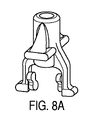
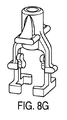
安全クリップ、又は先端プロテクタは、ニードルのニードル先端をブロックするように構成される任意の数の従来技術のガードを具現化できる。例示的な実施形態では、先端プロテクタは、米国特許第6616630号明細書に示されるガードの1つを具体化することが可能であって、その内容は、参照により本明細書に明示的に組み込まれる。先端プロテクタは、1つの近位壁及びそれぞれ遠位壁を備える2つの弾性アームを有することができる。襞(crimp)や膨張などのニードル上の外形変化部は、先端プロテクタの近位壁上の開口部を画定する周囲と係合して、静脈穿刺に成功した後でカテーテルハブの中から近位方向に先端プロテクタを後退させる。 A safety clip, or tip protector, can embody any number of prior art guards configured to block the needle tip of a needle. In an exemplary embodiment, the tip protector can embody one of the guards shown in U.S. Pat. No. 6,616,630, the contents of which are expressly incorporated herein by reference. be The tip protector can have two resilient arms with one proximal wall and each distal wall. A contour change on the needle, such as a crimp or dilation, engages a perimeter that defines an opening on the proximal wall of the tip protector to allow proximal movement out of the catheter hub after a successful venipuncture. Retract the tip protector in the direction
側面から見るときに2つのアームは交差することができ、又はこれらは、ニードルの異なる側面に沿って延在することができ、1つの側面内で交差することはない。一実施形態では、ニードルガードアームは、準備位置のアクチュエータによって広げられ、ニードルシャフトによってではない。アームの広がりは、ニードルガードのアームがカテーテルハブの内側、例えば、カテーテルハブのガード係合部(例えば、アンダーカット部又は溝部)などと係合するように付勢する。いくつかの例では、ニードルガードのアームは、アクチュエータによって広げられるが、当該アームは、使用準備位置でカテーテルハブの内部と係合しない。 The two arms can cross when viewed from the side, or they can extend along different sides of the needle and not cross within one side. In one embodiment, the needle guard arm is spread by the armed actuator and not by the needle shaft. The spreading of the arms urges the arms of the needle guard to engage the inside of the catheter hub, such as the guard engaging portion (eg, undercut or groove) of the catheter hub. In some examples, the arms of the needle guard are spread by the actuator, but the arms do not engage the interior of the catheter hub in the ready position.
他の例では、アームがアクチュエータによって広げられるときにアームの半径方向の最外面、例えば、アームと遠位壁との間の肘部などは、カテーテルハブの内部と係合又は接触しない。なぜなら、本実施形態においてアームは、ニードル上に載置するのではなくむしろアクチュエータのバンプに載置するためであり、従ってニードルガードは、バンプとの係合によってカテーテルハブの内部に保持され、カテーテルハブによってではない。例えば、アームがアクチュエータのバンプと係合するときに、間隙部がニードルガードの各最外面とカテーテルハブの内部との間に設けられてもよい。 In other examples, the radially outermost surfaces of the arms, such as elbows between the arms and the distal wall, do not engage or contact the interior of the catheter hub when the arms are spread by the actuator. Because in this embodiment the arm rests on the bumps of the actuator rather than on the needle, the needle guard is thus held inside the catheter hub by engagement with the bumps and the catheter Not by hub. For example, a gap may be provided between each outermost surface of the needle guard and the interior of the catheter hub when the arm engages the bump of the actuator.
従って、使用後のニードルの後退中に、ニードルガードは、アームとアクチュエータのバンプとの間の係合によってカテーテルハブの内部に保持できる。使用後にニードルが引き抜かれ、ニードルの襞が先端プロテクタの近位壁に係合し、先端プロテクタの1つのアームの場合の肘部、又は2つのアーム上の2つの肘部は、間隙によって提供される空間内に外向きに撓むか又はカテーテルハブ、例えば、カテーテルハブのガード係合セクションの端部に対してなどと及びバルブアクチュエータに対して接触する場合に平坦になることができ、アームがアクチュエータの1以上の延長脚上の1以上のバンプから移動し解放されることを引き起こす。 Thus, during retraction of the needle after use, the needle guard can be retained within the catheter hub by engagement between the arm and the bump of the actuator. After use the needle is withdrawn and the fold of the needle engages the proximal wall of the tip protector, the elbow in the case of one arm of the tip protector, or the two elbows on the two arms provided by the gap. or flattened when in contact with the catheter hub, e.g., against the end of the guard-engaging section of the catheter hub and against the valve actuator, so that the arm of the actuator causes movement and release from one or more bumps on one or more extended legs of the .
本開示の態様に従うバルブ開口器は、ノーズセクションを備える本体と、1以上の延長脚又はプランジャエレメント(例えば、脚エレメント又は細長い延長部など)と、及び1以上の誘導アームと、を備えてもよい。 A valve opener according to aspects of the present disclosure may comprise a body comprising a nose section, one or more extension legs or plunger elements (e.g., leg elements or elongated extensions, etc.), and one or more guide arms. good.
本体のノーズセクションは、細長くてもよく、ノーズセクションを通過する通路又は穴を有することができる。ノーズセクションの穴は、流体流動のための通路を備えてもよく、カテーテルアセンブリの使用準備位置にニードルを収容してもよい。 The nose section of the body may be elongated and may have passages or holes therethrough. A hole in the nose section may provide a passageway for fluid flow and may accommodate a needle in the ready-to-use position of the catheter assembly.
アクチュエータ又は開口器は、長手方向軸を有し、1以上の誘導アームは、長手方向軸に対して半径方向に延在し、1以上の延長脚は、長手方向軸に沿って軸方向に延在する。 The actuator or opening device has a longitudinal axis, one or more guide arms extend radially with respect to the longitudinal axis, and one or more extension legs extend axially along the longitudinal axis. exist.
延長脚は、本体から軸方向に延在できる。延長脚は、近位方向に延在できる。間隙部は、2つの延長脚の間に設けられてもよい。更に後述するように、フランジは、各延長脚の端部に配置することができ、雄ルアー先端のための当接面を提供できる。 The extension leg can extend axially from the body. The extension leg can extend proximally. A gap may be provided between the two extension legs. As further described below, a flange can be located at the end of each extension leg and can provide an abutment surface for the male luer tip.
特定の例では、2つの誘導アームが設けられ、直径方向に対向し、互いにアクチュエータの長手方向軸に沿っている。誘導アームは、本体から延在し、それぞれ、概して真っ直ぐな又は平坦な最外端部を有する長方形又は正方形の構造を具現化することができ、任意に湾曲形状、波形状、鋸歯形状、又は弧形状であってもよい。 In a particular example, two guide arms are provided, diametrically opposed to each other along the longitudinal axis of the actuator. The guide arms extend from the body and may each embody a rectangular or square structure having generally straight or flat outermost ends, optionally curved, wavy, serrated or arcuate. It may be in shape.
剛体部は、細長い形状を有し、例えば、作動端部を形成する円筒形状などが遠位端でリング形状の構造を具現化できる。細長い本体は、任意にドラフト角又は内向きのテーパーを遠位方向に有することができる。使用中、作動端部は、バルブの中に押し込むことができ、雄型医療器具、例えば、シリンジ先端、ルアーアダプタ、又はIVラインなどによって遠位方向に押されるときにバルブを作動させる。 The rigid portion has an elongated shape, for example a cylindrical shape forming the working end, which may embody a ring-shaped structure at the distal end. The elongated body can optionally have a draft angle or an inward taper distally. In use, the actuating end can be pushed into the valve, actuating the valve when pushed distally by a male medical device such as a syringe tip, luer adapter, or IV line.
準備位置では、作動端部は、バルブと接触してもよいが、バルブディスクの近位面から離間してもよい。任意に、作動端部は、作動前に雄ルアー先端によってバルブディスクの近位面と接触してもよい。 In the ready position, the working end may contact the valve, but may be spaced from the proximal surface of the valve disc. Optionally, the working end may contact the proximal face of the valve disc by means of a male luer tip prior to actuation.
更に後述するように、作動端部は、バルブの収容空間、例えば、バルブの近位収容部などに嵌合され、バルブ、例えば、収容空間の穴及び/又はバルブディスクなどと接触できる。 As will be further described below, the working end can fit into a receiving space of the valve, such as a proximal receiving portion of the valve, and can contact the valve, such as a hole in the receiving space and/or a valve disc.
2つのプランジャエレメントは、剛体部から近位方向に延在することができ、それぞれカテーテルアセンブリの長手方向に測定される長さ及びその長さに対して直角に測定される幅を有する。他の実施形態は、剛体部から延在する1つ又は3以上の脚延長部又はプランジャエレメントを使用してもよい。 Two plunger elements can extend proximally from the rigid portion and each have a length measured longitudinally of the catheter assembly and a width measured perpendicular to the length. Other embodiments may use one or more leg extensions or plunger elements extending from the rigid body.
一実施形態では、各プランジャエレメントは、雄ルアーによって接触するために適したサイズ及び形状であり、雄ルアーから遠位方向に向かう力を、ノーズセクションを通じて、作動端部に伝達し、バルブを開く。バルブ開口器、従って1以上のプランジャエレメントの全長は選択され得るため、カテーテルハブの雌ルアーへの雄ルアー先端の挿入は、バルブ開口器の近位端に対して押し当てるのに十分であり、バルブ開口器をバルブの中に近位方向に移動させ、流体流動のためにバルブの1以上のフラップを開く。 In one embodiment, each plunger element is sized and shaped to be contacted by the male luer to transmit a distal force from the male luer through the nose section to the actuating end to open the valve. . The total length of the valve opener, and thus the one or more plunger elements, can be selected such that insertion of the male luer tip into the female luer of the catheter hub is sufficient to press against the proximal end of the valve opener; A valve opener is moved proximally into the valve to open one or more flaps of the valve for fluid flow.
一例では、脚延長部又はプランジャエレメントは、可撓性且つ撓み可能であるため、雄ルアー先端によって押されるときに、プランジャエレメントは、撓む又は曲がる。プランジャエレメントは、材料選択によって撓み可能であり、必要な弾性特性を有する。他の例では、プランジャエレメントは、1以上の弱いセクション、例えば、構造的に薄い部分、切り欠き、キンク(kink)、同じ細長いプランジャエレメントの他の部分と比較して小さな断面の採用、又はそれらの組み合わせなどを組み込むことによって撓むことができる。代替的に、プランジャエレメントは、必要な弾性特性を有する材料選択によって且つ1以上の弱い部分の組み込みによって可撓性且つ撓み可能である。 In one example, the leg extension or plunger element is flexible and deflectable such that the plunger element deflects or bends when pushed by the male luer tip. The plunger element can be deflected by material selection and has the required elastic properties. In other examples, the plunger element has one or more weak sections, such as structural thinning, notches, kink, adoption of a smaller cross-section compared to other portions of the same elongated plunger element, or both. It can be bent by incorporating a combination of Alternatively, the plunger element is flexible and deflectable by selection of a material with the required elastic properties and by incorporation of one or more weak points.
複数のプランジャエレメントは、それぞれアクチュエータの幅に沿って三日月と同様の弧形状又は弧状断面を有することができる。別の例では、各プランジャエレメントは、断面に沿って概して平坦又は平面であってもよい。更に他の例では、各プランジャエレメントは、長さ部分に沿って複数の異なる断面の外形又は輪郭を有する。 The plurality of plunger elements can each have an arcuate shape or arcuate cross-section similar to a crescent along the width of the actuator. Alternatively, each plunger element may be generally flat or planar along its cross-section. In yet another example, each plunger element has a plurality of different cross-sectional contours or contours along its length.
細長いプランジャエレメントは、正方形の外形を有することができ、三日月形状の外形に隣接して配置される。一実施形態では、2つのプランジャエレメントのそれぞれの厚さは、十分に小さい又は薄いため、ニードルガード及び2つのプランジャエレメントは、十分な隙間を有し、カテーテルハブに対して物理的に拘束されることなくカテーテルハブの内部断面空間内に嵌合し、移動不能に又は固定される。 The elongated plunger element can have a square profile and is positioned adjacent to the crescent shaped profile. In one embodiment, the thickness of each of the two plunger elements is sufficiently small or thin that the needle guard and the two plunger elements have sufficient clearance to be physically constrained against the catheter hub. It fits within the internal cross-sectional space of the catheter hub without movement and is immovable or fixed.
一例では、2つのプランジャエレメントのそれぞれの厚さ及びニードルガードの幅は、カテーテルハブの内壁面に形成されるアンダーカット又はチャンネルを要求されないように、それらを収容する。プランジャエレメントは弧状断面を有するときに、雄型先端部が作動端部をバルブに押し当てることによって押されるときの大きな負荷に対して機械的に強くなることができる。これは、点滴装置のための薄くてコンパクトな設計を可能にすることができ、雌ルアーテーパーの標準化された空間により多くの場所を与えるために使用される。 In one example, the thickness of each of the two plunger elements and the width of the needle guard accommodate them such that no undercuts or channels formed in the inner wall surface of the catheter hub are required. When the plunger element has an arcuate cross-section, it can be mechanically strong against large loads when the male tip is pushed by pressing the working end against the valve. This can allow for a thin and compact design for the infusion set and is used to give more room to the female luer taper's standardized space.
バルブ開口器は、金属材料から又はプラスチック材料から又はその両方から作られる。金属材料から作られるとき、バルブ開口器は、深絞り方法によって形成され、プランジャエレメントの弧状断面は、雄ルアーによって押されるときに付加的に剛性を提供することができる。各プランジャエレメントは、少なくとも2つの長手方向端部を備えることができ、リブは、1つ又は両方の長手方向端部に沿って設けられ、構造的剛性を更に付加する。 The valve opener is made from a metallic material or from a plastic material or both. When made from a metallic material, the valve opener is formed by a deep drawing method and the arcuate cross-section of the plunger element can provide additional rigidity when pushed by the male luer. Each plunger element may comprise at least two longitudinal ends, with ribs provided along one or both longitudinal ends to further add structural rigidity.
1以上の間隙は、任意の2つのプランジャエレメントの間に設けられる。間隙は、それらを横切って流れる流体流動、例えば静脈点滴中などのための隙間又は空間を設けられる。また、間隙は、ニードルガードを収容するのにも利用される。 One or more gaps are provided between any two plunger elements. The gaps are provided with gaps or spaces for fluid flow across them, such as during an intravenous drip. The gap is also used to accommodate a needle guard.
バルブ開口器の剛体部は、外周部を画定する外面と、キャビティを画定する内面とを備えられる。一例では、外周部は概して円筒形であってもよい。他の例では、外周部は、テーパーを有することができ、任意に表面特徴、例えば、バンプ又は溝部などを備えられる。内部に、本体部は、穴部及び穴部の各端部に開口部を備える。 The rigid portion of the valve opener is provided with an outer surface defining an outer periphery and an inner surface defining a cavity. In one example, the perimeter may be generally cylindrical. Alternatively, the perimeter can be tapered and optionally provided with surface features such as bumps or grooves. Internally, the body includes a hole and an opening at each end of the hole.
アクチュエータ又はバルブ開口器の本体部は、間隙又はスロットがない、又は間隙/スロットを備える連続表面を有することができ、流体流動を容易にする。遠位端又は作動端部と外周部との交差部は、鋭い端部又は鈍い端部を有することができる。一例では、作動端部は鈍い端部であり、バルブに対して押し当てるための平面を有する。 The body of the actuator or valve opener can have a continuous surface without gaps or slots or with gaps/slots to facilitate fluid flow. The intersection of the distal or working end and the outer circumference can have a sharp edge or a blunt edge. In one example, the working end is a blunt end and has a flat surface for bearing against the valve.
アクチュエータの剛体部の近位面上で、2つのプランジャエレメントは、軸方向に近位方向の外側に及び半径方向に外周部から延在することができ、肩部を形成する。言い換えれば、脚延長部はそれぞれ、曲線部又は曲げ部を有することができる。言い換えれば、外周部は、第1の寸法の外径を有することができ、2つのプランジャエレメントは、第2の寸法の外径を画定することができ、第2の寸法は第1の寸法よりも大きい。肩部は、2つの異なる寸法の間に設けられる。 On the proximal face of the rigid portion of the actuator, the two plunger elements can extend axially proximally outwardly and radially from the outer periphery to form shoulders. In other words, each leg extension can have a curve or bend. In other words, the outer periphery can have an outer diameter of a first dimension and the two plunger elements can define an outer diameter of a second dimension, the second dimension being greater than the first dimension. is also big. A shoulder is provided between two different dimensions.
1以上のバンプは、脚延長部又はプランジャエレメントの内面上に形成されてもよい。いくつかの例では、1以上のバンプ又は係合セクションは、2つの脚延長部の間の間隙で各脚延長部、例えば、各脚の内面上などに形成される。言い換えれば、アクチュエータの長手方向軸に関連して、プランジャエレメントは、長手方向軸に近い内面及び長手方向軸から更に離れる外面を有することができる。バンプは、安全クリップまたは先端プロテクタの1以上のアームと係合するように構成され、それは、使用準備位置にある間、カテーテルハブの内部キャビティからの先端プロテクタの脱落を防ぐことができる。 One or more bumps may be formed on the inner surface of the leg extension or plunger element. In some examples, one or more bumps or engagement sections are formed on each leg extension, such as on the inner surface of each leg, in the gap between the two leg extensions. In other words, relative to the longitudinal axis of the actuator, the plunger element can have an inner surface closer to the longitudinal axis and an outer surface further away from the longitudinal axis. The bumps are configured to engage one or more arms of the safety clip or tip protector, which can prevent dislodgement of the tip protector from the internal cavity of the catheter hub while in the ready-to-use position.
1以上のバンプは、先端プロテクタの2つのアームの端部、例えば、アームの遠位壁の端部などのための取り付け面として務めることができ、ニードルシャフトに対する代わりにそれらを載置する。これは、静脈穿刺に成功した後のニードルの後退中に、端部がバンプに載置されるときにニードルシャフトと2つのアームの端部との間に接触がないため、抗力を減少する補助ができる。また、バンプ又は係合セクション又はセグメントに載置されるとき、ニードルガードは、カテーテルハブの内部と接触することもでき、又はカテーテルハブの内部から離間することもできる。 The one or more bumps can serve as mounting surfaces for the ends of the two arms of the tip protector, such as the ends of the distal walls of the arms, mounting them in place of the needle shaft. This helps reduce drag as there is no contact between the needle shaft and the ends of the two arms when the ends rest on the bumps during retraction of the needle after a successful venipuncture. can be done. Also, when resting on a bump or engagement section or segment, the needle guard can either contact the interior of the catheter hub or be spaced apart from the interior of the catheter hub.
図示の実施形態では、対向する2つのプランジャエレメント上に互いに対向する2対のバンプがあってもよい。各対のバンプは、プランジャエレメントの近位端から異なる距離にあってもよく、一方の対は近位端に近く、一方の対は近位端からさらに遠い。異なる距離は、バンプの各対と先端プロテクタの異なる長さのアームとの係合を可能にすることができ、それは、軸方向に互い違いにできる。 In the illustrated embodiment, there may be two pairs of opposing bumps on two opposing plunger elements. Each pair of bumps may be at a different distance from the proximal end of the plunger element, one pair closer to the proximal end and one pair farther from the proximal end. Different distances can allow engagement of each pair of bumps with different length arms of the tip protector, which can be axially staggered.
各プランジャエレメント上の2つのバンプは、プランジャエレメントの内面上に対角に形成され、先端プロテクタの上部アームと上部バンプとの係合及び先端プロテクタの下部アームと下部バンプとの係合を可能にする。 Two bumps on each plunger element are formed diagonally on the inner surface of the plunger element to allow engagement of the upper arm of the tip protector with the upper bump and engagement of the lower arm of the tip protector with the lower bump. do.
一方の対のバンプは、ニードルガードの一方の遠位壁の端部を支持でき、他方の対のバンプは、他方の遠位壁の端部を支持できる。 One pair of bumps can support the end of one distal wall of the needle guard and the other pair of bumps can support the end of the other distal wall.
各対のバンプは、第1のバンプ及び第2のバンプを備えられる。2つのバンプは、異なる平面又は高さに沿って配置され、ニードルガードの2つの異なるアーム上の2つの異なる端部を支持するための2つの異なる表面を画定する。 Each pair of bumps is provided with a first bump and a second bump. The two bumps are arranged along different planes or heights to define two different surfaces for supporting two different ends on two different arms of the needle guard.
1つのバンプは、遠位壁の一方の端部を支持できるため、2つのバンプは、2つの遠位壁の2つの端部(各遠位壁上の1つの端部)を支持するように構成される。 One bump can support one end of the distal wall, so two bumps support two ends of the two distal walls (one end on each distal wall). Configured.
1つのバンプは、遠位壁の一方の端部を支持できるため、一方のプランジャエレメント上の2つのバンプは、2つの遠位壁の2つの端部(各遠位壁上の1つの端部)を支持するように構成される。 Since one bump can support one end of the distal wall, two bumps on one plunger element support two ends of the two distal walls (one end on each distal wall). ).
バンプの第1セット及びバンプの第2セットは、プランジャエレメントに沿って軸方向に異なる距離にある。先端プロテクタの長いアームは、バンプの第1セットと係合でき、先端プロテクタの短いアームは、バンプの第2セットと係合できる。いくつかの例では、1つのみの第1バンプ及び1つの第2バンプが使用され、先端プロテクタの端部を支持する。2つの単一の第1バンプ及び第2バンプは、2つの脚延長部上に別個に配置されるため、一方のバンプは、一方の脚延長部上にあり、他方のバンプは、他方の脚延長部上にある。 The first set of bumps and the second set of bumps are at different axial distances along the plunger element. A long arm of the tip protector can engage a first set of bumps and a short arm of the tip protector can engage a second set of bumps. In some examples, only one first bump and one second bump are used to support the ends of the tip protector. The two single first and second bumps are separately placed on the two leg extensions so that one bump is on one leg extension and the other bump is on the other leg. on the extension.
いくつかの例では、バンプは、傾斜面又はランプ(ramps)部に備えられ、ニードル上の襞がニードルガードの近位壁を近位方向に引くような2つのアームの半径方向外側の移動を容易にする。 In some examples, the bumps are provided on ramps or ramps to prevent radial outward movement of the two arms such that the folds on the needle pull the proximal wall of the needle guard proximally. make it easier.
プランジャエレメントの近位端は、外側突出部を形成でき、又は外側突出部は、プランジャエレメントの近位端に組み込まれる。外側突出部は、ハブキャビティ内のアクチュエータの位置を維持する補助をするためにカテーテルハブの内面上に形成されるアンダーカット又は溝部と係合できる。 The proximal end of the plunger element can form the outer protrusion or the outer protrusion is incorporated into the proximal end of the plunger element. The outer protrusions can engage undercuts or grooves formed on the inner surface of the catheter hub to help maintain the position of the actuator within the hub cavity.
2つのプランジャエレメント上の2つの外側突出部は、平面を有することができ、それは、概してアクチュエータの長手方向軸と直交する。2つの外側突出部のそれぞれは、雄型医療器具のための物理的な障壁を提供でき、押し当ててアクチュエータをバルブに対して前進させてバルブを開く。他の例では、外側突出部は省略され、プランジャエレメントの断面は十分に大きく、雄型医療器具によって接触させられる。 The two outward projections on the two plunger elements can have a plane that is generally perpendicular to the longitudinal axis of the actuator. Each of the two outward projections can provide a physical barrier for the male medical device to press against to advance the actuator against the valve to open the valve. In other examples, the outward projection is omitted and the cross-section of the plunger element is large enough to be contacted by the male medical device.
組み込まれたとき、各外側突出部は断面を有し、それは、対応するプランジャエレメントの断面よりも大きい。他の例では、各外側突出部は、プランジャエレメントの断面よりも小さい断面を有することができるが、プランジャエレメントの近位端に戦略的に配置され、作動中に雄型医療器具と接触させられる。任意に、1つのみの外側突出部は、2つのプランジャエレメントの一方に組み込まれ、アクチュエータをカテーテルハブの内面に角度を合わせて整列させるように働き、雄型医療器具の負荷を受ける。 When assembled, each outward projection has a cross-section that is larger than the cross-section of the corresponding plunger element. In other examples, each outward protrusion can have a cross-section smaller than that of the plunger element, but is strategically located at the proximal end of the plunger element and is brought into contact with the male medical device during actuation. . Optionally, only one outward projection is incorporated into one of the two plunger elements and serves to angularly align the actuator with the inner surface of the catheter hub to receive the load of the male medical device.
2つのプランジャエレメント上の外側突出部は、カテーテルハブの内側の溝部の中を溝部の近位肩部と遠位肩部との間を移動するように構成される。溝部は、カテーテルハブの内面内又は内面上に形成され、近位肩部及び遠位肩部を形成するアンダーカットとして見られてもよい。 Outer protrusions on the two plunger elements are configured to travel within the groove inside the catheter hub between the proximal and distal shoulders of the groove. The grooves may be viewed as undercuts formed in or on the inner surface of the catheter hub forming proximal and distal shoulders.
カテーテルアセンブリの使用準備位置では、外側突出部は、溝部の近位肩部に当接することができるとともに、アクチュエータのノーズセクションは、バルブと接触でき、バルブ上の1以上のスリットが開くことなくアクチュエータとバルブとの積極的な係合を維持する。一例では、アクチュエータのノーズセクションは、バルブの近位穴部に配置され、カテーテルハブの内側の近位肩部に接触する。 In the ready-to-use position of the catheter assembly, the outer projection can abut the proximal shoulder of the groove and the nose section of the actuator can contact the valve without opening one or more slits on the valve. and maintain positive engagement with the valve. In one example, the nose section of the actuator is positioned in the proximal bore of the valve and contacts the inner proximal shoulder of the catheter hub.
作動位置では、アクチュエータは、カテーテルハブの穴部内に遠位方向に前進させられ、外側突出部は、カテーテルハブの内側の溝の遠位肩部と接触できる。溝部の遠位肩部と接触するときに、2つのプランジャエレメントは、当接又は接触のために内側に撓むことができ、2つのプランジャエレメントの曲げを援助する。一例では、2つのプランジャエレメントが作動中に撓むときに、それらは、ともに近づくように移動する。雄ルアー先端がプランジャエレメントから離れて後退させられるときに、2つのプランジャエレメントは、半径方向に更に互いから離れるように移動できる。 In the actuated position, the actuator is advanced distally into the bore of the catheter hub and the outer projection can contact the distal shoulder of the inner groove of the catheter hub. When in contact with the distal shoulder of the groove, the two plunger elements can flex inwardly for abutment or contact, assisting bending of the two plunger elements. In one example, when two plunger elements flex during actuation, they move closer together. When the male luer tip is retracted away from the plunger element, the two plunger elements can move radially further away from each other.
本発明のバルブ開口器又はアクチュエータは、2つのプランジャエレメントの外側突出部又は表面を有すると理解され、それらは、雄ルアー先端又はシリンジ先端によって押し当てられるのに適したサイズ及び形状であり、静脈穿刺が成功した後で前記先端がカテーテルハブの近位開口部に挿入されるときにバルブ開口器を遠位方向に押し、バルブを開く。 The valve opener or actuator of the present invention is understood to have outward projections or surfaces of two plunger elements, which are of a size and shape suitable to be pressed against by a male luer tip or syringe tip, and which are venous. After a successful puncture, the valve opener is pushed distally to open the valve when the tip is inserted into the proximal opening of the catheter hub.
当接面を有する外側突出部は、半径方向に延在するタブと呼ばれてもよい。半径方向に延在するタブは、プランジャエレメントから延びることができる。1以上の半径方向に延在するタブは、各プランジャエレメントから延びることができる。半径方向に延在する1以上のタブは、各プランジャエレメント上の最も近位の端部又は先端に配置できる。 Outer protrusions with abutment surfaces may be referred to as radially extending tabs. A radially extending tab can extend from the plunger element. One or more radially extending tabs can extend from each plunger element. One or more radially extending tabs can be located at the proximal-most end or tip on each plunger element.
2つの外側突出部又は半径方向に延在するタブのそれぞれは、雄型医療器具のための物理的な障壁を提供することができ、押し当ててアクチュエータをバルブに対して前進させ、バルブを開く。 Each of the two outward projections or radially extending tabs can provide a physical barrier for the male medical device to push against and advance the actuator against the valve to open it. .
半径方向に延在するタブは壁を提供でき、使用準備位置でニードルガード又は安全クリップのカテーテルハブからの脱落を防ぐ。一例では、ニードルガードは、外形変化又はニードルの襞の配置によって近位壁の近位への移動する前に、ニードルの後退中に半径方向に延在するタブによって保持される。 A radially extending tab can provide a wall to prevent the needle guard or safety clip from falling out of the catheter hub in the ready-to-use position. In one example, the needle guard is retained by radially extending tabs during retraction of the needle prior to proximal movement of the proximal wall due to contour change or placement of a fold on the needle.
遠位方向に押されるときに2つのプランジャエレメントは、遠位方向に押され且つ互いに向かって撓み又は曲がることができる。2つのプランジャエレメントは、ルアー先端によって遠位方向に押されるときに撓むことができ、雄ルアー先端によってもはや当接しないときに互いに近づくように移動できる。 When pushed distally, the two plunger elements can be pushed distally and flex or bend toward each other. The two plunger elements can flex when pushed distally by the luer tip and move closer together when no longer abutted by the male luer tip.
バルブは、カテーテルハブの内側に配置され、近位肩部及び遠位肩部を有する溝部のすぐ遠位且つブッシングのすぐ近位に配置される。いくつかの例では、バルブは、ブッシングに接触できる。他の例では、バルブは、ブッシングから離間できる。 A valve is positioned inside the catheter hub, just distal to the groove having proximal and distal shoulders and just proximal to the bushing. In some examples, the valve can contact the bushing. Alternatively, the valve can be spaced apart from the bushing.
一例では、バルブは、カテーテルハブ内に収容するのに適したサイズの本体直径を有するバルブ本体と、本体直径に対して直角に測定される厚さを有するバルブディスクと、バルブディスクの厚さを通じて形成される2以上のフラップを画定する1以上のスリットと、を備える。例えば、1つ又は2つ又は3つのスリットは、バルブの厚さを通じて備えられてもよく、2つから3つのフラップを画定する。図示の実施形態では、1つのスリットは、バルブディスクの中心を通じて延在する。 In one example, the valve includes a valve body having a body diameter sized appropriately to be accommodated within a catheter hub, a valve disc having a thickness measured perpendicular to the body diameter, and a valve through the thickness of the valve disc. and one or more slits defining two or more flaps to be formed. For example, one or two or three slits may be provided through the thickness of the valve, defining two to three flaps. In the illustrated embodiment, one slit extends through the center of the valve disc.
バルブは、近位バルブセクション及び遠位バルブセクションを備える。近位バルブセクションは、円錐台状面を有する穴部を備えられる。円錐台状面は、使用準備位置でアクチュエータの作動端部及び剛体部のノーズセクションの一部と係合するように構成される。いくつかの実施形態では、穴部の表面は、他の形状に形成されてもよく、作動体用の収容部、例えば、逆円筒形又は逆長方形又は立方体の箱などとして機能してもよい。穴部の遠位端は、バルブディスクによってブロックされ、それは、考えられる2以上のフラップを画定する2以上のスリットを備える1つのスリットを有する。 The valve comprises a proximal valve section and a distal valve section. The proximal valve section is provided with a bore having a frustoconical surface. The frustoconical surface is configured to engage the working end of the actuator and a portion of the nose section of the rigid body in the ready-to-use position. In some embodiments, the surface of the hole may be formed in other shapes and may serve as a housing for the actuator, such as an inverted cylindrical or inverted rectangular or cubic box. The distal end of the hole is blocked by a valve disc, which has one slit with two or more slits defining two or more possible flaps.
本明細書で開示されるバルブ又は隔壁は、外面を有する遠位バルブセクション及び穴部を画定する内面を備えられる。遠位端縁部は、内面と外面との間に備えられる。遠位バルブセクションの穴部は、逆ドーム面、例えば、凹曲面などを備え、バルブの遠位面上に形成される。 The valve or septum disclosed herein comprises a distal valve section having an outer surface and an inner surface defining a bore. A distal edge is provided between the inner surface and the outer surface. A bore in the distal valve section is formed on the distal face of the valve with an inverted domed surface, such as a concave curved surface.
ドーム面は、ルアー先端がカテーテルハブの中に挿入されるときにバルブを折り畳むための空間を提供できる。言い換えれば、遠位バルブセクションの穴部は、十分な空間を備え、バルブディスクが雄型医療器具又は雄ルアー先端によって遠位方向に押されるときにバルブディスクの伸張を収容する。これは、バルブの中にアクチュエータを前進させるのに使用した雄型医療器具の除去後でもバルブとアクチュエータとの係合を維持させる。 The domed surface can provide space for the valve to collapse when the luer tip is inserted into the catheter hub. In other words, the bore in the distal valve section is provided with sufficient space to accommodate the expansion of the valve disc as it is pushed distally by the male medical device or male luer tip. This allows the valve and actuator to remain engaged after removal of the male medical device used to advance the actuator into the valve.
本明細書で開示されるバルブ及び隔壁は、遠位キャビティ及び近位キャビティを備えられる。遠位キャビティは、ドーム形状又はドーム状面を有することができる。近位キャビティは、逆円錐台状面を有することができる。 The valves and septum disclosed herein are provided with a distal cavity and a proximal cavity. The distal cavity can have a dome shape or a domed surface. The proximal cavity can have an inverted frusto-conical surface.
2以上のフラップを画定する1以上のスリットを備えるバルブディスクは、バルブの近位と遠位キャビティとの間に配置される。近位キャビティは、アクチュエータのノーズセクションを収容でき、遠位キャビティは、バルブディスクがアクチュエータのノーズセクションによって遠位方向に押されるときにバルブディスクの2以上のフラップの伸張を収容できる。 A valve disc comprising one or more slits defining two or more flaps is positioned between the proximal and distal cavities of the valve. The proximal cavity can accommodate the nose section of the actuator and the distal cavity can accommodate the extension of two or more flaps of the valve disc when the valve disc is pushed distally by the nose section of the actuator.
3つのスリットは、1つの点から始まり、バルブディスクの略中心点又は中央部から半径方向に延びることができ、三芒星と同様に、スリットに沿って撓むことができる3つのフラップを形成する。 The three slits can start at one point and extend radially from approximately the center point or center of the valve disc, forming three flaps that can flex along the slits, similar to a three-pointed star. do.
バルブは外周部を備えられ、それは、バルブ開口器とブッシングとの間で、カテーテルハブの内部キャビティの中に浮かぶことができる。例えば、バルブの外周部は、カテーテルハブの内部キャビティ内の近位方向及び遠位方向に移動でき、カテーテルアセンブリの軸方向に沿ってカテーテルハブによって拘束されない。一実施形態では、後述するように、アクチュエータの作動端部の遠位縁部又は交差部の少なくとも一部又は全部は、バルブの外周部から凹むため、遠位縁部は、バルブディスクの近位側に面する壁面に当接又は接触でき、バルブディスクを開く。 The valve is provided with an outer periphery that can float within the internal cavity of the catheter hub between the valve opening and the bushing. For example, the outer periphery of the valve can move proximally and distally within the internal cavity of the catheter hub and is not constrained by the catheter hub along the axial direction of the catheter assembly. In one embodiment, as described below, at least a portion or all of the distal edge or intersection of the working end of the actuator is recessed from the outer periphery of the valve so that the distal edge is proximal to the valve disc. A side facing wall can be abutted or contacted to open the valve disc.
バルブの遠位バルブセクションは、カテーテルハブの内部キャビティの遠位端で、カテーテルハブの穴セクションの中に挿入される。遠位バルブセクションは、カテーテルハブの穴セクションに圧入でき、バルブの鈍い遠位端は、ブッシングと接触できる。 The distal valve section of the valve is inserted into the bore section of the catheter hub at the distal end of the inner cavity of the catheter hub. A distal valve section can be press fit into the bore section of the catheter hub and the blunt distal end of the valve can contact the bushing.
近位バルブセクション及び遠位バルブセクションと同様にバルブの近位バルブセクションと遠位バルブセクションとの間の交差部は、カテーテルハブの内部キャビティの中に形成される対応する肩部又は段付き面に対して着座でき、バルブをカテーテルハブ内で軸方向に固定する。いくつかの例では、バルブの遠位端はブッシングから離間できる。 The intersection between the proximal and distal valve sections of the valve as well as the proximal and distal valve sections are corresponding shoulders or stepped surfaces formed within the internal cavity of the catheter hub. to axially secure the valve within the catheter hub. In some examples, the distal end of the valve can be spaced from the bushing.
バルブは、カテーテルハブの単一のハブ本体の内側に位置決めされ、例えば、カテーテルハブの内部キャビティ内の内部肩部に対するバルブの前進などによる。言い換えると、バルブは、2以上のカテーテルハブ本体によって、例えば、2以上のハブ本体の継ぎ目などに沿って、カテーテルハブの内側に保持される必要はない。バルブの外周部は、カテーテルハブの内径よりも大きいため、バルブは、圧入によってカテーテルハブの内側に保持できる。 The valve is positioned inside the single hub body of the catheter hub, such as by advancement of the valve against an internal shoulder within the internal cavity of the catheter hub. In other words, the valve need not be held inside a catheter hub by more than one catheter hub body, such as along the seams of the two or more hub bodies. Since the outer circumference of the valve is larger than the inner diameter of the catheter hub, the valve can be retained inside the catheter hub by a press fit.
カテーテルハブの内部キャビティは、溝部を備えられ、それは、近位肩部及び遠位肩部を備えられる。2つのプランジャエレメント上の外側突出部は、カテーテルハブの内部で溝部の近位肩部に接触でき、アクチュエータ又は作動体の近位方向への移動を制限する。 The inner cavity of the catheter hub is provided with a groove, which is provided with a proximal shoulder and a distal shoulder. Outer protrusions on the two plunger elements can contact the proximal shoulder of the groove within the catheter hub to limit proximal movement of the actuator or effector.
作動体又はアクチュエータの遠位端で、作動端部及び剛体部のノーズセクションは、近位バルブセクションの近位穴部の中に突出でき、アクチュエータは、バルブとの接触によって遠位方向への移動を停止する。一例では、少なくともアクチュエータの遠位端で、ノーズセクションの外形及び近位バルブセクションの穴部は、同一又は概ね同一であり、例えば、円錐台形状及び逆円錐台形状を有するなど、サイズオンサイズの嵌合を提供する。他の例では、ノーズセクション及び穴部は、非類似の外形を有することができ、提供される少なくとも2つの構造の一部が互いに使用準備位置で作動前に接触できる。 At the distal end of the working body or actuator, the working end and the nose section of the rigid body can project into the proximal bore of the proximal valve section, the actuator moving distally upon contact with the valve. to stop. In one example, at least at the distal end of the actuator, the contour of the nose section and the bore of the proximal valve section are identical or nearly identical and are size-on-size, e.g., having frusto-conical and inverted frusto-conical shapes. Provide mating. In other examples, the nose section and the bore can have dissimilar geometries such that portions of at least two structures provided can contact each other in the ready-to-use position prior to actuation.
一例では、アクチュエータのノーズセクション及び作動端部は、サイズオンサイズの嵌合で穴部の内側に配置されている。別の例では、剛体部の遠位部、例えば、ノーズセクションなどは、バルブの穴部よりわずかに大きいため、剛体部は、使用準備位置でバルブの穴部の内部に予荷重する。 In one example, the nose section and working end of the actuator are positioned inside the hole in a size-on-size fit. In another example, the distal portion of the rigid portion, such as the nose section, is slightly larger than the valve bore, such that the rigid portion preloads inside the valve bore in the ready-to-use position.
様々な構成要素、例えば、バルブ、アクチュエータ、及び溝部などの荷重、サイズ、及び形状が選択できるため、アクチュエータは使用準備位置でバルブに接触するとともに、アクチュエータは、作動前にバルブディスクの1以上のスリットを開かない。言い換えれば、ニードルが静脈穿刺に成功した後で後退すると、アクチュエータは、雄ルアー先端によって作動せず、バルブが閉じられ、バルブの近位領域とバルブの遠位領域との間、又はその逆を通過する流体はなく、又は少なくとも十分な流体の流れはない。更に、アクチュエータとカテーテルハブの溝部との間及びアクチュエータとバルブとの接触関係は、静脈穿刺に成功した後のニードルの後退中又はカテーテルハブからのニードルの完全な除去の後で、バルブの潜在的な近位方向への移動を制限する。 Loads, sizes and shapes of various components, such as valves, actuators and grooves, can be selected so that the actuator contacts the valve in the ready position and the actuator has one or more of the valve discs prior to actuation. Do not open the slit. In other words, when the needle is retracted after a successful venipuncture, the actuator is not actuated by the male luer tip and the valve is closed, moving between the proximal region of the valve and the distal region of the valve or vice versa. There is no fluid passing through, or at least not sufficient fluid flow. In addition, the contact relationship between the actuator and the groove of the catheter hub and between the actuator and the valve may result in the valve potentially opening during retraction of the needle after a successful venipuncture or after complete removal of the needle from the catheter hub. limit proximal movement.
カテーテル処置の後、ニードル先端は、ニードルガード又は先端プロテクタの弾性アームの2つの遠位壁(各弾性アームの端部に1つずつ)の近位に移動できる。代替的に、ニードルガードは、1つの遠位壁及び/又は1つのアームを有することができる。2つの遠位壁それゆえ2つの弾性アームは、ニードル、例えば、ニードルガードの近位壁上の開口部を画定する周囲部を引っ張るニードルの外形又は襞の変化などによって近位方向に引かれ、2つのアームは、半径方向の外側に移動でき、バルブ開口器の2つのガード係合セクション又はバンプから係合解除する。代替的に、一方のアーム又は一方の遠位壁は、一方のガード係合セクションから係合解除する。 After catheterization, the needle tip can move proximally to the two distal walls of the resilient arms of the needle guard or tip protector, one at the end of each resilient arm. Alternatively, the needle guard can have one distal wall and/or one arm. The two distal walls and hence the two resilient arms are pulled proximally by a needle, such as a change in the contour or fold of the needle pulling on the perimeter defining the opening on the proximal wall of the needle guard, The two arms are movable radially outward to disengage from the two guard engaging sections or bumps of the valve opener. Alternatively, one arm or one distal wall disengages from one guard engaging section.
使用後にニードルが近位方向に移動し続け、ニードル上の外形変化部が先端プロテクタの近位壁上の周囲部を引くと、先端プロテクタは、ニードルとともに近位方向に移動でき、バンプから分離し、先端プロテクタ上の2つの遠位壁は、閉じられてニードル先端110を覆い、ニードル先端位置となる。
As the needle continues to move proximally after use and the contour change on the needle pulls the perimeter on the proximal wall of the tip protector, the tip protector can move proximally with the needle and separate from the bump. , the two distal walls on the tip protector are closed over the
代替的な実施形態で、ニードルガードは、ニードルシャフトに襞なしで留められ、ユニットとしてカテーテルハブから除去できる。例えば、それぞれ開口部を有する2つの壁面を備えるニードルガードは、ニードルガードが作動されたときにニードルガードの壁面が傾斜するため、2つの壁面上の開口部がニードルシャフトの外側に対して留められるなど、襞なしでニードルとともに使用されてもよい。 In an alternative embodiment, the needle guard can be clipped to the needle shaft without folds and removed from the catheter hub as a unit. For example, a needle guard with two walls each having an opening may have the openings on the two walls pin against the outside of the needle shaft because the walls of the needle guard tilt when the needle guard is actuated. , etc., may be used with needles without crimps.
バルブは、カテーテルハブの内部キャビティの内側に留まることができる。従って、バルブは、ニードルの準備位置とニードルの保護位置の両方でカテーテルハブの内側に配置される。 The valve can remain inside the inner cavity of the catheter hub. Thus, the valve is located inside the catheter hub in both the needle ready position and the needle protected position.
別の観点から見ると、バルブは、ニードル先端がカテーテルチューブの遠位開口部から突出するカテーテルアセンブリの使用準備位置と、カテーテルハブからニードルが除去されたカテーテルアセンブリの保護位置の両方でカテーテルハブの内側に配置され、ニードル先端は、カテーテルハブから除去され、先端プロテクタによって覆われる。 Viewed from another perspective, the valve is positioned on the catheter hub in both the ready-to-use position of the catheter assembly, with the needle tip protruding from the distal opening of the catheter tube, and the protected position of the catheter assembly, with the needle removed from the catheter hub. Disposed inside, the needle tip is removed from the catheter hub and covered by a tip protector.
1以上のスロットは、カテーテルハブの内面上に形成される。1以上のスロットは、カテーテルハブの内部に沿って軸方向に形成され、アクチュエータの1以上の誘導アームと係合するように構成される。雄ルアー先端によって係合するときに、アクチュエータは、軸方向にスライドできるが、1以上のスロットによって回転が制限される。 One or more slots are formed on the inner surface of the catheter hub. One or more slots are formed axially along the interior of the catheter hub and configured to engage one or more guide arms of the actuator. When engaged by the male luer tip, the actuator can slide axially but is restricted from rotation by one or more slots.
一実施形態では、2つのスロットは、カテーテルハブの対向する内面上に形成され、アクチュエータの2つの対向する誘導アームと係合するように構成される。他の実施形態は、1対又は3対以上の係合スロット及びアームを使用してもよく、カテーテルハブ内のアクチュエータの回転を防ぐ。これは、アクチュエータが軸方向に正しい方向に移動することを確実にすることができ、ルアー先端がカテーテルハブの中に挿入されるときにバルブを作動させる。 In one embodiment, two slots are formed on opposing inner surfaces of the catheter hub and configured to engage two opposing guide arms of the actuator. Other embodiments may use one or more pairs of engagement slots and arms to prevent rotation of the actuator within the catheter hub. This can ensure that the actuator moves axially in the correct direction, actuating the valve when the luer tip is inserted into the catheter hub.
1以上のスロットは、近位肩部及び遠位肩部を有する溝部と交差できる。溝部は、アクチュエータのプランジャエレメント上の半径方向のタブと当接するように構成される。 One or more slots can intersect a groove having proximal and distal shoulders. The groove is configured to abut radial tabs on the plunger element of the actuator.
雄型医療器具は、カテーテルハブの外側のねじ山と螺合するためのねじ付きカラーを有することができる。ねじ付きカラーは、雄型先端部に固定されるか又は雄型先端部に対して回転可能であってもよい。雄型医療器具又は器械は、雄ルアー、シリンジ先端、静脈内セットコネクタ、又はルアーテーパーを有する他の雄型先端部であってもよい。例えば、雄型医療器具は、IVチューブに接続されることができ、それは、雄型医療器具と、カテーテルハブと、カテーテルチューブと、を通じて流体送達のために静脈内流体源に接続され、輸液療法を患者に配給する。 The male medical device can have a threaded collar for threaded engagement with the outer threads of the catheter hub. The threaded collar may be fixed to the male tip or rotatable relative to the male tip. The male medical device or instrument may be a male luer, syringe tip, intravenous set connector, or other male tip with a luer taper. For example, a male medical device can be connected to an IV tube, which is connected to an intravenous fluid source for fluid delivery through the male medical device, catheter hub, catheter tube, and infusion therapy. to the patient.
雄型医療器具又は雄型先端部を本開示のカテーテルハブの近位開口部に挿入するときに、雄型先端部は最初に、バルブ開口器上のプランジャエレメントと接触し、遠位方向に前進して2つのプランジャエレメントに付勢し、作動端部を遠位方向前方にバルブの中に移動し、バルブを開く。 When a male medical device or tip is inserted into the proximal opening of the catheter hub of the present disclosure, the male tip first contacts the plunger element on the valve opening and is advanced distally. to urge the two plunger elements to move the actuating end distally forward into the valve and open the valve.
各プランジャエレメントの弧状断面は、カテーテルハブの内径よりも小さな直径を有することができ、雄型医療器具を押し当てるためのより大きく重なり合う接触面を提供する。 The arcuate cross-section of each plunger element can have a diameter smaller than the inner diameter of the catheter hub to provide a larger overlapping contact surface for pressing against the male medical device.
アクチュエータの2つのプランジャエレメント上の外側突出部又は半径方向のタブは、十分な近位面を提供でき、それは、作動中に紛失又はずれを生じることなく雄ルアー先端によって当接するように構成されている。 Outer protrusions or radial tabs on the two plunger elements of the actuator can provide a sufficient proximal surface that is configured to be abutted by the male luer tip without loss or displacement during actuation. there is
雄ルアーによって生成される遠位方向に向けられた力は、バルブ開口器を遠位方向に雄型先端部の形状及びカテーテルハブの近位開口部が雄型先端部の更なる遠位方向への前進を止めるまで移動できる。一例では、カテーテルハブの雌ルアーテーパー及び雄型先端部の雄ルアーテーパーは、カテーテルハブの開口部への雄型先端部の遠位への更なる前進を受け入れ及び阻止する。シールは、ルアーの係合によって提供され、流体がカテーテルハブの近位開口部から漏れ出るのを防ぐ。 The distally directed force generated by the male luer causes the valve opener to move distally due to the shape of the male tip and the proximal opening of the catheter hub further distally of the male tip. can move until it stops moving forward. In one example, the female luer taper of the catheter hub and the male luer taper of the male tip accommodate and prevent further distal advancement of the male tip into the opening of the catheter hub. A seal is provided by the luer engagement to prevent fluid from leaking out of the proximal opening of the catheter hub.
バルブ開口器又はアクチュエータが雄型先端部の遠位への前進によって遠位方向へ移動すると、バルブ開口器の作動端部は、遠位方向に付勢され、バルブのバルブディスクの近位側表面に押し当てる。具体的には、バルブ開口器の作動端部は最初に、バルブディスクの近位側表面を押し当てる。例えば、作動端部は、バルブディスクの近位側に面する壁面に接触して押すことができ、バルブディスク上のバルブスリットを開く。 When the valve opener or actuator is moved distally by distal advancement of the male tip, the working end of the valve opener is forced distally against the proximal surface of the valve disc of the valve. press against. Specifically, the working end of the valve opener first presses against the proximal surface of the valve disc. For example, the actuating end can be pushed against the proximally facing wall of the valve disc to open a valve slit on the valve disc.
バルブ本体は、軸方向に固定、例えば、遠位肩部又は段付き面に対して当接するなどしてカテーテルハブの内部キャビティの遠位穴セクション内に備えられ、アクチュエータによって押されるときにバルブディスクのフラップのみが遠位方向前方に撓み、バルブを開く。いくつかの例では、バルブ本体の弾性又は剛性に応じて、バルブディスクは、アクチュエータのテーパー面とカテーテルハブの内壁面との間で圧縮し、流体流動のためのスリットを開く。また、作動工程中にバルブ本体の一部は、雄ルアー先端によって撓み及び/又は圧縮することもできる。 A valve body is provided within the distal bore section of the internal cavity of the catheter hub axially fixed, e.g., abutting against a distal shoulder or stepped surface, to the valve disc when pushed by the actuator. only the flap of the valve flexes distally forward, opening the valve. In some examples, depending on the elasticity or stiffness of the valve body, the valve disc compresses between the tapered surface of the actuator and the inner wall surface of the catheter hub, opening a slit for fluid flow. A portion of the valve body may also be flexed and/or compressed by the male luer tip during the actuation stroke.
バルブが開かれると、雄型先端部からの流体は、カテーテルハブを通じ、バルブを通じ、及びカテーテルチューブの内腔を通じて流れることができる。 When the valve is opened, fluid from the male tip can flow through the catheter hub, through the valve, and through the lumen of the catheter tube.
代替的に、吸引力は雄型医療器具、例えば、シリンジ又は真空採血管などによって生成され、患者から血液を吸引できる。これは、注入療法が開始される前にサンプルをテストするために行われる。また、任意に残留血液は、注入療法が開始される前に最初にカテーテルハブの内側から洗い流される。 Alternatively, the suction force can be generated by a male medical device, such as a syringe or evacuated blood collection tube, to draw blood from the patient. This is done to test the sample before infusion therapy is started. Also, optionally residual blood is first flushed from the inside of the catheter hub before the infusion therapy is started.
本明細書で開示されるバルブ又は隔壁は、柔軟な材料、例えば、エラストマなどで作られ、それは、アクチュエータと、カテーテルハブの内面と、場合によってはブッシングの一部との間で変形及び圧縮するように構成される。一実施形態では、アクチュエータは、ルアー先端が作動工程後に除去された後でも、遠位方向前方位置でバルブに取り付けられたままであるように構成される。例えば、アクチュエータの誘導アームは、カテーテル内部表面上のアンダーカット又は溝部と係合でき、アクチュエータを前方位置にロックする。他の例では、案内アームは、カテーテルハブ内部表面に対する摩擦の付勢のためにアクチュエータを前方位置に保持する。更に別の例では、アクチュエータの剛体部のテーパーセクションによって生成される圧縮力は、バルブの弾性特性によって生成される回復力よりも大きく、バルブアクチュエータは、雄型先端部が除去された後でも、遠位前方位置に留まる。 The valves or septums disclosed herein are made of a flexible material, such as an elastomer, that deforms and compresses between the actuator, the inner surface of the catheter hub, and possibly a portion of the bushing. configured as In one embodiment, the actuator is configured to remain attached to the valve in the distal forward position even after the luer tip is removed after the actuation step. For example, the guide arm of the actuator can engage an undercut or groove on the inner catheter surface to lock the actuator in a forward position. In another example, the guide arm holds the actuator in a forward position due to its frictional bias against the inner surface of the catheter hub. In yet another example, the compressive force produced by the tapered section of the rigid body portion of the actuator is greater than the restoring force produced by the elastic properties of the valve, and the valve actuator remains stable even after the male tip is removed. Stay in the distal anterior position.
いくつかの例では、付勢部材、例えば、コイルバネ又は弾性リングなどは、バルブの遠位方向、例えば、ブッシングとバルブとの間などに配置されてもよく、フラップがそれらの圧縮されていない又は撓んでいない状態に戻るのを援助し、1以上のスリットを閉じる。 In some examples, a biasing member, such as a coil spring or resilient ring, may be positioned distally of the valve, such as between the bushing and the valve, such that the flaps are in their uncompressed or uncompressed state. Assists in returning to an undeflected state and closes one or more slits.
雄ルアー先端がアクチュエータを遠位方向に前進させるときに、雄ルアー先端の遠位端面は、1以上の外側突出部又は半径方向に延在するタブの近位面に対して押し当てる。一例では、近位面は、アクチュエータの長手方向軸と直交しないので、雄ルアー先端の平面によって押されるときに、接触が2つの細長いエレメントを引き起こし、それは、2つの外側突出部が取り付けられ、半径方向内側に向けて互いに撓む。 As the male luer tip advances the actuator distally, the distal end face of the male luer tip presses against the proximal face of the one or more outer projections or radially extending tabs. In one example, the proximal face is not orthogonal to the longitudinal axis of the actuator, so that when pushed by the plane of the male luer tip, contact causes two elongated elements, which are fitted with two outer protrusions and have a radius They flex against each other toward the direction inward.
それらに対して代替的に又は付加的に、2つの外側突出部がカテーテルハブの内部キャビティの内側の溝部内で遠位方向前方に移動すると、2つの外側突出部は、カテーテルハブの内部に形成される溝部の遠位肩部と接触し、その幾何学形状は、2つの外側突出部に半径方向内側への撓みを引き起こし、それは、2つの細長いエレメントに互いに向かって半径方向内側への撓みを引き起こす。 Alternatively or additionally thereto, the two outer protrusions are formed inside the catheter hub as the two outer protrusions move distally forward within the groove inside the inner cavity of the catheter hub. and its geometry causes the two outer projections to flex radially inwards, which causes the two elongated elements to flex radially inwards toward each other. cause.
一例では、雄ルアー先端による遠位変位中の2つの細長いエレメントの互いに向けた半径方向内側への撓みは、アクチュエータがカテーテルハブの内側の溝部の近位肩部と遠位肩部との間で測定される長さよりも大きい軸方向距離を移動するようにさせる。言い換えると、2つのプランジャエレメントの撓みは、半径方向内側に室を作り、例えば、空間を提供するなどして、アクチュエータが遠位方向に移動する。バルブアクチュエータの、従って1以上のプランジャエレメントの全長は選択され得るため、カテーテルハブの雌ルアーへの雄ルアー先端の挿入は、バルブアクチュエータの近位端に押し当てるのに十分であり、バルブアクチュエータをバルブの中に近位方向に移動させ、流体流動のためにバルブの1以上のフラップを開く。 In one example, the radially inward deflection of the two elongated elements toward each other during distal displacement by the male luer tip causes the actuator to move between the proximal and distal shoulders of the groove inside the catheter hub. Cause it to move an axial distance that is greater than the measured length. In other words, flexing of the two plunger elements chambers radially inwardly, eg, to provide space, for distal movement of the actuator. The total length of the valve actuator, and thus the one or more plunger elements, can be selected such that insertion of the male luer tip into the female luer of the catheter hub is sufficient to press against the proximal end of the valve actuator, thereby disengaging the valve actuator. Move proximally into the valve to open one or more flaps of the valve for fluid flow.
2つの脚延長部又は細長いエレメント上の外側突出部とカテーテルハブの内面上の溝部の遠位肩部との間の撓みは、アクチュエータ、従って雄ルアー先端が遠位方向に、カテーテルハブレジスタ(catheter hub register)の雄ルアー先端及び雌ルアー先端まで移動することを可能にする。従って、例えアクチュエータの外側突出部が、2つのルアー表面が合わさる又は着座する前に遠位肩部に接触したとしても、物理的な障壁は以後克服され、2つの細長いエレメントは、互いに向かって半径方向内側に撓むことができる。 Deflection between the outer protrusions on the two leg extensions or elongated elements and the distal shoulder of the groove on the inner surface of the catheter hub causes the actuator, and thus the male luer tip, to move distally into the catheter hub register. Allows movement to the male and female luer tips of the hub register. Thus, even if the outer protrusion of the actuator contacts the distal shoulder before the two luer surfaces meet or seat, the physical barrier is then overcome and the two elongated elements radiate toward each other. It can bend inward.
溝部の遠位肩部と接触するアクチュエータの外側突出部雄ルアー先端は、雄ルアー先端が雌ルアー内に着座するまで前進し続けられる。細長いエレメントは、遠位肩部に押し当てられるときに半径方向内側に撓むことができるため、接触による任意の物理的な障壁を克服できる。 The outer protrusion male luer tip of the actuator contacting the distal shoulder of the groove continues to be advanced until the male luer tip seats within the female luer. The elongated element can flex radially inward when pressed against the distal shoulder, thus overcoming any physical barriers due to contact.
雄ルアー先端を除去しても、アクチュエータは、バルブに係合したままであり、バルブの1以上のスリットは、アクチュエータの作動端をバルブディスクに押し当てるために開くことができる。雄ルアー先端が除去されるときに2つの細長いエレメントは、撓みをなくし、それらのより自然な状態に戻ることができ、それは、互いから離れる方向に移動することを含み、又は遠位肩部又はカテーテルハブ内の他の表面によって拘束されている場合には内側に撓んだままであってもよい。 When the male luer tip is removed, the actuator remains engaged with the valve and one or more slits in the valve can open to force the working end of the actuator against the valve disc. The two elongated elements can undeflect and return to their more natural state when the male luer tip is removed, which can include moving away from each other, or the distal shoulder or It may remain flexed inward when constrained by other surfaces within the catheter hub.
本開示の一態様は、バルブ本体を有するバルブを備えるカテーテルアセンブリを含み、バルブ本体のバルブ周囲は、段付き面でカテーテルハブの穴セクション内に着座できると理解される。バルブは、肩部を有することができ、カテーテルハブの内部の内側の肩部と当接でき、バルブの遠位方向の前進を制限する。 It is understood that one aspect of the present disclosure includes a catheter assembly that includes a valve having a valve body, the valve periphery of the valve body being seatable within the bore section of the catheter hub with a stepped surface. The valve can have a shoulder and can abut a shoulder inside the catheter hub to limit distal advancement of the valve.
バルブの肩部は、第1の直径を有するバルブ本体周囲部の遠位と、第2の直径を有するバルブ本体周囲部の近位とによって画定され、それは、第1の直径よりも大きい。 A valve shoulder is defined by a distal valve body perimeter having a first diameter and a proximal valve body perimeter having a second diameter that is larger than the first diameter.
また、バルブは隔壁と呼ばれてもよく、近位キャビティ又は近位収容部及び遠位キャビティ又は遠位収容部を有することができ、バルブディスクがそれらの間に配置される。 The valve may also be referred to as a septum and may have a proximal cavity or housing and a distal cavity or housing with a valve disc disposed therebetween.
バルブの近位収容部及び遠位収容部は、異なる形状の表面を有することができる。近位収容部は、逆円錐台状面を有することができる。遠位収容部は、逆ドーム面を有することができる。 The proximal and distal housing portions of the valve can have differently shaped surfaces. The proximal housing can have an inverted frusto-conical surface. The distal housing can have an inverted domed surface.
本開示のなお更なる一態様は、バルブを開くためのバルブ開口器を含むと理解される。バルブ開口器は、バルブを他の構造体、例えば、ブッシングに押し当て、カテーテルハブの内側の段付き面に押し当て、又はその両方などに押し当てるように構成される。 A still further aspect of the present disclosure is understood to include a valve opener for opening the valve. The valve opener is configured to press the valve against other structure, such as against a bushing, against an inner stepped surface of a catheter hub, or both.
バルブ開口器は、作動端部を備えるノーズセクションを有することができ、作動端部及び少なくともノーズセクションの一部は、作動前に、使用準備位置でバルブの穴部の中に配置される。アクチュエータのノーズセクション及びバルブの穴部は、サイズオンサイズの嵌合を有することができる。 The valve opener may have a nose section with a working end, the working end and at least a portion of the nose section positioned within the valve bore in a ready-to-use position prior to actuation. The actuator nose section and valve bore can have a size-on-size fit.
本開示のなお更なる一態様において、アクチュエータは、1以上の細長いエレメント、例えば、2以上の細長いエレメントなどを備え、ノーズセクションに対して近位方向に延在する。例えば、2つの細長いエレメントは、アクチュエータの本体セクションから延在でき、それぞれ本体セクションに取り付けられた固定端及び独立して撓み又は移動できる自由端を有することができる。 In yet a further aspect of the disclosure, the actuator comprises one or more elongated elements, such as two or more elongated elements, and extends proximally with respect to the nose section. For example, two elongated elements can extend from the body section of the actuator, each having a fixed end attached to the body section and a free end that can independently flex or move.
2つの細長いエレメントのそれぞれに1つずつある、2つの自由端のそれぞれは、バルブの作動中に雄型医療器具によって作動されるときに半径方向内側に撓むことができる。また、2つの細長いエレメントのそれぞれは、先端プロテクタ又はニードルガードと係合するように構成されたバンプを有することもできる。 Each of the two free ends, one on each of the two elongated elements, are capable of radially inward deflection when actuated by the male medical device during actuation of the valve. Also, each of the two elongated elements can have a bump configured to engage a tip protector or needle guard.
アクチュエータの自由端はそれぞれ、カテーテルハブの内部の内側に遠位肩部及び近位肩部を有する溝部の中に配置するための半径方向に延在するタブを備えられる。 The free ends of the actuators are each provided with radially extending tabs for placement in grooves having distal and proximal shoulders inside the interior of the catheter hub.
アクチュエータの本体セクションは、2つの開口端を有する穴部を画定する表面を有することができる。表面は連続的であってもよく、又は流路を画定するためのスロット又は溝部を有してもよい。 A body section of the actuator can have a surface defining a bore having two open ends. The surface may be continuous or may have slots or grooves to define flow paths.
アクチュエータの本体セクションは、第1の寸法を有する外径を有することができ、2つの細長い脚部は、第2の寸法を有する外径を画定することができ、第2の寸法は第1の寸法より大きい。 The body section of the actuator can have an outer diameter with a first dimension and the two elongated legs can define an outer diameter with a second dimension, the second dimension being the same as the first dimension. Greater than dimension.
1以上の誘導アームは、アクチュエータの本体セクションから半径方向に延在できる。各誘導アームは、カテーテルハブの内部キャビティの内側に形成される対応するスロット内に着座できる。スロットは、カテーテルハブの長手方向軸に対して軸方向に延在でき、角度を合わせてアクチュエータを整列させられるので、アクチュエータが回転しない。 One or more guide arms can extend radially from the body section of the actuator. Each guide arm can be seated within a corresponding slot formed inside the interior cavity of the catheter hub. The slot can extend axially relative to the longitudinal axis of the catheter hub to angularly align the actuator so that it does not rotate.
本開示のなお更なる態様において、カテーテルアセンブリは、バルブと、バルブ開口器
と、ニードルを有するニードルハブと、カテーテルチューブを有するカテーテルハブと、を備え、提供される。
In still a further aspect of the present disclosure, a catheter assembly is provided comprising a valve, a valve opener, a needle hub having a needle, and a catheter hub having a catheter tube.
バルブアセンブリは、ニードル保護位置でニードル先端をブロックするための先端プロテクタを更に備えられる。 The valve assembly is further provided with a tip protector for blocking the needle tip in the needle protection position.
静脈穿刺が成功した後、雄型先端部、例えば、雄ルアーなどは、カテーテルハブの近位開口部に挿入されることができ、バルブ開口器を遠位方向に前進させ、バルブを開く。バルブと、バルブ開口器と、ニードルハブと、任意の先端プロテクタとは、本明細書の他の箇所に開示されている構造的特徴を有することができる。 After a successful venipuncture, a male tip, such as a male luer, can be inserted into the proximal opening of the catheter hub, advancing the valve opener distally and opening the valve. The valve, valve opener, needle hub and optional tip protector can have structural features disclosed elsewhere herein.
ニードルガードは、開口部を画定する周囲部を有する近位壁を備える。近位壁は、近位方向に面する壁面と、近位方向に面する壁面に対向する遠位方向に面する壁面とを有する。 The needle guard has a proximal wall with a perimeter defining an opening. The proximal wall has a proximally facing wall surface and a distally facing wall surface opposite the proximally facing wall surface.
少なくとも1つの弾性アームは、近位壁の遠位方向に延在する。 At least one resilient arm extends distally of the proximal wall.
2つの弾性アームは、近位壁の遠位方向に延在する。一方のアームは、他のアームよりも長くできる。各アームは、異なるアーム幅を有してもよく、第1の幅の第1のアームセクション及び第2の幅の第2のアームセクションを備え、それは、第1の幅よりも小さい。 Two resilient arms extend distally of the proximal wall. One arm can be longer than the other. Each arm may have a different arm width, comprising a first arm section of a first width and a second arm section of a second width, which is less than the first width.
ニードルガードの2つのアームは、近位壁の異なる端部から始まってもよく、それらのそれぞれの第2のアームセクションで互いに交差できる。従って、ニードルガードの長手方向に沿った側面から見たときに、2つのアームは互いに交差できる。 The two arms of the needle guard may originate from different ends of the proximal wall and cross each other at their respective second arm sections. Therefore, the two arms can cross each other when viewed from the longitudinal side of the needle guard.
ニードルとともに使用されるときに、ニードルガードの2つのアームは、使用準備位置にあるとき及び保護位置にあるときに互いに交差する。代替の実施形態では、2つのアームは、近位壁の異なる端部から始まり、互いに交差することなく遠位方向に延在する。従って、2つのアームは、それぞれのアームの長さに沿って本質的に同じアーム幅を有することもできる。 When used with a needle, the two arms of the needle guard cross each other when in the ready-to-use position and in the protective position. In an alternative embodiment, the two arms originate at different ends of the proximal wall and extend distally without intersecting each other. Thus, the two arms can also have essentially the same arm width along the length of each arm.
遠位壁は、各アームの端部に備えられている。任意に1つのみの遠位壁が採用される。遠位壁は、異なるアーム長を利用すること及び/又は遠位壁と弾性アームとの間の交差部で壁の1つを斜めにすることによってニードルガードの軸方向に沿って互いに重なり合うことができる。 A distal wall is provided at the end of each arm. Optionally only one distal wall is employed. The distal walls can overlap each other along the axial direction of the needle guard by utilizing different arm lengths and/or beveling one of the walls at the intersection between the distal wall and the resilient arm. can.
2つのアームが利用される場合、各アームの交差部は、対応するガード係合セクション又はアクチュエータ上のバンプと係合でき、準備位置でカテーテルハブからのニードル除去の遷移工程中にニードルガードをカテーテルハブに取り外し可能に固定する。 When two arms are utilized, the intersection of each arm can engage a corresponding guard-engaging section or bump on the actuator to hold the needle guard in place during the transitional step of removing the needle from the catheter hub in the ready position. Detachably fixed to the hub.
2つの遠位壁の端部は、使用準備位置で任意にアクチュエータ上に形成されるバンプ上に載置され、遠位壁又はアームは、使用準備位置でカテーテルハブと係合することはない。 The ends of the two distal walls rest on bumps optionally formed on the actuator in the ready-to-use position, and the distal wall or arms do not engage the catheter hub in the ready-to-use position.
ニードルガードは、ガードを形成するために打ち抜かれた金属シートから折り曲げられてもよい。リブはアーム、近位壁及び/又は遠位壁に形成されてもよく、構造的な剛性を高める。 The needle guard may be folded from a stamped metal sheet to form the guard. Ribs may be formed in the arms, proximal and/or distal walls to increase structural rigidity.
アクチュエータの一実施形態は、対向するプランジャエレメント上に形成される2対のバンプを有することができる。 One embodiment of the actuator can have two pairs of bumps formed on opposing plunger elements.
本明細書に記載のバンプは、1つのプランジャエレメント又は複数のプランジャエレメントと一体的に形成でき、又は別個に形成し、その後1つ又は複数のプランジャエレメントに追加できる。アクチュエータのプランジャエレメントはそれぞれ、雄型医療器具によって接触するために適したサイズ及び形状の表面を備える外側突出部又は半径方向のタブを備えられる。 The bumps described herein can be integrally formed with a plunger element or multiple plunger elements, or can be formed separately and then added to one or more plunger elements. Each plunger element of the actuator is provided with an outer projection or radial tab with a surface sized and shaped suitable for contact by a male medical device.
アクチュエータの一実施形態は、対向するプランジャエレメントの交互の側面に単一のバンプを有することができ、軸方向に互い違いである。 One embodiment of the actuator can have single bumps on alternating sides of opposing plunger elements, which are axially staggered.
アクチュエータの一実施形態は、一方のプランジャエレメント上に2つのバンプを有することができ、対向するプランジャエレメント上にはバンプがない。動作時には、先端プロテクタのアームは、2つのバンプを有する片側とのみ係合できる。 One embodiment of the actuator can have two bumps on one plunger element and no bumps on the opposing plunger element. In operation, the arm of the tip protector can only engage one side with two bumps.
アクチュエータの一実施形態は、各対向するプランジャエレメント上に斜めに延在する単一の中実のバンプを有することができる。単一のバンプは、プランジャエレメントを概ね横切って延在できるため、単一のバンプは、先端プロテクタの第1のアーム及び第2のアームの両方の端部、例えば、2つの遠位壁の2つの端部などと係合できる。 One embodiment of the actuator can have a single solid bump extending diagonally on each opposing plunger element. A single bump can extend generally across the plunger element so that a single bump can extend across both ends of the first and second arms of the tip protector, e.g., two of the two distal walls. can be engaged with one end or the like.
アクチュエータの一実施形態は、一方のプランジャエレメント上に斜めに延びる単一の中実バンプを有することができ、対向するプランジャエレメント上にはバンプがないアクチュエータの実施形態を示す。 One embodiment of the actuator shows an embodiment of the actuator that can have a single obliquely extending solid bump on one plunger element and no bump on the opposing plunger element.
アクチュエータの一実施形態は、延長したプランジャエレメントを有することができ、それは、より長いカテーテルハブにより適している。 One embodiment of the actuator can have an elongated plunger element, which is better suited for longer catheter hubs.
本明細書に記載のアクチュエータの任意の長さは、選択され得るため、カテーテルハブへ雄ルアー先端を挿入するときに、近位開口部に対して雄型先端部が着座するような雄ルアー先端、例えば、カテーテルハブの雌ルアーなどによってアクチュエータとの接触が作られる。 Any length of the actuators described herein can be selected so that the male luer tip seats against the proximal opening when the male luer tip is inserted into the catheter hub. Contact is made with the actuator by, for example, a female luer in the catheter hub.
雄型先端部によるアクチュエータとの接触は、アクチュエータ上の雄型先端部によって適用される遠位方向の移動を含み、アクチュエータをバルブに対して前進させ、バルブを開く。 Contacting the actuator by the male tip involves distal movement applied by the male tip on the actuator to advance the actuator relative to the valve, opening the valve.
アクチュエータの一実施形態は、追加の突出部を備える拡張されたプランジャエレメントを有することができ、それは、様々なルアー先端と係合する表面積を増大する。 One embodiment of the actuator can have an enlarged plunger element with additional protrusions that increase the surface area for engaging the various luer tips.
また、アクチュエータは、各細長いエレメントの外面及び各細長いエレメントの内面に形成された外部バンプも備えられる。外部バンプは、カテーテルハブの内側の溝部の近位肩部及び遠位肩部との接触に適したサイズ及び形状であってもよい。 The actuator also includes external bumps formed on the outer surface of each elongated element and the inner surface of each elongated element. The external bump may be of a size and shape suitable for contacting the proximal and distal shoulders of the inner groove of the catheter hub.
本明細書で提供されるカテーテルハブは、ハブの内面に形成された1以上のリブを有することができる。 The catheter hubs provided herein can have one or more ribs formed on the inner surface of the hub.
アクチュエータの一実施形態は、1以上のスロット及び1以上のプランジャエレメント上に形成される1以上のアンダーカットを有することができる。 An embodiment of the actuator can have one or more slots and one or more undercuts formed on one or more plunger elements.
リブは、カテーテルハブの内面上に形成され、アクチュエータ上に形成されるスロットと係合し、回転防止機構を提供し、それは、アクチュエータの回転を減少又は除去する。 Ribs are formed on the inner surface of the catheter hub and engage slots formed on the actuator to provide an anti-rotation mechanism that reduces or eliminates rotation of the actuator.
空隙は、カテーテルハブの内面上に形成され、ニードルプロテクタの着座を援助する。 A void is formed on the inner surface of the catheter hub to assist in seating the needle protector.
カテーテルハブの内面上に形成されるバンプは、アクチュエータ上のアンダーカットと係合でき、アクチュエータの場所、例えば、カテーテルハブの開いた近位端から外への変位などの保持を援助する。 Bumps formed on the inner surface of the catheter hub can engage undercuts on the actuator to help hold the actuator in place, eg, displacement out of the open proximal end of the catheter hub.
本発明の一態様は更に、ニードルアセンブリを含み、これは、ニードルハブであって、当該ニードルハブの遠位端から延在するニードルを備えるニードルハブと、内部キャビティを画定する内面を有するカテーテルハブと、カテーテルハブに取り付けられるカテーテルチューブであって、当該カテーテルチューブを通じて延在するニードルを有し、使用準備位置にある当該カテーテルチューブの遠位開口部から外側に延出するニードル先端を有するカテーテルチューブと、カテーテルハブの内部キャビティに配置されるバルブであって、カテーテルハブの穴セクションに配置される外側周囲部を有するバルブ本体、近位端上の近位収容部、遠位端上の遠位収容部、及び前記近位収容部と前記遠位収容部との間に配置されるバルブディスクを有するバルブと、カテーテルハブの内部キャビティに配置されるアクチュエータであって、当該アクチュエータは、バルブを開くように構成され、ノーズセクション及び作動端部を有する本体であって、作動端部は、近位収容部内に配置され、バルブディスクを押してバルブを開くように構成される本体と、アクチュエータの近位端上の延長脚であって、支持表面を有する係合セクションを有する延長脚と、を含むアクチュエータと、近位壁、前記近位壁上の近位開口部、弾性アーム、及び端部を有する安全クリップであって、使用準備位置で安全クリップがカテーテルハブの内部キャビティ内にあるときにアームの端部は、係合セクションの表面によって支持される安全クリップと、を備える。 One aspect of the invention further includes a needle assembly, a needle hub having a needle extending from a distal end of the needle hub, and a catheter hub having an inner surface defining an internal cavity. and a catheter tube attached to the catheter hub, the catheter tube having a needle extending through the catheter tube and having a needle tip extending outwardly from a distal opening of the catheter tube in a ready-to-use position. and a valve body positioned in the inner cavity of the catheter hub, the valve body having an outer perimeter positioned in the bore section of the catheter hub; a proximal housing on the proximal end; a valve having a housing and a valve disc disposed between the proximal housing and the distal housing; and an actuator disposed within the internal cavity of the catheter hub, the actuator opening the valve. a body configured as a body having a nose section and a working end disposed within the proximal housing and configured to push the valve disc to open the valve; an extension leg on an end, the extension leg having an engagement section with a bearing surface; a proximal wall; a proximal opening on the proximal wall; a resilient arm; a safety clip, the end of the arm being supported by a surface of the engagement section when the safety clip is within the internal cavity of the catheter hub in the ready-to-use position.
更にアクチュエータは、カテーテルハブの内面上に形成されるアンダーカットに配置される延長脚上に形成される半径方向に延在するタブを備えられ、アンダーカットにおける半径方向に延在するタブの配置は、カテーテルハブの内部キャビティ内からのアクチュエータの脱落を防ぐことができる。 The actuator is further provided with radially extending tabs formed on the extension legs disposed in undercuts formed on the inner surface of the catheter hub, the arrangement of the radially extending tabs in the undercuts being: , the actuator can be prevented from falling out of the inner cavity of the catheter hub.
アンダーカットは、近位肩部及び遠位肩部を有することができ、半径方向に延在するタブは、使用準備位置で遠位肩部よりも近い近位肩部に配置される。 The undercut can have a proximal shoulder and a distal shoulder, with the radially extending tab positioned closer to the proximal shoulder than the distal shoulder in the ready-to-use position.
アクチュエータは、アクチュエータの本体から半径方向に延びる1以上の案内アームを備えられ、1以上の案内アームは、カテーテルハブの内面上の1以上のスロットと係合するように構成され、1以上の案内アームと1以上のスロットとの係合は、カテーテルハブ内のアクチュエータの回転を防ぐことができる。 The actuator is provided with one or more guide arms extending radially from the body of the actuator, the one or more guide arms configured to engage the one or more slots on the inner surface of the catheter hub and the one or more guide arms. Engagement of the arms with one or more slots can prevent rotation of the actuator within the catheter hub.
アクチュエータは、延長脚から離間するアクチュエータの近位端上の第2の延長脚を備えられ、第2の延長脚は、安全クリップを支持するための第2の係合セクションを有することができる。 The actuator may be provided with a second extension leg on the proximal end of the actuator spaced from the extension leg, the second extension leg having a second engagement section for supporting the safety clip.
アクチュエータは、係合セクションの側で延長脚上に形成される第3の係合セクションと、第2の係合セクションの側で第2の延長脚上に形成される第4の係合セクションとを備えられる。 The actuator has a third engagement section formed on the extension leg on the side of the engagement section and a fourth engagement section formed on the second extension leg on the side of the second engagement section. be provided.
係合セクションは、第2の係合セクションの反対側に形成され、第3の係合セクションは、第4の係合セクションの反対側に形成される。 An engagement section is formed opposite the second engagement section and a third engagement section is formed opposite the fourth engagement section.
係合セクション及び第4の係合セクションは、安全クリップの第1のアームと係合するように構成され、第2の係合セクション及び第3の係合セクションは、安全クリップの第2のアームと係合するように構成され、安全クリップの第1のアーム及び第2のアームは、異なる長さを有することができる。 The engagement section and the fourth engagement section are configured to engage the first arm of the safety clip and the second engagement section and the third engagement section are adapted to engage the second arm of the safety clip. The first and second arms of the safety clip configured to engage with can have different lengths.
延長脚は、第1の延長脚であってもよく、係合セクションは、第1の延長脚の内面上に形成され、第2の係合セクションは、第2の延長脚の内面上に係合セクションに対して斜めに形成される。 The extension leg may be a first extension leg, the engagement section is formed on the inner surface of the first extension leg and the second engagement section is engaged on the inner surface of the second extension leg. formed obliquely to the joint section.
ニードルクリップは、カテーテルハブとともに使用するために提供され、当該ニードルハブは、開口部を備える近位壁及び端部を備える1つのアームを備え、使用準備位置で当該端部は、係合セクションによって支持され、ニードル上に載置されない。 A needle clip is provided for use with a catheter hub, the needle hub comprising a proximal wall with an opening and one arm with an end, which in a ready-to-use position is secured by an engagement section. Supported and not resting on the needle.
本発明の一態様は、ニードルアセンブリの製造方法を含むことができる。当該方法は、遠位開口部を有するカテーテルチューブを備えるカテーテルハブを提供するステップであって、カテーテルハブは、内部キャビティを画定するハブ本体及び近位開口部を備えるステップと、カテーテルハブの内側でカテーテルチューブに対してブッシングを位置決めし、ブッシングの近位にバルブを位置決めするステップであって、バルブは、近位収容部を画定する遠位バルブセクション及び近位バルブセクションを有するバルブ本体を備え、遠位バルブセクションは、内部キャビティの穴セクションに配置され、穴セクションは、遠位バルブセクションに接触し、内部キャビティ内にバルブを固定するようにしたステップと、バルブ開口器を、バルブに隣接し、カテーテルハブの内部キャビティの中に位置決めするステップであって、バルブ開口器のノーズセクションは、近位収容部の内側に配置され、バルブ開口器は、バルブ開口器の近位端上の延長脚を備え、延長脚は、係合セクションを有する、ステップと、カテーテルハブの内部キャビティに安全クリップを位置決めするステップであって、安全クリップの1つのアームの1つの端部が、係合セクションを覆うように配置され、安全クリップがカテーテルハブの内部キャビティにあるときに係合セクションは、安全クリップ支持表面を有する、ステップと、ニードルハブに取り付けられたニードルを、カテーテルハブ、バルブ、バルブ開口器、安全クリップ、及びカテーテルチューブを通るように配置するステップであって、ニードルの先端は、カテーテルチューブの遠位開口部の外側に延出する、ステップと、を含む。 One aspect of the invention can include a method of manufacturing a needle assembly. The method includes providing a catheter hub comprising a catheter tube having a distal opening, the catheter hub comprising a hub body defining an internal cavity and a proximal opening; positioning a bushing relative to the catheter tube and positioning a valve proximal the bushing, the valve comprising a valve body having a distal valve section and a proximal valve section defining a proximal housing; a distal valve section disposed in the bore section of the internal cavity, the bore section contacting the distal valve section and adapted to secure the valve within the internal cavity; , positioning within the internal cavity of the catheter hub, wherein the nose section of the valve opener is disposed inside the proximal housing and the valve opener extends from the extended leg on the proximal end of the valve opener. and wherein the extension leg has an engagement section; and positioning a safety clip in the internal cavity of the catheter hub, wherein one end of one arm of the safety clip covers the engagement section. and the engaging section has a safety clip bearing surface when the safety clip is in the internal cavity of the catheter hub; a safety clip; and placing through the catheter tube, the tip of the needle extending outside the distal opening of the catheter tube.
当該方法は、カテーテルハブの内部キャビティに形成されるスロットのバルブ開口器から延びる誘導アームの配置を含むことができる。 The method can include positioning a guide arm extending from a valve opening in a slot formed in the internal cavity of the catheter hub.
当該方法は、係合セクションから離間して延長脚上の半径方向に延在するタブの提供を含むことができ、前記半径方向に延在するタブは、平面を有することができる。 The method may include providing a radially extending tab on the extension leg spaced from the engagement section, the radially extending tab may have a planar surface.
当該方法は、更に第2の係合セクション及び第2の半径方向に延在するタブを備える第2の延長脚が含まれ、延長脚上の前記半径方向に延在するタブ及び第2の延長脚上の前記第2の半径方向に延在するタブは、雄ルアー先端を押し当て、バルブを開くための表面を提供することができる。 The method further includes a second extension leg comprising a second engagement section and a second radially extending tab, wherein the radially extending tab on the extension leg and the second extension Said second radially extending tab on the leg can provide a surface against which the male luer tip bears to open the valve.
当該方法は、半径方向に延在するタブ及び第2の半径方向に延在するタブが雄ルアー先端によって押されるときに延長脚及び第2の延長脚は、半径方向に移動できる。 The method allows the extension leg and the second extension leg to move radially when the radially extending tab and the second radially extending tab are pushed by the male luer tip.
本装置、システム及び方法のこれら及び他の特徴及び利点は、理解されることになり、これは明細書、請求項及び添付図面を参照してより良く理解されるようになる。
添付図面と関連して記述した詳細な説明は、本装置、システム及び方法の態様に従って提供されるコントロールバルブを備えるカテーテルアセンブリの現時点で好ましい実施形態の説明を意図しており、本装置、システム及び方法が構築または利用できる形態だけを表現することは意図していない。この説明は、図示した実施形態に関連して、本装置、システム及び方法の実施形態を構築し使用するための特徴及びステップを記述する。しかしながら、同じ又は等価の機能及び構成が、本開示の精神及び範囲内で包囲されることを意図した異なる実施形態によって達成できることは理解すべきである。ここで示しているように、同様な要素番号は、同様又は類似の要素又は特徴を示すことを意図している。 DETAILED DESCRIPTION The detailed description set forth in conjunction with the accompanying drawings is intended to describe presently preferred embodiments of catheter assemblies with control valves provided in accordance with aspects of the present devices, systems and methods, and to describe the present devices, systems and methods. It is not intended to represent only the forms in which the methods can be constructed or utilized. The description sets forth features and steps for constructing and using embodiments of the present apparatus, systems and methods in conjunction with the illustrated embodiments. However, it should be understood that the same or equivalent functions and arrangements can be achieved by different embodiments intended to be covered within the spirit and scope of the present disclosure. Like element numbers, as indicated herein, are intended to indicate like or analogous elements or features.
図1は、カテーテルアセンブリ100の一実施形態の斜視分解図である。図1に示すように、カテーテルアセンブリ100は、より広義にニードルアセンブリ又はニードルデバイスと呼ばれてもよく、カテーテルハブに取り付けられたカテーテルチューブ104を備えるカテーテルハブ102を有するように示されている。カテーテルハブ102の内部には隔壁又はバルブ136、アクチュエータ150、及び安全クリップ132、例えば、ニードルガード又は先端プロテクタなどが備えられている。ニードル及びニードルハブ(図示せず)は、カテーテルハブ102の近位開口部111を通じて挿入でき、カテーテルチューブを貫通し、ニードル先端がカテーテルチューブの遠位開口部112から突出することができる。
FIG. 1 is a perspective exploded view of one embodiment of a
先端プロテクタ132は、静脈穿刺が成功した後など、使用後にニードル又はニードルハブと共に除去されるように構成され、バルブ136及びバルブアクチュエータ150は、カテーテルの内部に留まって、カテーテルの内部を流れる流体を制御する。アクチュエータ150は、バルブ136内に押し込まれ、流体流動のためにバルブを開くように構成される。一例では、雄ルアー先端は、ニードルを除去した後でカテーテルハブ102の近位開口部内に挿入され、バルブを開くようにアクチュエータ150を遠位方向にバルブの中に押し進めることができる。
The
いくつかの実施形態では、アクチュエータ150は、本体部151と、1以上の延長脚152と、1以上の誘導アーム又は案内アーム155を備える。本体151は硬質又は半硬質であってよい。本体は、雄ルアーの挿入中など、カテーテルアセンブリ100の遠位端に向けてアクチュエータに軸力が加えられたときにバルブ136と係合してバルブを開くように構成できる。概して、本体は、より柔軟なバルブ136に対して硬く、それは本体、例えば、作動端部を備えるアクチュエータのノーズセクションなどがバルブを作動させ、バルブの遠位領域とバルブの近位領域との間の流体連通のために少なくともバルブの一部を偏向することでバルブを開くことなどを可能にする。例えば、アクチュエータの本体は、金属などの非圧縮性材料、又は硬質エラストマなどのやや圧縮性の材料で製作できる。また、硬質プラスチック材料、例えばポリカーボネート材料などは、アクチュエータ150を形成するのに使用されてもよい。本体のノーズセクションは、細長くてもよく、ノーズセクションを通過する通路又は穴を有することができる。ノーズセクションの穴は、流体流動のための通路を備えてもよく、カテーテルアセンブリの使用準備位置にニードルを収容してもよい。
In some embodiments,
延長脚152は、雄ルアー先端が押し当てるような構造を示す。延長脚152は、安全クリップ132の1以上のアームと係合するために各脚に1以上のバンプ又は係合部330(図2~図3C)を有してもよく、それは、使用準備位置の間に安全クリップがカテーテルハブの内部キャビティから抜けるのを防止できる。例えば、安全クリップ132の2つの端面は、ニードルの側面に対して及びカテーテルハブの内部に対して押す代わりに使用準備位置の延長脚上の1以上のバンプ330と係合又は当接できる。係合部の実施形態はバンプを備えるが、他の実施形態は、安全クリップの1以上のアームと係合又は支持することが可能なアンダーカット、ノッチ、突起、リッジ、又は他の特徴を備えることができる。一実施形態では、1以上の誘導アーム155は、本体151から半径方向に延在し、カテーテルハブの回転防止構造、例えば、カテーテルハブの内部表面に軸方向に形成されるスロットなどと係合し、アクチュエータの回転を防止できる。延長脚152は、本体151から軸方向に延在できる。2つの延長脚152の間に間隙部が設けられてもよい。更に以下で説明するように、フランジが、各延長脚152の端部に配置することができ、雄ルアー先端のための当接面を提供できる。
図2は、部分的に引き抜かれた状態にあるカテーテルアセンブリ100の概略断面側面図であり、ニードル108がカテーテルハブ102に対して近位方向に後退しているがカテーテルハブ102からは完全に又は全て引き抜かれていない。従って、ニードルハブ106は、部分的に引き抜かれた状態で示され、ニードル108は、カテーテルチューブ104及びカテーテルハブ102を通じて延在している。
FIG. 2 is a schematic cross-sectional side view of
準備位置では、ニードルハブ106がカテーテルハブ102と接触し、ニードル先端110がカテーテルチューブ104の遠位端又は遠位開口部112の外側に延在し、カテーテルアセンブリ100は、使用、例えば、静脈穿刺又は静脈内アクセスなどの実行が可能な状態である。時には、当該準備位置では、カテーテルアセンブリ又はニードルアセンブリ100から保護キャップ(図示せず)を除去して、ニードル先端を露出する必要がある。
In the ready position, with
フラッシュバックプラグ114は、ニードルハブ106の近位端118に設置でき、それは、ニードルハブ106から除去可能で、空気がフラッシュバックチャンバ116内に通気することを可能にする他に、1次フラッシュバック中にフラッシュバックチャンバ116に入るときに近位端118から血液が漏れるのを防ぐ。代替的に、シリンジがニードルハブの近位端に取り付けられてもよい。更に後述するバルブ及びアクチュエータの例は、第2バルブとしてニードルハブ内に配置されてもよい。ニードルハブ106は更に、肩部120、タブ、又は他の表面を備え、カテーテルハブ102、例えば、カテーテルハブ102の近位端面122などと物理的に接触し、2つのハブ102、106を軸方向に位置合わせして、カテーテルチューブ104の遠位開口部112の外側に突出するニードル先端110の長さを設定する。
A
カテーテルハブ102の内部、内部キャビティ130には、安全クリップ(ニードル保護要素、ニードルガード又は先端プロテクタとも呼ばれる)132、アクチュエータ(又はバルブ開口器)150、バルブ(又は隔壁)136、及びブッシング138が設けられている。カテーテルハブ102の近位開口部は、雄ルアー先端を受け入れるように雌ルアーテーパーに合うサイズに設定できる。ブッシュ138は、カテーテルハブ102の内壁面に対してカテーテルチューブ104の近位端を押し込み、カテーテルチューブ104をカテーテルハブ102に保持するように構成され、これは従来通りである。
Inside the
安全クリップ、ニードルガード、又は先端プロテクタ132は、ニードル118のニードル先端110をブロックするように構成される任意の数の従来技術のガードを具現化できる。図示した例示的な実施形態では、先端プロテクタ132は、米国特許第6616630号明細書に示されるガードの1つを具体化することが可能であって、その内容は、参照により本明細書に明示的に組み込まれる。例えば、先端プロテクタ132は、1つの近位壁及びそれぞれ遠位壁を備える2つの弾性アームを有することができる。襞や膨張などのニードル108上の外形変化部144(図5A)は、先端プロテクタ132の近位壁上の開口部を画定する周囲と係合して、静脈穿刺に成功した後でカテーテルハブの中から近位方向に先端プロテクタ132を後退させる。
Safety clip, needle guard, or
2つのアームは米国特許第6616630号明細書で説明されるように及び図7に示されるように交差することができ、又はこれらは、ニードルの異なる側面に沿って延在することができ、1つの側面内で交差することはない。一実施形態では、ニードルガードアームは、準備位置のアクチュエータ150によって、例えば、バンプ又は係合部330などによって広げられ、ニードルシャフトによってではない。アームの広がりは、ニードルガードのアームがカテーテルハブの内側、例えば、カテーテルハブ102のガード係合部210(例えば、アンダーカット部又は溝部)などと係合するように付勢する。いくつかの例では、アームは、アクチュエータによって広げられるが、アームは、使用準備位置でカテーテルハブの内部と係合しない。例えば、ニードルガードのアームの半径方向の最外面215、例えば、ニードルガードのアームの細長い部分と遠位壁との間の肘部などは、カテーテルハブ102の内部と係合又は接触せず、アームがニードル上に載置するのではなくバンプ上に載るためであり、従ってニードルガードは、アクチュエータ上のバンプとの係合によってカテーテルハブの内部に保持される。例えば、ニードルガードのアームがアクチュエータのバンプと係合するときに、ニードルガードのアームの各最外面215、例えば、肘部とカテーテルハブの内部との間に間隙部が設けられてもよい。
The two arms can cross as described in US Pat. No. 6,616,630 and as shown in FIG. 7, or they can extend along different sides of the needle and one never intersect within one side. In one embodiment, the needle guard arms are spread by the
従って、使用後のニードルの後退中に、ニードルガードは、ニードルガードのアームとアクチュエータのバンプとの間の係合によってカテーテルハブの内部に保持することができる。使用後にニードルが引き抜かれ、ニードルの襞が先端プロテクタの近位壁に係合する、例えば、近位壁上に開口部を画定する近位に係合などすると、先端プロテクタ132のアームの肘部215は、先端プロテクタの1つのアーム又は2つのアームの2つの肘部の場合、肘部とカテーテルハブの内壁との間の間隙によって提供される空間内に外向きに撓むか又はカテーテルハブと接触、例えばカテーテルハブのガード係合部210の端部212に対して又はバルブアクチュエータに対してする場合に平坦になることができ、アームがアクチュエータの延長脚上のバンプから移動し解放されることを引き起こす。
Thus, during retraction of the needle after use, the needle guard can be retained within the catheter hub by engagement between the arms of the needle guard and the bumps of the actuator. The elbow of the arm of
静脈穿刺に成功した後、ニードル先端110がニードルガード132に引き込まれるとき、例えば、ニードル先端が1つの遠位壁の近位又は2つの遠位壁の近位に移動するなどのとき、ニードルガードのアームは、アームの遠位壁がアクチュエータ上の対応するバンプの近位側に移動した後でアームの保護位置に折り畳まれ、ニードル先端への偶発的なアクセスをブロックするように留まる。一例では、アームの端部にある1つ又は2つの遠位壁は、偶発的なニードル刺しからニードル先端をブロックするためにニードル先端の遠位を移動する。アームとアクチュエータプランジャエレメント上のバンプとの係合が解除された後、先端プロテクタは、カテーテルハブから近位方向にニードルに沿って除去することができる。また、同じ作用は、米国特許第6616630号明細書に記載されている1つのアームのニードルガードのうちの1つによっても達成でき、ニードルの側面からの視点及び米国特許第6616630号明細書の実施形態のいくつかに示されるように、ニードルが交差しないでニードルシャフトの側面に沿って延びる。同様に、1つのアームの遠位壁は、準備位置のニードルシャフトによって脇に押し出される。ニードル先端110が遠位壁の近位に移動するとき、遠位壁は、ニードル先端の前にはね返り、ニードル先端への偶発的なアクセスをブロックし、同時にニードルガードとバンプとの間の係合が解除される。使用可能なニードルガードは、一体的に、例えば、射出成形又は打ち抜かれた金属シートの冷間加工などによって形成することが可能であり、又は、2以上の別個に形成された副構成要素をともに使用してアセンブリが可能である。
After a successful venipuncture, when the
図3Aは、図1のバルブ開口器又はアクチュエータ150の実施形態の正面図を示し、アクチュエータのノーズセクションを見下ろしている。図3Bは、同じバルブ開口器の平面図を示し、図3Cは、バルブ開口器150の斜視背面図を示す。更に図1及び図3A~図3Cを参照すると、バルブ開口器150は、ノーズセクション161を備える本体151と、1以上の延長脚又はプランジャエレメント152(例えば、脚エレメント部又は細長い延長部など)と、1以上の誘導アーム155とを備えられる。例えば、アクチュエータ又は開口器150は、長手方向軸を有し、1以上の誘導アーム155は、長手方向軸に対して半径方向に延在し、1以上の延長脚152は、長手方向軸に沿って軸方向に延在する。延長脚152は、直線状の又は真っ直ぐな脚部分、あるいは本体から延在する湾曲部分と軸方向に沿って直線状の部分又は真っ直ぐな部分を有することができる。2つの直線状の部分は、それらの間に間隙を有することができる。
FIG. 3A shows a front view of an embodiment of the valve opener or
特定の例では、2つの誘導アーム又は案内アーム155は、直径方向に対向し、互いに長手方向軸に沿っている。誘導アーム155はそれぞれ、概して真っ直ぐな又は平坦な最外端部40を有する長方形又は正方形の構造を具現化することができ、任意に湾曲形状、波形状、鋸歯形状、又は弧形状であってもよい。剛体部151は、細長い形状を有し、例えば、作動端部315を形成する円筒形状などが遠位端でリング又は環状形状の構造を具現化できる。細長い本体は、任意にドラフト角又は内向きのテーパーを遠位方向に有することができる。
In the particular example, two guide arms or guiding
使用中、作動端部315は、図1のバルブ136の中に押し込むことができ、雄型医療器具、例えば、シリンジ先端、ルアーアダプタ、又はIVラインなどによって遠位方向に押されるときにバルブを作動させる。準備位置では、作動端部315は、バルブ136と接触してもよいが、任意にバルブディスクの近位面から離間してもよい。図2に示されるように、作動端部315は、バルブの収容空間、例えば、バルブ136の近位側のキャビティなどに嵌合され、バルブ、例えば、収容空間の穴を画定する表面及び/又はバルブディスクの表面などと接触できる。いくつかの例では、アクチュエータの作動端部315は、溝部又はキャッチセクションを有することができ、再使用しない1度限りのバルブの開口部としてバルブと係合するために使用する。アクチュエータに溝部又はキャッチセクションを備え、バルブ、例えば、1以上のスリットによって画定されるフラップなどは、溝部又はキャッチセクションと係合できるので、アクチュエータは、雄ルアー先端を除去した後もバルブとの係合を維持できる。
In use,
例示的な実施形態では、2つのプランジャエレメント152は、アクチュエータの剛体部151から近位方向に延在することができ、それぞれカテーテルアセンブリの長手方向に測定される長さ及びその長さに対して直角に測定される幅を有することができる。他の実施形態は、剛体部151から延在する1つ又は3つ以上の脚延長部又はプランジャエレメント152を使用してもよい。各プランジャエレメント又は脚拡張部152は、円形断面又は多面断面、例えば、多角形断面などを有することができる。断面は、任意に不規則な形状を有することができる。
In an exemplary embodiment, two
一実施形態では、各プランジャエレメント152は、雄ルアーによって接触するために適したサイズ及び形状であり、雄ルアーから遠位方向に向かう力を、ノーズセクションを通じ、作動端部315に伝達し、バルブ136に押し当て、後述するように、バルブ上の1以上のスリットを分離する。一例では、脚延長部又はプランジャエレメントは、可撓性且つ撓み可能であるため、雄ルアー先端によって押されるときに、プランジャエレメントは撓む又は曲がる。プランジャエレメントは、材料選択によって撓み可能であり、必要な弾性特性を有する。他の例では、プランジャエレメントは、1以上の弱い部分、例えば、構造的に薄い部分、切り欠き、キンク(kink)、同じ細長いプランジャエレメントの他の部分と比較して小さな断面の採用、又はそれらの組み合わせなどを組み込むことによって撓むことができる。代替的に、プランジャエレメントは、必要な弾性特性を有する材料選択によって且つ1以上の弱い部分の組み込みによって可撓性且つ撓み可能である。
In one embodiment, each
図3B及び図3Cから視認できるように、複数のプランジャエレメント152は、それぞれアクチュエータの幅に沿って三日月と同様の弧形状又は弧状断面152aを有することができる。別の例では、各プランジャエレメント152は、断面に沿って概して平坦又は平面であってもよい。更に他の例では、各プランジャエレメント152は、長さ部分に沿って複数の異なる断面の外形又は輪郭を有する。例えば、細長いプランジャエレメントは、正方形の外形を有することができ、三日月形状の外形に隣接して配置される。
一実施形態では、2つのプランジャエレメント152のそれぞれの厚さは、十分に小さい又は薄いため、ニードルガード132及び2つのプランジャエレメント152は、十分な隙間を有し、カテーテルハブ102に対して物理的に拘束されることなくカテーテルハブ102の内部断面空間内に嵌合し、移動不能に又は固定される。一例では、2つのプランジャエレメント152のそれぞれの厚さ及びニードルガード132の幅は、カテーテルハブ102の内壁面に形成されるアンダーカット又はチャンネルを要求されないように、それらを収容する。プランジャエレメント152は弧状断面を有するときに、雄型先端部が作動端部315をバルブ136に押し当てることによって押されるときの大きな負荷に対して機械的に強くなることができる。これは、点滴装置のための薄くてコンパクトな設計を可能にし、雌ルアーテーパーの標準化された空間により多くの場所を与える。
As can be seen from FIGS. 3B and 3C, each of the plurality of
In one embodiment, the thickness of each of the two
バルブ開口器150は、金属材料から又はプラスチック材料から又はその両方から作られる。金属材料から作られるとき、バルブ開口器150は、深絞り方法によって形成され、プランジャエレメント152の弧状断面は、雄ルアーによって押されるときに付加的に剛性を提供することができる。各プランジャエレメント152は、少なくとも2つの長手方向端部を備えることができ、リブは、1つ又は両方の長手方向端部に沿って設けられ、構造的剛性を更に付加する。1以上の溶接部は、金属アクチュエータのアセンブリを容易にするために使用されてもよい。1以上の間隙154は、任意の2つのプランジャエレメント152の間に設けられる。間隙154は、それらを横切って流れる流体流動、例えば静脈点滴中などのための隙間又は空間を設けられる。また、間隙154は、図1に示されるように、ニードルガード132を収容し、ニードルを使用準備位置に収容するのにも利用される。
The
バルブ開口器150の剛体部151は、外周部305を画定する外面と、キャビティ又は穴を画定する内面とを備えられる。一例では、外周部305は概して円筒形である。他の例では、外周部は、テーパーを有することができ、任意に表面特徴、例えば、バンプ又は溝部などを備えられる。内部に、本体部151は、穴部310及び穴部の各端部に開口部を備える。本体部151は、間隙又はスロットがない、又は間隙/スロットを備える連続表面を有することができ、流体流動を容易にする。
遠位端又は作動端部315と外周部305との交差部は、鋭い端部又は鈍い端部、例えば、面取りなどを有することができる。一例では、作動端部は鈍い端部であり、後述するバルブ136に対して押し当てるための平面を有する。剛体部151の近位面上で、2つのプランジャエレメント152は、外周部305から外向きに延在することができ、肩部320を形成する。言い換えれば、外周部305は、第1の寸法の外径を有することができ、2つのプランジャエレメント152は、第1の寸法よりも大きい第2の寸法の外形を画定することができる。肩部320は、2つの異なる寸法の間に設けられる。
The intersection of distal or working
図3B~図3Dに示すように、1以上のバンプ330又は係合セクション又はセグメントは、脚延長部又はプランジャエレメント152に形成されてもよい。いくつかの例では、1以上のバンプ又は係合セクション330は、2つの脚延長部の間に間隙がある各脚延長部、例えば、各脚内面などに形成される。バンプは、安全クリップ又は先端プロテクタ132(図示せず)の1以上のアームと係合するのに適したサイズ及び形状であり、使用準備位置の間にカテーテルハブの内部キャビティから先端プロテクタが脱落するのを防ぐことができる。また、バンプ又は係合セクション330は、ニードルガードのアームの支持も提供できるため、アームは、使用準備位置のニードルから離間する。1以上のバンプ330は、先端プロテクタ132の2つのアームの端部、例えば、アームの遠位壁の端部などのための取り付け面として務めることができ、ニードルシャフトに対する代わりにそれらを載置する。これは、静脈穿刺に成功した後のニードルの後退中に、端部がバンプに載置されるときにニードルシャフトと2つのアームの端部との間に接触がないため、ニードルガードとニードルとの間の抗力を減少する補助ができる。また、バンプ又は係合セクション又はセグメントに載置されるとき、ニードルガードは、カテーテルハブの内部と接触することもでき、又はカテーテルハブの内部から離間することもできる。
One or
図示の実施形態では、対向する2つのプランジャエレメント152上に互いに対向する2対のバンプ330がある。各対のバンプは、プランジャエレメント152の近位端から異なる距離にあってもよく、対の一方のバンプは近位端に近く、対の一方のバンプは近位端から離れる。異なる距離は、バンプの各対と先端プロテクタ132の異なる長さのアームとの係合を可能にし、それは軸方向に互い違いになっている。例えば、各対のバンプが第1バンプ及び第2バンプを有することができる場合、2つの脚延長部上のそれぞれの第1バンプ330Aは、ニードルガードの一方のアームを支持でき、2つの脚延長部上のそれぞれの第2バンプ330Bは、ニードルガードの第2のアームを支持でき、2つのアームは異なる長さを有する。
In the illustrated embodiment, there are two pairs of opposing
図3Dに示されるように、各プランジャエレメント152上の2つのバンプ330A、330Bは、各プランジャエレメントの内面の対角上、例えば異なる平面上などに形成され、先端プロテクタの上部アームと上部バンプとの係合及び先端プロテクタの下部アームと下部バンプとの係合を可能にする。
As shown in FIG. 3D, two
図3Dは、先端プロテクタ132及びアクチュエータ150の断面図を示し、長いアーム290とバンプ330Aの第1セット(一方のみ図示)との係合及び先端プロテクタの短いアーム288とバンプ330Bの第2セット(一方のみ図示)との係合を示す。バンプの第1セット及びバンプの第2セットは、プランジャエレメント152に沿って軸方向に異なる距離にある。いくつかの例では、1つのみの第1バンプ330A及び1つの第2バンプ330Bが使用され、先端プロテクタの端部333(図7)を支持する。2つの単一の第1バンプ及び第2バンプは、2つの脚延長部上に別個に、各脚延長部に1つ配置されるため、一方のバンプは、一方の脚延長部上にあり、他方のバンプは、他方の脚延長部上にある。
FIG. 3D shows a cross-sectional view of
一実施形態では、プランジャエレメント152の近位端は、外側突出部335を備えられる。図5A及び図5Bを参照して後述するように、外側突出部335は、カテーテルハブ102の(図1)の内面上に形成されるアンダーカット又は溝部と係合でき、ハブキャビティの中にアクチュエータ150の位置を維持する補助をする。2つのプランジャエレメント152上の2つの外側突出部335は、平面325を有することができ、それはアクチュエータ150の長手方向軸と直交する。言い換えれば、外側突出部335は、タブを具現化することができ、それはプランジャエレメント152の半径方向に延在する。
In one embodiment, the proximal end of
2つの外側突出部又は半径方向に延在するタブ335のそれぞれは、雄型医療器具のための物理的な障壁を提供することができ、押し当ててアクチュエータ150をバルブに対して前進させてバルブを開く。例えば、雄ルアー先端の遠位端は、タブ335の表面325に押し当てることができ、遠位方向にアクチュエータを前進させる。他の例では、外側突出部335は省略でき、タブ335を除いたプランジャエレメント152の断面が雄型医療器具によって接触されるように十分に大きい。組み込まれたとき、各外側突出部335は断面を有し、それは、対応するプランジャエレメントの断面よりも大きい。他の例では、各外側突出部は、プランジャエレメントの断面よりも小さい断面を有することができるが、プランジャエレメントの近位端に戦略的に配置され、作動中に雄型医療器具と接触させられる。任意に、1つのみの外側突出部335は、2つのプランジャエレメント152の一方に組み込まれ、アクチュエータをカテーテルハブの内面に角度を合わせて整列させるように働き、雄型医療器具の負荷を受ける。
Each of the two outward projections or radially extending
更に他の例では、2つのプランジャエレメント152上の外側突出部335は、カテーテルハブの内側の溝部の中を、溝部の近位肩部と遠位肩部との間を移動するように構成される。溝部は、カテーテルハブの内面内又は内面上に形成され、近位肩部及び遠位肩部を形成するアンダーカットとして見られ得る。カテーテルアセンブリの使用準備位置では、アクチュエータ上の外側突出部又は半径方向に延在するタブ335は、図5Aを参照して後述するように、溝の近位肩部に当接することができるとともに、アクチュエータ150のノーズセクションは、バルブと接触でき、バルブ上の1以上のスリットが開くことなくアクチュエータとバルブとの積極的な係合を維持する。
In yet another example, the
作動位置では、アクチュエータは雄型医療器具によってカテーテルハブの穴の中に遠位方向に前進させられ、外側突出部335は、2つの溝の遠位肩部と接触でき、2つの離間した溝部又は単一の連続した環状の溝部である場合、カテーテルハブの内側で溝部内の外側突出部335の遠位方向への移動の範囲を定める。後述するように、溝部の遠位肩部と接触するときに、2つのプランジャエレメント152は内側に撓むことができ、当接又は接触によって2つのプランジャエレメント152の曲げを援助する。一例では、2つのプランジャエレメントが作動中に撓むときに、それらはともに近づくように移動する。雄ルアー先端が2つのプランジャエレメント152から離れて後退させられるときに、2つのプランジャエレメントは、更に互いに離れるように移動できる。プランジャエレメント152の撓みは、溝部の表面から更に離れるように移動でき、アクチュエータが遠位方向に前進させられるときに抗力又は摩擦を最小にする。
In the actuated position, the actuator is advanced distally into the bore of the catheter hub by the male medical device, and the
従って、本発明のバルブ開口器150は、2つのプランジャエレメント152の外側突出部又は半径方向タブ335上に当接する1以上の近位面325を有すると理解され、それらは、雄ルアー先端又はシリンジ先端によって押し当てられるのに適したサイズ及び形状であり、静脈穿刺が成功した後で前記先端がカテーテルハブ102の近位開口部に挿入されるときに、バルブ開口器150が遠位方向にバルブ136を開く。当接面325を有する外側突出部335は、半径方向に延在するタブと呼ばれてもよい。1以上の半径方向に延在するタブは、各プランジャエレメントから延長できる。2つのプランジャエレメント152が遠位方向に押されると、それらは、曲がる又は撓むことができる。一例では、ルアー先端によって遠位方向に押されるときに、2つのプランジャエレメント152は、撓み且つ互いに接近するように移動する。2つのプランジャエレメントの撓みは、2つの半径方向のタブをカテーテルハブの内面から離間させることができ、アクチュエータが雄ルアー先端によって遠位方向に前進させられるときに抗力又は摩擦を減少する。
Accordingly, the
図4Aは、図1のバルブ136の近位図を示し、バルブの近位面を見る。図4Bは、同じバルブ136の遠位図を示し、バルブの遠位面を見る。図4Cは、同じバルブ136の断面図を示す。図4Dは、バルブ136の斜視側面図を示す。図2及び図3Cを再び参照すると、取り付けるときに、バルブ136は、カテーテルハブ102の内側に配置され、近位肩部及び遠位肩部を有する溝部124のすぐ遠位且つカテーテルチューブをカテーテルハブに固定するブッシング138のすぐ近位に配置される。いくつかの例では、バルブ136は、ブッシング138に接触できる。他の例では、バルブ136は、ブッシングから離間できる。内部の肩部は、カテーテルハブの内部キャビティの内側に設けられ、遠位変位からバルブを支持する。
FIG. 4A shows a proximal view of
一例では、バルブ136は、カテーテルハブ内に収容するのに適したサイズの本体直径を有するバルブ本体402と、本体直径に対して直角に測定される厚さを有するバルブディスク50と、バルブディスクの厚さを通じて形成される2以上のフラップを画定する1以上のスリット405とを備える。例えば、1つ又は2つ又は3つのスリット405は、バルブの厚さを通じて備えられてもよく、2つから3つのフラップを画定する。図示の実施形態では、1つのスリット405は、バルブディスクの中心を通じて延在する。他の例では、それらは3つより多いスリット及び3つより多いフラップがあってもよい。
In one example, the
図4A及び図4Dを参照すると、バルブ136は、近位バルブセクション404及び遠位バルブセクション406とともに示されている。近位バルブセクション404は、円錐台状の表面410を有する穴408を備える。円錐台状の表面410は、使用準備位置で作動端部315とアクチュエータ150の剛体部151のノーズセクション161とが係合するように構成できる。いくつかの実施形態では、バルブの穴408の表面は、他の形状に形成されてもよく、作動体用の収容部、例えば、逆円筒形又は逆長方形又は立方体の箱などとして機能してもよい。穴部408の遠位端は、バルブディスク50によって境界を定められ又はブロックされ、それは、考えられる2以上のフラップを画定する2以上のスリットを備える1つのスリット405を有する。
4A and 4D,
図4Bは、外面418を有する遠位バルブセクション406及び穴部422を画定する内面420を示す。遠位端縁部424は、内面と外面との間に備えられる。示されるように、穴部422は逆ドーム面415、例えば、凹曲面などを備え、バルブ136の遠位面上に形成される。ドーム面415は、ルアー先端がカテーテルハブ102の中に挿入されるときにバルブ136を折り畳むための空間を提供できる。後述するように、これは、バルブの中にアクチュエータを前進させるのに使用した雄型医療器具を除去した後でもバルブとアクチュエータとの係合を維持させることができる。
FIG. 4B shows
従って、バルブ136は、遠位キャビティ又は遠位収容部415と、近位キャビティ又は近位収容部410と、を備えられる。遠位キャビティ415は、遠位収容部とも呼ばれ、ドーム形状又は表面を有することができる。近位キャビティ410は、近位収容部とも呼ばれ、逆円錐台形状の表面を有することができる。バルブディスク50は、2以上のフラップを画定する1以上のスリット405を備えられ、近位キャビティ410と遠位キャビティ415との間に配置できる。近位キャビティ410は、アクチュエータのノーズセクションを収容でき、遠位キャビティ415は、バルブディスクがアクチュエータのノーズセクションによって遠位方向に押されるときにバルブディスク50の2以上のフラップの伸張を収容できる。
Accordingly,
別の実施形態では、3つのスリットは、1つの点から始まり、略バルブディスク50の略中心点又は中央部から半径方向に延びることができ、三芒星と同様に、スリットに沿って偏向できる3つのフラップを形成する。
In another embodiment, the three slits can start at one point and extend radially from about the center point or center of the
バルブ136は外周部を備えることができ、それは、バルブ開口器150とブッシング138との間で、カテーテルハブの内部キャビティの中に浮かぶことができる。例えば、バルブ136の外周部は、カテーテルハブ102の内部キャビティ130内の近位方向及び遠位方向に移動することができ、カテーテルアセンブリの軸方向に沿ってカテーテルハブ、例えば、カテーテルハブの内側の肩部などによって拘束されることはない。一実施形態では、後述するように、アクチュエータの作動端部315の遠位縁部又は交差部の少なくとも一部又は全部は、バルブ136の外周部から凹むため、遠位縁部は、バルブディスクの近位側に面する壁面に当接又は接触でき、バルブディスク50を開く。
The
特定の例では、図2に示されるように、遠位バルブセクション406は、内部キャビティ130の遠位端でカテーテルハブ102の穴セクション146の中に挿入される。遠位バルブセクション406は、穴セクション146に圧入することができ、鈍い遠位端424は、ブッシング138と接触する。近位バルブセクション及び遠位バルブセクションと同様にバルブ136の近位バルブセクションと遠位バルブセクションとの間の交差部は、カテーテルハブ102の内部キャビティ130の中に形成される対応する肩部又は段付き表面164に対して収容でき、バルブをカテーテルハブ内で軸方向に固定し、バルブがカテーテルハブ内で軸方向に移動しないようにする。いくつかの例では、バルブの遠位端424は、ブッシングから離間することができる。
In a particular example,
上述のように、バルブ136は、カテーテルハブ102の単一のハブ本体102aの内側に位置決めされ、例えば、カテーテルハブ102の内部キャビティ内の内部肩部に対するバルブの前進などによる。言い換えると、バルブ136は、2以上のカテーテルハブ本体によって、例えば、2以上のハブ本体の継ぎ目などに沿って、カテーテルハブの内側に保持される必要はない。しかしながら、本明細書に記載の様々な構成要素は、本開示の範囲から逸脱することなく、マルチピースカテーテルハブとともに容易に使用できる。図示のように、バルブ136の外周部は、カテーテルハブの内径よりも大きいため、バルブ136は、圧入によってカテーテルハブの内側に保持できる。
As described above, the
図5Aは、図2と同様の図を示しているが、更にニードルの後退過程に沿ってニードル108が略完全にカテーテルハブ102から除去され、保護位置でニードルプロテクタ132がニードル先端110を覆う。図3A~図3C及び図4A~図4Cに加えて図5Aを続けて参照すると、内部キャビティ130は溝部124を有し、それは、近位肩部172及び遠位肩部174を有する。溝部124は環状にすることができ、2つの脚延長部上の2つの外側突出部又は半径方向タブは、単一の環状溝部に配置することができる。溝部124は、カテーテルハブの内部にアンダーカットとして形成されてもよい。
FIG. 5A shows a view similar to FIG. 2, but with
図5Aに示す位置であるが、作動前には、2つのプランジャエレメント152上の外側突出部335は、近位肩部172に接触し、アクチュエータ又は作動体150の近位方向への移動を制限する。いくつかの例では、外側突出部335は、近位肩部172から離間できる。作動体又はアクチュエータの遠位端で、作動端部315及び剛体部151のノーズセクション161は、近位バルブセクション404の穴部408の中に突出し、アクチュエータ150は、バルブ136との接触によって遠位方向への移動を停止する。一例では、少なくともアクチュエータ150の遠位端で、ノーズセクション161の外形及び穴部408は、同一又は概ね同一であり、例えば、円錐台形状及び逆円錐台形状を備え、サイズオンサイズの嵌合を提供する。他の例では、ノーズセクション161及び穴部408は、非類似の外形を有することができ、提供される少なくとも2つの構造の一部が作動前に使用準備位置で接触できる。
5A, but prior to actuation, the
一例では、ノーズセクション161及び作動端部315は、サイズオンサイズの嵌合で穴部408の内側に配置されている。別の例では、剛体部151の遠位部、例えば、ノーズセクション161などは、穴部408よりわずかに大きいため、剛体部151は、使用準備位置でバルブの穴部408の内部に予荷重する。しかしながら、様々な構成要素、例えば、バルブ、アクチュエータ、及び溝部などの荷重、サイズ、及び形状は選択できるため、アクチュエータが作動前にバルブディスクの1以上のスリットを開かない。言い換えれば、ニードルが図示のように後退すると、アクチュエータは雄ルアー先端によって作動せず、バルブが閉じられ、バルブの近位領域とバルブの遠位領域との間、又はその逆を通過する流体はなく、又は少なくとも十分な流体の流れはない。更に、アクチュエータ150と溝部124との間及びアクチュエータ150とバルブ136との接触関係は、ニードルの後退中又はカテーテルハブからニードルの完全な除去の後で、バルブの潜在的な近位方向への移動を制限する。
In one example,
図2の位置から図5Aの位置への移行において、ニードル先端110は、先端プロテクタ132の弾性アーム288、290(図7)の各端部に1つずつある2つの遠位壁300、302(図7)の近位に移動する。代替的に、ニードルガード132は、1つの遠位壁及び/又は1つのアームを有することができる。2つの遠位壁それゆえ2つの弾性アームは、ニードル、例えば、ニードルガードの近位壁上の開口部を画定する周囲部を引っ張るニードルの外形又は襞の変化などによって近位方向に引かれ、2つのアーム288、290は、半径方向の外側に移動し、バルブ開口器150の2つのガード係合セクション又はバンプ330から係合解除する。代替的に、一方のアーム又は一方の遠位壁は、一方のガード係合セクション330から係合解除する。いくつかの例では、バンプは、傾斜面又はランプ部に備えられ、ニードル上の襞がニードルガードの近位壁を近位方向に引くような2つのアームの半径方向外側の移動を容易にする。
2 to the position of FIG. 5A, the
ニードルが近位方向に移動し続け、ニードル上の外形変化部144が先端プロテクタ132の近位壁上の周囲部282(図7)を引くと、先端プロテクタ132は、ニードルとともに近位方向に移動し、バンプ330から分離し、先端プロテクタ上の2つの遠位壁は、図5Aに示される位置まで閉じ、ニードル先端を覆う。覆われたニードル先端が完全にカテーテルハブ102から除去されると、カテーテルハブは、輸液のため又はサンプリングのための雄型医療器具を受け入れる準備ができる。輸液のため又はサンプリングのための雄型医療器具の挿入前に、バルブは閉じ、バルブを横切る過度の漏れを防ぐ。
As the needle continues to move proximally and the
代替的に、ニードルガードは、ニードルシャフトに襞なしで留められ、ユニットとしてカテーテルハブから除去できる。例えば、それぞれ開口部を有する2つの壁面を備えるニードルガードは、ニードルガードが作動されたときにニードルガードの壁面が傾斜するため、2つの壁面上の開口部がニードルシャフトの外側に対して留められるなど、ニードルとともに襞なしで使用できる。 Alternatively, the needle guard can be clipped onto the needle shaft without a fold and removed from the catheter hub as a unit. For example, a needle guard with two walls each having an opening may have the openings on the two walls pin against the outside of the needle shaft because the walls of the needle guard tilt when the needle guard is actuated. , etc., can be used without a fold with a needle.
先端プロテクタ132がニードル先端110を覆う保護位置では、バルブ136は、カテーテルハブ102の内部キャビティ130の内側に留まることに留意すべきである。従って、バルブ136は、ニードルの準備位置とニードルの保護位置の両方でカテーテルハブ102の内側に配置される。別の観点から見ると、バルブ136は、ニードル先端がカテーテルチューブ104の遠位開口部112(図1)から突出するカテーテルアセンブリ100の使用準備位置と、カテーテルハブ102からニードルが除去されたカテーテルアセンブリの保護位置の両方でカテーテルハブの内側に配置され、ニードル先端は、先端プロテクタによって覆われ、カテーテルハブの近位開口部は、静脈への点滴のため又はサンプリングのために露出される。
It should be noted that in the protective position in which
図5Bは、図5Aのカテーテルハブ102の505C-505C断面の断面図を示す。1以上のスロット510は、カテーテルハブ102の内面上に形成される。図示の実施形態では、1以上のスロットは、内部に沿って軸方向に形成され、図1のアクチュエータ150の1以上の誘導アーム155と係合するように構成される。従って、それらは、直径方向に対向する2つのスロット510をカテーテルハブの内部キャビティの中に形成でき、アクチュエータ上の2つの誘導アーム155を受け入れ、アクチュエータが雄ルアー先端によって前進させられるように誘導アームを案内する。
FIG. 5B shows a cross-sectional view of
雄型ルアー先端によって係合されるとき、アクチュエータは、軸方向にスライドできるが、回転が制限される。一実施形態では、2つのスロット510は、カテーテルハブ102の対向する内面上に形成され、アクチュエータの2つの対向する誘導アーム又は案内アーム155と係合するように構成されている。他の実施形態は、1対又は3対以上の係合スロット及びアームを使用してもよく、カテーテルハブ102内のアクチュエータの回転を防ぐ。これにより、アクチュエータ150が軸方向に正しい方向に移動することを確実にし、ルアー先端がカテーテルハブ102の中に挿入されるときに図1のバルブ136を作動させる。図示されるように、1以上のスロット510は、近位肩部172及び遠位肩部174を有する溝部124と交差する。
When engaged by the male luer tip, the actuator can slide axially, but is restricted in rotation. In one embodiment, two
ここで図5Cを参照すると、カテーテルハブ102は、雄型医療器具220とともに概略的にのみ示され、それの近位開口部に配置されているが、完全に遠位方向のカテーテルハブの内部に前進せず、アクチュエータ150によって未だにバルブディスクの中にバルブディスクを開くように押し込まれていない。雄型医療器具220は、カテーテルハブの外側のねじ山と螺合するためのねじ付きカラーを有することができる。ねじ付きカラーは、雄型先端部に固定されるか又は雄型先端部に対して回転可能であってもよい。雄型医療器具又は器械220は、雄ルアー、シリンジ先端、静脈内セットコネクタ、又はルアーテーパーを有する他の雄型先端部であってもよい。例えば、雄型医療器具は、IVチューブに接続することができ、それは、雄型医療器具220と、カテーテルハブ102と、カテーテルチューブ104とを通じて流体送達のために静脈内流体源に接続され、輸液療法を患者に配給する。
Referring now to FIG. 5C,
雄型医療器具220を、ここでは雄型先端部をカテーテルハブ102の近位開口部に最初に挿入するときに、雄型先端部は最初に、バルブ開口器150上の2つのプランジャエレメント152と接触し、遠位方向に前進して2つのプランジャエレメント152に付勢し、ノーズセクションの作動端部315を遠位方向前方のバルブ136の中に移動し、バルブを開く。各プランジャエレメント152の弧状断面は、カテーテルハブ102の内径よりも小さい直径を有することができ、前述のように、雄型医療器具220を押し当てるためのより大きく重なり合う接触面を提供する。またこれは、接線点でカテーテルハブの内壁と接触するように設計することもできる。この配置は、比較的薄いプランジャエレメントを、雄型先端部によって見逃されて雄型医療器具220とカテーテルハブ102の内壁との間に押し込まれることから回避できる。しかしながら、図3A~図3Cに示すように、アクチュエータ150の2つのプランジャエレメント152上の外側突出部335は、十分な近位面325を有し、それは、紛失又はずれを生じることなく雄ルアー先端によって当接するように構成されている。
When the male
遠位方向に向けられた力は、バルブ開口器150を遠位方向に雄型先端部220の形状及びカテーテルハブの近位開口部が雄型先端部の更なる遠位方向への前進を止めるまで移動し、それは図5Dに示される。一例では、カテーテルハブ102の雌ルアーテーパー及び雄型先端部220の雄ルアーテーパーは、カテーテルハブの開口部への雄型先端部の遠位への更なる前進を受け入れ及び阻止する。シールは、ルアーの係合によって提供され、流体がカテーテルハブの近位開口部から漏れ出るのを防ぐ。
A distally directed force moves
バルブ開口器150が雄型先端部220の遠位への前進によって遠位方向へ移動すると、アクチュエータの作動端部315は、遠位方向に付勢され、バルブ136のバルブディスク50の近位側表面に押し当てる。具体的には、バルブ開口器150の作動端部315は最初に、バルブディスク50の近位側表面を押し当てる。例えば、作動端部315は、バルブディスク50の近位側に面する壁面に接触して押し、バルブディスク50上のバルブスリット405、又は複数の場合のバルブスリットを開く。バルブ本体402は、軸方向に固定、例えば、遠位肩部又は段付き表面164に対して当接するなどしてカテーテルハブの内部キャビティ130の遠位穴セクション145内に備えられ、バルブディスク50のフラップのみがアクチュエータによって押されるときに遠位方向前方に撓みバルブを開く。いくつかの例では、バルブ本体の弾性又は剛性に応じて、バルブディスクは、アクチュエータのテーパー面とカテーテルハブの内壁面との間で圧縮し、流体流動のためのスリットを開く。
As
バルブ136が開かれると、雄型先端部220からの流体は、カテーテルハブ102を通じ、バルブ136を通じ、及びカテーテルチューブ104の内腔を通じて流れることができる。
When
代替的に、吸引力は雄型医療器具、例えば、シリンジ又は真空採血管などによって生成され、患者から血液を吸引できる。これは、注入療法が開始される前にサンプルをテストするために度々行われる。また、典型的には残留血液は、注入療法が開始される前に最初にカテーテルハブ102の内側から洗い流される。
Alternatively, the suction force can be generated by a male medical device, such as a syringe or evacuated blood collection tube, to draw blood from the patient. This is often done to test samples before infusion therapy begins. Also, residual blood is typically first flushed from the inside of the
図5Eは、図5Cのルアー先端が完全に挿入された後に除去された後の全開位置にあるバルブ136を示す。バルブ136は柔軟な材料、例えば、エラストマなどで作られ、それは、図5Dに示すように、アクチュエータ150と、カテーテルハブの内面と、場合によってはブッシング138の一部との間で変形及び圧縮するように構成される。一実施形態では、アクチュエータ150は、ルアー先端が除去された後でも、遠位方向前方位置でバルブに取り付けられたままであるように構成される。例えば、アクチュエータ上の誘導アーム155は、カテーテル内部表面上のアンダーカット又は溝部(図示せず)と係合でき、アクチュエータ150を前方位置にロックする。他の例では、誘導アーム155は、カテーテルハブ内部表面に対する摩擦の付勢のためにアクチュエータを前方位置に保持する。更に別の例では、アクチュエータの剛体部のテーパーセクション161によって生成される圧縮力は、バルブの弾性特性によって生成される回復力よりも大きいので、バルブアクチュエータは、雄型先端部が除去された後でも、遠位前方位置に留まる。いくつかの例では、付勢部材、例えば、コイルバネ又は弾性リングなどは、バルブの遠位方向、例えば、ブッシングとバルブとの間などに配置されてもよく、フラップがそれらの圧縮されていない又は撓んでいない状態に戻るのを援助し、雄型医療器具又は器械の除去の後で1以上のスリットを閉じる。
FIG. 5E shows the
再び図3A~図3C、図5C及び図5Dを参照すると、雄ルアー先端がアクチュエータ150を遠位方向に前進させるときに、雄ルアー先端の遠位端面が2つの外側突出部335の近位面又は当接面325に対して押し当てる。一例では、近位面325は、アクチュエータの長手方向軸と直交しないので、雄ルアー先端の平面によって押されるときに、接触が2つの細長いエレメント152が引き起こし、それは、2つの外側突出部が取り付けられ、雄ルアー先端の平坦な遠位端が当接面325と同一平面に押し据えるまで半径方向内側に向けて互いに又は互いから外側に離れるように撓む。それらに対して代替的に又は付加的に、2つの外側突出部335がカテーテルハブの内部キャビティの内側の溝部124内で遠位方向前方に移動すると、2つの外側突出部335は、遠位肩部174と接触し、その幾何学形状は、2つの外側突出部に半径方向内側への撓みを引き起こし、それは、2つの細長いエレメントに互いに向かって半径方向内側への撓みを引き起こす。
3A-3C, 5C and 5D, as the male luer tip advances
一例では、遠位変位中の2つの細長いエレメント152の互いに向けた半径方向内側への撓みにより、アクチュエータは、溝部124の近位肩部172と遠位肩部174との間で測定される長さよりも大きい軸方向距離を移動できる。言い換えると、撓みは、アクチュエータが遠位方向に移動するための隙間を提供する。2つの脚延長部又は細長いエレメント152上の外側突出部335と溝124の遠位肩部174との間の撓みは、アクチュエータ150、従って雄ルアー先端が、カテーテルハブレジスタの雄ルアー先端及び雌ルアー先端まで移動することを可能にする。従って、例え外側突出部335が2つのルアー表面の位置合わせ又は着座前に遠位肩部174に接触したとしても、雄ルアー先端は、細長いエレメント152が遠位肩部174に対して押されるときに半径方向内側に撓むことができるので、雌ルアー内に着座するまで遠位方向に前進し続けられる。
In one example, the radially inward deflection of the two
雄ルアー先端を除去しても、アクチュエータ150はバルブに係合したままであり、バルブの1以上のスリットは、アクチュエータの作動端部によって開かれる一方、2つの細長いエレメント152は撓みをなくし、それらのより自然な状態に戻ることができる。その状態は、互いから離れる方向に移動することを含み、又は遠位肩部174又はカテーテルハブ内の他の表面によって拘束されている場合には内側に撓んだままであってもよい。更に他の例では、バルブは、十分な弾性を有することができ、バルブ開口器、例えば、バルブ開口器の作動端部などは、フラップが伸びるのを可能にし、流体流動からフラップを閉じるバルブによってバルブ開口器を近位方向に押すのに適したサイズ及び形状であってもよい。再度バルブを開くため、雄ルアー先端は、カテーテルハブに再度挿入することができ、バルブ開口器をバルブの中に前進させ、フラップを開く。
Upon removal of the male luer tip, the
従って、本開示の一態様は、バルブ本体を有するバルブ136を備えるカテーテルアセンブリを含み、バルブ本体のバルブ周囲は、段付き表面でカテーテルハブの穴セクション内に着座できると理解される。従って、単一に形成されたハブ本体102aを備えるカテーテルハブは、本カテーテルアセンブリとともに使用されてもよい。従って、カテーテルハブ102のサイズ、例えば、カテーテルハブの外形又は寸法などは、2部分ハブ本体を利用するものと比較して小さくできる。従って、それらが継ぎ目に沿って連結する2部分ハブ本体は縮小でき、比較的小さな外形を有するカテーテルアセンブリを提供する。
Accordingly, one aspect of the present disclosure includes a catheter assembly comprising a
本開示のなお更なる一態様は、バルブ136を開くためのバルブ開口器150を含むと理解される。バルブ開口器150は、他の構造体、例えば、ブッシング138又はカテーテルハブの内側の段付き表面に対してなどにバルブを押し当てるように構成される。バルブ開口器は、作動端部315を備えるノーズセクション161を有することができ、作動端部及び少なくともノーズセクションの一部は、作動前に、使用準備位置でバルブの穴部の中に配置される。アクチュエータのノーズセクション及びバルブの穴部は、サイズオンサイズの嵌合を有することができる。一例では、ノーズセクションは円錐台形状を有し、バルブの穴部は逆円錐台形状の表面を有する。
A still further aspect of the present disclosure is understood to include a
本開示のなお更なる一態様において、アクチュエータは、1以上の細長いエレメント、例えば、2以上の細長いエレメントなどを備え、ノーズセクションに対して近位方向に延在する。例えば、2つの細長いエレメントは、アクチュエータの本体セクションから延在でき、それぞれ本体セクションに取り付けられた固定端及び独立して撓み又は移動できる自由端を有することができる。2つの自由端のそれぞれは、バルブの作動中に雄型医療器具によって作動されるときに半径方向内側に撓むことができる。また、2つの細長いエレメントのそれぞれは、先端プロテクタ又はニードルガードと係合するように構成されたバンプを有することができる。 In yet a further aspect of the disclosure, the actuator comprises one or more elongated elements, such as two or more elongated elements, and extends proximally with respect to the nose section. For example, two elongated elements can extend from the body section of the actuator, each having a fixed end attached to the body section and a free end that can independently flex or move. Each of the two free ends is radially inwardly deflectable when actuated by a male medical device during actuation of the valve. Also, each of the two elongated elements can have a bump configured to engage a tip protector or needle guard.
アクチュエータの本体セクションは、2つの開口端を有する穴部を画定する表面を有することができる。表面は連続的であってもよく、又は流路を画定するためのスロット又は溝部を有してもよい。アクチュエータの本体セクションは、第1の寸法を有する外径を有することができ、2つの細長い脚部は、第2の寸法を有する外形又は外径を画定することができ、第2の寸法は第1の寸法より大きい。 A body section of the actuator can have a surface defining a bore having two open ends. The surface may be continuous or may have slots or grooves to define flow paths. The body section of the actuator can have an outer diameter with a first dimension and the two elongated legs can define an outer shape or outer diameter with a second dimension, the second dimension being the second dimension. greater than one dimension.
1以上の誘導アームは、アクチュエータの本体セクションから半径方向に延在できる。各誘導アームは、カテーテルハブの内部キャビティの内側に形成される対応するスロット内に着座できる。スロットは、角度を合わせてアクチュエータを整列させられるので、アクチュエータが回転しない。 One or more guide arms can extend radially from the body section of the actuator. Each guide arm can be seated within a corresponding slot formed inside the interior cavity of the catheter hub. The slots can angularly align the actuator so it does not rotate.
本開示のなお更なる態様において、カテーテルアセンブリは、バルブ、バルブ開口器、ニードルを有するニードルハブ、及びカテーテルチューブを有するカテーテルハブを備え、提供される。バルブアセンブリは、ニードル保護位置でニードル先端をブロックするための先端プロテクタを更に備えられる。静脈穿刺が成功した後、雄型先端部、例えば、雄ルアーなどは、カテーテルハブの近位開口部に挿入することができ、バルブ開口器を遠位方向に前進させ、バルブを開く。バルブ、バルブ開口器、ニードルハブ、及び先端プロテクタは、本明細書の他の箇所に開示されている構造的特徴を有することができる。例えば、アクチュエータは、2つの脚延長部を有することができ、2つの脚延長部は、雄型医療器具によって一方向に押されるときに半径方向に曲がることができる。 In yet a further aspect of the present disclosure, a catheter assembly is provided comprising a valve, a valve opener, a needle hub having a needle, and a catheter hub having a catheter tube. The valve assembly is further provided with a tip protector for blocking the needle tip in the needle protection position. After a successful venipuncture, a male tip, such as a male luer, can be inserted into the proximal opening of the catheter hub, advancing the valve opener distally and opening the valve. The valve, valve opener, needle hub, and tip protector can have structural features disclosed elsewhere herein. For example, an actuator can have two leg extensions that can bend radially when pushed in one direction by a male medical device.
図6Aは、図2のブッシング138の側面図を示し、図6Bは、同じブッシングの斜視近位図を示す。ブッシング138は、第1の本体セクション192及び円錐形状を有する第1の本体セクション192から延びる第2の本体部分194を備える。第1の本体セクション192は、細長い本体を有することができ、それは、任意にテーパー状の遠位先端又はノーズセクションを備える円筒形状を有することができる。ブッシング138は通路605を画定し、ニードルが通過する。バルブ136(図示せず)は、第2の本体セクション194の近位端に隣接して配置することができ、直接的に第2の本体セクション194の近位端及び/又は内面610に当接できる。いくつかの実施形態では、少なくともカテーテルアセンブリ100が使用準備位置にある間は、バルブ136と第2の本体セクションの近位端又は近位内面610との間に小さな空間があってもよい。
6A shows a side view of
図7は、図1のニードルガード132の等角背面図である。ニードルガード132は、単なる例示であり、図7に示される正確なニードルガードの代わりに他の又は異なる特徴を有するニードルガード132を使用できる。本実施形態では、ニードルガード132は、開口部284を画定する周囲部282を有する近位壁280を備える。近位壁280は、近位方向に面する壁面286及び近位方向に面する壁面と対向する遠位方向に面する壁面を有する。少なくとも、1つの弾性アーム288は、近位壁280の遠位方向に延在する。図示のように、2つの弾性アーム288、290は、近位壁の遠位方向に延在する。一方のアームは、他のアームよりも長くできる。また、各アームは、異なるアーム幅を有してもよく、第1の幅の第1のアームセクション292及び第2の幅の第2のアームセクション294を備え、それは、第1の幅よりも小さい。2つのアームは、近位壁280の異なる端部から始まってもよく、それらのそれぞれの第2のアームセクション294で互いに交差できる。従って、ニードルガード132の長手方向に沿った側面から見たときに、2つのアームは互いに交差できる。ニードルとともに使用されるときに、2つのアーム288、290は、使用準備位置にあるとき及び保護位置にあるときに互いに交差する。代替の実施形態では、2つのアーム288、290は、近位壁280の異なる端部から始まることができ、互いに交差することなく遠位方向に延在できる。従って、2つのアーム288、290は、それぞれのアームの長さに沿って本質的に同じアーム幅を有することができる。
FIG. 7 is an isometric rear view of
遠位壁300、302は、各アーム288、290の端部に備えられている。遠位壁300、302は、異なるアーム長を利用すること及び/又は遠位壁と弾性アームとの間の交差部304で壁の1つを斜めにすることによってニードルガードの軸方向に沿って互いに重なり合うことができる。また、各アームの交差部304は肘部とも呼ばれる。例えば、2つのアームが利用される場合、各アームの交差部304は、カテーテルハブの内部と係合でき、ニードル108をカテーテルハブ102から除去する移行プロセス中に準備位置でカテーテルハブ内のニードルガードを取り外し可能に固定する。代替的に、1つ又は2つの肘部304は、半径方向外側に付勢され、カテーテルハブの内側のリング又はカテーテルハブと接触又は係合する。上述のように、2つの遠位壁300、302の端部333は、使用準備位置で任意にアクチュエータ150上に形成されるバンプ330上に載置され、遠位壁300、302又はアーム288、290は使用準備位置でカテーテルハブと係合することはない。アームを1以上のバンプ330に載置することによって、ニードルガードとニードルとの間の抗力を除去又は減少できる。図示のようにニードルガード132は、ガードを形成するために打ち抜かれた金属シートから折り曲げられてもよい。リブはアーム、近位壁及び/又は遠位壁に形成されてもよく、構造的な剛性を高める。
A distal wall 300,302 is provided at the end of each arm 288,290. The
図8A~図8Gは、アクチュエータの様々な実施形態を示す。本明細書に記載のバンプは、1つのプランジャエレメント又は複数のプランジャエレメントと一体的に形成でき、又は別個に形成し、その後1つ又は複数のプランジャエレメントに追加できる。アクチュエータのプランジャエレメントはそれぞれ、雄型医療器具によって接触するために適したサイズ及び形状の表面を備える外側突出部又は半径方向のタブを備えられる。 Figures 8A-8G show various embodiments of actuators. The bumps described herein can be integrally formed with a plunger element or multiple plunger elements, or can be formed separately and then added to one or more plunger elements. Each plunger element of the actuator is provided with an outer projection or radial tab with a surface sized and shaped suitable for contact by a male medical device.
図8Aは、対向するプランジャエレメント上に形成される2対のバンプを有するアクチュエータの実施形態を示す。各対のバンプは、第1のバンプ及び第2のバンプを備えられる。2つのバンプは、異なる平面又は高さに沿って配置され、ニードルガードの2つの異なるアーム上の2つの異なる端部を支持するための2つの異なる表面を画定する。例えば、2対のそれぞれから1つずつの、2つのバンプは、ニードルガードの一方の遠位壁の端部333を支持でき、他の2つのバンプは、他方の遠位壁の端部333を支持できる。ニードルガードの第1のアームを支持するための2つのバンプは、ニードルガードの第2のアームを支持するための2つのバンプよりも更に近位方向に配置することができる。
FIG. 8A shows an actuator embodiment having two pairs of bumps formed on opposing plunger elements. Each pair of bumps is provided with a first bump and a second bump. The two bumps are arranged along different planes or heights to define two different surfaces for supporting two different ends on two different arms of the needle guard. For example, two bumps, one from each of two pairs, can support one
図8Bは、アクチュエータの一実施形態を示し、対向するプランジャエレメントの交互の側面に単一のバンプを有し、軸方向に互い違いである。第1のプランジャエレメント上の一方のバンプは、遠位壁の一方の端部333を支持でき、第2のプランジャエレメント上の他方のバンプは、第2の遠位壁の他方の端部333を支持できるため、各プランジャエレメントに1つある、2つのバンプは、2つの遠位壁の2つの端部を支持するように構成される。
FIG. 8B shows an embodiment of an actuator that is axially staggered with single bumps on alternating sides of opposing plunger elements. One bump on the first plunger element can support one
図8Cは、アクチュエータの一実施形態を示し、2つのプランジャエレメントを備え、2つのバンプ、例えば、1対のバンプなどを1つのプランジャエレメント上に有し、アクチュエータの反対側のプランジャエレメント上にはバンプがない。1つのみのプランジャエレメント上の1対のバンプは、2つの異なる平面又は水平面上に置かれ又は配置されるため、1対のバンプの各バンプは、2つの端部を備える2つの遠位壁を有するニードルガードの異なる端部333を支持できる。動作時には、先端プロテクタのアームは、1対のバンプを有するアクチュエータの片側のみ、例えば、1つのプランジャエレメントのみなどと係合することになる。1つのバンプは、遠位壁の一方の端部333を支持できるため、一方のプランジャエレメント上の2つのバンプは、ニードルガードの2つの遠位壁の2つの端部(各遠位壁上の1つの端部)を支持するように構成される。
FIG. 8C shows an embodiment of an actuator with two plunger elements, with two bumps, such as a pair of bumps, on one plunger element and a bump on the opposite plunger element of the actuator. No bumps. A pair of bumps on only one plunger element are placed or arranged on two different planes or horizontal planes, so that each bump of the pair of bumps has two distal walls with two ends. can support
図8Dは、アクチュエータの一実施形態を示し、対向する各プランジャエレメント上に斜めに延在する単一の中実のバンプを有する。単一のバンプは、プランジャエレメントを概ね横切って延在できるため、各プランジャエレメント上の単一のバンプは、第1のアーム及び第2のアームの2つの遠位壁の両方の端部と係合でき、2つの遠位壁の2つの端部のそれぞれは、各プランジャエレメント上の同じバンプと接触する。言い換えれば、中心線が各単一のバンプを通じて引くことができる場合、中心線は傾斜するため、2つのバンプの中心線の第1の端部は、ニードルガードの1つのアームの一端を支持し、2つのバンプの中心線の第2の端部は、ニードルガードの他方のアームの他端を支持する。 FIG. 8D shows one embodiment of an actuator having a single solid bump extending diagonally on each opposing plunger element. A single bump can extend generally across the plunger element so that a single bump on each plunger element engages both ends of the two distal walls of the first and second arms. and each of the two ends of the two distal walls contact the same bump on each plunger element. In other words, if a centerline can be drawn through each single bump, the first end of the centerline of the two bumps will support one end of one arm of the needle guard because the centerline is slanted. , the second end of the centerline of the two bumps supports the other end of the other arm of the needle guard.
図8Eは、一方のプランジャエレメント上に斜めに延びる単一の中実バンプを有し、反対側のプランジャエレメント上にはバンプがないアクチュエータの実施形態を示す。 図8Eのバンプは、図8のバンプと同様である。 ただし、一方のプランジャエレメントはバンプを利用していない。 FIG. 8E shows an actuator embodiment having a single obliquely extending solid bump on one plunger element and no bump on the opposite plunger element. The bump in FIG. 8E is similar to the bump in FIG. However, one plunger element does not utilize bumps.
図8Fは、アクチュエータの一実施形態を示し、それは、本明細書の他の箇所に記載されているアクチュエータエレメントのいずれかを表すことができるが、各脚延長部が延長プランジャエレメント又はプランジャ延長部を有する。各プランジャエレメントに1つある、2つの延長プランジャエレメントは、アクチュエータの全長を延ばすことができる。従って、本アクチュエータエレメントは、より長いカテーテルハブにより適している。図示のように、プランジャ延長部は棒又は多角形の長さを有することができ、各プランジャエレメント上に設けられ、各プランジャエレメントの全長を延ばす。 FIG. 8F shows one embodiment of the actuator, which can represent any of the actuator elements described elsewhere herein, but each leg extension includes an extended plunger element or plunger extension. have Two extension plunger elements, one for each plunger element, can extend the overall length of the actuator. Therefore, the present actuator element is better suited for longer catheter hubs. As shown, the plunger extension, which may have the length of a bar or polygon, is provided on each plunger element and extends the full length of each plunger element.
図8Gは、アクチュエータの一実施形態を示し、それは、本明細書の他の箇所に記載されているアクチュエータ要素のいずれかを表すことができるが、各脚延長部が拡張されたプランジャエレメント又はプランジャ延長部を有し、各プランジャ延長部は、追加の突出部を有するアクチュエータ実施形態を示す。各プランジャ延長部は、2つの半径方向の延長部又は突出部を備える近位端を有することができ、プランジャ延長部の端部の表面積を増大する。従って、2つのプランジャ延長部は、各プランジャ延長部上に2つある、4つの半径方向の延長部を有することができ、カテーテルハブに挿入される様々なルアー先端と係合し、アクチュエータを前進させる。 FIG. 8G shows one embodiment of an actuator, which can represent any of the actuator elements described elsewhere herein, but with each leg extension extending a plunger element or plunger. The actuator embodiment has extensions, each plunger extension having an additional protrusion. Each plunger extension can have a proximal end with two radial extensions or protrusions to increase the surface area of the end of the plunger extension. Thus, the two plunger extensions can have four radial extensions, two on each plunger extension, to engage various luer tips inserted into the catheter hub and advance the actuator. Let
また、図8F及び図8Gのアクチュエータは、各細長いエレメントの外面及び各細長いエレメントの内面に形成された外部バンプも備えられる。外部バンプは、カテーテルハブの内側の溝部の近位肩部及び遠位肩部との接触に適したサイズ及び形状であってもよい。本明細書に記載の様々なバルブアクチュエータ、従って各バルブアクチュエータ上の1以上のプランジャエレメントの全長は選択され得るため、カテーテルハブの雌ルアーへの雄ルアー先端の挿入は、バルブアクチュエータの近位端に対して押し当てるのに十分であり、バルブアクチュエータをバルブの中に近位方向に移動させ、流体流動のためにバルブの1以上のフラップを開く。 The actuators of Figures 8F and 8G are also provided with external bumps formed on the outer surface of each elongated element and the inner surface of each elongated element. The external bump may be of a size and shape suitable for contacting the proximal and distal shoulders of the inner groove of the catheter hub. The length of the various valve actuators described herein, and thus the one or more plunger elements on each valve actuator, can be selected such that insertion of the male luer tip into the female luer of the catheter hub is the proximal end of the valve actuator. to move the valve actuator proximally into the valve and open one or more flaps of the valve for fluid flow.
図9A~図9Dは、カテーテルハブ及びアクチュエータの代替実施形態を示す。図9Aは、内面に形成された1以上のリブ905を有するカテーテルハブ900を示す。図9B~図9Dは、1以上のスロット920及び1以上のプランジャエレメント930上に形成される1以上のアンダーカット925を有するアクチュエータの一実施形態の側面図、平面図、及び近位図をそれぞれ示す。カテーテルハブ900のリブ905は、アクチュエータ918上に形成されるスロット920と係合するために構成され、回転防止機構を提供し、それは、アクチュエータの回転を減少又は除去する。空隙910は、カテーテルハブ900の内面上に形成され、ニードルプロテクタの着座を援助する。バンプ915は、アクチュエータ918上のアンダーカット925と係合でき、アクチュエータを特定の場所に保持するのを援助する。
Figures 9A-9D show alternative embodiments of the catheter hub and actuator. FIG. 9A shows a
図9E~図9Gは、図9B~図9Dのアクチュエータと同様のアクチュエータの他の実施形態を示すが、ルアー先端と係合するためのより大きい表面積を有する比較的広いプランジャエレメントを有する。いくつかの実施形態では、プランジャエレメントの長さは、延長又は短縮され、様々な長さのカテーテルハブを収容する。 Figures 9E-9G show another embodiment of an actuator similar to that of Figures 9B-9D, but with a relatively wide plunger element having a larger surface area for engaging the luer tip. In some embodiments, the length of the plunger element is lengthened or shortened to accommodate catheter hubs of varying lengths.
本明細書の他の箇所に記載されているカテーテルアセンブリ及びそれらの構成要素を製造および使用する方法は、本開示の範囲内である。 Methods of making and using the catheter assemblies and their components described elsewhere herein are within the scope of this disclosure.
カテーテルアセンブリ及びそれらの構成要素の限定された実施形態が本明細書において具体的に説明され例示されてきたが、多くの修正形態及び変形形態が当業者には明らかであろう。例えば、ニードルガードは1つの部品からなるものでもよく、又は複数の部品からのように1つより多い部品から一体化されてもよい。更に、1つのカテーテルアセンブリ又は1つの構成要素について具体的に論じられた特徴は、機能が両立するならば、他のカテーテルアセンブリ又は他の構成要素との包含のために採用されてもよいことが理解され且つ考えられる。従って、開示された装置、システム、及び方法の原理に従って構築されたカテーテルアセンブリ及びそれらの構成要素は、本明細書で具体的に説明されたもの以外にも具現化され得ることを理解されたい。本明細書に記載のバルブ及びバルブ開口器は、それらをニードルハブの雌ルアーテーパーの内側に配置することによってニードルハブとともに使用することもできる。またバルブ及びバルブ開口器は、注入針又は採血装置又は中心静脈カテーテル又は末梢穿刺中心静脈カテーテル(PICC)のメスコネクタにも使用できる。言い換えれば、バルブ及びバルブ開口器は、雌ルアーハウジング又はハブを備える点滴又は体液収集を目的とする任意の医療機器で使用できる。本開示は特許請求の範囲にも規定されている。 Although limited embodiments of catheter assemblies and their components have been specifically described and illustrated herein, many modifications and variations will be apparent to those skilled in the art. For example, the needle guard may consist of one piece, or may be integral from more than one piece, such as from multiple pieces. Further, it should be noted that features specifically discussed for one catheter assembly or component may be employed for inclusion with other catheter assemblies or other components, provided the functions are compatible. understood and considered. Accordingly, it should be understood that catheter assemblies and their components constructed according to the principles of the disclosed devices, systems and methods may be embodied other than those specifically described herein. The valves and valve openers described herein can also be used with a needle hub by placing them inside the female luer taper of the needle hub. The valves and valve openings can also be used in female connectors for infusion needles or blood collection devices or central venous catheters or peripheral puncture central venous catheters (PICC). In other words, the valves and valve openings can be used with any medical device intended for drip or bodily fluid collection that has a female luer housing or hub. The disclosure is also defined in the claims.
Claims (22)
内部キャビティ(130)を画定する内面を有するカテーテルハブ(102)と、
カテーテルチューブ(104)であって、前記カテーテルハブ(102)に取り付けられ、前記カテーテルチューブ(104)を通じて延在するニードル(108)を支持し、使用準備位置で前記カテーテルチューブ(104)の遠位開口部(112)の外側に延在するニードル先端(110)を有する、カテーテルチューブ(104)と、
前記カテーテルハブ(102)の前記内部キャビティ(130)に配置されるバルブ(136)であって、前記カテーテルハブ(102)の穴セクション(146)に配置される外側周囲部を有するバルブ本体(402)、近位端上の近位収容部(410)、遠位端上の遠位収容部(415)、及び前記近位収容部(410)と前記遠位収容部(415)との間に配置されるバルブディスク(50)を有する、バルブ(136)と、
前記カテーテルハブ(102)の内部キャビティ(130)に配置されるアクチュエータ(150)であって、前記アクチュエータ(150)は、前記バルブ(136)を開くように構成され、
・ノーズセクション(161)及び作動端部(315)を有する本体(151)であって、前記作動端部(315)は、前記近位収容部(410)内に配置され、前記バルブディスク(50)を押して前記バルブ(136)を開くように構成される、本体(151)と、
・前記アクチュエータ(150)の近位端上の延長脚(152)であって、支持表面を有する係合セクション(330)を有する延長脚(152)と、を含むアクチュエータ(150)と、
近位壁(280)、前記近位壁(280)上の近位開口部(284)、弾性アーム(290)、及び端部(333)を有する安全クリップ(132)であって、使用準備位置で前記安全クリップ(132)が前記カテーテルハブ(102)の前記内部キャビティ(130)内にあるときに前記弾性アーム(290)の前記端部(333)は、前記係合セクション(330)の表面によって支持される、安全クリップ(132)と、
を備える、ニードルアセンブリ。 a needle hub (106) comprising a needle (108) extending from a distal end of the needle hub (106);
a catheter hub (102) having an inner surface defining an internal cavity (130);
a catheter tube (104) attached to the catheter hub (102) and supporting a needle (108) extending through the catheter tube (104) and distal to the catheter tube (104) in a ready-to-use position; a catheter tube (104) having a needle tip (110) extending outside the opening (112);
A valve (136) positioned in the internal cavity (130) of the catheter hub (102), the valve body (402) having an outer perimeter positioned in the bore section (146) of the catheter hub (102). ), a proximal housing (410) on the proximal end, a distal housing (415) on the distal end, and between said proximal housing (410) and said distal housing (415). a valve (136) having a valve disc (50) disposed thereon;
an actuator (150) disposed in the internal cavity (130) of the catheter hub (102), the actuator (150) being configured to open the valve (136);
a body (151) having a nose section (161) and a working end (315), said working end (315) being disposed within said proximal housing (410) and said valve disc (50) ) to open said valve (136);
- an actuator (150) comprising an extension leg (152) on a proximal end of said actuator (150), said extension leg (152) having an engagement section (330) having a bearing surface;
A safety clip (132) having a proximal wall (280), a proximal opening (284) on said proximal wall (280), a resilient arm (290) and an end (333) in a ready-to-use position. and the end (333) of the resilient arm (290) contacts the surface of the engagement section (330) when the safety clip (132) is within the internal cavity (130) of the catheter hub (102) a safety clip (132) supported by
a needle assembly.
前記カテーテルハブ(102)の内面上に形成されるアンダーカット(124)に配置される延長脚(152)上に形成される半径方向に延在するタブ(335)を備え、前記アンダーカット(124)で前記半径方向に延在するタブ(335)の配置は、前記カテーテルハブ(102)の前記内部キャビティ(130)内からの前記アクチュエータ(150)の脱落を防ぐ、請求項1に記載のニードルアセンブリ。 The actuator (150) further comprises:
A radially extending tab (335) formed on an extension leg (152) located in an undercut (124) formed on the inner surface of the catheter hub (102), said undercut (124) 2. The needle of claim 1, wherein the radially extending tab (335) placement at ) prevents dislodgement of the actuator (150) from within the internal cavity (130) of the catheter hub (102). assembly.
前記アクチュエータ(150)の本体(151)から半径方向に延在する1以上の案内アーム(155)を備え、前記1以上の案内アーム(155)は、前記カテーテルハブ(102)の内面上の1以上のスロット(510)と係合するように構成され、前記1以上の案内アーム(155)と前記1以上のスロット(510)との間の係合は、前記カテーテルハブ(102)内の前記アクチュエータ(150)の回転を防ぐように構成される、請求項1~3のいずれか1つに記載のニードルアセンブリ。 The actuator (150) further comprises:
One or more guide arms (155) extending radially from the body (151) of the actuator (150) are provided, the one or more guide arms (155) being positioned on the inner surface of the catheter hub (102). The engagement between said one or more guide arms (155) and said one or more slots (510) is configured to engage said slots (510) in said catheter hub (102). The needle assembly of any one of claims 1-3, configured to prevent rotation of the actuator (150).
前記延長脚(152)から離間する前記アクチュエータ(150)の近位端上の第2の延長脚(152)を備え、前記安全クリップ(132)を支持するための第2の係合セクション(330)を有する第2の延長脚(152)を備える、請求項1~4のいずれか1つに記載のニードルアセンブリ。 The actuator (150) further comprises:
a second engagement section (330) for supporting said safety clip (132) comprising a second extension leg (152) on the proximal end of said actuator (150) spaced from said extension leg (152); 5. The needle assembly of any one of claims 1-4, comprising a second extension leg (152) having a .
前記係合セクション(330)の側で前記延長脚(152)上に形成される第3の係合セクション(330)及び前記第2の係合セクション(330)の側で前記第2の延長脚(152)上に形成される第4の係合セクション(330)を備える、請求項5に記載のニードルアセンブリ。 The actuator further
a third engagement section (330) formed on the extension leg (152) on the side of the engagement section (330) and the second extension leg on the side of the second engagement section (330); 6. The needle assembly of claim 5, comprising a fourth engagement section (330) formed on (152).
前記近位バルブセクション(404)には、円錐台状面を有する穴部が設けられる、請求項1に記載のニードルアセンブリ。 The valve (136) has a distal valve section (406) defining the distal housing (415) on the distal end and a proximal section (410) defining the proximal housing (410) on the proximal end. having a valve section (404);
The needle assembly of claim 1, wherein the proximal valve section (404) is provided with a bore having a frusto-conical surface.
前記遠位収容部(415)は、前記バルブディスク(50)が前記アクチュエータ(150)のノーズセクション(161)によって遠位方向に押された場合に前記バルブディスク(50)の2つ以上のフラップの伸張を収容できる、請求項1に記載のニードルアセンブリ。 said proximal housing (410) can house said nose section (161) of said actuator (150);
Said distal housing (415) allows two or more flaps of said valve disc (50) to move when said valve disc (50) is pushed distally by a nose section (161) of said actuator (150). 2. The needle assembly of claim 1, which can accommodate an extension of .
遠位開口部(112)を有するカテーテルチューブ(104)を備えるカテーテルハブ(102)を提供するステップであって、前記カテーテルハブ(102)は、内部キャビティ(130)を画定するハブ本体(102a)及び近位開口部を備える、ステップと、
前記カテーテルハブ(102)の内側で前記カテーテルチューブ(104)に対してブッシング(138)を位置決めし、前記ブッシング(138)の近位にバルブ(136)を位置決めするステップであって、前記バルブは、遠位端上の遠位収容部(415)を画定する遠位バルブセクション(406)、近位端上の近位収容部(410)を画定する近位バルブセクション(404)、及び前記近位収容部(410)と前記遠位収容部(415)との間に配置されるバルブディスク(50)を有するバルブ本体(402)を備え、前記遠位バルブセクション(406)は、前記内部キャビティ(130)の穴セクション(146)に配置され、前記穴セクション(146)は、前記遠位バルブセクション(406)に接触し、前記内部キャビティ(130)内に前記バルブ(136)を固定するようにした、ステップと、
バルブ開口器(150)を、前記バルブ(136)に隣接し、前記カテーテルハブ(102)の前記内部キャビティ(130)の中に位置決めするステップであって、前記バルブ開口器(150)は、前記バルブ開口器(150)の近位端上の延長脚(152)と、ノーズセクション(161)及び作動端部(315)を有する本体(151)とを備え、前記延長脚(152)は、係合セクション(330)を有し、前記バルブ開口器(150)のノーズセクション(161)は、前記近位収容部(410)の内側に配置され、前記作動端部(315)は、前記近位収容部(410)内に配置され、前記バルブディスク(50)を押して前記バルブ(136)を開くように構成される、ステップと、
前記カテーテルハブ(102)の前記内部キャビティ(130)に安全クリップ(132)を位置決めするステップであって、前記安全クリップ(132)の1つのアーム(290)の1つの端部(333)が、前記係合セクションを覆うように配置され、前記安全クリップ(132)が前記カテーテルハブ(102)の前記内部キャビティ(130)にあるときに前記係合セクション(330)は、前記安全クリップ(132)支持表面を有する、ステップと、
ニードルハブ(106)に取り付けられたニードル(108)を、前記カテーテルハブ(102)、前記バルブ(136)、前記バルブ開口器(150)、前記安全クリップ(132)、及びカテーテルチューブ(104)を通るように配置するステップであって、前記ニードル(108)の先端(110)は、前記カテーテルチューブ(104)の前記遠位開口部の外側に延出する、ステップと、を含む方法。 A method of manufacturing a needle assembly (100), comprising:
providing a catheter hub (102) comprising a catheter tube (104) having a distal opening (112), said catheter hub (102) having a hub body (102a) defining an internal cavity (130). and a proximal opening;
positioning a bushing (138) relative to the catheter tube (104) inside the catheter hub (102) and positioning a valve (136) proximal to the bushing (138), the valve comprising: , a distal valve section (406) defining a distal housing (415) on its distal end; a proximal valve section (404) defining a proximal housing (410) on its proximal end; a valve body (402) having a valve disc (50) disposed between a distal housing (410) and a distal housing (415), wherein the distal valve section (406) defines the internal cavity; (130) in bore section (146), said bore section (146) contacting said distal valve section (406) to secure said valve (136) within said internal cavity (130). step, and
positioning a valve opener (150) adjacent to said valve (136) and within said internal cavity (130) of said catheter hub (102), said valve opener (150) opening said It comprises an extension leg (152) on the proximal end of the valve opener (150) and a body (151) having a nose section (161) and an actuation end (315), said extension leg (152) for engaging. The nose section (161) of the valve opener (150) is located inside the proximal housing (410) and the working end (315) has a mating section (330). disposed within a housing (410) and configured to push against the valve disc (50) to open the valve (136);
positioning a safety clip (132) in the internal cavity (130) of the catheter hub (102), wherein one end (333) of one arm (290) of the safety clip (132) Disposed over the engagement section, the engagement section (330) engages the safety clip (132) when the safety clip (132) is in the internal cavity (130) of the catheter hub (102). a step having a support surface;
A needle (108) attached to a needle hub (106), the catheter hub (102), the valve (136), the valve opener (150), the safety clip (132), and the catheter tube (104). placing therethrough, wherein a tip (110) of said needle (108) extends outside said distal opening of said catheter tube (104).
Applications Claiming Priority (3)
| Application Number | Priority Date | Filing Date | Title |
|---|---|---|---|
| US201662413769P | 2016-10-27 | 2016-10-27 | |
| US62/413,769 | 2016-10-27 | ||
| PCT/EP2017/076856 WO2018077748A1 (en) | 2016-10-27 | 2017-10-20 | Catheter devices with valves and related methods |
Publications (2)
| Publication Number | Publication Date |
|---|---|
| JP2019533523A JP2019533523A (en) | 2019-11-21 |
| JP7148509B2 true JP7148509B2 (en) | 2022-10-05 |
Family
ID=60153305
Family Applications (1)
| Application Number | Title | Priority Date | Filing Date |
|---|---|---|---|
| JP2019522566A Active JP7148509B2 (en) | 2016-10-27 | 2017-10-20 | CATHETER DEVICE WITH VALVE AND RELATED METHODS |
Country Status (10)
| Country | Link |
|---|---|
| US (1) | US11285297B2 (en) |
| EP (1) | EP3532143B1 (en) |
| JP (1) | JP7148509B2 (en) |
| CN (1) | CN110290827B (en) |
| DK (1) | DK3532143T3 (en) |
| ES (1) | ES2834327T3 (en) |
| MX (1) | MX2019004724A (en) |
| PT (1) | PT3532143T (en) |
| SG (1) | SG11201903241SA (en) |
| WO (1) | WO2018077748A1 (en) |
Families Citing this family (6)
| Publication number | Priority date | Publication date | Assignee | Title |
|---|---|---|---|---|
| BR122019017170B1 (en) | 2015-08-18 | 2022-08-16 | B. Braun Melsungen Ag | CATHETER ASSEMBLY |
| WO2019008432A1 (en) * | 2017-07-05 | 2019-01-10 | B. Braun Medical Industries Sdn., Bhd. | Catheter devices with blood control systems and related methods |
| US11850377B2 (en) | 2018-12-17 | 2023-12-26 | B. Braun Melsungen Ag | Catheter assemblies and related methods |
| CN212347338U (en) * | 2018-12-17 | 2021-01-15 | B.布劳恩梅尔松根股份公司 | Catheter assembly |
| WO2022010396A1 (en) * | 2020-07-07 | 2022-01-13 | Vigmed Ab | A catheter instrument comprising a catheter assembly having a catheter hub, comprising a high pressure clip, and a needle shielding device. a method for assembling such a catheter instrument |
| WO2023145968A1 (en) * | 2022-01-31 | 2023-08-03 | ニプロ株式会社 | Needle assembly |
Citations (5)
| Publication number | Priority date | Publication date | Assignee | Title |
|---|---|---|---|---|
| US20080039802A1 (en) | 2006-08-11 | 2008-02-14 | Nypro Inc. | Medical Valve With Expandable Member |
| US20080108944A1 (en) | 2006-11-03 | 2008-05-08 | Kevin Woehr | Catheter assembly and components thereof |
| WO2015082551A1 (en) | 2013-12-04 | 2015-06-11 | B. Braun Melsungen Ag | Safety needle assemblies and related methods |
| WO2015104336A1 (en) | 2014-01-08 | 2015-07-16 | B. Braun Melsungen Ag | Catheter devices with valves and related methods |
| JP2016509916A (en) | 2013-03-15 | 2016-04-04 | ベー・ブラウン・メルズンゲン・アクチエンゲゼルシャフトB.Braun Melsungen Aktiengesellschaft | Valve catheter assembly and related methods |
Family Cites Families (9)
| Publication number | Priority date | Publication date | Assignee | Title |
|---|---|---|---|---|
| US5954698A (en) | 1997-01-08 | 1999-09-21 | Vadus, Inc. | Catheter apparatus having valved catheter hub and needle protector |
| US6616630B1 (en) | 1997-08-20 | 2003-09-09 | B. Braun Melsungen A.G. | Spring clip safety IV catheter |
| US20040193110A1 (en) | 2002-02-07 | 2004-09-30 | Lucio Giambattista | Pen needle and safety shield system |
| ES2332242T3 (en) * | 2007-02-15 | 2010-01-29 | F. Hoffmann-La Roche Ag | LUER-LOCK TYPE BAYONET CONNECTION FOR AN INSULIN PUMP. |
| BRPI0920464B8 (en) * | 2008-10-03 | 2021-06-22 | Nipro Corp | needle tip protector and permanent needle mount |
| US8388583B2 (en) | 2009-08-20 | 2013-03-05 | Becton, Dickinson And Company | Systems and methods for providing a flushable catheter assembly |
| CN104174099B (en) * | 2013-05-23 | 2016-12-28 | 群康生技股份有限公司 | Metering formula syringe |
| JP6316002B2 (en) * | 2013-08-05 | 2018-04-25 | 三菱鉛筆株式会社 | Puncture tool |
| SG11201705951TA (en) | 2015-03-10 | 2017-09-28 | Braun Melsungen Ag | Catheter assemblies with flow control valve mechanisms and related methods |
-
2017
- 2017-10-20 PT PT177873965T patent/PT3532143T/en unknown
- 2017-10-20 SG SG11201903241SA patent/SG11201903241SA/en unknown
- 2017-10-20 EP EP17787396.5A patent/EP3532143B1/en active Active
- 2017-10-20 US US16/344,746 patent/US11285297B2/en active Active
- 2017-10-20 MX MX2019004724A patent/MX2019004724A/en unknown
- 2017-10-20 WO PCT/EP2017/076856 patent/WO2018077748A1/en unknown
- 2017-10-20 JP JP2019522566A patent/JP7148509B2/en active Active
- 2017-10-20 CN CN201780081197.8A patent/CN110290827B/en active Active
- 2017-10-20 DK DK17787396.5T patent/DK3532143T3/en active
- 2017-10-20 ES ES17787396T patent/ES2834327T3/en active Active
Patent Citations (5)
| Publication number | Priority date | Publication date | Assignee | Title |
|---|---|---|---|---|
| US20080039802A1 (en) | 2006-08-11 | 2008-02-14 | Nypro Inc. | Medical Valve With Expandable Member |
| US20080108944A1 (en) | 2006-11-03 | 2008-05-08 | Kevin Woehr | Catheter assembly and components thereof |
| JP2016509916A (en) | 2013-03-15 | 2016-04-04 | ベー・ブラウン・メルズンゲン・アクチエンゲゼルシャフトB.Braun Melsungen Aktiengesellschaft | Valve catheter assembly and related methods |
| WO2015082551A1 (en) | 2013-12-04 | 2015-06-11 | B. Braun Melsungen Ag | Safety needle assemblies and related methods |
| WO2015104336A1 (en) | 2014-01-08 | 2015-07-16 | B. Braun Melsungen Ag | Catheter devices with valves and related methods |
Also Published As
| Publication number | Publication date |
|---|---|
| ES2834327T3 (en) | 2021-06-17 |
| BR112019008182A2 (en) | 2019-07-09 |
| DK3532143T3 (en) | 2020-11-16 |
| PT3532143T (en) | 2020-11-25 |
| JP2019533523A (en) | 2019-11-21 |
| SG11201903241SA (en) | 2019-05-30 |
| EP3532143A1 (en) | 2019-09-04 |
| EP3532143B1 (en) | 2020-08-19 |
| CN110290827B (en) | 2022-04-19 |
| WO2018077748A1 (en) | 2018-05-03 |
| CN110290827A (en) | 2019-09-27 |
| US20190262586A1 (en) | 2019-08-29 |
| US11285297B2 (en) | 2022-03-29 |
| MX2019004724A (en) | 2019-08-12 |
Similar Documents
| Publication | Publication Date | Title |
|---|---|---|
| JP7148509B2 (en) | CATHETER DEVICE WITH VALVE AND RELATED METHODS | |
| US11883614B2 (en) | Catheter devices with valves and related methods | |
| EP3302622B1 (en) | Catheter devices with needle guards and related methods | |
| US11617862B2 (en) | Catheter devices with blood control systems and related methods | |
| US10449331B2 (en) | Catheter devices with seals and related methods | |
| EP3893984B1 (en) | Catheter devices with blood control systems and related methods | |
| BR112019008182B1 (en) | NEEDLE ASSEMBLY AND METHOD OF MANUFACTURING A NEEDLE ASSEMBLY |
Legal Events
| Date | Code | Title | Description |
|---|---|---|---|
| A621 | Written request for application examination |
Free format text: JAPANESE INTERMEDIATE CODE: A621 Effective date: 20200929 |
|
| A977 | Report on retrieval |
Free format text: JAPANESE INTERMEDIATE CODE: A971007 Effective date: 20210719 |
|
| A131 | Notification of reasons for refusal |
Free format text: JAPANESE INTERMEDIATE CODE: A131 Effective date: 20210727 |
|
| A601 | Written request for extension of time |
Free format text: JAPANESE INTERMEDIATE CODE: A601 Effective date: 20211026 |
|
| A601 | Written request for extension of time |
Free format text: JAPANESE INTERMEDIATE CODE: A601 Effective date: 20211227 |
|
| A521 | Request for written amendment filed |
Free format text: JAPANESE INTERMEDIATE CODE: A523 Effective date: 20220127 |
|
| A131 | Notification of reasons for refusal |
Free format text: JAPANESE INTERMEDIATE CODE: A131 Effective date: 20220426 |
|
| A521 | Request for written amendment filed |
Free format text: JAPANESE INTERMEDIATE CODE: A523 Effective date: 20220711 |
|
| TRDD | Decision of grant or rejection written | ||
| A01 | Written decision to grant a patent or to grant a registration (utility model) |
Free format text: JAPANESE INTERMEDIATE CODE: A01 Effective date: 20220726 |
|
| A601 | Written request for extension of time |
Free format text: JAPANESE INTERMEDIATE CODE: A601 Effective date: 20220824 |
|
| A61 | First payment of annual fees (during grant procedure) |
Free format text: JAPANESE INTERMEDIATE CODE: A61 Effective date: 20220922 |
|
| R150 | Certificate of patent or registration of utility model |
Ref document number: 7148509 Country of ref document: JP Free format text: JAPANESE INTERMEDIATE CODE: R150 |