JP7148305B2 - Method and apparatus for increasing the strength and toughness of aircraft structural components - Google Patents
Method and apparatus for increasing the strength and toughness of aircraft structural components Download PDFInfo
- Publication number
- JP7148305B2 JP7148305B2 JP2018140001A JP2018140001A JP7148305B2 JP 7148305 B2 JP7148305 B2 JP 7148305B2 JP 2018140001 A JP2018140001 A JP 2018140001A JP 2018140001 A JP2018140001 A JP 2018140001A JP 7148305 B2 JP7148305 B2 JP 7148305B2
- Authority
- JP
- Japan
- Prior art keywords
- gap filler
- stringer
- gap
- exemplary
- filler
- Prior art date
- Legal status (The legal status is an assumption and is not a legal conclusion. Google has not performed a legal analysis and makes no representation as to the accuracy of the status listed.)
- Active
Links
Images


Classifications
-
- B—PERFORMING OPERATIONS; TRANSPORTING
- B29—WORKING OF PLASTICS; WORKING OF SUBSTANCES IN A PLASTIC STATE IN GENERAL
- B29D—PRODUCING PARTICULAR ARTICLES FROM PLASTICS OR FROM SUBSTANCES IN A PLASTIC STATE
- B29D99/00—Subject matter not provided for in other groups of this subclass
- B29D99/0003—Producing profiled members, e.g. beams
- B29D99/0005—Producing noodles, i.e. composite gap fillers, characterised by their construction
-
- B—PERFORMING OPERATIONS; TRANSPORTING
- B29—WORKING OF PLASTICS; WORKING OF SUBSTANCES IN A PLASTIC STATE IN GENERAL
- B29C—SHAPING OR JOINING OF PLASTICS; SHAPING OF MATERIAL IN A PLASTIC STATE, NOT OTHERWISE PROVIDED FOR; AFTER-TREATMENT OF THE SHAPED PRODUCTS, e.g. REPAIRING
- B29C70/00—Shaping composites, i.e. plastics material comprising reinforcements, fillers or preformed parts, e.g. inserts
- B29C70/68—Shaping composites, i.e. plastics material comprising reinforcements, fillers or preformed parts, e.g. inserts by incorporating or moulding on preformed parts, e.g. inserts or layers, e.g. foam blocks
-
- B—PERFORMING OPERATIONS; TRANSPORTING
- B29—WORKING OF PLASTICS; WORKING OF SUBSTANCES IN A PLASTIC STATE IN GENERAL
- B29C—SHAPING OR JOINING OF PLASTICS; SHAPING OF MATERIAL IN A PLASTIC STATE, NOT OTHERWISE PROVIDED FOR; AFTER-TREATMENT OF THE SHAPED PRODUCTS, e.g. REPAIRING
- B29C43/00—Compression moulding, i.e. applying external pressure to flow the moulding material; Apparatus therefor
- B29C43/003—Compression moulding, i.e. applying external pressure to flow the moulding material; Apparatus therefor characterised by the choice of material
-
- B—PERFORMING OPERATIONS; TRANSPORTING
- B29—WORKING OF PLASTICS; WORKING OF SUBSTANCES IN A PLASTIC STATE IN GENERAL
- B29C—SHAPING OR JOINING OF PLASTICS; SHAPING OF MATERIAL IN A PLASTIC STATE, NOT OTHERWISE PROVIDED FOR; AFTER-TREATMENT OF THE SHAPED PRODUCTS, e.g. REPAIRING
- B29C43/00—Compression moulding, i.e. applying external pressure to flow the moulding material; Apparatus therefor
- B29C43/22—Compression moulding, i.e. applying external pressure to flow the moulding material; Apparatus therefor of articles of indefinite length
- B29C43/24—Calendering
-
- B—PERFORMING OPERATIONS; TRANSPORTING
- B29—WORKING OF PLASTICS; WORKING OF SUBSTANCES IN A PLASTIC STATE IN GENERAL
- B29C—SHAPING OR JOINING OF PLASTICS; SHAPING OF MATERIAL IN A PLASTIC STATE, NOT OTHERWISE PROVIDED FOR; AFTER-TREATMENT OF THE SHAPED PRODUCTS, e.g. REPAIRING
- B29C48/00—Extrusion moulding, i.e. expressing the moulding material through a die or nozzle which imparts the desired form; Apparatus therefor
- B29C48/022—Extrusion moulding, i.e. expressing the moulding material through a die or nozzle which imparts the desired form; Apparatus therefor characterised by the choice of material
-
- B—PERFORMING OPERATIONS; TRANSPORTING
- B29—WORKING OF PLASTICS; WORKING OF SUBSTANCES IN A PLASTIC STATE IN GENERAL
- B29C—SHAPING OR JOINING OF PLASTICS; SHAPING OF MATERIAL IN A PLASTIC STATE, NOT OTHERWISE PROVIDED FOR; AFTER-TREATMENT OF THE SHAPED PRODUCTS, e.g. REPAIRING
- B29C70/00—Shaping composites, i.e. plastics material comprising reinforcements, fillers or preformed parts, e.g. inserts
- B29C70/04—Shaping composites, i.e. plastics material comprising reinforcements, fillers or preformed parts, e.g. inserts comprising reinforcements only, e.g. self-reinforcing plastics
- B29C70/28—Shaping operations therefor
- B29C70/40—Shaping or impregnating by compression not applied
- B29C70/42—Shaping or impregnating by compression not applied for producing articles of definite length, i.e. discrete articles
- B29C70/44—Shaping or impregnating by compression not applied for producing articles of definite length, i.e. discrete articles using isostatic pressure, e.g. pressure difference-moulding, vacuum bag-moulding, autoclave-moulding or expanding rubber-moulding
- B29C70/443—Shaping or impregnating by compression not applied for producing articles of definite length, i.e. discrete articles using isostatic pressure, e.g. pressure difference-moulding, vacuum bag-moulding, autoclave-moulding or expanding rubber-moulding and impregnating by vacuum or injection
-
- B—PERFORMING OPERATIONS; TRANSPORTING
- B64—AIRCRAFT; AVIATION; COSMONAUTICS
- B64C—AEROPLANES; HELICOPTERS
- B64C1/00—Fuselages; Constructional features common to fuselages, wings, stabilising surfaces or the like
- B64C1/06—Frames; Stringers; Longerons ; Fuselage sections
-
- B—PERFORMING OPERATIONS; TRANSPORTING
- B64—AIRCRAFT; AVIATION; COSMONAUTICS
- B64C—AEROPLANES; HELICOPTERS
- B64C3/00—Wings
- B64C3/18—Spars; Ribs; Stringers
- B64C3/182—Stringers, longerons
-
- B—PERFORMING OPERATIONS; TRANSPORTING
- B64—AIRCRAFT; AVIATION; COSMONAUTICS
- B64F—GROUND OR AIRCRAFT-CARRIER-DECK INSTALLATIONS SPECIALLY ADAPTED FOR USE IN CONNECTION WITH AIRCRAFT; DESIGNING, MANUFACTURING, ASSEMBLING, CLEANING, MAINTAINING OR REPAIRING AIRCRAFT, NOT OTHERWISE PROVIDED FOR; HANDLING, TRANSPORTING, TESTING OR INSPECTING AIRCRAFT COMPONENTS, NOT OTHERWISE PROVIDED FOR
- B64F5/00—Designing, manufacturing, assembling, cleaning, maintaining or repairing aircraft, not otherwise provided for; Handling, transporting, testing or inspecting aircraft components, not otherwise provided for
- B64F5/10—Manufacturing or assembling aircraft, e.g. jigs therefor
-
- B—PERFORMING OPERATIONS; TRANSPORTING
- B29—WORKING OF PLASTICS; WORKING OF SUBSTANCES IN A PLASTIC STATE IN GENERAL
- B29K—INDEXING SCHEME ASSOCIATED WITH SUBCLASSES B29B, B29C OR B29D, RELATING TO MOULDING MATERIALS OR TO MATERIALS FOR MOULDS, REINFORCEMENTS, FILLERS OR PREFORMED PARTS, e.g. INSERTS
- B29K2105/00—Condition, form or state of moulded material or of the material to be shaped
- B29K2105/06—Condition, form or state of moulded material or of the material to be shaped containing reinforcements, fillers or inserts
- B29K2105/12—Condition, form or state of moulded material or of the material to be shaped containing reinforcements, fillers or inserts of short lengths, e.g. chopped filaments, staple fibres or bristles
-
- B—PERFORMING OPERATIONS; TRANSPORTING
- B29—WORKING OF PLASTICS; WORKING OF SUBSTANCES IN A PLASTIC STATE IN GENERAL
- B29K—INDEXING SCHEME ASSOCIATED WITH SUBCLASSES B29B, B29C OR B29D, RELATING TO MOULDING MATERIALS OR TO MATERIALS FOR MOULDS, REINFORCEMENTS, FILLERS OR PREFORMED PARTS, e.g. INSERTS
- B29K2501/00—Use of unspecified macromolecular compounds as filler
- B29K2501/12—Thermoplastic materials
-
- B—PERFORMING OPERATIONS; TRANSPORTING
- B29—WORKING OF PLASTICS; WORKING OF SUBSTANCES IN A PLASTIC STATE IN GENERAL
- B29L—INDEXING SCHEME ASSOCIATED WITH SUBCLASS B29C, RELATING TO PARTICULAR ARTICLES
- B29L2031/00—Other particular articles
- B29L2031/30—Vehicles, e.g. ships or aircraft, or body parts thereof
- B29L2031/3076—Aircrafts
- B29L2031/3082—Fuselages
-
- B—PERFORMING OPERATIONS; TRANSPORTING
- B29—WORKING OF PLASTICS; WORKING OF SUBSTANCES IN A PLASTIC STATE IN GENERAL
- B29L—INDEXING SCHEME ASSOCIATED WITH SUBCLASS B29C, RELATING TO PARTICULAR ARTICLES
- B29L2031/00—Other particular articles
- B29L2031/30—Vehicles, e.g. ships or aircraft, or body parts thereof
- B29L2031/3076—Aircrafts
- B29L2031/3085—Wings
-
- Y—GENERAL TAGGING OF NEW TECHNOLOGICAL DEVELOPMENTS; GENERAL TAGGING OF CROSS-SECTIONAL TECHNOLOGIES SPANNING OVER SEVERAL SECTIONS OF THE IPC; TECHNICAL SUBJECTS COVERED BY FORMER USPC CROSS-REFERENCE ART COLLECTIONS [XRACs] AND DIGESTS
- Y02—TECHNOLOGIES OR APPLICATIONS FOR MITIGATION OR ADAPTATION AGAINST CLIMATE CHANGE
- Y02T—CLIMATE CHANGE MITIGATION TECHNOLOGIES RELATED TO TRANSPORTATION
- Y02T50/00—Aeronautics or air transport
- Y02T50/40—Weight reduction
Landscapes
- Engineering & Computer Science (AREA)
- Mechanical Engineering (AREA)
- Aviation & Aerospace Engineering (AREA)
- Manufacturing & Machinery (AREA)
- Chemical & Material Sciences (AREA)
- Composite Materials (AREA)
- Transportation (AREA)
- Moulding By Coating Moulds (AREA)
- Casting Or Compression Moulding Of Plastics Or The Like (AREA)
Description
本開示は、概して、航空機の構造的構成要素に関し、より具体的には、航空機の構造的構成要素の強度及び靭性を高めるための方法及び装置に関する。 TECHNICAL FIELD This disclosure relates generally to aircraft structural components and, more particularly, to methods and apparatus for increasing the strength and toughness of aircraft structural components.
航空機の胴体及び翼は、胴体及び翼が様々な応力条件及び歪み条件下でそれらの形状を維持するのを助けるための、ストリンガなどの支持構造体を含みうる。いくつかの実施例では、各ストリンガは、胴体又は翼の外板に隣接した間隙を含みうる。間隙は、ストリンガアセンブリに強度及び/又は剛性を提供するために充填されることがある。 Aircraft fuselages and wings may include support structures, such as stringers, to help the fuselage and wings maintain their shape under various stress and strain conditions. In some embodiments, each stringer may include a gap adjacent the skin of the fuselage or wing. The gap may be filled to provide strength and/or stiffness to the stringer assembly.
例示的装置は、航空機の複合構造体、及び航空機の複合構造体に連結されたストリンガを含み、ストリンガ及び複合構造体がストリンガ半径間隙を形成する。填隙材は、ストリンガ半径間隙内に配置され、填隙材の全体積にわたってランダムに分散したチョップドファイバーを含む。 An exemplary apparatus includes an aircraft composite structure and a stringer coupled to the aircraft composite structure, the stringer and composite structure forming a stringer radial gap. The gap filler is disposed within the stringer radial gap and includes chopped fibers randomly distributed throughout the entire volume of the gap filler.
例示的方法は、チョップドファイバーフレークを生成することと、チョップドファイバーフレークを填隙材に形成することと、チョップドファイバーフレークによって形成された填隙材を硬化させることとを含む。 An exemplary method includes producing chopped fiber flakes, forming the chopped fiber flakes into a gap filler, and curing the gap filler formed by the chopped fiber flakes.
別の例示的な方法は、硬化した填隙材をストリンガの間隙に挿入することと、ストリンガアセンブリを形成するために、填隙材を外板で覆うことと、ストリンガアセンブリを硬化させることとを含む。 Another exemplary method includes inserting a cured gap filler into a stringer gap, covering the gap filler with a skin to form a stringer assembly, and curing the stringer assembly. include.
図面は、縮尺通りではない。代わりに、複数の層及び部位を明確にするために、図中の各層の厚さが拡大されている場合がある。図面及び添付の記載の全体を通して、可能な箇所にはすべて、同じ部分又は類似の部分を指すために同じ参照番号が使用されることになる。本特許出願で使用されるように、任意の部分(例えば、層、フィルム、エリア、又はプレート)が、任意の方式で、別の部分の(例えば、上に配置される、上に位置される、上に設置される、上に形成される、など)の表現は、言及される部分がもう一方の部分と接触している、又は、言及される部分が、もう一方との間に一又は複数の中間部分を伴ってもう一方の部分の上部にある、のいずれをも示す。任意の部分が別の部分と接触しているとの表現は、当該2つの部分の間に中間部分がないことを意味する。 The drawings are not to scale. Alternatively, the thickness of each layer in the figures may be exaggerated for clarity of layers and sites. Wherever possible, the same reference numbers will be used throughout the drawings and accompanying description to refer to the same or like parts. As used in this patent application, any portion (e.g., layer, film, area, or plate) in any manner is positioned over, e.g., disposed over, another portion , placed on, formed on, etc.) means that the part referred to is in contact with another part, or that the part referred to is in one or more on top of another part with multiple intermediate parts. A statement that any portion is in contact with another portion means that there is no intermediate portion between the two portions.
航空機の胴体及び/又は翼は、胴体及び/又は翼が、様々な応力及び歪み条件下で形状を維持し、及び/又は胴体及び/又は翼の強度を高める助けとなるような、ストリンガといった支持構造体を含みうる。いくつかの実施例では、間隙が胴体又は翼の外板に隣接して形成されるように、ストリンガが成形される。間隙は、ラミネート構造体又は単一ヌードルを使用して充填されうる。しかしながら、ラミネート填隙材並びにストリンガ及び/又は外板の熱的特性及び機械的特性が異なるため、ラミネート填隙材に亀裂が生じる可能性がある。例えば、ストリンガは、ラミネート填隙材と異なる熱膨張率を有しており、熱膨張率が異なるため、間隙にかかる応力及び/又は歪みにより、填隙材に亀裂が生じることがある。ラミネート填隙材又は単一ヌードルにおける亀裂は、ストリンガ界面を弱め、補強材の引き抜き荷重運搬能力を低下させる可能性があり、追加的補強及びストリンガプライが必要となる。 The fuselage and/or wings of an aircraft may be provided with supports, such as stringers, that help the fuselage and/or wings maintain shape and/or increase the strength of the fuselage and/or wings under various stress and strain conditions. Can contain structures. In some embodiments, the stringers are shaped such that the gap is formed adjacent the skin of the fuselage or wing. Gaps can be filled using a laminate structure or a single noodle. However, due to the different thermal and mechanical properties of the laminate gap filler and the stringers and/or skins, the laminate gap filler may crack. For example, the stringer has a different coefficient of thermal expansion than the laminate gap filler, and because of the different coefficients of thermal expansion, stress and/or strain on the gap can cause the gap filler to crack. Cracks in laminate gap fillers or single noodles can weaken the stringer interface and reduce the pull-out load carrying capacity of the reinforcement, requiring additional reinforcement and stringer plies.
本明細書に記載の例示的実施例では、ストリンガは、多方向の短炭素繊維充填材によって充填された間隙を含む。より具体的には、填隙材は、填隙材の任意の所与の平面で多方向に配向された炭素繊維を有する。炭素繊維を多方向に配向させることにより、填隙材、ストリンガ及び/又は外板の熱膨張率が異なるため、填隙材にかかる熱応力が緩和される。本明細書に記載の例示的填隙材は、特に面外方向(例えば、外板の平面に垂直な方向)に、熱応力を緩和する。 In the exemplary embodiments described herein, the stringers include interstices filled with multi-directional short carbon fiber fillers. More specifically, the gap filler has carbon fibers oriented in multiple directions in any given plane of the gap filler. By orienting the carbon fibers in multiple directions, the gap filler, the stringers and/or the skin have different coefficients of thermal expansion, thereby relieving the thermal stress on the gap filler. Exemplary gap fillers described herein provide thermal stress relief, particularly in out-of-plane directions (eg, directions perpendicular to the plane of the skin).
本明細書に記載の例示的実施例では、複合構造体(例えば、航空機の胴体)が、支持のために一又は複数のストリンガに連結される。例示的ストリンガはまた、複合材料から作られてもよく、又はいくつかの実施例では、アルミニウムから作られてもよい。例示的ストリンガは、およそ15度のエッジ面取りを有し、このエッジ面取りは、荷重を低減し、接合部分(例えば、硬化後のストリンガ及び填隙材)の剥離モーメントを改善しうる。ストリンガが複合構造体に連結されると、ストリンガ及び複合構造体は、ストリンガ半径間隙を形成する。追加の構造的補強を提供するために、填隙材がストリンガ半径間隙内に配置される。本明細書に記載の例示的填隙材は、多方向に配向されたチョップドファイバーを含む。いくつかの実施例では、填隙材はまた、チョップドファイバーが配置及び分散された熱硬化性樹脂を含む。 In exemplary embodiments described herein, a composite structure (eg, an aircraft fuselage) is coupled to one or more stringers for support. Exemplary stringers may also be made from composite materials or, in some examples, from aluminum. Exemplary stringers have edge chamfers of approximately 15 degrees, which can reduce loads and improve the peel moment of joints (eg, stringers and gap fillers after curing). When the stringer is coupled to the composite structure, the stringer and composite structure form a stringer radial gap. A gap filler is placed in the stringer radial gap to provide additional structural reinforcement. Exemplary gap fillers described herein include multidirectionally oriented chopped fibers. In some embodiments, the gap filler also includes a thermoset resin in which the chopped fibers are arranged and dispersed.
繊維は、填隙材の全体積又は実質的に全体積にわたってランダムに分散され、填隙材の任意の所与の平面(例えば、x-y平面、x-z平面、y-z平面、又は任意の歪んだ平面)において多方向に配向される。例えば、填隙材の任意の所与の平面上で、繊維の縦軸は、多方向に配向されてもよく、並びに/又は平面を横切って及び/若しくは平面を通って移動してもよい。本明細書で使用されるように、「実質的に全体積」という表現は、75%を上回る填隙材の体積が、少なくとも1つの繊維の少なくとも一部を含むことを意味する。加えて、繊維は、填隙材全体にわたって、繊維の密度が実質的に同一(例えば、0.04ポンド/立方インチから0.06ポンド/立方インチの間)であるように、均一に分散又は分布されうる。填隙材全体にわたる繊維の密度は、ストリンガ全体にわたる繊維の密度と実質的に同一であり、填隙材とストリンガとの間に亀裂が形成される可能性を低減する。いくつかの実施例では、個々の繊維が多方向に湾曲及び/又は屈曲するように、繊維を填隙材内にも位置付けることができる。多方向(例えば、実質的に無指向性)の繊維は、いくつかの実施例では、航空機の外板に平行な平面に実質的に垂直であってもよく、又は外板に対して平行な平面に対して任意の他の方向(例えば、平行な方向、平行でない方向)に配向されてもよい。 The fibers are randomly distributed over the entire or substantially the entire volume of the gap filler and can be arranged in any given plane of the gap filler (eg, xy plane, xz plane, yz plane, or multidirectionally oriented in any distorted plane). For example, on any given plane of the gap filler, the longitudinal axes of the fibers may be oriented in multiple directions and/or may move across and/or through the plane. As used herein, the phrase "substantially the total volume" means that greater than 75% of the void filler volume comprises at least a portion of at least one fiber. Additionally, the fibers are uniformly distributed or dispersed throughout the gap filler such that the density of the fibers is substantially the same (e.g., between 0.04 lbs/in3 and 0.06 lbs/in3). can be distributed. The density of fibers throughout the gap filler is substantially the same as the density of fibers throughout the stringer, reducing the likelihood of cracks forming between the gap filler and the stringer. In some embodiments, fibers can also be positioned within the gap filler such that individual fibers bend and/or bend in multiple directions. The multidirectional (eg, substantially omnidirectional) fibers may, in some embodiments, be substantially perpendicular to a plane parallel to the skin of the aircraft, or parallel to the skin. It may be oriented in any other direction (eg, parallel, non-parallel) with respect to the plane.
填隙材を製造する方法は、チョップドファイバーフレークを生成すること、チョップドファイバーフレークを填隙材内に形成すること、チョップドファイバーフレークによって形成された填隙材を硬化させることを含む。例示的方法は、チョップドファイバーフレークを樹脂と混合することを更に含むことができる。いくつかの実施例では、チョップドファイバーフレークを填隙材内に形成することは、填隙材を配置すべき間隙の断面プロファイルと一致するように切断されたダイを通してチョップドファイバーフレークを押し出すことを含む。代替的には、チョップドファイバーフレークを填隙材内に形成することは、複数の可変直径ローラダイ形成プロセスを使用することを含む。他の例として、チョップドファイバーフレークを填隙材内に形成することは、熱及び圧力を型に配置された填隙材に加えることを含む。いくつかの実施例では、チョップドファイバーフレークを生成することは、繊維シートを細長片及び/又は正方形に切断することを含む。いくつかの実施例では、繊維フレークは、1インチの正方形である。代替的には、フレークは、任意の他の適切なサイズとすることができる。 A method of making a gap filler includes producing chopped fiber flakes, forming the chopped fiber flakes within the gap filler, and curing the gap filler formed by the chopped fiber flakes. Exemplary methods can further include mixing the chopped fiber flakes with a resin. In some embodiments, forming the chopped fiber flakes into the gap filler includes extruding the chopped fiber flakes through a die cut to match the cross-sectional profile of the gap in which the gap filler is to be placed. . Alternatively, forming the chopped fiber flakes into the gap filler includes using a multiple variable diameter roller die forming process. As another example, forming the chopped fiber flakes into the gap filler includes applying heat and pressure to the gap filler placed in the mold. In some examples, producing chopped fiber flakes includes cutting the fiber sheet into strips and/or squares. In some examples, the fiber flakes are 1 inch squares. Alternatively, the flakes can be any other suitable size.
ストリンガ間隙で填隙材を使用する方法は、硬化した填隙材をストリンガの間隙に挿入することと、ストリンガアセンブリを形成するために填隙材を外板で覆うことと、ストリンガアセンブリを硬化させることとを含む。いくつかの実施例では、ストリンガアセンブリを硬化させることは、圧力及び熱をストリンガアセンブリに加えることを含む。例示的方法は、ストリンガアセンブリを真空バッグ内に置くことを更に含む。例えば、真空バッグは、圧力をストリンガアセンブリに加えるために使用することができ、熱源(例えば、オートクレーブ)は、熱を供給することができる。方法は、硬化したストリンガアセンブリを航空機内に設置することを更に含むことができる。 A method of using a gap filler in a stringer gap includes inserting the cured gap filler into the stringer gap, covering the gap filler with a skin to form a stringer assembly, and curing the stringer assembly. Including things. In some examples, curing the stringer assembly includes applying pressure and heat to the stringer assembly. The exemplary method further includes placing the stringer assembly in a vacuum bag. For example, a vacuum bag can be used to apply pressure to the stringer assembly and a heat source (eg, autoclave) can provide heat. The method may further include installing the cured stringer assembly within the aircraft.
図1は、本明細書に記載の例示的装置及び方法が実施されうる例示的航空機100を示す。例示的航空機100は、客室及び/又は貨物エリアを囲みうる胴体102を含む。例示的胴体102は、外板及びストリンガを含みうる。ストリンガは、胴体の外板に構造的支持を提供する。いくつかの実施例では、胴体102は、炭素繊維強化プラスチック胴体などのマルチプライ複合胴体102であってもよい。代替的には、胴体102は、異なる種類の複合材料から作ることができる。例示的航空機100は、胴体102から外に向かって横方向に延びる翼104(例えば、右翼及び左翼)を含む。例示的翼104はまた、翼104の外板に構造的支持を提供するためにストリンガを含む。例示的翼104は、複合胴体102と実質的に同一の複合材料から作ることができる。代替的には、翼104は、異なる複合材料から作ることができる。
FIG. 1 illustrates an
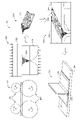
図2は、本明細書に記載の、チョップドファイバーを使用して作られた填隙材202を含む例示的ストリンガアセンブリ200を示す。例示的ストリンガ200は、構造体(例えば、胴体102、翼104)を支持するために外板208(例えば、航空機100の外板)に連結された2つの補強セグメント204、206を含む。いくつかの実施例では、ストリンガ200は、胴体102又は翼104を支持するために、航空機100で実施されうる。そのような例では、航空機100の例示的翼104及び/又は胴体102は、翼104及び/又は胴体102の長さに沿って、複数のストリンガ200を含むことができる。代替的には、ストリンガは、別の種類の航空機、船舶、陸上車両などの別の構造体を支持するために使用することができる。本明細書に記載の例示的ストリンガ200は、複合材料から作ることができる。代替的には、ストリンガ200は、任意の別の適切な材料とすることができる。
FIG. 2 shows an
例示的ストリンガ200は、補強セグメント204、206のそれぞれの第1の部分210、212が、ストリンガ200を連結させる外板208から垂直に延びるように、2つの補強セグメント204、206を連結することによって形成される。ストリンガ200が胴体102に連結される場合、ストリンガ200の例示的第1の部分210は、胴体102の長さに沿ったストリンガ200の任意の所与の断面において、外板208から実質的に垂直である。各補強セグメント204、206は、合わせ面218、220を有するそれぞれの第2の部分214、216を含む。補強セグメント204、206の第2の部分214、216の各々は、外板208に連結される。補強セグメント204、206の第2の部分214、216は、第1の部分210、212に実質的に垂直である。それぞれの補強セグメント204、206の第2の部分214、216は、ストリンガ200から反対方向に延びる。即ち、第1の部分210、212は、ストリンガ200のそれぞれの第2の部分214、216の間で共に連結されて配置される。
The
例示的な第2の部分214、216の各々は、ストリンガ200の剥離モーメント能力を低減することによってストリンガ200の引き抜き荷重を改善し、ひいては外板剥離応力を低減する面取り226、228を有するそれぞれの端部222、224を含む。図2に示す例示的ストリンガ200の面取り226、228は、15度±2度の面取り(例えば、面取り角度が13度から17度までの範囲を有する)である。およそ15度の面取り角度は、ストリンガの引き抜きに必要な最大の力を提供するように選択された。面取り角度を15度まで低減すると、90度、45度、及び30度に比べて必要な引き抜き強度が大幅に増加する。また、15度の面取り角度は、45度の面取り角度と比較して、ストリンガの外板への横引張強度を高める。
Each of the exemplary
面取り226、228は、ある点まで先細りしないが、その代わりに0.1±0.02インチの厚のエッジ230、232まで先細りし、早期故障を引き起こすことなくストリンガ200の剥離モーメント能力を低下させる。本明細書に記載の例示的填隙材202により、結合された複合部分(例えば、填隙材202、ストリンガ200)の剥離モーメントを低下させるために、より小さいストリンガフランジ面取り角度(例えば、15度)が使用可能になる。15度の例示的な面取り角度は、ストリンガ200の結合強度と剥離モーメントのバランスをとる。
The
図示された例では、各補強材セグメント204、206の第1及び第2の部分210、212、214、216は、それぞれのフィレット234、236によって接合される。フィレット234、236は、例示的ストリンガ200の強度を増加させるように作用することができ、かつ/又は補強セグメント204、206の2つの部分210、212、214、216の交差部分における例示的ストリンガ200の亀裂の可能性を低減しうる。フィレット234、236の反対側で、例示的な補強セグメント204、206のコーナー(例えば、アーチ形状)238、240はまた、それぞれの補強セグメント204、206の第1及び第2の部分210、212、214、216が交差する交差部分でアーチ状であるか、又は丸みを帯びている(radiused)。要するに、例示的補強材セグメント204、206は、第1及び第2の部分210、212、214、216と、第1及び第2の部分210、212、214、216が接するエッジとの両方を通って実質的に同じ幅である。それぞれの補強セグメント204、206の例示的アーチ形状238、240は、アーチ形状238、240及び外板208に隣接した、ストリンガ200の2つの補強セグメント204、206が接する間隙242(例えば、ストリンガ半径間隙)を形成する。図示された実施例の間隙242は、填隙材202(例えば、ヌードル、半径充填材、炭素繊維填隙材、複合填隙材、チョップドファイバー填隙材、又はそれらの組み合わせ)で充填される。
In the illustrated example, the first and
例示的填隙材202は、短炭素繊維材料244から作られる。填隙材202が、ストリンガ200(例えば、補強セグメント204、206)及び外板208の他の構成要素の膨張速度及び収縮速度と類似した速度で膨張し収縮するので、短炭素繊維材料244は、ストリンガ200の熱応力の緩和に役立つ。填隙材202、補強セグメント204、206、及び外板208の膨張速度が類似しているので、填隙材202及び/又は補強セグメント204、206は、亀裂に対して著しく強くより耐性がある。填隙材202及び補強セグメント204、206の膨張速度及び収縮速度が類似しているので、本明細書に記載の例示的填隙材202はまた、接合線246(例えば、補強セグメント204、206と外板208との間の平面)での分離を防止する。いくつかの実施例では、短炭素繊維244は、樹脂248と混合される。填隙材202に使用される材料(例えば、炭素繊維シート)は、ストリンガ200の補強セグメント204、206及び外板208に使用される材料に類似していてもよい。即ち、外板208及び補強セグメント204、206は、填隙材202の繊維フレークを作るためにも使用されうる炭素繊維シートを使用して作られてもよい。
The
填隙材202はまた、チョップドファイバー強化熱硬化性樹脂複合材又はチョップドファイバー強化熱可塑性樹脂複合材を含むことができる。いくつかの実施例では、Toray又はZoltekによって供給されるような、炭素繊維強化エポキシ樹脂熱硬化性シート材料は、填隙材202を作るために使用することができる。連続的プリプレグシートは、填隙材202の全体積にわたって比較的ランダムかつ均等な繊維分布を有するように、1インチ幅の細長片に切断し、次に1インチの正方形(例えば、フレーク)に切断することができる。代替的には、フレークは、任意の適切なサイズ(例えば、フレークの各エッジは、0.005インチから3インチまで、好ましくは0.125インチから1インチまでの範囲でありうる)とすることができる。繊維フレークの繊維は、繊維が填隙材202内で多方向になるように配向されうる(即ち、繊維は、填隙材202の任意の所与の平面において多方向に配向されうる)。
The
樹脂を強化するために、ナノ粒子などの粒子の追加的フレークをオプションで加えることができる。したがって、チョップドファイバー又はマイクロファイバを、最小化された熱膨張率、妥当な破壊靭性(例えば、少なくとも2in-lb/平方インチ)、及び補強セグメント材料と比べ、類似した又はより柔らかい弾性率(例えば、0.5msiから8msiの間)を有する、炭素繊維のミクロン粒子又はナノ粒子サイズの炭素繊維フレーク及び熱硬化性又は熱可塑性樹脂若しくは発泡複合材料と統合することによって、例示的填隙材202を形成することができる。
Additional flakes of particles, such as nanoparticles, can optionally be added to strengthen the resin. Therefore, chopped fibers or microfibers have a minimized coefficient of thermal expansion, reasonable fracture toughness (eg, at least 2 in-lb/in 2 ), and a similar or softer elastic modulus (eg, An
いくつかの実施例では、填隙材202は、填隙材202の靭性を高めるためにナノ粒子を含むことができる。填隙材202のチョップドファイバー244は、炭素繊維(例えば、華氏350度まで耐えることができる繊維)、繊維ガラス、アラミド、ケブラー、又はナイロンを含む。填隙材202は、少なくとも2in-lb/平方インチの破壊靭性及び15ksiの最小引張強度を有する。填隙材202は、0.5msiから8msiの間の弾性率を有する。填隙材202の繊維体積分率は、45%から65%の間、好ましくは50%の分率である。例示的チョップドファイバー長は、0.005インチから3インチの間、好ましくは0.125インチから1インチまでの範囲である。エポキシ又はPEEK樹脂などの高分子量樹脂は、華氏250度以上の最終硬化温度(Tg)を供給するために使用される。填隙材202の密度は、0.04ポンド/立方インチから0.06ポンド/立方インチの間である。温度変化による填隙材202の収縮は、0.001インチから0.008インチの間である。線熱膨張率は、すべての方向において、0.1×10-6インチ/インチ華氏度から10.0×10-6インチ/インチ華氏度の間である。
In some examples, the
本明細書に記載の例示的填隙材202及びストリンガ200の製造方法は、多くの利点を有する。多方向の繊維配向及び実質的に均一の繊維分布は、半径界面形状を維持する(即ち、填隙材202の形状を維持する)。填隙材202の炭素繊維材料は、熱応力を最小化して、亀裂発生の可能性を最小化し、硬化中のストリンガの熱歪みを最小化し、運航中に填隙材202におけるクリープ緩和又はクリープ歪みを低減するために、ストリンガ200及び外板208に適合可能な特性を有する。例示的填隙材202は、高い生産速度のための成形又は押出プロセスを使用して形成することができる。面取り部226、228の小さなテーパ角は、ストリンガアセンブリ200の剥離モーメント/負荷を低減する。
The
加えて、例示的な填隙材202は、処理及び運航中の温度変化に起因して発生する熱歪みを低減するために、厚さ方向を含むあらゆる方向の熱膨張のより小さい係数(即ち、ラミネート填隙材と比較して)を有する。例示的填隙材202はまた、処理及び運航中の冷却及び/又は加熱における充填材の圧縮及び/又は膨張を低減し、亀裂発生を防止する。例示的な填隙材202は、填隙材202内で、並びに填隙材202と補強材セグメント204、206及び/又は外板208との間の界面で亀裂を引き起こす熱応力を低減し、界面の静的及び疲労性能を改善するために、中程度の熱膨張率を有する。例示的填隙材202内の3D繊維分布の微細構造により、応力緩和は、亀裂発達を防止することができる。例示的填隙材202はまた、硬化中にそれらの充填された間隙位置での半径寸法制御のサポート及び部品品質サービスを提供することによって、フィレット(例えば、補強半径)234、236又はその下の外板208におけるプライのシワを防止する。例示的填隙材202は、間隙242における応力集中を最小化して、使用中の補強材界面の強度を改善する。例示的な填隙材202はまた、構造的信頼性を増大させる引き抜き荷重を改善し、翼、尾部、胴体、及び/又はフロアビームの構造に適した補強複合パネルを作製する。
Additionally, the
図3は、本明細書に記載の填隙材202の例示的製造プロセス300を示す。図3の例示的製造プロセス300は、例示的填隙材202を形成するために成形プロセスを使用する。繊維フレーク304が空洞305の体積全体に分散する(例えば、繊維フレーク304、更には、繊維フレーク304を構成する個々の繊維が多方向に配向されるように、ランダムかつ均等に分散する)ように、第1段階302の間、チョップドファイバーフレーク304は、型306の空洞305に挿入される。繊維フレーク304は、空洞305内に配置される前に、樹脂308と混合されてもよく、及び/又は繊維フレーク304が型306の空洞305に挿入された後に、樹脂308を型306内に注ぐこともできる。チョップドファイバー混合物(例えば、繊維フレーク304と樹脂308との混合物)は、いくらかの過剰充填(例えば、15%以下の過剰充填)で型306に挿入することができる。例示的填隙材202は、第1段階の硬化プロセスを用いて型306に形成することができる。第1段階の硬化プロセスは、プレート310及び熱源を使用して、チョップドファイバー混合物に熱及び圧力を加えることを含むことができる。いくつかの実施例では、熱源は、プレート310と統合されうる。熱及び圧力は、チョップドファイバー混合物が硬化して例示的填隙材202を形成するのに十分な時間にわたって加えることができる。例示的填隙材202は、型306内で冷却することができる。
FIG. 3 illustrates an
いくつかの例では、第1段階302の間に、填隙材202を圧縮し、填隙材202内部の空気空隙を抽出するために、真空バッグが約5~10分間適用される。圧縮後、填隙材202及び型306をオーブンに入れ、これを250℃で約10~15分間加熱して第1段階の硬化を完了する。この例の第1段階の硬化は、ストリンガ200の間隙242への最終的な適合のための初期形状を形成するために、約85%までの架橋を硬化させることができる。第1段階の硬化後、オーブンは室温まで冷却される。
In some examples, during the
第2段階312の間、例示的填隙材202は、次いで、填隙材202が形成され硬化された後に、型306から除去されうる。例示的填隙材202は、充填材202の体積全体にわたって、実質的に均一な繊維の分布を有する(例えば、繊維フレークの分布は、繊維の分布が実質的に均一であり、個々の繊維が配向される方向がランダムであるような分布である)。次いで、填隙材202を第3段階314でストリンガ200の間隙242に挿入することができる。
During the
填隙材202がストリンガ200の間隙に挿入された後に、補強セグメント204、206は、ストリンガアセンブリ200を形成するための最終段階316(例えば、第4段階)中に外板208に連結される。いくつかの例では、ストリンガアセンブリ200は、最終的な硬化プロセスを用いて硬化される。最終的な硬化プロセスは、例示的ストリンガアセンブリ200に圧力及び/又は熱を加えることを含みうる。いくつかの例では、真空バッグは、最終的な硬化プロセスの間、例示的ストリンガアセンブリ200の周りに配置される。いくつかの例では、ストリンガ200及び外板208との最終的な共硬化は、高圧及び華氏350度までの温度でオートクレーブ中で実行される。最終的な硬化プロセスの後、ストリンガアセンブリ200は、例えば、例示的航空機100に設置することができる。
After the
図4は、本明細書に記載の填隙材202のもう1つの例示的製造プロセス400を示す。図4の例示的製造プロセス400は、例示的填隙材202を形成するために押出プロセスを使用する。第1段階402の間、例示的チョップドファイバーフレーク404は、押出機408のホッパー406に挿入される。例示的チョップドファイバーフレーク404及び樹脂410は、切断されたダイ412を通って押し出されて、ストリンガ200の間隙242内に一致する填隙材202を形成する。押出プロセスの間に、熱を押出機408に加え、樹脂410及びチョップドファイバー404の混合物を押し出してもよい。混合物がダイ412を通って押し出されて填隙材202を形成した後、填隙材202は、第2段階414中に冷却することができる。次いで、填隙材202を第3段階416でストリンガ200の間隙242に挿入することができる。
FIG. 4 shows another
填隙材202がストリンガ200の間隙242に挿入された後に、補強セグメント204、206は、ストリンガアセンブリ200を形成するための最終段階418(例えば、第4段階)中に外板208に連結される。いくつかの例では、ストリンガアセンブリ200は、最終的な硬化プロセスを用いて硬化される。最終的な硬化プロセスは、例示的ストリンガアセンブリ200に圧力及び/又は熱を加えることを含みうる。いくつかの例では、真空バッグは、最終的な硬化プロセスの間、例示的ストリンガアセンブリ200の周りに配置される。いくつかの例では、ストリンガ200及び外板208との最終的な共硬化は、高圧及び華氏350度までの温度でオートクレーブ中で実行される。最終的な硬化プロセスの後、ストリンガアセンブリ200は、例えば、例示的航空機100に設置されうる。
After the
図5は、本明細書に記載の填隙材202のもう1つの例示的製造プロセス500を示す。図5の例示的製造プロセス500は、自動ローラダイプロセスである。第1段階502において、例示的プロセス500は、所望の形状の填隙材202を形成するために、一連のローラ503、504を使用する。ローラ503、504が間隙充填材202を形成する際に、熱が加えられてもよい。図示の例では、第1段階502の点線は、填隙材202がローラによって形成される際の填隙材202の反対側を示す。ローラ503、504の断面図505は、ストリンガ200内の間隙242の形状に対応する填隙材202の断面形状を示す。図示された例では、間隙242に対応する形状の填隙材202を形成するために、1組の上部ローラ503と2つの下部ローラ504が、各ローラセットで使用されうる。填隙材202が形成された後に、填隙材202は、第2段階506中に冷却することができる。次いで、填隙材202を第3段階508でストリンガ200の間隙242に挿入することができる。
FIG. 5 illustrates another
填隙材202がストリンガ200の間隙242に挿入された後に、補強セグメント204、206は、ストリンガアセンブリ200を形成するための最終段階510(例えば、第4段階)中に外板208に連結される。いくつかの例では、ストリンガアセンブリ200は、最終的な硬化プロセスを用いて硬化される。最終的な硬化プロセスは、例示的ストリンガアセンブリ200に圧力及び/又は熱を加えることを含むことができる。いくつかの例では、真空バッグは、最終的な硬化プロセスの間、例示的ストリンガアセンブリ200の周りに配置される。いくつかの例では、ストリンガ200及び外板208との最終的な共硬化は、高圧及び華氏350度までの温度でオートクレーブ中で実行される。最終的な硬化プロセスの後、ストリンガアセンブリ200は、例えば、例示的航空機100に設置することができる。
After the
図6は、図1から図4の例示的填隙材202を製造する例示的方法600を表す例示的フローチャートを示す。いくつかの実施例では、ブロックを再配置若しくは除去することができ、又は追加のブロックが追加されてもよい。例示的な方法600は、炭素繊維シート(例えば、プリプレグシート)を得ることによって開始することができる(ブロック602)。チョップドファイバーフレーク304は、シートを細長片及び/又は正方形に切断することによって炭素繊維シートから作成することができる(ブロック604)。いくつかの例では、細長片は1インチ幅であり、正方形は1インチの正方形である。例示的細長片又は四角形は、次いで、成形装置(例えば、型306、押出機408のホッパー406、又はローラ504など)に挿入することができる(ブロック606)。フレーク304を型306に挿入することができる実施例では、フレーク304は、填隙材202の体積全体にわたって繊維フレーク304のランダムな分布を生成するように配置することができる。繊維フレーク304は、樹脂308(例えば、エポキシ)と混合することができる(ブロック608)。いくつかの例では、繊維フレーク304は、成形装置に挿入される前に、樹脂308と混合される(例えば、ブロック608がブロック606の前に生じる)。図示された例示的な方法600では、ブロックの実行順序が変更されてもよく、及び/又は記載されたブロックのうちのいくつかが、特にブロック602~608が、変更、削除、又は結合されてもよい。
FIG. 6 shows an exemplary flowchart representing an
繊維フレーク304及び樹脂308が成形装置に挿入された後に、成形装置は、熱及び圧力の組み合わせを使用して、例示的フレーク及び樹脂混合物を填隙材202に形成する(ブロック610)。例示的な填隙材202は、次いで、第1段階の硬化プロセスを使用して(例えば、熱と圧力の組み合わせを使用して)、硬化させることができる(ブロック612)。填隙材202は、硬化後に冷却させる(ブロック614)。いくつかの実施例では、填隙材202は、冷却中に成形装置内に留まることができる。このような例では、填隙材202は次に、冷却後に成形装置から除去される(ブロック616)。ブロック614での冷却中に、填隙材202が成形装置内に残らない場合、填隙材202は、冷却前に除去されうる。
After the
填隙材202が硬化され冷却された後に、例示的填隙材202がストリンガ200の間隙242に挿入される(ブロック618)。填隙材202及びストリンガ200は、外板208(例えば、胴体の外板、翼の外板)によって覆われ、ストリンガアセンブリ200が形成される(ブロック620)。例示的外板208は、例示的間隙充填材202と類似の材料を含む炭素繊維複合材外板でありうる。例示的ストリンガアセンブリ200は、真空バッグ及び/又はオートクレーブ内に配置することができ(ブロック622)、熱及び圧力を含む最終段階のプロセスを用いて硬化させることができる(ブロック624)。ブロック622は、例示的方法600から削除することができる。例示的ストリンガアセンブリ200は、その後、航空機100に設置することができる(ブロック626)。代替的には、例示的な方法600は、ブロック624で終了する。
After the
本明細書に記載の例示的填隙材202は、ストリンガ200との容易な組み立てのために、構築時間を短縮し、填隙材202を適切な形状に予め成形することができる迅速成形又は押出プロセスを用いて製造することができる。したがって、補強セグメント204、206の填隙材202及び外板208との共硬化がより効率的である。例示的填隙材及び例示的填隙材の製造プロセスは、必要な最終硬化が1つだけであり、例示的填隙材がより大きな耐熱性を有するので、(典型的な共硬化サイクル時間(typical co-bon curing cycle time)と比較して)サイクル時間を短縮することができる。加えて、例示的填隙材は、補強セグメントと外板208との間の界面品質を改善し、追加の処理及び設置コストを削減する。填隙材の材料が補強セグメントの材料と類似しており、したがって、填隙材及び補強セグメントが加熱及び冷却と同じように反応するので、界面品質を改善することができる。複合ストリンガに関連するメンテナンスのための工場内修理関連のダウンタイムは、ストリンガの強固な耐熱性、品質、及び信頼性のために削減される。
The
例示的な填隙材202は、ミクロン粒子又はナノ粒子又はフレークを有するチョップドファイバー又はマイクロファイバを使用して作成される。繊維は、最小限の熱膨張率、妥当な靱性、及び類似の又はより柔らかい弾性率(補強セグメント204、206と比較して)を有する熱硬化性樹脂、熱可塑性樹脂、又は発泡複合材を補強する。填隙材202は、半径又は曲率変化交点で補強セグメント204、206と外板208との間の間隙を充填するために使用される。
An
填隙材は、迅速な組み立てのために填隙材202を指定された形状に迅速に事前成形するために、自動プロセスを用いて形成することができるので、本明細書に記載の例示的填隙材202により、ツーリング及び処理の開発コストが削減される。最終的な硬化は、アセンブリを硬化させるために既存のオートクレーブプロセスを使用するため、追加の及び/又は高価なツーリング及び複雑なプロセス開発が不要になる。更に、填隙材の設計された熱機械的特性による改良された耐熱性は、界面の破壊によって生じる熱歪み及び/又は応力を最小限に抑え、熱的亀裂の影響を受けやすく、より大きな拘束ファスナを必要とする様々なラミネート又は単一ニードルの開発に関連する広範な工学コストを削減する。複合補強セグメント及び外板のための本明細書に記載された填隙材202は、界面の完全性を高め、必要とする界面構造からの統合支持が少なくなる。例示的填隙材はまた、軽量化及び燃料性能向上のために、シヤタイのような効率的な界面構造の開発を可能にする。
The exemplary filler described herein can be formed using an automated process to quickly preform the
更に、本開示は、以下の条項による実施例を含む。
条項1. 航空機の複合構造体と;航空機の複合構造体に連結されたストリンガあって、ストリンガ及び複合構造体がストリンガ半径間隙を形成する、ストリンガと;
ストリンガ半径間隙内に配置された填隙材であって、填隙材の実質的に全体積にわたってランダムに分散したチョップドファイバーを含む填隙材とを含む装置。
条項2. 填隙材は、チョップドファイバーが配置される熱硬化性樹脂を更に含む、条項1に記載の装置。
条項3. 填隙材が、45%から65%の間のチョップドファイバーの体積分率を有する、条項1又は2に記載の装置。
条項4. 填隙材が、填隙材の靭性を高めるために、ミクロン粒子又はナノ粒子を更に含む、条項1から3の何れか一項に記載の装置。
条項5. ストリンガが、およそ15度のエッジ面取りを含む、条項1から4の何れか一項に記載の装置。
条項6. チョップドファイバーが、炭素繊維、繊維ガラス、アラミド、ケブラー、又はナイロンを含む、条項1から5の何れか一項に記載の装置。
条項7. 填隙材が、少なくとも2in-lb/平方インチの破壊靭性を有する、条項1から6の何れか一項に記載の装置。
条項8. 填隙材が、15ksiの最小引張強度を有する、条項1から7の何れか一項に記載の装置。
条項9. 填隙材が、0.5msiから8msiの間の弾性率を有する、条項1から8の何れか一項に記載の装置。
条項10. チョップドファイバーフレーク及び樹脂を填隙材内に形成することと、チョップドファイバーフレークによって形成された填隙材を硬化させることと、填隙材をストリンガの間隙内に挿入することとを含む方法。
条項11. 填隙材を硬化させることが、填隙材に熱及び圧力を加えることを含む、条項10に記載の方法。
条項12. チョップドファイバーフレーク及び樹脂を填隙材内に形成することが、チョップドファイバーフレークをダイを通して押し出すことを含む、条項10又は11に記載の方法。
条項13. チョップドファイバーフレーク及び樹脂を填隙材内に形成することが、複数の可変直径ローラダイ形成プロセスを使用することを含む、条項10から12の何れか一項に記載の方法。
条項14. チョップドファイバーフレーク及び樹脂を填隙材内に形成することが、填隙材に熱及び圧力を加えることを含み、填隙材が型の中に配置される、条項10から12の何れか一項に記載の方法。
条項15. 型内の填隙材を冷却することと、填隙材が冷却された後に、填隙材を型から取り外すことを更に含む、条項14に記載の方法。
条項16. 繊維フレークが、填隙材の実質的に全体積にわたってランダムに分散される、条項10から15の何れか一項に記載の方法。
条項17. 硬化した填隙材をストリンガの間隙に挿入することと、ストリンガアセンブリを形成するために、填隙材を外板で覆うことと、ストリンガアセンブリを硬化させることとを含む方法。
条項18. ストリンガアセンブリを硬化させることが、ストリンガアセンブリに圧力及び熱を加えることを含む、条項17に記載の方法。
条項19. ストリンガアセンブリを真空バッグ内に置くことを更に含む、条項17又は18に記載の方法。
条項20. 硬化したストリンガアセンブリを航空機の中に設置することを更に含む、条項17から19の何れか一項に記載の方法。
Further, the present disclosure includes examples according to the following clauses.
and a gap filler disposed within the stringer radial gap, the gap filler comprising chopped fibers randomly distributed throughout substantially the entire volume of the gap filler.
Clause 2. 2. The apparatus of
Article 3. 3. Apparatus according to
Article 4. 4. The device of any one of clauses 1-3, wherein the gap filler further comprises micron particles or nanoparticles to increase the toughness of the gap filler.
Article 5. 5. The apparatus of any one of clauses 1-4, wherein the stringer includes an edge chamfer of approximately 15 degrees.
Clause 6. 6. Apparatus according to any one of clauses 1-5, wherein the chopped fibers comprise carbon fibres, fiberglass, aramid, Kevlar or nylon.
Article 7. 7. The device of any one of clauses 1-6, wherein the gap filler has a fracture toughness of at least 2 in-lb/in 2 .
Article 8. 8. The device of any one of clauses 1-7, wherein the gap filler has a minimum tensile strength of 15 ksi.
Article 9. 9. The device of any one of clauses 1-8, wherein the gap filler has a modulus of elasticity between 0.5 msi and 8 msi.
Clause 10. A method comprising forming chopped fiber flakes and a resin in a gap filler, curing the gap filler formed by the chopped fiber flakes, and inserting the gap filler into the gaps of the stringers.
Clause 11. 11. The method of clause 10, wherein curing the gap filler comprises applying heat and pressure to the gap filler.
Clause 12. 12. The method of clause 10 or 11, wherein forming the chopped fiber flakes and resin into the gap filler comprises extruding the chopped fiber flakes through a die.
Article 13. 13. The method of any one of clauses 10-12, wherein forming the chopped fiber flakes and resin into the gap filler comprises using a multiple variable diameter roller die forming process.
Article 14. 13. Any one of clauses 10-12, wherein forming the chopped fiber flakes and resin into the gap filler comprises applying heat and pressure to the gap filler, wherein the gap filler is placed in the mold. The method described in .
Article 15. 15. The method of clause 14, further comprising cooling the gap filler within the mold and removing the gap filler from the mold after the gap filler has cooled.
Article 16. 16. The method of any one of clauses 10-15, wherein the fiber flakes are randomly distributed over substantially the entire volume of the gap filler.
Article 17. A method comprising: inserting a cured gap filler into a stringer gap; covering the gap filler with a skin to form a stringer assembly; and curing the stringer assembly.
Article 18. 18. The method of clause 17, wherein curing the stringer assembly comprises applying pressure and heat to the stringer assembly.
Article 19. 19. The method of Clause 17 or 18, further comprising placing the stringer assembly in a vacuum bag.
Clause 20. 20. The method of any one of Clauses 17-19, further comprising installing the cured stringer assembly in the aircraft.
また、例示的填隙材により、填隙材を形成するために使用されうる自動プロセスのために製造及び労働時間が低減される。耐熱性が高い部品は、填隙材の製造時間を短縮するために使用されうる。耐熱性及び填隙材の界面品質が高まるので、表面処理もまた減らすことができる。ラミネート填隙材のトリミング、軟化、又は追加的損傷阻止ファスナ及び半径補強の必要がなくなり、更に製造時間及びコストが削減される。 The exemplary gap filler also reduces manufacturing and labor time due to the automated processes that may be used to form the gap filler. Parts with high heat resistance can be used to reduce the manufacturing time of the gap filler. Surface treatments can also be reduced because of the increased heat resistance and interfacial quality of the gap filler. Trimming, softening of laminate gap fillers, or the need for additional damage arresting fasteners and radius reinforcements are eliminated, further reducing manufacturing time and costs.
上記より、例えば、航空機内のストリンガの強度を高め、その一方で製造時間及びコストを削減する例示的方法、装置及び製品が開示されたことが理解されるだろう。本明細書に記載の例示的装置は、熱膨張及び収縮に起因したストリンガ及び/又は外板の亀裂を防止するために、複合ストリンガ及び外板と共に使用されてもよい。 From the above, it will be appreciated that exemplary methods, apparatus and articles of manufacture have been disclosed for increasing the strength of stringers in, for example, an aircraft while reducing manufacturing time and costs. The exemplary devices described herein may be used with composite stringers and skins to prevent stringer and/or skin cracking due to thermal expansion and contraction.
本明細書では特定の例示的な方法、装置、及び製品が開示されるが、本特許出願の範囲はこれらに限定されるものではない。反対に、本特許出願は、本特許出願の特許請求の範囲内に公正に当てはまるすべての方法、装置、及び製品を包含する。
Although certain example methods, apparatus, and articles of manufacture are disclosed herein, the scope of this patent application is not limited thereto. On the contrary, this patent application covers all methods, apparatus and articles of manufacture fairly falling within the scope of the claims of this patent application.
Claims (20)
前記ストリンガ半径間隙内に配置された填隙材(202)であって、前記填隙材の実質的に全体積にわたってランダムに分散したチョップドファイバー(244)を含む填隙材(202)と
を含み、
前記ストリンガ(200)は、13度から17度の角度のエッジ面取り(226)、(228)を含み、前記エッジ面取りは、0.20cmから0.30cmの厚さを有する前記ストリンガのエッジまで先細りしている、装置。 a stringer (200) coupled to a composite structure of an aircraft, wherein said stringer and said composite structure form a stringer radius gap (242);
a gap filler (202) disposed within the stringer radial gap, the gap filler (202) comprising chopped fibers (244) randomly distributed throughout substantially the entire volume of the gap filler. fruit,
The stringer (200) includes edge chamfers (226), (228) at an angle of 13 to 17 degrees, the edge chamfers tapering to the edge of the stringer having a thickness of 0.20 cm to 0.30 cm. Doing, device.
チョップドファイバーフレーク(304)及び樹脂を填隙材(202)内に形成することと、
前記チョップドファイバーフレークによって形成された前記填隙材を硬化させることと、
前記填隙材をストリンガ(200)の間隙内に挿入することと
を含み、
前記ストリンガ(200)は、13度から17度の角度のエッジ面取り(226)、(228)を含み、前記エッジ面取りは、0.20cmから0.30cmの厚さを有する前記ストリンガのエッジまで先細りしている、方法。 A method of making a stringer comprising:
forming chopped fiber flakes (304) and resin into a gap filler (202);
curing the gap filler formed by the chopped fiber flakes;
inserting the gap filler into the gap of the stringer (200) ;
The stringer (200) includes edge chamfers (226), (228) at an angle of 13 to 17 degrees, the edge chamfers tapering to the edge of the stringer having a thickness of 0.20 cm to 0.30 cm. doing, how.
硬化した填隙材(202)をストリンガ(200)の間隙内に挿入することと、
ストリンガアセンブリを形成するために、前記填隙材を外板で覆うことと、
前記ストリンガアセンブリを硬化させることと
を含み、
前記ストリンガ(200)は、13度から17度の角度のエッジ面取り(226)、(228)を含み、前記エッジ面取りは、0.20cmから0.30cmの厚さを有する前記ストリンガのエッジまで先細りしている、方法。 A method of forming a stringer assembly, comprising:
inserting a cured gap filler (202) into the gaps of the stringers (200);
covering the gap filler with a skin to form a stringer assembly;
curing the stringer assembly ;
The stringer (200) includes edge chamfers (226), (228) at an angle of 13 to 17 degrees, the edge chamfers tapering to the edge of the stringer having a thickness of 0.20 cm to 0.30 cm. doing, how.
Applications Claiming Priority (2)
| Application Number | Priority Date | Filing Date | Title |
|---|---|---|---|
| US15/676,047 US10723436B2 (en) | 2017-08-14 | 2017-08-14 | Methods and apparatus to increase strength and toughness of aircraft structural components |
| US15/676,047 | 2017-08-14 |
Publications (2)
| Publication Number | Publication Date |
|---|---|
| JP2019073263A JP2019073263A (en) | 2019-05-16 |
| JP7148305B2 true JP7148305B2 (en) | 2022-10-05 |
Family
ID=63108466
Family Applications (1)
| Application Number | Title | Priority Date | Filing Date |
|---|---|---|---|
| JP2018140001A Active JP7148305B2 (en) | 2017-08-14 | 2018-07-26 | Method and apparatus for increasing the strength and toughness of aircraft structural components |
Country Status (5)
| Country | Link |
|---|---|
| US (1) | US10723436B2 (en) |
| EP (1) | EP3446864B1 (en) |
| JP (1) | JP7148305B2 (en) |
| CN (1) | CN109383048B (en) |
| CA (1) | CA3008090C (en) |
Families Citing this family (15)
| Publication number | Priority date | Publication date | Assignee | Title |
|---|---|---|---|---|
| US10689085B2 (en) | 2017-08-14 | 2020-06-23 | The Boeing Company | Stringer stiffened composite panels having improved pull-off strength |
| EP3698955B1 (en) * | 2019-02-19 | 2021-10-27 | Muelles Y Ballestas Hispano-Alemanas Projects, S.L. | Stiffened panel made of composite material and method for manufacturing the said panel |
| ES2952485T3 (en) * | 2019-04-18 | 2023-10-31 | Teijin Carbon Europe Gmbh | Wedge filling preform |
| US11254074B2 (en) * | 2019-06-19 | 2022-02-22 | The Boeing Company | Apparatus and method for making radius composite gap filler |
| US11446883B2 (en) | 2019-07-24 | 2022-09-20 | The Boeing Company | Radius filler for wet composite layup |
| US11298897B2 (en) | 2019-07-24 | 2022-04-12 | The Boeing Company | Composite structure having thermoplastic radius filler |
| US11529776B2 (en) | 2019-08-01 | 2022-12-20 | The Boeing Company | Aircraft comprising composite structural component, and method for forming composite structural component |
| JP7321030B2 (en) * | 2019-08-08 | 2023-08-04 | 三菱重工業株式会社 | Reinforcing member, assembly, and method for manufacturing reinforcing member |
| CN110525631B (en) * | 2019-08-22 | 2021-06-01 | 中国商用飞机有限责任公司北京民用飞机技术研究中心 | A kind of sealing structure and fastening method with preset gap |
| US11318705B2 (en) | 2019-08-26 | 2022-05-03 | The Boeing Company | Ply stackings for solid laminate stiffened panel |
| US11214349B2 (en) | 2019-09-24 | 2022-01-04 | The Boeing Company | Stringers for aircraft skin structures and related methods |
| US11377851B2 (en) | 2020-02-05 | 2022-07-05 | The Boeing Company | Stringer and associated composite structure and method for reinforcing a base structure |
| US12220890B2 (en) | 2020-02-18 | 2025-02-11 | The Boeing Company | Methods for fabricating solid laminate stringers on a composite panel |
| US11214021B2 (en) * | 2020-03-06 | 2022-01-04 | The Boeing Company | Method and system for manufacturing a cured composite structure |
| DE102024115900A1 (en) * | 2024-06-07 | 2025-12-11 | Dr. Ing. H.C. F. Porsche Aktiengesellschaft | Carbon trim |
Citations (11)
| Publication number | Priority date | Publication date | Assignee | Title |
|---|---|---|---|---|
| US4113910A (en) | 1977-04-27 | 1978-09-12 | Rockwell International Corporation | Composite load coupler for reinforcing composite structural joints |
| JP2009062648A (en) | 2007-09-07 | 2009-03-26 | Toray Ind Inc | Chopped fiber bundle, molding material, and method for producing fiber-reinforced plastic |
| JP2013529562A (en) | 2010-06-23 | 2013-07-22 | ザ プロクター アンド ギャンブル カンパニー | High speed injection molding products |
| JP2014151648A (en) | 2013-02-07 | 2014-08-25 | Boeing Co | Method and system of making composite structures having gap fillers with chopped fiber material |
| US20140374013A1 (en) | 2013-02-04 | 2014-12-25 | The Boeing Company | Fabrication of Stiffened Composite Panels |
| JP2015072041A (en) | 2013-10-02 | 2015-04-16 | 三菱重工業株式会社 | Joint and aircraft structure |
| JP2015147411A (en) | 2014-02-04 | 2015-08-20 | ザ・ボーイング・カンパニーTheBoeing Company | Radius filler and method of manufacturing radius filler |
| JP2016135669A (en) | 2015-01-02 | 2016-07-28 | ザ・ボーイング・カンパニーThe Boeing Company | Outer plate / stringer design for composite wings |
| JP2016182924A (en) | 2015-03-26 | 2016-10-20 | 富士重工業株式会社 | Aircraft structure, aircraft structure manufacturing method, and aircraft structure design information creation method |
| JP2016534295A (en) | 2013-08-09 | 2016-11-04 | ザ・ボーイング・カンパニーThe Boeing Company | Reinforced composite panel |
| US20170197350A1 (en) | 2015-07-29 | 2017-07-13 | The Boeing Company | 2-Stage Extrusion Apparatus and Method of Extrusion |
Family Cites Families (10)
| Publication number | Priority date | Publication date | Assignee | Title |
|---|---|---|---|---|
| US5248711A (en) * | 1989-02-16 | 1993-09-28 | Hexcel Corporation | Toughened resin systems for composite applications |
| JP3021077B2 (en) | 1991-03-28 | 2000-03-15 | 富士重工業株式会社 | Composite filler molding equipment |
| CN101711230B (en) * | 2007-06-04 | 2012-10-17 | 东丽株式会社 | Chopped fiber bundle, molding material, and fiber reinforced plastic, and process for producing them |
| CN101445663B (en) * | 2008-11-12 | 2012-01-04 | 中国航空工业第一集团公司北京航空制造工程研究所 | Filler of composite material structure interstice area and filling method thereof |
| US9492975B2 (en) * | 2009-03-09 | 2016-11-15 | The Boeing Company | Structural bonded patch with tapered adhesive design |
| US9359060B2 (en) * | 2013-11-07 | 2016-06-07 | The Boeing Company | Laminated composite radius filler with geometric shaped filler element and method of forming the same |
| US20150217850A1 (en) | 2014-02-06 | 2015-08-06 | The Boeing Company | Laminated i-blade stringer |
| US9517606B2 (en) | 2014-08-06 | 2016-12-13 | The Boeing Company | Composite structure and method of forming thereof |
| US10472472B2 (en) | 2014-09-23 | 2019-11-12 | The Boeing Company | Placement of modifier material in resin-rich pockets to mitigate microcracking in a composite structure |
| KR101722323B1 (en) | 2015-07-29 | 2017-03-31 | 경상대학교산학협력단 | Filler For Composites Molding and Composite Materials Using The Same |
-
2017
- 2017-08-14 US US15/676,047 patent/US10723436B2/en active Active
-
2018
- 2018-06-12 CA CA3008090A patent/CA3008090C/en active Active
- 2018-07-19 CN CN201810795639.1A patent/CN109383048B/en active Active
- 2018-07-26 JP JP2018140001A patent/JP7148305B2/en active Active
- 2018-07-31 EP EP18186499.2A patent/EP3446864B1/en active Active
Patent Citations (11)
| Publication number | Priority date | Publication date | Assignee | Title |
|---|---|---|---|---|
| US4113910A (en) | 1977-04-27 | 1978-09-12 | Rockwell International Corporation | Composite load coupler for reinforcing composite structural joints |
| JP2009062648A (en) | 2007-09-07 | 2009-03-26 | Toray Ind Inc | Chopped fiber bundle, molding material, and method for producing fiber-reinforced plastic |
| JP2013529562A (en) | 2010-06-23 | 2013-07-22 | ザ プロクター アンド ギャンブル カンパニー | High speed injection molding products |
| US20140374013A1 (en) | 2013-02-04 | 2014-12-25 | The Boeing Company | Fabrication of Stiffened Composite Panels |
| JP2014151648A (en) | 2013-02-07 | 2014-08-25 | Boeing Co | Method and system of making composite structures having gap fillers with chopped fiber material |
| JP2016534295A (en) | 2013-08-09 | 2016-11-04 | ザ・ボーイング・カンパニーThe Boeing Company | Reinforced composite panel |
| JP2015072041A (en) | 2013-10-02 | 2015-04-16 | 三菱重工業株式会社 | Joint and aircraft structure |
| JP2015147411A (en) | 2014-02-04 | 2015-08-20 | ザ・ボーイング・カンパニーTheBoeing Company | Radius filler and method of manufacturing radius filler |
| JP2016135669A (en) | 2015-01-02 | 2016-07-28 | ザ・ボーイング・カンパニーThe Boeing Company | Outer plate / stringer design for composite wings |
| JP2016182924A (en) | 2015-03-26 | 2016-10-20 | 富士重工業株式会社 | Aircraft structure, aircraft structure manufacturing method, and aircraft structure design information creation method |
| US20170197350A1 (en) | 2015-07-29 | 2017-07-13 | The Boeing Company | 2-Stage Extrusion Apparatus and Method of Extrusion |
Also Published As
| Publication number | Publication date |
|---|---|
| EP3446864A1 (en) | 2019-02-27 |
| EP3446864B1 (en) | 2023-05-03 |
| CN109383048A (en) | 2019-02-26 |
| JP2019073263A (en) | 2019-05-16 |
| US10723436B2 (en) | 2020-07-28 |
| CA3008090C (en) | 2022-11-08 |
| US20190047677A1 (en) | 2019-02-14 |
| CN109383048B (en) | 2023-06-23 |
| CA3008090A1 (en) | 2019-02-14 |
Similar Documents
| Publication | Publication Date | Title |
|---|---|---|
| JP7148305B2 (en) | Method and apparatus for increasing the strength and toughness of aircraft structural components | |
| US10689085B2 (en) | Stringer stiffened composite panels having improved pull-off strength | |
| KR101999577B1 (en) | Laminated composite radius filler with geometric shaped filler element and method of forming the same | |
| KR102197337B1 (en) | Composite structure having a stabilizing element | |
| US20160101543A1 (en) | Hybrid Laminate and Molded Composite Structures | |
| US20130171895A1 (en) | Composite gusset filler and method of manufacture of said composite gusset filler | |
| CA2829519A1 (en) | Composite radius fillers and methods of forming the same | |
| EP1261787A2 (en) | Laminated composite radius filler | |
| WO2010045572A1 (en) | Lightweight unit load device | |
| AU2015200414A1 (en) | Fabrication of composite laminates using temporarily stitched preforms | |
| CN110104202B (en) | Composite aircraft manufacturing tool using articulated mandrels | |
| Wang et al. | Improved structural efficiency in composite manufacturing via hammered printing for large-curvature fiber paths | |
| JP7455512B2 (en) | Stringer reinforced composite panel with improved pullout strength | |
| US20090126860A1 (en) | Prepeg pultrusion |
Legal Events
| Date | Code | Title | Description |
|---|---|---|---|
| A621 | Written request for application examination |
Free format text: JAPANESE INTERMEDIATE CODE: A621 Effective date: 20210716 |
|
| A977 | Report on retrieval |
Free format text: JAPANESE INTERMEDIATE CODE: A971007 Effective date: 20220421 |
|
| A131 | Notification of reasons for refusal |
Free format text: JAPANESE INTERMEDIATE CODE: A131 Effective date: 20220510 |
|
| A521 | Request for written amendment filed |
Free format text: JAPANESE INTERMEDIATE CODE: A523 Effective date: 20220810 |
|
| TRDD | Decision of grant or rejection written | ||
| A01 | Written decision to grant a patent or to grant a registration (utility model) |
Free format text: JAPANESE INTERMEDIATE CODE: A01 Effective date: 20220906 |
|
| A61 | First payment of annual fees (during grant procedure) |
Free format text: JAPANESE INTERMEDIATE CODE: A61 Effective date: 20220922 |
|
| R150 | Certificate of patent or registration of utility model |
Ref document number: 7148305 Country of ref document: JP Free format text: JAPANESE INTERMEDIATE CODE: R150 |
|
| R250 | Receipt of annual fees |
Free format text: JAPANESE INTERMEDIATE CODE: R250 |