JP7148054B2 - throttle grip device - Google Patents

throttle grip device Download PDF

Info

Publication number
JP7148054B2
JP7148054B2 JP2018085700A JP2018085700A JP7148054B2 JP 7148054 B2 JP7148054 B2 JP 7148054B2 JP 2018085700 A JP2018085700 A JP 2018085700A JP 2018085700 A JP2018085700 A JP 2018085700A JP 7148054 B2 JP7148054 B2 JP 7148054B2
Authority
JP
Japan
Prior art keywords
throttle grip
interlocking member
case
applying means
resistance applying
Prior art date
Legal status (The legal status is an assumption and is not a legal conclusion. Google has not performed a legal analysis and makes no representation as to the accuracy of the status listed.)
Active
Application number
JP2018085700A
Other languages
Japanese (ja)
Other versions
JP2019190405A (en
Inventor
幸男 大城
Current Assignee (The listed assignees may be inaccurate. Google has not performed a legal analysis and makes no representation or warranty as to the accuracy of the list.)
Asahi Denso Co Ltd
Original Assignee
Asahi Denso Co Ltd
Priority date (The priority date is an assumption and is not a legal conclusion. Google has not performed a legal analysis and makes no representation as to the accuracy of the date listed.)
Filing date
Publication date
Application filed by Asahi Denso Co Ltd filed Critical Asahi Denso Co Ltd
Priority to JP2018085700A priority Critical patent/JP7148054B2/en
Publication of JP2019190405A publication Critical patent/JP2019190405A/en
Application granted granted Critical
Publication of JP7148054B2 publication Critical patent/JP7148054B2/en
Active legal-status Critical Current
Anticipated expiration legal-status Critical

Links

Images

Classifications

    • YGENERAL TAGGING OF NEW TECHNOLOGICAL DEVELOPMENTS; GENERAL TAGGING OF CROSS-SECTIONAL TECHNOLOGIES SPANNING OVER SEVERAL SECTIONS OF THE IPC; TECHNICAL SUBJECTS COVERED BY FORMER USPC CROSS-REFERENCE ART COLLECTIONS [XRACs] AND DIGESTS
    • Y02TECHNOLOGIES OR APPLICATIONS FOR MITIGATION OR ADAPTATION AGAINST CLIMATE CHANGE
    • Y02TCLIMATE CHANGE MITIGATION TECHNOLOGIES RELATED TO TRANSPORTATION
    • Y02T10/00Road transport of goods or passengers
    • Y02T10/10Internal combustion engine [ICE] based vehicles
    • Y02T10/40Engine management systems

Description

本発明は、スロットルグリップの回転操作に基づいて車両のエンジンが制御されるスロットルグリップ装置に関するものである。 BACKGROUND OF THE INVENTION 1. Field of the Invention The present invention relates to a throttle grip device for controlling an engine of a vehicle based on rotating operation of a throttle grip.

近時の二輪車においては、スロットルグリップの回転角度をポテンショメータ等のスロットル開度センサにて検出し、その検出値を電気信号として当該二輪車が搭載する電子制御装置等に送るよう構成されたスロットルグリップ装置が普及されるに至っている。そして、かかる検出信号に基づき電子制御装置が所定の演算を行い、その演算結果に基づいてエンジンの点火時期、吸気バルブ若しくはスロットルバルブの開閉が制御されるようになっている。 In recent motorcycles, a throttle grip device configured to detect the rotation angle of the throttle grip with a throttle opening sensor such as a potentiometer and send the detected value as an electric signal to an electronic control device or the like mounted on the motorcycle. has become popular. Based on the detection signal, the electronic control unit performs a predetermined calculation, and based on the result of the calculation, the ignition timing of the engine and the opening and closing of the intake valve or throttle valve are controlled.

従来のスロットルグリップ装置として、例えば特許文献1にて開示されたものが挙げられる。かかる従来のスロットルグリップ装置は、スロットルグリップに形成された係合部を連動部材に形成された被係合部に係合することにより、これら別体のスロットルグリップと連動部材とを連結させ、連動部材の回転角度を検出することによりスロットルグリップの回転角度を検出してエンジン制御が行われるようになっていた。 As a conventional throttle grip device, there is, for example, one disclosed in Patent Document 1. In such a conventional throttle grip device, the separate throttle grip and the interlocking member are connected by engaging the engaging portion formed on the throttle grip with the engaged portion formed on the interlocking member. By detecting the rotation angle of the member, the rotation angle of the throttle grip is detected and the engine is controlled.

特開2015-224572号公報JP 2015-224572 A

しかしながら、上記従来技術においては、連動部材に当接して組み付けられ、スロットルグリップの回転操作時に当該連動部材に対して摺動して抵抗力を付与し得る抵抗力付与手段を具備しており、当該抵抗力付与手段を収容するケースが比較的大きくなってしまうという問題があった。すなわち、従来のスロットルグリップ装置においては、抵抗力付与手段が連動部材の外周側に配設されていたため、その大きさ分だけケースの寸法が大きくなってしまうのである。 However, the above-described prior art is provided with a resistance applying means that is assembled in contact with the interlocking member and that can slide against the interlocking member to apply resistance when the throttle grip is rotated. There is a problem that the case accommodating the resistance applying means becomes relatively large. That is, in the conventional throttle grip device, since the resistance applying means is arranged on the outer peripheral side of the interlocking member, the size of the case is increased by the size thereof.

本発明は、このような事情に鑑みてなされたもので、抵抗力付与手段を収容したケースの寸法を小さくすることができるスロットルグリップ装置を提供することにある。 SUMMARY OF THE INVENTION It is an object of the present invention to provide a throttle grip device capable of reducing the size of a case containing resistance applying means.

請求項1記載の発明は、車両のハンドルバーの先端に取り付けられ、運転者による回転操作が可能とされたスロットルグリップと、前記スロットルグリップに形成された係合部と係合し得る被係合部を有するとともに、当該スロットルグリップに連動して回転し得る連動部材と、前記連動部材の回転角度を検出することにより前記スロットルグリップの回転角度を検出し得る回転角度検出手段と、前記連動部材に当接して組み付けられ、前記スロットルグリップの回転操作時に当該連動部材に対して摺動して抵抗力を付与し得る抵抗力付与手段と、前記連動部材を回転自在に保持するとともに、前記抵抗力付与手段が取り付けられるケースとを具備し、前記回転角度検出手段で検出された前記スロットルグリップの回転角度に応じて車両のエンジンを制御可能とされたスロットルグリップ装置であって、前記ケースは、前記ハンドルバーを挿通し得る挿通孔が形成されるとともに、当該挿通孔の開口縁部に沿って前記抵抗力付与手段が取り付けられ、且つ、前記ケースには、前記スロットルグリップの回転操作時、当該スロットルグリップ及び連動部材を初期位置に向かって付勢するリターンスプリングが取り付けられ、前記連動部材は、当該リターンスプリングを収容する収容溝が形成されるとともに、当該収容溝の内径側に前記抵抗力付与手段を摺動させ得る摺動面が形成されたことを特徴とする。 The invention according to claim 1 comprises a throttle grip that is attached to the tip of a handlebar of a vehicle and that can be rotated by a driver; an interlocking member having a portion and capable of rotating in conjunction with the throttle grip; rotation angle detection means capable of detecting the rotation angle of the throttle grip by detecting the rotation angle of the interlocking member; a resistance applying means assembled in contact with the throttle grip and capable of applying resistance by sliding against the interlocking member when the throttle grip is rotated; A throttle grip device capable of controlling a vehicle engine according to the rotation angle of the throttle grip detected by the rotation angle detection means, wherein the case is attached to the handle. An insertion hole through which the bar can be inserted is formed, the resistance applying means is attached along the opening edge of the insertion hole , and the case is provided with the throttle grip when the throttle grip is rotated. and a return spring that biases the interlocking member toward the initial position, the interlocking member is formed with a housing groove for housing the return spring, and the resistance applying means is provided on the inner diameter side of the housing groove. It is characterized by forming a sliding surface on which it can slide .

請求項2記載の発明は、請求項1記載のスロットルグリップ装置において、前記抵抗力付与手段は、一方の面に凸形状又は凹形状が一体形成されるとともに、他方の面が前記連動部材の摺動面に当接して組み付けられる摩擦板から成り、且つ、前記ケースにおける前記挿通孔の開口縁部には、当該抵抗力付与手段の凸形状又は凹形状と合致して嵌合し得る嵌合形状が形成され、前記凸形状又は凹形状が前記嵌合形状に嵌合することにより前記抵抗力付与手段が前記ケースに取り付けられたことを特徴とする。 The invention according to claim 2 is the throttle grip device according to claim 1, wherein the resistance applying means has a convex shape or a concave shape integrally formed on one surface thereof, and the other surface thereof is a sliding contact of the interlocking member. It is composed of a friction plate that is assembled in contact with a moving surface, and has a fitting shape that can be fitted to the opening edge of the insertion hole in the case by matching the convex shape or concave shape of the resistance applying means. is formed, and the resistance applying means is attached to the case by fitting the convex or concave shape into the fitting shape.

請求項3記載の発明は、請求項1又は請求項2記載のスロットルグリップ装置において、前記ケースにおける前記挿通孔の開口縁部には、前記抵抗力付与手段を前記連動部材側に付勢させる付勢手段を収容するための収容穴が形成されたことを特徴とする。 The invention according to claim 3 is the throttle grip device according to claim 1 or claim 2, wherein the opening edge of the insertion hole in the case is provided with a biasing member for biasing the resistance applying means toward the interlocking member. A housing hole is formed for housing the force means.

請求項4記載の発明は、請求項1~3の何れか1つに記載のスロットルグリップ装置において、前記リターンスプリングの一端を係止する係止部が前記連動部材における前記収容溝より内径側に形成されたことを特徴とする。 The invention according to claim 4 is the throttle grip device according to any one of claims 1 to 3, wherein the locking portion for locking one end of the return spring is located on the inner diameter side of the accommodation groove in the interlocking member. characterized by being formed

請求項5記載の発明は、請求項1~4の何れか1つに記載のスロットルグリップ装置において、前記連動部材は、前記被係合部が一方の面に形成されるとともに、前記収容溝及び摺動面が他方の面に形成された環状部材から成ることを特徴とする。 The invention according to claim 5 is the throttle grip device according to any one of claims 1 to 4 , wherein the interlocking member has the engaged portion formed on one surface, and the receiving groove and It is characterized by comprising an annular member having a sliding surface formed on the other surface.

請求項1の発明によれば、ケースは、ハンドルバーを挿通し得る挿通孔が形成されるとともに、当該挿通孔の開口縁部に沿って抵抗力付与手段が取り付けられたので、ケースにおける挿通孔の開口縁部を有効利用することができ、抵抗力付与手段を収容したケースの寸法を小さくすることができる。
また、ケースには、スロットルグリップの回転操作時、当該スロットルグリップ及び連動部材を初期位置に向かって付勢するリターンスプリングが取り付けられ、連動部材は、当該リターンスプリングを収容する収容溝が形成されるとともに、当該収容溝の内径側に抵抗力付与手段を摺動させ得る摺動面が形成されたので、ケース内におけるスペースの有効利用を図ることができる。
According to the first aspect of the invention, the case is formed with an insertion hole through which the handlebar can be inserted, and the resistance applying means is attached along the opening edge of the insertion hole. The edge of the opening can be effectively used, and the size of the case housing the resistance applying means can be reduced.
Further, the case is provided with a return spring that biases the throttle grip and the interlocking member toward the initial position when the throttle grip is rotated, and the interlocking member is formed with an accommodation groove that accommodates the return spring. In addition, since the sliding surface on which the resistance applying means can slide is formed on the inner diameter side of the accommodation groove, the space in the case can be effectively utilized.

請求項2の発明によれば、抵抗力付与手段は、一方の面に凸形状又は凹形状が一体形成されるとともに、他方の面が連動部材の摺動面に当接して組み付けられる摩擦板から成り、且つ、ケースにおける挿通孔の開口縁部には、当該抵抗力付与手段の凸形状又は凹形状と合致して嵌合し得る嵌合形状が形成され、凸形状又は凹形状が嵌合形状に嵌合することにより抵抗力付与手段がケースに取り付けられたので、抵抗力付与手段の回転方向の固定を確実に行わせつつケースの小型化を図ることができる。 According to the invention of claim 2, the resistance applying means is composed of a friction plate having one surface integrally formed with a convex shape or a concave shape, and the other surface being in contact with the sliding surface of the interlocking member. and a fitting shape that can match and fit with the convex shape or concave shape of the resistance applying means is formed on the opening edge of the insertion hole in the case, and the convex shape or the concave shape is the fitting shape. Since the resistance applying means is attached to the case by fitting into the case, the size of the case can be reduced while securely fixing the resistance applying means in the rotational direction.

請求項3の発明によれば、ケースにおける挿通孔の開口縁部には、抵抗力付与手段を連動部材側に付勢させる付勢手段を収容するための収容穴が形成されたので、付勢手段の付勢力によって抵抗力付与手段による抵抗力を確実に生じさせつつケースの小型化を図ることができる。 According to the third aspect of the invention, the housing hole for housing the biasing means for biasing the resistance applying means toward the interlocking member is formed in the opening edge of the insertion hole in the case. It is possible to reduce the size of the case while reliably generating the resistance by the resistance applying means by the urging force of the means.

請求項4の発明によれば、リターンスプリングの一端を係止する係止部が連動部材における収容溝より内径側に形成されたので、収容溝より内側の位置に生じるスペースを利用して係止部を形成することができる。 According to the fourth aspect of the invention, since the locking portion for locking one end of the return spring is formed on the inner diameter side of the housing groove in the interlocking member, the space generated inside the housing groove is used for locking. part can be formed.

請求項5の発明によれば、連動部材は、被係合部が一方の面に形成されるとともに、収容溝及び摺動面が他方の面に形成された環状部材から成るので、スロットルグリップの回転操作力の伝達を確実に行わせつつリターンスプリングを収容溝に収容して安定して保持させることができ、且つ、抵抗力付与手段の摺動面に対する摺動を円滑に行わせることができる。 According to the fifth aspect of the invention, the interlocking member is an annular member having the engaged portion formed on one surface and the receiving groove and the sliding surface formed on the other surface. The return spring can be accommodated in the accommodation groove and stably held while ensuring transmission of the rotational operation force, and the resistance applying means can smoothly slide on the sliding surface. .

本発明の実施形態に係るスロットルグリップ装置が適用される車両のスロットルグリップ、カバー部材及びハンドルバーを示す側面図1 is a side view showing a throttle grip, a cover member and a handlebar of a vehicle to which the throttle grip device according to the embodiment of the invention is applied; FIG. 同スロットルグリップ装置のカバー部材を示す正面図Front view showing a cover member of the same throttle grip device 同スロットルグリップ装置のカバー部材を示す背面図Rear view showing a cover member of the throttle grip device 同スロットルグリップ装置におけるケースの正面側を示す斜視図A perspective view showing the front side of the case in the same throttle grip device. 同ケースの背面側を示す斜視図Perspective view showing the back side of the same case 同ケースの内部構成を示す正面図Front view showing the internal configuration of the same case 図6におけるVII-VII線断面図VII-VII line sectional view in FIG. 図6におけるVIII-VIII線断面図VIII-VIII line sectional view in FIG. 同スロットルグリップ装置におけるスロットルグリップを示す側面図及び背面図Side view and rear view showing a throttle grip in the same throttle grip device 同スロットルグリップ装置におけるケースを示す正面図及び側面図Front view and side view showing a case in the same throttle grip device 同スロットルグリップ装置における連動部材を示す3面図A three-sided view showing an interlocking member in the same throttle grip device. 図11におけるXII-XII線断面図XII-XII line sectional view in FIG. 図11におけるXIII-XIII線断面図XIII-XIII line sectional view in FIG. 同スロットルグリップ装置における摩擦板を示す3面図A three-sided view showing a friction plate in the same throttle grip device. 同スロットルグリップ装置におけるリターンスプリングを示す3面図A three-sided view showing a return spring in the same throttle grip device. 同スロットルグリップ装置のケースに回転部材、リターンスプリング及びコイルバネを取り付けた状態を示す斜視図A perspective view showing a state in which a rotating member, a return spring, and a coil spring are attached to the case of the throttle grip device. 同スロットルグリップ装置のケースに回転部材及び摩擦板を取り付けた状態を示す斜視図A perspective view showing a state in which a rotating member and a friction plate are attached to the case of the throttle grip device. 同スロットルグリップ装置のケースにおける収容凹部を示す底面図A bottom view showing a housing recess in the case of the throttle grip device. 同スロットルグリップ装置のケースにおける収容凹部の第1空間、第2空間及び第3空間の位置関係を示す模式図Schematic diagram showing the positional relationship among the first space, the second space and the third space of the accommodation recess in the case of the throttle grip device.

以下、本発明の実施形態について図面を参照しながら具体的に説明する。
本実施形態に係るスロットルグリップ装置は、図1に示すように、二輪車のハンドルバーHに取り付けられたスロットルグリップGの回転角度を検出し、その検出信号を二輪車が搭載するECU等電子制御装置に送信するためのもので、図1~9に示すように、スロットルグリップGと、ケース1と、連動部材2と、摩擦板3(抵抗力付与手段)と、リターンスプリング4と、回転部材6と、磁気センサ7(回転角度検出手段)と、プリント基板8とを有して構成されている。
Hereinafter, embodiments of the present invention will be specifically described with reference to the drawings.
As shown in FIG. 1, the throttle grip device according to the present embodiment detects the rotation angle of a throttle grip G attached to a handlebar H of a motorcycle, and sends the detection signal to an electronic control device such as an ECU mounted on the motorcycle. It is for transmission, and as shown in FIGS. , a magnetic sensor 7 (rotation angle detection means) and a printed circuit board 8 .

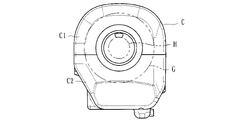
ケース1は、二輪車(車両)のハンドルバーHの先端側(スロットルグリップGの基端側)に取り付けられたカバー部材C(図1~3参照)内に配設されたもので、本スロットルグリップ装置を構成する各種部品を収容するとともに、連動部材2及び回転部材6等を回転自在に保持するものである。かかるケース1は、図10に示すように、連動部材2を回転自在に収容する第1凹部Aと、回転部材6を回転自在に収容する第2凹部Bとが形成された成形部品から成る。なお、符号5は、ケース1の開口側を塞ぐための蓋部材を示している。 The case 1 is arranged in a cover member C (see FIGS. 1 to 3) attached to the tip side of the handlebar H (base end side of the throttle grip G) of a motorcycle (vehicle), and the present throttle grip. It accommodates various parts that make up the device, and also holds the interlocking member 2, the rotating member 6, and the like so as to be rotatable. As shown in FIG. 10, the case 1 is made of a molded component in which a first recess A for rotatably accommodating the interlocking member 2 and a second recess B for rotatably accommodating the rotating member 6 are formed. Reference numeral 5 denotes a lid member for covering the opening side of the case 1. As shown in FIG.

なお、カバー部材Cは、図2、3に示すように、上側半割れ部材C1と、下側半割れ部材C2とを合致して組み付けることにより構成され、その内部に本スロットルグリップ装置を構成する各種部品を収容し得るとともに、下側半割れ部材C2には、切欠きC2a(図3参照)が形成されている。この切欠きC2aには、ケース1に一体形成された固定部ha及び凸条部hb(図5参照)が嵌合して組み付けられるようになっている。 As shown in FIGS. 2 and 3, the cover member C is constructed by assembling an upper half-split member C1 and a lower half-split member C2 together to form the present throttle grip device therein. A notch C2a (see FIG. 3) is formed in the lower half member C2 so as to accommodate various parts. A fixing portion ha and a ridge portion hb (see FIG. 5) integrally formed with the case 1 are fitted into the notch C2a to be assembled.

スロットルグリップGは、カバー部材Cから延設されるとともに、車両のハンドルバーHの先端に取り付けられ、運転者が把持しつつ回転操作が可能とされている。かかるスロットルグリップGの基端側には、凹部から成る係合部Ga(図9参照)が形成されており、この係合部Gaが連動部材2の被係合部2a(図4、5、6等参照)に係合することにより、スロットルグリップGと連動部材2とが連結されるようになっている。 The throttle grip G extends from the cover member C and is attached to the tip of the handlebar H of the vehicle so that it can be rotated while being gripped by the driver. An engaging portion Ga (see FIG. 9) consisting of a concave portion is formed on the base end side of the throttle grip G, and this engaging portion Ga is the engaged portion 2a of the interlocking member 2 (FIGS. 4, 5 and 5). 6, etc.), the throttle grip G and the interlocking member 2 are connected.

連動部材2は、スロットルグリップGに形成された係合部Gaと係合し得る被係合部2aを有するとともに、当該スロットルグリップGの回転操作に連動して回転し得るものである。具体的には、本実施形態に係る連動部材2は、図11に示すように、被係合部2aと、収容溝2bと、フランジ2cと、ギア2dと、収容溝2bと連なって形成された係止部2eと、ハンドルバーHを挿通し得る挿通孔2fとを有した環状部材から成る。なお、本実施形態に連動部材2には、後で詳述する摺動面n1が形成されている。 The interlocking member 2 has an engaged portion 2a that can be engaged with the engaging portion Ga formed on the throttle grip G, and can rotate in conjunction with the rotation of the throttle grip G. As shown in FIG. Specifically, as shown in FIG. 11, the interlocking member 2 according to the present embodiment is formed by connecting an engaged portion 2a, an accommodation groove 2b, a flange 2c, a gear 2d, and an accommodation groove 2b. An annular member having an engaging portion 2e and an insertion hole 2f through which the handlebar H can be inserted. In this embodiment, the interlocking member 2 is formed with a sliding surface n1, which will be described in detail later.

被係合部2aは、スロットルグリップGの係合部Gaと対応した位置にそれぞれ形成された凸形状から成り、当該被係合部2aに係合部Gaが嵌入して係合した状態で連動部材2にスロットルグリップGの基端側が接続されている。これにより、スロットルグリップGの回転に伴って連動部材2も回転し得るようになっている。かかる被係合部2aは、連動部材2の表面(ケース1に組み付けられた際、図4に示すように、外部に臨ませ得る一方の面)に形成されるとともに、連動部材2の他方の面には、図11に示すように、収容溝2b、係止部2e及び摺動面n1が形成されている。 The engaged portion 2a has a convex shape formed at a position corresponding to the engaging portion Ga of the throttle grip G. A base end side of a throttle grip G is connected to the member 2 . As a result, the interlocking member 2 can also rotate as the throttle grip G rotates. The engaged portion 2a is formed on the surface of the interlocking member 2 (one surface that can be exposed to the outside when assembled to the case 1, as shown in FIG. 4), and the other surface of the interlocking member 2. As shown in FIG. 11, the surface is formed with a housing groove 2b, a locking portion 2e, and a sliding surface n1.

収容溝2bは、連動部材2の他方の面において当該連動部材2の周方向(回転方向)に亘って形成された溝形状から成り、リターンスプリング4を収容し得るよう構成されている。また、連動部材2には、周方向に亘ってフランジ2cが形成されるとともに、所定範囲に亘ってギア2dが形成されている。このギア2dは、図6に示すように、回転部材6の外周に形成されたギアと噛み合う状態で組み付けられており、連動部材2の回転に伴って回転部材6が回転するようになっている。 The accommodating groove 2 b is formed in the other surface of the interlocking member 2 in a circumferential direction (rotational direction) of the interlocking member 2 , and is configured to accommodate the return spring 4 . A flange 2c is formed in the interlocking member 2 along the circumferential direction, and a gear 2d is formed over a predetermined range. As shown in FIG. 6, this gear 2d is assembled so as to mesh with a gear formed on the outer periphery of the rotating member 6, so that the rotating member 6 rotates as the interlocking member 2 rotates. .

回転部材6は、上述のように連動部材2の回転に伴って連動して回転し得るもので、ケース1の第2凹部Bに収容されるとともに、軸L1(図6~8参照)を中心として回転自在とされている。しかして、連動部材2が回転すると、その回転角度に応じた回転角度にて回転部材6が回転するようになっている。かかる回転部材6には、磁石mが取り付けられており、当該回転部材6の回転に伴って磁石mから生じる磁界の方向が変化するよう構成されている。なお、図7、8中符号aは、回転部材6を連動部材2側に付勢するねじりコイルバネを示している。 The rotating member 6 can rotate in conjunction with the rotation of the interlocking member 2 as described above, is housed in the second recess B of the case 1, and rotates about the axis L1 (see FIGS. 6 to 8). It is rotatable as Thus, when the interlocking member 2 rotates, the rotating member 6 rotates at a rotation angle corresponding to the rotation angle. A magnet m is attached to the rotating member 6, and the direction of the magnetic field generated from the magnet m is changed as the rotating member 6 rotates. 7 and 8, reference numeral a indicates a torsion coil spring that biases the rotating member 6 toward the interlocking member 2 side.

磁気センサ7(回転角度検出手段)は、図8に示すように、回転部材6の軸L1の延長線上の位置に配設されたセンサから成り、回転部材6に取り付けられた磁石mから生じる磁気の変化(磁界の方向の変化)を検出することにより、スロットルグリップGの回転角度を検出可能とされている。具体的には、磁気センサ7は、磁石mの磁場変化(磁束密度の変化)に応じた出力電圧を得ることができるもので、例えばホール効果を利用した磁気センサであるホール素子(具体的には、磁石mの磁場(磁束密度)に比例した出力電圧を得ることができるリニアホールIC)等により構成されている。なお、本実施形態に係る磁気センサ7は、所定の電気回路が印刷にて形成されたプリント基板8に取り付けられている。 As shown in FIG. 8, the magnetic sensor 7 (rotational angle detection means) is composed of a sensor arranged at a position on the extension line of the axis L1 of the rotating member 6, and the magnetism generated by the magnet m attached to the rotating member 6 is (change in the direction of the magnetic field), the rotation angle of the throttle grip G can be detected. Specifically, the magnetic sensor 7 can obtain an output voltage corresponding to a change in the magnetic field of the magnet m (change in magnetic flux density). is composed of a linear Hall IC) or the like capable of obtaining an output voltage proportional to the magnetic field (magnetic flux density) of the magnet m. The magnetic sensor 7 according to this embodiment is attached to a printed circuit board 8 on which a predetermined electric circuit is formed by printing.

しかして、スロットルグリップGが回転するのに伴って連動部材2が同方向に回転すると、回転部材6も連動してギア比(連動部材2及び回転部材6のギア比)に応じて回転し、当該回転部材6に取り付けられた磁石mも同一角度だけ回転する。これにより、その回転角度によって磁場が変化するので、当該回転角度に応じた出力電圧を得ることができ、当該出力電圧に基づき連動部材2の回転角度(即ち、スロットルグリップGの回転角度)を検出することが可能とされている。このように検出されたスロットルグリップGの回転角度は、二輪車に搭載されたECU(エンジン・コントロール・ユニット)に対して電気信号として送信され、送信されたスロットルグリップGの回転角度に応じて車両のエンジンが制御され得るようになっている。 When the interlocking member 2 rotates in the same direction as the throttle grip G rotates, the rotating member 6 also rotates in accordance with the gear ratio (the gear ratio between the interlocking member 2 and the rotating member 6). The magnet m attached to the rotating member 6 also rotates by the same angle. As a result, the magnetic field changes depending on the rotation angle, so that an output voltage corresponding to the rotation angle can be obtained, and the rotation angle of the interlocking member 2 (that is, the rotation angle of the throttle grip G) is detected based on the output voltage. It is possible to The rotation angle of the throttle grip G thus detected is transmitted as an electric signal to an ECU (engine control unit) mounted on the motorcycle, and the vehicle is controlled according to the transmitted rotation angle of the throttle grip G. The engine can be controlled.

リターンスプリング4は、スロットルグリップGの回転操作時、当該スロットルグリップG及び連動部材2を初期位置に向かって付勢する付勢手段にて構成されている。本実施形態に係るリターンスプリング4は、図15に示すように、一端4a及び他端4bと、コイル部4cとを有したねじりコイルバネから成り、一端4aが連動部材2の係止部2e(図11参照)に係止されるとともに、他端4bがケース1の係止部1f(図10参照)に係止されて組み付けられるようになっている。 The return spring 4 is composed of biasing means for biasing the throttle grip G and the interlocking member 2 toward the initial position when the throttle grip G is rotated. As shown in FIG. 15, the return spring 4 according to this embodiment is a torsion coil spring having one end 4a, the other end 4b, and a coil portion 4c. 11), and the other end 4b is engaged with the engaging portion 1f of the case 1 (see FIG. 10).

すなわち、リターンスプリング4は、その一端4aが連動部材2に取り付けられ、且つ、他端4bがケース1に取り付けられて組み付けられており、スロットルグリップGを回転させると、リターンスプリング4の付勢力に抗して連動部材2が回転するので、その付勢力がスロットルグリップGに伝わり、スロットルグリップG及び連動部材2を初期位置に戻す力が作用するのである。 That is, the return spring 4 is assembled with one end 4a attached to the interlocking member 2 and the other end 4b attached to the case 1. When the throttle grip G is rotated, the biasing force of the return spring 4 is applied. Since the interlocking member 2 rotates against it, the urging force is transmitted to the throttle grip G, and a force acts to return the throttle grip G and the interlocking member 2 to their initial positions.

また、リターンスプリング4の一端4aを係止する係止部2eは、図11、13に示すように、連動部材2における収容溝2bより内径側(連動部材2の中心に対して収容溝2bの形成位置より内側の位置)に形成されている。すなわち、本実施形態に係る収容溝2bは、連動部材2における被係合部2aより外径側(連動部材2の中心に対して被係合部2aの形成位置より外側の位置)に形成されているので、収容溝2bより内側の位置に生じるスペース(被係合部2eが形成される面とは反対側の面のスペース)を利用して係止部2eを形成することができるのである。 11 and 13, the locking portion 2e that locks the one end 4a of the return spring 4 is located on the inner diameter side of the housing groove 2b of the interlocking member 2 (the center of the housing groove 2b with respect to the center of the interlocking member 2). position inside the formation position). That is, the accommodation groove 2b according to the present embodiment is formed on the outer diameter side of the engaged portion 2a of the interlocking member 2 (position outside the position where the engaged portion 2a is formed with respect to the center of the interlocking member 2). Therefore, the locking portion 2e can be formed by utilizing the space generated inside the housing groove 2b (the space on the surface opposite to the surface on which the engaged portion 2e is formed). .

ここで、本実施形態に係るリターンスプリング4は、図7、12に示すように、少なくともそのコイル部4cの一部が収容溝2bに収容されつつ連動部材2の回転軸方向(同図の左右方向)の寸法α内にオフセット(寸法α内において寸法t重複)して組み付けられている。この場合の寸法αは、連動部材2の幅寸法を示しており、ケース1の厚み寸法βと同じ方向に延びる面の寸法である。なお、本実施形態に係るリターンスプリング4は、そのコイル部4cの一部が連動部材2の回転軸方向の寸法α内において寸法tだけオフセットして組み付けられているが、コイル部4cの全部が連動部材2の回転軸方向の寸法α内にオフセットして組み付けられるようにしてもよい。 Here, as shown in FIGS. 7 and 12, the return spring 4 according to the present embodiment has at least a part of the coil portion 4c accommodated in the accommodation groove 2b and is rotated in the rotation axis direction of the interlocking member 2 (left and right in the figure). direction) offset within dimension α (overlapping dimension t within dimension α). The dimension α in this case indicates the width dimension of the interlocking member 2 and is the dimension of the surface extending in the same direction as the thickness dimension β of the case 1 . In the return spring 4 according to the present embodiment, part of the coil portion 4c is offset by the dimension t within the dimension α of the interlocking member 2 in the rotation axis direction. The interlocking member 2 may be assembled with an offset within the dimension α in the rotation axis direction.

さらに、本実施形態に係る収容溝2bは、図11、13に示すように、連動部材2における被係合部2aより外径側(連動部材2の中心に対して被係合部2aの形成位置より外側の位置)に形成されている。これにより、リターンスプリング4を構成するねじりコイルバネは、コイル部4cの径が大きいものを使用することとなり、そのコイル部4cの巻き数を任意に設定することにより、付勢力(バネ荷重)を調整することができる。 Furthermore, as shown in FIGS. 11 and 13, the housing groove 2b according to the present embodiment is formed on the outer diameter side of the engaged portion 2a of the interlocking member 2 (the engagement portion 2a is formed with respect to the center of the interlocking member 2). position outside the position). As a result, the torsion coil spring that constitutes the return spring 4 has a coil portion 4c with a large diameter. can do.

すなわち、本実施形態の如く、リターンスプリング4のコイル部4cの径が大きい場合、バネ定数が小さくなって付勢力が小さくなるので、その分、設定し得る付勢力(設定バネ荷重)の下限側を広げることができるとともに、コイル部4cの巻き数を少なくすることにより、設定し得る付勢力(設定バネ荷重)の上限側を広げることができるのである。しかして、リターンスプリング4による付勢力の調整幅(設定することができるバネ荷重の範囲)を広げることができ、バネ荷重の設定の自由度を向上させることができる。 That is, when the diameter of the coil portion 4c of the return spring 4 is large as in the present embodiment, the spring constant becomes small and the biasing force becomes small. can be widened, and by reducing the number of turns of the coil portion 4c, the upper limit side of the urging force (set spring load) that can be set can be widened. Thus, the adjustment range of the biasing force of the return spring 4 (the range of spring load that can be set) can be widened, and the degree of freedom in setting the spring load can be improved.

摩擦板3(抵抗力付与手段)は、連動部材2に当接して組み付けられ、スロットルグリップGの回転操作時に当該連動部材2に対して摺動して抵抗力を付与し得る円環状部材から成り、図14に示すように、一方の面に凸形状3aが複数(本実施形態においては周方向に亘って3つ)一体形成されるとともに、他方の面が連動部材2の摺動面n1に当接して組み付けられるよう構成されている。一方、図10に示すように、ケース1における挿通孔1aの開口縁部1bには、摩擦板3の凸形状3aと合致して嵌合し得る凹状の嵌合形状1cが形成され、凸形状3aが嵌合形状1cに嵌合することにより摩擦板3がケース1に取り付けられている。 The friction plate 3 (resisting force applying means) is an annular member assembled in contact with the interlocking member 2 and capable of sliding against the interlocking member 2 to apply a resisting force when the throttle grip G is rotated. 14, a plurality of convex shapes 3a (three in the circumferential direction in this embodiment) are integrally formed on one surface, and the other surface is a sliding surface n1 of the interlocking member 2. It is configured to be abutted and assembled. On the other hand, as shown in FIG. 10, an opening edge portion 1b of the insertion hole 1a in the case 1 is formed with a concave fitting shape 1c that can be fitted by matching the convex shape 3a of the friction plate 3. The friction plate 3 is attached to the case 1 by fitting the friction plate 3a into the fitting shape 1c .

なお、本実施形態に係る摩擦板3は、一方の面に凸形状3aが形成されているが、これに代えて或いは共に、凹形状を形成するとともに、ケース1における挿通孔1aの開口縁部1bには、当該摩擦板3の凹形状と合致して嵌合し得る凸状の嵌合形状が形成され、凹形状が嵌合形状に嵌合することにより摩擦板3がケース1に取り付けられるようにしてもよい。しかして、摩擦板3は、一方の面に形成された凸形状3a(又は凹形状)がケース1における挿通孔1aの開口縁部1bに形成された嵌合形状に嵌合することにより、回転方向に対して固定可能とされている。 The friction plate 3 according to the present embodiment has a convex shape 3a formed on one surface, but instead of this or both, a concave shape is formed and the opening edge of the insertion hole 1a in the case 1 is formed. 1b is formed with a convex fitting shape that can be fitted by matching the concave shape of the friction plate 3, and the friction plate 3 is attached to the case 1 by fitting the concave shape into the fitting shape. You may do so. Thus, the friction plate 3 rotates when the convex shape 3a (or concave shape) formed on one surface fits into the fitting shape formed on the opening edge portion 1b of the insertion hole 1a in the case 1. The direction can be fixed.

また、ケース1における挿通孔1aの開口縁部1bには、摩擦板3を連動部材2側に付勢させるコイルバネc(付勢手段)を収容するための収容穴1dが複数(本実施形態においては周方向に亘って等間隔に3つ)形成されている。そして、図16に示すように、それぞれの収容穴1dにコイルバネcを収容させた後、図17に示すように、凸形状3aを嵌合形状1cに嵌合させることにより、摩擦板3をケース1における挿通孔1aの開口縁部1bに取り付け可能とされている。さらに、摩擦板3における収容穴1dに対応する位置には、図14に示すように、ボス部3bが突出形成されており、摩擦板3をケース1における挿通孔1aの開口縁部1bに取り付けると、ボス部3bが収容穴1d内に挿通してコイルバネcを確実に保持し得るようになっている。 Further, in the opening edge portion 1b of the insertion hole 1a in the case 1, there are a plurality of receiving holes 1d for receiving coil springs c (biasing means) for biasing the friction plate 3 toward the interlocking member 2 (in this embodiment, are formed at equal intervals in the circumferential direction. Then, as shown in FIG. 16, after the coil springs c are accommodated in the respective accommodation holes 1d, as shown in FIG. 1 can be attached to the opening edge portion 1b of the insertion hole 1a. Further, as shown in FIG. 14, a boss portion 3b is formed at a position corresponding to the receiving hole 1d in the friction plate 3, and the friction plate 3 is attached to the opening edge portion 1b of the insertion hole 1a in the case 1. Then, the boss portion 3b is inserted into the accommodation hole 1d to securely hold the coil spring c.

このように、摩擦板3をケース1における挿通孔1aの開口縁部1bに取り付けた状態で連動部材2を第1凹部Aに収容して組み付けると、図7に示すように、コイルバネcにて付勢された摩擦板3の当接面n2が連動部材2の摺動面n1に当接するようになっている。しかして、スロットルグリップGの回転操作により連動部材2が回転すると、当接面n2が摺動面n1に対して摺動して摩擦力を生じさせ、所望の回転負荷を生じさせることができるのである。 When the interlocking member 2 is accommodated in the first concave portion A and assembled with the friction plate 3 attached to the opening edge portion 1b of the insertion hole 1a in the case 1, as shown in FIG. The contact surface n2 of the urged friction plate 3 contacts the sliding surface n1 of the interlocking member 2. As shown in FIG. Therefore, when the interlocking member 2 rotates due to the rotational operation of the throttle grip G, the contact surface n2 slides against the sliding surface n1 to generate a frictional force, thereby generating a desired rotational load. be.

ここで、本実施形態に係る連動部材2は、図11に示すように、リターンスプリング4を収容する収容溝2bが形成されるとともに、当該収容溝2bの内径側(内側)に摩擦板3(抵抗力付与手段)を摺動させ得る摺動面n1が形成されている。すなわち、連動部材2には、その内径側(回転軸に近い側)に摺動面n1が周方向に亘って形成され、その外側(外径側)に収容溝2bが周方向に亘って形成されており、摺動面n1及び収容溝2bが挿通孔2fを中心とする同心円状にそれぞれ形成されているのである。また、本実施形態に係る連動部材2は、被係合部2aが一方の面に形成されるとともに、収容溝2b及び摺動面n1が他方の面に形成されて構成されている。 Here, as shown in FIG. 11, the interlocking member 2 according to the present embodiment is formed with a housing groove 2b for housing the return spring 4, and the friction plate 3 ( A sliding surface n1 is formed on which the resistance applying means) can slide. That is, in the interlocking member 2, a sliding surface n1 is formed along the inner diameter side (the side closer to the rotating shaft) along the circumferential direction, and a housing groove 2b is formed along the outer side (outer diameter side) along the circumferential direction. The sliding surface n1 and the housing groove 2b are formed concentrically around the insertion hole 2f. Further, the interlocking member 2 according to the present embodiment is configured such that the engaged portion 2a is formed on one surface, and the accommodation groove 2b and the sliding surface n1 are formed on the other surface.

さらに、本実施形態に係るケース1は、図8、16、17に示すように、磁気センサ7(回転角度検出手段)及びプリント基板8を収容可能な収容凹部1eを有している。かかる収容凹部1eは、磁気センサ7が位置する第1空間S1と、該第1空間S1からケース1の幅方向Yに延設された第2空間S2と、該第2空間S2から回転部材6の外径方向(図18、19において右方向)であって当該回転部材6の取付部位(本実施形態においては第2凹部B)と隣接する位置に亘って形成された第3空間S3とを有し、プリント基板8が第1空間S1から第2空間S2に亘って収容されるとともに、当該プリント基板8と車両側とを電気的に接続する配線の接続部Nが第3空間S3に位置するようになっている。 Further, the case 1 according to the present embodiment has an accommodation recess 1e capable of accommodating the magnetic sensor 7 (rotational angle detection means) and the printed circuit board 8, as shown in FIGS. The accommodation recess 1e includes a first space S1 in which the magnetic sensor 7 is positioned, a second space S2 extending from the first space S1 in the width direction Y of the case 1, and a rotary member 6 extending from the second space S2. A third space S3 formed over a position in the outer diameter direction (right direction in FIGS. 18 and 19) and adjacent to the mounting portion (second recess B in this embodiment) of the rotating member 6 The printed circuit board 8 is accommodated from the first space S1 to the second space S2, and the connection portion N of the wiring electrically connecting the printed circuit board 8 and the vehicle side is located in the third space S3. It is designed to

すなわち、第1空間S1及び第2空間S2をケース1の幅方向Y(図8、10、16、17に示すように、回転部材6の回転軸L1に対して直交する方向)に亘って略直線状に形成してプリント基板8を収容させるとともに、第2凹部Bと隣接する位置に形成された第3空間S3にプリント基板8に形成された接続部Nが位置するので、第2凹部Bと隣接する位置のデッドスペースに接続部Nを配設することができ、当該デッドスペースの有効利用を図ることができるのである。なお、接続部Nは、配線hの先端を接続するためのカプラやコネクタ等から成るものであってもよく、或いは配線hをプリント基板8の電気回路に対して半田付け等により直接接続する部位であってもよい。 That is, the first space S1 and the second space S2 are substantially spaced across the width direction Y of the case 1 (the direction orthogonal to the rotation axis L1 of the rotary member 6 as shown in FIGS. 8, 10, 16, and 17). Since the connection part N formed in the printed circuit board 8 is positioned in the third space S3 formed in a position adjacent to the second concave part B, the second concave part B The connection portion N can be arranged in the dead space adjacent to the , and the dead space can be effectively used. The connection portion N may be composed of a coupler, a connector, or the like for connecting the tip of the wiring h, or a portion for directly connecting the wiring h to the electric circuit of the printed circuit board 8 by soldering or the like. may be

また、本実施形態に係るケース1は、図18、19に示すように、第1空間S1、第2空間S2及び第3空間S3をそれぞれ外部に臨ませるL字状の開口を有している。なお、本実施形態に係る第3空間S3には、取付ネジのネジ穴が形成されたボス部bを有しているが、かかるボス部bを有さないもの、或いは他の空間にボス部bが形成されたもの等としてもよい。 In addition, as shown in FIGS. 18 and 19, the case 1 according to this embodiment has L-shaped openings that expose the first space S1, the second space S2, and the third space S3 to the outside. . The third space S3 according to the present embodiment has a boss portion b in which a screw hole for a mounting screw is formed. It is good also as what b was formed.

さらに、本実施形態に係るケース1は、配線hを第3空間S3に向かって延設させた状態で固定するための固定部haが一体形成されている。すなわち、固定部haに配線hの先端部近傍を接触させた状態で、例えば結束バンド等にて固定させることにより、配線hの先端が第3空間S3に位置する接続部Nに向かった状態となるよう構成されているのである。 Furthermore, the case 1 according to the present embodiment is integrally formed with a fixing portion ha for fixing the wiring h extending toward the third space S3. That is, in a state where the vicinity of the tip of the wiring h is brought into contact with the fixing portion ha, the tip of the wiring h is directed toward the connecting portion N located in the third space S3 by fixing with, for example, a binding band. It is configured to be

またさらに、本実施形態に係るケース1は、図19に示すように、回転部材6を回転自在に保持する凹部(本実施形態における第2凹部B)と、第1空間S1、第2空間S2及び第3空間S3を有する収容凹部1eとが画成(互いに独立した空間となるよう区画)して形成されている。しかるに、収容空間1eには、プリント基板8が収容された状態において、所定の樹脂材等が充填されるようになっている。 Furthermore, as shown in FIG. 19, the case 1 according to the present embodiment includes a recess (second recess B in the present embodiment) for rotatably holding the rotating member 6, a first space S1 and a second space S2. and a housing recess 1e having a third space S3 are defined (divided so as to be mutually independent spaces). However, the accommodation space 1e is filled with a predetermined resin material or the like in a state in which the printed circuit board 8 is accommodated.

上記実施形態によれば、連動部材2は、リターンスプリング4を収容する収容溝2bが形成されるとともに、リターンスプリング4は、当該収容溝2bに収容されつつ連動部材2の回転軸方向の寸法α内にオフセットした状態とされ、且つ、収容溝2bは、連動部材2における被係合部2aより外径側に形成されたので、連動部材2及びリターンスプリング4を収容したケース1の厚さ方向の寸法β(図7参照)を小さくするとともに、リターンスプリングによる付勢力の設定の自由度を向上させることができる。よって、ケース1を覆うカバー部材Cの厚さ方向の寸法γ(図1参照)を小さくすることができるので、ハンドルバーHの先端部に別個のスイッチケース等を容易に配設することができるとともに、車種や運転者の嗜好に応じてリターンスプリングの付勢力を容易に設定することができる。 According to the above-described embodiment, the interlocking member 2 is formed with the accommodation groove 2b for accommodating the return spring 4, and the return spring 4 is accommodated in the accommodation groove 2b and has a dimension α in the rotation axis direction of the interlocking member 2. Since the accommodating groove 2b is formed on the outer diameter side from the engaged portion 2a of the interlocking member 2, the thickness direction of the case 1 accommodating the interlocking member 2 and the return spring 4 is offset. (see FIG. 7) can be reduced, and the degree of freedom in setting the biasing force of the return spring can be improved. Therefore, since the thickness dimension γ (see FIG. 1) of the cover member C covering the case 1 can be reduced, a separate switch case or the like can be easily arranged at the tip of the handlebar H. At the same time, the biasing force of the return spring can be easily set according to the vehicle type and driver's preference.

また、連動部材2の回転に伴って回転する回転部材6を具備するとともに、磁気センサ7(回転角度検出手段)は、当該回転部材6の回転角度を検出することによりスロットルグリップGの回転角度を検出し得るので、連動部材2は、その収容溝2bにリターンスプリング4を安定して保持する保持機能と、スロットルグリップGの回転力を回転部材6に伝達する伝達機能とを兼ね備えることができる。 Further, a rotating member 6 that rotates with the rotation of the interlocking member 2 is provided, and a magnetic sensor 7 (rotation angle detection means) detects the rotation angle of the rotating member 6 to detect the rotation angle of the throttle grip G. Since it can be detected, the interlocking member 2 can have both a holding function of stably holding the return spring 4 in the accommodation groove 2b and a transmission function of transmitting the rotational force of the throttle grip G to the rotating member 6.

さらに、本実施形態に係る連動部材2は、収容溝2bと連なって形成され、リターンスプリング4の一端4aが係止される係止部2eを有するとともに、当該係止部2eは、連動部材2における収容溝2bより内径側に形成されたので、収容溝2bに収容されたリターンスプリング4の付勢力を効率的且つ安定的に連動部材2及びスロットルグリップGに及ばせることができ、且つ、連動部材2における収容溝2bよりも被係合部2a側(内径側)のスペースを活用してリターンスプリング4の一端4aを係止させることができる。またさらに、本実施形態に係る連動部材2は、被係合部2aが一方の面に形成されるとともに、収容溝2bが他方の面に形成された環状部材から成るので、スロットルグリップGの回転操作力の伝達を確実に行わせつつリターンスプリング4を収容溝2bに収容して安定して保持させることができる。 Further, the interlocking member 2 according to the present embodiment has a locking portion 2e that is formed continuously with the accommodation groove 2b and that locks the one end 4a of the return spring 4. , the urging force of the return spring 4 accommodated in the accommodation groove 2b can be efficiently and stably applied to the interlocking member 2 and the throttle grip G. One end 4a of the return spring 4 can be locked by utilizing the space on the engaged portion 2a side (inner diameter side) of the member 2 with respect to the accommodation groove 2b. Furthermore, the interlocking member 2 according to the present embodiment is an annular member having the engaged portion 2a formed on one surface and the housing groove 2b formed on the other surface. The return spring 4 can be accommodated in the accommodation groove 2b and stably held while ensuring transmission of the operating force.

加えて、本実施形態に係るケース1は、ハンドルバーHを挿通し得る挿通孔1aが形成されるとともに、当該挿通孔1aの開口縁部1bに沿って摩擦板3(抵抗力付与手段)が取り付けられたので、ケース1における挿通孔1aの開口縁部1bを有効利用することができ、摩擦板3(抵抗力付与手段)を収容したケース1の寸法を小さくすることができる。 In addition, the case 1 according to the present embodiment is formed with an insertion hole 1a through which the handlebar H can be inserted, and a friction plate 3 (resistance applying means) is provided along the opening edge 1b of the insertion hole 1a. Since it is attached, the opening edge portion 1b of the insertion hole 1a in the case 1 can be effectively used, and the size of the case 1 housing the friction plate 3 (resisting force applying means) can be reduced.

また、本実施形態に係る抵抗力付与手段は、一方の面に凸形状3a(又は凹形状)が一体形成されるとともに、他方の面が連動部材2の摺動面n1に当接して組み付けられる摩擦板3から成り、且つ、ケース1における挿通孔1aの開口縁部1bには、当該抵抗力付与手段の凸形状3a(又は凹形状)と合致して嵌合し得る嵌合形状1cが形成され、凸形状3a(又は凹形状)が嵌合形状1cに嵌合することにより摩擦板3がケース1に取り付けられたので、摩擦板3の回転方向の固定を確実に行わせつつケース1の小型化を図ることができる。 In addition, the resistance applying means according to the present embodiment has the convex shape 3a (or the concave shape) integrally formed on one surface, and the other surface is assembled in contact with the sliding surface n1 of the interlocking member 2. Composed of the friction plate 3, the opening edge portion 1b of the insertion hole 1a in the case 1 is formed with a fitting shape 1c that can match and fit with the convex shape 3a (or concave shape) of the resistance applying means. The friction plate 3 is attached to the case 1 by fitting the convex shape 3a (or concave shape) to the fitting shape 1c. Miniaturization can be achieved.

さらに、ケース1における挿通孔1aの開口縁部1bには、摩擦板3(抵抗力付与手段)を連動部材2側に付勢させるコイルバネc(付勢手段)を収容するための収容穴1dが形成されたので、コイルバネcの付勢力によって摩擦板3による抵抗力を確実に生じさせつつケース1の小型化を図ることができる。なお、コイルバネcに代えて、他の汎用的な付勢手段を収容穴1dに収容するようにしてもよい。 Further, in the opening edge portion 1b of the insertion hole 1a in the case 1, there is an accommodation hole 1d for accommodating a coil spring c (urging means) for urging the friction plate 3 (resistance applying means) toward the interlocking member 2 side. Since it is formed, the size of the case 1 can be reduced while the resistance force of the friction plate 3 is reliably generated by the biasing force of the coil spring c. Instead of the coil spring c, other general-purpose biasing means may be accommodated in the accommodation hole 1d.

またさらに、本実施形態に係るケース1には、スロットルグリップGの回転操作時、当該スロットルグリップG及び連動部材2を初期位置に向かって付勢するリターンスプリング4が取り付けられ、連動部材2は、当該リターンスプリング4を収容する収容溝2bが形成されるとともに、当該収容溝2bの内径側に摩擦板3(抵抗力付与手段)を摺動させ得る摺動面n1が形成されたので、ケース1内におけるスペースの有効利用を図ることができる。 Furthermore, the case 1 according to the present embodiment is provided with a return spring 4 that biases the throttle grip G and the interlocking member 2 toward their initial positions when the throttle grip G is rotated. A housing groove 2b for housing the return spring 4 is formed, and a sliding surface n1 on which the friction plate 3 (resistance applying means) can slide is formed on the inner diameter side of the housing groove 2b. It is possible to effectively use the space inside.

また、本実施形態に係る連動部材2は、被係合部2aが一方の面に形成されるとともに、収容溝2b及び摺動面n1が他方の面に形成された環状部材から成るので、スロットルグリップGの回転操作力の伝達を確実に行わせつつリターンスプリング4を収容溝2bに収容して安定して保持させることができ、且つ、摩擦板3(抵抗力付与手段)の摺動面n1に対する摺動を円滑に行わせることができる。 Further, the interlocking member 2 according to the present embodiment is an annular member having the engaged portion 2a formed on one surface and the receiving groove 2b and the sliding surface n1 formed on the other surface. The return spring 4 can be accommodated in the accommodation groove 2b and stably held while ensuring the transmission of the rotational operation force of the grip G, and the sliding surface n1 of the friction plate 3 (resistance applying means) can be smoothly slid against.

さらに加えて、本実施形態によれば、ケース1に形成された収容凹部1eは、磁気センサ7が位置する第1空間S1と、該第1空間S1からケース1の幅方向Yに延設された第2空間S2と、該第2空間S2から回転部材6の外径方向(図18、19において右方向)であって当該回転部材6の取付部位(本実施形態においては第2凹部B)と隣接する位置に亘って形成された第3空間S3とを有し、プリント基板8が第1空間S1から第2空間S2に亘って収容されるとともに、当該プリント基板8と車両側とを電気的に接続する配線hの接続部Nが第3空間S3に位置するので、回転部材6の外径側位置のデッドスペースを有効利用することができ、プリント基板8を収容したケース1の厚さ方向の寸法αを小さくすることができる。 In addition, according to the present embodiment, the housing recess 1e formed in the case 1 includes the first space S1 in which the magnetic sensor 7 is positioned, and the housing recess 1e extending from the first space S1 in the width direction Y of the case 1. a second space S2, and a mounting portion (second recess B in this embodiment) of the rotating member 6 in the outer diameter direction of the rotating member 6 from the second space S2 (right direction in FIGS. 18 and 19). and a third space S3 formed over an adjacent position, the printed circuit board 8 is accommodated from the first space S1 to the second space S2, and the printed circuit board 8 and the vehicle side are electrically connected Since the connection portion N of the wiring h that is connected directly is positioned in the third space S3, the dead space on the outer diameter side of the rotary member 6 can be effectively utilized, and the thickness of the case 1 containing the printed circuit board 8 can be reduced. The directional dimension α can be reduced.

また、本実施形態に係るケース1は、第1空間S1、第2空間S2及び第3空間S3をそれぞれ外部に臨ませるL字状の開口を有するので、磁気センサ7(回転角度検出手段)及び配線hに対する接続部Nが取り付けられたプリント基板8を収容空間1eに容易に挿通して収容させることができ、組み付け作業性を向上させることができる。さらに、本実施形態に係るケース1は、配線hを第3空間S3に向かって延設させた状態で固定するための固定部haが形成されたので、配線hとプリント基板8の接続部Nとの接続状態を良好に維持することができ、プリント基板8と車両側との電気的接続を安定して行わせることができる。 Further, since the case 1 according to the present embodiment has L-shaped openings that expose the first space S1, the second space S2, and the third space S3 to the outside, the magnetic sensor 7 (rotation angle detection means) and The printed circuit board 8 to which the connection portion N for the wiring h is attached can be easily inserted and accommodated in the accommodation space 1e, and the assembling workability can be improved. Furthermore, since the case 1 according to the present embodiment has the fixing portion ha for fixing the wiring h extending toward the third space S3, the connecting portion N between the wiring h and the printed circuit board 8 can be maintained in good condition, and the electrical connection between the printed circuit board 8 and the vehicle can be stably performed.

またさらに、本実施形態に係るケース1は、回転部材6を回転自在に保持する第2凹部Bと、第1空間S1、第2空間S2及び第3空間S3を有する収容凹部1eとが画成して形成されたので、回転部材6の回転を安定して行わせることができるとともに、収容凹部1eに対して樹脂等を充填して防水及び防塵を図ることができる。 Furthermore, the case 1 according to the present embodiment is defined by a second concave portion B that rotatably holds the rotating member 6, and an accommodating concave portion 1e having a first space S1, a second space S2, and a third space S3. Since it is formed as above, the rotation of the rotating member 6 can be stably performed, and the housing recess 1e can be filled with resin or the like to achieve water and dust resistance.

さらに、本実施形態によれば、収容空間1eが第1空間S1、第2空間S2及び第3空間を有する構成に加え、ケース1には、スロットルグリップGの回転操作時、当該スロットルグリップG及び連動部材2を初期位置に向かって付勢するリターンスプリングが取り付けられ、連動部材2は、リターンスプリング4を収容する収容溝2bが形成されるとともに、当該リターンスプリング4は、当該収容溝2bに収容されつつ連動部材2の回転軸方向の寸法α内にオフセットして組み付けられたので、ケース1の厚さ方向の寸法βをより一層小さくすることができる。 Furthermore, according to the present embodiment, in addition to the configuration in which the accommodation space 1e has the first space S1, the second space S2, and the third space, the case 1 has the throttle grip G and A return spring is attached to bias the interlocking member 2 toward the initial position. The interlocking member 2 is formed with a housing groove 2b for housing the return spring 4, and the return spring 4 is housed in the housing groove 2b. Since the interlocking member 2 is assembled with an offset within the dimension α in the rotation axis direction, the dimension β in the thickness direction of the case 1 can be further reduced.

以上、本実施形態について説明したが、本発明はこれに限定されるものではなく、例えばスロットルグリップGの回転角度を検出する磁気センサ7に代えて、他の汎用的なセンサ(磁石の磁気を検出するものに限らないとともに、非接触式のセンサに限らず接触式のセンサ等も含む)としてもよい。また、本実施形態においては、回転部材6の回転角度を検出してスロットルグリップGの回転角度を検出する構成とされているが、回転部材6を有さず、連動部材2に磁石を形成し、その磁石の磁気変化を磁気センサ(回転角度検出手段)にて検出することにより、スロットルグリップGの回転角度を検出するようにしてもよい。 Although the present embodiment has been described above, the present invention is not limited to this. For example, instead of the magnetic sensor 7 for detecting the rotation angle of the throttle grip G, another general-purpose sensor It is not limited to those that detect, and may include not only non-contact sensors but also contact sensors and the like). In this embodiment, the rotation angle of the rotating member 6 is detected to detect the rotation angle of the throttle grip G. Alternatively, the rotation angle of the throttle grip G may be detected by detecting the magnetic change of the magnet with a magnetic sensor (rotation angle detection means).

さらに、本実施形態に係るリターンスプリングは、ねじりコイルバネから成るものとされているが、他の汎用的な付勢手段としてもよい。また、ケース1の収容凹部1eは、第1空間S1のみ形成されたものであってもよい。なお、適用される車両は、本実施形態の如く二輪車に限定されるものではなく、ハンドルバーHを有した他の車両(例えばATVやスノーモービル等)に適用してもよい。 Furthermore, although the return spring according to the present embodiment is a torsion coil spring, it may be other general-purpose biasing means. Further, the housing recess 1e of the case 1 may be formed only with the first space S1. The applicable vehicle is not limited to a two-wheeled vehicle as in the present embodiment, and may be applied to other vehicles having a handlebar H (for example, an ATV, a snowmobile, etc.).

ケースは、ハンドルバーを挿通し得る挿通孔が形成されるとともに、当該挿通孔の開口縁部に沿って抵抗力付与手段が取り付けられ、且つ、ケースには、スロットルグリップの回転操作時、当該スロットルグリップ及び連動部材を初期位置に向かって付勢するリターンスプリングが取り付けられ、連動部材は、当該リターンスプリングを収容する収容溝が形成されるとともに、当該収容溝の内径側に抵抗力付与手段を摺動させ得る摺動面が形成されたスロットルグリップ装置であれば、外観形状が異なるもの或いは他の機能が付加されたもの等にも適用することができる。 The case has an insertion hole through which the handlebar can be inserted , and a resistance applying means is attached along the edge of the opening of the insertion hole. A return spring is attached to bias the grip and the interlocking member toward the initial position, and the interlocking member is formed with an accommodation groove that accommodates the return spring, and slides the resistance applying means on the inner diameter side of the accommodation groove. As long as the throttle grip device is formed with a sliding surface that can be moved, it can be applied to a throttle grip device having a different external shape or having other functions added.

1 ケース
1a 挿通孔
1b 開口縁部
1c 嵌合形状
1d 収容穴
1e 収容凹部
1f 係止部
2 連動部材
2a 被係合部
2b 収容溝
2c フランジ
2d ギア
2e 係止部
2f 挿通孔
3 摩擦板(抵抗力付与手段)
3a 凸形状
3b ボス部
4 リターンスプリング(ねじりコイルバネ)
4a 一端
4b 他端
4c コイル部
5 蓋部材
6 回転部材
7 磁気センサ(回転角度検出手段)
8 プリント基板
n1 摺動面
n2 当接面
G スロットルグリップ
Ga 係合部
h 配線
ha 固定部
N 接続部
A 第1凹部
B 第2凹部
S1 第1空間
S2 第2空間
S3 第3空間
1 Case 1a Insertion hole 1b Opening edge 1c Fitting shape 1d Accommodating hole 1e Accommodating recess 1f Locking portion 2 Interlocking member 2a Engaged portion 2b Accommodating groove 2c Flange 2d Gear 2e Locking portion 2f Insertion hole 3 Friction plate (resistance force applying means)
3a convex shape 3b boss portion 4 return spring (torsion coil spring)
4a One end 4b Other end 4c Coil portion 5 Lid member 6 Rotating member 7 Magnetic sensor (rotation angle detection means)
8 Printed circuit board n1 Sliding surface n2 Contact surface G Throttle grip Ga Engaging portion h Wiring ha Fixed portion N Connecting portion A First concave portion B Second concave portion S1 First space S2 Second space S3 Third space

Claims (5)

車両のハンドルバーの先端に取り付けられ、運転者による回転操作が可能とされたスロットルグリップと、
前記スロットルグリップに形成された係合部と係合し得る被係合部を有するとともに、当該スロットルグリップに連動して回転し得る連動部材と、
前記連動部材の回転角度を検出することにより前記スロットルグリップの回転角度を検出し得る回転角度検出手段と、
前記連動部材に当接して組み付けられ、前記スロットルグリップの回転操作時に当該連動部材に対して摺動して抵抗力を付与し得る抵抗力付与手段と、
前記連動部材を回転自在に保持するとともに、前記抵抗力付与手段が取り付けられるケースと、
を具備し、前記回転角度検出手段で検出された前記スロットルグリップの回転角度に応じて車両のエンジンを制御可能とされたスロットルグリップ装置であって、
前記ケースは、前記ハンドルバーを挿通し得る挿通孔が形成されるとともに、当該挿通孔の開口縁部に沿って前記抵抗力付与手段が取り付けられ、且つ、前記ケースには、前記スロットルグリップの回転操作時、当該スロットルグリップ及び連動部材を初期位置に向かって付勢するリターンスプリングが取り付けられ、前記連動部材は、当該リターンスプリングを収容する収容溝が形成されるとともに、当該収容溝の内径側に前記抵抗力付与手段を摺動させ得る摺動面が形成されたことを特徴とするスロットルグリップ装置。
A throttle grip that is attached to the tip of the handlebar of the vehicle and that can be rotated by the driver,
an interlocking member having an engaged portion that can engage with the engaging portion formed on the throttle grip and that can rotate in conjunction with the throttle grip;
rotation angle detection means capable of detecting the rotation angle of the throttle grip by detecting the rotation angle of the interlocking member;
a resistance applying means assembled in contact with the interlocking member and capable of sliding against the interlocking member to apply resistance when the throttle grip is rotated;
a case that rotatably holds the interlocking member and to which the resistance applying means is attached;
A throttle grip device capable of controlling a vehicle engine according to the rotation angle of the throttle grip detected by the rotation angle detection means,
The case is formed with an insertion hole through which the handlebar can be inserted , and the resistance applying means is attached along the opening edge of the insertion hole. A return spring is attached to bias the throttle grip and the interlocking member toward their initial positions during operation. A throttle grip device comprising a sliding surface on which the resistance applying means is slidable .
前記抵抗力付与手段は、一方の面に凸形状又は凹形状が一体形成されるとともに、他方の面が前記連動部材の摺動面に当接して組み付けられる摩擦板から成り、且つ、前記ケースにおける前記挿通孔の開口縁部には、当該抵抗力付与手段の凸形状又は凹形状と合致して嵌合し得る嵌合形状が形成され、前記凸形状又は凹形状が前記嵌合形状に嵌合することにより前記抵抗力付与手段が前記ケースに取り付けられたことを特徴とする請求項1記載のスロットルグリップ装置。 The resistance applying means comprises a friction plate having one surface integrally formed with a convex or concave shape and the other surface being assembled in contact with the sliding surface of the interlocking member, and An opening edge of the insertion hole is formed with a fitting shape that can match and fit with a convex shape or a concave shape of the resistance applying means, and the convex shape or the concave shape fits into the fitting shape. 2. The throttle grip device according to claim 1, wherein said resistance applying means is attached to said case by doing so. 前記ケースにおける前記挿通孔の開口縁部には、前記抵抗力付与手段を前記連動部材側に付勢させる付勢手段を収容するための収容穴が形成されたことを特徴とする請求項1又は請求項2記載のスロットルグリップ装置。 2. An accommodation hole for accommodating an urging means for urging the resistance applying means toward the interlocking member is formed in the opening edge of the insertion hole in the case. 3. The throttle grip device according to claim 2. 前記リターンスプリングの一端を係止する係止部が前記連動部材における前記収容溝より内径側に形成されたことを特徴とする請求項1~3の何れか1つに記載のスロットルグリップ装置。The throttle grip device according to any one of claims 1 to 3, wherein an engaging portion for engaging one end of the return spring is formed on the inner diameter side of the accommodating groove in the interlocking member. 前記連動部材は、前記被係合部が一方の面に形成されるとともに、前記収容溝及び摺動面が他方の面に形成された環状部材から成ることを特徴とする請求項1~4の何れか1つに記載のスロットルグリップ装置。 The interlocking member comprises an annular member having the engaged portion formed on one surface and the receiving groove and the sliding surface formed on the other surface . A throttle grip device according to any one of the above.
JP2018085700A 2018-04-26 2018-04-26 throttle grip device Active JP7148054B2 (en)

Priority Applications (1)

Application Number Priority Date Filing Date Title
JP2018085700A JP7148054B2 (en) 2018-04-26 2018-04-26 throttle grip device

Applications Claiming Priority (1)

Application Number Priority Date Filing Date Title
JP2018085700A JP7148054B2 (en) 2018-04-26 2018-04-26 throttle grip device

Publications (2)

Publication Number Publication Date
JP2019190405A JP2019190405A (en) 2019-10-31
JP7148054B2 true JP7148054B2 (en) 2022-10-05

Family

ID=68387789

Family Applications (1)

Application Number Title Priority Date Filing Date
JP2018085700A Active JP7148054B2 (en) 2018-04-26 2018-04-26 throttle grip device

Country Status (1)

Country Link
JP (1) JP7148054B2 (en)

Citations (5)

* Cited by examiner, † Cited by third party
Publication number Priority date Publication date Assignee Title
JP2003252274A (en) 2002-02-26 2003-09-10 Yamaha Motor Co Ltd Throttle opening detection device
JP2004144207A (en) 2002-10-24 2004-05-20 Jidosha Denki Kogyo Co Ltd Electromagnetic braking device and motor using it
JP2013203177A (en) 2012-03-28 2013-10-07 Nippon Seiki Co Ltd Position detection device
JP2013205141A (en) 2012-03-28 2013-10-07 Honda Motor Co Ltd Throttle opening detector
JP2015224572A (en) 2014-05-27 2015-12-14 朝日電装株式会社 Throttle grip device

Family Cites Families (1)

* Cited by examiner, † Cited by third party
Publication number Priority date Publication date Assignee Title
JPS5975927U (en) * 1982-11-15 1984-05-23 株式会社クボタ hydraulic clutch

Patent Citations (5)

* Cited by examiner, † Cited by third party
Publication number Priority date Publication date Assignee Title
JP2003252274A (en) 2002-02-26 2003-09-10 Yamaha Motor Co Ltd Throttle opening detection device
JP2004144207A (en) 2002-10-24 2004-05-20 Jidosha Denki Kogyo Co Ltd Electromagnetic braking device and motor using it
JP2013203177A (en) 2012-03-28 2013-10-07 Nippon Seiki Co Ltd Position detection device
JP2013205141A (en) 2012-03-28 2013-10-07 Honda Motor Co Ltd Throttle opening detector
JP2015224572A (en) 2014-05-27 2015-12-14 朝日電装株式会社 Throttle grip device

Also Published As

Publication number Publication date
JP2019190405A (en) 2019-10-31

Similar Documents

Publication Publication Date Title
JP6231349B2 (en) Throttle grip device
JP6845527B2 (en) Throttle grip device
TWI700430B (en) Throttle lever device
JP6370108B2 (en) Throttle grip device
JP6370109B2 (en) Throttle grip device
JP7146216B2 (en) throttle grip device
JP6178070B2 (en) Throttle grip device
JP6868863B2 (en) Throttle grip device
JP7148054B2 (en) throttle grip device
JP7148055B2 (en) throttle grip device
JP7241328B2 (en) throttle grip device
JP6918296B2 (en) Throttle grip device
JP7272545B2 (en) throttle grip device
JP7336108B2 (en) throttle grip device
JP7312999B2 (en) throttle grip device
JP7312998B2 (en) throttle grip device
JP2018177053A (en) Throttle grip device
JP2022089535A (en) Throttle operation device
JP7057590B2 (en) Throttle grip device
JP2020196388A (en) Throttle grip device
JP7214111B2 (en) throttle grip device
JP7337340B2 (en) throttle grip device
JP6993642B2 (en) Throttle grip device
JP2014113882A (en) Throttle grip device
JP2009133700A (en) Angle detector

Legal Events

Date Code Title Description
A621 Written request for application examination

Free format text: JAPANESE INTERMEDIATE CODE: A621

Effective date: 20210330

A977 Report on retrieval

Free format text: JAPANESE INTERMEDIATE CODE: A971007

Effective date: 20220308

A131 Notification of reasons for refusal

Free format text: JAPANESE INTERMEDIATE CODE: A131

Effective date: 20220318

A521 Request for written amendment filed

Free format text: JAPANESE INTERMEDIATE CODE: A523

Effective date: 20220510

TRDD Decision of grant or rejection written
A01 Written decision to grant a patent or to grant a registration (utility model)

Free format text: JAPANESE INTERMEDIATE CODE: A01

Effective date: 20220912

A61 First payment of annual fees (during grant procedure)

Free format text: JAPANESE INTERMEDIATE CODE: A61

Effective date: 20220913

R150 Certificate of patent or registration of utility model

Ref document number: 7148054

Country of ref document: JP

Free format text: JAPANESE INTERMEDIATE CODE: R150