JP7147984B2 - LOAD DETECTION DEVICE, LOAD DETECTION METHOD, AND PROGRAM - Google Patents
LOAD DETECTION DEVICE, LOAD DETECTION METHOD, AND PROGRAM Download PDFInfo
- Publication number
- JP7147984B2 JP7147984B2 JP2021528080A JP2021528080A JP7147984B2 JP 7147984 B2 JP7147984 B2 JP 7147984B2 JP 2021528080 A JP2021528080 A JP 2021528080A JP 2021528080 A JP2021528080 A JP 2021528080A JP 7147984 B2 JP7147984 B2 JP 7147984B2
- Authority
- JP
- Japan
- Prior art keywords
- displacement
- time
- load
- mechanical device
- load detection
- Prior art date
- Legal status (The legal status is an assumption and is not a legal conclusion. Google has not performed a legal analysis and makes no representation as to the accuracy of the status listed.)
- Active
Links
Images


Classifications
-
- G—PHYSICS
- G01—MEASURING; TESTING
- G01L—MEASURING FORCE, STRESS, TORQUE, WORK, MECHANICAL POWER, MECHANICAL EFFICIENCY, OR FLUID PRESSURE
- G01L1/00—Measuring force or stress, in general
-
- G—PHYSICS
- G01—MEASURING; TESTING
- G01L—MEASURING FORCE, STRESS, TORQUE, WORK, MECHANICAL POWER, MECHANICAL EFFICIENCY, OR FLUID PRESSURE
- G01L5/00—Apparatus for, or methods of, measuring force, work, mechanical power, or torque, specially adapted for specific purposes
-
- G—PHYSICS
- G01—MEASURING; TESTING
- G01M—TESTING STATIC OR DYNAMIC BALANCE OF MACHINES OR STRUCTURES; TESTING OF STRUCTURES OR APPARATUS, NOT OTHERWISE PROVIDED FOR
- G01M99/00—Subject matter not provided for in other groups of this subclass
Landscapes
- Physics & Mathematics (AREA)
- General Physics & Mathematics (AREA)
- Length Measuring Devices By Optical Means (AREA)
Description
本発明は、機械装置にかかる負荷の変化を検知するための、負荷検知装置、及び負荷検知方法に関し、更には、これらを実現するためのプログラムに関する。 The present invention relates to a load detection device and a load detection method for detecting changes in load applied to a mechanical device, and further to a program for realizing these.
空港監視用等の空中線装置、風力発電装置等のように、重量物が回転運動する構成を備えた機械装置は、重量物の回転運動の繰り返しによって、更には、風等の外力によって、大きな負荷を受けている。特に、空中線装置では、重量物である反射板が、その重心位置と回転中心とがずれた状態(偏心した状態)で、一定周期で回転運動するため、軸受け部分に非常に大きな負荷がかかる。 A mechanical device with a structure in which a heavy object rotates, such as an antenna device for airport surveillance and a wind power generator, is subjected to a large load due to the repetition of the rotary motion of the heavy object and further by external forces such as wind. Is receiving. In particular, in an antenna device, the reflector, which is a heavy object, rotates in a constant cycle with its center of gravity deviated from its center of rotation (eccentric state), so a very large load is applied to the bearing.
このため、このような機械装置においては、負荷によって構造部材が疲弊し、最終的には損壊する可能性があることから、正常な運用を維持するためには、機械装置にかかる負荷の状態を把握し、負荷の変化を検知することが重要となる。例えば、特許文献1は、機械装置が受ける負荷の変化を検知するシステムを開示している。
For this reason, in such machinery, the structural members may be exhausted by the load and may eventually be damaged. It is important to understand and detect changes in load. For example,
具体的には、特許文献1は、回転部材に取り付けられた第1の応力センサと、回転部材の軸受けに取り付けられた第2の応力センサと、制御装置とで構成されたシステムを開示している。特許文献1に開示されたシステムでは、制御装置は、第1の応力センサから検出された回転部材の応力と、第2の応力センサから検出された軸受けの応力とを比較し、比較結果に基づいて、回転に伴う応力を抽出する。更に、制御装置は、抽出した応力に基づいて、回転部材にかかる負荷の変化を検知する。
Specifically,
ところで、特許文献1に開示されたシステムで使用される応力センサは、ひずみゲージとも呼ばれ、直接ひずみを測定し、測定したひずみから応力を検出する。しかしながら、ひずみゲージは、基本的に貼り付け方向に応じた1軸方向のひずみのみを測定可能である。一方で、上述した空中線装置のように、風等の外力の影響を四方八方から受け、負荷の方向が変わる場合には、応力の方向も変わる。そのため、ひずみゲージでは、負荷を受ける方向によっては、応力を検出することができなくなる場合がある。従って、負荷の方向に影響されることなく応力を検出することは困難となる。つまり、上記特許文献1に開示されたシステムでは、このような機械装置の負荷の状態を、負荷の方向に影響されることなく把握し、負荷の変化を検知・診断することは困難である。
By the way, the stress sensor used in the system disclosed in
本発明の目的の一例は、上記問題を解消し、可動部分を有する機械装置において、様々な方向から負荷がかかるような状況においても、負荷の方向に影響されることなく、機械装置にかかる負荷の変化を検知し得る、負荷検知装置、負荷検知方法、及びプログラムを提供することにある。 An example of the object of the present invention is to solve the above problems, and in a mechanical device having movable parts, even in situations where loads are applied from various directions, the load applied to the mechanical device can be controlled without being affected by the direction of the load. To provide a load detection device, a load detection method, and a program capable of detecting a change in .
上記目的を達成するため、本発明の一側面における負荷検知装置は、可動部分を有する機械装置にかかる負荷の変化を検知するための装置であって、
前記機械装置の前記可動部分以外の部分を撮影する撮像装置から出力されてきた時系列画像に基づいて、前記機械装置の特定方向における変位を算出する、変位算出部と、
算出された前記変位の時系列変化と、予め所得されている基準時の時系列変化とを比較し、比較結果に基づいて、前記機械装置にかかる負荷の変化を検知する、負荷検知部と、
を備えている、ことを特徴とする。To achieve the above object, a load detection device according to one aspect of the present invention is a device for detecting changes in load applied to a mechanical device having a movable part,
a displacement calculation unit that calculates a displacement of the mechanical device in a specific direction based on time-series images output from an imaging device that captures a portion of the mechanical device other than the movable portion;
a load detection unit that compares the calculated time-series change in the displacement with a time-series change in a reference time obtained in advance, and detects a change in the load applied to the mechanical device based on the comparison result;
characterized by comprising
また、上記目的を達成するため、本発明の一側面における負荷検知方法は、可動部分を有する機械装置にかかる負荷の変化を検知するための方法であって、
(a)前記機械装置の前記可動部分以外の部分を撮影する撮像装置から出力されてきた時系列画像に基づいて、前記機械装置の特定方向における変位を算出する、ステップと、
(b)算出された前記変位の時系列変化と、予め所得されている基準時の時系列変化とを比較し、比較結果に基づいて、前記機械装置にかかる負荷の変化を検知する、ステップと、
を有する、ことを特徴とする。Further, in order to achieve the above object, a load detection method according to one aspect of the present invention is a method for detecting a change in load applied to a mechanical device having a movable part, comprising:
(a) calculating a displacement of the mechanical device in a specific direction based on time-series images output from an imaging device that captures a portion of the mechanical device other than the movable portion;
(b) comparing the calculated time-series change in the displacement with the time-series change in the reference time obtained in advance, and detecting a change in the load applied to the mechanical device based on the comparison result; ,
characterized by having
更に、上記目的を達成するため、本発明の一側面におけるプログラムは、コンピュータによって、可動部分を有する機械装置にかかる負荷の変化を検知するためのプログラムであって、
前記コンピュータに、
(a)前記機械装置の前記可動部分以外の部分を撮影する撮像装置から出力されてきた時系列画像に基づいて、前記機械装置の特定方向における変位を算出する、ステップと、
(b)算出された前記変位の時系列変化と、予め所得されている基準時の時系列変化とを比較し、比較結果に基づいて、前記機械装置にかかる負荷の変化を検知する、ステップと、
を実行させる、プログラム。
Furthermore, in order to achieve the above object, a program in one aspect of the present invention is a program for detecting a change in load applied to a mechanical device having movable parts by a computer,
to the computer;
(a) calculating a displacement of the mechanical device in a specific direction based on time-series images output from an imaging device that captures a portion of the mechanical device other than the movable portion;
(b) comparing the calculated time-series change in the displacement with the time-series change in the reference time obtained in advance, and detecting a change in the load applied to the mechanical device based on the comparison result; ,
The program that causes the to run .
以上のように、本発明によれば、可動部分を有する機械装置において、様々な方向から負荷がかかるような状況においても、負荷の方向に影響されることなく、機械装置にかかる負荷の変化を検知することができる。 As described above, according to the present invention, in a mechanical device having movable parts, even in situations where loads are applied from various directions, changes in the load applied to the mechanical device can be controlled without being affected by the direction of the load. can be detected.
(実施の形態)
以下、本発明の実施の形態における、負荷検知装置、負荷検知方法、及びプログラムについて、図1~図12を参照しながら説明する。(Embodiment)
A load detection device, a load detection method, and a program according to embodiments of the present invention will be described below with reference to FIGS. 1 to 12. FIG.
[装置構成]
最初に、図1を用いて、本発明の実施の形態における負荷検知装置の概略構成について説明する。図1は、本発明の実施の形態における負荷検知装置の概略構成を示すブロック図である。[Device configuration]
First, using FIG. 1, a schematic configuration of a load detection device according to an embodiment of the present invention will be described. FIG. 1 is a block diagram showing a schematic configuration of a load detection device according to an embodiment of the invention.
図1に示す、本実施の形態における負荷検知装置10は、可動部分を有する機械装置にかかる負荷の変化を検知するための装置である。図1に示すように、負荷検知装置10は、変位算出部11と、負荷検知部12とを備えている。
A
変位算出部11は、機械装置の可動部分以外の部分を撮影する撮像装置から出力されてきた時系列画像に基づいて、機械装置の特定方向における変位を算出する。負荷検知部12は、算出された変位の時系列変化と、予め所得されている基準時の時系列変化とを比較し、比較結果に基づいて、機械装置にかかる負荷を検知する。
The
このように、本実施の形態における負荷検知装置10では、応力センサではなく時系列画像から、機械装置の微少な3次元変位が検出される。このため、負荷検知装置10によれば、可動部分を有する機械装置において、様々な方向から負荷がかかるような状況においても、負荷の方向に影響されることなく機械装置にかかる負荷の状態を把握し、負荷の変化を検知することができる。
As described above, in the
続いて、図2~図10を用いて、本実施の形態における負荷検知装置10の構成について、より具体的に説明する。図2は、本発明の実施の形態における負荷検知装置の構成をより具体的に示すブロック図である。
Next, the configuration of the
図2に示すように、まず、本実施の形態では、検知対象となる機械装置30は、可動部分を有している。具体的には、図2の例では、機械装置30は、レーダーアンテナ装置(空中線装置)であり、一定の周期で回転する回転部(指向性アンテナ)31と、回転部31を指示する支持部32とを備えている。なお、以降においては、機械装置30は、レーダーアンテナ装置30とも表記し、回転部31は、指向性アンテナ31とも表記する。
As shown in FIG. 2, first, in the present embodiment, a
また、図2に示すように、撮像装置20は、指向性アンテナ31の回転軸に垂直な方向から、支持部32を撮影するように配置されている。撮像装置20は、例えば、デジタルカメラであり、時系列画像として、設定されたフレームレートで、画像データを連続的に出力する。
Further, as shown in FIG. 2 , the
更に、図2に示すように、本実施の形態では、負荷検知装置10は、上述の変位算出部11及び負荷検知部12に加えて、異常判定部13と、回転検出部14とを備えている。異常判定部13及び回転検出部14の詳細については後述する。
Furthermore, as shown in FIG. 2, in the present embodiment, the
変位算出部11は、本実施の形態では、レーダーアンテナ装置30の計測対象領域の時系列画像に基づいて、計測対象領域における、時系列画像の水平方向に相当する方向の変位と、時系列画像の垂直方向に相当する方向の変位と、撮像装置20の光軸方向に相当する方向(時系列画像の法線方向に相当する方向)の変位とを算出する。また、本実施の形態では、指向性アンテナ31の回転軸に相当する方向を時系列画像の垂直方向とする。この場合、時系列画像の水平方向に相当する方向と、撮像装置20の光軸方向に相当する方向とが、指向性アンテナ31の回転軸に垂直な方向となる。
In the present embodiment, based on the time-series images of the measurement target area of the
なお、以降において、時系列画像の水平方向に相当する方向を「X方向」と表記し、時系列画像の垂直方向に相当する方向の変位を「Y方向」と表記し、撮像装置の光軸方向に相当する方向(時系列画像の法線方向に相当する方向)を「Z方向」と表記する。 Hereinafter, the direction corresponding to the horizontal direction of the time-series images will be referred to as the “X direction”, the displacement in the direction corresponding to the vertical direction of the time-series images will be referred to as the “Y direction”, and the optical axis of the imaging device The direction corresponding to the direction (the direction corresponding to the normal direction of the time-series images) is referred to as "Z direction".
具体的には、変位算出部11は、まず、撮像装置20から出力されてくる時系列画像のうちの任意の時刻のフレームを基準画像とし、それ以外を処理画像とする。そして、変位算出部11は、基準画像内の任意の箇所(座標)に最も類似している処理画像における箇所(座標)を探索して、特定した箇所(座標)の変位を算出する。
Specifically, first, the
類似している箇所の特定手法としては、例えば、ある箇所(座標)、およびその周辺の座標の輝度値を用いて、SAD(Sum of Squared Difference)、SSD(Sum of Absolute Difference)、NCC(Normalized Cross-Correlation)、ZNCC(Zero-means Normalized Cross-Correlation)等の類似度相関関数を用いて、最も相関が高い位置(座標)を探索する手法が挙げられる。 As a method for identifying similar locations, for example, using luminance values of a certain location (coordinates) and coordinates around it, SAD (Sum of Squared Difference), SSD (Sum of Absolute Difference), NCC (Normalized Cross-Correlation), ZNCC (Zero-means Normalized Cross-Correlation), and other similarity correlation functions are used to search for the position (coordinates) with the highest correlation.
また、最も類似している箇所の特定は、最も相関が高い箇所(座標)と、その前後左右の位置(座標)における部分との類似度相関関数を利用し、直線フィッティング、曲線フィッティング、パラボラフィッティングなどの手法を適用することによっても行なうことができる。この場合は、より精度良く、サブピクセル精度で類似している領域の位置(座標)を算出できることになる。 In addition, the most similar portion is identified by using the similarity correlation function between the portion with the highest correlation (coordinates) and the portions at the front, rear, left, and right positions (coordinates), and linear fitting, curve fitting, and parabola fitting. It can also be performed by applying a technique such as In this case, the positions (coordinates) of the similar regions can be calculated with higher accuracy and sub-pixel accuracy.
また、変位算出部11は、このような算出処理を、処理画像内の箇所毎に繰り返し実施することで、その処理画像における各箇所の変位を特定する。更に、変位算出部11は、処理画像毎に、各箇所の変位を特定することで、レーダーアンテナ装置30の計測対象領域における変位分布を取得する。
Further, the
次いで、変位算出部11は、算出した変位分布と、撮像装置20の撮影情報とから、計測対象領域のX方向における変位△Xと、Y方向における変位△Yと、Z方向における変位△Zとを算出する。また、以降においては、変位△Xは、計測対象領域のX方向における移動量△Xとも表記する。変位△Yは、Y方向における移動量△Yとも表記する。変位△Zは、Z方向における移動量△Zとも表記する。撮影情報とは、少なくとも、撮像装置20の固体撮像素子の1画素のサイズ、レンズの焦点距離、撮像装置20から計測対象領域までの撮像距離(厳密にはレンズの主点から計測対象領域までの距離の事を指す)、撮影フレームレート、とを含む。
Next, the
ここで、図3及び図4を用いて、変位算出部11が算出した変位に、どのような変位の成分が含まれているかを説明する。図3は、対象物の計測対象領域を撮影した際に、ある点における撮像装置の撮像面上で観測される変位に含まれる成分を説明した図である。図3は、レーダーアンテナ装置30が振動によって移動する前と後で、計測対象領域が各方向において移動量(ΔX、ΔY、ΔZ)分だけ移動した状態を示している。
Here, what displacement components are included in the displacement calculated by the
撮像装置20の撮像面の中心、つまりレンズの光軸と撮像面との交点となる撮像中心にあたる点を原点とした座標系を考える。この座標系において、撮像装置20の撮像面上の座標(i,j)の点Aにおける観測される変位(δxij,δyij)について考える。なお、撮像装置20の撮像面上の座標(i,j)は、撮影された画像上の座標に置き換えて考えてもよい。Consider a coordinate system whose origin is the center of the imaging surface of the
図3の状態では、レーダーアンテナ装置30の計測対象領域には、画面上の水平方向(X方向)、垂直方向(Y方向)、及び法線方向(Z方向)において、移動量(ΔX、ΔY、ΔZ)が発生している。計測対象領域は、画面内の水平方向及び垂直方向(X,Y方向)に移動した分(ΔX、ΔY)だけ、撮像装置20の撮像面に対して平行に移動する。また、法線方向(Z方向)に移動した分(△Z)だけ撮像装置20に近づく。そのため、撮像距離は移動量ΔZだけ短くなる。
In the state of FIG. 3, the area to be measured by the
すると、図3に示すように、撮像装置20の撮像面に対して水平方向(X方向)における計測対象領域の移動量△Xによって生じる変位δxとは別に、移動量ΔZによる変位δzxijが生じる。同様に、撮像装置20の撮像面には、画面に対して垂直方向(Y方向)における撮像装置20の移動量ΔYによって生じる変位δyとは別に、移動量ΔZによる変位δzyijも生じる。Then, as shown in FIG. 3, in addition to the displacement δx caused by the movement amount ΔX of the measurement target area in the horizontal direction (X direction) with respect to the imaging surface of the
また、レーダーアンテナ装置30がなんらかの負荷を受けたことによって計測対象領域の表面に変形又は変位(ΔΔXij,ΔΔYij)が発生した場合、それに伴って撮像装置20の撮像面には、表面変位成分(δδxij,δδyij)が生じる。Further, when deformation or displacement (ΔΔX ij , ΔΔY ij ) occurs on the surface of the measurement target area due to the
これらの変位成分は、重ね合わせとして観察される。この場合に、点Aで観測される変位(δxij,δyij)は、後述の図4に示すように、以下の数1及び数2によって表すことができる。These displacement components are observed as a superposition. In this case, the displacement (δx ij , δy ij ) observed at point A can be expressed by the following


ここで、レンズの主点から計測対象領域までの撮像距離をL、撮像装置20のレンズ焦点距離をf、撮像中心からの座標を(i,j)とすると、レーダーアンテナ装置30のXY向の移動(Δx, Δy)に伴う変位成分(δx, δy)、Z方向の移動(Δz)に伴う変位成分(δzxij,δzyij)は、それぞれ、下記の数3、数4で表される。Let L be the imaging distance from the principal point of the lens to the measurement target area, f be the lens focal length of the


計測対象領域がすべて同じ3次元の動きをしていると仮定すると、上記の数3及び数4で示されるXY方向の移動(Δx, Δy)に伴う変位成分(δx, δy)は、図3に示す点Aの座標によらず一定であることがわかる。また、法線方向の移動(Δz)に伴う変位成分(δzxij ,δzyij)は、点Aの座標が原点から離れるほど大きくなることがわかる。一方、計測対象領域の表面変位成分 (δδxij ,δδyij)は、点Aの座標によらず、表面のひび割れなどの欠陥の位置などに応じて連続・不連続な変位の分布を示す。Assuming that all the measurement target areas are moving in the same three-dimensional manner, the displacement components (δx, δy) associated with the movement (Δx, Δy) in the XY directions shown in
図4は、計測対象領域を撮影した画像上の特定領域で観察される変位成分(δxij,δyij)の2次元空間分布(以下、変位分布とする)の様子を模擬的に示した図である。図4に示すように変位算出部11が算出した特定領域の各座標の変位成分(δxij,δyij)を変位ベクトルとして表記する。この場合、変位ベクトルは、画面全体で一様な方向及び大きさで観察されるXY方向の移動(Δx, Δy)に伴う変位成分(δx, δy)と、画面の撮像中心から放射状のベクトル群として観察されるZ方向の移動(Δz)に伴う変位成分(δzxij ,δzyij)と、計測対象領域の表面の変形及び変位に伴う表面変位成分(δδxij ,δδyij)との合成成分として表すことができる。FIG. 4 is a diagram schematically showing a two-dimensional spatial distribution (hereinafter referred to as a displacement distribution) of displacement components (δx ij , δy ij ) observed in a specific region on an image of the measurement target region. is. As shown in FIG. 4, the displacement component (δx ij , δy ij ) of each coordinate of the specific region calculated by the
XY方向の移動(Δx, Δy)に伴う変位ベクトル成分(δx, δy)を算出する方法について考える。図4に示すように、XY方向の移動(Δx, Δy)に伴う変位成分(δx, δy)は、基本的にはオフセットのように画面全体で一様な方向及び大きさで観察される成分である。そこで、変位算出部11が算出した変位分布から、撮像中心を中心とした特定領域の各座標において計測された変位成分を、変位の方向によってプラスマイナスを付加した変位ベクトルとして扱う。対象となる各座標における変位ベクトルを全て足し合わせ、平均を取る。これにより、XY方向の移動(Δx, Δy)に伴う変位ベクトル成分(δx, δy)を算出できる。
Consider a method for calculating displacement vector components (δx, δy) associated with movement (Δx, Δy) in the XY directions. As shown in FIG. 4, the displacement components (δx, δy) associated with the movement (Δx, Δy) in the XY directions are basically components observed in a uniform direction and magnitude over the entire screen, like offsets. is. Therefore, from the displacement distribution calculated by the
本手法について、詳しく述べる。まず、図4に示すように、変位分布を変位ベクトル分として扱うと、面方向の移動(Δx, Δy)に伴う変位ベクトル成分(δx, δy)と、法線方向の移動(Δz)に伴う変位ベクトル成分(δzxij ,δzyij)と、表面変位成分(δδxij ,δδyij)とが合成された変位ベクトル群が観察される。ここで、撮像中心を中心とした特定領域では、図4に示したように、法線方向の移動(Δz)に伴う変位ベクトル成分(δzxij,δzyij)は、放射状の変位ベクトルとして観察される。This method will be described in detail. First, as shown in Fig. 4, when the displacement distribution is treated as a displacement vector component, displacement vector components (δx, δy) associated with movement (Δx, Δy) in the planar direction and A displacement vector group in which displacement vector components (δzx ij , δzy ij ) and surface displacement components (δδx ij , δδy ij ) are synthesized is observed. Here, in a specific region centered on the imaging center, as shown in FIG. 4, the displacement vector components (δzx ij , δzy ij ) associated with the movement (Δz) in the normal direction are observed as radial displacement vectors. be.
ここで、表面変位成分(δδxij ,δδyij)は、計測対象領域の表面の変形・変位を表す変位ベクトル成分である。一般的に、計測対象領域に対して直接応力がかからないような場合には、表面の変形は小さい。表面変位成分(δδxij ,δδyij)は、面方向の移動(Δx, Δy)に伴う変位ベクトル成分(δx, δy)と、法線方向の移動(Δz)に伴う変位ベクトル成分(δzxij ,δzyij)と比べると十分に小さいため、無視することができる。Here, the surface displacement components (ΔΔx ij , ΔΔy ij ) are displacement vector components representing deformation/displacement of the surface of the measurement target region. In general, the deformation of the surface is small when no direct stress is applied to the area to be measured. The surface displacement components (δδx ij , δδy ij ) are the displacement vector components (δx, δy) accompanying the movement (Δx, Δy) in the plane direction and the displacement vector components (δzxij , δzyij ), so it can be ignored.
また、法線方向の移動(Δz)に伴う変位ベクトル成分(δzxij,δzyij)は、撮像中心を中心とした特定領域の各座標(i,j)までの距離に比例した放射状の変位ベクトルとして観察される。そのため、撮像中心を中心とした特定領域の各画素の変位ベクトル成分を足し合わせると相互に打ち消しあう。In addition, the displacement vector components (δzx ij , δzy ij ) associated with the movement (Δz) in the normal direction are radial displacement vectors proportional to the distance to each coordinate (i, j) of the specific area centered on the imaging center. observed as Therefore, when the displacement vector components of each pixel in the specific area around the imaging center are added, they cancel each other out.
以上より、撮像中心を中心とした特定領域の各画素の変位ベクトル成分を足し合わせ、平均を算出することによって、XY方向の移動(Δx, Δy)に伴う変位ベクトル成分(δx, δy)のみを算出することができる。 From the above, only the displacement vector components (δx, δy) associated with the movement (Δx, Δy) in the XY directions are obtained by adding up the displacement vector components of each pixel in the specific area around the imaging center and calculating the average. can be calculated.
次に、法線方向の移動(Δz)に伴う変位ベクトル成分(δzxij ,δzyij)を算出する方法について述べる。法線方向の移動(Δz)に伴う変位ベクトル成分(δzxij ,δzyij)のみが発生している状態を考える。そのベクトルの大きさR(i,j)は、計測対象領域の移動量Δzが計測対象領域内で一定であれば、下記の数5に示すように、撮像中心からの距離に比例した値となる。また、下記の数6に示すように比例定数をkと置けば、数5は、数7のようにも表される。Next, a method for calculating the displacement vector components (Δzx ij , Δzy ij ) associated with the movement (Δz) in the normal direction will be described. Consider a state in which only displacement vector components (δzx ij , δzy ij ) are generated due to movement (Δz) in the normal direction. The magnitude R(i,j) of the vector is a value proportional to the distance from the imaging center, as shown in


一方、実際に、変位算出部11によって算出された変位分布は、図4に示すように、合成ベクトル成分(δxij,δyij)(図4:超太実線の矢印)で構成されている。合成ベクトル成分(δxij,δyij)は、図4からもわかるとおり、Z方向の移動(Δz)に伴う変位ベクトル成分(δzxij ,δzyij)(図3、図4:中実線の矢印)と、XY方向の移動(Δx, Δy)に伴う変位ベクトル成分(δx, δy)(図3、図4:太実線の矢印)と、計測対象領域の表面の変形及び変位に伴う表面変位成分(δδxij ,δδyij)(図3、図4:細実線の矢印)とを含んでいる。On the other hand, the displacement distribution actually calculated by the
この合成ベクトル成分(δxij,δyij)のうち、先に算出したXY方向の移動(Δx, Δy)に伴う変位ベクトル成分(δx, δy)を減算したものが、Z方向の移動(Δz)に伴う変位ベクトル成分(δzxij ,δzyij)と、表面変位成分(δδxij ,δδyij)との合成ベクトルに相当する。従って、ある座標(i,j)におけるZ方向の移動(Δz)に伴う変位ベクトル成分(δzxij ,δzyijj)と表面変位成分(δδxij ,δδyij)との合成ベクトルをRmes(i ,j)とすると、これらは下記の数8のように表すことができ、この値は算出することができる。Of these combined vector components (δx ij , δy ij ), the displacement vector components (δx, δy) associated with the previously calculated XY direction movement (Δx, Δy) are subtracted to obtain the Z direction movement (Δz) It corresponds to a composite vector of displacement vector components (δzx ij , δzy ij ) and surface displacement components (δδx ij , δδy ij ) associated with . Therefore , R mes ( i , j), these can be expressed as in

先にも示した通り、表面変位成分(δδxij ,δδyij)は、XY方向の移動(Δx, Δy)に伴う変位ベクトル成分(δx, δy)、及びZ方向の移動(Δz)に伴う変位ベクトル成分(δzxij ,δzyij)に比べると、十分に小さいとみなせる場合が多い。そのため、ここでは支配的な成分である面内方向の移動(Δx, Δy)に伴う変位ベクトル成分(δx, δy)および法線方向の移動(Δz)に伴う変位ベクトル成分(δzxij ,δzyij)に着目して話を進める。この場合、上記数8は、数9として表せられる。As shown above, the surface displacement components (δδx ij , δδy ij ) are the displacement vector components (δx, δy) associated with movement in the XY direction (Δx, Δy) and the displacement vector components (δx, δy) associated with movement in the Z direction (Δz). In many cases, it can be regarded as sufficiently small compared to the vector components (δzx ij , δzy ij ). Therefore, the displacement vector components (δx, δy) associated with the movement in the in-plane direction (Δx, Δy) and the displacement vector components (δzx ij , δzy ij ) and proceed with the discussion. In this case,

この場合、座標(i,j)におけるRmes(i ,j)は、Z方向の移動(Δz)に伴う変位ベクトル成分(δzxij ,δzyij)とほぼ等しいとして扱うことができる。このとき、Z方向の移動量ΔZを与えた時の変位ベクトル成分は、数6~数8のようにR(i,j)で表される。In this case, R mes (i, j) at coordinates (i, j) can be treated as being substantially equal to the displacement vector components (δzx ij , δzy ij ) associated with movement (Δz) in the Z direction. At this time, the displacement vector component when the movement amount ΔZ in the Z direction is given is represented by R(i, j) as shown in Equations (6) to (8).
このため、数9によって、変位算出部11で算出した各座標における変位成分(δxij,δyij)と、面内方向の移動(Δx, Δy)に伴う変位ベクトル成分(δx, δy)とから求められる変位ベクトルの大きさRmes(i ,j)を用いて、Z方向の移動(Δz)に伴う変位ベクトル成分(δzxij ,δzyij)による変位ベクトルの大きさR(i ,j)の拡大・縮小の割合を推定することが可能となる。具体的には、R(i ,j)の倍率は、下記の数10に示す評価関数E(k)を最少にする比例定数kを求めることによって推定することができる。Therefore, from the displacement components (δx ij , δy ij ) at each coordinate calculated by the
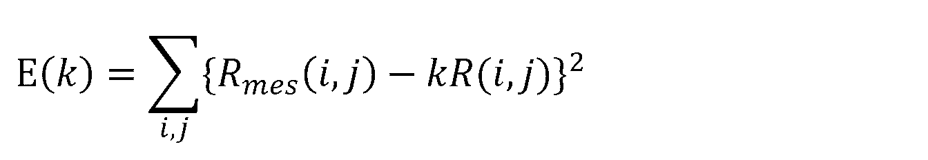
従って、本実施の形態では、変位算出部11は、上記の数10に最小2乗法を適用して、比例定数kを算出する。なお、評価関数E(k)として、上記の数10に示したRmes(i ,j)とR(i ,j)との差の2乗和以外に、絶対値和、他の累乗和等が用いられていても良い。Therefore, in the present embodiment, the
そして、変位算出部11は、算出した比例定数kを拡大・縮小の割合を示す定数として、上記数7に適用して、移動量ΔZを算出する。
Then, the
以上のように、変位算出部11は、計測対象領域の3方向への移動量ΔX、ΔY、ΔZを求めることができる。
As described above, the
また、変位算出部11は、算出した計測対象領域の移動量ΔX、ΔY、ΔZを用いて、さらに精度よく計測対象領域の移動量を算出することもできる。具体的には、算出した移動量ΔZを、上記数4に代入して、法線方向の移動(Δz)に伴う変位ベクトル成分(δzxij ,δzyij)を算出する。更に、変位算出部11によって変位分布として算出されている変位ベクトル(δxij,δyij)から、算出した法線方向の移動(Δz)に伴う変位ベクトル成分(δzxij ,δzyij)を減算することで、XY方向の移動(Δx, Δy)に伴う変位ベクトル成分(δx’, δy’)を算出する(上記数1及び数2参照)。Further, the
なお、ここでも、表面変位成分(δδxij ,δδyij)は、面内方向の移動(Δx, Δy)に伴う変位ベクトル成分(δx, δy)および法線方向の移動(Δz)に伴う変位ベクトル成分(δzxij ,δzyij)に比べると、十分に小さいとみなせるという条件を使って算出する。Here, too, the surface displacement components (δδx ij , δδy ij ) are the displacement vector components (δx, δy) associated with the in-plane movement (Δx, Δy) and the displacement vector components (Δz) associated with the normal direction movement (Δz). It is calculated using the condition that it can be regarded as sufficiently small compared to the components (δzx ij , δzy ij ).
その後、変位算出部11は、算出したXY方向の移動量に伴う変位ベクトル成分(δx’, δy’)と、移動量Δzとを、上記数3に代入することにより、計測対象領域のXY向における移動量△x’及び△y’を算出する。このようにして算出された計測対象領域の面方向における移動量、△x’、及び△y’は、先に算出された移動量ΔX、及びΔYよりも精度よく算出されている。
After that, the
更に、算出された計測対象領域の3方向への移動量、△x’、△y’を用いて、再び上記数10を適用してΔz’を算出し、3方向における計測対象領域の移動量△x’、△y’、Δz’を求めることも可能である。この値は、移動量ΔX、ΔY、ΔZ、および△x’、△y’、Δzとして算出した時よりも精度よく算出されている。上記の処理は、あらかじめ定められた回数分繰り返えされても良い、一定の値域に収束するまで繰り返えされても良い。
Furthermore, using the calculated movement amounts of the measurement target area in the three directions, Δx' and Δy', the
また、変位算出部11によって算出された計測対象領域のXY方向における移動量△X及び△Yと、計測対象領域のZ方向における移動量△Zとは、それぞれ、時系列画像を撮影した撮影毎に得られる。このようにして得られた方向毎の(移動量)は、各方向における変位の時系列変化を表しており、撮影の時間間隔をサンプリング間隔とした振動情報として扱うことができる。
Further, the movement amounts ΔX and ΔY in the XY directions of the measurement target region and the movement amount ΔZ in the Z direction of the measurement target region, which are calculated by the
回転検出部14は、レーダーアンテナ装置30における回転運動を検出する。具体的には、回転検出部14は、変位算出部11によって算出された変位の情報に基づいて、又は物理的なデバイスからの信号に基づいて、回転運動を検出する。「変位の情報」は、変位算出部11によって算出された、方向毎の変位の値である。また、本実施の形態では、回転検出部14は、指向性アンテナ31が回転中に特定の位置となると、そのことを検出して、検出信号を出力し、これを負荷検知部12に入力する。
The
各方向の変位の情報に基づいて回転運動が検出される場合は、回転検出部14は、まず、指向性アンテナ31が特定の位置となった時点で変位算出部11によって算出された、方向毎の変位の値を記録する。続いて、回転検出部14は、指向性アンテナ31が回転状態にあるときに、変位算出部11によって算出される方向毎の変位の各値を監視し、その値が、記録されている値に最も近くなったかどうかを判定する。具体的には、回転検出部14は、方向毎の変位の各値に対して、最小二乗法を適用することによって、各値が、記録されている値に最も近くなったかどうかを判定する。
When rotational motion is detected based on information on displacement in each direction, the
そして、回転検出部14は、方向毎の変位の各値が、記録されている値に最も近いと判定した場合は、その判定のタイミングで、負荷検知部12に信号を出力する。このとき出力される信号が、上述の検出信号となる。
When the
また「物理的なデバイス」としては、センサ、スイッチ等が挙げられる。物理的なデバイスからの信号に基づいて回転運動が検出される場合は、例えば、図2に示すように、レーダーアンテナ装置30の支持部32に、センサ40が取り付けられる。センサ40は、指向性アンテナ31が特定の位置となると、そのことを検知して検出信号を出力する。そして、回転検出部14は、センサ40から出力されてきた信号を受信すると、受信したタイミングで、負荷検知部12に信号を出力する。このとき出力される信号も、上述の検出信号となる。
A "physical device" includes a sensor, a switch, and the like. When rotational motion is detected based on a signal from a physical device, a
負荷検知部12は、本実施の形態では、まず、変位算出部11によって方向(X、Y、Z)毎に算出された変位の時系列変化に対して、回転検出部14によって検出された回転運動に基づいて、時間窓を設定する。続いて、負荷検知部12は、各方向について、設定した時間窓毎に、変位算出部11によって算出された変位の時系列変化と、基準時の時系列変化とを比較して、機械装置にかかる負荷を検知する。
In this embodiment, the
具体的には、負荷検知部12は、指向性アンテナ31が特定の位置となり、センサ40から検出信号が出力されてきた場合は、この検出信号をトリガとして、時間窓の終点と、次の時間窓の開始点とを設定する。これにより、時間窓は、指向性アンテナ31の回転周期に合わせて設定されることになる。また、終点及び開始点の設定は、検出信号が出力される度に行われても良いし、検出信号が特定回数出力される度に行われても良い。
Specifically, when the
また、本実施の形態では、レーダーアンテナ装置30において、指向性アンテナ31は、その重心と回転軸とがずれた状態で回転している。つまり、指向性アンテナ31が偏心している状態で回転することで、その重心の位置、重量、及び回転速度に応じて、指向性アンテナ31に負荷が作用し、揺動が発生している。このため、負荷検知部12は、この揺動の成分に着目し、設定した時間窓毎に、変位の時系列変化と、基準時の時系列変化とを比較して、振幅及び位相の相違を抽出し、抽出した相違に基づいて、レーダーアンテナ装置30にかかる負荷を検知することもできる。
Further, in the present embodiment, in the
ここで、図5を用いて、変位の時系列変化について説明する。図5(a)は、本発明の実施の形態において変位算出部によって算出された変位の時系列変化を示す図である。図5(b)は、図5(a)に示す時系列変化に時間窓が設定された状態を示す図である。図5(c)は、本発明の実施の形態で用いられる基準時の時系列変化を示す図である。図5(a)~(c)では、時系列画像の水平方向に相当するX方向における変位の時系列変化が示されており、縦軸が変位、横軸が時間を表している。 Here, time-series changes in displacement will be described with reference to FIG. FIG. 5(a) is a diagram showing a time series change in displacement calculated by the displacement calculator in the embodiment of the present invention. FIG. 5(b) is a diagram showing a state in which a time window is set for the time-series changes shown in FIG. 5(a). FIG. 5(c) is a diagram showing time-series changes in the reference time used in the embodiment of the present invention. FIGS. 5A to 5C show time-series changes in displacement in the X direction corresponding to the horizontal direction of the time-series images, with the vertical axis representing displacement and the horizontal axis representing time.
図5に示すように、変位は、指向性アンテナ31の回転周期に合わせて変動している。また、時間窓は、指向性アンテナ31の回転周期によって設定されており、1つの時間窓の長さは、指向性アンテナ31が一回転するのにかかる時間となる。負荷検知部12は、図3(b)に示す一回転分の変位の時系列変化と、図3(c)に示す基準時の時系列変化とを比較して負荷の変化を検知する。
As shown in FIG. 5, the displacement fluctuates according to the rotation period of the
続いて、図6~図10を用いて、負荷検知部12による負荷の変化の検知処理について説明する。また、以下の説明では、偏心している状態で回転する指向性アンテナの代わりに、偏心荷重の印加位置(回転中心からの距離)を3段階(0mm(偏心無)、50mm、150mm)に変化させることができる重りを載せた回転台(ペデスタル)の挙動を用いて説明する。支持部となる回転台部を計測対象領域として設定し、重りの回転に応じて回転台部に生じるわずかな動きを計測した結果を以下に示す。
Next, load change detection processing by the
図6(a)は、偏心荷重の印加位置と揺動成分の振幅との関係を示すグラフであり、図6(b)は、重りの質量(偏心荷重の大きさ)と揺動成分の振幅との関係を示すグラフである。一般に、偏心状態で回転が発生すると、半径方向に働く遠心力によって、揺動が発生する。そして、遠心力は、「質量×半径×(角速度)2」で算出される。従って、図6(a)に示すように、偏心荷重の印加位置が大きくなる程、揺動成分の振幅は大きくなる。また、図6(b)に示すように、重りの質量(偏心荷重の大きさ)が大きくなる程、この場合も揺動成分の振幅は大きくなる。また、揺動成分は、風等の外力による影響を受けて変化する。FIG. 6(a) is a graph showing the relationship between the application position of the eccentric load and the amplitude of the oscillation component, and FIG. 6(b) shows the mass of the weight (the magnitude of the eccentric load) and the amplitude of the oscillation component. is a graph showing the relationship between In general, when rotation occurs in an eccentric state, centrifugal force acting in the radial direction causes oscillation. The centrifugal force is calculated by "mass x radius x (angular velocity) 2 ". Therefore, as shown in FIG. 6A, the amplitude of the swing component increases as the eccentric load applied position increases. Also, as shown in FIG. 6B, the larger the mass of the weight (magnitude of the eccentric load), the larger the amplitude of the swing component. Further, the swing component changes under the influence of external forces such as wind.
図7は、変位の時系列変化のピーク位置(位相)の変化を示す図である。図7に示すように、トリガ位置と重りとの関係が変化すると、画像処理によって得られた変位の時系列変化の位相は変化する。具体的には、図7中の上図と下図とでは、偏心荷重の印加位置は90度異なっている。従って、下図では、トリガ位置に対する揺動成分の振幅のピーク位置が、上図に比べて約1.2秒シフトしている。つまり、図7の例では、回転の1周期は4.66秒であることから、約90度度分の位相シフトが発生していることになる。図7から分かるように、重りの位置が円周方向において変化すると、変位の時系列変化の位相が変化する。 FIG. 7 is a diagram showing changes in peak positions (phases) of time-series changes in displacement. As shown in FIG. 7, when the relationship between the trigger position and the weight changes, the phase of the time series change in displacement obtained by image processing changes. Specifically, the application position of the eccentric load differs by 90 degrees between the upper diagram and the lower diagram in FIG. Therefore, in the lower diagram, the peak position of the amplitude of the swing component with respect to the trigger position is shifted by about 1.2 seconds compared to the upper diagram. That is, in the example of FIG. 7, since one period of rotation is 4.66 seconds, a phase shift of about 90 degrees has occurred. As can be seen from FIG. 7, when the position of the weight changes in the circumferential direction, the phase of the time series change in displacement changes.
図8は、揺動成分の振幅と位相との関係を示す図である。図8において、縦軸及び横軸は、揺動成分の振幅、即ち、半径方向に働く力の大きさ(遠心力+その他の外力)を示している。また、図8において、●印は、偏心荷重の印加位置それぞれにおける振幅のピークを示している。そして、●から円の中心までを結ぶ線と、トリガ位置から円の中心までを結ぶ線とのなす角度θは、ピークの位相を示し、言い換えると、半径方向に働く力のタイミングのずれを示している。また、角度θは、指向性アンテナ31がトリガ位置にあるときから振幅がピークとなるまでにかかる時間に比例する。図8からは、偏心荷重の印加位置が変わったり、外力の大きさが変わったりすると、振幅のピークの発生位置が変わることが分かる。
FIG. 8 is a diagram showing the relationship between the amplitude and phase of the oscillation component. In FIG. 8, the vertical and horizontal axes represent the amplitude of the swinging component, that is, the magnitude of force acting in the radial direction (centrifugal force + other external force). In addition, in FIG. 8, the ● mark indicates the peak of the amplitude at each application position of the eccentric load. The angle θ formed by the line connecting ● to the center of the circle and the line connecting the trigger position to the center of the circle indicates the phase of the peak, in other words, the deviation of the timing of the force acting in the radial direction. ing. Also, the angle θ is proportional to the time it takes for the amplitude to peak after the
レーダーアンテナ装置30では、機械部品の摩耗、変形等によって、指向性アンテナ31の回転中心がわずかにずれ、回転軸や重心位置の変化が発生する可能性がある。本手法では、そのような摩耗や変形が発生した場合には、偏心荷重の印加位置が半径方向及び円周方向に変化することになる。従って、レーダーアンテナ装置30においても、図6~図8に示した変化が観察され、負荷の状態及び変化を検知することができる。また、この場合、変位の時系列変化は、図9及び図10に示すように変化する。図9は、偏心荷重の印加位置が半径方向にずれた場合の変位の時系列変化の変動を示す図である。図10は、偏心荷重の印加位置が円周方向にずれた場合の変位の時系列変化の変動を示す図である。
In the
従って、負荷検知部12は、変位の時系列変化と、基準時の時系列変化とを比較して、図7に示す結果が得られた場合は、例えば、レーダーアンテナ装置30において、回転軸を偏心させる負荷を検知することとなる。また、負荷検知部12は、変位の時系列変化と、基準時の時系列変化とを比較して、図8に示す結果が得られた場合は、例えば、回転軸を捻る負荷(風等の外力)を検知する。
Therefore, the
異常判定部13は、検知された負荷に基づいて、レーダーアンテナ装置30に異常が発生しているかどうかを判定する。具体的には、異常判定部13は、例えば、変位の時系列変化と基準時の時系列変化とを比較したときの、振動のピークの差分及び位相差の差分のいずれか又は両方が閾値以上となる場合に、レーダーアンテナ装置30に異常が発生していると判定する。
The
[装置動作]
次に、本実施の形態における負荷検知装置10の動作について図11を用いて説明する。図11は、本発明の実施の形態における負荷検知装置の動作を示すフロー図である。以下の説明においては、適宜図1~図10を参酌する。また、本実施の形態では、負荷検知装置を動作させることによって、負荷検知方法が実施される。よって、本実施の形態における負荷検知方法の説明は、以下の負荷検知装置10の動作説明に代える。[Device operation]
Next, the operation of
図11に示すように、最初に、変位算出部11は、撮像装置20から出力されてきている、レーダーアンテナ装置30の計測対象領域を撮影した時系列画像の画像データを取得する(ステップA1)。次に、変位算出部11は、時系列画像の画像データを用いて、X、Y、Zそれぞれの方向毎に、画像内の計測対象領域における変位分布を算出する(ステップA2)。
As shown in FIG. 11, first, the
次に、変位算出部11は、ステップA2で算出された各方向における変位分布と撮影情報とに基づいて、X、Y、Zそれぞれの方向毎に、移動量(△X、△Y、△Z)を算出する(ステップA3)。これにより、各方向における変位の時系列変化が得られる。
Next, the
次に、負荷検知部12は、ステップA3で得られた各方向における変位の時系列変化に対して、回転検出部14から出力されてきた検出信号をトリガとして、時間窓を設定する(ステップA4)。次いで、負荷検知部12は、設定した時間窓で区切った各波形と、基準時の時系列変化とを比較して、レーダーアンテナ装置30における負荷の変化を検知する(ステップA5)。
Next, the
次に、異常判定部13は、ステップA5検知された負荷の変化に基づいて、レーダーアンテナ装置30に異常が発生しているかどうかを判定し、判定結果を出力する(ステップA6)。
Next, the
ステップA6の実行により、負荷検知装置10における処理は一旦終了するが、その後、ステップA1が再度実行される。即ち、本実施の形態では、ステップA1~A6は、繰り返し実行される。
By executing step A6, the processing in the
[実施の形態における効果]
以上のように本実施の形態によれば、時系列画像から算出された機械装置30の微少な揺動成分が検出され、この揺動成分の時系列変化に基づいて、機械装置30における負荷の変化が検知される。このため、応力が比較的長い周期で変動する場合であっても、機械装置30における負荷の変化を検知することができる。また、機械装置30、及び機械装置30が設置されている鉄塔などの構造物に、風等の外力が四方八方から作用する場合にも、揺動成分が変化する。そのため、このような場合にも、同様の計測手法によって負荷の方向に影響されることなく、風等の外力による負荷の発生及び負荷の変化を検出することも可能となる。また、本実施の形態では、負荷の変化に基づいて異常判定も行われるため、機械装置30の管理者における負担が大きく低減される。[Effects of Embodiment]
As described above, according to the present embodiment, the slight swing component of the
[変形例]
続いて、本実施の形態における変形例について以下に説明する。上述した実施の形態では、変位算出部11は、変位分布から、各方向の変位を算出しているが、本変形例では、変位分布を算出することなく、各方向の変位が算出される。[Modification]
Next, modifications of the present embodiment will be described below. In the above-described embodiment, the
具体的には、変位算出部11は、まず、処理画像と基準画像とを対比して照合し、処理画像毎に、最も基準画像との照合度合の高い領域の位置を特定する。また、変位算出部11は、特定した位置を、X方向における変位d1x、Y方向における変位d1yとして算出する。本変形例1でも、最も照合度合いの高い対象領域の探索手法としては、上述した、SAD、SSD、NCC、ZNCC等の類似度相関関数を用いて、最も相関が高い位置(座標)を探索する手法が挙げられる。また、最も照合度合いの高い領域の探索手法としては、フィッティングを用いることもできる。
Specifically, the
変位算出部11は、更に、Z方向の変位d1zを算出するため、基準画像を予め定められた倍率で拡大及び縮小することによって画像群(以下「基準画像群」と表記する)を作成する。このとき、変位算出部11は、先に算出したXY方向における変位(d1x、d1y)に基づいて、基準画像の拡大画像及び縮小画像の中心位置を設定して、基準画像群を作成する。
Further, the
続いて、変位算出部11は、処理画像毎に、拡大画像及び縮小画像に照合し、最も照合度合の高い拡大画像又は縮小画像を特定する。照合度合の高い画像の特定は、例えば、SAD、SSD、NCC、ZNCC等の先に述べた類似度相関関数を用いて行なうことができる。そして、変位算出部11は、基準画像群を構成する画像の中から最も類似度が高い画像、即ち、相関が高い画像を特定し、特定した画像の拡大率又は縮小率(以下「倍率」と表記する)を、特定領域の法線方向の変位を示す量(d1z)として算出する。
Subsequently, the
また、変位算出部11は、最も照合度合が高い画像を特定した後、基準画像群の中から、特定した画像の前後の倍率の画像を選択し、特定した画像と選択した画像との類似度相関関数を算出する。そして、変位算出部11は、算出した類似度相関関数を用いて、直線フィッティング、曲線フィッティングなどの手法を適用して、法線方向の変位を示す量(d1z)となる倍率を算出することもできる。これにより、より精度良く、法線方向の変位を示す量として、倍率(d1z)を算出できることになる。このようにして処理画像毎のXY方向の変位(d1x、d1y)、およびZ方向の変位を示す量として倍率(d1z)を算出する。
Further, after identifying the image with the highest matching degree, the
また、変位算出部11は、変位の精度を高めるため、上述の処理を複数回実行することができる。具体的には、変位算出部11は、先に算出した倍率d1zの影響を考慮して、基準画像群を構成する画像の中から、倍率d1zに対応する画像を選択し、選択した画像を新たな基準画像とする。次いで、変位算出部11は、処理画像と新たな基準画像とを対比して、処理画像において、新たな基準画像に最も類似している類似箇所を特定し、その位置を求めて、類似箇所の変位(d2x、d2y)を検出する。
In addition, the
次いで、変位算出部11は、新たに検出した変位(d2x、d2y)に基づいて、基準画像群を構成する各画像の拡大又は縮小の中心位置を設定し、新たな基準画像群を作成する。そして、変位算出部11は、処理画像と新たな基準画像群を構成する各画像との類似度を算出し、新たな基準画像群を構成する画像の中から最も類似度が高い画像を特定する。その後、変位算出部11は、特定した画像の倍率を、特定領域の法線方向の変位を示す量(d2z)として算出する。
Next, based on the newly detected displacement (d2x, d2y), the
このように、1回目の処理では、Z方向の変位を示す倍率であるd1zが考慮されていない状態で、変位(d1x、d1y)が算出されているのに対して、2回目の処理では、倍率d1zが考慮された状態で、変位(d2x、d2y)が算出される。このため、2回目の処理で算出された変位(d2x、d2y)の方が、1回目に算出された変位に比べて、高い精度で算出されている。また、同様な処理を複数回実行する場合は、変位の精度がより向上することになる。 Thus, in the first process, displacement (d1x, d1y) is calculated without considering d1z, which is a magnification indicating the displacement in the Z direction, whereas in the second process, The displacement (d2x, d2y) is calculated with the scaling factor d1z taken into account. Therefore, the displacement (d2x, d2y) calculated in the second process is calculated with higher accuracy than the displacement calculated in the first time. In addition, when similar processing is executed a plurality of times, the accuracy of displacement is further improved.
なお、上述の例では、処理の繰り返し回数は2回であるが、特に限定されるものではない。繰り返しの回数は、予め設定された回数であっても良いし、結果に応じて適宜設定されても良い。また、算出された変位の値が閾値に到達するまで繰り返される態様であっても良い。 In the above example, the number of repetitions of the process is two, but the number of repetitions is not particularly limited. The number of repetitions may be a preset number, or may be appropriately set according to the results. Alternatively, the process may be repeated until the calculated displacement value reaches the threshold value.
また、以降の説明では、ある処理画像において最終的に得られる変位は、変位(dnx、dny)と、法線方向の変位を示す量である倍率(dnz)とで表される。時系列画像に対して同様に変位を算出した結果は、時間変化する値として扱うことができるため、変位(dnx(t)、dny(t))、および倍率(dnz(t))と表記する。 Further, in the following description, the displacement finally obtained in a certain processed image is represented by the displacement (dnx, dny) and the magnification (dnz) which is the amount indicating the displacement in the normal direction. Similar displacement calculation results for time-series images can be treated as time-varying values, so they are denoted as displacement (dnx(t), dny(t)) and magnification (dnz(t)). .
また、上記のXY方向における変位(dnx(t)、dny(t))は、ピクセル単位で算出されている。従って、変位算出部11は、下記の数11及び数12に示すように、X方向及びY方向それぞれにおける撮像装置20の撮像素子の1ピクセル当たりの長さ(Dx、Dy)[mm/pixel]を用いて、X方向及びY方向それぞれにおける変位(△x、△y)[mm]を算出する。また、撮像素子の1ピクセル当たりの長さ(Dx、Dy)[mm/pixel]は、撮像素子の画素ピッチ(px、py)[mm]と、レンズの焦点距離f[mm]と、レンズの主点から計測対象領域までの距離L[mm]とを用いて、下記の数13及び数14から算出できる。
Further, the displacements (dnx(t), dny(t)) in the XY directions are calculated in units of pixels. Therefore, as shown in
![]()
![]()
![]()
![]()
![]()
![]()

また、Z方向における変位は、倍率として算出されている。従って、変位算出部11は、下記の数15に示すように、撮像素子の主点から特定領域までの距離L[mm]を用いて、Z方向(法線方向)における変位△z[mm]を算出する。
Also, the displacement in the Z direction is calculated as a magnification. Therefore, as shown in Equation 15 below, the

また、このようにして得られた計測対象領域の変位(△x、△y、△z)は、時系列画像を撮影したフレーム毎に得られている。よって、時系列画像毎に得られた各変位は、撮影フレームレートの逆数をサンプリング間隔とした計測対象領域の振動成分を表している。 Further, the displacements (Δx, Δy, Δz) of the measurement target region obtained in this manner are obtained for each frame in which the time-series images are captured. Therefore, each displacement obtained for each time-series image represents the vibration component of the measurement target region with the reciprocal of the imaging frame rate as the sampling interval.
[プログラム]
本実施の形態におけるプログラムは、コンピュータに、図11に示すステップA1~A6を実行させるプログラムであれば良い。このプログラムをコンピュータにインストールし、実行することによって、本実施の形態における負荷検知装置10と負荷検知方法とを実現することができる。この場合、コンピュータのプロセッサは、変位算出部11、負荷検知部12、及び異常判定部13として機能し、処理を行なう。[program]
The program in this embodiment may be any program that causes a computer to execute steps A1 to A6 shown in FIG. By installing this program in a computer and executing it, the
また、本実施の形態におけるプログラムは、複数のコンピュータによって構築されたコンピュータシステムによって実行されても良い。この場合は、例えば、各コンピュータが、それぞれ、変位算出部11、負荷検知部12、及び異常判定部13のいずれかとして機能しても良い。
Also, the program in this embodiment may be executed by a computer system constructed by a plurality of computers. In this case, for example, each computer may function as one of the
ここで、本実施の形態におけるプログラムを実行することによって、負荷検知装置10を実現するコンピュータについて図12を用いて説明する。図12は、本発明の実施の形態における負荷検知装置を実現するコンピュータの一例を示すブロック図である。
Here, a computer that implements the
図12に示すように、コンピュータ110は、CPU(Central Processing Unit)111と、メインメモリ112と、記憶装置113と、入力インターフェイス114と、表示コントローラ115と、データリーダ/ライタ116と、通信インターフェイス117とを備える。これらの各部は、バス121を介して、互いにデータ通信可能に接続される。また、コンピュータ110は、CPU111に加えて、又はCPU111に代えて、GPU(Graphics Processing Unit)、又はFPGA(Field-Programmable Gate Array)を備えていても良い。
As shown in FIG. 12, a
CPU111は、記憶装置113に格納された、本実施の形態におけるプログラム(コード)をメインメモリ112に展開し、これらを所定順序で実行することにより、各種の演算を実施する。メインメモリ112は、典型的には、DRAM(Dynamic Random Access Memory)等の揮発性の記憶装置である。また、本実施の形態におけるプログラムは、コンピュータ読み取り可能な記録媒体120に格納された状態で提供される。なお、本実施の形態におけるプログラムは、通信インターフェイス117を介して接続されたインターネット上で流通するものであっても良い。
The
また、記憶装置113の具体例としては、ハードディスクドライブの他、フラッシュメモリ等の半導体記憶装置が挙げられる。入力インターフェイス114は、CPU111と、キーボード及びマウスといった入力機器118との間のデータ伝送を仲介する。表示コントローラ115は、ディスプレイ装置119と接続され、ディスプレイ装置119での表示を制御する。
Further, as a specific example of the
データリーダ/ライタ116は、CPU111と記録媒体120との間のデータ伝送を仲介し、記録媒体120からのプログラムの読み出し、及びコンピュータ110における処理結果の記録媒体120への書き込みを実行する。通信インターフェイス117は、CPU111と、他のコンピュータとの間のデータ伝送を仲介する。
Data reader/
また、記録媒体120の具体例としては、CF(Compact Flash(登録商標))及びSD(Secure Digital)等の汎用的な半導体記憶デバイス、フレキシブルディスク(Flexible Disk)等の磁気記録媒体、又はCD-ROM(Compact Disk Read Only Memory)などの光学記録媒体が挙げられる。
Specific examples of the
なお、本実施の形態における負荷検知装置10は、プログラムがインストールされたコンピュータではなく、各部に対応したハードウェアを用いることによっても実現可能である。更に、負荷検知装置10は、一部がプログラムで実現され、残りの部分がハードウェアで実現されていてもよい。
It should be noted that the
上述した実施の形態の一部又は全部は、以下に記載する(付記1)~(付記21)によって表現することができるが、以下の記載に限定されるものではない。 Some or all of the above-described embodiments can be expressed by (Appendix 1) to (Appendix 21) described below, but are not limited to the following descriptions.
(付記1)
可動部分を有する機械装置にかかる負荷の変化を検知するための装置であって、
前記機械装置の前記可動部分以外の部分を撮影する撮像装置から出力されてきた時系列画像に基づいて、前記機械装置の特定方向における変位を算出する、変位算出部と、
算出された前記変位の時系列変化と、予め所得されている基準時の時系列変化とを比較し、比較結果に基づいて、前記機械装置にかかる負荷の変化を検知する、負荷検知部と、
を備えている、ことを特徴とする負荷検知装置。(Appendix 1)
A device for detecting changes in load on a mechanical device having moving parts, comprising:
a displacement calculation unit that calculates a displacement of the mechanical device in a specific direction based on time-series images output from an imaging device that captures a portion of the mechanical device other than the movable portion;
a load detection unit that compares the calculated time-series change in the displacement with a time-series change in a reference time obtained in advance, and detects a change in the load applied to the mechanical device based on the comparison result;
A load detection device characterized by comprising:
(付記2)
付記1に記載の負荷検知装置であって、
前記機械装置が、一定の周期で回転する回転部と、前記回転部を支持する支持部とを備え、且つ、前記撮像装置が、前記回転部の回転軸に垂直な方向から、前記支持部を撮影している、
ことを特徴とする負荷検知装置。(Appendix 2)
The load detection device according to
The mechanical device includes a rotating portion that rotates at a constant cycle and a supporting portion that supports the rotating portion, and the imaging device moves the supporting portion from a direction perpendicular to the rotation axis of the rotating portion. are filming,
A load detection device characterized by:
(付記3)
付記2に記載の負荷検知装置であって、
前記変位算出部が、前記回転軸に垂直な方向と、前記回転軸に垂直な方向に垂直に交わり、且つ、互いに垂直に交わる2つの方向との、3方向において、前記変位を算出し、
前記負荷検知部が、前記3方向において前記機械装置にかかる負荷の変化を検知する、
ことを特徴とする負荷検知装置。(Appendix 3)
The load detection device according to
the displacement calculation unit calculates the displacement in three directions, namely, a direction perpendicular to the rotation axis and two directions perpendicular to the direction perpendicular to the rotation axis and perpendicular to each other;
wherein the load detection unit detects changes in the load applied to the mechanical device in the three directions;
A load detection device characterized by:
(付記4)
付記2または3に記載の負荷検知装置であって、
前記負荷検知部が、算出された前記変位の時系列変化に対して、前記周期毎に時間窓を設定し、設定した前記時間窓毎に、算出された前記変位の時系列変化と、前記基準時の時系列変化とを比較して、前記機械装置にかかる負荷の変化を検知する、
ことを特徴とする負荷検知装置。(Appendix 4)
The load detection device according to
The load detection unit sets a time window for each period with respect to the calculated time-series change in the displacement, and for each set time window, the calculated time-series change in the displacement and the reference detecting a change in the load applied to the mechanical device by comparing it with the time-series change of time;
A load detection device characterized by:
(付記5)
付記4のいずれかに記載の負荷検知装置であって、
前記機械装置の前記回転部が、その重心と回転軸とがずれた状態で回転している場合において、
前記負荷検知部が、設定した前記時間窓毎に、算出された前記変位の時系列変化と、前記基準時の時系列変化とを比較して、振幅及び位相の相違を抽出し、抽出した前記相違に基づいて、前記機械装置にかかる負荷の変化を検知する、
ことを特徴とする負荷検知装置。(Appendix 5)
4. The load detection device according to any one of
When the rotating part of the mechanical device rotates in a state where the center of gravity and the rotation axis are deviated,
The load detection unit compares the calculated time-series change of the displacement with the time-series change at the reference time for each of the set time windows, extracts differences in amplitude and phase, and extracts the extracted detecting a change in load on the mechanical device based on the difference;
A load detection device characterized by:
(付記6)
付記4または5に記載の負荷検知装置であって、
前記機械装置における回転運動を検出する、回転検出部を更に備え、
前記負荷検知部は、前記回転検出部によって検出された回転運動に基づいて、前記周期毎に時間窓を設定する、
ことを特徴とする、負荷検知装置。(Appendix 6)
The load detection device according to
further comprising a rotation detection unit that detects rotational motion in the mechanical device;
The load detection unit sets a time window for each cycle based on the rotational motion detected by the rotation detection unit.
A load detection device characterized by:
(付記7)
付記1~6のいずれかに記載の負荷検知装置であって、
検知された前記負荷に基づいて、前記機械装置に異常が発生しているかどうかを判定する、異常判定部を更に備えている、
ことを特徴とする負荷検知装置。(Appendix 7)
The load detection device according to any one of
further comprising an abnormality determination unit that determines whether an abnormality has occurred in the mechanical device based on the detected load;
A load detection device characterized by:
(付記8)
可動部分を有する機械装置にかかる負荷の変化を検知するための方法であって、
(a)前記機械装置の前記可動部分以外の部分を撮影する撮像装置から出力されてきた時系列画像に基づいて、前記機械装置の特定方向における変位を算出する、ステップと、
(b)算出された前記変位の時系列変化と、予め所得されている基準時の時系列変化とを比較し、比較結果に基づいて、前記機械装置にかかる負荷の変化を検知する、ステップと、
を有する、ことを特徴とする負荷検知方法。(Appendix 8)
A method for detecting changes in load on a mechanical device having moving parts, comprising:
(a) calculating a displacement of the mechanical device in a specific direction based on time-series images output from an imaging device that captures a portion of the mechanical device other than the movable portion;
(b) comparing the calculated time-series change in the displacement with the time-series change in the reference time obtained in advance, and detecting a change in the load applied to the mechanical device based on the comparison result; ,
A load detection method characterized by comprising:
(付記9)
付記8に記載の負荷検知方法であって、
前記機械装置が、一定の周期で回転する回転部と、前記回転部を支持する支持部とを備え、且つ、前記撮像装置が、前記回転部の回転軸に垂直な方向から、前記支持部を撮影している、
ことを特徴とする負荷検知方法。(Appendix 9)
The load detection method according to
The mechanical device includes a rotating portion that rotates at a constant cycle and a supporting portion that supports the rotating portion, and the imaging device moves the supporting portion from a direction perpendicular to the rotation axis of the rotating portion. are filming,
A load detection method characterized by:
(付記10)
付記9に記載の負荷検知方法であって、
前記(a)のステップにおいて、前記回転軸に垂直な方向と、前記回転軸に垂直な方向に垂直に交わり、且つ、互いに垂直に交わる2つの方向との、3方向において、前記変位を算出し、
前記(b)のステップにおいて、前記3方向において前記機械装置にかかる負荷の変化を検知する、
ことを特徴とする負荷検知方法。(Appendix 10)
The load detection method according to
In step (a), the displacement is calculated in three directions: a direction perpendicular to the rotation axis and two directions perpendicular to the direction perpendicular to the rotation axis and perpendicular to each other. ,
In step (b), detecting changes in the load applied to the mechanical device in the three directions;
A load detection method characterized by:
(付記11)
付記9または10に記載の負荷検知方法であって、
前記(b)のステップにおいて、算出された前記変位の時系列変化に対して、前記周期毎に時間窓を設定し、設定した前記時間窓毎に、算出された前記変位の時系列変化と、前記基準時の時系列変化とを比較して、前記機械装置にかかる負荷の変化を検知する、
ことを特徴とする負荷検知方法。(Appendix 11)
The load detection method according to
In step (b) above, a time window is set for each cycle with respect to the calculated time-series change in the displacement, and the calculated time-series change in the displacement for each set time window; Detecting a change in the load applied to the mechanical device by comparing it with the time-series change at the reference time;
A load detection method characterized by:
(付記12)
付記11に記載の負荷検知方法であって、
前記機械装置の前記回転部が、その重心と回転軸とがずれた状態で回転している場合において、
前記(b)のステップにおいて、設定した前記時間窓毎に、算出された前記変位の時系列変化と、前記基準時の時系列変化とを比較して、振幅及び位相の相違を抽出し、抽出した前記相違に基づいて、前記機械装置にかかる負荷の変化を検知する、
ことを特徴とする負荷検知方法。(Appendix 12)
The load detection method according to
When the rotating part of the mechanical device rotates in a state where the center of gravity and the rotation axis are deviated,
In the step (b), for each of the set time windows, the calculated time-series change in the displacement is compared with the time-series change in the reference time to extract differences in amplitude and phase. detecting a change in the load on the mechanical device based on the difference obtained;
A load detection method characterized by:
(付記13)
付記11または12に記載の負荷検知方法であって、
(c)前記機械装置における回転運動を検出する、ステップを更に有し、
前記(b)において、前記(c)によって検出された回転運動に基づいて、前記周期毎に時間窓を設定する、
ことを特徴とする、負荷検知方法。(Appendix 13)
13. The load detection method according to
(c) further comprising detecting rotational motion in the mechanical device;
In (b), setting a time window for each period based on the rotational motion detected in (c);
A load detection method characterized by:
(付記14)
付記8~13のいずれかに記載の負荷検知方法であって、
(d)検知された前記負荷に基づいて、前記機械装置に異常が発生しているかどうかを判定する、ステップを更に有している、
ことを特徴とする負荷検知方法。(Appendix 14)
The load detection method according to any one of
(d) further comprising determining whether an abnormality has occurred in the mechanical device based on the sensed load;
A load detection method characterized by:
(付記15)
コンピュータによって、可動部分を有する機械装置にかかる負荷の変化を検知するためのプログラムであって、
前記コンピュータに、
(a)前記機械装置の前記可動部分以外の部分を撮影する撮像装置から出力されてきた時系列画像に基づいて、前記機械装置の特定方向における変位を算出する、ステップと、
(b)算出された前記変位の時系列変化と、予め所得されている基準時の時系列変化とを比較し、比較結果に基づいて、前記機械装置にかかる負荷の変化を検知する、ステップと、
を実行させる、プログラム。
(Appendix 15)
A program for detecting a change in load applied to a mechanical device having moving parts by a computer,
to the computer;
(a) calculating a displacement of the mechanical device in a specific direction based on time-series images output from an imaging device that captures a portion of the mechanical device other than the movable portion;
(b) comparing the calculated time-series change in the displacement with the time-series change in the reference time obtained in advance, and detecting a change in the load applied to the mechanical device based on the comparison result; ,
The program that causes the to run .
(付記16)
付記15に記載のプログラムであって、
前記機械装置が、一定の周期で回転する回転部と、前記回転部を支持する支持部とを備え、且つ、前記撮像装置が、前記回転部の回転軸に垂直な方向から、前記支持部を撮影している、
ことを特徴とするプログラム。
(Appendix 16)
The program according to Appendix 15,
The mechanical device includes a rotating portion that rotates at a constant cycle and a supporting portion that supports the rotating portion, and the imaging device moves the supporting portion from a direction perpendicular to the rotation axis of the rotating portion. are filming,
A program characterized by
(付記17)
付記16に記載のプログラムであって、
前記(a)のステップにおいて、前記回転軸に垂直な方向と、前記回転軸に垂直な方向に垂直に交わり、且つ、互いに垂直に交わる2つの方向との、3方向において、前記変位を算出し、
前記(b)のステップにおいて、前記3方向において前記機械装置にかかる負荷の変化を検知する、
ことを特徴とするプログラム。
(Appendix 17)
The program according to Appendix 16,
In step (a), the displacement is calculated in three directions: a direction perpendicular to the rotation axis and two directions perpendicular to the direction perpendicular to the rotation axis and perpendicular to each other. ,
In step (b), detecting changes in the load applied to the mechanical device in the three directions;
A program characterized by
(付記18)
付記16または17に記載のプログラムであって、
前記(b)のステップにおいて、算出された前記変位の時系列変化に対して、前記周期毎に時間窓を設定し、設定した前記時間窓毎に、算出された前記変位の時系列変化と、前記基準時の時系列変化とを比較して、前記機械装置にかかる負荷の変化を検知する、
ことを特徴とするプログラム。
(Appendix 18)
The program according to Appendix 16 or 17,
In step (b) above, a time window is set for each cycle with respect to the calculated time-series change in the displacement, and the calculated time-series change in the displacement for each set time window; Detecting a change in the load applied to the mechanical device by comparing it with the time-series change at the reference time;
A program characterized by
(付記19)
付記18に記載のプログラムであって、
前記機械装置の前記回転部が、その重心と回転軸とがずれた状態で回転している場合において、
前記(b)のステップにおいて、設定した前記時間窓毎に、算出された前記変位の時系列変化と、前記基準時の時系列変化とを比較して、振幅及び位相の相違を抽出し、抽出した前記相違に基づいて、前記機械装置にかかる負荷の変化を検知する、
ことを特徴とするプログラム。
(Appendix 19)
The program according to Appendix 18,
When the rotating part of the mechanical device rotates in a state where the center of gravity and the rotation axis are deviated,
In the step (b), for each of the set time windows, the calculated time-series change in the displacement is compared with the time-series change in the reference time to extract differences in amplitude and phase. detecting a change in the load on the mechanical device based on the difference obtained;
A program characterized by
(付記20)
付記18または19に記載のプログラムであって、
前記コンピュータに、
(c)前記機械装置における回転運動を検出する、ステップを更に実行させ、
前記(b)のステップにおいて、前記(c)のステップによって検出された回転運動に基づいて、前記周期毎に時間窓を設定する、
ことを特徴とするプログラム。
(Appendix 20)
The program according to Appendix 18 or 19,
to the computer;
(c) further performing the step of detecting rotational motion in the mechanical device ;
In step (b), setting a time window for each cycle based on the rotational motion detected in step (c);
A program characterized by
(付記21)
付記15~20のいずれかに記載のプログラムであって、
前記コンピュータに、
(d)検知された前記負荷に基づいて、前記機械装置に異常が発生しているかどうかを判定する、ステップを更に実行させる、
ことを特徴とするプログラム。
(Appendix 21)
The program according to any one of Appendices 15 to 20,
to the computer;
(d) further executing a step of determining whether an abnormality has occurred in the mechanical device based on the sensed load ;
A program characterized by
以上のように、本発明によれば、可動部分を有する機械装置において、回転周期に影響されることなく、機械装置にかかる負荷の変化を検知することができる。本発明は、レーダーアンテナ装置、風力発電装置等の各種機械装置に有用である。 INDUSTRIAL APPLICABILITY As described above, according to the present invention, it is possible to detect changes in the load applied to a mechanical device having movable parts without being affected by the rotation period. INDUSTRIAL APPLICABILITY The present invention is useful for various mechanical devices such as radar antenna devices and wind power generators.
10 負荷検知装置
11 変位算出部
12 負荷検知部
13 異常判定部
14 回転検出部
20 撮像装置
30 機械装置(レーダーアンテナ装置)
31 指向性アンテナ
32 支持部
40 センサ
110 コンピュータ
111 CPU
112 メインメモリ
113 記憶装置
114 入力インターフェイス
115 表示コントローラ
116 データリーダ/ライタ
117 通信インターフェイス
118 入力機器
119 ディスプレイ装置
120 記録媒体
121 バスREFERENCE SIGNS
31
112
Claims (7)
前記機械装置の前記可動部分以外の部分を撮影する撮像装置から出力されてきた時系列画像に基づいて、前記機械装置の特定方向における変位を算出する、変位算出手段と、
算出された前記変位の時系列変化と、予め所得されている基準時の時系列変化とを比較し、比較結果に基づいて、前記機械装置にかかる負荷の変化を検知する、負荷検知手段と、
を備え、
前記機械装置が、一定の周期で回転する回転部と、前記回転部を支持する支持部とを備え、且つ、前記撮像装置が、前記回転部の回転軸に垂直な方向から、前記支持部を撮影しており、
前記負荷検知手段が、算出された前記変位の時系列変化に対して、前記周期毎に時間窓を設定し、設定した前記時間窓毎に、算出された前記変位の時系列変化と、前記基準時の時系列変化とを比較して、前記機械装置にかかる負荷の変化を検知する、
ことを特徴とする負荷検知装置。 A device for detecting changes in load on a mechanical device having moving parts, comprising:
Displacement calculation means for calculating a displacement of the mechanical device in a specific direction based on time-series images output from an imaging device that captures a portion of the mechanical device other than the movable portion;
load detection means for comparing the calculated time-series change in the displacement with a time-series change in a reference time obtained in advance, and detecting a change in the load applied to the mechanical device based on the comparison result;
with
The mechanical device includes a rotating portion that rotates at a constant cycle and a supporting portion that supports the rotating portion, and the imaging device moves the supporting portion from a direction perpendicular to the rotation axis of the rotating portion. I am filming
The load detection means sets a time window for each period with respect to the calculated time-series change of the displacement, and for each set time window, the calculated time-series change of the displacement and the reference detecting a change in the load applied to the mechanical device by comparing it with the time-series change of time;
A load detection device characterized by:
前記変位算出手段が、前記回転軸に垂直な方向と、前記回転軸に垂直な方向に垂直に交わり、且つ、互いに垂直に交わる2つの方向との、3方向において、前記変位を算出し、
前記負荷検知手段が、前記3方向において前記機械装置にかかる負荷の変化を検知する、
ことを特徴とする負荷検知装置。 The load detection device according to claim 1 ,
the displacement calculating means calculates the displacement in three directions, namely, a direction perpendicular to the rotation axis and two directions perpendicular to the direction perpendicular to the rotation axis and perpendicular to each other;
wherein the load sensing means senses changes in load on the mechanical device in the three directions;
A load detection device characterized by:
前記機械装置の前記回転部が、その重心と回転軸とがずれた状態で回転している場合において、
前記負荷検知手段が、設定した前記時間窓毎に、算出された前記変位の時系列変化と、前記基準時の時系列変化とを比較して、振幅及び位相の相違を抽出し、抽出した前記相違に基づいて、前記機械装置にかかる負荷の変化を検知する、
ことを特徴とする負荷検知装置。 The load detection device according to claim 1 ,
When the rotating part of the mechanical device rotates in a state where the center of gravity and the rotation axis are deviated,
The load detection means compares the calculated time-series change of the displacement with the time-series change at the reference time for each of the set time windows, extracts differences in amplitude and phase, and extracts the extracted detecting a change in load on the mechanical device based on the difference;
A load detection device characterized by:
前記機械装置における回転運動を検出する、回転検出手段を更に備え、
前記負荷検知手段は、前記回転検出手段によって検出された回転運動に基づいて、前記周期毎に時間窓を設定する、
ことを特徴とする、負荷検知装置。 The load detection device according to claim 1 or 3 ,
further comprising rotation detection means for detecting rotational movement in the mechanical device;
The load detection means sets a time window for each period based on the rotational motion detected by the rotation detection means.
A load detection device characterized by:
検知された前記負荷に基づいて、前記機械装置に異常が発生しているかどうかを判定する、異常判定手段を更に備えている、
ことを特徴とする負荷検知装置。 The load detection device according to any one of claims 1 to 4 ,
Further comprising abnormality determination means for determining whether an abnormality has occurred in the mechanical device based on the detected load,
A load detection device characterized by:
(a)前記機械装置の前記可動部分以外の部分を撮影する撮像装置から出力されてきた時系列画像に基づいて、前記機械装置の特定方向における変位を算出し、
(b)算出された前記変位の時系列変化と、予め所得されている基準時の時系列変化とを比較し、比較結果に基づいて、前記機械装置にかかる負荷の変化を検知し、
前記機械装置が、一定の周期で回転する回転部と、前記回転部を支持する支持部とを備え、且つ、前記撮像装置が、前記回転部の回転軸に垂直な方向から、前記支持部を撮影しており、
前記(b)において、算出された前記変位の時系列変化に対して、前記周期毎に時間窓を設定し、設定した前記時間窓毎に、算出された前記変位の時系列変化と、前記基準時の時系列変化とを比較して、前記機械装置にかかる負荷の変化を検知する、
ことを特徴とする負荷検知方法。 A method for detecting changes in load on a mechanical device having moving parts, comprising:
(a) calculating a displacement of the mechanical device in a specific direction based on time-series images output from an imaging device that captures a portion of the mechanical device other than the movable portion;
(b) comparing the calculated time-series change in the displacement with the time-series change in the reference time obtained in advance, and detecting a change in the load applied to the mechanical device based on the comparison result;
The mechanical device includes a rotating portion that rotates at a constant cycle and a supporting portion that supports the rotating portion, and the imaging device moves the supporting portion from a direction perpendicular to the rotation axis of the rotating portion. I am filming
In the above (b), a time window is set for each period with respect to the calculated time-series change in the displacement, and for each set time window, the calculated time-series change in the displacement and the reference detecting a change in the load applied to the mechanical device by comparing it with the time-series change of time;
A load detection method characterized by:
前記コンピュータに、
(a)前記機械装置の前記可動部分以外の部分を撮影する撮像装置から出力されてきた時系列画像に基づいて、前記機械装置の特定方向における変位を算出する、ステップと、
(b)算出された前記変位の時系列変化と、予め所得されている基準時の時系列変化とを比較し、比較結果に基づいて、前記機械装置にかかる負荷の変化を検知する、ステップと、
を実行させ、
前記機械装置が、一定の周期で回転する回転部と、前記回転部を支持する支持部とを備え、且つ、前記撮像装置が、前記回転部の回転軸に垂直な方向から、前記支持部を撮影しており、
前記(b)のステップにおいて、算出された前記変位の時系列変化に対して、前記周期毎に時間窓を設定し、設定した前記時間窓毎に、算出された前記変位の時系列変化と、前記基準時の時系列変化とを比較して、前記機械装置にかかる負荷の変化を検知させる、
プログラム。 A program for detecting a change in load applied to a mechanical device having moving parts by a computer,
to the computer;
(a) calculating a displacement of the mechanical device in a specific direction based on time-series images output from an imaging device that captures a portion of the mechanical device other than the movable portion;
(b) comparing the calculated time-series change in the displacement with the time-series change in the reference time obtained in advance, and detecting a change in the load applied to the mechanical device based on the comparison result; ,
and
The mechanical device includes a rotating portion that rotates at a constant cycle and a supporting portion that supports the rotating portion, and the imaging device moves the supporting portion from a direction perpendicular to the rotation axis of the rotating portion. I am filming
In step (b) above, a time window is set for each cycle with respect to the calculated time-series change in the displacement, and the calculated time-series change in the displacement for each set time window; Detecting a change in the load applied to the mechanical device by comparing it with the time-series change at the reference time;
program.
Applications Claiming Priority (1)
| Application Number | Priority Date | Filing Date | Title |
|---|---|---|---|
| PCT/JP2019/023981 WO2020255230A1 (en) | 2019-06-17 | 2019-06-17 | Load sensing device, load sensing method, and computer-readable recording medium |
Publications (3)
| Publication Number | Publication Date |
|---|---|
| JPWO2020255230A1 JPWO2020255230A1 (en) | 2020-12-24 |
| JPWO2020255230A5 JPWO2020255230A5 (en) | 2022-03-11 |
| JP7147984B2 true JP7147984B2 (en) | 2022-10-05 |
Family
ID=74036990
Family Applications (1)
| Application Number | Title | Priority Date | Filing Date |
|---|---|---|---|
| JP2021528080A Active JP7147984B2 (en) | 2019-06-17 | 2019-06-17 | LOAD DETECTION DEVICE, LOAD DETECTION METHOD, AND PROGRAM |
Country Status (2)
| Country | Link |
|---|---|
| JP (1) | JP7147984B2 (en) |
| WO (1) | WO2020255230A1 (en) |
Citations (4)
| Publication number | Priority date | Publication date | Assignee | Title |
|---|---|---|---|---|
| JP2010085105A (en) | 2008-09-29 | 2010-04-15 | Toshiba Corp | Motorized valve state monitoring and diagnosing apparatus and method |
| JP2016061634A (en) | 2014-09-17 | 2016-04-25 | Ntn株式会社 | Abnormality diagnosis device of rolling bearing, wind power generator, and abnormality diagnosis method of rolling bearing |
| WO2016152076A1 (en) | 2015-03-20 | 2016-09-29 | 日本電気株式会社 | Structure condition assessing device, condition assessing system, and condition assessing method |
| US20180238755A1 (en) | 2017-02-21 | 2018-08-23 | General Electric Company | Methods of Making and Monitoring Components with Integral Strain Indicators |
-
2019
- 2019-06-17 JP JP2021528080A patent/JP7147984B2/en active Active
- 2019-06-17 WO PCT/JP2019/023981 patent/WO2020255230A1/en active Application Filing
Patent Citations (4)
| Publication number | Priority date | Publication date | Assignee | Title |
|---|---|---|---|---|
| JP2010085105A (en) | 2008-09-29 | 2010-04-15 | Toshiba Corp | Motorized valve state monitoring and diagnosing apparatus and method |
| JP2016061634A (en) | 2014-09-17 | 2016-04-25 | Ntn株式会社 | Abnormality diagnosis device of rolling bearing, wind power generator, and abnormality diagnosis method of rolling bearing |
| WO2016152076A1 (en) | 2015-03-20 | 2016-09-29 | 日本電気株式会社 | Structure condition assessing device, condition assessing system, and condition assessing method |
| US20180238755A1 (en) | 2017-02-21 | 2018-08-23 | General Electric Company | Methods of Making and Monitoring Components with Integral Strain Indicators |
Also Published As
| Publication number | Publication date |
|---|---|
| JPWO2020255230A1 (en) | 2020-12-24 |
| WO2020255230A1 (en) | 2020-12-24 |
Similar Documents
| Publication | Publication Date | Title |
|---|---|---|
| Baqersad et al. | Photogrammetry and optical methods in structural dynamics–A review | |
| Diamond et al. | Accuracy evaluation of sub-pixel structural vibration measurements through optical flow analysis of a video sequence | |
| JP7238984B2 (en) | Vibration measuring device, vibration measuring method, and program | |
| Sładek et al. | Development of a vision based deflection measurement system and its accuracy assessment | |
| WO2018138943A1 (en) | Rigidity measurement device and rigidity measurement method | |
| Shan et al. | Free vibration monitoring experiment of a stayed-cable model based on stereovision | |
| Javed et al. | Vibration measurement of a rotating cylindrical structure using subpixel-based edge detection and edge tracking | |
| JP7047914B2 (en) | Information processing equipment, systems, methods, and programs | |
| WO2019097578A1 (en) | Displacement component detection device, displacement component detection method, and computer-readable recording medium | |
| JP6813025B2 (en) | Status determination device, status determination method, and program | |
| JP6954452B2 (en) | Vibration measurement system, vibration measurement device, vibration measurement method, and program | |
| Lv et al. | A point tracking method of TDDM for vibration measurement and large-scale rotational motion tracking | |
| WO2020059489A1 (en) | Tire testing device | |
| CN114862809A (en) | Vibration monitoring method and device based on mobile terminal and image processing | |
| JP7147984B2 (en) | LOAD DETECTION DEVICE, LOAD DETECTION METHOD, AND PROGRAM | |
| CN113076517B (en) | Hilbert transform-based civil engineering structure dynamic monitoring phase evaluation method | |
| WO2019053773A1 (en) | State determining device, state determining method, and computer readable recording medium | |
| WO2019097579A1 (en) | Vibration measurement device, vibration measurement method and computer-readable recording medium | |
| Chen et al. | Gradient-based point tracking method and its application in the modal test of a solar array model | |
| JP6996569B2 (en) | Measurement system, correction processing device, correction processing method, and program | |
| Prasad et al. | A real-time feature-based clustering approach for vibration-based SHM of large structures | |
| US20030182076A1 (en) | Gravity-reference vision system | |
| JP7156529B2 (en) | Displacement measuring device, displacement measuring method, and program | |
| CN112070810B (en) | Positioning method, mobile device, and computer-readable storage medium | |
| JP6954382B2 (en) | Vibration reliability calculation device, vibration reliability calculation method, and program |
Legal Events
| Date | Code | Title | Description |
|---|---|---|---|
| A521 | Request for written amendment filed |
Free format text: JAPANESE INTERMEDIATE CODE: A523 Effective date: 20211216 |
|
| A621 | Written request for application examination |
Free format text: JAPANESE INTERMEDIATE CODE: A621 Effective date: 20211216 |
|
| A131 | Notification of reasons for refusal |
Free format text: JAPANESE INTERMEDIATE CODE: A131 Effective date: 20220614 |
|
| A521 | Request for written amendment filed |
Free format text: JAPANESE INTERMEDIATE CODE: A523 Effective date: 20220809 |
|
| TRDD | Decision of grant or rejection written | ||
| A01 | Written decision to grant a patent or to grant a registration (utility model) |
Free format text: JAPANESE INTERMEDIATE CODE: A01 Effective date: 20220823 |
|
| A61 | First payment of annual fees (during grant procedure) |
Free format text: JAPANESE INTERMEDIATE CODE: A61 Effective date: 20220905 |
|
| R151 | Written notification of patent or utility model registration |
Ref document number: 7147984 Country of ref document: JP Free format text: JAPANESE INTERMEDIATE CODE: R151 |