JP7147603B2 - Vehicle instrument panel structure - Google Patents
Vehicle instrument panel structure Download PDFInfo
- Publication number
- JP7147603B2 JP7147603B2 JP2019017042A JP2019017042A JP7147603B2 JP 7147603 B2 JP7147603 B2 JP 7147603B2 JP 2019017042 A JP2019017042 A JP 2019017042A JP 2019017042 A JP2019017042 A JP 2019017042A JP 7147603 B2 JP7147603 B2 JP 7147603B2
- Authority
- JP
- Japan
- Prior art keywords
- vehicle
- instrument panel
- display device
- head
- defroster
- Prior art date
- Legal status (The legal status is an assumption and is not a legal conclusion. Google has not performed a legal analysis and makes no representation as to the accuracy of the status listed.)
- Active
Links
- 239000011521 glass Substances 0.000 claims description 27
- 230000000694 effects Effects 0.000 description 6
- 230000001143 conditioned effect Effects 0.000 description 3
- 239000011347 resin Substances 0.000 description 3
- 229920005989 resin Polymers 0.000 description 3
- 238000005034 decoration Methods 0.000 description 2
- 230000002787 reinforcement Effects 0.000 description 2
- 238000004378 air conditioning Methods 0.000 description 1
- 239000004973 liquid crystal related substance Substances 0.000 description 1
- 239000000463 material Substances 0.000 description 1
- 239000002184 metal Substances 0.000 description 1
- 238000012986 modification Methods 0.000 description 1
- 230000004048 modification Effects 0.000 description 1
Images


Classifications
-
- B—PERFORMING OPERATIONS; TRANSPORTING
- B60—VEHICLES IN GENERAL
- B60H—ARRANGEMENTS OF HEATING, COOLING, VENTILATING OR OTHER AIR-TREATING DEVICES SPECIALLY ADAPTED FOR PASSENGER OR GOODS SPACES OF VEHICLES
- B60H1/00—Heating, cooling or ventilating [HVAC] devices
- B60H1/24—Devices purely for ventilating or where the heating or cooling is irrelevant
- B60H1/241—Devices purely for ventilating or where the heating or cooling is irrelevant characterised by the location of ventilation devices in the vehicle
- B60H1/242—Devices purely for ventilating or where the heating or cooling is irrelevant characterised by the location of ventilation devices in the vehicle located in the front area
-
- B—PERFORMING OPERATIONS; TRANSPORTING
- B60—VEHICLES IN GENERAL
- B60K—ARRANGEMENT OR MOUNTING OF PROPULSION UNITS OR OF TRANSMISSIONS IN VEHICLES; ARRANGEMENT OR MOUNTING OF PLURAL DIVERSE PRIME-MOVERS IN VEHICLES; AUXILIARY DRIVES FOR VEHICLES; INSTRUMENTATION OR DASHBOARDS FOR VEHICLES; ARRANGEMENTS IN CONNECTION WITH COOLING, AIR INTAKE, GAS EXHAUST OR FUEL SUPPLY OF PROPULSION UNITS IN VEHICLES
- B60K35/00—Arrangement of adaptations of instruments
-
- G—PHYSICS
- G02—OPTICS
- G02B—OPTICAL ELEMENTS, SYSTEMS OR APPARATUS
- G02B27/00—Optical systems or apparatus not provided for by any of the groups G02B1/00 - G02B26/00, G02B30/00
- G02B27/01—Head-up displays
- G02B27/0101—Head-up displays characterised by optical features
-
- B—PERFORMING OPERATIONS; TRANSPORTING
- B60—VEHICLES IN GENERAL
- B60H—ARRANGEMENTS OF HEATING, COOLING, VENTILATING OR OTHER AIR-TREATING DEVICES SPECIALLY ADAPTED FOR PASSENGER OR GOODS SPACES OF VEHICLES
- B60H1/00—Heating, cooling or ventilating [HVAC] devices
- B60H1/34—Nozzles; Air-diffusers
-
- B60K35/10—
-
- B60K35/23—
-
- B60K35/50—
-
- B60K35/60—
-
- B—PERFORMING OPERATIONS; TRANSPORTING
- B60—VEHICLES IN GENERAL
- B60K—ARRANGEMENT OR MOUNTING OF PROPULSION UNITS OR OF TRANSMISSIONS IN VEHICLES; ARRANGEMENT OR MOUNTING OF PLURAL DIVERSE PRIME-MOVERS IN VEHICLES; AUXILIARY DRIVES FOR VEHICLES; INSTRUMENTATION OR DASHBOARDS FOR VEHICLES; ARRANGEMENTS IN CONNECTION WITH COOLING, AIR INTAKE, GAS EXHAUST OR FUEL SUPPLY OF PROPULSION UNITS IN VEHICLES
- B60K37/00—Dashboards
-
- B—PERFORMING OPERATIONS; TRANSPORTING
- B60—VEHICLES IN GENERAL
- B60S—SERVICING, CLEANING, REPAIRING, SUPPORTING, LIFTING, OR MANOEUVRING OF VEHICLES, NOT OTHERWISE PROVIDED FOR
- B60S1/00—Cleaning of vehicles
- B60S1/02—Cleaning windscreens, windows or optical devices
- B60S1/54—Cleaning windscreens, windows or optical devices using gas, e.g. hot air
-
- B—PERFORMING OPERATIONS; TRANSPORTING
- B60—VEHICLES IN GENERAL
- B60H—ARRANGEMENTS OF HEATING, COOLING, VENTILATING OR OTHER AIR-TREATING DEVICES SPECIALLY ADAPTED FOR PASSENGER OR GOODS SPACES OF VEHICLES
- B60H1/00—Heating, cooling or ventilating [HVAC] devices
- B60H1/34—Nozzles; Air-diffusers
- B60H1/3407—Nozzles; Air-diffusers providing an air stream in a fixed direction, e.g. using a grid or porous panel
-
- B60K2360/334—
-
- B60K2360/658—
-
- B—PERFORMING OPERATIONS; TRANSPORTING
- B60—VEHICLES IN GENERAL
- B60S—SERVICING, CLEANING, REPAIRING, SUPPORTING, LIFTING, OR MANOEUVRING OF VEHICLES, NOT OTHERWISE PROVIDED FOR
- B60S1/00—Cleaning of vehicles
- B60S1/02—Cleaning windscreens, windows or optical devices
- B60S1/023—Cleaning windscreens, windows or optical devices including defroster or demisting means
-
- G—PHYSICS
- G02—OPTICS
- G02B—OPTICAL ELEMENTS, SYSTEMS OR APPARATUS
- G02B27/00—Optical systems or apparatus not provided for by any of the groups G02B1/00 - G02B26/00, G02B30/00
- G02B27/01—Head-up displays
- G02B27/0149—Head-up displays characterised by mechanical features
Description
本発明は、車両用インストルメントパネル構造に関する。 The present invention relates to a vehicle instrument panel structure.
特許文献1には、ヘッドアップディスプレイ装置が開示されている。このヘッドアップディスプレイ装置は、インストルメントパネル(以下、単に「インパネ」と称する。)の上面における車両上方側へ向けて開口された開口部内に設けられており、画像出力機からの画像をウィンドシールドガラスに投影する。 Patent Literature 1 discloses a head-up display device. This head-up display device is provided in an opening on the upper surface of an instrument panel (hereinafter simply referred to as "instrument panel") that opens toward the upper side of the vehicle, and displays an image from an image output device on the windshield. Project on glass.
ここで、インパネの内側に、ヘッドアップディスプレイ装置と、ウィンドシールドガラスへ空気流を送ることでウィンドシールドガラスの曇りをとるデフロスタとが、車両幅方向に並んで配置される場合がある。ヘッドアップディスプレイ装置とデフロスタとが車両幅方向に並んで配置された場合、デフロスタノズルからウィンドシールドガラスに向けて送風する車両幅方向における送風幅は、ヘッドアップディスプレイ装置によって狭くなる。特に近年、ヘッドアップディスプレイ装置により表示される情報の増加に伴い、ヘッドアップディスプレイ装置が大型化する傾向にあるため、一層送風幅が狭くなる可能性がある。送風幅が狭くなると、ウィンドシールドガラスの特にヘッドアップディスプレイ装置により画像が表示されるエリアの曇りを晴らすデフロスタ性能が低下する可能性があり、上記先行技術はこの点で改良の余地がある。 Here, in some cases, a head-up display device and a defroster that defrosts the windshield glass by sending an air flow to the windshield glass are arranged side by side in the vehicle width direction inside the instrument panel. When the head-up display device and the defroster are arranged side by side in the vehicle width direction, the width of the air blown from the defroster nozzle toward the windshield glass in the vehicle width direction is narrowed by the head-up display device. In particular, in recent years, as the amount of information displayed by a head-up display device has increased, the size of the head-up display device has tended to increase. If the airflow width is narrowed, the defroster performance of the windshield glass, particularly the area where images are displayed by the head-up display device, may deteriorate.
本発明は上記事実を考慮し、ウィンドシールドガラスにおけるヘッドアップディスプレイ装置により画像が表示されるエリアの曇りを効率良く除去することができる車両用インストルメントパネル構造を得ることを目的とする。 SUMMARY OF THE INVENTION In view of the above facts, an object of the present invention is to provide a vehicle instrument panel structure capable of efficiently removing fogging in an area where an image is displayed by a head-up display device on the windshield glass.
請求項1に記載の発明に係る車両用インストルメントパネル構造は、車室前部に位置するインストルメントパネルの内部に設けられると共に、ウィンドシールドガラスに投光し情報の表示を行うヘッドアップディスプレイ装置と、前記インストルメントパネルの内部に設けられると共に、前記ヘッドアップディスプレイ装置と車両幅方向に並んで配置され、前記ウィンドシールドガラスへ向けて送風するデフロスタと、前記インストルメントパネルの上面における前記ヘッドアップディスプレイ装置と前記デフロスタとの間に設けられると共に、車両幅方向にて切断した断面形状が前記デフロスタからの空気流を自身の表面に付着させて前記ウィンドシールドガラスにおける前記ヘッドアップディスプレイ装置により情報の表示が行われるエリア側へ前記空気流を吹き付ける形状とされた案内部と、
を有し、前記案内部は、車両幅方向にて切断した断面形状が車両上方側へ向けて凸形状とされており、前記案内部の前記ヘッドアップディスプレイ装置側に配置されて当該ヘッドアップディスプレイ装置を車両上方側から覆う透明蓋部材をさらに備えると共に、前記透明蓋部材は、車両上下方向から見て前記空気流の流線と重なるように配置されている。
The vehicle instrument panel structure according to the first aspect of the invention is provided inside the instrument panel positioned in the front part of the vehicle compartment, and is a head-up display device that projects light onto the windshield glass to display information. a defroster provided inside the instrument panel and arranged side by side with the head-up display device in the vehicle width direction to blow air toward the windshield glass; and the head-up on the upper surface of the instrument panel. It is provided between the display device and the defroster, and the cross-sectional shape cut in the vehicle width direction causes the air flow from the defroster to adhere to its surface, and the head-up display device on the windshield glass displays information. a guide part shaped to blow the air flow toward the area where the display is performed;
and the guide portion has a cross-sectional shape cut in the vehicle width direction that is convex toward the upper side of the vehicle, and is arranged on the head-up display device side of the guide portion to display the head-up display. A transparent lid member that covers the device from above the vehicle is further provided, and the transparent lid member is arranged so as to overlap the streamline of the air flow when viewed from the vehicle up-down direction .
請求項1に記載の発明によれば、インパネの内部には、ヘッドアップディスプレイ装置とデフロスタとが車両幅方向に並んで配置されており、このインパネの上面におけるヘッドアップディスプレイ装置とデフロスタとの間には、案内部が設けられている。この案内部は、車両幅方向にて切断した断面形状がデフロスタからの空気流を自身の表面に付着させることでウィンドシールドガラスにおけるヘッドアップディスプレイ装置から投光されることで情報の表示がされるエリア(以下、単に「投影エリア」と称する。)側へ空気流を吹き付ける形状とされていることから、デフロスタから案内部を経て投影エリア側へ向かう空気流が発生する。したがって、投影エリアにも直接的に空気流が送られるため、投影エリアの曇りを素早くとることが可能となる。 According to the first aspect of the invention, the head-up display device and the defroster are arranged side by side in the vehicle width direction inside the instrument panel. is provided with a guide. This guide part has a cross-sectional shape cut in the width direction of the vehicle that allows the air flow from the defroster to adhere to its surface, so that information is displayed by projecting light from the head-up display device on the windshield glass. Since it is shaped to blow an air flow toward the area (hereinafter simply referred to as "projection area"), an air flow is generated from the defroster through the guide section toward the projection area side. Therefore, since the air flow is also sent directly to the projection area, it is possible to quickly remove fogging from the projection area.
ここで、「付着」とは、空気流が所謂コアンダ効果により案内部の表面に引き寄せられながら流れることをいう。 Here, "attachment" means that the air flow flows while being drawn to the surface of the guide portion by the so-called Coanda effect.
また、発明によれば、案内部は、車両幅方向にて切断した断面形状が車両上方側へ向けて凸状とされていることから、デフロスタから吹き出される空気流が、車両正面視にて案内部におけるデフロスタ側の下端部から案内部における頂点部近傍の範囲にて付着しながら流れると共に、頂点部から案内部におけるヘッドアップディスプレイ装置側の下端部へ向かい始めるあたりで案内部と剥離し、慣性によって投影エリア側へと流れる。つまり、デフロスタからヘッドアップディスプレイ装置側かつ略車両下方側へ向けて流れる空気流を発生させることができるので、投影エリアにも直接的に空気流を送ることができる。 Further, according to the invention, since the cross-sectional shape of the guide section cut in the vehicle width direction is convex toward the upper side of the vehicle, the air flow blown out from the defroster is While flowing while adhering in the range from the lower end portion of the guide portion on the defroster side to the vicinity of the vertex portion of the guide portion, it separates from the guide portion around the point where it begins to move from the vertex portion to the lower end portion of the guide portion on the side of the head-up display device, It flows to the projection area side due to inertia. That is, it is possible to generate an airflow that flows from the defroster toward the head-up display device side and substantially toward the lower side of the vehicle, so that the airflow can also be directly sent to the projection area.
請求項2に記載の発明に係る車両用インストルメントパネル構造は、請求項1記載の発明において、前記案内部は、前記インストルメントパネルと異なる外観を有する部材にて構成されている。 According to a second aspect of the invention, there is provided an instrument panel structure for a vehicle according to the first aspect of the invention, wherein the guide portion is made of a member having an appearance different from that of the instrument panel.
請求項2に記載の発明によれば、案内部がインパネと異なる外観を有する部材にて構成されていることから、案内部が外観意匠上にていわばアクセントとなる。つまり、案内部を加飾として用いることができる。 According to the second aspect of the present invention, since the guide portion is made up of a member having an appearance different from that of the instrument panel, the guide portion serves as an accent to the exterior design. That is, the guide portion can be used as a decoration.
請求項3に記載の発明に係る車両用インストルメントパネル構造は、請求項1又は請求項2記載の発明において、前記案内部には、少なくとも一部に車両正面視にて前記デフロスタの一部を構成するデフロスタノズルにおける前記ヘッドアップディスプレイ装置側の側壁部と連続的な面を有している。 A vehicle instrument panel structure according to the invention of claim 3 is characterized in that, in the invention of claim 1 or claim 2 , at least a part of the defroster is part of the defroster in the front view of the vehicle. It has a surface that is continuous with the side wall portion of the defroster nozzle that constitutes the head-up display device side.
請求項3に記載の発明によれば、デフロスタからウィンドシールドガラスへ向けて送られる空気流のうちデフロスタの一部を構成するデフロスタノズルにおけるヘッドアップディスプレイ装置側の側壁部に沿って流れる空気流が案内部へと円滑に流れやすくなる。したがって、案内部に空気流が付着し易くなることから、投影エリアに効率的に空気流を送ることができる。 According to the third aspect of the invention, of the airflow sent from the defroster toward the windshield glass, the airflow flowing along the side wall portion of the defroster nozzle, which constitutes a part of the defroster, on the side of the head-up display device is It becomes easy to smoothly flow to the guide part. Therefore, since the airflow is likely to adhere to the guide portion, it is possible to efficiently send the airflow to the projection area.
請求項1記載の本発明に係る車両用インストルメントパネル構造は、ウィンドシールドガラスにおけるヘッドアップディスプレイ装置により画像が表示されるエリアの曇りを効率良く除去することができるという優れた効果を有する。 The vehicle instrument panel structure according to the first aspect of the present invention has the excellent effect of being able to efficiently remove fogging in the area where an image is displayed by the head-up display device on the windshield glass.
また、請求項1、3記載の本発明に係る車両用インストルメントパネル構造は、ウィンドシールドガラスにおけるヘッドアップディスプレイ装置により画像が表示されるエリアの曇りをより一層効率良く除去することができるという優れた効果を有する。 In addition, the vehicle instrument panel structure according to the present invention according to claims 1 and 3 is excellent in that fogging in the area where an image is displayed by the head-up display device in the windshield glass can be removed more efficiently. have the same effect.
請求項2記載の本発明に係る車両用インストルメントパネル構造は、ウィンドシールドガラスの曇りの効率的な除去と外観意匠性とを両立させることができるという優れた効果を有する。 The vehicle instrument panel structure according to the second aspect of the present invention has the excellent effect of being able to achieve both efficient removal of fogging from the windshield glass and good appearance design.
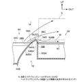
以下、図1~図4に基づいて本発明の車両用インストルメントパネル構造10について説明する。なお、各図に適宜記す矢印FR、矢印UP、矢印OUTは、車両の前方向(進行方向)、上方向、車両幅方向の外側をそれぞれ示している。以下、単に前後、左右、上下の方向を用いて説明する場合は、特に断りのない限り、車両前後方向の前後、車両左右方向(車両幅方向)の左右、車両上下方向の上下を示すものとする。
A vehicle
(全体構成)
車両12の車室14内の前部には、インパネ16が設けられている。このインパネ16は、車室14と車両前部とを隔成するダッシュパネル(不図示)の車両後方側の上部側に配置されている。ダッシュパネルの下端部は、図示しないフロアパネルの前端部に接合されており、フロアパネルは、車室14の下面を構成している。また、ダッシュパネルの上端部には、図示しないカウルが接合されており、このカウルは、ウィンドシールドガラス18の下端部を支持している。ウィンドシールドガラス18は、車室14の上部側の前面を構成してその下端部側がインパネ16の前端部16A側に配置されている。
(overall structure)
An
インパネ16の車両後方側には、車両用の前席としての車両用シート20が設けられている。車両用シート20は、本実施形態では車室14の前部左側が助手席とされ、車室14の前部右側が運転席とされている。
A
(インパネ)
インパネ16は、車両幅方向に沿って延在される樹脂製の内装パネル材として構成されている。インパネ16の内部(車両前方側)上部には、車両幅方向に沿って長尺状とされたインパネリインフォースメント(不図示)が配設されており、インパネ16は、このインパネリインフォースメントに複数箇所で取り付けられている。なお、前記インパネリインフォースメントは、金属製のパイプ材であり、その長手方向の両端部は、左右の車体側部に立設された一対のフロントピラー22(左右の骨格部材、左側は不図示)の車両下方側に固定されている。
(instrument panel)
The
インパネ16における運転席側には、計器部24が設けられている。計器部24は、インパネ16の上部かつステアリングホイール26に対応した位置に設けられており、略車両幅方向を長手方向とする略矩形状に形成されかつ車室14へ向けられた表示パネル48を含んで構成されている。表示パネル48は、一例として、液晶パネルにより構成されており、車両12の速度やパワーユニットの作動状況等が表示可能とされている。
A
(ヘッドアップディスプレイ装置)
インパネ16における運転席側の内部には、ヘッドアップディスプレイ装置28が設けられている。具体的には、ヘッドアップディスプレイ装置28は、インパネ16の運転席側の上面16Cにおける前端部16Aに形成され車両上方側へ向けて開口された開口部16Bの内部に設けられている。ヘッドアップディスプレイ装置28の内部には、表示制御装置に通信可能に接続された情報表示用の出射光としての発光像を出射する表示器と、表示器からの発光像を反射させる反射鏡と、を備えている(いずれも不図示)。表示器は、ヘッドアップディスプレイ装置28内の車両前後方向の後部側に配置されており、発光像を車両前方側に向けて出射する。表示器は、発光ダイオードなどからなる光源を備えている。
(head-up display device)
A head-up
反射鏡は、ヘッドアップディスプレイ装置28内の表示器と対向する車両前後方向の前部側に配置されており、一例として表示器に対して凹むように配置された凹面鏡とされている。車両側面視にて反射鏡は、上部が車両前方側で下部が車両後方側となるように斜めに配置されている。これにより、表示器からの発光像を反射鏡で車両上方斜め後方側に向けて反射させ、発光像を拡大させるようになっている。
The reflecting mirror is arranged on the front side in the vehicle front-rear direction facing the display in the head-up
反射鏡で反射させた発光像は、インパネ16の上面16Cに形成された開口部16Bに取り付けられている透明蓋部材40を経てウィンドシールドガラス18に投影される構成とされている。これにより、表示器からの発光像は反射鏡に導かれ、反射鏡で反射して拡大された発光像がウィンドシールドガラス18の図3に示される二点鎖線にて区切られた情報の表示される投影エリアS内に投影されるようになっている。なお、ヘッドアップディスプレイ装置28は、ウィンドシールドガラス18の投影エリアS内に一例として車両12の走行速度や目的地への案内表示や道路の制限速度等を表示させる。
The luminous image reflected by the reflecting mirror is projected onto the
(デフロスタ)
インパネ16における車両幅方向略中央部の内部には、デフロスタ44が設けられている。このデフロスタ44は、デフロスタ用開口部44Aと、デフロスタノズル44B(図3参照)とを有している。デフロスタ用開口部44Aは、図3に示されるように、インパネ16の車両幅方向略中央部の上面16Cにおける前端部16Aに形成され車両上方側へ向けて開口されており、格子状のフィン44Cによって車両上方側から覆われた構成とされている。
(Defroster)
A
図3に示されるように、デフロスタノズル44Bは、デフロスタ用開口部44Aの車両下方側に設けられていると共に、中空状に形成されかつ車両上方側(デフロスタ用開口部44A側)へ向かうに連れて車両幅方向に拡幅されている。具体的には、デフロスタノズル44Bは、車両前後方向に対向して配置された図示されていない前壁部及び後壁部を備えている。これら前壁部と後壁部の車両幅方向端部同士を繋ぐ、互いに対向する一対の側壁部44BA、44BBは、車両上方側に向かうに従って互いに離間する方向へ傾けられている。そして、これら側壁部44BA、44BBと図示されていない前壁部及び後壁部とによって、デフロスタノズル44Bの送風路が構成されている。
As shown in FIG. 3, the
デフロスタノズル44Bは、図1に示される車両用空調装置50に接続されている。車両用空調装置50は、一例として、車両12のインパネ16の車両前方側かつ下方側に配置されている。車両用空調装置50は、図示しないメインファンを備えており、メインファンが作動されることによって空気流が形成される。メインファンに対して気流の下流側には、エバポレータ、ヒータコア等(いずれも不図示)が設けられており、気流の温度、湿度等が調整された調和空気になる。この空気流は、車両用空調装置50に接続されたデフロスタノズル44Bの内部を通ってデフロスタ用開口部44Aから外部へ空調風として送風される。なお、車両用空調装置50は、後述するデフロスタ用開口部44A以外にも、車室14内の様々な位置に設けられた図示しない吹出口へ繋がる空調ダクトが接続されていると共に、図示しない制御装置に通信可能に接続されており、制御装置からの指示によりデフロスタ用開口部44Aやその他の吹出口毎に異なる温度や風量の空調風が送風可能とされている。
The
(案内部)
インパネ16の上面16Cにおけるヘッドアップディスプレイ装置28とデフロスタ44のデフロスタ用開口部44Aとの間には、加飾部材52が設けられている。この加飾部材52は、一例として、金属調に表面加工された樹脂等により構成されており、図2に示されるように、略車両前後方向に延設された案内部としての第1延在部54と、略車両幅方向に延在された第2延在部56とで車両平面視にて略L字状に形成されている。
(Information department)
A
第1延在部54は、インパネ16の前端部16Aから計器部24の近傍に亘って延設されており、図4に示されるように、車両幅方向(長手方向に直交する方向)にて切断した断面形状が車両上方側へ向けて凸形状とされている。具体的には、デフロスタ44側の側壁部54Aと、ヘッドアップディスプレイ装置28側の側壁部54Bと、側壁部54Aと側壁部54Bとの間にある頂点部56Cと、により構成されている。
The
側壁部54Aは、デフロスタノズル44Bの側壁部44BAと略同一の角度にて傾けられている。すなわち、側壁部54Aの下端部54AAから車両上方側に向かうに連れてヘッドアップディスプレイ装置28側へと傾けられており、側壁部54Aの水平方向に対する傾斜角度が、デフロスタノズル44Bの側壁部44BAにおけるデフロスタ用開口部44Aに対応した部位の水平方向に対する傾斜角度と略同一とされている。つまり、第1延在部54の側壁部54Aは、車両正面視にてデフロスタノズル44Bの側壁部44BAと連続的な面を構成している。
The
頂点部56Cは、第1延在部54における車両上方側部を構成している。そして、側壁部54Bの下端部54BAは、ヘッドアップディスプレイ装置28が内部に設けられている開口部16Bにおける車両幅方向に設けられた側壁部16BAの上端16BBと対向するように設けられている。すなわち、側壁部54Bは、頂点部56Cから側壁部16BAの上端16BBに繋がるように湾曲されている。この開口部16Bの側壁部16BAは、略垂直方向に立設されているため、第1延在部54の側壁部54Bの水平方向に対する傾斜角度が、側壁部54Aの水平方向に対する傾斜角度より大きく(垂直方向に近く)されている。つまり、第1延在部54の車両幅方向にて切断した断面形状は、左右非対称とされている。
The
図2に示されるように、第2延在部56は、第1延在部54の後端部から略車両幅方向に延設されており、一例として、車両前後方向(長手方向に直交する方向)にて切断した断面形状が第1延在部54と同様に車両上方側へ向けて凸形状とされている。また、第2延在部56は、一例として、インパネ16の上面16Cの後端部に設けられており、これによってインパネ16の上面16Cの後端部を加飾している(図1参照)。
As shown in FIG. 2 , the
(作用・効果)
次に、本実施形態の作用並びに効果を説明する。
(action/effect)
Next, the operation and effects of this embodiment will be described.
本実施形態では、図1に示されるように、インパネ16の内部には、ヘッドアップディスプレイ装置28とデフロスタ44とが車両幅方向に並んで配置されており、このインパネ16の上面16Cにおけるヘッドアップディスプレイ装置28とデフロスタ44との間には、第1延在部54が設けられている。この第1延在部54は、図4に示されるように、車両幅方向にて切断した断面形状がデフロスタ44からの空気流Wを第1延在部54自身の表面に付着させて投影エリアS側へ空気流Wを吹き付ける形状とされていることから、デフロスタ44から第1延在部54を経て投影エリアS側へ向かう空気流Wが発生する。したがって、投影エリアSにも直接的に空気流が送られるため、投影エリアSの曇りを素早くとることが可能となる。これにより、投影エリアSの曇りを効率良く除去することができる。
In this embodiment, as shown in FIG. 1 , a head-up
また、第1延在部54は、車両幅方向にて切断した断面形状が車両上方側へ向けて凸状とされていることから、デフロスタ44から吹き出される空気流Wが、車両正面視にて第1延在部54におけるデフロスタ44側の下端部54AAから第1延在部54における頂点部56C近傍の範囲の表面に付着しながら流れると共に、頂点部56Cから第1延在部54におけるヘッドアップディスプレイ装置28側の下端部54BAへ向かい始めるあたりで第1延在部54の表面と剥離し、慣性によって投影エリアS側へと流れる。つまり、デフロスタ44からヘッドアップディスプレイ装置28側かつ略車両下方側へ向けて流れる空気流Wを発生させることができるので、投影エリアSにも直接的に空気流を送ることができる。
In addition, since the cross-sectional shape of the first extending
さらに、第1延在部54には、車両正面視にてデフロスタ44の一部を構成するデフロスタノズル44Bにおけるヘッドアップディスプレイ装置28側の側壁部44BAと連続的な面を有する側壁部54Aが設けられている。これにより、デフロスタ44からウィンドシールドガラス18へ向けて送られる空気流Wのうちデフロスタ44の一部を構成するデフロスタノズル44Bにおけるヘッドアップディスプレイ装置28側の側壁部44BAに沿って流れる空気流Wが第1延在部54へと円滑に流れやすくなる。したがって、第1延在部54の表面に空気流Wが付着し易くなることから、投影エリアSに効率的に空気流Wを送ることができる。これらにより、投影エリアSの曇りをより一層効率良く除去することができる。
Further, the
さらにまた、第1延在部54がインパネ16と異なる外観を有する部材にて構成されていることから、第1延在部54が外観意匠上にていわばアクセントとなる。つまり、第1延在部54を加飾として用いることができる。これにより、ウィンドシールドガラス18の曇りの効率的な除去と外観意匠性とを両立させることができる。
Furthermore, since the
なお、本実施形態では、第1延在部54は、金属調に表面加工された樹脂等により構成されているが、これに限らず、インパネ16等と同一の外観を有する部材により構成されていてもよい。
In the present embodiment, the
また、第1延在部54の側壁部54Aは、デフロスタノズル44Bの側壁部44BAと略同一の傾斜角度にて傾けられて連続的な面を構成しているが、これに限らず、デフロスタノズル44Bの側壁部44BAと異なる傾斜角度としてもよい。
The
さらに、第1延在部54の車両幅方向にて切断した断面形状は、車両上方側へ突出した左右非対称な形状とされているが、これに限らず、左右対称な形状としてもよい。
Furthermore, the cross-sectional shape of the first extending
以上本発明は、上記の形態例に限定されるものではなく、上記の形態例以外にも、その主旨を逸脱しない範囲内において種々変形して実施可能であることは勿論である。 As described above, the present invention is not limited to the above-described embodiments, and it goes without saying that various modifications can be made in addition to the above-described embodiments without departing from the spirit of the present invention.
10 車両用インストルメントパネル構造
14 車室
16 インパネ(インストルメントパネル)
16C 上面
18 ウィンドシールドガラス
28 ヘッドアップディスプレイ装置
44 デフロスタ
44B デフロスタノズル
44BA 側壁部(デフロスタノズルのヘッドアップディスプレイ装置側の側壁部)
54 第1延在部(案内部)
S 投影エリア(ウィンドシールドガラスにおけるヘッドアップディスプレイ装置により情報の表示が行われるエリア)
10 vehicle
16C
54 first extension part (guide part)
S Projection area (area where information is displayed by a head-up display device on the windshield glass)
Claims (3)
前記インストルメントパネルの内部に設けられると共に、前記ヘッドアップディスプレイ装置と車両幅方向に並んで配置され、前記ウィンドシールドガラスへ向けて送風するデフロスタと、
前記インストルメントパネルの上面における前記ヘッドアップディスプレイ装置と前記デフロスタとの間に設けられると共に、車両幅方向にて切断した断面形状が前記デフロスタからの空気流を自身の表面に付着させて前記ウィンドシールドガラスにおける前記ヘッドアップディスプレイ装置により情報の表示が行われるエリア側へ前記空気流を吹き付ける形状とされた案内部と、
を有し、
前記案内部は、車両幅方向にて切断した断面形状が車両上方側へ向けて凸形状とされており、
前記案内部の前記ヘッドアップディスプレイ装置側に配置されて当該ヘッドアップディスプレイ装置を車両上方側から覆う透明蓋部材をさらに備えると共に、
前記透明蓋部材は、車両上下方向から見て前記空気流の流線と重なるように配置されている、
車両用インストルメントパネル構造。 A head-up display device that is provided inside the instrument panel located in the front part of the passenger compartment and that projects light onto the windshield glass to display information;
a defroster provided inside the instrument panel and arranged side by side with the head-up display device in the vehicle width direction to blow air toward the windshield glass;
The windshield is provided between the head-up display device and the defroster on the upper surface of the instrument panel, and the cross-sectional shape cut in the vehicle width direction causes the air flow from the defroster to adhere to the surface of the windshield. a guide part shaped to blow the air flow toward the area side where information is displayed by the head-up display device on the glass;
has
The guide portion has a cross-sectional shape cut in the vehicle width direction that is convex toward the vehicle upper side,
further comprising a transparent lid member disposed on the head-up display device side of the guide portion and covering the head-up display device from the upper side of the vehicle;
The transparent lid member is arranged so as to overlap the streamline of the air flow when viewed from the vehicle up-down direction.
Vehicle instrument panel structure.
請求項1記載の車両用インストルメントパネル構造。 The guide section is composed of a member having an appearance different from that of the instrument panel,
The vehicle instrument panel structure according to claim 1 .
請求項1又は請求項2記載の車両用インストルメントパネル構造。 At least a portion of the guide portion has a surface that is continuous with a side wall portion of the defroster nozzle that constitutes a part of the defroster in a front view of the vehicle, on the side of the head-up display device,
The vehicle instrument panel structure according to claim 1 or 2 .
Priority Applications (3)
| Application Number | Priority Date | Filing Date | Title |
|---|---|---|---|
| JP2019017042A JP7147603B2 (en) | 2019-02-01 | 2019-02-01 | Vehicle instrument panel structure |
| US16/718,734 US11506889B2 (en) | 2019-02-01 | 2019-12-18 | Vehicle instrument panel structure |
| CN201911325821.1A CN111516492B (en) | 2019-02-01 | 2019-12-20 | Instrument panel structure for vehicle |
Applications Claiming Priority (1)
| Application Number | Priority Date | Filing Date | Title |
|---|---|---|---|
| JP2019017042A JP7147603B2 (en) | 2019-02-01 | 2019-02-01 | Vehicle instrument panel structure |
Publications (2)
| Publication Number | Publication Date |
|---|---|
| JP2020124952A JP2020124952A (en) | 2020-08-20 |
| JP7147603B2 true JP7147603B2 (en) | 2022-10-05 |
Family
ID=71837019
Family Applications (1)
| Application Number | Title | Priority Date | Filing Date |
|---|---|---|---|
| JP2019017042A Active JP7147603B2 (en) | 2019-02-01 | 2019-02-01 | Vehicle instrument panel structure |
Country Status (3)
| Country | Link |
|---|---|
| US (1) | US11506889B2 (en) |
| JP (1) | JP7147603B2 (en) |
| CN (1) | CN111516492B (en) |
Citations (2)
| Publication number | Priority date | Publication date | Assignee | Title |
|---|---|---|---|---|
| JP2016016852A (en) | 2014-07-11 | 2016-02-01 | トヨタ自動車株式会社 | Instrument panel structure |
| JP2016088260A (en) | 2014-11-04 | 2016-05-23 | カルソニックカンセイ株式会社 | Cabin front structure |
Family Cites Families (7)
| Publication number | Priority date | Publication date | Assignee | Title |
|---|---|---|---|---|
| JPH04119479U (en) * | 1991-04-05 | 1992-10-26 | 矢崎総業株式会社 | Vehicle display device |
| CN101401149B (en) * | 2006-03-16 | 2011-08-10 | 埃米尔·明兰 | Portable adaptor and software for use with a heads-up display unit |
| CN101086447A (en) * | 2006-06-05 | 2007-12-12 | 本田技研工业株式会社 | Visual recognition assistance device for vehicle |
| WO2015190238A1 (en) * | 2014-06-12 | 2015-12-17 | 矢崎総業株式会社 | Display device for vehicle |
| JP6417188B2 (en) | 2014-10-31 | 2018-10-31 | ダイキョーニシカワ株式会社 | Vehicle defroster structure |
| JP2018004788A (en) | 2016-06-29 | 2018-01-11 | 本田技研工業株式会社 | Head-up display device |
| DE102017223436B4 (en) * | 2017-12-20 | 2023-01-12 | Volkswagen Aktiengesellschaft | Vehicle with a head-up display integrated in the instrument panel |
-
2019
- 2019-02-01 JP JP2019017042A patent/JP7147603B2/en active Active
- 2019-12-18 US US16/718,734 patent/US11506889B2/en active Active
- 2019-12-20 CN CN201911325821.1A patent/CN111516492B/en active Active
Patent Citations (2)
| Publication number | Priority date | Publication date | Assignee | Title |
|---|---|---|---|---|
| JP2016016852A (en) | 2014-07-11 | 2016-02-01 | トヨタ自動車株式会社 | Instrument panel structure |
| JP2016088260A (en) | 2014-11-04 | 2016-05-23 | カルソニックカンセイ株式会社 | Cabin front structure |
Also Published As
| Publication number | Publication date |
|---|---|
| JP2020124952A (en) | 2020-08-20 |
| CN111516492B (en) | 2023-05-12 |
| CN111516492A (en) | 2020-08-11 |
| US20200249477A1 (en) | 2020-08-06 |
| US11506889B2 (en) | 2022-11-22 |
Similar Documents
| Publication | Publication Date | Title |
|---|---|---|
| JP5860915B2 (en) | Vehicle with air conditioning function and display function | |
| JP2012148668A (en) | Defroster blowout port | |
| JP5141239B2 (en) | Arrangement structure of head-up display device | |
| JP2008126973A (en) | Vehicular head up display section structure | |
| JP2014162343A (en) | Instrument panel structure | |
| JP7147603B2 (en) | Vehicle instrument panel structure | |
| JP7077980B2 (en) | Instrument panel structure for vehicles | |
| JP6232330B2 (en) | instrument panel | |
| JP2016088260A (en) | Cabin front structure | |
| RU2702371C1 (en) | Air duct design for vehicle air conditioning | |
| JP6925891B2 (en) | Display device and interior member unit | |
| JP7012625B2 (en) | Side defroster device | |
| JP7012626B2 (en) | Side defroster device | |
| JP7268587B2 (en) | Defroster structure | |
| JP2016016852A (en) | Instrument panel structure | |
| JP2019142243A (en) | Air blowout device | |
| JP2010188870A (en) | Head-up display device for vehicle | |
| JP2009056893A (en) | Rear door of vehicle | |
| JP4058015B2 (en) | Car instrument panel fixing structure | |
| JP6115385B2 (en) | Defroster nozzle structure | |
| JP2003276474A (en) | Cockpit structure of vehicle | |
| JP2019217821A (en) | Head-up display device, built-in air conditioning duct, and vehicle | |
| JPH0699731A (en) | Defroster nozzle | |
| JP2002096656A (en) | Structure of instrument panel | |
| JP2021011197A (en) | Side defroster air outlet structure |
Legal Events
| Date | Code | Title | Description |
|---|---|---|---|
| A621 | Written request for application examination |
Free format text: JAPANESE INTERMEDIATE CODE: A621 Effective date: 20210526 |
|
| A131 | Notification of reasons for refusal |
Free format text: JAPANESE INTERMEDIATE CODE: A131 Effective date: 20220412 |
|
| A977 | Report on retrieval |
Free format text: JAPANESE INTERMEDIATE CODE: A971007 Effective date: 20220414 |
|
| A521 | Request for written amendment filed |
Free format text: JAPANESE INTERMEDIATE CODE: A523 Effective date: 20220608 |
|
| TRDD | Decision of grant or rejection written | ||
| A01 | Written decision to grant a patent or to grant a registration (utility model) |
Free format text: JAPANESE INTERMEDIATE CODE: A01 Effective date: 20220823 |
|
| A61 | First payment of annual fees (during grant procedure) |
Free format text: JAPANESE INTERMEDIATE CODE: A61 Effective date: 20220905 |
|
| R151 | Written notification of patent or utility model registration |
Ref document number: 7147603 Country of ref document: JP Free format text: JAPANESE INTERMEDIATE CODE: R151 |