JP7147218B2 - Inkjet recording device - Google Patents
Inkjet recording device Download PDFInfo
- Publication number
- JP7147218B2 JP7147218B2 JP2018061458A JP2018061458A JP7147218B2 JP 7147218 B2 JP7147218 B2 JP 7147218B2 JP 2018061458 A JP2018061458 A JP 2018061458A JP 2018061458 A JP2018061458 A JP 2018061458A JP 7147218 B2 JP7147218 B2 JP 7147218B2
- Authority
- JP
- Japan
- Prior art keywords
- ink
- supply
- path
- recording head
- liquid
- Prior art date
- Legal status (The legal status is an assumption and is not a legal conclusion. Google has not performed a legal analysis and makes no representation as to the accuracy of the status listed.)
- Active
Links
Images


Classifications
-
- B—PERFORMING OPERATIONS; TRANSPORTING
- B41—PRINTING; LINING MACHINES; TYPEWRITERS; STAMPS
- B41J—TYPEWRITERS; SELECTIVE PRINTING MECHANISMS, i.e. MECHANISMS PRINTING OTHERWISE THAN FROM A FORME; CORRECTION OF TYPOGRAPHICAL ERRORS
- B41J2/00—Typewriters or selective printing mechanisms characterised by the printing or marking process for which they are designed
- B41J2/005—Typewriters or selective printing mechanisms characterised by the printing or marking process for which they are designed characterised by bringing liquid or particles selectively into contact with a printing material
- B41J2/01—Ink jet
- B41J2/17—Ink jet characterised by ink handling
- B41J2/175—Ink supply systems ; Circuit parts therefor
-
- B—PERFORMING OPERATIONS; TRANSPORTING
- B41—PRINTING; LINING MACHINES; TYPEWRITERS; STAMPS
- B41J—TYPEWRITERS; SELECTIVE PRINTING MECHANISMS, i.e. MECHANISMS PRINTING OTHERWISE THAN FROM A FORME; CORRECTION OF TYPOGRAPHICAL ERRORS
- B41J2/00—Typewriters or selective printing mechanisms characterised by the printing or marking process for which they are designed
- B41J2/005—Typewriters or selective printing mechanisms characterised by the printing or marking process for which they are designed characterised by bringing liquid or particles selectively into contact with a printing material
- B41J2/01—Ink jet
- B41J2/135—Nozzles
- B41J2/165—Preventing or detecting of nozzle clogging, e.g. cleaning, capping or moistening for nozzles
- B41J2/16585—Preventing or detecting of nozzle clogging, e.g. cleaning, capping or moistening for nozzles for paper-width or non-reciprocating print heads
-
- B—PERFORMING OPERATIONS; TRANSPORTING
- B41—PRINTING; LINING MACHINES; TYPEWRITERS; STAMPS
- B41J—TYPEWRITERS; SELECTIVE PRINTING MECHANISMS, i.e. MECHANISMS PRINTING OTHERWISE THAN FROM A FORME; CORRECTION OF TYPOGRAPHICAL ERRORS
- B41J2/00—Typewriters or selective printing mechanisms characterised by the printing or marking process for which they are designed
- B41J2/005—Typewriters or selective printing mechanisms characterised by the printing or marking process for which they are designed characterised by bringing liquid or particles selectively into contact with a printing material
- B41J2/01—Ink jet
- B41J2/135—Nozzles
- B41J2/165—Preventing or detecting of nozzle clogging, e.g. cleaning, capping or moistening for nozzles
- B41J2/16505—Caps, spittoons or covers for cleaning or preventing drying out
- B41J2/16508—Caps, spittoons or covers for cleaning or preventing drying out connected with the printer frame
-
- B—PERFORMING OPERATIONS; TRANSPORTING
- B41—PRINTING; LINING MACHINES; TYPEWRITERS; STAMPS
- B41J—TYPEWRITERS; SELECTIVE PRINTING MECHANISMS, i.e. MECHANISMS PRINTING OTHERWISE THAN FROM A FORME; CORRECTION OF TYPOGRAPHICAL ERRORS
- B41J2/00—Typewriters or selective printing mechanisms characterised by the printing or marking process for which they are designed
- B41J2/005—Typewriters or selective printing mechanisms characterised by the printing or marking process for which they are designed characterised by bringing liquid or particles selectively into contact with a printing material
- B41J2/01—Ink jet
- B41J2/135—Nozzles
- B41J2/165—Preventing or detecting of nozzle clogging, e.g. cleaning, capping or moistening for nozzles
- B41J2/16517—Cleaning of print head nozzles
- B41J2/16535—Cleaning of print head nozzles using wiping constructions
- B41J2/16538—Cleaning of print head nozzles using wiping constructions with brushes or wiper blades perpendicular to the nozzle plate
-
- B—PERFORMING OPERATIONS; TRANSPORTING
- B41—PRINTING; LINING MACHINES; TYPEWRITERS; STAMPS
- B41J—TYPEWRITERS; SELECTIVE PRINTING MECHANISMS, i.e. MECHANISMS PRINTING OTHERWISE THAN FROM A FORME; CORRECTION OF TYPOGRAPHICAL ERRORS
- B41J2/00—Typewriters or selective printing mechanisms characterised by the printing or marking process for which they are designed
- B41J2/005—Typewriters or selective printing mechanisms characterised by the printing or marking process for which they are designed characterised by bringing liquid or particles selectively into contact with a printing material
- B41J2/01—Ink jet
- B41J2/135—Nozzles
- B41J2/165—Preventing or detecting of nozzle clogging, e.g. cleaning, capping or moistening for nozzles
- B41J2/16517—Cleaning of print head nozzles
- B41J2/16552—Cleaning of print head nozzles using cleaning fluids
-
- B—PERFORMING OPERATIONS; TRANSPORTING
- B41—PRINTING; LINING MACHINES; TYPEWRITERS; STAMPS
- B41J—TYPEWRITERS; SELECTIVE PRINTING MECHANISMS, i.e. MECHANISMS PRINTING OTHERWISE THAN FROM A FORME; CORRECTION OF TYPOGRAPHICAL ERRORS
- B41J2/00—Typewriters or selective printing mechanisms characterised by the printing or marking process for which they are designed
- B41J2/005—Typewriters or selective printing mechanisms characterised by the printing or marking process for which they are designed characterised by bringing liquid or particles selectively into contact with a printing material
- B41J2/01—Ink jet
- B41J2/17—Ink jet characterised by ink handling
- B41J2/175—Ink supply systems ; Circuit parts therefor
- B41J2/17503—Ink cartridges
-
- B—PERFORMING OPERATIONS; TRANSPORTING
- B41—PRINTING; LINING MACHINES; TYPEWRITERS; STAMPS
- B41J—TYPEWRITERS; SELECTIVE PRINTING MECHANISMS, i.e. MECHANISMS PRINTING OTHERWISE THAN FROM A FORME; CORRECTION OF TYPOGRAPHICAL ERRORS
- B41J2/00—Typewriters or selective printing mechanisms characterised by the printing or marking process for which they are designed
- B41J2/005—Typewriters or selective printing mechanisms characterised by the printing or marking process for which they are designed characterised by bringing liquid or particles selectively into contact with a printing material
- B41J2/01—Ink jet
- B41J2/17—Ink jet characterised by ink handling
- B41J2/18—Ink recirculation systems
-
- B—PERFORMING OPERATIONS; TRANSPORTING
- B41—PRINTING; LINING MACHINES; TYPEWRITERS; STAMPS
- B41J—TYPEWRITERS; SELECTIVE PRINTING MECHANISMS, i.e. MECHANISMS PRINTING OTHERWISE THAN FROM A FORME; CORRECTION OF TYPOGRAPHICAL ERRORS
- B41J2/00—Typewriters or selective printing mechanisms characterised by the printing or marking process for which they are designed
- B41J2/005—Typewriters or selective printing mechanisms characterised by the printing or marking process for which they are designed characterised by bringing liquid or particles selectively into contact with a printing material
- B41J2/01—Ink jet
- B41J2/135—Nozzles
- B41J2/165—Preventing or detecting of nozzle clogging, e.g. cleaning, capping or moistening for nozzles
- B41J2/16517—Cleaning of print head nozzles
- B41J2/16552—Cleaning of print head nozzles using cleaning fluids
- B41J2002/16558—Using cleaning liquid for wet wiping
Description
本発明は、用紙のような記録媒体にインクを吐出する記録ヘッドと、記録ヘッドに液体を供給する供給ユニットと、を備えたインクジェット記録装置に関するものである。 The present invention relates to an inkjet recording apparatus that includes a recording head that ejects ink onto a recording medium such as paper, and a supply unit that supplies liquid to the recording head.
ファクシミリ、複写機、プリンターのような記録装置として、インクを吐出して画像を形成するインクジェット記録装置が、高精細な画像を形成できることから広く用いられている。 2. Description of the Related Art Inkjet recording apparatuses that form images by ejecting ink are widely used as recording apparatuses such as facsimiles, copiers, and printers because they can form high-definition images.
インクジェット記録装置としては、記録ヘッドと、記録ヘッドにインク(液体)を供給する供給ユニットと、供給ユニットから記録ヘッドに供給されるインクが通過する供給経路と、記録ヘッドから供給ユニットに戻るインクが通過する循環経路と、を備えたものが知られている。循環経路は、記録ヘッド内の気泡を抜く(供給ユニットに戻す)ために設けられている。 An inkjet recording apparatus includes a recording head, a supply unit that supplies ink (liquid) to the recording head, a supply path through which the ink supplied from the supply unit to the recording head passes, and ink that returns from the recording head to the supply unit. circulatory pathways passing through. The circulation path is provided for removing air bubbles in the recording head (returning them to the supply unit).
インクジェット記録装置の出荷時には、供給ユニットは、インクの劣化を抑制するために空の状態(空気で満たされた状態)になっており、記録ヘッドは、気泡の巻き込みを抑制するために保存液が充填されている。インクジェット記録装置の着荷時には、供給ユニットにインクが充填されるとともに、記録ヘッドの保存液がインクに置換される。 When the inkjet recording apparatus is shipped, the supply unit is in an empty state (filled with air) to prevent deterioration of the ink, and the recording head is filled with storage liquid to prevent entrainment of air bubbles. filled. When the inkjet recording apparatus arrives, the supply unit is filled with ink, and the storage liquid in the recording head is replaced with ink.
なお、記録ヘッドと記録ヘッドにインクを供給する供給ユニットとを備え、出荷時に記録ヘッドに保存液が充填されるインクジェット記録装置は、例えば特許文献1に開示されている。 An ink jet printing apparatus that includes a print head and a supply unit that supplies ink to the print head, and in which the print head is filled with a storage liquid at the time of shipment is disclosed, for example, in Japanese Unexamined Patent Application Publication No. 2002-100000.
ところで、インクジェット記録装置の出荷時に、供給ユニットを空の状態にするとともに記録ヘッドに保存液を充填する場合、供給ユニットと記録ヘッドとを切り離しておく必要がある。このため、上記供給経路および循環経路を備えたインクジェット記録装置では、供給経路には、供給経路を分離および接続可能な供給カップリングが設けられ、循環経路には、循環経路を分離および接続可能な循環カップリングが設けられる。そして、インクジェット記録装置の出荷時には各カップリングが分離され、着荷時には各カップリングが接続される。 By the way, when the supply unit is emptied and the recording head is filled with the storage liquid when the inkjet recording apparatus is shipped, it is necessary to separate the supply unit and the recording head. For this reason, in the ink jet recording apparatus having the supply route and the circulation route, the supply route is provided with a supply coupling capable of separating and connecting the supply route, and the circulation route is provided with a supply coupling capable of separating and connecting the circulation route. A circulation coupling is provided. Each coupling is separated at the time of shipment of the inkjet recording apparatus, and each coupling is connected at the time of arrival.
しかしながら、インクジェット記録装置の着荷時に、各カップリングを接続した後に、供給ユニットにインクを充填するのと同時に記録ヘッドの保存液をインクに置換しようとすると、記録ヘッドのインクに気泡が巻き込まれる(インク内に気泡が発生する)。 However, when the ink jet recording apparatus is delivered, if the supply unit is filled with ink after each coupling is connected and the storage liquid in the recording head is replaced with ink at the same time, air bubbles are caught in the ink in the recording head ( air bubbles in the ink).
この不都合を回避するために、以下の方法が考えられる。すなわち、供給カップリングのオス部(またはメス部)と循環カップリングのメス部(またはオス部)とを接続することによって供給ユニット側で循環構造を形成し、この状態で供給ユニットにインクを充填する。すなわち、供給ユニットと記録ヘッドとを切り離した状態で供給ユニットにインクを充填する。その後、供給カップリングのオス部(またはメス部)と循環カップリングのメス部(またはオス部)とを分離し、供給カップリングのオス部とメス部とを接続して供給経路を連通するとともに、循環カップリングのオス部とメス部とを接続して循環経路を連通する。すなわち、供給ユニットと記録ヘッドとを接続する。そして、記録ヘッドの保存液をインクに置換する。この方法によれば、記録ヘッドのインクに気泡が巻き込まれるのを抑制することができる。 In order to avoid this inconvenience, the following method can be considered. That is, by connecting the male part (or female part) of the supply coupling and the female part (or male part) of the circulation coupling, a circulation structure is formed on the supply unit side, and the supply unit is filled with ink in this state. do. That is, the supply unit is filled with ink while the supply unit and the recording head are separated. After that, the male part (or female part) of the supply coupling and the female part (or male part) of the circulation coupling are separated, and the male part and the female part of the supply coupling are connected to communicate the supply route. , connect the male part and the female part of the circulation coupling to communicate the circulation path. That is, the supply unit and the recording head are connected. Then, the storage liquid of the recording head is replaced with ink. According to this method, it is possible to prevent air bubbles from being caught in the ink of the recording head.
しかしながら、カップリングを分離する際にはカップリング内部のインクが必ず漏れるので、上記方法では、インクジェット記録装置内がインクで汚れてしまうという懸念がある。 However, since the ink inside the coupling always leaks when the coupling is separated, there is a concern that the inside of the inkjet recording apparatus will be stained with the ink in the above method.
本発明は、上記のような課題を解決するためになされたものであり、本発明の目的は、記録ヘッドのインクに気泡が巻き込まれるのを抑制するとともに、装置内がインクで汚れるのを抑制することが可能なインクジェット記録装置を提供することである。 SUMMARY OF THE INVENTION The present invention has been made to solve the above problems, and an object of the present invention is to prevent air bubbles from being caught in the ink of the recording head and to prevent the inside of the apparatus from being stained with the ink. An object of the present invention is to provide an ink jet recording apparatus capable of
上記目的を達成するために、本発明の第1の局面のインクジェット記録装置は、記録媒体上にインクを吐出する記録ヘッドと、記録ヘッドに液体を供給する供給ユニットと、供給ユニットと記録ヘッドとを接続し、供給ユニットから記録ヘッドに供給される液体が通過する供給経路と、記録ヘッドと供給ユニットとを接続し、記録ヘッドから供給ユニットに戻る液体が通過する循環経路と、を備える。供給経路には、供給経路を分離および接続可能な供給カップリングが設けられており、循環経路には、循環経路を分離および接続可能な循環カップリングが設けられている。供給経路の供給カップリングに対して上流側の部分と循環経路の循環カップリングに対して下流側の部分とは、連通および遮断可能に構成されたバイパス経路によって接続されている。 In order to achieve the above object, an ink jet recording apparatus according to a first aspect of the present invention includes a recording head that ejects ink onto a recording medium, a supply unit that supplies liquid to the recording head, a supply unit and the recording head. and a supply path through which liquid supplied from the supply unit to the printhead passes, and a circulation path that connects the printhead and the supply unit and through which the liquid returning from the printhead to the supply unit passes. The supply path is provided with a supply coupling capable of separating and connecting the supply path, and the circulation path is provided with a circulation coupling capable of separating and connecting the circulation path. The upstream portion of the supply route with respect to the supply coupling and the downstream portion of the circulation route with respect to the circulation coupling are connected by a bypass route configured to be able to communicate and block.
本発明の第1の局面のインクジェット記録装置によれば、供給経路の供給カップリングに対して上流側の部分と循環経路の循環カップリングに対して下流側の部分とは、連通および遮断可能に構成されたバイパス経路によって接続されている。これにより、インクジェット記録装置の着荷時に、供給経路からバイパス経路を介して循環経路に液体を循環させることができる。すなわち、記録ヘッドを介することなく、供給ユニットに液体を充填することができる。その後、供給カップリングのオス部とメス部とを接続して供給経路を連通するとともに、循環カップリングのオス部とメス部とを接続して循環経路を連通し、記録ヘッドの保存液を液体に置換することによって、記録ヘッドの液体に気泡が巻き込まれるのを抑制することができる。 According to the inkjet recording apparatus of the first aspect of the present invention, the upstream portion of the supply path with respect to the supply coupling and the downstream portion of the circulation path with respect to the circulation coupling can be communicated and blocked. Connected by a configured bypass path. Accordingly, when the ink jet recording apparatus is loaded, the liquid can be circulated from the supply path to the circulation path via the bypass path. That is, the supply unit can be filled with the liquid without going through the recording head. After that, the male part and the female part of the supply coupling are connected to communicate the supply path, the male part and the female part of the circulation coupling are connected to communicate the circulation path, and the storage liquid of the recording head is replaced with the liquid. By substituting with , it is possible to suppress entrainment of air bubbles in the liquid of the recording head.
また、供給経路と循環経路とを接続するバイパス経路を設けることによって、供給ユニット側で循環構造を形成するために供給カップリングと循環カップリングとを接続する必要がない。これにより、供給ユニットに液体を充填した後に記録ヘッドの保存液を液体に置換する際に、供給カップリングと循環カップリングとを分離する必要がないので、供給カップリングと循環カップリングとの接続部分から液体が漏れることがない。このため、インクジェット記録装置内が液体で汚れるのを抑制することができる。 Also, by providing a bypass path connecting the supply path and the circulation path, it is not necessary to connect the supply coupling and the circulation coupling to form the circulation structure on the supply unit side. This eliminates the need to separate the supply coupling and the circulation coupling when replacing the storage fluid in the recording head with the liquid after filling the supply unit with the liquid. No liquid leaks from the part. Therefore, it is possible to prevent the inside of the inkjet recording apparatus from being contaminated with liquid.
以下、本発明の実施形態について図面を参照して説明する。 BEST MODE FOR CARRYING OUT THE INVENTION Hereinafter, embodiments of the present invention will be described with reference to the drawings.
図1~図7を参照して、本発明の一実施形態のインクジェット記録装置100について説明する。図1に示すように、インクジェット記録装置100では、装置本体1の内部下方に用紙収容部である給紙カセット2が配置されている。給紙カセット2の内部には、記録媒体の一例である用紙Pが収容されている。給紙カセット2の用紙搬送方向下流側、すなわち図1における給紙カセット2の右側の上方には給紙装置3が配置されている。この給紙装置3により、用紙Pは図1において給紙カセット2の右上方に向け、1枚ずつ分離されて送り出される。
An
また、インクジェット記録装置100はその内部に第1用紙搬送路4aを備えている。第1用紙搬送路4aは、給紙カセット2に関して言えばその給紙方向である右上方に位置する。給紙カセット2から送り出された用紙Pは第1用紙搬送路4aにより装置本体1の側面に沿って上方に搬送される。
In addition, the
用紙搬送方向に対し第1用紙搬送路4aの下流端にはレジストローラー対13が備えられている。さらにレジストローラー対13の用紙搬送方向下流側には第1搬送ユニット5及び記録部9が配置されている。給紙カセット2から送り出された用紙Pは第1用紙搬送路4aを通ってレジストローラー対13に到達する。レジストローラー対13は用紙Pの斜め送りを矯正しつつ記録部9が実行するインク吐出動作とのタイミングを計り、第1搬送ユニット5に向かって用紙Pを送り出す。
A
用紙搬送方向に対し第1搬送ユニット5の下流側(図1の左側)には第2搬送ユニット12が配置されている。記録部9にてインク画像が記録された用紙Pは第2搬送ユニット12へと送られ、第2搬送ユニット12を通過する間に用紙P表面に吐出されたインクが乾燥される。
A
用紙搬送方向に対し第2搬送ユニット12の下流側であって装置本体1の左側面近傍にはデカーラー部14が備えられている。第2搬送ユニット12にてインクが乾燥された用紙Pはデカーラー部14へと送られ、用紙Pに生じたカールが矯正される。
A
用紙搬送方向に対しデカーラー部14の下流側(図1の上方)には第2用紙搬送路4bが備えられている。デカーラー部14を通過した用紙Pは両面記録を行わない場合、第2用紙搬送路4bからインクジェット記録装置100の左側面外部に設けられた用紙排出トレイ15に排出される。
A second
装置本体1の上部であって記録部9及び第2搬送ユニット12の上方には両面記録を行うための反転搬送路16が備えられている。両面記録を行う場合には第一面への記録が終了して第2搬送ユニット12及びデカーラー部14を通過した用紙Pが第2用紙搬送路4bを通って反転搬送路16へと送られる。反転搬送路16へ送られた用紙Pは、続いて第二面の記録のために搬送方向が切り替えられ、装置本体1の上部を通過して右側に向かって送られ、第1用紙搬送路4a、及びレジストローラー対13を経て第二面を上向きにした状態で再度第1搬送ユニット5へと送られる。
A reversing
また、第2搬送ユニット12の下方にはワイプユニット19及びキャップユニット90が配置されている。ワイプユニット19は、後述するパージを実行する際に記録部9の下方に水平移動し、記録ヘッドのインク吐出口から押出されたインクを拭き取り、拭き取られたインクを回収する。キャップユニット90は、記録ヘッドのインク吐出面をキャッピングする際に記録部9の下方に水平移動し、さらに上方に移動して記録ヘッドの下面に装着される。
A wipe
記録部9は図2に示すように、ヘッドハウジング10と、ヘッドハウジング10に保持されたラインヘッド11C、11M、11Y、及び11Kを備えている。これらのラインヘッド11C~11Kは、第1搬送ユニット5の第1搬送ベルト8の搬送面に対して所定の間隔(例えば1mm)が形成されるような高さに支持され、用紙搬送方向(矢印X方向)と直交する用紙幅方向(図2の上下方向)に沿って延びる1個以上(ここでは1個)の記録ヘッド17によって構成されている。
The
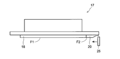
図3及び図4に示すように、記録ヘッド17のヘッド部18のインク吐出面F1には、インク吐出口18a(図2参照)が多数配列されたインク吐出領域R1が設けられている。
As shown in FIGS. 3 and 4, the ink ejection surface F1 of the
各ラインヘッド11C~11Kを構成する記録ヘッド17には、4色(シアン、マゼンタ、イエロー及びブラック)のインクがラインヘッド11C~11Kの色毎に供給される。
Ink of four colors (cyan, magenta, yellow and black) is supplied to the
各記録ヘッド17は、制御部110(図1参照)からの制御信号により外部コンピューターから受信した画像データに応じて、第1搬送ベルト8の搬送面に吸着保持されて搬送される用紙Pに向かってインク吐出口18aからインクを吐出する。これにより、第1搬送ベルト8上の用紙Pにはシアン、マゼンタ、イエロー、ブラックの4色のインクが重ね合わされたカラー画像が形成される。
Each
また、記録ヘッド17には、クリーニング液を供給するクリーニング液供給部材20が設けられている。クリーニング液供給部材20は、ヘッド部18に対してワイパー25のワイピング方向上流側(図3の右側)に隣接して配置されている。クリーニング液供給部材20は、クリーニング液を供給するクリーニング液供給口が多数配列されたクリーニング液供給領域R2を含むクリーニング液供給面F2を有する。
The
図5に示すように、各記録ヘッド17には、各色のインク22がそれぞれ通過するインク供給チューブ70の下流端が接続されている。各インク供給チューブ70の上流端は、各記録ヘッド17に供給するインク22を収容する各色のサブインクタンク(液体タンク)50に接続されている。各インク供給チューブ70には、インク22をサブインクタンク50から汲み上げて記録ヘッド17に送る供給ポンプ(送液ポンプ)72が設けられている。なお、供給ポンプ72、サブインクタンク50、インク供給チューブ70の後述する上流側チューブ70a、及び後述する空気抜きチューブ73、インク補給チューブ75等によって、記録ヘッド17にインク(液体)22を供給する供給ユニット60が構成されている。また、図では、理解を容易にするために、インク22にハッチングを施している。また、インク供給チューブ70、サブインクタンク50、供給ポンプ72、及び後述するインク補給チューブ75、インクパック76、補給ポンプ77は、各記録ヘッド17に対して設けられているが、図では図面簡略化のため、1つずつ描いている。
As shown in FIG. 5, each
また、各サブインクタンク50には、各色のインク22がそれぞれ通過するインク補給チューブ(補給経路)75の下流端が接続されている。各インク補給チューブ75の上流端は、各サブインクタンク50に補給するインク22を収容するインクパック(補給容器)76に接続されている。各インク補給チューブ75には、インク22をインクパック76から汲み上げてサブインクタンク50に送る補給ポンプ77が設けられている。供給ポンプ72および補給ポンプ77としては、例えば、チューブポンプ、シリンジポンプ、ダイアフラムポンプ等を用いることができる。
Further, each
インクパック76は、アルミニウムシートからなる容器であり、内部には脱気されたインク22が充填されている。インクパック76から記録ヘッド17へインク22を供給すると、インクパック76内のインク22が排出されるにつれ、インクパック76の外観形状が膨らんだ状態から次第につぶれて偏平な状態へと変化する。
The
サブインクタンク50には、インク22の液面(上面)を検知する検知センサー55が設けられている。検知センサー55によって液無し(又は液面低下)が検知されると、補給ポンプ77によってインクパック76からサブインクタンク50に所定量のインク22が補給される。
The
クリーニング液供給部材20は、ヘッド部18と同様の給液機構によってクリーニング液が供給されるように構成されている。すなわち、クリーニング液供給部材20には、供給ポンプを用いてメインクリーニング液タンクからサブクリーニング液タンク(いずれも図示せず)を介してクリーニング液が供給される。
The cleaning
このインクジェット記録装置100では、記録ヘッド17のインク吐出面F1を清浄にするために、長期間停止後の印字開始時及び印字動作の合間には、ヘッド部18のインク吐出口18aから粘度の高くなったインク22を押し出すパージを実行するとともに、クリーニング液供給部材20のクリーニング液供給口(図示せず)からクリーニング液を供給する。そして、ワイプユニット19のワイパー25(図3参照)によりクリーニング液供給面F2およびインク吐出面F1を拭き取る。このとき、ワイパー25によって拭き取られた廃インクおよび廃クリーニング液は、ワイプユニット19に設けられた回収トレイ(図示せず)に回収され、廃インクチューブを介して廃インクタンク(図示せず)に貯留される。この記録ヘッド17の回復動作は、制御部110(図1参照)からの制御信号に基づいて記録ヘッド17、ワイプユニット19、供給ポンプ72等の動作を制御することによって実行される。
In this
次に、サブインクタンク50周辺の構造について説明する。
Next, the structure around the
検知センサー55は図5に示すように、サブインクタンク50内に配置されサブインクタンク50内のインク量に応じて所定範囲内で上下に移動するフロート56と、フロート56の上下方向の移動に伴いインク22の液面を検知する棒状のセンサー本体57と、によって構成されている。フロート56は、円筒状に形成されているとともに、内部にマグネット(図示せず)が設けられている。センサー本体57は、フロート56の中心部に挿通されている。センサー本体57の内部には、マグネット(図示せず)の上下方向の移動に伴い作動するリードスイッチ(図示せず)が設けられている。なお、インク22の液面が所定位置まで低下すると、フロート56は下限位置まで低下する。これにより、リードスイッチ(図示せず)が作動し、センサー本体57から制御部110に補給信号が送信され、インク22がインクパック76からサブインクタンク50に所定量補給される。そして、インク22の液面が所定位置まで上昇し、フロート56は上限位置まで上昇する。
As shown in FIG. 5, the
また、サブインクタンク50は、インク22の液面が記録ヘッド17よりも少しだけ下方になる高さに配置されている。このため、記録ヘッド17のインク22には負圧がかかり、一定の位置(記録ヘッド17のインク吐出口18aの下端)にインク22のメニスカスが記録ヘッド17の内側(上側)に湾曲するように形成される。
The
図6に示すように、供給ポンプ72は、中空形状のシリンダー72aと、シリンダー72aの中空部分に配置され、駆動機構(図示せず)によってシリンダー72aの長手方向(上下方向)に沿って移動されるピストン部72bと、を含んでいる。
As shown in FIG. 6, the
インク供給チューブ70は上流側チューブ(送液経路)70aおよび下流側チューブ(供給経路)70bによって構成されており、シリンダー72aの底面には、サブインクタンク50に繋がる上流側チューブ70aの下流端と、記録ヘッド17に繋がる下流側チューブ70bの上流端と、が接続されている。すなわち、下流側チューブ70bは、記録ヘッド17と供給ユニット60とを接続し、供給ユニット60から記録ヘッド17に供給されるインク22が通過する。
The
また、ピストン部72bには、供給ポンプ72内の空気を通過させる空気抜きチューブ73の上流端が接続されている。この空気抜きチューブ73は、何らかの原因で(例えばシリンダー72aの内側面とピストン部72bとの間に異物が挟まり)、供給ポンプ72内に空気が徐々に入った場合に、供給ポンプ72内の空気を抜くために設けられている。供給ポンプ72内に入った空気は、ピストン部72bとインク22の液面(上面)との境界に溜まる。このため、ピストン部72bを下方に移動させると、供給ポンプ72内の空気を空気抜きチューブ73を介してサブインクタンク50に移動させることが可能である。なお、空気抜き動作は、定期的に(例えば、1週間に1回程度)行われる。
An upstream end of an
インク補給チューブ75、上流側チューブ70a、下流側チューブ70b、空気抜きチューブ73には、インク流路(又は空気流路)を開閉する電磁弁G75、G70a、G70bおよびG73がそれぞれ設けられている。なお、電磁弁G75、G70a、G70bおよびG73の開閉動作は、制御部110によって行われる。
The
ここで、本実施形態では、記録ヘッド17には、記録ヘッド17から供給ユニット60に戻るインク22が通過する循環チューブ(循環経路)78の上流端が接続されている。循環チューブ78は、記録ヘッド17内の空気を抜く際に記録ヘッド17から供給ユニット60にインク22を戻すために設けられている。循環チューブ78の下流端は、インク補給チューブ75に接続されており、ここでは、インク補給チューブ75のうちの補給ポンプ77(図5参照)よりも下流側で電磁弁G75よりも上流側の部分に接続されている。
Here, in this embodiment, the
図6および図7に示すように、供給ユニット60から記録ヘッド17に供給されるインク22が通過する下流側チューブ70bの所定位置には、下流側チューブ70bを分離および接続可能な供給カップリング41が設けられている。供給カップリング41は、上流側に配置されるオス部41aと、下流側に配置されオス部41aに対して着脱可能なメス部41bと、によって構成されている。なお、オス部41aおよびメス部41bのそれぞれには、オス部41aとメス部41bとの接続状態においてインク流路を開状態にし、オス部41aとメス部41bとの分離状態においてインク流路を閉状態にする弁部材(図示せず)が内蔵されている。
As shown in FIGS. 6 and 7, a
記録ヘッド17から供給ユニット60に戻るインク22が通過する循環チューブ78の所定位置には、循環チューブ78を分離および接続可能な循環カップリング42が設けられている。循環カップリング42は、上流側に配置されるメス部42aと、下流側に配置されメス部42aに対して着脱可能なオス部42bと、によって構成されている。なお、メス部42aおよびオス部42bのそれぞれには、メス部42aとオス部42bとの接続状態においてインク流路を開状態にし、メス部42aとオス部42bとの分離状態においてインク流路を閉状態にする弁部材(図示せず)が内蔵されている。
A
また、下流側チューブ70bの供給カップリング41に対して上流側の部分と循環チューブ78の循環カップリング42に対して下流側の部分とは、バイパスチューブ(バイパス経路)79によって接続されている。バイパスチューブ79は連通状態と遮断状態とに切替可能に構成されている。本実施形態では、バイパスチューブ79には、インク流路を開閉するクランプ(切替部材)80が設けられている。なお、クランプ80を設けず、市販のクリップ(図示せず)等を用いてバイパスチューブ79を連通状態と遮断状態とに切り替えてもよい。
A bypass tube (bypass route) 79 connects a portion of the
循環チューブ78には図6に示すように、初期状態(出荷時)に記録ヘッド17に充填された保存液を排出するための排出チューブ(排出経路)81の上流端が接続されている。ここでは、排出チューブ81は、循環チューブ78のうちの循環カップリング42よりも下流側の部分に接続されている。なお、排出チューブ81には、保存液流路を開閉する電磁弁G81が設けられている。排出チューブ81の下流端は、廃保存液タンク(図示せず)に繋がっている。また、循環チューブ78には、インク流路を開閉する電磁弁G78が設けられている。ここでは、電磁弁G78は、循環チューブ78の排出チューブ81との接続部分よりも下流側の部分に設けられている。なお、電磁弁G81およびG78の開閉動作は、制御部110によって行われる。
As shown in FIG. 6, the
このインクジェット記録装置100では、インクパック76からサブインクタンク50にインク22を補給する場合は、電磁弁G75は開いており、電磁弁G78は閉じている。サブインクタンク50から供給ポンプ72にインク22を供給する場合は、電磁弁G75およびG73は閉じており、電磁弁G70aは開いている。供給ポンプ72を用いて記録ヘッド17に向かってインク22を供給する場合は、電磁弁G70aおよびG73は閉じており、電磁弁G70bは開いている。なお、上述した空気抜き動作時には、電磁弁G70aおよびG70bは閉じられ、電磁弁G73は開かれる。
In this
インクジェット記録装置100の出荷時には、供給ユニット60はインク22の劣化を抑制するために空の状態(空気で満たされた状態)になっており、記録ヘッド17は、保存液(図示せず)が充填されている。また、供給カップリング41は、オス部41aとメス部41bとが分離されており、循環カップリング42は、メス部42aとオス部42bとが分離されている。
When the
インクジェット記録装置100の着荷時には、インク補給チューブ75の上流端にインクパック76が取り付けられ、供給ユニット60にインク22が充填される。このとき、下流側チューブ70bからバイパスチューブ79を介して循環チューブ78にインク22が循環される。すなわち、記録ヘッド17を介することなく、供給ユニット60にインク22が充填される。
When the
その後、供給カップリング41のオス部41aとメス部41bとを接続して下流側チューブ70bを連通するとともに、循環カップリング42のメス部42aとオス部42bとを接続して循環チューブ78を連通する。また、クランプ80によってバイパスチューブ79を閉じるとともに、電磁弁G78を閉じる。そして、供給ポンプ72により記録ヘッド17にインク22を供給することによって、記録ヘッド17の保存液をインク22に置換する。記録ヘッド17の保存液は、排出チューブ81を介して廃保存液タンク(図示せず)に排出される。その後、電磁弁G81が閉じられるとともに、電磁弁G78が開かれる。
After that, the
本実施形態では、上記のように、下流側チューブ70bの供給カップリング41に対して上流側の部分と循環チューブ78の循環カップリング42に対して下流側の部分とは、連通および遮断可能に構成されたバイパスチューブ79によって接続されている。これにより、インクジェット記録装置100の着荷時に、下流側チューブ70bからバイパスチューブ79を介して循環チューブ78にインク22を循環させることができる。すなわち、記録ヘッド17を介することなく、供給ユニット60にインク22を充填することができる。その後、供給カップリング41のオス部41aとメス部41bとを接続して下流側チューブ70bを連通するとともに、循環カップリング42のオス部42bとメス部42aとを接続して循環チューブ78を連通し、記録ヘッド17の保存液をインク22に置換することによって、記録ヘッド17のインク22に気泡が巻き込まれる(インク22内に気泡が発生する)のを抑制することができる。
In this embodiment, as described above, the portion of the
また、下流側チューブ70bと循環チューブ78とを接続するバイパスチューブ79を設けることによって、供給ユニット60側で循環構造を形成するために供給カップリング41と循環カップリング42とを接続する必要がない。これにより、供給ユニット60にインク22を充填した後に記録ヘッド17の保存液をインク22に置換する際に、供給カップリング41と循環カップリング42とを分離する必要がないので、供給カップリング41と循環カップリング42との接続部分からインク22が漏れることがない。このため、インクジェット記録装置100内がインク22で汚れるのを抑制することができる。
Also, by providing the
また、上記のように、下流側チューブ70bは、供給ポンプ72と記録ヘッド17とを接続し、循環チューブ78は、記録ヘッド17とインク補給チューブ75とを接続する。これにより、下流側チューブ70bを介して供給ユニット60から記録ヘッド17にインク22を容易に供給することができるとともに、循環チューブ78を介して記録ヘッド17から供給ユニット60にインク22を容易に戻すことができる。
Further, as described above, the
また、上記のように、バイパスチューブ79には、バイパスチューブ79を連通および遮断するクランプ80が設けられている。これにより、インクジェット記録装置100の着荷時に、バイパスチューブ79を連通状態にすることによって、下流側チューブ70bからバイパスチューブ79を介して循環チューブ78にインク22を容易に循環させることができる。また、供給ユニット60にインク22を充填した後に、バイパスチューブ79を遮断状態にすることによって、記録ヘッド17の保存液をインク22に容易に置換することができる。
Further, as described above, the
また、上記のように、循環チューブ78には、記録ヘッド17から排出される保存液が通過する排出チューブ81が接続されている。これにより、記録ヘッド17の保存液をインク22に置換する際に、保存液がサブインクタンク50に浸入するのを容易に抑制することができる。
Further, as described above, the
なお、今回開示された実施形態は、すべての点で例示であって制限的なものではないと考えられるべきである。本発明の範囲は、上記した実施形態の説明ではなく特許請求の範囲によって示され、さらに特許請求の範囲と均等の意味および範囲内でのすべての変更が含まれる。 It should be noted that the embodiments disclosed this time should be considered as examples and not restrictive in all respects. The scope of the present invention is indicated by the scope of the claims rather than the description of the above-described embodiments, and includes all modifications within the meaning and scope equivalent to the scope of the claims.
例えば、上記実施形態では、液体の一例としてインク22を用いる例について示したが、本発明はこれに限らない。供給ユニット60から記録ヘッド17に供給されるとともに記録ヘッド17から供給ユニット60に戻される液体として、クリーニング液を用いてもよい。
For example, in the above-described embodiment, the
また、上記実施形態では、排出チューブ(排出経路)81が循環チューブ(循環経路)78に接続される例について示したが、本発明はこれに限らず、排出チューブ(排出経路)81は循環チューブ(循環経路)78に接続されていなくてもよい。 Further, in the above-described embodiment, an example in which the discharge tube (discharge path) 81 is connected to the circulation tube (circulation path) 78 is shown, but the present invention is not limited to this, and the discharge tube (discharge path) 81 is connected to the circulation tube. It does not have to be connected to the (circulation path) 78 .
17 記録ヘッド
22 インク(液体)
41 供給カップリング
42 循環カップリング
50 サブインクタンク(液体タンク)
60 供給ユニット
70a 上流側チューブ(送液経路)
70b 下流側チューブ(供給経路)
72 供給ポンプ(送液ポンプ)
75 インク補給チューブ(補給経路)
76 インクパック(補給容器)
78 循環チューブ(循環経路)
79 バイパスチューブ(バイパス経路)
80 クランプ(切替部材)
81 排出チューブ(排出経路)
100 インクジェット記録装置
P 用紙(記録媒体)
17
41
60
70b downstream tube (supply route)
72 supply pump (liquid transfer pump)
75 Ink supply tube (supply path)
76 ink pack (replenishment container)
78 circulation tube (circulation path)
79 bypass tube (bypass route)
80 clamp (switching member)
81 discharge tube (discharge path)
100 inkjet recording device P paper (recording medium)
Claims (4)
前記記録ヘッドに液体を供給する供給ユニットと、
前記供給ユニットと前記記録ヘッドとを接続し、前記供給ユニットから前記記録ヘッドに供給される前記液体が通過する供給経路と、
前記記録ヘッドと前記供給ユニットとを接続し、前記記録ヘッドから前記供給ユニットに戻る前記液体が通過する循環経路と、
を備え、
前記供給経路には、前記供給経路を分離および接続可能な供給カップリングが設けられており、
前記循環経路には、前記循環経路を分離および接続可能な循環カップリングが設けられており、
前記供給経路の前記供給カップリングに対して上流側の部分と前記循環経路の前記循環カップリングに対して下流側の部分とは、連通および遮断可能に構成されたバイパス経路によって接続され、
前記供給カップリングは、分離状態において、前記供給経路を閉じ、
前記循環カップリングは、分離状態において、前記循環経路を閉じ、
前記循環経路には、前記記録ヘッドから排出される液状の物質が通過する排出経路が接続されていることを特徴とするインクジェット記録装置。 a recording head that ejects ink onto a recording medium;
a supply unit that supplies liquid to the recording head;
a supply path connecting the supply unit and the recording head and through which the liquid supplied from the supply unit to the recording head passes;
a circulation path connecting the recording head and the supply unit, through which the liquid returns from the recording head to the supply unit;
with
The supply path is provided with a supply coupling capable of separating and connecting the supply path,
The circulation path is provided with a circulation coupling capable of separating and connecting the circulation path,
a portion of the supply path on the upstream side with respect to the supply coupling and a portion of the circulation path on the downstream side with respect to the circulation coupling are connected by a bypass path configured to be able to communicate and disconnect;
the supply coupling closes the supply path in a separated state;
The circulation coupling closes the circulation path in the separated state ,
An inkjet recording apparatus , wherein the circulation path is connected to a discharge path through which a liquid substance discharged from the recording head passes .
前記供給経路は、前記送液ポンプと前記記録ヘッドとを接続し、
前記循環経路は、前記記録ヘッドと前記補給経路とを接続することを特徴とする請求項1に記載のインクジェット記録装置。 The supply unit comprises: a liquid tank containing the liquid replenished from a replenishment container; a replenishment path connecting the replenishment container and the liquid tank; a liquid-sending pump that sends the liquid to the head; and a liquid-sending path that connects the liquid tank and the liquid-sending pump,
the supply path connects the liquid-sending pump and the recording head;
2. An inkjet recording apparatus according to claim 1, wherein said circulation path connects said recording head and said supply path.
4. The inkjet recording apparatus according to claim 1 , wherein the liquid is ink.
Priority Applications (2)
| Application Number | Priority Date | Filing Date | Title |
|---|---|---|---|
| JP2018061458A JP7147218B2 (en) | 2018-03-28 | 2018-03-28 | Inkjet recording device |
| US16/281,818 US10654278B2 (en) | 2018-03-28 | 2019-02-21 | Inkjet recording apparatus |
Applications Claiming Priority (1)
| Application Number | Priority Date | Filing Date | Title |
|---|---|---|---|
| JP2018061458A JP7147218B2 (en) | 2018-03-28 | 2018-03-28 | Inkjet recording device |
Publications (3)
| Publication Number | Publication Date |
|---|---|
| JP2019171648A JP2019171648A (en) | 2019-10-10 |
| JP2019171648A5 JP2019171648A5 (en) | 2021-03-04 |
| JP7147218B2 true JP7147218B2 (en) | 2022-10-05 |
Family
ID=68056676
Family Applications (1)
| Application Number | Title | Priority Date | Filing Date |
|---|---|---|---|
| JP2018061458A Active JP7147218B2 (en) | 2018-03-28 | 2018-03-28 | Inkjet recording device |
Country Status (2)
| Country | Link |
|---|---|
| US (1) | US10654278B2 (en) |
| JP (1) | JP7147218B2 (en) |
Citations (4)
| Publication number | Priority date | Publication date | Assignee | Title |
|---|---|---|---|---|
| JP2005081775A (en) | 2003-09-10 | 2005-03-31 | Fuji Photo Film Co Ltd | Inkjet recording head assembly and inkjet recording device |
| US20110279610A1 (en) | 2010-05-17 | 2011-11-17 | Silverbrook Research Pty Ltd | Fluid Container with Air Lock Prevention |
| CN104417069A (en) | 2013-08-26 | 2015-03-18 | 东芝泰格有限公司 | Image formation apparatus and ink circulation control method |
| US20150283819A1 (en) | 2014-04-02 | 2015-10-08 | Memjet Technology Limited | Printer configured for optimized printing |
Family Cites Families (5)
| Publication number | Priority date | Publication date | Assignee | Title |
|---|---|---|---|---|
| JPH04187446A (en) * | 1990-11-21 | 1992-07-06 | Canon Inc | Ink jet recorder |
| JP3029498B2 (en) * | 1992-02-26 | 2000-04-04 | キヤノン株式会社 | Ink jet recording device |
| US6224201B1 (en) * | 1997-07-28 | 2001-05-01 | Canon Kabushiki Kaisha | Ink jet recording apparatus provided with an improved ink supply route |
| JPH1142795A (en) * | 1997-07-28 | 1999-02-16 | Canon Inc | Ink jet recording device and device for manufacture of color filter |
| JP2015205418A (en) | 2014-04-18 | 2015-11-19 | 京セラドキュメントソリューションズ株式会社 | Ink jet recording device |
-
2018
- 2018-03-28 JP JP2018061458A patent/JP7147218B2/en active Active
-
2019
- 2019-02-21 US US16/281,818 patent/US10654278B2/en active Active
Patent Citations (4)
| Publication number | Priority date | Publication date | Assignee | Title |
|---|---|---|---|---|
| JP2005081775A (en) | 2003-09-10 | 2005-03-31 | Fuji Photo Film Co Ltd | Inkjet recording head assembly and inkjet recording device |
| US20110279610A1 (en) | 2010-05-17 | 2011-11-17 | Silverbrook Research Pty Ltd | Fluid Container with Air Lock Prevention |
| CN104417069A (en) | 2013-08-26 | 2015-03-18 | 东芝泰格有限公司 | Image formation apparatus and ink circulation control method |
| US20150283819A1 (en) | 2014-04-02 | 2015-10-08 | Memjet Technology Limited | Printer configured for optimized printing |
Also Published As
| Publication number | Publication date |
|---|---|
| US10654278B2 (en) | 2020-05-19 |
| US20190299621A1 (en) | 2019-10-03 |
| JP2019171648A (en) | 2019-10-10 |
Similar Documents
| Publication | Publication Date | Title |
|---|---|---|
| JP4841467B2 (en) | Image forming apparatus | |
| JP5488052B2 (en) | Liquid ejector | |
| JP5169041B2 (en) | Liquid ejection head unit and image forming apparatus | |
| JP2008030333A (en) | Liquid discharge head unit and image formation device | |
| JP5246107B2 (en) | Liquid ejector | |
| JP2011088354A (en) | Liquid storage container and image forming apparatus | |
| JP2010137397A (en) | Liquid delivering apparatus and image forming apparatus | |
| JP5321969B2 (en) | Image forming apparatus | |
| JP6844427B2 (en) | Supply liquid tank unit and an inkjet recording device equipped with it | |
| JP5983827B2 (en) | Liquid ejector | |
| JP7147218B2 (en) | Inkjet recording device | |
| JP2007210231A (en) | Liquid vessel, liquid storage vessel, device for ejecting liquid droplet, and image forming apparatus | |
| JP2015205418A (en) | Ink jet recording device | |
| JP5309939B2 (en) | Liquid ejecting apparatus and image forming apparatus | |
| JP7005989B2 (en) | Supply liquid tank unit and inkjet recording device equipped with it | |
| CN108973338B (en) | Waste ink storage mechanism and ink jet recording apparatus having the same | |
| JP6708297B2 (en) | Recording head recovery system, inkjet recording apparatus including the same, and recording head recovery method | |
| JP7099004B2 (en) | Supply unit and inkjet recording device equipped with it | |
| JP6583238B2 (en) | Recording head, head cleaning mechanism including the same, and ink jet recording apparatus | |
| JP5776806B2 (en) | Liquid ejector | |
| JP5488737B2 (en) | Liquid ejector | |
| JP7248165B2 (en) | system | |
| JP2013173255A (en) | Liquid ejection device and image forming apparatus | |
| JP7135602B2 (en) | tanks and liquid consumers | |
| JP6702439B2 (en) | Recording head and ink jet recording apparatus including the same |
Legal Events
| Date | Code | Title | Description |
|---|---|---|---|
| A521 | Request for written amendment filed |
Free format text: JAPANESE INTERMEDIATE CODE: A523 Effective date: 20210125 |
|
| A621 | Written request for application examination |
Free format text: JAPANESE INTERMEDIATE CODE: A621 Effective date: 20210226 |
|
| A977 | Report on retrieval |
Free format text: JAPANESE INTERMEDIATE CODE: A971007 Effective date: 20220114 |
|
| A131 | Notification of reasons for refusal |
Free format text: JAPANESE INTERMEDIATE CODE: A131 Effective date: 20220125 |
|
| A521 | Request for written amendment filed |
Free format text: JAPANESE INTERMEDIATE CODE: A523 Effective date: 20220324 |
|
| A131 | Notification of reasons for refusal |
Free format text: JAPANESE INTERMEDIATE CODE: A131 Effective date: 20220614 |
|
| A521 | Request for written amendment filed |
Free format text: JAPANESE INTERMEDIATE CODE: A523 Effective date: 20220804 |
|
| TRDD | Decision of grant or rejection written | ||
| A01 | Written decision to grant a patent or to grant a registration (utility model) |
Free format text: JAPANESE INTERMEDIATE CODE: A01 Effective date: 20220823 |
|
| A61 | First payment of annual fees (during grant procedure) |
Free format text: JAPANESE INTERMEDIATE CODE: A61 Effective date: 20220905 |
|
| R150 | Certificate of patent or registration of utility model |
Ref document number: 7147218 Country of ref document: JP Free format text: JAPANESE INTERMEDIATE CODE: R150 |