JP7145957B2 - Method for correcting pseudoranges in receivers for satellite navigation - Google Patents
Method for correcting pseudoranges in receivers for satellite navigation Download PDFInfo
- Publication number
- JP7145957B2 JP7145957B2 JP2020544108A JP2020544108A JP7145957B2 JP 7145957 B2 JP7145957 B2 JP 7145957B2 JP 2020544108 A JP2020544108 A JP 2020544108A JP 2020544108 A JP2020544108 A JP 2020544108A JP 7145957 B2 JP7145957 B2 JP 7145957B2
- Authority
- JP
- Japan
- Prior art keywords
- discriminator
- pseudorange
- receiver
- measured
- value
- Prior art date
- Legal status (The legal status is an assumption and is not a legal conclusion. Google has not performed a legal analysis and makes no representation as to the accuracy of the status listed.)
- Active
Links
Images


Classifications
-
- G—PHYSICS
- G01—MEASURING; TESTING
- G01S—RADIO DIRECTION-FINDING; RADIO NAVIGATION; DETERMINING DISTANCE OR VELOCITY BY USE OF RADIO WAVES; LOCATING OR PRESENCE-DETECTING BY USE OF THE REFLECTION OR RERADIATION OF RADIO WAVES; ANALOGOUS ARRANGEMENTS USING OTHER WAVES
- G01S19/00—Satellite radio beacon positioning systems; Determining position, velocity or attitude using signals transmitted by such systems
- G01S19/38—Determining a navigation solution using signals transmitted by a satellite radio beacon positioning system
- G01S19/39—Determining a navigation solution using signals transmitted by a satellite radio beacon positioning system the satellite radio beacon positioning system transmitting time-stamped messages, e.g. GPS [Global Positioning System], GLONASS [Global Orbiting Navigation Satellite System] or GALILEO
- G01S19/40—Correcting position, velocity or attitude
-
- G—PHYSICS
- G01—MEASURING; TESTING
- G01S—RADIO DIRECTION-FINDING; RADIO NAVIGATION; DETERMINING DISTANCE OR VELOCITY BY USE OF RADIO WAVES; LOCATING OR PRESENCE-DETECTING BY USE OF THE REFLECTION OR RERADIATION OF RADIO WAVES; ANALOGOUS ARRANGEMENTS USING OTHER WAVES
- G01S19/00—Satellite radio beacon positioning systems; Determining position, velocity or attitude using signals transmitted by such systems
- G01S19/01—Satellite radio beacon positioning systems transmitting time-stamped messages, e.g. GPS [Global Positioning System], GLONASS [Global Orbiting Navigation Satellite System] or GALILEO
- G01S19/13—Receivers
- G01S19/24—Acquisition or tracking or demodulation of signals transmitted by the system
- G01S19/30—Acquisition or tracking or demodulation of signals transmitted by the system code related
Landscapes
- Engineering & Computer Science (AREA)
- Radar, Positioning & Navigation (AREA)
- Remote Sensing (AREA)
- Computer Networks & Wireless Communication (AREA)
- Physics & Mathematics (AREA)
- General Physics & Mathematics (AREA)
- Position Fixing By Use Of Radio Waves (AREA)
Description
本発明は、信号、本質的には、全地球的衛星航法システム(Global Navigation Satellite System:GNSS)において使用されるようなスペクトル拡散型の信号を受信および処理するための方法および装置に関する。 The present invention relates to methods and apparatus for receiving and processing signals, essentially spread spectrum type signals such as those used in the Global Navigation Satellite System (GNSS).
全地球的衛星航法システム(GNSS)は、衛星航法システムの一般的な名称である。GNSSシステムは、とりわけ、地球を周回し、「レンジング信号」とも呼ばれる専用の航法信号を送信する複数の航法衛星の集団を備える。最もよく知られているのは、米国政府によって開発された全地球測位システム(Global Positioning System:GPS)である。他のシステムは、欧州宇宙機関(European Space Agency:ESA)によって現在開発中のGalileoシステム、ロシアのGLONASS、および中国のBeiDouシステムを含む。これらのシステムの主な目的は、地球の表面上またはその近くの任意のユーザに位置、速度、および時間を提供することである。ユーザは、位置および時間が正確に決定されている少なくとも4つの衛星までのユーザの距離を測定することによって空間におけるユーザの位置および時間を決定し、その距離は、ユーザと衛星との間の距離として定義される。 Global Navigation Satellite System (GNSS) is a common name for satellite navigation systems. The GNSS system comprises, among other things, a constellation of navigation satellites orbiting the earth and transmitting dedicated navigation signals, also called "ranging signals". The best known is the Global Positioning System (GPS) developed by the US government. Other systems include the Galileo system currently under development by the European Space Agency (ESA), Russia's GLONASS, and China's BeiDou system. The primary purpose of these systems is to provide position, velocity, and time to any user on or near the surface of the Earth. The user determines the user's position and time in space by measuring the user's distance to at least four satellites whose position and time have been accurately determined, the distance being the distance between the user and the satellites. defined as
衛星ベースの測位システムの衛星は、いくつかのLバンドキャリアにおいて信号を送信する。キャリアは、各衛星に固有の疑似ランダム(PRN)拡散符号と、航法メッセージとによって変調される。一般に、すべての衛星は、同じ周波数において送信する。すべてのPRN符号が直交するように選択されるので、衛星間の分離が可能である。受信機は、衛星による信号出射と受信機によるその受信との間の時間差を測定する。この時間差に光速を乗算したものが、擬似距離である。時間差は、非理想的なクロックを用いて測定され、クロックオフセット項を含むので、「擬似距離」という用語は、「距離」の代わりに使用される。時間差を測定するために、受信機は、拡散符号のローカルレプリカを、衛星から到来する拡散符号と同期させる。時間差は、ローカルレプリカを到来符号と同期させるために受信機がそのローカルレプリカに適用しなければならなかった遅延である。ローカルレプリカを同期することは、2つのステップを含む。第1に、粗い同期が得られる必要がある。これは、捕捉と呼ばれる。通常、これは、ローカルレプリカを入力信号と相関させ(すなわち、両方の信号の乗算を積分し)、相関がピークをもたらすまでそれを徐々に遅延させることによって達成される。 Satellites in satellite-based positioning systems transmit signals on several L-band carriers. The carrier is modulated with a pseudo-random (PRN) spreading code unique to each satellite and a navigation message. Generally, all satellites transmit on the same frequency. Separation between satellites is possible because all PRN codes are chosen to be orthogonal. The receiver measures the time difference between the signal emitted by the satellite and its reception by the receiver. This time difference multiplied by the speed of light is the pseudorange. The term "pseudorange" is used instead of "range" because the time difference is measured using a non-ideal clock and includes a clock offset term. To measure the time difference, the receiver synchronizes a local replica of the spreading code with the spreading code coming from the satellite. The time difference is the delay that the receiver had to apply to its local replica in order to synchronize it with the incoming code. Synchronizing the local replicas involves two steps. First, coarse synchronization must be obtained. This is called capture. Usually this is achieved by correlating the local replica with the input signal (ie integrating the multiplication of both signals) and gradually delaying it until the correlation yields a peak.
一旦捕捉されると、第2のステップは、拡散符号を追跡することである。これは、遅延ロックループ(Delay-Lock-Loop:DLL)によって達成される。DLLの一般的な実装形態において、オンタイムレプリカ(定時(punctual)(P))に加えて、ローカルレプリカの先行(早め(early)(E))バージョンおよび遅延(遅め(late)(L))バージョンが生成される。早めレプリカと遅めレプリカとの間の遅延は、追跡ゲート幅と呼ばれ、dで示される。EレプリカとLレプリカとの間の差を、ベースバンド入力信号と相関させる。この相関の出力は、ローカルの定時レプリカと到来符号との間の不整合に比例する。DLLに関与する信号は、図1に示されている。 Once acquired, the second step is to track the spreading code. This is accomplished by a Delay-Lock-Loop (DLL). In a typical implementation of a DLL, in addition to an on-time replica (punctual (P)), an early (early (E)) and delayed (late (L)) version of a local replica ) version is generated. The delay between early and late replicas is called the tracking gate width and is denoted by d. The difference between the E and L replicas is correlated with the baseband input signal. The output of this correlation is proportional to the mismatch between the local punctual replica and the incoming code. Signals involved in DLL are shown in FIG.
図1は、値+1または-1をとる到来PRN符号(IN)と、3つのローカルレプリカ(P、E、L)と、EレプリカとLレプリカとの間の差(E-L)と、(E-L)およびINの積とを示す。IN信号におけるPRN遷移は、受信機のフロントエンドフィルタリングのために瞬時ではない。図は、DLLがロックされている場合、すなわち、定時ローカルレプリカ(P)が到来符号と位置合わせされている場合を示す。到来符号のチップ境界は、垂直線によってマークされている。E-L相関は、通常は1ミリ秒の倍数である特定の時間間隔中の(E-L)*IN信号を積分することによって得られる。図のようにローカル定時レプリカが入力信号と同期している場合、(E-L)*INがゼロの平均を有すること、すなわち、これらの2つの信号の相関がゼロであることがわかる。ローカル定時レプリカが入力信号に対して遅延した場合、相関は、正になる。逆に、ローカルレプリカが先行した場合、相関は、負になる。これは、フィードバックを提供し、正のE-L相関出力が、ローカルレプリカが高速化される必要があることを示し、負の出力が、ローカルレプリカが低速化される必要があることを示す。DLLにおいて、E-L相関の正規化された値は、弁別器値として使用され、その出力は、ローカルレプリカのチッピングレートを制御する。 Figure 1 shows the incoming PRN code (IN) taking the value +1 or -1, the three local replicas (P, E, L), the difference between the E and L replicas (E-L), and (E-L ) and the product of IN. PRN transitions in the IN signal are not instantaneous due to receiver front-end filtering. The figure shows the case when the DLL is locked, ie the time local replica (P) is aligned with the incoming code. The incoming code chip boundaries are marked by vertical lines. The E-L correlation is obtained by integrating the (E-L)*IN signal during a specific time interval, usually a multiple of 1 millisecond. If the local punctual replica is synchronous with the input signal as shown, we know that (E−L)*IN has zero mean, ie the correlation of these two signals is zero. If the local punctual replica is delayed with respect to the input signal, the correlation will be positive. Conversely, if the local replica is ahead, the correlation will be negative. This provides feedback, a positive E-L correlation output indicating that the local replica should be speeded up and a negative output indicating that the local replica should be slowed down. In the DLL the normalized value of the E-L correlation is used as the discriminator value and its output controls the chipping rate of the local replicas.
DLLの従来技術の実装形態が図2に示されている。到来符号(IN)は、ベースバンドにダウンコンバートされた衛星から受信された信号である。2つの遅延要素2および3が後に続く符号生成器1が、PRN符号の3つのレプリカを生成する。定時レプリカは、第1の乗算器4によって到来符号(IN)と乗算され、積は、第1の相関器5において、相関間隔にわたって累積され、P(定時)相関値(CP)をもたらす。遅めレプリカは、早めレプリカから減算され、結果は、第2の乗算器6においてINと乗算され、E-L相関器7において累積され、E-L相関値(CE-L)をもたらす。弁別器ブロック8において、E-L相関値は、P相関値の2倍で除算される。結果は、弁別器値として知られる量であり、これは、DLLの典型的な動作領域において、ローカル符号レプリカと到来符号との間の時間オフセットに等しく、チップの単位において表される。弁別器出力は、DLLフィルタ9においてローパスフィルタリングされ、結果(ΔF)は、符号NCO(数値制御発振器)10の周波数を駆動する。符号NCOは、各チップ境界においてパルスを生成し、これは、符号生成器1に符号の次のチップを出力するように指示する。ΔFが正である場合、符号NCOは、より高速に動作し、ローカル符号レプリカを時間において早める。ΔFが負である場合、符号NCOは、より低速に動作し、ローカル符号レプリカを時間において遅らせる。DLLは、弁別器値がゼロである、すなわちΔFがゼロである点に収束する。
A prior art implementation of a DLL is shown in FIG. The incoming code (IN) is the signal received from the satellite that has been downconverted to baseband. A
擬似距離は、受信機の時間と同期して生成される符号レプリカと比較した定時符号レプリカの遅延に光速を乗じたものである。それは、符号生成器の位相から計算される。上記で説明したDLLは、コヒーレントな早めマイナス遅め弁別器を使用する。多くの他の弁別器タイプが当該技術分野において知られている。例えば、文献US-A-5953367は、弁別器値が4つの相関値に基づくDLLを開示している。ローカル定時符号の到来符号との同期の精度、すなわち、擬似距離が決定され得る精度は、到来PRNチップ遷移の時間を特定する能力に密接に依存する。DLLの動作の分析、特に擬似距離の精度について、文献において詳細に説明されている。例えば、John W BetzおよびKevin R Kolodziejskiは、「Extended Theory of Early-Late Code Tracking for a Bandlimited GPS Receiver. Navigation、47(3):211~226、2000」において、符号特性および受信機パラメータの関数として、符号追跡誤差分散に関する式を提供する。しかしながら、その文書において説明されているDLLモデルは、文献において見られる大部分のモデルと同様に、信号処理が連続信号を使用することを仮定する。例えば、ローカル符号レプリカにおけるチップ遷移の位置は、無限の精度で制御可能であると仮定される。モデルは、時間離散化を考慮に入れない。 The pseudorange is the delay of the punctual code replica compared to the code replica generated synchronously with the receiver's time multiplied by the speed of light. It is calculated from the phase of the code generator. The DLL described above uses a coherent early-minus-late discriminator. Many other discriminator types are known in the art. For example, document US-A-5953367 discloses a DLL whose discriminator values are based on four correlation values. The accuracy of synchronization of the local punctual code with the incoming code, ie the accuracy with which pseudoranges can be determined, is closely dependent on the ability to time incoming PRN chip transitions. Analysis of the operation of the DLL, in particular the accuracy of pseudoranges, is well documented in the literature. For example, John W Betz and Kevin R Kolodziejski, "Extended Theory of Early-Late Code Tracking for a Bandlimited GPS Receiver. Navigation, 47(3):211-226, 2000", as a function of code characteristics and receiver parameters. , provides an expression for the code tracking error variance. However, the DLL model described in that document, like most models found in the literature, assumes that the signal processing uses continuous signals. For example, the positions of chip transitions in local code replicas are assumed to be controllable with infinite precision. The model does not take time discretization into account.
実際には、すべてではないにしてもほとんどの最新のGNSS受信機は、有限周波数Fsにおいてサンプリングした後、デジタル領域において信号を処理する。これは、DLLが衛星からの連続信号にアクセスするのではなく、Ts=1/Fsごとに取得される離散サンプルのみにアクセスすることを意味する。2つの連続信号(到来信号およびローカルレプリカ)を同期させる必要がある代わりに、DLLは、離散サンプルの2つのシーケンスを同期させる必要がある。直感的に、チップ遷移に入るサンプル数が減少するので、サンプリング周波数が低い場合、PRNチップ遷移を特定する能力が低下することが予想される。正確な擬似距離決定は、時間離散化の影響を最小限に抑えるために、チップ遷移の周りに均一に分布された十分なサンプルを取得することを必要とする。図3aは、時間離散化から生じる擬似距離誤差のタイプを示す。それは、軌道衛星からの実際のGNSS信号を追跡する測地グレードの受信機を使用して得られる。誤差(曲線15)は、周期的パターンを示し、見かけのドップラー周波数(曲線16)が小さい場合、すなわち、測定された擬似距離が時間の関数として急速に変化しない場合に最も顕著である。図3bは、衛星パス全体にわたる擬似距離誤差15を、ドップラー周波数16とともに示す。予想どおり、擬似距離誤差は、衛星の低い高さのために、パスの最初と最後においてより大きい。図3aは、ドップラーのゼロ交差周囲の「グリッチ」17の拡張画像である。図3bは、MEO(Medium-Earth-Orbit)(中軌道)GNSS衛星の例を示す。静止衛星の信号が使用される場合、ドップラーが常にゼロに近いままであるので、ゼロ付近のドップラー周波数における擬似距離誤差の問題は、さらにより深刻になる。一部の研究者は、擬似距離分散に対する有限サンプリング周波数の影響を分析している。例えば、Dennis M.AkosおよびMarco Piniは、「Effect of Sampling Frequency on GNSS Receiver Performance. Navigation、53(2):85~95、2006」において、擬似距離ノイズ分散をサンプリング周波数の関数として分析し、最悪の場合のノイズ増加がゼロドップラー条件の近くで発生することを示している。「Vinh T Tranら、The effect of sampling frequency and front-end bandwidth on the DLL code tracking performance. IGNSS Symposium 2015」という文書は、擬似距離分散の点から、受信機のフロントエンドフィルタ帯域幅とサンプリング周波数との間の関係を示している。
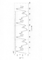
In practice, most if not all modern GNSS receivers process the signal in the digital domain after sampling at a finite frequency F s . This means that the DLL does not access the continuous signal from the satellite, but only discrete samples taken every T s =1/F s . Instead of having to synchronize two continuous signals (the incoming signal and the local replica), the DLL needs to synchronize two sequences of discrete samples. Intuitively, one would expect the ability to identify PRN chip transitions to decrease when the sampling frequency is low, as the number of samples entering a chip transition is reduced. Accurate pseudorange determination requires acquiring enough samples uniformly distributed around the tip transition to minimize the effects of time discretization. Figure 3a shows the types of pseudorange errors resulting from the time discretization. It is obtained using a geodetic grade receiver that tracks actual GNSS signals from orbiting satellites. The error (curve 15) exhibits a periodic pattern and is most pronounced when the apparent Doppler frequency (curve 16) is small, ie when the measured pseudoranges do not change rapidly as a function of time. FIG. 3b shows the
これらの刊行物によって示されるように、デジタル受信機における時間離散化は、擬似距離の精度に影響を及ぼすことが従来技術において知られている。この問題に対処するための提案された手法は、主に、擬似距離分散の点から精度低下を定量化すること、および、時間離散化の影響を最小限に抑えるためにサンプリング周波数を上昇させることにある。しかしながら、サンプリング周波数を変更することは、しばしば非実際的であり、受信機の複雑さおよび電力消費における許容できない増加につながる。 As indicated by these publications, it is known in the prior art that time discretization in digital receivers affects the accuracy of pseudoranges. Proposed techniques to address this issue are primarily focused on quantifying the precision loss in terms of pseudorange variance and increasing the sampling frequency to minimize the effects of time discretization. It is in. However, changing the sampling frequency is often impractical and leads to unacceptable increases in receiver complexity and power consumption.
「XiaoJun Jinら、PN Ranging Based on Noncommensurate Sampling: Zero-Bias Mitigation Methods、IEEE Transactions on Aerospace and Electronic Systems、Vol.53、No.2、2017年4月」という文書は、離散化の影響を補償する方法を開示しているが、一定の擬似距離、したがって一定のゼロバイアスの場合、すなわち、ドップラーが厳密にゼロである場合にのみ対処する。図3aにおける振動によって示されているように、GNSS擬似距離、したがってバイアスは、経時的に変化するので、軽減技法は、GNSSに直接適用できない。 The document "XiaoJun Jin et al., PN Ranging Based on Noncommensurate Sampling: Zero-Bias Mitigation Methods, IEEE Transactions on Aerospace and Electronic Systems, Vol.53, No.2, April 2017" compensates for discretization effects Although the method is disclosed, it only addresses the case of constant pseudorange and thus constant zero bias, ie the Doppler is exactly zero. Mitigation techniques cannot be directly applied to GNSS, as GNSS pseudoranges, and thus biases, change over time, as shown by the oscillations in FIG. 3a.
本発明は、大部分のGNSS受信機において使用される有限サンプリング周波数から生じる擬似距離誤差を補正することを目的とする。本発明は、サンプリング周波数を変更することを必要とせず、したがって、受信機の複雑さへの影響を最低限にして既存の受信機に適用され得る。本発明は、経時的な擬似距離の変化から生じる一定でない誤差の場合にも適している。この目的は、添付の特許請求の範囲において開示される受信機および方法によって達成される。 The present invention aims to correct pseudorange errors resulting from the finite sampling frequency used in most GNSS receivers. The present invention does not require changing the sampling frequency and can therefore be applied to existing receivers with minimal impact on receiver complexity. The invention is also suitable for non-constant errors resulting from changes in pseudoranges over time. This object is achieved by the receiver and method disclosed in the appended claims.
サンプリング周波数Fsにおいてサンプリングされた信号に基づいて動作する、本発明による衛星航法受信機によって測定された擬似距離に補正が適用され、補正は、測定された擬似距離自体に基づく。補正は、DLLにおいて決定された弁別器値に対する補正であってもよく、または、実際に測定された擬似距離それ自体に対する補正であってもよい。補正は、特定のPRN符号と受信機のパラメータとに対して固有である。したがって、補正は、リアルタイムで計算される測定された擬似距離の関数として、または、少なくとも0と、Tsが1/Fsに等しく、cが光速であるcTsとの間の事前定義された値のルックアップテーブルとして受信機において実施される。 A correction is applied to the pseudoranges measured by the satellite navigation receiver according to the invention operating on the basis of the sampled signal at the sampling frequency F s , the correction being based on the measured pseudoranges themselves. The corrections may be corrections to the discriminator values determined in the DLL, or to the actually measured pseudoranges themselves. The corrections are specific to a particular PRN code and receiver parameters. Therefore, the correction is either as a function of the measured pseudorange calculated in real time or at a predefined value between at least 0 and cT s where T s is equal to 1/F s and c is the speed of light. It is implemented in the receiver as a lookup table of values.
第1の実施形態によれば、本発明は、衛星航法用の受信機によって取得された測定された擬似距離を補正するための方法に関し、受信機がDLLフィルタと弁別器値Dを計算するための弁別器とを含む遅延ロックループ(DLL)を備え、測定された擬似距離が真の擬似距離の推定値であり、方法が、
衛星を表す疑似ランダムノイズ(PRN)符号を少なくとも含むダウンコンバートされた信号を取得するために、衛星によって放出されたRF信号をベースバンドまたはIF周波数にダウンコンバートするステップと、
所与のサンプリング周波数Fsにおいて離散時間信号を取得するために、ダウンコンバートされた信号をサンプリングするステップと、
DLLフィルタによってフィルタリングされた弁別器値に基づいて、PRN符号のローカルレプリカをサンプリングされた信号と同期させ、同期されたローカルレプリカから測定された擬似距離cτrを決定するステップであって、τrが同期されたローカルレプリカの時間遅延であり、cが光速であり、τrが衛星からの到来符号の時間遅延τsの推定値であり、擬似距離誤差がcΔτに等しくなるように、Δτ=τr-τsである、ステップと
を含み、
受信機が、擬似距離誤差に関する補正項cΔτbを決定するように構成され、補正項が、cTsに等しい周期を有する測定されたまたは真の擬似距離の周期関数であり、Tsが1/Fsに等しく、Δτbが、弁別器値DがゼロであるΔτの値であり、方法が、
測定された擬似距離におけるcΔτbを決定するステップと、
DLLフィルタと本質的に同じ特性を有するローパスフィルタによってcΔτbをフィルタリングするステップと、
補正された擬似距離値を取得するために、フィルタリングされたcΔτbをcτrから減算するステップと
を含む。
According to a first embodiment, the invention relates to a method for correcting measured pseudoranges acquired by a receiver for satellite navigation, for the receiver to calculate DLL filters and discriminator values D and a delay locked loop (DLL) containing a discriminator of
downconverting an RF signal emitted by the satellite to a baseband or IF frequency to obtain a downconverted signal including at least a pseudorandom noise (PRN) code representative of the satellite;
sampling the downconverted signal to obtain a discrete-time signal at a given sampling frequency F s ;
Synchronizing a local replica of the PRN code with the sampled signal based on the discriminator values filtered by the DLL filter and determining a pseudorange cτr measured from the synchronized local replica, wherein τr is the time delay of the synchronized local replica, c is the speed of light, τ r is an estimate of the time delay τ s of the incoming code from the satellite, and Δτ= a step where τ r -τ s ;
A receiver is configured to determine a correction term cΔτ b for the pseudorange error, the correction term being a periodic function of the measured or true pseudorange with a period equal to cT s and T s being 1/ is equal to F s , Δτ b is the value of Δτ for which the discriminator value D is zero, and the method is
determining cΔτ b at the measured pseudorange;
filtering cΔτ b with a low pass filter having essentially the same characteristics as the DLL filter;
Subtracting the filtered cΔτ b from cτ r to obtain a corrected pseudorange value.
受信機は、測定された擬似距離を計算のための入力として使用して、cΔτb=cΔτ(D=0)の値をリアルタイムで計算するように構成されてもよい。代替的には、受信機は、少なくとも0とcTsとの間の真のまたは測定された擬似距離の複数の値に関するcΔτbの複数の値を含むルックアップテーブルを備えてもよく、cΔτbは、ルックアップテーブルの値間の補間によって決定される。ルックアップテーブルの値は、弁別器値Dが少なくとも0とcTsとの間の前記複数の真のもしくは測定された擬似距離においてゼロであるΔτの値としてのΔτbの計算によって、または、シミュレートされた信号もしくは現実の信号に基づく受信機の較正によって決定されてもよい。一実施形態によれば、ドップラー周波数が所与のしきい値を超えると、Δτbは、ゼロに設定される。 The receiver may be configured to calculate the value of cΔτ b =cΔτ(D=0) in real time using the measured pseudoranges as input for the calculation. Alternatively, the receiver may comprise a lookup table containing multiple values of cΔτ b for multiple values of true or measured pseudoranges at least between 0 and cT s , where cΔτ b is determined by interpolation between lookup table values. The values in the lookup table are calculated by calculating Δτ b as the value of Δτ for which the discriminator value D is zero at the plurality of true or measured pseudoranges between at least 0 and cT s , or by simulating may be determined by calibration of the receiver based on simulated or real-world signals. According to one embodiment, Δτ b is set to zero when the Doppler frequency exceeds a given threshold.
第2の実施形態によれば、本発明は、衛星航法用の受信機によって取得された測定された擬似距離を補正するための方法に関し、受信機がDLLフィルタと弁別器値Dを計算するための弁別器とを含む遅延ロックループを備え、測定された擬似距離が真の擬似距離の推定値であり、方法が、
衛星を表す疑似ランダムノイズ(PRN)符号を少なくとも含むダウンコンバートされた信号を取得するために、衛星によって放出されたRF信号をベースバンドまたはIF周波数にダウンコンバートするステップと、
所与のサンプリング周波数FsにおいてサンプリングされたPRN符号を取得するために、ダウンコンバートされた信号をサンプリングするステップと、
DLLフィルタによってフィルタリングされた弁別器値に基づいて、PRN符号のローカルレプリカをサンプリングされた信号と同期させ、同期されたローカルレプリカから測定された擬似距離cτrを決定するステップであって、τrが同期されたローカルレプリカの時間遅延であり、cが光速であり、τrが衛星からの到来符号の時間遅延τsの推定値であり、擬似距離誤差がcΔτに等しくなるように、Δτ=τr-τsである、ステップと
を含み、
受信機が、弁別器値Dに関する弁別器補正項Dbを決定するように構成され、補正項が、cTsに等しい周期を有する測定されたまたは真の擬似距離の周期関数であり、Tsが1/Fsに等しく、Dbが、ΔτがゼロであるときのDの値であり、方法が、
測定された擬似距離におけるDbを決定するステップと、
補正された弁別器値を取得するために、DLLフィルタの前に弁別器によって計算された弁別器値DにからDbを減算するステップであって、同期させるステップが、DLLフィルタ(9)によってフィルタリングされた補正された弁別器値に基づいて行われる、ステップと
を含む。
According to a second embodiment, the invention relates to a method for correcting measured pseudoranges acquired by a receiver for satellite navigation, for the receiver to calculate the DLL filter and the discriminator value D and a delay-locked loop comprising a discriminator of
downconverting an RF signal emitted by the satellite to a baseband or IF frequency to obtain a downconverted signal including at least a pseudorandom noise (PRN) code representative of the satellite;
sampling the downconverted signal to obtain a sampled PRN code at a given sampling frequency F s ;
Synchronizing a local replica of the PRN code with the sampled signal based on the discriminator values filtered by the DLL filter and determining a pseudorange cτr measured from the synchronized local replica, wherein τr is the time delay of the synchronized local replica, c is the speed of light, τ r is an estimate of the time delay τ s of the incoming code from the satellite, and Δτ= a step where τ r -τ s ;
A receiver is configured to determine a discriminator correction term D b for the discriminator value D, the correction term being a periodic function of the measured or true pseudoranges with a period equal to cT s and T s is equal to 1/F s , D b is the value of D when Δτ is zero, and the method is
determining D b in the measured pseudorange;
subtracting D b from the discriminator value D calculated by the discriminator before the DLL filter to obtain a corrected discriminator value, wherein the step of synchronizing is performed by the DLL filter (9) based on the filtered corrected discriminator values.
受信機は、測定された擬似距離を計算のための入力として使用して、Db=D(Δτ=0)の値をリアルタイムで計算するように構成されてもよい。代替的には、受信機は、少なくとも0とcTsとの間の真のまたは測定された擬似距離の複数の値に関するDbの複数の値を含むルックアップテーブルを備えてもよく、Dbは、ルックアップテーブルの値間の補間によって決定される。ルックアップテーブルからの値は、少なくとも0とcTsとの間の前記複数の真のもしくは測定された擬似距離においてΔτがゼロであるときのDの値としてのDbの計算によって、または、シミュレートされた信号もしくは現実の信号に基づく受信機の較正によって決定されてもよい。一実施形態によれば、ドップラー周波数が所与のしきい値を超えると、Dbは、ゼロに設定される。 The receiver may be configured to calculate the value of D b =D(Δτ=0) in real time using the measured pseudoranges as input for the calculation. Alternatively, the receiver may comprise a lookup table containing multiple values of D b for multiple values of true or measured pseudoranges at least between 0 and cT s , D b is determined by interpolation between lookup table values. Values from the lookup table are obtained by calculating D b as the value of D when Δτ is zero at the plurality of true or measured pseudoranges at least between 0 and cT s , or by simulating may be determined by calibration of the receiver based on simulated or real-world signals. According to one embodiment, Db is set to zero when the Doppler frequency exceeds a given threshold.
前記の第1および第2の実施形態に関連する「弁別器値」は、受信された信号と信号のローカルレプリカとの間の不整合を表す値である。ローカルレプリカは、DLLにおいて生成された時間厳守のローカルレプリカであり、DLLは、少なくとも1つの先行レプリカまたは遅延レプリカをさらに生成し、それらに基づいて、弁別器値が決定される。 A "discriminator value" in connection with the first and second embodiments above is a value that represents the mismatch between the received signal and the local replica of the signal. A local replica is a punctual local replica generated in the DLL, which further generates at least one leading or lagging replica, based on which discriminator values are determined.
本発明は、
全地球的航法衛星からのRF信号を捕捉するためのアンテナと、
衛星を表す疑似ランダムノイズ符号(PRN)を少なくとも含む信号を取得するためのダウンコンバータと、
サンプリング周波数Fsにおいて離散シーケンスを取得するために信号をサンプリングするためのサンプラーと、
遅延ロックループ回路であって、
PRN符号のローカル定時レプリカ、ローカル早めレプリカ、およびローカル遅めレプリカを生成するための符号生成器および遅延要素と、
到来ダウンコンバート信号とローカルレプリカまたは前記ローカルレプリカの組合せとの間の相関値を計算するための相関器と、
相関値から弁別器値を計算するための弁別器回路と、
弁別器出力をローパスフィルタリングするための第1のフィルタ回路と、
ローカルレプリカのチッピングレートを制御するための数値制御発振器と、
定時レプリカの位相から測定された擬似距離を計算するための擬似距離計算機と
を備える、遅延ロックループ回路と
を備える、衛星航法のための受信機にさらに関し、
受信機が、
第1の実施形態による方法に従ってcΔτbを計算するための擬似距離補正計算機と、
擬似距離補正計算機の出力にローパスフィルタリングを適用するための第2のフィルタ回路であって、第2のフィルタ回路が第1のフィルタ回路と同じ特性を有する、第2のフィルタ回路と、
補正された擬似距離を決定するための減算回路と
をさらに備える。
The present invention
an antenna for picking up RF signals from global navigation satellites;
a downconverter for obtaining a signal including at least a pseudorandom noise code (PRN) representing a satellite;
a sampler for sampling the signal to obtain a discrete sequence at a sampling frequency F s ;
A delay locked loop circuit,
a code generator and delay elements for generating local punctual, local early, and local late replicas of the PRN code;
a correlator for calculating a correlation value between an incoming downconverted signal and a local replica or a combination of said local replicas;
a discriminator circuit for calculating a discriminator value from the correlation values;
a first filter circuit for lowpass filtering the discriminator output;
a numerically controlled oscillator for controlling the chipping rate of the local replica;
a pseudorange calculator for calculating pseudoranges measured from the phases of the punctual replicas; and a delay locked loop circuit comprising:
the receiver
a pseudorange correction calculator for calculating cΔτ b according to the method according to the first embodiment;
a second filter circuit for applying low-pass filtering to the output of the pseudorange correction calculator, the second filter circuit having the same characteristics as the first filter circuit;
and a subtraction circuit for determining corrected pseudoranges.
本発明は、
全地球的航法衛星からのRF信号を捕捉するためのアンテナと、
衛星を表す疑似ランダムノイズ符号(PRN)を少なくとも含む信号を取得するためのダウンコンバータと、
サンプリング周波数Fsにおいて離散シーケンスを取得するために信号をサンプリングするためのサンプラーと、
遅延ロックループ回路であって、
PRN符号のローカル定時レプリカ、ローカル早めレプリカ、およびローカル遅めレプリカを生成するための符号生成器および遅延要素と、
到来ダウンコンバート信号とローカルレプリカまたは前記ローカルレプリカの組合せとの間の相関値を計算するための相関器と、
相関値から弁別器値を計算するための弁別器回路と、
弁別器出力をローパスフィルタリングするためのフィルタ回路と、
ローカルレプリカのチッピングレートを制御するための数値制御発振器と、
定時レプリカの位相から測定された擬似距離を計算するための擬似距離計算機と
を備える、遅延ロックループ回路と
を備える、衛星航法のための受信機にさらに関し、
DLLが、
第2の実施形態による方法に従ってDbを計算するための計算機と、
補正された弁別器値を決定するための減算回路と
をさらに備える。
The present invention
an antenna for picking up RF signals from global navigation satellites;
a downconverter for obtaining a signal including at least a pseudorandom noise code (PRN) representing a satellite;
a sampler for sampling the signal to obtain a discrete sequence at a sampling frequency F s ;
A delay locked loop circuit,
a code generator and delay elements for generating local punctual, local early, and local late replicas of the PRN code;
a correlator for calculating a correlation value between an incoming downconverted signal and a local replica or a combination of said local replicas;
a discriminator circuit for calculating a discriminator value from the correlation values;
a filter circuit for low-pass filtering the discriminator output;
a numerically controlled oscillator for controlling the chipping rate of the local replica;
a pseudorange calculator for calculating pseudoranges measured from the phases of the punctual replicas; and a delay locked loop circuit comprising:
DLL is
a calculator for calculating D b according to the method according to the second embodiment;
and a subtraction circuit for determining a corrected discriminator value.
本発明は、IFまたはベースバンド信号がサンプリングされるデジタルGNSS受信機に関する。時間離散化を考慮に入れて、図1が再考されなければならない。したがって、DLL内に含まれる様々な信号のより現実的な表現が、時間離散化を考慮に入れている図4において与えられている。図4に示す信号は、図1に示すものに対応しているが、デジタル領域にある。サンプリングエポックは、垂直の灰色線として示され、DLLは、点によって表される一連の離散サンプルを処理する。IN(t)は、アナログ信号であり、IN[k]は、周波数Fsにおいてサンプリングされたその時間離散バージョンである。ADCとDLLの入力との間でダウンサンプリングまたはデシメーションが適用される場合があるので、この説明全体および特許請求の範囲において参照されるサンプリング周波数Fsは、受信機のアナログ-デジタル(ADC)回路においてアナログ信号が物理的にサンプリングされる周波数とは異なる場合があることに留意すべきである。したがって、Fsは、受信機のDLLによって処理される時間離散信号のサンプリング周波数である。E-L相関は、ここでは、(E(t)-L(t))*IN(t)の連続積分の代わりに、離散「(E[k]-L[k])*IN[k]」サンプルの合計である。図1において(E(t)-L(t))*IN(t)の平均値がゼロであることは明らかであったが、これは、離散サンプルではもはや明確ではない。例えば、図4に示すようなサンプリング周波数および早め-遅めゲート幅では、チップ遷移ごとに2つのみの非ゼロ(E[k]-L[k])*IN[k]サンプルが利用可能である(長方形14を参照)。第1のサンプルは、典型的には負であり、第2のサンプルは、典型的には正である。サンプルがチップ遷移全体にわたって均一に分布している場合、および、累積するのに十分なチップ遷移が存在する場合にのみ、E-L相関は、ゼロである。ほとんどの場合、これは、厳密に真ではなく、DLL弁別器出力は、公称値からわずかに逸脱する。 The present invention relates to digital GNSS receivers in which IF or baseband signals are sampled. Taking into account the time discretization, Fig. 1 must be reconsidered. A more realistic representation of the various signals contained within the DLL is therefore given in FIG. 4, which takes into account the time discretization. The signals shown in FIG. 4 correspond to those shown in FIG. 1, but in the digital domain. A sampling epoch is shown as a vertical gray line and the DLL processes a series of discrete samples represented by dots. IN(t) is the analog signal and IN[k] is its time-discrete version sampled at frequency F s . Since downsampling or decimation may be applied between the ADC and DLL inputs, the sampling frequency F s referred to throughout this description and claims is the receiver analog-to-digital (ADC) circuit It should be noted that the frequency at which the analog signal is physically sampled at may differ from the frequency at which it is sampled. F s is therefore the sampling frequency of the time-discrete signal processed by the DLL of the receiver. The EL correlation is now represented by the discrete '(E[k]-L[k])*IN[k]' sample is the sum of Although it was clear in FIG. 1 that the mean of (E(t)-L(t))*IN(t) is zero, this is no longer clear for discrete samples. For example, with the sampling frequency and early-late gate width shown in Figure 4, only two non-zero (E[k]-L[k])*IN[k] samples are available per chip transition. Yes (see Rectangle 14). The first sample is typically negative and the second sample is typically positive. The EL correlation is zero only if the samples are evenly distributed over the tip transitions and if there are enough tip transitions to accumulate. In most cases this is not strictly true and the DLL discriminator output deviates slightly from the nominal value.
以下の段落は、時間離散化を考慮に入れて、PRN符号、到来符号およびローカル符号の遅延、ならびに受信機パラメータ(IF帯域幅、早め-遅めゲート幅、およびサンプリング周波数)の関数として、E-L相関と弁別器値とを計算する方法について説明する。フィルタリングおよび遅延されていないPRN符号は、次の式、 The following paragraphs describe the E-L A method for calculating correlation and discriminator values is described. The unfiltered and undelayed PRN code is given by the formula,

によって与えられ、ここで、chipkは、PRN符号のk番目のチップの値(-1または+1)であり、{k}Nは、kモジュロNであり、Nは、PRN符号内のチップの数(例えば、GPS CA符号の場合1023)であり、Tcは、チップ持続時間であり、rect(x)は、0≦x≦Tcの場合1であり、それ以外の場合0である。いくつかのGNSS PRN符号は、サブキャリアによって変調されることに留意すべきである。サブキャリア変調は、明確にするために、以下の導出以外ここでは明示的に示されておらず、本発明は、一般に、サブキャリアによって変調されたPRN符号に等しく適用される。 where chip k is the value of the kth chip in the PRN code (-1 or +1), {k} N is k modulo N, and N is the number of chips in the PRN code (e.g., 1023 for GPS CA codes), Tc is the chip duration, and rect(x) is 1 if 0≤x≤Tc and 0 otherwise. . Note that some GNSS PRN codes are modulated by subcarriers. Subcarrier modulation is not explicitly shown here, except in the following derivations, for clarity, and the invention applies equally to PRN codes modulated by subcarriers in general.
以下の導出において、τsは、衛星から到来する符号の時間遅延であり、τrは、ローカル定時レプリカの時間遅延である。真の擬似距離は、cτsであり、ここで、cは、光速であり、測定された擬似距離は、cτrである。Δτ=τr-τsは、ローカル定時レプリカと到来符号との間の不整合であり、cΔτは測定された擬似距離と真の擬似距離との差、すなわち、擬似距離誤差である。フロントエンドフィルタリング後に衛星から受信される信号は、
IN(t)=H*e(t-τs)=H*e(t-τr+Δτ)
である。ここで、Hは、衛星および受信機のフロントエンドフィルタリングを表す。以下の導出の文脈において、フィルタは、IFを中心とし、所与の両側帯域幅(two-sided bandwidth)を有する理想的なゼロ遅延矩形フィルタによって近似される。IN(t)信号は、連続的である。それは、周波数Fsにおいてサンプリングされ、結果のサンプルは、
IN[k]=IN(k・Ts)
を示す。ここで、Ts=1/Fsは、サンプリング間隔である。
In the following derivations, τ s is the time delay of the code arriving from the satellite and τ r is the time delay of the local punctual replica. The true pseudorange is cτ s , where c is the speed of light, and the measured pseudorange is cτ r . Δτ=τ r −τ s is the mismatch between the local punctual replica and the incoming code, and cΔτ is the difference between the measured pseudorange and the true pseudorange, ie the pseudorange error. The signal received from the satellite after front-end filtering is
IN(t)=H*e(t-τ s )=H*e(t-τ r +Δτ)
is. where H represents the satellite and receiver front-end filtering. In the context of the following derivations, the filter is approximated by an ideal zero-delay rectangular filter centered at IF and having a given two-sided bandwidth. The IN(t) signal is continuous. It is sampled at frequency F s and the resulting samples are
IN[k]=IN(k・Ts )
indicates where T s =1/F s is the sampling interval.
受信機は、遅延τrを有するそのローカル定時レプリカを生成し、早めレプリカおよび遅めレプリカは、それぞれ、d/2だけ進められ、遅らされる(図2参照)。P[k]、E[k]、およびL[k]のローカル符号レプリカサンプルは、
P[k]=e(k・TS-τr)
E[k]=e(k・TS-τr+d/2)
L[k]=e(k・TrS-τr-d/2)
を示す。E-LおよびP相関値は、
The receiver generates its local punctual replica with delay τ r , the early and late replicas being advanced and retarded by d/2, respectively (see FIG. 2). The local code replica samples of P[k], E[k], and L[k] are
P[k]=e(k・T S -τ r )
E[k]=e(k・TS -τr+ d /2)
L[k]=e(k・TrS -τr- d /2)
indicates The EL and P correlation values are

として計算され、ここで、Mは、相関間隔中のサンプル数である。最後に、DLL弁別器値(チップ単位における)は、不整合Δτの関数として計算される。 where M is the number of samples in the correlation interval. Finally, the DLL discriminator value (in chips) is calculated as a function of the mismatch Δτ.

上記で提示された弁別器値の導出は、1つの早めレプリカと、1つの定時レプリカと、1つの遅めレプリカとを使用するE-L弁別器値の例をとったことに留意されたい。点乗積弁別器値、ダブルデルタ弁別器値などの、到来符号を任意の数の時間遅延ローカルレプリカを相関させることに基づく任意のタイプのDLL弁別器値に上記の導出を適合させることは、当業者にとって簡単である。したがって、「弁別器値」は、本発明の文脈において上記の式(1)に限定されず、異なるタイプのDLL弁別器(すなわち、弁別器値を決定するための異なるハードウェアデバイス)に基づく同等の式に基づくことができる。弁別器値は、受信信号と信号のローカルレプリカとの間の不整合を表す値として解釈されるべきである。 Note that the derivation of discriminator values presented above took the example of E-L discriminator values using one early replica, one punctual replica, and one late replica. Adapting the above derivation to any type of DLL discriminator value based on correlating the incoming code with any number of time-delayed local replicas, such as dot product discriminator values, double delta discriminator values, etc. It is straightforward for those skilled in the art. Therefore, "discriminator value" in the context of the present invention is not limited to equation (1) above, but equivalent can be based on the formula The discriminator value should be interpreted as a value representing the mismatch between the received signal and the local replica of the signal.
所与のPRN符号およびτsまたはτrの所与の値に関するD(Δτ)関数を計算するために上記のまたは同等の式を使用すると、図5における曲線12と同様の曲線が得られる。その図における点線13は、名目上の弁別器応答がどうあるべきかを示す。DLLは、D(Δτ)がゼロであるロックポイント18に収束するが、これは、Δτ=0において発生しない。不整合Δτbが存在し、cΔτbの擬似距離誤差を引き起こす。この誤差を補正する2つの方法が存在し、(i)ゼロ交差がΔτ=0において発生するように弁別器値をシフトする、すなわち、弁別器値からDbを減算するか、または(ii)測定された擬似距離からcΔτbを減算する。これらの2つの手法は、本発明による方法および受信機の2つのそれぞれの実施形態に適用される。
Using the above or equivalent equations to calculate the D(Δτ) function for a given PRN code and given values of τ s or τ r yields a curve similar to
既知のサンプリング周波数Fs、IF帯域幅、および早め-遅めゲート幅dを有する受信機の場合、Dbの値およびΔτbの値は、PRN符号に依存し、DbならびにΔτbは、上記の式を使用してτsまたはτrの関数として(または真のもしくは測定された擬似距離の関数として同等に)計算され得る。例えば、DbおよびΔτbは、それぞれ、τsおよびτrの関数として図6および図7に示されている。これの代わりに、同様の曲線が、それぞれ、τrおよびτsの関数としてDbおよびΔτbについて描かれ得る。図は、以下の条件、すなわち、GPS CA符号PRN#1、IF両側帯域幅=16MHz、Fs=20MHz、d=100ns、1ms積分時間(M=20000)、0<τs<170ns、0<τr<170nsに適用される。
For a receiver with known sampling frequency F s , IF bandwidth, and early-late gate width d, the values of D b and Δτ b depend on the PRN code, D b and Δτ b are It can be calculated as a function of τ s or τ r (or equivalently as a function of true or measured pseudoranges) using the equations above. For example, D b and Δτ b are shown in FIGS. 6 and 7 as functions of τ s and τ r , respectively. Alternatively, similar curves can be drawn for D b and Δτ b as functions of τ r and τ s , respectively. The figure is for the following conditions: GPS CA
見てわかるように、DbおよびΔτbは、τsまたはτrの周期関数であり、同じ誤差がTsごとに、すなわち、サンプリング周波数Fs=20MHzに対応して示されているこの例では50nsごとに繰り返される。図は、最初の3つの期間のみを示しているが、同じパターンが無限に繰り返される。到来符号とサンプリングクロックとの間の位相関係は、Ts秒ごとにそれ自体繰り返されるので、これは、予想される。これは、DbおよびΔτbがτsモジュロTsまたはτrモジュロTsに依存することを意味する。したがって、DbおよびΔτbが0秒とTs秒との間のτsまたはτrについて既知である場合、それらは、Tsよりも高いτsまたはτrの任意の値について既知である。また、真のまたは測定された擬似距離がcτsおよびcτrに等しいので、DbおよびΔτbは、真のまたは測定された擬似距離モジュロcTsに依存すると言うことができる。例えば、Tsが50nsに等しい場合、cTsは、15mに等しい。そのように、ΔτbまたはDbが0mと15mとの間の測定された擬似距離について既知である場合、ΔτbまたはDbは、任意の測定された擬似距離について計算され得る。 As can be seen, D b and Δτ b are periodic functions of τ s or τ r and the same error is shown every T s , i.e. corresponding to sampling frequency F s =20 MHz in this example is repeated every 50ns. The figure shows only the first three periods, but the same pattern repeats infinitely. This is expected since the phase relationship between the incoming code and the sampling clock repeats itself every T s seconds. This means that D b and Δτ b depend on τ s modulo T s or τ r modulo T s . Therefore, if D b and Δτ b are known for τ s or τ r between 0 seconds and T s seconds, they are known for any value of τ s or τ r above T s . Also, since the true or measured pseudoranges are equal to cτ s and cτ r , we can say that D b and Δτ b depend on the true or measured pseudoranges modulo cT s . For example, if T s equals 50ns, cT s equals 15m. As such, if Δτ b or D b is known for a measured pseudorange between 0m and 15m, Δτ b or Db can be calculated for any measured pseudorange.
したがって、図7は、以下のように解釈されてもよく、すなわち、測定された擬似距離がPRである場合、真の擬似距離は、 Therefore, Figure 7 may be interpreted as follows: if the measured pseudorange is PR, then the true pseudorange is

において評価されたΔτbの値を減算し、光速を乗算することによって取得され得、ここで、{X}yは、XモジュロYである。図6および図7における曲線は、所与のPRN符号、すなわち、所与の衛星に固有のものであることに留意されたい。各PRN、および、したがって、各衛星は、τsまたはτrの関数としてのDbおよびΔτbのそれ自体の値を有する。本発明によれば、これらの値DbおよびΔτbは、測距用途において関与する衛星によって使用されている様々なPRN符号について、関数またはルックアップテーブルとして受信機に実装され、すなわち、受信機は、所与の測定された擬似距離についてDbまたはΔτbを決定するように構成される。ルックアップテーブルが受信機内に実装されている場合、DbおよびΔτbが擬似距離の周期関数(周期cTs)であることを考えると、テーブルは、0とcTsとの間の擬似距離に対してのみ定義される必要がある。測定された擬似距離モジュロcTsは、次いで、補正項DbまたはΔτbを決定するための入力として使用される。例えば、受信機は、k=0...99について can be obtained by subtracting the value of Δτ b evaluated at and multiplying by the speed of light, where {X} y is X modulo Y. Note that the curves in Figures 6 and 7 are specific to a given PRN code, ie a given satellite. Each PRN, and thus each satellite, has its own values of D b and Δτ b as a function of τ s or τ r . According to the invention, these values D b and Δτ b are implemented in the receiver as functions or lookup tables for the various PRN codes used by the satellites involved in ranging applications, i.e. the receiver is configured to determine D b or Δτ b for a given measured pseudorange. Given that D b and Δτ b are periodic functions of the pseudoranges (period cT s ), if a lookup table is implemented in the receiver, the table is a pseudorange between 0 and cT s . need only be defined for The measured pseudorange modulo cT s is then used as input to determine the correction term D b or Δτ b . For example, a receiver may for k=0...99

に対応するDbまたはΔτbに関する100個の値を含むルックアップテーブルを含んでもよい。受信機は、 A lookup table containing 100 values for D b or Δτ b corresponding to . the receiver

の実際の値においてこれらのテーブル化された値を補間することによって得られたDbまたはΔτbの値を決定するようにさらに構成される(DまたはcΔτの補正に基づく特定の実施形態の説明をさらに参照されたい)。cTsが15mに等しい例を再びとり、測定された擬似距離が50mである場合、擬似距離モジュロcTsは、50-3×15=5mであり、ルックアップテーブルは、5mにおけるDbまたはΔτbの値を決定することを可能にする。ルックアップテーブルは、少なくとも0とcTsとの間の値を含む。ルックアップテーブルは、同様にcTsを超える値を含んでもよい。より一般的には、補正項DbおよびΔτbは、周期ncTsを有する真のまたは測定された擬似距離の周期関数であり、nは、1以上の整数であり、すなわち、cTsの整数倍である。したがって、ルックアップテーブルは、0とcTsの整数倍との間の範囲において定義されてもよく、この場合、測定された擬似距離モジュロncTsが、補正項を決定するための入力として使用される。 further configured to determine the value of D b or Δτ b obtained by interpolating these tabulated values at the actual value of (description of certain embodiments based on correction of D or cΔτ (see further). Again taking the example where cT s equals 15m and the measured pseudorange is 50m, the pseudorange modulo cT s is 50−3×15=5m and the lookup table is D b or Δτ at 5m Allows to determine the value of b . The lookup table contains values at least between 0 and cT s . The lookup table may contain values that exceed cT s as well. More generally, the correction terms D b and Δτ b are periodic functions of the true or measured pseudoranges with period ncT s , where n is an integer greater than or equal to 1, i.e. an integer of cT s Double. Thus, the lookup table may be defined in the range between 0 and integer multiples of cT s , where the measured pseudorange modulo ncT s is used as input to determine the correction term. be.
上述のように、DbまたはΔτbを決定するために受信機において実行された関数またはルックアップテーブルは、真の擬似距離cτsの関数として、または測定された擬似距離cτrの関数として定義されてもよい。しかしながら、DbまたはΔτbを決定するための入力として使用されるのは、測定された擬似距離である。関数またはルックアップテーブルが真の擬似距離の関数として実装されている場合、測定された擬似距離は、補正項を決定するための真の擬似距離として入力される。しかしながら、その場合、真の擬似距離と測定された擬似距離との間の最初の差は、擬似距離が補正されるとすぐに除去される。 As noted above, the function or lookup table implemented in the receiver to determine D b or Δτ b is defined as a function of the true pseudorange cτ s or as a function of the measured pseudorange cτ r may be However, it is the measured pseudoranges that are used as input for determining D b or Δτ b . If the function or lookup table is implemented as a function of true pseudoranges, the measured pseudoranges are input as true pseudoranges for determining the correction term. However, in that case the initial difference between the true pseudorange and the measured pseudorange is removed as soon as the pseudorange is corrected.
補正項DbまたはΔτbと測定されたまたは真の擬似距離との間の関係は、各PRNおよび受信機のパラメータ(Fs、d、IF帯域幅)に対して事前定義され、これは、補正項を決定するために、測定された擬似距離自体の使用を可能にする。この特徴は、サンプリング周波数Fsを上げることなく、図3aおよび図3bに示すような低いドップラー周波数における擬似距離誤差を軽減するのに特に有用である。 The relationship between the correction term D b or Δτ b and the measured or true pseudorange is predefined for each PRN and receiver parameters (F s , d, IF bandwidth), which is Allows the use of the measured pseudoranges themselves to determine the correction terms. This feature is particularly useful for mitigating pseudorange errors at low Doppler frequencies, such as those shown in Figures 3a and 3b, without increasing the sampling frequency Fs .
上記で説明した効果は、擬似距離モジュロcTsが追加されている(トレース19-単位は、より容易な読みやすさのために適合されており、物理的ではない)ことを除いて図3aと同じである図8において明確に見ることができる。以下で説明するように、誤差は、ゼロドップラーにおいて最大であり、ドップラーが増加するにつれて減少する。 3a and The same can be clearly seen in FIG. As explained below, the error is maximum at zero Doppler and decreases as Doppler increases.
上記で説明した項cΔτbと同等の補正項に基づくゼロドップラー周波数における擬似距離自体の補正は、XiaoJun Jinらによる上記で引用した文書において、これらの著者によって効果的に提案されている。しかしながら、この文書は、実際には、衛星に関して受信機によって決定される擬似距離が受信機に対する衛星の相対的な移動により時間とともに変化している任意のGNSSにおいて現実である非ゼロドップラーの場合を扱っていない。その結果、DbおよびΔτbも、図6および図7におけるパターンに従って時間とともに変化する。測定された擬似距離において振動する誤差パターンが見られ、パターンの1周期は、cTsによる疑似距離の変化に対応する。疑似距離の変化が遅い場合、振動も同様に遅くなる。疑似距離の変化率が上昇すると、振動は、より速くなる。これは、疑似距離がcTsだけ、例えば、Tsが50nsに等しい場合、15mだけ変化するのに必要な時間がますます短くなるためである。結局、振動は、DLLフィルタによって除去され、疑似距離の変化率が1秒あたり数メートルよりも大きい場合、影響は、無視できるようになる。疑似距離の変化率は、ドップラーに直接関係し、ここで、ヘルツにおけるドップラーは、疑似距離の変化率をキャリア波長で割ったものである。言い換えれば、DLLフィルタのおかげで、ドップラーが絶対値において増加するにつれて、振動の振幅は、減少する。しかしながら、上記で説明した補正cΔτbが非ゼロドップラーに適用された場合、この補正は、減衰なしで、ドップラー周波数が上昇するにつれてますます速く振動し、これは、誤った結果につながる。この問題は、本発明による2つの実施形態によって解決され、各実施形態は、方法と、方法を実施するための関連する受信機とに関係する。第1の実施形態によれば、上記で説明した補正Dbは、上記で説明した方法において、測定された擬似距離に基づいて計算され、すなわち、計算またはルックアップテーブルから決定され、計算された補正は、DLLフィルタの前に弁別器値に適用される。弁別器のレベルにおいて、DLLフィルタの前に補正を適用することによって、DLLフィルタがより高いドップラー周波数における任意の不必要な影響を除去する前に、補正がすでに提供されるので、非ゼロドップラー周波数における問題には遭遇しない。言い換えれば、弁別器レベルにおいて補正を適用することによって、DLLフィルタのローパス効果の影響を計画的に受け、速い振動が減衰する。 Correction of the pseudorange itself at zero Doppler frequency based on a correction term equivalent to the term cΔτ b discussed above is effectively proposed by these authors in the above-cited paper by XiaoJun Jin et al. However, this document does not actually consider the non-zero Doppler case, which is real in any GNSS, where the pseudoranges determined by the receiver with respect to the satellites are changing over time due to the relative motion of the satellites with respect to the receiver. not dealt with As a result, D b and Δτ b also change with time according to the patterns in FIGS. An oscillating error pattern is seen in the measured pseudoranges, one period of the pattern corresponding to the change in pseudorange with cT s . If the change in pseudorange is slow, the oscillation will be slow as well. As the pseudorange rate of change increases, the oscillations become faster. This is because the time needed to change the pseudorange by cT s , eg, 15m if Ts is equal to 50ns, becomes shorter and shorter. Ultimately, the vibrations are removed by the DLL filter and the effect becomes negligible if the pseudorange rate of change is greater than a few meters per second. The rate of change of pseudorange is directly related to Doppler, where Doppler in Hertz is the rate of change of pseudorange divided by the carrier wavelength. In other words, thanks to the DLL filter, the amplitude of oscillation decreases as Doppler increases in absolute value. However, when the correction cΔτ b described above is applied to non-zero Doppler, the correction oscillates faster and faster as the Doppler frequency increases, without damping, leading to erroneous results. This problem is solved by two embodiments according to the invention, each pertaining to a method and an associated receiver for implementing the method. According to a first embodiment, the correction D b described above is calculated based on the measured pseudoranges, i.e. determined from a calculation or lookup table, calculated in the manner described above A correction is applied to the discriminator values before the DLL filter. By applying the correction before the DLL filter at the level of the discriminator, the correction is already provided before the DLL filter removes any unwanted effects at higher Doppler frequencies, so the non-zero Doppler frequencies I don't encounter any problems with In other words, by applying the correction at the discriminator level, the low-pass effect of the DLL filter is deliberately affected to dampen fast oscillations.
したがって、第1の実施形態によれば、本発明の方法および受信機は、適用可能なDb値を減算することによる弁別器出力の補正に基づく。本実施形態による受信機のDLLが図9において示されている。参照番号は、図2におけるこれらの参照番号とともに示されている同じ構成要素を指し、唯一の違いは、すべての構成要素が、連続信号ではなく、サンプリングされた信号に対して作用するように構成されていることである。新しいブロック「弁別器オフセット(Discr Offset)」20は、基本的に、特定のPRN符号および特定の測定された擬似距離cτrに対してDbの値を返す計算機である。Dbは、弁別器値Dから減算され、補正されたD値は、ローパスフィルタ9(上記のDLLフィルタである)および符号NCO10のための入力として使用される。「弁別器オフセット」ブロック20の出力は、例えば、十分な処理能力が利用可能な場合、図6に関連して上記で説明した計算を受信器内でリアルタイムで実行することによって、または、図6における曲線の値を事前に計算し、それらをルックアップテーブル内に記憶することによって取得され得る。ルックアップテーブルが使用される場合、Dbが擬似距離モジュロcTsにのみ依存するので、受信機は、少なくとも0からcTsまでの擬似距離をカバーするPRN符号ごとの異なるテーブルを保持しなければならない。例えば、テーブルは、k=0...99について
Thus, according to a first embodiment, the method and receiver of the invention are based on correction of the discriminator output by subtracting the applicable D b value. A receiver DLL according to this embodiment is shown in FIG. Reference numbers refer to the same components shown with these reference numbers in FIG. 2, the only difference being that all components are configured to operate on sampled signals rather than continuous signals. It is being done. The new block " Discr Offset" 20 is basically a calculator that returns the value of Db for a particular PRN code and a particular measured pseudorange cτr . Db is subtracted from the discriminator value D and the corrected D value is used as input for low pass filter 9 (which is the DLL filter above) and sign NCO10 . The output of the 'discriminator offset'

に対応する100個のDb値を含むことができ、「弁別器オフセット」ブロックは、 can contain 100 D b values corresponding to , and the "discriminator offset" block is

の実際の値においてこれらのテーブル化された値を補間することによって得られたDbの値を返すことができる。なお、「弁別器オフセット」ブロック20は、測定された擬似距離を入力として受け取るが、図6における計算された曲線は、真の擬似距離の関数として(実際には、τs、すなわち、真の擬似距離を光速で割ったものの関数として)Dbを示す。しかしながら、弁別器値はDbによって補正されるため、測定された擬似距離は、真の擬似距離に等しいと予想される。したがって、図6の曲線は、弁別器オフセットブロック20においてDbを決定するために使用され得る。しかしながら、計算またはルックアップテーブルは、補正の僅かに低下した精度を犠牲にして、測定された擬似距離cτrの関数としてのDbに基づいてもよい。
We can return the value of D b obtained by interpolating these tabulated values at the actual value of . Note that although the 'discriminator offset'
第1の実施形態の変形例において、補正項Dbは、所与のドップラー周波数を上回るとゼロに設定される。この場合、「弁別器オフセット」ブロック20は、ドップラー周波数が事前定義されたしきい値よりも大きい場合にゼロを返すように構成される。これは、ノイズ挿入を回避するために有利である。
In a variant of the first embodiment, the correction term D b is set to zero above a given Doppler frequency. In this case, the 'discriminator offset'
弁別器値を補正する代わりに、本発明の第2の実施形態は、光速を乗算し、本質的にDLLフィルタと同じ特性を有するローパスフィルタによってフィルタリングされた適用可能なΔτbを減算することによって、測定された擬似距離を補正することからなる。このローパスフィルタは、第2の実施形態の必須部分である。このフィルタのため、ドップラーが増加するにつれて、補正の振幅は、減少する。上記のように、フィルタが適用されていない場合、補正は、減衰することなく、ドップラー周波数が上昇するにつれてますます速く振動する。第2の実施形態は、図10において示されている。再び、図2と同じ構成要素は、同じ参照番号によって示されている。新しいブロック「PRオフセット」21は、基本的には、特定のPRN符号および特定の測定された擬似距離に対してcΔτbの値を返す計算機である。図10に示す実施形態によれば、PRオフセットブロックの出力は、ローパスフィルタ22によってフィルタリングされる。このフィルタは、補正のスペクトル特性が測定された擬似距離のスペクトル特性に調整されるように、基本的に、DLLフィルタ9と同じ特性を有する。オフセット値は、測定された擬似距離から減算され、補正された擬似距離値をもたらす。「PRオフセット」ブロックの出力は、例えば、十分な処理能力が利用可能な場合、図7に関連して上記で説明した計算を受信機内でリアルタイムで実行することによって、または、図7における曲線の値を事前に計算し、それらをルックアップテーブル内に記憶することによって取得され得る。ルックアップテーブルが使用される場合、cΔτbが擬似距離モジュロcTsにのみ依存するので、受信機は、少なくとも0からcTsまでの擬似距離をカバーするPRN符号ごとの異なるテーブルを保持しなければならない。例えば、テーブルは、k=0...99について
Instead of correcting the discriminator value, a second embodiment of the present invention multiplies the speed of light and subtracts the applicable Δτ b filtered by a low-pass filter with essentially the same characteristics as the DLL filter. , consists of correcting the measured pseudoranges. This low pass filter is an integral part of the second embodiment. Because of this filter, the amplitude of the correction decreases as Doppler increases. As noted above, if no filter is applied, the correction oscillates faster and faster as the Doppler frequency increases, without damping. A second embodiment is shown in FIG. Again, the same components as in FIG. 2 are indicated by the same reference numerals. The new block "PR Offset" 21 is basically a calculator that returns the value of cΔτ b for a particular PRN code and a particular measured pseudorange. According to the embodiment shown in FIG. 10, the output of the PR offset block is filtered by

に対応する100個のcΔτb値を含むことができ、「PRオフセット」ブロック21は、
The 'PR offset'

の実際の値においてこれらのテーブル化された値を補間することによって得られたcΔτbの値を返すことができる。 We can return the value of cΔτ b obtained by interpolating these tabulated values at the actual value of .
好ましい実施形態において、ルックアップテーブルは、(x軸が測定された擬似距離τrである図7において示すように)測定された擬似距離モジュロcτrの関数としての擬似距離補正を含む。代替的には、真の疑似距離cτsの関数として擬似距離補正を記憶することができる。その場合、真の疑似距離が測定された擬似距離と僅かに異なるので、補正は、低い精度になる。これは、反復(最初に、 In a preferred embodiment, the lookup table contains the pseudorange correction as a function of the measured pseudorange modulo cτr (as shown in FIG. 7, where the x-axis is the measured pseudorange τr) . Alternatively, the pseudorange corrections can be stored as a function of the true pseudorange cτ s . In that case, the correction will be less accurate because the true pseudoranges will differ slightly from the measured pseudoranges. This is an iteration (first,

においてcΔτbを推定し、次いで、cΔτbを減算することによって疑似距離を補正し、次いで、補正された疑似距離を使用してcΔτbの別の(よりよい)推定を行い、など)によって改善され得る。 , then correct the pseudoranges by subtracting cΔτ b , then use the corrected pseudoranges to make another ( better) estimate of cΔτ b , etc.). can be
第2の実施形態の変形例において、「PRオフセット」ブロックは、ドップラーが事前定義されたしきい値よりも大きい場合にゼロを返すように構成される。これは、ノイズ挿入を回避するために有利である。 In a variant of the second embodiment, the 'PR offset' block is configured to return zero if the Doppler is greater than a predefined threshold. This is advantageous to avoid noise insertion.
上記の説明において、DbおよびΔτbは、リアルタイムで、または、ルックアップテーブル内に以前に記憶された計算値に基づく補間によって決定される。しかしながら、ルックアップテーブル内の値は、シミュレートされた信号または実際の信号を使用して、所与の受信機に関する誤差の較正からも決定され得る。これは、例えば、制御されたドップラーパターンを有する誤差のない信号を生成するGNSS信号シミュレータに受信機を接続することによって行われ得る。その場合、図3に示すものなどの擬似距離における任意の変動が容易に測定可能である。より具体的には、擬似距離誤差cΔτbに関するルックアップテーブル内の値は、測定された擬似距離をシミュレートされた誤差のない擬似距離と比較することによって、所与の擬似距離およびPRN符号に対して直接測定され得る。したがって、この場合、cΔτbは、D=0のcΔτの値として計算されず、実験的に測定される。計算された値および測定された値は、類似しているが、測定値がシミュレートされた信号の精度に依存する場合があるので、必ずしも数学的に等しいとは限らない。したがって、本発明は、ルックアップテーブル内の補正項が取得される特定の方法に限定されない。重要なのは、測定された擬似距離とこれらの補正項のうちの1つとの間の事前定義された関係が受信機において実装されていること、すなわち、受信機が、任意の測定された擬似距離のための補正項を決定することができることである。較正から取得された観察された擬似距離誤差は、再び、擬似距離の周期関数であり、同じ誤差がcTsごとに繰り返される。周期関数は、図6および図7に示す数学的に取得された曲線と類似している。したがって、すべての可能なPRN符号について、擬似距離モジュロcTsの関数として誤差を含む較正テーブルを構築することができる。同じことが実際の信号を用いて行われ得、疑似距離誤差は、当該技術分野において知られている方法において疑似距離測定とキャリア位相測定との組合せを使用して監視され得る。実際の較正の欠点は、他の誤差の原因(マルチパス効果など)の存在のために擬似距離誤差の可観測性がより低いこと、および、ドップラーがゼロに近い有用な時間間隔が現実の状況において短いためである(図3b参照)。シミュレートされた信号は、これらの困難を克服することを可能にする。 In the above discussion, D b and Δτ b are determined either in real time or by interpolation based on calculated values previously stored in lookup tables. However, the values in the lookup table can also be determined from error calibration for a given receiver using simulated or real signals. This can be done, for example, by connecting the receiver to a GNSS signal simulator that produces an error-free signal with a controlled Doppler pattern. Any variations in pseudoranges such as those shown in FIG. 3 can then be easily measured. More specifically, the value in the lookup table for the pseudorange error cΔτ b is determined for a given pseudorange and PRN code by comparing the measured pseudorange to the simulated error-free pseudorange. can be measured directly against Therefore, in this case cΔτb is not calculated as the value of cΔτ for D=0, but is measured experimentally. The calculated and measured values are similar but not necessarily mathematically equal, as the measured value may depend on the accuracy of the simulated signal. Accordingly, the invention is not limited to any particular method by which the correction terms in the lookup table are obtained. Importantly, a predefined relationship between the measured pseudorange and one of these correction terms is implemented at the receiver, i.e. the receiver can It is possible to determine the correction term for The observed pseudorange error obtained from calibration is again a periodic function of pseudorange, with the same error repeated every cT s . The periodic function is analogous to the mathematically obtained curves shown in FIGS. Therefore, for all possible PRN codes, we can construct a calibration table containing the error as a function of the pseudorange modulo cT s . The same can be done with the actual signal and the pseudorange error can be monitored using a combination of pseudorange measurements and carrier phase measurements in a manner known in the art. A disadvantage of practical calibration is that pseudorange errors are less observable due to the presence of other sources of error (such as multipath effects), and that useful time intervals with near-zero Doppler may be limited in real-world situations. (see Figure 3b). Simulated signals make it possible to overcome these difficulties.
上記の説明全体を通して、本発明の方法は、「測定された擬似距離」に適用される。現在の文脈において、この「測定された擬似距離」という用語は、実際の擬似距離、すなわち、受信機と衛星との間の距離の推定値、ならびに、この距離に、光速を掛けた任意の整数ミリ秒を加えたものに適用される。擬似距離のこのミリ秒のあいまいさは、例えば、擬似距離がいくつかの差動補正メッセージにおいて符号化されるときに発生する場合がある。本発明の方法は、ミリ秒のあいまいさを伴う擬似距離に変更なしに適用可能である。 Throughout the above description, the method of the invention applies to "measured pseudoranges". In the present context, the term "measured pseudorange" refers to the actual pseudorange, i.e., an estimate of the range between the receiver and the satellite, as well as any integer multiplication of this range by the speed of light. Applies to plus milliseconds. This millisecond ambiguity in pseudoranges may occur, for example, when the pseudoranges are encoded in some differential correction messages. The method of the present invention is applicable unchanged to pseudoranges with millisecond ambiguity.
図11は、測地グレードのGNSS受信機を使用して実際の信号から取られた擬似距離に本発明の方法を適用した結果を示す。曲線32は、未補正の擬似距離誤差を示す。曲線30は、図10におけるPRオフセットフィルタの出力に対応する。曲線31は、補正cΔτb後の擬似距離誤差を表す。曲線30および31は、それらの可視性を改善するために曲線を別々に示すために、それぞれ、y軸に沿って上方および下方にシフトされている。擬似距離誤差は、この技法を使用して大幅に減少することがわかる。
FIG. 11 shows the results of applying the method of the present invention to pseudoranges taken from real signals using a geodetic grade GNSS receiver.
1 符号生成器
2 遅延要素
3 遅延要素
4 第1の乗算器
5 第1の相関器
6 第2の乗算器
7 E-L相関器
8 弁別器ブロック、弁別器
9 DLLフィルタ
10 符号NCO(数値制御発振器)、符号NCO
12 曲線
13 点線
14 長方形
15 曲線、擬似距離誤差
16 曲線、ドップラー周波数
17 グリッチ
18 ロックポイント
19 トレース
20 弁別器オフセット、弁別器オフセットブロック
21 PRオフセット、PRオフセットブロック、
22 ローパスフィルタ
30 曲線
31 曲線
32 曲線
1 code generator
2 delay elements
3 delay elements
4 first multiplier
5 first correlator
6 second multiplier
7 EL Correlator
8 discriminator block, discriminator
9 DLL filter
10 Code NCO (Numerically Controlled Oscillator), Code NCO
12 curves
13 dotted lines
14 rectangles
15 curve, pseudorange error
16 curves, Doppler frequency
17 Glitch
18 Rock Point
19 Trace
20 Discriminator Offset, Discriminator Offset Block
21 PR offset, PR offset block,
22 Low pass filter
30 curves
31 curves
32 curves
Claims (12)
衛星を表す疑似ランダムノイズ(PRN)符号を少なくとも含むダウンコンバートされた信号を取得するために、前記衛星によって放出されたRF信号をベースバンドまたはIF周波数にダウンコンバートするステップと、
所与のサンプリング周波数Fsにおいて離散時間信号を取得するために、前記ダウンコンバートされた信号をサンプリングするステップと、
前記DLLフィルタ(9)によってフィルタリングされた前記弁別器値に基づいて、前記PRN符号のローカルレプリカを前記サンプリングされた信号と同期させ、前記同期されたローカルレプリカから前記測定された擬似距離cτrを決定するステップであって、τrが前記同期されたローカルレプリカの時間遅延であり、cが光速であり、τrが前記衛星からの到来符号の時間遅延τsの推定値であり、擬似距離誤差がcΔτに等しくなるように、Δτ=τr-τsである、ステップと
を含み、
前記受信機が、前記擬似距離誤差に関する補正項cΔτbを決定するように構成され、前記補正項が、cTsに等しい周期を有する前記測定されたまたは前記真の擬似距離の周期関数であり、Tsが1/Fsに等しく、Δτbが、前記弁別器値DがゼロであるΔτの値であり、前記方法が、
前記測定された擬似距離におけるcΔτbを決定するステップと、
前記DLLフィルタ(9)と本質的に同じ特性を有するローパスフィルタによってcΔτbをフィルタリングするステップと、
補正された擬似距離値を取得するために、前記フィルタリングされたcΔτb値をcτrから減算するステップと
を含む、方法。 A method for correcting measured pseudoranges acquired by a receiver for satellite navigation, said receiver comprising a DLL filter (9) and a discriminator (8) for calculating a discriminator value D wherein the measured pseudoranges are estimates of true pseudoranges, the method comprising:
downconverting an RF signal emitted by a satellite to a baseband or IF frequency to obtain a downconverted signal comprising at least a pseudorandom noise (PRN) code representative of the satellite;
sampling the downconverted signal to obtain a discrete-time signal at a given sampling frequency F s ;
Synchronize a local replica of the PRN code with the sampled signal based on the discriminator values filtered by the DLL filter (9) and derive the measured pseudorange cτr from the synchronized local replica. determining, wherein τ r is the time delay of the synchronized local replica, c is the speed of light, τ r is an estimate of the time delay τ s of the incoming code from the satellite, and a pseudorange Δτ=τ r −τ s such that the error is equal to cΔτ;
the receiver is configured to determine a correction term cΔτ b for the pseudorange error, the correction term being a periodic function of the measured or true pseudorange with a period equal to cT s ; T s is equal to 1/F s and Δτ b is the value of Δτ at which the discriminator value D is zero, the method comprising:
determining cΔτ b at the measured pseudorange;
filtering cΔτ b with a low pass filter having essentially the same characteristics as said DLL filter (9);
and subtracting the filtered cΔτ b value from cτ r to obtain a corrected pseudorange value.
衛星を表す疑似ランダムノイズ(PRN)符号を少なくとも含むダウンコンバートされた信号を取得するために、前記衛星によって放出されたRF信号をベースバンドまたはIF周波数にダウンコンバートするステップと、
所与のサンプリング周波数Fsにおいてサンプリングされた前記PRN符号を取得するために、前記ダウンコンバートされた信号をサンプリングするステップと、
前記DLLフィルタ(9)によってフィルタリングされた前記弁別器値に基づいて、前記PRN符号のローカルレプリカを前記サンプリングされた信号と同期させ、前記同期されたローカルレプリカから前記測定された擬似距離cτrを決定するステップであって、τrが前記同期されたローカルレプリカの時間遅延であり、cが光速であり、τrが前記衛星からの到来符号の時間遅延τsの推定値であり、擬似距離誤差がcΔτに等しくなるように、Δτ=τr-τsである、ステップと
を含み、
前記受信機が、前記弁別器値Dに関する弁別器補正項Dbを決定するように構成され、前記補正項が、cTsに等しい周期を有する前記測定されたまたは前記真の擬似距離の周期関数であり、Tsが1/Fsに等しく、Dbが、ΔτがゼロであるときのDの値であり、前記方法が、
前記測定された擬似距離におけるDbを決定するステップと、
補正された弁別器値を取得するために、前記DLLフィルタ(9)の前に前記弁別器(8)によって計算された前記弁別器値DからDbを減算するステップであって、前記同期させるステップが、前記DLLフィルタ(9)によってフィルタリングされた前記補正された弁別器値に基づいて行われる、ステップと
を含む、方法。 A method for correcting measured pseudoranges acquired by a receiver for satellite navigation, said receiver comprising a DLL filter (9) and a discriminator (8) for calculating a discriminator value D wherein the measured pseudoranges are estimates of true pseudoranges, the method comprising:
downconverting an RF signal emitted by a satellite to a baseband or IF frequency to obtain a downconverted signal comprising at least a pseudorandom noise (PRN) code representative of the satellite;
sampling the downconverted signal to obtain the PRN code sampled at a given sampling frequency F s ;
Synchronize a local replica of the PRN code with the sampled signal based on the discriminator values filtered by the DLL filter (9) and derive the measured pseudorange cτr from the synchronized local replica. determining, wherein τ r is the time delay of the synchronized local replica, c is the speed of light, τ r is an estimate of the time delay τ s of the incoming code from the satellite, and a pseudorange Δτ=τ r −τ s such that the error is equal to cΔτ;
The receiver is configured to determine a discriminator correction term D b for the discriminator value D, the correction term being a periodic function of the measured or true pseudoranges having a period equal to cT s where T s is equal to 1/F s and D b is the value of D when Δτ is zero, the method comprising:
determining D b in the measured pseudorange;
subtracting D b from the discriminator value D calculated by the discriminator (8) before the DLL filter (9) to obtain a corrected discriminator value, wherein the synchronizing A step is performed based on said corrected discriminator values filtered by said DLL filter (9).
前記衛星を表す疑似ランダムノイズ符号(PRN)を少なくとも含む信号を取得するためのダウンコンバータと、
サンプリング周波数Fsにおいて離散シーケンスを取得するために前記信号をサンプリングするためのサンプラーと、
遅延ロックループ回路であって、
前記PRN符号のローカル定時レプリカ、ローカル早めレプリカ、およびローカル遅めレプリカを生成するための符号生成器(1)および遅延要素(2、3)と、
到来ダウンコンバート信号と前記ローカルレプリカまたは前記ローカルレプリカの組合せとの間の相関値を計算するための相関器(5、7)と、
前記相関値から弁別器値を計算するための弁別器回路(8)と、
前記弁別器出力をローパスフィルタリングするための第1のフィルタ回路(9)と、
前記ローカルレプリカのチッピングレートを制御するための数値制御発振器(10)と、
前記定時レプリカの位相から測定された擬似距離を計算するための擬似距離計算機と
を備える、遅延ロックループ回路と
を備える、衛星航法のための受信機であって、
前記受信機が、
請求項1から5のいずれか一項に記載の方法に従ってcΔτbを計算するための擬似距離補正計算機(21)と、
前記擬似距離補正計算機(21)の出力にローパスフィルタリングを適用するための第2のフィルタ回路(22)であって、前記第2のフィルタ回路が前記第1のフィルタ回路(9)と同じ特性を有する、第2のフィルタ回路(22)と、
補正された擬似距離を決定するための減算回路と
をさらに備える、受信機。 an antenna for picking up RF signals from global navigation satellites;
a downconverter for obtaining a signal including at least a pseudorandom noise code (PRN) representing the satellite;
a sampler for sampling the signal to obtain a discrete sequence at a sampling frequency F s ;
A delay locked loop circuit,
a code generator (1) and delay elements (2, 3) for generating local punctual, local early and local late replicas of said PRN code;
a correlator (5, 7) for calculating a correlation value between an incoming downconverted signal and said local replica or combination of said local replicas;
a discriminator circuit (8) for calculating discriminator values from said correlation values;
a first filter circuit (9) for low-pass filtering said discriminator output;
a numerically controlled oscillator (10) for controlling the chipping rate of said local replica;
a pseudorange calculator for calculating pseudoranges measured from the phases of the fixed replicas, and a delay locked loop circuit comprising:
the receiver
a pseudorange correction calculator (21) for calculating cΔτb according to the method of any one of claims 1 to 5;
a second filter circuit (22) for applying low-pass filtering to the output of the pseudorange correction calculator (21), the second filter circuit having the same characteristics as the first filter circuit (9); a second filter circuit (22), comprising:
and a subtraction circuit for determining corrected pseudoranges.
前記衛星を表す疑似ランダムノイズ符号(PRN)を少なくとも含む信号を取得するためのダウンコンバータと、
サンプリング周波数Fsにおいて離散シーケンスを取得するために前記信号をサンプリングするためのサンプラーと、
遅延ロックループ(DLL)回路であって、
前記PRN符号のローカル定時レプリカ、ローカル早めレプリカ、およびローカル遅めレプリカを生成するための符号生成器(1)および遅延要素(2、3)と、
到来ダウンコンバート信号と前記ローカルレプリカまたは前記ローカルレプリカの組合せとの間の相関値を計算するための相関器(5、7)と、
前記相関値から弁別器値を計算するための弁別器回路(8)と、
前記弁別器出力をローパスフィルタリングするためのフィルタ回路(9)と、
前記ローカルレプリカのチッピングレートを制御するための数値制御発振器(10)と、
前記定時レプリカの位相から測定された擬似距離を計算するための擬似距離計算機と
を備える、遅延ロックループ回路と
を備える、衛星航法のための受信機であって、
前記DLLが、
請求項6から10のいずれか一項に記載の方法に従ってDbを計算するための計算機(20)と、
補正された弁別器値を決定するための減算回路と
をさらに備える、受信機。 an antenna for picking up RF signals from global navigation satellites;
a downconverter for obtaining a signal including at least a pseudorandom noise code (PRN) representing the satellite;
a sampler for sampling the signal to obtain a discrete sequence at a sampling frequency F s ;
A delay locked loop (DLL) circuit,
a code generator (1) and delay elements (2, 3) for generating local punctual, local early and local late replicas of said PRN code;
a correlator (5, 7) for calculating a correlation value between an incoming downconverted signal and said local replica or combination of said local replicas;
a discriminator circuit (8) for calculating discriminator values from said correlation values;
a filter circuit (9) for low-pass filtering said discriminator output;
a numerically controlled oscillator (10) for controlling the chipping rate of said local replica;
a pseudorange calculator for calculating pseudoranges measured from the phases of the fixed replicas, and a delay locked loop circuit comprising:
The DLL is
a calculator (20) for calculating D b according to the method of any one of claims 6 to 10;
and a subtraction circuit for determining corrected discriminator values.
Applications Claiming Priority (3)
| Application Number | Priority Date | Filing Date | Title |
|---|---|---|---|
| EP17200916.9A EP3483632A1 (en) | 2017-11-09 | 2017-11-09 | Method for correcting a pseudorange in a receiver for satellite navigation |
| EP17200916.9 | 2017-11-09 | ||
| PCT/EP2018/078923 WO2019091769A1 (en) | 2017-11-09 | 2018-10-22 | Method for correcting a pseudorange in a receiver for satellite navigation |
Publications (2)
| Publication Number | Publication Date |
|---|---|
| JP2021502568A JP2021502568A (en) | 2021-01-28 |
| JP7145957B2 true JP7145957B2 (en) | 2022-10-03 |
Family
ID=60301848
Family Applications (1)
| Application Number | Title | Priority Date | Filing Date |
|---|---|---|---|
| JP2020544108A Active JP7145957B2 (en) | 2017-11-09 | 2018-10-22 | Method for correcting pseudoranges in receivers for satellite navigation |
Country Status (5)
| Country | Link |
|---|---|
| US (1) | US11221418B2 (en) |
| EP (2) | EP3483632A1 (en) |
| JP (1) | JP7145957B2 (en) |
| ES (1) | ES2907002T3 (en) |
| WO (1) | WO2019091769A1 (en) |
Families Citing this family (10)
| Publication number | Priority date | Publication date | Assignee | Title |
|---|---|---|---|---|
| US10048385B2 (en) * | 2015-10-12 | 2018-08-14 | Deere & Company | Satellite navigation receiver with fixed point sigma RHO filter |
| CN111010235B (en) * | 2019-12-19 | 2021-07-06 | 北京无线电计量测试研究所 | Transceiver and optical time-frequency transmission device |
| CN111208543B (en) * | 2020-03-08 | 2022-05-10 | 湖南跨线桥航天科技有限公司 | Quick positioning method and system by utilizing GEO satellite of BDS (brain-based data service) system |
| US11750274B2 (en) | 2020-10-16 | 2023-09-05 | Deere & Company | Adaptive narrowband interference rejection for satellite navigation receiver |
| US11742883B2 (en) | 2020-10-16 | 2023-08-29 | Deere & Company | Adaptive narrowband interference rejection for satellite navigation receiver |
| US11671133B2 (en) | 2020-10-16 | 2023-06-06 | Deere & Company | Adaptive narrowband and wideband interference rejection for satellite navigation receiver |
| RU2769113C1 (en) * | 2021-01-11 | 2022-03-28 | Федеральное государственное автономное образовательное учреждение высшего образования "Сибирский федеральный университет" | Method of correcting sampling error of ranging code |
| CN113472464B (en) * | 2021-09-06 | 2021-11-12 | 中国人民解放军国防科技大学 | Method and system for real-time simulation of high dynamic satellite channel Doppler characteristics |
| CN114465692B (en) * | 2022-02-16 | 2022-12-02 | 北京卫信杰科技发展有限公司 | Collaborative distance measurement prototype design method |
| CN116047411B (en) * | 2023-02-06 | 2023-11-10 | 南京航空航天大学 | Signal positioning method and system based on distributed unmanned aerial vehicle under synchronization error |
Citations (3)
| Publication number | Priority date | Publication date | Assignee | Title |
|---|---|---|---|---|
| US6744404B1 (en) | 2003-07-09 | 2004-06-01 | Csi Wireless Inc. | Unbiased code phase estimator for mitigating multipath in GPS |
| JP2008249660A (en) | 2007-03-30 | 2008-10-16 | Toyota Motor Corp | Moving-object positioning device |
| JP2014228540A (en) | 2013-05-24 | 2014-12-08 | オーツー マイクロ, インコーポレーテッド | System and method for estimating pseudorange errors |
Family Cites Families (3)
| Publication number | Priority date | Publication date | Assignee | Title |
|---|---|---|---|---|
| US5953367A (en) | 1995-08-09 | 1999-09-14 | Magellan Corporation | Spread spectrum receiver using a pseudo-random noise code for ranging applications in a way that reduces errors when a multipath signal is present |
| US8044857B2 (en) * | 2009-08-26 | 2011-10-25 | Raytheon Company | System and method for correcting global navigation satellite system pseudorange measurements in receivers having controlled reception pattern antennas |
| US20190041527A1 (en) * | 2017-08-03 | 2019-02-07 | The Charles Stark Draper Laboratory, Inc. | Gps-based navigation system using a nonlinear discrete-time tracking filter |
-
2017
- 2017-11-09 EP EP17200916.9A patent/EP3483632A1/en not_active Withdrawn
-
2018
- 2018-10-22 JP JP2020544108A patent/JP7145957B2/en active Active
- 2018-10-22 US US16/763,215 patent/US11221418B2/en active Active
- 2018-10-22 WO PCT/EP2018/078923 patent/WO2019091769A1/en unknown
- 2018-10-22 ES ES18786371T patent/ES2907002T3/en active Active
- 2018-10-22 EP EP18786371.7A patent/EP3707532B1/en active Active
Patent Citations (3)
| Publication number | Priority date | Publication date | Assignee | Title |
|---|---|---|---|---|
| US6744404B1 (en) | 2003-07-09 | 2004-06-01 | Csi Wireless Inc. | Unbiased code phase estimator for mitigating multipath in GPS |
| JP2008249660A (en) | 2007-03-30 | 2008-10-16 | Toyota Motor Corp | Moving-object positioning device |
| JP2014228540A (en) | 2013-05-24 | 2014-12-08 | オーツー マイクロ, インコーポレーテッド | System and method for estimating pseudorange errors |
Non-Patent Citations (3)
| Title |
|---|
| Kevin J. Quirk et al., "PN Code Tracking Using Noncommensurate Sampling", IEEE Transactions on Communications,2006年10月,Vol.54, No.10,pp.1845-1856,DOI: 10.1109/TCOMM.2006.881259 |
| Xiaojun Jin et al.,"PN Ranging Based on Noncommensurate Sampling: Zero-Bias Mitigation Methods",IEEE Transactions on Aerospace and Electronic Systems,2017年04月,Vol. 53, No.2,pp.926-940,DOI: 10.1109/TAES.2017.2667236 |
| Zhibin Luo et al.,"The Code Phase Error Compensation Technique in GNSS Receivers",Proceedings of the 2017 International Technical Meeting, ION ITM 2017 [CD-ROM],The Institute of Navigation,2017年02月,pp.365-387,ISSN: 2330-3646 |
Also Published As
| Publication number | Publication date |
|---|---|
| EP3483632A1 (en) | 2019-05-15 |
| JP2021502568A (en) | 2021-01-28 |
| ES2907002T3 (en) | 2022-04-21 |
| EP3707532A1 (en) | 2020-09-16 |
| US11221418B2 (en) | 2022-01-11 |
| US20200271794A1 (en) | 2020-08-27 |
| WO2019091769A1 (en) | 2019-05-16 |
| EP3707532B1 (en) | 2021-12-15 |
Similar Documents
| Publication | Publication Date | Title |
|---|---|---|
| JP7145957B2 (en) | Method for correcting pseudoranges in receivers for satellite navigation | |
| JP4646901B2 (en) | Apparatus and method for performing pulse waveform measurement | |
| US6658048B1 (en) | Global positioning system code phase detector with multipath compensation and method for reducing multipath components associated with a received signal | |
| JP2931462B2 (en) | Multi-channel digital receiver for global positioning system. | |
| JPH09505404A (en) | Pseudo Random Noise Ranging Receiver Compensating Multipath Distortion by Using Multicorrelator Time Delay Intervals | |
| US20100104048A1 (en) | Time delay measurement | |
| JP2006502412A (en) | Improvement of positioning system using satellite | |
| EP3076204A1 (en) | Scanning correlator for global navigation satellite system signal tracking | |
| CA2087909C (en) | Pseudorandom noise ranging receiver which compensates for multipath distortion by dynamically adjusting the time delay spacing between early and late correlators | |
| US20220276389A1 (en) | Satellite navigation receiver for acquisition of gnss signals | |
| KR101133398B1 (en) | Staccato pulse edge correlation | |
| CA3236798A1 (en) | Satellite navigation receiver with aggregate channel digital baseband processing | |
| EP2188907B1 (en) | Method and device for multipath mitigation | |
| KR20140138037A (en) | System and method for estimating pseudorange errors | |
| JP5603251B2 (en) | Measurement of energy potential (signal-to-noise ratio) in a digital global navigation satellite system receiver | |
| KR20020081678A (en) | A receiver for a spread spectrum system | |
| CN108169773A (en) | A kind of satellite navigation signals tracking based on maximum likelihood coherent integration | |
| JP2005204079A (en) | Receiving method and apparatus | |
| US20130114646A1 (en) | Receiver apparatus, reception method and computer program | |
| JP4133808B2 (en) | Multipath discriminator module for navigation systems | |
| EP2851707B1 (en) | Method of satellite radio navigation signal acquisition and satellite radio navigation receiver implementing the method | |
| Won et al. | Signal Proces |
Legal Events
| Date | Code | Title | Description |
|---|---|---|---|
| A621 | Written request for application examination |
Free format text: JAPANESE INTERMEDIATE CODE: A621 Effective date: 20211013 |
|
| A977 | Report on retrieval |
Free format text: JAPANESE INTERMEDIATE CODE: A971007 Effective date: 20220728 |
|
| TRDD | Decision of grant or rejection written | ||
| A01 | Written decision to grant a patent or to grant a registration (utility model) |
Free format text: JAPANESE INTERMEDIATE CODE: A01 Effective date: 20220822 |
|
| A61 | First payment of annual fees (during grant procedure) |
Free format text: JAPANESE INTERMEDIATE CODE: A61 Effective date: 20220920 |
|
| R150 | Certificate of patent or registration of utility model |
Ref document number: 7145957 Country of ref document: JP Free format text: JAPANESE INTERMEDIATE CODE: R150 |