JP7145757B2 - Stents with protruding drug delivery features and related systems and methods - Google Patents
Stents with protruding drug delivery features and related systems and methods Download PDFInfo
- Publication number
- JP7145757B2 JP7145757B2 JP2018538539A JP2018538539A JP7145757B2 JP 7145757 B2 JP7145757 B2 JP 7145757B2 JP 2018538539 A JP2018538539 A JP 2018538539A JP 2018538539 A JP2018538539 A JP 2018538539A JP 7145757 B2 JP7145757 B2 JP 7145757B2
- Authority
- JP
- Japan
- Prior art keywords
- expandable element
- drug
- drug delivery
- projecting members
- body lumen
- Prior art date
- Legal status (The legal status is an assumption and is not a legal conclusion. Google has not performed a legal analysis and makes no representation as to the accuracy of the status listed.)
- Active
Links
Images


Classifications
-
- A—HUMAN NECESSITIES
- A61—MEDICAL OR VETERINARY SCIENCE; HYGIENE
- A61F—FILTERS IMPLANTABLE INTO BLOOD VESSELS; PROSTHESES; DEVICES PROVIDING PATENCY TO, OR PREVENTING COLLAPSING OF, TUBULAR STRUCTURES OF THE BODY, e.g. STENTS; ORTHOPAEDIC, NURSING OR CONTRACEPTIVE DEVICES; FOMENTATION; TREATMENT OR PROTECTION OF EYES OR EARS; BANDAGES, DRESSINGS OR ABSORBENT PADS; FIRST-AID KITS
- A61F2/00—Filters implantable into blood vessels; Prostheses, i.e. artificial substitutes or replacements for parts of the body; Appliances for connecting them with the body; Devices providing patency to, or preventing collapsing of, tubular structures of the body, e.g. stents
- A61F2/82—Devices providing patency to, or preventing collapsing of, tubular structures of the body, e.g. stents
- A61F2/86—Stents in a form characterised by the wire-like elements; Stents in the form characterised by a net-like or mesh-like structure
- A61F2/90—Stents in a form characterised by the wire-like elements; Stents in the form characterised by a net-like or mesh-like structure characterised by a net-like or mesh-like structure
-
- A—HUMAN NECESSITIES
- A61—MEDICAL OR VETERINARY SCIENCE; HYGIENE
- A61F—FILTERS IMPLANTABLE INTO BLOOD VESSELS; PROSTHESES; DEVICES PROVIDING PATENCY TO, OR PREVENTING COLLAPSING OF, TUBULAR STRUCTURES OF THE BODY, e.g. STENTS; ORTHOPAEDIC, NURSING OR CONTRACEPTIVE DEVICES; FOMENTATION; TREATMENT OR PROTECTION OF EYES OR EARS; BANDAGES, DRESSINGS OR ABSORBENT PADS; FIRST-AID KITS
- A61F2/00—Filters implantable into blood vessels; Prostheses, i.e. artificial substitutes or replacements for parts of the body; Appliances for connecting them with the body; Devices providing patency to, or preventing collapsing of, tubular structures of the body, e.g. stents
- A61F2/82—Devices providing patency to, or preventing collapsing of, tubular structures of the body, e.g. stents
- A61F2/848—Devices providing patency to, or preventing collapsing of, tubular structures of the body, e.g. stents having means for fixation to the vessel wall, e.g. barbs
-
- A—HUMAN NECESSITIES
- A61—MEDICAL OR VETERINARY SCIENCE; HYGIENE
- A61L—METHODS OR APPARATUS FOR STERILISING MATERIALS OR OBJECTS IN GENERAL; DISINFECTION, STERILISATION OR DEODORISATION OF AIR; CHEMICAL ASPECTS OF BANDAGES, DRESSINGS, ABSORBENT PADS OR SURGICAL ARTICLES; MATERIALS FOR BANDAGES, DRESSINGS, ABSORBENT PADS OR SURGICAL ARTICLES
- A61L31/00—Materials for other surgical articles, e.g. stents, stent-grafts, shunts, surgical drapes, guide wires, materials for adhesion prevention, occluding devices, surgical gloves, tissue fixation devices
- A61L31/14—Materials characterised by their function or physical properties, e.g. injectable or lubricating compositions, shape-memory materials, surface modified materials
- A61L31/16—Biologically active materials, e.g. therapeutic substances
-
- A—HUMAN NECESSITIES
- A61—MEDICAL OR VETERINARY SCIENCE; HYGIENE
- A61F—FILTERS IMPLANTABLE INTO BLOOD VESSELS; PROSTHESES; DEVICES PROVIDING PATENCY TO, OR PREVENTING COLLAPSING OF, TUBULAR STRUCTURES OF THE BODY, e.g. STENTS; ORTHOPAEDIC, NURSING OR CONTRACEPTIVE DEVICES; FOMENTATION; TREATMENT OR PROTECTION OF EYES OR EARS; BANDAGES, DRESSINGS OR ABSORBENT PADS; FIRST-AID KITS
- A61F2/00—Filters implantable into blood vessels; Prostheses, i.e. artificial substitutes or replacements for parts of the body; Appliances for connecting them with the body; Devices providing patency to, or preventing collapsing of, tubular structures of the body, e.g. stents
- A61F2/82—Devices providing patency to, or preventing collapsing of, tubular structures of the body, e.g. stents
- A61F2/86—Stents in a form characterised by the wire-like elements; Stents in the form characterised by a net-like or mesh-like structure
-
- A—HUMAN NECESSITIES
- A61—MEDICAL OR VETERINARY SCIENCE; HYGIENE
- A61F—FILTERS IMPLANTABLE INTO BLOOD VESSELS; PROSTHESES; DEVICES PROVIDING PATENCY TO, OR PREVENTING COLLAPSING OF, TUBULAR STRUCTURES OF THE BODY, e.g. STENTS; ORTHOPAEDIC, NURSING OR CONTRACEPTIVE DEVICES; FOMENTATION; TREATMENT OR PROTECTION OF EYES OR EARS; BANDAGES, DRESSINGS OR ABSORBENT PADS; FIRST-AID KITS
- A61F2/00—Filters implantable into blood vessels; Prostheses, i.e. artificial substitutes or replacements for parts of the body; Appliances for connecting them with the body; Devices providing patency to, or preventing collapsing of, tubular structures of the body, e.g. stents
- A61F2/95—Instruments specially adapted for placement or removal of stents or stent-grafts
-
- A—HUMAN NECESSITIES
- A61—MEDICAL OR VETERINARY SCIENCE; HYGIENE
- A61F—FILTERS IMPLANTABLE INTO BLOOD VESSELS; PROSTHESES; DEVICES PROVIDING PATENCY TO, OR PREVENTING COLLAPSING OF, TUBULAR STRUCTURES OF THE BODY, e.g. STENTS; ORTHOPAEDIC, NURSING OR CONTRACEPTIVE DEVICES; FOMENTATION; TREATMENT OR PROTECTION OF EYES OR EARS; BANDAGES, DRESSINGS OR ABSORBENT PADS; FIRST-AID KITS
- A61F2/00—Filters implantable into blood vessels; Prostheses, i.e. artificial substitutes or replacements for parts of the body; Appliances for connecting them with the body; Devices providing patency to, or preventing collapsing of, tubular structures of the body, e.g. stents
- A61F2/82—Devices providing patency to, or preventing collapsing of, tubular structures of the body, e.g. stents
- A61F2/848—Devices providing patency to, or preventing collapsing of, tubular structures of the body, e.g. stents having means for fixation to the vessel wall, e.g. barbs
- A61F2002/8483—Barbs
-
- A—HUMAN NECESSITIES
- A61—MEDICAL OR VETERINARY SCIENCE; HYGIENE
- A61F—FILTERS IMPLANTABLE INTO BLOOD VESSELS; PROSTHESES; DEVICES PROVIDING PATENCY TO, OR PREVENTING COLLAPSING OF, TUBULAR STRUCTURES OF THE BODY, e.g. STENTS; ORTHOPAEDIC, NURSING OR CONTRACEPTIVE DEVICES; FOMENTATION; TREATMENT OR PROTECTION OF EYES OR EARS; BANDAGES, DRESSINGS OR ABSORBENT PADS; FIRST-AID KITS
- A61F2/00—Filters implantable into blood vessels; Prostheses, i.e. artificial substitutes or replacements for parts of the body; Appliances for connecting them with the body; Devices providing patency to, or preventing collapsing of, tubular structures of the body, e.g. stents
- A61F2/95—Instruments specially adapted for placement or removal of stents or stent-grafts
- A61F2002/9528—Instruments specially adapted for placement or removal of stents or stent-grafts for retrieval of stents
-
- A—HUMAN NECESSITIES
- A61—MEDICAL OR VETERINARY SCIENCE; HYGIENE
- A61F—FILTERS IMPLANTABLE INTO BLOOD VESSELS; PROSTHESES; DEVICES PROVIDING PATENCY TO, OR PREVENTING COLLAPSING OF, TUBULAR STRUCTURES OF THE BODY, e.g. STENTS; ORTHOPAEDIC, NURSING OR CONTRACEPTIVE DEVICES; FOMENTATION; TREATMENT OR PROTECTION OF EYES OR EARS; BANDAGES, DRESSINGS OR ABSORBENT PADS; FIRST-AID KITS
- A61F2220/00—Fixations or connections for prostheses classified in groups A61F2/00 - A61F2/26 or A61F2/82 or A61F9/00 or A61F11/00 or subgroups thereof
- A61F2220/0008—Fixation appliances for connecting prostheses to the body
- A61F2220/0016—Fixation appliances for connecting prostheses to the body with sharp anchoring protrusions, e.g. barbs, pins, spikes
-
- A—HUMAN NECESSITIES
- A61—MEDICAL OR VETERINARY SCIENCE; HYGIENE
- A61F—FILTERS IMPLANTABLE INTO BLOOD VESSELS; PROSTHESES; DEVICES PROVIDING PATENCY TO, OR PREVENTING COLLAPSING OF, TUBULAR STRUCTURES OF THE BODY, e.g. STENTS; ORTHOPAEDIC, NURSING OR CONTRACEPTIVE DEVICES; FOMENTATION; TREATMENT OR PROTECTION OF EYES OR EARS; BANDAGES, DRESSINGS OR ABSORBENT PADS; FIRST-AID KITS
- A61F2250/00—Special features of prostheses classified in groups A61F2/00 - A61F2/26 or A61F2/82 or A61F9/00 or A61F11/00 or subgroups thereof
- A61F2250/0014—Special features of prostheses classified in groups A61F2/00 - A61F2/26 or A61F2/82 or A61F9/00 or A61F11/00 or subgroups thereof having different values of a given property or geometrical feature, e.g. mechanical property or material property, at different locations within the same prosthesis
- A61F2250/0023—Special features of prostheses classified in groups A61F2/00 - A61F2/26 or A61F2/82 or A61F9/00 or A61F11/00 or subgroups thereof having different values of a given property or geometrical feature, e.g. mechanical property or material property, at different locations within the same prosthesis differing in porosity
-
- A—HUMAN NECESSITIES
- A61—MEDICAL OR VETERINARY SCIENCE; HYGIENE
- A61F—FILTERS IMPLANTABLE INTO BLOOD VESSELS; PROSTHESES; DEVICES PROVIDING PATENCY TO, OR PREVENTING COLLAPSING OF, TUBULAR STRUCTURES OF THE BODY, e.g. STENTS; ORTHOPAEDIC, NURSING OR CONTRACEPTIVE DEVICES; FOMENTATION; TREATMENT OR PROTECTION OF EYES OR EARS; BANDAGES, DRESSINGS OR ABSORBENT PADS; FIRST-AID KITS
- A61F2250/00—Special features of prostheses classified in groups A61F2/00 - A61F2/26 or A61F2/82 or A61F9/00 or A61F11/00 or subgroups thereof
- A61F2250/0058—Additional features; Implant or prostheses properties not otherwise provided for
- A61F2250/0067—Means for introducing or releasing pharmaceutical products into the body
- A61F2250/0068—Means for introducing or releasing pharmaceutical products into the body the pharmaceutical product being in a reservoir
-
- A—HUMAN NECESSITIES
- A61—MEDICAL OR VETERINARY SCIENCE; HYGIENE
- A61F—FILTERS IMPLANTABLE INTO BLOOD VESSELS; PROSTHESES; DEVICES PROVIDING PATENCY TO, OR PREVENTING COLLAPSING OF, TUBULAR STRUCTURES OF THE BODY, e.g. STENTS; ORTHOPAEDIC, NURSING OR CONTRACEPTIVE DEVICES; FOMENTATION; TREATMENT OR PROTECTION OF EYES OR EARS; BANDAGES, DRESSINGS OR ABSORBENT PADS; FIRST-AID KITS
- A61F2250/00—Special features of prostheses classified in groups A61F2/00 - A61F2/26 or A61F2/82 or A61F9/00 or A61F11/00 or subgroups thereof
- A61F2250/0058—Additional features; Implant or prostheses properties not otherwise provided for
- A61F2250/0096—Markers and sensors for detecting a position or changes of a position of an implant, e.g. RF sensors, ultrasound markers
- A61F2250/0098—Markers and sensors for detecting a position or changes of a position of an implant, e.g. RF sensors, ultrasound markers radio-opaque, e.g. radio-opaque markers
-
- A—HUMAN NECESSITIES
- A61—MEDICAL OR VETERINARY SCIENCE; HYGIENE
- A61L—METHODS OR APPARATUS FOR STERILISING MATERIALS OR OBJECTS IN GENERAL; DISINFECTION, STERILISATION OR DEODORISATION OF AIR; CHEMICAL ASPECTS OF BANDAGES, DRESSINGS, ABSORBENT PADS OR SURGICAL ARTICLES; MATERIALS FOR BANDAGES, DRESSINGS, ABSORBENT PADS OR SURGICAL ARTICLES
- A61L2300/00—Biologically active materials used in bandages, wound dressings, absorbent pads or medical devices
- A61L2300/40—Biologically active materials used in bandages, wound dressings, absorbent pads or medical devices characterised by a specific therapeutic activity or mode of action
- A61L2300/416—Anti-neoplastic or anti-proliferative or anti-restenosis or anti-angiogenic agents, e.g. paclitaxel, sirolimus
-
- A—HUMAN NECESSITIES
- A61—MEDICAL OR VETERINARY SCIENCE; HYGIENE
- A61L—METHODS OR APPARATUS FOR STERILISING MATERIALS OR OBJECTS IN GENERAL; DISINFECTION, STERILISATION OR DEODORISATION OF AIR; CHEMICAL ASPECTS OF BANDAGES, DRESSINGS, ABSORBENT PADS OR SURGICAL ARTICLES; MATERIALS FOR BANDAGES, DRESSINGS, ABSORBENT PADS OR SURGICAL ARTICLES
- A61L2300/00—Biologically active materials used in bandages, wound dressings, absorbent pads or medical devices
- A61L2300/40—Biologically active materials used in bandages, wound dressings, absorbent pads or medical devices characterised by a specific therapeutic activity or mode of action
- A61L2300/44—Radioisotopes, radionuclides
Description
関連出願との相互参照
本出願は、2015年10月12日に出願された「DRUG-ELUTING STENTS HAVING PROTRUDING DRUG-DELIVERY FEATURES AND ASSOCIATED SYSTEMS AND METHODS」という標題の米国仮出願第62/240,320号の利益を主張し、それは、その全体が参照により本明細書に組み込まれている。
CROSS-REFERENCE TO RELATED APPLICATIONS This application is related to U.S. Provisional Application Serial No. 62/240,320, entitled "DRUG-ELUTING STENTS HAVING PROTRUDING DRUG-DELIVERY FEATURES AND ASSOCIATED SYSTEMS AND METHODS," filed Oct. 12, 2015. , which is hereby incorporated by reference in its entirety.
本技術は、概して、薬剤を送達するための、および/または、人間の患者の中のターゲット組織を突き通すための、スパイク、フレイル(flails)、または、他の突出するフィーチャーを有する、ステントまたはスカッフォールドなどのような拡張可能なエレメントに関する。 The present technology generally involves stents or scars having spikes, flails, or other protruding features for delivering drugs and/or for penetrating target tissue in a human patient. Regarding expandable elements such as folds.
さまざまなデバイスが、患者の中の所望の治療場所において薬剤を送達するために使用され得る。たとえば、薬剤溶出性ステント(DES)は、動脈硬化症によって引き起こされる狭窄症(動脈の狭窄)の場所に位置決めされ得る。DESは、一般的に、金属ステントまたはスカッフォールドの上にコーティングされた薬剤含有ポリマーを含むか、または、薬剤含有ポリマーから構成された生体吸収性のステントもしくはスカッフォールドを含む。DESが身体の内腔の中の治療場所に送達された後に、DESは、血管壁に接触して拡張され、薬剤が、壁との直接接触を介して放出される。血管壁への薬剤の直接的な送達は、他の送達手段(たとえば、錠剤または注射)を介して必要とされるものよりもかなり低い投与量を可能にする。しかし、下層にあるステントまたはスカッフォールドの設計に応じて、ステント付きの血管壁の面積の85%以上が、ステント・ストラットと接触していない可能性がある。したがって、血管壁の病気にかかったかなりの部分は所望の投与を受け取らない可能性があり、または、薬剤の送達は、治療部位の全体を通して均一でないこととなる。追加的に、DESの一部分は、血液、動脈プラーク、および/または、薬剤に関して意図した送達部位ではない血管内腔の中の他の流体または材料と接触していない可能性がある。これらの問題は、所望のものよりも低く、または、所望のものよりも不均一な、組織内薬剤濃度を結果として生じさせる可能性がある。 Various devices may be used to deliver the drug at the desired treatment location within the patient. For example, drug eluting stents (DES) can be positioned at sites of stenosis (narrowing of arteries) caused by arteriosclerosis. A DES generally includes a drug-containing polymer coated onto a metal stent or scaffold or a bioabsorbable stent or scaffold constructed from a drug-containing polymer. After the DES is delivered to the treatment site within the body lumen, the DES is expanded against the vessel wall and the drug is released through direct contact with the wall. Direct delivery of drugs to the vessel wall allows for much lower dosages than would be required via other means of delivery (eg, tablets or injections). However, depending on the design of the underlying stent or scaffold, 85% or more of the area of the stented vessel wall may not be in contact with the stent struts. Therefore, a significant portion of the diseased portion of the vessel wall may not receive the desired dose, or the drug delivery will be uneven throughout the treatment site. Additionally, portions of the DES may not be in contact with blood, arterial plaque, and/or other fluids or materials within the vessel lumen that are not the intended delivery site for the drug. These problems can result in tissue drug concentrations that are lower than desired or more uneven than desired.
薬剤溶出性バルーン(DEB)および非薬剤溶出性バルーンは、DESに対する代替例を提供し、また、上記に議論されている制限のうちのいくつかに対処することが可能である。たとえば、DEBは、また、所望の治療場所に送達され、血管壁に接触して拡張され、薬剤を放出することが可能である。しかし、DEBは、血管壁との均一な接触状態になるように拡張するバルーンの表面積全体の上に薬剤のコーティングを含むことが可能である。したがって、DEBは、隣接する血管組織に対して、より均一な投与を提供することが可能である。追加的に、血管形成術に関連して使用されるときに、薬剤は、手順の間に起こる任意の血管損傷の場所および時間において送達され得る。そうであったとしても、DEBは、また、いくつかの制限を有している。たとえば、薬剤の送達の間に(すなわち、バルーンが膨張させられるときに)、関連の血管の中の血液フローが、停止されるかまたは深刻に妨害され、他の治療デバイスが、血管を通過させられることができない。追加的に、DEBおよび既存のDESの両方は、隣接する血管壁に沿ったすべての場所において、薬剤送達を提供することができるわけではない。具体的には、凹凸のある血管壁、障害物、輪郭、または、他のフィーチャーは、バルーン表面またはステント・ストラットが、血管壁の一部分に到達することを妨げる可能性がある。そのうえ、既存のDESおよびDEBは、血管壁の中への薬剤送達(すなわち、組織自身の中の薬剤送達のために血管壁を突き通すこと)を提供しない。 Drug-eluting balloons (DEBs) and non-drug-eluting balloons offer an alternative to DES and can address some of the limitations discussed above. For example, DEBs can also be delivered to the desired treatment location and expanded against the vessel wall to release the drug. However, DEBs can include a coating of drug over the entire surface area of the balloon that expands into uniform contact with the vessel wall. Therefore, DEB can provide more uniform dosing to adjacent vascular tissue. Additionally, when used in connection with angioplasty, the agent can be delivered at the location and time of any vascular injury that occurs during the procedure. Even so, DEB also has some limitations. For example, during drug delivery (i.e., when the balloon is inflated), blood flow in the vessel of interest is stopped or severely impeded, and other therapeutic devices are forced through the vessel. cannot be Additionally, both DEBs and existing DESs are not able to provide drug delivery at all locations along the adjacent vessel wall. Specifically, uneven vessel walls, obstructions, contours, or other features can prevent balloon surfaces or stent struts from reaching a portion of the vessel wall. Moreover, existing DES and DEB do not provide drug delivery into the vessel wall (ie, penetrating the vessel wall for drug delivery within the tissue itself).
本技術の多くの態様が、以下の図面を参照して、より良好に理解され得る。図面の中のコンポーネントは、必ずしも実寸であるわけではない。その代わりに、本技術の原理を明確に図示することに重点が置かれている。参照を容易にするために、本開示の全体を通して、同一の参照数字は、同一のまたは少なくとも概して類似のもしくは同様のコンポーネントまたは特徴を特定するために使用され得る。 Many aspects of the present technology can be better understood with reference to the following drawings. Components in the drawings are not necessarily to scale. Instead, the emphasis is on clearly illustrating the principles of the technology. For ease of reference, the same reference numerals may be used throughout this disclosure to identify the same or at least generally similar or similar components or features.
以下の開示は、薬剤を送達するための、および/または、人間の患者の中のターゲット組織を突き通すための、スパイク、フレイル、または、他の突出するフィーチャーを有する、ステントまたはスカッフォールドなどのような拡張可能な構造体のさまざまな実施形態、ならびに、関連のシステムおよび方法を説明している。薬剤送達フィーチャーは、拡張可能なエレメントと一体的に形成され得り、または、ストラットから突出する別々のフィーチャー、もしくは、血管壁に係合しおよび/もしくは血管壁を突き通すように位置決めされている拡張可能なエレメントの他の部材を含むことが可能である。たとえば、本技術にしたがって構成されているいくつかの実施形態は、深く血管の内膜層および/または中膜層に薬剤を送達するための薬剤送達フィーチャーを備えた拡張可能な構造体を含む。いくつかの実施形態では、薬剤送達フィーチャーは、1つもしくは複数のストラットまたは拡張可能な構造体の一部分から突出するスパイクを含むことが可能である。スパイクは、血管壁を突き通すように構成され得る。追加的な実施形態では、薬剤送達フィーチャーは、1つまたは複数のストラットから延在する角張った(angular)突出部を含むことが可能である。そのような角張った突出部は、より良好な血管壁との接触を提供することが期待され、障害物または他の干渉材料を通過して移動し、より効果的に薬剤をターゲット組織に送達する。追加的に、角張った突出部は、血管壁と接触している薬剤送達フィーチャーの表面積を増加させ、それによって、より均一な薬剤の送達を提供する。さらに他の実施形態は、特定のコンポーネントおよび/または手順を排除することが可能である。 The following disclosure describes stents, scaffolds, etc., having spikes, flails, or other protruding features, for delivering drugs and/or for penetrating target tissue in a human patient. Various embodiments of an expandable structure are described, as well as related systems and methods. The drug delivery feature can be integrally formed with the expandable element, or a separate feature projecting from struts or extensions positioned to engage and/or penetrate the vessel wall. It is possible to include other members of the possible elements. For example, some embodiments constructed in accordance with the present technology include expandable structures with drug delivery features for delivering drugs deep into the intimal and/or medial layers of a blood vessel. In some embodiments, drug delivery features can include spikes projecting from one or more struts or portions of the expandable structure. The spike may be configured to pierce the vessel wall. In additional embodiments, the drug delivery features can include angular protrusions extending from one or more struts. Such angular projections are expected to provide better contact with the vessel wall, move past obstacles or other interfering materials, and more effectively deliver the drug to the target tissue. . Additionally, the angular protrusions increase the surface area of the drug delivery feature in contact with the vessel wall, thereby providing more uniform drug delivery. Still other embodiments may omit certain components and/or procedures.
特定の詳細が、以下の説明および図1~図9Kに述べられており、本開示のさまざまな実施形態の完全な理解を提供する。本開示のさまざまな実施形態の説明を不必要に分かりにくくすることを回避するために、拡張可能な構造体に関連付けられることが多い周知の構造体およびシステム、薬剤送達フィーチャー、および、そのような構造体の製造に関連付けられたコンポーネントまたはデバイスを説明する他の詳細は、下記に述べられていない。そのうえ、図に示されている詳細および特徴の多くは、本開示の特定の実施形態の単なる例示目的のためのものである。したがって、他の実施形態は、本開示の精神および範囲から逸脱することなく、他の詳細および特徴を有することが可能である。したがって、当業者は、関連のデバイス、システム、および手順を含む本技術が、追加的なエレメントまたはステップを備えた他の実施形態を含むことが可能であり、および/または、図1~図9Kを参照して下記に示されて説明されている特徴またはステップのうちのいくつかを備えていない他の実施形態を含むことが可能であるということを理解することとなる。そのうえ、本開示のさまざまな実施形態は、図に図示されているもの以外の構造体を含むことが可能であり、図に示されている構造体に特に限定されない。 Certain details are set forth in the following description and in FIGS. 1-9K to provide a thorough understanding of various embodiments of the disclosure. To avoid unnecessarily obscuring the description of the various embodiments of the present disclosure, well-known structures and systems often associated with expandable structures, drug delivery features, and such Other details describing components or devices associated with manufacturing the structure are not provided below. Moreover, many of the details and features shown in the figures are for purposes of illustration only of the particular embodiments of this disclosure. Accordingly, other embodiments can have other details and features without departing from the spirit and scope of the disclosure. Accordingly, one skilled in the art will appreciate that the present technology, including related devices, systems and procedures, may include other embodiments with additional elements or steps and/or the It will be appreciated that other embodiments may be included that do not include some of the features or steps shown and described below with reference to. Moreover, various embodiments of the present disclosure can include structures other than those shown in the figures and are not specifically limited to the structures shown in the figures.
I.薬剤溶出性ステントおよび他の構造体、ならびに、関連のシステムおよび方法
図1は、本技術の実施形態にしたがって構成された薬剤送達システム100(「システム100」)の一部分の部分的な概略側面図である。図1に示されている配置では、システム100は、人間の患者の身体の内腔102(たとえば、血管)の中で送達状態(たとえば、ロー・プロファイルの構成または崩壊した構成)になっている。システム100は、たとえば、カテーテル104と、カテーテル104の遠位部分の中に送達/崩壊した状態で担持されている薬剤溶出性ステント106とを含む。ステントが図示されているが、本技術の実施形態は、また、ガイドワイヤー・ルーメン有りのおよび無しの、ケージ、メッシュ、バルーン、膜、チューブ状の構造体、円周方向の本体部、拡張可能なエレメント、拡張可能な膜、拡張可能な構造体、拡張可能なチューブ状の構造体、および、円周方向に拡張可能なカテーテル先端部を含むことが可能であるということが認識されることとなる。
I. Drug Eluting Stents and Other Structures and Related Systems and Methods FIG. 1 is a partial schematic side view of a portion of a drug delivery system 100 (“
カテーテル104は、身体の内腔102を通る血管内送達のために構成されており、薬剤溶出性ステント106を所望の治療場所に位置付ける。追加的に、いくつかの実施形態は、薬剤送達フィーチャーを含むステントまたは他の構造体の取り外しを提供することが可能である。たとえば、いくつかの実施形態では、ワイヤーまたはアタッチメント部材は、機械的な手段、熱的な手段、電気的な手段、または、他の手段を介して、ステント106を放出することが可能である。いくつかの実施形態では、薬剤溶出性ステント106は、円形または非円形の長手方向部材に動作可能に連結され得り、長手方向部材は、システム100の中の薬剤溶出性ステント106を放出および/または再捕獲するように構成されている。部材は、直接的または間接的のいずれかで、薬剤溶出性ステントのフレーム(図2Aの111)に連結され得る。これらの実施形態のうちのいくつかでは、ステント106または他の構造体は、患者の中での恒久的な設置のために設計され得る。
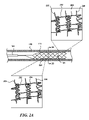
図2Aは、身体の内腔102の中で部分的に展開された状態(たとえば、拡張された構成)になっている、図1のシステム100の部分的な概略側面図である。図2Aの図示されている実施形態では、薬剤溶出性ステント106は、カテーテル104の遠位端部から前進させられており、所望の治療部位に隣接して位置決めされている。ステント106は、半径方向に拡張可能な円筒形状のフレーム111を形成する複数のストラット204と、ストラットの2つ以上の列に係合し、ストラットの2つ以上の列の間に延在する部材とを含む。図示されているように、拡張された薬剤溶出性ステント106のストラット204は、身体の内腔102の壁と並置状態になっている。図2Aの引き伸ばした部分を参照すると、薬剤溶出性ステント106は、ストラット2204によって担持されている複数の薬剤送達フィーチャー206をさらに含む。いくつかの実施形態は、ステントまたは薬剤送達フィーチャーの上に薬剤の塗布のために設計され得り、薬剤送達フィーチャーは、ステントが所望の治療部位において拡張されると、薬剤を受け入れるようにおよび薬剤を放出するように構成されている。図2Bは、線2B-2Bに沿って見た図2Aの薬剤送達システムの一部分の断面図である。図2Bに図示されているように、薬剤溶出性ステント106は、複数の薬剤送達フィーチャー206を有する複数のストラット204を含み、複数の薬剤送達フィーチャー206は、ストラット204によって担持されている。薬剤送達フィーチャー206は、ストラット204の一体的に形成された部分であり、ステント106の外側寸法の少なくとも一部分を横切って配設されており、ステント106から離れるように身体の内腔のターゲット部分に向けて半径方向外向きに延在している。
FIG. 2A is a partial schematic side view of
薬剤溶出性ステント106は、自己拡張型の構造体であることが可能である。他の実施形態では、薬剤溶出性ステント106は、バルーンに連結され得り、または、他の適切な技法および/もしくは当業者に公知の構造体は、ロー・プロファイル送達状態から、図2Aに示されている展開された/拡張された状態へ、薬剤溶出性ステント106を変形させるために使用され得る。それに加えて、薬剤溶出性ステント106は、機械的な作動メカニズムなどのような作動メカニズムに動作可能に連結され得り、作動メカニズムは、薬剤溶出性ステント106を位置決めし、拡張させ、後退させ、再位置決めし、および/または除去するように構成されている。
Drug-eluting
フレーム111、ストラット204、および/または薬剤送達フィーチャー112は、たとえば、ニチノール、コバルトクロム、ステンレス鋼、さまざまな他の金属もしくは金属合金のいずれか、または、それらの組み合わせを含む、さまざまな材料から構成または形成され得る。また、フレーム111、ストラット204、および/または薬剤送達フィーチャー112は、たとえば、1つまたは複数のポリマー、プラスチック材料など、または、それらの組み合わせを含む、生体吸収性の材料、生分解性の材料、ナノ多孔性の材料、または、非生体吸収性の材料、非生分解性の材料、非ナノ多孔性の材料から構成または形成され得る。いくつかの実施形態では、フレーム111およびストラット204は、生体吸収性の材料から形成され得り、薬剤送達フィーチャー112は、ニチノールなどのような非生体吸収性の材料から形成され得る。これらの実施形態では、薬剤送達フィーチャー112は、拡張されたフレーム111およびストラット204が生体吸収した後に、身体の内腔の一部分と係合したままになるか、または、それを突き通したままになっていることが可能である。拡張されたフレーム111およびストラットが204生体吸収した後に、薬剤溶出性ステント106が拡張された場所の身体の内腔は、フレーム111およびストラット204によって、もはや部分的に閉塞されておらず、それは、より大きい体積の流体、たとえば、水溶性の医薬組成物などが、身体の内腔を通過して内腔壁に接触することを可能にする。また、薬剤送達フィーチャー112は、生体吸収性の材料から形成され得り、薬剤溶出性ステント106が生体吸収されると、薬剤送達フィーチャー112によって空けられた身体の内腔壁の中のスペースが、内腔を通過する流体によって接触され得る。このように、薬剤溶出性ステント106は、流体によって接触されている内腔壁の表面積を増加させることが可能である。
フレーム111、ストラット204、および/または薬剤送達フィーチャー112を形成するための材料は、機械的な特性および/または熱的な特性、たとえば、強度、延性、硬度、弾性、柔軟性、曲げ弾性率、曲げ強度、塑性、剛性、放射率、熱伝導率、比熱、熱拡散率、熱膨張率、さまざまな他の特性のいずれか、または、それらの組み合わせなどに基づいて選択され得る。熱的な特性を有する材料から形成されている場合には、材料は、所望の治療部位に熱的治療を送達するように活性化され得る。
Materials for forming
材料にかかわらず、フレーム111、ストラット204、および/または薬剤送達フィーチャー112は、レーザー切断または他の適切な技法によって、チューブまたはワイヤー、たとえば、中実のワイヤーなどから形成され得る。ワイヤーから形成されているとき、ワイヤーの一部分は、化学エッチングまたは別の適切な方法によって除去され、薬剤溶出性ステント106の内側寸法を生成させることが可能である。
Regardless of material,
本技術によれば、薬剤溶出性ステント106(たとえば、フレーム111およびストラット204)は、血管を破らない状態で、血管を含むさまざまな身体の内腔の中への設置のためにサイズ決めおよび形状決めされ得る。たとえば、本技術にしたがって構成されているいくつかのステントおよび他の構造体は、身体の内腔(たとえば、血管壁)のフィーチャーがそれに対する解剖または損傷なしに薬剤を受け入れることを可能にする半径方向の強度を有することが可能である。薬剤溶出性ステント106がその中に設置のためにサイズ決めおよび形状決めされ得る血管は、動脈、たとえば、冠状動脈、末梢動脈、頸動脈、ウィルス動脈輪、前大脳動脈、中大脳動脈、後大脳動脈、レンズ核線条体動脈のいずれか、腎動脈、大腿動脈など、静脈、たとえば、大脳静脈、伏在静脈、動静脈瘻など、または、治療部位を含有し得る任意の他の血管を含む。薬剤溶出性ステント106は、立方体、直方体、円柱、円錐、角錐、または、そのバリエーションを含む、さまざまな形状を有することが可能である。
In accordance with the present technology, drug-eluting stent 106 (eg,
本技術にしたがって構成されている薬剤送達フィーチャーを有するステント106および他の構造体は、(ロー・プロファイル送達状態および拡張された展開された状態の両方で)さまざまな寸法を含むことが可能である。これらの実施形態は、幅広い範囲の寸法をカバーするさまざまな状況における使用法を可能にする拡張を提供することが可能である。形状にかかわらず、薬剤溶出性ステント106は、約0.25mm、約0.5mm、約1mm、約2mm、約3mm、約4mm、約5mm、約6mm、約7mm、約8mm、約9mm、約10mm、約12mm、約14mm、約16mm、約18mm、約20mm、約30mm、約40mm、約50mm、約60mm、約70mm、約80mm、約90mm、または約100mmの長さを有することが可能である。それに加えて、立方体、直方体、または角錐に形状決めされた薬剤溶出性ステント106は、約0.25mm、約0.5mm、約1mm、約2mm、約3mm、約4mm、約5mm、約6mm、約7mm、約8mm、約9mm、約10mm、約12mm、約14mm、約16mm、約18mm、約20mm、約25mm、または約30mmの幅を有することが可能である。そのうえ、円柱または円錐に形状決めされている薬剤溶出性ステント106は、約0.25mm、約0.5mm、約1mm、約2mm、約3mm、約4mm、約5mm、約6mm、約7mm、約8mm、約9mm、約10mm、約12mm、約14mm、約16mm、約18mm、約20mm、約25mm、約30mm、約35mm、約40mm、または約50mmの直径を有することが可能である。薬剤溶出性ステント106の幅または直径は、ステントの長さに沿ってデクリメントに減少することが可能である。それに加えて、薬剤溶出性ステント106は、薬剤溶出性ステント設置手順などのような特定の手順のために身体の内腔を準備するようにサイズ決めおよび形状決めされ得る。
薬剤溶出性ステントまたは他の構造体のプロファイルは、薬剤溶出性ステントまたは他の構造体が幅広い範囲のカテーテル・サイズに適合するように、サイズ決めされ得る。本技術による実施形態は、0.010、0.014、0.018、0.035、または0.038インチの直径を有するガイドワイヤーなどのような、ガイドワイヤーを受け入れるように設計された薬剤溶出性ステントまたは他の構造体を含むことが可能である。いくつかの実施形態では、ステントまたはスカッフォールド構造体は、マイクロカテーテルを介した送達のためにサイズ決めおよび設計され得り、それは、マイクロカテーテルを通して押し込まれる。いくつかの実施形態では、本技術にしたがって構成されたステントまたは構造体は、モジュール式または単一ユニットの送達システムを含む、送達システムの中へ組み込まれ得る。 The profile of the drug eluting stent or other structure can be sized such that the drug eluting stent or other structure fits a wide range of catheter sizes. Embodiments in accordance with the present technology include drug-eluting guidewires designed to receive guidewires, such as guidewires having diameters of 0.010, 0.014, 0.018, 0.035, or 0.038 inches. It is possible to include an elastic stent or other structure. In some embodiments, a stent or scaffold structure can be sized and designed for delivery via a microcatheter, which is pushed through the microcatheter. In some embodiments, a stent or structure constructed in accordance with the present technology may be incorporated into delivery systems, including modular or single unit delivery systems.
薬剤溶出性ステント106は、1つまたは複数のX線不透過性のマーカーなどのような、身体の内腔の中のステント106の可視化のためのマーキングを含むことが可能である。X線不透過性のマーカーは、Clearfil Photo Core PLT(登録商標)、タンタル、チタン、タングステン、硫酸バリウム、および酸化ジルコニウム、または、別の適切なX線不透過性のマーキングから形成され得る。マーキングは、薬剤溶出性ステント106の近位部分、遠位部分、中間部分、または、それらの組み合わせの上に形成され得る。マーキングは、バンド、コイル、クリップであるか、ステントの中のチューブの1つまたは複数の部分の中へ充填されるか、ステントの1つまたは複数の部分の上にメッキされるか、または、それらの組み合わせであることが可能である。マーキングのタイプにかかわらず、マーキングは、ステントの任意の部分に沿って、または、その上に、コイニングされるか(coined)、スウェージングされるか(swaged)、巻き付けられるか、またはケースに入れられ得る。
本技術にしたがって構成されたステントおよび他の構造体は、湾曲部を有するものを含む、さまざまな解剖学的特徴を通して追跡するのに十分に可撓性であることが可能である。ステントおよび他の構造体の可撓性の特性は、それらが形成される材料によって提供され得る。また、それに加えて、2つ以上の列のストラットと係合し、また、2つ以上の列のストラットとの間に延在する部材のうちの1つまたは複数を折ることによって、可撓性の特性が提供され得る。追加的に、薬剤溶出性ステントまたは他の構造体は、容易に展開および拡張され、ならびに、後退および収縮され得る。また、薬剤溶出性ステントまたは他の構造体は、血管または他の内腔の中に容易に再位置決めされ得る。 Stents and other structures constructed in accordance with the present technology can be flexible enough to track through various anatomical features, including those with curves. The flexibility properties of stents and other structures can be provided by the materials from which they are made. Also, in addition, by folding one or more of the members engaging two or more rows of struts and extending between the two or more rows of struts, the flexible properties can be provided. Additionally, drug-eluting stents or other structures can be easily deployed and expanded, as well as retracted and retracted. Also, drug-eluting stents or other structures can be easily repositioned within blood vessels or other lumens.
II.薬剤溶出性ステントおよび他の構造体の薬剤送達フィーチャー、ならびに、関連のシステムおよび方法
図2に示されている実施形態では、薬剤溶出性ステント106は、ストラット204によって担持されている薬剤送達フィーチャー206を含む。また、薬剤送達フィーチャー206は、2つ以上のストラット204、フレーム111、または、それらの組み合わせによって担持され得る。薬剤送達フィーチャー206は、たとえば、1つまたは複数のストラットおよび/またはフレーム111の一部分をステント106の長手方向軸線から離れるように曲げるかまたは捩じることによって、ストラット204と一体的に形成され得り、または、代替的に、薬剤送達フィーチャー206は、ストラット204および/またはフレーム111に沿って所望の場所に取り付けられている別々になった別個のコンポーネントであることが可能である。図示されているように、薬剤送達フィーチャー206は、ストラット204と一体的に形成されている。しかし、図3A~図3Dを参照して下記に説明されているように、薬剤送達フィーチャー206は、さまざまな異なる形状、サイズ、および構成を有することが可能である。本明細書で開示されている薬剤送達フィーチャーは、内腔壁との係合および/または内腔壁の貫通を強化し、強化された薬剤送達を提供し、所望の場所において、より良好な治療を可能にする。非薬剤送達ステントなどのような他の実施形態では、薬剤送達フィーチャー206は、突出する部材であることが可能である。
II. Drug-Eluting Stents and Other Structures Drug-Delivery Features and Related Systems and Methods In the embodiment shown in FIG. including. Also,
いくつかの実施形態では、薬剤溶出性化合物が、薬剤送達フィーチャーの少なくとも一部分の上にコーティングされている。薬剤溶出性化合物は、その中に含有されている薬剤を送達するのに適切なさまざまな異なるパターンおよび厚さにコーティングされた合成ポリマーまたは生物学的ポリマーであることが可能である。他の実施形態では、薬剤送達フィーチャー自身は、薬剤溶出性材料から構成され得る。本技術による薬剤溶出性化合物および/または薬剤送達フィーチャーによって担持されている薬剤は、薬剤溶出性ステントが設置されることとなる治療部位を治療するのに適切な任意の薬剤であることが可能であり、また、賦形剤を含んでもよく、または、賦形剤を含まなくてもよい。たとえば、薬剤は、抗増殖剤、抗腫瘍剤、遊走阻止剤、強化されたヒーリング・ファクター、免疫抑制剤、抗血栓剤、抗凝血剤、または放射性化合物であることが可能である。抗腫瘍剤の例は、それに限定されないが、シロリムス、タクロリムス、エベロリムス、レフルノミド、M-プレドニゾロン、デキサメタゾン、シクロスポリン、ミコフェノール酸、ミゾリビン、インターフェロン、およびトラニラストを含む。抗増殖剤の例は、それに限定されないが、タキソール/パクリタキセル、アクチノマイシン、メトトレキサート、アンジオペプチン、ビンクリスチン、マイトマイシン、スタチン、c-mycアンチセンス、Abbot ABT-578、RestinASE、2-クロロ-デオキシ・アデノシン、およびPCNAリボザイムを含む。遊走阻止剤の例は、それに限定されないが、バチマスタット、プロリルヒドロキシラーゼ、ハロフジノン、c-プロテイナーゼ阻害薬、およびプロブコールを含む。強化されたヒーリング・ファクターの例は、それに限定されないが、BCP671、VEGF、エストラジオール、NOドナー化合物、およびEPC抗体を含む。放射性化合物の例は、それに限定されないが、塩化ストロンチウム-89(Metastron(登録商標))、サマリウム-153(Quadramet(登録商標))、二塩化ラジウム-223(Xofigo(登録商標))、イットリウム-90、およびヨウ素-131を含む。いくつかの実施形態では、薬剤溶出性化合物および/または薬剤送達フィーチャーは、2つ以上の薬剤を担持することが可能である。 In some embodiments, a drug eluting compound is coated over at least a portion of the drug delivery feature. Drug-eluting compounds can be synthetic or biological polymers coated in a variety of different patterns and thicknesses suitable for delivering the drug contained therein. In other embodiments, the drug delivery feature itself may be constructed of drug eluting material. The drug carried by the drug-eluting compound and/or drug-delivery feature according to the present technology can be any drug suitable for treating the treatment site at which the drug-eluting stent is to be placed. Yes, and may or may not contain excipients. For example, the agent can be an anti-proliferative agent, an anti-tumor agent, an anti-migration agent, an enhanced healing factor, an immunosuppressive agent, an anti-thrombotic agent, an anti-coagulant agent, or a radioactive compound. Examples of anti-neoplastic agents include, but are not limited to, sirolimus, tacrolimus, everolimus, leflunomide, M-prednisolone, dexamethasone, cyclosporine, mycophenolic acid, mizoribine, interferon, and tranilast. Examples of antiproliferative agents include, but are not limited to taxol/paclitaxel, actinomycin, methotrexate, angiopeptin, vincristine, mitomycin, statins, c-myc antisense, Abbot ABT-578, RestinASE, 2-chloro-deoxyadenosine, and PCNA ribozymes. Examples of migration inhibitors include, but are not limited to, batimastat, prolyl hydroxylase, halofuginone, c-proteinase inhibitors, and probucol. Examples of enhanced healing factors include, but are not limited to, BCP671, VEGF, estradiol, NO donor compounds, and EPC antibodies. Examples of radioactive compounds include, but are not limited to, strontium-89 chloride (Metastron®), samarium-153 (Quadramet®), radium dichloride-223 (Xofigo®), yttrium-90 , and iodine-131. In some embodiments, drug-eluting compounds and/or drug-delivery features are capable of carrying more than one drug.
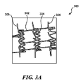
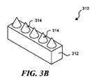
図3A~図3Dは、本技術の追加的な実施形態にしたがって構成されている薬剤溶出性ステントによって担持されている突出する部材、たとえば、薬剤送達フィーチャーなどの部分の等角図である。これらの突出する部材は、図1および図2を参照して上記に説明されている薬剤溶出性ステント106、または、本技術にしたがって構成されてい他の適切な薬剤溶出性ステントおよび非薬剤溶出性ステントとともに使用され得る。たとえば、図3Aは、ステント300の一部分を図示しており、ステント300は、フレーム302、および、突出する部材306(たとえば、スパイク、先の尖った/テーパー付きの部材、バーブ、針)を有する複数のストラット304を含み、突出する部材306は、血管(図示せず)などのような、身体の内腔の一部分と係合しおよび/または突き通すように構成されている。突出する部材306は、ストラット304の一体的に形成された部分であり、ステント300から離れるように身体の内腔のターゲット部分に向けて半径方向外向きに延在している。図3Bに図示されている実施形態では、たとえば、薬剤溶出性ステント310は、ストラット312を含み、ストラット312は、その上に担持されている薬剤送達フィーチャー314を有している。この実施形態では、薬剤送達フィーチャー314は、先の鋭い円錐形状の突出部である。いくつかの実施形態では、先の鋭い円錐形状の突出部は、身体の内腔壁(たとえば、血管壁)を通る貫通を提供し、血管壁を越えてターゲット組織の中へ直接的に薬剤を送達することが可能である。血管およびターゲット組織は、図2Aおよび図2Bを参照して上記に説明されている。図3Cは、薬剤送達フィーチャー324を担持するストラット322を備えた薬剤溶出性ステント320の一部分を図示している。この実施形態では、薬剤送達フィーチャー324は、リブ付きの表面および平坦化された上部を有する、先の鋭い円錐形状の突出部である。いくつかの実施形態では、突出するおよび円錐形状の薬剤送達フィーチャー324のテクスチャー加工された(たとえば、リブ付きの)表面は、薬剤送達に関してより大きい表面積を提供することが期待される。円錐形状の薬剤送達フィーチャー324だけについて図示されているが、任意の薬剤送達フィーチャーは、テクスチャー加工された表面、たとえば、リブ付きの表面(薬剤送達フィーチャーの長手方向の平面に対して、垂直方向の、水平方向の、半径方向の、または円形の)、クロスハッチング付きの表面、等方性表面、または、薬剤送達に関してより大きい表面積を提供するのに適切な他の表面タイプなどを含むことが可能である。図3Dは、薬剤送達フィーチャー334を担持するストラット332を含む薬剤溶出性ステント330の一部分を図示している。図示されている実施形態では、薬剤送達フィーチャー334は、薬剤送達のために血管壁に係合/突き通するように構成されたくさび形状の突出部である。
3A-3D are isometric views of portions of protruding members, such as drug delivery features, carried by drug-eluting stents configured in accordance with additional embodiments of the present technology. These protruding members may be the
図2および図3A~図3Dの図示されている実施形態は、さまざまな形状を有する薬剤送達フィーチャーなどのような、突出する部材を含むが、他の実施形態は、これらの図に示されているものに対する代替的な形状を有する薬剤送達フィーチャーを含むことが可能であるということが理解されるべきである。たとえば、薬剤送達フィーチャーは、本明細書で説明されているように、血管を含むさまざまな身体の内腔の中の設置のためにサイズ決めおよび形状決めされ得る。サイズおよび形状は、薬剤溶出性ステント106がその中に設置されることとなる身体の内腔の特定の特徴(たとえば、ターゲット組織)との所望の係合または貫通を実現するために選択され得る。薬剤送達フィーチャーは、それに限定されないが、立方体、正方形、直方体、円柱、円形、円錐、角錐、湾曲したスパイク、または、他の先の鋭い形状を含む、複数の形状を有することが可能である。これらの形状のいずれかは、平坦な、鈍い、先の鋭い、および/または鋭利な遠位部分を有することが可能である。
Although the illustrated embodiments of FIGS. 2 and 3A-3D include protruding members, such as drug delivery features having various shapes, other embodiments are illustrated in these figures. It should be understood that it is possible to include drug delivery features having alternative shapes to those that are present. For example, drug delivery features can be sized and shaped for placement within various body lumens, including blood vessels, as described herein. The size and shape may be selected to achieve the desired engagement or penetration with a particular feature (e.g., target tissue) of the body lumen in which the drug-
薬剤送達フィーチャーは、閉塞部(occlusion)、新生内膜、内膜、内弾性板(IEL)、中膜、外弾性板(EEL)、外膜、または、それらの組み合わせと係合しおよび/または突き通すようにサイズ決めおよび形状決めされ得る。また、薬剤送達フィーチャーは、身体の内腔に隣接する組織および/または構造体と係合しおよび/または突き通すようにサイズ決めおよび形状決めされ得り、薬剤溶出性ステント106が、身体の内腔を破らない状態で、身体の内腔の中に設置されることとなる。たとえば、薬剤溶出性ステント106は、身体の内腔の内膜および/または中膜の中へ突き通すようにサイズ決めおよび構成されている正方形の薬剤送達フィーチャー、また、中膜および/またはIELを突き通してその中へ延在するようにサイズ決めおよび構成されている先の鋭い薬剤送達フィーチャーを含むことが可能である。それに加えて、薬剤送達フィーチャーは、薬剤溶出性ステントの長手方向軸線に対して1つまたは複数の方向に曲がるように構成されており、本明細書で説明されている身体の内腔の一部分と係合しおよび/または突き通すことが可能である。いくつかの実施形態では、薬剤送達フィーチャーは、薬剤送達フィーチャーを欠いているステントと比較して、病気にかかった身体の内腔、たとえば、血管などの壁の中へ、より深く突き通すことが可能である。それに加えて、薬剤溶出性ステントは、拡張された位置になっている間でも、および、薬剤溶出が進行している状態でも、血液が流れることを可能にすることができる。
The drug delivery feature engages and/or an occlusion, neointima, intima, internal elastic lamina (IEL), media, external elastic lamina (EEL), adventitia, or combinations thereof It can be sized and shaped to penetrate. Also, the drug delivery features may be sized and shaped to engage and/or penetrate tissue and/or structures adjacent to the body lumen, such that the drug-
本明細書で説明されているさまざまな薬剤送達フィーチャーは、血管形成術バルーンまたは他の既存のデバイスを介して可能であるものよりも、血管壁の中へ深く薬剤を送達することが可能である。部位の治療のために1つまたは複数の薬剤を担持することに加えて、薬剤送達フィーチャーは、また、閉塞部、新生内膜、および/または内膜の一部分を分解するのに適切な分子を担持することが可能であり、分子がない状態よりも、薬剤送達フィーチャーが血管壁の中へ深く突き通すことを可能にする。たとえば、分解に適切な分子は、酵素、たとえば、エラスターゼ、コラゲナーゼなど、または、プロテイナーゼ、たとえば、メタロプロテイナーゼ、セリンプロテイナーゼ、システインプロテイナーゼ、細胞外スルファターゼ、ヒアルロニダーゼ、リシルオキシダーゼ、リシルヒドロキシラーゼなど、または、それらの組み合わせであることが可能である。 The various drug delivery features described herein are capable of delivering drugs deeper into the vessel wall than is possible via angioplasty balloons or other existing devices. . In addition to carrying one or more agents for treatment of the site, the drug delivery feature also delivers molecules suitable for degrading the occlusion, neointima, and/or portions of the intima. It can be loaded, allowing the drug delivery feature to penetrate deeper into the vessel wall than without the molecule. For example, molecules suitable for degradation include enzymes such as elastase, collagenase, etc., or proteinases, such as metalloproteinases, serine proteinases, cysteine proteinases, extracellular sulfatases, hyaluronidases, lysyl oxidases, lysyl hydroxylases, etc. can be a combination of
さらに、本技術にしたがって構成されている薬剤溶出性ステントは、ステントの1つまたは複数の部分の上に1つまたは複数の薬剤送達フィーチャーを担持することが可能であるということも理解されることとなる。たとえば、薬剤溶出性ステントは、約5個の薬剤送達フィーチャー、約10個の薬剤送達フィーチャー、約15個の薬剤送達フィーチャー、約20個の薬剤送達フィーチャー、約30個の薬剤送達フィーチャー、約40個の薬剤送達フィーチャー、約50個の薬剤送達フィーチャー、約60個の薬剤送達フィーチャー、約70個の薬剤送達フィーチャー、約80個の薬剤送達フィーチャー、約90個の薬剤送達フィーチャー、または、約100個の薬剤送達フィーチャーを担持することが可能である。薬剤送達フィーチャーは、フレーム111、ストラット204、または、それらの組み合わせによって担持され得る。薬剤送達フィーチャーの数は、たとえば、ターゲット治療部位、送達されている薬剤のタイプ、および、ステントのサイズなどに依存して、変化することが可能である。それに加えて、ステントによって担持されている薬剤送達フィーチャーは、本明細書で開示されている薬剤送達フィーチャーの異なるタイプであることが可能である。
It is further understood that drug-eluting stents constructed in accordance with the present technology can carry one or more drug delivery features on one or more portions of the stent. becomes. For example, a drug eluting stent has about 5 drug delivery features, about 10 drug delivery features, about 15 drug delivery features, about 20 drug delivery features, about 30 drug delivery features, about 40 drug delivery features, about 50 drug delivery features, about 60 drug delivery features, about 70 drug delivery features, about 80 drug delivery features, about 90 drug delivery features, or about 100 It is possible to carry a single drug delivery feature. Drug delivery features may be carried by
図4は、本技術のさらなる別の実施形態にしたがって構成された薬剤送達フィーチャー404を担持しているストラット402を含む薬剤溶出性ステント400の一部分の断面図である。図示されている実施形態では、薬剤送達フィーチャー404は、貯蔵部406、および、貯蔵部406に担持されている薬剤408を含む。貯蔵部406は、少なくとも部分的に薬剤408を含有することが可能であり、(たとえば、カテーテルを通る関連のステントの送達の間のスクレイピングを介して)薬剤408が時期尚早に放出されることを保護する。身体の内腔壁(たとえば、血管壁)に対して位置決めされると、組織および/または流体は、薬剤送達フィーチャー404と相互作用し、薬剤408を溶解させ、薬剤408を貯蔵部406から選択的に放出することが可能である。他の実施形態では、薬剤送達フィーチャーは、薬剤溶出性ステントが拡張されると、さまざまな手段を介して薬剤を送達するように構成され得る。したがって、薬剤送達フィーチャー404は、不注意な薬剤の喪失または放出を低減させながら、所望の場所に薬剤を選択的に送達するための効果的な手段を提供することが期待される。他の実施形態では、薬剤溶出性ステントは、2つ以上の薬剤送達フィーチャーを含むことが可能であり、または、2つ以上の貯蔵部を有する薬剤送達フィーチャーを含むことが可能である。いくつかの実施形態では、本技術にしたがって構成された薬剤送達フィーチャーを含むステントは、ステントが治療部位に位置決めされるまで隠されている(たとえば、凹んでいる)薬剤送達フィーチャー、たとえば、コーティングまたは貯蔵部などを有することが可能である。ターゲット部位に位置決めされると、薬剤送達フィーチャーは、ステントの拡張の間および/または後に現わせられ得る(たとえば、拡張される/突き出されるなど)。これは、治療部位への送達との間に薬剤送達フィーチャーによって担持されている薬剤の任意の喪失を低減させることが期待される。
FIG. 4 is a cross-sectional view of a portion of a
いくつかの実施形態では、薬剤溶出性ステントは、外側表面積の少なくとも一部分をカバーする薬剤送達フィーチャーを有するステント、スカッフォールド、または他の構造体の上に位置決めされている材料(たとえば、PTFE、Dacron、ポリアミド、たとえば、ナイロンおよび/またはポリウレタンベースの材料、シリコーンなど)をさらに含むことが可能である。いくつかの実施形態では、この材料は、外側表面積全体をカバーしている。この材料は、メッシュまたはブレイドであることが可能である。いくつかの実施形態では、この材料は、薬剤を伴うコーティングのためのステントの追加的な表面積を提供するのに有用なステントの表面積を増加させるように構成され得る。他の実施形態では、この材料は、ステントの内径を通る血液フローを可能にするように、および/または、血液フローをステントの外側寸法に制限するようにさらに構成され得る。追加的な実施形態では、この材料は、流体フロー(たとえば、血液フロー)と薬剤送達場所との間にバリアを生成させることが可能である。それに加えて、この材料は、身体の内腔の壁からの破片が血液ストリームに進入することを防止するように構成され得る。そのような実施形態では、関連のシステムおよびデバイスは、手順の間に穿孔され得る領域の一時的な解剖仮縫い(dissection tacking)または被覆(coverage)のために使用され得る。 In some embodiments, the drug-eluting stent is a material (e.g., PTFE, Dacron , polyamides, such as nylon and/or polyurethane based materials, silicones, etc.). In some embodiments, the material covers the entire exterior surface area. This material can be a mesh or braid. In some embodiments, the material can be configured to increase the surface area of the stent useful to provide additional surface area of the stent for coating with the drug. In other embodiments, the material may be further configured to allow blood flow through the inner diameter of the stent and/or to restrict blood flow to the outer dimensions of the stent. In additional embodiments, the material can create a barrier between fluid flow (eg, blood flow) and the drug delivery location. Additionally, the material may be configured to prevent debris from the walls of the body lumen from entering the blood stream. In such embodiments, related systems and devices may be used for temporary dissection tacking or coverage of areas that may be perforated during the procedure.
III.ステントおよび他の構造体の追加的な実施形態、ならびに、関連のシステムおよび方法
本明細書で説明されている実施形態は、構造体が設置された治療エリアを通って流体(たとえば、血液)が流れることを依然として可能にしながら、血管系などのような身体の内腔の中の特定の領域に薬剤を送達するための手段、および/または、隣接する身体の内腔の中の他のデバイスまたは治療手段を備えた構造体を提供する。いくつかの実施形態では、薬剤溶出性ステントは、身体の内腔(たとえば、血管)を通る流体フロー(たとえば、血液フロー)を制限しないように構成されている。それに加えて、ステントは、治療部位の近位または遠位において、ステントでならすこと、ステントを引っ張ること、ステントを回すこと、または、それらの組み合わせによって、治療のために身体の内腔を準備するように構成され得る。他の実施形態では、薬剤溶出性ステントは、機械的な力が印加されるときに、回転するように構成され得る。
III. Additional Embodiments of Stents and Other Structures, and Related Systems and Methods Means for delivering drugs to specific regions within body lumens such as the vasculature, and/or other devices or devices within adjacent body lumens, while still allowing flow. A structure with a therapeutic means is provided. In some embodiments, drug-eluting stents are configured so as not to restrict fluid flow (eg, blood flow) through body lumens (eg, blood vessels). In addition, the stent prepares the body lumen for treatment by rolling the stent, pulling the stent, rolling the stent, or a combination thereof, proximal or distal to the treatment site. can be configured as In other embodiments, drug-eluting stents can be configured to rotate when a mechanical force is applied.
本明細書で開示されているシステムは、関連のステントまたは他の構造体の調節、再捕獲、および再展開を提供することが可能であり、施術者がより正確におよび慎重に所望の領域をより効果的に治療することを可能にする。いくつかの実施形態では、ステントまたは他の送達構造体は、一時的な期間にわたって(たとえば、24時間未満にわたって)展開され、次いで、後退および除去され得る。また、薬剤溶出性ステントは、身体の内腔から除去されるときに、後拡張する(post-dilate)ように構成され得る。他の実施形態では、ステントまたは他の送達構造体は、長期間の一時的な期間にわたって(たとえば、2週間未満、1ヶ月未満、6ヶ月未満、1年未満にわたって)展開され、次いで、後退および除去され得る。いくつかの実施形態では、異なるステントまたは送達構造体が、第1のステントまたは送達構造体が後退および除去された後に展開され得る。展開の持続期間、および、異なるステントまたは送達構造体の展開の前の除去の後の持続期間は、数分から、数時間、数日、数週間、数ヶ月、または数年に変化することが可能である。これらの実施形態では、第1のステントまたは送達構造体の除去、および、異なるステントまたは送達構造体の展開は、1回、2回、3回、4回、5回、6回、7回、8回、9回、または10回起こることが可能である。そのうえ、本明細書で説明されている実施形態は、現在利用可能なバルーンよりもロー・プロファイルのシステムを可能にすることができる。 The systems disclosed herein can provide for adjustment, recapture, and redeployment of associated stents or other structures, allowing the practitioner to more accurately and discreetly target the desired area. Allows for more effective treatment. In some embodiments, a stent or other delivery structure can be deployed for a temporary period of time (eg, less than 24 hours) and then retracted and removed. Drug-eluting stents can also be configured to post-dilate when removed from a body lumen. In other embodiments, the stent or other delivery structure is deployed for an extended temporary period of time (eg, less than 2 weeks, less than 1 month, less than 6 months, less than 1 year) and then retracted and can be removed. In some embodiments, a different stent or delivery structure may be deployed after the first stent or delivery structure is retracted and removed. The duration of deployment and duration after removal prior to deployment of different stents or delivery structures can vary from minutes to hours, days, weeks, months, or years. is. In these embodiments, removal of a first stent or delivery structure and deployment of a different stent or delivery structure are performed once, twice, three times, four times, five times, six times, seven times, It can occur 8, 9, or 10 times. Moreover, the embodiments described herein can enable a lower profile system than currently available balloons.
本明細書で説明されているステントおよび/または構造体の多くの実施形態は、薬剤溶出性ステントを含むが、ステントおよび/または構造体などのような、拡張可能なエレメントの追加的な実施形態は、非薬剤溶出性ステントおよび/または非薬剤溶出性構造体を含むことが可能である。これらの実施形態では、非薬剤溶出性ステントは、1つまたは複数の突出する部材、たとえば、スパイクなどを含むことが可能である。スパイクは、身体の内腔または血管の一部分と係合し、および/またはそれを突き通すように構成され得る。たとえば、スパイクは、血管壁を突き通すことが可能であり、それによって、血管壁の弾性を低減および/または排除する。これらの実施形態では、突出する部材は、血管壁が内腔に向けて内向きに進行し、その中の流れを制限および/または抑制することを防止するように構成され得る。突出する部材は、ストラットと一体的に形成され得るか、または、ストラットの表面の上に配設され得り、ストラットからターゲット組織に向けて半径方向外向きに延在している。 Although many embodiments of stents and/or structures described herein include drug-eluting stents, additional embodiments of expandable elements, such as stents and/or structures, can include non-drug eluting stents and/or non-drug eluting structures. In these embodiments, the non-drug eluting stent can include one or more protruding members, such as spikes. The spike may be configured to engage and/or penetrate a portion of a body lumen or vessel. For example, the spikes can penetrate the vessel wall, thereby reducing and/or eliminating elasticity of the vessel wall. In these embodiments, the protruding member may be configured to prevent the vessel wall from progressing inward toward the lumen and restricting and/or inhibiting flow therein. The protruding members may be integrally formed with the struts or may be disposed on the surfaces of the struts and extend radially outwardly from the struts toward the target tissue.
IV.追加的な例
以下の例は、本技術のいくつかの実施形態の例示目的のためのものである。これらの例では、薬剤溶出性ステントは、死後の人間の患者の血管の中に設置された。3つの異なるタイプのステントが使用された:(a)正方形の薬剤送達フィーチャーを有する金属ステント、(b)丸い薬剤送達フィーチャーを有する金属ステント、および、(c)先の尖った/テーパー付きの薬剤送達フィーチャーを有する金属ステント。正方形のまたは直線の薬剤送達フィーチャーを有するステントは、約115μm×100μmの寸法であり、丸いまたは丸みを帯びた薬剤送達フィーチャーを有するステントは、直径が約650μmの寸法であり、先の尖った/テーパー付きの薬剤送達フィーチャーを有するステントは、最も幅広い部分において、長さ約870μmおよび幅約193μm幅の寸法であった。
IV. Additional Examples The following examples are for illustrative purposes of some embodiments of the present technology. In these examples, drug-eluting stents were placed in the blood vessels of post-mortem human patients. Three different types of stents were used: (a) metal stents with square drug delivery features, (b) metal stents with round drug delivery features, and (c) pointed/tapered drug. A metal stent with delivery features. Stents with square or straight drug delivery features measure approximately 115 μm×100 μm, and stents with round or rounded drug delivery features measure approximately 650 μm in diameter and are pointed/ The stent with tapered drug delivery features measured approximately 870 μm long and approximately 193 μm wide at its widest point.
A.例1-先の尖った/テーパー付きの薬剤送達フィーチャーを有するステントが外弾性板と係合している
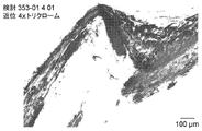
この例では、先の尖った/テーパー付きの薬剤送達フィーチャーを有するステントが、人間の死体の血管の中に設置された。先の尖った/テーパー付きの薬剤送達フィーチャーステントの設置に続いて、血管が、死体から除去され、プラスチックの中に埋め込まれ、組織学にとって適切な厚さの断面にスライスされた。断面は、弾性的なマッソン・トリクローム染色を使用して染色され、イメージ化され、血管の中での先の鋭い薬剤送達フィーチャーステントの位置決めに関して評価された。
A. Example 1 - Stent with pointed/tapered drug delivery features engaged with external elastic lamina In this example, a stent with pointed/tapered drug delivery features is attached to a human cadaver placed in the blood vessels of Following placement of the pointed/tapered drug-delivery feature stent, the vessel was removed from the cadavers, embedded in plastic, and sliced into cross-sections of appropriate thickness for histology. Cross-sections were stained using elastic Masson's Trichrome stain, imaged, and evaluated for positioning of the sharp-tipped drug-delivery feature stent within the vessel.
図5A~図5Cは、先の尖った/テーパー付きの薬剤送達フィーチャーを有するステントを死体の血管の中に設置した後にとられた組織学イメージを含む。図5Aは、たとえば、新生内膜、IEL、中膜を通して突き通され、EELと係合している、先の尖った/テーパー付きの薬剤送達フィーチャーを示している。図5Bは、新生内膜、IELを通して、中膜の中へ突き通されている、先の尖った/テーパー付きの薬剤送達フィーチャーを示している。図5Cは、新生内膜、IEL、中膜を通して突き通され、EELと係合している、先の尖った/テーパー付きの薬剤送達フィーチャーを示している。例1において上記に説明されている薬剤送達フィーチャーのいずれも、血管を穿孔しなかった。 5A-5C include histological images taken after placement of a stent with pointed/tapered drug delivery features into a cadaver vessel. FIG. 5A, for example, shows a pointed/tapered drug delivery feature penetrating through the neointima, IEL, media and engaging the EEL. FIG. 5B shows a pointed/tapered drug delivery feature penetrating through the neointima, the IEL, and into the media. FIG. 5C shows a pointed/tapered drug delivery feature penetrating through the neointima, IEL, media and engaging the EEL. None of the drug delivery features described above in Example 1 perforated the vessel.
B.例2-正方形の薬剤送達フィーチャーを有するステント
この例では、正方形のまたは直線の薬剤送達フィーチャーを有するステントが、人間の死体の血管の中に設置された。正方形の薬剤送達フィーチャーステントの設置に続いて、血管が、死体から除去され、プラスチックの中に埋め込まれ、組織学にとって適切な厚さの断面にスライスされた。断面は、弾性的なマッソン・トリクローム染色を使用して染色され、イメージ化され、血管の中での正方形の薬剤送達フィーチャーステントの位置決めに関して評価された。
B. Example 2 - Stents with Square Drug Delivery Features In this example, stents with square or straight drug delivery features were placed in a human cadaver vessel. Following placement of the square drug-delivery feature stents, vessels were removed from the cadavers, embedded in plastic, and sliced into cross-sections of appropriate thickness for histology. Cross-sections were stained using elastic Masson's trichrome stain, imaged, and evaluated for positioning of the square drug-delivery feature stent within the vessel.
図6A~図6Oは、正方形の薬剤送達フィーチャーを有するステントを死体の血管の中に設置した後にとられた組織学イメージを含む。たとえば、図6Aは、96.79μmの幅および115.62μmの深さを有する正方形の薬剤送達フィーチャーを示している。図6Bおよび図6Cは、2つの正方形の薬剤送達フィーチャーを示しており、1つが、新生内膜と係合しており、1つが、新生内膜をIELの中へ押している。図6Dは、1つの正方形の薬剤送達フィーチャーを示しており、1つが、新生内膜と係合しており、1つが、中膜と係合している。図6Eは、1つの正方形の薬剤送達フィーチャーを示しており、1つが、新生内膜と係合している。図6Fは、3つの正方形の薬剤送達フィーチャーを示しており、1つが、新生内膜と係合している。図6Gおよび図6Hは、新生内膜をIELの中へ押している、正方形の薬剤送達フィーチャーを示している。図6Iは、IELと係合している、1つの正方形の薬剤送達フィーチャーを示している。図6Jは、新生内膜を突き通している正方形の薬剤送達フィーチャー、および、新生内膜をIELの中へ押している他のものを示している。図6Kは、新生内膜と係合している正方形の薬剤送達フィーチャーを示している。図6Lは、新生内膜を突き通している正方形の薬剤送達フィーチャーを示している。図6Mは、新生内膜と係合している正方形の薬剤送達フィーチャー、および、内膜を突き通し、IELと係合している他のものを示している。図6Nは、新生内膜と係合している正方形の薬剤送達フィーチャーを示している。図6Oは、新生内膜と係合している正方形の薬剤送達フィーチャー、および、中膜の中へ突き通している他のものを示している。例2に関連付けられる薬剤送達フィーチャーのいずれも、血管を穿孔しなかった。 Figures 6A-6O include histological images taken after placement of a stent with square drug delivery features into a cadaver vessel. For example, FIG. 6A shows a square drug delivery feature with a width of 96.79 μm and a depth of 115.62 μm. Figures 6B and 6C show two square drug delivery features, one engaging the neointima and one pushing the neointima into the IEL. FIG. 6D shows one square drug delivery feature, one engaging the neointima and one engaging the media. FIG. 6E shows one square drug delivery feature, one engaging the neointima. FIG. 6F shows three square drug delivery features, one engaging the neointima. Figures 6G and 6H show a square drug delivery feature pushing the neointima into the IEL. FIG. 6I shows a single square drug delivery feature engaged with an IEL. FIG. 6J shows a square drug delivery feature penetrating the neointima and another pushing the neointima into the IEL. FIG. 6K shows a square drug delivery feature engaging the neointima. FIG. 6L shows a square drug delivery feature penetrating the neointima. FIG. 6M shows a square drug delivery feature engaging the neointima and another penetrating the intima and engaging the IEL. FIG. 6N shows a square drug delivery feature engaging the neointima. FIG. 6O shows square drug delivery features engaging the neointima and others penetrating into the media. None of the drug delivery features associated with Example 2 perforated the vessel.
C.例3-丸い薬剤送達フィーチャーを有するステント
この例では、丸いまたは丸みを帯びた薬剤送達フィーチャーを有するステントが、人間の死体の血管の中に設置された。丸い薬剤送達フィーチャーステントの設置に続いて、血管が、死体から除去され、プラスチックの中に埋め込まれ、組織学にとって適切な厚さの断面にスライスされた。断面は、弾性的なマッソン・トリクローム染色を使用して染色され、イメージ化され、血管の中での丸い薬剤送達フィーチャーステントの位置決めに関して評価された。
C. Example 3 - Stent with rounded drug delivery features In this example, a stent with rounded or rounded drug delivery features was placed in a human cadaver vessel. Following placement of the round drug-delivery feature stent, the vessel was removed from the cadavers, embedded in plastic, and sliced into cross-sections of appropriate thickness for histology. Cross-sections were stained using elastic Masson's trichrome stain, imaged, and evaluated for positioning of the round drug-delivery feature stent within the vessel.
図7A~図7Cは、丸い薬剤送達フィーチャーを有するステントを人間の患者の血管の中に設置した後にとられた組織学イメージを含む。図7Aは、651.41μmの直径を有する丸い薬剤送達フィーチャーを示している。図7Bは、新生内膜と係合しており、新生内膜をIELの中へ押している、丸い薬剤送達フィーチャーを示している。図7Cは、新生内膜と係合している丸い薬剤送達フィーチャー、および、中膜の中へ突き通している他のものを示している。例3に関連付けられる薬剤送達フィーチャーのいずれも、血管を穿孔しなかった。 Figures 7A-7C include histological images taken after placement of a stent with rounded drug delivery features into a blood vessel of a human patient. FIG. 7A shows a round drug delivery feature with a diameter of 651.41 μm. FIG. 7B shows a rounded drug delivery feature engaging the neointima and pushing the neointima into the IEL. FIG. 7C shows rounded drug delivery features engaging the neointima and others penetrating into the media. None of the drug delivery features associated with Example 3 perforated the vessel.
D.例4-先の尖った/テーパー付きの薬剤送達フィーチャーを有するステント
この例では、先の尖った/テーパー付きの薬剤送達フィーチャーを有するステントが、人間の死体の血管の中に設置された。先の尖った/テーパー付きの薬剤送達フィーチャーステントの設置に続いて、血管が、患者から除去され、プラスチックの中に埋め込まれ、組織学にとって適切な厚さの断面にスライスされた。断面は、弾性的なマッソン・トリクローム染色を使用して染色され、イメージ化され、血管の中での先の尖った/テーパー付きの薬剤送達フィーチャーステントの位置決めに関して評価された。
D. Example 4 - Stent with Pointed/Tapered Drug Delivery Features In this example, a stent with pointed/tapered drug delivery features was placed in a human cadaver vessel. Following placement of the pointed/tapered drug delivery feature stent, the vessel was removed from the patient, embedded in plastic, and sliced into cross-sections of appropriate thickness for histology. Cross-sections were stained using elastic Masson's trichrome stain, imaged, and evaluated for positioning of the pointed/tapered drug delivery feature stent within the vessel.
図8A~図8Hは、先の尖った/テーパー付きの薬剤送達フィーチャーを有するステントを死体の血管の中に設置した後にとられた組織学イメージを含む。図8Aは、たとえば、193.32μmの最大幅および868.88μmの長さを有する先の尖った/テーパー付きの薬剤送達フィーチャーを示している。図8Bは、新生内膜を通して突き通しており、IELを通して突き通しており、中膜と係合している、先の尖った/テーパー付きの薬剤送達フィーチャーを示している。図8Cおよび図8Dは、新生内膜を通して突き通しており、IELを通して突き通しており、中膜を通して突き通しており、EELと係合している、先の尖った/テーパー付きの薬剤送達フィーチャーを示している。図8Eは、新生内膜を通して突き通しており、IELを通して突き通しており、中膜と係合している、先の尖った/テーパー付きの薬剤送達フィーチャーを示している。図8Fは、新生内膜と係合している先の尖った/テーパー付きの薬剤送達フィーチャーを示している。図8Gは、新生内膜を通して突き通しており、IELを通して突き通しており、中膜を通して突き通しており、EELと係合している、先の尖った/テーパー付きの薬剤送達フィーチャーを示している。図8Hは、新生内膜を通して突き通しており、IELを通して突き通しており、中膜を通して突き通している、先の尖った/テーパー付きの薬剤送達フィーチャーを示している。例4に関連して本明細書で説明されている先の尖った/テーパー付きの薬剤送達フィーチャーのいずれも、血管を穿孔しなかった。 Figures 8A-8H include histological images taken after placement of a stent with pointed/tapered drug delivery features into a cadaver vessel. FIG. 8A, for example, shows a pointed/tapered drug delivery feature with a maximum width of 193.32 μm and a length of 868.88 μm. FIG. 8B shows a pointed/tapered drug delivery feature penetrating through the neointima, penetrating through the IEL, and engaging the media. 8C and 8D are pointed/tapered drug delivery features penetrating through the neointima, penetrating through the IEL, penetrating through the media, and engaging the EEL. is shown. FIG. 8E shows a pointed/tapered drug delivery feature penetrating through the neointima, penetrating through the IEL, and engaging the media. FIG. 8F shows a pointed/tapered drug delivery feature engaging the neointima. FIG. 8G shows a pointed/tapered drug delivery feature penetrating through the neointima, penetrating through the IEL, penetrating through the media, and engaging the EEL. there is FIG. 8H shows a pointed/tapered drug delivery feature piercing through the neointima, piercing through the IEL, and piercing through the media. None of the pointed/tapered drug delivery features described herein in connection with Example 4 perforated the vessel.
E.例5-アテローム、アテローム性動脈硬化病変、および/または石灰化の近くに設置された正方形の薬剤送達フィーチャーを有するステント
この例では、正方形のまたは直線の薬剤送達フィーチャーを有するステントが、人間の死体の血管の中に設置された。正方形の薬剤送達フィーチャーステントの設置に続いて、血管が、患者から除去され、プラスチックの中に埋め込まれ、組織学にとって適切な厚さの断面にスライスされた。断面は、H&E染色を使用して染色され、イメージ化され、血管の中での正方形の薬剤送達フィーチャーステントの位置決めに関して評価された。
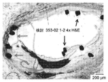
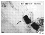
E. Example 5 - Stent with Square Drug Delivery Features Placed Near Atheroma, Atherosclerotic Lesions, and/or Calcifications In this example, a stent with square or straight drug delivery features was placed near a human cadaver placed in the blood vessels of Following placement of the square drug-delivery feature stent, the vessel was removed from the patient, embedded in plastic, and sliced into cross-sections of appropriate thickness for histology. Cross-sections were stained using H&E staining, imaged, and evaluated for positioning of the square drug-delivery feature stent within the vessel.
図9A~図9Kは、正方形の薬剤送達フィーチャーを有するステントを死体の血管の中に設置した後にとられた組織学イメージを含む。たとえば、図9Aは、248.47μmの幅および292.40μmの深さを有する正方形の薬剤送達フィーチャーを示している。図9Bは、新生内膜と係合しており、IELの中へ新生内膜をおしているか、または、石灰化を有するプラークと係合しているかのいずれかである、22個の正方形の薬剤送達フィーチャーを示している。図9Cは、新生内膜と係合しており、石灰化を有するプラークと係合しており、または、非石灰化された内膜と係合している、正方形の薬剤送達フィーチャーを示している。図9Dは、IELと係合している正方形の薬剤送達フィーチャー、および、石灰化を有する内膜および中膜を突き通している他のものを示している。図9Eは、IELと係合している正方形の薬剤送達フィーチャー、および、新生内膜をIELの中へ押している他のものを示している。図9Fは、新生内膜を突き通している正方形の薬剤送達フィーチャー、および、中膜を突き通している他のものを示している。図9Gは、石灰化されたアテロームと係合している正方形の薬剤送達フィーチャー、新生内膜を突き通している他のもの、および、中膜を突き通している別のものを示している。図9Hは、図9Gに示されているアテロームの一部分のより高い倍率のものである。図9Iは、石灰化されたアテローム動脈硬化性のプラークの新生内膜および中膜と係合している正方形の薬剤送達フィーチャーを示している。図9Jは、図9Iに示されているアテロームの一部分のより高い倍率のものである。図9Kは、図9Jに示されているアテロームの一部分より高い倍率のものである。例5に関連付けられている薬剤送達フィーチャーのいずれも、血管を穿孔しなかった。 Figures 9A-9K include histological images taken after placement of a stent with square drug delivery features into a cadaver vessel. For example, FIG. 9A shows a square drug delivery feature with a width of 248.47 μm and a depth of 292.40 μm. FIG. 9B shows 22 squares of agents engaging the neointima and either pushing the neointima into the IEL or engaging plaque with calcification. 4 shows a delivery feature. FIG. 9C shows a square drug delivery feature engaging neointima, engaging plaque with calcification, or engaging non-calcified intima. there is FIG. 9D shows a square drug delivery feature engaging the IEL and others penetrating the intima and media with calcification. FIG. 9E shows a square drug delivery feature engaging the IEL and another pushing the neointima into the IEL. FIG. 9F shows a square drug delivery feature penetrating the neointima and another penetrating the media. FIG. 9G shows a square drug delivery feature engaging a calcified atheroma, another penetrating the neointima, and another penetrating the media. FIG. 9H is a higher magnification of a portion of the atheroma shown in FIG. 9G. FIG. 9I shows a square drug delivery feature engaging the neointima and media of a calcified atherosclerotic plaque. FIG. 9J is a higher magnification of a portion of the atheroma shown in FIG. 9I. FIG. 9K is at a higher magnification than the portion of the atheroma shown in FIG. 9J. None of the drug delivery features associated with Example 5 perforated the vessel.
以下の例は、本技術のいくつかの実施形態のさらに例示目的のものである。
1. 人間の患者を治療するための拡張可能なエレメントであって、拡張可能なエレメントは、
複数のストラットまたはワイヤーを有する、半径方向に拡張可能な円筒形状のフレームまたは編み組されたメッシュであって、フレームは、ロー・プロファイル送達状態と拡張された展開された状態との間で変形可能である、フレームまたは編み組されたメッシュと、
複数の薬剤送達フィーチャーであって、複数の薬剤送達フィーチャーは、1つまたは複数のストラットによって担持されており、また、患者の身体の内腔の中の治療部位に薬剤を送達するように構成されている、複数の薬剤送達フィーチャーと
を含み、
フレームが身体の内腔の中で拡張された状態になっているときに、
薬剤送達フィーチャーは、ストラットから離れるように半径方向外向きに延在しており、
薬剤送達フィーチャーは、身体の内腔の第1の部分に係合するように構成されている、拡張可能なエレメント。
2. フレームが拡張された状態になっているときに、薬剤送達フィーチャーは、身体の内腔の第1の部分を突き通し、身体の内腔の第2の部分の中へ延在するように構成されている、例1に記載の拡張可能なエレメント。
3. 身体の内腔の第1の部分は、閉塞部、内膜、または、それらの組み合わせである、例1または例2に記載の拡張可能なエレメント。
4. 身体の内腔の第2の部分は、中膜、外膜、または、それらの組み合わせである、例1~3のいずれか1つに記載の拡張可能なエレメント。
5. 薬剤送達フィーチャーは、身体の内腔の近位にある第3の部分の中へ延在するようにさらに構成されている、例1~4のいずれか1つに記載の拡張可能なエレメント。
6. 第3の部分は、筋膜、異なる身体の内腔、または、それらの組み合わせである、例5に記載の拡張可能なエレメント。
7. 複数の薬剤送達フィーチャーは、第1のストラットによって担持されている第1のセットの薬剤送達フィーチャーと、異なる第2のストラットによって担持されている第2のセットの薬剤送達フィーチャーとを含む、例1~6のいずれか1つに記載の拡張可能なエレメント。
8. 複数の薬剤送達フィーチャーは、第1のストラットによって担持されている第1のセットの薬剤送達フィーチャーおよび第2のセットの薬剤送達フィーチャーを含む、例1~7のいずれか1つに記載の拡張可能なエレメント。
9. 複数の薬剤送達フィーチャーは、第1のセットの薬剤送達フィーチャー、第2のセットの薬剤送達フィーチャー、および、第3のセットの薬剤送達フィーチャーを含み、第1のセット、第2のセット、および第3のセットは、それぞれ、第1のストラット、第2の異なるストラット、第3の異なるストラットによって担持されている、例1~8のいずれか1つに記載の拡張可能なエレメント。
10. 複数の薬剤送達フィーチャーは、ストラットと一体的に形成されている、例1~9のいずれか1つに記載の拡張可能なエレメント。
11. 複数の薬剤送達フィーチャーは、ストラットに取り付けられている別々になった別個のコンポーネントである、例1~10のいずれか1つに記載の拡張可能なエレメント。
12. 複数の薬剤送達フィーチャーは、単一の薬剤または薬物を患者に送達するように構成されている、例1~11のいずれか1つに記載の拡張可能なエレメント。
13. 複数の薬剤送達フィーチャーは、第1の薬剤を患者に送達するように構成されている第1のセットの薬剤送達フィーチャーと、第2の薬剤を患者に送達するように構成されている第2のセットの薬剤送達フィーチャーとを含み、第1の薬剤および第2の薬剤は異なっている、例1~12のいずれか1つに記載の拡張可能なエレメント。
14. 複数の薬剤送達フィーチャーは、その中に一体的に形成された貯蔵部を含む、例1~13のいずれか1つに記載の拡張可能なエレメント。
15. 複数の薬剤送達フィーチャー、拡張可能なエレメント、または、それらの組み合わせは、基材によってコーティングされている、例1~14のいずれか1つに記載の拡張可能なエレメント。
16. 基材は、その中に担持されている薬剤を患者に送達するように構成されており、凝固を防止し、拡張可能なエレメントの閉塞を防止し、または、それらの組み合わせを防止する、例15に記載の拡張可能なエレメント。
17. 基材は、賦形剤である、例15に記載の拡張可能なエレメント。
18. 基材は、放射性である、例15に記載の拡張可能なエレメント。
19. 拡張可能なエレメントは、X線不透過性のマーカーをさらに含む、例1~18のいずれか1つに記載の拡張可能なエレメント。
20. 拡張可能なエレメントは、熱的に活性であるように構成されており、また、活性化されているときに、拡張可能なエレメントは、熱的治療を身体の内腔に送達するように構成されている、例1~19のいずれか1つに記載の拡張可能なエレメント。
21. 拡張可能なエレメントは、自己拡張型である、例1~20のいずれか1つに記載の拡張可能なエレメント。
22. 拡張可能なエレメント、拡張可能なエレメントの一部分、複数の薬剤送達フィーチャー、複数のフィーチャーの一部分、複数のフィーチャーのそれぞれの一部分、または、それらの組み合わせは、生分解性である、例1~21のいずれか1つに記載の拡張可能なエレメント。
23. 拡張可能なエレメントは、送達状態と展開された状態との間で拡張可能なエレメントを変形させるように機械的に作動させられる、例1~22のいずれか1つに記載の拡張可能なエレメント。
24. フレームが身体の内腔の中で拡張された状態になっているときに、拡張可能なエレメントは、1つまたは複数の物質が拡張可能なエレメントを通って流れることを可能にするように構成されている、例1~23のいずれか1つに記載の拡張可能なエレメント。
25. フレームが身体の内腔の中で拡張された状態になっているときに、拡張可能なエレメントは、身体の内腔を通って流れる流体の流量を制限しない、例1~24のいずれか1つに記載の拡張可能なエレメント。
26. 拡張可能なエレメントは、後拡張のために、身体の内腔の準備のために、力が加えられるときの回転のために、または、それらの組み合わせのために構成されている、例1~25のいずれか1つに記載の拡張可能なエレメント。
27. 半径方向に拡張可能な円筒形状のフレームは、ステントを含む、例1~26のいずれか1つに記載の拡張可能なエレメント。
28. 拡張可能なエレメントによって人間の患者を治療するための方法であって、方法は、
拡張可能なエレメントを患者の身体の内腔の中のターゲット治療部位に血管内で送達するステップであって、拡張可能なエレメントは、
複数のストラットを有する半径方向に拡張可能な円筒形状のフレームと、
複数の薬剤送達フィーチャーであって、複数の薬剤送達フィーチャーは、1つまたは複数のストラットによって担持されており、また、患者の身体の内腔の中の治療部位に薬剤を送達するように構成されている、複数の薬剤送達フィーチャーと
を含む、ステップと、
ロー・プロファイル送達状態と拡張された展開された状態との間でフレームを変形させるステップと
を含み、
フレームが身体の内腔の中で拡張された状態になっているときに、薬剤送達フィーチャーは、ストラットから離れるように半径方向外向きに延在しており、身体の内腔の壁を突き通し、身体の内腔の第1の部分と係合し、随意的に、身体の内腔の第2の部分の中へ延在し、薬剤を第2の部分に送達する、方法。
29. 身体の内腔の第1の部分は、閉塞部、内膜、または、それらの組み合わせであり、身体の内腔の第2の部分は、中膜、外膜、または、それらの組み合わせである、例28に記載の方法。
30. 複数の薬剤送達フィーチャーは、第1の薬剤を患者に送達するように構成されている第1のセットの薬剤送達フィーチャーと、第2の薬剤を患者に送達するように構成されている第2のセットの薬剤送達フィーチャーとを含み、第1の薬剤および第2の薬剤は、同じ薬剤または異なる薬剤である、例28または例29に記載の方法。
31. 複数の薬剤送達フィーチャーは、その中に一体的に形成された貯蔵部を含み、および/または、複数の薬剤送達フィーチャー、拡張可能なエレメント、または、それらの組み合わせは、基材によってコーティングされており、基材は、その中に担持されている薬剤を患者に送達するように構成されており、凝固を防止し、拡張可能なエレメントの閉塞を防止し、または、それらの組み合わせを防止する、例28~30のいずれか1つに記載の方法。
The following examples are for further illustration purposes of some embodiments of the present technology.
1. An expandable element for treating a human patient, the expandable element comprising:
A radially expandable cylindrical frame or braided mesh having a plurality of struts or wires, wherein the frame is deformable between a low profile delivery state and an expanded deployed state. a frame or braided mesh that is
A plurality of drug delivery features carried by one or more struts and configured to deliver drugs to a treatment site within a body lumen of a patient. and a plurality of drug delivery features;
When the frame is in its expanded state within the body lumen,
the drug delivery feature extends radially outward away from the strut;
The drug delivery feature is an expandable element configured to engage a first portion of a body lumen.
2. The drug delivery feature is configured to extend through a first portion of the body lumen and into a second portion of the body lumen when the frame is in the expanded state. The extensible element described in Example 1, which is
3. The expandable element of Example 1 or Example 2, wherein the first portion of the body lumen is an occlusion, an intima, or a combination thereof.
4. The expandable element of any one of Examples 1-3, wherein the second portion of the body lumen is media, adventitia, or a combination thereof.
5. The expandable element of any one of Examples 1-4, wherein the drug delivery feature is further configured to extend into a proximal third portion of the body lumen.
6. The expandable element of example 5, wherein the third portion is fascia, a different body lumen, or a combination thereof.
7. The plurality of drug delivery features includes a first set of drug delivery features carried by a first strut and a second set of drug delivery features carried by a different second strut, Example 1 An expandable element according to any one of 6.
8. The expandable of any one of Examples 1-7, wherein the plurality of drug delivery features includes a first set of drug delivery features and a second set of drug delivery features carried by the first strut. element.
9. The plurality of drug delivery features includes a first set of drug delivery features, a second set of drug delivery features, and a third set of drug delivery features, wherein the first set, the second set, and the third set of drug delivery features. An expandable element according to any one of Examples 1-8, wherein the three sets are respectively carried by a first strut, a second different strut, a third different strut.
10. The expandable element of any one of Examples 1-9, wherein the plurality of drug delivery features are integrally formed with the strut.
11. 11. The expandable element of any one of Examples 1-10, wherein the multiple drug delivery features are separate and distinct components attached to the strut.
12. 12. The expandable element of any one of Examples 1-11, wherein the multiple drug delivery features are configured to deliver a single drug or drug to the patient.
13. The plurality of drug delivery features includes a first set of drug delivery features configured to deliver a first drug to the patient and a second set of drug delivery features configured to deliver a second drug to the patient. and a set of drug delivery features, wherein the first drug and the second drug are different.
14. 14. The expandable element of any one of Examples 1-13, wherein the plurality of drug delivery features includes reservoirs integrally formed therein.
15. The expandable element of any one of Examples 1-14, wherein the plurality of drug delivery features, expandable element, or combination thereof is coated with a substrate.
16. The substrate is configured to deliver an agent carried therein to the patient, prevents clotting, prevents occlusion of the expandable element, or a combination thereof, Example 15 Extensible elements described in .
17. The expandable element of Example 15, wherein the base material is an excipient.
18. The expandable element of Example 15, wherein the substrate is radioactive.
19. The expandable element of any one of Examples 1-18, wherein the expandable element further comprises a radiopaque marker.
20. The expandable element is configured to be thermally active, and when activated, the expandable element is configured to deliver thermal therapy to the body lumen. The expandable element according to any one of Examples 1-19, wherein the expandable element is
21. The expandable element of any one of Examples 1-20, wherein the expandable element is self-expanding.
22. The expandable element, the portion of the expandable element, the plurality of drug delivery features, the plurality of portions of the plurality of features, the portion of each of the plurality of features, or combinations thereof, are biodegradable, of Examples 1-21. An expandable element according to any one of the preceding claims.
23. An expandable element according to any one of Examples 1-22, wherein the expandable element is mechanically actuated to deform the expandable element between a delivered state and a deployed state.
24. The expandable element is configured to allow one or more substances to flow through the expandable element when the frame is in an expanded state within the body lumen. The expandable element according to any one of Examples 1-23, wherein the expandable element is
25. 25. Any one of Examples 1-24, wherein the expandable element does not restrict the flow of fluid through the body lumen when the frame is in the expanded state within the body lumen. Extensible elements described in .
26. The expandable element is configured for post-expansion, for preparation of a body lumen, for rotation when force is applied, or combinations thereof, Examples 1-25. An expandable element according to any one of .
27. 27. The expandable element of any one of Examples 1-26, wherein the radially expandable cylindrical frame comprises a stent.
28. A method for treating a human patient with an expandable element, the method comprising:
intravascularly delivering an expandable element to a target treatment site within a body lumen of a patient, the expandable element comprising:
a radially expandable cylindrical frame having a plurality of struts;
A plurality of drug delivery features carried by one or more struts and configured to deliver drugs to a treatment site within a body lumen of a patient. a plurality of drug delivery features, and
transforming the frame between a low profile delivery state and an expanded deployed state;
The drug delivery features extend radially outward away from the struts and penetrate the walls of the body lumen when the frame is in its expanded state within the body lumen. , engaging a first portion of a body lumen and optionally extending into a second portion of the body lumen to deliver an agent to the second portion.
29. A first portion of the body lumen is the occlusion, the intima, or a combination thereof, and a second portion of the body lumen is the media, the adventitia, or a combination thereof; The method described in Example 28.
30. The plurality of drug delivery features includes a first set of drug delivery features configured to deliver a first drug to the patient and a second set of drug delivery features configured to deliver a second drug to the patient. and the set of drug delivery features, wherein the first drug and the second drug are the same drug or different drugs.
31. The plurality of drug delivery features includes reservoirs integrally formed therein and/or the plurality of drug delivery features, expandable elements, or combinations thereof are coated with a substrate. e.g., the substrate is configured to deliver an agent carried therein to a patient, prevents clotting, prevents occlusion of the expandable element, or a combination thereof, e.g. 31. The method of any one of 28-30.
本技術の実施形態の上記の詳細な説明は、包括的であることが意図されておらず、または、上記に開示されている正確な形態に本技術を限定することが意図されていない。本技術の特定の実施形態、および、本技術に関する例が、例示目的のために上記に説明されているが、当業者が認識することとなるように、さまざまな同等の修正が、本技術の範囲の中で可能である。たとえば、ステップは所与の順序で提示されているが、代替的な実施形態は、異なる順序でステップを実施することが可能である。また、本明細書で説明されているさまざまな実施形態は、さらなる実施形態を提供するために組み合わせられ得る。 The above detailed descriptions of embodiments of the technology are not intended to be exhaustive or to limit the technology to the precise forms disclosed above. Although specific embodiments of the technology and examples of the technology have been described above for purposes of illustration, various equivalent modifications of the technology will be recognized by those skilled in the art. possible within the range. For example, although the steps are presented in a given order, alternate embodiments may perform the steps in a different order. Also, various embodiments described herein can be combined to provide additional embodiments.
先述のものから、本技術の特定の実施形態が、図示の目的のために本明細書で説明されてきたが、周知の構造および機能は、本技術の実施形態の説明を不必要に分かりにくくすることを回避するために、詳細には示されても説明されてもいないということが認識されることとなる。文脈が許す場合に、単数形または複数形の用語は、それぞれ、複数形または単数形も含むことが可能である。 From the foregoing, although specific embodiments of the technology have been described herein for purposes of illustration, well-known structures and functions may unnecessarily obscure the description of the embodiments of the technology. It will be appreciated that it has not been shown or described in detail to avoid doing so. Each singular or plural term can also include the plural or singular, where the context permits.
そのうえ、「または」の語句が、2つ以上のアイテムのリストを参照して他のアイテムから排他的に単一のアイテムだけを意味するように明示的に限定されていなければ、そのようなリストの中の「または」の使用は、(a)リストの中の任意の単一のアイテム、(b)リストの中のアイテムのすべて、または、(c)リストの中のアイテムの任意の組み合わせを含むものとして解釈されるべきである。追加的に、「含む(comprising)」という用語は、全体を通して、記載されている特徴を少なくとも含むことを意味するために使用されており、より大きい任意の数の同じ特徴および/または追加的なタイプの他の特徴が除外されないようになっている。また、特定の実施形態が図示の目的のために本明細書で説明されてきたが、本技術から逸脱することなく、さまざまな修正が行われ得るということが理解されることとなる。さらに、本技術の特定の実施形態に関連付けられた利点が、それらの実施形態の文脈において説明されてきたが、他の実施形態もそのような利点を示すことが可能であり、また、本技術の範囲の中に入るために、必ずしもすべての実施形態がそのような利点を示す必要があるわけではない。したがって、本開示および関連の技術は、本明細書で明示的に示されていないまたは説明されていない他の実施形態を包含することが可能である。 Moreover, unless the phrase "or" refers to a list of two or more items and is expressly qualified to mean only a single item exclusively from other items, such a list The use of "or" in the should be interpreted as including Additionally, the term "comprising" is used throughout to mean including at least the recited features, any greater number of the same features and/or additional Other features of the type are not excluded. Also, although specific embodiments have been described herein for purposes of illustration, it will be appreciated that various modifications can be made without departing from the technology. Moreover, while advantages associated with particular embodiments of the technology have been described in the context of those embodiments, other embodiments may also exhibit such advantages and the technology Not all embodiments must exhibit such advantages in order to fall within the scope of Accordingly, the disclosure and related technology are capable of encompassing other embodiments not expressly shown or described herein.
Claims (23)
複数のストラットを有する、半径方向に拡張可能な円筒形状のフレームであって、前記フレームは、ロー・プロファイル送達状態と拡張された展開された状態との間で変形可能である、フレームと、
複数の突出する部材であって、前記複数の突出する部材は、1つまたは複数のストラットによって担持されており、前記ストラットと一体的に形成されており、前記フレームが身体の内腔の中で前記拡張された状態になっているときに、前記突出する部材は、前記ストラットから離れるように半径方向外向きに延在しており、前記突出する部材は、前記身体の内腔を突き通すことによって、前記身体の内腔の第1の部分に係合するように構成されている、複数の突出する部材と、
前記フレームに連結された長手方向部材であって、前記長手方向部材は、送達システムのカテーテルの中に前記拡張可能なエレメントを再捕獲するように構成されている、長手方向部材と、
前記フレームと前記長手方向部材との間の部分であって、前記拡張可能なエレメントは、前記フレームが前記拡張された状態になっているときに、前記部分において、前記フレームの直径から前記長手方向部材の直径へ移行する、部分と
を含む、拡張可能なエレメント。 An expandable element for treating a human patient, said expandable element comprising:
a radially expandable cylindrical frame having a plurality of struts, said frame being deformable between a low profile delivery state and an expanded deployed state;
a plurality of projecting members, said plurality of projecting members being carried by and integrally formed with said struts, said frame extending within a body lumen; When in the expanded state, the projecting members extend radially outward away from the struts, the projecting members penetrating the body lumen to a plurality of projecting members configured to engage a first portion of the body lumen;
a longitudinal member coupled to the frame, the longitudinal member configured to recapture the expandable element within a catheter of a delivery system;
A portion between the frame and the longitudinal member, the expandable element extending in the longitudinal direction from the diameter of the frame at the portion when the frame is in the expanded state. An expandable element, including a portion that transitions to the diameter of the member.
Priority Applications (1)
| Application Number | Priority Date | Filing Date | Title |
|---|---|---|---|
| JP2021118516A JP2021168946A (en) | 2015-10-12 | 2021-07-19 | Stents having protruding drug-delivery features and associated systems and methods |
Applications Claiming Priority (3)
| Application Number | Priority Date | Filing Date | Title |
|---|---|---|---|
| US201562240320P | 2015-10-12 | 2015-10-12 | |
| US62/240,320 | 2015-10-12 | ||
| PCT/US2016/056688 WO2017066355A1 (en) | 2015-10-12 | 2016-10-12 | Stents having protruding drug-delivery features and associated systems and methods |
Related Child Applications (1)
| Application Number | Title | Priority Date | Filing Date |
|---|---|---|---|
| JP2021118516A Division JP2021168946A (en) | 2015-10-12 | 2021-07-19 | Stents having protruding drug-delivery features and associated systems and methods |
Publications (3)
| Publication Number | Publication Date |
|---|---|
| JP2018531135A JP2018531135A (en) | 2018-10-25 |
| JP2018531135A6 JP2018531135A6 (en) | 2018-12-13 |
| JP7145757B2 true JP7145757B2 (en) | 2022-10-03 |
Family
ID=58499124
Family Applications (2)
| Application Number | Title | Priority Date | Filing Date |
|---|---|---|---|
| JP2018538539A Active JP7145757B2 (en) | 2015-10-12 | 2016-10-12 | Stents with protruding drug delivery features and related systems and methods |
| JP2021118516A Pending JP2021168946A (en) | 2015-10-12 | 2021-07-19 | Stents having protruding drug-delivery features and associated systems and methods |
Family Applications After (1)
| Application Number | Title | Priority Date | Filing Date |
|---|---|---|---|
| JP2021118516A Pending JP2021168946A (en) | 2015-10-12 | 2021-07-19 | Stents having protruding drug-delivery features and associated systems and methods |
Country Status (8)
| Country | Link |
|---|---|
| US (3) | US10172729B2 (en) |
| EP (1) | EP3362006B1 (en) |
| JP (2) | JP7145757B2 (en) |
| CN (2) | CN108366866A (en) |
| AU (1) | AU2016339033B2 (en) |
| CA (1) | CA3001249C (en) |
| ES (1) | ES2906444T3 (en) |
| WO (1) | WO2017066355A1 (en) |
Families Citing this family (21)
| Publication number | Priority date | Publication date | Assignee | Title |
|---|---|---|---|---|
| WO2009091899A2 (en) * | 2008-01-17 | 2009-07-23 | Boston Scientific Scimed, Inc. | Stent with anti-migration feature |
| US11219750B2 (en) | 2008-03-21 | 2022-01-11 | Cagent Vascular, Inc. | System and method for plaque serration |
| US9480826B2 (en) | 2008-03-21 | 2016-11-01 | Cagent Vascular, Llc | Intravascular device |
| EP2254641B1 (en) | 2008-03-21 | 2016-09-21 | Cagent Vascular, LLC | Device for pre-angioplasty serration and dilatation |
| WO2015187872A1 (en) | 2014-06-04 | 2015-12-10 | Cagent Vascular, Llc | Cage for medical balloon |
| CN107405475B (en) | 2014-11-03 | 2020-09-15 | 开金血管有限公司 | Sawtooth air bag |
| EP3349837B1 (en) | 2015-09-17 | 2020-10-21 | Cagent Vascular, LLC | Wedge dissectors for a medical ballon |
| CN110114108B (en) | 2016-11-16 | 2022-12-06 | 开金血管公司 | System and method for depositing a drug into tissue through teeth |
| CN114587704A (en) | 2017-09-12 | 2022-06-07 | W.L.戈尔及同仁股份有限公司 | Medical device substrate with rotatable struts |
| US11318288B2 (en) | 2018-03-27 | 2022-05-03 | Gyrus Acmi, Inc. | Instrument for delivering substances into the anatomy |
| CA3105746A1 (en) | 2018-07-25 | 2020-01-30 | Cagent Vascular, Llc | Medical balloon catheters with enhanced pushability |
| JP2022508647A (en) * | 2018-10-08 | 2022-01-19 | リフロー メディカル インコーポレイテッド | Stent delivery system with protruding mechanism |
| DE102019116791B4 (en) | 2019-06-21 | 2023-10-26 | InnoRa Gesellschaft mbH | Stent with immediately removable coating |
| CA3146575A1 (en) | 2019-08-13 | 2021-02-18 | Outhit Bouasaysy | Support catheter |
| AU2020373059A1 (en) | 2019-11-01 | 2022-05-26 | Reflow Medical, Inc. | Retrieval devices having protruding features for thrombectomy |
| CA3156969A1 (en) * | 2019-11-04 | 2021-05-14 | John Fulkerson | Stents having protruding features for anchoring |
| CA3168819A1 (en) | 2019-12-24 | 2021-07-01 | Encompass Vascular, Inc. | Medical devices for fluid delivery |
| US20210393422A1 (en) * | 2020-06-19 | 2021-12-23 | Massachusetts Institute Of Technology | Kirigami-inspired stents for sustained local delivery of therapeutics |
| WO2021258062A1 (en) * | 2020-06-19 | 2021-12-23 | Massachusetts Institute Of Technology | Endovascular injectable stents for cardiovascular drug delivery |
| EP4297837A1 (en) | 2021-02-23 | 2024-01-03 | Encompass Vascular, Inc. | Medical devices for fluid delivery and methods of use and manufacture |
| WO2022232589A1 (en) | 2021-04-30 | 2022-11-03 | Encompass Vascular, Inc. | Medical devices for fluid delivery and methods of use and manufacture |
Citations (4)
| Publication number | Priority date | Publication date | Assignee | Title |
|---|---|---|---|---|
| US20050096731A1 (en) | 2002-07-11 | 2005-05-05 | Kareen Looi | Cell seeded expandable body |
| JP2006505364A (en) | 2002-11-08 | 2006-02-16 | コナー メドシステムズ, インコーポレイテッド | Expandable medical device and method for treating chronic total infarction using a local supply of angiogenic factors |
| JP2006521881A (en) | 2003-04-02 | 2006-09-28 | ボストン サイエンティフィック リミテッド | Separable and recoverable stent assembly |
| JP2010520785A (en) | 2007-03-09 | 2010-06-17 | アイコン メディカル コーポレーション | Bioabsorbable coating for medical devices |
Family Cites Families (125)
| Publication number | Priority date | Publication date | Assignee | Title |
|---|---|---|---|---|
| US5824041A (en) | 1994-06-08 | 1998-10-20 | Medtronic, Inc. | Apparatus and methods for placement and repositioning of intraluminal prostheses |
| CA2171896C (en) | 1995-03-17 | 2007-05-15 | Scott C. Anderson | Multi-anchor stent |
| US6197013B1 (en) | 1996-11-06 | 2001-03-06 | Setagon, Inc. | Method and apparatus for drug and gene delivery |
| EP0973575A1 (en) * | 1997-02-07 | 2000-01-26 | Leuven Research & Development vzw | Gene therapeutic treatment of blood vessel associated disorders |
| US6048360A (en) | 1997-03-18 | 2000-04-11 | Endotex Interventional Systems, Inc. | Methods of making and using coiled sheet graft for single and bifurcated lumens |
| US6425915B1 (en) | 1997-03-18 | 2002-07-30 | Endotex Interventional Systems, Inc. | Helical mesh endoprosthesis and methods of use |
| US6290728B1 (en) | 1998-09-10 | 2001-09-18 | Percardia, Inc. | Designs for left ventricular conduit |
| ATE322230T1 (en) | 1998-09-10 | 2006-04-15 | Percardia Inc | TMR DEVICE |
| US6991643B2 (en) * | 2000-12-20 | 2006-01-31 | Usgi Medical Inc. | Multi-barbed device for retaining tissue in apposition and methods of use |
| US6706034B1 (en) | 1999-12-30 | 2004-03-16 | Advanced Cardiovascular Systems, Inc. | Process for agent retention in biological tissues |
| US6800089B1 (en) | 2000-05-31 | 2004-10-05 | Advanced Cardiovascular Systems, Inc. | Mechanical attachment method of cover materials on stents |
| US7651696B2 (en) | 2000-08-25 | 2010-01-26 | Nexeon Medical Systems, Inc. | Implantable device for treating disease states and methods of using same |
| GB0023008D0 (en) | 2000-09-20 | 2000-11-01 | Glaxo Group Ltd | Improvements in vaccination |
| US6805898B1 (en) | 2000-09-28 | 2004-10-19 | Advanced Cardiovascular Systems, Inc. | Surface features of an implantable medical device |
| AU780015B2 (en) * | 2000-11-16 | 2005-02-24 | Cordis Corporation | A stent graft having an improved means for attaching a stent to a graft |
| CA2436814A1 (en) | 2000-12-01 | 2002-07-18 | Nephros Therapeutics, Inc. | Intravascular drug delivery device and use therefor |
| EP1355588B1 (en) * | 2000-12-22 | 2007-08-15 | Avantec Vascular Corporation | Device for delivery of therepeutic agents |
| CN101129327A (en) * | 2001-04-20 | 2008-02-27 | 阿尔扎公司 | Micro-projection array having a beneficial agent containing coating |
| WO2003003948A1 (en) | 2001-07-06 | 2003-01-16 | Tricardia, L.L.C. | Anti-arrhythmia devices and methods of use |
| US6808518B2 (en) * | 2001-09-28 | 2004-10-26 | Ethicon, Inc. | Methods and devices for treating diseased blood vessels |
| US7892273B2 (en) | 2001-12-03 | 2011-02-22 | Xtent, Inc. | Custom length stent apparatus |
| AUPR969201A0 (en) | 2001-12-20 | 2002-01-24 | White, Geoffrey H. | A device for use in intraluminal grafting |
| AU2003239881A1 (en) | 2002-01-28 | 2003-09-02 | Orbus Medical Technologies Inc. | Flared ostial endoprosthesis and delivery system |
| US7044962B2 (en) | 2002-06-25 | 2006-05-16 | Scimed Life Systems, Inc. | Implantable prosthesis with displaceable skirt |
| WO2004006983A2 (en) | 2002-07-11 | 2004-01-22 | University Of Virginia Patent Foundation | Expandable body having deployable microstructures and related methods |
| US20070038288A1 (en) | 2002-07-11 | 2007-02-15 | Whye-Kei Lye | Methods and apparatuses for repairing aneurysms |
| US20040034407A1 (en) | 2002-08-16 | 2004-02-19 | John Sherry | Covered stents with degradable barbs |
| US6991617B2 (en) | 2002-08-21 | 2006-01-31 | Hektner Thomas R | Vascular treatment method and device |
| US7001422B2 (en) | 2002-09-23 | 2006-02-21 | Cordis Neurovascular, Inc | Expandable stent and delivery system |
| FR2845590B1 (en) * | 2002-10-10 | 2005-10-21 | Jean Francois Garbe | DEVICE FOR CONNECTION BETWEEN A PROSTHESIS AND A BODY CONDUIT AND DEVICE FOR CONNECTING TWO BODY CONDUITS DISPOSED AT END-TO-END |
| AU2003284088A1 (en) | 2002-10-11 | 2004-05-04 | Boston Scientific Limited | Implantable medical devices |
| US7144422B1 (en) | 2002-11-13 | 2006-12-05 | Advanced Cardiovascular Systems, Inc. | Drug-eluting stent and methods of making the same |
| US20040098116A1 (en) | 2002-11-15 | 2004-05-20 | Callas Peter L. | Valve annulus constriction apparatus and method |
| US7122058B2 (en) * | 2002-12-02 | 2006-10-17 | Gi Dynamics, Inc. | Anti-obesity devices |
| US20050165469A1 (en) | 2002-12-24 | 2005-07-28 | Michael Hogendijk | Vascular prosthesis including torsional stabilizer and methods of use |
| US7846198B2 (en) | 2002-12-24 | 2010-12-07 | Novostent Corporation | Vascular prosthesis and methods of use |
| US7753945B2 (en) | 2003-01-17 | 2010-07-13 | Gore Enterprise Holdings, Inc. | Deployment system for an endoluminal device |
| CN1750855A (en) | 2003-03-10 | 2006-03-22 | 株式会社钟化 | Stent |
| EP2191790A3 (en) | 2003-05-19 | 2012-10-17 | SeptRx, Inc. | Tissue distention device and related methods for therapeutic intervention |
| US7041127B2 (en) | 2003-05-28 | 2006-05-09 | Ledergerber Walter J | Textured and drug eluting coronary artery stent |
| US20030216803A1 (en) | 2003-05-28 | 2003-11-20 | Ledergerber Walter J. | Textured and drug eluting stent-grafts |
| EP1635734A2 (en) | 2003-06-09 | 2006-03-22 | MacroPore Biosurgery, Inc. | Helical endoluminal stent and related methods |
| US20050049692A1 (en) | 2003-09-02 | 2005-03-03 | Numamoto Michael J. | Medical device for reduction of pressure effects of cardiac tricuspid valve regurgitation |
| US8876882B2 (en) * | 2003-10-10 | 2014-11-04 | Mark Gelido Barongan | Cutting stent |
| US7258697B1 (en) | 2003-12-22 | 2007-08-21 | Advanced Cardiovascular Systems, Inc. | Stent with anchors to prevent vulnerable plaque rupture during deployment |
| US8092549B2 (en) * | 2004-09-24 | 2012-01-10 | The Invention Science Fund I, Llc | Ciliated stent-like-system |
| US7470252B2 (en) * | 2004-09-16 | 2008-12-30 | Boston Scientific Scimed, Inc. | Expandable multi-port therapeutic delivery system |
| US9788978B2 (en) | 2004-12-20 | 2017-10-17 | Nicholas A. Rojo | Implantable systems and stents containing cells for therapeutic uses |
| FR2880796B1 (en) | 2005-01-18 | 2008-02-22 | Novatech Sa Sa | ENDOPROTHESIS FOR ANOTOMIC CHANNEL |
| US8157851B2 (en) | 2005-06-08 | 2012-04-17 | Xtent, Inc. | Apparatus and methods for deployment of multiple custom-length prostheses |
| DE102006017873A1 (en) | 2005-07-14 | 2007-01-25 | Qualimed Innovative Medizinprodukte Gmbh | Temporary stent |
| US8202311B2 (en) * | 2005-07-27 | 2012-06-19 | Cook Medical Technologies Llc | Stent/graft device and method for open surgical placement |
| US8771340B2 (en) | 2005-08-25 | 2014-07-08 | Cook Medical Technologies Llc | Methods and devices for the endoluminal deployment and securement of prostheses |
| US20070191811A1 (en) | 2006-02-10 | 2007-08-16 | Joseph Berglund | System and Method for Treating a Vascular Condition |
| ATE447370T1 (en) * | 2006-02-24 | 2009-11-15 | Nat Univ Ireland | MINIMAL INVASIVE INTRAVASCULAR TREATMENT DEVICE |
| GB2440332A (en) * | 2006-07-22 | 2008-01-30 | George Andrew Francis Roberts | Polymer-metal complexes |
| US8057399B2 (en) * | 2006-09-15 | 2011-11-15 | Cardiac Pacemakers, Inc. | Anchor for an implantable sensor |
| US20110257723A1 (en) * | 2006-11-07 | 2011-10-20 | Dc Devices, Inc. | Devices and methods for coronary sinus pressure relief |
| US8414909B2 (en) | 2006-11-20 | 2013-04-09 | Lutonix, Inc. | Drug releasing coatings for medical devices |
| JP2010516393A (en) | 2007-01-29 | 2010-05-20 | クック・インコーポレイテッド | Medical prosthesis and manufacturing method |
| WO2008125145A1 (en) | 2007-04-13 | 2008-10-23 | Synergio Ag | A tissue penetration device and method |
| US8778012B2 (en) | 2012-11-27 | 2014-07-15 | Cormatrix Cardiovascular, Inc. | ECM constructs for tissue regeneration |
| US9149496B2 (en) | 2007-05-10 | 2015-10-06 | Cormatrix Cardiovascular, Inc. | ECM Constructs for treating damaged biological tissue |
| US8109904B1 (en) | 2007-06-25 | 2012-02-07 | Abbott Cardiovascular Systems Inc. | Drug delivery medical devices |
| US8007470B2 (en) | 2007-07-10 | 2011-08-30 | Cook Medical Technologies Llc | Minimally invasive medical device and method for delivery of therapeutic or diagnostic agents into a vessel wall |
| US9566178B2 (en) * | 2010-06-24 | 2017-02-14 | Edwards Lifesciences Cardiaq Llc | Actively controllable stent, stent graft, heart valve and method of controlling same |
| US20090062839A1 (en) * | 2007-08-31 | 2009-03-05 | Cook Incorporated | Barbed stent vascular occlusion device |
| US9198687B2 (en) * | 2007-10-17 | 2015-12-01 | Covidien Lp | Acute stroke revascularization/recanalization systems processes and products thereby |
| US8573150B2 (en) * | 2007-11-14 | 2013-11-05 | Biosensors International Group, Ltd. | Automated stent coating apparatus and method |
| US8128677B2 (en) | 2007-12-12 | 2012-03-06 | Intact Vascular LLC | Device and method for tacking plaque to a blood vessel wall |
| US8187316B2 (en) | 2007-12-27 | 2012-05-29 | Cook Medical Technologies Llc | Implantable graft device having treated yarn and method for making same |
| US20100042206A1 (en) | 2008-03-04 | 2010-02-18 | Icon Medical Corp. | Bioabsorbable coatings for medical devices |
| EP2254641B1 (en) * | 2008-03-21 | 2016-09-21 | Cagent Vascular, LLC | Device for pre-angioplasty serration and dilatation |
| US9480826B2 (en) * | 2008-03-21 | 2016-11-01 | Cagent Vascular, Llc | Intravascular device |
| US9138233B2 (en) * | 2011-03-17 | 2015-09-22 | Micokoll Inc. | Apparatus and method for tissue adhesion |
| GB2469072A (en) | 2009-03-31 | 2010-10-06 | Royal Brompton & Harefield Nhs | Guidewire with Anchor for a catheter |
| GB2469297B (en) | 2009-04-07 | 2011-05-25 | Cook Inc | Introducer assembly and implantable medical device |
| US8764712B2 (en) * | 2009-08-04 | 2014-07-01 | Cook Medical Technologies Llc | Micro-needle array and method of use thereof |
| US9757107B2 (en) * | 2009-09-04 | 2017-09-12 | Corvia Medical, Inc. | Methods and devices for intra-atrial shunts having adjustable sizes |
| KR20120081025A (en) | 2009-09-25 | 2012-07-18 | 가부시키가이샤 교토 이료 세케이 | Medical catheter device |
| JP5918700B2 (en) * | 2010-01-29 | 2016-05-18 | アイコン メディカル コーポレーション | Biodegradable protrusions on inflatable devices |
| AU2010348988B2 (en) | 2010-03-25 | 2014-07-03 | Lutonix, Inc. | Drug releasing coatings for medical devices |
| EP2545887B1 (en) | 2010-03-30 | 2016-08-10 | Terumo Kabushiki Kaisha | Stent delivery system |
| US20110295353A1 (en) | 2010-04-29 | 2011-12-01 | Vanderbilt University | Patent body lumen stent |
| DE102010022588A1 (en) | 2010-05-27 | 2011-12-01 | Hemoteq Ag | Balloon catheter with a particle-free drug-releasing coating |
| US8337542B2 (en) | 2010-07-14 | 2012-12-25 | Cook Medical Technologies Llc | Delivery system for simultaneous deployment of intraluminal device |
| US20120095542A1 (en) | 2010-10-15 | 2012-04-19 | Cook Incorporated | Intraluminal medical device |
| EP2450010B1 (en) | 2010-11-09 | 2013-11-20 | Biotronik AG | Balloon catheter, in particular for delivering drugs or stents in the region of a stenosis |
| WO2012071224A1 (en) * | 2010-11-24 | 2012-05-31 | Cook Medical Technologies Llc | Dome-shaped vascular filter |
| DE102011011869A1 (en) * | 2011-02-22 | 2012-08-23 | Phenox Gmbh | implant |
| US10092426B2 (en) * | 2011-05-31 | 2018-10-09 | Cook Medical Technologies Llc | Non-foreshortening, axial tension constrainable stent |
| US8715334B2 (en) | 2011-07-14 | 2014-05-06 | Boston Scientific Scimed, Inc. | Anti-migration stent with quill filaments |
| ES2558564T3 (en) | 2011-08-15 | 2016-02-05 | Meko Laserstrahl-Materialbearbeitungen E.K. | Magnesium alloy, as well as endovascular prostheses that contain this |
| WO2013101667A1 (en) | 2011-12-29 | 2013-07-04 | Boston Scientific Scimed, Inc. | Stent with anti-migration features |
| US9011513B2 (en) | 2012-05-09 | 2015-04-21 | Abbott Cardiovascular Systems Inc. | Catheter having hydraulic actuator |
| CN104519831B (en) | 2012-06-05 | 2016-06-22 | 卡迪奥奇斯公司 | Interior prosthese and for implanting the delivery apparatus of this interior prosthese |
| US9283078B2 (en) | 2012-09-21 | 2016-03-15 | Materialise N.V. | Patient-specific intraluminal implants |
| CN111166942A (en) | 2012-10-26 | 2020-05-19 | 优敦力公司 | Drug-coated balloon catheter for non-vascular stenosis |
| US9585741B2 (en) * | 2013-02-22 | 2017-03-07 | NeuroVasc Technologies, Inc | Embolus removal device with blood flow restriction and related methods |
| US9855160B2 (en) | 2013-03-14 | 2018-01-02 | W. L. Gore & Associates, Inc. | Endoprosthesis delivery systems with deployment aids |
| WO2014143730A1 (en) | 2013-03-15 | 2014-09-18 | Boston Scientific Scimed, Inc. | Anti-migratory stent coating |
| US9517122B2 (en) | 2013-03-15 | 2016-12-13 | Boston Scientific Scimed, Inc. | Anti-migration micropatterned stent coating |
| US10285702B2 (en) | 2013-04-24 | 2019-05-14 | Trustees Of Tufts College | Bioresorbable biopolymer anastomosis devices |
| US10076399B2 (en) * | 2013-09-13 | 2018-09-18 | Covidien Lp | Endovascular device engagement |
| GB2527761A (en) * | 2014-06-30 | 2016-01-06 | Cook Medical Technologies Llc | Improved vascular filter and anchoring arrangement therefor |
| US10617435B2 (en) * | 2014-11-26 | 2020-04-14 | Neuravi Limited | Clot retrieval device for removing clot from a blood vessel |
| US9375336B1 (en) | 2015-01-29 | 2016-06-28 | Intact Vascular, Inc. | Delivery device and method of delivery |
| US10307273B2 (en) | 2015-03-03 | 2019-06-04 | Boston Scientific Scimed, Inc. | Stent with anti-migration features |
| US10765539B2 (en) * | 2015-05-27 | 2020-09-08 | W. L. Gore & Associates, Inc. | Stent graft device with anchoring members having adjustable geometries |
| EP3352689B1 (en) * | 2015-09-21 | 2018-12-26 | Stryker Corporation | Embolectomy devices |
| US20180271683A1 (en) * | 2015-09-30 | 2018-09-27 | Neurvana Medical, Llc | Treatment Systems Processes and Devices Addressing Cerebral Vasospasm/Vasoconstriction |
| EP3432826A1 (en) * | 2016-03-24 | 2019-01-30 | Covidien LP | Thin wall constructions for vascular flow diversion |
| EP3342433A1 (en) | 2016-12-27 | 2018-07-04 | MeKo Laserstrahl-Materialbearbeitungen e.K. | Stent made of a biodegradable magnesium alloy with a magnesium fluoride coding and an organic coating |
| EP3612140A4 (en) | 2017-04-21 | 2021-05-12 | Merit Medical Systems, Inc. | Deployable stents and related devices, systems, and methods |
| US10575972B2 (en) * | 2017-04-28 | 2020-03-03 | Cook Medical Technologies Llc | Medical device with induction triggered anchors and system for deployment of the same |
| ES2871499T3 (en) | 2017-05-15 | 2021-10-29 | Bard Inc C R | Medical device with drug elution coating and interlayer |
| WO2018232134A1 (en) | 2017-06-16 | 2018-12-20 | Boston Scientific Scimed, Inc. | Stent and sleeve deployment |
| WO2019008192A1 (en) | 2017-07-07 | 2019-01-10 | Drei Lilien Pvg Gmbh & Co. Kg | Bioresorbable surface coating for delaying degradation |
| CN114587704A (en) * | 2017-09-12 | 2022-06-07 | W.L.戈尔及同仁股份有限公司 | Medical device substrate with rotatable struts |
| EP3494936A1 (en) | 2017-12-05 | 2019-06-12 | Cook Medical Technologies LLC | Endograft delivery device assembly |
| KR20230152842A (en) * | 2018-06-04 | 2023-11-03 | 보스톤 싸이엔티픽 싸이메드 인코포레이티드 | Removable stent |
| US10842498B2 (en) * | 2018-09-13 | 2020-11-24 | Neuravi Limited | Systems and methods of restoring perfusion to a vessel |
| WO2020101675A1 (en) | 2018-11-14 | 2020-05-22 | Lutonix, Inc. | Medical device with drug-eluting coating on modified device surface |
| JP2022521000A (en) | 2019-02-22 | 2022-04-04 | ウロトロニック・インコーポレイテッド | Drug-coated balloon catheter for body cavity |
| JP6989580B2 (en) * | 2019-11-15 | 2022-01-05 | 株式会社Biomedical Solutions | Stent and its inspection method |
-
2016
- 2016-10-12 WO PCT/US2016/056688 patent/WO2017066355A1/en active Application Filing
- 2016-10-12 CN CN201680072455.1A patent/CN108366866A/en active Pending
- 2016-10-12 EP EP16856132.2A patent/EP3362006B1/en active Active
- 2016-10-12 CN CN202211482262.7A patent/CN115778654A/en active Pending
- 2016-10-12 ES ES16856132T patent/ES2906444T3/en active Active
- 2016-10-12 US US15/292,072 patent/US10172729B2/en active Active
- 2016-10-12 CA CA3001249A patent/CA3001249C/en active Active
- 2016-10-12 JP JP2018538539A patent/JP7145757B2/en active Active
- 2016-10-12 AU AU2016339033A patent/AU2016339033B2/en active Active
-
2017
- 2017-03-27 US US15/470,688 patent/US10258487B2/en active Active
-
2019
- 2019-03-06 US US16/294,806 patent/US11253379B2/en active Active
-
2021
- 2021-07-19 JP JP2021118516A patent/JP2021168946A/en active Pending
Patent Citations (4)
| Publication number | Priority date | Publication date | Assignee | Title |
|---|---|---|---|---|
| US20050096731A1 (en) | 2002-07-11 | 2005-05-05 | Kareen Looi | Cell seeded expandable body |
| JP2006505364A (en) | 2002-11-08 | 2006-02-16 | コナー メドシステムズ, インコーポレイテッド | Expandable medical device and method for treating chronic total infarction using a local supply of angiogenic factors |
| JP2006521881A (en) | 2003-04-02 | 2006-09-28 | ボストン サイエンティフィック リミテッド | Separable and recoverable stent assembly |
| JP2010520785A (en) | 2007-03-09 | 2010-06-17 | アイコン メディカル コーポレーション | Bioabsorbable coating for medical devices |
Also Published As
| Publication number | Publication date |
|---|---|
| ES2906444T3 (en) | 2022-04-18 |
| EP3362006A4 (en) | 2019-05-15 |
| US10172729B2 (en) | 2019-01-08 |
| US10258487B2 (en) | 2019-04-16 |
| AU2016339033A1 (en) | 2018-04-26 |
| JP2018531135A (en) | 2018-10-25 |
| AU2016339033B2 (en) | 2021-04-08 |
| US20170100266A1 (en) | 2017-04-13 |
| EP3362006B1 (en) | 2021-11-24 |
| CN108366866A (en) | 2018-08-03 |
| US20170196717A1 (en) | 2017-07-13 |
| JP2021168946A (en) | 2021-10-28 |
| CA3001249A1 (en) | 2017-04-20 |
| CA3001249C (en) | 2023-10-17 |
| US20190201219A1 (en) | 2019-07-04 |
| US11253379B2 (en) | 2022-02-22 |
| EP3362006A1 (en) | 2018-08-22 |
| WO2017066355A1 (en) | 2017-04-20 |
| CN115778654A (en) | 2023-03-14 |
Similar Documents
| Publication | Publication Date | Title |
|---|---|---|
| JP7145757B2 (en) | Stents with protruding drug delivery features and related systems and methods | |
| JP2018531135A6 (en) | Stents with protruding drug delivery features, and related systems and methods | |
| US8679142B2 (en) | Methods and apparatus for flow restoration | |
| JPWO2003004089A1 (en) | Stent | |
| US20040236414A1 (en) | Devices and methods for treatment of stenotic regions | |
| EP1604704A1 (en) | Drug delivery device using microprojections | |
| JP2018506373A (en) | Insertable medical device system having a plaque treatment portion and method of use thereof | |
| AU2005202176A1 (en) | Method for delivering drugs to the adventitia using device having microprojections | |
| US11648139B2 (en) | Delivery systems for stents having protruding features | |
| JP2022189857A (en) | Delivery systems for stents having protruding features | |
| JP2003093520A (en) | Stent | |
| JP2022553794A (en) | Stent with protruding features for anchoring |
Legal Events
| Date | Code | Title | Description |
|---|---|---|---|
| A621 | Written request for application examination |
Free format text: JAPANESE INTERMEDIATE CODE: A621 Effective date: 20190925 |
|
| A977 | Report on retrieval |
Free format text: JAPANESE INTERMEDIATE CODE: A971007 Effective date: 20200727 |
|
| A131 | Notification of reasons for refusal |
Free format text: JAPANESE INTERMEDIATE CODE: A131 Effective date: 20200804 |
|
| A601 | Written request for extension of time |
Free format text: JAPANESE INTERMEDIATE CODE: A601 Effective date: 20201028 |
|
| A601 | Written request for extension of time |
Free format text: JAPANESE INTERMEDIATE CODE: A601 Effective date: 20210104 |
|
| A521 | Request for written amendment filed |
Free format text: JAPANESE INTERMEDIATE CODE: A523 Effective date: 20210118 |
|
| A02 | Decision of refusal |
Free format text: JAPANESE INTERMEDIATE CODE: A02 Effective date: 20210317 |
|
| A521 | Request for written amendment filed |
Free format text: JAPANESE INTERMEDIATE CODE: A523 Effective date: 20210719 |
|
| C60 | Trial request (containing other claim documents, opposition documents) |
Free format text: JAPANESE INTERMEDIATE CODE: C60 Effective date: 20210719 |
|
| A521 | Request for written amendment filed |
Free format text: JAPANESE INTERMEDIATE CODE: A821 Effective date: 20210721 |
|
| C11 | Written invitation by the commissioner to file amendments |
Free format text: JAPANESE INTERMEDIATE CODE: C11 Effective date: 20210907 |
|
| A911 | Transfer to examiner for re-examination before appeal (zenchi) |
Free format text: JAPANESE INTERMEDIATE CODE: A911 Effective date: 20211014 |
|
| C21 | Notice of transfer of a case for reconsideration by examiners before appeal proceedings |
Free format text: JAPANESE INTERMEDIATE CODE: C21 Effective date: 20211015 |
|
| A912 | Re-examination (zenchi) completed and case transferred to appeal board |
Free format text: JAPANESE INTERMEDIATE CODE: A912 Effective date: 20211105 |
|
| C211 | Notice of termination of reconsideration by examiners before appeal proceedings |
Free format text: JAPANESE INTERMEDIATE CODE: C211 Effective date: 20211109 |
|
| C22 | Notice of designation (change) of administrative judge |
Free format text: JAPANESE INTERMEDIATE CODE: C22 Effective date: 20211217 |
|
| C13 | Notice of reasons for refusal |
Free format text: JAPANESE INTERMEDIATE CODE: C13 Effective date: 20220225 |
|
| C22 | Notice of designation (change) of administrative judge |
Free format text: JAPANESE INTERMEDIATE CODE: C22 Effective date: 20220412 |
|
| A521 | Request for written amendment filed |
Free format text: JAPANESE INTERMEDIATE CODE: A523 Effective date: 20220525 |
|
| C22 | Notice of designation (change) of administrative judge |
Free format text: JAPANESE INTERMEDIATE CODE: C22 Effective date: 20220614 |
|
| C23 | Notice of termination of proceedings |
Free format text: JAPANESE INTERMEDIATE CODE: C23 Effective date: 20220722 |
|
| C03 | Trial/appeal decision taken |
Free format text: JAPANESE INTERMEDIATE CODE: C03 Effective date: 20220909 |
|
| C30A | Notification sent |
Free format text: JAPANESE INTERMEDIATE CODE: C3012 Effective date: 20220909 |
|
| A61 | First payment of annual fees (during grant procedure) |
Free format text: JAPANESE INTERMEDIATE CODE: A61 Effective date: 20220920 |
|
| R150 | Certificate of patent or registration of utility model |
Ref document number: 7145757 Country of ref document: JP Free format text: JAPANESE INTERMEDIATE CODE: R150 |