JP7145675B2 - Expandable Interspinous Process Fixation Device - Google Patents
Expandable Interspinous Process Fixation Device Download PDFInfo
- Publication number
- JP7145675B2 JP7145675B2 JP2018139028A JP2018139028A JP7145675B2 JP 7145675 B2 JP7145675 B2 JP 7145675B2 JP 2018139028 A JP2018139028 A JP 2018139028A JP 2018139028 A JP2018139028 A JP 2018139028A JP 7145675 B2 JP7145675 B2 JP 7145675B2
- Authority
- JP
- Japan
- Prior art keywords
- endplate
- ramp
- plate
- drive
- edge
- Prior art date
- Legal status (The legal status is an assumption and is not a legal conclusion. Google has not performed a legal analysis and makes no representation as to the accuracy of the status listed.)
- Active
Links
Images


Classifications
-
- A—HUMAN NECESSITIES
- A61—MEDICAL OR VETERINARY SCIENCE; HYGIENE
- A61F—FILTERS IMPLANTABLE INTO BLOOD VESSELS; PROSTHESES; DEVICES PROVIDING PATENCY TO, OR PREVENTING COLLAPSING OF, TUBULAR STRUCTURES OF THE BODY, e.g. STENTS; ORTHOPAEDIC, NURSING OR CONTRACEPTIVE DEVICES; FOMENTATION; TREATMENT OR PROTECTION OF EYES OR EARS; BANDAGES, DRESSINGS OR ABSORBENT PADS; FIRST-AID KITS
- A61F2/00—Filters implantable into blood vessels; Prostheses, i.e. artificial substitutes or replacements for parts of the body; Appliances for connecting them with the body; Devices providing patency to, or preventing collapsing of, tubular structures of the body, e.g. stents
- A61F2/02—Prostheses implantable into the body
- A61F2/30—Joints
- A61F2/44—Joints for the spine, e.g. vertebrae, spinal discs
- A61F2/4455—Joints for the spine, e.g. vertebrae, spinal discs for the fusion of spinal bodies, e.g. intervertebral fusion of adjacent spinal bodies, e.g. fusion cages
- A61F2/447—Joints for the spine, e.g. vertebrae, spinal discs for the fusion of spinal bodies, e.g. intervertebral fusion of adjacent spinal bodies, e.g. fusion cages substantially parallelepipedal, e.g. having a rectangular or trapezoidal cross-section
-
- A—HUMAN NECESSITIES
- A61—MEDICAL OR VETERINARY SCIENCE; HYGIENE
- A61F—FILTERS IMPLANTABLE INTO BLOOD VESSELS; PROSTHESES; DEVICES PROVIDING PATENCY TO, OR PREVENTING COLLAPSING OF, TUBULAR STRUCTURES OF THE BODY, e.g. STENTS; ORTHOPAEDIC, NURSING OR CONTRACEPTIVE DEVICES; FOMENTATION; TREATMENT OR PROTECTION OF EYES OR EARS; BANDAGES, DRESSINGS OR ABSORBENT PADS; FIRST-AID KITS
- A61F2/00—Filters implantable into blood vessels; Prostheses, i.e. artificial substitutes or replacements for parts of the body; Appliances for connecting them with the body; Devices providing patency to, or preventing collapsing of, tubular structures of the body, e.g. stents
- A61F2/02—Prostheses implantable into the body
- A61F2/30—Joints
- A61F2/44—Joints for the spine, e.g. vertebrae, spinal discs
- A61F2/442—Intervertebral or spinal discs, e.g. resilient
-
- A—HUMAN NECESSITIES
- A61—MEDICAL OR VETERINARY SCIENCE; HYGIENE
- A61F—FILTERS IMPLANTABLE INTO BLOOD VESSELS; PROSTHESES; DEVICES PROVIDING PATENCY TO, OR PREVENTING COLLAPSING OF, TUBULAR STRUCTURES OF THE BODY, e.g. STENTS; ORTHOPAEDIC, NURSING OR CONTRACEPTIVE DEVICES; FOMENTATION; TREATMENT OR PROTECTION OF EYES OR EARS; BANDAGES, DRESSINGS OR ABSORBENT PADS; FIRST-AID KITS
- A61F2/00—Filters implantable into blood vessels; Prostheses, i.e. artificial substitutes or replacements for parts of the body; Appliances for connecting them with the body; Devices providing patency to, or preventing collapsing of, tubular structures of the body, e.g. stents
- A61F2/02—Prostheses implantable into the body
- A61F2/30—Joints
- A61F2/44—Joints for the spine, e.g. vertebrae, spinal discs
- A61F2/4455—Joints for the spine, e.g. vertebrae, spinal discs for the fusion of spinal bodies, e.g. intervertebral fusion of adjacent spinal bodies, e.g. fusion cages
-
- A—HUMAN NECESSITIES
- A61—MEDICAL OR VETERINARY SCIENCE; HYGIENE
- A61B—DIAGNOSIS; SURGERY; IDENTIFICATION
- A61B17/00—Surgical instruments, devices or methods, e.g. tourniquets
- A61B17/56—Surgical instruments or methods for treatment of bones or joints; Devices specially adapted therefor
- A61B17/58—Surgical instruments or methods for treatment of bones or joints; Devices specially adapted therefor for osteosynthesis, e.g. bone plates, screws, setting implements or the like
- A61B17/68—Internal fixation devices, including fasteners and spinal fixators, even if a part thereof projects from the skin
- A61B17/70—Spinal positioners or stabilisers ; Bone stabilisers comprising fluid filler in an implant
- A61B17/7062—Devices acting on, attached to, or simulating the effect of, vertebral processes, vertebral facets or ribs ; Tools for such devices
- A61B17/7065—Devices with changeable shape, e.g. collapsible or having retractable arms to aid implantation; Tools therefor
-
- A—HUMAN NECESSITIES
- A61—MEDICAL OR VETERINARY SCIENCE; HYGIENE
- A61B—DIAGNOSIS; SURGERY; IDENTIFICATION
- A61B17/00—Surgical instruments, devices or methods, e.g. tourniquets
- A61B17/56—Surgical instruments or methods for treatment of bones or joints; Devices specially adapted therefor
- A61B17/58—Surgical instruments or methods for treatment of bones or joints; Devices specially adapted therefor for osteosynthesis, e.g. bone plates, screws, setting implements or the like
- A61B17/68—Internal fixation devices, including fasteners and spinal fixators, even if a part thereof projects from the skin
- A61B17/70—Spinal positioners or stabilisers ; Bone stabilisers comprising fluid filler in an implant
- A61B17/7062—Devices acting on, attached to, or simulating the effect of, vertebral processes, vertebral facets or ribs ; Tools for such devices
- A61B17/7068—Devices comprising separate rigid parts, assembled in situ, to bear on each side of spinous processes; Tools therefor
Description
関連出願の相互参照
本出願は、2010年9月3日に出願された米国特許出願第12/875,818号、現在は米国特許第8,632,595号の分割出願である、2013年12月17日に出願された米国出願第14/109,429号、現在は米国特許第9,370,434号の一部継続出願である、2016年2月3日に出願された米国出願第15/014,189号の一部継続出願である、2016年6月22日に出願された米国出願第15/189,188号の一部継続出願である2017年6月28日に出願された米国出願第15/635,267号の一部継続出願であり、これらの開示全体は、すべての目的のために、参照によりそれらの全体が本明細書に組み込まれる。
CROSS-REFERENCE TO RELATED APPLICATIONS This application is a divisional application of U.S. Patent Application Serial No. 12/875,818, filed September 3, 2010, now U.S. Patent No. 8,632,595, December 2013. U.S. Application No. 14/109,429, filed Jan. 17, now a continuation-in-part of U.S. Patent No. 9,370,434, U.S. Application No. 15, filed February 3, 2016 U.S. filed June 28, 2017, which is a continuation-in-part of U.S. Application No. 15/189,188, filed June 22, 2016, which is a continuation-in-part of U.S. Ser. This is a continuation-in-part of application Ser. No. 15/635,267, the entire disclosures of which are hereby incorporated by reference in their entireties for all purposes.
本開示は、一般に、外科用装置、システム、及び方法に関する。より詳細には、本開示は、拡張可能な棘突起間の突起固定装置、システム、及び方法に関する。 The present disclosure relates generally to surgical devices, systems, and methods. More particularly, the present disclosure relates to expandable interspinous process fixation devices, systems and methods.
脊椎は、一連の小さい骨である椎骨を含み、また棘状突起も含む。棘状突起は、人間の脊椎における各椎骨の後方側から生じている2つの骨突起のうちの1つである。各棘状突起は、椎骨の本体から後方かつ下方へ伸び、薄層の延在部である。この薄層は、各椎骨の後部に収斂して椎弓を形成する2つの骨板である。棘状突起は、この接合部から外側に湾曲している。以下に限定されないが、怪我や病気を含む脊椎への損傷が起こる可能性がある様々なシナリオが存在し得る。激しい、さらに衰弱させる痛みが、そのような損傷から生じることがある。場合によっては、そのような損傷に対処するため、人工的な補助が必要になることがある。 The spine contains a series of small bones, the vertebrae, and also spinous processes. The spinous process is one of two bony processes arising from the posterior side of each vertebra in the human spine. Each spinous process extends posteriorly and inferiorly from the body of the vertebra and is a laminar extension. The laminae are two bony plates that converge behind each vertebra to form the vertebral arch. The spinous process curves outward from this junction. There may be various scenarios in which damage to the spine may occur, including but not limited to injury or illness. Severe and even debilitating pain can result from such injuries. In some cases, artificial assistance may be required to address such injuries.
そのような損傷に対処しようとする外科手技が存在し、種々の椎骨固定装置の使用を含む。従来の装置は、椎骨固定装置を移植するために存在するが、そのような装置は、しばしば純粋に手動であるという問題を抱えており、通常は複雑である。そのような手動装置は、人間の筋肉の使用を必要とし、その筋肉は、手技を実行するために疲労し得る。さらに、これらの固定装置の挿入のための切開開口部は、棘状突起へのアクセスを達成するために、かなりの数の開口部を必要とすることがある。 Surgical procedures exist to attempt to address such injuries and include the use of various vertebral fixation devices. Conventional devices exist for implanting vertebral fixation devices, but such devices often suffer from being purely manual and are usually complex. Such manual devices require the use of human muscles, which can fatigue to perform the procedure. Additionally, the incision opening for insertion of these fixation devices may require a significant number of openings to achieve access to the spinous process.
既知の従来の固定装置及び方法論と関連するいくつかの欠点がある。例えば、従来の固定装置を設置するための現在の方法では、しばしば、固定装置の植え付けの前に、罹患した椎間板腔をその正常または健康な高さに回復させるため、隣接する椎体を伸延させることが必要となる。固定装置がひとたび挿入されると、この高さを維持するため、固定装置は、通常、初期の伸延高さよりも大きな寸法に設定される。この高さの差により、外科医が、伸延された椎間板腔に固定装置を設置することを困難にし得る。 There are several drawbacks associated with known conventional fixation devices and methodologies. For example, current methods for placing conventional fixation devices often distract the adjacent vertebral bodies to restore the diseased intervertebral disc space to its normal or healthy height prior to implantation of the fixation device. is required. In order to maintain this height once the fixation device is inserted, the fixation device is usually sized larger than the initial distraction height. This height difference can make it difficult for the surgeon to place the fixation device in the distracted disc space.
このように、伸延高さまで到達しない最小値で椎間板腔内に設置することが可能な固定装置、及び移植される際に隣接する椎体間の正常な距離を維持することが可能な固定装置が必要とされている。 Thus, there is a fixation device that can be placed in the intervertebral disc space at a minimum that does not reach the height of distraction, and a fixation device that can maintain the normal distance between adjacent vertebral bodies when implanted. is necessary.
このニーズ及び他のニーズを満たすために、固定の装置、システム、及び方法が提供される。この固定装置及びシステムは、拡張可能な棘突起間の突起固定装置及びシステム、関連する植え付け方法を含むことができる。 Fixed devices, systems, and methods are provided to meet this and other needs. The fixation devices and systems can include expandable interspinous process fixation devices and systems and associated implantation methods.
少なくとも1つの実施形態では、本開示は、後方の非椎弓根補助固定装置である拡張可能な棘突起間の突起固定システムを提供する。いくつかの実施形態では、棘突起間の突起固定システムは、非頸椎での使用を意図することができる。棘突起間の突起固定システムは、隣接する棘状突起にしっかりと取り付けられ、後方の腰部運動セグメントを固定することができる。この装置は、腰椎に見られる圧縮、ねじり及びせん断の荷重に耐えるように構成することができる。この装置は、補助的な癒合を達成することを意図し、様々な状態、例えば変性円板疾患、脊椎すべり症、外傷(すなわち、骨折または脱臼)、腫瘍、及び/または他の状態を治療する。 In at least one embodiment, the present disclosure provides an expandable interspinous process fixation system that is a posterior non-pedicle assist fixation device. In some embodiments, the interspinous process fixation system can be intended for use in non-cervical spines. An interspinous process fixation system can be securely attached to adjacent spinous processes and fixate the posterior lumbar motion segment. The device can be configured to withstand compressive, torsional and shear loads found in the lumbar spine. The device is intended to achieve adjunctive fusion to treat a variety of conditions such as degenerative disc disease, spondylolisthesis, trauma (i.e., fractures or dislocations), tumors, and/or other conditions. .
少なくとも1つの実施形態では、本開示による装置は、正確な解剖学的適合を達成するため、棘状突起固定インプラントを低い高さで挿入し、次いで挿入後の高さを増加させることを可能にする。インプラントの調整可能性は、1つの装置が広範囲のインプラントサイズをカバーし、インプラントの長さ及び幅のいくつかのバリエーションの必要性を無効にするため、棘突起間装置の挿入の複雑さを大幅に低減する。インプラントは、予め組み立てられて、装置を挿入するために必要とされるステップの数を大幅に減少させてもよく、このことが全体的な手順を単純化し、手術室時間を短縮する。 In at least one embodiment, a device according to the present disclosure allows a spinous process fixation implant to be inserted at a lower height and then increased in height after insertion to achieve a correct anatomical fit. do. The adjustability of the implant greatly increases the complexity of interspinous device insertion, as one device covers a wide range of implant sizes, negating the need for several variations in implant length and width. to The implant may be pre-assembled, greatly reducing the number of steps required to insert the device, which simplifies the overall procedure and reduces operating room time.
少なくとも1つの実施形態において、本開示は、椎間インプラント用の第1及び第2のエンドプレートを含む固定装置を提供する。第1のエンドプレートは、第1のエンドプレートの第1の縁部から延在する第1の横方向調整アームを有し、第2のエンドプレートは、第2のエンドプレートの第1の縁部から延在する第2の横方向調整アームを有する。第1の固定プレートが、第1のエンドプレートの第1の縁部の反対側の、第1のエンドプレートの第2の縁部に沿って延在する。この第1の固定プレートは、第1のエンドプレートに対して実質的に垂直に延在し、第1の棘状突起係合面を画定する内側表面を有する。第2の固定プレートが、第2のエンドプレートの第1の縁部の反対側の、第2のエンドプレートの第2の縁部に沿って延在する。この第2の固定プレートは、第2のエンドプレートに対して実質的に垂直に延在し、第2の棘状突起係合面を画定する内側表面を有する。第1のスライドプレートは、この第1のスライドプレートが、第1のエンドプレートに対して実質的に垂直に延在し、第3の棘状突起係合面を画定する内側表面を有するように、第1の横方向調整アーム上に調整可能に搭載される。第2のスライドプレートは、この第2のスライドプレートが、第2のエンドプレートに対して実質的に垂直に延在し、第4の棘状突起係合面を画定する内側表面を有するように、第2の横方向調整アーム上に調整可能に搭載される。拡張アセンブリが、第1及び第2のエンドプレートとの間に配置され、第1及び第2のエンドプレートが選択的に離れて移動することができるように構成される。 In at least one embodiment, the present disclosure provides a fixation device that includes first and second endplates for an intervertebral implant. The first endplate has a first lateral adjustment arm extending from the first edge of the first endplate and the second endplate has a first edge of the second endplate. It has a second lateral adjustment arm extending from the portion. A first fixation plate extends along a second edge of the first endplate opposite the first edge of the first endplate. The first fixation plate extends substantially perpendicular to the first endplate and has an inner surface defining a first spinous process engaging surface. A second fixation plate extends along a second edge of the second endplate opposite the first edge of the second endplate. The second fixation plate extends substantially perpendicular to the second endplate and has an inner surface defining a second spinous process engaging surface. The first slide plate is configured such that the first slide plate extends substantially perpendicular to the first endplate and has an inner surface defining a third spinous process engaging surface. , is adjustably mounted on the first lateral adjustment arm. The second slide plate is configured such that the second slide plate extends substantially perpendicular to the second endplate and has an inner surface defining a fourth spinous process engaging surface. , is adjustably mounted on the second lateral adjustment arm. An extension assembly is disposed between the first and second endplates and is configured such that the first and second endplates can be selectively moved apart.
少なくとも1つの実施形態では、本開示は、1つの方法を含み、この方法は、拡張可能な固定装置を椎間板腔の中に挿入することと、拡張可能な固定装置は、椎間インプラントのための第1のエンドプレートであって、第1のエンドプレートは、第1のエンドプレートの第1の縁部から延在する第1の横方向調整アームを有する、第1のエンドプレートと、椎間インプラントのための第2のエンドプレートであって、第2のエンドプレートは、第2のエンドプレートの第1の縁部から延在する第2の横方向調整アームを有する、第2のエンドプレートと、第1のエンドプレートの第1の縁部の反対側の、第1のエンドプレートの第2の縁部に沿って延在する第1の固定プレートであって、第1の固定プレートは、第1のエンドプレートに対して実質的に垂直に延在し、第1の棘状突起係合面を画定する内側表面を有する、第1の固定プレートと、第2のエンドプレートの第1の縁部の反対側の、第2のエンドプレートの第2の縁部に沿って延在する第2の固定プレートであって、第2の固定プレートは、第2のエンドプレートに対して実質的に垂直に延在し、第2の棘状突起係合面を画定する内側表面を有する、第2の固定プレートと、第1のエンドプレートに対して実質的に垂直に延在し、第3の棘状突起係合面を画定する内側表面を有するように、第1の横方向調整アーム上に調整可能に搭載された第1のスライドプレートと、第2のエンドプレートに対して実質的に垂直に延在し、第4の棘状突起係合面を画定する内側表面を有するように、第2の横方向調整アーム上に調整可能に搭載された第2のスライドプレートと、第1及び第2のエンドプレートとの間に配置された拡張アセンブリであって、拡張アセンブリは、第1及び第2のエンドプレートが選択的に離れて移動することができるように構成された、拡張アセンブリと、を備え、第1及び第2のエンドプレートを互いから離れて移動させるように、拡張アセンブリを作動させることと、棘状突起が、第1及び第3の棘状突起との間で圧縮されて表面と係合し、その後、第1のスライドプレートの位置を固定するように、第1のスライドプレートの横方向位置を調整することと、棘状突起が、第2及び第4の棘状突起との間で圧縮されて表面と係合し、その後、第2のスライドプレートの位置を固定するように、第2のスライドプレートの横方向位置を調整することと、を含む。 In at least one embodiment, the present disclosure includes a method of inserting an expandable fixation device into an intervertebral disc space, the expandable fixation device for an intervertebral implant. a first endplate, the first endplate having a first lateral adjustment arm extending from a first edge of the first endplate; A second endplate for the implant, the second endplate having a second lateral adjustment arm extending from a first edge of the second endplate. and a first fixation plate extending along a second edge of the first endplate opposite the first edge of the first endplate, the first fixation plate , a first fixation plate extending substantially perpendicular to the first endplate and having an inner surface defining a first spinous process engaging surface; and a first fixation plate of the second endplate. a second fixation plate extending along a second edge of the second endplate opposite the edge of the second fixation plate substantially relative to the second endplate a second fixation plate extending substantially perpendicularly and having an inner surface defining a second spinous process engaging surface; a second fixation plate extending substantially perpendicularly to the first endplate; A first slide plate adjustably mounted on the first lateral adjustment arm so as to have an inner surface defining three spinous process-engaging surfaces; a second slide plate adjustably mounted on the second lateral adjustment arm so as to have an inner surface extending perpendicular to and defining a fourth spinous process engaging surface; and a second endplate, the expansion assembly configured to allow the first and second endplates to be selectively moved apart. and actuating the expansion assembly to move the first and second endplates away from each other; and the spinous process compressing between the first and third spinous processes. adjusting the lateral position of the first slide plate to engage the surface and thereafter fix the position of the first slide plate; adjusting the lateral position of the second slide plate such that it is compressed between the projections to engage the surface and thereafter fixes the position of the second slide plate. including
本開示の追加の特徴、利点、及び態様は、以下の詳細な説明、図面、及び特許請求の範囲の考察から説明され、または明らかにされる。さらに、本開示の上記概要及び以下の詳細な説明の両方は、例示的なものであり、特許請求の範囲に記載された本開示の範囲を限定することなくさらなる説明を提供することを意図するものと理解されたい。 Additional features, advantages, and aspects of the disclosure will be set forth or made apparent from consideration of the following detailed description, drawings, and claims. Furthermore, both the above summary of the disclosure and the following detailed description are exemplary and are intended to provide further explanation without limiting the scope of the disclosure as recited in the claims. should be understood as
本開示のさらなる理解を提供するために含まれる添付の図面は、本明細書に組み込まれ、本明細書の一部を構成し、本開示の態様を説明し、詳細な説明と共に、本開示の原理を説明する役割を果たす。本開示の基本的な理解及びそれが実施され得る様々な方法のために必要である場合よりも、本開示の構造的詳細をより詳細に示す試みはなされていない。図面では: The accompanying drawings, which are included to provide a further understanding of the disclosure, are incorporated in and constitute a part of this specification, illustrate aspects of the disclosure, and, together with the detailed description, point out the scope of the disclosure. It serves to explain the principle. No attempt has been made to present the structural details of the disclosure in more detail than is necessary for a basic understanding of the disclosure and the various ways in which it may be practiced. In the drawing:
本開示の態様及びその様々な特徴及びその有利な詳細は、添付の図面に記載及び/または図示され、以下の説明において詳述される非限定的な態様及び実施例を参照してより完全に説明される。図面に示された特徴は必ずしも正確な縮尺で描かれておらず、一態様の特徴は、本明細書に明示的に述べられていなくても当業者が認識するであろう他の態様と共に用いられ得ることに留意されたい。周知の構成要素及び処理技術の説明は、本開示の態様を不必要に不明瞭にしないように省略されてもよい。本明細書で使用される例は、単に本開示が実施され得る方法の理解を容易にし、さらに当業者が本開示の態様を実施することを可能にすることを意図している。したがって、本明細書の実施例及び態様は、添付の特許請求の範囲及び適用法によってのみ定義される本開示の範囲を限定するものと解釈されるべきではない。さらに、同様の参照番号は、図面のいくつかの図を通じて類似の部分を表すことに留意されたい。 Aspects of the present disclosure and various features and advantageous details thereof are described and/or illustrated in the accompanying drawings and more fully described in the non-limiting aspects and examples set forth in the following description. explained. Features shown in the drawings are not necessarily drawn to scale, and features of one aspect may be used with other aspects that a person skilled in the art would recognize even if not explicitly stated herein. Note that Descriptions of well-known components and processing techniques may be omitted so as not to unnecessarily obscure aspects of the disclosure. The examples used herein are merely intended to facilitate understanding of the manner in which the disclosure may be practiced and to enable those skilled in the art to practice aspects of the disclosure. Therefore, the examples and aspects herein should not be construed as limiting the scope of the disclosure, which is defined solely by the appended claims and applicable law. Further, it should be noted that like reference numerals represent like parts throughout the several views of the drawings.
おそらく他の治療法が失敗した慢性的な背痛を有する人々のために、背痛に対する外科的介入が起こり得る。例えば、慢性腰痛や坐骨神経痛(しばしば椎間板ヘルニアと診断される)、脊柱管狭窄症、脊椎すべり症(腰椎の中の椎骨が、場違いにすべる)、神経傷害を伴う椎骨骨折、または医療専門家が評価した他の適応症を有する人々のために、外科手術が必要となる場合がある。また、老化過程の一部として発生する可能性のある椎間板慢性腰痛(例えば、変性円板疾患)を有する人々にも、外科手術が必要となる可能性がある。このような状況では、とりわけ、インプラントは、治療の過程に含まれることがある。一般に、目標は、補助的な癒合または脊椎の完全な癒合を達成することであり得る。 Surgical intervention for back pain may occur for people with chronic back pain, perhaps for whom other treatments have failed. For example, chronic back pain or sciatica (often diagnosed as a herniated disc), spinal stenosis, spondylolisthesis (a vertebra in the lumbar spine slipping out of place), vertebral fracture with nerve injury, or Surgery may be required for those with other indications evaluated. Surgery may also be required for people with chronic disc pain (eg, degenerative disc disease), which can develop as part of the aging process. In such situations, inter alia, implants may be included in the course of treatment. In general, the goal may be to achieve an auxiliary fusion or a complete fusion of the spine.
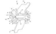
図1~9を参照すると、固定装置10の一実施形態が示されている。例示的な実施形態では、固定装置10は、第1のエンドプレート20、第2のエンドプレート40、第1及び第2の固定プレート60、70、一対のスライドプレート80、90、中央傾斜110、及び駆動傾斜130を含む。
1-9, one embodiment of a
エンドプレート20、40の各々は、反対側の端部21、23と41、43との間に延びる本体22、42を含む。図示の実施形態では、各エンドプレート本体22、42は、第1の端部21、41及び第2の端部23、43を接続する外側表面24、44、ならびに第1の端部21、41及び第2の端部23、43を接続する内側表面26、46を画定する。一実施形態では、各エンドプレート20、40は、貫通開口部25、45を画定する。例示的な一実施形態における貫通開口部25、45は、骨移植片または類似の骨成長誘導材料を受容し、さらに、骨移植片または類似の骨成長誘導材料が装置10の中央領域に充填されることを可能にする大きさである。
Each of the
各エンドプレート20、40の外側表面24、44は、平坦であり得、エンドプレート20、40の外側表面24、44が、隣接する椎体と係合することが可能なように、おおむね平面とすることができる。別の方法として、外側表面24、44のうちの一方または両方は、隣接する椎体とのより大きいまたはより小さい係合を可能にするように、凸状または凹状に湾曲することができる。また、外側表面24、44は、概して平面であり得るが、一般に真っ直ぐな傾斜面または湾曲した傾斜面を含み、傾斜しているか、または他の形に構成されていることも考えられる。1つ以上の傾斜した表面の存在は、脊柱前弯様式で隣接する椎体との係合を可能にすることができる。図示されていないが、例示的な実施形態では、一方または両方の外側表面24、44は、隣接する椎体を把持するのを助けるテクスチャ加工または他の表面形状を含むことができる。以下に限定されるものではないが、テクスチャ加工または他の表面形状は、歯、隆起部、摩擦増大要素、キール部、把持または購入突起部などを含むことができる。
The
図3、5、及び9を参照すると、第1のエンドプレート20の内側表面26は、本体22の第1の端部21に間隔を置いて配置された第1の対30と、本体の第2の端部23に間隔を置いて配置された第2の対34を画定している。第1の端部21の延在部30は、第2の端部23、例えば第1の端部21上の延在部34とは反対側に配置され、右側の延在部30は縁部にあり、これに対して左側の延在部は、縁部の内側でかつ第2の端部23上にあり、右側の延在部34は縁部の内側にあり、これに対して左側の延在部は縁部にある。同様に、第2のエンドプレート40の内側表面46は、本体42の第1の端部41に第1の対の離間した延在部50、及び本体の第2の端部43に第2の対の離間した延在部54を画定している。第2のエンドプレート40では、延在部50、54は、第1のプレート20上の延在部とは反対側、すなわち第1の端部41上にあり、右側の延在部50は縁部の内側にあり、これに対して左側の延在部は縁部にあってかつ第2の端部43上にあり、右側の延在部54は縁部にあり、これに対して左側の延在部は縁部の内側にある。この構成では、第1のエンドプレート20の延在部30が、第2のエンドプレート40の延在部50と重なり、第2のエンドプレート40の延在部54が、第1のエンドプレート20の延在部34と重なる。
3, 5 and 9, the
各延在部30、34、50、54は、それぞれの傾斜面31、35、51、55を画定する。傾斜面31、35、51、55は、後述するように、中央傾斜110及び駆動傾斜130上の傾斜面によって係合されるように構成されている。また、延在部30、34、50、54の各々は、それぞれの溝33、37、53、57を画定する。後述するように、溝33、37、53、57は、中央傾斜110上及び駆動傾斜130上の突起によって係合されるように構成され、装置10を組み立てられた状態に維持し、エンドプレート20、40の移動を案内する。
Each
各エンドプレート20、40は、本体22、42の一方の側縁に沿って取り付けられた固定プレート60、70を含む。図示の実施形態の各固定プレート60、70は、固定端61、71から自由端63、73に延在する本体62、72を含む。固定プレート本体62、72は、それぞれの棘状突起との意図した係合を補完するための任意の所望の形状を有してもよく、互いに鏡像であってもよいし、または互いに異なっていてもよい。各固定プレート60、70の内側表面64、74は、棘状突起が係合するときに棘状突起を把持するための複数のスパイク66、76などを含む。各固定プレートの外側表面は、盲孔67、77、貫通孔などを含むことができる。例示的な一実施形態では、孔67、77は、骨移植片または同様の骨成長誘導材料を受容するような大きさにされている。
Each
横方向調整バー28、48は、各エンドプレート20、40の本体22、42の反対側の側縁から自由端29、49に向かって外側に延在している。調整バー28、48は、それぞれのスライドプレート80、90を支持する。図示された実施形態の各スライドプレート80、90は、接続端部81、91から自由端部83、93まで延在する本体82、92を含む。スライドプレート本体82、92は、それぞれの棘状突起との意図された係合を補完するための任意の所望の形状を有してもよく、互いに鏡像であってもよいし、または互いに異なっていてもよい。各固定プレート80、90の内側表面84、94は、棘状突起が係合するときに棘状突起を把持するための複数のスパイク86、96などを含む。各固定プレートの外側表面は、盲孔87、97、貫通孔などを含むことができる。例示的な一実施形態では、孔87、97は、骨移植片または同様の骨成長誘導材料を受容するように寸法決めされている。
A
各スライドプレート80、90の接続端部81、91は、スライドプレート80、90がそれぞれの横方向調整バー28、48上に搭載されることを可能にする接続アセンブリ88、98を含み、スライドプレート80、90は、横方向に調整可能であるが、回転しないように固定されている。図示された実施形態では、各接続アセンブリ88、98は、本体82、92を通って横方向に延在し、それぞれの横方向調整バー28、48を受容するように構成された受容孔85、95を画定している。受容孔85、95及び横方向調整バー28、48は、横方向調整を可能にするが相対的な回転を防止することができる相補的な形状を有する。図示された実施形態では、受容孔85、95及び横方向調整バー28、48は、相補的な丸みのある矩形形状を有するが、他の非円形形状も可能である。
The connecting
スライドプレート80、90の位置をそれぞれの横方向調整バー28、48に沿って設定するために、止めねじ100が、それぞれの接続アセンブリ88、98に画定された貫通孔89、99内に延在し、受容孔85、95と交差している。各止めねじ100は、ねじ付き部分102、及び受容孔85、95に向かって延在する係合端部103を有する駆動ヘッド104を含む。ねじ部分102は、貫通孔89、99内のねじと係合するように構成されている。止め輪105などは、各止めねじ100の周りに配置され、貫通孔89、99内の溝と係合して、組立後に止めねじ100を貫通孔89、99に保持することができる。ひとたび、スライドプレート80、90がそれぞれの横方向調整バー28、48に沿って所望の横方向位置に配置されると、止めねじ100は、係合端部103が横方向調整バー28、48と係合し、それぞれのエンドプレート20、40に対してスライドプレート80、90を固定するように、螺合しながら前進する。
Set
中央傾斜110は、第1の端部111から第2の端部113まで延在する本体112を含む。貫通孔114は、第1の端部111から第2の端部113まで本体112を通って延在し、その結果、駆動ねじ120を受容するように構成されている。駆動ねじ120は、ねじ部122及び駆動ヘッド124を有する。平坦なワッシャ126及び抗力低減ワッシャ128が、駆動ヘッド124と、貫通孔114(図示せず)内に画定された内部肩部との間の貫通孔114内に配置され、抗力を最小にしながら中央傾斜の駆動を容易にすることができる。ノッチ119などは、搬送/位置決めツール(図示せず)などと係合するように構成された中央傾斜本体112に沿って画定されてもよい。
中央傾斜110の第2の端部113は、第1の対の傾斜116及び第2の対の傾斜117を画定する。第1の傾斜116は、第1のエンドプレート20上の傾斜31と位置合わせされ、そして傾斜31とスライド可能に係合するように構成されている。第2の傾斜117は、第2のエンドプレート40上の傾斜51と位置合わせされ、そして係合するように構成されている。傾斜116に隣接する突起118は、第1のエンドプレート20上の溝33内に延在し、傾斜117(図示せず)に隣接する突起は、第2のエンドプレート40上の溝53内に延在する。突起118と溝33、53との間の係合は、エンドプレート20、40に組み立てられた中央傾斜110を維持し、中央傾斜110が前進するにつれてエンドプレート20、40の動きを案内する。
A
駆動傾斜130は、傾斜本体132及びねじ受容部134を含む。ねじを切られた盲孔139が、ねじ受容部134内に延在し、駆動ねじ120のねじ部分122を受容するように構成されている。このように、駆動ねじ120が前進方向に回転することにより、中央傾斜110及び駆動傾斜130が互いに向かって移動することができる。
駆動傾斜130の傾斜本体132は、一対の第1の傾斜136及び一対の第2の傾斜137(図3を参照)を画定する。第1の傾斜136は、第2のエンドプレート40上の傾斜55と位置合わせされ、そしてスライド可能に係合するように構成されている。第2の傾斜137は、第1のエンドプレート20上の傾斜35と位置合わせされ、そして傾斜35と係合するように構成されている。傾斜136に隣接する突起138は、第2のエンドプレート40上の溝57内に延在し、傾斜137に隣接する突起138は、第1のエンドプレート20上の溝37内に延在している。突起138と溝37、57との間の係合は、エンドプレート20、40に組み立てられた駆動傾斜130を維持し、駆動傾斜130が前進されるときにエンドプレート20、40の移動を案内する。
A
固定装置10の構成要素を大まかに説明してきたので、固定装置の動作を一般的に説明する。固定装置10は、図1、2、4及び5に示すように、その完全に倒れた高さで挿入され、潰れた棘突起間腔に容易に挿入できるようにしてもよい。挿入の間、固定プレート60、70のスパイク66、76は、それぞれの棘状突起に圧縮され得る。挿入後、固定装置10は、駆動ねじ120を前進方向に回転させることによって拡張されることができる。駆動ねじ120が回転すると、中央傾斜110及び駆動傾斜130は、互いの方向に引き寄せられ、これに伴い、傾斜31が傾斜116に乗り上がり、傾斜51が傾斜117に乗り上がり、傾斜35が傾斜137に乗り上がり、傾斜55が傾斜136に乗り上がる。このような移動は、エンドプレート20、40を互いから離れるように移動させ、それにより、固定装置10の高さを所望の適合を得るように増加させるか、または棘突起間腔を伸延して神経要素への圧力を緩和するために使用される。エンドプレート20、40が互いから離れるように移動するにつれて、固定プレート60、70及びスライドプレート80、90は、それと一緒に呼応して移動する。エンドプレート20、40の拡張後、スライドプレート80、90は、横方向調整バー28、48に沿って移動され、棘状突起に圧縮される。スライドプレート80,90は、ひとたび配置されると、止めねじ100を用いて所定の位置に固定される。
Having generally described the components of the
図10~16を参照すると、別の実施形態の固定装置10’が示されている。本例示的な実施形態の固定装置10’は、以前の実施形態の固定装置10と同様であり、第1のエンドプレート20’、第2のエンドプレート40’、第1及び第2の固定プレート60、70、一対のスライドプレート80、90、中央傾斜110’、及び駆動傾斜130’を含む。これら両者の実施形態の間の違いのみを説明する。そうでない場合は、固定装置10、10’は、実質的に同じ方法で動作する。
10-16, another embodiment fixation device 10' is shown. The fixation device 10' of this exemplary embodiment is similar to the
本実施形態では、エンドプレート20’及び40’、ならびに中央傾斜110’は、エンドプレート20’、40’の拡張前に、エンドプレート20’、40’の間で枢動するように構成されている。前の実施形態と同様に、各エンドプレート20’、40’は、第1の端部21’、41’から第2の端部23’、43’まで延在する本体22’、42’を含む。図14を参照すると、本実施形態では、第1の端部21’、31は、延在部を含まず、代わりに、傾斜31’、51’を画定する先細の端面を有する。第2の端部23’、43’は、前の実施形態と同様であり、傾斜35、55を画定する延在部34’、54’を含む。また、延在部34’、54’は、内側傾斜36,56も画定する。延在部34、54の内側には、各エンドプレート本体22’、44’が、保持ノッチ29、49を画定している。保持ノッチ29、49は、中央傾斜110’の内側端部113’により係合され、エンドプレート20’、40’が互いに対して枢動するまで中央傾斜110’の内側への前進を防止するように構成されている。
In this embodiment, the end plates 20' and 40' and the central ramp 110' are configured to pivot between the end plates 20', 40' prior to expansion of the end plates 20', 40'. there is As with the previous embodiment, each end plate 20', 40' has a body 22', 42' extending from a first end 21', 41' to a
中央傾斜110’は、第1の端部111’から第2の端部113’まで延在する本体112’を含み、その本体112’は、前の実施形態の中央傾斜本体112と比較してより長い長さを有する。貫通孔114は、第1の端部111’から本体112’を貫通して延在し、それを通して駆動ねじ120を受容するように構成されている。中央本体110’の第1の端部111’は、傾斜116’及び117’を画定する。傾斜116’及び117’は、それぞれ傾斜31’及び51’に係合するように構成されている。
The central ramp 110' includes a body 112' extending from a first end 111' to a second end 113', the body 112' being different from the
中央傾斜110の第2の端部113’は、その第1の表面上の一対の延在部123、及び反対側の表面上の一対の延在部125を画定する。延在部123は、第1のエンドプレート20’により画定されたノッチ29と位置合わせされてその中に受容されるように構成され、延在部125は、第2エンドプレート40’により画定されたノッチ49と位置合わせされてその中に受容されるように構成されている(図13を参照)。また、延在部123は、前方傾斜127も画定し、これに対して、延在部125は、前方傾斜129を画定している。
A second end 113' of the
駆動傾斜130’は、傾斜本体132’及びねじ受容部分134’を含む。ねじ受容部分134’の長さは、前の実施形態におけるよりもより短い。ねじを切られた盲孔139は、ねじ受容部分134’内に延在し、駆動ねじ120のねじ部分122を受容するように構成されている。
The drive ramp 130' includes a ramp body 132' and a threaded receiving portion 134'. The length of the screw receiving portion 134' is shorter than in the previous embodiments. A blind threaded
駆動傾斜130’の傾斜本体132’は、第2のエンドプレート40’上の傾斜55と位置合わせされてスライド可能に係合するように構成された1対の傾斜136’を画定している。また、傾斜本体132’は、第1のエンドプレート20’上の傾斜35と位置合わせされて係合するように構成された一対の傾斜137’も画定している。傾斜136’、137’に隣接する突起138’は、エンドプレート20’、40’の溝37、57内に延在している。突起138’と溝37、57との間の係合が、エンドプレート20’、40’に組み立てられた駆動傾斜130’を維持し、駆動傾斜130’が前進するときにエンドプレート20’、40’の移動を案内する。
A ramp body 132' of drive ramp 130' defines a pair of ramps 136' configured for aligned and slidable engagement with
固定装置10’の構成要素を大まかに説明してきたので、図12~16を参照して、その固定装置の動作を一般的に説明する。固定装置10’は、図12及び図13に示すように、その完全に倒れた高さで挿入され、潰れた棘突起間腔に容易に挿入できるようにしてもよい。図示されているように、折り畳まれた位置では、延在部123及び125は、それぞれのノッチ29、49内に配置されている。挿入の間、固定プレート60、70のスパイク66、76は、それぞれの棘状突起に圧縮され得る。挿入後、エンドプレート20’、40’間の角度関係は、駆動ねじ120を前進方向に回転させることによって調整される。駆動ねじ120の最初の前進中、延在部123、125がノッチ29、49に係合することにより、中央傾斜110’が前進するのを防止する。駆動傾斜130’のみが前進することができる。駆動傾斜130’が前進すると、傾斜35が傾斜136’に乗り上がり、傾斜55が傾斜137’に乗り上がる。図14に示すように、このようにして、エンドプレート20’、40’は、端部23’及び43’が互いから離れて移動するように、互いに対して枢動する。ひとたびエンドプレート20’、40’が、最大量(図14)枢動すると、延在部123、125は、ノッチ29、49から解放される。このように、図15及び16に示すように、駆動ねじ120の回転前進の継続により、中央傾斜110’は、駆動傾斜130’に向かって自由に移動し、中央傾斜110’及び駆動傾斜130’は互いに引き寄せられ、傾斜31’は傾斜116’に乗り上げ、傾斜51’は傾斜117’に乗り上げ、傾斜35は傾斜136’に乗り上げ、傾斜55は傾斜137’に乗り上げ、また前方傾斜127、129は内側傾斜36、56に沿って乗っている。このような移動により、エンドプレート20’、40’が互いから離れて移動し、それによって、固定装置10の高さを所望の適合を得るように増加させるか、または棘突起間腔を伸延して神経要素の圧力を緩和するために使用される。エンドプレート20’、40’が枢動し、次いで互いから離れて移動すると、固定プレート60、70及びスライドプレート80、90は、それと一緒に呼応して移動する。エンドプレート20’、40’の拡張後、スライドプレート80、90は、横方向調整バー28、48に沿って移動され、棘状突起に圧縮される。スライドプレート80、90は、ひとたび配置されると、止めねじ100を用いて所定の位置に固定される。
Having generally described the components of the fixation device 10', the operation of the fixation device will be generally described with reference to FIGS. 12-16. The fixation device 10' may be inserted at its fully collapsed height, as shown in FIGS. 12 and 13, to facilitate insertion into the collapsed interspinous space. As shown, in the folded position,
拡張可能な固定装置10、10’は、以下に限定するものではないが、チタン、ステンレス鋼、チタン合金、非チタン金属合金、ポリマー材料、プラスチック、プラスチック複合材、PEEK(ポリエーテルエーテルケトン)、セラミック、弾性材料を含む多数の好適な生体適合性材料、または他の好適な生体適合性材料から製造することができる。
The
例示的な実施形態では、骨移植片または類似の骨成長誘導材料が、固定装置10、10’の周囲及び/または内部に導入され、椎間癒合をさらに促進し、容易にすることができる。一実施形態では、固定装置10、10’は、好ましくは、固定装置を通って、かつ固定装置の周りで骨の成長を促進するように、骨移植片または類似の骨成長誘導材料で充填される。そのような骨移植片は、固定装置の植え付け前、植え付け後、または植え付け中に、隣接する椎体のエンドプレートの間に充填されてもよい。
In an exemplary embodiment, bone graft or similar bone growth inducing material can be introduced around and/or within the
この開示に記載された装置のいくつかの利点は、低減した高さに棘状突起癒合インプラントを挿入し、次いで挿入後に高さを増加させて、正確な解剖学的適合を達成する能力である。インプラントのサイズは調整可能であるため、インプラントの長さ及び幅のいくつかのバリエーションを必要とせず、1つの装置が広範囲のインプラントサイズをカバーするため、棘突起間装置を挿入する複雑さもまた、大幅に低減される。インプラントは、予め組み立てられて、装置を挿入するために必要とされるステップの数を大幅に減少させてもよく、このことが全体的な手順を単純化し、手術室時間を短縮する。 Some advantages of the devices described in this disclosure are the ability to insert a spinous fusion implant at a reduced height and then increase the height after insertion to achieve a precise anatomical fit. . The complexity of inserting interspinous devices is also greatly reduced. The implant may be pre-assembled, greatly reducing the number of steps required to insert the device, which simplifies the overall procedure and reduces operating room time.
本開示は、例示的な態様に関して記載されているが、当業者であれば、本開示が、添付の特許請求の範囲の主旨及び範囲内で変更して実施できることを認識するであろう。上に示されたこれらの例は単なる例示であり、本開示のすべての可能な設計、態様、適用、または修正の網羅的なリストであることを意味しない。 Although the present disclosure has been described with respect to exemplary aspects, those skilled in the art will recognize that the present disclosure can be practiced with modification within the spirit and scope of the appended claims. These examples given above are merely illustrative and are not meant to be an exhaustive list of all possible designs, aspects, applications or modifications of the disclosure.
Claims (16)
椎間インプラントのための第1のエンドプレートであって、前記第1のエンドプレートは、第1の上面及び第1の下面を有する第1のプレート部分を含み、前記第1のエンドプレートは、前記第1の下面から離れて延在する第1の前方傾斜部、及び第1の下面から離れて延在する第1の後方傾斜部をさらに含み、前記第1のエンドプレートは、前記第1のエンドプレートの第1の縁部から延在する第1の横方向調整アームを有する、第1のエンドプレートと、
椎間インプラントのための第2のエンドプレートであって、前記第2のエンドプレートは、第2の上面及び第2の下面を有する第2のプレート部分を含み、前記第2のエンドプレートは、前記第2の下面から離れて延在する第2の前方傾斜部、及び第2の下面から離れて延在する第2の後方傾斜部をさらに含み、前記第2のエンドプレートは、前記第2のエンドプレートの第1の縁部から延在する第2の横方向調整アームを有する、第2のエンドプレートと、
前記第1のエンドプレートの前記第1の縁部の反対側の、前記第1のエンドプレートの第2の縁部に沿って延在する第1の固定プレートであって、前記第1の固定プレートは、前記第1のエンドプレートに対して実質的に垂直に延在し、第1の棘状突起係合面を画定する内側表面を有する、第1の固定プレートと、
前記第2のエンドプレートの前記第1の縁部の反対側の、前記第2のエンドプレートの第2の縁部に沿って延在する第2の固定プレートであって、前記第2の固定プレートは、前記第2のエンドプレートに対して実質的に垂直に延在し、第2の棘状突起係合面を画定する内側表面を有する、第2の固定プレートと、
前記第1のエンドプレートに対して実質的に垂直に延在し、第3の棘状突起係合面を画定する内側表面を有するように、前記第1の横方向調整アーム上に調整可能に搭載された第1のスライドプレートと、
前記第2のエンドプレートに対して実質的に垂直に延在し、第4の棘状突起係合面を画定する内側表面を有するように、前記第2の横方向調整アーム上に調整可能に搭載された第2のスライドプレートと、
前記第1のエンドプレートと前記第2のエンドプレートとの間に配置された中央傾斜であって、本体が後方エンドプレート係合傾斜を含む、中央傾斜と、
前記第1のエンドプレートと前記第2のエンドプレートとの間に配置された駆動傾斜であって、前記駆動傾斜は、前方エンドプレート係合傾斜を含む、駆動傾斜と、を備え、
前記装置は、前記中央傾斜及び前記駆動傾斜が互いに向かって移動すると、前記第1及び第2のエンドプレートが離れて移動するように構成されている、装置。 A device, said device comprising:
A first endplate for an intervertebral implant, said first endplate comprising a first plate portion having a first upper surface and a first lower surface, said first endplate comprising: Further comprising a first forward ramp extending away from the first lower surface and a first rearward ramp extending away from the first lower surface, wherein the first endplate comprises the first a first endplate having a first lateral adjustment arm extending from a first edge of the endplate of
A second endplate for an intervertebral implant, said second endplate comprising a second plate portion having a second upper surface and a second lower surface, said second endplate comprising: Further comprising a second forward ramp extending away from the second lower surface and a second rearward ramp extending away from the second lower surface, wherein the second endplate comprises the second a second endplate having a second lateral adjustment arm extending from a first edge of the endplate of
a first fixation plate extending along a second edge of said first endplate opposite said first edge of said first endplate, said first fixation plate a first fixation plate, the plate extending substantially perpendicular to said first endplate and having an inner surface defining a first spinous process engaging surface;
a second fixation plate extending along a second edge of said second endplate opposite said first edge of said second endplate, said second fixation plate a second fixation plate, the plate extending substantially perpendicular to said second endplate and having an inner surface defining a second spinous process engaging surface;
adjustably on said first lateral adjustment arm to have an inner surface extending substantially perpendicular to said first endplate and defining a third spinous process engaging surface; a mounted first slide plate;
adjustably on said second lateral adjustment arm to have an inner surface extending substantially perpendicular to said second endplate and defining a fourth spinous process engaging surface; a mounted second slide plate;
a central ramp positioned between the first endplate and the second endplate, wherein the body includes a rear endplate engaging ramp;
a drive ramp positioned between the first endplate and the second endplate, the drive ramp including a forward endplate engagement ramp;
The apparatus is configured such that the first and second end plates move apart when the central ramp and the drive ramp move toward each other.
椎間インプラントのための第1のエンドプレートであって、前記第1のエンドプレートは、前記第1のエンドプレートの第1の縁部から延在する第1の横方向調整アームを有する、第1のエンドプレートと、
椎間インプラントのための第2のエンドプレートであって、前記第2のエンドプレートは、前記第2のエンドプレートの第1の縁部から延在する第2の横方向調整アームを有する、第2のエンドプレートと、
前記第1のエンドプレートの前記第1の縁部の反対側の、前記第1のエンドプレートの第2の縁部に沿って延在する第1の固定プレートであって、前記第1の固定プレートは、前記第1のエンドプレートに対して実質的に垂直に延在し、第1の棘状突起係合面を画定する内側表面を有する、第1の固定プレートと、
前記第2のエンドプレートの前記第1の縁部の反対側の、前記第2のエンドプレートの第2の縁部に沿って延在する第2の固定プレートであって、前記第2の固定プレートは、前記第2のエンドプレートに対して実質的に垂直に延在し、第2の棘状突起係合面を画定する内側表面を有する、第2の固定プレートと、
前記第1のエンドプレートに対して実質的に垂直に延在し、第3の棘状突起係合面を画定する内側表面を有するように、前記第1の横方向調整アーム上に調整可能に搭載された第1のスライドプレートと、
前記第2のエンドプレートに対して実質的に垂直に延在し、第4の棘状突起係合面を画定する内側表面を有するように、前記第2の横方向調整アーム上に調整可能に搭載された第2のスライドプレートと、
前記第1のエンドプレートと前記第2のエンドプレートとの間に配置された拡張アセンブリであって、前記拡張アセンブリは、前記第1及び第2のエンドプレートを選択的に離れて移動させるように構成された、拡張アセンブリと、を備え、
各スライドプレートが、それぞれの横方向調整アームをスライド可能に受容するように構成された受容孔を有し、
前記各スライドプレートが、前記受容孔と連通している貫通孔を含み、それによって、前記貫通孔の中のねじ止め調整可能な止めねじが、前記受容孔に受容された前記横方向調整アームと係合するように構成されている、装置。 A device, the device comprising:
A first endplate for an intervertebral implant, said first endplate having a first lateral adjustment arm extending from a first edge of said first endplate. 1 end plate;
A second endplate for an intervertebral implant, said second endplate having a second lateral adjustment arm extending from a first edge of said second endplate. 2 end plates;
a first fixation plate extending along a second edge of said first endplate opposite said first edge of said first endplate, said first fixation plate a first fixation plate, the plate extending substantially perpendicular to said first endplate and having an inner surface defining a first spinous process engaging surface;
a second fixation plate extending along a second edge of said second endplate opposite said first edge of said second endplate, said second fixation plate a second fixation plate, the plate extending substantially perpendicular to said second endplate and having an inner surface defining a second spinous process engaging surface;
adjustably on said first lateral adjustment arm to have an inner surface extending substantially perpendicular to said first endplate and defining a third spinous process engaging surface; a mounted first slide plate;
adjustably on said second lateral adjustment arm to have an inner surface extending substantially perpendicular to said second endplate and defining a fourth spinous process engaging surface; a mounted second slide plate;
an expansion assembly disposed between the first endplate and the second endplate, the expansion assembly selectively moving the first and second endplates apart; an expansion assembly, and
each slide plate having a receiving hole configured to slidably receive a respective lateral adjustment arm;
Each of said slide plates includes a through hole in communication with said receiving hole whereby a screwable adjustable set screw in said through hole engages said lateral adjustment arm received in said receiving hole. A device configured to engage .
Applications Claiming Priority (2)
| Application Number | Priority Date | Filing Date | Title |
|---|---|---|---|
| US15/662,423 US10512550B2 (en) | 2010-09-03 | 2017-07-28 | Expandable interspinous process fixation device |
| US15/662,423 | 2017-07-28 |
Publications (2)
| Publication Number | Publication Date |
|---|---|
| JP2019025329A JP2019025329A (en) | 2019-02-21 |
| JP7145675B2 true JP7145675B2 (en) | 2022-10-03 |
Family
ID=63041855
Family Applications (1)
| Application Number | Title | Priority Date | Filing Date |
|---|---|---|---|
| JP2018139028A Active JP7145675B2 (en) | 2017-07-28 | 2018-07-25 | Expandable Interspinous Process Fixation Device |
Country Status (2)
| Country | Link |
|---|---|
| EP (1) | EP3434229B1 (en) |
| JP (1) | JP7145675B2 (en) |
Citations (3)
| Publication number | Priority date | Publication date | Assignee | Title |
|---|---|---|---|---|
| US20130184754A1 (en) | 2007-11-02 | 2013-07-18 | Lanx Inc. | Telescoping Interspinous Fixation Device and Methods of Use |
| US20140343608A1 (en) | 2013-05-16 | 2014-11-20 | Smokey Mountain Spine, Llc | Expansion interspinous fixation device and method |
| JP2016533221A (en) | 2012-12-31 | 2016-10-27 | グローバス メディカル インコーポレイティッド | Spinous process fixation system and method |
Family Cites Families (3)
| Publication number | Priority date | Publication date | Assignee | Title |
|---|---|---|---|---|
| US9498560B2 (en) * | 2011-03-04 | 2016-11-22 | Spinefrontier, Inc | Interspinous spacer implant |
| EP2819621A4 (en) * | 2012-02-28 | 2015-12-16 | Globus Medical Inc | Spinous process fusion devices |
| US9011493B2 (en) * | 2012-12-31 | 2015-04-21 | Globus Medical, Inc. | Spinous process fixation system and methods thereof |
-
2018
- 2018-07-24 EP EP18185145.2A patent/EP3434229B1/en active Active
- 2018-07-25 JP JP2018139028A patent/JP7145675B2/en active Active
Patent Citations (3)
| Publication number | Priority date | Publication date | Assignee | Title |
|---|---|---|---|---|
| US20130184754A1 (en) | 2007-11-02 | 2013-07-18 | Lanx Inc. | Telescoping Interspinous Fixation Device and Methods of Use |
| JP2016533221A (en) | 2012-12-31 | 2016-10-27 | グローバス メディカル インコーポレイティッド | Spinous process fixation system and method |
| US20140343608A1 (en) | 2013-05-16 | 2014-11-20 | Smokey Mountain Spine, Llc | Expansion interspinous fixation device and method |
Also Published As
| Publication number | Publication date |
|---|---|
| JP2019025329A (en) | 2019-02-21 |
| EP3434229B1 (en) | 2020-04-15 |
| EP3434229A1 (en) | 2019-01-30 |
Similar Documents
| Publication | Publication Date | Title |
|---|---|---|
| US10512550B2 (en) | Expandable interspinous process fixation device | |
| US11642230B2 (en) | Expandable interspinous process fixation device | |
| US11813175B2 (en) | Spinous process fixation system and methods thereof | |
| US11759331B2 (en) | Stabilized expandable intervertebral spacer | |
| US11944551B2 (en) | Expandable vertebral implant | |
| US11660127B2 (en) | Spinous process fixation system and methods thereof | |
| US11896493B2 (en) | Expandable intervertebral spacer | |
| US10500059B2 (en) | Methods of 3D printing universally expanding cages | |
| US11007067B2 (en) | Expandable spinal fusion cage | |
| US6461359B1 (en) | Spine stabilization device | |
| EP1819287B1 (en) | System for stabilizing the motion or adjusting the position of the spine | |
| US8267970B2 (en) | Laminar hook spring | |
| JP7145675B2 (en) | Expandable Interspinous Process Fixation Device |
Legal Events
| Date | Code | Title | Description |
|---|---|---|---|
| A621 | Written request for application examination |
Free format text: JAPANESE INTERMEDIATE CODE: A621 Effective date: 20210603 |
|
| A977 | Report on retrieval |
Free format text: JAPANESE INTERMEDIATE CODE: A971007 Effective date: 20220428 |
|
| A131 | Notification of reasons for refusal |
Free format text: JAPANESE INTERMEDIATE CODE: A131 Effective date: 20220524 |
|
| A521 | Request for written amendment filed |
Free format text: JAPANESE INTERMEDIATE CODE: A523 Effective date: 20220824 |
|
| TRDD | Decision of grant or rejection written | ||
| A01 | Written decision to grant a patent or to grant a registration (utility model) |
Free format text: JAPANESE INTERMEDIATE CODE: A01 Effective date: 20220913 |
|
| A61 | First payment of annual fees (during grant procedure) |
Free format text: JAPANESE INTERMEDIATE CODE: A61 Effective date: 20220920 |
|
| R150 | Certificate of patent or registration of utility model |
Ref document number: 7145675 Country of ref document: JP Free format text: JAPANESE INTERMEDIATE CODE: R150 |