JP7145622B2 - Information processing device, information processing device control method, subject detection system, and program - Google Patents
Information processing device, information processing device control method, subject detection system, and program Download PDFInfo
- Publication number
- JP7145622B2 JP7145622B2 JP2018037730A JP2018037730A JP7145622B2 JP 7145622 B2 JP7145622 B2 JP 7145622B2 JP 2018037730 A JP2018037730 A JP 2018037730A JP 2018037730 A JP2018037730 A JP 2018037730A JP 7145622 B2 JP7145622 B2 JP 7145622B2
- Authority
- JP
- Japan
- Prior art keywords
- subject
- information
- detected
- image
- captured image
- Prior art date
- Legal status (The legal status is an assumption and is not a legal conclusion. Google has not performed a legal analysis and makes no representation as to the accuracy of the status listed.)
- Active
Links
Images


Description
本発明は、情報処理装置、情報処理装置の制御方法、被写体検出システム、及び、プログラムに関する。 The present invention relates to an information processing device, a control method for an information processing device, a subject detection system, and a program.
近年、多数のネットワークカメラを用いた大規模な監視システムが登場してきている。このような監視システムでは、オフィス、店舗、ショッピングモール、スタジアム、街頭、地域全体など、広い範囲にネットワークカメラが設置されるようになっており、セキュリティの向上に役立っている。 In recent years, large-scale surveillance systems using many network cameras have appeared. In such surveillance systems, network cameras are being installed in wide areas such as offices, stores, shopping malls, stadiums, streets, and entire communities, helping to improve security.
このような監視システムの一例として、ネットワークカメラで撮像した画像に対して画像解析・認識処理を行うことで、画像中の被写体認識を行い、被写体を検出する被写体検出システム等が提案されている。被写体検出システムでは、検出すべき物体や人物等の特定の被写体の画像をシステムに予め登録しておき、リアルタイムにカメラ映像を解析し検出対象の被写体を検出した際に警報(アラーム)を監視員や警備員に通知する。当該アラームは、検出時に監視モニタへアラーム表示を行うことで、監視員らに通知することができる。このとき監視員らはアラーム通知の原因となったカメラ映像も確認できる。このような被写体検出システムにつき特許文献1では、ネットワークカメラで撮影した人物の顔画像と、予め登録した要注意人物の顔画像を照合することで、要注意人物であるか否かを判定するシステムが提案されている。
As an example of such a monitoring system, there has been proposed an object detection system that detects an object by recognizing an object in the image by performing image analysis/recognition processing on an image captured by a network camera. In the subject detection system, images of specific subjects such as objects and people to be detected are registered in advance in the system, and the camera image is analyzed in real time and an alarm is sent to the observer when the subject to be detected is detected. or notify a security guard. The alarm can be notified to the surveillance staff by displaying the alarm on the surveillance monitor when it is detected. At this time, the observers can also check the camera image that caused the alarm notification. Regarding such a subject detection system,
また、監視システムが大規模化するにつれ、カメラ台数やそれを表示するモニタ数が増加し、システムの操作者の負担が大きくなりつつある。そこで、特許文献2では、保安システムの警報活動がリスト化されたログを一覧表示することで操作員のシステムの操作性を向上させる技術を提案している。
In addition, as the monitoring system becomes larger in scale, the number of cameras and the number of monitors for displaying them are increasing, and the burden on the system operator is increasing. Therefore,
提案にかかる被写体検出システムでは、映像解析により検出対象の人物が検出されると、表示画面にカメラ映像と共にアラームやその履歴を表示し、当該人物が検出されたことを報知していた。 In the proposed subject detection system, when a person to be detected is detected by image analysis, an alarm and its history are displayed on the display screen along with the camera image to notify that the person has been detected.
しかし、画面表示されるカメラ映像は、ネットワークカメラの設置条件や照明条件、被写体の状態などの影響を受けるため、必ずしも操作者が人物を特定できる程度に鮮明に撮影されているとは限らない。よって、アラームが発生した場合に操作者がカメラ映像を見ても検出された人物を特定することが困難となるおそれがある。 However, the camera image displayed on the screen is affected by the installation conditions of the network camera, the lighting conditions, the state of the subject, and the like, so the image is not necessarily sharp enough for the operator to identify the person. Therefore, when an alarm is generated, it may be difficult for the operator to identify the detected person even if he or she looks at the camera image.
また、撮影条件によっては映像解析の結果に誤りが生ずる場合もある。この場合、映像中の人物を別の人物と誤認識してアラーム表示を行うことになるが、検出された人物をカメラ映像において特定しにくいと操作者は誤認識が発生していることにすら気づかないおそれがある。 In addition, an error may occur in the result of image analysis depending on shooting conditions. In this case, the person in the image is erroneously recognized as another person and an alarm is displayed. You may not notice it.
そこで、本発明は、被写体検出システムにおいて、被写体を検出したことの通知表示において、検出対象の被写体の視認性を向上させることを可能とする技術を提供する。 Accordingly, the present invention provides a technique for improving the visibility of a subject to be detected in a notification display indicating that the subject has been detected in a subject detection system.
上記課題を解決するための本発明は情報処理装置であって、
撮像画像から検出すべき被写体の特徴情報を保持する保持手段と、
前記特徴情報に基づいて、撮像画像から前記被写体を検出する検出手段と、
前記検出手段が第1の撮像画像において検出した前記被写体について、過去に検出された複数の前記被写体に関する情報のリストを含む表示情報を生成する生成手段と
前記表示情報を出力する出力手段と
を備え、
前記リストには、少なくとも前記被写体の検出の報知に関わる優先度に関する情報が含まれ、
前記生成手段は、前記被写体の優先度が表示されるように前記表示情報を生成し、
前記生成手段は、前記撮像画像に、前記検出された被写体を識別可能に示すための、前記被写体の名称を含む標識が重畳されて表示されるように前記表示情報を生成することを特徴とする。
The present invention for solving the above problems is an information processing device,
holding means for holding feature information of a subject to be detected from a captured image;
detection means for detecting the subject from the captured image based on the feature information;
generating means for generating display information including a list of information relating to a plurality of subjects detected in the past with respect to the subject detected in the first captured image by the detecting means; and output means for outputting the display information. ,
the list includes at least information about priority related to notification of detection of the subject;
The generating means generates the display information so that the priority of the subject is displayed,
The generating means generates the display information such that a marker including the name of the subject is superimposed on the captured image to indicate the detected subject in an identifiable manner . .
本発明によれば、被写体検出システムにおいて、被写体を検出したことの通知表示において、検出対象の被写体の視認性を向上させることを可能とする技術を提供することができる。 Advantageous Effects of Invention According to the present invention, it is possible to provide a technique that enables improvement in the visibility of a subject to be detected in a notification display indicating that the subject has been detected in a subject detection system.
以下、添付図面を参照して、発明を実施するための形態について詳細に説明する。なお、以下に説明する実施の形態は、本発明の実現手段としての一例であり、本発明が適用される装置の構成や各種条件によって適宜修正又は変更されるべきものであり、本発明は以下の実施の形態に限定されるものではない。 BEST MODE FOR CARRYING OUT THE INVENTION Hereinafter, embodiments for carrying out the invention will be described in detail with reference to the accompanying drawings. The embodiments described below are examples of means for realizing the present invention, and should be appropriately modified or changed according to the configuration of the apparatus to which the present invention is applied and various conditions. It is not limited to the embodiment of
図1は、本実施形態における被写体検出システムの構成の一例を示したブロック図である。本実施形態では、被写体検出システムをネットワークカメラシステム10に適用する。
FIG. 1 is a block diagram showing an example of the configuration of a subject detection system according to this embodiment. In this embodiment, the subject detection system is applied to the
ネットワークカメラシステム10は、少なくとも1台のネットワークカメラ(以下、単に「カメラ」ともいう)102と、情報処理装置103、104、105を備える。情報処理装置103は画像録画サーバ、情報処理装置104は画像解析サーバ、情報処理装置105は操作端末として、それぞれ構成することができる。これらの情報処理装置は、物理的に独立した装置として構成しても、あるいは、一体的に構成してもよい。
The
カメラ102と情報処理装置103、104、105とは、ネットワーク回線であるLAN(Local Area Network)101によって接続されている。なお、ネットワーク回線はLANに限定されるものではなく、インターネットやWAN(Wide Area Network)などであってもよい。また、LAN101への物理的な接続形態は、有線であってもよいし、無線であってもよい。さらに、図1において、カメラ102及び情報処理装置103、104、105は、1台または2台がLAN101に接続されているが、接続台数は図1に示す数に限定されない。
The
カメラ102は、所定の画角で監視対象空間内に存在する所定の被写体を撮像する、監視カメラ等の撮像装置である。カメラ102は、撮像画像(以下、単に「画像」ともいう。)を、LAN101を介して各情報処理装置103、104、105へ送信する機能を有する。
The
画像録画サーバ103は、ネットワークカメラ102から送信された撮像画像をLAN101経由で受信して保存、蓄積する。また、画像録画サーバ103は、画像解析サーバ104及び操作端末105から受け付けた要求に応じて保存している撮像画像を各装置に送信する。画像解析サーバ104は、撮像画像から検出すべき被写体の画像等を操作端末105からLAN101経由で受信し、被写体検出処理に必要な特徴量を生成し被写体を検出するために用いる特徴情報として保存しておく。また、画像解析サーバ104は、カメラ102が撮像した撮像画像をLAN101経由でカメラ102から受信して画像解析処理を行い、検出すべき被写体が当該撮像画像に含まれているかどうかの被写体検出処理を行うことができる。また、画像録画サーバ103に記録されている撮像画像をLAN101経由で受信した場合も、当該撮像画像について同様に被写体検出処理を行うことができる。
The
画像解析サーバ104は、撮像画像中で検出すべき被写体を検出した場合にはアラーム表示情報を生成し、操作端末105に生成したアラーム表示情報を送信する。アラーム表示情報の送信は、操作端末105からの要求に基づき実行してもよいし、操作端末105が検出結果をリアルタイムで受信する設定であれば、画像解析サーバ104は解析結果を解析処理終了毎に操作端末105へ送信してもよい。
The
本実施形態の以下の説明では、画像解析サーバ104がネットワークカメラ102の撮像画像を画像録画サーバ103経由で受信する場合を想定しているが、ネットワークカメラ102から直接受信する場合も同様にして各種の処理を実行することができる。また、以下の説明では、画像解析サーバ104が解析結果や登録情報を保持する場合を想定しているが、ネットワークを介した他のデータベースや操作端末105に保存するようにしても構わない。
In the following description of this embodiment, it is assumed that the
操作端末105は、表示装置(ディスプレイ)を備え、カメラ102から受信した撮像画像や、画像録画サーバ103に記録された画像データの再生・表示や、画像解析サーバ104から受信したアラーム表示情報を表示するための表示制御機能を有する。また操作端末105は、被写体検出用のユーザインタフェースと入力部を備え、被写体検出のための画像解析処理に関するパラメータ設定や、登録情報の設定、アラーム表示情報の各種パラメータの設定の操作を行うための機能を有する。
The
次に、発明の実施形態に対応する各装置の構成について説明する。図2(A)は、発明の実施形態に対応するカメラ102のハードウェア構成の一例を示す図である。カメラ102は、CPU201、ROM202、RAM203、外部メモリ204、撮像部205、入力部206、通信I/F207、システムバス208を含んで構成することができる。これ以外の構成をさらに含んでいてもよい。
Next, the configuration of each device corresponding to the embodiment of the invention will be described. FIG. 2A is a diagram showing an example of the hardware configuration of the
CPU201は、カメラ102における動作を統括的に制御する制御部であって、システムバス208を介して、各構成要素(202~207)の動作を制御する。ROM202は、CPU201が処理を実行するために必要な制御プログラム等を記憶する不揮発性メモリである。なお、当該プログラムは、外部メモリ204や着脱可能な記憶媒体(不図示)に記憶されていてもよい。RAM203は、CPU201の主メモリ、ワークエリア等として機能する。すなわち、CPU201は、処理の実行に際してROM202から必要なプログラム等をRAM203にロードし、当該プログラム等を実行することで各種の機能動作を実現する。
The
外部メモリ204は、例えば、CPU201がプログラムを用いた処理を行う際に必要な各種データや各種情報等を記憶している。また、外部メモリ204には、例えば、CPU201がプログラム等を用いた処理を行うことにより得られた各種データや各種情報等が記憶される。撮像部205は、被写体の撮像を行って撮像画像を生成する。撮像部205は、例えばCMOS(Complementary Metal Oxide Semiconductor)、CCD(Charge Coupled Device)等の撮像素子、A/D変換器、現像処理部等を含んで構成することができる。
The
入力部206は電源ボタンや設定ボタンなどから構成され、カメラ102の操作者は、入力部206を介して当該カメラ102に指示を与えることができる。通信I/F207は、外部装置(ここでは、情報処理装置103)と通信するためのインターフェースである。通信I/F207は、例えばLANインターフェースである。システムバス208は、CPU201、ROM202、RAM203、外部メモリ204、撮像部205、入力部206及び通信I/F207を通信可能に接続する。カメラ102の各部の機能は、CPU201がROM202もしくは外部メモリ204に記憶されたプログラムを実行することで実現される。
An
本実施形態において、情報処理装置103から105のそれぞれのハードウェア構成についても、図2(A)に示すハードウェア構成に準ずることができる。ただし、その場合には、撮像部205に代えて、表示部等のハードウェア構成を具備することができる。ここで、表示部は、液晶ディスプレイ(LCD)等のモニタで構成される。また、情報処理装置103から105は、入力部206として、キーボードやマウス等のポインティングデバイスを具備し、操作者が情報処理装置103から105に対して指示を与えることができるように構成される。また、外部メモリ204は、種々の情報を記憶しておくためのデータベースを含むことができる。
In this embodiment, the hardware configuration of each of the
図2(B)は、発明の実施形態に対応する情報処理装置としての画像解析サーバ104の機能構成の一例を示すブロック図である。画像解析サーバ104は、画像取得部211、被写体領域検出部212、特徴量取得部213、被写体情報登録部214、被写体情報管理部215、照合部216を備えることができる。さらに、アラーム情報設定部217、アラーム情報管理部218、アラーム作成部219、アラーム通信部220、設定管理部221を備えることができる。
FIG. 2B is a block diagram showing an example of the functional configuration of the
図2(B)に示す各機能構成要素は、画像解析サーバ104のCPU201が対応する処理プログラムを実行することによって実現され得る。ただし、図2(B)に示す各要素のうち少なくとも一部を専用のハードウェアで実現するように構成してもよい。この場合、専用のハードウェアは、CPU201の制御に基づいて動作する。
Each functional component shown in FIG. 2B can be realized by the
本実施形態では、図2(B)の各機能を画像解析サーバ104内に搭載する場合を説明するが、機能の一部を他の機器に搭載してもよい。例えば、機能の一部をカメラ102内に搭載してもよいし、画像録画サーバ103を含む他の情報処理装置に搭載してもよい。また、本実施形態においては、画像解析サーバ104が被写体として主に人物を検出する場合を説明するが、検出対象となる被写体は人物に限定されるものではない。例えば、車両や不審物などの特定の被写体を検出対象とすることもできる。
In this embodiment, the case where each function of FIG. 2B is installed in the
画像取得部211は、カメラ102から送信された撮像画像を画像録画サーバ103経由で受信し、伸長、復号化して画像(動画像若しくは静止画像)を取得する。画像取得部211は、取得した画像を順次、被写体領域検出部212へ送出する。ここで、本実施形態においてカメラ102から提供される撮像画像は、静止画であっても動画であってもよい。また、撮像画像の供給元については特に限定するものではない。供給元は、有線若しくは無線を介して撮像画像を供給するカメラ102、画像録画サーバ103、あるいは、それら以外の他の撮像装置であってもよい。また、画像取得部211は、同一の装置内のメモリ(例えば、外部メモリ204)から撮像画像を取得するようにしてもよい。以下の説明では、画像取得部211が動画像を取得した場合であっても静止画像を取得した場合であっても、画像取得部211は、被写体領域検出部212へ1枚の画像を送出する場合について説明する。前者の場合は、上記1枚の画像が動画像を構成する各フレームに相当し、後者の場合は、上記1枚の画像が静止画像に相当する。動画像の場合は、各フレームについて同様の処理を繰り返せばよい。
The
次に、被写体領域検出部212は、画像取得部211が受信した撮像画像に対し、照合パターン辞書等を用いて被写体領域検出処理を実施する。これにより、撮像画像中で被写体(例えば、人物)が含まれる被写体領域(人物領域)が抽出される。特徴量取得部213は、被写体領域検出部212で抽出された被写体領域の画像から、所定の演算に基づいて特徴量を抽出する特徴量抽出処理を行う。例えば、被写体として人物が抽出される場合、特徴量として人物の顔の特徴量を抽出することができる。また、顔以外にも上半身、下半身、全身、後姿、着衣等の特徴量を抽出してもよい。
Next, the subject
次に、被写体情報登録部214は、検出対象とする被写体の画像を含む情報を操作端末105からLAN101経由で受信し、被写体検出処理に必要な特徴量を生成し被写体の特徴情報(以下、「被写体情報」という)として被写体情報管理部215に登録する。ここでの特徴量の生成については、特徴量取得部213が行う処理と同様に実施することができる。被写体情報管理部215は、被写体情報登録部214が生成した登録対象の被写体の特徴量や画像を、登録名や登録時刻等の情報と共に被写体情報として管理する。
Next, the subject
照合部216は特徴量取得部213が取得した特徴量と被写体情報管理部215が保持・管理する、検出対象の被写体の特徴量とを照合し、類似度を算出する。算出した類似度が所定の閾値以上である場合、撮像された被写体は、検出対象の被写体に類似していると判断し、検出対象の被写体が検出されたと認識する。
A
上述のように本実施形態において検出すべき対象である被写体は人物に限定されない。したがって、被写体情報登録部214は、操作端末105から提供された被写体画像から、当該被写体を撮像画像において検出するのに有効となる特徴量を抽出する。検出対象が車両であれば、当該車両を検出可能な車両の形状的特徴や、車両に固有の識別情報(例えばナンバープレートの番号)を特徴量として抽出することができる。
As described above, subjects to be detected in this embodiment are not limited to people. Therefore, the subject
アラーム情報設定部217は、画像解析サーバ104での解析処理結果に応じたアラームの通知内容や対象カメラなどのアラーム設定を行う。アラーム情報設定部217は、アラーム設定を操作端末105からLAN101経由で受信し、アラーム情報管理部218へ登録する。アラーム作成部219は、検出対象の被写体が検出されたことを通知するためのアラーム表示情報をアラーム情報管理部218の設定及びに基づき作成する。アラーム通信部220は、アラーム作成部219が作成したアラーム表示情報をLAN101経由で操作端末105へ送信する。設定管理部221は、画像解析サーバ104の設定や映像解析に必要な設定、カメラ設定など映像解析処理及びアラーム作成処理に必要な情報を保持している。
The alarm
図2(C)は、発明の実施形態に対応する操作端末105の機能構成の一例を示すブロック図である。操作端末105は、アラーム受信部231と、画像取得部232と、設定入力部233と、設定通信部234と、アラーム通知部235とを備える。設定入力部233は、検出対象とする被写体の画像を含む被写体に関する情報やアラーム設定情報を入力する。設定通信部234は、入力された情報をLAN101経由で画像解析サーバ104に送信する。アラーム受信部231は、画像解析サーバ104からアラーム表示情報をLAN101経由で受信する。画像取得部232は、受信したアラーム表示情報のアラーム発生時刻の撮像画像を画像録画サーバ103から取得する。アラーム通知部235は、受信したアラーム表示情報とアラームに関する撮像画像等を含むアラーム表示画面をディスプレイに表示し操作者へアラームを通知する。
FIG. 2C is a block diagram showing an example of the functional configuration of the
上記構成で本発明が適用できる被写体検出システムの動作の詳細を説明する。まず画像解析サーバ104が実行する被写体情報登録処理手順について、図3を参照しながら説明する。
The details of the operation of the subject detection system to which the present invention can be applied with the above configuration will be described. First, the subject information registration processing procedure executed by the
S301では、被写体情報登録部214は、検出対象となる被写体に関する情報が入力されたか否かを判定する。本実施形態では、操作端末105から画像解析サーバ104に対して当該情報を入力することができる。操作端末105の操作者は、被写体情報登録時に、登録しようとする被写体の名称(人物であれば氏名、名称)、被写体画像、被写体に関する記述的情報を含めることができる。例えば、記述的情報には、被写体に関するコメントや、被写体が人物である場合には性別、年齢、その他の当該人物に関連する任意の属性情報を含めることができる。被写体画像は、例えば人物の場合には顔画像とすることができ、複数枚数の画像を登録することができる。複数枚の画像を登録することで、人物を検出する精度をより高めることが可能となる。情報が入力された場合、処理はS302へ進む。
In S301, the subject
S302では、S301で入力された情報のチェックを行う。入力値のチェックとして、入力された画像に対し特徴量の抽出処理を行う。例えば、検出対象の被写体が人物の場合には、顔検出処理を行って、入力画像に顔画像が含まれるかどうかを判定する。顔画像が含まれる場合には、顔特徴量抽出処理を更に行って、顔特徴量が抽出する。S301において顔画像が複数枚入力された場合には、顔画像ごとに顔特徴量を抽出する。顔特徴量が抽出できる場合には、処理はS303へ進む。一方、検出対象の被写体の特徴量が抽出できない場合には、入力された情報は、登録するには不十分な情報であるので、処理はS301に戻る。S303では、S301で入力された被写体画像等の情報と、S302で抽出した特徴量とを関連付けて被写体情報管理部215に被写体情報として登録する。
In S302, the information input in S301 is checked. As a check of the input value, the feature amount extraction processing is performed on the input image. For example, when the subject to be detected is a person, face detection processing is performed to determine whether or not the input image includes a face image. When a face image is included, facial feature quantity extraction processing is further performed to extract the face feature quantity. When a plurality of face images are input in S301, a face feature amount is extracted for each face image. If facial features can be extracted, the process proceeds to S303. On the other hand, if the feature amount of the object to be detected cannot be extracted, the input information is insufficient for registration, and the process returns to S301. In S303, the information such as the subject image input in S301 and the feature amount extracted in S302 are associated and registered as subject information in the subject
ここで、被写体情報管理部215が管理する被写体情報について説明する。図4(A)は被写体情報として人物情報を登録している登録者リスト400の一例を示す。登録者リスト400は、登録者ID401、登録時刻402、登録名403、特徴量404、顔画像405、性別406、コメント407のフィールドを有するが、登録人物に関するさらなる情報が登録されていてもよい。
Here, subject information managed by the subject
登録者ID401は、登録人物に対して一意に割り当てられる識別情報であり、登録人物と関連付けられた登録情報を識別するために用いることができる。登録時刻402は、被写体情報管理部215に当該人物情報が登録された時刻を示す。登録名403は、登録された人物の指名、名称等が登録される。登録名403は、操作端末105から被写体情報を画像解析サーバ104に登録する際に、端末操作者により入力することができる。同様に顔画像405、性別406、コメント407は端末操作者により入力された内容を登録することができる。特徴量404には、登録人物が含まれる画像において、当該人物を特定するために利用可能な特徴量が登録される。本実施形態では、顔画像405から抽出された顔特徴量を登録することができる。また、顔画像以外の他の画像(全身画像、上半身画像、下半身画像、後姿、着衣の画像)が提供される場合にも、それらの画像から抽出された特徴量が登録される。また、提供された他の画像も登録者リスト400に登録することができる。
A
このようにして登録者リストを生成することができるが、当該リストは登録される対象の属性に応じて複数種類を生成することもできる。図4(B)は、複数種類のリストが生成される場合に、当該リストを管理するための登録者リスト管理テーブルの構成の一例を示す図である。図4(B)に示すように、図4(A)の一般的な登録人物のリストの他に、例えば要注意人物リストや従業員リストといったリストを作成することもできる。テーブル410は、これらのリストを識別するための識別情報であるリストID、リスト名412、コメント413が登録される。ここで、リストID001の登録者リスト1が図4(A)に示した登録者リスト400に対応している。
A registrant list can be generated in this manner, and a plurality of types of the list can be generated according to the attributes of objects to be registered. FIG. 4B is a diagram showing an example of the configuration of a registrant list management table for managing lists when multiple types of lists are generated. As shown in FIG. 4(B), in addition to the general registered person list of FIG. 4(A), for example, a list of persons requiring caution or a list of employees can be created. List ID,
登録者リスト400は、一部の情報が操作端末105に保持されてもよい。例えば、登録者ID401、登録時刻402、登録名403、顔画像405、性別406、コメント407の情報は、操作端末105側にもリストとして保持されてもよい。このリストを操作端末105側での保持しておくことにより、画像解析サーバ104から受信したアラーム表示情報を操作端末105の表示装置に表示する際に、検出された被写体の画像を特定してアラーム表示に含めることが可能となる。
Part of the information in the
次に、画像解析サーバ104が実行する照合処理について、図5(A)のフローチャートを参照しながら説明する。まず、S501では、画像取得部211が、カメラ102が撮像した撮像画像を画像録画サーバ103経由で受信し、伸長、復号化して画像(動画像若しくは静止画像)を取得する。取得した画像は順次、被写体領域検出部212へ送出する。S502では、被写体領域検出部212が、照合パターン辞書等を用いて取得した画像から被写体領域を検出する処理を実施する。ここで検出すべき被写体が特定の人物である場合には、撮像画像から人物領域を抽出する。その場合、被写体領域検出部212は、画像から人物が含まれる領域であって、少なくとも顔特徴量等を抽出可能な領域を検出する機能を有していればよく、人物領域の検出処理はパターン処理に限定されない。
Next, the matching process executed by the
人物領域を検出するための他の手法としては例えば、以下の方法がある。当該方法では所定の大きさの検出ウィンドウを入力画像上で走査させ、検出ウィンドウ内の画像を切り出したパターン画像に対し人物であるか否かの2クラス判別を行う。この判別には、アダブーストを使って多くの弱判別器を有効に組み合わせて判別器を構成し、判別精度を向上させる。また、この判別器を直列に繋ぎ、カスケード型の検出器を構成するようにしている。弱判別器はHOG特徴量で構成されている。そして、カスケード型の検出器は、まず前段の単純な判別器を使って明らかに被写体でないパターンの候補をその場で除去する。それ以外の候補に対してのみ、より高い識別性能を持つ後段の複雑な判別器を使って人物かどうかの判別を行う。 Other techniques for detecting a person area include, for example, the following method. In this method, a detection window of a predetermined size is scanned on the input image, and two-class discrimination is performed to determine whether or not the pattern image obtained by cutting out the image within the detection window is a person. For this discrimination, Adaboost is used to effectively combine many weak discriminators to form a discriminator, thereby improving discrimination accuracy. Also, the discriminators are connected in series to constitute a cascade type detector. The weak discriminator is composed of HOG features. Then, the cascade-type detector first eliminates pattern candidates that are clearly not the object on the spot using a simple discriminator in the preceding stage. Only for other candidates, it is determined whether or not they are people by using a later-stage complicated discriminator having higher discriminating performance.
また、被写体領域検出部212による被写体領域検出処理においては、必ずしも受信した撮像画像の全体について処理を行う必要はない。例えば、撮像画像のうち特定の領域あるいは範囲をあらかじめ処理対象に定めておき、当該範囲内で被写体が存在するか否かを判定し、被写体領域を抽出してもよい。また、検出対象とする被写体の最大サイズと最小サイズとに基づく範囲を指定しておき、この範囲から外れた被写体の検出を行わないようにすることも可能である。このような処理により、被写体領域の検出処理を高速化することができる。当該範囲などの指定は、情報処理装置104又は操作端末105のユーザインタフェースを介して被写体領域検出部212に処理パラメータを設定することにより行うことができる。
Further, in the subject area detection processing by the subject
続くS503では、特徴量取得部213が、S502で取得した被写体領域画像から特徴量を抽出する抽出処理を行う。例えば、被写体が人物である場合には、被写体領域である人物領域から顔検出処理を行って顔領域を特定し、当該顔領域から顔特徴量を抽出する。顔検出処理は、画像から目、口等のエッジを検出して人物の顔の特徴部分を検出する処理を行う。すなわち、顔検出処理では、顔位置や顔の大きさ、顔の確からしさ等から顔領域を検出する。
In subsequent S503, the feature
続くS504では、照合部216が、S503で取得した特徴量と、被写体情報管理部215に保持されている被写体情報における特徴量とを照合し、類似度を算出する。例えば、検出しようとする被写体が図4(A)に示す登録者リスト1に含まれる人物である場合、S503で取得した特徴量としての顔特徴量と、登録者リスト400に登録されている各人物の特徴量404とを順に比較して、それぞれについて類似度を算出する。
In subsequent S504, the
続くS505では、照合部216が、被写体情報管理部215に登録されている被写体と同一とみなされる被写体が検出されたか否かの判定を行う。当該判定は、S504で算出した類似度が所定の類似度閾値以上となるかどうかに基づく。具体的に図4(A)のリストを用いた場合では、登録者リスト400に登録されている各人物の特徴量404と比較して算出された類似度のうち、閾値以上となった特徴量404があれば、当該特徴量404対応する人物が判定対象の撮像画像に写っている人物とみなすことができるので、登録人物が検出されたことになる。一方、類似度が閾値以上となる特徴量404が存在しない場合には、撮像画像に写っている人物は、登録人物ではないとみなすことができる。なお、類似度が閾値以上になる人物が複数存在する場合には、類似度がより高い人物を選択する。また、複数の登録画像が存在する場合には、画像ごとに算出された特徴量との比較を行い、算出された類似度の平均値がより高くなる人物を選択してもよい。
In subsequent S505, the
S505において、照合部216が登録被写体を検出したと判定される場合、処理はS506に進む。一方、照合部216が登録被写体を検出していないと判定される場合、処理はS508に進む。S506では、アラーム作成部219が、登録された被写体が検出されたことを操作端末105において報知(画面表示)するためのアラーム表示情報の作成を行う。このアラーム表示情報は、アラーム情報管理部218で設定された条件を満たす検出結果について生成される。続くS507において、アラーム通信部220が、S506で作成したアラーム表示情報を操作端末105へ送信する。S508では、本処理を継続するか否かを判別し、継続する場合はS501へ戻り、継続しない場合は本処理を終了する。
If it is determined in S505 that the
S507における送信では、生成したアラーム表示情報を外部装置である操作端末105に送信する場合を記載したが、画像解析サーバ104がディスプレイ等の表示装置を有する場合に、当該表示装置にも表示してもよい。
In the transmission in S507, the case where the generated alarm display information is transmitted to the
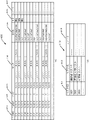
次に図6を参照して、アラーム情報管理部218で管理するアラーム設定項目について説明する。図6(A)はアラーム設定リストであり、アラーム情報管理部218で管理するアラーム条件設定の一例である。アラーム設定は画像解析サーバ104が保持する情報であり、アラームID601、リストID602、アラーム種別603、優先度604、対象カメラ605、アラーム閾値606の項目が含まれる。
Next, alarm setting items managed by the alarm
アラームID601はアラーム設定に対して一意に割り当てられ、アラームを識別するための識別情報である。リストID602は、アラーム設定が適用されるリストIDを示し、図4(B)のリストID411と共通の識別情報が用いられる。図6(A)の設定では登録者リストID「001」の登録者が検出された際はアラームID「1」が出力される。
An
アラーム種別603には、撮像画像を解析して検出する内容が登録される。本実施形態では人物検出を行っているため設定値として「Human Detection」が設定されている。画像解析サーバ104で他の画像解析を行い、その結果をアラームとして通知する場合には、対応する解析種別を設定することができる。例えば画像解析サーバ104で人物が侵入禁止エリアに侵入したことを検知し、それをアラームとして出力することもできる。
The content detected by analyzing the captured image is registered in the
優先度604には、出力するアラームの優先度を示す値が設定される。優先度604は、リストID602に登録されるリストの種別に対応付けられている。よって、操作端末105上でアラーム表示画面に優先度の表示を含めることで、どのリストに登録されている人物についてアラームが出力されたのかを把握することができる。優先度は、アラームに対する優先度の高低を操作者が認識することを可能とする。例えば、アラームとしての緊急性が高いものほど優先度を高くすることができる。図4(B)に示したリストとの関連では、リストID411が002の要注意人物リストには優先度Highを割り当て、001の登録者リスト1にはMiddleを割り当て、003の従業員リストにはLowを割り当てることができる。また、優先度に応じて操作端末105側で別の警報装置へ通知する等のシステムを導入することも可能である。
A value indicating the priority of the alarm to be output is set in the
対象カメラ605には、アラーム生成の対象となるカメラ102を特定する値が登録される。システム10に接続されているカメラ102のすべてを対象とする場合は「all」を示す値が登録される。一部のカメラ102のみを指定する場合には、当該カメラを特定するためのカメラID等を登録することができる。アラーム閾値606には、照合部216が算出した類似度に基づきアラームを生成する場合に用いるアラーム閾値が登録される。アラーム閾値606は、照合部216が登録された被写体が検出されたか否かを判定する際に用いる閾値とは異なる。アラーム閾値606は、照合部216で登録人物と判定した人物について、アラーム生成の有無やアラーム種別の変更等を行うかどうかを判定するために用いられる閾値である。よって、リスト001や002の人物が検出されたと照合部216が判定した場合には、アラーム閾値は0であるので、全てがアラーム生成の対象となる。アラーム閾値606を設定することにより、例えば、画像解析処理の設定パラメータは変更せずにアラームの発行制限を行うことや、類似度が高く登録人物の可能性が高い場合に別のアラーム種別のアラーム生成を行ったりすることができる。
A
図6(B)は、発明の実施形態に対応するアラーム表示情報テーブルの一例を示す。アラーム表示情報テーブル610は画像解析サーバ104が保持する情報であり、検出日時611、登録者ID612、登録名613、アラーム種別614、場所615、カメラID616、カメラ名617、優先度618、登録リスト名619、類似度620のフィールドを有する。
FIG. 6B shows an example of an alarm display information table corresponding to the embodiment of the invention. An alarm display information table 610 is information held by the
検出日時611はカメラ102の撮像画像から登録人物が検出された日時である。登録者ID612は、照合部216で検出した人物を識別するための識別情報であり、図4(A)の登録者ID401と対応する値が登録される。登録名613は、照合部216で検出した被写体の登録名であり、図4(A)の登録名403と対応する値が登録される。アラーム種別は614、アラーム情報管理部218の設定条件に基づき作成されたアラームの種類である。場所615は、被写体が検出された画像を撮像したカメラ102の設置場所である。カメラID616は、被写体を検出した画像を撮像したカメラ102の識別情報である。カメラ名617は被写体を検出した画像を撮像したカメラ102のカメラ名である。優先度618は、アラーム情報管理部218の設定条件に基づき作成されたアラームの優先度である。登録リスト名619は、検出した被写体が含まれるリスト名である。類似度620は、被写体を検出した際に算出した類似度である。
Detection date and
このようなアラーム表示情報は、画像解析サーバ104から操作端末105へアラーム表示を操作端末105で行うための表示情報として送信され、図7に示すアラーム表示処理手順にしたがって表示される。
Such alarm display information is transmitted from the
次に図6(C)は、発明の実施形態に対応するカメラ情報テーブル630の一例を示す図である。カメラ情報テーブル630は、カメラID631、カメラ名632、場所633、IPアドレス644、領域635、マップID636、マップ位置637の項目を有する。カメラID631には、個々のカメラ102を識別する情報が登録される。カメラ名632には、個々のカメラに与えられる名称が登録される。場所633には、カメラが配置される場所を示す情報が登録される。IPアドレス634には、個々のカメラに与えられたIPアドレスが登録される。これによりカメラ102は外部装置と直接に通信することができる。領域635には、カメラが撮影する領域を示す情報が登録される。マップID636には、表示情報で用いられるマップ画像を特定するための識別情報が登録される。マップ位置637は、マップID636により特定されるマップ画像上におけるカメラ相対位置を示す情報が登録される。これらの情報は画像解析サーバ104が保持する情報であり、カメラ名632、場所633、領域635、マップ位置637は、操作端末105からも変更が可能である。また、アラーム作成部219は、当該情報をアラーム作成時に参照し、作成したアラーム表示情報を操作端末105へ送信する。
Next, FIG. 6C is a diagram showing an example of a camera information table 630 corresponding to the embodiment of the invention. The camera information table 630 has items of
次に図6(D)は、発明の実施形態に対応するマップ情報テーブル640の一例を示す図である。マップ情報テーブル640は、マップID641、マップ名642、画像データ643の項目を有する。マップID641は、マップを一意に特定するための識別情報が登録され、カメラ情報テーブル630のマップID636と対応する。マップ名642には、マップの名称が登録される。画像データ643は、マップIDで識別されるマップ画像のデータが登録される。本テーブルを参照することにより、マップIDが特定されれば、対応するマップ画像を取得することが可能となる。マップ情報テーブル640は、画像解析サーバ104が保持していてもよいし、操作端末105が保持していてもよい。また、両装置がそれぞれ保持していてもよい。
Next, FIG. 6D is a diagram showing an example of a map information table 640 corresponding to the embodiment of the invention. The map information table 640 has items of
次に、操作端末105が実行するアラーム表示処理手順について、図5(B)のフローチャートを参照しながら説明する。S511において、操作端末105は、画像解析サーバ104からアラーム表示情報を受信する。続くS512において、操作端末105は、操作端末105の表示装置にアラーム表示画面を表示するために、S511で受信したアラーム表示情報を解析する。続くS513において、S512における解析結果に基づき、アラーム表示情報に含める各種の情報を取得する。当該情報は、画像録画サーバ103や画像解析サーバ104から取得することもできるし、操作端末105自体が保持している場合には操作端末105が保持する情報を利用することもできる。例えば、操作端末105は、検出日時611及びカメラID616に基づいてアラーム発生時の撮像画像を画像録画サーバ103から取得する。また、受信したアラーム表示情報の登録者ID612に基づき、登録者リストからアラーム表示に含める顔画像を取得する。また、アラーム表示情報のカメラID616に基づき、カメラ情報テーブル630に従いマップID636及びマップ位置637を取得する。また、取得したマップID636とマップ情報テーブル640とに基づき、対応するマップ画像データを取得する。
Next, an alarm display processing procedure executed by the
続くS514では、以上により取得した情報に基づいてアラーム表示画面を操作端末105の表示装置上に表示する。アラーム表示画面は、アラーム表示情報に含まれる検出日時、アラーム種別などのテキストデータの他、検出した被写体の画像、被写体が検出された画像を撮像カメラ102の位置により、マップ上において被写体が検出された位置を示すマップ画像等を含むことができる。S514におけるアラーム画面表示では、S513で取得した情報を全て表示してもよいが、操作者の設定や操作に応じて、所定の情報に絞り込んで表示を行ったり、段階的に情報を提供したりするようにしてもよい。
In subsequent S514, an alarm display screen is displayed on the display device of the
また、アラーム表示情報を画像解析サーバ104がディスプレイ等の表示装置に表示する場合には、画像解析サーバ104が図5(B)の処理を実行することができる。
Further, when the
次に、発明の実施形態に対応するアラーム表示画面の例を説明する。図7は発明の実施形態に対応するアラーム表示画面の一例を示す図である。図7に示すアラーム表示画面701は、アラーム情報リスト702、被写体情報表示領域703、撮像画像704、登録画像705、操作パネル706、マップ画像707、カメラ標識708を含めることができる。
Next, an example of an alarm display screen corresponding to the embodiment of the invention will be described. FIG. 7 is a diagram showing an example of an alarm display screen corresponding to the embodiment of the invention. An
アラーム情報リスト702は、検出された被写体を一覧表示するリストであり、検出対象の被写体が検出される度にリストの先頭行に当該検出被写体に関する情報が追加される。被写体情報表示領域703には、被写体が検出されたときに撮像された撮像画像704と、検出された被写体の登録画像705、撮像画像704が動画である場合、あるいは、複数枚の静止画である場合に、表示を制御するための操作パネル706が含まれる。アラーム情報リスト702の中からから、いずれかの検出被写体が選択されると、選択された被写体の検出時の画像が撮像画像704として表示される。また、当該被写体の画像が登録画像705として表示される。これにより、操作端末105の操作者は、検出時の被写体の様子を把握すると同時に、検出された被写体が誰(何)であるかを登録画像705により直ちに認識することが可能となる。よって、撮像画像704からは被写体を認識しづらい場合であっても、直ちに検出された被写体を特定することが可能となる。登録画像705を表示する場合に、枠の色を優先度に対応する色としてもよい。例えば、優先度がHighの場合は赤、Middleは黄色、Lowは青といったように色分けすることにより、検出された被写体の優先度を直感的に把握することが可能となる。
The
マップ707には、撮像画像704を撮像したカメラ102に対応するマップ画像が表示され、当該カメラ102の位置がカメラ標識708により示される。これにより、どのカメラ102によって被写体が検出されたか、換言すれば、マップ上のどの位置において被写体が検出されたかを直ちに把握することができる。
A map image corresponding to the
次に、図8を参照して、発明の実施形態に対応するアラーム表示画面の他の例を説明する。図8は発明の実施形態に対応するアラーム表示画面の他の一例を示す図である。図8に示すアラーム表示画面801は図7に示したアラーム表示画面701とほぼ同様であるが、図7では登録画像が1枚であったのに対して、図8では3枚の登録画像が表示される点で異なっている。登録画像801から803は、同一の被写体について登録された画像である。ここでは、人物を想定しているので同一人物について3枚の画像が登録されている。これらの画像は登録者リスト400に登録された画像を用いることができるので、登録者リスト400に複数枚の画像が登録されていれば、それらを表示することができる。
Next, another example of the alarm display screen corresponding to the embodiment of the invention will be described with reference to FIG. FIG. 8 is a diagram showing another example of the alarm display screen corresponding to the embodiment of the invention. The
また、複数の画像を表示する場合、撮像画像から抽出された特徴量との類似度が最も高いと判定された登録画像を優先して表示することができる。その際に、類似度がより高いと判定された画像を識別可能に表示してもよい。例えば、類似度が高いほど表示サイズを大きくしたり、撮像画像704の近くに表示したりしてもよい。
Also, when displaying a plurality of images, it is possible to preferentially display a registered image determined to have the highest degree of similarity with the feature amount extracted from the captured image. At that time, an image determined to have a higher degree of similarity may be displayed in an identifiable manner. For example, the higher the degree of similarity, the larger the display size, or the closer the captured
次に、図9を参照して、発明の実施形態に対応するアラーム表示画面の更に他の例を説明する。図9は発明の実施形態に対応するアラーム表示画面の更に他の一例を示す図である。図9に示すアラーム表示画面901は図7に示したアラーム表示画面701とほぼ同様であるが、図7と比較して撮像画像704をより大きく表示するとともに、登録画像をマップ707上に表示している点で異なる。アラーム表示画面701では、被写体を検出したカメラの位置をカメラ標識708により示していたが、図9に示すように登録画像902を標識として用いて当該カメラと関連付けることにより、被写体が検出された位置をマップ上で特定できると同時に、被写体が誰(何)であるかを把握することが可能となる。また、図9に示すように、操作端末105のアラーム表示画面上において、アラーム情報リスト702、被写体情報表示領域703及びマップ707の表示位置は固定的ではなく、任意に変更が可能である。
Next, still another example of the alarm display screen corresponding to the embodiment of the invention will be described with reference to FIG. FIG. 9 is a diagram showing still another example of the alarm display screen corresponding to the embodiment of the invention. The
次に、図10を参照して、発明の実施形態に対応するアラーム表示画面の更に他の例を説明する。図10は発明の実施形態に対応するアラーム表示画面の更に他の一例を示す図である。図10に示すアラーム表示画面1001は図7に示したアラーム表示画面701とほぼ同様であるが、図7と比較して登録画像1002から1004がマップ上707にも表示されるとともに、登録画像705と関連付けて検出日時、登録名、検出場所の情報1005が表示される点で異なる。
Next, still another example of the alarm display screen corresponding to the embodiment of the invention will be described with reference to FIG. FIG. 10 is a diagram showing still another example of the alarm display screen corresponding to the embodiment of the invention.
登録画像1002は、カメラ標識708で示すカメラ102で検出された被写体の登録画像を表示する。また、登録画像1003及び1004は、登録画像1002に対応する画像であって、カメラ標識708で示すカメラ102で検出される以前に、同一の被写体を検出したカメラ102をマップ上で示すための標識として機能しえる。このように過去に検出された位置をマップ上で示すことにより、検出対象の被写体の移動の軌跡をマップ上に示すことが可能となる。このとき被写体の移動方向が分かりやすいように、移動の方向を示す表示を付加してもよい。例えば、被写体の移動方向に合わせて矢印等の方向を示す表示を重畳してもよい。あるいは、表示する登録画像の透明度や色や枠等の画像表示形態を変える等で過去のアラームであることが分かるようにすることも可能である。具体的には、新しく検出された位置程、透明度を低くし、古い検出位置ほど透明度を高くすることができる。
情報1005は、検出された被写体に関する情報の別の表示形態の例を示す。当該情報は、アラーム情報リスト702に含まれる情報を用いてもよい。これにより、検出された被写体に関する情報を登録画像と対応付けてより把握しやすくすることができる。情報1005の表示位置は、図10に示した位置に限定されるものではなく、マップ707上に表示してもよい。また、情報1005に含める情報の種類は、操作端末105の操作者が任意に選択できるようにしてもよい。
次に、図11を参照して、発明の実施形態に対応するアラーム表示画面における撮像画像704及びマップ707の他の表示形態を説明する。図11(A)は発明の実施形態に対応する撮像画像704の他の表示形態の一例を示す図である。図11(A)に示す撮像画像704においては、検出対象の被写体が撮像画像704に含まれる被写体のうちのいずれであるかを示す標識1101と、被写体の登録名1102とが撮像画像に重畳表示される。これの表示により、撮像画像中において検出対象の被写体を直ちに特定することが可能となる。この時、登録名1102と共に他の被写体情報を表示してもよい。例えば、登録画像を合わせて表示してもよい。これらの標識の表示は、画像解析サーバ104における画像解析において顔領域を撮像画像から検出した際に特定した顔位置の情報を利用することができる。当該顔位置の情報は、アラーム表示情報に含められて、画像解析サーバ104から操作端末105に提供される。
Next, another display form of the captured
次に、図11(B)及び(C)は発明の実施形態に対応するマップ707の他の表示形態の一例を示す図である。図11(B)に示すマップ707においては、検出対象の被写体を検出したカメラ102を示すカメラ標識1103が、図7等に示したカメラ標識708とは異なっている。これは標識の表示形態を、アラームの優先度に対応させたものであって、アラームの優先度が高い場合には、優先度が高いことを示すように標識の表示を切り替えることができる。これによりマップ表示を見るだけで、優先度の高さを直感的に認識することが可能となる。
Next, FIGS. 11B and 11C are diagrams showing examples of other display forms of the
また、現在マップで表示されている検出被写体よりもアラームの優先度が高い被写体が検出された場合には、図11(C)に示すように選択されていない検出被写体であっても重畳表示をして、操作者に通知を行うことができる。例えば、アラーム情報リスト702において選択され表示されていた検出被写体が、優先度がMiddleの人物Aであり、操作者は当該人物Aについて撮像画像を確認している最中に、優先度がHighの人物Zが検出された場合を想定する。この時、操作者は直ちに人物Zについて把握するべきであるが、アラーム情報リスト702に人物Zについての情報が一行追加されただけでは気づかないことも考えられる。そこで、現在表示している被写体よりも優先度の高い被写体が検出された場合には、マップ上で当該人物を検出したカメラ位置を標識1103を使って通知することで、操作者に確実に新しい被写体が検出されたことを通知することができる。このとき、単に画面上の表示によるだけではなく、音声を出力することにより操作者に通知してもよい。
Also, when a subject with a higher alarm priority than the detected subject currently displayed on the map is detected, as shown in FIG. to notify the operator. For example, the detected subject selected and displayed in the
以上に説明した発明の実施形態によれば、被写体検出システムにおいて、登録されている検出対象の被写体を検出した際の表示の視認性を向上させることが可能となる。 According to the embodiments of the invention described above, in the subject detection system, it is possible to improve the visibility of display when detecting a registered detection target subject.
(その他の実施形態)
本発明は、上述の実施形態の1以上の機能を実現するプログラムを、ネットワーク又は記憶媒体を介してシステム又は装置に供給し、そのシステム又は装置のコンピュータにおける1つ以上のプロセッサがプログラムを読出し実行する処理でも実現可能である。また、1以上の機能を実現する回路(例えば、ASIC)によっても実現可能である。
(Other embodiments)
The present invention supplies a program that implements one or more functions of the above-described embodiments to a system or apparatus via a network or a storage medium, and one or more processors in the computer of the system or apparatus reads and executes the program. It can also be realized by processing to It can also be implemented by a circuit (for example, ASIC) that implements one or more functions.
10...被写体検出システム、101...LAN、102...ネットワークカメラ、103...画像録画サーバ、104...画像解析サーバ、105...操作端末 10... Object detection system, 101... LAN, 102... Network camera, 103... Image recording server, 104... Image analysis server, 105... Operation terminal
Claims (19)
前記特徴情報に基づいて、撮像画像から前記被写体を検出する検出手段と、
前記検出手段が第1の撮像画像において検出した前記被写体について、過去に検出された複数の前記被写体に関する情報のリストを含む表示情報を生成する生成手段と
前記表示情報を出力する出力手段と
を備え、
前記リストには、少なくとも前記被写体の検出の報知に関わる優先度に関する情報が含まれ、
前記生成手段は、前記被写体の優先度が表示されるように前記表示情報を生成し、
前記生成手段は、前記撮像画像に、前記検出された被写体を識別可能に示すための、前記被写体の名称を含む標識が重畳されて表示されるように前記表示情報を生成することを特徴とする情報処理装置。 holding means for holding feature information of a subject to be detected from a captured image;
detection means for detecting the subject from the captured image based on the feature information;
generating means for generating display information including a list of information relating to a plurality of subjects detected in the past with respect to the subject detected in the first captured image by the detecting means; and output means for outputting the display information. ,
the list includes at least information about priority related to notification of detection of the subject;
The generating means generates the display information so that the priority of the subject is displayed,
The generating means generates the display information such that a marker including the name of the subject is superimposed on the captured image to indicate the detected subject in an identifiable manner . Information processing equipment.
前記特徴情報に基づいて、撮像画像から前記被写体を検出する検出手段と、
前記検出手段が第1の撮像画像において検出した前記被写体について、過去に検出された複数の前記被写体に関する情報のリストを含む表示情報を生成する生成手段と
前記表示情報を出力する出力手段と
を備え、
前記リストには、少なくとも前記被写体の検出の報知に関わる優先度に関する情報が含まれ、
前記生成手段は、前記被写体の優先度が表示されるように前記表示情報を生成し、
前記生成手段は、前記複数の被写体のうち、前記リストにおいて選択された第1の被写体について、前記第1の被写体が検出された撮像画像と、検出された前記第1の被写体を特定する情報と、前記検出された第1の被写体の前記特徴情報が表示されるように前記表示情報を生成し、
前記出力手段は、前記第1の被写体よりも前記優先度が高い被写体が検出された場合に、新しい被写体が検出されたことを通知することを特徴とする情報処理装置。 holding means for holding feature information of a subject to be detected from a captured image;
detection means for detecting the subject from the captured image based on the feature information;
generating means for generating display information including a list of information about a plurality of subjects detected in the past with respect to the subject detected by the detecting means in the first captured image;
output means for outputting the display information;
with
the list includes at least information about priority related to notification of detection of the subject;
The generating means generates the display information so that the priority of the subject is displayed,
For a first subject selected from the list among the plurality of subjects, the generating means generates a captured image in which the first subject is detected and information specifying the detected first subject. , generating the display information such that the characteristic information of the detected first subject is displayed;
The information processing apparatus, wherein the output unit notifies that a new subject has been detected when the subject having the higher priority than the first subject is detected.
前記特徴情報に基づいて、撮像画像から前記被写体を検出する検出手段と、
前記検出手段が第1の撮像画像において検出した前記被写体について、過去に検出された複数の前記被写体に関する情報のリストを含む表示情報を生成する生成手段と
前記表示情報を出力する出力手段と
を備え、
前記リストには、少なくとも前記被写体の検出の報知に関わる優先度に関する情報が含まれ、
前記生成手段は、前記被写体の優先度が表示されるように前記表示情報を生成し、
前記表示情報は、前記優先度が他の被写体より高い被写体を撮像した撮像装置を強調する表示を含むことを特徴とする情報処理装置。 holding means for holding feature information of a subject to be detected from a captured image;
detection means for detecting the subject from the captured image based on the feature information;
generating means for generating display information including a list of information about a plurality of subjects detected in the past with respect to the subject detected by the detecting means in the first captured image;
output means for outputting the display information;
with
the list includes at least information about priority related to notification of detection of the subject;
The generating means generates the display information so that the priority of the subject is displayed,
The information processing apparatus, wherein the display information includes a display that emphasizes an imaging device that has captured an image of a subject having a higher priority than other subjects.
前記生成手段は、前記優先度に基づいて、前記検出された被写体の前記優先度に応じて区別して表示するための前記表示情報を生成することを特徴とする請求項1から10のいずれか1項に記載の情報処理装置。 The detection means detects a plurality of subjects included in the captured image,
11. The display information according to any one of claims 1 to 10 , wherein the generating means generates the display information for distinguishing and displaying the detected subject according to the priority, based on the priority. The information processing device according to the item.
前記生成手段は、前記被写体が登録されている前記リストに基づいて、前記被写体の前記優先度を決定することを特徴とする請求項1から11のいずれか1項に記載の情報処理装置。 the list is generated by associating the priority with each attribute of the subject;
12. The information processing apparatus according to any one of claims 1 to 11 , wherein said generating means determines said priority of said subject based on said list in which said subject is registered.
前記撮像装置が撮像した撮像画像を処理する請求項1から14のいずれか1項に記載の情報処理装置と、
前記情報処理装置が出力した表示情報を表示する表示装置と
を備える、被写体検出システム。 an imaging device;
The information processing device according to any one of claims 1 to 14 , which processes a captured image captured by the imaging device;
and a display device for displaying the display information output by the information processing device.
検出手段が、撮像画像から検出すべき被写体の特徴情報に基づいて、撮像画像から前記被写体を検出する検出工程と、
前記検出手段が第1の撮像画像において検出した前記被写体について、過去に検出された複数の前記被写体に関する情報のリストを含む表示情報を生成する生成工程と
前記表示情報を出力する出力工程と
を含み、
前記リストには、少なくとも前記被写体の検出の報知に関わる優先度に関する情報が含まれ、
前記生成工程では、前記被写体の優先度が表示されるように前記表示情報が生成され、
前記生成工程では、前記撮像画像に、前記検出された被写体を識別可能に示すための、前記被写体の名称を含む標識が重畳されて表示されるように前記表示情報が生成されることを特徴とする情報処理装置の制御方法。 A control method for an information processing device,
a detection step in which the detection means detects the subject from the captured image based on the feature information of the subject to be detected from the captured image;
a generating step of generating display information including a list of information about a plurality of subjects detected in the past with respect to the subject detected in the first captured image by the detecting means; and an outputting step of outputting the display information. ,
the list includes at least information about priority related to notification of detection of the subject;
In the generating step, the display information is generated so as to display the priority of the subject ;
In the generating step, the display information is generated such that a marker including the name of the subject is superimposed on the captured image to indicate the detected subject in an identifiable manner. A control method for an information processing device.
検出手段が、撮像画像から検出すべき被写体の特徴情報に基づいて、撮像画像から前記被写体を検出する検出工程と、a detection step in which the detection means detects the subject from the captured image based on the feature information of the subject to be detected from the captured image;
前記検出手段が第1の撮像画像において検出した前記被写体について、過去に検出された複数の前記被写体に関する情報のリストを含む表示情報を生成する生成工程とa generating step of generating display information including a list of information about a plurality of subjects detected in the past, with respect to the subject detected by the detection means in the first captured image;
前記表示情報を出力する出力工程とan output step of outputting the display information;
を含み、including
前記リストには、少なくとも前記被写体の検出の報知に関わる優先度に関する情報が含まれ、the list includes at least information about priority related to notification of detection of the subject;
前記生成工程では、前記被写体の優先度が表示されるように前記表示情報が生成され、In the generating step, the display information is generated so as to display the priority of the subject;
前記生成工程では、前記複数の被写体のうち、前記リストにおいて選択された第1の被写体について、前記第1の被写体が検出された撮像画像と、検出された前記第1の被写体を特定する情報と、前記検出された第1の被写体の前記特徴情報が表示されるように前記表示情報が生成され、In the generating step, for a first subject selected in the list among the plurality of subjects, a captured image in which the first subject is detected and information specifying the detected first subject. , the display information is generated such that the characteristic information of the detected first subject is displayed;
前記出力工程では、前記第1の被写体よりも前記優先度が高い被写体が検出された場合に、新しい被写体が検出されたことが通知されることを特徴とする情報処理装置の制御方法。A control method for an information processing apparatus, wherein, in the output step, detection of a new subject is notified when a subject having a higher priority than the first subject is detected.
検出手段が、撮像画像から検出すべき被写体の特徴情報に基づいて、撮像画像から前記被写体を検出する検出工程と、a detection step in which the detection means detects the subject from the captured image based on the feature information of the subject to be detected from the captured image;
前記検出手段が第1の撮像画像において検出した前記被写体について、過去に検出された複数の前記被写体に関する情報のリストを含む表示情報を生成する生成工程とa generating step of generating display information including a list of information about a plurality of subjects detected in the past, with respect to the subject detected by the detection means in the first captured image;
前記表示情報を出力する出力工程とan output step of outputting the display information;
を含み、including
前記リストには、少なくとも前記被写体の検出の報知に関わる優先度に関する情報が含まれ、the list includes at least information about priority related to notification of detection of the subject;
前記生成工程では、前記被写体の優先度が表示されるように前記表示情報が生成され、In the generating step, the display information is generated so as to display the priority of the subject;
前記表示情報は、前記優先度が他の被写体より高い被写体を撮像した撮像装置を強調する表示を含むことを特徴とする情報処理装置の制御方法。A control method for an information processing apparatus, wherein the display information includes a display emphasizing an imaging apparatus that has captured an image of a subject having a higher priority than other subjects.
Priority Applications (1)
| Application Number | Priority Date | Filing Date | Title |
|---|---|---|---|
| JP2018037730A JP7145622B2 (en) | 2018-03-02 | 2018-03-02 | Information processing device, information processing device control method, subject detection system, and program |
Applications Claiming Priority (1)
| Application Number | Priority Date | Filing Date | Title |
|---|---|---|---|
| JP2018037730A JP7145622B2 (en) | 2018-03-02 | 2018-03-02 | Information processing device, information processing device control method, subject detection system, and program |
Publications (3)
| Publication Number | Publication Date |
|---|---|
| JP2019153920A JP2019153920A (en) | 2019-09-12 |
| JP2019153920A5 JP2019153920A5 (en) | 2021-04-15 |
| JP7145622B2 true JP7145622B2 (en) | 2022-10-03 |
Family
ID=67947056
Family Applications (1)
| Application Number | Title | Priority Date | Filing Date |
|---|---|---|---|
| JP2018037730A Active JP7145622B2 (en) | 2018-03-02 | 2018-03-02 | Information processing device, information processing device control method, subject detection system, and program |
Country Status (1)
| Country | Link |
|---|---|
| JP (1) | JP7145622B2 (en) |
Families Citing this family (4)
| Publication number | Priority date | Publication date | Assignee | Title |
|---|---|---|---|---|
| CN111182265B (en) * | 2019-12-31 | 2021-12-17 | 浙江大华技术股份有限公司 | Video monitoring equipment cascading method and device |
| US20230097749A1 (en) | 2021-09-30 | 2023-03-30 | Woven Alpha, Inc. | Vehicle data collection system and method of using |
| WO2023203637A1 (en) * | 2022-04-19 | 2023-10-26 | 日本電気株式会社 | Monitoring system, information processing device, monitoring device, method, and non-transitory computer recording medium |
| WO2024079847A1 (en) * | 2022-10-13 | 2024-04-18 | 日本電気株式会社 | Security assistance system, security assistance method, and recording medium |
Citations (3)
| Publication number | Priority date | Publication date | Assignee | Title |
|---|---|---|---|---|
| JP2009077064A (en) | 2007-09-19 | 2009-04-09 | Fujifilm Corp | Monitoring method and monitoring apparatus |
| WO2016147770A1 (en) | 2015-03-19 | 2016-09-22 | 日本電気株式会社 | Monitoring system and monitoring method |
| JP2018018150A (en) | 2016-07-25 | 2018-02-01 | ユニティガードシステム株式会社 | Crime prevention system, crime prevention method, and robot |
-
2018
- 2018-03-02 JP JP2018037730A patent/JP7145622B2/en active Active
Patent Citations (3)
| Publication number | Priority date | Publication date | Assignee | Title |
|---|---|---|---|---|
| JP2009077064A (en) | 2007-09-19 | 2009-04-09 | Fujifilm Corp | Monitoring method and monitoring apparatus |
| WO2016147770A1 (en) | 2015-03-19 | 2016-09-22 | 日本電気株式会社 | Monitoring system and monitoring method |
| JP2018018150A (en) | 2016-07-25 | 2018-02-01 | ユニティガードシステム株式会社 | Crime prevention system, crime prevention method, and robot |
Also Published As
| Publication number | Publication date |
|---|---|
| JP2019153920A (en) | 2019-09-12 |
Similar Documents
| Publication | Publication Date | Title |
|---|---|---|
| JP7145622B2 (en) | Information processing device, information processing device control method, subject detection system, and program | |
| JP7160154B2 (en) | System, abnormality determination device and method | |
| JP5339476B2 (en) | Image processing system, fever tracking method, image processing apparatus, control method thereof, and control program | |
| JP5523900B2 (en) | Person search device, person search method, and person search program | |
| WO2018116488A1 (en) | Analysis server, monitoring system, monitoring method, and program | |
| KR20130085315A (en) | Method for video surveillance system based on human identification | |
| JP5590945B2 (en) | Person search device, person search method, and person search program | |
| JP2018085597A (en) | Person behavior monitoring device and person behavior monitoring system | |
| JP2021132267A (en) | Video monitoring system and video monitoring method | |
| WO2018179202A1 (en) | Information processing device, control method, and program | |
| JP5718632B2 (en) | Part recognition device, part recognition method, and part recognition program | |
| JP2022003526A (en) | Information processor, detection system, method for processing information, and program | |
| US20190122228A1 (en) | Examination device | |
| JP7210163B2 (en) | Image processing device, image processing method and program | |
| JP5188840B2 (en) | Security device and update method | |
| JP2020166590A (en) | Monitoring system, monitoring device, monitoring method, and monitoring program | |
| JP2021012657A (en) | Information processing apparatus, information processing method, and camera | |
| JP2015176489A (en) | Monitor system, monitor method and monitor program | |
| WO2022059223A1 (en) | Video analyzing system and video analyzing method | |
| US10931923B2 (en) | Surveillance system, surveillance network construction method, and program | |
| JP2020191585A (en) | Information processing device, information processing method, and program | |
| JP2010244090A (en) | Person information extraction device, person information extraction method, and person information extraction program | |
| JP6022625B2 (en) | Part recognition device, part recognition method, and part recognition program | |
| JP7285536B2 (en) | Classifier generation device, target person estimation device and their programs, and target person estimation system | |
| JP7039084B1 (en) | Self-registration monitoring system and self-registration monitoring method |
Legal Events
| Date | Code | Title | Description |
|---|---|---|---|
| RD01 | Notification of change of attorney |
Free format text: JAPANESE INTERMEDIATE CODE: A7421 Effective date: 20210103 |
|
| A521 | Request for written amendment filed |
Free format text: JAPANESE INTERMEDIATE CODE: A523 Effective date: 20210113 |
|
| A521 | Request for written amendment filed |
Free format text: JAPANESE INTERMEDIATE CODE: A523 Effective date: 20210301 |
|
| A621 | Written request for application examination |
Free format text: JAPANESE INTERMEDIATE CODE: A621 Effective date: 20210301 |
|
| A977 | Report on retrieval |
Free format text: JAPANESE INTERMEDIATE CODE: A971007 Effective date: 20220225 |
|
| A131 | Notification of reasons for refusal |
Free format text: JAPANESE INTERMEDIATE CODE: A131 Effective date: 20220404 |
|
| A521 | Request for written amendment filed |
Free format text: JAPANESE INTERMEDIATE CODE: A523 Effective date: 20220602 |
|
| TRDD | Decision of grant or rejection written | ||
| A01 | Written decision to grant a patent or to grant a registration (utility model) |
Free format text: JAPANESE INTERMEDIATE CODE: A01 Effective date: 20220822 |
|
| A61 | First payment of annual fees (during grant procedure) |
Free format text: JAPANESE INTERMEDIATE CODE: A61 Effective date: 20220920 |
|
| R151 | Written notification of patent or utility model registration |
Ref document number: 7145622 Country of ref document: JP Free format text: JAPANESE INTERMEDIATE CODE: R151 |